POWDER CORES
Molypermalloy | High Flux | Kool Mµ
®
| XF
lux
®
| Kool Mµ
®
MAX
POWDER CORES
Molypermalloy | High Flux | Kool Mµ
®
| XF
lux
®
| Kool Mµ
®
MAX

We offer the confidence of over sixty years of expertise in the
research, design, manufacture and support of high quality magnetic
materials and components.
A major manufacturer of the highest performance materials in the
industry including: MPP, High Flux, Kool Mµ®, Kool Mµ® MAX,
XFlux®, power ferrites, high permeability ferrites and strip wound
cores, Magnetics’ products set the standard for providing consistent
and reliable electrical properties for a comprehensive range of core
materials and geometries. Magnetics is the best choice for a variety
of applications ranging from simple chokes and transformers used
in telecommunications equipment to sophisticated devices for
aerospace electronics.
Magnetics backs it products with unsurpassed technical expertise
and customer service. Magnetics’ Sales Engineers offer the
experience necessary to assist the designer from the initial design
phase through prototype approval. Knowledgeable Sales Managers
provide dedicated account management. Skilled Customer Service
Representatives are easily accessible to provide exceptional sales
support. This support, combined with a global presence via a
worldwide distribution network, including a Hong Kong distribution
center, makes Magnetics a superior supplier to the international
electronics industry.

www.mag-inc.com
1
Contents
Contents
Core Locator by Part Number
Core Index and Unit Pack Quantities . . . . . . . 2
General Information
Introduction . . . . . . . . . . . . . . . . . . . . . . . . . . 8
Applications and Materials . . . . . . . . . . . . . . 9
Material Properties . . . . . . . . . . . . . . . . . . . 10
Core Weights and Unit Conversions . . . . . . 11
Core Identification . . . . . . . . . . . . . . . . . . . . 12
Inductance and Grading . . . . . . . . . . . . . . . 13
Core Coating . . . . . . . . . . . . . . . . . . . . . . . 14
Core Selection
Inductor Core Selection Procedure . . . . . . . 15
Core Selection Example . . . . . . . . . . . . . . . 16
Toroid Winding . . . . . . . . . . . . . . . . . . . . . . 17
Powder Core Loss Calculation . . . . . . . . . . 18
Core Selector Charts . . . . . . . . . . . . . . . . . 23
Wire Table . . . . . . . . . . . . . . . . . . . . . . . . . . 28
Material Data
Permeability versus DC Bias Curves . . . . . . 29
Core Loss Density Curves . . . . . . . . . . . . . . 35
DC Magnetization Curves . . . . . . . . . . . . . . 47
Permeability versus Temperature Curves . . . 51
Permeability versus Frequency Curves . . . . 55
Core Data
Toroid Data . . . . . . . . . . . . . . . . . . . . . . . . . 58
E Core Data . . . . . . . . . . . . . . . . . . . . . . . . 96
Block Data . . . . . . . . . . . . . . . . . . . . . . . . . 97
U Core Data . . . . . . . . . . . . . . . . . . . . . . . . 98
MPP THINZ
Data . . . . . . . . . . . . . . . . . . . . 99
Hardware
E Core Hardware . . . . . . . . . . . . . . . . . . . 100
Toroid Hardware . . . . . . . . . . . . . . . . . . . . 101
Winding Tables
Winding Tables . . . . . . . . . . . . . . . . . . . . . 103
Index
< Click the page name
or page number to go
directly to the page
www.mag-inc.com
3
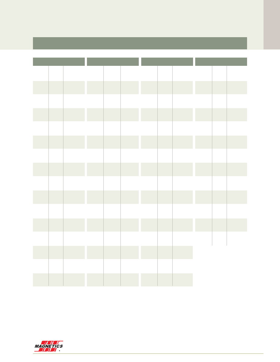
Core Locator & Unit Pack Quantity
High Flux Toroids
Index
P/N PAGE BOX QTY
P/N PAGE BOX QTY
P/N PAGE BOX QTY
P/N PAGE BOX QTY
58018
61
10,000
58019
61
10,000
58020
61
10,000
58021
61
10,000
58022
61
10,000
58023
61
10,000
58028
65
10,000
58029
65
10,000
58030
65
10,000
58031
65
10,000
58032
65
10,000
58033
65
10,000
58038
68
8,000
58039
68
8,000
58040
68
8,000
58041
68
8,000
58042
68
8,000
58043
68
8,000
58048
70
5,000
58049
70
5,000
58050
70
5,000
58051
70
5,000
58052
70
5,000
58053
70
5,000
58059
74
1,000
58070 88
35
58071
77
250
58072
88
35
58073
88
35
58074
88
35
58075
88
35
58076
79
220
58083
80
180
58089
81
120
58090
81
120
58091
81
120
58092
81
120
58099
93
25
58100
93
25
58101
93
25
58102
93
25
58109
85
90
58110
85
90
58111
85
90
58112
85
90
58118
71
2,000
58119
71
2,000
58120
71
2,000
58121
71
2,000
58122
71
2,000
58123
71
2,000
58128
69
6,000
58129
69
6,000
58130
69
6,000
58131
69
6,000
58132
69
6,000
58133
69
6,000
58164
95
6
58165
95
6
58190
86
80
58191
86
80
58192
86
80
58195
86
80
58204
73
1,600
58205
73
1,600
58206
73
1,600
58208
73
1,600
58209
73
1,600
58238
62
10,000
58239
62
10,000
58240
62
10,000
58241
62
10,000
58242
62
10,000
58243
62
10,000
58252
80
180
58253
80
180
58254
80
180
58256
80
180
58257
80
180
58268
63
10,000
58269
63
10,000
58270
63
10,000
58271
63
10,000
58272
63
10,000
58273
63
10,000
58278
66
8,000
58279
66
8,000
58280
66
8,000
58281
66
8,000
58282
66
8,000
58283
66
8,000
58288
67
8,000
58289
67
8,000
58290
67
8,000
58291
67
8,000
58292
67
8,000
58293
67
8,000
58308
74
1,000
58309
74
1,000
58310
74
1,000
58312
74
1,000
58313
74
1,000
58322
79
220
58323
79
220
58324
79
220
58326
79
220
58327
79
220
58336
94
16
58337
94
16
58338
94
16
58339
94
16
58348
75
720
58349
75
720
58350
75
720
58351
75
720
58352
75
720
58353
75
720
58378
72
2,000
58379
72
2,000
58380
72
2,000
58381
72
2,000
58382
72
2,000
58383
72
2,000
58408
64
10,000
58409
64
10,000
58410
64
10,000
58411
64
10,000
58412
64
10,000
58413
64
10,000
58437
82
105
58438
82
105
58439
82
105
58440
82
105
58441
82
105
58546
77
250
58547
77
250
58548
77
250
58550
77
250
58551
77
250
58583
78
300
58584
78
300
58585
78
300
58586
78
300
58587
78
300
58588
78
300
58614
87
45
58615
87
45
58616
87
45
58617
87
45
58620
87
45
58714
84
90
58715
84
90
58716
84
90
58717
84
90
58718
84
90
58725 83
70
58726
83
70
58727
83
70
58728
83
70
58734
89
24
58735
89
24
58736
89
24
58737
89
24
58774
92
20
58775
92
20
58776
92
20
58777
92
20
58778
92
20
58848
73
1,600
58866
90
45
58867
90
45
58868
90
45
58869
90
45
58894
76
400
58906
91
40
58907
91
40
58908
91
40
58909
91
40
58928
76
400
58929
76
400
58930
76
400
58932
76
400
58933
76
400
MAGNETICS
4
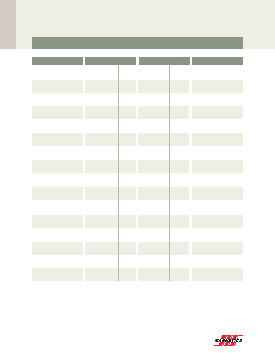
P/N PAGE BOX QTY
P/N PAGE BOX QTY
P/N PAGE BOX QTY
P/N PAGE BOX QTY
Core Locator & Unit Pack Quantity
Kool Mµ
®
Toroids
77020
61
10,000
77021
61
10,000
77030
65
10,000
77031
65
10,000
77040
68
8,000
77041
68
8,000
77050
70
5,000
77051
70
5,000
77052
70
5,000
77054
70
5,000
77055
70
5,000
77059
74
1,000
77068 88
35
77069
88
35
77070
88
35
77071
77
250
77072
88
35
77073
88
35
77074
88
35
77075
88
35
77076
79
220
77083
80
180
77089
81
120
77090
81
120
77091
81
120
77093
81
120
77094
81
120
77095
81
120
77098
93
25
77099
93
25
77100
93
25
77101
93
25
77102
93
25
77109
85
90
77110
85
90
77111
85
90
77120
71
2,000
77121
71
2,000
77130
69
6,000
77131
69
6,000
77140
58
7,500
77141
58
7,500
77150
59
7,500
77151
59
7,500
77154
59
7,500
77155
59
7,500
77164
95
6
77165
95
6
77180
60
5,000
77181
60
5,000
77184
60
5,000
77185
60
5,000
77189
86
80
77191
86
80
77192
86
80
77193
86
80
77194
86
80
77195
86
80
77206
73
1,600
77210
73
1,600
77211
73
1,600
77212
85
90
77213
85
90
77214
85
90
77224
71
2,000
77225
71
2,000
77240
62
10,000
77241
62
10,000
77244
62
10,000
77245
62
10,000
77254
80
180
77256
80
180
77258
80
180
77259
80
180
77260
80
180
77270
63
10,000
77271
63
10,000
77280
66
8,000
77281
66
8,000
77290
67
8,000
77291
67
8,000
77294
67
8,000
77295
67
8,000
77310
74
1,000
77312
74
1,000
77314
74
1,000
77315
74
1,000
77316
74
1,000
77324
79
220
77326
79
220
77328
79
220
77329
79
220
77330
79
220
77334
69
6,000
77335
69
6,000
77336
94
16
77337
94
16
77338
94
16
77339
94
16
77350
75
720
77351
75
720
77352
75
720
77354
75
720
77355
75
720
77356
75
720
77380
72
2,000
77381
72
2,000
77384
72
2,000
77385
72
2,000
77410
64
10,000
77411
64
10,000
77414
64
10,000
77415
64
10,000
77431
82
105
77438
82
105
77439
82
105
77440
82
105
77442
82
105
77443
82
105
77444
58
7,500
77445
58
7,500
77548
77
250
77550
77
250
77552
77
250
77553
77
250
77555
77
250
77585
78
300
77586
78
300
77587
78
300
77589
78
300
77590
78
300
77591
78
300
77614
87
45
77615
87
45
77616
87
45
77617
87
45
77618
87
45
77619
87
45
77620
87
45
77715
84
90
77716
84
90
77717
84
90
77719
84
90
77720
84
90
77721
84
90
77725
83
70
77726
83
70
77727
83
70
77729
83
70
77730
83
70
77733
83
70
77734
89
24
77735
89
24
77736
89
24
77737
89
24
77738
89
24
77739
89
24
77740
89
24
77774
92
20
77775
92
20
77776
92
20
77777
92
20
77778
92
20
77824
61
10,000
77825
61
10,000
77834
65
10,000
77835
65
10,000
77844
68
8,000
77845
68
8,000
77847
73
1,600
77848
73
1,600
77866
90
45
77867
90
45
77868
90
45
77869
90
45
77872
90
45
77874
63
10,000
77875
63
10,000
77884
66
8,000
77885
66
8,000
77894
76
400
77906
91
40
77907
91
40
77908
91
40
77909
91
40
77912
91
40
77930
76
400
77932
76
400
77934
76
400
77935
76
400
77936
76
400
Index

www.mag-inc.com
5
Core Locator & Unit Pack Quantity
K114LE026
96
18
K114LE040
96
18
K114LE060
96
18
K130LE026
96
12
K130LE040
96
12
K130LE060
96
12
K160LE026
96
16
K160LE040
96
16
K160LE060
96
16
K1808E026
96
2,880
K1808E040
96
2,880
K1808E060
96
2,880
K1808E090
96
2,880
K2510E026
96
1,728
K2510E040
96
1,728
K2510E060
96
1,728
K2510E090
96
1,728
K3007E026
96
720
K3007E040
96
720
K3007E060
96
720
K3007E090
96
720
K3112U040
98
672
K3112U060
98
672
K3112U090
98
672
K3515E026
96
720
K3515E040
96
720
K3515E060
96
720
K3515E090
96
720
K4017E026
96
264
K4017E040
96
264
K4017E060
96
264
K4017E090
96
264
K4020E026
96
192
K4020E040
96
192
K4020E060
96
192
K4020E090
96
192
K4022E026
96
168
K4022E040
96
168
K4022E060
96
168
K4022E090
96
168
K4110U040
98
480
K4110U060
98
480
K4110U090
98
480
K4111U040
98
480
K4111U060
98
480
K4111U090
98
480
K4119U040
98
240
K4119U060
98
240
K4119U090
98
240
K4317E026
96
270
K4317E040
96
270
K4317E060
96
270
K4317E090
96
270
K4741B026
97
48
K4741B040
97
48
K4741B060
97
48
K5030B026
97
64
K5030B040
97
64
K5030B060
97
64
K5527U026
98
128
K5528B026
97
112
K5528B040
97
112
K5528B060
97
112
K5528E026
96
112
K5528E040
96
112
K5528E060
96
112
K5529U026
98
96
K5530E026
96
96
K5530E040
96
96
K5530E060
96
96
K6030B026
97
80
K6030B040
97
80
K6030B060
97
80
K6527E026
96
54
K6527E040
96
54
K6527E060
96
54
K6527U026
98
54
K6533U026
98
54
K7020B026
97
90
K7020B040
97
90
K7020B060
97
90
K7030B026
97
60
K7030B040
97
60
K7030B060
97
60
K7228E026
96
84
K7228E040
96
84
K7228E060
96
84
K7236U026
98
60
K8020E026
96
63
K8020E040
96
63
K8020E060
96
63
K8020U026
98
63
K8024E026
96
45
K8024E040
96
45
K8024E060
96
45
K8030B026
97
48
K8030B040
97
48
K8030B060
97
48
K8038U026
98
63
K8044E026
96
63
K8044E040
96
63
K8044E060
96
63
K9541B026
97
30
Kool Mµ
®
Blocks, E Cores, and U Cores
P/N
PAGE BOX QTY
P/N
PAGE BOX QTY
P/N
PAGE BOX QTY
Index

www.mag-inc.com
7
Core Locator & Unit Pack Quantity
79051
70
5,000
79052
70
5,000
79059
74
1,000
79071
77
250
79072
88
35
79074
88
35
79076
79
220
79083
80
180
79090
81
120
79091
81
120
79099
93
25
79102
93
25
79110
85
90
79111
85
90
79121
71
2,000
79122
71
2,000
79191
86
80
79192
86
80
79208
73
1,600
79256
80
180
79312
74
1,000
79326
79
220
79337
94
16
79351
75
720
79352
75
720
79381
72
2,000
79382
72
2,000
79439
82
105
79440
82
105
79550
77
250
79586
78
300
79587
78
300
79615
87
45
79617
87
45
79716
84
90
79717
84
90
79726
83
70
79727
83
70
79735
89
24
79737
89
24
79848
73
1,600
79867
90
45
79868
90
45
79894
76
400
79907
91
40
79908
91
40
79932
76
400
Kool Mµ
®
MAX Toroids
P/N
PAGE BOX QTY
P/N
PAGE BOX QTY
P/N
PAGE BOX QTY
Index

Magnetics Molypermalloy Powder (MPP)
, or washer cores, put the premium
powder cores are distributed air
cores . Frequently, High Flux allows the designer to
reduce the size of an inductive component compared with
MPP, powdered iron, or ferrite .
powder cores are distributed air
distributed air gap cores are made from
6 .5% silicon iron powder . XF
powdered iron cores and superior DC bias performance .
The soft saturation of XF
cores are ideal for low and medium
frequency chokes where inductance at peak load is critical .
www.mag-inc.com
9
General Information
can be a lower cost alternative
to High Flux, in situations where the higher core losses and
more limited permeability availability of XF
more information on cylinders or custom shapes, please
contact Magnetics.
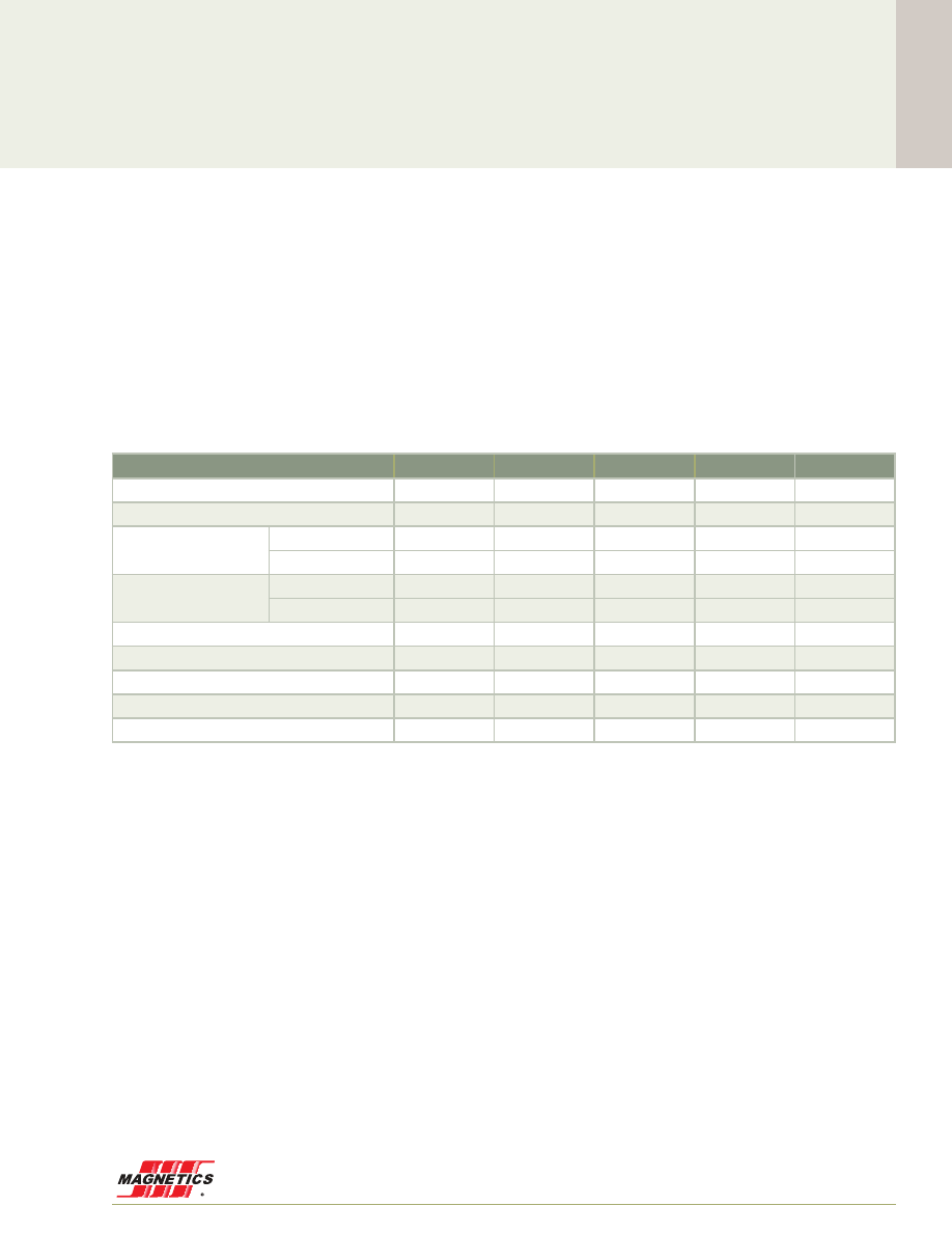
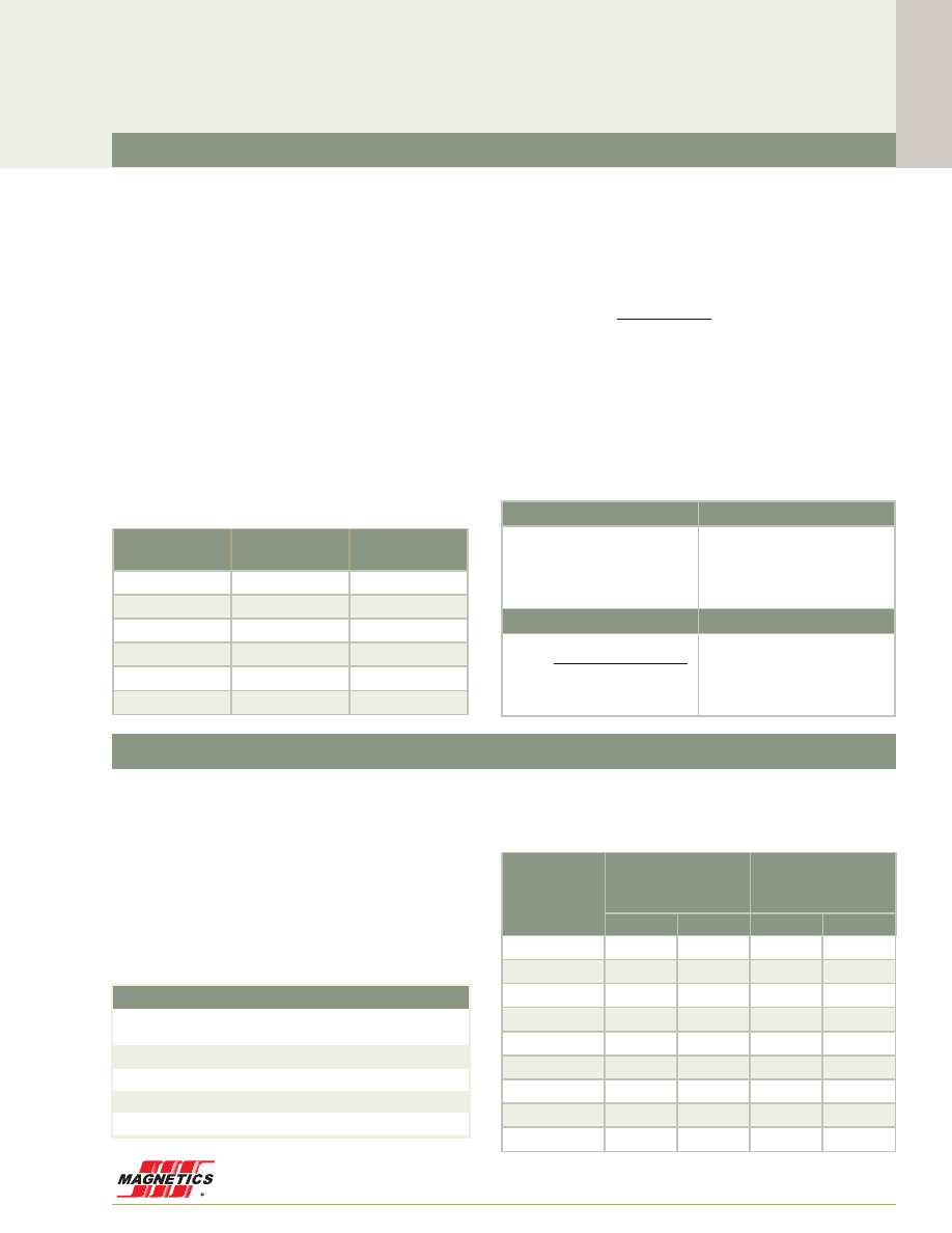
Perm vs. DC Bias - 60µ (AT/cm)
60µ Temperature Stability - Typical % shift from -60 to 200°C
Saturation Flux Density (Tesla)

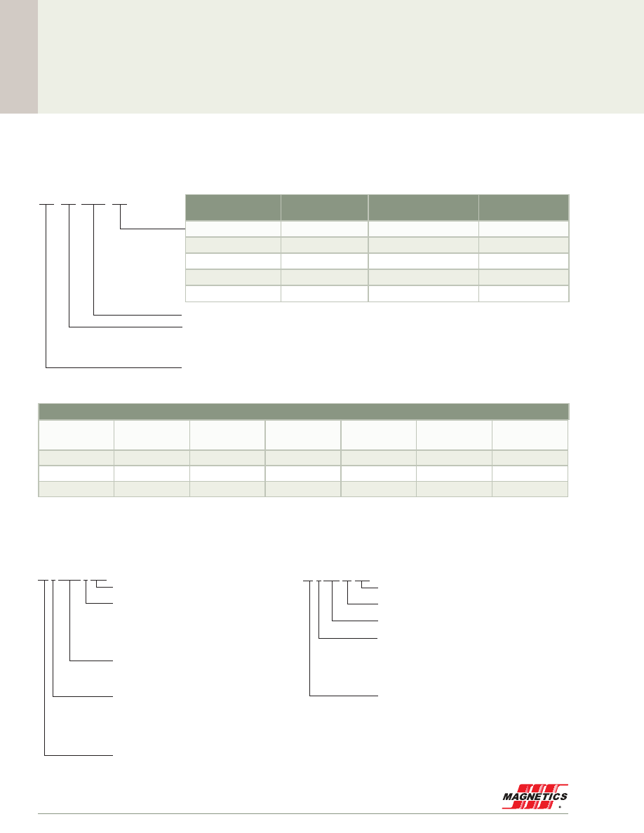
Catalog Number (designates size and permeability)
Material Code . . . . 55 = MPP
Grading Code . . . . . CO = Graded into 2% inductance bands – OD <4.65 mm, 5% bands
• No voltage breakdown min for A2 or A7 with OD
• A2 and A7 voltage breakdown is 1000 V
• AY finish not available for 550µ MPP
Permeability Code ... Permeability, e.g. 060 for 60µ
Shape Code . . . . . . E = E Core
Size Code . . . . . . . First two digits equal approximate length
or OD in mm / Last two digits equal
approximate height or ID in mm
Material Code . . . . . K = Kool Mµ
Grading Code . . . . . 00 = Not graded
• Full part number and shop order
number are marked on all shapes
Permeability Code . . Permeability, e.g. 026 for 26µ
Shape Code . . . . . . LE = Large E Core
Material Code . . . . . M = MPP*
Grading Code . . . . . 00 = Not graded
• Full part number and shop order
number are marked on all shapes
Powder Core Toroid Marking Summary
• Inductance Code is only marked on MPP and High Flux toroids with C0 grading code
• Cores with OD < 6.35 mm are not marked
• Shop order number identifies the product batch, ensuring traceability of every
core through the entire manufacturing process, back to raw materials
(Inductance factor) is given for each core in this catalog .
Inductance for blocks is tested in standard picture frame
arrangements . Units for A
, in µH) by the number of turns, N .
Example: C055930A2 with 25 turns (p . 76)
Example : C055930A2 (26 .9 mm, 125µ, p . 76)
• 14µ and 26µ cores • MPP THINZ
The following toroid OD sizes:
Core Inductance Tolerance and Grading
Measured vs. Calculated Inductance
= leakage induc tan ce adder (µH)
= core magnetic path length (mm)
Est Measured Induc tan ce
L = L
= leakage induc tan ce adder (µH)
= core magnetic path length (mm)
Est Measured Induc tan ce
L = L
= leakage induc tan ce adder (µH)
= core magnetic path length (mm)
Est Measured Induc tan ce
L = L
= leakage induc tan ce adder (µH)
= core magnetic path length (mm)
Est Measured Induc tan ce
L = L
9 - old1 - 4?or5
= leakage induc tan ce adder (µH)
= core magnetic path length (mm)
Est Measured Induc tan ce
L = L
= leakage inductance adder (µH)
= core magnetic path length (mm)
*THINZ and Kool Mµ cores with OD < 12 .7 mm have wider tolerances .
Higher minimum breakdown coatings can be applied upon
request for cores larger than 4 .65 mm .
materials can be operated continuously at 200°C with no
aging or damage .

www.mag-inc.com
15
Cor
e Selection
Inductor Core Selection Procedure
Only two parameters of the design application must be
known to select a core for a current-limited inductor; in-
ductance required with DC bias and the DC current . Use
the following procedure to determine the core size and
number of turns .
1 .
Compute the product of LI
2
where:
L = inductance required with DC bias (mH)
I = DC current (A)
2 .
Locate the LI
2
value on the Core Selector Chart
(pgs . 24 - 27) . Follow this coordinate to the inter-
section with the first core size that lies above the
diagonal permeability line . This is the smallest core
size that can be used .
3 .
The permeability line is sectioned into standard
available core permeabilities . Selecting the core
listed on the graph will tend to be the best tradeoff
between A
L
and DC bias .
4 .
Inductance, core size, and permeability are now
known . Calculate the number of turns by using the
following procedure:
(a) The inductance factor (A
L
in nH/T
2
) for the
core is obtained from the core data sheet .
Determine the minimum A
L
by using the worst
case negative tolerance (generally -8%) . With
this information, calculate the number of turns
needed to obtain the required inductance
from:
11old 2 - 1
N =
A
L
L 10
3
H =
l
e
NI
3
T (˚C) =
Component Surface Area (cm
2
)
Total Losses (mW)
U
Z
0 .833
Where L is required inductance (µH)
(b) Calculate the bias in A·T/cm from:
11old 2 - 1
N =
A
L
L 10
3
H =
l
e
NI
3
T (˚C) =
Component Surface Area (cm
2
)
Total Losses (mW)
U
Z
0 .833
(c) From the Permeability vs . DC Bias curves
(pgs . 29 - 33), determine the rolloff percentage
of initial permeability for the previously calculat-
ed bias level . Curve fit equations shown in the
catalog can simplify this step . They are also
available to use on Magnetics website: http://
www .mag-inc .com/design/design-guides/
Curve-Fit-Equation-Tool
(d) Multiply the required inductance by the per-
centage rolloff to find the inductance with bias
current applied .
(e) Increase the number of turns by dividing the
initial number of turns (from step 4(a)) by the
percentage rolloff . This will yield an inductance
close to the required value after steps 4 (b), (c)
and (d) are repeated .
(f) Iterate steps 4 (b), (c) and (d) if needed to adjust
turns up or down until the biased inductance is
satisfactorily close to the target .
5 . Choose a suitable wire size using the Wire Table (p .
28) . Duty cycles below 100% allow smaller wire
sizes and lower winding factors, but do not allow
smaller core sizes .
6 .
Design Checks
(a)
Winding Factor
. See p .17 for notes on checking
the coil design .
(b)
Copper Losses
.
See p .17 for notes on calculat-
ing conductor resistance and losses .
(c)
Core Losses
. See p .18 for notes on calculating
AC core losses . If AC losses result in too much
heating or low efficiency, then the inductor may
be loss-limited rather than current-limited . Design
alternatives for this case include using a larger
core or a lower permeability core to reduce the
AC flux density; or using a lower loss material
such as MPP or Kool Mµ MAX in place of Kool
Mµ, or High Flux in place of XF
lux
.
(d)
Temperature Rise
. Dissipation of the heat gener-
ated by conductor and core losses is influenced
by many factors . This means there is no simple
way to predict temperature rise (
%
T) precisely .
But the following equation is known to give a
useful approximation for a component in still air .
Surface areas for cores wound to 40% fill are
given with the core data in this catalog .
11old 2 - 1
N =
A
L
L 10
3
H =
l
e
NI
3
T (˚C) =
Component Surface Area (cm
2
)
Total Losses (mW)
U
Z
0 .833

0.00 mm O.D.
Cor
e Selection
MAGNETICS
16
Core Selection Example
Determine core size and number of turns to meet the
following requirement:
(a) Minimum inductance with DC bias of
0 .6 mH (600 µH)
(b) DC current of 5 .0 A
1 . LI
2
= (0 .6)(5 .0)
2
=15 .0 mH·A
2
2 . Using the Kool Mµ Toroids LI
2
chart found on p .
25, locate 15 mH·A
2
on the bottom axis . Following
this coordinate vertically results in the selection of
0077083A7 as an appropriate core for the above
requirements .
3 . From the 0077083A7 core data p . 80, the inductance
factor (A
L
) of this core is 81 nH/T
2
± 8% . The minimum
A
L
of this core is 74 .6 nH/T
2
.
4 . The number of turns needed to obtain 600 µH at no
load is 90 turns . To calculate the number of turns
required at full load, determine the DC bias level:
H= N·I/
l
e
where
l
e
is the path length in cm . The DC bias
is 45 .7 A·T/cm, yielding 71% of initial permeability from
the 60µ Kool Mµ DC bias curve on p . 30 .The adjusted
turns are 90/0 .71 =127 Turns .
5 . Re-calculate the DC bias level . The permeability versus
DC bias curve shows 57% of initial permeability at
64 .5 A·T/cm .
6 . Multiply the minimum A
L
74 .6 nH/T
2
by 0 .57 to yield
effective A
L
= 42 .5 nH/T
2
. The inductance of this core
with 127 turns and with 64 .5 A·T/cm will be 685 µH
minimum . The inductance requirement has been met .
7 . The wire table indicates that 17 AWG is needed to
carry 5 .0 A with a current density of 500 A/cm
2
.
127 turns of 17 AWG (wire area = 1 .177 mm
2
) equals
a total wire area of 149 .5 mm
2
. The window area of a
0077083A7 is 427 mm
2
. Calculating window fill,
149 .5 mm
2
/427 mm
2
corresponds to an approximate
35% winding factor . A 0077083A7 with 127 turns of
17 AWG is a manufacturable design .
Cor
e Selection

0.00 mm O.D.
www.mag-inc.com
17
Cor
e Selection
4
Toroid Winding
Winding Factor
Winding factor, also called fill factor, is the ratio of total
conductor cross section (usually copper cross section) to
the area of the core window . In other words, in a toroid,
winding factor is given by:
N
•
A
W
/W
A
N = Number of turns
where:
A
W
= Area of the wire
W
A
= Window Area of the core
p
·
ID
2
Toroid Core Winding factors can vary from 20-60%, a typical
value in many applications being 35-40% .
In practice, several approaches to toroid winding are used:
-
Single layer: The number of turns is limited by
the inside circumference of the core divided by
the wire diameter . Advantages are lower winding
capacitance, more repeatable parasitics, good
cooling, and low cost . Disadvantages are reduced
power handling and higher flux leakage .
-
Low fill: For manufacturing ease and reduced
capacitance, winding factor between single layer
and 30% may be used .
-
Full winding: Factors between 30% and 45%
are normally a reasonable trade off between fully
utilizing the space available for a given core size,
while avoiding excessive manufacturing cost .
-
High fill: Winding factors up to about 65%
are achievable, but generally only with special
expensive measures, such as completing each coil
by hand after the residual hole becomes too small
to fit the winding shuttle .
Estimating Wound Coil Dimensions
For each core size, wound coil dimensions are given for
40% winding factor, since this is a typical, practical value .
Worst case package dimensions for coils wound completely
full are also shown . These are max expected OD and max
expected HT .
To estimate dimensions for other winding factors, use:
Rv 7 - 17
OD
x%
=
40%
X% OD
40%
2
- OD
core
2
Q
V
+ OD
core
2
HT
x%
=ID
core
+ HT
core
-
60%
100%- X% ID
core
+ HT
core
- HT
40%
Q
V
2 - 8
H
ACmax
=
I
e
N I
DC
+ 2
3
I
S
X
#
&
2 - 9
H
ACmax
= 6 .35
20
20 + 2
2
S
X
= 66 .14
A
$
T
cm
"
B
ACmax
b
0 .44T
2 - 11
B
pk
= 0 .5 µ
0
Q V
%µ
i
Q V
µ
i
Q V
3
H
where
3
H
=
I
e
N
%
I
Where: X% is the new winding factor;
OD
40%
and HT
40%
are the coil dimensions shown on
the core data page;
OD
core
and HT
core
are the maximum core dimensions
after finish .
Cor
e Selection
MLT and DCR
MLT (Mean Length of Turn) is given for a range of winding
factors for each core size . To estimate DCR, first, calculate
the winding factor for the core, wire gauge, and number of
turns selected . On the wire table look up resistance per
unit of length for the gauge selected . On the data page for
the core selected, consult the Winding Turn Length chart .
Unless the winding factor is exactly one of the values listed,
interpolate to find the MLT . Then,
DCR = (MLT)(N) (
Q
/Length) .
For single layer winding, MLT is the 0% fill value on each
core data page . Even easier, DCRs for single layer windings
for a range of wire gauges are given in the winding tables on
pgs . 103 - 107 .
Wire Loss
DC copper loss is calculated directly as I
2
R . Naturally, for
aluminum conductors, a suitable wire table must be used .
Also, the increase of wire resistance with temperature
should be considered .
AC copper loss can be significant for large ripple and for
high frequency . Unfortunately, calculation of AC copper loss
is not a straight-forward matter . Estimates are typically used .

Cor
e Selection
MAGNETICS
18
Powder Core Loss Calculation
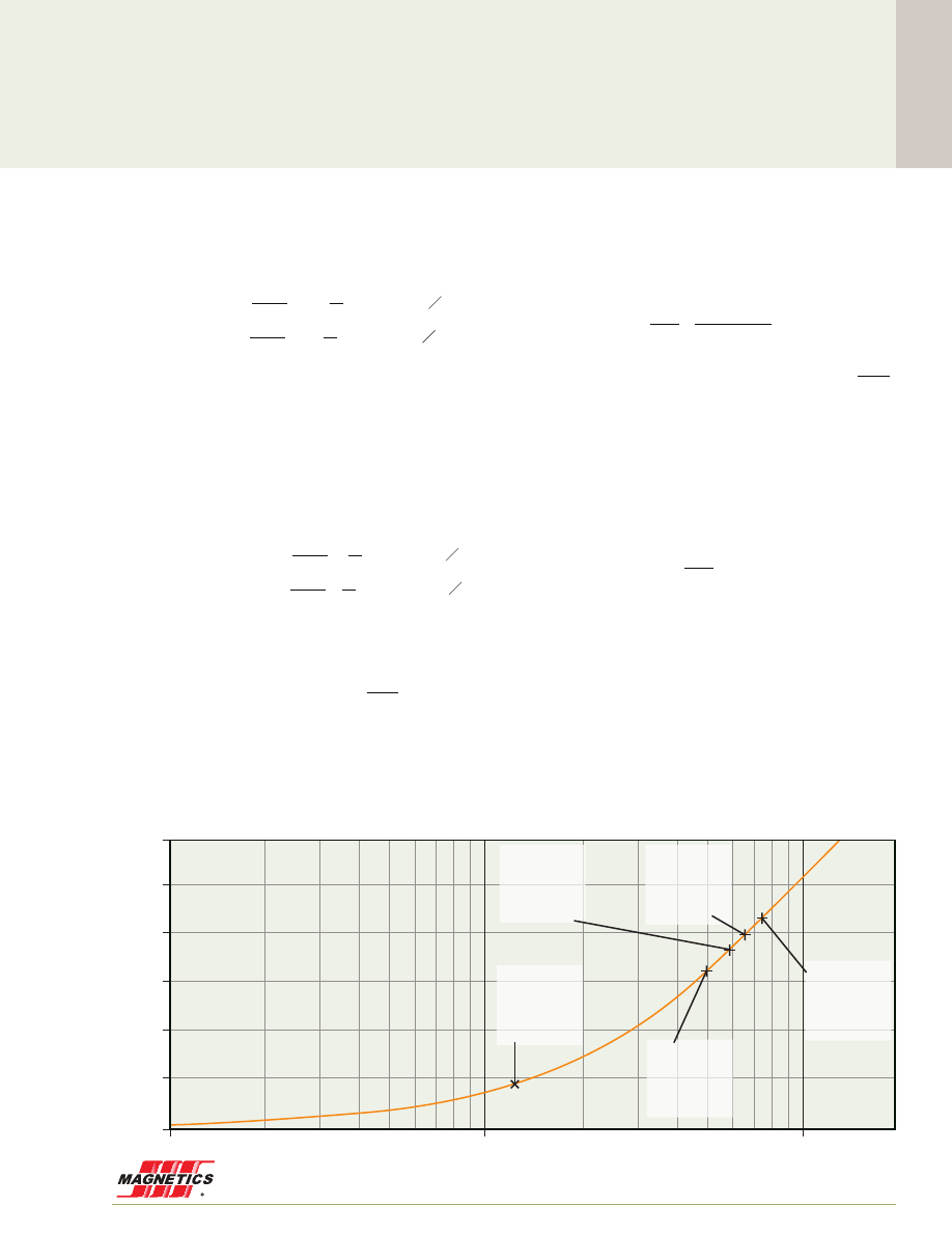
Magnetizing Force (A·T/cm)
60µ Kool Mµ DC Magnetization (Example 2)
1
0.0
0.1
0.2
0.3
0.4
0.5
0.6
10
100
Flux Density (T
esla)
160
147
125
90
75
60
40
26
14
173
200
250
300
550
500
550µ
160µ
H
AC min
H
AC max
B
AC max
B
AC min
B
H
Core loss is generated by the changing magnetic flux
field within a material, since no magnetic materials exhibit
perfectly efficient magnetic response . Core loss density (PL)
is a function of half of the AC flux swing (½ B=B
pk
) and
frequency (
f
) . It can be approximated from core loss charts
or the curve fit loss equation:
14 - old 2 - 8
PL = aB
pk
b
f
c
B
pk
= 2
%
B =
2
B
AC max
- B
AC min
H
AC max
=
I
e
N I
DC
+ 2
3
I
S
X
#
&
H
AC min
=
I
e
N I
DC
+ 2
3
I
S
X
#
&
where a, b, c are constants determined from curve fitting,
and B
pk
is defined as half of the AC flux swing:
14 - old 2 - 8
PL = aB
pk
b
f
c
B
pk
= 2
%
B =
2
B
AC max
- B
AC min
H
AC max
=
I
e
N I
DC
+ 2
3
I
S
X
#
&
H
AC min
=
I
e
N I
DC
+ 2
3
I
S
X
#
&
Units typically used are (mW/cm
3
) for PL; Tesla (T) for B
pk
;
and (kHz) for
f
.
The task of core loss calculation is to determine B
pk
from
known design parameters .
Example 1 - AC current is 10% of DC current:
Approximate the core loss of an inductor with 20 turns wound on Kool Mµ p/n 77894A7 p . 76 (60µ,
l
e
=6 .35 cm, A
e
=0 .654 cm
2
,
A
L
=75 nH/T
2
) . Inductor current is 20 Amps DC with ripple of 2 Amps peak-peak at 100kHz .
1 .) Calculate
H
and determine
B
from BH curve (p . 48) or curve fit equation (p . 50):
1415 - old 2 - 9 & 10
H
ACmax
= 6 .35
20
20 + 2
2
S
X
= 66 .14
A
$
T
cm
"
B
ACmax
b
0 .40T
H
ACmin
= 6 .35
20
20 - 2
2
S
X
= 59 .84
A
$
T
cm
"
B
ACmin
b
0 .37T
"
B
pk
= 2
%
B =
2
0 .40 - 0 .37 =0 .015T
PL = (62 .65) (0 .015
1 .781
)(100
1 .36
)
,
18 .5 cm
3
mW
P
fe
= (PL) (
l
e
) (A
e
) ~ (18 .5)(6 .35)(0 .654)
b
77mW
H
ACmax
= 6 .35
20
20 + 2
8
S
X
= 75 .59
A
$
T
cm
"
B
ACmax
b
0 .44T
H
ACmin
= 6 .35
20
20 - 2
8
S
X
= 50 .39
A
$
T
cm
"
B
ACmin
b
0 .33T
"
B
pk
= 2
%
B =
2
0 .44 - 0 .33 =0 .055T
PL = (62 .65) (0 .055
1 .781
) (100
1 .36
)
,
188 cm
3
mW
P
fe
= (PL) (
l
e
) (A
e
) = (188)(6 .35)(0 .654)
,
781mW
H
ACmax
= 6 .35
20
+ 2
8
S
X
= 12 .60
A
$
T
cm
"
B
ACmax
b
0 .092T
H
ACmin
= 6 .35
20
- 2
8
S X
= - 12 .60
A
$
T
cm
"
B
ACmin
b
-0 .092T
"
B
pk
= 2
%
B ~0 .092T
PL = (62 .65) (0 .092
1 .781
) (100
1 .36
)
,
470 cm
3
mW
P
fe
= (PL) (
l
e
) (A
e
) = (470)(6 .35)(0 .654)
,
1 .95W
2 .) Determine Core Loss density from chart or calculate from loss equation p . 46:
1415 - old 2 - 9 & 10
H
ACmax
= 6 .35
20
20 + 2
2
S
X
= 66 .14
A
$
T
cm
"
B
ACmax
b
0 .40T
H
ACmin
= 6 .35
20
20 - 2
2
S
X
= 59 .84
A
$
T
cm
"
B
ACmin
b
0 .37T
"
B
pk
= 2
%
B =
2
0 .40 - 0 .37 =0 .015T
PL = (62 .65) (0 .015
1 .781
)(100
1 .36
)
,
18 .5 cm
3
mW
P
fe
= (PL) (
l
e
) (A
e
) ~ (18 .5)(6 .35)(0 .654)
b
77mW
H
ACmax
= 6 .35
20
20 + 2
8
S
X
= 75 .59
A
$
T
cm
"
B
ACmax
b
0 .44T
H
ACmin
= 6 .35
20
20 - 2
8
S
X
= 50 .39
A
$
T
cm
"
B
ACmin
b
0 .33T
"
B
pk
= 2
%
B =
2
0 .44 - 0 .33 =0 .055T
PL = (62 .65) (0 .055
1 .781
) (100
1 .36
)
,
188 cm
3
mW
P
fe
= (PL) (
l
e
) (A
e
) = (188)(6 .35)(0 .654)
,
781mW
H
ACmax
= 6 .35
20
+ 2
8
S
X
= 12 .60
A
$
T
cm
"
B
ACmax
b
0 .092T
H
ACmin
= 6 .35
20
- 2
8
S X
= - 12 .60
A
$
T
cm
"
B
ACmin
b
-0 .092T
"
B
pk
= 2
%
B ~0 .092T
PL = (62 .65) (0 .092
1 .781
) (100
1 .36
)
,
470 cm
3
mW
P
fe
= (PL) (
l
e
) (A
e
) = (470)(6 .35)(0 .654)
,
1 .95W
3 .) Calculate core loss:
1415 - old 2 - 9 & 10
H
ACmax
= 6 .35
20
20 + 2
2
S
X
= 66 .14
A
$
T
cm
"
B
ACmax
b
0 .40T
H
ACmin
= 6 .35
20
20 - 2
2
S
X
= 59 .84
A
$
T
cm
"
B
ACmin
b
0 .37T
"
B
pk
= 2
%
B =
2
0 .40 - 0 .37 =0 .015T
PL = (62 .65) (0 .015
1 .781
)(100
1 .36
)
,
18 .5 cm
3
mW
P
fe
= (PL) (
l
e
) (A
e
) ~ (18 .5)(6 .35)(0 .654)
b
77mW
H
ACmax
= 6 .35
20
20 + 2
8
S
X
= 75 .59
A
$
T
cm
"
B
ACmax
b
0 .44T
H
ACmin
= 6 .35
20
20 - 2
8
S
X
= 50 .39
A
$
T
cm
"
B
ACmin
b
0 .33T
"
B
pk
= 2
%
B =
2
0 .44 - 0 .33 =0 .055T
PL = (62 .65) (0 .055
1 .781
) (100
1 .36
)
,
188 cm
3
mW
P
fe
= (PL) (
l
e
) (A
e
) = (188)(6 .35)(0 .654)
,
781mW
H
ACmax
= 6 .35
20
+ 2
8
S
X
= 12 .60
A
$
T
cm
"
B
ACmax
b
0 .092T
H
ACmin
= 6 .35
20
- 2
8
S X
= - 12 .60
A
$
T
cm
"
B
ACmin
b
-0 .092T
"
B
pk
= 2
%
B ~0 .092T
PL = (62 .65) (0 .092
1 .781
) (100
1 .36
)
,
470 cm
3
mW
P
fe
= (PL) (
l
e
) (A
e
) = (470)(6 .35)(0 .654)
,
1 .95W
Method 1 – Determine B
pk
from DC
Magnetization Curve . B
pk
=
f(
H
)
Flux density (B) is a non-linear function of magnetizing field (H),
which in turn is a function of winding number of turns (N), current
(I), and magnetic path length (
l
e
) . The value of B
pk
can typically be
determined by first calculating
H
at each AC extreme:
14 - old 2 - 8
PL = aB
pk
b
f
c
B
pk
= 2
%
B =
2
B
ACmax
- B
ACmin
H
ACmax
=
I
e
N I
DC
+ 2
3
I
S
X
#
&
H
ACmin
=
I
e
N I
DC
- 2
3
I
S
X
#
&
Units typically used are (A·T/cm) for H .
From H
AC max
, H
AC min
, and the BH curve or equation (listed as
DC Magnetization, pgs . 47 - 50) B
AC max
, B
AC min
and therefore
B
pk
can be determined .
www.mag-inc.com
19
Cor
e Selection
Powder Core Loss Calculation
Example 2 - AC current is 40% of DC current:
Approximate the core loss for the same 20-turn inductor, with same inductor current of 20 Amps DC but ripple of 8 Amps peak-
peak at 100kHz .
1 .) Calculate
H
and determine
B
from BH curve fit equation p . 50:
1415 - old 2 - 9 & 10
H
ACmax
= 6 .35
20
20 + 2
2
S
X
= 66 .14
A
$
T
cm
"
B
ACmax
b
0 .40T
H
ACmin
= 6 .35
20
20 - 2
2
S
X
= 59 .84
A
$
T
cm
"
B
ACmin
b
0 .37T
"
B
pk
= 2
%
B =
2
0 .40 - 0 .37 =0 .015T
PL = (62 .65) (0 .015
1 .781
)(100
1 .36
)
,
18 .5 cm
3
mW
P
fe
= (PL) (
l
e
) (A
e
) ~ (18 .5)(6 .35)(0 .654)
b
77mW
H
ACmax
= 6 .35
20
20 + 2
8
S
X
= 75 .59
A
$
T
cm
"
B
ACmax
b
0 .44T
H
ACmin
= 6 .35
20
20 - 2
8
S
X
= 50 .39
A
$
T
cm
"
B
ACmin
b
0 .33T
"
B
pk
= 2
%
B =
2
0 .44 - 0 .33 =0 .055T
PL = (62 .65) (0 .055
1 .781
) (100
1 .36
)
,
188 cm
3
mW
P
fe
= (PL) (
l
e
) (A
e
) = (188)(6 .35)(0 .654)
,
781mW
H
ACmax
= 6 .35
20
+ 2
8
S
X
= 12 .60
A
$
T
cm
"
B
ACmax
b
0 .092T
H
ACmin
= 6 .35
20
- 2
8
S X
= - 12 .60
A
$
T
cm
"
B
ACmin
b
-0 .092T
"
B
pk
= 2
%
B ~0 .092T
PL = (62 .65) (0 .092
1 .781
) (100
1 .36
)
,
470 cm
3
mW
P
fe
= (PL) (
l
e
) (A
e
) = (470)(6 .35)(0 .654)
,
1 .95W
2 .) Determine Core Loss density from chart or calculate from loss equation p . 46:
1415 - old 2 - 9 & 10
H
ACmax
= 6 .35
20
20 + 2
2
S
X
= 66 .14
A
$
T
cm
"
B
ACmax
b
0 .40T
H
ACmin
= 6 .35
20
20 - 2
2
S
X
= 59 .84
A
$
T
cm
"
B
ACmin
b
0 .37T
"
B
pk
= 2
%
B =
2
0 .40 - 0 .37 =0 .015T
PL = (62 .65) (0 .015
1 .781
)(100
1 .36
)
,
18 .5 cm
3
mW
P
fe
= (PL) (
l
e
) (A
e
) ~ (18 .5)(6 .35)(0 .654)
b
77mW
H
ACmax
= 6 .35
20
20 + 2
8
S
X
= 75 .59
A
$
T
cm
"
B
ACmax
b
0 .44T
H
ACmin
= 6 .35
20
20 - 2
8
S
X
= 50 .39
A
$
T
cm
"
B
ACmin
b
0 .33T
"
B
pk
= 2
%
B =
2
0 .44 - 0 .33 =0 .055T
PL = (62 .65) (0 .055
1 .781
) (100
1 .36
)
,
188 cm
3
mW
P
fe
= (PL) (
l
e
) (A
e
) = (188)(6 .35)(0 .654)
,
781mW
H
ACmax
= 6 .35
20
+ 2
8
S
X
= 12 .60
A
$
T
cm
"
B
ACmax
b
0 .092T
H
ACmin
= 6 .35
20
- 2
8
S X
= - 12 .60
A
$
T
cm
"
B
ACmin
b
-0 .092T
"
B
pk
= 2
%
B ~0 .092T
PL = (62 .65) (0 .092
1 .781
) (100
1 .36
)
,
470 cm
3
mW
P
fe
= (PL) (
l
e
) (A
e
) = (470)(6 .35)(0 .654)
,
1 .95W
3 .) Calculate core loss:
1415 - old 2 - 9 & 10
H
ACmax
= 6 .35
20
20 + 2
2
S
X
= 66 .14
A
$
T
cm
"
B
ACmax
b
0 .40T
H
ACmin
= 6 .35
20
20 - 2
2
S
X
= 59 .84
A
$
T
cm
"
B
ACmin
b
0 .37T
"
B
pk
= 2
%
B =
2
0 .40 - 0 .37 =0 .015T
PL = (62 .65) (0 .015
1 .781
)(100
1 .36
)
,
18 .5 cm
3
mW
P
fe
= (PL) (
l
e
) (A
e
) ~ (18 .5)(6 .35)(0 .654)
b
77mW
H
ACmax
= 6 .35
20
20 + 2
8
S
X
= 75 .59
A
$
T
cm
"
B
ACmax
b
0 .44T
H
ACmin
= 6 .35
20
20 - 2
8
S
X
= 50 .39
A
$
T
cm
"
B
ACmin
b
0 .33T
"
B
pk
= 2
%
B =
2
0 .44 - 0 .33 =0 .055T
PL = (62 .65) (0 .055
1 .781
) (100
1 .36
)
,
188 cm
3
mW
P
fe
= (PL) (
l
e
) (A
e
) = (188)(6 .35)(0 .654)
,
781mW
H
ACmax
= 6 .35
20
+ 2
8
S
X
= 12 .60
A
$
T
cm
"
B
ACmax
b
0 .092T
H
ACmin
= 6 .35
20
- 2
8
S X
= - 12 .60
A
$
T
cm
"
B
ACmin
b
-0 .092T
"
B
pk
= 2
%
B ~0 .092T
PL = (62 .65) (0 .092
1 .781
) (100
1 .36
)
,
470 cm
3
mW
P
fe
= (PL) (
l
e
) (A
e
) = (470)(6 .35)(0 .654)
,
1 .95W
Note: Core losses result only from AC excitation . DC bias applied to any core does not cause any core losses, regardless of the
magnitude of the bias .
Example 3 – pure AC, no DC:
Approximate the core loss for the same 20-turn inductor, now with 0 Amps DC and 8 Amps peak-peak at 100kHz .
1 .) Calculate H and determine B from BH curve fit equation p . 50:
1415 - old 2 - 9 & 10
H
ACmax
= 6 .35
20
20 + 2
2
S
X
= 66 .14
A
$
T
cm
"
B
ACmax
b
0 .40T
H
ACmin
= 6 .35
20
20 - 2
2
S
X
= 59 .84
A
$
T
cm
"
B
ACmin
b
0 .37T
"
B
pk
= 2
%
B =
2
0 .40 - 0 .37 =0 .015T
PL = (62 .65) (0 .015
1 .781
)(100
1 .36
)
,
18 .5 cm
3
mW
P
fe
= (PL) (
l
e
) (A
e
) ~ (18 .5)(6 .35)(0 .654)
b
77mW
H
ACmax
= 6 .35
20
20 + 2
8
S
X
= 75 .59
A
$
T
cm
"
B
ACmax
b
0 .44T
H
ACmin
= 6 .35
20
20 - 2
8
S
X
= 50 .39
A
$
T
cm
"
B
ACmin
b
0 .33T
"
B
pk
= 2
%
B =
2
0 .44 - 0 .33 =0 .055T
PL = (62 .65) (0 .055
1 .781
) (100
1 .36
)
,
188 cm
3
mW
P
fe
= (PL) (
l
e
) (A
e
) = (188)(6 .35)(0 .654)
,
781mW
H
ACmax
= 6 .35
20
+ 2
8
S
X
= 12 .60
A
$
T
cm
"
B
ACmax
b
0 .092T
H
ACmin
= 6 .35
20
- 2
8
S X
= - 12 .60
A
$
T
cm
"
B
ACmin
b
-0 .092T
"
B
pk
= 2
%
B ~0 .092T
PL = (62 .65) (0 .092
1 .781
) (100
1 .36
)
,
470 cm
3
mW
P
fe
= (PL) (
l
e
) (A
e
) = (470)(6 .35)(0 .654)
,
1 .95W
Note: Curve fit equations are not valid for negative values of B . Evaluate for the absolute value of B, then reverse the sign of the
resulting H value .
2 .) Determine Core Loss density from chart or calculate from loss equation p . 46 .
1415 - old 2 - 9 & 10
H
ACmax
= 6 .35
20
20 + 2
2
S
X
= 66 .14
A
$
T
cm
"
B
ACmax
b
0 .40T
H
ACmin
= 6 .35
20
20 - 2
2
S
X
= 59 .84
A
$
T
cm
"
B
ACmin
b
0 .37T
"
B
pk
= 2
%
B =
2
0 .40 - 0 .37 =0 .015T
PL = (62 .65) (0 .015
1 .781
)(100
1 .36
)
,
18 .5 cm
3
mW
P
fe
= (PL) (
l
e
) (A
e
) ~ (18 .5)(6 .35)(0 .654)
b
77mW
H
ACmax
= 6 .35
20
20 + 2
8
S
X
= 75 .59
A
$
T
cm
"
B
ACmax
b
0 .44T
H
ACmin
= 6 .35
20
20 - 2
8
S
X
= 50 .39
A
$
T
cm
"
B
ACmin
b
0 .33T
"
B
pk
= 2
%
B =
2
0 .44 - 0 .33 =0 .055T
PL = (62 .65) (0 .055
1 .781
) (100
1 .36
)
,
188 cm
3
mW
P
fe
= (PL) (
l
e
) (A
e
) = (188)(6 .35)(0 .654)
,
781mW
H
ACmax
= 6 .35
20
+ 2
8
S
X
= 12 .60
A
$
T
cm
"
B
ACmax
b
0 .092T
H
ACmin
= 6 .35
20
- 2
8
S X
= - 12 .60
A
$
T
cm
"
B
ACmin
b
-0 .092T
"
B
pk
= 2
%
B ~0 .092T
PL = (62 .65) (0 .092
1 .781
) (100
1 .36
)
,
470 cm
3
mW
P
fe
= (PL) (
l
e
) (A
e
) = (470)(6 .35)(0 .654)
,
1 .95W
3 .) Calculate core loss:
1415 - old 2 - 9 & 10
H
ACmax
= 6 .35
20
20 + 2
2
S
X
= 66 .14
A
$
T
cm
"
B
ACmax
b
0 .40T
H
ACmin
= 6 .35
20
20 - 2
2
S
X
= 59 .84
A
$
T
cm
"
B
ACmin
b
0 .37T
"
B
pk
= 2
%
B =
2
0 .40 - 0 .37 =0 .015T
PL = (62 .65) (0 .015
1 .781
)(100
1 .36
)
,
18 .5 cm
3
mW
P
fe
= (PL) (
l
e
) (A
e
) ~ (18 .5)(6 .35)(0 .654)
b
77mW
H
ACmax
= 6 .35
20
20 + 2
8
S
X
= 75 .59
A
$
T
cm
"
B
ACmax
b
0 .44T
H
ACmin
= 6 .35
20
20 - 2
8
S
X
= 50 .39
A
$
T
cm
"
B
ACmin
b
0 .33T
"
B
pk
= 2
%
B =
2
0 .44 - 0 .33 =0 .055T
PL = (62 .65) (0 .055
1 .781
) (100
1 .36
)
,
188 cm
3
mW
P
fe
= (PL) (
l
e
) (A
e
) = (188)(6 .35)(0 .654)
,
781mW
H
ACmax
= 6 .35
20
+ 2
8
S
X
= 12 .60
A
$
T
cm
"
B
ACmax
b
0 .092T
H
ACmin
= 6 .35
20
- 2
8
S X
= - 12 .60
A
$
T
cm
"
B
ACmin
b
-0 .092T
"
B
pk
= 2
%
B ~0 .092T
PL = (62 .65) (0 .092
1 .781
) (100
1 .36
)
,
470 cm
3
mW
P
fe
= (PL) (
l
e
) (A
e
) = (470)(6 .35)(0 .654)
,
1 .95W
Plotted below are the operating ranges for each of the three examples .
Note the significant influence of DC bias on core loss, comparing Example 3 with Example 2 . Lower permeability results in less B
pk
,
even if the current ripple is the same . This effect can be achieved with DC bias, or by selecting a lower permeability material .
Magnetizing Force (A·T/cm)
60µ Kool Mµ DC Magnetization
1
0.0
0.1
0.2
0.3
0.4
0.5
0.6
10
100
Flux Density (T
esla)
160
147
125
90
75
60
40
26
14
173
200
250
300
550
500
550µ
160µ
H
AC min
H
AC max
B
AC max
B
AC min
B
H
Example 1
H
AC max
=66.14
B
AC max
=0.4
Example 3
H
AC max
=12.6
B
AC max
=0.092
Example 2
H
AC max
=75.59
B
AC max
=0.44
Example 1
H
AC min
= 59.84
B
AC min
= 0.37
Example 2
H
AC min
= 50.39
B
AC min
= 0.33

Cor
e Selection
MAGNETICS
20
Method 2, for small H, approximate B
pk
from effective perm with DC bias .
B
pk
= f(
µ
e
, H)
The instantaneous slope of the BH curve is defined as the absolute permeability, which is the product of permeability of free space
(µ
0
=4
p
x10
-7
) and the material permeability (µ), which varies along the BH curve . For small AC, this slope can be modeled as a
constant throughout AC excitation, with µ approximated as the effective perm at DC bias (µ
e
):
16 - old 2 - 11
ppp
dH
dB =
µ
0
µ
e
"
%
H
%
B =
µ
0
µ
e
"
%
B =
µ
0
µ
e
%
H B
pk
= 2
%
B = 0 .5
Q V
µ
0
µ
e
%
H
B
pk
= 0 .5
Q V
µ
0
Q V
%µ
i
Q V
µ
i
Q V
100
Q V
%
H
Q V
where
%
H =
l
e
N
%
I
H
DC
= 6 .35
20 20
Q V
#
&
= 63
A
$
T
cm
"
from curve or curve fit equation,
%µ
i
= 0 .58
µ
i
= 60
%
H =
l
e
N
%
I =
6 .35
20(2)
= 6 .3
A
$
T
cm
B
pk
= 0 .5(4
r
x 10
-7
)(0 .58)(60)(100)(6 .3)
b
0 .014T
(this compares to 0 .015T using Method1)
The effective perm with DC bias is shown in this catalog as % of initial perm and can be obtained from the DC bias curve or curve
fit equation, pgs 29 - 34
16 - old 2 - 11
ppp
dH
dB =
µ
0
µ
e
"
%
H
%
B =
µ
0
µ
e
"
%
B =
µ
0
µ
e
%
H B
pk
= 2
%
B = 0 .5
Q V
µ
0
µ
e
%
H
B
pk
= 0 .5
Q V
µ
0
Q V
%µ
i
Q V
µ
i
Q V
100
Q V
%
H
Q V
where
%
H =
l
e
N
%
I
H
DC
= 6 .35
20 20
Q V
#
&
= 63
A
$
T
cm
"
from curve or curve fit equation,
%µ
i
= 0 .58
µ
i
= 60
%
H =
l
e
N
%
I =
6 .35
20(2)
= 6 .3
A
$
T
cm
B
pk
= 0 .5(4
r
x 10
-7
)(0 .58)(60)(100)(6 .3)
b
0 .014T
(this compares to 0 .015T using Method1)
H is multiplied by 100 because
l
e
is expressed in cm, while B
pk
units include m .
Reworking Example 1
(20 Amps DC, 2 Amps pk-pk)
16 - old 2 - 11
ppp
dH
dB =
µ
0
µ
e
"
%
H
%
B =
µ
0
µ
e
"
%
B =
µ
0
µ
e
%
H B
pk
= 2
%
B = 0 .5
Q V
µ
0
µ
e
%
H
B
pk
= 0 .5
Q V
µ
0
Q V
%µ
i
Q V
µ
i
Q V
100
Q V
%
H
Q V
where
%
H =
l
e
N
%
I
H
DC
= 6 .35
20 20
Q V
#
&
= 63
A
$
T
cm
"
from curve or curve fit equation,
%µ
i
= 0 .58
µ
i
= 60
%
H =
l
e
N
%
I =
6 .35
20(2)
= 6 .3
A
$
T
cm
B
pk
= 0 .5(4
r
x 10
-7
)(0 .58)(60)(100)(6 .3)
b
0 .014T
(this compares to 0 .015T using Method1)
Reworking Example 2
(20 Amps DC, 8 Amps pk-pk)
From example 1,
H
DC
= 63
A
$
T
cm
,
%µ
i
= 0 .58;
µ
i
= 60
%
H =
l
e
N
%
I =
6 .35
20(8)
= 25 .2
A
$
T
cm
B
pk
= 0 .5(4
r
x 10
-7
) (0 .58) (60) (100) (25 .2) = 0 .055T
(this compares to 0 .055T usingMethod 1)
%
H = 25 .20
A
$
T
cm
H
DC
= 0
A
$
T
cm
%µ
i
= 1
B
pk
= 0 .5(4
r
x 10
-7
) (1) (60) (100) (25 .2) = 0 .095T
(this compares to 0 .092T usingMethod 1)
Reworking Example 3
(0 Amps DC, 8 Amps pk-pk)
From example 2,
H
DC
= 63
A
$
T
cm
,
%µ
i
= 0 .58;
µ
i
= 60
%
H =
l
e
N
%
I =
6 .35
20(8)
= 25 .2
A
$
T
cm
B
pk
= 0 .5(4
r
x 10
-7
) (0 .58) (60) (100) (25 .2) = 0 .055T
(this compares to 0 .055T usingMethod 1)
%
H = 25 .20
A
$
T
cm
H
DC
= 0
A
$
T
cm
%µ
i
= 1
B
pk
= 0 .5(4
r
x 10
-7
) (1) (60) (100) (25 .2) = 0 .095T
(this compares to 0 .092T usingMethod 1)
Powder Core Loss Calculation

www.mag-inc.com
21
Cor
e Selection
Powder Core Loss Calculation
Method 3, for small H, determine B
pk
from biased inductance . B
pk=
=
f
(L,I)
B can be rewritten in terms of inductance by considering Faraday’s equation and its effect on inductor current:
17 - old 2 - 12
V
L
=NA dt
dB =L
dt
dl
"
dB = NA
L dl
%
B = NA
L
DC
%
I
"
B
pk
= 2NA
e
L
DC
%
I
"
dH
dB =
NA
L
dH
dl
"
dH
dB =
N
2
A
e
L
I
e
%
H
%
B =
N
2
A
e
L
DC
I
e
"
%
B = N
2
A
e
L
DC
l
e
%
H= NA
e
L
DC
%
I
"
%
B
pk
= 2NA
e
L
DC
%
I
L varies non-linearly with I . For small AC, L can be assumed constant throughout AC excitation and is approximated by the biased
inductance (L
DC
) .
17 - old 2 - 12
V
L
=NA dt
dB =L
dt
dl
"
dB = NA
L dl
%
B = NA
L
DC
%
I
"
B
pk
= 2NA
e
L
DC
%
I
"
dH
dB =
NA
L
dH
dl
"
dH
dB =
N
2
A
e
L
I
e
%
H
%
B =
N
2
A
e
L
DC
I
e
"
%
B = N
2
A
e
L
DC
l
e
%
H= NA
e
L
DC
%
I
"
%
B
pk
= 2NA
e
L
DC
%
I
Another way of looking at this is by rewriting the relationship between B and L as:
17 - old 2 - 12
V
L
=NA dt
dB =L
dt
dl
"
dB = NA
L dl
%
B = NA
L
DC
%
I
"
B
pk
= 2NA
e
L
DC
%
I
"
dH
dB =
NA
L
dH
dl
"
dH
dB =
N
2
A
e
L
I
e
%
H
%
B =
N
2
A
e
L
DC
I
e
"
%
B = N
2
A
e
L
DC
l
e
%
H= NA
e
L
DC
%
I
"
%
B
pk
= 2NA
e
L
DC
%
I
Substituting (dH/dI) with (N/
l
e
) and A with A
e
:
17 - old 2 - 12
V
L
=NA dt
dB =L
dt
dl
"
dB = NA
L dl
%
B = NA
L
DC
%
I
"
B
pk
= 2NA
e
L
DC
%
I
"
dH
dB =
NA
L
dH
dl
"
dH
dB =
N
2
A
e
L
I
e
%
H
%
B =
N
2
A
e
L
DC
I
e
"
%
B = N
2
A
e
L
DC
l
e
%
H= NA
e
L
DC
%
I
"
%
B
pk
= 2NA
e
L
DC
%
I
L varies non-linearly with H . For small AC, the slope of the BH curve is assumed constant throughout AC excitation, and L is
approximated by the biased inductance (L
DC
) .
17 - old 2 - 12
V
L
=NA dt
dB =L
dt
dl
"
dB = NA
L dl
%
B = NA
L
DC
%
I
"
B
pk
= 2NA
e
L
DC
%
I
"
dH
dB =
NA
L
dH
dl
"
dH
dB =
N
2
A
e
L
I
e
%
H
%
B =
N
2
A
e
L
DC
I
e
"
%
B = N
2
A
e
L
DC
l
e
%
H= NA
e
L
DC
%
I
"
%
B
pk
= 2NA
e
L
DC
%
I
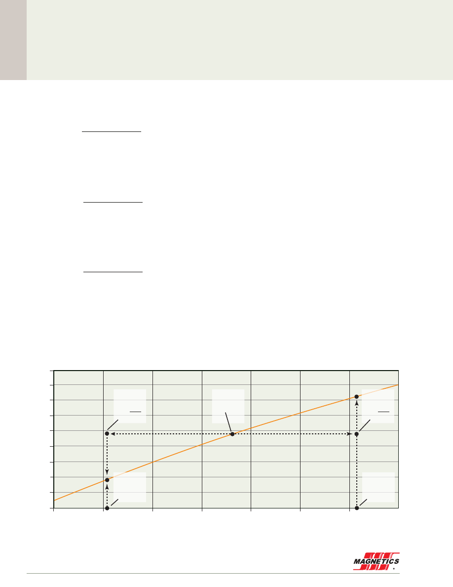
Cor
e Selection
MAGNETICS
22
Powder Core Loss Calculation
Magnetizing Force (A·T/cm)
60µ Kool Mµ DC Magnetization
45
50
55
60
65
70
75
80
0.47
0.45
0.43
0.41
0.39
0.37
0.35
0.33
0.31
0.29
Flux Density (T
esla)
160
147
125
90
75
60
40
26
14
173
200
250
300
550
500
Method 2
H
DC
25.2
2
-
550µ
160µ
H
AC min
H
AC max
B
H
Method 2
H
DC
25.2
2
Method 2
H
DC
Method 1
H
AC max
Method 1
H
AC min
+
Reworking Example 1:
18 - old 2 - 13
L
nl
(no load) = (A
L
) (N
2
) = (75 nH/T
2
) (20
2
) = 30µH
L
DC
(20A) = (%µ
i
) (L
nl
) = (0 .58) (30) =17 .4µH
"
B
pk
= 2(20)(0 .654)(10
-4
)
(17 .4) (10
-6
)(2)
= 0 .013T
(this compares to 0 .015T per Method1, 0 .014T per Method 2) .
From example 1, L
DC
=17 .4µH
"
B
pk
= 2(20)(0 .654)(10
-4
)
(17 .4) (10
-6
) (8)
= 0 .053T
(this compares to 0 .055T per Method1, 0 .055T per Method 2) .
L
DC
=L
nl
= 30µH
"
B
pk
= 2(20)(0 .654)(10
-4
)
(30) (10
-6
) (8)
= 0 .092T
(this compares to 0 .092T per Method1, 0 .095T per Method 2) .
Reworking Example 2:
18 - old 2 - 13
L
nl
(no load) = (A
L
) (N
2
) = (75 nH/T
2
) (20
2
) = 30µH
L
DC
(20A) = (%µ
i
) (L
nl
) = (0 .58) (30) =17 .4µH
"
B
pk
= 2(20)(0 .654)(10
-4
)
(17 .4) (10
-6
)(2)
= 0 .013T
(this compares to 0 .015T per Method1, 0 .014T per Method 2) .
From example 1, L
DC
=17 .4µH
"
B
pk
= 2(20)(0 .654)(10
-4
)
(17 .4) (10
-6
) (8)
= 0 .053T
(this compares to 0 .055T per Method1, 0 .055T per Method 2) .
L
DC
=L
nl
= 30µH
"
B
pk
= 2(20)(0 .654)(10
-4
)
(30) (10
-6
) (8)
= 0 .092T
(this compares to 0 .092T per Method1, 0 .095T per Method 2) .
Reworking Example 3:
18 - old 2 - 13
L
nl
(no load) = (A
L
) (N
2
) = (75 nH/T
2
) (20
2
) = 30µH
L
DC
(20A) = (%µ
i
) (L
nl
) = (0 .58) (30) =17 .4µH
"
B
pk
= 2(20)(0 .654)(10
-4
)
(17 .4) (10
-6
)(2)
= 0 .013T
(this compares to 0 .015T per Method1, 0 .014T per Method 2) .
From example 1, L
DC
=17 .4µH
"
B
pk
= 2(20)(0 .654)(10
-4
)
(17 .4) (10
-6
) (8)
= 0 .053T
(this compares to 0 .055T per Method1, 0 .055T per Method 2) .
L
DC
=L
nl
= 30µH
"
B
pk
= 2(20)(0 .654)(10
-4
)
(30) (10
-6
) (8)
= 0 .092T
(this compares to 0 .092T per Method1, 0 .095T per Method 2) .
The plot below illustrates the difference between Method 1 and Method 2

www.mag-inc.com
23
Cor
e Selection
Core Selector Charts
The core selector charts are a quick guide to finding the
optimum permeability and smallest core size for DC bias
applications . These charts are based on a permeability
reduction of not more than 50% with DC bias, typical winding
factors of 40% for toroids and 60% for shapes, and an AC
current that is small relative to the DC current . These charts
are based on the nominal core inductance and a current
density 500-600 A/cm
2
.
If a core is being selected for use with a large AC current
relative to any DC current, such as a flyback inductor or
buck/boost inductor, frequently a larger core will be needed
to limit the core losses due to AC flux . In other words, the
design becomes loss-limited rather than bias-limited .
For additional power handling capability, stacking of cores
will yield a proportional increase in power handling . For
example, double stacking of the 55908 core will result in
doubled power handling capability to about 400 mH·A
2
.
Cores with increased heights are easily ordered . Contact
Magnetics for more information .
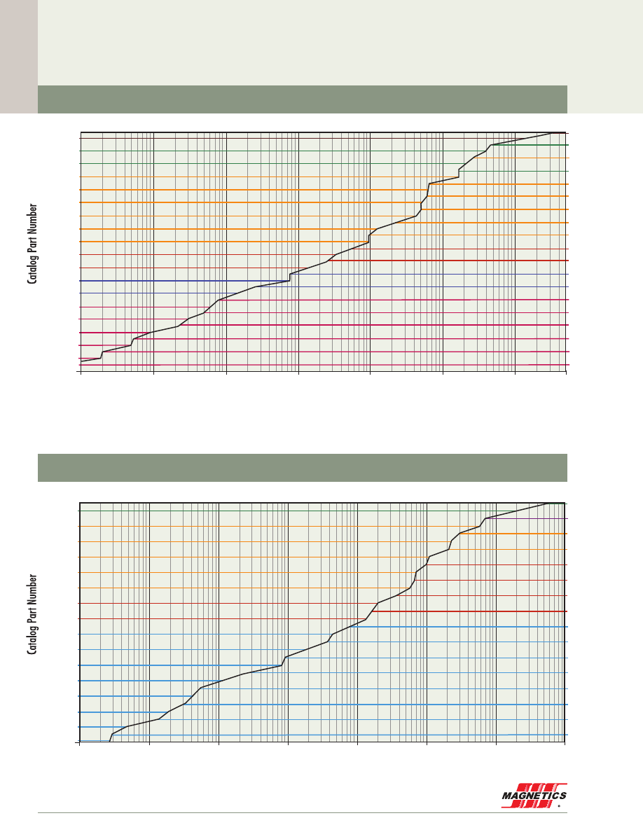
Cor
e Selection
MAGNETICS
24
Core Selector Charts
0.001
0.01
0.1
1
10
100
1,000
5,000
LI², (mH·A²)
55336 p. 94
55735 p. 89
55908 p. 91
55617 p. 87
55726 p. 83
55716 p. 84
55439 p. 82
55076 p. 79
55071 p. 77
55350 p. 75
55206 p. 73
55117 p. 71
55127 p. 69
55285 p. 67
55405 p. 64
55265 p. 63
55015 p. 61
55145 p. 59
55164 p. 95
55102 p. 93
55777 p. 92
55868 p. 90
55110 p. 85
55192 p. 86
55090 p. 81
55083 p. 80
55586 p. 78
55930 p. 76
55310 p. 74
55377 p. 72
55047 p. 70
55035 p. 68
55275 p. 66
55025 p. 65
55235 p. 62
55175 p. 60
55135 p. 58
300µ
200µ
125µ
26µ
60µ
14µ
125 perm
90
100
75
60
40
50
26
25
160
147
14
173
200
250
300
550
500
0.001
0.01
0.1
1
10
100
1,000
10,000
LI², (mH·A²)
125 perm
90
100
75
60
40
50
26
25
160
147
14
173
200
250
300
550
500
160µ
125µ
26µ
60µ
40µ
58337 p. 94
58737 p. 89
58867 p. 90
58110 p. 85
58716 p. 84
58090 p. 81
58324 p. 79
58585 p. 78
58348 p. 75
58204 p. 73
58378 p. 72
58128 p. 69
58288 p. 67
58408 p. 64
58268 p. 63
58018 p. 61
58165 p. 95
58100 p. 93
58907 p. 91
58617 p. 87
58195 p. 86
58438 p. 82
58254 p. 80
58548 p. 77
58928 p. 76
58308 p. 74
58118 p. 71
58048 p. 70
58038 p. 68
58278 p. 66
58028 p. 65
58238 p. 62
MPP Toroids
High Flux Toroids
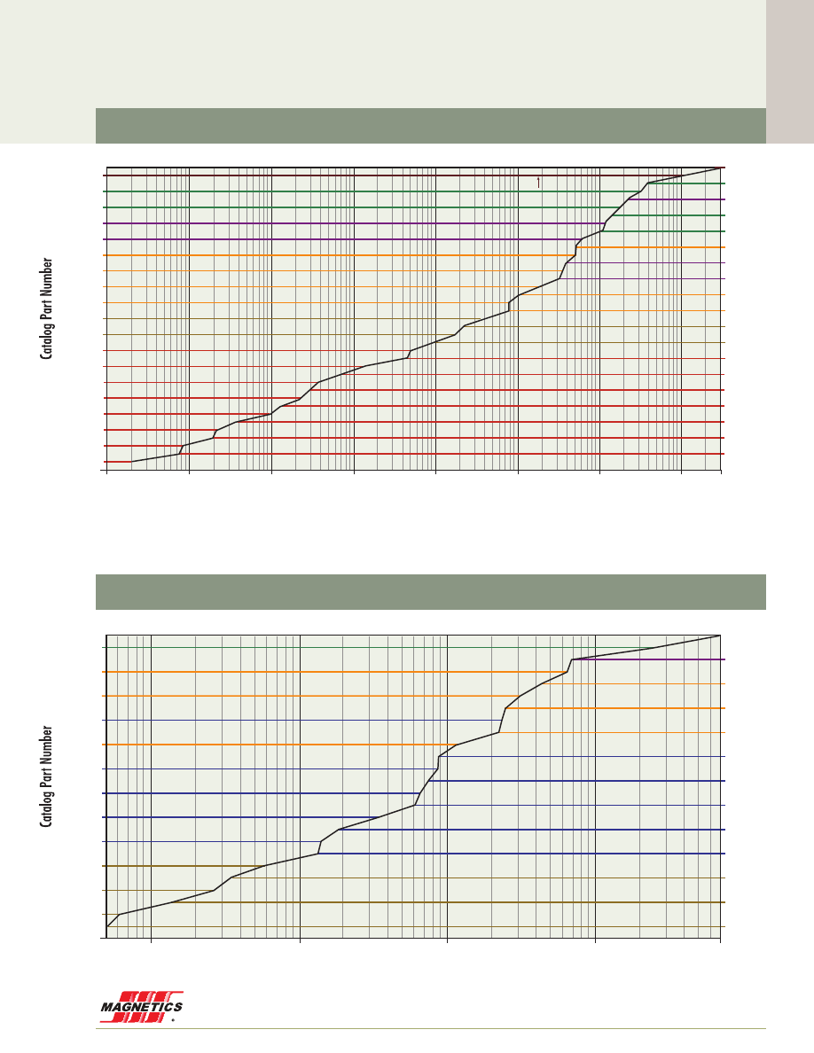
www.mag-inc.com
25
Cor
e Selection
Core Selector Charts
0.0001
0.001
0.01
0.1
1
10
100
1,000 3,000
LI², (mH·A²)
125 perm
90
100
75
60
40
50
26
25
160
147
14
173
200
250
300
550
500
160µ
14µ
125µ
26µ
60µ
40µ
77336 p. 94
77735 p. 89
77908 p. 91
77616 p. 87
77212 p. 85
77192 p. 86
77439 p. 82
77083 p. 80
77071 p. 77
77934 p. 76
77314 p. 74
77120 p. 71
77050 p. 70
77040 p. 68
77280 p. 66
77030 p. 65
77240 p. 62
77180 p. 60
77140 p. 58
77164 p. 95
77102 p. 93
77776 p. 92
77868 p. 90
77074 p. 88
77726 p. 83
77721 p. 84
77095 p. 81
77076 p. 79
77586 p. 78
77354 p. 75
77210 p. 73
77380 p. 72
77130 p. 69
77290 p. 67
77410 p. 64
77270 p. 63
77020 p. 61
77150 p. 59
Kool Mµ
®
Toroids
XF
lux
®
Toroids
0.5
1
10
100
1,000
7,000
LI², (mH·A²)
125 perm
90
100
75
60
40
50
26
25
160
147
14
173
200
250
300
550
500
90µ
75µ
26µ
60µ
40µ
78337 p. 94
78737 p. 89
78907 p. 91
78618 p. 87
78110 p. 85
78193 p. 86
78094 p. 81
78259 p. 80
78590 p. 78
78934 p. 76
78314 p. 74
78384 p. 72
78100 p. 93
78777 p. 92
78867 p. 90
78072 p. 88
78729 p. 83
78720 p. 84
78443 p. 82
78329 p. 79
78553 p. 77
78354 p. 75
78210 p. 73
78224 p. 71
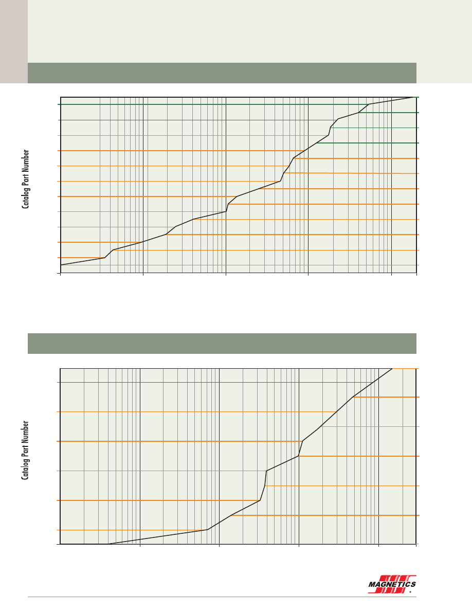
Cor
e Selection
MAGNETICS
26
Core Selector Charts
Kool Mµ
®
MAX Toroids
XF
lux
®
E Cores
WAITING FOR
CHART
0.1
1
10
1,000
2,000
100
LI², (mH·A²)
125 perm
90
100
75
60
40
50
26
25
160
147
14
173
200
250
300
550
500
26µ
60µ
79102 p. 93
79908 p. 91
79617 p. 87
79110 p. 85
79716 p. 84
79439 p. 82
79076 p. 79
79071 p. 77
79351 p. 75
79848 p. 73
79381 p. 72
79337 p. 94
79735 p. 89
79868 p. 90
79074 p. 88
79192 p. 86
79090 p. 81
79083 p. 80
79586 p. 78
79894 p. 76
79059 p. 74
79121 p. 71
79051 p. 70
0.1
1
10
100
1,000
3,000
LI², (mH·A²)
125 perm
90
100
75
60
40
50
26
25
160
147
14
173
200
250
300
550
500
26µ
60µ
X114LE060
p. 96
X8020E060
p. 96
X7228E060
p. 96
X5528E060
p. 96
X4022E060
p. 96
X4317E060
p. 96
X1808E060
p. 96
X8044E026
p. 96
X6527E060
p. 96
X5530E060
p. 96
X4017E060
p. 96
X4020E060
p. 96
X3515E060
p. 96

www.mag-inc.com
27
Cor
e Selection
LI², (mH·A²)
1
10
100
1,000
26µ
90µ
K8020U026
p. 98
K7236U026
p. 98
K5529U026
p. 98
K4119U090
p. 98
K4110U090
p. 98
K8038U026
p. 98
K6527U026
p. 98
K6533U026
p. 98
K5527U026
p. 98
K4111U090
p. 98
K3112U090
p. 98
125 perm
90
100
75
60
40
50
26
25
160
147
14
173
200
250
300
550
500
0.1
1
10
100
1,000
3,000
LI², (mH·A²)
125 perm
90
100
75
60
40
50
26
25
160
147
14
173
200
250
300
550
500
26µ
60µ
90µ
40µ
K130LE026
p. 96
K8044E026
p. 96
K6527E060
p. 96
K5530E060
p. 96
K4022E090
p. 96
K4020E060
p. 96
K3515E090
p. 96
K2510E090
p. 96
K160LE026
p. 96
K114LE040
p. 96
K8020E040
p. 96
K7228E060
p. 96
K5528E060
p. 96
K4017E060
p. 96
K4317E090
p. 96
K3007E090
p. 96
K1808E090
p. 96
Core Selector Charts
Kool Mµ
®
E Cores
Kool Mµ
®
U Cores
Cor
e Selection
MAGNETICS
28
Wire Table
AWG
Wire Size
Resistance
Q
/meter
Wire
O.D. (cm)
Heavy Build
Wire Area
cm
2
Current Capacity, Amps
(listed by columns of Amps/cm
2
)
200
400
500
600
800
6
.00130
.421
0.1392
26.6
53.2
66.5
79.8
106
7
.00163
.376
0.1110
21.1
42.2
52.8
63.3
84.4
8
.00206
.336
0.0887
16.7
33.5
41.8
50.2
66.9
9
.00260
.299
0.0702
13.3
26.5
33.2
39.8
53.1
10
.00328
.267
0.0560
10.5
21.0
26.3
31.6
42.1
11
.00414
.238
0.0445
8.34
16.7
20.8
25.0
33.3
12
.00521
.213
0.0356
6.62
13.2
16.5
19.8
26.5
13
.00656
.1902
0.0284
5.25
10.5
13.1
15.8
21.0
14
.00828
.1715
0.0231
4.16
8.33
10.4
12.5
16.7
15
.01044
.1529
0.01840
3.30
6.61
8.26
9.91
13.2
16
.01319
.1369
0.01472
2.62
5.23
6.54
7.85
10.5
17
.01658
.1224
0.01177
2.08
4.16
5.20
6.24
8.32
18
.02095
.1095
0.00942
1.65
3.29
4.11
4.94
6.58
19
.02640
.0980
0.00754
1.31
2.61
3.27
3.92
5.22
20
.03323
.0879
0.00607
1.04
2.08
2.59
3.11
4.15
21
.04190
.0785
0.00484
0.823
1.65
2.06
2.47
3.29
22
.05315
.0701
0.00386
0.649
1.30
1.62
1.95
2.59
23
.06663
.0632
0.00314
0.518
1.04
1.29
1.55
2.07
24
.08422
.0566
0.00252
0.409
0.819
1.0236
1.23
1.64
25
.10620
.0505
0.00200
0.325
0.649
0.812
0.974
1.30
26
.13458
.0452
0.00160
0.256
0.512
0.641
0.769
1.02
27
.16873
.0409
0.00131
0.204
0.409
0.511
0.613
0.817
28
0.214
.0366
0.00105
0.161
0.322
0.402
0.483
0.644
29
0.266
.0330
0.000855
0.129
0.259
0.324
0.388
0.518
30
0.340
.0295
0.000683
0.101
0.203
0.253
0.304
0.405
31
0.429
.0267
0.000560
0.0803
0.161
0.201
0.241
0.321
32
0.532
.0241
0.000456
0.0649
0.130
0.162
0.195
0.259
33
0.675
.0216
0.000366
0.0511
0.102
0.128
0.153
0.204
34
0.857
.01905
0.000285
0.0402
0.0804
0.101
0.121
0.161
35
1.085
.01702
0.000228
0.0318
0.0636
0.0795
0.0953
0.127
36
1.361
.01524
0.000182
0.0253
0.0507
0.0633
0.0760
0.101
37
1.680
.01397
0.000153
0.0205
0.0410
0.0513
0.0616
0.0821
38
2.13
.01245
0.000122
0.0162
0.0324
0.0405
0.0486
0.0649
39
2.78
.01092
0.000094
0.0124
0.0248
0.0310
0.0372
0.0497
40
3.54
.00965
0.000073
0.00974
0.0195
0.0243
0.0292
0.0390
41
4.34
.00864
0.000059
0.00795
0.0159
0.0199
0.0238
0.0318
42
5.44
.00762
0.000046
0.00633
0.0127
0.0158
0.0190
0.0253
43
7.03
.00686
0.000037
0.00490
0.00981
0.0123
0.0147
0.0196
44
8.51
.00635
0.000032
0.00405
0.00811
0.0101
0.0122
0.0162
45
10.98
.00546
0.000023
0.00314
0.00628
0.00785
0.00942
0.0126
46
13.80
.00498
0.000019
0.00250
0.00500
0.00624
0.00749
0.00999
47
17.36
.00452
0.000016
0.00199
0.00397
0.00497
0.00596
0.00795
48
22.10
.00394
0.000012
0.00156
0.00312
0.00390
0.00467
0.00623
49
27.60
.00353
0.000010
0.00125
0.00250
0.00312
0.00375
0.00499

www.mag-inc.com
29
AWG
Wire Size
Resistance
Q
/meter
Wire
O.D. (cm)
Heavy Build
Wire Area
cm
2
Current Capacity, Amps
(listed by columns of Amps/cm
2
)
200
400
500
600
800
6
.00130
.421
0.1392
26.6
53.2
66.5
79.8
106
7
.00163
.376
0.1110
21.1
42.2
52.8
63.3
84.4
8
.00206
.336
0.0887
16.7
33.5
41.8
50.2
66.9
9
.00260
.299
0.0702
13.3
26.5
33.2
39.8
53.1
10
.00328
.267
0.0560
10.5
21.0
26.3
31.6
42.1
11
.00414
.238
0.0445
8.34
16.7
20.8
25.0
33.3
12
.00521
.213
0.0356
6.62
13.2
16.5
19.8
26.5
13
.00656
.1902
0.0284
5.25
10.5
13.1
15.8
21.0
14
.00828
.1715
0.0231
4.16
8.33
10.4
12.5
16.7
15
.01044
.1529
0.01840
3.30
6.61
8.26
9.91
13.2
16
.01319
.1369
0.01472
2.62
5.23
6.54
7.85
10.5
17
.01658
.1224
0.01177
2.08
4.16
5.20
6.24
8.32
18
.02095
.1095
0.00942
1.65
3.29
4.11
4.94
6.58
19
.02640
.0980
0.00754
1.31
2.61
3.27
3.92
5.22
20
.03323
.0879
0.00607
1.04
2.08
2.59
3.11
4.15
21
.04190
.0785
0.00484
0.823
1.65
2.06
2.47
3.29
22
.05315
.0701
0.00386
0.649
1.30
1.62
1.95
2.59
23
.06663
.0632
0.00314
0.518
1.04
1.29
1.55
2.07
24
.08422
.0566
0.00252
0.409
0.819
1.0236
1.23
1.64
25
.10620
.0505
0.00200
0.325
0.649
0.812
0.974
1.30
26
.13458
.0452
0.00160
0.256
0.512
0.641
0.769
1.02
27
.16873
.0409
0.00131
0.204
0.409
0.511
0.613
0.817
28
0.214
.0366
0.00105
0.161
0.322
0.402
0.483
0.644
29
0.266
.0330
0.000855
0.129
0.259
0.324
0.388
0.518
30
0.340
.0295
0.000683
0.101
0.203
0.253
0.304
0.405
31
0.429
.0267
0.000560
0.0803
0.161
0.201
0.241
0.321
32
0.532
.0241
0.000456
0.0649
0.130
0.162
0.195
0.259
33
0.675
.0216
0.000366
0.0511
0.102
0.128
0.153
0.204
34
0.857
.01905
0.000285
0.0402
0.0804
0.101
0.121
0.161
35
1.085
.01702
0.000228
0.0318
0.0636
0.0795
0.0953
0.127
36
1.361
.01524
0.000182
0.0253
0.0507
0.0633
0.0760
0.101
37
1.680
.01397
0.000153
0.0205
0.0410
0.0513
0.0616
0.0821
38
2.13
.01245
0.000122
0.0162
0.0324
0.0405
0.0486
0.0649
39
2.78
.01092
0.000094
0.0124
0.0248
0.0310
0.0372
0.0497
40
3.54
.00965
0.000073
0.00974
0.0195
0.0243
0.0292
0.0390
41
4.34
.00864
0.000059
0.00795
0.0159
0.0199
0.0238
0.0318
42
5.44
.00762
0.000046
0.00633
0.0127
0.0158
0.0190
0.0253
43
7.03
.00686
0.000037
0.00490
0.00981
0.0123
0.0147
0.0196
44
8.51
.00635
0.000032
0.00405
0.00811
0.0101
0.0122
0.0162
45
10.98
.00546
0.000023
0.00314
0.00628
0.00785
0.00942
0.0126
46
13.80
.00498
0.000019
0.00250
0.00500
0.00624
0.00749
0.00999
47
17.36
.00452
0.000016
0.00199
0.00397
0.00497
0.00596
0.00795
48
22.10
.00394
0.000012
0.00156
0.00312
0.00390
0.00467
0.00623
49
27.60
.00353
0.000010
0.00125
0.00250
0.00312
0.00375
0.00499
Permeability versus DC Bias Curves
30%
40%
50%
60%
70%
90%
80%
100%
% Initial Permeability
µ
i
147µ
125µ
60µ
26µ
14µ
1
100
500
10
H (A·T/cm)
160µ
173µ
200µ
30%
40%
50%
60%
70%
90%
80%
100%
% Initial Permeability
µ
i
550µ
300µ
0.1
10
30
1
H (A·T/cm)
MPP Toroids 14µ - 200µ
MPP Toroids 300µ & 550µ
Material Data
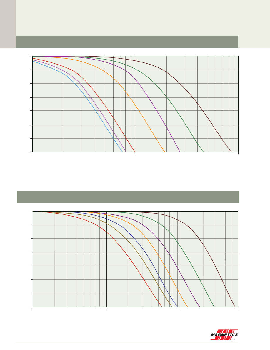
MAGNETICS
30
100
600
1
40%
30%
50%
60%
70%
80%
90%
100%
10
% Initial Permeability
µ
i
125 perm
90
75
60
40
26
160
147
14
173
200
250
300
550
500
90µ
75µ
60µ
40µ
26µ
14µ
125µ
H (A·T/cm)
Permeability versus DC Bias Curves
30%
40%
50%
60%
70%
80%
90%
100
1,000
10
% Initial Permeability
µ
i
100%
H (A·T/cm)
14µ
26µ
40µ
60µ
125µ
160µ
147µ
Kool Mµ
®
Toroids
High Flux Toroids
Material Data
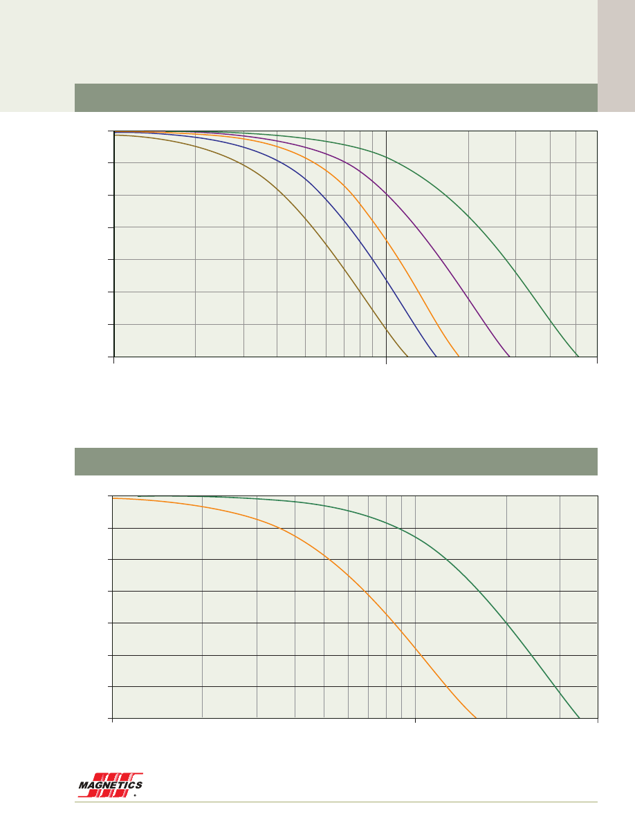
www.mag-inc.com
31
Material Data
Permeability versus DC Bias Curves
125 perm
90
75
60
40
26
100%
90%
80%
70%
60%
50%
40%
30%
% Initial Permeability
µ
i
H (A·T/cm)
60µ
26µ
10
100
400
Kool Mµ
®
MAX Toroids
50%
40%
30%
60%
70%
80%
90%
100%
10
100
600
% Initial Permeability
µ
i
H (A·T/cm)
125 perm
90
75
60
40
26
160
147
14
173
200
250
300
550
500
60µ
75µ
90µ
26µ
40µ
XF
lux
®
Toroids
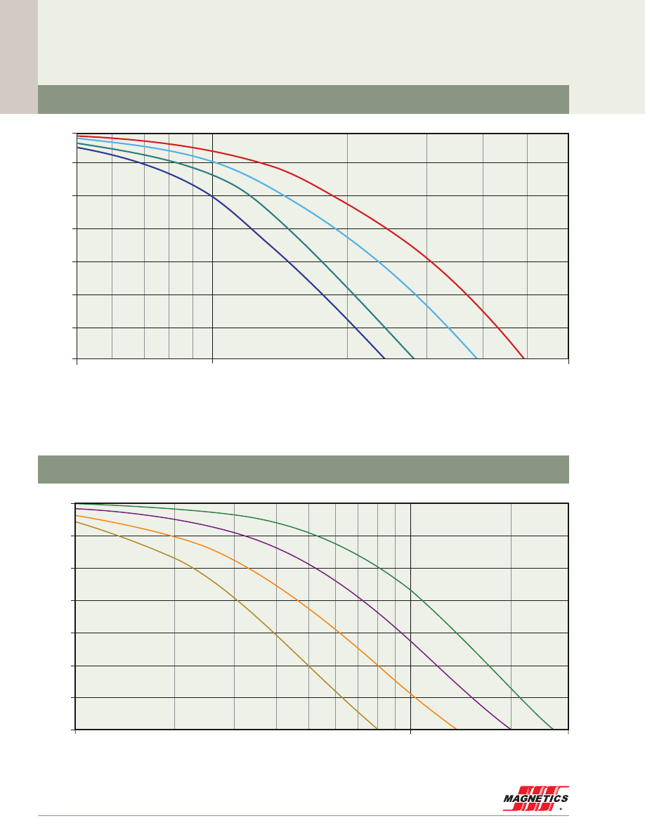
MAGNETICS
32
Material Data
Permeability versus DC Bias Curves
100%
90%
80%
70%
60%
50%
40%
30%
H (A·T/cm)
% Initial Permeability
µ
i
5
60
10
160µ
200µ
250µ
125µ
MPP THINZ
®
100%
90%
80%
70%
60%
50%
40%
30%
% Initial Permeability
µ
i
H (A·T/cm)
10
100
300
60µ
90µ
26µ
40µ
125 perm
90
75
60
40
26
Kool Mµ
®
Shapes
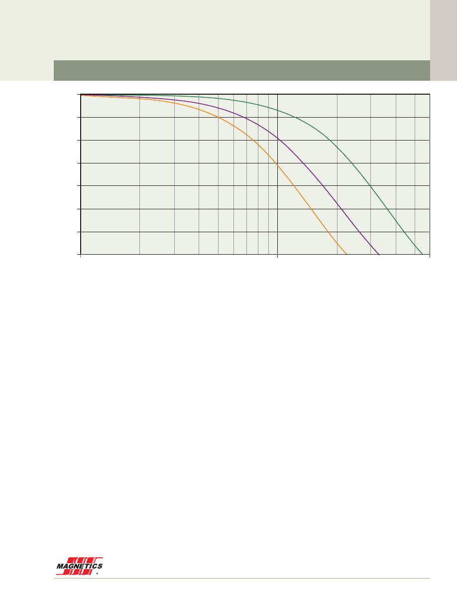
www.mag-inc.com
33
Material Data
Permeability versus DC Bias Curves
125 perm
90
75
60
40
26
100%
90%
80%
70%
60%
50%
40%
30%
% Initial Permeability
µ
i
H (A·T/cm)
10
100
600
60µ
26µ
40µ
XF
lux
®
Shapes
MAGNETICS
34
Perm
a
b
c
MPP
14µ
0.01
2.435E-09
2.596
26µ
0.01
1.931E-08
2.505
60µ
0.01
2.033E-07
2.436
125µ
0.01
1.963E-06
2.253
147µ
0.01
1.588E-06
2.430
160µ
0.01
1.677E-06
2.477
173µ
0.01
1.451E-06
2.563
200µ
0.01
2.635E-06
2.477
300µ
0.01
1.852E-05
2.216
550µ
0.01
8.271E-04
1.710
Kool Mµ
®
14µ
0.01
8.220E-08
1.990
26µ
0.01
7.979E-07
1.819
40µ
0.01
3.213E-06
1.704
60µ
0.01
5.184E-06
1.749
75µ
0.01
1.272E-05
1.664
90µ
0.01
2.698E-05
1.558
125µ
0.01
6.345E-05
1.462
High Flux
14µ
0.01
4.550E-08
1.948
26µ
0.01
7.178E-08
2.069
40µ
0.01
3.192E-08
2.409
60µ
0.01
2.582E-07
2.166
125µ
0.01
1.458E-06
2.108
147µ
0.01
1.964E-06
2.131
160µ
0.01
2.749E-06
2.094
X
F
lux
®
26µ
0.01
1.014E-07
1.976
40µ
0.01
9.786E-08
2.188
60µ
0.01
4.795E-08
2.511
75µ
0.01
2.073E-07
2.306
90µ
0.01
8.021E-07
2.150
Kool Mµ
®
MAX
26µ
0.01
5.700E-08
2.205
60µ
0.01
9.344E-07
2.000
Kool Mµ
®
Shapes
26µ
0.01
6.615E-07
1.874
40µ
0.01
3.627E-06
1.656
60µ
0.01
1.108E-05
1.555
90µ
0.01
1.115E-05
1.744
X
F
lux
®
Shapes
26µ
0.01
5.560E-08
2.054
40µ
0.01
3.206E-07
1.932
60µ
0.01
3.570E-07
2.047
Permeability versus DC Bias Curves
Fit Formula
Note: all numbers calculated using A
•
T/cm Fit valid only for range shown on graph
% initial permeability =
Units in A
•
T/cm
1
(a + bH
c
)
Material Data
www.mag-inc.com
35
Material Data
MPP 14µ
MPP 26µ
Flux Density (Tesla)
0.01
0.1
1
1
10
100
1,000
5,000
Core Loss (mW/cm
3
)
200 khz
300 khz
100 khz
50 khz
20 khz
25 khz
40 khz
10 khz
5 khz
2 khz
100 hz
1 khz
60 hz
500 hz
P
L
= 115.9B
2.5
f
1.87
300 kHz
100 kHz
200 kHz
50 kHz
40 kHz
20 kHz
10 kHz
5 kHz
2 kHz
1 kHz
500 Hz
Flux Density (Tesla)
0.01
0.1
1
1
10
100
1,000
5,000
Core Loss (mW/cm
3
)
200 khz
300 khz
100 khz
50 khz
20 khz
25 khz
40 khz
10 khz
5 khz
2 khz
100 hz
1 khz
60 hz
500 hz
P
L
= 115.9B
2.5
f
1.87
300 kHz
100 kHz
200 kHz
50 kHz
40 kHz
20 kHz
10 kHz
5 kHz
2 kHz
1 kHz
500 Hz
Core Loss Density Curves
Material Data
MAGNETICS
36
Core Loss Density Curves
Flux Density (Tesla)
0.01
0.1
1
1
10
100
1,000
5,000
Core Loss (mW/cm
3
)
200 khz
300 khz
100 khz
50 khz
20 khz
25 khz
40 khz
10 khz
5 khz
2 khz
100 hz
1 khz
60 hz
500 hz
P
L
= 115.9B
2.5
f
1.87
300 kHz
100 kHz
200 kHz
50 kHz
40 kHz
20 kHz
10 kHz
5 kHz
2 kHz
1 kHz
500 Hz
MPP 60µ
Flux Density (Tesla)
0.01
0.1
1
1
10
100
1,000
5,000
Core Loss (mW/cm
3
)
200 khz
300 khz
100 khz
50 khz
20 khz
25 khz
40 khz
10 khz
5 khz
2 khz
100 hz
1 khz
60 hz
500 hz
P
L
= 115.9B
2.5
f
1.87
300 kHz
100 kHz
200 kHz
50 kHz
40 kHz
20 kHz
10 kHz
5 kHz
2 kHz
1 kHz
500 Hz
MPP 125µ, 147µ, 160µ, 173µ
www.mag-inc.com
37
Material Data
Core Loss Density Curves
Flux Density (Tesla)
0.01
0.1
1
1
10
100
1,000
5,000
Core Loss (mW/cm
3
)
200 khz
300 khz
100 khz
50 khz
20 khz
25 khz
40 khz
10 khz
5 khz
2 khz
100 hz
1 khz
60 hz
500 hz
P
L
= 115.9B
2.5
f
1.87
300 kHz
100 kHz
200 kHz
50 kHz
40 kHz
20 kHz
10 kHz
5 kHz
2 kHz
1 kHz
500 Hz
MPP 200µ, 300µ
Flux Density (Tesla)
0.01
0.1
1
1
10
100
1,000
5,000
Core Loss (mW/cm
3
)
200 khz
300 khz
100 khz
50 khz
20 khz
25 khz
40 khz
10 khz
5 khz
2 khz
100 hz
1 khz
60 hz
500 hz
P
L
= 115.9B
2.5
f
1.87
300 kHz
100 kHz
200 kHz
50 kHz
40 kHz
20 kHz
10 kHz
5 kHz
2 kHz
1 kHz
500 Hz
MPP 550µ

Core Loss Density Curves
Material Data
MAGNETICS
38
Flux Density (Tesla)
0.01
0.1
1
1
10
100
1,000
5,000
Core Loss (mW/cm
3
)
200 khz
300 khz
100 khz
50 khz
20 khz
25 khz
40 khz
10 khz
5 khz
2 khz
100 hz
1 khz
60 hz
500 hz
P
L
= 115.9B
2.5
f
1.87
100 Hz
100 kHz
60 Hz
50 kHz
40 kHz
20 kHz
10 kHz
5 kHz
2 kHz
1 kHz
500 Hz
High Flux 14µ
High Flux 26µ
Flux Density (Tesla)
0.01
0.1
1
1
10
100
1,000
5,000
Core Loss (mW/cm
3
)
200 khz
300 khz
100 khz
50 khz
20 khz
25 khz
40 khz
10 khz
5 khz
2 khz
100 hz
1 khz
60 hz
500 hz
P
L
= 115.9B
2.5
f
1.87
100 Hz
100 kHz
60 Hz
50 kHz
40 kHz
20 kHz
10 kHz
5 kHz
2 kHz
1 kHz
500 Hz
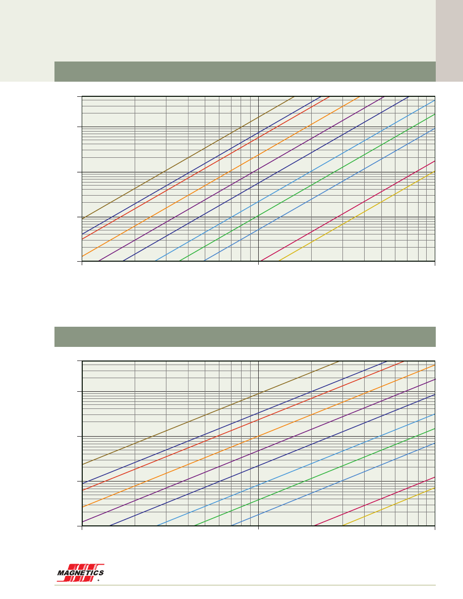
Core Loss Density Curves
www.mag-inc.com
39
Material Data
High Flux 40µ
Flux Density (Tesla)
0.01
0.1
1
1
10
100
1,000
5,000
Core Loss (mW/cm
3
)
200 khz
300 khz
100 khz
50 khz
20 khz
25 khz
40 khz
10 khz
5 khz
2 khz
100 hz
1 khz
60 hz
500 hz
P
L
= 115.9B
2.5
f
1.87
100 Hz
100 kHz
60 Hz
50 kHz
40 kHz
20 kHz
10 kHz
5 kHz
2 kHz
1 kHz
500 Hz
Flux Density (Tesla)
0.01
0.1
1
1
10
100
1,000
5,000
Core Loss (mW/cm
3
)
200 khz
300 khz
100 khz
50 khz
20 khz
25 khz
40 khz
10 khz
5 khz
2 khz
100 hz
1 khz
60 hz
500 hz
P
L
= 115.9B
2.5
f
1.87
100 Hz
100 kHz
60 Hz
50 kHz
40 kHz
20 kHz
10 kHz
5 kHz
2 kHz
1 kHz
500 Hz
High Flux 60µ, 125µ
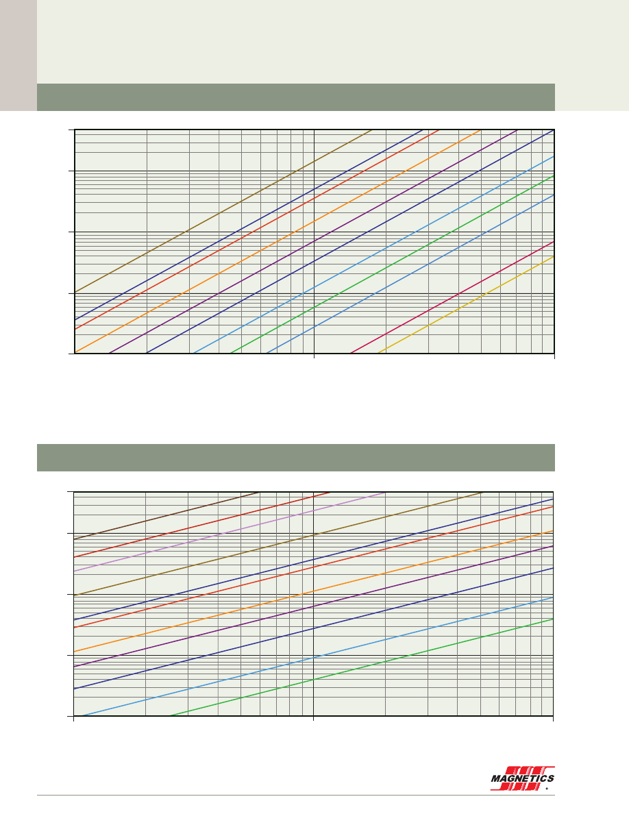
Core Loss Density Curves
Material Data
MAGNETICS
40
Flux Density (Tesla)
0.01
0.1
1
1
10
100
1,000
5,000
Core Loss (mW/cm
3
)
200 khz
300 khz
500 khz
100 khz
50 khz
20 khz
25 khz
40 khz
10 khz
5 khz
2 khz
100 hz
1 khz
60 hz
500 hz
P
L
= 115.9B
2.5
f
1.87
100 kHz
500 kHz
300 kHz
200 kHz
50 kHz
40 kHz
20 kHz
10 kHz
5 kHz
2 kHz
1 kHz
Kool Mµ
®
14µ
Flux Density (Tesla)
0.01
0.1
1
1
10
100
1,000
5,000
Core Loss (mW/cm
3
)
200 khz
300 khz
100 khz
50 khz
20 khz
25 khz
40 khz
10 khz
5 khz
2 khz
100 hz
1 khz
60 hz
500 hz
P
L
= 115.9B
2.5
f
1.87
100 Hz
100 kHz
60 Hz
50 kHz
40 kHz
20 kHz
10 kHz
5 kHz
2 kHz
1 kHz
500 Hz
High Flux 147µ, 160µ
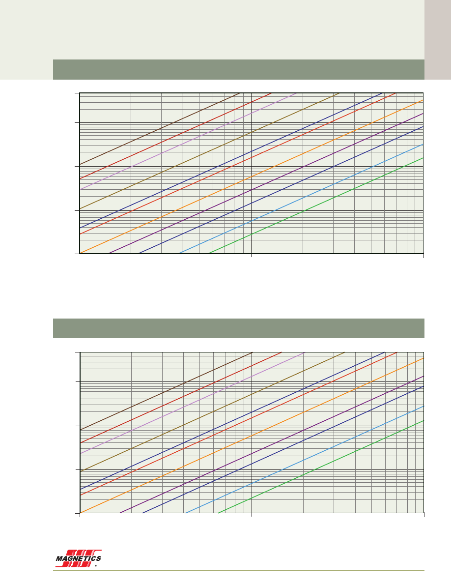
Core Loss Density Curves
www.mag-inc.com
41
Material Data
Flux Density (Tesla)
0.01
0.1
1
1
10
100
1,000
5,000
Core Loss (mW/cm
3
)
200 khz
300 khz
500 khz
100 khz
50 khz
20 khz
25 khz
40 khz
10 khz
5 khz
2 khz
100 hz
1 khz
60 hz
500 hz
P
L
= 115.9B
2.5
f
1.87
100 kHz
500 kHz
300 kHz
200 kHz
50 kHz
40 kHz
20 kHz
10 kHz
5 kHz
2 kHz
1 kHz
Flux Density (Tesla)
0.01
0.1
1
1
10
100
1,000
5,000
Core Loss (mW/cm
3
)
200 khz
300 khz
500 khz
100 khz
50 khz
20 khz
25 khz
40 khz
10 khz
5 khz
2 khz
100 hz
1 khz
60 hz
500 hz
P
L
= 115.9B
2.5
f
1.87
100 kHz
500 kHz
300 kHz
200 kHz
50 kHz
40 kHz
20 kHz
10 kHz
5 kHz
2 kHz
1 kHz
Kool Mµ
®
60µ
Kool Mµ
®
26µ, 40µ
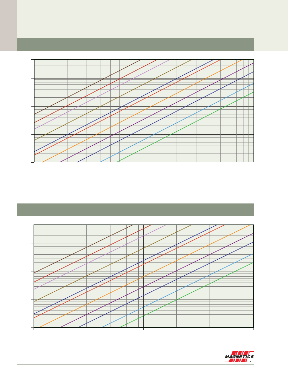
Core Loss Density Curves
Material Data
MAGNETICS
42
Flux Density (Tesla)
0.01
0.1
1
1
10
100
1,000
5,000
Core Loss (mW/cm
3
)
200 khz
300 khz
500 khz
100 khz
50 khz
20 khz
25 khz
40 khz
10 khz
5 khz
2 khz
100 hz
1 khz
60 hz
500 hz
P
L
= 115.9B
2.5
f
1.87
100 kHz
500 kHz
300 kHz
200 kHz
50 kHz
40 kHz
20 kHz
10 kHz
5 kHz
2 kHz
1 kHz
Kool Mµ
®
75µ, 90µ
Flux Density (Tesla)
0.01
0.1
1
1
10
100
1,000
5,000
Core Loss (mW/cm
3
)
200 khz
300 khz
500 khz
100 khz
50 khz
20 khz
25 khz
40 khz
10 khz
5 khz
2 khz
100 hz
1 khz
60 hz
500 hz
P
L
= 115.9B
2.5
f
1.87
100 kHz
500 kHz
300 kHz
200 kHz
50 kHz
40 kHz
20 kHz
10 kHz
5 kHz
2 kHz
1 kHz
Kool Mµ
®
125µ
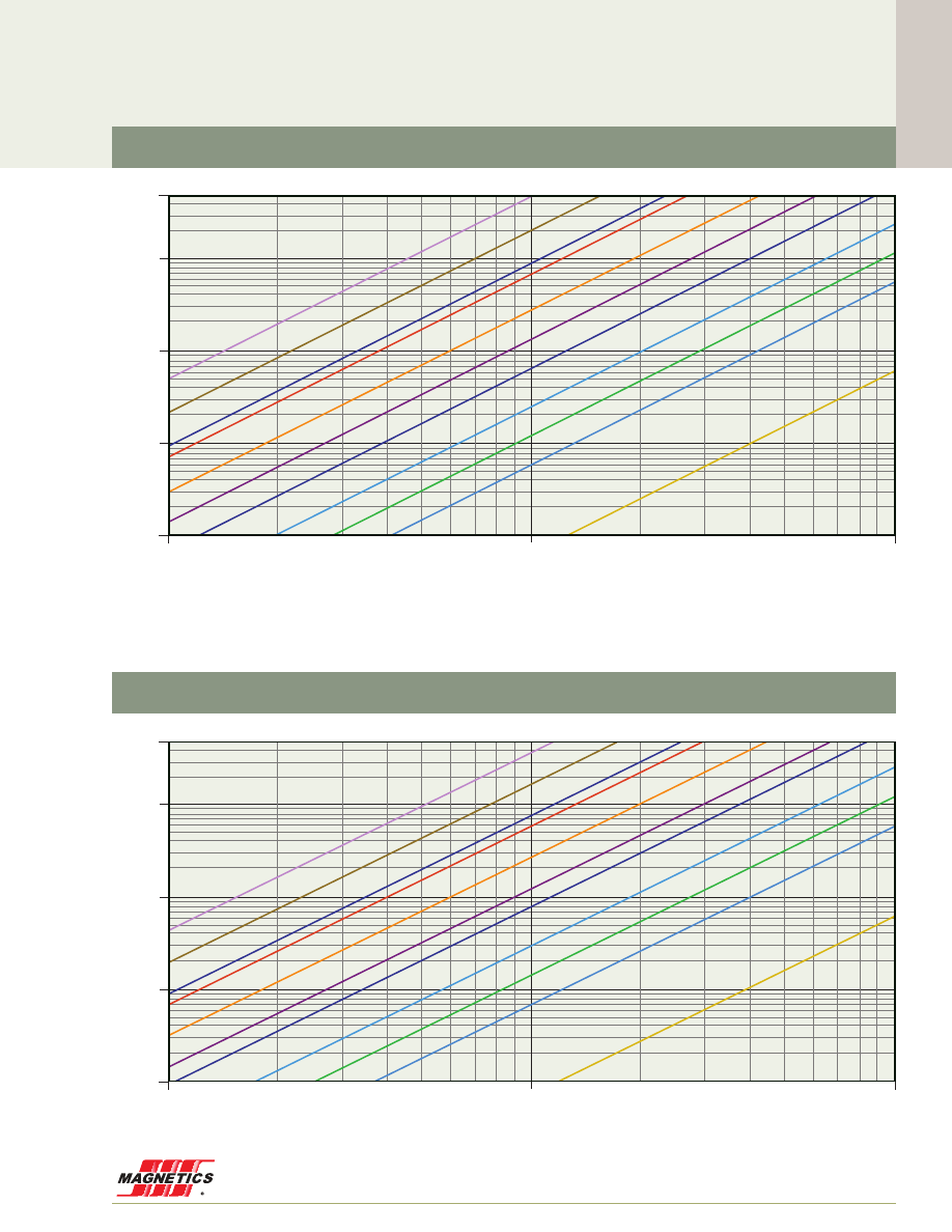
Core Loss Density Curves
www.mag-inc.com
43
Material Data
Flux Density (Tesla)
0.01
0.1
1
1
10
100
1,000
5,000
Core Loss (mW/cm
3
)
200 khz
300 khz
500 khz
100 khz
50 khz
20 khz
25 khz
40 khz
10 khz
5 khz
2 khz
100 hz
1 khz
60 hz
500 hz
P
L
= 115.9B
2.5
f
1.87
100 kHz
200 kHz
50 kHz
40 kHz
20 kHz
10 kHz
5 kHz
2 kHz
1 kHz
500 Hz
60 Hz
Flux Density (Tesla)
0.01
0.1
1
1
10
100
1,000
5,000
Core Loss (mW/cm
3
)
200 khz
300 khz
500 khz
100 khz
50 khz
20 khz
25 khz
40 khz
10 khz
5 khz
2 khz
100 hz
1 khz
60 hz
500 hz
P
L
= 115.9B
2.5
f
1.87
100 kHz
200 kHz
50 kHz
40 kHz
20 kHz
10 kHz
5 kHz
2 kHz
1 kHz
500 Hz
60 Hz
XF
lux
®
40µ
XF
lux
®
26µ

Core Loss Density Curves
Material Data
MAGNETICS
44
Flux Density (Tesla)
0.01
0.1
1
1
10
100
1,000
5,000
Core Loss (mW/cm
3
)
200 khz
300 khz
500 khz
100 khz
50 khz
20 khz
25 khz
40 khz
10 khz
5 khz
2 khz
100 hz
1 khz
60 hz
500 hz
P
L
= 115.9B
2.5
f
1.87
100 kHz
200 kHz
50 kHz
40 kHz
20 kHz
10 kHz
5 kHz
2 kHz
1 kHz
500 Hz
60 Hz
Flux Density (Tesla)
0.01
0.1
1
1
10
100
1,000
5,000
Core Loss (mW/cm
3
)
200 khz
300 khz
500 khz
100 khz
50 khz
20 khz
25 khz
40 khz
10 khz
5 khz
2 khz
100 hz
1 khz
60 hz
500 hz
P
L
= 115.9B
2.5
f
1.87
100 kHz
200 kHz
50 kHz
40 kHz
20 kHz
10 kHz
5 kHz
2 kHz
1 kHz
500 Hz
60 Hz
XF
lux
®
75µ, 90µ
XF
lux
®
60µ
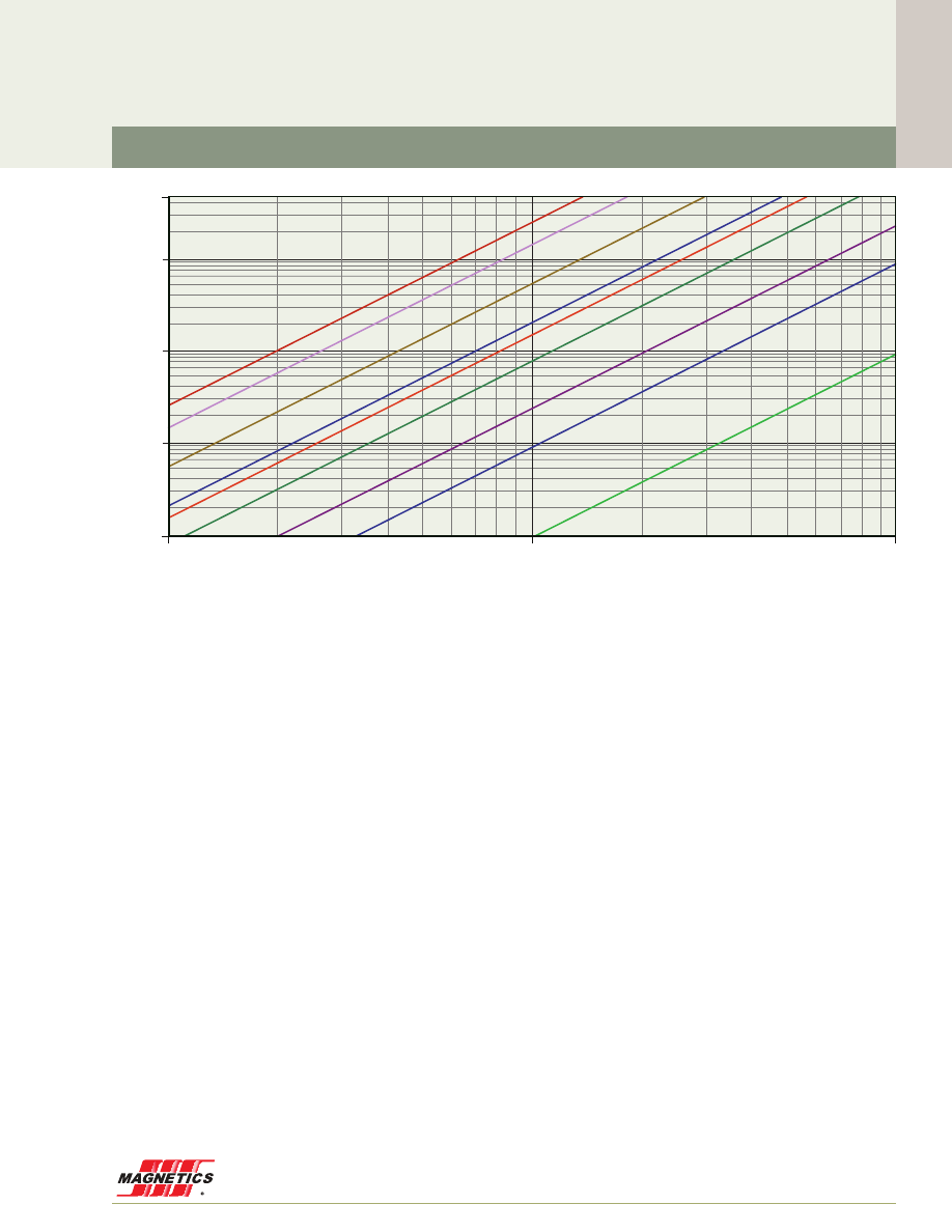
www.mag-inc.com
45
Material Data
Core Loss Density Curves
Kool Mµ
®
MAX 26µ, 60µ
1,000
5,000
100
10
1
0.01
0.1
1
Kool Mµ MAX Core Loss Density
Flux Density (Tesla)
Core Loss (mW/cm
3
)
300 kHz
200 kHz
100 kHz
50 kHz 40 kHz
25 kHz
10 kHz
5 kHz
1 kHz
200 khz
300 khz
500 khz
100 khz
50 khz
20 khz
25 khz
40 khz
10 khz
5 khz
2 khz
100 hz
1 khz
60 hz
500 hz
MAGNETICS
46
Material Data
Core Loss Density Curves
Fit Formula
P = a(B
b
)(f
c
) (B in Tesla, f in kHz)
Perm
freq:
a
b
c
MPP
14µ
> 10kHz
21.06
1.074
1.38
14µ
< 10kHz
64.02
1.074
1.11
26µ
> 10kHz
109.17
2.000
1.37
26µ
< 10kHz
361.62
2.000
1.08
60µ
> 10kHz
31.32
1.585
1.37
60µ
< 10kHz
80.12
1.585
1.04
125µ-173µ
> 10kHz
87.07
2.222
1.56
125µ-173µ
< 10kHz
254.26
2.222
1.17
200µ, 300µ
> 10kHz
115.52
2.322
1.59
200µ, 300µ
< 10kHz
320.32
2.322
1.19
500µ
> 10kHz
96.89
1.999
1.54
500µ
< 10kHz
303.43
1.999
1.09
High Flux
14µ
all
181.14
1.386
1.21
26µ
> 25kHz
532.55
2.170
1.35
26µ
< 25kHz
1550.54
2.170
1.05
40µ
> 25kHz
1707.09
2.280
1.14
40µ
< 25kHz
2021.58
2.280
1.05
60µ, 125µ
> 25kHz
47.51
1.585
1.43
60µ, 125µ
< 25kHz
151.44
1.585
1.09
147µ-160µ
> 25kHz
203.61
2.163
1.52
147µ-160µ
< 25kHz
883.51
2.163
1.09
Kool Mµ
®
14µ
> 10kHz
21.49
1.000
1.33
14µ
< 10kHz
40.18
1.000
1.22
26µ, 40µ
> 10kHz
45.48
1.774
1.46
26µ, 40µ
< 10kHz
170.17
1.774
1.03
60µ
> 9kHz
62.65
1.781
1.36
60µ
< 9kHz
136.93
1.781
1.12
75µ, 90µ
> 10kHz
146.81
2.022
1.33
75µ, 90µ
< 10kHz
338.51
2.022
1.05
125µ
> 10kHz
71.93
1.928
1.47
125µ
< 10kHz
228.46
1.928
1.05
X
F
lux
®
26µ
> 25kHz
761.36
1.977
1.21
26µ
< 25kHz
1187.96
1.977
1.05
40µ
> 9kHz
804.88
1.934
1.14
40µ
< 9kHz
1274.93
1.934
1.06
60µ
> 10kHz
454.56
1.909
1.19
60µ
< 10kHz
670.26
1.909
1.06
75µ, 90µ
> 9kHz
566.54
2.018
1.17
75µ, 90µ
< 9kHz
862.34
2.018
1.02
Kool Mµ
®
MAX
26µ, 60µ
>10kHz
86.00
1.998
1.40
26µ, 60µ
<10kHz
94.67
1.998
1.40

www.mag-inc.com
47
Material Data
DC Magnetization Curves
Magnetizing Force (A·T/cm)
1
0.0
0.1
0.2
0.3
0.4
0.5
0.6
10
100
600
Flux Density (T
esla)
160
147
125
90
75
60
40
26
14
173
200
250
300
550
500
550µ
300µ
200µ
60µ
26µ
14µ
173µ
160µ
147µ
125µ
Magnetizing Force (A·T/cm)
1
0.0
0.1
0.2
0.3
2
3
4
5
6
7
8
9
Flux Density (T
esla)
160
147
125
90
75
60
40
26
14
173
200
250
300
550
500
550µ
MPP 550µ
MPP 14µ-300µ

MAGNETICS
48
DC Magnetization Curves
Material Data
Magnetizing Force (A·T/cm)
1
0.0
0.1
0.2
0.3
0.4
0.5
0.6
0.7
0.8
0.9
10
100
1,000
Flux Density (T
esla)
160
147
125
90
75
60
40
26
14
173
200
250
300
550
500
550µ
40µ
60µ
26µ
14µ
160µ
147µ
125µ
Magnetizing Force (A·T/cm)
1
0.0
0.1
0.2
0.3
0.4
0.5
10
100
500
Flux Density (T
esla)
160
147
125
90
75
60
40
26
14
173
200
250
300
550
500
550µ
40µ
26µ
14µ
160µ
60µ
75µ
90µ
125µ
Kool Mµ
®
High Flux
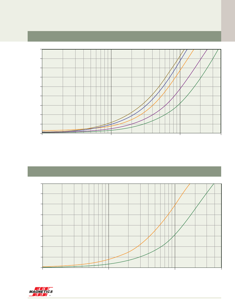
www.mag-inc.com
49
Material Data
DC Magnetization Curves
Magnetizing Force (A·T/cm)
1
0.0
0.1
0.2
0.3
0.4
0.5
0.6
0.7
0.8
0.9
10
100
400
1000
Flux Density (T
esla)
160
147
125
90
75
60
40
26
14
173
200
250
300
550
500
550µ
40µ
60µ
26µ
90µ
75µ
Magnetizing Force (A·T/cm)
1
0.0
0.1
0.2
0.3
0.4
0.5
0.6
0.7
0.8
10
100
500
1000
Flux Density (T
esla)
160
147
125
90
75
60
40
26
14
173
200
250
300
550
500
550µ
60µ
26µ
Kool Mµ
®
MAX
XF
lux
®
Material Data
MAGNETICS
50
DC Magnetization Curves
Perm
a
b
c
d
e
x
MPP
14µ
1.106E-01
1.275E-02
6.686E-04
1.308E-01
6.381E-04
1.876
26µ
1.112E-01
1.369E-02
7.979E-04
8.732E-02
7.647E-04
1.907
60µ
7.871E-02
1.893E-02
9.356E-04
5.847E-02
8.919E-04
1.724
125µ
2.429E-02
2.184E-02
1.287E-03
5.362E-02
1.144E-03
1.258
147µ
1.707E-02
2.077E-02
1.310E-03
4.408E-02
1.246E-03
1.152
160µ
1.458E-02
2.140E-02
1.436E-03
4.367E-02
1.389E-03
1.124
173µ
1.221E-02
2.147E-02
1.468E-03
3.965E-02
1.435E-03
1.089
200µ
7.098E-03
2.201E-02
1.516E-03
3.398E-02
1.517E-03
1.022
300µ
0.000E+00
2.808E-02
1.373E-03
1.612E-02
1.905E-03
0.906
550µ
0.000E+00
7.907E-02
0.000E+00
1.016E-01
2.109E-03
1.013
Kool
Mµ
®
14µ
1.105E-01
1.301E-02
6.115E-04
1.386E-01
5.735E-04
1.760
26µ
1.008E-01
1.452E-02
7.846E-04
1.035E-01
7.573E-04
1.754
40µ
5.180E-02
2.132E-02
7.941E-04
8.447E-02
7.652E-04
1.756
60µ
5.214E-02
2.299E-02
8.537E-04
7.029E-02
8.183E-04
1.658
75µ
4.489E-02
2.593E-02
7.949E-04
6.463E-02
7.925E-04
1.595
90µ
4.182E-02
2.990E-02
7.826E-04
6.542E-02
7.669E-04
1.569
125µ
1.414E-02
2.851E-02
1.135E-03
7.550E-02
1.088E-03
1.274
High Flux
14µ
1.060E-01
1.305E-02
5.119E-04
1.497E-01
3.616E-04
1.617
26µ
1.098E-01
1.421E-02
7.332E-04
1.123E-01
5.217E-04
1.695
40µ
9.617E-02
1.690E-02
8.908E-04
8.503E-02
6.628E-04
1.784
60µ
8.049E-02
1.887E-02
9.733E-04
7.198E-02
6.927E-04
1.660
125µ
4.235E-02
2.235E-02
1.330E-03
5.798E-02
8.447E-04
1.324
147µ
3.315E-02
2.308E-02
1.454E-03
5.459E-02
9.259E-04
1.242
160µ
2.616E-02
2.332E-02
1.537E-03
5.408E-02
9.642E-04
1.186
X
F
lux
®
26µ
1.093E-01
1.478E-02
6.629E-04
1.085E-01
4.429E-04
1.683
40µ
8.539E-02
1.772E-02
8.617E-04
8.744E-02
6.280E-04
1.753
60µ
1.220E-01
1.471E-02
0.000E+00
9.272E-03
5.418E-06
1.837
75µ
1.081E-01
1.882E-02
1.834E-04
1.999E-02
1.408E-04
1.778
90µ
5.668E-02
2.116E-02
1.088E-03
5.968E-02
7.969E-04
1.497
Kool Mµ
®
MAX
26µ
8.741E-02
1.634E-02
7.844E-04
1.044E-01
6.576E-04
1.814
60µ
6.944E-02
2.004E-02
8.924E-04
6.666E-02
7.314E-04
1.666
Fit Formula
41- old 3 - 35
B = 1+ dH+ eH
2
a + bH + cH
2
#
&
x
Units:B in Tesla; H in A
$
Turns/cm
where:
Note: all numbers calculated using A
•
T/cm
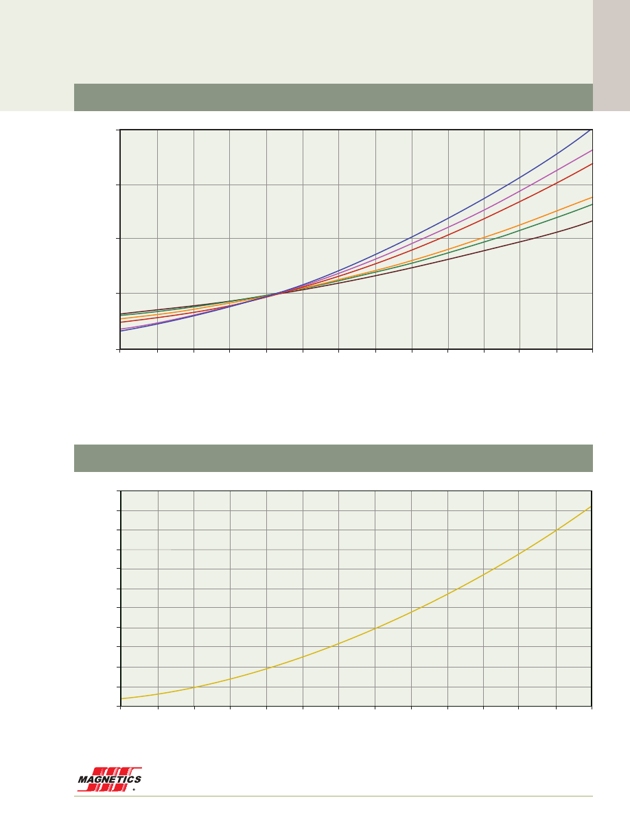
www.mag-inc.com
51
Material Data
Permeability versus Temperature Curves
Temperature (˚C)
-60
-40
-20
0
20
40
60
80
100
120
140
160
180
200
-1%
0%
1%
2%
3%
+/- % Initial Permeability
µ
i
300µ
200µ -
147µ - 173µ
125µ
60µ
26µ
14µ
14µ
125 perm
90
75
60
40
26
160
147
14
173
200
250
300
550
500
Temperature (˚C)
-60
-40
-20
0
20
40
60
80
100
120
140
160
180
200
-4%
-2%
-0%
2%
4%
6%
8%
10%
12%
14%
16%
18%
+/- % Initial Permeability
µ
i
550µ
125 perm
90
75
60
40
26
160
147
14
173
200
250
300
550
500
MPP 550µ
MPP 14µ-300µ
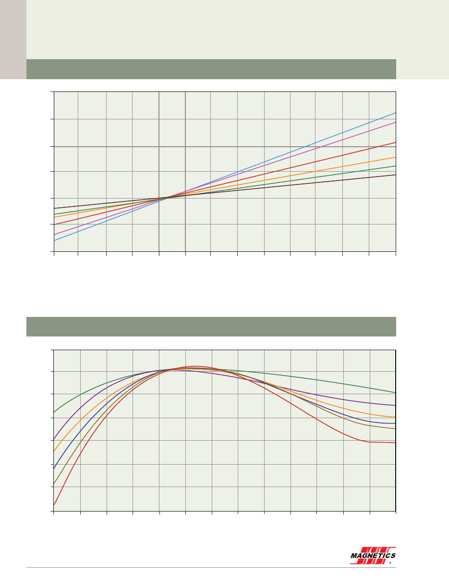
MAGNETICS
52
Material Data
Permeability versus Temperature Curves
Temperature (˚C)
-40
-60
-20
0
20
40
60
80
100
120
140
160
180
200
-4%
-2%
0%
2%
4%
6%
8%
+/- % Initial Permeability
µ
i
14µ
26µ - 40µ
60µ
125µ
147µ
160µ
125 perm
90
75
60
40
26
160
147
14
173
200
250
300
550
500
Kool Mµ
®
High Flux
Temperature (˚C)
-60
-40
-20
0
20
40
80
140
160
200
180
120
100
60
-12%
-10%
-8%
-6%
-4%
-2%
0%
2%
+/- % Initial Permeability
µ
i
125 perm
90
75
60
40
26
160
147
14
173
200
250
300
550
500
26µ
40µ
60µ
75µ
90µ
125µ

www.mag-inc.com
53
Material Data
Permeability versus Temperature Curves
XF
lux
®
Temperature (˚C)
-50
0
50
100
150
200
5.0%
4.0%
3.0%
2.0%
1.0%
0.0%
-1.0%
-2.0%
+/- % Initial Permeability
µ
i
60µ
26µ
125 perm
90
75
60
40
26
160
147
14
173
200
250
300
550
500
60µ XF
LUX
Toroid:
[% change in µ
i
] = -4.010x10
-3
+ (1.553x10
-4
)(T) + (1.875x10
-8
)(T
2
) + (3.907x10
-9
)(T
3
) + (1.213x10
-11
)(T
4
)
26µ XF
LUX
Toroid:
[% change in µ
i
] = -3.879x10
-3
+ (1.356x10
-4
)(T) + (1.228x10
-7
)(T
2
) + (1.739x10
-9
)(T
3
) + (4.35x10
-12
)(T
4
)
MAGNETICS
54
Material Data
44 - old 3 - 35
Change compared with µ
25˚C
=
µ
25˚C
µ
T
- µ
25˚C
= a + bT + cT
2
where:
Change compared with µ
25˚C
=
µ
25˚C
µ
T
- µ
25˚C
= a + bT + cT
2
+ dT
3
+ eT
4
where:
Perm
a
b
c
MPP
14µ
-1.300E-03
4.750E-05
1.300E-07
26µ
-1.431E-03
5.265E-05
1.837E-07
60µ
-1.604E-03
5.945E-05
1.875E-07
125µ
-1.939E-03
7.013E-05
2.967E-07
147µ
-2.308E-03
8.497E-05
2.943E-07
160µ
-2.308E-03
8.497E-05
2.943E-07
173µ
-2.308E-03
8.497E-05
2.943E-07
200µ
-2.528E-03
9.211E-05
3.601E-07
300µ
-2.528E-03
9.211E-05
3.601E-07
550µ
-1.309E-02
4.716E-04
2.086E-06
High Flux
14µ
-2.500E-03
9.670E-05
5.560E-08
26µ
-3.300E-03
1.290E-04
3.800E-08
60µ
-4.400E-03
1.740E-04
4.090E-08
125µ
-6.000E-03
2.400E-04
3.220E-08
147µ
-7.900E-03
3.140E-04
7.310E-08
160µ
-9.200E-03
3.670E-04
1.750E-08
Perm
a
b
c
d
e
Kool Mµ
®
26µ
-4.289E-03
2.521E-04
-3.557E-06
1.384E-08
-2.066E-11
40µ
-5.034E-03
3.521E-04
-6.797E-06
3.193E-08
-4.916E-11
6 0µ
-8.841E-03
5.197E-04
-7.064E-06
1.667E-08
8.820E-12
75µ
-1.174E-02
6.653E-04
-8.195E-06
1.411E-08
3.032E-11
90µ
-1.369E-02
7.705E-04
-9.385E-06
1.812E-08
2.524E-11
125µ
-1.647E-02
9.306E-04
-1.132E-05
1.623E-08
5.722E-11
X
F
lux
®
26µ
-3.879E-03
1.356E-04
1.228E-07
-1.739E-09
4.35E-12
60µ
-4.010E-03
1.553E-04
-1.875E-08
3.907E-09
-1.213E-11
Permeability versus Temperature Curves
Fit Formula
44 - old 3 - 35
Change compared with µ
25˚C
=
µ
25˚C
µ
T
- µ
25˚C
= a + bT + cT
2
where:
Change compared with µ
25˚C
=
µ
25˚C
µ
T
- µ
25˚C
= a + bT + cT
2
+ dT
3
+ eT
4
where:
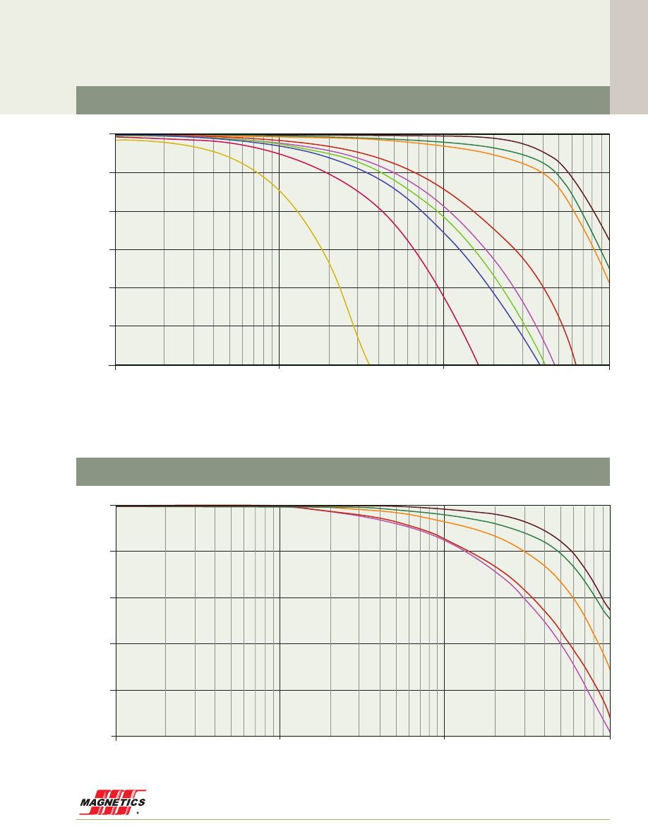
www.mag-inc.com
55
Material Data
Perm
a
b
c
MPP
14µ
-1.300E-03
4.750E-05
1.300E-07
26µ
-1.431E-03
5.265E-05
1.837E-07
60µ
-1.604E-03
5.945E-05
1.875E-07
125µ
-1.939E-03
7.013E-05
2.967E-07
147µ
-2.308E-03
8.497E-05
2.943E-07
160µ
-2.308E-03
8.497E-05
2.943E-07
173µ
-2.308E-03
8.497E-05
2.943E-07
200µ
-2.528E-03
9.211E-05
3.601E-07
300µ
-2.528E-03
9.211E-05
3.601E-07
550µ
-1.309E-02
4.716E-04
2.086E-06
High Flux
14µ
-2.500E-03
9.670E-05
5.560E-08
26µ
-3.300E-03
1.290E-04
3.800E-08
60µ
-4.400E-03
1.740E-04
4.090E-08
125µ
-6.000E-03
2.400E-04
3.220E-08
147µ
-7.900E-03
3.140E-04
7.310E-08
160µ
-9.200E-03
3.670E-04
1.750E-08
Frequency (MHz)
0.01
0.1
1
10
-30%
-25%
-20%
-15%
-10%
-5%
0
+/- % Initial Permeability
µ
i
125 perm
90
75
60
40
26
160
147
14
173
200
250
300
550
500
14µ
26µ
60µ
125µ
147µ
160µ -
173µ
200µ
300µ
550µ
Frequency (MHz)
0.01
0.1
1
10
-50%
-40%
-30%
-20%
-10%
0%
+/- % Initial Permeability
µ
i
125 perm
90
75
60
40
26
160
147
14
173
200
250
300
550
500
14µ
26µ
60µ
125µ
147µ -
160µ
High Flux
MPP
Permeability versus Frequency Curves

Material Data
MAGNETICS
56
Frequency (MHz)
0.1
1
10
0%
-5%
-10%
-15%
-20%
-25%
-30%
+/- % Initial Permeability
µ
i
125 perm
90
75
60
40
26
160
147
14
173
200
250
300
550
500
26µ
40µ
60µ
75µ - 90µ
125µ
Frequency (MHz)
0.1
1
10
0%
-5%
-10%
-15%
-20%
-25%
-30%
-35%
-40%
-45%
-50%
+/- % Initial Permeability
µ
i
60µ
26µ
125 perm
90
75
60
40
26
160
147
14
173
200
250
300
550
500
60µ XF
LUX
Toroid:
[% change in µ
i
] = -1.584x10
-3
+ (7.074x10
-1
)(B) + (-2.782)(B
2
) + (4.403)(B
3
) + (-2.621)(B
4
)
26µ XF
LUX
Toroid:
[% change in µ
i
] = -3.846x10
-4
+ (4.288x10
-1
)(B) + (-1.853)(B
2
) + (3.132)(B
3
) + (-2.138)(B
4
)
XF
lux
®
Kool Mµ
®
Permeability versus Frequency Curves
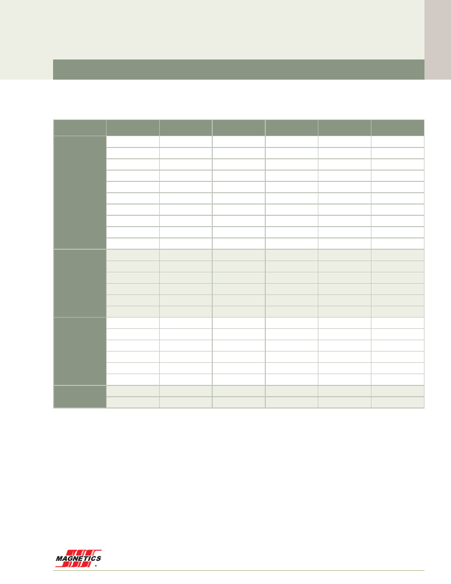
www.mag-inc.com
57
Material Data
Perm
a
b
c
d
e
MPP
14µ
0
-2.320E-03
7.630E-04
-5.070E-04
3.170E-05
26µ
0
-1.560E-02
5.190E-03
-1.160E-03
6.230E-05
60µ
0
-1.820E-02
4.320E-03
-9.780E-04
5.360E-05
125µ
0
-8.430E-02
1.590E-02
-2.270E-03
1.080E-04
147µ
0
-1.110E-01
2.040E-02
-2.810E-03
1.300E-04
160µ
0
-1.290E-01
2.390E-02
-3.080E-03
1.410E-04
173µ
0
-1.290E-01
2.390E-02
-3.080E-03
1.410E-04
200µ
0
-1.610E-01
3.820E-02
-5.170E-03
2.160E-04
300µ
0
-2.590E-01
5.570E-02
-6.530E-03
2.780E-04
550µ
0
--4.590E-01
-3.3E+00
8.14E+00
-5.73E+00
High
Flux
14µ
0
-1.070E-02
5.960E-04
-4.920E-04
3.070E-05
26µ
0
-2.560E-02
3.430E-03
-7.340E-04
3.990E-05
60µ
0
-3.870E-02
3.050E-03
-5.490E-04
2.690E-05
125µ
0
-8.600E-02
1.140E-02
-1.370E-03
6.050E-05
147µ
0
-8.170E-02
7.330E-03
-6.400E-04
2.390E-05
160µ
0
-8.590E-02
7.220E-03
-5.530E-04
1.880E-05
Kool
Mµ
®
26µ
0
-5.500E-03
1.400E-03
-6.200E-04
3.700E-05
40µ
0
-7.300E-03
8.400E-04
-5.900E-04
3.700E-05
60µ
0
-1.100E-02
1.600E-03
-7.100E-04
4.400E-05
75µ
0
-2.000E-02
3.500E-03
-9.500E-04
5.500E-05
90µ
0
-1.500E-02
6.900E-04
-4.800E-04
3.100E-05
125µ
0
-3.000E-02
-5.500E-03
2.400E-04
4.500E-06
X
F
lux
®
26µ
3.000E-04
-3.132E-02
4.902E-03
-1.015E-03
5.543E-05
60µ
6.805E-03
-7.575E-02
1.206E-02
-1.607E-03
7.524E-05
Fit Formula
Permeability versus Frequency Curves
52 - old 3 - 24
!
µ
i
= a + bf + cf
2
+ df
3
+ ef
4
Units: f in MHz
where:
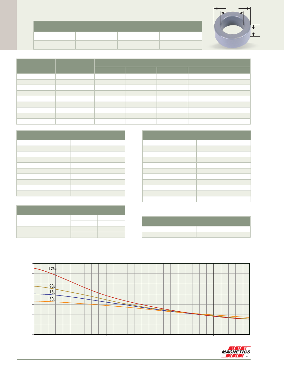
Cor
e Data
MAGNETICS
58
0.060"
0.070”
0.140”
3.56 mm OD
Before Finish (nominal)
3.56 mm/0.140 in
1.78 mm/0.070 in
1.52 mm/0.060 in
After Finish (limits)
4.20 mm/0.165 in
1.27 mm/0.050 in
2.16 mm/0.085 in
Core Dimensions
OD(max) ID(min) HT(max)
FOR PLACEMENT ONLY
Permeability (µ)
A
L
± 8%
Kool Mµ A
L
± 15%
Part Number
MPP
High Flux
Kool Mµ
®
XF
lux
®
Kool Mµ
®
MAX
60
13
-
-
77141
-
-
75
16
-
-
77445
-
-
90
19
-
-
77444
-
-
125
26
55140
-
77140
-
-
147
31
55139
-
-
-
-
160
33
55138
-
-
-
-
173
36
55134
-
-
-
-
200
42
55137
-
-
-
-
300
62
55135
-
-
-
-
Physical Characteristics
Window Area
1.27 mm
2
Cross Section
1.30 mm
2
Path Length
8.06 mm
Volume
10.5 mm
3
Weight - MPP
0.094 g
Weight - High Flux
-
Weight - Kool Mµ
0.065 g
Weight -
xF
lux
-
Weight - Kool Mµ MAX
-
Area Product
1.65 mm
4
Winding Turn Length
* Reference General Winding Data pgs. 103 - 107
Winding Factor
Length/Turn (mm)
0%
7.24
20%
7.56
25%
7.65
30%
7.70
35%
7.81
40%
7.89
45%
7.98
50%
8.08
60%
8.27
70%
8.48
Wound Coil Dimensions
40% Winding Factor
OD
4.30 mm
HT
2.56 mm
Completely Full Window
Max OD
4.95 mm
Max HT
2.74 mm
Surface Area
Unwound Core
60 mm
2
40% Winding Factor
70 mm
2
Kool Mµ A
L
vs. DC Bias
A
L
(nH/
T )
2
A·T
28
24
20
16
12
8
4
0
0
10
20
30
40
50
60
55140A2
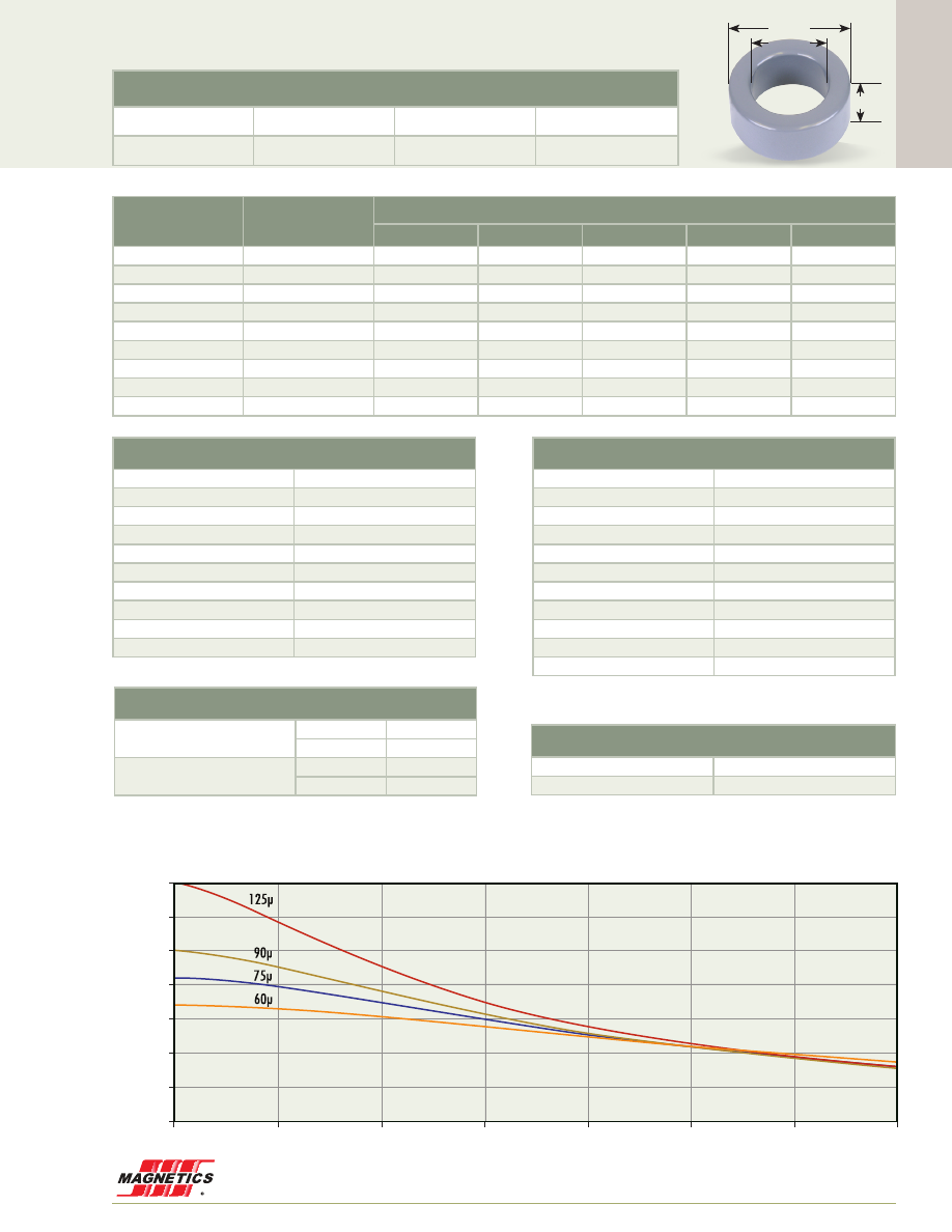
Cor
e Data
www.mag-inc.com
59
125 perm
90
75
60
40
26
Kool Mµ A
L
vs. DC Bias
A
L
(nH/
T )
2
A·T
0
10
20
35
30
25
20
15
10
5
0
30
40
50
60
70
0.100”
0.088”
0.155”
3.94 mm OD
Before Finish (nominal)
3.94 mm/0.155 in
2.24 mm/0.088 in
2.54 mm/0.100 in
After Finish (limits)
4.58 mm/0.180 in
1.72 mm/0.068 in
3.18 mm/0.125 in
Permeability (µ)
A
L
± 8%
Kool Mµ A
L
± 15%
Part Number
MPP
High Flux
Kool Mµ
®
XF
lux
®
Kool Mµ
®
MAX
60
17
-
-
77151
-
-
75
21
-
-
77155
-
-
90
25
-
-
77154
-
-
125
35
55150
-
77150
-
-
147
41
55149
-
-
-
-
160
45
55148
-
-
-
-
173
48
55144
-
-
-
-
200
56
55147
-
-
-
-
300
84
55145
-
-
-
-
Physical Characteristics
Window Area
2.32 mm
2
Cross Section
2.11 mm
2
Path Length
9.42 mm
Volume
19.9 mm
3
Weight - MPP
0.17 g
Weight - High Flux
-
Weight - Kool Mµ
0.12 g
Weight -
xF
lux
-
Weight - Kool Mµ MAX
-
Area Product
4.90 mm
4
Surface Area
Unwound Core
90 mm
2
40% Winding Factor
110 mm
2
Winding Turn Length
* Reference General Winding Data pgs. 103 - 107
Winding Factor
Length/Turn (mm)
0%
9.20
20%
9.64
25%
9.76
30%
9.84
35%
9.98
40%
10.1
45%
10.2
50%
10.3
60%
10.6
70%
10.9
Wound Coil Dimensions
40% Winding Factor
OD
4.85 mm
HT
3.73 mm
Completely Full Window
Max OD
5.77 mm
Max HT
4.75 mm
Core Dimensions
OD(max) ID(min) HT(max)
55150A2
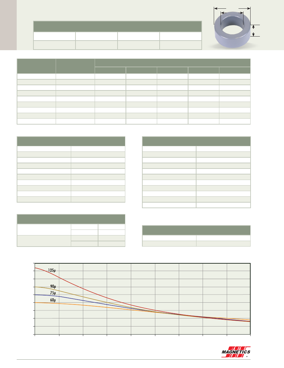
Cor
e Data
MAGNETICS
60
0.100”
0.183”
0.093”
4.65 mm OD
Before Finish (nominal)
4.65 mm/0.183 in
2.36 mm/0.093 in
2.54 mm/0.100 in
After Finish (limits)
5.29 mm/0.208 in
1.85 mm/0.073 in
3.18 mm/0.125 in
FOR PLACEMENT ONLY
Permeability (µ)
A
L
± 8%
Kool Mµ A
L
± 15%
Part Number
MPP
High Flux
Kool Mµ
®
XF
lux
®
Kool Mµ
®
MAX
60
20
55181
-
77181
-
-
75
25
-
-
77185
-
-
90
30
-
-
77184
-
-
125
42
55180
-
77180
-
-
147
49
55179
-
-
-
-
160
53
55178
-
-
-
-
173
57
55174
-
-
-
-
200
67
55177
-
-
-
-
300
99
55175
-
-
-
-
Physical Characteristics
Window Area
2.69 mm
2
Cross Section
2.85 mm
2
Path Length
10.6 mm
Volume
30.3 mm
3
Weight - MPP
0.25 g
Weight - High Flux
-
Weight - Kool Mµ
0.18 g
Weight -
xF
lux
-
Weight - Kool Mµ MAX
-
Area Product
7.66 mm
4
Surface Area
Unwound Core
110 mm
2
40% Winding Factor
130 mm
2
125 perm
90
75
60
40
26
Kool Mµ A
L
vs. DC Bias
A
L
(nH/
T )
2
A·T
0
10
20
45
40
35
30
25
20
15
10
5
0
30
40
50
60
70
80
90
Winding Turn Length
* Reference General Winding Data pgs. 103 - 107
Winding Factor
Length/Turn (mm)
0%
9.79
20%
10.3
25%
10.4
30%
10.5
35%
10.6
40%
10.7
45%
10.9
50%
11.0
60%
11.3
70%
11.6
Wound Coil Dimensions
40% Winding Factor
OD
5.56 mm
HT
3.73 mm
Completely Full Window
Max OD
6.65 mm
Max HT
4.94 mm
Core Dimensions
OD(max) ID(min) HT(max)
55180A2
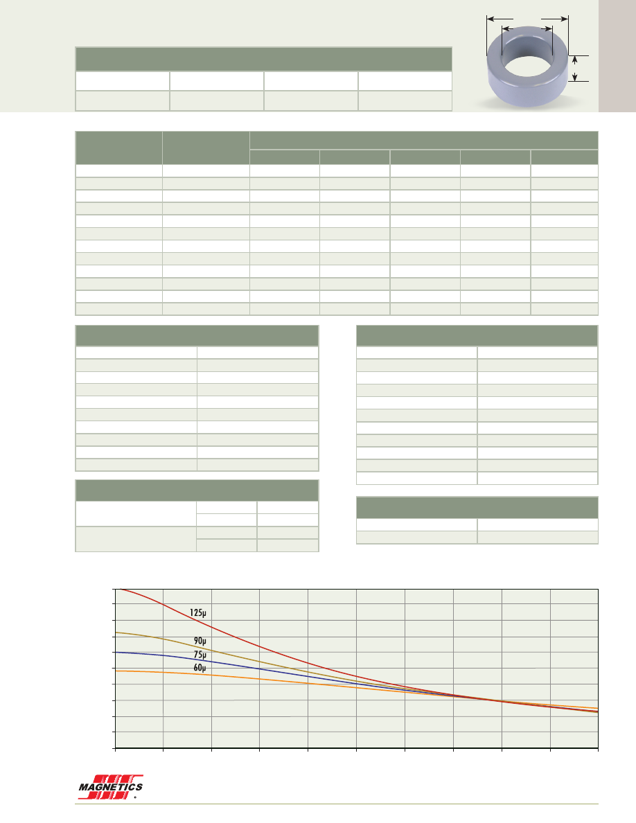
Cor
e Data
www.mag-inc.com
61
125 perm
90
75
60
40
26
Kool Mµ A
L
vs. DC Bias
A
L
(nH/
T )
2
A·T
0
10
20
50
45
40
35
30
25
20
15
10
5
0
30
40
50
60
70
80
100
90
0.110”
0.110”
0.250”
6.35 mm OD
Before Finish (nominal)
6.35 mm/0.250 in
2.79 mm/0.110 in
2.79 mm/0.110 in
After Finish (limits)
6.99 mm/0.275 in
2.28 mm/0.090 in
3.43 mm/0.135 in
Permeability (µ)
A
L
± 8%
Kool Mµ A
L
± 12%
Part Number
MPP
High Flux
Kool Mµ
®
XF
lux
®
Kool Mµ
®
MAX
14
6
55023
58023
-
-
-
26
10
55022
58022
-
-
-
60
24
55021
58021
77021
-
-
75
30
-
-
77825
-
-
90
36
-
-
77824
-
-
125
50
55020
58020
77020
-
-
147
59
55019
58019
-
-
-
160
64
55018
58018
-
-
-
173
69
55014
-
-
-
-
200
80
55017
-
-
-
-
300
120
55015
-
-
-
-
550
220
55016
-
-
-
-
Physical Characteristics
Window Area
4.08 mm
2
Cross Section
4.70 mm
2
Path Length
13.6 mm
Volume
64.0 mm
3
Weight - MPP
0.59 g
Weight - High Flux
0.55 g
Weight - Kool Mµ
0.39 g
Weight -
xF
lux
-
Weight - Kool Mµ MAX
-
Area Product
19.2 mm
4
Surface Area
Unwound Core
170 mm
2
40% Winding Factor
200 mm
2
Winding Turn Length
* Reference General Winding Data pgs. 103 - 107
Winding Factor
Length/Turn (mm)
0%
11.6
20%
12.2
25%
12.3
30%
12.4
35%
12.6
40%
12.8
45%
12.9
50%
13.1
60%
13.4
70%
13.9
Wound Coil Dimensions
40% Winding Factor
OD
7.34 mm
HT
4.12 mm
Completely Full Window
Max OD
8.81 mm
Max HT
5.38 mm
Core Dimensions
OD(max) ID(min) HT(max)
55020A2
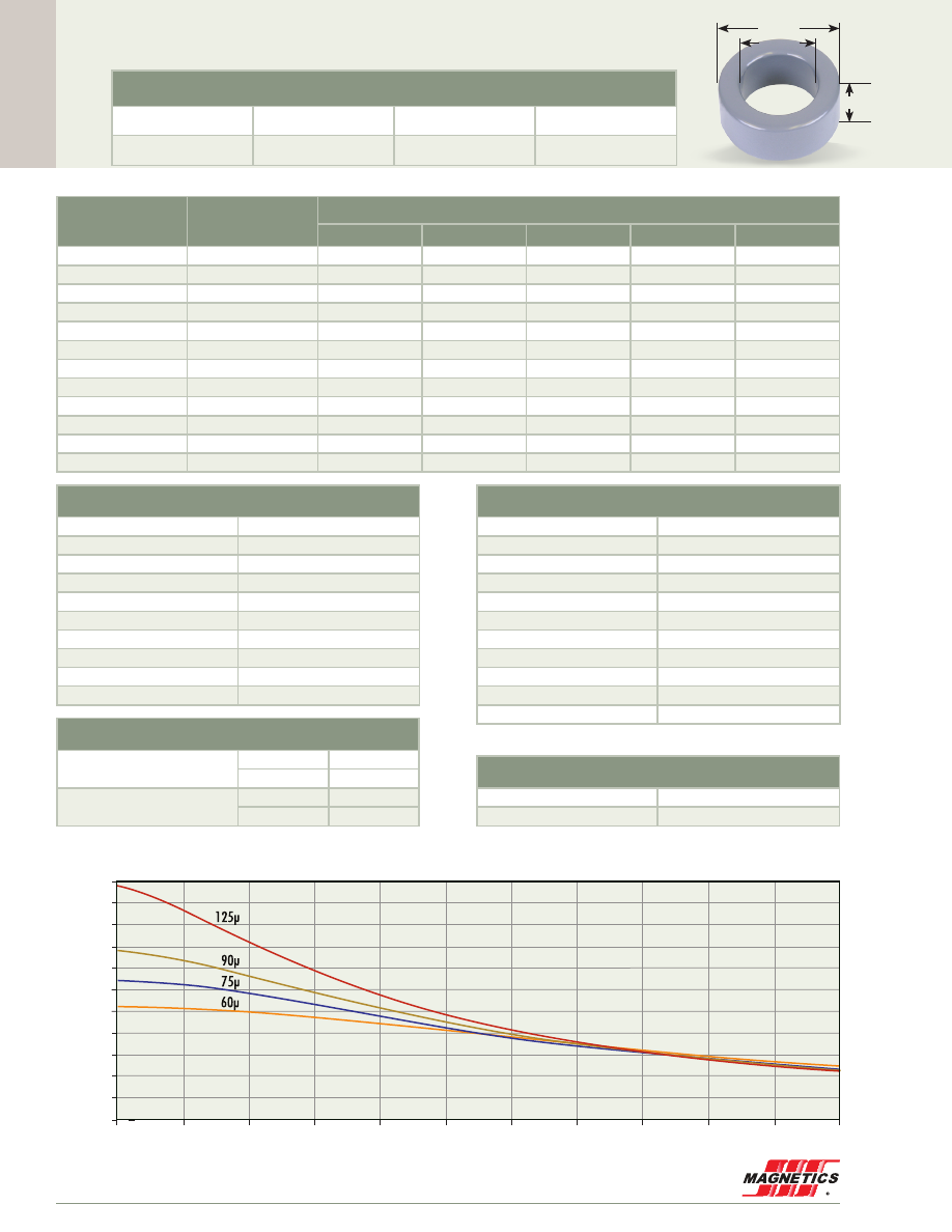
Cor
e Data
MAGNETICS
62
0.100”
0.105”
0.260”
6.60 mm OD
Before Finish (nominal)
6.60 mm/0.260 in
2.67 mm/0.105 in
2.54 mm/0.100 in
After Finish (limits)
7.24 mm/0.285 in
2.15 mm/0.085 in
3.18 mm/0.125 in
FOR PLACEMENT ONLY
Permeability (µ)
A
L
± 8%
Kool Mµ A
L
± 12%
Part Number
MPP
High Flux
Kool Mµ
®
XF
lux
®
Kool Mµ
®
MAX
14
6
55243
58243
-
-
-
26
11
55242
58242
-
-
-
60
26
55241
58241
77241
-
-
75
32
-
-
77245
-
-
90
39
-
-
77244
-
-
125
54
55240
58240
77240
-
-
147
64
55239
58239
-
-
-
160
69
55238
58238
-
-
-
173
75
55234
-
-
-
-
200
86
55237
-
-
-
-
300
130
55235
-
-
-
-
550
242
55236
-
-
-
-
Physical Characteristics
Window Area
3.63 mm²
Cross Section
4.76 mm²
Path Length
13.6 mm
Volume
64.9 mm³
Weight - MPP
0.58 g
Weight - High Flux
0.55 g
Weight - Kool Mµ
0.40 g
Weight -
xF
lux
-
Weight - Kool Mµ MAX
-
Area Product
17.3 mm
4
Surface Area
Unwound Core
170 mm²
40% Winding Factor
190 mm²
125 perm
90
75
60
40
26
Kool Mµ A
L
vs. DC Bias
A
L
(nH/
T )
2
A·T
0
10
20
55
50
45
40
35
30
25
20
15
10
5
0
30
40
50
60
70
80
110
100
90
Winding Turn Length
* Reference General Winding Data pgs. 103 - 107
Winding Factor
Length/Turn (mm)
0%
11.4
20%
12.0
25%
12.2
30%
12.3
35%
12.4
40%
12.6
45%
12.7
50%
12.9
60%
13.2
70%
13.6
Wound Coil Dimensions
40% Winding Factor
OD
7.41 mm
HT
3.87 mm
Completely Full Window
Max OD
9.12 mm
Max HT
5.13 mm
Core Dimensions
OD(max) ID(min) HT(max)
55240A2

Cor
e Data
www.mag-inc.com
63
125 perm
90
75
60
40
26
Kool Mµ A
L
vs. DC Bias
A
L
(nH/
T )
2
A·T
0
10
20
110
100
90
80
70
60
50
40
30
20
10
0
30
40
50
60
70
80
110
100
90
0.188”
0.105”
0.260”
6.60 mm OD
Before Finish (nominal)
6.60 mm/0.260 in
2.67 mm/0.105 in
4.78 mm/0.188 in
After Finish (limits)
7.24 mm/0.285 in
2.15 mm/0.085 in
5.42 mm/0.213 in
Permeability (µ)
A
L
± 8%
Kool Mµ A
L
± 12%
Part Number
MPP
High Flux
Kool Mµ
®
XF
lux
®
Kool Mµ
®
MAX
14
12
55273
58273
-
-
-
26
21
55272
58272
-
-
-
60
50
55271
58271
77271
-
-
75
62
-
-
77875
-
-
90
74
-
-
77874
-
-
125
103
55270
58270
77270
-
-
147
122
55269
58269
-
-
-
160
132
55268
58268
-
-
-
173
144
55264
-
-
-
-
200
165
55267
-
-
-
-
300
247
55265
-
-
-
-
550
466
55266
-
-
-
-
Physical Characteristics
Window Area
3.63 mm
2
Cross Section
9.20 mm
2
Path Length
13.6 mm
Volume
125 mm
3
Weight - MPP
1.1 g
Weight - High Flux
1.0 g
Weight - Kool Mµ
0.77 g
Weight -
xF
lux
-
Weight - Kool Mµ MAX
-
Area Product
33.4 mm
4
Surface Area
Unwound Core
230 mm
2
40% Winding Factor
260 mm
2
Winding Turn Length
* Reference General Winding Data pgs. 103 - 107
Winding Factor
Length/Turn (mm)
0%
16.2
20%
16.7
25%
16.9
30%
17.0
35%
17.1
40%
17.3
45%
17.4
50%
17.6
60%
17.9
70%
18.3
Wound Coil Dimensions
40% Winding Factor
OD
7.41 mm
HT
6.11 mm
Completely Full Window
Max OD
9.17 mm
Max HT
7.42 mm
Core Dimensions
OD(max) ID(min) HT(max)
55270A2
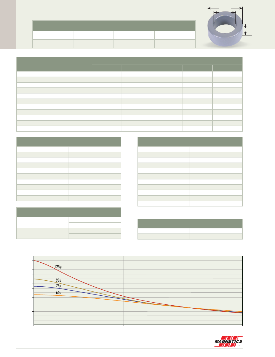
Cor
e Data
MAGNETICS
64
0.270”
0.156”
0.200”
6.86 mm OD
Before Finish (nominal)
6.86 mm/0.270 in
3.96 mm/0.156 in
5.08 mm/0.200 in
After Finish (limits)
7.50 mm/0.295 in
3.45 mm/0.136 in
5.72 mm/0.225 in
Permeability (µ)
A
L
± 8%
Kool Mµ A
L
± 12%
Part Number
MPP
High Flux
Kool Mµ
®
XF
lux
®
Kool Mµ
®
MAX
14
8
55413
58413
-
-
-
26
14
55412
58412
-
-
-
60
33
55411
58411
77411
-
-
75
42
-
-
77415
-
-
90
50
-
-
77414
-
-
125
70
55410
58410
77410
-
-
147
81
55409
58409
-
-
-
160
89
55408
58408
-
-
-
173
95
55404
-
-
-
-
200
112
55407
-
-
-
-
300
166
55405
-
-
-
-
Physical Characteristics
Window Area
9.35 mm²
Cross Section
7.25 mm²
Path Length
16.5 mm
Volume
120 mm³
Weight - MPP
1.0 g
Weight - High Flux
0.94 g
Weight - Kool Mµ
0.74 g
Weight -
xF
lux
-
Weight - Kool Mµ MAX
-
Area Product
67.8 mm
4
Surface Area
Unwound Core
260 mm
2
40% Winding Factor
330 mm
2
125 perm
90
75
60
40
26
Kool Mµ A
L
vs. DC Bias
A
L
(nH/
T )
2
A·T
0
20
40
75
70
65
60
55
50
45
40
35
30
25
20
15
10
5
0
60
80
100
120
140
Kool Mµ A
L
vs. DC Bias
A
L
(nH/
T )
2
A·T
0
10
20
75
70
65
60
55
50
45
40
35
30
25
20
15
10
5
0
30
40
50
Winding Turn Length
* Reference General Winding Data pgs. 103 - 107
Winding Factor
Length/Turn (mm)
0%
15.5
20%
16.4
25%
16.6
30%
16.8
35%
17.0
40%
17.3
45%
17.5
50%
17.8
60%
18.3
70%
18.9
Wound Coil Dimensions
40% Winding Factor
OD
8.06 mm
HT
6.84 mm
Completely Full Window
Max OD
9.60 mm
Max HT
10.0 mm
Core Dimensions
OD(max) ID(min) HT(max)
55410A2
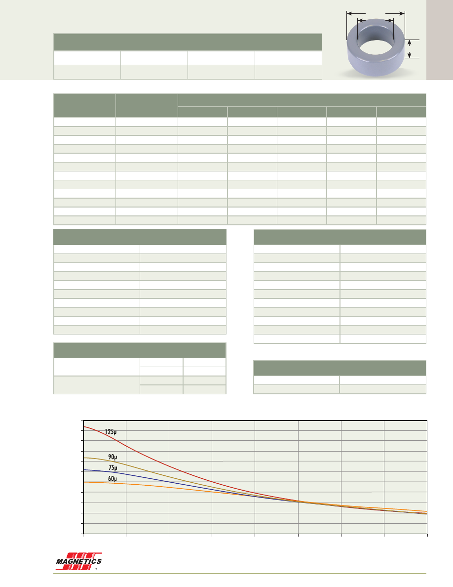
Cor
e Data
www.mag-inc.com
65
0.125”
0.156”
0.310”
7.87 mm OD
Before Finish (nominal)
7.87 mm/0.310 in
3.96 mm/0.156 in
3.18 mm/0.125 in
After Finish (limits)
8.51 mm/0.335 in
3.45 mm/0.136 in
3.81 mm/0.150 in
Permeability (µ)
A
L
± 8%
Kool Mµ A
L
± 12%
Part Number
MPP
High Flux
Kool Mµ
®
XF
lux
®
Kool Mµ
®
MAX
14
6
55033
58033
-
-
-
26
11
55032
58032
-
-
-
60
25
55031
58031
77031
-
-
75
31
-
-
77835
-
-
90
37
-
-
77834
-
-
125
52
55030
58030
77030
-
-
147
62
55029
58029
-
-
-
160
66
55028
58028
-
-
-
173
73
55024
-
-
-
-
200
83
55027
-
-
-
-
300
124
55025
-
-
-
-
550
229
55026
-
-
-
-
Physical Characteristics
Window Area
9.35 mm²
Cross Section
5.99 mm²
Path Length
17.9 mm
Volume
107 mm³
Weight - MPP
0.92 g
Weight - High Flux
0.87 g
Weight - Kool Mµ
0.68 g
Weight -
xF
lux
-
Weight - Kool Mµ MAX
-
Area Product
56.0 mm
4
Surface Area
Unwound Core
240 mm
2
40% Winding Factor
310 mm
2
125 perm
90
75
60
40
26
Kool Mµ A
L
vs. DC Bias
A
L
(nH/
T )
2
A·T
0
20
55
50
45
40
35
30
25
20
15
10
5
0
40
100
60
120
140
80
160
Winding Turn Length
* Reference General Winding Data pgs. 103 - 107
Winding Factor
Length/Turn (mm)
0%
12.7
20%
13.6
25%
13.8
30%
14.0
35%
14.3
40%
14.5
45%
14.7
50%
15.0
60%
15.5
70%
16.1
Wound Coil Dimensions
40% Winding Factor
OD
9.07 mm
HT
4.93 mm
Completely Full Window
Max OD
11.0 mm
Max HT
6.73 mm
Core Dimensions
OD(max) ID(min) HT(max)
55030A2
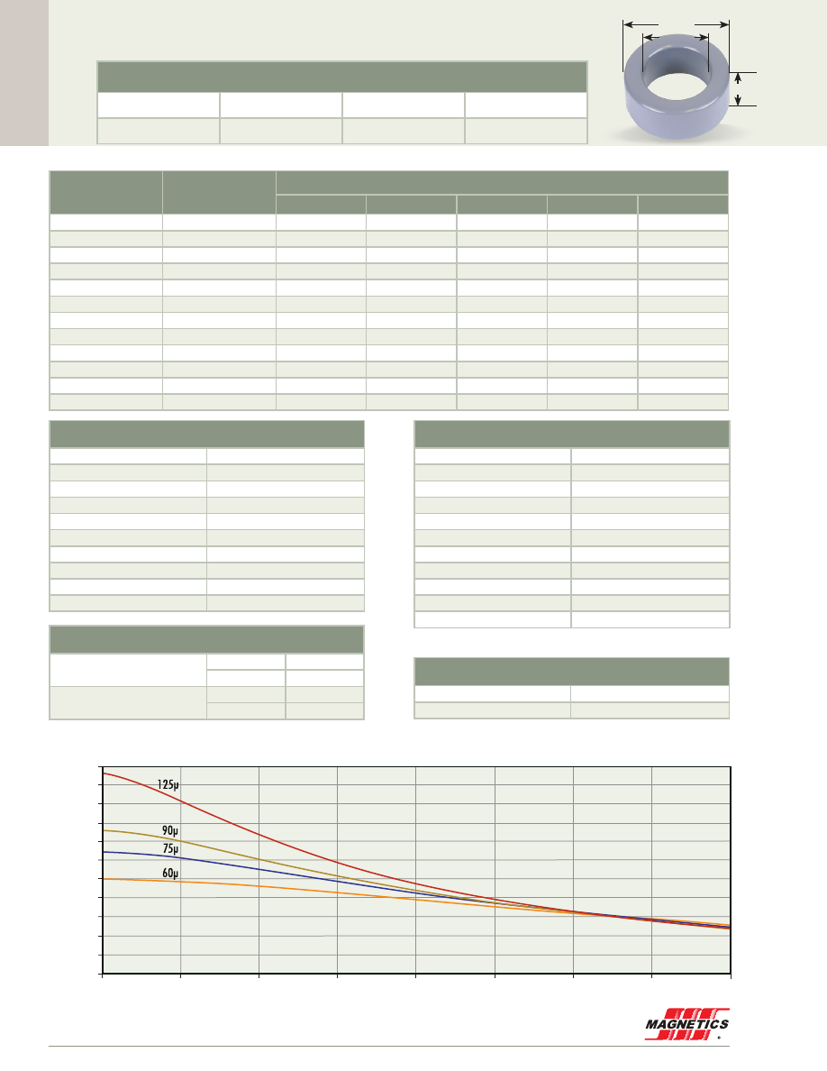
Cor
e Data
MAGNETICS
66
0.125”
0.188”
0.380”
9.65 mm OD
Before Finish (nominal)
9.65 mm/0.380 in
4.78 mm/0.188 in
3.18 mm/0.125 in
After Finish (limits)
10.3 mm/0.405 in
4.26 mm/0.168 in
3.81 mm/0.150 in
Permeability (µ)
A
L
± 8%
Kool Mµ A
L
± 12%
Part Number
MPP
High Flux
Kool Mµ
®
XF
lux
®
Kool Mµ
®
MAX
14
6
55283
58283
-
-
-
26
11
55282
58282
-
-
-
60
25
55281
58281
77281
-
-
75
32
-
-
77885
-
-
90
38
-
-
77884
-
-
125
53
55280
58280
77280
-
-
147
63
55279
58279
-
-
-
160
68
55278
58278
-
-
-
173
74
55274
-
-
-
-
200
84
55277
-
-
-
-
300
128
55275
-
-
-
-
550
232
55276
-
-
-
-
Physical Characteristics
Window Area
14.3 mm²
Cross Section
7.52 mm²
Path Length
21.8 mm
Volume
164 mm³
Weight - MPP
1.4 g
Weight - High Flux
1.3 g
Weight - Kool Mµ
1.0 g
Weight -
xF
lux
-
Weight - Kool Mµ MAX
-
Area Product
107 mm
4
Surface Area
Unwound Core
310 mm
2
40% Winding Factor
410 mm
2
125 perm
90
75
60
40
26
Kool Mµ A
L
vs. DC Bias
A
L
(nH/
T )
2
A·T
0
20
55
50
45
40
35
30
25
20
15
10
5
0
40
100
60
120
140
80
160
Winding Turn Length
* Reference General Winding Data pgs. 103 - 107
Winding Factor
Length/Turn (mm)
0%
13.6
20%
14.7
25%
15.0
30%
15.3
35%
15.6
40%
15.9
45%
16.2
50%
16.5
60%
17.2
70%
17.9
Wound Coil Dimensions
40% Winding Factor
OD
11.0 mm
HT
5.17 mm
Completely Full Window
Max OD
13.4 mm
Max HT
7.44 mm
Core Dimensions
OD(max) ID(min) HT(max)
55280A2
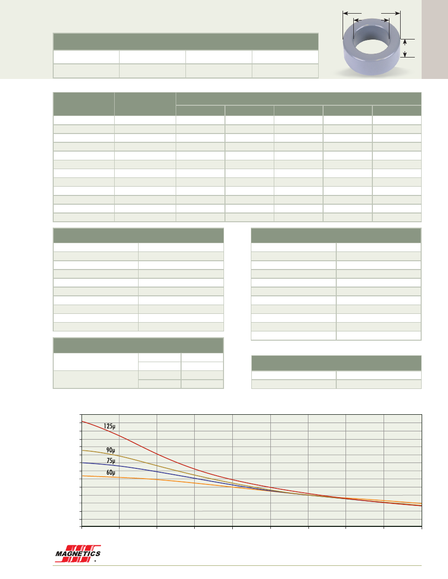
Cor
e Data
www.mag-inc.com
67
125 perm
90
75
60
40
26
Kool Mµ A
L
vs. DC Bias
A
L
(nH/
T )
2
A·T
0
20
70
65
60
55
50
45
40
35
30
25
20
15
10
5
0
40
100
60
120
140
80
180
160
0.156”
0.188”
0.380”
9.65 mm OD
Before Finish (nominal)
9.65 mm/0.380 in
4.78 mm/0.188 in
3.96 mm/0.156 in
After Finish (limits)
10.3 mm/0.405 in
4.26 mm/0.168 in
4.60 mm/0.181 in
Permeability (µ)
A
L
± 8%
Kool Mµ A
L
± 12%
Part Number
MPP
High Flux
Kool Mµ
®
XF
lux
®
Kool Mµ
®
MAX
14
7
55293
58293
-
-
-
26
14
55292
58292
-
-
-
60
32
55291
58291
77291
-
-
75
40
-
-
77295
-
-
90
48
-
-
77294
-
-
125
66
55290
58290
77290
-
-
147
78
55289
58289
-
-
-
160
84
55288
58288
-
-
-
173
92
55284
-
-
-
-
200
105
55287
-
-
-
-
300
159
55285
-
-
-
-
550
290
55286
-
-
-
-
Physical Characteristics
Window Area
14.3 mm
2
Cross Section
9.45 mm
2
Path Length
21.8 mm
Volume
206 mm
3
Weight - MPP
1.8 g
Weight - High Flux
1.7 g
Weight - Kool Mµ
1.4 g
Weight -
xF
lux
-
Weight - Kool Mµ MAX
-
Area Product
135 mm
4
Surface Area
Unwound Core
350 mm²
40% Winding Factor
450 mm²
Winding Turn Length
* Reference General Winding Data pgs. 103 - 107
Winding Factor
Length/Turn (mm)
0%
15.2
20%
16.4
25%
16.6
30%
16.9
35%
17.2
40%
17.4
45%
17.8
50%
18.1
60%
18.7
70%
19.5
Wound Coil Dimensions
40% Winding Factor
OD
11.0 mm
HT
5.96 mm
Completely Full Window
Max OD
13.4 mm
Max HT
8.20 mm
Core Dimensions
OD(max) ID(min) HT(max)
55290A2
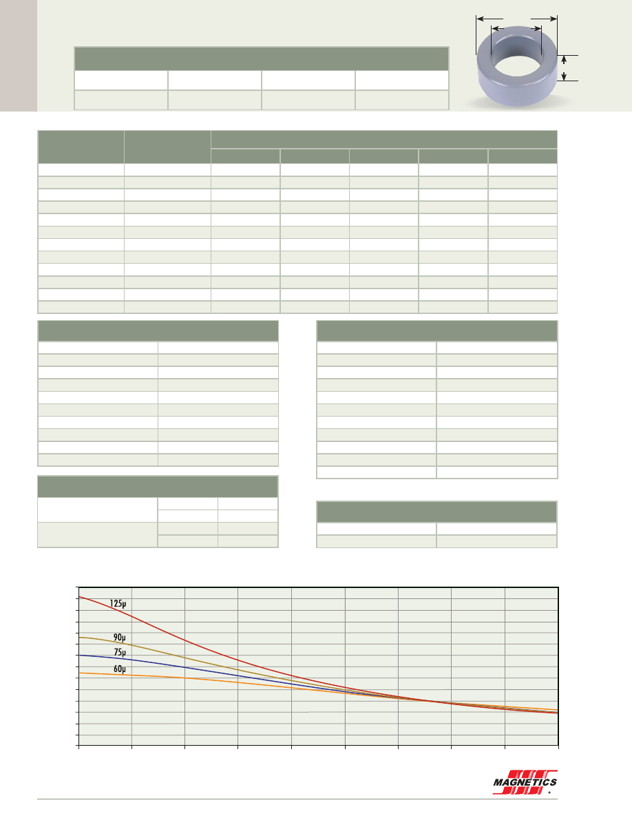
Cor
e Data
MAGNETICS
68
125 perm
90
75
60
40
26
Kool Mµ A
L
vs. DC Bias
A
L
(nH/
T )
2
A·T
0
20
70
65
60
55
50
45
40
35
30
25
20
15
10
5
0
40
100
60
120
140
80
180
160
0.156”
0.200”
0.400”
10.2 mm OD
Before Finish (nominal)
10.2 mm/0.400 in
5.08 mm/0.200 in
3.96 mm/0.156 in
After Finish (limits)
10.8 mm/0.425 in
4.57 mm/0.180 in
4.60 mm/0.181 in
Permeability (µ)
A
L
± 8%
Kool Mµ A
L
± 12%
Part Number
MPP
High Flux
Kool Mµ
®
XF
lux
®
Kool Mµ
®
MAX
14
7
55043
58043
-
-
-
26
14
55042
58042
-
-
-
60
32
55041
58041
77041
-
-
75
40
-
-
77845
-
-
90
48
-
-
77844
-
-
125
66
55040
58040
77040
-
-
147
78
55039
58039
-
-
-
160
84
55038
58038
-
-
-
173
92
55034
-
-
-
-
200
105
55037
-
-
-
-
300
159
55035
-
-
-
-
550
290
55036
-
-
-
-
Physical Characteristics
Window Area
16.4 mm²
Cross Section
9.57 mm²
Path Length
23.0 mm
Volume
220 mm³
Weight - MPP
1.9 g
Weight - High Flux
1.8 g
Weight - Kool Mµ
1.5 g
Weight -
xF
lux
-
Weight - Kool Mµ MAX
-
Area Product
156 mm
4
Surface Area
Unwound Core
370 mm
2
40% Winding Factor
480 mm
2
Winding Turn Length
* Reference General Winding Data pgs. 103 - 107
Winding Factor
Length/Turn (mm)
0%
15.4
20%
16.6
25%
16.9
30%
17.1
35%
17.5
40%
17.8
45%
18.1
50%
18.4
60%
19.2
70%
20.0
Wound Coil Dimensions
40% Winding Factor
OD
11.5 mm
HT
5.96 mm
Completely Full Window
Max OD
14.1 mm
Max HT
8.46 mm
Core Dimensions
OD(max) ID(min) HT(max)
55040A2
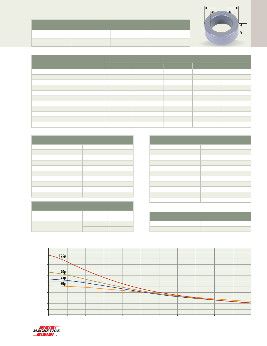
Cor
e Data
www.mag-inc.com
69
125 perm
90
75
60
40
26
Kool Mµ A
L
vs. DC Bias
A
L
(nH/
T )
2
A·T
0
20
40
60
55
50
45
40
35
30
25
20
15
10
5
0
60
80
100
120
140
160
220
200
180
0.156”
0.250”
0.440”
11.2 mm OD
Before Finish (nominal)
11.2 mm/0.440 in
6.35 mm/0.250 in
3.96 mm/0.156 in
After Finish (limits)
11.9 mm/0.465 in
5.84 mm/0.230 in
4.60 mm/0.181 in
Permeability (µ)
A
L
± 8%
Kool Mµ A
L
± 12%
Part Number
MPP
High Flux
Kool Mµ
®
XF
lux
®
Kool Mµ
®
MAX
14
6
55133
58133
-
-
-
26
11
55132
58132
-
-
-
60
26
55131
58131
77131
-
-
75
32
-
-
77335
-
-
90
38
-
-
77334
-
-
125
53
55130
58130
77130
-
-
147
63
55129
58129
-
-
-
160
68
55128
58128
-
-
-
173
74
55124
-
-
-
-
200
85
55127
-
-
-
-
300
127
55125
-
-
-
-
Physical Characteristics
Window Area
26.8 mm²
Cross Section
9.06 mm²
Path Length
26.9 mm
Volume
244 mm²
Weight - MPP
2.1 g
Weight - High Flux
2.0 g
Weight - Kool Mµ
1.5 g
Weight -
xF
lux
-
Weight - Kool Mµ MAX
-
Area Product
243 mm
4
Surface Area
Unwound Core
420 mm
2
40% Winding Factor
600 mm
2
Winding Turn Length
* Reference General Winding Data pgs. 103 - 107
Winding Factor
Length/Turn (mm)
0%
15.2
20%
16.7
25%
17.0
30%
17.4
35%
17.8
40%
18.1
45%
18.6
50%
19.0
60%
19.9
70%
20.9
Wound Coil Dimensions
40% Winding Factor
OD
12.9 mm
HT
6.53 mm
Completely Full Window
Max OD
15.7 mm
Max HT
8.97 mm
Core Dimensions
OD(max) ID(min) HT(max)
55130A2
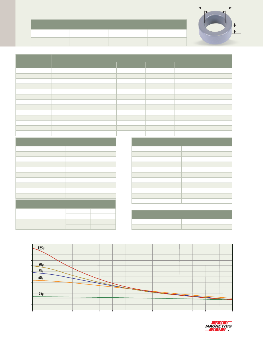
Cor
e Data
MAGNETICS
70
55050A2
0.187”
0.300”
0.500”
12.7 mm OD
Before Finish (nominal)
12.7 mm/0.500 in
7.62 mm/0.300 in
4.75 mm/0.187 in
After Finish (limits)
13.5 mm/0.530 in
6.98 mm/0.275 in
5.52 mm/0.217 in
Permeability (µ)
A
L
± 8%
Part Number
MPP
High Flux
Kool Mµ
®
XF
lux
®
Kool Mµ
®
MAX
14
6.4
55053
58053
-
-
-
26
12
55052
58052
77052
78052
79052
40
18
-
-
-
78056
-
60
27
55051
58051
77051
78051
79051
75
34
-
-
77055
78055
-
90
40
-
-
77054
78054
-
125
56
55050
58050
77050
-
-
147
67
55049
58049
-
-
-
160
72
55048
58048
-
-
-
173
79
55044
-
-
-
-
200
90
55047
-
-
-
-
300
134
55045
-
-
-
-
550
255
55046
-
-
-
-
Physical Characteristics
Window Area
38.3 mm
2
Cross Section
10.9 mm
2
Path Length
31.2 mm
Volume
340 mm
3
Weight - MPP
3.1 g
Weight - High Flux
2.9 g
Weight - Kool Mµ
2.2 g
Weight -
xF
lux
2.5 g
Weight - Kool Mµ MAX
2.2 g
Area Product
417 mm
4
Surface Area
Unwound Core
560 mm
2
40% Winding Factor
800 mm
2
Kool Mµ A
L
vs. DC Bias
A
L
(nH/
T )
2
A·T
0
20
40
60
55
50
45
40
35
30
25
20
15
10
5
0
60
80
100
120
140
160
300
220
240
260
280
200
180
125 perm
90
75
60
40
26
14
125µ
90µ
75µ
60µ
40µ
26µ
14µ
Winding Turn Length
* Reference General Winding Data pgs. 103 - 107
Winding Factor
Length/Turn (mm)
0%
17.5
20%
19.3
25%
19.8
30%
20.1
35%
20.7
40%
21.1
45%
21.7
50%
22.1
60%
23.2
70%
24.5
Wound Coil Dimensions
40% Winding Factor
OD
14.6 mm
HT
7.66 mm
Completely Full Window
Max OD
18.2 mm
Max HT
11.5 mm
Core Dimensions
OD(max) ID(min) HT(max)

Cor
e Data
www.mag-inc.com
71
125 perm
90
75
60
40
26
A
L
(nH/
T )
2
A·T
0
75
70
65
60
55
50
45
40
35
30
25
20
15
10
5
0
330
30
60
90
120
150
180
210
240
270
300
Kool Mµ A
L
vs. DC Bias
55120A2
0.250”
0.400”
0.653”
16.6 mm OD
Before Finish (nominal)
16.6 mm/0.653 in
10.2 mm/0.400 in
6.35 mm/0.250 in
After Finish (limits)
17.3 mm/0.680 in
9.52 mm/0.375 in
7.12 mm/0.280 in
Permeability (µ)
A
L
± 8%
Part Number
MPP
High Flux
Kool Mµ
®
XF
lux
®
Kool Mµ
®
MAX
14
8
55123
58123
-
-
-
26
15
55122
58122
-
78122
79122
40
24
-
-
-
78113
-
60
35
55121
58121
77121
78121
79121
75
43
-
-
77225
78225
-
90
52
-
-
77224
78224
-
125
72
55120
58120
77120
-
-
147
88
55119
58119
-
-
-
160
92
55118
58118
-
-
-
173
104
55114
-
-
-
-
200
115
55117
-
-
-
-
300
173
55115
-
-
-
-
550
317
55116
-
-
-
-
Physical Characteristics
Window Area
71.2 mm
2
Cross Section
19.2 mm
2
Path Length
41.2 mm
Volume
791 mm
3
Weight - MPP
6.8 g
Weight - High Flux
6.3 g
Weight - Kool Mµ
5.0 g
Weight -
xF
lux
5.6 g
Weight - Kool Mµ MAX
4.9 g
Area Product
1,370 mm
4
Surface Area
Unwound Core
920 mm
2
40% Winding Factor
1,300 mm
2
Winding Turn Length
* Reference General Winding Data pgs. 103 - 107
Winding Factor
Length/Turn (mm)
0%
22.1
20%
24.6
25%
25.2
30%
25.6
35%
26.4
40%
27.0
45%
27.7
50%
28.4
60%
29.8
70%
31.5
Wound Coil Dimensions
40% Winding Factor
OD
18.8 mm
HT
10.1 mm
Completely Full Window
Max OD
23.7 mm
Max HT
15.2 mm
Core Dimensions
OD(max) ID(min) HT(max)
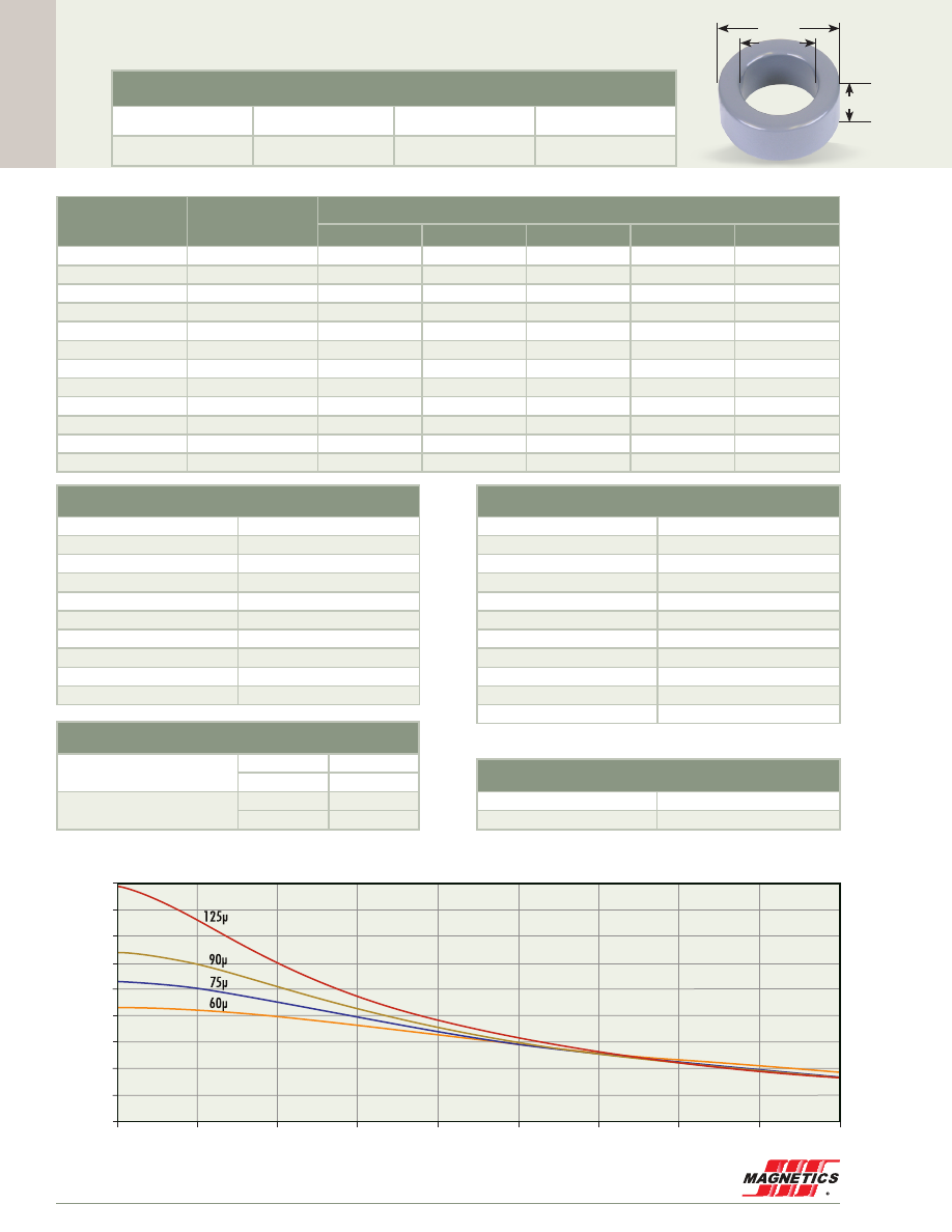
Cor
e Data
MAGNETICS
72
55380A2
0.250”
0.380”
0.680”
17.3 mm OD
Before Finish (nominal)
17.3 mm/0.680 in
9.65 mm/0.380 in
6.35 mm/0.250 in
After Finish (limits)
18.1 mm/0.710 in
9.01 mm/0.355 in
7.12 mm/0.280 in
Permeability (µ)
A
L
± 8%
Part Number
MPP
High Flux
Kool Mµ
®
XF
lux
®
Kool Mµ
®
MAX
14
10
55383
58383
-
-
-
26
19
55382
58382
-
78382
79382
40
28
-
-
-
78386
-
60
43
55381
58381
77381
78381
79381
75
53
-
-
77385
78385
-
90
64
-
-
77384
78384
-
125
89
55380
58380
77380
-
-
147
105
55379
58379
-
-
-
160
114
55378
58378
-
-
-
173
123
55374
-
-
-
-
200
142
55377
-
-
-
-
300
214
55375
-
-
-
-
Physical Characteristics
Window Area
63.8 mm
2
Cross Section
23.2 mm
2
Path Length
41.4 mm
Volume
960 mm
3
Weight - MPP
8.2 g
Weight - High Flux
7.7 g
Weight - Kool Mµ
5.9 g
Weight -
xF
lux
7.2 g
Weight - Kool Mµ MAX
5.9 g
Area Product
1,480 mm
4
Surface Area
Unwound Core
990 mm
2
40% Winding Factor
1,400 mm
2
125 perm
90
75
60
40
26
Kool Mµ A
L
vs. DC Bias
A
L
(nH/
T )
2
A·T
0
40
90
80
70
60
50
40
30
20
10
0
80
200
120
240
280
160
360
320
Winding Turn Length
* Reference General Winding Data pgs. 103 - 107
Winding Factor
Length/Turn (mm)
0%
23.2
20%
25.6
25%
26.2
30%
26.6
35%
27.4
40%
28.0
45%
28.6
50%
29.3
60%
30.8
70%
32.4
Wound Coil Dimensions
40% Winding Factor
OD
19.6 mm
HT
10.1 mm
Completely Full Window
Max OD
24.9 mm
Max HT
16.3 mm
Core Dimensions
OD(max) ID(min) HT(max)
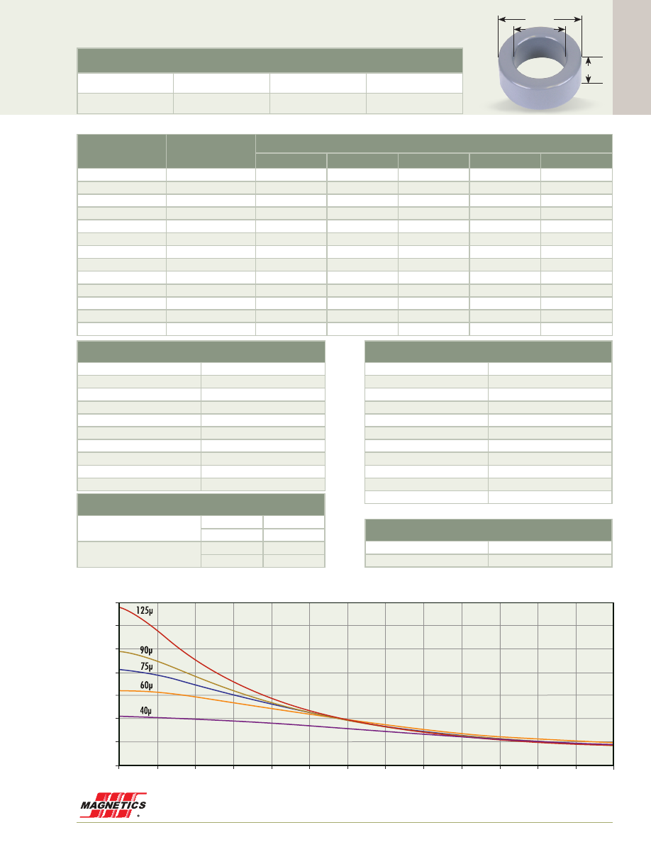
Cor
e Data
www.mag-inc.com
73
55206A2
0.250”
0.500”
0.800”
20.3 mm OD
Kool Mµ A
L
vs. DC Bias
A
L
(nH/
T )
2
A·T
0
50
70
60
50
40
30
20
10
0
350
100
150
200
400
450
500
300
250
600
650
550
125 perm
90
75
60
40
26
125µ
90µ
75µ
60µ
40µ
26µ
Before Finish (nominal)
20.3 mm/0.800 in
12.7 mm/0.500 in
6.35mm/0.250 in
After Finish (limits)
21.1 mm/0.830 in
12.0 mm/0.475 in
7.12 mm/0.280 in
Physical Characteristics
Window Area
114 mm
2
Cross Section
22.1 mm
2
Path Length
50.9 mm
Volume
1,120 mm
3
Weight - MPP
9.4 g
Weight - High Flux
8.9 g
Weight - Kool Mµ
7.1 g
Weight -
xF
lux
7.9 g
Weight - Kool Mµ MAX
7.2 g
Area Product
2,520 mm
4
Surface Area
Unwound Core
1,200 mm²
40% Winding Factor
1,900 mm²
Permeability (µ)
A
L
± 8%
Part Number
MPP
High Flux
Kool Mµ
®
XF
lux
®
Kool Mµ
®
MAX
14
7.8
55209
58209
-
-
-
26
14
55208
58208
-
78208
79208
40
21
-
-
77847
78847
-
60
32
55848
58848
77848
78848
79848
75
41
-
-
77211
78211
-
90
49
-
-
77210
78210
-
125
68
55206
58206
77206
-
-
147
81
55205
58205
-
-
-
160
87
55204
58204
-
-
-
173
96
55200
-
-
-
-
200
109
55203
-
-
-
-
300
163
55201
-
-
-
-
550
320
55202
-
-
-
-
Winding Turn Length
* Reference General Winding Data pgs. 103 - 107
Winding Factor
Length/Turn (mm)
0%
23.3
20%
26.4
25%
27.2
30%
27.8
35%
28.8
40%
29.5
45%
30.5
50%
31.3
60%
33.2
70%
35.4
Wound Coil Dimensions
40% Winding Factor
OD
22.9 mm
HT
10.7 mm
Completely Full Window
Max OD
29.2 mm
Max HT
17.4 mm
Core Dimensions
OD(max) ID(min) HT(max)
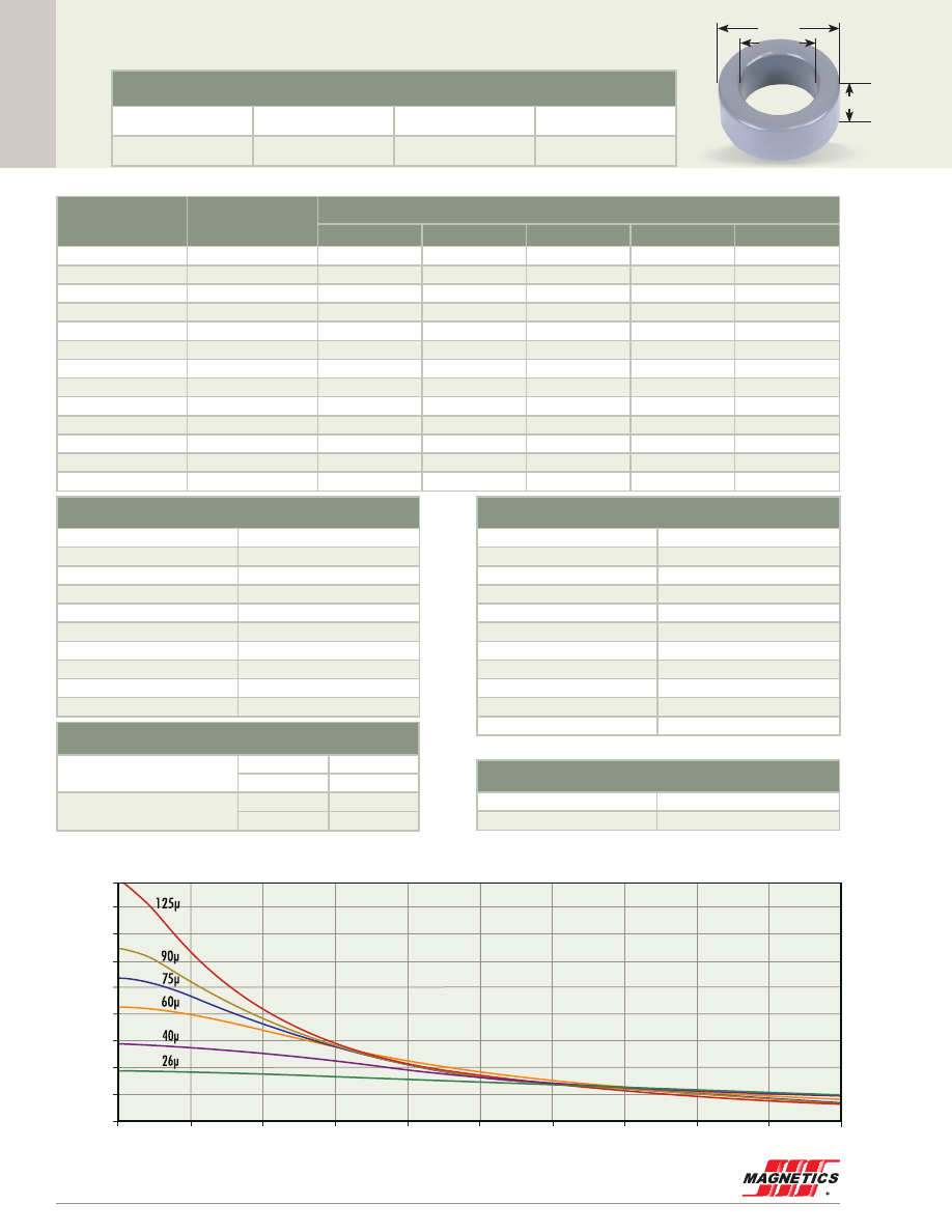
Cor
e Data
MAGNETICS
74
0.300”
55310A2
0.550”
0.900”
22.9 mm OD
Before Finish (nominal)
22.9 mm/0.900 in
14.0 mm/0.550 in
7.62 mm/0.300 in
After Finish (limits)
23.7 mm/0.930 in
13.3 mm/0.525 in
8.39 mm/0.330 in
Permeability (µ)
A
L
± 8%
Part Number
MPP
High Flux
Kool Mµ
®
XF
lux
®
Kool Mµ
®
MAX
14
9.9
55313
58313
-
-
-
26
19
55312
58312
77312
78312
79312
40
29
-
-
77316
78316
-
60
43
55059
58059
77059
78059
79059
75
54
-
-
77315
78315
-
90
65
-
-
77314
78314
-
125
90
55310
58310
77310
-
-
147
106
55309
58309
-
-
-
160
115
55308
58308
-
-
-
173
124
55304
-
-
-
-
200
144
55307
-
-
-
-
300
216
55305
-
-
-
-
550
396
55306
-
-
-
-
Physical Characteristics
Window Area
139 mm
2
Cross Section
31.7 mm
2
Path Length
56.7 mm
Volume
1,800 mm
3
Weight - MPP
16 g
Weight - High Flux
15 g
Weight - Kool Mµ
12 g
Weight -
xF
lux
13 g
Weight - Kool Mµ MAX
12 g
Area Product
4,430 mm
4
Surface Area
Unwound Core
1,600 mm
2
40% Winding Factor
2,400 mm
2
Kool Mµ A
L
vs. DC Bias
A
L
(nH/
T )
2
A·T
0
100
90
80
70
60
50
40
30
20
10
0
200
500
300
600
700
400
1000
900
800
125 perm
90
75
60
40
26
125µ
90µ
75µ
60µ
40µ
26µ
Winding Turn Length
* Reference General Winding Data pgs. 103 - 107
Winding Factor
Length/Turn (mm)
0%
27.0
20%
30.5
25%
31.3
30%
32.0
35%
33.1
40%
33.9
45%
34.9
50%
35.9
60%
38.0
70%
40.4
Wound Coil Dimensions
40% Winding Factor
OD
25.7 mm
HT
12.4 mm
Completely Full Window
Max OD
32.6 mm
Max HT
19.8 mm
Core Dimensions
OD(max) ID(min) HT(max)
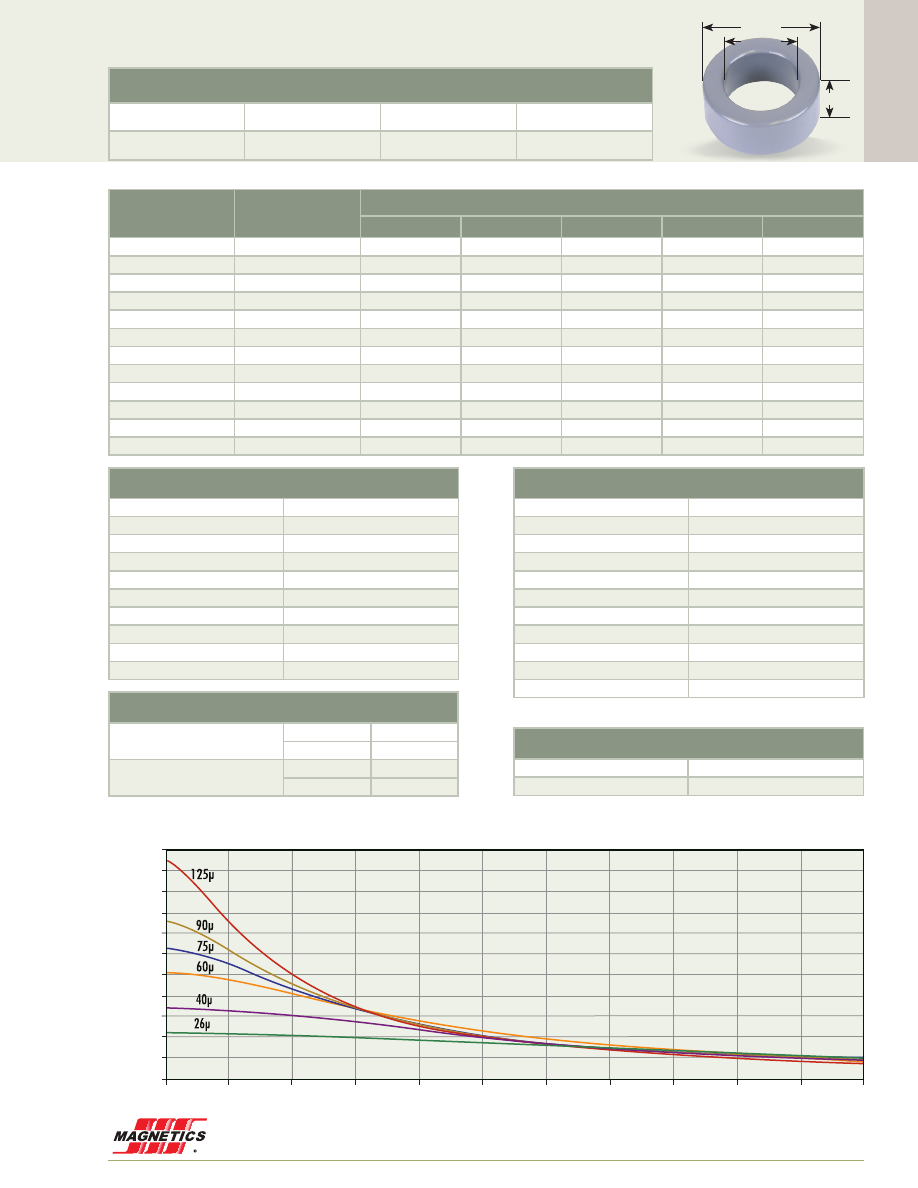
Cor
e Data
www.mag-inc.com
75
55350A2
0.350”
0.567”
0.928”
23.6 mm OD
Kool Mµ A
L
vs. DC Bias
A
L
(nH/
T )
2
A·T
0
100
110
100
90
80
70
60
50
40
30
20
10
0
600
200
300
700
800
900
500
400
1000
1100
125 perm
90
75
60
40
26
125µ
90µ
75µ
60µ
40µ
26µ
Before Finish (nominal)
23.6 mm/0.928 in
14.4 mm/0.567 in
8.89 mm/0.350 in
After Finish (limits)
24.4 mm/0.958 in
13.7 mm/0.542 in
9.66 mm/0.380 in
Permeability (µ)
A
L
± 8%
Part Number
MPP
High Flux
Kool Mµ
®
XF
lux
®
Kool Mµ
®
MAX
14
12
55353
58353
-
-
-
26
22
55352
58352
77352
78352
79352
40
34
-
-
77356
78356
-
60
51
55351
58351
77351
78351
79351
75
62
-
-
77355
78355
-
90
76
-
-
77354
78354
-
125
105
55350
58350
77350
-
-
147
124
55349
58349
-
-
-
160
135
55348
58348
-
-
-
173
146
55344
-
-
-
-
200
169
55347
-
-
-
-
300
253
55345
-
-
-
-
Physical Characteristics
Window Area
149 mm
2
Cross Section
38.8 mm
2
Path Length
58.8 mm
Volume
2,280 mm
3
Weight - MPP
20 g
Weight - High Flux
19 g
Weight - Kool Mµ
14 g
Weight -
xF
lux
16 g
Weight - Kool Mµ MAX
14 g
Area Product
5,770 mm
4
Surface Area
Unwound Core
1,800 mm
2
40% Winding Factor
2,700 mm
2
Winding Turn Length
* Reference General Winding Data pgs. 103 - 107
Winding Factor
Length/Turn (mm)
0%
29.8
20%
33.4
25%
34.2
30%
35.0
35%
36.1
40%
36.9
45%
38.0
50%
38.9
60%
41.1
70%
43.6
Wound Coil Dimensions
40% Winding Factor
OD
26.7 mm
HT
14.2 mm
Completely Full Window
Max OD
33.5 mm
Max HT
21.4 mm
Core Dimensions
OD(max) ID(min) HT(max)

Cor
e Data
MAGNETICS
76
55930A2
0.440”
0.580”
1.060”
26.9 mm OD
Before Finish (nominal)
26.90 mm/1.060 in
14.7 mm/0.580 in
11.2 mm/0.440 in
After Finish (limits)
27.69 mm/1.090 in
14.1 mm/0.555 in
12.0 mm/0.470 in
Permeability (µ)
A
L
± 8%
Part Number
MPP
High Flux
Kool Mµ
®
XF
lux
®
Kool Mµ
®
MAX
14
18
55933
58933
-
-
-
26
32
55932
58932
77932
78932
79932
40
50
-
-
77936
78936
-
60
75
55894
58894
77894
78894
79894
75
94
-
-
77935
78935
-
90
113
-
-
77934
78934
-
125
157
55930
58930
77930
-
-
147
185
55929
58929
-
-
-
160
201
55928
58928
-
-
-
173
217
55924
-
-
-
-
200
251
55927
-
-
-
-
300
377
55925
-
-
-
-
550
740
55926
-
-
-
-
Physical Characteristics
Window Area
156 mm
2
Cross Section
65.4 mm
2
Path Length
63.5 mm
Volume
4,150 mm
3
Weight - MPP
36 g
Weight - High Flux
34 g
Weight - Kool Mµ
26 g
Weight -
xF
lux
29 g
Weight - Kool Mµ MAX
26 g
Area Product
10,200 mm
4
Surface Area
Unwound Core
2,400 mm
2
40% Winding Factor
3,500 mm
2
Kool Mµ A
L
vs. DC Bias
A
L
(nH/
T )
2
A·T
0
100
160
150
140
130
120
110
100
90
80
70
60
50
40
30
20
10
0
600
200
300
700
800
900
500
400
1000
1100
1200
125 perm
90
75
60
40
26
125µ
90µ
75µ
60µ
40µ
26µ
Winding Turn Length
* Reference General Winding Data pgs. 103 - 107
Winding Factor
Length/Turn (mm)
0%
37.5
20%
41.1
25%
41.9
30%
42.8
35%
43.8
40%
44.6
45%
45.7
50%
46.6
60%
48.8
70%
51.3
Wound Coil Dimensions
40% Winding Factor
OD
30.0 mm
HT
16.5 mm
Completely Full Window
Max OD
37.3 mm
Max HT
24.0 mm
Core Dimensions
OD(max) ID(min) HT(max)

Cor
e Data
www.mag-inc.com
77
55548A2
0.420”
0.791”
1.291”
32.8 mm OD
Kool Mµ A
L
vs. DC Bias
A
L
(nH/
T )
2
A·T
0
150
140
130
120
110
100
90
80
70
60
50
40
30
20
10
0
300
750
450
900
1050
600
1500
1350
1200
125 perm
90
75
60
40
26
125µ
90µ
75µ
60µ
40µ
26µ
Before Finish (nominal)
32.8 mm/1.291 in
20.1 mm/0.791 in
10.7 mm/0.420 in
After Finish (limits)
33.66 mm/1.325 in
19.4 mm/0.766 in
11.5 mm/0.450 in
Permeability (µ)
A
L
± 8%
Part Number
MPP
High Flux
Kool Mµ
®
XF
lux
®
Kool Mµ
®
MAX
14
14
55551
58551
-
-
-
26
28
55550
58550
77550
78550
79550
40
41
-
-
77555
78555
-
60
61
55071
58071
77071
78071
79071
75
76
-
-
77553
78553
-
90
91
-
-
77552
78552
-
125
127
55548
58548
77548
-
-
147
150
55547
58547
-
-
-
160
163
55546
58546
-
-
-
173
176
55542
-
-
-
-
200
203
55545
-
-
-
-
300
305
55543
-
-
-
-
550
559
55544
-
-
-
-
Physical Characteristics
Window Area
297 mm
2
Cross Section
65.6 mm
2
Path Length
81.4 mm
Volume
5,340 mm
3
Weight - MPP
47 g
Weight - High Flux
44 g
Weight - Kool Mµ
34 g
Weight -
xF
lux
38 g
Weight - Kool Mµ MAX
34 g
Area Product
19,500 mm
4
Surface Area
Unwound Core
3,100 mm
2
40% Winding Factor
4,900 mm
2
Winding Turn Length
* Reference General Winding Data pgs. 103 - 107
Winding Factor
Length/Turn (mm)
0%
37.4
20%
42.4
25%
43.5
30%
44.7
35%
46.1
40%
47.2
45%
48.8
50%
50.1
60%
53.2
70%
56.7
Wound Coil Dimensions
40% Winding Factor
OD
36.8 mm
HT
17.8 mm
Completely Full Window
Max OD
46.7 mm
Max HT
28.0 mm
Core Dimensions
OD(max) ID(min) HT(max)
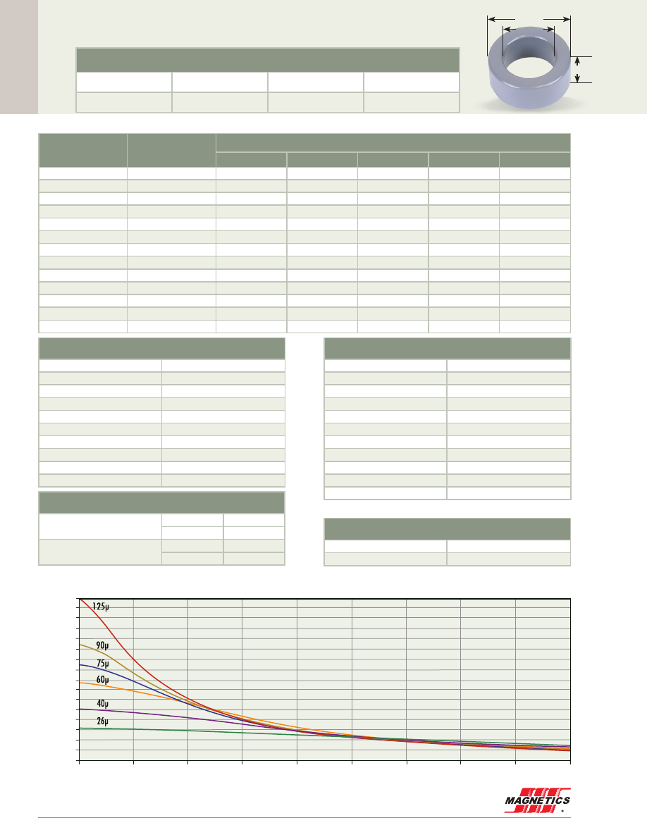
Cor
e Data
MAGNETICS
78
55585A2
0.350”
0.920”
1.350”
34.3 mm OD
Before Finish (nominal)
34.30 mm/1.350 in
23.4 mm/0.920 in
8.89 mm/0.350 in
After Finish (limits)
35.18 mm/1.385 in
22.5 mm/0.888 in
9.78 mm/0.385 in
Permeability (µ)
A
L
± 8%
Part Number
MPP
High Flux
Kool Mµ
®
XF
lux
®
Kool Mµ
®
MAX
14
9
55588
58588
-
-
-
26
16
55587
58587
77587
78587
79587
40
25
-
-
77591
78591
-
60
38
55586
58586
77586
78586
79586
75
47
-
-
77590
78590
-
90
57
-
-
77589
78589
-
125
79
55585
58585
77585
-
-
147
93
55584
58584
-
-
-
160
101
55583
58583
-
-
-
173
109
55579
-
-
-
-
200
126
55582
-
-
-
-
300
190
55580
-
-
-
-
550
348
55581
-
-
-
-
Physical Characteristics
Window Area
399 mm
2
Cross Section
46.4 mm
2
Path Length
89.5 mm
Volume
4,150 mm
3
Weight - MPP
35 g
Weight - High Flux
33 g
Weight - Kool Mµ
25 g
Weight -
xF
lux
29 g
Weight - Kool Mµ MAX
26 g
Area Product
18,500 mm
4
Surface Area
Unwound Core
2,900 mm
2
40% Winding Factor
5,500 mm
2
Kool Mµ A
L
vs. DC Bias
A
L
(nH/
T )
2
A·T
0
200
80
75
70
65
60
55
50
45
40
35
30
25
20
15
10
5
0
400
1000
600
1200
1400
800
1800
1600
125 perm
90
75
60
40
26
125µ
90µ
75µ
60µ
40µ
26µ
Winding Turn Length
* Reference General Winding Data pgs. 103 - 107
Winding Factor
Length/Turn (mm)
0%
32.2
20%
38.1
25%
39.6
30%
40.6
35%
42.5
40%
44.0
45%
45.6
50%
47.3
60%
50.8
70%
54.9
Wound Coil Dimensions
40% Winding Factor
OD
40.5 mm
HT
16.8 mm
Completely Full Window
Max OD
50.1 mm
Max HT
29.0 mm
Core Dimensions
OD(max) ID(min) HT(max)
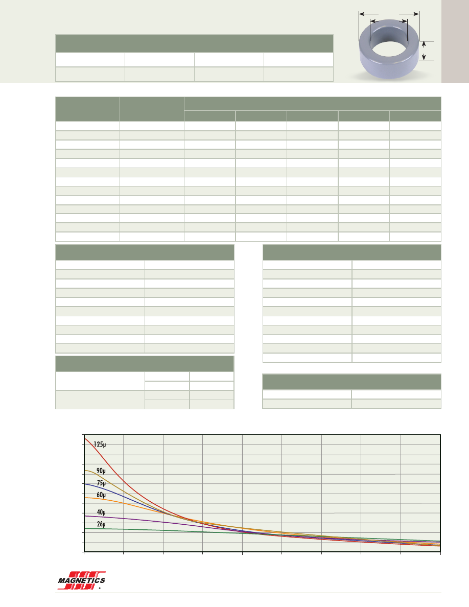
Cor
e Data
www.mag-inc.com
79
55324A2
0.412”
0.880”
1.410”
35.8 mm OD
Kool Mµ A
L
vs. DC Bias
A
L
(nH/
T )
2
A·T
0
200
120
110
100
90
80
70
60
50
40
30
20
10
0
400
1000
600
1200
1400
800
1800
1600
125 perm
90
75
60
40
26
125µ
90µ
75µ
60µ
40µ
26µ
Before Finish (nominal)
35.80 mm/1.410 in
22.4 mm/0.880 in
10.5 mm/0.412 in
After Finish (limits)
36.71 mm/1.445 in
21.5 mm/0.848 in
11.4 mm/0.447 in
Permeability (µ)
A
L
± 8%
Part Number
MPP
High Flux
Kool Mµ
®
XF
lux
®
Kool Mµ
®
MAX
14
13
55327
58327
-
-
-
26
24
55326
58326
77326
78326
79326
40
37
-
-
77330
78330
-
60
56
55076
58076
77076
78076
79076
75
70
-
-
77329
78329
-
90
84
-
-
77328
78328
-
125
117
55324
58324
77324
-
-
147
138
55323
58323
-
-
-
160
150
55322
58322
-
-
-
173
162
55318
-
-
-
-
200
187
55321
-
-
-
-
300
281
55319
-
-
-
-
550
515
55320
-
-
-
-
Physical Characteristics
Window Area
364 mm
2
Cross Section
67.8 mm
2
Path Length
89.8 mm
Volume
6,090 mm
3
Weight - MPP
52 g
Weight - High Flux
49 g
Weight - Kool Mµ
37 g
Weight -
xF
lux
43 g
Weight - Kool Mµ MAX
38 g
Area Product
24,700 mm
4
Surface Area
Unwound Core
3,400 mm
2
40% Winding Factor
5,700 mm
2
Winding Turn Length
* Reference General Winding Data pgs. 103 - 107
Winding Factor
Length/Turn (mm)
0%
37.9
20%
43.5
25%
44.8
30%
46.0
35%
47.6
40%
48.9
45%
50.6
50%
52.0
60%
55.5
70%
59.3
Wound Coil Dimensions
40% Winding Factor
OD
40.2 mm
HT
18.4 mm
Completely Full Window
Max OD
51.1 mm
Max HT
29.6 mm
Core Dimensions
OD(max) ID(min) HT(max)
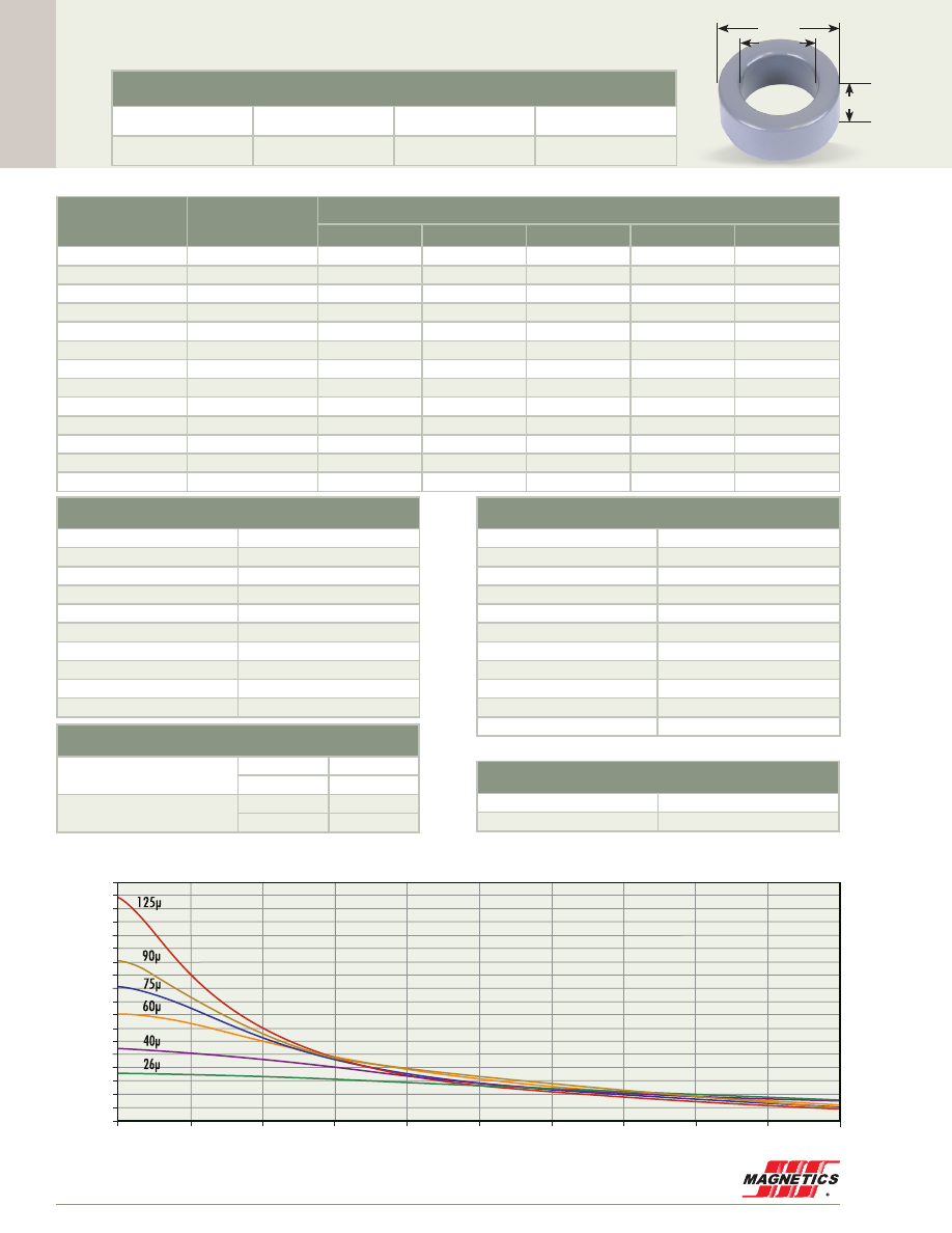
Cor
e Data
MAGNETICS
80
55254A2
0.570”
0.950”
1.570”
39.9 mm OD
Before Finish (nominal)
39.90 mm/1.570 in
24.1 mm/0.950 in
14.5 mm/0.570 in
After Finish (limits)
40.77 mm/1.605 in
23.3 mm/0.918 in
15.4 mm/0.605 in
Permeability (µ)
A
L
± 8%
Part Number
MPP
High Flux
Kool Mµ
®
XF
lux
®
Kool Mµ
®
MAX
14
19
55257
58257
-
-
-
26
35
55256
58256
77256
78256
79256
40
54
-
-
77260
78260
-
60
81
55083
58083
77083
78083
79083
75
101
-
-
77259
78259
-
90
121
-
-
77258
78258
-
125
168
55254
58254
77254
-
-
147
198
55253
58253
-
-
-
160
215
55252
58252
-
-
-
173
233
55248
-
-
-
-
200
269
55251
-
-
-
-
300
403
55249
-
-
-
-
550
740
55250
-
-
-
-
Physical Characteristics
Window Area
427 mm
2
Cross Section
107 mm
2
Path Length
98.4 mm
Volume
10,600 mm
3
Weight - MPP
92 g
Weight - High Flux
87 g
Weight - Kool Mµ
65 g
Weight -
xF
lux
78 g
Weight - Kool Mµ MAX
65 g
Area Product
45,800 mm
4
Surface Area
Unwound Core
4,800 mm
2
40% Winding Factor
7,300 mm
2
Kool Mµ A
L
vs. DC Bias
A
L
(nH/
T )
2
A·T
0
200
180
170
160
150
140
130
120
110
100
90
80
70
60
50
40
30
20
10
0
400
1000
600
1200
1400
800
1800
2000
1600
125 perm
90
75
60
40
26
125µ
90µ
75µ
60µ
40µ
26µ
Winding Turn Length
* Reference General Winding Data pgs. 103 - 107
Winding Factor
Length/Turn (mm)
0%
48.2
20%
54.3
25%
55.8
30%
57.0
35%
58.8
40%
60.2
45%
62.1
50%
63.7
60%
67.3
70%
71.5
Wound Coil Dimensions
40% Winding Factor
OD
44.3 mm
HT
22.4 mm
Completely Full Window
Max OD
56.4 mm
Max HT
35.2 mm
Core Dimensions
OD(max) ID(min) HT(max)

Cor
e Data
www.mag-inc.com
81
55089A2
0.600”
1.130”
1.840”
46.7 mm OD
Before Finish (nominal)
46.70 mm/1.840 in
28.70 mm/1.130 in
15.2 mm/0.600 in
After Finish (limits)
47.63 mm/1.875 in
27.88 mm/1.098 in
16.2 mm/0.635 in
Permeability (µ)
A
L
± 8%
Part Number
MPP
High Flux
Kool Mµ
®
XF
lux
®
Kool Mµ
®
MAX
14
20
55092
58092
-
-
-
26
37
55091
58091
77091
78091
79091
40
57
-
-
77095
78095
-
60
86
55090
58090
77090
78090
79090
75
107
-
-
77094
78094
-
90
128
-
-
77093
78093
-
125
178
55089
58089
77089
-
-
147
210
55088
-
-
-
-
160
228
55087
-
-
-
-
173
246
55082
-
-
-
-
200
285
55086
-
-
-
-
300
427
55084
-
-
-
-
Physical Characteristics
Window Area
610 mm
2
Cross Section
134 mm
2
Path Length
116 mm
Volume
15,600 mm
3
Weight - MPP
130 g
Weight - High Flux
120 g
Weight - Kool Mµ
96 g
Weight -
xF
lux
110 g
Weight - Kool Mµ MAX
100 g
Area Product
81,800 mm
4
Surface Area
Unwound Core
6,100 mm
2
40% Winding Factor
9,800 mm
2
Kool Mµ A
L
vs. DC Bias
A
L
(nH/
T )
2
A·T
0
200
180
170
160
150
140
130
120
110
100
90
80
70
60
50
40
30
20
10
0
400
1000
600
1200
1400
800
1800
1600
125 perm
90
75
60
40
26
125µ
90µ
75µ
60µ
40µ
26µ
Winding Turn Length
* Reference General Winding Data pgs. 103 - 107
Winding Factor
Length/Turn (mm)
0%
52.0
20%
59.1
25%
61.0
30%
62.2
35%
64.5
40%
66.4
45%
68.2
50%
70.4
60%
74.7
70%
79.5
Wound Coil Dimensions
40% Winding Factor
OD
52.0 mm
HT
24.9 mm
Completely Full Window
Max OD
66.3 mm
Max HT
39.8 mm
Core Dimensions
OD(max) ID(min) HT(max)
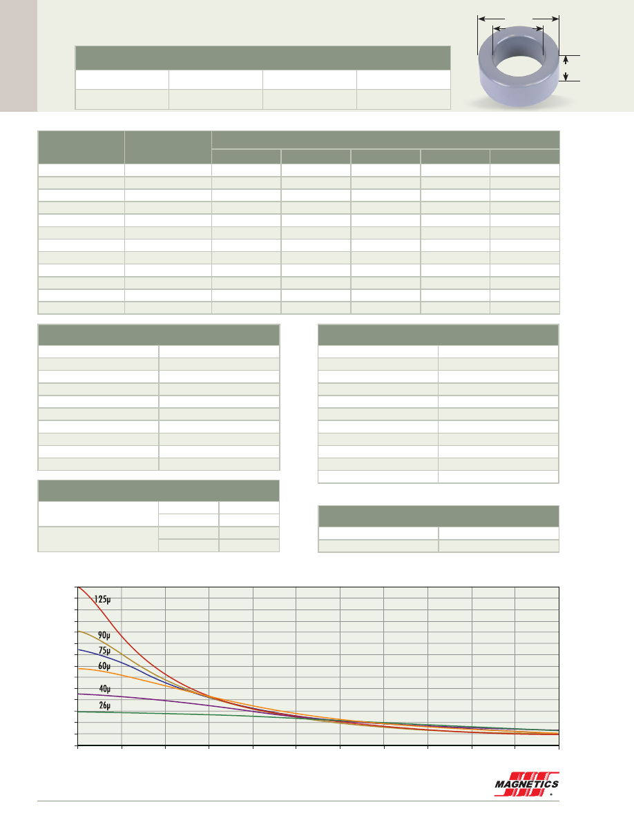
Cor
e Data
MAGNETICS
82
55438A2
0.710”
0.950”
1.840”
46.7 mm OD
Kool Mµ A
L
vs. DC Bias
A
L
(nH/
T )
2
A·T
0
200
280
260
240
220
200
180
160
140
120
100
80
60
40
20
0
1200
400
600
1400
1600
1800
1000
800
2000
2200
125 perm
90
75
60
40
26
125µ
90µ
75µ
60µ
40µ
26µ
Before Finish (nominal)
46.70 mm/1.840 in
24.1 mm/0.950 in
18.0 mm/0.710 in
After Finish (limits)
47.63 mm/1.875 in
23.3 mm/0.918 in
19.0 mm/0.745 in
Permeability (µ)
A
L
± 8%
Part Number
MPP
High Flux
Kool Mµ
®
XF
lux
®
Kool Mµ
®
MAX
14
32
55441
58441
-
-
-
26
59
55440
58440
77440
78440
79440
40
90
-
-
77431
78431
-
60
135
55439
58439
77439
78439
79439
75
169
-
-
77443
78443
-
90
202
-
-
77442
78442
-
125
281
55438
58438
77438
-
-
147
330
55437
58437
-
-
-
160
360
55436
-
-
-
-
173
390
55432
-
-
-
-
200
450
55435
-
-
-
-
300
674
55433
-
-
-
-
Physical Characteristics
Window Area
427 mm
2
Cross Section
199 mm
2
Path Length
107 mm
Volume
21,300 mm
3
Weight - MPP
180 g
Weight - High Flux
170 g
Weight - Kool Mµ
130 g
Weight -
xF
lux
150 g
Weight - Kool Mµ MAX
130 g
Area Product
85,900 mm
4
Surface Area
Unwound Core
6,900 mm
2
40% Winding Factor
9,600 mm
2
Winding Turn Length
* Reference General Winding Data pgs. 103 - 107
Winding Factor
Length/Turn (mm)
0%
62.1
20%
68.2
25%
69.7
30%
70.9
35%
72.7
40%
74.1
45%
76.0
50%
77.6
60%
81.2
70%
85.4
Wound Coil Dimensions
40% Winding Factor
OD
51.2 mm
HT
26.0 mm
Completely Full Window
Max OD
63.8 mm
Max HT
38.7 mm
Core Dimensions
OD(max) ID(min) HT(max)
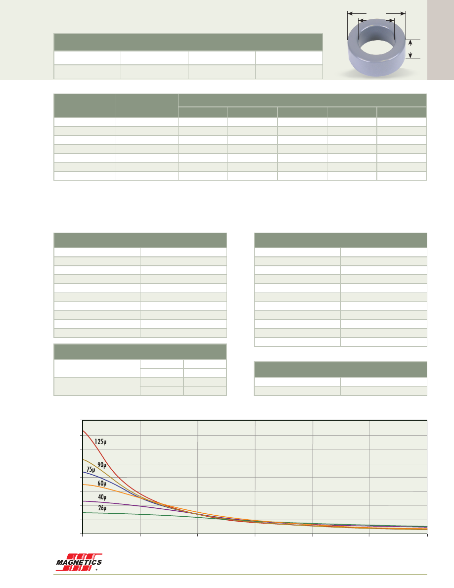
Cor
e Data
www.mag-inc.com
83
55725A2
0.830”
0.980”
1.990”
50.5 mm OD
Kool Mµ A
L
vs. DC Bias
A
L
(nH/
T )
2
A·T
0
500
1000
1500
2000
2500
3000
400
350
300
250
200
150
100
50
0
125 perm
90
75
60
40
26
125µ
90µ
75µ
60µ
40µ
26µ
Before Finish (nominal)
50.55 mm/1.990 in
24.89 mm/0.980 in
21.08 mm/0.830 in
After Finish (limits)
51.31 mm/2.020 in
23.88 mm/0.940 in
21.59 mm/0.850 in
Permeability (µ)
A
L
± 8%
Part Number
MPP
High Flux
Kool Mµ
®
XF
lux
®
Kool Mµ
®
MAX
14
41
55728
58728
-
-
-
26
76
55727
58727
77727
78727
79727
40
117
-
-
77733
78733
-
60
175
55726
58726
77726
78726
79726
75
219
-
-
77729
78729
-
90
263
-
-
77730
78730
-
125
366
55725
58725
77725
-
-
Physical Characteristics
Window Area
452 mm
2
Cross Section
262 mm
2
Path Length
1,135 mm
Volume
29,700 mm
3
Weight - MPP
250 g
Weight - High Flux
230 g
Weight - Kool Mµ
185 g
Weight -
xF
lux
210 g
Weight - Kool Mµ MAX
200 g
Area Product
118,000 mm
4
Surface Area
Unwound Core
23,310 mm
2
40% Winding Factor
33,600 mm
2
Winding Turn Length
* Reference General Winding Data pgs. 103 - 107
Winding Factor
Length/Turn (mm)
0%
131
20%
137
25%
138
30%
140
35%
142
40%
143
45%
145
50%
147
60%
150
70%
155
Wound Coil Dimensions
40% Winding Factor
OD
64.0 mm
HT
39.6 mm
Completely Full Window
Max OD
72.0 mm
Max HT
42.0 mm
Core Dimensions
OD(max) ID(min) HT(max)

Cor
e Data
MAGNETICS
84
55715A2
50.8 mm OD
0.530”
1.250”
2.000”
Kool Mµ A
L
vs. DC Bias
A
L
(nH/
T )
2
A·T
0
200
160
150
140
130
120
110
100
90
80
70
60
50
40
30
20
10
0
1200
400
600
1400
1600
1800
1000
800
2000
125 perm
90
75
60
40
26
125µ
90µ
75µ
60µ
40µ
26µ
Before Finish (nominal)
50.80 mm/2.000 in
31.80 mm/1.250 in
13.5 mm/0.530 in
After Finish (limits)
51.69 mm/2.035 in
30.93 mm/1.218 in
14.4 mm/0.565 in
Permeability (µ)
A
L
± 8%
Part Number
MPP
High Flux
Kool Mµ
®
XF
lux
®
Kool Mµ
®
MAX
14
17
55718
58718
-
-
-
26
32
55717
58717
77717
78717
79717
40
49
-
-
77721
78721
-
60
73
55716
58716
77716
78716
79716
75
91
-
-
77720
78720
-
90
109
-
-
77719
78719
-
125
152
55715
58715
77715
-
-
147
179
55714
58714
-
-
-
160
195
55713
-
-
-
-
173
210
55709
-
-
-
-
200
243
55712
-
-
-
-
300
365
55710
-
-
-
-
Physical Characteristics
Window Area
751 mm
2
Cross Section
125 mm
2
Path Length
127 mm
Volume
15,900 mm
3
Weight - MPP
140 g
Weight - High Flux
130 g
Weight - Kool Mµ
98 g
Weight -
xF
lux
110 g
Weight - Kool Mµ MAX
98 g
Area Product
94,000 mm
4
Surface Area
Unwound Core
6,400 mm
2
40% Winding Factor
11,000 mm
2
Winding Turn Length
* Reference General Winding Data pgs. 103 - 107
Winding Factor
Length/Turn (mm)
0%
49.5
20%
57.4
25%
59.6
30%
61.0
35%
63.5
40%
65.5
45%
67.7
50%
70.1
60%
74.9
70%
80.3
Wound Coil Dimensions
40% Winding Factor
OD
56.6 mm
HT
24.2 mm
Completely Full Window
Max OD
72.4 mm
Max HT
40.6 mm
Core Dimensions
OD(max) ID(min) HT(max)

Cor
e Data
www.mag-inc.com
85
55109A2
57.2 mm OD
0.550”
1.400”
2.250”
Kool Mµ A
L
vs. DC Bias
A
L
(nH/
T )
2
A·T
0
200
160
150
140
130
120
110
100
90
80
70
60
50
40
30
20
10
0
1200
400
600
1400
1600
1800
2000
2200
2400
2600
1000
800
2800
125 perm
90
75
60
40
26
125µ
90µ
75µ
60µ
40µ
26µ
Before Finish (nominal)
57.20 mm/2.250 in
35.60 mm/1.400 in
14.0 mm/0.550 in
After Finish (limits)
58.04 mm/2.285 in
34.74 mm/1.368 in
14.9 mm/0.585 in
Permeability (µ)
A
L
± 8%
Part Number
MPP
High Flux
Kool Mµ
®
XF
lux
®
Kool Mµ
®
MAX
14
18
55112
58112
-
-
-
26
33
55111
58111
77111
78111
79111
40
50
-
-
77212
78212
-
60
75
55110
58110
77110
78110
79110
75
94
-
-
77214
78214
-
90
112
-
-
77213
78213
-
125
156
55109
58109
77109
-
-
147
185
55108
-
-
-
-
160
200
55107
-
-
-
-
173
218
55103
-
-
-
-
200
250
55106
-
-
-
-
300
374
55104
-
-
-
-
Physical Characteristics
Window Area
948 mm
2
Cross Section
144 mm
2
Path Length
143 mm
Volume
20,700 mm
3
Weight - MPP
180 g
Weight - High Flux
170 g
Weight - Kool Mµ
130 g
Weight -
xF
lux
150 g
Weight - Kool Mµ MAX
130 g
Area Product
137,000 mm
4
Surface Area
Unwound Core
7,700 mm
2
40% Winding Factor
13,000 mm
2
Winding Turn Length
* Reference General Winding Data pgs. 103 - 107
Winding Factor
Length/Turn (mm)
0%
53.0
20%
61.9
25%
64.3
30%
65.8
35%
68.7
40%
71.0
45%
73.2
50%
76.0
60%
81.3
70%
87.1
Wound Coil Dimensions
40% Winding Factor
OD
63.5 mm
HT
25.9 mm
Completely Full Window
Max OD
81.3 mm
Max HT
44.4 mm
Core Dimensions
OD(max) ID(min) HT(max)
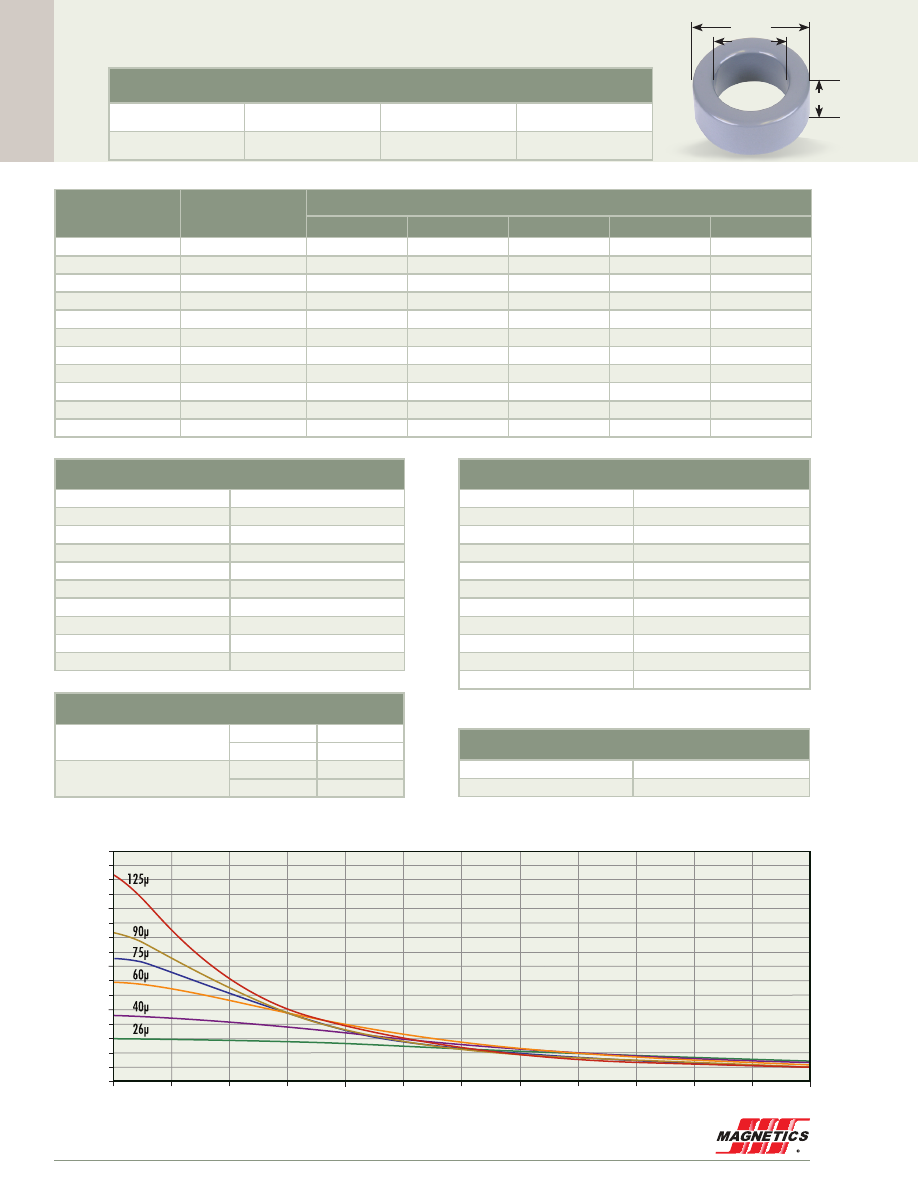
Cor
e Data
MAGNETICS
86
57.2 mm OD
55195A2
0.600”
1.039”
2.250”
Before Finish (nominal)
57.20 mm/2.250 in
26.40 mm/1.039 in
15.2 mm/0.600 in
After Finish (limits)
58.04 mm/2.285 in
25.57 mm/1.007 in
16.2 mm/0.635 in
Permeability (µ)
A
L
± 8%
Part Number
MPP
High Flux
Kool Mµ
®
XF
lux
®
Kool Mµ
®
MAX
14
32
55190
58190
-
-
-
26
60
55191
58191
77191
78191
79191
40
92
-
-
77189
78189
-
60
138
55192
58192
77192
78192
79192
75
172
-
-
77193
78193
-
90
207
-
-
77194
78194
-
125
287
55195
58195
77195
-
-
147
306
55196
-
-
-
-
160
333
55197
-
-
-
-
173
360
55198
-
-
-
-
200
417
55199
-
-
-
-
Physical Characteristics
Window Area
514 mm
2
Cross Section
229 mm
2
Path Length
125 mm
Volume
28,600 mm
3
Weight - MPP
240 g
Weight - High Flux
230 g
Weight - Kool Mµ
180 g
Weight -
xF
lux
200 g
Weight - Kool Mµ MAX
175 g
Area Product
118,000 mm
4
Surface Area
Unwound Core
8,500 mm
2
40% Winding Factor
12,000 mm
2
Kool Mµ A
L
vs. DC Bias
A
L
(nH/
T )
2
A·T
0
200
320
300
280
260
240
220
200
180
160
140
120
100
80
60
40
20
0
1200
400
600
1400
1600
1800
2000
2200
1000
800
2400
125 perm
90
75
60
40
26
125µ
90µ
75µ
60µ
40µ
26µ
Winding Turn Length
* Reference General Winding Data pgs. 103 - 107
Winding Factor
Length/Turn (mm)
0%
64.6
20%
71.2
25%
72.9
30%
74.1
35%
76.3
40%
77.8
45%
79.8
50%
81.6
60%
85.6
70%
90.1
Wound Coil Dimensions
40% Winding Factor
OD
62.0 mm
HT
24.0 mm
Completely Full Window
Max OD
75.7 mm
Max HT
34.0 mm
Core Dimensions
OD(max) ID(min) HT(max)
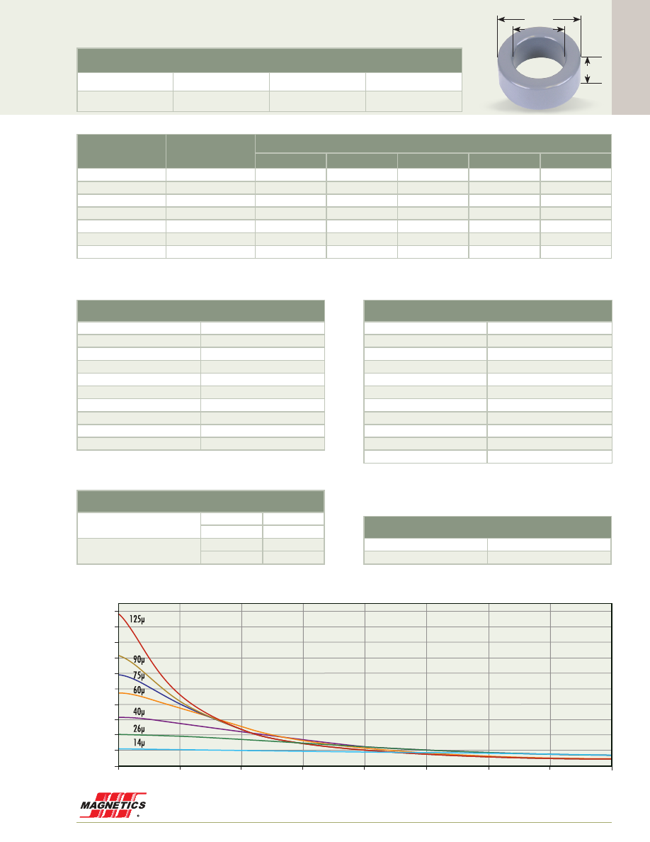
Cor
e Data
www.mag-inc.com
87
55620A2
0.984”
1.283”
2.440”
62.0 mm OD
Before Finish (nominal)
62.00 mm/2.440 in
32.60 mm/1.283 in
25.0 mm/0.984 in
After Finish (limits)
62.91 mm/2.477 in
31.69 mm/1.248 in
25.91 mm/1.020 in
Permeability (µ)
A
L
± 8%
Part Number
MPP
High Flux
Kool Mµ
®
XF
lux
®
Kool Mµ
®
MAX
14
44
55614
58614
77614
-
-
26
82
55615
58615
77615
78615
79615
40
126
-
58616
77616
78616
-
60
189
55617
58617
77617
78617
79617
75
237
-
-
77618
78618
-
90
284
-
-
77619
78619
-
125
394
55620
58620
77620
-
-
Physical Characteristics
Window Area
789 mm
2
Cross Section
360 mm
2
Path Length
144 mm
Volume
51,800 mm
3
Weight - MPP
460 g
Weight - High Flux
440 g
Weight - Kool Mµ
340 g
Weight -
xF
lux
380 g
Weight - Kool Mµ MAX
350 g
Area Product
284,000 mm
4
Surface Area
Unwound Core
12,000 mm
2
40% Winding Factor
21,000 mm
2
Winding Turn Length
* Reference General Winding Data pgs. 103 - 107
Winding Factor
Length/Turn (mm)
0%
83.0
20%
91.3
25%
93.4
30%
94.9
35%
97.5
40%
99.5
45%
102
50%
104
60%
109
70%
115
Kool Mµ A
L
vs. DC Bias
A
L
(nH/
T )
2
A·T
0
500
400
360
320
280
240
200
160
120
80
40
0
1000
1500
2000
2500
3000
3500
4000
125 perm
90
75
60
40
26
14
125µ
90µ
75µ
60µ
40µ
26µ
14µ
Wound Coil Dimensions
40% Winding Factor
OD
75.3 mm
HT
39.7 mm
Completely Full Window
Max OD
81.4 mm
Max HT
47.4 mm
Core Dimensions
OD(max) ID(min) HT(max)

Cor
e Data
MAGNETICS
88
55070A2
0.787”
1.417”
2.677”
68.0 mm OD
Kool Mµ A
L
vs. DC Bias
A
L
(nH/
T )
2
A·T
0
500
1000
1500
2000
2500
3000
4500
4000
3500
350
300
250
200
150
100
50
0
125 perm
90
75
60
40
26
14
125µ
90µ
75µ
60µ
40µ
26µ
14µ
Before Finish (nominal)
68.00 mm/2.677 in
35.99 mm/1.417 in
19.99 mm/0.787 in
After Finish (limits)
69.42 mm/2.733 in
34.67 mm/1.365 in
21.41 mm/0.843 in
Permeability (µ)
A
L
± 8%
Part Number
MPP
High Flux
Kool Mµ
®
XF
lux
®
Kool Mµ
®
MAX
14
35
55075
58075
77075
-
-
26
65
55074
58074
77074
78074
79074
40
100
-
58073
77073
78073
-
60
143
55072
58072
77072
78072
79072
75
187
-
-
77069
78069
-
90
225
-
-
77068
78068
-
125
312
55070
58070
77070
-
-
Physical Characteristics
Window Area
945 mm
2
Cross Section
314 mm
2
Path Length
158 mm
Volume
49,700 mm
3
Weight - MPP
440 g
Weight - High Flux
420 g
Weight - Kool Mµ
320 g
Weight -
xF
lux
360 g
Weight - Kool Mµ MAX
360 g
Area Product
297,000 mm
4
Surface Area
Unwound Core
12,700 mm
2
40% Winding Factor
18,400 mm
2
Winding Turn Length
* Reference General Winding Data pgs. 103 - 107
Winding Factor
Length/Turn (mm)
0%
77.7
20%
86.6
25%
89.0
30%
90.5
35%
93.4
40%
95.7
45%
97.9
50%
100.1
60%
106.0
70%
112.0
Wound Coil Dimensions
40% Winding Factor
OD
79.3 mm
HT
37.2 mm
Completely Full Window
Max OD
89.2 mm
Max HT
45.4 mm
Core Dimensions
OD(max) ID(min) HT(max)
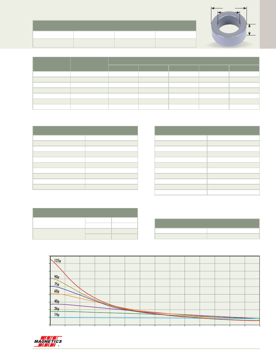
Cor
e Data
www.mag-inc.com
89
55740A2
1.378”
1.783”
2.917”
74.1 mm OD
Kool Mµ A
L
vs. DC Bias
A
L
(nH/
T )
2
A·T
0
250
500
750
1000
1250
1500
1750
2000
2250
2500
2750
3000
3250
3500
450
400
350
300
250
200
150
100
50
0
125 perm
90
75
60
40
26
14
125µ
90µ
75µ
60µ
40µ
26µ
14µ
Before Finish (nominal)
74.10 mm/2.917 in
45.30 mm/1.783 in
35.00 mm/1.378 in
After Finish (limits)
75.01 mm/2.953 in
44.39 mm/1.748 in
35.92 mm/1.414 in
Permeability (µ)
A
L
± 8%
Part Number
MPP
High Flux
Kool Mµ
®
XF
lux
®
Kool Mµ
®
MAX
14
48
55734
58734
77734
-
-
26
88
55735
58735
77735
78735
79735
40
136
-
58736
77736
78736
-
60
204
55737
58737
77737
78737
79737
75
255
-
-
77738
78738
-
90
306
-
-
77739
78739
-
125
425
55740
-
77740
-
-
Physical Characteristics
Window Area
1,550 mm
2
Cross Section
497 mm
2
Path Length
184 mm
Volume
91,400 mm
3
Weight - MPP
790 g
Weight - High Flux
750 g
Weight - Kool Mµ
570 g
Weight -
xF
lux
660 g
Weight - Kool Mµ MAX
580 g
Area Product
769,000 mm
4
Surface Area
Unwound Core
19,000 mm
2
40% Winding Factor
33,000 mm
2
Winding Turn Length
* Reference General Winding Data pgs. 103 - 107
Winding Factor
Length/Turn (mm)
0%
102
20%
114
25%
117
30%
119
35%
122
40%
125
45%
129
50%
132
60%
139
70%
147
Wound Coil Dimensions
40% Winding Factor
OD
91.0 mm
HT
55.2 mm
Completely Full Window
Max OD
102 mm
Max HT
65.7 mm
Core Dimensions
OD(max) ID(min) HT(max)
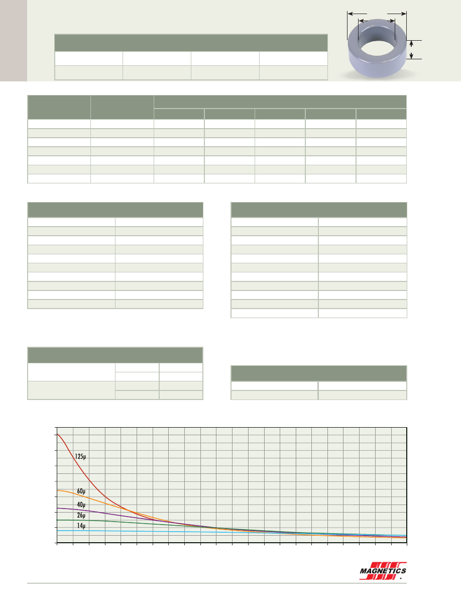
Cor
e Data
MAGNETICS
90
0.500”
1.938”
3.063”
77.8 mm OD
Kool Mµ A
L
vs. DC Bias
A
L
(nH/
T )
2
A·T
0
250
500
750 1000 1250 1500 1750 2000 2250 2500 2750 3000 3250 3500 3750 4000 4250 4500 4750 5000 5250 5500
140
120
100
80
60
40
20
0
125 perm
90
75
60
40
26
14
125µ
90µ
75µ
60µ
40µ
26µ
14µ
Before Finish (nominal)
77.80 mm/3.063 in
49.20 mm/1.938 in
12.7 mm/0.500 in
After Finish (limits)
78.95 mm/3.108 in
48.20 mm/1.898 in
13.9 mm/0.545 in
55866A2
Permeability (µ)
A
L
± 8%
Part Number
MPP
High Flux
Kool Mµ
®
XF
lux
®
Kool Mµ
®
MAX
14
16
55869
58869
77869
-
-
26
30
55868
58868
77868
78868
79868
40
45
-
-
77872
78872
-
60
68
55867
58867
77867
78867
79867
75
85
-
-
-
78871
-
90
102
-
-
-
78870
-
125
142
55866
58866
77866
-
-
Physical Characteristics
Window Area
1,820 mm
2
Cross Section
176 mm
2
Path Length
196 mm
Volume
34,500 mm
3
Weight - MPP
290 g
Weight - High Flux
270 g
Weight - Kool Mµ
210 g
Weight -
xF
lux
240 g
Weight - Kool Mµ MAX
210 g
Area Product
321,000 mm
4
Surface Area
Unwound Core
11,000 mm
2
40% Winding Factor
23,000 mm
2
Winding Turn Length
* Reference General Winding Data pgs. 103 - 107
Winding Factor
Length/Turn (mm)
0%
58.4
20%
70.9
25%
74.1
30%
76.3
35%
80.4
40%
83.5
45%
86.7
50%
90.4
60%
98.1
70%
107
Wound Coil Dimensions
40% Winding Factor
OD
86.6 mm
HT
29.1 mm
Completely Full Window
Max OD
112 mm
Max HT
54.3 mm
Core Dimensions
OD(max) ID(min) HT(max)
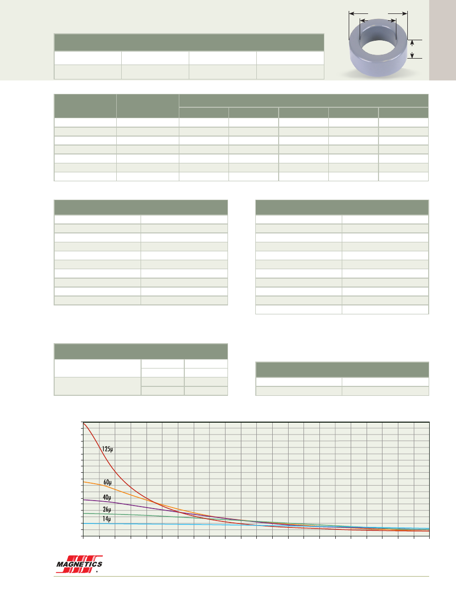
Cor
e Data
www.mag-inc.com
91
0.625”
55906A2
1.938”
3.063”
77.8 mm OD
Before Finish (nominal)
77.80 mm/3.063 in
49.20 mm/1.938 in
15.9 mm/0.625 in
After Finish (limits)
78.95 mm/3.108 in
48.20 mm/1.898 in
17.1 mm/0.670 in
Permeability (µ)
A
L
± 8%
Part Number
MPP
High Flux
Kool Mµ
®
XF
lux
®
Kool Mµ
®
MAX
14
20
55909
58909
77909
-
-
26
37
55908
58908
77908
78908
79908
40
57
-
-
77912
78912
-
60
85
55907
58907
77907
78907
79907
75
106
-
-
-
78911
-
90
128
-
-
-
78910
-
125
177
55906
58906
77906
-
-
Physical Characteristics
Window Area
1,820 mm
2
Cross Section
221 mm
2
Path Length
196 mm
Volume
43,400 mm
3
Weight - MPP
380 g
Weight - High Flux
360 g
Weight - Kool Mµ
280 g
Weight -
xF
lux
320 g
Weight - Kool Mµ MAX
280 g
Area Product
403,000 mm
4
Surface Area
Unwound Core
13,000 mm
2
40% Winding Factor
24,000 mm
2
Winding Turn Length
* Reference General Winding Data pgs. 103 - 107
Winding Factor
Length/Turn (mm)
0%
64.7
20%
77.2
25%
80.5
30%
82.7
35%
86.8
40%
89.9
45%
93.1
50%
96.8
60%
104
70%
113
Kool Mµ A
L
vs. DC Bias
A
L
(nH/
T )
2
A·T
0
250
500
750 1000 1250 1500 1750 2000 2250 2500 2750 3000 3250 3500 3750 4000 4250 4500 4750 5000 5250 5500
180
170
160
150
140
130
120
110
100
90
80
70
60
50
40
30
20
10
0
125 perm
90
75
60
40
26
14
125µ
90µ
75µ
60µ
40µ
26µ
14µ
Wound Coil Dimensions
40% Winding Factor
OD
86.6 mm
HT
32.3 mm
Completely Full Window
Max OD
113 mm
Max HT
57.7 mm
Core Dimensions
OD(max) ID(min) HT(max)
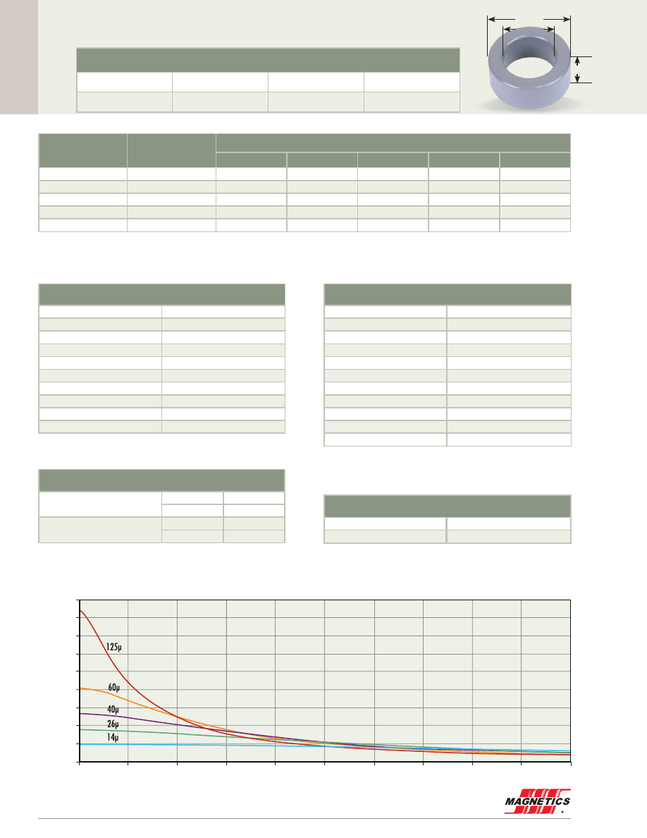
Cor
e Data
MAGNETICS
92
55778A2
1.018”
1.549”
3.063”
77.8 mm OD
Before Finish (nominal)
77.80 mm/3.063 in
39.34 mm/1.549 in
25.85 mm/1.018 in
After Finish (limits)
78.95 mm/3.108 in
38.34 mm/1.509 in
26.85 mm/1.057 in
Permeability (µ)
A
L
± 8%
Part Number
MPP
High Flux
Kool Mµ
®
XF
lux
®
Kool Mµ
®
MAX
14
47
55774
58774
77774
-
-
26
88
55775
58775
77775
78775
-
40
135
-
58776
77776
78776
-
60
205
55777
58777
77777
78777
-
125
425
55778
58778
77778
-
-
Physical Characteristics
Window Area
1,150 mm
2
Cross Section
478 mm
2
Path Length
170 mm
Volume
81,500 mm
3
Weight - MPP
700 g
Weight - High Flux
640 g
Weight - Kool Mµ
550 g
Weight -
xF
lux
550 g
Weight - Kool Mµ MAX
-
Area Product
550,000 mm
4
Surface Area
Unwound Core
19,000 mm
2
40% Winding Factor
32,000 mm
2
Winding Turn Length
* Reference General Winding Data pgs. 103 - 107
Winding Factor
Length/Turn (mm)
0%
94.3
20%
104
25%
107
30%
109
35%
112
40%
114
45%
117
50%
120
60%
126
70%
132
Wound Coil Dimensions
40% Winding Factor
OD
91.0 mm
HT
45.4 mm
Completely Full Window
Max OD
117 mm
Max HT
69.3 mm
Core Dimensions
OD(max) ID(min) HT(max)
Kool Mµ A
L
vs. DC Bias
A
L
(nH/
T )
2
A·T
0
4000
500
1000
1500
2000
2500
3000
3500
4000
4500
450
400
350
300
250
200
150
100
50
0
125 perm
90
75
60
40
26
14
125µ
90µ
75µ
60µ
40µ
26µ
14µ
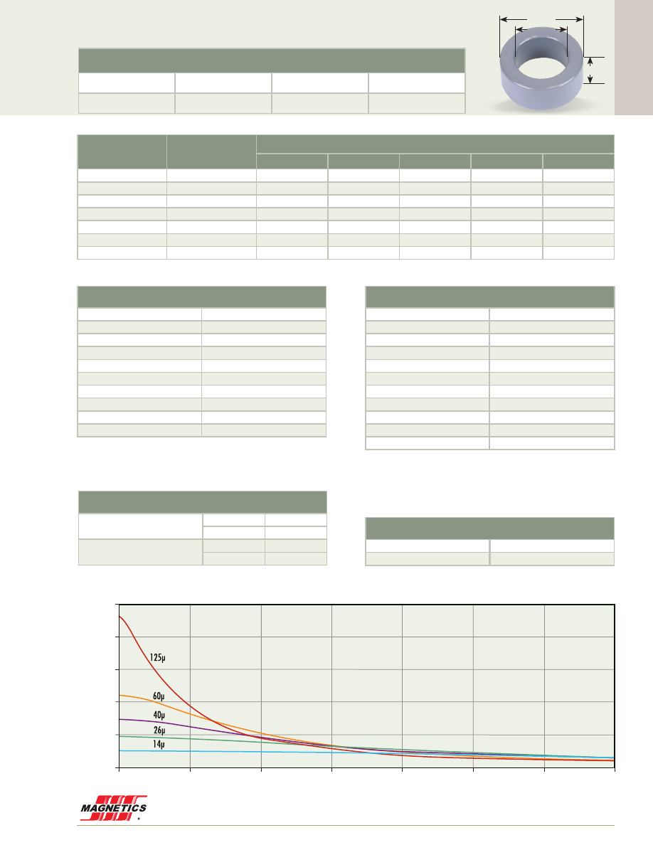
Cor
e Data
www.mag-inc.com
93
55102A2
0.650”
2.252”
4.000”
101.6 mm OD
Kool Mµ A
L
vs. DC Bias
A
L
(nH/
T )
2
A·T
0
7000
1000
2000
4000
3000
5000
6000
250
200
150
100
50
0
125 perm
90
75
60
40
26
14
125µ
90µ
75µ
60µ
40µ
26µ
14µ
Before Finish (nominal)
101.6 mm/4.000 in
57.20 mm/2.252 in
16.5 mm/0.650 in
After Finish (limits)
103.0 mm/4.055 in
55.75 mm/2.195 in
17.9 mm/0.705 in
Permeability (µ)
A
L
± 8%
Part Number
MPP
High Flux
Kool Mµ
®
XF
lux
®
Kool Mµ
®
MAX
14
26
55101
58101
77101
-
-
26
48
55102
58102
77102
78102
79102
40
74
-
58100
77100
78100
-
60
111
55099
58099
77099
78099
79099
75
138
-
-
-
78159
-
90
167
-
-
-
78096
-
125
232
55098
-
77098
-
-
Physical Characteristics
Window Area
2,470 mm
2
Cross Section
358 mm
2
Path Length
243 mm
Volume
86,900 mm
3
Weight - MPP*
650 g
Weight - High Flux*
610 g
Weight - Kool Mµ*
470 g
Weight -
xF
lux
620 g
Weight - Kool Mµ MAX
490 g
Area Product
885,000 mm
4
Surface Area
Unwound Core
20,000 mm
2
40% Winding Factor
36,000 mm
2
Winding Turn Length
* Reference General Winding Data pgs. 103 - 107
Winding Factor
Length/Turn (mm)
0%
82.2
20%
96.8
25%
100
30%
103
35%
108
40%
111
45%
116
50%
120
60%
128
70%
139
*26µ, see p.11
Wound Coil Dimensions
40% Winding Factor
OD
112 mm
HT
34.9 mm
Completely Full Window
Max OD
136 mm
Max HT
55.1 mm
Core Dimensions
OD(max) ID(min) HT(max)
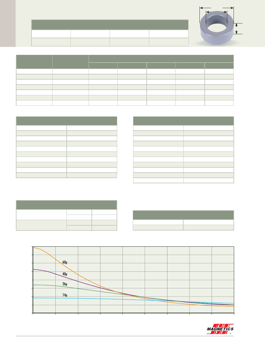
Cor
e Data
MAGNETICS
94
55337A2
1.000”
3.094”
5.219”
132.6 mm OD
Before Finish (nominal)
132.6 mm/5.219 in
78.60 mm/3.094 in
25.4 mm/1.000 in
After Finish (limits)
134.0 mm/5.274 in
77.19 mm/3.039 in
26.8 mm/1.055 in
Permeability (µ)
A
L
± 8%
Part Number
MPP
High Flux
Kool Mµ
®
XF
lux
®
Kool Mµ
®
MAX
14
37
55336
58336
77336
-
-
19
50
-
-
-
78342
-
26
68
55337
58337
77337
78337
79337
40
105
-
58338
77338
78338
-
60
158
55339
58339
77339
-
-
125
329
55340
-
-
-
-
147
380
55341
-
-
-
-
Physical Characteristics
Window Area
4,710 mm
2
Cross Section
678 mm
2
Path Length
324 mm
Volume
220,000 mm
3
Weight - MPP*
1,700 g
Weight - High Flux*
1,500 g
Weight - Kool Mµ*
1,200 g
Weight -
xF
lux
1,400 g
Weight - Kool Mµ MAX
-
Area Product
3,190,000 mm
4
Surface Area
Unwound Core
36,000 mm
2
40% Winding Factor
65,000 mm
2
Winding Turn Length
* Reference General Winding Data pgs. 103 - 107
Winding Factor
Length/Turn (mm)
0%
110
20%
130
25%
135
30%
139
35%
145
40%
150
45%
156
50%
162
60%
173
70%
187
Kool Mµ A
L
vs. DC Bias
A
L
(nH/
T )
2
A·T
0
7000
8000
9000
1000
2000
4000
3000
5000
6000
160
140
120
100
80
60
40
20
0
125 perm
90
75
60
40
26
14
125µ
90µ
75µ
60µ
40µ
26µ
14µ
*26µ, see p. 11
Wound Coil Dimensions
40% Winding Factor
OD
146 mm
HT
50.7 mm
Completely Full Window
Max OD
179 mm
Max HT
78.8 mm
Core Dimensions
OD(max) ID(min) HT(max)
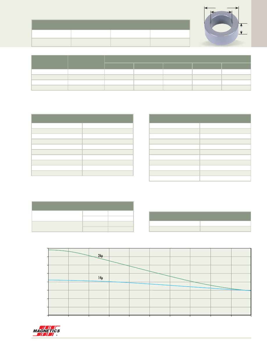
Cor
e Data
www.mag-inc.com
95
Surface Area
Unwound Core
55,000 mm
2
40% Winding Factor
102,000 mm
2
55165A2
1.250”
4.032”
6.500”
165.1 mm OD
Before Finish (nominal)
165.1 mm/6.500 in
102.4 mm/4.032 in
31.75 mm/1.250 in
After Finish (limits)
166.5 mm/6.555 in
101.0 mm/3.977 in
33.15 mm/1.305 in
Core Dimensions
OD(max) ID(min) HT(max)
Permeability (µ)
A
L
± 8%
Part Number
MPP
High Flux
Kool Mµ
®
XF
lux
®
Kool Mµ
®
MAX
14
42
55164
58164
77164
-
-
26
78
55165
58165
77165
-
-
40
120
-
-
-
-
-
60
180
55167
-
-
-
-
Physical Characteristics
Window Area
8,030 mm
2
Cross Section
987 mm
2
Path Length
412 mm
Volume
407,000 mm
3
Weight - MPP*
3,000 g
Weight - High Flux*
2,800 g
Weight - Kool Mµ*
2,200 g
Weight -
xF
lux
-
Weight - Kool Mµ MAX
-
Area Product
7,920,000 mm
4
Winding Turn Length
* Reference General Winding Data pgs. 103 - 107
Winding Factor
Length/Turn (mm)
0%
132
20%
158
25%
164
30%
170
35%
178
40%
184
45%
192
50%
199
60%
215
70%
233
Kool Mµ A
L
vs. DC Bias
A
L
(nH/
T )
2
A·T
0
7000
8000
10000
9000
1000
2000
4000
3000
5000
6000
80
70
60
50
40
30
20
10
0
125 perm
90
75
60
40
26
14
125µ
90µ
75µ
60µ
40µ
26µ
14µ
*26µ, see p.11
Wound Coil Dimensions
40% Winding Factor
OD
182 mm
HT
63.2 mm
Completely Full Window
Max OD
228 mm
Max HT
103 mm
Material Data
MAGNETICS
96
For material code see p. 12.
Add permeability code*** to part number, e.g. for 26µ Kool Mµ the complete part number is 00K4022E026.
E
F
M
L
A
B
C
D
PART NO
A
B
C
D(min)
E(min)
F
L(nom)
M(min)
00_1808E***
(EI-187)
mm
in
19.3±0.305
0.760±0.012
8.10±0.178
0.319±0.007
4.78±0.152
0.188±0.006
5.53
0.218
13.9
0.548
4.78±0.127
0.188±0.005
2.39
0.094
4.64
0.183
00_2510E***
(E-2425)
mm
in
25.4±0.381
1.000±0.015
9.53±0.178
0.375±0.007
6.35±0.102
0.250±0.004
6.22
0.245
18.7
0.740
6.35±0.127
0.250±0.005
3.18
0.125
6.24
0.246
00_3007E***
(DIN 30/7)
mm
in
30.10±0.457
1.185±0.018
15.0±0.229
0.591±0.009
7.06±0.152
0.278±0.006
9.55
0.376
19.8
0.782
6.96±0.203
0.274±0.008
5.11
0.201
6.32
0.249
00_3515E***
(EI-375)
mm
in
34.54±0.508
1.360±0.020
14.2±0.229
0.557±0.009
9.35±0.178
0.368±0.007
9.60
0.378
25.2
0.995
9.32±0.203
0.367±0.008
4.45
0.175
7.87
0.310
00_4017E***
(EE 42/11)
mm
in
42.85±0.635
1.687±0.025
21.1±0.305
0.830±0.012
10.8±0.254
0.424±0.010
14.9
0.587
30.30
1.195
11.9±0.254
0.468±0.010
5.94
0.234
9.27
0.365
00_4020E***
(DIN 42/15)
mm
in
42.85±0.635
1.687±0.025
21.1±0.330
0.830±0.013
15.4±0.254
0.608±0.010
14.9
0.587
30.35
1.195
11.9±0.254
0.468±0.010
5.94
0.234
9.27
0.365
00_4022E***
(DIN 42/20)
mm
in
42.85±0.635
1.687±0.025
21.1±0.330
0.830±0.013
20.0±0.254
0.788±0.010
14.9
0.587
30.35
1.195
11.9±0.254
0.468±0.010
5.94
0.234
9.27
0.365
00_4317E***
(EI-21)
mm
in
40.87±0.610
1.609±0.024
16.5±0.279
0.650±0.011
12.5±0.178
0.493±0.007
10.3
0.409
28.32
1.115
12.5±0.300
0.493±0.008
6.05
0.238
7.87
0.310
00_5528E***
(DIN 55/21)
mm
in
54.86±0.813
2.160±0.032
27.56±0.406
1.085±0.016
20.6±0.381
0.812±0.015
18.5
0.729
37.49
1.476
16.8±0.381
0.660±0.015
8.38
0.330
10.2
0.405
00_5530E***
(DIN 55/25)
mm
in
54.86±0.813
2.160±0.032
27.56±0.406
1.085±0.016
24.6±0.381
0.969±0.015
18.5
0.729
37.49
1.476
16.8±0.381
0.660±0.015
8.38
0.330
10.2
0.405
00_6527E***
(Metric E65)
mm
in
65.15±1.27
2.565±0.050
32.51±0.381
1.280±0.015
27.00±0.406
1.063±0.016
22.1
0.874
44.19
1.740
19.7±0.356
0.774±0.014
10.0
0.394
12.0
0.476
00_7228E***
(F11)
mm
in
72.39±1.09
2.85±0.043
27.94±0.508
1.100±0.020
19.1±0.381
0.750±0.015
17.7
0.699
52.62
2.072
19.1±0.381
0.750±0.015
9.53
0.375
16.8
0.665
00_8020E***
(Metric E80)
mm
in
80.01±1.19
3.150±0.047
38.10±0.635
1.500±0.025
19.8±0.381
0.780±0.015
28.01
1.103
59.28
2.334
19.8±0.381
0.780±0.015
9.91
0.390
19.8
0.780
00_8024E***
mm
in
80.01±1.19
3.150±0.047
24.05±0.635
0.950±0.025
29.72±0.381
1.170±0.015
14.02
0.552
59.28
2.334
19.8±0.381
0.780±0.015
9.91
0.390
19.8
0.780
00_8044E***
mm
in
80.01±1.19
3.150±0.047
44.58±0.635
1.755±0.025
19.8±0.381
0.780±0.015
34.36
1.353
59.28
2.334
19.8±0.381
0.780±0.015
9.91
0.390
19.8
0.780
00_114LE***
mm
in
114.3±0.762
4.500±0.030
46.18±0.381
1.818±0.015
34.93±0.381
1.375±0.015
28.60
1.126
79.50
3.13
35.10±0.381
1.382±0.015
17.2
0.676
22.1
0.874
00_130LE***
mm
in
130.3±3.81
5.130±0.150
32.51±0.305
1.280±0.012
53.85±1.27
2.120±0.050
22.1
0.874
108.4
4.270
20.0±0.762
0.788±0.030
10.0
0.394
44.22
1.741
00_160LE***
mm
in
160.0±2.54
6.300±0.100
38.10±0.635
1.500±0.025
39.62±1.27
1.560±0.050
28.14
1.108
138.2
5.440
19.8±0.762
0.780±0.030
9.91
0.390
59.28
2.334
E Core Data
www.mag-inc.com
97
Material Data
Cor
e Data
E Core Data
26µ 40µ 60µ 90µ
PART NO
A
L
nH/T
²
± 8%
Path Length
Ie (mm)
Cross Section
Ae (mm
2
)
Volume
Ve (mm
³
)
00_1808E***
26
35
48
69
40.1
22.8
914
00_2510E***
39
52
70
100
48.5
38.5
1,870
00_3007E***
33
46
71
92
65.6
60.1
3,940
00_3515E***
56
75
102
146
69.4
84.0
5,830
00_4017E***
56
76
105
151
98.4
128
12,600
00_4020E***
80
108
150
217
98.4
183
18,000
00_4022E***
104
140
194
281
98.4
237
23,300
00_4317E***
88
119
163
234
77.5
152
11,800
00_5528E***
116
157
219
322
123
350
43,100
00_5530E***
138
187
261
338
123
417
51,300
00_6527E***
162
230
300
-
147
540
79,400
00_7228E***
130
173
235
-
137
368
50,400
00_8020E***
103
145
190
-
185
389
72,000
00_8024E***
200
275
370
-
131.4
600
78,840
00_8044E***
91
113
170
-
208
389
80,900
00_114LE***
235
335
445
-
215
1,220
262,000
00_130LE***
254
-
-
-
219
1,080
237,000
00_160LE***
180
-
-
-
273
778
212,000
PART NO
A
B
C
Volume V
e
(mm
3
)
00_4741B***
mm
in
47.50±0.61
1.870±0.024
41.00±0.51
1.614±0.020
27.51±0.41
1.083±0.016
53,600
00_5030B***
mm
in
50.50±0.51
1.988±0.02
30.30±0.30
1.193±0.12
15.0±0.26
0.591±0.01
23,000
00_5528B***
mm
in
54.86±0.64
2.160±0.025
27.56±0.41
1.085±0.016
20.6±0.39
0.812±0.015
31,200
00_6030B***
mm
in
60.00±0.51
2.362±0.02
30.00±0.25
1.181±0.01
15.0±0.25
0.591±0.01
27,000
00_7020B***
mm
in
70.5±0.51
2.776±0.020
20.3±0.25
0.799±0.010
20.0±0.25
0.787±0.010
28,600
00_7030B***
mm
in
70.5±0.5
3.169±0.02
30.3±0.25
1.193±0.02
20.0±0.2
0.787±0.008
42,800
00_8030B***
mm
in
80.49±0.51
3.169±0.020
30.30±0.51
1.193±0.020
20.00±0.21
0.787±0.008
48,800
00_9541B***
mm
in
95.00±0.61
3.740±0.024
41.00±0.51
1.614±0.020
27.51±0.41
1.083±0.016
107,200
For material code see p. 12. Add permeability code*** to part number, e.g. for 26µ Kool Mµ the complete part number is 00K4022E026.
For material code see p. 12. Add permeability code*** to part number, e.g. for 26µ Kool Mµ the complete part number is 00K6030B026.
Standard blocks are available in 26µ. For other permeabilities, contact Magnetics. Note: Inductance is tested in standard picture frame arrangements.
Blocks
E
F
M
L
A
B
C
D

MAGNETICS
98
Cor
e Data
U Core Data
For material code see p. 12.
Add permeability code*** to part number, e.g., for 26µ Kool Mµ, the complete part number is 00K6527U026.
PART NO
26µ
40µ
60µ
A
L
nH/T
2
± 8%
90µ
Path Length
Ie (mm)
Cross Section
Ae (mm
2
)
Volume
Ve (mm
3
)
00_3112U***
-
92
111
179
65.6
101
6,630
00_4110U***
-
56
78
109
85.2
80
6,820
00_4111U***
-
72
95
138
85.2
101
8,600
00_4119U***
-
110
151
218
85.2
159
13,600
00_5527U***
67
-
-
-
168
172
28,900
00_5529U***
85
-
-
-
168
244
41,000
00_6527U***
89
-
-
-
219
270
59,100
00_6533U***
82
-
-
-
199
250
49,800
00_7236U***
87
-
-
-
219
290
63,500
00_8020U***
64
-
-
-
273
195
53,200
00_8038U***
97
-
-
-
237
354
83,900
PART NO
A
B
C
D(min)
E(min)
L(nom)
00_3112U***
mm
in
31.24±0.51
1.230±0.020
11.2±0.26
0.440±0.010
12.1±0.39
0.475±0.015
2.54
0.100
14.2
0.560
8.26
0.325
00_4110U***
mm
in
40.64±0.51
1.600±0.020
11.2±0.51
0.440±0.020
9.53±0.39
0.375±0.015
2.54
0.100
23.6
0.930
8.38
0.330
00_4111U***
mm
in
40.64±0.51
1.600±0.020
11.2±0.26
0.440±0.010
12.1±0.39
0.475±0.015
2.54
0.100
23.6
0.930
8.38
0.330
00_4119U***
mm
in
40.64±0.51
1.600±0.020
11.2±0.26
0.440±0.010
19.1±0.39
0.750±0.015
2.54
0.100
23.6
0.930
8.38
0.330
00_5527U***
mm
in
54.86±0.64
2.160±0.025
27.56±0.51
1.085±0.020
16.3±0.39
0.643±0.015
16.7
0.660
33.78
1.330
10.5
0.415
00_5529U***
mm
in
54.86±0.64
2.160±0.025
27.56±0.51
1.085±0.020
23.2±0.39
0.912±0.015
16.5
0.650
33.02
1.300
10.5
0.415
00_6527U***
mm
in
65.15±1.4
2.565±0.053
32.51±0.31
1.280±0.012
27.00±0.41
1.063±0.016
22.1
0.874
44.22
1.741
10.0
0.394
00_6533U***
mm
in
65.15±1.4
2.565±0.053
32.51±0.31
1.280±0.012
20.0±0.41
0.788±0.016
19.6
0.772
39.24
1.545
12.5
0.493
00_7236U***
mm
in
72.39±0.89
2.850±0.035
35.56±0.64
1.400±0.025
20.9±0.39
0.821±0.015
21.3
0.841
43.68
1.720
13.9
0.547
00_8020U***
mm
in
80.01±0.89
3.150±0.035
38.10±0.64
1.500±0.025
19.8±0.39
0.780±0.015
28.14
1.108
59.28
2.334
9.91
0.390
00_8038U***
mm
in
80.01±0.89
3.150±0.035
38.10±0.64
1.500±0.025
23.0±0.39
0.907±0.015
22.4
0.883
49.27
1.940
15.4
0.605
E
L
A
B
C
D
www.mag-inc.com
99
Cor
e Data
MPP THINZ
®
Core Data
MPP THINZ DC Bias
THINZ are available in four permeabilities, 125µ, 160µ, 200µ,
and 250µ, but the product is designed to be easily customized
to any permeability up to 250 . The most critical parameter of
a power inductor material is its ability to provide inductance,
or permeability, under DC bias . The distributed air gap of MPP
results in a soft inductance versus DC bias curve .
This swinging inductance is often desirable since it maximizes
power handling for a given package size; improves efficiency;
accommodates a wide operating range; and provides
automatic fault or overload protection .
A
B
C
PART NO
A nom
B nom
C nom
A max
B min
C max
00M0301T***
mm
in
3.05
0.120
1.78
0.070
0.81
0.032
3.18
0.125
1.70
0.067
0.89
0.035
00M0302T***
mm
in
3.55
0.140
1.78
0.070
0.81
0.032
3.69
0.145
1.70
0.067
0.89
0.035
00M0402T***
mm
in
3.94
0.155
2.23
0.088
0.81
0.032
4.07
0.160
2.13
0.084
0.89
0.035
00M0502T***
mm
in
4.60
0.181
2.36
0.093
0.81
0.032
4.73
0.186
2.26
0.089
0.89
0.035
00M0603T***
mm
in
6.35
0.250
2.79
0.110
0.81
0.032
6.48
0.255
2.67
0.105
0.89
0.035
00M0804T***
mm
in
7.87
0.310
3.96
0.156
0.81
0.032
8.03
0.316
3.83
0.151
0.89
0.035
Special core heights are available, consult Magnetics.
PART NO
125µ
160µ
200µ
A
L
nH/T
2
± 15%
250µ
Path Length
Ie (mm)
Cross Section
Ae (mm
²
)
Volume
Ve (mm
³
)
00M0301T***
8.4
10.8
13.5
16.9
7.04
0.40
2.8
00M0302T***
11.6
14.8
18.7
23.4
8.06
0.60
4.8
00M0402T***
9.6
12.3
15.4
19.3
9.44
0.58
5.5
00M0502T***
11.7
15.0
18.7
23.4
10.6
0.79
8.3
00M0603T***
14.9
19.1
24.0
30.0
13.6
1.30
17.7
00M0804T***
12.6
16.2
20.2
25.3
17.9
1.45
25.9
Add permeability code*** to part number, e.g., for 125µ the complete part number is 00M0502T125
MAGNETICS
100
E Core Hardware
Magnetics has bobbins available for use with Kool Mµ
cores . Refer to Magnetics Ferrite Cores catalog for a
complete listing of available bobbins . The cores are
standard industry sizes that will fit standard bobbins
available from many sources . Core pieces can be
Core Number
Bobbin Number
Number of Pins
Winding Area
Length Per Turn
(mm
2
)
(mm)
1808E
(EI-187)
PCB1808B1
00B180801
8
-
31.6
34.2
40.5
39.4
2510E
(E-2425)
PCB2510V1
PCB2510V2
00B251001
10
10
-
40.6
20.3
51
54.2
54.2
45.4
3007E
(DIN 30/7)
PCB3007T1
10
83.3
55
3515E
(EI-375)
PCB3515M1
PCB3515M2
00B351501
12
12
-
94.8
47.4
113
73.4
73.4
72
4020E
(DIN 42/15)
PCB4020N1
00B402021
12
-
194
207
91.4
97.5
4022E
(DIN 42/20)
PCB4022N1
12
194
102.1
4317E
(EI-21)
PCB4317M1
00B4317B1
12
-
101
122
85.6
86
5528E
(DIN55/25)
PCB5528WC
00B5528B1
14
-
302
302
107.3
107.3
5530E
PCB5530FA
14
289
133.8
6527E
(Metric E65)
00B6527B1
00B652701
-
-
490
440
166
168
7228E
(F11)
00B722801
-
408
149
8020E
(Metric E80)
00B8020B1
-
806
165
114LE
OOB114LB1
-
945
230
assembled by bonding the mating surfaces or taping
around the perimeter of the core set . Caution is advised if
metal clamps are considered, since eddy current heating
can occur in conductive material that is very close to the
surface of low permeability powder core material .
Har
dwar
e
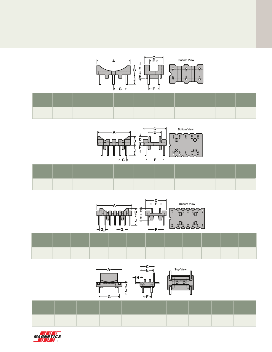
www.mag-inc.com
101
Har
dwar
e
Toroid Hardware
TVH22064A
TVB3610FA
TVB2908TA
TVB22066A
For use with toroids from
12 .7 mm through 25 .4 mm
For use with toroids from
28 .6 mm through 38 .1 mm
For use with toroids from
20 .5 mm through 31 .8 mm
For use with toroids from
12 .7 mm through 22 .2 mm
Material
4 Pins
A
Nom.
B
Nom.
C
Nom.
E
Ref.
F
Typ.
G
Typ.
H
Ref.
J
Ref.
Nylon 6/6
rated UL94V0
CP wire
1.02 mm
19.1 mm
3.94 mm
10.8 mm
9.78 mm
6.35 mm
15.2 mm
3.30 mm
3.81 mm
Material 14 Pins
A
Nom.
B
Nom.
C
Nom.
D
Nom.
E
Ref.
F
Typ.
G
1
Typ.
G
2
Typ.
H
Ref.
J
Ref.
Phenolic
rated UL94V0
CP wire
0.99 mm
35.8 mm
7.59 mm
20.8 mm
5.00 mm
12.3 mm
16.0 mm
5.00 mm
6.30 mm
4.5 mm
9.75 mm
Material 10 Pins
A
Nom.
B
Nom.
C
Nom.
D
Nom.
E
Ref.
F
Typ.
G
Typ.
H
Ref.
J
Ref.
Phenolic
rated UL94V0
CP wire
0.99 mm
27.0 mm
7.49 mm
19.0 mm
5.00 mm
11.0 mm
15.0 mm
5.00 mm
3.51 mm
8.13 mm
Material
6 Pins
A
Nom.
B
Nom.
C
Nom.
D
Nom.
E
Ref.
F
Typ.
G
Typ.
H
Ref.
J
Ref.
Phenolic
rated UL94V0
CP wire
0.99 mm
19.0 mm
5.44 mm
10.8 mm
3.51 mm
4.80 mm
6.00 mm
7.49 mm
2.01 mm
5.49 mm
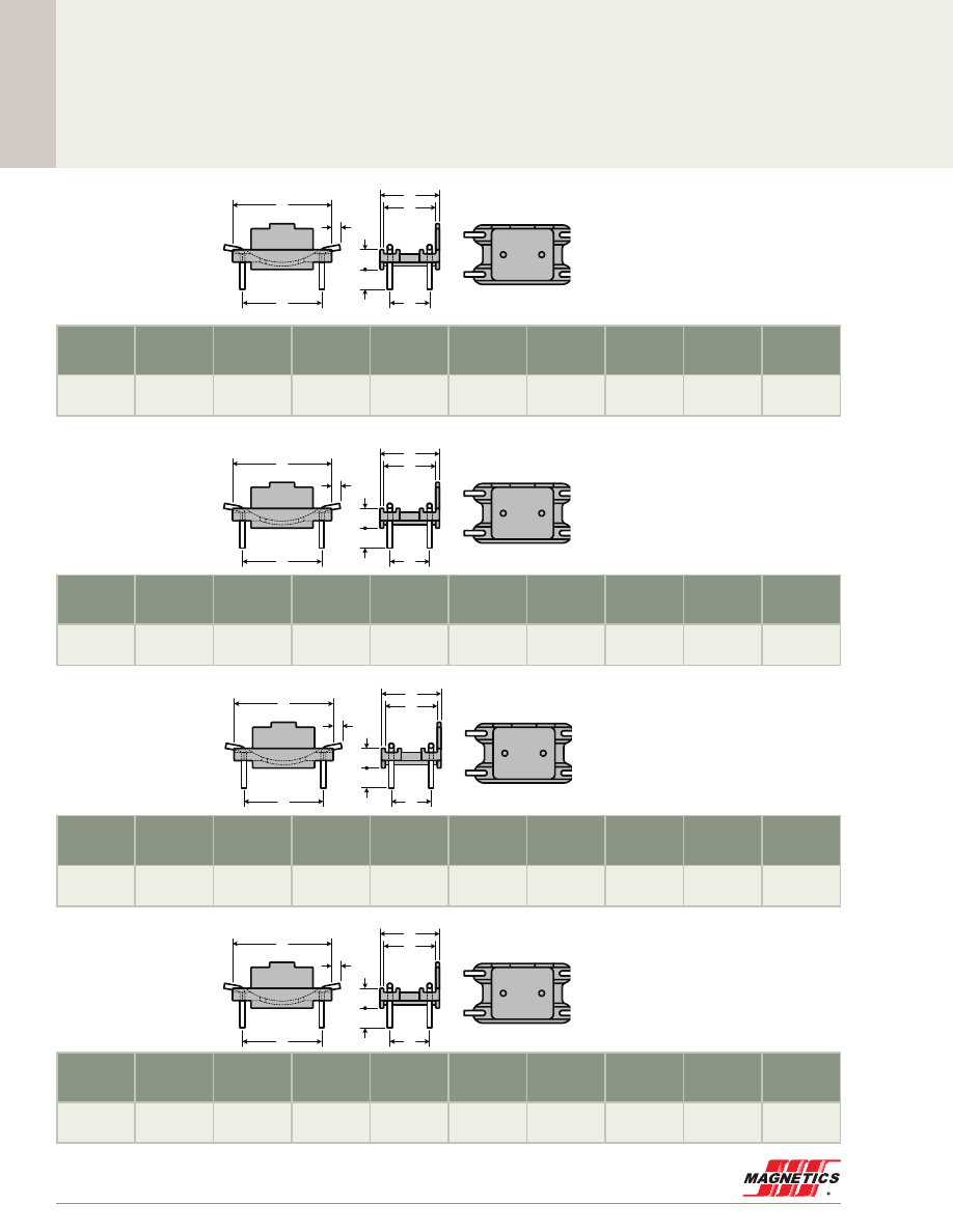
MAGNETICS
102
Toroid Hardware
Har
dwar
e
For use with toroids
from 44 .4 mm
through 71 .1 mm
For use with toroids
from 38 .1 mm
through 63 .5 mm
For use with toroids
from 25 .4 mm (1 .000”)
through 40 .6 mm
For use with toroids
from 20 .5 mm (0 .810”)
through 30 .5 mm
Material
4 Pins
A
Nom.
B
Nom.
C
Nom.
E
Ref.
F
Typ.
G
Typ.
H
Ref.
J
Ref.
Nylon 6/6
rated UL94V0
CP wire
1.27 mm
43.2 mm
5.08 mm
27.9 mm
25.7 mm
22.9 mm
38.1 mm
2.29 mm
5.08 mm
Material
4 Pins
A
Nom.
B
Nom.
C
Nom.
E
Ref.
F
Typ.
G
Typ.
H
Ref.
J
Ref.
Nylon 6/6
rated UL94V0
CP wire
1.27 mm
35.6 mm
5.08 mm
22.9 mm
20.6 mm
17.8 mm
30.5 mm
2.29 mm
5.08 mm
Material
4 Pins
A
Nom.
B
Nom.
C
Nom.
E
Ref.
F
Typ.
G
Typ.
H
Ref.
J
Ref.
Nylon 6/6
rated UL94V0
CP wire
1.27 mm
27.9 mm
5.08 mm
20.3 mm
18.0 mm
15.2 mm
22.9 mm
2.29 mm
5.08 mm
Material
4 Pins
A
Nom.
B
Nom.
C
Nom.
E
Ref.
F
Typ.
G
Typ.
H
Ref.
J
Ref.
Nylon 6/6
rated UL94V0
CP wire
1.21 mm
25.4 mm
5.08 mm
15.2 mm
13.0 mm
10.2 mm
20.3 mm
2.29 mm
5.08 mm
TVH61134A
TVH49164A
TVH38134A
TVH25074A
TV-H4916-4A
Usable with toroids from 1.500" (38.1m m) through 2.500" (63.5mm).
Top View
Material
Nylon,
rated UL94V0
4 Pins
0.050"
CP wire
A
Nom.
1.400"
35.6mm
B
Nom.
0.200"
5.1mm
C
Nom.
0.900"
22.9mm
E
Ref.
0.810"
20.6mm
F
Typ.
0.700"
17.8mm
G
Typ.
1.200"
30.5mm
H
Typ.
0.090"
2.3mm
J
Typ.
0.200"
5.1mm
B
J
C
E
F
A
G
H

www.mag-inc.com
103
Winding T
ables
Winding Tables
6 .60 mm OD (270 size)
4 .65 mm OD (180 size)
6 .60 mm OD (240 size)
3 .94 mm OD (150 size)
6 .35 mm OD (020 size)
3 .56 mm OD (140 size)
AWG
Wire Size
Single Layer Turns
Single Layer R
DC
(Ohms,
Ω
)
26
11
0.0266
27
13
0.0390
28
15
0.0566
29
17
0.0790
30
19
0.112
31
22
0.163
32
25
0.228
33
28
0.322
34
32
0.474
35
36
0.658
36
41
0.936
37
45
1.26
38
51
1.81
39
58
2.68
40
67
3.92
41
75
5.37
42
85
7.61
43
95
11.0
44
103
14.4
45
121
21.8
AWG
Wire Size
Single Layer Turns
Single Layer R
DC
(Ohms,
Ω
)
27
11
0.0212
28
12
0.0289
29
14
0.0414
30
16
0.0597
31
18
0.0838
32
20
0.114
33
23
0.165
34
27
0.249
35
31
0.352
36
34
0.481
37
38
0.661
38
43
0.942
39
50
1.42
40
57
2.05
41
64
2.82
42
73
4.01
43
81
5.73
44
88
7.52
45
103
11.3
46
113
15.6
AWG
Wire Size
Single Layer Turns
Single Layer R
DC
(Ohms,
Ω
)
26
11
0.0196
27
13
0.0287
28
15
0.0414
29
17
0.0577
30
19
0.0815
31
22
0.118
32
25
0.165
33
28
0.233
34
32
0.342
35
36
0.473
36
41
0.672
37
45
0.907
38
51
1.30
39
58
1.92
40
67
2.80
41
75
3.84
42
85
5.43
43
95
7.82
44
103
10.3
45
121
15.5
AWG
Wire Size
Single Layer Turns
Single Layer R
DC
(Ohms,
Ω
)
28
11
0.0251
29
13
0.0364
30
15
0.0529
31
17
0.0749
32
19
0.103
33
22
0.149
34
25
0.218
35
28
0.300
36
32
0.427
37
35
0.574
38
40
0.826
39
46
1.23
40
53
1.80
41
59
2.44
42
68
3.52
43
76
5.06
44
82
6.60
45
96
9.93
46
105
13.6
47
117
19.1
AWG
Wire Size
Single Layer Turns
Single Layer R
DC
(Ohms,
Ω
)
26
12
0.0216
27
14
0.0312
28
16
0.0446
29
18
0.0617
30
21
0.0910
31
23
0.125
32
26
0.173
33
30
0.252
34
34
0.367
35
39
0.518
36
44
0.729
37
48
0.977
38
54
1.39
39
62
2.07
40
71
3.00
41
80
4.13
42
91
5.87
43
101
8.40
44
110
11.1
45
128
16.6
AWG
Wire Size
Single Layer Turns
Single Layer R
DC
(Ohms,
Ω
)
30
10
0.0286
31
11
0.0392
32
13
0.0567
33
15
0.0821
34
17
0.119
35
20
0.172
36
23
0.246
37
25
0.328
38
28
0.461
39
33
0.704
40
38
1.03
41
43
1.42
42
49
2.01
43
55
2.91
44
59
3.76
45
69
5.65
46
76
7.80
47
85
11.0
48
98
16.0
49
109
22.2
9 .65 mm OD (280 size)
7 .87 mm OD (030 size)
6 .86 mm OD (410 size)
AWG
Wire Size
Single Layer Turns
Single Layer R
DC
(Ohms,
Ω
)
20
12
0.00684
21
13
0.00914
22
15
0.0131
23
18
0.0194
24
20
0.0268
25
23
0.0383
26
26
0.0541
27
29
0.0747
28
33
0.107
29
37
0.147
30
42
0.212
31
47
0.297
32
52
0.404
33
58
0.568
34
67
0.844
35
75
1.17
36
84
1.63
37
92
2.19
38
104
3.13
39
119
4.66
AWG
Wire Size
Single Layer Turns
Single Layer R
DC
(Ohms,
Ω
)
22
12
0.00988
23
14
0.0142
24
16
0.0201
25
18
0.0281
26
20
0.0390
27
23
0.0556
28
26
0.0787
29
29
0.108
30
33
0.156
31
37
0.218
32
41
0.298
33
47
0.430
34
53
0.623
35
60
0.870
36
67
1.21
37
74
1.65
38
83
2.33
39
96
3.50
40
109
5.04
41
122
6.90
AWG
Wire Size
Single Layer Turns
Single Layer R
DC
(Ohms,
Ω
)
22
12
0.0116
23
14
0.0168
24
16
0.0239
25
18
0.0334
26
20
0.0465
27
23
0.0663
28
26
0.0942
29
29
0.129
30
33
0.187
31
37
0.262
32
41
0.358
33
47
0.518
34
53
0.752
35
60
1.05
36
67
1.47
37
74
1.99
38
83
2.82
39
96
4.24
40
109
6.11
41
122
8.37
MAGNETICS
104
Winding T
ables
Winding Tables
23 .6 mm OD (350 size)
17 .3 mm OD (380 size)
22 .9 mm OD (310 size)
16 .5 mm OD (120 size)
20 .3 mm OD (206 size)
12 .7 mm OD (050 size)
9 .65 mm OD (290 size)
11 .2 mm OD (130 size)
10 .2 mm OD (040 size)
AWG
Wire Size
Single Layer Turns
Single Layer R
DC
(Ohms,
Ω
)
9
11
0.00120
10
13
0.00173
11
15
0.00244
12
17
0.00340
13
19
0.00467
14
22
0.00668
15
25
0.00938
16
28
0.0130
17
32
0.0184
18
36
0.0258
19
41
0.0365
20
46
0.0510
21
51
0.0705
22
58
0.101
23
65
0.140
24
73
0.197
25
82
0.277
26
92
0.392
27
102
0.542
28
115
0.770
AWG
Wire Size
Single Layer Turns
Single Layer R
DC
(Ohms,
Ω
)
13
11
0.00223
14
13
0.00324
15
15
0.00460
16
17
0.00644
17
20
0.00933
18
22
0.0127
19
25
0.0179
20
29
0.0258
21
32
0.0354
22
37
0.0512
23
41
0.0704
24
46
0.099
25
52
0.139
26
59
0.199
27
66
0.277
28
74
0.391
29
82
0.535
30
92
0.764
31
102
1.06
32
114
1.47
AWG
Wire Size
Single Layer Turns
Single Layer R
DC
(Ohms,
Ω
)
10
12
0.00148
11
14
0.00212
12
16
0.00296
13
18
0.00409
14
21
0.00589
15
24
0.00830
16
27
0.0116
17
31
0.0164
18
35
0.0230
19
39
0.0319
20
44
0.0446
21
50
0.0632
22
56
0.0888
23
63
0.124
24
70
0.173
25
79
0.244
26
89
0.345
27
99
0.479
28
111
0.677
29
123
0.927
AWG
Wire Size
Single Layer Turns
Single Layer R
DC
(Ohms,
Ω
)
13
12
0.00234
14
14
0.00336
15
16
0.00471
16
18
0.00654
17
21
0.00940
18
24
0.0133
19
27
0.0185
20
30
0.0255
21
34
0.0359
22
39
0.0516
23
44
0.0722
24
49
0.101
25
56
0.143
26
63
0.203
27
70
0.280
28
78
0.393
29
87
0.542
30
98
0.775
31
108
1.07
32
121
1.48
AWG
Wire Size
Single Layer Turns
Single Layer R
DC
(Ohms,
Ω
)
11
12
0.00163
12
14
0.00232
13
16
0.00324
14
18
0.00449
15
21
0.00644
16
24
0.00909
17
27
0.0126
18
31
0.0179
19
35
0.0251
20
39
0.0347
21
45
0.0498
22
50
0.0692
23
56
0.0962
24
63
0.135
25
71
0.191
26
80
0.270
27
89
0.374
28
100
0.529
29
111
0.725
30
125
1.04
AWG
Wire Size
Single Layer Turns
Single Layer R
DC
(Ohms,
Ω
)
16
12
0.00364
17
14
0.00520
18
16
0.00733
19
19
0.0107
20
21
0.0147
21
24
0.0207
22
28
0.0302
23
31
0.0413
24
35
0.0582
25
40
0.0829
26
45
0.117
27
50
0.161
28
56
0.227
29
63
0.315
30
71
0.451
31
79
0.629
32
87
0.854
33
98
1.21
34
112
1.79
35
125
2.46
AWG
Wire Size
Single Layer Turns
Single Layer R
DC
(Ohms,
Ω
)
16
10
0.00272
17
11
0.00366
18
13
0.00532
19
15
0.00756
20
17
0.0106
21
20
0.0153
22
23
0.0220
23
25
0.0295
24
29
0.0426
25
33
0.0602
26
37
0.0845
27
41
0.116
28
46
0.164
29
52
0.228
30
59
0.328
31
65
0.453
32
72
0.618
33
81
0.877
34
93
1.30
35
104
1.79
AWG
Wire Size
Single Layer Turns
Single Layer R
DC
(Ohms,
Ω
)
20
13
0.00818
21
15
0.0117
22
17
0.0165
23
19
0.0227
24
22
0.0328
25
25
0.0463
26
28
0.0650
27
31
0.0893
28
36
0.130
29
40
0.178
30
45
0.254
31
50
0.354
32
56
0.488
33
63
0.693
34
72
1.02
35
81
1.42
36
91
1.99
37
99
2.66
38
112
3.80
39
128
5.65
AWG
Wire Size
Single Layer Turns
Single Layer R
DC
(Ohms,
Ω
)
20
12
0.00747
21
13
0.0100
22
15
0.0144
23
18
0.0213
24
20
0.0295
25
23
0.0421
26
26
0.0596
27
29
0.0825
28
33
0.118
29
37
0.163
30
42
0.234
31
47
0.328
32
52
0.448
33
58
0.630
34
67
0.937
35
75
1.29
36
84
1.81
37
92
2.44
38
104
3.48
39
119
5.18
www.mag-inc.com
105
Winding T
ables
Winding Tables
35 .8 mm OD (324 size)
39 .9 mm OD (254 size)
46 .7 mm OD (438 size)
34 .3 mm OD (585 size)
33 .0 mm OD (548 size)
26 .9 mm OD (930 size)
AWG
Wire Size
Single Layer Turns
Single Layer R
DC
(Ohms,
Ω
)
8
18
0.00280
9
21
0.00405
10
24
0.00573
11
27
0.00801
12
31
0.0114
13
35
0.0160
14
39
0.0223
15
44
0.0314
16
50
0.0446
17
56
0.0622
18
63
0.0878
19
71
0.124
20
80
0.175
21
90
0.246
22
101
0.349
23
112
0.483
24
126
0.683
25
141
0.961
26
158
1.36
27
175
1.88
AWG
Wire Size
Single Layer Turns
Single Layer R
DC
(Ohms,
Ω
)
8
17
0.00160
9
20
0.00229
10
23
0.00323
11
26
0.00449
12
30
0.00636
13
34
0.00887
14
38
0.0123
15
43
0.0172
16
48
0.0238
17
54
0.0332
18
61
0.0467
19
69
0.0657
20
77
0.0913
21
87
0.1287
22
98
0.1821
23
109
0.2519
24
122
0.354
25
137
0.497
26
153
0.699
27
170
0.969
AWG
Wire Size
Single Layer Turns
Single Layer R
DC
(Ohms,
Ω
)
8
18
0.00229
9
21
0.00329
10
24
0.00464
11
27
0.00646
12
31
0.00917
13
35
0.0128
14
39
0.0178
15
44
0.0250
16
50
0.0354
17
56
0.0493
18
63
0.0695
19
71
0.0978
20
80
0.138
21
90
0.194
22
101
0.274
23
112
0.379
24
126
0.536
25
141
0.753
26
158
1.06
27
175
1.47
AWG
Wire Size
Single Layer Turns
Single Layer R
DC
(Ohms,
Ω
)
8
16
0.00169
9
19
0.00246
10
22
0.00351
11
25
0.00491
12
28
0.00677
13
32
0.00955
14
36
0.0133
15
41
0.0188
16
46
0.0263
17
52
0.0369
18
58
0.0514
19
65
0.0718
20
73
0.1
21
82
0.141
22
93
0.201
23
103
0.277
24
116
0.392
25
130
0.551
26
146
0.78
27
162
1.08
AWG
Wire Size
Single Layer Turns
Single Layer R
DC
(Ohms,
Ω
)
8
14
0.00147
9
17
0.00218
10
19
0.00299
11
22
0.00427
12
25
0.00598
13
28
0.00826
14
32
0.0117
15
36
0.0163
16
41
0.0232
17
46
0.0322
18
52
0.0455
19
58
0.0632
20
65
0.0883
21
74
0.126
22
83
0.177
23
92
0.245
24
103
0.344
25
116
0.485
26
131
0.691
27
145
0.954
AWG
Wire Size
Single Layer Turns
Single Layer R
DC
(Ohms,
Ω
)
9
11
0.00141
10
13
0.00205
11
15
0.00292
12
17
0.00407
13
20
0.00592
14
22
0.00808
15
25
0.0114
16
29
0.0164
17
33
0.0232
18
37
0.0324
19
42
0.0459
20
47
0.0640
21
53
0.0902
22
60
0.128
23
66
0.176
24
75
0.251
25
84
0.352
26
94
0.497
27
105
0.693
28
117
0.975
50 .8 mm OD (715 size)
46 .7 mm OD (089 size)
AWG
Wire Size
Single Layer Turns
Single Layer R
DC
(Ohms,
Ω
)
8
25
0.00324
9
29
0.00463
10
33
0.00651
11
37
0.00904
12
42
0.0127
13
47
0.0176
14
53
0.0247
15
60
0.0348
16
67
0.0486
17
76
0.0685
18
85
0.0959
19
95
0.134
20
107
0.189
21
120
0.265
22
135
0.375
23
150
0.520
24
168
0.732
25
189
1.03
26
211
1.46
27
234
2.02
AWG
Wire Size
Single Layer Turns
Single Layer R
DC
(Ohms,
Ω
)
8
22
0.00296
9
26
0.00432
10
29
0.00596
11
33
0.00840
12
38
0.0120
13
42
0.0164
14
47
0.0229
15
54
0.0327
16
60
0.0455
17
68
0.0641
18
76
0.0897
19
86
0.127
20
96
0.177
21
108
0.249
22
121
0.352
23
135
0.490
24
151
0.690
25
170
0.975
26
190
1.37
27
211
1.91
AWG
Wire Size
Single Layer Turns
Single Layer R
DC
(Ohms,
Ω
)
8
19
0.0033
9
22
0.0047
10
25
0.0067
11
28
0.0093
12
32
0.0132
13
36
0.0185
14
40
0.026
15
46
0.037
16
51
0.051
17
58
0.073
18
65
0.102
19
73
0.144
20
82
0.202
21
92
0.28
22
104
0.41
23
116
0.57
24
130
0.80
25
146
1.13
26
163
1.59
27
181
2.21
50 .5 mm OD (725 size)
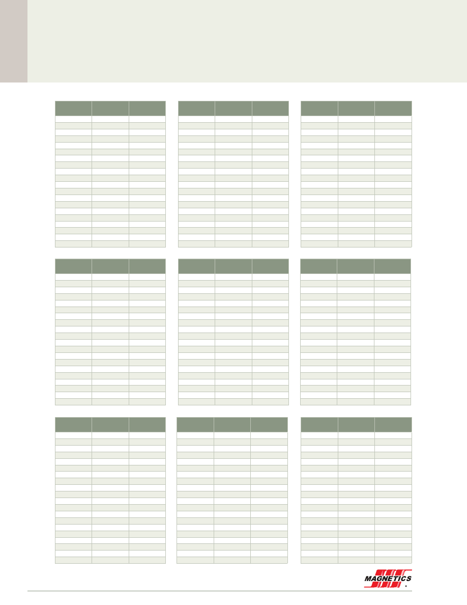
MAGNETICS
106
Winding T
ables
57 .2 mm OD (195 size)
AWG
Wire Size
Single Layer Turns
Single Layer R
DC
(Ohms,
Ω
)
8
20
0.00322
9
23
0.00458
10
26
0.00642
11
30
0.00921
12
34
0.0130
13
39
0.0185
14
43
0.0254
15
49
0.0362
16
55
0.0508
17
62
0.0714
18
70
0.101
19
78
0.141
20
88
0.199
21
99
0.281
22
111
0.398
23
124
0.555
24
138
0.777
25
156
1.10
26
174
1.56
27
193
2.16
57 .2 mm OD (109 size)
77 .8 mm OD (778 size)
68 .0 mm OD (070 size)
62 .0 mm OD (620 size)
77 .8 mm OD (866 size)
74 .1 mm OD (740 size)
77 .8 mm OD (906 size)
101 .6 mm OD (102 size)
AWG
Wire Size
Single Layer Turns
Single Layer R
DC
(Ohms,
Ω
)
8
41
0.00660
9
47
0.00937
10
53
0.0131
11
60
0.0184
12
67
0.0256
13
76
0.0361
14
85
0.0504
15
95
0.0703
16
107
0.0991
17
120
0.139
18
135
0.195
19
151
0.274
20
169
0.383
21
189
0.538
22
212
0.761
23
236
1.06
24
264
1.49
25
296
2.10
26
331
2.96
27
367
4.11
AWG
Wire Size
Single Layer Turns
Single Layer R
DC
(Ohms,
Ω
)
6
38
0.00489
7
43
0.00682
8
49
0.00965
9
55
0.0135
10
62
0.0189
11
70
0.0266
12
79
0.0373
13
89
0.0524
14
99
0.0730
15
112
0.103
16
125
0.145
17
140
0.202
18
157
0.285
19
176
0.400
20
197
0.561
21
221
0.790
22
248
1.12
23
275
1.55
24
308
2.19
25
345
3.09
AWG
Wire Size
Single Layer Turns
Single Layer R
DC
(Ohms,
Ω
)
8
41
0.00607
9
47
0.00860
10
53
0.0120
11
60
0.0169
12
67
0.0234
13
76
0.0329
14
85
0.0459
15
95
0.0640
16
107
0.0901
17
120
0.126
18
135
0.178
19
151
0.248
20
169
0.348
21
189
0.487
22
212
0.689
23
236
0.958
24
264
1.35
25
296
1.90
26
331
2.68
27
367
3.72
AWG
Wire Size
Single Layer Turns
Single Layer R
DC
(Ohms,
Ω
)
6
29
0.00450
7
33
0.00632
8
38
0.00907
9
43
0.0128
10
49
0.0182
11
55
0.0255
12
62
0.0358
13
70
0.0505
14
78
0.0706
15
88
0.0997
16
98
0.139
17
110
0.196
18
124
0.277
19
139
0.390
20
155
0.546
21
174
0.769
22
195
1.09
23
217
1.52
24
243
2.14
25
273
3.03
Ω
AWG
Wire Size
Single Layer Turns
Single Layer R
DC
(Ohms,
Ω
)
8
29
0.00397
9
33
0.00558
10
37
0.00773
11
42
0.0109
12
48
0.0154
13
54
0.0215
14
60
0.0297
15
68
0.0420
16
76
0.0586
17
85
0.0816
18
96
0.115
19
108
0.162
20
120
0.225
21
135
0.318
22
152
0.451
23
169
0.625
24
189
0.880
25
212
1.24
26
238
1.76
27
263
2.43
AWG
Wire Size
Single Layer Turns
Single Layer R
DC
(Ohms,
Ω
)
8
32
0.0071
9
37
0.0102
10
41
0.0141
11
47
0.0202
12
53
0.0284
13
60
0.0401
14
67
0.056
15
75
0.079
16
84
0.111
17
95
0.156
18
106
0.219
19
119
0.309
20
133
0.432
21
150
0.61
22
168
0.87
23
187
1.21
24
209
1.70
25
235
2.40
26
263
3.40
27
291
4.71
AWG
Wire Size
Single Layer Turns
Single Layer R
DC
(Ohms,
Ω
)
6
22
0.0027
7
25
0.0038
8
29
0.0054
9
33
0.0077
10
37
0.0107
11
42
0.0151
12
48
0.022
13
54
0.030
14
60
0.042
15
68
0.059
16
76
0.083
17
85
0.116
18
96
0.165
19
108
0.23
20
120
0.32
21
135
0.46
22
152
0.65
23
169
0.90
24
189
1.27
25
212
1.79
AWG
Wire Size
Single Layer Turns
Single Layer R
DC
(Ohms,
Ω
)
6
20
0.00260
7
23
0.00368
8
26
0.00517
9
30
0.00741
10
34
0.0104
11
38
0.0146
12
43
0.0205
13
49
0.0291
14
54
0.0402
15
61
0.0568
16
69
0.0805
17
78
0.114
18
87
0.159
19
98
0.225
20
110
0.316
21
123
0.444
22
138
0.629
23
154
0.878
24
172
1.24
25
194
1.75
Winding Tables
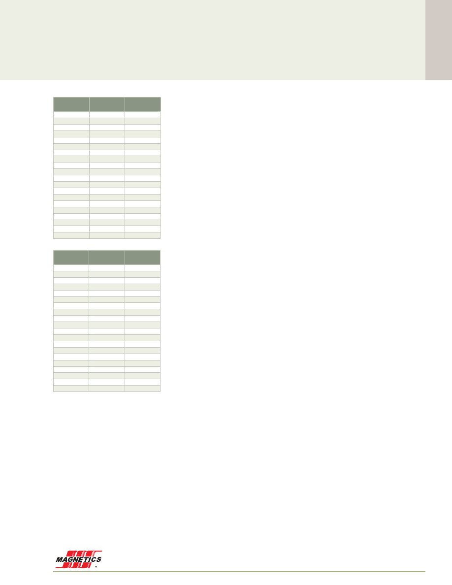
www.mag-inc.com
107
Winding T
ables
Winding Tables
132 .6 mm OD (337 size)
165 .1 mm OD (165 size)
AWG
Wire Size
Single Layer Turns
Single Layer R
DC
(Ohms,
Ω
)
6
72
0.0139
7
81
0.0193
8
91
0.0272
9
103
0.0384
10
115
0.0536
11
130
0.0759
12
145
0.106
13
163
0.149
14
182
0.209
15
204
0.293
16
228
0.412
17
256
0.579
18
286
0.814
19
320
1.14
20
358
1.61
21
401
2.26
22
449
3.21
23
499
4.46
24
558
6.29
25
625
8.86
AWG
Wire Size
Single Layer Turns
Single Layer R
DC
(Ohms,
Ω
)
6
54
0.00890
7
61
0.0124
8
69
0.0175
9
78
0.0247
10
87
0.0344
11
99
0.0489
12
111
0.0685
13
124
0.0956
14
138
0.133
15
155
0.188
16
174
0.265
17
195
0.371
18
218
0.522
19
244
0.733
20
273
1.03
21
306
1.45
22
343
2.05
23
381
2.85
24
426
4.02
25
478
5.68

MAGNETICS
108
Other Products from Magnetics
Ferrites
Magnetics’ ferrite cores are manufactured for a wide
variety of applications . Magnetics produces the leading
MnZn ferrite materials for power transformers, power
inductors, wideband transformers, common mode chokes,
and many other applications . In addition to offering
the leading materials, other advantages of ferrites from
Magnetics include the full range of standard planar E, ER,
and I cores; the widest range of toroid sizes in power and
high permeability materials; standard gapping to precise
inductance or mechanical dimension; a wide range of
available coil formers and assembly hardware; and superior
toroid coatings available in several options .
Power Materials
Five low loss materials are engineered for optimum
frequency and temperature performance in power
applications . Magnetics’ R, P, F, L, and T materials provide
superior saturation, high temperature performance, low
losses and product consistency .
Shapes: E cores, Planar E cores, ER cores, ETD, EC, U
cores, I cores, PQ, Planar PQ, RM, Toroids, Pot cores, RS
(round-slab), DS (double slab), EP, Special Shapes .
Applications: Telecom power supplies, computer power
supplies, commercial power supplies, consumer power
supplies, automotive, DC-DC converters, telecom data
interfaces, impedance matching transformers, handheld
devices, high power control (gate drive), computer servers,
distributed power (DC-DC), EMI filters, aerospace, and
medical .
High Permeability Materials
Three high permeability materials (5,000µ J material,
10,000µ W material, and 15,000µ M material) are
engineered for optimum frequency and impedance
performance in signal, choke and filter applications . These
Magnetics materials provide superior loss factor, frequency
response, temperature performance, and product
consistency .
Shapes: Toroids, E cores, U cores, RM, Pot cores, RS
(round-slab), DS (double slab), EP, Special Shapes .
Applications: common mode chokes, EMI filters, other
filters, pulse transformers, current transformers, broadband
transformers, current sensors, telecom data interfaces,
impedance matching interfaces, handheld devices, spike
suppression, and gate drive transformers .
Tape Wound Cores
Magnetics strip wound cores are made from high
permeability magnetic strip alloys of nickel-iron (80%
or 50% nickel), and silicon-iron . The alloys are know
as Orthonol
®
, Permalloy 80, 48 Alloy and Magnesil
®
.
Tape Wound Cores are produced as small as 0 .438”
OD in hundreds of sizes . For a wide range of frequency
applications, materials are produced in thicknesses
from 1/2 mil (0 .013 mm) through 4 mils (0 .102 mm) .
Cases are robust nylon and aluminum boxes, rated for
200°C continuous operation and 2,000 minimum voltage
breakdown .
Applications: aerospace applications, radar installations, jet
engine controls, power supplies, current transformers and
other high reliability applications .
Bobbin Cores
Magnetics bobbin cores are miniature tape cores made
from ultra-thin (0 .000125” to 0 .001” thick) strip material
wound on nonmagnetic stainless steel bobbins . Bobbin
Cores are generally manufactured from Permalloy 80 and
Orthonol
®
. Covered with protective caps and then epoxy
coated, Bobbin Cores can be made as small as 0 .05”
ID and with strip widths down to 0 .032” . Bobbin Cores
can switch from positive to negative saturation in a few
microseconds or less, making them ideal for analog logic
elements, magnetometers, and pulse transformers .
Applications: high frequency magnetic amplifiers, flux gate
magnetometers, harmonic generators, oscillators, pulse
transformers, current transformers, analog counters and
timers and inverters .

Visit
www.mag-inc.com
Design
with Magnetics Cores
From novice to experienced designers, our informative website has
all the tools you need get your design started.
Design Software for Inductors, Common Mode Filters,
Current Transformers and MagAmps
Competitor Part Number Cross Reference
Technical Documents
Core Selection Guide
Find
Magnetics Cores
Whether you need a specific part number or are looking for ways to
narrow your core search, our multiple search functions can guide
you in the right direction.
Part Number Search
Parametric Search (by material, size, shape, inductance)
Competitor Part Number Cross Reference
Distributor Stock Check
Buy
Magnetics Cores
The easiest way to get Magnetics cores is to request a MyMagnetics
account. MyMagnetics is your secure gateway to managing your
customer account online.
Pricing and Availability
Place New Orders
Review Existing Orders
Track Orders
View Invoices
Sample Request

Headquarters
110 Delta Drive
P.O. Box 11422
Pittsburgh, PA 15238 • USA
Phone:
1.800.245.3984
+1.412.696.1333
e-mail:
magnetics@spang.com
Magnetics International
13/F 1-3 Chatham Road South
Tsim Sha Tsui
Kowloon, Hong Kong
Phone:
+852.3102.9337
+86.139.1147.1417
e-mail:
asiasales@spang.com
www.mag-inc.com
©2017 Magnetics