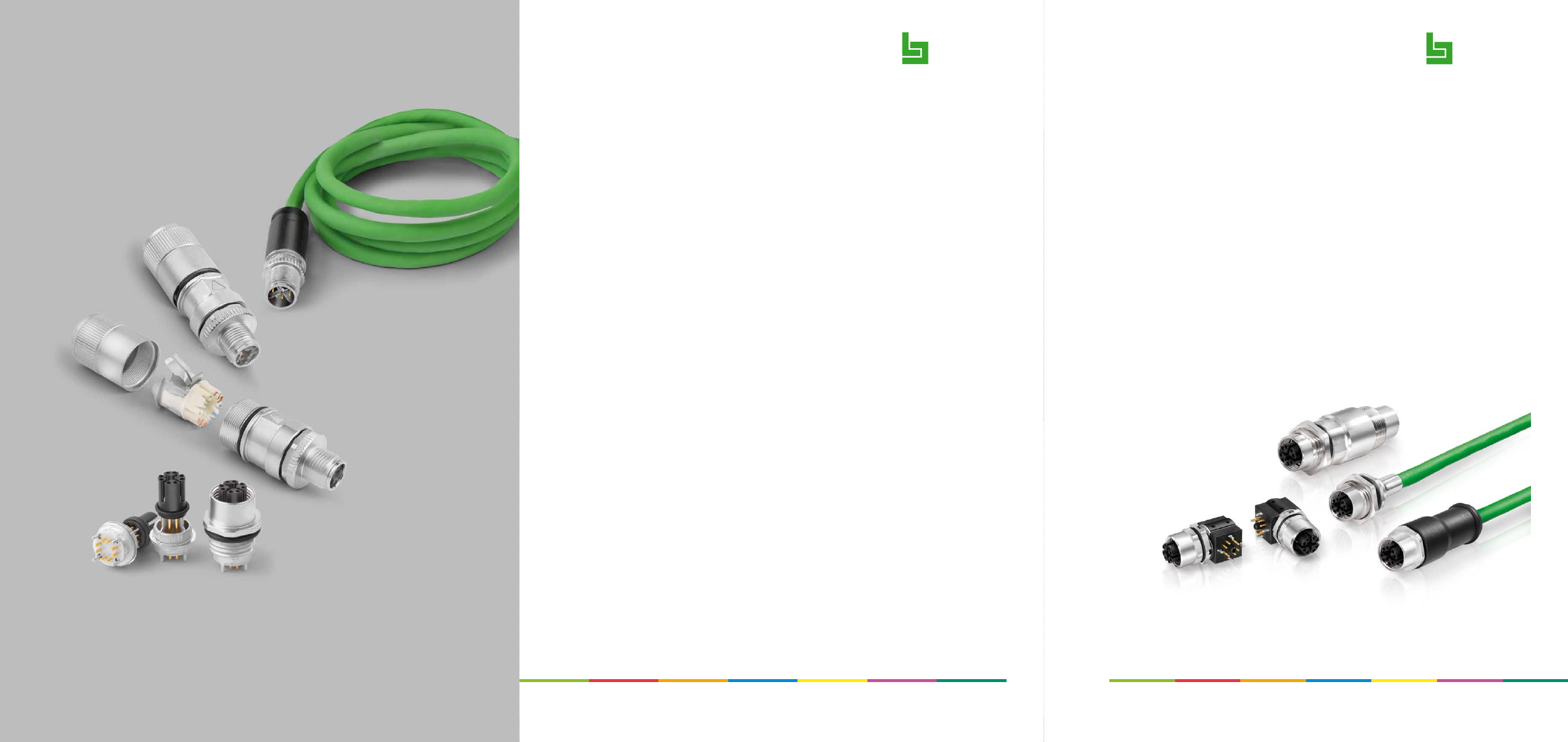
background image

binder

M12 X-Kodierung

M12 X-Coding

Franz Binder GmbH & Co.
Elektrische Bauelemente KG

Rötelstraße 27
74172 Neckarsulm
Deutschland

Tel.  +49 7132 325–0
Fax  +49 7132 325–190

vk@binder-connector.de
www.binder-connector.de

Best.-Nr. W M12-X DE/EN 2016

binder

Technische Änderungen und Irrtum vorbehalten. 

Specifications maybe changed without notice, errors excepted.

AGB: www.binder-connector.de/de/agb

25150-html.html
background image

Verbindungsleitung, Kabelstecker – Kabeldose, geschirmt

Connecting cable, male cable connector – female cable connector, shielded

Flanschdose, von vorn verschraubbar, mit Ethernetkabel

Female panel mount connector, front fastened, with Ethernet cable

M12-X

Extension of the M12 X-coded product portfolio
4 twin data transmission up to 10 Gbit/s 


In accordance with DIN IEC 61076-2-109
Male and female receptacles with angled dip solder 

contacts
Female moulded connecting cords
Cabinet lead-through/adaptor for the connection of 

cable connectors

M12-X


M12 X-Coded

Serie · 

Series

Polzahl · 

Contacts

Kodierung · 

Coding

Gewinde

 · Thread

Bemessungsstrom · 

Rated current

Bemessungsspannung · 

Rated voltage

Schutzart · 

Degree of protection

Kontaktoberfläche · 

Contact plating

Anschluss · 

Termination

Polzahl

Contacts

Kabelmantel

Cable jacket

Kabellänge

Cable length

Bestell-Nr.

Ordering-No.

8

PUR

2 m

79 9724 020 08

5 m

79 9724 050 08

10 m

79 9724 100 08

Polzahl

Contacts

Kabelmantel

Cable jacket

Kabellänge

Cable length

Bestell-Nr.

Ordering-No.

8

PUR

0,5 m

70 3784 706 08

Montageausschnitt

Panel cut out

Erweiterung des Produktportfolios M12-X
Datenübertragung 4-paarig bis 10 Gbit/s
Nach DIN IEC 61076-2-109
Flansch- und Einbaudosen mit gewinkelten Tauchlöt-

kontakten
Umspritzte Verbindungsleitungen mit Dosen
Schaltschrankdurchführungen bzw. Adapter zum 

Verbinden von Kabelsteckern

M12 X-Kodierung


825 · 876

8

X

M12 x 1

0,5 A

50 V AC, 60 V DC

IP67

Au

Kabel/tauchlöt

Cable/dip solder

min. 2
max. 4,5

Ø 

18

Ø 

21

SW 19mm

SW 17mm

SW 17mm

M1

6 x 

1,5

2

2,8

17,65

38

L

M1

2 x 1

Ø 

18

SW 17mm

Ø 

18

Ø 6,2

52

L

47

M1

2x1

Ø 

14,5

SW 13mm/0,6 Nm

M12-X

Montageausschnitt

Panel cut out

Leiterplattenlayout

PCB layout

Montageausschnitt

Panel cut out

Flanschdose, tauchlöten, gewinkelt

Female panel mount connector, dip solder, angled

Kontakteinsatz, tauchlöten, gewinkelt, für Einbau in Kundengehäuse

Contact insert, dip solder, angled, for mounting in customer housing

min. 2
max. 3

9,65

SW 15mm

SW 14mm

14,75

2

8,5

14,3

15,75

~30

Ø 

17

Ø 

15

12,2

6,1

14,75

2

8,5

~30

12,2

Adapter, Schaltschrankdurchführung, Dose – Dose, geschirmt

Adapter, lead through for control cabinet, female–female, shielded

M1

2 x 1

SW 17mm

62

M1

6 x 

1,5

Ø 

21

2,8

SW 13,4mm

SW 19mm

Ø 20

M1

2x1

SW 16,5mm

M1

8 x 1

Polzahl

Contacts

Bestell-Nr.

Ordering-No.

8

09 5286 00 08

Polzahl

Contacts

Kontaktierung

Contact carrier

Bestell-Nr.

Ordering-No.

8

fest/

fix

99 3782 213 08

über Feder/

via undular washer

99 3782 202 08

Polzahl

Contacts

Bestell-Nr.

Ordering-No.

8

09 3782 202 08

16

,1

1 x 45°

13,5

Mit Durchgangsbohrung

With bore hole 


max. 4,5

Anzugsdrehmoment/

Tightening moment

Metallgehäuse/

Metal housing 

6,25 Nm

Kunststoffgehäuse/

Plastic housing 

3,75 Nm

Mit Fläche als Verdrehschutz

With flats as anti-rotation device

16

,1

1 x 45°

13,5

Mit Durchgangsbohrung

With bore hole 


max. 4,5

Anzugsdrehmoment/

Tightening moment

Metallgehäuse/

Metal housing 

6,25 Nm

Kunststoffgehäuse/

Plastic housing 

3,75 Nm

Mit Fläche als Verdrehschutz

With flats as anti-rotation device

Flanschsteckverbinder, von vorn verschraubbar

Panel mount connectors, front fastened

Flanschsteckverbinder, von vorn verschraubbar

Panel mount connectors, front fastened

Flanschsteckverbinder mit Gewinde M12 x 1

Panel mount connectors with M12 x 1 thread

Bohrbilder Buchseneinsatz (Leiterplatte)

Drilling schemes female insert (PCB)

2

5

3

4

1

7

6

8

2,8

5,6

10

Ø 1,9

Ø 1,2

Ø 1
Ø 1,4

2,8

5,6

10

Ansicht Bestückungsseite

View of mating side

Leiterplattendicke: 1,6 mm

Alle Bohrungen (ausser Ø 2,85) 

durchkontaktiert.

Cu 35/35

Thickness of PCB: 1,6 mm

All holes fully contacted 

(except Ø 2,85).

CU 35/35

max. 9,3

Ø 2,85

Ø 

12,2

min. 2
max. 3

Anzugsdrehmoment/

Tightening moment 

M12 x 1 

6,25 Nm

Ø 12,2