FEATURES
* Plastic package has underwriters laboratory
* Glass passivated chip construction
* 3000 watt surage capability at 1ms
* Excellent clamping capability
* Low zener impedance
* Fast response time
MAXIMUM RATINGS AND ELECTRICAL CHARACTERISTICS
Ratings at 25
o
C ambient temperature unless otherwise specified.
TVS
3KP
SERIES
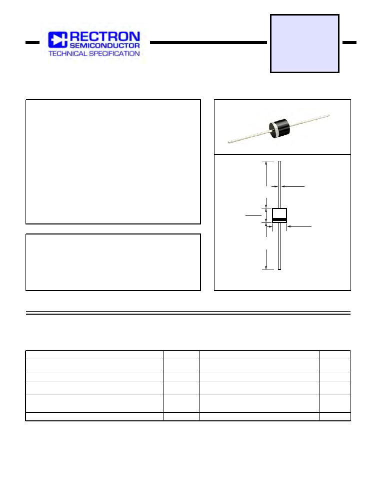
R-6
3000 WATT PEAK POWER 8.0 WATTS STEADY STATE
GPP TRANSIENT VOLTAGE SUPPRESSOR
Dimensions in inches and (millimeters)
MAXIMUM RATINGS
(At T
A
= 25
o
C unless otherwise noted)
RATINGS
Peak Pulse Current with a 10/1000uS waveform (Note 1, Fig. 3)
Peak Forward Surge Current, 8.3ms single half sine wave-
superimposed on rated load( JEDEC METHOD ) (Note 3)
Steady State Power Dissipation at T
L
= 75
o
C lead lengths
0.375” (9.5mm) (Note 2)
SYMBOL
P
M(AV)
I
FSM
Amps
UNITS
Watts
Peak Pulse Power Dissipation with a 10/1000uS
waveform (Note 1, FIG.1)
Minimum 3000
8.0
250
VALUE
P
PPM
Watts
I
PPM
Amps
SEE TABLE 1
2009-02
REV: O
T
J
, T
STG
-55 to + 175
0
C
Operating and Storage Temperature Range
3. Measured on 8.3mS single half sine-wave or equivalent square wave, duty cycle = 4 pulses per minute maximum.
NOTES :
2. Mounted on copper pad area of 0.8 X 0.8” ( 20 X 20mm ) per Fig. 5
1. Non-repetitive current pulse, per Fig.3 and derated above T
A
= 25
o
C per Fig.2.
.360 (9.1)
.340 (8.6)
DIA.
.052 (1.3)
.048 (1.2)
DIA.
1.0 (25.4)
MIN.
.340 (8.6)
.360 (9.1)
1.0 (25.4)
MIN.
DEVICES FOR BIPOLAR APPLICATIONS
For Bidirectional use C or CA suffix for types 3KP5.0 thru 3KP110
Electrical characteristics apply in both direction