GPP TRANSIENT VOLTAGE SUPPRESSOR
3000 WATT PEAK POWER 7.5 WATTS STEADY STATE
MAXIMUM RATINGS AND ELECTRICAL CHARACTERISTICS
TVS
3KPSMC
SERIES
MAXIMUM RATINGS
(@ T
A
=25
O
C unless otherwise noted)
FEATURES
* Plastic package has underwriters laboratory
* Glass passivated chip construction
* 3000 watt surage capability at 1ms
* Excellent clamping capability
* Low zener impedance
* Fast response time
RATINGS
Steady State Power Dissipation at T
L
= 75
O
C lead length,
.375" (9.5 mm) (Note 2)
SYMBOL
P
M(AV)
I
FSM
I
2
t
250
259.2
A
A
2
/Sec
U N I T S
Peak Power Dissipation at T
A
= 25
O
C,T
P
= 1mS (Note 1)
Minimum 3000
7.5
W
VALUE
Peak Forward Surge Current, 8.3mS Single half sine-wave
superimposed on rated load (JEDEC METHODE)
P
PPM
W
Ratings at 25
o
C ambient temperature unless otherwise specified.
resistive or inductive load,
2010-10
REV: O
NOTES :
3. "Fully ROHS compliant", "100% Sn plating (Pb-free)".
T
J
, T
STG
-55 to + 150
0
C
Operating and Storage T
Current Squarad Time
emperature Range
2. Mounted on 0.2 X 0.2” (5.0 X 5.0mm) copper pad to each terminal.
1. Non-repetitive current pulse, per Fig.3 and derated above T
A
= 25
o
C per Fig.2.
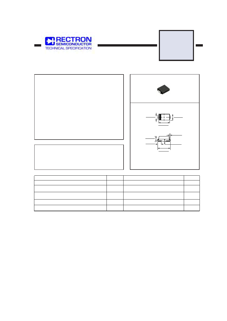
DO-214AB
Dimensions in inches and (millimeters)
.006 (.152)
.012 (.305)
.008 (.203)
.004 (.102)
.320 (8.13)
.305 (7.75)
.030 (0.76)
.060 (1.52)
.079 (2.06)
.103 (2.62)
.260 (6.60)
.280 (7.11)
.220 (5.59)
.245 (6.22)
.125 (3.17)
.115 (2.92)