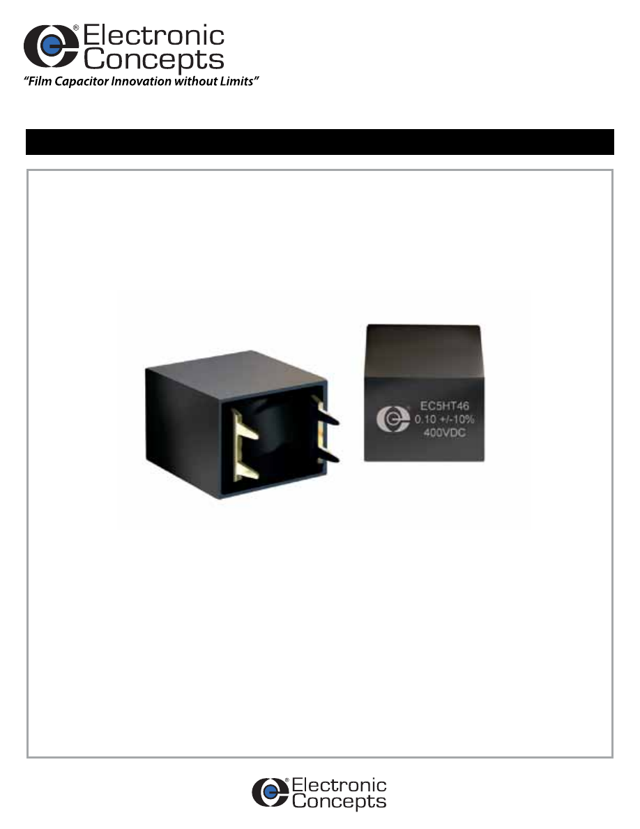
5HT
SERIES
High Temperature Film & Foil
Rev. 1
High Temperature Film & Foil Resonant Power Supply Capacitors
Specifically designed to meet higher ambient temperature requirements of resonant
power circuits.
FEATURES
- Operation to 175°C
- Compact Configuration
- Direct Plug-in Spade Lugs
- Low ESL
- Low ESR
- High dv/dt
- High Peak Current
Rev. 1
Parameter
Method
Condition
Vibration
204
D
Shock
213
I
Humidity
106
-
Thermal Shock
107
F*
Life
108
F**
Reference MIL-STD-202
-0.7%
-0.6%
-0.5%
-0.4%
-0.3%
-0.2%
-0.1%
0.0%
0.1%
0.2%
0.3%
0.4%
-60
-40
-20
0
20
40
60
80
100 120 140 160 180
%
C
ap
ac
ita
nc
e
Ch
an
ge
Temperature Deg-C
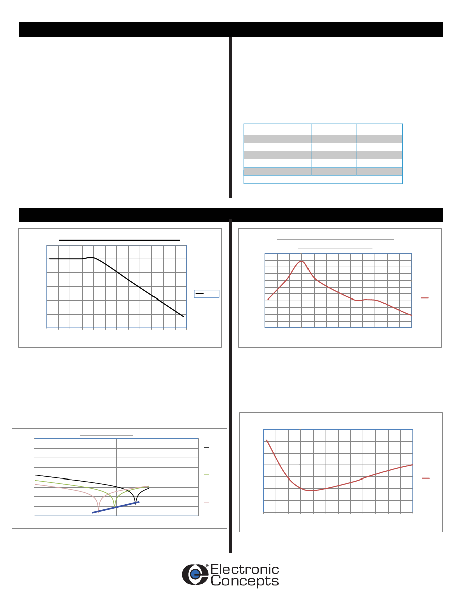
5HT Capacitance Change vs. Temperature
at 1kHz Referenced to 25C
1KHz
0.00
0.05
0.10
0.15
0.20
0.25
0.30
0.35
-60
-40
-20
0
20
40
60
80
100 120 140 160 180
%
is
sp
a
ti
on
fa
ct
or
Temperature Deg-C
5HT Dissipa
ti
on Factor vs. Temperature at 1kHz
1KHz
0.00
0.01
0.10
1.00
10.00
100.00
1,000.00
10,000.00
100,000.00
1,000
10,000
100,000
Im
pe
da
nc
e
oh
m
s
Frequency (kHz)
5HT Impedance vs. Frequency
5HT46J103_
5HT46J333_
5HT46J823_
0
10,000
20,000
30,000
40,000
50,000
60,000
-60 -40 -20
0
20
40
60
80
100 120 140 160 180
In
su
la
ti
on
R
es
is
ta
nc
e
M
eg
oh
m
s X
u
F
Temperature Deg-C
5HT Insula
ti
on Resistance vs. Tempertaure
100VDC
Specification Summary
Characteristics
Dielectric Strength
Capacitors withstand a DC potential of 1.5 x rated
voltage for one (1) minute without damage or
breakdown. Test voltage is applied and discharged
through a minimum resistance of 100 OHMS per
volt minimum.
Dissipation Factor
When mearsured at the frequency specified for
capacitance measurement, the dissipation factor will
not exceed 0.05%.
Capacitance Range
0.010μF to 0.100μF
Capacitance Tolerance
Standard capacitance tolerance is ±10%. Tolerances of ±5%, ±2%
and ±1% are also available.
Operating Temperature Range
-55°C to +175°C
Enclosure/Construction
High temperature film and foil potted in a thermo plastic housing.
Voltage Rating
400 VDC
230 VAC
Quality Control
Capacitors are tested 100% for:
• Capacitance
• Tolerance
• Dissipation Factor
• Dielectric withstanding voltage
• Insulation Resistance
Process and inspection data are maintained on file and available
upon special request.
Environmental
* The temperature at step 3 shall be set at 175°C instead of 150°C
** Life test conditions: 133% of rated voltage at 175°C
Rev. 1
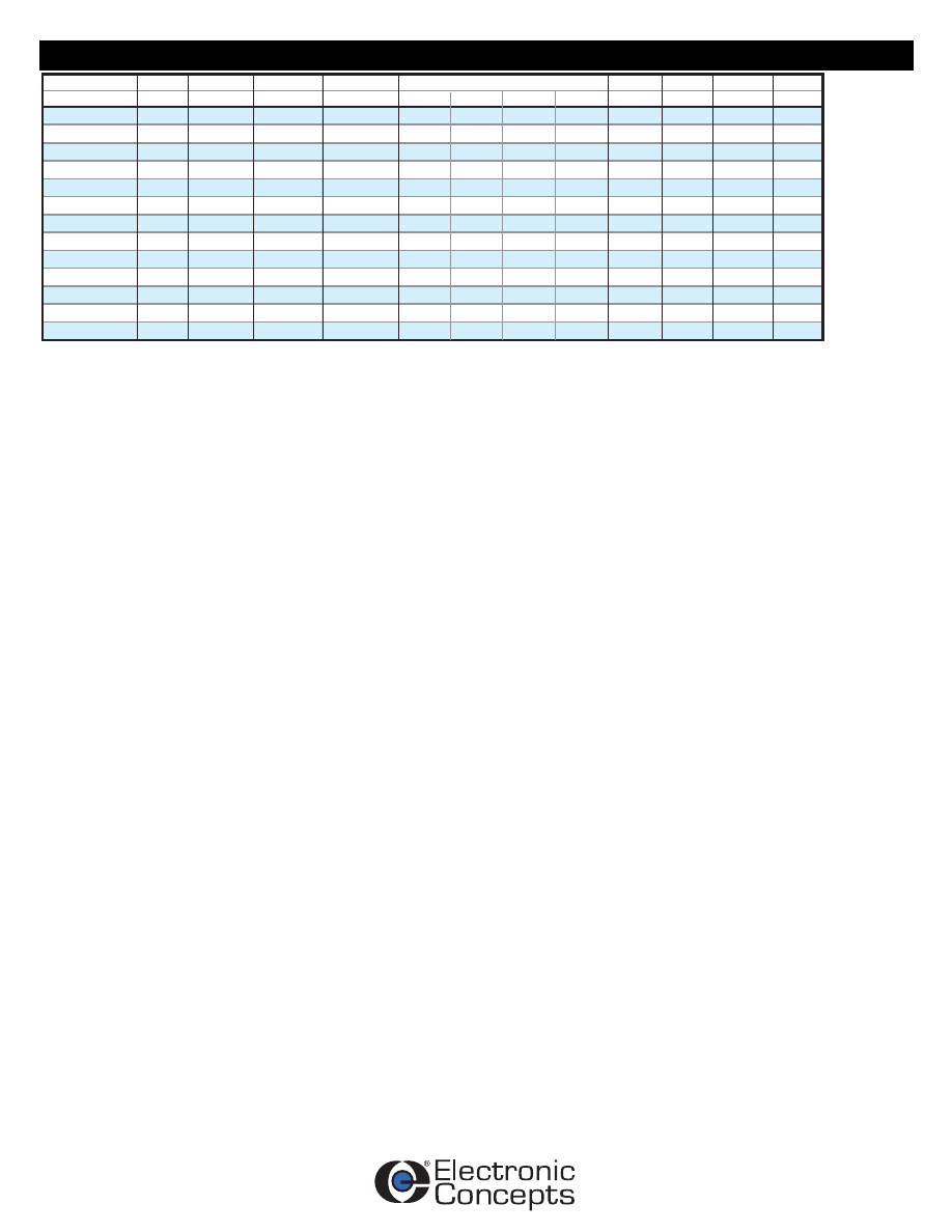
5HT46J103_
5HT46J123_
5HT46J153_
5HT46J183_
5HT46J223_
5HT46J273_
5HT46J333_
5HT46J393_
5HT46J473_
5HT46J563_
5HT46J683_
5HT46J823_
5HT46J104_
0.010
0.012
0.015
0.018
0.022
0.027
0.033
0.039
0.047
0.056
0.068
0.082
0.10
230
230
230
230
230
230
230
230
230
230
230
230
230
400
400
400
400
400
400
400
400
400
400
400
400
400
17.2
15.7
14.0
12.8
11.6
10.4
9.4
8.7
7.9
7.3
6.6
6.0
5.4
8.6
8.6
8.6
8.6
8.6
8.6
8.6
8.6
8.6
8.6
8.6
8.6
8.6
27,937
27,937
23,280
23,280
18,624
18,624
16,296
13,968
11,640
11,640
10,476
10,476
9,209
5.8
6.7
7.6
8.4
9.3
10.2
11.2
12.2
13.6
15.0
16.7
17.3
20.3
7.1
8.2
9.4
10.2
11.3
12.5
13.7
15.0
16.7
18.3
20.4
21.2
24.8
279
335
349
419
410
503
538
545
608
652
712
859
921
PART NUMBER
CAP
µF
VOLTAGE
VDC
VOLTAGE
VAC
100kHz (Arms)
75°C
I PEAK
(AMPS)
dv/dt
V/µs
ESL
(nH)
Fres
(MHz)
25°C
0.075
0.070
0.056
0.046
0.038
0.031
0.025
0.022
0.018
0.015
0.012
0.010
0.009
ESR (ohms)
100 kHz
4.1
4.8
5.4
5.9
6.5
7.2
7.9
8.7
9.6
10.6
11.8
12.2
14.3
125°C
0.21
0.24
0.27
0.30
0.33
0.37
0.40
0.44
0.49
0.54
0.60
0.62
0.73
175°C
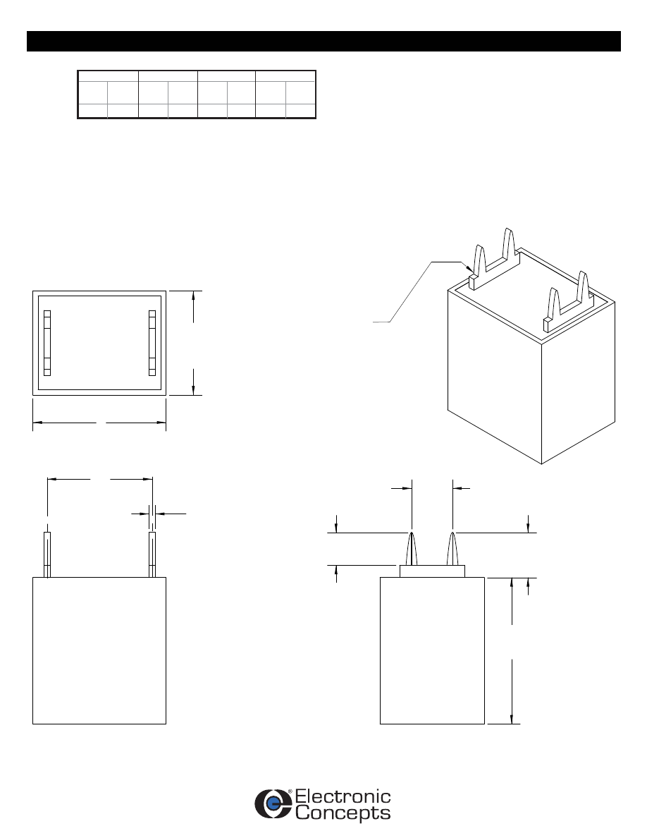
Detail Data
Rev. 1
TAPERED TO 0.889 ± .076mm
( 0.035 ± .003" )
PINS ARE 1.270 ± .127mm
( 0.050 ± .005" )
0.787 ±0.076mm
( 0.031 ± .003" )
LS
TH
L
5.080 ±0.254mm
( 0.200 ± .010" )
3.810 ±0.254mm
( .150 ± .010" )
5.080 ±1.575mm
( 0.200 ± .062" )
H
0.500
18.542
12.700
0.730
16.383 0.500
0.645
TH
in.
max
mm
max
in.
±0.010
LS
mm
±0.254
mm
±0.254
in.
±0.010
H
L
mm
±0.254
in.
±0.010
12.700
Mechanical Data
Rev. 1
TYPE
Polypropylene & Foil
VOLTAGE
J = 400VDC
5HT46
J
103
K
CAPACITANCE IN PICOFARADS
The first two digits are significant, the third represents the number
of zeros
TOLERANCE
K = ±10%. Tolerances of ±5%, ±2%, and ±1% are also available.
Marking And Date Code
All capacitors are marked with company initials "EC", corporate logo or EC trademark—in addition to type 5PT, capacitance, tolerance, rated
DC working voltage and date code. The first two digits of the date code represent the year, the second two digits the week, i.e., 1252 is the
52nd week of 2012, 1202 is the second week of 2012.
Quality Assurance
Major emphasis is placed on quality assurance. EC is an ISO 9001 and AS9100 Certified Company. Raw material inspection and the use of
SPC manufacturing procedures assure the highest quality standards. Procedures are fully described in the EC Quality Control Manual.
Electronic Concepts will continue to advance the state-of-the-art by utilizing leading edge technology, compact capacitor designs and
establishing reliability procedures.
This series is specifically designed to meet the challenges of high temperature environments in resonant power supplies with
operation to 175°C. The 5HT series meets the critical requirements of series resonant power supplies for high current
carrying capabilities at lower capacitance values.
United States Headquarters
Electronic Concepts, Inc.
526 Industrial Way West
Eatontown, NJ 07724
Tel: 732-542-7880
Fax: 732-542-0524
email: sales@ecicaps.com
website:www.ecicaps.com
European Headquarters
Electronic Concepts Europe LTD
IDA Estate
Oughterard
Co. Galway
Ireland
tel: +353-91-552385,552432
fax: +353-91-552387
email: sales@ecicaps.ie
website:www.electronicconcepts.ie
Distribution Center
Elcon Sales
542 Industrial Way West
Eatontown, NJ 07724
Tel: 732-380-0405
Fax: 732-380-0409
email: sales@elconsales.com
How to Order
Sales Offices
Additional Information