background image

GN Series

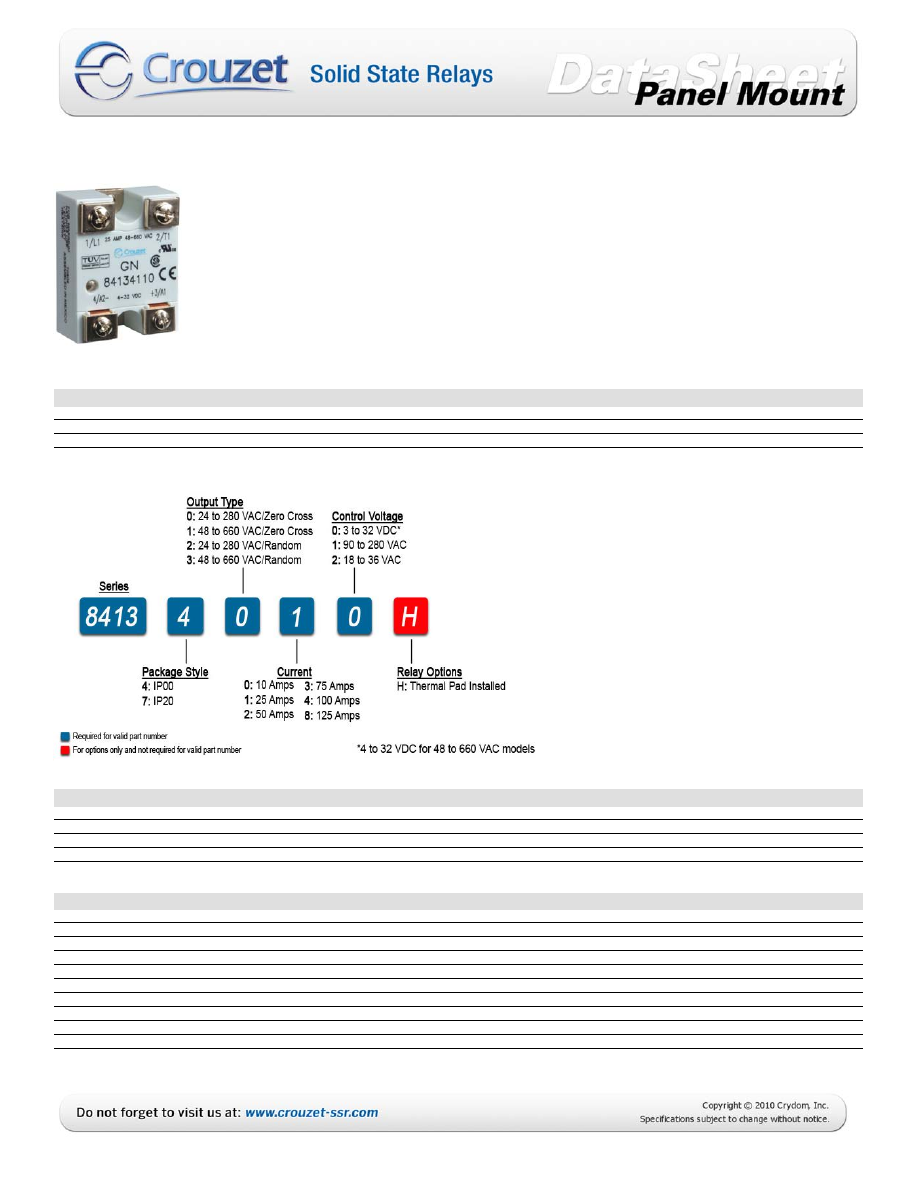
• Current ratings from 10 to 125 amps
• Output voltage 24-280 and 48-660 VAC 
• Direct bond copper substrate 
• LED input status indicator 
• Available with IP20 “touch-safe” cover 
• Transient protection built-in 
• 100K cycle UL508 Endurance Rating (10-50A) 
• UL/CSA/ TUV Approved, CE Compliant to EN60950-1


PRODUCT SELECTION

Control Voltage

10A

25A

50A

75A

100A

125A

3-32 VDC 

84134000

84134010

84134020

84134030

84134040

84134080

18-36 VAC 

84134002

84134012

84134022

84134032

84134042

84134082

90-280 VAC 

84134001

84134011

84134021

84134031

84134041

84134081

AVAILABLE OPTIONS

OUTPUT SPECIFICATIONS (Voltage) (1)

Description

280 VAC

660 VAC

Operating Voltage (47-63Hz) [Vrms]

24-280

48-660


Transient Overvoltage [Vpk, t = 1 min.]

600

1200


Maximum Off-State Leakage Current @ Rated Voltage [mArms]

0.1

0.25


Static off-state dv/dt (Vµs, Ta =25°C)

500

500

OUTPUT SPECIFICATIONS (Current) (1)

Description

10A

25A

50A

75A

100A

125A

Maximum Load Current (3) [Arms]

10A

25A

50A

75A

100A

125A

Minimum Load Current [mArms]

50

50

100

100

100

100

1 cycle surge current (50Hz)

150

275

710

1050

1120

1600

1 cycle surge current (60Hz)

175

300

750

1100

1200

1700

1 second surge current (Apk. Ta = 25°C) 50/60 Hz

50

85

150

225

300

375

Forward Voltage Drop (Vpk @ Imax, Ta = 25°C)

1.35

1.35

1.35

1.3

1.3

1.3

I²T (50Hz, 1/2 cycle)

110

380

2520

5500

6270

12800

I²T (60Hz, 1/2 cycle)

120

370

2320

5000

6000

12050

Thermal Resistance Junction to baseplate (Rjb) [°C/W]

0.5

0.4

0.25

.0155

0.155

0.15

Minimum heat sink @ Ambient (for max current = °C/W & Ta)

3.0 @ 70°C

1.5 @ 50°C

1.0 @ 40°C

0.7 @ 40°C

0.5 @ 40°C

0.5 @ 40°C


Courtesy of Steven Engineering, Inc.-230 Ryan Way, South San Francisco, CA 94080-6370 

Main Office: (650) 588-9200-Outside Local Area: (800) 258-9200-www.stevenengineering.com

60CROUZET-SSR-html.html
background image

INPUT SPECIFICATIONS (1)

Description

8413xxx0

8413xxx2

8413xxx1

Input Voltage Range (2)

3-32 VDC

18-36 VAC

90-280 VAC (3)

Minimum Turn-On Voltage 

3.0 VDC

18 Vrms

90 Vrms

Drop out Voltage 

1.0 VDC

2 Vrms

10 Vrms

Maximum Input Current  

14mA

20mArms

10mArms

Minimum input current (for on-state)

7mA

16mArms

5mArms

Input Resistance


Current Regulated


Turn-on time (4)

8.33ms

20ms

20ms

Turn-off time

8.33ms

30ms

30ms

GENERAL SPECIFICATIONS

Description

Parameters

Ambient Operating Temperature Range (5)


-20 to 80 °C


Ambient Storage Temperature Range

-40 to 100 °C

Input to output isolation

4000 Vrms

Input/output to ground isolation

2500 Vrms

Input to output capacitance

8 pF

Housing Material

UL 94V0 (self extinguishing)

Status Indicating Display

Green LED

Weight (typical)

3.0 oz (86.5 g)

Input Terminal Screw Torque (6-32 screw) [in lbs/Nm]

8-10 / 0.9-1.1

Output Terminal Screw Torque (8-32 screw) [in lbs/Nm]

15-20 / 1.7-2.2

GENERAL NOTES

1) All parameters at 25°C unless otherwise  specified. 
2) 4-32Vdc for 48-660Vac models 
3) For ambient temperatures above 40°C the maximum control voltage 
    must not exceed 250Vac. 
4) Random turn-on time is 100µs (for DC control only). 
5) Increase minimum input voltage by 1 Vdc for operation from -20° to -40°C 

MECHANICAL SPECIFICATIONS


Courtesy of Steven Engineering, Inc.-230 Ryan Way, South San Francisco, CA 94080-6370 

Main Office: (650) 588-9200-Outside Local Area: (800) 258-9200-www.stevenengineering.com

60CROUZET-SSR-html.html
background image

WIRING DIAGRAM

THERMAL DERATE INFORMATION


Courtesy of Steven Engineering, Inc.-230 Ryan Way, South San Francisco, CA 94080-6370 

Main Office: (650) 588-9200-Outside Local Area: (800) 258-9200-www.stevenengineering.com

60CROUZET-SSR-html.html
background image

THERMAL DERATE INFORMATION

AGENCY APPROVALS

EN60950 : Meets the requirements of sections1.5: 1,7: 2.9: 2.10.5.3: 4.2: 4.5: 4.7: 
IEC 1000-4-2 : Elect rostatic Discharge – Level 3 
IEC 1000-4-3 : Radiated Electromagnetic Noise – Level 3 
IEC 1000-4-4 : Electrically Fast Transients – Level 3 
IEC 1000-4-5 : Elect rical Surges – Level 3 
IEC 1000-4-6 : Conducted Electromagnetic Noise – Level 3 
CISPIR 11 – Class A: Allowable Levels of Conducted and Radiated Noise for Industrial Environments 

 E79183, 

 LR38595 


         Rev. 

072910 


Courtesy of Steven Engineering, Inc.-230 Ryan Way, South San Francisco, CA 94080-6370 

Main Office: (650) 588-9200-Outside Local Area: (800) 258-9200-www.stevenengineering.com

60CROUZET-SSR-html.html
background image


Courtesy of Steven Engineering, Inc.-230 Ryan Way, South San Francisco, CA 94080-6370 

Main Office: (650) 588-9200-Outside Local Area: (800) 258-9200-www.stevenengineering.com

60CROUZET-SSR-html.html
background image

ANNEX - ENVIROMENTAL INFORMATION


Courtesy of Steven Engineering, Inc.-230 Ryan Way, South San Francisco, CA 94080-6370 

Main Office: (650) 588-9200-Outside Local Area: (800) 258-9200-www.stevenengineering.com

60CROUZET-SSR-html.html
background image

GNA5 Series

• Current ratings 10 and 25 amps
• Output voltage 24-280 VAC 
• Triac Output 
• LED input status indicator 
• Available with or without IP20 “touch-safe” cover 
• Screw or Fast-on Terminals

PRODUCT SELECTION

Control Voltage

10A

25A

3-32 VDC 

84134900

84134910

90-280 VAC 

84134901

84134911

AVAILABLE OPTIONS

OUTPUT SPECIFICATIONS (Voltage) (1)

Description

280 VAC

Operating Voltage (47-63Hz) [Vrms]

24-280


Transient Overvoltage [Vpk, t = 1 min.]

600

Maximum Off-State Leakage Current @ Rated Voltage [mArms]

0.1

Static off-state dv/dt (Vµs, Ta =25°C)

500

OUTPUT SPECIFICATIONS (Current) (1)

Description

10A

25A

Maximum Load Current (3) [Arms]

10A

25A

Minimum Load Current [mArms]

100

100

1 cycle surge current (50Hz)

90

230

1 cycle surge current (60Hz)

100

250

1 second surge current (Apk. Ta = 25°C) 50/60 Hz

30

75

Forward Voltage Drop (Vpk @ Imax, Ta = 25°C)

1.5

1.3

I²T (50Hz, 1/2 cycle)

40

260

I²T (60Hz, 1/2 cycle)

40

250

Thermal Resistance Junction to baseplate (Rjb) [°C/W]

2.2

1.7

Minimum heat sink @ Ambient (for max current = °C/W & Ta)

3.0 @ 40°C

1.0 @ 40°C


Courtesy of Steven Engineering, Inc.-230 Ryan Way, South San Francisco, CA 94080-6370 

Main Office: (650) 588-9200-Outside Local Area: (800) 258-9200-www.stevenengineering.com

60CROUZET-SSR-html.html
background image

INPUT SPECIFICATIONS (1)

Description

8413x9x0

8413x9x1

Input Voltage Range (2)

3-32 VDC

90-280 VAC

Minimum Turn-On Voltage 

3.0 VDC

90 Vrms

Drop out Voltage 

1.0 VDC

10 Vrms

Maximum Input Current  

14mA

8.5mArms

Minimum input current (for on-state)

9.5mA

5mArms

Input Resistance

Current Regulated

Current Regulated

Turn-on time 

8.33ms

20ms

Turn-off time

8.33ms

30ms

GENERAL SPECIFICATIONS

Description

Parameters

Ambient Operating Temperature Range 

-20 to 80 °C


Ambient Storage Temperature Range

-40 to 100 °C


Input to output isolation

4000 Vrms

Input/output to ground isolation

2500 Vrms

Input to output capacitance

8 pF

Housing Material

UL 94V0 (self extinguishing)

Status Indicating Display

Green LED

Weight (typical)

3.0 oz (86.5 g)

GENERAL NOTES

1) All parameters at 25°C unless otherwise  specified. 
2) For ambient temperatures above 40°C the maximum control voltage 
    must not exceed 250Vac. 

MECHANICAL SPECIFICATIONS

WIRING DIAGRAM


Courtesy of Steven Engineering, Inc.-230 Ryan Way, South San Francisco, CA 94080-6370 

Main Office: (650) 588-9200-Outside Local Area: (800) 258-9200-www.stevenengineering.com

60CROUZET-SSR-html.html
background image

THERMAL DERATE INFORMATION

AGENCY APPROVALS

 
IEC 1000-4-2 : Elect rostatic Discharge – Level 3 
IEC 1000-4-3 : Radiated Electromagnetic Noise – Level 3 
IEC 1000-4-4 : Electrically Fast Transients – Level 3 
IEC 1000-4-5 : Electrical Surges – Level 3 
IEC 1000-4-6 : Conducted Electromagnetic Noise – Level 3 
CISPIR 11 – Class A: Allowable Levels of Conducted and Radiated Noise for Industrial Environments 

 E79183, 

 LR38595 


         Rev. 

083110 


Courtesy of Steven Engineering, Inc.-230 Ryan Way, South San Francisco, CA 94080-6370 

Main Office: (650) 588-9200-Outside Local Area: (800) 258-9200-www.stevenengineering.com

60CROUZET-SSR-html.html
background image


Courtesy of Steven Engineering, Inc.-230 Ryan Way, South San Francisco, CA 94080-6370 

Main Office: (650) 588-9200-Outside Local Area: (800) 258-9200-www.stevenengineering.com

60CROUZET-SSR-html.html
background image

ANNEX - ENVIROMENTAL INFORMATION


Courtesy of Steven Engineering, Inc.-230 Ryan Way, South San Francisco, CA 94080-6370 

Main Office: (650) 588-9200-Outside Local Area: (800) 258-9200-www.stevenengineering.com

60CROUZET-SSR-html.html
background image

280 VOLT DUAL SOLID STATE RELAYS

     40 amp dual AC output relays
     Output voltage from 24 to 280 Vac
     Direct bond copper substrate


     Back to back dual SCR output
     4000 Vac optical isolation
     Zero crossing or random turn on
     UL/cUL Recognized, CE Compliant

Output Specifications

Part Numbers

1/4" Quick Connect

Voltage range (Vrms)
Peak Voltage (Vpk , t = I min.)

Rating

Output

Input

Part Number

Off-state leakage mArms

25 Amp

24-280Vac

4-15Vdc

84140000

(@ max. line voltage & Ta = 25ºC)


25 Amp

24-280Vac 17-32Vdc

84140010

Output Current (Mounted on

25


40

40 Amp

24-280Vac

4-15Vdc

84140200

proper heat sink, see deratings)


40 Amp

24-280Vac 17-32Vdc

84140210

Minimum Current (mArms)

100


100

1 cycle surge current 50-60 Hz

275-300


710-750

Rating

Output

Input

Part Number

(Apk, Ta = 25ºC)


25 Amp

24-280Vac

4-15Vdc

84140100

1 second surge current 50/60 Hz

85


150

25 Amp

24-280Vac 17-32Vdc

84140110

(Apk, Ta = 25ºC)


40 Amp

24-280Vac

4-15Vdc

84140300

Forward voltage drop

1.4


1.3

40 

Amp

24-280Vac 17-32Vdc

84140310

(Vpk @ Imax, Ta = 25ºC)


Part Numbers

Locking Connector

I

2

T (50-60Hz, ½ cycle)

380-370

   2520-2320

Rjb


(thermal res. Junction to

0.6


0.4

Rating

Output

Input

Part Number

baseplate, ºC/W)


25 Amp

24-280Vac

4-15Vdc

84140800

Static off-state dv/dt 

500


500

25 Amp

24-280Vac 17-32Vdc

84140810

(Vµs, Ta = 25ºC)

 40 

Amp

24-280Vac

4-15Vdc

84140900

Input Specifications

40 Amp

24-280Vac 17-32Vdc

84140910

Input voltage

4-15Vdc


17-32Vdc

Drop out voltage

1Vdc


1Vdc

Rating

Output

Input

Part Number

Min. input current (for on-state) 7.5mA


13mA

25 

Amp

24-280Vac

4-15Vdc

84140801

Maximum input current

34mA


24mA

25 Amp

24-280Vac 17-32Vdc

84140811

Input Resistance (Ohms)

500

   1500

40 

Amp

24-280Vac

4-15Vdc

84140901

Turn-on time*

8.33msec  


8.33msec

40 Amp

24-280Vac 17-32Vdc

84140911

Turn-off time

8.33msec  


8.33msec

Mating Connector: Molex # 14-56-2042

* Random SSR's turn on in less than 100µs


Part Numbers

Screw Terminals

General Characteristics

Operating Temperature (ºC)

Rating

Output

Input

Part Number

Storage Temperature (ºC)

25 Amp

24-280Vac

4-15Vdc

84140003

Input to output isolation

4000Vrms


25 Amp

24-280Vac 17-32Vdc

84140013

Input/output to ground isolation

2500Vrms


40 Amp

24-280Vac

4-15Vdc

84140203

Input to output capacitance

40 Amp

24-280Vac 17-32Vdc

84140213

Operating Frequency
Housing Material

Rating

Output

Input

Part Number

25 Amp

24-280Vac

4-15Vdc

84140103

Standards of Compliance

25 Amp

24-280Vac 17-32Vdc

84140113

CE Compliant with the LVD 73/23/EEC 

40 Amp

24-280Vac

4-15Vdc

84140303

UL / cUL Recognized per UL 508 and CSA C22.2 no. 14-M91

40 Amp

24-280Vac 17-32Vdc

84140313

See next page thermal curves.

Mating Connector for 841408xxx and 841409xxx

Molex # 50-57-9404 without pins

Crimp Pins Molex # 16-02-0103 

UL 94V0 (self extinguishing

Random Fire Output

St

andard Input

 Pins

-40 to + 80
-40 to + 100

8pF (typical)
47 to 63 Hz

Zero Crossing Output

24-280Vac

550

0.1

Zero Crossing Output

Random Fire Output

Random Fire Output

Zero Crossing Output

QC

, St

andard Input

 Pins

QC

, Mat

e

d/Locking Input

Products and specifications subject to change without notice

Order/Technical Support - Tel: (877) 502-5500 / Fax: (619) 710-8540 / www.crouzet-usa.com

Obsolete

Obsolete

Courtesy of Steven Engineering, Inc.-230 Ryan Way, South San Francisco, CA 94080-6370 

Main Office: (650) 588-9200-Outside Local Area: (800) 258-9200-www.stevenengineering.com

60CROUZET-SSR-html.html
background image

660 VOLT DUAL SOLID STATE RELAYS

     40 amp dual AC output relays
     Output voltage from 48 to 660 Vac
     Direct bond copper substrate


     Back to back dual SCR output
     4000 Vac optical isolation
     Zero crossing or random turn on
     UL/cUL Recognized, CE Compliant

Output Specifications

Part Numbers

1/4" Quick Connect

Voltage range (Vrms)
Peak Voltage (Vpk , t = I min.)

Rating

Output

Input

Part Number

Off-state leakage mArms

25 Amp

48-660Vac

4-15Vdc

84140500

(@ max. line voltage & Ta = 25ºC)

25 Amp

48-660Vac

17-32Vdc

84140510

Output Current (Mounted on

25

 40

40 Amp

48-660Vac

4-15Vdc

84140600

proper heat sink, see deratings)

40 Amp

48-660Vac

17-32Vdc

84140610

Minimum Current (mArms)

100

 100

1 cycle surge current 50-60 Hz

275-300


710-750

Rating

Output

Input

Part Number

(Apk, Ta = 25ºC)

25 Amp

48-660Vac

4-15Vdc

84140501

1 second surge current 50/60 Hz

85


150

25 Amp

48-660Vac

17-32Vdc

84140511

(Apk, Ta = 25ºC)

40 Amp

48-660Vac

4-15Vdc

84140601

Forward voltage drop

1.4

 1.3

40 

Amp

48-660Vac

17-32Vdc

84140611

(Vpk @ Imax, Ta = 25ºC)

Part Numbers

Screw Terminals

I

2

T (50-60Hz, ½ cycle)

380-370

 2520-2320

Rjb


(thermal res. Junction to

0.6

 0.4

Rating

Output

Input

Part Number

baseplate, ºC/W)

25 Amp

48-660Vac

4-15Vdc

84140503

Static off-state dv/dt 

500


500

25 Amp

48-660Vac

17-32Vdc

84140513

(Vµs, Ta = 25ºC)


40 Amp

48-660Vac

4-15Vdc

84140603

Input Specifications

40 Amp

48-660Vac

17-32Vdc

84140613

Input voltage

4-15Vdc


17-32Vdc


Drop out voltage

1Vdc


1Vdc


Rating

Output

Input

Part Number

Min. input current (for on-state) 7.5mA


13mA

25 

Amp

48-660Vac

4-15Vdc

84140530

Maximum input current

34mA


24mA

25 Amp

48-660Vac

17-32Vdc

84140531

Input Resistance (Ohms)

500

 1500

40 

Amp

48-660Vac

4-15Vdc

84140630

Turn-on time*

8.33msec


8.33msec

40 Amp

48-660Vac

17-32Vdc

84140631

Turn-off time

8.33msec


8.33msec

* Random SSR's turn on in less than 100µs

General Characteristics

Operating Temperature (ºC)

-40 to + 80


Storage Temperature (ºC)

-40 to + 100  

Input to output isolation

4000Vrms


Input/output to ground isolation

2500Vrms


Input to output capacitance

8pF (typical)  

Operating Frequency

47 to 63 Hz


Housing Material

Standards of Compliance

CE Compliant with the LVD 73/23/EEC 
UL / cUL Recognized per UL 508 and CSA C22.2 no. 14-M91

QC

, St

andard Input

 Pins

St

andard Input

 Pins

48-660Vac

1000

0.25

UL 94V0 (self extinguishing)

Zero Crossing Output

Random Fire Output

Zero Crossing Output

Random Fire Output

Products and specifications subject to change without notice

Order/Technical Support - Tel: (877) 502-5500 / Fax: (619) 710-8540 / www.crouzet-usa.com

Obsolete

Obsolete

Courtesy of Steven Engineering, Inc.-230 Ryan Way, South San Francisco, CA 94080-6370 

Main Office: (650) 588-9200-Outside Local Area: (800) 258-9200-www.stevenengineering.com

60CROUZET-SSR-html.html
background image

GNA3 Series

• Current ratings of 25 and 50 amps
• Output voltage 48-600 VAC 
• Direct bond copper substrate 
• LED input status indicator 
• IP20 “touch-safe” cover 
• Transient protection built-in 
• 100K-Cycle UL508 endurance rating for enhanced reliability 
• UL/CSA/TUV Approved, CE & RoHS Compliant


PRODUCT SELECTION

Control Voltage

25A

50A

4-32 VDC 

GN325DLZ

GN350DLZ

18-36 VAC 

GN325ELZ

GN350ELZ

90-140 VAC 

GN325BLZ

GN350BLZ

180-280 VAC 

GN325ALZ

GN350ALZ

AVAILABLE OPTIONS

OUTPUT SPECIFICATIONS (1)

Description

25A

50A

Operating Voltage (47-63Hz) [Vrms] 

48-600

48-600


Transient Overvoltage [Vpk, t = 1 min.]

1200

1200


Static off-state dv/dt (Vµs, Ta =25°C) (2)

500

500

Maximum Load Current [Arms] (3)

25A

50A

Minimum Load Current [mArms]

100

100

Maximum Off-State Leakage Current [mArms] (4)

0.06

0.06

1 cycle surge current (50Hz)

275

710

1 cycle surge current (60Hz)

300

750

1 second surge current (Apk. Ta = 25°C) 50/60 Hz

85

150

Forward Voltage Drop (Vpk @ Imax, Ta = 25°C)

1.35

1.35

I²T (50Hz, 1/2 cycle)

380

2520

I²T (60Hz, 1/2 cycle)

370

2320

Thermal Resistance Junction to baseplate (Rjb) [°C/W]

0.24

0.12

HP Ratings at 120V / FLC

0.75 / 6.4A

1.5 / 12A

HP Ratings at 240V / FLC

1 / 4.2A

3 / 9.6A

HP Ratings at 480V / FLC

3 / 4.8A

7.5 / 11A

HP Ratings at 600V / FLC

5 / 6.1A

10 / 11A

Min/Max wire size [AWG]

16/8 

16/8 

Screw Torque Range [in lbs/Nm]

18-20 / 2.03-2.26

18-20 / 2.03-2.26


Courtesy of Steven Engineering, Inc.-230 Ryan Way, South San Francisco, CA 94080-6370 

Main Office: (650) 588-9200-Outside Local Area: (800) 258-9200-www.stevenengineering.com

60CROUZET-SSR-html.html
background image

INPUT SPECIFICATIONS (1)

Description

GN3xxDx

GN3xxEx

GN3xxBx

GN3xxAx

Input Voltage Range (5)

4-32 VDC

18-36 VAC

90-140 VAC

180-280 VAC

Minimum Turn-On Voltage 

4.0 VDC

18 Vrms

90 Vrms

180 Vrms

Drop out Voltage 

1.0 VDC

10 Vrms

10 Vrms

10 Vrms

Maximum Input Current  

35mA

20mArms

16mArms

16mArms

Minimum input current (for on-state)

24mA

15mArms

7mArms

7mArms

Input Resistance


Current Regulated


Turn-on time (5)

8.33ms

20ms

20ms

20ms

Turn-off time

8.33ms

30ms

30ms

30ms

Min/Max wire size [AWG]

24/14

Screw Torque Range [in lbs/Nm]

8-10 / 0.9-1.13

GENERAL SPECIFICATIONS

Description

Parameters

Ambient Operating Temperature Range (5)


-40 to 80 °C


Ambient Storage Temperature Range

-40 to 100 °C

Input to output isolation

4000 Vrms

Input/output to ground isolation

2500 Vrms

Input to output capacitance

8 pF

Housing Material

UL 94V0 (self extinguishing)

Status Indicating Display

Green LED

Weight (typical)

0.79 lbs (360 g)

GENERAL NOTES

1) All parameters at 25°C unless otherwise specified. 
2) When mounted to the proper size heat sink (see derating curves) 
3) Measured between 1/L1  and 2/T1 or 3/L2 and 4/T2 
4) Off-State dv/dt test method per EIA/NARM standard RS-443, paragraph 13.11.1 


MECHANICAL SPECIFICATIONS


Courtesy of Steven Engineering, Inc.-230 Ryan Way, South San Francisco, CA 94080-6370 

Main Office: (650) 588-9200-Outside Local Area: (800) 258-9200-www.stevenengineering.com

60CROUZET-SSR-html.html
background image

WIRING DIAGRAM

THERMAL DERATE INFORMATION


Courtesy of Steven Engineering, Inc.-230 Ryan Way, South San Francisco, CA 94080-6370 

Main Office: (650) 588-9200-Outside Local Area: (800) 258-9200-www.stevenengineering.com

60CROUZET-SSR-html.html
background image

AGENCY APPROVALS

IEC 62314 
IEC 60068-2-6   35mm / 10-55Hz 
IEC 60068-2-27 15G / 11ms 
IEC 1000-4-2 :   Electrostatic Discharge – Level 3 
IEC 1000-4-3 :   Radiated Electromagnetic Noise – Level 3 
IEC 1000-4-4 :   Electrically Fast Transients – Level 3 
IEC 1000-4-5 :   Electrical Surges – Level 3 
IEC 1000-4-6 :   Conducted Electromagnetic N oise – Level 3 
CISPIR 11 –       Class A: Allowable Levels of Conducted and Radiated Noise for Industrial Environments 

 E79183, 

 LR38595 


Rev. 

061310


Courtesy of Steven Engineering, Inc.-230 Ryan Way, South San Francisco, CA 94080-6370 

Main Office: (650) 588-9200-Outside Local Area: (800) 258-9200-www.stevenengineering.com

60CROUZET-SSR-html.html
background image


Courtesy of Steven Engineering, Inc.-230 Ryan Way, South San Francisco, CA 94080-6370 

Main Office: (650) 588-9200-Outside Local Area: (800) 258-9200-www.stevenengineering.com

60CROUZET-SSR-html.html
background image

ANNEX - ENVIROMENTAL INFORMATION


Courtesy of Steven Engineering, Inc.-230 Ryan Way, South San Francisco, CA 94080-6370 

Main Office: (650) 588-9200-Outside Local Area: (800) 258-9200-www.stevenengineering.com

60CROUZET-SSR-html.html
background image

GN0 Series

 
• Three-phase Motor Reversing solid-state relay  
• Ratings from 25A and 50A per phase @ 48-530 VAC  
• SCR output for heavy industrial loads  
• DC control  
• LED input status indicator 


• 100K cycle UL508 Endurance Rating  

    • UL/CSA/ TUV Approved, CE Compliant to EN60950-1


PRODUCT SELECTION

Control Voltage

25A

50A

4-32 VDC

GN025DSR

GN050DSR

AVAILABLE OPTIONS

OUTPUT SPECIFICATIONS (1)

Description

25A

50A

Operating Voltage (47-63Hz) [Vrms]

48-530

48-530

Maximum Load Current [Arms] (2)

25

50

Transient Overvoltage [Vpk]

1100

1100

Maximum Off-State Leakage Current @ Rated Voltage [mArms] (3)

6

6

Minimum Load Current [Arms]

0.1

0.1

Maximum Surge Current 50/60 Hz (1 cycle) [Apk]

475/500

710/750

1 Second Surge Current 50/60 Hz  [Apk]

100

150

Maximum On-State Voltage Drop @ Rated Current [Vpk]

1.35

1.35

Maximum I²T for Fusing (50/60 Hz, 1/2 cycle) [A² sec]

1130/1030

2520/2320

Thermal Resistance Junction to Case (Rjc) [°C/W]

0.26

0.25

Minimum Off-State dv/dt @ Maximum Rated Voltage [V/µsec] (4)

500

500

HP Ratings at 120V / FLC

0.75 / 6.4A

1.5 / 12A

HP Ratings at 240V / FLC

1 / 4.2A

3 / 9.6A

HP Ratings at 480V / FLC

3 / 4.8A

7.5 / 11A

HP Ratings at 600V / FLC

5 / 6.1A

10 / 11A

INPUT SPECIFICATIONS (1)

Description

Parameters

Control Voltage Range 

4-32 VDC


Minimum Turn-On Voltage 

4.0 VDC

Minimum Turn-Off Voltage

1.0 VDC

Minimum Input Current (for on-state)

17mA

Maximum Input Current 

25mA

Input Resistance

Current Regulated

Maximum Turn-On Time  [msec]

150

Maximum Turn-Off Time  [msec] 

1/2 Cycle

Interlocking Time [msec]

100

GENERAL SPECIFICATIONS

Description

Parameters

Input to Output Isolation

4000 Vrms


Input/ Output to Ground Isolation

2500 Vrms

Maximum Capacitance, Input/Output

8 pF

Ambient Operating Temperature Range

-40 to 80°C

Ambient Storage Temperature Range

-40 to 100 °C

Weight (typical)

13.1 oz (370g)

Housing Material

UL 94V0 (self extinguishing

Input Terminal Screw Torque Range:[in lbs/Nm]

16.8/1.9

Output Terminal Screw Torque Range:[in lbs/Nm]

21.2/2.4


Courtesy of Steven Engineering, Inc.-230 Ryan Way, South San Francisco, CA 94080-6370 

Main Office: (650) 588-9200-Outside Local Area: (800) 258-9200-www.stevenengineering.com

60CROUZET-SSR-html.html
background image

GENERAL NOTES

1) All parameters at 25°C unless otherwise specified. 
2) When mounted to the proper size heat sink (see derating curves) 
3) Measured between 1/L1  and 2/T1 or 3/L2 and 4/T2 
4) Off-State dv/dt test method per EIA/NARM standard RS-443, paragraph 13.11.1 


THERMAL DERATE INFORMATION

MECHANICAL SPECIFICATIONS


Courtesy of Steven Engineering, Inc.-230 Ryan Way, South San Francisco, CA 94080-6370 

Main Office: (650) 588-9200-Outside Local Area: (800) 258-9200-www.stevenengineering.com

60CROUZET-SSR-html.html
background image

WIRING DIAGRAM

AGENCY APPROVALS

EN60950 : Meets the requirements of sections1.5: 1,7: 2.9: 2.10.5.3: 4.2: 4.5: 4.7: 
IEC 62314 
IEC 60068-2-6   35mm / 10-55Hz 
IEC 60068-2-27 15G / 11ms 
IEC 1000-4-2 :   Electrostatic Discharge – Level 3 
IEC 1000-4-3 :   Radiated Electromagnetic Noise – Level 3 
IEC 1000-4-4 :   Electrically Fast Transients – Level 3 
IEC 1000-4-5 :   Electrical Surges – Level 3 
IEC 1000-4-6 :   Conducted Electromagnetic Noise – Level 3 
CISPIR 11 –       Class A: Allowable Levels of Conducted and Radiated Noise for Industrial Environments 

 E79183, 

 LR38595 


Rev. 

061810


Courtesy of Steven Engineering, Inc.-230 Ryan Way, South San Francisco, CA 94080-6370 

Main Office: (650) 588-9200-Outside Local Area: (800) 258-9200-www.stevenengineering.com

60CROUZET-SSR-html.html
background image


Courtesy of Steven Engineering, Inc.-230 Ryan Way, South San Francisco, CA 94080-6370 

Main Office: (650) 588-9200-Outside Local Area: (800) 258-9200-www.stevenengineering.com

60CROUZET-SSR-html.html
background image

ANNEX - ENVIROMENTAL INFORMATION


Courtesy of Steven Engineering, Inc.-230 Ryan Way, South San Francisco, CA 94080-6370 

Main Office: (650) 588-9200-Outside Local Area: (800) 258-9200-www.stevenengineering.com

60CROUZET-SSR-html.html
background image

GNR 22.5MM Series

• Current ratings 10, 20 and 30 amps
• Output voltage 24-280 and 48-600 VAC 
• Direct Bond Copper (DBC) Substrate 
• LED input status indicator 
• 100K cycle UL508 Endurance Rating 
• UL / CSA / TUV Approved, CE Compliant 
• EMC Compliant Level 3 
• DIN-RAIL or Panel Mount 
• Zero-Crossing or Random Turn-on


PRODUCT SELECTION

Control Voltage

10A

20A

30A

4-32 VDC 

GNR10DHZ

GNR20DHZ

GNR30DHZ

90-140 VAC 

GNR10BHZ

GNR20BHZ

GNR30BHZ

1800-280 VAC 

GNR10AHZ

GNR20AHZ

GNR30AHZ

AVAILABLE OPTIONS

OUTPUT SPECIFICATIONS (Voltage) (1)

Description

GNR10

GNR20/30

Operating Voltage (47-63Hz) [Vrms]

24-280

48-600


Transient Overvoltage [Vpk, t = 1 min.]

600

1100


Maximum Off-State Leakage Current @ Rated Voltage [mArms]

0.1

0.1


Static off-state dv/dt (Vµs, Ta =25°C) (2)

500

500

OUTPUT SPECIFICATIONS (Current) (1)

Description

GNR10x

GNR20x

GNR30x

Maximum Load Current [Arms]

10A

20A

30A

Minimum Load Current [mArms]

100

100

100

1 cycle surge current (50Hz)

190

275

710

1 cycle surge current (60Hz)

200

300

750

1 second surge current (Apk. Ta = 25°C) 50/60 Hz

65

85

150

Forward Voltage Drop (Vpk @ Imax, Ta = 25°C)

1.5

1.35

1.35

I²T (50Hz, 1/2 cycle)

180

380

2520

I²T (60Hz, 1/2 cycle)

160

370

2320

HP Ratings at 120V / FLC

NA

1/2 / 9.8A

3/4 / 13.8A

HP Ratings at 240V / FLC

NA

1 / 8A

1 / 8A

Min/Max stranded wire

16/8 AWG

16/8 AWG

16/8 AWG

Min/Max solid wire

16/10 AWG

16/10 AWG

16/10 AWG


Courtesy of Steven Engineering, Inc.-230 Ryan Way, South San Francisco, CA 94080-6370 

Main Office: (650) 588-9200-Outside Local Area: (800) 258-9200-www.stevenengineering.com

60CROUZET-SSR-html.html
background image

INPUT SPECIFICATIONS (1)

Description

GNRxxDx

GNRxxBx

GNRxxAx

Input Voltage Range (3)

4-32 VDC

90-140VAC

180-280VAC

Minimum Turn-On Voltage 

4.0 VDC

90 Vrms

180Vrms

Drop out Voltage 

1.0 VDC

10 Vrms

10 Vrms

Maximum Input Current  

19mA

23mArms

23mArms

Minimum input current (for on-state)

16mA

6mArms

8mArms

Input Resistance

Current Regulated

Current Regulated

Current Regulated

Turn-on time (4)

8.33ms

20ms

20ms

Turn-off time

8.33ms

30ms

30ms

Min/Max stranded/solid wire

24/16AWG

24/16AWG

24/16AWG

GENERAL SPECIFICATIONS

Description

Parameters

Ambient Operating Temperature Range (3)

-20 to 80 °C


Ambient Storage Temperature Range

-40 to 100 °C


Input to output isolation

4000 Vrms

Input/output to ground isolation

2500 Vrms

Input to output capacitance

8 pF

Housing Material

UL 94V0 (self extinguishing)

Status Indicating Display

Green LED

Weight (typical)

0.5lbs (225 g)

GENERAL NOTES

1) All parameters at 25°C unless otherwise specified. 
2) Off-State dv/dt test method per EIA/NARM standard RS-433, paragraph 13.11.1 
3) For 180-280VAC control, maximum Ambient operating temperature is 60°C  
4) Random turn-on time R suffix is 100µs (for D C control only). 


Courtesy of Steven Engineering, Inc.-230 Ryan Way, South San Francisco, CA 94080-6370 

Main Office: (650) 588-9200-Outside Local Area: (800) 258-9200-www.stevenengineering.com

60CROUZET-SSR-html.html
background image

MECHANICAL SPECIFICATIONS

WIRING DIAGRAM


Courtesy of Steven Engineering, Inc.-230 Ryan Way, South San Francisco, CA 94080-6370 

Main Office: (650) 588-9200-Outside Local Area: (800) 258-9200-www.stevenengineering.com

60CROUZET-SSR-html.html
background image

THERMAL DERATE INFORMATION

AGENCY APPROVALS

IEC 62314 
IEC 60068-2-6 : 35mm/10-55Hz 
IEC 60068-2-27 : 15G/11ms 
IEC 61000-4-2 : Electrostatic Discharge – Level 3 
IEC 61000-4-3 : Radiated Electromagnetic Noise – Level 3 
IEC 61000-4-4 : Electrically Fast Transients – Level 3 
IEC 61000-4-5 : Electrical Surges – Level 3 
IEC 61000-4-6 : Conducted Electromagnetic N oise – Level 3 
CISPIR 11 – Class A: Allowable Levels of Conducted and Radiated Noise for Industrial Environments 

 E79183, 

 LR38595 


         Rev. 

061310 


Courtesy of Steven Engineering, Inc.-230 Ryan Way, South San Francisco, CA 94080-6370 

Main Office: (650) 588-9200-Outside Local Area: (800) 258-9200-www.stevenengineering.com

60CROUZET-SSR-html.html
background image


Courtesy of Steven Engineering, Inc.-230 Ryan Way, South San Francisco, CA 94080-6370 

Main Office: (650) 588-9200-Outside Local Area: (800) 258-9200-www.stevenengineering.com

60CROUZET-SSR-html.html
background image

ANNEX - ENVIROMENTAL INFORMATION


Courtesy of Steven Engineering, Inc.-230 Ryan Way, South San Francisco, CA 94080-6370 

Main Office: (650) 588-9200-Outside Local Area: (800) 258-9200-www.stevenengineering.com

60CROUZET-SSR-html.html
background image

GNR 45MM Series

• Current ratings 35 and 45 amps
• Output voltage 48-600 VAC 
• Direct Bond Copper (DBC) Substrate 
• LED input status indicator 
• 100K cycle UL508 Endurance Rating 
• UL / CSA / TUV Approved, CE Compliant 
• EMC Compliant Level 3 
• DIN-RAIL or Panel Mount 
• Zero-Crossing or Random Turn-on


PRODUCT SELECTION

Control Voltage

35A

45A

4-32 VDC 

GNR35DHZ

GNR45DHZ

90-140 VAC 

GNR35BHZ

GNR45BHZ

1800-280 VAC 

GNR35AHZ

GNR45AHZ

AVAILABLE OPTIONS

OUTPUT SPECIFICATIONS (Voltage) (1)

Description

GNR35

GNR45

Operating Voltage (47-63Hz) [Vrms]

48-600

48-600

Transient Overvoltage [Vpk, t = 1 min.]

1100

1100

Maximum Off-State Leakage Current @ Rated Voltage [mArms]

0.25

0.25

Static off-state dv/dt (Vµs, Ta =25°C) (2)

500

500

OUTPUT SPECIFICATIONS (Current) (1)

Description

GNR35

GNR45

Maximum Load Current [Arms]

35A

45A

Minimum Load Current [mArms]

100

100

1 cycle surge current (50Hz)

655

710

1 cycle surge current (60Hz)

700

750

1 second surge current (Apk. Ta = 25°C) 50/60 Hz

130

150

Forward Voltage Drop (Vpk @ Imax, Ta = 25°C)

1.35

1.35

I²T (50Hz, 1/2 cycle)

2230

2520

I²T (60Hz, 1/2 cycle)

2020

2320

HP Ratings at 120V / FLC

1 / 16A

1 / 16A

HP Ratings at 240V / FLC

1 / 8A

1 / 8A

HP Ratings at 480V / FLC

1 / 4A

1 / 4A

Min/Max stranded wire

16/8 AWG

16/8 AWG

Min/Max solid wire

16/10 AWG

16/10 AWG


Courtesy of Steven Engineering, Inc.-230 Ryan Way, South San Francisco, CA 94080-6370 

Main Office: (650) 588-9200-Outside Local Area: (800) 258-9200-www.stevenengineering.com

60CROUZET-SSR-html.html
background image

INPUT SPECIFICATIONS (1)

Description

GNRxxDx

GNRxxBx

GNRxxAx

Input Voltage Range (3)

4-32 VDC

90-140VAC

180-280VAC

Minimum Turn-On Voltage 

4.0 VDC

90 Vrms

180Vrms

Drop out Voltage 

1.0 VDC

10 Vrms

10 Vrms

Maximum Input Current  

19mA

5mArms

6mArms

Minimum input current (for on-state)

16mA

6mArms

8mArms

Input Resistance

Current Regulated

Current Regulated

Current Regulated

Turn-on time (4)

8.33ms

20ms

20ms

Turn-off time

8.33ms

30ms

30ms

Min/Max stranded/solid wire

24/16AWG

24/16AWG

24/16AWG

GENERAL SPECIFICATIONS

Description

Parameters

Ambient Operating Temperature Range (3)

-20 to 80 °C


Ambient Storage Temperature Range

-40 to 100 °C


Input to output isolation

4000 Vrms

Input/output to ground isolation

2500 Vrms

Input to output capacitance

8 pF

Housing Material

UL 94V0 (self extinguishing)

Status Indicating Display

Green LED

Weight (typical)

0.88lbs (400g)

GENERAL NOTES

1) All parameters at 25°C unless otherwise specified. 
2) Off-State dv/dt test method per EIA/NARM standard RS-433, paragraph 13.11.1 
3) For 180-280VAC control, maximum Ambient operating temperature is 60°C  
4) Random turn-on time R suffix is 100µs (for D C control only). 


Courtesy of Steven Engineering, Inc.-230 Ryan Way, South San Francisco, CA 94080-6370 

Main Office: (650) 588-9200-Outside Local Area: (800) 258-9200-www.stevenengineering.com

60CROUZET-SSR-html.html
background image

MECHANICAL SPECIFICATIONS

WIRING DIAGRAM


Courtesy of Steven Engineering, Inc.-230 Ryan Way, South San Francisco, CA 94080-6370 

Main Office: (650) 588-9200-Outside Local Area: (800) 258-9200-www.stevenengineering.com

60CROUZET-SSR-html.html
background image

THERMAL DERATE INFORMATION

AGENCY APPROVALS

IEC 62314 
IEC 60068-2-6 : 35mm/10-55Hz 
IEC 60068-2-27 : 15G/11ms 
IEC 61000-4-2 : Electrostatic Discharge – Level 3 
IEC 61000-4-3 : Radiated Electromagnetic Noise – Level 3 
IEC 61000-4-4 : Electrically Fast Transients – Level 3 
IEC 61000-4-5 : Electrical Surges – Level 3 
IEC 61000-4-6 : Conducted Electromagnetic N oise – Level 3 
CISPIR 11 – Class A: Allowable Levels of Conducted and Radiated Noise for Industrial Environments 

 E79183, 

 LR38595 


         Rev. 

061310 


Courtesy of Steven Engineering, Inc.-230 Ryan Way, South San Francisco, CA 94080-6370 

Main Office: (650) 588-9200-Outside Local Area: (800) 258-9200-www.stevenengineering.com

60CROUZET-SSR-html.html
background image


Courtesy of Steven Engineering, Inc.-230 Ryan Way, South San Francisco, CA 94080-6370 

Main Office: (650) 588-9200-Outside Local Area: (800) 258-9200-www.stevenengineering.com

60CROUZET-SSR-html.html
background image

ANNEX - ENVIROMENTAL INFORMATION


Courtesy of Steven Engineering, Inc.-230 Ryan Way, South San Francisco, CA 94080-6370 

Main Office: (650) 588-9200-Outside Local Area: (800) 258-9200-www.stevenengineering.com

60CROUZET-SSR-html.html
background image

GNR 90MM Series

• Current rating 25 amps
• Output voltage 48-600 VAC 
• Direct Bond Copper (DBC) Substrate 
• LED input status indicator 
• 100K cycle UL508 Endurance Rating 
• UL / CSA / TUV Approved, CE Compliant 
• EMC Compliant Level 3 
• DIN-RAIL or Panel Mount 
• Zero-Crossing or Random Turn-on


PRODUCT SELECTION

Control Voltage

25A

4-32 VDC 

GNR25DCZ


90-140 VAC 

GNR25BCZ

1800-280 VAC 

GNR25ACZ

AVAILABLE OPTIONS

OUTPUT SPECIFICATIONS (Voltage) (1)

Description

GNR25

Operating Voltage (47-63Hz) [Vrms]

48-600


Transient Overvoltage [Vpk, t = 1 min.]

1100

Maximum Off-State Leakage Current @ Rated Voltage [mArms]

0.25

Static off-state dv/dt (Vµs, Ta =25°C) (2)

500

OUTPUT SPECIFICATIONS (Current) (1)

Description

GNR25

Maximum Load Current [Arms]

25A


Minimum Load Current [mArms]

100


1 cycle surge current (50Hz)

655

1 cycle surge current (60Hz)

700

1 second surge current (Apk. Ta = 25°C) 50/60 Hz

130

Forward Voltage Drop (Vpk @ Imax, Ta = 25°C)

1.35

I²T (50Hz, 1/2 cycle)

2230

I²T (60Hz, 1/2 cycle)

2020

HP Ratings at 480V / FLC

1 / 2.1A

Min/Max stranded wire

16/8 AWG

Min/Max solid wire

16/10 AWG

INPUT SPECIFICATIONS (1)

Description

GNRxxDx

GNRxxBx

GNRxxAx

Input Voltage Range (3)

4-32 VDC

90-140VAC

180-280VAC

Minimum Turn-On Voltage 

4.0 VDC

90 Vrms

180Vrms

Drop out Voltage 

1.0 VDC

10 Vrms

10 Vrms

Maximum Input Current  

19mA

5mArms

6mArms

Minimum input current (for on-state)

16mA

6mArms

8mArms

Input Resistance

Current Regulated

Current Regulated

Current Regulated

Turn-on time (4)

8.33ms

20ms

20ms

Turn-off time

8.33ms

30ms

30ms

Min/Max stranded/solid wire

24/16AWG

24/16AWG

24/16AWG


Courtesy of Steven Engineering, Inc.-230 Ryan Way, South San Francisco, CA 94080-6370 

Main Office: (650) 588-9200-Outside Local Area: (800) 258-9200-www.stevenengineering.com

60CROUZET-SSR-html.html
background image

GENERAL SPECIFICATIONS

Description

Parameters

Ambient Operating Temperature Range (3)

-20 to 80 °C


Ambient Storage Temperature Range

-40 to 100 °C


Input to output isolation

4000 Vrms

Input/output to ground isolation

2500 Vrms

Input to output capacitance

8 pF

Housing Material

UL 94V0 (self extinguishing)

Status Indicating Display

Green LED

Weight (typical)

1.32lbs (600g)

GENERAL NOTES

1) All parameters at 25°C unless otherwise specified. 
2) Off-State dv/dt test method per EIA/NARM standard RS-433, paragraph 13.11.1 
3) For 180-280VAC control, maximum Ambient operating temperature is 60°C  
4) Random turn-on time R suffix is 100µs (for D C control only). 

MECHANICAL SPECIFICATIONS


Courtesy of Steven Engineering, Inc.-230 Ryan Way, South San Francisco, CA 94080-6370 

Main Office: (650) 588-9200-Outside Local Area: (800) 258-9200-www.stevenengineering.com

60CROUZET-SSR-html.html
background image

WIRING DIAGRAM


Courtesy of Steven Engineering, Inc.-230 Ryan Way, South San Francisco, CA 94080-6370 

Main Office: (650) 588-9200-Outside Local Area: (800) 258-9200-www.stevenengineering.com

60CROUZET-SSR-html.html
background image

THERMAL DERATE INFORMATION

AGENCY APPROVALS

IEC 62314 
IEC 60068-2-6 : 35mm/10-55Hz 
IEC 60068-2-27 : 15G/11ms 
IEC 61000-4-2 : Electrostatic Discharge – Level 3 
IEC 61000-4-3 : Radiated Electromagnetic Noise – Level 3 
IEC 61000-4-4 : Electrically Fast Transients – Level 3 
IEC 61000-4-5 : Electrical Surges – Level 3 
IEC 61000-4-6 : Conducted Electromagnetic N oise – Level 3 
CISPIR 11 – Class A: Allowable Levels of Conducted and Radiated Noise for Industrial Environments 

 E79183 

 LR38595 


         Rev. 

081610 


Courtesy of Steven Engineering, Inc.-230 Ryan Way, South San Francisco, CA 94080-6370 

Main Office: (650) 588-9200-Outside Local Area: (800) 258-9200-www.stevenengineering.com

60CROUZET-SSR-html.html
background image


Courtesy of Steven Engineering, Inc.-230 Ryan Way, South San Francisco, CA 94080-6370 

Main Office: (650) 588-9200-Outside Local Area: (800) 258-9200-www.stevenengineering.com

60CROUZET-SSR-html.html
background image

ANNEX - ENVIROMENTAL INFORMATION


Courtesy of Steven Engineering, Inc.-230 Ryan Way, South San Francisco, CA 94080-6370 

Main Office: (650) 588-9200-Outside Local Area: (800) 258-9200-www.stevenengineering.com

60CROUZET-SSR-html.html
background image

Products and specifications subject to change without notice.

Consult factory for application assistance.

204 Airline Drive, Suite 300, Coppell, Texas 75019 / Tel: (800) 677-5311 / FAX: (800) 677-3865 / www.crouzet-usa.com

1-18

SOLID STATE RELAYS

GA1, GA8, SERIES

High Current Thyristor for 100A Surge Capability

UL Recognized/Horse Power Rated (GA8) 

(E46203)

4KV Optical Isolation

Zero Voltage Turn-On

Industry Standard Packaging

. (GA1 Series is Obsolete)

Form A Output

CE Compliant

GA1

0.04 (1.0) DIA. TYP.

0.375 (9,5)

0.25 (6,4)

1.4 (35,6)

0.8 (20,3)

1.2 (30,5)

0.15 (3,8)

1.1 (27,9)

0.15 (3,8)

1.5 (38,2)

0.3 (7,6)

(INPUT)

(OUTPUT)

4

3+

2

1

EQUIVALENT CIRCUIT

TRIGGER

CIRCUIT

4

3

1

2

+

GA1 & GA8 SERIES DC INPUT

SNUBBER

1.0 (25,4)

4

3

2

1

1.7 (43,2)

0.3 (7,6)

0.7 (17,8)    

1.2 (30,5)       

1.4 (35,5)           

0.042 (1,1) DIA

0.035 (,89)

0.245 (6,2)

0.4 (10,2)

0.1 (2,5)

GA8

DIMENSIONS:

inches (mm)

TOLERANCE:

±0.020 (±0,50)

DIMENSIONS:

inches (mm)

TOLERANCE:

±0.020 (±0,50)

GA1 is OBSOLETE

Courtesy of Steven Engineering, Inc.-230 Ryan Way, South San Francisco, CA 94080-6370 

Main Office: (650) 588-9200-Outside Local Area: (800) 258-9200-www.stevenengineering.com

60CROUZET-SSR-html.html
background image

1

Products and specifications subject to change without notice.

Consult factory for application assistance.

204 Airline Drive, Suite 300, Coppell, Texas 75019 / Tel: (800) 677-5311 / FAX: (800) 677-3865 / www.crouzet-usa.com

1-19

SOLID STATE RELAYS

GA1, GA8, SERIES

INPUT SPECIFICATIONS:

(1)

GA16B02

GA86D05

Parameter

GA86B02

GA86D05R

Units

Minimum Turn-On Voltage

3.0

3.0

VDC

Maximum Input Voltage

28

28

VDC

Drop Out Voltage

1.0

1.0

VDC

Maximum Input Current (2)

16                          16                          m

ADC

Nominal Input Resistance (3)

                              Current Regulated

OUTPUT SPECIFICATIONS:

Model Number

GA16B02   (10)

GA86D05

GA86B02

GA86D05R

Units

Parameter

Nominal Line Voltage

240

240

Vrms

Minimum Line Voltage

24

24

Vrms

Maximum Line Voltage

280

280

Vrms

Maximum Peak Off-State Voltage(4)

±600

±600

Vpeak

Static (Off-State) dv/dt

200

200

V/

S

GA16B02

GA86D05

Parameter

GA86B02

GA86D05R

Units

Maximum On-State Current (5)

                        3.5                      

5.0

                         A

rms

Minimum On-State Current

.05

.05

Arms

Maximum 1-Cycle Surge (6)

100

100

Apeak

On-State Voltage Drop (7)

1.6

1.6

Vpeak

Maximum Off-State Leakage (8)

240V Models

.1

.1

mArms

HP Rating (11)

1/4

1/4

H.P.

GENERAL SPECIFICATION:

(1)

Parameter

All Devices

Units

Operating Temperature Range

-30 to +80

°C

Storage Temperature Range

-40 to +100

°C

Response Time (12)

.5

Cycle

Input to Output Isolation Voltage (9)

4000

Vrms

Capacitance Input to Output (Typ)

8

pF

Line Frequency Range

47 to 63

Hz

Note:

GA1

 Series is Obsolete

GA8-2B and GA8-4B have been replaced by GA8-6B

Notes:

(1)

Specifications apply to Ta -30 TO +80 unless otherwise noted.

(2)

At maximum input voltage.

(3)

Does not include IRED impedance (drop).

(4)

One minute maximum duration when applied as a DC Voltage.

(5)

   Derate 

50 mA/°C from

 40°C to 80°C

UL rating is 3.5 Arms, CSA rating is 3.0 Arms.

(6)

At Ta of 25°C, non-repetitive.

(7)

At Ta of 25°C and maximum on-state current.

(8)

At Ta of 25°C and maximum line voltage.

(9)

At Ta of 25°C, for one second.

(10)

Random turn-on versions available. Specify by adding suffix “R” to
appropriate part number. Contact factory for additional details.

(11)

For GA8 only, 1/4 H.P. at 240 VAC, 1/8 HP at 120 VAC

(12) AT 60 Hz 100 µS for Random Turn-on

(suffix “R”) models

5 AMP. GA8 DERATING CURVE

10

9

8

7

6

5

4

3

2

1

0

–30

–20

–10

0

10

20

30

40

50

60

70

80

TEMPERATURE   DEGREE C

AMP

.     A rms

Courtesy of Steven Engineering, Inc.-230 Ryan Way, South San Francisco, CA 94080-6370 

Main Office: (650) 588-9200-Outside Local Area: (800) 258-9200-www.stevenengineering.com

60CROUZET-SSR-html.html
background image

1

Products and specifications subject to change without notice.

Consult factory for application assistance.


Tel: (8

77

502

-5

500

 / FAX: (

619

710

-

8540

 / www.crouzet-usa.com

1-3

20 Amp output (Resistive only)

Every SSR advantage without the drawbacks

Lifetime > 5 million operations full load 

Noiseless

Functions: contactor – bistable

17.5 mm DIN rail mount

UL/c UL (listed)

Label NF-USE

CE compliant

Hybrid Power Relay – RHP (Single Pole Relay)

Operation:

Contactor

Output of the contactor is closed when the input is On.
Output of the contactor is opened when the input is Off.
Led is On when the output is closed.

Bistable Relay

Output of the bistable changes of status for every pulse on the input
and stays in its position between pulses.
Front plate push button allows to select the operation mode:
Stop – led off – output off
On forced – led flashing – output on
Auto – led on – bistable relay operation

Day/night contactor

Output of the contactor is closed when the input is On
Output of the contactor is opened when the input is Off.
Front plate push button allows to select the operation mode:
Stop – led off – output off
On forced – led flashing – output on – back to the Auto mode at the
next change of the input.
Auto – led on – day/night contactor operation

Compliance

CEI/EN 60947-4-3 (industrial environment)
CEI/EN 60669-2-1 (household environment)
CEI/EN 60601-1 (medical environment)
CEI/EN 60947-7-1 (connections in industrial env.)
CEI/EN 60998-2-1 (connections in household env.
Insulation:

Installation category: 3
pollution: 3
CEI60664-1: 4KV/3

dielectric CEI/EN 60669-2-1:

2 KV/1mm / 1mA / 50 Hz

Insulation CEI/EN 60669-2-1:

> 5M

/500VDC / 1 min

Vibrations CEI/EN 60068-2-6:

frequencies: 10 to 55 Hz

magnitude: 0,35 mm

Type
Part number

AC input contactor

DC input contactor

AC input distable relay

AC input day/night contactor

Specifications

Power supply

90-260 Vac

Frequency

50 / 60 Hz

Max. power consumption

11 VA

Input Control

Voltage

90-260 Vac

0-32 Vdc

Frequency

50 / 60 Hz

Value

Input OFF

0 – 46 Vac

0 – 1 Vdc

Input ON

76 – 260 Vac

4 – 32 Vdc

Min. time input

50 ms

50 ms

Output

Voltage

90-260 Vac

Max. current

20A in AC1 / AC51 / AC7a

Overload current 20A

AC-51: 1,25 x Ie – 60s: 50 – 30

(CEI 60947-4-3)

Min current

100mA in AC1 / AC51 / AC7a

Frequency

50 / 60 Hz

Contact

N.O.

Switching frequency

                      20

 / min

lifetime

> 5,000,000

leakage current

< 5 mA

Acoustic noise

ON position

< 35 dB @ 1m

switching

< 50 dB @ 0.5m

terminal capacity

2 x 1.5 mm2 with ferrule

2 x 2.5 mm2 without ferrule

1 x 4 mm2 without ferrule

Torque

1Nm maxi. screw M3 (CEI 60947-1)

Operating temperature:

–5°C to +55°C

Storage temperature

–40°C to +85°C

Humidity

90 to 95% non-condensing

Housing

self extinguish

protection

housing IP 50

(CEI 60529)

terminal IP 20

weight

70 gr

84 138 001  

84 138 000

84 138 101

84 138 201

1

3

A1

N
1

I

3

A1

90...
260V~

2

LOAD

4 A2

4

2

A2

81

17.5

5.5

44

60

45

18

Courtesy of Steven Engineering, Inc.-230 Ryan Way, South San Francisco, CA 94080-6370 

Main Office: (650) 588-9200-Outside Local Area: (800) 258-9200-www.stevenengineering.com

60CROUZET-SSR-html.html
background image

HS053 

• 0.5°C/W Thermal resistance  
• Suitable for 1, 2 or 3 single or dual SSRs 
   Or one 3 Phase SSR  
• Panel mounting 


GENERAL SPECIFICATIONS

Description

Panel Mount

Model Number

HS053

Thermal resistance [°C/W]

0.5

Surface area [in²/cm²]

694/4480

Heat sink mounting

Panel Mount

Weight  [lbs/grs]

3.14/1424

Material

Aluminum

Finish

Black Anodized

SSR Mounting Holes/ threads

8, 8x32

Number and type of relay accepted

1,2 or 3 single or dual or 1, 3-Phase

Mounting screw torque [in lbs/nm]

15-20/1.7-2.2

Accepts Fan/size [mm]

Yes/ 1-80

MECHANICAL SPECIFICATIONS


         Rev. 072209 


Courtesy of Steven Engineering, Inc.-230 Ryan Way, South San Francisco, CA 94080-6370 

Main Office: (650) 588-9200-Outside Local Area: (800) 258-9200-www.stevenengineering.com

60CROUZET-SSR-html.html
background image


Courtesy of Steven Engineering, Inc.-230 Ryan Way, South San Francisco, CA 94080-6370 

Main Office: (650) 588-9200-Outside Local Area: (800) 258-9200-www.stevenengineering.com

60CROUZET-SSR-html.html
background image

ANNEX - ENVIROMENTAL INFORMATION


Courtesy of Steven Engineering, Inc.-230 Ryan Way, South San Francisco, CA 94080-6370 

Main Office: (650) 588-9200-Outside Local Area: (800) 258-9200-www.stevenengineering.com

60CROUZET-SSR-html.html
background image

HS072 

• 0.7°C/W Thermal resistance  
• Suitable for 1 or 2 single or dual SSR’s  
• Panel mounting 


GENERAL SPECIFICATIONS

Description

Panel Mount

Model Number

HS072

Thermal resistance [°C/W]

0.70

Surface area [in²/cm²]

254/1640

Heat sink mounting

Panel Mount

Weight  [lbs/grs]

1.16/526

Material

Aluminum

Finish

None

SSR Mounting Holes/ threads

8, 8x32

Number and type of relay accepted

1 or 2 single or dual

Mounting screw torque [in lbs/nm]

15-20/1.7-2.2

Accepts Fan/size [mm]

No

MECHANICAL SPECIFICATIONS


                              Rev. 072209 


Courtesy of Steven Engineering, Inc.-230 Ryan Way, South San Francisco, CA 94080-6370 

Main Office: (650) 588-9200-Outside Local Area: (800) 258-9200-www.stevenengineering.com

60CROUZET-SSR-html.html
background image


Courtesy of Steven Engineering, Inc.-230 Ryan Way, South San Francisco, CA 94080-6370 

Main Office: (650) 588-9200-Outside Local Area: (800) 258-9200-www.stevenengineering.com

60CROUZET-SSR-html.html
background image

ANNEX - ENVIROMENTAL INFORMATION


Courtesy of Steven Engineering, Inc.-230 Ryan Way, South San Francisco, CA 94080-6370 

Main Office: (650) 588-9200-Outside Local Area: (800) 258-9200-www.stevenengineering.com

60CROUZET-SSR-html.html
background image

HS103 Series

• 1.0°C/W Thermal resistance  
• Suitable for 1, 2 or 3 single or dual SSR’s 
   or one 3 Phase SSR 
• DIN rail or panel mounting 


GENERAL SPECIFICATIONS

Description

Panel Mount

Din-Rail Mount

Model Number

HS103

HS103DR

Thermal resistance [°C/W]

1.0

1.0

Surface area [in²/cm²]

227/1470

227/1470

Heat sink mounting

Panel Mount

Din-Rail Mount

Weight  [lbs/grs]

0.97/440

1.20/544

Material

Aluminum

Aluminum

Finish

Black Anodized

Black Anodized

SSR Mounting Holes/ threads

6, 8x32

6, 8x32

Mounting screw torque [in lbs/nm]

15-20/1.7-2.2

15-20/1.7-2.2

Number and type of relay accepted

1,2 or 3 single or dual or 1, 3-Phase

1,2 or 3 single or dual or 1, 3-Phase

Accepts Fan/size [mm]

Yes/ 2-40

Yes/ 2-40

MECHANICAL SPECIFICATIONS


Courtesy of Steven Engineering, Inc.-230 Ryan Way, South San Francisco, CA 94080-6370 

Main Office: (650) 588-9200-Outside Local Area: (800) 258-9200-www.stevenengineering.com

60CROUZET-SSR-html.html
background image

MECHANICAL SPECIFICATIONS 


Rev. 

072209 


Courtesy of Steven Engineering, Inc.-230 Ryan Way, South San Francisco, CA 94080-6370 

Main Office: (650) 588-9200-Outside Local Area: (800) 258-9200-www.stevenengineering.com

60CROUZET-SSR-html.html
background image


Courtesy of Steven Engineering, Inc.-230 Ryan Way, South San Francisco, CA 94080-6370 

Main Office: (650) 588-9200-Outside Local Area: (800) 258-9200-www.stevenengineering.com

60CROUZET-SSR-html.html
background image

ANNEX - ENVIROMENTAL INFORMATION


Courtesy of Steven Engineering, Inc.-230 Ryan Way, South San Francisco, CA 94080-6370 

Main Office: (650) 588-9200-Outside Local Area: (800) 258-9200-www.stevenengineering.com

60CROUZET-SSR-html.html
background image

HS122 Series

• 1.2°C/W Thermal resistance  
• Suitable for 1 or 2 single or dual SSR  
• DIN rail or panel mounting 


GENERAL SPECIFICATIONS

Description

Panel Mount

Din-Rail Mount

Model Number

HS122

HS122DR

Thermal resistance [°C/W]

1.2

1.2

Surface area [in²/cm²]

210/1360

210/1360

Heat sink mounting

Panel Mount

Panel or Din-Rail Mount

Weight  [lbs/grs]

1.17/531

1.24/562

Material

Aluminum

Aluminum

Finish

Black Anodized

Black Anodized

SSR Mounting Holes/ threads

6, 8x32

6, 8x32

Mounting screw torque [in lbs/nm]

15-20/1.7-2.2

15-20/1.7-2.2

Number and type of relay accepted

1 or 2 single or dual

1 or 2 single or dual

Accepts Fan/size [mm]

Yes/ 1-80

Yes/ 1-80

MECHANICAL SPECIFICATIONS


Courtesy of Steven Engineering, Inc.-230 Ryan Way, South San Francisco, CA 94080-6370 

Main Office: (650) 588-9200-Outside Local Area: (800) 258-9200-www.stevenengineering.com

60CROUZET-SSR-html.html
background image

MECHANICAL SPECIFICATIONS


           Rev. 

072209 


Courtesy of Steven Engineering, Inc.-230 Ryan Way, South San Francisco, CA 94080-6370 

Main Office: (650) 588-9200-Outside Local Area: (800) 258-9200-www.stevenengineering.com

60CROUZET-SSR-html.html
background image


Courtesy of Steven Engineering, Inc.-230 Ryan Way, South San Francisco, CA 94080-6370 

Main Office: (650) 588-9200-Outside Local Area: (800) 258-9200-www.stevenengineering.com

60CROUZET-SSR-html.html
background image

ANNEX - ENVIROMENTAL INFORMATION


Courtesy of Steven Engineering, Inc.-230 Ryan Way, South San Francisco, CA 94080-6370 

Main Office: (650) 588-9200-Outside Local Area: (800) 258-9200-www.stevenengineering.com

60CROUZET-SSR-html.html
background image

HS151 Series

 
• 1.5°C/W Thermal resistance  
• Suitable for 1 single or dual SSR  
• DIN rail or panel mounting 


GENERAL SPECIFICATIONS

Description

Panel Mount

Din-Rail Mount

Model Number

HS151

HS151DR

Thermal resistance [°C/W]

1.5

1.5

Surface area [in²/cm²]

138/891

138/891

Heat sink mounting

Panel Mount

Panel or Din-Rail Mount

Weight  [lbs/grs]

0.85/319

0.92/350

Material

Aluminum

Aluminum

Finish

Black Anodized

Black Anodized

SSR Mounting Holes/ threads

2, 8x32

2, 8x32

Mounting screw torque [in lbs/nm]

15-20/1.7-2.2

15-20/1.7-2.2

Number and type of relay accepted

1 single or dual

1 single or dual

Accepts Fan/size [mm]

Yes/ 2-40

Yes/ 2-40

MECHANICAL SPECIFICATIONS


Courtesy of Steven Engineering, Inc.-230 Ryan Way, South San Francisco, CA 94080-6370 

Main Office: (650) 588-9200-Outside Local Area: (800) 258-9200-www.stevenengineering.com

60CROUZET-SSR-html.html
background image

MECHANICAL SPECIFICATIONS


           Rev. 

072209 


Courtesy of Steven Engineering, Inc.-230 Ryan Way, South San Francisco, CA 94080-6370 

Main Office: (650) 588-9200-Outside Local Area: (800) 258-9200-www.stevenengineering.com

60CROUZET-SSR-html.html
background image


Courtesy of Steven Engineering, Inc.-230 Ryan Way, South San Francisco, CA 94080-6370 

Main Office: (650) 588-9200-Outside Local Area: (800) 258-9200-www.stevenengineering.com

60CROUZET-SSR-html.html
background image

ANNEX - ENVIROMENTAL INFORMATION


Courtesy of Steven Engineering, Inc.-230 Ryan Way, South San Francisco, CA 94080-6370 

Main Office: (650) 588-9200-Outside Local Area: (800) 258-9200-www.stevenengineering.com

60CROUZET-SSR-html.html
background image

HS172 Series

 
• 1.7°C/W Thermal resistance  
• Suitable for 1 or 2 single or dual SSR  
• Panel mounting 


GENERAL SPECIFICATIONS

Description

Panel Mount

Model Number

HS172

Thermal resistance [°C/W]

1.70

Surface area [in²/cm²]

102/659

Heat sink mounting

Panel Mount

Weight  [lbs/grs]

0.43/195

Material

Aluminum

Finish

None

SSR Mounting Holes/ threads

6, 8x32

Number and type of relay accepted

1 or 2 single or dual

Mounting screw torque [in lbs/nm]

15-20/1.7-2.2

Accepts Fan/size [mm]

No

MECHANICAL SPECIFICATIONS


           Rev. 

072209 


Courtesy of Steven Engineering, Inc.-230 Ryan Way, South San Francisco, CA 94080-6370 

Main Office: (650) 588-9200-Outside Local Area: (800) 258-9200-www.stevenengineering.com

60CROUZET-SSR-html.html
background image


Courtesy of Steven Engineering, Inc.-230 Ryan Way, South San Francisco, CA 94080-6370 

Main Office: (650) 588-9200-Outside Local Area: (800) 258-9200-www.stevenengineering.com

60CROUZET-SSR-html.html
background image

ANNEX - ENVIROMENTAL INFORMATION


Courtesy of Steven Engineering, Inc.-230 Ryan Way, South San Francisco, CA 94080-6370 

Main Office: (650) 588-9200-Outside Local Area: (800) 258-9200-www.stevenengineering.com

60CROUZET-SSR-html.html
background image

HS201 Series

 
• 2.0°C/W Thermal resistance  
• Suitable for 1 single or dual SSR  
• DIN rail or panel mounting 


GENERAL SPECIFICATIONS

Description

Panel Mount

Din-Rail Mount

Model Number

HS201

HS201DR

Thermal resistance [°C/W]

2.0

2.0

Surface area [in²/cm²]

116/750

116/750

Heat sink mounting

Panel Mount

Panel or Din-Rail Mount

Weight  [lbs/grs]

0.71/322

0.78/353

Material

Aluminum

Aluminum

Finish

None

None

SSR Mounting Holes/ threads

2, 8x32

2, 8x32

Mounting screw torque [in lbs/nm]

15-20/1.7-2.2

15-20/1.7-2.2

Number and type of relay accepted

1 or 2 single or dual

1 or 2 single or dual

Accepts Fan/size [mm]

Yes/ 2-40

Yes/ 2-40

MECHANICAL SPECIFICATIONS


Courtesy of Steven Engineering, Inc.-230 Ryan Way, South San Francisco, CA 94080-6370 

Main Office: (650) 588-9200-Outside Local Area: (800) 258-9200-www.stevenengineering.com

60CROUZET-SSR-html.html
background image

MECHANICAL SPECIFICATIONS


           Rev. 

072209 


Courtesy of Steven Engineering, Inc.-230 Ryan Way, South San Francisco, CA 94080-6370 

Main Office: (650) 588-9200-Outside Local Area: (800) 258-9200-www.stevenengineering.com

60CROUZET-SSR-html.html
background image


Courtesy of Steven Engineering, Inc.-230 Ryan Way, South San Francisco, CA 94080-6370 

Main Office: (650) 588-9200-Outside Local Area: (800) 258-9200-www.stevenengineering.com

60CROUZET-SSR-html.html
background image

ANNEX - ENVIROMENTAL INFORMATION


Courtesy of Steven Engineering, Inc.-230 Ryan Way, South San Francisco, CA 94080-6370 

Main Office: (650) 588-9200-Outside Local Area: (800) 258-9200-www.stevenengineering.com

60CROUZET-SSR-html.html
background image

HS202 Series

 
• 2.0°C/W Thermal resistance  
• Suitable for 1 or 2 single or dual SSRs  
• DIN rail or panel mounting 


GENERAL SPECIFICATIONS

Description

Panel Mount

Din-Rail Mount

Model Number

HS202

HS202DR

Thermal resistance [°C/W]

2.0

2.0

Surface area [in²/cm²]

106.7/688

106.7/688

Heat sink mounting

Panel Mount

Panel or Din-Rail Mount

Weight  [lbs/grs]

0.70/318

0.77/350

Material

Aluminum

Aluminum

Finish

None

None

SSR Mounting Holes/ threads

6, 8x32

6, 8x32

Mounting screw torque [in lbs/nm]

15-20/1.7-2.2

15-20/1.7-2.2

Number and type of relay accepted

1 or 2 single or dual

1 or 2 single or dual

Accepts Fan/size [mm]

Yes/ 2-40

Yes/ 2-40

MECHANICAL SPECIFICATIONS


Courtesy of Steven Engineering, Inc.-230 Ryan Way, South San Francisco, CA 94080-6370 

Main Office: (650) 588-9200-Outside Local Area: (800) 258-9200-www.stevenengineering.com

60CROUZET-SSR-html.html
background image

MECHANICAL SPECIFICATIONS


           Rev. 

072209 


Courtesy of Steven Engineering, Inc.-230 Ryan Way, South San Francisco, CA 94080-6370 

Main Office: (650) 588-9200-Outside Local Area: (800) 258-9200-www.stevenengineering.com

60CROUZET-SSR-html.html
background image


Courtesy of Steven Engineering, Inc.-230 Ryan Way, South San Francisco, CA 94080-6370 

Main Office: (650) 588-9200-Outside Local Area: (800) 258-9200-www.stevenengineering.com

60CROUZET-SSR-html.html
background image

ANNEX - ENVIROMENTAL INFORMATION


Courtesy of Steven Engineering, Inc.-230 Ryan Way, South San Francisco, CA 94080-6370 

Main Office: (650) 588-9200-Outside Local Area: (800) 258-9200-www.stevenengineering.com

60CROUZET-SSR-html.html
background image

HS251 Series

• 2.5°C/W Thermal resistance  
• Suitable for 1 single or dual SSR  
• Panel mounting 


GENERAL SPECIFICATIONS

Description

Panel Mount

Model Number

HS251

Thermal resistance [°C/W]

2.5

Surface area [in²/cm²]

521./336

Heat sink mounting

Panel Mount

Weight  [lbs/grs]

0.22/100

Material

Aluminum

Finish

None

SSR Mounting Holes/ threads

2, 8x32

Mounting screw torque [in lbs/nm]

15-20/1.7-2.2

Number and type of relay accepted

1 single or dual

Accepts Fan/size [mm]

No

MECHANICAL SPECIFICATIONS


           Rev. 

072209 


Courtesy of Steven Engineering, Inc.-230 Ryan Way, South San Francisco, CA 94080-6370 

Main Office: (650) 588-9200-Outside Local Area: (800) 258-9200-www.stevenengineering.com

60CROUZET-SSR-html.html
background image


Courtesy of Steven Engineering, Inc.-230 Ryan Way, South San Francisco, CA 94080-6370 

Main Office: (650) 588-9200-Outside Local Area: (800) 258-9200-www.stevenengineering.com

60CROUZET-SSR-html.html
background image

ANNEX - ENVIROMENTAL INFORMATION


Courtesy of Steven Engineering, Inc.-230 Ryan Way, South San Francisco, CA 94080-6370 

Main Office: (650) 588-9200-Outside Local Area: (800) 258-9200-www.stevenengineering.com

60CROUZET-SSR-html.html
background image

HS271 Series

 
• 2.7°C/W Thermal resistance  
• Suitable for 1 single or dual SSR  
• DIN rail or panel mounting 


GENERAL SPECIFICATIONS

Description

Panel Mount

Din-Rail Mount

Model Number

HS271

HS271DR

Thermal resistance [°C/W]

2.7

2.7

Surface area [in²/cm²]

68.5/442

68.5/442

Heat sink mounting

Panel Mount

Panel or Din-Rail Mount

Weight  [lbs/grs]

0.45/204

0.51/232

Material

Aluminum

Aluminum

Finish

None

None

SSR Mounting Holes/ threads

2, 8x32

2, 8x32

Mounting screw torque [in lbs/nm]

15-20/1.7-2.2

15-20/1.7-2.2

Number and type of relay accepted

1 single or dual

1 single or dual

Accepts Fan/size [mm]

No

No

MECHANICAL SPECIFICATIONS


Courtesy of Steven Engineering, Inc.-230 Ryan Way, South San Francisco, CA 94080-6370 

Main Office: (650) 588-9200-Outside Local Area: (800) 258-9200-www.stevenengineering.com

60CROUZET-SSR-html.html
background image

MECHANICAL SPECIFICATIONS


           Rev. 

072209 


Courtesy of Steven Engineering, Inc.-230 Ryan Way, South San Francisco, CA 94080-6370 

Main Office: (650) 588-9200-Outside Local Area: (800) 258-9200-www.stevenengineering.com

60CROUZET-SSR-html.html
background image


Courtesy of Steven Engineering, Inc.-230 Ryan Way, South San Francisco, CA 94080-6370 

Main Office: (650) 588-9200-Outside Local Area: (800) 258-9200-www.stevenengineering.com

60CROUZET-SSR-html.html
background image

ANNEX - ENVIROMENTAL INFORMATION


Courtesy of Steven Engineering, Inc.-230 Ryan Way, South San Francisco, CA 94080-6370 

Main Office: (650) 588-9200-Outside Local Area: (800) 258-9200-www.stevenengineering.com

60CROUZET-SSR-html.html
background image

HS301 Series

• 3.0°C/W Thermal resistance  
• Suitable for 1 single or dual SSR  
• DIN rail or panel mounting 


GENERAL SPECIFICATIONS

Description

Panel Mount

Din-Rail Mount

Model Number

HS301

HS301DR

Thermal resistance [°C/W]

3.0

3.0

Surface area [in²/cm²]

59/381

59/381

Heat sink mounting

Panel Mount

Panel or Din-Rail Mount

Weight  [lbs/grs]

0.40/178

0.47/209

Material

Aluminum

Aluminum

Finish

None

None

SSR Mounting Holes/ threads

2, 8x32

2, 8x32

Mounting screw torque [in lbs/nm]

15-20/1.7-2.2

15-20/1.7-2.2

Number and type of relay accepted

1 single or dual

1 single or dual

Accepts Fan/size [mm]

Yes/ 1-40

Yes/ 1-40

MECHANICAL SPECIFICATIONS


Courtesy of Steven Engineering, Inc.-230 Ryan Way, South San Francisco, CA 94080-6370 

Main Office: (650) 588-9200-Outside Local Area: (800) 258-9200-www.stevenengineering.com

60CROUZET-SSR-html.html
background image

MECHANICAL SPECIFICATIONS


           Rev. 

072209 


Courtesy of Steven Engineering, Inc.-230 Ryan Way, South San Francisco, CA 94080-6370 

Main Office: (650) 588-9200-Outside Local Area: (800) 258-9200-www.stevenengineering.com

60CROUZET-SSR-html.html
background image


Courtesy of Steven Engineering, Inc.-230 Ryan Way, South San Francisco, CA 94080-6370 

Main Office: (650) 588-9200-Outside Local Area: (800) 258-9200-www.stevenengineering.com

60CROUZET-SSR-html.html
background image

ANNEX - ENVIROMENTAL INFORMATION


Courtesy of Steven Engineering, Inc.-230 Ryan Way, South San Francisco, CA 94080-6370 

Main Office: (650) 588-9200-Outside Local Area: (800) 258-9200-www.stevenengineering.com

60CROUZET-SSR-html.html
background image

HS351 Series


• 3.5°C/W Thermal resistance  
• Suitable for 1 single or dual SSR  
• DIN rail or panel mounting 


GENERAL SPECIFICATIONS

Description

Panel Mount

Din-Rail Mount

Model Number

HS351

HS351DR

Thermal resistance [°C/W]

3.5

3.5

Surface area [in²/cm²]

44.9/290

44.9/290

Heat sink mounting

Panel Mount

Panel or Din-Rail Mount

Weight  [lbs/grs]

0.28/128

0.40/181

Material

Aluminum

Aluminum

Finish

Black Anodized

Black Anodized

SSR Mounting Holes/ threads

2, 8x32

2, 8x32

Mounting screw torque [in lbs/nm]

15-20/1.7-2.2

15-20/1.7-2.2

Number and type of relay accepted

1 single or dual

1 single or dual

Accepts Fan/size [mm]

No

No

MECHANICAL SPECIFICATIONS


Courtesy of Steven Engineering, Inc.-230 Ryan Way, South San Francisco, CA 94080-6370 

Main Office: (650) 588-9200-Outside Local Area: (800) 258-9200-www.stevenengineering.com

60CROUZET-SSR-html.html
background image

MECHANICAL SPECIFICATIONS


           Rev. 

072209 


Courtesy of Steven Engineering, Inc.-230 Ryan Way, South San Francisco, CA 94080-6370 

Main Office: (650) 588-9200-Outside Local Area: (800) 258-9200-www.stevenengineering.com

60CROUZET-SSR-html.html
background image


Courtesy of Steven Engineering, Inc.-230 Ryan Way, South San Francisco, CA 94080-6370 

Main Office: (650) 588-9200-Outside Local Area: (800) 258-9200-www.stevenengineering.com

60CROUZET-SSR-html.html
background image

ANNEX - ENVIROMENTAL INFORMATION


Courtesy of Steven Engineering, Inc.-230 Ryan Way, South San Francisco, CA 94080-6370 

Main Office: (650) 588-9200-Outside Local Area: (800) 258-9200-www.stevenengineering.com

60CROUZET-SSR-html.html
background image

HS501DR


• 5.0°C/W Thermal resistance  
• Suitable for 1 single or dual SSR  
• DIN rail mounting 
 

GENERAL SPECIFICATIONS

Description

Din-Rail Mount

Model Number

HS501DR

Thermal resistance [°C/W]

5.0

Surface area [in²/cm²]

19.0/122

Heat sink mounting

Din-Rail Mount

Weight  [lbs/grs]

0.12/54

Material

Steel

Finish

Yellow Zinc

SSR Mounting Holes/ threads

2, M4

Mounting screw torque [in lbs/nm]

15-20/1.7-2.2

Number and type of relay accepted

1 single or dual

Accepts Fan/size [mm]

No

MECHANICAL SPECIFICATIONS


           Rev. 

072109 


Courtesy of Steven Engineering, Inc.-230 Ryan Way, South San Francisco, CA 94080-6370 

Main Office: (650) 588-9200-Outside Local Area: (800) 258-9200-www.stevenengineering.com

60CROUZET-SSR-html.html
background image


Courtesy of Steven Engineering, Inc.-230 Ryan Way, South San Francisco, CA 94080-6370 

Main Office: (650) 588-9200-Outside Local Area: (800) 258-9200-www.stevenengineering.com

60CROUZET-SSR-html.html
background image

ANNEX - ENVIROMENTAL INFORMATION


Courtesy of Steven Engineering, Inc.-230 Ryan Way, South San Francisco, CA 94080-6370 

Main Office: (650) 588-9200-Outside Local Area: (800) 258-9200-www.stevenengineering.com

60CROUZET-SSR-html.html
background image

1

Products and specifications subject to change without notice.

Order/Technical Support – Tel: (8

77

502

-5

500

 / FAX: (

619

710

-

8540

 / www.crouzet-usa.com

1/29

SOLID STATE RELAY ACCESSORIES

HSP1

for Single Phase Relay.

HSP3 

for 3 phase 

G

N0


Series and 

G

N

3

Series.

Sold in multiples of 25 (1 package) per part number.

®

Thermstrate is a registered Trademark of Power Devices, Inc

.

HSP1

HSP3

Series:

Single Phase

Series:

Three Phase

G

N0


and 

G

N

3

THERMAL PADS

Solid State Relay Cover

FEATURES:

Snaps onto Crouzet Single Phase SSRs

Provides “Finger Safe Operation” of SSRs

Made of High Impact, Flame Retardant Polycarbonate.

ORDERING INFORMATION:

Model #

Description

SSRC             

Solid State Relay Cover

Courtesy of Steven Engineering, Inc.-230 Ryan Way, South San Francisco, CA 94080-6370 

Main Office: (650) 588-9200-Outside Local Area: (800) 258-9200-www.stevenengineering.com

60CROUZET-SSR-html.html
background image

Products and specifications subject to change without notice.

Consult factory for application assistance.

204 Airline Drive, Suite 300, Coppell, Texas 75019 / Tel: (800) 677-5311 / FAX: (800) 677-3865 / www.crouzet-usa.com

1-14

SOLID STATE RELAYS

ELECTRICAL SPECIFICATIONS:

(1)

INPUT:

Nominal Voltage

5-24 VDC

Maximum Voltage

32 VDC

Minimum Voltage

3 VDC

Off-State Voltage (2)

1 VDC

DC SUPPLY/ERROR SIGNAL:

Supply Voltage (3)

4-32 VDC

Supply Current (4)

15-30 mA

Error Output Voltage (5)

4-32 VDC

Error Output Current

30 mA

FEATURES:

Supplies Electrical And Visual Feedback If An Error
Occurs In The Circuit Or With The Host SSR

4 to 32 VDC Push-Pull Transistor Alarm Output

4000 VAC Optical Isolation

1200 VAC Peak Off-State Blocking Voltage Allows For
Use With Any DC Input G & GA5 Series SSR

UL/cUL Recognition Evaluation Pending

Mounts On Any Standard Puck Style SSR

LINE VOLTAGE:

Line Voltage

24-660 Vrms

Off-State Blocking Voltage (6)

1200 Vpk

Off-State Leakage Current (7)

8 mArms

GENERAL SPECIFICATIONS:

Operating Temperature

-20° to +80°C

Storage Temperature

-40° to +100°C

Input To Output Isolation (8)

4000 Vrms

Turn-On Time

8.3 mSec

Turn-Off Time

8.3 mSec

Notes:

(1)

Specifications apply to an ambient of -20° to + 80°C unless
otherwise specified

(2)

Defined as the maximum allowable voltage on the input terminals of the SSR for
the module to “sense” an off-state condition

(3)

Referenced to pin #4 (common) of the SSR

(4)

30 mA max @ 32 VDC supply voltage; current regulated

(5)

During normal operation of the SSR; Error output = DC supply voltage

(6)

Maximum 1 minute duration

(7)

At maximum line voltage

(8)

At 25°C for 1 second

SSR OUTPUT

VDC IN

ERR

ON

ERR OUT

84060001

1.1 (27,9)

1.0 (25,4)

1.7 (43,2)

INDICATOR

ON

(GREEN LED)

NO INPUT TO

SSR

INPUT

POWER TO

SSR

NORMAL

OPERATION

INTERNAL

SHORT

EXTERNAL SHORT

OR OPEN CIRCUIT

N/A

4-32VDC

(DC SUPPLY)

0VDC

(GROUND)

0VDC

(GROUND)

ERROR

(RED LED)

ERROR OUTPUT

SIGNAL

OFF

ON

STATUS

BLINKING

Ordering Information
Part Number: 

84060001

FUNCTION: (SMART MODULE ENERGIZED) 

“SMART MODULE”

Courtesy of Steven Engineering, Inc.-230 Ryan Way, South San Francisco, CA 94080-6370 

Main Office: (650) 588-9200-Outside Local Area: (800) 258-9200-www.stevenengineering.com

60CROUZET-SSR-html.html
background image

1

Products and specifications subject to change without notice.

Consult factory for application assistance.

204 Airline Drive, Suite 300, Coppell, Texas 75019 / Tel: (800) 677-5311 / FAX: (800) 677-3865 / www.crouzet-usa.com

1-15

SOLID STATE RELAYS

WIRING DIAGRAM:

Load

Load

A

AC Line (24 - 660 

C Line (24 - 660 V

Vac)

ac)

DC P

DC Po

ow

wer Supply (2)

er Supply (2)

(4-32 

(4-32 Vdc)

Vdc)

Error Output (2)

Error Output (2)

(4-32 

(4-32  Vdc)

Vdc)

Error Indicator

Error Indicator

Input Indicator

Input Indicator

Input

Input

(3-32  

(3-32  Vdc) (1)

Vdc) (1)

Ground  (2)

Ground  (2)

Note:

Note:

1.

1. G480D and G575D Ser

G480D and G575D Series DC Input Range is 4-32 

ies DC Input Range is 4-32 Vdc

Vdc

2.

2. Input, Outputs and DC P

Input, Outputs and DC Po

ow

wer Supply

er Supply

v

voltages are ref

oltages are refered to the same common Ground

ered to the same common Ground

Smar

Smart Module

t Module

SOLID ST

SOLID STA

ATE RELA

TE RELAY

Y

Note: 

1. HV GN Series DC Input Range is 4-32 Vdc

2. Input, Outputs and DC Power Supply

voltages are referred to the same common Ground

Courtesy of Steven Engineering, Inc.-230 Ryan Way, South San Francisco, CA 94080-6370 

Main Office: (650) 588-9200-Outside Local Area: (800) 258-9200-www.stevenengineering.com

60CROUZET-SSR-html.html
background image

17.5mm INPUT MODULES

 
• DIN-Rail Mountable Single Point Input Modules 
• AC Inputs (Yellow Top), DC Inputs (White Top)   
• UL, cUL Recognized, CE Compliant 
• 4kV Optical isolation 
• Input and Output Barrier Strips Accept 14 to 28 
  AWG Wire 
• Open-Collector Output, with LED Status Indicator   


SPECIFICATIONS (1)

Input 

Part Number

84115501

84115502

84115503

Voltage Range 

90-140 VAC/DC

180-280 VAC/DC

4-32 VDC

Maximum Current  [mA](2)

7

2

27

Minimum Current [mA](2)

28 k

75 k

28 k

Drop-out Current [mA](3)

3

1

1

Voltage for No Output (4)

50 VAC/DC

50 VAC/DC

2.2 VDC

Allowable Current [mA] (4)

2.5

0.7

1

Output 

Logic Supply Voltage Range  [VDC]

4.5 to 30

4.5 to 30

4.5 to 30

Maximum Logic Supply Voltage [VDC]

30

30

30

Maximum Logic Supply Current [mA](5)

32

32

32

Maximum Supply Idle Current (5)

7

7

7

Maximum  Current  [mA](6)

50

50

50

Maximum Logic Leakage Current  [µA]

10.0

10.0

10.0

Maximum Voltage Drop [VDC]

0.2

0.2

0.2

Maximum Turn-On Time  [msec] (7)

20

20

20

Maximum Turn-Off Time  [msec] (7)

30

30

30

GENERAL SPECIFICATIONS

Description

Input/Output Isolation Voltage (8)

4000

Input/Output  Capacitance 


8


Operating Temperature Range

-30 to 80°C

Storage Temperature Range

-40 to 100°C

Line Frequency Range 

47 to 63

Weight 

1.1 oz. (31.2g)


GENER AL NOTES: 


    (1)  Specif icat ions  apply t o  an ambient  temperature  of   -30 to 80 °C  unless  ot herwise noted.  
    (2)  Measured at maximum specifi ed input  voltage,  25° C. 
    (3)  Defined  as  the maximum  current  allowed  through  the module's  input t o  guarantee t hat 
              the  out put  will  switch f rom  "on" t o "of f".  Higher current s may result in t he output  remaining 
             i n  the  "on" s tate. 
    (4)  Defined  as  the maximum  current  allowed  through  the module's  input t hat  will not  switc h 
              the  module's  output  state f rom "off : t o  "on".  
    (5)  At  maximum specified logic  voltage and 25° C. 
    (6)  Maximum  allowable  sink ing c urrent  through the open c ollector out put  transistor. 
    (7)  At  15 VDC logic,  30 VDC output,  50  mA,  25° C and  nominal input  voltage.  
    (8)  At  25°C  for 1 second  maximum durat ion. 


Courtesy of Steven Engineering, Inc.-230 Ryan Way, South San Francisco, CA 94080-6370 

Main Office: (650) 588-9200-Outside Local Area: (800) 258-9200-www.stevenengineering.com

60CROUZET-SSR-html.html
background image

MECHANICAL SPECIFICATIONS

AGENCY APPROVALS

UL  E46203 


Rev. 080309


Courtesy of Steven Engineering, Inc.-230 Ryan Way, South San Francisco, CA 94080-6370 

Main Office: (650) 588-9200-Outside Local Area: (800) 258-9200-www.stevenengineering.com

60CROUZET-SSR-html.html
background image


Courtesy of Steven Engineering, Inc.-230 Ryan Way, South San Francisco, CA 94080-6370 

Main Office: (650) 588-9200-Outside Local Area: (800) 258-9200-www.stevenengineering.com

60CROUZET-SSR-html.html
background image


Courtesy of Steven Engineering, Inc.-230 Ryan Way, South San Francisco, CA 94080-6370 

Main Office: (650) 588-9200-Outside Local Area: (800) 258-9200-www.stevenengineering.com

60CROUZET-SSR-html.html
background image

17.5mm OUTPUT MODULES


• DIN-Rail Mountable Single Point Output Modules (35mm DIN) 
• UL and cUL Recognized, CE Compliant 
• Zero Voltage or Random Turn-On for AC Modules 
• 4kV Optical isolation  with LED Indicator 
• AC Ratings 12-280 VAC, 5A. DC Output 5-60 VDC, 3A 
• Industry standard Color Coding Black (AC Output) Red (DC Output) 
• Barrier Strips Accept 14 to 28 AWG Wire. 


SPECIFICATIONS (1)

Input 

Part Number

84130105

84130108

84130104

Nominal Voltage VDC

4-32

4-32

4-32

Minimum Voltage VDC 

4

4

4

Maximum Voltage VDC

32

32

32

Drop-out Voltage

1.0

1.0

1.0

Maximum Current (2)

22

22

22

Resistance 

Current Regulated

Current Regulated

Current Regulated

Output 

84130105

84130108

84130104

Nominal Line Voltage 

240 VAC

240 VAC

5-60 VDC

Minimum Line Voltage

12 VAC

12 VAC

5 VDC

Maximum Line Voltage

280 VAC

280 VAC

60 VDC

Max Off-State Voltage (3)

800 Vpeak

800 Vpeak

60 VDC

Max Off-State Leakage (4)

0.1mArms

0.1mArms

10 uA

Static Off-State dv/dt (5)

50 V/usec

50 V/usec

N/A

Maximum Rated On-State Current (6) 

5.0 Arms

5.0 Arms

3.0 A

Minimum On-State Current

50 mArms

50 mArms

10 mA

Max Surge Current (7)

350 Apeak

350 Apeak

5.0 A

On-State Voltage Drop or Resistance (8)

1.85 V

1.85 V

1.6 V

Maximum Turn-On Time  [msec] (9)

8.33

0.1

0.05

Maximum Turn-Off Time  [msec] (9)

8.33

8.33

0.05

Input/Output Isolation Voltage (10)

4000

4000

4000

Input/Output  Capacitance 

6

6

4

Operating Temperature Range

-30 to 80°C

-30 to 80°C

-30 to 80°C

Storage Temperature Range

-40 to 100°C

-40 to 100°C

-40 to 100°C

Line Frequency Range 

47 to 63

47 to 63

DC

Weight 

1.1 oz. (31.2g)

1.1 oz. (31.2g)

1.1 oz. (31.2g)

GENERAL NOTES

(1)      Specific ations apply  to an ambient t emperat ure of   -30  to 80  °C  unless otherwise not ed. 
(2)      Modules are  current limited +/-  10%  at 25°C. 
(3)      Maximum 1  mi nute duration f or  AC  modules  when  applied as a  DC voltage  rather than 
            Peak  AC  voltage.  
(4)      At maximum  line  volt age,  25°C  for AC modules and 80° C for DC  module.  
(5)    Minimum dv/dt  per EI A/N ARM RS443, method RS397. dv/ dt  ratings  do not apply t o DC module. 
(6)      At 25°C,  derate AC modules by  50 mA/° C to  80°C;  derate  DC module by 21.5mA/ °C t o 80°C. 
(7)    At 25°C, maxi mum durat ion:  1 AC cyc le for AC modules, 1 second f or DC module. 
(8)    At maximum rat ed on-stat e current and 25°C . 
(9)      At maximum  line  volt age,  maximum rated output  current,  nominal input  volt age,  25°C.  
(10)   At 25°C f or  1  second maximum duration. 


Courtesy of Steven Engineering, Inc.-230 Ryan Way, South San Francisco, CA 94080-6370 

Main Office: (650) 588-9200-Outside Local Area: (800) 258-9200-www.stevenengineering.com

60CROUZET-SSR-html.html
background image

MECHANICAL SPECIFICATIONS

AGENCY APPROVALS

UL  E46203 


Rev. 080309


Courtesy of Steven Engineering, Inc.-230 Ryan Way, South San Francisco, CA 94080-6370 

Main Office: (650) 588-9200-Outside Local Area: (800) 258-9200-www.stevenengineering.com

60CROUZET-SSR-html.html
background image


Courtesy of Steven Engineering, Inc.-230 Ryan Way, South San Francisco, CA 94080-6370 

Main Office: (650) 588-9200-Outside Local Area: (800) 258-9200-www.stevenengineering.com

60CROUZET-SSR-html.html
background image

ANNEX - ENVIROMENTAL INFORMATION


Courtesy of Steven Engineering, Inc.-230 Ryan Way, South San Francisco, CA 94080-6370 

Main Office: (650) 588-9200-Outside Local Area: (800) 258-9200-www.stevenengineering.com

60CROUZET-SSR-html.html
background image

C4 SERIES INPUT MODULES


• Plug into mounting boards for C4 Series modules 
• AC Inputs (Yellow Case)  
• DC Inputs (White Case)  
• 4kV Optical isolation 
• Open-collector Output 
• Industry standard packaging 
• Built-in LED Status Indicator   

SPECIFICATIONS (1)

Input 

Part Number

C4IAC

C4IACA

C4IDC

Voltage Range

90-140 VAC

180-280 VAC

10-32 VDC

Maximum Current  [mA](2)

14

5

20

Resistance [Ohms](3)(4)

22 k

75 k

2 k

Drop-out Current [mA](5)

3

1

1.5

Allowable Voltage for No Output [VAC/VDC](6)

50

50

3.0

Allowable Current for No Output [mA](6)

2.5

0.7

1.0

Output 

Maximum Logic Supply Voltage[VDC]

30

30

30

Maximum Output Voltage Drop [VDC](7)

0.2

0.2

0.2

Minimum Logic Supply Voltage [VDC]

4.5

4.5

4.5

Logic Supply Voltage Range  [VDC]

4.5-30

4.5-30

4.5-30

Maximum  Current  [mA](8)

50

50

50

Maximum Logic Supply Current [mA](9)

25.0

25.0

25.0

Maximum Logic Supply  Leakage Current [µA]10)

10.0

10.0

10.0

Maximum Supply Idle Current  [µA](11)

10.0

10.0

10.0

Maximum Turn-On Time  [msec] (12)

20

20

5.0

Maximum Turn-Off Time  [msec] (12)

20

20

5.0

 SPECIFICATIONS (1)

Input 

Part Number

C4IDCB

C4IDCG

C4IDCK

Voltage Range

4-16 VDC

35-60 VDC

2.5-16 VDC

Maximum Current  [mA](2)

40

10

60

Resistance [Ohms](3)(4)

400

10 k

300

Drop-out Current [mA](5)

2

1

2

Allowable Voltage for No Output [VAC/VDC](6)

1

7

1

Allowable Current for No Output [mA](6)

0.7

0.7

0.2

Output 

Maximum Logic Supply Voltage[VDC]

30

30

30

Maximum Output Voltage Drop [VDC](7)

0.2

0.2

0.2

Minimum Logic Supply Voltage [VDC]

4.5

4.5

4.5

Logic Supply Voltage Range  [VDC]

4.5-30

4.5-30

4.5-30

Maximum  Current  [mA](8)

50

50

50

Maximum Logic Supply Current [mA](9)

25.0

25.0

25.0

Maximum Logic Supply  Leakage Current [µA]10)

10.0

10.0

10.0

Maximum Supply Idle Current  [µA](11)

10.0

10.0

10.0

Maximum Turn-On Time  [msec] (12)

0.05

10.0

0.025

Maximum Turn-Off Time  [msec] (12)

0.1

10.0

0.025


Courtesy of Steven Engineering, Inc.-230 Ryan Way, South San Francisco, CA 94080-6370 

Main Office: (650) 588-9200-Outside Local Area: (800) 258-9200-www.stevenengineering.com

60CROUZET-SSR-html.html
background image

GENERAL SPECIFICATIONS

Description

Parameters

Input/Output Isolation Voltage (13)

4000 VAC


Input/Output  Capacitance 

8 pF


Operating Temperature Range

-30 to 80°C

Storage Temperature Range

-40 to 100°C

Weight 

1.1 oz. (31.2g)


GENER AL NOTES: 


    (1)  Specif icat ions  apply t o  an ambient  temperature  of  -30  to 80  °C  unless otherwise not ed. 
    (2)  Measured at maximum specifi ed input  voltage,  25° C. 
    (3)  Resist ance v alues for C4IAC modules  are eff ective impedance values  at  25 °C.  
   (4)  Resistance v alues are  +/-10%  at 25 ° C. 
   (5)  Defined as  the maximum current allowed through the module's input t o guarantee t hat 
              the  out put  will  switch f rom  "on" t o "of f".  Higher current s may result in t he output  remaining 
            i n  the  "on" s tate. 
    (6)  Defined  as  the maximum  voltage/ current  allowed t hrough the module's input  that will not  
              switch  the  modul e's output st ate from "off:  t o  "on". 
    (7)  At  maximum output  current  and 25°C 
    (8)  Maximum  allowable  sink ing c urrent  through open collector out put  transistor 
    (9)  At  maximum logic suppl y voltage  and 25° C. 
 (10)  At  maximum output  volt age and 25°C.  
 (11)  At  maximum specified logic  voltage and 25° C. 
 (12)  At  15 VDC logic,  30 VDC output,  50  mA,  25° Cand nominal input  voltage. 
 (13)  At  25°C  for 1 second  maximum durat ion. 


MECHANICAL SPECIFICATIONS

AGENCY APPROVALS

UL  E46203 
CSA  38595 


Rev. 080210


Courtesy of Steven Engineering, Inc.-230 Ryan Way, South San Francisco, CA 94080-6370 

Main Office: (650) 588-9200-Outside Local Area: (800) 258-9200-www.stevenengineering.com

60CROUZET-SSR-html.html
background image


Courtesy of Steven Engineering, Inc.-230 Ryan Way, South San Francisco, CA 94080-6370 

Main Office: (650) 588-9200-Outside Local Area: (800) 258-9200-www.stevenengineering.com

60CROUZET-SSR-html.html
background image

ANNEX - ENVIROMENTAL INFORMATION


Courtesy of Steven Engineering, Inc.-230 Ryan Way, South San Francisco, CA 94080-6370 

Main Office: (650) 588-9200-Outside Local Area: (800) 258-9200-www.stevenengineering.com

60CROUZET-SSR-html.html
background image

C4 SERIES OUTPUT MODULES


• Plug into mounting boards for C4 Series modules 
• AC Outputs (Black Case)  
• DC Outputs (Red Case)  
• 4kV Optical isolation 
• Replaceable 2 AG Type Fuse 
• Industry standard packaging 
• Built-in LED Status Indicator   

SPECIFICATIONS (1)

Input 

Part Number

C4OAC

C4OACA

C4OACR

C4OACAR

C4ODC

C4ODCA

Nominal Voltage VDC

4-32

4-32

4-32

4-32

4-32

4-32

Minimum Voltage VDC 

4.0

4.0

4.0

4.0

4.0

4.0

Maximum Voltage VDC

32

32

32

32

32

32

Drop-out Voltage

1.0

1.0

1.0

1.0

1.0

1.0

Maximum Current (2) (3)

22

22

22

22

16

16

Resistance 

Regulated Input

Regulated Input

Regulated Input

Regulated Input

Regulated Input

Regulated Input

Output 

Nominal Line Voltage 

120 VAC

240 VAC

120 VAC

240 VAC

5-48 VDC

5-150 VDC

Minimum Line Voltage

12 VAC

12 VAC

12 VAC

12 VAC

5.0 VDC

3 VDC

Maximum Line Voltage

140 VAC

280 VAC

140 VAC

280 VAC

60 VDC

250 VDC

Max Off-State Voltage (4)

600 Vpeak

600 Vpeak

600 Vpeak

600 Vpeak

60 VDC

250 VDC

Max Off-State Leakage (5)

0.1mArms

0.1mArms

0.1mArms

0.1mArms

10 uA

10 uA

Static Off-State dv/dt  (6)

200 V/usec

200 V/usec

200 V/usec

200 V/usec

n/a

n/a

Maximum Rated On-State Current (7) 

3.0 Arms

3.0 Arms

3.0 Arms

3.0 Arms

3.0 A

1.0 A

Minimum On-State Current

50 mArms

50 mArms

50 mArms

50 mArms

10 mA

10 mA

Max Surge Current (8)

100 Apeak

100 Apeak

100 Apeak

100 Apeak

5.0 Apeak

5.0 Apeak

On-State Voltage Drop or Resistance
(9)

1.6 V

1.6 V

1.6 V

1.6 V

1.6 V

1.6 V

HP Rating

1/4

1/4

1/4

1/4

n/a

n/a

Maximum Turn-On Time  [msec]  (10)

8.33

8.33

0.1

0.1

0.05

0.05

Maximum Turn-Off Time  [msec] 

8.33

8.33

8.33

8.33

0.05

0.05

Input/Output Isolation Voltage (11)

4000

4000

4000

4000

4000

4000

Input/Output  Capacitance 

4

4

4

4

4

4

Operating Temperature Range

-30 to 80°C

-30 to 80°C

-30 to 80°C

-30 to 80°C

-30 to 80°C

-30 to 80°C

Storage Temperature Range

-40 to 100°C

-40 to 100°C

-40 to 100°C

-40 to 100°C

-40 to 100°C

-40 to 100°C

Line Frequency Range 

47 to 63 Hz

47 to 63 Hz

47 to 63 Hz

47 to 63 Hz

DC

DC

Weight 

1.1 oz. (31.2g)

1.1 oz. (31.2g)

1.1 oz. (31.2g)

1.1 oz. (31.2g)

1.1 oz. (31.2g)

1.1 oz. (31.2g)

General Notes: 


(1)  Spec ifications  apply  to  an  ambient  temperature of -30 to 80 °C  unless  ot herwise noted.  

    (2)  At  32 VDC t ypical.  
    (3)  13 m at  5  VDC  for AC output  modules only. 
    (4)  Maximum  1 minut e  duration.  
    (5)  At  maximum rated line  volt age, T A=80°C. 
    (6)  Minimum D V/ DT per EIA/NARM RS433,  met hod RS397,  DV/DT  ratings do not  apply  to DC output models . 
    (7)  Without  any external   heat  sink  in still  air,  TA=45°C,  at 40°C  derate 40  mA/° C t o  80° C. 
    (8)  At  25°C  for 1 second  maximum durat ion:  1  AC  cyc le  for  AC  modules,  1  second f or DC  modules. 
    (9)  At  peak rated  current. 
 (10)  Before  zero voltage,  Vin=4V AC modules only based  on 60Hz.  Vin=15V f or  DC modules. 
 (11)  For 1 second  maximum  duration  TA=  25°C.  


Courtesy of Steven Engineering, Inc.-230 Ryan Way, South San Francisco, CA 94080-6370 

Main Office: (650) 588-9200-Outside Local Area: (800) 258-9200-www.stevenengineering.com

60CROUZET-SSR-html.html
background image

MECHANICAL SPECIFICATIONS

AGENCY APPROVALS

UL  E46203 
CSA  38595 


Rev. 040609


Courtesy of Steven Engineering, Inc.-230 Ryan Way, South San Francisco, CA 94080-6370 

Main Office: (650) 588-9200-Outside Local Area: (800) 258-9200-www.stevenengineering.com

60CROUZET-SSR-html.html
background image


Courtesy of Steven Engineering, Inc.-230 Ryan Way, South San Francisco, CA 94080-6370 

Main Office: (650) 588-9200-Outside Local Area: (800) 258-9200-www.stevenengineering.com

60CROUZET-SSR-html.html
background image

ANNEX - ENVIROMENTAL INFORMATION

Solid State Relays

I/O Modules


Courtesy of Steven Engineering, Inc.-230 Ryan Way, South San Francisco, CA 94080-6370 

Main Office: (650) 588-9200-Outside Local Area: (800) 258-9200-www.stevenengineering.com

60CROUZET-SSR-html.html
background image

DR INPUT MODULES


• DIN-Rail Mountable Single Point Input Modules 
• AC Inputs (Yellow Case)  
• DC Inputs (White Case)  
• 4kV Optical isolation 
• Input and Output Barrier Strips Accept 14 to 28 
  AWG Wire 
• Configured for Panel Mounting 
• Open-Collector Output, with LED Status Indicator   

SPECIFICATIONS (1)

Input 

Part Number

DR-IAC5

DR- IAC5A

DR- IAC24

DR- IAC24A

Voltage Range 

90-140 VAC/DC

180-280 VAC/DC

90-140 VAC/DC

180-280 VAC/DC

Maximum Current  [mA](4)

6

5

6

5

Resistance [Ohms](2)(3)

28 k

75 k

28 k

75 k

Drop-out Current [mA](5)

2

1.5

2

1.5

Voltage for No Output [VAC/VDC](6)

50

50

50

50

Allowable Current [mA]

2.5

2

2.5

2

Output 

Maximum Voltage[VDC](9)

30

30

30

30

Maximum Voltage Drop [VDC](12)

0.2

0.2

0.2

0.2

Nominal Logic Supply Voltage [VDC]

5.0

5.0

24

24

Logic Supply Voltage Range  [VDC]

3.0-6.0

3.0-6.0

20-30

20-30

Maximum  Current  [mA](10)

50

50

50

50

Maximum Logic Supply Current [mA](7)

28

28

28

28

Maximum Logic Supply  Leakage Current [µA](8)

10.0

10.0

10.0

10.0

Maximum Leakage Current  [µA](11)

10.0

10.0

10.0

10.0

Maximum Turn-On Time  [msec] (13)

20

20

20

20

Maximum Turn-Off Time  [msec] (13)

30

30

30

30

 SPECIFICATIONS (1)

Input 

Part Number

DR-IDC5

DR-IDC5A

DR-IDC24

DR-IDC24A

Voltage Range 

4-32 VDC/AC

10-48 VDC

4-32 VDC/AC

10-48 VDC

Maximum Current  [mA](4)

34

34

34

34

Resistance [Ohms](2)(3)

1 k

2 k

1 k

2 k

Drop-out Current [mA](5)

1

1

1

1

Voltage for No Output [VAC/VDC](6)

2

4

2

4

Allowable Current [mA]

1.5

1.5

1.5

1.5

Output 

Maximum Voltage[VDC](9)

30

30

30

30

Maximum Voltage Drop [VDC](12)

0.2

0.2

0.2

0.2

Nominal Logic Supply Voltage [VDC]

5.0

5.0

5.0

5.0

Logic Supply Voltage Range  [VDC]

3.0-6.0

3.0-6.0

20-30

20-30

Maximum  Current  [mA](10)

50

50

50

50

Maximum Logic Supply Current [mA](7)

28

28

28

28

Maximum Logic Supply  Leakage Current [µA](8)

10.0

10.0

10.0

10.0

Maximum Leakage Current  [µA](11)

10.0

10.0

10.0

10.0

Maximum Turn-On Time  [msec] (13)

1.0

1.0

1.0

1.0

Maximum Turn-Off Time  [msec] (13)

1.0

1.0

1.0

1.0


Courtesy of Steven Engineering, Inc.-230 Ryan Way, South San Francisco, CA 94080-6370 

Main Office: (650) 588-9200-Outside Local Area: (800) 258-9200-www.stevenengineering.com

60CROUZET-SSR-html.html
background image

GENERAL SPECIFICATIONS

Description

Input/Output Isolation Voltage (14)

4000

Input/Output  Capacitance 


8


Operating Temperature Range

-30 to 80°C

Storage Temperature Range

-40 to 100°C

Line Frequency Range 

47 to 63

Weight 

1.1 oz. (31.2g)

MECHANICAL SPECIFICATIONS

AGENCY APPROVALS

UL  E46203 
CSA  38595 


Rev. 040609


Courtesy of Steven Engineering, Inc.-230 Ryan Way, South San Francisco, CA 94080-6370 

Main Office: (650) 588-9200-Outside Local Area: (800) 258-9200-www.stevenengineering.com

60CROUZET-SSR-html.html
background image


Courtesy of Steven Engineering, Inc.-230 Ryan Way, South San Francisco, CA 94080-6370 

Main Office: (650) 588-9200-Outside Local Area: (800) 258-9200-www.stevenengineering.com

60CROUZET-SSR-html.html
background image

ANNEX - ENVIROMENTAL INFORMATION


Courtesy of Steven Engineering, Inc.-230 Ryan Way, South San Francisco, CA 94080-6370 

Main Office: (650) 588-9200-Outside Local Area: (800) 258-9200-www.stevenengineering.com

60CROUZET-SSR-html.html
background image

DR OUTPUT MODULES


• DIN-Rail Mountable Single Point Output Modules (35mm DIN) 
• Plug into mounting boards for 0.6" modules 
• Zero Voltage  Turn-On for AC  Modules 
• 4kV Optical isolation  with LED Indicator 
• UL Recognized, CSA Certified, CE Compliant 
• Industry standard Color Coding Black (AC Output) Red (DC Output) 
• Barrier Strips Accept 14 to 28 AWG Wire.

SPECIFICATIONS (1)

Input 

Part Number

DR-OAC

DR-ODC5

DR-ODC24

Nominal Voltage VDC

5-24

5.0

24.0

Minimum Voltage VDC 

3.7

3.5

18.0

Maximum Voltage VDC

32

8.0

32.0

Drop-out Voltage

1.0

1.0

1.0

Maximum Current (2)

18

18

13

Resistance (3)

NA

250

2000

Output 

Nominal Line Voltage 

240 VAC

5-48 VDC

5-48 VDC

Minimum Line Voltage

12 VAC

3 VDC

3 VDC

Maximum Line Voltage

280 VAC

60 VDC

60 VDC

Max Off-State Voltage (4)

600 Vpeak

60 VDC

60 VDC

Max Off-State Leakage (5)

0.1mArms

10 uA

10 uA

Static Off-State dv/dt (6)

200 V/usec

N/A

N/A

Maximum Rated On-State Current (7) 

5.0 Arms

3.0 A

3.0 A

Minimum On-State Current

50 mArms

10 mA

10 mA

Max Surge Current (8)

250 Apeak

5.0 A

5.0 A

On-State Voltage Drop or Resistance (9)

1.6 V

1.6 V

1.6 V

Horse POwer Rating (13)

1/2 H.P.

N/A

N/A

Maximum Turn-On Time  [msec] (13)

8.33

0.1

0.1

Maximum Turn-Off Time  [msec] (13)

8.33

0.75

0.75

Input/Output Isolation Voltage (14)

4000

4000

4000

Input/Output  Capacitance 

8

8

8

Operating Temperature Range

-30 to 80°C

-30 to 80°C

-30 to 80°C

Storage Temperature Range

-40 to 80°C

-40 to 80°C

-40 to 80°C

Line Frequency Range 

47 to 63

DC

DC

Weight 

1.1 oz. (31.2g)

1.1 oz. (31.2g)

1.1 oz. (31.2g)

General Notes: 


(1)  Spec ifications  apply  to  an  ambient  temperature of -30 to 80 °C  unless  otherwise noted.  

    (2)  At  nominal input voltage, without external  LED s tatus indic ator. 
   (3)  +/-10% at  25° C. 
    (4)  Maximum  1 minute  duration  for O AC  modules  when applied as a D C voltage  rather than  a peek  AC  voltage. 
    (5)  At  maximum line voltage,  25° C for O AC modules,  and 80°C f or  ODC  modules . 
    (6)  Minimum D V/DT per EIA/NARM RS433,  method RS397,  DV/DT  ratings do not apply  to DC output models  
    (7)  At  40°C,  derate OAC modules 58 mA/°C  to 80°C,  derate ODC.  ODCx MC  and O DCxML  modules  50  mA/° C 
               to 80°C. CSA  rating of  OAC modules is  3. 0 Arms  at  40°C. 
   (8)  At 25°C for 1 second maximum durat ion: 1 AC  cyc le for AC modules, 1 second for DC modules. 
    (9)  At  maximum rated on-st ate current  and 25° C. 
 (10)  At  maximum line voltage,  maximum  rated output c urrent, nominal input  voltage  and 25° C. Switc hing speed 
              of  O AC  modules is  based upon 60 Hz line frequency.  
 (11)  At  25°C  for 1 second  maximum durat ion. 
 (12)  1/3 H.P. at  240 VAC,  1/8 H.P.  at 120  VAC. 

 . 


Courtesy of Steven Engineering, Inc.-230 Ryan Way, South San Francisco, CA 94080-6370 

Main Office: (650) 588-9200-Outside Local Area: (800) 258-9200-www.stevenengineering.com

60CROUZET-SSR-html.html
background image

MECHANICAL SPECIFICATIONS

AGENCY APPROVALS

UL  E46203 
CSA  38595 


Rev. 040609


Courtesy of Steven Engineering, Inc.-230 Ryan Way, South San Francisco, CA 94080-6370 

Main Office: (650) 588-9200-Outside Local Area: (800) 258-9200-www.stevenengineering.com

60CROUZET-SSR-html.html
background image


Courtesy of Steven Engineering, Inc.-230 Ryan Way, South San Francisco, CA 94080-6370 

Main Office: (650) 588-9200-Outside Local Area: (800) 258-9200-www.stevenengineering.com

60CROUZET-SSR-html.html
background image


Courtesy of Steven Engineering, Inc.-230 Ryan Way, South San Francisco, CA 94080-6370 

Main Office: (650) 588-9200-Outside Local Area: (800) 258-9200-www.stevenengineering.com

60CROUZET-SSR-html.html
background image

M SERIES INPUT MODULES 


• Plug into mounting boards for M Series modules 
• AC Inputs (Yellow Case) for 24 V, 120 V, 240 V 
• DC Inputs (White Case) for 3.3 to 32 V, 10 to 48 V 
• 4kV Optical isolation 
• Open-collector Output 
• Industry standard packaging 

SPECIFICATIONS (1)

Input 

Part Number

M-IAC5

M- IAC5A

M- IAC24

M- IAC24A

M-IDC5

Voltage Range 

90-140 VAC/DC

180-280 VAC/DC

90-140 VAC/DC

180-280 VAC/DC

3.3-32 VDC/AC

Maximum Current  [mA](4)

6

5

6

5

34

Resistance [Ohms](2)(3)

28 k

75 k

28 k

75 k

500

Drop-out Current [mA](5)

2

1.5

2

1.5

1.0

Voltage for No Output [VAC/VDC](6)

50

50

50

50

2.0

Allowable Current [mA]

2.5

2

2.5

2

1.5

Output 

Maximum Voltage[VDC](9)

30

30

30

30

30

Maximum Voltage Drop [VDC](12)

0.2

0.2

0.2

0.2

0.2

Nominal Logic Supply Voltage [VDC]

5.0

5.0

24

24

5.0

Logic Supply Voltage Range  [VDC]

3.0-6.0

3.0-6.0

20-30

20-30

3.0-6.0

Maximum  Current  [mA](10)

50

50

50

50

50

Maximum Logic Supply Current [mA](7)

16.0

16.0

16.0

16.0

16.0

Maximum Logic Supply  Leakage Current [µA](8)

10.0

10.0

10.0

10.0

10.0

Maximum Leakage Current  [µA](11)

10.0

10.0

10.0

10.0

10.0

Maximum Turn-On Time  [msec] (13)

20

20

20

20

1.0

Maximum Turn-Off Time  [msec] (13)

20

20

20

20

1.0

 SPECIFICATIONS (1)

Input 

Part Number

M-IDC24

M-IDC5F

M-IDC5N

Voltage Range 

3.3-32 VDC/AC

4-32 V

10-48 VDC/AC


Maximum Current  [mA](4)

34

68

34

Resistance [Ohms](2)(3)

1 k

500

1 k

Drop-out Current [mA](5)

1

1

1

Voltage for No Output [VAC/VDC](6)

2

2

4

Allowable Current [mA]

1.5

1.5

1.5

Output 

Maximum Voltage[VDC](9)

30

30

30


Maximum Voltage Drop [VDC](12)

0.2

0.2

0.2

Nominal Logic Supply Voltage [VDC]

24

5.0

5.0

Logic Supply Voltage Range  [VDC]

20-30

3.0-6.0

3.0-6.0

Maximum  Current  [mA](10)

50

50

50

Maximum Logic Supply Current [mA](7)

16.0

16.0

16.0

Maximum Logic Supply  Leakage Current [µA](8)

10.0

10.0

10.0

Maximum Leakage Current  [µA](11)

10.0

10.0

10.0

Maximum Turn-On Time  [msec] (13)

1.0

0.05

8.0

Maximum Turn-Off Time  [msec] (13)

1.0

0.10

7.0


Courtesy of Steven Engineering, Inc.-230 Ryan Way, South San Francisco, CA 94080-6370 

Main Office: (650) 588-9200-Outside Local Area: (800) 258-9200-www.stevenengineering.com

60CROUZET-SSR-html.html
background image

GENERAL SPECIFICATIONS

Description

Input/Output Isolation Voltage (14)

4000

Input/Output  Capacitance 


8


Operating Temperature Range

-30 to 80°C

Storage Temperature Range

-40 to 80°C

Line Frequency Range 

47 to 63

Weight 

1.1 oz. (31.2g)


GENERAL NOTES: 


    (1)  Specificat ions  apply t o  an ambient  temperature  of   -30 to 80 °C  unless  otherwise noted. 
    (2)  Resistance v alues for I AC  modules  are  effective impedance values  at 25 °C . 
    (3)  Resistance v alues are  +/-10%  at  25 ° C. 
    (4)  Measured at maximum specifi ed input  voltage,  25° C. 
    (5)  Defined  as  the maximum  current  allowed  through  the module's  input t o  guarantee that 
            the  out put will switch from  "on" to "of f". Higher current s may result in t he output remaining 
             i n  the  "on" s tate. 
    (6)  Defined  as  the maximum  current  allowed  through  the module's  input t hat will not switc h 
              the  module's  output  state f rom "off: to  "on". 
    (7)  With external  LED  status indicator at maximum specified logic  supply  voltage and 25°C.  
            18mA without  external LED. 
    (8)  At  maximum specified logic  voltage and 25° C. 
    (9)  Applied  ac ros s open collec tor output transis tor. 
 (10)  Sink ing current through the open collector out put  trans istor. 
 (11)  At  maximum output voltage and 25°C.  
 (12)  At  maximum output current  and 25°C. 
 (13)  At  nominal logic supply  voltage, 25mA output sinking current,  nominal  input v olt age 
              and 25°C 
 (14)  At  25°C  for 1 second  maximum durat ion


MECHANICAL SPECIFICATIONS

AGENCY APPROVALS

UL  E46203 
CSA  38595 


Rev. 040609


Courtesy of Steven Engineering, Inc.-230 Ryan Way, South San Francisco, CA 94080-6370 

Main Office: (650) 588-9200-Outside Local Area: (800) 258-9200-www.stevenengineering.com

60CROUZET-SSR-html.html
background image


Courtesy of Steven Engineering, Inc.-230 Ryan Way, South San Francisco, CA 94080-6370 

Main Office: (650) 588-9200-Outside Local Area: (800) 258-9200-www.stevenengineering.com

60CROUZET-SSR-html.html
background image

ANNEX - ENVIROMENTAL INFORMATION


Courtesy of Steven Engineering, Inc.-230 Ryan Way, South San Francisco, CA 94080-6370 

Main Office: (650) 588-9200-Outside Local Area: (800) 258-9200-www.stevenengineering.com

60CROUZET-SSR-html.html
background image

M SERIES OUTPUT MODULES


• AC Modules have High Current Thyristors with 100 Amp 
  Surge Capability 
• Plug into mounting boards for 0.6" modules 
• Zero or Random Turn-On Available in AC Modules 
• 4kV Optical isolation (1500 VAC Isolation for 
   FET DC Output Modules) 
• UL Recognized, CSA Certified, CE Compliant 
• Industry standard packaging and Color Coding 
   Black (AC Output) Red (DC Output)

SPECIFICATIONS (1)

Input 

Part Number

M-OAC5

M-OAC5A

M-OAC5AH

M-OAC5AR

M-OAC5R

Nominal Voltage VDC

5.0

5.0

5.0

5.0

5.0

Minimum Voltage VDC (2)

2.75

2.75

2.75

2.75

2.75

Maximum Voltage VDC

8.0

8.0

8.0

8.0

8.0

Drop-out Voltage

1.0

1.0

1.0

1.0

1.0

Maximum Current (3)

20

20

20

20

20

Resistance (4)

220

220

220

220

220

Output 

Nominal Line Voltage 

120 VAC

240 VAC

240 VAC

240 VAC

120 VAC

Minimum Line Voltage

12 VAC

24 VAC

24 VAC

24 VAC

12 VAC

Maximum Line Voltage

140 VAC

280 VAC

280 VAC

280 VAC

140 VAC

Max Off-State Voltage (5)

400 Vpeak

600 Vpeak

600 Vpeak

600 Vpeak

400 Vpeak

Max Off-State Leakage (6)

0.1mArms

0.1mArms

0.1mArms

0.1mArms

0.1mArms

Static Off-State dv/dt (7)

200 V/usec

200 V/usec

200 V/usec

200 V/usec

200 V/usec

Maximum Rated On-State Current (8)

3.5 Arms

3.5 Arms

5.0 Arms

3.5 Arms

3.5 Arms

Minimum On-State Current

50 mArms

50 mArms

50 mArms

50 mArms

50 mArms

Max Surge Current (9)

100 Apeak

100 Apeak

100 Apeak

100 Apeak

100 Apeak

On-State Voltage Drop or Resistance (10)

1.6 V

1.6 V

1.6 V

1.6 V

1.6 V

Maximum Turn-On Time  [msec] (13)

8.33

8.33

8.33

0.1

0.1

Maximum Turn-Off Time  [msec] (13)

8.33

8.33

8.33

8.33

8.33

Input/Output Isolation Voltage (14)

4000

4000

4000

4000

4000

Input/Output  Capacitance 

8

8

8

8

8

Operating Temperature Range

-30 to 80°C

-30 to 80°C

-30 to 80°C

-30 to 80°C

-30 to 80°C

Storage Temperature Range

-40 to 80°C

-40 to 80°C

-40 to 80°C

-40 to 80°C

-40 to 80°C

Line Frequency Range 

47 to 63

47 to 63

47 to 63

47 to 63

47 to 63

Weight 

1.1 oz. (31.2g)

1.1 oz. (31.2g)

1.1 oz. (31.2g)

1.1 oz. (31.2g)

1.1 oz. (31.2g)


Courtesy of Steven Engineering, Inc.-230 Ryan Way, South San Francisco, CA 94080-6370 

Main Office: (650) 588-9200-Outside Local Area: (800) 258-9200-www.stevenengineering.com

60CROUZET-SSR-html.html
background image

 SPECIFICATIONS (1)

Input 

Part Number

M-OAC24

M-OAC24A

M-ODC5

M-ODC5A

M-ODC5F

Nominal Voltage VDC

24

24

5.0

5.0

5.0

Minimum Voltage VDC (2)

18

18

2.75

2.75

2.75

Maximum Voltage VDC

32

32

8.0

8.0

8.0

Drop-out Voltage

1.0

1.0

1.0

1.0

1.0

Maximum Current (3)

13

13

18

18

18

Resistance (4)

2000

2000

250

250

250

Output 

Nominal Line Voltage 

120 VAC

240 VAC

5-48 VDC

5-150 VDC

5-48 VDC

Minimum Line Voltage

12 VAC

24 VAC

3.0 VDC

3.0 VDC

3.0 VDC

Maximum Line Voltage

140 VAC

280 VAC

60 VDC

250 VDC

60 VDC

Max Off-State Voltage (5)

400 Vpeak

600 Vpeak

60 VDC

250 VDC

60 VDC

Max Off-State Leakage (6)

0.1mArms

0.1mArms

10 uA

10 uA

10 uA

Static Off-State dv/dt (7)

200 V/usec

200 V/usec

N/A

N/A

N/A

Maximum Rated On-State Current (8)

3.5 Arms

3.5 Arms

3.0 A

1.0 A

3.0 A

Minimum On-State Current

50 mArms

50 mArms

10 mA

10 mA

10 mA

Max Surge Current (9)

100 Apeak

100 Apeak

5.0 A

5.0 A

5.0 A

On-State Voltage Drop or Resistance (10)

1.6 V

1.6 V

1.5 V

1.5 V

1.5 V

Maximum Turn-On Time  [msec] (13)

8.33

8.33

0.1

0.1

0.025

Maximum Turn-Off Time  [msec] (13)

8.33

8.33

0.75

0.75

0.05

Input/Output Isolation Voltage (14)

4000

4000

4000

4000

4000

Input/Output  Capacitance 

8

8

8

8

8

Operating Temperature Range

-30 to 80°C

-30 to 80°C

-30 to 80°C

-30 to 80°C

-30 to 80°C

Storage Temperature Range

-40 to 80°C

-40 to 80°C

-40 to 80°C

-40 to 80°C

-40 to 80°C

Line Frequency Range 

47 to 63

47 to 63

DC

DC

DC

Weight 

1.1 oz. (31.2g)

1.1 oz. (31.2g)

1.1 oz. (31.2g)

1.1 oz. (31.2g)

1.1 oz. (31.2g)

  SPECIFICATIONS (1)

Input 

Part Number

M-ODC5MA

M-ODC5MC

M-ODC5ML

M-ODC24

M-ODC24A

Nominal Voltage VDC

5.0

5.0

5.0

24

24

Minimum Voltage VDC (2)

2.75

2.75

2.75

18

18

Maximum Voltage VDC

8.0

8.0

8.0

32

32

Drop-out Voltage

1.0

1.0

1.0

1.0

1.0

Maximum Current (3)

18

18

18

13

13

Resistance (4)

250

250

250

2000

2000

Output 

Nominal Line Voltage 

5-150 VDC

5-90 VDC

5-48 VDC

5-48 VDC

5-150 VDC

Minimum Line Voltage

1.0 VDC

1.0 VDC

50 VDC

60 VDC

250 VDC

Maximum Line Voltage

200 VDC

100 VDC

50 VDC

60 VDC

250 VDC

Max Off-State Voltage (5)

200 VDC

100 VDC

50 VDC

60 VDC

250 VDC

Max Off-State Leakage (6)

10 uA

10 uA

10 uA

10 uA

10 uA

Static Off-State dv/dt (7)

N/A

N/A

N/A

N/A

N/A

Maximum Rated On-State Current (8)

3.0 A

5.0 A

1.0 A

3.0 A

1.0 A

Minimum On-State Current

1.0 mA

1.0 mA

10 mA

10 mA

10 mA

Max Surge Current (9)

10 A

10 A

10 A

5.0 A

5.0 A

On-State Voltage Drop or Resistance (10)

0.25 Ohms

0.10 Ohms

0.05 Ohms

1.5 V

1.5 V

Maximum Turn-On Time  [msec] (13)

1.0

1.0

1.0

0.1

0.1

Maximum Turn-Off Time  [msec] (13)

0.05

0.05

0.05

0.75

0.75

Input/Output Isolation Voltage (14)

1500

1500

1500

4000

4000

Input/Output  Capacitance 

8

8

8

8

8

Operating Temperature Range

-30 to 80°C

-30 to 80°C

-30 to 80°C

-30 to 80°C

-30 to 80°C

Storage Temperature Range

-40 to 80°C

-40 to 80°C

-40 to 80°C

-40 to 80°C

-40 to 80°C

Line Frequency Range 

DC

DC

DC

DC

DC

Weight 

1.1 oz. (31.2g)

1.1 oz. (31.2g)

1.1 oz. (31.2g)

1.1 oz. (31.2g)

1.1 oz. (31.2g)


Courtesy of Steven Engineering, Inc.-230 Ryan Way, South San Francisco, CA 94080-6370 

Main Office: (650) 588-9200-Outside Local Area: (800) 258-9200-www.stevenengineering.com

60CROUZET-SSR-html.html
background image

General Notes: 


(1)  Specifications apply to an ambient temperature of -30 to 80 °C unless otherwise noted. 

   (2)  Without external LED status indicator. Add 1.7 volts for external LED if utilized. 
   (3)  At nominal input voltage, without external LED status indicator. 
     (4)  +/-10% at  25°C. 

   (5)  Maximum 1 minute duration for OAC modules when applied as a DC voltage rather than a peek AC voltage. 
   (6)  At maximum line voltage, 25°C for OAC modules, and 80°C for ODC modules. 
   (7)  Minimum DV/DT per EIA/NARM RS433, method RS397, DV/DT ratings do not apply to DC output models 
     (8)   At  40°C,  derate O AC  modules 58 mA/°C to  80°C,  derate ODC. ODCxMC and O DC xML  modules  50 mA/°C 

           to 80°C. CSA rating of OAC modules is 3.0 Arms at 40°C. 
   (9)  At 25°C for 1 second maximum duration: 1 AC  cycle for AC modules, 1 second for DC modules. 
 (10)  At maximum rated on-state current and 25°C. 
 (11)  At maximum line voltage, maximum rated output current, nominal input voltage and 25° C. Switching speed 
               of    OAC modules is based upon  60 H z  line  frequency. 

 (12)  At 25°C for 1 second maximum duration. 
 (13)  1/3 H.P. at 240 VAC, 1/8 H .P. at 120 VAC . 

 . 


MECHANICAL SPECIFICATIONS

AGENCY APPROVALS

UL  E46203 
CSA  38595 


Rev. 040609


Courtesy of Steven Engineering, Inc.-230 Ryan Way, South San Francisco, CA 94080-6370 

Main Office: (650) 588-9200-Outside Local Area: (800) 258-9200-www.stevenengineering.com

60CROUZET-SSR-html.html
background image


Courtesy of Steven Engineering, Inc.-230 Ryan Way, South San Francisco, CA 94080-6370 

Main Office: (650) 588-9200-Outside Local Area: (800) 258-9200-www.stevenengineering.com

60CROUZET-SSR-html.html
background image

ANNEX - ENVIROMENTAL INFORMATION


Courtesy of Steven Engineering, Inc.-230 Ryan Way, South San Francisco, CA 94080-6370 

Main Office: (650) 588-9200-Outside Local Area: (800) 258-9200-www.stevenengineering.com

60CROUZET-SSR-html.html
background image

QUAD SERIES INPUT MODULES


• Plug into mounting boards for Quad Series modules 
• AC Inputs (Yellow Case) for 24 V, 120 V, 240 V 
• DC Inputs (White Case) for 4 to 32 V, 10 to 60 V 
• 4kV Optical isolation 
• Open-collector Output 
• Industry standard packaging 

SPECIFICATIONS (1)

Input 

Part Number

IAC5Q

IAC5AQ

IAC5EQ

Voltage Range

90-140 VAC/DC

180-280 VAC/DC

18-36 VAC/DC

Maximum Current  [mA](4)

6

5

10

Resistance [Ohms](2)(3)

28 k

75 k

3.3 k

Drop-out Current [mA](5)

2

1.5

1.0

Voltage for No Output [VAC/VDC](6)

50

50

50

Allowable Current [mA]

2.5

2

1.5

Output 

Maximum Voltage[VDC](9)

30

30

30

Maximum Voltage Drop [VDC](12)

0.2

0.2

0.2

Nominal Logic Supply Voltage [VDC]

5.0

5.0

5.0

Logic Supply Voltage Range  [VDC]

3.0-6.0

3.0-6.0

3.0-6.0

Maximum  Current  [mA](10)

50

50

50

Maximum Logic Supply Current [mA](7)

16.0

16.0

16.0

Maximum Logic Supply  Leakage Current [µA](8)

10.0

10.0

10.0

Maximum Leakage Current  [µA](11)

10.0

10.0

10.0

Maximum Turn-On Time  [msec] (13)

20

20

60

Maximum Turn-Off Time  [msec] (13)

20

20

30

 SPECIFICATIONS (1)

Input 

Part Number

IDC5Q

IDC5BQ

Voltage Range

12-60 VDC/AC

5-32 VDC


Maximum Current  [mA](4)

34

68


Resistance [Ohms](2)(3)

2 k

500


Drop-out Current [mA](5)

1

1


Voltage for No Output [VAC/VDC](6)

1

2


Allowable Current [mA]

4

1.5


Output 

Maximum Voltage[VDC](9)

30

30


Maximum Voltage Drop [VDC](12)

0.2

0.2


Nominal Logic Supply Voltage [VDC]

5.0

5.0


Logic Supply Voltage Range  [VDC]

3.0-6.0

3.0-6.0

Maximum  Current  [mA](10)

50

50

Maximum Logic Supply Current [mA](7)

16.0

16.0

Maximum Logic Supply  Leakage Current [µA](8)

10.0

10.0

Maximum Leakage Current  [µA](11)

10.0

10.0

Maximum Turn-On Time  [msec] (13)

1.0

0.05

Maximum Turn-Off Time  [msec] (13)

1.0

0.10


Courtesy of Steven Engineering, Inc.-230 Ryan Way, South San Francisco, CA 94080-6370 

Main Office: (650) 588-9200-Outside Local Area: (800) 258-9200-www.stevenengineering.com

60CROUZET-SSR-html.html
background image

GENERAL SPECIFICATIONS

Description

Input/Output Isolation Voltage (14)

4000

Input/Output  Capacitance 


8


Operating Temperature Range

-30 to 80°C

Storage Temperature Range

-40 to 100°C

Line Frequency Range 

47 to 63


GENERAL NOTES: 


    (1)  Specificat ions  apply t o  an ambient  temperature  of   -30 to 80 °C  unless  otherwise noted. 
    (2)  Resistance v alues for I AC  modules  are  effective impedance values  at 25 °C . 
    (3)  Resistance v alues are  +/-10%  at  25 ° C. 
    (4)  Measured at maximum specifi ed input  voltage,  25° C. 
    (5)  Defined  as  the maximum  current  allowed  through  the module's  input t o  guarantee that 
            the  out put will switch from  "on" to "of f". Higher current s may result in t he output remaining 
             i n  the  "on" s tate. 
    (6)  Defined  as  the maximum  current  allowed  through  the module's  input t hat will not switc h 
              the  module's  output  state f rom "off: to  "on". 
    (7)  With external  LED  status indicator at maximum specified logic  supply  voltage and 25°C.  
            18mA without  external LED. 
    (8)  At  maximum specified logic  voltage and 25° C. 
    (9)  Applied  ac ros s open collec tor output transis tor. 
 (10)  Sink ing current through the open collector out put  trans istor. 
 (11)  At  maximum output voltage and 25°C.  
 (12)  At  maximum output current  and 25°C. 
 (13)  At  nominal logic supply  voltage, 25mA output sinking current,  nominal  input v olt age 
              and 25°C 
 (14)  At  25°C  for 1 second  maximum durat ion


MECHANICAL SPECIFICATIONS

AGENCY APPROVALS

UL  E46203 
CSA  38595 


Rev. 040609


Courtesy of Steven Engineering, Inc.-230 Ryan Way, South San Francisco, CA 94080-6370 

Main Office: (650) 588-9200-Outside Local Area: (800) 258-9200-www.stevenengineering.com

60CROUZET-SSR-html.html
background image


Courtesy of Steven Engineering, Inc.-230 Ryan Way, South San Francisco, CA 94080-6370 

Main Office: (650) 588-9200-Outside Local Area: (800) 258-9200-www.stevenengineering.com

60CROUZET-SSR-html.html
background image

ANNEX - ENVIROMENTAL INFORMATION


Courtesy of Steven Engineering, Inc.-230 Ryan Way, South San Francisco, CA 94080-6370 

Main Office: (650) 588-9200-Outside Local Area: (800) 258-9200-www.stevenengineering.com

60CROUZET-SSR-html.html
background image

QUAD SERIES OUTPUT MODULES


• AC Modules have High Current Thyristors with 100 Amp 
  Surge Capability 
• Plug into mounting boards for Quad modules 
• Zero or Random Turn-On Available in AC Modules 
• 4kV Optical isolation  
• 4 Outputs per Quad-Pack Module 
• UL Recognized, CSA Certified, CE Compliant 
• Industry standard packaging and Color Coding 
   Black (AC Output) Red (DC Output)

SPECIFICATIONS (1)

Input 

Part Number

OAC5Q

OAC5AQ

OAC5RQ

OAC5ARQ

ODC5Q

ODC5Q-11

Nominal Voltage VDC

5

5

5

5

5

5

Minimum Voltage VDC 

4.0

4.0

4.0

4.0

4.0

4.0

Maximum Voltage VDC

8

8

8

8

8

8

Drop-out Voltage

1.0

1.0

1.0

1.0

1.0

1.0

Maximum Current (2) (3)

20 mA

20 mA

20 mA

20 mA

18 mA

18 mA

Resistance 

220 Ohms

220 Ohms

220 Ohms

220 Ohms

250 Ohms

250 Ohms

Output 

Nominal Line Voltage 

120 VAC

240 VAC

120 VAC

240 VAC

5-48 VDC

5-48 VDC

Minimum Line Voltage

12 VAC

12 VAC

12 VAC

12 VAC

3.0 VDC

3.0 VDC

Maximum Line Voltage

140 VAC

280 VAC

140 VAC

280 VAC

60 VDC

60 VDC

Max Off-State Voltage (4)

600 Vpeak

600 Vpeak

600 Vpeak

600 Vpeak

60 VDC

60 VDC

Max Off-State Leakage (5)

0.1mArms

0.1mArms

0.1mArms

0.1mArms

10 uA

10 uA

Static Off-State dv/dt  (6)

200 V/usec

200 V/usec

200 V/usec

200 V/usec

n/a

n/a

Maximum Rated On-State Current (7) 

3.0 Arms

3.0 Arms

3.0 Arms

3.0 Arms

3.0 A

1.0 A

Minimum On-State Current

50 mArms

50 mArms

50 mArms

50 mArms

10 mA

10 mA

Max Surge Current (8)

100 Apeak

100 Apeak

100 Apeak

100 Apeak

5.0 Apeak

5.0 Apeak

On-State Voltage Drop or Resistance
(9)

1.6 V

1.6 V

1.6 V

1.6 V

1.6 V

1.6 V

HP Rating

1/4

1/4

1/4

1/4

n/a

n/a

Maximum Turn-On Time  [msec]  (10)

8.33

8.33

0.1

0.1

0.1

0.05

Maximum Turn-Off Time  [msec] 

8.33

8.33

8.33

8.33

0.05

0.05

Input/Output Isolation Voltage (11)

4000

4000

4000

4000

4000

4000

Input/Output  Capacitance 

4

4

4

4

4

4

Operating Temperature Range

-30 to 80°C

-30 to 80°C

-30 to 80°C

-30 to 80°C

-30 to 80°C

-30 to 80°C

Storage Temperature Range

-40 to 100°C

-40 to 100°C

-40 to 100°C

-40 to 100°C

-40 to 100°C

-40 to 100°C

Line Frequency Range 

47 to 63 Hz

47 to 63 Hz

47 to 63 Hz

47 to 63 Hz

DC

DC

Weight 

1.1 oz. (31.2g)

1.1 oz. (31.2g)

1.1 oz. (31.2g)

1.1 oz. (31.2g)

1.1 oz. (31.2g)

1.1 oz. (31.2g)

General Notes: 


(1)  Spec ifications  apply  to  Each Quad-Pack  channel at an ambient  temperat ure of  -30 t o  80 ° C  

              unless otherwise not ed. 
    (2)  At  nominal input  voltage,  without external  LED s tatus indic at or. . 
   (3)  +/-10%  at 25  °C. 
    (4)  Maximum  1 minut e  duration  for O ACQ modules when applied  as  a DC  volt age rather  than 
              peak AC v oltage. 
    (5)  At  maximum line voltage,  25° C for O ACQ modules,  and  80° C for ODCQ  modules. 
    (6)  Minimum D V/ DT per EIA/NARM RS433,  met hod RS397,  DV/DT  ratings do not  apply  to O DCQ  models. 
    (7)  At  40°C,  derate O ACQ  modules  by 58mA/° C t o  80° C; derat e  ODC Q modules 
              By  50mA/°C  to 80°C;  CSA  rat ing f or  OACQ  modules  is 3.0  Arms at  40° C.. 
    (8)  At  25°C  maxi mum durat ion:  1 AC cyc le  for  OACQ  modules,  1  second f or  ODCQ  modules. . 
    (9)  At  maximum rated on-st ate current  and 25° C. 
 (10)  At  maximum line voltage,  maximum  rat ed output c urrent , nominal input  voltage,  25° C. 
              Swit ching speed  for  OACQ modules based  upon  60Hz.  .  
 (11)  At  25°C  for 1 second  maximum durat ion. 


Courtesy of Steven Engineering, Inc.-230 Ryan Way, South San Francisco, CA 94080-6370 

Main Office: (650) 588-9200-Outside Local Area: (800) 258-9200-www.stevenengineering.com

60CROUZET-SSR-html.html
background image

MECHANICAL SPECIFICATIONS

AGENCY APPROVALS

UL  E46203 
CSA  38595 


Rev. 040609


Courtesy of Steven Engineering, Inc.-230 Ryan Way, South San Francisco, CA 94080-6370 

Main Office: (650) 588-9200-Outside Local Area: (800) 258-9200-www.stevenengineering.com

60CROUZET-SSR-html.html
background image


Courtesy of Steven Engineering, Inc.-230 Ryan Way, South San Francisco, CA 94080-6370 

Main Office: (650) 588-9200-Outside Local Area: (800) 258-9200-www.stevenengineering.com

60CROUZET-SSR-html.html
background image

ANNEX - ENVIROMENTAL INFORMATION


Courtesy of Steven Engineering, Inc.-230 Ryan Way, South San Francisco, CA 94080-6370 

Main Office: (650) 588-9200-Outside Local Area: (800) 258-9200-www.stevenengineering.com

60CROUZET-SSR-html.html
background image

SM SERIES INPUT MODULES 


• Plug into mounting boards for SM Series modules 
• AC Inputs (Yellow Case) for 24 V, 120 V, 240 V 
• DC Inputs (White Case) for 3.3 to 32 V, 10 to 48 V 
• 4kV Optical isolation 
• Open-collector Output 
• Industry standard packaging 

SPECIFICATIONS (1)

Input 

Part Number

SM-IAC5

SM- IAC5A

SM- IAC24

SM- IAC24A

SM-IDC5

Voltage Range 

90-140 VAC/DC

180-280 VAC/DC

90-140 VAC/DC

180-280 VAC/DC

3.3-32 VDC/AC

Maximum Current  [mA](4)

6

5

6

5

34

Resistance [Ohms](2)(3)

28 k

75 k

28 k

75 k

500

Drop-out Current [mA](5)

2

1.5

2

1.5

1.0

Voltage for No Output [VAC/VDC](6)

50

50

50

50

2.0

Allowable Current [mA]

2.5

2

2.5

2

1.5

Output 

Maximum Voltage[VDC](9)

30

30

30

30

30

Maximum Voltage Drop [VDC](12)

0.2

0.2

0.2

0.2

0.2

Nominal Logic Supply Voltage [VDC]

5.0

5.0

24

24

5.0

Logic Supply Voltage Range  [VDC]

3.0-6.0

3.0-6.0

20-30

20-30

3.0-6.0

Maximum  Current  [mA](10)

50

50

50

50

50

Maximum Logic Supply Current [mA](7)

16.0

16.0

16.0

16.0

16.0

Maximum Logic Supply  Leakage Current [µA](8)

10.0

10.0

10.0

10.0

10.0

Maximum Leakage Current  [µA](11)

10.0

10.0

10.0

10.0

10.0

Maximum Turn-On Time  [msec] (13)

20

20

20

20

1.0

Maximum Turn-Off Time  [msec] (13)

20

20

20

20

1.0

 SPECIFICATIONS (1)

Input 

Part Number

SM-IDC24

SM-IDC5F

SM-IDC5N

Voltage Range 

3.3-32 VDC/AC

4-32 V

10-48 VDC/AC


Maximum Current  [mA](4)

34

68

34


Resistance [Ohms](2)(3)

1 k

500

1 k

Drop-out Current [mA](5)

1

1

1

Voltage for No Output [VAC/VDC](6)

2

2

4

Allowable Current [mA]

1.5

1.5

1.5

Output 

Maximum Voltage[VDC](9)

30

30

30


Maximum Voltage Drop [VDC](12)

0.2

0.2

0.2

Nominal Logic Supply Voltage [VDC]

24

5.0

5.0

Logic Supply Voltage Range  [VDC]

20-30

3.0-6.0

3.0-6.0

Maximum  Current  [mA](10)

50

50

50

Maximum Logic Supply Current [mA](7)

16.0

16.0

16.0

Maximum Logic Supply  Leakage Current [µA](8)

10.0

10.0

10.0

Maximum Leakage Current  [µA](11)

10.0

10.0

10.0

Maximum Turn-On Time  [msec] (13)

1.0

0.05

8.0

Maximum Turn-Off Time  [msec] (13)

1.0

0.10

7.0


Courtesy of Steven Engineering, Inc.-230 Ryan Way, South San Francisco, CA 94080-6370 

Main Office: (650) 588-9200-Outside Local Area: (800) 258-9200-www.stevenengineering.com

60CROUZET-SSR-html.html
background image

GENERAL SPECIFICATIONS

Description

Input/Output Isolation Voltage (14)

4000

Input/Output  Capacitance 


8


Operating Temperature Range

-30 to 80°C

Storage Temperature Range

-40 to 80°C

Line Frequency Range 

47 to 63

Weight 

1.1 oz. (31.2g)


GENERAL NOTES: 


    (1)  Specificat ions  apply t o  an ambient  temperature  of   -30 to 80 °C  unless  otherwise noted. 
    (2)  Resistance v alues for I AC  modules  are  effective impedance values  at 25 °C . 
    (3)  Resistance v alues are  +/-10%  at  25 ° C. 
    (4)  Measured at maximum specifi ed input  voltage,  25° C. 
    (5)  Defined  as  the maximum  current  allowed  through  the module's  input t o  guarantee that 
            the  out put will switch from  "on" to "of f". Higher current s may result in t he output remaining 
             i n  the  "on" s tate. 
    (6)  Defined  as  the maximum  current  allowed  through  the module's  input t hat will not switc h 
              the  module's  output  state f rom "off: to  "on". 
    (7)  With external  LED  status indicator at maximum specified logic  supply  voltage and 25°C.  
            18mA without  external LED. 
    (8)  At  maximum specified logic  voltage and 25° C. 
    (9)  Applied  ac ros s open collec tor output transis tor. 
 (10)  Sink ing current through the open collector out put  trans istor. 
 (11)  At  maximum output voltage and 25°C.  
 (12)  At  maximum output current  and 25°C. 
 (13)  At  nominal logic supply  voltage, 25mA output sinking current,  nominal  input v olt age 
              and 25°C 
 (14)  At  25°C  for 1 second  maximum durat ion


MECHANICAL SPECIFICATIONS

AGENCY APPROVALS

UL  E46203 
CSA  38595 


Rev. 040609


Courtesy of Steven Engineering, Inc.-230 Ryan Way, South San Francisco, CA 94080-6370 

Main Office: (650) 588-9200-Outside Local Area: (800) 258-9200-www.stevenengineering.com

60CROUZET-SSR-html.html
background image


Courtesy of Steven Engineering, Inc.-230 Ryan Way, South San Francisco, CA 94080-6370 

Main Office: (650) 588-9200-Outside Local Area: (800) 258-9200-www.stevenengineering.com

60CROUZET-SSR-html.html
background image

ANNEX - ENVIROMENTAL INFORMATION


Courtesy of Steven Engineering, Inc.-230 Ryan Way, South San Francisco, CA 94080-6370 

Main Office: (650) 588-9200-Outside Local Area: (800) 258-9200-www.stevenengineering.com

60CROUZET-SSR-html.html
background image

SM SERIES OUTPUT MODULES


• AC Modules have High Current Thyristors with 100 Amp 
  Surge Capability 
• Plug into mounting boards for 0.6" modules 
• Zero or Random Turn-On Available in AC Modules 
• 4kV Optical isolation (1500 VAC Isolation for 
   FET DC Output Modules) 
• UL Recognized, CSA Certified, CE Compliant 
• Industry standard packaging and Color Coding 
   Black (AC Output) Red (DC Output)

SPECIFICATIONS (1)

Input 

Part Number

SM-OAC5

SM-OAC5A

SM-OAC5AH

SM-OAC5AR

SM-OAC5R

Nominal Voltage VDC

5.0

5.0

5.0

5.0

5.0

Minimum Voltage VDC (2)

2.75

2.75

2.75

2.75

2.75

Maximum Voltage VDC

8.0

8.0

8.0

8.0

8.0

Drop-out Voltage

1.0

1.0

1.0

1.0

1.0

Maximum Current (3)

20

20

20

20

20

Resistance (4)

220

220

220

220

220

Output 

Nominal Line Voltage 

120 VAC

240 VAC

240 VAC

240 VAC

120 VAC

Minimum Line Voltage

12 VAC

24 VAC

24 VAC

24 VAC

12 VAC

Maximum Line Voltage

140 VAC

280 VAC

280 VAC

280 VAC

140 VAC

Max Off-State Voltage (5)

400 Vpeak

600 Vpeak

600 Vpeak

600 Vpeak

400 Vpeak

Max Off-State Leakage (6)

0.1mArms

0.1mArms

0.1mArms

0.1mArms

0.1mArms

Static Off-State dv/dt (7)

200 V/usec

200 V/usec

200 V/usec

200 V/usec

200 V/usec

Maximum Rated On-State Current (8)

3.5 Arms

3.5 Arms

5.0 Arms

3.5 Arms

3.5 Arms

Minimum On-State Current

50 mArms

50 mArms

50 mArms

50 mArms

50 mArms

Max Surge Current (9)

100 Apeak

100 Apeak

100 Apeak

100 Apeak

100 Apeak

On-State Voltage Drop or Resistance (10)

1.6 V

1.6 V

1.6 V

1.6 V

1.6 V

Maximum Turn-On Time  [msec] (13)

8.33

8.33

8.33

0.1

0.1

Maximum Turn-Off Time  [msec] (13)

8.33

8.33

8.33

8.33

8.33

Input/Output Isolation Voltage (14)

4000

4000

4000

4000

4000

Input/Output  Capacitance 

8

8

8

8

8

Operating Temperature Range

-30 to 80°C

-30 to 80°C

-30 to 80°C

-30 to 80°C

-30 to 80°C

Storage Temperature Range

-40 to 80°C

-40 to 80°C

-40 to 80°C

-40 to 80°C

-40 to 80°C

Line Frequency Range 

47 to 63

47 to 63

47 to 63

47 to 63

47 to 63

Weight 

1.1 oz. (31.2g)

1.1 oz. (31.2g)

1.1 oz. (31.2g)

1.1 oz. (31.2g)

1.1 oz. (31.2g)


Courtesy of Steven Engineering, Inc.-230 Ryan Way, South San Francisco, CA 94080-6370 

Main Office: (650) 588-9200-Outside Local Area: (800) 258-9200-www.stevenengineering.com

60CROUZET-SSR-html.html
background image

 SPECIFICATIONS (1)

Input 

Part Number

SM-OAC24

SM-OAC24A

SM-ODC5

SM-ODC5A

SM-ODC5F

Nominal Voltage VDC

24

24

5.0

5.0

5.0

Minimum Voltage VDC (2)

18

18

2.75

2.75

2.75

Maximum Voltage VDC

32

32

8.0

8.0

8.0

Drop-out Voltage

1.0

1.0

1.0

1.0

1.0

Maximum Current (3)

13

13

18

18

18

Resistance (4)

2000

2000

250

250

250

Output 

Nominal Line Voltage 

120 VAC

240 VAC

5-48 VDC

5-150 VDC

5-48 VDC

Minimum Line Voltage

12 VAC

24 VAC

3.0 VDC

3.0 VDC

3.0 VDC

Maximum Line Voltage

140 VAC

280 VAC

60 VDC

250 VDC

60 VDC

Max Off-State Voltage (5)

400 Vpeak

600 Vpeak

60 VDC

250 VDC

60 VDC

Max Off-State Leakage (6)

0.1mArms

0.1mArms

10 uA

10 uA

10 uA

Static Off-State dv/dt (7)

200 V/usec

200 V/usec

N/A

N/A

N/A

Maximum Rated On-State Current (8)

3.5 Arms

3.5 Arms

3.0 A

1.0 A

3.0 A

Minimum On-State Current

50 mArms

50 mArms

10 mA

10 mA

10 mA

Max Surge Current (9)

100 Apeak

100 Apeak

5.0 A

5.0 A

5.0 A

On-State Voltage Drop or Resistance (10)

1.6 V

1.6 V

1.5 V

1.5 V

1.5 V

Maximum Turn-On Time  [msec] (13)

8.33

8.33

0.1

0.1

0.025

Maximum Turn-Off Time  [msec] (13)

8.33

8.33

0.75

0.75

0.05

Input/Output Isolation Voltage (14)

4000

4000

4000

4000

4000

Input/Output  Capacitance 

8

8

8

8

8

Operating Temperature Range

-30 to 80°C

-30 to 80°C

-30 to 80°C

-30 to 80°C

-30 to 80°C

Storage Temperature Range

-40 to 80°C

-40 to 80°C

-40 to 80°C

-40 to 80°C

-40 to 80°C

Line Frequency Range 

47 to 63

47 to 63

DC

DC

DC

Weight 

1.1 oz. (31.2g)

1.1 oz. (31.2g)

1.1 oz. (31.2g)

1.1 oz. (31.2g)

1.1 oz. (31.2g)

  SPECIFICATIONS (1)

Input 

Part Number

SM-ODC5MA

SM-ODC5MC

SM-ODC5ML

SM-ODC24

SM-ODC24A

Nominal Voltage VDC

5.0

5.0

5.0

24

24

Minimum Voltage VDC (2)

2.75

2.75

2.75

18

18

Maximum Voltage VDC

8.0

8.0

8.0

32

32

Drop-out Voltage

1.0

1.0

1.0

1.0

1.0

Maximum Current (3)

18

18

18

13

13

Resistance (4)

250

250

250

2000

2000

Output 

Nominal Line Voltage 

5-150 VDC

5-90 VDC

5-48 VDC

5-48 VDC

5-150 VDC

Maximum Line Voltage

200 VDC

100 VDC

50 VDC

60 VDC

250 VDC

Max Off-State Voltage (5)

200 VDC

100 VDC

50 VDC

60 VDC

250 VDC

Max Off-State Leakage (6)

10 uA

10 uA

10 uA

10 uA

10 uA

Static Off-State dv/dt (7)

N/A

N/A

N/A

N/A

N/A

Maximum Rated On-State Current (8)

3.0 A

5.0 A

1.0 A

3.0 A

1.0 A

Minimum On-State Current

1.0 mA

1.0 mA

10 mA

10 mA

10 mA

Max Surge Current (9)

10 A

10 A

10 A

5.0 A

5.0 A

On-State Voltage Drop or Resistance (10)

0.25 Ohms

0.10 Ohms

0.05 Ohms

1.5 V

1.5 V

Maximum Turn-On Time  [msec] (13)

1.0

1.0

1.0

0.1

0.1

Maximum Turn-Off Time  [msec] (13)

0.05

0.05

0.05

0.75

0.75

Input/Output Isolation Voltage (14)

1500

1500

1500

4000

4000

Input/Output  Capacitance 

8

8

8

8

8

Operating Temperature Range

-30 to 80

-30 to 80°C

-30 to 80°C

-30 to 80°C

-30 to 80°C

Storage Temperature Range

-40 to 80

-40 to 80°C

-40 to 80°C

-40 to 80°C

-40 to 80°C

Line Frequency Range 

DC

DC

DC

DC

DC

Weight 

1.1 oz. (31.2g)

1.1 oz. (31.2g)

1.1 oz. (31.2g)

1.1 oz. (31.2g)

1.1 oz. (31.2g)


Courtesy of Steven Engineering, Inc.-230 Ryan Way, South San Francisco, CA 94080-6370 

Main Office: (650) 588-9200-Outside Local Area: (800) 258-9200-www.stevenengineering.com

60CROUZET-SSR-html.html
background image

General Notes: 


(1)  Specifications apply to an ambient temperature of -30 to 80 °C unless otherwise noted. 

   (2)  Without external LED status indicator. Add 1.7 volts for external LED if utilized. 
   (3)  At nominal input voltage, without external LED status indicator. 
     (4)  +/-10% at  25°C. 

   (5)  Maximum 1 minute duration for OAC modules when applied as a DC voltage rather than a peek AC voltage. 
   (6)  At maximum line voltage, 25°C for OAC modules, and 80°C for ODC modules. 
   (7)  Minimum DV/DT per EIA/NARM RS433, method RS397, DV/DT ratings do not apply to DC output models 
     (8)   At  40°C,  derate O AC  modules 58 mA/°C to  80°C,  derate ODC. ODCxMC and O DC xML  modules  50 mA/°C 

           to 80°C. CSA rating of OAC modules is 3.0 Arms at 40°C. 
   (9)  At 25°C for 1 second maximum duration: 1 AC  cycle for AC modules, 1 second for DC modules. 
 (10)  At maximum rated on-state current and 25°C. 
 (11)  At maximum line voltage, maximum rated output current, nominal input voltage and 25° C. Switching speed 
               of    OAC modules is based upon  60 H z  line  frequency. 

 (12)  At 25°C for 1 second maximum duration. 
 (13)  1/3 H.P. at 240 VAC, 1/8 H .P. at 120 VAC . 

 . 


MECHANICAL SPECIFICATIONS

AGENCY APPROVALS

UL  E46203 
CSA  38595 


Rev. 040609


Courtesy of Steven Engineering, Inc.-230 Ryan Way, South San Francisco, CA 94080-6370 

Main Office: (650) 588-9200-Outside Local Area: (800) 258-9200-www.stevenengineering.com

60CROUZET-SSR-html.html
background image


Courtesy of Steven Engineering, Inc.-230 Ryan Way, South San Francisco, CA 94080-6370 

Main Office: (650) 588-9200-Outside Local Area: (800) 258-9200-www.stevenengineering.com

60CROUZET-SSR-html.html
background image

ANNEX - ENVIROMENTAL INFORMATION


Courtesy of Steven Engineering, Inc.-230 Ryan Way, South San Francisco, CA 94080-6370 

Main Office: (650) 588-9200-Outside Local Area: (800) 258-9200-www.stevenengineering.com

60CROUZET-SSR-html.html
background image

0.6" SERIES INPUT MODULES


 Plug into mounting boards for 0.6" modules 

• AC Inputs for 24 V, 120 V, 240 V 
• DC Inputs for 3.3 to 32 V, 10 to 48 V 
• 4kV Optical isolation 
• Open-collector Output 
• Industry standard packaging

SPECIFICATIONS (1)

Input 

Part Number

IAC5

 IAC5A

 IAC24

 IAC24A

IDC5

Voltage Range

90-140 VAC/DC

180-280 VAC/DC

90-140 VAC/DC

180-280 VAC/DC

3.3-32 VDC/AC

Maximum Current  [mA](4)

6

5

6

5

34

Resistance [Ohms](2)(3)

28 k

75 k

28 k

75 k

500

Drop-out Current [mA](5)

2

1.5

2

1.5

1.0

Voltage for No Output [VAC/VDC](6)

50

50

50

50

2.0

Allowable Current [mA]

2.5

2

2.5

2

1.5

Output 

Maximum Voltage[VDC](9)

30

30

30

30

30

Maximum Voltage Drop [VDC](12)

0.2

0.2

0.2

0.2

0.2

Nominal Logic Supply Voltage [VDC]

5.0

5.0

24

24

5.0

Logic Supply Voltage Range  [VDC]

3.0-6.0

3.0-6.0

20-30

20-30

3.0-6.0

Maximum  Current  [mA](10)

50

50

50

50

50

Maximum Logic Supply Current [mA](7)

16.0

16.0

16.0

16.0

16.0

Maximum Logic Supply  Leakage Current [µA](8)

10.0

10.0

10.0

10.0

10.0

Maximum Leakage Current  [µA](11)

10.0

10.0

10.0

10.0

10.0

Maximum Turn-On Time  [msec] (13)

20

20

20

20

1.0

Maximum Turn-Off Time  [msec] (13)

20

20

20

20

1.0

 SPECIFICATIONS (1)

Input 

Part Number

IDC24

IDC5F

IDC24F

IDC5N

IDC24N

Voltage Range (VAC or VDC)

3.3-32 VDC/AC

4-32 VDC

4-32 VDC

10-48 VDC/AC

10-48 VDC/AC

Maximum Current  [mA](4)

34

68

68

34

34

Resistance [Ohms](2)(3)

1 k

500

500

1 k

1 k

Drop-out Current [mA](5)

1

1

1

1

1

Voltage for No Output [VAC/VDC](6)

2

2

2

4

4

Allowable Current [mA]

1.5

1.5

1.5

1.5

1.5

Output 

Maximum Voltage[VDC](9)

30

30

30

30

30

Maximum Voltage Drop [VDC](12)

0.2

0.2

0.2

0.2

0.2

Nominal Logic Supply Voltage [VDC]

24

5.0

24

5.0

24

Logic Supply Voltage Range  [VDC]

20-30

3.0-6.0

20-30

3.0-6.0

20-30

Maximum  Current  [mA](10)

50

50

50

50

50

Maximum Logic Supply Current [mA](7)

16.0

16.0

16.0

16.0

16.0

Maximum Logic Supply  Leakage Current [µA](8)

10.0

10.0

10.0

10.0

10.0

Maximum Leakage Current  [µA](11)

10.0

10.0

10.0

10.0

10.0

Maximum Turn-On Time  [msec] (13)

1.0

0.05

0.05

8.0

8.0

Maximum Turn-Off Time  [msec] (13)

1.0

0.10

0.10

7.0

7.0


Courtesy of Steven Engineering, Inc.-230 Ryan Way, South San Francisco, CA 94080-6370 

Main Office: (650) 588-9200-Outside Local Area: (800) 258-9200-www.stevenengineering.com

60CROUZET-SSR-html.html
background image

GENERAL SPECIFICATIONS

Description

Input/Output Isolation Voltage (14)

4000

Input/Output  Capacitance 


8


Operating Temperature Range

-30 to 80°C

Storage Temperature Range

-40 to 80°C

Line Frequency Range 

47 to 63

Weight 

1.1 oz. (31.2g)


GENERAL NOTES: 


    (1)  Specificat ions  apply t o  an ambient  temperature  of   -30 to 80 °C  unless  otherwise noted. 
    (2)  Resistance v alues for I AC  modules  are  effective impedance values  at 25 °C . 
    (3)  Resistance v alues are  +/-10%  at  25 ° C. 
    (4)  Measured at maximum specifi ed input  voltage,  25° C. 
    (5)  Defined  as  the maximum  current  allowed  through  the module's  input t o  guarantee that 
            the  out put will switch from  "on" to "of f". Higher current s may result in t he output remaining 
             i n  the  "on" s tate. 
    (6)  Defined  as  the maximum  current  allowed  through  the module's  input t hat will not switc h 
              the  module's  output  state f rom "off: to  "on". 
    (7)  With external  LED  status indicator at maximum specified logic  supply  voltage and 25°C.  
            18mA without  external LED. 
    (8)  At  maximum specified logic  voltage and 25° C. 
    (9)  Applied  ac ros s open collec tor output transis tor. 
 (10)  Sink ing current through the open collector out put  trans istor. 
 (11)  At  maximum output voltage and 25°C.  
 (12)  At  maximum output current  and 25°C. 
 (13)  At  nominal logic supply  voltage, 25mA output sinking current,  nominal  input v olt age 
              and 25°C 
 (14)  At  25°C  for 1 second  maximum durat ion


MECHANICAL SPECIFICATIONS

AGENCY APPROVALS

UL  E46203 
CSA  38595 


Rev. 040609


Courtesy of Steven Engineering, Inc.-230 Ryan Way, South San Francisco, CA 94080-6370 

Main Office: (650) 588-9200-Outside Local Area: (800) 258-9200-www.stevenengineering.com

60CROUZET-SSR-html.html
background image


Courtesy of Steven Engineering, Inc.-230 Ryan Way, South San Francisco, CA 94080-6370 

Main Office: (650) 588-9200-Outside Local Area: (800) 258-9200-www.stevenengineering.com

60CROUZET-SSR-html.html
background image

ANNEX - ENVIROMENTAL INFORMATION


Courtesy of Steven Engineering, Inc.-230 Ryan Way, South San Francisco, CA 94080-6370 

Main Office: (650) 588-9200-Outside Local Area: (800) 258-9200-www.stevenengineering.com

60CROUZET-SSR-html.html
background image

0.6" SERIES OUTPUT MODULES


• AC Modules have High Current Thyristors with 100 Amp 
  Surge Capability 
• Plug into mounting boards for 0.6" modules 
• Zero or Random Turn-On Available in AC Modules 
• 4kV Optical isolation (1500 VAC Isolation for 
   FET DC Output Modules) 
• UL Recognized, CSA Certified, CE Compliant 
• Industry standard packaging and Color Coding 
   Black (AC Output) Red (DC Output)

SPECIFICATIONS (1)

Input 

Part Number

OAC5

OAC5A

OAC5AH

OAC5AR

OAC5R

OAC24

Nominal Voltage VDC

5.0

5.0

5.0

5.0

5.0

24

Minimum Voltage VDC (2)

2.75

2.75

2.75

2.75

2.75

18

Maximum Voltage VDC

8.0

8.0

8.0

8.0

8.0

32

Drop-out Voltage

1.0

1.0

1.0

1.0

1.0

1.0

Maximum Current (3)

20

20

20

20

20

13

Resistance (4)

220

220

220

220

220

2000

Output 

Nominal Line Voltage 

120 VAC

240 VAC

240 VAC

240 VAC

120 VAC

120 VAC

Minimum Line Voltage

12 VAC

24 VAC

24 VAC

24 VAC

12 VAC

12 VAC

Maximum Line Voltage

140 VAC

280 VAC

280 VAC

280 VAC

140 VAC

140 VAC

Max Off-State Voltage (5)

400 Vpeak

600 Vpeak

600 Vpeak

600 Vpeak

400 Vpeak

400 Vpeak

Max Off-State Leakage (6)

0.1mArms

0.1mArms

0.1mArms

0.1mArms

0.1mArms

0.1mArms

Static Off-State dv/dt (7)

200 V/usec

200 V/usec

200 V/usec

200 V/usec

200 V/usec

200 V/usec

Maximum Rated On-State Current (8)

3.5 Arms

3.5 Arms

5.0 Arms

3.5 Arms

3.5 Arms

3.5 Arms

Minimum On-State Current

50 mArms

50 mArms

50 mArms

50 mArms

50 mArms

50 mArms

Max Surge Current (9)

100 Apeak

100 Apeak

100 Apeak

100 Apeak

100 Apeak

100 Apeak

On-State Voltage Drop or Resistance
(10)

1.6 V

1.6 V

1.6 V

1.6 V

1.6 V

1.6 V

Maximum Turn-On Time  [msec] (13)

8.33

8.33

8.33

0.1

0.1

8.33

Maximum Turn-Off Time  [msec] (13)

8.33

8.33

8.33

8.33

8.33

8.33

Input/Output Isolation Voltage (14)

4000

4000

4000

4000

4000

4000

Input/Output  Capacitance 

8

8

8

8

8

8

Operating Temperature Range

-30 to 80°C

-30 to 80°C

-30 to 80°C

-30 to 80°C

-30 to 80°C

-30 to 80°C

Storage Temperature Range

-40 to 80°C

-40 to 80°C

-40 to 80°C

-40 to 80°C

-40 to 80°C

-40 to 80°C

Line Frequency Range 

47 to 63

47 to 63

47 to 63

47 to 63

47 to 63

47 to 63

Weight 

1.1 oz. (31.2g)

1.1 oz. (31.2g)

1.1 oz. (31.2g)

1.1 oz. (31.2g)

1.1 oz. (31.2g)

1.1 oz. (31.2g)


Courtesy of Steven Engineering, Inc.-230 Ryan Way, South San Francisco, CA 94080-6370 

Main Office: (650) 588-9200-Outside Local Area: (800) 258-9200-www.stevenengineering.com

60CROUZET-SSR-html.html
background image

Input 

Part Number

OAC24A

ODC5

ODC5A

ODC5F

ODC5MA

Nominal Voltage VDC

24

5.0

5.0

5.0

5.0

Minimum Voltage VDC (2)

18

2.75

2.75

2.75

2.75

Maximum Voltage VDC

32

8.0

8.0

8.0

8.0

Drop-out Voltage

1.0

1.0

1.0

1.0

1.0

Maximum Current (3)

13

18

18

18

18

Resistance (4)

2000

250

250

250

250

Output 

Nominal Line Voltage 

240 VAC

5-48 VDC

5-150 VDC

5-48 VDC

5-150 VDC

Minimum Line Voltage

24 VAC

3.0 VDC

3.0 VDC

3.0 VDC

1.0 VDC

Maximum Line Voltage

280 VAC

60 VDC

250 VDC

60 VDC

200 VDC

Max Off-State Voltage (5)

600 Vpeak

60 VDC

250 VDC

60 VDC

200 VDC

Max Off-State Leakage (6)

0.1mArms

10 uA

10 uA

10 uA

10 uA

Static Off-State dv/dt (7)

200 V/usec

N/A

N/A

N/A

N/A

Maximum Rated On-State Current (8)

3.5 Arms

3.0 A

1.0 A

3.0 A

3.0 A

Minimum On-State Current

50 mArms

10 mA

10 mA

10 mA

1.0 mA

Max Surge Current (9)

100 Apeak

5.0 A

5.0 A

5.0 A

10 A

On-State Voltage Drop or Resistance (10)

1.6 V

1.5 V

1.5 V

1.5 V

0.25 Ohms

Maximum Turn-On Time  [msec] (13)

8.33

0.1

0.1

0.025

1.0

Maximum Turn-Off Time  [msec] (13)

8.33

0.75

0.75

0.05

0.05

Input/Output Isolation Voltage (14)

4000

4000

4000

4000

1500

Input/Output  Capacitance 

8

8

8

8

8

Operating Temperature Range

-30 to 80°C

-30 to 80°C

-30 to 80°C

-30 to 80°C

-30 to 80°C

Storage Temperature Range

-40 to 80°C

-40 to 80°C

-40 to 80°C

-40 to 80°C

-40 to 80°C

Line Frequency Range 

47 to 63

DC

DC

DC

DC

Weight 

1.1 oz. (31.2g)

1.1 oz. (31.2g)

1.1 oz. (31.2g)

1.1 oz. (31.2g)

1.1 oz. (31.2g)

Input 

Part Number

ODC5MC

ODC5ML

ODC24

ODC24A

ODC24F

Nominal Voltage VDC

5.0

5.0

24

24

24

Minimum Voltage VDC (2)

2.75

2.75

18

18

18

Maximum Voltage VDC

8.0

8.0

32

32

32

Drop-out Voltage

1.0

1.0

1.0

1.0

1.0

Maximum Current (3)

18

18

13

13

13

Resistance (4)

250

250

2000

2000

2000

Output 

Nominal Line Voltage 

5-90 VDC

5-48 VDC

5-48 VDC

5-150 VDC

5-48 VDC

Minimum Line Voltage

1.0 VDC

1.0 VDC

3.0 VDC

3.0 VDC

3.0 VDC

Maximum Line Voltage

100 VDC

50 VDC

60 VDC

250 VDC

60 VDC

Max Off-State Voltage (5)

50 VDC

60 VDC

250 VDC

60 VDC

60 VDC

Max Off-State Leakage (6)

10 uA

10 uA

10 uA

10 uA

10 uA

Static Off-State dv/dt (7)

N/A

N/A

N/A

N/A

N/A

Maximum Rated On-State Current (8)

5.0 A

1.0 A

3.0 A

1.0 A

3.0 A

Minimum On-State Current

1.0 mA

10 mA

10 mA

10 mA

10 mA

Max Surge Current (9)

10 A

10 A

5.0 A

5.0 A

5.0 A

On-State Voltage Drop or Resistance (10)

0.10 Ohms

0.05 Ohms

1.5 V

1.5 V

1.5 V

Maximum Turn-On Time  [msec] (13)

1.0

1.0

0.1

0.1

0.025

Maximum Turn-Off Time  [msec] (13)

0.05

0.05

0.75

0.75

0.05

Input/Output Isolation Voltage (14)

1500

1500

4000

4000

4000

Input/Output  Capacitance 

8

8

8

8

8

Operating Temperature Range

-30 to 80°C

-30 to 80°C

-30 to 80°C

-30 to 80°C

-30 to 80°C

Storage Temperature Range

-40 to 80°C

-40 to 80°C

-40 to 80°C

-40 to 80°C

-40 to 80°C

Line Frequency Range 

DC

DC

DC

DC

DC

Weight 

1.1 oz. (31.2g)

1.1 oz. (31.2g)

1.1 oz. (31.2g)

1.1 oz. (31.2g)

1.1 oz. (31.2g)


Courtesy of Steven Engineering, Inc.-230 Ryan Way, South San Francisco, CA 94080-6370 

Main Office: (650) 588-9200-Outside Local Area: (800) 258-9200-www.stevenengineering.com

60CROUZET-SSR-html.html
background image

GENERAL NOTES

General Notes: 


(1)  Specifications apply to an ambient temperature of -30 to 80 °C unless otherwise noted. 

   (2)  Without external LED status indicator. Add 1.7 volts for external LED if utilized. 
   (3)  At nominal input voltage, without external LED status indicator. 
     (4)  +/-10% at  25°C. 

   (5)  Maximum 1 minute duration for OAC modules when applied as a DC voltage rather than a peek AC voltage. 
   (6)  At maximum line voltage, 25°C for OAC modules, and 80°C for ODC modules. 
   (7)  Minimum DV/DT per EIA/NARM RS433, method RS397, DV/DT ratings do not apply to DC output models 
     (8)   At  40°C,  derate O AC  modules 58 mA/°C to  80°C,  derate ODC. ODCxMC and O DC xML  modules  50 mA/°C 

           to 80°C. CSA rating of OAC modules is 3.0 Arms at 40°C. 
   (9)  At 25°C for 1 second maximum duration: 1 AC  cycle for AC modules, 1 second for DC modules. 
 (10)  At maximum rated on-state current and 25°C. 
 (11)  At maximum line voltage, maximum rated output current, nominal input voltage and 25° C. Switching speed 
               of    OAC modules is based upon  60 H z  line  frequency. 

 (12)  At 25°C for 1 second maximum duration. 
 (13)  1/3 H.P. at 240 VAC, 1/8 H .P. at 120 VAC . 

 . 


MECHANICAL SPECIFICATIONS

AGENCY APPROVALS

UL 

CSA 
CE 


Courtesy of Steven Engineering, Inc.-230 Ryan Way, South San Francisco, CA 94080-6370 

Main Office: (650) 588-9200-Outside Local Area: (800) 258-9200-www.stevenengineering.com

60CROUZET-SSR-html.html
background image


Courtesy of Steven Engineering, Inc.-230 Ryan Way, South San Francisco, CA 94080-6370 

Main Office: (650) 588-9200-Outside Local Area: (800) 258-9200-www.stevenengineering.com

60CROUZET-SSR-html.html
background image


Courtesy of Steven Engineering, Inc.-230 Ryan Way, South San Francisco, CA 94080-6370 

Main Office: (650) 588-9200-Outside Local Area: (800) 258-9200-www.stevenengineering.com

60CROUZET-SSR-html.html
background image

Products and specifications subject to change without notice.

Consult factory for application assistance.

204 Airline Drive, Suite 300, Coppell, Texas 75019 / Tel: (800) 677-5311 / FAX: (800) 677-3865 / www.crouzet-usa.com

2-60

DIGITAL I/O MODULE MOUNTING BOARDS

1

1

2

3

4

5

6

7

8

3

4

5

1

2

3

4

5

1

2

3

4

5

1

2

3

4

5

0

1

2

3

SPARE
FUSE

4.7K

PULL UP

RESISTOR

TYP

N/C

N/C

680
OHM

FUSE GOOD
INDICATOR

FUSE
TEST

1

2

3

4

5

6

7

8

9

2

PB4C4

3.25˝  [82.6]

2.75˝  [69.9]

0.25˝  [6.4]

0.25˝  [6.4]

SEE THRU
FUSE HOLDER
OUTPUT MODULES

3.25˝  [82.6]

2.75˝  [69.9]

LED STATUS INDICATOR

FOR C4 MODULES

NOTES: 1)

BARRIER STRIP IS PHOENIX MKDS5/X 6.35mm

2)

ACCEPTS UP TO 10 AWG WIRE

3)

LITTLE FUSE 229003S OR EQUIVALENT

BARRIER STRIPS
(SEE NOTES 1,2)

SEE NOTE 3

SWAGED STANDOFF (4)
0.62 (15.7)

DIMENSION: INCHES (MILLIMETERS)

TOLERANCE: ±0.20 (±0, 50)

Courtesy of Steven Engineering, Inc.-230 Ryan Way, South San Francisco, CA 94080-6370 

Main Office: (650) 588-9200-Outside Local Area: (800) 258-9200-www.stevenengineering.com

60CROUZET-SSR-html.html
background image

Products and specifications subject to change without notice.

Consult factory for application assistance.

204 Airline Drive, Suite 300, Coppell, Texas 75019 / Tel: (800) 677-5311 / FAX: (800) 677-3865 / www.crouzet-usa.com

2-61

DIGITAL I/O MODULE MOUNTING BOARDS

FOR C4 MODULES

NOTES: 1) BARRIER STRIP IS PHOENIX MKDS5/X 6.35mm

2) ACCEPTS UP TO 10 AWG WIRE
3) CONNECTOR IS CIRCUIT ASSEMBLY CA-50H-2B OR

EQUIVALENT

4) LITTLE FUSE 229003S OR EQUIVALENT

PB8C4

LED STATUS INDICATOR

5.10˝  [129.5]

0.65˝  [16.5]

50 PIN IDC
HEADER
CONNECTOR
(SEE NOTE 3)

SEE THRU
FUSE HOLDER
OUTPUT MODULES

0.25˝  [6.4]

3.25˝  [82.6]

2.75˝  [69.9]

POWER BARRIER STRIP
(SEE NOTES 1, 2)

SEE NOTE 4

1

1

2

3

4

5

6

7

8

9

10

11

12

13

14

15

16

3

4

5

1

2

3

4

5

1

2

3

4

5

1

2

3

4

5

1

2

3

4

5

1

2

3

4

5

1

2

3

4

5

1

2

3

4

5

0

1

2

3

4

5

6

7

SPARE
FUSE

LOGIC

J1

33
35
37
39
41
43
45
47

50 PIN IDC
HEADER
CONNECTOR

4.7K

PULL UP

RESISTOR

TYP

EVEN PINS

2–50

+

N/C

N/C

880
OHM

FUSE GOOD
INDICATOR

FUSE
TEST

2

6.0˝  [152.4]

SWAGED STANDOFF (4)
0.62 (15.7)

DIMENSION: INCHES (MILLIMETERS)

TOLERANCE: ±0.20 (±0, 50)

2

Courtesy of Steven Engineering, Inc.-230 Ryan Way, South San Francisco, CA 94080-6370 

Main Office: (650) 588-9200-Outside Local Area: (800) 258-9200-www.stevenengineering.com

60CROUZET-SSR-html.html
background image

Products and specifications subject to change without notice.

Consult factory for application assistance.

204 Airline Drive, Suite 300, Coppell, Texas 75019 / Tel: (800) 677-5311 / FAX: (800) 677-3865 / www.crouzet-usa.com

2-62

DIGITAL I/O MODULE MOUNTING BOARDS

FOR C4 MODULES

50 PIN IDC
HEADER
CONNECTOR
(SEE NOTE 3)

PB16C4

0.65˝  [16.5]

LED STATUS INDICATOR

9.10˝  [231.1]

10.00˝  [254.0]

SEE THRU

FUSE HOLDER

OUTPUT MODULES

0.25˝  [6.4]

2.75˝  [69.9]

3.25˝  [82.6]

POWER BARRIER STRIP
(SEE NOTES 1, 2)

SEE NOTE 4

1

1

2

3

4

5

6

7

8

9

10

11

12

13

14

15

16

32

31

3

4

5

1

2

3

4

5

1

2

3

4

5

1

2

3

4

5

1

2

3

4

5

1

2

3

4

5

1

2

3

4

5

1

2

3

4

5

1

2

3

4

5

0

1

2

3

4

5

6

7

SPARE
FUSE

LOGIC

J1

17
19
21
23
25
27
29
31
33
35
37
39
41
43
17
47

50 PIN IDC
HEADER
CONNECTOR

4.7K

PULL UP

RESISTOR

TYP

EVEN PINS

2–50

+

N/C

N/C

880
OHM

FUSE GOOD
INDICATOR

FUSE
TEST

15

2

NOTES: 1) BARRIER STRIP IS PHOENIX MKDS5/X 6.35mm

2) ACCEPTS UP TO 10 AWG WIRE
3) CONNECTOR IS CIRCUIT ASSEMBLY CA-50H-2B OR

EQUIVALENT

4) LITTLE FUSE 229003S OR EQUIVALENT

DIMENSION: INCHES (MILLIMETERS)

TOLERANCE: ±0.20 (±0, 50)

SWAGED STANDOFF (4)
0.62 (15.7)

Courtesy of Steven Engineering, Inc.-230 Ryan Way, South San Francisco, CA 94080-6370 

Main Office: (650) 588-9200-Outside Local Area: (800) 258-9200-www.stevenengineering.com

60CROUZET-SSR-html.html
background image

Products and specifications subject to change without notice.

Consult factory for application assistance.

204 Airline Drive, Suite 300, Coppell, Texas 75019 / Tel: (800) 677-5311 / FAX: (800) 677-3865 / www.crouzet-usa.com

2-63

DIGITAL I/O MODULE MOUNTING BOARDS

FOR C4 MODULES

1

2

3

4

5

6

7

8

9

10

11

12

13

15

16

17

18

19

20

21

22

23

24

25

26

27

28

29

30

31

32

14

1

2

3

4

5

6

7

8

9

10

11

12

13

15

16

17

18

19

20

21

22

23

24

25

26

27

28

29

30

31

32

14

0

1

2

3

4

5

6

7

8

9

10

11

12

13

14

15

SP

ARE FUSE

FUSE TESTER

R1

D1

F2

TB2

250V

3 AMP

F1

TB4

9.00 (228.6)

9.50 (241.3)

0.25 (6.4)

FUSE TESTER

SPARE FUSE
(SEE NOTE 3)

SWAGED STANDOFF (4)
0.62 " (15.7)

0.25 (6.4)

2.75 (69.85)

LOGIC

3.25 (82.6)

RN1

RN1

PB-16C4-T

CROUZET

+

-

BARRIER STRIPS
(SEE NOTES 1,2)

PULL UP RESISTOR

STATUS LED INDICATOR

FUSED OUTPUT MODULE

3

4

5

3

4

5

3

4

5

3

4

5

3

4

5

3

4

5

3

4

5

3

4

5

3

4

5

3

4

5

3

4

5

3

4

5

3

4

5

3

4

5

3

4

5

3

4

5

0

1

2

1

1

2

2

1

2

3

1

2

4

1

2

5

1

2

6

1

2

7

1

2

8

1

2

9

1

2

10

1

2

11

1

2

12

1

2

13

1

2

14

1

2

15

1

2

1

2

3

4

5

6

7

8

9

10 11 12 13 14 15 16 17 18 19 20 21 22 23 24 25 26 27 28 29 30 31 32

1

2

3

4

5

6

7

8

9

10 11 12 13 14 15 16 17 18 19 20 21 22 23 24 25 26 27 28 29 30 31 32

BARRIER
STRIP

LOGIC

BARRIER
STRIP

TB2

N/C

N/C

F2

R1

D1

F1

TB4

TB1

TB3

RN1

TB5

MODULE INPUT/OUTPUT

MODULE INPUT/OUTPUT

+

-

RN2

PB16C4T

NOTES:

1) BARRIER STRIP IS PHOENIX MKDS5/X 6.35mm
2) ACCEPTS UP TO 10 AWG WIRE
3) LITTLE FUSE 229003S OR EQUIVALENT

PB16C4T

2

Courtesy of Steven Engineering, Inc.-230 Ryan Way, South San Francisco, CA 94080-6370 

Main Office: (650) 588-9200-Outside Local Area: (800) 258-9200-www.stevenengineering.com

60CROUZET-SSR-html.html
background image

Products and specifications subject to change without notice.

Consult factory for application assistance.

204 Airline Drive, Suite 300, Coppell, Texas 75019 / Tel: (800) 677-5311 / FAX: (800) 677-3865 / www.crouzet-usa.com

2-64

DIGITAL I/O MODULE MOUNTING BOARDS

FOR C4 MODULES

7.50˝  [190.5]

7.00˝  [177.8]

LED STATUS 
INDICATOR

0.25˝  [6.4]

50 PIN IDC
HEADER
CONNECTOR
(SEE NOTE 3)

0.25˝  [6.4]

6.25˝  [158.8]

5.75˝  [146.1]

SEE THRU
FUSE HOLDER
OUTPUT MODULES

POWER BARRIER STRIP (SEE NOTES 1, 2)

PB24C4

SEE NOTE 4

NOTES: 1) BARRIER STRIP IS PHOENIX MKDS5/X 6.35mm

2) ACCEPTS UP TO 10 AWG WIRE
3) CONNECTOR IS CIRCUIT ASSEMBLY CA-50H-2B OR

EQUIVALENT

4) LITTLE FUSE 229003S OR EQUIVALENT

1

1

2

3

4

5

6

7

8

9

10

11

12

13

14

15

16

48

47

3

4

5

1

2

3

4

5

1

2

3

4

5

1

2

3

4

5

1

2

3

4

5

1

2

3

4

5

1

2

3

4

5

1

2

3

4

5

1

2

3

4

5

0

1

2

3

4

5

6

7

SPARE
FUSE

LOGIC

J1

1
3
5
7
9

11
13
15

33
35
37
39
41
43
45
47

17
19
21
23
25
27
29
31

50 PIN IDC
HEADER
CONNECTOR

4.7K

PULL UP

RESISTOR

TYP

EVEN PINS

2–50

+

N/C

N/C

880
OHM

FUSE GOOD
INDICATOR

FUSE
TEST

23

2

DIMENSION: INCHES (MILLIMETERS)

TOLERANCE: ±0.20 (±0, 50)

SWAGED STANDOFF (4)
0.62 (15.7)

Courtesy of Steven Engineering, Inc.-230 Ryan Way, South San Francisco, CA 94080-6370 

Main Office: (650) 588-9200-Outside Local Area: (800) 258-9200-www.stevenengineering.com

60CROUZET-SSR-html.html
background image

Products and specifications subject to change without notice.

Consult factory for application assistance.

204 Airline Drive, Suite 300, Coppell, Texas 75019 / Tel: (800) 677-5311 / FAX: (800) 677-3865 / www.crouzet-usa.com

2-44

DIGITAL I/O MODULE MOUNTING BOARDS

FOR “M” SERIES MINIATURE MODULES

PB8M

1

3

4

5

5

4

3

1

1

3

4

5

1

3

4

5

5

4

3

1

5

4

3

1

1

3

4

5

5

4

3

2

2

2

2

2

2

2

2

1

25
23
21
19
17
15
13
11

9
1

49
47
45
43
41
39
37
35
33
25

1

ALL

EVEN

PINS

BOTTOM

-

+

+ LOGIC

+LOGIC

SIGNAL

INPUT/

OUTPUT

EDGE CONN TOP

PULL UP RESISTOR

3.3K OHM

(8)

1 2

3 4

5 6

7 8

9 10

1112

13 14

1516

BARRIER STRIP

LOGIC SUPPLY

5 AMP
LINE FUSE (8)

LED STATUS
INDICATOR (8)

POWER BARRIER STRIP

OPTIONAL CUSTOMER INSTALLED JUMPERS
FOR WIRING LOGIC SUPPLY TO
HEADER CONNECTOR

I/O MODULE
PIN SOCKETS

50 TRACE (0.1" CENTERS)

MALE CARD EDGE OR OPTIONAL

PIN CONNECTOR

+

-

B

W

3.5 (88,9)

3.0 (76,2)

0.25 (6,4)

6.4 (162,5)

6.0 (152,4)

5.3 (134,5)

0.9 (22,8)

1.9 (47,6)

0.75 (19,0)

PULL UP RESISTOR
3.3K OHM (8)

AC INPUT

DC INPUT

AC OUTPUT

DC OUTPUT

1 2

3 4 5

6 7

8 9 10 11 12 13 14 15 16

1

2

3

4

5

7

6

0

NOTES: 1) MATING CONNECTOR IS BERG 66317-150 OR EQUIVALENT.

          SPECIFY SUFFIX 'C' FOR OPTIONAL 65823-093 OR EQUIVALENT
          MALE PIN CONNECTOR FOR PARALLEL-TO-THE-BOARD CABLE 

          CONNECTION.  SPECIFY SUFFIX 'V' FOR OPTIONAL CIRCUIT ASSEMBLY CA-50H-2B-SR
          OR EQUIVALENT MALE PIN CONNECTOR FOR PERPENDICULAR-TO-THE-BOARD

          CABLE CONNECTION.

       3) OPTIONAL JUMPERS ARE AVAILABLE TO INTERCONNECT BARRIER STRIP

          COMMONS.  ORDER 1 EACH "JM8".

          BLOCKS STANDARD.  SPECIFY SUFFIX "A" FOR BOARD-MOUNTED PHOENIX

MSTBVA 1.5/16-G-5.08 (OR EQUIVALENT) MALE CONNECTOR.  SPECIFY

SUFFIX "B" FOR BOARD-MOUNTED PHOENIX MSTBVA 1.5/16-G-5.08 

(OR EQUIVALENT) MALE CONNECTOR AND MATING PHOENIX MSTBVA 1.5/16-ST-5.08

(see notes 2,3,4)

REPLACEABLE 5 AMP LINE FUSE (8)
(see note 5)

OPTIONAL HOLD DOWN BAR KIT
(see note 6)

GORDOS DIGITAL I/O MODULES

(see note 2)

SIGNAL INPUT/OUTPUT

(see note 1)

SWAGED STANDOFF
THRU HOLE
0.1" (3,8) DIA. (4)

SOLD SEPERATELY

LED STATUS INDICATORS (8)

(OR EQUIVALENT) FEMALE, SCREW-TERMINAL PLUG-IN CONNECTOR.

5) LITTLE FUSE 251005 OR EQUIVALENT.

50 TRACE (0.1" CENTERS)
MALE CARD EDGE.

4) PHOENIX MKD51.5 5.08mm SERIES (OR EQUIVALENT) SCREW TERMINAL

   EMPLOYS A PLAIN ALUMINUM CHANNEL WHILE MODEL NO. 11.06.293 PROVIDES
   POCKETS IN THE CHANNEL FOR INDIVIDUAL MODULES.

6) TWO HOLD-DOWN BAR KITS ARE AVAILABLE SEPARATELY.  MODEL NO. 11.06.414

LOGIC SUPPLY TERMINAL STRIP

POWER TERMINAL STRIP

2) 4-40 SCREW TERMINAL STRIPS ACCEPT WIRE SIZES FROM 26 TO 14 AWG.

+

-

DIMENSIONS: INCHES (MILLIMETERS)
TOLERANCE:  0.020 (   0,50)

+

-

Courtesy of Steven Engineering, Inc.-230 Ryan Way, South San Francisco, CA 94080-6370 

Main Office: (650) 588-9200-Outside Local Area: (800) 258-9200-www.stevenengineering.com

60CROUZET-SSR-html.html
background image

Products and specifications subject to change without notice.

Consult factory for application assistance.

204 Airline Drive, Suite 300, Coppell, Texas 75019 / Tel: (800) 677-5311 / FAX: (800) 677-3865 / www.crouzet-usa.com

2-45

DIGITAL I/O MODULE MOUNTING BOARDS

FOR “M” SERIES MINIATURE MODULES

PB16M

5

4

3

2

1

1

2

3

4

5

1

2

3

4

5

1

2

3

4

5

1

2

3

4

5

1

2

3

4

5

1

2

3

4

5

1

2

3

4

5

1

2

3

4

5

1

2

3

4

5

1

2

3

4

5

1

2

3

4

5

1

2

3

4

5

1

2

3

4

5

1

2

3

4

5

1

2

3

4

5

*

*

EVEN

ALL

PINS

GND

LOGIC

+

-

BARRIER STRIP

LOGIC SUPPLY

TOP

+LOGIC

+LOGIC

1

17
19
21
23
25
27
29
31
33
35
37
39
41
43
45
47
49

PULL UP
RESISTOR

3.3K OHM

1 2

3 4

5 6

7 8

9 10 1112 13 14 15 16 17 18 1920 21 22 23 24 25 26 27 28 29 30 3132

5 AMP

LINE FUSE (16)

I/O MODULE

PIN SOCKETS

(16)

LED STATUS
INDICATOR (16)

1 AMP LOGIC SUPPLY FUSE

CUSTOMER INSTALLED OPTIONAL JUMPERS TO WIRE
LOGIC SUPPLY TO HEADER CONNECTOR

POWER BARRIER STRIP

SIGNAL INPUT/OUTPUT 50 TRACE (0.1" CENTERS) MALE

CARD EDGE OR OPTIONAL PIN CONNECTOR

(16)

(16)

+

-

1.25 (31.75)

1.75 (44.45)

0.25 (6,4)

0.2 (5,1)

4.225 (107,3)

5.125 (130,2)

10.0 (254,0)

0.4 (10,2)

2.6 (66,0)

3.5 (88,9)

0.45 (11,4)

1.9 (47,6)

0.75 (19,0)

LED STATUS INDICATOR

PULL UP RESISTOR

3.3K OHM

1

16

17

32

STRIP (see note 2)

REPLACEABLE 1 AMP

(see note 5)

(see notes 2,3,4)

REPLACEABLE 5 AMP LINE FUSES (16)
(see note 6)

GORDOS DIGITAL I/O 
MODULE SOLD SEPERATELY

OPTIONAL HOLD DOWN
BAR KIT (see note 7)

SIGNAL INPUT/OUTPUT

OPTIONAL MALE PIN
CONNECTOR (see note 1)

3-32 NYLON
STANDOFF (1)

SWAGED STANDOFF
THRU HOLE 
0.15 (3,8) DIA. (4)

(OR EQUIVALENT) FEMALE.  SCREW-TERMINAL PLUG-IN CONNECTOR.

(OR EQUIVALENT) MALE CONNECTOR AND MATING PHOENIX MSTBVA 1.5/16-ST-5.08

SUFFIX "B" FOR BOARD-MOUNTED PHOENIX MSTBVA 1.5/16-G-5.08 

MSTBVA 1.5/16-G-5.08 (OR EQUIVALENT) MALE CONNECTOR.  SPECIFY

          BLOCKS STANDARD.  SPECIFY SUFFIX "A" FOR BOARD-MOUNTED PHOENIX

       4) PHOENIX MKD51.5 5.08mm SERIES (OR EQUIVALENT) SCREW TERMINAL

       3) OPTIONAL JUMPERS ARE AVAILABLE TO INTERCONNECT BARRIER STRIP

          CABLE CONNECTION.

          OR EQUIVALENT MALE PIN CONNECTOR FOR PERPENDICULAR-TO-THE-BOARD

          CONNECTION.  SPECIFY SUFFIX 'V' FOR OPTIONAL CIRCUIT ASSEMBLY CA-50H-2B-SR

          MALE PIN CONNECTOR FOR PARALLEL-TO-THE-BOARD CABLE 

          SPECIFY SUFFIX 'C' FOR OPTIONAL 65823-093 OR EQUIVALENT

NOTES: 1) MATING CONNECTOR IS BERG 66317-150 OR EQUIVALENT.

ORDER 1 EACH "JM2" AND 2 EACH "JM8".

LOGIC SUPPLY FUSE

5) LITTLE FUSE 251001 OR EQUIVALENT.
6) LITTLE FUSE 251005 OR EQUIVALENT.

LOGIC SUPPLY TERMIANL

POWER TERMINAL STRIP

50 TRACE (0.1" CENTERS)
MALE CARD EDGE OR

2)  4-40 SCREW TERMINAL STRIPS ACCEPT WIRE SIZES FROM 26 TO 14 AWG.

7) TWO HOLD-DOWN BAR KITS ARE AVAILABLE SEPARATELY.  MODEL NO. 11.06.415

   EMPLOYS A PLAIN ALUMINUM CHANNEL WHILE MODEL NO. 11.06.278 PROVIDES

POCKETS IN THE CHANNEL FOR INDIVIDUAL MODULES.

+

-

DIMENSIONS: INCHES (MILLIMETERS)
TOLERANCE:  0.020 (   0,50)

+

-

2

Courtesy of Steven Engineering, Inc.-230 Ryan Way, South San Francisco, CA 94080-6370 

Main Office: (650) 588-9200-Outside Local Area: (800) 258-9200-www.stevenengineering.com

60CROUZET-SSR-html.html
background image

Products and specifications subject to change without notice.

Consult factory for application assistance.

204 Airline Drive, Suite 300, Coppell, Texas 75019 / Tel: (800) 677-5311 / FAX: (800) 677-3865 / www.crouzet-usa.com

2-46

DIGITAL I/O MODULE MOUNTING BOARDS

FOR “M” SERIES MINIATURE MODULES

PB24M

5

4

3

2

1

1

2

3

4

5

1

2

3

4

5

1

2

3

4

5

1

2

3

4

5

1

2

3

4

5

1

2

3

4

5

1

2

3

4

5

1

2

3

4

5

1

2

3

4

5

1

2

3

4

5

1

2

3

4

5

1

2

3

4

5

1

2

3

4

5

1

2

3

4

5

1

2

3

4

5

1

2

3

4

5

1

2

3

4

5

1

2

3

4

5

1

2

3

4

5

1

2

3

4

5

1

2

3

4

5

1

2

3

4

5

1

2

3

4

5

1
5
9

13
17
21
25
29
33
37
41
45
49

+LOGIC

EVEN

PINS

ALL

+

-

1 2 3 4 5 6 7 8 9 10 11 12 13 14 1516 17 1819 20 21 22 23 24 25 2627 28 29 30 31 32 3334 3536 3738 39 40 4142 43 44 45 46 47 48

5 AMP LINE FUSE (24)

I/O MODULE PIN SOCKET

LED STATUS INDICATOR (24)

PULL UP RESISTOR 3.3K OHM (24)

1 AMP LOGIC 
SUPPLY FUSE

POWER BARRIER STRIP

LOGIC SUPPLY
BARRIER STRIP

EDGE
CONN
BOTTOM
LOGIC
GRD

SIGNAL INPUT/OUTPUT

OR OPTIONAL PIN
CONNECTOR

50 TRACE (0.1" CENTERS)
MALE CARD EDGE

3.45 (67,6)

5.1 (129,5)

3.45 (87,6)

3.05 (77,5)

3.75 (95,3)

0.35 (8,9)

13.0 (330,2)

4.0 (101,6)

4.0 (101,6)

4.0 (101,6)

0.5 (12,7)

1.88 (47,6)

0.75 (19,1)

Y

AC INPUT

DC INPUT

B

AC OUTPUT

R

DC OUTPUT

1 2 3 4 5 6 7 8 9 1011 1213 141516

17 1819 202122 2324 252627 282930 3132

33 343536 3738 394041 4243 444546 4748

+

-

0

1

2

3

4

5

6

7

8

9

10

11

12

13

14

15

16

17

18

19

20

21

22

23

(see notes 2,3,4)

REPLACEABLE 5 AMP
LINE FUSE (24)
(see note 6)

GORDOS DIGITAL
I/O MODULES SOLD
SEPERATELY

OPTIONAL HOLD DOWN
BAR KIT (see note 7)

LED STATUS
INDICATOR (24)

(24)

PULL UP RESISTOR
3.3K OHM

SIGNAL INPUT/OUTPUT 50

LOGIC SUPPLY

(see note 2)

REPLACEABLE
1 AMP LOGIC
SUPPLY FUSE
(see note 5)

SWAGED STANDOFF
THRU HOLE 0.15 (3,8) DIA.
(8)

(OR EQUIVALENT) FEMALE.  SCREW-TERMINAL PLUG-IN CONNECTOR.

(OR EQUIVALENT) MALE CONNECTOR AND MATING PHOENIX MSTBVA 1.5/16-ST-5.08

SUFFIX "B" FOR BOARD-MOUNTED PHOENIX MSTBVA 1.5/16-G-5.08 

MSTBVA 1.5/16-G-5.08 (OR EQUIVALENT) MALE CONNECTOR.  SPECIFY

          BLOCKS STANDARD.  SPECIFY SUFFIX "A" FOR BOARD-MOUNTED PHOENIX

       4) PHOENIX MKD51.5 5.08mm SERIES (OR EQUIVALENT) SCREW TERMINAL

       3) OPTIONAL JUMPERS ARE AVAILABLE TO INTERCONNECT BARRIER STRIP

          CABLE CONNECTION.

          OR EQUIVALENT MALE PIN CONNECTOR FOR PERPENDICULAR-TO-THE-BOARD

          CONNECTION.  SPECIFY SUFFIX 'V' FOR OPTIONAL CIRCUIT ASSEMBLY CA-50H-2B-SR

          MALE PIN CONNECTOR FOR PARALLEL-TO-THE-BOARD CABLE 

          SPECIFY SUFFIX 'C' FOR OPTIONAL 65823-093 OR EQUIVALENT

NOTES: 1) MATING CONNECTOR IS BERG 66317-150 OR EQUIVALENT.

ORDER 3 EACH "JM8".

5) LITTLE FUSE 251001 OR EQUIVALENT.
6) LITTLE FUSE 251005 OR EQUIVALENT.

POWER TERMINAL STRIP

TERMINAL STRIP

TRACE (0.1" CENTERS) MALE
CARD EDGE (see note 1)

2) 4-40 TERMINAL STRIPS ACCEPT WIRE SIZES FROM 26 TO 14 AWG.

   THE CHANNEL FOR INDIVIDUAL MODULES.

   A PLAIN ALUMINUM CHANNEL WHILE MODEL NO. 11.06.288 PROVIDES POCKETS IN

7) TWO HOLD-DOWN BAR KITS ARE AVAILABLE SEPARATELY.  MODEL NO. 11.06.413 EMPLOYS

+

-

DIMENSIONS: INCHES (MILLIMETERS)
TOLERANCE:  0.020 (   0,50)

+

-

Courtesy of Steven Engineering, Inc.-230 Ryan Way, South San Francisco, CA 94080-6370 

Main Office: (650) 588-9200-Outside Local Area: (800) 258-9200-www.stevenengineering.com

60CROUZET-SSR-html.html
background image

Products and specifications subject to change without notice.

Consult factory for application assistance.

204 Airline Drive, Suite 300, Coppell, Texas 75019 / Tel: (800) 677-5311 / FAX: (800) 677-3865 / www.crouzet-usa.com

2-47

DIGITAL I/O MODULE MOUNTING BOARDS

LOGIC SUPPLY

TERMINAL STRIP

1

2

4

3

2

1

5

3

4

4

3

2

1

5

5

6

4

3

2

1

5

7

8

4

3

2

1

5

9

10

4

3

2

1

5

11

12

4

3

2

1

5

13

14

4

3

2

1

5

15

16

4

3

2

1

5

17

18

4

3

2

1

5

19

20

4

3

2

1

5

21

22

4

3

2

1

5

23

24

4

3

2

1

5

+

-

25

27

29

31

33

35

37

39

41

43

45

47

49

50 PIN

CONNECTOR

48

47

2

3

4

5

1

46

45

2

3

4

5

1

4

43

2

3

4

5

1

42

41

2

3

4

5

1

40

39

2

3

4

5

1

38

37

2

3

4

5

1

36

35

2

3

4

5

1

34

33

2

3

4

5

1

32

31

2

3

4

5

1

30

29

2

3

4

5

1

28

27

2

3

4

5

1

26

25

2

3

4

5

1

1

3

5

7

9

11

13

15

17

19

21

23

50 PIN

CONNECTOR

ALL EVEN
PINS 2-50

POWER BARRIER STRIP

POWER BARRIER STRIP

NOTES: 1)

MATING CONNECTOR IS BERG66317-150 OR EQUIVALENT. SPECIFY SUFFIX ‘C’ FOR OPTIONAL 65823-093 OR EQUIVALENT
MALE PIN CONNECTOR FOR PARALLEL-TO-THE-BOARD CABLE CONNECTION. SPECIFY SUFFIX ‘V’ FOR OPTIONAL CIRCUIT
ASSEMBLY CA-50H-2B-SR OR EQUIVALENT MALE PIN CONNECTOR FOR PERPENDICULAR-TO-THE-BOARD CABLE CONNECTION.

2)

4-40 TERMINAL STRIPS ACCEPT WIRE SIZES FROM 26 TO 14 AWG .

3) 

OPTIONAL JUMPERS ARE AVAILABLE TO INTERCONNECT BARRIER STRIP ORDER “JM8”

4)  

PHOENIX MKD51.5 5.08mm SERIES (OR EQUIVALENT) SCREW TERMINAL BLOCKS STANDARD. SPECIFY SUFFIX “A” FOR 
BOARD-MOUNTED PHOENIX MSTBVA 1.5/16-G-5.08 (OR EQUIVALENT) MALE CONNECTOR. SPECIFY SUFFIX “B” FOR 
BOARD-MOUNTED PHOENIX MSTBVA 1.5/16-G-5.08 (OR EQUIVALENT) MALE CONNECTOR AND MATING PHOENIX 
MSTBVA 1.5/16-ST-5.08 (OR EQUIVALENT) FEMALE. SCREW-TERMINAL PLUG-IN CONNECTOR.

5) 

LITTLE FUSE 251001 OR EQUIVALENT. 

6) 

LITTLE FUSE 251005 OR EQUIVALENT. 

NOTES:
DIMENSIONS: INCHES 9MILLIMETERS)
TOLERANCE: +0.020 (+.50)

Y

W

B

R

1          2          3          4          5         6              7         8          9          10       11        12

24        23        22        21       20        19           18        17        16        15       14        13

1

1    2     3    4    5     6    7    8

9  10  11  12   13  14  15   16

17  18  19   20  21  22   23  24

48 47   46  45  44   43  42  41

40  39   38  37  36   35  34  33

32  31  30   29   28  27  26  25

NOTES:
DIMENSIONS: INCHES  (MILLIMETERS)
TOLERANCE: +0.020 (+.50)

REPLACEABLE 1A

LOGIC SUPPLY FUSE

0.400˝   (10.16)

8.000˝   (203.19)

SCREW TERMINAL
LOGIC SUPPLY BARRIER STRIP

POWER BARRIER STRIP

WIRE INSERTION SIDE

HOLD-DOWN BAR

LED STATUS INDICATOR
(24 PLCS)

REPLACEABLE 5A LINE FUSE
(24 PLCS)

SIGNAL INPUT/OUTPUT 50 TRACE
(0.1˝ CENTERS) MALE CARD EDGE.

0.294˝  (7.46)

CROUZET
PB-24MD

AC INPUT

DC INPUT

AC OUTPUT

DC OUTPUT

0.250˝  (6.35)

6.000˝   (152.40)

2.600˝   (66.04)

1.700˝   (43.18)

RESISTOR NETWORK

R2

R3

R1

1

1

1

2.200˝   (55.88)

0.750˝   (19.05)

3-32 NYLON STANDOFF

SWAGED STANDOFF

0.15 (3.8) DIA

FOR “M” SERIES MINIATURE MODULES

PB24MD

2

Courtesy of Steven Engineering, Inc.-230 Ryan Way, South San Francisco, CA 94080-6370 

Main Office: (650) 588-9200-Outside Local Area: (800) 258-9200-www.stevenengineering.com

60CROUZET-SSR-html.html
background image

Products and specifications subject to change without notice.

Consult factory for application assistance.

204 Airline Drive, Suite 300, Coppell, Texas 75019 / Tel: (800) 677-5311 / FAX: (800) 677-3865 / www.crouzet-usa.com

2-48

DIGITAL I/O MODULE MOUNTING BOARDS

0.25 (6,4)

3.2 (81,3)

1.25 (31,8)

1.25 (31,8)

10.2 (259,1)

4.225 (107,3)

5.475 (139,1)

0.4 (10,2)

6.2 (157,5)

2.6 (66,0)

1.8 (45,7)

1.9 (47,6)

0.75 (19,1)

1

16

17

32

49

1

0

1

2

3

4

5

6

7

8

9

10

11

12

13

14

15

31

30

29

28

26

25

24

27

23

22

21

20

19

18

17

16

64

49

48

33

(8)

THRU HOLE 0.15 (3,8) DIA.

SWAGED STANDOFF

LOGIC SUPPLY

(see note 2)

(see notes 2,3,4)

REPLACEABLE 5 AMP
LINE FUSES (32)
(see note 6)

OPTIONAL HOLD DOWN
BAR KIT (see note 7)

LED STATUS
INDICATOR (32)

GORDOS DIGITAL I/O
MODULES SOLD SEPERATELY

REPLACEABLE 1 AMP
LOGIC SUPPLY FUSE
(see note 5)

SIGNAL INPUT/OUTPUT

(see note 1)

6-32 NYLON
STANDOFF (2)

NOTES: 1) MATING CONNECTOR IS BERG 66317-150 OR EQUIVALENT.

          SPECIFY SUFFIX 'C' FOR OPTIONAL 65823-093 OR EQUIVALENT
          MALE PIN CONNECTOR FOR PARALLEL-TO-THE-BOARD CABLE 
          CONNECTION.  SPECIFY SUFFIX 'V' FOR OPTIONAL CIRCUIT ASSEMBLY CA-50H-2B-SR
          OR EQUIVALENT MALE PIN CONNECTOR FOR PERPENDICULAR-TO-THE-BOARD
          CABLE CONNECTION.

       3) OPTIONAL JUMPERS ARE AVAILABLE TO INTERCONNECT BARRIER STRIP

       4) PHOENIX MKD51.5 5.08mm SERIES (OR EQUIVALENT) SCREW TERMINAL

          BLOCKS STANDARD.  SPECIFY SUFFIX "A" FOR BOARD-MOUNTED PHOENIX

MSTBVA 1.5/16-G-5.08 (OR EQUIVALENT) MALE CONNECTOR.  SPECIFY
SUFFIX "B" FOR BOARD-MOUNTED PHOENIX MSTBVA 1.5/16-G-5.08 
(OR EQUIVALENT) MALE CONNECTOR AND MATING PHOENIX MSTBVA 1.5/16-ST-5.08
(OR EQUIVALENT) FEMALE.  SCREW-TERMINAL PLUG-IN CONNECTOR.

PULL UP RESISTOR
3.3K OHM (32)

ORDER 2 EACH "JM2" AND 4 EACH "JM8".

5) LITTLE FUSE 251001 OR EQUIVALENT.
6) LITTLE FUSE 251005 OR EQUIVALENT.

TERMINAL STRIP

POWER TERMINAL STRIP (4)

50 TRACE (0.1" CENTERS)
MALE CARD EDGE

2) 4-40 SCREW TERMINAL STRIPS ACCEPT WIRE SIZES FROM 26 TO 14 AWG.

7) TWO HOLD-DOWN BAR KITS ARE AVAILABLE SEPARATELY.  MODEL NO. 11.06.418

   EMPLOYS A PLAIN ALUMINUM CHANNEL WHILE MODEL NO. 11.06.305 PROVIDES
   POCKETS IN THE CHANNEL FOR INDIVIDUAL MODULES.

+

-

DIMENSIONS: INCHES (MILLIMETERS)
TOLERANCE:  0.020 (   0,50)

+

-

FOR “M” SERIES MINIATURE MODULES

PB32M

25

1 2

3 4

5 6

7 8

9 10 11 12 13 14 15 16 17 18 19 20 21 22 23 24

26 27 28 29 30 31 32

64 63 62 61 60 59 58 57 56 55 54 53 52 51 50 49 48 47 46 45 44 43 42 41 40 39 38 37 36 35 34 33

17

34

32

31

30

28

26

25

23

22

21

19

6

5

8

2

3

7

1

4

10

15

9

16

11

13

12

14

45

46
43

49
48

44

50
47

41
36

42

35
40

38

39
37

GROUND

LOGIC

+

-

BARRIER STRIP

LOGIC SUPPLY

INDICATOR

(32)

PULL UP

RESISTOR

3.3K OHM

(32)

POWER BARRIER STRIP

5 AMP LINE

FUSES (32)

LED STATUS

POWER BARRIER STRIP

1 AMP LOGIC
SUPPLY FUSE

SIGNAL INPUT/OUTPUT

CONNECTOR

50 TRACE (0.1" CENTERS)
MALE CARD EDGE 
OR OPTIONAL MALE PIN

1

2

3

4

5

1

2

3

4

5

1

2

3

4

5

1

2

3

4

5

1

2

3

4

5

1

2

3

4

5

1

2

3

4

5

1

2

3

4

5

1

2

3

4

5

1

2

3

4

5

1

2

3

4

5

1

2

3

4

5

1

2

3

4

5

1

2

3

4

5

1

2

3

4

5

1

2

3

4

5

5

4

3

2

1

5

4

3

2

1

5

4

3

2

1

5

4

3

2

1

5

4

3

2

1

5

4

3

2

1

5

4

3

2

1

5

4

3

2

1

5

4

3

2

1

5

4

3

2

1

5

4

3

2

1

5

4

3

2

1

5

4

3

2

1

5

4

3

2

1

5

4

3

2

1

5

4

3

2

1

5 AMP LINE
FUSES (32)

Courtesy of Steven Engineering, Inc.-230 Ryan Way, South San Francisco, CA 94080-6370 

Main Office: (650) 588-9200-Outside Local Area: (800) 258-9200-www.stevenengineering.com

60CROUZET-SSR-html.html
background image

Products and specifications subject to change without notice.

Consult factory for application assistance.

204 Airline Drive, Suite 300, Coppell, Texas 75019 / Tel: (800) 677-5311 / FAX: (800) 677-3865 / www.crouzet-usa.com

2-49

DIGITAL I/O MODULE MOUNTING BOARDS

FOR QUAD-PACK MODULES

PB16Q

1

C

3

2

C

4

5

7

C

6

C

8

9

C

11

C

10

12

13

C

15

14

C

16

BARRIER STRIP

LOWER POWER

BARRIER STRIP

UPPER POWER

+

-

TIED TO COM

PINS 2-50

49

47 4543 41

39 3735 33

31 2927 25

23 2119 17

1

2

3

4

5

6

7

14

13

12

11

10

9

8

1

2

3

4

5

6

7

14

13

12

11

10

9

8

1

8

9

10

3

2

4

11

12

13

14

7

6

5

1

8

9

10

3

2

4

11

12

13

14

7

6

5

LOGIC

SUPPLY

BARRIER

STRIP

REPLACEABLE

1 AMP

LOGIC SUPPLY

FUSE

OPTIONAL FUSE LOCATION TO PROVIDE
LOGIC SUPPLY POWER THROUGH EDGE
CONNECTOR PIN 49 (CUSTOMER INSTALLED).

REPLACEABLE
5 AMP LINE
FUSES (8)

I/O MODULE 
PIN SOCKETS

SIGNAL INPUT/OUTPUT TRACE (0.1" CENTERS) CONNECTOR OR OPTIONAL MALE
PIN CONNECTOR (OPTION "C" OR "V")

0.25  (6,4)

3.9  (99,1)

6.0 (152,4)

0.25  (6,4)

DIMENSIONS: INCHES (MILLIMETERS)
TOLERANCE: 

±

0.20 (

±

0.50)

5.5 (139,7)

SWAGED STANDOFF
THRU HOLE 0.15, (3,8) DIA
X 0.75 (19,1) LONG (4)

REPLACEABLE 1A
LOGIC SUPPLY FUSE
(SEE NOTE 4)

2.65 (67,31)

5.8 (147,3)

5.3 (134,6)

2.05 (52,07)

1
2

c
c

3
4

5
6

c
c

7
8

9

10

c
c

11
12

13
14

c
c

15
16

F1A

P1

+5V GND

LOGIC SUPPLY
BARRIER STRIP
(SEE NOTE 2)

SIGNAL INPUT/OUTPUT
50 CONDUCTOR CARD
EDGE (SEE NOTE 1)

CROUZET
57-466
PB-16Q

THREADED (6-32)
NYLON STANDOFF

QUAD PACK I/O MODULES
SOLD SEPERATELY

REPLACEABLE 5A
LINE FUSE (8)
(SEE NOTE 5)

POWER BARRIER STRIP
(SEE NOTE 2,3)

OPTIONAL FUSE LOCATION
MOVE 1A FUSE TO HERE
TO PROVIDE LOGIC SUPPLY
VOLTAGE THROUGH EDGE
CONNECTOR PIN 49

J1

TB2

0-3

4-7

8-11

12-15

F1

F2

F3

F4

F5

F6

F7

F8

THROUGH EDGE CONNECTOR PIN 49

NOTES:

     FOR PARALLEL-TO-THE BOARD CABLE CONNECTION.

     SPECIFY SUFFIX "V" FOR OPTIONAL CIRCUIT ASSEMBLY CA-50H-2B-SR (OR EQUIVALENT) MALE PIN CONNECTOR

     FOR PERPENDICULAR-TO-THE-BOARD CABLE CONNECTION.

   2)

   3) OPTIONAL JUMPERS AVAILABLE TO INTERCONNECT BARRIER STRIP COMMONS.

      ORDER 2 EACH JUMPER "JQ4".

   4) LITTLE FUSE 251001 OR EQUIVALENT.

   5) LITTLE FUSE 251005 OR EQUIVALENT.

1) MATING CONNECTOR IS BERG 66317-150 OR EQUIVALENT.

  SPECIFY SUFFIX "C" FOR OPTIONAL BERG 65823-093 (OR EQUIVALENT) MALE PIN CONNECTOR

BARRIER STRIPS ACCEPT WIRE SIZES FROM 24 TO 12 AWG.

2

Courtesy of Steven Engineering, Inc.-230 Ryan Way, South San Francisco, CA 94080-6370 

Main Office: (650) 588-9200-Outside Local Area: (800) 258-9200-www.stevenengineering.com

60CROUZET-SSR-html.html
background image

Products and specifications subject to change without notice.

Consult factory for application assistance.

204 Airline Drive, Suite 300, Coppell, Texas 75019 / Tel: (800) 677-5311 / FAX: (800) 677-3865 / www.crouzet-usa.com

2-50

DIGITAL I/O MODULE MOUNTING BOARDS

FOR QUAD-PACK MODULES

PB16HQ

D1

PWR

ON

+

-

2-50

EVEN

PINS

49

1

J1

+5V GND

1

C

3

5

C

7

9

C

11

13

C

15

2

C

4

6

C

8

10

C

12

14

C

16

1

2

3

4

5

6

7

14

13

12

11

10

9

8

8

9

10

11

12

13

14

7

6

5

4

3

2

1

1

8

9

10

11

12

13

14

7

6

5

4

3

2

1

8

9

10

11

12

13

14

7

6

5

4

3

2

LOGIC SUPPLY

BUS TERMINATION

47
45

43

41
39

37
35

33

31
29

27

25
23

21

19
17

50 CONDUCTOR

MALE PIN

CONNECTOR TO

G1 BOARD OR

RIBBON

CABLE

1A LOGIC

FUSE

LOGIC SUPPLY

BARRIER STRIP

(-)

I/O MODULE

PIN SOCKETS

5A LINE FUSES (8)

LOWER BARRIER STRIP

UPPER BARRIER STRIP

SIGNAL

INPUT/OUTPUT

NOTES:

3) OPTIONAL JUMPERS AVAILABLE TO INTERCONNECT BARRIER

STRIP COMMONS.  ORDER 2 EACH JUMPER "JQ4".

1) CONNECTOR IS BERG 65863-145 OR EQUIVALENT.

4) LITTLE FUSE 251001 OR EQUIVALENT.

5) LITTLE FUSE 251005 OR EQUIVALENT.

2) 6-32 SCREW TERMINAL BARRIER STRIPS ACCEPT WIRE SIZES FROM 24 TO 12 AWG.

9

10

c
c

11
12

5
6

c
c

7
8

1
2

c
c

3
4

JUMPERS

CONNECTING LOGIC

SUPPLY THROUGH

HEADER CONNECTOR

POSITIVE (+)

LOGIC SUPPLY

BUS TERMINATION

DIMENSIONS:  INCHES  (MILLIMETERS)
TOLERANCE:  

±

 0.20    (

±

 0,50)

REPLACEABLE 1A
LOGIC SUPPLY FUSE
(SEE NOTE 4)

 LOGIC SUPPLY
BARRIER STRIP

 NEGATIVE (-)
LOGIC SUPPLY
BUS TERMINATION

 SIGNAL INPUT/OUTPUT
50 CONDUCTOR MALE PIN
CONNETOR (SEE NOTE 1)

POWER BARRIER STRIPS
(SEE NOTE 2,3)

REPLACEABLE POWER
LINE FUSE (8)
(SEE NOTE 5)

GORDOS QUAD PACK DIGITAL
DIFITAL I/O MODULES
SOLD SEPERATELY

SPARE 5A LINE FUSE
(SEE NOTE 5)

SWAGED STANDOFF
THRU HOLE
0.15 (3,8) DIA
X 0.65 (16,5) LONG (4)

F1

F2

F3

F4

F5

F6

F7

F8

J3

PWR
ON

D2

TB2

R1

D1

J1

PIN 49

5V JUMPERS

PIN

J2

F1A

0.375   (9,5)

+5V   GND

6.75   (171,5)

6.0    (152,4)

F9

12 - 15

8 - 11

4 - 7

CROUZET
57 - 463
PB - 16HO

0 - 3

SP

ARE      5A

  FUSE


5.0   

(127,0)


4.5  (114,3)

3.75  (95,3)

0.25  (6,4)

13
14

c

c

15
16

Courtesy of Steven Engineering, Inc.-230 Ryan Way, South San Francisco, CA 94080-6370 

Main Office: (650) 588-9200-Outside Local Area: (800) 258-9200-www.stevenengineering.com

60CROUZET-SSR-html.html
background image

Products and specifications subject to change without notice.

Consult factory for application assistance.

204 Airline Drive, Suite 300, Coppell, Texas 75019 / Tel: (800) 677-5311 / FAX: (800) 677-3865 / www.crouzet-usa.com

2-51

DIGITAL I/O MODULE MOUNTING BOARDS

FOR QUAD-PACK MODULES

PB24Q

1

2

3

4

5

6

7

8

9

10

11

12

13

14

1

C

3

2

C

4

5

7

6

8

C

C

9

C

11

10

C

12

13

15

C

14

C

16

17 C

19

18

C

20

22

C

24

21 C 23

BARRIER STRIP

UPPER POWER

BARRIER STRIP

LOWER POWER

TIED TO COM

PINS 2-50

49

47

45 43 41

39

37 35 33

31

29 27

25

23

21 19

17

15

13 11

9

7

5

3

1

+

-

REPLACEABLE 5 AMP
LINE FUSES (12)

I/O MODULE PIN SOCKETS

MALE PIN CONNECTOR (option "C" or "V")

REPLACEABLE
1 AMP LOGIC
SUPPLY FUSE

OPTIONAL FUSE LOCATION TO
PROVIDE LOGIC SUPPLY
POWER THROUGH EDGE
CONNECTOR PIN 49
( customer installed)

LOGIC SUPPLY
BARRIER STRIP

SIGNAL INPUT/OUTPUT 50 TRACE (0.1" CENTERS) MALE CARD EDGE OR OPTIONAL

1

2

3

4

5

6

7

8

9

10

11

12

13

14

1

2

3

4

5

6

7

8

9

10

11

12

13

14

1

2

3

4

5

6

7

8

9

10

11

12

13

14

1

2

3

4

5

6

7

8

9

10

11

12

13

14

1

2

3

4

5

6

7

8

9

10

11

12

13

14

  SPECIFY SUFFIX "C" FOR OPTIONAL BERG 65823-093 (OR EQUIVALENT) MALE PIN CONNECTOR

1) MATING CONNECTOR IS BERG 66317-150 OR EQUIVALENT.

      ORDER 2 EACH JUMPER "JQ4".

   3) OPTIONAL JUMPERS AVAILABLE TO INTERCONNECT BARRIER STRIP COMMONS.

   2)

     FOR PERPENDICULAR-TO-THE-BOARD CABLE CONNECTION.

     SPECIFY SUFFIX "V" FOR OPTIONAL BERG 65863-145 (OR EQUIVALENT) MALE PIN CONNECTOR

     FOR PARALLEL-TO-THE BOARD CABLE CONNECTION.

NOTES:

6-32 SCREW TERMINAL BARRIER STRIPS ACCEPT WIRE SIZES FORM 24 TO 12 AWG.

4) LITTLE FUSE 251001 OR EQUIVALENT.
5) LITTLE FUSE 251005 OR EQUIVALENT.

4-40 SCREW
TERMINAL LOGIC
SUPPLY BARRIER
STRIP

1

C

3

2

C

4

5

C

7

6

C

8

9

C

11

C

12

C

15

C

16

C

19

C

20

C

23

C

25

16 - 19

20 - 23

12 - 15

4 - 7

8 - 11

0 - 3

COUZET
57-465
PB-24Q

P1

F1A

TB2

+5V    GND

TB1

F1

F2

F3

F4

F5

F6

F7

F8

F9

F10

F11

F12

OPTIONAL FUSE LOCATION
MOVE 1A FUSE TO HERE
TO PROVIDE LOGIC SUPPLY VOLTAGE
THROUGH EDGE CONNECTOR PIN 49

SIGNAL INPUT/OUTPUT
50 TRACE (0.1" CENTERS)
MALE CARD EDGE
(SEE NOTE 1)

THREADED (6-32)
NYLON STANDOFF

GORDOS QUAD-PACK
DIGITAL I/O MODULES
SOLD SEPERATELY

REPLACEABLE 5A
POWER LINE FUSE
(SEE NOTE 5)

POWER BARRIER STRIPS
(SEE NOTE 2,3)

REPLACEABLE 1A

LOGIC SUPPLY FUSE

(SEE NOTE 4)

SWAGED STANDOFF
THRU HOLE 0.15 (3,8) DIA
x 0.75 (19,1) LONG (4)

DIMENSIONS: INCHES (MILLIMETERS)
TOLERANCE: 

±

0.20 (

±

0.50)

8.0 (203,2)

7.5 (190,5)

3.75 (92,3)

2.0 (50,8)

0.25 (6,4)

6.0 (152,4)

5.5 (139,7)

0.25 (6,4)

17
18

21
22

10

13
14

3.9 (99,1)

2

Courtesy of Steven Engineering, Inc.-230 Ryan Way, South San Francisco, CA 94080-6370 

Main Office: (650) 588-9200-Outside Local Area: (800) 258-9200-www.stevenengineering.com

60CROUZET-SSR-html.html
background image

Products and specifications subject to change without notice.

Consult factory for application assistance.

204 Airline Drive, Suite 300, Coppell, Texas 75019 / Tel: (800) 677-5311 / FAX: (800) 677-3865 / www.crouzet-usa.com

2-52

DIGITAL I/O MODULE MOUNTING BOARDS

FOR QUAD-PACK MODULES

PB24HQ

2

3

4

5

1

47
45
43
41
39
37
35
33
31
29
27
25
23
21
19
17

PWR

ON

+5V

GND

D1

J1

49

2-50

EVEN

PINS

6

7

8

9

10

11

12

13

14

14

13

12

11

10

9

8

7

6

1

5

4

3

2

14

13

12

11

10

9

8

7

6

1

5

4

3

2

2

3

4

5

1

6

7

8

9

10

11

12

13

14

1

C

3

5

C

7

2

C

4

6

C

8

10

C

12

14

C

16

9

C

11

13

C

15

C

C

C

C

14

13

12

11

10

9

8

7

6

1

5

4

3

2

2

3

4

5

1

6

7

8

9

10

11

12

13

14

15
13
11

9
7
5
3

1

18

17

C

19

20

22

21

23

24

LOGIC SUPPLY

BARRIER STRIP

1 AMP

LOGIC

SUPPLY

FUSE

SIGNAL

INPUT/OUTPUT

50 CONDUCTOR

MALE PIN

CONNECTOR

TO RIBBON CABLE

LOWER BARRIER STRIP

UPPER BARRIER STRIP

5 AMP LINE FUSES (12)

I/O MODULE

PIN SOCKETS

JQ4 REQUIRES CUSTOMER MODIFACATIONS TO USE WITH PB24HQ.

NOTES: 1) CONNECTOR IS CIRCUIT ASSEMBLY CA-50H-2B-SR OR EQUIVALENT.

      3) OPTIONAL JUMPERS AVAILABLE TO INTERCONNECT BARRIER STRIP COMMONS.

         ORDER 2 EACH JUMPERS "JQ2" AND 4 EACH JUMPERS "JQ4".

4) LITTLE FUSE 251001 OR EQUIVALENT.
5) LITTLE FUSE 251005 OR EQUIVALENT.

2) 6-32 SCREW TERMINAL BARRIER STRIPS ACCEPT WIRE SIZES FROM 24 TO 12 AWG.

F1

F2

F3

F4

F5

F6

F7

F8

F9

F10

F11

F12

F13

SP

ARE

5A

   FUSE

SPARE 5A
LINE FUSE

REPLACEABLE 5A
LINE FUSE  (12)
(SEE NOTE  5)

POWER BARRIER
STRIPS
(SEE NOTE  2,3

GORDOS QUAD-PACK
DIGITAL 1/0 MODULES
SOLD SEPERATELY

2 0 - 2 3

1 6 - 1 9

1 2 - 1 5

8 - 11

4 - 7

0 - 3

F1A

D1

D2

R1 J1

PWR
  ON

TB2

+5V   GND

REPLACEABLE
1A FUSE LOGIC
SUPPLY FUSE
(SEE NOTE 4)

4–40 SCREW TERMINAL LOGIC
SUPPLY BARRIER STRIP

SIGNAL INPUT / OUTPUT
50 CONDUCTOR MALE PIN CONNECTOR
(SEE NOTE 1 )

CROUZET
57–464
PB–24HQ

P 1

1

1

2

2

C

C

C

C

3

3

4

4

5

5

6

6

C

C

C

C

7

7

8

8

C

C

C

C

11

11

12

12

C

C

C

C

15

15

16

16

C

C

C

C

19

19

20

20

C

C

C

C

23

23

24

24

9

9

10

10

13

13

14

14

17

17

18

18

21

21

22

22

8.0 (203,2)

7.5 (190,5)

0.25 (6,4)

DIMENSIONS: INCHES (MILLIMETERS)
TOLERANCE: 

±

0.20 (

±

0.50)

SWAGED STANDOFF

THRU HOLE

0.15 (3,8) DIA.

x 0.75 (19,1) LONG (4)

0.25 (6,4)

3.9 (99,1)

5.5 (139,7)

6.0 (152,4)

Courtesy of Steven Engineering, Inc.-230 Ryan Way, South San Francisco, CA 94080-6370 

Main Office: (650) 588-9200-Outside Local Area: (800) 258-9200-www.stevenengineering.com

60CROUZET-SSR-html.html
background image

Products and specifications subject to change without notice.

Consult factory for application assistance.

204 Airline Drive, Suite 300, Coppell, Texas 75019 / Tel: (800) 677-5311 / FAX: (800) 677-3865 / www.crouzet-usa.com

2-53

DIGITAL I/O MODULE MOUNTING BOARDS

FOR QUAD-PACK MODULES

PB32Q

1

2

3

4

5

6

7

8

9

10

11

12

13

14

1

2

3

10

9

8

11

12

13

14

7

6

5

4

1

2

3

4

5

6

7

14

13

12

11

10

9

8

1

8

9

10

3

2

4

11

12

5

6

7

14

13

1

8

9

10

3

2

4

5

6

7

14

13

12

11

1

2

3

4

5

6

7

14

13

12

11

10

9

8

1

2

3

4

5

6

7

14

13

12

11

10

9

8

8

9

10

11

12

13

1

3

2

4

6

5

7

14

1

C

3

5

C

7

2

C

4

6

C

8

10

C

12

9

C

11

13

C

15

14

C

16

17

C 19

18

C

20

21

C

23

22

C

24

25

C 27

26

C

28

30

C

32

29

C 31

LOGIC GROUND

N/C

LOGIC SUPPLY

BARRIER STRIP

17 19 21 22 23 25 26 28 30 31 32 34

18 20 24 27 29 33

37 39 38 40

35 42 36 41

47 50 44 48

49 43 46 45

14 12 13 11

16 9 15 10

4

1 7

3

2

8 5

6

BARRIER STRIP

UPPER POWER

BARRIER STRIP

LOWER POWER

REPLACEABLE 5 AMP

I/O MODULE

PIN SOCKETS

REPLACEABLE 1 AMP
LOGIC SUPPLY FUSE

LINE FUSES (16)

SIGNAL INPUT/OUTPUT TRACE (0.1" CENTERS) MALE
CARD EDGE OR OPTIONAL MALE PIN CONNECTOR
(option "C" OR "V")

+   –

0.25  (6,4)

3.9  (99,1)

6.2  (157,5)

0.25  (6,4)

DIMENSIONS: INCHES (MILLIMETERS)
TOLERANCE: 

±

0.20 (

±

0.50)

5.7  (144.8)

SWAGED STANDOFF
THRU HOLE 0.15, (3,8) DIA
X 0.75 (19,1) LONG (4)

REPLACEABLE 1A
LOGIC SUPPLY FUSE
(SEE NOTE 4)

F1

F2

F3

F4

F5

F6

F7

F8

F9

F10

F11

F12

F13

F14

F15

F16

5.0625  (128,6)

10.2  (259,1)

9.7  (246,4)

2.25  (57,2)

1
2

c
c

3
4

5
6

c
c

7
8

9

10

c
c

11
12

13
14

c
c

15
16

17
18

c
c

19

20

21

22

c
c

23
24

25
26

c

c

27
28

29
30

c
c

31
32

F1A

0-3

4-7

8-11

12-15

16-19

49

TB2

+

4-40 SCREW
TERMINAL LOGIC SUPPLY
BARRIER STRIP

0-3

20-23

24-27

28-31

SIGNAL INPUT/OUTPUT 50 TRACE
(0.1" CENTERS) MALE CARD EDGE
(SEE NOTE 1)

CROUZET
57-467
PB-32Q

THREADED (6-32)
NYLON STANDOFF

GORDOS QUAD-PACK
DIGITAL I/O MODULE
SOLD SEPERATELY

REPLACEABLE 5A
LINE FUSE
(SEE NOTE 5)

POWER BARRIER STRIP
(SEE NOTE 2)

TB1

1

  SPECIFY SUFFIX "C" FOR OPTIONAL BERG 65823-093 (OR EQUIVALENT) MALE PIN CONNECTOR

1) MATING CONNECTOR IS BERG 66317-150 OR EQUIVALENT.

   3) OPTIONAL JUMPERS AVAILABLE TO INTERCONNECT BARRIER STRIP COMMONS.

   2)

     FOR PERPENDICULAR-TO-THE-BOARD CABLE CONNECTION.

     SPECIFY SUFFIX "V" FOR OPTIONAL CIRCUIT ASSEMBLY CA-50H-2B-SR (OR EQUIVALENT) MALE PIN CONNECTOR

     FOR PARALLEL-TO-THE BOARD CABLE CONNECTION.

NOTES:

ORDER 2 EACH JUMPERS "JQ2" AND 2 EACH JUMPERS "JQ4".

4) LITTLE FUSE 251001 OR EQUIVALENT.
5) LITTLE FUSE 251005 OR EQUIVALENT.

6-32 SCREW TERMINAL BARRIER STRIPS ACCEPT WIRE SIZES FROM 24 TO 12 AWG.

2

Courtesy of Steven Engineering, Inc.-230 Ryan Way, South San Francisco, CA 94080-6370 

Main Office: (650) 588-9200-Outside Local Area: (800) 258-9200-www.stevenengineering.com

60CROUZET-SSR-html.html
background image

Products and specifications subject to change without notice.

Consult factory for application assistance.

204 Airline Drive, Suite 300, Coppell, Texas 75019 / Tel: (800) 677-5311 / FAX: (800) 677-3865 / www.crouzet-usa.com

2-54

DIGITAL I/O MODULE MOUNTING BOARDS

FOR QUAD-PACK MODULES

PB32HQ

1

2

3

4

5

6

7

8

9

10

11

12

13

14

ON

PWR

+5V

1

C

3

5

C

7

2

C

4

6

C

8

9

C

11

13

C

15

17

C

19

10

C

12

14

C

16

18

C

20

21

C

23

25

27

29

C

31

C

22

C

24

26

C

28

30

32

C

LOWER BARRIER STRIP

UPPER BARRIER STRIP

5 AMP LINE
FUSES (16)

MODULE PIN

SOCKETS

GND

LOGIC SUPPLY

BARRIER STRIP

1 AMP

LOGIC

SUPPLY

FUSE

J1                                                                          J2

SIGNAL INPUT/OUTPUT 50 CONDUCTOR
MALE PIN CONNECTORS.  J1 AND J2
ARE WIRED IN PARALLEL.

I/O

70-PIN MALE CONNECTOR ACCEPTS PAM4 MULTIPLEXER BOARD

1

2

3

4

5

6

7

8

9

10

11

12

13

14

1

2

3

4

5

6

7

8

9

10

11

12

13

14

1

2

3

4

5

6

7

8

9

10

11

12

13

14

1

2

3

4

5

6

7

8

9

10

11

12

13

14

1

2

3

4

5

6

7

8

9

10

11

12

13

14

1

2

3

4

5

6

7

8

9

10

11

12

13

14

1

2

3

4

5

6

7

8

9

10

11

12

13

14

   3) OPTIONAL JUMPERS AVAILABLE TO INTERCONNECT BARRIER STRIP COMMONS.

ORDER 2 EACH JUMPERS "JQ2" AND 4 EACH JUMPERS "JQ4".

NOTES: 1) CONNECTOR IS CIRCUIT ASSEMBLY CA-50H-2B-SR OR EQUIVALENT.

         CONNECTORS ARE WIRED IN PARALLEL.

4) LITTLE FUSE 251001 OR EQUIVALENT.

5) LITTLE FUSE 251005 OR EQUIVALENT.

2) 6-32 SCREW TERMINAL BARRIER STRIPS ACCEPT WIRE SIZES FROM 24 TO 12 AWG.

50 CONDUCTOR MALE
PIN CONNECTORS (J1,J2)
(SEE NOTE 1)

0-3

4-7

8-11

12-15

16-19

20-23

24-27

28-31

CROUZET CORP.
57-462
PB-32HQ

1

C

3

5

C

7

9

C

11 13

C

15

17

C

19

21

C

23

25

C

27

29

C

31

2

C

4

6

C

8

10

C

12 14

C

16

18

C

20

22

C

24

26

C

28

30

C

32

PAM-4 MULTIPLEXER
BOARD SOLD SEPERATELY

HEADER CONNECTOR (J3)

CARD SUPPORTS (2)

GORDOS QUAD-PACK DIGITAL
I/O MODULES SOLD
SEPERATELY

REPLACEABLE 5 AMP
LINE FUSES (16)
(SEE NOTE 5)

POWER BARRIER STRIPS
(SEE NOTE 2,3)

4-40 SCREW TERMINAL

LOGIC SUPPLY BARRIER STRIP

REPLACEABLE 2 AMP
LOGIC SUPPLY FUSE
          (SEE NOTE 4)

11.5 (291,9)

11.0 (279,4)

5.5 (139,7)

0.25 (6,4)

DIMENSIONS: INCHES (MILLIMETERS)
TOLERANCE: 

±

0.020 (

±

0.50)

SWAGED STANDOFF
THRU HOLE
0.15 (3.8) DIA.
x 0.75 (19,1) LONG (4)

D2

5A

SPARE

FUSE

GND +5V

R1 D1

TB3

F1A

J2

J1

F1

F2

F3

F4

F5

F6

F7

F8

F9

F10

F11

F12

F13

F14

F15

F16

J3

PWR

ON

3.15 (80,0)

3.9 (100,2)

6.5 (164,9)

6.0 (152,4)

0.25 (6,4)

TB1

Courtesy of Steven Engineering, Inc.-230 Ryan Way, South San Francisco, CA 94080-6370 

Main Office: (650) 588-9200-Outside Local Area: (800) 258-9200-www.stevenengineering.com

60CROUZET-SSR-html.html
background image

Products and specifications subject to change without notice.

Consult factory for application assistance.

204 Airline Drive, Suite 300, Coppell, Texas 75019 / Tel: (800) 677-5311 / FAX: (800) 677-3865 / www.crouzet-usa.com

2-55

DIGITAL I/O MODULE MOUNTING BOARDS

FOR “SM” SERIES MINIATURE MODULES

PB8SM

5

4

3

2

1

49
47
45
43
41
39
37
35
33
25

1

ALL

EVEN

PINS

BOTTOM

-

+

+ LOGIC

+LOGIC

SIGNAL

INPUT/

OUTPUT

EDGE CONN TOP

PULL UP RESISTOR

3.3K OHM

(8)

1 2

3 4

5 6

7 8

9 10

11 12

13 14

15 16

BARRIER STRIP

LOGIC SUPPLY

5 AMP
LINE FUSE (8)

LED STATUS
INDICATOR (8)

POWER BARRIER STRIP

OPTIONAL CUSTOMER INSTALLED JUMPERS
FOR WIRING LOGIC SUPPLY TO
HEADER CONNECTOR

I/O MODULE
PIN SOCKETS
AMP #645979-1
OR EQUIVALENT

OPTIONAL PIN CONNECTOR

50 TRACE (0.1" CENTERS)

MALE CARD EDGE OR

5

4

3

2

1

5

4

3

2

1

5

4

3

2

1

5

4

3

2

1

5

4

3

2

1

5

4

3

2

1

5

4

3

2

1

+

-

B

W

3.5 (88,9)

3.0 (76,2)

0.25 (6,4)

6.4 (162,5)

6.0 (152,4)

5.3 (134,5)

0.9 (22,8)

1.9 (47,6)

0.75 (19,0)

PULL UP RESISTOR

3.3K OHM (8)

AC INPUT

DC INPUT

AC OUTPUT

DC OUTPUT

1 2

3 4 5

6 7

8 9 10 11 12 13 14 15 16

1

2

3

4

5

7

6

0

NOTES: 1) MATING CONNECTOR IS BERG 66317-150 OR EQUIVALENT.

          SPECIFY SUFFIX 'C' FOR OPTIONAL 65823-093 OR EQUIVALENT
          MALE PIN CONNECTOR FOR PARALLEL-TO-THE-BOARD CABLE 
          CONNECTION.  SPECIFY SUFFIX 'V' FOR OPTIONAL CIRCUIT ASSEMBLY CA-50H-2B-SR

          OR EQUIVALENT MALE PIN CONNECTOR FOR PERPENDICULAR-TO-THE-BOARD
          CABLE CONNECTION.

       3) OPTIONAL JUMPERS ARE AVAILABLE TO INTERCONNECT BARRIER STRIP

          COMMONS.  ORDER 1 EACH "JM8".

       4) PHOENIX MKD51.5 5.08mm SERIES (OR EQUIVALENT) SCREW TERMINAL

          BLOCKS STANDARD.  SPECIFY SUFFIX "A" FOR BOARD-MOUNTED PHOENIX

MSTBVA 1.5/16-G-5.08 (OR EQUIVALENT) MALE CONNECTOR.  SPECIFY
SUFFIX "B" FOR BOARD-MOUNTED PHOENIX MSTBVA 1.5/16-G-5.08 
(OR EQUIVALENT) MALE CONNECTOR AND MATING PHOENIX MSTBVA 1.5/16-ST-5.08

(see notes 2,3,4)

REPLACEABLE 5 AMP LINE FUSE (8)
(see note 5)

OPTIONAL HOLD DOWN BAR KIT
(see note 6)

GORDOS DIGITAL I/O MODULES

(see note 2)

SIGNAL INPUT/OUTPUT

(see note 1)

SWAGED STANDOFF
THRU HOLE
0.1" (3,8) DIA. (4)

SOLD SEPERATELY

LED STATUS INDICATORS (8)

(OR EQUIVALENT) FEMALE, SCREW-TERMINAL PLUG-IN CONNECTOR.

5) LITTLE FUSE 251005 OR EQUIVALENT.

50 TRACE (0.1" CENTERS)
MALE CARD EDGE

2) 4-40 SCREW TERMINAL STRIPS ACCEPT WIRE SIZES FROM 26 TO 14 AWG.

LOGIC SUPPLY TERMINAL STRIP

POWER TERMINAL STRIP

6) TWO HOLD-DOWN BAR KITS ARE AVAILABLE SEPARATELY. MODEL NO. 11.06.414

   EMPLOYS A PLAIN ALUMINUM CHANNEL WHILE MODEL NO. 11.06.293 PROVIDES
   POCKETS IN THE CHANNEL FOR INDIVIDUAL MODULES.

+

-

DIMENSIONS: INCHES (MILLIMETERS)
TOLERANCE:  0.020 (   0,50)

+

-

2

Courtesy of Steven Engineering, Inc.-230 Ryan Way, South San Francisco, CA 94080-6370 

Main Office: (650) 588-9200-Outside Local Area: (800) 258-9200-www.stevenengineering.com

60CROUZET-SSR-html.html
background image

Products and specifications subject to change without notice.

Consult factory for application assistance.

204 Airline Drive, Suite 300, Coppell, Texas 75019 / Tel: (800) 677-5311 / FAX: (800) 677-3865 / www.crouzet-usa.com

2-56

DIGITAL I/O MODULE MOUNTING BOARDS

FOR “SM” SERIES MINIATURE MODULES

PB16SM

5

4

3

2

1

*

*

EVEN

ALL

PINS

GND

LOGIC

+

-

BARRIER STRIP

LOGIC SUPPLY

TOP

+LOGIC

+LOGIC

1

17
19

21
23
25
27
29
31
33
35
37
39
41

43
45
47

49

PULL UP
RESISTOR
3.3K OHM

1 2

3 4

5 6

7 8

9 10 11 12 13 14 15 16 17 18 19 20 21 22 23 24 25 26 27 28 29 30 31 32

5 AMP

LINE FUSE (16)

I/O MODULE

PIN SOCKETS

(16)

LED STATUS
INDICATOR (16)

1 AMP LOGIC SUPPLY FUSE

CUSTOMER INSTALLED OPTIONAL JUMPERS TO WIRE
LOGIC SUPPLY TO HEADER CONNECTOR

POWER BARRIER STRIP

SIGNAL INPUT/OUTPUT 50 TRACE (0.1" CENTERS) MALE
CARD EDGE OR OPTIONAL PIN CONNECTOR.

5

4

3

2

1

5

4

3

2

1

5

4

3

2

1

5

4

3

2

1

5

4

3

2

1

5

4

3

2

1

5

4

3

2

1

5

4

3

2

1

5

4

3

2

1

5

4

3

2

1

5

4

3

2

1

5

4

3

2

1

5

4

3

2

1

5

4

3

2

1

5

4

3

2

1

(16)

(16)

+

-

1.3 (44,5)

1.8 (31,8)

0.25 (6,4)

0.2 (5,1)

4.225 (107,3)

5.125 (130,2)

10.0 (254,0)

0.4 (10,2)

2.6 (66,0)

3.5 (88,9)

0.45 (11,4)

1.9 (47,6)

0.75 (19,0)

LED STATUS INDICATOR

PULL UP RESISTOR

3.3K OHM

1

16

17

32

REPLACEABLE 1 AMP

(see note 6)

(see notes 2,3,4)

REPLACEABLE 5 AMP LINE FUSES (16)
(see note 5)

GORDOS DIGITAL
I/O MODULE
SOLD SEPERATELY 

OPTIONAL HOLD
DOWN BAR KIT
(see note 7)

SIGNAL INPUT/OUTPUT

OPTIONAL MALE PIN
CONNECTOR (see note 1)

3-32 NYLON
STANDOFF (1)

SWAGED STANDOFF
THRU HOLE 
0.15 (3,8) DIA. (4)

(OR EQUIVALENT) FEMALE.  SCREW-TERMINAL PLUG-IN CONNECTOR.

(OR EQUIVALENT) MALE CONNECTOR AND MATING PHOENIX MSTBVA 1.5/16-ST-5.08

SUFFIX "B" FOR BOARD-MOUNTED PHOENIX MSTBVA 1.5/16-G-5.08 

MSTBVA 1.5/16-G-5.08 (OR EQUIVALENT) MALE CONNECTOR.  SPECIFY

          BLOCKS STANDARD.  SPECIFY SUFFIX "A" FOR BOARD-MOUNTED PHOENIX

       4) PHOENIX MKD51.5 5.08mm SERIES (OR EQUIVALENT) SCREW TERMINAL

       3) OPTIONAL JUMPERS ARE AVAILABLE TO INTERCONNECT BARRIER STRIP

          CABLE CONNECTION.

          OR EQUIVALENT MALE PIN CONNECTOR FOR PERPENDICULAR-TO-THE-BOARD

          CONNECTION.  SPECIFY SUFFIX 'V' FOR OPTIONAL CIRCUIT ASSEMBLY CA-50H-2B-SR

          MALE PIN CONNECTOR FOR PARALLEL-TO-THE-BOARD CABLE 

          SPECIFY SUFFIX 'C' FOR OPTIONAL 65823-093 OR EQUIVALENT

NOTES: 1) MATING CONNECTOR IS BERG 66317-150 OR EQUIVALENT.

ORDER 1 EACH "JM2" AND 2 EACH "JM8".

LOGIC SUPPLY FUSE

5) LITTLE FUSE 251001 OR EQUIVALENT.
6) LITTLE FUSE 251005 OR EQUIVALENT.

4-40 SCREW TERMINAL
LOGIC SUPPLY
BARRIER STRIP

50 TRACE (0.1" CENTERS)
MALE CARD EDGE OR

2) 6-32 SCREW TERMINAL BARRIER STRIPS ACCEPT WIRE SIZES FROM 24 TO 12 AWG.

   EMPLOYS A PLAIN ALUMINUM CHANNEL WHILE MODEL NO. 11.06.278 PROVIDES

7) TWO HOLD-DOWN BAR KITS ARE AVAILABLE SEPARATELY.  MODEL NO. 11.06.415

POCKETS IN THE CHANNEL FOR INDIVIDUAL MODULES.

POWER TERMINAL STRIP

+

-

DIMENSIONS: INCHES (MILLIMETERS)
TOLERANCE:  0.020 (   0,50)

+

-

Courtesy of Steven Engineering, Inc.-230 Ryan Way, South San Francisco, CA 94080-6370 

Main Office: (650) 588-9200-Outside Local Area: (800) 258-9200-www.stevenengineering.com

60CROUZET-SSR-html.html
background image

Products and specifications subject to change without notice.

Consult factory for application assistance.

204 Airline Drive, Suite 300, Coppell, Texas 75019 / Tel: (800) 677-5311 / FAX: (800) 677-3865 / www.crouzet-usa.com

2-58

DIGITAL I/O MODULE MOUNTING BOARDS

FOR “SM” SERIES MINIATURE MODULES

PB24SM

5

4

3

2

1

1
5
9

13
17
21
25
29
33
37
41
45
49

+LOGIC

EVEN

PINS

ALL

+

-

1 2 3 4 5 6 7 8 9 10 11 12 13 14 1516 17 1819 20 21 22 23 2425 26 27 28 2930 31 32 3334 35 36 3738 3940 4142 43 44 45 46 47 48

5 AMP LINE FUSE (24)

I/O MODULE PIN SOCKET

LED STATUS INDICATOR (24)

PULL UP RESISTOR 3.3K OHM (24)

1 AMP LOGIC 
SUPPLY FUSE

POWER BARRIER STRIP

LOGIC SUPPLY
BARRIER STRIP

EDGE
CONN
BOTTOM
LOGIC
GRD

SIGNAL INPUT/OUTPUT

OR OPTIONAL PIN
CONNECTOR

50 TRACE (0.1" CENTERS)
MALE CARD EDGE

5

4

3

2

1

5

4

3

2

1

5

4

3

2

1

5

4

3

2

1

5

4

3

2

1

5

4

3

2

1

5

4

3

2

1

5

4

3

2

1

5

4

3

2

1

5

4

3

2

1

5

4

3

2

1

5

4

3

2

1

5

4

3

2

1

5

4

3

2

1

5

4

3

2

1

5

4

3

2

1

5

4

3

2

1

5

4

3

2

1

5

4

3

2

1

5

4

3

2

1

5

4

3

2

1

5

4

3

2

1

5

4

3

2

1

3.45 (67,6)

5.1 (129,5)

3.45 (87,6)

3.05 (77,5)

3.75 (95,3)

0.35 (8,9)

13.0 (330,2)

4.0 (101,6)

4.0 (101,6)

4.0 (101,6)

0.5 (12,7)

1.88 (47,6)

0.75 (19,1)

Y

AC INPUT

DC INPUT

B

AC OUTPUT

R

DC OUTPUT

1 2 3 4 5 6 7 8 9 1011 1213 141516

17 1819 202122 232425 2627 282930 3132

33 343536 3738 394041 4243 444546 4748

+

-

0

1

2

3

4

5

6

7

8

9

10

11

12

13

14

15

16

17

18

19

20

21

22

23

(see notes 2,3,4)

REPLACEABLE 5 AMP

LINE FUSE (24)
(see note 6)

GORDOS DIGITAL
I/O MODULES
SOLD SEPERATELY

OPTIONAL HOLD DOWN
BAR KIT (see note 7)

LED STATUS
INDICATOR (24)

(24)

PULL UP RESISTOR
3.3K OHM

SIGNAL INPUT/OUTPUT 50

LOGIC SUPPLY

(see note 2)

REPLACEABLE
1 AMP LOGIC
SUPPLY FUSE
(see note 5)

SWAGED STANDOFF
THRU HOLE 0.15 (3,8) DIA.
(8)

(OR EQUIVALENT) FEMALE.  SCREW-TERMINAL PLUG-IN CONNECTOR.

(OR EQUIVALENT) MALE CONNECTOR AND MATING PHOENIX MSTBVA 1.5/16-ST-5.08

SUFFIX "B" FOR BOARD-MOUNTED PHOENIX MSTBVA 1.5/16-G-5.08 

MSTBVA 1.5/16-G-5.08 (OR EQUIVALENT) MALE CONNECTOR.  SPECIFY

          BLOCKS STANDARD.  SPECIFY SUFFIX "A" FOR BOARD-MOUNTED PHOENIX

       4) PHOENIX MKD51.5 5.08mm SERIES (OR EQUIVALENT) SCREW TERMINAL

       3) OPTIONAL JUMPERS ARE AVAILABLE TO INTERCONNECT BARRIER STRIP

          CABLE CONNECTION.

          OR EQUIVALENT MALE PIN CONNECTOR FOR PERPENDICULAR-TO-THE-BOARD

          CONNECTION.  SPECIFY SUFFIX 'V' FOR OPTIONAL CIRCUIT ASSEMBLY CA-50H-2B-SR

          MALE PIN CONNECTOR FOR PARALLEL-TO-THE-BOARD CABLE 

          SPECIFY SUFFIX 'C' FOR OPTIONAL 65823-093 OR EQUIVALENT

NOTES: 1) MATING CONNECTOR IS BERG 66317-150 OR EQUIVALENT.

ORDER 3 EACH "JM8".

5) LITTLE FUSE 251001 OR EQUIVALENT.

6) LITTLE FUSE 251005 OR EQUIVALENT.

TERMINAL STRIP

POWER TERMINAL STRIP

TRACE (0.1" CENTERS) MALE
CARD EDGE (see note 1)

2) 4-40 SCREW TERMINAL STRIPS ACCEPT WIRE SIZES FROM 26 TO 14 AWG.

   THE CHANNEL FOR INDIVIDUAL MODULES.

   A PLAIN ALUMINUM CHANNEL WHILE MODEL NO. 11.06.288 PROVIDES POCKETS IN

7) TWO HOLD-DOWN BAR KITS ARE AVAILABLE SEPARATELY. MODEL NO. 11.06.413 EMPLOYS

+

-

DIMENSIONS: INCHES (MILLIMETERS)
TOLERANCE:  0.020 (   0,50)

+

-

Courtesy of Steven Engineering, Inc.-230 Ryan Way, South San Francisco, CA 94080-6370 

Main Office: (650) 588-9200-Outside Local Area: (800) 258-9200-www.stevenengineering.com

60CROUZET-SSR-html.html
background image

Products and specifications subject to change without notice.

Consult factory for application assistance.

204 Airline Drive, Suite 300, Coppell, Texas 75019 / Tel: (800) 677-5311 / FAX: (800) 677-3865 / www.crouzet-usa.com

2-59

DIGITAL I/O MODULE MOUNTING BOARDS

FOR “SM” SERIES MINIATURE MODULES

PB32SM

0.25 (6,4)

3.2 (81,3)

1.3 (31,8)

1.3 (31,8)

10.2 (259,1)

4.225 (107,3)

5.475 (139,1)

0.4 (10,2)

6.2 (157,5)

2.6 (66,0)

1.8 (45,7)

1.9 (47,6)

0.75 (19,1)

1

16

17

32

49

1

0

1

2

3

4

5

6

7

8

9

10

11

12

13

14

15

31

30

29

28

26

25

24

27

23

22

21

20

19

18

17

16

64

49

48

33

(8)

THRU HOLE 0.15 (3,8) DIA.

SWAGED STANDOFF

LOGIC SUPPLY
BARRIER STRIP
(see note 2)

POWER BARRIER STRIP (4)
(see notes 2,3,4)

REPLACEABLE 5 AMP
LINE FUSES (32)
(see note 6)

OPTIONAL HOLD DOWN
BAR KIT (see note 7)

LED STATUS
INDICATOR (32)

GORDOS DIGITAL 
I/O MODULES 
SOLD SEPERATELY

REPLACEABLE 1 AMP
LOGIC SUPPLY FUSE
(see note 5)

SIGNAL INPUT/OUTPUT
50 CONDUCTOR MALE
CARD EDGE CONNECTOR
(see note 1)

6-32 NYLON
STANDOFF (2)

6) LITTLE FUSE 251005 OR EQUIVALENT.

5) LITTLE FUSE 251001 OR EQUIVALENT.

NOTES: 1) MATING CONNECTOR IS BERG 66317-150 OR EQUIVALENT.

          SPECIFY SUFFIX 'C' FOR OPTIONAL 65823-093 OR EQUIVALENT
          MALE PIN CONNECTOR FOR PARALLEL-TO-THE-BOARD CABLE 
          CONNECTION.  SPECIFY SUFFIX 'V' FOR OPTIONAL CIRCUIT ASSEMBLY CA-50H-2B-SR
          OR EQUIVALENT MALE PIN CONNECTOR FOR PERPENDICULAR-TO-THE-BOARD
          CABLE CONNECTION.

       2) BARRIER STRIPS ACCEPT WIRE SIZES FROM 26 TO 14 AWG.

       3) OPTIONAL JUMPERS ARE AVAILABLE TO INTERCONNECT BARRIER STRIP

       4) PHOENIX MKD51.5 5.08mm SERIES (OR EQUIVALENT) SCREW TERMINAL

          BLOCKS STANDARD.  SPECIFY SUFFIX "A" FOR BOARD-MOUNTED PHOENIX

MSTBVA 1.5/16-G-5.08 (OR EQUIVALENT) MALE CONNECTOR.  SPECIFY
SUFFIX "B" FOR BOARD-MOUNTED PHOENIX MSTBVA 1.5/16-G-5.08 
(OR EQUIVALENT) MALE CONNECTOR AND MATING PHOENIX MSTBVA 1.5/16-ST-5.08
(OR EQUIVALENT) FEMALE.  SCREW-TERMINAL PLUG-IN CONNECTOR.

7) OPTIONAL HOLD DOWN BAR KITS AVAILABLE.  ORDER KIT 11.06.418 FOR LOW

COST CLAMPING VERSION, OR KIT 11.06.305 FOR FULLY RETAINED VERSION.

PULL UP RESISTORS
3.3K OHM (32)

ORDER 2 EACH "JM2" AND 4 EACH "JM8".

+

-

DIMENSIONS: INCHES (MILLIMETERS)
TOLERANCE:  0.020 (   0,50)

+

-

1

2

3

4

5

5

4

3

2

1

1 2

3 4

5 6

7 8

9 10 11 12 13 14 15 16 17 18 19 20 21 22 23 24 25 26 27 28 29 30 31 32

64 63 62 61 60 59 58 57 56 55 54 53 52 51 50 49 48 47 46 45 44 43 42 41 40 39 38 37 36 35 34 33

17

34

32

31

30

28

26

25

23

22

21

19

6

5

8

2

3

7

1

4

10

15

9

16

11

13

12

14

45
46
43
49
48
44
50
47
41
36
42
35
40
38
39
37

GROUND

LOGIC

+

-

BARRIER STRIP

LOGIC SUPPLY

INDICATOR
(32)

PULL UP

RESISTOR

3.3K OHM

(32)

POWER BARRIER STRIP

5 AMP LINE
FUSES (32)

LED STATUS

POWER BARRIER STRIP

1 AMP LOGIC
SUPPLY FUSE

SIGNAL INPUT/OUTPUT

18, 20, 24,
27, 29, 33
NOT CONNECTED

50 TRACE (0.1"CENTERS)
MALE CARD EDGE OR
OPTIONAL MALE PIN

1

2

3

4

5

1

2

3

4

5

1

2

3

4

5

1

2

3

4

5

1

2

3

4

5

1

2

3

4

5

1

2

3

4

5

1

2

3

4

5

1

2

3

4

5

1

2

3

4

5

1

2

3

4

5

1

2

3

4

5

1

2

3

4

5

1

2

3

4

5

1

2

3

4

5

5

4

3

2

1

5

4

3

2

1

5

4

3

2

1

5

4

3

2

1

5

4

3

2

1

5

4

3

2

1

5

4

3

2

1

5

4

3

2

1

5

4

3

2

1

5

4

3

2

1

5

4

3

2

1

5

4

3

2

1

5

4

3

2

1

5

4

3

2

1

5

4

3

2

2

Courtesy of Steven Engineering, Inc.-230 Ryan Way, South San Francisco, CA 94080-6370 

Main Office: (650) 588-9200-Outside Local Area: (800) 258-9200-www.stevenengineering.com

60CROUZET-SSR-html.html
background image

Products and specifications subject to change without notice.

Consult factory for application assistance.

204 Airline Drive, Suite 300, Coppell, Texas 75019 / Tel: (800) 677-5311 / FAX: (800) 677-3865 / www.crouzet-usa.com

2-34

DIGITAL I/O MODULE MOUNTING BOARDS

FEATURES:

Input and output modules accepted interchangeably

Operate with 5, 15 or 24 volt logic supplies

Captive-screw retaining system for standard-size
modules and “Quad-Packs.” Pin retaining system
for “SM” series minature modules. Optional hold
down bar for “M” and “SM” series miniature
modules.

PB4, PB4R, PB8, PB16, PB16S, PB16T,
PB24, PB24Q and PB32Q UL recognized and 
approved for field wiring (E79183) and CSA
certified (38595). Additional approvials pending. 
Consult factory for updated list.

Plug-compatible logic connections on 8, 16, 24 and
32 position boards. Screw terminal barrier block for
logic connections on 4-positon boards. 

Screw terminal barrier block for load connections

Resident pull-up resistors

5 amp field-replaceable fuses
(LITTLEFUSE #251005 or equivalent)

LEDs indicate logic status

All even-numbered logic connections are
logic ground

FOR 0.6 INCH MODULES 

(Compatible with “SM” Series Modules)

PB4

PB4R

1     2     3     4     5     6     7     8     9

POWER BARRIER STRIP
(see notes 1,2)

REPLACEABLE 5 AMP LINE FUSES (4)
(see note 3)

GORDOS DIGITAL I/O
MODULES SOLD SEPERATELY

PULL UP RESISTOR
3.3K OHM (4)
LED STATUS INDICATORS (4)

SIGNAL INPUT/OUTPUT
BARRIER STRIP
(see notes 2,3)

      2) OPTIONAL JUMPERS AVAILABLE TO

         INTERCONNECT BARRIER STRIP COMMONS.

         ORDER 1 EACH "JS8" AND CUT IN HALF.

3) LITTLE FUSE 251005 OR EQUIVALENT.

NOTES: 1) 6-32 SCREW TERMINAL BARRIER STRIPS ACCEPT

4.5 (114,3)

4.0 (101,6)

0.25 (6,4)

3.5 (88,9)

3.0 (76,2)

0.25 (6,4)

2.2 (55,9)

0.75 (19,1)

+

-

DIMENSIONS: INCHES (MILLIMETERS)
TOLERANCE:  0.020 (   0,50)

+

-

SWAGED STANDOFF
THRU HOLE 0.15 (3,8) DIA.
(4)

LOGIC SUPPLY CONNECTED
TO BARRIER STRIP
(+1, -2)
(see note 1)

1     2     3     4     5     6     7     8     9

WIRE SIZES FROM 24 TO 12 AWG.

1

2

3

4

5

1

2

3

4

5

1

2

3

4

5

1

2

3

4

5

+LOGIC

INDICATOR

(4)

BARRIER

STRIP

POWER

UNUSED

2

3

4

5

6

7

8

9

1

1

2

3

4

5

6

7

8

9

RESISTOR

PULL UP

(4)

3.3K OHM

REPLACEABLE
5 AMP FUSE
(4)

I/O MODULE
PIN SOCKETS

LOGIC GND

LED STATUS

SIGNAL INPUT/OUTPUT

BARRIER STRIP

1    2     3     4     5     6     7     8    9

(see notes 1,2)

REPLACEABLE 5 AMP LINE FUSES (4)
(see note 3)

GORDOS DIGITAL I/O
MODULES SOLD SEPERATELY

PULL UP RESISTOR
3.3K OHM (4)
LED STATUS INDICATORS (4)

SWAGED STANDOFF
THRU HOLE 0.15 (3,8) DIA.
(4)

      2) OPTIONAL JUMPERS AVAILABLE TO

         INTERCONNECT BARRIER STRIP COMMONS.
         ORDER 1 EACH "JS8" AND CUT IN HALF.

POWER OUTPUT BARRIER STRIP

4) PB4R ACCEPTS ONLY OUTPUT MODULES.

   INPUT MODULES WILL NOT PLUG INTO PB4R.

LOGIC SUPPLY CONNECTED
TO BARRIER STRIP
(+1,-2) (see note 1)

SIGNAL INPUT/OUTPUT
BARRIER STRIP
(see notes 2,3)

3) LITTLE FUSE 251005 OR EQUIVALENT.

NOTES: 1) 6-32 SCREW TERMINAL BARRIER STRIPS ACCEPT WIRE

4.5 (114,3)

4.0 (101,6)

0.25 (6,4)

3.5 (88,9)

3.0 (76,2)

0.25 (6,4)

2.2 (55,9)

0.75 (19,1)

+

-

DIMENSIONS: INCHES (MILLIMETERS)
TOLERANCE:  0.020 (   0,50)

+

-

1    2     3     4     5     6     7     8    9

SIZES FROM 24 TO 12 AWG.

1

2

3

4

4

3

2

1

4

3

2

1

4

3

2

1

UNUSED

UNUSED

RESISTOR

PULL UP

INDICATOR

(4)

1

2

3

4

5

6

7

8

9

9

8

7

6

5

4

3

2

1

(4)

3.3K OHM

POWER

BARRIER
STRIP

REPLACEABLE 5 AMP
FUSE (4)

I/O MODULE
PIN SOCKETS

LED STATUS

SIGNAL

INPUT/OUTPUT

BARRIER

STRIP

Courtesy of Steven Engineering, Inc.-230 Ryan Way, South San Francisco, CA 94080-6370 

Main Office: (650) 588-9200-Outside Local Area: (800) 258-9200-www.stevenengineering.com

60CROUZET-SSR-html.html
background image

Products and specifications subject to change without notice.

Consult factory for application assistance.

204 Airline Drive, Suite 300, Coppell, Texas 75019 / Tel: (800) 677-5311 / FAX: (800) 677-3865 / www.crouzet-usa.com

2-35

DIGITAL I/O MODULE MOUNTING BOARDS

PB4H

FOR 0.6 INCH MODULES 

(Compatible with “SM” Series Modules)

5.25 (133,4)

4.5 (114,3)

4.0 (101,6)

3.5 (88,9)

0.25 (6,4)

0.375 (9,5)

2.1 (53,3)

0.65 (16,5)

+5V GND

ON

PWR

PIN 49

PIN 1

5V JUMPERS

0

1

2

3

1       2

3

4

5

6

7

8

REPLACEABLE 1 AMP
LOGIC SUPPLY FUSE
(see note 4)

POWER BARRIER STRIP
(see notes 2,3)

REPLACEABLE 5 AMP LINE
FUSE (4) (see note 5)

PULL UP 3.3K OHM
RESISTOR (4)

SPARE 5 AMP LINE FUSE

GORDOS DIGITAL I/O MODULES
SOLD SEPERATELY

LED STATUS
INDICATORS (4)

50 CONDUCTOR SIGNAL
INPUT/OUTPUT MALE PIN
CONNECTOR
(see note 1)

NEGATIVE (-) LOGIC
SUPPLY BUS
TERMINATION

JUMPERS CONNECTING
LOGIC SUPPLY 
THROUGH HEADER
CONNECTOR

POSITIVE (+) LOGIC
SUPPLY BUS
TERMINATION

SWAGED STANDOFF
THRU HOLE
0.15 (3,8) DIA. (4)

       3) OPTIONAL JUMPERS ARE AVAILABLE

          TO INTERCONNECT BARRIER STRIP

          COMMONS.  ORDER 1 EACH "JS8" AND

          CUT IN HALF.

4) LITTLE FUSE 251001 OR EQUIVALENT.
5) LITTLE FUSE 251005 OR EQUIVALENT.

NOTES: 1) CONNECTOR IS CIRCUIT ASSEMBLY CA-50H-2B-SR OR EQUIVLAENT.

2) 6-32 SCREW TERMINAL BARRIER STRIPS ACCEPT WIRE SIZES FROM 24 TO 12 AWG.

SCREW TERMINAL

LOGIC SUPPLY

BARRIER STRIP

+

-

DIMENSIONS: INCHES (MILLIMETERS)
TOLERANCE:  0.020 (   0,50)

+

-

D1

NC

NC

PWR

ON

RESISTOR

PULL UP

+

-

2-50

EVEN

PINS

49

1

J1

+5V GND

1

2

3

4

5

7

8

6

1

2

3

4

5

5

4

3

2

1

5

4

3

2

1

5

4

3

2

1

3.3K OHM

17

19
21
23
25

27
29

31

33

35

37

39

41

43

45

47

SIGNAL INPUT/OUTPUT
50 CONDUCTOR MALE 

PIN CONNECTOR TO 

G1 BOARD OR 
RIBBON CABLE

LOGIC SUPPLY

BUS TERMINATION

1 AMP LOGIC

SUPPLY FUSE

LOGIC SUPPLY

BARRIER STRIP

POWER BARRIER STRIP

5 AMP LINE
FUSES (4)

I/O MODULE
PIN SOCKETS
AMP 645979-1
OR EQUIVALENT

(4)

LED STATUS

INDICATORS (4)

15

2

Courtesy of Steven Engineering, Inc.-230 Ryan Way, South San Francisco, CA 94080-6370 

Main Office: (650) 588-9200-Outside Local Area: (800) 258-9200-www.stevenengineering.com

60CROUZET-SSR-html.html
background image

Products and specifications subject to change without notice.

Consult factory for application assistance.

204 Airline Drive, Suite 300, Coppell, Texas 75019 / Tel: (800) 677-5311 / FAX: (800) 677-3865 / www.crouzet-usa.com

2-36

DIGITAL I/O MODULE MOUNTING BOARDS

FOR 0.6 INCH MODULES 

(Compatible with “SM” Series Modules)

PB8

8.0 (203,2)

7.5 (190,5)

1.4 (35,6)

0.3 (7,6)

0.45 (11,4)

2.6 (66,0)

3.5 (88,9)

3.0 (76,2)

2.2 (55,9)

0.75 (19,1)

+

-

1    2     3     4     5     6     7     8     9    10   11   12   13   14   15  16

0           1            2            3            4            5            6            7

LOGIC SUPPLY
BARRIER STRIP

POWER BARRIER STRIP

REPLACEABLE 5 AMP
LINE FUSE (8)

GORDOS DIGITAL I/O
MODULES SOLD SEPERATELY

PULL UP RESISTORS
3.3K OHM (8)

SIGNAL INPUT/OUTPUT

(see note 1)

NOTES: 1) MATING CONNECTOR IS BERG 66317-150 OR EQUIVALENT.

          SPECIFY SUFFIX "V" FOR OPTIONAL CA26HM-2F-SR CIRCUIT ASSEMBLY OR
          EQUIVALENT 26 CONDUCTOR PERPENDICULAR-TO-THE-BOARD
          MALE PIN CONNECTOR.
      2) 6-32 SCREW TERMINAL BARRIER STRIPS ACCEPT WIRE SIZES FROM 24 TO 12 AWG.


 3) OPTIONAL JUMPERS ARE AVAILABLE TO INTERCONNECT BARRIER

          STRIP COMMONS.  ORDER 1 EACH "JS8".
      4) LITTLE FUSE 251005 OR EQUIVALENT.

SWAGED STANDOFF
THRU HOLE
0.15 (3,2) DIA.
(4)

LED STATUS INDICATORS (8)

SCREW TERMINAL

6-32 SCREW TERMINAL

(see note 2)

50 TRACE (0.1" CENTERS)
MALE CARD EDGE

(see note 4)

+

-

DIMENSIONS: INCHES (MILLIMETERS)
TOLERANCE:  0.020 (   0,50)

+

-

5

5

5

5

5

5

5

5

4

4

4

4

4

4

4

4

3

3

3

3

3

3

3

3

2

2

2

2

2

2

2

2

1

1

1

1

1

1

1

1

25
23
21
19
17
15
13
11

9
1

49
47
45
43
41
39
37
35
33
25

1

ALL

EVEN

PINS

BOTTOM

-

+

+ LOGIC

+LOGIC

EDGE CONN TOP

INDICATOR
(8)

PULL UP RESISTOR

3.3K OHM

(8)

1 2

3 4

5 6

7 8

9 10

1112

1314

15 16

BARRIER STRIP

LOGIC SUPPLY

POWER BARRIER STRIP

5 AMP LINE FUSE

I/O MODULE
PIN SOCKETS
AMP #645979-1
OR EQUIVALENT

LED STATUS

SIGNAL INPUT/OUTPUT

CUSTOMER INSTALLED
OPTIONAL JUMPERS
FOR CONNECTING LOGIC
SUPPLY THRU CARD EDGE
CONNECTOR

50 TRACE (0.1" CENTERS)
MALE CARD EDGE OR
OPTIONAL PIN CONNECTOR

“V” OR “C” OPTION

Courtesy of Steven Engineering, Inc.-230 Ryan Way, South San Francisco, CA 94080-6370 

Main Office: (650) 588-9200-Outside Local Area: (800) 258-9200-www.stevenengineering.com

60CROUZET-SSR-html.html
background image

Products and specifications subject to change without notice.

Consult factory for application assistance.

204 Airline Drive, Suite 300, Coppell, Texas 75019 / Tel: (800) 677-5311 / FAX: (800) 677-3865 / www.crouzet-usa.com

2-38

DIGITAL I/O MODULE MOUNTING BOARDS

FOR 0.6 INCH MODULES 

(Compatible with “SM” Series Modules)

PB16

3

1

1

3

1

3

1

3

1

3

1

3

1

2

2

2

2

2

2

2

3

4

4

4

4

4

4

4

3

4

3

4

3

4

3

4

3

4

3

4

2

2

2

2

2

2

2

5

5

5

5

5

5

5

5

5

5

5

5

5

5

2

1

1

1

1

1

1

1

1

1

2

3

4

3

4

5

3

4

5

1

17
19
21
23
25
27
29
31
33
35
37
39
41
43
45
47
49

EVEN

ALL

PINS

+

-

1 2

3 4

5 6

7 8

9 10 11 12 13 14 15 16 17 18 19

21 22

20

23 24 25 26 27 28 29 30 31 32

+LOGIC

+LOGIC

TOP

GND

LOGIC

EDGE CONN

BOTTOM

BARRIER STRIP

LOGIC SUPPLY

POWER BARRIER STRIP

5 AMP 
LINE FUSES (16)

I/O MODULE

PIN SOCKETS

PULL UP RESISTOR

3.3K OHM (16)

LED STATUS

INDICATOR (16)

CUSTOMER INSTALLED
OPTIONAL JUMPERS TO
CONNECT LOGIC SUPPLY
TO EDGE CONNECTOR (2)

SIGNAL

INPUT/OUTPUT

OR OPTIONAL PIN

CONNECTOR

50 TRACE (0.1" CENTERS)

MALE CARD EDGE

0.75 (19,1)

2.2 (55,9)

14.1 (356,9)

7.3 (185,4)

6.25 (158,8)

0.2 (6,4)

1.4 (35,6)

1.6 (40,6)

3.5 (88,9)

2.6 (66,0)

0.4 (10,2)

0.45 (11,4)

0            1            2            3            4            5            6            7

1    2     3     4     5     6     7     8     9    10   11   12  13   14   15   16     17   18   19    20   21  22   23   24   25   26    27   28   29   30   31   32

8            9           10          11          12          13          14        15

-

+

(4)

0.15 (3,2) DIA.

THRU HOLE

SWAGED STANDOFF

POWER BARRIER STRIP
(see notes 2,3)

REPLACEABLE 5 AMP LINE FUSES (16)
(see note 4)

GORDOS DIGITAL I/O
MODULES SOLD SEPERATELY

PULL UP RESISTOR
3.3K OHM (16)

LED STATUS
INDICATOR (16)

NYLON STANDOFF
6-32 THD.

(see note 1)

SCREW TERMINAL
LOGIC SUPPLY BARRIER STRIP

SIGNAL INPUT/OUTPUT 50 TRACE (0.1" CENTERS)
MALE CARD EDGE

NOTES: 1) MATING CONNECTOR IS BERG 66317-150 OR EQUIVALENT.  SPECIFY SUFFIX 'C'

          FOR OPTIONAL 65823-093 OR EQUIVALENT MALE PIN CONNECTOR FOR THE
          PARALLEL-TO-THE-BOARD CABLE CONNECTION.  SPECIFY SUFFIX 'V' FOR

   OPTIONAL CIRCUIT ASSEMBLY CA-50H-2B-SR OR EQUIVALENT MALE PIN CONNECTOR FOR

   PERPENDICULAR-TO-THE-BOARD CABLE CONNECTION.

3) OPTIONAL JUMPERS ARE AVAILABLE TO INTERCONNECT BARRIER STRIP COMMONS.

   ORDER 1 EACH "JS2" AND 2 EACH "JS8".

4) LITTLE FUSE 251005 OR EQUIVALENT.

2) 6-32 SCREW TERMINAL BARRIER STRIPS ACCEPT WIRE SIZES FROM 24 TO 12 AWG.

+

-

DIMENSIONS: INCHES (MILLIMETERS)
TOLERANCE:  0.020 (   0,50)

+

-

Courtesy of Steven Engineering, Inc.-230 Ryan Way, South San Francisco, CA 94080-6370 

Main Office: (650) 588-9200-Outside Local Area: (800) 258-9200-www.stevenengineering.com

60CROUZET-SSR-html.html
background image

Products and specifications subject to change without notice.

Consult factory for application assistance.

204 Airline Drive, Suite 300, Coppell, Texas 75019 / Tel: (800) 677-5311 / FAX: (800) 677-3865 / www.crouzet-usa.com

2-40

DIGITAL I/O MODULE MOUNTING BOARDS

FOR 0.6 INCH MODULES 

(Compatible with “SM” Series Modules)

PB16S

14.1 (356,9)

6.25 (158,8)

7.3 (185,4)

0.25 (6,4)

1.4 (35,6)

1.6 (40,6)

3.5 (88,9)

0.75 (19,1)

2.2 (55,9)

0.25 (6,4)

1    2     3     4     5     6     7    8      9   10    11  12   13   14    15   16

(4)

THRU HOLE 0.15 (3,8) DIA.

SWAGED STANDOFF

17  18  19    20   21  22   23   24   25   26   27   28   29   30   31   32

+  -

LOGIC SUPPLY
BARRIER STRIP

INPUT/OUTPUT
SIGNAL BARRIER STRIP
(see note 1)

POWER BARRIER STRIP
(see notes 1,2)

REPLACEABLE 5 AMP
LINE FUSES (16) (see note 3)

GORDOS DIGITAL I/O MODULES
SOLD SEPERATELY

PULL UP RESISTORS
3.3K OHM (16)

LED STATUS INDICATORS (16)

NYLON STANDOFF
6-32 THD.

SCREW TERMINAL

          ORDER 1 EACH "JS2" AND 2 EACH "JS8".

3) LITTLE FUSE 251005 OR EQUIVALENT.

NOTES: 1) 6-32 SCREW TERMINAL BARRIER STRIPS ACCEPT WIRE SIZES FROM 24 TO 12 AWG.

       2) OPTIONAL JUMPERS ARE AVAILABLE TO INTERCONNECT COMMONS.

+

-

DIMENSIONS: INCHES (MILLIMETERS)
TOLERANCE:  0.020 (   0,50)

+

-

5

4

3

2

1

1

2

3

4

5

1

2

3

4

5

1

3

4

5

1

3

4

5

1

3

4

5

1

2

2

2

2

3

4

5

4

4

3

4

4

4

4

4

4

1

1

1

1

1

1

1

1

1

2

2

2

2

2

2

2

2

2

3

3

3

3

3

3

3

3

4

5

5

5

5

5

5

5

5

5

1 2

3 4

5 6

7

9

8

10

1112

1314

1516

1718

19 20

2122

2324

2526

2728

2930

3132

32

31

30

29

28

27

26

25

24

23

12

11

10

8

9

7

6

5

4

3

2

1

1314

1516

1718

1920

2122

SIGNAL INPUT/OUTPUT BARRIER STRIP

LED STATUS
INDICATOR (16)

PULL UP
RESISTOR
3.3K OHM
(16)

I/O MODULE
PIN SOCKETS

5 AMP LINE
FUSUES (16)

POWER BARRIER STRIP

+LOGIC

UNUSED

Courtesy of Steven Engineering, Inc.-230 Ryan Way, South San Francisco, CA 94080-6370 

Main Office: (650) 588-9200-Outside Local Area: (800) 258-9200-www.stevenengineering.com

60CROUZET-SSR-html.html
background image

Products and specifications subject to change without notice.

Consult factory for application assistance.

204 Airline Drive, Suite 300, Coppell, Texas 75019 / Tel: (800) 677-5311 / FAX: (800) 677-3865 / www.crouzet-usa.com

2-41

DIGITAL I/O MODULE MOUNTING BOARDS

FOR 0.6 INCH MODULES 

(Compatible with “SM” Series Modules)

PB16T

0.75 (19,1)

2.2 (55,9)

14.1 (356,9)

6.25 (158,8)

7.3 (185,4)

0.25 (6,4)

1.4 (35,6)

1.6 (40,6)

3.5 (88,9)

0.25 (6,4)

1    2     3     4     5     6     7     8     9    10   11   12   13   14  15   16

(4)

THRU HOLE 0.15 (3,8) DIA.

SWAGED STANDOFF

17  18   19   20    21  22   23   24   25   26   27   28   29   30   31   32

+  -

LOGIC SUPPLY

BARRIER STRIP

INPUT/OUTPUT
SIGNAL BARRIER STRIP
(see note 1)

POWER BARRIER STRIP
(see notes 1,2)

REPLACEABLE 5 AMP
LINE FUSES (16) (see note 3)

GORDOS DIGITAL I/O MODULES
SOLD SEPERATELY

PULL UP RESISTORS
3.3K OHM (16)

LED STATUS INDICATORS (16)

NYLON STANDOFF
6-32 THD.

SCREW TERMINAL

       2) OPTIONAL JUMPERS ARE AVAILABLE TO INTERCONNECT COMMONS.

          ORDER 1 EACH "JS2" AND 2 EACH "JS8".

3) LITTLE FUSE 251005 OR EQUIVALENT.

NOTES: 1) 6-32 SCREW TERMINAL BARRIER STRIPS ACCEPT WIRE SIZES FROM 24 TO 12 AWG.

+

-

DIMENSIONS: INCHES (MILLIMETERS)
TOLERANCE:  0.020 (   0,50)

+

-

5

4

3

2

1

1 2

3 4

5 6

7

9

8

10

11 12

13 14

1516

1718

19 20

21 22

2324

25 26

27 28

29 30

3132

32

31

30

29

28

27

26

25

24

23

12

11

10

8

9

7

6

5

4

3

2

1

1314

15 16

1718

1920

2122

SIGNAL INPUT/OUTPUT BARRIER STRIP

LED STATUS
INDICATOR (16)

PULL UP
RESISTOR
3.3K OHM
(16)

I/O MODULE
PIN SOCKETS

5 AMP LINE
FUSUES (16)

POWER BARRIER STRIP

+LOGIC

GRD

5

4

3

2

1

5

4

3

2

1

5

4

3

2

1

5

4

3

2

1

5

4

3

2

1

5

4

3

2

1

5

4

3

2

1

5

4

3

2

1

5

4

3

2

1

5

4

3

2

1

5

4

3

2

1

5

4

3

2

1

5

4

3

2

1

5

4

3

2

1

5

4

3

2

1

2

Courtesy of Steven Engineering, Inc.-230 Ryan Way, South San Francisco, CA 94080-6370 

Main Office: (650) 588-9200-Outside Local Area: (800) 258-9200-www.stevenengineering.com

60CROUZET-SSR-html.html
background image

Products and specifications subject to change without notice.

Consult factory for application assistance.

204 Airline Drive, Suite 300, Coppell, Texas 75019 / Tel: (800) 677-5311 / FAX: (800) 677-3865 / www.crouzet-usa.com

2-42

DIGITAL I/O MODULE MOUNTING BOARDS

FOR 0.6 INCH MODULES 

(Compatible with “SM” Series Modules)

PB24

5

4

3

2

1

1

5
9

13
17
21

25
29
33
37
41
45
49

EVEN

ALL

PINS

+

-

POWER BARRIER STRIP

5 AMP LINE

FUSE (24)

I/O MODULE
PIN SOCKETS
AMP #645979-1
OR EQUIVALENT

LED STATUS

INDICATORS (24)

PULL UP RESISTOR

3.3K OHM (24)

REPLACEABLE 1 AMP

LOGIC SUPPLY FUSE

SIGNAL

INPUT/OUTPUT

OR OPTIONAL

PIN CONNECTOR

LOGIC SUPPLY

BARRIER STRIP

LOGIC GRD

50 TRACE (0.1" CENTERS)

MALE CARD EDGE

5

4

3

2

1

5

4

3

2

1

5

4

3

2

1

5

4

3

2

1

5

4

3

2

1

5

4

3

2

1

5

4

3

2

1

5

4

3

2

1

5

4

3

2

1

5

4

3

2

1

5

4

3

2

1

5

4

3

2

1

5

4

3

2

1

5

4

3

2

1

5

4

3

2

1

5

4

3

2

1

5

4

3

2

1

5

4

3

2

1

5

4

3

2

1

5

4

3

2

1

5

4

3

2

1

5

4

3

2

1

5

4

3

2

1

REPLACEABLE 1 AMP

LOGIC SUPPLY FUSE

1.1 (28,5)

POWER BARRIER STRIP
(see notes 2,3)

8.1 (204,9)

2.6 (66,0)

1.0 (25,4)

0.4 (10,2)

8            9           10          11          12          13          14          15           16         17          18           19          20          21          22         23

REPLACEABLE 5 AMP

(see note 5)

GORDOS DIGITAL I/O
MODULE SOLD SEPERATELY

PULL UP RESISTOR
3.3K OHM (24)

LED STATUS
INDICATOR (24)

LINE FUSES (24)

(see note 1)

5.5 (139,7)

11.0 (279,4)

16.5 (419,1)

18.75 (476,3)

4.0 (101,6)

0.25 (6,4)

0            1            2            3            4            5            6            7

1      2     3     4     5     6     7    8     9    10   11   12   13   14   15  16

17  18   19   20   21   22   23   24   25   26    27  28   29   30    32   33   34   35   36   37   38   39  40   41    42   43  44   45    47  48

-     +

REPLACEABLE 1 AMP
LOGIC SUPPLY FUSE
(see note 4)

LOGIC SUPPLY
BARRIER STRIP

SCREW
TERMINAL

SIGNAL INPUT/OUTPUT 50 TRACE (0.1" CENTERS)
MALE CARD EDGE

4.5 (114,3)

2.2 (55,9)

0.75 (19,1)

THRU HOLE 0.15 (3,8) DIA.

SWAGED STANDOFF

(8)

NOTES: 1) MATING CONNECTOR IS BERG 66317-150 OR EQUIVALENT.  SPECIFY SUFFIX 'C' FOR

          OPTIONAL 65823-093 OR EQUIVALANT MALE PIN CONNECTOR FOR PARALLEL-TO-THE-BOARD
          CABLE CONNECTION.  SPECIFY SUFFIX 'V' FOR OPTIONAL CIRCUIT ASSEMBLY CA-50H-2B-SR OR EQUIVALENT
          MALE PIN CONNECTOR FOR PERPENDICULAR-TO-THE-BOARD CABLE CONNECTION.

       3) OPTIONAL JUMPERS ARE AVAILABLE TO INTERCONNECT BARRIER STRIP COMMONS.

          ORDER 2 EACH "JS2" AND 3 EACH "JS8".

4) LITTLE FUSE 251001 OR EQUIVALENT.

5) LITTLE FUSE 251005 OR EQUIVALENT.

2) 6-32 SCREW TERMINAL BARRIER STRIPS ACCEPT WIRE SIZES FROM 24 TO 12 AWG.

+

-

DIMENSIONS: INCHES (MILLIMETERS)
TOLERANCE:  0.020 (   0,50)

+

-

Courtesy of Steven Engineering, Inc.-230 Ryan Way, South San Francisco, CA 94080-6370 

Main Office: (650) 588-9200-Outside Local Area: (800) 258-9200-www.stevenengineering.com

60CROUZET-SSR-html.html
background image

Products and specifications subject to change without notice.

Consult factory for application assistance.

204 Airline Drive, Suite 300, Coppell, Texas 75019 / Tel: (800) 677-5311 / FAX: (800) 677-3865 / www.crouzet-usa.com

2-43

DIGITAL I/O MODULE MOUNTING BOARDS

FOR 0.6 INCH MODULES 

(Compatible with “SM” Series Modules)

PB32D

7.3 (185,4)

6.25 (158,7)

14.05 (356,9)

1.4 (35,5)

1.4 (35,5)

2.6 (66,0)

7.0 (177,8)

0.4 (10,2)

2.2 (55,8)

0.75 (19,1)

3.3 (82,5)

3.3 (82,5)

0           1             2            3            4            5            6            7                8            9           10          11          12          13          14          15

 31          30          29         28           27          26          25         24              23           22          21          20          19         18           17         18

LOGIC SUPPLY BARRIER STRIP

POWER BARRIER STRIP
(see notes 2,3)

LED STATUS
INDICATOR (32)

PULL UP RESISTOR
3.3K OHM (32)

GORDOS DIGITAL I/O
MODULES SOLD SEPERATLEY

REPLACEABLE 5 AMP
LINE FUSES (32)
(see note 4)

3-32

NYLON STANDOFF

SWAGED STANDOFF THRU HOLE

0.15 (3,8) DIA.

(8)

(4)

SIGNAL INPUT/OUTPUT 50 TRACE
(0.1" CENTERS) MALE CARD EDGE
(see note 1)

SCREW TERMINAL

NOTES: 1) MATING CONNECTOR IS BERG 66317-150 OR EQUIVALENT.  SPECIFY SUFFIX 'C' FOR OPTIONAL

          65823-093 OR EQUIVALENT MALE PIN CONNECTOR FOR PARALLEL-TO-THE-BOARD CABLE
          CONNECTION.  SPECIFY SUFFIX 'V' FOR OPTIONAL CIRCUIT ASSEMBLY CA-50H-2B-SR OR EQUIVALENT MALE
          PIN CONNECTOR FOR PERPENDICULAR-TO-THE-BOARD CABLE CONNECTION.

       3) OPTIONAL JUMPERS ARE AVAILABLE TO INTERCONNECT BARRIER STRIP COMMONS.  ORDER

2 EACH "JS2" AND 4 EACH "JS8".

4) LITTLE FUSE 251005 OR EQUIVALENT.

2) 6-32 SCREW TERMINAL BARRIER STRIPS ACCEPT WIRE SIZES FROM 24 TO 12 AWG.

+

-

DIMENSIONS: INCHES (MILLIMETERS)
TOLERANCE:  0.020 (   0,50)

+

-

1

2

3

4

5

5

4

3

2

1

5

4

3

2

1

5

4

3

2

1

5

4

3

2

1

1

2

3

4

5

1

2

3

4

5

1

2

3

4

5

1

2

3

4

5

1

2

3

4

5

1

2

3

4

5

5

4

3

2

1

5

4

3

2

1

5

4

3

2

1

5

4

3

2

1

5

4

3

2

1

5

4

3

2

1

5

4

3

2

1

5

4

3

2

1

5

4

3

2

1

5

4

3

2

1

5

4

3

2

1

5

4

3

2

1

5

4

3

2

1

5

4

3

2

1

5

4

3

2

1

5

4

3

2

1

5

4

3

2

1

5

4

3

2

1

5

4

3

2

1

5

4

3

2

1

5

4

3

2

1

1 2

3 4

5 6

7 8

9 10 11 12 13 14 15 16 17 18 19 20 21 22 23 24 25 26 27 28 29 30 31 32

64 63 62 61 60 59 58 57 56 55 54 53 52 51 50 49 48 47 46 45 44 43 42 41 40 39 38 37 36 35 34 33

17

34

32

31

30

28

26

25

23

22

21

19

6

5

8

2

3

7

1

4

10

15

9

16

11

13

12

14

45
46
43
49
48
44
50
47
41
36
42
35
40
38
39
37

GROUND

LOGIC

+

-

BARRIER STRIP

LOGIC SUPPLY

PULL UP

RESISTOR

3.3K OHM

(32)

POWER BARRIER STRIP

5 AMP LINE FUSES (32)

LED STATUS INDICATOR (32)

POWER BARRIER STRIP

SIGNAL

INPUT/OUTPUT

OR OPTIONAL

PIN CONNECTOR

50 TRACE (0.1" CENTERS)

MALE CARD EDGE

2

Courtesy of Steven Engineering, Inc.-230 Ryan Way, South San Francisco, CA 94080-6370 

Main Office: (650) 588-9200-Outside Local Area: (800) 258-9200-www.stevenengineering.com