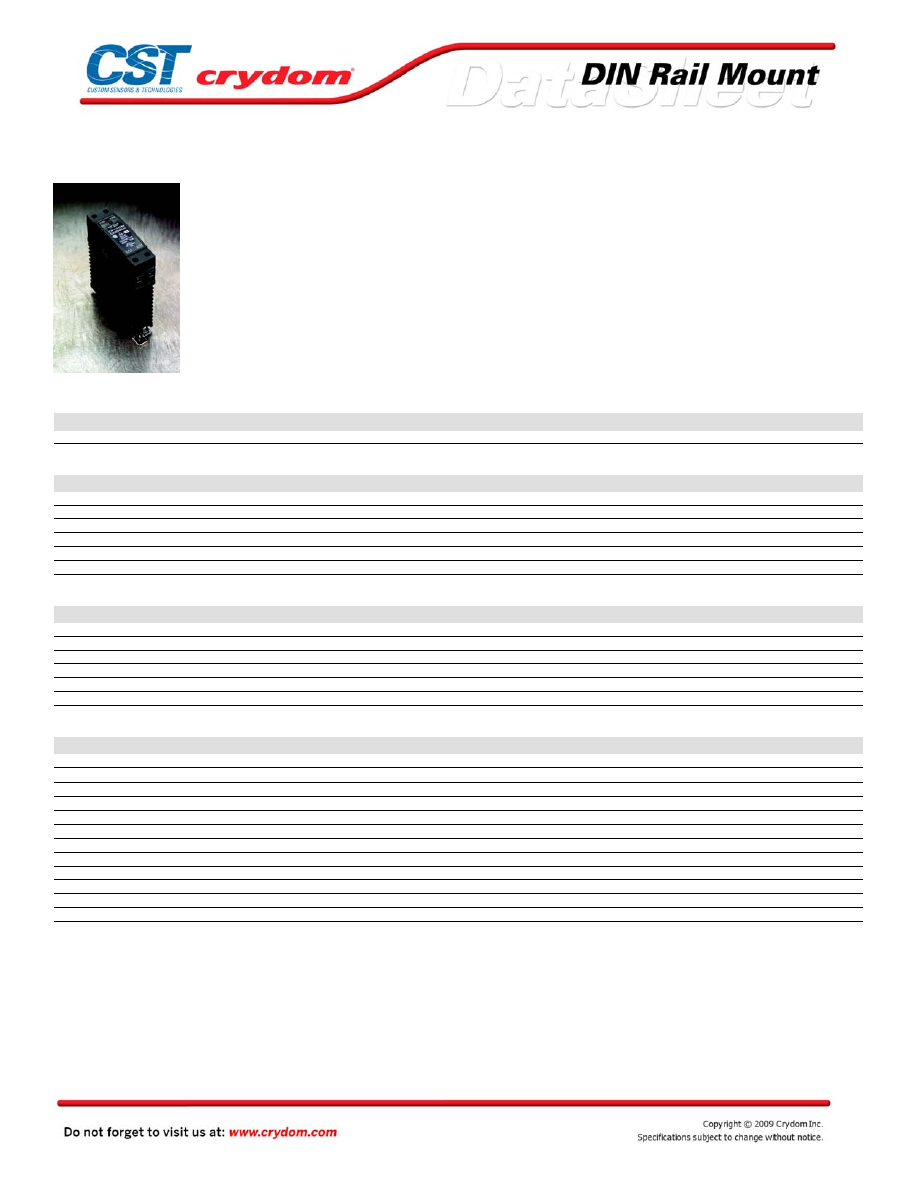
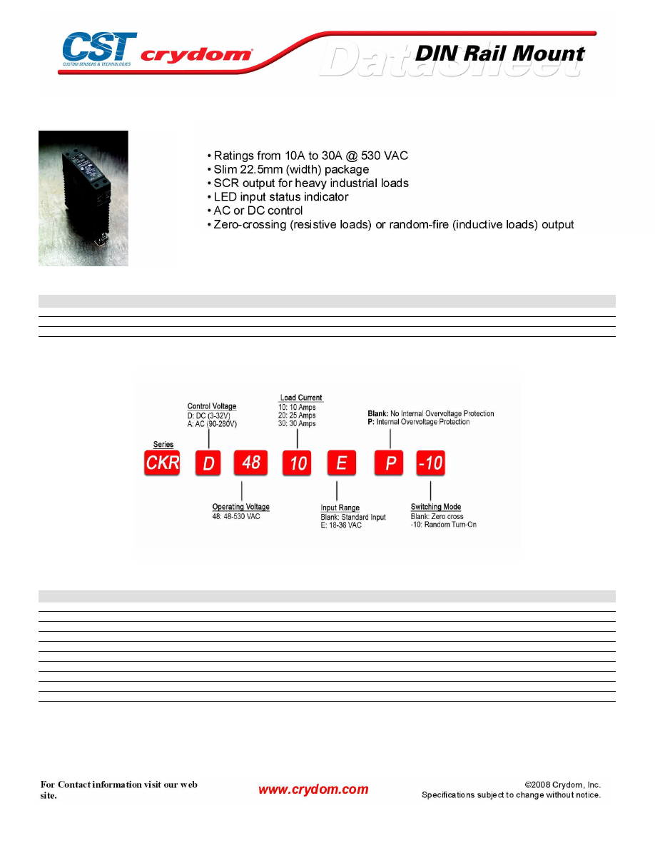
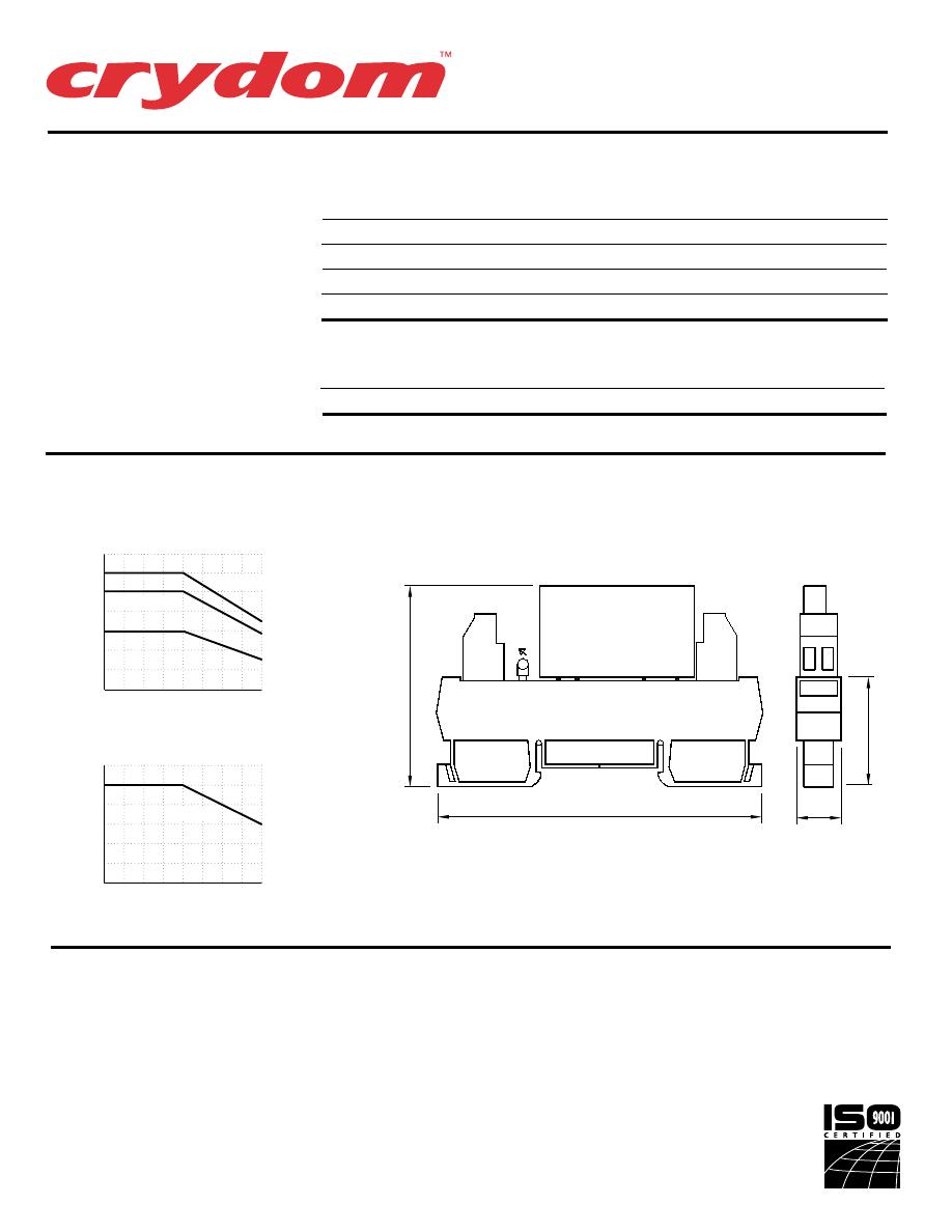
CKM Series
• Ratings from 10A to 30A @ 60 VDC
• Slim 22.5mm (width) package
• Low Leakage
• LED input status indicator
• DC control
• DIN Rail and Panel Mount
PRODUCT SELECTION
Description
10 A
20 A
30 A
4.5-32 VDC Control
CKM6010
CKM6020
CKM6030
OUTPUT SPECIFICATIONS (1)
Description
CKM0610
CKM0620
CKM0630
Operating Voltage [VDC]
0-60
0-60
0-60
Maximum Off-State Leakage Current @ Rated Voltage [mArms]
0.1
0.1
0.1
Maximum Load Current [Arms]
10
20
30
Maximum Surge Current (10msec) [ADC]
30
60
90
Maximum On-State Voltage Drop @ Rated Current [VDC]
0.2
0.4
0.5
Maximum On-state Resistance @ Rated current (RDS-ON) [ohms]
0.02
0.018
0.016
INPUT SPECIFICATIONS (1)
Description
Control Voltage Range
4.0-32 VDC
Maximum Turn-On Voltage
4.0 VDC
Minimum Turn-Off Voltage
1.0 VDC
Maximum Input Current (4)
9 mA @ 5 VDC, 11 mA @ 32 VDC (3)
Maximum Turn-On Time [msec]
1.0
Maximum Turn-Off Time [msec]
1.0
GENERAL SPECIFICATIONS
Description
Parameters
Dielectric Strength, Input/Output/Base (50/60Hz)
2500Vrms
Minimum Insulation Resistance (@ 500 V DC)
10
9
Ohms
Maximum Capacitance, Input/Output
8 pF
Ambient Operating Temperature Range
-40ºC to 80ºC
Ambient Storage Temperature Range
-40ºC to 125ºC
Status Indicator Display
Green LED
Weight (typical)
10 oz. (280g)
Encapsulation
Thermally Conductive Epoxy
Terminals
Box Clamp Type
Maximum Wire Size:
AWG # 10 (3mm)
Recommended Terminal Screw Torque Range:
5.0-6.0 in lb (0.6-0.7 Nm)
Min. Side by Side Spacing
0.8 inch (20mm)
GENERAL NOTES
1) All parameters at 25°C unless otherwise specified.
2) Off-State dv/dt test method per EIA/NARM standard RS-443, paragraph 13.11.1
3) Turn-on time for DC control random turn-on versions is 0.02 msec
4) Input circuitry for DC control version incorporates active current limiter.
Courtesy of Steven Engineering, Inc.-230 Ryan Way, South San Francisco, CA 94080-6370-Main Office: (650) 588-9200-Outside Local Area: (800) 258-9200-www.stevenengineering.com
60MAIN-html.html
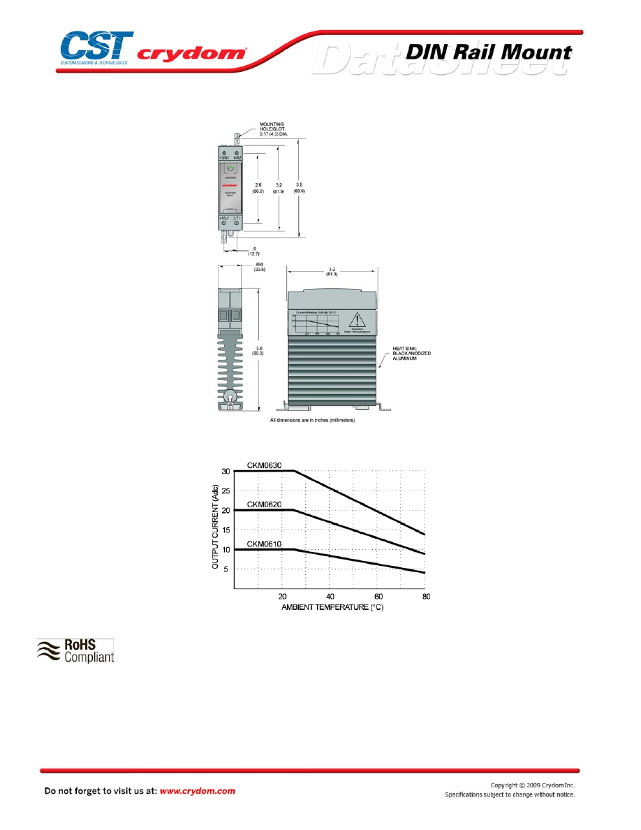
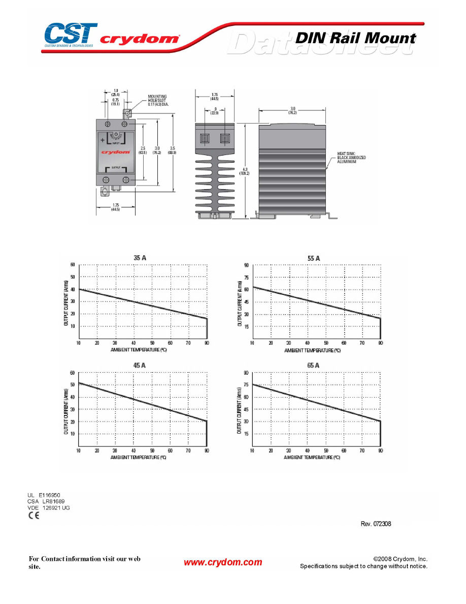
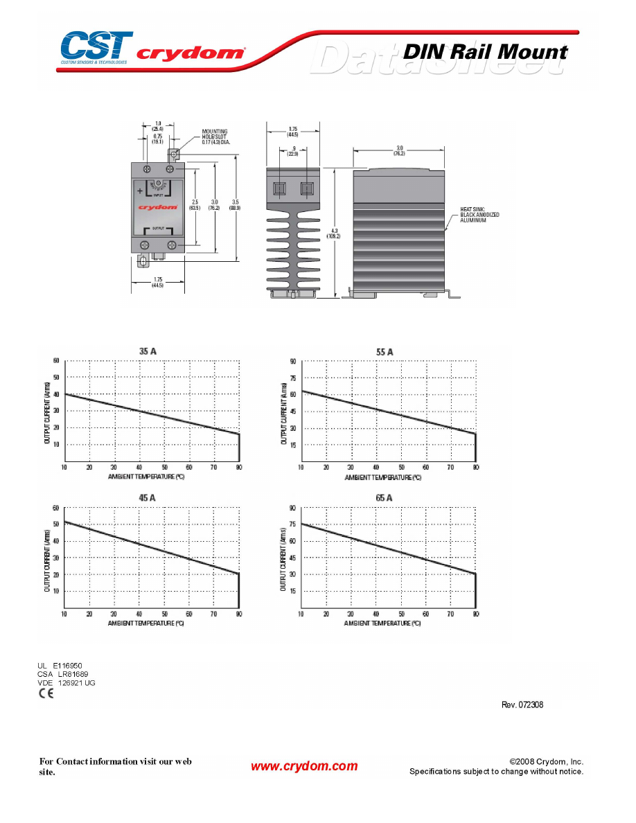
MECHANICAL SPECIFICATIONS
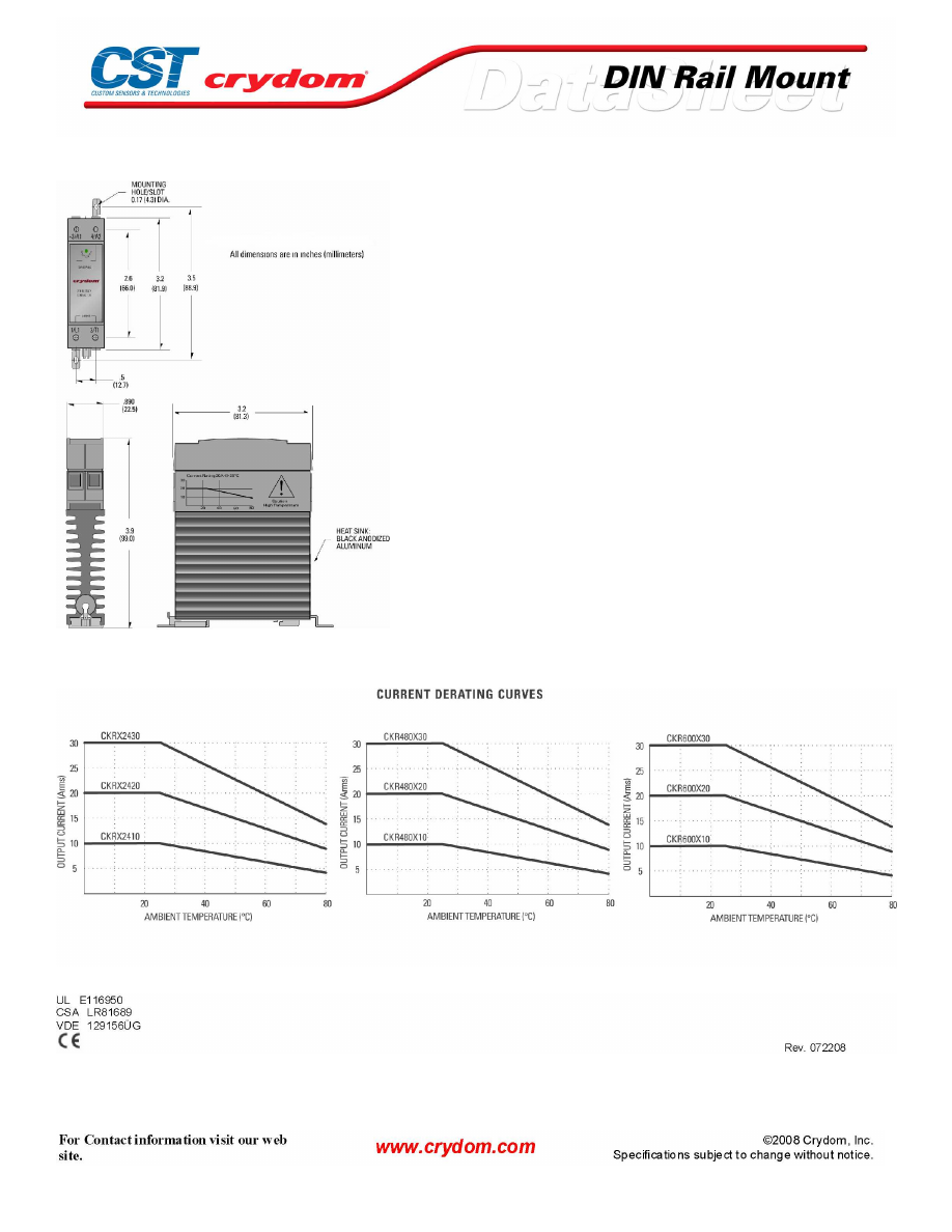
THERMAL DERATE INFORMATION
AGENCY APPROVALS
Rev. 011209
Courtesy of Steven Engineering, Inc.-230 Ryan Way, South San Francisco, CA 94080-6370-Main Office: (650) 588-9200-Outside Local Area: (800) 258-9200-www.stevenengineering.com
60MAIN-html.html
Courtesy of Steven Engineering, Inc.-230 Ryan Way, South San Francisco, CA 94080-6370-Main Office: (650) 588-9200-Outside Local Area: (800) 258-9200-www.stevenengineering.com
60MAIN-html.html
ANNEX - ENVIROMENTAL INFORMATION
Courtesy of Steven Engineering, Inc.-230 Ryan Way, South San Francisco, CA 94080-6370-Main Office: (650) 588-9200-Outside Local Area: (800) 258-9200-www.stevenengineering.com
60MAIN-html.html

CKR24 Series
PRODUCT SELECTION
Description
10 A
20 A
30 A
4.5-32 VDC Control
CKRD2410
CKRD2420
CKRD2430
90-280 VAC Control
CKRA2410
CKRA2420
CKRA2430
18-36 VAC Control
CKRA2410E
CKRA2420E
CKRA2430E
AVAILABLE OPTIONS
OUTPUT SPECIFICATIONS (1)
Description
Operating Voltage (47-63Hz) [Vrms]
24-280
24-280
24-280
Transient Overvoltage [Vpk]
600
600
600
Maximum Off-State Leakage Current @ Rated Voltage [mArms]
10
10
10
Minimum Off-State dv/dt @ Maximum Rated Voltage [V/µsec] (2)
500
500
500
Maximum Load Current [Arms]
10
20
30
Minimum Load Current [Arms]
0.15
0.15
0.15
Maximum Surge Current (16.6ms) [Apk]
120
250
625
Maximum On-State Voltage Drop @ Rated Current [Vpk]
1.6
1.6
1.6
Maximum I² t for Fusing (8.3 msec) [A² sec]
60
260
1620
Minimum Power Factor (with Maximum Load)
0.5
0.5
0.5
Courtesy of Steven Engineering, Inc.-230 Ryan Way, South San Francisco, CA 94080-6370-Main Office: (650) 588-9200-Outside Local Area: (800) 258-9200-www.stevenengineering.com
60MAIN-html.html

INPUT SPECIFICATIONS (1)
Description
Control Voltage Range
4.0-32 VDC
90-280 Vrms
18-36 Vrms
Maximum Turn-On Voltage
4.0 VDC
90 Vrms
18 Vrms
Minimum Turn-Off Voltage
1.0 VDC
10 Vrms
4.0 Vrms
Typical Input Current (4)
8-12 mA
2 mA @ 120 Vrms, 4 mA @ 240 Vrms
10 mA @ 240 Vrms
Maximum Turn-On Time [msec] (3)
1/2 Cycle
10
10
Maximum Turn-Off Time [msec]
1/2 Cycle
40
40
GENERAL SPECIFICATIONS
Description
Parameters
Dielectric Strength, Input/Output/Base (50/60Hz)
4000Vrms
Minimum Insulation Resistance (@ 500 V DC)
10
9
Ohms
Maximum Capacitance, Input/Output
8 pF
Ambient Operating Temperature Range
-40ºC to 80ºC
Ambient Storage Temperature Range
-40ºC to 125ºC
Status Indicator Display
Green LED
Weight (typical)
10 oz. (280g)
Encapsulation
Thermally Conductive Epoxy
Terminals
Box Clamp Type
Maximum Wire Size:
AWG # 10 (3mm)
Recommended Terminal Screw Torque Range:
5.0-6.0 in lb (0.6-0.7 Nm)
Min. Side by Side Spacing
0.8 inch (20mm)
Courtesy of Steven Engineering, Inc.-230 Ryan Way, South San Francisco, CA 94080-6370-Main Office: (650) 588-9200-Outside Local Area: (800) 258-9200-www.stevenengineering.com
60MAIN-html.html
MECHANICAL SPECIFICATIONS
THERMAL DERATE INFORMATION
AGENCY APPROVALS
Courtesy of Steven Engineering, Inc.-230 Ryan Way, South San Francisco, CA 94080-6370-Main Office: (650) 588-9200-Outside Local Area: (800) 258-9200-www.stevenengineering.com
60MAIN-html.html

Courtesy of Steven Engineering, Inc.-230 Ryan Way, South San Francisco, CA 94080-6370-Main Office: (650) 588-9200-Outside Local Area: (800) 258-9200-www.stevenengineering.com
60MAIN-html.html

ANNEX - ENVIROMENTAL INFORMATION
Courtesy of Steven Engineering, Inc.-230 Ryan Way, South San Francisco, CA 94080-6370-Main Office: (650) 588-9200-Outside Local Area: (800) 258-9200-www.stevenengineering.com
60MAIN-html.html
CKR48Series
PRODUCT SELECTION
Description
10 A
20 A
30 A
4.5-32 VDC Control
CKRD4810
CKRD4820
CKRD4830
90-280 VAC Control
CKRA4810
CKRA4820
CKRA4830
18-36 VAC Control
CKRA4810E
CKRA4820E
CKRA4830E
AVAILABLE OPTIONS
OUTPUT SPECIFICATIONS (1)
Description
Operating Voltage (47-63Hz) [Vrms]
48-530
48-530
48-530
Transient Overvoltage [Vpk]
1200
1200
1200
Maximum Off-State Leakage Current @ Rated Voltage [mArms]
10
10
10
Minimum Off-State dv/dt @ Maximum Rated Voltage [V/µsec] (2)
500
500
500
Maximum Load Current [Arms]
10
20
30
Minimum Load Current [Arms]
0.15
0.15
0.15
Maximum Surge Current (16.6ms) [Apk]
120
250
625
Maximum On-State Voltage Drop @ Rated Current [Vpk]
1.6
1.6
1.6
Maximum I² t for Fusing (8.3 msec) [A² sec]
60
260
1620
Minimum Power Factor (with Maximum Load)
0.5
0.5
0.5
Courtesy of Steven Engineering, Inc.-230 Ryan Way, South San Francisco, CA 94080-6370-Main Office: (650) 588-9200-Outside Local Area: (800) 258-9200-www.stevenengineering.com
60MAIN-html.html

INPUT SPECIFICATIONS (1)
Description
Control Voltage Range
4.0-32 VDC
90-280 Vrms
18-36 Vrms
Maximum Turn-On Voltage
4.0 VDC
90 Vrms
18 Vrms
Minimum Turn-Off Voltage
1.0 VDC
10 Vrms
4.0 Vrms
Typical Input Current (4)
8-12 mA
2 mA @ 120 Vrms, 4 mA @ 240
Vrms
10 mA @ 24 Vrms
Maximum Turn-On Time [msec] (3)
1/2 Cycle
10
10
Maximum Turn-Off Time [msec]
1/2 Cycle
40
40
GENERAL SPECIFICATIONS
Description
Parameters
Dielectric Strength, Input/Output/Base (50/60Hz)
4000Vrms
Minimum Insulation Resistance (@ 500 V DC)
10
9
Ohms
Maximum Capacitance, Input/Output
8 pF
Ambient Operating Temperature Range
-40ºC to 80ºC
Ambient Storage Temperature Range
-40ºC to 125ºC
Status Indicator Display
Green LED
Weight (typical)
10 oz. (280g)
Encapsulation
Thermally Conductive Epoxy
Terminals
Box Clamp Type
Maximum Wire Size:
AWG # 10 (3mm)
Recommended Terminal Screw Torque Range:
5.0-6.0 in lb (0.6-0.7 Nm)
Min. Side by Side Spacing
0.8 inch (20mm)
Courtesy of Steven Engineering, Inc.-230 Ryan Way, South San Francisco, CA 94080-6370-Main Office: (650) 588-9200-Outside Local Area: (800) 258-9200-www.stevenengineering.com
60MAIN-html.html

MECHANICAL SPECIFICATIONS
THERMAL DERATE INFORMATION
AGENCY APPROVALS
Courtesy of Steven Engineering, Inc.-230 Ryan Way, South San Francisco, CA 94080-6370-Main Office: (650) 588-9200-Outside Local Area: (800) 258-9200-www.stevenengineering.com
60MAIN-html.html
Courtesy of Steven Engineering, Inc.-230 Ryan Way, South San Francisco, CA 94080-6370-Main Office: (650) 588-9200-Outside Local Area: (800) 258-9200-www.stevenengineering.com
60MAIN-html.html

ANNEX - ENVIROMENTAL INFORMATION
Courtesy of Steven Engineering, Inc.-230 Ryan Way, South San Francisco, CA 94080-6370-Main Office: (650) 588-9200-Outside Local Area: (800) 258-9200-www.stevenengineering.com
60MAIN-html.html

CKR60 Series
PRODUCT SELECTION
Description
10 A
20 A
30 A
4.5-32 VDC Control
CKRD6010
CKRD6020
CKRD6030
90-280 VAC Control
CKRA6010
CKRA6020
CKRA6030
18-36 VAC Control
CKRA6010E
CKRA6020E
CKRA6030E
AVAILABLE OPTIONS
OUTPUT SPECIFICATIONS (1)
Description
Operating Voltage (47-63Hz) [VRMS]
48-660
48-660
48-660
Transient Overvoltage [Vpk]
1200
1200
1200
Maximum Off-State Leakage Current @ Rated Voltage [mArms]
1.0
1.0
1.0
Minimum Off-State dv/dt @ Maximum Rated Voltage [V/µsec] (2)
500
500
500
Maximum Load Current (3) [Arms]
10
20
30
Minimum Load Current [Arms]
0.15
0.15
0.15
Maximum Surge Current (16.6ms) [Apk]
120
250
625
Maximum On-State Voltage Drop @ Rated Current [Vpk]
1.6
1.6
1.6
Maximum I²t for Fusing (8.3 msec) [A² sec]
60
260
1620
Minimum Power Factor (with Maximum Load)
0.5
0.5
0.5
Courtesy of Steven Engineering, Inc.-230 Ryan Way, South San Francisco, CA 94080-6370-Main Office: (650) 588-9200-Outside Local Area: (800) 258-9200-www.stevenengineering.com
60MAIN-html.html
INPUT SPECIFICATIONS (1)
Description
Control Voltage Range
4.0-32 VDC
90-280 Vrms
18-36 Vrms
Maximum Turn-On Voltage
4.0 VDC
90 Vrms
18 Vrms
Minimum Turn-Off Voltage
1.0 VDC
10 Vrms
4.0 Vrms
Typical Input Current (4)
8-12 mA
2 mA @ 120 Vrms, 4 mA @ 240
Vrms
10 mA @ 24 Vrms
Maximum Turn-On Time [msec] (3)
1/2 Cycle
10
10
Maximum Turn-Off Time [msec]
1/2 Cycle
40
40
GENERAL SPECIFICATIONS
Description
Parameters
Dielectric Strength, Input/Output/Base (50/60Hz)
4000Vrms
Minimum Insulation Resistance (@ 500 V DC)
10 9 Ohms
Maximum Capacitance, Input/Output
8 pF
Ambient Operating Temperature Range
-40ºC to 80ºC
Ambient Storage Temperature Range
-40ºC to 125ºC
Status Indicator Display
Green LED
Weight (typical)
10 oz. (280g)
Encapsulation
Thermally Conductive Epoxy
Terminals
Box Clamp Type
Maximum Wire Size:
AWG # 10 (3mm)
Recommended Terminal Screw Torque Range:
5.0-6.0 in lb (0.6-0.7 Nm)
Min. Side by Side Spacing
0.8 inch (20mm)
Courtesy of Steven Engineering, Inc.-230 Ryan Way, South San Francisco, CA 94080-6370-Main Office: (650) 588-9200-Outside Local Area: (800) 258-9200-www.stevenengineering.com
60MAIN-html.html
MECHANICAL SPECIFICATIONS
THERMAL DERATE INFORMATION
AGENCY APPROVALS
Courtesy of Steven Engineering, Inc.-230 Ryan Way, South San Francisco, CA 94080-6370-Main Office: (650) 588-9200-Outside Local Area: (800) 258-9200-www.stevenengineering.com
60MAIN-html.html

Courtesy of Steven Engineering, Inc.-230 Ryan Way, South San Francisco, CA 94080-6370-Main Office: (650) 588-9200-Outside Local Area: (800) 258-9200-www.stevenengineering.com
60MAIN-html.html

ANNEX - ENVIROMENTAL INFORMATION
Courtesy of Steven Engineering, Inc.-230 Ryan Way, South San Francisco, CA 94080-6370-Main Office: (650) 588-9200-Outside Local Area: (800) 258-9200-www.stevenengineering.com
60MAIN-html.html

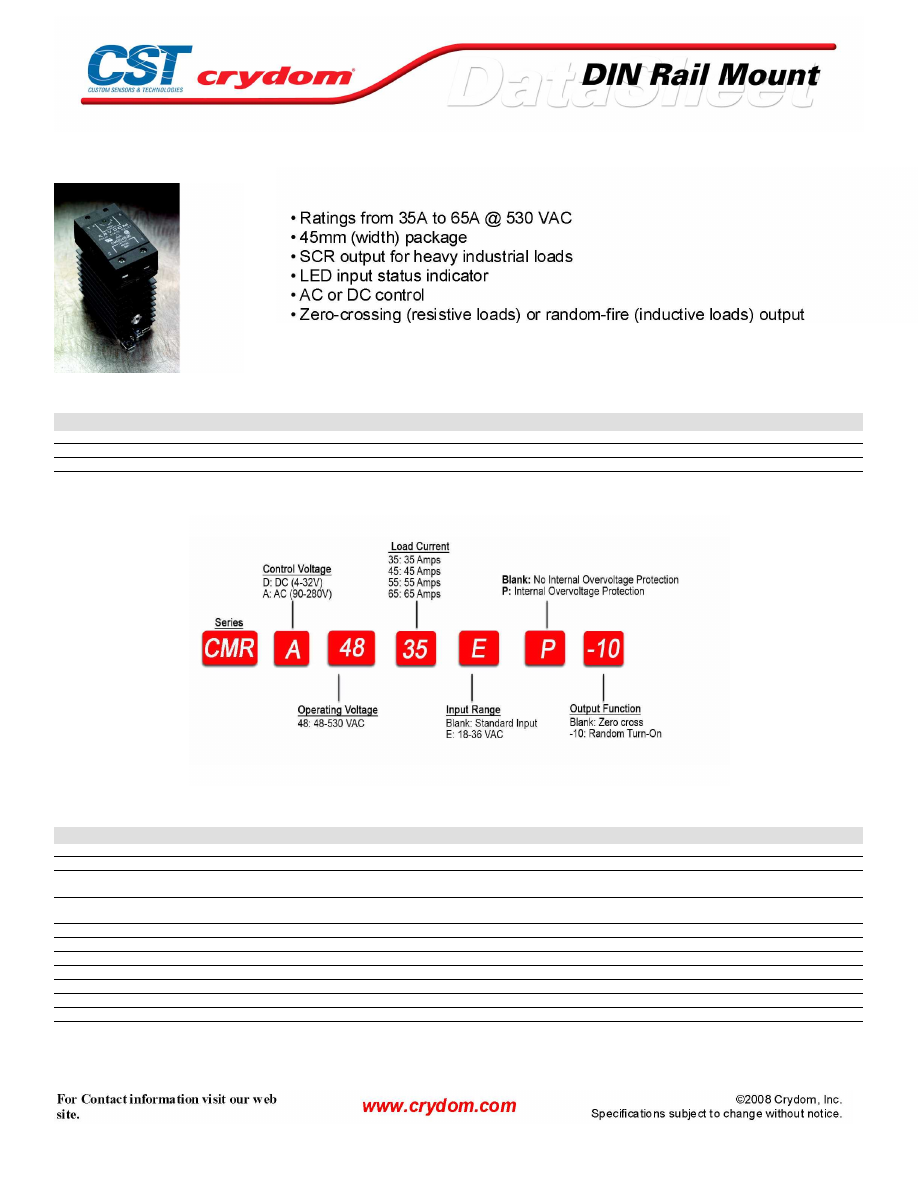
CMR24 Series
PRODUCT SELECTION
Description
35 A
45 A
55 A
65 A
3-32 VDC Control
CMRD2435
CMRD2445
CMRD2455
CMRD2465
90-140 VAC Control
CMRA2435
CMRA2445
CMRA2455
CMRA2465
18-36 VAC Control
CMRA2435E
CMRA2445E
CMRA2455E
CMRA2465E
AVAILABLE OPTIONS
OUTPUT SPECIFICATIONS (1)
Description
Operating Voltage (47-63Hz) [Vrms]
24-280
24-280
24-280
24-280
Transient Overvoltage [Vpk]
600
600
600
600
Maximum Off-State Leakage Current @ Rated Voltage [mArms]
10
10
10
10
Minimum Off-State dv/dt @ Maximum Rated Voltage [V/µsec] (2)
500
500
500
500
Maximum Load Current [Arms]
35
45
55
65
Minimum Load Current [Arms]
0.15
0.15
0.25
0.25
Maximum Surge Current (16.6ms) [Apk]
250
625
1000
1200
Maximum On-State Voltage Drop @ Rated Current [Vpk]
1.6
1.6
1.6
1.6
Thermal Resistance Junction to Case (Rjc) [°C/W]
1.02
0.63
0.31
0.28
Maximum I² t for Fusing (8.3 msec) [A² sec]
260
1620
4150
6000
Minimum Power Factor (with Maximum Load)
0.5
0.5
0.5
0.5
Courtesy of Steven Engineering, Inc.-230 Ryan Way, South San Francisco, CA 94080-6370-Main Office: (650) 588-9200-Outside Local Area: (800) 258-9200-www.stevenengineering.com
60MAIN-html.html

INPUT SPECIFICATIONS (1)
Description
Control Voltage Range (DC or RMS)
3-32 VDC
90-140 Vrms
Maximum Turn-On Voltage
4.0 VDC
90 Vrms
Minimum Turn-Off Voltage
1.0 VDC
10 Vrms
Maximum Reverse Voltage
32 VDC
-
Maximum Off-State Voltage
1.0 VDC
10 VAC
Maximum Input Current
30 mA (4)
-
Typical Input Current (4)
17 mA @ 5 Vdc
15 mA @ 120 Vrms
Maximum Turn-On Time [msec] (3)
1/2 Cycle
10
Maximum Turn-Off Time [msec]
1/2 Cycle
40
GENERAL SPECIFICATIONS
Description
Parameters
Dielectric Strength, Input/Output/Base (50/60Hz)
4000 Vrms
Minimum Insulation Resistance (@ 500 V DC)
10 9 Ohms
Maximum Capacitance, Input/Output
8 pF
Ambient Operating Temperature Range
-40 to 80˚C
Ambient Storage Temperature Range
-40 to 125˚C
Status Indicator Display
Green LED
Weight (typical)
16.8 oz. (476g)
Encapsulation
Themally Conductive Epoxy
Terminals
Cage Type
Maximum Wire Size:
Output: AWG 8 (3.8mm) Input: AWG12(2.5mm)
Recommended Terminal Screw Torque Range:
Output:10-15 in lb (1.1-1.7 Nm) Input: 5-6in lb (0.6-0.7 Nm)
Courtesy of Steven Engineering, Inc.-230 Ryan Way, South San Francisco, CA 94080-6370-Main Office: (650) 588-9200-Outside Local Area: (800) 258-9200-www.stevenengineering.com
60MAIN-html.html
MECHANICAL SPECIFICATIONS
THERMAL DERATE INFORMATION
AGENCY APPROVALS
Courtesy of Steven Engineering, Inc.-230 Ryan Way, South San Francisco, CA 94080-6370-Main Office: (650) 588-9200-Outside Local Area: (800) 258-9200-www.stevenengineering.com
60MAIN-html.html

Courtesy of Steven Engineering, Inc.-230 Ryan Way, South San Francisco, CA 94080-6370-Main Office: (650) 588-9200-Outside Local Area: (800) 258-9200-www.stevenengineering.com
60MAIN-html.html

ANNEX - ENVIROMENTAL INFORMATION
Courtesy of Steven Engineering, Inc.-230 Ryan Way, South San Francisco, CA 94080-6370-Main Office: (650) 588-9200-Outside Local Area: (800) 258-9200-www.stevenengineering.com
60MAIN-html.html
CMR48 Series
PRODUCT SELECTION
Description
35 A
45 A
55 A
65 A
3-32 VDC Control
CMRD4835
CMRD4845
CMRD4855
CMRD4865
90-140 VAC Control
CMRA4835
CMRA4845
CMRA4855
CMRA4865
18-36 VAC Control
CMRA4835E
CMRA4845E
CMRA4855E
CMRA4865E
AVAILABLE OPTIONS
OUTPUT SPECIFICATIONS (1)
Description
Operating Voltage (47-63Hz) [Vrms]
48-530
48-530
48-530
48-530
Transient Overvoltage [Vpk]
1200
1200
1200
1200
Maximum Off-State Leakage Current @ Rated Voltage
[mArms]
10
10
10
10
Minimum Off-State dv/dt @ Maximum Rated Voltage
[V/µsec] (2)
500
500
500
500
Maximum Load Current [Arms]
35
45
55
65
Minimum Load Current [Arms]
0.15
0.15
0.25
0.25
Maximum Surge Current (16.6ms) [Apk]
250
625
1000
1200
Maximum On-State Voltage Drop @ Rated Current [Vpk]
1.7
1.7
1.7
1.7
Thermal Resistance Junction to Case (Rjc) [°C/W]
1.02
0.63
0.31
0.28
Maximum I²t for Fusing (8.3 msec) [A² sec]
260
1620
4150
6000
Minimum Power Factor (with Maximum Load)
0.5
0.5
0.5
0.5
Courtesy of Steven Engineering, Inc.-230 Ryan Way, South San Francisco, CA 94080-6370-Main Office: (650) 588-9200-Outside Local Area: (800) 258-9200-www.stevenengineering.com
60MAIN-html.html
INPUT SPECIFICATIONS (1)
Description
Control Voltage Range
4-32 VDC
90-140 Vrms
Maximum Turn-On Voltage
4.0 VDC
90 Vrms
Minimum Turn-Off Voltage
1.0 VDC
10 Vrms
Maximum Reverse Voltage
32 VDC
-
Maximum Input Current
30 mA (4)
-
Typical Input Current (4)
14 mA @ 5 VDC
15 mA @ 120 Vrms
Maximum Turn-On Time [msec] (3)
1/2 Cycle
10
Maximum Turn-Off Time [msec]
1/2 Cycle
40
GENERAL SPECIFICATIONS
Description
Parameters
Dielectric Strength, Input/Output/Base (50/60Hz)
4000 Vrms
Minimum Insulation Resistance (@ 500 V DC)
10 9 Ohms
Maximum Capacitance, Input/Output
8 pF
Ambient Operating Temperature Range
-40 to 80˚C
Ambient Storage Temperature Range
-40 to 125˚C
Status Indicator Display
Green LED
Weight (typical)
16.8 oz. (476g)
Encapsulation
Themally Conductive Epoxy
Terminals
Cage Type
Maximum Wire Size:
Output: AWG 8 (3.8mm) Input: AWG12(2.5mm)
Recommended Terminal Screw Torque Range:
Output:10-15 in lb (1.1-1.7 Nm) Input: 5-6 in lb (0.6-0.7 Nm)
Courtesy of Steven Engineering, Inc.-230 Ryan Way, South San Francisco, CA 94080-6370-Main Office: (650) 588-9200-Outside Local Area: (800) 258-9200-www.stevenengineering.com
60MAIN-html.html
MECHANICAL SPECIFICATIONS
THERMAL DERATE INFORMATION
AGENCY APPROVALS
Courtesy of Steven Engineering, Inc.-230 Ryan Way, South San Francisco, CA 94080-6370-Main Office: (650) 588-9200-Outside Local Area: (800) 258-9200-www.stevenengineering.com
60MAIN-html.html

Courtesy of Steven Engineering, Inc.-230 Ryan Way, South San Francisco, CA 94080-6370-Main Office: (650) 588-9200-Outside Local Area: (800) 258-9200-www.stevenengineering.com
60MAIN-html.html

ANNEX - ENVIROMENTAL INFORMATION
Courtesy of Steven Engineering, Inc.-230 Ryan Way, South San Francisco, CA 94080-6370-Main Office: (650) 588-9200-Outside Local Area: (800) 258-9200-www.stevenengineering.com
60MAIN-html.html

CMR60 Series
PRODUCT SELECTION
Description
35 A
45 A
55 A
65 A
3-32 VDC Control
CMRD6035
CMRD6045
CMRD6055
CMRD6065
90-140 VAC Control
CMRA6035
CMRA6045
CMRA6055
CMRA6065
18-36 VAC Control
CMRA6035E
CMRA6045E
CMRA6055E
CMRA6065E
AVAILABLE OPTIONS
OUTPUT SPECIFICATIONS (1)
Description
Operating Voltage (47-63Hz) [Vrms]
48-660
48-660
48-660
48-660
Transient Overvoltage [Vpk]
1200
1200
1200
1200
Maximum Off-State Leakage Current @ Rated Voltage [mArms]
1.0
1.0
1.0
1.0
Minimum Off-State dv/dt @ Maximum Rated Voltage [V/µsec] (2)
500
500
500
500
Maximum Load Current [Arms]
35
45
55
65
Minimum Load Current [Arms]
0.15
0.15
0.25
0.25
Maximum Surge Current (16.6ms) [Apk]
250
625
1000
1200
Maximum On-State Voltage Drop @ Rated Current [Vpk]
1.7
1.7
1.7
1.7
Thermal Resistance Junction to Case (Rjc) [°C/W]
1.02
0.63
0.31
0.28
Maximum I²t for Fusing (8.3 msec) [A² sec]
260
1620
4150
6000
Minimum Power Factor (with Maximum Load)
0.5
0.5
0.5
0.5
Courtesy of Steven Engineering, Inc.-230 Ryan Way, South San Francisco, CA 94080-6370-Main Office: (650) 588-9200-Outside Local Area: (800) 258-9200-www.stevenengineering.com
60MAIN-html.html

INPUT SPECIFICATIONS (1)
Description
Control Voltage Range
4-32 VDC
90-140 Vrms
Maximum Turn-On Voltage
4.0 VDC
90 Vrms
Minimum Turn-Off Voltage
1.0 VDC
10 Vrms
Maximum Reverse Voltage
32 VDC
-
Maximum Input Current
30 mA (4)
Typical Input Current (4)
14 mA @ 5 VDC
15 mA @ 120 Vrms
Maximum Turn-On Time [msec] (3)
1/2 Cycle
10
Maximum Turn-Off Time [msec]
1/2 Cycle
40
GENERAL SPECIFICATIONS
Description
Parameters
Dielectric Strength, Input/Output/Base (50/60Hz)
4000 Vrms
Minimum Insulation Resistance (@ 500 V DC)
10 9 Ohms
Maximum Capacitance, Input/Output
8 pF
Ambient Operating Temperature Range
-40 to 80˚C
Ambient Storage Temperature Range
-40 to 125˚C
Status Indicator Display
Green LED
Weight (typical)
16.8 oz. (476g)
Encapsulation
Themally Conductive Epoxy
Terminals
Cage Type
Maximum Wire Size:
Output: AWG 8 (3.8mm) Input: AWG12(2.5mm)
Recommended Terminal Screw Torque Range:
Output:10-15 in lb(1.1-1.7 Nm) Input: 5-6 in lb (0.6-0.7 Nm)
Courtesy of Steven Engineering, Inc.-230 Ryan Way, South San Francisco, CA 94080-6370-Main Office: (650) 588-9200-Outside Local Area: (800) 258-9200-www.stevenengineering.com
60MAIN-html.html
MECHANICAL SPECIFICATIONS
THERMAL DERATE INFORMATION
AGENCY APPROVALS
Courtesy of Steven Engineering, Inc.-230 Ryan Way, South San Francisco, CA 94080-6370-Main Office: (650) 588-9200-Outside Local Area: (800) 258-9200-www.stevenengineering.com
60MAIN-html.html

Courtesy of Steven Engineering, Inc.-230 Ryan Way, South San Francisco, CA 94080-6370-Main Office: (650) 588-9200-Outside Local Area: (800) 258-9200-www.stevenengineering.com
60MAIN-html.html
ANNEX - ENVIROMENTAL INFORMATION
Courtesy of Steven Engineering, Inc.-230 Ryan Way, South San Francisco, CA 94080-6370-Main Office: (650) 588-9200-Outside Local Area: (800) 258-9200-www.stevenengineering.com
60MAIN-html.html
SERIES MS11-CMX.
Rev. 110707
PAGE 1 OF 3
• DIN Rail Mount
(TS 35)
• MOSFET Output
DC output SPST-NO solid state relays
use MOSFET output for high switching
capabilities in a DIN Rail (TS-35) mount
air-cooled package.
M O D E L N O .
MS11-CMX60D10
MS11-CMX100D6
INPUT SPECIFICATIONS
Control Voltage Range
5-10 Vdc
Nominal Input Impedance
300 Ohm
Typical Input Current @ 5 Vdc
12 mA
Must Turn On Voltage
5 Vdc
Must Turn Off Voltage
1.0 Vdc
OUTPUT SPECIFICATIONS
Operating Voltage Range
0-60 Vdc
0-100 Vdc
Load Current Range
0-10 Adc
0-6 Adc
Max. Surge Current, (10 msec)
100 Apk
100 Apk
Max.Off-State Leakage
@ Rated Voltage
100 µAdc
Max. On-State Resistance
@ Rated Current (R
DS-ON
)
.018 Ohm
.040 Ohm
Max. On-State Voltage Drop
@ Rated Current
0.18V
0.24V
Max.Turn-On Time @ 10Vdc Control
1.0 msec
Max. Turn-Off TIme @ 10Vdc Control
300 µsec
G E N E R A L N O T E S
© 2007 CRYDOM Inc., Specifications subject to change without notice.
5-10 Vdc
300 Ohm
12 mA
5 Vdc
1.0 Vdc
100 µAdc
1.0 msec
300 µsec
Series MS11-CMX
3 -10 Amp • 0-200 Vdc • DC Output
Extra Low On State
Resistance
Input Status LED
•
•
All parameters at 25ºC unless otherwise specified.
Dielectric and insulation resistance are
measured between input and output.
Inductive loads should be diode suppressed.
At 55 Vdc.
1
1
3
1
2
3
4
MS11-CMX60D5
5-10 Vdc
300 Ohm
12 mA
5 Vdc
1.0 Vdc
0-60 Vdc
0-5 Adc
60 Apk
100 µAdc
.10 Ohm
0.5V
1.0 msec
300 µsec
MS11-CMX200D3
6-10 Vdc
300 Ohm
12 mA
6 Vdc
1.0 Vdc
0-200 Vdc
0-3 Adc
30 Apk
100 µAdc
.20 Ohm
0.6V
1.0 msec
300 µsec
For recommended applications and more information contact:
USA:
Sales Support (877) 502-5500
Tech Support
(877) 702-7700 FAX (619) 710-8540
Crydom Inc., 2320 Paseo de las Americas, Ste. 201, San Diego, CA 92154
Email:
sales@crydom.com
WEB SITE:
http://www.crydom.com
UK:
+44 (0)1202 606030 •
FAX
+44 (0)1202 606035 Crydom SSR Ltd., Arena Business Centre,
Holyrood Close, Poole, Dorset BH17 7FJ, Email: intsales@crydom.com.
GERMANY:
+49 (0)180 3000 506
4
Courtesy of Steven Engineering, Inc.-230 Ryan Way, South San Francisco, CA 94080-6370-Main Office: (650) 588-9200-Outside Local Area: (800) 258-9200-www.stevenengineering.com
60MAIN-html.html
SERIES MS11-CMX.
Rev. 110707
PAGE 2 OF 3
Series MS11-CMX
3 -10 Amp • 0-200 Vdc • DC Output
All dimensions are in millimeters (not to scale)
Colour of carrier including terminations - orange
29.0
12.5
85.0
54.0
-A2 +A1
Input Output
CMX Series
Solid State Relay
CRYDOM
DIN Rail TS35
G E N E R A L S P E C I F I C A T I O N S
Dielectric Strength
2500 Vrms
Insulation Resistance (Min.) @ 500 Vdc
10 9 Ohm
Max. Capacitance (Input/Output)
15 pF
Ambient Operating Temperature Range
-30 to 80°C
Ambient Storage Temperature Range
-30 to 125°C
M E C H A N I C A L S P E C I F I C A T I O N S
Weight: (typical)
30 g
Encapsulation(SSR):
Thermally Conductive Epoxy
C U R R E N T D E R A T I N G C U R V E S
5.0
6.0
7.0
3.0
1.0
2.0
4.0
0
20 40 60 80
AMBIENT TEMPERATURE [ °C ]
LOAD CURRENT [AMPS]
Max. Load Current vs. Temp.
10.0
12.0
6.0
2.0
4.0
8.0
0
20 40 60 80
AMBIENT TEMPERATURE [ °C ]
LOAD CURRENT [AMPS]
CMX
100
D
6
CMX
60
D
5
CMX
60
D
10
CMX
200
D
3
APPROVALS (SSR ONLY)
UL E116950 (3A, 6A & 10A Models)
2
2
©
2007 CRYDOM Inc., Specifications subject to change without notice.
For recommended applications and more information contact:
USA:
Sales Support (877) 502-5500
Tech Support
(877) 702-7700 FAX (619) 710-8540
Crydom Inc., 2320 Paseo de las Americas, Ste. 201, San Diego, CA 92154
Email:
sales@crydom.com
WEB SITE:
http://www.crydom.com
UK:
+44 (0)1202 606030 •
FAX
+44 (0)1202 606035 Crydom SSR Ltd., Arena Business Centre,
Holyrood Close, Poole, Dorset BH17 7FJ, Email: intsales@crydom.com.
GERMANY:
+49 (0)180 3000 506
Courtesy of Steven Engineering, Inc.-230 Ryan Way, South San Francisco, CA 94080-6370-Main Office: (650) 588-9200-Outside Local Area: (800) 258-9200-www.stevenengineering.com
60MAIN-html.html
AC CONTROL (120Vac)
M O D E L N U M B E R S
(24Vac)
MS11-CXE
240
A
5
DC CONTROL (5Vdc)
(24Vdc)
1
Operating Voltage (47-63 Hz) [Vrms]
12-280
Load Current Range [Arms]
.06-5
Transient Overvoltage [Vpk]
600
Max. Surge Current, (16.6ms) [Apk]
250
Max. On-State Voltage Drop @ Rated Current [Vpk]
1.4
Maximum I 2 t for Fusing, (8.3 msec.) [A2sec]
260
Max. Off-State Leakage Current @ Rated Voltage [mArms]
0.1
Min. Off-State dv/dt @ Max. Rated Voltage [V/µsec]
2
500
Max. Turn-On Time
3
1/2 Cycle (DC Control), 10.0 msec (AC Control)
Max. Turn-Off Time
1/2 Cycle (DC Control), 40.0 msec (AC Control)
Power Factor (Min.) with Max. Load
0.5
1
4
N o m i n a l V o l t a g e
5 V d c
2 4 V d c
M O D E L N U M B E R S
Control Voltage Range
4-5 Vdc
15-32 Vdc
90-140 Vrms
18-36 Vrms
Max. Turn-On Voltage
3.0 Vdc
15.0 Vdc
90.0 Vrms
18.0 Vrms
Min. Turn-Off Voltage
1.0 Vdc
1.0 Vdc
10.0 Vrms
2.0 Vrms
Nominal Input Impedance
300 Ohm
1.0k Ohm
14.1k Ohm
4.2k Ohm
Typical Input Current @ Nominal Voltage
12 mA
8 mA
10 mArms
5 mArms
1
All parameters at 25ºC unless otherwise specified.
2
Off-State dv/dt test method per EIA/NARM standard RS-443, paragraph 13.11.1
3
Turn-On Time for Random Turn-On versions 0.1msec (DC Control Models).
SCR Output Rating
Ultra High Surge
Crydom’s Patented Design
SERIES MS11-CX.
Rev. 012505
PAGE 1 OF 2
Series
MS11-CX
exceptional steady state current, plus
ultra-high surge ratings. Models are
available to switch up to 280 Vrms with
AC or DC control, and either zero-cross
or random turn-on ("R") switching ver-
sions.
© 2005 CRYDOM CORP, Specifications subject to change without notice.
5 Amp• 240 Vac• AC Output
MS11-CX
2405A
MS11-CXE
240D5
MS11-CX
240D5
MS11-CX240D5
•
•
•
Crydom's family of SPST-NO relays
achieves the highest power switching
capability in a DIN mounted air-cooled
package. Advanced features include
Input Status LED
•
DIN Rail Mount
(TS-35)
•
No input status LED on AC control modules.
O U T P U T S P E C I F I C A T I O N S
I N P U T S P E C I F I C A T I O N S
D C C O N T R O L
MS11-CXE240D5
1 2 0 V a c
2 4 V a c
A C C O N T R O L
MS11-CX240A5
MS11-CXE240A5
G E N E R A L N O T E S
4
For recommended applications and more information contact:
USA: Sales Support
(877) 502-5500 •
Tech Support
(877) 702-7700 •
FAX
(619) 710-8540
Crydom Corp, 2320 Paseo de las Americas, Ste. 201, San Diego, CA 92154
Email:
sales@crydom.com •
WEB SITE:
http://www.crydom.com
UK:
+44 (0)1202 365070 •
FAX:
+44 (0)1202 365090 Crydom International Ltd., 7 Cobham
Road, Ferndown Industrial Estate, Ferndown, Dorset BH21 7PE, Email: intsales@crydom.com.
GERMANY:
+49 (0)180 3000 506
Courtesy of Steven Engineering, Inc.-230 Ryan Way, South San Francisco, CA 94080-6370-Main Office: (650) 588-9200-Outside Local Area: (800) 258-9200-www.stevenengineering.com
60MAIN-html.html
5.0
6.0
3.0
1.0
2.0
4.0
0
20
40
60
80
LOAD CURRENT [AMPS]
Max. Load Current vs. Temp.
Dielectric Strength 50/60Hz Input/Output/Base
2500 Vrms
Insulation Resistance (Min.) @ 500 Vdc
10
9
Ohm
Max. Capacitance Input/Output
10 pF
Ambient Operating Temperature Range
-30 to 80ºC
Ambient Storage Temperature Range
-30 to 80ºC
Weight: (typical)
Encapsulation (SSR):
Thermally Conductive Epoxy
SERIES MS11-CX
Rev. 012405
PAGE 2 OF 2
© 2005 CRYDOM CORP, Specifications subject to change without notice.
R
Random Turn-On Switching
Example: MS11-
CX240D5R, MS11-CX240A5R
APPROVALS ( SSR ONLY )
UL
E
116949
CSA
LR
81689
VDE
70938
UG (240V, DC Control Only)
All dimensions are in millimeters (not to scale)
Colour of carrier and termination housing - orange
30 grms
Series MS11-
CX
5Amp • 240 Vac • AC Output
Input status LED is on DC control module only
29.0
12.5
85.0
54.0
-A2 +A1
Input Output
CX Series
Solid State Relay
CRYDOM
DIN Rail TS35
G E N E R A L S P E C I F I C A T I O N S
M E C H A N I C A L S P E C I F I C A T I O N
C U R R E N T D E R A T I N G C U R V E
AMBIENT TEMPERATURE [ C]
A V A I L A B L E O P T I O N S
For recommended applications and more information contact:
USA: Sales Support
(877) 502-5500 •
Tech Support
(877) 702-7700 •
FAX
(619) 710-8540
Crydom Corp, 2320 Paseo de las Americas, Ste. 201, San Diego, CA 92154
Email:
sales@crydom.com •
WEB SITE:
http://www.crydom.com
UK:
+44 (0)1202 365070 •
FAX:
+44 (0)1202 365090 Crydom International Ltd., 7 Cobham
Road, Ferndown Industrial Estate, Ferndown, Dorset BH21 7PE, Email: intsales@crydom.com.
GERMANY:
+49 (0)180 3000 506
Courtesy of Steven Engineering, Inc.-230 Ryan Way, South San Francisco, CA 94080-6370-Main Office: (650) 588-9200-Outside Local Area: (800) 258-9200-www.stevenengineering.com
60MAIN-html.html
HAZARD OF
ELECTRIC
SHOCK,
EXPLOSION,
OR ARC FLASH.
•
Disconnect all
power before
installing or
working with
this equipment.
•
Verify all
connections
and replace all
covers before
turning on
power.
Failure to follow
these
instructions will
result in death
or serious injury.
RIESGO DE
DESCARGA
ELECTRICA O
EXPLOSION.
•
Desconectar
todos los
suministros de
energia a este
equipo antes
de trabajar
con este equipo.
•
Verificar todas
las conexiones
y colocar todas
las tapas antes
de energizer
el equipo.
El
incumplimiento
de estas
instrucciones
puede provocar
la muerte o
lesiones serias.
RISQUE DE
DESCHARGE
ELECTRIQUE
OU EXPLOSION
•
Eteindre
toutes les
sources
d'énergie de
cet appareil
avant de
travailler
dessus de cet
appareil
•
Vérifier tous
connections, et
remettre tous
couverts en
olace avant de
mettre sous
De non-suivi de
ces instructions
provoquera la
mort ou des
lésions sérieuses
sérieuses.
GEFAHR EINES
ELEKTRISCHE
N SCHLAGES
ODER EINER
EXPLOSION.
•
Stellen Sie
jeglichen
Strom ab, der
dieses Gerät
versorgt, bevor
Sie an dem
Gerät Arbeiten
durchführen
•
Vor dem
Drehen auf
Energie alle
Anschlüsse
überprüfen
und alle
Abdeckungen
ersetzen.
Unterlassung
dieser
Anweisungen
können zum
Tode oder zu
schweren
Verletzungen
führen.
RISCHIO DI
SCOSSA
ELETTRICA O
DELL’ESPLOSI
ONE.
•
Spenga tutta
l'alimentazion
e che fornisce
questa
apparecchiatu
ra prima del
lavorare a questa
apparecchiatu ra
•
Verificare tutti
i collegamenti
e sostituire
tutte le coperture
prima della
rotazione
sull'alimentazi one
L'omissione di
seguire queste
istruz ioni
provocherà la
morte o di
lesioni serie
RISCO DE
DESCARGA
ELÉTTRICA OU
EXPLOSÃO
•
Desconectar
o equipamento
de toda á
energia antes
de instalar ou
trabalhar com
este equipamen
to
•
Verificar todas
as conexões e
recolocar todas
as tampas
antes de religar
o equipamento
O não cumprimento
destas instruções
pode levar á morte
ou lesões sérias.
RISQUE DE DOMMAGE MATERIEL ET DE
SURCHAUFFE DU BOITIER
•
Les panneaux latéraux du produit peuvent être
chauds. Laisser le produit refroidir avant de le
toucher.
•
Respecter les consignes de montage, et
notamment les couples de serrage.
•
Ne pas laisser pénétrer de liquide ni de corps
étrangers à l'intérieur du produit.
RISK OF MATERIAL DAMAGE AND HOT
ENCLOSURE
•
The product's side panels may be hot, allow
time for product to cool before touching.
•
Follow proper mounting instructions including
torque values
.
•
Do not allow liquids or foreign objects to enter
this product.
Le non-respect de cette directive peut entraîner,
des lésions corporelles graves ou des
dommages matériels.
Failure to follow this instruction can result in
serious injury, or equipment damage.
La mancata osservanza di questa precauzione può
causare gravi rischi per l'incolumità personale o
danni alle apparecchiature.
Si no se respetan estas precauciones pueden
producirse graves lesiones, daños materiales.
Die Nichtbeachtung dieser Anweisung kann
Körperverletzung oder Materialschäden
zur Folge haben.
A não observância destas precauções pode
provocar a morte, ferimentos graves ou
danos materiais.
GEFAHR VON MATERIALSCHÄDEN UND
GEHÄUSEERHITZUNG
•
Die Seitenwände können heiß sein. Lassen Sie
das Produkt abkühlen, bevor Sie es berühren.
•
Beachten Sie die Montageanweisungen,
•
Führen Sie keine Flüssigkeiten oder
Fremdkörper in das Produkt ein.
RISCHIO DI DANNI MATERIALI E D'INVOLUCRO
CALDO
•
I pannelli laterali dell'apparecchio possono
scottare; lasciar quindi raffreddare il prodotto
prima di toccarlo.
•
Seguire le istruzioni di montaggio corrette.
•
Non far entrare liquidi o oggetti estranei in questo
apparecchio.
RIESGO DE DAÑOS MATERIALES Y DE
SOBRECALENTAMIENTO DE LA UNIDAD
•
Los paneles laterales del producto pueden
estar calientes. Esperar que el producto se
enfríe antes de tocarlo.
•
Respetar las instrucciones de montaje, y en
particular los pares de apretado.
•
No dejar que penetren líquidos o cuerpos
extraños en el producto.
RISCO DE DANO MATERIAL E DE AQUECIMENTO
•
Os painéis laterais do produto podem estar
quentes; dê tempo ao produto para arrefecer
antes de lhe tocar.
•
Siga devidamente as instruções de montagem.
•
Não permita a entrada de líquidos e de objectos
estranhos no produto.
DANGER / PELIGRO / DANGER /GEFAHR / PERICOLO / PERIGO
WARNING / AVERTISSEMENT / WARNUNG /ADVERTENCIA / AVVERTENZA / AVISO
SERIES MS11-CMX.
Rev. 110707
PAGE 3 OF 3
Courtesy of Steven Engineering, Inc.-230 Ryan Way, South San Francisco, CA 94080-6370-Main Office: (650) 588-9200-Outside Local Area: (800) 258-9200-www.stevenengineering.com
60MAIN-html.html

ANNEX – ENVIRONMENTAL INFORMATION:
The environmental information disclosed in this annex including the EIP
Pollution logo are in compliance with People’s Republic of China Electronic
Industry Standard SJ/T11364 – 2006, Marking for Control of Pollution
Caused by Electronic Information Products.
Part
Toxic or hazardous Substance and Elements
Name
Lead
Mercury Cadmium Hexavalent
Polybrominated Polybrominated
(Pb)
(Hg)
(Cd)
Chromium
(Cr (VI))
biphenyls
(PBB)
diphenyl ethers
(PBDE)
Semiconductor
die
X
O
O
O
O
O
Solder
X
O
O
O
O
O
䰘ӊ
-
⦃ֱֵᙃ
:
ℸ䰘ӊ᠔ᷛ⼎ⱘࣙᣀ⬉ᄤֵᙃѻક∵ᶧᷛⱘ⦃ֱֵᙃ
ヺড়ЁढҎ⇥݅⬉ᄤ㸠Ϯᷛޚ
SJ/T11364 - 2006,
⬉ᄤֵᙃѻક∵ᶧࠊᷛ䆚㽕∖
㋴
ܗ
䋼
⠽
ᆇ
᳝
↦
᳝
ӊ
䚼
ৡ⿄
䪙
∲
䬝
݁Ӌ䫀
⒈㘨㣃
⒈Ѡ㣃䝮
(Pb)
(Hg)
(Cd)
(Cr (VI))
(PBB)
(PBDE)
ञᇐԧ㢃⠛
X
O
O
O
O
O
⛞⚍
X
O
O
O
O
O
© 2007 CRYDOM Inc., Specifications subject to change without notice.
Courtesy of Steven Engineering, Inc.-230 Ryan Way, South San Francisco, CA 94080-6370-Main Office: (650) 588-9200-Outside Local Area: (800) 258-9200-www.stevenengineering.com
60MAIN-html.html
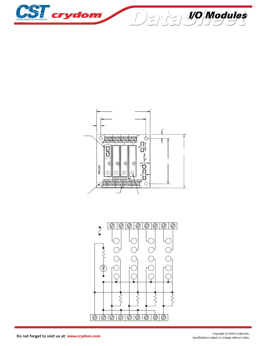
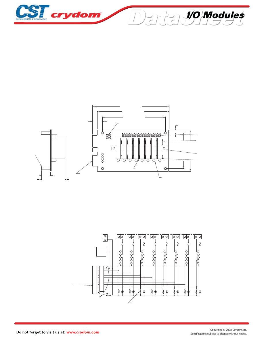
Input and output modules accepted interchangeably
Operate with 5, 15 or 24 volt logic supplies
Captive-screw retaining system for C4 Modules
Screw terminal barrier block for logic connections
Screw terminal barrier block for load connections
Resident pull-up resistors
5 amp field-replaceable fuses
(LITTLEFUSE #251005 or equivalent)
All even-numbered logic connections are
logic ground
PB4C4
MECHANICAL SPECIFICATIONS
LEDs indicate logic status
MOUNTING BOARD
Rev. 070808
•
•
•
•
•
•
•
•
•
3.25˝ [82.6]
2.75˝ [69.9]
0.25˝ [6.4]
0.25˝ [6.4]
SEE THRU
FUSE HOLDER
OUTPUT MODULES
3.25˝ [82.6]
2.75˝ [69.9]
LED STATUS INDICATOR
NOTES: 1)
BARRIER STRIP IS PHOENIX MKDS5/X 6.35mm
2)
ACCEPTS UP TO 10 AWG WIRE
3)
LITTLE FUSE 229003S OR EQUIVALENT
BARRIER STRIPS
(SEE NOTES 1,2)
SEE NOTE 3
SWAGED STANDOFF (4)
0.62 (15.7)
DIMENSION: INCHES (MILLIMETERS)
TOLERANCE: ±0.20 (±0, 50)
Courtesy of Steven Engineering, Inc.-230 Ryan Way, South San Francisco, CA 94080-6370-Main Office: (650) 588-9200-Outside Local Area: (800) 258-9200-www.stevenengineering.com
60MAIN-html.html

HAZARD OF
ELECTRIC
SHOCK,
EXPLOSION,
OR ARC FLASH.
x
Disconnect all
power before
installing or
working with
this equipment.
x
Verify all
connections
and replace all
covers before
turning on
power.
Failure to follow
these
instructions will
result in death
or serious injury.
RIESGO DE
DESCARGA
ELECTRICA O
EXPLOSION.
x
Desconectar
todos los
suministros de
energia a este
equipo antes
de trabajar
con este equipo.
x
Verificar todas
las conexiones
y colocar todas
las tapas antes
de energizer
el equipo.
El
incumplimiento
de estas
instrucciones
puede provocar
la muerte o
lesiones serias.
RISQUE DE
DESCHARGE
ELECTRIQUE
OU EXPLOSION
x
Eteindre
toutes les
sources
d'énergie de
cet appareil
avant de
travailler
dessus de cet
appareil
x
Vérifier tous
connections, et
remettre tous
couverts en
olace avant de
mettre sous
De non-suivi de
ces instructions
provoquera la
mort ou des
lésions sérieuses
sérieuses.
GEFAHR EINES
ELEKTRISCHE
N SCHLAGES
ODER EINER
EXPLOSION.
x
Stellen Sie
jeglichen
Strom ab, der
dieses Gerät
versorgt, bevor
Sie an dem
Gerät Arbeiten
durchführen
x
Vor dem
Drehen auf
Energie alle
Anschlüsse
überprüfen
und alle
Abdeckungen
ersetzen.
Unterlassung
dieser
Anweisungen
können zum
Tode oder zu
schweren
Verletzungen
führen.
RISCHIO DI
SCOSSA
ELETTRICA O
DELL’ESPLOSI
ONE.
x
Spenga tutta
l'alimentazion
e che fornisce
questa
apparecchiatu
ra prima del
lavorare a questa
apparecchiatu ra
x
Verificare tutti
i collegamenti
e sostituire
tutte le coperture
prima della
rotazione
sull'alimentazi one
L'omissione di
seguire queste
istruz ioni
provocherà la
morte o di
lesioni serie
RISCO DE
DESCARGA
ELÉTTRICA OU
EXPLOSÃO
x
Desconectar
o equipamento
de toda á
energia antes
de instalar ou
trabalhar com
este equipamen
to
x
Verificar todas
as conexões e
recolocar todas
as tampas
antes de religar
o equipamento
O não cumprimento
destas instruções
pode levar á morte
ou lesões sérias.
DANGER / PELIGRO / DANGER /GEFAHR / PERICOLO / PERIGO
Courtesy of Steven Engineering, Inc.-230 Ryan Way, South San Francisco, CA 94080-6370-Main Office: (650) 588-9200-Outside Local Area: (800) 258-9200-www.stevenengineering.com
60MAIN-html.html

ANNEX - ENVIROMENTAL INFORMATION
Courtesy of Steven Engineering, Inc.-230 Ryan Way, South San Francisco, CA 94080-6370-Main Office: (650) 588-9200-Outside Local Area: (800) 258-9200-www.stevenengineering.com
60MAIN-html.html
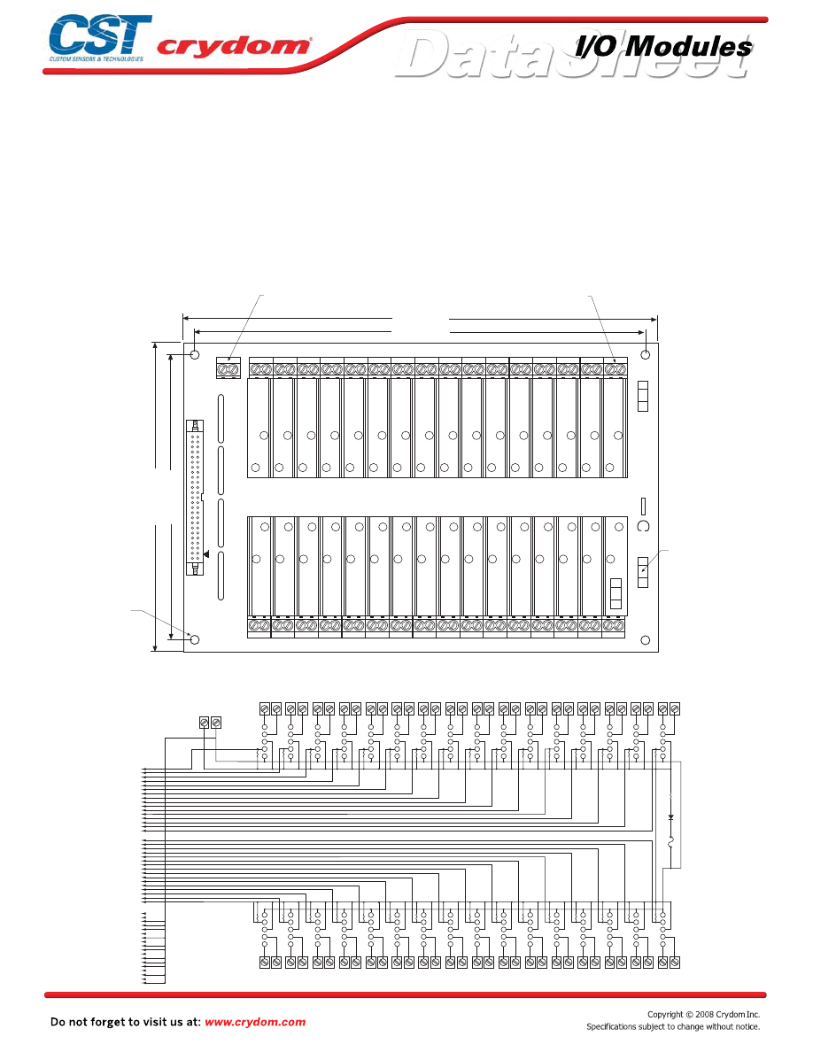
Input and output modules accepted interchangeably
Operate with 5, 15 or 24 volt logic supplies
Captive-screw retaining system for C4 modules
Plug-compatible logic connections
Screw terminal barrier block for load connections
Resident pull-up resistors
5 amp field-replaceable fuses
(LITTLEFUSE #251005 or equivalent)
All even-numbered logic connections are
logic ground
PB16C4
MECHANICAL SPECIFICATIONS
MOUNTING BOARD
Rev. 070808
•
•
•
•
•
•
•
•
50 PIN IDC
HEADER
CONNECTOR
(SEE NOTE 3)
0.65˝ [16.5]
LED STATUS INDICATOR
9.10˝ [231.1]
10.00˝ [254.0]
FUSE HOLDER
OUTPUT MODULES
0.25˝ [6.4]
2.75˝ [69.9]
3.25˝ [82.6]
POWER BARRIER STRIP
(SEE NOTES 1, 2)
SEE NOTE 4
NOTES: 1) BARRIER STRIP IS PHOENIX MKDS5/X 6.35mm
2) ACCEPTS UP TO 10 AWG WIRE
3) CONNECTOR IS CIRCUIT ASSEMBLY CA-50H-2B OR EQUIVALENT
4) LITTLE FUSE 229003S OR EQUIVALENT
DIMENSION: INCHES (MILLIMETERS)
TOLERANCE: ±0.20 (±0, 50)
SWAGED STANDOFF (4)
0.62 (15.7)
1
1
2
3
4
5
6
7
8
9
10
11
12
13
14
15
16
32
31
3
4
5
1
2
3
4
5
1
2
3
4
5
1
2
3
4
5
1
2
3
4
5
1
2
3
4
5
1
2
3
4
5
1
2
3
4
5
1
2
3
4
5
0
1
2
3
4
5
6
7
SPARE
FUSE
LOGIC
J1
17
19
21
23
25
27
29
31
33
35
37
39
41
43
17
47
50 PIN IDC
HEADER
CONNECTOR
4.7K
PULL UP
RESISTOR
TYP
EVEN PINS
2–50
+
–
N/C
N/C
880
OHM
FUSE GOOD
INDICATOR
FUSE
TEST
15
2
Courtesy of Steven Engineering, Inc.-230 Ryan Way, South San Francisco, CA 94080-6370-Main Office: (650) 588-9200-Outside Local Area: (800) 258-9200-www.stevenengineering.com
60MAIN-html.html

HAZARD OF
ELECTRIC
SHOCK,
EXPLOSION,
OR ARC FLASH.
x
Disconnect all
power before
installing or
working with
this equipment.
x
Verify all
connections
and replace all
covers before
turning on
power.
Failure to follow
these
instructions will
result in death
or serious injury.
RIESGO DE
DESCARGA
ELECTRICA O
EXPLOSION.
x
Desconectar
todos los
suministros de
energia a este
equipo antes
de trabajar
con este equipo.
x
Verificar todas
las conexiones
y colocar todas
las tapas antes
de energizer
el equipo.
El
incumplimiento
de estas
instrucciones
puede provocar
la muerte o
lesiones serias.
RISQUE DE
DESCHARGE
ELECTRIQUE
OU EXPLOSION
x
Eteindre
toutes les
sources
d'énergie de
cet appareil
avant de
travailler
dessus de cet
appareil
x
Vérifier tous
connections, et
remettre tous
couverts en
olace avant de
mettre sous
De non-suivi de
ces instructions
provoquera la
mort ou des
lésions sérieuses
sérieuses.
GEFAHR EINES
ELEKTRISCHE
N SCHLAGES
ODER EINER
EXPLOSION.
x
Stellen Sie
jeglichen
Strom ab, der
dieses Gerät
versorgt, bevor
Sie an dem
Gerät Arbeiten
durchführen
x
Vor dem
Drehen auf
Energie alle
Anschlüsse
überprüfen
und alle
Abdeckungen
ersetzen.
Unterlassung
dieser
Anweisungen
können zum
Tode oder zu
schweren
Verletzungen
führen.
RISCHIO DI
SCOSSA
ELETTRICA O
DELL’ESPLOSI
ONE.
x
Spenga tutta
l'alimentazion
e che fornisce
questa
apparecchiatu
ra prima del
lavorare a questa
apparecchiatu ra
x
Verificare tutti
i collegamenti
e sostituire
tutte le coperture
prima della
rotazione
sull'alimentazi one
L'omissione di
seguire queste
istruz ioni
provocherà la
morte o di
lesioni serie
RISCO DE
DESCARGA
ELÉTTRICA OU
EXPLOSÃO
x
Desconectar
o equipamento
de toda á
energia antes
de instalar ou
trabalhar com
este equipamen
to
x
Verificar todas
as conexões e
recolocar todas
as tampas
antes de religar
o equipamento
O não cumprimento
destas instruções
pode levar á morte
ou lesões sérias.
DANGER / PELIGRO / DANGER /GEFAHR / PERICOLO / PERIGO
Courtesy of Steven Engineering, Inc.-230 Ryan Way, South San Francisco, CA 94080-6370-Main Office: (650) 588-9200-Outside Local Area: (800) 258-9200-www.stevenengineering.com
60MAIN-html.html

ANNEX - ENVIROMENTAL INFORMATION
Courtesy of Steven Engineering, Inc.-230 Ryan Way, South San Francisco, CA 94080-6370-Main Office: (650) 588-9200-Outside Local Area: (800) 258-9200-www.stevenengineering.com
60MAIN-html.html
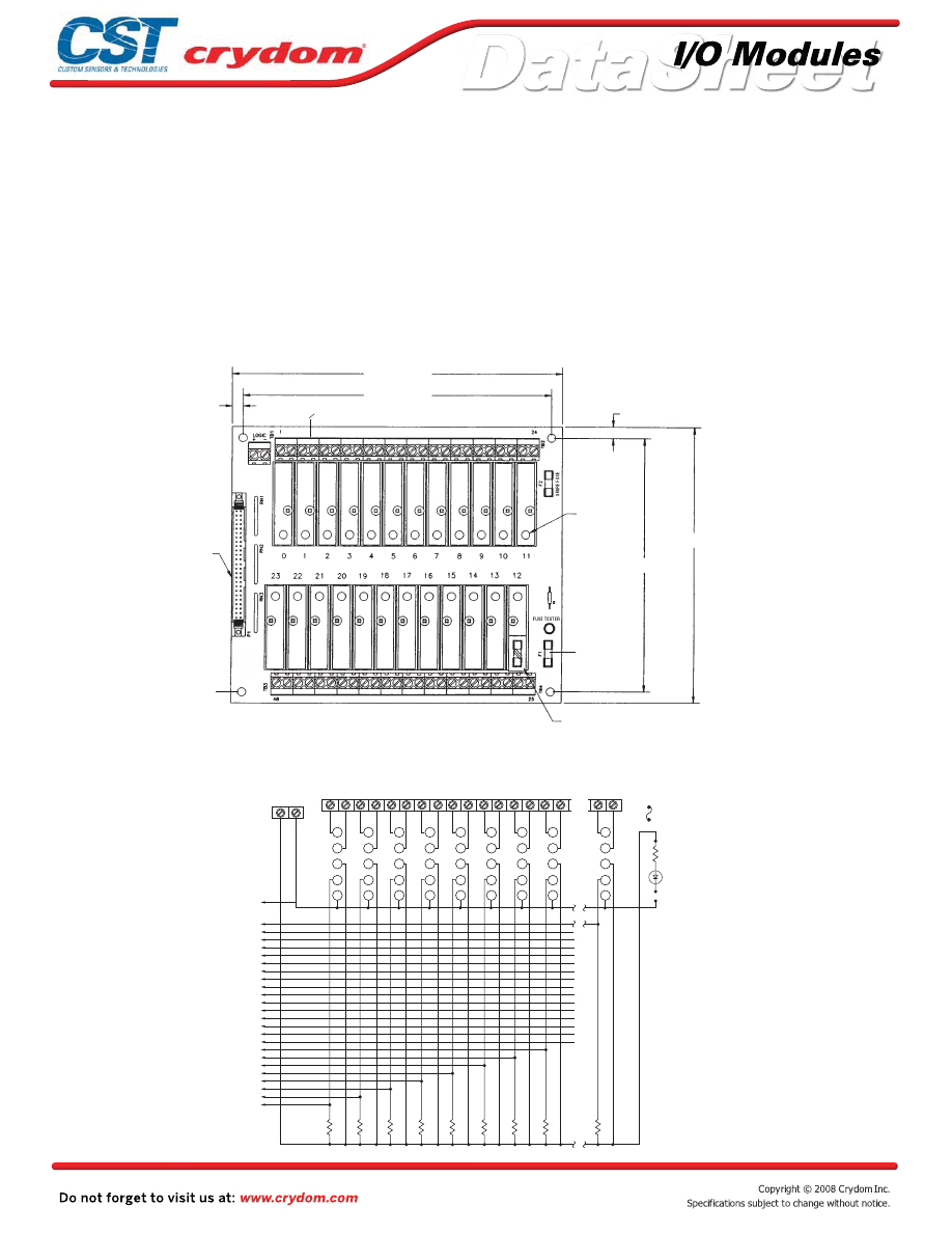
Input and output modules accepted interchangeably
Operate with 5, 15 or 24 volt logic supplies
Captive-screw retaining system for C4 modules
Screw terminal barrier block for load connections
Resident pull-up resistors
5 amp field-replaceable fuses
(LITTLEFUSE #251005 or equivalent)
All even-numbered logic connections are
logic ground
PB16C4T
MECHANICAL SPECIFICATIONS
MOUNTING BOARD
Rev. 070808
•
•
•
•
•
•
•
•
NOTES:
1) BARRIER STRIP IS PHOENIX MKDS5/X 6.35mm
2) ACCEPTS UP TO 10 AWG WIRE
3) LITTLE FUSE 229003S OR EQUIVALENT
1
2
3
4
5
6
7
8
9
10
11
12
13
15
16
17
18
19
20
21
22
23
24
25
26
27
28
29
30
31
32
14
1
2
3
4
5
6
7
8
9
10
11
12
13
15
16
17
18
19
20
21
22
23
24
25
26
27
28
29
30
31
32
14
0
1
2
3
4
5
6
7
8
9
10
11
12
13
14
15
SP
ARE FUSE
FUSE TESTER
R1
D1
F2
TB2
250V
3 AMP
F1
TB4
9.00 (228.6)
9.50 (241.3)
0.25 (6.4)
FUSE TESTER
SPARE FUSE
(SEE NOTE 3)
SWAGED STANDOFF (4)
0.62 " (15.7)
0.25 (6.4)
2.75 (69.85)
LOGIC
3.25 (82.6)
RN1
RN1
PB-16C4-T
+
-
BARRIER STRIPS
(SEE NOTES 1,2)
E
L
U
D
O
M
T
U
P
T
U
O
D
E
S
U
F
R
O
T
A
C
I
D
N
I
D
E
L
S
U
T
A
T
S
R
O
T
S
I
S
E
R
P
U
L
L
U
P
3
4
5
3
4
5
3
4
5
3
4
5
3
4
5
3
4
5
3
4
5
3
4
5
3
4
5
3
4
5
3
4
5
3
4
5
3
4
5
3
4
5
3
4
5
3
4
5
0
1
2
1
1
2
2
1
2
3
1
2
4
1
2
5
1
2
6
1
2
7
1
2
8
1
2
9
1
2
10
1
2
11
1
2
12
1
2
13
1
2
14
1
2
15
1
2
1
2
3
4
5
6
7
8
9
10 11 12 13 14 15 16 17 18 19 20 21 22 23 24 25 26 27 28 29 30 31 32
1
2
3
4
5
6
7
8
9
10 11 12 13 14 15 16 17 18 19 20 21 22 23 24 25 26 27 28 29 30 31 32
BARRIER
STRIP
LOGIC
BARRIER
STRIP
TB2
N/C
N/C
F2
R1
D1
F1
TB4
TB1
TB3
RN1
TB5
MODULE INPUT/OUTPUT
MODULE INPUT/OUTPUT
+
-
RN2
Screw terminal barrier block for logic connections
Courtesy of Steven Engineering, Inc.-230 Ryan Way, South San Francisco, CA 94080-6370-Main Office: (650) 588-9200-Outside Local Area: (800) 258-9200-www.stevenengineering.com
60MAIN-html.html

HAZARD OF
ELECTRIC
SHOCK,
EXPLOSION,
OR ARC FLASH.
x
Disconnect all
power before
installing or
working with
this equipment.
x
Verify all
connections
and replace all
covers before
turning on
power.
Failure to follow
these
instructions will
result in death
or serious injury.
RIESGO DE
DESCARGA
ELECTRICA O
EXPLOSION.
x
Desconectar
todos los
suministros de
energia a este
equipo antes
de trabajar
con este equipo.
x
Verificar todas
las conexiones
y colocar todas
las tapas antes
de energizer
el equipo.
El
incumplimiento
de estas
instrucciones
puede provocar
la muerte o
lesiones serias.
RISQUE DE
DESCHARGE
ELECTRIQUE
OU EXPLOSION
x
Eteindre
toutes les
sources
d'énergie de
cet appareil
avant de
travailler
dessus de cet
appareil
x
Vérifier tous
connections, et
remettre tous
couverts en
olace avant de
mettre sous
De non-suivi de
ces instructions
provoquera la
mort ou des
lésions sérieuses
sérieuses.
GEFAHR EINES
ELEKTRISCHE
N SCHLAGES
ODER EINER
EXPLOSION.
x
Stellen Sie
jeglichen
Strom ab, der
dieses Gerät
versorgt, bevor
Sie an dem
Gerät Arbeiten
durchführen
x
Vor dem
Drehen auf
Energie alle
Anschlüsse
überprüfen
und alle
Abdeckungen
ersetzen.
Unterlassung
dieser
Anweisungen
können zum
Tode oder zu
schweren
Verletzungen
führen.
RISCHIO DI
SCOSSA
ELETTRICA O
DELL’ESPLOSI
ONE.
x
Spenga tutta
l'alimentazion
e che fornisce
questa
apparecchiatu
ra prima del
lavorare a questa
apparecchiatu ra
x
Verificare tutti
i collegamenti
e sostituire
tutte le coperture
prima della
rotazione
sull'alimentazi one
L'omissione di
seguire queste
istruz ioni
provocherà la
morte o di
lesioni serie
RISCO DE
DESCARGA
ELÉTTRICA OU
EXPLOSÃO
x
Desconectar
o equipamento
de toda á
energia antes
de instalar ou
trabalhar com
este equipamen
to
x
Verificar todas
as conexões e
recolocar todas
as tampas
antes de religar
o equipamento
O não cumprimento
destas instruções
pode levar á morte
ou lesões sérias.
DANGER / PELIGRO / DANGER /GEFAHR / PERICOLO / PERIGO
Courtesy of Steven Engineering, Inc.-230 Ryan Way, South San Francisco, CA 94080-6370-Main Office: (650) 588-9200-Outside Local Area: (800) 258-9200-www.stevenengineering.com
60MAIN-html.html

ANNEX - ENVIROMENTAL INFORMATION
Courtesy of Steven Engineering, Inc.-230 Ryan Way, South San Francisco, CA 94080-6370-Main Office: (650) 588-9200-Outside Local Area: (800) 258-9200-www.stevenengineering.com
60MAIN-html.html
Input and output modules accepted interchangeably
Operate with 5, 15 or 24 volt logic supplies
Captive-screw retaining system for C4 modules
Plug-compatible logic connections
Screw terminal barrier block for load connections
Resident pull-up resistors
5 amp field-replaceable fuses
(LITTLEFUSE #251005 or equivalent)
All even-numbered logic connections are
logic ground
PB24C4
MECHANICAL SPECIFICATIONS
MOUNTING BOARD
Rev. 070808
•
•
•
•
•
•
•
•
7.50˝ [190.5]
7.00˝ [177.8]
LED STATUS
INDICATOR
0.25˝ [6.4]
50 PIN IDC
HEADER
CONNECTOR
(SEE NOTE 3)
0.25˝ [6.4]
6.25˝ [158.8]
5.75˝ [146.1]
FUSE HOLDER
OUTPUT MODULES
POWER BARRIER STRIP (SEE NOTES 1, 2)
SEE NOTE 4
NOTES: 1) BARRIER STRIP IS PHOENIX MKDS5/X 6.35mm
2) ACCEPTS UP TO 10 AWG WIRE
3) CONNECTOR IS CIRCUIT ASSEMBLY CA-50H-2B OR EQUIVALENT
4) LITTLE FUSE 229003S OR EQUIVALENT
DIMENSION: INCHES (MILLIMETERS)
TOLERANCE: ±0.20 (±0, 50)
SWAGED STANDOFF (4)
0.62 (15.7)
1
1
2
3
4
5
6
7
8
9
10
11
12
13
14
15
16
48
47
3
4
5
1
2
3
4
5
1
2
3
4
5
1
2
3
4
5
1
2
3
4
5
1
2
3
4
5
1
2
3
4
5
1
2
3
4
5
1
2
3
4
5
0
1
2
3
4
5
6
7
SPARE
FUSE
LOGIC
J1
1
3
5
7
9
11
13
15
33
35
37
39
41
43
45
47
17
19
21
23
25
27
29
31
50 PIN IDC
HEADER
CONNECTOR
4.7K
PULL UP
RESISTOR
TYP
EVEN PINS
2–50
+
–
N/C
N/C
880
OHM
FUSE GOOD
INDICATOR
FUSE
TEST
23
2
Courtesy of Steven Engineering, Inc.-230 Ryan Way, South San Francisco, CA 94080-6370-Main Office: (650) 588-9200-Outside Local Area: (800) 258-9200-www.stevenengineering.com
60MAIN-html.html

HAZARD OF
ELECTRIC
SHOCK,
EXPLOSION,
OR ARC FLASH.
x
Disconnect all
power before
installing or
working with
this equipment.
x
Verify all
connections
and replace all
covers before
turning on
power.
Failure to follow
these
instructions will
result in death
or serious injury.
RIESGO DE
DESCARGA
ELECTRICA O
EXPLOSION.
x
Desconectar
todos los
suministros de
energia a este
equipo antes
de trabajar
con este equipo.
x
Verificar todas
las conexiones
y colocar todas
las tapas antes
de energizer
el equipo.
El
incumplimiento
de estas
instrucciones
puede provocar
la muerte o
lesiones serias.
RISQUE DE
DESCHARGE
ELECTRIQUE
OU EXPLOSION
x
Eteindre
toutes les
sources
d'énergie de
cet appareil
avant de
travailler
dessus de cet
appareil
x
Vérifier tous
connections, et
remettre tous
couverts en
olace avant de
mettre sous
De non-suivi de
ces instructions
provoquera la
mort ou des
lésions sérieuses
sérieuses.
GEFAHR EINES
ELEKTRISCHE
N SCHLAGES
ODER EINER
EXPLOSION.
x
Stellen Sie
jeglichen
Strom ab, der
dieses Gerät
versorgt, bevor
Sie an dem
Gerät Arbeiten
durchführen
x
Vor dem
Drehen auf
Energie alle
Anschlüsse
überprüfen
und alle
Abdeckungen
ersetzen.
Unterlassung
dieser
Anweisungen
können zum
Tode oder zu
schweren
Verletzungen
führen.
RISCHIO DI
SCOSSA
ELETTRICA O
DELL’ESPLOSI
ONE.
x
Spenga tutta
l'alimentazion
e che fornisce
questa
apparecchiatu
ra prima del
lavorare a questa
apparecchiatu ra
x
Verificare tutti
i collegamenti
e sostituire
tutte le coperture
prima della
rotazione
sull'alimentazi one
L'omissione di
seguire queste
istruz ioni
provocherà la
morte o di
lesioni serie
RISCO DE
DESCARGA
ELÉTTRICA OU
EXPLOSÃO
x
Desconectar
o equipamento
de toda á
energia antes
de instalar ou
trabalhar com
este equipamen
to
x
Verificar todas
as conexões e
recolocar todas
as tampas
antes de religar
o equipamento
O não cumprimento
destas instruções
pode levar á morte
ou lesões sérias.
DANGER / PELIGRO / DANGER /GEFAHR / PERICOLO / PERIGO
Courtesy of Steven Engineering, Inc.-230 Ryan Way, South San Francisco, CA 94080-6370-Main Office: (650) 588-9200-Outside Local Area: (800) 258-9200-www.stevenengineering.com
60MAIN-html.html

ANNEX - ENVIROMENTAL INFORMATION
Courtesy of Steven Engineering, Inc.-230 Ryan Way, South San Francisco, CA 94080-6370-Main Office: (650) 588-9200-Outside Local Area: (800) 258-9200-www.stevenengineering.com
60MAIN-html.html
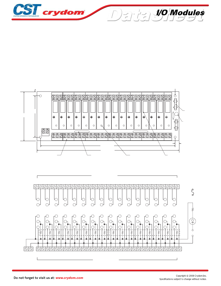
Input and output modules accepted interchangeably
Operate with 5, 15 or 24 volt logic supplies
Captive-screw retaining system for C4 modules
Plug-compatible logic connections
Screw terminal barrier block for load connections
Resident pull-up resistors
5 amp field-replaceable fuses
(LITTLEFUSE #251005 or equivalent)
All even-numbered logic connections are
logic ground
PB32C4
MECHANICAL SPECIFICATIONS
MOUNTING BOARD
Rev. 070808
•
•
•
•
•
•
•
•
Notes:
1) BARRIER STRIP IS PHOENIX MKDS5/X 6.35mm
2) ACCEPTS UP TO 10 AWG WIRE
3) LITTLE FUSE 229003S OR EQUIVALENT
0
1
2
3
4
5
6
7
8
9
10
11
12
13
14
15
31
30
29
28
27
26
25
24
23
22
21
20
19
18
17
16
32
31
30
2
9
28
27
2
6
2
5
24
23
2
2
21
20
1
9
1
8
17
16
1
5
14
1
3
12
11
1
0
9
8
7
6
5
4
3
2
1
64 63 62 61 60 59 58 57 56 55 54 53 52 51 50 49 48 47 46 45 44 43
42 41 40 39 38 37 36 35 34 33
10.000” [ 254.00 ]
9.500” [ 241.43 ]
6.500”
[ 165.09 ]
6.000”
[ 152.40 ]
DIMENSIONS:
INCHES (MILLIMETERS)
TOLERANCE:
±
.020 (
±
0,50)
SP
ARE FUSE
3 AMP 250V
D1
FUSE TESTER
F1
F2
SEE NOTE 3
SCREW TERMINAL
(SEE NOTES 1 & 2)
POWER BARRIER STRIP
LOGIC SUPPLY BARRIER STRIP
1
N
R
2
N
R
3
N
R
4
N
R
P1
LOGIC
+ -
TB2
TB1
R1
TB3
SWAGED STANDOFF
45
46
43
49
48
44
50
47
41
36
42
35
40
38
39
37
1
2
4
3
2
1
5
+
-
3
4
4
3
2
1
5
5
6
4
3
2
1
5
7
8
4
3
2
1
5
9
10
4
3
2
1
5
11
12
4
3
2
1
5
13
14
4
3
2
1
5
15
16
4
3
2
1
5
17
18
4
3
2
1
5
19
20
4
3
2
1
5
21
22
4
3
2
1
5
23
24
4
3
2
1
5
25
26
4
3
2
1
5
27
28
4
3
2
1
5
29
30
4
3
2
1
5
31
32
4
3
2
1
5
6
5
8
2
3
7
1
4
10
15
9
16
11
13
12
14
64
63
4
3
2
1
5
4
3
2
1
5
62
61
60
59
58
57
56
55 54
53 52
51
50
49
48
47 46
45
44
43 42
41 40
39
38
37 36
35
34
33
4
3
2
1
5
4
3
2
1
5
4
3
2
1
5
4
3
2
1
5
4
3
2
1
5
4
3
2
1
5
4
3
2
1
5
4
3
2
1
5
4
3
2
1
5
4
3
2
1
5
4
3
2
1
5
4
3
2
1
5
4
3
2
1
5
4
3
2
1
5
17
18
19
20
21
22
23
24
25
26
27
28
29
30
31
32
33
34
680 OHMS
FUSE GOOD INDICATOR
FUSE TEST
Courtesy of Steven Engineering, Inc.-230 Ryan Way, South San Francisco, CA 94080-6370-Main Office: (650) 588-9200-Outside Local Area: (800) 258-9200-www.stevenengineering.com
60MAIN-html.html

HAZARD OF
ELECTRIC
SHOCK,
EXPLOSION,
OR ARC FLASH.
•
Disconnect all
power before
installing or
working with
this equipment.
•
Verify all
connections
and replace all
covers before
turning on
power.
Failure to follow
these
instructions will
result in death
or serious injury.
RIESGO DE
DESCARGA
ELECTRICA O
EXPLOSION.
•
Desconectar
todos los
suministros de
energia a este
equipo antes
de trabajar
con este equipo.
•
Verificar todas
las conexiones
y colocar todas
las tapas antes
de energizer
el equipo.
El
incumplimiento
de estas
instrucciones
puede provocar
la muerte o
lesiones serias.
RISQUE DE
DESCHARGE
ELECTRIQUE
OU EXPLOSION
•
Eteindre
toutes les
sources
d'énergie de
cet appareil
avant de
travailler
dessus de cet
appareil
•
Vérifier tous
connections, et
remettre tous
couverts en
olace avant de
mettre sous
De non-suivi de
ces instructions
provoquera la
mort ou des
lésions sérieuses
sérieuses.
GEFAHR EINES
ELEKTRISCHE
N SCHLAGES
ODER EINER
EXPLOSION.
•
Stellen Sie
jeglichen
Strom ab, der
dieses Gerät
versorgt, bevor
Sie an dem
Gerät Arbeiten
durchführen
•
Vor dem
Drehen auf
Energie alle
Anschlüsse
überprüfen
und alle
Abdeckungen
ersetzen.
Unterlassung
dieser
Anweisungen
können zum
Tode oder zu
schweren
Verletzungen
führen.
RISCHIO DI
SCOSSA
ELETTRICA O
DELL’ESPLOSI
ONE.
•
Spenga tutta
l'alimentazion
e che fornisce
questa
apparecchiatu
ra prima del
lavorare a questa
apparecchiatu ra
•
Verificare tutti
i collegamenti
e sostituire
tutte le coperture
prima della
rotazione
sull'alimentazi one
L'omissione di
seguire queste
istruz ioni
provocherà la
morte o di
lesioni serie
RISCO DE
DESCARGA
ELÉTTRICA OU
EXPLOSÃO
•
Desconectar
o equipamento
de toda á
energia antes
de instalar ou
trabalhar com
este equipamen
to
•
Verificar todas
as conexões e
recolocar todas
as tampas
antes de religar
o equipamento
O não cumprimento
destas instruções
pode levar á morte
ou lesões sérias.
DANGER / PELIGRO / DANGER /GEFAHR / PERICOLO / PERIGO
Courtesy of Steven Engineering, Inc.-230 Ryan Way, South San Francisco, CA 94080-6370-Main Office: (650) 588-9200-Outside Local Area: (800) 258-9200-www.stevenengineering.com
60MAIN-html.html
ANNEX - ENVIROMENTAL INFORMATION
Courtesy of Steven Engineering, Inc.-230 Ryan Way, South San Francisco, CA 94080-6370-Main Office: (650) 588-9200-Outside Local Area: (800) 258-9200-www.stevenengineering.com
60MAIN-html.html
Input and output modules accepted interchangeably
Operate with 5, 15 or 24 volt logic supplies
Optional Hold Down Bar for retaining “M” series modules
Plug-compatible logic connections
Screw terminal barrier block for load connections
Resident pull-up resistors
5 amp field-replaceable fuses
(LITTLEFUSE #251005 or equivalent)
All even-numbered logic connections are
logic ground
PB8M
MECHANICAL SPECIFICATIONS
LEDs indicate logic status
MOUNTING BOARD
Rev. 070808
+
-
R
B
W
Y
3.5 (88,9)
3.0 (76,2)
0.25 (6,4)
6.4 (162,5)
6.0 (152,4)
5.3 (134,5)
0.9 (22,8)
1.9 (47,6)
0.75 (19,0)
PULL UP RESISTOR
3.3K OHM (8)
AC INPUT
DC INPUT
AC OUTPUT
DC OUTPUT
1 2
3 4 5
6 7
8 9 10 11 12 13 14 15 16
1
2
3
4
5
7
6
0
NOTES: 1) MATING CONNECTOR IS BERG 66317-150 OR EQUIVALENT.
SPECIFY SUFFIX 'C' FOR OPTIONAL 65823-093 OR EQUIVALENT
MALE PIN CONNECTOR FOR PARALLEL-TO-THE-BOARD CABLE
CONNECTION. SPECIFY SUFFIX 'V' FOR OPTIONAL CIRCUIT ASSEMBLY CA-50H-2B-SR
OR EQUIVALENT MALE PIN CONNECTOR FOR PERPENDICULAR-TO-THE-BOARD
CABLE CONNECTION.
3) OPTIONAL JUMPERS ARE AVAILABLE TO INTERCONNECT BARRIER STRIP
COMMONS. ORDER 1 EACH "JM8".
(see notes 2,3,4)
REPLACEABLE 5 AMP LINE FUSE (8)
(see note 5)
OPTIONAL HOLD DOWN BAR KIT
(see note 6)
GORDOS DIGITAL I/O MODULES
(see note 2)
SIGNAL INPUT/OUTPUT
(see note 1)
SWAGED STANDOFF
THRU HOLE
0.1" (3,8) DIA. (4)
SOLD SEPERATELY
LED STATUS INDICATORS (8)
50 TRACE (0.1" CENTERS)
MALE CARD EDGE.
LOGIC SUPPLY TERMINAL STRIP
POWER TERMINAL STRIP
2) 4-40 SCREW TERMINAL STRIPS ACCEPT WIRE SIZES FROM 26 TO 14 AWG.
+
-
DIMENSIONS: INCHES (MILLIMETERS)
TOLERANCE: 0.020 ( 0,50)
+
-
BLOCKS STANDARD. SPECIFY SUFFIX "A" FOR BOARD-MOUNTED PHOENIX
MSTBVA 1.5/16-G-5.08 (OR EQUIVALENT) MALE CONNECTOR. SPECIFY
SUFFIX "B" FOR BOARD-MOUNTED PHOENIX MSTBVA 1.5/16-G-5.08
(OR EQUIVALENT) MALE CONNECTOR AND MATING PHOENIX MSTBVA 1.5/16-ST-5.08
(OR EQUIVALENT) FEMALE, SCREW-TERMINAL PLUG-IN CONNECTOR.
5) LITTLE FUSE 251005 OR EQUIVALENT.
4) PHOENIX MKD51.5 5.08mm SERIES (OR EQUIVALENT) SCREW TERMINAL
EMPLOYS A PLAIN ALUMINUM CHANNEL WHILE MODEL NO. 11.06.293 PROVIDES
POCKETS IN THE CHANNEL FOR INDIVIDUAL MODULES.
6) TWO HOLD-DOWN BAR KITS ARE AVAILABLE SEPARATELY. MODEL NO. 11.06.414
1
3
4
5 5
4
3
1 1
3
4
5
1
3
4
5
5
4
3
1
5
4
3
1
1
3
4
5
5
4
3
2
2
2
2
2
2
2
2
1
25
23
21
19
17
15
13
11
9
1
49
47
45
43
41
39
37
35
33
25
1
ALL
EVEN
PINS
BOTTOM
-
+
+ LOGIC
+LOGIC
SIGNAL
INPUT/
OUTPUT
EDGE CONN TOP
PULL UP RESISTOR
3.3K OHM
(8)
1 2
3 4
5 6
7 8
9 10 11
12 13 14
15
16
BARRIER STRIP
LOGIC SUPPLY
5 AMP
LINE FUSE (8)
LED STATUS
INDICATOR (8)
POWER BARRIER STRIP
OPTIONAL CUSTOMER INSTALLED JUMPERS
FOR WIRING LOGIC SUPPLY TO
HEADER CONNECTOR
I/O MODULE
PIN SOCKETS
50 TRACE (0.1" CENTERS)
MALE CARD EDGE OR OPTIONAL
PIN CONNECTOR
•
•
•
•
•
•
•
•
•
Courtesy of Steven Engineering, Inc.-230 Ryan Way, South San Francisco, CA 94080-6370-Main Office: (650) 588-9200-Outside Local Area: (800) 258-9200-www.stevenengineering.com
60MAIN-html.html

HAZARD OF
ELECTRIC
SHOCK,
EXPLOSION,
OR ARC FLASH.
x
Disconnect all
power before
installing or
working with
this equipment.
x
Verify all
connections
and replace all
covers before
turning on
power.
Failure to follow
these
instructions will
result in death
or serious injury.
RIESGO DE
DESCARGA
ELECTRICA O
EXPLOSION.
x
Desconectar
todos los
suministros de
energia a este
equipo antes
de trabajar
con este equipo.
x
Verificar todas
las conexiones
y colocar todas
las tapas antes
de energizer
el equipo.
El
incumplimiento
de estas
instrucciones
puede provocar
la muerte o
lesiones serias.
RISQUE DE
DESCHARGE
ELECTRIQUE
OU EXPLOSION
x
Eteindre
toutes les
sources
d'énergie de
cet appareil
avant de
travailler
dessus de cet
appareil
x
Vérifier tous
connections, et
remettre tous
couverts en
olace avant de
mettre sous
De non-suivi de
ces instructions
provoquera la
mort ou des
lésions sérieuses
sérieuses.
GEFAHR EINES
ELEKTRISCHE
N SCHLAGES
ODER EINER
EXPLOSION.
x
Stellen Sie
jeglichen
Strom ab, der
dieses Gerät
versorgt, bevor
Sie an dem
Gerät Arbeiten
durchführen
x
Vor dem
Drehen auf
Energie alle
Anschlüsse
überprüfen
und alle
Abdeckungen
ersetzen.
Unterlassung
dieser
Anweisungen
können zum
Tode oder zu
schweren
Verletzungen
führen.
RISCHIO DI
SCOSSA
ELETTRICA O
DELL’ESPLOSI
ONE.
x
Spenga tutta
l'alimentazion
e che fornisce
questa
apparecchiatu
ra prima del
lavorare a questa
apparecchiatu ra
x
Verificare tutti
i collegamenti
e sostituire
tutte le coperture
prima della
rotazione
sull'alimentazi one
L'omissione di
seguire queste
istruz ioni
provocherà la
morte o di
lesioni serie
RISCO DE
DESCARGA
ELÉTTRICA OU
EXPLOSÃO
x
Desconectar
o equipamento
de toda á
energia antes
de instalar ou
trabalhar com
este equipamen
to
x
Verificar todas
as conexões e
recolocar todas
as tampas
antes de religar
o equipamento
O não cumprimento
destas instruções
pode levar á morte
ou lesões sérias.
DANGER / PELIGRO / DANGER /GEFAHR / PERICOLO / PERIGO
Courtesy of Steven Engineering, Inc.-230 Ryan Way, South San Francisco, CA 94080-6370-Main Office: (650) 588-9200-Outside Local Area: (800) 258-9200-www.stevenengineering.com
60MAIN-html.html

ANNEX - ENVIROMENTAL INFORMATION
Courtesy of Steven Engineering, Inc.-230 Ryan Way, South San Francisco, CA 94080-6370-Main Office: (650) 588-9200-Outside Local Area: (800) 258-9200-www.stevenengineering.com
60MAIN-html.html
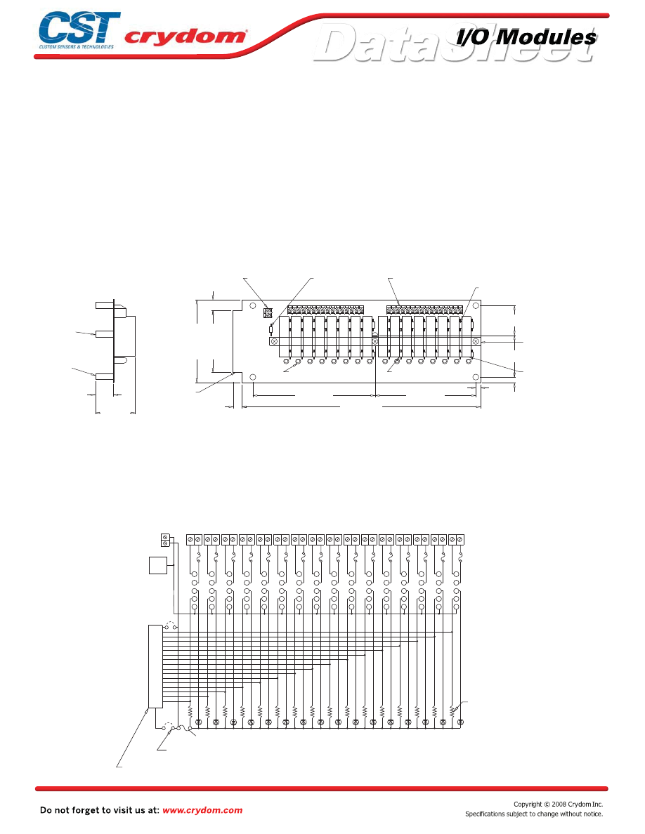
Input and output modules accepted interchangeably
Operate with 5, 15 or 24 volt logic supplies
Optional Hold Down Bar for retaining “M” series modules
Plug-compatible logic connections
Screw terminal barrier block for load connections
Resident pull-up resistors
5 amp field-replaceable fuses
(LITTLEFUSE #251005 or equivalent)
All even-numbered logic connections are
logic ground
PB16M
MECHANICAL SPECIFICATIONS
LEDs indicate logic status
MOUNTING BOARD
Rev. 070808
(16)
(16)
+
-
1.25 (31.75)
1.75 (44.45)
0.25 (6,4)
0.2 (5,1)
4.225 (107,3)
5.125 (130,2)
10.0 (254,0)
0.4 (10,2)
2.6 (66,0)
3.5 (88,9)
0.45 (11,4)
1.9 (47,6)
0.75 (19,0)
LED STATUS INDICATOR
PULL UP RESISTOR
3.3K OHM
2
3
7
1
6
1
1
STRIP (see note 2)
REPLACEABLE 1 AMP
(see note 5)
(see notes 2,3,4)
REPLACEABLE 5 AMP LINE FUSES (16)
(see note 6)
GORDOS DIGITAL I/O
MODULE SOLD SEPERATELY
OPTIONAL HOLD DOWN
BAR KIT (see note 7)
SIGNAL INPUT/OUTPUT
OPTIONAL MALE PIN
CONNECTOR (see note 1)
3-32 NYLON
STANDOFF (1)
SWAGED STANDOFF
THRU HOLE
0.15 (3,8) DIA. (4)
3) OPTIONAL JUMPERS ARE AVAILABLE TO INTERCONNECT BARRIER STRIP
CABLE CONNECTION.
OR EQUIVALENT MALE PIN CONNECTOR FOR PERPENDICULAR-TO-THE-BOARD
CONNECTION. SPECIFY SUFFIX 'V' FOR OPTIONAL CIRCUIT ASSEMBLY CA-50H-2B-SR
MALE PIN CONNECTOR FOR PARALLEL-TO-THE-BOARD CABLE
SPECIFY SUFFIX 'C' FOR OPTIONAL 65823-093 OR EQUIVALENT
NOTES: 1) MATING CONNECTOR IS BERG 66317-150 OR EQUIVALENT.
ORDER 1 EACH "JM2" AND 2 EACH "JM8".
LOGIC SUPPLY FUSE
LOGIC SUPPLY TERMIANL
POWER TERMINAL STRIP
50 TRACE (0.1" CENTERS)
MALE CARD EDGE OR
2) 4-40 SCREW TERMINAL STRIPS ACCEPT WIRE SIZES FROM 26 TO 14 AWG.
+
-
DIMENSIONS: INCHES (MILLIMETERS)
TOLERANCE: 0.020 ( 0,50)
+
-
(OR EQUIVALENT) FEMALE. SCREW-TERMINAL PLUG-IN CONNECTOR.
(OR EQUIVALENT) MALE CONNECTOR AND MATING PHOENIX MSTBVA 1.5/16-ST-5.08
SUFFIX "B" FOR BOARD-MOUNTED PHOENIX MSTBVA 1.5/16-G-5.08
MSTBVA 1.5/16-G-5.08 (OR EQUIVALENT) MALE CONNECTOR. SPECIFY
BLOCKS STANDARD. SPECIFY SUFFIX "A" FOR BOARD-MOUNTED PHOENIX
4) PHOENIX MKD51.5 5.08mm SERIES (OR EQUIVALENT) SCREW TERMINAL
5) LITTLE FUSE 251001 OR EQUIVALENT.
6) LITTLE FUSE 251005 OR EQUIVALENT.
7) TWO HOLD-DOWN BAR KITS ARE AVAILABLE SEPARATELY. MODEL NO. 11.06.415
EMPLOYS A PLAIN ALUMINUM CHANNEL WHILE MODEL NO. 11.06.278 PROVIDES
POCKETS IN THE CHANNEL FOR INDIVIDUAL MODULES.
5
4
3
2
1
1
2
3
4
5
1
2
3
4
5
1
2
3
4
5
1
2
3
4
5
1
2
3
4
5
1
2
3
4
5
1
2
3
4
5
1
2
3
4
5
1
2
3
4
5
1
2
3
4
5
1
2
3
4
5
1
2
3
4
5
1
2
3
4
5
1
2
3
4
5
1
2
3
4
5
*
*
EVEN
ALL
PINS
GND
LOGIC
+
-
BARRIER STRIP
LOGIC SUPPLY
TOP
+LOGIC
+LOGIC
1
17
19
21
23
25
27
29
31
33
35
37
39
41
43
45
47
49
PULL UP
RESISTOR
3.3K OHM
1 2 3 4 5 6 7 8 9 10 11 12 13 14 15 16 17 18 19 20 21 22 23 24 25 26 27 28 29 30 31 32
5 AMP
LINE FUSE (16)
I/O MODULE
PIN SOCKETS
(16)
LED STATUS
INDICATOR (16)
1 AMP LOGIC SUPPLY FUSE
CUSTOMER INSTALLED OPTIONAL JUMPERS TO WIRE
LOGIC SUPPLY TO HEADER CONNECTOR
POWER BARRIER STRIP
SIGNAL INPUT/OUTPUT 50 TRACE (0.1" CENTERS) MALE
CARD EDGE OR OPTIONAL PIN CONNECTOR
•
•
•
•
•
•
•
•
•
Courtesy of Steven Engineering, Inc.-230 Ryan Way, South San Francisco, CA 94080-6370-Main Office: (650) 588-9200-Outside Local Area: (800) 258-9200-www.stevenengineering.com
60MAIN-html.html

HAZARD OF
ELECTRIC
SHOCK,
EXPLOSION,
OR ARC FLASH.
x
Disconnect all
power before
installing or
working with
this equipment.
x
Verify all
connections
and replace all
covers before
turning on
power.
Failure to follow
these
instructions will
result in death
or serious injury.
RIESGO DE
DESCARGA
ELECTRICA O
EXPLOSION.
x
Desconectar
todos los
suministros de
energia a este
equipo antes
de trabajar
con este equipo.
x
Verificar todas
las conexiones
y colocar todas
las tapas antes
de energizer
el equipo.
El
incumplimiento
de estas
instrucciones
puede provocar
la muerte o
lesiones serias.
RISQUE DE
DESCHARGE
ELECTRIQUE
OU EXPLOSION
x
Eteindre
toutes les
sources
d'énergie de
cet appareil
avant de
travailler
dessus de cet
appareil
x
Vérifier tous
connections, et
remettre tous
couverts en
olace avant de
mettre sous
De non-suivi de
ces instructions
provoquera la
mort ou des
lésions sérieuses
sérieuses.
GEFAHR EINES
ELEKTRISCHE
N SCHLAGES
ODER EINER
EXPLOSION.
x
Stellen Sie
jeglichen
Strom ab, der
dieses Gerät
versorgt, bevor
Sie an dem
Gerät Arbeiten
durchführen
x
Vor dem
Drehen auf
Energie alle
Anschlüsse
überprüfen
und alle
Abdeckungen
ersetzen.
Unterlassung
dieser
Anweisungen
können zum
Tode oder zu
schweren
Verletzungen
führen.
RISCHIO DI
SCOSSA
ELETTRICA O
DELL’ESPLOSI
ONE.
x
Spenga tutta
l'alimentazion
e che fornisce
questa
apparecchiatu
ra prima del
lavorare a questa
apparecchiatu ra
x
Verificare tutti
i collegamenti
e sostituire
tutte le coperture
prima della
rotazione
sull'alimentazi one
L'omissione di
seguire queste
istruz ioni
provocherà la
morte o di
lesioni serie
RISCO DE
DESCARGA
ELÉTTRICA OU
EXPLOSÃO
x
Desconectar
o equipamento
de toda á
energia antes
de instalar ou
trabalhar com
este equipamen
to
x
Verificar todas
as conexões e
recolocar todas
as tampas
antes de religar
o equipamento
O não cumprimento
destas instruções
pode levar á morte
ou lesões sérias.
DANGER / PELIGRO / DANGER /GEFAHR / PERICOLO / PERIGO
Courtesy of Steven Engineering, Inc.-230 Ryan Way, South San Francisco, CA 94080-6370-Main Office: (650) 588-9200-Outside Local Area: (800) 258-9200-www.stevenengineering.com
60MAIN-html.html

ANNEX - ENVIROMENTAL INFORMATION
Courtesy of Steven Engineering, Inc.-230 Ryan Way, South San Francisco, CA 94080-6370-Main Office: (650) 588-9200-Outside Local Area: (800) 258-9200-www.stevenengineering.com
60MAIN-html.html
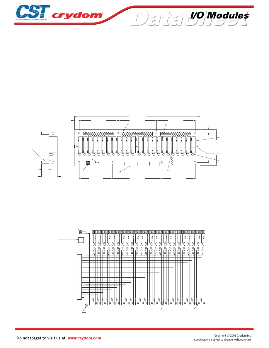
Input and output modules accepted interchangeably
Operate with 5, 15 or 24 volt logic supplies
Optional Hold Down Bar for retaining “M” series modules
Plug-compatible logic connections
Screw terminal barrier block for load connections
Resident pull-up resistors
5 amp field-replaceable fuses
(LITTLEFUSE #251005 or equivalent)
All even-numbered logic connections are
logic ground
PB24M
MECHANICAL SPECIFICATIONS
LEDs indicate logic status
MOUNTING BOARD
Rev. 070808
•
•
•
•
•
•
•
•
•
3.45 (67,6)
5.1 (129,5)
3.45 (87,6)
3.05 (77,5)
3.75 (95,3)
0.35 (8,9)
13.0 (330,2)
4.0 (101,6)
4.0 (101,6)
4.0 (101,6)
0.5 (12,7)
1.88 (47,6)
0.75 (19,1)
Y
AC INPUT
W
DC INPUT
B
AC OUTPUT
R
DC OUTPUT
1 2 3 4 5 6 7 8 9 1011 1213 141516
17 1819 202122 2324 252627 282930 3132
33 343536 3738 394041 4243 444546 4748
+
-
0
1
2
3
4
5
6
7
8
9
10
11
12
13
14
15
16
17
18
19
20
21
22
23
(see notes 2,3,4)
REPLACEABLE 5 AMP
LINE FUSE (24)
(see note 6)
GORDOS DIGITAL
I/O MODULES SOLD
SEPERATELY
OPTIONAL HOLD DOWN
BAR KIT (see note 7)
LED STATUS
INDICATOR (24)
(24)
PULL UP RESISTOR
3.3K OHM
SIGNAL INPUT/OUTPUT 50
LOGIC SUPPLY
(see note 2)
REPLACEABLE
1 AMP LOGIC
SUPPLY FUSE
(see note 5)
SWAGED STANDOFF
THRU HOLE 0.15 (3,8) DIA.
(8)
3) OPTIONAL JUMPERS ARE AVAILABLE TO INTERCONNECT BARRIER STRIP
CABLE CONNECTION.
OR EQUIVALENT MALE PIN CONNECTOR FOR PERPENDICULAR-TO-THE-BOARD
CONNECTION. SPECIFY SUFFIX 'V' FOR OPTIONAL CIRCUIT ASSEMBLY CA-50H-2B-SR
MALE PIN CONNECTOR FOR PARALLEL-TO-THE-BOARD CABLE
SPECIFY SUFFIX 'C' FOR OPTIONAL 65823-093 OR EQUIVALENT
NOTES: 1) MATING CONNECTOR IS BERG 66317-150 OR EQUIVALENT.
ORDER 3 EACH "JM8".
POWER TERMINAL STRIP
TERMINAL STRIP
TRACE (0.1" CENTERS) MALE
CARD EDGE (see note 1)
2) 4-40 TERMINAL STRIPS ACCEPT WIRE SIZES FROM 26 TO 14 AWG.
+
-
DIMENSIONS: INCHES (MILLIMETERS)
TOLERANCE: 0.020 ( 0,50)
+
-
(OR EQUIVALENT) FEMALE. SCREW-TERMINAL PLUG-IN CONNECTOR.
(OR EQUIVALENT) MALE CONNECTOR AND MATING PHOENIX MSTBVA 1.5/16-ST-5.08
SUFFIX "B" FOR BOARD-MOUNTED PHOENIX MSTBVA 1.5/16-G-5.08
MSTBVA 1.5/16-G-5.08 (OR EQUIVALENT) MALE CONNECTOR. SPECIFY
BLOCKS STANDARD. SPECIFY SUFFIX "A" FOR BOARD-MOUNTED PHOENIX
4) PHOENIX MKD51.5 5.08mm SERIES (OR EQUIVALENT) SCREW TERMINAL
5) LITTLE FUSE 251001 OR EQUIVALENT.
6) LITTLE FUSE 251005 OR EQUIVALENT.
THE CHANNEL FOR INDIVIDUAL MODULES.
A PLAIN ALUMINUM CHANNEL WHILE MODEL NO. 11.06.288 PROVIDES POCKETS IN
7) TWO HOLD-DOWN BAR KITS ARE AVAILABLE SEPARATELY. MODEL NO. 11.06.413 EMPLOYS
5
4
3
2
1
1
2
3
4
5
1
2
3
4
5
1
2
3
4
5
1
2
3
4
5
1
2
3
4
5
1
2
3
4
5
1
2
3
4
5
1
2
3
4
5
1
2
3
4
5
1
2
3
4
5
1
2
3
4
5
1
2
3
4
5
1
2
3
4
5
1
2
3
4
5
1
2
3
4
5
1
2
3
4
5
1
2
3
4
5
1
2
3
4
5
1
2
3
4
5
1
2
3
4
5
1
2
3
4
5
1
2
3
4
5
1
2
3
4
5
1
5
9
13
17
21
25
29
33
37
41
45
49
+LOGIC
EVEN
PINS
ALL
+
-
1 2 3 4 5 6 7 8 9 10 11 12 13 14 15 16 17 18 19 20 21 22 23 24 25 26 27 28 29 30 31 32 33 34 35 36 37 38 39 40 41 42 43 44 45 46 47 48
5 AMP LINE FUSE (24)
I/O MODULE PIN SOCKET
LED STATUS INDICATOR (24)
PULL UP RESISTOR 3.3K OHM (24)
1 AMP LOGIC
SUPPLY FUSE
POWER BARRIER STRIP
LOGIC SUPPLY
BARRIER STRIP
EDGE
CONN
BOTTOM
LOGIC
GRD
SIGNAL INPUT/OUTPUT
OR OPTIONAL PIN
CONNECTOR
50 TRACE (0.1" CENTERS)
MALE CARD EDGE
Courtesy of Steven Engineering, Inc.-230 Ryan Way, South San Francisco, CA 94080-6370-Main Office: (650) 588-9200-Outside Local Area: (800) 258-9200-www.stevenengineering.com
60MAIN-html.html

HAZARD OF
ELECTRIC
SHOCK,
EXPLOSION,
OR ARC FLASH.
x
Disconnect all
power before
installing or
working with
this equipment.
x
Verify all
connections
and replace all
covers before
turning on
power.
Failure to follow
these
instructions will
result in death
or serious injury.
RIESGO DE
DESCARGA
ELECTRICA O
EXPLOSION.
x
Desconectar
todos los
suministros de
energia a este
equipo antes
de trabajar
con este equipo.
x
Verificar todas
las conexiones
y colocar todas
las tapas antes
de energizer
el equipo.
El
incumplimiento
de estas
instrucciones
puede provocar
la muerte o
lesiones serias.
RISQUE DE
DESCHARGE
ELECTRIQUE
OU EXPLOSION
x
Eteindre
toutes les
sources
d'énergie de
cet appareil
avant de
travailler
dessus de cet
appareil
x
Vérifier tous
connections, et
remettre tous
couverts en
olace avant de
mettre sous
De non-suivi de
ces instructions
provoquera la
mort ou des
lésions sérieuses
sérieuses.
GEFAHR EINES
ELEKTRISCHE
N SCHLAGES
ODER EINER
EXPLOSION.
x
Stellen Sie
jeglichen
Strom ab, der
dieses Gerät
versorgt, bevor
Sie an dem
Gerät Arbeiten
durchführen
x
Vor dem
Drehen auf
Energie alle
Anschlüsse
überprüfen
und alle
Abdeckungen
ersetzen.
Unterlassung
dieser
Anweisungen
können zum
Tode oder zu
schweren
Verletzungen
führen.
RISCHIO DI
SCOSSA
ELETTRICA O
DELL’ESPLOSI
ONE.
x
Spenga tutta
l'alimentazion
e che fornisce
questa
apparecchiatu
ra prima del
lavorare a questa
apparecchiatu ra
x
Verificare tutti
i collegamenti
e sostituire
tutte le coperture
prima della
rotazione
sull'alimentazi one
L'omissione di
seguire queste
istruz ioni
provocherà la
morte o di
lesioni serie
RISCO DE
DESCARGA
ELÉTTRICA OU
EXPLOSÃO
x
Desconectar
o equipamento
de toda á
energia antes
de instalar ou
trabalhar com
este equipamen
to
x
Verificar todas
as conexões e
recolocar todas
as tampas
antes de religar
o equipamento
O não cumprimento
destas instruções
pode levar á morte
ou lesões sérias.
DANGER / PELIGRO / DANGER /GEFAHR / PERICOLO / PERIGO
Courtesy of Steven Engineering, Inc.-230 Ryan Way, South San Francisco, CA 94080-6370-Main Office: (650) 588-9200-Outside Local Area: (800) 258-9200-www.stevenengineering.com
60MAIN-html.html

ANNEX - ENVIROMENTAL INFORMATION
Courtesy of Steven Engineering, Inc.-230 Ryan Way, South San Francisco, CA 94080-6370-Main Office: (650) 588-9200-Outside Local Area: (800) 258-9200-www.stevenengineering.com
60MAIN-html.html
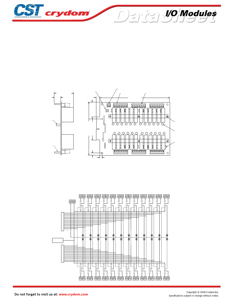
Input and output modules accepted interchangeably
Operate with 5, 15 or 24 volt logic supplies
Plug-compatible logic connections
Screw terminal barrier block for load connections
Resident pull-up resistors
5 amp field-replaceable fuses
(LITTLEFUSE #251005 or equivalent)
All even-numbered logic connections are
logic ground
PB24MD
MECHANICAL SPECIFICATIONS
LEDs indicate logic status
MOUNTING BOARD
Rev. 070808
•
•
•
•
•
•
•
•
•
NOTES: 1)
MATING CONNECTOR IS BERG66317-150 OR EQUIVALENT. SPECIFY SUFFIX ‘C’ FOR OPTIONAL 65823-093 OR EQUIVALENT
MALE PIN CONNECTOR FOR PARALLEL-TO-THE-BOARD CABLE CONNECTION. SPECIFY SUFFIX ‘V’ FOR OPTIONAL CIRCUIT
ASSEMBLY CA-50H-2B-SR OR EQUIVALENT MALE PIN CONNECTOR FOR PERPENDICULAR-TO-THE-BOARD CABLE CONNECTION.
2)
4-40 TERMINAL STRIPS ACCEPT WIRE SIZES FROM 26 TO 14 AWG .
3)
OPTIONAL JUMPERS ARE AVAILABLE TO INTERCONNECT BARRIER STRIP ORDER “JM8”
4)
PHOENIX MKD51.5 5.08mm SERIES (OR EQUIVALENT) SCREW TERMINAL BLOCKS STANDARD. SPECIFY SUFFIX “A” FOR
BOARD-MOUNTED PHOENIX MSTBVA 1.5/16-G-5.08 (OR EQUIVALENT) MALE CONNECTOR. SPECIFY SUFFIX “B” FOR
BOARD-MOUNTED PHOENIX MSTBVA 1.5/16-G-5.08 (OR EQUIVALENT) MALE CONNECTOR AND MATING PHOENIX
MSTBVA 1.5/16-ST-5.08 (OR EQUIVALENT) FEMALE. SCREW-TERMINAL PLUG-IN CONNECTOR.
5)
LITTLE FUSE 251001 OR EQUIVALENT.
6)
LITTLE FUSE 251005 OR EQUIVALENT.
NOTES:
DIMENSIONS: INCHES 9MILLIMETERS)
TOLERANCE: +0.020 (+.50)
Y
W
B
R
1 2 3 4 5 6 7 8 9 10 11 12
24 23 22 21 20 19 18 17 16 15 14 13
1
1 2 3 4 5 6 7 8
9 10 11 12 13 14 15 16
17 18 19 20 21 22 23 24
48 47 46 45 44 43 42 41
40 39 38 37 36 35 34 33
32 31 30 29 28 27 26 25
REPLACEABLE 1A
LOGIC SUPPLY FUSE
0.400˝ (10.16)
8.000˝ (203.19)
SCREW TERMINAL
LOGIC SUPPLY BARRIER STRIP
POWER BARRIER STRIP
WIRE INSERTION SIDE
HOLD-DOWN BAR
LED STATUS INDICATOR
(24 PLCS)
REPLACEABLE 5A LINE FUSE
(24 PLCS)
SIGNAL INPUT/OUTPUT 50 TRACE
(0.1˝ CENTERS) MALE CARD EDGE.
0.294˝ (7.46)
CROUZET
PB-24MD
AC INPUT
DC INPUT
AC OUTPUT
DC OUTPUT
0.250
˝
(6.35)
6.000˝ (152.40)
2.600˝ (66.04)
1.700˝ (43.18)
RESISTOR NETWORK
R2
R3
R1
1
1
1
2.200˝ (55.88)
0.750˝ (19.05)
3-32 NYLON STANDOFF
SWAGED STANDOFF
0.15 (3.8) DIA
LOGIC SUPPLY
TERMINAL STRIP
1
2
4
3
2
1
5
3
4
4
3
2
1
5
5
6
4
3
2
1
5
7
8
4
3
2
1
5
9
10
4
3
2
1
5
11
12
4
3
2
1
5
13
14
4
3
2
1
5
15
16
4
3
2
1
5
17
18
4
3
2
1
5
19
20
4
3
2
1
5
21
22
4
3
2
1
5
23
24
4
3
2
1
5
+
-
25
27
29
31
33
35
37
39
41
43
45
47
49
50 PIN
CONNECTOR
48
47
2
3
4
5
1
46
45
2
3
4
5
1
4
43
2
3
4
5
1
42
41
2
3
4
5
1
40
39
2
3
4
5
1
38
37
2
3
4
5
1
36
35
2
3
4
5
1
34
33
2
3
4
5
1
32
31
2
3
4
5
1
30
29
2
3
4
5
1
28
27
2
3
4
5
1
26
25
2
3
4
5
1
1
3
5
7
9
11
13
15
17
19
21
23
50 PIN
CONNECTOR
ALL EVEN
PINS 2-50
POWER BARRIER STRIP
Optional Hold Down Bar for retaining “M” series modules
Courtesy of Steven Engineering, Inc.-230 Ryan Way, South San Francisco, CA 94080-6370-Main Office: (650) 588-9200-Outside Local Area: (800) 258-9200-www.stevenengineering.com
60MAIN-html.html

HAZARD OF
ELECTRIC
SHOCK,
EXPLOSION,
OR ARC FLASH.
x
Disconnect all
power before
installing or
working with
this equipment.
x
Verify all
connections
and replace all
covers before
turning on
power.
Failure to follow
these
instructions will
result in death
or serious injury.
RIESGO DE
DESCARGA
ELECTRICA O
EXPLOSION.
x
Desconectar
todos los
suministros de
energia a este
equipo antes
de trabajar
con este equipo.
x
Verificar todas
las conexiones
y colocar todas
las tapas antes
de energizer
el equipo.
El
incumplimiento
de estas
instrucciones
puede provocar
la muerte o
lesiones serias.
RISQUE DE
DESCHARGE
ELECTRIQUE
OU EXPLOSION
x
Eteindre
toutes les
sources
d'énergie de
cet appareil
avant de
travailler
dessus de cet
appareil
x
Vérifier tous
connections, et
remettre tous
couverts en
olace avant de
mettre sous
De non-suivi de
ces instructions
provoquera la
mort ou des
lésions sérieuses
sérieuses.
GEFAHR EINES
ELEKTRISCHE
N SCHLAGES
ODER EINER
EXPLOSION.
x
Stellen Sie
jeglichen
Strom ab, der
dieses Gerät
versorgt, bevor
Sie an dem
Gerät Arbeiten
durchführen
x
Vor dem
Drehen auf
Energie alle
Anschlüsse
überprüfen
und alle
Abdeckungen
ersetzen.
Unterlassung
dieser
Anweisungen
können zum
Tode oder zu
schweren
Verletzungen
führen.
RISCHIO DI
SCOSSA
ELETTRICA O
DELL’ESPLOSI
ONE.
x
Spenga tutta
l'alimentazion
e che fornisce
questa
apparecchiatu
ra prima del
lavorare a questa
apparecchiatu ra
x
Verificare tutti
i collegamenti
e sostituire
tutte le coperture
prima della
rotazione
sull'alimentazi one
L'omissione di
seguire queste
istruz ioni
provocherà la
morte o di
lesioni serie
RISCO DE
DESCARGA
ELÉTTRICA OU
EXPLOSÃO
x
Desconectar
o equipamento
de toda á
energia antes
de instalar ou
trabalhar com
este equipamen
to
x
Verificar todas
as conexões e
recolocar todas
as tampas
antes de religar
o equipamento
O não cumprimento
destas instruções
pode levar á morte
ou lesões sérias.
DANGER / PELIGRO / DANGER /GEFAHR / PERICOLO / PERIGO
Courtesy of Steven Engineering, Inc.-230 Ryan Way, South San Francisco, CA 94080-6370-Main Office: (650) 588-9200-Outside Local Area: (800) 258-9200-www.stevenengineering.com
60MAIN-html.html

ANNEX - ENVIROMENTAL INFORMATION
Courtesy of Steven Engineering, Inc.-230 Ryan Way, South San Francisco, CA 94080-6370-Main Office: (650) 588-9200-Outside Local Area: (800) 258-9200-www.stevenengineering.com
60MAIN-html.html
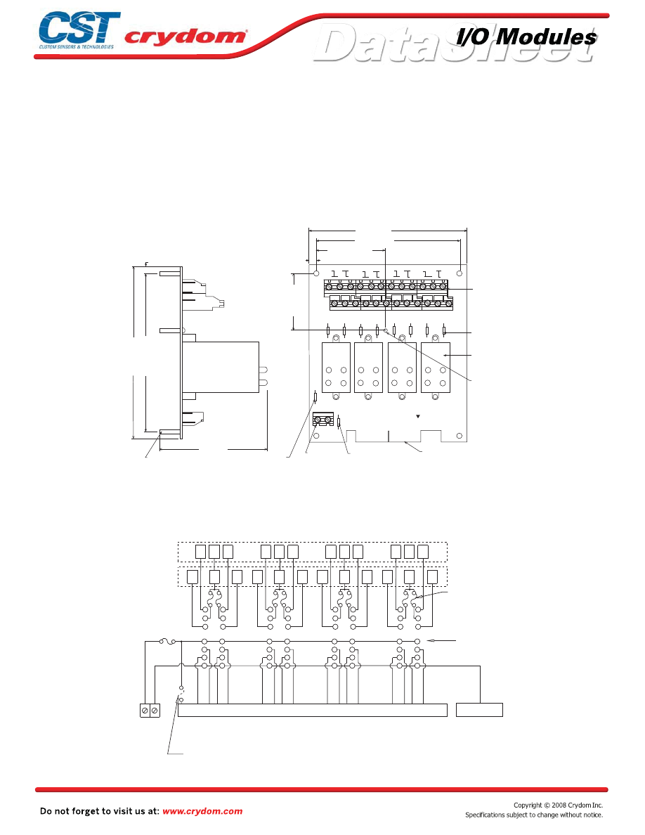
Input and output modules accepted interchangeably
Operate with 5, 15 or 24 volt logic supplies
Captive-screw retaining system for Quad-Pack
modules
Plug-compatible logic connections
Screw terminal barrier block for load connections
5 amp field-replaceable fuses
(LITTLEFUSE #251005 or equivalent)
All even-numbered logic connections are
logic ground
PB16Q
MECHANICAL SPECIFICATIONS
MOUNTING BOARD
Rev. 070808
•
•
•
•
•
•
•
NOTES:
FOR PARALLEL-TO-THE BOARD CABLE CONNECTION.
SPECIFY SUFFIX "V" FOR OPTIONAL CIRCUIT ASSEMBLY CA-50H-2B-SR (OR EQUIVALENT)
MALE PIN CONNECTOR FOR PERPENDICULAR-TO-THE-BOARD CABLE CONNECTION.
1) MATING CONNECTOR IS BERG 66317-150 OR EQUIVALENT.
SPECIFY SUFFIX "C" FOR OPTIONAL BERG 65823-093 (OR EQUIVALENT) MALE PIN CONNECTOR
0.25 (6,4)
3.9 (99,1)
6.0 (152,4)
0.25 (6,4)
DIMENSIONS: INCHES (MILLIMETERS)
TOLERANCE:
±
0.20 (
±
0.50)
5.5 (139,7)
SWAGED STANDOFF
THRU HOLE 0.15, (3,8) DIA
X 0.75 (19,1) LONG (4)
REPLACEABLE 1A
LOGIC SUPPLY FUSE
(SEE NOTE 4)
2.65 (67,31)
5.8 (147,3)
5.3 (134,6)
2.05 (52,07)
1
2
c
c
3
4
5
6
c
c
7
8
9
10
c
c
11
12
13
14
c
c
15
16
F1A
P1
+5V GND
LOGIC SUPPLY
BARRIER STRIP
(SEE NOTE 2)
SIGNAL INPUT/OUTPUT
50 CONDUCTOR CARD
EDGE (SEE NOTE 1)
CROUZET
57-466
PB-16Q
THREADED (6-32)
NYLON STANDOFF
QUAD PACK I/O MODULES
SOLD SEPERATELY
REPLACEABLE 5A
LINE FUSE (8)
(SEE NOTE 5)
POWER BARRIER STRIP
(SEE NOTE 2,3)
OPTIONAL FUSE LOCATION
MOVE 1A FUSE TO HERE
TO PROVIDE LOGIC SUPPLY
VOLTAGE THROUGH EDGE
CONNECTOR PIN 49
J1
TB2
0-3
4-7
8-11
12-15
F1
F2
F3
F4
F5
F6
F7
F8
2)
3) OPTIONAL JUMPERS AVAILABLE TO INTERCONNECT BARRIER STRIP COMMONS.
ORDER 2 EACH JUMPER "JQ4".
4) LITTLE FUSE 251001 OR EQUIVALENT.
5) LITTLE FUSE 251005 OR EQUIVALENT.
BARRIER STRIPS ACCEPT WIRE SIZES FROM 24 TO 12 AWG.
1 C 3
2 C 4
5 7
C
6 C 8
9 C 11
C
10 12
13 C 15
14 C 16
BARRIER STRIP
LOWER POWER
BARRIER STRIP
UPPER POWER
+ -
TIED TO COM
PINS 2-50
49 47 45
43 41
39 37
35 33
31 29
27 25
23 21
19 17
1
2
3
4
5
6
7
14
13
12
11
10
9
1
8
2
3
4
5
6
7
14
13
12
11
10
9
8
1 8
9
10
3
2
4
11
12
13
14
7
6
5
1 8
9
10
3
2
4 11
12
13
14
7
6
5
LOGIC
SUPPLY
BARRIER
STRIP
REPLACEABLE
1 AMP
LOGIC SUPPLY
FUSE
OPTIONAL FUSE LOCATION TO PROVIDE
LOGIC SUPPLY POWER THROUGH EDGE
CONNECTOR PIN 49 (CUSTOMER INSTALLED).
REPLACEABLE
5 AMP LINE
FUSES (8)
I/O MODULE
PIN SOCKETS
SIGNAL INPUT/OUTPUT TRACE (0.1" CENTERS) CONNECTOR OR OPTIONAL MALE
PIN CONNECTOR (OPTION "C" OR "V")
Courtesy of Steven Engineering, Inc.-230 Ryan Way, South San Francisco, CA 94080-6370-Main Office: (650) 588-9200-Outside Local Area: (800) 258-9200-www.stevenengineering.com
60MAIN-html.html

HAZARD OF
ELECTRIC
SHOCK,
EXPLOSION,
OR ARC FLASH.
•
Disconnect all
power before
installing or
working with
this equipment.
•
Verify all
connections
and replace all
covers before
turning on
power.
Failure to follow
these
instructions will
result in death
or serious injury.
RIESGO DE
DESCARGA
ELECTRICA O
EXPLOSION.
•
Desconectar
todos los
suministros de
energia a este
equipo antes
de trabajar
con este equipo.
•
Verificar todas
las conexiones
y colocar todas
las tapas antes
de energizer
el equipo.
El
incumplimiento
de estas
instrucciones
puede provocar
la muerte o
lesiones serias.
RISQUE DE
DESCHARGE
ELECTRIQUE
OU EXPLOSION
•
Eteindre
toutes les
sources
d'énergie de
cet appareil
avant de
travailler
dessus de cet
appareil
•
Vérifier tous
connections, et
remettre tous
couverts en
olace avant de
mettre sous
De non-suivi de
ces instructions
provoquera la
mort ou des
lésions sérieuses
sérieuses.
GEFAHR EINES
ELEKTRISCHE
N SCHLAGES
ODER EINER
EXPLOSION.
•
Stellen Sie
jeglichen
Strom ab, der
dieses Gerät
versorgt, bevor
Sie an dem
Gerät Arbeiten
durchführen
•
Vor dem
Drehen auf
Energie alle
Anschlüsse
überprüfen
und alle
Abdeckungen
ersetzen.
Unterlassung
dieser
Anweisungen
können zum
Tode oder zu
schweren
Verletzungen
führen.
RISCHIO DI
SCOSSA
ELETTRICA O
DELL’ESPLOSI
ONE.
•
Spenga tutta
l'alimentazion
e che fornisce
questa
apparecchiatu
ra prima del
lavorare a questa
apparecchiatu ra
•
Verificare tutti
i collegamenti
e sostituire
tutte le coperture
prima della
rotazione
sull'alimentazi one
L'omissione di
seguire queste
istruz ioni
provocherà la
morte o di
lesioni serie
RISCO DE
DESCARGA
ELÉTTRICA OU
EXPLOSÃO
•
Desconectar
o equipamento
de toda á
energia antes
de instalar ou
trabalhar com
este equipamen
to
•
Verificar todas
as conexões e
recolocar todas
as tampas
antes de religar
o equipamento
O não cumprimento
destas instruções
pode levar á morte
ou lesões sérias.
DANGER / PELIGRO / DANGER /GEFAHR / PERICOLO / PERIGO
Courtesy of Steven Engineering, Inc.-230 Ryan Way, South San Francisco, CA 94080-6370-Main Office: (650) 588-9200-Outside Local Area: (800) 258-9200-www.stevenengineering.com
60MAIN-html.html

ANNEX - ENVIROMENTAL INFORMATION
Courtesy of Steven Engineering, Inc.-230 Ryan Way, South San Francisco, CA 94080-6370-Main Office: (650) 588-9200-Outside Local Area: (800) 258-9200-www.stevenengineering.com
60MAIN-html.html
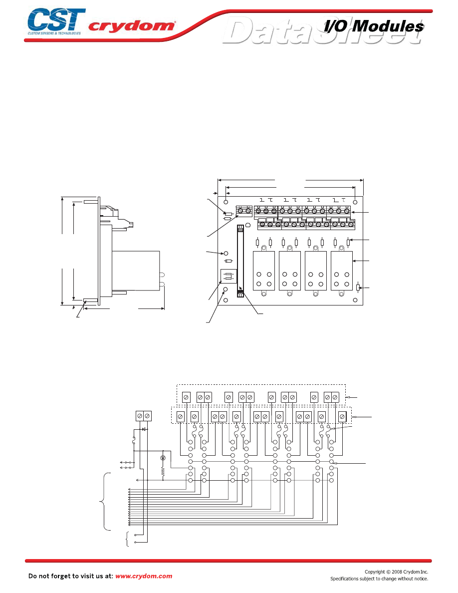
Input and output modules accepted interchangeably
Operate with 5, 15 or 24 volt logic supplies
Plug-compatible logic connections
Screw terminal barrier block for load connections
5 amp field-replaceable fuses
(LITTLEFUSE #251005 or equivalent)
All even-numbered logic connections are
logic ground
PB16HQ
MECHANICAL SPECIFICATIONS
MOUNTING BOARD
Rev. 070808
•
•
•
•
•
•
•
NOTES:
3) OPTIONAL JUMPERS AVAILABLE TO INTERCONNECT BARRIER
STRIP COMMONS. ORDER 2 EACH JUMPER "JQ4".
1) CONNECTOR IS BERG 65863-145 OR EQUIVALENT.
4) LITTLE FUSE 251001 OR EQUIVALENT.
5) LITTLE FUSE 251005 OR EQUIVALENT.
2) 6-32 SCREW TERMINAL BARRIER STRIPS ACCEPT WIRE SIZES FROM 24 TO 12 AWG.
9
10
c
c
11
12
5
6
c
c
7
8
1
2
c
c
3
4
JUMPERS
CONNECTING LOGIC
SUPPLY THROUGH
HEADER CONNECTOR
POSITIVE (+)
LOGIC SUPPLY
BUS TERMINATION
DIMENSIONS: INCHES (MILLIMETERS)
TOLERANCE:
±
0.20 (
±
0,50)
REPLACEABLE 1A
LOGIC SUPPLY FUSE
(SEE NOTE 4)
LOGIC SUPPLY
BARRIER STRIP
NEGATIVE (-)
LOGIC SUPPLY
BUS TERMINATION
SIGNAL INPUT/OUTPUT
50 CONDUCTOR MALE PIN
CONNETOR (SEE NOTE 1)
POWER BARRIER STRIPS
(SEE NOTE 2,3)
REPLACEABLE POWER
LINE FUSE (8)
(SEE NOTE 5)
GORDOS QUAD PACK DIGITAL
DIFITAL I/O MODULES
SOLD SEPERATELY
SPARE 5A LINE FUSE
(SEE NOTE 5)
SWAGED STANDOFF
THRU HOLE
0.15 (3,8) DIA
X 0.65 (16,5) LONG (4)
F1
F2
F3
F4
F5
F6
F7
F8
J3
PWR
ON
D2
TB2
R1
D1
J1
PIN 49
5V JUMPERS
PIN
J2
F1A
0.375 (9,5)
+5V GND
6.75 (171,5)
6.0 (152,4)
F9
12 - 15
8 - 11
4 - 7
CROUZET
57 - 463
PB - 16HO
0 - 3
SP
ARE 5A
FUSE
5.0
(127,0)
4.5 (114,3)
3.75 (95,3)
0.25 (6,4)
13
14
c
c
15
16
D1
PWR
ON
+
-
2-50
EVEN
PINS
49
1
J1
+5V GND
1
C
3 5
C
7 9
C
11 13
C
15
2 C
4
6 C
8
10 C
12
14 C
16
1
2
3
4
5
6
7
14
13
12
11
10
9
8
8
9
10
11
12
13
14
7
6
5
4
3
2
1
1
8
9
10
11
12
13
14
7
6
5
4
3
2
1
8
9
10
11
12
13
14
7
6
5
4
3
2
LOGIC SUPPLY
BUS TERMINATION
47
45
43
41
39
37
35
33
31
29
27
25
23
21
19
17
50 CONDUCTOR
MALE PIN
CONNECTOR TO
G1 BOARD OR
RIBBON
CABLE
1A LOGIC
FUSE
LOGIC SUPPLY
BARRIER STRIP
(-)
I/O MODULE
PIN SOCKETS
5A LINE FUSES (8)
LOWER BARRIER STRIP
UPPER BARRIER STRIP
SIGNAL
INPUT/OUTPUT
Captive-screw retaining system for Quad-Pack
modules
Courtesy of Steven Engineering, Inc.-230 Ryan Way, South San Francisco, CA 94080-6370-Main Office: (650) 588-9200-Outside Local Area: (800) 258-9200-www.stevenengineering.com
60MAIN-html.html

HAZARD OF
ELECTRIC
SHOCK,
EXPLOSION,
OR ARC FLASH.
•
Disconnect all
power before
installing or
working with
this equipment.
•
Verify all
connections
and replace all
covers before
turning on
power.
Failure to follow
these
instructions will
result in death
or serious injury.
RIESGO DE
DESCARGA
ELECTRICA O
EXPLOSION.
•
Desconectar
todos los
suministros de
energia a este
equipo antes
de trabajar
con este equipo.
•
Verificar todas
las conexiones
y colocar todas
las tapas antes
de energizer
el equipo.
El
incumplimiento
de estas
instrucciones
puede provocar
la muerte o
lesiones serias.
RISQUE DE
DESCHARGE
ELECTRIQUE
OU EXPLOSION
•
Eteindre
toutes les
sources
d'énergie de
cet appareil
avant de
travailler
dessus de cet
appareil
•
Vérifier tous
connections, et
remettre tous
couverts en
olace avant de
mettre sous
De non-suivi de
ces instructions
provoquera la
mort ou des
lésions sérieuses
sérieuses.
GEFAHR EINES
ELEKTRISCHE
N SCHLAGES
ODER EINER
EXPLOSION.
•
Stellen Sie
jeglichen
Strom ab, der
dieses Gerät
versorgt, bevor
Sie an dem
Gerät Arbeiten
durchführen
•
Vor dem
Drehen auf
Energie alle
Anschlüsse
überprüfen
und alle
Abdeckungen
ersetzen.
Unterlassung
dieser
Anweisungen
können zum
Tode oder zu
schweren
Verletzungen
führen.
RISCHIO DI
SCOSSA
ELETTRICA O
DELL’ESPLOSI
ONE.
•
Spenga tutta
l'alimentazion
e che fornisce
questa
apparecchiatu
ra prima del
lavorare a questa
apparecchiatu ra
•
Verificare tutti
i collegamenti
e sostituire
tutte le coperture
prima della
rotazione
sull'alimentazi one
L'omissione di
seguire queste
istruz ioni
provocherà la
morte o di
lesioni serie
RISCO DE
DESCARGA
ELÉTTRICA OU
EXPLOSÃO
•
Desconectar
o equipamento
de toda á
energia antes
de instalar ou
trabalhar com
este equipamen
to
•
Verificar todas
as conexões e
recolocar todas
as tampas
antes de religar
o equipamento
O não cumprimento
destas instruções
pode levar á morte
ou lesões sérias.
DANGER / PELIGRO / DANGER /GEFAHR / PERICOLO / PERIGO
Courtesy of Steven Engineering, Inc.-230 Ryan Way, South San Francisco, CA 94080-6370-Main Office: (650) 588-9200-Outside Local Area: (800) 258-9200-www.stevenengineering.com
60MAIN-html.html
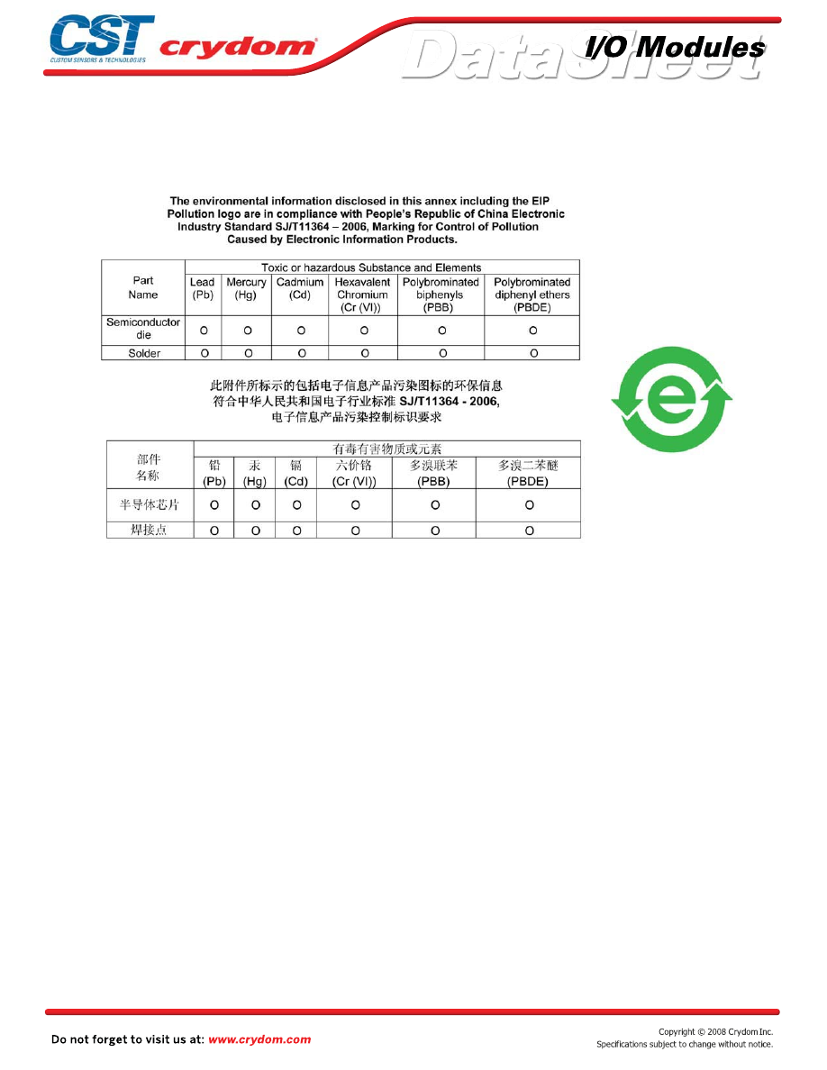
ANNEX - ENVIROMENTAL INFORMATION
Courtesy of Steven Engineering, Inc.-230 Ryan Way, South San Francisco, CA 94080-6370-Main Office: (650) 588-9200-Outside Local Area: (800) 258-9200-www.stevenengineering.com
60MAIN-html.html
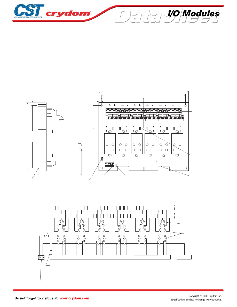
Input and output modules accepted interchangeably
Operate with 5, 15 or 24 volt logic supplies
Plug-compatible logic connections
Screw terminal barrier block for load connections
5 amp field-replaceable fuses
(LITTLEFUSE #251005 or equivalent)
All even-numbered logic connections are
logic ground
PB24Q
MECHANICAL SPECIFICATIONS
APPROVALS
UL
E79183
CSA 38595
MOUNTING BOARD
Rev. 070808
•
•
•
•
•
•
SPECIFY SUFFIX "C" FOR OPTIONAL BERG 65823-093 (OR EQUIVALENT) MALE PIN CONNECTOR
1) MATING CONNECTOR IS BERG 66317-150 OR EQUIVALENT.
FOR PERPENDICULAR-TO-THE-BOARD CABLE CONNECTION.
SPECIFY SUFFIX "V" FOR OPTIONAL BERG 65863-145 (OR EQUIVALENT) MALE PIN CONNECTOR
FOR PARALLEL-TO-THE BOARD CABLE CONNECTION.
NOTES:
4-40 SCREW
TERMINAL LOGIC
SUPPLY BARRIER
STRIP
1
C
3
2
C
4
5
C
7
6
C
8
9
C
11
C
12
C
15
C
16
C
19
C
20
C
23
C
25
16 - 19
20 - 23
12 - 15
4 - 7
8 - 11
0 - 3
COUZET
57-465
PB-24Q
P1
F1A
TB2
+5V GND
TB1
F1
F2
F3
F4
F5
F6
F7
F8
F9
F10
F11
F12
OPTIONAL FUSE LOCATION
MOVE 1A FUSE TO HERE
TO PROVIDE LOGIC SUPPLY VOLTAGE
THROUGH EDGE CONNECTOR PIN 49
SIGNAL INPUT/OUTPUT
50 TRACE (0.1" CENTERS)
MALE CARD EDGE
(SEE NOTE 1)
THREADED (6-32)
NYLON STANDOFF
GORDOS QUAD-PACK
DIGITAL I/O MODULES
SOLD SEPERATELY
REPLACEABLE 5A
POWER LINE FUSE
(SEE NOTE 5)
POWER BARRIER STRIPS
(SEE NOTE 2,3)
REPLACEABLE 1A
LOGIC SUPPLY FUSE
(SEE NOTE 4)
SWAGED STANDOFF
THRU HOLE 0.15 (3,8) DIA
x 0.75 (19,1) LONG (4)
DIMENSIONS: INCHES (MILLIMETERS)
TOLERANCE:
±
0.20 (
±
0.50)
8.0 (203,2)
7.5 (190,5)
3.75 (92,3)
2.0 (50,8)
0.25 (6,4)
6.0 (152,4)
5.5 (139,7)
0.25 (6,4)
17
18
21
22
10
13
14
3.9 (99,1)
ORDER 2 EACH JUMPER "JQ4".
3) OPTIONAL JUMPERS AVAILABLE TO INTERCONNECT BARRIER STRIP COMMONS.
2) 6-32 SCREW TERMINAL BARRIER STRIPS ACCEPT WIRE SIZES FORM 24 TO 12 AWG.
4) LITTLE FUSE 251001 OR EQUIVALENT.
5) LITTLE FUSE 251005 OR EQUIVALENT.
1
2
3
4
5
6
7
8
9
10
11
12
13
14
1 C 3
2 C 4
5 7
6 8
C
C
9 C 11
10 C 12
13 15
C
14 C 16
17 C 19
18 C 20
22 C 24
21 C 23
BARRIER STRIP
UPPER POWER
BARRIER STRIP
LOWER POWER
TIED TO COM
PINS 2-50
49
47
45
43
41 39
37
35
33 31
29
27
25 23
21
19
17 15
13
11
9 7
5
3
1
+
-
REPLACEABLE 5 AMP
LINE FUSES (12)
I/O MODULE PIN SOCKETS
MALE PIN CONNECTOR (option "C" or "V")
REPLACEABLE
1 AMP LOGIC
SUPPLY FUSE
OPTIONAL FUSE LOCATION TO
PROVIDE LOGIC SUPPLY
POWER THROUGH EDGE
CONNECTOR PIN 49
( customer installed)
LOGIC SUPPLY
BARRIER STRIP
SIGNAL INPUT/OUTPUT 50 TRACE (0.1" CENTERS) MALE CARD EDGE OR OPTIONAL
1
2
3
4
5
6
7
8
9
10
11
12
13
14
1
2
3
4
5
6
7
8
9
10
11
12
13
14
1
2
3
4
5
6
7
8
9
10
11
12
13
14
1
2
3
4
5
6
7
8
9
10
11
12
13
14
1
2
3
4
5
6
7
8
9
10
11
12
13
14
Captive-screw retaining system for Quad-Pack
modules
•
Courtesy of Steven Engineering, Inc.-230 Ryan Way, South San Francisco, CA 94080-6370-Main Office: (650) 588-9200-Outside Local Area: (800) 258-9200-www.stevenengineering.com
60MAIN-html.html

HAZARD OF
ELECTRIC
SHOCK,
EXPLOSION,
OR ARC FLASH.
•
Disconnect all
power before
installing or
working with
this equipment.
•
Verify all
connections
and replace all
covers before
turning on
power.
Failure to follow
these
instructions will
result in death
or serious injury.
RIESGO DE
DESCARGA
ELECTRICA O
EXPLOSION.
•
Desconectar
todos los
suministros de
energia a este
equipo antes
de trabajar
con este equipo.
•
Verificar todas
las conexiones
y colocar todas
las tapas antes
de energizer
el equipo.
El
incumplimiento
de estas
instrucciones
puede provocar
la muerte o
lesiones serias.
RISQUE DE
DESCHARGE
ELECTRIQUE
OU EXPLOSION
•
Eteindre
toutes les
sources
d'énergie de
cet appareil
avant de
travailler
dessus de cet
appareil
•
Vérifier tous
connections, et
remettre tous
couverts en
olace avant de
mettre sous
De non-suivi de
ces instructions
provoquera la
mort ou des
lésions sérieuses
sérieuses.
GEFAHR EINES
ELEKTRISCHE
N SCHLAGES
ODER EINER
EXPLOSION.
•
Stellen Sie
jeglichen
Strom ab, der
dieses Gerät
versorgt, bevor
Sie an dem
Gerät Arbeiten
durchführen
•
Vor dem
Drehen auf
Energie alle
Anschlüsse
überprüfen
und alle
Abdeckungen
ersetzen.
Unterlassung
dieser
Anweisungen
können zum
Tode oder zu
schweren
Verletzungen
führen.
RISCHIO DI
SCOSSA
ELETTRICA O
DELL’ESPLOSI
ONE.
•
Spenga tutta
l'alimentazion
e che fornisce
questa
apparecchiatu
ra prima del
lavorare a questa
apparecchiatu ra
•
Verificare tutti
i collegamenti
e sostituire
tutte le coperture
prima della
rotazione
sull'alimentazi one
L'omissione di
seguire queste
istruz ioni
provocherà la
morte o di
lesioni serie
RISCO DE
DESCARGA
ELÉTTRICA OU
EXPLOSÃO
•
Desconectar
o equipamento
de toda á
energia antes
de instalar ou
trabalhar com
este equipamen
to
•
Verificar todas
as conexões e
recolocar todas
as tampas
antes de religar
o equipamento
O não cumprimento
destas instruções
pode levar á morte
ou lesões sérias.
DANGER / PELIGRO / DANGER /GEFAHR / PERICOLO / PERIGO
Courtesy of Steven Engineering, Inc.-230 Ryan Way, South San Francisco, CA 94080-6370-Main Office: (650) 588-9200-Outside Local Area: (800) 258-9200-www.stevenengineering.com
60MAIN-html.html

ANNEX - ENVIROMENTAL INFORMATION
Courtesy of Steven Engineering, Inc.-230 Ryan Way, South San Francisco, CA 94080-6370-Main Office: (650) 588-9200-Outside Local Area: (800) 258-9200-www.stevenengineering.com
60MAIN-html.html
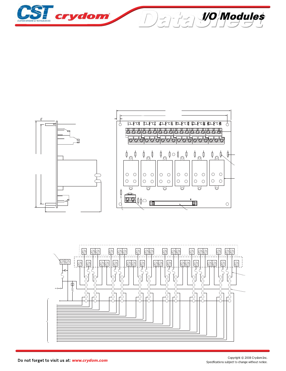
Input and output modules accepted interchangeably
Operate with 5, 15 or 24 volt logic supplies
Plug-compatible logic connections
Screw terminal barrier block for load connections
5 amp field-replaceable fuses
(LITTLEFUSE #251005 or equivalent)
All even-numbered logic connections are
logic ground
PB24HQ
MECHANICAL SPECIFICATIONS
MOUNTING BOARD
Rev. 070808
•
•
•
•
•
•
JQ4 REQUIRES CUSTOMER MODIFACATIONS TO USE WITH PB24HQ.
NOTES: 1) CONNECTOR IS CIRCUIT ASSEMBLY CA-50H-2B-SR OR EQUIVALENT.
3) OPTIONAL JUMPERS AVAILABLE TO INTERCONNECT BARRIER STRIP COMMONS.
ORDER 2 EACH JUMPERS "JQ2" AND 4 EACH JUMPERS "JQ4".
4) LITTLE FUSE 251001 OR EQUIVALENT.
5) LITTLE FUSE 251005 OR EQUIVALENT.
2) 6-32 SCREW TERMINAL BARRIER STRIPS ACCEPT WIRE SIZES FROM 24 TO 12 AWG.
F1
F2
F3
F4
F5
F6
F7
F8
F9
F10
F11
F12
F13
SP
ARE
5A
FUSE
SPARE 5A
LINE FUSE
REPLACEABLE 5A
LINE FUSE (12)
(SEE NOTE 5)
POWER BARRIER
STRIPS
(SEE NOTE 2,3
GORDOS QUAD-PACK
DIGITAL 1/0 MODULES
SOLD SEPERATELY
2 0 - 2 3
1 6 - 1 9
1 2 - 1 5
8 - 11
4 - 7
0 - 3
F1A
D1
D2
R1 J1
PWR
ON
TB2
+5V GND
REPLACEABLE
1A FUSE LOGIC
SUPPLY FUSE
(SEE NOTE 4)
4–40 SCREW TERMINAL LOGIC
SUPPLY BARRIER STRIP
SIGNAL INPUT / OUTPUT
50 CONDUCTOR MALE PIN CONNECTOR
(SEE NOTE 1 )
CROUZET
57–464
PB–24HQ
P 1
1
2
C
C
3
4
5
6
C
C
7
8
C
C
11
12
C
C
15
16
C
C
19
20
C
C
23
24
9
10
13
14
17
18
21
22
8.0 (203,2)
7.5 (190,5)
0.25 (6,4)
DIMENSIONS: INCHES (MILLIMETERS)
TOLERANCE:
±
0.20 (
±
0.50)
SWAGED STANDOFF
THRU HOLE
0.15 (3,8) DIA.
x 0.75 (19,1) LONG (4)
0.25 (6,4)
3.9 (99,1)
5.5 (139,7)
6.0 (152,4)
2
3
4
5
1
47
45
43
41
39
37
35
33
31
29
27
25
23
21
19
17
PWR
ON
+5V
GND
D1
J1
49
2-50
EVEN
PINS
6
7
8
9
10
11
12
13
14
14
13
12
11
10
9
8
7
6
1
5
4
3
2
14
13
12
11
10
9
8
7
6
1
5
4
3
2
2
3
4
5
1
6
7
8
9
10
11
12
13
14
1
C
3
5
C
7
2
C
4
6
C
8
10
C
12
14
C
16
9
C
11
C
5
1
C
3
C
1
C
C
14
13
12
11
10
9
8
7
6
1
5
4
3
2
2
3
4
5
1
6
7
8
9
10
11
12
13
14
15
13
11
9
7
5
3
1
18
17
C
19
20
22
21
23
24
LOGIC SUPPLY
BARRIER STRIP
1 AMP
LOGIC
SUPPLY
FUSE
SIGNAL
INPUT/OUTPUT
50 CONDUCTOR
MALE PIN
CONNECTOR
TO RIBBON CABLE
LOWER BARRIER STRIP
UPPER BARRIER STRIP
5 AMP LINE FUSES (12)
I/O MODULE
PIN SOCKETS
Captive-screw retaining system for Quad-Pack
modules
•
Courtesy of Steven Engineering, Inc.-230 Ryan Way, South San Francisco, CA 94080-6370-Main Office: (650) 588-9200-Outside Local Area: (800) 258-9200-www.stevenengineering.com
60MAIN-html.html

HAZARD OF
ELECTRIC
SHOCK,
EXPLOSION,
OR ARC FLASH.
•
Disconnect all
power before
installing or
working with
this equipment.
•
Verify all
connections
and replace all
covers before
turning on
power.
Failure to follow
these
instructions will
result in death
or serious injury.
RIESGO DE
DESCARGA
ELECTRICA O
EXPLOSION.
•
Desconectar
todos los
suministros de
energia a este
equipo antes
de trabajar
con este equipo.
•
Verificar todas
las conexiones
y colocar todas
las tapas antes
de energizer
el equipo.
El
incumplimiento
de estas
instrucciones
puede provocar
la muerte o
lesiones serias.
RISQUE DE
DESCHARGE
ELECTRIQUE
OU EXPLOSION
•
Eteindre
toutes les
sources
d'énergie de
cet appareil
avant de
travailler
dessus de cet
appareil
•
Vérifier tous
connections, et
remettre tous
couverts en
olace avant de
mettre sous
De non-suivi de
ces instructions
provoquera la
mort ou des
lésions sérieuses
sérieuses.
GEFAHR EINES
ELEKTRISCHE
N SCHLAGES
ODER EINER
EXPLOSION.
•
Stellen Sie
jeglichen
Strom ab, der
dieses Gerät
versorgt, bevor
Sie an dem
Gerät Arbeiten
durchführen
•
Vor dem
Drehen auf
Energie alle
Anschlüsse
überprüfen
und alle
Abdeckungen
ersetzen.
Unterlassung
dieser
Anweisungen
können zum
Tode oder zu
schweren
Verletzungen
führen.
RISCHIO DI
SCOSSA
ELETTRICA O
DELL’ESPLOSI
ONE.
•
Spenga tutta
l'alimentazion
e che fornisce
questa
apparecchiatu
ra prima del
lavorare a questa
apparecchiatu ra
•
Verificare tutti
i collegamenti
e sostituire
tutte le coperture
prima della
rotazione
sull'alimentazi one
L'omissione di
seguire queste
istruz ioni
provocherà la
morte o di
lesioni serie
RISCO DE
DESCARGA
ELÉTTRICA OU
EXPLOSÃO
•
Desconectar
o equipamento
de toda á
energia antes
de instalar ou
trabalhar com
este equipamen
to
•
Verificar todas
as conexões e
recolocar todas
as tampas
antes de religar
o equipamento
O não cumprimento
destas instruções
pode levar á morte
ou lesões sérias.
DANGER / PELIGRO / DANGER /GEFAHR / PERICOLO / PERIGO
Courtesy of Steven Engineering, Inc.-230 Ryan Way, South San Francisco, CA 94080-6370-Main Office: (650) 588-9200-Outside Local Area: (800) 258-9200-www.stevenengineering.com
60MAIN-html.html

ANNEX - ENVIROMENTAL INFORMATION
Courtesy of Steven Engineering, Inc.-230 Ryan Way, South San Francisco, CA 94080-6370-Main Office: (650) 588-9200-Outside Local Area: (800) 258-9200-www.stevenengineering.com
60MAIN-html.html
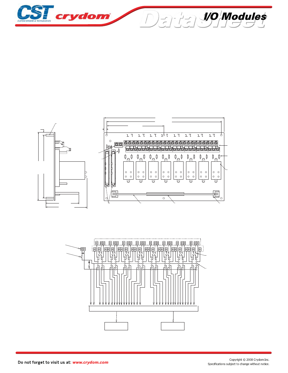
Input and output modules accepted interchangeably
Operate with 5, 15 or 24 volt logic supplies
Plug-compatible logic connections
Screw terminal barrier block for load connections
5 amp field-replaceable fuses
(LITTLEFUSE #251005 or equivalent)
All even-numbered logic connections are
logic ground
PB32HQ
MECHANICAL SPECIFICATIONS
MOUNTING BOARD
Rev. 070808
•
•
•
•
•
•
3) OPTIONAL JUMPERS AVAILABLE TO INTERCONNECT BARRIER STRIP COMMONS.
ORDER 2 EACH JUMPERS "JQ2" AND 4 EACH JUMPERS "JQ4".
NOTES: 1) CONNECTOR IS CIRCUIT ASSEMBLY CA-50H-2B-SR OR EQUIVALENT.
CONNECTORS ARE WIRED IN PARALLEL.
4) LITTLE FUSE 251001 OR EQUIVALENT.
5) LITTLE FUSE 251005 OR EQUIVALENT.
2) 6-32 SCREW TERMINAL BARRIER STRIPS ACCEPT WIRE SIZES FROM 24 TO 12 AWG.
50 CONDUCTOR MALE
PIN CONNECTORS (J1,J2)
(SEE NOTE 1)
0-3
4-7
8-11
12-15
16-19
20-23
24-27
28-31
57-462
PB-32HQ
1
C
3
5
C
7
9
C
11 13
C
15
17
C
19 21
C
23
25
C
27
29
C
31
2
C
4
6
C
8
10
C
12 14
C
16
18
C
20
22
C
24
26
C
28
30
C
32
PAM-4 MULTIPLEXER
BOARD SOLD SEPERATELY
HEADER CONNECTOR (J3)
CARD SUPPORTS (2)
GORDOS QUAD-PACK DIGITAL
I/O MODULES SOLD
SEPERATELY
REPLACEABLE 5 AMP
LINE FUSES (16)
(SEE NOTE 5)
POWER BARRIER STRIPS
(SEE NOTE 2,3)
4-40 SCREW TERMINAL
LOGIC SUPPLY BARRIER STRIP
REPLACEABLE 2 AMP
LOGIC SUPPLY FUSE
(SEE NOTE 4)
11.5 (291,9)
11.0 (279,4)
5.5 (139,7)
0.25 (6,4)
DIMENSIONS: INCHES (MILLIMETERS)
TOLERANCE:
±
0.020 (
±
0.50)
SWAGED STANDOFF
THRU HOLE
0.15 (3.8) DIA.
x 0.75 (19,1) LONG (4)
D2
5A
SPARE
FUSE
GND +5V
R1 D1
TB3
F1A
J2
J1
F1
F2
F3
F4
F5
F6
F7
F8
F9
F10
F11
F12
F13
F14
F15
F16
J3
PWR
ON
3.15 (80,0)
3.9 (100,2)
6.5 (164,9)
6.0 (152,4)
0.25 (6,4)
TB1
1
2
3
4
5
6
7
8
9
10
11
12
13
14
ON
PWR
+5V
1 C
3
5 C
7
2 C
4
6 C
8
9
C 11
13
C 15
17
C 19
10
C 12
14
C 16
18
C 20
21
C 23
25
27
29
C 31
C
22 C
24
26 C
28
30
32
C
LOWER BARRIER STRIP
UPPER BARRIER STRIP
5 AMP LINE
FUSES (16)
MODULE PIN
SOCKETS
GND
LOGIC SUPPLY
BARRIER STRIP
1 AMP
LOGIC
SUPPLY
FUSE
J1 J2
SIGNAL INPUT/OUTPUT 50 CONDUCTOR
MALE PIN CONNECTORS. J1 AND J2
ARE WIRED IN PARALLEL.
I/O
70-PIN MALE CONNECTOR ACCEPTS PAM4 MULTIPLEXER BOARD
1
2
3
4
5
6
7
8
9
10
11
12
13
14
1
2
3
4
5
6
7
8
9
10
11
12
13
14
1
2
3
4
5
6
7
8
9
10
11
12
13
14
1
2
3
4
5
6
7
8
9
10
11
12
13
14
1
2
3
4
5
6
7
8
9
10
11
12
13
14
1
2
3
4
5
6
7
8
9
10
11
12
13
14
1
2
3
4
5
6
7
8
9
10
11
12
13
14
Captive-screw retaining system for Quad-Pack
modules
•
Courtesy of Steven Engineering, Inc.-230 Ryan Way, South San Francisco, CA 94080-6370-Main Office: (650) 588-9200-Outside Local Area: (800) 258-9200-www.stevenengineering.com
60MAIN-html.html

HAZARD OF
ELECTRIC
SHOCK,
EXPLOSION,
OR ARC FLASH.
•
Disconnect all
power before
installing or
working with
this equipment.
•
Verify all
connections
and replace all
covers before
turning on
power.
Failure to follow
these
instructions will
result in death
or serious injury.
RIESGO DE
DESCARGA
ELECTRICA O
EXPLOSION.
•
Desconectar
todos los
suministros de
energia a este
equipo antes
de trabajar
con este equipo.
•
Verificar todas
las conexiones
y colocar todas
las tapas antes
de energizer
el equipo.
El
incumplimiento
de estas
instrucciones
puede provocar
la muerte o
lesiones serias.
RISQUE DE
DESCHARGE
ELECTRIQUE
OU EXPLOSION
•
Eteindre
toutes les
sources
d'énergie de
cet appareil
avant de
travailler
dessus de cet
appareil
•
Vérifier tous
connections, et
remettre tous
couverts en
olace avant de
mettre sous
De non-suivi de
ces instructions
provoquera la
mort ou des
lésions sérieuses
sérieuses.
GEFAHR EINES
ELEKTRISCHE
N SCHLAGES
ODER EINER
EXPLOSION.
•
Stellen Sie
jeglichen
Strom ab, der
dieses Gerät
versorgt, bevor
Sie an dem
Gerät Arbeiten
durchführen
•
Vor dem
Drehen auf
Energie alle
Anschlüsse
überprüfen
und alle
Abdeckungen
ersetzen.
Unterlassung
dieser
Anweisungen
können zum
Tode oder zu
schweren
Verletzungen
führen.
RISCHIO DI
SCOSSA
ELETTRICA O
DELL’ESPLOSI
ONE.
•
Spenga tutta
l'alimentazion
e che fornisce
questa
apparecchiatu
ra prima del
lavorare a questa
apparecchiatu ra
•
Verificare tutti
i collegamenti
e sostituire
tutte le coperture
prima della
rotazione
sull'alimentazi one
L'omissione di
seguire queste
istruz ioni
provocherà la
morte o di
lesioni serie
RISCO DE
DESCARGA
ELÉTTRICA OU
EXPLOSÃO
•
Desconectar
o equipamento
de toda á
energia antes
de instalar ou
trabalhar com
este equipamen
to
•
Verificar todas
as conexões e
recolocar todas
as tampas
antes de religar
o equipamento
O não cumprimento
destas instruções
pode levar á morte
ou lesões sérias.
DANGER / PELIGRO / DANGER /GEFAHR / PERICOLO / PERIGO
Courtesy of Steven Engineering, Inc.-230 Ryan Way, South San Francisco, CA 94080-6370-Main Office: (650) 588-9200-Outside Local Area: (800) 258-9200-www.stevenengineering.com
60MAIN-html.html

ANNEX - ENVIROMENTAL INFORMATION
Courtesy of Steven Engineering, Inc.-230 Ryan Way, South San Francisco, CA 94080-6370-Main Office: (650) 588-9200-Outside Local Area: (800) 258-9200-www.stevenengineering.com
60MAIN-html.html
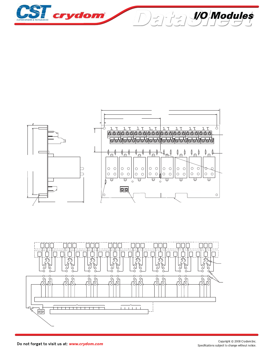
Input and output modules accepted interchangeably
Operate with 5, 15 or 24 volt logic supplies
Plug-compatible logic connections
Screw terminal barrier block for load connections
5 amp field-replaceable fuses
(LITTLEFUSE #251005 or equivalent)
All even-numbered logic connections are
logic ground
PB32Q
MECHANICAL SPECIFICATIONS
APPROVALS
UL
E79183
CSA 38595
LEDs indicate logic status
MOUNTING BOARD
Rev. 070808
•
•
•
•
•
•
•
0.25 (6,4)
3.9 (99,1)
6.2 (157,5)
0.25 (6,4)
DIMENSIONS: INCHES (MILLIMETERS)
TOLERANCE:
±
0.20 (
±
0.50)
5.7 (144.8)
SWAGED STANDOFF
THRU HOLE 0.15, (3,8) DIA
X 0.75 (19,1) LONG (4)
REPLACEABLE 1A
LOGIC SUPPLY FUSE
(SEE NOTE 4)
F1
F2
F3
F4
F5
F6
F7
F8
F9
F10
F11
F12
F13
F14
F15
F16
5.0625 (128,6)
10.2 (259,1)
9.7 (246,4)
2.25 (57,2)
1
2
c
c
3
4
5
6
c
c
7
8
9
10
c
c
11
12
13
14
c
c
15
16
17
18
c
c
19
20
21
22
c
c
23
24
25
26
c
c
27
28
29
30
c
c
31
32
F1A
0-3
4-7
8-11
12-15
16-19
49
TB2
+
–
4-40 SCREW
TERMINAL LOGIC SUPPLY
BARRIER STRIP
0-3
20-23
24-27
28-31
SIGNAL INPUT/OUTPUT 50 TRACE
(0.1" CENTERS) MALE CARD EDGE
(SEE NOTE 1)
CROUZET
57-467
PB-32Q
THREADED (6-32)
NYLON STANDOFF
GORDOS QUAD-PACK
DIGITAL I/O MODULE
SOLD SEPERATELY
REPLACEABLE 5A
LINE FUSE
(SEE NOTE 5)
POWER BARRIER STRIP
(SEE NOTE 2)
TB1
1
SPECIFY SUFFIX "C" FOR OPTIONAL BERG 65823-093 (OR EQUIVALENT) MALE PIN CONNECTOR
1) MATING CONNECTOR IS BERG 66317-150 OR EQUIVALENT.
MALE PIN CONNECTOR FOR PERPENDICULAR-TO-THE-BOARD CABLE CONNECTION.
SPECIFY SUFFIX "V" FOR OPTIONAL CIRCUIT ASSEMBLY CA-50H-2B-SR (OR EQUIVALENT)
FOR PARALLEL-TO-THE BOARD CABLE CONNECTION.
NOTES:
3) OPTIONAL JUMPERS AVAILABLE TO INTERCONNECT BARRIER STRIP COMMONS.
2)
ORDER 2 EACH JUMPERS "JQ2" AND 2 EACH JUMPERS "JQ4".
4) LITTLE FUSE 251001 OR EQUIVALENT.
5) LITTLE FUSE 251005 OR EQUIVALENT.
6-32 SCREW TERMINAL BARRIER STRIPS ACCEPT WIRE SIZES FROM 24 TO 12 AWG.
1
2
3
4
5
6
7
8
9
10
11
12
13
14
1
2
3
10
9
8
11
12
13
14
7
6
5
4
1
2
3
4
5
6
7
14
13
12
11
10
9
8
1
8
9
10
3
2
4
11
12
5
6
7
14
13
1
8
9
10
3
2
4
5
6
7
14
13
12
11
1
2
3
4
5
6
7
14
13
12
11
10
9
1
8
2
3
4
5
6
7
14
13
12
11
10
9
8
8
9
10
11
12
13
1
3
2
4
6
5
7
14
1
C
3
5
C
7
2
C
4
6
C
8
10
C
12
9
C
11
13
C
15
14
C
16
17
C 19
18
C
20
21
C
23
22
C
24
25
C 27
26
C
28
30
C
32
29
C 31
LOGIC GROUND
N/C
LOGIC SUPPLY
BARRIER STRIP
17 19 21 22 23 25 26 28 30 31 32 34
18 20 24 27 29 33
37 39 38 40
35 42 36 41
47 50 44 48
49 43 46 45
14 12 13 11
16 9 15 10
4
1 7
3
2
8 5
6
BARRIER STRIP
UPPER POWER
BARRIER STRIP
LOWER POWER
REPLACEABLE 5 AMP
I/O MODULE
PIN SOCKETS
REPLACEABLE 1 AMP
LOGIC SUPPLY FUSE
LINE FUSES (16)
SIGNAL INPUT/OUTPUT TRACE (0.1" CENTERS) MALE
CARD EDGE OR OPTIONAL MALE PIN CONNECTOR
(option "C" OR "V")
+ –
Captive-screw retaining system for Quad-Pack
modules
•
Courtesy of Steven Engineering, Inc.-230 Ryan Way, South San Francisco, CA 94080-6370-Main Office: (650) 588-9200-Outside Local Area: (800) 258-9200-www.stevenengineering.com
60MAIN-html.html

HAZARD OF
ELECTRIC
SHOCK,
EXPLOSION,
OR ARC FLASH.
•
Disconnect all
power before
installing or
working with
this equipment.
•
Verify all
connections
and replace all
covers before
turning on
power.
Failure to follow
these
instructions will
result in death
or serious injury.
RIESGO DE
DESCARGA
ELECTRICA O
EXPLOSION.
•
Desconectar
todos los
suministros de
energia a este
equipo antes
de trabajar
con este equipo.
•
Verificar todas
las conexiones
y colocar todas
las tapas antes
de energizer
el equipo.
El
incumplimiento
de estas
instrucciones
puede provocar
la muerte o
lesiones serias.
RISQUE DE
DESCHARGE
ELECTRIQUE
OU EXPLOSION
•
Eteindre
toutes les
sources
d'énergie de
cet appareil
avant de
travailler
dessus de cet
appareil
•
Vérifier tous
connections, et
remettre tous
couverts en
olace avant de
mettre sous
De non-suivi de
ces instructions
provoquera la
mort ou des
lésions sérieuses
sérieuses.
GEFAHR EINES
ELEKTRISCHE
N SCHLAGES
ODER EINER
EXPLOSION.
•
Stellen Sie
jeglichen
Strom ab, der
dieses Gerät
versorgt, bevor
Sie an dem
Gerät Arbeiten
durchführen
•
Vor dem
Drehen auf
Energie alle
Anschlüsse
überprüfen
und alle
Abdeckungen
ersetzen.
Unterlassung
dieser
Anweisungen
können zum
Tode oder zu
schweren
Verletzungen
führen.
RISCHIO DI
SCOSSA
ELETTRICA O
DELL’ESPLOSI
ONE.
•
Spenga tutta
l'alimentazion
e che fornisce
questa
apparecchiatu
ra prima del
lavorare a questa
apparecchiatu ra
•
Verificare tutti
i collegamenti
e sostituire
tutte le coperture
prima della
rotazione
sull'alimentazi one
L'omissione di
seguire queste
istruz ioni
provocherà la
morte o di
lesioni serie
RISCO DE
DESCARGA
ELÉTTRICA OU
EXPLOSÃO
•
Desconectar
o equipamento
de toda á
energia antes
de instalar ou
trabalhar com
este equipamen
to
•
Verificar todas
as conexões e
recolocar todas
as tampas
antes de religar
o equipamento
O não cumprimento
destas instruções
pode levar á morte
ou lesões sérias.
DANGER / PELIGRO / DANGER /GEFAHR / PERICOLO / PERIGO
Courtesy of Steven Engineering, Inc.-230 Ryan Way, South San Francisco, CA 94080-6370-Main Office: (650) 588-9200-Outside Local Area: (800) 258-9200-www.stevenengineering.com
60MAIN-html.html

ANNEX - ENVIROMENTAL INFORMATION
Courtesy of Steven Engineering, Inc.-230 Ryan Way, South San Francisco, CA 94080-6370-Main Office: (650) 588-9200-Outside Local Area: (800) 258-9200-www.stevenengineering.com
60MAIN-html.html
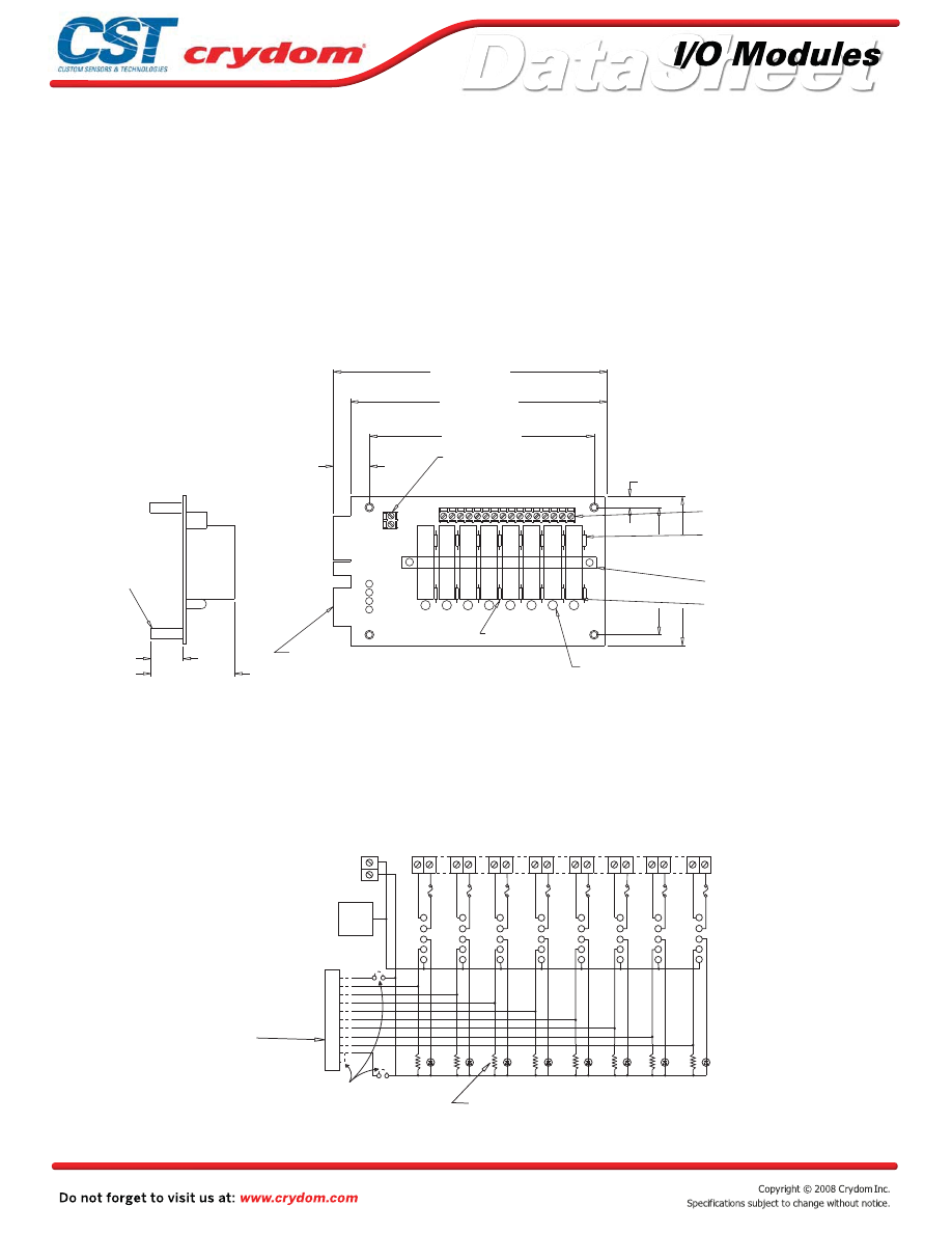
Input and output modules accepted interchangeably
Operate with 5, 15 or 24 volt logic supplies
Pin retaining system for “SM” series minature modules.
Plug-compatible logic connections
Screw terminal barrier block for load connections
Resident pull-up resistors
5 amp field-replaceable fuses
(LITTLEFUSE #251005 or equivalent)
All even-numbered logic connections are
logic ground
PB8SM
MECHANICAL SPECIFICATIONS
LEDs indicate logic status
MOUNTING BOARD
Rev. 070808
•
•
•
•
•
•
•
•
•
+
-
R
B
W
Y
3.5 (88,9)
3.0 (76,2)
0.25 (6,4)
6.4 (162,5)
6.0 (152,4)
5.3 (134,5)
0.9 (22,8)
1.9 (47,6)
0.75 (19,0)
PULL UP RESISTOR
3.3K OHM (8)
AC INPUT
DC INPUT
AC OUTPUT
DC OUTPUT
1 2
3 4 5
6 7
8 9 10 11 12 13 14 15 16
1
2
3
4
5
7
6
0
NOTES: 1) MATING CONNECTOR IS BERG 66317-150 OR EQUIVALENT.
SPECIFY SUFFIX 'C' FOR OPTIONAL 65823-093 OR EQUIVALENT
MALE PIN CONNECTOR FOR PARALLEL-TO-THE-BOARD CABLE
CONNECTION. SPECIFY SUFFIX 'V' FOR OPTIONAL CIRCUIT ASSEMBLY CA-50H-2B-SR
OR EQUIVALENT MALE PIN CONNECTOR FOR PERPENDICULAR-TO-THE-BOARD
CABLE CONNECTION.
3) OPTIONAL JUMPERS ARE AVAILABLE TO INTERCONNECT BARRIER STRIP
COMMONS. ORDER 1 EACH "JM8".
4) PHOENIX MKD51.5 5.08mm SERIES (OR EQUIVALENT) SCREW TERMINAL
BLOCKS STANDARD. SPECIFY SUFFIX "A" FOR BOARD-MOUNTED PHOENIX
MSTBVA 1.5/16-G-5.08 (OR EQUIVALENT) MALE CONNECTOR. SPECIFY
SUFFIX "B" FOR BOARD-MOUNTED PHOENIX MSTBVA 1.5/16-G-5.08
(OR EQUIVALENT) MALE CONNECTOR AND MATING PHOENIX MSTBVA 1.5/16-ST-5.08
(see notes 2,3,4)
REPLACEABLE 5 AMP LINE FUSE (8)
(see note 5)
OPTIONAL HOLD DOWN BAR KIT
(see note 6)
CRYDOM DIGITAL I/O MODULES
(see note 2)
SIGNAL INPUT/OUTPUT
(see note 1)
SWAGED STANDOFF
THRU HOLE
0.1" (3,8) DIA. (4)
SOLD SEPERATELY
LED STATUS INDICATORS (8)
(OR EQUIVALENT) FEMALE, SCREW-TERMINAL PLUG-IN CONNECTOR.
5) LITTLE FUSE 251005 OR EQUIVALENT.
50 TRACE (0.1" CENTERS)
MALE CARD EDGE
2) 4-40 SCREW TERMINAL STRIPS ACCEPT WIRE SIZES FROM 26 TO 14 AWG.
LOGIC SUPPLY TERMINAL STRIP
POWER TERMINAL STRIP
6) TWO HOLD-DOWN BAR KITS ARE AVAILABLE SEPARATELY. MODEL NO. 11.06.414
EMPLOYS A PLAIN ALUMINUM CHANNEL WHILE MODEL NO. 11.06.293 PROVIDES
POCKETS IN THE CHANNEL FOR INDIVIDUAL MODULES.
+
-
DIMENSIONS: INCHES (MILLIMETERS)
TOLERANCE: 0.020 ( 0,50)
+
-
5
4
3
2
1
49
47
45
43
41
39
37
35
33
25
1
ALL
EVEN
PINS
BOTTOM
-
+
+ LOGIC
+LOGIC
SIGNAL
INPUT/
OUTPUT
EDGE CONN TOP
PULL UP RESISTOR
3.3K OHM
(8)
1 2
3 4
5 6
7 8
9 10
11 12
13 14
15 16
BARRIER STRIP
LOGIC SUPPLY
5 AMP
LINE FUSE (8)
LED STATUS
INDICATOR (8)
POWER BARRIER STRIP
OPTIONAL CUSTOMER INSTALLED JUMPERS
FOR WIRING LOGIC SUPPLY TO
HEADER CONNECTOR
I/O MODULE
PIN SOCKETS
AMP #645979-1
OR EQUIVALENT
OPTIONAL PIN CONNECTOR
50 TRACE (0.1" CENTERS)
MALE CARD EDGE OR
5
4
3
2
1
5
4
3
2
1
5
4
3
2
1
5
4
3
2
1
5
4
3
2
1
5
4
3
2
1
5
4
3
2
1
Courtesy of Steven Engineering, Inc.-230 Ryan Way, South San Francisco, CA 94080-6370-Main Office: (650) 588-9200-Outside Local Area: (800) 258-9200-www.stevenengineering.com
60MAIN-html.html

HAZARD OF
ELECTRIC
SHOCK,
EXPLOSION,
OR ARC FLASH.
x
Disconnect all
power before
installing or
working with
this equipment.
x
Verify all
connections
and replace all
covers before
turning on
power.
Failure to follow
these
instructions will
result in death
or serious injury.
RIESGO DE
DESCARGA
ELECTRICA O
EXPLOSION.
x
Desconectar
todos los
suministros de
energia a este
equipo antes
de trabajar
con este equipo.
x
Verificar todas
las conexiones
y colocar todas
las tapas antes
de energizer
el equipo.
El
incumplimiento
de estas
instrucciones
puede provocar
la muerte o
lesiones serias.
RISQUE DE
DESCHARGE
ELECTRIQUE
OU EXPLOSION
x
Eteindre
toutes les
sources
d'énergie de
cet appareil
avant de
travailler
dessus de cet
appareil
x
Vérifier tous
connections, et
remettre tous
couverts en
olace avant de
mettre sous
De non-suivi de
ces instructions
provoquera la
mort ou des
lésions sérieuses
sérieuses.
GEFAHR EINES
ELEKTRISCHE
N SCHLAGES
ODER EINER
EXPLOSION.
x
Stellen Sie
jeglichen
Strom ab, der
dieses Gerät
versorgt, bevor
Sie an dem
Gerät Arbeiten
durchführen
x
Vor dem
Drehen auf
Energie alle
Anschlüsse
überprüfen
und alle
Abdeckungen
ersetzen.
Unterlassung
dieser
Anweisungen
können zum
Tode oder zu
schweren
Verletzungen
führen.
RISCHIO DI
SCOSSA
ELETTRICA O
DELL’ESPLOSI
ONE.
x
Spenga tutta
l'alimentazion
e che fornisce
questa
apparecchiatu
ra prima del
lavorare a questa
apparecchiatu ra
x
Verificare tutti
i collegamenti
e sostituire
tutte le coperture
prima della
rotazione
sull'alimentazi one
L'omissione di
seguire queste
istruz ioni
provocherà la
morte o di
lesioni serie
RISCO DE
DESCARGA
ELÉTTRICA OU
EXPLOSÃO
x
Desconectar
o equipamento
de toda á
energia antes
de instalar ou
trabalhar com
este equipamen
to
x
Verificar todas
as conexões e
recolocar todas
as tampas
antes de religar
o equipamento
O não cumprimento
destas instruções
pode levar á morte
ou lesões sérias.
DANGER / PELIGRO / DANGER /GEFAHR / PERICOLO / PERIGO
Courtesy of Steven Engineering, Inc.-230 Ryan Way, South San Francisco, CA 94080-6370-Main Office: (650) 588-9200-Outside Local Area: (800) 258-9200-www.stevenengineering.com
60MAIN-html.html

ANNEX - ENVIROMENTAL INFORMATION
Courtesy of Steven Engineering, Inc.-230 Ryan Way, South San Francisco, CA 94080-6370-Main Office: (650) 588-9200-Outside Local Area: (800) 258-9200-www.stevenengineering.com
60MAIN-html.html
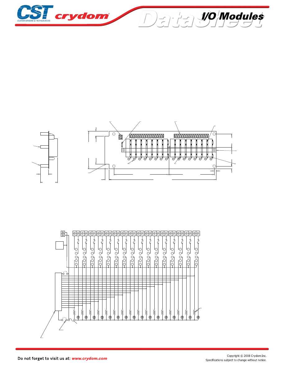
Input and output modules accepted interchangeably
Operate with 5, 15 or 24 volt logic supplies
Pin retaining system for “SM” series minature modules.
Plug-compatible logic connections
Screw terminal barrier block for load connections
Resident pull-up resistors
5 amp field-replaceable fuses
(LITTLEFUSE #251005 or equivalent)
All even-numbered logic connections are
logic ground
PB16SM
MECHANICAL SPECIFICATIONS
LEDs indicate logic status
MOUNTING BOARD
Rev. 070808
•
•
•
•
•
•
•
•
•
(16)
(16)
+
-
1.3 (44,5)
1.8 (31,8)
0.25 (6,4)
0.2 (5,1)
4.225 (107,3)
5.125 (130,2)
10.0 (254,0)
0.4 (10,2)
2.6 (66,0)
3.5 (88,9)
0.45 (11,4)
1.9 (47,6)
0.75 (19,0)
LED STATUS INDICATOR
PULL UP RESISTOR
3.3K OHM
6
1
1
2
3
7
1
REPLACEABLE 1 AMP
(see note 6)
(see notes 2,3,4)
REPLACEABLE 5 AMP LINE FUSES (16)
(see note 5)
CRYDOM DIGITAL
I/O MODULE
SOLD SEPERATELY
OPTIONAL HOLD
DOWN BAR KIT
(see note 7)
SIGNAL INPUT/OUTPUT
OPTIONAL MALE PIN
CONNECTOR (see note 1)
3-32 NYLON
STANDOFF (1)
SWAGED STANDOFF
THRU HOLE
0.15 (3,8) DIA. (4)
(OR EQUIVALENT) FEMALE. SCREW-TERMINAL PLUG-IN CONNECTOR.
(OR EQUIVALENT) MALE CONNECTOR AND MATING PHOENIX MSTBVA 1.5/16-ST-5.08
SUFFIX "B" FOR BOARD-MOUNTED PHOENIX MSTBVA 1.5/16-G-5.08
MSTBVA 1.5/16-G-5.08 (OR EQUIVALENT) MALE CONNECTOR. SPECIFY
BLOCKS STANDARD. SPECIFY SUFFIX "A" FOR BOARD-MOUNTED PHOENIX
4) PHOENIX MKD51.5 5.08mm SERIES (OR EQUIVALENT) SCREW TERMINAL
3) OPTIONAL JUMPERS ARE AVAILABLE TO INTERCONNECT BARRIER STRIP
CABLE CONNECTION.
OR EQUIVALENT MALE PIN CONNECTOR FOR PERPENDICULAR-TO-THE-BOARD
CONNECTION. SPECIFY SUFFIX 'V' FOR OPTIONAL CIRCUIT ASSEMBLY CA-50H-2B-SR
MALE PIN CONNECTOR FOR PARALLEL-TO-THE-BOARD CABLE
SPECIFY SUFFIX 'C' FOR OPTIONAL 65823-093 OR EQUIVALENT
NOTES: 1) MATING CONNECTOR IS BERG 66317-150 OR EQUIVALENT.
ORDER 1 EACH "JM2" AND 2 EACH "JM8".
LOGIC SUPPLY FUSE
5) LITTLE FUSE 251001 OR EQUIVALENT.
6) LITTLE FUSE 251005 OR EQUIVALENT.
4-40 SCREW TERMINAL
LOGIC SUPPLY
BARRIER STRIP
50 TRACE (0.1" CENTERS)
MALE CARD EDGE OR
2) 6-32 SCREW TERMINAL BARRIER STRIPS ACCEPT WIRE SIZES FROM 24 TO 12 AWG.
EMPLOYS A PLAIN ALUMINUM CHANNEL WHILE MODEL NO. 11.06.278 PROVIDES
7) TWO HOLD-DOWN BAR KITS ARE AVAILABLE SEPARATELY. MODEL NO. 11.06.415
POCKETS IN THE CHANNEL FOR INDIVIDUAL MODULES.
POWER TERMINAL STRIP
+
-
DIMENSIONS: INCHES (MILLIMETERS)
TOLERANCE: 0.020 ( 0,50)
+
-
5
4
3
2
1
*
*
EVEN
ALL
PINS
GND
LOGIC
+
-
BARRIER STRIP
LOGIC SUPPLY
TOP
+LOGIC
+LOGIC
1
17
19
21
23
25
27
29
31
33
35
37
39
41
43
45
47
49
PULL UP
RESISTOR
3.3K OHM
1 2 3 4 5 6 7 8 9 10 11 12 13 14 15 16 17 18 19 20 21 22 23 24 25 26 27 28 29 30 31 32
5 AMP
LINE FUSE (16)
I/O MODULE
PIN SOCKETS
(16)
LED STATUS
INDICATOR (16)
1 AMP LOGIC SUPPLY FUSE
CUSTOMER INSTALLED OPTIONAL JUMPERS TO WIRE
LOGIC SUPPLY TO HEADER CONNECTOR
POWER BARRIER STRIP
SIGNAL INPUT/OUTPUT 50 TRACE (0.1" CENTERS) MALE
CARD EDGE OR OPTIONAL PIN CONNECTOR.
5
4
3
2
1
5
4
3
2
1
5
4
3
2
1
5
4
3
2
1
5
4
3
2
1
5
4
3
2
1
5
4
3
2
1
5
4
3
2
1
5
4
3
2
1
5
4
3
2
1
5
4
3
2
1
5
4
3
2
1
5
4
3
2
1
5
4
3
2
1
5
4
3
2
1
Courtesy of Steven Engineering, Inc.-230 Ryan Way, South San Francisco, CA 94080-6370-Main Office: (650) 588-9200-Outside Local Area: (800) 258-9200-www.stevenengineering.com
60MAIN-html.html

HAZARD OF
ELECTRIC
SHOCK,
EXPLOSION,
OR ARC FLASH.
x
Disconnect all
power before
installing or
working with
this equipment.
x
Verify all
connections
and replace all
covers before
turning on
power.
Failure to follow
these
instructions will
result in death
or serious injury.
RIESGO DE
DESCARGA
ELECTRICA O
EXPLOSION.
x
Desconectar
todos los
suministros de
energia a este
equipo antes
de trabajar
con este equipo.
x
Verificar todas
las conexiones
y colocar todas
las tapas antes
de energizer
el equipo.
El
incumplimiento
de estas
instrucciones
puede provocar
la muerte o
lesiones serias.
RISQUE DE
DESCHARGE
ELECTRIQUE
OU EXPLOSION
x
Eteindre
toutes les
sources
d'énergie de
cet appareil
avant de
travailler
dessus de cet
appareil
x
Vérifier tous
connections, et
remettre tous
couverts en
olace avant de
mettre sous
De non-suivi de
ces instructions
provoquera la
mort ou des
lésions sérieuses
sérieuses.
GEFAHR EINES
ELEKTRISCHE
N SCHLAGES
ODER EINER
EXPLOSION.
x
Stellen Sie
jeglichen
Strom ab, der
dieses Gerät
versorgt, bevor
Sie an dem
Gerät Arbeiten
durchführen
x
Vor dem
Drehen auf
Energie alle
Anschlüsse
überprüfen
und alle
Abdeckungen
ersetzen.
Unterlassung
dieser
Anweisungen
können zum
Tode oder zu
schweren
Verletzungen
führen.
RISCHIO DI
SCOSSA
ELETTRICA O
DELL’ESPLOSI
ONE.
x
Spenga tutta
l'alimentazion
e che fornisce
questa
apparecchiatu
ra prima del
lavorare a questa
apparecchiatu ra
x
Verificare tutti
i collegamenti
e sostituire
tutte le coperture
prima della
rotazione
sull'alimentazi one
L'omissione di
seguire queste
istruz ioni
provocherà la
morte o di
lesioni serie
RISCO DE
DESCARGA
ELÉTTRICA OU
EXPLOSÃO
x
Desconectar
o equipamento
de toda á
energia antes
de instalar ou
trabalhar com
este equipamen
to
x
Verificar todas
as conexões e
recolocar todas
as tampas
antes de religar
o equipamento
O não cumprimento
destas instruções
pode levar á morte
ou lesões sérias.
DANGER / PELIGRO / DANGER /GEFAHR / PERICOLO / PERIGO
Courtesy of Steven Engineering, Inc.-230 Ryan Way, South San Francisco, CA 94080-6370-Main Office: (650) 588-9200-Outside Local Area: (800) 258-9200-www.stevenengineering.com
60MAIN-html.html

ANNEX - ENVIROMENTAL INFORMATION
Courtesy of Steven Engineering, Inc.-230 Ryan Way, South San Francisco, CA 94080-6370-Main Office: (650) 588-9200-Outside Local Area: (800) 258-9200-www.stevenengineering.com
60MAIN-html.html
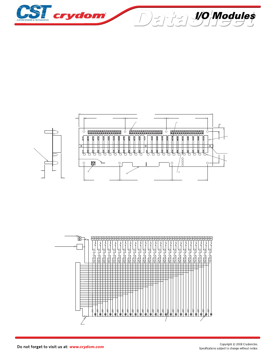
Input and output modules accepted interchangeably
Operate with 5, 15 or 24 volt logic supplies
Pin retaining system for “SM” series minature modules
Plug-compatible logic connections
Screw terminal barrier block for load connections
Resident pull-up resistors
5 amp field-replaceable fuses
(LITTLEFUSE #251005 or equivalent)
All even-numbered logic connections are
logic ground
PB24SM
MECHANICAL SPECIFICATIONS
LEDs indicate logic status
MOUNTING BOARD
Rev. 070808
•
•
•
•
•
•
•
•
•
3.45 (67,6)
5.1 (129,5)
3.45 (87,6)
3.05 (77,5)
3.75 (95,3)
0.35 (8,9)
13.0 (330,2)
4.0 (101,6)
4.0 (101,6)
4.0 (101,6)
0.5 (12,7)
1.88 (47,6)
0.75 (19,1)
Y
AC INPUT
W
DC INPUT
B
AC OUTPUT
R
DC OUTPUT
1 2 3 4 5 6 7 8 9 1011 1213 141516
17 1819 202122 232425 2627 282930 3132
33 343536 3738 394041 4243 444546 4748
+
-
0
1
2
3
4
5
6
7
8
9
10
11
12
13
14
15
16
17
18
19
20
21
22
23
(see notes 2,3,4)
REPLACEABLE 5 AMP
LINE FUSE (24)
(see note 6)
CRYDOM DIGITAL
I/O MODULES
SOLD SEPERATELY
OPTIONAL HOLD DOWN
BAR KIT (see note 7)
LED STATUS
INDICATOR (24)
(24)
PULL UP RESISTOR
3.3K OHM
SIGNAL INPUT/OUTPUT 50
LOGIC SUPPLY
(see note 2)
REPLACEABLE
1 AMP LOGIC
SUPPLY FUSE
(see note 5)
SWAGED STANDOFF
THRU HOLE 0.15 (3,8) DIA.
(8)
(OR EQUIVALENT) FEMALE. SCREW-TERMINAL PLUG-IN CONNECTOR.
(OR EQUIVALENT) MALE CONNECTOR AND MATING PHOENIX MSTBVA 1.5/16-ST-5.08
SUFFIX "B" FOR BOARD-MOUNTED PHOENIX MSTBVA 1.5/16-G-5.08
MSTBVA 1.5/16-G-5.08 (OR EQUIVALENT) MALE CONNECTOR. SPECIFY
BLOCKS STANDARD. SPECIFY SUFFIX "A" FOR BOARD-MOUNTED PHOENIX
4) PHOENIX MKD51.5 5.08mm SERIES (OR EQUIVALENT) SCREW TERMINAL
3) OPTIONAL JUMPERS ARE AVAILABLE TO INTERCONNECT BARRIER STRIP
CABLE CONNECTION.
OR EQUIVALENT MALE PIN CONNECTOR FOR PERPENDICULAR-TO-THE-BOARD
CONNECTION. SPECIFY SUFFIX 'V' FOR OPTIONAL CIRCUIT ASSEMBLY CA-50H-2B-SR
MALE PIN CONNECTOR FOR PARALLEL-TO-THE-BOARD CABLE
SPECIFY SUFFIX 'C' FOR OPTIONAL 65823-093 OR EQUIVALENT
NOTES: 1) MATING CONNECTOR IS BERG 66317-150 OR EQUIVALENT.
ORDER 3 EACH "JM8".
5) LITTLE FUSE 251001 OR EQUIVALENT.
6) LITTLE FUSE 251005 OR EQUIVALENT.
TERMINAL STRIP
POWER TERMINAL STRIP
TRACE (0.1" CENTERS) MALE
CARD EDGE (see note 1)
2) 4-40 SCREW TERMINAL STRIPS ACCEPT WIRE SIZES FROM 26 TO 14 AWG.
THE CHANNEL FOR INDIVIDUAL MODULES.
A PLAIN ALUMINUM CHANNEL WHILE MODEL NO. 11.06.288 PROVIDES POCKETS IN
7) TWO HOLD-DOWN BAR KITS ARE AVAILABLE SEPARATELY. MODEL NO. 11.06.413 EMPLOYS
+
-
DIMENSIONS: INCHES (MILLIMETERS)
TOLERANCE: 0.020 ( 0,50)
+
-
5
4
3
2
1
1
5
9
13
17
21
25
29
33
37
41
45
49
+LOGIC
EVEN
PINS
ALL
+
-
1 2 3 4 5 6 7 8 9 10 11 12 13 14 15 16 17 18 19 20 21 22 23 24 25 26 27 28 29 30 31 32 33 34 35 36 37 38 39 40 41 42 43 44 45 46 47 48
5 AMP LINE FUSE (24)
I/O MODULE PIN SOCKET
LED STATUS INDICATOR (24)
PULL UP RESISTOR 3.3K OHM (24)
1 AMP LOGIC
SUPPLY FUSE
POWER BARRIER STRIP
LOGIC SUPPLY
BARRIER STRIP
EDGE
CONN
BOTTOM
LOGIC
GRD
SIGNAL INPUT/OUTPUT
OR OPTIONAL PIN
CONNECTOR
50 TRACE (0.1" CENTERS)
MALE CARD EDGE
5
4
3
2
1
5
4
3
2
1
5
4
3
2
1
5
4
3
2
1
5
4
3
2
1
5
4
3
2
1
5
4
3
2
1
5
4
3
2
1
5
4
3
2
1
5
4
3
2
1
5
4
3
2
1
5
4
3
2
1
5
4
3
2
1
5
4
3
2
1
5
4
3
2
1
5
4
3
2
1
5
4
3
2
1
5
4
3
2
1
5
4
3
2
1
5
4
3
2
1
5
4
3
2
1
5
4
3
2
1
5
4
3
2
1
Courtesy of Steven Engineering, Inc.-230 Ryan Way, South San Francisco, CA 94080-6370-Main Office: (650) 588-9200-Outside Local Area: (800) 258-9200-www.stevenengineering.com
60MAIN-html.html

HAZARD OF
ELECTRIC
SHOCK,
EXPLOSION,
OR ARC FLASH.
x
Disconnect all
power before
installing or
working with
this equipment.
x
Verify all
connections
and replace all
covers before
turning on
power.
Failure to follow
these
instructions will
result in death
or serious injury.
RIESGO DE
DESCARGA
ELECTRICA O
EXPLOSION.
x
Desconectar
todos los
suministros de
energia a este
equipo antes
de trabajar
con este equipo.
x
Verificar todas
las conexiones
y colocar todas
las tapas antes
de energizer
el equipo.
El
incumplimiento
de estas
instrucciones
puede provocar
la muerte o
lesiones serias.
RISQUE DE
DESCHARGE
ELECTRIQUE
OU EXPLOSION
x
Eteindre
toutes les
sources
d'énergie de
cet appareil
avant de
travailler
dessus de cet
appareil
x
Vérifier tous
connections, et
remettre tous
couverts en
olace avant de
mettre sous
De non-suivi de
ces instructions
provoquera la
mort ou des
lésions sérieuses
sérieuses.
GEFAHR EINES
ELEKTRISCHE
N SCHLAGES
ODER EINER
EXPLOSION.
x
Stellen Sie
jeglichen
Strom ab, der
dieses Gerät
versorgt, bevor
Sie an dem
Gerät Arbeiten
durchführen
x
Vor dem
Drehen auf
Energie alle
Anschlüsse
überprüfen
und alle
Abdeckungen
ersetzen.
Unterlassung
dieser
Anweisungen
können zum
Tode oder zu
schweren
Verletzungen
führen.
RISCHIO DI
SCOSSA
ELETTRICA O
DELL’ESPLOSI
ONE.
x
Spenga tutta
l'alimentazion
e che fornisce
questa
apparecchiatu
ra prima del
lavorare a questa
apparecchiatu ra
x
Verificare tutti
i collegamenti
e sostituire
tutte le coperture
prima della
rotazione
sull'alimentazi one
L'omissione di
seguire queste
istruz ioni
provocherà la
morte o di
lesioni serie
RISCO DE
DESCARGA
ELÉTTRICA OU
EXPLOSÃO
x
Desconectar
o equipamento
de toda á
energia antes
de instalar ou
trabalhar com
este equipamen
to
x
Verificar todas
as conexões e
recolocar todas
as tampas
antes de religar
o equipamento
O não cumprimento
destas instruções
pode levar á morte
ou lesões sérias.
DANGER / PELIGRO / DANGER /GEFAHR / PERICOLO / PERIGO
Courtesy of Steven Engineering, Inc.-230 Ryan Way, South San Francisco, CA 94080-6370-Main Office: (650) 588-9200-Outside Local Area: (800) 258-9200-www.stevenengineering.com
60MAIN-html.html

ANNEX - ENVIROMENTAL INFORMATION
Courtesy of Steven Engineering, Inc.-230 Ryan Way, South San Francisco, CA 94080-6370-Main Office: (650) 588-9200-Outside Local Area: (800) 258-9200-www.stevenengineering.com
60MAIN-html.html
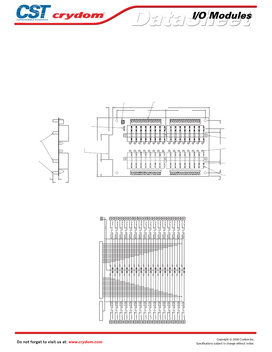
Input and output modules accepted interchangeably
Operate with 5, 15 or 24 volt logic supplies
Pin retaining system for “SM” series minature modules
Plug-compatible logic connections
Screw terminal barrier block for load connections
Resident pull-up resistors
5 amp field-replaceable fuses
(LITTLEFUSE #251005 or equivalent)
All even-numbered logic connections are
logic ground
PB32SM
MECHANICAL SPECIFICATIONS
LEDs indicate logic status
MOUNTING BOARD
Rev. 070808
•
•
•
•
•
•
•
•
•
0.25 (6,4)
3.2 (81,3)
1.3 (31,8)
1.3 (31,8)
10.2 (259,1)
4.225 (107,3)
5.475 (139,1)
0.4 (10,2)
6.2 (157,5)
2.6 (66,0)
1.8 (45,7)
1.9 (47,6)
0.75 (19,1)
2
3
7
1
6
1
1
49
1
0
1
2
3
4
5
6
7
8
9
10
11
12
13
14
15
6
4
2
5
2
6
2
8
2
9
2
0
3
1
3
1
7
1
8
1
9
1
0
2
1
2
2
2
3
2
7
2
3
3
8
4
9
4
4
6
(8)
THRU HOLE 0.15 (3,8) DIA.
SWAGED STANDOFF
LOGIC SUPPLY
BARRIER STRIP
(see note 2)
POWER BARRIER STRIP (4)
(see notes 2,3,4)
REPLACEABLE 5 AMP
LINE FUSES (32)
(see note 6)
OPTIONAL HOLD DOWN
BAR KIT (see note 7)
LED STATUS
INDICATOR (32)
CRYDOM DIGITAL
I/O MODULES
SOLD SEPERATELY
REPLACEABLE 1 AMP
LOGIC SUPPLY FUSE
(see note 5)
SIGNAL INPUT/OUTPUT
50 CONDUCTOR MALE
CARD EDGE CONNECTOR
(see note 1)
6-32 NYLON
STANDOFF (2)
6) LITTLE FUSE 251005 OR EQUIVALENT.
5) LITTLE FUSE 251001 OR EQUIVALENT.
NOTES: 1) MATING CONNECTOR IS BERG 66317-150 OR EQUIVALENT.
SPECIFY SUFFIX 'C' FOR OPTIONAL 65823-093 OR EQUIVALENT
MALE PIN CONNECTOR FOR PARALLEL-TO-THE-BOARD CABLE
CONNECTION. SPECIFY SUFFIX 'V' FOR OPTIONAL CIRCUIT ASSEMBLY CA-50H-2B-SR
OR EQUIVALENT MALE PIN CONNECTOR FOR PERPENDICULAR-TO-THE-BOARD
CABLE CONNECTION.
2) BARRIER STRIPS ACCEPT WIRE SIZES FROM 26 TO 14 AWG.
3) OPTIONAL JUMPERS ARE AVAILABLE TO INTERCONNECT BARRIER STRIP
4) PHOENIX MKD51.5 5.08mm SERIES (OR EQUIVALENT) SCREW TERMINAL
BLOCKS STANDARD. SPECIFY SUFFIX "A" FOR BOARD-MOUNTED PHOENIX
MSTBVA 1.5/16-G-5.08 (OR EQUIVALENT) MALE CONNECTOR. SPECIFY
SUFFIX "B" FOR BOARD-MOUNTED PHOENIX MSTBVA 1.5/16-G-5.08
(OR EQUIVALENT) MALE CONNECTOR AND MATING PHOENIX MSTBVA 1.5/16-ST-5.08
(OR EQUIVALENT) FEMALE. SCREW-TERMINAL PLUG-IN CONNECTOR.
7) OPTIONAL HOLD DOWN BAR KITS AVAILABLE. ORDER KIT 11.06.418 FOR LOW
COST CLAMPING VERSION, OR KIT 11.06.305 FOR FULLY RETAINED VERSION.
PULL UP RESISTORS
3.3K OHM (32)
ORDER 2 EACH "JM2" AND 4 EACH "JM8".
+
-
DIMENSIONS: INCHES (MILLIMETERS)
TOLERANCE: 0.020 ( 0,50)
+
-
1
2
3
4
5
5
4
3
2
1
1 2
3 4
5 6
7 8
9 10 11 12 13 14 15 16 17 18 19 20 21 22 23 24 25 26 27 28 29 30 31 32
64 63 62 61 60 59 58 57 56 55 54 53 52 51 50 49 48 47 46 45 44 43 42 41 40 39 38 37 36 35 34 33
17
34
32
31
30
28
26
25
23
22
21
19
6
5
8
2
3
7
1
4
10
15
9
16
11
13
12
14
45
46
43
49
48
44
50
47
41
36
42
35
40
38
39
37
GROUND
LOGIC
+
-
BARRIER STRIP
LOGIC SUPPLY
INDICATOR
(32)
PULL UP
RESISTOR
3.3K OHM
(32)
POWER BARRIER STRIP
5 AMP LINE
FUSES (32)
LED STATUS
POWER BARRIER STRIP
1 AMP LOGIC
SUPPLY FUSE
SIGNAL INPUT/OUTPUT
18, 20, 24,
27, 29, 33
NOT CONNECTED
50 TRACE (0.1"CENTERS)
MALE CARD EDGE OR
OPTIONAL MALE PIN
1
2
3
4
5
1
2
3
4
5
1
2
3
4
5
1
2
3
4
5
1
2
3
4
5
1
2
3
4
5
1
2
3
4
5
1
2
3
4
5
1
2
3
4
5
1
2
3
4
5
1
2
3
4
5
1
2
3
4
5
1
2
3
4
5
1
2
3
4
5
1
2
3
4
5
5
4
3
2
1
5
4
3
2
1
5
4
3
2
1
5
4
3
2
1
5
4
3
2
1
5
4
3
2
1
5
4
3
2
1
5
4
3
2
1
5
4
3
2
1
5
4
3
2
1
5
4
3
2
1
5
4
3
2
1
5
4
3
2
1
5
4
3
2
1
5
4
3
2
Courtesy of Steven Engineering, Inc.-230 Ryan Way, South San Francisco, CA 94080-6370-Main Office: (650) 588-9200-Outside Local Area: (800) 258-9200-www.stevenengineering.com
60MAIN-html.html
HAZARD OF
ELECTRIC
SHOCK,
EXPLOSION,
OR ARC FLASH.
x
Disconnect all
power before
installing or
working with
this equipment.
x
Verify all
connections
and replace all
covers before
turning on
power.
Failure to follow
these
instructions will
result in death
or serious injury.
RIESGO DE
DESCARGA
ELECTRICA O
EXPLOSION.
x
Desconectar
todos los
suministros de
energia a este
equipo antes
de trabajar
con este equipo.
x
Verificar todas
las conexiones
y colocar todas
las tapas antes
de energizer
el equipo.
El
incumplimiento
de estas
instrucciones
puede provocar
la muerte o
lesiones serias.
RISQUE DE
DESCHARGE
ELECTRIQUE
OU EXPLOSION
x
Eteindre
toutes les
sources
d'énergie de
cet appareil
avant de
travailler
dessus de cet
appareil
x
Vérifier tous
connections, et
remettre tous
couverts en
olace avant de
mettre sous
De non-suivi de
ces instructions
provoquera la
mort ou des
lésions sérieuses
sérieuses.
GEFAHR EINES
ELEKTRISCHE
N SCHLAGES
ODER EINER
EXPLOSION.
x
Stellen Sie
jeglichen
Strom ab, der
dieses Gerät
versorgt, bevor
Sie an dem
Gerät Arbeiten
durchführen
x
Vor dem
Drehen auf
Energie alle
Anschlüsse
überprüfen
und alle
Abdeckungen
ersetzen.
Unterlassung
dieser
Anweisungen
können zum
Tode oder zu
schweren
Verletzungen
führen.
RISCHIO DI
SCOSSA
ELETTRICA O
DELL’ESPLOSI
ONE.
x
Spenga tutta
l'alimentazion
e che fornisce
questa
apparecchiatu
ra prima del
lavorare a questa
apparecchiatu ra
x
Verificare tutti
i collegamenti
e sostituire
tutte le coperture
prima della
rotazione
sull'alimentazi one
L'omissione di
seguire queste
istruz ioni
provocherà la
morte o di
lesioni serie
RISCO DE
DESCARGA
ELÉTTRICA OU
EXPLOSÃO
x
Desconectar
o equipamento
de toda á
energia antes
de instalar ou
trabalhar com
este equipamen
to
x
Verificar todas
as conexões e
recolocar todas
as tampas
antes de religar
o equipamento
O não cumprimento
destas instruções
pode levar á morte
ou lesões sérias.
DANGER / PELIGRO / DANGER /GEFAHR / PERICOLO / PERIGO
Courtesy of Steven Engineering, Inc.-230 Ryan Way, South San Francisco, CA 94080-6370-Main Office: (650) 588-9200-Outside Local Area: (800) 258-9200-www.stevenengineering.com
60MAIN-html.html

ANNEX - ENVIROMENTAL INFORMATION
Courtesy of Steven Engineering, Inc.-230 Ryan Way, South San Francisco, CA 94080-6370-Main Office: (650) 588-9200-Outside Local Area: (800) 258-9200-www.stevenengineering.com
60MAIN-html.html
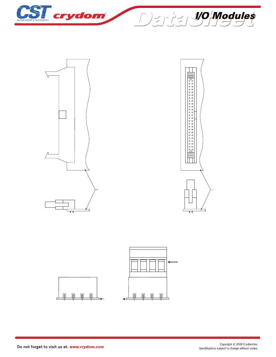
)
2
(
N
O
I
T
P
O
R
O
T
C
E
N
N
O
C
"
V
–
"
)
1
(
N
O
I
T
P
O
R
O
T
C
E
N
N
O
C
"
C
–
"
TOP
VIEW
TOP
VIEW
SIDE
VIEW
SIDE
VIEW
D
R
A
O
B
D
R
A
O
B
NOTES: 1.) CONNECTOR IS BERG 65823-093 OR EQUIVALENT
2.) CONNECTOR IS CIRCUIT ASSEMBLY CA-50H-2B OR EQUIVALENT
HEADER CONNECTOR OPTION
PC BOARD
REMOVABLE TERMINAL BLOCK
OPTION A
TERMINAL OPTIONS FOR "M" AND "SM" I/O MOUNTING BOARDS
OPTION B
Courtesy of Steven Engineering, Inc.-230 Ryan Way, South San Francisco, CA 94080-6370-Main Office: (650) 588-9200-Outside Local Area: (800) 258-9200-www.stevenengineering.com
60MAIN-html.html

Input and output modules accepted interchangeably
Operate with 5, 15 or 24 volt logic supplies
Captive-screw retaining system for standard-size modules
Screw terminal barrier block for logic connections
Screw terminal barrier block for load connections
Resident pull-up resistors
5 amp field-replaceable fuses
(LITTLEFUSE #251005 or equivalent)
All even-numbered logic connections are
logic ground
PB4
1 2 3 4 5 6 7 8 9
POWER BARRIER STRIP
(see notes 1,2)
REPLACEABLE 5 AMP LINE FUSES (4)
(see note 3)
CRYDOM DIGITAL I/O
MODULES SOLD SEPERATELY
PULL UP RESISTOR
3.3K OHM (4)
LED STATUS INDICATORS (4)
SIGNAL INPUT/OUTPUT
BARRIER STRIP
(see notes 2,3)
2) OPTIONAL JUMPERS AVAILABLE TO
INTERCONNECT BARRIER STRIP COMMONS.
ORDER 1 EACH "JS8" AND CUT IN HALF.
3) LITTLE FUSE 251005 OR EQUIVALENT.
NOTES: 1) 6-32 SCREW TERMINAL BARRIER STRIPS ACCEPT
4.5 (114,3)
4.0 (101,6)
0.25 (6,4)
3.5 (88,9)
3.0 (76,2)
0.25 (6,4)
2.2 (55,9)
0.75 (19,1)
+
-
DIMENSIONS: INCHES (MILLIMETERS)
TOLERANCE: 0.020 ( 0,50)
+
-
SWAGED STANDOFF
THRU HOLE 0.15 (3,8) DIA.
(4)
LOGIC SUPPLY CONNECTED
TO BARRIER STRIP
(+1, -2)
(see note 1)
1 2 3 4 5 6 7 8 9
WIRE SIZES FROM 24 TO 12 AWG.
1
2
3
4
5
1
2
3
4
5
1
2
3
4
5
1
2
3
4
5
+LOGIC
INDICATOR
(4)
BARRIER
STRIP
POWER
UNUSED
2 3
4 5
6 7
8 9
1
1
2
3 4
5 6
7 8
9
RESISTOR
PULL UP
(4)
3.3K OHM
REPLACEABLE
5 AMP FUSE
(4)
I/O MODULE
PIN SOCKETS
LOGIC GND
LED STATUS
SIGNAL INPUT/OUTPUT
BARRIER STRIP
MECHANICAL SPECIFICATIONS
APPROVALS
UL
E79183
CSA 38595
LEDs indicate logic status
MOUNTING BOARD
Rev. 070808
•
•
•
•
•
•
•
•
•
Courtesy of Steven Engineering, Inc.-230 Ryan Way, South San Francisco, CA 94080-6370-Main Office: (650) 588-9200-Outside Local Area: (800) 258-9200-www.stevenengineering.com
60MAIN-html.html

HAZARD OF
ELECTRIC
SHOCK,
EXPLOSION,
OR ARC FLASH.
x
Disconnect all
power before
installing or
working with
this equipment.
x
Verify all
connections
and replace all
covers before
turning on
power.
Failure to follow
these
instructions will
result in death
or serious injury.
RIESGO DE
DESCARGA
ELECTRICA O
EXPLOSION.
x
Desconectar
todos los
suministros de
energia a este
equipo antes
de trabajar
con este equipo.
x
Verificar todas
las conexiones
y colocar todas
las tapas antes
de energizer
el equipo.
El
incumplimiento
de estas
instrucciones
puede provocar
la muerte o
lesiones serias.
RISQUE DE
DESCHARGE
ELECTRIQUE
OU EXPLOSION
x
Eteindre
toutes les
sources
d'énergie de
cet appareil
avant de
travailler
dessus de cet
appareil
x
Vérifier tous
connections, et
remettre tous
couverts en
olace avant de
mettre sous
De non-suivi de
ces instructions
provoquera la
mort ou des
lésions sérieuses
sérieuses.
GEFAHR EINES
ELEKTRISCHE
N SCHLAGES
ODER EINER
EXPLOSION.
x
Stellen Sie
jeglichen
Strom ab, der
dieses Gerät
versorgt, bevor
Sie an dem
Gerät Arbeiten
durchführen
x
Vor dem
Drehen auf
Energie alle
Anschlüsse
überprüfen
und alle
Abdeckungen
ersetzen.
Unterlassung
dieser
Anweisungen
können zum
Tode oder zu
schweren
Verletzungen
führen.
RISCHIO DI
SCOSSA
ELETTRICA O
DELL’ESPLOSI
ONE.
x
Spenga tutta
l'alimentazion
e che fornisce
questa
apparecchiatu
ra prima del
lavorare a questa
apparecchiatu ra
x
Verificare tutti
i collegamenti
e sostituire
tutte le coperture
prima della
rotazione
sull'alimentazi one
L'omissione di
seguire queste
istruz ioni
provocherà la
morte o di
lesioni serie
RISCO DE
DESCARGA
ELÉTTRICA OU
EXPLOSÃO
x
Desconectar
o equipamento
de toda á
energia antes
de instalar ou
trabalhar com
este equipamen
to
x
Verificar todas
as conexões e
recolocar todas
as tampas
antes de religar
o equipamento
O não cumprimento
destas instruções
pode levar á morte
ou lesões sérias.
DANGER / PELIGRO / DANGER /GEFAHR / PERICOLO / PERIGO
Courtesy of Steven Engineering, Inc.-230 Ryan Way, South San Francisco, CA 94080-6370-Main Office: (650) 588-9200-Outside Local Area: (800) 258-9200-www.stevenengineering.com
60MAIN-html.html

ANNEX - ENVIROMENTAL INFORMATION
Courtesy of Steven Engineering, Inc.-230 Ryan Way, South San Francisco, CA 94080-6370-Main Office: (650) 588-9200-Outside Local Area: (800) 258-9200-www.stevenengineering.com
60MAIN-html.html
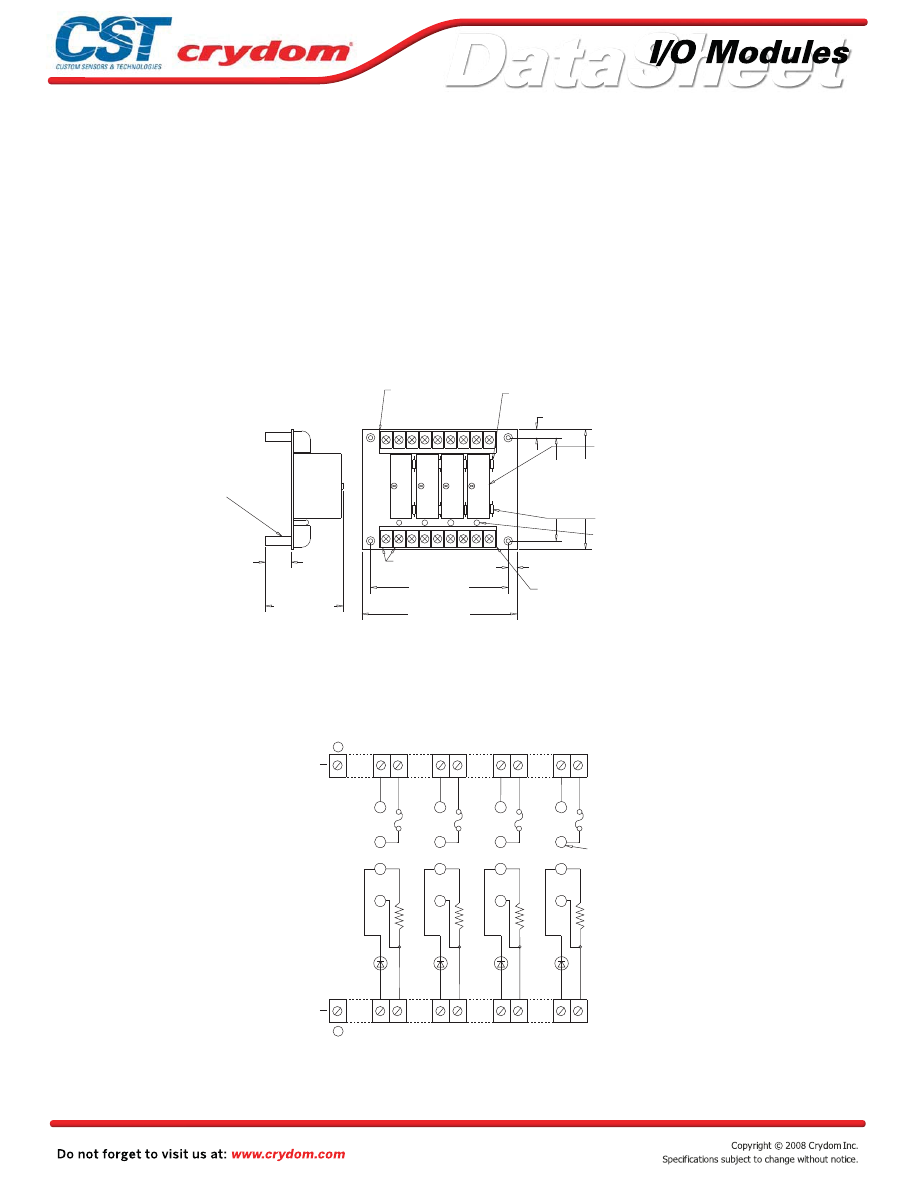
Accepts only output modules
Operate with 5, 15 or 24 volt logic supplies
Captive-screw retaining system for standard-size modules
Screw terminal barrier block for load connections
Resident pull-up resistors
5 amp field-replaceable fuses
(LITTLEFUSE #251005 or equivalent)
All even-numbered logic connections are
logic ground
PB4R
MECHANICAL SPECIFICATIONS
APPROVALS
UL
E79183
CSA 38595
LEDs indicate logic status
MOUNTING BOARD
Rev. 070808
•
•
•
•
•
•
•
•
•
1 2 3 4 5 6 7 8 9
(see notes 1,2)
REPLACEABLE 5 AMP LINE FUSES (4)
(see note 3)
GORDOS DIGITAL I/O
MODULES SOLD SEPERATELY
PULL UP RESISTOR
3.3K OHM (4)
LED STATUS INDICATORS (4)
SWAGED STANDOFF
THRU HOLE 0.15 (3,8) DIA.
(4)
2) OPTIONAL JUMPERS AVAILABLE TO
INTERCONNECT BARRIER STRIP COMMONS.
ORDER 1 EACH "JS8" AND CUT IN HALF.
POWER OUTPUT BARRIER STRIP
4) PB4R ACCEPTS ONLY OUTPUT MODULES.
INPUT MODULES WILL NOT PLUG INTO PB4R.
LOGIC SUPPLY CONNECTED
TO BARRIER STRIP
(+1,-2) (see note 1)
SIGNAL INPUT/OUTPUT
BARRIER STRIP
(see notes 2,3)
3) LITTLE FUSE 251005 OR EQUIVALENT.
NOTES: 1) 6-32 SCREW TERMINAL BARRIER STRIPS ACCEPT WIRE
4.5 (114,3)
4.0 (101,6)
0.25 (6,4)
3.5 (88,9)
3.0 (76,2)
0.25 (6,4)
2.2 (55,9)
0.75 (19,1)
+
-
DIMENSIONS: INCHES (MILLIMETERS)
TOLERANCE: 0.020 ( 0,50)
+
-
1 2 3 4 5 6 7 8 9
SIZES FROM 24 TO 12 AWG.
1
2
3
4 4
3
2
1
4
3
2
1
4
3
2
1
UNUSED
UNUSED
RESISTOR
PULL UP
INDICATOR
(4)
1 2
3 4
5 6
7 8
9
9
8
7
6
5
4
3
2
1
(4)
3.3K OHM
POWER
BARRIER
STRIP
REPLACEABLE 5 AMP
FUSE (4)
I/O MODULE
PIN SOCKETS
LED STATUS
SIGNAL
INPUT/OUTPUT
BARRIER
STRIP
Screw terminal barrier block for logic connections
Courtesy of Steven Engineering, Inc.-230 Ryan Way, South San Francisco, CA 94080-6370-Main Office: (650) 588-9200-Outside Local Area: (800) 258-9200-www.stevenengineering.com
60MAIN-html.html

HAZARD OF
ELECTRIC
SHOCK,
EXPLOSION,
OR ARC FLASH.
x
Disconnect all
power before
installing or
working with
this equipment.
x
Verify all
connections
and replace all
covers before
turning on
power.
Failure to follow
these
instructions will
result in death
or serious injury.
RIESGO DE
DESCARGA
ELECTRICA O
EXPLOSION.
x
Desconectar
todos los
suministros de
energia a este
equipo antes
de trabajar
con este equipo.
x
Verificar todas
las conexiones
y colocar todas
las tapas antes
de energizer
el equipo.
El
incumplimiento
de estas
instrucciones
puede provocar
la muerte o
lesiones serias.
RISQUE DE
DESCHARGE
ELECTRIQUE
OU EXPLOSION
x
Eteindre
toutes les
sources
d'énergie de
cet appareil
avant de
travailler
dessus de cet
appareil
x
Vérifier tous
connections, et
remettre tous
couverts en
olace avant de
mettre sous
De non-suivi de
ces instructions
provoquera la
mort ou des
lésions sérieuses
sérieuses.
GEFAHR EINES
ELEKTRISCHE
N SCHLAGES
ODER EINER
EXPLOSION.
x
Stellen Sie
jeglichen
Strom ab, der
dieses Gerät
versorgt, bevor
Sie an dem
Gerät Arbeiten
durchführen
x
Vor dem
Drehen auf
Energie alle
Anschlüsse
überprüfen
und alle
Abdeckungen
ersetzen.
Unterlassung
dieser
Anweisungen
können zum
Tode oder zu
schweren
Verletzungen
führen.
RISCHIO DI
SCOSSA
ELETTRICA O
DELL’ESPLOSI
ONE.
x
Spenga tutta
l'alimentazion
e che fornisce
questa
apparecchiatu
ra prima del
lavorare a questa
apparecchiatu ra
x
Verificare tutti
i collegamenti
e sostituire
tutte le coperture
prima della
rotazione
sull'alimentazi one
L'omissione di
seguire queste
istruz ioni
provocherà la
morte o di
lesioni serie
RISCO DE
DESCARGA
ELÉTTRICA OU
EXPLOSÃO
x
Desconectar
o equipamento
de toda á
energia antes
de instalar ou
trabalhar com
este equipamen
to
x
Verificar todas
as conexões e
recolocar todas
as tampas
antes de religar
o equipamento
O não cumprimento
destas instruções
pode levar á morte
ou lesões sérias.
DANGER / PELIGRO / DANGER /GEFAHR / PERICOLO / PERIGO
Courtesy of Steven Engineering, Inc.-230 Ryan Way, South San Francisco, CA 94080-6370-Main Office: (650) 588-9200-Outside Local Area: (800) 258-9200-www.stevenengineering.com
60MAIN-html.html
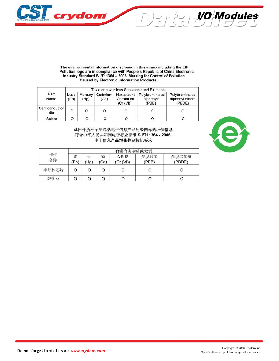
ANNEX - ENVIROMENTAL INFORMATION
Courtesy of Steven Engineering, Inc.-230 Ryan Way, South San Francisco, CA 94080-6370-Main Office: (650) 588-9200-Outside Local Area: (800) 258-9200-www.stevenengineering.com
60MAIN-html.html
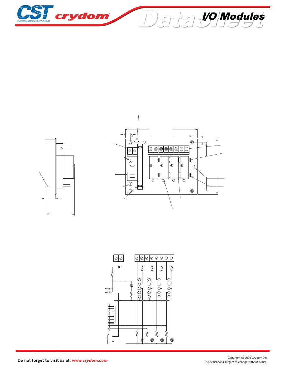
Input and output modules accepted interchangeably
Operate with 5, 15 or 24 volt logic supplies
Captive-screw retaining system for standard-size
modules
Plug-compatible logic connections
Screw terminal barrier block for load connections
Resident pull-up resistors
5 amp field-replaceable fuses
(LITTLEFUSE #251005 or equivalent)
All even-numbered logic connections are
logic ground
PB4H
MECHANICAL SPECIFICATIONS
LEDs indicate logic status
MOUNTING BOARD
Rev. 070808
5.25 (133,4)
4.5 (114,3)
4.0 (101,6)
3.5 (88,9)
0.25 (6,4)
0.375 (9,5)
2.1 (53,3)
0.65 (16,5)
+5V GND
ON
PWR
PIN 49
PIN 1
5V JUMPERS
0
1
2
3
1 2
3
4
5
6
7
8
REPLACEABLE 1 AMP
LOGIC SUPPLY FUSE
(see note 4)
POWER BARRIER STRIP
(see notes 2,3)
REPLACEABLE 5 AMP LINE
FUSE (4) (see note 5)
PULL UP 3.3K OHM
RESISTOR (4)
SPARE 5 AMP LINE FUSE
GORDOS DIGITAL I/O MODULES
SOLD SEPERATELY
LED STATUS
INDICATORS (4)
50 CONDUCTOR SIGNAL
INPUT/OUTPUT MALE PIN
CONNECTOR
(see note 1)
NEGATIVE (-) LOGIC
SUPPLY BUS
TERMINATION
JUMPERS CONNECTING
LOGIC SUPPLY
THROUGH HEADER
CONNECTOR
POSITIVE (+) LOGIC
SUPPLY BUS
TERMINATION
SWAGED STANDOFF
THRU HOLE
0.15 (3,8) DIA. (4)
3) OPTIONAL JUMPERS ARE AVAILABLE
TO INTERCONNECT BARRIER STRIP
COMMONS. ORDER 1 EACH "JS8" AND
NOTES: 1) CONNECTOR IS CIRCUIT ASSEMBLY CA-50H-2B-SR OR EQUIVLAENT.
2) 6-32 SCREW TERMINAL BARRIER STRIPS ACCEPT WIRE SIZES FROM 24 TO 12 AWG.
SCREW TERMINAL
LOGIC SUPPLY
BARRIER STRIP
+
-
DIMENSIONS: INCHES (MILLIMETERS)
TOLERANCE: 0.020 ( 0,50)
+
-
D1
NC
NC
PWR
ON
RESISTOR
PULL UP
+
-
2-50
EVEN
PINS
49
1
J1
+5V GND
1
2
3
4
5
7
8
6
1
2
3
4
5
5
4
3
2
1
5
4
3
2
1
5
4
3
2
1
3.3K OHM
17
19
21
23
25
27
29
31
33
35
37
39
41
43
45
47
SIGNAL INPUT/OUTPUT
50 CONDUCTOR MALE
PIN CONNECTOR TO
G1 BOARD OR
RIBBON CABLE
LOGIC SUPPLY
BUS TERMINATION
1 AMP LOGIC
SUPPLY FUSE
LOGIC SUPPLY
BARRIER STRIP
POWER BARRIER STRIP
5 AMP LINE
FUSES (4)
I/O MODULE
PIN SOCKETS
AMP 645979-1
OR EQUIVALENT
(4)
LED STATUS
INDICATORS (4)
15
•
•
•
•
•
•
•
•
•
Courtesy of Steven Engineering, Inc.-230 Ryan Way, South San Francisco, CA 94080-6370-Main Office: (650) 588-9200-Outside Local Area: (800) 258-9200-www.stevenengineering.com
60MAIN-html.html

HAZARD OF
ELECTRIC
SHOCK,
EXPLOSION,
OR ARC FLASH.
x
Disconnect all
power before
installing or
working with
this equipment.
x
Verify all
connections
and replace all
covers before
turning on
power.
Failure to follow
these
instructions will
result in death
or serious injury.
RIESGO DE
DESCARGA
ELECTRICA O
EXPLOSION.
x
Desconectar
todos los
suministros de
energia a este
equipo antes
de trabajar
con este equipo.
x
Verificar todas
las conexiones
y colocar todas
las tapas antes
de energizer
el equipo.
El
incumplimiento
de estas
instrucciones
puede provocar
la muerte o
lesiones serias.
RISQUE DE
DESCHARGE
ELECTRIQUE
OU EXPLOSION
x
Eteindre
toutes les
sources
d'énergie de
cet appareil
avant de
travailler
dessus de cet
appareil
x
Vérifier tous
connections, et
remettre tous
couverts en
olace avant de
mettre sous
De non-suivi de
ces instructions
provoquera la
mort ou des
lésions sérieuses
sérieuses.
GEFAHR EINES
ELEKTRISCHE
N SCHLAGES
ODER EINER
EXPLOSION.
x
Stellen Sie
jeglichen
Strom ab, der
dieses Gerät
versorgt, bevor
Sie an dem
Gerät Arbeiten
durchführen
x
Vor dem
Drehen auf
Energie alle
Anschlüsse
überprüfen
und alle
Abdeckungen
ersetzen.
Unterlassung
dieser
Anweisungen
können zum
Tode oder zu
schweren
Verletzungen
führen.
RISCHIO DI
SCOSSA
ELETTRICA O
DELL’ESPLOSI
ONE.
x
Spenga tutta
l'alimentazion
e che fornisce
questa
apparecchiatu
ra prima del
lavorare a questa
apparecchiatu ra
x
Verificare tutti
i collegamenti
e sostituire
tutte le coperture
prima della
rotazione
sull'alimentazi one
L'omissione di
seguire queste
istruz ioni
provocherà la
morte o di
lesioni serie
RISCO DE
DESCARGA
ELÉTTRICA OU
EXPLOSÃO
x
Desconectar
o equipamento
de toda á
energia antes
de instalar ou
trabalhar com
este equipamen
to
x
Verificar todas
as conexões e
recolocar todas
as tampas
antes de religar
o equipamento
O não cumprimento
destas instruções
pode levar á morte
ou lesões sérias.
DANGER / PELIGRO / DANGER /GEFAHR / PERICOLO / PERIGO
Courtesy of Steven Engineering, Inc.-230 Ryan Way, South San Francisco, CA 94080-6370-Main Office: (650) 588-9200-Outside Local Area: (800) 258-9200-www.stevenengineering.com
60MAIN-html.html

ANNEX - ENVIROMENTAL INFORMATION
Courtesy of Steven Engineering, Inc.-230 Ryan Way, South San Francisco, CA 94080-6370-Main Office: (650) 588-9200-Outside Local Area: (800) 258-9200-www.stevenengineering.com
60MAIN-html.html
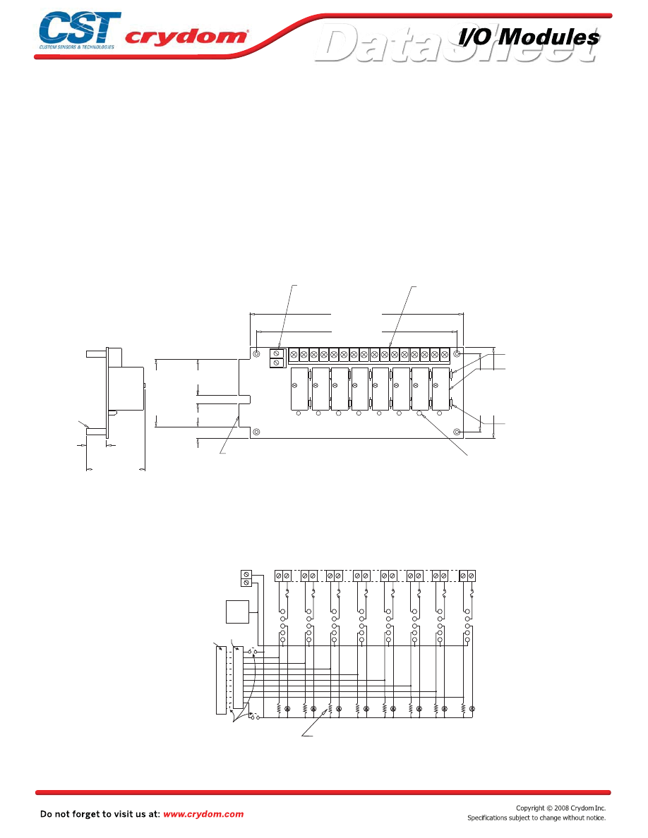
Input and output modules accepted interchangeably
Operate with 5, 15 or 24 volt logic supplies
Captive-screw retaining system for standard-size
modules
Plug-compatible logic connections
Screw terminal barrier block for load connections
Resident pull-up resistors
5 amp field-replaceable fuses
(LITTLEFUSE #251005 or equivalent)
All even-numbered logic connections are
logic ground
PB8
MECHANICAL SPECIFICATIONS
APPROVALS
UL
E79183
CSA 38595
LEDs indicate logic status
MOUNTING BOARD
Rev. 070808
8.0 (203,2)
7.5 (190,5)
1.4 (35,6)
0.3 (7,6)
0.45 (11,4)
2.6 (66,0)
3.5 (88,9)
3.0 (76,2)
2.2 (55,9)
0.75 (19,1)
+
-
1 2 3 4 5 6 7 8 9 10 11 12 13 14 15 16
0 1 2 3 4 5 6 7
LOGIC SUPPLY
BARRIER STRIP
POWER BARRIER STRIP
REPLACEABLE 5 AMP
LINE FUSE (8)
GORDOS DIGITAL I/O
MODULES SOLD SEPERATELY
PULL UP RESISTORS
3.3K OHM (8)
SIGNAL INPUT/OUTPUT
(see note 1)
NOTES: 1) MATING CONNECTOR IS BERG 66317-150 OR EQUIVALENT.
SPECIFY SUFFIX "V" FOR OPTIONAL CA26HM-2F-SR CIRCUIT ASSEMBLY OR
EQUIVALENT 26 CONDUCTOR PERPENDICULAR-TO-THE-BOARD
MALE PIN CONNECTOR.
2) 6-32 SCREW TERMINAL BARRIER STRIPS ACCEPT WIRE SIZES FROM 24 TO 12 AWG.
3) OPTIONAL JUMPERS ARE AVAILABLE TO INTERCONNECT BARRIER
STRIP COMMONS. ORDER 1 EACH "JS8".
4) LITTLE FUSE 251005 OR EQUIVALENT.
SWAGED STANDOFF
THRU HOLE
0.15 (3,2) DIA.
(4)
LED STATUS INDICATORS (8)
SCREW TERMINAL
6-32 SCREW TERMINAL
(see note 2)
50 TRACE (0.1" CENTERS)
MALE CARD EDGE
(see note 4)
+
-
DIMENSIONS: INCHES (MILLIMETERS)
TOLERANCE: 0.020 ( 0,50)
+
-
5
5
5
5
5
5
5
5
4
4
4
4
4
4
4
4
3
3
3
3
3
3
3
3
2
2
2
2
2
2
2
2
1
1
1
1
1
1
1
1
25
23
21
19
17
15
13
11
9
1
49
47
45
43
41
39
37
35
33
25
1
ALL
EVEN
PINS
BOTTOM
-
+
+ LOGIC
+LOGIC
EDGE CONN TOP
INDICATOR
(8)
PULL UP RESISTOR
3.3K OHM
(8)
1 2
3 4
5 6
7 8
9 10
1112
1314
15 16
BARRIER STRIP
LOGIC SUPPLY
POWER BARRIER STRIP
5 AMP LINE FUSE
I/O MODULE
PIN SOCKETS
AMP #645979-1
OR EQUIVALENT
LED STATUS
SIGNAL INPUT/OUTPUT
CUSTOMER INSTALLED
OPTIONAL JUMPERS
FOR CONNECTING LOGIC
SUPPLY THRU CARD EDGE
CONNECTOR
50 TRACE (0.1" CENTERS)
MALE CARD EDGE OR
OPTIONAL PIN CONNECTOR
“V” OR “C” OPTION
•
•
•
•
•
•
•
•
•
Courtesy of Steven Engineering, Inc.-230 Ryan Way, South San Francisco, CA 94080-6370-Main Office: (650) 588-9200-Outside Local Area: (800) 258-9200-www.stevenengineering.com
60MAIN-html.html

HAZARD OF
ELECTRIC
SHOCK,
EXPLOSION,
OR ARC FLASH.
x
Disconnect all
power before
installing or
working with
this equipment.
x
Verify all
connections
and replace all
covers before
turning on
power.
Failure to follow
these
instructions will
result in death
or serious injury.
RIESGO DE
DESCARGA
ELECTRICA O
EXPLOSION.
x
Desconectar
todos los
suministros de
energia a este
equipo antes
de trabajar
con este equipo.
x
Verificar todas
las conexiones
y colocar todas
las tapas antes
de energizer
el equipo.
El
incumplimiento
de estas
instrucciones
puede provocar
la muerte o
lesiones serias.
RISQUE DE
DESCHARGE
ELECTRIQUE
OU EXPLOSION
x
Eteindre
toutes les
sources
d'énergie de
cet appareil
avant de
travailler
dessus de cet
appareil
x
Vérifier tous
connections, et
remettre tous
couverts en
olace avant de
mettre sous
De non-suivi de
ces instructions
provoquera la
mort ou des
lésions sérieuses
sérieuses.
GEFAHR EINES
ELEKTRISCHE
N SCHLAGES
ODER EINER
EXPLOSION.
x
Stellen Sie
jeglichen
Strom ab, der
dieses Gerät
versorgt, bevor
Sie an dem
Gerät Arbeiten
durchführen
x
Vor dem
Drehen auf
Energie alle
Anschlüsse
überprüfen
und alle
Abdeckungen
ersetzen.
Unterlassung
dieser
Anweisungen
können zum
Tode oder zu
schweren
Verletzungen
führen.
RISCHIO DI
SCOSSA
ELETTRICA O
DELL’ESPLOSI
ONE.
x
Spenga tutta
l'alimentazion
e che fornisce
questa
apparecchiatu
ra prima del
lavorare a questa
apparecchiatu ra
x
Verificare tutti
i collegamenti
e sostituire
tutte le coperture
prima della
rotazione
sull'alimentazi one
L'omissione di
seguire queste
istruz ioni
provocherà la
morte o di
lesioni serie
RISCO DE
DESCARGA
ELÉTTRICA OU
EXPLOSÃO
x
Desconectar
o equipamento
de toda á
energia antes
de instalar ou
trabalhar com
este equipamen
to
x
Verificar todas
as conexões e
recolocar todas
as tampas
antes de religar
o equipamento
O não cumprimento
destas instruções
pode levar á morte
ou lesões sérias.
DANGER / PELIGRO / DANGER /GEFAHR / PERICOLO / PERIGO
Courtesy of Steven Engineering, Inc.-230 Ryan Way, South San Francisco, CA 94080-6370-Main Office: (650) 588-9200-Outside Local Area: (800) 258-9200-www.stevenengineering.com
60MAIN-html.html
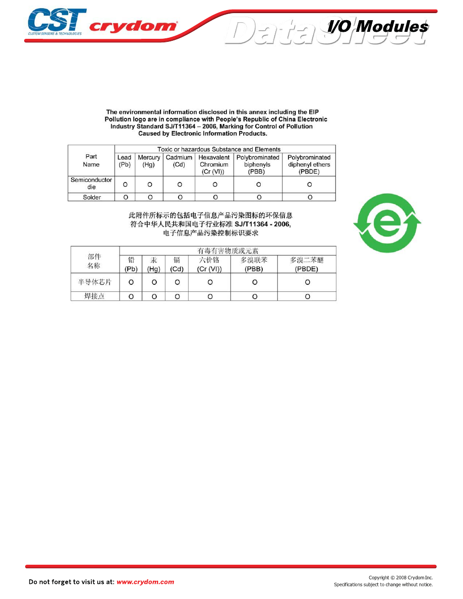
ANNEX - ENVIROMENTAL INFORMATION
Courtesy of Steven Engineering, Inc.-230 Ryan Way, South San Francisco, CA 94080-6370-Main Office: (650) 588-9200-Outside Local Area: (800) 258-9200-www.stevenengineering.com
60MAIN-html.html
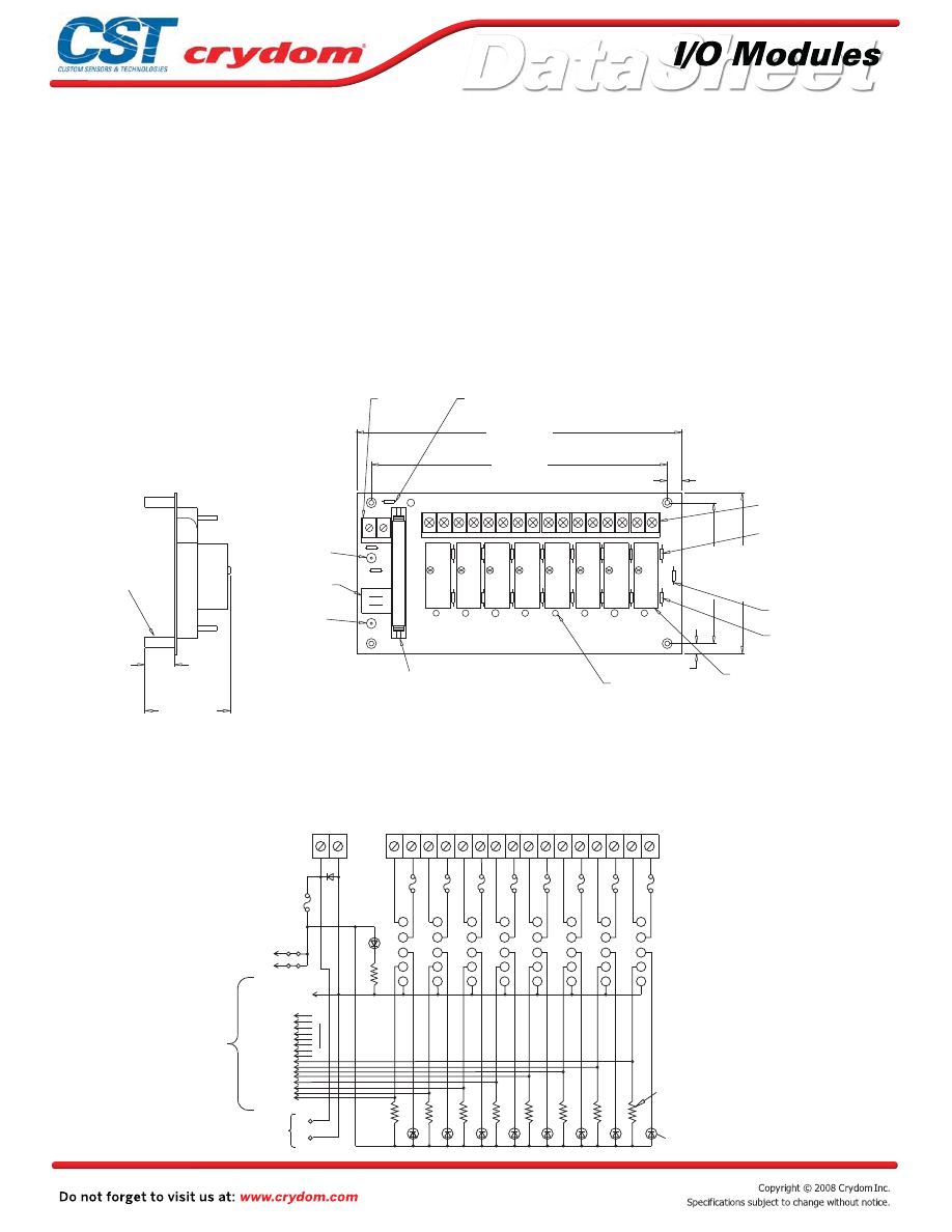
Input and output modules accepted interchangeably
Operate with 5, 15 or 24 volt logic supplies
Captive-screw retaining system for standard-size
modules
Plug-compatible logic connections
Screw terminal barrier block for load connections
Resident pull-up resistors
5 amp field-replaceable fuses
(LITTLEFUSE #251005 or equivalent)
All even-numbered logic connections are
logic ground
PB8H
MECHANICAL SPECIFICATIONS
LEDs indicate logic status
MOUNTING BOARD
Rev. 070808
8.25 (209,55)
7.5 (190,5)
4.0 (101,6)
3.5 (88,9)
0.25 (6,4)
0.375 (9,5)
0 1 2 3 4 5 6 7
1 2 3 4 5 6 7 8 9 10 11 12 13 14 15 16
5V JUMPERS
PIN 1
PIN 49
PWR
ON
+5V GND
1 AMP FUSE
SPARE
5A FUSE
0.65 (16,5)
2.1 (53,3)
0.15 (3,8) DIA. (4)
THRU HOLE
SWAGED STANDOFF
LOGIC SUPPLY
BARRIER STRIP
REPLACEABLE 1 AMP
LOGIC SUPPLY FUSE
(see note 4)
POWER BARRIER STRIP
(see notes 2,3)
REPLACEABLE 5 AMP LINE
FUSES (8) (see note 5)
SPARE 5 AMP LINE FUSE
PULL UP RESISTOR
3.3K OHM (8)
GORDOS DIGITAL I/O
MODULES SOLD SEPERATELY
LED STATUS
INDICATORS
SIGNAL INPUT/OUTPUT
50 CONDUCTOR MALE
PIN CONNECTOR
(see note 1)
NEGATIVE (-) LOGIC
SUPPLY BUS
TERMINATION
JUMPERS CONNECTING
LOGIC SUPPLY THRU
HEADER CONNECTOR
POSITIVE (+) LOGIC
SUPPLY BUS
TERMINATION
3) OPTIONAL JUMPERS ARE AVAILABLE TO INTERCONNECT
BARRIER STRIP COMMONS. ORDER 1 EACH "JS8".
4) LITTLE FUSE 251001 OR EQUIVALENT.
5) LITTLE FUSE 251005 OR EQUIVALENT.
SCREW TERMINAL
NOTES: 1) CONNECTOR IS CIRCUIT ASSEMBLY CA-50H-2B-SR OR EQUIVALENT.
2) 6-32 SCREW TERMINAL BARRIER STRIPS ACCEPT WIRE SIZES FROM 24 TO 12 AWG.
+
-
DIMENSIONS: INCHES (MILLIMETERS)
TOLERANCE: 0.020 ( 0,50)
+
-
D1
NC
NC
PWR
ON
RESISTOR
PULL UP
+
-
2-50
EVEN
PINS
49
1
J1
+5V GND
1 2 3 4 5
7 8
6
9 10 11 12 13 14 15 16
2
4
5
2
4
5
2
4
5
2
4
5
2
4
5
2
4
5
2
4
5
1 1 1 1 1 1 1 1
2
3 3 3 3 3 3 3 3
4
5
3.3K OHM
LOGIC SUPPLY
BARRIER STRIP
POWER BARRIER STRIP
5 AMP LINE FUSUES (8)
I/O MODULE
PIN SOCKETS
(8)
LED STATUS
INDICATORS (8)
1 AMP LOGIC
SUPPLY FUSE
LOGIC SUPPLY
BUS TERMINATION
SIGNAL INPUT/OUTPUT
50 CONDUCTOR
MALE PIN
CONNECTOR TO
G1 BOARD
OR RIBBON
CABLE
17
19
21
23
25
27
29
31
33
35
37
39
41
43
45
47
•
•
•
•
•
•
•
•
•
Courtesy of Steven Engineering, Inc.-230 Ryan Way, South San Francisco, CA 94080-6370-Main Office: (650) 588-9200-Outside Local Area: (800) 258-9200-www.stevenengineering.com
60MAIN-html.html

HAZARD OF
ELECTRIC
SHOCK,
EXPLOSION,
OR ARC FLASH.
x
Disconnect all
power before
installing or
working with
this equipment.
x
Verify all
connections
and replace all
covers before
turning on
power.
Failure to follow
these
instructions will
result in death
or serious injury.
RIESGO DE
DESCARGA
ELECTRICA O
EXPLOSION.
x
Desconectar
todos los
suministros de
energia a este
equipo antes
de trabajar
con este equipo.
x
Verificar todas
las conexiones
y colocar todas
las tapas antes
de energizer
el equipo.
El
incumplimiento
de estas
instrucciones
puede provocar
la muerte o
lesiones serias.
RISQUE DE
DESCHARGE
ELECTRIQUE
OU EXPLOSION
x
Eteindre
toutes les
sources
d'énergie de
cet appareil
avant de
travailler
dessus de cet
appareil
x
Vérifier tous
connections, et
remettre tous
couverts en
olace avant de
mettre sous
De non-suivi de
ces instructions
provoquera la
mort ou des
lésions sérieuses
sérieuses.
GEFAHR EINES
ELEKTRISCHE
N SCHLAGES
ODER EINER
EXPLOSION.
x
Stellen Sie
jeglichen
Strom ab, der
dieses Gerät
versorgt, bevor
Sie an dem
Gerät Arbeiten
durchführen
x
Vor dem
Drehen auf
Energie alle
Anschlüsse
überprüfen
und alle
Abdeckungen
ersetzen.
Unterlassung
dieser
Anweisungen
können zum
Tode oder zu
schweren
Verletzungen
führen.
RISCHIO DI
SCOSSA
ELETTRICA O
DELL’ESPLOSI
ONE.
x
Spenga tutta
l'alimentazion
e che fornisce
questa
apparecchiatu
ra prima del
lavorare a questa
apparecchiatu ra
x
Verificare tutti
i collegamenti
e sostituire
tutte le coperture
prima della
rotazione
sull'alimentazi one
L'omissione di
seguire queste
istruz ioni
provocherà la
morte o di
lesioni serie
RISCO DE
DESCARGA
ELÉTTRICA OU
EXPLOSÃO
x
Desconectar
o equipamento
de toda á
energia antes
de instalar ou
trabalhar com
este equipamen
to
x
Verificar todas
as conexões e
recolocar todas
as tampas
antes de religar
o equipamento
O não cumprimento
destas instruções
pode levar á morte
ou lesões sérias.
DANGER / PELIGRO / DANGER /GEFAHR / PERICOLO / PERIGO
Courtesy of Steven Engineering, Inc.-230 Ryan Way, South San Francisco, CA 94080-6370-Main Office: (650) 588-9200-Outside Local Area: (800) 258-9200-www.stevenengineering.com
60MAIN-html.html
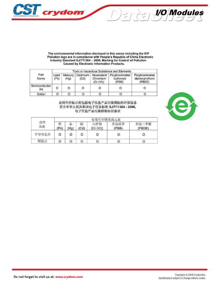
ANNEX - ENVIROMENTAL INFORMATION
Courtesy of Steven Engineering, Inc.-230 Ryan Way, South San Francisco, CA 94080-6370-Main Office: (650) 588-9200-Outside Local Area: (800) 258-9200-www.stevenengineering.com
60MAIN-html.html
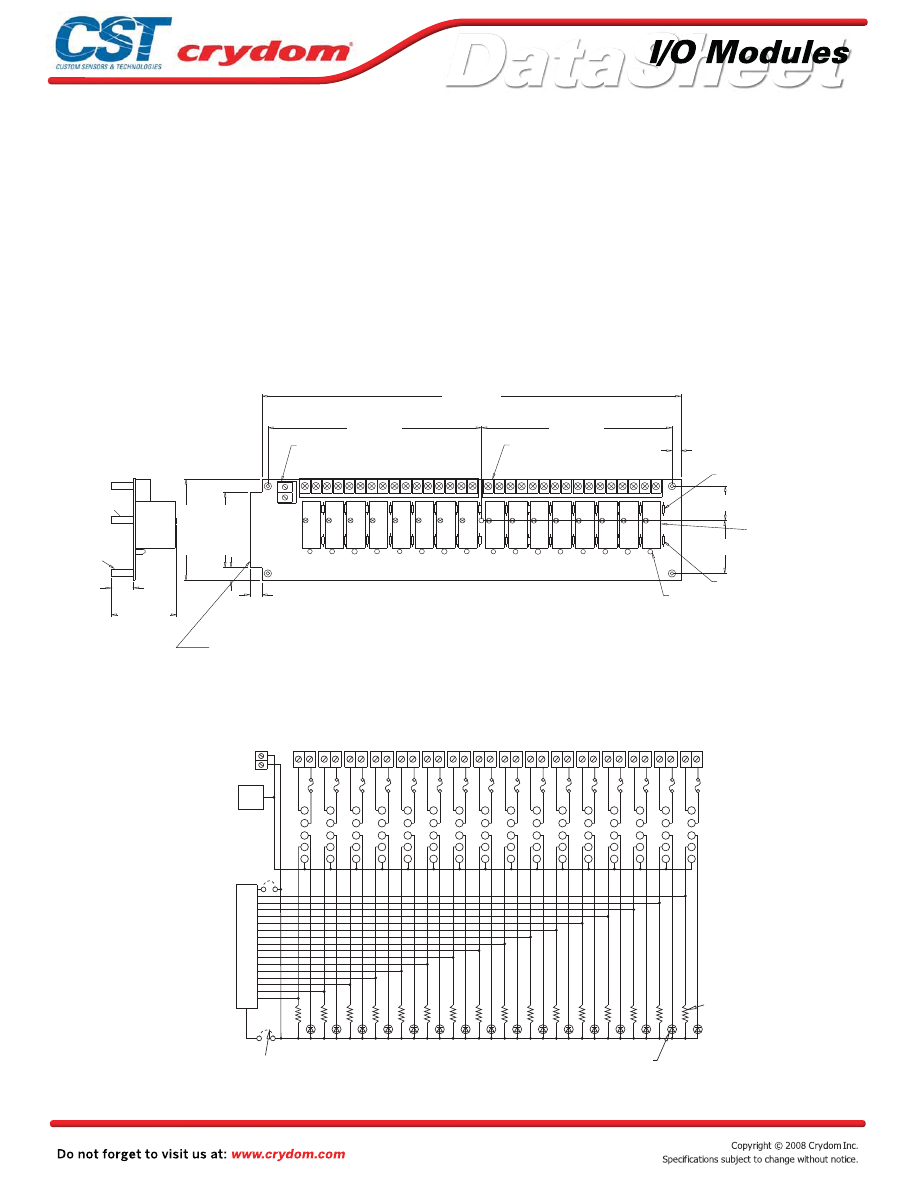
Input and output modules accepted interchangeably
Operate with 5, 15 or 24 volt logic supplies
Captive-screw retaining system for standard-size
modules
Plug-compatible logic connections
Screw terminal barrier block for load connections
Resident pull-up resistors
5 amp field-replaceable fuses
(LITTLEFUSE #251005 or equivalent)
All even-numbered logic connections are
logic ground
PB16
MECHANICAL SPECIFICATIONS
APPROVALS
UL
E79183
CSA 38595
LEDs indicate logic status
MOUNTING BOARD
Rev. 070808
0.75 (19,1)
2.2 (55,9)
14.1 (356,9)
)
8
,
8
5
1
(
5
2
.
6
)
4
,
5
8
1
(
3
.
7
0.2 (6,4)
1.4 (35,6)
1.6 (40,6)
3.5 (88,9)
2.6 (66,0)
0.4 (10,2)
0.45 (11,4)
0 1 2 3 4 5 6 7
1 2 3 4 5 6 7 8 9 10 11 12 13 14 15 16 17 18 19 20 21 22 23 24 25 26 27 28 29 30 31 32
8 9 10 11 12 13 14 15
-
+
(4)
0.15 (3,2) DIA.
THRU HOLE
SWAGED STANDOFF
POWER BARRIER STRIP
(see notes 2,3)
REPLACEABLE 5 AMP LINE FUSES (16)
(see note 4)
GORDOS DIGITAL I/O
MODULES SOLD SEPERATELY
PULL UP RESISTOR
3.3K OHM (16)
LED STATUS
INDICATOR (16)
NYLON STANDOFF
6-32 THD.
(see note 1)
SCREW TERMINAL
LOGIC SUPPLY BARRIER STRIP
SIGNAL INPUT/OUTPUT 50 TRACE (0.1" CENTERS)
MALE CARD EDGE
NOTES: 1) MATING CONNECTOR IS BERG 66317-150 OR EQUIVALENT. SPECIFY SUFFIX 'C'
FOR OPTIONAL 65823-093 OR EQUIVALENT MALE PIN CONNECTOR FOR THE
PARALLEL-TO-THE-BOARD CABLE CONNECTION. SPECIFY SUFFIX 'V' FOR
OPTIONAL CIRCUIT ASSEMBLY CA-50H-2B-SR OR EQUIVALENT MALE PIN CONNECTOR FOR
PERPENDICULAR-TO-THE-BOARD CABLE CONNECTION.
3) OPTIONAL JUMPERS ARE AVAILABLE TO INTERCONNECT BARRIER STRIP COMMONS.
ORDER 1 EACH "JS2" AND 2 EACH "JS8".
4) LITTLE FUSE 251005 OR EQUIVALENT.
2) 6-32 SCREW TERMINAL BARRIER STRIPS ACCEPT WIRE SIZES FROM 24 TO 12 AWG.
+
-
DIMENSIONS: INCHES (MILLIMETERS)
TOLERANCE: 0.020 ( 0,50)
+
-
3
1 1
3
1
3
1
3
1
3
1
3
1
2 2 2 2 2 2 2
3
4 4 4 4 4 4 4
3
4
3
4
3
4
3
4
3
4
3
4
2 2 2 2 2 2 2
5 5 5 5 5 5 5 5 5 5 5 5 5 5
2
1 1 1 1 1 1 1 1 1
2
3
4
3
4
5
3
4
5
1
17
19
21
23
25
27
29
31
33
35
37
39
41
43
45
47
49
EVEN
ALL
PINS
+
-
1 2 3 4 5 6 7 8 9 10 11
12 13
14 15
16 17
18 19
21
22
20
23 24 25 26 27 28 29 30 31 32
+LOGIC
+LOGIC
TOP
GND
LOGIC
EDGE CONN
BOTTOM
BARRIER STRIP
LOGIC SUPPLY
POWER BARRIER STRIP
5 AMP
LINE FUSES (16)
I/O MODULE
PIN SOCKETS
PULL UP RESISTOR
3.3K OHM (16)
LED STATUS
INDICATOR (16)
CUSTOMER INSTALLED
OPTIONAL JUMPERS TO
CONNECT LOGIC SUPPLY
TO EDGE CONNECTOR (2)
SIGNAL
INPUT/OUTPUT
OR OPTIONAL PIN
CONNECTOR
50 TRACE (0.1" CENTERS)
MALE CARD EDGE
•
•
•
•
•
•
•
•
•
Courtesy of Steven Engineering, Inc.-230 Ryan Way, South San Francisco, CA 94080-6370-Main Office: (650) 588-9200-Outside Local Area: (800) 258-9200-www.stevenengineering.com
60MAIN-html.html

HAZARD OF
ELECTRIC
SHOCK,
EXPLOSION,
OR ARC FLASH.
x
Disconnect all
power before
installing or
working with
this equipment.
x
Verify all
connections
and replace all
covers before
turning on
power.
Failure to follow
these
instructions will
result in death
or serious injury.
RIESGO DE
DESCARGA
ELECTRICA O
EXPLOSION.
x
Desconectar
todos los
suministros de
energia a este
equipo antes
de trabajar
con este equipo.
x
Verificar todas
las conexiones
y colocar todas
las tapas antes
de energizer
el equipo.
El
incumplimiento
de estas
instrucciones
puede provocar
la muerte o
lesiones serias.
RISQUE DE
DESCHARGE
ELECTRIQUE
OU EXPLOSION
x
Eteindre
toutes les
sources
d'énergie de
cet appareil
avant de
travailler
dessus de cet
appareil
x
Vérifier tous
connections, et
remettre tous
couverts en
olace avant de
mettre sous
De non-suivi de
ces instructions
provoquera la
mort ou des
lésions sérieuses
sérieuses.
GEFAHR EINES
ELEKTRISCHE
N SCHLAGES
ODER EINER
EXPLOSION.
x
Stellen Sie
jeglichen
Strom ab, der
dieses Gerät
versorgt, bevor
Sie an dem
Gerät Arbeiten
durchführen
x
Vor dem
Drehen auf
Energie alle
Anschlüsse
überprüfen
und alle
Abdeckungen
ersetzen.
Unterlassung
dieser
Anweisungen
können zum
Tode oder zu
schweren
Verletzungen
führen.
RISCHIO DI
SCOSSA
ELETTRICA O
DELL’ESPLOSI
ONE.
x
Spenga tutta
l'alimentazion
e che fornisce
questa
apparecchiatu
ra prima del
lavorare a questa
apparecchiatu ra
x
Verificare tutti
i collegamenti
e sostituire
tutte le coperture
prima della
rotazione
sull'alimentazi one
L'omissione di
seguire queste
istruz ioni
provocherà la
morte o di
lesioni serie
RISCO DE
DESCARGA
ELÉTTRICA OU
EXPLOSÃO
x
Desconectar
o equipamento
de toda á
energia antes
de instalar ou
trabalhar com
este equipamen
to
x
Verificar todas
as conexões e
recolocar todas
as tampas
antes de religar
o equipamento
O não cumprimento
destas instruções
pode levar á morte
ou lesões sérias.
DANGER / PELIGRO / DANGER /GEFAHR / PERICOLO / PERIGO
Courtesy of Steven Engineering, Inc.-230 Ryan Way, South San Francisco, CA 94080-6370-Main Office: (650) 588-9200-Outside Local Area: (800) 258-9200-www.stevenengineering.com
60MAIN-html.html

ANNEX - ENVIROMENTAL INFORMATION
Courtesy of Steven Engineering, Inc.-230 Ryan Way, South San Francisco, CA 94080-6370-Main Office: (650) 588-9200-Outside Local Area: (800) 258-9200-www.stevenengineering.com
60MAIN-html.html
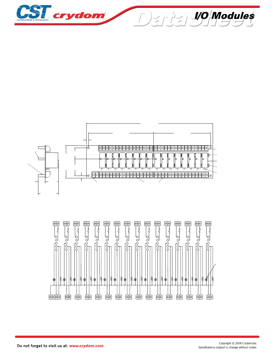
Input and output modules accepted interchangeably
Operate with 5, 15 or 24 volt logic supplies
Captive-screw retaining system for standard-size modules
Screw terminal barrier block for load connections
Screw terminal barrier block for logic connections
Resident pull-up resistors
5 amp field-replaceable fuses
(LITTLEFUSE #251005 or equivalent)
Logic ground separate for each channel (no common)
PB16S
MECHANICAL SPECIFICATIONS
APPROVALS
UL
E79183
CSA 38595
LEDs indicate logic status
MOUNTING BOARD
Rev. 070808
14.1 (356,9)
6.25 (158,8)
7.3 (185,4)
0.25 (6,4)
1.4 (35,6)
1.6 (40,6)
3.5 (88,9)
0.75 (19,1)
2.2 (55,9)
0.25 (6,4)
1 2 3 4 5 6 7 8 9 10 11 12 13 14 15 16
(4)
THRU HOLE 0.15 (3,8) DIA.
SWAGED STANDOFF
17 18 19 20 21 22 23 24 25 26 27 28 29 30 31 32
+ -
LOGIC SUPPLY
BARRIER STRIP
INPUT/OUTPUT
SIGNAL BARRIER STRIP
(see note 1)
POWER BARRIER STRIP
(see notes 1,2)
REPLACEABLE 5 AMP
LINE FUSES (16) (see note 3)
CRYDOM DIGITAL I/O MODULES
SOLD SEPERATELY
PULL UP RESISTORS
3.3K OHM (16)
LED STATUS INDICATORS (16)
NYLON STANDOFF
6-32 THD.
SCREW TERMINAL
ORDER 1 EACH "JS2" AND 2 EACH "JS8".
3) LITTLE FUSE 251005 OR EQUIVALENT.
NOTES: 1) 6-32 SCREW TERMINAL BARRIER STRIPS ACCEPT WIRE SIZES FROM 24 TO 12 AWG.
2) OPTIONAL JUMPERS ARE AVAILABLE TO INTERCONNECT COMMONS.
+
-
DIMENSIONS: INCHES (MILLIMETERS)
TOLERANCE: 0.020 ( 0,50)
+
-
5
4
3
2
1
1
2
3
4
5
1
2
3
4
5
1
3
4
5
1
3
4
5
1
3
4
5
1
2
2
2
2
3
4
5
4
4
3
4
4
4
4
4
4
1
1
1
1
1
1
1
1
1
2
2
2
2
2
2
2
2
2
3
3
3
3
3
3
3
3
4
5
5
5
5
5
5
5
5
5
1 2
3 4
5 6
7
9
8
10
1112
1314
1516
1718
19 20
2122
2324
2526
2728
2930
3132
32
31
30
29
28
27
26
25
24
23
12
11
10
8
9
7
6
5
4
3
2
1
1314
1516
1718
1920
2122
SIGNAL INPUT/OUTPUT BARRIER STRIP
LED STATUS
INDICATOR (16)
PULL UP
RESISTOR
3.3K OHM
(16)
I/O MODULE
PIN SOCKETS
5 AMP LINE
FUSUES (16)
POWER BARRIER STRIP
+LOGIC
UNUSED
•
•
•
•
•
•
•
•
•
Courtesy of Steven Engineering, Inc.-230 Ryan Way, South San Francisco, CA 94080-6370-Main Office: (650) 588-9200-Outside Local Area: (800) 258-9200-www.stevenengineering.com
60MAIN-html.html

HAZARD OF
ELECTRIC
SHOCK,
EXPLOSION,
OR ARC FLASH.
x
Disconnect all
power before
installing or
working with
this equipment.
x
Verify all
connections
and replace all
covers before
turning on
power.
Failure to follow
these
instructions will
result in death
or serious injury.
RIESGO DE
DESCARGA
ELECTRICA O
EXPLOSION.
x
Desconectar
todos los
suministros de
energia a este
equipo antes
de trabajar
con este equipo.
x
Verificar todas
las conexiones
y colocar todas
las tapas antes
de energizer
el equipo.
El
incumplimiento
de estas
instrucciones
puede provocar
la muerte o
lesiones serias.
RISQUE DE
DESCHARGE
ELECTRIQUE
OU EXPLOSION
x
Eteindre
toutes les
sources
d'énergie de
cet appareil
avant de
travailler
dessus de cet
appareil
x
Vérifier tous
connections, et
remettre tous
couverts en
olace avant de
mettre sous
De non-suivi de
ces instructions
provoquera la
mort ou des
lésions sérieuses
sérieuses.
GEFAHR EINES
ELEKTRISCHE
N SCHLAGES
ODER EINER
EXPLOSION.
x
Stellen Sie
jeglichen
Strom ab, der
dieses Gerät
versorgt, bevor
Sie an dem
Gerät Arbeiten
durchführen
x
Vor dem
Drehen auf
Energie alle
Anschlüsse
überprüfen
und alle
Abdeckungen
ersetzen.
Unterlassung
dieser
Anweisungen
können zum
Tode oder zu
schweren
Verletzungen
führen.
RISCHIO DI
SCOSSA
ELETTRICA O
DELL’ESPLOSI
ONE.
x
Spenga tutta
l'alimentazion
e che fornisce
questa
apparecchiatu
ra prima del
lavorare a questa
apparecchiatu ra
x
Verificare tutti
i collegamenti
e sostituire
tutte le coperture
prima della
rotazione
sull'alimentazi one
L'omissione di
seguire queste
istruz ioni
provocherà la
morte o di
lesioni serie
RISCO DE
DESCARGA
ELÉTTRICA OU
EXPLOSÃO
x
Desconectar
o equipamento
de toda á
energia antes
de instalar ou
trabalhar com
este equipamen
to
x
Verificar todas
as conexões e
recolocar todas
as tampas
antes de religar
o equipamento
O não cumprimento
destas instruções
pode levar á morte
ou lesões sérias.
DANGER / PELIGRO / DANGER /GEFAHR / PERICOLO / PERIGO
Courtesy of Steven Engineering, Inc.-230 Ryan Way, South San Francisco, CA 94080-6370-Main Office: (650) 588-9200-Outside Local Area: (800) 258-9200-www.stevenengineering.com
60MAIN-html.html

ANNEX - ENVIROMENTAL INFORMATION
Courtesy of Steven Engineering, Inc.-230 Ryan Way, South San Francisco, CA 94080-6370-Main Office: (650) 588-9200-Outside Local Area: (800) 258-9200-www.stevenengineering.com
60MAIN-html.html
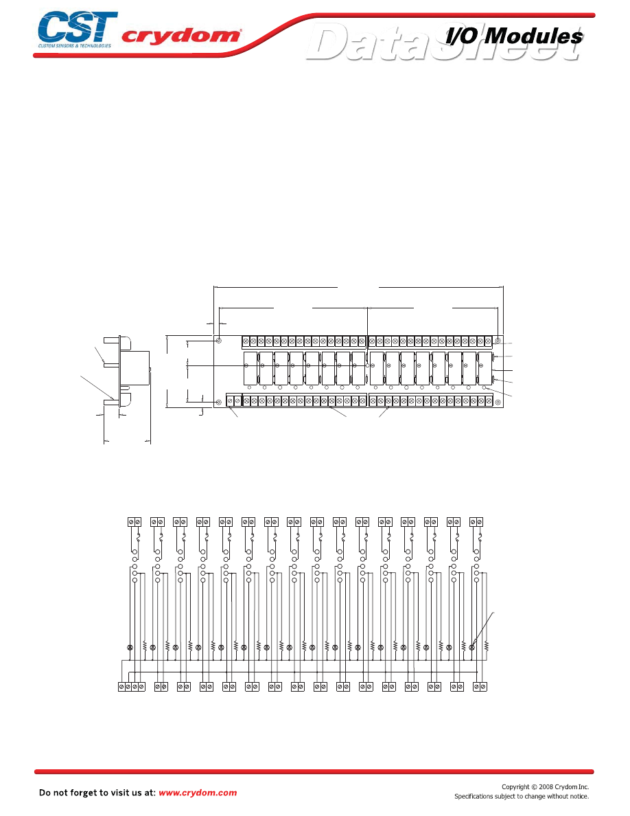
Input and output modules accepted interchangeably
Operate with 5, 15 or 24 volt logic supplies
Captive-screw retaining system for standard-size
modules
Screw terminal barrier block for load connections
Screw terminal barrier block for logic connections
Resident pull-up resistors
5 amp field-replaceable fuses
(LITTLEFUSE #251005 or equivalent)
All even-numbered logic connections are
logic ground
PB16T
MECHANICAL SPECIFICATIONS
APPROVALS
UL
E79183
CSA 38595
LEDs indicate logic status
MOUNTING BOARD
Rev. 070808
0.75 (19,1)
2.2 (55,9)
14.1 (356,9)
6.25 (158,8)
7.3 (185,4)
0.25 (6,4)
1.4 (35,6)
1.6 (40,6)
3.5 (88,9)
0.25 (6,4)
1 2 3 4 5 6 7 8 9 10 11 12 13 14 15 16
(4)
THRU HOLE 0.15 (3,8) DIA.
SWAGED STANDOFF
17 18 19 20 21 22 23 24 25 26 27 28 29 30 31 32
+ -
LOGIC SUPPLY
BARRIER STRIP
INPUT/OUTPUT
SIGNAL BARRIER STRIP
(see note 1)
POWER BARRIER STRIP
(see notes 1,2)
REPLACEABLE 5 AMP
LINE FUSES (16) (see note 3)
CRYDOM DIGITAL I/O MODULES
SOLD SEPERATELY
PULL UP RESISTORS
3.3K OHM (16)
LED STATUS INDICATORS (16)
NYLON STANDOFF
6-32 THD.
SCREW TERMINAL
2) OPTIONAL JUMPERS ARE AVAILABLE TO INTERCONNECT COMMONS.
ORDER 1 EACH "JS2" AND 2 EACH "JS8".
3) LITTLE FUSE 251005 OR EQUIVALENT.
NOTES: 1) 6-32 SCREW TERMINAL BARRIER STRIPS ACCEPT WIRE SIZES FROM 24 TO 12 AWG.
+
-
DIMENSIONS: INCHES (MILLIMETERS)
TOLERANCE: 0.020 ( 0,50)
+
-
5
4
3
2
1
1 2
3 4
5 6
7
9
8
10
11 12
13 14
1516
1718
19 20
21 22
2324
25 26
27 28
29 30
3132
32
31
30
29
28
27
26
25
24
23
12
11
10
8
9
7
6
5
4
3
2
1
1314
15 16
1718
1920
2122
SIGNAL INPUT/OUTPUT BARRIER STRIP
LED STATUS
INDICATOR (16)
PULL UP
RESISTOR
3.3K OHM
(16)
I/O MODULE
PIN SOCKETS
5 AMP LINE
FUSUES (16)
POWER BARRIER STRIP
+LOGIC
GRD
5
4
3
2
1
5
4
3
2
1
5
4
3
2
1
5
4
3
2
1
5
4
3
2
1
5
4
3
2
1
5
4
3
2
1
5
4
3
2
1
5
4
3
2
1
5
4
3
2
1
5
4
3
2
1
5
4
3
2
1
5
4
3
2
1
5
4
3
2
1
5
4
3
2
1
•
•
•
•
•
•
•
•
•
Courtesy of Steven Engineering, Inc.-230 Ryan Way, South San Francisco, CA 94080-6370-Main Office: (650) 588-9200-Outside Local Area: (800) 258-9200-www.stevenengineering.com
60MAIN-html.html

HAZARD OF
ELECTRIC
SHOCK,
EXPLOSION,
OR ARC FLASH.
x
Disconnect all
power before
installing or
working with
this equipment.
x
Verify all
connections
and replace all
covers before
turning on
power.
Failure to follow
these
instructions will
result in death
or serious injury.
RIESGO DE
DESCARGA
ELECTRICA O
EXPLOSION.
x
Desconectar
todos los
suministros de
energia a este
equipo antes
de trabajar
con este equipo.
x
Verificar todas
las conexiones
y colocar todas
las tapas antes
de energizer
el equipo.
El
incumplimiento
de estas
instrucciones
puede provocar
la muerte o
lesiones serias.
RISQUE DE
DESCHARGE
ELECTRIQUE
OU EXPLOSION
x
Eteindre
toutes les
sources
d'énergie de
cet appareil
avant de
travailler
dessus de cet
appareil
x
Vérifier tous
connections, et
remettre tous
couverts en
olace avant de
mettre sous
De non-suivi de
ces instructions
provoquera la
mort ou des
lésions sérieuses
sérieuses.
GEFAHR EINES
ELEKTRISCHE
N SCHLAGES
ODER EINER
EXPLOSION.
x
Stellen Sie
jeglichen
Strom ab, der
dieses Gerät
versorgt, bevor
Sie an dem
Gerät Arbeiten
durchführen
x
Vor dem
Drehen auf
Energie alle
Anschlüsse
überprüfen
und alle
Abdeckungen
ersetzen.
Unterlassung
dieser
Anweisungen
können zum
Tode oder zu
schweren
Verletzungen
führen.
RISCHIO DI
SCOSSA
ELETTRICA O
DELL’ESPLOSI
ONE.
x
Spenga tutta
l'alimentazion
e che fornisce
questa
apparecchiatu
ra prima del
lavorare a questa
apparecchiatu ra
x
Verificare tutti
i collegamenti
e sostituire
tutte le coperture
prima della
rotazione
sull'alimentazi one
L'omissione di
seguire queste
istruz ioni
provocherà la
morte o di
lesioni serie
RISCO DE
DESCARGA
ELÉTTRICA OU
EXPLOSÃO
x
Desconectar
o equipamento
de toda á
energia antes
de instalar ou
trabalhar com
este equipamen
to
x
Verificar todas
as conexões e
recolocar todas
as tampas
antes de religar
o equipamento
O não cumprimento
destas instruções
pode levar á morte
ou lesões sérias.
DANGER / PELIGRO / DANGER /GEFAHR / PERICOLO / PERIGO
Courtesy of Steven Engineering, Inc.-230 Ryan Way, South San Francisco, CA 94080-6370-Main Office: (650) 588-9200-Outside Local Area: (800) 258-9200-www.stevenengineering.com
60MAIN-html.html
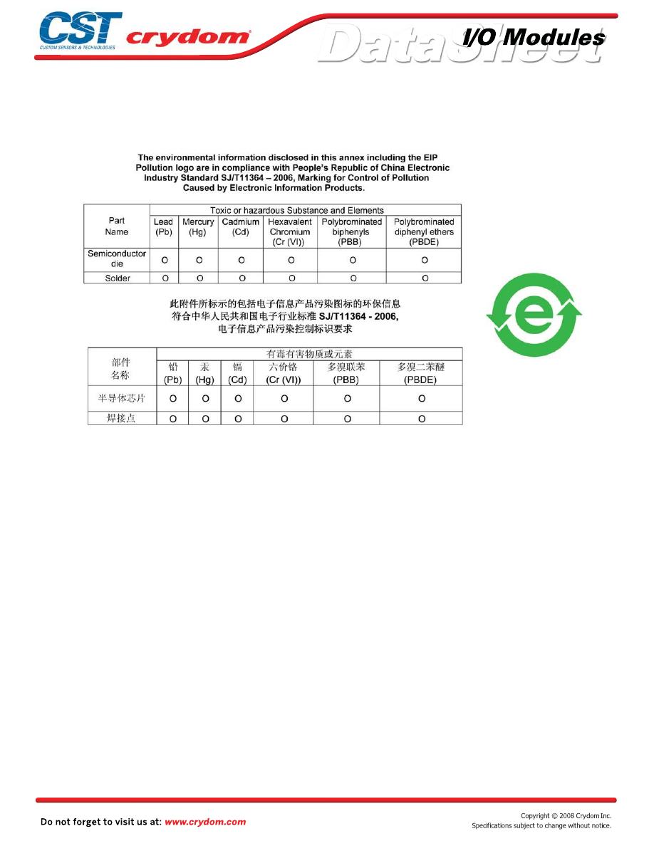
ANNEX - ENVIROMENTAL INFORMATION
Courtesy of Steven Engineering, Inc.-230 Ryan Way, South San Francisco, CA 94080-6370-Main Office: (650) 588-9200-Outside Local Area: (800) 258-9200-www.stevenengineering.com
60MAIN-html.html
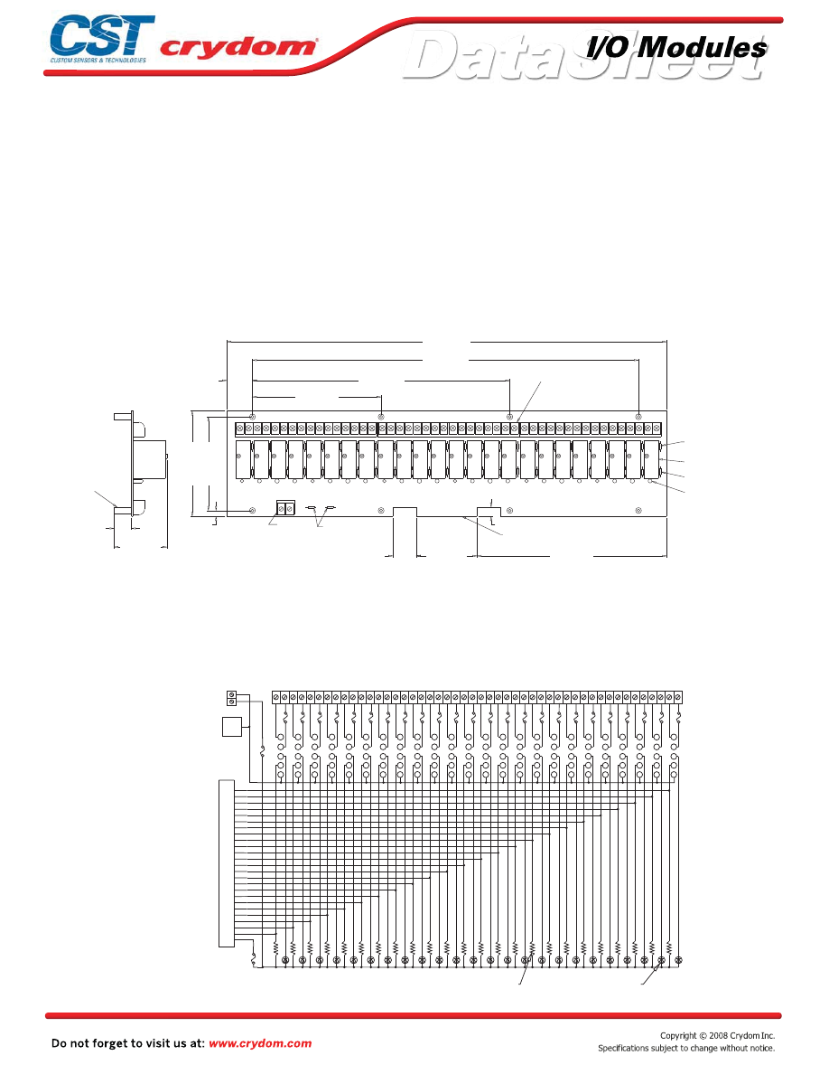
Input and output modules accepted interchangeably
Operate with 5, 15 or 24 volt logic supplies
Captive-screw retaining system for standard-size
modules
Plug-compatible logic connections
Screw terminal barrier block for load connections
Resident pull-up resistors
5 amp field-replaceable fuses
(LITTLEFUSE #251005 or equivalent)
All even-numbered logic connections are
logic ground
PB24
MECHANICAL SPECIFICATIONS
APPROVALS
UL
E79183
CSA 38595
LEDs indicate logic status
MOUNTING BOARD
Rev. 070808
1.1 (28,5)
POWER BARRIER STRIP
(see notes 2,3)
8.1 (204,9)
2.6 (66,0)
1.0 (25,4)
0.4 (10,2)
8 9 10 11 12 13 14 15 16 17 18
19 20 21 22 23
REPLACEABLE 5 AMP
(see note 5)
GORDOS DIGITAL I/O
MODULE SOLD SEPERATELY
PULL UP RESISTOR
3.3K OHM (24)
LED STATUS
INDICATOR (24)
LINE FUSES (24)
(see note 1)
5.5 (139,7)
11.0 (279,4)
16.5 (419,1)
18.75 (476,3)
4.0 (101,6)
0.25 (6,4)
0 1 2 3 4 5 6 7
1 2 3 4 5 6 7 8 9 10 11 12 13 14 15 16
17 18 19 20 21 22 23 24 25 26 27 28 29 30 32 33 34 35 36 37 38 39 40 41 42 43 44 45 47 48
- +
REPLACEABLE 1 AMP
LOGIC SUPPLY FUSE
(see note 4)
LOGIC SUPPLY
BARRIER STRIP
SCREW
TERMINAL
SIGNAL INPUT/OUTPUT 50 TRACE (0.1" CENTERS)
MALE CARD EDGE
4.5 (114,3)
2.2 (55,9)
0.75 (19,1)
THRU HOLE 0.15 (3,8) DIA.
SWAGED STANDOFF
(8)
NOTES: 1) MATING CONNECTOR IS BERG 66317-150 OR EQUIVALENT. SPECIFY SUFFIX 'C' FOR
OPTIONAL 65823-093 OR EQUIVALANT MALE PIN CONNECTOR FOR PARALLEL-TO-THE-BOARD
CABLE CONNECTION. SPECIFY SUFFIX 'V' FOR OPTIONAL CIRCUIT ASSEMBLY CA-50H-2B-SR OR EQUIVALENT
MALE PIN CONNECTOR FOR PERPENDICULAR-TO-THE-BOARD CABLE CONNECTION.
3) OPTIONAL JUMPERS ARE AVAILABLE TO INTERCONNECT BARRIER STRIP COMMONS.
ORDER 2 EACH "JS2" AND 3 EACH "JS8".
4) LITTLE FUSE 251001 OR EQUIVALENT.
5) LITTLE FUSE 251005 OR EQUIVALENT.
2) 6-32 SCREW TERMINAL BARRIER STRIPS ACCEPT WIRE SIZES FROM 24 TO 12 AWG.
+
-
DIMENSIONS: INCHES (MILLIMETERS)
TOLERANCE: 0.020 ( 0,50)
+
-
5
4
3
2
1
1
5
9
13
17
21
25
29
33
37
41
45
49
EVEN
ALL
PINS
+
-
POWER BARRIER STRIP
5 AMP LINE
FUSE (24)
I/O MODULE
PIN SOCKETS
AMP #645979-1
OR EQUIVALENT
LED STATUS
INDICATORS (24)
PULL UP RESISTOR
3.3K OHM (24)
REPLACEABLE 1 AMP
LOGIC SUPPLY FUSE
SIGNAL
INPUT/OUTPUT
OR OPTIONAL
PIN CONNECTOR
LOGIC SUPPLY
BARRIER STRIP
LOGIC GRD
50 TRACE (0.1" CENTERS)
MALE CARD EDGE
5
4
3
2
1
5
4
3
2
1
5
4
3
2
1
5
4
3
2
1
5
4
3
2
1
5
4
3
2
1
5
4
3
2
1
5
4
3
2
1
5
4
3
2
1
5
4
3
2
1
5
4
3
2
1
5
4
3
2
1
5
4
3
2
1
5
4
3
2
1
5
4
3
2
1
5
4
3
2
1
5
4
3
2
1
5
4
3
2
1
5
4
3
2
1
5
4
3
2
1
5
4
3
2
1
5
4
3
2
1
5
4
3
2
1
REPLACEABLE 1 AMP
LOGIC SUPPLY FUSE
•
•
•
•
•
•
•
•
•
Courtesy of Steven Engineering, Inc.-230 Ryan Way, South San Francisco, CA 94080-6370-Main Office: (650) 588-9200-Outside Local Area: (800) 258-9200-www.stevenengineering.com
60MAIN-html.html

HAZARD OF
ELECTRIC
SHOCK,
EXPLOSION,
OR ARC FLASH.
x
Disconnect all
power before
installing or
working with
this equipment.
x
Verify all
connections
and replace all
covers before
turning on
power.
Failure to follow
these
instructions will
result in death
or serious injury.
RIESGO DE
DESCARGA
ELECTRICA O
EXPLOSION.
x
Desconectar
todos los
suministros de
energia a este
equipo antes
de trabajar
con este equipo.
x
Verificar todas
las conexiones
y colocar todas
las tapas antes
de energizer
el equipo.
El
incumplimiento
de estas
instrucciones
puede provocar
la muerte o
lesiones serias.
RISQUE DE
DESCHARGE
ELECTRIQUE
OU EXPLOSION
x
Eteindre
toutes les
sources
d'énergie de
cet appareil
avant de
travailler
dessus de cet
appareil
x
Vérifier tous
connections, et
remettre tous
couverts en
olace avant de
mettre sous
De non-suivi de
ces instructions
provoquera la
mort ou des
lésions sérieuses
sérieuses.
GEFAHR EINES
ELEKTRISCHE
N SCHLAGES
ODER EINER
EXPLOSION.
x
Stellen Sie
jeglichen
Strom ab, der
dieses Gerät
versorgt, bevor
Sie an dem
Gerät Arbeiten
durchführen
x
Vor dem
Drehen auf
Energie alle
Anschlüsse
überprüfen
und alle
Abdeckungen
ersetzen.
Unterlassung
dieser
Anweisungen
können zum
Tode oder zu
schweren
Verletzungen
führen.
RISCHIO DI
SCOSSA
ELETTRICA O
DELL’ESPLOSI
ONE.
x
Spenga tutta
l'alimentazion
e che fornisce
questa
apparecchiatu
ra prima del
lavorare a questa
apparecchiatu ra
x
Verificare tutti
i collegamenti
e sostituire
tutte le coperture
prima della
rotazione
sull'alimentazi one
L'omissione di
seguire queste
istruz ioni
provocherà la
morte o di
lesioni serie
RISCO DE
DESCARGA
ELÉTTRICA OU
EXPLOSÃO
x
Desconectar
o equipamento
de toda á
energia antes
de instalar ou
trabalhar com
este equipamen
to
x
Verificar todas
as conexões e
recolocar todas
as tampas
antes de religar
o equipamento
O não cumprimento
destas instruções
pode levar á morte
ou lesões sérias.
DANGER / PELIGRO / DANGER /GEFAHR / PERICOLO / PERIGO
Courtesy of Steven Engineering, Inc.-230 Ryan Way, South San Francisco, CA 94080-6370-Main Office: (650) 588-9200-Outside Local Area: (800) 258-9200-www.stevenengineering.com
60MAIN-html.html

ANNEX - ENVIROMENTAL INFORMATION
Courtesy of Steven Engineering, Inc.-230 Ryan Way, South San Francisco, CA 94080-6370-Main Office: (650) 588-9200-Outside Local Area: (800) 258-9200-www.stevenengineering.com
60MAIN-html.html
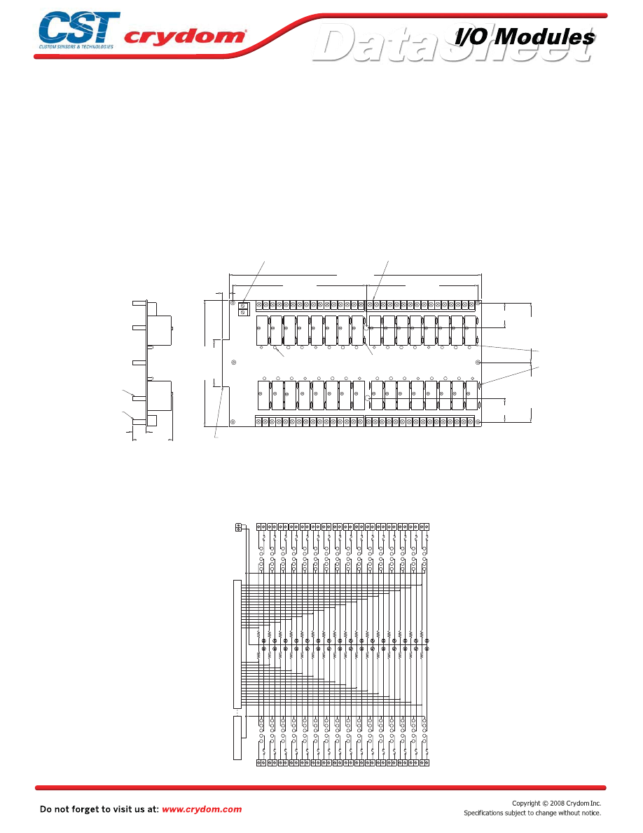
Input and output modules accepted interchangeably
Operate with 5, 15 or 24 volt logic supplies
Captive-screw retaining system for standard-size
modules
Plug-compatible logic connections
Screw terminal barrier block for load connections
Resident pull-up resistors
5 amp field-replaceable fuses
(LITTLEFUSE #251005 or equivalent)
All even-numbered logic connections are
logic ground
PB32D
MECHANICAL SPECIFICATIONS
LEDs indicate logic status
MOUNTING BOARD
Rev. 070808
7.3 (185,4)
6.25 (158,7)
14.05 (356,9)
1.4 (35,5)
1.4 (35,5)
2.6 (66,0)
7.0 (177,8)
0.4 (10,2)
2.2 (55,8)
0.75 (19,1)
3.3 (82,5)
3.3 (82,5)
0 1 2 3 4 5 6 7 8 9
10 11 12 13 14 15
31 30 29 28 27 26 25 24 23 22 21 20 19 18 17 18
LOGIC SUPPLY BARRIER STRIP
POWER BARRIER STRIP
(see notes 2,3)
LED STATUS
INDICATOR (32)
PULL UP RESISTOR
3.3K OHM (32)
GORDOS DIGITAL I/O
MODULES SOLD SEPERATLEY
REPLACEABLE 5 AMP
LINE FUSES (32)
(see note 4)
3-32
NYLON STANDOFF
SWAGED STANDOFF THRU HOLE
0.15 (3,8) DIA.
(8)
(4)
SIGNAL INPUT/OUTPUT 50 TRACE
(0.1" CENTERS) MALE CARD EDGE
(see note 1)
SCREW TERMINAL
NOTES: 1) MATING CONNECTOR IS BERG 66317-150 OR EQUIVALENT. SPECIFY SUFFIX 'C' FOR OPTIONAL
65823-093 OR EQUIVALENT MALE PIN CONNECTOR FOR PARALLEL-TO-THE-BOARD CABLE
CONNECTION. SPECIFY SUFFIX 'V' FOR OPTIONAL CIRCUIT ASSEMBLY CA-50H-2B-SR OR EQUIVALENT MALE
PIN CONNECTOR FOR PERPENDICULAR-TO-THE-BOARD CABLE CONNECTION.
3) OPTIONAL JUMPERS ARE AVAILABLE TO INTERCONNECT BARRIER STRIP COMMONS. ORDER
2 EACH "JS2" AND 4 EACH "JS8".
4) LITTLE FUSE 251005 OR EQUIVALENT.
2) 6-32 SCREW TERMINAL BARRIER STRIPS ACCEPT WIRE SIZES FROM 24 TO 12 AWG.
+
-
DIMENSIONS: INCHES (MILLIMETERS)
TOLERANCE: 0.020 ( 0,50)
+
-
1
2
3
4
5 5
4
3
2
1
5
4
3
2
1
5
4
3
2
1
5
4
3
2
1 1
2
3
4
5
1
2
3
4
5
1
2
3
4
5
1
2
3
4
5
1
2
3
4
5
1
2
3
4
5 5
4
3
2
1
5
4
3
2
1
5
4
3
2
1
5
4
3
2
1
5
4
3
2
1
5
4
3
2
1
5
4
3
2
1
5
4
3
2
1
5
4
3
2
1
5
4
3
2
1
5
4
3
2
1
5
4
3
2
1
5
4
3
2
1
5
4
3
2
1
5
4
3
2
1
5
4
3
2
1
5
4
3
2
1
5
4
3
2
1
5
4
3
2
1
5
4
3
2
1
5
4
3
2
1
1 2 3 4 5 6 7 8 9 10 11
12 13
14 15
16 17
18 19
20 21
22 23
24 25
26 27
28 29
30 31
32
64 63 62 61 60 59 58 57 56 55 54 53 52 51 50 49 48 47 46 45 44 43 42 41 40 39 38 37 36 35 34 33
17
34
32
31
30
28
26
25
23
22
21
19
6
5
8
2
3
7
1
4
10
15
9
16
11
13
12
14
45
46
43
49
48
44
50
47
41
36
42
35
40
38
39
37
GROUND
LOGIC
+
-
BARRIER STRIP
LOGIC SUPPLY
PULL UP
RESISTOR
3.3K OHM
(32)
POWER BARRIER STRIP
5 AMP LINE FUSES (32)
LED STATUS INDICATOR (32)
POWER BARRIER STRIP
SIGNAL
INPUT/OUTPUT
OR OPTIONAL
PIN CONNECTOR
50 TRACE (0.1" CENTERS)
MALE CARD EDGE
•
•
•
•
•
•
•
•
•
Courtesy of Steven Engineering, Inc.-230 Ryan Way, South San Francisco, CA 94080-6370-Main Office: (650) 588-9200-Outside Local Area: (800) 258-9200-www.stevenengineering.com
60MAIN-html.html

HAZARD OF
ELECTRIC
SHOCK,
EXPLOSION,
OR ARC FLASH.
x
Disconnect all
power before
installing or
working with
this equipment.
x
Verify all
connections
and replace all
covers before
turning on
power.
Failure to follow
these
instructions will
result in death
or serious injury.
RIESGO DE
DESCARGA
ELECTRICA O
EXPLOSION.
x
Desconectar
todos los
suministros de
energia a este
equipo antes
de trabajar
con este equipo.
x
Verificar todas
las conexiones
y colocar todas
las tapas antes
de energizer
el equipo.
El
incumplimiento
de estas
instrucciones
puede provocar
la muerte o
lesiones serias.
RISQUE DE
DESCHARGE
ELECTRIQUE
OU EXPLOSION
x
Eteindre
toutes les
sources
d'énergie de
cet appareil
avant de
travailler
dessus de cet
appareil
x
Vérifier tous
connections, et
remettre tous
couverts en
olace avant de
mettre sous
De non-suivi de
ces instructions
provoquera la
mort ou des
lésions sérieuses
sérieuses.
GEFAHR EINES
ELEKTRISCHE
N SCHLAGES
ODER EINER
EXPLOSION.
x
Stellen Sie
jeglichen
Strom ab, der
dieses Gerät
versorgt, bevor
Sie an dem
Gerät Arbeiten
durchführen
x
Vor dem
Drehen auf
Energie alle
Anschlüsse
überprüfen
und alle
Abdeckungen
ersetzen.
Unterlassung
dieser
Anweisungen
können zum
Tode oder zu
schweren
Verletzungen
führen.
RISCHIO DI
SCOSSA
ELETTRICA O
DELL’ESPLOSI
ONE.
x
Spenga tutta
l'alimentazion
e che fornisce
questa
apparecchiatu
ra prima del
lavorare a questa
apparecchiatu ra
x
Verificare tutti
i collegamenti
e sostituire
tutte le coperture
prima della
rotazione
sull'alimentazi one
L'omissione di
seguire queste
istruz ioni
provocherà la
morte o di
lesioni serie
RISCO DE
DESCARGA
ELÉTTRICA OU
EXPLOSÃO
x
Desconectar
o equipamento
de toda á
energia antes
de instalar ou
trabalhar com
este equipamen
to
x
Verificar todas
as conexões e
recolocar todas
as tampas
antes de religar
o equipamento
O não cumprimento
destas instruções
pode levar á morte
ou lesões sérias.
DANGER / PELIGRO / DANGER /GEFAHR / PERICOLO / PERIGO
Courtesy of Steven Engineering, Inc.-230 Ryan Way, South San Francisco, CA 94080-6370-Main Office: (650) 588-9200-Outside Local Area: (800) 258-9200-www.stevenengineering.com
60MAIN-html.html

ANNEX - ENVIROMENTAL INFORMATION
Courtesy of Steven Engineering, Inc.-230 Ryan Way, South San Francisco, CA 94080-6370-Main Office: (650) 588-9200-Outside Local Area: (800) 258-9200-www.stevenengineering.com
60MAIN-html.html
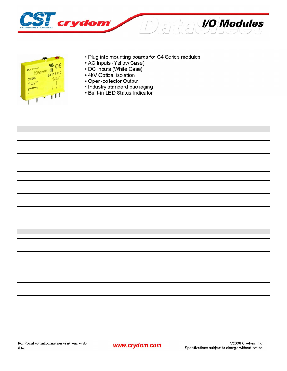
C4 SERIES INPUT MODULES
SPECIFICATIONS (1)
Input
Part Number
C4IAC
C4IACA
C4IDC
Voltage Range
90-140 VAC
180-280 VAC
10-32 VDC
Maximum Current [mA](4)
14
5
20
Resistance [Ohms](2)(3)
22 k
75 k
2 k
Drop-out Current [mA](5)
3
1
1.5
Allowable Voltage for No Output [VAC/VDC](6)
50
50
3.0
Allowable Current for No Output [mA](6)
2.5
0.7
1.0
Output
Maximum Logic Supply Voltage[VDC](9)
30
30
30
Maximum Output Voltage Drop [VDC](12)
0.2
0.2
0.2
Minimum Logic Supply Voltage [VDC]
4.5
4.5
4.5
Logic Supply Voltage Range [VDC]
4.5-30
4.5-30
4.5-30
Maximum Current [mA](10)
50
50
50
Maximum Logic Supply Current [mA](7)
25.0
25.0
25.0
Maximum Logic Supply Leakage Current [µA](8)
10.0
10.0
10.0
Maximum Leakage Current [µA](11)
10.0
10.0
10.0
Maximum Turn-On Time [msec] (13)
20
20
5.0
Maximum Turn-Off Time [msec] (13)
20
20
5.0
SPECIFICATIONS (1)
Input
Part Number
C4IDCB
C4IDCG
C4IDCK
Voltage Range
4-16 VDC
35-60 VDC
2.5-16 VDC
Maximum Current [mArms](4)
40
10
60
Resistance [Ohms](2)(3)
400
10 k
300
Drop-out Current [mArms](5)
2
1
2
Allowable Voltage for No Output [VAC/VDC](6)
1
7
1
Allowable Current for No Output [mA](6)
0.7
0.7
0.2
Output
Maximum Logic Supply Voltage[VDC](9)
30
30
30
Maximum Output Voltage Drop [VDC](12)
0.2
0.2
0.2
Minimum Logic Supply Voltage [VDC]
4.5
4.5
4.5
Logic Supply Voltage Range [VDC]
4.5-30
4.5-30
4.5-30
Maximum Current [mA](10)
50
50
50
Maximum Logic Supply Current [mA](7)
25.0
25.0
25.0
Maximum Logic Supply Leakage Current [µA](8)
10.0
10.0
10.0
Maximum Leakage Current [µA](11)
10.0
10.0
10.0
Maximum Turn-On Time [msec] (13)
0.05
10.0
0.025
Maximum Turn-Off Time [msec] (13)
0.1
10.0
0.025
Courtesy of Steven Engineering, Inc.-230 Ryan Way, South San Francisco, CA 94080-6370-Main Office: (650) 588-9200-Outside Local Area: (800) 258-9200-www.stevenengineering.com
60MAIN-html.html
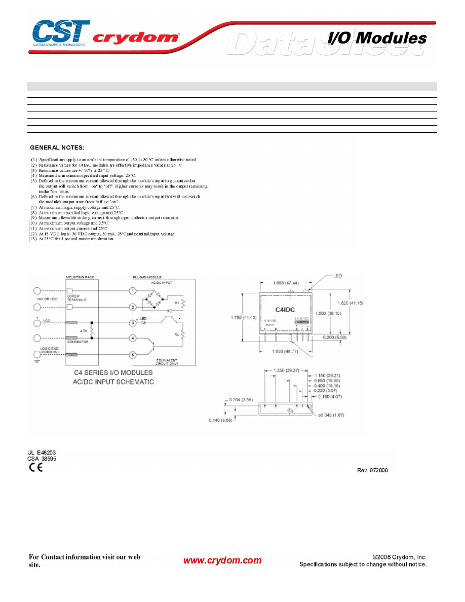
GENERAL SPECIFICATIONS
Description
Input/Output Isolation Voltage (14)
4000
Input/Output Capacitance
8
Operating Temperature Range
-30 to 80°C
Storage Temperature Range
-40 to 100°C
Weight
1.1 oz. (31.2g)
MECHANICAL SPECIFICATIONS
AGENCY APPROVALS
Courtesy of Steven Engineering, Inc.-230 Ryan Way, South San Francisco, CA 94080-6370-Main Office: (650) 588-9200-Outside Local Area: (800) 258-9200-www.stevenengineering.com
60MAIN-html.html

Courtesy of Steven Engineering, Inc.-230 Ryan Way, South San Francisco, CA 94080-6370-Main Office: (650) 588-9200-Outside Local Area: (800) 258-9200-www.stevenengineering.com
60MAIN-html.html

ANNEX - ENVIROMENTAL INFORMATION
Courtesy of Steven Engineering, Inc.-230 Ryan Way, South San Francisco, CA 94080-6370-Main Office: (650) 588-9200-Outside Local Area: (800) 258-9200-www.stevenengineering.com
60MAIN-html.html
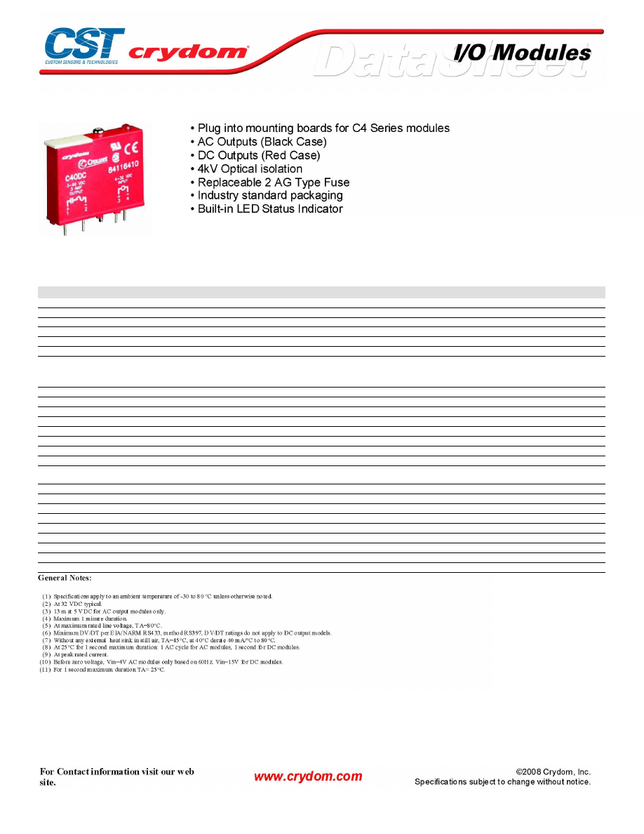
C4 SERIES OUTPUT MODULES
SPECIFICATIONS (1)
Input
Part Number
C4OAC
C4OACA
C4OACR
C4OACAR
C4ODC
C4ODCA
Nominal Voltage VDC
4-32
4-32
4-32
4-32
4-32
4-32
Minimum Voltage VDC
4.0
4.0
4.0
4.0
4.0
4.0
Maximum Voltage VDC
32
32
32
32
32
32
Drop-out Voltage
1.0
1.0
1.0
1.0
1.0
1.0
Maximum Current (2) (3)
22
22
22
22
16
16
Resistance
Regulated Input
Regulated Input
Regulated Input
Regulated Input
Regulated Input
Regulated Input
Output
Nominal Line Voltage
120 VAC
240 VAC
120 VAC
240 VAC
5-48 VDC
5-150 VDC
Minimum Line Voltage
12 VAC
12 VAC
12 VAC
12 VAC
5.0 VDC
3 VDC
Maximum Line Voltage
140 VAC
280 VAC
140 VAC
280 VAC
60 VDC
250 VDC
Max Off-State Voltage (4)
600 Vpeak
600 Vpeak
600 Vpeak
600 Vpeak
60 VDC
250 VDC
Max Off-State Leakage (5)
0.1mArms
0.1mArms
0.1mArms
0.1mArms
10 uA
10 uA
Static Off-State dv/dt (6)
200 V/usec
200 V/usec
200 V/usec
200 V/usec
n/a
n/a
Maximum Rated On-State Current (7)
3.0 Arms
3.0 Arms
3.0 Arms
3.0 Arms
3.0 A
1.0 A
Minimum On-State Current
50 mArms
50 mArms
50 mArms
50 mArms
10 mA
10 mA
Max Surge Current (8)
100 Apeak
100 Apeak
100 Apeak
100 Apeak
5.0 Apeak
5.0 Apeak
On-State Voltage Drop or Resistance
(9)
1.6 V
1.6 V
1.6 V
1.6 V
1.6 V
1.6 V
HP Rating
1/4
1/4
1/4
1/4
n/a
n/a
Maximum Turn-On Time [msec] (10)
8.33
8.33
0.1
0.1
0.05
0.05
Maximum Turn-Off Time [msec]
8.33
8.33
8.33
8.33
0.05
0.05
Input/Output Isolation Voltage (11)
4000
4000
4000
4000
4000
4000
Input/Output Capacitance
4
4
4
4
4
4
Operating Temperature Range
-30 to 80°C
-30 to 80°C
-30 to 80°C
-30 to 80°C
-30 to 80°C
-30 to 80°C
Storage Temperature Range
-40 to 100°C
-40 to 100°C
-40 to 100°C
-40 to 100°C
-40 to 100°C
-40 to 100°C
Line Frequency Range
47 to 63 Hz
47 to 63 Hz
47 to 63 Hz
47 to 63 Hz
DC
DC
Weight
1.1 oz. (31.2g)
1.1 oz. (31.2g)
1.1 oz. (31.2g)
1.1 oz. (31.2g)
1.1 oz. (31.2g)
1.1 oz. (31.2g)
Courtesy of Steven Engineering, Inc.-230 Ryan Way, South San Francisco, CA 94080-6370-Main Office: (650) 588-9200-Outside Local Area: (800) 258-9200-www.stevenengineering.com
60MAIN-html.html
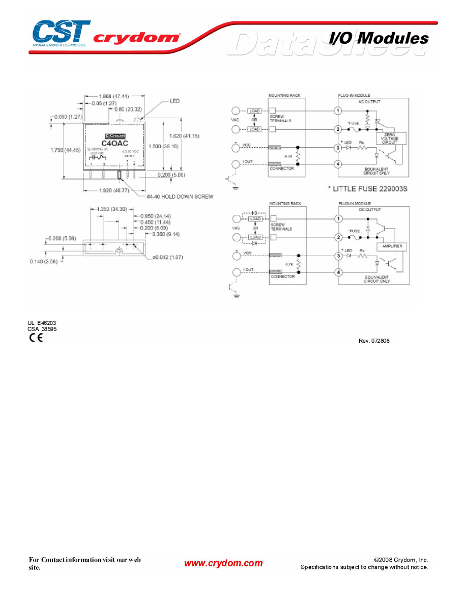
MECHANICAL SPECIFICATIONS
AGENCY APPROVALS
Courtesy of Steven Engineering, Inc.-230 Ryan Way, South San Francisco, CA 94080-6370-Main Office: (650) 588-9200-Outside Local Area: (800) 258-9200-www.stevenengineering.com
60MAIN-html.html

Courtesy of Steven Engineering, Inc.-230 Ryan Way, South San Francisco, CA 94080-6370-Main Office: (650) 588-9200-Outside Local Area: (800) 258-9200-www.stevenengineering.com
60MAIN-html.html

ANNEX - ENVIROMENTAL INFORMATION
Solid State Relays
I/O Modules
Courtesy of Steven Engineering, Inc.-230 Ryan Way, South San Francisco, CA 94080-6370-Main Office: (650) 588-9200-Outside Local Area: (800) 258-9200-www.stevenengineering.com
60MAIN-html.html
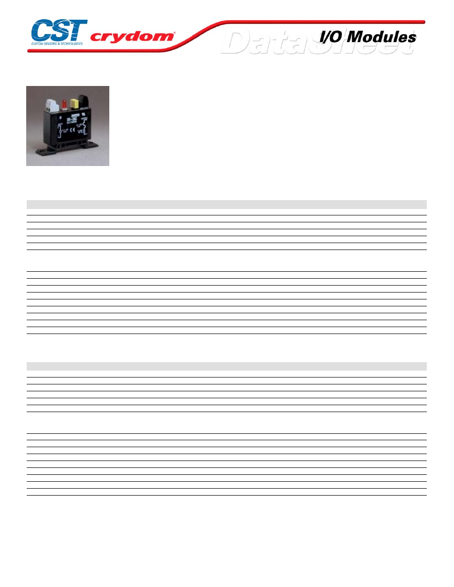
DR INPUT MODULES
• DIN-Rail Mountable Single Point Input Modules
• AC Inputs (Yellow Case)
• DC Inputs (White Case)
• 4kV Optical isolation
• Input and Output Barrier Strips Accept 14 to 28
AWG Wire
• Configured for Panel Mounting
• Open-Collector Output, with LED Status Indicator
SPECIFICATIONS (1)
Input
Part Number
DR-IAC5
DR- IAC5A
DR- IAC24
DR- IAC24A
Voltage Range
90-140 VAC/DC
180-280 VAC/DC
90-140 VAC/DC
180-280 VAC/DC
Maximum Current [mA](4)
6
5
6
5
Resistance [Ohms](2)(3)
28 k
75 k
28 k
75 k
Drop-out Current [mA](5)
2
1.5
2
1.5
Voltage for No Output [VAC/VDC](6)
50
50
50
50
Allowable Current [mA]
2.5
2
2.5
2
Output
Maximum Voltage[VDC](9)
30
30
30
30
Maximum Voltage Drop [VDC](12)
0.2
0.2
0.2
0.2
Nominal Logic Supply Voltage [VDC]
5.0
5.0
24
24
Logic Supply Voltage Range [VDC]
3.0-6.0
3.0-6.0
20-30
20-30
Maximum Current [mA](10)
50
50
50
50
Maximum Logic Supply Current [mA](7)
28
28
28
28
Maximum Logic Supply Leakage Current [µA](8)
10.0
10.0
10.0
10.0
Maximum Leakage Current [µA](11)
10.0
10.0
10.0
10.0
Maximum Turn-On Time [msec] (13)
20
20
20
20
Maximum Turn-Off Time [msec] (13)
30
30
30
30
SPECIFICATIONS (1)
Input
Part Number
DR-IDC5
DR-IDC5A
DR-IDC24
DR-IDC24A
Voltage Range
4-32 VDC/AC
10-48 VDC
4-32 VDC/AC
10-48 VDC
Maximum Current [mA](4)
34
34
34
34
Resistance [Ohms](2)(3)
1 k
2 k
1 k
2 k
Drop-out Current [mA](5)
1
1
1
1
Voltage for No Output [VAC/VDC](6)
2
4
2
4
Allowable Current [mA]
1.5
1.5
1.5
1.5
Output
Maximum Voltage[VDC](9)
30
30
30
30
Maximum Voltage Drop [VDC](12)
0.2
0.2
0.2
0.2
Nominal Logic Supply Voltage [VDC]
5.0
5.0
5.0
5.0
Logic Supply Voltage Range [VDC]
3.0-6.0
3.0-6.0
20-30
20-30
Maximum Current [mA](10)
50
50
50
50
Maximum Logic Supply Current [mA](7)
28
28
28
28
Maximum Logic Supply Leakage Current [µA](8)
10.0
10.0
10.0
10.0
Maximum Leakage Current [µA](11)
10.0
10.0
10.0
10.0
Maximum Turn-On Time [msec] (13)
1.0
1.0
1.0
1.0
Maximum Turn-Off Time [msec] (13)
1.0
1.0
1.0
1.0
For Conta ct information vis it our web site .
www.crydom.com
© 2008 Cryd om, Inc.
Specifications subject to change without notice.
Courtesy of Steven Engineering, Inc.-230 Ryan Way, South San Francisco, CA 94080-6370-Main Office: (650) 588-9200-Outside Local Area: (800) 258-9200-www.stevenengineering.com
60MAIN-html.html
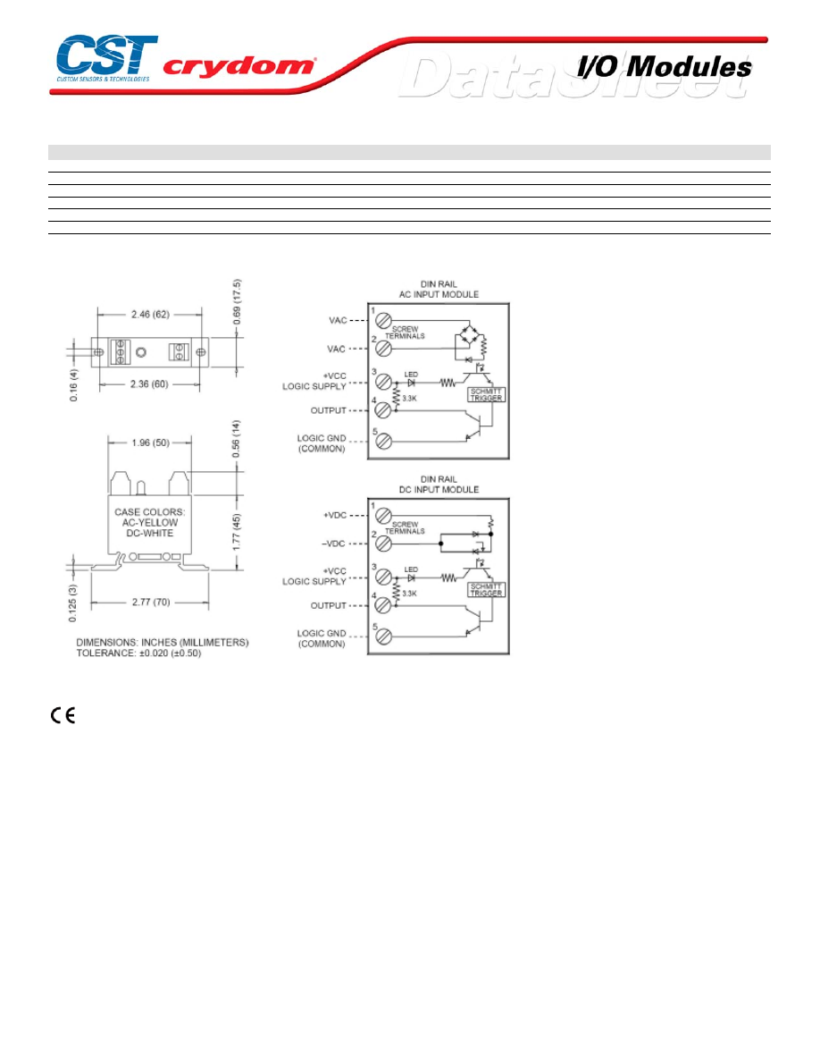
GENERAL SPECIFICATIONS
Description
Input/Output Isolation Voltage (14)
4000
Input/Output Capacitance
8
Operating Temperature Range
-30 to 80°C
Storage Temperature Range
-40 to 100°C
Line Frequency Range
47 to 63
Weight
1.1 oz. (31.2g)
MECHANICAL SPECIFICATIONS
AGENCY APPROVALS
UL E46203
CSA 38595
Rev. 072808
For Conta ct information vis it our web site .
www.crydom.com
© 2008 Cryd om, Inc.
Specifications subject to change without notice.
Courtesy of Steven Engineering, Inc.-230 Ryan Way, South San Francisco, CA 94080-6370-Main Office: (650) 588-9200-Outside Local Area: (800) 258-9200-www.stevenengineering.com
60MAIN-html.html
ANNEX - ENVIROMENTAL INFORMATION
For Conta ct information vis it our web site .
www.crydom.com
© 2008 Cryd om, Inc.
Specifications subject to change without notice.
Courtesy of Steven Engineering, Inc.-230 Ryan Way, South San Francisco, CA 94080-6370-Main Office: (650) 588-9200-Outside Local Area: (800) 258-9200-www.stevenengineering.com
60MAIN-html.html
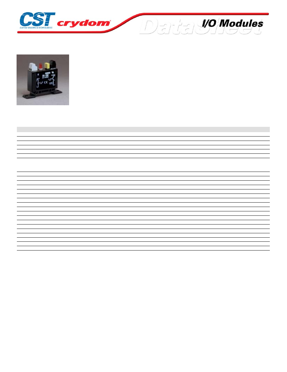
DR OUTPUT MODULES
• DIN-Rail Mountable Single Point Output Modules (35mm DIN)
• Plug into mounting boards for 0.6" modules
• Zero Voltage Turn-On for AC Modules
• 4kV Optical isolation with LED Indicator
• UL Recognized, CSA Certified, CE Compliant
• Industry standard Color Coding Black (AC Output) Red (DC Output)
• Barrier Strips Accept 14 to 28 AWG Wire.
SPECIFICATIONS (1)
Input
Part Number
DR-OAC
DR-ODC5
DR-ODC24
Nominal Voltage VDC
5-24
5.0
24.0
Minimum Voltage VDC
3.7
3.5
18.0
Maximum Voltage VDC
32
8.0
32.0
Drop-out Voltage
1.0
1.0
1.0
Maximum Current (2)
18
18
13
Resistance (3)
NA
250
2000
Output
Nominal Line Voltage
240 VAC
5-48 VDC
5-48 VDC
Minimum Line Voltage
12 VAC
3 VDC
3 VDC
Maximum Line Voltage
280 VAC
60 VDC
60 VDC
Max Off-State Voltage (4)
600 Vpeak
60 VDC
60 VDC
Max Off-State Leakage (5)
0.1mArms
10 uA
10 uA
Static Off-State dv/dt (6)
200 V/usec
N/A
N/A
Maximum Rated On-State Current (7)
5.0 Arms
3.0 A
3.0 A
Minimum On-State Current
50 mArms
10 mA
10 mA
Max Surge Current (8)
250 Apeak
5.0 A
5.0 A
On-State Voltage Drop or Resistance (9)
1.6 V
1.6 V
1.6 V
Horse POwer Rating (13)
1/2 H.P.
N/A
N/A
Maximum Turn-On Time [msec] (13)
8.33
0.1
0.1
Maximum Turn-Off Time [msec] (13)
8.33
0.75
0.75
Input/Output Isolation Voltage (14)
4000
4000
4000
Input/Output Capacitance
8
8
8
Operating Temperature Range
-30 to 80°C
-30 to 80°C
-30 to 80°C
Storage Temperature Range
-40 to 80°C
-40 to 80°C
-40 to 80°C
Line Frequency Range
47 to 63
DC
DC
Weight
1.1 oz. (31.2g)
1.1 oz. (31.2g)
1.1 oz. (31.2g)
General Notes:
(1) Specifications apply to an ambient temperat ure of -30 to 80 ° C unless otherwise noted.
(2) At nominal input voltage, wit hout external LED status indicator.
(3) +/-10% at 25°C.
(4) Maximum 1 minute duration for O AC modules when applied as a DC v oltage rather than a peek AC voltage.
(5) At maximum line voltage, 25°C for OAC modules, and 80°C for OD C modules.
(6) Minimum DV/DT per EIA/NARM RS433, method RS397, DV/DT ratings do not apply to DC output models
(7) At 40°C, derate OAC modules 58 mA/°C to 80°C, derate ODC. O DCxMC and ODC xML modules 50 mA/°C
to 80°C. CSA rati ng of OAC modules is 3.0 Arms at 40°C.
(8) At 25°C for 1 second maxi mum duration: 1 AC cy cle for AC modules, 1 second for DC modules.
(9) At maximum rated on-s tate current and 25°C.
(10) At maximum line voltage, maximum rated output current, nominal input v oltage and 25°C. Switching speed
of O AC modules is based upon 60 Hz line f requency.
(11) At 25°C for 1 second maxi mum duration.
(12) 1/3 H.P. at 240 VAC, 1/8 H.P. at 120 VAC.
.
For Contact information visit our web
site.
www.crydom.com
©2008 Crydom, Inc.
Specifications subject to change without notice.
Courtesy of Steven Engineering, Inc.-230 Ryan Way, South San Francisco, CA 94080-6370-Main Office: (650) 588-9200-Outside Local Area: (800) 258-9200-www.stevenengineering.com
60MAIN-html.html
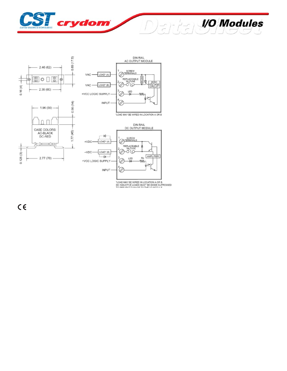
MECHANICAL SPECIFICATIONS
AGENCY APPROVALS
UL E46203
CSA 38595
Rev. 072808
For Contact information visit our web
site.
www.crydom.com
©2008 Crydom, Inc.
Specifications subject to change without notice.
Courtesy of Steven Engineering, Inc.-230 Ryan Way, South San Francisco, CA 94080-6370-Main Office: (650) 588-9200-Outside Local Area: (800) 258-9200-www.stevenengineering.com
60MAIN-html.html
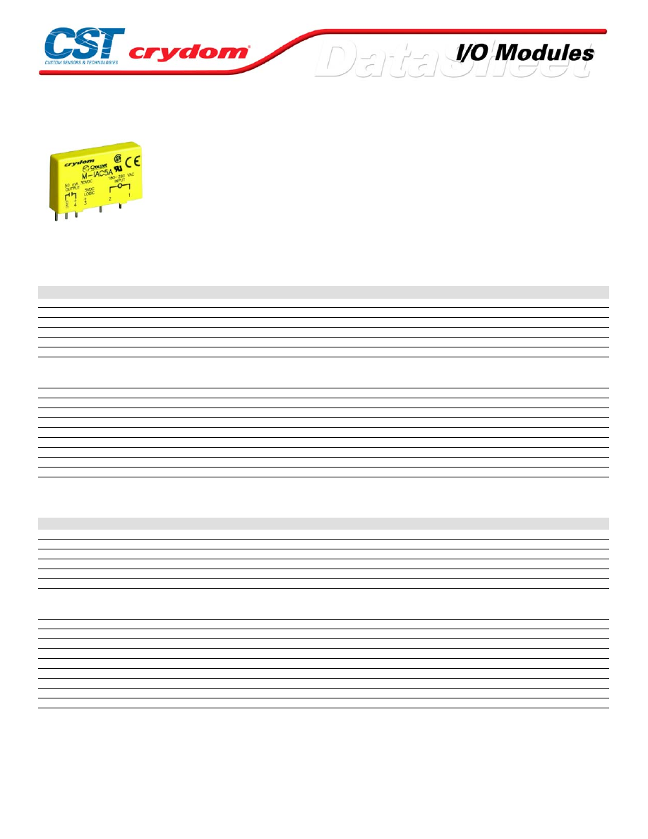
M SERIES INPUT MODULES
• Plug into mounting boards for M Series modules
• AC Inputs (Yellow Case) for 24 V, 120 V, 240 V
• DC Inputs (White Case) for 3.3 to 32 V, 10 to 48 V
• 4kV Optical isolation
• Open-collector Output
• Industry standard packaging
SPECIFICATIONS (1)
Input
Part Number
M-IAC5
M- IAC5A
M- IAC24
M- IAC24A
M-IDC5
Voltage Range
90-140 VAC/DC
180-280 VAC/DC
90-140 VAC/DC
180-280 VAC/DC
3.3-32 VDC/AC
Maximum Current [mA](4)
6
5
6
5
34
Resistance [Ohms](2)(3)
28 k
75 k
28 k
75 k
500
Drop-out Current [mA](5)
2
1.5
2
1.5
1.0
Voltage for No Output [VAC/VDC](6)
50
50
50
50
2.0
Allowable Current [mA]
2.5
2
2.5
2
1.5
Output
Maximum Voltage[VDC](9)
30
30
30
30
30
Maximum Voltage Drop [VDC](12)
0.2
0.2
0.2
0.2
0.2
Nominal Logic Supply Voltage [VDC]
5.0
5.0
5.0
5.0
5.0
Logic Supply Voltage Range [VDC]
3.0-6.0
3.0-6.0
20-30
20-30
3.0-6.0
Maximum Current [mA](10)
50
50
50
50
50
Maximum Logic Supply Current [mA](7)
16.0
16.0
16.0
16.0
16.0
Maximum Logic Supply Leakage Current [µA](8)
10.0
10.0
10.0
10.0
10.0
Maximum Leakage Current [µA](11)
10.0
10.0
10.0
10.0
10.0
Maximum Turn-On Time [msec] (13)
20
20
20
20
1.0
Maximum Turn-Off Time [msec] (13)
20
20
20
20
1.0
SPECIFICATIONS (1)
Input
Part Number
M-IDC24
M-IDC5F
M-IDC24F
M-IDC5N
M-IDC24N
Voltage Range
3.3-32 VDC/AC
4-32 V
4-32 V
10-48 VDC/AC
10-48 VDC/AC
Maximum Current [mA](4)
34
68
68
34
34
Resistance [Ohms](2)(3)
1 k
500
500
1 k
1 k
Drop-out Current [mA](5)
1
1
1
1
1
Voltage for No Output [VAC/VDC](6)
2
2
2
4
4
Allowable Current [mA]
1.5
1.5
1.5
1.5
1.5
Output
Maximum Voltage[VDC](9)
30
30
30
30
30
Maximum Voltage Drop [VDC](12)
0.2
0.2
0.2
0.2
0.2
Nominal Logic Supply Voltage [VDC]
5.0
5.0
5.0
5.0
5.0
Logic Supply Voltage Range [VDC]
3.0-6.0
3.0-6.0
20-30
3.0-6.0
20-30
Maximum Current [mA](10)
50
50
50
50
50
Maximum Logic Supply Current [mA](7)
16.0
16.0
16.0
16.0
16.0
Maximum Logic Supply Leakage Current [µA](8)
10.0
10.0
10.0
10.0
10.0
Maximum Leakage Current [µA](11)
10.0
10.0
10.0
10.0
10.0
Maximum Turn-On Time [msec] (13)
1.0
0.05
0.05
8.0
8.0
Maximum Turn-Off Time [msec] (13)
1.0
0.10
0.10
7.0
7.0
For Contact information visit our web
site.
www.crydom.com
©2008 Crydom, Inc.
Specifications subject to change without notice.
Courtesy of Steven Engineering, Inc.-230 Ryan Way, South San Francisco, CA 94080-6370-Main Office: (650) 588-9200-Outside Local Area: (800) 258-9200-www.stevenengineering.com
60MAIN-html.html
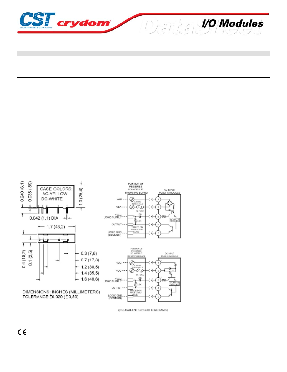
GENERAL SPECIFICATIONS
Description
Input/Output Isolation Voltage (14)
4000
Input/Output Capacitance
8
Operating Temperature Range
-30 to 80°C
Storage Temperature Range
-40 to 80°C
Line Frequency Range
47 to 63
Weight
1.1 oz. (31.2g)
GENERAL NOTES:
(1) Specifications apply to an ambient temperature of -30 t o 80 ° C unl ess otherwise noted.
(2) Resistance v alues for I AC modules are effectiv e impedance v alues at 25 ° C.
(3) Resistance v alues are +/-10% at 25 ° C.
(4) Measured at maximum s pecif ied input voltage, 25°C.
(5) Defined as the maximum current allowed through the module's input to guarantee that
the output will switc h from "on" to "off". Higher c urrents may result in the out put remaining
in the "on" s tate.
(6) Defined as the maximum current allowed through the module's input that will not s witch
the module's output state f rom "off: t o "on".
(7) With ext ernal LED status indicator at maximum specified logic supply vol tage and 25° C.
18mA without external LED.
(8) At maximum specif ied logic voltage and 25°C.
(9) Applied acros s open collector output trans istor.
(10) Sinking c urrent through the open c ollector output transistor.
(11) At maximum output voltage and 25°C.
(12) At maximum output current and 25°C .
(13) At nominal logic supply voltage, 25mA output sinking current, nominal input vol tage
and 25°C
(14) At 25°C for 1 second maxi mum duration
.
MECHANICAL SPECIFICATIONS
AGENCY APPROVALS
UL E46203
CSA 38595
Rev. 072808
For Contact information visit our web
site.
www.crydom.com
©2008 Crydom, Inc.
Specifications subject to change without notice.
Courtesy of Steven Engineering, Inc.-230 Ryan Way, South San Francisco, CA 94080-6370-Main Office: (650) 588-9200-Outside Local Area: (800) 258-9200-www.stevenengineering.com
60MAIN-html.html

For Contact information visit our web
site.
www.crydom.com
©2008 Crydom, Inc.
Specifications subject to change without notice.
Courtesy of Steven Engineering, Inc.-230 Ryan Way, South San Francisco, CA 94080-6370-Main Office: (650) 588-9200-Outside Local Area: (800) 258-9200-www.stevenengineering.com
60MAIN-html.html

ANNEX - ENVIROMENTAL INFORMATION
For Contact information visit our web
site.
www.crydom.com
©2008 Crydom, Inc.
Specifications subject to change without notice.
Courtesy of Steven Engineering, Inc.-230 Ryan Way, South San Francisco, CA 94080-6370-Main Office: (650) 588-9200-Outside Local Area: (800) 258-9200-www.stevenengineering.com
60MAIN-html.html
M SERIES OUTPUT MODULES
SPECIFICATIONS (1)
Input
Part Number
M-OAC5
M-OAC5A
M-OAC5AH
M-OAC5AR
M-OAC5R
Nominal Voltage VDC
5.0
5.0
5.0
5.0
5.0
Minimum Voltage VDC (2)
2.75
2.75
2.75
2.75
2.75
Maximum Voltage VDC
8.0
8.0
8.0
8.0
8.0
Drop-out Voltage
1.0
1.0
1.0
1.0
1.0
Maximum Current (3)
20
20
20
20
20
Resistance (4)
220
220
220
220
220
Output
Nominal Line Voltage
120 VAC
240 VAC
240 VAC
240 VAC
120 VAC
Minimum Line Voltage
12 VAC
24 VAC
24 VAC
24 VAC
12 VAC
Maximum Line Voltage
140 VAC
280 VAC
280 VAC
280 VAC
140 VAC
Max Off-State Voltage (5)
400 Vpeak
600 Vpeak
600 Vpeak
600 Vpeak
400 Vpeak
Max Off-State Leakage (6)
0.1mArms
0.1mArms
0.1mArms
0.1mArms
0.1mArms
Static Off-State dv/dt (7)
200 V/usec
200 V/usec
200 V/usec
200 V/usec
200 V/usec
Maximum Rated On-State Current (8)
3.5 Arms
3.5 Arms
5.0 Arms
3.5 Arms
3.5 Arms
Minimum On-State Current
50 mArms
50 mArms
50 mArms
50 mArms
50 mArms
Max Surge Current (9)
100 Apeak
100 Apeak
100 Apeak
100 Apeak
100 Apeak
On-State Voltage Drop or Resistance (10)
1.6 V
1.6 V
1.6 V
1.6 V
1.6 V
Maximum Turn-On Time [msec] (13)
8.33
8.33
8.33
0.1
0.1
Maximum Turn-Off Time [msec] (13)
8.33
8.33
8.33
8.33
8.33
Input/Output Isolation Voltage (14)
4000
4000
4000
4000
4000
Input/Output Capacitance
8
8
8
8
8
Operating Temperature Range
-30 to 80°C
-30 to 80°C
-30 to 80°C
-30 to 80°C
-30 to 80°C
Storage Temperature Range
-40 to 80°C
-40 to 80°C
-40 to 80°C
-40 to 80°C
-40 to 80°C
Line Frequency Range
47 to 63
47 to 63
47 to 63
47 to 63
47 to 63
Weight
1.1 oz. (31.2g)
1.1 oz. (31.2g)
1.1 oz. (31.2g)
1.1 oz. (31.2g)
1.1 oz. (31.2g)
Courtesy of Steven Engineering, Inc.-230 Ryan Way, South San Francisco, CA 94080-6370-Main Office: (650) 588-9200-Outside Local Area: (800) 258-9200-www.stevenengineering.com
60MAIN-html.html
SPECIFICATIONS (1)
Input
Part Number
M-OAC24
M-OAC24A
M-ODC5
M-ODC5A
M-ODC5F
Nominal Voltage VDC
24
24
5.0
5.0
5.0
Minimum Voltage VDC (2)
18
18
2.75
2.75
2.75
Maximum Voltage VDC
32
32
8.0
8.0
8.0
Drop-out Voltage
1.0
1.0
1.0
1.0
1.0
Maximum Current (3)
13
13
18
18
18
Resistance (4)
2000
2000
250
250
250
Output
Nominal Line Voltage
120 VAC
240 VAC
5-48 VDC
5-150 VDC
5-48 VDC
Minimum Line Voltage
12 VAC
24 VAC
3.0 VDC
3.0 VDC
3.0 VDC
Maximum Line Voltage
140 VAC
280 VAC
60 VDC
250 VDC
60 VDC
Max Off-State Voltage (5)
400 Vpeak
600 Vpeak
60 VDC
250 VDC
60 VDC
Max Off-State Leakage (6)
0.1mArms
0.1mArms
10 uA
10 uA
10 uA
Static Off-State dv/dt (7)
200 V/usec
200 V/usec
N/A
N/A
N/A
Maximum Rated On-State Current (8)
3.5 Arms
3.5 Arms
3.0 A
1.0 A
3.0 A
Minimum On-State Current
50 mArms
50 mArms
10 mA
10 mA
10 mA
Max Surge Current (9)
100 Apeak
100 Apeak
5.0 A
5.0 A
5.0 A
On-State Voltage Drop or Resistance (10)
1.6 V
1.6 V
1.5 V
1.5 V
1.5 V
Maximum Turn-On Time [msec] (13)
8.33
8.33
0.1
0.1
0.025
Maximum Turn-Off Time [msec] (13)
8.33
8.33
0.75
0.75
0.05
Input/Output Isolation Voltage (14)
4000
4000
4000
4000
4000
Input/Output Capacitance
8
8
8
8
8
Operating Temperature Range
-30 to 80°C
-30 to 80°C
-30 to 80°C
-30 to 80°C
-30 to 80°C
Storage Temperature Range
-40 to 80°C
-40 to 80°C
-40 to 80°C
-40 to 80°C
-40 to 80°C
Line Frequency Range
47 to 63
47 to 63
DC
DC
DC
Weight
1.1 oz. (31.2g)
1.1 oz. (31.2g)
1.1 oz. (31.2g)
1.1 oz. (31.2g)
1.1 oz. (31.2g)
SPECIFICATIONS (1)
Input
Part Number
M-ODC5MA
M-ODC5MC
M-ODC5ML
M-ODC24
M-ODC24A
Nominal Voltage VDC
5.0
5.0
5.0
24
24
Minimum Voltage VDC (2)
2.75
2.75
2.75
18
18
Maximum Voltage VDC
8.0
8.0
8.0
32
32
Drop-out Voltage
1.0
1.0
1.0
1.0
1.0
Maximum Current (3)
18
18
18
13
13
Resistance (4)
250
250
250
2000
2000
Output
Nominal Line Voltage
5-150 VDC
5-90 VDC
5-48 VDC
5-48 VDC
5-150 VDC
Minimum Line Voltage
1.0 VDC
1.0 VDC
50 VDC
60 VDC
250 VDC
Maximum Line Voltage
200 VDC
100 VDC
50 VDC
60 VDC
250 VDC
Max Off-State Voltage (5)
200 VDC
100 VDC
50 VDC
60 VDC
250 VDC
Max Off-State Leakage (6)
10 uA
10 uA
10 uA
10 uA
10 uA
Static Off-State dv/dt (7)
N/A
N/A
N/A
N/A
N/A
Maximum Rated On-State Current (8)
3.0 A
5.0 A
1.0 A
3.0 A
1.0 A
Minimum On-State Current
1.0 mA
1.0 mA
10 mA
10 mA
10 mA
Max Surge Current (9)
10 A
10 A
10 A
5.0 A
5.0 A
On-State Voltage Drop or Resistance (10)
0.25 Ohms
0.10 Ohms
0.05 Ohms
1.5 V
1.5 V
Maximum Turn-On Time [msec] (13)
1.0
1.0
1.0
0.1
0.1
Maximum Turn-Off Time [msec] (13)
0.05
0.05
0.05
0.75
0.75
Input/Output Isolation Voltage (14)
1500
1500
1500
4000
4000
Input/Output Capacitance
8
8
8
8
8
Operating Temperature Range
-30 to 80°C
-30 to 80°C
-30 to 80°C
-30 to 80°C
-30 to 80°C
Storage Temperature Range
-40 to 80°C
-40 to 80°C
-40 to 80°C
-40 to 80°C
-40 to 80°C
Line Frequency Range
DC
DC
DC
DC
DC
Weight
1.1 oz. (31.2g)
1.1 oz. (31.2g)
1.1 oz. (31.2g)
1.1 oz. (31.2g)
1.1 oz. (31.2g)
Courtesy of Steven Engineering, Inc.-230 Ryan Way, South San Francisco, CA 94080-6370-Main Office: (650) 588-9200-Outside Local Area: (800) 258-9200-www.stevenengineering.com
60MAIN-html.html
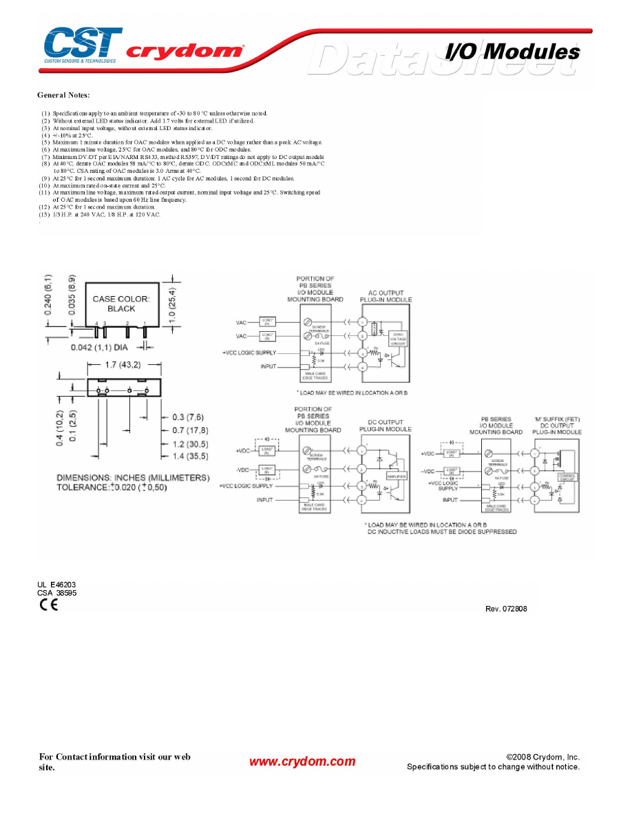
MECHANICAL SPECIFICATIONS
AGENCY APPROVALS
Courtesy of Steven Engineering, Inc.-230 Ryan Way, South San Francisco, CA 94080-6370-Main Office: (650) 588-9200-Outside Local Area: (800) 258-9200-www.stevenengineering.com
60MAIN-html.html
Courtesy of Steven Engineering, Inc.-230 Ryan Way, South San Francisco, CA 94080-6370-Main Office: (650) 588-9200-Outside Local Area: (800) 258-9200-www.stevenengineering.com
60MAIN-html.html

ANNEX - ENVIROMENTAL INFORMATION
Courtesy of Steven Engineering, Inc.-230 Ryan Way, South San Francisco, CA 94080-6370-Main Office: (650) 588-9200-Outside Local Area: (800) 258-9200-www.stevenengineering.com
60MAIN-html.html
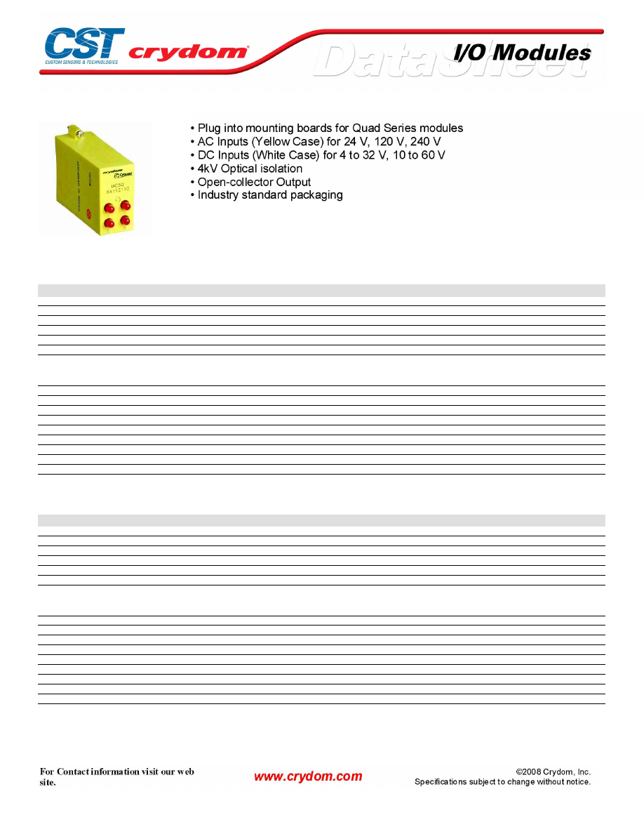
QUAD SERIES INPUT MODULES
SPECIFICATIONS (1)
Input
Part Number
IAC5Q
IAC5AQ
IAC5EQ
Voltage Range
90-140 VAC/DC
180-280 VAC/DC
18-36 VAC/DC
Maximum Current [mA](4)
6
5
10
Resistance [Ohms](2)(3)
28 k
75 k
3.3 k
Drop-out Current [mA](5)
2
1.5
1.0
Voltage for No Output [VAC/VDC](6)
50
50
50
Allowable Current [mA]
2.5
2
1.5
Output
Maximum Voltage[VDC](9)
30
30
30
Maximum Voltage Drop [VDC](12)
0.2
0.2
0.2
Nominal Logic Supply Voltage [VDC]
5.0
5.0
5.0
Logic Supply Voltage Range [VDC]
3.0-6.0
3.0-6.0
3.0-6.0
Maximum Current [mA](10)
50
50
50
Maximum Logic Supply Current [mA](7)
16.0
16.0
16.0
Maximum Logic Supply Leakage Current [µA](8)
10.0
10.0
10.0
Maximum Leakage Current [µA](11)
10.0
10.0
10.0
Maximum Turn-On Time [msec] (13)
20
20
60
Maximum Turn-Off Time [msec] (13)
20
20
30
SPECIFICATIONS (1)
Input
Part Number
IDC5Q
IDC5BQ
Voltage Range
12-60 VDC/AC
5-32 VDC
Maximum Current [mA](4)
34
68
Resistance [Ohms](2)(3)
2 k
500
Drop-out Current [mA](5)
1
1
Voltage for No Output [VAC/VDC](6)
1
2
Allowable Current [mA]
4
1.5
Output
Maximum Voltage[VDC](9)
30
30
Maximum Voltage Drop [VDC](12)
0.2
0.2
Nominal Logic Supply Voltage [VDC]
5.0
5.0
Logic Supply Voltage Range [VDC]
3.0-6.0
3.0-6.0
Maximum Current [mA](10)
50
50
Maximum Logic Supply Current [mA](7)
16.0
16.0
Maximum Logic Supply Leakage Current [µA](8)
10.0
10.0
Maximum Leakage Current [µA](11)
10.0
10.0
Maximum Turn-On Time [msec] (13)
1.0
0.05
Maximum Turn-Off Time [msec] (13)
1.0
0.10
Courtesy of Steven Engineering, Inc.-230 Ryan Way, South San Francisco, CA 94080-6370-Main Office: (650) 588-9200-Outside Local Area: (800) 258-9200-www.stevenengineering.com
60MAIN-html.html
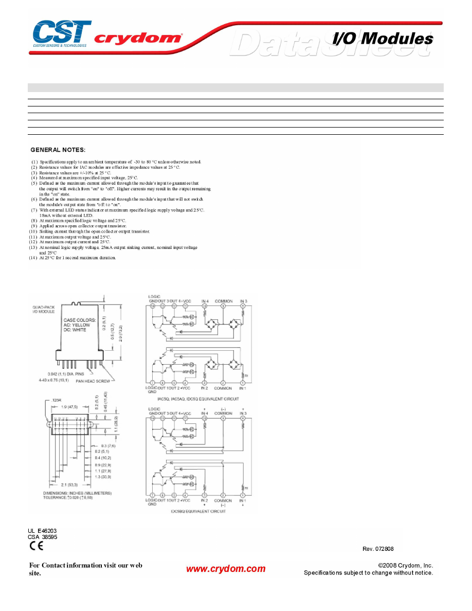
GENERAL SPECIFICATIONS
Description
Input/Output Isolation Voltage (14)
4000
Input/Output Capacitance
8
Operating Temperature Range
-30 to 80°C
Storage Temperature Range
-40 to 100°C
Line Frequency Range
47 to 63
MECHANICAL SPECIFICATIONS
AGENCY APPROVALS
Courtesy of Steven Engineering, Inc.-230 Ryan Way, South San Francisco, CA 94080-6370-Main Office: (650) 588-9200-Outside Local Area: (800) 258-9200-www.stevenengineering.com
60MAIN-html.html

Courtesy of Steven Engineering, Inc.-230 Ryan Way, South San Francisco, CA 94080-6370-Main Office: (650) 588-9200-Outside Local Area: (800) 258-9200-www.stevenengineering.com
60MAIN-html.html

ANNEX - ENVIROMENTAL INFORMATION
Courtesy of Steven Engineering, Inc.-230 Ryan Way, South San Francisco, CA 94080-6370-Main Office: (650) 588-9200-Outside Local Area: (800) 258-9200-www.stevenengineering.com
60MAIN-html.html
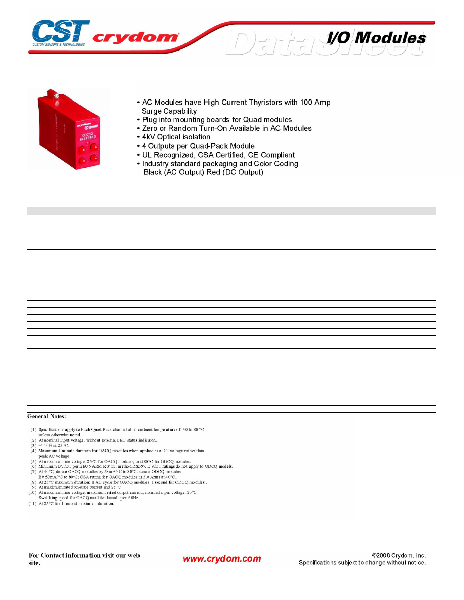
QUAD SERIES OUTPUT MODULES
SPECIFICATIONS (1)
Input
Part Number
OAC5Q
OAC5AQ
OAC5RQ
OAC5ARQ
ODC5Q
ODC5Q-11
Nominal Voltage VDC
5
5
5
5
5
5
Minimum Voltage VDC
4.0
4.0
4.0
4.0
4.0
4.0
Maximum Voltage VDC
8
8
8
8
8
8
Drop-out Voltage
1.0
1.0
1.0
1.0
1.0
1.0
Maximum Current (2) (3)
20 mA
20 mA
20 mA
20 mA
18 mA
18 mA
Resistance
220 Ohms
220 Ohms
220 Ohms
220 Ohms
250 Ohms
250 Ohms
Output
Nominal Line Voltage
120 VAC
240 VAC
120 VAC
240 VAC
5-48 VDC
5-48 VDC
Minimum Line Voltage
12 VAC
12 VAC
12 VAC
12 VAC
3.0 VDC
3.0 VDC
Maximum Line Voltage
140 VAC
280 VAC
140 VAC
280 VAC
60 VDC
60 VDC
Max Off-State Voltage (4)
600 Vpeak
600 Vpeak
600 Vpeak
600 Vpeak
60 VDC
60 VDC
Max Off-State Leakage (5)
0.1mArms
0.1mArms
0.1mArms
0.1mArms
10 uA
10 uA
Static Off-State dv/dt (6)
200 V/usec
200 V/usec
200 V/usec
200 V/usec
n/a
n/a
Maximum Rated On-State Current (7)
3.0 Arms
3.0 Arms
3.0 Arms
3.0 Arms
3.0 A
1.0 A
Minimum On-State Current
50 mArms
50 mArms
50 mArms
50 mArms
10 mA
10 mA
Max Surge Current (8)
100 Apeak
100 Apeak
100 Apeak
100 Apeak
5.0 Apeak
5.0 Apeak
On-State Voltage Drop or Resistance
(9)
1.6 V
1.6 V
1.6 V
1.6 V
1.6 V
1.6 V
HP Rating
1/4
1/4
1/4
1/4
n/a
n/a
Maximum Turn-On Time [msec] (10)
8.33
8.33
0.1
0.1
0.1
0.05
Maximum Turn-Off Time [msec]
8.33
8.33
8.33
8.33
0.05
0.05
Input/Output Isolation Voltage (11)
4000
4000
4000
4000
4000
4000
Input/Output Capacitance
4
4
4
4
4
4
Operating Temperature Range
-30 to 80°C
-30 to 80°C
-30 to 80°C
-30 to 80°C
-30 to 80°C
-30 to 80°C
Storage Temperature Range
-40 to 100°C
-40 to 100°C
-40 to 100°C
-40 to 100°C
-40 to 100°C
-40 to 100°C
Line Frequency Range
47 to 63 Hz
47 to 63 Hz
47 to 63 Hz
47 to 63 Hz
DC
DC
Weight
1.1 oz. (31.2g)
1.1 oz. (31.2g)
1.1 oz. (31.2g)
1.1 oz. (31.2g)
1.1 oz. (31.2g)
1.1 oz. (31.2g)
Courtesy of Steven Engineering, Inc.-230 Ryan Way, South San Francisco, CA 94080-6370-Main Office: (650) 588-9200-Outside Local Area: (800) 258-9200-www.stevenengineering.com
60MAIN-html.html
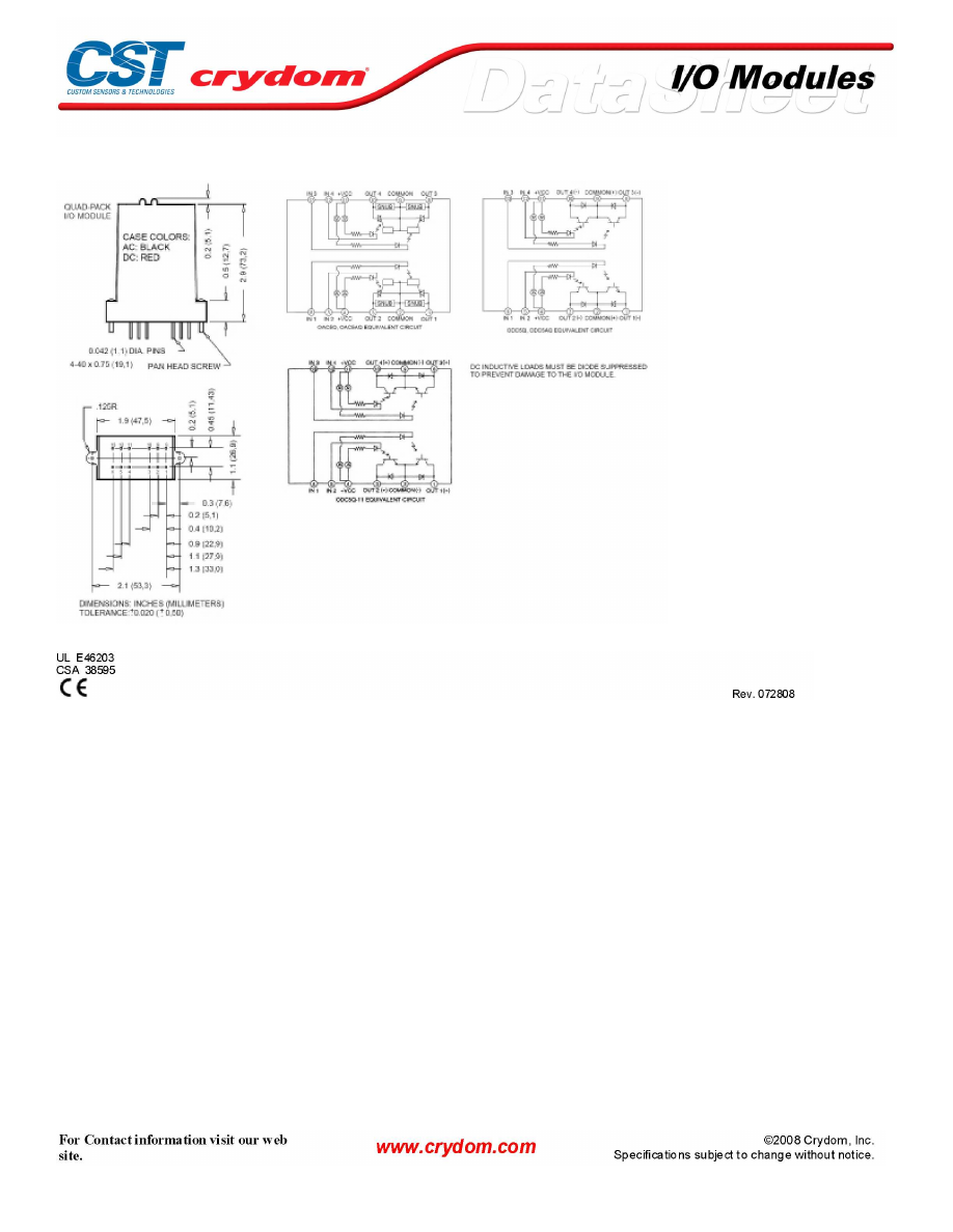
MECHANICAL SPECIFICATIONS
AGENCY APPROVALS
Courtesy of Steven Engineering, Inc.-230 Ryan Way, South San Francisco, CA 94080-6370-Main Office: (650) 588-9200-Outside Local Area: (800) 258-9200-www.stevenengineering.com
60MAIN-html.html

Courtesy of Steven Engineering, Inc.-230 Ryan Way, South San Francisco, CA 94080-6370-Main Office: (650) 588-9200-Outside Local Area: (800) 258-9200-www.stevenengineering.com
60MAIN-html.html
ANNEX - ENVIROMENTAL INFORMATION
Courtesy of Steven Engineering, Inc.-230 Ryan Way, South San Francisco, CA 94080-6370-Main Office: (650) 588-9200-Outside Local Area: (800) 258-9200-www.stevenengineering.com
60MAIN-html.html
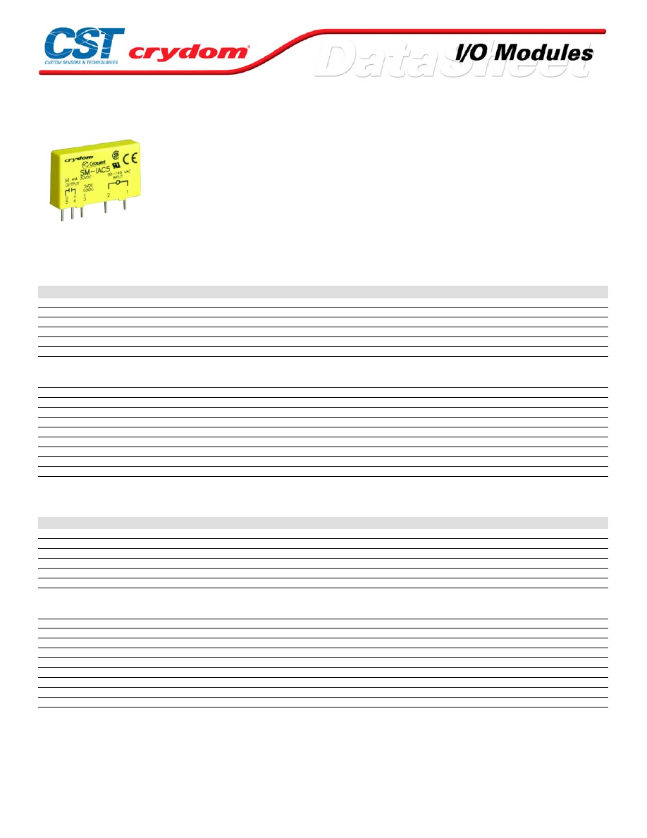
SM SERIES INPUT MODULES
• Plug into mounting boards for SM Series modules
• AC Inputs (Yellow Case) for 24 V, 120 V, 240 V
• DC Inputs (White Case) for 3.3 to 32 V, 10 to 48 V
• 4kV Optical isolation
• Open-collector Output
• Industry standard packaging
SPECIFICATIONS (1)
Input
Part Number
SM-IAC5
SM- IAC5A
SM- IAC24
SM- IAC24A
SM-IDC5
Voltage Range
90-140 VAC/DC
180-280 VAC/DC
90-140 VAC/DC
180-280 VAC/DC
3.3-32 VDC/AC
Maximum Current [mA](4)
6
5
6
5
34
Resistance [Ohms](2)(3)
28 k
75 k
28 k
75 k
500
Drop-out Current [mA](5)
2
1.5
2
1.5
1.0
Voltage for No Output [VAC/VDC](6)
50
50
50
50
2.0
Allowable Current [mA]
2.5
2
2.5
2
1.5
Output
Maximum Voltage[VDC](9)
30
30
30
30
30
Maximum Voltage Drop [VDC](12)
0.2
0.2
0.2
0.2
0.2
Nominal Logic Supply Voltage [VDC]
5.0
5.0
5.0
5.0
5.0
Logic Supply Voltage Range [VDC]
3.0-6.0
3.0-6.0
20-30
20-30
3.0-6.0
Maximum Current [mA](10)
50
50
50
50
50
Maximum Logic Supply Current [mA](7)
16.0
16.0
16.0
16.0
16.0
Maximum Logic Supply Leakage Current [µA](8)
10.0
10.0
10.0
10.0
10.0
Maximum Leakage Current [µA](11)
10.0
10.0
10.0
10.0
10.0
Maximum Turn-On Time [msec] (13)
20
20
20
20
1.0
Maximum Turn-Off Time [msec] (13)
20
20
20
20
1.0
SPECIFICATIONS (1)
Input
Part Number
SM-IDC24
SM-IDC5F
SM-IDC24F
SM-IDC5N
SM-IDC24N
Voltage Range
3.3-32 VDC/AC
4-32 V
4-32 V
10-48 VDC/AC
10-48 VDC/AC
Maximum Current [mA](4)
34
68
68
34
34
Resistance [Ohms](2)(3)
1 k
500
500
1 k
1 k
Drop-out Current [mA](5)
1
1
1
1
1
Voltage for No Output [VAC/VDC](6)
2
2
2
4
4
Allowable Current [mA]
1.5
1.5
1.5
1.5
1.5
Output
Maximum Voltage[VDC](9)
30
30
30
30
30
Maximum Voltage Drop [VDC](12)
0.2
0.2
0.2
0.2
0.2
Nominal Logic Supply Voltage [VDC]
5.0
5.0
5.0
5.0
5.0
Logic Supply Voltage Range [VDC]
3.0-6.0
3.0-6.0
20-30
3.0-6.0
20-30
Maximum Current [mA](10)
50
50
50
50
50
Maximum Logic Supply Current [mA](7)
16.0
16.0
16.0
16.0
16.0
Maximum Logic Supply Leakage Current [µA](8)
10.0
10.0
10.0
10.0
10.0
Maximum Leakage Current [µA](11)
10.0
10.0
10.0
10.0
10.0
Maximum Turn-On Time [msec] (13)
1.0
0.05
0.05
8.0
8.0
Maximum Turn-Off Time [msec] (13)
1.0
0.10
0.10
7.0
7.0
For Contact information visit our web
site.
www.crydom.com
©2008 Crydom, Inc.
Specifications subject to change without notice.
Courtesy of Steven Engineering, Inc.-230 Ryan Way, South San Francisco, CA 94080-6370-Main Office: (650) 588-9200-Outside Local Area: (800) 258-9200-www.stevenengineering.com
60MAIN-html.html
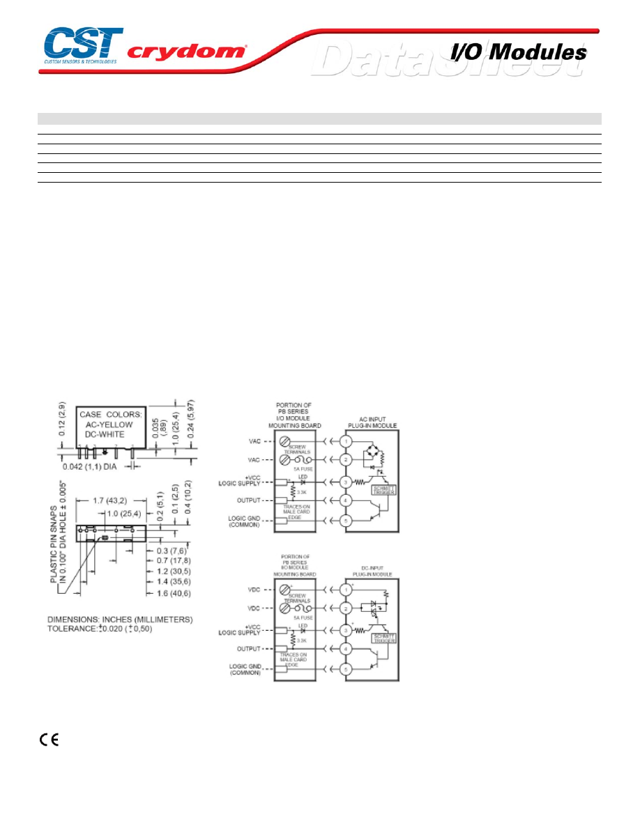
GENERAL SPECIFICATIONS
Description
Input/Output Isolation Voltage (14)
4000
Input/Output Capacitance
8
Operating Temperature Range
-30 to 80°C
Storage Temperature Range
-40 to 80°C
Line Frequency Range
47 to 63
Weight
1.1 oz. (31.2g)
GENERAL NOTES:
(1) Specifications apply to an ambient temperature of -30 t o 80 ° C unl ess otherwise noted.
(2) Resistance v alues for I AC modules are effectiv e impedance v alues at 25 ° C.
(3) Resistance v alues are +/-10% at 25 ° C.
(4) Measured at maximum s pecif ied input voltage, 25°C.
(5) Defined as the maximum current allowed through the module's input to guarantee that
the output will switc h from "on" to "off". Higher c urrents may result in the out put remaining
in the "on" s tate.
(6) Defined as the maximum current allowed through the module's input that will not s witch
the module's output state f rom "off: t o "on".
(7) With ext ernal LED status indicator at maximum specified logic supply vol tage and 25° C.
18mA without external LED.
(8) At maximum specif ied logic voltage and 25°C.
(9) Applied acros s open collector output trans istor.
(10) Sinking c urrent through the open c ollector output transistor.
(11) At maximum output voltage and 25°C.
(12) At maximum output current and 25°C .
(13) At nominal logic supply voltage, 25mA output sinking current, nominal input vol tage
and 25°C
(14) At 25°C for 1 second maxi mum duration
.
MECHANICAL SPECIFICATIONS
AGENCY APPROVALS
UL E46203
CSA 38595
Rev. 072808
For Contact information visit our web
site.
www.crydom.com
©2008 Crydom, Inc.
Specifications subject to change without notice.
Courtesy of Steven Engineering, Inc.-230 Ryan Way, South San Francisco, CA 94080-6370-Main Office: (650) 588-9200-Outside Local Area: (800) 258-9200-www.stevenengineering.com
60MAIN-html.html

For Contact information visit our web
site.
www.crydom.com
©2008 Crydom, Inc.
Specifications subject to change without notice.
Courtesy of Steven Engineering, Inc.-230 Ryan Way, South San Francisco, CA 94080-6370-Main Office: (650) 588-9200-Outside Local Area: (800) 258-9200-www.stevenengineering.com
60MAIN-html.html

ANNEX - ENVIROMENTAL INFORMATION
For Contact information visit our web
site.
www.crydom.com
©2008 Crydom, Inc.
Specifications subject to change without notice.
Courtesy of Steven Engineering, Inc.-230 Ryan Way, South San Francisco, CA 94080-6370-Main Office: (650) 588-9200-Outside Local Area: (800) 258-9200-www.stevenengineering.com
60MAIN-html.html
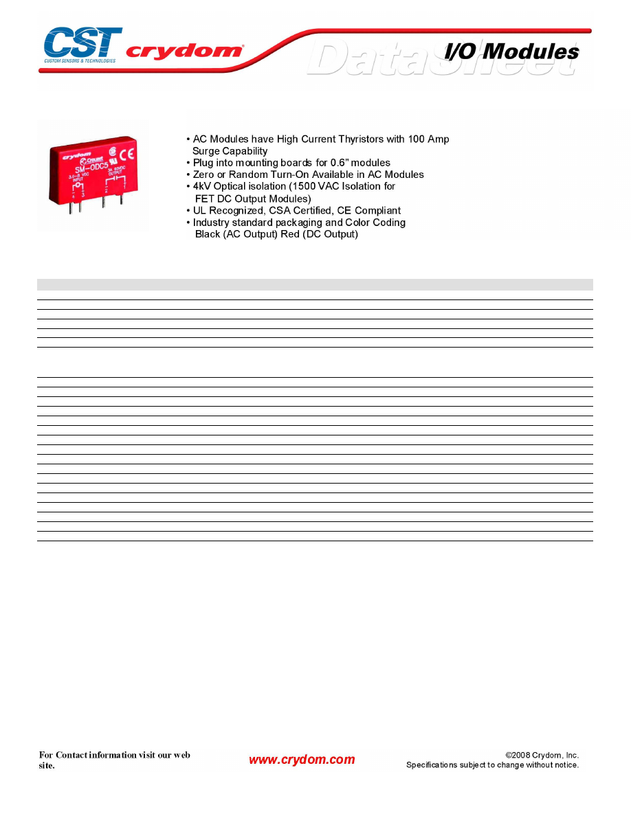
SM SERIES OUTPUT MODULES
SPECIFICATIONS (1)
Input
Part Number
SM-OAC5
SM-OAC5A
SM-OAC5AH
SM-OAC5AR
SM-OAC5R
Nominal Voltage VDC
5.0
5.0
5.0
5.0
5.0
Minimum Voltage VDC (2)
2.75
2.75
2.75
2.75
2.75
Maximum Voltage VDC
8.0
8.0
8.0
8.0
8.0
Drop-out Voltage
1.0
1.0
1.0
1.0
1.0
Maximum Current (3)
20
20
20
20
20
Resistance (4)
220
220
220
220
220
Output
Nominal Line Voltage
120 VAC
240 VAC
240 VAC
240 VAC
120 VAC
Minimum Line Voltage
12 VAC
24 VAC
24 VAC
24 VAC
12 VAC
Maximum Line Voltage
140 VAC
280 VAC
280 VAC
280 VAC
140 VAC
Max Off-State Voltage (5)
400 Vpeak
600 Vpeak
600 Vpeak
600 Vpeak
400 Vpeak
Max Off-State Leakage (6)
0.1mArms
0.1mArms
0.1mArms
0.1mArms
0.1mArms
Static Off-State dv/dt (7)
200 V/usec
200 V/usec
200 V/usec
200 V/usec
200 V/usec
Maximum Rated On-State Current (8)
3.5 Arms
3.5 Arms
5.0 Arms
3.5 Arms
3.5 Arms
Minimum On-State Current
50 mArms
50 mArms
50 mArms
50 mArms
50 mArms
Max Surge Current (9)
100 Apeak
100 Apeak
100 Apeak
100 Apeak
100 Apeak
On-State Voltage Drop or Resistance (10)
1.6 V
1.6 V
1.6 V
1.6 V
1.6 V
Maximum Turn-On Time [msec] (13)
8.33
8.33
8.33
0.1
0.1
Maximum Turn-Off Time [msec] (13)
8.33
8.33
8.33
8.33
8.33
Input/Output Isolation Voltage (14)
4000
4000
4000
4000
4000
Input/Output Capacitance
8
8
8
8
8
Operating Temperature Range
-30 to 80°C
-30 to 80°C
-30 to 80°C
-30 to 80°C
-30 to 80°C
Storage Temperature Range
-40 to 80°C
-40 to 80°C
-40 to 80°C
-40 to 80°C
-40 to 80°C
Line Frequency Range
47 to 63
47 to 63
47 to 63
47 to 63
47 to 63
Weight
1.1 oz. (31.2g)
1.1 oz. (31.2g)
1.1 oz. (31.2g)
1.1 oz. (31.2g)
1.1 oz. (31.2g)
Courtesy of Steven Engineering, Inc.-230 Ryan Way, South San Francisco, CA 94080-6370-Main Office: (650) 588-9200-Outside Local Area: (800) 258-9200-www.stevenengineering.com
60MAIN-html.html

SPECIFICATIONS (1)
Input
Part Number
SM-OAC24
SM-OAC24A
SM-ODC5
SM-ODC5A
SM-ODC5F
Nominal Voltage VDC
24
24
5.0
5.0
5.0
Minimum Voltage VDC (2)
18
18
2.75
2.75
2.75
Maximum Voltage VDC
32
32
8.0
8.0
8.0
Drop-out Voltage
1.0
1.0
1.0
1.0
1.0
Maximum Current (3)
13
13
18
18
18
Resistance (4)
2000
2000
250
250
250
Output
Nominal Line Voltage
120 VAC
240 VAC
5-48 VDC
5-150 VDC
5-48 VDC
Minimum Line Voltage
12 VAC
24 VAC
3.0 VDC
3.0 VDC
3.0 VDC
Maximum Line Voltage
140 VAC
280 VAC
60 VDC
250 VDC
60 VDC
Max Off-State Voltage (5)
400 Vpeak
600 Vpeak
60 VDC
250 VDC
60 VDC
Max Off-State Leakage (6)
0.1mArms
0.1mArms
10 uA
10 uA
10 uA
Static Off-State dv/dt (7)
200 V/usec
200 V/usec
N/A
N/A
N/A
Maximum Rated On-State Current (8)
3.5 Arms
3.5 Arms
3.0 A
1.0 A
3.0 A
Minimum On-State Current
50 mArms
50 mArms
10 mA
10 mA
10 mA
Max Surge Current (9)
100 Apeak
100 Apeak
5.0 A
5.0 A
5.0 A
On-State Voltage Drop or Resistance (10)
1.6 V
1.6 V
1.5 V
1.5 V
1.5 V
Maximum Turn-On Time [msec] (13)
8.33
8.33
0.1
0.1
0.025
Maximum Turn-Off Time [msec] (13)
8.33
8.33
0.75
0.75
0.05
Input/Output Isolation Voltage (14)
4000
4000
4000
4000
4000
Input/Output Capacitance
8
8
8
8
8
Operating Temperature Range
-30 to 80°C
-30 to 80°C
-30 to 80°C
-30 to 80°C
-30 to 80°C
Storage Temperature Range
-40 to 80°C
-40 to 80°C
-40 to 80°C
-40 to 80°C
-40 to 80°C
Line Frequency Range
47 to 63
47 to 63
DC
DC
DC
Weight
1.1 oz. (31.2g)
1.1 oz. (31.2g)
1.1 oz. (31.2g)
1.1 oz. (31.2g)
1.1 oz. (31.2g)
SPECIFICATIONS (1)
Input
Part Number
SM-ODC5MA
SM-ODC5MC
SM-ODC5ML
SM-ODC24
SM-ODC24A
Nominal Voltage VDC
5.0
5.0
5.0
24
24
Minimum Voltage VDC (2)
2.75
2.75
2.75
18
18
Maximum Voltage VDC
8.0
8.0
8.0
32
32
Drop-out Voltage
1.0
1.0
1.0
1.0
1.0
Maximum Current (3)
18
18
18
13
13
Resistance (4)
250
250
250
2000
2000
Output
Nominal Line Voltage
5-150 VDC
5-90 VDC
5-48 VDC
5-48 VDC
5-150 VDC
Maximum Line Voltage
200 VDC
100 VDC
50 VDC
60 VDC
250 VDC
Max Off-State Voltage (5)
200 VDC
100 VDC
50 VDC
60 VDC
250 VDC
Max Off-State Leakage (6)
10 uA
10 uA
10 uA
10 uA
10 uA
Static Off-State dv/dt (7)
N/A
N/A
N/A
N/A
N/A
Maximum Rated On-State Current (8)
3.0 A
5.0 A
1.0 A
3.0 A
1.0 A
Minimum On-State Current
1.0 mA
1.0 mA
10 mA
10 mA
10 mA
Max Surge Current (9)
10 A
10 A
10 A
5.0 A
5.0 A
On-State Voltage Drop or Resistance (10)
0.25 Ohms
0.10 Ohms
0.05 Ohms
1.5 V
1.5 V
Maximum Turn-On Time [msec] (13)
1.0
1.0
1.0
0.1
0.1
Maximum Turn-Off Time [msec] (13)
0.05
0.05
0.05
0.75
0.75
Input/Output Isolation Voltage (14)
1500
1500
1500
4000
4000
Input/Output Capacitance
8
8
8
8
8
Operating Temperature Range
-30 to 80
-30 to 80°C
-30 to 80°C
-30 to 80°C
-30 to 80°C
Storage Temperature Range
-40 to 80
-40 to 80°C
-40 to 80°C
-40 to 80°C
-40 to 80°C
Line Frequency Range
DC
DC
DC
DC
DC
Weight
1.1 oz. (31.2g)
1.1 oz. (31.2g)
1.1 oz. (31.2g)
1.1 oz. (31.2g)
1.1 oz. (31.2g)
Courtesy of Steven Engineering, Inc.-230 Ryan Way, South San Francisco, CA 94080-6370-Main Office: (650) 588-9200-Outside Local Area: (800) 258-9200-www.stevenengineering.com
60MAIN-html.html
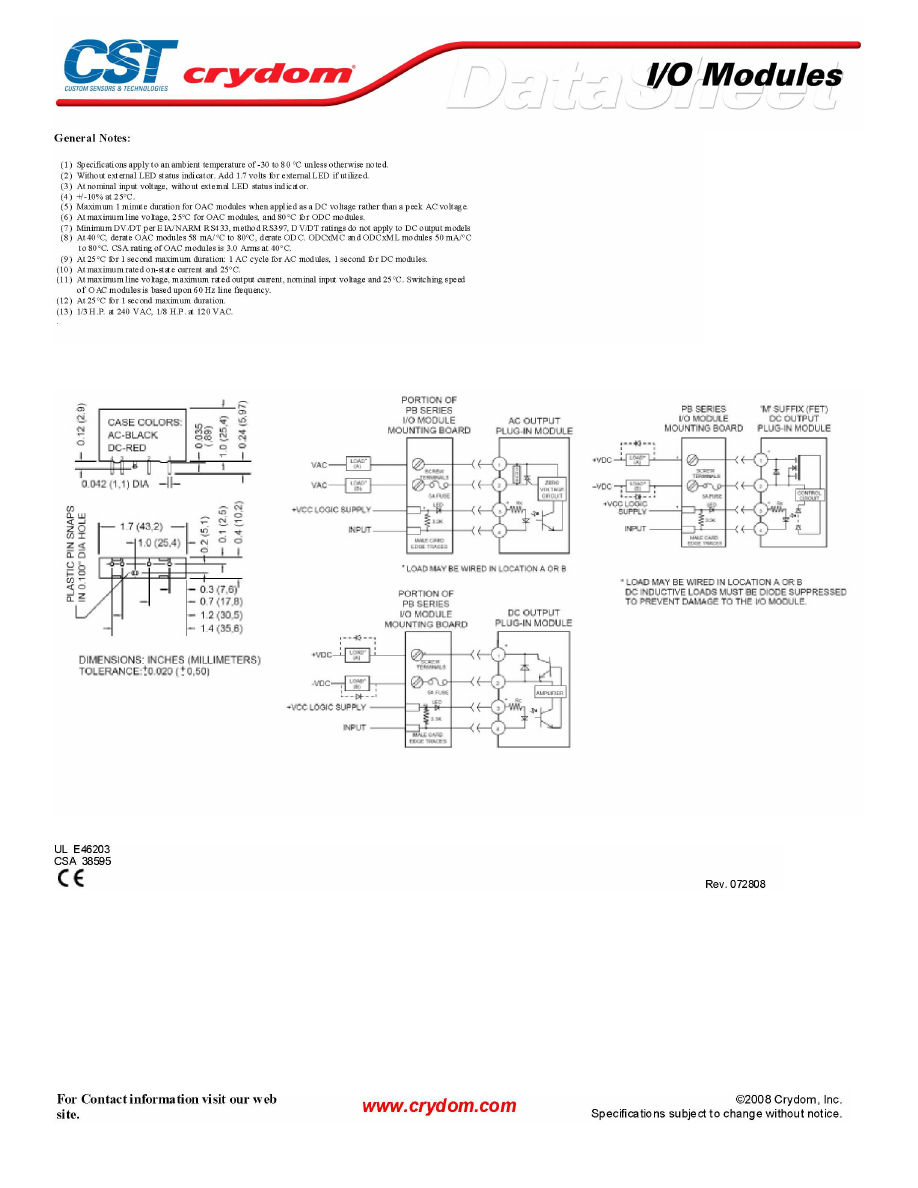
MECHANICAL SPECIFICATIONS
AGENCY APPROVALS
Courtesy of Steven Engineering, Inc.-230 Ryan Way, South San Francisco, CA 94080-6370-Main Office: (650) 588-9200-Outside Local Area: (800) 258-9200-www.stevenengineering.com
60MAIN-html.html

Courtesy of Steven Engineering, Inc.-230 Ryan Way, South San Francisco, CA 94080-6370-Main Office: (650) 588-9200-Outside Local Area: (800) 258-9200-www.stevenengineering.com
60MAIN-html.html

ANNEX - ENVIROMENTAL INFORMATION
Courtesy of Steven Engineering, Inc.-230 Ryan Way, South San Francisco, CA 94080-6370-Main Office: (650) 588-9200-Outside Local Area: (800) 258-9200-www.stevenengineering.com
60MAIN-html.html
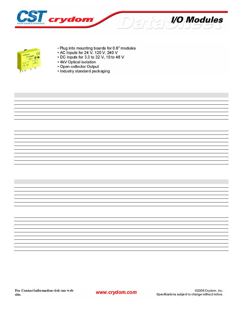
0.6" SERIES INPUT MODULES
SPECIFICATIONS (1)
Input
Part Number
IAC5
IAC5A
IAC24
IAC24A
IDC5
Voltage Range
90-140 VAC/DC
180-280 VAC/DC
90-140 VAC/DC
180-280 VAC/DC
3.3-32 VDC/AC
Maximum Current [mA](4)
6
5
6
5
34
Resistance [Ohms](2)(3)
28 k
75 k
28 k
75 k
500
Drop-out Current [mA](5)
2
1.5
2
1.5
1.0
Voltage for No Output [VAC/VDC](6)
50
50
50
50
2.0
Allowable Current [mA]
2.5
2
2.5
2
1.5
Output
Maximum Voltage[VDC](9)
30
30
30
30
30
Maximum Voltage Drop [VDC](12)
0.2
0.2
0.2
0.2
0.2
Nominal Logic Supply Voltage [VDC]
5.0
5.0
5.0
5.0
5.0
Logic Supply Voltage Range [VDC]
3.0-6.0
3.0-6.0
20-30
20-30
3.0-6.0
Maximum Current [mA](10)
50
50
50
50
50
Maximum Logic Supply Current [mA](7)
16.0
16.0
16.0
16.0
16.0
Maximum Logic Supply Leakage Current [µA](8)
10.0
10.0
10.0
10.0
10.0
Maximum Leakage Current [µA](11)
10.0
10.0
10.0
10.0
10.0
Maximum Turn-On Time [msec] (13)
20
20
20
20
1.0
Maximum Turn-Off Time [msec] (13)
20
20
20
20
1.0
SPECIFICATIONS (1)
Input
Part Number
IDC24
IDC5F
IDC24F
IDC5N
IDC24N
Voltage Range (VAC or VDC)
3.3-32 VDC/AC
4-32 VDC
4-32 VDC
10-48 VDC/AC
10-48 VDC/AC
Maximum Current [mA](4)
34
68
68
34
34
Resistance [Ohms](2)(3)
1 k
500
500
1 k
1 k
Drop-out Current [mA](5)
1
1
1
1
1
Voltage for No Output [VAC/VDC](6)
2
2
2
4
4
Allowable Current [mA]
1.5
1.5
1.5
1.5
1.5
Output
Maximum Voltage[VDC](9)
30
30
30
30
30
Maximum Voltage Drop [VDC](12)
0.2
0.2
0.2
0.2
0.2
Nominal Logic Supply Voltage [VDC]
5.0
5.0
5.0
5.0
5.0
Logic Supply Voltage Range [VDC]
3.0-6.0
3.0-6.0
20-30
3.0-6.0
20-30
Maximum Current [mA](10)
50
50
50
50
50
Maximum Logic Supply Current [mA](7)
16.0
16.0
16.0
16.0
16.0
Maximum Logic Supply Leakage Current [µA](8)
10.0
10.0
10.0
10.0
10.0
Maximum Leakage Current [µA](11)
10.0
10.0
10.0
10.0
10.0
Maximum Turn-On Time [msec] (13)
1.0
0.05
0.05
8.0
8.0
Maximum Turn-Off Time [msec] (13)
1.0
0.10
0.10
7.0
7.0
Courtesy of Steven Engineering, Inc.-230 Ryan Way, South San Francisco, CA 94080-6370-Main Office: (650) 588-9200-Outside Local Area: (800) 258-9200-www.stevenengineering.com
60MAIN-html.html
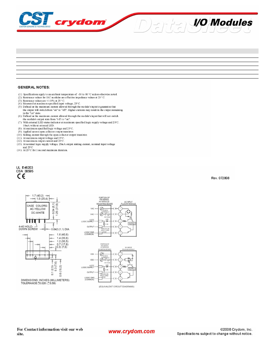
GENERAL SPECIFICATIONS
Description
Input/Output Isolation Voltage (14)
4000
Input/Output Capacitance
8
Operating Temperature Range
-30 to 80°C
Storage Temperature Range
-40 to 80°C
Line Frequency Range
47 to 63
Weight
1.1 oz. (31.2g)
AGENCY APPROVALS
MECHANICAL SPECIFICATIONS
Courtesy of Steven Engineering, Inc.-230 Ryan Way, South San Francisco, CA 94080-6370-Main Office: (650) 588-9200-Outside Local Area: (800) 258-9200-www.stevenengineering.com
60MAIN-html.html

ANNEX - ENVIROMENTAL INFORMATION
Courtesy of Steven Engineering, Inc.-230 Ryan Way, South San Francisco, CA 94080-6370-Main Office: (650) 588-9200-Outside Local Area: (800) 258-9200-www.stevenengineering.com
60MAIN-html.html
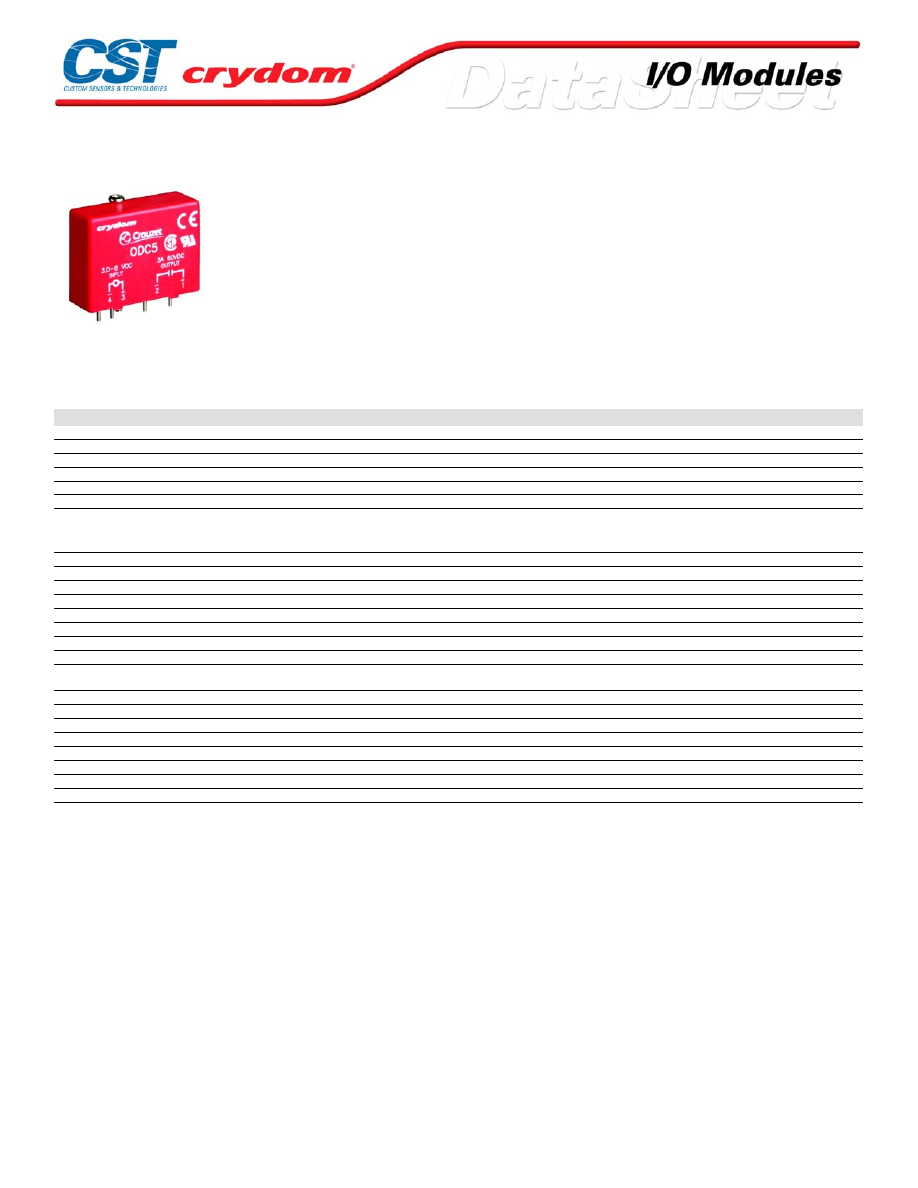
0.6" SERIES OUTPUT MODULES
• AC Modules have High Current Thyristors with 100 Amp
Surge Capability
• Plug into mounting boards for 0.6" modules
• Zero or Random Turn-On Available in AC Modules
• 4kV Optical isolation (1500 VAC Isolation for
FET DC Output Modules)
• UL Recognized, CSA Certified, CE Compliant
• Industry standard packaging and Color Coding
Black (AC Output) Red (DC Output)
SPECIFICATIONS (1)
Input
Part Number
OAC5
OAC5A
OAC5AH
OAC5AR
OAC5R
OAC24
Nominal Voltage VDC
5.0
5.0
5.0
5.0
5.0
24
Minimum Voltage VDC (2)
2.75
2.75
2.75
2.75
2.75
18
Maximum Voltage VDC
8.0
8.0
8.0
8.0
8.0
32
Drop-out Voltage
1.0
1.0
1.0
1.0
1.0
1.0
Maximum Current (3)
20
20
20
20
20
13
Resistance (4)
220
220
220
220
220
2000
Output
Nominal Line Voltage
120 VAC
240 VAC
240 VAC
240 VAC
120 VAC
120 VAC
Minimum Line Voltage
12 VAC
24 VAC
24 VAC
24 VAC
12 VAC
12 VAC
Maximum Line Voltage
140 VAC
280 VAC
280 VAC
280 VAC
140 VAC
140 VAC
Max Off-State Voltage (5)
400 Vpeak
600 Vpeak
600 Vpeak
600 Vpeak
400 Vpeak
400 Vpeak
Max Off-State Leakage (6)
0.1mArms
0.1mArms
0.1mArms
0.1mArms
0.1mArms
0.1mArms
Static Off-State dv/dt (7)
200 V/usec
200 V/usec
200 V/usec
200 V/usec
200 V/usec
200 V/usec
Maximum Rated On-State Current (8)
3.5 Arms
3.5 Arms
5.0 Arms
3.5 Arms
3.5 Arms
3.5 Arms
Minimum On-State Current
50 mArms
50 mArms
50 mArms
50 mArms
50 mArms
50 mArms
Max Surge Current (9)
100 Apeak
100 Apeak
100 Apeak
100 Apeak
100 Apeak
100 Apeak
On-State Voltage Drop or Resistance
(10)
1.6 V
1.6 V
1.6 V
1.6 V
1.6 V
1.6 V
Maximum Turn-On Time [msec] (13)
8.33
8.33
8.33
0.1
0.1
8.33
Maximum Turn-Off Time [msec] (13)
8.33
8.33
8.33
8.33
8.33
8.33
Input/Output Isolation Voltage (14)
4000
4000
4000
4000
4000
4000
Input/Output Capacitance
8
8
8
8
8
8
Operating Temperature Range
-30 to 80°C
-30 to 80°C
-30 to 80°C
-30 to 80°C
-30 to 80°C
-30 to 80°C
Storage Temperature Range
-40 to 80°C
-40 to 80°C
-40 to 80°C
-40 to 80°C
-40 to 80°C
-40 to 80°C
Line Frequency Range
47 to 63
47 to 63
47 to 63
47 to 63
47 to 63
47 to 63
Weight
1.1 oz. (31.2g)
1.1 oz. (31.2g)
1.1 oz. (31.2g)
1.1 oz. (31.2g)
1.1 oz. (31.2g)
1.1 oz. (31.2g)
For Contact information visit our web
site.
www.crydom.com
©2008 Crydom, Inc.
Specifications subject to change without notice.
Courtesy of Steven Engineering, Inc.-230 Ryan Way, South San Francisco, CA 94080-6370-Main Office: (650) 588-9200-Outside Local Area: (800) 258-9200-www.stevenengineering.com
60MAIN-html.html
Input
Part Number
OAC24A
ODC5
ODC5A
ODC5F
ODC5MA
Nominal Voltage VDC
24
5.0
5.0
5.0
5.0
Minimum Voltage VDC (2)
18
2.75
2.75
2.75
2.75
Maximum Voltage VDC
32
8.0
8.0
8.0
8.0
Drop-out Voltage
1.0
1.0
1.0
1.0
1.0
Maximum Current (3)
13
18
18
18
18
Resistance (4)
2000
250
250
250
250
Output
Nominal Line Voltage
240 VAC
5-48 VDC
5-150 VDC
5-48 VDC
5-150 VDC
Minimum Line Voltage
24 VAC
3.0 VDC
3.0 VDC
3.0 VDC
1.0 VDC
Maximum Line Voltage
280 VAC
60 VDC
250 VDC
60 VDC
200 VDC
Max Off-State Voltage (5)
600 Vpeak
60 VDC
250 VDC
60 VDC
200 VDC
Max Off-State Leakage (6)
0.1mArms
10 uA
10 uA
10 uA
10 uA
Static Off-State dv/dt (7)
200 V/usec
N/A
N/A
N/A
N/A
Maximum Rated On-State Current (8)
3.5 Arms
3.0 A
1.0 A
3.0 A
3.0 A
Minimum On-State Current
50 mArms
10 mA
10 mA
10 mA
1.0 mA
Max Surge Current (9)
100 Apeak
5.0 A
5.0 A
5.0 A
10 A
On-State Voltage Drop or Resistance (10)
1.6 V
1.5 V
1.5 V
1.5 V
0.25 Ohms
Maximum Turn-On Time [msec] (13)
8.33
0.1
0.1
0.025
1.0
Maximum Turn-Off Time [msec] (13)
8.33
0.75
0.75
0.05
0.05
Input/Output Isolation Voltage (14)
4000
4000
4000
4000
1500
Input/Output Capacitance
8
8
8
8
8
Operating Temperature Range
-30 to 80°C
-30 to 80°C
-30 to 80°C
-30 to 80°C
-30 to 80°C
Storage Temperature Range
-40 to 80°C
-40 to 80°C
-40 to 80°C
-40 to 80°C
-40 to 80°C
Line Frequency Range
47 to 63
DC
DC
DC
DC
Weight
1.1 oz. (31.2g)
1.1 oz. (31.2g)
1.1 oz. (31.2g)
1.1 oz. (31.2g)
1.1 oz. (31.2g)
Input
Part Number
ODC5MC
ODC5ML
ODC24
ODC24A
ODC24F
Nominal Voltage VDC
5.0
5.0
24
24
24
Minimum Voltage VDC (2)
2.75
2.75
18
18
18
Maximum Voltage VDC
8.0
8.0
32
32
32
Drop-out Voltage
1.0
1.0
1.0
1.0
1.0
Maximum Current (3)
18
18
13
13
13
Resistance (4)
250
250
2000
2000
2000
Output
Nominal Line Voltage
5-90 VDC
5-48 VDC
5-48 VDC
5-150 VDC
5-48 VDC
Minimum Line Voltage
1.0 VDC
1.0 VDC
3.0 VDC
3.0 VDC
3.0 VDC
Maximum Line Voltage
100 VDC
50 VDC
60 VDC
250 VDC
60 VDC
Max Off-State Voltage (5)
50 VDC
60 VDC
250 VDC
60 VDC
60 VDC
Max Off-State Leakage (6)
10 uA
10 uA
10 uA
10 uA
10 uA
Static Off-State dv/dt (7)
N/A
N/A
N/A
N/A
N/A
Maximum Rated On-State Current (8)
5.0 A
1.0 A
3.0 A
1.0 A
3.0 A
Minimum On-State Current
1.0 mA
10 mA
10 mA
10 mA
10 mA
Max Surge Current (9)
10 A
10 A
5.0 A
5.0 A
5.0 A
On-State Voltage Drop or Resistance (10)
0.10 Ohms
0.05 Ohms
1.5 V
1.5 V
1.5 V
Maximum Turn-On Time [msec] (13)
1.0
1.0
0.1
0.1
0.025
Maximum Turn-Off Time [msec] (13)
0.05
0.05
0.75
0.75
0.05
Input/Output Isolation Voltage (14)
1500
1500
4000
4000
4000
Input/Output Capacitance
8
8
8
8
8
Operating Temperature Range
-30 to 80°C
-30 to 80°C
-30 to 80°C
-30 to 80°C
-30 to 80°C
Storage Temperature Range
-40 to 80°C
-40 to 80°C
-40 to 80°C
-40 to 80°C
-40 to 80°C
Line Frequency Range
DC
DC
DC
DC
DC
Weight
1.1 oz. (31.2g)
1.1 oz. (31.2g)
1.1 oz. (31.2g)
1.1 oz. (31.2g)
1.1 oz. (31.2g)
For Contact information visit our web
site.
www.crydom.com
©2008 Crydom, Inc.
Specifications subject to change without notice.
Courtesy of Steven Engineering, Inc.-230 Ryan Way, South San Francisco, CA 94080-6370-Main Office: (650) 588-9200-Outside Local Area: (800) 258-9200-www.stevenengineering.com
60MAIN-html.html
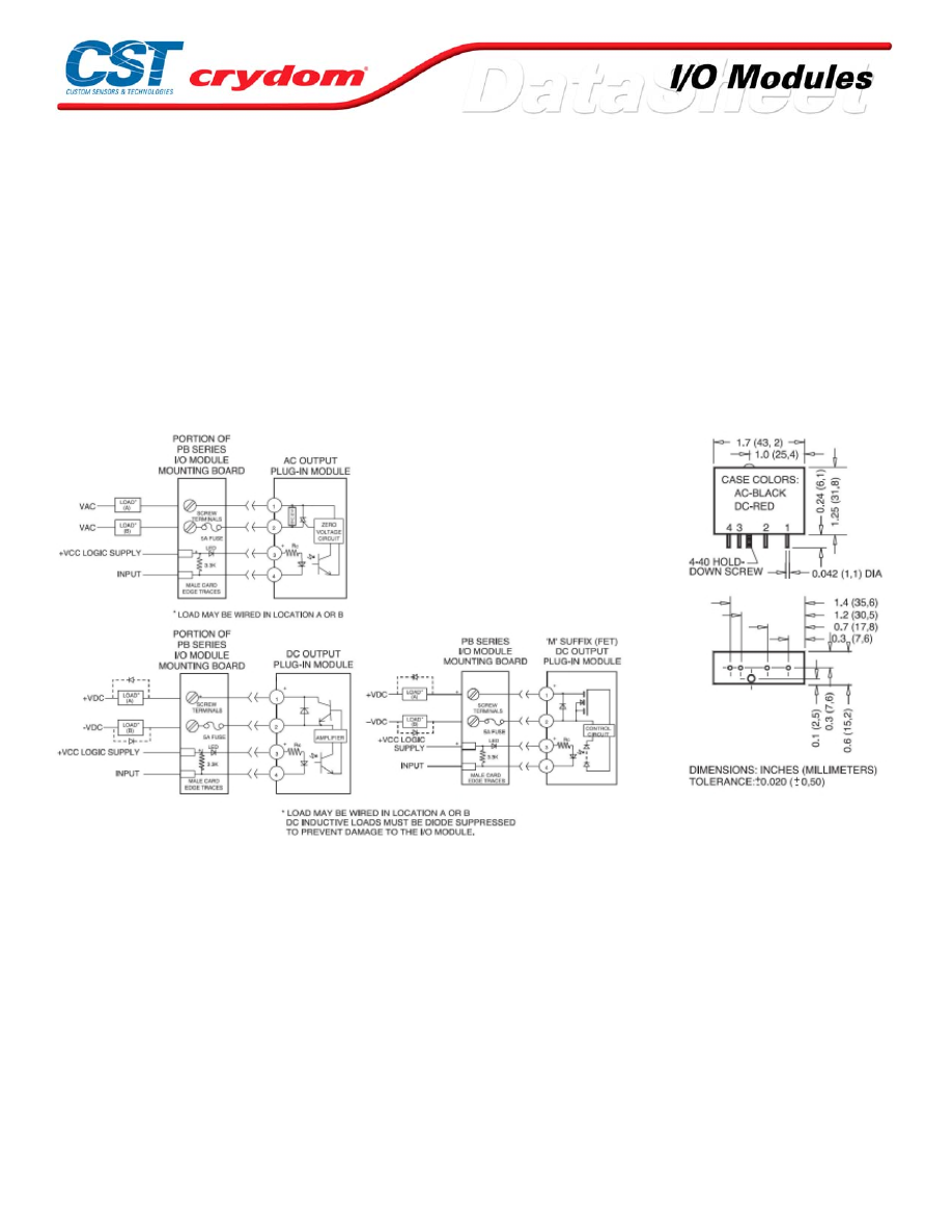
GENERAL NOTES
General Notes:
(1 ) Sp ecificati ons app ly t o an amb ient temperature of -30 to 8 0 °C un less o therwise no ted.
(2 ) Witho ut ext ernal LED st atus indi cat or. Add 1.7 vo lts fo r external LED if ut ilized.
(3 ) At no minal inp ut volt age, witho ut ext ern al LED statu s ind icat or.
(4 ) +/ -10% at 2 5°C.
(5 ) Maxim um 1 m inut e duratio n for OAC mo dules when appl ied as a DC vo ltage rather than a p eek AC vo lt ag e.
(6 ) At max imu m l ine vo ltage, 2 5°C for OAC m odules, and 80 °C fo r ODC mo dules.
(7 ) Min imu m DV /DT p er E IA/ NARM RS4 33, m etho d RS3 97, D V/DT rati ngs do not apply to DC o utpu t models
(8 ) At 40 °C, derat e OAC modu les 58 mA/ °C to 80°C, d erate OD C. ODCxM C an d ODCxM L mo dules 50 mA/° C
t o 80 °C. CSA rati ng of OAC modu les is 3.0 Arms at 40° C.
(9 ) At 25 °C fo r 1 second maxim um durat ion: 1 AC cycle fo r AC mod ules, 1 second fo r DC modu les.
(10 ) At max imu m rated o n-st at e current and 25° C.
(11 ) At max imu m l ine vo ltage, m axim um rat ed out put cu rrent , nom inal input vo ltage and 25 °C. Switch ing s peed
o f O AC m odu les is based up on 6 0 Hz li ne frequ ency.
(12 ) At 25 °C fo r 1 second maxim um durat ion.
(13 ) 1/3 H .P. at 240 VAC, 1/8 H.P. at 12 0 VAC.
.
MECHANICAL SPECIFICATIONS
AGENCY APPROVALS
UL
CSA
CE
For Contact information visit our web
site.
www.crydom.com
©2008 Crydom, Inc.
Specifications subject to change without notice.
Courtesy of Steven Engineering, Inc.-230 Ryan Way, South San Francisco, CA 94080-6370-Main Office: (650) 588-9200-Outside Local Area: (800) 258-9200-www.stevenengineering.com
60MAIN-html.html

)
2
(
N
O
I
T
P
O
R
O
T
C
E
N
N
O
C
"
V
–
"
)
1
(
N
O
I
T
P
O
R
O
T
C
E
N
N
O
C
"
C
–
"
TOP
VIEW
TOP
VIEW
SIDE
VIEW
SIDE
VIEW
D
R
A
O
B
D
R
A
O
B
NOTES: 1.) CONNECTOR IS BERG 65823-093 OR EQUIVALENT
2.) CONNECTOR IS CIRCUIT ASSEMBLY CA-50H-2B OR EQUIVALENT
HEADER CONNECTOR OPTION
PC BOARD
REMOVABLE TERMINAL BLOCK
OPTION A
TERMINAL OPTIONS FOR "M" AND "SM" I/O MOUNTING BOARDS
OPTION B
Courtesy of Steven Engineering, Inc.-230 Ryan Way, South San Francisco, CA 94080-6370-Main Office: (650) 588-9200-Outside Local Area: (800) 258-9200-www.stevenengineering.com
60MAIN-html.html

Series 1-DC
• D1D to D5D series SSRs; MOSFET output
• Ratings from 7A to 40A @ 200 VDC, and from 7A to 10A @ 500 VDC
• DC Control
• Relays are easily paralleled for higher-current applications
PRODUCT SELECTION
Load Voltage
7A
10A
12A
20A
40A
100 VDC
D1D07
D1D12
D1D20
D1D40
200 VDC
D2D07
D2D12
D2D40
400 VDC
D4D07
D4D12
500 VDC
D5D07
D5D10
OUTPUT SPECIFICATIONS (1)
Description
7A
12A
20A
40A
7A
12A
40A
7A
12A
7A
10A
Operating Voltage Range
0-100
0-100
0-100
0-100
0-200
0-200
0-200
0-400
0-400
0-500
0-500
Maximum Off-State Leakage Current @ Rated Voltage [mArms]
0.1
0.2
0.3
0.3
0.1
0.3
0.3
0.3
0.3
0.2
0.3
Maximum Load Current (3) [Adc]
7
12
20
40
7
12
40
7
12
7
10
Minimum Load Current [mA]
0
0
0
0
0
0
0
0
0
0
0
Maximum Surge Current (16.6ms) [Apk]
15
28
42
106
22
27
106
17
36
19
29
Maximum On-State Voltage Drop @ Rated Current [Vpk]
2.0
1.6
2.1
2.1
2.0
2.8
2.1
4.2
4.2
5.7
5.5
Thermal Resistance Junction to Case (Rjc) [°C/W]
2.2
1.34
1.06
0.83
1.5
1.06
0.83
1.06
0.8
1.0
0.8
Maximum On-State Resistance [RDS-ON][Ohms]
0.29
0.13
0.10
0.05
0.29
0.23
0.05
0.6
0.35
0.8
0.55
INPUT SPECIFICATIONS (1)
Description
DC Control
Control Voltage Range
3.5-32 VDC
Maximum Turn-On Voltage
3.5 VDC
Minimum Turn-Off Voltage
1.0 VDC
Maximum Input Current (1-DC only)
1.6 mA (5 VDC), 28 mA (32 VDC)
Nominal Input Impedance
See Note 4
Maximum Turn-On Time [µsec]
100
Maximum Turn-Off Time [msec]
1.0
GENERAL SPECIFICATIONS
Description
Parameters
Dielectric Strength, Input/Output/Base (50/60Hz)
2500 VRMS
Minimum Insulation Resistance (@ 500 V DC)
10
9
Ohm
Maximum Capacitance, Input/Output
50 pF
Ambient Operating Temperature Range
-20 to 80°C
Ambient Storage Temperature Range
-20 to 125 °C
Weight (typical)
3.0 oz (86.5g)
Encapsulation
Thermally conductive Epoxy
Terminals
Screws and Saddle Clamps Furnished, Unmounted
Recommended Terminal Screw Torque Range:
6-32 Screws - 10 in lbs. 8-32 and 10-32 Screws -20 in. lbs. (Screws dry without grase)
GENERAL NOTES
1) All parameters at 25°C and per section unless otherwise specified.
2) Dielectric strength and insulation resistance are measured between input and output
3) Heat sinking required, for derating curves see page 3.
4) Input circuitry version incorporates active current limiter.
Courtesy of Steven Engineering, Inc.-230 Ryan Way, South San Francisco, CA 94080-6370-Main Office: (650) 588-9200-Outside Local Area: (800) 258-9200-www.stevenengineering.com
60MAIN-html.html
MECHANICAL SPECIFICATIONS
THERMAL DERATE INFORMATION
Courtesy of Steven Engineering, Inc.-230 Ryan Way, South San Francisco, CA 94080-6370-Main Office: (650) 588-9200-Outside Local Area: (800) 258-9200-www.stevenengineering.com
60MAIN-html.html
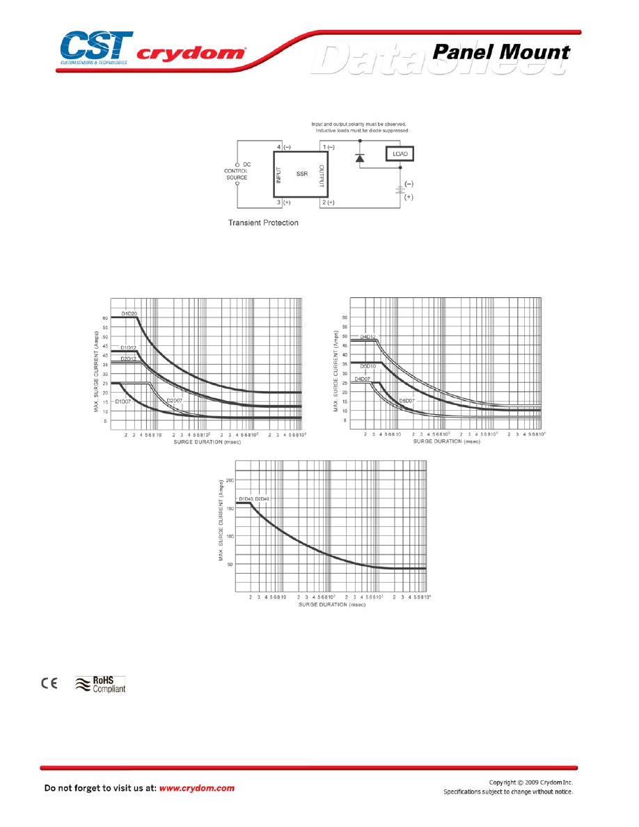
WIRING DIAGRAM
MAXIMUM SURGE VS DURATION
AGENCY APPROVALS
UL E116950 (100 Volt Models 1-DC Only )
Rev. 121608
Courtesy of Steven Engineering, Inc.-230 Ryan Way, South San Francisco, CA 94080-6370-Main Office: (650) 588-9200-Outside Local Area: (800) 258-9200-www.stevenengineering.com
60MAIN-html.html
Courtesy of Steven Engineering, Inc.-230 Ryan Way, South San Francisco, CA 94080-6370-Main Office: (650) 588-9200-Outside Local Area: (800) 258-9200-www.stevenengineering.com
60MAIN-html.html

ANNEX - ENVIROMENTAL INFORMATION
Courtesy of Steven Engineering, Inc.-230 Ryan Way, South San Francisco, CA 94080-6370-Main Office: (650) 588-9200-Outside Local Area: (800) 258-9200-www.stevenengineering.com
60MAIN-html.html
Series 1-DCL
• Optically Coupled MOSFET output
• Ratings from 7A to 40A @ 200 VDC, and from 7A to 10A @ 500 VDC
• DC Control
• Relays are easily paralleled for higher-current applications
PRODUCT SELECTION
Load Voltage
7A
10A
12A
20A
40A
100 VDC
D1D07L
D1D12L
D1D20L
D1D40L
200 VDC
D2D07L
D2D12L
D2D40L
400 VDC
D4D07L
D4D12L
500 VDC
D5D07L
D5D10L
OUTPUT SPECIFICATIONS (1)
Description
7A
12A
20A
40A
7A
12A
40A
7A
12A
7A
10A
Operating Voltage Range
0-100
0-100
0-100
0-100
0-200
0-200
0-200
0-400
0-400
0-500
0-500
Maximum Off-State Leakage Current @ Rated Voltage [mArms]
0.1
0.2
0.3
0.3
0.1
0.3
0.3
0.3
0.3
0.2
0.3
Maximum Load Current (3) [Adc]
7
12
20
40
7
12
40
7
12
7
10
Minimum Load Current [mA]
0
0
0
0
0
0
0
0
0
0
0
Maximum Surge Current (16.6ms) [Apk]
15
28
42
106
22
27
106
17
36
19
29
Maximum On-State Voltage Drop @ Rated Current [Vpk]
2.0
1.6
2.1
2.1
2.0
2.8
2.1
4.2
4.2
5.7
5.5
Thermal Resistance Junction to Case (Rjc) [°C/W]
2.2
1.34
1.06
0.83
1.5
1.06
0.83
1.06
0.8
1.0
0.8
Maximum On-State Resistance [RDS-ON][Ohms]
0.29
0.13
0.10
0.05
0.29
0.23
0.05
0.6
0.35
0.8
0.55
INPUT SPECIFICATIONS (1)
Description
Control Voltage Range
3.5-32 VDC
Maximum Turn-On Voltage
3.5 VDC
Minimum Turn-Off Voltage
1.0 VDC
Typical Input Current
10 mA
Nominal Input Impedance
See Note 4
Maximum Turn-On Time [µsec]
100
Maximum Turn-Off Time [msec]
1.0
GENERAL SPECIFICATIONS
Description
Parameters
Dielectric Strength, Input/Output/Base (50/60Hz)
2500 VRMS
Minimum Insulation Resistance (@ 500 V DC)
10
9
Ohm
Maximum Capacitance, Input/Output
50 pF
Ambient Operating Temperature Range
-20 to 80°C
Ambient Storage Temperature Range
-20 to 125 °C
Weight (typical)
3.0 oz (86.5g)
Encapsulation
Thermally conductive Epoxy
Terminals
Screws and Saddle Clamps Furnished, Unmounted
Recommended Terminal Screw Torque Range:
6-32 Screws - 10 in lbs. 8-32 and 10-32 Screws -20 in. lbs. (Screws dry without grase)
GENERAL NOTES
1) All parameters at 25°C and per section unless otherwise specified.
2) Dielectric strength and insulation resistance are measured between input and output
3) Heat sinking required, for derating curves see page 3.
4) Input circuitry version incorporates active current limiter.
Courtesy of Steven Engineering, Inc.-230 Ryan Way, South San Francisco, CA 94080-6370-Main Office: (650) 588-9200-Outside Local Area: (800) 258-9200-www.stevenengineering.com
60MAIN-html.html

MECHANICAL SPECIFICATIONS
THERMAL DERATE INFORMATION
Courtesy of Steven Engineering, Inc.-230 Ryan Way, South San Francisco, CA 94080-6370-Main Office: (650) 588-9200-Outside Local Area: (800) 258-9200-www.stevenengineering.com
60MAIN-html.html

WIRING DIAGRAM
MAXIMUM SURGE VS DURATION
AGENCY APPROVALS
UL E116950 (100 Volt Models 1-DC Only )
Rev. 121608
Courtesy of Steven Engineering, Inc.-230 Ryan Way, South San Francisco, CA 94080-6370-Main Office: (650) 588-9200-Outside Local Area: (800) 258-9200-www.stevenengineering.com
60MAIN-html.html

Courtesy of Steven Engineering, Inc.-230 Ryan Way, South San Francisco, CA 94080-6370-Main Office: (650) 588-9200-Outside Local Area: (800) 258-9200-www.stevenengineering.com
60MAIN-html.html

ANNEX - ENVIROMENTAL INFORMATION
Courtesy of Steven Engineering, Inc.-230 Ryan Way, South San Francisco, CA 94080-6370-Main Office: (650) 588-9200-Outside Local Area: (800) 258-9200-www.stevenengineering.com
60MAIN-html.html
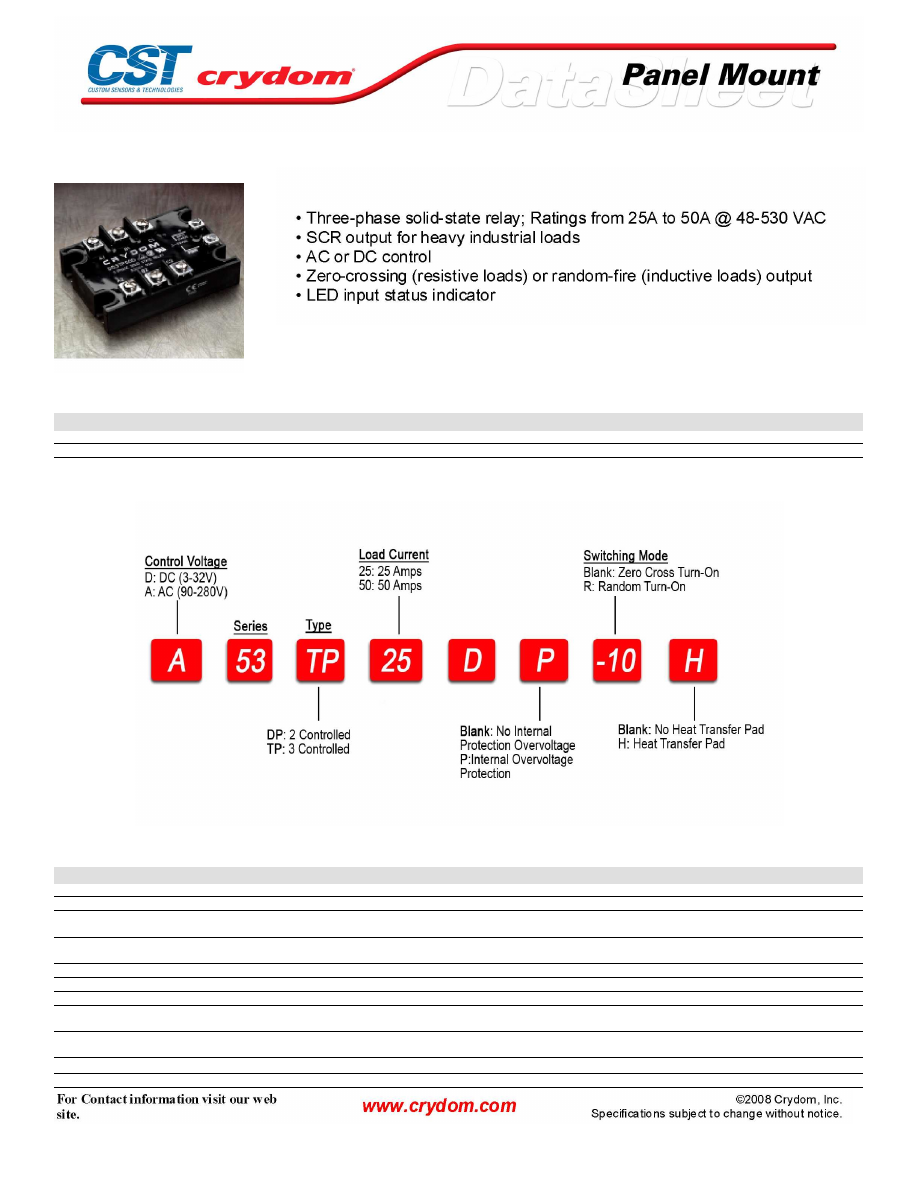
53TP Series
PRODUCT SELECTION
Control Voltage
25A
50A
3-32 VDC
D53TP25D
D53TP50D
90-280 VAC
A53TP25D
A53TP50D
AVAILABLE OPTIONS
OUTPUT SPECIFICATIONS (1)
Description
Operating Voltage (47-63Hz) [Vrms]
48-530
48-530
Transient Overvoltage [Vpk]
1200
1200
Maximum Off-State Leakage Current @
Rated Voltage [mArms]
10
10
Minimum Off-State dv/dt @ Maximum Rated
Voltage [V/µsec] (2)
500
500
Maximum Load Current (3) [Arms]
25
50
Minimum Load Current [Arms]
0.05
0.05
Maximum Surge Current (16.6ms) [Apk]
250
625
Maximum On-State Voltage Drop @ Rated
Current [Vpk]
1.6
1.6
Thermal Resistance Junction to Case (Rjc)
[°C/W]
1.02
0.63
Maximum I
2
t for Fusing (8.3 msec) [A
2
sec]
260
1620
Minimum Power Factor (with Maximum Load)
0.5
0.5
Courtesy of Steven Engineering, Inc.-230 Ryan Way, South San Francisco, CA 94080-6370-Main Office: (650) 588-9200-Outside Local Area: (800) 258-9200-www.stevenengineering.com
60MAIN-html.html
INPUT SPECIFICATIONS (1)
Description
Control Voltage Range
3-32 VDC
90-280 VAC
Maximum Turn-On Voltage
3.0 VDC
90 Vrms
Minimum Turn-Off Voltage
1.0 VDC
10 Vrms
Typical Input Current
10 mA @ 5 VDC
2.2 mA @ 120 Vrms, 4.4 mA @ 240 Vrms
Nominal Input Impedance
450 Ohm
54.8 k Ohm
Maximum Turn-On Time [msec] (4)
1/2 Cycle
10
Maximum Turn-Off Time [msec]
1/2 Cycle
40
GENERAL SPECIFICATIONS
Description
Parameters
Dielectric Strength, Input/Output/Base (50/60Hz)
4000 Vrms
Minimum Insulation Resistance (@ 500 V DC)
10
9
Ohm
Maximum Capacitance, Input/Output
8 pF
Ambient Operating Temperature Range
-40 to 80°C
Ambient Storage Temperature Range
-40 to 125 °C
Weight (typical)
10.3 oz (315g)
Encapsulation
Thermally conductive Epoxy
Terminals
Screws and Saddle Clamps Furnished, Unmounted
Recommended Terminal Screw Torque Range:
6-32 Screws - 10 in lbs. 8-32 and 10-32 Screws -20 in. lbs. Screws dry without grase)
Courtesy of Steven Engineering, Inc.-230 Ryan Way, South San Francisco, CA 94080-6370-Main Office: (650) 588-9200-Outside Local Area: (800) 258-9200-www.stevenengineering.com
60MAIN-html.html
MECHANICAL SPECIFICATIONS
THERMAL DERATE INFORMATION
AGENCY APPROVALS
Courtesy of Steven Engineering, Inc.-230 Ryan Way, South San Francisco, CA 94080-6370-Main Office: (650) 588-9200-Outside Local Area: (800) 258-9200-www.stevenengineering.com
60MAIN-html.html

Courtesy of Steven Engineering, Inc.-230 Ryan Way, South San Francisco, CA 94080-6370-Main Office: (650) 588-9200-Outside Local Area: (800) 258-9200-www.stevenengineering.com
60MAIN-html.html

ANNEX - ENVIROMENTAL INFORMATION
Courtesy of Steven Engineering, Inc.-230 Ryan Way, South San Francisco, CA 94080-6370-Main Office: (650) 588-9200-Outside Local Area: (800) 258-9200-www.stevenengineering.com
60MAIN-html.html
CMD/CMA24 Series
• Ratings from 25A to 125A @ 24-280 VAC
• SCR output for heavy industrial loads
• AC or DC control
• LED input status indicator
• Zero-crossing (resistive loads) or random-fire (inductive loads) output
• IP20 touch-safe housing
• Standard box-clamp connections
PRODUCT SELECTION
Control Voltage
25A
50A
75A
90A
110A
125A
3-32 VDC
CMD2425
CMD2450
CMD2475
CMD2490
CMD24110
CMD24125
90-140 VAC
CMA2425
CMA2450
CMA2475
CMA2490
CMA24110
CMA24125
18-36 VAC
CMA2425E
CMA2450E
CMA2475E
CMA2490E
CMA24110E
CMA24125E
AVAILABLE OPTIONS
OUTPUT SPECIFICATIONS (1)
Description
Operating Voltage (47-63Hz) [Vrms]
24-280
24-280
24-280
24-280
24-280
24-280
Transient Overvoltage [Vpk]
600
600
600
600
600
600
Maximum Off-State Leakage Current @ Rated Voltage [mArms]
10
10
10
10
10
10
Minimum Off-State dv/dt @ Maximum Rated Voltage [V/µsec] (2)
500
500
500
500
500
500
Maximum Load Current (3) [Arms]
25
50
75
90
110
125
Minimum Load Current [Arms]
0.15
0.15
0.25
0.25
0.25
0.025
Maximum Surge Current (16.6ms) [Apk]
250
625
1000
1200
1500
1750
Maximum On-State Voltage Drop @ Rated Current [Vpk]
1.6
1.6
1.6
1.6
1.6
1.6
Thermal Resistance Junction to Case (Rjc) [°C/W]
1.02
0.63
0.31
0.28
0.25
0.22
Maximum I
2
t for Fusing (8.3 msec) [A
2
sec]
260
1620
4150
6000
9340
12700
Minimum Power Factor (with Maximum Load)
0.5
0.5
0.5
0.5
0.5
0.5
For Contact information visit our web
site.
www.crydom.com
©2008 Crydom, Inc.
Specifications subject to change without notice.
Courtesy of Steven Engineering, Inc.-230 Ryan Way, South San Francisco, CA 94080-6370-Main Office: (650) 588-9200-Outside Local Area: (800) 258-9200-www.stevenengineering.com
60MAIN-html.html

INPUT SPECIFICATIONS (1)
Description
Control Voltage Range
3-32 VDC
90-140 Vrms
Maximum Reverse Voltage
32 VDC
-
Minimum Turn-On Voltage
3.0 VDC
90 Vrms
Minimum Turn-Off Voltage
1.0 VDC
10 Vrms
Maximum Input Current
30 mA
-
Typical Input current
17 mA @ 5 VDC
15 mA @ 120 Vrms
Maximum Turn-On Time [msec] (4)
1/2 Cycle
10
Maximum Turn-Off Time [msec]
1/2 Cycle
40
GENERAL SPECIFICATIONS
Description
Parameters
Dielectric Strength, Input/Output/Base (50/60Hz)
4000 Vrms
Minimum Insulation Resistance (@ 500 VDC)
10
9
Ohm
Maximum Capacitance, Input/Output
8 pF
Ambient Operating Temperature Range
-40 to 80 °C
Ambient Storage Temperature Range
-40 to 125 °C
Status Indicating Display
Green LED
Weight (typical)
3.0 oz (86.5 g)
Encapsulation
Thermally conductive Epoxy
Terminals
Cage type
Maximum Wire Size-Output:
AWG 8 (3.8mm)
Maximum Wire Size-Input:
AWG 12 (2.5mm)
Recommended Terminal Screw Torque Range:
Output: 10-15 in lb (1.1-1.7 Nm)
Input: 5-6 in lb (0.6-0.7 Nm)
GENERAL NOTES
1) All parameters at 25°C unless otherwise specified.
2) Off-State dv/dt test method per EIA/NARM standard RS-443, paragraph 13.11.1
3) HEAT SINKING REQUIRED, FOR DERATING curves see page 2.
4) Turn-on time for DC control random turn-on versions is 0.02msec
5) Input circuitry incorporates active current limiter
For Contact information visit our web
site.
www.crydom.com
©2008 Crydom, Inc.
Specifications subject to change without notice.
Courtesy of Steven Engineering, Inc.-230 Ryan Way, South San Francisco, CA 94080-6370-Main Office: (650) 588-9200-Outside Local Area: (800) 258-9200-www.stevenengineering.com
60MAIN-html.html
MECHANICAL SPECIFICATIONS
THERMAL DERATE INFORMATION
AGENCY APPROVALS
UL E116949, E116950
CSA LR81689
VDE 126921 UG (up to 90A models only)
Rev. 062508
For Contact information visit our web
site.
www.crydom.com
©2008 Crydom, Inc.
Specifications subject to change without notice.
Courtesy of Steven Engineering, Inc.-230 Ryan Way, South San Francisco, CA 94080-6370-Main Office: (650) 588-9200-Outside Local Area: (800) 258-9200-www.stevenengineering.com
60MAIN-html.html

ANNEX - ENVIROMENTAL INFORMATION
For Contact information visit our web
site.
www.crydom.com
©2008 Crydom, Inc.
Specifications subject to change without notice.
Courtesy of Steven Engineering, Inc.-230 Ryan Way, South San Francisco, CA 94080-6370-Main Office: (650) 588-9200-Outside Local Area: (800) 258-9200-www.stevenengineering.com
60MAIN-html.html

CMD / CMA48 Series
• Ratings from 25A to 125A @ 48-530 VAC
• SCR output for heavy industrial loads
• AC or DC control
• LED input status indicator
• Zero-crossing (resistive loads) or random-fire (inductive loads) output
• IP20 touch-safe housing
• Standard box-clamp connections
PRODUCT SELECTION
Control Voltage
25A
50A
75A
90A
110A
125A
4-32 VDC
CMD4825
CMD4850
CMD4875
CMD4890
CMD48110
CMD48125
90-140 VAC
CMA4825
CMA4850
CMA4875
CMA4890
CMA48110
CMA48125
18-36 VAC
CMA4825E
CMA4850E
CMA2475E
CMA4890E
CMA48110E
CMA48125E
AVAILABLE OPTIONS
OUTPUT SPECIFICATIONS (1)
Description
Operating Voltage (47-63Hz) [Vrms]
48-530
48-530
48-530
48-530
48-530
48-530
Transient Overvoltage [Vpk]
1200
1200
1200
1200
1200
1200
Maximum Off-State Leakage Current @ Rated Voltage [mArms]
10
10
10
10
10
10
Minimum Off-State dv/dt @ Maximum Rated Voltage [V/µsec] (2)
500
500
500
500
500
500
Maximum Load Current (3) [Arms]
25
50
75
90
110
125
Minimum Load Current [Arms]
0.15
0.15
0.25
0.25
0.25
0.025
Maximum Surge Current (16.6ms) [Apk]
250
625
1000
1200
1500
1750
Maximum On-State Voltage Drop @ Rated Current [Vpk]
1.6
1.6
1.6
1.6
1.6
1.6
Thermal Resistance Junction to Case (Rjc) [°C/W]
1.02
0.63
0.31
0.28
0.25
0.22
Maximum I
2
t for Fusing (8.3 msec) [A
2
sec]
260
1620
4150
6000
9340
12700
Minimum Power Factor (with Maximum Load)
0.5
0.5
0.5
0.5
0.5
0.5
For Contact information visit our web
site.
www.crydom.com
©2008 Crydom, Inc.
Specifications subject to change without notice.
Courtesy of Steven Engineering, Inc.-230 Ryan Way, South San Francisco, CA 94080-6370-Main Office: (650) 588-9200-Outside Local Area: (800) 258-9200-www.stevenengineering.com
60MAIN-html.html
INPUT SPECIFICATIONS (1)
Description
Control Voltage Range
3-32 VDC
90-140 Vrms
Maximum Reverse Voltage
32 VDC
-
Minimum Turn-On Voltage
3.0 VDC
90 Vrms
Minimum Turn-Off Voltage
1.0 VDC
10 Vrms
Maximum Input Current
30 mA (5)
-
Typical Input current
17 mA @ 5 VDC
15 mA @ 120 Vrms
Maximum Turn-On Time [msec] (4)
1/2 Cycle
10
Maximum Turn-Off Time [msec]
1/2 Cycle
40
GENERAL SPECIFICATIONS
Description
Parameters
Dielectric Strength, Input/Output/Base (50/60Hz)
4000 Vrms
Minimum Insulation Resistance (@ 500 VDC)
10
9
Ohm
Maximum Capacitance, Input/Output
8 pF
Ambient Operating Temperature Range
-40 to 80 °C
Ambient Storage Temperature Range
-40 to 125 °C
Status Indicating Display
Green LED
Weight (typical)
3.0 oz (86.5 g)
Encapsulation
Thermally conductive Epoxy
Terminals
Cage type
Maximum Wire Size-Output:
AWG 8 (3.8mm)
Maximum Wire Size-Input:
AWG 12 (2.5mm)
Recommended Terminal Screw Torque Range:
Output: 10-15 in lb (1.1-1.7 Nm)
Input: 5-6 in lb (0.6-0.7 Nm)
GENERAL NOTES
1) All parameters at 25°C unless otherwise specified.
2) Off-State dv/dt test method per EIA/NARM standard RS-443, paragraph 13.11.1
3) HEAT SINKING REQUIRED, FOR DERATING curves see page 2.
4) Turn-on time for DC control random turn-on versions is 0.02msec
5) Input circuitry incorporates active current limiter.
For Contact information visit our web
site.
www.crydom.com
©2008 Crydom, Inc.
Specifications subject to change without notice.
Courtesy of Steven Engineering, Inc.-230 Ryan Way, South San Francisco, CA 94080-6370-Main Office: (650) 588-9200-Outside Local Area: (800) 258-9200-www.stevenengineering.com
60MAIN-html.html
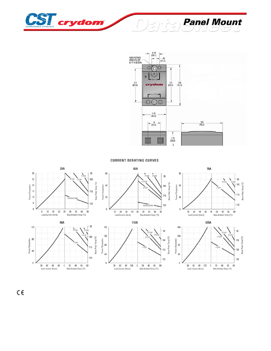
MECHANICAL SPECIFICATIONS
THERMAL DERATE INFORMATION
AGENCY APPROVALS
CSA LR81689
VDE 126921 UG (up to 90A models only)
Rev. 070808
For Contact information visit our web
site.
www.crydom.com
©2008 Crydom, Inc.
Specifications subject to change without notice.
Courtesy of Steven Engineering, Inc.-230 Ryan Way, South San Francisco, CA 94080-6370-Main Office: (650) 588-9200-Outside Local Area: (800) 258-9200-www.stevenengineering.com
60MAIN-html.html

ANNEX - ENVIROMENTAL INFORMATION
For Contact information visit our web
site.
www.crydom.com
©2008 Crydom, Inc.
Specifications subject to change without notice.
Courtesy of Steven Engineering, Inc.-230 Ryan Way, South San Francisco, CA 94080-6370-Main Office: (650) 588-9200-Outside Local Area: (800) 258-9200-www.stevenengineering.com
60MAIN-html.html

CMD / CMA60 Series
• Ratings from 25A to 125A @ 48-660 VAC
• SCR output for heavy industrial loads
• AC or DC control
• LED input status indicator
• Zero-crossing (resistive loads) or random-fire (inductive loads) output
• IP20 touch-safe housing
• Standard box-clamp connections
• Ratings from 25A to 125A @ 48-660 VAC
PRODUCT SELECTION
Control Voltage
25A
50A
75A
90A
110A
125A
4-32 VDC
CMD6025
CMD6050
CMD6075
CMD6090
CMD60110
CMD60125
90-140 Vrms
CMA6025
CMA6050
CMA6075
CMA6090
CMA60110
CMA60125
18-36 Vrms
CMA6025E
CMA6050E
CMA6075E
CMA6090E
CMA60110E
CMA60125E
AVAILABLE OPTIONS
OUTPUT SPECIFICATIONS (1)
Description
Operating Voltage (47-63Hz) [Vrms]
48-660
48-660
48-660
48-660
48-660
48-660
Transient Overvoltage [Vpk]
1200
1200
1200
1200
1200
1200
Maximum Off-State Leakage Current @ Rated Voltage [mArms]
1.0
1.0
1.0
1.0
1.0
1.0
Minimum Off-State dv/dt @ Maximum Rated Voltage [V/µsec] (2)
500
500
500
500
500
500
Maximum Load Current (3) [Arms]
25
50
75
90
110
125
Minimum Load Current [Arms]
0.15
0.15
0.25
0.25
0.25
0.025
Maximum Surge Current (16.6ms) [Apk]
250
625
1000
1200
1500
1750
Maximum On-State Voltage Drop @ Rated Current [Vpk]
1.6
1.6
1.6
1.6
1.6
1.6
Thermal Resistance Junction to Case (Rjc) [°C/W]
1.02
0.63
0.31
0.28
0.25
0.22
Maximum I
2
t for Fusing (8.3 msec) [A
2
sec]
260
1620
4150
6000
9340
12700
Minimum Power Factor (with Maximum Load)
0.5
0.5
0.5
0.5
0.5
0.5
For Contact information visit our web
site.
www.crydom.com
©2008 Crydom, Inc.
Specifications subject to change without notice.
Courtesy of Steven Engineering, Inc.-230 Ryan Way, South San Francisco, CA 94080-6370-Main Office: (650) 588-9200-Outside Local Area: (800) 258-9200-www.stevenengineering.com
60MAIN-html.html

INPUT SPECIFICATIONS (1)
Description
Control Voltage Range
3-32 VDC
90-140 Vrms
Maximum Reverse Voltage
32 VDC
-
Minimum Turn-On Voltage
3.0 VDC
90 Vrms
Minimum Turn-Off Voltage
1.0 VDC
10 Vrms
Maximum Input Current
30 mA(5)
-
Typical Input current
17 mA @ 5 VDC
15 mA @ 120 Vrms
Maximum Turn-On Time [msec] (4)
1/2 Cycle
10
Maximum Turn-Off Time [msec]
1/2 Cycle
40
GENERAL SPECIFICATIONS
Description
Parameters
Dielectric Strength, Input/Output/Base (50/60Hz)
4000 Vrms
Minimum Insulation Resistance (@ 500 VDC)
10
9
Ohm
Maximum Capacitance, Input/Output
8 pF
Ambient Operating Temperature Range
-40 to 80 °C
Ambient Storage Temperature Range
-40 to 125 °C
Status Indicating Display
Green LED
Weight (typical)
3.0 oz (86.5 g)
Encapsulation
Thermally conductive Epoxy
Terminals
Cage type
Maximum Wire Size-Output:
AWG 8 (3.8mm)
Maximum Wire Size-Input:
AWG 12 (2.5mm)
Recommended Terminal Screw Torque Range:
Output: 10-15 in lb (1.1-1.7 Nm)
Input: 5-6 in lb (0.6-0.7 Nm)
GENERAL NOTES
1) All parameters at 25°C unless otherwise specified.
2) Off-State dv/dt test method per EIA/NARM standard RS-443, paragraph 13.11.1
3) HEAT SINKING REQUIRED, FOR DERATING curves see page 2.
4) Turn-on time for DC control random turn-on versions is 0.02msec
5) Input circuitry incorporates active current limiter.
For Contact information visit our web
site.
www.crydom.com
©2008 Crydom, Inc.
Specifications subject to change without notice.
Courtesy of Steven Engineering, Inc.-230 Ryan Way, South San Francisco, CA 94080-6370-Main Office: (650) 588-9200-Outside Local Area: (800) 258-9200-www.stevenengineering.com
60MAIN-html.html

MECHANICAL SPECIFICATIONS
THERMAL DERATE INFORMATION
AGENCY APPROVALS
UL E116949, E116950
CSA LR 81689
VDE 126921 UG (up to 90A models only)
R ev. 062508
For Contact information visit our web
site.
www.crydom.com
©2008 Crydom, Inc.
Specifications subject to change without notice.
Courtesy of Steven Engineering, Inc.-230 Ryan Way, South San Francisco, CA 94080-6370-Main Office: (650) 588-9200-Outside Local Area: (800) 258-9200-www.stevenengineering.com
60MAIN-html.html

ANNEX - ENVIROMENTAL INFORMATION
For Contact information visit our web
site.
www.crydom.com
©2008 Crydom, Inc.
Specifications subject to change without notice.
Courtesy of Steven Engineering, Inc.-230 Ryan Way, South San Francisco, CA 94080-6370-Main Office: (650) 588-9200-Outside Local Area: (800) 258-9200-www.stevenengineering.com
60MAIN-html.html
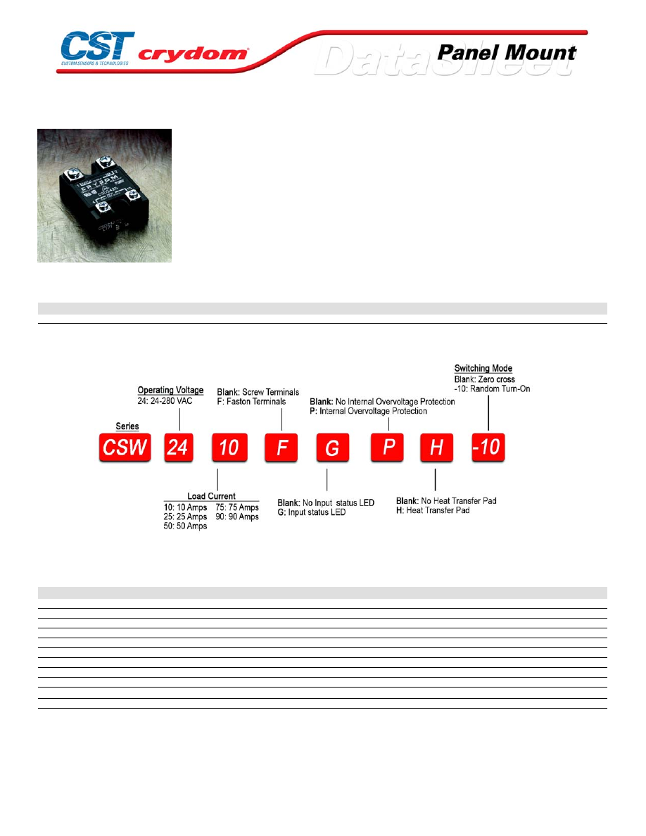
CSW Series
• Ratings from 10A to 90A @ 12-280 V AC
• 3-32 V DC input range
• Low off-state leakage current (snubberless)
• SCR output for heavy industrial loads
• Replaces the popular CSD/CSE series relays
PRODUCT SELECTION
Control Voltage
10A
25A
50A
75A
90A
3-32 VDC
CSW2410
CSW2425
CSW2450
CSW2475
CSW2490
AVAILABLE OPTIONS
OUTPUT SPECIFICATIONS (1)
Description
Operating Voltage (47-63Hz) [Vrms]
24-280
24-280
24-280
24-280
24-280
Transient Overvoltage [Vpk]
600
600
600
600
600
Maximum Off-State Leakage Current @ Rated Voltage [mArms]
1.0
1.0
1.0
1.0
1.0
Minimum Off-State dv/dt @ Maximum Rated Voltage [V/µsec] (2)
500
500
500
500
500
Maximum Load Current (3) [Arms]
10
25
50
75
90
Minimum Load Current [Arms]
0.15
0.15
0.15
0.25
0.25
Maximum Surge Current (16.6ms) [Apk]
120
250
625
1000
1200
Maximum On-State Voltage Drop @ Rated Current [Vpk]
1.6
1.6
1.6
1.6
1.6
Thermal Resistance Junction to Case (Rjc) [°C/W]
1.48
1.02
0.63
0.31
0.28
Maximum I
2
t for Fusing (8.3 msec) [A
2
sec]
60
260
1620
4150
6000
Minimum Power Factor (with Maximum Load)
0.5
0.5
0.5
0.5
0.5
For Contact information visit our web
site.
www.crydom.com
©2008 Crydom, Inc.
Specifications subject to change without notice.
Courtesy of Steven Engineering, Inc.-230 Ryan Way, South San Francisco, CA 94080-6370-Main Office: (650) 588-9200-Outside Local Area: (800) 258-9200-www.stevenengineering.com
60MAIN-html.html

INPUT SPECIFICATIONS (1)
Description
Control Voltage Range
3-32 VDC
Minimum Turn-On Voltage
3 VDC
Minimum Turn-Off Voltage
1.0 VDC
Typical Input Current
10 mA @ 12 VDC
Nominal Input Impedance
See note 4
Maximum Turn-On Time [msec] (4)
1/2 Cycle
Maximum Turn-Off Time [msec]
1/2 Cycle
GENERAL SPECIFICATIONS
Description
Parameters
Dielectric Strength, Input/Output/Base (50/60Hz)
4000 Vrms
Minimum Insulation Resistance (@ 500 V DC)
10
9
Ohm
Maximum Capacitance, Input/Output
10 pF
Ambient Operating Temperature Range
-40 to 80 °C
Ambient Storage Temperature Range
-40 to 125 °C
Weight (typical)
3.0 oz (86.5 g)
Encapsulation
Thermally conductive Epoxy
Terminals
Srews and Saddle Clamps Furnished, Unmounted
Recommended Terminal Screw Torque Range:
6-32 Screws - 10 in/lbs. 8-32 & 10-32 Screws - 20 in. lbs. (Screws dry without grease)
Fastons:
Single pair (up to 25A) Double pair* (up to 50A). *Caution: User must connect to both pairs
GENERAL NOTES
1) All parameters at 25°C unless otherwise specified.
2) Off-State dv/dt test method per EIA/NARM standard R S-443, paragraph 13.11.1
3) H eat sinking required, for derating curves see page 2.
4) Turn-on time f or random turn-on version (-10 suffix) is 0.1ms
For Contact information visit our web
site.
www.crydom.com
©2008 Crydom, Inc.
Specifications subject to change without notice.
Courtesy of Steven Engineering, Inc.-230 Ryan Way, South San Francisco, CA 94080-6370-Main Office: (650) 588-9200-Outside Local Area: (800) 258-9200-www.stevenengineering.com
60MAIN-html.html
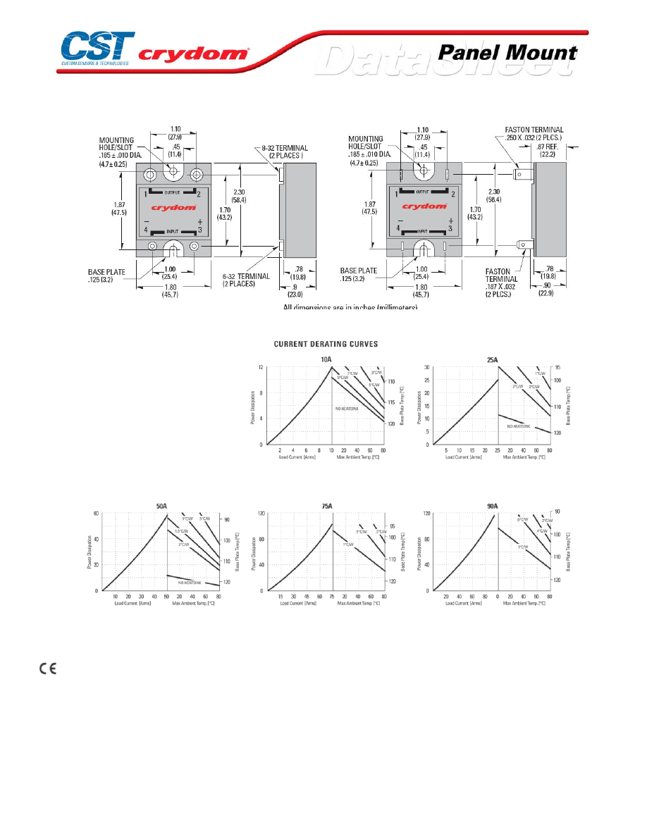
MECHANICAL SPECIFICATIONS
THERMAL DERATE INFORMATION
AGENCY APPROVALS
UL E116949
CSA LR81689
VDE 10143 UG
Rev. 070908
For Contact information visit our web
site.
www.crydom.com
©2008 Crydom, Inc.
Specifications subject to change without notice.
Courtesy of Steven Engineering, Inc.-230 Ryan Way, South San Francisco, CA 94080-6370-Main Office: (650) 588-9200-Outside Local Area: (800) 258-9200-www.stevenengineering.com
60MAIN-html.html
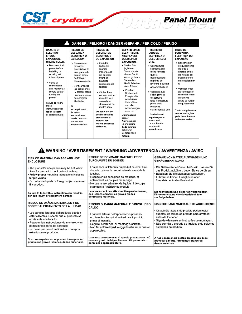
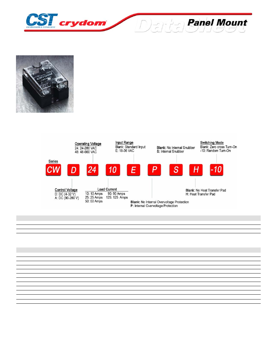
CW24 Series
• The newest family to the SSR range; Ratings from 10A to 125A @
12-660 V AC
• SCR output for heavy industrial loads
• EMC Compliant for reliable operation in harsh environments
• Removable IP 20 touch-safe cover
• DBC substrate for superior thermal performance
• LED input status indicator
• AC or DC input
• Zero-crossing (resistive loads) or random-fire (inductive loads) output
PRODUCT SELECTION
Description
10A
25A
50A
90A
125A
3-32 VDC
CWD2410
CWD2425
CWD2450
CWD2490
CWD24125
90-280 Vrms
CWA2410
CWA2425
CWA2450
CWA2490
CWA24125
18-36 Vrms
CWA2410E
CWA2425E
CWA2450E
CWA2490E
CWA24125E
OUTPUT SPECIFICATIONS (1)
Description
Operating Voltage (47-63Hz) [Vrms]
24-280
24-280
24-280
24-280
24-280
Transient Overvoltage [Vpk]
600
600
600
600
600
Maximum Off-State Leakage Current @ Rated Voltage [mArms](6)
1
1
1
1
1
Minimum Off-State dv/dt @ Maximum Rated Voltage [V/µsec] (2)
500
500
500
500
500
Maximum Load Current (3) [Arms]
10
25
50
90
125
Minimum Load Current [Arms]
0.15
0.15
0.15
0.25
0.25
Maximum Surge Current (16.6ms) [Apk]
400
600
850
1350
2000
Maximum Surge Current (20ms) [Apk]
380
570
810
1290
1900
Maximum On-State Voltage Drop @ Rated Current [Vpk]
1.3
1.3
1.3
1.3
1.25
Thermal Resistance Junction to Case (Rjc) [°C/W]
0.35
0.35
0.2
0.14
0.13
Maximum I
2
t for Fusing (8.3 msec) [A
2
sec]
660
1500
3000
7560
16600
Minimum Power Factor (with Maximum Load)
0.5
0.5
0.5
0.5
0.5
For Contact information visit our web
site.
www.crydom.com
©2008 Crydom, Inc.
Specifications subject to change without notice.
Courtesy of Steven Engineering, Inc.-230 Ryan Way, South San Francisco, CA 94080-6370-Main Office: (650) 588-9200-Outside Local Area: (800) 258-9200-www.stevenengineering.com
60MAIN-html.html

INPUT SPECIFICATIONS (1)
Description
Control Voltage Range
3-32 VDC
90-280 Vrms
18-36 Vrms
Minimum Turn-On Voltage
3 VDC
90 Vrms
18 Vrms
Minimum Turn-Off Voltage
1.0 VDC
10 Vrms
2 Vrms
Typical Input Current
10 mA @ 12 VDC
6 mA @ 120 Vrms
24 mA @ 24 Vrms
Nominal Input Impedance
See note 7
21.5 Ohms
1.0 Ohm
Maximum Turn-On Time [msec] (4)(5)
1/2 Cycle
1/2 Cycle
1/2 Cycle
Maximum Turn-Off Time [msec] (5)
1/2 Cycle
1/2 Cycle
1/2 Cycle
GENERAL SPECIFICATIONS
Description
Parameters
Dielectric Strength, Input/Output/Base (50/60Hz)
4000 Vrms
Minimum Insulation Resistance (@ 500 VDC)
10
9
Ohm
Maximum Capacitance, Input/Output
8 pF
Ambient Operating Temperature Range
-40 to 80 °C
Ambient Storage Temperature Range
-40 to 125 °C
Weight (typical)
3.0 oz (86.5 g)
Encapsulation
Thermally conductive Epoxy
Terminals
Screw Type, Finger Proof Output: 8-32, Combo Drive Input: 6-32, Combo Drive
Max. Torque
Output: 20 in lb (2.2Nm) Input: 10 in lb (1.1Nm)
Max. Wire Size
Output:2 x AWG 8 (3.8mm) Input: 2 x AWG 12 (2.5mm)
GENERAL NOTES
1) All parameters at 25°C unless otherwise specified.
2) Off-State dv/dt test method per EIA/NARM standard RS-443, paragraph 13.11.1
3) Heat sinking required, for derating c urves see page 2.
4) Turn-on time for random turn-on version is 0.02 msec.
5) Turn-on and turn-off time for AC input models is 50 ms.
6) 10mA for models with snubber.
7) Input circuit incorporates active current limiter.
For Contact information visit our web
site.
www.crydom.com
©2008 Crydom, Inc.
Specifications subject to change without notice.
Courtesy of Steven Engineering, Inc.-230 Ryan Way, South San Francisco, CA 94080-6370-Main Office: (650) 588-9200-Outside Local Area: (800) 258-9200-www.stevenengineering.com
60MAIN-html.html

MECHANICAL SPECIFICATIONS
EMC Compatibility
Input: EN61000-4-2, Level 3 ESD
EN61000-4-4, Level 3 Burst
Output: EN61000-4-2, Level 3 ESD
Level 4 ESD (with P option)
EN61000-4-4, Level 3 Burst
Level 4 Burst (with P option)
EN61000-4-5, Level 4 Surge
THERMAL DERATE INFORMATION
AGENCY APPROVALS
UL E116949
CSA 1405925
VDE 40007242
Rev. 062508
For Contact information visit our web
site.
www.crydom.com
©2008 Crydom, Inc.
Specifications subject to change without notice.
Courtesy of Steven Engineering, Inc.-230 Ryan Way, South San Francisco, CA 94080-6370-Main Office: (650) 588-9200-Outside Local Area: (800) 258-9200-www.stevenengineering.com
60MAIN-html.html

For Contact information visit our web
site.
www.crydom.com
©2008 Crydom, Inc.
Specifications subject to change without notice.
Courtesy of Steven Engineering, Inc.-230 Ryan Way, South San Francisco, CA 94080-6370-Main Office: (650) 588-9200-Outside Local Area: (800) 258-9200-www.stevenengineering.com
60MAIN-html.html
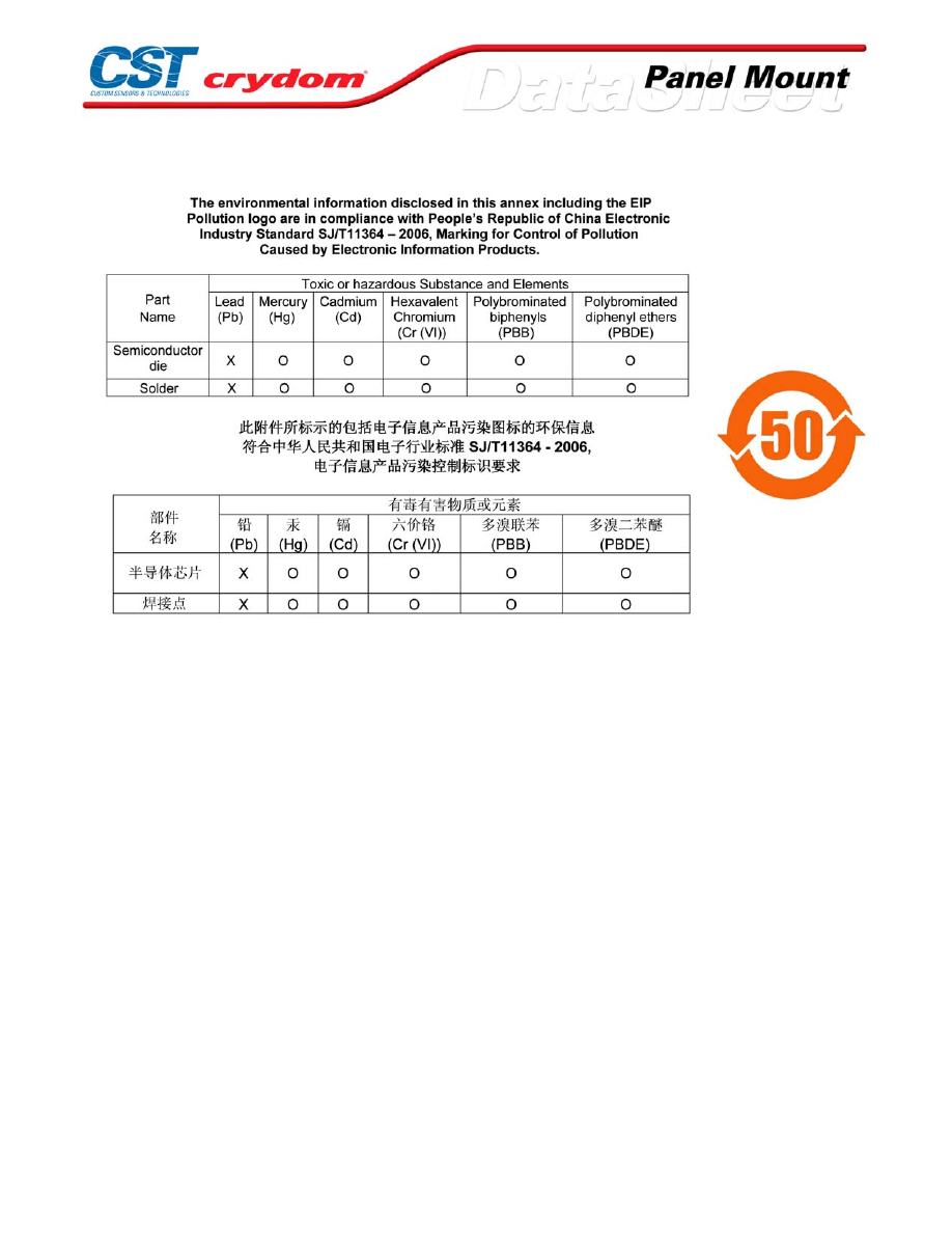
ANNEX - ENVIROMENTAL INFORMATION
For Contact information visit our web
site.
www.crydom.com
©2008 Crydom, Inc.
Specifications subject to change without notice.
Courtesy of Steven Engineering, Inc.-230 Ryan Way, South San Francisco, CA 94080-6370-Main Office: (650) 588-9200-Outside Local Area: (800) 258-9200-www.stevenengineering.com
60MAIN-html.html
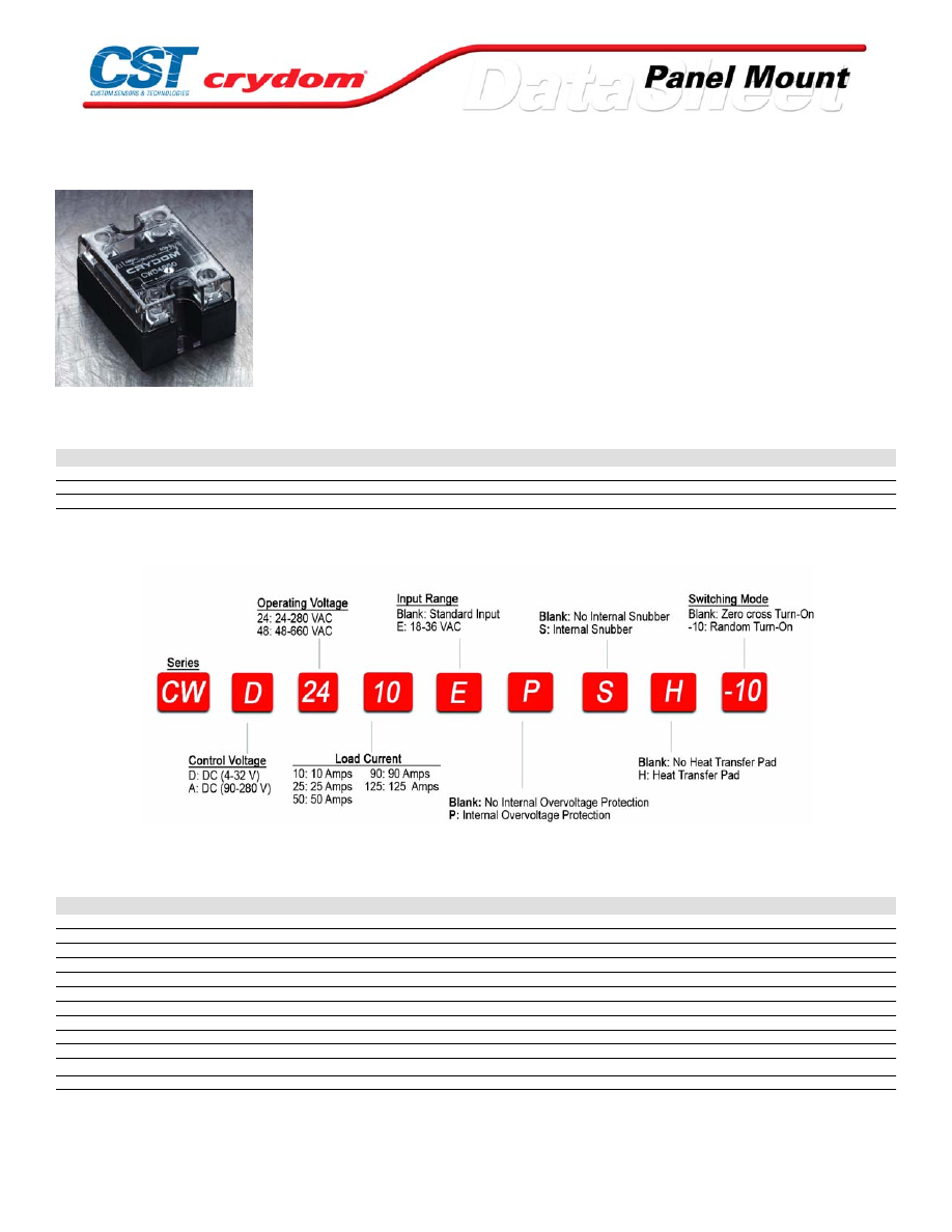
CW48 Series
• The newest family to the SSR range; Ratings from 10A to 125A @
12-660 VAC
• SCR output for heavy industrial loads
• EMC Compliant for reliable operation in harsh environments
• Removable IP 20 touch-safe cover
• DBC substrate for superior therm al performance
• LED input status indicator
• AC or DC input
PRODUCT SELECTION
Control Voltage
10A
25A
50A
90A
125A
3-32 VDC
CWD4810
CWD4825
CWD4850
CWD4890
CWD48125
90-280 Vrms
CWA4810
CWA4825
CWA4850
CWA4890
CWA48125
18-36 Vrms
CWA4810E
CWA4825E
CWA4850E
CWA4890E
CWA48125E
AVAILABLE OPTIONS
OUTPUT SPECIFICATIONS (1)
Description
Operating Voltage (47-63Hz) [Vrms]
48-660
48-660
48-660
48-660
48-660
Transient Overvoltage [Vpk]
1200
1200
1200
1200
1200
Maximum Off-State Leakage Current @ Rated Voltage [mArms](6)
1.0
1.0
1.0
1.0
1.0
Minimum Off-State dv/dt @ Maximum Rated Voltage [V/µsec] (2)
500
500
500
500
500
Maximum Load Current (3) [Arms]
10
25
50
90
125
Minimum Load Current [Arms]
0.15
0.15
0.15
0.25
0.25
Maximum Surge Current (16.6ms) [Apk]
400
600
850
1350
2000
Maximum Surge Current (20ms) [Apk]
380
570
810
1290
1900
Maximum On-State Voltage Drop @ Rated Current [Vpk]
1.3
1.3
1.3
1.3
1.25
Thermal Resistance Junction to Case (Rjc) [°C/W]
0.35
0.35
0.2
0.14
0.13
Maximum I
2
t for Fusing (8.3 msec) [A
2
sec]
660
1500
3000
7560
16600
Minimum Power Factor (with Maximum Load)
0.5
0.5
0.5
0.5
0.5
For Contact information visit our web
site.
www.crydom.com
©2008 Crydom, Inc.
Specifications subject to change without notice.
Courtesy of Steven Engineering, Inc.-230 Ryan Way, South San Francisco, CA 94080-6370-Main Office: (650) 588-9200-Outside Local Area: (800) 258-9200-www.stevenengineering.com
60MAIN-html.html

INPUT SPECIFICATIONS (1)
Description
Control Voltage Range
3-32 VDC
18-36 Vrms
90-280 Vrms
Minimum Turn-On Voltage
3 VDC
18 Vrms
90 Vrms
Minimum Turn-Off Voltage
1 .0 VDC
2 Vrms
10 Vrms
Typical Input Current
10 mA @ 12 VDC
24 mA @ 24 Vrms
6 mA @ 120 Vrms
Nominal Input Impedance
See note 7
1.0 k Ohm
21.5 k Ohms
Maximum Turn-On Time [msec] (4)(5)
1/2 Cycle
1/2 Cycle
1/2 Cycle
Maximum Turn-Off Time [msec] (5)
1/2 Cycle
1/2 Cycle
1/2 Cycle
GENERAL SPECIFICATIONS
Description
Parameters
Dielectric Strength, Input/Output/Base (50/60Hz)
4000 Vrms
Minimum Insulation Resistance (@ 500 V DC)
10
9
Ohm
Maximum Capacitance, Input/Output
8 pF
Ambient Operating Temperature Range
-40 to 80 °C
Ambient Storage Temperature Range
-40 to 125 °C
Weight (typical)
3.0 oz (86.5 g)
Encapsulation
Thermally conductive Epoxy
Terminals
Screw Type, Finger Proof Output: 8-32, Combo rive Input: 6-32, Combo Drive
Max. Torque
Output: 20 in lb (2.2Nm) Input: 10 in lb (1.1Nm)
Max. Wire Size
Output:2 x AWG 8 (3.8mm) Input: 2 x AWG 12 (2.5mm)
GENERAL NOTES
1) All parameters at 25°C unless otherwise specified.
2) Off-State dv/dt test method per EIA/NARM standard RS-443, paragraph 13.11.1
3) Heat sinking required, for derating curves see page 2.
4) Turn-on time for random turn-on version is 0.02 msec.
5) Turn-on and turn-off time for AC input models is 50 ms.
6) 10mA for models with snubber.
7) Input circuit incorporates active current limiter.
8) 48-530 VRMS for models with snubber.
For Contact information visit our web
site.
www.crydom.com
©2008 Crydom, Inc.
Specifications subject to change without notice.
Courtesy of Steven Engineering, Inc.-230 Ryan Way, South San Francisco, CA 94080-6370-Main Office: (650) 588-9200-Outside Local Area: (800) 258-9200-www.stevenengineering.com
60MAIN-html.html
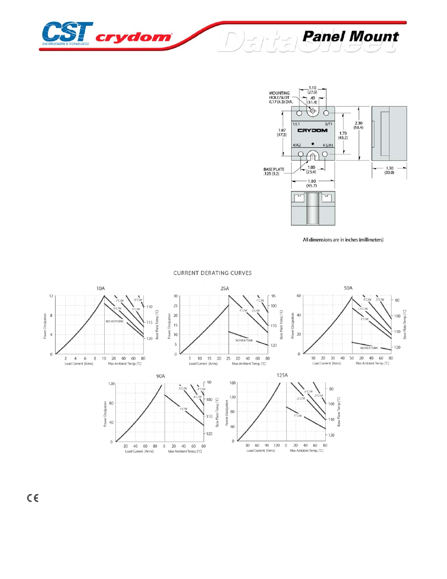
MECHANICAL SPECIFICATIONS
EMC Compatibility
Input: EN61000-4-2, Level 3 ESD
EN61000-4-4, Level 3 Burst
Output: EN61000-4-2, Level 3 ESD
Level 4 ESD (with P option)
EN61000-4-4, Level 3 Burst
Level 4 Burst (with P option)
EN61000-4-5, Level 4 Surge
THERMAL DERATE INFORMATION
AGENCY APPROVALS
UL E116949
CSA 1405925
VDE 40007242
Rev. 071008
For Contact information visit our web
site.
www.crydom.com
©2008 Crydom, Inc.
Specifications subject to change without notice.
Courtesy of Steven Engineering, Inc.-230 Ryan Way, South San Francisco, CA 94080-6370-Main Office: (650) 588-9200-Outside Local Area: (800) 258-9200-www.stevenengineering.com
60MAIN-html.html

ANNEX - ENVIROMENTAL INFORMATION
For Contact information visit our web
site.
www.crydom.com
©2008 Crydom, Inc.
Specifications subject to change without notice.
Courtesy of Steven Engineering, Inc.-230 Ryan Way, South San Francisco, CA 94080-6370-Main Office: (650) 588-9200-Outside Local Area: (800) 258-9200-www.stevenengineering.com
60MAIN-html.html
D06D Series
• MOSFET output
• Ratings from 60A to 100A @ 60 VDC
• DC control
• Relays are easily paralleled for higher-current applications
PRODUCT SELECTION
Control Voltage
60A
80A
100A
3.5-32 VDC
D06D60
D06D80
D06D100
OUTPUT SPECIFICATIONS (1)
Description
Operating Voltage (47-63Hz) [Vrms]
0-60 VDC
0-60 VDC
0-60 VDC
Maximum Off-State Leakage Current @ Rated Voltage [mArms]
0.1
0.2
0.3
Maximum On-State Resistance @ Rated Current [RDS-ON][Ohms]
0.010
0.008
0.005
Maximum Load Current (3) [Arms]
60
80
100
Minimum Load Current [mArms]
5
5
5
Maximum Surge Current (16.6ms) [Apk]
180
220
270
Maximum On-State Voltage Drop @ Rated Current [Vpk]
0.6
0.7
0.5
Thermal Resistance Junction to Case (Rjc) [°C/W]
0.6
0.47
0.32
INPUT SPECIFICATIONS (1)
Description
DC Control
Control Voltage Range
3.5-32 VDC
Maximum Turn-On Voltage
3.5 VDC
Minimum Turn-Off Voltage
1.0 VDC
Maximum Input Current
1.6 mA (5 VDC), 28 mA (32 VDC)
Nominal Input Impedance
See Note 4
Maximum Turn-On Time [
μ
sec]
300
Maximum Turn-Off Time [
μ
sec]
1.0
GENERAL SPECIFICATIONS
Description
Parameters
Dielectric Strength, Input/Output/Base (50/60Hz)
2500 Vrms
Minimum Insulation Resistance (@ 500 V DC)
10
9
Ohm
Maximum Capacitance, Input/Output
50 pF
Ambient Operating Temperature Range
-30 to 80°C
Ambient Storage Temperature Range
-40 to 125 °C
Weight (typical)
3.0 oz (86.5g)
Encapsulation
Thermally conductive Epoxy
Terminals
Screws and Saddle Clamps Furnished, Unmounted
Recommended Terminal Screw Torque Range:
6-32 Screws - 10 in lbs. 8-32 and 10-32 Screws -20 in. lbs. (Screws dry without grase)
GENERAL NOTES
1) All parameters at 25°C unless otherwise specified.
2) Off-State dv/dt test method per EIA/NARM standard RS-443, paragraph 13.11.1
3) Heat sinking required, for derating curves see page 2.
4) Input circuitry incorporates active current limiter
For Contact information visit our web
site.
www.crydom.com
©2008 Crydom, Inc.
Specifications subject to change without notice.
Courtesy of Steven Engineering, Inc.-230 Ryan Way, South San Francisco, CA 94080-6370-Main Office: (650) 588-9200-Outside Local Area: (800) 258-9200-www.stevenengineering.com
60MAIN-html.html
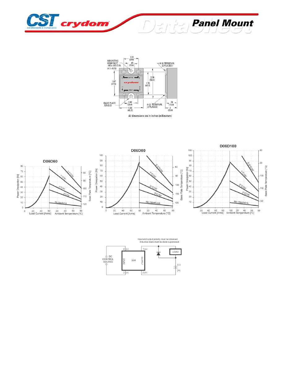
MECHANICAL SPECIFICATIONS
THERMAL DERATE INFORMATION
WIRING DIAGRAM
For Contact information visit our web
site.
www.crydom.com
©2008 Crydom, Inc.
Specifications subject to change without notice.
Courtesy of Steven Engineering, Inc.-230 Ryan Way, South San Francisco, CA 94080-6370-Main Office: (650) 588-9200-Outside Local Area: (800) 258-9200-www.stevenengineering.com
60MAIN-html.html

ANNEX - ENVIROMENTAL INFORMATION
For Contact information visit our web
site.
www.crydom.com
©2008 Crydom, Inc.
Specifications subject to change without notice.
Courtesy of Steven Engineering, Inc.-230 Ryan Way, South San Francisco, CA 94080-6370-Main Office: (650) 588-9200-Outside Local Area: (800) 258-9200-www.stevenengineering.com
60MAIN-html.html
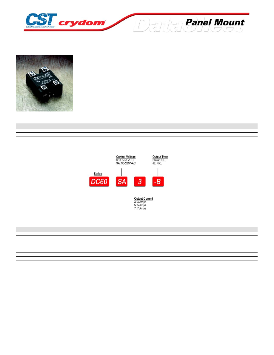
DC60 Series
• Bi-polar transistor output
• Ratings from 3A to 7A @ 60 VDC
• AC or DC control
PRODUCT SELECTION
Control Voltage
3A
5A
7A
3.5-32 VDC
DC60S3
DC60S5
DC60S7
90-280 VAC
DC60SA3
DC60SA5
DC60SA7
AVAILABLE OPTIONS
OUTPUT SPECIFICATIONS (1)
Description
Operating Voltage (47-63Hz) [VDC]
3-60
3-60
3-60
Maximum Off-State Leakage Current @ Rated Voltage [mArms]
0.1
0.1
0.1
Maximum Load Current (2) [ADC]
3
5
7
Minimum Load Current [Arms]
0.02
0.02
0.02
Maximum Surge Current (16.6ms) [Apk]
6
10
14
Maximum On-State Voltage Drop @ Rated Current [Vpk]
1.3
1.5
1.7
Thermal Resistance Junction to Case (Rjc) [°C/W]
2.2
2.2
2.2
For Contact information visit our web
site.
www.crydom.com
©2008 Crydom, Inc.
Specifications subject to change without notice.
Courtesy of Steven Engineering, Inc.-230 Ryan Way, South San Francisco, CA 94080-6370-Main Office: (650) 588-9200-Outside Local Area: (800) 258-9200-www.stevenengineering.com
60MAIN-html.html
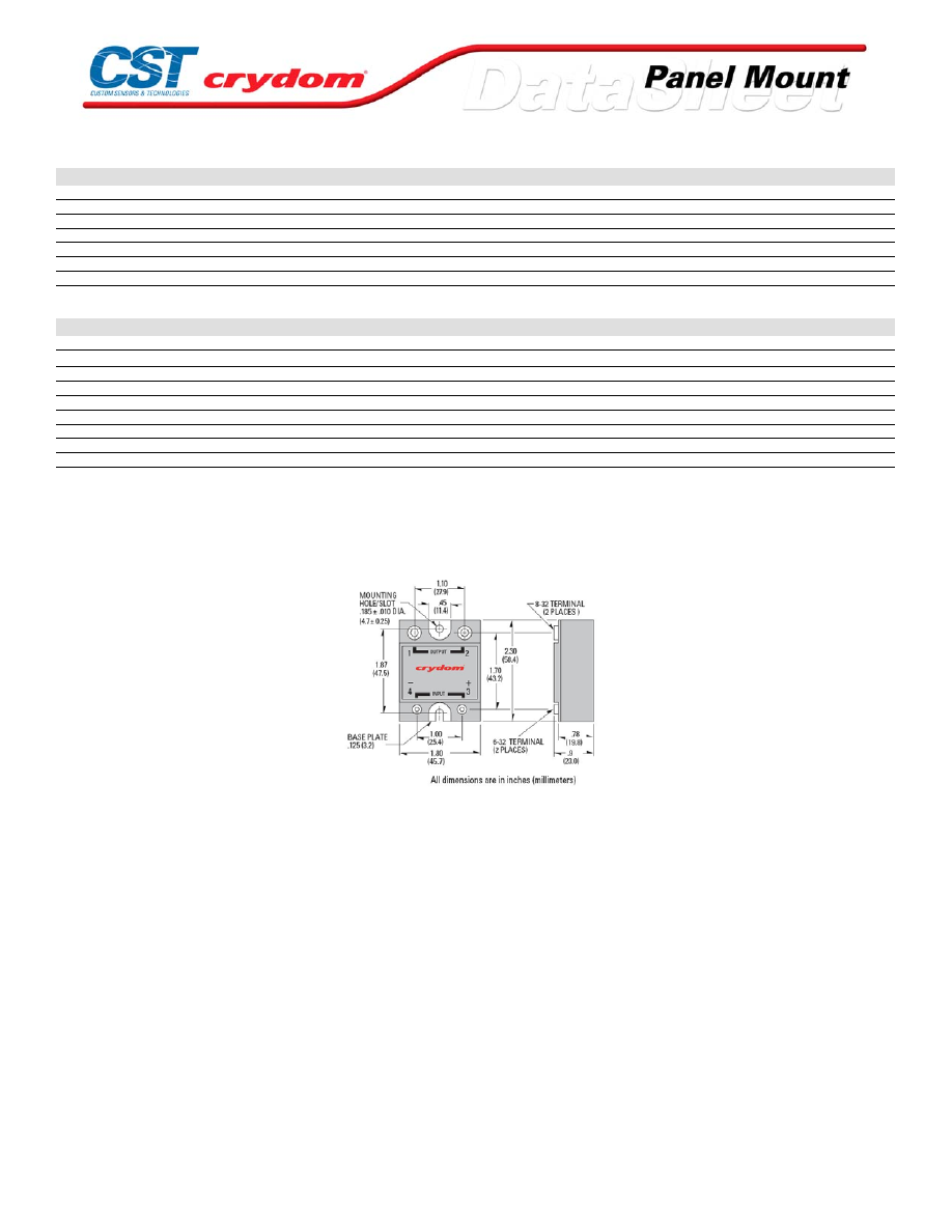
INPUT SPECIFICATIONS (1)
Description
DC Control
AC Control
Control Voltage Range
3.5-32 VDC
90-280 Vrms
Maximum Turn-On Voltage
3.5 VDC
90 Vrms
Minimum Turn-Off Voltage
1.0 VDC
10 Vrms
Typical Input Current
2.2 mA @ 5 VDC
2 mA @ 120 Vrms, 4 mA @ 240 Vrms
Nominal Input Impedance
1500 Ohm
60K
Maximum Turn-On Time [msec]
0.1
10
Maximum Turn-Off Time [msec]
0.3
40
GENERAL SPECIFICATIONS
Description
Parameters
Dielectric Strength, Input/Output/Base (50/60Hz) [Vrms]
4000
Minimum Insulation Resistance (@ 500 V DC)
10
9
Ohm
Maximum Capacitance, Input/Output
8 pF
Ambient Operating Temperature Range
-30 to 80°C
Ambient Storage Temperature Range
-40 to 125 °C
Weight (typical)
3.0 oz (86.5g)
Encapsulation
Thermally conductive Epoxy
Terminals
Screws and Saddle Clamps Furnished, Unmounted
Recommended Terminal Screw Torque Range:
6-32 Screws - 10 in lbs. 8-32 and 10-32 Screws -20 in. lbs. (Screws dry without grase)
GENERAL NOTES
1) All parameters at 25°C unless otherwise specified.
2) Heat sinking required, see derating curves.
MECHANICAL SPECIFICATIONS
For Contact information visit our web
site.
www.crydom.com
©2008 Crydom, Inc.
Specifications subject to change without notice.
Courtesy of Steven Engineering, Inc.-230 Ryan Way, South San Francisco, CA 94080-6370-Main Office: (650) 588-9200-Outside Local Area: (800) 258-9200-www.stevenengineering.com
60MAIN-html.html
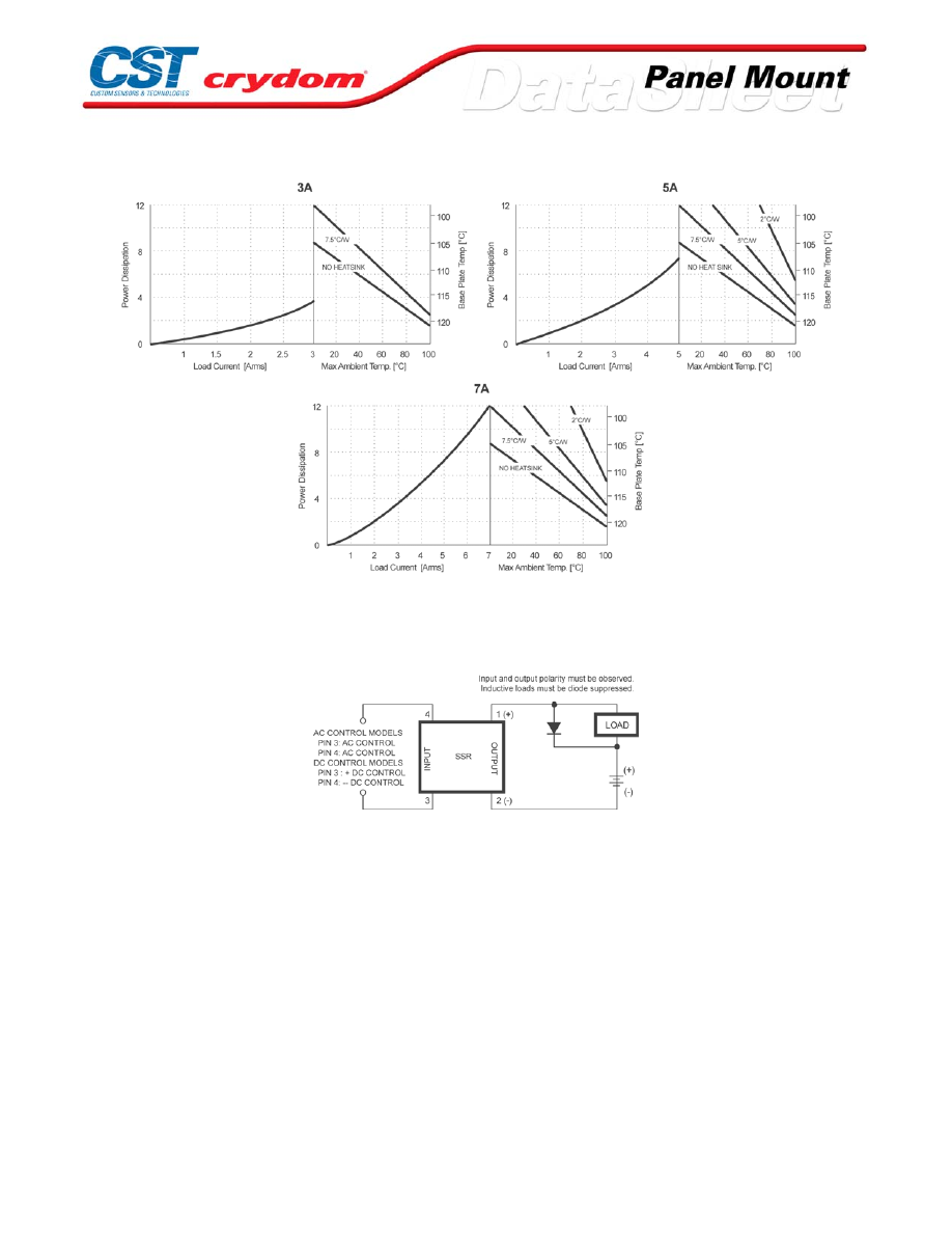
THERMAL DERATE INFORMATION
WIRING DIAGRAM
For Contact information visit our web
site.
www.crydom.com
©2008 Crydom, Inc.
Specifications subject to change without notice.
Courtesy of Steven Engineering, Inc.-230 Ryan Way, South San Francisco, CA 94080-6370-Main Office: (650) 588-9200-Outside Local Area: (800) 258-9200-www.stevenengineering.com
60MAIN-html.html

For Contact information visit our web
site.
www.crydom.com
©2008 Crydom, Inc.
Specifications subject to change without notice.
Courtesy of Steven Engineering, Inc.-230 Ryan Way, South San Francisco, CA 94080-6370-Main Office: (650) 588-9200-Outside Local Area: (800) 258-9200-www.stevenengineering.com
60MAIN-html.html
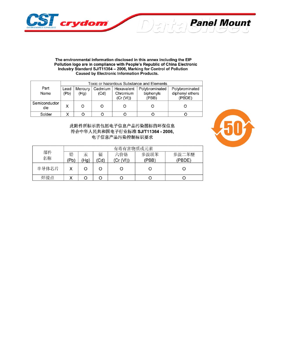
ANNEX - ENVIROMENTAL INFORMATION
For Contact information visit our web
site.
www.crydom.com
©2008 Crydom, Inc.
Specifications subject to change without notice.
Courtesy of Steven Engineering, Inc.-230 Ryan Way, South San Francisco, CA 94080-6370-Main Office: (650) 588-9200-Outside Local Area: (800) 258-9200-www.stevenengineering.com
60MAIN-html.html
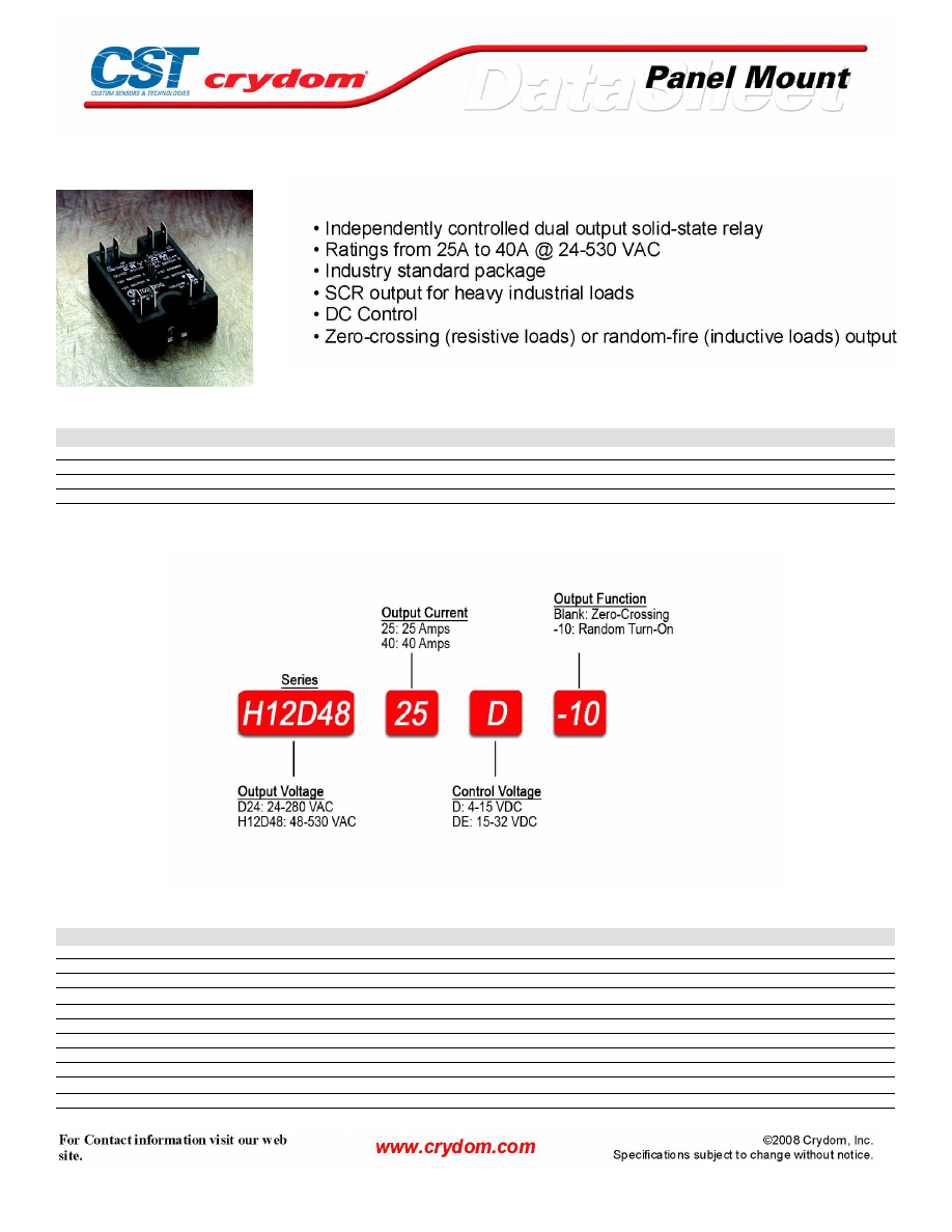
DUAL
PRODUCT SELECTION
Control Voltage
25A
40A
4-15 VDC
D2425D
D2440D
15-32 VDC
D2425DE
D2440DE
4-15 VDC
H12D4825D
H12D4840D
15-32 VDC
H12D4825DE
H12D4840DE
AVAILABLE OPTIONS
OUTPUT SPECIFICATIONS (1)
Description
Operating Voltage (47-63Hz) [Vrms]
24-280
24-280
48-530
48-530
Transient Overvoltage [Vpk]
600
600
1200
1200
Maximum Off-State Leakage Current @ Rated Voltage [mArms]
10
10
10
10
Minimum Off-State dv/dt @ Maximum Rated Voltage [V/µsec] (2)
500
500
500
500
Maximum Load Current (3) [Arms]
25
40
25
40
Minimum Load Current [Arms]
0.15
0.15
0.15
0.15
Maximum Surge Current (16.6ms) [Apk]
250
625
250
625
Maximum On-State Voltage Drop @ Rated Current [Vpk]
1.6
1.6
1.6
1.6
Thermal Resistance Junction to Case (Rjc) [°C/W]
1.02
0.63
1.02
0.63
Maximum I
2
t for Fusing (8.3 msec) [A
2
sec]
260
1620
260
1620
Minimum Power Factor (with Maximum Load)
0.5
0.5
0.5
0.5
Courtesy of Steven Engineering, Inc.-230 Ryan Way, South San Francisco, CA 94080-6370-Main Office: (650) 588-9200-Outside Local Area: (800) 258-9200-www.stevenengineering.com
60MAIN-html.html
INPUT SPECIFICATIONS (1)
Description
D24XXD
H12D48XXD
E-SUFFIX
Control Voltage Range
4-15 VDC
4-15 VDC
15-32 VDC
Maximum Turn-On Voltage
4.0 VDC
4.0 VDC
15.0 VDC
Minimum Turn-Off Voltage
1.0 VDC
1.0 VDC
1.0 VDC
Typical Input Current @ 5 VDC (@ 24 VDC for E-Suffix)
13 mA
13 mA
15 mA
Nominal Input Impedance
300 Ohm
240 Ohm
1500 Ohm
Maximum Turn-On Time [msec] (4)
1/2 cycle
1/2 cycle
1/2 cycle
Maximum Turn-Off Time [msec]
1/2 cycle
1/2 cycle
1/2 cycle
GENERAL SPECIFICATIONS
Description
Parameters
Dielectric Strength, Input/Output/Base (50/60Hz)
4000 Vrms
Minimum Insulation Resistance (@ 500 V DC)
10
9
Ohm
Maximum Capacitance, Input/Output
10 pF
Ambient Operating Temperature Range
-40 to 80°C
Ambient Storage Temperature Range
-40 to 125 °C
Weight (typical)
3.0 oz (86.5g)
Encapsulation
Thermally conductive Epoxy
Terminals
.25" Fastons, .025" Square Pins
Courtesy of Steven Engineering, Inc.-230 Ryan Way, South San Francisco, CA 94080-6370-Main Office: (650) 588-9200-Outside Local Area: (800) 258-9200-www.stevenengineering.com
60MAIN-html.html
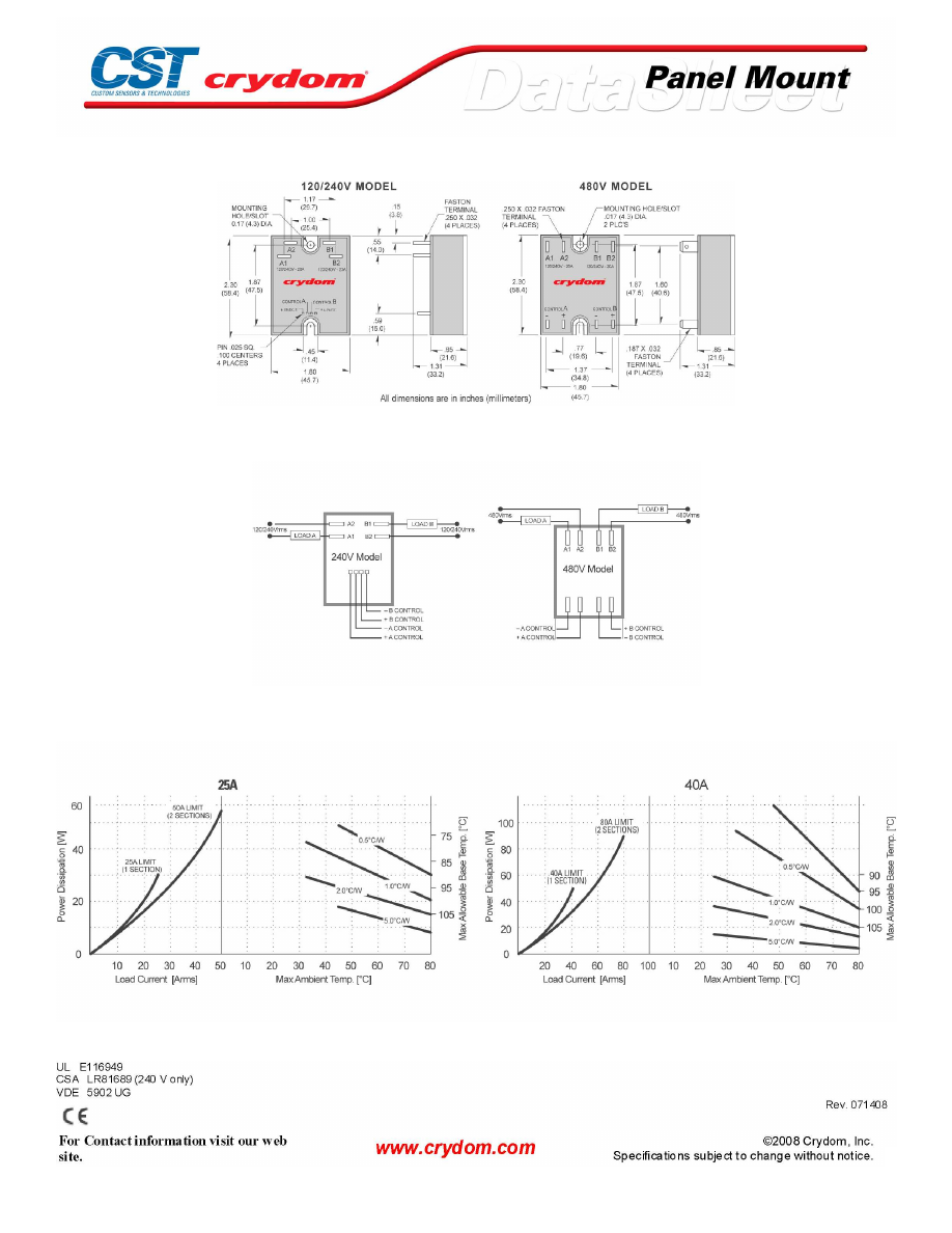
MECHANICAL SPECIFICATIONS
WIRING DIAGRAM
THERMAL DERATE INFORMATION
AGENCY APPROVALS
Courtesy of Steven Engineering, Inc.-230 Ryan Way, South San Francisco, CA 94080-6370-Main Office: (650) 588-9200-Outside Local Area: (800) 258-9200-www.stevenengineering.com
60MAIN-html.html

Courtesy of Steven Engineering, Inc.-230 Ryan Way, South San Francisco, CA 94080-6370-Main Office: (650) 588-9200-Outside Local Area: (800) 258-9200-www.stevenengineering.com
60MAIN-html.html

ANNEX - ENVIROMENTAL INFORMATION
Courtesy of Steven Engineering, Inc.-230 Ryan Way, South San Francisco, CA 94080-6370-Main Office: (650) 588-9200-Outside Local Area: (800) 258-9200-www.stevenengineering.com
60MAIN-html.html
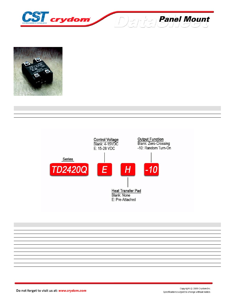
Quad
• Industry standard package
• SCR output for heavy industrial loads
• DC Control
• Zero-crossing (resistive loads) or random-fire (inductive loads) output
PRODUCT SELECTION
Control Voltage
20A
4-15 VDC
TD2420Q
15-28 VDC
TD2420QE
AVAILABLE OPTIONS
OUTPUT SPECIFICATIONS (1)
Description
Operating Voltage (47-63Hz) [VRMS]
24-280
Transient Overvoltage [Vpk]
600
Maximum Off-State Leakage Current @ Rated Voltage [mArms]
10
Minimum Off-State dv/dt @ Maximum Rated Voltage [V/µsec] (2)
200
Maximum Load Current (3) [Arms]
20
Minimum Load Current [Arms]
0.15
Maximum Surge Current (16.6ms) [Apk]
250
Maximum On-State Voltage Drop @ Rated Current [Vpk]
1.6
Thermal Resistance Junction to Case (Rjc) [°C/W]
1.2
Maximum I
2
t for Fusing (8.3 msec) [A
2
sec]
260
Minimum Power Factor (with Maximum Load)
0.5
Courtesy of Steven Engineering, Inc.-230 Ryan Way, South San Francisco, CA 94080-6370-Main Office: (650) 588-9200-Outside Local Area: (800) 258-9200-www.stevenengineering.com
60MAIN-html.html
INPUT SPECIFICATIONS (1)
Description
Control Voltage Range
4-15 VDC
15-28 VDC
Maximum Turn-On Voltage
4.0 VDC
15.0 VDC
Minimum Turn-Off Voltage
1.0 VDC
1.0 VDC
Typical Input Current
12 mA
15 mA
Nominal Input Impedance
330 Ohm
1500 Ohm
Maximum Turn-On Time [msec] (4)
1/2 cycle
1/2 cycle
Maximum Turn-Off Time [msec]
1/2 cycle
1/2 cycle
GENERAL SPECIFICATIONS
Description
Parameters
Dielectric Strength, Input/Output/Base (50/60Hz)
2500 VRMS
Minimum Insulation Resistance (@ 500 V DC)
10
9
Ohm
Maximum Capacitance, Input/Output
10 pF
Ambient Operating Temperature Range
-40 to 80°C
Ambient Storage Temperature Range
-40 to 125 °C
Weight (typical)
3.5 oz (109g)
Encapsulation
Thermally conductive Epoxy
Terminals
.25" Fastons, .025" Square Pins
GENERAL NOTES
1) All parameters at 25°C and per section unless otherwise specified.
2) Off-State dv/dt test method per EIA/NARM standard RS-443, paragraph 13.11.1
3) Heat sinking required, max. 20A per section, max 60A per package.
4) Turn-on time for random turn-on versions is 0.1 msec
Courtesy of Steven Engineering, Inc.-230 Ryan Way, South San Francisco, CA 94080-6370-Main Office: (650) 588-9200-Outside Local Area: (800) 258-9200-www.stevenengineering.com
60MAIN-html.html
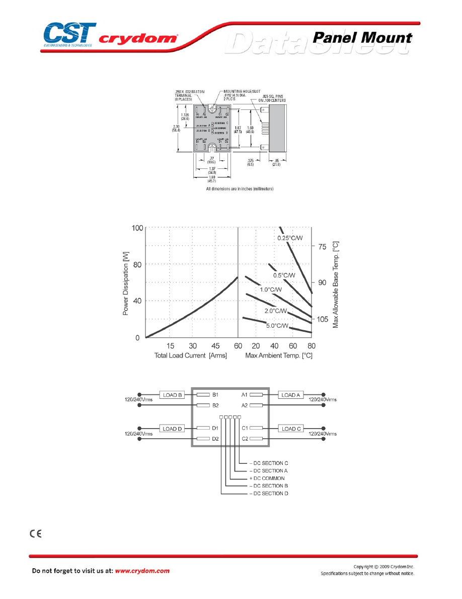
MECHANICAL SPECIFICATIONS
THERMAL DERATE INFORMATION
WIRING DIAGRAM
AGENCY APPROVALS
UL E116949
CSA LR81689
Rev. 121808
Courtesy of Steven Engineering, Inc.-230 Ryan Way, South San Francisco, CA 94080-6370-Main Office: (650) 588-9200-Outside Local Area: (800) 258-9200-www.stevenengineering.com
60MAIN-html.html

Courtesy of Steven Engineering, Inc.-230 Ryan Way, South San Francisco, CA 94080-6370-Main Office: (650) 588-9200-Outside Local Area: (800) 258-9200-www.stevenengineering.com
60MAIN-html.html
ANNEX - ENVIROMENTAL INFORMATION
Courtesy of Steven Engineering, Inc.-230 Ryan Way, South San Francisco, CA 94080-6370-Main Office: (650) 588-9200-Outside Local Area: (800) 258-9200-www.stevenengineering.com
60MAIN-html.html
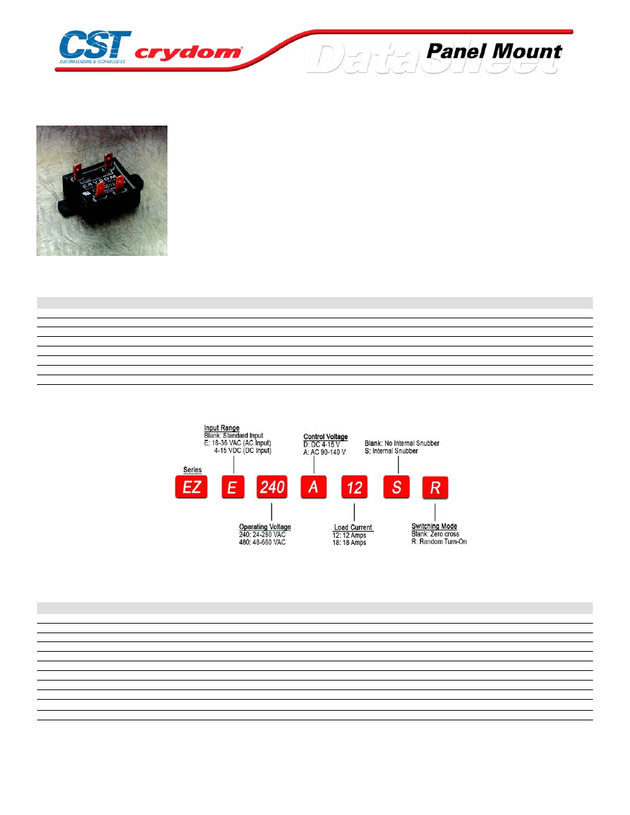
EZ Series
• Compact design for low-profile applications; Ratings from 5A to
18A @ 600 VAC
• SCR output for heavy industrial loads
• AC or DC control
• 1/4" fast-on terminals for easy installation
PRODUCT SELECTION
Control Voltage
5A
12A
18A
4-15 VDC
EZ240D5
EZ240D12
EZ240D18
15-32 VDC
EZE240D12
EZE240D18
90-140 Vrms
EZ240A12
EZ240A18
18-36 Vrms
EZE240A12
EZE240A18
4-15 VDC
EZ480D12
EZ480D18
15-32 VDC
EZE480D12
EZE480D18
90-140 Vrms
EZ480A12
EZ480A18
18-36 Vrms
EZE480A12
EZE480A18
AVAILABLE OPTIONS
OUTPUT SPECIFICATIONS (1)
Description
Operating Voltage (47-63Hz) [Vrms]
24-280
24-280
24-280
48-660
48-660
Transient Overvoltage [Vpk]
600
600
600
1200
1200
Maximum Off-State Leakage Current @ Rated Voltage [mArms](5)
0.1
0.1
0.1
0.1
0.1
Minimum Off-State dv/dt @ Maximum Rated Voltage [V/µsec] (2)
500
500
500
500
500
Maximum Load Current (4) [Arms]
5
12
18
12
18
Minimum Load Current [mArms]
150
150
150
150
150
Maximum Surge Current (16.6ms) [Apk]
40
150
200
150
200
Maximum On-State Voltage Drop @ Rated Current [Vpk]
1.5
1.5
1.5
1.5
1.5
Thermal Resistance Junction to Case (Rjc) [°C/W]
2
2
1.1
2
1.1
Maximum I
2
t for Fusing (8.3 msec) [A
2
sec]
95
95
170
95
170
Minimum Power Factor (with Maximum Load)
0.5
0.5
0.5
0.5
0.5
For Contact information visit our web
site.
www.crydom.com
©2008 Crydom, Inc.
Specifications subject to change without notice.
Courtesy of Steven Engineering, Inc.-230 Ryan Way, South San Francisco, CA 94080-6370-Main Office: (650) 588-9200-Outside Local Area: (800) 258-9200-www.stevenengineering.com
60MAIN-html.html

INPUT SPECIFICATIONS (1)
Description
EZ240D5
EZ240Dxx
EZ480Dxx
EZExxxDxx
EZxxxAxx
EZExxxAxx
Control Voltage Range
4-15 VDC
3-15 VDC
4-15 VDC
15-32 VDC
90-140 Vrms
18-36 Vrms
Minimum Turn-On Voltage
4.0 VDC
3.0 VDC
4.0 VDC
15.0 VDC
90.0 Vrms
18.0 Vrms
Minimum Turn-Off Voltage
1.0 VDC
1.0 VDC
1.0 VDC
1.0 VDC
10.0 Vrms
2.0 Vrms
Typical Input Current @ Nominal Voltage
13 mAdc
15 mAdc
15 mAdc
15 mAdc
10 mAdc
10 mAdc
Nominal Input Impedance
300 Ohm
300 Ohm
240 Ohm
1500 Ohm
10.6 k Ohm
1.8 k Ohm
Maximum Turn-On Time [msec] (6)
1/2 Cycle
1/2 Cycle
1/2 Cycle
1/2 Cycle
10
10
Maximum Turn-Off Time [msec]
1/2 Cycle
1/2 Cycle
1/2 Cycle
1/2 Cycle
40
40
GENERAL SPECIFICATIONS
Description
Parameters
Dielectric Strength, Input/Output/Base (50/60Hz)(3)
4000 Vrms *
Minimum Insulation Resistance (@ 500 V DC)
10
9
Ohm
Maximum Capacitance, Input/Output
8 pF
Ambient Operating Temperature Range
-40 to 80 °C
Ambient Storage Temperature Range
-40 to 125 °C
Weight (typical)
1.5 oz (43 g)
Encapsulation
Thermally conductive Epoxy
Terminals
0.25 Inch Faston
GENERAL NOTES
1) All parameters at 25°C unless otherwise specified.
2) Off-State dv/dt test method per EIA/NARM standard RS-443, paragraph 13.11.1
3) 240V, DC control models only, all others 2500VRMS
4) Heat sinking required, for derating curves see page 2.
5) Off- state leakage for snubbered version (suffix S) is 10.0mArms
6) Turn-on time for random turn-on versions is 0.1 msec (DC Control Models).
For Contact information visit our web
site.
www.crydom.com
©2008 Crydom, Inc.
Specifications subject to change without notice.
Courtesy of Steven Engineering, Inc.-230 Ryan Way, South San Francisco, CA 94080-6370-Main Office: (650) 588-9200-Outside Local Area: (800) 258-9200-www.stevenengineering.com
60MAIN-html.html
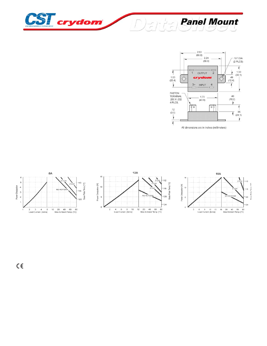
MECHANICAL SPECIFICATIONS
*240, DC Control Models Only
DC CONTROL.
PI N 1: AC LOAD
PI N 2: AC LOAD
PI N 3: +D C CO NTROL
PI N 4: -D C CONTRO L
Note:
Recommended t orque for mounti ng Screw is 8 – 14 in lb (1.1 – 1.6 Nm)
Thi s assumes a st andard # 8-32 UNC screw
THERMAL DERATE INFORMATION
AGENCY APPROVALS
UL E116950
CSA LR81689
VDE 10139 UG (240 VDC Control Only)
Rev. 062708
For Contact information visit our web
site.
www.crydom.com
©2008 Crydom, Inc.
Specifications subject to change without notice.
Courtesy of Steven Engineering, Inc.-230 Ryan Way, South San Francisco, CA 94080-6370-Main Office: (650) 588-9200-Outside Local Area: (800) 258-9200-www.stevenengineering.com
60MAIN-html.html

ANNEX - ENVIROMENTAL INFORMATION
For Contact information visit our web
site.
www.crydom.com
©2008 Crydom, Inc.
Specifications subject to change without notice.
Courtesy of Steven Engineering, Inc.-230 Ryan Way, South San Francisco, CA 94080-6370-Main Office: (650) 588-9200-Outside Local Area: (800) 258-9200-www.stevenengineering.com
60MAIN-html.html
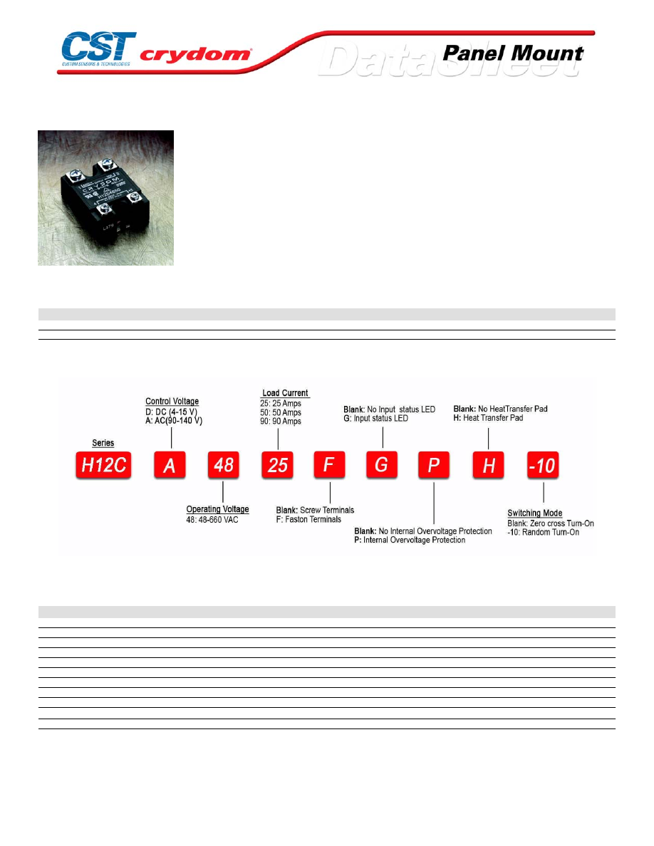
H12C Series
• Ratings from 25A to 125A @ 48-660 VAC
• SCR output for heavy industrial loads
• AC or DC control
• Zero-crossing (resistive loads) or random-fire (inductive loads) output
PRODUCT SELECTION
Control Voltage
25A
50A
90A
4-15 VDC
H12CD4825
H12CD4850
H12CD4890
90-140 Vrms
H12CA4825
H12CA4850
H12CA4890
AVAILABLE OPTIONS
OUTPUT SPECIFICATIONS (1)
Description
Operating Voltage (47-63Hz) [Vrms]
48-660
48-660
48-660
Transient Overvoltage [Vpk]
1200
1200
1200
Maximum Off-State Leakage Current @ Rated Voltage [mArms]
1.0
1.0
1.0
Minimum Off-State dv/dt @ Maximum Rated Voltage [V/µsec] (2)
500
500
500
Maximum Load Current (3) [Arms]
25
50
90
Minimum Load Current [mArms]
150
150
150
Maximum Surge Current (16.6ms) [Apk]
250
625
1200
Maximum On-State Voltage Drop @ Rated Current [Vpk]
1.6
1.6
1.6
Thermal Resistance Junction to Case (Rjc) [°C/W]
1.02
0.63
0.28
Maximum I
2
t for Fusing (8.3 msec) [A
2
sec]
260
1620
6000
Minimum Power Factor (with Maximum Load)
0.5
0.5
0.5
For Contact information visit our web
site.
www.crydom.com
©2008 Crydom, Inc.
Specifications subject to change without notice.
Courtesy of Steven Engineering, Inc.-230 Ryan Way, South San Francisco, CA 94080-6370-Main Office: (650) 588-9200-Outside Local Area: (800) 258-9200-www.stevenengineering.com
60MAIN-html.html
INPUT SPECIFICATIONS (1)
Description
Control Voltage Range
4-15 VDC
90-140 Vrms
Minimum Turn-On Voltage
4.0 VDC
90 VAC
Minimum Turn-Off Voltage
1.0 VDC
10.0 VAC
Typical Input Current
15 mA
15 mA
Nominal Input Impedance
300 Ohm
8k Ohm
Maximum Turn-On Time [msec] (4)
1/2 Cycle
10
Maximum Turn-Off Time [msec]
1/2 Cycle
40
GENERAL SPECIFICATIONS
Description
Parameters
Dielectric Strength, Input/Output/Base (50/60Hz)
4000 Vrms
Minimum Insulation Resistance (@ 500 V DC)
10
9
Ohm
Maximum Capacitance, Input/Output
8 pF
Ambient Operating Temperature Range
-40 to 80 °C
Ambient Storage Temperature Range
-40 to 125 °C
Weight (typical)
3 oz (86.5 g)
Encapsulation
Thermally conductive Epoxy
Terminals
Screw and saddle Clamps Furnished, Unmounted
Recommended Terminal Screw Torque Range:
6-32 Screws - 10 in/lbs. 8-32 & 10-32 Screws - 20 in. lbs. (Screws dry without grease)
Fastons:
Double pair* (50A model only) Caution: User must connect to both pairs
GENERAL NOTES
1) All parameters at 25°C unless otherwise specified.
2) Off-State dv/dt test method per EIA/NARM standard R S-443, paragraph 13.11.1
3) H eat sinking required, for derating curves see page 2.
4) Turn-on time for DC random turn-on versions is 0.02 msec (DC Control Models).
For Contact information visit our web
site.
www.crydom.com
©2008 Crydom, Inc.
Specifications subject to change without notice.
Courtesy of Steven Engineering, Inc.-230 Ryan Way, South San Francisco, CA 94080-6370-Main Office: (650) 588-9200-Outside Local Area: (800) 258-9200-www.stevenengineering.com
60MAIN-html.html
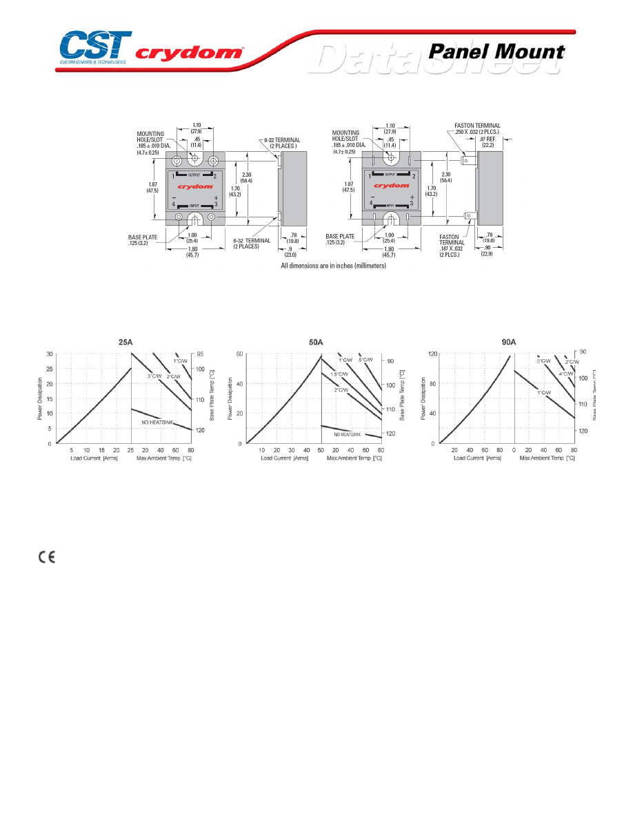
MECHANICAL SPECIFICATIONS
THERMAL DERATE INFORMATION
AGENCY APPROVALS
UL E116949
CSA LR81689
VDE 10143 UG
Rev. 062708
For Contact information visit our web
site.
www.crydom.com
©2008 Crydom, Inc.
Specifications subject to change without notice.
Courtesy of Steven Engineering, Inc.-230 Ryan Way, South San Francisco, CA 94080-6370-Main Office: (650) 588-9200-Outside Local Area: (800) 258-9200-www.stevenengineering.com
60MAIN-html.html

For Contact information visit our web
site.
www.crydom.com
©2008 Crydom, Inc.
Specifications subject to change without notice.
Courtesy of Steven Engineering, Inc.-230 Ryan Way, South San Francisco, CA 94080-6370-Main Office: (650) 588-9200-Outside Local Area: (800) 258-9200-www.stevenengineering.com
60MAIN-html.html

ANNEX - ENVIROMENTAL INFORMATION
For Contact information visit our web
site.
www.crydom.com
©2008 Crydom, Inc.
Specifications subject to change without notice.
Courtesy of Steven Engineering, Inc.-230 Ryan Way, South San Francisco, CA 94080-6370-Main Office: (650) 588-9200-Outside Local Area: (800) 258-9200-www.stevenengineering.com
60MAIN-html.html
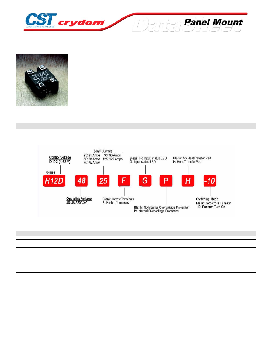
H12 Series
•
Ratings from 25A to 125A @ 48-660 V AC
•
SCR output for heavy industrial loads
•
AC or DC control
•
Zero-crossing (resistive loads) or random-fire (inductive loads) output
PRODUCT SELECTION
Control Voltage
25A
50A
75A
90A
125A
4-32 VDC
H12D4825
H12D4850
H12D4875
H12D4890
H12D48125
AVAILABLE OPTIONS
OUTPUT SPECIFICATIONS (1)
Description
Operating Voltage (47-63Hz) [Vrms]
48-530
48-530
48-530
48-530
48-530
Transient Overvoltage [Vpk]
1200
1200
1200
1200
1200
Maximum Off-State Leakage Current @ Rated Voltage [mArms]
10
10
10
10
10
Minimum Off-State dv/dt @ Maximum Rated Voltage [V/µsec] (2)
500
500
500
500
500
Maximum Load Current (3) [Arms]
25
50
75
90
125
Minimum Load Current [mArms]
150
150
150
150
150
Maximum Surge Current (16.6ms) [Apk]
250
625
1000
1200
1750
Maximum On-State Voltage Drop @ Rated Current [Vpk]
1.6
1.6
1.6
1.6
1.7
Thermal Resistance Junction to Case (Rjc) [°C/W]
1.02
0.63
0.31
0.28
0.22
Maximum I
2
t for Fusing (8.3 msec) [A
2
sec]
260
1620
4150
6000
12700
Minimum Power Factor (with Maximum Load)
0.5
0.5
0.5
0.5
0.5
For Contact information visit our web
site.
www.crydom.com
©2008 Crydom, Inc.
Specifications subject to change without notice.
Courtesy of Steven Engineering, Inc.-230 Ryan Way, South San Francisco, CA 94080-6370-Main Office: (650) 588-9200-Outside Local Area: (800) 258-9200-www.stevenengineering.com
60MAIN-html.html

INPUT SPECIFICATIONS (1)
Description
DC Control
Control Voltage Range
4-32 VDC
Maximum Turn-On Voltage
4.0 VDC
Minimum Turn-Off Voltage
1 .0 VDC
Typical Input Current
15 mADC (5)
Nominal Input Impedance
See Note 5
Maximum Turn-On Time [msec] (4)
1/2 Cycle
Maximum Turn-Off Time [msec]
1/2 Cycle
GENERAL SPECIFICATIONS
Description
Parameters
Dielectric Strength, Input/Output/Base (50/60Hz)
4000 Vrms
Minimum Insulation Resistance (@ 500 V DC)
10
9
Ohm
Maximum Capacitance, Input/Output
8 pF
Ambient Operating Temperature Range
-40 to 80 °C
Ambient Storage Temperature Range
-40 to 125 °C
Weight (typical)
3 oz (86.5 g)
Encapsulation
Thermally conductive Epoxy
Terminals
Screw and saddle Clamps Furnished, Unmounted
Recommended Terminal Screw Torque Range:
6-32 Screws - 10 in/lbs. 8-32 & 10-32 Screws - 20 in. lbs. (Screws dry without grease)
Fastons:
Single pair (up to 25A) Double pair* (50A model only) Caution: User must connect to both pairs
GENERAL NOTES
1) All parameters at 25°C and per section unless otherwise specified.
2) Off-State dv/dt test method per EIA/NARM standard RS-443, paragraph 13.11.1
3) Heat sinking required, for derating curves see page 2.
4) Turn-on time for DC control random turn-on versions is 0.02 msec
5) Input circuitry version incorporates active current limiter.
6) Only 125A model CE Compliant.
For Contact information visit our web
site.
www.crydom.com
©2008 Crydom, Inc.
Specifications subject to change without notice.
Courtesy of Steven Engineering, Inc.-230 Ryan Way, South San Francisco, CA 94080-6370-Main Office: (650) 588-9200-Outside Local Area: (800) 258-9200-www.stevenengineering.com
60MAIN-html.html
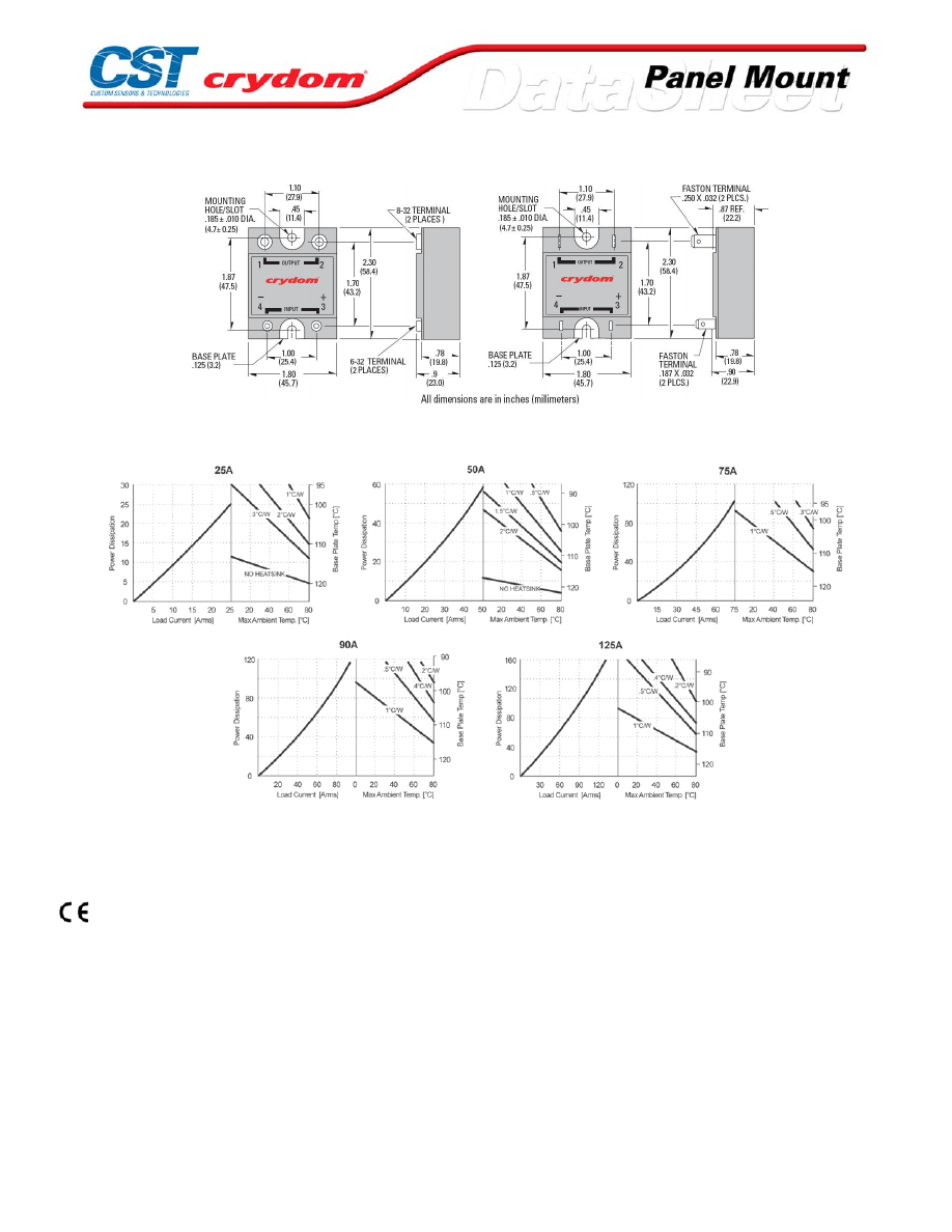
MECHANICAL SPECIFICATIONS
THERMAL DERATE INFORMATION
AGENCY APPROVALS
UL E116949
CSA LR81689
VDE 10143 UG
Rev. 063008
For Contact information visit our web
site.
www.crydom.com
©2008 Crydom, Inc.
Specifications subject to change without notice.
Courtesy of Steven Engineering, Inc.-230 Ryan Way, South San Francisco, CA 94080-6370-Main Office: (650) 588-9200-Outside Local Area: (800) 258-9200-www.stevenengineering.com
60MAIN-html.html

ANNEX - ENVIROMENTAL INFORMATION
For Contact information visit our web
site.
www.crydom.com
©2008 Crydom, Inc.
Specifications subject to change without notice.
Courtesy of Steven Engineering, Inc.-230 Ryan Way, South San Francisco, CA 94080-6370-Main Office: (650) 588-9200-Outside Local Area: (800) 258-9200-www.stevenengineering.com
60MAIN-html.html
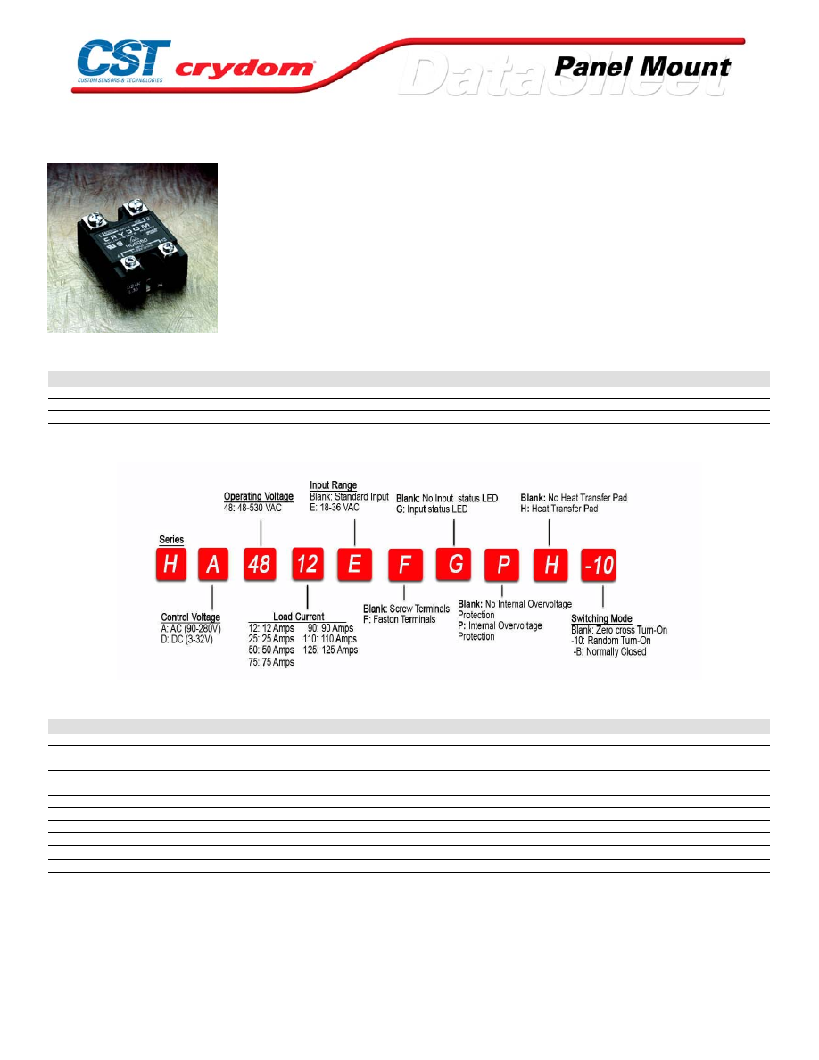
HA / HD48 Series
• Ratings from 12A to 125A @ 48-530 VAC
• SCR output for heavy industrial loads
• AC or DC control
• Zero-crossing (resistive loads) or random-fire (inductive loads) output
PRODUCT SELECTION
Control Voltage
12A
25A
50A
75A
90A
110A
125A
3-32 VDC
HD4812
HD4825
HD4850
HD4875
HD4890
HD48110
HD48125
90-280 Vrms
HA4812
HA4825
HA4850
HA4875
HA4890
HA48110
HA48125
18-36 Vrms
HA4812E
HA4825E
HA4850E
HA4875E
HA4890E
HA48110E
HA48125E
AVAILABLE OPTIONS
OUTPUT SPECIFICATIONS (1)
Description
Operating Voltage (47-63Hz) [Vrms]
48-530
48-530
48-530
48-530
48-530
48-530
48-530
Transient Overvoltage [Vpk]
1200
1200
1200
1200
1200
1200
1200
Maximum Off-State Leakage Current @ Rated Voltage [mArms]
10
10
10
10
10
10
10
Minimum Off-State dv/dt @ Maximum Rated Voltage [V/µsec] (2)
500
500
500
500
500
500
500
Maximum Load Current (3) [Arms]
12
25
50
75
90
110
125
Minimum Load Current [mArms]
40
40
40
40
40
150
150
Maximum Surge Current (16.6ms) [Apk]
140
250
625
1000
1200
1500
1750
Maximum On-State Voltage Drop @ Rated Current [Vpk]
1.7
1.7
1.7
1.7
1.7
1.7
1.7
Thermal Resistance Junction to Case (Rjc) [°C/W]
1.48
1.02
0.63
0.31
0.28
0.25
0.22
Maximum I
2
t for Fusing (8.3 msec) [A
2
sec]
81
260
1620
4150
6000
9340
12700
Minimum Power Factor (with Maximum Load)
0.5
0.5
0.5
0.5
0.5
0.5
0.5
For Contact information visit our web
site.
www.crydom.com
©2008 Crydom, Inc.
Specifications subject to change without notice.
Courtesy of Steven Engineering, Inc.-230 Ryan Way, South San Francisco, CA 94080-6370-Main Office: (650) 588-9200-Outside Local Area: (800) 258-9200-www.stevenengineering.com
60MAIN-html.html

INPUT SPECIFICATIONS (1)
Description
D PREFIX
A PREFIX
E PREFIX
Control Voltage Range
3-32 VDC
90-280 Vrms
18-36 Vrms
Maximum Turn-On Voltage
3.0 VDC
90 Vrms
18 Vrms
Minimum Turn-Off Voltage
1.0 VDC
10 Vrms
4.0 Vrms
Maximum Reverse Voltage
-32 VDC
-
-
Typical Input Current
2.0 mA (6)
2 mA @ 120 Vrms, 4mA @ 240 Vrms
3 mA @ 240 Vrms
Nominal Input Impedance
See Note 6
60 K ohms
9.0 K ohms
Maximum Turn-On Time [msec] (5)
1/2 Cycle
10
10
Maximum Turn-Off Time [msec]
1/2 Cycle
40
40
GENERAL SPECIFICATIONS
Description
Parameters
Dielectric Strength, Input/Output/Base (50/60Hz)
4000 Vrms
Minimum Insulation Resistance (@ 500 V DC)
10
9
Ohm
Maximum Capacitance, Input/Output
8 pF
Ambient Operating Temperature Range
-40 to 80 °C
Ambient Storage Temperature Range
-40 to 125 °C
Weight (typical)
3.0 oz (86.5 g)
Encapsulation
Thermally conductive Epoxy
Terminals
Screw and saddle Clamps Furnished, Unmounted
Recommended Terminal Screw Torque Range:
6-32 Screws - 10 in/lbs. 8-32 & 10-32 Screws - 20 in. lbs. (Screws dry without grease)
Fastons:
Single pair (up to 25A) Double pair* (50A model only) *Caution: User must connect to both pairs
GENERAL NOTES
1) All parameters at 25°C unless otherwise specified.
2) Off-State dv/dt test method per EIA/NARM standard RS-443, paragraph 13.11.1
3) Heat sinking required, for derating curves see page 2.
4) 24 VAC Input option, E suffix
5) Turn-on time for random turn-on versions is 0.02 msec (DC control Models)
6) Input circuitry incorporat es active current limit er.
For Contact information visit our web
site.
www.crydom.com
©2008 Crydom, Inc.
Specifications subject to change without notice.
Courtesy of Steven Engineering, Inc.-230 Ryan Way, South San Francisco, CA 94080-6370-Main Office: (650) 588-9200-Outside Local Area: (800) 258-9200-www.stevenengineering.com
60MAIN-html.html
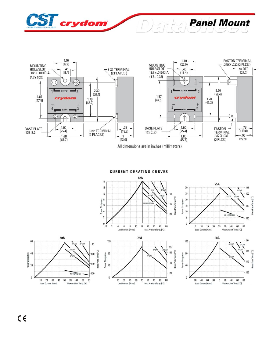
MECHANICAL SPECIFICATIONS
THERMAL DERATE INFORMATION
AGENCY APPROVALS
UL E116949
CSA LR81689
VDE 10143 UG
Rev. 063008
For Contact information visit our web
site.
www.crydom.com
©2008 Crydom, Inc.
Specifications subject to change without notice.
Courtesy of Steven Engineering, Inc.-230 Ryan Way, South San Francisco, CA 94080-6370-Main Office: (650) 588-9200-Outside Local Area: (800) 258-9200-www.stevenengineering.com
60MAIN-html.html

For Contact information visit our web
site.
www.crydom.com
©2008 Crydom, Inc.
Specifications subject to change without notice.
Courtesy of Steven Engineering, Inc.-230 Ryan Way, South San Francisco, CA 94080-6370-Main Office: (650) 588-9200-Outside Local Area: (800) 258-9200-www.stevenengineering.com
60MAIN-html.html

ANNEX - ENVIROMENTAL INFORMATION
For Contact information visit our web
site.
www.crydom.com
©2008 Crydom, Inc.
Specifications subject to change without notice.
Courtesy of Steven Engineering, Inc.-230 Ryan Way, South San Francisco, CA 94080-6370-Main Office: (650) 588-9200-Outside Local Area: (800) 258-9200-www.stevenengineering.com
60MAIN-html.html

HA / HD60 Series
• Ratings from 25A to 125A @ 48-660 VAC
• SCR output for heavy industrial loads
• AC or DC control
• Zero-crossing (resistive loads) or random-fire (inductive loads) output
PRODUCT SELECTION
Control Voltage
25A
50A
90A
125A
3-32 VDC
HD6025
HD6050
HD6090
HD60125
90-280 Vrms
HA6025
HA6050
HA6090
HA60125
18-36 Vrms
HA6025E
HA6050E
HA6090E
HA60125E
AVAILABLE OPTIONS
OUTPUT SPECIFICATIONS (1)
Description
Operating Voltage (47-63Hz) [Vrms]
48-660
48-660
48-660
48-660
Transient Overvoltage [Vpk]
1200
1200
1200
1200
Maximum Off-State Leakage Current @ Rated Voltage [mArms]
5
5
5
5
Minimum Off-State dv/dt @ Maximum Rated Voltage [V/µsec] (2)
500
500
500
500
Maximum Load Current (3) [Arms]
25
50
90
125
Minimum Load Current [mArms]
40
40
40
150
Maximum Surge Current (16.6ms) [Apk]
250
625
1200
1750
Maximum On-State Voltage Drop @ Rated Current [Vpk]
1.7
1.7
1.7
1.7
Thermal Resistance Junction to Case (Rjc) [°C/W]
1.02
0.63
0.28
0.22
Maximum I
2
t for Fusing (8.3 msec) [A
2
sec]
260
1620
6000
12700
Minimum Power Factor (with Maximum Load)
0.5
0.5
0.5
0.5
For Contact information visit our web
site.
www.crydom.com
©2008 Crydom, Inc.
Specifications subject to change without notice.
Courtesy of Steven Engineering, Inc.-230 Ryan Way, South San Francisco, CA 94080-6370-Main Office: (650) 588-9200-Outside Local Area: (800) 258-9200-www.stevenengineering.com
60MAIN-html.html

INPUT SPECIFICATIONS (1)
Description
D PREFIX
A PREFIX
E SUFFIX
Control Voltage Range
3-32 VDC
90-280 Vrms
18-36 Vrms
Maximum Turn-On Voltage
3.0 VDC
90 Vrms
18 Vrms
Minimum Turn-Off Voltage
1.0 VDC
10 Vrms
4.0 Vrms
Maximum Reverse Voltage
-32 VDC
-
-
Typical Input Current
2.0 mA (6)
2 mA @ 120 Vrms, 4 mA @ 240 Vrms
3 mA @ 24 Vrms
Nominal Input Impedance [kOhms]
See Note 6
60
9.0
Maximum Turn-On Time [msec] (5)
1/2 Cycle
10
10
Maximum Turn-Off Time [msec]
1/2 Cycle
40
40
GENERAL SPECIFICATIONS
Description
Parameters
Dielectric Strength, Input/Output/Base (50/60Hz)
4000 Vrms
Minimum Insulation Resistance (@ 500 V DC)
10
9
Ohm
Maximum Capacitance, Input/Output
8 pF
Ambient Operating Temperature Range
-40 to 80 °C
Ambient Storage Temperature Range
-40 to 125 °C
Weight (typical)
3.0 oz (86.5 g)
Encapsulation
Thermally conductive Epoxy
Terminals
Screw and saddle Clamps Furnished, Unmounted
Recommended Terminal Screw Torque Range:
6-32 Screws - 10 in/lbs. 8-32 & 10-32 Screws - 20 in. lbs. (Screws dry without grease)
Fastons:
Single pair (up to 25A) Double pair* (50A model only) *Caution: User must connect to both pairs
GENERAL NOTES
1) All parameters at 25°C unless otherwise specified.
2) Off-State dv/dt test method per EIA/NARM standard RS-443, paragraph 13.11.1
3) Heat sinking required, for derating curves see page 2.
4) 24 VAC Input option, E suffix
5) Turn-on time for random turn-on versions is 0.02 msec (DC control Models)
6) Input circuitry incorporates active current limiter.
For Contact information visit our web
site.
www.crydom.com
©2008 Crydom, Inc.
Specifications subject to change without notice.
Courtesy of Steven Engineering, Inc.-230 Ryan Way, South San Francisco, CA 94080-6370-Main Office: (650) 588-9200-Outside Local Area: (800) 258-9200-www.stevenengineering.com
60MAIN-html.html

MECHANICAL SPECIFICATIONS
THERMAL DERATE INFORMATION
AGENCY APPROVALS
UL E116949
CSA LR81689
VDE 10143 UG
Rev. 063008
For Contact information visit our web
site.
www.crydom.com
©2008 Crydom, Inc.
Specifications subject to change without notice.
Courtesy of Steven Engineering, Inc.-230 Ryan Way, South San Francisco, CA 94080-6370-Main Office: (650) 588-9200-Outside Local Area: (800) 258-9200-www.stevenengineering.com
60MAIN-html.html

For Contact information visit our web
site.
www.crydom.com
©2008 Crydom, Inc.
Specifications subject to change without notice.
Courtesy of Steven Engineering, Inc.-230 Ryan Way, South San Francisco, CA 94080-6370-Main Office: (650) 588-9200-Outside Local Area: (800) 258-9200-www.stevenengineering.com
60MAIN-html.html

ANNEX - ENVIROMENTAL INFORMATION
For Contact information visit our web
site.
www.crydom.com
©2008 Crydom, Inc.
Specifications subject to change without notice.
Courtesy of Steven Engineering, Inc.-230 Ryan Way, South San Francisco, CA 94080-6370-Main Office: (650) 588-9200-Outside Local Area: (800) 258-9200-www.stevenengineering.com
60MAIN-html.html
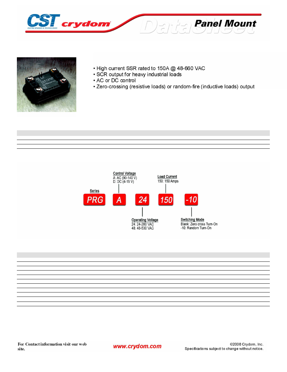
PRG Series
PRODUCT SELECTION
Control Voltage
150A
150A
150A
3-15 VDC
PRGD24150
90-140 VAC
PRGA24150
PRGA48150
PRGA60150
4-15 VDC
PRGD48150
PRGD60150
AVAILABLE OPTIONS
OUTPUT SPECIFICATIONS (1)
Description
Operating Voltage (47-63Hz) [Vrms]
24-280
48-530
48-660
Transient Overvoltage [Vpk]
600
1200
1200
Maximum Off-State Leakage Current @ Rated Voltage [mArms]
5.0
5.0
1.0
Minimum Off-State dv/dt @ Maximum Rated Voltage [V/µsec] (2)
500
500
500
Maximum Load Current (3) [Arms]
150
150
150
Minimum Load Current [Arms]
0.15
0.15
0.15
Maximum Surge Current (16.6ms) [Apk]
1750
1750
1750
Maximum On-State Voltage Drop @ Rated Current [Vpk]
1.7
1.7
1.7
Thermal Resistance Junction to Case (Rjc) [°C/W]
0.15
0.15
0.15
Maximum I
2
t for Fusing (8.3 msec) [A
2
sec]
12700
12700
12700
Minimum Power Factor (with Maximum Load)
0.5
0.5
0.5
Courtesy of Steven Engineering, Inc.-230 Ryan Way, South San Francisco, CA 94080-6370-Main Office: (650) 588-9200-Outside Local Area: (800) 258-9200-www.stevenengineering.com
60MAIN-html.html
INPUT SPECIFICATIONS (1)
Description
240 V Models
Control Voltage Range
3-15 VDC
4-15 VDC
90-140 Vrms
Maximum Turn-On Voltage
3.0 VDC
4.0 VDC
90 Vrms
Minimum Turn-Off Voltage
1.0 VDC
1.0 VDC
10 Vrms
Typical Input Current
15 mA @5 VDC
15 mA @ 5 VDC
10 mA @ 120 VAC
Nominal Input Impedance
300 Ohm
300 Ohm
14.1 K Ohm
Maximum Turn-On Time [msec] (4)
1/2 Cycle
1/2 Cycle
10
Maximum Turn-Off Time [msec]
1/2 Cycle
1/2 Cycle
40
GENERAL SPECIFICATIONS
Description
Parameters
Dielectric Strength, Input/Output/Base (50/60Hz)
4000 Vrms
Minimum Insulation Resistance (@ 500 V DC)
Maximum Capacitance, Input/Output
10 pF
Ambient Operating Temperature Range
-30 to 80 °C
Ambient Storage Temperature Range
-40 to 125 °C
Weight (typical)
12 oz (340g)
Encapsulation
Thermally conductive Epoxy
Power Terminals:
MS Screws Furnished, Mounted
Control Terminals:
.050 x .020 Square Pins
Courtesy of Steven Engineering, Inc.-230 Ryan Way, South San Francisco, CA 94080-6370-Main Office: (650) 588-9200-Outside Local Area: (800) 258-9200-www.stevenengineering.com
60MAIN-html.html
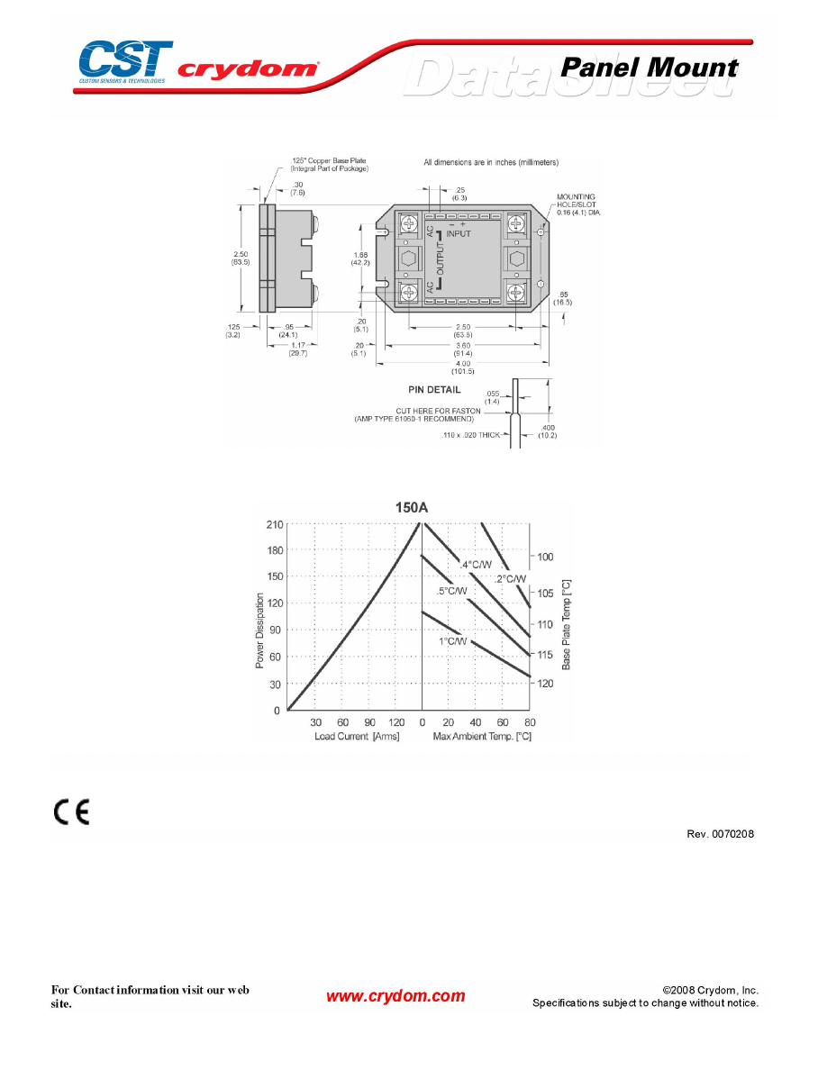
MECHANICAL SPECIFICATIONS
THERMAL DERATE INFORMATION
AGENCY APPROVALS
Courtesy of Steven Engineering, Inc.-230 Ryan Way, South San Francisco, CA 94080-6370-Main Office: (650) 588-9200-Outside Local Area: (800) 258-9200-www.stevenengineering.com
60MAIN-html.html

Courtesy of Steven Engineering, Inc.-230 Ryan Way, South San Francisco, CA 94080-6370-Main Office: (650) 588-9200-Outside Local Area: (800) 258-9200-www.stevenengineering.com
60MAIN-html.html

ANNEX - ENVIROMENTAL INFORMATION
Courtesy of Steven Engineering, Inc.-230 Ryan Way, South San Francisco, CA 94080-6370-Main Office: (650) 588-9200-Outside Local Area: (800) 258-9200-www.stevenengineering.com
60MAIN-html.html
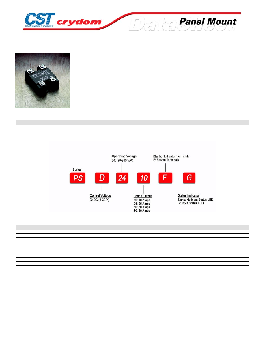
PS24 Series
• Peak-fire SSR for high inductance applications; Ratings from 10A to
90A @ 90- 280 VAC
• SCR output for heavy industrial loads
• DC control
PRODUCT SELECTION
Control Voltage
10A
25A
50A
90A
3-32 VDC
PSD2410
PSD2425
PSD2450
PSD2490
AVAILABLE OPTIONS
OUTPUT SPECIFICATIONS (1)
Description
Operating Voltage (47-63Hz) [Vrms]
90-280
90-280
90-280
90-280
Transient Overvoltage [Vpk]
600
600
600
600
Maximum Off-State Leakage Current @ Rated Voltage [mArms]
10
10
10
10
Minimum Off-State dv/dt @ Maximum Rated Voltage [V/µsec] (2)
500
500
500
500
Maximum Load Current (3) [Arms]
10
25
50
90
Minimum Load Current [mArms]
40m
40
40
40
Maximum Surge Current (16.6ms) [Apk]
120
250
625
1200
Maximum On-State Voltage Drop @ Rated Current [Vpk]
1.6
1.6
1.6
1.6
Thermal Resistance Junction to Case (Rjc) [°C/W]
1.48
1.02
0.63
0.28
Maximum I
2
t for Fusing (8.3 msec) [A
2
sec]
60
260
1620
6000
Minimum Power Factor (with Maximum Load)
0.5
0.5
0.5
0.5
For Contact information visit our web
site.
www.crydom.com
©2008 Crydom, Inc.
Specifications subject to change without notice.
Courtesy of Steven Engineering, Inc.-230 Ryan Way, South San Francisco, CA 94080-6370-Main Office: (650) 588-9200-Outside Local Area: (800) 258-9200-www.stevenengineering.com
60MAIN-html.html
INPUT SPECIFICATIONS (1)
Description
DC Control
Control Voltage Range
3-32 VDC
Maximum Turn-On Voltage
3.0 VDC
Minimum Turn-Off Voltage
1.0 VDC
Maximum Reverse Voltage
-32
Typical Input Current
2 mA(4)
Nominal Input Impedance
See Note 4
Maximum Turn-On Time [msec]
1/2 Cycle
Maximum Turn-Off Time [msec]
1/2 Cycle
GENERAL SPECIFICATIONS
Description
Parameters
Dielectric Strength, Input/Output/Base (50/60Hz)
4000 Vrms
Minimum Insulation Resistance (@ 500 V DC)
10
9
Ohm
Maximum Capacitance, Input/Output
8 pF
Ambient Operating Temperature Range
-40 to 80 °C
Ambient Storage Temperature Range
-40 to 125 °C
Weight (typical)
3.0 oz (86.5g)
Encapsulation
Thermally conductive Epoxy
Terminals
Screw and saddle Clamps Furnished, Unmounted
Recommended Terminal Screw Torque Range:
6-32 Screws - 10 in/lbs. 8-32 & 10-32 Screws - 20 in. lbs. (Screws dry without grease)
Fastons:
Single pair (up to 25A) Double pair* (50A model only) *Caution: User must connect to both pairs
GENERAL NOTES
1) All parameters at 25°C unless otherwise specified.
2) Off-State dv/dt test method per EIA/NARM standard RS-443, paragraph 13.11.1
3) Heat sinking required, for derating curves see page 3.
4) Input circuit incorporates active current limiter
For Contact information visit our web
site.
www.crydom.com
©2008 Crydom, Inc.
Specifications subject to change without notice.
Courtesy of Steven Engineering, Inc.-230 Ryan Way, South San Francisco, CA 94080-6370-Main Office: (650) 588-9200-Outside Local Area: (800) 258-9200-www.stevenengineering.com
60MAIN-html.html
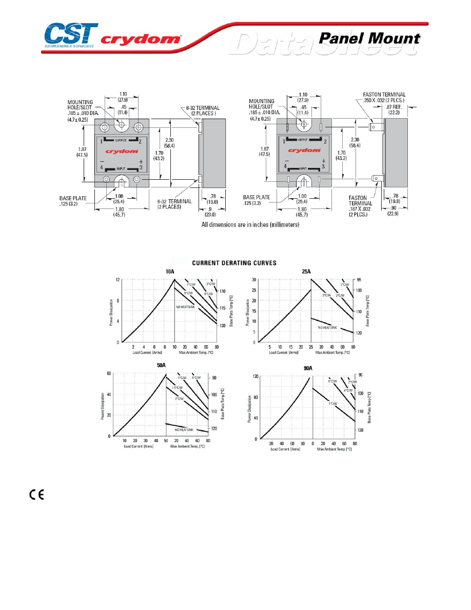
MECHANICAL SPECIFICATIONS
THERMAL DERATE INFORMATION
AGENCY APPROVALS
UL, cUL E116950
Rev. 052307
For Contact information visit our web
site.
www.crydom.com
©2008 Crydom, Inc.
Specifications subject to change without notice.
Courtesy of Steven Engineering, Inc.-230 Ryan Way, South San Francisco, CA 94080-6370-Main Office: (650) 588-9200-Outside Local Area: (800) 258-9200-www.stevenengineering.com
60MAIN-html.html
ANNEX - ENVIROMENTAL INFORMATION
For Contact information visit our web
site.
www.crydom.com
©2008 Crydom, Inc.
Specifications subject to change without notice.
Courtesy of Steven Engineering, Inc.-230 Ryan Way, South San Francisco, CA 94080-6370-Main Office: (650) 588-9200-Outside Local Area: (800) 258-9200-www.stevenengineering.com
60MAIN-html.html
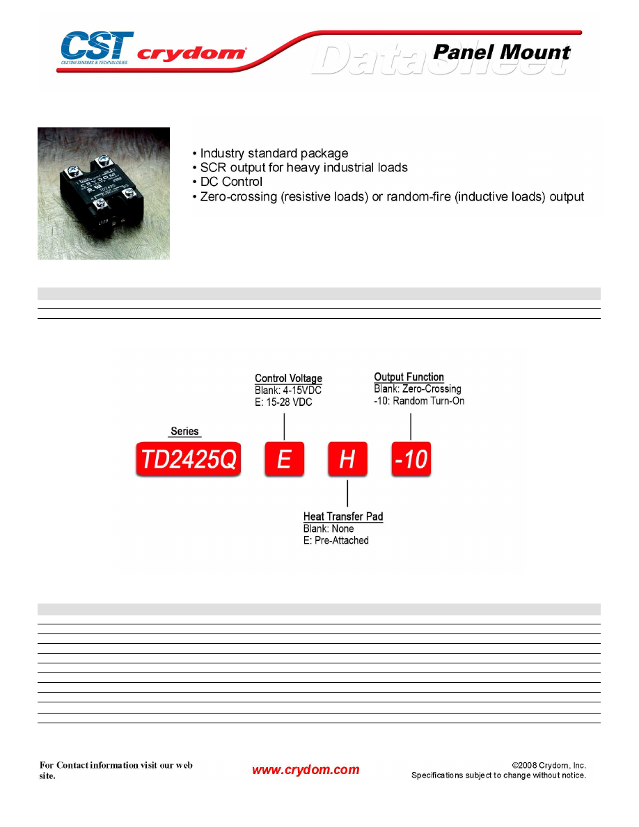
Quad
PRODUCT SELECTION
Control Voltage
20A
4-15 VDC
TD2420Q
15-28 VDC
TD2420QE
AVAILABLE OPTIONS
OUTPUT SPECIFICATIONS (1)
Description
Operating Voltage (47-63Hz) [VRMS]
24-280
Transient Overvoltage [Vpk]
600
Maximum Off-State Leakage Current @ Rated Voltage [mArms]
10
Minimum Off-State dv/dt @ Maximum Rated Voltage [V/µsec] (2)
200
Maximum Load Current (3) [Arms]
20
Minimum Load Current [Arms]
0.15
Maximum Surge Current (16.6ms) [Apk]
250
Maximum On-State Voltage Drop @ Rated Current [Vpk]
1.6
Thermal Resistance Junction to Case (Rjc) [°C/W]
1.2
Maximum I
2
t for Fusing (8.3 msec) [A
2
sec]
260
Minimum Power Factor (with Maximum Load)
0.5
Courtesy of Steven Engineering, Inc.-230 Ryan Way, South San Francisco, CA 94080-6370-Main Office: (650) 588-9200-Outside Local Area: (800) 258-9200-www.stevenengineering.com
60MAIN-html.html

INPUT SPECIFICATIONS (1)
Description
Control Voltage Range
4-15 VDC
15-28 VDC
Maximum Turn-On Voltage
4.0 VDC
15.0 VDC
Minimum Turn-Off Voltage
1.0 VDC
1.0 VDC
Typical Input Current
12 mA
15 mA
Nominal Input Impedance
330 Ohm
1500 Ohm
Maximum Turn-On Time [msec] (4)
1/2 cycle
1/2 cycle
Maximum Turn-Off Time [msec]
1/2 cycle
1/2 cycle
GENERAL SPECIFICATIONS
Description
Parameters
Dielectric Strength, Input/Output/Base (50/60Hz)
2500 VRMS
Minimum Insulation Resistance (@ 500 V DC)
10
9
Ohm
Maximum Capacitance, Input/Output
10 pF
Ambient Operating Temperature Range
-40 to 80°C
Ambient Storage Temperature Range
-40 to 125 °C
Weight (typical)
3.5 oz (109g)
Encapsulation
Thermally conductive Epoxy
Terminals
.25" Fastons, .025" Square Pins
Courtesy of Steven Engineering, Inc.-230 Ryan Way, South San Francisco, CA 94080-6370-Main Office: (650) 588-9200-Outside Local Area: (800) 258-9200-www.stevenengineering.com
60MAIN-html.html
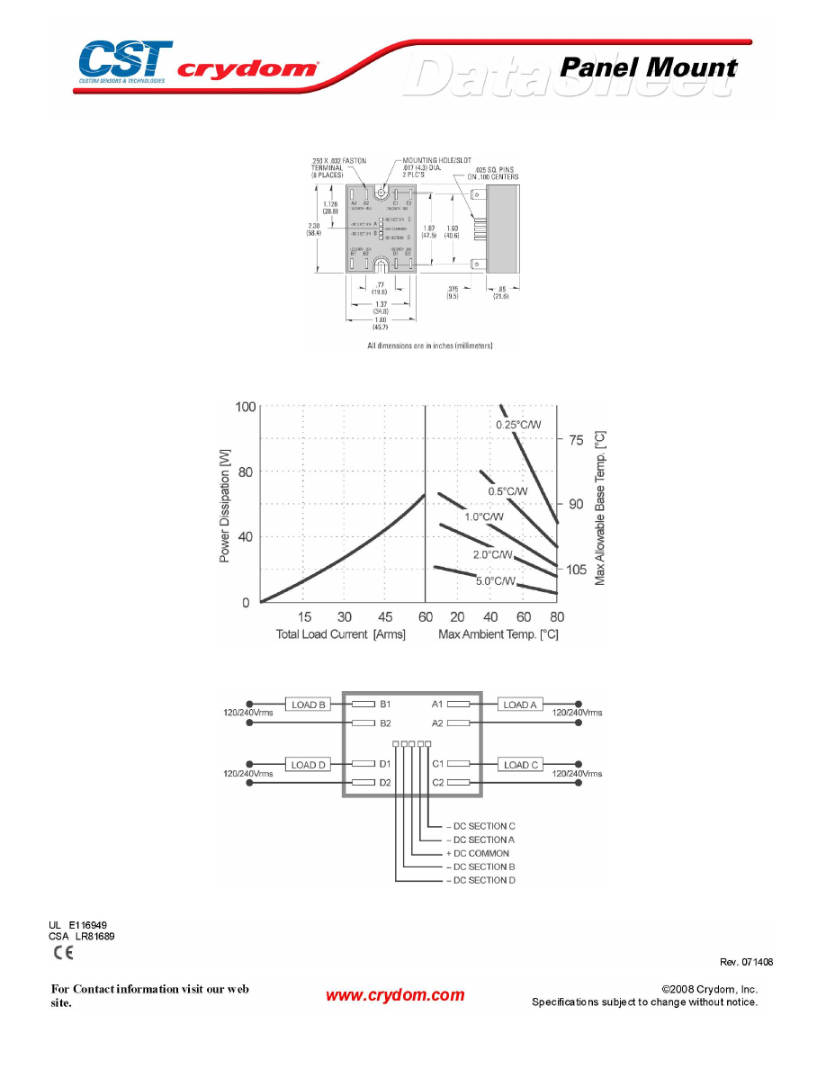
MECHANICAL SPECIFICATIONS
THERMAL DERATE INFORMATION
WIRING DIAGRAM
AGENCY APPROVALS
Courtesy of Steven Engineering, Inc.-230 Ryan Way, South San Francisco, CA 94080-6370-Main Office: (650) 588-9200-Outside Local Area: (800) 258-9200-www.stevenengineering.com
60MAIN-html.html

Courtesy of Steven Engineering, Inc.-230 Ryan Way, South San Francisco, CA 94080-6370-Main Office: (650) 588-9200-Outside Local Area: (800) 258-9200-www.stevenengineering.com
60MAIN-html.html

ANNEX - ENVIROMENTAL INFORMATION
Courtesy of Steven Engineering, Inc.-230 Ryan Way, South San Francisco, CA 94080-6370-Main Office: (650) 588-9200-Outside Local Area: (800) 258-9200-www.stevenengineering.com
60MAIN-html.html
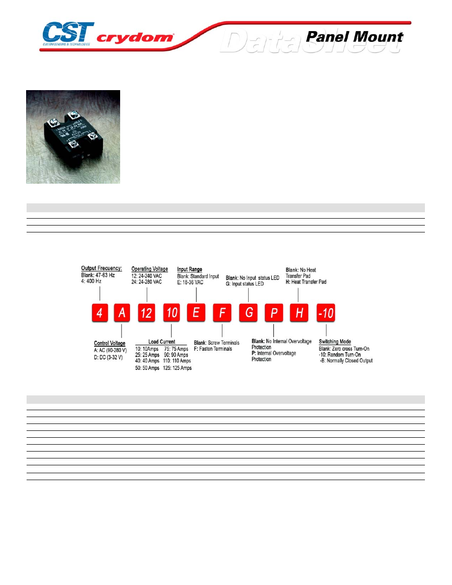
Series 1 240 VAC
• Crydom's signature family of solid-state relays. Ratings from 10A to
125A @ 12-280 VAC
• SCR output for heavy industrial loads
• AC or DC control
• Zero-crossing (resistive loads) or random-fire (inductive loads) output
PRODUCT SELECTION
Control Voltage
10A
25A
50A
75A
90A
110A
125A
3-32 VDC
D2410
D2425
D2450
D2475
D2490
D21110
D24125
90-280 VAC
A2410
A2425
A2450
A2475
A2490
A24110
A24125
18-36 VAC
A2410E
A2425E
A2450E
A2475E
A2490E
A24110E
A24125E
AVAILABLE OPTIONS
OUTPUT SPECIFICATIONS (1)
Description
Operating Voltage (47-63Hz) [Vrms]
24-280
24-280
24-280
24-280
24-280
24-280
24-280
Transient Overvoltage [Vpk]
600
600
600
600
600
600
600
Maximum Off-State Leakage Current @ Rated Voltage [mArms]
10
10
10
10
10
10
10
Minimum Off-State dv/dt @ Maximum Rated Voltage [V/µsec] (2)
500
500
500
500
500
500
500
Maximum Load Current (3) [Arms]
10
25
50
75
90
110
125
Minimum Load Current [mArms]
40
40
40
40
40
150
150
Maximum Surge Current (16.6ms) [Apk]
120
250
625
1000
1200
1500
1750
Maximum On-State Voltage Drop @ Rated Current [Vpk]
1.6
1.6
1.6
1.6
1.6
1.7
1.7
Thermal Resistance Junction to Case (Rjc) [°C/W]
1.48
1.02
0.63
0.31
0.28
0.25
0.22
Maximum I
2
t for Fusing (8.3 msec) [A
2
sec]
60
260
1620
4150
6000
9340
12700
Minimum Power Factor (with Maximum Load)
0.5
0.5
0.5
0.5
0.5
0.5
0.5
For Contact information visit our web
site.
www.crydom.com
©2008 Crydom, Inc.
Specifications subject to change without notice.
Courtesy of Steven Engineering, Inc.-230 Ryan Way, South San Francisco, CA 94080-6370-Main Office: (650) 588-9200-Outside Local Area: (800) 258-9200-www.stevenengineering.com
60MAIN-html.html

INPUT SPECIFICATIONS (1)
Description
( D PREFIX)
( A PREFIX)
( E SUFFIX)
Control Voltage Range
3-32 VDC
90-280 Vrms
18-36 Vrms
Maximum Reverse Voltage
-32
-
-
Maximum Turn-On Voltage
3.0 VDC
90 Vrms
18 Vrms
Minimum Turn-Off Voltage
1.0 VDC
10 Vrms
4.0 Vrms
Typical Input Current
3.4-20 mA
2.0-4.0 mA
3 mA
Nominal Input Impedance [Ohms]
1500 Ohm
60 K Ohm
9.0 K Ohm
Maximum Turn-On Time [msec] (4)
1/2 Cycle
10
10
Maximum Turn-Off Time [msec]
1/2 Cycle
40
40
GENERAL SPECIFICATIONS
Description
Parameters
Dielectric Strength, Input/Output/Base (50/60Hz)
4000 Vrms
Minimum Insulation Resistance (@ 500 V DC)
10
9
Ohm
Maximum Capacitance, Input/Output
8 pF
Ambient Operating Temperature Range
-40 to 80 °C
Ambient Storage Temperature Range
-40 to 125 °C
Weight (typical)
3 oz (86.5g)
Encapsulation
Thermally conductive Epoxy
Terminals
Screw and saddle Clamps Furnished, Unmounted
Recommended Terminal Screw Torque Range:
6-32 Screws - 10 in/lbs. 8-32 & 10-32 Screws - 20 in. lbs. (Screws dry without grease)
Fastons:
Single pair (up to 25A) Double pair* (50A model only) *Caution: User must connect to both pairs
GENERAL NOTES
1) All parameters at 25°C unless otherwise specified.
2) Off-State dv/dt test method per EIA/NARM standard RS-443, paragraph 13.11.1
3) Heat sinking required, for derating curves see page 3.
4) Turn-on time for Random turn-on versions is 0.02 msec (DC Control Models)
For Contact information visit our web
site.
www.crydom.com
©2008 Crydom, Inc.
Specifications subject to change without notice.
Courtesy of Steven Engineering, Inc.-230 Ryan Way, South San Francisco, CA 94080-6370-Main Office: (650) 588-9200-Outside Local Area: (800) 258-9200-www.stevenengineering.com
60MAIN-html.html
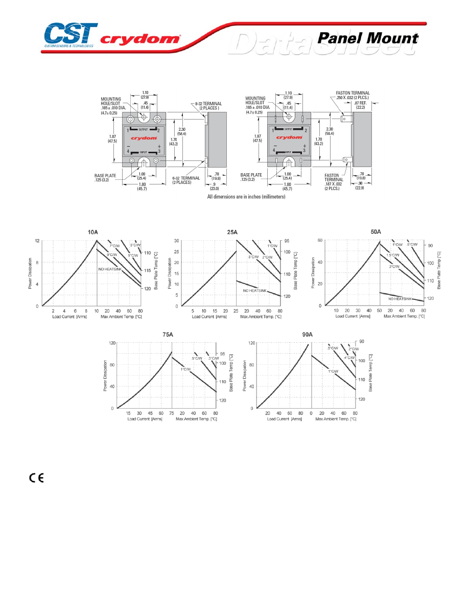
MECHANICAL SPECIFICATIONS
THERMAL DERATE INFORMATION
AGENCY APPROVALS
UL E116949
CSA LR81689
VDE 10143 UG (Not Applicable: -B and 4D
)
Rev. 070308
For Contact information visit our web
site.
www.crydom.com
©2008 Crydom, Inc.
Specifications subject to change without notice.
Courtesy of Steven Engineering, Inc.-230 Ryan Way, South San Francisco, CA 94080-6370-Main Office: (650) 588-9200-Outside Local Area: (800) 258-9200-www.stevenengineering.com
60MAIN-html.html

ANNEX - ENVIROMENTAL INFORMATION
For Contact information visit our web
site.
www.crydom.com
©2008 Crydom, Inc.
Specifications subject to change without notice.
Courtesy of Steven Engineering, Inc.-230 Ryan Way, South San Francisco, CA 94080-6370-Main Office: (650) 588-9200-Outside Local Area: (800) 258-9200-www.stevenengineering.com
60MAIN-html.html
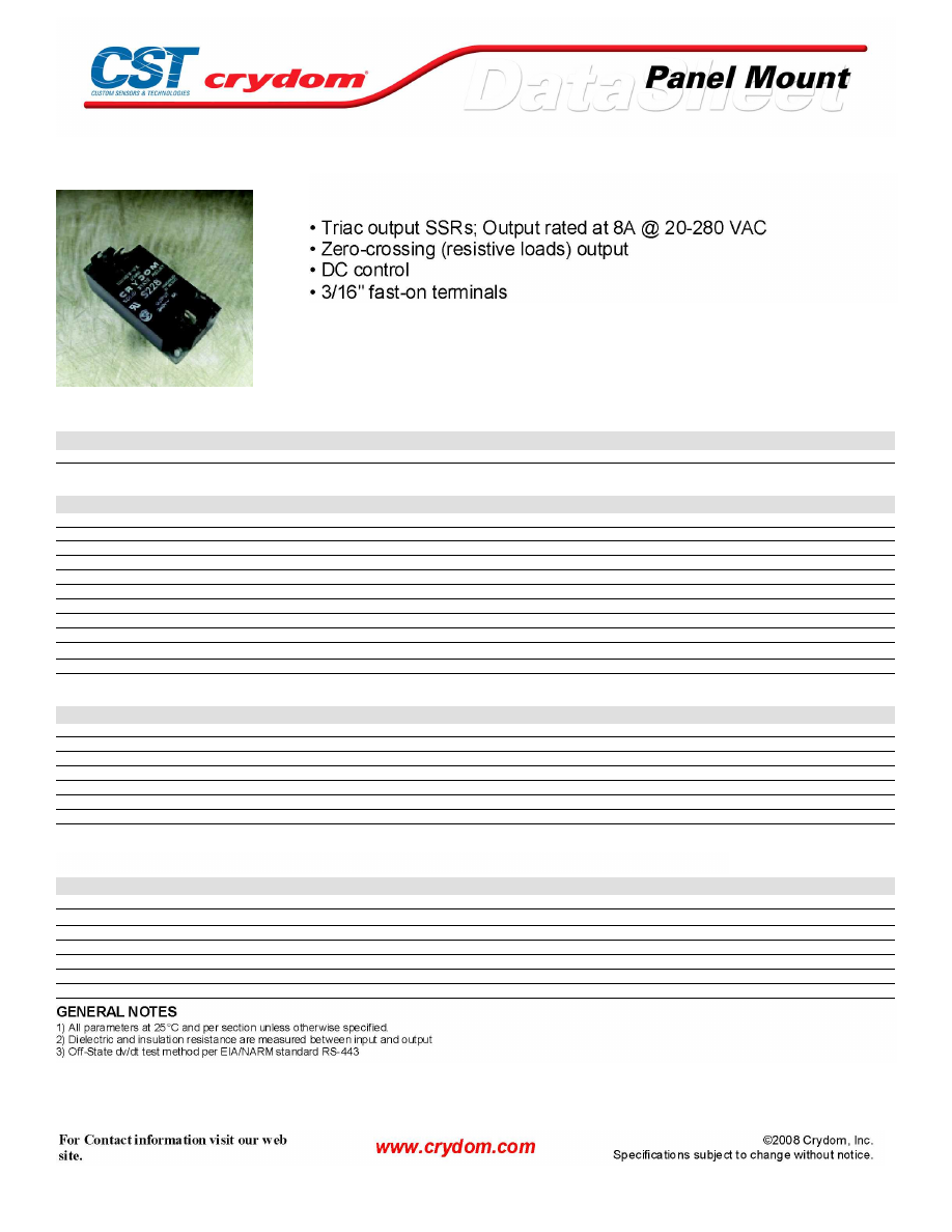
Series 2
PRODUCT SELECTION
Control Voltage
3.5-8 VDC
S218
S228
S228C
OUTPUT SPECIFICATIONS (1)
Description
S218
S228
S228C
Operating Voltage (47-63Hz) [Vrms]
20-140
40-280
40-280
Transient Overvoltage [Vpk]
400
600
600
Maximum Off-State Leakage Current @ Rated Voltage [mArms]
4.0
4.0
1.0
Minimum Off-State dv/dt @ Maximum Rated Voltage [V/µsec] (3)
200
200
200
Maximum Load Current [Arms]
8.0
8.0
8.0
Minimum Load Current [Arms]
0.15
0.15
0.15
Maximum Surge Current (16.6ms) [Apk]
120
120
120
Maximum On-State Voltage Drop @ Rated Current [Vpk]
1.6
1.6
1.6
Thermal Resistance Junction to Case (Rjc) [°C/W]
1.5
1.5
1.5
Maximum I
2
t for Fusing (8.3 msec) [A
2
sec]
60
60
60
Minimum Power Factor (with Maximum Load)
0.5
0.5
0.5
INPUT SPECIFICATIONS (1)
Description
DC Control
Control Voltage Range
3.5-8.0 VDC
Maximum Turn-On Voltage
3.5 VDC
Minimum Turn-Off Voltage
1.0 VDC
Typical Input Current @ 5 VDC
18 mA
Nominal Input Impedance
200 Ohm
Maximum Turn-On Time [msec] (4)
1/2 Cycle
Maximum Turn-Off Time [msec] (4)
1/2 Cycle
GENERAL SPECIFICATIONS
Description
Parameters
Dielectric Strength, Input/Output/Base (50/60Hz)(2)
2500 Vrms
Minimum Insulation Resistance (@ 500 V DC)(2)
10
9
Ohm
Maximum Capacitance, Input/Output
8.0 pF
Ambient Operating Temperature Range
-30 to 80°C
Ambient Storage Temperature Range
-30 to 125 °C
Weight (typical)
1.3 oz (40g)
Encapsulation
Thermally conductive Epoxy
Courtesy of Steven Engineering, Inc.-230 Ryan Way, South San Francisco, CA 94080-6370-Main Office: (650) 588-9200-Outside Local Area: (800) 258-9200-www.stevenengineering.com
60MAIN-html.html
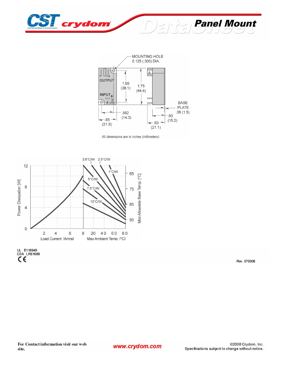
MECHANICAL SPECIFICATIONS
THERMAL DERATE INFORMATION
AGENCY APPROVALS
Courtesy of Steven Engineering, Inc.-230 Ryan Way, South San Francisco, CA 94080-6370-Main Office: (650) 588-9200-Outside Local Area: (800) 258-9200-www.stevenengineering.com
60MAIN-html.html

Courtesy of Steven Engineering, Inc.-230 Ryan Way, South San Francisco, CA 94080-6370-Main Office: (650) 588-9200-Outside Local Area: (800) 258-9200-www.stevenengineering.com
60MAIN-html.html
ANNEX - ENVIROMENTAL INFORMATION
Courtesy of Steven Engineering, Inc.-230 Ryan Way, South San Francisco, CA 94080-6370-Main Office: (650) 588-9200-Outside Local Area: (800) 258-9200-www.stevenengineering.com
60MAIN-html.html
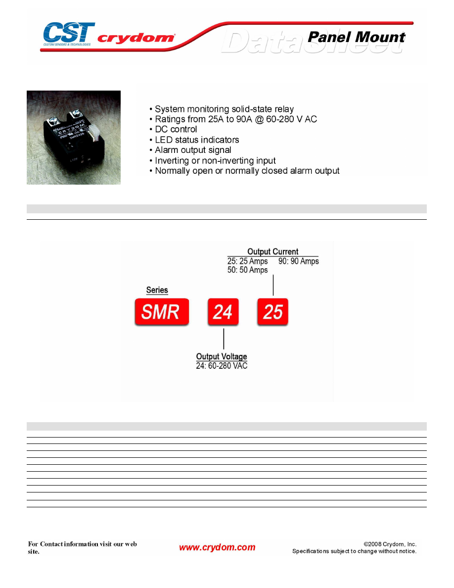
SMR Series
PRODUCT SELECTION
Control Voltage
25A
50A
90A
8-32 VDC
SMR2425
SMR2450
SMR2490
AVAILABLE OPTIONS
OUTPUT SPECIFICATIONS (1)
Description
Operating Voltage (47-63Hz) [Vrms]
60-280
60-280
60-280
Transient Overvoltage [Vpk]
600
600
600
Maximum Off-State Leakage Current @ Rated Voltage [mArms]
10
10
10
Minimum Off-State dv/dt @ Maximum Rated Voltage [V/µsec] (2)
500
500
500
Maximum Load Current (3) [Arms]
25
50
90
Minimum Load Current [mArms]
40
40
40
Maximum Surge Current (16.6ms) [Apk]
250
625
1200
Maximum On-State Voltage Drop @ Rated Current [Vpk]
1.6
1.6
1.6
Thermal Resistance Junction to Case (Rjc) [°C/W]
1.02
0.63
0.28
Maximum I
2
t for Fusing (8.3 msec) [A
2
sec]
260
1620
6000
Minimum Power Factor (with Maximum Load)
0.5
0.5
0.5
Courtesy of Steven Engineering, Inc.-230 Ryan Way, South San Francisco, CA 94080-6370-Main Office: (650) 588-9200-Outside Local Area: (800) 258-9200-www.stevenengineering.com
60MAIN-html.html
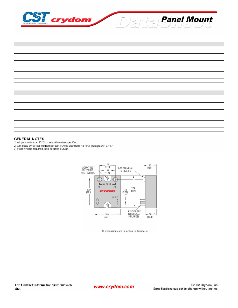
INPUT SPECIFICATIONS (1)
Description
DC Control
Control Voltage Range
8-32 VDC
Minimum Turn-Off Voltage (pin 6)
0.4 VDC
DC Suply Current @ 12 VDC
8 mA
DC Control Current @ 12 VDC
6 mA
Maximum Alarm Output Current
100 mA
Alarm On Output Voltage (Open), (pin 7)
Supply Voltage
Maximum Alarm Off Output Voltage @ 100 mA (Active Low),(pin 7)
1.5 VDC
AlarmDelay (Min.-Max.)
30-100 msec
Maximum Turn-On Time [msec]
1/2 Cycle
Maximum Turn-Off Time [msec]
1/2 Cycle
GENERAL SPECIFICATIONS
Description
Parameters
Dielectric Strength, Input/Output/Base (50/60Hz)
4000 Vrms
Minimum Insulation Resistance (@ 500 V DC)
10
9
Ohm
Maximum Capacitance, Input/Output
8 pF
Ambient Operating Temperature Range
-40 to 80°C
Ambient Storage Temperature Range
-40 to 125 °C
Weight (typical)
3.0 oz (86.5g)
Encapsulation
Thermally conductive Epoxy
Output Terminals:
Screws and Saddle Clamps Furnished, Unmounted
Input Connector (locking):
Panduit No. MLSS100-5 or Equivalent
Mating Connector (supplied):
Panduit No. CT00F22-5 or Equivalent
Recommended Terminal Screw Torque Range:
8-32 & 10-32 Screws - 20 in. lbs. (Screws dry without grease)
MECHANICAL SPECIFICATIONS
Courtesy of Steven Engineering, Inc.-230 Ryan Way, South San Francisco, CA 94080-6370-Main Office: (650) 588-9200-Outside Local Area: (800) 258-9200-www.stevenengineering.com
60MAIN-html.html
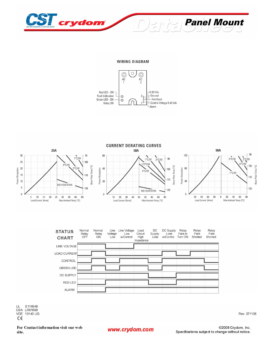
WIRING DIAGRAM
THERMAL DERATE INFORMATION
STATUS CHART
AGENCY APPROVALS
Courtesy of Steven Engineering, Inc.-230 Ryan Way, South San Francisco, CA 94080-6370-Main Office: (650) 588-9200-Outside Local Area: (800) 258-9200-www.stevenengineering.com
60MAIN-html.html

Courtesy of Steven Engineering, Inc.-230 Ryan Way, South San Francisco, CA 94080-6370-Main Office: (650) 588-9200-Outside Local Area: (800) 258-9200-www.stevenengineering.com
60MAIN-html.html

ANNEX - ENVIROMENTAL INFORMATION
Courtesy of Steven Engineering, Inc.-230 Ryan Way, South San Francisco, CA 94080-6370-Main Office: (650) 588-9200-Outside Local Area: (800) 258-9200-www.stevenengineering.com
60MAIN-html.html
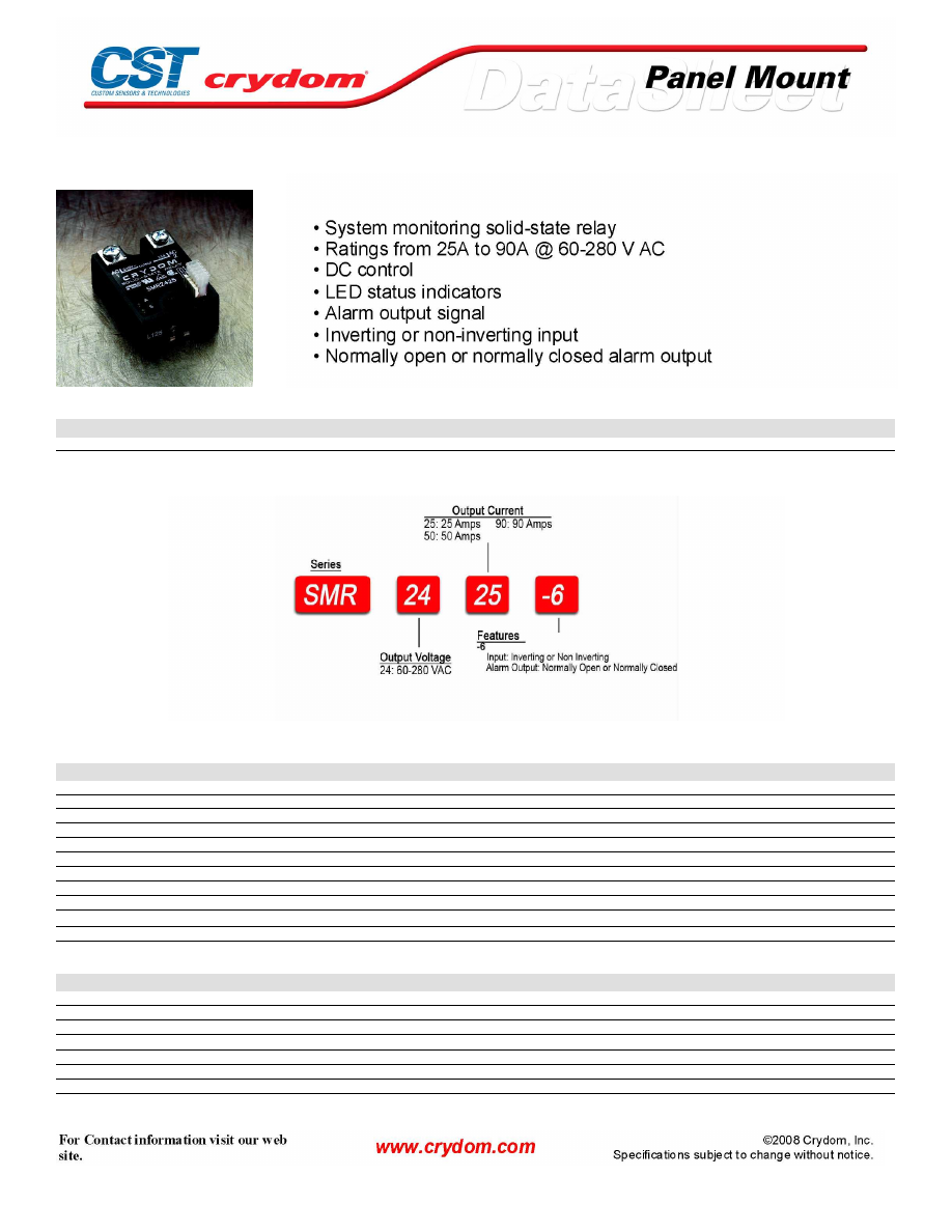
SMR -6 Series
PRODUCT SELECTION
Control Voltage
25A
50A
90A
8-32 VDC
SMR2425-6
SMR2450-6
SMR2490-6
AVAILABLE OPTIONS
OUTPUT SPECIFICATIONS (1)
Description
Operating Voltage (47-63Hz) [Vrms]
60-280
60-280
60-280
Transient Overvoltage [Vpk]
600
600
600
Maximum Off-State Leakage Current @ Rated Voltage [mArms]
10
10
10
Minimum Off-State dv/dt @ Maximum Rated Voltage [V/µsec] (2)
500
500
500
Maximum Load Current (3) [Arms]
25
50
90
Minimum Load Current [mArms]
40
40
40
Maximum Surge Current (16.6ms) [Apk]
250
625
1200
Maximum On-State Voltage Drop @ Rated Current [Vpk]
1.6
1.6
1.6
Thermal Resistance Junction to Case (Rjc) [°C/W]
1.02
0.63
0.28
Maximum I
2
t for Fusing (8.3 msec) [A
2
sec]
260
1620
6000
Minimum Power Factor (with Maximum Load)
0.5
0.5
0.5
CONTROL SPECIFICATIONS (1)(4)
Description
INVERTING
NON-INVERTING
Logic Supply Voltage Range
8-32 VDC (pin 3)
8-32 VDC (pin 3)
Logic Supply Current @ 12
8 mA
14 mA (plus pin 8 loading)
Input-On Voltage Range
8-32 VDC (pin 6)
0-1.0 VDC (pin 5)
Input-Off Voltage Range
0-0.4 VDC (pin 6)
8-32 VDC (pin 5)
Input-On Current @ 12 VDC[Logic Supply]
6 mA
1.0 mA
Maximum Turn-On Time [msec]
1/2 Cycle
1/2 Cycle
Maximum Turn-Off Time [msec]
1/2 Cycle
1/2 Cycle
Courtesy of Steven Engineering, Inc.-230 Ryan Way, South San Francisco, CA 94080-6370-Main Office: (650) 588-9200-Outside Local Area: (800) 258-9200-www.stevenengineering.com
60MAIN-html.html
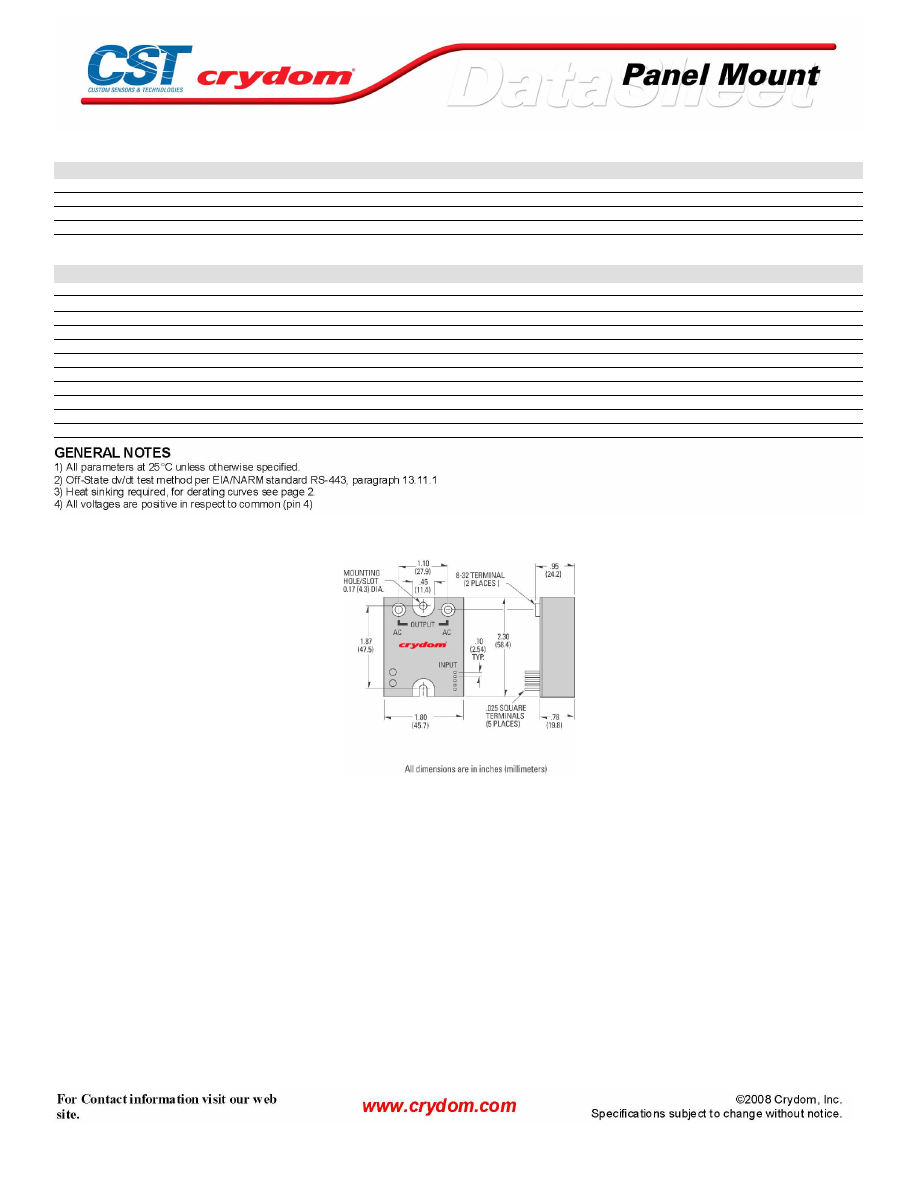
ALARM SPECIFICATIONS (1)(4)
Description
NORMALLY CLOSED
NORMALLY OPEN
Alarm-On Voltage
"Supply Voltage (with load) Open Col. NPN (pin 7)" "Supply Voltage (minus 1.0 V) Active High PNP (pin 8)"
Alarm-Off Voltage
"1.5 VDC Active Low NPN (pin 7)"
"0.0 VDC (with load) Open Col. PNP (pin 8)"
Maximum Alarm Output Current
100 mA
100 mA
Alarm Delay (Min.-Max.)
30-100 msec
30-100 msec
GENERAL SPECIFICATIONS
Description
Parameters
Dielectric Strength, Input/Output/Base (50/60Hz)
4000 Vrms
Minimum Insulation Resistance (@ 500 VDC)
10
9
Ohm
Maximum Capacitance, Input/Output
8 pF
Ambient Operating Temperature Range
-40 to 80°C
Ambient Storage Temperature Range
-40 to 125 °C
Weight (typical)
3.0 oz (86.5g)
Encapsulation
Thermally conductive Epoxy
Output Terminals:
Screws and Saddle Clamps Furnished, Unmounted
Input Connector (locking):
Panduit No. MLSS100-6 or Equivalent
Mating Connector (supplied):
Panduit No. CT00F22-6 or Equivalent
Recommended Terminal Screw Torque Range:
8-32 & 10-32 Screws - 20 in. lbs. (Screws dry without grease)
MECHANICAL SPECIFICATIONS
Courtesy of Steven Engineering, Inc.-230 Ryan Way, South San Francisco, CA 94080-6370-Main Office: (650) 588-9200-Outside Local Area: (800) 258-9200-www.stevenengineering.com
60MAIN-html.html
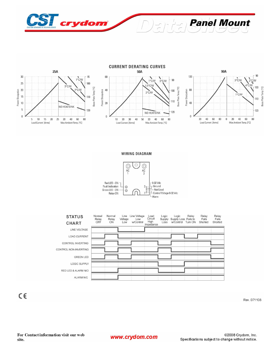
THERMAL DERATE INFORMATION
WIRING DIAGRAM
STATUS CHART
AGENCY APPROVALS
Courtesy of Steven Engineering, Inc.-230 Ryan Way, South San Francisco, CA 94080-6370-Main Office: (650) 588-9200-Outside Local Area: (800) 258-9200-www.stevenengineering.com
60MAIN-html.html

Courtesy of Steven Engineering, Inc.-230 Ryan Way, South San Francisco, CA 94080-6370-Main Office: (650) 588-9200-Outside Local Area: (800) 258-9200-www.stevenengineering.com
60MAIN-html.html

ANNEX - ENVIROMENTAL INFORMATION
Courtesy of Steven Engineering, Inc.-230 Ryan Way, South San Francisco, CA 94080-6370-Main Office: (650) 588-9200-Outside Local Area: (800) 258-9200-www.stevenengineering.com
60MAIN-html.html
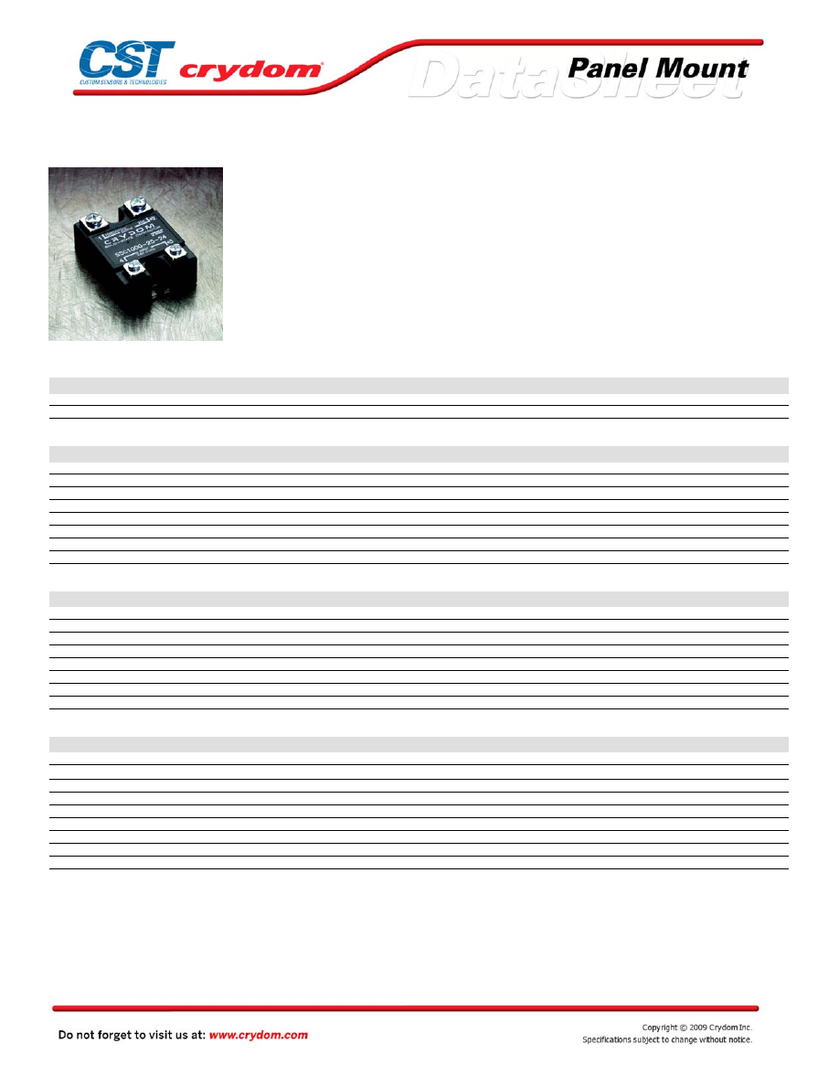
SSC Series
• IGBT based solid-state relay
• Ratings up to 25A @ 1,000 VDC
• DC control
PRODUCT SELECTION
25A
25A
SSC800-25
SSC1000-25
OUTPUT SPECIFICATIONS (1)
Description
800 VDC
1000 VDC
Operating Voltage [VDC]
0-800
0-1000
MaxImumTransient Overvoltage [Vpk]
900(4)
1200(5)
Maximum Off-State Leakage Current @ Rated Voltage [mArms]
0.3
0.3
Maximum Load Current (3) [Arms]
25
25
Minimum Load Current [mA]
20
20
Maximum Surge Current (16.6ms) [Apk]
75
75
Maximum On-State Voltage Drop @ Rated Current [Vpk]
1.6
1.6
Thermal Resistance Junction to Case (Rjc) [°C/W]
0.8
0.8
INPUT SPECIFICATIONS (1)
Description
Suffix -12
Suffix -24
Suffix -36
Nominal Control Voltage (6)
12 VDC
24 VDC
36 VDC
Control Voltage Range
8-16 VDC
20-28 VDC
32-40 VDC
Maximum Turn-On Voltage
8 VDC
20 VDC
32 VDC
Minimum Turn-Off Voltage
1.0 VDC
1.0 VDC
1.0 VDC
Typical Input Current at Nominal Voltage
15 mA
15 mA
15 mA
Nominal Input Impedance
780 Ohm
1500 Ohm
2400 Ohm
Maximum Turn-On Time [msec] (4)
1.5
1.5
1.5
Maximum Turn-Off Time [msec]
1.5
1.5
1.5
GENERAL SPECIFICATIONS
Description
Parameters
Dielectric Strength, Input/Output/Base (50/60Hz)(2)
2500 VRMS
Minimum Insulation Resistance (@ 500 V DC)(2)
10
9
Ohm
Maximum Capacitance, Input/Output
50 pF
Ambient Operating Temperature Range
-30 to 80°C
Ambient Storage Temperature Range
-40 to 125 °C
Weight (typical)
3.0 oz (86.5g)
Encapsulation
Thermally conductive Epoxy
Terminals
Screws and Saddle Clamps Furnished, Unmounted
Recommended Terminal Screw Torque Range:
6-32 Screws - 10 in lbs. 8-32 -20 in. lbs. (Screws dry without grase)
Courtesy of Steven Engineering, Inc.-230 Ryan Way, South San Francisco, CA 94080-6370-Main Office: (650) 588-9200-Outside Local Area: (800) 258-9200-www.stevenengineering.com
60MAIN-html.html
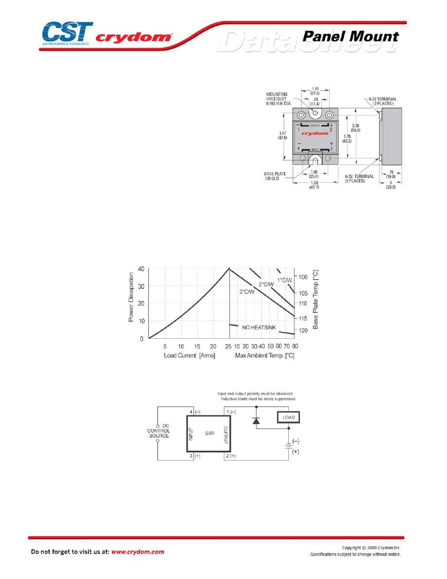
MECHANICAL SPECIFICATIONS
GENERAL NOTES
1
) All parameters at 25°C unless otherwise specified.
2) Dielectric strength and insulation resistance are measured between input and output
3) Heat sinking required, for derating curves see next page.
4) Internal overvoltage protection included.
5) Internal overvoltage protection not included.
6) Use suffix -12, -24 or -36 to specify control voltage. For other values call factory Sample:
SSC800-25-24
THERMAL DERATE INFORMATION
WIRING DIAGRAM
Transient Protection
All loads are inductive, even ones that are not so labeled. An
induc tive load will produce harmful transient voltages when it
is turned off. The more perfect the switch, the larger the
transient v oltages; the MOSFET output is so nearly an ideal
switch that the transient voltages produced by seemingly
“non-inductive” loads can cause damage if not suppressed.
Diodes should be fast recovery type with PIV rated greater
than
supply
voltage.
Rev.010509
Courtesy of Steven Engineering, Inc.-230 Ryan Way, South San Francisco, CA 94080-6370-Main Office: (650) 588-9200-Outside Local Area: (800) 258-9200-www.stevenengineering.com
60MAIN-html.html

Courtesy of Steven Engineering, Inc.-230 Ryan Way, South San Francisco, CA 94080-6370-Main Office: (650) 588-9200-Outside Local Area: (800) 258-9200-www.stevenengineering.com
60MAIN-html.html

ANNEX - ENVIROMENTAL INFORMATION
Courtesy of Steven Engineering, Inc.-230 Ryan Way, South San Francisco, CA 94080-6370-Main Office: (650) 588-9200-Outside Local Area: (800) 258-9200-www.stevenengineering.com
60MAIN-html.html
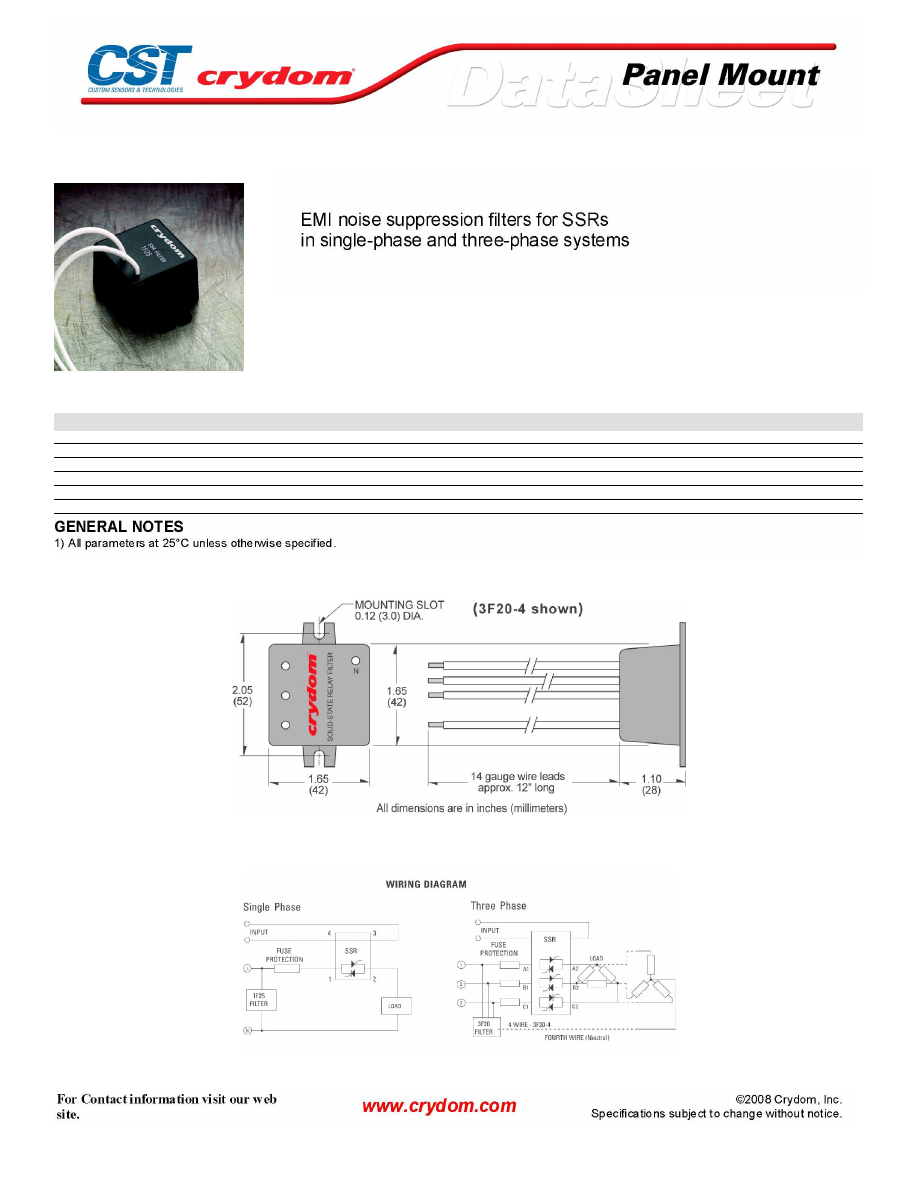
AC Filters
SPECIFICATIONS
Description
Model Number
1F25
3F20
3F20-4
Connection (number of phases)
Single
Three
Three (w/neutral)
Maximum Operating Voltage
275 VRMS
475 VRMS
475 VRMS
Operating Temperature Range
-40 to +100 ° C
Attenuation (150 to 250 Khz), typical
30 dBμV
25 dBμV
25 dBμV
Current Drain at VRMS max
40 mA
35 mA
35 mA
MECHANICAL SPECIFICATIONS
WIRING DIAGRAM
Courtesy of Steven Engineering, Inc.-230 Ryan Way, South San Francisco, CA 94080-6370-Main Office: (650) 588-9200-Outside Local Area: (800) 258-9200-www.stevenengineering.com
60MAIN-html.html

ANNEX - ENVIROMENTAL INFORMATION
Courtesy of Steven Engineering, Inc.-230 Ryan Way, South San Francisco, CA 94080-6370-Main Office: (650) 588-9200-Outside Local Area: (800) 258-9200-www.stevenengineering.com
60MAIN-html.html
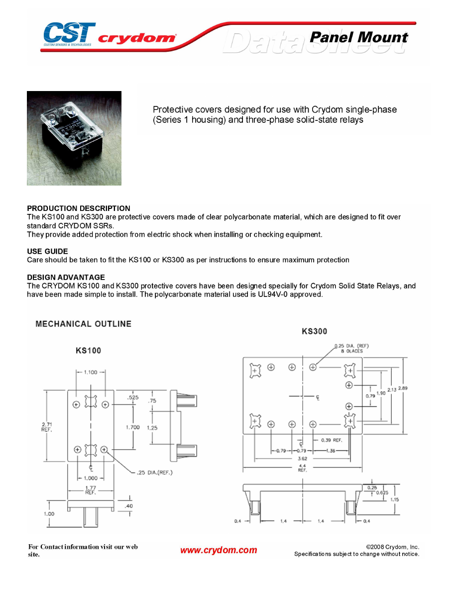
Protective Covers
KS100
MECHANICAL SPECIFICATIONS
Courtesy of Steven Engineering, Inc.-230 Ryan Way, South San Francisco, CA 94080-6370-Main Office: (650) 588-9200-Outside Local Area: (800) 258-9200-www.stevenengineering.com
60MAIN-html.html
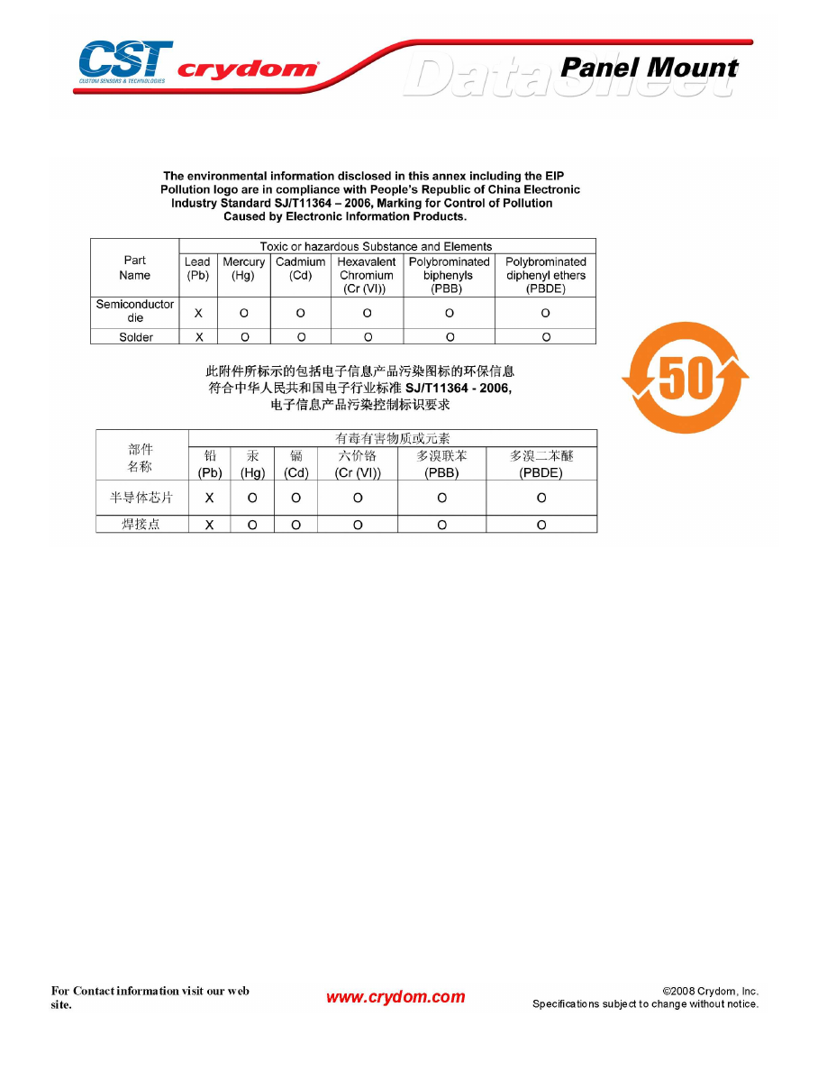
ANNEX - ENVIROMENTAL INFORMATION
Courtesy of Steven Engineering, Inc.-230 Ryan Way, South San Francisco, CA 94080-6370-Main Office: (650) 588-9200-Outside Local Area: (800) 258-9200-www.stevenengineering.com
60MAIN-html.html
Heat Transfer Pad
TP01
TP03
MECHANICAL SPECIFICATIONS
Courtesy of Steven Engineering, Inc.-230 Ryan Way, South San Francisco, CA 94080-6370-Main Office: (650) 588-9200-Outside Local Area: (800) 258-9200-www.stevenengineering.com
60MAIN-html.html
CMX Series
• SIP SSR
• Ratings to 10A @ 100 VDC, 10A @ 60 VDC and 3A @ 200 VDC
• MOSFET output
• DC control
• Low on-state impedance
PRODUCT SELECTION
Control Voltage
3A
5A
6A
10A
10A
20A
3-10 VDC
CMX200D3
CMX60D5
CMX100D6
CMX60D10
CMX100D10
CMX60D20
OUTPUT SPECIFICATIONS (1)(4)
Description
Operating Voltage [VDC]
0-200
0-60
0-100
0-60
0-100
0-60
Maximum Off-State Leakage Current @ Rated Voltage [µAdc]
100
100
100
100 (5)
100
100
Maximum Load Current [Arms]
3
5
6
10
10
20
Minimum Load Current [Arms]
0
0
0
0
0
0
Maximum On-State Resistence [Ohm] (2)
0.20
.10
.040
.018
.010
.0033
Maximum Surge Current (10msec) [Apk]
30
60
100
100
100
200
Maximum On-State Voltage Drop @ Rated Current [VDC]
0.6
0.5
0.24
0.18
0.1
0.1
INPUT SPECIFICATIONS (1)
Description
Control Voltage Range
3.0-10.0 VDC
Must Turn On Voltage
3.0 VDC
Must Turn Off Voltage
1 .0 VDC
Typycal Input Current @ 5 VDC
15 mAdc
Nominal Input Impedance
300 Ohm
Maximum Turn-On Time [msec]
1.0
Maximum Turn-Off Time [µsec]
300
GENERAL SPECIFICATIONS
Description
Parameters
Dielectric Strength, Input/Output/Base (50/60Hz)(3)
2500 Vrms
Minimum Insulation Resistance (@ 500 VDC)(3)
10
9
Ohm
Maximum Capacitance, Input/Output
15 pF
Ambient Operating Temperature Range
-30 to 80°C
Ambient Storage Temperature Range
-30 to 125°C
Weight (typical)
0.4 oz. (11g)
Encapsulation
Thermally Conductive Epoxy
1) All parameters at 25°C unless otherwise specified.
2) @ rated current (RDS-ON)
3) Dielectric and insulation resistance are measured between input and output
4) Inductiv e loads should be diode suppressed
5) At 55 Vdc
Courtesy of Steven Engineering, Inc.-230 Ryan Way, South San Francisco, CA 94080-6370-Main Office: (650) 588-9200-Outside Local Area: (800) 258-9200-www.stevenengineering.com
60MAIN-html.html
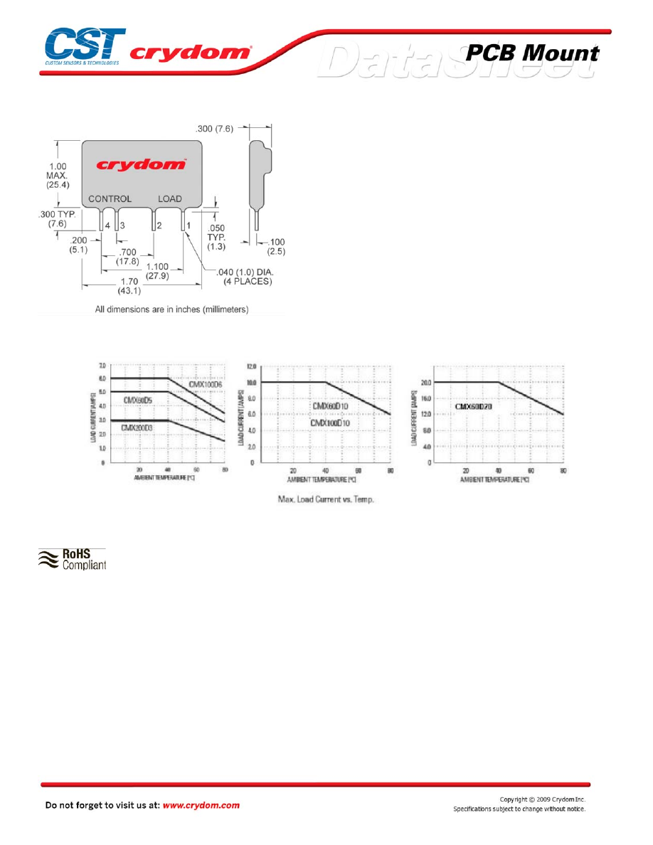
MECHANICAL SPECIFICATIONS
DC C ONTR OL
PIN 1: +DC LOAD
PIN 2: -D C LOAD
PIN 3: +DC CONTROL
PIN 4: -D C CONTROL
THERMAL DERATE INFORMATION
AGENCY APPROVALS
UL E116950(3 Amps, 6 Amps and 10 Amps Models)
Rev. 010509
Courtesy of Steven Engineering, Inc.-230 Ryan Way, South San Francisco, CA 94080-6370-Main Office: (650) 588-9200-Outside Local Area: (800) 258-9200-www.stevenengineering.com
60MAIN-html.html
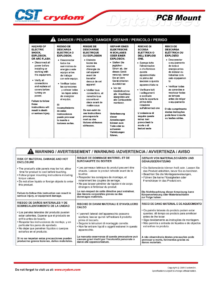
Courtesy of Steven Engineering, Inc.-230 Ryan Way, South San Francisco, CA 94080-6370-Main Office: (650) 588-9200-Outside Local Area: (800) 258-9200-www.stevenengineering.com
60MAIN-html.html
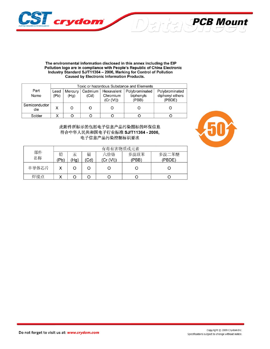
ANNEX - ENVIROMENTAL INFORMATION
Courtesy of Steven Engineering, Inc.-230 Ryan Way, South San Francisco, CA 94080-6370-Main Office: (650) 588-9200-Outside Local Area: (800) 258-9200-www.stevenengineering.com
60MAIN-html.html
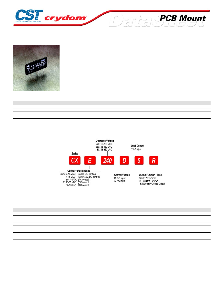
CX Series
• SIP SSR
• Ratings of 5A @ 660 VAC
• SCR output for heavy industrial loads
• AC or DC control
• Zero-crossing (resistive loads) or random-fire (inductive loads) output
PRODUCT SELECTION
Control Voltage
3-15 VDC
CX240D5
4-15 VDC
CX380D5
CX480D5
15-32 VDC
CXE240D5
CXE380D5
CXE480D5
18-36 VAC
CXE240A5
90-140 VAC
CX240A5
AVAILABLE OPTIONS
OUTPUT SPECIFICATIONS (1)
Description
Operating Voltage (47-63Hz) [Vrms]
12-280
48-530
48-660
Transient Overvoltage [Vpk]
600
1200
1200
Maximum Off-State Leakage Current @ Rated Voltage [mArms]
0.1
0.1
0.1
Minimum Off-State dv/dt @ Maximum Rated Voltage [V/µsec] (2)
500
500
500
Maximum Load Current [Arms]
5
5
5
Minimum Load Current [Arms]
0.06
0.06
0.06
Maximum Surge Current (16.6ms) [Apk]
250
250
250
Maximum On-State Voltage Drop @ Rated Current [Vpk]
1.4
1.4
1.4
Maximum I²t for fusing (8.3 msec) [A² sec]
260
260
260
Minimum Power Factor (with Maximum Load)
0.5
0.5
0.5
For Contact information visit our web
site.
www.crydom.com
©2008 Crydom, Inc.
Specifications subject to change without notice.
Courtesy of Steven Engineering, Inc.-230 Ryan Way, South San Francisco, CA 94080-6370-Main Office: (650) 588-9200-Outside Local Area: (800) 258-9200-www.stevenengineering.com
60MAIN-html.html
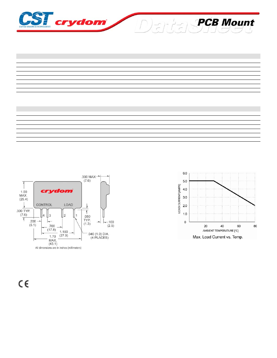
INPUT SPECIFICATIONS (1)
Description
CX240Dx
CX380Dx
CXExxxDx
CX240A5
CXE240A5
Nominal Voltage
5 VDC
5 VDC
24 VDC
120 VAC
24 VAC
Control Voltage Range
3-15 VDC
4-15 VDC
15-32 VDC
90-140 VAC
18-36 VAC
Minimum Turn-On Voltage
3.0 VDC
4.0 VDC
15.0 VDC
90.0 Vrms
18.0 Vrms
Drop Out Voltage
1.0 VDC
1.0 VDC
1.0 VDC
10.0 Vrms
2.0 Vrms
Typical Input Current
15 mAdc
15 mAdc
15 mAdc
10 mArms
10 mArms
Nominal Input Impedance
300 Ohm
240 Ohm
1500 Ohm
14.1 Ohm
2.1 Ohm
Maximum Turn-On Time [msec] (3)
1/2 Cycle
1/2 Cycle
1/2 Cycle
10
10
Maximum Turn-Off Time [msec]
1/2 Cycle
1/2 Cycle
1/2 Cycle
40
40
GENERAL SPECIFICATIONS
Description
Parameters
Dielectric Strength, Input/Output/Base (50/60Hz)
4000 Vrms
Minimum Insulation Resistance (@ 500 VDC)
10
9
Ohm
Maximum Capacitance, Input/Output
10 pF
Ambient Operating Temperature Range
-30 to 80 °C
Ambient Storage Temperature Range
-30 to 125 °C
Weight (typical)
0.4 oz. (11g)
Encapsulation
Therminally Conductive Epoxy
GENERAL NOTES
1) All parameters at 25°C unless otherwise specified.
2) Off-State dv/dt test method per EIA/NARM standard RS-443, paragraph 13.11.1
3) Turn-On time for random turn-on versions is 0.1 msec (DC Control Models).
MECHANICAL SPECIFICATIONS
DC C ONTR OL.
PIN 1: AC LOAD
PIN 2: AC LOAD
PIN 3: +DC CONTROL
PIN 4: -D C CONTROL
AC CONTROL.
PIN 1: AC LOAD
PIN 2: AC LOAD
PIN 3: AC C ONTR OL
PIN 4: AC C ONTR OL
AGENCY APPROVALS
UL E116949
CSA LR81689
VD E 70938 UG(240 V, 380V, DC Control Only)
VG (240 V, 380 V, DC Control Only)
Rev.
06132008
For Contact information visit our web
site.
www.crydom.com
©2008 Crydom, Inc.
Specifications subject to change without notice.
Courtesy of Steven Engineering, Inc.-230 Ryan Way, South San Francisco, CA 94080-6370-Main Office: (650) 588-9200-Outside Local Area: (800) 258-9200-www.stevenengineering.com
60MAIN-html.html
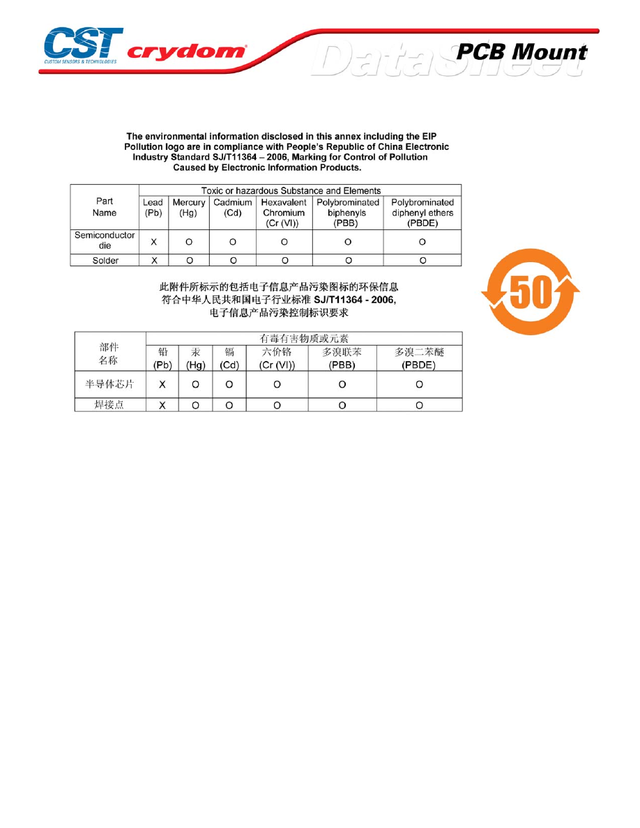
ANNEX - ENVIROMENTAL INFORMATION
For Contact information visit our web
site.
www.crydom.com
©2008 Crydom, Inc.
Specifications subject to change without notice.
Courtesy of Steven Engineering, Inc.-230 Ryan Way, South San Francisco, CA 94080-6370-Main Office: (650) 588-9200-Outside Local Area: (800) 258-9200-www.stevenengineering.com
60MAIN-html.html
CX-B Series
• SCR Output
• NC (Normally Closed) Configuration
• Ultra High Surge Rating
• Crydom’s Patented Design
PRODUCT SELECTION
Control Voltage
5 A
3-15 VDC
CX240D5-B
4-15 VDC
CX480D5-B
OUTPUT SPECIFICATIONS (1)
Description
Operating Voltage (47-63Hz) [Vrms]
12-280
48-530
Transient Overvoltage [Vpk]
600
1200
Maximum Off-State Leakage Current @ Rated Voltage [mArms]
5.0
5.0
Minimum Off-State dv/dt @ Maximum Rated Voltage [V/µsec] (2)
500
500
Maximum Load Current [Arms]
5
5
Minimum Load Current [Arms]
0.06
0.06
Maximum Surge Current (16.6ms) [Apk]
250
250
Maximum On-State Voltage Drop @ Rated Current [Vpk]
1.4
1.4
Maximum I² t for fusing (8.3 msec) [A² sec]
260
260
Minimum Power Factor (with Maximum Load)
0.5
0.5
INPUT SPECIFICATIONS (1)
Description
Must Turn On Voltage Range
0-1.0 VDC
Must Turn Off Voltage Range
4-28 VDC
Typical Input Current @ 15 VDC
10 mAdc
Nominal Input Impedance
1360 Ohm
Maximum Turn-On Time [msec] (3)
1/2 Cycle
Maximum Turn-Off Time [msec]
1/2 Cycle
GENERAL SPECIFICATIONS
Description
Parameters
Dielectric Strength, Input/Output/Base (50/60Hz)
4000 Vrms
Minimum Insulation Resistance (@ 500 VDC)
10
9
Ohm
Maximum Capacitance, Input/Output
10 pF
Ambient Operating Temperature Range
-30 to 80 °C
Ambient Storage Temperature Range
-30 to 125 °C
Weight (typical)
0.4 oz. (11g)
Encapsulation
Therminally Conductive Epoxy
GENERAL NOTES
1) All parameters at 25°C unless otherwise specified.
2) Off-State dv/dt test method per EIA/NARM standard RS-443, paragraph 13.11.1
3) Turn-On time for random turn-on versions is 0.01 msec (DC Control Models).
For Contact information visit our web
site.
www.crydom.com
©2008 Crydom, Inc.
Specifications subject to change without notice.
Courtesy of Steven Engineering, Inc.-230 Ryan Way, South San Francisco, CA 94080-6370-Main Office: (650) 588-9200-Outside Local Area: (800) 258-9200-www.stevenengineering.com
60MAIN-html.html
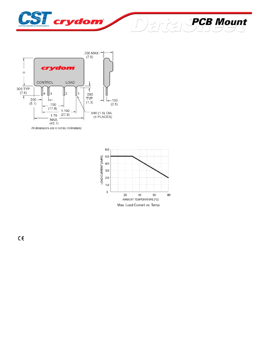
MECHANICAL SPECIFICATIONS
DC CONTROL
PIN 1: AC LOAD
PIN 2: AC LOAD
PIN 3: +D C CONTROL
PIN 4: -DC CONTROL
AC CONTROL
PIN 1: AC LOAD
PIN 2: AC LOAD
PIN 3: AC CONTROL
PIN 4: AC CONTROL
H = 1.0 (25.4) max for CX240
H = 1.5 (36.8) max for CX480
THERMAL DERATE INFORMATION
AGENCY APPROVALS
UL E116950
CSA LR81689
Rev. 061608
For Contact information visit our web
site.
www.crydom.com
©2008 Crydom, Inc.
Specifications subject to change without notice.
Courtesy of Steven Engineering, Inc.-230 Ryan Way, South San Francisco, CA 94080-6370-Main Office: (650) 588-9200-Outside Local Area: (800) 258-9200-www.stevenengineering.com
60MAIN-html.html
ANNEX - ENVIROMENTAL INFORMATION
For Contact information visit our web
site.
www.crydom.com
©2008 Crydom, Inc.
Specifications subject to change without notice.
Courtesy of Steven Engineering, Inc.-230 Ryan Way, South San Francisco, CA 94080-6370-Main Office: (650) 588-9200-Outside Local Area: (800) 258-9200-www.stevenengineering.com
60MAIN-html.html
D2W Series
• SIP SSR
• Ratings to 3.5A @ 280 VAC
• DC control
• Zero-crossing (resistive loads) output
• Internal snubber network
PRODUCT SELECTION
Control Voltage
2A
3A
3.5A
3-32 VDC
D2W202F
D2W203F
D2W203F-11
OUTPUT SPECIFICATIONS (1)
Description
Operating Voltage (47-63Hz) [Vrms]
24-280
24-280
24-280
Transient Overvoltage [Vpk]
600
600
600
Maximum Off-State Leakage Current @ Rated Voltage [mArms]
8
8
8
Minimum Off-State dv/dt @ Maximum Rated Voltage [V/µsec] (3)
200
200
200
Maximum Load Current [Arms]
2
3
3.5
Minimum Load Current [Arms]
0.06
0.06
0.06
Maximum Surge Current (16.6ms) [Apk]
28
70
80
Maximum On-State Voltage Drop @ Rated Current [Vpk]
1.4
1.4
1.4
Minimum Power Factor (with Maximum Load)
0.5
0.5
0.5
INPUT SPECIFICATIONS (1)
Description
Control Voltage Range
3-32 VDC
Must Turn On Voltage
3.0 VDC
Must Turn Off Voltage
1.0 VDC
Typical Input Current @ 5 VDC
3.0 mAdc
Nominal Input Impedance
1500 Ohm
Maximum Turn-On Time [msec]
1/2 Cycle
Maximum Turn-Off Time [msec]
1/2 Cycle
GENERAL SPECIFICATIONS
Description
Parameters
Dielectric Strength, Input/Output/Base (50/60Hz)(2)
4000 Vrms
Minimum Insulation Resistance (@ 500 VDC)(2)
10
9
Ohm
Maximum Capacitance, Input/Output
10 pF
Ambient Operating Temperature Range
-30 to 80°C
Ambient Storage Temperature Range
-30 to 125°C
Weight (typical)
0.6 oz. (17g)
Encapsulation
Thermally Conductive Epoxy
GENERAL NOTES
1) All parameters at 25°C unless otherwise specified.
2) Dielectric and insulation resistance are measured between input and output
3) Off-State dv/dt test method per EIA/NARM standard RS
For Contact information visit our web
site.
www.crydom.com
©2008 Crydom, Inc.
Specifications subject to change without notice.
Courtesy of Steven Engineering, Inc.-230 Ryan Way, South San Francisco, CA 94080-6370-Main Office: (650) 588-9200-Outside Local Area: (800) 258-9200-www.stevenengineering.com
60MAIN-html.html
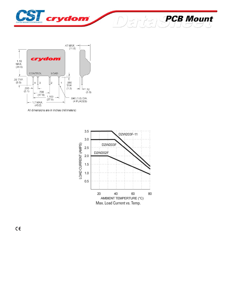
MECHANICAL SPECIFICATIONS
PIN 1: AC LOAD
PIN 2: AC LOAD
PIN 3: +DC CONTROL
PIN 4: -DC CONTROL
THERMAL DERATE INFORMATION
AGENCY APPROVALS
UL E116950
CSA LR81689
Rev. 061608
For Contact information visit our web
site.
www.crydom.com
©2008 Crydom, Inc.
Specifications subject to change without notice.
Courtesy of Steven Engineering, Inc.-230 Ryan Way, South San Francisco, CA 94080-6370-Main Office: (650) 588-9200-Outside Local Area: (800) 258-9200-www.stevenengineering.com
60MAIN-html.html

For Contact information visit our web
site.
www.crydom.com
©2008 Crydom, Inc.
Specifications subject to change without notice.
Courtesy of Steven Engineering, Inc.-230 Ryan Way, South San Francisco, CA 94080-6370-Main Office: (650) 588-9200-Outside Local Area: (800) 258-9200-www.stevenengineering.com
60MAIN-html.html

ANNEX - ENVIROMENTAL INFORMATION
For Contact information visit our web
site.
www.crydom.com
©2008 Crydom, Inc.
Specifications subject to change without notice.
Courtesy of Steven Engineering, Inc.-230 Ryan Way, South San Francisco, CA 94080-6370-Main Office: (650) 588-9200-Outside Local Area: (800) 258-9200-www.stevenengineering.com
60MAIN-html.html
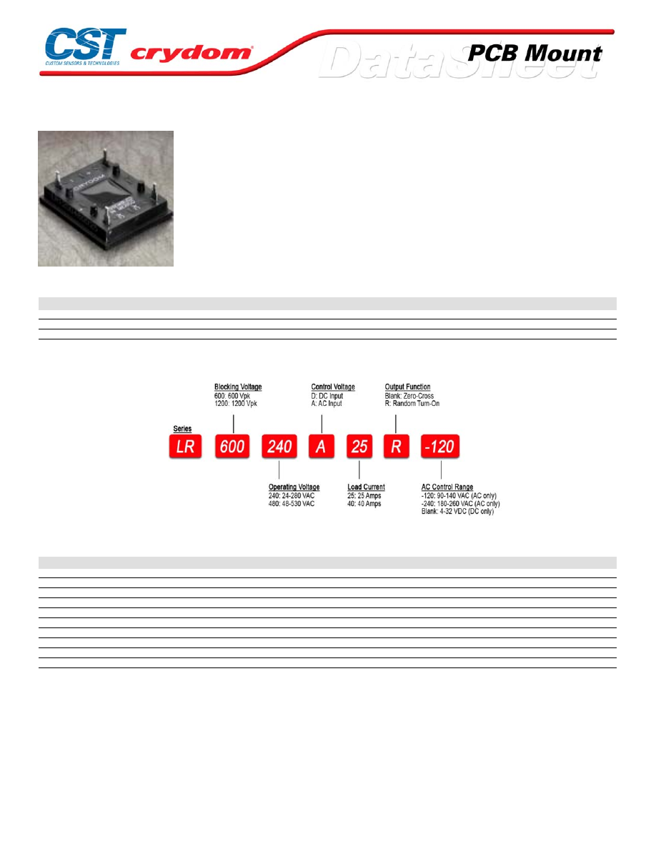
LR Series
• DIP SSR
• Ratings to 40A @ 480 V AC with external heat sink
• SCR output for heavy industrial loads
• AC or DC control
• Zero-crossing (resistive loads) or random-fire (inductive loads) output
PRODUCT SELECTION
Control Voltage
25A
25A
40A
40A
90-140 VAC
LR600240A25
LR600240A40
LR1200480A25
LR1200480A40
180-260 VAC
LR600240A25
LR600240A40
LR1200480A25
LR1200480A40
4-32 VDC
LR600240D25
LR600240D40
LR1200480D25
LR1200480D40
AVAILABLE OPTIONS
OUTPUT SPECIFICATIONS (1)
Description
Operating Voltage (47-63Hz) [Vrms]
24-280
24-280
48-530
48-530
Transient Overvoltage [Vpk]
600
600
1200
1200
Maximum Off-State Leakage Current @ Rated Voltage [mArms]
0.1
0.1
0.1
0.1
Minimum Off-State dv/dt @ Maximum Rated Voltage [V/µsec] (3)
500
500
500
500
Maximum Load Current [Arms]
25
40
25
40
Minimum Load Current [Arms]
0.15
0.15
0.15
0.15
Maximum Surge Current Non-Repetitive(16.6ms) [Apk]
250
400
250
400
Maximum On-State Voltage Drop @ Rated Current [Vpk]
1.6
1.6
1.6
1.6
Maximum I² t for fusing (8.3 msec) [A² sec]
260
660
260
660
Minimum Power Factor (with Maximum Load)
0.5
0.5
0.5
0.5
For Contact information visit our web
site.
www.crydom.com
©2008 Crydom, Inc.
Specifications subject to change without notice.
Courtesy of Steven Engineering, Inc.-230 Ryan Way, South San Francisco, CA 94080-6370-Main Office: (650) 588-9200-Outside Local Area: (800) 258-9200-www.stevenengineering.com
60MAIN-html.html
INPUT SPECIFICATIONS (1)
Description
Control Voltage Range
4-32 VDC
90-140 V
180-260 V
Must Turn On Voltage
4.0 VDC
90 VAC
180 VAC
Must Turn Off Voltage
1.0 VDC
10 VAC
10 VAC
Typical Input Current (5)(6)
9 mAdc
15
11
Maximum Turn-On Time [msec] (4)
1/2 Cycle
10.0
10.0
Maximum Turn-Off Time [msec]
1/2 Cycle
40.0
40.0
GENERAL SPECIFICATIONS
Description
Parameters
Dielectric Strength, Input/Output/Base (50/60Hz)
2500 Vrms
Minimum Insulation Resistance (@ 500 VDC)
10
9
Ohm
Maximum Capacitance, Input/Output
8.0 pF
Ambient Operating Temperature Range
-30 to 80°C
Ambient Storage Temperature Range
-30 to 125°C
Weight (typical)
0.5 oz. (14.4g)
Encapsulation
Thermally Conductive Epoxy
GENERAL NOTES
1) All parameters at 25°C and per section unless otherwise specified.
2) Dielectric and insulation resistance are measured between input and output
3) Off-State dv/dt test method per EIA/NARM standard RS-443, paragraph 13.11.1
4) Turn-on time for random Switching models is 0.1 ms.
5) DC Input circ uitry inc orporates active current limiter.
6) Us e suffix-120 for 120 VAC control and -240 for 240VAC control
For Contact information visit our web
site.
www.crydom.com
©2008 Crydom, Inc.
Specifications subject to change without notice.
Courtesy of Steven Engineering, Inc.-230 Ryan Way, South San Francisco, CA 94080-6370-Main Office: (650) 588-9200-Outside Local Area: (800) 258-9200-www.stevenengineering.com
60MAIN-html.html
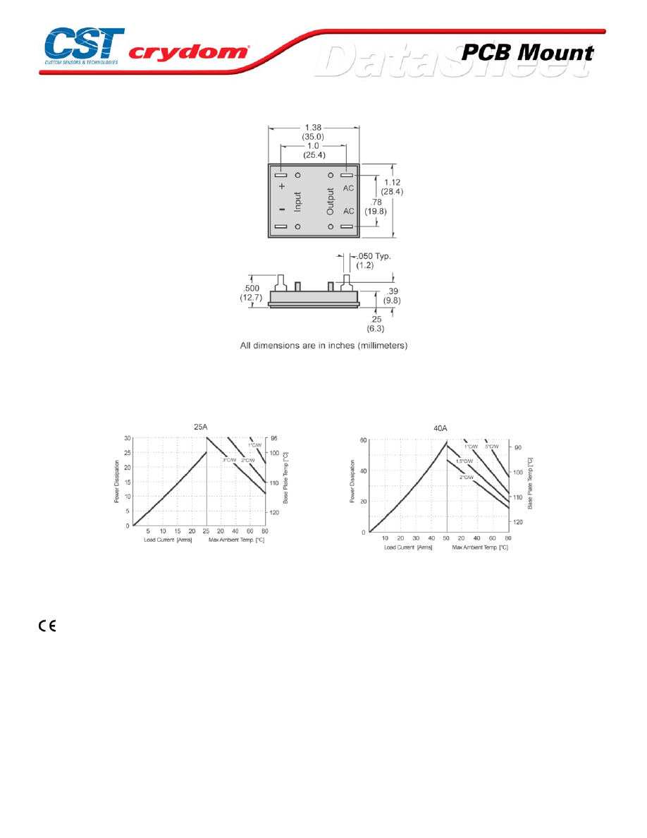
MECHANICAL SPECIFICATIONS
THERMAL DERATE INFORMATION
AGENCY APPROVALS
UL/cUL E116950
For Contact information visit our web
site.
www.crydom.com
©2008 Crydom, Inc.
Specifications subject to change without notice.
Courtesy of Steven Engineering, Inc.-230 Ryan Way, South San Francisco, CA 94080-6370-Main Office: (650) 588-9200-Outside Local Area: (800) 258-9200-www.stevenengineering.com
60MAIN-html.html

ANNEX - ENVIROMENTAL INFORMATION
For Contact information visit our web
site.
www.crydom.com
©2008 Crydom, Inc.
Specifications subject to change without notice.
Courtesy of Steven Engineering, Inc.-230 Ryan Way, South San Francisco, CA 94080-6370-Main Office: (650) 588-9200-Outside Local Area: (800) 258-9200-www.stevenengineering.com
60MAIN-html.html
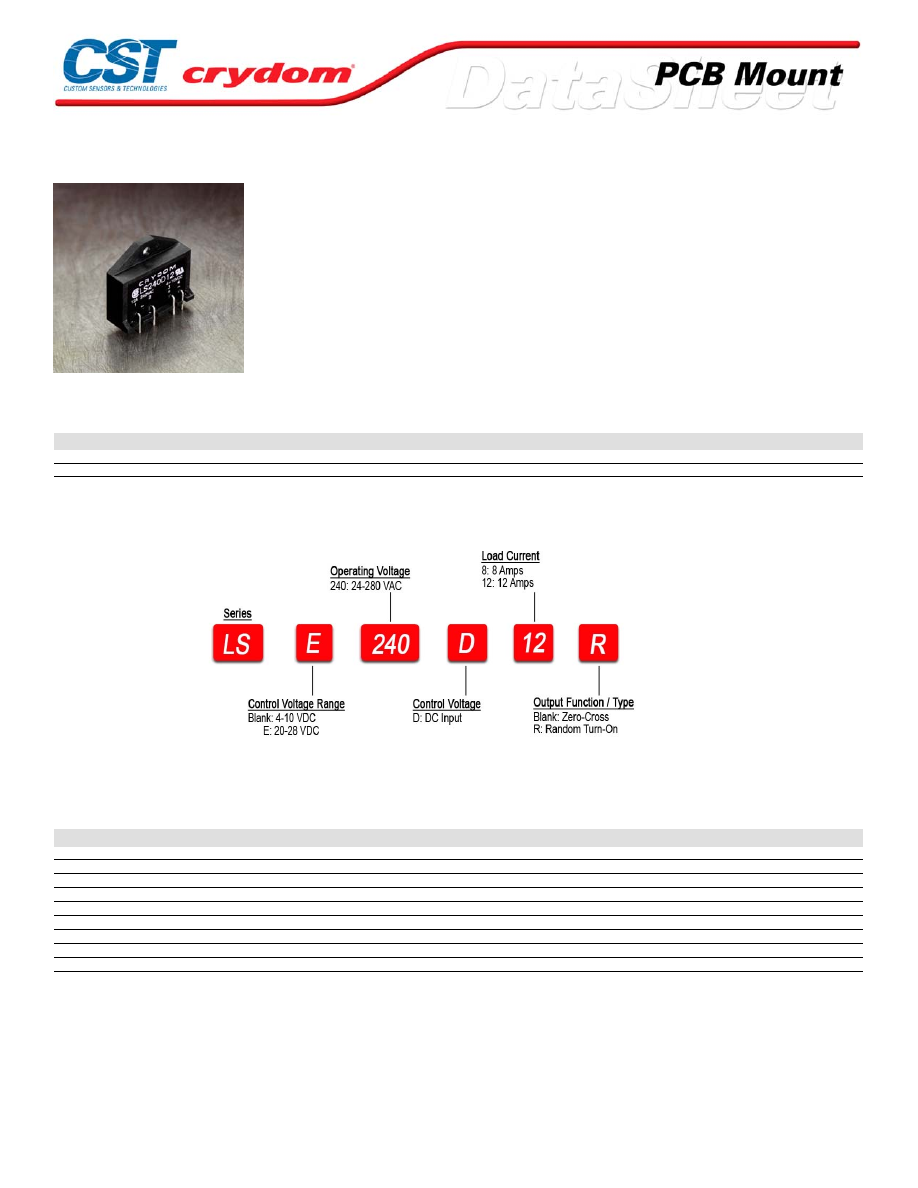
LS Series
• SIP SSR
• Ratings to 12A @ 280 VAC
• SCR output for heavy industrial loads
• DC control
• Zero-crossing (resistive loads) or random-fire (inductive loads) output
PRODUCT SELECTION
Control Voltage
8A
12A
4-10 VDC
LS240D8
LS240D12
20-28 VDC
LSE240D8
LSE240D12
AVAILABLE OPTIONS
OUTPUT SPECIFICATIONS (1)
Description
Operating Voltage (47-63Hz) [Vrms]
24-280
24-280
Transient Overvoltage [Vpk]
600
600
Maximum Off-State Leakage Current @ Rated Voltage [mArms]
0.1
0.1
Minimum Off-State dv/dt @ Maximum Rated Voltage [V/µsec] (2)
500
500
Maximum Load Current [Arms](3)
8
12
Minimum Load Current [Arms]
0.15
0.15
Maximum Surge Current (16.6ms) [Apk]
80
120
Maximum On-State Voltage Drop @ Rated Current [Vpk]
1.6
1.6
Minimum Power Factor (with Maximum Load)
0.5
0.5
For Contact information visit our web
site.
www.crydom.com
©2008 Crydom, Inc.
Specifications subject to change without notice.
Courtesy of Steven Engineering, Inc.-230 Ryan Way, South San Francisco, CA 94080-6370-Main Office: (650) 588-9200-Outside Local Area: (800) 258-9200-www.stevenengineering.com
60MAIN-html.html
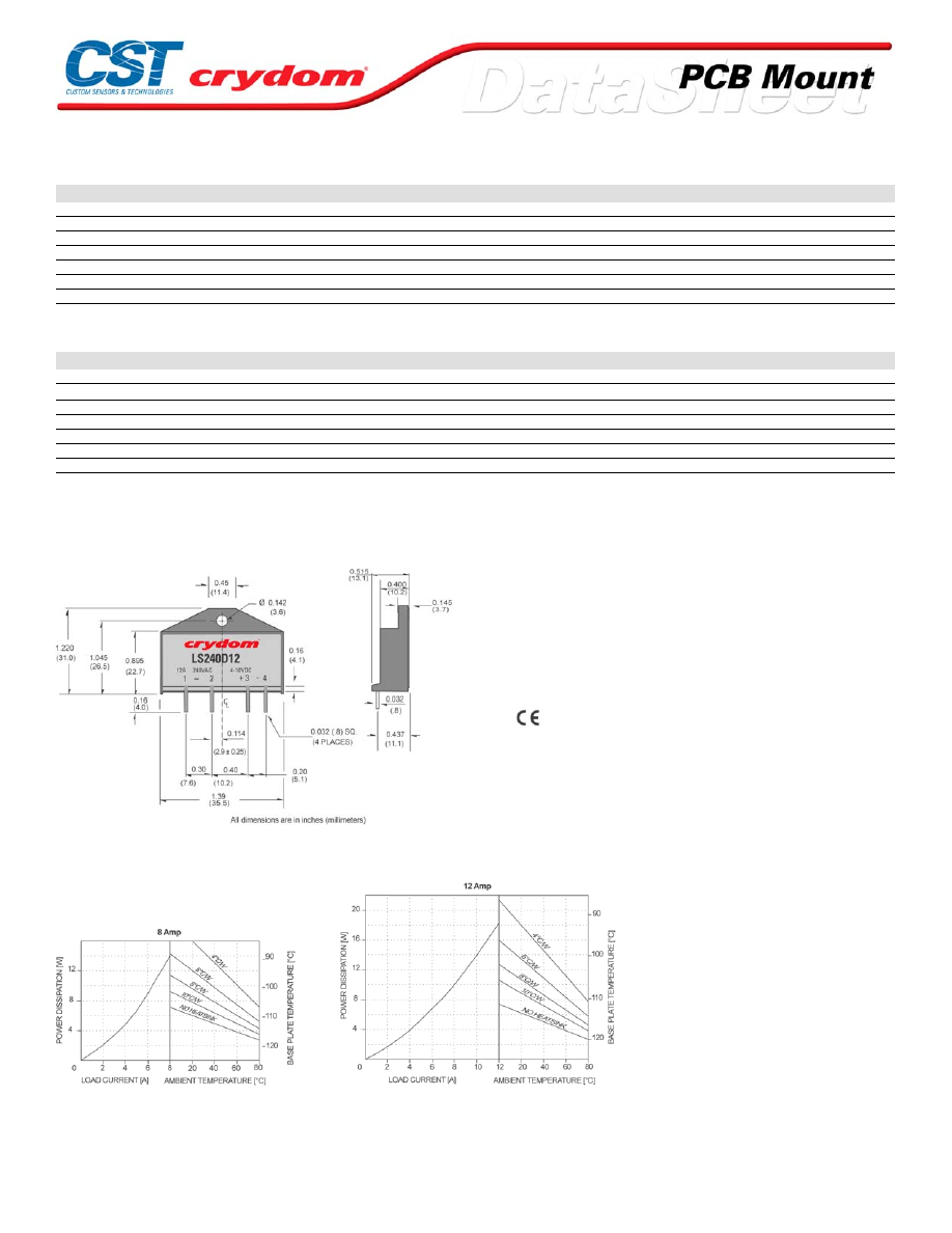
INPUT SPECIFICATIONS (1)
Description
Control Voltage Range
4-10 VDC
20-28 VDC
Minimum Turn On Voltage
4.0 VDC
20 VDC
Minimum Turn-Off Voltage
1.0 VDC
1.0 VDC
Typical Input Current @ Nominal Voltage
15 mAdc
15 mAdc
Nominal Input Impedance
270 Ohm
1500 Ohm
Maximum Turn-On Time [msec]
1/2 Cycle
1/2 Cycle
Maximum Turn-Off Time [msec]
1/2 Cycle
1/2 Cycle
GENERAL SPECIFICATIONS
Description
Parameters
Dielectric Strength, Input/Output/Base (50/60Hz)
2500 Vrms
Minimum Insulation Resistance (@ 500 VDC)
10
9
Ohm
Maximum Capacitance, Input/Output
10pF
Ambient Operating Temperature Range
-30 to 80°C
Ambient Storage Temperature Range
-30 to 125°C
Weight (typical)
0.6 oz. (17g)
Encapsulation
Therminally Conductive Epoxy
GENERAL NOTES
1) All parameters at 25°C unless otherwise specified.
2) Off-State dv/dt test method per EIA/NARM standard RS-443, paragraph 13.11.1
3) See current derating curve.
MECHANICAL SPECIFICATIONS
PIN 1: AC LOAD
PIN 2: AC LOAD
PIN 3: + DC CONTROL
PIN 4: -DC CONTROL
N otes:
1.-Tolerances are ±0.02" (0.5mm) unless otherwise stated.
2.-All pin dimensions are from center of pin
UL E116950
CSA LR816889
TUV E2072777
Rev. 071608
THERMAL DERATE INFORMATION
For Contact information visit our web
site.
www.crydom.com
©2008 Crydom, Inc.
Specifications subject to change without notice.
Courtesy of Steven Engineering, Inc.-230 Ryan Way, South San Francisco, CA 94080-6370-Main Office: (650) 588-9200-Outside Local Area: (800) 258-9200-www.stevenengineering.com
60MAIN-html.html

ANNEX - ENVIROMENTAL INFORMATION
For Contact information visit our web
site.
www.crydom.com
©2008 Crydom, Inc.
Specifications subject to change without notice.
Courtesy of Steven Engineering, Inc.-230 Ryan Way, South San Francisco, CA 94080-6370-Main Office: (650) 588-9200-Outside Local Area: (800) 258-9200-www.stevenengineering.com
60MAIN-html.html
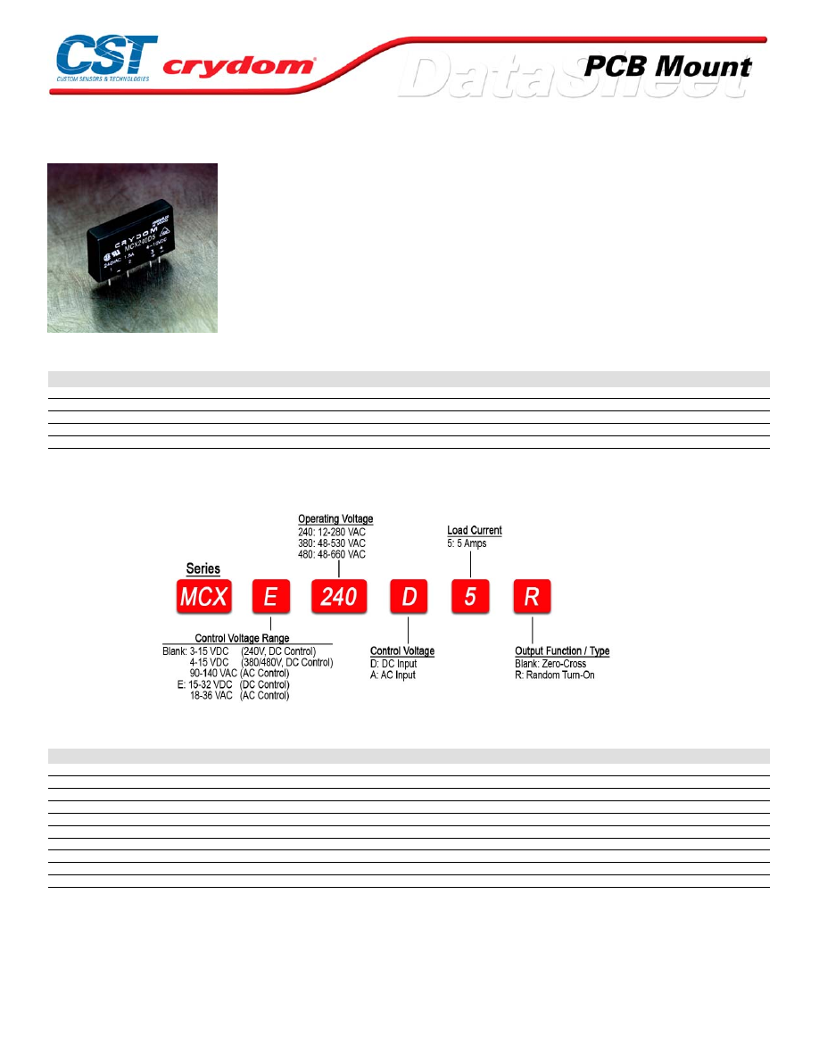
MCX Series
• SIP SSR
• Ratings to 5A @ 280 VAC
• SCR output for heavy industrial loads
• AC or DC control
• Zero-crossing (resistive loads) or random-fire (inductive loads) output
• Plastic encapsulated
PRODUCT SELECTION
Control Voltage
5A
5A
5A
3-15 VDC
MCX240D5
4-15 VDC
MCX380D5
MCX480D5
15-32 VDC
MCXE240D5
MCXE380D5
MCXE480D5
18-36 VAC
MCXE240A5
90-140 VAC
MCX240A5
AVAILABLE OPTIONS
OUTPUT SPECIFICATIONS (1)
Description
Operating Voltage (47-63Hz) [Vrms]
12-280
48-530
48-660
Transient Overvoltage [Vpk]
600
1200
1200
Maximum Off-State Leakage Current @ Rated Voltage [mArms]
0.1
0.1
0.1
Minimum Off-State dv/dt @ Maximum Rated Voltage [V/µsec] (2)
500
500
500
Maximum Load Current [Arms](3)
5
5
5
Minimum Load Current [Arms]
0.06
0.06
0.06
Maximum Surge Current (16.6ms) [Apk]
250
250
250
Maximum On-State Voltage Drop @ Rated Current [Vpk]
1.4
1.4
1.4
Maximum I²t for fusing (8.3 msec) [A²sec]
260
260
260
Minimum Power Factor (with Maximum Load)
0.5
0.5
0.5
For Contact information visit our web
site.
www.crydom.com
©2008 Crydom, Inc.
Specifications subject to change without notice.
Courtesy of Steven Engineering, Inc.-230 Ryan Way, South San Francisco, CA 94080-6370-Main Office: (650) 588-9200-Outside Local Area: (800) 258-9200-www.stevenengineering.com
60MAIN-html.html
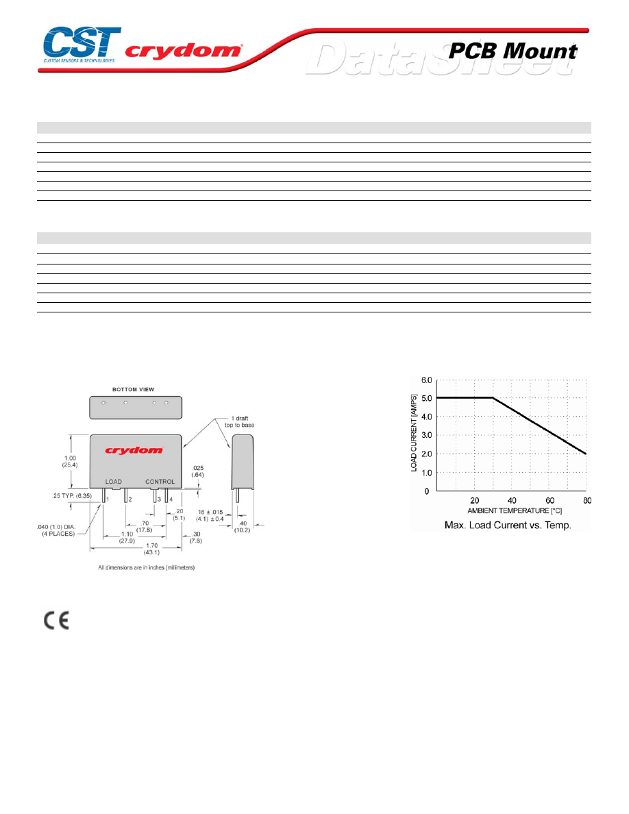
INPUT SPECIFICATIONS (1)
Description
MCX240Dx
MCX380Dx
MCXExxxDx
MCX240A5
MCXE240A5
Control Voltage Range
3-15 VDC
4-15 VDC
15-32 VDC
90-140 VAC
18-36 VAC
Maximum Turn On Voltage
3.0 VDC
4.0 VDC
15.0 VDC
90.0 Vrms
18.0 Vrms
Mimimum Turn-Off Voltage
1.0 VDC
1.0 VDC
1.0 VDC
10.0 Vrms
2.0 VDC
Input Current @ Nominal Voltage
15 mAdc
15 mAdc
15 mAdc
10 mAdc
10 mAdc
Nominal Input Impedance
300 Ohm
240 Ohm
1500 Ohm
14.1 Ohm
2.1 k Ohm
Maximum Turn-On Time [msec] (3)
1/2 Cycle
1/2 Cycle
1/2 Cycle
10
10
Maximum Turn-Off Time [msec]
1/2 Cycle
1/2 Cycle
1/2 Cycle
40
40
GENERAL SPECIFICATIONS
Description
Parameters
Dielectric Strength, Input/Output/Base (50/60Hz)
4000 Vrms
Minimum Insulation Resistance (@ 500 VDC)
10
9
Ohm
Maximum Capacitance, Input/Output
10pF
Ambient Operating Temperature Range
-40 to 80 °C
Ambient Storage Temperature Range
-40 to 125 °C
Weight (typical)
0.7 oz. (20g)
Encapsulation
Therminally Conductive Epoxy
GENERAL NOTES
1) All parameters at 25°C unless otherwise specified.
2) Off-State dv/dt test method per EIA/NARM standard RS-443, paragraph 13.11.1
3) Turn-On time for random turn-on versions is 0.01 msec (DC Control Models).
MECHANICAL SPECIFICATIONS
DC CONTROL.
PIN 1: AC LOAD
PIN 2: AC LOAD
PIN 3: +DC CONTROL
PIN 4: -DC CONTROL
AC CONTROL.
PIN 1: AC LOAD
PIN 2: AC LOAD
PIN 3: AC C ONTR OL
PIN 4: AC CONTROL
AGENCY APPROVALS
UL E116949
Rev. 061608
For Contact information visit our web
site.
www.crydom.com
©2008 Crydom, Inc.
Specifications subject to change without notice.
Courtesy of Steven Engineering, Inc.-230 Ryan Way, South San Francisco, CA 94080-6370-Main Office: (650) 588-9200-Outside Local Area: (800) 258-9200-www.stevenengineering.com
60MAIN-html.html

For Contact information visit our web
site.
www.crydom.com
©2008 Crydom, Inc.
Specifications subject to change without notice.
Courtesy of Steven Engineering, Inc.-230 Ryan Way, South San Francisco, CA 94080-6370-Main Office: (650) 588-9200-Outside Local Area: (800) 258-9200-www.stevenengineering.com
60MAIN-html.html

ANNEX - ENVIROMENTAL INFORMATION
For Contact information visit our web
site.
www.crydom.com
©2008 Crydom, Inc.
Specifications subject to change without notice.
Courtesy of Steven Engineering, Inc.-230 Ryan Way, South San Francisco, CA 94080-6370-Main Office: (650) 588-9200-Outside Local Area: (800) 258-9200-www.stevenengineering.com
60MAIN-html.html
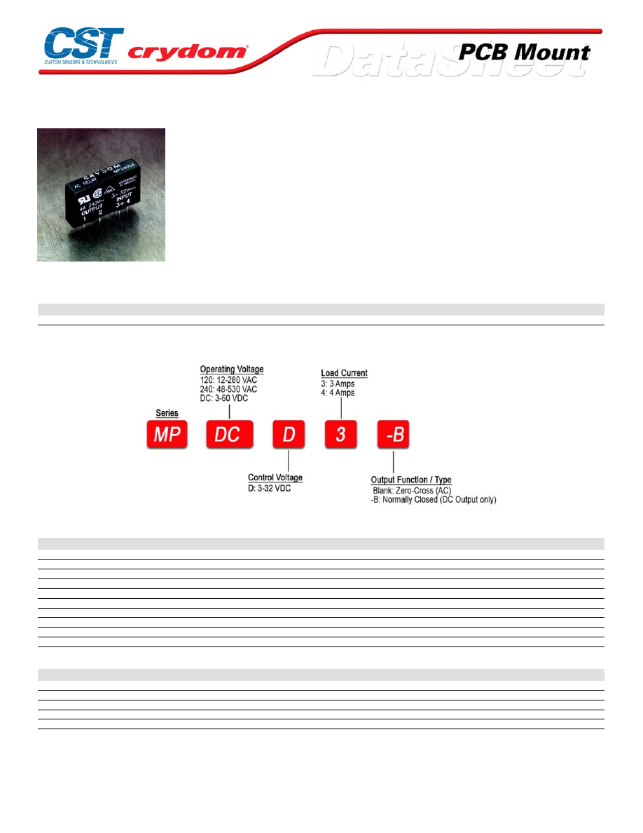
MP Series
•
SIP SSR
• Ratings to 3A @ 60 VDC
• MOSFET output
• DC Control
• Low on-state impedance
• Normally open or normally closed output
PRODUCT SELECTION
Control Voltage
3A
3A
4A
3A
3-32 VDC
MP120D3
MP240D3
MP240D4
MPDCD3
AVAILABLE OPTIONS
AC OUTPUT SPECIFICATIONS (1)
Description
Operating Voltage (47-63Hz) [Vrms]
12-140
24-280
24-280
Transient Overvoltage [Vpk]
400
600
600
Maximum Off-State Leakage Current @ Rated Voltage [mArms]
5
5
5
Minimum Off-State dv/dt @ Maximum Rated Voltage [V/µsec] (2)
200
200
200
Maximum Load Current [Arms]
3
3
4
Minimum Load Current [Arms]
0.02
0.02
0.02
Maximum Surge Current (16.6ms) [Apk]
90
90
130
Maximum On-State Voltage Drop @ Rated Current [Vpk]
1.6
1.6
1.6
Maximum I²t for fusing (8.3 msec) [A² sec]
36
36
72
Minimum Power Factor (with Maximum Load)
0.5
0.5
0.5
DC OUTPUT SPECIFICATIONS (1)
Description
Operating Voltage Range [VDC]
3-60
Maximum Load Current [Arms]
3
Minimum Load Current [Arms]
0.02
Maximum Surge Current [Adc]
5
Maximum On-State Voltage Drop @ Rated Current [Vpk]
1.5
For Contact information visit our web
site.
www.crydom.com
©2008 Crydom, Inc.
Specifications subject to change without notice.
Courtesy of Steven Engineering, Inc.-230 Ryan Way, South San Francisco, CA 94080-6370-Main Office: (650) 588-9200-Outside Local Area: (800) 258-9200-www.stevenengineering.com
60MAIN-html.html

INPUT SPECIFICATIONS (1)
Description
AC Output
DC Output
DC Output (-B)
Control Voltage Range
3-32 VDC
3-32 VDC
3-32 VDC
Must Turn On Voltage
3.0 VDC
3.0 VDC
1.0 VDC
Must Turn Off Voltage
1.0 VDC
1.0 VDC
3.0 VDC
Nominal Input Impedance
1500 Ohm
1500 Ohm
1500 Ohm
Maximum Turn-On Time [msec]
1/2 Cycle
100 µs
100 µs
Maximum Turn-Off Time [msec]
1/2 Cycle
100 µs
100 µs
GENERAL SPECIFICATIONS
Description
Parameters
Dielectric Strength, Input/Output/Base (50/60Hz)
4000 Vrms
Minimum Insulation Resistance (@ 500 VDC)
10
9
Ohm
Maximum Capacitance, Input/Output
8 pF
Ambient Operating Temperature Range
-40 to 80°C
Ambient Storage Temperature Range
-40 to 125°C
Weight (typical)
0.7 oz. (20g)
Encapsulation
Thermally Conductive Epoxy
GENERAL NOTES
1) All parameters at 25°C unless otherwise specified.
2) Off-State dv/dt test method per EIA/NARM standard RS-443,13.11.1
3) Inductiv e loads should be diode suppressed
For Contact information visit our web
site.
www.crydom.com
©2008 Crydom, Inc.
Specifications subject to change without notice.
Courtesy of Steven Engineering, Inc.-230 Ryan Way, South San Francisco, CA 94080-6370-Main Office: (650) 588-9200-Outside Local Area: (800) 258-9200-www.stevenengineering.com
60MAIN-html.html
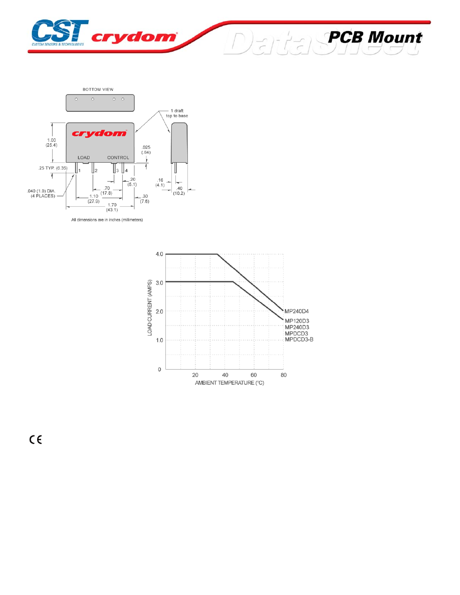
MECHANICAL SPECIFICATIONS
DC OUTPUT
PIN 1: +DC LOAD
PIN 2: -D C LOAD
PIN 3: +DC CONTROL
PIN 4: -D C CONTROL
AC Output
PIN 1: AC LOAD
PIN 2: AC LOAD
PIN 3: +DC CONTROL
PIN 4: -D C CONTROL
THERMAL DERATE INFORMATION
AGENCY APPROVALS
UL E116950
CSA LR81689 (AC Output Only)
VDE 5900 UG (AC Output Only)
For Contact information visit our web
site.
www.crydom.com
©2008 Crydom, Inc.
Specifications subject to change without notice.
Courtesy of Steven Engineering, Inc.-230 Ryan Way, South San Francisco, CA 94080-6370-Main Office: (650) 588-9200-Outside Local Area: (800) 258-9200-www.stevenengineering.com
60MAIN-html.html

ANNEX - ENVIROMENTAL INFORMATION
For Contact information visit our web
site.
www.crydom.com
©2008 Crydom, Inc.
Specifications subject to change without notice.
Courtesy of Steven Engineering, Inc.-230 Ryan Way, South San Francisco, CA 94080-6370-Main Office: (650) 588-9200-Outside Local Area: (800) 258-9200-www.stevenengineering.com
60MAIN-html.html
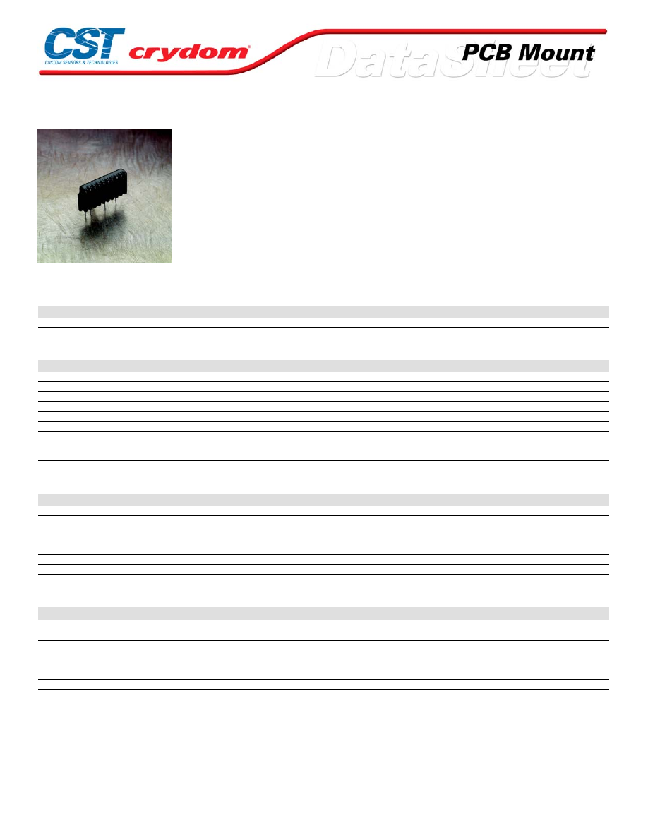
MPF Series
• SIP SSR
• Ratings to 4A @ 280 VAC
• SCR output for heavy industrial loads
• DC control
• Zero-crossing (resistive loads) or random-fire (inductive loads) output
PRODUCT SELECTION
Control Voltage
Zero Crossing
Random Fire
4-10 VDC
MPF240D4
MPF240D4R
OUTPUT SPECIFICATIONS (1)
Description
Operating Voltage (47-63Hz) [Vrms]
12-280
12-280
Transient Overvoltage [Vpk]
600
600
Maximum Off-State Leakage Current @ Rated Voltage [mArms]
0.1
0.1
Minimum Off-State dv/dt @ Maximum Rated Voltage [V/µsec] (3)
500
500
Maximum Load Current [Arms]
4
4
Minimum Load Current [Arms]
0.1
0.1
Maximum Surge Current (16.6ms) [Apk]
40
40
Maximum On-State Voltage Drop @ Rated Current [Vpk]
1.5
1.5
Minimum Power Factor (with Maximum Load)
0.5
0.5
INPUT SPECIFICATIONS (1)
Description
Control Voltage Range
4-10 VDC
Must Turn On Voltage
4.0 VDC
Must Turn Off Voltage
1.0 VDC
Typical Input Current @ 5 VDC
15 mAdc
Nominal Input Impedance
300 Ohm
Maximum Turn-On Time [msec] *
1/2 Cycle
Maximum Turn-Off Time [msec]
1/2 Cycle
GENERAL SPECIFICATIONS
Description
Parameters
Dielectric Strength, Input/Output/Base (50/60Hz)(2)
3750 Vrms
Minimum Insulation Resistance (@ 500 VDC)(2)
10
9
Ohm
Maximum Capacitance, Input/Output
8.0 pF
Ambient Operating Temperature Range
-30 to 80°C
Ambient Storage Temperature Range
-30 to 125°C
Weight (typical)
0.6 oz. (17g)
Encapsulation
Thermally Conductive Epoxy
GENERAL NOTES
1) All parameters at 25°C unless otherwise specified.
2) Dielectric and insulation resistance are measured are between input and output
3) Off-State dv/dt test method per EIA/NARM standard RS-443
For Contact information visit our web
site.
www.crydom.com
©2008 Crydom, Inc.
Specifications subject to change without notice.
Courtesy of Steven Engineering, Inc.-230 Ryan Way, South San Francisco, CA 94080-6370-Main Office: (650) 588-9200-Outside Local Area: (800) 258-9200-www.stevenengineering.com
60MAIN-html.html
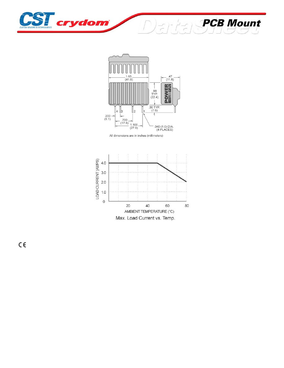
MECHANICAL SPECIFICATIONS
THERMAL DERATE INFORMATION
AGENCY APPROVALS
UL E116950
CSA LR81689
Rev. 0061608
For Contact information visit our web
site.
www.crydom.com
©2008 Crydom, Inc.
Specifications subject to change without notice.
Courtesy of Steven Engineering, Inc.-230 Ryan Way, South San Francisco, CA 94080-6370-Main Office: (650) 588-9200-Outside Local Area: (800) 258-9200-www.stevenengineering.com
60MAIN-html.html

ANNEX - ENVIROMENTAL INFORMATION
For Contact information visit our web
site.
www.crydom.com
©2008 Crydom, Inc.
Specifications subject to change without notice.
Courtesy of Steven Engineering, Inc.-230 Ryan Way, South San Francisco, CA 94080-6370-Main Office: (650) 588-9200-Outside Local Area: (800) 258-9200-www.stevenengineering.com
60MAIN-html.html
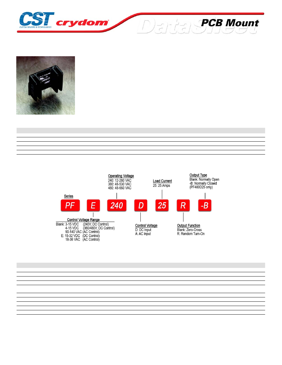
PF Series
• SIP SSR
• Ratings to 25A (forced air) @ 480 VAC
• SCR output for heavy industrial loads
• AC or DC control
• Zero-crossing (resistive loads) or random-fire (inductive loads) output
PRODUCT SELECTION
Control Voltage
25A
25A
25A
3-15 VDC
PF240D25
4-15 VDC
PF380D25
PFE480D25
15-32 VDC
PFE240D25
PFE380D25
PF480D25
18-36 VAC
PFE240A25
90-140 VAC
PF240A25
AVAILABLE OPTIONS
OUTPUT SPECIFICATIONS (1)
Description
Operating Voltage (47-63Hz) [Vrms]
12-280
48-530
48-660
Transient Overvoltage [Vpk]
600
1200
1200
Maximum Off-State Leakage Current @ Rated Voltage [mArms]
0.1
0.1
0.1
Minimum Off-State dv/dt @ Maximum Rated Voltage [V/µsec] (2)
500
500
500
Maximum Load Current [Arms](3)
Forced Air 25
Convection Air 10
Forced Air 25
Convection Air 10
Forced Air 25
Convection Air 10
Minimum Load Current [Arms]
0.06
0.06
0.06
Maximum Surge Current (16.6ms) [Apk]
250
250
250
Maximum On-State Voltage Drop @ Rated Current [Vpk]
1.6
1.6
1.6
Maximum I²t for fusing (8.3 msec) [A² sec]
260
260
260
Minimum Power Factor (with Maximum Load)
0.5
0.5
0.5
For Contact information visit our web
site.
www.crydom.com
©2008 Crydom, Inc.
Specifications subject to change without notice.
Courtesy of Steven Engineering, Inc.-230 Ryan Way, South San Francisco, CA 94080-6370-Main Office: (650) 588-9200-Outside Local Area: (800) 258-9200-www.stevenengineering.com
60MAIN-html.html
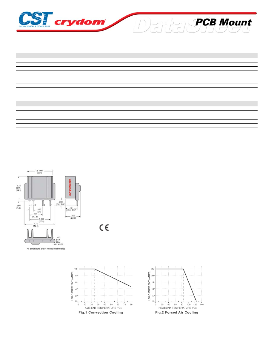
INPUT SPECIFICATIONS (1)
Description
PF240D25
PF380D/480D
PFExxxD25
PF240A25
PFE240A25
Control Voltage Range
3-15 VDC
4-15 VDC
15-32 VDC
90-140 VAC
18-36 VAC
Maximum Turn On Voltage
3.0 VDC
4.0 VDC
15.0 VDC
90.0 Vrms
18.0 Vrms
Minimum Turn-Off Voltage
1.0 VDC
1.0 VDC
1.0 VDC
10.0 Vrms
2.0 Vrms
Typical Input Current @ Nominal Voltage
15 mAdc
15 mAdc
15 mAdc
10 mAdc
10 mAdc
Nominal Input Impedance
300 Ohm
240 Ohm
1500 Ohm
14.1 k Ohm
2.1 k Ohm
Maximum Turn-On Time [msec] (4)
1/2 Cycle
1/2 Cycle
1/2 Cycle
10
10
Maximum Turn-Off Time [msec]
1/2 Cycle
1/2 Cycle
1/2 Cycle
40
40
GENERAL SPECIFICATIONS
Description
Parameters
Dielectric Strength, Input/Output/Base (50/60Hz)
4000 Vrms
Minimum Insulation Resistance (@ 500 VDC)
10
9
Ohm
Maximum Capacitance, Input/Output
8 pF
Ambient Operating Temperature Range
-30 to 80˚C
Ambient Storage Temperature Range
-30 to 125˚C
Weight (typical)
0.85 oz. (25g)
Encapsulation
Thermally Conductive Epoxy
GEN ERAL NOTES
1) All parameters at 25°C unless otherwise specified.
2) Off-State dv/dt test method per EIA/NARM standard RS-443,13.11.1
3) Heatsink temperature 85 ûC Maximum.
4) Turn-On Time for Random Turn-On versions 0.1 msec (DC Control Models)
MECHANICAL SPECIFICATIONS
DC CONTROL.
PIN 1: AC LOAD
PIN 2: AC LOAD
PIN 3: +DC CONTROL
PIN 4: -DC CONTROL
AC CONTROL.
PIN 1: AC LOAD
PIN 2: AC LOAD
PIN 3: AC CONTROL
PIN 4: AC CONTROL
UL E116950
CSA LR 70938(DC Control Only)
Rev. 061608
THERMAL DERATE INFORMATION
For Contact information visit our web
site.
www.crydom.com
©2008 Crydom, Inc.
Specifications subject to change without notice.
Courtesy of Steven Engineering, Inc.-230 Ryan Way, South San Francisco, CA 94080-6370-Main Office: (650) 588-9200-Outside Local Area: (800) 258-9200-www.stevenengineering.com
60MAIN-html.html
AGENCY APPROVALS
U L E116950
C SA LR70938(DC Control Only)
Rev. 0061608
For Contact information visit our web
site.
www.crydom.com
©2008 Crydom, Inc.
Specifications subject to change without notice.
Courtesy of Steven Engineering, Inc.-230 Ryan Way, South San Francisco, CA 94080-6370-Main Office: (650) 588-9200-Outside Local Area: (800) 258-9200-www.stevenengineering.com
60MAIN-html.html
ANNEX - ENVIROMENTAL INFORMATION
For Contact information visit our web
site.
www.crydom.com
©2008 Crydom, Inc.
Specifications subject to change without notice.
Courtesy of Steven Engineering, Inc.-230 Ryan Way, South San Francisco, CA 94080-6370-Main Office: (650) 588-9200-Outside Local Area: (800) 258-9200-www.stevenengineering.com
60MAIN-html.html
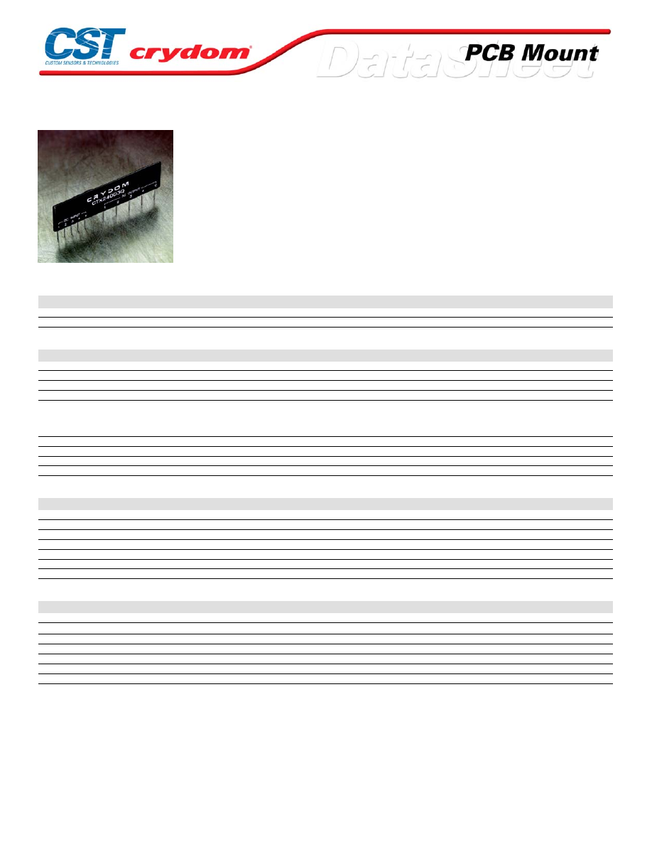
CTX SERIES
• Independently controlled quad output solid-state relay; Rated at 20A
@ 24-280 VAC
• Industry standard package
• DC Control
• Zero-crossing (resistive loads) or random-fire (inductive loads) output
• Ideal for limited-space applications
PRODUCT SELECTION
Control Voltage
Zero-crossing
Random Fire
3-15 VDC
CX240D3Q
4-10 VDC
CTX240D3Q
CTX240D3QR
OUTPUT SPECIFICATIONS (1)(3)
Description
Operating Voltage (47-63Hz) [Vrms]
24-280
Transient Overvoltage [Vpk]
600
Maximum Off-State Leakage Current @ Rated Voltage [mArms]
0.1
Minimum Off-State dv/dt @ Maximum Rated Voltage [V/µsec] (2)
200
Maximum Load Current [Arms](3)
1 Section ON: 0.1-6.0
2 Section ON: 0.1-4.0
3 Section ON: 0.1-3.0
4 Section ON: 0.1-2.5
Maximum Surge Current (16.6ms) [Apk]
120
Maximum On-State Voltage Drop @ Rated Current [Vpk]
1.4
Maximum I² t for fusing (8.3 msec) [A² sec]
60
Minimum Power Factor (with Maximum Load)
0.5
INPUT SPECIFICATIONS (1)(3)
Description
Control Voltage Range
4-10 VDC
Must Turn On Voltage
4.0 VDC
Must Turn Off Voltage
1.0 VDC
Typical Input Current @ 5 VDC
15 mAdc
Nominal Input Impedance
270 Ohm
Maximum Turn-On Time [msec]
1/2 Cycle
Maximum Turn-Off Time [msec]
1/2 Cycle
GENERAL SPECIFICATIONS
Description
Parameters
Dielectric Strength, Input/Output/Base (50/60Hz)
2500 Vrms
Minimum Insulation Resistance (@ 500 VDC)
10
9
Ohm
Maximum Capacitance, Input/Output
10 pF
Ambient Operating Temperature Range
-30 to 80°C
Ambient Storage Temperature Range
-30 to 125°C
Weight (typical)
0.5 oz. (14.4g)
Encapsulation
Thermally Conductive Epoxy
GENERAL NOTES
1) All parameters at 25°C unless otherwise specified.
2) Off-State dv/dt test method per EIA/NARM standard RS-443,13.11.1
3) All specifications are per section unless otherwise noted
For Contact information visit our web
site.
www.crydom.com
©2008 Crydom, Inc.
Specifications subject to change without notice.
Courtesy of Steven Engineering, Inc.-230 Ryan Way, South San Francisco, CA 94080-6370-Main Office: (650) 588-9200-Outside Local Area: (800) 258-9200-www.stevenengineering.com
60MAIN-html.html
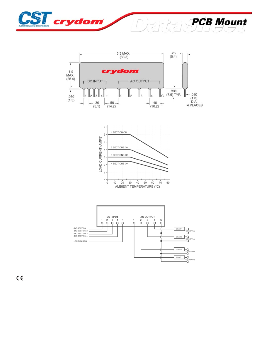
MECHANICAL SPECIFICATIONS
THERMAL DERATE INFORMATION
WIRING DIAGRAM
AGENCY APPROVALS
For Contact information visit our web
site.
www.crydom.com
©2008 Crydom, Inc.
Specifications subject to change without notice.
Courtesy of Steven Engineering, Inc.-230 Ryan Way, South San Francisco, CA 94080-6370-Main Office: (650) 588-9200-Outside Local Area: (800) 258-9200-www.stevenengineering.com
60MAIN-html.html
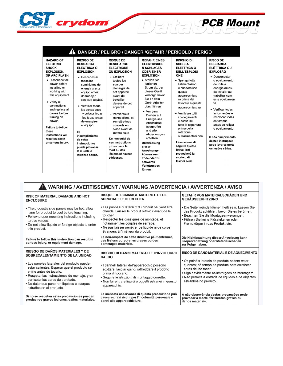

ANNEX - ENVIROMENTAL INFORMATION
For Contact information visit our web
site.
www.crydom.com
©2008 Crydom, Inc.
Specifications subject to change without notice.
Courtesy of Steven Engineering, Inc.-230 Ryan Way, South San Francisco, CA 94080-6370-Main Office: (650) 588-9200-Outside Local Area: (800) 258-9200-www.stevenengineering.com
60MAIN-html.html
SPF Series
• SIP SSR
• Ratings to 25A (forced air) @ 480 VAC
• SCR output for heavy industrial loads
• AC or DC control
• Zero-crossing (resistive loads) or random-fire (inductive loads) output
PRODUCT SELECTION
Control Voltage
25A
25A
25A
SPF240D25
4-15 VDC
SPF380D25
SPFE480D25
15-32 VDC
SPFE240D25
SPFE380D25
SPF480D25
18-36 VAC
SPFE240A25
90-140 VAC
SPF240A25
AVAILABLE OPTIONS
OUTPUT SPECIFICATIONS (1)
Description
Operating Voltage (47-63Hz) [Vrms]
12-280
48-530
48-660
Transient Overvoltage [Vpk]
600
1200
1200
Maximum Off-State Leakage Current @ Rated Voltage [mArms]
0.1
0.1
0.1
Minimum Off-State dv/dt @ Maximum Rated Voltage [V/µsec] (2)
500
500
500
Maximum Load Current [Arms](3)
Forced Air 25
Convection Air 10
Forced Air 25
Convection Air 10
Forced Air 25
Convection Air 10
Minimum Load Current [Arms]
0.06
0.06
0.06
Maximum Surge Current (16.6ms) [Apk]
250
250
250
Maximum On-State Voltage Drop @ Rated Current [Vpk]
1.6
1.6
1.6
Maximum I² t for fusing (8.3 msec) [A² sec]
260
260
260
Minimum Power Factor (with Maximum Load)
0.5
0.5
0.5
For Contact information visit our web
site.
www.crydom.com
©2008 Crydom, Inc.
Specifications subject to change without notice.
Courtesy of Steven Engineering, Inc.-230 Ryan Way, South San Francisco, CA 94080-6370-Main Office: (650) 588-9200-Outside Local Area: (800) 258-9200-www.stevenengineering.com
60MAIN-html.html
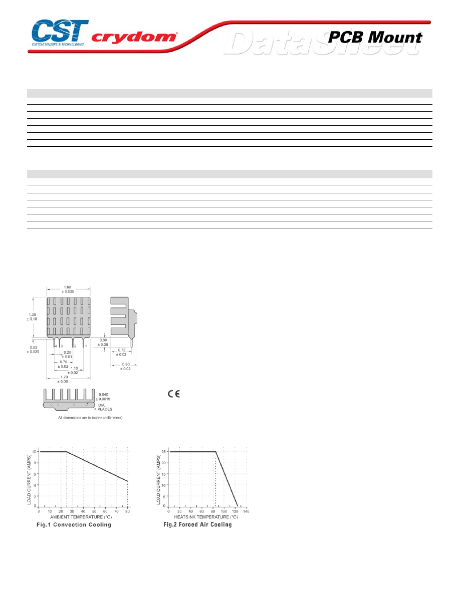
INPUT SPECIFICATIONS (1)
Description
SPF240D25
SPF380D/480D
SPFExxxD25
SPF240A25
SPFE240A25
Control Voltage Range
3-15 VDC
4-15 VDC
15-32 VDC
90-140 VAC
18-36 VAC
Maximum Turn On Voltage
3.0 VDC
4.0 VDC
15.0 VDC
90.0 Vrms
18.0 Vrms
Minimum Turn-Off Voltage
1.0 VDC
1.0 VDC
1.0 VDC
10.0 Vrms
2.0 Vrms
Typical Input Current @ Nominal Voltage
15 mAdc
15 mAdc
15 mAdc
10 mAdc
10 mAdc
Nominal Input Impedance
300 Ohm
240 Ohm
1500 Ohm
14.1 k Ohm
2.1 k Ohm
Maximum Turn-On Time [msec] (4)
1/2 Cycle
1/2 Cycle
1/2 Cycle
10
10
Maximum Turn-Off Time [msec]
1/2 Cycle
1/2 Cycle
1/2 Cycle
40
40
GENERAL SPECIFICATIONS
Description
Parameters
Dielectric Strength, Input/Output/Base (50/60Hz)
4000 Vrms
Minimum Insulation Resistance (@ 500 VDC)
10
9
Ohm
Maximum Capacitance, Input/Output
8 pF
Ambient Operating Temperature Range
-30 to 80˚C
Ambient Storage Temperature Range
-30 to 125˚C
Weight (typical)
0.85 oz. (25g)
Encapsulation
Thermally Conductive Epoxy
GENERAL NOTES
1) All parameters at 25°C unless otherwise specified.
2) Off-State dv/dt test method per EIA/NARM standard RS-443,13.11.1
3) Heatsink temperature 85 ûC Maximum.
4) Turn-On Time for Random Turn-On versions 0.1 msec (DC Control Models)
MECHANICAL SPECIFICATIONS
AC CONTROL
PIN 1: AC LOAD
PIN 2: AC LOAD
PIN 3: AC CONTROL
PIN 4: AC CONTROL
DC CONTROL
PIN 1: AC LOAD
PIN 2: AC LOAD
PIN 3: +DC CONTROL
PIN 4: -DC C ON TR OL
UL E116950
Rev. 061608
THERMAL DERATE INFORMATION
For Contact information visit our web
site.
www.crydom.com
©2008 Crydom, Inc.
Specifications subject to change without notice.
Courtesy of Steven Engineering, Inc.-230 Ryan Way, South San Francisco, CA 94080-6370-Main Office: (650) 588-9200-Outside Local Area: (800) 258-9200-www.stevenengineering.com
60MAIN-html.html

ANNEX - ENVIROMENTAL INFORMATION
For Contact information visit our web
site.
www.crydom.com
©2008 Crydom, Inc.
Specifications subject to change without notice.
Courtesy of Steven Engineering, Inc.-230 Ryan Way, South San Francisco, CA 94080-6370-Main Office: (650) 588-9200-Outside Local Area: (800) 258-9200-www.stevenengineering.com
60MAIN-html.html
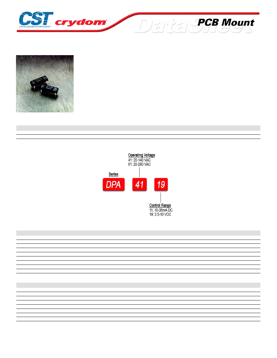
DPA Series
• 16 Pin DIP SSR
• Ratings to 1A @ 280 VAC
• SCR output
• Voltage or current-control input
• Zero-crossing (resistive loads) output
PRODUCT SELECTION
Control Voltage
3.5-10 VDC
DPA4119
DPA6119
10-35 mA
DPA4111
DPA6111
AVAILABLE OPTIONS
OUTPUT SPECIFICATIONS (1)
Description
Operating Voltage (47-63Hz) [Vrms]
20-140
20-280
Transient Overvoltage [Vpk]
400
600
Maximum Off-State Leakage Current @ Rated Voltage [mArms]
0.01
0.01
Minimum Off-State dv/dt @ Maximum Rated Voltage [V/µsec] (3)
500
500
Maximum Load Current [Arms]
1.0
1.0
Minimum Load Current [Arms]
0.025
0.025
Maximum Surge Current (16.6ms) [Apk]
30
30
Maximum On-State Voltage Drop @ Rated Current [Vpk]
1.2
1.2
Minimum Power Factor (with Maximum Load)
0.5
0.5
INPUT SPECIFICATIONS (1)
Description
Control Voltage Range
-
3.5-10 VDC
Control Current Range
10-35 mA
-
Must Turn Off-State Current
1.0 mA
-
Must Turn Off-State Voltage
-
1.0 VDC
Typical Input Current @ 5 VDC
-
15 mAdc
Nominal Input Impedance
-
270 Ohm
Maximum Turn-On Time [msec]
1/2 Cycle
1/2 Cycle
Maximum Turn-Off Time [msec]
1/2 Cycle
1/2 Cycle
For Contact information visit our web
site.
www.crydom.com
©2008 Crydom, Inc.
Specifications subject to change without notice.
Courtesy of Steven Engineering, Inc.-230 Ryan Way, South San Francisco, CA 94080-6370-Main Office: (650) 588-9200-Outside Local Area: (800) 258-9200-www.stevenengineering.com
60MAIN-html.html
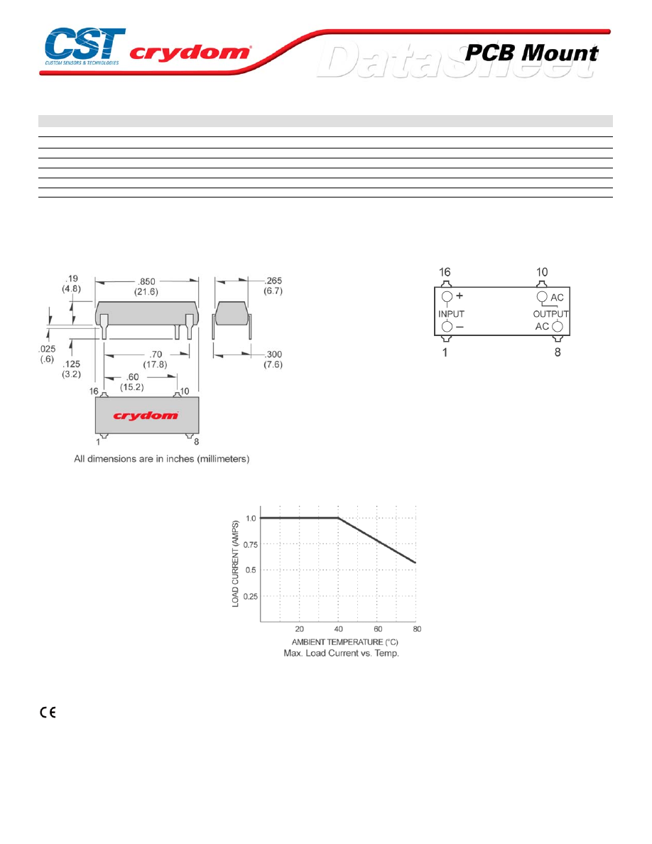
GENERAL SPECIFICATIONS
Description
Parameters
Dielectric Strength, Input/Output/Base (50/60Hz)(2)
3750 Vrms
Minimum Insulation Resistance (@ 500 VDC)(2)
10
9
Ohm
Maximum Capacitance, Input/Output
2.0 pF
Ambient Operating Temperature Range
-30 to 80°C
Ambient Storage Temperature Range
-30 to 125°C
Weight (typical)
0.1 oz. (2.9g)
Encapsulation
Thermally Conductive Epoxy
GENERAL NOTES
1) All parameters at 25°C unless otherwise specified.
2) Dielectric and insulation resistance are measured between input and output
3) Off-State dv/dt test method per EIA/NARM standard RS
MECHANICAL SPECIFICATIONS
PIN 8: AC LOAD
PIN 10: AC LOAD
PIN 16: +DC CONTROL
PIN 1: -D C CONTROL
THERMAL DERATE INFORMATION
AGENCY APPROVALS
UL E116950
CSA LR81689
For Contact information visit our web
site.
www.crydom.com
©2008 Crydom, Inc.
Specifications subject to change without notice.
Courtesy of Steven Engineering, Inc.-230 Ryan Way, South San Francisco, CA 94080-6370-Main Office: (650) 588-9200-Outside Local Area: (800) 258-9200-www.stevenengineering.com
60MAIN-html.html

ANNEX - ENVIROMENTAL INFORMATION
For Contact information visit our web
site.
www.crydom.com
©2008 Crydom, Inc.
Specifications subject to change without notice.
Courtesy of Steven Engineering, Inc.-230 Ryan Way, South San Francisco, CA 94080-6370-Main Office: (650) 588-9200-Outside Local Area: (800) 258-9200-www.stevenengineering.com
60MAIN-html.html
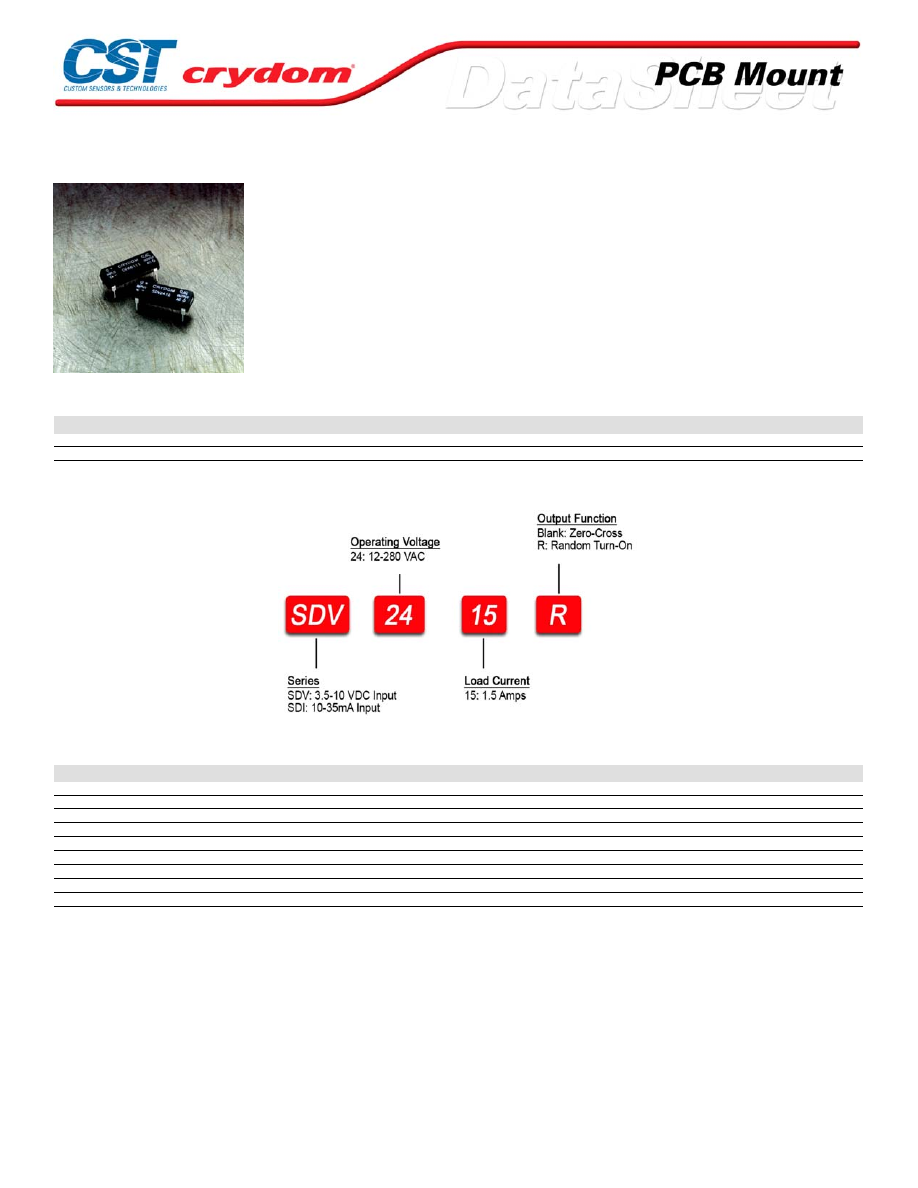
SDV / SDI Series
• 16 Pin DIP SSR
• Ratings to 1.5A @ 280 VAC
• SCR output
• Voltage or current-control input
• Zero-crossing (resistive loads) or random-fire (inductive loads) output
PRODUCT SELECTION
Control Voltage
1.5A
1.5A
3.5-10 VDC
SDV2415
SDV2415R
10-35mA
SDI2415
SDI2415R
AVAILABLE OPTIONS
OUTPUT SPECIFICATIONS (1)
Description
Operating Voltage (47-63Hz) [Vrms]
12-280
Transient Overvoltage [Vpk]
600
Maximum Off-State Leakage Current @ Rated Voltage [mArms]
0.01
Minimum Off-State dv/dt @ Maximum Rated Voltage [V/µsec] (3)
500
Maximum Load Current [Arms](3)
1.5
Minimum Load Current [Arms]
0.025
Maximum Surge Current (16.6ms) [Apk]
30
Maximum On-State Voltage Drop @ Rated Current [Vpk]
1.2
Minimum Power Factor (with Maximum Load)
0.5
For Contact information visit our web
site.
www.crydom.com
©2008 Crydom, Inc.
Specifications subject to change without notice.
Courtesy of Steven Engineering, Inc.-230 Ryan Way, South San Francisco, CA 94080-6370-Main Office: (650) 588-9200-Outside Local Area: (800) 258-9200-www.stevenengineering.com
60MAIN-html.html
INPUT SPECIFICATIONS (1)
Description
Model
SDV
SDI
Control Voltage Range
-
3.5-10 VDC
Control Current Range
10-32 mA
-
Must Turn On Voltage
-
3.5 VDC
Must Turn On Current
10 mA
-
Must Turn Off Voltage
-
1.0 VDC
Must Turn Off Current
1.0 mA
-
Typical Input Current @ 5 VDC
-
15 mAdc
Nominal Input Impedance
-
270 Ohm
Maximum Turn-On Time [msec] (4)
1/2 Cycle
1/2 Cycle
Maximum Turn-Off Time [msec]
1/2 Cycle
1/2 Cycle
GENERAL SPECIFICATIONS
Description
Parameters
Dielectric Strength, Input/Output/Base (50/60Hz)(2)
3750 Vrms
Minimum Insulation Resistance (@ 500 VDC)(2)
10
9
Ohm
Maximum Capacitance, Input/Output
2.0 pF
Ambient Operating Temperature Range
-30 to 80°C
Ambient Storage Temperature Range
-30 to 125°C
Weight (typical)
0.10 oz. (2.9g)
Encapsulation
Thermally Conductive Epoxy
GENERAL NOTES
1) All parameters at 25¼°C unless otherwise specified.
2) Dielectric and insulation resistance are measured
3) Off-State dv/dt test method per EIA/NARM standard RS-443
For Contact information visit our web
site.
www.crydom.com
©2008 Crydom, Inc.
Specifications subject to change without notice.
Courtesy of Steven Engineering, Inc.-230 Ryan Way, South San Francisco, CA 94080-6370-Main Office: (650) 588-9200-Outside Local Area: (800) 258-9200-www.stevenengineering.com
60MAIN-html.html
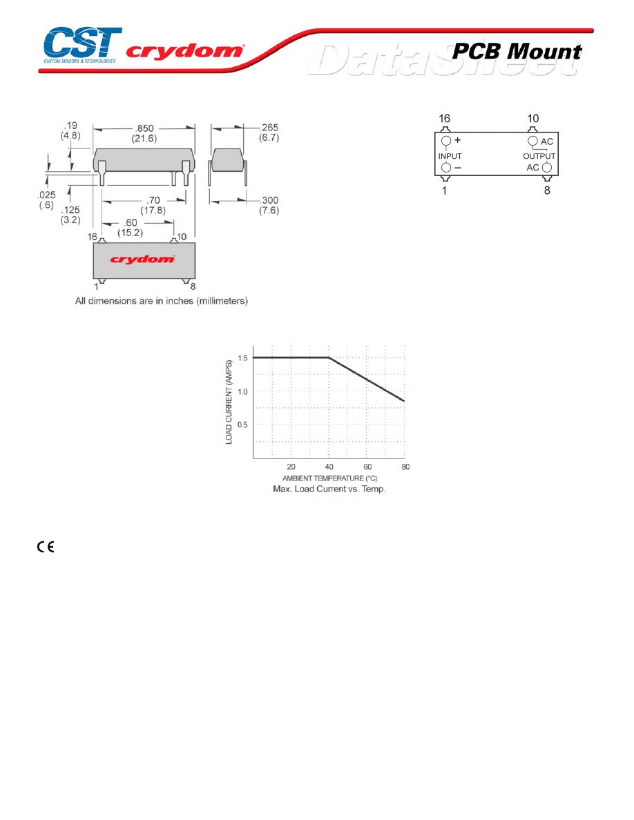
MECHANICAL SPECIFICATIONS
DC C ONTR OL
PIN 8: AC LOAD
PIN 10: AC LOAD
PIN 16: +DC CONTROL
PIN 1: -D C CONTROL
THERMAL DERATE INFORMATION
AGENCY APPROVALS
UL 116950
CSA LR81689
For Contact information visit our web
site.
www.crydom.com
©2008 Crydom, Inc.
Specifications subject to change without notice.
Courtesy of Steven Engineering, Inc.-230 Ryan Way, South San Francisco, CA 94080-6370-Main Office: (650) 588-9200-Outside Local Area: (800) 258-9200-www.stevenengineering.com
60MAIN-html.html

ANNEX - ENVIROMENTAL INFORMATION
For Contact information visit our web
site.
www.crydom.com
©2008 Crydom, Inc.
Specifications subject to change without notice.
Courtesy of Steven Engineering, Inc.-230 Ryan Way, South San Francisco, CA 94080-6370-Main Office: (650) 588-9200-Outside Local Area: (800) 258-9200-www.stevenengineering.com
60MAIN-html.html
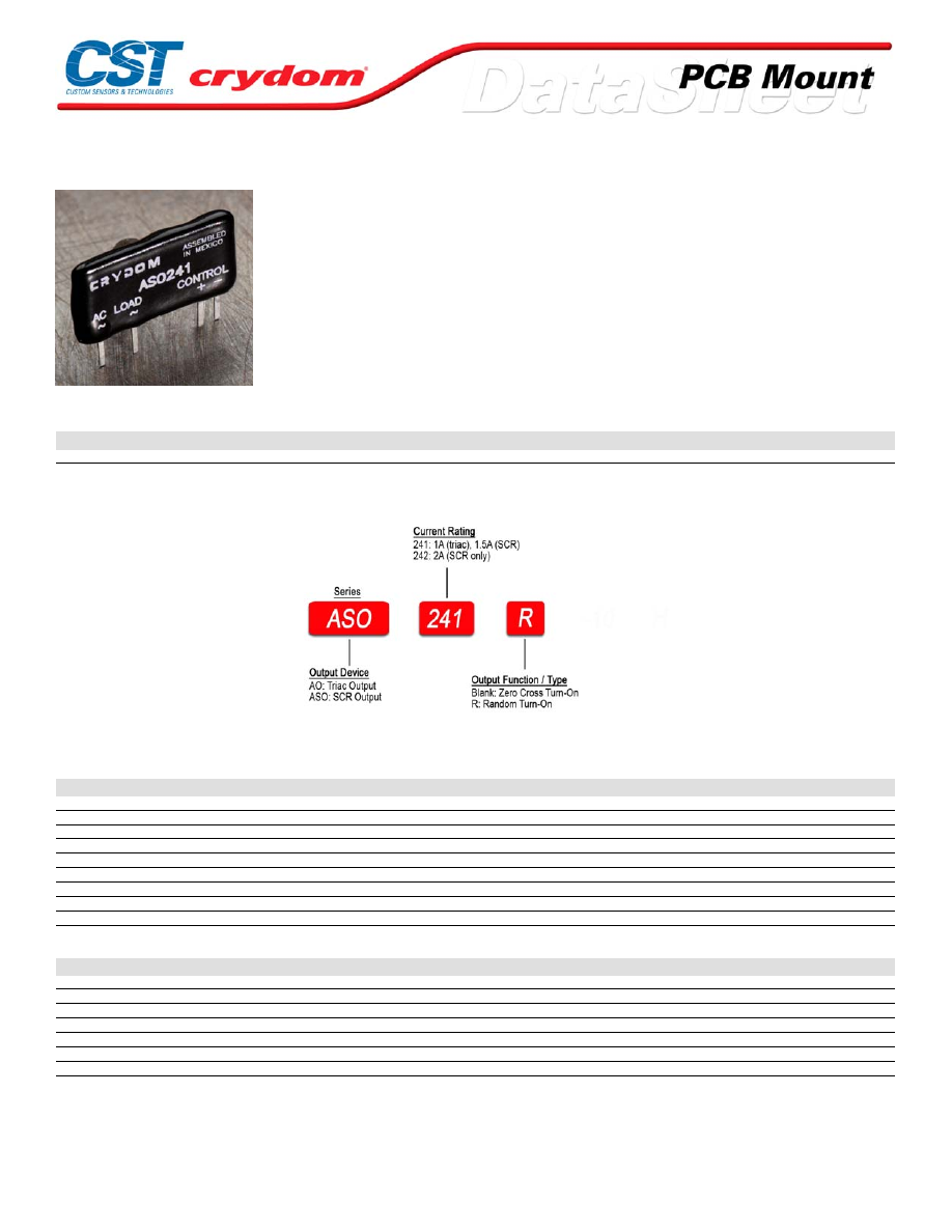
AO / ASO Series
• Mini-SIP SSR
• Ratings to 2A @ 280 VAC
• SCR or Triac output
• DC control
• Zero-crossing (resistive loads) or random-fire (inductive loads) output
PRODUCT SELECTION
Control Voltage
1A
1.5A
2A
4-10 VDC
AO241
ASO241
ASO242
AVAILABLE OPTIONS
OUTPUT SPECIFICATIONS (1)
Description
Operating Voltage (47-63Hz) [Vrms]
24-280
24-280
24-280
Transient Overvoltage [Vpk]
600
600
600
Maximum Off-State Leakage Current @ Rated Voltage [mArms]
0.1
0.1
0.1
Minimum Off-State dv/dt @ Maximum Rated Voltage [V/µsec] (3)
500
500
500
Maximum Load Current [Arms](3)
1.0
1.5
2.0
Minimum Load Current [Arms]
0.025
0.025
0.06
Maximum Surge Current (16.6ms) [Apk]
40
40
120
Maximum On-State Voltage Drop @ Rated Current [Vpk]
1.5
1.5
1.5
Minimum Power Factor (with Maximum Load)
0.5
0.5
0.5
INPUT SPECIFICATIONS (1)
Description
Control Voltage Range
4-10 VDC
Must Turn On Voltage
4.0 VDC
Must Turn Off Voltage
1.0 VDC
Typical Input Current @ 5 VDC
15 mAdc
Nominal Input Impedance
300 Ohm
Maximum Turn-On Time [msec]
1/2 Cycle
Maximum Turn-Off Time [msec]
1/2 Cycle
For Contact information visit our web
site.
www.crydom.com
©2008 Crydom, Inc.
Specifications subject to change without notice.
Courtesy of Steven Engineering, Inc.-230 Ryan Way, South San Francisco, CA 94080-6370-Main Office: (650) 588-9200-Outside Local Area: (800) 258-9200-www.stevenengineering.com
60MAIN-html.html
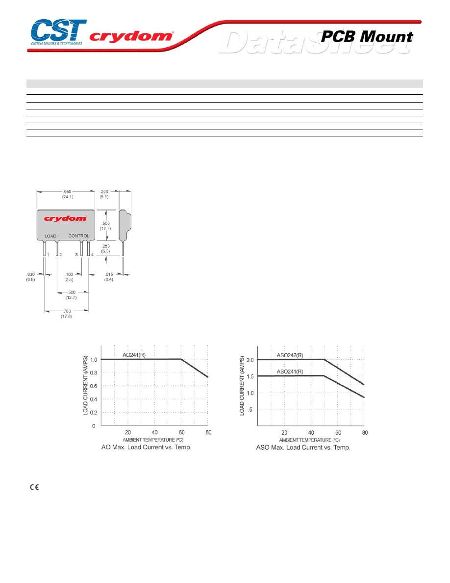
GENERAL SPECIFICATIONS
Description
Parameters
Dielectric Strength, Input/Output/Base (50/60Hz)(2)
2500 Vrms
Minimum Insulation Resistance (@ 500 VDC)(2)
10
9
Ohm
Maximum Capacitance, Input/Output
8.0 pF
Ambient Operating Temperature Range
-30 to 80˚C
Ambient Storage Temperature Range
-30 to 125˚C
Weight (typical)
0.15 oz. (4.3g)
Encapsulation
Thermally Conductive Epoxy
GENERAL NOTES
1) All parameters at 25°C unless otherwise specified.
2) Dielectric and insulation resistence are measured between input and output
3) Off-State dv/dt test method per EIA/NARM standard RS-443
MECHANICAL SPECIFICATIONS
DC CONTROL.
PIN 1: AC LOAD
PIN 2: AC LOAD
PIN 3: +DC CONTROL
PIN 4: -DC CONTROL
THERMAL DERATE INFORMATION
AGENCY APPROVALS
UL E116950
CSA LR81689
Rev. 061608
For Contact information visit our web
site.
www.crydom.com
©2008 Crydom, Inc.
Specifications subject to change without notice.
Courtesy of Steven Engineering, Inc.-230 Ryan Way, South San Francisco, CA 94080-6370-Main Office: (650) 588-9200-Outside Local Area: (800) 258-9200-www.stevenengineering.com
60MAIN-html.html

ANNEX - ENVIROMENTAL INFORMATION
For Contact information visit our web
site.
www.crydom.com
©2008 Crydom, Inc.
Specifications subject to change without notice.
Courtesy of Steven Engineering, Inc.-230 Ryan Way, South San Francisco, CA 94080-6370-Main Office: (650) 588-9200-Outside Local Area: (800) 258-9200-www.stevenengineering.com
60MAIN-html.html
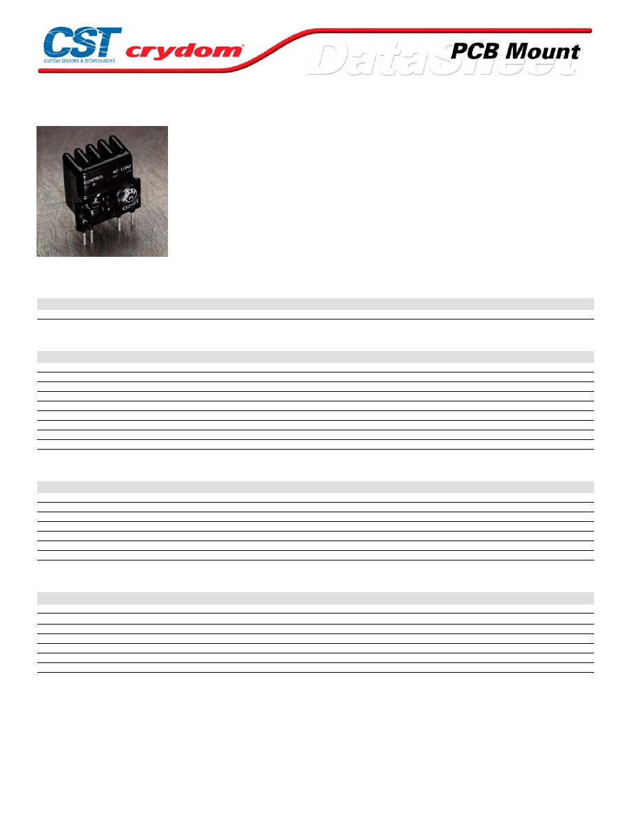
ASPF Series
• Mini-SIP SSR
• Ratings to 3A @ 280 V AC
• SCR output
• DC control
• Zero-crossing (resistive loads) or random-fire (inductive loads) output
PRODUCT SELECTION
Control Voltage
Zero Crossing
Random Fire
4-10 VDC
ASPF240D3
ASPF240D3R
OUTPUT SPECIFICATIONS (1)
Description
Operating Voltage (47-63Hz) [Vrms]
24-280
24-280
Transient Overvoltage [Vpk]
600
600
Maximum Off-State Leakage Current @ Rated Voltage [mArms]
0.1
0.1
Minimum Off-State dv/dt @ Maximum Rated Voltage [V/µsec] (3)
500
500
Maximum Load Current [Arms]
3.0
3.0
Minimum Load Current [Arms]
0.1
0.1
Maximum Surge Current (16.6ms) [Apk]
40
40
Maximum On-State Voltage Drop @ Rated Current [Vpk]
1.5
1.5
Minimum Power Factor (with Maximum Load)
0.5
0.5
INPUT SPECIFICATIONS (1)
Description
Control Voltage Range
4-10 VDC
Must Turn On Voltage
4.0 VDC
Must Turn Off Voltage
1.0 VDC
Typical Input Current @ 5 VDC
15 mAdc
Nominal Input Impedance
300 Ohm
Maximum Turn-On Time [msec] (4)
1/2 Cycle
Maximum Turn-Off Time [msec]
1/2 Cycle
GENERAL SPECIFICATIONS
Description
Parameters
Dielectric Strength, Input/Output/Base (50/60Hz)(2)
3750 Vrms
Minimum Insulation Resistance (@ 500 VDC)(2)
10
9
Ohm
Maximum Capacitance, Input/Output
8 pF
Ambient Operating Temperature Range
-30 to 80˚C
Ambient Storage Temperature Range
-30 to 125˚C
Weight (typical)
0.35 oz. (10g)
Encapsulation
Thermally Conductive Epoxy
GENERAL NOTES
1) All parameters at 25°C unless otherwise specified.
2) Dielectric and insulation resistence are measured between input and output
3) Off-State dv/dt test method per EIA/NARM standard RS-443.
4) Turn-On time for random turn-on versions is 0.01 msec (DC C
For Contact information visit our web
site.
www.crydom.com
©2008 Crydom, Inc.
Specifications subject to change without notice.
Courtesy of Steven Engineering, Inc.-230 Ryan Way, South San Francisco, CA 94080-6370-Main Office: (650) 588-9200-Outside Local Area: (800) 258-9200-www.stevenengineering.com
60MAIN-html.html
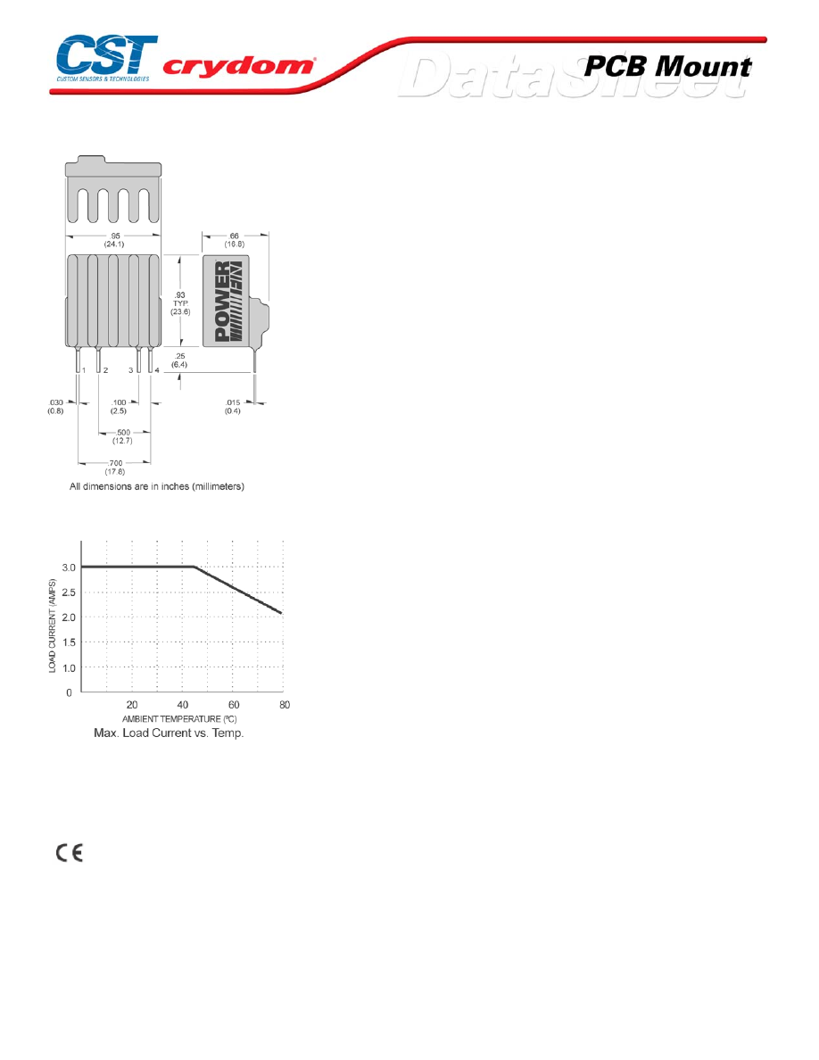
MECHANICAL SPECIFICATIONS
DC CONTROL.
PIN 1: AC LOAD
PIN 2: AC LOAD
PIN 3: +DC CONTROL
PIN 4: -DC C ON TR OL
THERMAL DERATE INFORMATION
AGENCY APPROVALS
UL E116950
CSA LR81689
Rev. 061608
For Contact information visit our web
site.
www.crydom.com
©2008 Crydom, Inc.
Specifications subject to change without notice.
Courtesy of Steven Engineering, Inc.-230 Ryan Way, South San Francisco, CA 94080-6370-Main Office: (650) 588-9200-Outside Local Area: (800) 258-9200-www.stevenengineering.com
60MAIN-html.html

For Contact information visit our web
site.
www.crydom.com
©2008 Crydom, Inc.
Specifications subject to change without notice.
Courtesy of Steven Engineering, Inc.-230 Ryan Way, South San Francisco, CA 94080-6370-Main Office: (650) 588-9200-Outside Local Area: (800) 258-9200-www.stevenengineering.com
60MAIN-html.html

ANNEX - ENVIROMENTAL INFORMATION
For Contact information visit our web
site.
www.crydom.com
©2008 Crydom, Inc.
Specifications subject to change without notice.
Courtesy of Steven Engineering, Inc.-230 Ryan Way, South San Francisco, CA 94080-6370-Main Office: (650) 588-9200-Outside Local Area: (800) 258-9200-www.stevenengineering.com
60MAIN-html.html
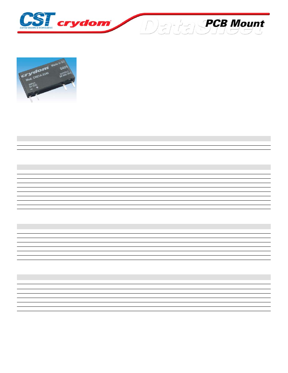
CR-A Series
• Mini-SIP SSR
• Ratings to 2A @ 280 VAC
• 15-72 V DC control
• Zero-crossing (resistive loads) output
PRODUCT SELECTION
Control Voltage
24 VDC
CR01A-2240
60 VDC
CR02A-2240
OUTPUT SPECIFICATIONS (1)
Description
Operating Voltage (47-63Hz) [Vrms]
12-280
Transient Overvoltage [Vpk]
600
Maximum Off-State Leakage @ Rated Voltage [mArms]
1.5
Minimum Off-State dv/dt @ Maximum Rated Voltage [V/µsec] (3)
500
Maximum Load Current [Arms]
2
Minimum Load Current [Arms]
0.025
Maximum Surge Current (20ms) [Apk]
40
Maximum On-State Voltage Drop @ Rated Current [Vpk]
1.6
Maximum l²t for fusing (10ms)[A²s]
8
INPUT SPECIFICATIONS (1)
Description
Control Voltage Range
15-30 VDC
35-72 VDC
Must Turn On Voltage
15 VDC
35 VDC
Must Turn Off Voltage
9 VDC
35 VDC
Typical Input Current @ Nominal Voltage
7 mAdc
3 mAdc
Nominal Input Impedance
3.2 K Ohm
21.3 K Ohm
Maximum Turn-On Time [msec]
1/2 Cycle
1/2 Cycle
Maximum Turn-Off Time [msec]
1/2 Cycle
1/2 Cycle
GENERAL SPECIFICATIONS
Description
Parameters
Dielectric Strength, Input/Output/Base (50/60Hz)
2500 Vrms
Minimum Insulation Resistance (@ 500 VDC)
10
9
Ohm
Maximum Capacitance, Input/Output
8.0 pF
Ambient Operating Temperature Range
-20 to 80˚C
Ambient Storage Temperature Range
-40 to 100˚C
Weight (typical)
0.15 oz. (4.3g)
Encapsulation
UL94V-0 Moulded epoxy
GENERAL NOTES
1) All parameters at 25°C unless otherwise specified.
2) Dielectric and insulation resistence are measured between input and output.
3) Off-State dv/dt test method per EIA/NARM standard RS-443
For Contact information visit our web
site.
www.crydom.com
©2008 Crydom, Inc.
Specifications subject to change without notice.
Courtesy of Steven Engineering, Inc.-230 Ryan Way, South San Francisco, CA 94080-6370-Main Office: (650) 588-9200-Outside Local Area: (800) 258-9200-www.stevenengineering.com
60MAIN-html.html
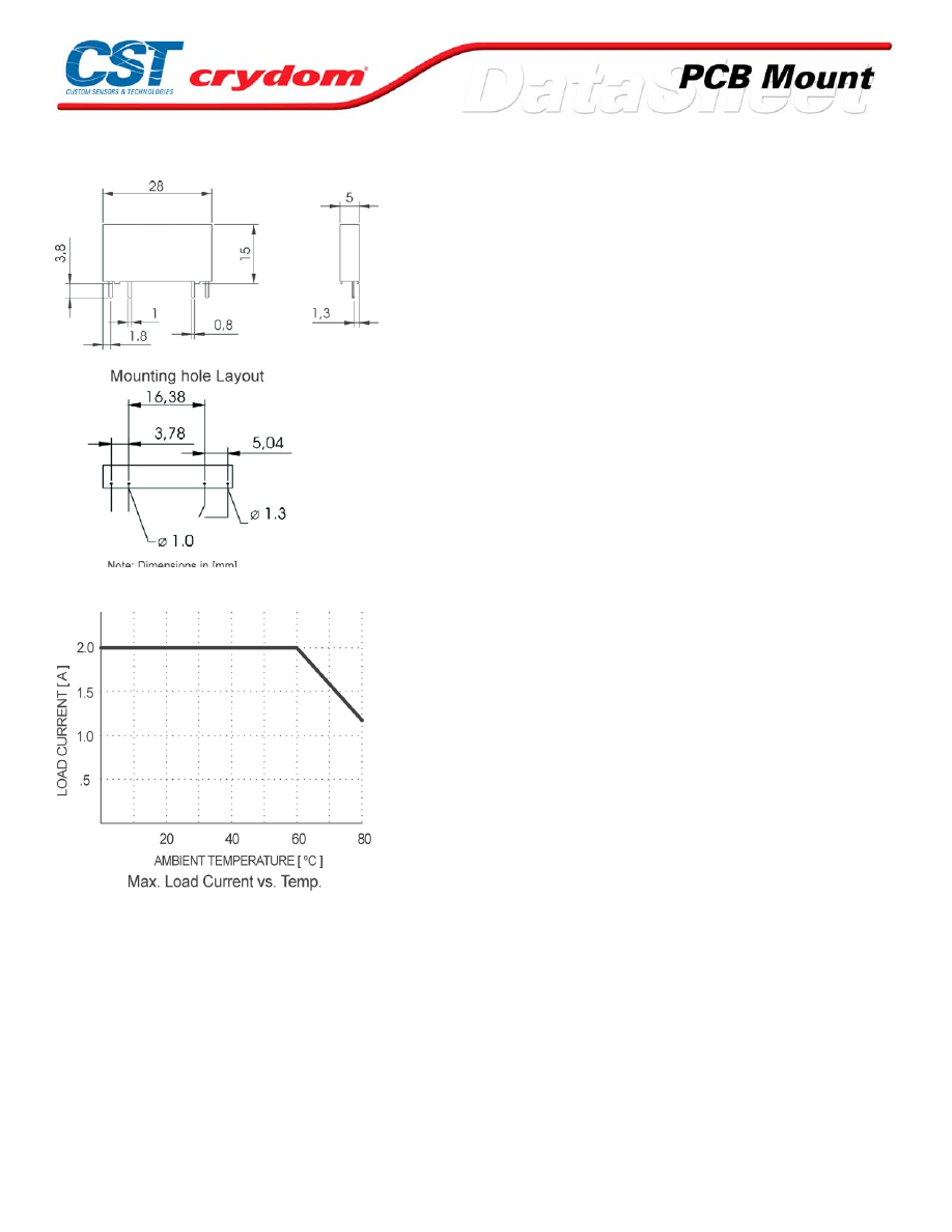
MECHANICAL SPECIFICATIONS
THERMAL DERATE INFORMATION
For Contact information visit our web
site.
www.crydom.com
©2008 Crydom, Inc.
Specifications subject to change without notice.
Courtesy of Steven Engineering, Inc.-230 Ryan Way, South San Francisco, CA 94080-6370-Main Office: (650) 588-9200-Outside Local Area: (800) 258-9200-www.stevenengineering.com
60MAIN-html.html

ANNEX - ENVIROMENTAL INFORMATION
For Contact information visit our web
site.
www.crydom.com
©2008 Crydom, Inc.
Specifications subject to change without notice.
Courtesy of Steven Engineering, Inc.-230 Ryan Way, South San Francisco, CA 94080-6370-Main Office: (650) 588-9200-Outside Local Area: (800) 258-9200-www.stevenengineering.com
60MAIN-html.html
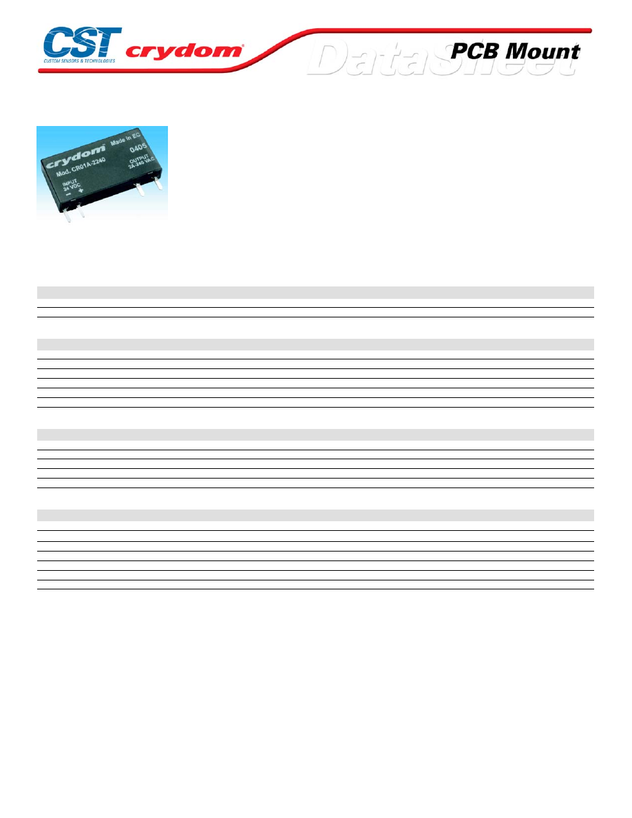
CR-D Series
•
Mini-SIP SSR
•
Ratings to 3A @ 24 VDC or 100mA @ 48 VDC
•
MOSFET or bi-polar transistor output
•
DC control
PRODUCT SELECTION
Control Voltage
2 A
100 mA
24 VDC
CR01D-224
CR01D-0148
60 VDC
CR02D-224
CR02D-0148
OUTPUT SPECIFICATIONS (1)
Description
Nominal Control Voltage
24
60
Operating Voltage (47-63Hz) [VDC]
0-24
0-48
Maximum Blocking voltage [VDC]
33
60
Maximum Load Current [A] @20°C
3A
100 mA
Minimum Load Current [mA]
0.05
0.05
Maximum On-State Voltage Drop @ Rated Current [VDC]
120m
1.0
INPUT SPECIFICATIONS (1)
Description
Control Voltage Range
15-30 VDC
35-72 VDC
Must Turn On Voltage
15 VDC
35 VDC
Must Turn Off Voltage
10 VDC
20 VDC
Typical Input Current @ Nominal Voltage
7 mAdc
3 mAdc
Nominal Input Impedance
3.2 K Ohm
21.3 K Ohm
GENERAL SPECIFICATIONS
Description
Parameters
Dielectric Strength, Input/Output/Base (50/60Hz)
2500 Vrms
Minimum Insulation Resistance (@ 500 VDC) (2)
10
9
Ohm
Maximum Capacitance, Input/Output
8.0 pF
Ambient Operating Temperature Range
-20 to 80°C
Ambient Storage Temperature Range
-40 to 100°C
Weight (typical)
0.15 oz. (4.3g)
Encapsulation
UL94V-0 Moulded epoxy
GENERAL NOTES
1) All parameters at 25°C unless otherwise specified.
2) Dielectric and insulation resistence are measured between input and output
For Contact information visit our web
site.
www.crydom.com
©2008 Crydom, Inc.
Specifications subject to change without notice.
Courtesy of Steven Engineering, Inc.-230 Ryan Way, South San Francisco, CA 94080-6370-Main Office: (650) 588-9200-Outside Local Area: (800) 258-9200-www.stevenengineering.com
60MAIN-html.html
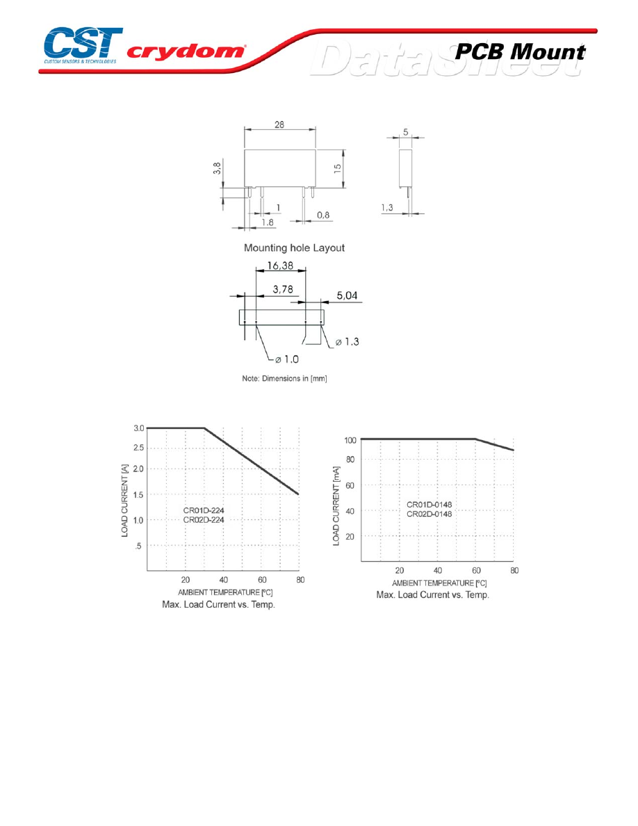
MECHANICAL SPECIFICATIONS
THERMAL DERATE INFORMATION
For Contact information visit our web
site.
www.crydom.com
©2008 Crydom, Inc.
Specifications subject to change without notice.
Courtesy of Steven Engineering, Inc.-230 Ryan Way, South San Francisco, CA 94080-6370-Main Office: (650) 588-9200-Outside Local Area: (800) 258-9200-www.stevenengineering.com
60MAIN-html.html

For Contact information visit our web
site.
www.crydom.com
©2008 Crydom, Inc.
Specifications subject to change without notice.
Courtesy of Steven Engineering, Inc.-230 Ryan Way, South San Francisco, CA 94080-6370-Main Office: (650) 588-9200-Outside Local Area: (800) 258-9200-www.stevenengineering.com
60MAIN-html.html
ANNEX - ENVIROMENTAL INFORMATION
For Contact information visit our web
site.
www.crydom.com
©2008 Crydom, Inc.
Specifications subject to change without notice.
Courtesy of Steven Engineering, Inc.-230 Ryan Way, South San Francisco, CA 94080-6370-Main Office: (650) 588-9200-Outside Local Area: (800) 258-9200-www.stevenengineering.com
60MAIN-html.html
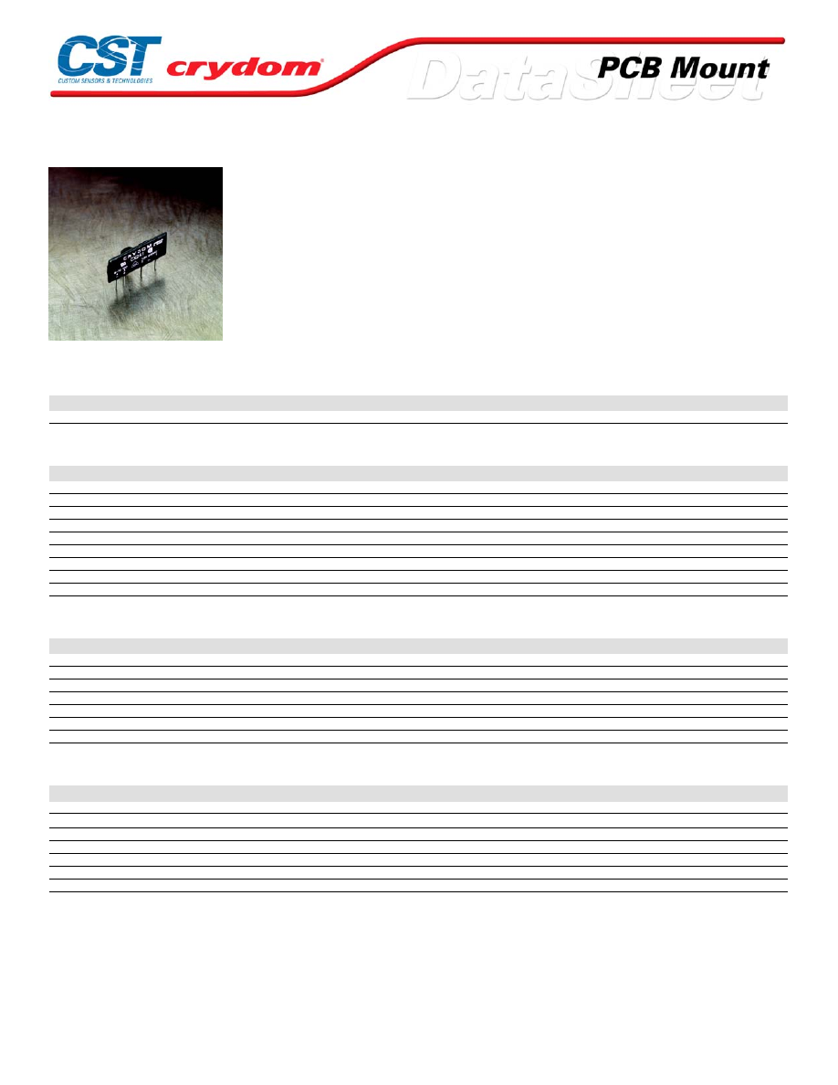
CX241 Series
• Mini-SIP SSR
• Ratings to 1.5A @ 280 VAC
• SCR output
• DC control
• Zero-crossing (resistive loads) or random-fire (inductive loads) output
PRODUCT SELECTION
Control Voltage
Zero Crossing
Random Fire
4-10 VDC
CX241
CX241R
OUTPUT SPECIFICATIONS (1)
Description
Operating Voltage (47-63Hz) [Vrms]
12-280
12-280
Transient Overvoltage [Vpk]
600
600
Maximum Off-State Leakage Current @ Rated Voltage [mArms]
0.1
0.1
Minimum Off-State dv/dt @ Maximum Rated Voltage [V/µsec] (3)
500
500
Maximum Load Current [Arms](3)
1.5
1.5
Minimum Load Current [Arms]
0.025
0.025
Maximum Surge Current (16.6ms) [Apk]
40
40
Maximum On-State Voltage Drop @ Rated Current [Vpk]
1.5
1.5
Minimum Power Factor (with Maximum Load)
0.5
0.5
INPUT SPECIFICATIONS (1)
Description
DC Control
Control Voltage Range
4-10 VDC
Must Turn On Voltage
4.0 VDC
Must Turn Off Voltage
1.0 VDC
Typycal Input Current @ 5 VDC
15 mAdc
Nominal Input Impedance
300 Ohm
Maximum Turn-On Time [msec]
1/2 Cycle
Maximum Turn-Off Time [msec]
1/2 Cycle
GENERAL SPECIFICATIONS
Description
Parameters
Dielectric Strength, Input/Output/Base (50/60Hz)(2)
4000 Vrms
Minimum Insulation Resistance (@ 500 VDC) (2)
10
9
Ohm
Maximum Capacitance, Input/Output
8.0 pF
Ambient Operating Temperature Range
-30 to 80˚C
Ambient Storage Temperature Range
-30 to 125˚C
Weight (typical)
0.4 oz. (11 g)
Encapsulation
Thermally Conductive Epoxy
GENERAL NOTES
1) All parameters at 25°C unless otherwise specified.
2) Dielectric and insulation resistence are measured between input and output
3) Off-State dv/dt test method per EIA/NARM standard RS-443
For Contact information visit our web
site.
www.crydom.com
©2008 Crydom, Inc.
Specifications subject to change without notice.
Courtesy of Steven Engineering, Inc.-230 Ryan Way, South San Francisco, CA 94080-6370-Main Office: (650) 588-9200-Outside Local Area: (800) 258-9200-www.stevenengineering.com
60MAIN-html.html

MECHANICAL SPECIFICATIONS
DC CONTROL.
PIN 1: AC LOAD
PIN 2: AC LOAD
PIN 3: +DC CONTROL
PIN 4: -DC CONTROL
THERMAL DERATE INFORMATION
AGENCY APPROVALS
UL E116950
CSA LR81689
VDE 5921 UG
Rev. 061608
For Contact information visit our web
site.
www.crydom.com
©2008 Crydom, Inc.
Specifications subject to change without notice.
Courtesy of Steven Engineering, Inc.-230 Ryan Way, South San Francisco, CA 94080-6370-Main Office: (650) 588-9200-Outside Local Area: (800) 258-9200-www.stevenengineering.com
60MAIN-html.html

For Contact information visit our web
site.
www.crydom.com
©2008 Crydom, Inc.
Specifications subject to change without notice.
Courtesy of Steven Engineering, Inc.-230 Ryan Way, South San Francisco, CA 94080-6370-Main Office: (650) 588-9200-Outside Local Area: (800) 258-9200-www.stevenengineering.com
60MAIN-html.html

ANNEX - ENVIROMENTAL INFORMATION
For Contact information visit our web
site.
www.crydom.com
©2008 Crydom, Inc.
Specifications subject to change without notice.
Courtesy of Steven Engineering, Inc.-230 Ryan Way, South San Francisco, CA 94080-6370-Main Office: (650) 588-9200-Outside Local Area: (800) 258-9200-www.stevenengineering.com
60MAIN-html.html
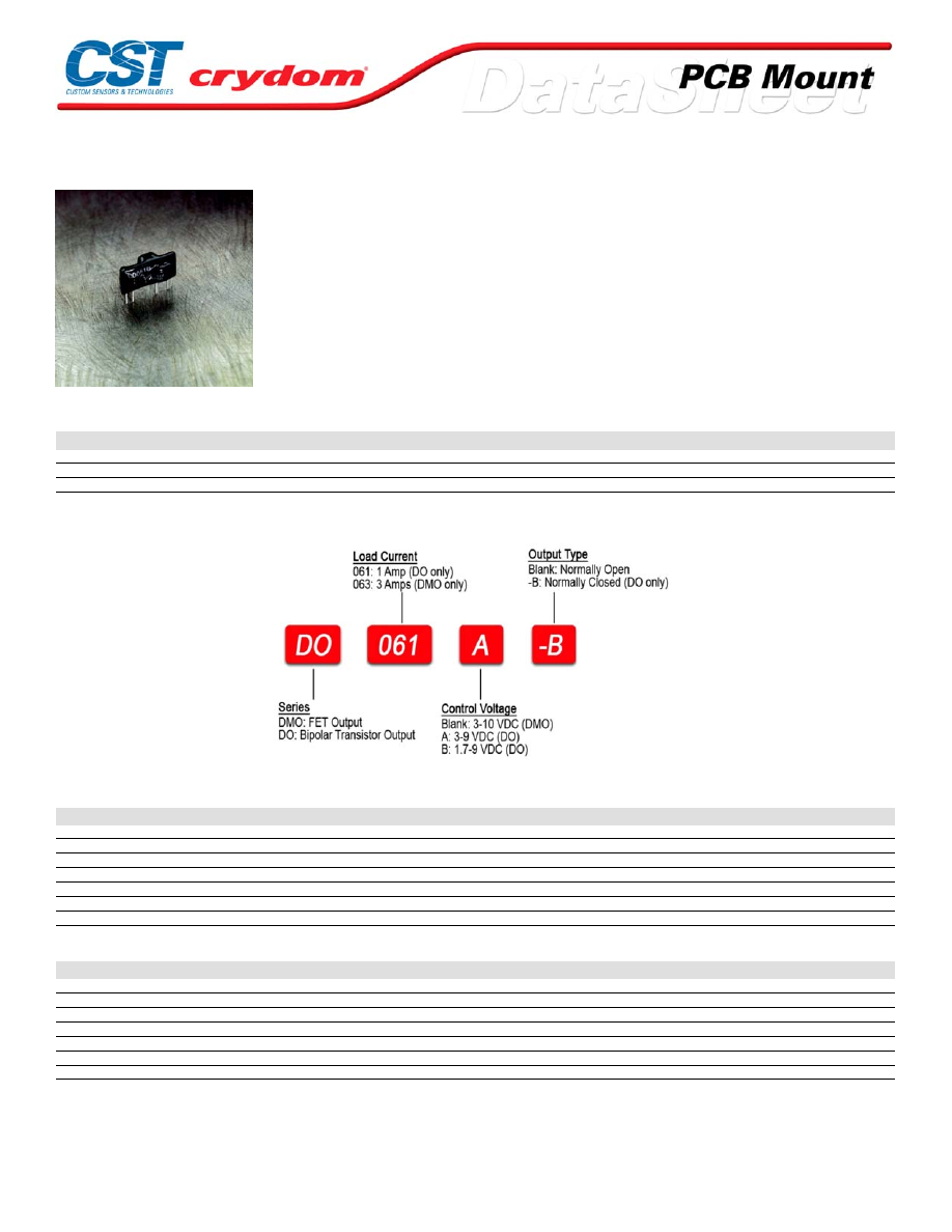
DO / DMO Series
• Mini-SIP SSR
• Ratings to 2A @ 60 V DC
• MOSFET or bi-polar transistor output
• DC control
• Normally open or normally closed output
PRODUCT SELECTION
Control Voltage
1 A
3 A
3-9 VDC
DO061A (4), DO061A-B
1.7-9 VDC
DO061B (4), DO061B -B
3-10 VDC
DMO063 (4)
AVAILABLE OPTIONS
OUTPUT SPECIFICATIONS (1)
Description
DO0
DMO
Operating Voltage Range (47-63Hz) [VDC]
3-60
0-60
Maximum Off-State Leakage Current @ Rated Voltage [mArms]
200
100
Maximum Load Current [Arms]
1.0
3.0
Minimum Load Current [Arms]
0.02
0
Maximum Surge Current [Adc]
5 (1sec)
12 (10ms)
Maximum On-State Voltage Drop @ Rated Current [Vpk]
1.5
0.4
Minimum Power Factor (with Maximum Load)
0.5
0.5
INPUT SPECIFICATIONS (1)
Description
DO061A
DO061B
DMO063
Control Voltage Range
3-9 VDC
1.7-9 VDC
3-10 VDC
Must Turn On Voltage
3.0 VDC
1.7 VDC
3.0 VDC
Must Turn Off Voltage
1.0 VDC
0.8 VDC
1.0 VDC
Typycal Input Current @ 5 VDC
15 mAdc
15 mAdc
20 mAdc
Nominal Input Impedance
270 Ohm
270 Ohm
270 Ohm
Maximum Turn-On Time [msec]
50
50
50
Maximum Turn-Off Time [msec]
50
150
300
For Contact information visit our web
site.
www.crydom.com
©2008 Crydom, Inc.
Specifications subject to change without notice.
Courtesy of Steven Engineering, Inc.-230 Ryan Way, South San Francisco, CA 94080-6370-Main Office: (650) 588-9200-Outside Local Area: (800) 258-9200-www.stevenengineering.com
60MAIN-html.html
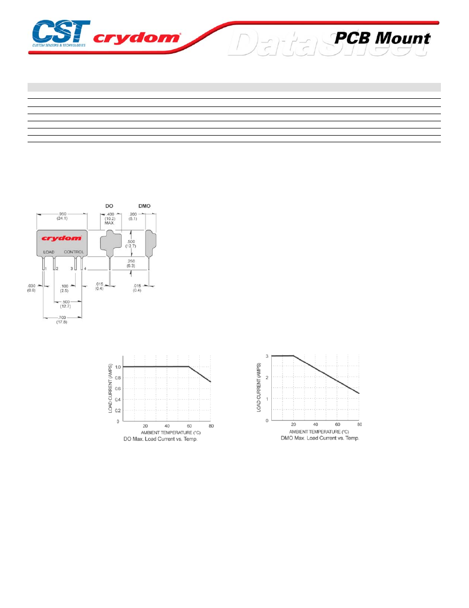
GENERAL SPECIFICATIONS
Description
Parameters
Dielectric Strength, Input/Output/Base (50/60Hz)(3)
4000 Vrms
Minimum Insulation Resistance (@ 500 VDC)(3)
10
9
Ohm
Maximum Capacitance, Input/Output
8 pF
Ambient Operating Temperature Range
-30 to 80 °C
Ambient Storage Temperature Range
-30 to 125 °C
Weight (typical)
0.15 oz. (4.3g)
Encapsulation
Thermally Conductive Epoxy
GENERAL NOTES
1) All parameters at 25°C unless otherwise specified.
2) T ypical On-State Resistance=.13
3) Dielectric and insulation resistance are measured between input and output
4) Inductiv e loads should be diode suppressed
MECHANICAL SPECIFICATIONS
DC C ONTR OL
PIN 1: +DC LOAD
PIN 2: -D C LOAD
PIN 3: +DC CONTROL
PIN 4: -D C CONTROL
THERMAL DERATE INFORMATION
For Contact information visit our web
site.
www.crydom.com
©2008 Crydom, Inc.
Specifications subject to change without notice.
Courtesy of Steven Engineering, Inc.-230 Ryan Way, South San Francisco, CA 94080-6370-Main Office: (650) 588-9200-Outside Local Area: (800) 258-9200-www.stevenengineering.com
60MAIN-html.html

ANNEX - ENVIROMENTAL INFORMATION
For Contact information visit our web
site.
www.crydom.com
©2008 Crydom, Inc.
Specifications subject to change without notice.
Courtesy of Steven Engineering, Inc.-230 Ryan Way, South San Francisco, CA 94080-6370-Main Office: (650) 588-9200-Outside Local Area: (800) 258-9200-www.stevenengineering.com
60MAIN-html.html
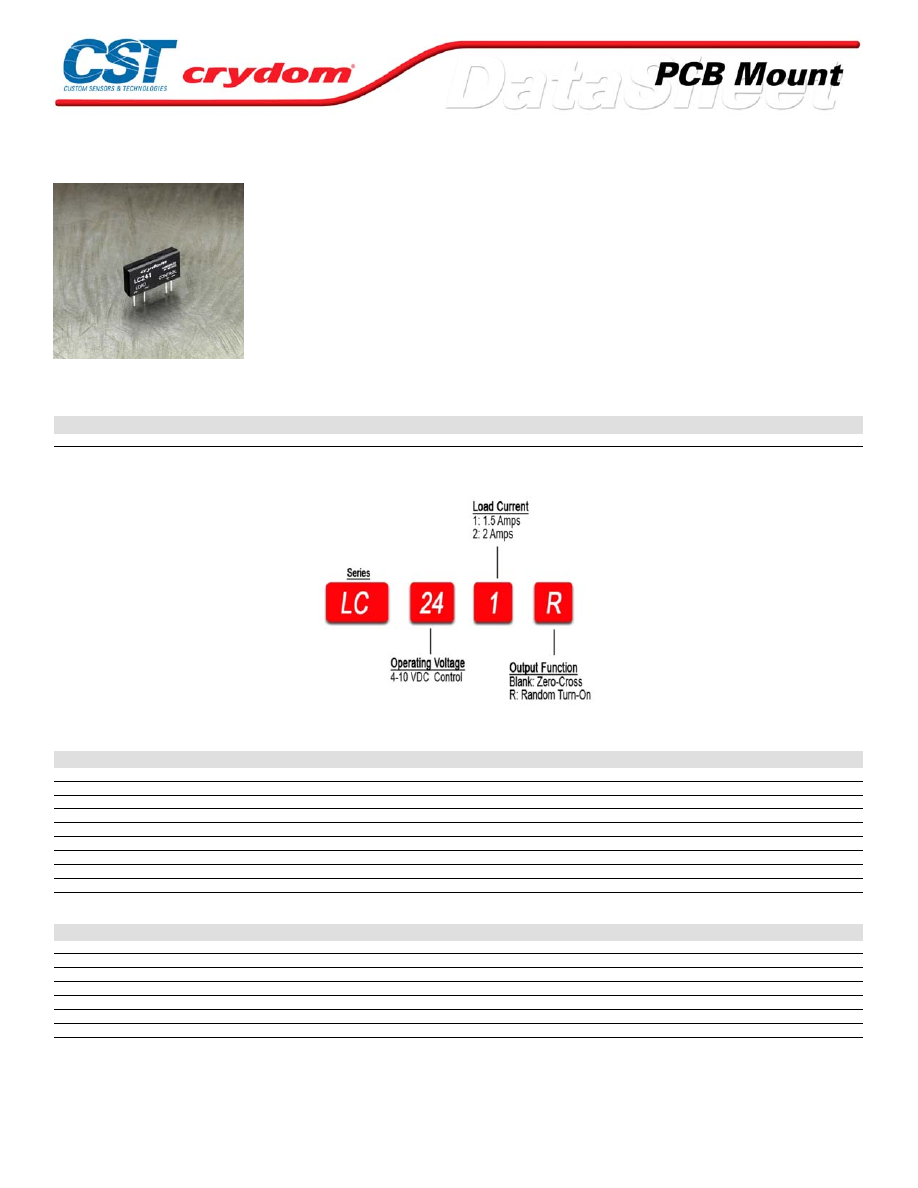
LC Series
• Mini-SIP SSR
• Ratings to 2A @ 280 VAC
• Triac output
• DC control
• Zero-crossing (resistive loads) or random-fire (inductive loads) output
• Plastic encapsulated
PRODUCT SELECTION
Control Voltage
1.5A
2A
4-10 VDC
LC241
LC242
AVAILABLE OPTIONS
OUTPUT SPECIFICATIONS (1)
Description
Operating Voltage (47-63Hz) [Vrms]
12-280
12-280
Transient Overvoltage [Vpk]
600
600
Maximum Off-State Leakage Current @ Rated Voltage [mArms]
0.1
0.1
Minimum Off-State dv/dt @ Maximum Rated Voltage [V/µsec] (3)
500
500
Maximum Load Current [Arms]
1.5
2.0
Minimum Load Current [Arms]
0.025
0.025
Maximum Surge Current (16.6ms) [Apk]
80
100
Maximum On-State Voltage Drop @ Rated Current [Vpk]
1.5
1.5
Minimum Power Factor (with Maximum Load)
0.5
0.5
INPUT SPECIFICATIONS (1)
Description
Control Voltage Range
4-10 VDC
Must Turn On Voltage
4.0 VDC
Must Turn Off Voltage
1.0 VDC
Typycal Input Current @ 5 VDC
15 mAdc
Nominal Input Impedance
300 Ohm
Maximum Turn-On Time [msec] (4)
1/2 Cycle
Maximum Turn-Off Time [msec]
1/2 Cycle
For Contact information visit our web
site.
www.crydom.com
©2008 Crydom, Inc.
Specifications subject to change without notice.
Courtesy of Steven Engineering, Inc.-230 Ryan Way, South San Francisco, CA 94080-6370-Main Office: (650) 588-9200-Outside Local Area: (800) 258-9200-www.stevenengineering.com
60MAIN-html.html
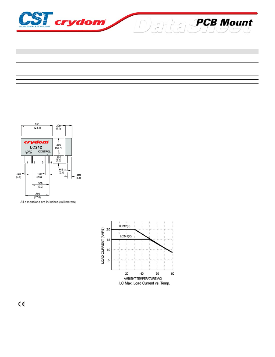
GENERAL SPECIFICATIONS
Description
Parameters
Dielectric Strength, Input/Output/Base (50/60Hz)(2)
2500 Vrms
Minimum Insulation Resistance (@ 500 VDC)(2)
10
9
Ohm
Maximum Capacitance, Input/Output
8 pF
Ambient Operating Temperature Range
-40 to 80˚C
Ambient Storage Temperature Range
-40 to 125˚C
Weight (typical)
0.15 oz. (4.3g)
Encapsulation
UL94V-0Molded epoxy
GENERAL NOTES
1) All parameters at 25°C unless otherwise specified.
2) Dielectric and insulation resistence are measured between input and output.
3) Off-State dv/dt test method per EIA/NARM standard RS-443.
4) 0.1 msec for random turn-on version (R suffix).
MECHANICAL SPECIFICATIONS
DC C ONTR OL
PIN 1: AC LOAD
PIN 2: AC LOAD
PIN 3: +DC CONTROL
PIN 4: -D C CONTROL
THERMAL DERATE INFORMATION
AGENCY APPROVALS
UL
/
cUL
E116950
Rev.
061608
For Contact information visit our web
site.
www.crydom.com
©2008 Crydom, Inc.
Specifications subject to change without notice.
Courtesy of Steven Engineering, Inc.-230 Ryan Way, South San Francisco, CA 94080-6370-Main Office: (650) 588-9200-Outside Local Area: (800) 258-9200-www.stevenengineering.com
60MAIN-html.html
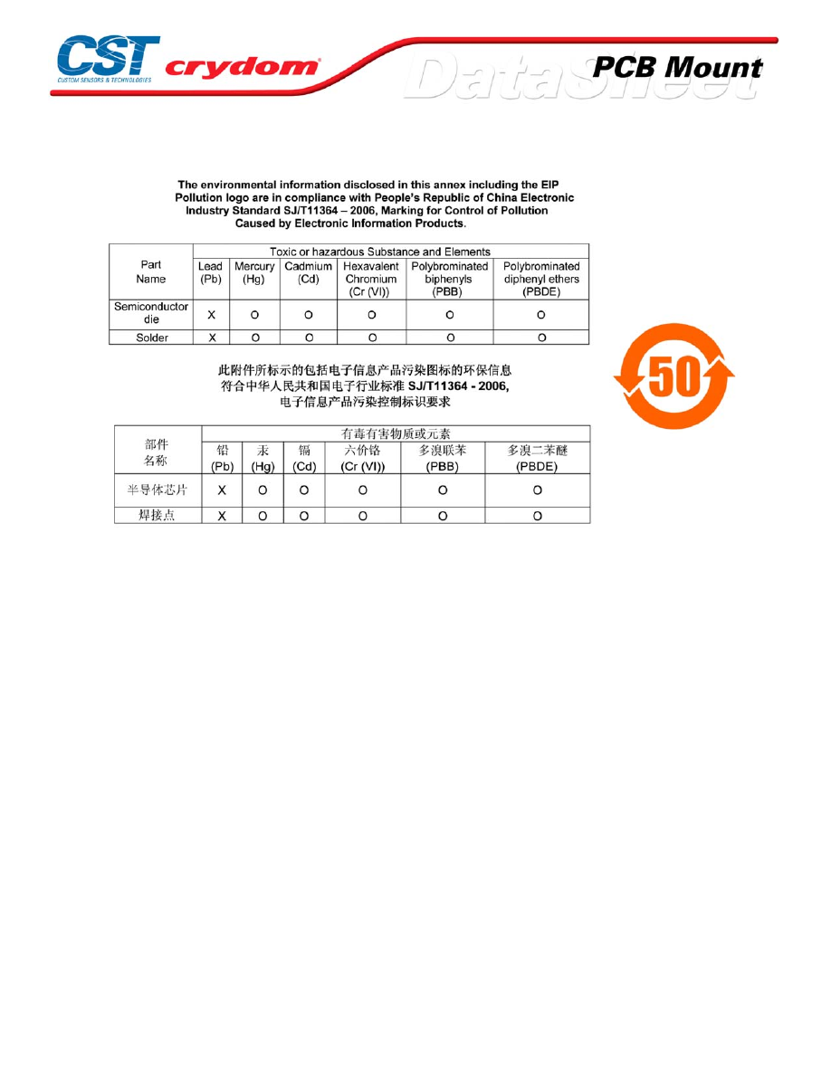
ANNEX - ENVIROMENTAL INFORMATION
For Contact information visit our web
site.
www.crydom.com
©2008 Crydom, Inc.
Specifications subject to change without notice.
Courtesy of Steven Engineering, Inc.-230 Ryan Way, South San Francisco, CA 94080-6370-Main Office: (650) 588-9200-Outside Local Area: (800) 258-9200-www.stevenengineering.com
60MAIN-html.html
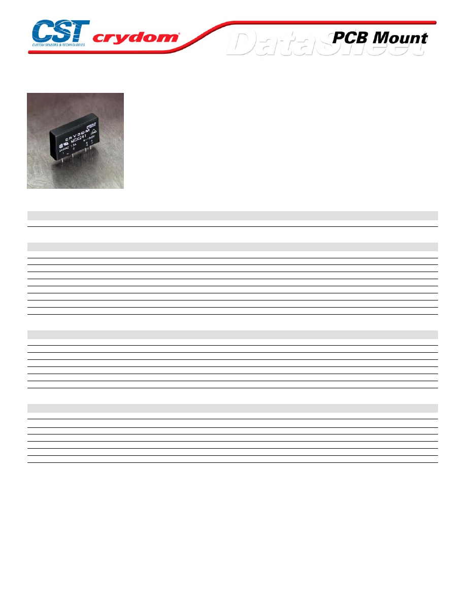
MCX 241 Series
• Mini-SIP SSR
• Ratings to 1.5A @ 280 VAC
• SCR output • DC control
• Zero-crossing (resistive loads) or random-fire (inductive loads) output
• Plastic encapsulated
PRODUCT SELECTION
Control Voltage
Zero-crossing
Random Fire
4-10 VDC
MCX241
MCX241R
OUTPUT SPECIFICATIONS (1)
Description
Operating Voltage (47-63Hz) [Vrms]
12-280
12-280
Transient Overvoltage [Vpk]
600
600
Maximum Off-State Leakage Current @ Rated Voltage [mArms]
0.1
0.1
Minimum Off-State dv/dt @ Maximum Rated Voltage [V/µsec] (3)
200
200
Maximum Load Current [Arms]
1.5
1.5
Minimum Load Current [Arms]
0.025
0.025
Maximum Surge Current (16.6ms) [Apk]
40
40
Maximum On-State Voltage Drop @ Rated Current [Vpk]
1.5
1.5
Minimum Power Factor (with Maximum Load)
0.5
0.5
INPUT SPECIFICATIONS (1)
Description
Control Voltage Range
4-10 VDC
4-10 VDC
Must Turn On Voltage
4.0 VDC
4.0 VDC
Must Turn Off Voltage
1.0 VDC
1.0 VDC
Typycal Input Current @ 5 VDC
15 mAdc
15 mAdc
Nominal Input Impedance
300 Ohm
300 Ohm
Maximum Turn-On Time [msec] (4)
1/2 Cycle
0.1
Maximum Turn-Off Time [msec]
1/2 Cycle
1/2 Cycle
GENERAL SPECIFICATIONS
Description
Parameters
Dielectric Strength, Input/Output/Base (50/60Hz)(2)
4000 Vrms
Minimum Insulation Resistance (@ 500 VDC)(2)
10
9
Ohm
Maximum Capacitance, Input/Output
8 pF
Ambient Operating Temperature Range
-40 to 80°C
Ambient Storage Temperature Range
-40 to 125°C
Weight (typical)
0.7 oz.(20g)
Encapsulation
Thermally Conductive Epoxy
GENERAL NOTES
1) All parameters at 25°C unless otherwise specified.
2) Dielectric and insulation resistence are measured between input and output
3) Off-State dv/dt test method per EIA/NARM standard RS-443
4) Turn on time or Random Turn on is 0.1 m sec
For Contact information visit our web
site.
www.crydom.com
©2008 Crydom, Inc.
Specifications subject to change without notice.
Courtesy of Steven Engineering, Inc.-230 Ryan Way, South San Francisco, CA 94080-6370-Main Office: (650) 588-9200-Outside Local Area: (800) 258-9200-www.stevenengineering.com
60MAIN-html.html
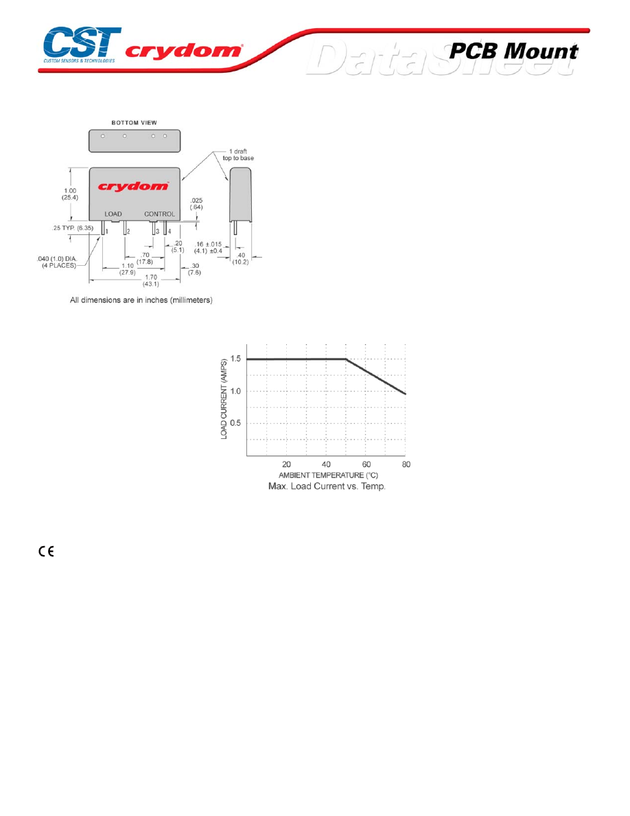
MECHANICAL SPECIFICATIONS
DC C ONTR OL.
PIN 1:+DC LOAD
PIN 2: -D C LOAD
PIN 3: +DC CONTROL
PIN 4: -D C CONTROL
THERMAL DERATE INFORMATION
AGENCY APPROVALS
UL E116950
CSA LR81689
VDE 5921 UG
For Contact information visit our web
site.
www.crydom.com
©2008 Crydom, Inc.
Specifications subject to change without notice.
Courtesy of Steven Engineering, Inc.-230 Ryan Way, South San Francisco, CA 94080-6370-Main Office: (650) 588-9200-Outside Local Area: (800) 258-9200-www.stevenengineering.com
60MAIN-html.html
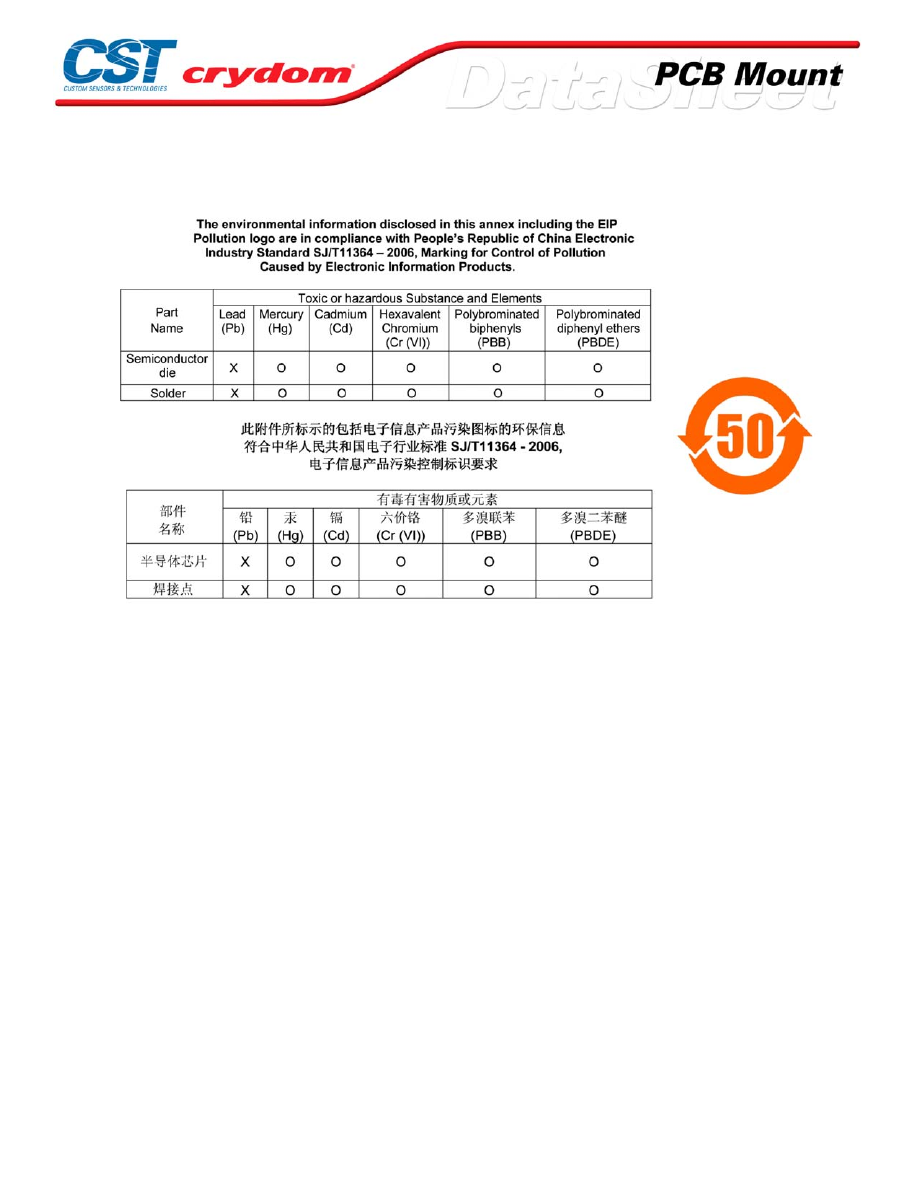
ANNEX - ENVIROMENTAL INFORMATION
For Contact information visit our web
site.
www.crydom.com
©2008 Crydom, Inc.
Specifications subject to change without notice.
Courtesy of Steven Engineering, Inc.-230 Ryan Way, South San Francisco, CA 94080-6370-Main Office: (650) 588-9200-Outside Local Area: (800) 258-9200-www.stevenengineering.com
60MAIN-html.html
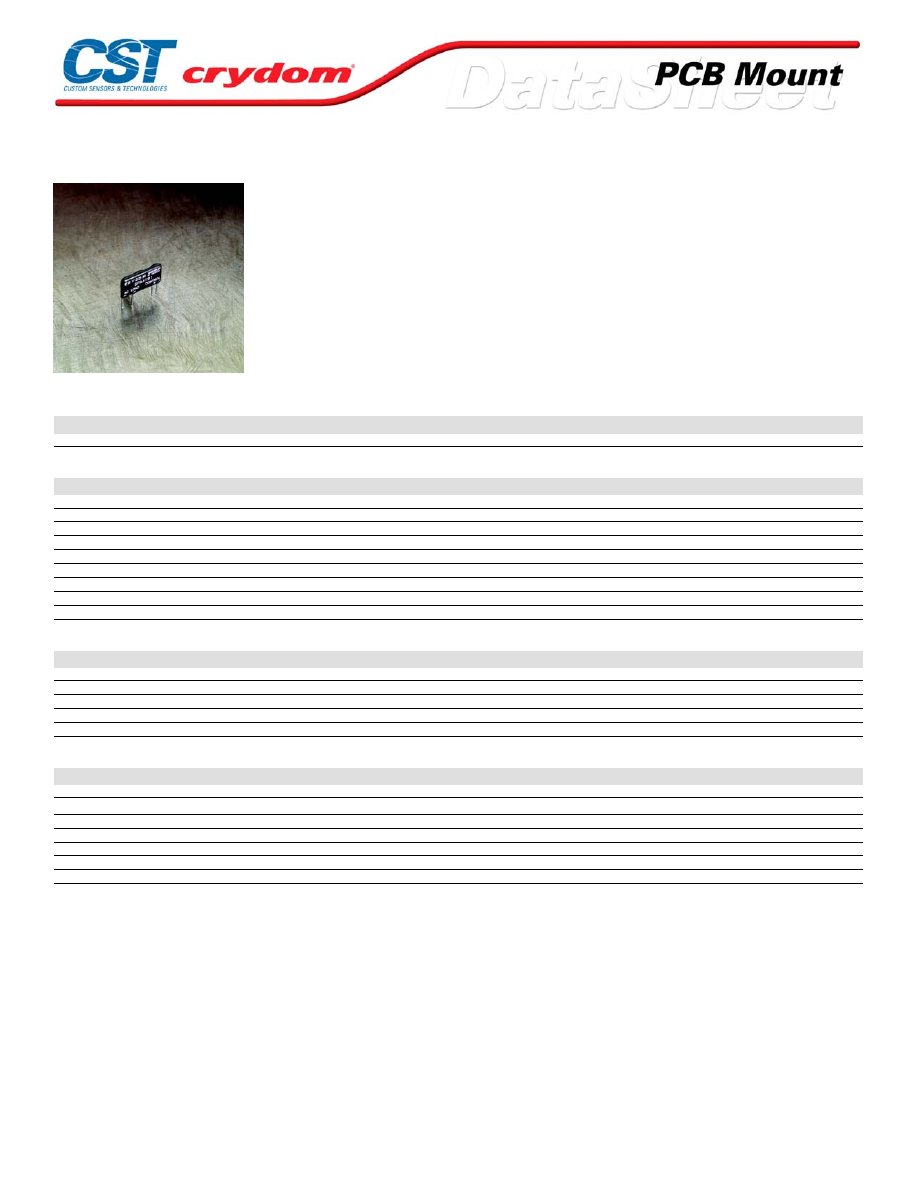
SPA Series
• Mini-SIP SSR
• Ratings to 1A @ 280 VAC
• SCR output
• DC control
• Zero-crossing (resistive loads) output
• 10-35mA current-control input
PRODUCT SELECTION
Control Voltage
1A
1A
10-35 VDC
SPA4191
SPA6191
OUTPUT SPECIFICATIONS (1)
Description
Operating Voltage (47-63Hz) [Vrms]
20-140
20-280
Transient Overvoltage [Vpk]
400
600
Maximum Off-State Leakage Current @ Rated Voltage [mArms]
0.01
0.01
Minimum Off-State dv/dt @ Maximum Rated Voltage [V/µsec] (3)
500
500
Maximum Load Current [Arms](3)
1.0
1.0
Minimum Load Current [Arms]
0.025
0.025
Maximum Surge Current (16.6ms) [Apk]
30
30
Maximum On-State Voltage Drop @ Rated Current [Vpk]
1.5
1.5
Minimum Power Factor (with Maximum Load)
0.5
0.5
INPUT SPECIFICATIONS (1)
Description
DC Control
Control Current Range
10-35 VDC
Must Turn On Current
10 mA
Must Turn Off Current
1 mA
Maximum Turn-On Time [msec]
1/2 cycle
Maximum Turn-Off Time [msec]
1/2 cycle
GENERAL SPECIFICATIONS
Description
Parameters
Dielectric Strength, Input/Output/Base (50/60Hz)(2)
2500 Vrms
Minimum Insulation Resistance (@ 500 VDC)(2)
10
9
Ohm
Maximum Capacitance, Input/Output
8.0 pF
Ambient Operating Temperature Range
-30 to 80°C
Ambient Storage Temperature Range
-30 to 125°C
Weight (typical)
0.15 oz. (4.3g)
Encapsulation
Thermally Conductive Epoxy
GENERAL NOTES
1) All parameters at 25°C unless otherwise specified.
2) Dielectric and insulation resistence are measured between input and output
3) Off-State dv/dt test method per EIA/NARM standard RS-443
For Contact information visit our web
site.
www.crydom.com
©2008 Crydom, Inc.
Specifications subject to change without notice.
Courtesy of Steven Engineering, Inc.-230 Ryan Way, South San Francisco, CA 94080-6370-Main Office: (650) 588-9200-Outside Local Area: (800) 258-9200-www.stevenengineering.com
60MAIN-html.html
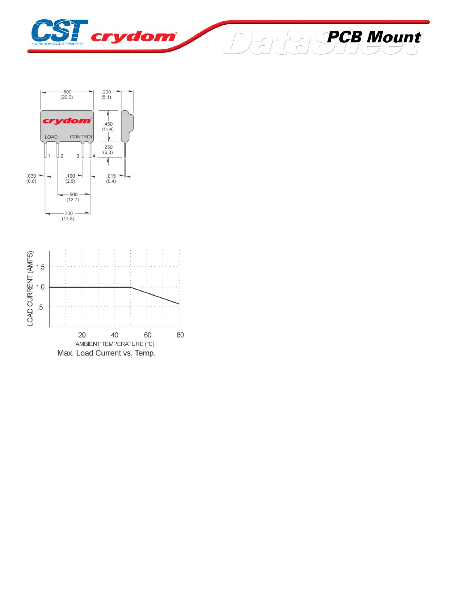
MECHANICAL SPECIFICATIONS
DC C ONTR OL
PIN 1: AC LOAD
PIN 2: AC LOAD
PIN 3: +DC CONTROL
PIN 4: -D C CONTROL
THERMAL DERATE INFORMATION
For Contact information visit our web
site.
www.crydom.com
©2008 Crydom, Inc.
Specifications subject to change without notice.
Courtesy of Steven Engineering, Inc.-230 Ryan Way, South San Francisco, CA 94080-6370-Main Office: (650) 588-9200-Outside Local Area: (800) 258-9200-www.stevenengineering.com
60MAIN-html.html

ANNEX - ENVIROMENTAL INFORMATION
For Contact information visit our web
site.
www.crydom.com
©2008 Crydom, Inc.
Specifications subject to change without notice.
Courtesy of Steven Engineering, Inc.-230 Ryan Way, South San Francisco, CA 94080-6370-Main Office: (650) 588-9200-Outside Local Area: (800) 258-9200-www.stevenengineering.com
60MAIN-html.html
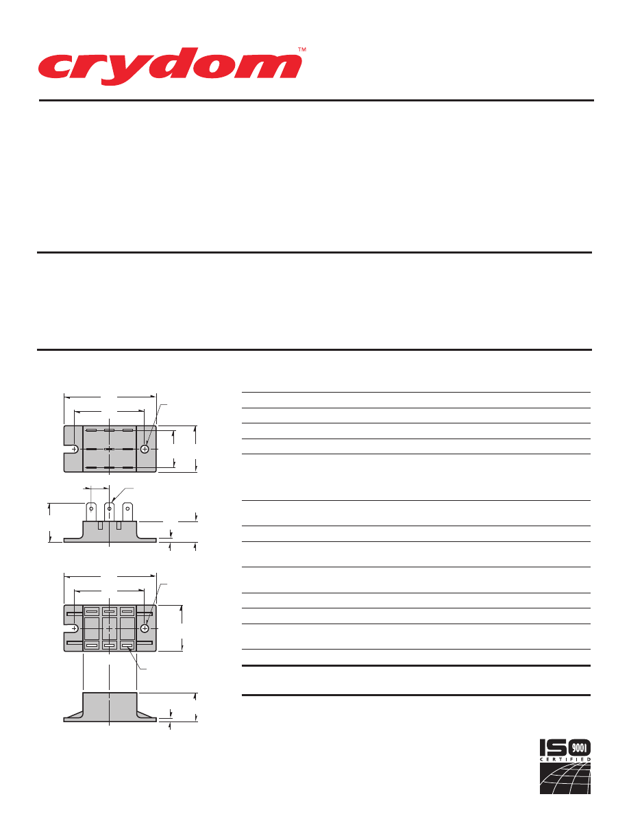
ELECTRICAL SPECIFICATIONS
MODEL NO.
B5
B6
SYMBOL SPECIFICATION
RATINGS
I
D
Maximum DC Output Current (Tc = 85°C)
25A
42.5A
V
F
Maximum Voltage Drop @ Amps Peak
1.65V @ 25A
1.6V @ 42.5A
T
J
Operating Junction Temperature Range
-40°C to +125°C
di/dt
Critical Rate of Rise of On-State Current @ TJ=125°C
100A/µs
100A/µs
dv/dt
Critical Rate of Rise of Off-State Voltage [V/µs]
500V/µs
500V/µs
120 (400 V
RRM
)
V
RMS
AC Line Input Voltage
240 (600 V
RRM
)
(Repetitive Peak Reverse Voltage)
280 (800 V
RRM
)
480 (1200 V
RRM
)
I
TSM
Maximum Non-Repetitive Surge Current
( 1 / 2 Cycle, 60Hz)
250A
600A
I
2
T
Maximum I 2 T for Fusing (t=8.3ms) [A
2 sec]
260
1500
I
GT
Maximum Required Gate Current
to Trigger @ 25°C
60mA
80mA
V
GT
Maximum Required Gate Voltage
to Trigger @ 25°C
2.5V
3.0V
P
G(AV)
Average Gate Power
0.5W
0.5W
V
GM
Maximum Peak Gate Voltage (Reverse)
5.0V
5.0V
R
q JC
Maximum Thermal Resistance Junction to
Ceramic Base per Chip
0.9°C/W
0.7°C/W
V
ISOL
Isolation Voltage
2500 V
RMS
2500 V
RMS
MECHANICAL SPECIFICATIONS
Weight: (typical)
1.5 oz. (42.5g)
MECHANICAL DIMENSIONS
All dimensions are in inches (millimeters)
PART NUMBER IDENTIFICATION
Series Type
Current
Circuit Type
AC Line Voltage
Options
Case Style
B
-Case style
5
- 25 Amps
1 - 8
1
- 120 Vac
F
- Free Wheeling Diode
-2T
(Standard)
(Ceramic
6
- 42.5 Amps
(see schematic
2
- 240 Vac
(
Circuits 1 & 2 Only)
-2
With Isolation
Base)
diagrams)
3
- 280 Vac
SE
- External Suppressor
Barriers
4
- 480 Vac
(-2T Only, Circuits 1-6 Only)
Example: B512FSE-2T
• Eight Standard Circuits
• For AC or DC Variable
Voltage Output Up To
15KW
SERIES B2T.
Rev. 121207
PAGE 1 OF 3
2.50
(63.5)
1.25
(31.7)
1.00
(25.4 )
1.90
(48.2)
1.06
(26.9)
.55
(14.0)
.50
(12.7)
.25
(6.3)
TERMINAL
CL
CL
2.50
(63.5)
1.25
(31.7)
1.90
(48.2)
.78
(19.7)
.25
(6.3)
TERMINAL
CL
CL
.10
(2.5)
.10
(2.5)
MOUNTING
HOLE/SLOT
0.21 (5.2) DIA.
MOUNTING
HOLE/SLOT
0.21 (5.2) DIA.
B-2T
B-2
Modules come in eight standard circuits
and are designed to control AC or DC
variable voltage output up to 15KW.
The package comes with standard .250
quick-connect terminals. All models
have 2500 Vrms isolation and are UL
recognized (file no. E72445). Optional
isolation barriers are available.
Manufactured in Crydom’s ISO 9001
Certified facility for optimum product
performance and reliability.
© 2007 CRYDOM Inc., Specifications subject to change without notice.
Series
B-2T
,
B-2
25-42.5Amp • SCR/DIODE Modules
For recommended applications and more information contact:
USA:
Sales Support (877) 502-5500
Tech Support
(877) 702-7700 FAX (619) 710-8540
Crydom Inc., 2320 Paseo de las Americas, Ste. 201, San Diego, CA 92154
Email:
sales@crydom.com
WEB SITE:
http://www.crydom.com
UK:
+44 (0)1202 606030 •
FAX
+44 (0)1202 606035 Crydom SSR Ltd., Arena Business Centre,
Holyrood Close, Poole, Dorset BH17 7FJ, Email: intsales@crydom.com.
GERMANY:
+49 (0)180 3000 506
Courtesy of Steven Engineering, Inc.-230 Ryan Way, South San Francisco, CA 94080-6370-Main Office: (650) 588-9200-Outside Local Area: (800) 258-9200-www.stevenengineering.com
60MAIN-html.html
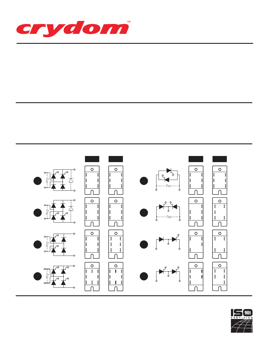
SERIES B2T.
Rev. 121207
PAGE 2 OF 3
SERIES B-2T, B-2 CIRCUITS
PART NUMBER IDENTIFICATION
Series Type
Current
Circuit Type
AC Line Voltage
Options
Case Style
B
-Case style
5
- 25 Amps
1 - 8
1
- 120 Vac
F
- Free Wheeling Diode
-2T
(Standard)
(Ceramic
6
- 42.5 Amps
(see schematic
2
- 240 Vac
(
Circuits 1 & 2 Only)
-2
With Isolation
Base)
diagrams)
3
- 280 Vac
SE
- External Suppressor
Barriers
4
- 480 Vac
(-2T Only, Circuits 1-6 Only)
Example:
B512FSE-2T
G2
AC1
AC2
G1
+
--
1
2
3
4
5
6
7
8
AC1
AC2
G4
G2
G1
G3
+
--
AC1
AC2
G2
G1
+
--
G2
G1
AC1
AC2
G2
G1
AC
+
--
G1
G2
G1
AC1
AC2
+
G2
AC2
AC1
G1
+
--
+
--
AC
B-2T
B-2
B-2T
B-2
G2
AC1
AC2
G1
+
G1
AC
+
--
G2
AC
G1
+
--
G1
AC1
AC1
G2
AC2
AC2
AC
G
+
--
AC2
G1
AC1
G2
+
G2
AC
G1
+
--
G1
AC1
AC1
G2
AC2
AC2
G2
AC1
AC2
G1
+
--
G2
AC1
AC2
G1
+
--
G2
AC1
AC2
G1
+
--
G3
AC2
AC1
G2
+
--
G1
G4
G2
AC2
AC1
G1
+
--
G2
AC1
AC2
G1
+
--
G2
AC1
AC2
G1
+
--
G3
AC2
AC1
G2
+
--
G1
G4
• Eight Standard Circuits
• For AC orDC Variable Voltage
Output Up To 15KW
© 2007 CRYDOM Inc., Specifications subject to change without notice.
APPROVALS
UL
E72445
Series
B-2T
,
B-2
25-42.5Amp • SCR/DIODE Modules
For recommended applications and more information contact:
USA:
Sales Support (877) 502-5500
Tech Support
(877) 702-7700 FAX (619) 710-8540
Crydom Inc., 2320 Paseo de las Americas, Ste. 201, San Diego, CA 92154
Email:
sales@crydom.com
WEB SITE:
http://www.crydom.com
UK:
+44 (0)1202 606030 •
FAX
+44 (0)1202 606035 Crydom SSR Ltd., Arena Business Centre,
Holyrood Close, Poole, Dorset BH17 7FJ, Email: intsales@crydom.com.
GERMANY:
+49 (0)180 3000 506
Courtesy of Steven Engineering, Inc.-230 Ryan Way, South San Francisco, CA 94080-6370-Main Office: (650) 588-9200-Outside Local Area: (800) 258-9200-www.stevenengineering.com
60MAIN-html.html

HAZARD OF
ELECTRIC
SHOCK,
EXPLOSION,
OR ARC FLASH.
•
Disconnect all
power before
installing or
working with
this equipment.
•
Verify all
connections
and replace all
covers before
turning on
power.
Failure to follow
these
instructions will
result in death
or serious injury.
RIESGO DE
DESCARGA
ELECTRICA O
EXPLOSION.
•
Desconectar
todos los
suministros de
energia a este
equipo antes
de trabajar
con este equipo.
•
Verificar todas
las conexiones
y colocar todas
las tapas antes
de energizer
el equipo.
El
incumplimiento
de estas
instrucciones
puede provocar
la muerte o
lesiones serias.
RISQUE DE
DESCHARGE
ELECTRIQUE
OU EXPLOSION
•
Eteindre
toutes les
sources
d'énergie de
cet appareil
avant de
travailler
dessus de cet
appareil
•
Vérifier tous
connections, et
remettre tous
couverts en
olace avant de
mettre sous
De non-suivi de
ces instructions
provoquera la
mort ou des
lésions sérieuses
sérieuses.
GEFAHR EINES
ELEKTRISCHE
N SCHLAGES
ODER EINER
EXPLOSION.
•
Stellen Sie
jeglichen
Strom ab, der
dieses Gerät
versorgt, bevor
Sie an dem
Gerät Arbeiten
durchführen
•
Vor dem
Drehen auf
Energie alle
Anschlüsse
überprüfen
und alle
Abdeckungen
ersetzen.
Unterlassung
dieser
Anweisungen
können zum
Tode oder zu
schweren
Verletzungen
führen.
RISCHIO DI
SCOSSA
ELETTRICA O
DELL’ESPLOSI
ONE.
•
Spenga tutta
l'alimentazion
e che fornisce
questa
apparecchiatu
ra prima del
lavorare a questa
apparecchiatu ra
•
Verificare tutti
i collegamenti
e sostituire
tutte le coperture
prima della
rotazione
sull'alimentazi one
L'omissione di
seguire queste
istruz ioni
provocherà la
morte o di
lesioni serie
RISCO DE
DESCARGA
ELÉTTRICA OU
EXPLOSÃO
•
Desconectar
o equipamento
de toda á
energia antes
de instalar ou
trabalhar com
este equipamen
to
•
Verificar todas
as conexões e
recolocar todas
as tampas
antes de religar
o equipamento
O não cumprimento
destas instruções
pode levar á morte
ou lesões sérias.
RISQUE DE DOMMAGE MATERIEL ET DE
SURCHAUFFE DU BOITIER
•
Les panneaux latéraux du produit peuvent être
chauds. Laisser le produit refroidir avant de le
toucher.
•
Respecter les consignes de montage, et
notamment les couples de serrage.
•
Ne pas laisser pénétrer de liquide ni de corps
étrangers à l'intérieur du produit.
RISK OF MATERIAL DAMAGE AND HOT
ENCLOSURE
•
The product's side panels may be hot, allow
time for product to cool before touching.
•
Follow proper mounting instructions including
torque values
.
•
Do not allow liquids or foreign objects to enter
this product.
Le non-respect de cette directive peut entraîner,
des lésions corporelles graves ou des
dommages matériels.
Failure to follow this instruction can result in
serious injury, or equipment damage.
La mancata osservanza di questa precauzione può
causare gravi rischi per l'incolumità personale o
danni alle apparecchiature.
Si no se respetan estas precauciones pueden
producirse graves lesiones, daños materiales.
Die Nichtbeachtung dieser Anweisung kann
Körperverletzung oder Materialschäden
zur Folge haben.
A não observância destas precauções pode
provocar a morte, ferimentos graves ou
danos materiais.
GEFAHR VON MATERIALSCHÄDEN UND
GEHÄUSEERHITZUNG
•
Die Seitenwände können heiß sein. Lassen Sie
das Produkt abkühlen, bevor Sie es berühren.
•
Beachten Sie die Montageanweisungen,
•
Führen Sie keine Flüssigkeiten oder
Fremdkörper in das Produkt ein.
RISCHIO DI DANNI MATERIALI E D'INVOLUCRO
CALDO
•
I pannelli laterali dell'apparecchio possono
scottare; lasciar quindi raffreddare il prodotto
prima di toccarlo.
•
Seguire le istruzioni di montaggio corrette.
•
Non far entrare liquidi o oggetti estranei in questo
apparecchio.
RIESGO DE DAÑOS MATERIALES Y DE
SOBRECALENTAMIENTO DE LA UNIDAD
•
Los paneles laterales del producto pueden
estar calientes. Esperar que el producto se
enfríe antes de tocarlo.
•
Respetar las instrucciones de montaje, y en
particular los pares de apretado.
•
No dejar que penetren líquidos o cuerpos
extraños en el producto.
RISCO DE DANO MATERIAL E DE AQUECIMENTO
•
Os painéis laterais do produto podem estar
quentes; dê tempo ao produto para arrefecer
antes de lhe tocar.
•
Siga devidamente as instruções de montagem.
•
Não permita a entrada de líquidos e de objectos
estranhos no produto.
DANGER / PELIGRO / DANGER /GEFAHR / PERICOLO / PERIGO
WARNING / AVERTISSEMENT / WARNUNG /ADVERTENCIA / AVVERTENZA / AVISO
SERIES B2T.
Rev. 121207
PAGE 3 OF 3
Courtesy of Steven Engineering, Inc.-230 Ryan Way, South San Francisco, CA 94080-6370-Main Office: (650) 588-9200-Outside Local Area: (800) 258-9200-www.stevenengineering.com
60MAIN-html.html

ANNEX – ENVIRONMENTAL INFORMATION:
The environmental information disclosed in this annex including the EIP
Pollution logo are in compliance with People’s Republic of China Electronic
Industry Standard SJ/T11364 – 2006, Marking for Control of Pollution
Caused by Electronic Information Products.
Part
Toxic or hazardous Substance and Elements
Name
Lead
Mercury Cadmium Hexavalent
Polybrominated Polybrominated
(Pb)
(Hg)
(Cd)
Chromium
(Cr (VI))
biphenyls
(PBB)
diphenyl ethers
(PBDE)
Semiconductor
die
X
O
O
O
O
O
Solder
X
O
O
O
O
O
䰘ӊ
-
⦃ֱֵᙃ
:
ℸ䰘ӊ᠔ᷛ⼎ⱘࣙᣀ⬉ᄤֵᙃѻક∵ᶧᷛⱘ⦃ֱֵᙃ
ヺড়ЁढҎ⇥݅⬉ᄤ㸠Ϯᷛޚ
SJ/T11364 - 2006,
⬉ᄤֵᙃѻક∵ᶧࠊᷛ䆚㽕∖
㋴
ܗ
䋼
⠽
ᆇ
᳝
↦
᳝
ӊ
䚼
ৡ⿄
䪙
∲
䬝
݁Ӌ䫀
⒈㘨㣃
⒈Ѡ㣃䝮
(Pb)
(Hg)
(Cd)
(Cr (VI))
(PBB)
(PBDE)
ञᇐԧ㢃⠛
X
O
O
O
O
O
⛞⚍
X
O
O
O
O
O
© 2007 CRYDOM Inc., Specifications subject to change without notice.
Courtesy of Steven Engineering, Inc.-230 Ryan Way, South San Francisco, CA 94080-6370-Main Office: (650) 588-9200-Outside Local Area: (800) 258-9200-www.stevenengineering.com
60MAIN-html.html
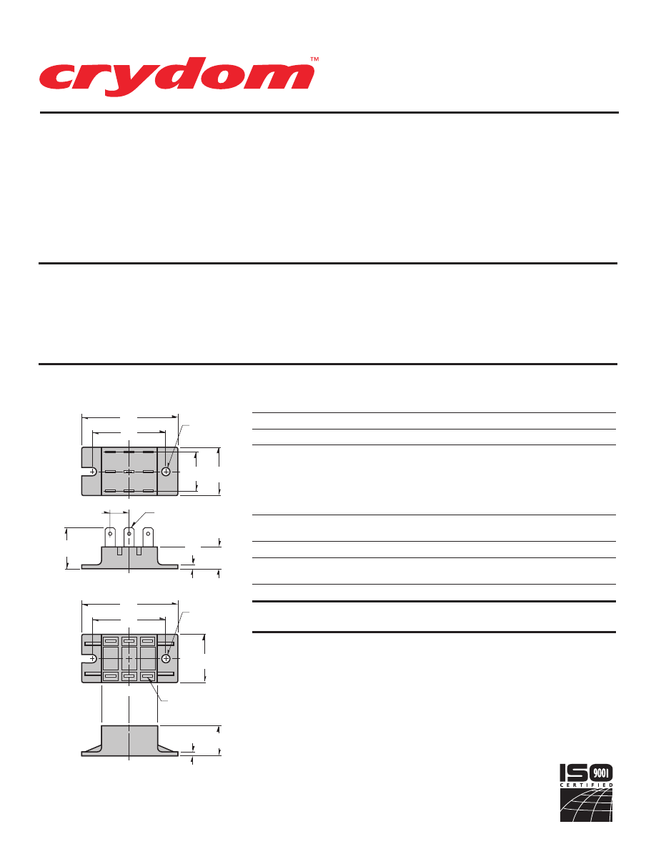
• Single and Three
Phase Circuits
• Up to 1600 Volt Blocking
Standard
SERIES B48.
Rev. 121207
PAGE 1 OF 3
Single- and three-phase diode circuits
come in a panel mount package that
provides 2500 Vrms isolation from the
terminals to the ceramic base. Available in
ratings up to 1600 Volts,
all models are
UL recognized (file no. E72445).
Manufactured in Crydom’s ISO 9001
Certified facility for optimum product
performance and reliability.
ELECTRICAL SPECIFICATIONS
RATINGS
SYMBOL
SPECIFICATION
SINGLE PHASE
THREE PHASE
I
D
Maximum DC Output Current (Tc = 85°C)
35A
50A
V
F
Maximum Voltage Drop @ Amps Peak
1.25V @ 35A
1.35V @ 50A
T
J
Operating Junction Temperature Range
-40°C to +125°C
400 (120 Vac)
600 (240 Vac)
V
RRM
Repetitive Peak Reverse Voltage (Ac Line)
1000 (380 Vac)
1200 (480 Vac)
1400 (530 Vac)
1600 (600 Vac)
I
TSM
Maximum Non-Repetitive Surge Current
(
1 /
2 Cycle, 60Hz)
600A
600A
I
2
T
Maximum I 2 T for Fusing (t=8.3ms) [A 2 sec]
1500
1500
R
q JC
Maximum Thermal Resistance Junction to
Ceramic Base per Chip
0.9°C/W
0.9°C/W
V
ISOL
Isolation Voltage
2500 V
RMS
2500 V
RMS
MECHANICAL SPECIFICATIONS
Weight: (typical)
1.5 oz. (42.5g)
MECHANICAL DIMENSIONS
All dimensions are in inches (millimeters)
PART NUMBER IDENTIFICATION
Series Type
Circuit Type
Voltage
Case Style
B48
1 - 5
B
- 400 (120Vac)
F
- 1200 (480Vac)
-2T
(Standard)
(see schematic
C
- 600 (240Vac)
G
- 1400 (530Vac)
-2
With Isolation Barriers
diagrams)
E
- 1000 (380Vac)
H
- 1600 (600Vac)
Example:
B483C-2T
2.50
(63.5)
1.25
(31.7)
1.00
(25.4
)
1.90
(48.2)
1.06
(26.9)
.55
(14.0)
.50
(12.7)
.25
(6.3)
TERMINAL
CL
CL
2.50
(63.5)
1.25
(31.7)
1.90
(48.2)
.78
(19.7)
.25
(6.3)
TERMINAL
CL
CL
.10
(2.5)
.10
(2.5)
MOUNTING
HOLE/SLOT
0.21 (5.2) DIA.
MOUNTING
HOLE/SLOT
0.21 (5.2) DIA.
© 2007 CRYDOM Inc., Specifications subject to change without notice.
B48-2T
B48-2
Series
B48-2T
,
B48-2
35-50Amp • DIODE Modules
For recommended applications and more information contact:
USA:
Sales Support (877) 502-5500
Tech Support
(877) 702-7700 FAX (619) 710-8540
Crydom Inc., 2320 Paseo de las Americas, Ste. 201, San Diego, CA 92154
Email:
sales@crydom.com
WEB SITE:
http://www.crydom.com
UK:
+44 (0)1202 606030 •
FAX
+44 (0)1202 606035 Crydom SSR Ltd., Arena Business Centre,
Holyrood Close, Poole, Dorset BH17 7FJ, Email: intsales@crydom.com.
GERMANY:
+49 (0)180 3000 506
Courtesy of Steven Engineering, Inc.-230 Ryan Way, South San Francisco, CA 94080-6370-Main Office: (650) 588-9200-Outside Local Area: (800) 258-9200-www.stevenengineering.com
60MAIN-html.html
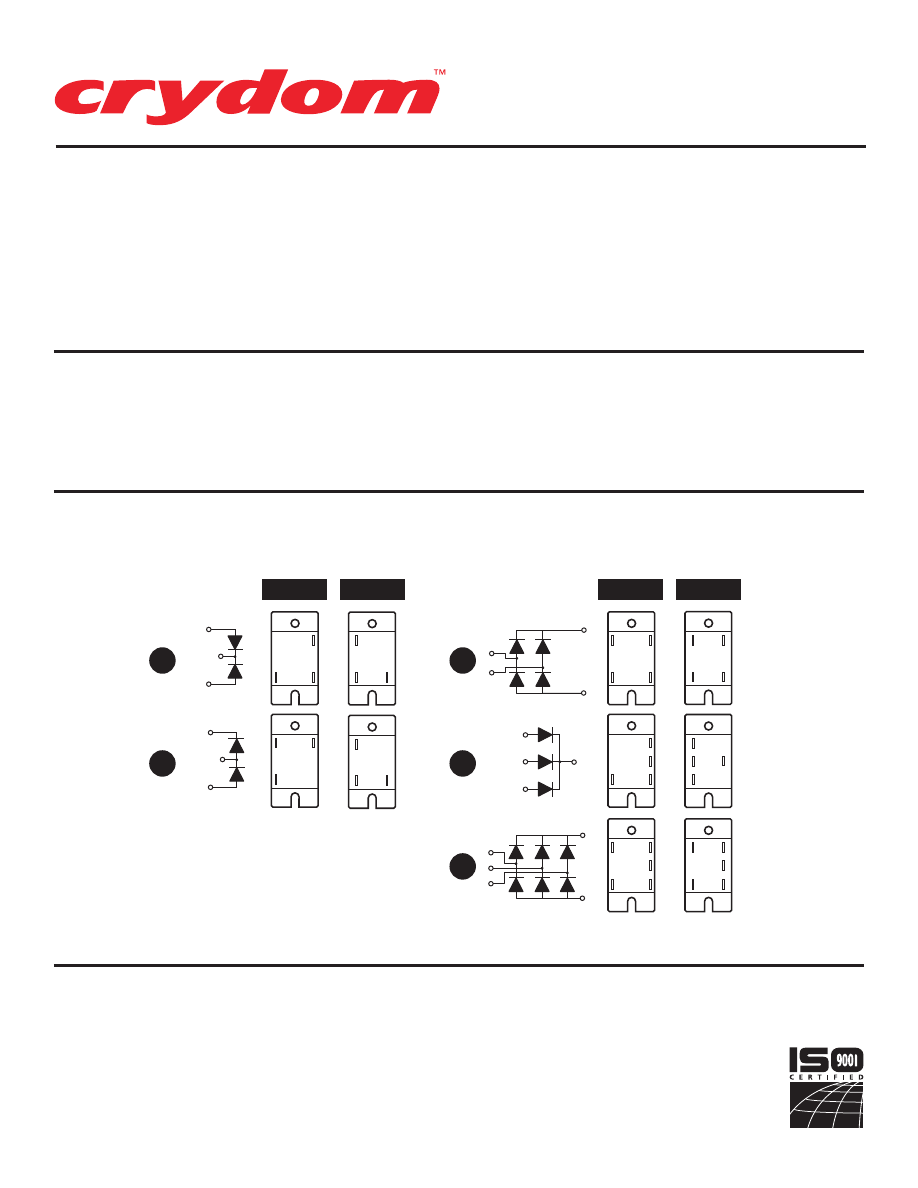
SERIES B48.
Rev. 121207
PAGE 2 OF 3
• Single and Three
Phase Circuits
• Up to 1600 Volt Blocking
Standard
AC
AC
+
--
AC
AC
AC
+
--
AC
AC
+
AC
AC
+
AC
--
AC
+
1
2
3
4
5
AC
AC
+
AC
+
--
AC
+
AC
+
--
+
B48-2T
B48-2
B48-2T
B48-2
AC
+
--
AC
AC
+
AC
AC
+
--
AC
AC
+
--
AC
AC
AC
AC
AC
AC
AC
AC
+
--
AC
AC
PART NUMBER IDENTIFICATION
Series Type
Circuit Type
Voltage
Case Style
B48
1 - 5
B
- 400 (120Vac)
F
- 1200 (480Vac)
-2T
(Standard)
(see schematic
C
- 600 (240Vac)
G
- 1400 (530Vac)
-2
With Isolation Barriers
diagrams)
E
- 1000 (380Vac)
H
- 1600 (600Vac)
Example: B483C-2T
SERIES B48 CIRCUITS
© 2007 CRYDOM Inc., Specifications subject to change without notice.
APPROVALS
UL
E72445
Series
B48-2T
,
B48-2
35-50Amp • DIODE Modules
For recommended applications and more information contact:
USA:
Sales Support (877) 502-5500
Tech Support
(877) 702-7700 FAX (619) 710-8540
Crydom Inc., 2320 Paseo de las Americas, Ste. 201, San Diego, CA 92154
Email:
sales@crydom.com
WEB SITE:
http://www.crydom.com
UK:
+44 (0)1202 606030 •
FAX
+44 (0)1202 606035 Crydom SSR Ltd., Arena Business Centre,
Holyrood Close, Poole, Dorset BH17 7FJ, Email: intsales@crydom.com.
GERMANY:
+49 (0)180 3000 506
Courtesy of Steven Engineering, Inc.-230 Ryan Way, South San Francisco, CA 94080-6370-Main Office: (650) 588-9200-Outside Local Area: (800) 258-9200-www.stevenengineering.com
60MAIN-html.html

HAZARD OF
ELECTRIC
SHOCK,
EXPLOSION,
OR ARC FLASH.
•
Disconnect all
power before
installing or
working with
this equipment.
•
Verify all
connections
and replace all
covers before
turning on
power.
Failure to follow
these
instructions will
result in death
or serious injury.
RIESGO DE
DESCARGA
ELECTRICA O
EXPLOSION.
•
Desconectar
todos los
suministros de
energia a este
equipo antes
de trabajar
con este equipo.
•
Verificar todas
las conexiones
y colocar todas
las tapas antes
de energizer
el equipo.
El
incumplimiento
de estas
instrucciones
puede provocar
la muerte o
lesiones serias.
RISQUE DE
DESCHARGE
ELECTRIQUE
OU EXPLOSION
•
Eteindre
toutes les
sources
d'énergie de
cet appareil
avant de
travailler
dessus de cet
appareil
•
Vérifier tous
connections, et
remettre tous
couverts en
olace avant de
mettre sous
De non-suivi de
ces instructions
provoquera la
mort ou des
lésions sérieuses
sérieuses.
GEFAHR EINES
ELEKTRISCHE
N SCHLAGES
ODER EINER
EXPLOSION.
•
Stellen Sie
jeglichen
Strom ab, der
dieses Gerät
versorgt, bevor
Sie an dem
Gerät Arbeiten
durchführen
•
Vor dem
Drehen auf
Energie alle
Anschlüsse
überprüfen
und alle
Abdeckungen
ersetzen.
Unterlassung
dieser
Anweisungen
können zum
Tode oder zu
schweren
Verletzungen
führen.
RISCHIO DI
SCOSSA
ELETTRICA O
DELL’ESPLOSI
ONE.
•
Spenga tutta
l'alimentazion
e che fornisce
questa
apparecchiatu
ra prima del
lavorare a questa
apparecchiatu ra
•
Verificare tutti
i collegamenti
e sostituire
tutte le coperture
prima della
rotazione
sull'alimentazi one
L'omissione di
seguire queste
istruz ioni
provocherà la
morte o di
lesioni serie
RISCO DE
DESCARGA
ELÉTTRICA OU
EXPLOSÃO
•
Desconectar
o equipamento
de toda á
energia antes
de instalar ou
trabalhar com
este equipamen
to
•
Verificar todas
as conexões e
recolocar todas
as tampas
antes de religar
o equipamento
O não cumprimento
destas instruções
pode levar á morte
ou lesões sérias.
RISQUE DE DOMMAGE MATERIEL ET DE
SURCHAUFFE DU BOITIER
•
Les panneaux latéraux du produit peuvent être
chauds. Laisser le produit refroidir avant de le
toucher.
•
Respecter les consignes de montage, et
notamment les couples de serrage.
•
Ne pas laisser pénétrer de liquide ni de corps
étrangers à l'intérieur du produit.
RISK OF MATERIAL DAMAGE AND HOT
ENCLOSURE
•
The product's side panels may be hot, allow
time for product to cool before touching.
•
Follow proper mounting instructions including
torque values
.
•
Do not allow liquids or foreign objects to enter
this product.
Le non-respect de cette directive peut entraîner,
des lésions corporelles graves ou des
dommages matériels.
Failure to follow this instruction can result in
serious injury, or equipment damage.
La mancata osservanza di questa precauzione può
causare gravi rischi per l'incolumità personale o
danni alle apparecchiature.
Si no se respetan estas precauciones pueden
producirse graves lesiones, daños materiales.
Die Nichtbeachtung dieser Anweisung kann
Körperverletzung oder Materialschäden
zur Folge haben.
A não observância destas precauções pode
provocar a morte, ferimentos graves ou
danos materiais.
GEFAHR VON MATERIALSCHÄDEN UND
GEHÄUSEERHITZUNG
•
Die Seitenwände können heiß sein. Lassen Sie
das Produkt abkühlen, bevor Sie es berühren.
•
Beachten Sie die Montageanweisungen,
•
Führen Sie keine Flüssigkeiten oder
Fremdkörper in das Produkt ein.
RISCHIO DI DANNI MATERIALI E D'INVOLUCRO
CALDO
•
I pannelli laterali dell'apparecchio possono
scottare; lasciar quindi raffreddare il prodotto
prima di toccarlo.
•
Seguire le istruzioni di montaggio corrette.
•
Non far entrare liquidi o oggetti estranei in questo
apparecchio.
RIESGO DE DAÑOS MATERIALES Y DE
SOBRECALENTAMIENTO DE LA UNIDAD
•
Los paneles laterales del producto pueden
estar calientes. Esperar que el producto se
enfríe antes de tocarlo.
•
Respetar las instrucciones de montaje, y en
particular los pares de apretado.
•
No dejar que penetren líquidos o cuerpos
extraños en el producto.
RISCO DE DANO MATERIAL E DE AQUECIMENTO
•
Os painéis laterais do produto podem estar
quentes; dê tempo ao produto para arrefecer
antes de lhe tocar.
•
Siga devidamente as instruções de montagem.
•
Não permita a entrada de líquidos e de objectos
estranhos no produto.
DANGER / PELIGRO / DANGER /GEFAHR / PERICOLO / PERIGO
WARNING / AVERTISSEMENT / WARNUNG /ADVERTENCIA / AVVERTENZA / AVISO
SERIES B48.
Rev. 121207
PAGE 3 OF 3
Courtesy of Steven Engineering, Inc.-230 Ryan Way, South San Francisco, CA 94080-6370-Main Office: (650) 588-9200-Outside Local Area: (800) 258-9200-www.stevenengineering.com
60MAIN-html.html
ANNEX – ENVIRONMENTAL INFORMATION:
The environmental information disclosed in this annex including the EIP
Pollution logo are in compliance with People’s Republic of China Electronic
Industry Standard SJ/T11364 – 2006, Marking for Control of Pollution
Caused by Electronic Information Products.
Part
Toxic or hazardous Substance and Elements
Name
Lead
Mercury Cadmium Hexavalent
Polybrominated Polybrominated
(Pb)
(Hg)
(Cd)
Chromium
(Cr (VI))
biphenyls
(PBB)
diphenyl ethers
(PBDE)
Semiconductor
die
X
O
O
O
O
O
Solder
X
O
O
O
O
O
䰘ӊ
-
⦃ֱֵᙃ
:
ℸ䰘ӊ᠔ᷛ⼎ⱘࣙᣀ⬉ᄤֵᙃѻક∵ᶧᷛⱘ⦃ֱֵᙃ
ヺড়ЁढҎ⇥݅⬉ᄤ㸠Ϯᷛޚ
SJ/T11364 - 2006,
⬉ᄤֵᙃѻક∵ᶧࠊᷛ䆚㽕∖
㋴
ܗ
䋼
⠽
ᆇ
᳝
↦
᳝
ӊ
䚼
ৡ⿄
䪙
∲
䬝
݁Ӌ䫀
⒈㘨㣃
⒈Ѡ㣃䝮
(Pb)
(Hg)
(Cd)
(Cr (VI))
(PBB)
(PBDE)
ञᇐԧ㢃⠛
X
O
O
O
O
O
⛞⚍
X
O
O
O
O
O
© 2007 CRYDOM Inc., Specifications subject to change without notice.
Courtesy of Steven Engineering, Inc.-230 Ryan Way, South San Francisco, CA 94080-6370-Main Office: (650) 588-9200-Outside Local Area: (800) 258-9200-www.stevenengineering.com
60MAIN-html.html
• High Thermal Efficiency
• Complete Power Control
Circuits in a Single
Package
SERIES EF.
Rev. 121207
PAGE 1 OF 4
These circuits provide complete power
control in a single package, utilizing
high thermal efficiency to assure long
life and reliable performance. Twelve
standard models provide 2500 Vrms
isolation from all terminals to ceramic
base and are UL recognized (file no.
E72445).
Manufactured in Crydom’s ISO 9001
Certified facility for optimum product
performance and reliability.
ELECTRICAL SPECIFICATIONS
CURRENT CODE
D
E
F
G
SYMBOL SPECIFICATION
RATINGS
I
D
Maximum DC Output Current (Tc = 85°C)
See Part Number Identification Above for Ratings of
Single Phase, Three Phase and AC Switch Circuits
V
F
Maximum Voltage Drop @ Amps Peak
1.7V @ 50A
1.85V @ 75A
1.4V @ 100A
1.55V @ 125A
T
J
Operating Junction Temperature Range
-40°C to +125°C
di/dt
Critical Rate of Rise of On-State Current @ TJ=125°C
100A/µs
100A/µs
100A/µs
100A/µs
dv/dt
Critical Rate of Rise of Off-State Voltage [V/µs]
500V/µs
500V/µs
500V/µs
500V/µs
400 (120 Vac)
600 (240 Vac)
V
RRM
Repetitive Peak Reverse Voltage (AC Line)
1000 (380 Vac)
1200 (480 Vac)
1400 (530 Vac)
I
TSM
Maximum Non-Repetitive Surge Current
( 1 / 2 Cycle, 60Hz)
400A
600A
1500A
1950A
I
2
T
Maximum I 2 T for Fusing (t=8.3ms) [A 2 sec]
670
1500
9340
15800
I
GT
Maximum Required Gate Current
to Trigger @ 25°C
60mA
80mA
150mA
150mA
V
GT
Maximum Required Gate Voltage
to Trigger @ 25°C
2.5V
3.0V
3.0V
3.0V
P
G(AV)
Average Gate Power
0.5W
0.5W
0.5W
0.5W
V
GM
Maximum Peak Gate Voltage (Reverse)
5.0V
5.0V
5.0V
5.0V
R
q
JC
Maximum Thermal Resistance Junction to
Ceramic Base per Chip
0.8°C/W
0.7°C/W
0.36°C/W
0.3°C/W
V
ISOL
Isolation Voltage
2500 V
RMS
2500 V
RMS
2500 V
RMS
2500 V
RMS
MECHANICAL SPECIFICATIONS
Weight: (typical)
7.0 oz. (198g)
PART NUMBER IDENTIFICATION
Series Type
Current
(Amps)
Circuit Type
Voltage
Options
EF
-Case style
1Ø
3Ø
AC SW.
(see schematic
B
- 120 Vac
F
- Free Wheeling Diode
D
- 50
70
55
diagrams)
C
- 240 Vac
(Circuits 1, 2, 16, 19 Only)
E
- 75
100
85
Example:
01
E
- 380 Vac
F
- 100
135
110
F
- 480 Vac
Example: EFD02CF
G
- 125
170
140
G
- 530 Vac
© 2007 CRYDOM Inc., Specifications subject to change without notice.
APPROVALS
UL
E72445
Series
EF
50-170Amp • DIODE • SCR/DIODE Modules
For recommended applications and more information contact:
USA:
Sales Support (877) 502-5500
Tech Support
(877) 702-7700 FAX (619) 710-8540
Crydom Inc., 2320 Paseo de las Americas, Ste. 201, San Diego, CA 92154
Email:
sales@crydom.com
WEB SITE:
http://www.crydom.com
UK:
+44 (0)1202 606030 •
FAX
+44 (0)1202 606035 Crydom SSR Ltd., Arena Business Centre,
Holyrood Close, Poole, Dorset BH17 7FJ, Email: intsales@crydom.com.
GERMANY:
+49 (0)180 3000 506
Courtesy of Steven Engineering, Inc.-230 Ryan Way, South San Francisco, CA 94080-6370-Main Office: (650) 588-9200-Outside Local Area: (800) 258-9200-www.stevenengineering.com
60MAIN-html.html
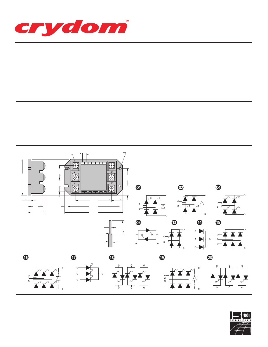
SERIES EF.
Rev. 121207
PAGE 2 OF 4
• High Thermal Efficiency
• Complete Power Control
Circuits in a Single
Package
G2
AC1
AC2
G1
+
--
AC1
AC2
G2
G1
G3
AC1
AC2
G1
G4
G2
AC3
G5
G6
+
--
G1
AC1
G2
AC2
G3
AC3
+
G2
G1
AC1
L1
G4
G3
AC2
L2
G6
G5
AC3
L3
G2
AC1
AC2
G1
AC3
G3
+
--
G1
AC1
L1
G2
AC2
L2
G3
AC3
L3
--
AC1
AC2
G2
G1
+
AC1
AC2
G4
G2
G1
G3
+
--
AC
AC
AC
+
--
AC
AC
+
AC
AC
AC
+
--
2.50
(63.5)
.83
(21.1)
.25
(6.3)
2.50
(63.5)
3.60
(91.4)
4.00
(101.5)
.83
(21.1)
.20
(5.1)
.20
(5.1)
.16
(4.1)
1.20
(30.5)
.65
(16.5)
1.17
(29.7)
.95
(24.1)
MOUNTING
HOLE/SLOT
0.16 (4.1) DIA.
M5 SCREWs
5 PLACES
.400
(10.2)
.055
(1.4)
.110 x .020 THICK
CUT HERE FOR FASTON
(AMP TYPE 61060-1 RECOMMEND)
PIN DETAIL
PART NUMBER IDENTIFICATION
Series Type
Current
(Amps)
Circuit Type
Voltage
Options
EF
-Case style
1Ø
3Ø
AC SW.
(see schematic
B
- 120 Vac
F
- Free Wheeling Diode
D
-
50
70
55
diagrams)
C
- 240 Vac
(Circuits 1, 2, 16, 19 Only)
E
-
75
100
85
Example:
01
E
- 380 Vac
F
-
100
135
110
F
- 480 Vac
Example: EFD02CF
G
- 125
170
140
G
- 530 Vac
MECHANICAL DIMENSIONS
SERIES EF CIRCUITS
All dimensions
are in inches (millimeters)
© 2007 CRYDOM Inc., Specifications subject to change without notice.
Series
EF
50-170Amp • DIODE • SCR/DIODE Modules
For recommended applications and more information contact:
USA:
Sales Support (877) 502-5500
Tech Support
(877) 702-7700 FAX (619) 710-8540
Crydom Inc., 2320 Paseo de las Americas, Ste. 201, San Diego, CA 92154
Email:
sales@crydom.com
WEB SITE:
http://www.crydom.com
UK:
+44 (0)1202 606030 •
FAX
+44 (0)1202 606035 Crydom SSR Ltd., Arena Business Centre,
Holyrood Close, Poole, Dorset BH17 7FJ, Email: intsales@crydom.com.
GERMANY:
+49 (0)180 3000 506
Courtesy of Steven Engineering, Inc.-230 Ryan Way, South San Francisco, CA 94080-6370-Main Office: (650) 588-9200-Outside Local Area: (800) 258-9200-www.stevenengineering.com
60MAIN-html.html
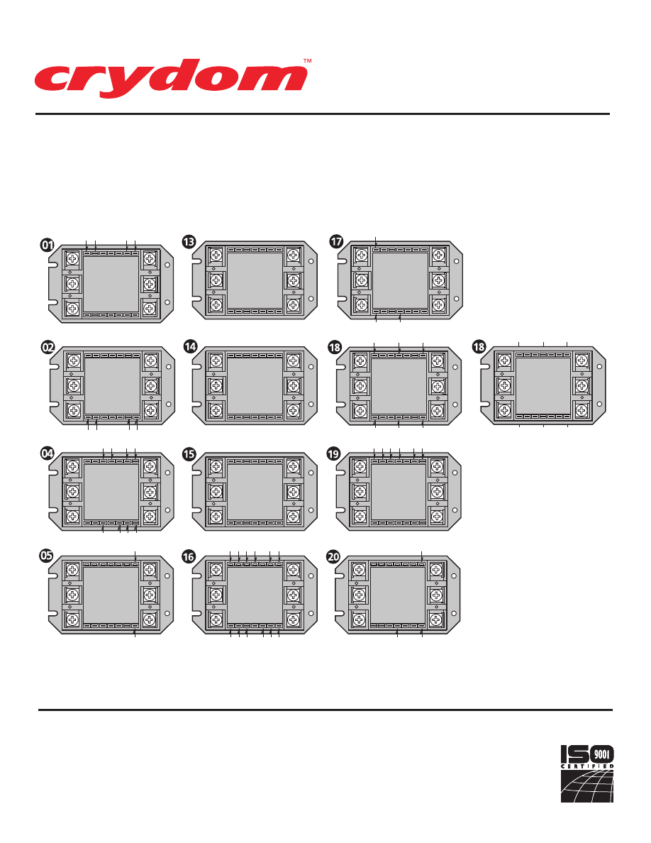
G2 K2
K1 G1
AC2
AC1
+
–
G2
G5
G1
G4
G6
G3
AC2
AC3
AC1
L2
L3
L1
G2
G1
G5
G6
G4
G3
AC2
AC1
AC3
L2
L3
L1
G1
G3
G2
AC2
AC1
AC3
L2
L3
L1
G2
G1
AC2
AC1
AC2
AC1
K2
G 2
K1 G1
AC2
AC1
+
–
AC2
AC3
AC1
+
K2 G2
K1 G1
K4
G4 K3 G3
AC2
AC1
+
–
AC
AC
AC
+
–
G6 K6 K4
G4 K2 G2
G5 K5 K3 G3
K1 G1
AC2
AC3
AC1
+
–
AC2
AC1
+
–
G2
G3
G1
AC2
AC1
+
AC3
G3 K3 K2 G2
K1 G1
AC2
AC1
+
–
AC3
EFC18
EFD18
EFE18
EFF18
EFG18
TERMINAL ORIENTATION
SERIES EF.
Rev. 121207
PAGE 3 OF 4
© 2007 CRYDOM Inc., Specifications subject to change without notice.
Series
EF
50-170Amp • DIODE • SCR/DIODE Modules
For recommended applications and more information contact:
USA:
Sales Support (877) 502-5500
Tech Support
(877) 702-7700 FAX (619) 710-8540
Crydom Inc., 2320 Paseo de las Americas, Ste. 201, San Diego, CA 92154
Email:
sales@crydom.com
WEB SITE:
http://www.crydom.com
UK:
+44 (0)1202 606030 •
FAX
+44 (0)1202 606035 Crydom SSR Ltd., Arena Business Centre,
Holyrood Close, Poole, Dorset BH17 7FJ, Email: intsales@crydom.com.
GERMANY:
+49 (0)180 3000 506
Courtesy of Steven Engineering, Inc.-230 Ryan Way, South San Francisco, CA 94080-6370-Main Office: (650) 588-9200-Outside Local Area: (800) 258-9200-www.stevenengineering.com
60MAIN-html.html

HAZARD OF
ELECTRIC
SHOCK,
EXPLOSION,
OR ARC FLASH.
•
Disconnect all
power before
installing or
working with
this equipment.
•
Verify all
connections
and replace all
covers before
turning on
power.
Failure to follow
these
instructions will
result in death
or serious injury.
RIESGO DE
DESCARGA
ELECTRICA O
EXPLOSION.
•
Desconectar
todos los
suministros de
energia a este
equipo antes
de trabajar
con este equipo.
•
Verificar todas
las conexiones
y colocar todas
las tapas antes
de energizer
el equipo.
El
incumplimiento
de estas
instrucciones
puede provocar
la muerte o
lesiones serias.
RISQUE DE
DESCHARGE
ELECTRIQUE
OU EXPLOSION
•
Eteindre
toutes les
sources
d'énergie de
cet appareil
avant de
travailler
dessus de cet
appareil
•
Vérifier tous
connections, et
remettre tous
couverts en
olace avant de
mettre sous
De non-suivi de
ces instructions
provoquera la
mort ou des
lésions sérieuses
sérieuses.
GEFAHR EINES
ELEKTRISCHE
N SCHLAGES
ODER EINER
EXPLOSION.
•
Stellen Sie
jeglichen
Strom ab, der
dieses Gerät
versorgt, bevor
Sie an dem
Gerät Arbeiten
durchführen
•
Vor dem
Drehen auf
Energie alle
Anschlüsse
überprüfen
und alle
Abdeckungen
ersetzen.
Unterlassung
dieser
Anweisungen
können zum
Tode oder zu
schweren
Verletzungen
führen.
RISCHIO DI
SCOSSA
ELETTRICA O
DELL’ESPLOSI
ONE.
•
Spenga tutta
l'alimentazion
e che fornisce
questa
apparecchiatu
ra prima del
lavorare a questa
apparecchiatu ra
•
Verificare tutti
i collegamenti
e sostituire
tutte le coperture
prima della
rotazione
sull'alimentazi one
L'omissione di
seguire queste
istruz ioni
provocherà la
morte o di
lesioni serie
RISCO DE
DESCARGA
ELÉTTRICA OU
EXPLOSÃO
•
Desconectar
o equipamento
de toda á
energia antes
de instalar ou
trabalhar com
este equipamen
to
•
Verificar todas
as conexões e
recolocar todas
as tampas
antes de religar
o equipamento
O não cumprimento
destas instruções
pode levar á morte
ou lesões sérias.
RISQUE DE DOMMAGE MATERIEL ET DE
SURCHAUFFE DU BOITIER
•
Les panneaux latéraux du produit peuvent être
chauds. Laisser le produit refroidir avant de le
toucher.
•
Respecter les consignes de montage, et
notamment les couples de serrage.
•
Ne pas laisser pénétrer de liquide ni de corps
étrangers à l'intérieur du produit.
RISK OF MATERIAL DAMAGE AND HOT
ENCLOSURE
•
The product's side panels may be hot, allow
time for product to cool before touching.
•
Follow proper mounting instructions including
torque values
.
•
Do not allow liquids or foreign objects to enter
this product.
Le non-respect de cette directive peut entraîner,
des lésions corporelles graves ou des
dommages matériels.
Failure to follow this instruction can result in
serious injury, or equipment damage.
La mancata osservanza di questa precauzione può
causare gravi rischi per l'incolumità personale o
danni alle apparecchiature.
Si no se respetan estas precauciones pueden
producirse graves lesiones, daños materiales.
Die Nichtbeachtung dieser Anweisung kann
Körperverletzung oder Materialschäden
zur Folge haben.
A não observância destas precauções pode
provocar a morte, ferimentos graves ou
danos materiais.
GEFAHR VON MATERIALSCHÄDEN UND
GEHÄUSEERHITZUNG
•
Die Seitenwände können heiß sein. Lassen Sie
das Produkt abkühlen, bevor Sie es berühren.
•
Beachten Sie die Montageanweisungen,
•
Führen Sie keine Flüssigkeiten oder
Fremdkörper in das Produkt ein.
RISCHIO DI DANNI MATERIALI E D'INVOLUCRO
CALDO
•
I pannelli laterali dell'apparecchio possono
scottare; lasciar quindi raffreddare il prodotto
prima di toccarlo.
•
Seguire le istruzioni di montaggio corrette.
•
Non far entrare liquidi o oggetti estranei in questo
apparecchio.
RIESGO DE DAÑOS MATERIALES Y DE
SOBRECALENTAMIENTO DE LA UNIDAD
•
Los paneles laterales del producto pueden
estar calientes. Esperar que el producto se
enfríe antes de tocarlo.
•
Respetar las instrucciones de montaje, y en
particular los pares de apretado.
•
No dejar que penetren líquidos o cuerpos
extraños en el producto.
RISCO DE DANO MATERIAL E DE AQUECIMENTO
•
Os painéis laterais do produto podem estar
quentes; dê tempo ao produto para arrefecer
antes de lhe tocar.
•
Siga devidamente as instruções de montagem.
•
Não permita a entrada de líquidos e de objectos
estranhos no produto.
DANGER / PELIGRO / DANGER /GEFAHR / PERICOLO / PERIGO
WARNING / AVERTISSEMENT / WARNUNG /ADVERTENCIA / AVVERTENZA / AVISO
SERIES EF.
Rev. 121207
PAGE 4 OF 4
Courtesy of Steven Engineering, Inc.-230 Ryan Way, South San Francisco, CA 94080-6370-Main Office: (650) 588-9200-Outside Local Area: (800) 258-9200-www.stevenengineering.com
60MAIN-html.html

ANNEX – ENVIRONMENTAL INFORMATION:
The environmental information disclosed in this annex including the EIP
Pollution logo are in compliance with People’s Republic of China Electronic
Industry Standard SJ/T11364 – 2006, Marking for Control of Pollution
Caused by Electronic Information Products.
Part
Toxic or hazardous Substance and Elements
Name
Lead
Mercury Cadmium Hexavalent
Polybrominated Polybrominated
(Pb)
(Hg)
(Cd)
Chromium
(Cr (VI))
biphenyls
(PBB)
diphenyl ethers
(PBDE)
Semiconductor
die
X
O
O
O
O
O
Solder
X
O
O
O
O
O
䰘ӊ
-
⦃ֱֵᙃ
:
ℸ䰘ӊ᠔ᷛ⼎ⱘࣙᣀ⬉ᄤֵᙃѻક∵ᶧᷛⱘ⦃ֱֵᙃ
ヺড়ЁढҎ⇥݅⬉ᄤ㸠Ϯᷛޚ
SJ/T11364 - 2006,
⬉ᄤֵᙃѻક∵ᶧࠊᷛ䆚㽕∖
㋴
ܗ
䋼
⠽
ᆇ
᳝
↦
᳝
ӊ
䚼
ৡ⿄
䪙
∲
䬝
݁Ӌ䫀
⒈㘨㣃
⒈Ѡ㣃䝮
(Pb)
(Hg)
(Cd)
(Cr (VI))
(PBB)
(PBDE)
ञᇐԧ㢃⠛
X
O
O
O
O
O
⛞⚍
X
O
O
O
O
O
© 2007 CRYDOM Inc., Specifications subject to change without notice.
Courtesy of Steven Engineering, Inc.-230 Ryan Way, South San Francisco, CA 94080-6370-Main Office: (650) 588-9200-Outside Local Area: (800) 258-9200-www.stevenengineering.com
60MAIN-html.html
• Industry Standard
Package and Circuits
• Power Control
Building Blocks
SERIES F18
Rev. 121207
PAGE 1 OF 3
Modules come in an industry standard
package, offering nine circuits that can
be used singly or as power control
building blocks. All models feature
highly efficient thermal management
for greatly extended cycle life and are
UL recognized (file no. E72445).
Manufactured in Crydom's ISO 9001
Certified facility for optimum product
performance and reliability.
ELECTRICAL SPECIFICATIONS
RATINGS
SYMBOL SPECIFICATION
27
42
57
92
I
D
Maximum DC Output Current (Tc = 85°C) [A]
25
40
55
V
F
Maximum Voltage Drop
1.55V @ 75Apk
1.4V @ 120Apk
1.4V @ 165Apk
1.4V @ 270Apk
T
J
Operating Junction Temperature Range
-40°C to +125°C
di/dt
Critical Rate of Rise of On-State Current @ TJ=125°C [A/µs]
100
100
100
100
dv/dt
Critical Rate of Rise of Off-State Voltage [V/µs]
1000
1000
1000
1000
400 (120 Vac)
600 (240 Vac)
V
RRM
Repetitive Peak Reverse Voltage (AC Line Nominal) [Vpk]
1000 (380 Vac)
1200 (480 Vac)
1400 (530 Vac)
I
TSM
Maximum Non-Repetitive Surge Current
( 1 / 2 Cycle, 60Hz) [A]
400
1000
1500
1950
I
2
T
Maximum I 2 T for Fusing (t=8.3ms) [A 2 sec]
670
4150
9350
15800
I
GT
Maximum Required Gate Current
to Trigger @ 25°C [mA]
150
150
150
150
V
GT
Maximum Required Gate Voltage
to Trigger @ 25°C [V]
3.0
3.0
3.0
3.0
P
G(AV)
Average Gate Power [W]
0.5
0.5
0.5
0.5
V
GM
Maximum Peak Gate Voltage (Reverse) [V]
5.0
5.0
5.0
5.0
R
q
JC
Maximum Thermal Resistance Junction to
Ceramic Base per Chip [°C/W]
0.4
0.28
0.25
0.14
V
ISOL
Isolation Voltage [
V
RMS]
2500
2500
2500
2500
Weight: (typical)
4.75 oz. (135g)
PART NUMBER IDENTIFICATION
Series Type
Current
Circuit Type
Voltage
F18
-Case style
27
- 25 Amps
(see schematic
400
- 120 Vac
42
- 40 Amps
diagrams)
600
- 240 Vac
57
- 55 Amps
Example:
SD
1000
- 380 Vac
92
- 90 Amps
1200
- 480 Vac
Example: F1892SD1200
1400
- 530 Vac
© 2007 CRYDOM Inc., Specifications subject to change without notice.
Torque Required
Terminal Stud Screw : 30 inch lb
Mounting Screw : 20 inch lb
90
107
1.65V @ 300Apk
100
1000
2250
25000
150
3.0
0.5
5.0
0.135
2500
105
G E N E R A L N O T E S
1
All parameters at 25°C unless otherwise specified.
2
Available only in SD and SDK circuit configuration.
1
2
1600
- 600 Vac
1600 (600 Vac)
Series
F18
25-105Amp • SCR/DIODE Modules
107
- 105 Amps
MECHANICAL SPECIFICATION
For recommended applications and more information contact:
USA:
Sales Support (877) 502-5500
Tech Support
(877) 702-7700 FAX (619) 710-8540
Crydom Inc., 2320 Paseo de las Americas, Ste. 201, San Diego, CA 92154
Email:
sales@crydom.com
WEB SITE:
http://www.crydom.com
UK:
+44 (0)1202 606030 •
FAX
+44 (0)1202 606035 Crydom SSR Ltd., Arena Business Centre,
Holyrood Close, Poole, Dorset BH17 7FJ, Email: intsales@crydom.com.
GERMANY:
+49 (0)180 3000 506
Courtesy of Steven Engineering, Inc.-230 Ryan Way, South San Francisco, CA 94080-6370-Main Office: (650) 588-9200-Outside Local Area: (800) 258-9200-www.stevenengineering.com
60MAIN-html.html
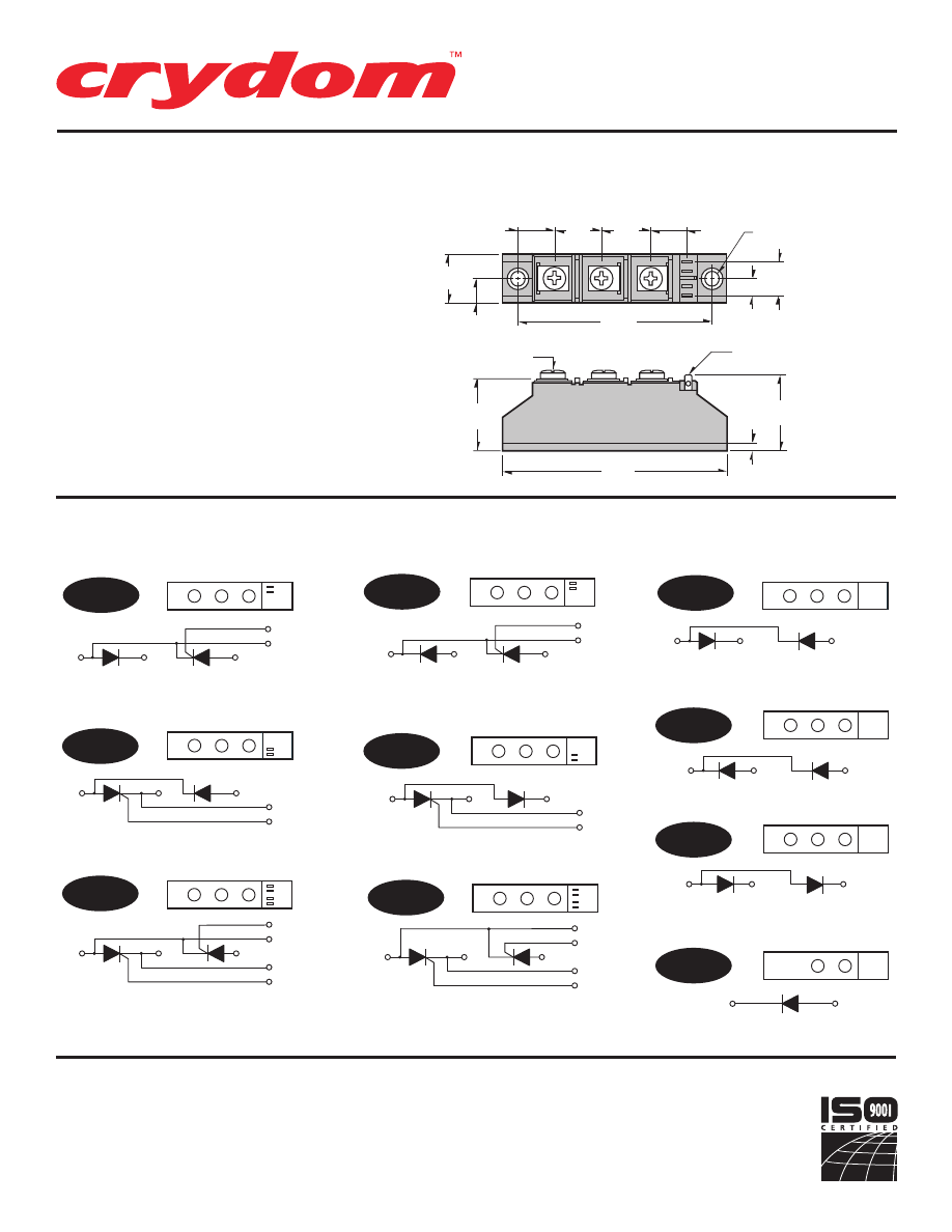
SERIES F18
Rev. 121207
PAGE 2 OF 3
• Industry Standard Package and Circuits
• Power Control Building Blocks
AC
+
--
AC
G1
+
--
K1
G2
K2
1
G2
K2
2
3
1
G1
K1
2
3
AC
G2
+
--
K2
AC
G2
+
--
K2
AC
G1
+
--
K1
AC
+
--
K1
G1
AC
+
--
K1
G1
G2
K2
AC
+
--
+
--
G2
K2
K1
G1
1
2
3
1
2
3
DH
HD
SD
RD
CCH
CAH
CCD
CAD
D
+
--
1
2
3
1
2
3
1
2
3
1
2
3
.550
(14.0)
.787
(20.0)
.787
(20.0)
.590
(15.0)
.244
(6.2)
DIA.
3.150
(79.9)
.393
(10.0)
.787
(20.0)
.393
(10.0)
.12
(3.0)
.500
(12.7)
M5 SCREW
3 PLCS
.110 X .036
FASTON TERMINALS
1.195
(30.3)
3.620
(91.9)
1.180
(29.9)
MECHANICAL DIMENSIONS
All dimensions are in inches (millimeters)
SERIES F18 CIRCUITS
© 2007 CRYDOM Inc., Specifications subject to change without notice.
AC
G1
+
--
K1
K2
G2
AC
+
--
K1
G1
K2
G2
SDK
Series
F18
25-105Amp • SCR/DIODE Modules
For recommended applications and more information contact:
USA:
Sales Support (877) 502-5500
Tech Support
(877) 702-7700 FAX (619) 710-8540
Crydom Inc., 2320 Paseo de las Americas, Ste. 201, San Diego, CA 92154
Email:
sales@crydom.com
WEB SITE:
http://www.crydom.com
UK:
+44 (0)1202 606030 •
FAX
+44 (0)1202 606035 Crydom SSR Ltd., Arena Business Centre,
Holyrood Close, Poole, Dorset BH17 7FJ, Email: intsales@crydom.com.
GERMANY:
+49 (0)180 3000 506
Courtesy of Steven Engineering, Inc.-230 Ryan Way, South San Francisco, CA 94080-6370-Main Office: (650) 588-9200-Outside Local Area: (800) 258-9200-www.stevenengineering.com
60MAIN-html.html

HAZARD OF
ELECTRIC
SHOCK,
EXPLOSION,
OR ARC FLASH.
•
Disconnect all
power before
installing or
working with
this equipment.
•
Verify all
connections
and replace all
covers before
turning on
power.
Failure to follow
these
instructions will
result in death
or serious injury.
RIESGO DE
DESCARGA
ELECTRICA O
EXPLOSION.
•
Desconectar
todos los
suministros de
energia a este
equipo antes
de trabajar
con este equipo.
•
Verificar todas
las conexiones
y colocar todas
las tapas antes
de energizer
el equipo.
El
incumplimiento
de estas
instrucciones
puede provocar
la muerte o
lesiones serias.
RISQUE DE
DESCHARGE
ELECTRIQUE
OU EXPLOSION
•
Eteindre
toutes les
sources
d'énergie de
cet appareil
avant de
travailler
dessus de cet
appareil
•
Vérifier tous
connections, et
remettre tous
couverts en
olace avant de
mettre sous
De non-suivi de
ces instructions
provoquera la
mort ou des
lésions sérieuses
sérieuses.
GEFAHR EINES
ELEKTRISCHE
N SCHLAGES
ODER EINER
EXPLOSION.
•
Stellen Sie
jeglichen
Strom ab, der
dieses Gerät
versorgt, bevor
Sie an dem
Gerät Arbeiten
durchführen
•
Vor dem
Drehen auf
Energie alle
Anschlüsse
überprüfen
und alle
Abdeckungen
ersetzen.
Unterlassung
dieser
Anweisungen
können zum
Tode oder zu
schweren
Verletzungen
führen.
RISCHIO DI
SCOSSA
ELETTRICA O
DELL’ESPLOSI
ONE.
•
Spenga tutta
l'alimentazion
e che fornisce
questa
apparecchiatu
ra prima del
lavorare a questa
apparecchiatu ra
•
Verificare tutti
i collegamenti
e sostituire
tutte le coperture
prima della
rotazione
sull'alimentazi one
L'omissione di
seguire queste
istruz ioni
provocherà la
morte o di
lesioni serie
RISCO DE
DESCARGA
ELÉTTRICA OU
EXPLOSÃO
•
Desconectar
o equipamento
de toda á
energia antes
de instalar ou
trabalhar com
este equipamen
to
•
Verificar todas
as conexões e
recolocar todas
as tampas
antes de religar
o equipamento
O não cumprimento
destas instruções
pode levar á morte
ou lesões sérias.
RISQUE DE DOMMAGE MATERIEL ET DE
SURCHAUFFE DU BOITIER
•
Les panneaux latéraux du produit peuvent être
chauds. Laisser le produit refroidir avant de le
toucher.
•
Respecter les consignes de montage, et
notamment les couples de serrage.
•
Ne pas laisser pénétrer de liquide ni de corps
étrangers à l'intérieur du produit.
RISK OF MATERIAL DAMAGE AND HOT
ENCLOSURE
•
The product's side panels may be hot, allow
time for product to cool before touching.
•
Follow proper mounting instructions including
torque values
.
•
Do not allow liquids or foreign objects to enter
this product.
Le non-respect de cette directive peut entraîner,
des lésions corporelles graves ou des
dommages matériels.
Failure to follow this instruction can result in
serious injury, or equipment damage.
La mancata osservanza di questa precauzione può
causare gravi rischi per l'incolumità personale o
danni alle apparecchiature.
Si no se respetan estas precauciones pueden
producirse graves lesiones, daños materiales.
Die Nichtbeachtung dieser Anweisung kann
Körperverletzung oder Materialschäden
zur Folge haben.
A não observância destas precauções pode
provocar a morte, ferimentos graves ou
danos materiais.
GEFAHR VON MATERIALSCHÄDEN UND
GEHÄUSEERHITZUNG
•
Die Seitenwände können heiß sein. Lassen Sie
das Produkt abkühlen, bevor Sie es berühren.
•
Beachten Sie die Montageanweisungen,
•
Führen Sie keine Flüssigkeiten oder
Fremdkörper in das Produkt ein.
RISCHIO DI DANNI MATERIALI E D'INVOLUCRO
CALDO
•
I pannelli laterali dell'apparecchio possono
scottare; lasciar quindi raffreddare il prodotto
prima di toccarlo.
•
Seguire le istruzioni di montaggio corrette.
•
Non far entrare liquidi o oggetti estranei in questo
apparecchio.
RIESGO DE DAÑOS MATERIALES Y DE
SOBRECALENTAMIENTO DE LA UNIDAD
•
Los paneles laterales del producto pueden
estar calientes. Esperar que el producto se
enfríe antes de tocarlo.
•
Respetar las instrucciones de montaje, y en
particular los pares de apretado.
•
No dejar que penetren líquidos o cuerpos
extraños en el producto.
RISCO DE DANO MATERIAL E DE AQUECIMENTO
•
Os painéis laterais do produto podem estar
quentes; dê tempo ao produto para arrefecer
antes de lhe tocar.
•
Siga devidamente as instruções de montagem.
•
Não permita a entrada de líquidos e de objectos
estranhos no produto.
DANGER / PELIGRO / DANGER /GEFAHR / PERICOLO / PERIGO
WARNING / AVERTISSEMENT / WARNUNG /ADVERTENCIA / AVVERTENZA / AVISO
SERIES F18
Rev. 121207
PAGE 3 OF 3
Courtesy of Steven Engineering, Inc.-230 Ryan Way, South San Francisco, CA 94080-6370-Main Office: (650) 588-9200-Outside Local Area: (800) 258-9200-www.stevenengineering.com
60MAIN-html.html

ANNEX – ENVIRONMENTAL INFORMATION:
The environmental information disclosed in this annex including the EIP
Pollution logo are in compliance with People’s Republic of China Electronic
Industry Standard SJ/T11364 – 2006, Marking for Control of Pollution
Caused by Electronic Information Products.
Part
Toxic or hazardous Substance and Elements
Name
Lead
Mercury Cadmium Hexavalent
Polybrominated Polybrominated
(Pb)
(Hg)
(Cd)
Chromium
(Cr (VI))
biphenyls
(PBB)
diphenyl ethers
(PBDE)
Semiconductor
die
X
O
O
O
O
O
Solder
X
O
O
O
O
O
䰘ӊ
-
⦃ֱֵᙃ
:
ℸ䰘ӊ᠔ᷛ⼎ⱘࣙᣀ⬉ᄤֵᙃѻક∵ᶧᷛⱘ⦃ֱֵᙃ
ヺড়ЁढҎ⇥݅⬉ᄤ㸠Ϯᷛޚ
SJ/T11364 - 2006,
⬉ᄤֵᙃѻક∵ᶧࠊᷛ䆚㽕∖
㋴
ܗ
䋼
⠽
ᆇ
᳝
↦
᳝
ӊ
䚼
ৡ⿄
䪙
∲
䬝
݁Ӌ䫀
⒈㘨㣃
⒈Ѡ㣃䝮
(Pb)
(Hg)
(Cd)
(Cr (VI))
(PBB)
(PBDE)
ञᇐԧ㢃⠛
X
O
O
O
O
O
⛞⚍
X
O
O
O
O
O
© 2007 CRYDOM Inc., Specifications subject to change without notice.
Courtesy of Steven Engineering, Inc.-230 Ryan Way, South San Francisco, CA 94080-6370-Main Office: (650) 588-9200-Outside Local Area: (800) 258-9200-www.stevenengineering.com
60MAIN-html.html
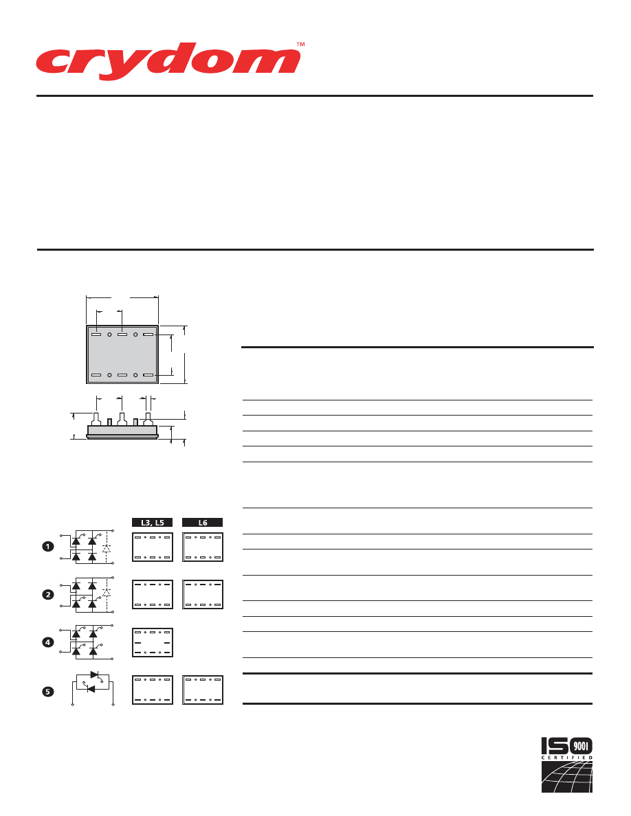
• Low Profile
• Designed for Printed
Circuit Board Connections
SERIES L.
Rev. 032608
PAGE 1 OF 2
© 2008 CRYDOM Inc., Specifications subject to change without notice.
MODEL NO.
L3
L5
L6
ELECTRICAL SPECIFICATIONS
RATINGS
I
D
Maximum DC Output Current (Tc = 85°C)
15A
25A
42.5A
V
F
Maximum Voltage Drop @ Amps Peak
2.2V @ 15A
1.65V @ 25A
1.6V @ 42.5A
T
J
Operating Junction Temperature Range
-40°C to +125°C
di/dt
Critical Rate of Rise of On-State Current @ TJ=125ûC
100A/µs
dv/dt
Critical Rate of Rise of Off-State Voltage
500V/µs
500V/µs
500V/µs
120 (400 V
RRM
)
V
RMS
AC Line Input Voltage
240 (600 V
RRM
)
(Repetitive Peak Reverse Voltage)
280 (800 V
RRM
)
480 (1200 V
RRM
)
I
TSM
Maximum Non-Repetitive Surge Current
(1/2Cycle, 60Hz)
225A
300A
600A
I
2
T
Maximum I 2T for Fusing (t=8.3ms) [A
2sec]
210
375
1500
I
GT
Maximum Required Gate Current
to Trigger @ 25°C
100mA
100mA
100mA
V
GT
Maximum Required Gate Voltage
to Trigger @ 25°C
2.5V
2.5V
3.0V
P
G(AV)
Average Gate Power
0.5W
0.5W
0.5W
V
GM
Maximum Peak Gate Voltage (Reverse)
5.0V
5.0V
5.0V
R
θ
JC
Maximum Thermal Resistance Junction to
Ceramic Base per Chip
1.25°C/W
0.9°C/W
0.7°C/W
V
ISOL
Isolation Voltage
2500 V
RMS
2500 V
RMS
2500 V
RMS
MECHANICAL SPECIFICATIONS
Weight: (typical)
.5 oz. (14.4 g)
PART NUMBER IDENTIFICATION
Series Type
Current
Circuit Type
AC Line Voltage
Options
L
-Case style
3
- 15 Amps
1 - 5
1
- 120 Vac
F
- Free
(Ceramic
5
- 25 Amps
(see schematic
2
- 240 Vac
Wheeling
Base)
6
- 42.5 Amps*
diagrams)
3
- 280 Vac
Diode
4
- 480 Vac
Example: L512F
* 42.5 Amp Rating Not Available In Circuit 4
G2
AC1
AC2
G1
+
--
G2
AC1
AC2
G1
+
--
AC1
AC2
G2
G1
+
--
G2
AC1
+
--
G2
AC1
AC2
G1
+
--
G2
AC1
AC2
G1
+
--
AC2
G1
G2
G1
AC1
AC2
AC1
AC2
G4
G2
G1
G3
+
--
G3
AC2
AC1
G2
+
--
G1
AC2
AC1
G2
G1
G1
G4
AC2
G2
AC1
AC2
AC1
AC2
AC1
1.38
(35.0)
.78
(19.8)
1.12
(28.4)
.500
(12.7)
.500
(12.7)
.500
(12.7)
.39
(9.8)
.25
(6.3)
.050 Typ.
(1.2)
MECHANICAL DIMENSIONS
All dimensions are in inches (millimeters)
APPROVALS
UL
E72445
Series
L
15-42.5Amp • SCR/DIODE Modules
Circuit Modules provide ratings up to42.5 amps in
a low profile packagedesigned for printed circuit
b o a r d c o n - n e c t i o n s . A v a i l a b l e i n t h r e e
s t a n d a r d b r i d g e c i r c u i t s a n d a n A C s w i t c h
ver-sion, all models have 2500 Vrms isola-tion and
are UL recognized (file no.E72445).
Manufactured in Crydom's ISO 9001Certified
facility for optimum productperformance and
reliability. Mounting clip available, order part
number LMC-1.
(Circuits 1,2 only)
For recommended applications and more information contact:
USA:
Sales Support (877) 502-5500
Tech Support
(877) 702-7700 FAX (619) 710-8540
Crydom Inc., 2320 Paseo de las Americas, Ste. 201, San Diego, CA 92154
Email:
sales@crydom.com
WEB SITE:
http://www.crydom.com
UK:
+44 (0)1202 606030 •
FAX
+44 (0)1202 606035 Crydom SSR Ltd., Arena Business Centre,
Holyrood Close, Poole, Dorset BH17 7FJ, Email: intsales@crydom.com.
GERMANY:
+49 (0)180 3000 506
Courtesy of Steven Engineering, Inc.-230 Ryan Way, South San Francisco, CA 94080-6370-Main Office: (650) 588-9200-Outside Local Area: (800) 258-9200-www.stevenengineering.com
60MAIN-html.html
HAZARD OF
ELECTRIC
SHOCK,
EXPLOSION,
OR ARC FLASH.
•
Disconnect all
power before
installing or
working with
this equipment.
•
Verify all
connections
and replace all
covers before
turning on
power.
Failure to follow
these
instructions will
result in death
or serious injury.
RIESGO DE
DESCARGA
ELECTRICA O
EXPLOSION.
•
Desconectar
todos los
suministros de
energia a este
equipo antes
de trabajar
con este equipo.
•
Verificar todas
las conexiones
y colocar todas
las tapas antes
de energizer
el equipo.
El
incumplimiento
de estas
instrucciones
puede provocar
la muerte o
lesiones serias.
RISQUE DE
DESCHARGE
ELECTRIQUE
OU EXPLOSION
•
Eteindre
toutes les
sources
d'énergie de
cet appareil
avant de
travailler
dessus de cet
appareil
•
Vérifier tous
connections, et
remettre tous
couverts en
olace avant de
mettre sous
De non-suivi de
ces instructions
provoquera la
mort ou des
lésions sérieuses
sérieuses.
GEFAHR EINES
ELEKTRISCHE
N SCHLAGES
ODER EINER
EXPLOSION.
•
Stellen Sie
jeglichen
Strom ab, der
dieses Gerät
versorgt, bevor
Sie an dem
Gerät Arbeiten
durchführen
•
Vor dem
Drehen auf
Energie alle
Anschlüsse
überprüfen
und alle
Abdeckungen
ersetzen.
Unterlassung
dieser
Anweisungen
können zum
Tode oder zu
schweren
Verletzungen
führen.
RISCHIO DI
SCOSSA
ELETTRICA O
DELL’ESPLOSI
ONE.
•
Spenga tutta
l'alimentazion
e che fornisce
questa
apparecchiatu
ra prima del
lavorare a questa
apparecchiatu ra
•
Verificare tutti
i collegamenti
e sostituire
tutte le coperture
prima della
rotazione
sull'alimentazi one
L'omissione di
seguire queste
istruz ioni
provocherà la
morte o di
lesioni serie
RISCO DE
DESCARGA
ELÉTTRICA OU
EXPLOSÃO
•
Desconectar
o equipamento
de toda á
energia antes
de instalar ou
trabalhar com
este equipamen
to
•
Verificar todas
as conexões e
recolocar todas
as tampas
antes de religar
o equipamento
O não cumprimento
destas instruções
pode levar á morte
ou lesões sérias.
RISQUE DE DOMMAGE MATERIEL ET DE
SURCHAUFFE DU BOITIER
•
Les panneaux latéraux du produit peuvent être
chauds. Laisser le produit refroidir avant de le
toucher.
•
Respecter les consignes de montage, et
notamment les couples de serrage.
•
Ne pas laisser pénétrer de liquide ni de corps
étrangers à l'intérieur du produit.
RISK OF MATERIAL DAMAGE AND HOT
ENCLOSURE
•
The product's side panels may be hot, allow
time for product to cool before touching.
•
Follow proper mounting instructions including
torque values
.
•
Do not allow liquids or foreign objects to enter
this product.
Le non-respect de cette directive peut entraîner,
des lésions corporelles graves ou des
dommages matériels.
Failure to follow this instruction can result in
serious injury, or equipment damage.
La mancata osservanza di questa precauzione può
causare gravi rischi per l'incolumità personale o
danni alle apparecchiature.
Si no se respetan estas precauciones pueden
producirse graves lesiones, daños materiales.
Die Nichtbeachtung dieser Anweisung kann
Körperverletzung oder Materialschäden
zur Folge haben.
A não observância destas precauções pode
provocar a morte, ferimentos graves ou
danos materiais.
GEFAHR VON MATERIALSCHÄDEN UND
GEHÄUSEERHITZUNG
•
Die Seitenwände können heiß sein. Lassen Sie
das Produkt abkühlen, bevor Sie es berühren.
•
Beachten Sie die Montageanweisungen,
•
Führen Sie keine Flüssigkeiten oder
Fremdkörper in das Produkt ein.
RISCHIO DI DANNI MATERIALI E D'INVOLUCRO
CALDO
•
I pannelli laterali dell'apparecchio possono
scottare; lasciar quindi raffreddare il prodotto
prima di toccarlo.
•
Seguire le istruzioni di montaggio corrette.
•
Non far entrare liquidi o oggetti estranei in questo
apparecchio.
RIESGO DE DAÑOS MATERIALES Y DE
SOBRECALENTAMIENTO DE LA UNIDAD
•
Los paneles laterales del producto pueden
estar calientes. Esperar que el producto se
enfríe antes de tocarlo.
•
Respetar las instrucciones de montaje, y en
particular los pares de apretado.
•
No dejar que penetren líquidos o cuerpos
extraños en el producto.
RISCO DE DANO MATERIAL E DE AQUECIMENTO
•
Os painéis laterais do produto podem estar
quentes; dê tempo ao produto para arrefecer
antes de lhe tocar.
•
Siga devidamente as instruções de montagem.
•
Não permita a entrada de líquidos e de objectos
estranhos no produto.
DANGER / PELIGRO / DANGER /GEFAHR / PERICOLO / PERIGO
WARNING / AVERTISSEMENT / WARNUNG /ADVERTENCIA / AVVERTENZA / AVISO
SERIES L.
Rev. 032608
PAGE 2 OF 2
Courtesy of Steven Engineering, Inc.-230 Ryan Way, South San Francisco, CA 94080-6370-Main Office: (650) 588-9200-Outside Local Area: (800) 258-9200-www.stevenengineering.com
60MAIN-html.html

ANNEX – ENVIRONMENTAL INFORMATION:
The environmental information disclosed in this annex including the EIP
Pollution logo are in compliance with People’s Republic of China Electronic
Industry Standard SJ/T11364 – 2006, Marking for Control of Pollution
Caused by Electronic Information Products.
Part
Toxic or hazardous Substance and Elements
Name
Lead
Mercury Cadmium Hexavalent
Polybrominated Polybrominated
(Pb)
(Hg)
(Cd)
Chromium
(Cr (VI))
biphenyls
(PBB)
diphenyl ethers
(PBDE)
Semiconductor
die
X
O
O
O
O
O
Solder
X
O
O
O
O
O
䰘ӊ
-
⦃ֱֵᙃ
:
ℸ䰘ӊ᠔ᷛ⼎ⱘࣙᣀ⬉ᄤֵᙃѻક∵ᶧᷛⱘ⦃ֱֵᙃ
ヺড়ЁढҎ⇥݅⬉ᄤ㸠Ϯᷛޚ
SJ/T11364 - 2006,
⬉ᄤֵᙃѻક∵ᶧࠊᷛ䆚㽕∖
㋴
ܗ
䋼
⠽
ᆇ
᳝
↦
᳝
ӊ
䚼
ৡ⿄
䪙
∲
䬝
݁Ӌ䫀
⒈㘨㣃
⒈Ѡ㣃䝮
(Pb)
(Hg)
(Cd)
(Cr (VI))
(PBB)
(PBDE)
ञᇐԧ㢃⠛
X
O
O
O
O
O
⛞⚍
X
O
O
O
O
O
© 2007 CRYDOM Inc., Specifications subject to change without notice.
Courtesy of Steven Engineering, Inc.-230 Ryan Way, South San Francisco, CA 94080-6370-Main Office: (650) 588-9200-Outside Local Area: (800) 258-9200-www.stevenengineering.com
60MAIN-html.html
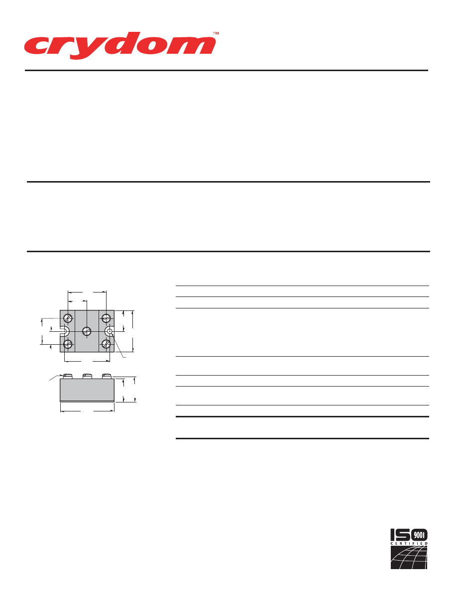
• High Surge Current
Rectifier Circuits
• Up to 1600 Volt Blocking
Standard
SERIES M50D
Rev. 020608
PAGE 1 OF 3
Single- and three-phase diode circuits
incorporate highly efficient thermal
management to provide high surge
capability, extended life, and reliable
performance. Available in five circuits,
all models come in an industry standard
package, provide 2500 Vrms from all
terminals to the baseplate, and are UL
recognized (file no. E72445).
Manufactured in Crydom's ISO 9002
Certified facility for optimum product
performance and reliability.
1.070
(27.2)
.535
(13.6)
1.625
(41.2)
.815
(20.7)
.875
(22.2)
1.750
(44.4)
1.880
(47.8)
10-32 SCREW
5 PLCS.
.95
(24.1)
2.265
(57.5)
1.140
(28.9)
MOUNTING
HOLE/SLOT
0.20 (5.1) DIA.
ELECTRICAL SPECIFICATIONS
RATINGS
SYMBOL
SPECIFICATION
M5060
M50100
I
D
Maximum DC Output Current (Tc = 85°C)
60A
100A
V
F
Maximum Voltage Drop @ Amps Peak
1.35V @ 60A
1.2V @ 100A
T
J
Operating Junction Temperature Range
-40°C to +125°C
400 (120 Vac)
600 (240 Vac)
V
RRM
(Repetitive Peak Reverse Voltage (AC Line)
1000 (380 Vac)
1200 (480 Vac)
1400 (530 Vac)
1600 (600 Vac)
I
TSM
Maximum Non-Repetitive Surge Current
(1/2Cycle, 60Hz)
800A
1500A
I
2
T
Maximum I 2T for Fusing (t=8.3ms) [A 2sec]
2650
9350
R
θ
JC
Maximum Thermal Resistance Junction to
Ceramic Base per Chip
0.45°C/W
0.3°C/W
V
ISOL
Isolation Voltage
2500 V
RMS
2500 V
RMS
MECHANICAL SPECIFICATIONS
Weight: (typical)
4.5 oz. ( 158g)
MECHANICAL DIMENSIONS
All dimensions are in inches (millimeters)
PART NUMBER IDENTIFICATION
Series Type
Current
Circuit Type
Voltage
M50
60
- 60 Amps
(see schematic
400
(120Vac)
1200
(480Vac)
100
- 100 Amps
diagrams)
600
(240Vac)
1400
(530Vac)
Example:
TB
1000
(380Vac)
1600
(600Vac)
Example: M50100TB1200
©2008 CRYDOM Inc., Specifications subject to change without notice.
Series
M50 Diode
60-100Amp • DIODE Modules
For recommended applications and more information contact:
USA:
Sales Support (877) 502-5500
Tech Support
(877) 702-7700 FAX (619) 710-8540
Crydom Inc., 2320 Paseo de las Americas, Ste. 201, San Diego, CA 92154
Email:
sales@crydom.com
WEB SITE:
http://www.crydom.com
UK:
+44 (0)1202 606030 •
FAX
+44 (0)1202 606035 Crydom SSR Ltd., Arena Business Centre,
Holyrood Close, Poole, Dorset BH17 7FJ, Email: intsales@crydom.com.
GERMANY:
+49 (0)180 3000 506
Courtesy of Steven Engineering, Inc.-230 Ryan Way, South San Francisco, CA 94080-6370-Main Office: (650) 588-9200-Outside Local Area: (800) 258-9200-www.stevenengineering.com
60MAIN-html.html
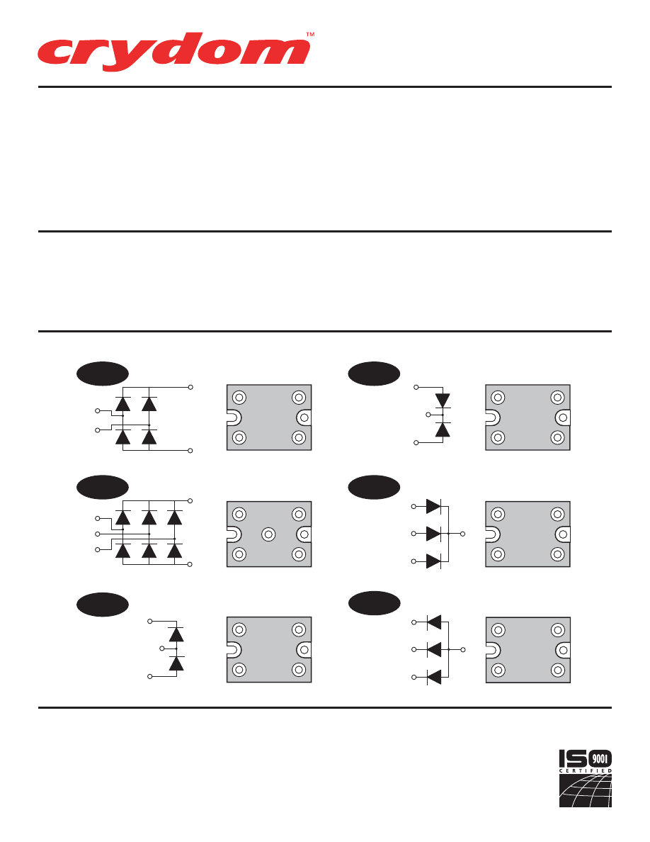
SERIES M50D
Rev. 020608
PAGE 2 OF 3
• High Surge Current
Rectifier Circuits
• Up to 1600 Volt Blocking
Standard
+
AC
AC
--
AC
AC
+
--
AC
AC
AC
+
--
AC
AC
+
--
+
AC
AC
--
+
AC
--
+
AC
AC
AC
AC
SB
CC
TB
THC
DD
AC
+
+
AC
AC
AC
+
AC
AC
+
PART NUMBER IDENTIFICATION
Series Type
Current
Circuit Type
Voltage
M50
60
- 60 Amps
(see schematic
400
(120Vac)
1200
(480Vac)
100
- 100 Amps
diagrams)
600
(240Vac)
1400
(530Vac)
Example:
TB
1000
(380Vac)
1600
(600Vac)
Example: M50100TB1200
M50 DIODE CIRCUITS
© 2008 CRYDOM Inc., Specifications subject to change without notice.
Series
M50 Diode
60-100Amp • DIODE Modules
For recommended applications and more information contact:
USA:
Sales Support (877) 502-5500
Tech Support
(877) 702-7700 FAX (619) 710-8540
Crydom Inc., 2320 Paseo de las Americas, Ste. 201, San Diego, CA 92154
Email:
sales@crydom.com
WEB SITE:
http://www.crydom.com
UK:
+44 (0)1202 606030 •
FAX
+44 (0)1202 606035 Crydom SSR Ltd., Arena Business Centre,
Holyrood Close, Poole, Dorset BH17 7FJ, Email: intsales@crydom.com.
GERMANY:
+49 (0)180 3000 506
AC
AC
-
AC
AC
THA
AC
AC
--
Courtesy of Steven Engineering, Inc.-230 Ryan Way, South San Francisco, CA 94080-6370-Main Office: (650) 588-9200-Outside Local Area: (800) 258-9200-www.stevenengineering.com
60MAIN-html.html

HAZARD OF
ELECTRIC
SHOCK,
EXPLOSION,
OR ARC FLASH.
•
Disconnect all
power before
installing or
working with
this equipment.
•
Verify all
connections
and replace all
covers before
turning on
power.
Failure to follow
these
instructions will
result in death
or serious injury.
RIESGO DE
DESCARGA
ELECTRICA O
EXPLOSION.
•
Desconectar
todos los
suministros de
energia a este
equipo antes
de trabajar
con este equipo.
•
Verificar todas
las conexiones
y colocar todas
las tapas antes
de energizer
el equipo.
El
incumplimiento
de estas
instrucciones
puede provocar
la muerte o
lesiones serias.
RISQUE DE
DESCHARGE
ELECTRIQUE
OU EXPLOSION
•
Eteindre
toutes les
sources
d'énergie de
cet appareil
avant de
travailler
dessus de cet
appareil
•
Vérifier tous
connections, et
remettre tous
couverts en
olace avant de
mettre sous
De non-suivi de
ces instructions
provoquera la
mort ou des
lésions sérieuses
sérieuses.
GEFAHR EINES
ELEKTRISCHE
N SCHLAGES
ODER EINER
EXPLOSION.
•
Stellen Sie
jeglichen
Strom ab, der
dieses Gerät
versorgt, bevor
Sie an dem
Gerät Arbeiten
durchführen
•
Vor dem
Drehen auf
Energie alle
Anschlüsse
überprüfen
und alle
Abdeckungen
ersetzen.
Unterlassung
dieser
Anweisungen
können zum
Tode oder zu
schweren
Verletzungen
führen.
RISCHIO DI
SCOSSA
ELETTRICA O
DELL’ESPLOSI
ONE.
•
Spenga tutta
l'alimentazion
e che fornisce
questa
apparecchiatu
ra prima del
lavorare a questa
apparecchiatu ra
•
Verificare tutti
i collegamenti
e sostituire
tutte le coperture
prima della
rotazione
sull'alimentazi one
L'omissione di
seguire queste
istruz ioni
provocherà la
morte o di
lesioni serie
RISCO DE
DESCARGA
ELÉTTRICA OU
EXPLOSÃO
•
Desconectar
o equipamento
de toda á
energia antes
de instalar ou
trabalhar com
este equipamen
to
•
Verificar todas
as conexões e
recolocar todas
as tampas
antes de religar
o equipamento
O não cumprimento
destas instruções
pode levar á morte
ou lesões sérias.
RISQUE DE DOMMAGE MATERIEL ET DE
SURCHAUFFE DU BOITIER
•
Les panneaux latéraux du produit peuvent être
chauds. Laisser le produit refroidir avant de le
toucher.
•
Respecter les consignes de montage, et
notamment les couples de serrage.
•
Ne pas laisser pénétrer de liquide ni de corps
étrangers à l'intérieur du produit.
RISK OF MATERIAL DAMAGE AND HOT
ENCLOSURE
•
The product's side panels may be hot, allow
time for product to cool before touching.
•
Follow proper mounting instructions including
torque values
.
•
Do not allow liquids or foreign objects to enter
this product.
Le non-respect de cette directive peut entraîner,
des lésions corporelles graves ou des
dommages matériels.
Failure to follow this instruction can result in
serious injury, or equipment damage.
La mancata osservanza di questa precauzione può
causare gravi rischi per l'incolumità personale o
danni alle apparecchiature.
Si no se respetan estas precauciones pueden
producirse graves lesiones, daños materiales.
Die Nichtbeachtung dieser Anweisung kann
Körperverletzung oder Materialschäden
zur Folge haben.
A não observância destas precauções pode
provocar a morte, ferimentos graves ou
danos materiais.
GEFAHR VON MATERIALSCHÄDEN UND
GEHÄUSEERHITZUNG
•
Die Seitenwände können heiß sein. Lassen Sie
das Produkt abkühlen, bevor Sie es berühren.
•
Beachten Sie die Montageanweisungen,
•
Führen Sie keine Flüssigkeiten oder
Fremdkörper in das Produkt ein.
RISCHIO DI DANNI MATERIALI E D'INVOLUCRO
CALDO
•
I pannelli laterali dell'apparecchio possono
scottare; lasciar quindi raffreddare il prodotto
prima di toccarlo.
•
Seguire le istruzioni di montaggio corrette.
•
Non far entrare liquidi o oggetti estranei in questo
apparecchio.
RIESGO DE DAÑOS MATERIALES Y DE
SOBRECALENTAMIENTO DE LA UNIDAD
•
Los paneles laterales del producto pueden
estar calientes. Esperar que el producto se
enfríe antes de tocarlo.
•
Respetar las instrucciones de montaje, y en
particular los pares de apretado.
•
No dejar que penetren líquidos o cuerpos
extraños en el producto.
RISCO DE DANO MATERIAL E DE AQUECIMENTO
•
Os painéis laterais do produto podem estar
quentes; dê tempo ao produto para arrefecer
antes de lhe tocar.
•
Siga devidamente as instruções de montagem.
•
Não permita a entrada de líquidos e de objectos
estranhos no produto.
DANGER / PELIGRO / DANGER /GEFAHR / PERICOLO / PERIGO
WARNING / AVERTISSEMENT / WARNUNG /ADVERTENCIA / AVVERTENZA / AVISO
SERIES M50D
Rev. 020608
PAGE 3 OF 3
Courtesy of Steven Engineering, Inc.-230 Ryan Way, South San Francisco, CA 94080-6370-Main Office: (650) 588-9200-Outside Local Area: (800) 258-9200-www.stevenengineering.com
60MAIN-html.html
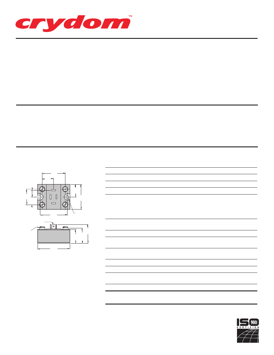
• Over 40KW Output
Capability
SERIES M50
Rev. 121807
PAGE 1 OF 3
The M50 Series modules utilize highly
efficient thermal management of pro-
vide high surge capability, long lifetime
and reliable performance. Available in
eight standard circuits, all models come
in an industry standard package, pro-
vide 2500Vrms from all terminals to the
baseplate and are UL recognized (file
no. E72445).
Manufactured in Crydom's ISO 9002
Certified facility for optimum product
performance and reliability.
1.070
(27.2)
.535
(13.6)
.475
(12.1)
1.625
(41.2)
.815
(20.7)
.875
(22.2)
1.750
(44.4)
1.880
(47.7)
10-32 SCREW
4 PLCS.
.250 X .032 THK.
4 PLCS.
1.055
(26.8)
2.265
(57.5)
1.365
(34.6)
1.140
(29.0)
MOUNTING
HOLE/SLOT
0.20 (5.1) DIA.
ELECTRICAL SPECIFICATIONS
RATINGS
SYMBOL SPECIFICATION
M5050
M50100
I
D
Maximum DC Output Current (Tc = 85°C)
50A
100A
V
F
Maximum Voltage Drop @ Amps Peak
1.7V @ 50A
1.4V @ 100A
T
J
Operating Junction Temperature Range
-40°C to +125°C
di/dt
Critical Rate of Rise of On-State Current @ TJ=125°C
100A/µs
100A/µs
dv/dt
Critical Rate of Rise of Off-State Voltage [V/µs]
500V/µs
500V/µs
120 (400 V
RRM
)
V
RMS
AC Line Input Voltage
240 (600 V
RRM
)
(Repetitive Peak Reverse Voltage)
280 (800 V
RRM
)
380 (1000 V
RRM
)
480 (1200 V
RRM
)
I
TSM
Maximum Non-Repetitive Surge Current
( 1 / 2 Cycle, 60Hz)
600A
1500A
I
2
T
Maximum I 2 T for Fusing (t=8.3ms) [A 2 sec]
1500
9350
I
GT
Maximum Required Gate Current
to Trigger @ 25°C
150mA
150mA
V
GT
Maximum Required Gate Voltage
to Trigger @ 25°C
3.0V
3.0V
P
G(AV)
Average Gate Power
0.5W
0.5W
V
GM
Maximum Peak Gate Voltage (Reverse)
5.0V
5.0V
R
q
JC
Maximum Thermal Resistance Junction to
Ceramic Base per Chip
0.7°C/W
0.36°C/W
V
ISOL
Isolation Voltage
2500 V
RMS
2500 V
RMS
MECHANICAL SPECIFICATIONS
Weight: (typical)
4.9 oz. ( 140g)
MECHANICAL DIMENSIONS
All dimensions are in inches (millimeters)
PART NUMBER IDENTIFICATION
Series Type
Current
Circuit Type
AC Line Voltage
Options
M50
-Case style
50
- 50 Amps
1 - 8
1
- 120 Vac
F
-
Free Wheeling Diode
100
- 100 Amps
(see schematic
2
- 240 Vac
(Circuits 1 & 2 Only)
diagrams)
3
- 280 Vac
V
- External Suppressor
4
- 380 Vac
(Circuits 1, 2, 3, 4, 6 & 7 Only)
Example: M505012FV
5
- 480 Vac
©2007 CRYDOM Inc., Specifications subject to change without notice.
Series
M50
50-100Amp • SCR/DIODE Modules
For recommended applications and more information contact:
USA:
Sales Support (877) 502-5500
Tech Support
(877) 702-7700 FAX (619) 710-8540
Crydom Inc., 2320 Paseo de las Americas, Ste. 201, San Diego, CA 92154
Email:
sales@crydom.com
WEB SITE:
http://www.crydom.com
UK:
+44 (0)1202 606030 •
FAX
+44 (0)1202 606035 Crydom SSR Ltd., Arena Business Centre,
Holyrood Close, Poole, Dorset BH17 7FJ, Email: intsales@crydom.com.
GERMANY:
+49 (0)180 3000 506
Courtesy of Steven Engineering, Inc.-230 Ryan Way, South San Francisco, CA 94080-6370-Main Office: (650) 588-9200-Outside Local Area: (800) 258-9200-www.stevenengineering.com
60MAIN-html.html
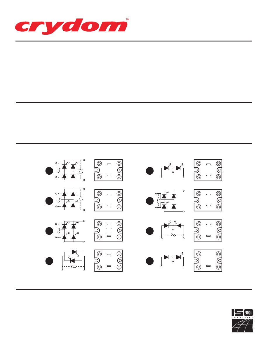
SERIES M50
Rev. 121807
PAGE 2 OF 3
• Over 40KW Output
Capability
G2
G1
AC
+
--
G2
AC
G2
G1
AC1
AC2
+
G2
G1
AC1
AC2
AC1
AC2
G1
G2
G4
G3
+
--
G2
AC2
AC1
G1
+
--
G2
AC1
AC2
G1
+
--
G2
AC1
AC2
G1
+
--
G2
AC1
AC2
G1
+
--
G2
AC2
AC1
G1
+
--
G1
AC1
AC1
G2
G4
G3
AC2
AC2
G1
AC
G2
+
--
G2
AC1
AC2
G1
+
--
G2
AC1
AC2
G1
+
G2
AC
+
--
AC1
AC2
G2
G1
+
--
1
2
3
4
5
6
7
8
+
--
+
PART NUMBER IDENTIFICATION
Series Type
Current
Circuit Type
AC Line Voltage
Options
M50
-Case style
50
- 50 Amps
1 - 8
1
- 120 Vac
F
- Free Wheeling Diode
100
- 100 Amps
(see schematic
2
- 240 Vac
(Circuits 1 & 2 Only)
diagrams)
3
- 280 Vac
V
- External Suppressor
4
- 380 Vac
(Circuits 1, 2, 3, 4, 6 & 7 Only)
Example: M505012FV
5
- 480 Vac
SERIES M50 CIRCUITS
© 2007 CRYDOM Inc., Specifications subject to change without notice.
Series
M50
50-100Amp • SCR/DIODE Modules
For recommended applications and more information contact:
USA:
Sales Support (877) 502-5500
Tech Support
(877) 702-7700 FAX (619) 710-8540
Crydom Inc., 2320 Paseo de las Americas, Ste. 201, San Diego, CA 92154
Email:
sales@crydom.com
WEB SITE:
http://www.crydom.com
UK:
+44 (0)1202 606030 •
FAX
+44 (0)1202 606035 Crydom SSR Ltd., Arena Business Centre,
Holyrood Close, Poole, Dorset BH17 7FJ, Email: intsales@crydom.com.
GERMANY:
+49 (0)180 3000 506
Courtesy of Steven Engineering, Inc.-230 Ryan Way, South San Francisco, CA 94080-6370-Main Office: (650) 588-9200-Outside Local Area: (800) 258-9200-www.stevenengineering.com
60MAIN-html.html
HAZARD OF
ELECTRIC
SHOCK,
EXPLOSION,
OR ARC FLASH.
•
Disconnect all
power before
installing or
working with
this equipment.
•
Verify all
connections
and replace all
covers before
turning on
power.
Failure to follow
these
instructions will
result in death
or serious injury.
RIESGO DE
DESCARGA
ELECTRICA O
EXPLOSION.
•
Desconectar
todos los
suministros de
energia a este
equipo antes
de trabajar
con este equipo.
•
Verificar todas
las conexiones
y colocar todas
las tapas antes
de energizer
el equipo.
El
incumplimiento
de estas
instrucciones
puede provocar
la muerte o
lesiones serias.
RISQUE DE
DESCHARGE
ELECTRIQUE
OU EXPLOSION
•
Eteindre
toutes les
sources
d'énergie de
cet appareil
avant de
travailler
dessus de cet
appareil
•
Vérifier tous
connections, et
remettre tous
couverts en
olace avant de
mettre sous
De non-suivi de
ces instructions
provoquera la
mort ou des
lésions sérieuses
sérieuses.
GEFAHR EINES
ELEKTRISCHE
N SCHLAGES
ODER EINER
EXPLOSION.
•
Stellen Sie
jeglichen
Strom ab, der
dieses Gerät
versorgt, bevor
Sie an dem
Gerät Arbeiten
durchführen
•
Vor dem
Drehen auf
Energie alle
Anschlüsse
überprüfen
und alle
Abdeckungen
ersetzen.
Unterlassung
dieser
Anweisungen
können zum
Tode oder zu
schweren
Verletzungen
führen.
RISCHIO DI
SCOSSA
ELETTRICA O
DELL’ESPLOSI
ONE.
•
Spenga tutta
l'alimentazion
e che fornisce
questa
apparecchiatu
ra prima del
lavorare a questa
apparecchiatu ra
•
Verificare tutti
i collegamenti
e sostituire
tutte le coperture
prima della
rotazione
sull'alimentazi one
L'omissione di
seguire queste
istruz ioni
provocherà la
morte o di
lesioni serie
RISCO DE
DESCARGA
ELÉTTRICA OU
EXPLOSÃO
•
Desconectar
o equipamento
de toda á
energia antes
de instalar ou
trabalhar com
este equipamen
to
•
Verificar todas
as conexões e
recolocar todas
as tampas
antes de religar
o equipamento
O não cumprimento
destas instruções
pode levar á morte
ou lesões sérias.
RISQUE DE DOMMAGE MATERIEL ET DE
SURCHAUFFE DU BOITIER
•
Les panneaux latéraux du produit peuvent être
chauds. Laisser le produit refroidir avant de le
toucher.
•
Respecter les consignes de montage, et
notamment les couples de serrage.
•
Ne pas laisser pénétrer de liquide ni de corps
étrangers à l'intérieur du produit.
RISK OF MATERIAL DAMAGE AND HOT
ENCLOSURE
•
The product's side panels may be hot, allow
time for product to cool before touching.
•
Follow proper mounting instructions including
torque values
.
•
Do not allow liquids or foreign objects to enter
this product.
Le non-respect de cette directive peut entraîner,
des lésions corporelles graves ou des
dommages matériels.
Failure to follow this instruction can result in
serious injury, or equipment damage.
La mancata osservanza di questa precauzione può
causare gravi rischi per l'incolumità personale o
danni alle apparecchiature.
Si no se respetan estas precauciones pueden
producirse graves lesiones, daños materiales.
Die Nichtbeachtung dieser Anweisung kann
Körperverletzung oder Materialschäden
zur Folge haben.
A não observância destas precauções pode
provocar a morte, ferimentos graves ou
danos materiais.
GEFAHR VON MATERIALSCHÄDEN UND
GEHÄUSEERHITZUNG
•
Die Seitenwände können heiß sein. Lassen Sie
das Produkt abkühlen, bevor Sie es berühren.
•
Beachten Sie die Montageanweisungen,
•
Führen Sie keine Flüssigkeiten oder
Fremdkörper in das Produkt ein.
RISCHIO DI DANNI MATERIALI E D'INVOLUCRO
CALDO
•
I pannelli laterali dell'apparecchio possono
scottare; lasciar quindi raffreddare il prodotto
prima di toccarlo.
•
Seguire le istruzioni di montaggio corrette.
•
Non far entrare liquidi o oggetti estranei in questo
apparecchio.
RIESGO DE DAÑOS MATERIALES Y DE
SOBRECALENTAMIENTO DE LA UNIDAD
•
Los paneles laterales del producto pueden
estar calientes. Esperar que el producto se
enfríe antes de tocarlo.
•
Respetar las instrucciones de montaje, y en
particular los pares de apretado.
•
No dejar que penetren líquidos o cuerpos
extraños en el producto.
RISCO DE DANO MATERIAL E DE AQUECIMENTO
•
Os painéis laterais do produto podem estar
quentes; dê tempo ao produto para arrefecer
antes de lhe tocar.
•
Siga devidamente as instruções de montagem.
•
Não permita a entrada de líquidos e de objectos
estranhos no produto.
DANGER / PELIGRO / DANGER /GEFAHR / PERICOLO / PERIGO
WARNING / AVERTISSEMENT / WARNUNG /ADVERTENCIA / AVVERTENZA / AVISO
SERIES M50
Rev. 121807
PAGE 3 OF 3
Courtesy of Steven Engineering, Inc.-230 Ryan Way, South San Francisco, CA 94080-6370-Main Office: (650) 588-9200-Outside Local Area: (800) 258-9200-www.stevenengineering.com
60MAIN-html.html

ANNEX – ENVIRONMENTAL INFORMATION:
The environmental information disclosed in this annex including the EIP
Pollution logo are in compliance with People’s Republic of China Electronic
Industry Standard SJ/T11364 – 2006, Marking for Control of Pollution
Caused by Electronic Information Products.
Part
Toxic or hazardous Substance and Elements
Name
Lead
Mercury Cadmium Hexavalent
Polybrominated Polybrominated
(Pb)
(Hg)
(Cd)
Chromium
(Cr (VI))
biphenyls
(PBB)
diphenyl ethers
(PBDE)
Semiconductor
die
X
O
O
O
O
O
Solder
X
O
O
O
O
O
䰘ӊ
-
⦃ֱֵᙃ
:
ℸ䰘ӊ᠔ᷛ⼎ⱘࣙᣀ⬉ᄤֵᙃѻક∵ᶧᷛⱘ⦃ֱֵᙃ
ヺড়ЁढҎ⇥݅⬉ᄤ㸠Ϯᷛޚ
SJ/T11364 - 2006,
⬉ᄤֵᙃѻક∵ᶧࠊᷛ䆚㽕∖
㋴
ܗ
䋼
⠽
ᆇ
᳝
↦
᳝
ӊ
䚼
ৡ⿄
䪙
∲
䬝
݁Ӌ䫀
⒈㘨㣃
⒈Ѡ㣃䝮
(Pb)
(Hg)
(Cd)
(Cr (VI))
(PBB)
(PBDE)
ञᇐԧ㢃⠛
X
O
O
O
O
O
⛞⚍
X
O
O
O
O
O
© 2007 CRYDOM Inc., Specifications subject to change without notice.
Courtesy of Steven Engineering, Inc.-230 Ryan Way, South San Francisco, CA 94080-6370-Main Office: (650) 588-9200-Outside Local Area: (800) 258-9200-www.stevenengineering.com
60MAIN-html.html
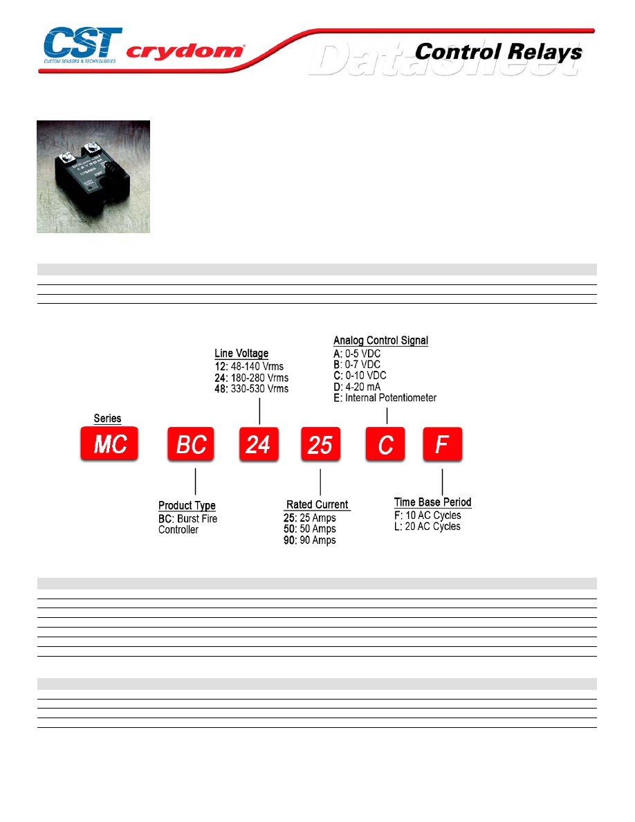
MCBC Series
• Microprocessor based burst-fire controller / SSR
• Ratings from 25A to 90A @ 48-530 VAC
• Low-voltage, current, or potentiometer control
• Output status indicator
• Separate output enable / disable control
• Two time-base periods available
PRODUCT SELECTION
Line Voltage
25 A
50 A
90 A
40-140 VAC
MCBC1225
MCBC1250
MCBC1290
180-280 VAC
MCBC2425
MCBC2450
MCBC2490
300-530 VAC
MCBC4825
MCBC4850
MCBC4890
AVAILABLE OPTIONS
OUTPUT SPECIFICATIONS (current)
Description
25 A
50 A
90 A
Maximum Load Current (3) [Arms]
25
50
90
Minimum Load Current [mArms]
150
150
150
Maximum Surge Current (16.6ms) [Apk]
250
625
1200
Maximum On-State Voltage Drop @ Rated Current [Vpk]
1.6
1.6
1.6
Thermal Resistance Junction to Case (Rjc) [°C/W]
1.02
0.63
0.28
Maximum I² t for Fusing (8.3 msec) [A²sec]
260
1620
6000
Minimum Power Factor (with Maximum Load)
0.5
0.5
0.5
OUTPUT SPECIFICATIONS (voltage)
Description
120 VAC
240 VAC
480 VAC
Operating Voltage (47-63Hz) [Vrms]
48-140
180-280
300-530
Transient Overvoltage [Vpk]
400
600
1200
Maximum Off-State Leakage Current @ Rated Voltage [mArms]
5
7
12
Minimum Off-State dv/dt @ Maximum Rated Voltage [V/µsec] (2)
200
200
200
For Conta ct information vis it our web site .
www.crydom.com
© 2008 Cryd om, Inc.
Specifications subject to change without notice.
Courtesy of Steven Engineering, Inc.-230 Ryan Way, South San Francisco, CA 94080-6370-Main Office: (650) 588-9200-Outside Local Area: (800) 258-9200-www.stevenengineering.com
60MAIN-html.html

INPUT SPECIFICATIONS (1)
Description
DC Control
Control Voltage Range (VDC)
8-32
Input Current Range [mA]
28-30
Nominal Input Impedance [Ohms]
30K
Control Must Operate Voltage "On"[VDC][P3]
5-32
Control Must Release Voltage "Off" [VDC][P3]
0-4
Control Input Current [mA][P3]
0-1.25
PLV Range Option A [VDC][P4] (2)
0-5
PLV Range Option B [VDC][P4] (2)
0-7
PLV Range Option C [VDC][P4] (2)
0-10
PLV Range Option D [VDC][P4] (2)
4-20
Nominal Input Impedance Option A,B,C[ohms][P4]
20K
Nominal Input Impedance Option D [ohms][P4]
220
OUTPUT STATUS FUNCTIONS
Conditions
LED
Initial Logic Supply On
Flash Once
Load Voltage Missing / Load Open (w/control disabled)
Flash Once Intermittenly
Load Voltage Missing / Load Open (w/control enabled))
Flash Twice Intermittently
Analog Input < Threshold
Off
Analog Input < Threshold < max
Varying Brightness
Analog Input > max
On, Bright
GENERAL SPECIFICATIONS
Description
Parameters
Dielectric Strength, Input/Output/Base (50/60Hz)
4000 Vrms
Minimum Insulation Resistance (@ 500 V DC)
10
9
Ohm
Maximum Capacitance, Input/Output
10 pF
Ambient Operating Temperature Range
-20 to 80°C
Ambient Storage Temperature Range
-40 to 125 °C
Weight (typical)
3.0 oz (86.5g)
Encapsulation
Thermally conductive Epoxy
Terminals-Power
Screws and Saddle Clamps Furnished, Unmounted
Terminals-Control
Barrier Strip Screw Terminals
Recommended Terminal Screw Torque Range:
8-32 Screws -20 in. lbs.(Screws dry without grase)
GENERAL NOTES
1) Voltages are reference to GND (Ground = 0 VDC) P2
2) PLVI voltage can go up to max. supply voltage without damage
For Conta ct information vis it our web site .
www.crydom.com
© 2008 Cryd om, Inc.
Specifications subject to change without notice.
Courtesy of Steven Engineering, Inc.-230 Ryan Way, South San Francisco, CA 94080-6370-Main Office: (650) 588-9200-Outside Local Area: (800) 258-9200-www.stevenengineering.com
60MAIN-html.html
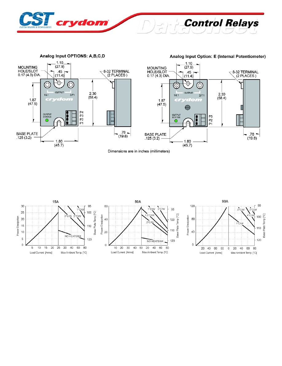
MECHANICAL SPECIFICATIONS
THERMAL DERATE INFORMATION
For Conta ct information vis it our web site .
www.crydom.com
© 2008 Cryd om, Inc.
Specifications subject to change without notice.
Courtesy of Steven Engineering, Inc.-230 Ryan Way, South San Francisco, CA 94080-6370-Main Office: (650) 588-9200-Outside Local Area: (800) 258-9200-www.stevenengineering.com
60MAIN-html.html
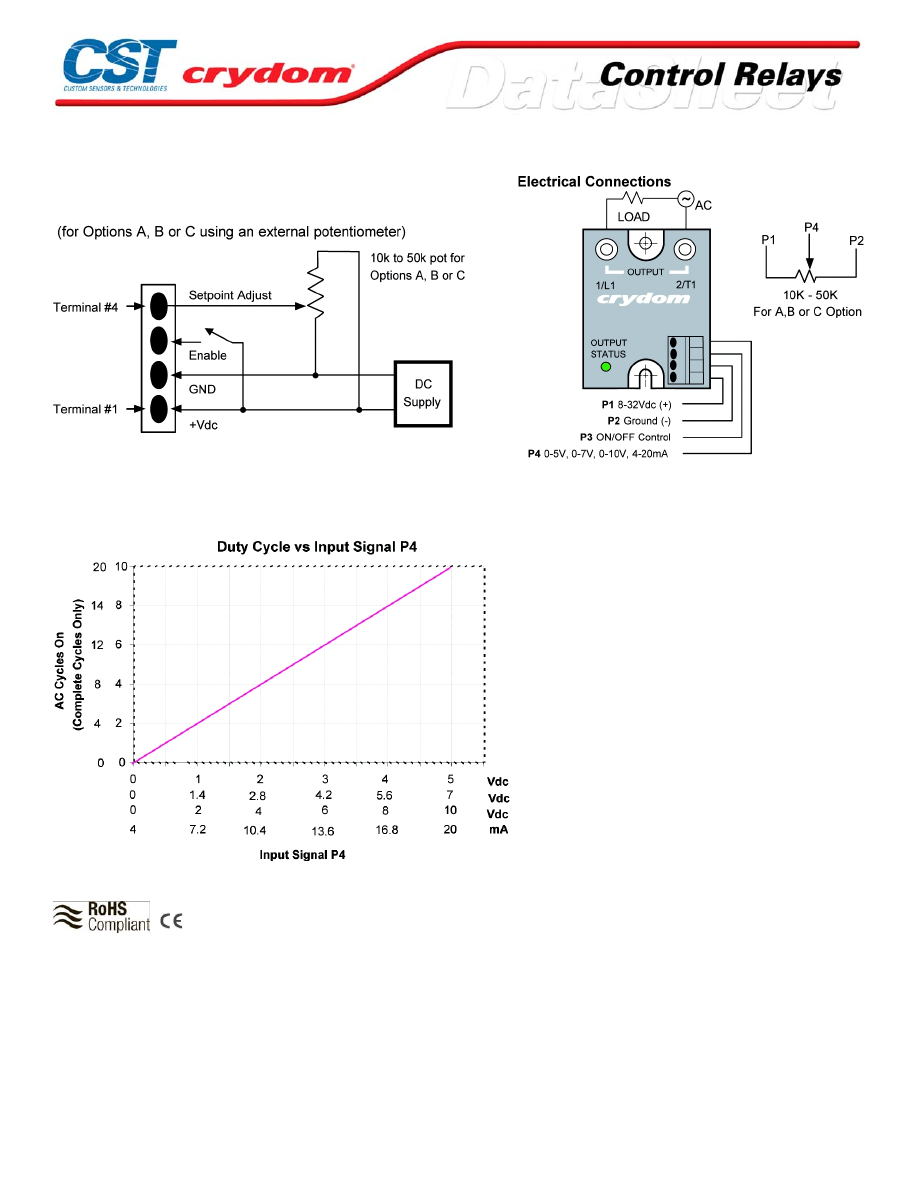
WIRING DIAGRAM
OUTPUT VS ANALOG INPUT SIGNAL CURVES
AGENCY APPROVALS
UL E11 6949
Rev. 102 308
For Conta ct information vis it our web site .
www.crydom.com
©2008 Cryd om, Inc.
Specifications subject to change without notice.
Courtesy of Steven Engineering, Inc.-230 Ryan Way, South San Francisco, CA 94080-6370-Main Office: (650) 588-9200-Outside Local Area: (800) 258-9200-www.stevenengineering.com
60MAIN-html.html

ANNEX - ENVIROMENTAL INFORMATION
For Conta ct information vis it our web site .
www.crydom.com
©2008 Cryd om, Inc.
Specifications subject to change without notice.
Courtesy of Steven Engineering, Inc.-230 Ryan Way, South San Francisco, CA 94080-6370-Main Office: (650) 588-9200-Outside Local Area: (800) 258-9200-www.stevenengineering.com
60MAIN-html.html
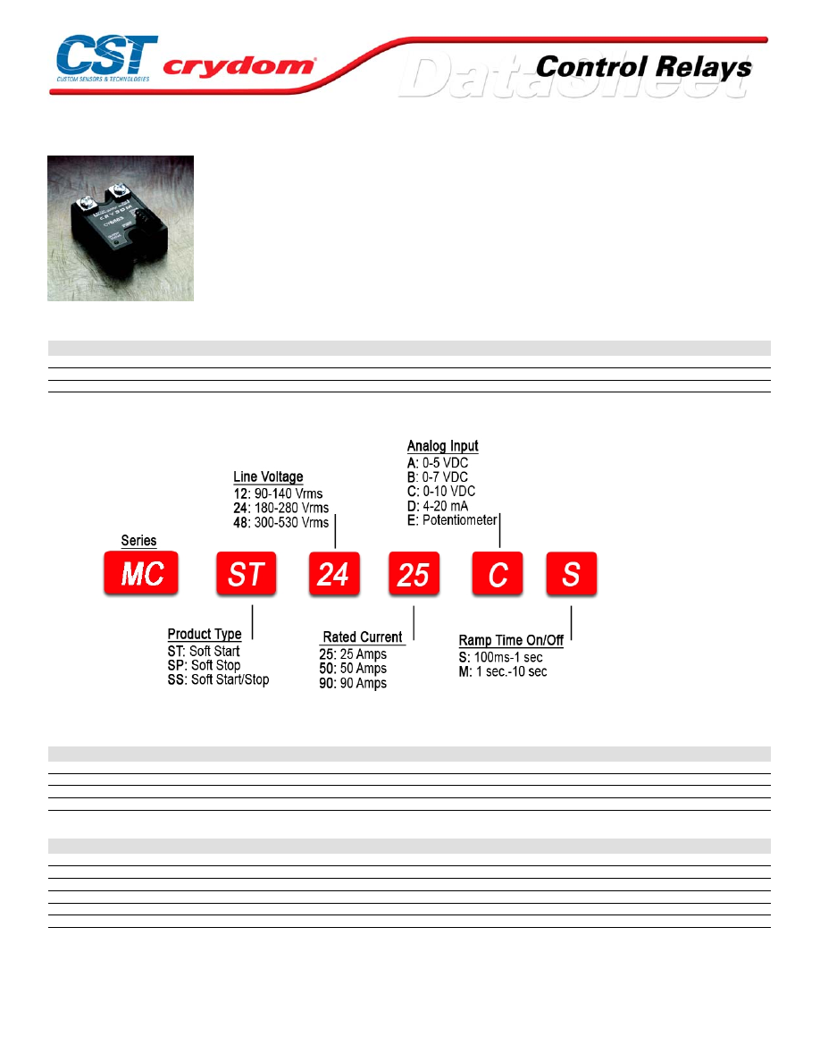
MCS Series
• Microprocessor based soft-start / soft-stop controller
• Ratings from 25A to 90A @ 48-530 VAC
• Low-voltage, current, or potentiometer control
• Output status indicator
• Adjustable ramp rates
PRODUCT SELECTION
Line Voltage
25 A
50 A
90 A
120 Vrms
MCST1225
MCST1250
MCST1290
240 Vrms
MCST2425
MCST2450
MCST2490
480 Vrms
MCST4825
MCST4850
MCST4890
AVAILABLE OPTIONS
OUTPUT SPECIFICATIONS (voltage)
Description
120 VAC
240 VAC
480 VAC
Operating Voltage (47-63Hz) [Vrms]
48-140
180-280
300-530
Transient Overvoltage [Vpk]
400
600
1200
Maximum Off-State Leakage Current @ Rated Voltage [mArms]
5
7
12
Minimum Off-State dv/dt @ Maximum Rated Voltage [V/µsec]
200
200
200
OUTPUT SPECIFICATIONS (current)
Description
25 A
50 A
90 A
Maximum Load Current [Arms]
25
50
90
Minimum Load Current [mArms]
150
150
150
Maximum Surge Current (16.6ms) [Apk]
250
625
1200
Maximum On-State Voltage Drop @ Rated Current [Vpk]
1.6
1.6
1.6
Thermal Resistance Junction to Case (Rjc) [°C/W]
1.02
0.63
0.28
Maximum I²t for Fusing (8.3 msec) [A²sec]
260
1620
6000
For Conta ct information vis it our web site .
www.crydom.com
© 2008 Cryd om, Inc.
Specifications subject to change without notice.
Courtesy of Steven Engineering, Inc.-230 Ryan Way, South San Francisco, CA 94080-6370-Main Office: (650) 588-9200-Outside Local Area: (800) 258-9200-www.stevenengineering.com
60MAIN-html.html
INPUT SPECIFICATIONS (1)
Description
DC Control
Control Voltage Range (VDC)
8-32
Input Current Range [mA]
28-30
Nominal Input Impedance [Ohms]
30K
Control Must Operate Voltage "On"[VDC][P3]
5-32
Control Must Release Voltage "Off" [VDC][P3]
0-4
Input Current [mA][P3]
0-2.6
Analog Range Option A [VDC][P4]
0.5-5
Analog Range Option B [VDC][P4]
1.25-7
Analog Range Option C [VDC][P4]
2-10
Analog Range Option D [VDC][P4]
4-20
Nominal Input Impedance Option A,B,C[ohms][P4]
20K
Nominal Input Impedance Option D [ohms][P4]
220
GENERAL SPECIFICATIONS
Description
Parameters
Minimum Power Factor (with Maximum Load)
0.5
Dielectric Strength, Input/Output/Base (50/60Hz)
4000 Vrms
Minimum Insulation Resistance (@ 500 V DC)
10
9
Ohm
Maximum Capacitance, Input/Output
10 pF
Ambient Operating Temperature Range
-20 to 80°C
Ambient Storage Temperature Range
-40 to 125 °C
Weight (typical)
3.0 oz (86.5g)
Encapsulation
Thermally conductive Epoxy
Terminals-Power
Screws and Saddle Clamps Furnished, Unmounted
Terminals-Control
Barrier Strip Screw Terminals
Recommended Terminal Screw Torque Range:
8-32 Screws -20 in. lbs.(Screws dry without grase)
Input Connections via Screw Type Barrier Strip
GENERAL NOTES
1) Voltages are reference t o GND (Ground = 0 VDC) P2
OUTPUT STATUS FUNCTIONS
Conditions
LED Status
Initial Logic Supply On
Flash Once
Load Voltage Missing / Load Open (w/control P3 disabled)
Flash Once Intermittenly
Load Voltage Missing / Load Open (w/control P3 enabled))
Off
Ramp Time (Soft Start upon P3 Enabled)
Off to Bright
Ramp Time (Soft Start upon P3 Disabled)
Bright to Off
Output ON (Normally Steady Operation)
On
For Conta ct information vis it our web site .
www.crydom.com
© 2008 Cryd om, Inc.
Specifications subject to change without notice.
Courtesy of Steven Engineering, Inc.-230 Ryan Way, South San Francisco, CA 94080-6370-Main Office: (650) 588-9200-Outside Local Area: (800) 258-9200-www.stevenengineering.com
60MAIN-html.html
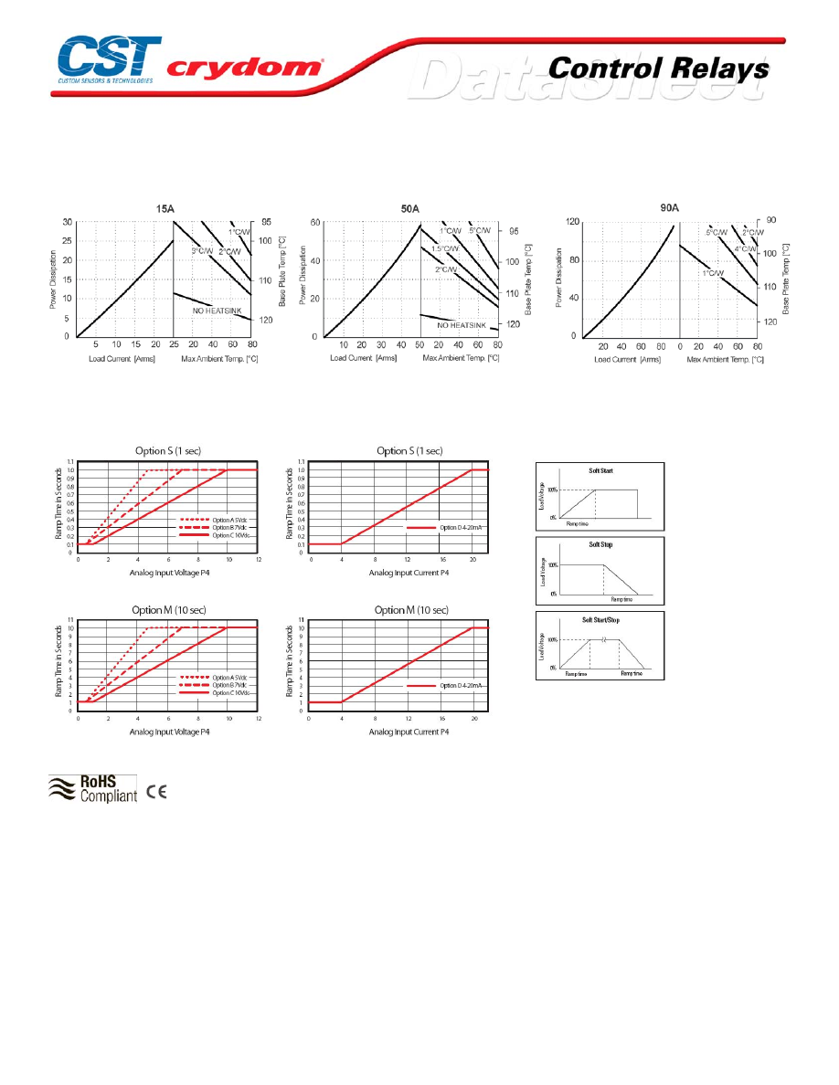
THERMAL DERATE INFORMATION
RAMP TIME IN SECONDS
AGENCY APPROVALS
UL E116949
Rev.
102408
For Conta ct information vis it our web site .
www.crydom.com
© 2008 Cryd om, Inc.
Specifications subject to change without notice.
Courtesy of Steven Engineering, Inc.-230 Ryan Way, South San Francisco, CA 94080-6370-Main Office: (650) 588-9200-Outside Local Area: (800) 258-9200-www.stevenengineering.com
60MAIN-html.html
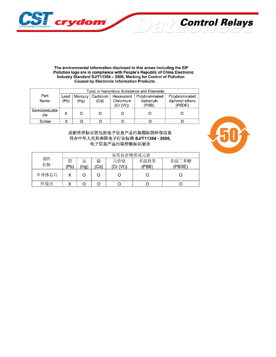
CONTACTS
ANNEX - ENVIROMENTAL INFORMATION
For Conta ct information vis it our web site .
www.crydom.com
© 2008 Cryd om, Inc.
Specifications subject to change without notice.
Courtesy of Steven Engineering, Inc.-230 Ryan Way, South San Francisco, CA 94080-6370-Main Office: (650) 588-9200-Outside Local Area: (800) 258-9200-www.stevenengineering.com
60MAIN-html.html
PCV Series
• Proportional controller
• Ratings from 15A to 90A @ 240 VAC
• 2-7 V DC or 2-10 V DC analog input range
PRODUCT SELECTION
Description
15 A
25 A
50 A
75 A
90 A
2-7 VDC Control
7PCV2415
7PCV2425
2-10 VDC Control
10PCV2415
10PCV2425
10PCV2450
10PCV2475
10PCV2490
OUTPUT SPECIFICATIONS (1)
Description
Operating Voltage (47-63Hz) [Vrms]
100-240
100-240
100-240
100-240
100-240
Transient Overvoltage [Vpk]
600
600
600
600
600
Maximum Off-State Leakage Current @ Rated Voltage [mArms]
10
10
10
10
10
Minimum Off-State dv/dt @ Maximum Rated Voltage [V/µsec] (2)
200
200
200
200
200
Maximum Load Current (3) [Arms]
15
25
50
75
90
Minimum Load Current [Arms]
0.15
0.15
0.15
0.15
0.15
Maximum Surge Current (16.6ms) [Apk]
150
250
625
1000
1200
Maximum On-State Voltage Drop @ Rated Current [Vpk]
1.6
1.6
1.6
1.6
1.6
Maximum I² t for Fusing (8.3 msec) [A² sec]
94
260
1620
4150
6000
Minimum Power Factor (with Maximum Load)
0.5
0.5
0.5
0.5
0.5
INPUT SPECIFICATIONS (1)
Description
Control Voltage Range
2-7 VDC
2-10 VDC
Typical Input Current @ 5 VDC
4 mA
4 mA
GENERAL SPECIFICATIONS
Description
Parameters
Dielectric Strength, Signal to Load (50/60Hz)
2500 Vrms
Dielectric Strength, Signal to Base
2500 Vrms
Ambient Operating Temperature Range
-30 to 80 °C
Ambient Storage Temperature Range
-40 to 125 °C
Weight (typical)
3.5 oz. (100g)
Encapsulation
Themaly Conductive Epoxy
Terminals
Screws and Saddle clamps Furnished, Unmounted
GENERAL NOTES
1) All param eters at 25°C un less othe rwise specif ied .
Courtesy of Steven Engineering, Inc.-230 Ryan Way, South San Francisco, CA 94080-6370-Main Office: (650) 588-9200-Outside Local Area: (800) 258-9200-www.stevenengineering.com
60MAIN-html.html
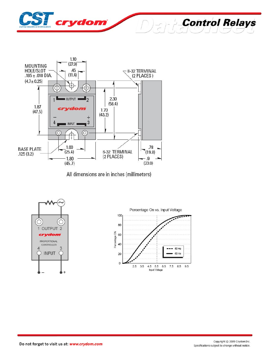
MECHANICAL SPECIFICATIONS
WIRING DIAGRAM
Courtesy of Steven Engineering, Inc.-230 Ryan Way, South San Francisco, CA 94080-6370-Main Office: (650) 588-9200-Outside Local Area: (800) 258-9200-www.stevenengineering.com
60MAIN-html.html
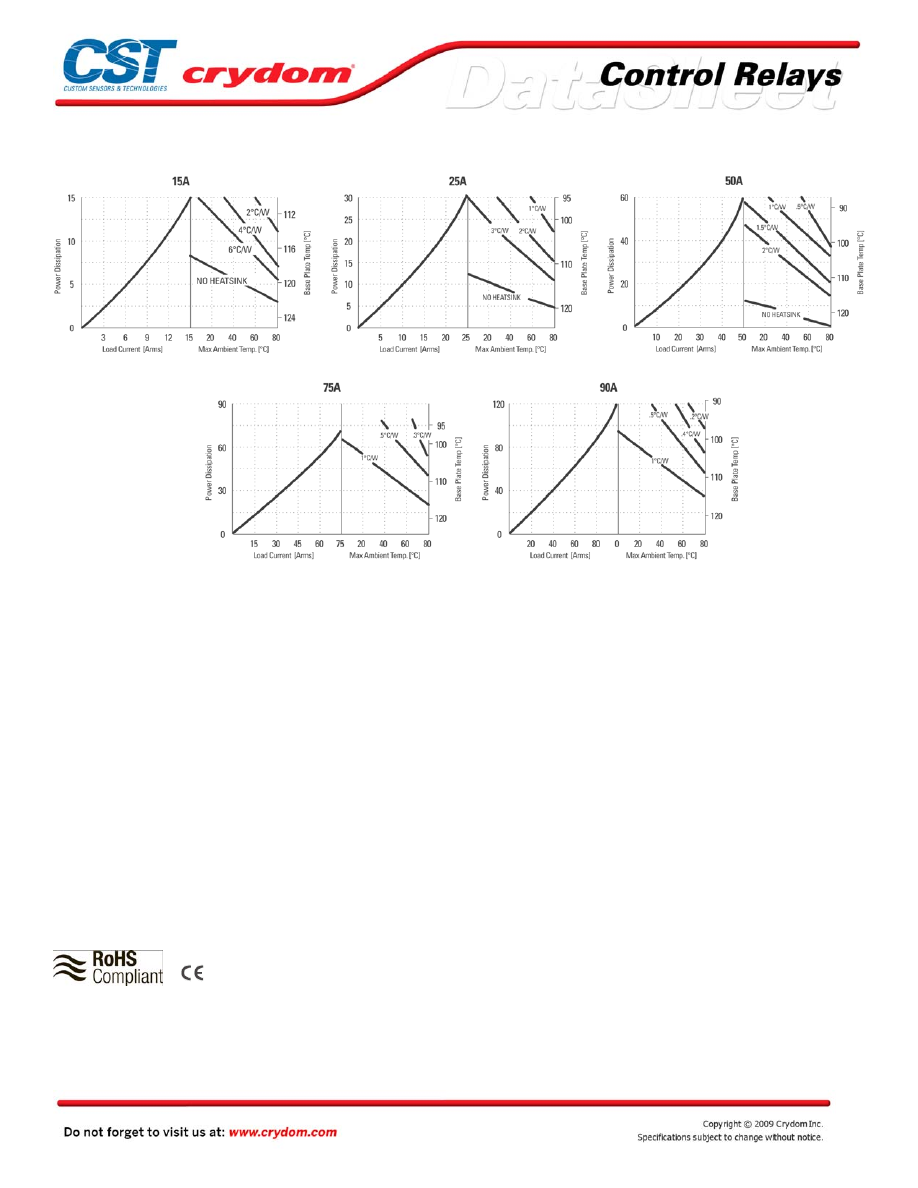
THERMAL DERATE INFORMATION
TYPICAL APPLICATIONS
• Industrial temperature controllers
• Light dimming
• Vibratory feeders
• Resistive heating elements
• Rectified DC motors
• Conveyor speed control
UNSUITABLE APPLICATIONS
The PCV is not suitable for some load applications
Including, but not limited to the following:
• AC motor control
• Three Phase motors
• Transformers requiring pure sine wave input
• Zero crossing applications
Please contact Crydom’s application
Engineering department for additional
Information and specific application questions.
AGENCY APPROVALS
Rev. 121108
Courtesy of Steven Engineering, Inc.-230 Ryan Way, South San Francisco, CA 94080-6370-Main Office: (650) 588-9200-Outside Local Area: (800) 258-9200-www.stevenengineering.com
60MAIN-html.html
Courtesy of Steven Engineering, Inc.-230 Ryan Way, South San Francisco, CA 94080-6370-Main Office: (650) 588-9200-Outside Local Area: (800) 258-9200-www.stevenengineering.com
60MAIN-html.html

ANNEX - ENVIROMENTAL INFORMATION
Courtesy of Steven Engineering, Inc.-230 Ryan Way, South San Francisco, CA 94080-6370-Main Office: (650) 588-9200-Outside Local Area: (800) 258-9200-www.stevenengineering.com
60MAIN-html.html
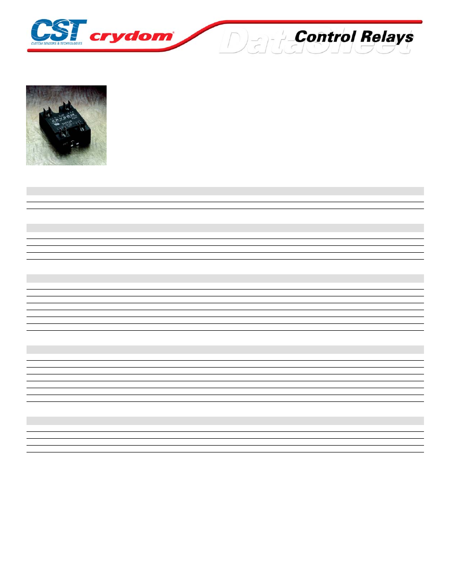
SST Series
• Soft-start modules
• 120/240 V AC models
• 3.5-10 V DC control range
• Used with Series 1 random-fire solid-state relays
PRODUCT SELECTION
Description
10 A
25 A
50 A
75 A
90A
120 Vrms Line Voltage
10SST120
25SST120
40SST120
240 Vrms Line Voltage
10SST240
25SST240
50SST240
75SST240
90SST240
OUTPUT SPECIFICATIONS (voltage) (1)
Description
120 VAC
240 VAC
Operating Voltage (47-63Hz) [Vrms]
90-140
180-280
Transient Overvoltage [Vpk]
400
600
Maximum Off-State Leakage Current @ Rated Voltage [mArms]
10
10
Minimum Off-State dv/dt @ Maximum Rated Voltage [V/µsec] (2)
500
500
OUTPUT SPECIFICATIONS (current) (1)
Description
10 A
25 A
50 A
75 A
90 A
Maximum Load Current (3) [Arms]
10
25
50
75
90
Minimum Load Current (3) [Arms]
0.04
0.04
0.04
0.04
0.04
Maximum Surge Current (16.6ms) [Apk]
120
250
625
1000
1200
Maximum On-State Voltage Drop @ Rated Current [Vpk]
1.6
1.6
1.6
1.6
1.6
Thermal Resistance Junction to Case (Rjc) [°C/W]
1.48
1.02
0.63
0.31
0.28
Maximum I²t for Fusing (8.3 msec) [A²sec]
60
260
1620
4150
6000
Minimum Power Factor (with Maximum Load)
0.5
0.5
0.5
0.5
0.5
CONTROL MODULE INPUT SPECIFICATIONS (1)
Description
DC Control
Control Voltage Range
3.5-10 VDC
Maximum Off-State Voltage
1.0 VDC
Typical Input Current
1.6 mA @ 5 VDC
Nominal Turn-On Delay time @ 60Hz
150 msec
Nominal Swell (Ramp) Time @ 60Hz
180 msec
Maximum Reset Time
0.1 msec
Maximum Turn-Off Time [msec]
1/2 Cycle
CONTROL MODULE OUTPUT SPECIFICATIONS (1)
Description
DC Control
Maximum Off-State Operating Voltage
36 VDC
Maximum Load Current
3 mADC
Maximum Turn-On Voltage@ 3mA
0.5 VDC
Maximum Off-State Leakage@ 10 VDC
1.0 µADC
For Conta ct information vis it our web site .
www.crydom.com
© 2008 Cryd om, Inc.
Specifications subject to change without notice.
Courtesy of Steven Engineering, Inc.-230 Ryan Way, South San Francisco, CA 94080-6370-Main Office: (650) 588-9200-Outside Local Area: (800) 258-9200-www.stevenengineering.com
60MAIN-html.html
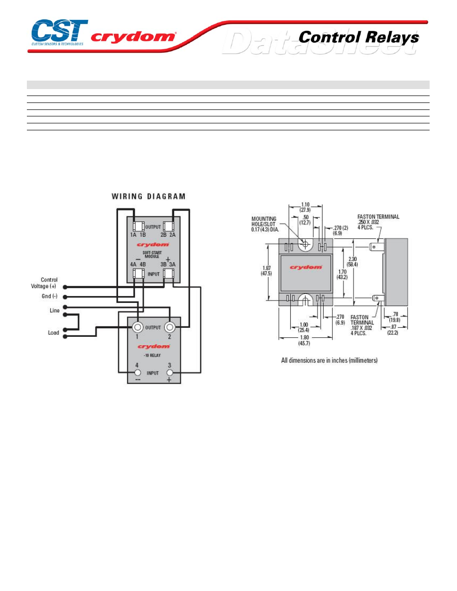
GENERAL SPECIFICATIONS
Description
Parameters
Dielectric Strength, signal to load
4000 Vrms
Dielectric Strength, signal to Base
4000 Vrms
Ambient Operating Temperature Range
-30 to 80 °C
Ambient Storage Temperature Range
-40 to 125 °C
Weight (typical)
3.0 oz. (43g)
Encapsulation
Thermally Conductive Epoxy
GENERAL NOTES
1) All parameters at 25°C unless otherwise specified.
2) Off-State dv/dt test method per EIA/NARM standard RS-443, paragraph 13.11.1
3) Heat sinking required (Relay Only).
WIRING DIAGRAM
NOTES
1. Following pins may be interchanged: 1A & 1B, 2A & 2B, 3A & 3B.
2. Pin 4A & 4B may not be interchanged
3. The line and load may be interchanged.
For Conta ct information vis it our web site .
www.crydom.com
© 2008 Cryd om, Inc.
Specifications subject to change without notice.
Courtesy of Steven Engineering, Inc.-230 Ryan Way, South San Francisco, CA 94080-6370-Main Office: (650) 588-9200-Outside Local Area: (800) 258-9200-www.stevenengineering.com
60MAIN-html.html
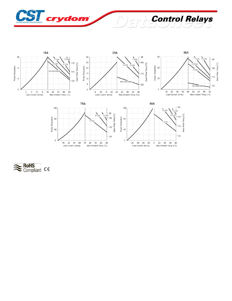
THERMAL DERATE INFORMATION
AGENCY APPROVALS
UL E116949
R ev.
102408
For Conta ct information vis it our web site .
www.crydom.com
© 2008 Cryd om, Inc.
Specifications subject to change without notice.
Courtesy of Steven Engineering, Inc.-230 Ryan Way, South San Francisco, CA 94080-6370-Main Office: (650) 588-9200-Outside Local Area: (800) 258-9200-www.stevenengineering.com
60MAIN-html.html

For Conta ct information vis it our web site .
www.crydom.com
© 2008 Cryd om, Inc.
Specifications subject to change without notice.
Courtesy of Steven Engineering, Inc.-230 Ryan Way, South San Francisco, CA 94080-6370-Main Office: (650) 588-9200-Outside Local Area: (800) 258-9200-www.stevenengineering.com
60MAIN-html.html

ANNEX - ENVIROMENTAL INFORMATION
For Conta ct information vis it our web site .
www.crydom.com
© 2008 Cryd om, Inc.
Specifications subject to change without notice.
Courtesy of Steven Engineering, Inc.-230 Ryan Way, South San Francisco, CA 94080-6370-Main Office: (650) 588-9200-Outside Local Area: (800) 258-9200-www.stevenengineering.com
60MAIN-html.html
CPV Series
• Phase control modules
• 120/240 VAC models
• 0-5 V DC phase control
• Used with Series 1 random-fire solid-state relays
PRODUCT SELECTION
Description
10 A
25 A
50 A
75 A
90 A
120 VAC
10CPV120
25CPV120
50CPV120
75CPV120
90CPV120
240 VAC
10CPV240
25CPV240
50CPV240
75CPV240
90CPV240
OUTPUT SPECIFICATIONS (voltage) (1)
Description
120 VAC
240 VAC
Operating Voltage (47-63Hz) [Vrms]
90-140 VAC
180-280 VAC
Transient Overvoltage [Vpk]
400
600
Maximum Off-State Leakage Current @ Rated Voltage [mArms]
10
10
Minimum Off-State dv/dt @ Maximum Rated Voltage [V/µsec] (2)
500
500
OUTPUT SPECIFICATIONS (current) (1)
Description
10 A
25 A
50 A
75 A
90 A
Maximum Load Current (3) [Arms]
10
25
75
50
90
Minimum Load Current [Arms]
0.04
0.04
0.04
0.04
0.04
Maximum Surge Current (16.6ms) [Apk]
120
250
625
1000
1200
Maximum On-State Voltage Drop @ Rated Current [Vpk]
1.6
1.6
1.6
1.6
1.6
Thermal Resistance Junction to Case (Rjc) [°C/W]
1.48
1.02
0.31
0.63
0.28
Maximum I²t for Fusing (8.3 msec) [A² sec]
60
260
4150
1620
6000
Minimum Power Factor (with Maximum Load)
0.5
0.5
0.5
0.5
0.5
CONTROL MODULE INPUT SPECIFICATIONS (1)
Description
DC Control
Control Voltage Range
0-5 VDC
Minimum Turn-Off Voltage
1.0 VDC
Typical Supply Current
1.6 mA @ 5 VDC
Nominal Control Input Impedance
1500 Ohm
Maximum Turn-On Time [msec]
0.02
Maximum Turn-Off Time [msec]
1/2 Cycle
CONTROL MODULE OUTPUT SPECIFICATIONS (Terminal 4B - Input to Relay) (1)
Description
DC Control
Maximum Off-State Operating Voltage
36 VDC
Maximum Load Current (Sink)
3.0 mA
Maximum On-State Voltage @ 3 mA
0.5 VDC
Max. Off State Leakage @ 10 VDC
1.0 µADC
GENERAL SPECIFICATIONS
Description
Parameters
Dielectric Strength, signal to load
4000 Vrms
Dielectric Strength, signal to Base
4000 Vrms
Ambient Operating Temperature Range
-30 to 80°C
Ambient Storage Temperature Range
-40 to 125°C
Weight (typical)
3.0 oz. (43g)
Encapsulation
Themally Conductive Epoxy
For Conta ct information vis it our web site .
www.crydom.com
© 2008 Cryd om, Inc.
Specifications subject to change without notice.
Courtesy of Steven Engineering, Inc.-230 Ryan Way, South San Francisco, CA 94080-6370-Main Office: (650) 588-9200-Outside Local Area: (800) 258-9200-www.stevenengineering.com
60MAIN-html.html
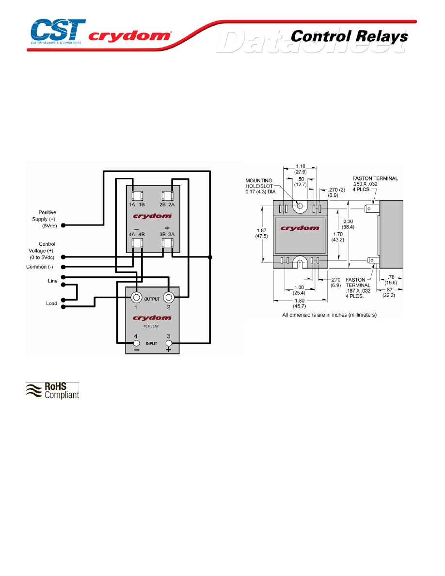
GENERAL NOTES
1) All parameters at 25°C unless otherwise spec ified.
2) Off-State dv/dt test method per EIA/NARM sta ndard RS-443, paragraph 13.11.1
3 ) Heat sinking required (relay only), see derating curves.
AVAILABLE OPTIONS
CPV120 Control Module Only (120 Vac Line)
CPV240 Control Module Only (240 Vac Line)
WIRING DIAGRAM
AGENCY APPROVAL
Rev. 102208
For Conta ct information vis it our web site .
www.crydom.com
© 2008 Cryd om, Inc.
Specifications subject to change without notice.
Courtesy of Steven Engineering, Inc.-230 Ryan Way, South San Francisco, CA 94080-6370-Main Office: (650) 588-9200-Outside Local Area: (800) 258-9200-www.stevenengineering.com
60MAIN-html.html
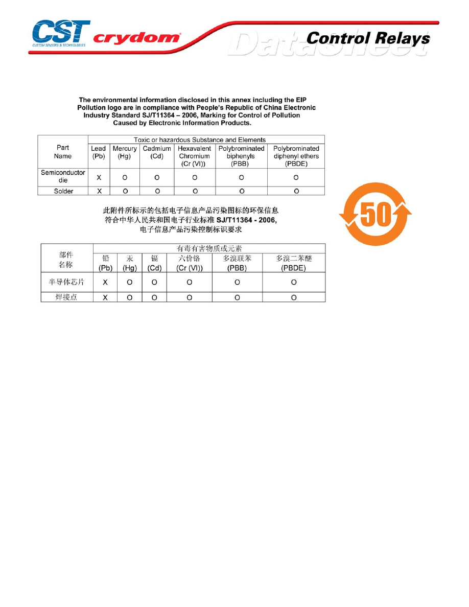
ANNEX - ENVIROMENTAL INFORMATION
For Conta ct information vis it our web site .
www.crydom.com
© 2008 Cryd om, Inc.
Specifications subject to change without notice.
Courtesy of Steven Engineering, Inc.-230 Ryan Way, South San Francisco, CA 94080-6370-Main Office: (650) 588-9200-Outside Local Area: (800) 258-9200-www.stevenengineering.com
60MAIN-html.html
LPCV Series
• Linear proportional controller
• Ratings from 15A to 110A @ 240 VAC
• 0-5 V DC, 0-10 V DC, or 4-20mA input
PRODUCT SELECTION
Description
15 A
25 A
40 A
75 A
110 A
0-5 VDC Control
5LPCV2415
5LPCV2425
5LPCV2440
5LPCV2475
5LPCV24110
0-10 VDC Control
10LPCV2415
10LPCV2425
10LPCV2440
10LPCV2475
10LPCV24110
4-20 VDC Control
20LPCV2415
20LPCV2425
20LPCV2440
20LPCV2475
20LPCV24110
OUTPUT SPECIFICATIONS (voltage) (1)
Description
240 VAC
Operating Voltage (60Hz) [Vrms]
20-300
Transient Overvoltage [Vpk]
600
Maximum Off-State Leakage Current @ Rated Voltage [mArms]
10
Minimum Off-State dv/dt @ Maximum Rated Voltage [V/µsec]
200
OUTPUT SPECIFICATIONS (current) (1)
Description
15 A
25 A
40 A
75 A
110 A
Maximum Load Current [Arms]
15
25
40
75
110
Minimum Load Current [Arms]
0.10
0.10
0.10
0.15
0.20
Maximum Surge Current (16.6ms) [Apk]
150
250
625
1000
1500
Maximum On-State Voltage Drop @ Rated Current [Vpk]
1.6
1.6
1.6
1.6
1.6
Thermal Resistance Junction to Case (Rjc) [°C/W]
1.48
1.02
0.63
0.31
0.28
Maximum I² t for Fusing (8.3 msec) [A² sec]
94
260
1620
4150
9340
Minimum Power Factor (with Maximum Load)
0.5
0.5
0.5
0.5
0.5
INPUT SPECIFICATIONS (1)
Description
5LPCV
10LPCV
20LPCV
Control Voltage Range
0-5 VDC
0-10 VDC
4-20 mA
Control Range Limits (Min/Msx)
-0.5/10 VDC
-1.0/20 VDC
-0.5/25 mA
Turn-On Threshold
0.25 VDC
0.5 VDC
4.5 VDC
Nominal Input Impedance
12.7K Ohm
25 K Ohm
460 Ohm
POWER SUPPLY SPECIFICATION (4)
Description
PS120
PS240
Input Voltage 50/60Hz
120 VAC
240 VAC
Output Voltage 50/60Hz
20 VAC/100mA
20 VAC/100mA
Ambient Operating Temperature Range
-30 to 80°C
-30 to 80°C
Ambient Storage Temperature Range
-40 to 125°C
-40 to 125°C
Terminals
6-32 Screws, .25" Fastons
Screw Torque Requirement
6-32 Screws -10 in lbs.
Weight (typical)
8.6 oz. (245g)
Courtesy of Steven Engineering, Inc.-230 Ryan Way, South San Francisco, CA 94080-6370-Main Office: (650) 588-9200-Outside Local Area: (800) 258-9200-www.stevenengineering.com
60MAIN-html.html
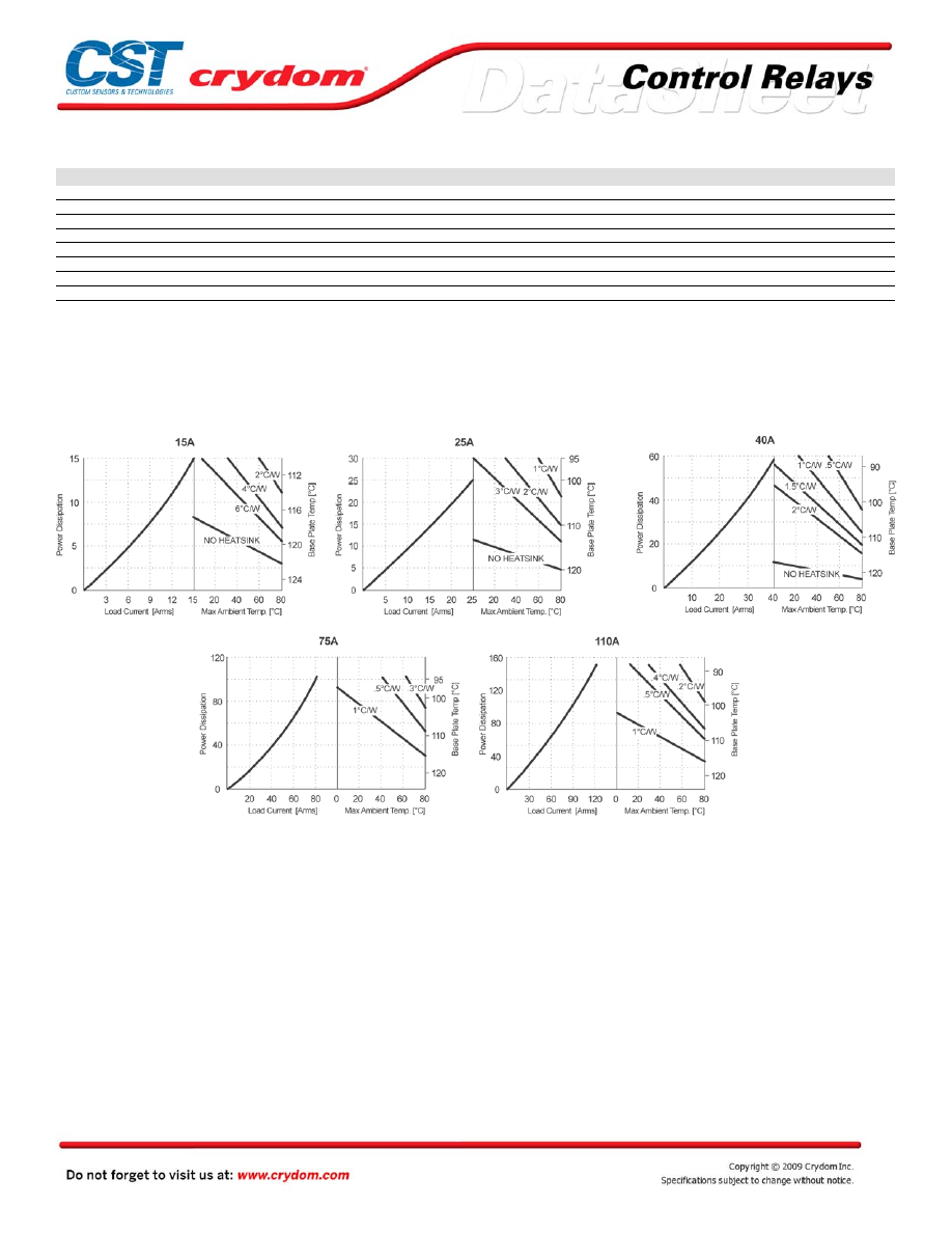
GENERAL SPECIFICATIONS
Description
Dielectric Strength, signal to load
2500 Vrms
Dielectric Strength, signal to Base
2500 Vrms
Ambient Operating Temperature Range
-30 to 80°C
Ambient Storage Temperature Range
-40 to 125°C
Weight (typical)
6.0 oz. (175g)
Encapsulation
Themally Conductive Epoxy
Terminals
8-32 Screws, .25" Fastons
Screw Torque Requirement
8-32 and 10-32 Screws - 20in. lbs.
GENERAL NOTES
1) All parameters at 25°C unless otherwise specified.
2) Linear taper potentiometer 1-10K Ohm, ½ watt.
3) 50Hz models available.
4) 20 VAC must be in phase with load
THERMAL DERATE INFORMATION
TYPICAL APPLICATIONS
• Infrared and quartz heaters • Thermal forming equipment
• Resistive heating elements • Conveyor speed control
• Rectified DC motors • Printing applications
• Industrial temperature controllers
Courtesy of Steven Engineering, Inc.-230 Ryan Way, South San Francisco, CA 94080-6370-Main Office: (650) 588-9200-Outside Local Area: (800) 258-9200-www.stevenengineering.com
60MAIN-html.html
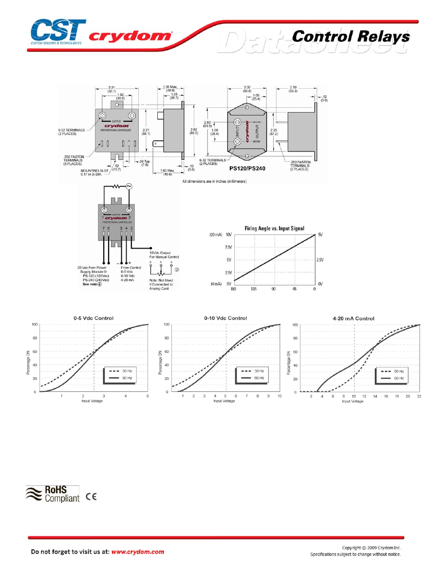
WIRING DIAGRAM
PERCENT VS INPUT VOLTAGE
AGENCY APPROVALS
Rev. 011209
Courtesy of Steven Engineering, Inc.-230 Ryan Way, South San Francisco, CA 94080-6370-Main Office: (650) 588-9200-Outside Local Area: (800) 258-9200-www.stevenengineering.com
60MAIN-html.html
Courtesy of Steven Engineering, Inc.-230 Ryan Way, South San Francisco, CA 94080-6370-Main Office: (650) 588-9200-Outside Local Area: (800) 258-9200-www.stevenengineering.com
60MAIN-html.html
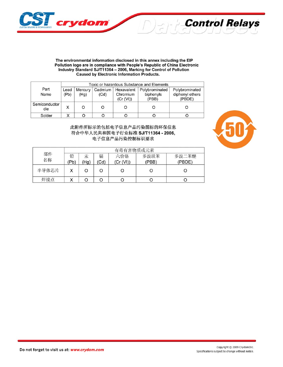
ANNEX - ENVIROMENTAL INFORMATION
Courtesy of Steven Engineering, Inc.-230 Ryan Way, South San Francisco, CA 94080-6370-Main Office: (650) 588-9200-Outside Local Area: (800) 258-9200-www.stevenengineering.com
60MAIN-html.html
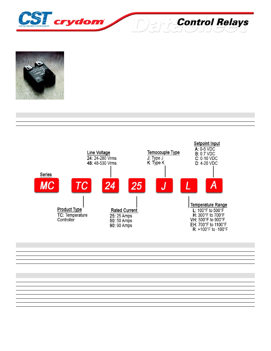
MCTC Series
• Microprocessor based temperature controller / SSR
• Ratings from 25A to 90A @ 48-530 VAC
• Direct J or K thermocouple input
• Voltage or current controlled setpoint
• Separate output enable / disable control
• Open thermocouple protection
• LED status indicators
PRODUCT SELECTION
Description
25 A
50 A
90 A
280 VAC
MCTC2425
MCTC2450
MCTC2490
480 VAC
MCTC4825
MCTC4850
MCTC4890
AVAILABLE OPTIONS
OUTPUT SPECIFICATIONS (voltage)
Description
240 VAC
480 VAC
Operating Voltage (47-63Hz) [Vrms]
24-280
48-530
Transient Overvoltage [Vpk]
600
1200
Maximum Off-State Leakage Current @ Rated Voltage [mArms]
7
12
Minimum Off-State dv/dt @ Maximum Rated Voltage [V/µsec]
200
200
OUTPUT SPECIFICATIONS (current)
Description
25 A
50 A
90 A
Maximum Load Current [Arms]
25
50
90
Minimum Load Current [mArms]
150
150
150
Maximum Surge Current (16.6ms) [Apk]
250
625
1200
Maximum On-State Voltage Drop @ Rated Current [Vpk]
1.6
1.6
1.6
Thermal Resistance Junction to Case (Rjc) [°C/W]
1.02
0.63
0.28
Maximum I 2 t for Fusing (8.3 msec) [A 2 sec]
260
1620
6000
Minimum Power Factor (with Maximum Load)
0.5
0.5
0.5
For Conta ct information vis it our web site .
www.crydom.com
© 2008 Cryd om, Inc.
Specifications subject to change without notice.
Courtesy of Steven Engineering, Inc.-230 Ryan Way, South San Francisco, CA 94080-6370-Main Office: (650) 588-9200-Outside Local Area: (800) 258-9200-www.stevenengineering.com
60MAIN-html.html
INPUT SPECIFICATIONS (1)
Description
DC Control
Control Voltage Range (VDC)
8-32
Input Current Range [mA]
28-30
Nominal Input Impedance [Ohms]
30K
Control Must Operate Voltage "On"[VDC][P3]
5-32
Control Must Release Voltage "Off" [VDC][P3]
0-4
Control Input Current [mA][P3]
0-1.25
PLVI Range Option A [VDC][P4] (2)
0.8-5
PLVI Range Option B [VDC][P4] (2)
1-7
PLVI Range Option C [VDC][P4] (2)
2-10
PLVI Range Option D [VDC][P4] (2)
4-20
Nominal Input Impedance Option A,B,C[ohms][P4]
20K
Nominal Input Impedance Option D [ohms][P4]
220
GENERAL SPECIFICATIONS
Description
Parameters
Dielectric Strength, Input/Output/Base (50/60Hz)
4000 Vrms
Minimum Insulation Resistance (@ 500 V DC)
10
9
Ohm
Maximum Capacitance, Input/Output
10 pF
Ambient Operating Temperature Range
-20 to 80°C
Ambient Storage Temperature Range
-40 to 125 °C
Weight (typical)
3.0 oz (86.5g)
Encapsulation
Thermally conductive Epoxy
Terminals-Power
Screws and Saddle Clamps Furnished, Unmounted
Terminals-Control
Barrier Strip Screw Terminals
Recommended Terminal Screw Torque Range:
8-32 Screws -20 in. lbs.(Screws dry without grase)
OUTPUT STATUS FUNCTIONS
Description
GREEN LED (setpoint)
RED LED (output)
Initial Logic Supply On
Flash Once
Flash Once
Operating (to 85 % of set point)
Off
On
Approaching Setpoint
Off
Variable Flashing
At Setpoint (± 5%)
On
Slow Flashing
Over Setpoint (>5%) (3)
Flashing
Off
Short-Cycle Timing ("R" suffix only)
Flash 2x Intermittently
Off
Open Thermocouple
Flash 3x Intermittently
Off
GENERAL NOTES
1) Voltages are reference to GND (Ground = 0 VDC) P2
2) PLVI voltage can go up to max. supply voltage without damage.
3) Below Setpoint for “R” suffix
For Conta ct information vis it our web site .
www.crydom.com
© 2008 Cryd om, Inc.
Specifications subject to change without notice.
Courtesy of Steven Engineering, Inc.-230 Ryan Way, South San Francisco, CA 94080-6370-Main Office: (650) 588-9200-Outside Local Area: (800) 258-9200-www.stevenengineering.com
60MAIN-html.html
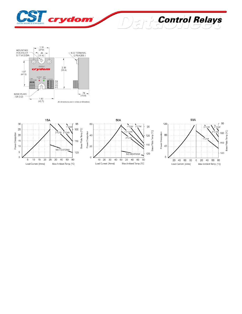
MECHANICAL SPECIFICATIONS
THERMAL DERATE INFORMATION
For Conta ct information vis it our web site .
www.crydom.com
© 2008 Cryd om, Inc.
Specifications subject to change without notice.
Courtesy of Steven Engineering, Inc.-230 Ryan Way, South San Francisco, CA 94080-6370-Main Office: (650) 588-9200-Outside Local Area: (800) 258-9200-www.stevenengineering.com
60MAIN-html.html
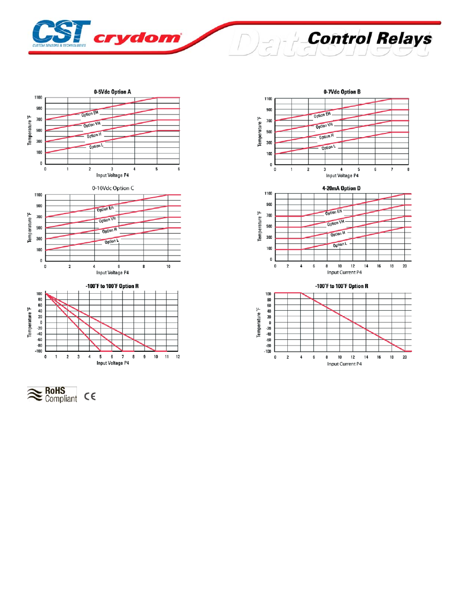
TEMPERATURE VS SETPOINT INPUT P4
AGENCY APPROVALS
UL
E116949
Rev.
103108
For Conta ct information vis it our web site .
www.crydom.com
© 2008 Cryd om, Inc.
Specifications subject to change without notice.
Courtesy of Steven Engineering, Inc.-230 Ryan Way, South San Francisco, CA 94080-6370-Main Office: (650) 588-9200-Outside Local Area: (800) 258-9200-www.stevenengineering.com
60MAIN-html.html

ANNEX - ENVIROMENTAL INFORMATION
For Conta ct information vis it our web site .
www.crydom.com
© 2008 Cryd om, Inc.
Specifications subject to change without notice.
Courtesy of Steven Engineering, Inc.-230 Ryan Way, South San Francisco, CA 94080-6370-Main Office: (650) 588-9200-Outside Local Area: (800) 258-9200-www.stevenengineering.com
60MAIN-html.html
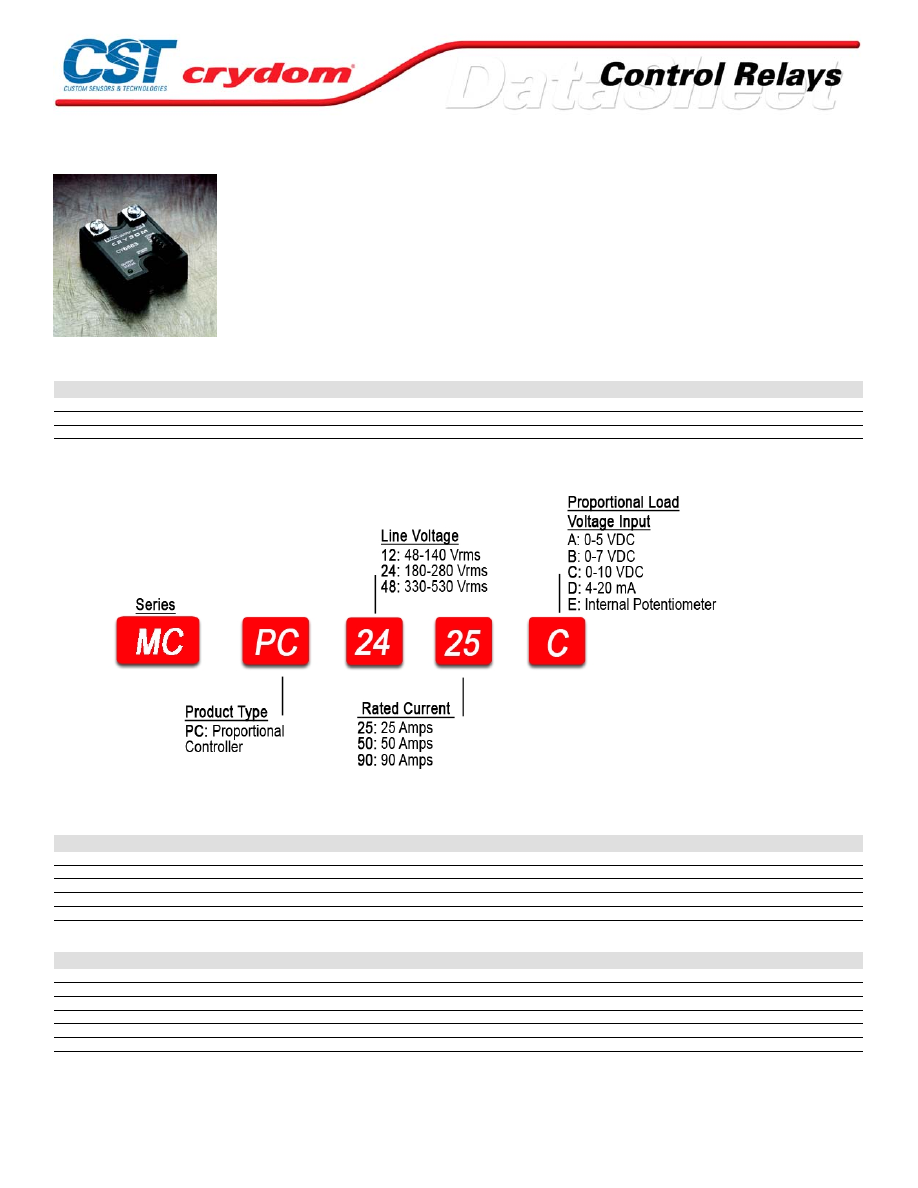
MCPC Series
• Microprocessor based burst-fire controller / SSR
• Ratings from 25A to 90A @ 48-530 VAC
• Low-voltage, current, or potentiometer control
• Output status indicator
• Separate output enable / disable control
• Two time-base periods available
PRODUCT SELECTION
Description
25 A
50 A
90 A
40-140 VAC
MCPC1225
MCPC1250
MCPC1290
180-280 VAC
MCPC2425
MCPC2450
MCPC2490
330-530 VAC
MCPC4825
MCPC4850
MCPC4890
AVAILABLE OPTIONS
OUTPUT SPECIFICATIONS (voltage)
Description
120 VAC
240 VAC
480 VAC
Operating Voltage (47-63Hz) [Vrms]
48-140
180-280
300-530
Transient Overvoltage [Vpk]
400
600
1200
Maximum Off-State Leakage Current @ Rated Voltage [mArms]
5
7
12
Minimum Off-State dv/dt @ Maximum Rated Voltage [V/µsec] (2)
200
200
200
Minimum Power Factor (with Maximum Load)
0.5
0.5
0.5
OUTPUT SPECIFICATIONS (current)
Description
25A
50A
90A
Maximum Load Current (3) [Arms]
25
50
90
Minimum Load Current [mArms]
150
150
150
Maximum Surge Current (16.6ms) [Apk]
250
625
1200
Maximum On-State Voltage Drop @ Rated Current [Vpk]
1.6
1.6
1.6
Thermal Resistance Junction to Case (Rjc) [°C/W]
1.02
0.63
0.28
Maximum I²t for Fusing (8.3 msec) [A²sec]
260
1620
6000
For Conta ct information vis it our web site .
www.crydom.com
© 2008 Cryd om, Inc.
Specifications subject to change without notice.
Courtesy of Steven Engineering, Inc.-230 Ryan Way, South San Francisco, CA 94080-6370-Main Office: (650) 588-9200-Outside Local Area: (800) 258-9200-www.stevenengineering.com
60MAIN-html.html

INPUT SPECIFICATIONS (1)
Description
DC Control
Control Voltage Range (VDC)
8-32
Input Current Range [mA]
28-30
Nominal Input Impedance [Ohms]
30K
Control Must Operate Voltage "On"[VDC][P3]
5-32
Control Must Release Voltage "Off" [VDC][P3]
0-4
Control Input Current [mA][P3]
0-1.25
PLVI Range Option A [VDC][P4] (2)
0.8-5
PLVI Range Option B [VDC][P4] (2)
1-7
PLVI Range Option C [VDC][P4] (2)
2-10
PLVI Range Option D [VDC][P4] (2)
4-20
Nominal Input Impedance Option A,B,C[ohms][P4]
20K
Nominal Input Impedance Option D [ohms][P4]
220
OUTPUT STATUS FUNCTIONS
Conditions
LED
Initial Logic Supply On
Flash Once
Load Voltage Missing / Load Open (w/control disabled)
Flash Once Intermittenly
Load Voltage Missing / Load Open (w/control enabled))
Flash Twice Intermittently
Analog Input < Threshold
Off
Analog Input < Threshold < max
Varying Brightness
Analog Input > max
On, Bright
GENERAL SPECIFICATIONS
Description
Parameters
Dielectric Strength, Input/Output/Base (50/60Hz)
4000 Vrms
Minimum Insulation Resistance (@ 500 V DC)
10
9
Ohm
Maximum Capacitance, Input/Output
10 pF
Ambient Operating Temperature Range
-20 to 80°C
Ambient Storage Temperature Range
-40 to 125 °C
Weight (typical)
3.0 oz (86.5g)
Encapsulation
Thermally conductive Epoxy
Terminals-Power
Screws and Saddle Clamps Furnished, Unmounted
Terminals-Control
Barrier Strip Screw Terminals
Recommended Terminal Screw Torque Range:
8-32 Screws -20 in. lbs.(Screws dry without grase)
GENERAL NOTES
1) Voltages are reference to GND (Ground = 0 VDC) P2
2) PLVI voltage can go up to max. supply voltage without damage
For Conta ct information vis it our web site .
www.crydom.com
© 2008 Cryd om, Inc.
Specifications subject to change without notice.
Courtesy of Steven Engineering, Inc.-230 Ryan Way, South San Francisco, CA 94080-6370-Main Office: (650) 588-9200-Outside Local Area: (800) 258-9200-www.stevenengineering.com
60MAIN-html.html
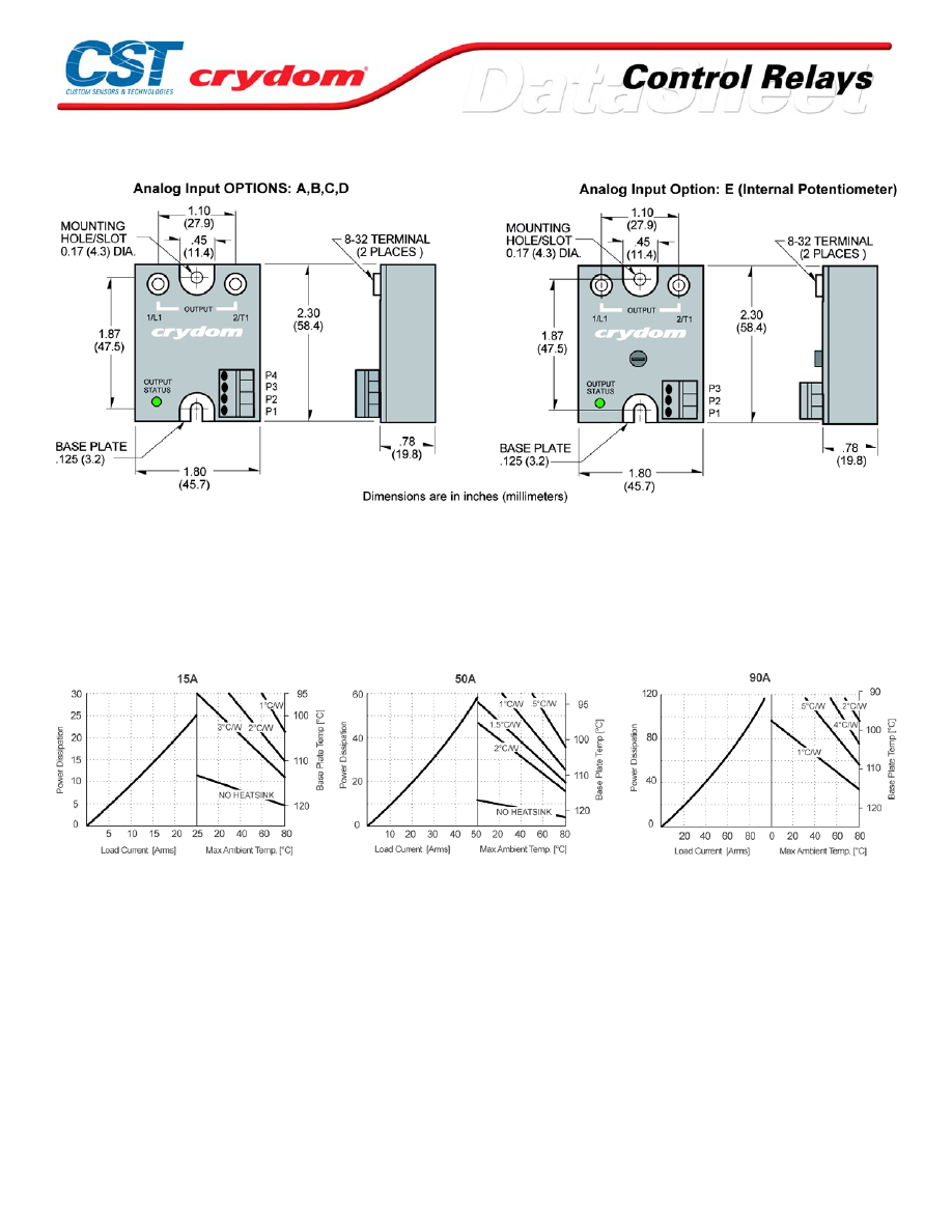
MECHANICAL SPECIFICATIONS
THERMAL DERATE INFORMATION
For Conta ct information vis it our web site .
www.crydom.com
© 2008 Cryd om, Inc.
Specifications subject to change without notice.
Courtesy of Steven Engineering, Inc.-230 Ryan Way, South San Francisco, CA 94080-6370-Main Office: (650) 588-9200-Outside Local Area: (800) 258-9200-www.stevenengineering.com
60MAIN-html.html
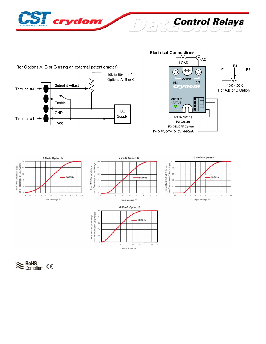
WIRING DIAGRAM
OUTPUT VS ANALOG INPUT SIGNAL CURVES
AGENCY APPROVALS
UL E116949
Rev. 102208
For Conta ct information vis it our web site .
www.crydom.com
© 2008 Cryd om, Inc.
Specifications subject to change without notice.
Courtesy of Steven Engineering, Inc.-230 Ryan Way, South San Francisco, CA 94080-6370-Main Office: (650) 588-9200-Outside Local Area: (800) 258-9200-www.stevenengineering.com
60MAIN-html.html

For Conta ct information vis it our web site .
www.crydom.com
© 2008 Cryd om, Inc.
Specifications subject to change without notice.
Courtesy of Steven Engineering, Inc.-230 Ryan Way, South San Francisco, CA 94080-6370-Main Office: (650) 588-9200-Outside Local Area: (800) 258-9200-www.stevenengineering.com
60MAIN-html.html

ANNEX - ENVIROMENTAL INFORMATION
For Conta ct information vis it our web site .
www.crydom.com
© 2008 Cryd om, Inc.
Specifications subject to change without notice.
Courtesy of Steven Engineering, Inc.-230 Ryan Way, South San Francisco, CA 94080-6370-Main Office: (650) 588-9200-Outside Local Area: (800) 258-9200-www.stevenengineering.com
60MAIN-html.html
RPC Series
• Proportional controller
• Ratings from 15A to 40A @ 480 VAC
• 500k or 1M Ohm potentiometer control
PRODUCT SELECTION
Description
15 A
25 A
40 A
120 VAC
RPC1215
RPC1225
RPC1240
240 VAC
RPC2415
RPC2425
RPC2440
480 VAC
RPC4815
RPC4825
RPC4840
OUTPUT SPECIFICATIONS (voltage) (1)
Description
120 VAC
240 VAC
480 VAC
Operating Voltage (47-63Hz) [Vrms]
90-130
200-240
400-480
Transient Overvoltage [Vpk]
400
600
1200
Maximum Off-State Leakage Current @ Rated Voltage [mArms]
10
7
3
Minimum Off-State dv/dt @ Maximum Rated Voltage [V/µsec] (2)
5000
500
500
Snubber (Internal)
yes
yes
no
OUTPUT SPECIFICATIONS (current) (1)
Description
15 A
25 A
40 A
Maximum Load Current [Arms] (3)
15
25
40
Minimum Load Current [mArms]
70
80
90
Maximum Surge Current (16.6ms) [Apk]
150
250
625
Maximum On-State Voltage Drop @ Rated Current [Vpk]
1.6
1.6
1.6
Thermal Resistance Junction to Case (Rjc) [°C/W]
1.48
1.02
0.63
Maximum I²t for Fusing (8.3 msec) [A² sec]
94
260
1620
INPUT SPECIFICATIONS (1)
Description
120 VAC
240 VAC
480 VAC
Variable Resistor Size (4)
150K (1W)
1M (1/2W)
1M (1/2W)
GENERAL SPECIFICATIONS
Description
Minimum Power Factor (with Maximum Load)
0.6
Dielectric Strength, Input/Output/Base (50/60Hz)
2500 Vrms
Ambient Operating Temperature Range
-30 to 80 °C
Ambient Storage Temperature Range
-40 to 125 °C
Weight (typical)
3.2 oz (90g)
Encapsulation
Thermally conductive Epoxy
Terminals
Screws and saddle Clamps Furnished, Unmounted
Recommended Terminal Screw Torque Range:
6-32 Screws -10 in lbs.
8-32 and 10-32 Screws -20 in. lbs.
(Screws dry without grase)
GENERAL NOTES
1) All parameters at 25°C unless otherwise specified. 3) Heat sinking required, see derating curves.
2) Off-State dv/dt test method per EIA/NARM standard RS-443 4) Potentiometer should be line voltage rated.
For Conta ct information vis it our web site .
www.crydom.com
© 2008 Cryd om, Inc.
Specifications subject to change without notice.
Courtesy of Steven Engineering, Inc.-230 Ryan Way, South San Francisco, CA 94080-6370-Main Office: (650) 588-9200-Outside Local Area: (800) 258-9200-www.stevenengineering.com
60MAIN-html.html
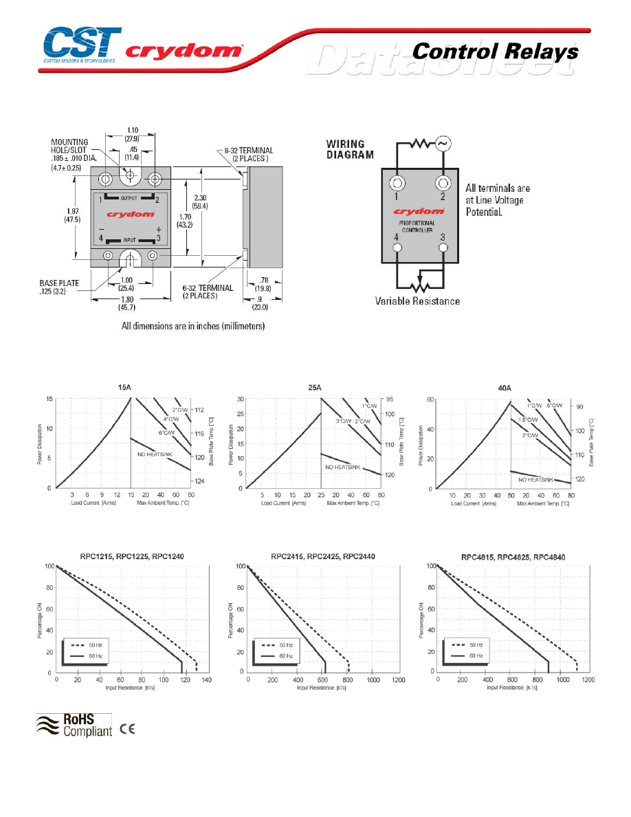
MECHANICAL SPECIFICATIONS
THERMAL DERATE INFORMATION
PERCENTAGE ON VS INPUT RESISTANCE
AGENCY APPROVALS
Rev.
102408
For Conta ct information vis it our web site .
www.crydom.com
© 2008 Cryd om, Inc.
Specifications subject to change without notice.
Courtesy of Steven Engineering, Inc.-230 Ryan Way, South San Francisco, CA 94080-6370-Main Office: (650) 588-9200-Outside Local Area: (800) 258-9200-www.stevenengineering.com
60MAIN-html.html
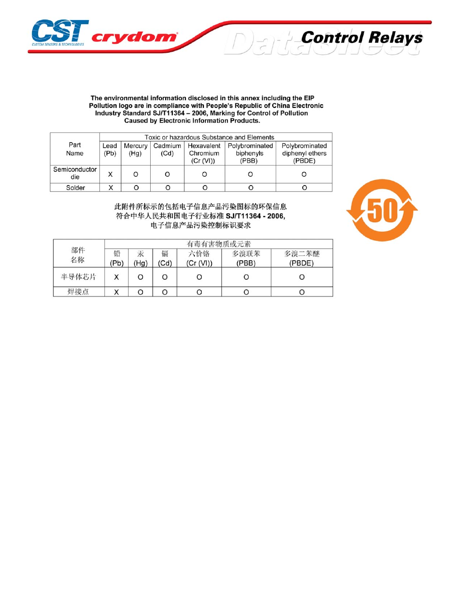
ANNEX - ENVIROMENTAL INFORMATION
For Conta ct information vis it our web site .
www.crydom.com
© 2008 Cryd om, Inc.
Specifications subject to change without notice.
Courtesy of Steven Engineering, Inc.-230 Ryan Way, South San Francisco, CA 94080-6370-Main Office: (650) 588-9200-Outside Local Area: (800) 258-9200-www.stevenengineering.com
60MAIN-html.html
DSD / DLD Series
• Time-delay solid-state relays
• Ratings from 10A to 50A @ 240 VAC
• External time adjustment
• DC control
• Zero-crossing (resistive loads) output
• Ideal for compressor applications
PRODUCT SELECTION
Description
10 A
25 A
50 A
3.5-15 VDC Control
DSD2410
DSD2425
DSD2450
3.5-15 VDC Control
DLD2410
DLD2425
DLD2450
OUTPUT SPECIFICATIONS (voltage) (1)
Description
Operating Voltage (47-63Hz) [Vrms]
48-280
Transient Overvoltage [Vpk]
600
Maximum Off-State Leakage Current @ Rated Voltage [mArms]
10
Minimum Off-State dv/dt @ Maximum Rated Voltage [V/µsec] (2)
500
OUTPUT SPECIFICATIONS (current) (1)
Description
10 A
25 A
50 A
Maximum Load Current (3) [Arms]
10
25
50
Minimum Load Current (3) [Arms]
0.04
0.04
0.04
Maximum Surge Current (16.6ms) [Apk]
120
250
625
Maximum On-State Voltage Drop @ Rated Current [Vpk]
1.6
1.6
1.6
Thermal Resistance Junction to Case (Rjc) [°C/W]
1.48
1.02
0.63
Maximum I²t for Fusing (8.3 msec) [A²sec]
60
260
1620
Minimum Power Factor (with Maximum Load)
0.5
0.5
0.5
INPUT SPECIFICATIONS (1)
Description
DC Control
Control Voltage Range
3.5-15 VDC
Maximum Turn-On Voltage
3.5 VDC
Maximum Turn-Off Voltage
1.0 VDC
Typical Input Current
3.4 mA @ 5 Vdc, 11.4 mA @ 15 Vdc
Nominal Input Impedance
1500 Ohm
Maximum Turn-On Time [msec] (4)
Adlustable, See Table
Maximum Turn-Off Time [msec]
1/2 Cycle
Maximum Reset Time [µsec] (5)
100
TYPICAL TURN-ON DELAY
Resistor
Time DSD
Time DLD
0 (Short)
.10 sec
1.6 sec
10K
.19 sec
3.1 sec
100K
.94 sec
15 sec
470K
4.0 sec
64 sec
1.0M (4)
8.3 sec
133 sec
For Conta ct information vis it our web site .
www.crydom.com
© 2008 Cryd om, Inc.
Specifications subject to change without notice.
Courtesy of Steven Engineering, Inc.-230 Ryan Way, South San Francisco, CA 94080-6370-Main Office: (650) 588-9200-Outside Local Area: (800) 258-9200-www.stevenengineering.com
60MAIN-html.html
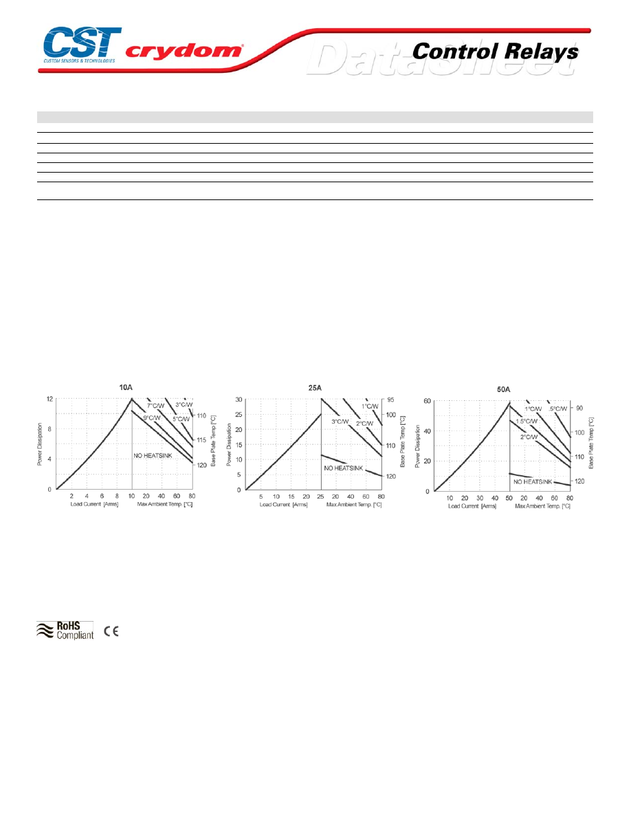
GENERAL SPECIFICATIONS
Description
Parameters
Dielectric Strength, Input/Output/Base (50/60Hz)
4000 Vrms
Minimum Insulation Resistance (@ 500 V DC)
10
10
Ohm
Ambient Operating Temperature Range
-30 to 80°C
Ambient Storage Temperature Range
-40 to 125°C
Weight (typical)
3.0 oz. (43g)
Encapsulation
Themally Conductive Epoxy
Terminals
Screws and saddle Clamps
Furnished, Unmounted
GENERAL NOTES
1) All parameters at 25°C unless otherwise specified.
2) Off-State dv/dt test method per EIA/NARM standard RS-443, paragraph 13.11.1
3) Heat sinking required, see derating curves.
4) Timing Resist or may be as high as 10M Ohm with performance dependent on resistor quality
5) Before and after time-out.
THERMAL DERATE INFORMATION
AGENCY APPROVALS
UL
E116949
Rev.
102708
For Conta ct information vis it our web site .
www.crydom.com
© 2008 Cryd om, Inc.
Specifications subject to change without notice.
Courtesy of Steven Engineering, Inc.-230 Ryan Way, South San Francisco, CA 94080-6370-Main Office: (650) 588-9200-Outside Local Area: (800) 258-9200-www.stevenengineering.com
60MAIN-html.html

ANNEX - ENVIROMENTAL INFORMATION
For Conta ct information vis it our web site .
www.crydom.com
© 2008 Cryd om, Inc.
Specifications subject to change without notice.
Courtesy of Steven Engineering, Inc.-230 Ryan Way, South San Francisco, CA 94080-6370-Main Office: (650) 588-9200-Outside Local Area: (800) 258-9200-www.stevenengineering.com
60MAIN-html.html

1RHP Series
•
Combined SSR and EMR advantages
•
Lifetime > 5 million operations full load
•
No heat sink required
• Input status LED indicator
•
Quiet Operation
•
17.5 mm DIN rail mount
•
UL/cUL Listed, CE & RoHS Compliant
• US Patent No. 6,347,024 B1
PRODUCT SELECTION
Control Voltage
4-32 VDC
1RHP2520D32
90-250 VAC
1RHP2520A
OUTPUT SPECIFICATIONS (1)
Description
Operating Voltage (47-63Hz) [Vrms]
90-250
Maximum Load Current [Arms] (Resistive Load
Only)
20
Minimum Current [mArms]
100
Maximum Off-State Leakage Current [mArms]
5
INPUT SPECIFICATIONS (1)
Description
DC
AC
Control Voltage Range
4-32 VDC
90-250 VAC
Maximum Input Current [mA]
30
4.85
Minimum Input Current
2.3
1.65
Drop out Voltage
1 VDC
46 VAC
GENERAL SPECIFICATIONS (1)
Description
Parameters
Contacts
N.O.
Ambient Operating Temperature Range
-5 to 70°C
Ambient Storage Temperature Range
-40 to 85°C
Maximum Turn-On Time 50/60 Hz [msec]
20 / 16.6
Maximum Turn-Off Time 50/60 Hz [msec]
40 / 32
Maximum Number of Operations
20/min
Lifetime Number of Operations
>5 Million
Torque
8.85 in lb (1 Nm) max
Acoustic noise ON position
<35 db @ 3.2 ft (1m)
Acoustic noise switching
<50 db @ 1.6 ft (0.5m) max
Weight (typical)
70 gr
Terminal capacity
2x AWG 14 (1.5mm²) with ferrule:2 x AWG 12 (2.5mm²)
without ferrule
GENERAL NOTES
1) Specif ications @ 25°C unless othe rwise no ted.
Courtesy of Steven Engineering, Inc.-230 Ryan Way, South San Francisco, CA 94080-6370-Main Office: (650) 588-9200-Outside Local Area: (800) 258-9200-www.stevenengineering.com
60MAIN-html.html
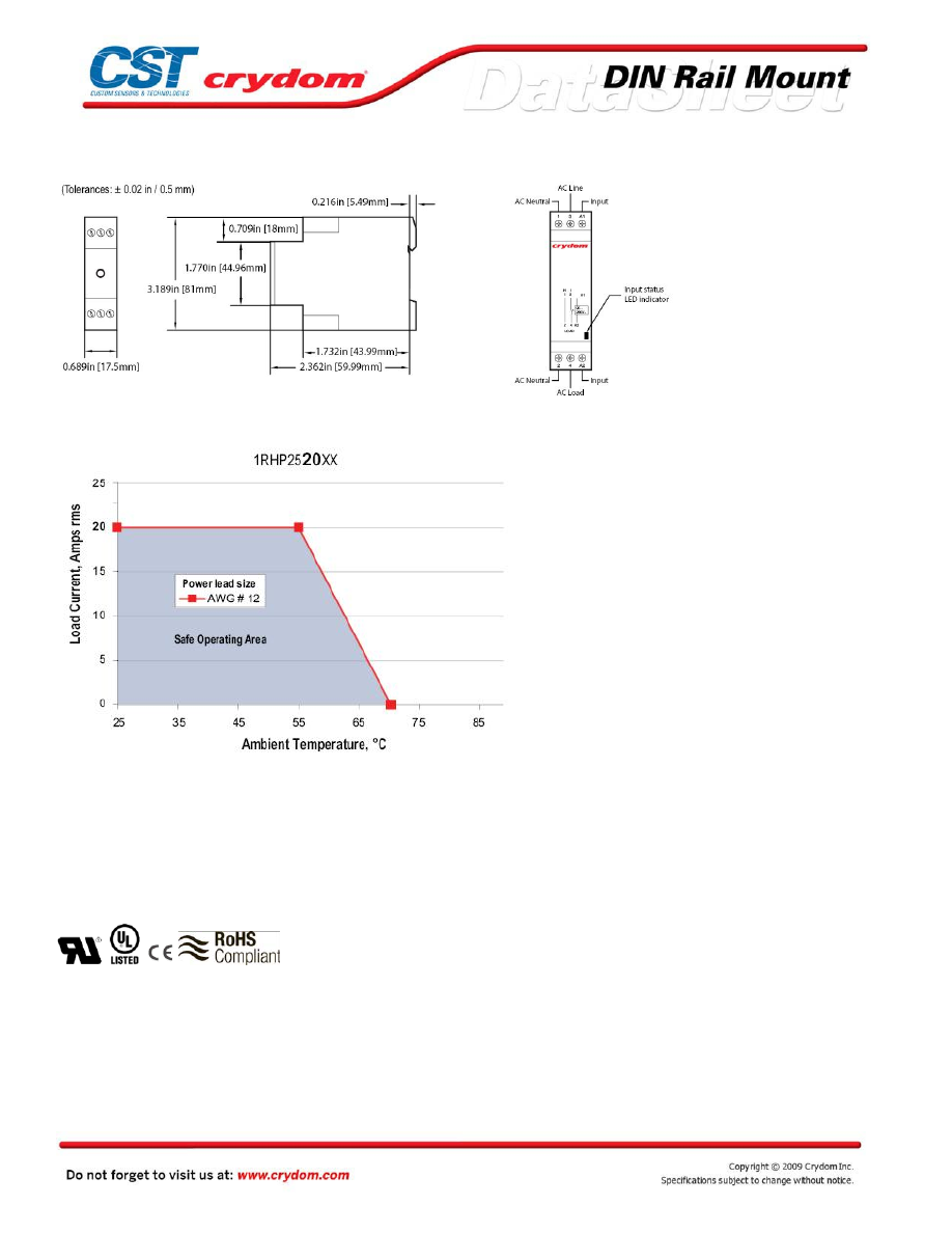
MECHANICAL SPECIFICATIONS
THERMAL DERATE INFORMATION
AGENCY APPROVALS
IEC 60947-4-3 (Industrial environment)
IEC 60669-2-1 (Household environment)
IEC 60601-1-1 (Medical environment)
IEC 60947-7-1 (Connections in industrial environment)
IEC 60998-2-1 (Connections in household environment)
Rev.
1210808
Courtesy of Steven Engineering, Inc.-230 Ryan Way, South San Francisco, CA 94080-6370-Main Office: (650) 588-9200-Outside Local Area: (800) 258-9200-www.stevenengineering.com
60MAIN-html.html
Courtesy of Steven Engineering, Inc.-230 Ryan Way, South San Francisco, CA 94080-6370-Main Office: (650) 588-9200-Outside Local Area: (800) 258-9200-www.stevenengineering.com
60MAIN-html.html
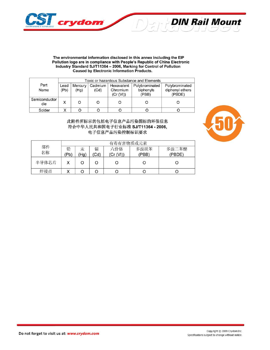
ANNEX - ENVIROMENTAL INFORMATION
Courtesy of Steven Engineering, Inc.-230 Ryan Way, South San Francisco, CA 94080-6370-Main Office: (650) 588-9200-Outside Local Area: (800) 258-9200-www.stevenengineering.com
60MAIN-html.html
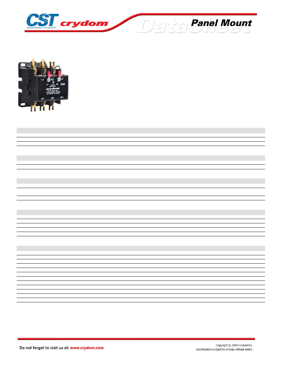
3RHP Series AC Control
• 40 and 50A output
• Voltage ratings to 600 VAC
• Lifetime 2 million operations at full load
• LED input status indicator
• Wire, lug or quick connect termination
• Industry Standard DP contactor mounting
PRODUCT SELECTION
Control Voltage
40A 280 VAC
50A 280 VAC
40A 600 VAC
50A 600 VAC
20-26 VAC
3RHP2840E
3RHP2850E
3RHP6040E
3RHP6050E
100-130 VAC
3RHP2840F
3RHP2850F
3RHP6040F
3RHP6050F
208-240 VAC
3RHP2840G
3RHP2850G
3RHP6040G
3RHP6050G
OUTPUT SPECIFICATIONS (voltage)
Description
280 VAC
600 VAC
Operating Voltage (47-63Hz) [Vrms]
24-280
48-600
Maximum Off-State Leakage Current per channel
0.05 mA @ 240 VAC
0.06 mA @ 480 VAC
OUTPUT SPECIFICATIONS (current)
Description
40A
50A
Maximum Load Current per phase @ 40°C [Arms] (1)
40A Resistive / 30A Inductive
50A Resistive / 40A Inductive
Power terminals
1/4" Quick Connect and 10x32 binder
head screws
1/4" Quick Connect and box lugs
Wire Size
8-14 AWG
6-14 AWG
INPUT SPECIFICATIONS
Description
SUFIX E
SUFIX F
SUFIX G
Coil Voltage [50/60 Hz]
20-26 VAC
100-130 VAC
208-240 VAC
Min. Turn-On Voltage
20 VAC
100 VAC
208 VAC
Min. Turn-Off Voltage
12 VAC
24 VAC
48 VAC
Coil Power Consumption, inrush.
56 VA @ 220 VAC
56 VA @ 220 VAC
56 VA @ 220 VAC
Coil Power Consumption, sealed.
6.6 VA @ 220 VAC
6.6 VA @ 220 VAC
6.6 VA @ 220 VAC
GENERAL SPECIFICATIONS
Description
Parameters
Dielectric Strength, Input to Output
4000 Vrms
Dielectric Strength, Input/Output to ground
2500 Vrms
Contacts (2)
Three Normally Open
Ambient Operating Temperature Range (3)
-20 to 65 °C
Ambient Storage Temperature Range
-40 to 100 °C
Max. Turn-On Time 50/60 Hz
20 ms / 16.6 ms
Max. Turn-Off Time 50/60Hz
40 ms / 32 ms
Maximum Number of Operations
30 per Minute
Lifetime Number of Operations @ Rated Current (4)
> 2 Million
Weight (typical)
1.19 lbs (540 g)
Screw Torque (input/Output) 40A
10 in lb (1.13 Nm) / 18 in lb (2.1 Nm)
Screw Torque (input/Output) 50A
10 in lb (1.13 Nm) / 25 in lb (2.9 Nm)
GENERAL NOTES
(1) See Derating curves for additional operating conditions.
(2) The R HP includes a Solid Stat e Relay, therefore electrical isolation is not provided.
(3) The R HP includes over temperature protection for the solid state relay.
(4) 40°C ambient temperature, 30 operations/min, maximum voltage control.
Courtesy of Steven Engineering, Inc.-230 Ryan Way, South San Francisco, CA 94080-6370-Main Office: (650) 588-9200-Outside Local Area: (800) 258-9200-www.stevenengineering.com
60MAIN-html.html

MECHANICAL SPECIFICATIONS
THERMAL DERATE INFORMATION
Courtesy of Steven Engineering, Inc.-230 Ryan Way, South San Francisco, CA 94080-6370-Main Office: (650) 588-9200-Outside Local Area: (800) 258-9200-www.stevenengineering.com
60MAIN-html.html
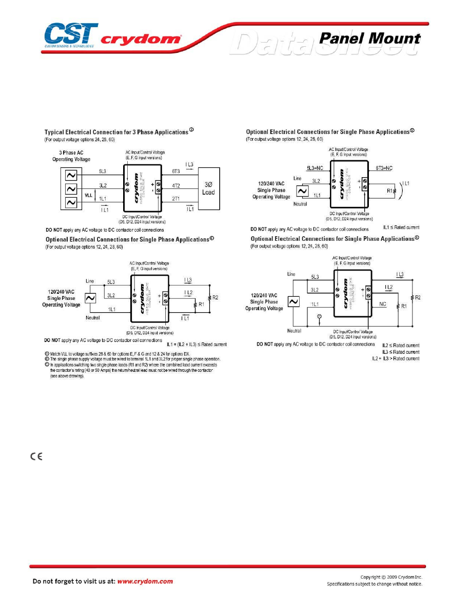
TYPICAL ELECTRICAL CONNECTIONS
AGENCY APPROVALS
UL/ cUL
Rev. 011409
Courtesy of Steven Engineering, Inc.-230 Ryan Way, South San Francisco, CA 94080-6370-Main Office: (650) 588-9200-Outside Local Area: (800) 258-9200-www.stevenengineering.com
60MAIN-html.html
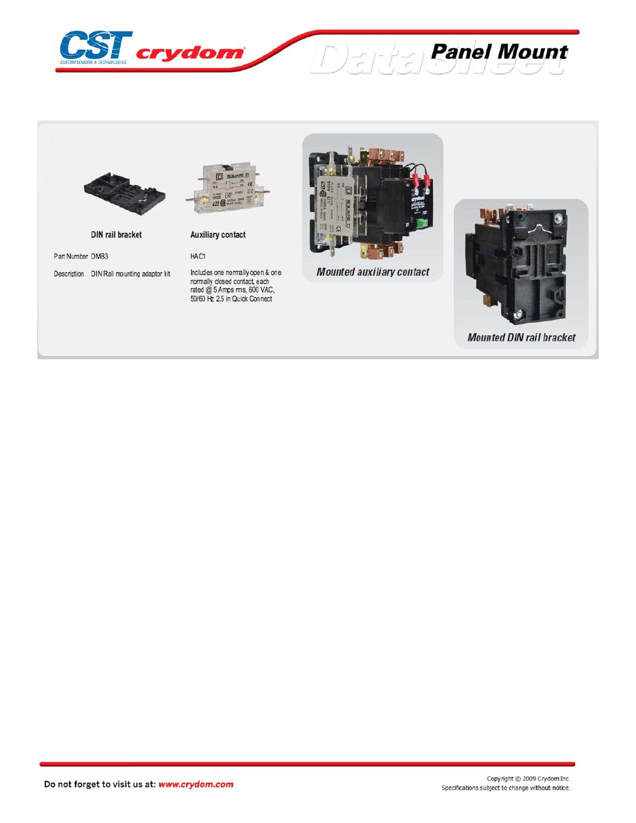
ACCESSORIES
Courtesy of Steven Engineering, Inc.-230 Ryan Way, South San Francisco, CA 94080-6370-Main Office: (650) 588-9200-Outside Local Area: (800) 258-9200-www.stevenengineering.com
60MAIN-html.html
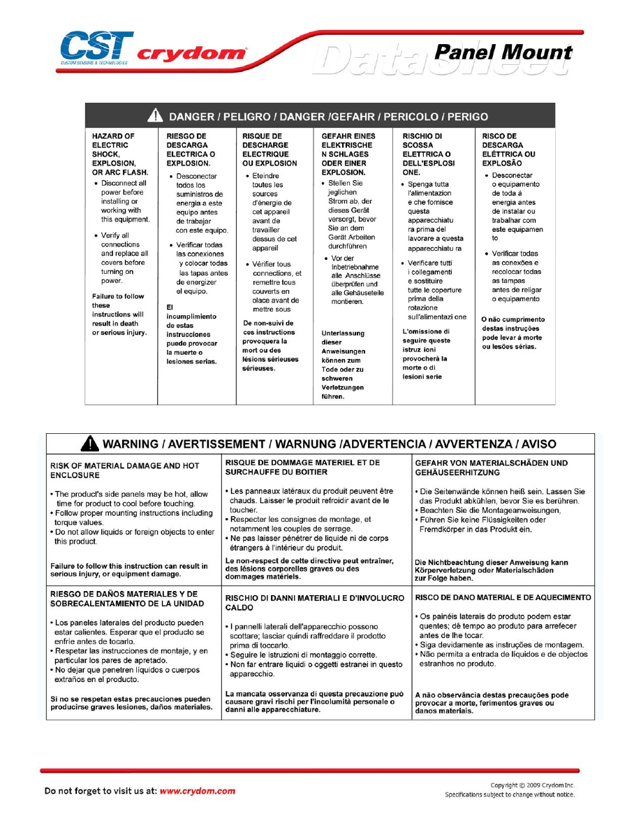
Courtesy of Steven Engineering, Inc.-230 Ryan Way, South San Francisco, CA 94080-6370-Main Office: (650) 588-9200-Outside Local Area: (800) 258-9200-www.stevenengineering.com
60MAIN-html.html
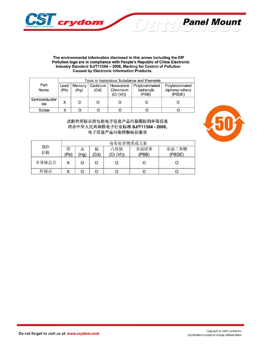
ANNEX - ENVIROMENTAL INFORMATION
Courtesy of Steven Engineering, Inc.-230 Ryan Way, South San Francisco, CA 94080-6370-Main Office: (650) 588-9200-Outside Local Area: (800) 258-9200-www.stevenengineering.com
60MAIN-html.html
3RHP Series DC Control
• 40 and 50A output
• Voltage ratings to 240 VAC
• Lifetime 2 million operations at full load
• LED input status indicator
• Wire, lug or quick connect termination
• Industry Standard DP contactor mounting
PRODUCT SELECTION
Control Voltage
40A 120 VAC
50A 120 VAC
40A 240 VAC
50A 240 VAC
4.5-5.5 VDC
3RHP1240D5
3RHP1250D5
3RHP2440D5
3RHP2450D5
10-15 VDC
3RHP1240D12
3RHP1250D12
3RHP2440D12
3RHP2450D12
22-27 VDC
3RHP1240D24
3RHP1250D24
3RHP2440D24
3RHP2450D24
OUTPUT SPECIFICATIONS (voltage)
Description
120 VAC
240 VAC
Operating Voltage (47-63Hz) [Vrms]
100-120
208-240
Maximum Off-State Leakage Current per channel
0.05 mA @ 120 VAC
0.06 mA @ 240 VAC
OUTPUT SPECIFICATIONS (current)
Description
40A
50A
Maximum Load Current per phase @ 40°C [Arms] (1)
40A Resistive / 30A Inductive
50A Resistive / 40A Inductive
Power terminals
1/4" Quick Connect and 10x32 binder
head screws
1/4" Quick Connect and box lugs
Wire Size
8-14 AWG
6-14 AWG
INPUT SPECIFICATIONS
Description
SUFIX D5
SUFIX D12
SUFIX D24
Coil Voltage
4.5-5.5 VDC
10-15 VDC
22-27 VDC
Max. Reverse Voltage
-5.5 VDC
-15.5 VDC
-27.5 VDC
Input Current
12mA @ 5 VDC
12mA @ 12 VDC
12mA @ 24 VDC
Min. Turn-On Voltage
4.5 VDC
9.5 VDC
9.5 VDC
Min. Turn-Off Voltage
1 VDC
2 VDC
2 VDC
GENERAL SPECIFICATIONS
Description
Parameters
Dielectric Strength, Input to Output
4000 Vrms
Dielectric Strength, Input/Output to ground
2500 Vrms
Contacts (2)
Three Normally Open
Ambient Operating Temperature Range (3)
-20 to 75 °C
Ambient Storage Temperature Range
-40 to 100 °C
Max. Turn-On Time 50/60 Hz
20 ms / 16.6 ms
Max. Turn-Off Time 50/60Hz
40 ms / 32 ms
Maximum Number of Operations
30 per Minute
Lifetime Number of Operations @ Rated Current (4)
> 2 Million
Weight (typical)
1.19 lbs (540 g)
Screw Torque (input/Output) 40A
5.31 in lb (0.6 Nm) / 18 in lb (2.1 Nm)
Screw Torque (input/Output) 50A
5.31 in lb (0.6 Nm) / 25 in lb (2.9 Nm)
GENERAL NOTES
(1) See Derating curves for additional operating conditions.
(2) The R HP includes a Solid State Relay, therefore electrical isolation is not provided.
(3) The R HP includes over temperature protection for the solid state relay.
(4) 40°C ambient temperature, 30 operations/min, maximum voltage control.
Courtesy of Steven Engineering, Inc.-230 Ryan Way, South San Francisco, CA 94080-6370-Main Office: (650) 588-9200-Outside Local Area: (800) 258-9200-www.stevenengineering.com
60MAIN-html.html
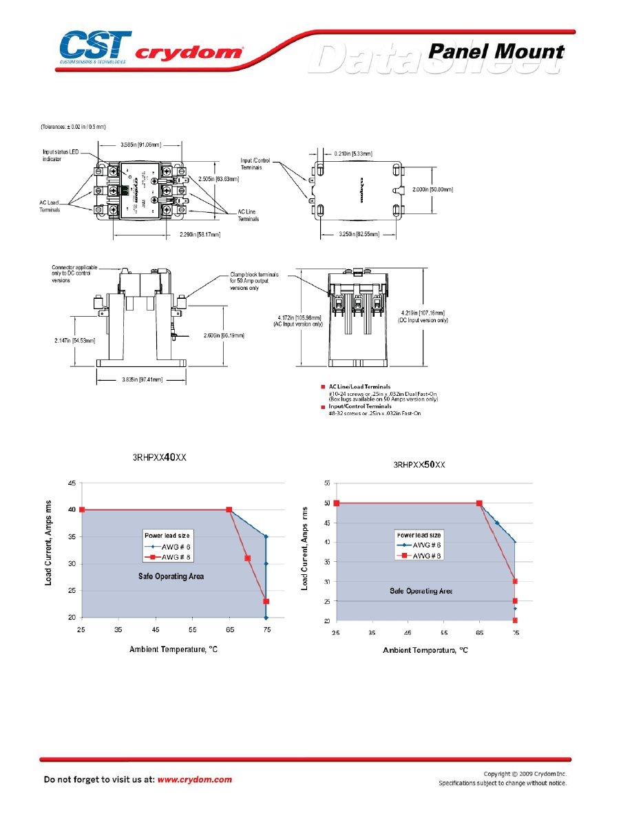
MECHANICAL SPECIFICATIONS
THERMAL DERATE INFORMATION
Courtesy of Steven Engineering, Inc.-230 Ryan Way, South San Francisco, CA 94080-6370-Main Office: (650) 588-9200-Outside Local Area: (800) 258-9200-www.stevenengineering.com
60MAIN-html.html
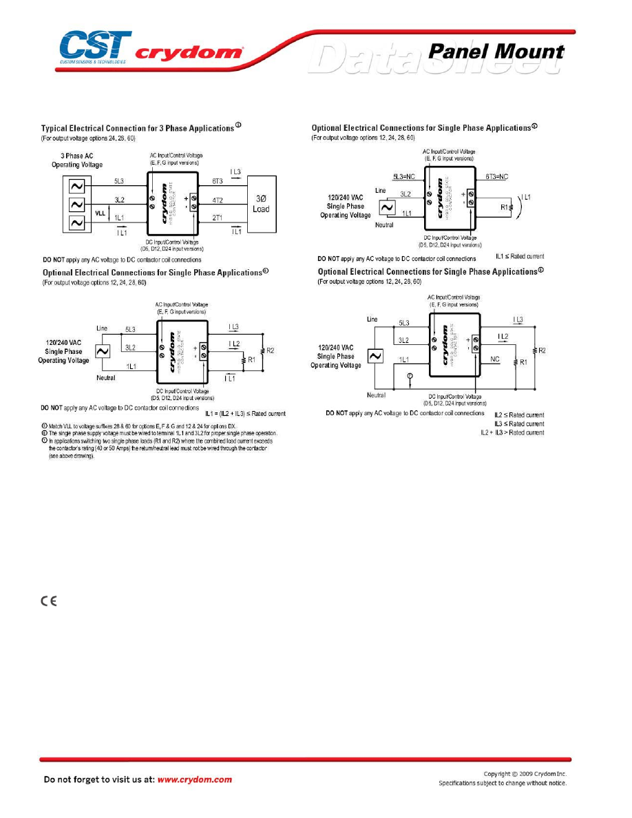
TYPICAL ELECTRICAL CONNECTIONS
AGENCY APPROVALS
UL/cUL
Rev. 011409
Courtesy of Steven Engineering, Inc.-230 Ryan Way, South San Francisco, CA 94080-6370-Main Office: (650) 588-9200-Outside Local Area: (800) 258-9200-www.stevenengineering.com
60MAIN-html.html
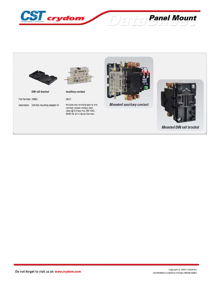
ACCESSORIES
Courtesy of Steven Engineering, Inc.-230 Ryan Way, South San Francisco, CA 94080-6370-Main Office: (650) 588-9200-Outside Local Area: (800) 258-9200-www.stevenengineering.com
60MAIN-html.html

Courtesy of Steven Engineering, Inc.-230 Ryan Way, South San Francisco, CA 94080-6370-Main Office: (650) 588-9200-Outside Local Area: (800) 258-9200-www.stevenengineering.com
60MAIN-html.html

ANNEX - ENVIROMENTAL INFORMATION
Courtesy of Steven Engineering, Inc.-230 Ryan Way, South San Francisco, CA 94080-6370-Main Office: (650) 588-9200-Outside Local Area: (800) 258-9200-www.stevenengineering.com