background image

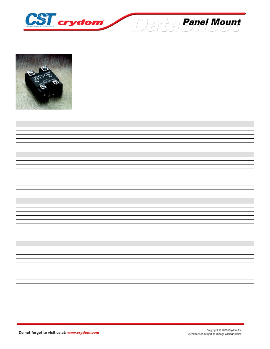
Series 1-DC 


• D1D to  D5D series  SSRs; MOSFET  output  
• Ratings from 7A to 40A @ 200 VDC, and from 7A to 10A @ 500 VDC  
• DC Control  
• Relays are easily paralleled for higher-current applications 


PRODUCT SELECTION

Load Voltage

7A

10A

12A

20A

40A

100 VDC

D1D07

D1D12

D1D20

D1D40

200 VDC

D2D07

D2D12

D2D40

400 VDC

D4D07

D4D12

500 VDC

D5D07

D5D10

OUTPUT SPECIFICATIONS (1)

Description

7A

12A

20A

40A

7A

12A

40A

7A

12A

7A

10A

Operating Voltage Range

0-100

0-100

0-100

0-100

0-200

0-200

0-200

0-400

0-400

0-500

0-500

Maximum Off-State Leakage Current @ Rated Voltage [mArms]

0.1

0.2

0.3

0.3

0.1

0.3

0.3

0.3

0.3

0.2

0.3

Maximum Load Current (3) [Adc]

7

12

20

40

7

12

40

7

12

7

10

Minimum Load Current [mA]

0

0

0

0

0

0

0

0

0

0

0

Maximum Surge Current (16.6ms) [Apk]

15

28

42

106

22

27

106

17

36

19

29

Maximum On-State Voltage Drop @ Rated Current [Vpk]

2.0

1.6

2.1

2.1

2.0

2.8

2.1

4.2

4.2

5.7

5.5

Thermal Resistance Junction to Case (Rjc) [°C/W]

2.2

1.34

1.06

0.83

1.5

1.06

0.83

1.06

0.8

1.0

0.8

Maximum On-State Resistance [RDS-ON][Ohms]

0.29

0.13

0.10

0.05

0.29

0.23

0.05

0.6

0.35

0.8

0.55

INPUT SPECIFICATIONS (1)

Description

DC Control

Control Voltage Range 

3.5-32 VDC

Maximum Turn-On Voltage 

3.5 VDC

Minimum Turn-Off Voltage

1.0 VDC

Maximum Input Current  (1-DC only)

1.6 mA (5 VDC), 28 mA (32 VDC)

Nominal Input Impedance

See Note 4

Maximum Turn-On Time  [µsec] 

100

Maximum Turn-Off Time  [msec] 

1.0

GENERAL SPECIFICATIONS

Description

Parameters

Dielectric Strength, Input/Output/Base (50/60Hz)

2500 VRMS

Minimum Insulation Resistance (@ 500 V DC)

10

9

 Ohm

Maximum Capacitance, Input/Output

50 pF

Ambient Operating Temperature Range

-20 to 80°C

Ambient Storage Temperature Range

-20 to 125 °C

Weight (typical)

3.0 oz (86.5g)

Encapsulation

Thermally conductive Epoxy

Terminals

Screws and Saddle Clamps Furnished, Unmounted

Recommended Terminal Screw Torque Range:

6-32 Screws - 10 in lbs. 8-32 and 10-32 Screws -20 in. lbs. (Screws dry without grase)


GENERAL NOTES 

1) All parameters at 25°C and per section unless otherwise specified. 
2) Dielectric strength and insulation resistance are measured between input and output 
3) Heat sinking required, for derating curves see page 3. 
4) Input circuitry version incorporates active current limiter. 


Courtesy of Steven Engineering, Inc.-230 Ryan Way, South San Francisco, CA 94080-6370-Main Office: (650) 588-9200-Outside Local Area: (800) 258-9200-www.stevenengineering.com

60PMRLY-html.html
background image

MECHANICAL SPECIFICATIONS

THERMAL DERATE INFORMATION

Courtesy of Steven Engineering, Inc.-230 Ryan Way, South San Francisco, CA 94080-6370-Main Office: (650) 588-9200-Outside Local Area: (800) 258-9200-www.stevenengineering.com

60PMRLY-html.html
background image

WIRING DIAGRAM

MAXIMUM SURGE VS DURATION 

AGENCY APPROVALS

UL   E116950 (100 Volt Models 1-DC Only ) 


                     Rev. 121608

Courtesy of Steven Engineering, Inc.-230 Ryan Way, South San Francisco, CA 94080-6370-Main Office: (650) 588-9200-Outside Local Area: (800) 258-9200-www.stevenengineering.com

60PMRLY-html.html
background image

Courtesy of Steven Engineering, Inc.-230 Ryan Way, South San Francisco, CA 94080-6370-Main Office: (650) 588-9200-Outside Local Area: (800) 258-9200-www.stevenengineering.com

60PMRLY-html.html
background image

ANNEX - ENVIROMENTAL INFORMATION

Courtesy of Steven Engineering, Inc.-230 Ryan Way, South San Francisco, CA 94080-6370-Main Office: (650) 588-9200-Outside Local Area: (800) 258-9200-www.stevenengineering.com

60PMRLY-html.html
background image

Series 1-DCL


• Optically Coupled MOSFET output  
• Ratings from 7A to 40A @ 200 VDC, and from 7A to 10A @ 500 VDC  
• DC Control  
• Relays are easily paralleled for higher-current applications 


PRODUCT SELECTION

Load Voltage

7A

10A

12A

20A

40A

100 VDC

D1D07L

D1D12L

D1D20L

D1D40L

200 VDC

D2D07L

D2D12L

D2D40L

400 VDC

D4D07L

D4D12L

500 VDC

D5D07L

D5D10L

OUTPUT SPECIFICATIONS (1)

Description

7A

12A

20A

40A

7A

12A

40A

7A

12A

7A

10A

Operating Voltage Range

0-100

0-100

0-100

0-100

0-200

0-200

0-200

0-400

0-400

0-500

0-500

Maximum Off-State Leakage Current @ Rated Voltage [mArms]

0.1

0.2

0.3

0.3

0.1

0.3

0.3

0.3

0.3

0.2

0.3

Maximum Load Current (3) [Adc]

7

12

20

40

7

12

40

7

12

7

10

Minimum Load Current [mA]

0

0

0

0

0

0

0

0

0

0

0

Maximum Surge Current (16.6ms) [Apk]

15

28

42

106

22

27

106

17

36

19

29

Maximum On-State Voltage Drop @ Rated Current [Vpk]

2.0

1.6

2.1

2.1

2.0

2.8

2.1

4.2

4.2

5.7

5.5

Thermal Resistance Junction to Case (Rjc) [°C/W]

2.2

1.34

1.06

0.83

1.5

1.06

0.83

1.06

0.8

1.0

0.8

Maximum On-State Resistance [RDS-ON][Ohms]

0.29

0.13

0.10

0.05

0.29

0.23

0.05

0.6

0.35

0.8

0.55

INPUT SPECIFICATIONS (1)

Description

Control Voltage Range 

3.5-32 VDC

Maximum Turn-On Voltage 

3.5 VDC

Minimum Turn-Off Voltage

1.0 VDC

Typical  Input Current 

10 mA

Nominal Input Impedance

See Note 4

Maximum Turn-On Time  [µsec] 

100

Maximum Turn-Off Time  [msec] 

1.0

GENERAL SPECIFICATIONS

Description

Parameters

Dielectric Strength, Input/Output/Base (50/60Hz)

2500 VRMS

Minimum Insulation Resistance (@ 500 V DC)

10

9

 Ohm

Maximum Capacitance, Input/Output

50 pF

Ambient Operating Temperature Range

-20 to 80°C

Ambient Storage Temperature Range

-20 to 125 °C

Weight (typical)

3.0 oz (86.5g)

Encapsulation

Thermally conductive Epoxy

Terminals

Screws and Saddle Clamps Furnished, Unmounted

Recommended Terminal Screw Torque Range:

6-32 Screws - 10 in lbs. 8-32 and 10-32 Screws -20 in. lbs. (Screws dry without grase)


GENERAL NOTES 

1) All parameters at 25°C and per section unless otherwise specified. 
2) Dielectric strength and insulation resistance are measured between input and output 
3) Heat sinking required, for derating curves see page 3. 
4) Input circuitry version incorporates active current limiter. 


Courtesy of Steven Engineering, Inc.-230 Ryan Way, South San Francisco, CA 94080-6370-Main Office: (650) 588-9200-Outside Local Area: (800) 258-9200-www.stevenengineering.com

60PMRLY-html.html
background image

MECHANICAL SPECIFICATIONS

THERMAL DERATE INFORMATION

Courtesy of Steven Engineering, Inc.-230 Ryan Way, South San Francisco, CA 94080-6370-Main Office: (650) 588-9200-Outside Local Area: (800) 258-9200-www.stevenengineering.com

60PMRLY-html.html
background image

WIRING DIAGRAM

MAXIMUM SURGE VS DURATION 

AGENCY APPROVALS

UL   E116950 (100 Volt Models 1-DC Only ) 


                     Rev. 121608

Courtesy of Steven Engineering, Inc.-230 Ryan Way, South San Francisco, CA 94080-6370-Main Office: (650) 588-9200-Outside Local Area: (800) 258-9200-www.stevenengineering.com

60PMRLY-html.html
background image

Courtesy of Steven Engineering, Inc.-230 Ryan Way, South San Francisco, CA 94080-6370-Main Office: (650) 588-9200-Outside Local Area: (800) 258-9200-www.stevenengineering.com

60PMRLY-html.html
background image

ANNEX - ENVIROMENTAL INFORMATION

Courtesy of Steven Engineering, Inc.-230 Ryan Way, South San Francisco, CA 94080-6370-Main Office: (650) 588-9200-Outside Local Area: (800) 258-9200-www.stevenengineering.com

60PMRLY-html.html
background image

53TP Series

PRODUCT SELECTION

Control Voltage

25A

50A

3-32 VDC

D53TP25D

D53TP50D


90-280 VAC

A53TP25D

A53TP50D

AVAILABLE OPTIONS

OUTPUT SPECIFICATIONS (1)

Description

Operating Voltage (47-63Hz) [Vrms]

48-530

48-530


Transient Overvoltage [Vpk]

1200

1200

Maximum Off-State Leakage Current @

Rated Voltage [mArms]

10

10

Minimum Off-State dv/dt @ Maximum Rated

Voltage [V/µsec] (2)

500

500

Maximum Load Current (3) [Arms]

25

50

Minimum Load Current [Arms]

0.05

0.05

Maximum Surge Current (16.6ms) [Apk]

250

625

Maximum On-State Voltage Drop @ Rated

Current [Vpk]

1.6

1.6

Thermal Resistance Junction to Case (Rjc)

[°C/W]

1.02

0.63

Maximum I

2

 t for Fusing (8.3 msec) [A

2

 sec]

260

1620

Minimum Power Factor (with Maximum Load)

0.5

0.5

Courtesy of Steven Engineering, Inc.-230 Ryan Way, South San Francisco, CA 94080-6370-Main Office: (650) 588-9200-Outside Local Area: (800) 258-9200-www.stevenengineering.com

60PMRLY-html.html
background image

INPUT SPECIFICATIONS (1)

Description

Control Voltage Range 

3-32 VDC

90-280 VAC

Maximum Turn-On Voltage 

3.0 VDC

90 Vrms

Minimum Turn-Off Voltage

1.0 VDC

10 Vrms

Typical Input Current 

10 mA @ 5 VDC

2.2 mA @ 120 Vrms, 4.4 mA @ 240 Vrms

Nominal Input Impedance 

450 Ohm

54.8 k Ohm

Maximum Turn-On Time  [msec] (4)

1/2 Cycle

10

Maximum Turn-Off Time  [msec] 

1/2 Cycle

40

GENERAL SPECIFICATIONS

Description

Parameters

Dielectric Strength, Input/Output/Base (50/60Hz)

4000 Vrms

Minimum Insulation Resistance (@ 500 V DC)

10

9

 Ohm

Maximum Capacitance, Input/Output

8 pF

Ambient Operating Temperature Range

-40 to 80°C

Ambient Storage Temperature Range

-40 to 125 °C

Weight (typical)

10.3 oz (315g)

Encapsulation

Thermally conductive Epoxy

Terminals

Screws and Saddle Clamps Furnished, Unmounted

Recommended Terminal Screw Torque Range:

6-32 Screws - 10 in lbs. 8-32 and 10-32 Screws -20 in. lbs. Screws dry without grase)

Courtesy of Steven Engineering, Inc.-230 Ryan Way, South San Francisco, CA 94080-6370-Main Office: (650) 588-9200-Outside Local Area: (800) 258-9200-www.stevenengineering.com

60PMRLY-html.html
background image

MECHANICAL SPECIFICATIONS

THERMAL DERATE INFORMATION

AGENCY APPROVALS

Courtesy of Steven Engineering, Inc.-230 Ryan Way, South San Francisco, CA 94080-6370-Main Office: (650) 588-9200-Outside Local Area: (800) 258-9200-www.stevenengineering.com

60PMRLY-html.html
background image

Courtesy of Steven Engineering, Inc.-230 Ryan Way, South San Francisco, CA 94080-6370-Main Office: (650) 588-9200-Outside Local Area: (800) 258-9200-www.stevenengineering.com

60PMRLY-html.html
background image

ANNEX - ENVIROMENTAL INFORMATION

Courtesy of Steven Engineering, Inc.-230 Ryan Way, South San Francisco, CA 94080-6370-Main Office: (650) 588-9200-Outside Local Area: (800) 258-9200-www.stevenengineering.com

60PMRLY-html.html
background image

CMD/CMA24 Series


• Ratings from 25A to 125A @ 24-280 VAC 
• SCR output for heavy industrial loads 
• AC or DC control 
• LED input status indicator 
• Zero-crossing (resistive loads) or random-fire (inductive loads) output 
• IP20 touch-safe housing 
• Standard box-clamp connections 


PRODUCT SELECTION

Control Voltage

25A

50A

75A

90A

110A

125A

3-32 VDC 

CMD2425

CMD2450

CMD2475

CMD2490

CMD24110

CMD24125

90-140 VAC 

CMA2425

CMA2450

CMA2475

CMA2490

CMA24110

CMA24125

18-36 VAC 

CMA2425E

CMA2450E

CMA2475E

CMA2490E

CMA24110E

CMA24125E

AVAILABLE OPTIONS

OUTPUT SPECIFICATIONS (1)

Description

Operating Voltage (47-63Hz) [Vrms]

24-280

24-280

24-280

24-280

24-280

24-280

Transient Overvoltage [Vpk]

600

600

600

600

600

600

Maximum Off-State Leakage Current @ Rated Voltage [mArms]

10

10

10

10

10

10

Minimum Off-State dv/dt @ Maximum Rated Voltage [V/µsec] (2)

500

500

500

500

500

500

Maximum Load Current (3) [Arms]

25

50

75

90

110

125

Minimum Load Current [Arms]

0.15

0.15

0.25

0.25

0.25

0.025

Maximum Surge Current (16.6ms) [Apk]

250

625

1000

1200

1500

1750

Maximum On-State Voltage Drop @ Rated Current [Vpk]

1.6

1.6

1.6

1.6

1.6

1.6

Thermal Resistance Junction to Case (Rjc) [°C/W]

1.02

0.63

0.31

0.28

0.25

0.22

Maximum I

2

 t for Fusing (8.3 msec) [A

2

 sec]

260

1620

4150

6000

9340

12700

Minimum Power Factor (with Maximum Load)

0.5

0.5

0.5

0.5

0.5

0.5

For Contact information visit our web  
site. 

      www.crydom.com 

©2008 Crydom, Inc.

Specifications  subject to change without notice.

Courtesy of Steven Engineering, Inc.-230 Ryan Way, South San Francisco, CA 94080-6370-Main Office: (650) 588-9200-Outside Local Area: (800) 258-9200-www.stevenengineering.com

60PMRLY-html.html
background image

INPUT SPECIFICATIONS (1)

Description

Control Voltage Range 

3-32 VDC

90-140 Vrms

Maximum Reverse Voltage

32 VDC

-

Minimum Turn-On Voltage 

3.0 VDC

90 Vrms

Minimum Turn-Off  Voltage 

1.0 VDC

10 Vrms

Maximum Input Current  

30 mA

-

Typical Input current 

17 mA @ 5 VDC

15 mA @ 120 Vrms

Maximum Turn-On Time  [msec] (4)

1/2 Cycle

10

Maximum Turn-Off Time  [msec] 

1/2 Cycle

40

GENERAL SPECIFICATIONS

Description

Parameters

Dielectric Strength, Input/Output/Base (50/60Hz)

4000 Vrms

Minimum Insulation Resistance (@ 500 VDC)

10

9

 Ohm

Maximum Capacitance, Input/Output

8 pF

Ambient Operating Temperature Range

-40 to 80 °C

Ambient Storage Temperature Range

-40 to 125 °C

Status Indicating Display

Green LED

Weight (typical)

3.0 oz (86.5 g)

Encapsulation

Thermally conductive Epoxy

Terminals

Cage type

Maximum Wire Size-Output:

AWG 8 (3.8mm)

Maximum Wire Size-Input:

AWG 12 (2.5mm)

Recommended Terminal Screw Torque Range:

Output: 10-15 in lb (1.1-1.7 Nm)

Input: 5-6 in lb (0.6-0.7 Nm)

GENERAL NOTES 

1) All parameters at 25°C unless otherwise specified. 
2) Off-State dv/dt test method per EIA/NARM standard RS-443, paragraph 13.11.1  
3) HEAT SINKING REQUIRED, FOR DERATING curves  see page 2. 
4) Turn-on time for DC control random turn-on versions is 0.02msec 
5) Input circuitry incorporates active current limiter 

For Contact information visit our web  
site. 

      www.crydom.com 

©2008 Crydom, Inc.

Specifications  subject to change without notice.

Courtesy of Steven Engineering, Inc.-230 Ryan Way, South San Francisco, CA 94080-6370-Main Office: (650) 588-9200-Outside Local Area: (800) 258-9200-www.stevenengineering.com

60PMRLY-html.html
background image

MECHANICAL SPECIFICATIONS

THERMAL DERATE INFORMATION

AGENCY APPROVALS

UL   E116949, E116950 
CSA   LR81689 
VDE   126921 UG (up to 90A models only) 

                                                                                                                                                                                                                                     Rev. 062508 

For Contact information visit our web  
site. 

      www.crydom.com 

©2008 Crydom, Inc.

Specifications  subject to change without notice.

Courtesy of Steven Engineering, Inc.-230 Ryan Way, South San Francisco, CA 94080-6370-Main Office: (650) 588-9200-Outside Local Area: (800) 258-9200-www.stevenengineering.com

60PMRLY-html.html
background image

ANNEX - ENVIROMENTAL INFORMATION

For Contact information visit our web  
site. 

      www.crydom.com 

©2008 Crydom, Inc.

Specifications  subject to change without notice.

Courtesy of Steven Engineering, Inc.-230 Ryan Way, South San Francisco, CA 94080-6370-Main Office: (650) 588-9200-Outside Local Area: (800) 258-9200-www.stevenengineering.com

60PMRLY-html.html
background image

CMD / CMA48 Series


• Ratings from 25A to 125A @ 48-530 VAC 
• SCR output for heavy industrial loads 
• AC or DC control 
• LED input status indicator 
• Zero-crossing (resistive loads) or random-fire (inductive loads) output 
• IP20 touch-safe housing 
• Standard box-clamp connections 


PRODUCT SELECTION

Control Voltage

25A

50A

75A

90A

110A

125A

4-32 VDC 

CMD4825

CMD4850

CMD4875

CMD4890

CMD48110

CMD48125

90-140 VAC 

CMA4825

CMA4850

CMA4875

CMA4890

CMA48110

CMA48125

18-36 VAC 

CMA4825E

CMA4850E

CMA2475E

CMA4890E

CMA48110E

CMA48125E

AVAILABLE OPTIONS

OUTPUT SPECIFICATIONS (1)

Description

Operating Voltage (47-63Hz) [Vrms]

48-530

48-530

48-530

48-530

48-530

48-530

Transient Overvoltage [Vpk]

1200

1200

1200

1200

1200

1200

Maximum Off-State Leakage Current @ Rated Voltage [mArms]

10

10

10

10

10

10

Minimum Off-State dv/dt @ Maximum Rated Voltage [V/µsec] (2)

500

500

500

500

500

500

Maximum Load Current (3) [Arms]

25

50

75

90

110

125

Minimum Load Current [Arms]

0.15

0.15

0.25

0.25

0.25

0.025

Maximum Surge Current (16.6ms) [Apk]

250

625

1000

1200

1500

1750

Maximum On-State Voltage Drop @ Rated Current [Vpk]

1.6

1.6

1.6

1.6

1.6

1.6

Thermal Resistance Junction to Case (Rjc) [°C/W]

1.02

0.63

0.31

0.28

0.25

0.22

Maximum I

2

 t for Fusing (8.3 msec) [A

2

 sec]

260

1620

4150

6000

9340

12700

Minimum Power Factor (with Maximum Load)

0.5

0.5

0.5

0.5

0.5

0.5

For Contact information visit our web  
site. 

      www.crydom.com 

©2008 Crydom, Inc.

Specifications  subject to change without notice.

Courtesy of Steven Engineering, Inc.-230 Ryan Way, South San Francisco, CA 94080-6370-Main Office: (650) 588-9200-Outside Local Area: (800) 258-9200-www.stevenengineering.com

60PMRLY-html.html
background image

INPUT SPECIFICATIONS (1)

Description

Control Voltage Range 

3-32 VDC

90-140 Vrms

Maximum Reverse Voltage

32 VDC

-

Minimum Turn-On Voltage 

3.0 VDC

90 Vrms

Minimum Turn-Off  Voltage 

1.0 VDC

10 Vrms

Maximum Input Current  

30 mA (5)

-

Typical Input current 

17 mA @ 5 VDC

15 mA @ 120 Vrms

Maximum Turn-On Time  [msec] (4)

1/2 Cycle

10

Maximum Turn-Off Time  [msec] 

1/2 Cycle

40

GENERAL SPECIFICATIONS

Description

Parameters

Dielectric Strength, Input/Output/Base (50/60Hz)

4000 Vrms

Minimum Insulation Resistance (@ 500 VDC)

10

9

 Ohm

Maximum Capacitance, Input/Output

8 pF

Ambient Operating Temperature Range

-40 to 80 °C

Ambient Storage Temperature Range

-40 to 125 °C

Status Indicating Display

Green LED

Weight (typical)

3.0 oz (86.5 g)

Encapsulation

Thermally conductive Epoxy

Terminals

Cage type

Maximum Wire Size-Output:

AWG 8 (3.8mm)

Maximum Wire Size-Input:

AWG 12 (2.5mm)

Recommended Terminal Screw Torque Range:

Output: 10-15 in lb (1.1-1.7 Nm) 

Input: 5-6 in lb (0.6-0.7 Nm)

GENERAL NOTES 

1) All parameters at 25°C unless otherwise specified. 
2) Off-State dv/dt test method per EIA/NARM standard RS-443, paragraph 13.11.1  
3) HEAT SINKING REQUIRED, FOR DERATING curves  see page 2. 
4) Turn-on time for DC control random turn-on versions is 0.02msec 
5) Input circuitry incorporates active current limiter. 

For Contact information visit our web  
site. 

      www.crydom.com 

©2008 Crydom, Inc.

Specifications  subject to change without notice.

Courtesy of Steven Engineering, Inc.-230 Ryan Way, South San Francisco, CA 94080-6370-Main Office: (650) 588-9200-Outside Local Area: (800) 258-9200-www.stevenengineering.com

60PMRLY-html.html
background image

MECHANICAL SPECIFICATIONS

THERMAL DERATE INFORMATION


AGENCY APPROVALS

CSA   LR81689 
VDE   126921 UG (up to 90A models only) 


Rev.  070808

For Contact information visit our web  
site. 

      www.crydom.com 

©2008 Crydom, Inc.

Specifications  subject to change without notice.

Courtesy of Steven Engineering, Inc.-230 Ryan Way, South San Francisco, CA 94080-6370-Main Office: (650) 588-9200-Outside Local Area: (800) 258-9200-www.stevenengineering.com

60PMRLY-html.html
background image

ANNEX - ENVIROMENTAL INFORMATION

For Contact information visit our web  
site. 

      www.crydom.com 

©2008 Crydom, Inc.

Specifications  subject to change without notice.

Courtesy of Steven Engineering, Inc.-230 Ryan Way, South San Francisco, CA 94080-6370-Main Office: (650) 588-9200-Outside Local Area: (800) 258-9200-www.stevenengineering.com

60PMRLY-html.html
background image

CMD / CMA60 Series


• Ratings from 25A to 125A @ 48-660 VAC 
• SCR output for heavy industrial loads 
• AC or DC control 
• LED input status indicator 
• Zero-crossing (resistive loads) or random-fire (inductive loads) output 
• IP20 touch-safe housing 
• Standard box-clamp connections 
• Ratings from 25A to 125A @ 48-660 VAC

PRODUCT SELECTION

Control Voltage

25A

50A

75A

90A

110A

125A

4-32 VDC 

CMD6025

CMD6050

CMD6075

CMD6090

CMD60110

CMD60125

90-140 Vrms

CMA6025

CMA6050

CMA6075

CMA6090

CMA60110

CMA60125

18-36 Vrms

CMA6025E

CMA6050E

CMA6075E

CMA6090E

CMA60110E

CMA60125E

AVAILABLE OPTIONS

OUTPUT SPECIFICATIONS (1)

Description

Operating Voltage (47-63Hz) [Vrms]

48-660

48-660

48-660

48-660

48-660

48-660

Transient Overvoltage [Vpk]

1200

1200

1200

1200

1200

1200

Maximum Off-State Leakage Current @ Rated Voltage [mArms]

1.0

1.0

1.0

1.0

1.0

1.0

Minimum Off-State dv/dt @ Maximum Rated Voltage [V/µsec] (2)

500

500

500

500

500

500

Maximum Load Current (3) [Arms]

25

50

75

90

110

125

Minimum Load Current [Arms]

0.15

0.15

0.25

0.25

0.25

0.025

Maximum Surge Current (16.6ms) [Apk]

250

625

1000

1200

1500

1750

Maximum On-State Voltage Drop @ Rated Current [Vpk]

1.6

1.6

1.6

1.6

1.6

1.6

Thermal Resistance Junction to Case (Rjc) [°C/W]

1.02

0.63

0.31

0.28

0.25

0.22

Maximum I

2

 t for Fusing (8.3 msec) [A

2

 sec]

260

1620

4150

6000

9340

12700

Minimum Power Factor (with Maximum Load)

0.5

0.5

0.5

0.5

0.5

0.5

For Contact information visit our web  
site. 

      www.crydom.com 

©2008 Crydom, Inc.

Specifications  subject to change without notice.

Courtesy of Steven Engineering, Inc.-230 Ryan Way, South San Francisco, CA 94080-6370-Main Office: (650) 588-9200-Outside Local Area: (800) 258-9200-www.stevenengineering.com

60PMRLY-html.html
background image

INPUT SPECIFICATIONS (1)

Description

Control Voltage Range 

3-32 VDC

90-140 Vrms

Maximum Reverse Voltage

32 VDC

-

Minimum Turn-On Voltage 

3.0 VDC

90 Vrms

Minimum Turn-Off  Voltage 

1.0 VDC

10 Vrms

Maximum Input Current  

30 mA(5)

-

Typical Input current 

17 mA @ 5 VDC

15 mA @ 120 Vrms

Maximum Turn-On Time  [msec] (4)

1/2 Cycle

10

Maximum Turn-Off Time  [msec] 

1/2 Cycle

40

GENERAL SPECIFICATIONS

Description

Parameters

Dielectric Strength, Input/Output/Base (50/60Hz)

4000 Vrms

Minimum Insulation Resistance (@ 500 VDC)

10

9

 Ohm

Maximum Capacitance, Input/Output

8 pF

Ambient Operating Temperature Range

-40 to 80 °C

Ambient Storage Temperature Range

-40 to 125 °C

Status Indicating Display

Green LED

Weight (typical)

3.0 oz (86.5 g)

Encapsulation

Thermally conductive Epoxy

Terminals

Cage type

Maximum Wire Size-Output:

AWG 8 (3.8mm)

Maximum Wire Size-Input:

AWG 12 (2.5mm)

Recommended Terminal Screw Torque Range:

Output: 10-15 in lb (1.1-1.7 Nm)

Input: 5-6 in lb (0.6-0.7 Nm)


GENERAL NOTES 

1) All parameters at 25°C unless otherwise specified. 
2) Off-State dv/dt test method per EIA/NARM standard RS-443, paragraph 13.11.1 
3) HEAT SINKING REQUIRED, FOR DERATING curves see page 2. 
4) Turn-on time for DC control random turn-on versions is  0.02msec 
5) Input circuitry incorporates active current limiter. 

For Contact information visit our web  
site. 

      www.crydom.com 

©2008 Crydom, Inc.

Specifications  subject to change without notice.

Courtesy of Steven Engineering, Inc.-230 Ryan Way, South San Francisco, CA 94080-6370-Main Office: (650) 588-9200-Outside Local Area: (800) 258-9200-www.stevenengineering.com

60PMRLY-html.html
background image

MECHANICAL SPECIFICATIONS

THERMAL DERATE INFORMATION

AGENCY APPROVALS

UL   E116949, E116950 
CSA   LR 81689 
VDE   126921 UG (up to 90A models  only) 


R ev. 062508 

For Contact information visit our web  
site. 

      www.crydom.com 

©2008 Crydom, Inc.

Specifications  subject to change without notice.

Courtesy of Steven Engineering, Inc.-230 Ryan Way, South San Francisco, CA 94080-6370-Main Office: (650) 588-9200-Outside Local Area: (800) 258-9200-www.stevenengineering.com

60PMRLY-html.html
background image

ANNEX - ENVIROMENTAL INFORMATION

For Contact information visit our web  
site. 

      www.crydom.com 

©2008 Crydom, Inc.

Specifications  subject to change without notice.

Courtesy of Steven Engineering, Inc.-230 Ryan Way, South San Francisco, CA 94080-6370-Main Office: (650) 588-9200-Outside Local Area: (800) 258-9200-www.stevenengineering.com

60PMRLY-html.html
background image

CSW Series


• Ratings from 10A to 90A @ 12-280 V AC  
• 3-32 V DC input range  
• Low off-state leakage current (snubberless)  
• SCR output for heavy industrial loads  
• Replaces the popular CSD/CSE series relays 

PRODUCT SELECTION

Control Voltage

10A

25A

50A

75A

90A

3-32 VDC 

CSW2410

CSW2425

CSW2450

CSW2475

CSW2490

AVAILABLE OPTIONS

OUTPUT SPECIFICATIONS (1)

Description

Operating Voltage (47-63Hz) [Vrms]

24-280

24-280

24-280

24-280

24-280

Transient Overvoltage [Vpk]

600

600

600

600

600

Maximum Off-State Leakage Current @ Rated Voltage [mArms]

1.0

1.0

1.0

1.0

1.0

Minimum Off-State dv/dt @ Maximum Rated Voltage [V/µsec] (2)

500

500

500

500

500

Maximum Load Current (3) [Arms]

10

25

50

75

90

Minimum Load Current [Arms]

0.15

0.15

0.15

0.25

0.25

Maximum Surge Current (16.6ms) [Apk]

120

250

625

1000

1200

Maximum On-State Voltage Drop @ Rated Current [Vpk]

1.6

1.6

1.6

1.6

1.6

Thermal Resistance Junction to Case (Rjc) [°C/W]

1.48

1.02

0.63

0.31

0.28

Maximum I

2

 t for Fusing (8.3 msec) [A

2

 sec]

60

260

1620

4150

6000

Minimum Power Factor (with Maximum Load)

0.5

0.5

0.5

0.5

0.5

For Contact information visit our web  
site. 

      www.crydom.com 

©2008 Crydom, Inc.

Specifications  subject to change without notice.

Courtesy of Steven Engineering, Inc.-230 Ryan Way, South San Francisco, CA 94080-6370-Main Office: (650) 588-9200-Outside Local Area: (800) 258-9200-www.stevenengineering.com

60PMRLY-html.html
background image

INPUT SPECIFICATIONS (1)

Description

Control Voltage Range 

3-32 VDC

Minimum Turn-On Voltage 

3 VDC

Minimum Turn-Off Voltage 

1.0 VDC

Typical Input Current 

10 mA @ 12 VDC

Nominal Input Impedance 

See note 4

Maximum Turn-On Time  [msec] (4)

1/2 Cycle

Maximum Turn-Off Time  [msec] 

1/2 Cycle

GENERAL SPECIFICATIONS

Description

Parameters

Dielectric Strength, Input/Output/Base (50/60Hz)

4000 Vrms

Minimum Insulation Resistance (@ 500 V DC)

10

9

 Ohm

Maximum Capacitance, Input/Output

10 pF

Ambient Operating Temperature Range

-40 to 80 °C

Ambient Storage Temperature Range

-40 to 125 °C

Weight (typical)

3.0 oz (86.5 g)

Encapsulation

Thermally conductive Epoxy

Terminals

Srews and Saddle Clamps Furnished, Unmounted

Recommended Terminal Screw Torque Range:

6-32 Screws - 10 in/lbs. 8-32 & 10-32 Screws - 20 in. lbs. (Screws dry without grease)

Fastons:

Single pair (up to 25A) Double pair* (up to 50A). *Caution: User must connect to both pairs

GENERAL NOTES 

1) All parameters at 25°C unless otherwise specified. 
2) Off-State dv/dt test method per EIA/NARM standard R S-443, paragraph 13.11.1  
3) H eat sinking required, for derating curves see page 2. 
4) Turn-on time f or random turn-on version (-10 suffix) is 0.1ms 

For Contact information visit our web  
site. 

      www.crydom.com 

©2008 Crydom, Inc.

Specifications  subject to change without notice.

Courtesy of Steven Engineering, Inc.-230 Ryan Way, South San Francisco, CA 94080-6370-Main Office: (650) 588-9200-Outside Local Area: (800) 258-9200-www.stevenengineering.com

60PMRLY-html.html
background image

MECHANICAL SPECIFICATIONS

THERMAL DERATE INFORMATION

AGENCY APPROVALS

UL   E116949 
CSA   LR81689 
VDE   10143 UG 


       Rev. 070908 


For Contact information visit our web  
site. 

      www.crydom.com 

©2008 Crydom, Inc.

Specifications  subject to change without notice.

Courtesy of Steven Engineering, Inc.-230 Ryan Way, South San Francisco, CA 94080-6370-Main Office: (650) 588-9200-Outside Local Area: (800) 258-9200-www.stevenengineering.com

60PMRLY-html.html
background image

CW24 Series


• The newest family to the SSR range; Ratings from 10A to 125A @  
  12-660 V AC 
• SCR output for heavy industrial loads  
• EMC Compliant for reliable operation in harsh environments  
• Removable IP 20 touch-safe cover  
• DBC substrate for superior thermal performance  
• LED input status indicator  
• AC or DC input  
• Zero-crossing (resistive loads) or random-fire (inductive loads) output

PRODUCT SELECTION

Description

10A

25A

50A

90A

125A

3-32 VDC 

CWD2410

CWD2425

CWD2450

CWD2490

CWD24125

90-280 Vrms

CWA2410

CWA2425

CWA2450

CWA2490

CWA24125

18-36 Vrms

CWA2410E

CWA2425E

CWA2450E

CWA2490E

CWA24125E

OUTPUT SPECIFICATIONS (1)

Description

Operating Voltage (47-63Hz) [Vrms]

24-280

24-280

24-280

24-280

24-280

Transient Overvoltage [Vpk]

600

600

600

600

600

Maximum Off-State Leakage Current @ Rated Voltage [mArms](6)

1

1

1

1

1

Minimum Off-State dv/dt @ Maximum Rated Voltage [V/µsec] (2)

500

500

500

500

500

Maximum Load Current (3) [Arms]

10

25

50

90

125

Minimum Load Current [Arms]

0.15

0.15

0.15

0.25

0.25

Maximum Surge Current (16.6ms) [Apk]

400

600

850

1350

2000

Maximum Surge Current (20ms) [Apk]

380

570

810

1290

1900

Maximum On-State Voltage Drop @ Rated Current [Vpk]

1.3

1.3

1.3

1.3

1.25

Thermal Resistance Junction to Case (Rjc) [°C/W]

0.35

0.35

0.2

0.14

0.13

Maximum I

2

 t for Fusing (8.3 msec) [A

2

 sec]

660

1500

3000

7560

16600

Minimum Power Factor (with Maximum Load)

0.5

0.5

0.5

0.5

0.5

For Contact information visit our web  
site. 

      www.crydom.com 

©2008 Crydom, Inc.

Specifications  subject to change without notice.

Courtesy of Steven Engineering, Inc.-230 Ryan Way, South San Francisco, CA 94080-6370-Main Office: (650) 588-9200-Outside Local Area: (800) 258-9200-www.stevenengineering.com

60PMRLY-html.html
background image

INPUT SPECIFICATIONS (1)

Description

Control Voltage Range 

3-32 VDC

90-280 Vrms

18-36 Vrms

Minimum Turn-On Voltage 

3 VDC

90 Vrms

18 Vrms

Minimum Turn-Off Voltage 

1.0 VDC

10 Vrms

2 Vrms

Typical Input Current 

10 mA @ 12 VDC

6 mA @ 120 Vrms

24 mA @ 24 Vrms

Nominal Input Impedance 

See note 7

21.5 Ohms

1.0 Ohm

Maximum Turn-On Time  [msec] (4)(5)

1/2 Cycle

1/2 Cycle

1/2 Cycle

Maximum Turn-Off Time  [msec] (5)

1/2 Cycle

1/2 Cycle

1/2 Cycle

GENERAL SPECIFICATIONS

Description

Parameters

Dielectric Strength, Input/Output/Base (50/60Hz)

4000 Vrms

Minimum Insulation Resistance (@ 500 VDC)

10

9

 Ohm

Maximum Capacitance, Input/Output

8 pF

Ambient Operating Temperature Range

-40 to 80 °C

Ambient Storage Temperature Range

-40 to 125 °C

Weight (typical)

3.0 oz (86.5 g)

Encapsulation

Thermally conductive Epoxy

Terminals

Screw Type, Finger Proof Output: 8-32, Combo Drive Input: 6-32, Combo Drive

Max. Torque

Output: 20 in lb (2.2Nm) Input: 10 in lb (1.1Nm)

Max. Wire Size

Output:2 x AWG 8 (3.8mm) Input: 2 x AWG 12 (2.5mm)

GENERAL NOTES


1) All parameters at 25°C unless otherwise specified. 
2) Off-State dv/dt test method per EIA/NARM standard RS-443, paragraph 13.11.1 
3) Heat sinking required, for derating c urves see page 2. 
4) Turn-on time for random turn-on version is 0.02 msec. 
5) Turn-on and turn-off time for AC input models is 50 ms. 
6) 10mA for models with snubber. 
7) Input circuit incorporates active current limiter. 

For Contact information visit our web  
site. 

      www.crydom.com 

©2008 Crydom, Inc.

Specifications  subject to change without notice.

Courtesy of Steven Engineering, Inc.-230 Ryan Way, South San Francisco, CA 94080-6370-Main Office: (650) 588-9200-Outside Local Area: (800) 258-9200-www.stevenengineering.com

60PMRLY-html.html
background image

MECHANICAL SPECIFICATIONS


EMC Compatibility 
             Input: EN61000-4-2, Level 3 ESD 
EN61000-4-4, Level 3 Burst 
             Output: EN61000-4-2, Level 3 ESD 
              Level 4 ESD (with P option) 
EN61000-4-4, Level 3 Burst 
              Level 4 Burst (with P option) 
EN61000-4-5, Level 4 Surge 

THERMAL DERATE INFORMATION


AGENCY APPROVALS

UL   E116949 
CSA   1405925 
VDE   40007242 


   Rev. 062508

For Contact information visit our web  
site. 

      www.crydom.com 

©2008 Crydom, Inc.

Specifications  subject to change without notice.

Courtesy of Steven Engineering, Inc.-230 Ryan Way, South San Francisco, CA 94080-6370-Main Office: (650) 588-9200-Outside Local Area: (800) 258-9200-www.stevenengineering.com

60PMRLY-html.html
background image

ANNEX - ENVIROMENTAL INFORMATION

For Contact information visit our web  
site. 

      www.crydom.com 

©2008 Crydom, Inc.

Specifications  subject to change without notice.

Courtesy of Steven Engineering, Inc.-230 Ryan Way, South San Francisco, CA 94080-6370-Main Office: (650) 588-9200-Outside Local Area: (800) 258-9200-www.stevenengineering.com

60PMRLY-html.html
background image

CW48 Series


• The newest family to the SSR range; Ratings from 10A to 125A @  
  12-660 VAC 
• SCR output for heavy industrial loads  
• EMC Compliant for reliable operation in harsh environments  
• Removable IP 20 touch-safe cover  
• DBC substrate for superior therm al performance  
• LED input status indicator  
• AC or DC input

PRODUCT SELECTION

Control Voltage

10A

25A

50A

90A

125A

3-32 VDC 

CWD4810

CWD4825

CWD4850

CWD4890

CWD48125

90-280 Vrms

CWA4810

CWA4825

CWA4850

CWA4890

CWA48125

18-36 Vrms

CWA4810E

CWA4825E

CWA4850E

CWA4890E

CWA48125E

AVAILABLE OPTIONS

OUTPUT SPECIFICATIONS (1)

Description

Operating Voltage (47-63Hz) [Vrms]

48-660

48-660

48-660

48-660

48-660

Transient Overvoltage [Vpk]

1200

1200

1200

1200

1200

Maximum Off-State Leakage Current @ Rated Voltage [mArms](6)

1.0

1.0

1.0

1.0

1.0

Minimum Off-State dv/dt @ Maximum Rated Voltage [V/µsec] (2)

500

500

500

500

500

Maximum Load Current (3) [Arms]

10

25

50

90

125

Minimum Load Current [Arms]

0.15

0.15

0.15

0.25

0.25

Maximum Surge Current (16.6ms) [Apk]

400

600

850

1350

2000

Maximum Surge Current (20ms) [Apk]

380

570

810

1290

1900

Maximum On-State Voltage Drop @ Rated Current [Vpk]

1.3

1.3

1.3

1.3

1.25

Thermal Resistance Junction to Case (Rjc) [°C/W]

0.35

0.35

0.2

0.14

0.13

Maximum I

2

 t for Fusing (8.3 msec) [A

2

 sec]

660

1500

3000

7560

16600

Minimum Power Factor (with Maximum Load)

0.5

0.5

0.5

0.5

0.5

For Contact information visit our web  
site. 

      www.crydom.com 

©2008 Crydom, Inc.

Specifications  subject to change without notice.

Courtesy of Steven Engineering, Inc.-230 Ryan Way, South San Francisco, CA 94080-6370-Main Office: (650) 588-9200-Outside Local Area: (800) 258-9200-www.stevenengineering.com

60PMRLY-html.html
background image

INPUT SPECIFICATIONS (1)

Description

Control Voltage Range 

3-32 VDC

18-36 Vrms

90-280 Vrms

Minimum Turn-On Voltage 

3 VDC

18 Vrms

90 Vrms

Minimum Turn-Off Voltage 

1 .0 VDC

2 Vrms

10 Vrms

Typical Input Current 

10 mA @ 12 VDC

24 mA @ 24 Vrms

6 mA @ 120 Vrms

Nominal Input Impedance 

See note 7

1.0 k Ohm

21.5 k Ohms

Maximum Turn-On Time  [msec] (4)(5)

1/2 Cycle

1/2 Cycle

1/2 Cycle

Maximum Turn-Off Time  [msec] (5)

1/2 Cycle

1/2 Cycle

1/2 Cycle

GENERAL SPECIFICATIONS

Description

Parameters

Dielectric Strength, Input/Output/Base (50/60Hz)

4000 Vrms

Minimum Insulation Resistance (@ 500 V DC)

10

9

 Ohm

Maximum Capacitance, Input/Output

8 pF

Ambient Operating Temperature Range

-40 to 80 °C

Ambient Storage Temperature Range

-40 to 125 °C

Weight (typical)

3.0 oz (86.5 g)

Encapsulation

Thermally conductive Epoxy

Terminals

Screw Type, Finger Proof Output: 8-32, Combo  rive Input: 6-32, Combo Drive

Max. Torque

Output: 20 in lb (2.2Nm) Input: 10 in lb (1.1Nm)

Max. Wire Size

Output:2 x AWG 8 (3.8mm) Input: 2 x AWG 12 (2.5mm)

GENERAL NOTES 

1) All parameters at 25°C unless otherwise specified. 
2) Off-State dv/dt test method per EIA/NARM standard RS-443, paragraph 13.11.1 
3) Heat sinking required, for derating curves see page 2. 
4) Turn-on time for random turn-on version is 0.02 msec. 
5) Turn-on and turn-off time for AC input models is 50 ms. 
6) 10mA for models with snubber. 
7) Input circuit incorporates active current limiter. 
8) 48-530 VRMS for models with snubber. 

For Contact information visit our web  
site. 

      www.crydom.com 

©2008 Crydom, Inc.

Specifications  subject to change without notice.

Courtesy of Steven Engineering, Inc.-230 Ryan Way, South San Francisco, CA 94080-6370-Main Office: (650) 588-9200-Outside Local Area: (800) 258-9200-www.stevenengineering.com

60PMRLY-html.html
background image

MECHANICAL SPECIFICATIONS


EMC Compatibility 
             Input: EN61000-4-2, Level 3 ESD 
EN61000-4-4, Level 3 Burst 
             Output: EN61000-4-2, Level 3 ESD 
              Level 4 ESD (with P option) 
EN61000-4-4, Level 3 Burst 
              Level 4 Burst (with P option) 
EN61000-4-5, Level 4 Surge 

THERMAL DERATE INFORMATION


AGENCY APPROVALS

UL   E116949 
CSA   1405925 
VDE   40007242 


Rev. 071008

For Contact information visit our web  
site. 

      www.crydom.com 

©2008 Crydom, Inc.

Specifications  subject to change without notice.

Courtesy of Steven Engineering, Inc.-230 Ryan Way, South San Francisco, CA 94080-6370-Main Office: (650) 588-9200-Outside Local Area: (800) 258-9200-www.stevenengineering.com

60PMRLY-html.html
background image

ANNEX - ENVIROMENTAL INFORMATION

For Contact information visit our web  
site. 

      www.crydom.com 

©2008 Crydom, Inc.

Specifications  subject to change without notice.

Courtesy of Steven Engineering, Inc.-230 Ryan Way, South San Francisco, CA 94080-6370-Main Office: (650) 588-9200-Outside Local Area: (800) 258-9200-www.stevenengineering.com

60PMRLY-html.html
background image

D06D Series 


• MOSFET output  
• Ratings from 60A to 100A @ 60 VDC  
• DC control  
• Relays are easily paralleled for higher-current applications  


PRODUCT SELECTION

Control Voltage

60A

80A

100A

3.5-32 VDC

D06D60

D06D80

D06D100


OUTPUT SPECIFICATIONS (1)

Description

Operating Voltage (47-63Hz) [Vrms]

0-60 VDC

0-60 VDC

0-60 VDC


Maximum Off-State Leakage Current @ Rated Voltage [mArms]

0.1

0.2

0.3

Maximum  On-State Resistance @ Rated Current [RDS-ON][Ohms]

0.010

0.008

0.005

Maximum Load Current (3) [Arms]

60

80

100

Minimum Load Current [mArms]

5

5

5

Maximum Surge Current (16.6ms) [Apk]

180

220

270

Maximum On-State Voltage Drop @ Rated Current [Vpk]

0.6

0.7

0.5

Thermal Resistance Junction to Case (Rjc) [°C/W]

0.6

0.47

0.32

INPUT SPECIFICATIONS (1)

Description

DC Control

Control Voltage Range 

3.5-32 VDC

Maximum Turn-On Voltage 

3.5 VDC

Minimum Turn-Off Voltage

1.0 VDC

Maximum Input Current 

1.6 mA (5 VDC), 28 mA (32 VDC)

Nominal Input Impedance 

See Note 4

Maximum Turn-On Time  [

μ

sec] 

300

Maximum Turn-Off Time [

μ

sec] 

1.0

GENERAL SPECIFICATIONS

Description

Parameters

Dielectric Strength, Input/Output/Base (50/60Hz)

2500 Vrms

Minimum Insulation Resistance (@ 500 V DC)

10

9

 Ohm

Maximum Capacitance, Input/Output

50 pF

Ambient Operating Temperature Range

-30 to 80°C

Ambient Storage Temperature Range

-40 to 125 °C

Weight (typical)

3.0 oz (86.5g)

Encapsulation

Thermally conductive Epoxy

Terminals

Screws and Saddle Clamps Furnished, Unmounted

Recommended Terminal Screw Torque Range:

6-32 Screws - 10 in lbs. 8-32 and 10-32 Screws -20 in. lbs. (Screws dry without grase)


GENERAL NOTES 

1) All parameters at 25°C unless otherwise specified. 
2) Off-State dv/dt test method per EIA/NARM standard RS-443, paragraph 13.11.1 
3) Heat sinking required, for derating curves see page 2. 
4) Input circuitry incorporates active current limiter 


For Contact information visit our web  
site. 

      www.crydom.com 

©2008 Crydom, Inc.

Specifications subject to change without notice.

Courtesy of Steven Engineering, Inc.-230 Ryan Way, South San Francisco, CA 94080-6370-Main Office: (650) 588-9200-Outside Local Area: (800) 258-9200-www.stevenengineering.com

60PMRLY-html.html
background image

MECHANICAL SPECIFICATIONS

THERMAL DERATE INFORMATION

WIRING DIAGRAM

For Contact information visit our web  
site. 

      www.crydom.com 

©2008 Crydom, Inc.

Specifications subject to change without notice.

Courtesy of Steven Engineering, Inc.-230 Ryan Way, South San Francisco, CA 94080-6370-Main Office: (650) 588-9200-Outside Local Area: (800) 258-9200-www.stevenengineering.com

60PMRLY-html.html
background image

ANNEX - ENVIROMENTAL INFORMATION

For Contact information visit our web  
site. 

      www.crydom.com 

©2008 Crydom, Inc.

Specifications subject to change without notice.

Courtesy of Steven Engineering, Inc.-230 Ryan Way, South San Francisco, CA 94080-6370-Main Office: (650) 588-9200-Outside Local Area: (800) 258-9200-www.stevenengineering.com

60PMRLY-html.html
background image

DC60 Series


• Bi-polar transistor output  
• Ratings from 3A to 7A @ 60 VDC  
• AC or DC control  


PRODUCT SELECTION

Control Voltage

3A

5A

7A

3.5-32 VDC

DC60S3

DC60S5

DC60S7

90-280 VAC

DC60SA3

DC60SA5

DC60SA7

AVAILABLE OPTIONS

OUTPUT SPECIFICATIONS (1)

Description

Operating Voltage (47-63Hz) [VDC]

3-60

3-60

3-60

Maximum Off-State Leakage Current @ Rated Voltage [mArms]

0.1

0.1

0.1

Maximum Load Current (2) [ADC]

3

5

7

Minimum Load Current [Arms]

0.02

0.02

0.02

Maximum Surge Current (16.6ms) [Apk]

6

10

14

Maximum On-State Voltage Drop @ Rated Current [Vpk]

1.3

1.5

1.7

Thermal Resistance Junction to Case (Rjc) [°C/W]

2.2

2.2

2.2

For Contact information visit our web  
site. 

      www.crydom.com 

©2008 Crydom, Inc.

Specifications subject to change without notice.

Courtesy of Steven Engineering, Inc.-230 Ryan Way, South San Francisco, CA 94080-6370-Main Office: (650) 588-9200-Outside Local Area: (800) 258-9200-www.stevenengineering.com

60PMRLY-html.html
background image

INPUT SPECIFICATIONS (1)

Description

DC Control

AC Control

Control Voltage Range 

3.5-32 VDC

90-280 Vrms

Maximum Turn-On Voltage 

3.5 VDC

90 Vrms

Minimum Turn-Off Voltage

1.0 VDC

10 Vrms

Typical Input Current

2.2 mA @ 5 VDC

2 mA @ 120 Vrms, 4 mA @ 240 Vrms

Nominal Input Impedance 

1500 Ohm

60K

Maximum Turn-On Time  [msec] 

0.1

10

Maximum Turn-Off Time  [msec] 

0.3

40

GENERAL SPECIFICATIONS

Description

Parameters

Dielectric Strength, Input/Output/Base (50/60Hz) [Vrms]

4000

Minimum Insulation Resistance (@ 500 V DC)

10

9

 Ohm

Maximum Capacitance, Input/Output

8 pF

Ambient Operating Temperature Range

-30 to 80°C

Ambient Storage Temperature Range

-40 to 125 °C

Weight (typical)

3.0 oz (86.5g)

Encapsulation

Thermally conductive Epoxy

Terminals

Screws and Saddle Clamps Furnished, Unmounted

Recommended Terminal Screw Torque Range:

6-32 Screws - 10 in lbs. 8-32 and 10-32 Screws -20 in. lbs. (Screws dry without grase)


GENERAL NOTES 

1) All parameters at 25°C unless otherwise specified. 

2) Heat sinking required, see derating curves. 


MECHANICAL SPECIFICATIONS

For Contact information visit our web  
site. 

      www.crydom.com 

©2008 Crydom, Inc.

Specifications subject to change without notice.

Courtesy of Steven Engineering, Inc.-230 Ryan Way, South San Francisco, CA 94080-6370-Main Office: (650) 588-9200-Outside Local Area: (800) 258-9200-www.stevenengineering.com

60PMRLY-html.html
background image

THERMAL DERATE INFORMATION

WIRING DIAGRAM

For Contact information visit our web  
site. 

      www.crydom.com 

©2008 Crydom, Inc.

Specifications subject to change without notice.

Courtesy of Steven Engineering, Inc.-230 Ryan Way, South San Francisco, CA 94080-6370-Main Office: (650) 588-9200-Outside Local Area: (800) 258-9200-www.stevenengineering.com

60PMRLY-html.html
background image

For Contact information visit our web  
site. 

      www.crydom.com 

©2008 Crydom, Inc.

Specifications subject to change without notice.

Courtesy of Steven Engineering, Inc.-230 Ryan Way, South San Francisco, CA 94080-6370-Main Office: (650) 588-9200-Outside Local Area: (800) 258-9200-www.stevenengineering.com

60PMRLY-html.html
background image

ANNEX - ENVIROMENTAL INFORMATION

For Contact information visit our web  
site. 

      www.crydom.com 

©2008 Crydom, Inc.

Specifications subject to change without notice.

Courtesy of Steven Engineering, Inc.-230 Ryan Way, South San Francisco, CA 94080-6370-Main Office: (650) 588-9200-Outside Local Area: (800) 258-9200-www.stevenengineering.com

60PMRLY-html.html
background image

DUAL 

PRODUCT SELECTION

Control Voltage

25A

40A

4-15 VDC

D2425D

D2440D

15-32 VDC

D2425DE

D2440DE

4-15 VDC

H12D4825D

H12D4840D

15-32 VDC

H12D4825DE

H12D4840DE

AVAILABLE OPTIONS

OUTPUT SPECIFICATIONS (1)

Description

Operating Voltage (47-63Hz) [Vrms]

24-280

24-280

48-530

48-530

Transient Overvoltage [Vpk]

600

600

1200

1200

Maximum Off-State Leakage Current @ Rated Voltage [mArms]

10

10

10

10

Minimum Off-State dv/dt @ Maximum Rated Voltage [V/µsec] (2)

500

500

500

500

Maximum Load Current (3) [Arms]

25

40

25

40

Minimum Load Current [Arms]

0.15

0.15

0.15

0.15

Maximum Surge Current (16.6ms) [Apk]

250

625

250

625

Maximum On-State Voltage Drop @ Rated Current [Vpk]

1.6

1.6

1.6

1.6

Thermal Resistance Junction to Case (Rjc) [°C/W]

1.02

0.63

1.02

0.63

Maximum I

2

 t for Fusing (8.3 msec) [A

2

 sec]

260

1620

260

1620

Minimum Power Factor (with Maximum Load)

0.5

0.5

0.5

0.5

Courtesy of Steven Engineering, Inc.-230 Ryan Way, South San Francisco, CA 94080-6370-Main Office: (650) 588-9200-Outside Local Area: (800) 258-9200-www.stevenengineering.com

60PMRLY-html.html
background image

INPUT SPECIFICATIONS (1)

Description

D24XXD

H12D48XXD

E-SUFFIX

Control Voltage Range 

4-15 VDC

4-15 VDC

15-32 VDC

Maximum Turn-On Voltage 

4.0 VDC

4.0 VDC

15.0 VDC

Minimum Turn-Off Voltage

1.0 VDC

1.0 VDC

1.0 VDC

Typical Input Current  @ 5 VDC (@ 24 VDC for E-Suffix)

13 mA

13 mA

15 mA

Nominal Input Impedance 

300 Ohm

240 Ohm

1500 Ohm

Maximum Turn-On Time  [msec] (4)

1/2 cycle

1/2 cycle

1/2 cycle

Maximum Turn-Off Time [msec] 

1/2 cycle

1/2 cycle

1/2 cycle

GENERAL SPECIFICATIONS

Description

Parameters

Dielectric Strength, Input/Output/Base (50/60Hz)

4000 Vrms

Minimum Insulation Resistance (@ 500 V DC)

10

9

 Ohm

Maximum Capacitance, Input/Output

10 pF

Ambient Operating Temperature Range

-40 to 80°C

Ambient Storage Temperature Range

-40 to 125 °C

Weight (typical)

3.0 oz (86.5g)

Encapsulation

Thermally conductive Epoxy

Terminals

.25" Fastons, .025" Square Pins

Courtesy of Steven Engineering, Inc.-230 Ryan Way, South San Francisco, CA 94080-6370-Main Office: (650) 588-9200-Outside Local Area: (800) 258-9200-www.stevenengineering.com

60PMRLY-html.html
background image

MECHANICAL SPECIFICATIONS

WIRING DIAGRAM

THERMAL DERATE INFORMATION

AGENCY APPROVALS

Courtesy of Steven Engineering, Inc.-230 Ryan Way, South San Francisco, CA 94080-6370-Main Office: (650) 588-9200-Outside Local Area: (800) 258-9200-www.stevenengineering.com

60PMRLY-html.html
background image

Courtesy of Steven Engineering, Inc.-230 Ryan Way, South San Francisco, CA 94080-6370-Main Office: (650) 588-9200-Outside Local Area: (800) 258-9200-www.stevenengineering.com

60PMRLY-html.html
background image

ANNEX - ENVIROMENTAL INFORMATION

Courtesy of Steven Engineering, Inc.-230 Ryan Way, South San Francisco, CA 94080-6370-Main Office: (650) 588-9200-Outside Local Area: (800) 258-9200-www.stevenengineering.com

60PMRLY-html.html
background image

EZ Series


• Compact design for low-profile applications; Ratings from 5A to  
  18A @ 600 VAC  
• SCR output for heavy industrial loads  
• AC or DC control  
• 1/4" fast-on terminals for easy installation 

PRODUCT SELECTION

Control Voltage

5A

12A

18A

4-15 VDC 

EZ240D5

EZ240D12

EZ240D18

15-32 VDC 

EZE240D12

EZE240D18

90-140 Vrms

EZ240A12

EZ240A18

18-36 Vrms

EZE240A12

EZE240A18

4-15 VDC 

EZ480D12

EZ480D18

15-32 VDC 

EZE480D12

EZE480D18

90-140 Vrms

EZ480A12

EZ480A18

18-36 Vrms

EZE480A12

EZE480A18

AVAILABLE OPTIONS

OUTPUT SPECIFICATIONS (1)

Description

Operating Voltage (47-63Hz) [Vrms]

24-280

24-280

24-280

48-660

48-660

Transient Overvoltage [Vpk]

600

600

600

1200

1200

Maximum Off-State Leakage Current @ Rated Voltage [mArms](5)

0.1

0.1

0.1

0.1

0.1

Minimum Off-State dv/dt @ Maximum Rated Voltage [V/µsec] (2)

500

500

500

500

500

Maximum Load Current (4) [Arms]

5

12

18

12

18

Minimum Load Current [mArms]

150

150

150

150

150

Maximum Surge Current (16.6ms) [Apk]

40

150

200

150

200

Maximum On-State Voltage Drop @ Rated Current [Vpk]

1.5

1.5

1.5

1.5

1.5

Thermal Resistance Junction to Case (Rjc) [°C/W]

2

2

1.1

2

1.1

Maximum I

2

 t for Fusing (8.3 msec) [A

2

 sec]

95

95

170

95

170

Minimum Power Factor (with Maximum Load)

0.5

0.5

0.5

0.5

0.5


For Contact information visit our web  
site. 

      www.crydom.com 

©2008 Crydom, Inc.

Specifications  subject to change without notice.

Courtesy of Steven Engineering, Inc.-230 Ryan Way, South San Francisco, CA 94080-6370-Main Office: (650) 588-9200-Outside Local Area: (800) 258-9200-www.stevenengineering.com

60PMRLY-html.html
background image

INPUT SPECIFICATIONS (1)

Description

 EZ240D5

 EZ240Dxx

 EZ480Dxx

 EZExxxDxx

EZxxxAxx

EZExxxAxx

Control Voltage Range 

4-15 VDC

3-15 VDC

4-15 VDC

15-32 VDC

90-140 Vrms

18-36 Vrms

Minimum Turn-On Voltage 

4.0 VDC

3.0 VDC

4.0 VDC

15.0 VDC

90.0 Vrms

18.0 Vrms

Minimum Turn-Off Voltage 

1.0 VDC

1.0 VDC

1.0 VDC

1.0 VDC

10.0 Vrms

2.0 Vrms

Typical Input Current @ Nominal Voltage

13 mAdc

15 mAdc

15 mAdc

15 mAdc

10 mAdc

10 mAdc

Nominal Input Impedance 

300 Ohm

300 Ohm

240 Ohm

1500 Ohm

10.6 k Ohm

1.8 k Ohm

Maximum Turn-On Time  [msec] (6)

1/2 Cycle

1/2 Cycle

1/2 Cycle

1/2 Cycle

10

10

Maximum Turn-Off Time  [msec] 

1/2 Cycle

1/2 Cycle

1/2 Cycle

1/2 Cycle

40

40

GENERAL SPECIFICATIONS

Description

Parameters

Dielectric Strength, Input/Output/Base (50/60Hz)(3)

4000 Vrms *

Minimum Insulation Resistance (@ 500 V DC)

10

9

 Ohm


Maximum Capacitance, Input/Output

8 pF

Ambient Operating Temperature Range

-40 to 80 °C

Ambient Storage Temperature Range

-40 to 125 °C

Weight (typical)

1.5 oz (43 g)

Encapsulation

Thermally conductive Epoxy

Terminals

0.25 Inch Faston

GENERAL NOTES


1) All parameters at 25°C unless otherwise specified. 
2) Off-State dv/dt test method per EIA/NARM standard RS-443, paragraph 13.11.1 
3) 240V, DC control models only, all others 2500VRMS 
4) Heat sinking required, for derating curves see page 2. 
5) Off- state leakage for snubbered version (suffix S) is 10.0mArms 
6) Turn-on time for random turn-on versions is 0.1 msec (DC Control Models). 

For Contact information visit our web  
site. 

      www.crydom.com 

©2008 Crydom, Inc.

Specifications  subject to change without notice.

Courtesy of Steven Engineering, Inc.-230 Ryan Way, South San Francisco, CA 94080-6370-Main Office: (650) 588-9200-Outside Local Area: (800) 258-9200-www.stevenengineering.com

60PMRLY-html.html
background image

MECHANICAL SPECIFICATIONS


*240,  DC Control Models  Only 
DC CONTROL. 
PI N 1: AC  LOAD 
PI N 2: AC  LOAD 
PI N 3:  +D C CO NTROL 
PI N 4:  -D C CONTRO L 
Note: 
Recommended t orque for mounti ng Screw is 8 –  14 in lb (1.1 – 1.6 Nm)   
Thi s assumes a st andard # 8-32 UNC screw 

THERMAL DERATE INFORMATION


AGENCY APPROVALS

UL   E116950 
CSA   LR81689 
VDE   10139 UG (240 VDC Control Only) 


     Rev. 062708


For Contact information visit our web  
site. 

      www.crydom.com 

©2008 Crydom, Inc.

Specifications  subject to change without notice.

Courtesy of Steven Engineering, Inc.-230 Ryan Way, South San Francisco, CA 94080-6370-Main Office: (650) 588-9200-Outside Local Area: (800) 258-9200-www.stevenengineering.com

60PMRLY-html.html
background image

ANNEX - ENVIROMENTAL INFORMATION

For Contact information visit our web  
site. 

      www.crydom.com 

©2008 Crydom, Inc.

Specifications  subject to change without notice.

Courtesy of Steven Engineering, Inc.-230 Ryan Way, South San Francisco, CA 94080-6370-Main Office: (650) 588-9200-Outside Local Area: (800) 258-9200-www.stevenengineering.com

60PMRLY-html.html
background image

H12C Series


• Ratings from 25A to 125A @ 48-660 VAC  
• SCR output for heavy  industrial loads  
• AC or DC control  
• Zero-crossing (resistive loads) or random-fire (inductive loads) output

PRODUCT SELECTION

Control Voltage

25A

50A

90A

4-15 VDC 

H12CD4825

H12CD4850

H12CD4890

90-140 Vrms

H12CA4825

H12CA4850

H12CA4890

AVAILABLE OPTIONS

OUTPUT SPECIFICATIONS (1)

Description

Operating Voltage (47-63Hz) [Vrms]

48-660

48-660

48-660

Transient Overvoltage [Vpk]

1200

1200

1200

Maximum Off-State Leakage Current @ Rated Voltage [mArms]

1.0

1.0

1.0

Minimum Off-State dv/dt @ Maximum Rated Voltage [V/µsec] (2)

500

500

500

Maximum Load Current (3) [Arms]

25

50

90

Minimum Load Current [mArms]

150

150

150

Maximum Surge Current (16.6ms) [Apk]

250

625

1200

Maximum On-State Voltage Drop @ Rated Current [Vpk]

1.6

1.6

1.6

Thermal Resistance Junction to Case (Rjc) [°C/W]

1.02

0.63

0.28

Maximum I

2

 t for Fusing (8.3 msec) [A

2

 sec]

260

1620

6000

Minimum Power Factor (with Maximum Load)

0.5

0.5

0.5

For Contact information visit our web  
site. 

      www.crydom.com 

©2008 Crydom, Inc.

Specifications  subject to change without notice.

Courtesy of Steven Engineering, Inc.-230 Ryan Way, South San Francisco, CA 94080-6370-Main Office: (650) 588-9200-Outside Local Area: (800) 258-9200-www.stevenengineering.com

60PMRLY-html.html
background image

INPUT SPECIFICATIONS (1)

Description

Control Voltage Range 

4-15 VDC

90-140 Vrms

Minimum Turn-On Voltage 

4.0 VDC

90 VAC

Minimum Turn-Off Voltage

1.0 VDC

10.0 VAC

Typical Input Current 

15 mA

15 mA

Nominal Input Impedance 

300 Ohm

8k Ohm

Maximum Turn-On Time [msec] (4)

1/2 Cycle

10

Maximum Turn-Off Time [msec] 

1/2 Cycle

40

GENERAL SPECIFICATIONS

Description

Parameters

Dielectric Strength, Input/Output/Base (50/60Hz)

4000 Vrms

Minimum Insulation Resistance (@ 500 V DC)

10

9

 Ohm

Maximum Capacitance, Input/Output

8 pF

Ambient Operating Temperature Range

-40 to 80 °C

Ambient Storage Temperature Range

-40 to 125 °C

Weight (typical)

3 oz (86.5 g)

Encapsulation

Thermally conductive Epoxy

Terminals

Screw and saddle Clamps Furnished, Unmounted

Recommended Terminal Screw Torque Range:

6-32 Screws - 10 in/lbs. 8-32 & 10-32 Screws - 20 in. lbs. (Screws dry without grease)

Fastons:

Double pair* (50A model only) Caution: User must connect to both pairs

GENERAL NOTES 

1) All parameters at 25°C unless otherwise specified. 
2) Off-State dv/dt test method per EIA/NARM standard R S-443, paragraph 13.11.1 
3) H eat sinking required, for derating curves see page 2. 
4) Turn-on time for DC random turn-on versions is 0.02 msec (DC Control Models).

For Contact information visit our web  
site. 

      www.crydom.com 

©2008 Crydom, Inc.

Specifications  subject to change without notice.

Courtesy of Steven Engineering, Inc.-230 Ryan Way, South San Francisco, CA 94080-6370-Main Office: (650) 588-9200-Outside Local Area: (800) 258-9200-www.stevenengineering.com

60PMRLY-html.html
background image

MECHANICAL SPECIFICATIONS

THERMAL DERATE INFORMATION


AGENCY APPROVALS

UL   E116949 
CSA   LR81689 
VDE   10143 UG 


  Rev. 062708

For Contact information visit our web  
site. 

      www.crydom.com 

©2008 Crydom, Inc.

Specifications  subject to change without notice.

Courtesy of Steven Engineering, Inc.-230 Ryan Way, South San Francisco, CA 94080-6370-Main Office: (650) 588-9200-Outside Local Area: (800) 258-9200-www.stevenengineering.com

60PMRLY-html.html
background image

ANNEX - ENVIROMENTAL INFORMATION

For Contact information visit our web  
site. 

      www.crydom.com 

©2008 Crydom, Inc.

Specifications  subject to change without notice.

Courtesy of Steven Engineering, Inc.-230 Ryan Way, South San Francisco, CA 94080-6370-Main Office: (650) 588-9200-Outside Local Area: (800) 258-9200-www.stevenengineering.com

60PMRLY-html.html
background image

H12 Series


Ratings from 25A to 125A @ 48-660 V AC  


SCR output for heavy industrial loads  


AC or DC control  


Zero-crossing (resistive loads) or random-fire (inductive loads) output

PRODUCT SELECTION

Control Voltage

25A

50A

75A

90A

125A

4-32 VDC 

H12D4825

H12D4850

H12D4875

H12D4890

H12D48125

AVAILABLE OPTIONS

OUTPUT SPECIFICATIONS (1)

Description

Operating Voltage (47-63Hz) [Vrms]

48-530

48-530

48-530

48-530

48-530

Transient Overvoltage [Vpk]

1200

1200

1200

1200

1200

Maximum Off-State Leakage Current @ Rated Voltage [mArms]

10

10

10

10

10

Minimum Off-State dv/dt @ Maximum Rated Voltage [V/µsec] (2)

500

500

500

500

500

Maximum Load Current (3) [Arms]

25

50

75

90

125

Minimum Load Current [mArms]

150

150

150

150

150

Maximum Surge Current (16.6ms) [Apk]

250

625

1000

1200

1750

Maximum On-State Voltage Drop @ Rated Current [Vpk]

1.6

1.6

1.6

1.6

1.7

Thermal Resistance Junction to Case (Rjc) [°C/W]

1.02

0.63

0.31

0.28

0.22

Maximum I

2

 t for Fusing (8.3 msec) [A

2

 sec]

260

1620

4150

6000

12700

Minimum Power Factor (with Maximum Load)

0.5

0.5

0.5

0.5

0.5

For Contact information visit our web  
site. 

      www.crydom.com 

©2008 Crydom, Inc.

Specifications  subject to change without notice.

Courtesy of Steven Engineering, Inc.-230 Ryan Way, South San Francisco, CA 94080-6370-Main Office: (650) 588-9200-Outside Local Area: (800) 258-9200-www.stevenengineering.com

60PMRLY-html.html
background image

INPUT SPECIFICATIONS (1)

Description

DC Control

Control Voltage Range 

4-32 VDC

Maximum Turn-On Voltage 

4.0 VDC

Minimum Turn-Off Voltage

1 .0 VDC

Typical Input Current 

15 mADC (5)

Nominal Input Impedance 

See Note 5

Maximum Turn-On Time  [msec] (4)

1/2 Cycle

Maximum Turn-Off Time  [msec] 

1/2 Cycle

GENERAL SPECIFICATIONS

Description

Parameters

Dielectric Strength, Input/Output/Base (50/60Hz)

4000 Vrms

Minimum Insulation Resistance (@ 500 V DC)

10

9

 Ohm

Maximum Capacitance, Input/Output

8 pF

Ambient Operating Temperature Range

-40 to 80 °C

Ambient Storage Temperature Range

-40 to 125 °C

Weight (typical)

3 oz (86.5 g)

Encapsulation

Thermally conductive Epoxy

Terminals

Screw and saddle Clamps Furnished, Unmounted

Recommended Terminal Screw Torque Range:

6-32 Screws - 10 in/lbs. 8-32 & 10-32 Screws - 20 in. lbs. (Screws dry without grease)

Fastons:

Single pair (up to 25A) Double pair* (50A model only) Caution: User must connect to both pairs


GENERAL NOTES 

1) All parameters at 25°C and per section unless otherwise specified. 
2) Off-State dv/dt test method per EIA/NARM standard RS-443, paragraph 13.11.1 
3) Heat sinking required, for derating curves see page 2. 
4) Turn-on time for DC control random turn-on versions is  0.02 msec  
5) Input circuitry version incorporates active current limiter. 
6) Only 125A model CE Compliant. 

For Contact information visit our web  
site. 

      www.crydom.com 

©2008 Crydom, Inc.

Specifications  subject to change without notice.

Courtesy of Steven Engineering, Inc.-230 Ryan Way, South San Francisco, CA 94080-6370-Main Office: (650) 588-9200-Outside Local Area: (800) 258-9200-www.stevenengineering.com

60PMRLY-html.html
background image

MECHANICAL SPECIFICATIONS

THERMAL DERATE INFORMATION


AGENCY APPROVALS

UL   E116949 
CSA   LR81689 
VDE   10143 UG 


Rev. 063008

For Contact information visit our web  
site. 

      www.crydom.com 

©2008 Crydom, Inc.

Specifications  subject to change without notice.

Courtesy of Steven Engineering, Inc.-230 Ryan Way, South San Francisco, CA 94080-6370-Main Office: (650) 588-9200-Outside Local Area: (800) 258-9200-www.stevenengineering.com

60PMRLY-html.html
background image

ANNEX - ENVIROMENTAL INFORMATION

For Contact information visit our web  
site. 

      www.crydom.com 

©2008 Crydom, Inc.

Specifications  subject to change without notice.

Courtesy of Steven Engineering, Inc.-230 Ryan Way, South San Francisco, CA 94080-6370-Main Office: (650) 588-9200-Outside Local Area: (800) 258-9200-www.stevenengineering.com

60PMRLY-html.html
background image

HA / HD48 Series


• Ratings from 12A to 125A @ 48-530 VAC  
• SCR output for heavy industrial loads  
• AC or DC control  
• Zero-crossing (resistive loads) or random-fire (inductive loads) output 

PRODUCT SELECTION

Control Voltage

12A

25A

50A

75A

90A

110A

125A

3-32 VDC 

HD4812

HD4825

HD4850

HD4875

HD4890

HD48110

HD48125

90-280 Vrms 

HA4812

HA4825

HA4850

HA4875

HA4890

HA48110

HA48125

18-36 Vrms 

HA4812E

HA4825E

HA4850E

HA4875E

HA4890E

HA48110E

HA48125E

AVAILABLE OPTIONS

OUTPUT SPECIFICATIONS (1)

Description

Operating Voltage (47-63Hz) [Vrms]

48-530

48-530

48-530

48-530

48-530

48-530

48-530

Transient Overvoltage [Vpk]

1200

1200

1200

1200

1200

1200

1200

Maximum Off-State Leakage Current @ Rated Voltage [mArms]

10

10

10

10

10

10

10

Minimum Off-State dv/dt @ Maximum Rated Voltage [V/µsec] (2)

500

500

500

500

500

500

500

Maximum Load Current (3) [Arms]

12

25

50

75

90

110

125

Minimum Load Current [mArms]

40

40

40

40

40

150

150

Maximum Surge Current (16.6ms) [Apk]

140

250

625

1000

1200

1500

1750

Maximum On-State Voltage Drop @ Rated Current [Vpk]

1.7

1.7

1.7

1.7

1.7

1.7

1.7

Thermal Resistance Junction to Case (Rjc) [°C/W]

1.48

1.02

0.63

0.31

0.28

0.25

0.22

Maximum I

2

 t for Fusing (8.3 msec) [A

2

 sec]

81

260

1620

4150

6000

9340

12700

Minimum Power Factor (with Maximum Load)

0.5

0.5

0.5

0.5

0.5

0.5

0.5


For Contact information visit our web  
site. 

      www.crydom.com 

©2008 Crydom, Inc.

Specifications  subject to change without notice.

Courtesy of Steven Engineering, Inc.-230 Ryan Way, South San Francisco, CA 94080-6370-Main Office: (650) 588-9200-Outside Local Area: (800) 258-9200-www.stevenengineering.com

60PMRLY-html.html
background image

INPUT SPECIFICATIONS (1)

Description

D PREFIX

A PREFIX

E PREFIX

Control Voltage Range 

3-32 VDC

90-280 Vrms

18-36 Vrms

Maximum Turn-On Voltage 

3.0 VDC

90 Vrms

18 Vrms

Minimum Turn-Off Voltage

1.0 VDC

10 Vrms

4.0 Vrms

Maximum Reverse Voltage

-32 VDC

-

-

Typical Input Current 

2.0 mA (6)

2 mA @ 120 Vrms, 4mA @ 240 Vrms

3 mA @ 240 Vrms

Nominal Input Impedance 

See Note 6

60 K ohms

9.0 K ohms

Maximum Turn-On Time  [msec] (5)

1/2 Cycle

10

10

Maximum Turn-Off Time  [msec] 

1/2 Cycle

40

40

GENERAL SPECIFICATIONS

Description

Parameters

Dielectric Strength, Input/Output/Base (50/60Hz)

4000 Vrms

Minimum Insulation Resistance (@ 500 V DC)

10

9

 Ohm

Maximum Capacitance, Input/Output

8 pF

Ambient Operating Temperature Range

-40 to 80 °C

Ambient Storage Temperature Range

-40 to 125 °C

Weight (typical)

3.0 oz (86.5 g)

Encapsulation

Thermally conductive Epoxy

Terminals

Screw and saddle Clamps Furnished, Unmounted

Recommended Terminal Screw Torque Range:

6-32 Screws - 10 in/lbs. 8-32 & 10-32 Screws - 20 in. lbs. (Screws dry without grease)

Fastons:

Single pair (up to 25A) Double pair* (50A model only) *Caution: User must connect to both pairs


GENERAL NOTES 

1) All parameters at 25°C unless otherwise specified. 
2) Off-State dv/dt test method per EIA/NARM standard RS-443, paragraph 13.11.1  
3) Heat sinking required, for derating curves see page 2.  
4) 24 VAC Input option, E suffix 
5) Turn-on time for  random turn-on versions is 0.02 msec (DC  control Models)  
6) Input circuitry incorporat es active current limit er. 


For Contact information visit our web  
site. 

      www.crydom.com 

©2008 Crydom, Inc.

Specifications  subject to change without notice.

Courtesy of Steven Engineering, Inc.-230 Ryan Way, South San Francisco, CA 94080-6370-Main Office: (650) 588-9200-Outside Local Area: (800) 258-9200-www.stevenengineering.com

60PMRLY-html.html
background image

MECHANICAL SPECIFICATIONS

THERMAL DERATE INFORMATION


AGENCY APPROVALS

UL   E116949 
CSA   LR81689 
VDE   10143 UG 


Rev. 063008

For Contact information visit our web  
site. 

      www.crydom.com 

©2008 Crydom, Inc.

Specifications  subject to change without notice.

Courtesy of Steven Engineering, Inc.-230 Ryan Way, South San Francisco, CA 94080-6370-Main Office: (650) 588-9200-Outside Local Area: (800) 258-9200-www.stevenengineering.com

60PMRLY-html.html
background image

For Contact information visit our web  
site. 

      www.crydom.com 

©2008 Crydom, Inc.

Specifications  subject to change without notice.

Courtesy of Steven Engineering, Inc.-230 Ryan Way, South San Francisco, CA 94080-6370-Main Office: (650) 588-9200-Outside Local Area: (800) 258-9200-www.stevenengineering.com

60PMRLY-html.html
background image

ANNEX - ENVIROMENTAL INFORMATION

For Contact information visit our web  
site. 

      www.crydom.com 

©2008 Crydom, Inc.

Specifications  subject to change without notice.

Courtesy of Steven Engineering, Inc.-230 Ryan Way, South San Francisco, CA 94080-6370-Main Office: (650) 588-9200-Outside Local Area: (800) 258-9200-www.stevenengineering.com

60PMRLY-html.html
background image

HA / HD60 Series


• Ratings from 25A to 125A @ 48-660 VAC  
• SCR output for heavy industrial loads  
• AC or DC control  
• Zero-crossing (resistive loads) or random-fire (inductive loads) output

PRODUCT SELECTION

Control Voltage

25A

50A

90A

125A

3-32 VDC 

HD6025

HD6050

HD6090

HD60125

90-280 Vrms 

HA6025

HA6050

HA6090

HA60125

18-36 Vrms 

HA6025E

HA6050E

HA6090E

HA60125E

AVAILABLE OPTIONS

OUTPUT SPECIFICATIONS (1)

Description

Operating Voltage (47-63Hz) [Vrms]

48-660

48-660

48-660

48-660

Transient Overvoltage [Vpk]

1200

1200

1200

1200

Maximum Off-State Leakage Current @ Rated Voltage [mArms]

5

5

5

5

Minimum Off-State dv/dt @ Maximum Rated Voltage [V/µsec] (2)

500

500

500

500

Maximum Load Current (3) [Arms]

25

50

90

125

Minimum Load Current [mArms]

40

40

40

150

Maximum Surge Current (16.6ms) [Apk]

250

625

1200

1750

Maximum On-State Voltage Drop @ Rated Current [Vpk]

1.7

1.7

1.7

1.7

Thermal Resistance Junction to Case (Rjc) [°C/W]

1.02

0.63

0.28

0.22

Maximum I

2

 t for Fusing (8.3 msec) [A

2

 sec]

260

1620

6000

12700

Minimum Power Factor (with Maximum Load)

0.5

0.5

0.5

0.5


For Contact information visit our web  
site. 

      www.crydom.com 

©2008 Crydom, Inc.

Specifications  subject to change without notice.

Courtesy of Steven Engineering, Inc.-230 Ryan Way, South San Francisco, CA 94080-6370-Main Office: (650) 588-9200-Outside Local Area: (800) 258-9200-www.stevenengineering.com

60PMRLY-html.html
background image

INPUT SPECIFICATIONS (1)

Description

D PREFIX

A PREFIX

E SUFFIX

Control Voltage Range 

3-32 VDC

90-280 Vrms

18-36 Vrms

Maximum Turn-On Voltage 

3.0 VDC

90 Vrms

18 Vrms

Minimum Turn-Off Voltage

1.0 VDC

10 Vrms

4.0 Vrms

Maximum Reverse Voltage

-32 VDC

-

-

Typical Input Current 

2.0 mA (6)

2 mA @ 120 Vrms, 4 mA @ 240 Vrms

3 mA @ 24 Vrms

Nominal Input Impedance [kOhms]

See Note 6

60

9.0

Maximum Turn-On Time  [msec] (5)

1/2 Cycle

10

10

Maximum Turn-Off Time  [msec] 

1/2 Cycle

40

40

GENERAL SPECIFICATIONS

Description

Parameters

Dielectric Strength, Input/Output/Base (50/60Hz)

4000 Vrms

Minimum Insulation Resistance (@ 500 V DC)

10

9

 Ohm

Maximum Capacitance, Input/Output

8 pF

Ambient Operating Temperature Range

-40 to 80 °C

Ambient Storage Temperature Range

-40 to 125 °C

Weight (typical)

3.0 oz (86.5 g)

Encapsulation

Thermally conductive Epoxy

Terminals

Screw and saddle Clamps Furnished, Unmounted

Recommended Terminal Screw Torque Range:

6-32 Screws - 10 in/lbs. 8-32 & 10-32 Screws - 20 in. lbs. (Screws dry without grease)

Fastons:

Single pair (up to 25A) Double pair* (50A model only) *Caution: User must connect to both pairs


GENERAL NOTES 

1) All parameters at 25°C unless otherwise specified. 
2) Off-State dv/dt test method per EIA/NARM standard RS-443, paragraph 13.11.1  
3) Heat sinking required, for derating curves see page 2. 
4) 24 VAC Input option, E suffix 
5) Turn-on time for random turn-on versions is 0.02 msec (DC control Models)  
6) Input circuitry incorporates active current limiter. 

For Contact information visit our web  
site. 

      www.crydom.com 

©2008 Crydom, Inc.

Specifications  subject to change without notice.

Courtesy of Steven Engineering, Inc.-230 Ryan Way, South San Francisco, CA 94080-6370-Main Office: (650) 588-9200-Outside Local Area: (800) 258-9200-www.stevenengineering.com

60PMRLY-html.html
background image

MECHANICAL SPECIFICATIONS

THERMAL DERATE INFORMATION


AGENCY APPROVALS

UL   E116949 
CSA   LR81689 
VDE   10143 UG 


Rev. 063008

For Contact information visit our web  
site. 

      www.crydom.com 

©2008 Crydom, Inc.

Specifications  subject to change without notice.

Courtesy of Steven Engineering, Inc.-230 Ryan Way, South San Francisco, CA 94080-6370-Main Office: (650) 588-9200-Outside Local Area: (800) 258-9200-www.stevenengineering.com

60PMRLY-html.html
background image

For Contact information visit our web  
site. 

      www.crydom.com 

©2008 Crydom, Inc.

Specifications  subject to change without notice.

Courtesy of Steven Engineering, Inc.-230 Ryan Way, South San Francisco, CA 94080-6370-Main Office: (650) 588-9200-Outside Local Area: (800) 258-9200-www.stevenengineering.com

60PMRLY-html.html
background image

ANNEX - ENVIROMENTAL INFORMATION

For Contact information visit our web  
site. 

      www.crydom.com 

©2008 Crydom, Inc.

Specifications  subject to change without notice.

Courtesy of Steven Engineering, Inc.-230 Ryan Way, South San Francisco, CA 94080-6370-Main Office: (650) 588-9200-Outside Local Area: (800) 258-9200-www.stevenengineering.com

60PMRLY-html.html
background image

PRG Series

PRODUCT SELECTION

Control Voltage

150A

150A

150A

3-15 VDC 

PRGD24150

90-140 VAC

PRGA24150

PRGA48150

PRGA60150

4-15 VDC 

PRGD48150

PRGD60150

AVAILABLE OPTIONS

OUTPUT SPECIFICATIONS (1)

Description

Operating Voltage (47-63Hz) [Vrms]

24-280

48-530

48-660

Transient Overvoltage [Vpk]

600

1200

1200

Maximum Off-State Leakage Current @ Rated Voltage [mArms]

5.0

5.0

1.0

Minimum Off-State dv/dt @ Maximum Rated Voltage [V/µsec] (2)

500

500

500

Maximum Load Current (3) [Arms]

150

150

150

Minimum Load Current [Arms]

0.15

0.15

0.15

Maximum Surge Current (16.6ms) [Apk]

1750

1750

1750

Maximum On-State Voltage Drop @ Rated Current [Vpk]

1.7

1.7

1.7

Thermal Resistance Junction to Case (Rjc) [°C/W]

0.15

0.15

0.15

Maximum I

2

 t for Fusing (8.3 msec) [A

2

 sec]

12700

12700

12700

Minimum Power Factor (with Maximum Load)

0.5

0.5

0.5

Courtesy of Steven Engineering, Inc.-230 Ryan Way, South San Francisco, CA 94080-6370-Main Office: (650) 588-9200-Outside Local Area: (800) 258-9200-www.stevenengineering.com

60PMRLY-html.html
background image

INPUT SPECIFICATIONS (1)

Description

240 V Models

Control Voltage Range 

3-15 VDC

4-15 VDC

90-140 Vrms

Maximum Turn-On Voltage 

3.0 VDC

4.0 VDC

90 Vrms

Minimum Turn-Off Voltage

1.0 VDC

1.0 VDC

10 Vrms

Typical Input Current  

15 mA @5 VDC

15 mA @ 5 VDC

10 mA @ 120 VAC

Nominal Input Impedance

300 Ohm

300 Ohm

14.1 K Ohm

Maximum Turn-On Time  [msec] (4)

1/2 Cycle 

1/2 Cycle 

10

Maximum Turn-Off Time  [msec] 

1/2 Cycle 

1/2 Cycle 

40

GENERAL SPECIFICATIONS

Description

Parameters

Dielectric Strength, Input/Output/Base (50/60Hz)

4000 Vrms

Minimum Insulation Resistance (@ 500 V DC)

Maximum Capacitance, Input/Output

10 pF

Ambient Operating Temperature Range

-30 to 80 °C

Ambient Storage Temperature Range

-40 to 125 °C

Weight (typical)

12 oz (340g)

Encapsulation

Thermally conductive Epoxy

Power Terminals:

MS Screws Furnished, Mounted

Control Terminals:

.050 x .020 Square Pins

Courtesy of Steven Engineering, Inc.-230 Ryan Way, South San Francisco, CA 94080-6370-Main Office: (650) 588-9200-Outside Local Area: (800) 258-9200-www.stevenengineering.com

60PMRLY-html.html
background image

MECHANICAL SPECIFICATIONS

THERMAL DERATE INFORMATION

AGENCY APPROVALS

Courtesy of Steven Engineering, Inc.-230 Ryan Way, South San Francisco, CA 94080-6370-Main Office: (650) 588-9200-Outside Local Area: (800) 258-9200-www.stevenengineering.com

60PMRLY-html.html
background image

Courtesy of Steven Engineering, Inc.-230 Ryan Way, South San Francisco, CA 94080-6370-Main Office: (650) 588-9200-Outside Local Area: (800) 258-9200-www.stevenengineering.com

60PMRLY-html.html
background image

ANNEX - ENVIROMENTAL INFORMATION

Courtesy of Steven Engineering, Inc.-230 Ryan Way, South San Francisco, CA 94080-6370-Main Office: (650) 588-9200-Outside Local Area: (800) 258-9200-www.stevenengineering.com

60PMRLY-html.html
background image

PS24 Series


• Peak-fire SSR for high inductance applications; Ratings from 10A to 
   90A @ 90- 280 VAC   
• SCR output for heavy industrial loads  
• DC control 

PRODUCT SELECTION

Control Voltage

10A

25A

50A

90A

3-32 VDC 

PSD2410

PSD2425

PSD2450

PSD2490

AVAILABLE OPTIONS

OUTPUT SPECIFICATIONS (1)

Description

Operating Voltage (47-63Hz) [Vrms]

90-280

90-280

90-280

90-280

Transient Overvoltage [Vpk]

600

600

600

600

Maximum Off-State Leakage Current @ Rated Voltage [mArms]

10

10

10

10

Minimum Off-State dv/dt @ Maximum Rated Voltage [V/µsec] (2)

500

500

500

500

Maximum Load Current (3) [Arms]

10

25

50

90

Minimum Load Current [mArms]

40m

40

40

40

Maximum Surge Current (16.6ms) [Apk]

120

250

625

1200

Maximum On-State Voltage Drop @ Rated Current [Vpk]

1.6

1.6

1.6

1.6

Thermal Resistance Junction to Case (Rjc) [°C/W]

1.48

1.02

0.63

0.28

Maximum I

2

 t for Fusing (8.3 msec) [A

2

 sec]

60

260

1620

6000

Minimum Power Factor (with Maximum Load)

0.5

0.5

0.5

0.5

For Contact information visit our web  
site. 

      www.crydom.com 

©2008 Crydom, Inc.

Specifications  subject to change without notice.

Courtesy of Steven Engineering, Inc.-230 Ryan Way, South San Francisco, CA 94080-6370-Main Office: (650) 588-9200-Outside Local Area: (800) 258-9200-www.stevenengineering.com

60PMRLY-html.html
background image

INPUT SPECIFICATIONS (1)

Description

DC Control

Control Voltage Range 

3-32 VDC

Maximum Turn-On Voltage 

3.0 VDC

Minimum Turn-Off Voltage

1.0 VDC

Maximum Reverse Voltage

-32

Typical Input Current 

2 mA(4)

Nominal Input Impedance 

See Note  4

Maximum Turn-On Time  [msec] 

1/2 Cycle

Maximum Turn-Off Time  [msec] 

1/2 Cycle

GENERAL SPECIFICATIONS

Description

Parameters

Dielectric Strength, Input/Output/Base (50/60Hz)

4000 Vrms

Minimum Insulation Resistance (@ 500 V DC)

10

9

 Ohm

Maximum Capacitance, Input/Output

8 pF

Ambient Operating Temperature Range

-40 to 80 °C

Ambient Storage Temperature Range

-40 to 125 °C

Weight (typical)

3.0 oz (86.5g)

Encapsulation

Thermally conductive Epoxy

Terminals

Screw and saddle Clamps Furnished, Unmounted

Recommended Terminal Screw Torque Range:

6-32 Screws - 10 in/lbs. 8-32 & 10-32 Screws - 20 in. lbs. (Screws dry without grease)

Fastons:

Single pair (up to 25A) Double pair* (50A model only) *Caution: User must connect to both pairs


GENERAL NOTES 

1) All parameters at 25°C unless otherwise specified. 
2) Off-State dv/dt test method per EIA/NARM standard RS-443, paragraph 13.11.1 
3) Heat sinking required, for derating curves see page 3. 
4) Input circuit incorporates active current limiter 


For Contact information visit our web  
site. 

      www.crydom.com 

©2008 Crydom, Inc.

Specifications  subject to change without notice.

Courtesy of Steven Engineering, Inc.-230 Ryan Way, South San Francisco, CA 94080-6370-Main Office: (650) 588-9200-Outside Local Area: (800) 258-9200-www.stevenengineering.com

60PMRLY-html.html
background image

MECHANICAL SPECIFICATIONS

THERMAL DERATE INFORMATION


AGENCY APPROVALS

UL, cUL   E116950 


Rev. 052307

For Contact information visit our web  
site. 

      www.crydom.com 

©2008 Crydom, Inc.

Specifications  subject to change without notice.

Courtesy of Steven Engineering, Inc.-230 Ryan Way, South San Francisco, CA 94080-6370-Main Office: (650) 588-9200-Outside Local Area: (800) 258-9200-www.stevenengineering.com

60PMRLY-html.html
background image

ANNEX - ENVIROMENTAL INFORMATION

For Contact information visit our web  
site. 

      www.crydom.com 

©2008 Crydom, Inc.

Specifications  subject to change without notice.

Courtesy of Steven Engineering, Inc.-230 Ryan Way, South San Francisco, CA 94080-6370-Main Office: (650) 588-9200-Outside Local Area: (800) 258-9200-www.stevenengineering.com

60PMRLY-html.html
background image

Quad 

PRODUCT SELECTION

Control Voltage

20A

4-15 VDC

TD2420Q

15-28 VDC

TD2420QE

AVAILABLE OPTIONS

OUTPUT SPECIFICATIONS (1)

Description

Operating Voltage (47-63Hz) [VRMS]

24-280

Transient Overvoltage [Vpk]

600

Maximum Off-State Leakage Current @ Rated Voltage [mArms]

10

Minimum Off-State dv/dt @ Maximum Rated Voltage [V/µsec] (2)

200

Maximum Load Current (3) [Arms]

20

Minimum Load Current [Arms]

0.15

Maximum Surge Current (16.6ms) [Apk]

250

Maximum On-State Voltage Drop @ Rated Current [Vpk]

1.6

Thermal Resistance Junction to Case (Rjc) [°C/W]

1.2

Maximum I

2

 t for Fusing (8.3 msec) [A

sec]

260

Minimum Power Factor (with Maximum Load)

0.5

Courtesy of Steven Engineering, Inc.-230 Ryan Way, South San Francisco, CA 94080-6370-Main Office: (650) 588-9200-Outside Local Area: (800) 258-9200-www.stevenengineering.com

60PMRLY-html.html
background image

INPUT SPECIFICATIONS (1)

Description

Control Voltage Range 

4-15 VDC

15-28 VDC

Maximum Turn-On Voltage 

4.0 VDC

15.0 VDC

Minimum Turn-Off Voltage

1.0 VDC

1.0 VDC

Typical Input Current 

12 mA

15 mA

Nominal Input Impedance 

330 Ohm

1500 Ohm

Maximum Turn-On Time [msec] (4)

1/2 cycle

1/2 cycle

Maximum Turn-Off Time [msec] 

1/2 cycle

1/2 cycle

GENERAL SPECIFICATIONS

Description

Parameters

Dielectric Strength, Input/Output/Base (50/60Hz)

2500 VRMS

Minimum Insulation Resistance (@ 500 V DC)

10

9

 Ohm

Maximum Capacitance, Input/Output

10 pF

Ambient Operating Temperature Range

-40 to 80°C

Ambient Storage Temperature Range

-40 to 125 °C

Weight (typical)

3.5 oz (109g)

Encapsulation

Thermally conductive Epoxy

Terminals

.25" Fastons, .025" Square Pins

Courtesy of Steven Engineering, Inc.-230 Ryan Way, South San Francisco, CA 94080-6370-Main Office: (650) 588-9200-Outside Local Area: (800) 258-9200-www.stevenengineering.com

60PMRLY-html.html
background image

MECHANICAL SPECIFICATIONS

THERMAL DERATE INFORMATION

WIRING DIAGRAM

AGENCY APPROVALS

Courtesy of Steven Engineering, Inc.-230 Ryan Way, South San Francisco, CA 94080-6370-Main Office: (650) 588-9200-Outside Local Area: (800) 258-9200-www.stevenengineering.com

60PMRLY-html.html
background image

Courtesy of Steven Engineering, Inc.-230 Ryan Way, South San Francisco, CA 94080-6370-Main Office: (650) 588-9200-Outside Local Area: (800) 258-9200-www.stevenengineering.com

60PMRLY-html.html
background image

ANNEX - ENVIROMENTAL INFORMATION

Courtesy of Steven Engineering, Inc.-230 Ryan Way, South San Francisco, CA 94080-6370-Main Office: (650) 588-9200-Outside Local Area: (800) 258-9200-www.stevenengineering.com

60PMRLY-html.html
background image

Series 1 240 VAC


• Crydom's signature family of solid-state relays. Ratings from 10A to 
  125A @ 12-280 VAC  
• SCR output for heavy industrial loads  
• AC or DC control  
• Zero-crossing (resistive loads) or random-fire (inductive loads) output

PRODUCT SELECTION

Control Voltage

10A

25A

50A

75A

90A

110A

125A

3-32 VDC 

D2410

D2425

D2450

D2475

D2490

D21110

D24125

90-280 VAC 

A2410

A2425

A2450

A2475

A2490

A24110

A24125

18-36 VAC 

A2410E

A2425E

A2450E

A2475E

A2490E

A24110E

A24125E

AVAILABLE OPTIONS

OUTPUT SPECIFICATIONS (1)

Description

Operating Voltage (47-63Hz) [Vrms]

24-280

24-280

24-280

24-280

24-280

24-280

24-280

Transient Overvoltage [Vpk]

600

600

600

600

600

600

600

Maximum Off-State Leakage Current @ Rated Voltage [mArms]

10

10

10

10

10

10

10

Minimum Off-State dv/dt @ Maximum Rated Voltage [V/µsec] (2)

500

500

500

500

500

500

500

Maximum Load Current (3) [Arms]

10

25

50

75

90

110

125

Minimum Load Current [mArms]

40

40

40

40

40

150

150

Maximum Surge Current (16.6ms) [Apk]

120

250

625

1000

1200

1500

1750

Maximum On-State Voltage Drop @ Rated Current [Vpk]

1.6

1.6

1.6

1.6

1.6

1.7

1.7

Thermal Resistance Junction to Case (Rjc) [°C/W]

1.48

1.02

0.63

0.31

0.28

0.25

0.22

Maximum I

2

 t for Fusing (8.3 msec) [A

2

 sec]

60

260

1620

4150

6000

9340

12700

Minimum Power Factor (with Maximum Load)

0.5

0.5

0.5

0.5

0.5

0.5

0.5


For Contact information visit our web  
site. 

      www.crydom.com 

©2008 Crydom, Inc.

Specifications  subject to change without notice.

Courtesy of Steven Engineering, Inc.-230 Ryan Way, South San Francisco, CA 94080-6370-Main Office: (650) 588-9200-Outside Local Area: (800) 258-9200-www.stevenengineering.com

60PMRLY-html.html
background image

INPUT SPECIFICATIONS (1)

Description

( D PREFIX)

( A PREFIX)

 ( E SUFFIX)

Control Voltage Range 

3-32 VDC

90-280 Vrms

18-36 Vrms

Maximum Reverse Voltage

-32

-

-

Maximum Turn-On Voltage 

3.0 VDC

90 Vrms

18 Vrms

Minimum Turn-Off Voltage

1.0 VDC

10 Vrms

4.0 Vrms

Typical Input Current 

3.4-20 mA

2.0-4.0 mA

3 mA

Nominal Input Impedance [Ohms]

1500 Ohm

60 K Ohm

9.0 K Ohm

Maximum Turn-On Time  [msec] (4)

1/2 Cycle

10

10

Maximum Turn-Off Time  [msec] 

1/2 Cycle

40

40

GENERAL SPECIFICATIONS

Description

Parameters

Dielectric Strength, Input/Output/Base (50/60Hz)

4000 Vrms

Minimum Insulation Resistance (@ 500 V DC)

10

9

 Ohm

Maximum Capacitance, Input/Output

8 pF

Ambient Operating Temperature Range

-40 to 80 °C

Ambient Storage Temperature Range

-40 to 125 °C

Weight (typical)

3 oz (86.5g)

Encapsulation

Thermally conductive Epoxy

Terminals

Screw and saddle Clamps Furnished, Unmounted

Recommended Terminal Screw Torque Range:

6-32 Screws - 10 in/lbs. 8-32 & 10-32 Screws - 20 in. lbs. (Screws dry without grease)

Fastons:

Single pair (up to 25A) Double pair* (50A model only) *Caution: User must connect to both pairs


GENERAL NOTES 

1) All parameters at 25°C unless otherwise specified. 
2) Off-State dv/dt test method per EIA/NARM standard RS-443, paragraph 13.11.1 
3) Heat sinking required, for derating curves see page 3. 
4) Turn-on time for Random turn-on versions is 0.02 msec (DC Control Models) 


For Contact information visit our web  
site. 

      www.crydom.com 

©2008 Crydom, Inc.

Specifications  subject to change without notice.

Courtesy of Steven Engineering, Inc.-230 Ryan Way, South San Francisco, CA 94080-6370-Main Office: (650) 588-9200-Outside Local Area: (800) 258-9200-www.stevenengineering.com

60PMRLY-html.html
background image

MECHANICAL SPECIFICATIONS

THERMAL DERATE INFORMATION


AGENCY APPROVALS

UL   E116949 
CSA   LR81689 
VDE   10143 UG (Not Applicable: -B and 4D


Rev. 070308

For Contact information visit our web  
site. 

      www.crydom.com 

©2008 Crydom, Inc.

Specifications  subject to change without notice.

Courtesy of Steven Engineering, Inc.-230 Ryan Way, South San Francisco, CA 94080-6370-Main Office: (650) 588-9200-Outside Local Area: (800) 258-9200-www.stevenengineering.com

60PMRLY-html.html
background image

ANNEX - ENVIROMENTAL INFORMATION

For Contact information visit our web  
site. 

      www.crydom.com 

©2008 Crydom, Inc.

Specifications  subject to change without notice.

Courtesy of Steven Engineering, Inc.-230 Ryan Way, South San Francisco, CA 94080-6370-Main Office: (650) 588-9200-Outside Local Area: (800) 258-9200-www.stevenengineering.com

60PMRLY-html.html
background image

Series 2

PRODUCT SELECTION

Control Voltage

3.5-8 VDC 

S218

S228

S228C

OUTPUT SPECIFICATIONS (1)

Description

S218

S228

S228C

Operating Voltage (47-63Hz) [Vrms]

20-140

40-280

40-280

Transient Overvoltage [Vpk]

400

600

600

Maximum Off-State Leakage Current @ Rated Voltage [mArms]

4.0

4.0

1.0

Minimum Off-State dv/dt @ Maximum Rated Voltage [V/µsec] (3)

200

200

200

Maximum Load Current [Arms]

8.0 

8.0 

8.0 

Minimum Load Current [Arms]

0.15

0.15

0.15

Maximum Surge Current (16.6ms) [Apk]

120

120

120

Maximum On-State Voltage Drop @ Rated Current [Vpk]

1.6

1.6

1.6

Thermal Resistance Junction to Case (Rjc) [°C/W]

1.5

1.5

1.5

Maximum I

2

 t for Fusing (8.3 msec) [A

2

 sec]

60

60

60

Minimum Power Factor (with Maximum Load)

0.5

0.5

0.5

INPUT SPECIFICATIONS (1)

Description

DC Control

Control Voltage Range 

3.5-8.0 VDC

Maximum Turn-On Voltage 

3.5 VDC

Minimum Turn-Off Voltage

1.0 VDC

Typical Input Current @ 5 VDC

18 mA

Nominal Input Impedance 

200 Ohm

Maximum Turn-On Time  [msec] (4)

1/2 Cycle

Maximum Turn-Off Time [msec] (4)

1/2 Cycle

GENERAL SPECIFICATIONS

Description

Parameters

Dielectric Strength, Input/Output/Base (50/60Hz)(2)

2500 Vrms

Minimum Insulation Resistance (@ 500 V DC)(2)

10

9

 Ohm

Maximum Capacitance, Input/Output

8.0 pF

Ambient Operating Temperature Range

-30 to 80°C

Ambient Storage Temperature Range

-30 to 125 °C

Weight (typical)

1.3 oz (40g)

Encapsulation

Thermally conductive Epoxy

Courtesy of Steven Engineering, Inc.-230 Ryan Way, South San Francisco, CA 94080-6370-Main Office: (650) 588-9200-Outside Local Area: (800) 258-9200-www.stevenengineering.com

60PMRLY-html.html
background image

MECHANICAL SPECIFICATIONS

THERMAL DERATE INFORMATION

AGENCY APPROVALS

Courtesy of Steven Engineering, Inc.-230 Ryan Way, South San Francisco, CA 94080-6370-Main Office: (650) 588-9200-Outside Local Area: (800) 258-9200-www.stevenengineering.com

60PMRLY-html.html
background image

Courtesy of Steven Engineering, Inc.-230 Ryan Way, South San Francisco, CA 94080-6370-Main Office: (650) 588-9200-Outside Local Area: (800) 258-9200-www.stevenengineering.com

60PMRLY-html.html
background image

ANNEX - ENVIROMENTAL INFORMATION

Courtesy of Steven Engineering, Inc.-230 Ryan Way, South San Francisco, CA 94080-6370-Main Office: (650) 588-9200-Outside Local Area: (800) 258-9200-www.stevenengineering.com

60PMRLY-html.html
background image

SMR Series

PRODUCT SELECTION

Control Voltage

25A

50A

90A

8-32 VDC

SMR2425

SMR2450

SMR2490

AVAILABLE OPTIONS

OUTPUT SPECIFICATIONS (1)

Description

Operating Voltage (47-63Hz) [Vrms]

60-280

60-280

60-280

Transient Overvoltage [Vpk]

600

600

600

Maximum Off-State Leakage Current @ Rated Voltage [mArms]

10

10

10

Minimum Off-State dv/dt @ Maximum Rated Voltage [V/µsec] (2)

500

500

500

Maximum Load Current (3) [Arms]

25

50

90

Minimum Load Current [mArms]

40

40

40

Maximum Surge Current (16.6ms) [Apk]

250

625

1200

Maximum On-State Voltage Drop @ Rated Current [Vpk]

1.6

1.6

1.6

Thermal Resistance Junction to Case (Rjc) [°C/W]

1.02

0.63

0.28

Maximum I

2  

t for Fusing (8.3 msec) [A

2

 sec]

260

1620

6000

Minimum Power Factor (with Maximum Load)

0.5

0.5

0.5

Courtesy of Steven Engineering, Inc.-230 Ryan Way, South San Francisco, CA 94080-6370-Main Office: (650) 588-9200-Outside Local Area: (800) 258-9200-www.stevenengineering.com

60PMRLY-html.html
background image

INPUT SPECIFICATIONS (1)

Description

DC Control

Control Voltage Range 

8-32 VDC

Minimum Turn-Off Voltage (pin 6) 

0.4 VDC

DC Suply Current @ 12 VDC 

8 mA

DC Control Current @ 12 VDC 

6 mA

Maximum Alarm Output Current 

100 mA

Alarm On Output Voltage (Open), (pin 7)

Supply Voltage

Maximum Alarm Off Output Voltage @ 100 mA (Active Low),(pin 7)

1.5 VDC

AlarmDelay (Min.-Max.) 

30-100 msec

Maximum Turn-On Time  [msec] 

1/2 Cycle

Maximum Turn-Off Time  [msec] 

1/2 Cycle

GENERAL SPECIFICATIONS

Description

Parameters

Dielectric Strength, Input/Output/Base (50/60Hz)

4000 Vrms

Minimum Insulation Resistance (@ 500 V DC)

10

9

 Ohm

Maximum Capacitance, Input/Output

8 pF

Ambient Operating Temperature Range

-40 to 80°C

Ambient Storage Temperature Range

-40 to 125 °C

Weight (typical)

3.0 oz (86.5g)

Encapsulation

Thermally conductive Epoxy

Output Terminals:

Screws and Saddle Clamps Furnished, Unmounted

Input Connector (locking):

Panduit No. MLSS100-5 or Equivalent

Mating Connector (supplied):

Panduit No. CT00F22-5 or Equivalent

Recommended Terminal Screw Torque Range:

8-32 & 10-32 Screws - 20 in. lbs. (Screws dry without grease)

MECHANICAL SPECIFICATIONS

Courtesy of Steven Engineering, Inc.-230 Ryan Way, South San Francisco, CA 94080-6370-Main Office: (650) 588-9200-Outside Local Area: (800) 258-9200-www.stevenengineering.com

60PMRLY-html.html
background image

WIRING DIAGRAM

THERMAL DERATE INFORMATION

STATUS CHART

AGENCY APPROVALS

Courtesy of Steven Engineering, Inc.-230 Ryan Way, South San Francisco, CA 94080-6370-Main Office: (650) 588-9200-Outside Local Area: (800) 258-9200-www.stevenengineering.com

60PMRLY-html.html
background image

Courtesy of Steven Engineering, Inc.-230 Ryan Way, South San Francisco, CA 94080-6370-Main Office: (650) 588-9200-Outside Local Area: (800) 258-9200-www.stevenengineering.com

60PMRLY-html.html
background image

ANNEX - ENVIROMENTAL INFORMATION

Courtesy of Steven Engineering, Inc.-230 Ryan Way, South San Francisco, CA 94080-6370-Main Office: (650) 588-9200-Outside Local Area: (800) 258-9200-www.stevenengineering.com

60PMRLY-html.html
background image

SMR -6 Series

PRODUCT SELECTION

Control Voltage

25A

50A

90A

8-32 VDC

SMR2425-6

SMR2450-6

SMR2490-6

AVAILABLE OPTIONS

OUTPUT SPECIFICATIONS (1)

Description

Operating Voltage (47-63Hz) [Vrms]

60-280

60-280

60-280

Transient Overvoltage [Vpk]

600

600

600

Maximum Off-State Leakage Current @ Rated Voltage [mArms]

10

10

10

Minimum Off-State dv/dt @ Maximum Rated Voltage [V/µsec] (2)

500

500

500

Maximum Load Current (3) [Arms]

25

50

90

Minimum Load Current [mArms]

40

40

40

Maximum Surge Current (16.6ms) [Apk]

250

625

1200

Maximum On-State Voltage Drop @ Rated Current [Vpk]

1.6

1.6

1.6

Thermal Resistance Junction to Case (Rjc) [°C/W]

1.02

0.63

0.28

Maximum I

2

 t for Fusing (8.3 msec) [A

2

 sec]

260

1620

6000

Minimum Power Factor (with Maximum Load)

0.5

0.5

0.5

CONTROL SPECIFICATIONS (1)(4)

Description

INVERTING

NON-INVERTING

Logic Supply Voltage Range 

8-32 VDC (pin 3)

8-32 VDC (pin 3)

Logic Supply Current @ 12  

8 mA

14 mA (plus pin 8 loading)

Input-On Voltage Range 

8-32 VDC (pin 6)

0-1.0 VDC (pin 5)

Input-Off  Voltage Range 

0-0.4 VDC (pin 6)

8-32 VDC (pin 5)

Input-On Current  @ 12 VDC[Logic Supply] 

6 mA

1.0 mA

Maximum Turn-On Time  [msec] 

1/2 Cycle

1/2 Cycle

Maximum Turn-Off Time  [msec] 

1/2 Cycle

1/2 Cycle

Courtesy of Steven Engineering, Inc.-230 Ryan Way, South San Francisco, CA 94080-6370-Main Office: (650) 588-9200-Outside Local Area: (800) 258-9200-www.stevenengineering.com

60PMRLY-html.html
background image

ALARM SPECIFICATIONS (1)(4)

Description

NORMALLY CLOSED

NORMALLY OPEN

Alarm-On Voltage

"Supply Voltage (with load) Open Col. NPN (pin 7)" "Supply Voltage (minus 1.0 V) Active High PNP (pin 8)"

Alarm-Off Voltage 

"1.5 VDC Active Low NPN (pin 7)"

"0.0 VDC (with load) Open Col. PNP (pin 8)"

Maximum Alarm Output Current

100 mA

100 mA

Alarm Delay (Min.-Max.) 

30-100 msec

30-100 msec

GENERAL SPECIFICATIONS

Description

Parameters

Dielectric Strength, Input/Output/Base (50/60Hz)

4000 Vrms

Minimum Insulation Resistance (@ 500 VDC)

10

9

Ohm

Maximum Capacitance, Input/Output

8 pF

Ambient Operating Temperature Range

-40 to 80°C

Ambient Storage Temperature Range

-40 to 125 °C

Weight (typical)

3.0 oz (86.5g)

Encapsulation

Thermally conductive Epoxy

Output Terminals:

Screws and Saddle Clamps Furnished, Unmounted

Input Connector (locking):

Panduit No. MLSS100-6 or Equivalent

Mating Connector (supplied):

Panduit No. CT00F22-6 or Equivalent

Recommended Terminal Screw Torque Range:

8-32 & 10-32 Screws - 20 in. lbs. (Screws dry without grease)

MECHANICAL SPECIFICATIONS

Courtesy of Steven Engineering, Inc.-230 Ryan Way, South San Francisco, CA 94080-6370-Main Office: (650) 588-9200-Outside Local Area: (800) 258-9200-www.stevenengineering.com

60PMRLY-html.html
background image

THERMAL DERATE INFORMATION

WIRING DIAGRAM

STATUS CHART

AGENCY APPROVALS

Courtesy of Steven Engineering, Inc.-230 Ryan Way, South San Francisco, CA 94080-6370-Main Office: (650) 588-9200-Outside Local Area: (800) 258-9200-www.stevenengineering.com

60PMRLY-html.html
background image

Courtesy of Steven Engineering, Inc.-230 Ryan Way, South San Francisco, CA 94080-6370-Main Office: (650) 588-9200-Outside Local Area: (800) 258-9200-www.stevenengineering.com

60PMRLY-html.html
background image

ANNEX - ENVIROMENTAL INFORMATION

Courtesy of Steven Engineering, Inc.-230 Ryan Way, South San Francisco, CA 94080-6370-Main Office: (650) 588-9200-Outside Local Area: (800) 258-9200-www.stevenengineering.com

60PMRLY-html.html
background image

SSC Series 


• IGBT based solid-state relay  
• Ratings up to 25A @ 1,000 VDC  
• DC control 

PRODUCT SELECTION

25A

25A 


SSC800-25

SSC1000-25

OUTPUT SPECIFICATIONS (1)

Description

800 VDC

1000 VDC

Operating Voltage  [VDC]

0-800

0-1000

MaxImumTransient Overvoltage [Vpk]

900(4)

1200(5)

Maximum Off-State Leakage Current @ Rated Voltage [mArms]

0.3

0.3

Maximum Load Current (3) [Arms]

25

25

Minimum Load Current [mA]

20

20

Maximum Surge Current (16.6ms) [Apk]

75

75

Maximum On-State Voltage Drop @ Rated Current [Vpk]           

1.6

1.6

Thermal Resistance Junction to Case (Rjc) [°C/W]

0.8

0.8

INPUT SPECIFICATIONS (1)

Description

Suffix -12

Suffix -24

Suffix -36

Nominal Control Voltage (6)

12 VDC

24 VDC

36 VDC

Control Voltage Range 

8-16 VDC

20-28 VDC 

32-40 VDC

Maximum Turn-On Voltage 

8 VDC

20 VDC

32 VDC

Minimum Turn-Off Voltage

1.0 VDC

1.0 VDC

1.0 VDC

Typical Input Current  at Nominal Voltage

15 mA

15 mA

15 mA

Nominal Input Impedance 

780 Ohm

1500 Ohm

2400 Ohm

Maximum Turn-On Time  [msec] (4)

1.5

1.5

1.5

Maximum Turn-Off Time [msec] 

1.5

1.5

1.5

GENERAL SPECIFICATIONS

Description

Parameters

Dielectric Strength, Input/Output/Base (50/60Hz)(2)

2500 VRMS

Minimum Insulation Resistance (@ 500 V DC)(2)

10

9

 Ohm

Maximum Capacitance, Input/Output

50 pF

Ambient Operating Temperature Range

-30 to 80°C

Ambient Storage Temperature Range

-40 to 125 °C

Weight (typical)

3.0 oz (86.5g)

Encapsulation

Thermally conductive Epoxy

Terminals

Screws and Saddle Clamps Furnished, Unmounted

Recommended Terminal Screw Torque Range:

6-32 Screws - 10 in lbs. 8-32 -20 in. lbs. (Screws dry without grase)

Courtesy of Steven Engineering, Inc.-230 Ryan Way, South San Francisco, CA 94080-6370-Main Office: (650) 588-9200-Outside Local Area: (800) 258-9200-www.stevenengineering.com

60PMRLY-html.html
background image

MECHANICAL SPECIFICATIONS


GENERAL NOTES 

1

) All parameters at 25°C unless otherwise specified. 

2) Dielectric strength and insulation resistance are measured between input and output 
3) Heat sinking required, for derating curves see next page. 
4) Internal overvoltage protection included. 
5) Internal overvoltage protection not included. 
6) Use suffix -12, -24 or -36 to specify control voltage. For other values call factory Sample: 

SSC800-25-24


THERMAL DERATE INFORMATION

WIRING DIAGRAM

Transient Protection


All loads are inductive, even ones that are not so labeled. An  
induc tive load will produce harmful transient voltages when it 
is turned off. The more perfect the switch, the larger the  
transient v oltages; the MOSFET output is so nearly an ideal  
switch that the transient voltages produced by seemingly  
“non-inductive” loads can cause damage if not suppressed.  
Diodes should be fast recovery type with PIV rated greater  
than 

supply 

voltage. 


           Rev.010509


Courtesy of Steven Engineering, Inc.-230 Ryan Way, South San Francisco, CA 94080-6370-Main Office: (650) 588-9200-Outside Local Area: (800) 258-9200-www.stevenengineering.com

60PMRLY-html.html
background image

Courtesy of Steven Engineering, Inc.-230 Ryan Way, South San Francisco, CA 94080-6370-Main Office: (650) 588-9200-Outside Local Area: (800) 258-9200-www.stevenengineering.com

60PMRLY-html.html
background image

ANNEX - ENVIROMENTAL INFORMATION

Courtesy of Steven Engineering, Inc.-230 Ryan Way, South San Francisco, CA 94080-6370-Main Office: (650) 588-9200-Outside Local Area: (800) 258-9200-www.stevenengineering.com

60PMRLY-html.html
background image

AC Filters 

 SPECIFICATIONS

Description

Model Number

1F25

3F20

3F20-4

Connection (number of phases)

Single

Three

Three (w/neutral)

Maximum Operating Voltage

275 VRMS

475 VRMS

475 VRMS

Operating Temperature Range

-40 to +100 ° C

Attenuation (150 to 250 Khz), typical

30 dBμV

25 dBμV

25 dBμV

Current Drain at VRMS max

40 mA

35 mA

35 mA

MECHANICAL SPECIFICATIONS

WIRING DIAGRAM

Courtesy of Steven Engineering, Inc.-230 Ryan Way, South San Francisco, CA 94080-6370-Main Office: (650) 588-9200-Outside Local Area: (800) 258-9200-www.stevenengineering.com

60PMRLY-html.html
background image

ANNEX - ENVIROMENTAL INFORMATION

Courtesy of Steven Engineering, Inc.-230 Ryan Way, South San Francisco, CA 94080-6370-Main Office: (650) 588-9200-Outside Local Area: (800) 258-9200-www.stevenengineering.com

60PMRLY-html.html
background image

Protective Covers

KS100

MECHANICAL SPECIFICATIONS

Courtesy of Steven Engineering, Inc.-230 Ryan Way, South San Francisco, CA 94080-6370-Main Office: (650) 588-9200-Outside Local Area: (800) 258-9200-www.stevenengineering.com

60PMRLY-html.html
background image

ANNEX - ENVIROMENTAL INFORMATION

Courtesy of Steven Engineering, Inc.-230 Ryan Way, South San Francisco, CA 94080-6370-Main Office: (650) 588-9200-Outside Local Area: (800) 258-9200-www.stevenengineering.com

60PMRLY-html.html
background image

Heat Transfer Pad

TP01

TP03

MECHANICAL SPECIFICATIONS

Courtesy of Steven Engineering, Inc.-230 Ryan Way, South San Francisco, CA 94080-6370-Main Office: (650) 588-9200-Outside Local Area: (800) 258-9200-www.stevenengineering.com