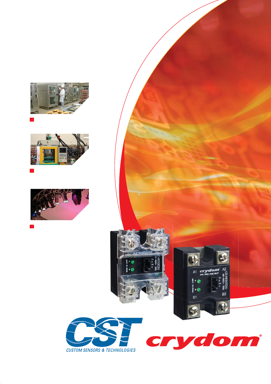
Food Preparation Equipment
Plastic Molding
Lighting Control
Dual Solid State Relays
THE GLOBAL EXPERT
IN
SOLID STATE RELAY
TECHNOLOGY
Courtesy of Steven Engineering, Inc.-230 Ryan Way, South San Francisco, CA 94080-6370-Main Office: (650) 588-9200-Outside Local Area: (800) 258-9200-www.stevenengineering.com
60SSR-DUAL-html.html
rydom has a
distinguished record of
providing advanced, high
quality products with
timely delivery and
competitive pricing. Your
success in today’s
fastpaced global markets
hinges on working with suppliers who respond
quickly and appropriately to your every need.
In addition to an extensive selection of catalog
off-the-shelf items, Crydom offers
custom-designed solid state relays. Fact is we
specialize in satisfying the most demanding
environmental and performance requirements
our customers can devise. Give us your specs,
and watch us exceed your expectations!
At Crydom’s custom-built
100,000 square
foot manufacturing facility,
virtually
everything is accomplished in-house to assure
complete control over delivery, production, and
above all quality. With design, development,
manufacturing and management personnel
under one roof, we’re geared for fast response
to your requirements.
In
Design Engineering
, we focus on pushing
performance, reliability and quality standards
ever higher. Working under a conservative
design and rating philosophy, Crydom’s
seasoned engineering team makes extensive
use of CAD to optimize design of mechanical
parts.
As a result of these efforts, Crydom has
acquired an impressive list of patents in solid
state relay technology, while continuing to
create new circuit and technology-related
inventions as part of our ongoing R & D
programs.
Once the design is solidified,
Production
Engineering
is responsible for the engineering
control of the techniques used throughout
manufacturing. This department works closely
with our design engineering group, establishes
assembly processes, and oversees a
comprehensive on-premises machine shop
which fabricates our assembly fixtures.
As the work progresses,
Material and
Production Control
employ our advanced
computer system, upgraded with our
customized software to keep manufacturing
operations humming. The computer system
employs integral MRP and MSP capabilities to
generate detailed scheduling and planning
information.
Ceramic Hybrid Manufacturing
also is
performed in-house. Crydom manufactures all
metallized ceramic substrates used in our
relays — a major factor in product performance
and reliability, including direct bond copper
substrates.
Courtesy of Steven Engineering, Inc.-230 Ryan Way, South San Francisco, CA 94080-6370-Main Office: (650) 588-9200-Outside Local Area: (800) 258-9200-www.stevenengineering.com
60SSR-DUAL-html.html
Quality Assurance
conducts ongoing product
reliability verification tests, gathering precise
data on the quality of our power semiconductor
vendors and the silicon chips they provide.
Additional tests are performed to meet specific
customer burn-in requirements.
Crydom tests are exhaustive, including
100%
verification
at final test. After units are
completely assembled, they must pass a
complete set of electrical tests, which are
performed twice, once prior to encapsulation and
then again afterward.
Because of our dedication to quality, Crydom
was one of the first American companies to
achieve full certification to the demanding
standards of ISO 9001. In addition, most Crydom
products are approved by UL, CSA, VDE, TUV
and carry the CE Mark signifying conformance
with the latest European directives. Certain panel
mount and din rail mount relays carry UL 508A
SCCR ratings.
Learn how an alliance with the world leader in
solid state relays can pay off for you. For details,
call your authorized Crydom distributor today.
DUAL SOLID STATE RELAYS
Dual Output SSRs
Evolution Dual SSRs
For decades Crydom has manufactured top quality Dual Solid State
Relays in addition to its standard single and three phase SSR lines. All
Crydom
“D”
and
“H12”
series Dual SSRs have two totally
independent AC output relays in a single standard panel mount
package making them ideal for a wide variety of applications including
Heating, Lighting and Motion Control.
Each Dual SSR has two outputs controlled by two independent inputs.
This allows engineers using multiple Solid State Relays in a panel to
save space in many applications. Fast-on termination suitable for
rated load currents to 40 amps/ 530 VAC per channel are standard.
Terminations for the input controls are either square pins or fast-on
connectors Utilizing dual SCR’s for the AC switch output with internal
snubber, Crydom Dual SSRs provide greater protection against false
triggering. Model choices include zero voltage or random turn-on
switching.
Crydom has used innovation and technology to expand its line of Dual
SSRs creating the
Evolution Dual
series. Evolving from Crydom’s
successful
“D”
and
“H12”
series of Dual SSRs, the
Evolution Duals
offer an improved mechanical and thermal design providing higher
capacity outputs and significantly increased power density. Screw
termination suitable for rated load currents to 50 amps/ 660 VAC per
channel is standard in either “SSR” or “Contactor” output termination
configurations. Each AC output channel features high power SCRs
with high surge ratings and is available with either zero voltage or
random turn on.
The new generation of Dual SSRs with four different input termination
options (pin, locking connector, detachable barriers w/screws, and
direct wire) are available with three different input voltage ratings
including a wide range (4 to 32 VDC) current regulated version.
The new two channel relays are available with an innovative optional
clear IP20 touch safe cover allowing a clear view of the power lead
terminations while providing touch safe operation. Crydom’s AC
output
Evolution Dual Solid State Relays
also feature LED input
status indicators for each channel.
Crydom Dual SSRs are RoHS compliant, CE certified and have pending
UL and cUL recognition.
Courtesy of Steven Engineering, Inc.-230 Ryan Way, South San Francisco, CA 94080-6370-Main Office: (650) 588-9200-Outside Local Area: (800) 258-9200-www.stevenengineering.com
60SSR-DUAL-html.html
Dual Solid State Relays
Questions?
Call or e-mail
+1 (877) 502 5500
+44 (0) 1202 606030
sales@crydom.com
sales-europe@crydom.com
Americas
Europe
OUTPUT SPECIFICATIONS
Operating Voltage (47-63 Hz) [Vrms]
Load Current Range [Arms]
Maximum Surge Current (1 cycle) [Apk] @ 60 Hz
Maximum Surge Current (1 cycle) [Apk] @ 50 Hz
Transient Overvoltage [Vpk]
Maximum On-State Voltage Drop @ Rated Current [Vpk]
Thermal Resistance Junction to Case (RqJC) [ºC/W]
Maximum I²t for Fusing (8.3 msec.) [A²sec]
Maximum I²t for Fusing (10 msec.) [A²sec]
Minimum Off-State dv/dt @ Max. Rated Voltage [V/sec]
Off-state leakage [mArms]
(@ max. line voltage & Ta = 25ºC)
Maximum Turn-On Time
Maximum Turn-Off Time
C
X
2425
XXXX
24-280
0.15-25
300
275
600
1.3
0.65
370
380
500
0.1
1/2 cycle
1/2 cycle
0.5
C
X
2450
XXXX
24-280
0.15-50
750
710
600
1.3
0.33
2320
2520
500
0.1
1/2 cycle
1/2 cycle
0.5
C
X
4825
XXXX
48-660
0.15-25
300
275
1200
1.3
0.65
370
380
500
0.25
1/2 cycle
1/2 cycle
0.5
C
X
4850
XXXX
48-660
0.15-50
750
710
1200
1.3
0.33
2320
2520
500
0.25
1/2 cycle
1/2 cycle
0.5
Power Factor (Minimum) with Maximum Load
INPUT SPECIFICATIONS
Control Voltage Range [VDC]
Minimum Turn-On Voltage [VDC]
Minimum Turn-Off Voltage [VDC]
Nominal Input Impedance [Ohms]
C
XXX
W
XXX
4-32
4
1
See note 5
10 @ 12 VDC
C
XXX
E
XXX
15-32
15
1
1500
18 @ 24 VDC
C
XXX
D
XXX
4-15
4
1
300
16 @ 5 VDC
Typical Input Current [mA]
All parameters at 25ºC and per channel unless otherwise specified.
Turn-On time for random turn-on (R) versions is 0.1 msec.
Off-State dv/dt test method per EIA/NARM standard RS-443, paragraph 13.11.1
Input circuit incorporates active current limitation.
Heat sinking required, see derating curves.
1
1
2
4
5
4
3
2
1
3
Dielectric Strength 50/60Hz Input/Output [Vrms]
Dielectric Strength 50/60Hz Input-Output/Baseplate [Vrms]
Insulation Resistance (Min.) @ 500 VDC [Ohms]
Maximum Capacitance Input/Output [pF]
Ambient Operating Temperature Range [ºC]
Ambient Storage Temperature Range [ºC]
GENERAL SPECIFICATIONS
MECHANICAL SPECIFICATIONS
Weight (Typical)
Maximum Wire Size (Output Terminals)
Encapsulation
Terminals
Maximum Torque (Output Terminals)
Screw Type Output: 8-32
20 in lbs (2.2 Nm)
- 40 to 80
- 40 to 125
0.25 lb (100 grs)
10
9
10
4000
AWG #8 with terminals. AWG #10 Stranded
2500
Thermally Conductive Epoxy
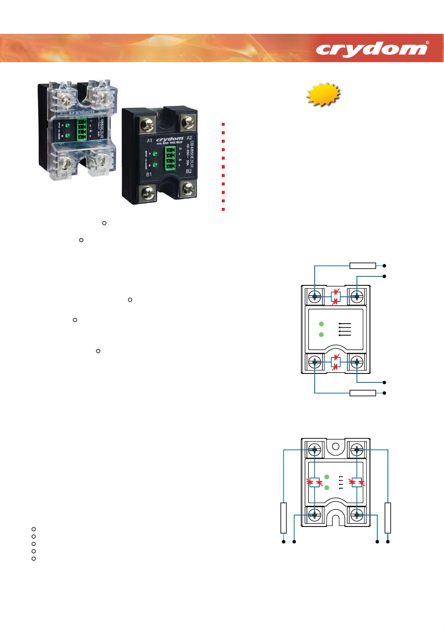
Evolution Dual Relays
AC Output
25-50 Amp
280/660 VAC
25A & 50A Output rating per channel @ 40ºC
120/240 & 480VAC Operating voltage rating
4-15, 15-32 & 4-32VDC Control input options
Four input termination options available
Top-bottom or left-right output screw connections available
Zero voltage or random turn-on available
SCR output for heavy industrial loads
Industry standard panel mount package
IP20 Protective cover available
Input status LED indicators for each channel
CE & RoHS compliant, pending UL & cUL recognition
Wiring Diagrams
New
New
SSR Output Configuration
"U" Option Top-Bottom
Line/Load Connections
LOAD A
LOAD B
AC SUPPLY
AC SUPPLY
+A
+B
-A
-B
A
B
Contactor Output Configuration
"V" Option Left-Right
Line/Load Connections
L
O
A
D
A
L
O
A
D
B
AC SUPPLY
+A
+B
-A
-B
AC SUPPLY
A
B
Courtesy of Steven Engineering, Inc.-230 Ryan Way, South San Francisco, CA 94080-6370-Main Office: (650) 588-9200-Outside Local Area: (800) 258-9200-www.stevenengineering.com
60SSR-DUAL-html.html
Dual Solid State Relays
Other Crydom products and competitive part number cross-reference available at:
www.crydom.com
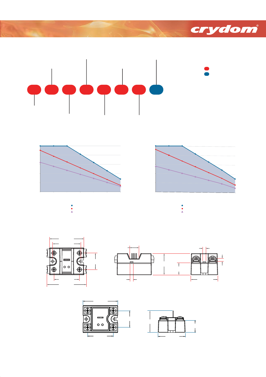
Part Number Nomenclature
V
R
1
D
D
24
25
C
Evolution
Dual Series
Cover Option
C:
IP20
D:
IP00 (No cover)
Output Voltage
@ 50/60 Hz
24:
24-280 VAC
48:
48-660 VAC
Options
Blank:
Zero Turn On
R:
Random Turn On
H:
TP- 01 thermal pad
installed on relay
Required for valid part number
For options only and not required
for valid part number
Output Current
Rating per Channel
25:
25 Amps rms
50:
50 Amps rms
@ Ta= 40ºC
Output Terminal Orientation
U:
A channel on top/ B on bottom (SSR output configurations)
V:
A channel on left/ B on right (Contactor output configurations)
(See wiring diagrams)
Input Control
D:
4-15 VDC
E:
15-32 VDC
W:
4-32 VDC
Input Connector
Options
1, 2, 3, or 4
Mechanical Dimensions
IP20
IP00
Tolerances: ± 0.02 in / 0.5 m
All dimensions are in: inches [millimeters]
1.425 [36.20]
.625 [15.89]
2X .200 [5.08]
2.300 [58.42]
2.635 [66.93]
1.100 [27.94]
1.700 [43.18]
1.875 [47.63]
1.800 [45.72]
8X .191 [4.85]
.803 [20.40]
2X .203 [5.15]
1.700 [43.18]
1.100 [27.94]
2.300 [58.42]
1.800 [45.72]
.803 [20.40]
1.429 [36.30]
New
Derating Curves
1.0°C/W - HS13
1.5°C/W - HS-2
2.0°C/W - HS8.1
Ambient Temperature [°C]
Combined Load Current [Amps]
(25 Amps per Channel)
CXXX
25
XXXX
0
10
20
30
40
50
20
30
40
50
60
70
80
0.5°C/W - HS053
1.0°C/W - HS13
1.5°C/W - HS-2
Ambient Temperature [°C]
Combined Load Current [Amps]
(50 Amps per Channel)
CXXX
50
XXXX
0
20
40
60
80
100
20
30
40
50
60
70
80
Courtesy of Steven Engineering, Inc.-230 Ryan Way, South San Francisco, CA 94080-6370-Main Office: (650) 588-9200-Outside Local Area: (800) 258-9200-www.stevenengineering.com
60SSR-DUAL-html.html
Dual Solid State Relays
Questions?
Call or e-mail
+1 (877) 502 5500
+44 (0) 1202 606030
sales@crydom.com
sales-europe@crydom.com
Americas
Europe
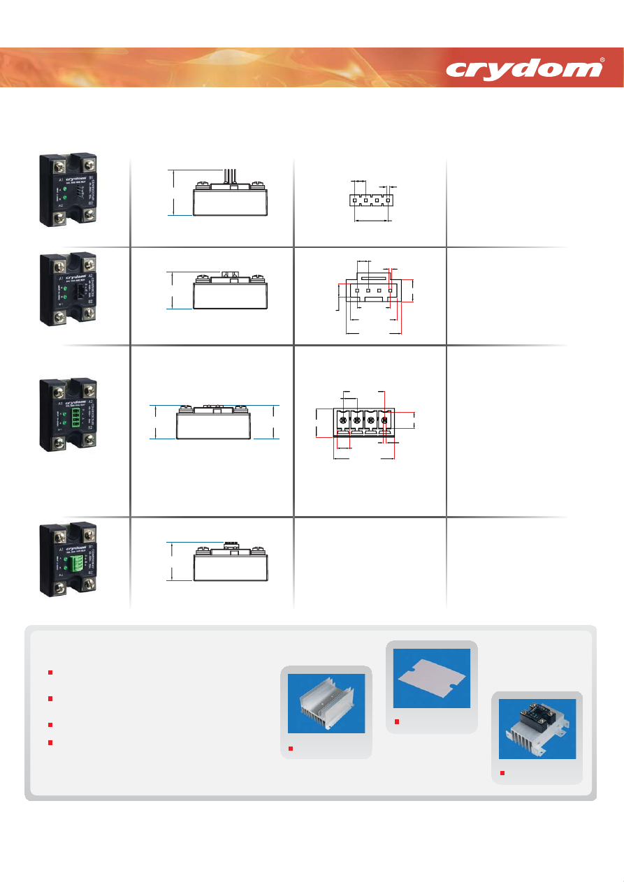
Available Input Connector Options
0.420 [10.67]
0.120 [3.05]
0.300 [7.62]
3X 0.100 [2.54]
4X 0.026 [0.66]
(SQUARE)
0.500 [12.71]
0.200 [5.08]
1.150 [29.21]
INPUT CONNECTOR
OPTION 2
0.300 [7.62]
3X 0.100 [2.54]
4X 0.026 [0.66]
(SQUARE)
1.429 [36.30]
INPUT CONNECTOR
OPTION 1
0.413 [10.50]
3X 0.138 [3.50]
0.122 [3.10]
0.157 [4.00]
0.606 [15.40]
0.285 [7.25]
4X 0.031 [0.80]
(SQUARE)
1.046 [26.58]
1.059 [26.90]
INPUT CONNECTOR
OPTION 3
1.201 [30.50]
INPUT CONNECTOR
OPTION 4
Four Pin Standard
Locking Connector
Detachable Barriers
w/Screws
Direct Wire
Crimp Housing, Positive Latch
Molex 050579404
Accepts wires: AWG #24, 0.2 mm²
Pin Connector
TYCO 3-640440-4
Accepts wires: AWG #22
MECHANICAL DIMENSIONS
INPUT CONNECTOR DIMENSIONS
SUGGESTED MATING
CONNECTORS/PLUGS
Vertical Plug, Top Wire entry
Molex 039500-0004
Phoenix 1840382
Dinkle EC350V-04P
N/A
Vertical Plug, Rear Wire entry
Molex 39503-2004
Phoenix 1862878
Dinkle EC350RL-04P
Vertical Spring Cage Plug, top Wire E
Phoenix 1939934
Dinkle 0221-2004
Vertical Plug, Front Wire entry
Molex 39503-3004
Phoenix 1863178
Dinkle EC350R-04P
All 4 options accept wires: AWG #16 to 24
Accepts wires: AWG #16 to 24
(shown without IP20 cover)
D
h bl B
i
Four Pin Standard
Direct Wire
Locking Connecto
New
Accessories
A large variety of
Heat Sinks
rated from .25 to 5.0 C/W specially
engineered to match the heat dissipation requirements of Crydom SSRs.
Heat Transfer Pads (
Thermal Pads
)
for single, dual and 3 phase SSRs to
maximize thermal conductivity.
Assemblies
of Crydom SSRs on Crydom heat sinks are also available.
SSR mounting
Hardware Kits (English and Metric threads)
.
For more information about these and other accessories please ask your Crydom authorized distributor or visit
www.crydom.com/en/accessories
Heat Sinks
Heat Transfer Pads
Assemblies
Courtesy of Steven Engineering, Inc.-230 Ryan Way, South San Francisco, CA 94080-6370-Main Office: (650) 588-9200-Outside Local Area: (800) 258-9200-www.stevenengineering.com
60SSR-DUAL-html.html
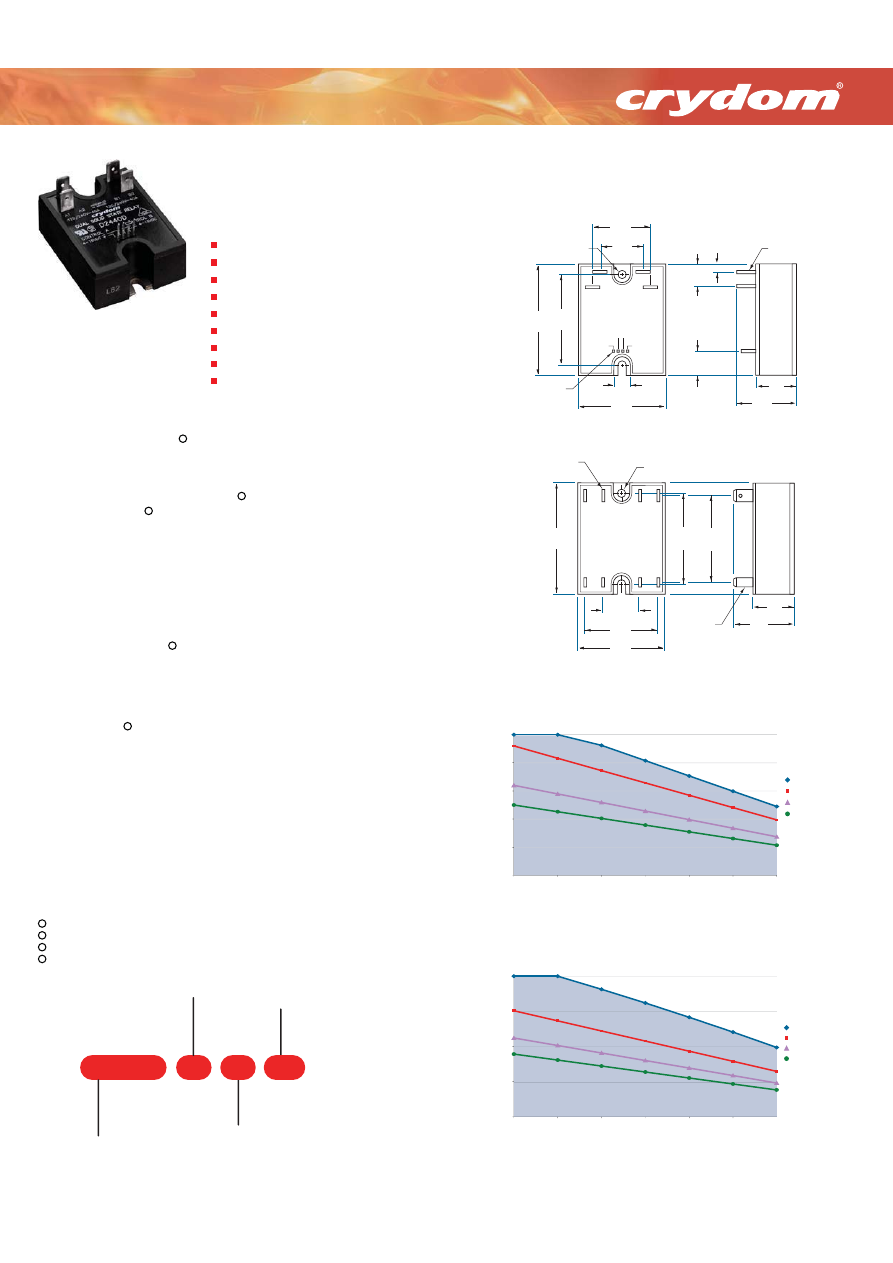
Part Number Nomenclature
-10
D
25
H12D48
Output Function
Blank
: Zero-Crossing
-10
: Random Turn-On
Output Current
per Channel
25
: 25 Amps
40
: 40 Amps
Output Voltage
@ 50/60 Hz
D24:
24-280 VAC
H12D48:
48-530 VAC
Control Voltage
D
: 4-15 VDC
DE
: 15-32 VDC
SERIES
Dual Solid State Relays
Other Crydom products and competitive part number cross-reference available at:
www.crydom.com
Derating Curves
D24
25
XX, H12D48
25
XX
0
10
20
30
40
50
20
30
40
50
60
70
80
Ambient Temperature (°C)
Combined Load Current [Amps]
0.5°C/W
1.0°C/W
2.0°C/W
5.0°C/W
(25 Amps per Channel)
D24
40
XX, H12D48
40
XX
0
20
40
60
80
20
30
40
50
60
70
80
Combined Load Current [Amps]
Ambient Temperature (°C)
0.5°C/W
1.0°C/W
1.5°C/W
2.0°C/W
(40 Amps per Channel)
25A & 40A Output rating per channel
120/240 & 480VAC Operating voltage rating
4-15 & 15-32 VDC Control input options
Internal output snubber standard
SCR output for heavy industrial loads
Industry standard panel mount package
0.25 inch Faston output connectors
Zero voltage or random turn-on available
CE & RoHS compliant, UL & cUL recognized &
VDE approved*
25-40 Amp
120/240/480 VAC
AC Output
Dual Relays
Operating Voltage (47-63 Hz) [Vrms]
Transient Overvoltage [Vpk]
Maximum Off-State Leakage Current @ Rated Voltage [mArms]
Minimum Off-State dv/dt @ Maximum Rated Voltage [V/sec]
Maximum Load Current [Arms]
Minimum Load Current [Arms]
Maximum Surge Current (16.6ms) [Apk] @ 60 Hz
Maximum On-State Voltage Drop @ Rated Current [Vpk]
Thermal Resistance Junction to Case (Rjc) [°C/W]
Maximum I²t for Fusing (8.3 msec) [A²sec]
Minimum Power Factor (with Maximum Load)
INPUT SPECIFICATIONS
D24
XX
D
H12D48
XX
D
24-280
600
10
500
25
0.15
250
1.6
1.02
260
0.5
D2425D
D2425DE
24-280
600
10
500
40
0.15
625
1.6
0.63
1620
0.5
D2440D
D2440DE
48-530
1200
10
500
25
0.15
250
1.6
1.02
260
0.5
H12D4825D
H12D4825DE
48-530
1200
10
500
40
0.15
625
Maximum Surge Current (20.0ms) [Apk] @ 50 Hz
240
600
240
600
1.6
0.63
1620
Maximum I²t for Fusing (10 msec) [A²sec]
285
1780
285
1780
0.5
H12D4840D
H12D4840DE
Control Voltage Range [VDC]
4-15
4-15
Minimum Turn-On Voltage [VDC]
4.0
4.0
Minimum Turn-Off Voltage [VDC]
1.0
1.0
Typical Input Current @ 5 VDC (@ 24 VDC for E-Suffix) [mA]
13
13
Nominal Input Impedance [Ohm]
300
240
Maximum Turn-On Time
1/2 cycle
1/2 cycle
Maximum Turn-Off Time
1/2 cycle
1/2 cycle
DE-
SUFFIX
15-32
15.0
1.0
15
1500
1/2 cycle
1/2 cycle
GENERAL SPECIFICATIONS
Dielectric Strength 50/60 Hz Input/Output [Vrms]
4000
Minimum Insulation Resistance (@ 500 V DC) [Ohm]
10
9
Maximum Capacitance, Input/Output [pF]
10
Ambient Operating Temperature Range [°C]
All parameters at 25°C and per channel unless otherwise specified.
* D2425D & D2440D Models are also CSA approved.
Off-State dv/dt test method pes EIA/NARM standard RS-443, paragraph 13.11.1
Heat sinking required, see derating curves.
Turn-on time for random turn-on (-10) versions is 0.1msec.
-40 to 80
Ambient Storage Temperature Range [°C]
-40 to 125
Weight (typical)
3.0 oz (86.5g)
Encapsulation
Thermally conductive Epoxy
Terminals (Output / Input)
0.25" Fastons / 0.025" Square Pins
4
3
2
1
4
1
OUTPUT SPECIFICATIONS
1
2
3
Dielectric Strength 50/60 Hz Input-Output/Baseplate [Vrms]
2500
120/240V Model
1.87
[47.5]
.85
[21.6]
1.31
[33.2]
1.00
[25.4]
1.17
[29.7]
FASTON terminal
.250 X .032
[4 places]
PIN .025 SQ.
.100 centers
4 places
Mounting hola/slot
0.192 [4.9] DIA.
± 4-15VDC
CONTROL
B
CONTROL
A
4-15VDC ±
A1
A2
B1
B2
120/24OV - 20A
120/24OV - 20A
.15
[3.8]
.59
[15.0]
.45
[11.4]
.55
[14.0]
2.30
[58.4]
1.80
[45.7]
480V Model
.85
[21.6]
1.31
[33.2]
.77
[19.6]
1.37
[34.8]
1.87
[47.5]
1.60
[40.6]
Mounting hole/slot
.0192 [4.9] DIA.
2 PLC'S
120/24OV - 20 A
120/24OV - 20 A
1.80
2.30
[58.4]
-
+
-
+
.250 X .032 FASTON
terminal
[4 places]
.187 X .032
FASTON
terminal
[4 places]
[45.7]
Mechanical Dimensions
Tolerances: ± 0.02 in / 0.5 m
All dimensions are in: inches [millimeters]
CONTROL
B
CONTROL
A
A1
B2
B1
B2
New
Courtesy of Steven Engineering, Inc.-230 Ryan Way, South San Francisco, CA 94080-6370-Main Office: (650) 588-9200-Outside Local Area: (800) 258-9200-www.stevenengineering.com
60SSR-DUAL-html.html
© 2009 Crydom Inc., All Rights Reserved.
03/2009
Specifications are subject to change without prior notice.
Crydom and the Crydom logo are registered trademarks
of Crydom Inc.
Distributed by :
Across the Globe
AMERICAS
USA & CANADA
Crydom Inc
2320 Paseo de las Americas,
Suite 201
San Diego CA 92154
sales@crydom.com
support@crydom.com
Sales Support
Sales Support
Tel.: +1 (877) 502 5500
Tech Support
Tel.: +1 (877) 702 7700
tech-europe@crydom.com
Tech Support
Fax: +1 (619) 710 8540
ASIA
PACIFIC
CHINA & HONG KONG
Custom Sensors &
Technologies Asia
(Shanghai) Ltd.
2 Floor, Innovation Building,
No.1009, Yi Shan Road,
Shanghai, 200233
Tel.: +86 (21) 2401 7766
Fax: +86 (21) 6249 0701
sales-cn@crydom.com
EUROPE
MIDDLE EAST
AFRICA
Crydom SSR Ltd
Arena Business Centre
Holyrood, Close
Poole, Dorset BH17 7FJ
Tel.: +44 (0) 1202 606030
Fax: +44 (0) 1202 606035
sales-europe@crydom.com
CST Latinoamerica
SOUTHERN AND
CENTRAL AMERICAN
COUNTRIES
INDIA
SOUTH KOREA
CST Sensors India Pvt Ltd
Unit 1301 and 1302 Prestige
Meridian II
30 M.G.Road,
Bangalore - 560001
INDIA
Tel.: +91 (80) 4113 2204/05
Fax: +91 (80) 4113 2206
india@cstsensors.com
OTHER ASIAN AND
PACIFIC COUNTRIES
AUSTRIA & SWITZERLAND
BELGIUM
Tel.: +32 (0) 2 460 4413
Fax: +32 (0) 2 461 2614
sales-europe@crydom.com
UNITED KINGDOM
FRANCE
sales-europe@crydom.com
Tel.: +44 (0) 1202 606030
Fax: +44 (0) 1202 606035
vertrieb@crydom.com
GERMANY
Tel.: +49 (0) 180 3000 506
Fax: +49 (0) 180 3205 227
vertrieb@crydom.com
ITALY
Tel.: +39 (0) 2 665 99 260
Fax: +39 (0) 2 665 99 268
sales-europe@crydom.com
THE NETHERLANDS
Tel.: +31 (0) 71 582 0068
Fax: +31 (0) 71 542 1648
sales-europe@crydom.com
SPAIN
Tel.: +34 902 876 217
Fax: +34 902 876 219
sales-europe@crydom.com
MIDDLE EAST,
AFRICA AND OTHER
EUROPEAN COUNTRIES
Tel.: +44 (0) 1202 606030
Fax: +44 (0) 1202 606035
sales-europe@crydom.com
0 810 123 963
0 810 057 605
Custom Sensors &
Technologies
3F, No. 39, Ji-Hu Road
Nei-Hu Dist.
Taipei 114, Taiwan
Tel.: +886 2 8751 6388
Fax: +886 2 2657 8725
eap@cstsensors.com
TAIWAN
Custom Sensors &
Technologies
3F, No. 39, Ji-Hu Road
Nei-Hu Dist.
Taipei 114, Taiwan
Tel.: +886 2 8751 6388
Fax: +886 2 2657 8725
taiwan@cstsensors.com
MEXICO
Automatismo Crouzet
S.A. de C.V.
Calzada Zavaleta 2505 - C
Col Sta Cruz Buenavista
C.P. 72150 - Puebla
MEXICO
Tel. : +52 (222) 409 7000
Fax : +52 (222) 409 7810
01 800 087 6333
Custom Sensors &
Technologies
5F, Jeil Bldg.,
94-46 Youngdeungpo-dong 7-ga
Youngdeungpo-gu,
Seoul, 150-037
South Korea
Tel.: +82 2 2629 8312
Fax: +82 2 2629 8310
korea@cstsensors.com
BRASIL
info@cst-latinoamerica.com
sales-mx@crydom.com
Alameda Rio Negro, 1.084-cj.A31
Centro Empresarial de Alphaville
CEP: 06454-000
Barueri - SP
Tel.: +55 (11) 4191 9797
Fax: +55 (11) 4191 9136
CAT/CR/ED/EN
Courtesy of Steven Engineering, Inc.-230 Ryan Way, South San Francisco, CA 94080-6370-Main Office: (650) 588-9200-Outside Local Area: (800) 258-9200-www.stevenengineering.com