8 PIN DIP HIGH SPEED 10MBit/s LOGIC GATE
PHOTOCOUPLER
Isocom Components Ltd. 1 http://www.isocom.com
Document No
:
DC93136 Rev. 1 April 15, 2009
6N137 Series
F
e
atures:
•
Hig
h
speed 10Mbit/s
•
Fan out of 8 over -40 to 85
℃
•
Logic gate output
•
High isolation voltage between input
and output (Viso=5000 V rms )
•
Compact small outline package
•
Pb free and RoHS compliant.
Description
The 6N137series devices each of consist of an infrared
emitting diodes, optically coupled to a Very high speed
integrated photo detector logic gate with a strobable output.
They are packaged in an 8-pin DIP package and
available in wide-lead spacing and SMD option.
Applications
•
Ground loop elimination
•
LSTTL to TTL, LSTTL or 5 volt CMOS
•
Line receiver, data transmission
•
Data multiplexing
•
Switching power supplies
•
Pulse transformer replacement
•
Computer peripheral interface
Truth Table (Positive Logic)
Input Enable Output
H H L
L H H
H L H
L L H
H NC L
L NC H
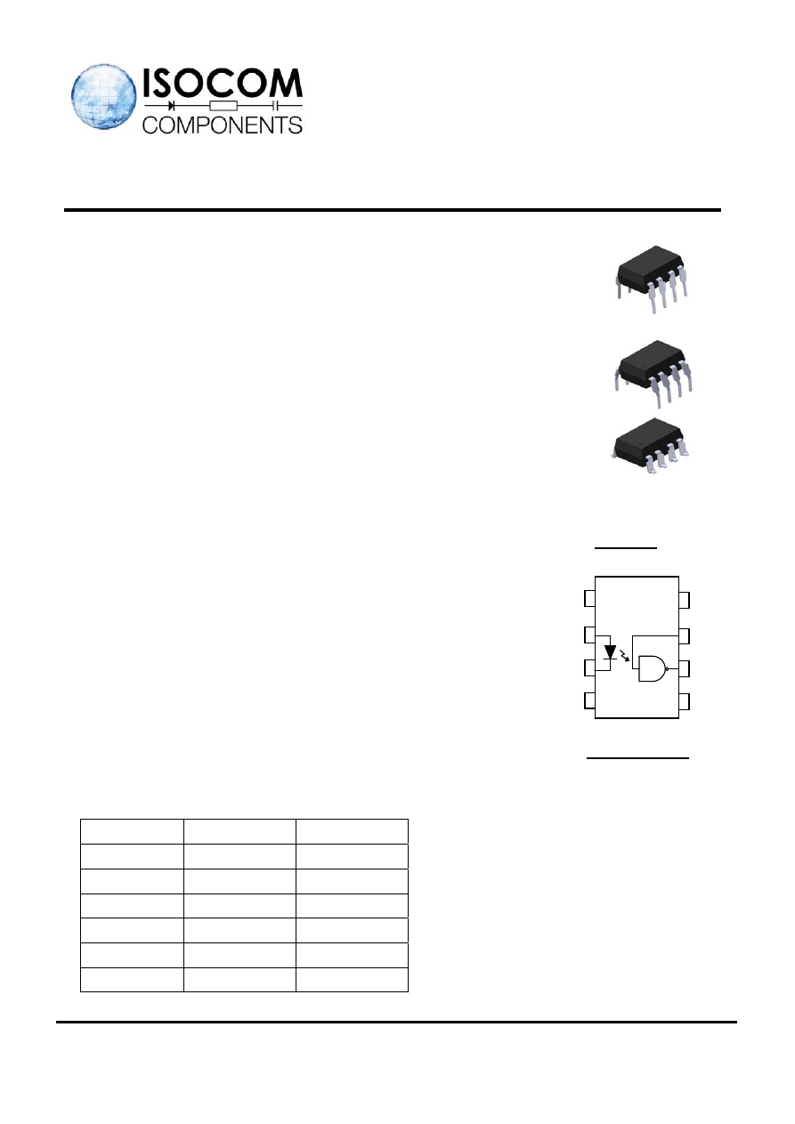
Pin Configuration
1, 4. N.C
2, Anode
3, Cathode
5, Gnd
6, Vout
7, V
E
8, V
CC
Schematic
5
6
7
8
1
2
3
4