Isolation Switches 911/912/913-...
www.e-t-a.com
Issue B
4
- 65
4
Description
Typical applications
Technical data
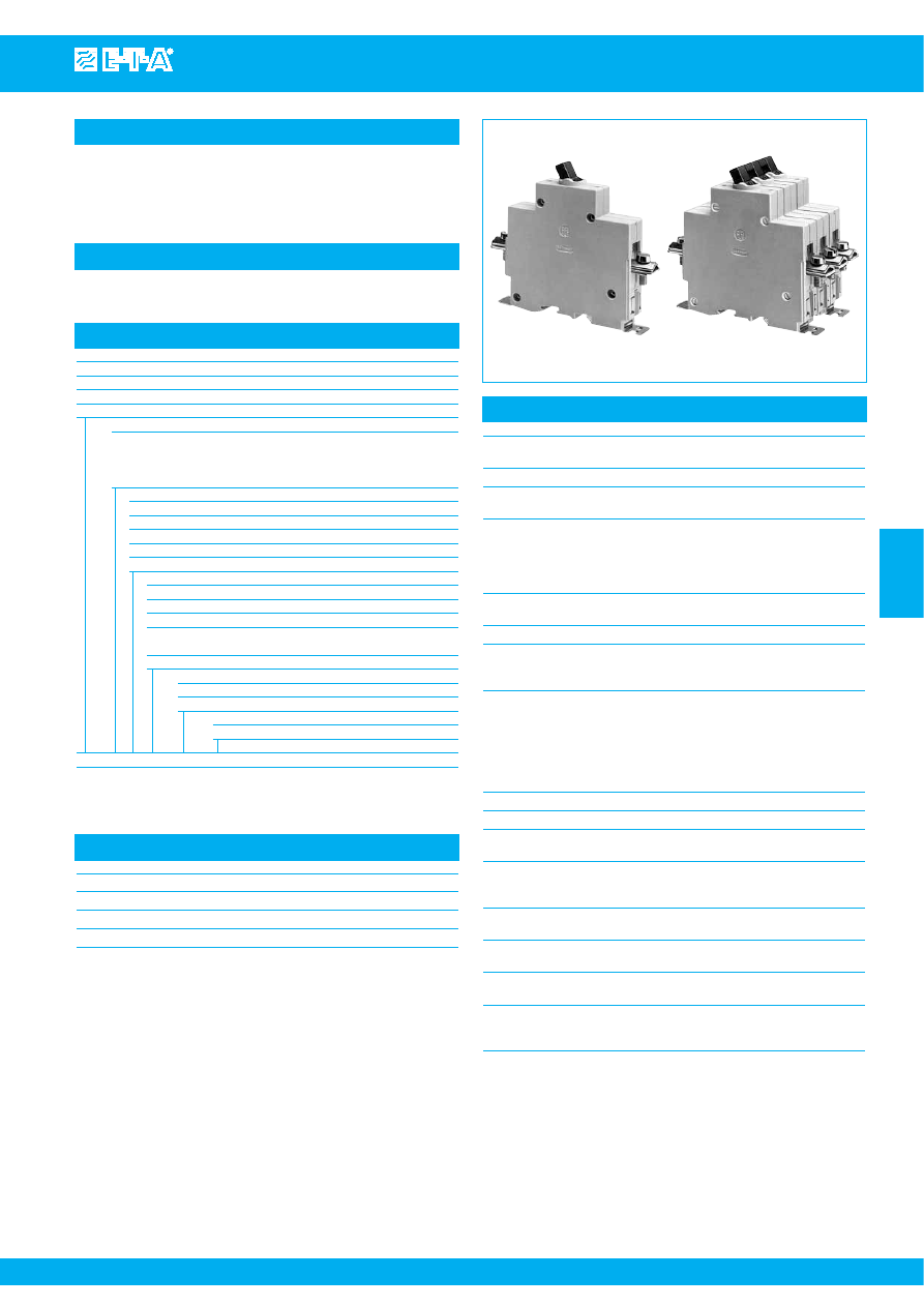
Single, two and three pole isolators to EN 60947 / IEC 60947 with toggle
actuation. Designed for rail, panel or surface mounting. Options include
auxiliary contacts and remote electrical disconnection.
For circuit breaker versions see types 410, 520, 530.
Control systems, industrial equipment.
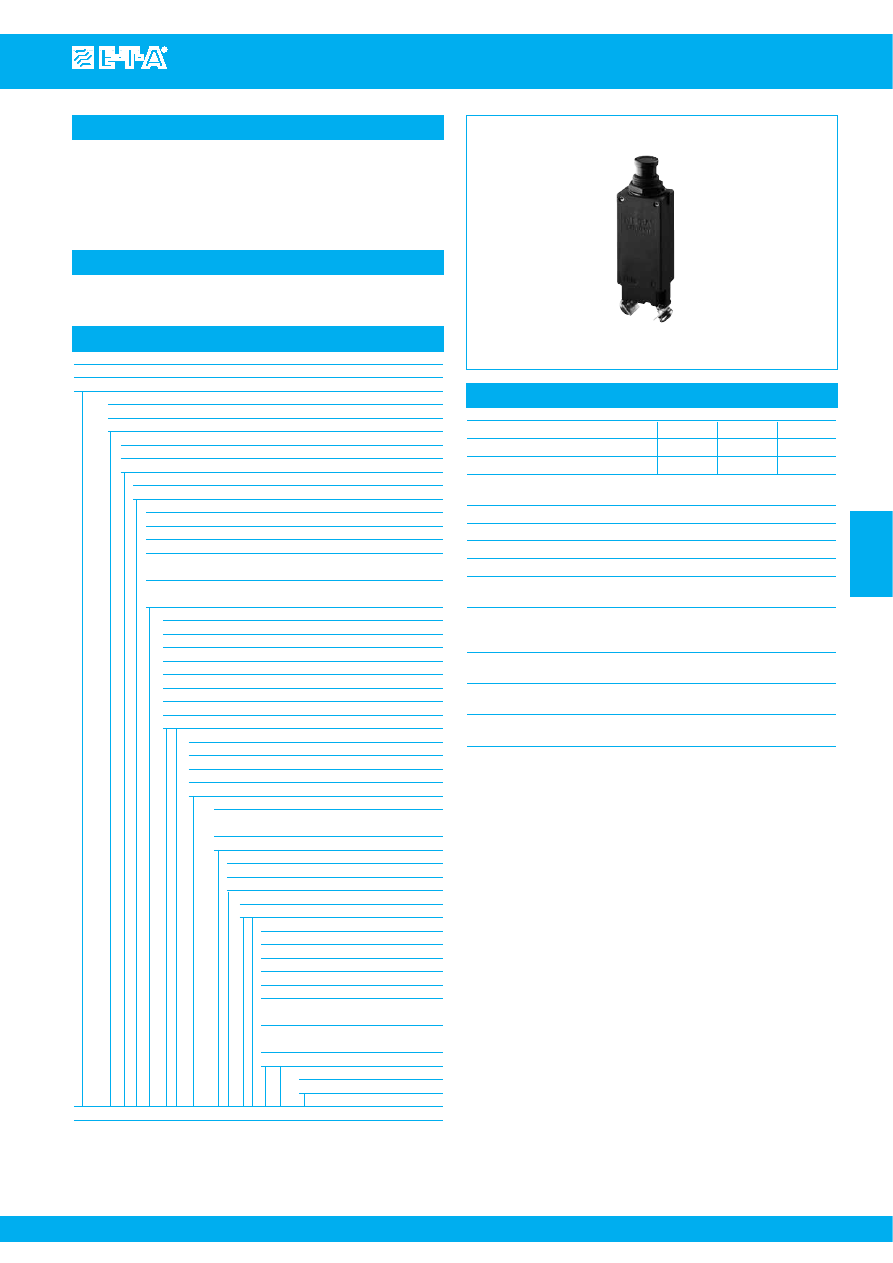
911-K
913-K
Voltage rating
AC 240 V; 3 AC 415 A; 3 AC 500 V;
DC 110 V
Current rating range
32 A, 63 A, 125 A
Auxiliary contact rating
6 A at AC 240 V or DC 28 V;
1 A at DC 110 V
Electrical remote disconnection (FA)
operating voltage
DC 12 V or DC 24 V
operating current
approx. 18 A or 12 A
max. pulse time
10 ms < t
ON
< 20 ms /t
OFF
> 10 s
switching time
< 20 msec
Typical life
10,000 operations at I
N
20,000 operations mechanical
Ambient temperature -40...+75 °C (-40...+167 °F)
Insulation co-ordination rated impulse
pollution
(IEC 60664 and 60664A)
withstand voltage
degree
6 kV
3
Dielectric strength
(IEC 60664 and 60664A)
test voltage
operating area
AC 3,300 V
pole/pole
AC 3,300 V
main to aux. circuit
AC 2,200 V
aux. circuit 11-12
to 13-14
AC 1,000 V
Insulation resistance
> 100 MΩ (DC 500 V)
Short-circuit protection
back up fuse max. 125 A
Degree of protection
operating area IP40
(IEC 60529/DIN 40050)
terminal area IP00
Vibration
5 g (57-200 Hz), ± 0.38 mm (10-57 Hz)
to IEC 60068-2-6, test Fc
10 frequency cycles/axis
Shock
25 g (11 ms)
to IEC 60068-2-27, test Ea
Corrosion
96 hours at 5 % salt mist
to IEC 60068-2-11, test Ka
Humidty
240 hours at 95 % RH
to IEC 60068-2-3, test Ca
Mass
approx. 220 g single pole
approx. 440 g double pole
approx. 660 g three pole
Standard current ratings and typical internal resistance values
Current rating (A)
Internal resistance (
Ω
)
32
≤ 0.002 per pole
63
≤ 0.002 per pole
125
≤ 0.002 per pole
Ordering information
Type No.
911
single pole switch
912
double pole switch
913
three pole switch
Terminal design
K
main terminal
up to 32 A: pressure plate B5-DIN 46288
up to 63 A: pressure plate B6-DIN 46288
up to 125 A: terminal screws DIN 46206, sheet 2, form 1, thread M6
Mounting
1
surface mounting
2
rail or panel mounting (rail DIN EN 50022-35x7.5)
3
rail or panel mounting (rail DIN EN 50035-G32)
4
panel mounting only
5
mounting brackets – surface mounting
Auxiliary contacts (terminals M3.5 or blade terminals (-FA)
Si
one each N/O and N/C (not for 911-FA)
Si1
one N/C (11,12) (not for 911-FA)
Si2
one N/O (13,14)
2Si
two each N/O and N/C – types 912, 913 only
(not for 912-FA)
3Si
three each N/O and N/C – type 913 only (not for 913-FA)
Remote trip (optional)
FA 12
remote disconnection, for DC 12 V
FA 24
remote disconnection, for DC 24 V
Current ratings
32, 63, 125 A
911 - K - 1- Si -
... - 63 A
ordering example
The exact part number required can be built up from the table of choices shown
above. Ordering references for optional features should be omitted if not required.
Courtesy of Steven Engineering, Inc.-230 Ryan Way, South San Francisco, CA 94080-6370-Main Office: (650) 588-9200-Outside Local Area: (800) 258-9200-www.stevenengineering.com
87BATSW-html.html
2.84
2
8.7
14
9
92
72
83.5
M5
57
10
.551
.354
.394
2.24
3.62
3.29
.343
.079
S
urface mounting
s
uffi
x
: -1
Rail mounting
(EN 50035-G32)
s
uffi
x
: -3
Mounting bracket
s
-
s
urface mounting
s
uffi
x
: -5
Rail mounting
(EN 50022-35
x
7.5)
s
uffi
x
: -2
Panel mounting
s
uffi
x
: -4
Cover
s
, label
s
,
s
ealing
s
crew
s
etc. can be fitted on the
front of the hou
s
ing.
www.e-t-a.com
Issue B
4
- 66
Isolation Switches 911/912/913-...
4
1
line
3
1
5
3
2
FA
13
14
13
21
11
12
4
22
23
24
14
1
2
S
i
13
21
11
12
4
22
23
24
14
2
3
S
i
6
31
32
33
34
11
13
2
12
14
2
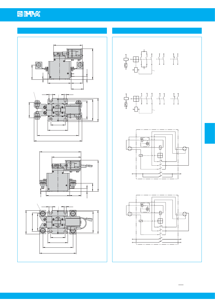
911
911-…-FA
912-K
913-K
line 1
recommended lin
k
for FA coil protection
pre-wired at the factory
line
line
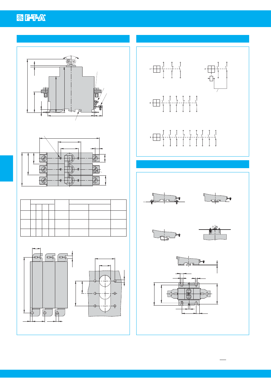
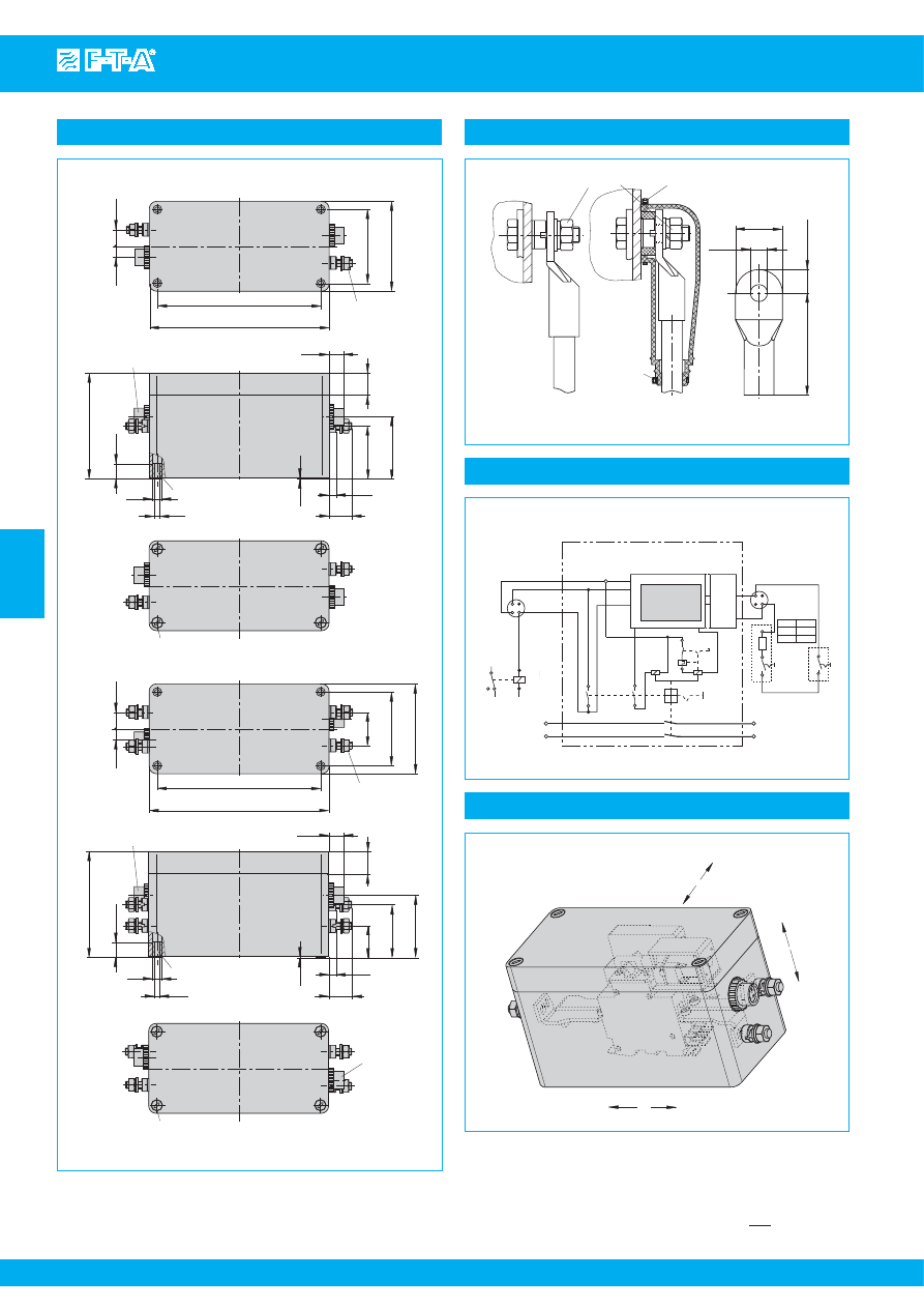
Internal connection diagrams
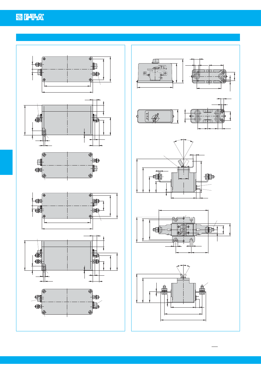
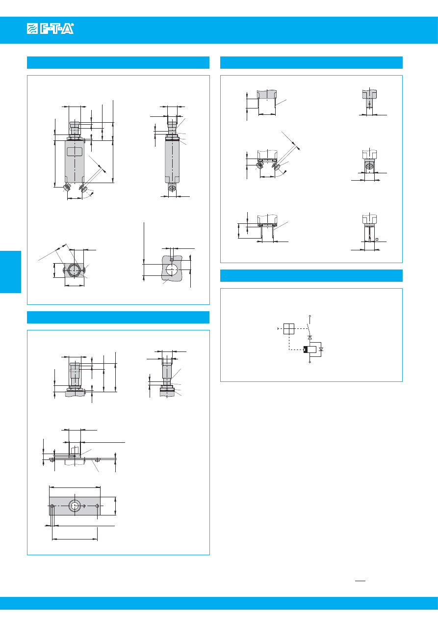
Dimensions
13
.512
15.4
.606
15.4
.606
114
4.49
120
4.72
120
4.72
7
.276
9
.354
9
.354
Max.
tightening
tor
q
ue
≤
32 A
≤
63 A
≤
125 A
Dimen
s
ion
s
mm/in. Terminal
B
pre
ss
ure
plate B5
DIN 46288
pre
ss
ure
plate B6
DIN 46288
terminal
s
crew
97
3.7
22
ø4.6
4.6
14.6
s
urface mounting
35
ø20
ø4
22
+0,5
44
+1
monting hole
s
26
°
26
°
106
90.5
71.5
41
6
92
16
s
ymmetrical rail DIN EN 50022-35x7.5
G
profile rail DIN EN 50035-
G
32 (not
s
hown)
D
45
35
66
44
22
E
B
C
S
i terminal
s
M3.5*
1 N/C (
S
i1) or FA
coil (pole 1 only)
OFF
ON
M3.5 - thread max. 9 mm (.354 in.) deep
tightening tor
q
ue max. 0.55 Nm
3
pole 1
pole 2
pole 3
1N/O (
S
i2)
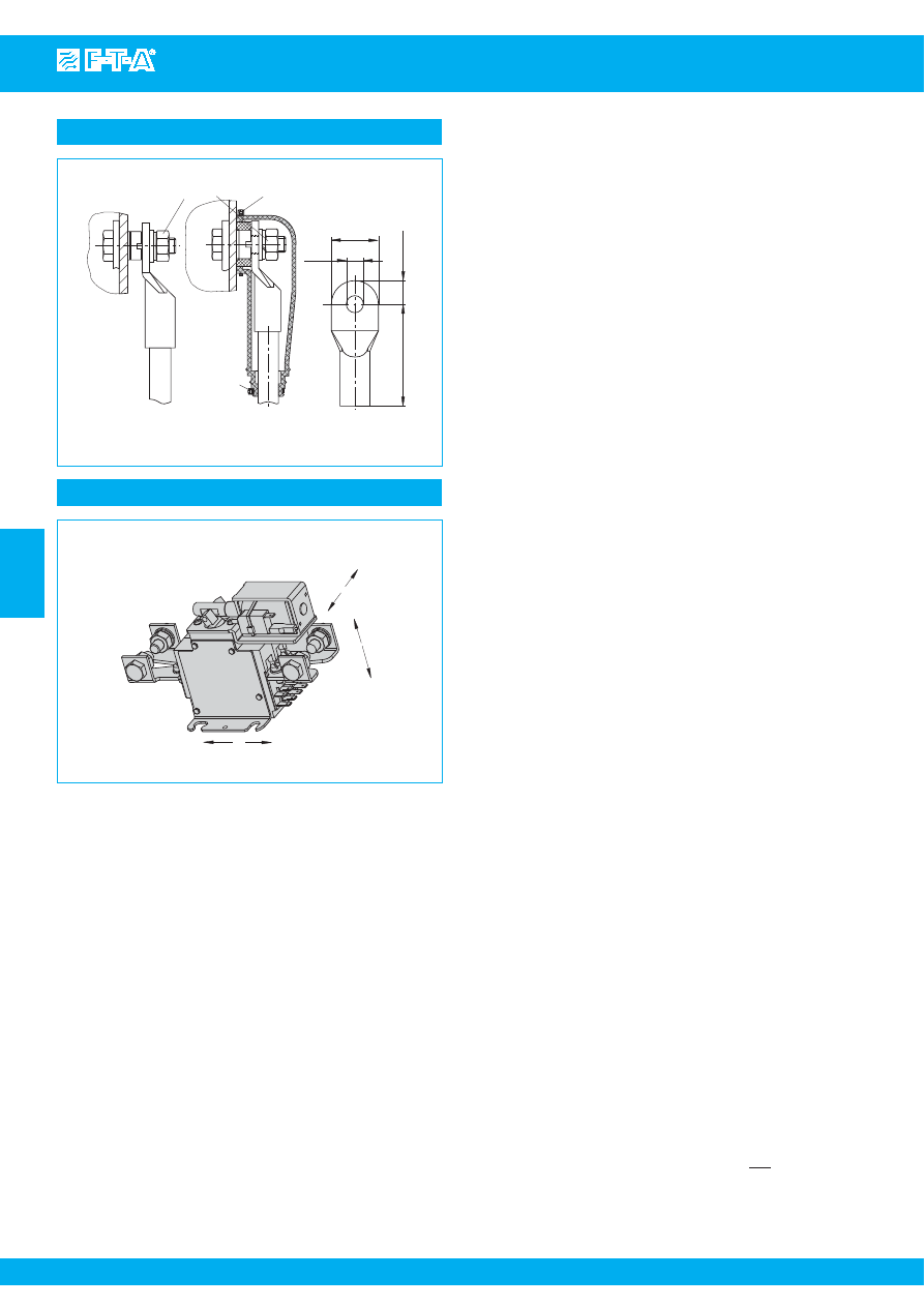
Current
rating
Cro
ss
s
ection (
s
ee DIN 46288)
with 1 or 2 e
q
ual
conductor
s
with 2 different
conductor
s
M5
M6
M6
C
D
E
2.0 Nm
2.5 Nm
2.5 Nm
2.5 mm
2
to
10 mm
2
2.5 mm
2
to
10 mm
2
4 mm
2
to
16 mm
2
4 mm
2
and 6 mm
2
or
6 mm
2
to 16 mm
2
.236
3.56
1.64
4.17
.118
2.82
3.62
.630
1.77
1.38
.866
1.73
2.60
19
.748
.575
.181
3.82
.146
.181
.866
.787
1.38
.157
.866
1.73
+.020
+.039
tightening tor
q
ue
max. 4 Nm
tightening tor
q
ue
max. 0.8 Nm
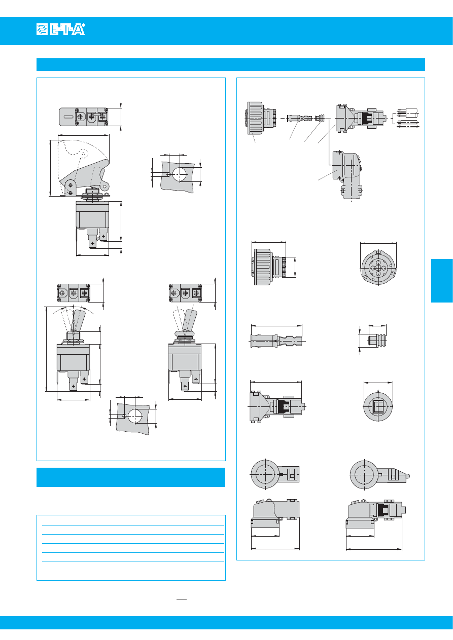
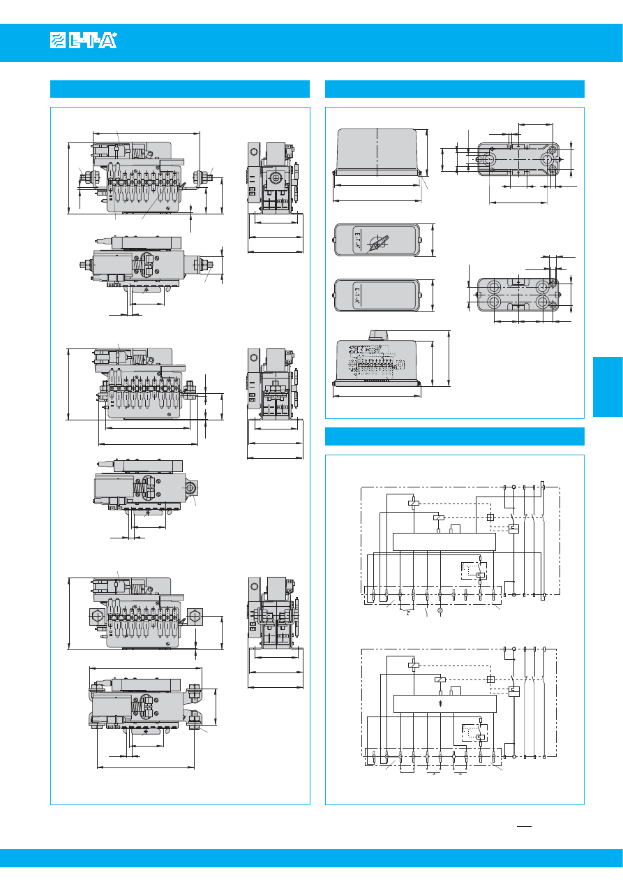
Mounting method
This is a metric design and millimeter dimensions take precedence ( mm )
inch
Courtesy of Steven Engineering, Inc.-230 Ryan Way, South San Francisco, CA 94080-6370-Main Office: (650) 588-9200-Outside Local Area: (800) 258-9200-www.stevenengineering.com
87BATSW-html.html
Isolation Switches 911/912/913-...
www.e-t-a.com
Issue B
4
- 67
4
mounting hole
s
1.2
38
max. 4
24.5
53
62
59
59
+0.3
35
22
ø4
.047
25
+0.3
21
2.07
2.44
1.50
.827
.965
max .157
.984
+.012
.157
2.32
+.012
1.38
2.32
.827
.047
1.2
44
53
40
40
35
25
+0.3
+0.3
ø4
38
21
max. 4
24.5
mounting hole
2.07
1.73
1.50
.827
.965
max .157
.984
+.012
.157
1.58
+.012
1.38
1.58
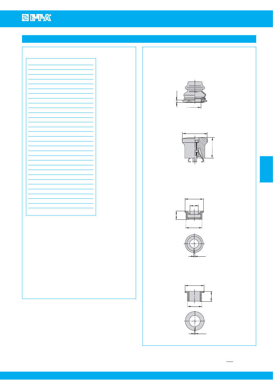
For
s
erie
s
911
≤
125 A
Water
s
pla
s
h cover tran
s
lucent with fi
x
ing plate
and
s
crew
s
(IP54)
X 211 118 01
For
s
erie
s
911 - 240 A and 912
Water
s
pla
s
h cover tran
s
lucent with fi
x
ing plate
and
s
crew
s
(IP54)
X 211 119 01
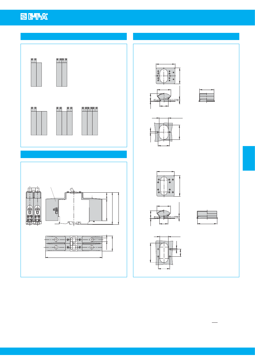
Accessories
Accessories
protected again
s
t bru
s
h contact *
165
ø10
44
64
19
92
94
protected again
s
t bru
s
h contact *
* to DIN 57106T100/VDE 0106 T100
6.50
.748
2.52
3.62
3.70
.394
1.73
Terminal in
s
ulation cover
X 211 705 01
(1
s
et = 2 pc
s
per pole)
Auxiliary contact arrangement with multipole switches
S
i
2
S
i
S
i
2
S
i
3
S
i
double pole device
s
three pole device
s
This is a metric design and millimeter dimensions take precedence ( mm )
inch
All dimensions without tolerances are for reference only. In the interest of improved design,
performance and cost effectiveness the right to make changes in these specifications
without notice is reserved.Product markings may not be exactly as the ordering codes.
Errors and omissions excepted.
Courtesy of Steven Engineering, Inc.-230 Ryan Way, South San Francisco, CA 94080-6370-Main Office: (650) 588-9200-Outside Local Area: (800) 258-9200-www.stevenengineering.com
87BATSW-html.html
Battery Isolation Switches 921/922
www.e-t-a.com
Issue B
4
- 69
4
Description
Typical applications
Ordering information
Technical data
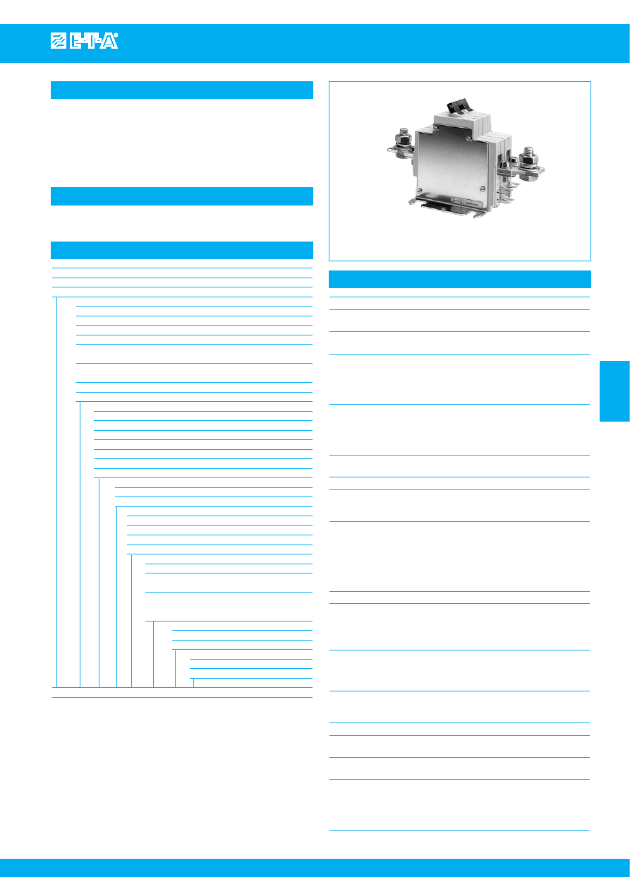
Single or two pole isolation switches to IEC 60947/EN 60947 with toggle
actuation. Options include auxiliary contacts, a moulded flame retardant
enclosure for added environmental protection (with or without rotary
action external operating knob), and remote operation - disconnection
only, or disconnection and re-connection. A version for use in hazardous
areas (e.g. petroleum and chemical tankers) is available to special order.
Vehicles of all types (including tankers), boats, battery powered systems.
921 922
single pole double pole
Type No.
921
single pole switch
922
double pole switch
Enclosure design (optional)
B3
without external operating knob, for use only with single pole devices
B31
with external operating knob, for use only with single pole devices
B32
without external operating knob, for use only with double pole devices
B33
with external operating knob, for use with double pole devices
B34
with external operating knob, for use only with double pole devices
with remote-re-connection facility
B35
with external operating knob, for use only with single pole devices
with remote-re-connection facility
C3
without external operating knob, 1-pole, IP65
C32
without external operating knob, 2-pole, IP65
Terminal design
K12
for single pole version, enclosures B3, B31, B35
K60
for single pole version
K61
for double pole version
K62
for double pole version
K71
compulsory and only for C3 housing
K72
for double pole version, enclosures B32, B33, B34
K76
compulsory and only for C32 housing
Mounting
2
compulsory and only for C3 and C32 housing
5
mounting brackets - surface mounting
Auxiliary contacts (blade terminals 6.3x0.8)
Si2
one N/O
Si01
one N/C, two N/O
2Si2
two N/O
Si10
one each N/O and N/C
Remote operation
FA
remote disconnection
FC
electrical remote disconnection (FA)
and re-connection (FE)
BC-FA
electrical remote disconnection and
manual remote re-connection
(not for enclosure -B.. or -C..)
Coil voltage
12
AC/DC 12 V
24
AC/DC 24 V
Current ratings
240 A
type 921
120 A
type 922
921 - ... - K60 - 5 - Si2 - FA
24 - 240 A
ordering example
The exact part number required can be built up from the table of choices shown
above. Ordering references for optional features should be omitted if not required.
Voltage rating
DC 12 V; DC 24 V
Current rating range
240 A type 921, single pole
120 A type 922, double pole
Auxiliary contact rating
6 A at DC 24 V
1 A at DC 110 V
Electrical remote disconnection (-FA):
operating voltage
DC 12 V or DC 24 V
operating current
approx. 18 A or approx. 12 A
max. pulse time
10 ms < t
ON
< 20 ms /t
OFF
> 10 s
switching time
< 20 ms
Electrical remote re-connection (-FE):
operating voltage
DC 12 V or DC 24 V
operating current
approx. 30 A or approx. 15 A
max. pulse time
0.1 s < t
ON
< 1.2 s /t
OFF
> 60 s
switching time
< 100 ms
Typical life
10,000 operations at I
N
20,000 operations mechanical
Ambient temperature -40...+75 °C (-40...+167 °F)
Insulation co-ordination rated impulse
pollution
(IEC 60664 and 60664A)
withstand voltage degree
6 kV
3
Dielectric strength
(IEC 60664 and 60664A) test voltage
operating area
AC 3,300 V
pole/pole
AC 3,300 V
main to aux. circuit
AC 2,200 V
aux. circuits 11-12
to 13-14
AC 1,000 V
Insulation resistance
> 100 MΩ (DC 500 V)
Switching capacity
Type 921
Type 922
2,500A for 1s at +23°C
1,500A for 1s at +23°C
600A for 1min at +23°C
600A for 30s at +23°C
600A for 2min at -23°C
600A for 1min at -23°C
600A for 90s at 0°C
600A for 45s at 0°C
Degree of protection
operating area IP40
(IEC 529/DIN 40050)
terminal area IP00
IP54 with enclosure -B..
IP65 with enclosure -C..
Vibration
5 g (57-200 Hz), ± 0.38 mm (10-57 Hz)
to IEC 60068-2-6, test Fc
10 frequency cycles/axis
Shock
25 g (11 ms), to IEC 60068-2-27, test Ea
Corrosion
96 hours at 5 % salt mist
to IEC 60068-2-11, test Ka
Humidity
240 hours at 95 % RH,
to IEC 60068-2-3, test Ca
Mass
approx. 900 g base unit
+ approx. 400 g remote disconnection
+ approx. 100 g remote re-connection
+ approx. 750 g B housing
+ approx. 1,000 g C housing
Courtesy of Steven Engineering, Inc.-230 Ryan Way, South San Francisco, CA 94080-6370-Main Office: (650) 588-9200-Outside Local Area: (800) 258-9200-www.stevenengineering.com
87BATSW-html.html
www.e-t-a.com
Issue B
4
- 70
Battery Isolation Switches 921/922
4
Dimensions
3.62
116
288
155
192
0
I
M3.5x10
tightening tor
q
ue
max. 0.55 Nm
123
91
61
45
4
2
35
11.5
114.5
92
13
26
°
26
°
180
83.5
M5
M10x25
tightening tor
q
ue
max. 4 Nm
72
92
14
9
57
61.5
11
30
26
°
26
°
106
91
45
4
2
92
13
M10x25
tightening tor
q
ue max. 4 Nm
72
ø26
ø15.3
49
82.5
82.5
35
70
44
N/C or FA
N/O
ø16.5
116
196
141
1
2
167.5
1-pole
2-pole
921-K12-5-…-BC-FA..
921-K60-…-FA
ø28.5
ø47
1.85
1.12
4.57
7.72
7.56
6.10
11.34
2.84
.650
4.57
2.76
1.02
.602
1.38
3.25
3.25
1.93
.453
4.51
1.38
.512
3.62
.079
.157
1.77
2.40
3.58
4.84
7.09
3.29
2.84
.433
1.18
1.73
.551
.354
2.24
2.42
5.55
6.59
.512
3.62
.079
.157
1.77
3.58
4.17
Moulded enclo
s
ure IP54 -B3
8.74
222
AUX.
CONTACT
S
+ BATTERY
REMOTE
CONTROL
- LOAD
102
222
244
31
9.5
s
lot for mounting
s
crew M6
20
M10 tightening tor
q
ue
max. 20 Nm
21
ø11
ø7
AUX.
CONTACT
S
BATTERY
REMOTE
CONTROL
LOAD
s
lotted
s
crew plug, tightening tor
q
ue 2 Nm
±
0,2 Nm
124
30
connector
to DIN 72585
146
15
23
73
86
+ LOAD
- BATTERY
46
43
Moulded enclo
s
ure IP 65 -C3
Moulded enclo
s
ure IP 65 -C32
.591
.906
8.74
9.61
4.02
4.88
.787
1
1.18
2.87
3.39
.827
5.75
.433
.276
.039
.374
1.22
102
244
M10 tightening tor
q
ue
max. 20 Nm
124
15
23
.591
.906
4.02
4.88
9.61
1.81
31
9.5
s
lot for mounting
s
crew M6
20
21
ø11
ø7
30
connector
to DIN 72585
146
73
86
.787
1
1.18
2.87
3.39
.827
5.75
.433
.276
.039
.374
1.22
1.69
s
lotted
s
crew plug, tightening tor
q
ue 2 Nm
±
0,2 Nm
This is a metric design and millimeter dimensions take precedence ( mm )
inch
Courtesy of Steven Engineering, Inc.-230 Ryan Way, South San Francisco, CA 94080-6370-Main Office: (650) 588-9200-Outside Local Area: (800) 258-9200-www.stevenengineering.com
87BATSW-html.html
Battery Isolation Switches 921/922
www.e-t-a.com
Issue B
4
- 71
4
Dimensions types 922
2.24
114
0
I
122
11
45
92
49
57
2
M10x25
tightening tor
q
ue max. 4 Nm
M5
9
72
83.5
92
79
164
190
57
61
14
162
114
M10x25
tightening tor
q
ue max. 4 Nm
2
92
45
32
122
M5
922-K72-5-…-FC
922-K61-5-…-FC
118
143
72
67.5
93
4.49
4.80
.433
2.24
.079
3.62
1.77
1.93
.354
.551
2.84
3.29
3.62
2.24
3.11
6.46
7.48
2.40
11
4.49
4.80
.433
3.66
.079
3.62
1.77
6.38
1.26
9
79
57
14
.354
.551
3.11
4.65
5.63
83.5
92
3.29
3.62
2.66
2.84
Internal connection diagrams
connector acc.
to DIN 72582
REMOTE CONTROL
BATT
LOAD
AUX. CONTACT
S
BATT
LOAD
REMOTE CONTROL
13
14
S
i2
FE
load 2
FA
battery +
13
14
S
i2
23
24
13
14
2
S
i2
13
14
11
12
S
i10
FE
load
1
FA
2
4
3
1
921
922
3
1
2
4
FA
3
1
2
4
11
13
12
14
FE
921-C3-…
922-C32-…
3
1
2
4
FA
3
1
2
4
11
13
12
14
FE
connector acc.
to DIN 72582
connector acc.
to DIN 72582
AUX. CONTACT
S
recommended lin
k
for FA coil protection
pre-wired at the factory
battery +
recommended lin
k
for FA coil protection
pre-wired at the factory
connector acc.
to DIN 72582
23
24
13
14
2
S
i2
13
14
11
12
S
i10
This is a metric design and millimeter dimensions take precedence ( mm )
inch
Courtesy of Steven Engineering, Inc.-230 Ryan Way, South San Francisco, CA 94080-6370-Main Office: (650) 588-9200-Outside Local Area: (800) 258-9200-www.stevenengineering.com
87BATSW-html.html
www.e-t-a.com
Issue B
4
- 72
Battery Isolation Switches 921/922
4
4
3
5
6
1
2
Terminals with housing C3.
Shoc
k
directions
max. 30
IP00
IP54
T
max
= 20 Nm
max. 65
max. 15
ø 11.5
cable fa
s
tener
cable fa
s
tener
Rubber cap
s
and cable fa
s
tener
s
are
s
upplied with the product.
.453
max. 1.18
max .591
max. 2.56
This is a metric design and millimeter dimensions take precedence ( mm )
inch
All dimensions without tolerances are for reference only. In the interest of improved design,
performance and cost effectiveness the right to make changes in these specifications
without notice is reserved.Product markings may not be exactly as the ordering codes.
Errors and omissions excepted.
Courtesy of Steven Engineering, Inc.-230 Ryan Way, South San Francisco, CA 94080-6370-Main Office: (650) 588-9200-Outside Local Area: (800) 258-9200-www.stevenengineering.com
87BATSW-html.html
4
- 73
4
Description
Typical applications
Ordering information
Technical data
Single pole, miniaturised aircraft simulator switch with extremely fast
magnetic trip time. Blade, screw and wire wrap terminals. Aircraft style
threadneck and push/pull button with white trip indicator ring. Current
rating marked on the push button according to customer’s request by
adhesive labels or marking inserts.
Simulators.
9510-...
Type No.
9510
switch with magnetic instantaneous trip for flight simulators
Mounting method and style
G
threadneck mounting with standard push button
L
threadneck mounting with long push button
Threadnec
k
design
1
M12x1x6.3
2
7/16-32UNx6.3
Number of poles
1
single pole
Accessories for threadnec
k
0
without accessories
1
hex nut M12x1, aluminium, lock washer ø12/ ø15 (crinkle) fitted
2
hex nut M12x1, aluminium, serrated lock washer ø12.1/ø17.2, fitted
3
hex nut 7/16-32UN, aluminium, toothed washer
ø11.3/ø14.9, fitted (MS 3533-141)
9
front plate with mounting thread 6-32UNC-2B for
threadneck 7/16-32 UN, threaded sleeve 7/16-32 UN
Terminal configuration
J
screw terminals with inch thread
1
6-32UNC-2B, silver plated bent 45° inwards
3
6-32UNC-2B, silver plated, with socket, bent 45° inwards
P
blade terminals
1
A6.3x0.8 DIN 46244, silver plated
W
wire wrap terminal
4
pin size 1.2x1.2 EN 60352-1, gold plated, with socket
Z 0
without terminals
Rated voltage
F0
DC 24 V
F1
DC 28 V
F2
DC 48 V
F4
DC 12 V
Accessories (terminal screws)
B
Phillips screw 6-32UNC-2Ax4.8 fitted
(MS 51957-25)
Z
without accessories
Accessories (terminal washers)
0
without accessories
2
3.6 split washer fitted (MS 35338-136)
Internal circuit
R2
with logic diode, contacts gold plated
Colour of the push button
S
black
G
green
A
green, for marking insert
B
black, for marking insert
0
without marking
1
hot-stamped marking, can be
read when locating pin is above
2
hot-stamped marking, can be read
when locating pin is at the bottom
9
without marking insert
Current ratings
0.5...150 A
9510 -
G
1 1 1 - J 1 F1 - B 0 R 2 S 0 - 10 A
ordering example
Voltage rating
DC 12 V
DC 24 V
DC 28 V
DC 48 V
Trip current
< 450 mA < 160 mA < 200 mA < 340 mA
Trip time
< 25 ms
< 25 ms
< 25 ms
< 20 ms
Min. switching voltage
at +23 °C/+73.4 °F DC 25 V
at +60 °C/+140 °F
DC 28 V
Internal resistance
157 Ω
Typical life
10,000 operations at DC 24, 28 or 48 V
Temperature range
-30...+60 °C (-22...+140 °F)
Insulation resistance
> 100 MΩ (DC 500 V)
Degree of protection
operating area IP40
(IEC 60529)
terminal area IP00
Vibration (sinusoidal) 3 g (57-500 Hz), ± 0.23 mm (10-57 Hz)
to DIN IEC 60068-2-6, test Fc
10 cycles/frequency axis
Shock
5 g (11 ms),
to DIN IEC 60068-2-27, test Ea
Humidity
240 hours at 95 % RH, 40 °C
to DIN IEC 60068-2-3, test Ca
Mass
23 g without hardware
26 g with hardware
Simulator switch, magnetic operation 9510-...
Issue B
www.e-t-a.com
Courtesy of Steven Engineering, Inc.-230 Ryan Way, South San Francisco, CA 94080-6370-Main Office: (650) 588-9200-Outside Local Area: (800) 258-9200-www.stevenengineering.com
87BATSW-html.html
www.e-t-a.com
Issue B
4
- 74
Simulator switch, magnetic operation 9510-...
4
2
-
line I
+
internal circuit R 2
Dimensions
Other main terminal designs
Internal connection diagram
15
+0.15
9.5
±
0.2
45
°
2
tightening tor
q
ue max. 3.5 Nm
M12x1 or
7/16-32UN-2A THD
18.5 OFF
I LINE
m
ax
. 2
1.5
2.5
13 ON
42.7
terminal
s
crew
6-32UNC-2A x 4.8/.189
(M
S
51957-25)
with loc
k
wa
s
her (M
S
35338-136)
plug-in terminal
s
tightening tor
q
ue:
0.8 Nm factory mounted
0.4 Nm mounted by cu
s
tomer
47.5
ø10
blac
k
or
green
white
hex nut
loc
k
wa
s
he
ø8.4
3.5
8
mounting hole
s
ø3.2
thic
k
ne
ss
1.5 … 3
.059 … .118
S
W
14
(M12x1)
S
W12.7(7/16-32)
9.5
locating pin
current rating in A
14.2
19.5
6.35
+0.2
(M12x1)
(7/16-32)
+0.2
ø12.5
ø11.5
.250
1.87
.059
.098
m
ax .079
.512
.728
1.68
.591
.315
.138
.331
.394
.374
.559
.768
.374
±
.008
.126
+.006
+.008
(M12x1)
(7/16-32)
+.008
.492
.453
9510-G…-J1..-B2....
m
ax
. 2
m
ax .079
15
45
°
.591
8
.315
.248
17
9.5
blade terminal
DIN 46244-A6.3-0.8 (QC .250)
plug-in terminal
s
.374
.669
-P1…
6.3
.268
6.8
-J3…
1.2
12.7
.614
wire wrap pin 1.2 x 1.2 /.047 x .047
EN 60352-1
plug-in/pull-out terminal
module (max. 25 time
s
)
15.6
3.6
.142
.500
.047
-W4…
terminal
s
crew
6-32UNC-2A x 4.8/.189
(M
S
51957-25)
with loc
k
wa
s
her
(M
S
35338-136)
plug-in/pull-out terminal
module
(max. 25 time
s
)
tightening tor
q
ue 1 Nm
10
.394
10
.394
Other threadnec
k
designs
6-32UNC-2B in
s
ertion nut
s
M12x1 or
7/16-32UN-2A THD
28
1.5
2.5
22.5
6.35
.250
.059
.098
.886
1.10
ON
OFF
blac
k
or
green
ø10
white
hex nut
loc
k
wa
s
her
ø8.4
3.5
.138
.331
.394
-G219
-L219
-L…
.250
7/16-32UN-2. THD
1.5
.059
6.35
1.6
.063
ø12
.472
52.1
2.05
18.5
.728
46
1.81
(
s
elf loc
k
ing)
threaded
s
leeve
front plate
This is a metric design and millimeter dimensions take precedence ( mm )
inch
Courtesy of Steven Engineering, Inc.-230 Ryan Way, South San Francisco, CA 94080-6370-Main Office: (650) 588-9200-Outside Local Area: (800) 258-9200-www.stevenengineering.com
87BATSW-html.html
4
- 75
4
Plug-in screw terminal,
bent at 45° inwards (2 pcs needed per unit)
Y 307 187 02
terminal silver plated
Y 304 508 02
Phillips screw 6-32 UNC-2Ax4.8 (MS 51957-25)
Y 304 509 01
split washer (MS 35338-36)
Plug-in blade terminal
(2 pcs needed per unit)
Y 307 202 02
P10 terminal silver plated
Plug-in/pull-out screw terminals with soc
k
et,
bent at 45° inwards
X 222 173 11
terminals silver plated
Plug-in/pull-out wire wrap terminals with soc
k
et
X 222 174 12
terminals gold plated
Part number
Rated current (A)
Y 307 082 01
0.5
Y 307 082 02
1/2
Y 307 082 03
1
Y 307 082 04
1.5
Y 307 082 05
1 1/2
Y 307 082 06
2
Y 307 082 07
3
Y 307 082 08
5
Y 307 082 09
7.5
Y 307 082 10
7 1/2
Y 307 082 11
10
Y 307 082 12
15
Y 307 082 13
20
Y 307 082 14
25
Y 307 082 15
30
Y 307 082 16
35
Y 307 082 17
6
Y 307 082 18
40
Y 307 082 19
50
Y 307 082 20
60
Y 307 082 21
70
Y 307 082 22
75
Y 307 082 23
80
Y 307 082 24
90
Y 307 082 25
100
Y 307 082 26
120
Y 307 082 27
125
Y 307 082 28
150
Y 307 082 29
2.5
Y 307 082 30
2 1/2
Y 307 082 31
7
Label (blac
k
) for push/pull button (S0 or
G
0)
S
pla
s
h cover/he
x
nut a
ss
embly with O ring
(IP66 and IP67)
(approved to V
G
95345, part 23)
X 200 801 03
matt black fini
s
h nut M12
x
1
x
1.8, black cover
X 200 801 08
nickel plated nut M12
x
1
x
1.8, tran
s
parent cover
X 200 801 09
matt black fini
s
h nut
7/16-32
x
1
x
1.8,
black cover
X 200 801 10
matt black fini
s
h nut
7/16-32
x
1
x
1.8,
tran
s
parent cover
M12x1 or
.071
7/16-32
1.8
Actuator e
x
ten
s
ion
(blac
k
) to be fitted on the pu
s
h button
(approved to V
G
95345, T23)
X 200 803 01
ø20
17
ø.787
.669
Identification collar
to be
s
napped on the pu
s
h button
Y 307 004 01
black
Y 307 004 02
white
Y 307 004 03
red
Y 307 004 04
green
Y 307 004 05
blue
6.4
ø6.85
ø12.35
ø14
.270
.551
.486
.252
0.65
.026
Lock out ring
to bloc
k
the pu
s
h button in OFF po
s
ition
Y 307 005 01
red
Y 307 005 02
black
0.8
.031
ø10.9
ø14.6
.575
.429
7.7
.303
Accessories
This is a metric design and millimeter dimensions take precedence ( mm )
inch
Issue B
www.e-t-a.com
Simulator switch, magnetic operation 9510-...
Courtesy of Steven Engineering, Inc.-230 Ryan Way, South San Francisco, CA 94080-6370-Main Office: (650) 588-9200-Outside Local Area: (800) 258-9200-www.stevenengineering.com
87BATSW-html.html
4
- 76
4
Hex nut M12x1
Y 300 116 04
Hex nut 7/16-32
Y 304 506 03
Loc
k
washer Ø12 / Ø15
Y 300 118 03
Serrated loc
k
washer Ø12.1 / Ø17.2
Y 302 911 01
Toothed washer Ø11.3 / Ø14.9 (MS 35333-141)
Y 304 507 01
Front plate with mounting thread 6-32UNC-2B
for threadnec
k
7/16-32UN
Y 301 516 21
Threaded sleeve
Y 307 281 02
Extracting tool of mar
k
ing insert
Y 307 301 01
Mar
k
ing inserts (push button configuration A or B)
Accessories
hot stamped
current rating
blac
k
green
(A)
Y 307 280 01
Y 307 280 02
without
X 222 175 01
X 222 176 01
0.5
X 222 175 02
X 222 176 02
1/2
X 222 175 03
X 222 176 03
1
X 222 175 04
X 222 176 04
1.5
X 222 175 05
X 222 176 05
1 1/2
X 222 175 06
X 222 176 06
2
X 222 175 07
X 222 176 07
3
X 222 175 08
X 222 176 08
5
X 222 175 09
X 222 176 09
7.5
X 222 175 10
X 222 176 10
7 1/2
X 222 175 11
X 222 176 11
10
X 222 175 12
X 222 176 12
15
X 222 175 13
X 222 176 13
20
X 222 175 14
X 222 176 14
25
X 222 175 15
X 222 176 15
30
X 222 175 16
X 222 176 16
35
X 222 175 17
X 222 176 17
6
X 222 175 18
X 222 176 18
40
X 222 175 19
X 222 176 19
50
X 222 175 20
X 222 176 20
60
X 222 175 21
X 222 176 21
70
X 222 175 22
X 222 176 22
75
X 222 175 23
X 222 176 23
80
X 222 175 24
X 222 176 24
90
X 222 175 25
X 222 176 25
100
X 222 175 26
X 222 176 26
120
X 222 175 27
X 222 176 27
125
X 222 175 28
X 222 176 28
150
X 222 175 29
X 222 176 29
2.5
X 222 175 30
X 222 176 30
2 1/2
X 222 175 31
X 222 176 31
7
All dimensions without tolerances are for reference only. In the interest of improved design,
performance and cost effectiveness the right to make changes in these specifications
without notice is reserved.Product markings may not be exactly as the ordering codes.
Errors and omissions excepted.
Simulator switch, magnetic operation 9510-...
Issue B
www.e-t-a.com
Courtesy of Steven Engineering, Inc.-230 Ryan Way, South San Francisco, CA 94080-6370-Main Office: (650) 588-9200-Outside Local Area: (800) 258-9200-www.stevenengineering.com
87BATSW-html.html
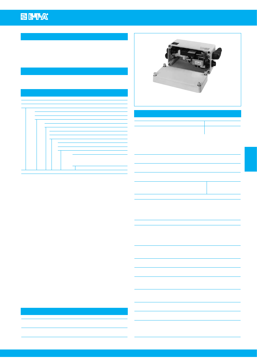
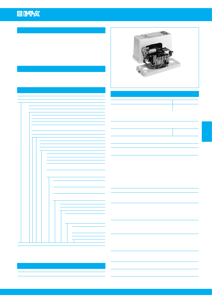
Battery Master Switch E-1032-...
www.e-t-a.com
Issue B
4
- 77
4
Description
Typical applications
Ordering information
Technical data
The battery master switch E-1032-... allows remotely controlled
connection and disconnection of the battery. In the event of reverse
connection the battery will be disconnected from the vehicle electrical
system.
Commercial vehicles
E-1032
Type No.
E-1032
Version
NA1
single pole
NA2
double pole
Enclosure
C
with moulded enclosure IP65
Isolation switch
921
single pole switch
922
double pole switch
Voltage rating
DC 24 V
DC 12 V
Variant No.
e.g. special versions, mounting plate.
Designation determined by
manufacturer
E-1032 - NA1 - C 921 - DC 24 V - ...
ordering example
Voltage rating
DC 24 V
DC 12 V
Voltage rang
ON
18 - 32 V
9 - 16 V
OFF 15 - 32 V
8.5 - 16 V
The switching function is no longer ensured
when the voltage falls below the minimum
values. The switch will not change its
position when the voltage falls down to 0 V
(automatic locking).
Current ratings
240 A single pole
120 A double pole
Overload capacity
2,500 A for 1 s at 23 °C, single pole
1,500 A for 1 s at 23 °C, double pole
Current consumption
≤ 15 mA
of the electronics
(with the control circuit connected)
Switching current at U
N
DC 24 V:
DC 12 V:
ON
approx. 15A/100 ms approx. 20A/100 ms
OFF
approx. 12A/100 ms approx. 10A/100
ms
Control circuit
4 - 6 mA ON
Control switch
with coding resistance
(accessory)
DC 24 V: 1 kΩ
DC 12 V: 330 Ω
without coding resistance to ADR for
external actuation
Temperature range
-40...+75 °C (-40...+167 °F)
Reverse polarity
If polarized incorrectly, the Master Switch
protection
will switch off immediately, disconnecting
the entire vehicle electrical system. After
approx. 30 s the circuit breaker of the ON
coil will trip.
Resettability
When the Battery Master Switch is
mechanically switched off, it will be reset
immediately by the electronics.
Typical life
10,000 operations at I
N
20,000 operations, mechanical
Degree of protection
housing IP65
IEC 60529/DIN40050)
terminal studs with rubber cap IP54
Vibration
5 g (57-200 Hz), ± 0.38 mm (10-57 Hz)
to IEC 60068-2-6, test Fc,
10 frequency cycles/axis
Shock
25 g (11 ms) direction 1, 2, 3, 4
15 g (11 ms) direction 5, 6
to IEC 60068-2-27, test Ea
Corrosion
96 h at 5 % salt mist,
to IEC 60068-2-11, test Ka
Humidity
240 h at 95 % RH,
to IEC 60068-2-78, test Cab
Terminals
Main terminals
blade terminals with cable lugs for M10
terminal studs
Control cable
connector to DIN 72585
Technical data
Auxiliary contact
max. 6 A
for auxiliary relay
(circuit not protected)
Mass single pole:
approx. 3,500 g with enclosure,
double pole:
approx. 3,700 g with enclosure,
Courtesy of Steven Engineering, Inc.-230 Ryan Way, South San Francisco, CA 94080-6370-Main Office: (650) 588-9200-Outside Local Area: (800) 258-9200-www.stevenengineering.com
87BATSW-html.html
www.e-t-a.com
Issue B
4
- 78
Battery Master Switch E-1032-...
4
max. 30
IP00
IP54
T
max
= 20 Nm
max. 65
max. 15
ø 11.5
cable fa
s
tener
cable fa
s
tener
Rubber cap
s
and cable fa
s
tener
s
are
s
upplied with the product.
.453
max. 1.18
max .591
max. 2.56
Rubber cap
Dimensions
E-1032-NA1-…
1 pole
E-1032-NA2-…
2 pole
8.74
222
+ BATTERY
POWER
S
UPPLY
- LOAD
BATTERY
POWER
S
UPPLY
LOAD
s
lotted
s
crew plug, tightening tor
q
ue 2 Nm
±
0,2 Nm
+ LOAD
- BATTERY
46
43
102
244
M10 tightening tor
q
ue
max. 20 Nm
124
15
23
.591
.906
4.02
4.88
9.61
1.81
31
9.5
s
lot for mounting
s
crew M6
20
21
ø11
ø7
30
connector
to DIN 72585
146
73
86
.787
1
1.18
2.87
3.39
.827
5.75
.433
.276
.039
.374
1.22
1.69
s
lotted
s
crew plug, tightening tor
q
ue 2 Nm
±
0,2 Nm
102
222
244
M10 tightening tor
q
ue
max. 20 Nm
124
15
23
.591
.906
8.74
9.61
4.02
4.88
31
9.5
s
lot for mounting
s
crew M6
20
21
ø11
ø7
30
connector
to DIN 72585
146
73
86
.787
1
1.18
2.87
3.39
.827
5.75
.433
.276
.039
.374
1.22
Internal connection diagrams
connector acc.
to DIN 72582
3 pole
OFF
2(-)
connector acc.
to DIN 72582
2 pole
- rel.85
87a
E-1032-
Electronic
R1
BATT
(D+)
generator D+
85
86
87
30
15
31
LOAD
ON
circuit
brea
k
er
ON 4…6 mA
3
(+)
1
(-)
2
1
(+)
batt +
batt -
1
2
3
2
3
Power connection
R1
12 V
24 V
UB
330
Ω
1
k
Ω
contr
ol
cir
cuit
Shock directions
4
3
5
6
1
2
Please follow the instructions for installation
This is a metric design and millimeter dimensions take precedence ( mm )
inch
Courtesy of Steven Engineering, Inc.-230 Ryan Way, South San Francisco, CA 94080-6370-Main Office: (650) 588-9200-Outside Local Area: (800) 258-9200-www.stevenengineering.com
87BATSW-html.html
Battery Master Switch E-1032-...
www.e-t-a.com
Issue B
4
- 79
4
5. 90
°
cover for
corrugated conduit NW10
Y 306 499 01
ø25.8
42
ø25.8
33
6. 90
°
cover for
s
heathed cable
Y 306 499 02
47.5
ø25.8
4. 180
°
cover for
s
heathed cable
Y 306 500 01
1. Female connector
S
W
X 221 378 02
2-way
X 221 378 01
3-way
X 221 378 03
4-way
ø5.9
7.8
3.
S
eal
Y 306 502 01
31
ø18.3
ø32.8
2. Jac
k
for female connector
Y 306 501 01
20.7
jac
k
for female
connector
female connector
1
2
3
4
5 or 6
180
°
cover for
s
heathed cable
90
°
cover
Manufacturer: AMP
s
eal
1.22
.720
1.29
.307
.232
.815
1.87
1.02
1.02
1.30
1.02
1.65
Accessories
.126
mounting hole
s
(with pin wa
s
her)
9.3
ø3.2
ø12.4
ADR
s
witch with
s
afety cover
0Z223Z000141
12 V
0Z223Z000142
24 V
mounting hole
s
(with pin wa
s
her)
9.3
ø3.2
ø12.4
ADR
s
witch without rubber boot
0Z223Z000143
ADR
s
witch with rubber boot
(IP54 in operating area)
0Z223Z000144
max.16
max.16
35
max. 29
max. 50
max. 52
6.5
max.16
35
max. 29
17
°
17
°
12
6.5
73.5
35
max. 29
6.5
.366
.126
.488
max .630
max. 1.97
max. 2.05
1.38
.256
max. 1.14
max .630
max .630
.472
2.89
1.38
.256
max. 1.14
max. 1.14
.366
.488
1.38
.256
Standard connector set OZ112Z000179,
comprising:
(AMP-parts) suitable for single/double pole Battery Master Switch
E-1032-..., DC 12 V and DC 24 V
Quantity
Designation
Ref. No.
1
female connector, 3-pole
X 221 378 01
1
female connector, 2-pole
X 221 378 02
5+1 replacem.
jack for female connector
Y 306 501 01
5+1 replacem.
seal
Y 306 502 01
2
90 ° cover
Y 306 499 01
corrugated conduit NW 10
This is a metric design and millimeter dimensions take precedence ( mm )
inch
All dimensions without tolerances are for reference only. In the interest of improved design,
performance and cost effectiveness the right to make changes in these specifications
without notice is reserved.Product markings may not be exactly as the ordering codes.
Errors and omissions excepted.
Courtesy of Steven Engineering, Inc.-230 Ryan Way, South San Francisco, CA 94080-6370-Main Office: (650) 588-9200-Outside Local Area: (800) 258-9200-www.stevenengineering.com
87BATSW-html.html
Battery Isolation Switches E-1073-437 and E-1073-921/-922
www.e-t-a.com
Issue B
4
- 81
4
Description
Typical applications
Ordering information
Technical data – Electronic module
Single pole circuit breaker type 437 or single/two pole isolation switches
types 921/922 featuring an additional electronic function module which
limits the duration of the supply to the remote disconnect and re-
connect coils, avoiding damage in the event of unusual operating
circumstances. Available with undervoltage monitoring option to
protect batteries from the effects of deep discharge, status output for
undervoltage, auto reset feature.
Battery and cable protection for all types of vehicle (including electric),
battery powered systems.
E-1073-437
Type No.
E-1073
control unit for types 921/922 and 437 with remote control
Voltage rating
0
DC 12 V
1
DC 24 V
Control mode
1
ON/OFF control input
00
without additional function
02
with undervoltage protection and status output
12
with autoreset, undervoltage protection and status output
(921/922 only)
2
ON and OFF buttons
33
with control current supply and ON/OFF test input
Circuit Breaker/Isolation Switch
437
single pole circuit breaker (2-pole upon request)
921
single pole battery isolation switch
922
double pole battery isolation switch
Enclosure design (optional)
blank = without housing
B3
moulded housing, for use with single pole devices
B32
moulded housing, for use with double pole device
B34
moulded housing, external operating knob, for use
with double pole devices (not with auto reset)
B35
moulded housing, external operating knob, for use
with single pole devices (not with auto reset)
Terminal design
K12
flat screw terminals angled 90°,
for single pole version
K60
straight flat screw terminals,
for single pole version, without housing
K72
flat screw terminals angled 90°,
for double pole version
Characteristic curve (type 437 only)
06
fast magnetic trip
07
delayed magnetic trip (standard)
Auxiliary contacts
Si01
one N/C, two N/O
(one N/C, one N/O with
autoreset option)
Current ratings
437:
40, 50, 63, 80, 100,
120, 160, 200, 240A
921:
240 A
922:
120 A
E-1073 - 1 1 02 - 437 - B3 - K12 - 07 - Si01 - 240 A
ordering example
The exact part number required can be built up from the table of choices shown
above. Ordering references for optional features should be omitted if not required.
Voltage rating
DC 12 V
DC 24 V
Voltage rating range
ON 10.3 - 16 V
18 - 32 V
OFF 9 - 16 V
16 - 32 V
Correct switching performance is not
guaranteed if the voltage falls below the
minimum value.
Temperature range
electronic control unit -40...+80 °C (-40...+176 °F)
Operating current
ON
approx. 30 A approx. 15 A
OFF
approx. 10 A approx. 20 A
Excitation time
ON
typically 100 ms
OFF
typically 20 ms
Switching frequency
0.1 Hz max.
Power consumption typically < 1 mA
of electronic control unit (when switched off or button operated)
Control inputs
E-1073-.1..:
»E/A« (ON/OFF), »U-AUS«
(undervoltage protection OFF), »A-W« (auto reset)
E-1073-.2..:
»T-EIN« (button ON), »T-AUS« (button OFF)
voltage
max. 32 V
ON (high)
> 8 V
OFF (low)
< 3 V
power consumption DC 12 V: typically 1 mA
DC 24 V: typically 5 mA
EMC
according to DIN 40839/ISO 7637
Reverse polarity
If polarized incorrectly, the Battery Isolation
protection Switch will operate immediately. The
circuit breaker will trip after a few seconds.
Undervoltage protection
optional with E-1073-.1..
switching thresholds DC 12 V: 11.0 V ± 0.2 V
DC 24 V: 22.8 V ± 0.2 V
hysteresis
typically 0.5 V
trip time
typically 40 sec
Undervoltage status output »UST«, optional with E-1073-.1..
transistor output minus switching
current load
corresponding to 2 W lamp load, short-
circuit proof
Automatic reset »A-W«,
(optional with E-1073-.1.., with series 921/922 only)
Reset after mechanical disconnection is
provided by the integral electronic
control after approx. 100 ms.
Control current supply »+US2«, with E-1073-.2.. for T-EIN/T-AUS
May be connected to 20 control inputs.
Noise-voltage proof, short-circuit proof
Terminals
control terminals
blade terminals 6.3x0.8 mm
Mass, with circuit breaker approx. 2,000 g without enclosure
or isolation switch approx. 2,500 g with enclosure
Technical data of switch or circuit breaker
see types 437, 921 or 922
Courtesy of Steven Engineering, Inc.-230 Ryan Way, South San Francisco, CA 94080-6370-Main Office: (650) 588-9200-Outside Local Area: (800) 258-9200-www.stevenengineering.com
87BATSW-html.html

www.e-t-a.com
Issue B
4
- 82
Battery Isolation Switches E-1073-437 and E-1073-921/-922
4
Features
●
Multiple functions in one unit
●
High performance circuit breaker providing battery and cable
protection from overloads and short-circuits.
●
Master switch for ON/OFF operation
●
Electrical remote control
●
Undervoltage protection with status output
●
Auxiliary contacts (e.g. for generator disconnection)
●
Active reverse polarity protection of the entire vehicle electrical
system
●
Current ratings to 240 A (higher voltage ratings to special order)
●
Closed-circuit current consumption < 1 mA
Technical description
E-T-A circuit breaker/battery isolation switches combined with electronic
control unit E-1073 will meet a wide range of requirements.
Circuit breaker/battery isolation switches
The main switching contacts will open the plus, the minus or both
poles according to model and application.
●
Series E-1073-....437
Single pole thermal-magnetic circuit breaker for current ratings up
to 240 A, to protect the vehicle electrical system from overloads
and short circuits.
●
Series E-1073-...-921
Single pole battery isolation switch for current ratings up to 240 A.
●
Series E-1073-...922
Double pole battery isolation switch for current ratings up to 120 A.
Electronic control unit
An electronic control unit enables the basic on/off function and two
additional functions. The system voltage is connected across terminals
+UB/-UB to provide the supply to the control unit and a feed is taken
from +US1 for the remotely sited operating switch(es). The quiescent
current drain is typically less than 1 mA, with a short duration excursion
during excitation of the ON/OFF coils.
Basic function
Switch ON/OFF
Operation of the ON control switch will energise the switch-on coil for
approximately 100 ms causing the main switching contacts to latch
closed. Operation of the OFF control switch will cause the disconnect
coil to trigger the release of the switching mechanism within
approximately 20 ms. Both coil circuits are current limited to prevent
damage through overheating.
Manual operation
An optional external operating knob is available to provide manual
control in addition to electrical ON/OFF operation.
Reverse polarity protection
In the event of reverse polarity connection, the electronic control unit
will immediately operate the battery switch to isolate the entire
electrical system. The circuit breaker will trip after a short delay to
protect the operating coils and must be re-set once the fault has been
corrected.
Control functions
Type 1 E-1073-.1.. with ON/OFF switch
ON/OFF control switch input (»E/A«)
The battery isolation switch can be operated on or off by an external
control switch to plus.
Undervoltage protection (optional)
This optional feature protects the battery from deep discharge
should electrical loads be left on.
The battery is automatically disconnected whenever the voltage
falls below a critical value for more than 40 s. The unit is reset by
operation of the control switch. Sustained undervoltage after
reconnection causes the unit to disconnect again after approx. 40 s.
Overriding the undervoltage protection (»U-AUS«)
Undervoltage protection may be overridden if required by
connecting control output »U-AUS« to plus terminal or terminal 15.
Undervoltage status output (»UST«)
Undervoltage is signalled immediately via the minus-switching,
short-circuit proof transistor output (2 W lamp load).
Auto reset (»A-W«), optional with series 921 and 922
Immediate reset after unwanted mechanical disconnection (e.g.
upon excessive vibration) is provided by the integral electronic
control.
Type 2 E-1073-.2.. with ON/OFF button
ON/OFF control inputs (»T-ON/T-OFF«)
ON/OFF function is provided by two external switches with a
central control function, i.e. several systems can be operated
simultaneously.
Additional control current supply (»+US2«)
If several circuit breakers/battery isolation switches are operated
in parallel, switches can be supplied with control current from any
of the electronic control units available. This power source is
short-circuit proof, protected from noise voltages and will operate
for 20 inputs.
Additional control input »ON/OFF Test« (»E/A«)
This control input can be used for maintenance purposes. The
battery isolation switch is switched on when plus voltage is applied,
and switched off when plus voltage is removed.
Note
The circuit breaker should be in the OFF condition when connecting or
replacing the battery.
Observe instructions for installation!
Courtesy of Steven Engineering, Inc.-230 Ryan Way, South San Francisco, CA 94080-6370-Main Office: (650) 588-9200-Outside Local Area: (800) 258-9200-www.stevenengineering.com
87BATSW-html.html
Battery Isolation Switches E-1073-437 and E-1073-921/-922
www.e-t-a.com
Issue B
4
- 83
4
300
288
155
67
ø15.3
116
57
ø28.5
47
116
155
192
116
cylinder head
s
crew
I
S
O 1207 M6x16-4.8
72
196
300
-B3,
s
ingle pole
-B35,
s
ingle pole with operating
k
nob
-B32, double pole
-B34, double pole with operating
k
nob
11.34
11.81
.354
ø9
4.57
1.12
6.10
2.84
1.85
2.24
7.72
.602
2.64
4.57
4.57
70
ø26
ø15.3
49
82.5
82.5
35
1.93
3.25
3.25
1.38
.602
1.02
2.76
11.81
6.10
7.56
Dimensions – Enclosures
Dimensions
92
2.84
72
94
3.70
3.62
57
9
M10x25
tightening tor
q
ue max. 4 Nm
2.24
.354
92
2.84
M5
30
23
13
11 12
14
a
b
24
FE
CB
180
122
61
terminal
s
trip
1
10
II
I
5
6
4
2
57
M5
23
13
11 12
14
a
b
24
72
FE
CB
141
5
6
45
4
167
9
57
M5
61
M10x25
tightening tor
q
ue max. 4 Nm
190
164
E-1073-…-437/-921-…-K12-…
E-1073-…-437/-921-…-K60-…
E-1073-…-922-…-K72-…
7.48
2.40
2.24
.354
6.46
CB
122
57
2
.079
2.24
4.80
23
13
11 12
14
a
b
24
72
92
FE
5
6
94
3.70
3.62
2.84
9
M10x25
tightening tor
q
ue max. 4 Nm
2.24
.354
122
2
.079
4.80
94
3.70
3.62
5.55
6.58
.157
1.77
45
4
.079
.157
1.77
4.80
2.40
1.18
7.09
Connection diagrams
E-1073-.1…-437/-921/-922 control function ON/OFF
s
witch
ON / OFF
s
witch
s
erie
s
921/922
s
erie
s
437
(only with
s
erie
s
437)
Electronic control unit
I >
FE
load
A-W
II
11
23
13
FA
b
a
FE
3
4
L13
brown
L15
blac
k
-
red
L12
brown
L11
green
FA
ON/OFF
L4 gr
ey
L5 gr
ey
L6 yellow
L2 gr
ey
battery
I
12
1
2
3
4
5
6
7
8
9
10
24
14
L3 br
own
+U
S
1
L7 orange
L8 white
U-OFF U
S
T.
CB
6
5
L1 red
+UB
-UB
L10 blac
k
-UB
+
+
UVP OFF
unde
s
rvoltage
s
tatu
s
max. 2 W
L14 grey
ON/OFF
+U
S
1
U-OFF
U
S
T.
terminal
s
trip
double
contact
≥
125 A
Aux. contact 23-24 pr
e-wir
ed with option
“autor
e
s
et” and/or hou
s
ing B35.
power
s
upply
2
main contact
s
with
s
erie
s
922
E-1073-.2…-437/-921/-922 control function ON/OFF button
terminal
s
trip
battery
double
contact
≥
125 A
+U
S
2
ON / OFF
te
s
t
s
erie
s
921/922
s
erie
s
437
Electronic conrol unit
I >
FE
load
II
11
23
13
FA
b
a
FE
3
4
L13
brown
L12
brown
L11
green
FA
ON/OFF
L4 gr
ey
L5 gr
ey
L6 yellow
L2 gr
ey
I
12
1
2
3
4
5
6
7
8
9
10
24
14
L3 br
own
+U
S
1
L7 orange
L8 white
T-OFF
T-ON
CB
6
5
L1 red
+UB
-UB
L10 blac
k
-UB
ON/OFF
+U
S
1
T-OFF
+U
S
2
+U
S
2
T-ON
L9 violet
(only with
s
erie
s
437)
power
s
upply
2
main contact
s
with
s
erie
s
922
OFF
button
ON
button
This is a metric design and millimeter dimensions take precedence ( mm )
inch
Courtesy of Steven Engineering, Inc.-230 Ryan Way, South San Francisco, CA 94080-6370-Main Office: (650) 588-9200-Outside Local Area: (800) 258-9200-www.stevenengineering.com
87BATSW-html.html
For road vehicles, e.g. buses and coaches
Series E-1073-1102-437-B3-K12-07-Si01-240 A
In this application, the E-T-A combined battery switch/circuit
breaker has several functions:
●
High performance circuit breaker rated at 240 A, providing
battery and cable protection from overloads and short circuits.
●
Isolation switch, for ON/OFF operation (e.g. for main system
disconnection).
●
Remote control via external, low-current circuit.
●
Undervoltage protection from battery deep discharge should
electrical loads be left on.
●
Early under voltage signalisation via a warning lamp
(undervoltage status output), located as required.
●
Undervoltage operation can be overridden if required.
●
Auxiliary contact to disconnect the generator field.
●
Reverse polarity protection through immediate disconnection
of the entire vehicle electrical system if the battery is
incorrectly connected.
These functions allow the number of components and cables
required to be reduced, with significant space and weight saving
benefits.
www.e-t-a.com
Issue B
4
- 84
Battery Isolation Switches E-1073-437 and E-1073-921/-922
4
E-T-A E- 1073-1233-437-
control
battery
ON/OFF
T-OFF
T-ON
+U
S
2
battery + E- 1073-1233-437-
underground carriage
load
load cir
cuit
ON/OFF te
s
t
OFF
ON
contr
ol cir
cuit
contr
ol cable “ON”
contr
ol cable “OFF”
II
I
3
4
5
6/7
8
9
10
+UB
-UB
+U
S
1
+
–
+U
S
2
I >
+
–
+
+
–
E-T-A E- 1073-1233-437-
control
II
battery
I
3
4
5
6/7
8
9
10
+UB
-UB
ON/OFF
+U
S
1
T-OFF
+
–
T-ON
+U
S
2
I >
battery + E- 1073-1233-437-
underground carriage
+
–
load
+
load cir
cuit
+
–
ON/OFF te
s
t
OFF
ON
contr
ol cir
cuit
contr
ol cable “ON”
contr
ol cable “OFF”
(External power
s
upply not
s
hown)
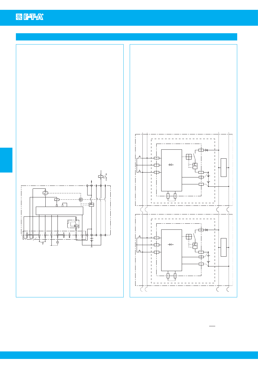
Typical applications
ON / OFF
button
s
erie
s
437
Electronic control unit
I >
FE
vehicle electrical
s
y
s
tem
II
11
23
13
FA
b
a
FE
3
4
L13
brown
L12
brown
L11
green
FA
ON/OFF
L4 gr
ey
L5 gr
ey
L6 yellow
L2 gr
ey
battery
I
12
1
2
3
4
5
6
7
8
9
10
24
14
L3 br
own
+U
S
1
L7 orange
L8 white
U-OFF U
S
T.
CB
6
5
L1 red
+UB
-UB
L10 blac
k
-UB
+
+
UVP OFF
undervoltage
s
tatu
s
max. 2 W
ON/OFF
+U
S
1
U-OFF
U
S
T.
terminal
s
trip
double
contact
≥
125 A
generator field
di
s
connection
85
86
generator D+
30
87
87a
31
K
l. 15
+
-
K
l. 15
For rail vehicles, e.g. underground carriages
Series E-1073-1233-437-K60-06-Si01-200 A
In this application, the E-T-A combined battery switch/circuit
breaker has two functions:
●
High performance circuit breaker providing battery and cable
protection from overloads and short circuits.
●
Isolation switch between battery and loads.
In this application, an ON/OFF remote control switch can be provided
in both the first and last carriages. This will enable all batteries to be
disconnected from the power distribution system by the operation
of one control, irrespective of its location. In the same way, all
batteries can be re-connected by the operation of a single control
switch.
This is extremely helpful during coupling/de-coupling of carriages
for example. In addition the E/A test input permits the operation of
individual battery switch/circuit breakers during maintenance.
This is a metric design and millimeter dimensions take precedence ( mm )
inch
All dimensions without tolerances are for reference only. In the interest of improved design,
performance and cost effectiveness the right to make changes in these specifications
without notice is reserved.Product markings may not be exactly as the ordering codes.
Errors and omissions excepted.
Courtesy of Steven Engineering, Inc.-230 Ryan Way, South San Francisco, CA 94080-6370-Main Office: (650) 588-9200-Outside Local Area: (800) 258-9200-www.stevenengineering.com