www.e-t-a.com
Digital Panel Instruments MDA241/ MDV241/ MDC241
06/07
3
- 7
3
Description
Technical Data
Measuring Ranges
MDA241
MDV241
MDC241
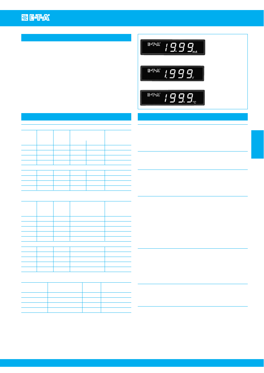
Digital panel instruments type MD.241 are designed to measure,
display, and monitor either DC and AC currents (MDA241), DC and
AC voltages (MDV241), or temperature (MDC241) in industrial
applications.
The instruments are panel mounted with a front frame dimension of
96 x 24 mm and a mounting depth of 89 mm, and are available with
3 1/2 digit 7-segment LED display covering various measuring ranges.
The supply voltage range of DC 12 V...26 V, physically isolated from
the measuring circuit, allows a wide spread of applications.
Display
Red 7-segment LED display
3 1/2 digit, 13 mm high
Full scale range: 1999 digits
Over-range indication:
The last 3 digits will extinguish
Reading characteristics
Integrating dual-slope
Count rate: 2.5 readings/second
Setting time for a 100 % reading change: < 3 s
Accuracy of display (at 23 °C)
Current/Voltage DC version
≤ 0.1 % span ± 1 digit
Current/Voltage AC version
≤ 0.2 % span ± 1 digit
Temperature 0.1 K resolution
≤ 0.1 % span ± 1 digit
Temperature 1 K resolution
≤ 0.3 % span ± 1 digit
(span = full measuring range)
Input
General (MD.241): Physically isolated from mains
Common mode range:
input circuit against
main circuit
± 600V
Common mode rejection:
≥ 60dB
Temperature instrument MDC 241: Pt100 connected in 2-conductor
circuit. Line resistance may be
corrected between 0...10
Ω
by
means of the potentiometer
accessible from the front.
Sensor current:
approx. 1 mA
Overload protection:
25 V
Environmental requirements
Temperature drift:
≤ 0.1 % span/10 K
Warm-up to full accuracy:
15 minutes
Operating temperature range:
0...+50 °C
Storage temperature range:
-20...+70 °C
Relative humidity:
0...75 % annual average,
95 % max.
(without condensation)
Voltage supply (voltage rating):
DC 12 V...26 V physically isolated from the measuring input.
Max. allowed residual ripple 10 %, but not less than the minimum
voltage or more than the maximum voltage.
Power consumption:
≤ 3 W
DC Current
Measuring Resolution
Input
Overload protection Pin designation
range
resistance
cont. max. 3 sec.
Lo - Hi
– +
±2 mA
1 µA
100
Ω
50 mA
100 mA
3 - 1
±20 mA
10 µA
10
Ω
160 mA
300 mA
3 - 1
±200 mA
0.1 mA
1
Ω
600 mA
1.5 A
3 - 1
±2 A
1 mA
0.1
Ω
3 A
5 A
3 - 1
AC Current, frequency range 15 Hz...1 kHz
2 mA
1 µA
100
Ω
50 mA
100 mA
3 - 1
20 mA
10 µA
10
Ω
160 mA
300 mA
3 - 1
200 mA
0.1 mA
1
Ω
600 mA
1.5 A
3 - 1
2 A
1 mA
0.1
Ω
3 A
5 A
3 - 1
DC Voltage
Measuring Resolution
Input
Overload protection
Pin designation
range
resistance
continuous
Lo - Hi
– +
±200 mV
0.1 mV
≥10 M
Ω
150 V
3 - 1
±2 V
1 mV
≥10 M
Ω
500 V
3 - 1
±20 V
10 mV
10 M
Ω
1000 V
3 - 1
±200 V
0.1 V
10 M
Ω
1000 V
3 - 1
±600 V
1 V
10 M
Ω
1000 V
3 - 1
AC Voltage, frequency range 15 Hz...1 kHz
200 mV
0.1 mV
≥10 M
Ω
150 V
3 - 1
2 V
1 mV
≥10 M
Ω
500 V
3 - 1
20 V
10 mV
10 M
Ω
1000 V
3 - 1
200 V
0.1 V
10 M
Ω
1000 V
3 - 1
600 V
1 V
10 M
Ω
1000 V
3 - 1
Temperature
Sensor
Measuring range
Resolution Pin designation
in °C
Pt100 (IEC751)
0...+300 °C
1
1 - 2
Pt100 (IEC751)
+250...+800 °C
1
1 - 2
Pt100 (IEC751)
-200...+200 °C
1
1 - 2
Pt100 (IEC751)
-100.0...+100.0 °C
0.1
1 - 2
Courtesy of Steven Engineering, Inc.-230 Ryan Way, South San Francisco, CA 94080-6370-Main Office: (650) 588-9200-Outside Local Area: (800) 258-9200-www.stevenengineering.com