3
- 5
3
Current
Internal Current
Internal
rating (A)
resistance (Ω)
rating (A)
resistance (Ω)
0.01
625
0.8
0.096
0.02
170
0.9
0.085
0.03
77
1
0.073
0.04
47
1.2
0.050
0.05
29.2
1.5
0.031
0.08
10.3
2
≤ 0.02
0.1
5.6
2.5
≤ 0.02
0.2
1.65
3
≤ 0.02
0.3
0.89
3.25
≤ 0.02
0.4
0.39
4
≤ 0.02
0.5
0.28
4.5
≤ 0.02
0.6
0.198
5
≤ 0.02
0.7
0.143
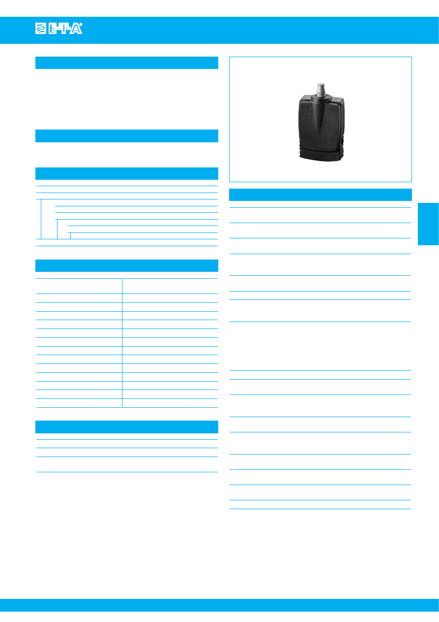
Description
Typical applications
Ordering information
Approvals
Technical data
Single pole miniaturised magnetic circuit breakers with unique high-
speed operating mechanism and push/pull on/off manual actuation.
Fitted with electrically separate excitation and switching circuits, and
one pair of auxiliary contacts which close when the main circuit is
open. Also suitable for impulse operation. Designed for printed circuit
board mounting. Low temperature sensitivity.
Printed circuit boards and components, safety and control systems.
808
Voltage rating
DC 24 V
(higher voltages to special order)
UL: AC 120 V; DC 60 V
Current ratings 0.01...5 A
(higher current ratings to special order)
Max. continuous load
excitation circuit (2-3)
2.65 x I
N
Max. continuous load
switching circuit 6-7
auxiliary circuit 4-5
5 A
Typical life 6,000 operations
at 5 A for switching circuit
Ambient temperature
-30...+70 °C (-22...+158 °F)
Insulation co-ordination
rated impulse
pollution
(IEC 60664-1)
withstand voltage
degree
1.5 kV
2
Dielectric strength
(UL 1077)
test voltage
operating area
AC 1,240 V
excitation to
switching circuit
AC 1,240 V
excitation to
auxiliary circuit
AC 1,240 V
Insulation resistance
> 100 MΩ (DC 500 V)
Interrupting capacity
(o-o-o)
100 A
Interrupting capacity
(UL 1077)
2,000 A AC 120 V
1,000 A DC 60 V
Degree of protection
operating area IP30
(IEC 60529/DIN 40050) terminal area IP00
Vibration 3 g (57-500 Hz), ± 0.23 mm (10-57 Hz),
to IEC 60068-2-6, test Fc
10 frequency cycles/axis
Shock 25 g (11 ms)
to IEC 60068-2-27, test Ea
Corrosion 48 hours at 5 % salt mist,
to IEC 60068-2-11, test Ka
Humidity 240 hours at 95 % RH
to IEC 60068-2-78, test Cab
Mass approx. 10 g
Authority
Voltage ratings
Current ratings
CSA
AC 120 V; DC 60 V
0.01...5 A
UL
DC 60 V
0.01...5 A
AC 120 V
0.01...5 A
Standard current ratings and typical internal resistance values
Type No.
808
fast-acting
Manual release
01
press-to-reset button, blue
B
manual release facility, blue (Standard)
Current ratings
0.01...5 A
808 -
B - 5 A
ordering example
Magnetic Overcurrent Circuit Breaker 808-...
Issue B
www.e-t-a.com
Courtesy of Steven Engineering, Inc.-230 Ryan Way, South San Francisco, CA 94080-6370-Main Office: (650) 588-9200-Outside Local Area: (800) 258-9200-www.stevenengineering.com