www.e-t-a.com
7
- 1
Power distribution systems - accessories
08/09
(040309)
7
9
7.3
18.15
Load output terminal proteced again
s
t rever
s
e polarity
(set: 4 moduled sleeves, 8 blade terminals 6.3 x 0.8 mm)
X 222 847 01
for cable cross section 0.7 ...2.0 mm
2
X 222 625 01
for cable cross section 2.5 ...4.0 mm
2
X 222 848 01
for cable cross section 4.0 ...6.0 mm
2
.287
.715
Load output terminal protected X 222 847 01
against reverse polarity
X 222 625 01
X 222 848 01
s
uitable for
19BGT-2-X8340-S02
19BGT-2-X8340-SZ4
X8340-S02
X8340-SZ4
S
crew terminal
for busbar Y 307 016 11
X 211 156 01
non insulated
(max. 35 m
2
)
Screw terminal X 211 156 01
s
uitable for
Module 17plus
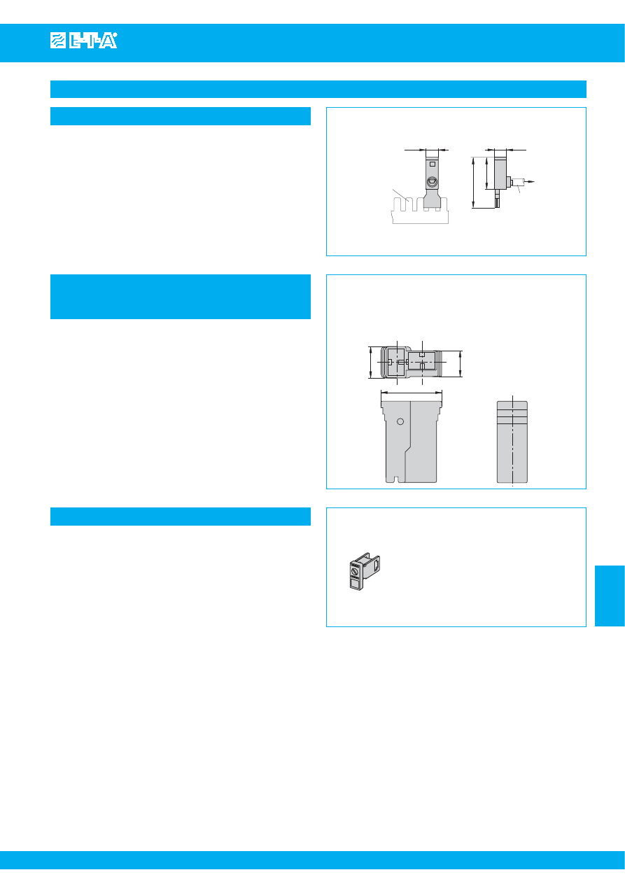
Connections and terminals
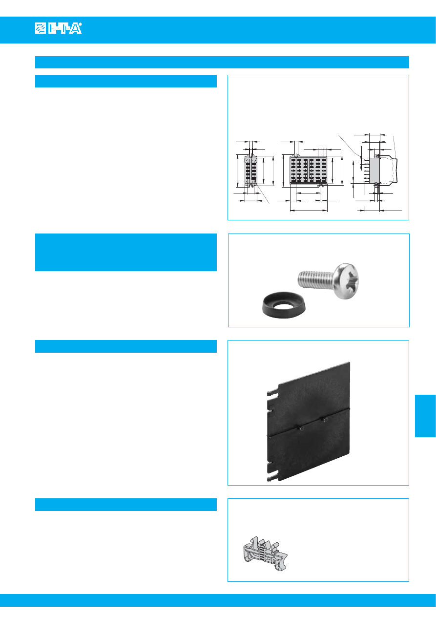
Line terminal
(max. 63 A)
X 221 503 01
30
50
15
14
busbar X1, X2
blade terminals 6.3 mm
cable cross section
10…25 mm
2
Caution:
cables must not be connected with terminal plugged in
pull-out
max. 10 N
max. tightening torque 3.0 Nm
.591
1.97
1.18
.551
Line terminal X 221 503 01
s
uitable for
Power-D-Box with sockets pre-wired
Courtesy of Steven Engineering, Inc.-230 Ryan Way, South San Francisco, CA 94080-6370-Main Office: (650) 588-9200-Outside Local Area: (800) 258-9200-www.stevenengineering.com
87PDS-html.html
www.e-t-a.com
7
- 2
08/09
(040309)
Power distribution systems - accessories
7
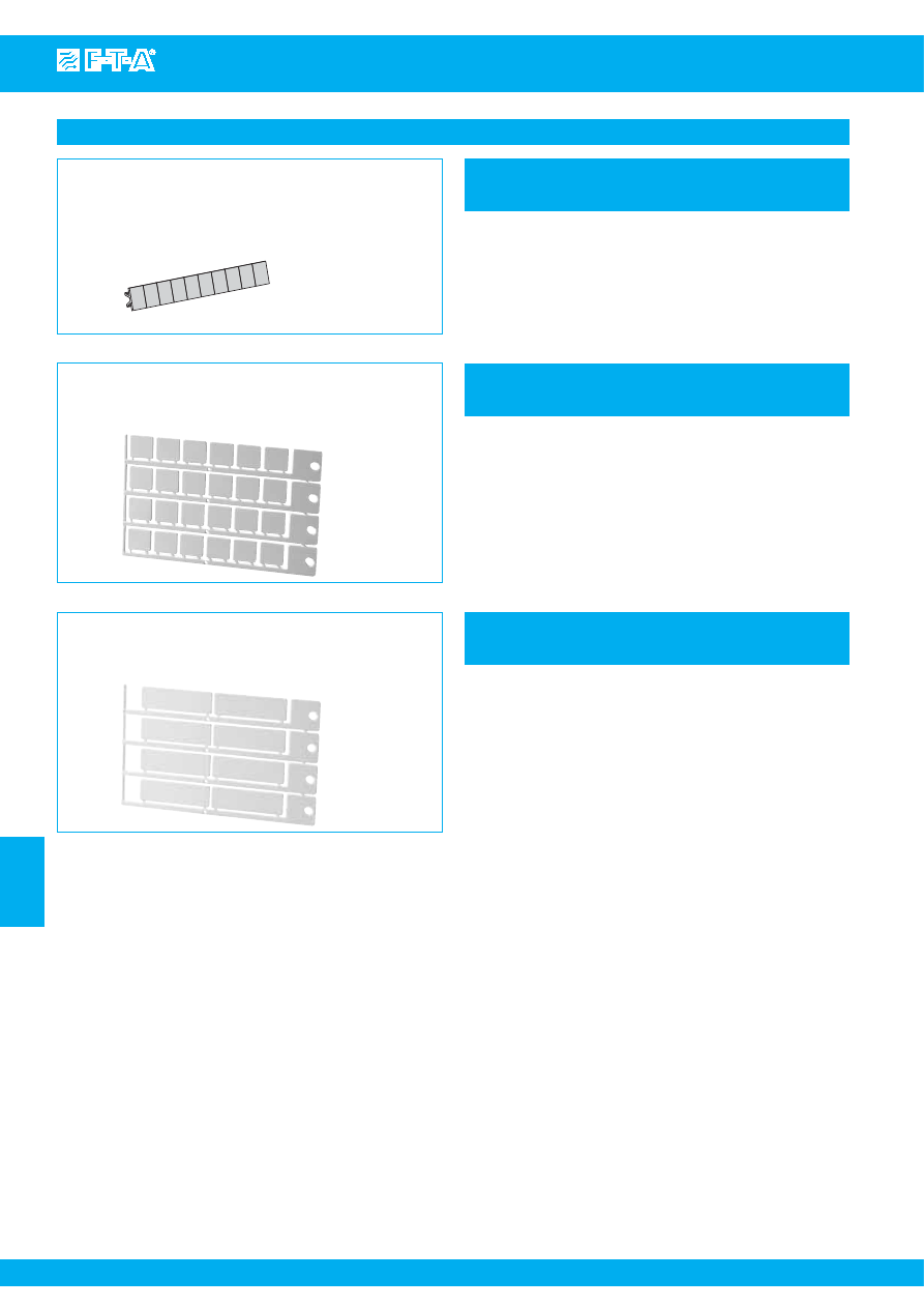
Labels
Label
marking area 6 x 10 mm / .629 x .394 in.
Y 307 942 61
Label white Y 307 942 61
ordering unit 10 pcs = 1 strip
s
uitable for
Module 17plus
Label white Y 308 327 01
ordering unit 24 pcs = 1 plate
Label white Y 308 328 01
ordering unit 8 pcs = 1 plate
s
uitable for
19BGT-2-X83S2
19BGT-2-X83S4
19BGT-2-X83Z4
19BGT-2-X8345
s
uitable for
19BGT-2-2210
19BGT-2-3600
19BGT-2-ESS20
19BGT-2-ESX10
19BGT-2-X2210
Label
mar
k
ing area 16 x 13 mm / .629 x .512 in.
Y 308 327 01
Label
mar
k
ine area 46 x 13 mm / 1.81 x .512 in.
Y 308 328 01
Courtesy of Steven Engineering, Inc.-230 Ryan Way, South San Francisco, CA 94080-6370-Main Office: (650) 588-9200-Outside Local Area: (800) 258-9200-www.stevenengineering.com
87PDS-html.html
www.e-t-a.com
7
- 3
Power distribution systems - accessories
08/09
(040309)
7
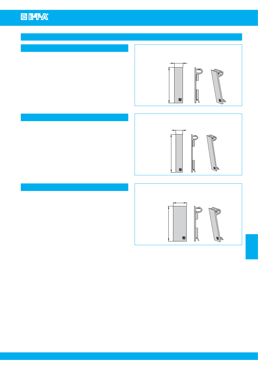
Blanking piece
Blanking piece Y 308 563 01
s
uitable for
19BGT-2-2210
19BGT-2-3600/3900
Blan
k
ing piece for Power-D-Bo
x
(circuit breaker types 3600/3900, 2210)
Y 308 563 01
52
12.5
.502
2.05
Blanking piece Y 308 563 41
s
uitable for
19BGT-2-ESS20
19BGT-2-ESX10
Blan
k
ing piece for Power-D-Bo
x
(circuit breaker types ESS20, ESX10)
Y 308 563 41
12.5
68.5
.492
2.69
Blanking piece Y 308 563 21
s
uitable for
19BGT-2-X8345
19BGT-2-X83S2
19BGT-2-X83S4
19BGT-2-X83Z4
Blan
k
ing piece for Power-D-Bo
x
(circuit breaker types 8345,
X8345-D01)
Y 308 563 21
52
20
.787
2.05
Courtesy of Steven Engineering, Inc.-230 Ryan Way, South San Francisco, CA 94080-6370-Main Office: (650) 588-9200-Outside Local Area: (800) 258-9200-www.stevenengineering.com
87PDS-html.html
www.e-t-a.com
7
- 4
08/09
(040309)
Power distribution systems - accessories
7
Mounting aids
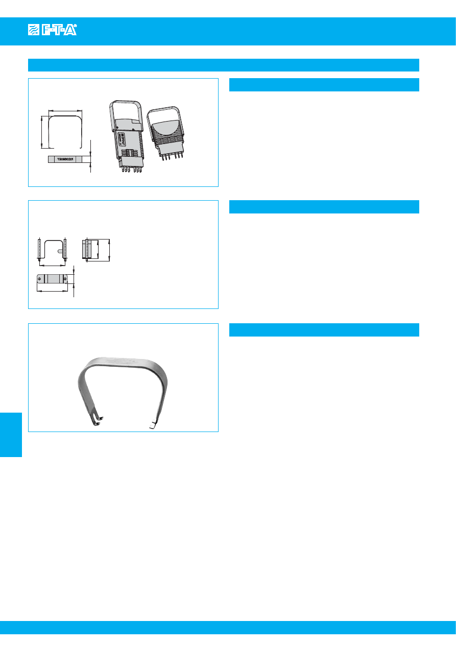
Retaining clip Y 307 754 01
s
uitable for
Module 17 plus mit ESS20
Module 17 plus mit ESX10
Retaining clip for electronic circuit brea
k
er E
SS
20/E
S
X10
recommended for fitting the devices
Y 307 754 01
8
2
5
18.5
4.5
G
ERMANY
.738
.187
.315
.197
.189
Retaining clip Y 300 581 11
s
uitable for
socket type 17...
Module 17plus
with 3600
with 3600
3900
3900
E-1048-6..
E-1048-6..
E-1048-7..
E-1048-7..
E-1079-6..
E-1079-6..
Retaining clip for circuit brea
k
er 3600/3900/E-1048/E-1079
recommended for fitting the devices
Y 300 581 11
30
ø1
5.5
mounting dimension
44.4
60
45
retaining clip
1
11
23
2(k)
12
24
2(i)
1.77
2.36
1.75
1.18
.217
top view
retaining clip
1
11
23
2(k)
12
24
2(i)
24
ø1
7
Retaining clip for circuit brea
k
er 2210
recommended for fitting single pole devices
Y 302 974 21
mounting dimension
61.5
60
45
1.77
2.36
2.42
.945
.276
top view
Retaining clip Y 302 974 21
s
uitable for
socket type 17...
Module 17plus
with 2210-...
with 2210-...
Retaining clip for circuit brea
k
er 3600/3900/E-1048/E-1079
recommended for fitting the devices
Y 300 581 03
23-P10-
S
i
63-P10-
S
i
6 x 6.8 = 40.8
6 x .268 = 1.61
retaining
clip
22.2
21
10
2
max. 30
6
3.5
6.8
7.4
4.4
64
50
57.4
25
12.5
4.4
7.4
12.5
6.25
64
50
75
12.5
polarized
recess
.173
.291
2.52
1.97
2.26
.492
.984
.291
.173
.394
.827
.874
.079
.236
max. 1.18
2.52
.492
1.97
2.95
50
1
.97
2
.26
57.4
.268
.138
.492
.246
polarized blade terminals
DIN 46244-A6.3-0.8 (QC .250)
Retaining clip Y 300 581 03
s
uitable for
socket type 23...
socket type 63...
with
3600
with
3600
3900
3900
E-1048-6..
E-1048-6..
E-1048-7..
E-1048-7..
E-1079-6..
E-1079-6..
Courtesy of Steven Engineering, Inc.-230 Ryan Way, South San Francisco, CA 94080-6370-Main Office: (650) 588-9200-Outside Local Area: (800) 258-9200-www.stevenengineering.com
87PDS-html.html
www.e-t-a.com
7
- 5
Power distribution systems - accessories
08/09
(040309)
7
Mounting aids
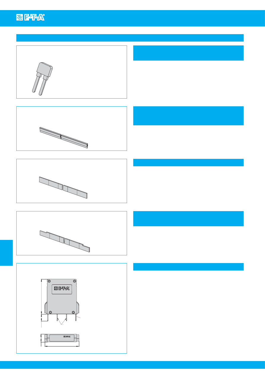
Screw and washer X 223 019 01
1 set with
4 screw and
4 washers
in a plastic bag
s
uitable for
19BGT-...
Sufficient for mounting one Power-D-Box
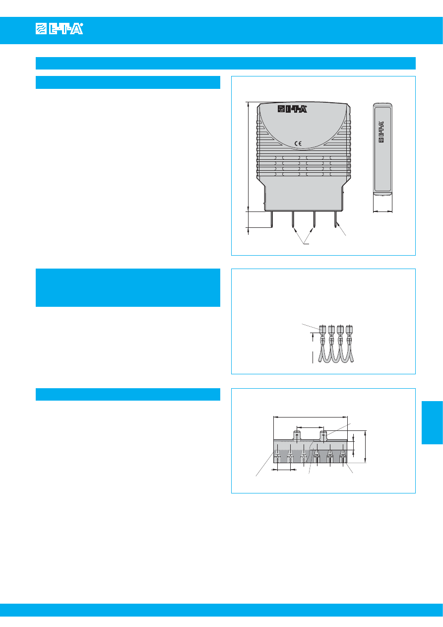
End brac
k
et
recommended for fixing on symmetrical rails
X 222 004 01
Barrier Y 308 139 01
s
uitable for
19BGT-2-X8345
X8345-D01
End bracket X 222 004 01
s
uitable for
Module 17plus
socket type 17
Barrier
for i
s
olating the load terminal
s
of the Power-D-Box (High-Power)
Y 308 139 01
Retaining clip for circuit brea
k
er 2210-
S
...
recommended for fitting single pole devices
Y 302 974 01
23-P10-
S
i
63-P10-
S
i
6 x 6.8 = 40.8
6 x .268 = 1.61
retaining
clip
22.2
21
10
2
max. 30
6
3.5
6.8
7.4
4.4
64
50
57.4
25
12.5
4.4
7.4
12.5
6.25
64
50
75
12.5
polarized
recess
.173
.291
2.52
1.97
2.26
.492
.984
.291
.173
.394
.827
.874
.079
.236
max. 1.18
2.52
.492
1.97
2.95
50
1
.97
2
.26
57.4
.268
.138
.492
.246
polarized blade terminals
DIN 46244-A6.3-0.8 (QC .250)
Retaining clip Y 302 974 01
s
uitable for
socket type 23...
socket type 63...
with
2210-S...
with
2210-S...
Screw and washer
s
crew for mounting the Power-D-Box (19BGT)
X 223 019 01
Courtesy of Steven Engineering, Inc.-230 Ryan Way, South San Francisco, CA 94080-6370-Main Office: (650) 588-9200-Outside Local Area: (800) 258-9200-www.stevenengineering.com
87PDS-html.html
www.e-t-a.com
7
- 6
08/09
(040309)
Power distribution systems - accessories
7
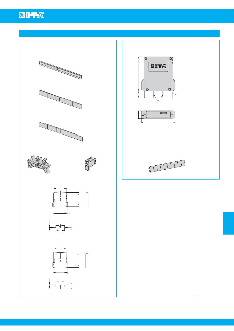
Busbars and jumpers
In
s
ulated wire bridge
X 222 984 01
packaging quantity: 10 pcs
Bu
s
bar 32 A
X 222 005 01
blue insulated, 500 mm
X 222 005 02
red insulated, 500 mm
X 222 005 03
grey insulated, 500 mm
Bu
s
bar 50 A
Y 307 016 01
non insulated, 500 mm
Insulated wire bridge X 222 984 01
packaging quantity 1 pc = 10 wire bridges
Bus bar 50 A Y 307 016 01
s
uitable for
SVS.
Bus bar 32 A
X 222 005 01 blue
X 222 005 02 red
X 222 005 03 grey
s
uitable for
Module 17plus
s
uitable for
Module 17plus
Jumper
X 222 066 01
blade terminals
DIN 46244-A6.3-0.8
Signalbrücke
Signal loop
X22206601
1
4
6
3
7
5
2
51
10
terminals 1+2
no connection
terminals 6+7
bridged
11.5
1.97
2.01
.394
50
.453
Jumper X 222 066 01 old version
s
uitable for
Module 17plus
SVS.
19BGT-2-2210
19BGT-2-3600/3900
19BGT-2-ESS20
9BGT-2-ESX10
New version see jumper SB-S11-P1-01-1-1A
Bu
s
bar for line entry on the
s
ide
(in combination with screw terminal X 211 156 01)
Y 307 016 11
non insulated, 500 mm
Busbar Y 307 016 11
for line entry on the side
s
uitable for
Module 17plus
Courtesy of Steven Engineering, Inc.-230 Ryan Way, South San Francisco, CA 94080-6370-Main Office: (650) 588-9200-Outside Local Area: (800) 258-9200-www.stevenengineering.com
87PDS-html.html
www.e-t-a.com
7
- 7
Power distribution systems - accessories
08/09
(040309)
7
Bu
s
bar 50 A for
s
oc
k
et 63-P10-
S
i
X 221 760 11
insulation to VB
G
4
translucent
female connector
6.3 DIN 46247 Ms,
max. 25 A
70
30.5
8
blade terminal
DIN 46244 A6.3x0.8
max. 25 A
25
12.5
bus bar
max. 50 A
2.79
.984
.315
1.18
.492
Connector bu
s
lin
k
-P10
X 210 588 01/ 1.5 mm
2
,
brown
(up to 13 A max. load)
X 210 588 02/ 2.5 mm
2
,
blac
k
(up to 20 A max. load)
X 210 588 03/ 2.5 mm
2
,
red
(up to 20 A max. load)
X 210 588 04/ 2.5 mm
2
,
blue
(up to 20 A max. load)
~70
100 quick-connect tabs
6.3 (.250) DIN 46247
tinned brass, insulated
Bus bar 50 A X 221 760 11
s
uitable for
Power-D-Box with socketsX 211 530 01
Busbars and jumpers
blade terminals
DIN 46244-A 6.3-0.8
70
10.3
12.3
terminals 13+14
bridged
Signalbrücke
Signal loop
G
ermany
www.e-t-a.com
S
ignalbrüc
k
e
S
ignal loop
xxxx
S
B-
S
11-P1-01-1-1A
Jumper
S
B-
S
11-P1-01-1-1A
.484
.406
2.76
top view
Jumper SB-S11-P1-01-1-1A
s
uitable for
Module 17 plus
SVS...
19BGT-2-2210
19BGT-2-3600/390
19BGT-2-ESS20
19BGT-2-ESX10
Connector bus link -P10
X 210 588 01 (brown)
X 210 588 02 (black)
X 210 588 03 (red)
X 210 588 04 (blue)
s
uitable for
Power-D-Box with sockets X 211 530 01
Courtesy of Steven Engineering, Inc.-230 Ryan Way, South San Francisco, CA 94080-6370-Main Office: (650) 588-9200-Outside Local Area: (800) 258-9200-www.stevenengineering.com
87PDS-html.html
www.e-t-a.com
7
- 8
08/09
(040309)
Power distribution systems - accessories
7
67
65
12.5
with ESS20
with ESX10
Withdrawal tool for E
SS
20 /E
S
X10
Y 308 602 01
2.64
2.56
.492
Withdrawal tool
for removing circuit breaker type 8345
X 222 547 02
52.3
36.8
44.1
61.8
18
2.06
2.43
.709
1.45
1.74
Withdrawal tool Y 308 602 01
Tools
Withdrawal tool X 222 547 02
s
uitable for
19BGT-2-ESS20
19BGT-2-ESX10
s
uitable for
19BGT-2-X8345
X8345-D01
Withdrawal tool X 211 018 01
s
uitable for
19BGT-2-X2210
X2210-S06…
Withdrawal tool
for removing circuit brea
k
er type 2210-
S
291
X 211 018 01
Courtesy of Steven Engineering, Inc.-230 Ryan Way, South San Francisco, CA 94080-6370-Main Office: (650) 588-9200-Outside Local Area: (800) 258-9200-www.stevenengineering.com
87PDS-html.html
Customer-specific solutions / Power-D-Box (customised)
www.e-t-a.com
Issue B
7
- 7
7
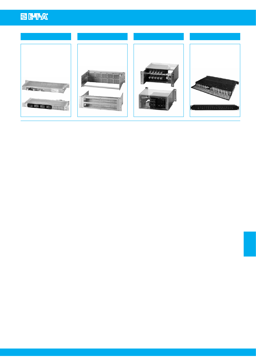
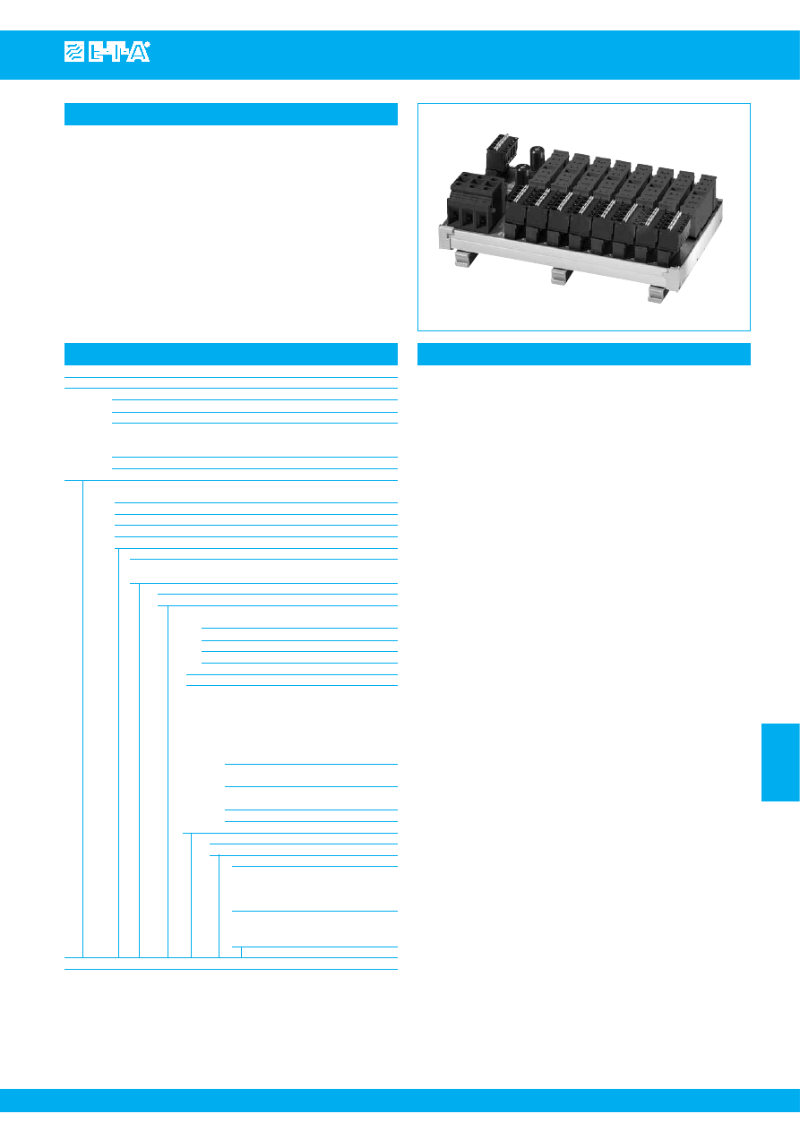
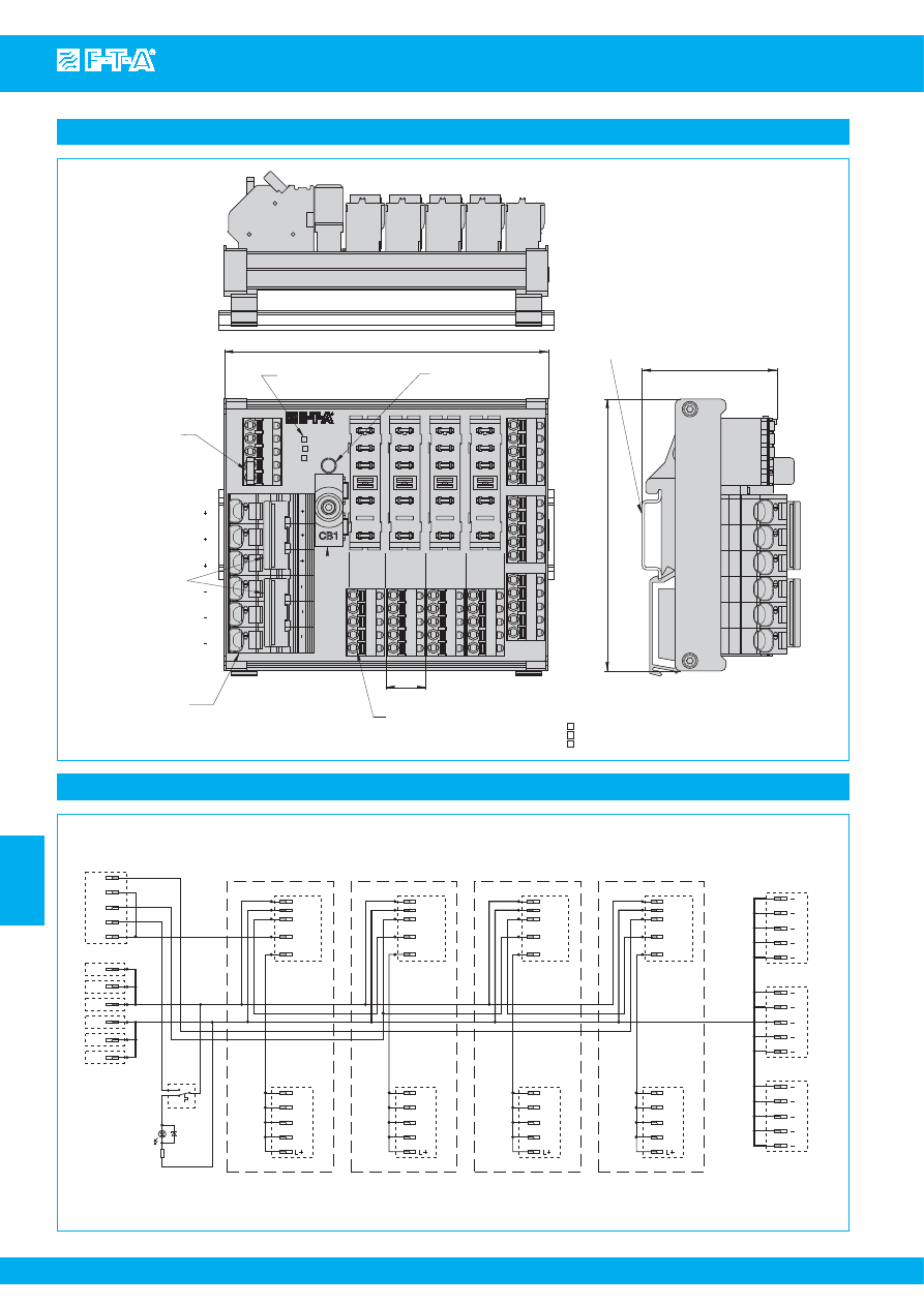
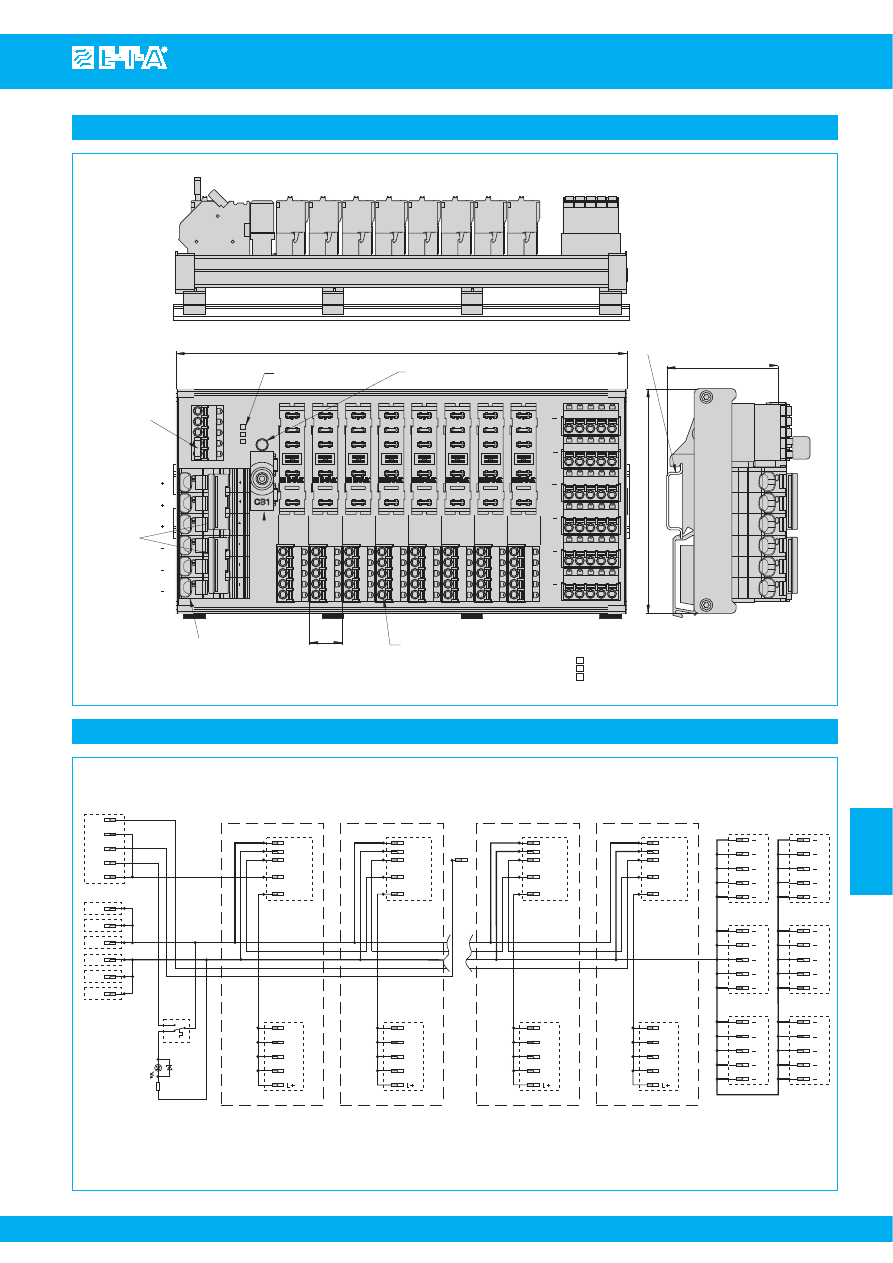
1U compact solution
19" 1U Power-D-Box power
distribution system (also for ETSI
systems) accommodating plug-in
thermal-magnetic circuit breakers
type 2210-S or similar types,
single or double pole, with or
without signal contact.
8 single pole (or 4 double pole)
circuit breakers are fitted
transversely as vertical pairs, line
entry is at the rear by means of
screw terminals with 16 (25) mm
2
cable cross section capacity.
Redundant design of the system
(2 x 4 single pole circuit breakers)
is also available.
The load terminals are connected
from the front by means of high
current sub-D connectors or by
means of screw terminals up to 4
mm². Auxiliary contact terminals
can be connected form the rear
(serial or parallel connection
possible).
For replacing or retrofitting circuit
breakers part of the front plate
can be removed.
Above and below the circuit
breakers are two narrow strips
for customer-specific marking.
Permanent marking is available
ex factory for the front plate as
an option.
Max. rating per way is 16 A (due to
the derating of the circuit breakers
mounted closely side-by-side),
max. load of the line entry is 63 A
at DC 65 V / AC 250 V.
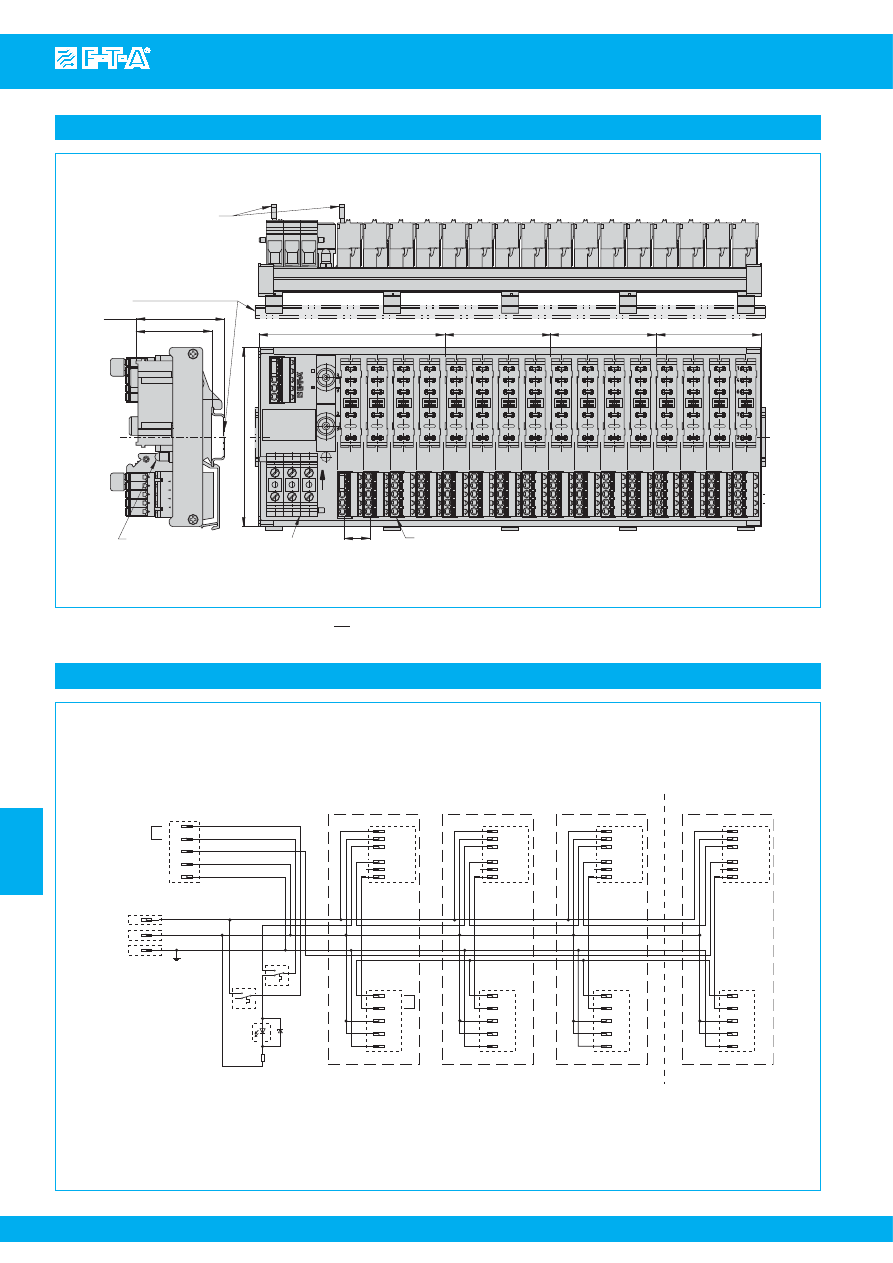
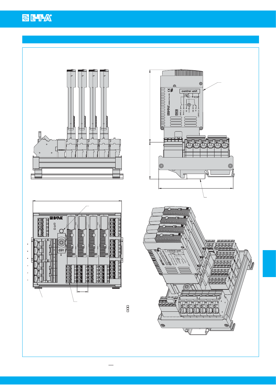
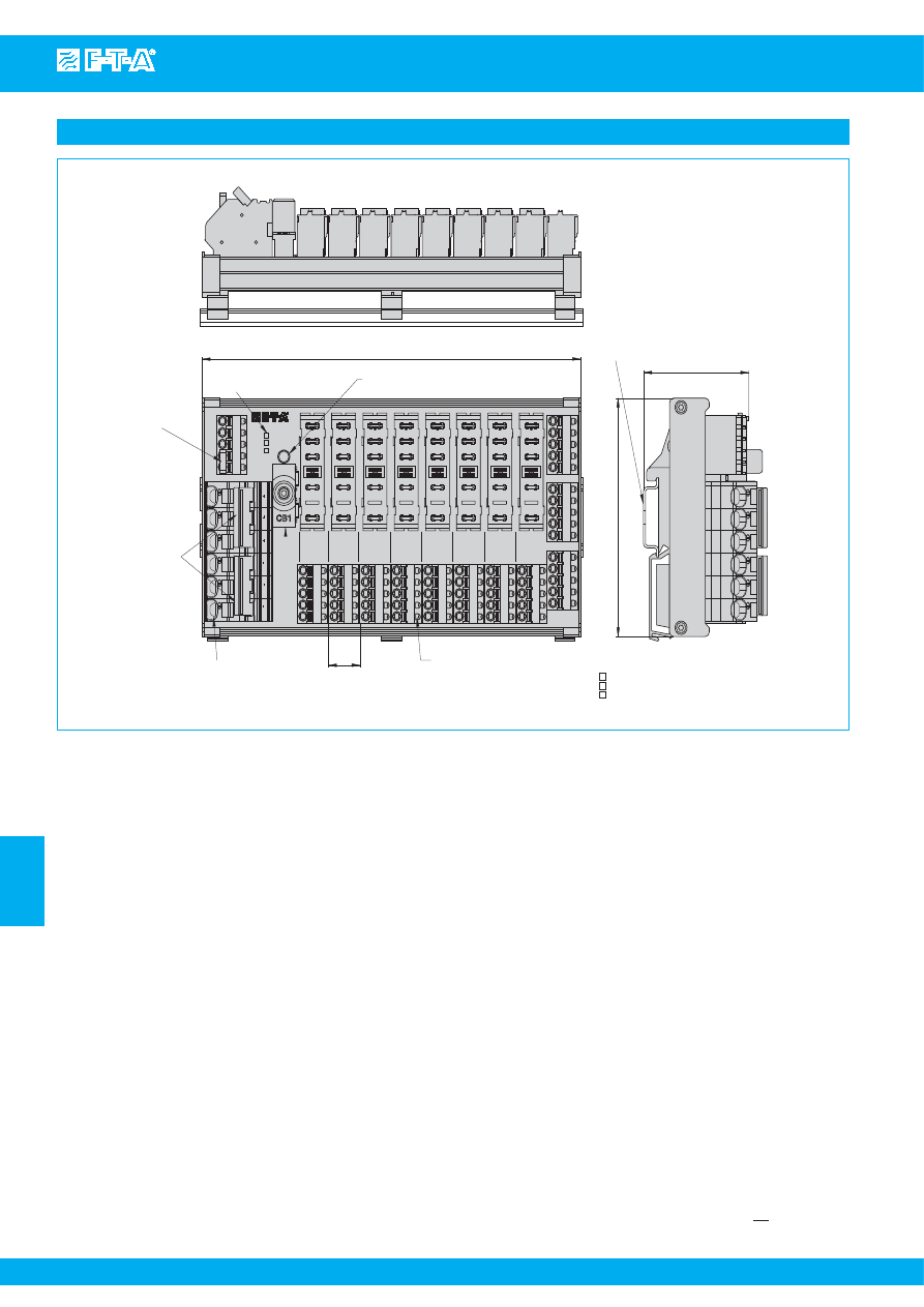
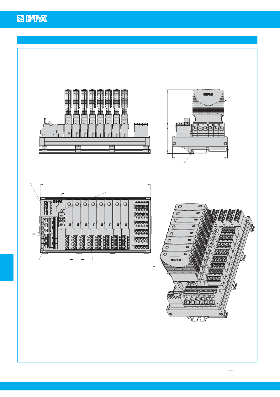
3 U multi-channel solution
19
"
3U racks (also for ETSI
systems) for accommodating
plug-in type 2210-S or similar,
single pole or multipole, with or
without auxiliary contacts.
Up to 60 single pole circuit
breakers can be fitted (in 2 rows
above each other). Standard
version of the rack is supplied
without wiring, but customer-
specific wiring is possible upon
request.
Type and size of line entry, wiring
of load outputs, signal contact
connection as well as fitting with
connecting terminals will be to
order.
For replacing or retrofitting circuit
breakers part of the front plate
can be removed. Unused ways
can be covered with blanking
pieces.
Above and below the circuit
breakers customer-specific
marking is possible. Permanent
marking is available ex factory
for the front plate as an option.
Max. rating per way is 16 A (due
to the derating of the circuit
breakers mounted closely side-
by-side), max. load of the line
entry is 63 A at DC 65 V / AC
250 V.
High Power
Power distribution system for
direct mounting to the rear wall of
a control cabinet. Featuring type
X8345-D01 power distribution
rail with a variable number of
modules possible.
Plug-in type 8345 circuit breakers
are installed allowing load output
currents of up to 125 A per
module, with a maximum of 160 A
for two adjacent positions.
Line entry is on the side, connected
directly to internal busbars with
up to 300 A at max. DC 110 V /
AC 230 V.
Optional auxiliary contacts are
also connected from the side by
means of 2.8 mm blade terminals,
all contacts are connected in
parallel.
Reliable main and load terminal
connections are by means of
M10/M12 hexagonal screws.
The entire power distribution
system is protected against brush
contact by a slide-on plexi glass
cover.
The system is mounted on the
rear wall of a control cabinet by
means of aluminium brackets.
The system is also available as a
version offering system
redundancy.
The circuit breakers are hot-
swappable without removing the
protective cover.
Above and below the circuit
breakers customer-specific
marking is possible. Permanent
marking is available ex factory
for the front plate as an option.
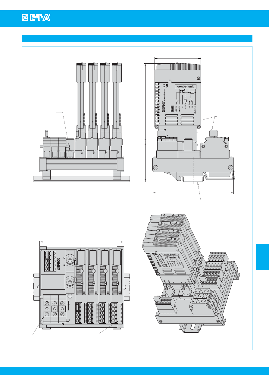
1U compact solution X482
1U rack for 19
"
, 23
"
and ETSI
systems for accommodating
thermal circuit breakers type
482, single pole with or without
auxiliary contact.
The rack is redundantly
configurable with up to 8 circuit
breakers (A + B supply). Line
entry is at the rear by means of
screw terminals or optionally by
means of pluggable connector
technology. The system is also
available with only one line entry
(1 x 16 circuit breakers).
Load terminals are connected
form the side via high current
contacts (optionally from the rear
via screw terminals). Auxiliary
contact terminals are on the side
(serial and parallel wiring), optional
LED indication is configurable on
the front.
For replacing or retrofitting circuit
breakers the front plate can be
removed. Circuit breakers must
be switched off but may be
replaced with power on.
Customer-specific marking of
the front plate is possible.
Max load of one way is 50 A
(please observe derating factor),
max. load of the line entry is 2 x
450 A at DC 72 V (optionally AC
230 V or AC 115 V).
Courtesy of Steven Engineering, Inc.-230 Ryan Way, South San Francisco, CA 94080-6370-Main Office: (650) 588-9200-Outside Local Area: (800) 258-9200-www.stevenengineering.com
87PDS-html.html
www.e-t-a.com
Issue B
7
- 8
Customer-specific solutions / Power-D-Box (customised)
7
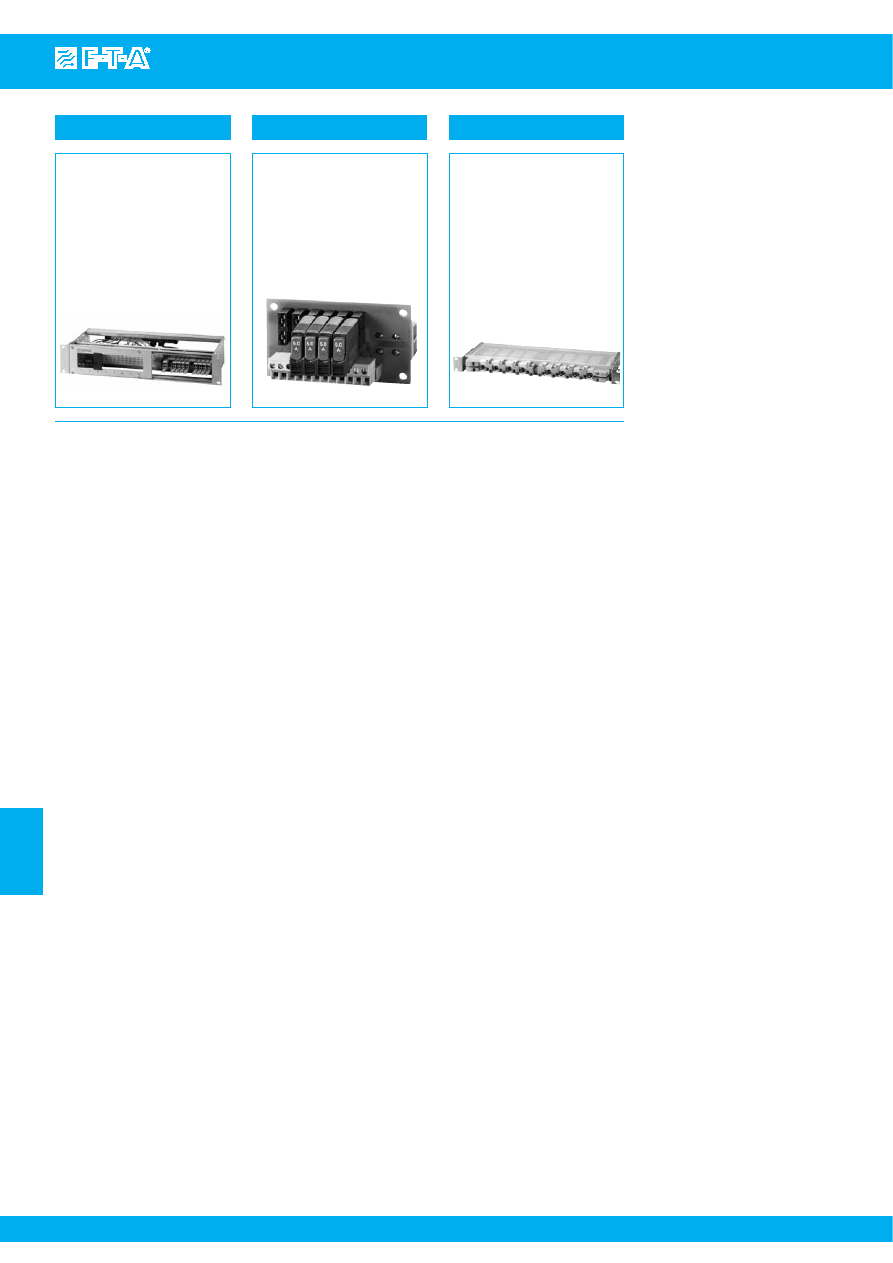
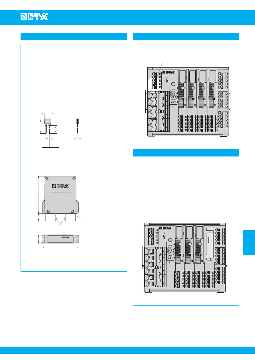
2U version with front terminals
Modular distribution system on pcb
1U Compact Solution High Power
The Power-D-Box is a 2U 19"
power distribution system (also for
ETSI systems), accommodating
plug-in type double pole thermal-
magnetic circuit breakers 2210-S
with auxiliary contacts.
All cable connections are on the
front by means of feed-through
terminals, partly pluggable.
Line entry is via two fixed feed-
through screw terminals up to
10 mm² with cable feed from
below, max. line current 50 A.
The load outputs are connected
via double pole plug-in type
screw terminals or alternatively
spring-loaded terminals up to 4
mm
2
. Polarisation is colour-
coded. Cable feed is from the
front. Max. load current is 16 A.
All auxiliary contacts are
combined as a group signal
(series or parallel connection are
possible) and also have plug-in
type terminals up to 4 mm
2
.
All connectors may optionally
be fitted with a strain relief by
means of wire wraps.
All terminals and circuit breakers
are marked correspondingly.
The version shown above
accommodates 8 double pole
circuit breakers, variations upon
request.
The front plate can be removed
for replacing the circuit breakers.
Small compact power distribution
system on printed circuit board
to accommodate 6 plug-in type
thermal overcurrent circuit
breakers type 1180.
Line entry is on the rear via screw
terminals up to 10 mm
2
, max. 16 A
(back-up fuse required).
Load outputs are connected via a
plug-in type screw terminal
busbar, cable cross section 2.5
mm
2
, max. 10 A.
Dimensions of the system are 90
x 50 x 96 mm (l x w x d) including
the installed circuit breakers.
Numbers of ways, termination as
well as mechanical design of the
power distribution system can be
tailored to customers
’
needs.
Max. rated voltage DC 65 V, AC
250 V.
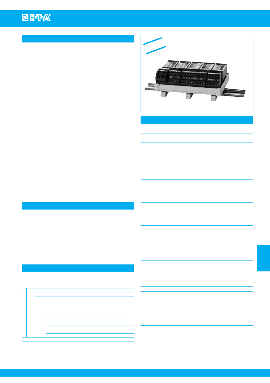
Two Power-D-Boxes, 1U 19" power
distribution systems, for use with
thermal high-performance circuit
breakers type 482.
The power distribution systems
feature a redundant design with
2 x 4 ways.
Connection of all cables can be
either from the rear or on the
front.
Line entry is on the right and left
sides by means of screw-type
feed-through terminals up to
16 mm
2
cable cross section, max.
100 A per side.
Load outputs are also via screw-
type feed-through terminals up
to 10 mm
2
, max. 50 A per way
(please observe derating factor
of the circuit breakers).
Plug-in design of the circuit
breakers allows easy adaptation
to changing loads.
The max. installation depth is
less than 180 mm including front
and rear screw terminals.
Max. rated voltage is DC 72 V or
AC 230 V.
Courtesy of Steven Engineering, Inc.-230 Ryan Way, South San Francisco, CA 94080-6370-Main Office: (650) 588-9200-Outside Local Area: (800) 258-9200-www.stevenengineering.com
87PDS-html.html
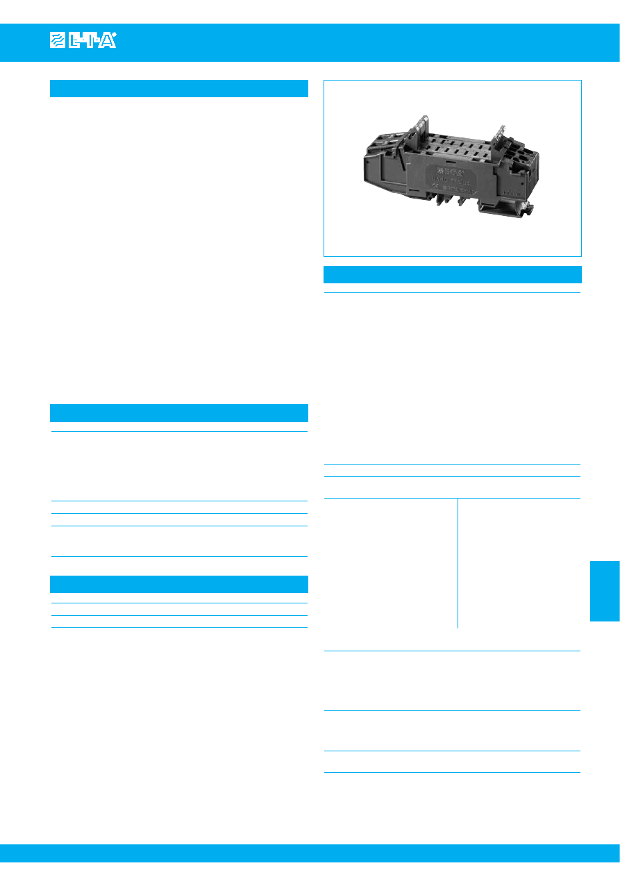
Module 17plus
www.e-t-a.com
Issue B
7
- 9
7
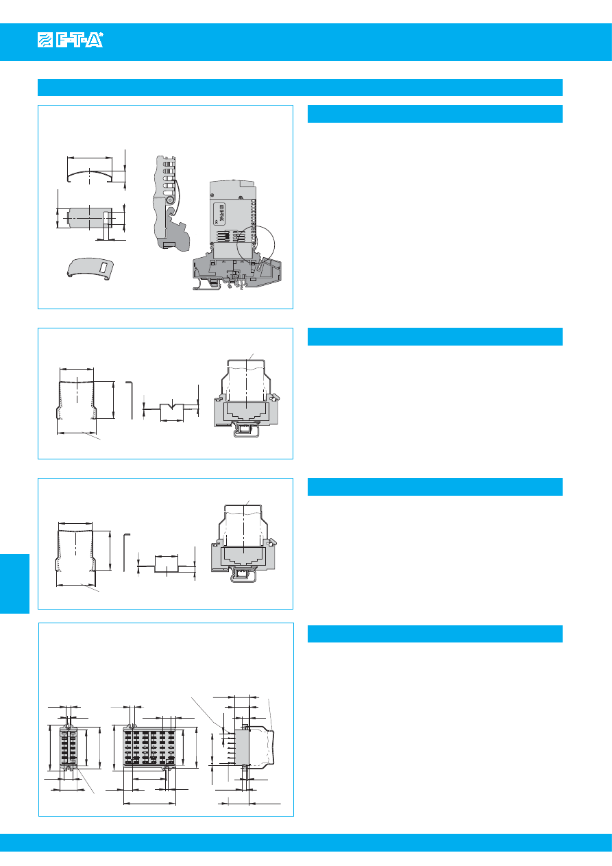
Description
Technical data
Module 17plus is a power distribution system for use with E-T-A circuit
breakers type 2210-S... or 3600-.../3900-... or electronic circuit breaker
ESS20 or SSRPC E-1048-7... Each module accommodates two single
pole plug-in circuit breakers with an individual housing width of only
12.5 mm and fits onto all industry standard mounting rails.
The two-way modules can be interconnected to provide as many ways
as required with a terminal block fitted at each end for connection of
signalling circuits. A distribution busbar can be fitted on the supply side
of the modules, but each pole of multipole circuit breakers must be
individually connected. Electrical connections are by means of
screwless spring loaded terminals.
Suitable electro-mechanical circuit breakers have integral make and
break auxiliary contacts. Depending on the application these may be
used for either single or group signalisation. For group signalisation, the
make contacts (which open in the event of a fault) are connected in
series to the terminal blocks of the modules. The module is designed
to accommodate a probe for series connection continuity tests. When
multipole circuit breakers are fitted auxiliary contacts are required for
each pole.
Single signalisation is achieved through use of the break contacts
(which close in the event of failure) connected in parallel by means of
terminals on each module. Both types of signalisation (individual and
group signalisation) are available at the same time if the circuit breakers
used provide auxiliary contacts (please note when ordering). The
signalling circuitry between modules is automatically connected when
modules are linked together.
Meets the requirements of UL60950
201107
17plus
Connection
Spring-loaded terminals for rigid wires
and flexible cables with and without wire
end ferrules. Please use appropriate
screw driver size (SD) for removing the
spring loaded terminals.
Line feed (1):
spring-loaded terminals for
1.5 – 10 mm
2
, SD 2 (0.8x4.0)
Load output (2):
spring-loaded terminals for
0.25-4 mm
2
, SD 1 (0.6x3.5)
Signalisation:
terminals (11, 13, 14):
spring-loaded terminals for
0.25-2.5 mm
2
, SD 1 (0.6x3.5)
terminal (12):
spring-loaded terminal for
0.25-1.5 mm
2
, SD 0 (0.4x2.5)
Test probe for testing the group signal for line interruption: ≤ 2 mm ø
Voltage rating
(without circuit breaker):
AC 433 V; DC 65 V
Current rating
Internal resistances
(without circuit breaker)
(without circuit breaker)
Line feed (1)
50 A
Line/load (1-2) ≤ 5 mΩ
Load output (2)
25 A*)
Signalisation
Signalisation
parallel (11-12) ≤ 9 mΩ
1)
/per pole
Feed (11)
(ground with electronic
components)
10 A
serial per module
(13-14)
≤ 8 mΩ
2)
/per pole
Single output (12)
1 A
plus
1)
+ 2 mΩ
Group signal (13-14)
1 A
2)
+ 5 mΩ
for each further module
interconnected
*) Caution: When several devices are mounted together, each should
carry only max. 80 % ( I
N
≤ 16 A) or max. 65 % (I
N
> 16 A) of its rating.
Busbar for power distribution
insulated busbar
(blue or red):
I
max
32 A
non-insulated busbar:
I
max
50 A
(The non-insulated busbar, too, meets brush contact safety
standards when fitted.)
Dielectric strength
between main circuits (without busbar):
1,500 V
main circuit to auxiliary circuit:
1,500 V
between auxiliary circuits:
1,500 V
Mass: Module 17plus (centre piece)
approx. 85 g
terminal blocks (pair)
approx. 30 g
Ordering information
For thermal magnetic circuit breakers types 2210-S, 3600, 3900:
For electronic circuit breaker type ESS20:
For solid state remote power controller E-1048-7..:
17PLUS-Q02-00
Module 17plus, centre piece, two-way
17PLUS-QA0-LR
one each left- and right-side terminal block
for supply feed from the side by means of
screw terminal
Technical data of:
please see:
Circuit Breaker 2210-S, 3600, 3900
product group 2
Electronic Circuit Breaker ESS20, ESX10
product group 5
Solid State Remote Power Controller E-1048-7.. product group 6
Approvals
Authority
Voltage ratings
Current ratings
UL USA + Canada
AC 250 V; DC 80 V
50 A
Courtesy of Steven Engineering, Inc.-230 Ryan Way, South San Francisco, CA 94080-6370-Main Office: (650) 588-9200-Outside Local Area: (800) 258-9200-www.stevenengineering.com
87PDS-html.html
www.e-t-a.com
Issue B
7
- 10
Module 17plus
7
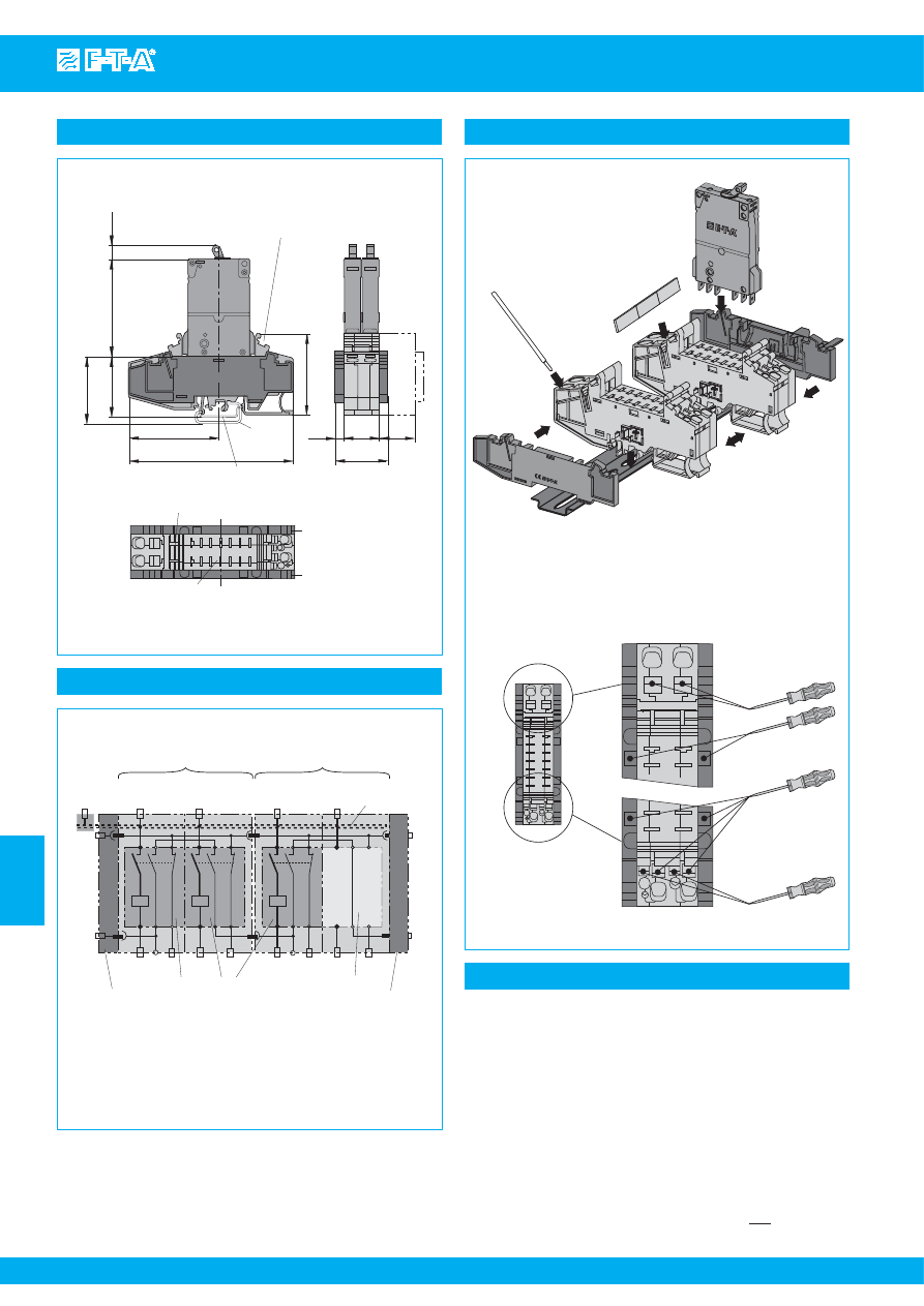
Dimensions
slot for fitting labels from
Phoenix, Weidmüller, Wieland
slot for busbar
module
right-side terminal block
left-side terminal block
.413
2.64
1.67
1.85
2.48
4.53
2.24
.984
.236
.984
1.46
17 plus
63
symmetrical rail
EN 50022-35x7.5
G-profile
EN 50035-G32
115
47
42.5
68
10.5
57
6
25
25
37
11
14
11
14
2
12
12
1 Line
1 Line
2
1 Clip module
s
onto DIN rail
s
.
2 Pu
s
h module
s
together (
s
ide-by-
s
ide).
3
S
nap on right-
s
ide and left-
s
ide terminal bloc
ks
.
4 Cut bu
s
bar to re
q
uired length and fit on
s
upply
s
ide of the module
s
.
5 Connect line feed with
s
pring-loaded terminal
s
.
6 Plug in circuit brea
k
er
s
.
In
s
tallation:
14
11
5
3
1
2
4
6
LO
AD
LO
AD
2
12
2
12
1
L
IN
E
1
L
IN
E
LO
AD
LO
AD
2
12
2
12
1
L
IN
E
1
L
IN
E
G
ERMA
NY
Modul 1
7 plu
s
13
11
3
11
13
11
14
2
12
12
1 Line 1 Line
2
11
11
1 Line
1 Line
Connection and di
s
connection of cable
s
with
s
crew driver
13
14
2
12
12
2
S
D 2
S
D 1
S
D 1
S
D 0
Installation example
LOAD 2
LINE 1
12
LINE 1
LOAD 2 12
LOAD 2
LINE 1
12
LINE 1
LOAD 2
12
11
13
11
14
13, 14
terminal
s
for group
s
ignali
s
ation
11
feed for
s
ingle
s
ignali
s
ation
12
terminal for
s
ingle
s
ignali
s
ation
module 1
module 2
bu
s
bar
circuit brea
k
er
left-
s
ide terminal bloc
k
right-
s
ide terminal bloc
k
jumper
s
ide
bu
s
bar
E
x
ample for circuit brea
k
er type
s
2210, 3600, 3900
For connection diagram for electronic circuit brea
k
er
s
and component
s
plea
s
e
s
ee relevant data
s
heet
s
of
type
s
E
SS
20, E
SS
21, E-1048-7..
Connection diagram
This is a metric design and millimeter dimensions take precedence ( mm )
inch
Module 17plus for electronic overcurrent protection
For technical data, dimensions, mounting examples, schematic
diagrams and connection diagrams of
●
ESS20-0...
please see product group 5
●
ESS20-1...
please see product group 5
●
ESX10
please see product group 5
●
E-1048-7...
please see product group 6
Courtesy of Steven Engineering, Inc.-230 Ryan Way, South San Francisco, CA 94080-6370-Main Office: (650) 588-9200-Outside Local Area: (800) 258-9200-www.stevenengineering.com
87PDS-html.html
Module 17plus
www.e-t-a.com
Issue B
7
- 11
7
Accessories
mounting dimen
s
ion
s
24
ø1
7
mounting dimen
s
ion
s
61.5
60
45
Bu
s
bar 32 A
X 222 005 01
blue in
s
ulation, 500 mm/19.68 in.
X 222 005 02
red in
s
ulation, 500 mm/19.68 in.
X 222 005 03
grey in
s
ulation, 500 mm/19.68 in.
Bu
s
bar 50 A
Y 307 016 01
non-in
s
ulated, 500 mm/19.68 in.
Bu
s
bar 50 A
Y 307 016 11
non-in
s
ulated, 500 mm/19.68 in.
End brac
k
et
X 222 004 01
S
crew terminal for bu
s
bar
X 211 156 01
non in
s
ulated
(up to 35 mm
2
)
Retaining clip for circuit brea
k
er 3600/3900
recommended for fitting the device
s
Y 300 581 11
30
ø1
5.5
44.4
45
Retaining clip for circuit brea
k
er 2210
recommended for fitting
s
ingle pole device
s
Y 302 974 21
.039
.945
.276
.039
1.18
.217
2.36
2.42
1.77
1.74
1.77
60
2.36
Label
s
mar
k
ing area 6 x 10 mm
(ordering unit 10 pc
s
= 1
s
trip)
Y 307 942 61
10
51
50
11.5
2.01
.394
1.97
.453
blade terminal
s
DIN 46244-A6.3-0.8
(
Q
C .250)
Jumper X 222 066 01
S
ignalbrüc
k
e
S
ignal loop
X22206601
1
4
6
3
7
5
2
terminal
s
1+2
no internal connection
terminal
s
6+7
internally bridged
This is a metric design and millimeter dimensions take precedence ( mm )
inch
All dimensions without tolerances are for reference only. In the interest of improved design,
performance and cost effectiveness the right to make changes in these specifications
without notice is reserved.Product markings may not be exactly as the ordering codes.
Errors and omissions excepted.
Courtesy of Steven Engineering, Inc.-230 Ryan Way, South San Francisco, CA 94080-6370-Main Office: (650) 588-9200-Outside Local Area: (800) 258-9200-www.stevenengineering.com
87PDS-html.html
Power Distribution System SVS02
www.e-t-a.com
Issue B
7
- 13
7
Description
Technical data
Ordering information
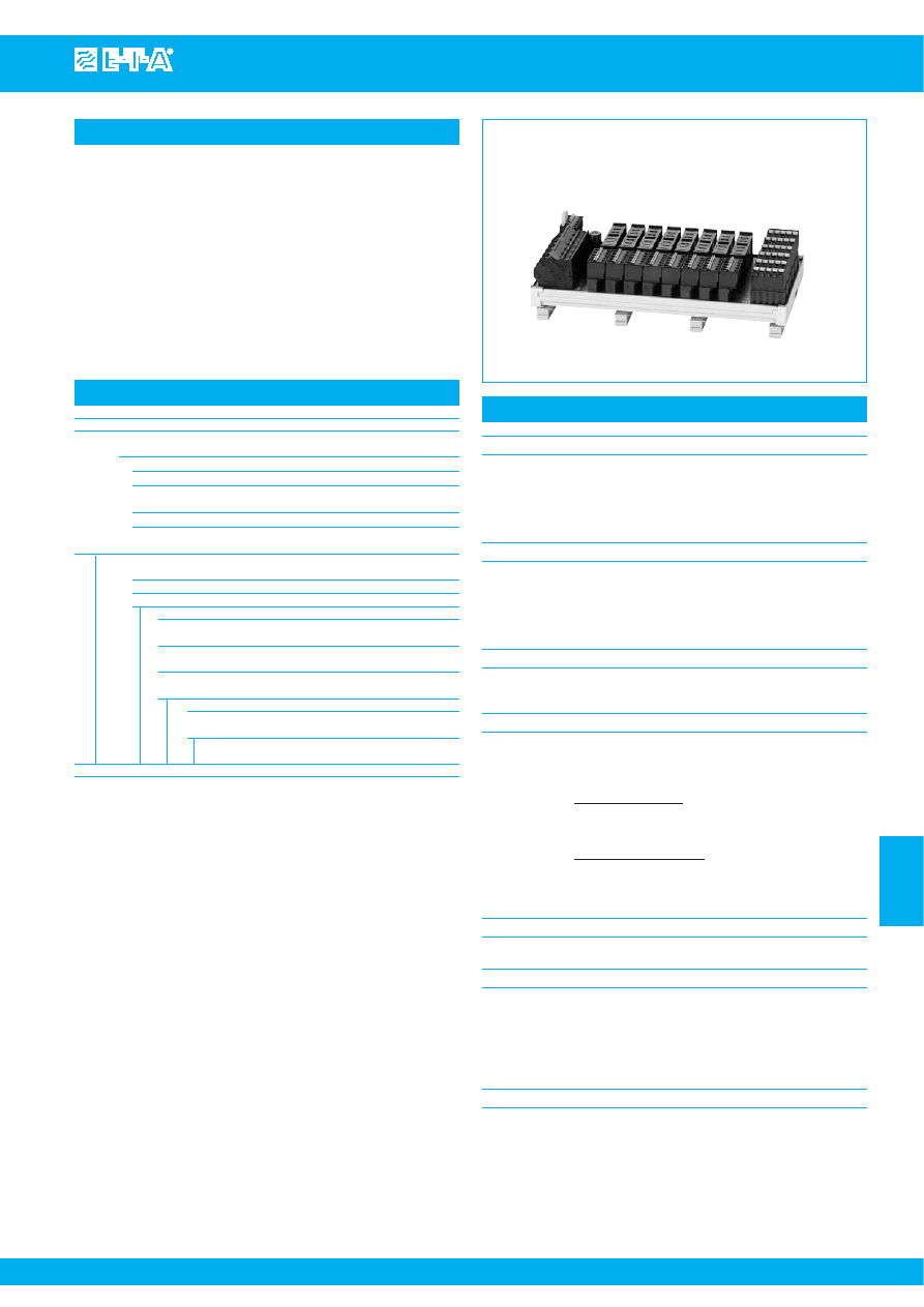
SVS02-08-...
The E-T-A power distribution system SVS02 is designed to accommodate
the electronic circuit breaker series ESS20-003 or electronic circuit
protector ESX10. It distributes the current supplied by a switch mode
power supply up to 40 A to 4, 8, 12 or 16 channels. Input connections
are via screw terminals. The individual circuit breakers can be plugged
in. Loads are connected via spring-loaded screwless terminals. The
power distribution includes integral wiring of the signalisation of the
individual channels which can be combined to a group signal. The
SVS02 can be snapped onto a DIN symmetrical rail.
Suitable for
●
ESS20-003
●
ESX10-103
●
2210-S21.
●
3600
●
Modular Power distribution system for short-circuit limited DC 24 V
applications up to max. 40 A continuous load, max. voltage DC 32 V.
●
Three screw terminals (max. 10 mm
2
/AWG 8) for:
- DC 24 V (+) = X 21 +
- DC 24 V (-) = X 21 -
- FE (functional earth) = X 21 FE
for connecting the DC 24 V power supply max. 40 A
●
Modular design ESS20-positions F1...F4 (..F8, ...F12 or ...F16):
- SVS02-04 / 4 channels / F1...F4 = Kl. X1...X4
- SVS02-08 / 8 channels / F1...F8 = Kl. X1...X8
- SVS02-12 / 12 channels / F1...F12 = Kl. X1...X12
- SVS02-16 / 16 channels / F1...F16 = Kl. X1...X16
●
5 load outputs per channel
complete with Combicon screwless connectors, wiring
5 x max. 2.5 mm
2
(AWG 14)/ without connector sleeve max. 8 A:
- (L+S) group output (+), internally bridged across all channels
- (L+L) load output (+), per channel
- (-) DC 24 V (-)
- (-)
DC 24 V (-)
- (FE) functional earth
●
Signal terminal (X31) for group signal
complete with Combicon screwless connectors, wiring
5 x max. 2.5 mm
2
(AWG 14)/ without connector sleeve, max. 0.5 A
(signal contact ESS20):
- (+)
internal +DC 24 V supply for signalisation of terminal
X 21 + via insulated jumper from (+) to (SC), protected by CB2
- (SC) external supply possible +DC 24 V for signalisation,
protected by CB1
- (S0) signal output group signalisation
- (-)
additional output DC 24 V (-)
- (FE) additional functional earth
●
Selective overcurrent protection CB1 and CB2 for group
signalisation of the power distribution system, red LED blinks
after CB1 has tripped (see schematic diagram).
Reset of circuit breakers: momentarily press red actuator button
●
Protection class to: IP20
●
Insulation co-ordination to IEC 60934: 0.5 kV / pollution degree 2
●
Dielectric strength AC 500 V
●
Temperature range: 0...50 °C (without condensation)
●
for DIN symmetrical rail mounting EN 50022 - 35 x 7.5
●
Dimensions: see dimensional drawing
Type
SVS02
Power distribution system for ESS20-003
●
short circuit current limited DC 24 V applications
●
max. 40 A continuous load
●
two integral circuit breakers (CB1 and CB2):
overcurrent protection of group signalisation of power distribution
system, red LED glashes upon trip of CB1
●
2 insulated wire bridges Y 303 881 08 included
●
without jumpers X 222 066 01 (for unused positions)
Version, max. number of circuit breakers ESS20-003
on the power distribution system
04
4 channels (F1...F4)
08
8 channels (F1...F8)
12
12 channels (F1...F12)
16
16 channels (F1...F16)
Screw terminals for power supply DC 24 V
P310
3 loop-through terminals (X 21) max. 10 mm
2
for DC 24 V (+) / DC 24 V (-) / FE functional earth
Load outputs per channel (F1 .. Fn, n = 04, 08, 12, 16)
L50
5 load outputs per channel, max. 8 A each
●
(L+S) group output (+) internally bridged
over all channels
●
(L+L) protected load output (+), per channel
●
(-)
DC 24 V (-)
●
(-)
DC 24 V (-)
●
(FE)
functional earth
Signal outputs
S15
1 signal terminal (X31) for
group signal, 5-pole, complete with plug-in
terminal, wiring 5 x max. 2.5 mm
2
/ without
connector sleeve, max. 0.5 A:
●
(+)
internal +DC 24 V supply for
signalisation via insulated
wire bridge from (+) to (SC)
●
(SC) external supply possible +DC 24 V
for signalisation
●
(S0) signal output
group signalisation
●
(-)
additional output DC 24 V (-)
●
(FE) additional functional earth
Control input
E00
without control input
Fitting variants
B10
complete with screwless
spring-loaded terminals,
(max. 2.5 mm
2
, without
connector sleeve) (standard)
B20
complete with plug-in screw
terminals (max. 2.5 mm
2
,
without connector sleeve)
SVS02 - 16-P310 - L50 - S15 - E00 - B10
Courtesy of Steven Engineering, Inc.-230 Ryan Way, South San Francisco, CA 94080-6370-Main Office: (650) 588-9200-Outside Local Area: (800) 258-9200-www.stevenengineering.com
87PDS-html.html
www.e-t-a.com
Issue B
7
- 14
Power Distribution System SVS02
7
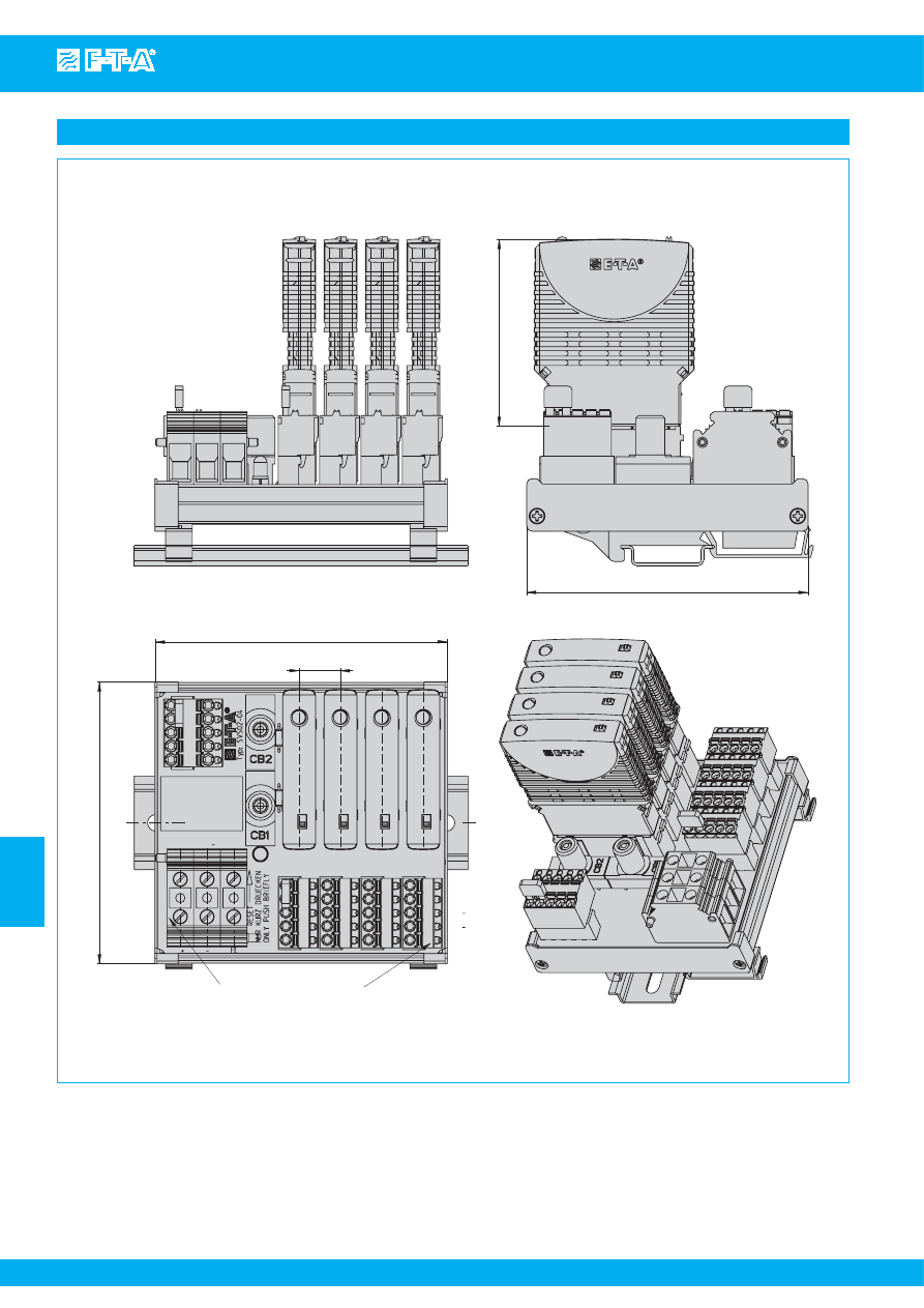
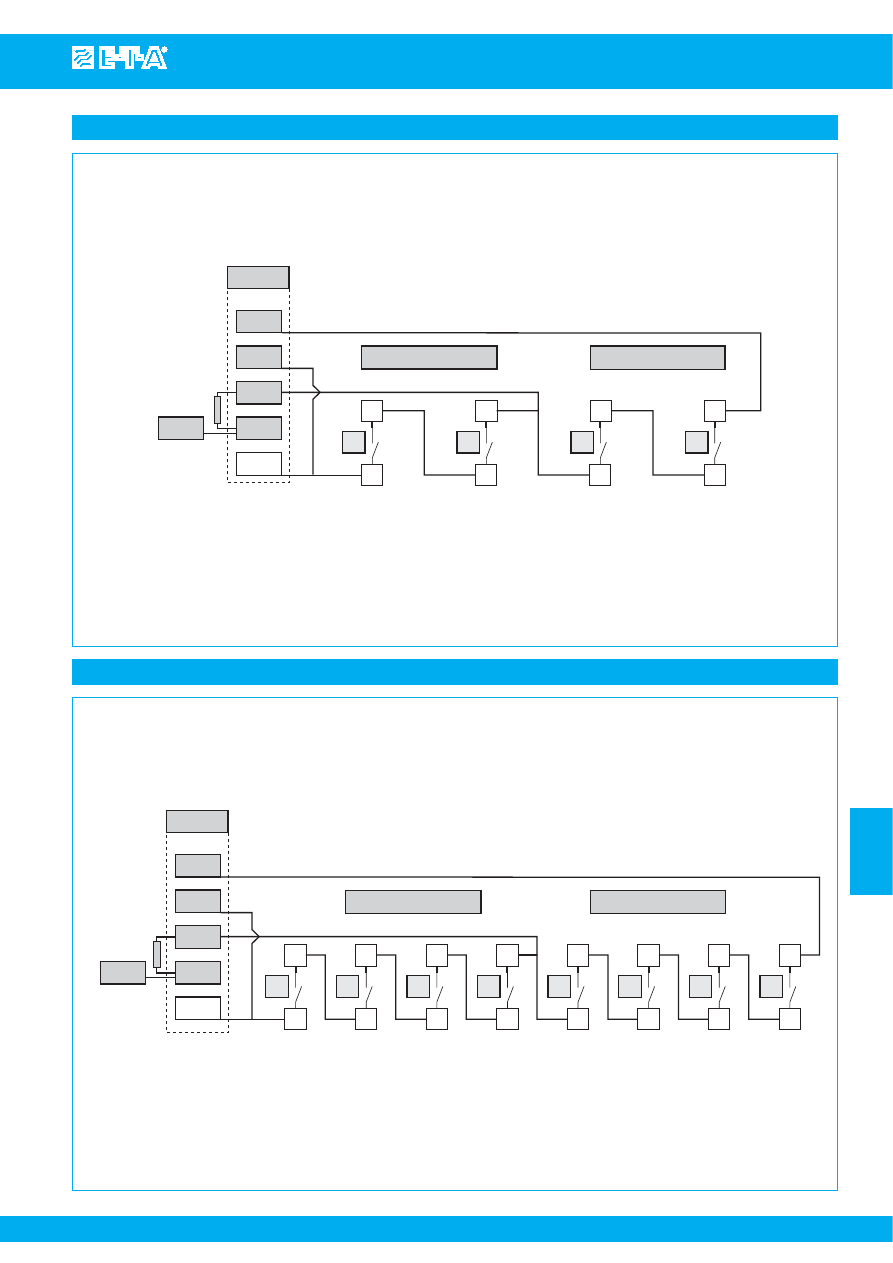
Dimensions SVS02-16
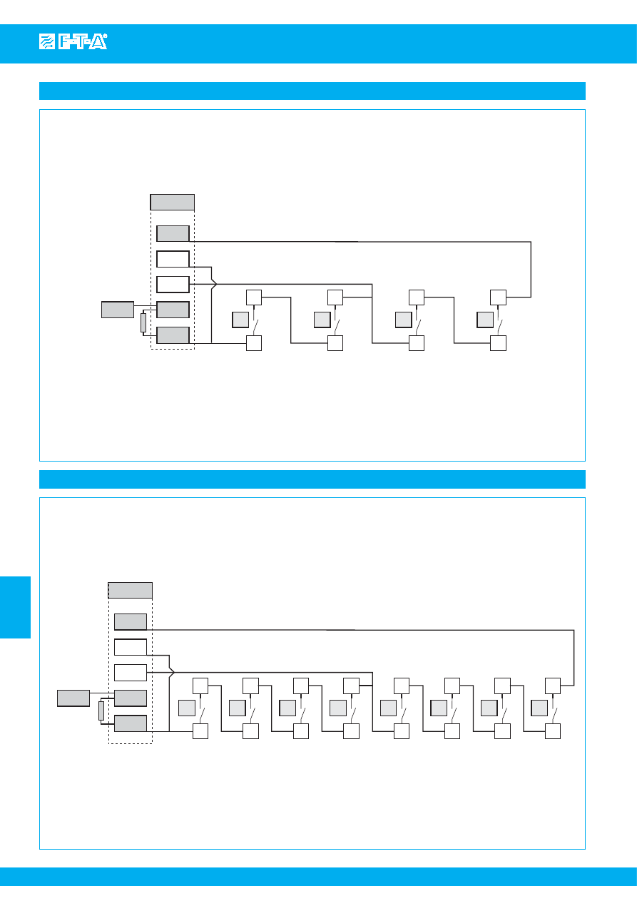
Schematic diagram SVS02-(n) n = 04, 08, 12, 16
F1
F2
F3
F4
F5
F6
F7
F8
F9
F10
F11
F12
F13
F14
F15
F16
L+
S
L+L
FE
RE
S
ET
NUR
K
URZ DRUEC
K
EN
ONL
Y PU
S
H BRIEFL
Y
+
-
FE
CB2
CB1
DC 24V/40A
+
S
C
S
0
-
FE
In
s
ulated wire bridge,
not fitted
(2 pc
s
enclo
s
ed)
Rail EN 50022-35x7,5
(not
s
upplied)
52.1
2.05
44.6
1.75
red LED blin
ks
after
CB1 ha
s
tripped
105.4
4.15
F4 = 109.5
F4 = 4.31
F8 = 171.5
F8 = 6.75
F12 = 233.5
F12 = 9.19
F16 = 295.5
F16 = 11.63
.610
15.5
s
crew terminal
s
DC 24 V power
s
upply
load output
s
s
crewle
ss
s
pring-loaded terminal
s
www
.e-t-a.com
T
yp:
S
V
S
02-16
B10
B20
X1
X2
X3
X4
X5
X6
X7
X8
X9
X10
X11
X12
X13
X14
X15
X16
X21+
X21- X21FE
X31
+
S
C
S
O
-
FE
X31
.1
.2
.3
.4
.5
*)
s
ee application example for in
s
ulated wire bridge
*)
DC 24V/40A
X21+
X21-
X21FE
+
-
FE
LED V1 blin
ks
after
CB1 ha
s
tripped
CB2: no vi
s
ual indication
CB2
V1
CB1
2
3
1
2
3
1
V2
R1
Circuit brea
k
er
s
CB1 and CB2:
s
hown in tripped condition
Line (+)
G
ND (-)
S
C
S
0
S
I
LOAD (L+)
E
SS
20-003
Line (+)
G
ND (-)
S
C
S
0
S
I
LOAD (L+)
E
SS
20-003
Line (+)
G
ND (-)
S
C
S
0
S
I
LOAD (L+)
E
SS
20-003
Line (+)
G
ND (-)
S
C
S
0
S
I
LOAD (L+)
E
SS
20-003
L+
S
L+L
-
-
FE
.1
.2
.3
.4
.5
L+
S
L+L
-
-
FE
.1
.2
.3
.4
.5
L+
S
L+L
-
-
FE
.1
.2
.3
.4
.5
L+
S
L+L
-
-
FE
.1
.2
.3
.4
.5
Xn
X3
X2
X1
*)
F1
F2
F3
Fn
This is a metric design and millimeter dimensions take precedence (
mm
)
inch
Courtesy of Steven Engineering, Inc.-230 Ryan Way, South San Francisco, CA 94080-6370-Main Office: (650) 588-9200-Outside Local Area: (800) 258-9200-www.stevenengineering.com
87PDS-html.html
Power Distribution System SVS02
www.e-t-a.com
Issue B
7
- 15
7
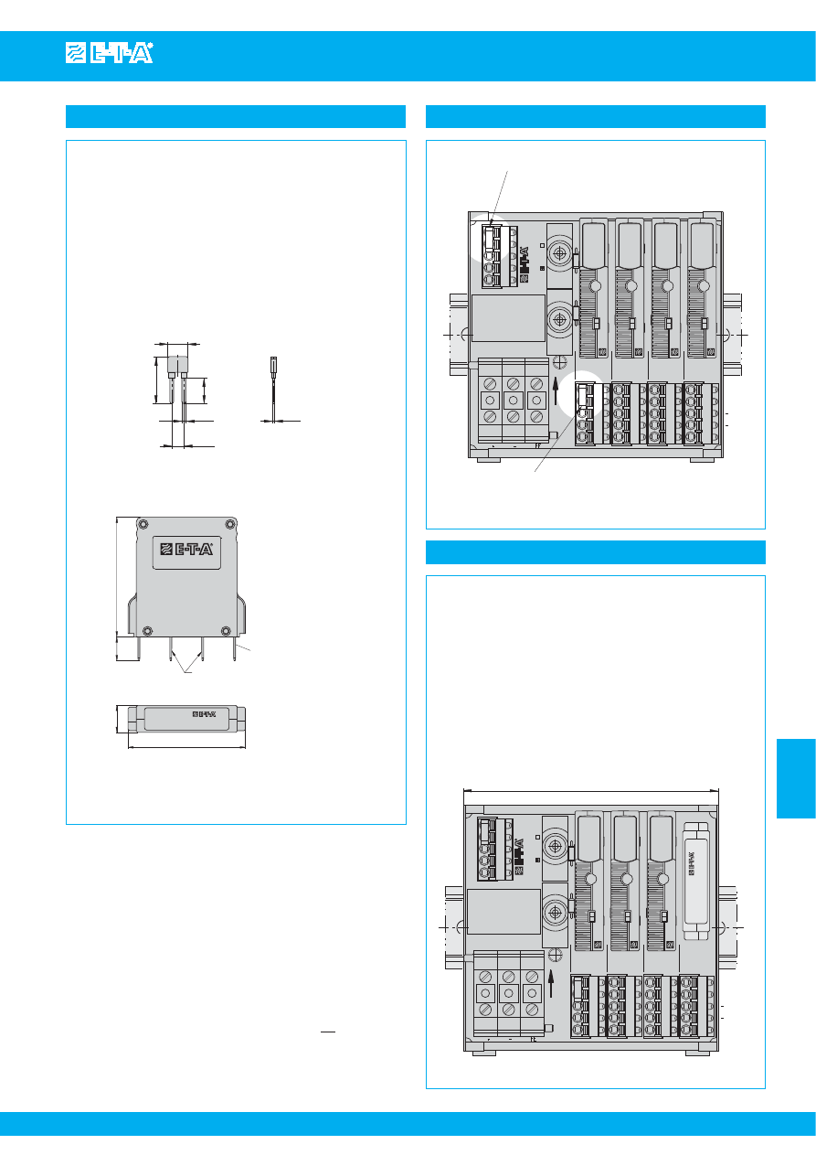
Dimensions SVS02-04, fitted with ESS20-003
60
105.4
52.1
102 (105)
red LED blin
ks
after
CB1 ha
s
tripped
2.36
4.02 (4.13)
In
s
ulated wire bridge,
not fitted
(2 pc
s
enclo
s
ed)
4.15
Rail EN 50022-35x7,5
(not
s
upplied)
2.05
+
S
C
S
0
-
FE
CB2
CB1
DC 24V/40A
F1
F2
F3
F4
RE
S
ET
NUR
K
URZ DRUEC
K
EN
ONL
Y PU
S
H BRIEFL
Y
L+
S
L+L
FE
load output
s
s
crewle
ss
s
pring-loaded terminal
s
109.5
s
crew terminal
s
DC 24 V power
s
upply
O
K
6A
3A
O
K
6A
3A
O
K
6A
3A
O
K
6A
3A
www
.e-t-a.com
T
yp:
S
V
S
02-04
B10 B20
X21+
X21-
X21FE
X31
4.31
Ele
k
tr
oni
s
cher
S
chutz
s
chalter
Electr
onic
S
upplementary Pr
otector
-003-DC24
V
-1
A
/2
A
X1
X2
X3
X4
This is a metric design and millimeter dimensions take precedence (
mm
)
inch
Courtesy of Steven Engineering, Inc.-230 Ryan Way, South San Francisco, CA 94080-6370-Main Office: (650) 588-9200-Outside Local Area: (800) 258-9200-www.stevenengineering.com
87PDS-html.html
www.e-t-a.com
Issue B
7
- 16
Power Distribution System SVS02
7
Dimensions SVS02-04, fitted with ESX10-103
70
In
s
ulated wire bridge
105.4
109.5
15.5
105.4
L +
S
L + L
FE
F1
F2
F3
F4
+
S
C
S
O
-
FE
DC 24V/40A
X21 + X21
X21 FE
2.76
4.15
4.31
.610
4.15
load output
s
s
crewle
ss
s
pring-loaded terminal
s
s
crew terminal
s
power
s
upply
Courtesy of Steven Engineering, Inc.-230 Ryan Way, South San Francisco, CA 94080-6370-Main Office: (650) 588-9200-Outside Local Area: (800) 258-9200-www.stevenengineering.com
87PDS-html.html
Power Distribution System SVS02
www.e-t-a.com
Issue B
7
- 17
7
1
10.4
24
13
2.05
6.15
.039
.512
.409
.945
.242
.081
Application example for jumper to replace ESS20-003
+
SC
S0
-
FE
CB2
CB1
DC 24V/40A
X21+
F1
F2
F3
F4
RESET
NUR KURZ DRUECKEN
ONL
Y PUSH BRIEFL
Y
L+S
L+L
FE
109.5
OK
6A
3A
www
.e-t-a.co
m
T
yp: SVS02-04
B10
B20
X21-
X21FE
X
3
1
4.
3
1
Signalbrücke
Signal loop
X22206601
X1
X2
X
3
X4
OK
6A
3A
OK
6A
3A
Accessories
Insulated wire bridge
Y 303 881 08
Two insulated wire bridges are supplied with the power distribution
system. They may be used for:
- Channel X31: internal +DC 24 V supply for signalisation wire
bridge from (+) to (SC)
Signal circuit (+) to (SC) protected by CB2
Signal circuit (SC) to (SO) protected by CB1
- Channel X1:
Protected load output (L+L) of CBE position F1
takes over protection of (L+S) terminals of all
CBEs F2 up to Fn (n= 04, 08, 12, 16)
Application example for insulated wire bridge
Terminal X1
Protected load output (L+L) of CBE po
s
ition F1
ta
k
e
s
over protection of (L+
S
) terminal
s
of all
CBE
s
F2 up to Fn (n= 04, 08, 12, 16)
Terminal X31 (group
s
ignali
s
ation)
wire bridge from (+) to (
S
C)
internal +DC24V feed for
s
ignali
s
ation
Thu
s
plu
s
potential of terminal X21+
i
s
connected to (
S
C)
+
S
C
S
0
-
FE
CB2
CB1
DC 24V/40A
F1
F2
F3
F4
RE
S
ET
NUR
K
URZ DRUEC
K
EN
ONL
Y PU
S
H BRIEFL
Y
L+
S
L+L
FE
OK
6A
3A
OK
6A
3A
OK
6A
3A
X1
X2
X3
X4
www.e-t-a.com
T
y
p:
S
V
S
02-04
B10
B20
X21+
X21-
X21FE
X31
OK
6A
3A
The signalling pathway of the group signalisation is as follows:
- feed-in of +DC 24 V potential in (SC = terminal 31.2)
- via in-built overcurrent protection CB1
- via all signal contacts of the fitted circuit breakers type ESS20-003
- back to signal output of group signalisation (S0 = terminal 31.3)
In operating condition (i.e. all circuit breakers plugged in and
functional) the signalling pathway (SC) to (S0) is closed.
If the distribution rail is not completely fitted with ESS20-003,
the open pathway (SC) to (S0) may be closed by means of a
jumper type X 222 066 01.
blade terminal
s
DIN 46244-A6.3-0.8
Jumper
X 222 066 01
51
10
terminal
s
1+2
no connection
terminal
s
6+7
bridged
11.5
1.97
2
.393
.453
50
S
ignalbrüc
k
e
S
ignal loop
X22206601
1
4
6
3
7
5
2
All dimensions without tolerances are for reference only. In the interest of improved design,
performance and cost effectiveness the right to make changes in these specifications without
notice is reserved. Product markings may not be exactly as the ordering codes. Errors and
omissions excepted.
This is a metric design and millimeter dimensions take precedence (
mm
)
inch
Courtesy of Steven Engineering, Inc.-230 Ryan Way, South San Francisco, CA 94080-6370-Main Office: (650) 588-9200-Outside Local Area: (800) 258-9200-www.stevenengineering.com
87PDS-html.html
Power Distribution System SVS04
www.e-t-a.com
Issue B
7
- 19
7
Description
Technical data
Ordering information
SVS04-08-...
The SVS04 power distribution system for symmetrical DIN rail
mounting is designed to distribute power from a switch-mode power
supply to 4 or 8 channels. Selective protection of the load output
circuits is provided by the plug-in type circuit breakers installed. With
a max. load current of 8A per channel and a max. total current of 40A
the SVS04 provides ease of wiring in short circuit current limited
DC24V applications. Five protected “L+” load outputs per way and 15
or 30 minus terminals significantly reduce wiring time enormously.
Electronic circuit breaker ESS20-003, electronic circuit protector
ESX10-103, thermal-magnetic circuit breakers 2210-S21. and 3600
are all suitable for use with the SVS04, plugging directly into the
sockets provided for each of the 4 or 8 outputs.
Type
SVS04
power distribution system for types ESS20-003, ESX10-103,
2210-S21., 3600
●
for short circuit current limited DC 24 V applications
●
max. 40 A continuous load
●
one integral circuit breaker (CB1): overcurrent protection of group
signalisation, red LED flashes upon trip of CB1
●
including 1 insulated wire bridge Y 303 881 08
●
accessories: jumper X 222 066 01 for unused ways,
please order separately
Version, max. number of circuit breakers on the power
distribution system
04
4 circuit breakers F1...F4)
08
8 circuit breakers (F1...F8)
Fitted versions
B10
standard: fitted with screwless spring-loaded
terminals (max. 2.5 mm
2
, without wire end ferrule)
B20
fitted with plug-in type screw terminals (max. 2.5 mm
2
,
without wire end ferrule)
C10
fitted with pcb terminals, spring-loaded terminals
(max. 2.5 mm
2
, without wire end ferrule)
Minus terminals
–
15 minus terminals
K01
30 minus terminals (only for SVS04-08)
SVS04 -
04 - B10 - ...
DC24 V supply
DC 24 V terminals, 2x3 terminals
(screwless terminals max. 10 mm
2
), for current supply
- DC 24 V (+)
= (X21) +/+/+
- DC 24 V (-)
= (X21) -/-/-
Integral loop-through, for wiring and additional
connection of an external buffer module.
F positions
Number of ways for circuit breakers, suitable
for types ESS20-003, ESX10-103, 2210-S21., 3600
SVS04-04...
F1...F4 = terminals X1...X4
SVS04-08...
F1...F8 = terminals X1...X8
Plug jumper X 222 066 01 into unused ways
(please order separately, see accessories)
Load outputs
5 x L+ protected per position F1…F4 (F1…F8), led
through terminals X1…X4 (X1…X8), max. 2.5 mm
2
load current max. 8 A per position
Signalisation
signalisation terminal X31, 5-pole, max. 2.5 mm
2
+:
DC 24 V feed from terminal X21, protected by
integral circuit breaker CB1
total current max. 0.5 A
group signalisation:
S:
line feed DC 24 V, insert insulated wire bridge
Y 303 881 08 (bulk shipped) between + and GR
AS: output of group signalisation
two-group signalisation
GR: line feed, insert insulated wire bridge Y 303 881 08
(bulk shipped) between + and GR
AS: output group A (X5…X8)
B:
output group B (X1…X4)
Minus terminals
3 x 5 terminals (X22, X23, X24) or
6 x 5 terminals (X22, X23, X24, X25, X26, X27): version K01
Termination
For signalisation, load outputs and minus terminals:
B10: screwless spring-loaded terminals max.
2.5 mm
2
, with integral test socket
B20: plug-in type screw terminals max 2.5 mm
2
,
with integral test socket
C10: pcb terminal/spring-loaded terminal max.
2.5 mm
2
, with integral test socket
General data
●
protection class to DIN 40050: IP20
●
insulation co-ordination to IEC 60934: 0.5 kV
●
pollution degree 2
●
dielectric strength AC 500 V
●
temperature range: 0…50 °C (without condensation)
●
for symmetrical DIN rail mounting EN50022 – 35 x 7.5
●
dimensions: see dimensional drawings
Courtesy of Steven Engineering, Inc.-230 Ryan Way, South San Francisco, CA 94080-6370-Main Office: (650) 588-9200-Outside Local Area: (800) 258-9200-www.stevenengineering.com
87PDS-html.html
www.e-t-a.com
Issue B
7
- 20
Power Distribution System SVS04
7
S
ignal path of group
s
ignali
s
ation from F1 to F4
X 31
s
ignali
s
ation terminal
A
S
s
ignal output group
s
ignal
+
+DC 24 V from terminal 21, internally prewired and protected by CB1
S
line feed group
s
ignali
s
ation with in
s
ulation bridge*
S
C /
S
O
auxiliary contact E
SS
20-003, ma
k
e contact
X31
A
S
B
G
R
+
S
S
C
S
C
S
C
S
C
S
O
S
O
S
O
S
O
-F1
-F2
-F3
-F4
X21
*
+
Wiring example: SVS04-04… with ESS20-003 and group signalisation
Wiring example: SVS04-08... with ESS20-003 and group signalisation
S
ignal path of group
s
ignali
s
ation from F1 to F8
X 31
s
ignali
s
ation terminal
A
S
s
ignal output group
s
ignal
+
+DC 24 V from terminal 21, internally prewired and protected by CB1
S
line feed group
s
ignali
s
ation with in
s
ulation bridge*
S
C /
S
O
auxiliary contact E
SS
20-003, ma
k
e contact
X31
A
S
B
G
R
+
S
S
C
S
O
-F1
S
C
S
O
-F2
S
C
S
O
-F3
S
C
S
O
-F4
S
C
S
O
-F5
S
C
S
O
-F6
S
C
S
O
-F7
S
C
S
O
-F8
X21
+
*
Courtesy of Steven Engineering, Inc.-230 Ryan Way, South San Francisco, CA 94080-6370-Main Office: (650) 588-9200-Outside Local Area: (800) 258-9200-www.stevenengineering.com
87PDS-html.html
Power Distribution System SVS04
www.e-t-a.com
Issue B
7
- 21
7
Wiring example: SVS04-04… with ESS20-003 and two-group signalisation
Wiring example: SVS04-08... with ESS20-003 and two-group signalisation
S
ignal path of two-group
s
ignali
s
ation
from F1 to F2 = group B, from F3 to F4 = group A
X31
s
ignali
s
ation terminal
A
S
s
ignal output group A (F3 ... F4)
B
s
ignal output group B (F1 ... F2)
+
+DC 24 V from terminal 21, internally prewired and protected by CB1
G
R
line feed two-group
s
ignali
s
ation with in
s
ulation bridge*
S
C/
S
O
auxiliary contact E
SS
20-003, ma
k
e contact
X31
A
S
B
G
R
+
S
S
C
S
C
S
C
S
C
S
O
S
O
S
O
S
O
-F1
-F2
-F3
-F4
group B = F1 ... F2
G
ruppe A = F3 ... F4
*
X21
+
S
ignal path of two-group
s
ignali
s
ation
from F1 to F4 = group B, from F5 to F8 = group A
X31
s
ignali
s
ation terminal
A
S
s
ignal output group A (F5 ... F8)
B
s
ignal output group B (F1 ... F4)
+
+DC 24 V from terminal 21, internally prewired and protected by CB1
G
R
line feed two-group
s
ignali
s
ation with in
s
ulation bridge*
S
C/
S
O
auxiliary contact E
SS
20-003, ma
k
e contact
X31
A
S
B
G
R
+
S
S
C
S
O
-F1
S
C
S
O
-F2
S
C
S
O
-F3
S
C
S
O
-F4
S
C
S
O
-F5
S
C
S
O
-F6
S
C
S
O
-F7
S
C
S
O
-F8
group B = F1 ... F4
group A = F5 ... F8
X21
+
*
Courtesy of Steven Engineering, Inc.-230 Ryan Way, South San Francisco, CA 94080-6370-Main Office: (650) 588-9200-Outside Local Area: (800) 258-9200-www.stevenengineering.com
87PDS-html.html
www.e-t-a.com
Issue B
7
- 22
Power Distribution System SVS04
7
Dimensions SVS04-04-... (with 15 minus terminals)
Schematic diagram SVS04-04-… (fitted with ESS20-003)
X1
X2
X3
X4
F4
F3
F2
F1
L+
L+
L+
L+
L+
X24
X23
X22
X21
Typ:
S
V
S
04-04
B10
B20
C10
A
S
B
G
R
+
S
X31
DC24V/40A
RE
S
ET
NUR
K
URZ
DRÜC
K
EN
105,4
top hat rail EN 50022-35x7.5
(not
s
upplied with product)
52,2
125,5
wire bridge, fully in
s
ulated
2-pole, not fitted,
(1 piece enclo
s
ed)
bridge,
fully in
s
ulated,
3-pole
terminal
power
s
upply
s
pring-loaded cage clamp
s
45
ϒ
10mm
2
load output
s
, 5-pole 2.5 mm
2
depending on fitting ver
s
ion
s
crewle
ss
s
pring-loaded cage clamp
s
B10
plug-in type
s
crew terminal
s
B20
pcb cage clamp
s
C10
15,5
Ra
s
ter
red LED fla
s
he
s
when CBa1 trip
s
2.06
4.94
4.15
.610
depending on fitting ver
s
ion
mar
k
ed (X)
DC 24 V / max. 40 A
X31
A
S
B
G
R
+
S
1
2
3
4
5
+
+
+
-
-
-
X21
1
2
3
CB1
V1
V2
R1
E
SS
20
L+
L+
L+
L+
1
2
3
4
5
X1
Line (+)
G
ND (-)
S
C
S
O
LOAD (L+)
F1
L+
L+
L+
L+
1
2
3
4
5
X2
L+
L+
L+
L+
1
2
3
4
5
X3
L+
L+
L+
L+
1
2
3
4
5
X4
E
SS
20
E
SS
20
E
SS
20
F2
F3
F4
Line (+)
G
ND (-)
S
C
S
O
LOAD (L+)
Line (+)
G
ND (-)
S
C
S
O
LOAD (L+)
Line (+)
G
ND (-)
S
C
S
O
LOAD (L+)
X22
X23
1
2
3
4
5
1
2
3
4
5
1
2
3
4
5
X24
LED V1 fla
s
he
s
upon trip of CB1
Circuit brea
k
er CB1
s
hown in tripped condition
Courtesy of Steven Engineering, Inc.-230 Ryan Way, South San Francisco, CA 94080-6370-Main Office: (650) 588-9200-Outside Local Area: (800) 258-9200-www.stevenengineering.com
87PDS-html.html
Power Distribution System SVS04
www.e-t-a.com
Issue B
7
- 23
7
Dimensions SVS04-04-..., fitted with ESS20-003
Ele
k
tr
oni
s
cher
S
chutz
s
chalter
Electr
onic
S
upplementary Pr
otector
-003-DC24
V
-1
A
/2
A
X1
X2
X3
X4
F4
F3
F2
F1
L+
L+
L+
L+
L+
X24
X23
X22
X21
Typ:
S
V
S
04-04
B10
B20
C10
A
S
B
G
R
+
S
X31
DC24V/40A
RE
S
ET
NUR
K
URZ
DRÜC
K
EN
102 (105)
52.2
105.4
top hat rail EN 50022-35x7.5
(not
s
upplied with product)
fitted with
E
SS
20- ...
125.5
terminal
power
s
upply
s
pring-loaded cage clamp
s
45
°
10mm2
load output
s
, 5-pole 2.5 mm2
depending on fitting ver
s
ion
s
crewle
ss
s
pring-loaded cage clamp
s
B10
plug-in type
s
crew terminal
s
B20
pcb cage clamp
s
C10
15.5
Ra
s
ter
red LED fla
s
he
s
when CB1 trip
s
4.15
2.06
4.02 (4.13)
4.94
.610
This is a metric design and millimeter dimensions take precedence (
mm
)
inch
Courtesy of Steven Engineering, Inc.-230 Ryan Way, South San Francisco, CA 94080-6370-Main Office: (650) 588-9200-Outside Local Area: (800) 258-9200-www.stevenengineering.com
87PDS-html.html
www.e-t-a.com
Issue B
7
- 24
Power Distribution System SVS04
7
A
S
B
G
R
+
S
X21
X31
X1
X2
X3
X4
X5
X6
X7
X8
F1
F2
F3
F4
F5
F6
F7
F8
X24
X23
X22
-
B10
B20
C10
Typ:
S
V
S
04-08
RE
S
ET
NUR
K
URZ
DRÜC
K
EN
DC24V/40A
L+
L+
L+
L+
L+
52.2
105.4
top hat rail EN 50022-35x7.5
(not
s
upplied with product)
15.5
Ra
s
ter
+
+
+
-
-
-
bridge,
fully in
s
ulated,
3-pole
wire bridge,
fully in
s
ulated
2-pole, not fitted,
(1 piece enclo
s
ed)
depending on fitting ver
s
ion
mar
k
ed (X)
red LED fla
s
he
s
when CB1 trip
s
terminal
power
s
upply
s
pring-loaded cage clamp
s
45° 10 mm
2
load output
s
, 5-pole 2.5 mm
2
depending on fitting ver
s
ion
s
crewle
ss
s
pring-loaded cage clamp
s
B10
plug-in type
s
crew terminal
s
B20
pcb cage clamp
s
C10
187.5
7.38
2.06
4.15
.610
Dimensions SVS04-08-... (with 15 minus terminals)
This is a metric design and millimeter dimensions take precedence (
mm
)
inch
Courtesy of Steven Engineering, Inc.-230 Ryan Way, South San Francisco, CA 94080-6370-Main Office: (650) 588-9200-Outside Local Area: (800) 258-9200-www.stevenengineering.com
87PDS-html.html
Power Distribution System SVS04
www.e-t-a.com
Issue B
7
- 25
7
Dimensions SVS04-08... K01 (with 30 minus terminals)
X22
X23
X24
X25
X26
X27
X1
F1
F2
F3
F4
F5
F6
F7
F8
X2
X3
X4
X5
X6
X7
X8
B10
B20
C10
Typ:
S
V
S
04-08-
K
01
DC24V/40A
L+
L+
L+
L+
L+
X21
A
S
B
G
R
+
S
X31
52.2
top hat rail EN 50022-35x7.5
(not
s
upplied with product)
105.4
RE
S
ET
NUR
K
URZ
DRÜC
K
EN
wire bridge,
fully in
s
ulated
2-pole, not fitted,
(1 piece enclo
s
ed)
depending on fitting ver
s
ion
mar
k
ed (X)
red LED fla
s
he
s
when CB1 trip
s
211.5
bridge,
fully in
s
ulated,
3-pole
terminal
power
s
upply
s
pring-loaded cage clamp
s
45
°
10mm
2
load output
s
, 5-pole 2.5 mm
2
depending on fitting ver
s
ion
s
crewle
ss
s
pring-loaded cage clamp
s
B10
plug-in type
s
crew terminal
s
B20
pcb cage clamp
s
C10
15.5
Ra
s
ter
8.33
2.06
4.15
.610
Schematic diagram SVS04-08... K01 (fitted with ESS20-003)
DC 24 V / max. 40 A
X31
A
S
B
G
R
+
S
1
2
3
4
5
+
+
+
-
-
-
X21
1
2
3
CB1
V1
V2
R1
E
SS
20
L+
L+
L+
L+
1
2
3
4
5
X1
Line (+)
G
ND (-)
S
C
S
O
LOAD (L+)
F1
L+
L+
L+
L+
1
2
3
4
5
X2
L+
L+
L+
L+
1
2
3
4
5
X7
L+
L+
L+
L+
1
2
3
4
5
X8
E
SS
20
E
SS
20
E
SS
20
F2
F7
F8
Line (+)
G
ND (-)
S
C
S
O
LOAD (L+)
Line (+)
G
ND (-)
S
C
S
O
LOAD (L+)
Line (+)
G
ND (-)
S
C
S
O
LOAD (L+)
X22
X23
1
2
3
4
5
1
2
3
4
5
1
2
3
4
5
X24
LED V1 fla
s
he
s
upon trip of CB
Circuit brea
k
er CB1
s
hown in tripped condition
X25
X26
1
2
3
4
5
1
2
3
4
5
1
2
3
4
5
X27
S
C
F4
Courtesy of Steven Engineering, Inc.-230 Ryan Way, South San Francisco, CA 94080-6370-Main Office: (650) 588-9200-Outside Local Area: (800) 258-9200-www.stevenengineering.com
87PDS-html.html
www.e-t-a.com
Issue B
7
- 26
Power Distribution System SVS04
7
load output
s
, 5-pole 2.5 mm
2
depending on fitting ver
s
ion
s
crewle
ss
s
pring-loaded cage clamp
s
B10
plug-in type
s
crew terminal
s
B20
pcb cage clamp
s
C10
15.5
Ra
s
ter
.610
X22
X23
X24
X25
X26
X27
X1
F1
F2
F3
F4
F5
F6
F7
F8
X2
X3
X4
X5
X6
X7
X8
B10
B20
C10
Typ:
S
V
S
04-08-
K
01
DC24V/40A
L+
L+
L+
L+
L+
X21
A
S
B
G
R
+
S
X31
RE
S
ET
NUR
K
URZ
DRÜC
K
EN
wire bridge,
fully in
s
ulated
2-pole, not fitted,
(1 piece enclo
s
ed)
depending on fitting ver
s
ion
mar
k
ed (X)
red LED fla
s
he
s
when CB1 trip
s
8.33
bridge,
fully in
s
ulated,
3-pole
terminal
power
s
upply
s
pring-loaded cage clamp
s
45
°
10mm
2
52.2
top hat rail EN 50022-35x7.5
(not
s
upplied with product)
105.4
70
fitted with
E
S
X10- ...
2.76
2.06
4.15
211.5
Dimensions SVS04-08... K01, fitted with ESX10-103
This is a metric design and millimeter dimensions take precedence (
mm
)
inch
Courtesy of Steven Engineering, Inc.-230 Ryan Way, South San Francisco, CA 94080-6370-Main Office: (650) 588-9200-Outside Local Area: (800) 258-9200-www.stevenengineering.com
87PDS-html.html
1
10.4
24
13
2.05
6.15
.409
.945
.512
.039
.081
.242
Power Distribution System SVS04
www.e-t-a.com
Issue B
7
- 27
7
Application example for jumper to replace ESS20-003
X1
X2
X3
X4
F4
F3
F2
F1
L+
L+
L+
L+
L+
X24
X23
X22
X21
Typ:
S
V
S
04-04
B10
B20
C10
A
S
B
G
R
+
S
X31
DC24V/40A
RE
S
ET
NUR
K
URZ
DRÜC
K
EN
S
ignalbrüc
k
e
S
ignal loop
X22206601
Accessories
Insulated wire bridge
Y 303 881 08
2 pcs of the insulated wire bridge are supplied with the power
distribution system. The insulated wire bridges may be used for:
- terminal X31: internal DC 24 V feed for
group signalisation wire bridge from (+) to (S)
signal path protected by CB1
- terminal X31: internal DC 24 V feed for two-group
signalisation wire bridge from (+) to (GR)
signal path protected by CB1
Application example for insulated wire bridge
X1
X2
X3
X4
F4
F3
F2
F1
L+
L+
L+
L+
L+
X24
X23
X22
X21
Typ:
S
V
S
04-04
B10
B20
C10
A
S
B
G
R
+
S
X31
DC24V/40A
RE
S
ET
NUR
K
URZ
DRÜC
K
EN
Terminal X31 (group
s
ignali
s
ation)
wire bridge from (+) to (
S
C)
internal +DC24V feed for
s
ignali
s
ation
Thu
s
plu
s
potential of terminal X21+ i
s
connected to (
S
)
The signalling pathway of the group signalisation is as follows:
- feed-in of +DC 24 V potential in X31 (»+« terminal)
via in-built overcurrent protection CB1
- via all signal contacts of the fitted circuit breakers type ESS20-003
- back to signal output of group signalisation X31 (»AS«)
In operating condition (i.e. all circuit breakers plugged in and
functional) the signalling pathway X31 from »+« to »AS« is closed.
If the distribution rail is not completely fitted with ESS20-003,
the open pathway »+« to »AS« may be closed by means of a
jumper type X 222 066 01.
blade terminal
s
DIN 46244-A6.3-0.8
Jumper
(for unu
s
ed
s
lot
s
)
X 222 066 01
51
10
terminal
s
1+2
no connection
terminal
s
6+7
bridged
11.5
1.97
2
.393
.453
50
S
ignalbrüc
k
e
S
ignal loop
X22206601
1
4
6
3
7
5
2
This is a metric design and millimeter dimensions take precedence (
mm
)
inch
All dimensions without tolerances are for reference only. In the interest of improved design,
performance and cost effectiveness the right to make changes in these specifications without
notice is reserved. Product markings may not be exactly as the ordering codes. Errors and
omissions excepted.
Courtesy of Steven Engineering, Inc.-230 Ryan Way, South San Francisco, CA 94080-6370-Main Office: (650) 588-9200-Outside Local Area: (800) 258-9200-www.stevenengineering.com
87PDS-html.html
1) When mounted side-by-side or fully fitted with thermal-magnetic circuit breaker types 2210,
3600 or 3900, each breaker should only carry 80 % of its rating or a higher rating should be
chosen.
2) For failure signalisation and for cascading functions on the master-slave principle the
plug-in type signalisation module SIGMO-09-1xx is required. See accessories.
www.e-t-a.com
Power distribution system SVS09
Issue B
(240309)
7
- 29
7
●
integral distribution, protection and signalling functions
●
power distribution and selective protection of DC 24 V load circuits
form one source
●
single signalling with manual reset on the protective device
●
group signalling and acknowledgement by means of momentary
switch/signal (local/remote)
●
ease of signalling integration into signal concept of the entire
system
●
cascading of several SVS09 systems on the master-slave principle
●
ease of configuration with wire bridges on the master SVS09
Description
Technical data (T
amb
= 25 °C, U
S
= DC 24 V)
SVS09-10-C10
The SVS09 power distribution system with integral signalling module
optimises DC 24 V distribution at the machine-oriented field level in
automated process control, production plants and power plants.
Offering 10-plug-in sockets for electronic and thermal-magnetic circuit
breakers and an integrated alarm handling function for single and
group signalisation, the SVS09 distribution board can be cascaded on
the master-slave principle to meet specific requirements. This cascading
allows transducers, actuators, valves, distributed PLCs, intelligent
terminals etc. to be clustered into distinct function groups and to be
conveniently incorporated into the plant’s overall alarm monitoring
scheme. Particularly for applications with a great number of sensors/
actuators, the SVS09 offers possibilities for cost- and space-saving in
the design of control cabinets.
Each load circuit that is interrupted by an overload or short circuit trip
always generates a single alarm. In addition, a group alarm for the entire
SVS09 cascade is induced which will be acknowledged by means of a
command element (momentary switch, relay, PLC) either locally in the
control cabinet or remotely in the control room. Acknowledging the
group alarm immediately reactivates the group signalling function of
the SVS09 cascade remobilising it for new incoming short-circuit or
overload messages.
The power distribution system SVS09 is mounted on a symmetrical
rail and accommodates 10 electronic or thermal-magnetic circuit breakers.
All terminals (line entry DC +24 V, GND (-) for self-supply, load outputs
L(+), signalling and acknowledgment) are spring-loaded terminals.
Suitable for the following E-T-A circuit breaker types:
electronic circuit breaker
ESS20-003..
electronic circuit protector
ESX10-103..
thermal-magnetic circuit breakers
2210-S211
(also with
intermediate position)
3600-P10, 3900-P10
Features and benefits
Type No.
SVS09
power distribution system for ESS20-003, ESX10-103,
2210-S211, 3600-P10, 3900-P10
●
for short circuit limited DC 24 V applications
●
max. continuous load per SVS09 system: 30 A
●
max. continuous load per load output: 4 A
Version
max. number of circuit breakers on the power distribution system
10
10 circuit breakers (F1...F10)
Assembly version, load output
C10
standard: completely fitted with spring-loaded
terminals (max. 1.5 mm², without wire end ferrule)
C20
option: completely fitted with screw terminals
(max. 1,5 mm
2
, without wire end ferrule)
SVS09
-
10 - C10
ordering example
Ordering information
Accessory:
signalling module SIGMO-09-1xx, see Accessories
W
E
N
Application
modular power distribution system for short circuit limited
DC 24 V applications
Line entry
rated voltage DC 24 V (19...28 V)
residual ripple 5 % max.
total current
max. 30 A
DC 24 V (+) = X 21:1+, X21:2+
GND (-)
= X 22:4-, X22:3- (for self-supply of
circuit breakers)
F positions
10 ways for circuit breakers, suitable for types ESS20-003,
ESX10-103, 2210-S211, 3600-P10, 3900-P10
SVS09-10 / 10-way / F1...F10
load output /way
terminal block X24
Load outputs per position
rated voltage: DC 24 V (19...28 V)
current:
max. 4 A
1)
number:
1 protected load output L(+) via
circuit breaker (Fx)
Single signalisation
2)
10 x single signalisation for 10 x F(x)
terminal block X23, contacts 30-40, 31-41, 32-42, …
potential-free make contacts (N/O)
error indication:
contact open
OK indication:
contact closed
Empty way:
contact closed
reset:
manually on plugged-in circuit breaker
Group signalisation
2)
1 x group signalisation pro SVS09-cascade (1 master + 5 slaves)
terminal block master X22, contact 13-23,
potential-free contact
error indication: contact closed
OK indication: contact open
configuration as Local/Remote-group signal
Acknowledgment of group signalisation
1)
1 x acknowledgment instruction per SVS09-cascade (1 master
+ 5 slaves) acknowledgment only on the master
terminal block master X22, contact 10-11,
terminal potential-free break contact (N/C) or bridge
with bridge:
master, acknowledgment locally, momentary
switch on SVS09 (module SIGMO)
break contact N/C: master, acknowledgment locally and remote
(momentary switch, relay, external PLC)
Courtesy of Steven Engineering, Inc.-230 Ryan Way, South San Francisco, CA 94080-6370-Main Office: (650) 588-9200-Outside Local Area: (800) 258-9200-www.stevenengineering.com
87PDS-html.html
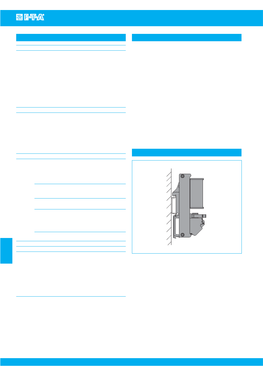
www.e-t-a.com
Power distribution system SVS09
7
- 30
7
Issue B
(240309)
Technical data (T
amb
= 25 °C, U
S
= DC 24 V)
Reference notes:
●
The power distribution system must be installed by qualified
personnel only.
●
Only after expert installation may the assembly be connected to a
power supply.
●
The assembly is only suitable for use at safety extra-low voltage
(DC 24 V).
●
Connection to higher or not reliably disconnected voltages may be
hazardous or cause damage.
●
The max. total current of the SVS09 system must not be exceeded.
●
In each load circuit the cable cross sections and the current rating
of the protective device must be selected according to the rating
of the connected load.
●
The technical data of the circuit breakers used must be observed.
●
According to “Machinery Directive 98/37/EG and EN 60204-1,
Machine Safety” special precautions have to be taken in machinery
(e. g. use of a safety PLC) to prevent inadvertent start-up of machinery
parts. In the event of a failure (short circuit/overload) the load circuit
will be disconnected by the circuit breaker.
●
After tripping of the circuit breaker and before reset the cause of
tripping (short circuit or overload) must be remedied.
●
The international standards (e. g. DIN VDE 0100 for Germany) must
be observed with respect to installation and selection of cables.
Mounting position
2) The plug-in type signalisation module SIGMO-09-1xx is required for failure signalisation
and for the cascading functions on the master/slave principle. See accessories.
3) The SVS09 power distribution system is supplied without wire bridges and can thus be
integrated into existing SVS09 cascade as a slave unit without further configuration.
The user inserts wire bridges on terminal block X22 of the master.
Configuration master/slave and group signal
1)
configuration of master/slave functions of a SVS09-cascade
on the master SVS09 via bridges
3)
on terminal block X22
X22: 20-21
master/slave-marking:
with bridge
= master
without bridge = slave
X22: 13-23
group signal locally/remote
pre-adjustment = only locally, LED on master-SVS09
terminal of external indication element = locally
and remote
X22: 10-11
acknowledgment of group signal locally/remote
with bridge = master, acknowledgment locally
with break contact = master, acknowledgment
locally and remote
without bridge = slave, no acknowledgment
Cascading several SVS09 systems
cascading possible with 1 x master M and max. 5 slaves S1...S5
Loop through the following 4 lines:
24 V (+) supply voltage
M-X21:2+
→
S1-X21:1+
→
S1-X21:2+
→
S2-X21:1+...
GND (-) self-supply circuit breaker/signalisation
M-X22:3-
→
S1-X22:4-
→
S1-X22:3-
→
S2-X22:4-...
S (+)
group signalisation (+)
M-X22:12
→
S1-X22:11
→
S1-X22:12
→
S2-X22:11...
S (-)
group signalisation (-)
M-X22:22
→
S1-X22:21
→
S1-X22:22
→
S2-X22:21...
Termination
C10
pcb spring-loaded terminals (standard)
line entry DC 24 V on terminal block X21
line (+) terminals 1+ und 2+,
connection capability (cable cross section)
with and without wire end ferrule
0.25 - 10 mm
2
stripped length
12 mm
configuration, GND (-) (self-supply) and
group signal on terminal block X22
5x double level terminal block
single signalisation on terminal block X23
10x double level terminal block
load outputs on terminal block X24
5x double level terminal block
connection capability (cable cross section)
with and without wire end ferrule
0.25 - 1.5 mm
2
stripped length
7 mm
plug-in type signalisation module SIGMO-09-1xx
50-pole Card Edge socket board
C20
pcb screw terminals (option)
General data
●
Mounting:
symmetrical rail to EN 50022 - 35 x 7.5
●
Temperature range: 0...50 °C (without condensation)
●
Storage temperature: -20...+70 °
●
Housing material:
plastic
●
Protection class
terminals
IP20 DIN 40050
pcb
IP00 DIN 40050 (double-lacquered)
●
Insulation voltage:
DC 250 V (pcb)
●
Dimensions:
see drawings
(tolerances to DIN ISO 286 part 1 IT13)
●
Mass: SVS09-10
approx. 380 g
Courtesy of Steven Engineering, Inc.-230 Ryan Way, South San Francisco, CA 94080-6370-Main Office: (650) 588-9200-Outside Local Area: (800) 258-9200-www.stevenengineering.com
87PDS-html.html
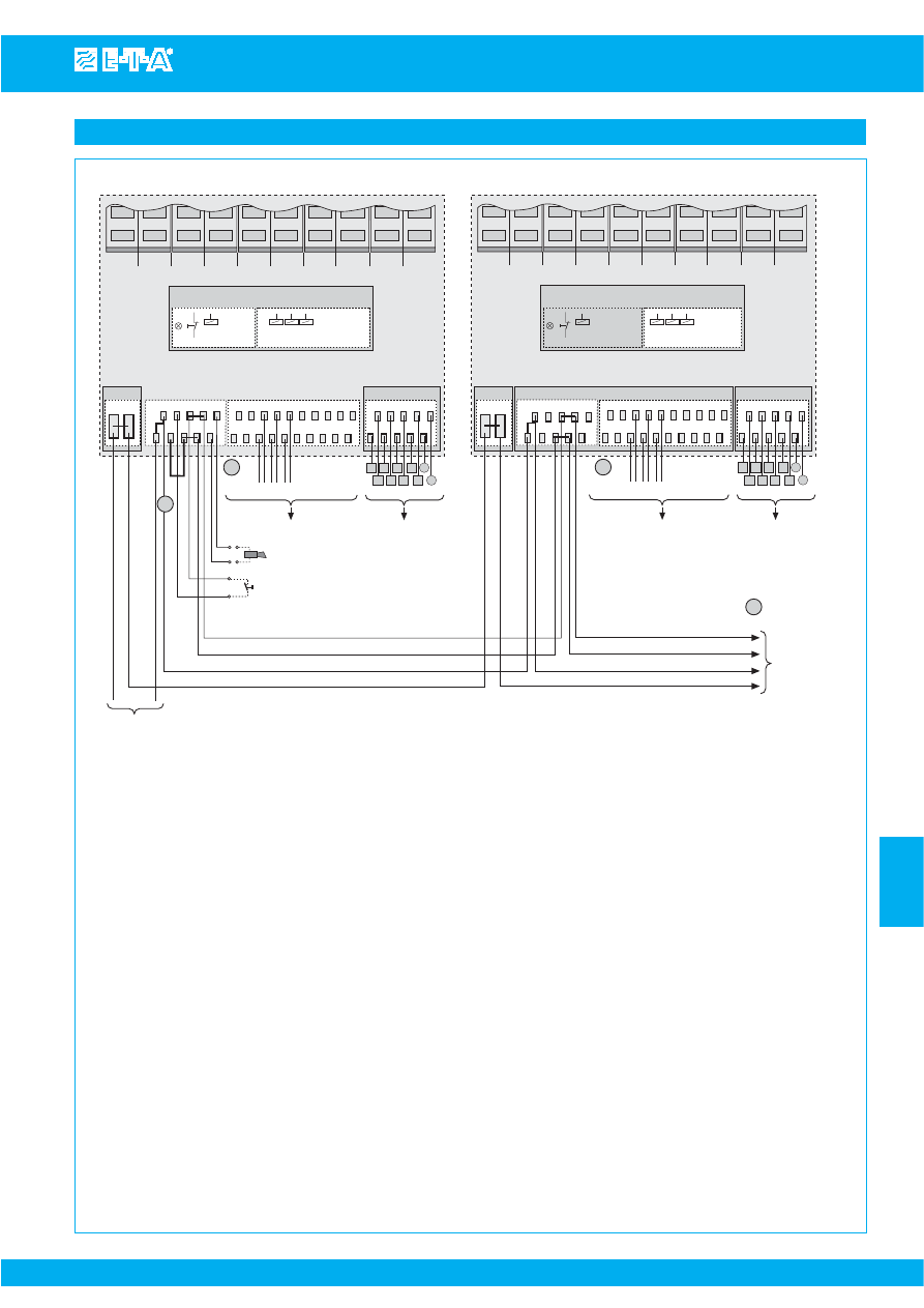
www.e-t-a.com
Power distribution system SVS09
Issue B
(240309)
7
- 31
7
1 Configuration ma
s
ter /
s
lave
terminal bloc
k
X22
X22 20-21
ma
s
ter /
s
lave mar
k
ing
with bridge:
ma
s
ter
without bridge:
s
lave: (factory
s
etting)
X22 10-11
ac
k
nowledgment of group
s
ignali
s
ation
with bridge:
= ma
s
ter: ac
k
nowledgment locally
brea
k
contactN/C: = ma
s
ter: ac
k
nowledgment locally + remote
(momentary
s
witch, PLC ...external)
without bridge:
=
s
lave: no ac
k
nowledgment on
s
lave (factory
s
etting)
2 Fault
s
ignali
s
ation
s
ingle
s
ignal:
terminal bloc
k
X23
terminal
s
30-40, 31-41, 32-42, 33-43, 34-44, 35-45, 36-46, ...
potential-free contact
fault:
contact open
O
K
: contact
clo
s
ed
empty way: contact clo
s
ed
group
s
ignal:
terminal bloc
k
X22
locally
LED on ma
s
ter
remote
terminal
s
13-23, potential-free contact
fault:
contact clo
s
ed
O
K
:
contact open
3 Ca
s
cading
loop-through of 4 line
s
ma
s
ter
→
s
lave 1
→
...
s
lave n
S
(+)
group
s
ignali
s
ation (+)
M-X22:12
→
S
1-X22:11 X22:12
→
S
2-X22:11 X22:11
→
S
3...
S
(-)
group
s
ignali
s
ation (-)
M-X22:22
→
S
1-X22:21 X22:22
→
S
2-X22:21 X22:22
→
S
3 ...
G
ND (-)
s
elf-
s
upply circuit brea
k
er / plug-in type
S
I
G
MO module
M-X22:3-
→
S
1-X22:4- X22:3-
→
S
2-X22:4- X22:3-
→
S
3 ...
24 V (+)
LINE (
s
upply voltage)
M-X21:2+
→
S
1-X21:1+ X21:2+
→
S
2-X21:1+ X21:2+
→
S
3 ...
F1
F2
F3
F4
F5
F6
F7
F8
F9
F10
s
ignali
s
ation module
S
I
G
MO
X21
X22
X23
X24
1+ 2+
3-
S
V
S
09-10 MA
S
TER
DC 24 V
c onfiguration
Q
local and remote
group
s
ignal (+
)
group
s
ignal (-)
G
ND (-)
24 V (+)
line entry
+ 24 V DC
...
group
s
ignal (e. g. control room)
s
ingle
s
ignali
s
ation for F1...F10
e. g. PLC, ET200,...
F
T
P
M
F
T
P
P
P
M
load
s
F1...F10
...
group
s
ignali
s
ation
s
ingle
s
ignali
s
ation
s
ingle
s
ignali
s
ation
load output
s
11
4-
10
12 13
20 21 22 23
30 31 32 33 34 35 36 37 38 39
40 41 42 43 44 45 46 47 48 49
50 51 52 53 54
60 61 62 63 64
...
ma
s
ter - X21:2+
→
s
lave 1 - X21:1+
Q
2
F1
F2
F3
F4
F5
F6
F7
F8
F9
F10
s
ignali
s
ation module
S
I
G
MO
X21
X22
X23
X24
1+ 2+
3-
DC 24 V
configuration
...
s
ingle
s
ignali
s
ation for F1...F10
e. g. PLC, ET200,...
F
T
P
M
F
T
P
P
P
M
load
s
F1...F10
...
group
s
ignali
s
ation
s
ingle
s
ignali
s
ation
s
ingle
s
ignali
s
ation
load output
s
11
4-
10
12 13
20 21 22 23
30 31 32 33 34 35 36 37 38 39
40 41 42 43 44 45 46 47 48 49
50 51 52 53 54
60 61 62 63 64
...
s
lave 1 - X21:2+
→
s
lave 2 - X21:1+ 24 V (+ )
Q
2
3
1
s
lave 1 - X22:3-
→
s
lave 2 - X22:4-
G
ND (-)
s
lave 1 - X22:22
→
s
lave 2 - X22:21
S
(-)
s
lave 1 - X22:12
→
s
lave 2 - X22:11
S
(+ )
ma
s
ter - X22:3-
→
s
lave 1 - X22:4-
ma
s
ter - X22:22
→
s
lave 1 - X22:21
ma
s
ter - X22:12
→
s
lave 1 - X22:11
probe
s
, valve
s
,
s
tepping motor
s
...
S
LAVE 2
S
V
S
09-10
S
LAVE 1 ...
S
V
S
09-10
S
LAVE n
probe
s
, valve
s
,
s
tepping motor
s
...
ac
k
nowledge group
s
ignal (e.g. in control room)
(terminal of potential-free brea
k
contact N/C or bridge)
Power distribution system with overcurrent protection and integral signalling logic
Courtesy of Steven Engineering, Inc.-230 Ryan Way, South San Francisco, CA 94080-6370-Main Office: (650) 588-9200-Outside Local Area: (800) 258-9200-www.stevenengineering.com
87PDS-html.html
www.e-t-a.com
Power distribution system SVS09
7
- 32
7
Issue B
(240309)
Configuration instruction
Individual application
General information
Minimal configuration: 1 master with local group signalisation and acknowledgment
step
configuration
1
mounting:
mount SVS09 on the symmetrical rail
2
connect DC +24 V (+) supply:
on terminal block DC 24 V, +24 V to terminal 1+
3
connect GND (-) supply:
1)
on terminal block X22, GND (-) to terminal 4-
4
master identification:
bridge terminals 20-21 on terminal block X22
5
group signal locally:
pre-adjustment. In the event of group failure the red LED is always lighted (only) on the master.
6
group acknowledgment locally:
bridge terminals 10-11 on terminal block X22
acknowledgment manually with red momentary switch on SVS09 (module SIGMO)
7
single signalisation:
connect single signalisation for F1 through F10 on terminal block X23,
F1: terminals 30-40, F2: terminals 31-41, F3: terminals 32-42 … F10: terminals 39-49
signal: potential-free contact: fault = contact open, OK = contact closed, empty way: contact closed
8
loads:
on terminal block X24: connect loads to be protected to terminals 50 through 64
1 master with local and external (remote) group signalisation and acknowledgment
step
configuration
1
mounting:
mount SVS09 on the symmetrical rail
2
DC +24 V (+) supply:
on terminal block DC 24 V, connect +24 V to terminal 1+
3
GND (-) supply:
1)
on terminal block X22, connect GND (-) to terminal 4-
4
master identification:
bridge terminals 20-21 on terminal block X22
5
group signal locally and remote:
on terminal block X22, connect to external display element to terminals 13-23 (e.g. LED,
relay, acoustic signal). In addition the red LED is always lighted on the master with group signal
signal: potential-free contact: fault = contact closed, OK = contact open
6
group acknowledgment locally or remote:
on terminal block X22, connect a command element to the terminals 10-11,
e.g. momentary switch, relay, PLC signal (potential-free break contact N/C)
7
single signalisation:
on terminal block X23, connect single signalisation for F1 through F1
F1: terminals 30-40, F2: terminals 31-41, F3: terminals 32-42, … F10: terminals 39-49
signal: potential-free contact: fault = contact open, OK = contact closed, empty way: contact closed
8
loads:
on terminal block X24: connect loads to be protected to terminals 50 through 64
1)
GND (-) potential serves for self-supply of SVS09
(circuit breaker and SIGMO-module)
●
Application individually (1 SVS09-10 as master) or as cascade
(1 master + max. 5 slaves)
●
Any configuration with wire bridges will
only
be done on the
master.
●
The minimum configuration with a master and local signalisation and
acknowledgment directly on the SVS09 power distribution system
requires wiring of two bridges: X22:20-21 for master identification
and X22:10-11 for group acknowledgment.
●
Configuration of a cascade is always carried out
only
on the
master with cascades consisting of several SVS09 mounted side-
by-side. No adjustments are required on the slaves.
●
Devices for status indication and acknowledgment for external
signalisation must be connected only to the master. Should several
external display elements be required (e. g. LED, acoustic signal),
these must also be connected only to the corresponding signal
outputs of the master.
●
Unused slots do not have to be bridged, they have no influence
on the signalisation of the installed circuit breakers. Unused slots
forward to OK indication to the signalisation outputs.
●
The SVS09 power distribution system invariably requires a plugged-
in signalisation module SIGMO-09-xxx (on separate order).
Courtesy of Steven Engineering, Inc.-230 Ryan Way, South San Francisco, CA 94080-6370-Main Office: (650) 588-9200-Outside Local Area: (800) 258-9200-www.stevenengineering.com
87PDS-html.html
www.e-t-a.com
Power distribution system SVS09
Issue B
(240309)
7
- 33
7
Cascading: 1 master and several (n) slaves (max. 5)
1 master + n slaves: with local group signalisation and acknowledgment
step
configuration
1
mounting:
mount all SVS09 onto symmetrical rail
2
DC +24 V (+) supply: terminal block DC 24 V
- on the master:
connect +24 V (+) to terminal 1+ and lead through to terminal 2+ for slave 1
- on slave 1:
connect +24 V (+) of master to terminal 1+ + lead through to terminal 2+ for slave 2
- on slave n:
connect +24 V (+) of slave (n-1) ) to terminal 1+
- additional slaves: always lead through +24 V (+) of terminal 2+ for next slave, terminal 1+
3
GND (-) supply:
1)
terminal block X22
- on the master:
connect GND (-) to terminal 4- and lead through at terminal 3- for slave 1
- on slave 1:
connect GND (-) of master to terminal 4- and lead through at terminal 3- for slave 2
- on slave n:
connect GND (-) of slave (n-1) to terminal 4-
- additional slaves: always lead through GND (-) of terminal 3- for next slave, terminal 4-
4
master identification:
bridge terminals 20-21 on the SVS09-master, on terminal block X22
Note: no adjustments on the slaves required!
5
group signal locally:
pre-adjustment. In the event of group fault the red LED is always lighted (only) on the master.
6
group acknowledgment locally:
bridge terminals 10-11 on SVS09-master, terminal block X22
acknowledgment manually with red momentary switch on SVS09-master (module SIGMO)
Note: no adjustments on the slaves required!
7
single signalisation:
on terminal block X23, connect single signalisation for F1 through F10
F1: terminals 30-40, F2: terminals 31-41, F3: terminals 32-42, … F10: terminals 39-49
signal: potential-free contact: fault = contact open, OK = contact closed, empty way: contact closed
8
loads:
on terminal block X24: connect loads to be protected to terminals 50 through 64
1 master + n slaves: with local and external (remote) group signalisation and acknowledgment
step
configuration
1
mounting:
mount all SVS09 onto the symmetrical rail
2
DC +24 V (+) supply: terminal block DC 24 V
- on the master:
connect +24 V (+) to terminal 1+ and lead through terminal 2+ for slave 1
- on slave 1:
connect +24 V (+) of master to terminal 1+ and lead through terminal 2+ for slave 2
- on slave n:
connect +24 V (+) of slave (n-1) to terminal 1
- additional slaves: always lead through +24 V (+) of terminal 2+ for next slave, terminal 1+
3
GND (-) supply:
1)
terminal block X22
- on the master:
connect GND (-) to terminal 4- and lead through at terminal 3- for slave 1
- on slave 1:
connect GND (-) of master to terminal 4- and lead through at terminal 3- for slave 2
- on slave n:
connect GND (-) of slave (n-1) to terminal 4-
- additional slaves: always lead through GND (-) of terminal 3- for next slave, terminal 4-
4
master identification:
bridge terminals 20-21 on the SVS09-master, on terminal block X22
Note: no adjustments on the slaves required!
5
group signal locally and remote:
connect an external display element (e.g. LED, relay, acoustic signal) on master, terminal
block X22, to terminals 13-23. In addition the red LED is always lighted in the event of group signal.
signal: potential-free contact: fault = contact closed, OK = contact open
Note: no adjustments on the slaves required, group acknowledgment is valid for the entire cascade.
6
group acknowledgment locally or remote:
connect a command element on master, terminal block X22, to terminals 10-
11, e. g. momentary switch, relay, PLC signal (potential-free break contact N/C)
Note: no adjustments on the slaves required, group acknowledgment is valid for the entire cascade.
7
single signalisation:
on terminal block X23, connect single signalisation for F1 through F10
F1: terminals 30-40, F2: terminals 31-41, F3: terminals 32-42, … F10: terminals 39-49
signal: potential-free contact: fault = contact open, OK = contact closed, empty way: contact closed
8
loads:
on terminal block X24: connect loads to be protected to terminals 50 through 64
1)
GND (-) potential serves for self-supply of the SVS09
(circuit breaker and SIGMO module)
Courtesy of Steven Engineering, Inc.-230 Ryan Way, South San Francisco, CA 94080-6370-Main Office: (650) 588-9200-Outside Local Area: (800) 258-9200-www.stevenengineering.com
87PDS-html.html
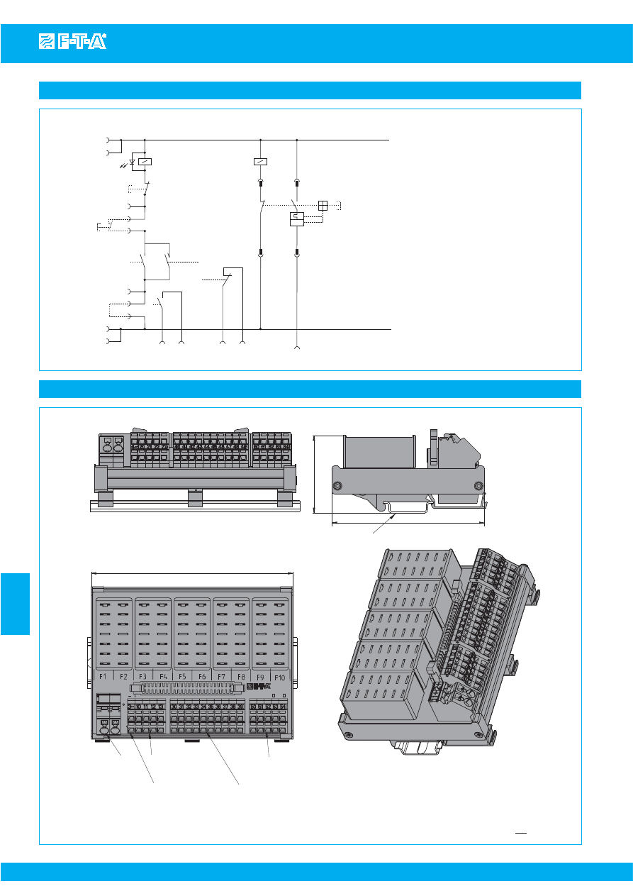
www.e-t-a.com
s
ymmetrical rail EN 50022-35x7.5
(not included in delivery)
53.5
105.4
139.5
s
crew terminal
s
power
s
upply (++)
s
pring loaded terminal
s
45
°
10.0 mm
2
G
ND (-)
s
elf-
s
upply
s
pring-loaded terminal
s
double level 1.5 mm
2
group
s
ignali
s
ation
s
pring-loaded terminal
s
double level 1.5 mm
2
s
ingle
s
ignali
s
ation
s
pring-loaded terminal
s
double level 1.5 mm
2
load output
s
s
pring-loaded terminal
s
double level 1.5 mm
2
DC24V/30A
X21+
+
X22
X23
X23
G
ERMANY
Typ:
S
V
S
09-10-
C 10
C 20
X24
1+ 2+
5.49
2.10
4.14
double level 1.5 mm
2
Dimensions SVS09-10-C10
Schematic diagram
Issue B
(240309)
7
7
- 34
Power distribution system SVS09
1
2
LED red
S
Q
Int
MA
S
TER
S
Q
Ext
K
11
12
11
10
K
11
K
1 ...
K
10
K
1 ...
K
10
K
11
22
21
20
MA
S
TER
bridge
3
4
13
23
30 ... 39
40 ... 49
50 ... 64
K
1 ...
K
10
I
>
F1 ... F10
11/10
MA
S
TER
bridge or brea
k
contact
21/20
MA
S
TER
bridge
relay contact
s
in OFF condition
K
1 ...
K
10
s
ingle
s
ignali
s
ation
K
11
group
s
ignali
s
ation
12
group
s
ignali
s
ation (+)
22
group
s
ignali
s
ation (-)
DC + 24 V
G
ND (-)
This is a metric design and millimeter dimensions take precedence (
mm
)
inch
Courtesy of Steven Engineering, Inc.-230 Ryan Way, South San Francisco, CA 94080-6370-Main Office: (650) 588-9200-Outside Local Area: (800) 258-9200-www.stevenengineering.com
87PDS-html.html
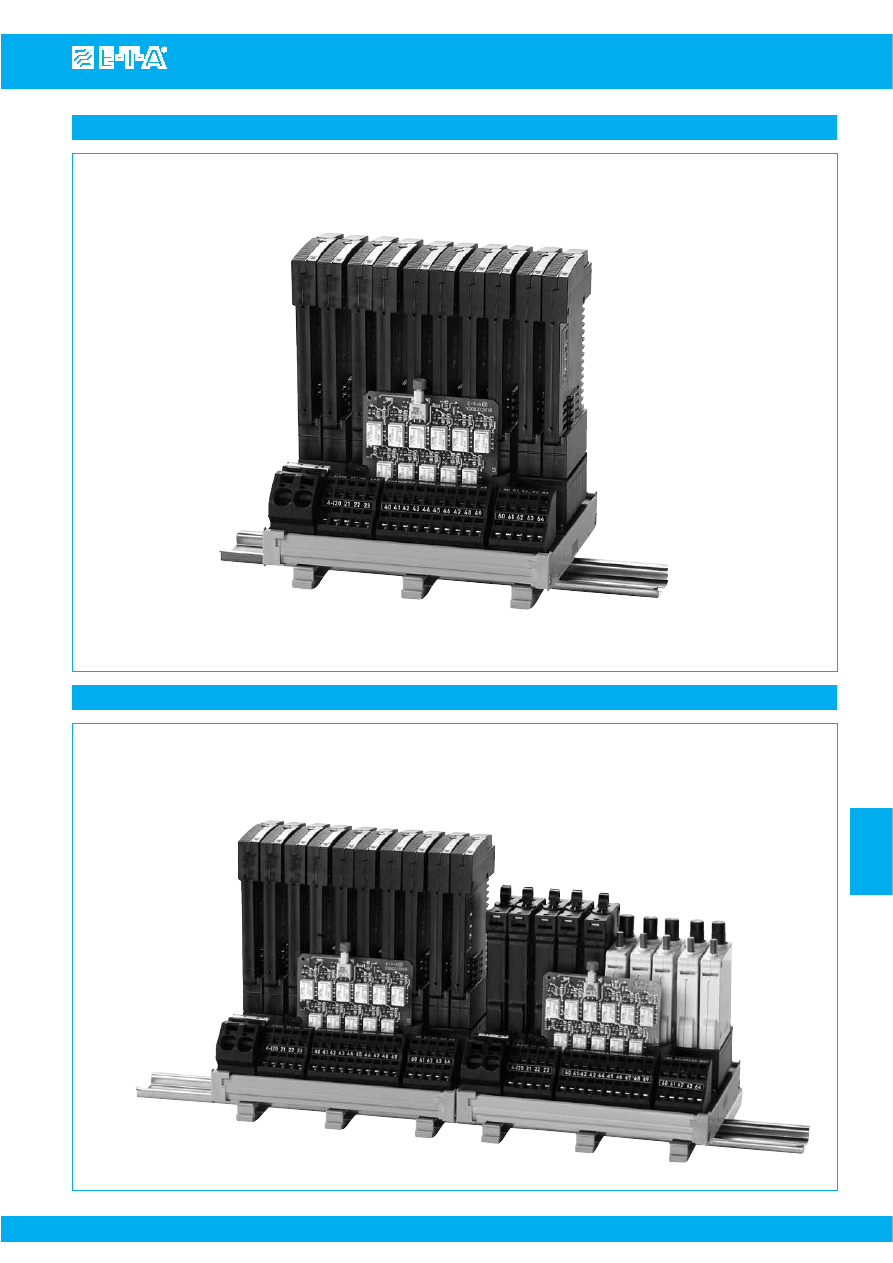
www.e-t-a.com
Application example: SVS09-10-C10 fitted with ESS20-003
7
7
- 35
Issue B
(240309)
Power distribution system SVS09
Plug-on module (circuit breaker / signalisation module SIGMO-09-1xx)
to be ordered separately
Application example: SVS09 cascade with 1 master and 1 slave
SVS09-10-C10 master fitted with 10 x ESS20-003
SVS09-10-C10 slave fitted with 5 x 2210-S2 and 5 x 3600
Courtesy of Steven Engineering, Inc.-230 Ryan Way, South San Francisco, CA 94080-6370-Main Office: (650) 588-9200-Outside Local Area: (800) 258-9200-www.stevenengineering.com
87PDS-html.html
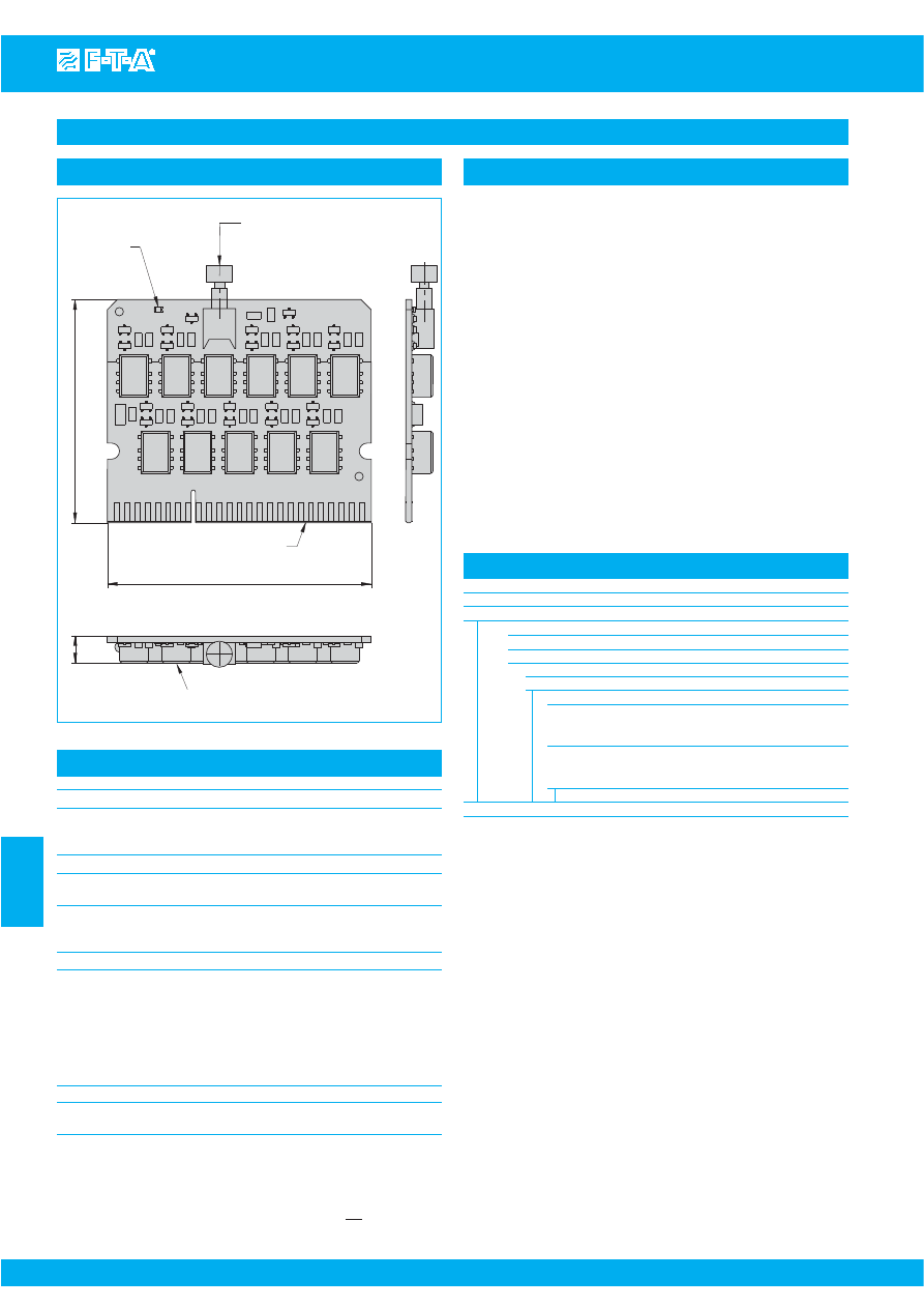
LED
plug-in terminal
65.7
55.5
7
RE
S
ET momentary
s
witch
direction of actuation
2.18
2.58
Option:
pcb encap
s
ulation
(electronic
s
epoxied)
0.27
www.e-t-a.com
Accessories
Issue B
(240309)
7
7
- 36
Power distribution system SVS09
All dimensions without tolerances are for reference only. In the interest of improved design,
performance and cost effectiveness the right to make changes in these specifications without
notice is reserved.Product markings may not be exactly as the ordering codes. Errors and
omissions excepted.
Plug-in type signalisation module for the power distribution system
SVS09 for group signalisation and acknowledgment for an isolated
SVS09 application or a cascade. The SIGMO module ensures a group
fault to be indicated after each trip of a circuit breaker on the SVS09. Fault
indication can be – depending on the configuration
1)
– locally on the
power distribution system (red LED) or locally and externally (remotely),
e. g. by means of an acoustic signal in the control room. Acknowledgment
of the group signal can also be only locally via a momentary switch on the
power distribution system, or locally and remotely, e. g. via a momentary
switch in the control room. Acknowledgment of the group signal re-
activates the group signalisation, so that it is released again and ready for
new error messages. The single signalisation and the tripped circuit
breaker will be manually reset by actuating the push button of the circuit
after remedy of the failure.
Note: Proper function of the signalisation module SIGMO-09-1xx
is ensured only in connection with the power distribution
system SVS09-10-Cxx.
1)
see power distribution system SVS09, basic schematic diagram
and configuration instruction
Application
Signalisation module SIGMO-09-1xx
Voltage supply
rated voltage:
DC 24 V (19...28 V)
residual ripple 5 % max.
supply via SVS09
Current load
normal operation without trip: 0 mA
max. 150 mA with 10-way fault on SVS09 (all relays loaded)
Contacts
min. 10 V / 10 mA
max. 28 V / 200 mA…
Status indication and actuation
LED red:
lighted in the event of group fault
momentary switch red:
for local acknowledgment of group
signalisation
remote acknowledgment: terminal of an external command
(momentary switch, relay, PLC signal)
rupture capacity 28 V / 20 mA
integral free-wheeling diode in SIGMO
module
Reverse polarity protection
Protected against reverse polarity of potentials DC 24 V (+) and
GND (-) on the SVS09. No function if connected reversely
Technical data (T
amb
= 25 °C, U
S
= DC 24 V)
Type No.
SIGMO
signalisation module for SVS09 power distribution system
●
plug-in type signalisation module
●
DC 24 V-applications
●
supply via SVS09
Version for power distribution system
09
SVS09-10 for circuit breakers (F1...F10)
Pcb version
100
standard: plug-in type signalisation module for
circuit breaker (F1...F10)
pcb populated, open,
120
option: plug-in type signalisation module for
circuit breaker (F1...F10)
pcb populated, encapsulated
SIGMO -
09 - 100
ordering example
Ordering information
This is a metric design and millimeter dimensions take precedence (
mm
)
inch
Courtesy of Steven Engineering, Inc.-230 Ryan Way, South San Francisco, CA 94080-6370-Main Office: (650) 588-9200-Outside Local Area: (800) 258-9200-www.stevenengineering.com
87PDS-html.html
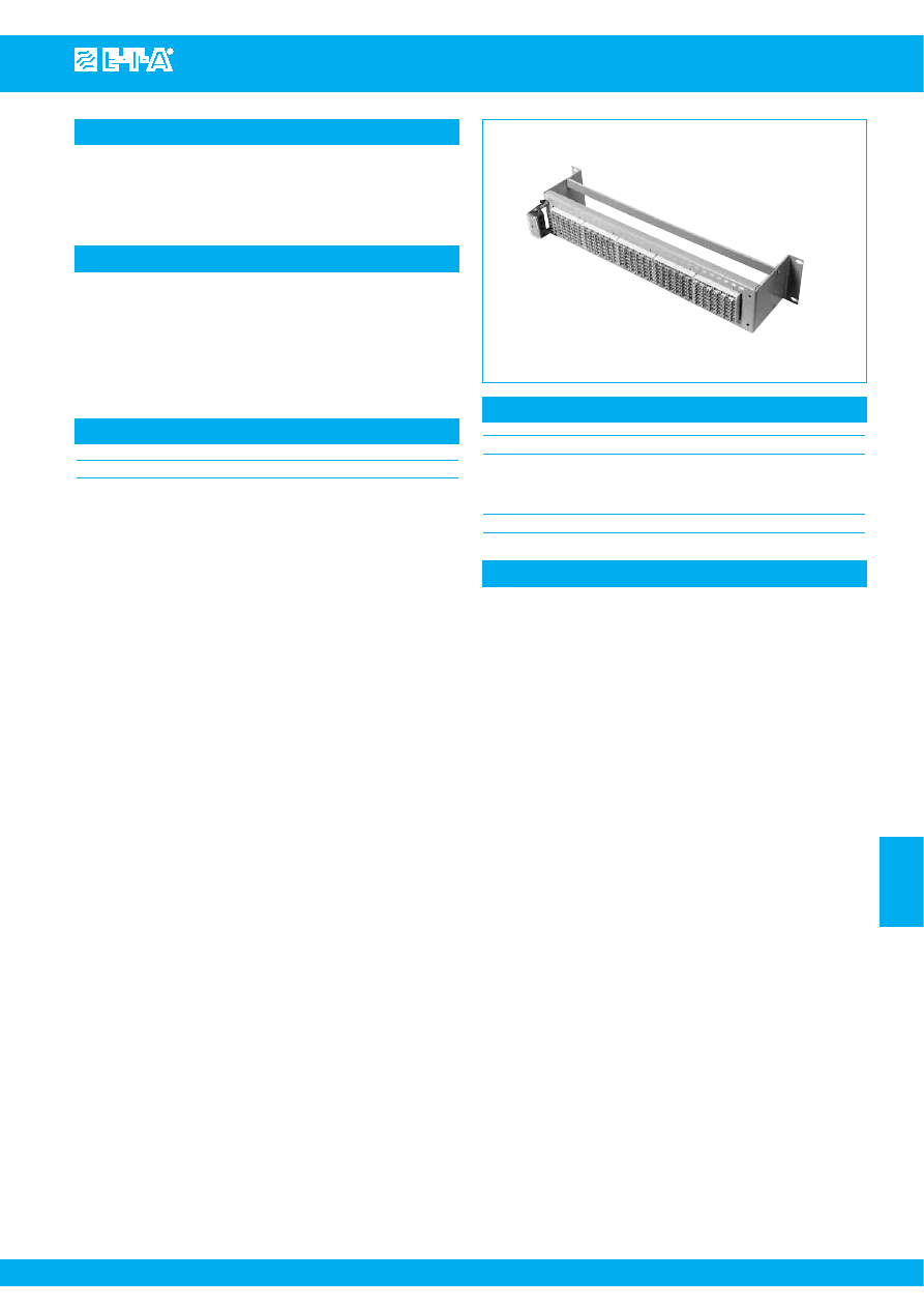
Description
Typical applications
Connection
Technical data
Power-D-Box 19" power distribution system fitted with E-T-A sockets
63-P10-Si to accommodate thermal-magnetic circuit breakers with
each terminal block accepting up to 6 circuit breakers. Other rack
types upon request.
Circuit breakers that may be accommodated on Power-D-Box 19"
racks fitted with E-T-A sockets 63-P10-Si:
type 2210
see section 2 - thermal-magnetic overcurrent CBs
type 3600
see section 2 - thermal-magnetic overcurrent CBs
type 3900
see section 2 - thermal-magnetic overcurrent CBs
type E-1048-60.
see section 6 - SSRPCs
Power-D-Box with sockets
By means of one or two 4-pole female multi-pin connectors for max.
4 mm
2
cables, which may be connected either on the right or left side
of the rack.
X 211 530 01
2 U
Material:
The Power-D-Box 19" power distribution
system and the mounting
flanges are made of 2 mm thick
steel sheet.
Colour:
RAL 7032, grey
Ordering information
X 211 530 01
for 5 E-T-A terminal blocks 63-P10-Si
7
7
- 37
Issue B
www.e-t-a.com
Power-D-Box with sockets
Courtesy of Steven Engineering, Inc.-230 Ryan Way, South San Francisco, CA 94080-6370-Main Office: (650) 588-9200-Outside Local Area: (800) 258-9200-www.stevenengineering.com
87PDS-html.html
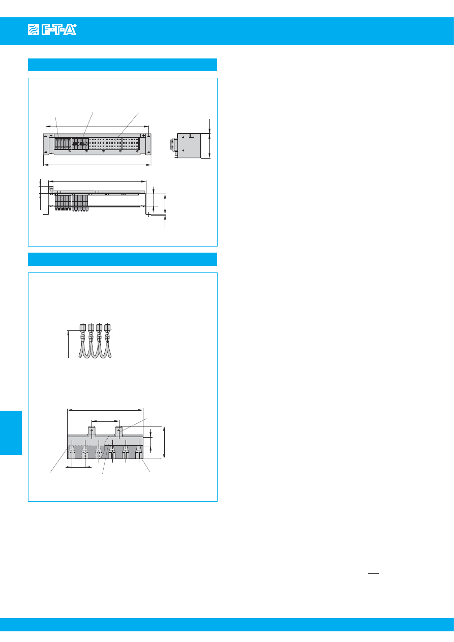
Dimensions
Accessories
X 211 530 01
19" rac
k
Power-D-Bo
x
with 5 E-T-A
s
oc
k
et
s
63-P10-Si
e.g. 6 x type 2210
e.g. type 3600-P-
S
i
or 3900-P-
S
i
type 63
431
56
93
16.97
40
1.57
2.20
.079
3.66
482.6
19.00
465
88.5
2
2
(18.31)
3.48
.079
blade terminal
DIN 46244 A6.3x0.8 (QC .250)
max. 25 A
12.5
.492
8
in
s
ulation to VBG4
tran
s
parent
q
uic
k
connect
tab
s
6.3 (.250)
DIN 46247 M
s
, max. 25 A
70
30.5
25
bu
s
bar
max. 50 A
.984
2.76
1.20
.315
~70
100
q
uic
k
-connect tab
s
6.3 (.250)
DIN 46247 tinned bra
ss
,
in
s
ulated
~2.76
Bu
s
bar 50 A for
s
oc
k
et 63-P10-Si
X 221 760 11
Connector bu
s
lin
ks
-P10
X 210 588 01/
1.5 mm
2
(AWG 16), brown (up to 13 A max. load)
X 210 588 02/
2.5 mm
2
(AWG 14), blac
k
(up to 20 A max. load)
X 210 588 03/
2.5 mm
2
(AWG 14), red (up to 20 A max. load
)
X 210 588 04/
2.5 mm
2
(AWG 14), blue (up to 20 A max. load)
All dimensions without tolerances are for reference only. In the interest of improved design,
performance and cost effectiveness the right to make changes in these specifications
without notice is reserved.Product markings may not be exactly as the ordering codes.
Errors and omissions excepted.
This is a metric design and millimeter dimensions take precedence ( mm )
inch
7
7
- 38
Issue B
www.e-t-a.com
Power-D-Box with sockets
Courtesy of Steven Engineering, Inc.-230 Ryan Way, South San Francisco, CA 94080-6370-Main Office: (650) 588-9200-Outside Local Area: (800) 258-9200-www.stevenengineering.com
87PDS-html.html
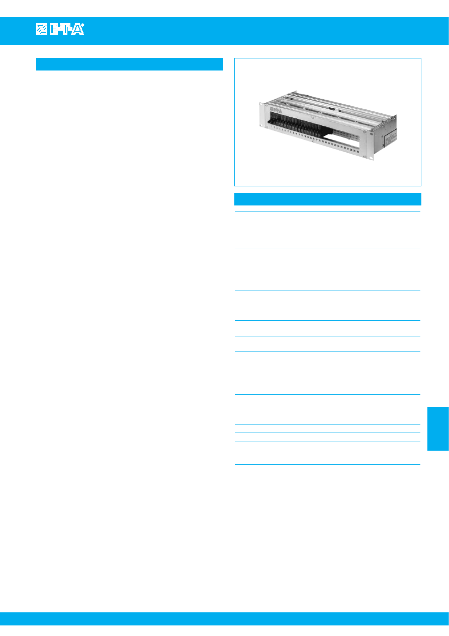
www.e-t-a.com
Description
Technical data
The compact 19" Power-D-Box features aluminium profiled cross
members with an anodised front plate. The panel cutout
accommodates up to 30 positions numbered 1 to 30. Blanks cover
unused positions, with 6, 12, 24 or 30 being ”open“.
The rack can be fitted with plug-in type circuit breakers 3600/3900 and
2210, electronic circuit breakers ESS20 or electronic circuit protector
ESX10 or E-T-A Solid State Remote Power Controllers (SSRPC)
E-1048-600/700. Please specify the correct option according to the
ordering information shown, as different depths as well as different
heights of the front cut-out must be allowed for.
The devices are plugged into sockets 63-P10-Si (6 positions each).
These sockets (S1...S5) are provided with 6.3 mm blade terminals on
the rear.
Four busbars (X1...X4) with 6 (signalisation) or 15 (feed) positions each
(6.3 mm blade terminals) provide easy terminal connection.
Prewired options available ex factory are:
●
Parallel connected feed (2.5 mm
2
) with separate supply for each
socket via busbars X1 and X2.
Choice of wiring colours: black, red, blue, grey. Outputs are not
connected.
●
Parallel connected auxiliary contacts (N/C) grouped per socket,
1 mm
2
, via busbars X3 (supply) and X4 (signalisation).
Choice of wiring colours: black, red, blue, grey.
●
Series connected auxiliary contacts (N/O) of all positions with
1 mm
2
, via busbars X3 (feed) and X4 (signalisation).
Choice of wiring colours: black, red, blue, grey.
●
Custom designed connection according to specification.
Other fittings, e.g. back-up fuse, separate circuits or redundancy,
multipole circuits, screw terminals, custom designed markings etc., are
available to special order (please enquire).
A compact printed circuit board with rear screw terminals is available as
an alternative to the standard cable wiring (see pages
7
- 45 to
7
- 51).
Power-D-Box with sockets pre-wired
19" Power-D-Box
length: 84 modules (426.72 mm)
height: 2 U (88.90 mm)
depth: 205...295 mm (depending on the
selected version)
material: aluminium, anodized
Front cutout for
1 socket = 6 positions (No. 1 - 6)
30 positions, numbered
2 sockets = 12 positions (No. 1 - 12)
1 through 30
3 sockets = 18 positions (No. 1 - 18)
4 sockets = 24 positions (No. 1 - 24)
5 sockets = 30 positions (No. 1 - 30)
blanks cover unused sockets.
Mounting socket
polarised E-T-A mounting socket
type 63-P10-Si (6 positions)
rear blade terminals 6.3 mm
max. load: 16 A continuous
Busbars
15-way for 6.3 mm blade terminals
Feed (X1, X2)
max. current rating: 63 A
Busbars
6-way for 6.3 mm blade terminals
Auxiliary contacts (X3, X4) max. current rating: 32 A
Feed
busbar 50 A per socket (= 6 positions)
HO7Z-K cables 2.5 mm
2
with fully insulated 6.3 mm blade terminals
to VBG 4
one cable per socket
max. current rating: 20 A
Auxiliary contact wiring HO7Z-K cables 1 mm
2
with fully insulated 6.3 mm blade terminals
to VBG 4
max. current rating: 4 A
Wire colour option
black, red, blue or grey
Voltage rating
AC 250 V/DC 65 V
Housing ground/earth on the inside via M6 screw
by means of ring cable lug (two with
redundant systems)
7
7
- 39
Issue B
Power-D-Box with sockets pre-wired
Courtesy of Steven Engineering, Inc.-230 Ryan Way, South San Francisco, CA 94080-6370-Main Office: (650) 588-9200-Outside Local Area: (800) 258-9200-www.stevenengineering.com
87PDS-html.html
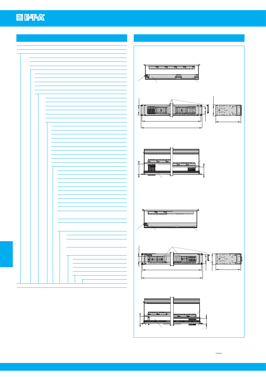
www.e-t-a.com
Dimensions
465
482.6
76.2
205 (250/295)
88.1
19B
G
T-2-3600-30A0-B0
line entry
ground
s
crew M6
Bottom view
19B
G
T-2-E
SS
20-30A0-B0
blan
k
ing piece Y30856341
19B
G
T-2-E
SS
20-30A0-B0
19B
G
T-2-E
S
X10-30A0-B0
Fitted with circuit protector type E
SS
20
s
hown for E
S
X10
205 (250/295)
88.1
76.2
465
482.6
61
Top view
86.5
61
Bottom view
19B
G
T-2-2210-30A0-B0
44.6
19B
G
T-2-2210-30A0-B0
Top view
61
44
s
upply auxiliary
contact
s
s
ignal
in
s
tallation depth
205 mm (without
additional wiring,
s
tandard)
in
s
tallation depth
250/295 mm,
depending on
additional wiring
3
19
18.31
2.40
3.47
Fitted with circuit
protector type E
S
X10
2.40
3.40
line entry
ground
s
crew M6
s
upply auxiliary
contact
s
s
ignal
blan
k
ing piece Y30856301
1.75
18.31
19
3
3.47
in
s
tallation depth
205 mm (without
additional wiring,
s
tandard)
in
s
tallation depth
250/295 mm,
depending on
additional wiring
Fitted with circuit brea
k
er type 2210
Fitted with circuit brea
k
er
type 3600/3900
1.73
2.40
s
hown for type
3600/3900
This is a metric design and millimeter dimensions take precedence ( mm )
inch
Ordering information
Type No.
19BGT
19" Power-D-Box with sockets pre-wired
Height
1
1 U
2
2 U
3
3 U
Prepared for circuit breaker types (supplied separately)
2210
for circuit breaker type 2210
3600
for circuit breaker type 3600/3900
1048
for SSRPC E-1048-600
ESS20
for electronic circuit breaker type ESS20
ESX10
for electronic circuit protector type ESX10
Number of positions
06
6-poles
12
12-poles
18
18-poles
24
24-poles
30
30-poles
nn
number of poles (special version)
Feed prewired
A0
without
R0
without, redundant
A2
line feed pre-wired (2.5 mm
2
) 1-pole (or 1 circuit)
R2
line feed pre-wired 1-pole redundant
A4
line feed pre-wired (2.5 mm
2
) 2-pole (or 2 circuits)
R4
line feed pre-wired 2-pole redundant
A6
line feed pre-wired 3-pole (or 3 circuits)
R6
line feed pre-wired 3-pole redundant
A8
line feed pre-wired 4-pole (or 4 circuits)
R8
line feed pre-wired 4-pole redundant
Wire colour
(not with A0 + R0)
1-pole
SW
black
RT
red
BL
blue
GR
grey
2-pole
RB
1
st
pole red, 2
nd
pole blue
RS
1
st
pole red, 2
nd
pole black
SB
1
st
pole black, 2
nd
pole blue
3-pole
SW
1
st
pole to 3
rd
pole black
SB
1
st
pole to 2
nd
pole black, 3
rd
pole blue
4-pole
SW
1
st
pole to 4
th
pole black
SB
1
st
pole to 3
rd
pole black, 4
th
pole blue
Auxiliary contacts prewired (1 mm
2
)
B0
without
B1
auxiliary contacts connected in series
(please consider plug-in device)
B2
auxiliary contacts connected in parallel
(please consider plug-in device)
Wire colour
(not with B0)
SW
black
RT
red
BL
blue
GR
grey (standard)
S...
customer-specific version
19BGT - 2 - 2210 - 24 A2 SW - B1 GR - S...
ordering example
7
7
- 40
Issue B
Power-D-Box with sockets pre-wired
Courtesy of Steven Engineering, Inc.-230 Ryan Way, South San Francisco, CA 94080-6370-Main Office: (650) 588-9200-Outside Local Area: (800) 258-9200-www.stevenengineering.com
87PDS-html.html
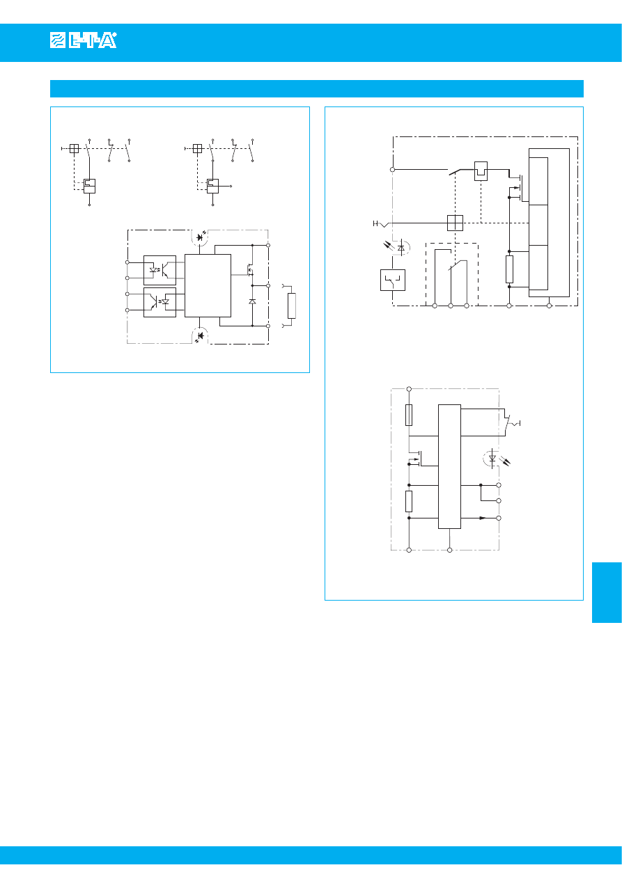
www.e-t-a.com
24
12
23
11
line 1
2(
k
)
I >
E-1048-600
2210
3600/3900
3 from I
N
=8 A
7
6
line 1
3
2
5
4
I >
Control and
Protection
Electronic
F +
F -
control circuit
fault indication
circuit
red
green
load
Q
-U
S
+U
S
E-1048-600
IN+
IN-
7
3
2
5
4
6
1
Internal connection diagrams
E
SS
20-003- …
(group
s
ignali
s
ation with change over)
R
s
en
s
e
contr
ol
S
O
S
I
S
C
s
ignal output
LOAD (+)
LINE (+)
DC 24 V
s
tatu
s
indication
green / orange
rated current I
N
ON / OFF
load output
s
hort cir
cuit /
overload
curr
ent
mea
s
ur
ement
electr
onic contr
ol unit
G
ND (-)
3 A 6 A
E
S
X10-124-…
Fail
s
afe
R
s
en
s
e
LINE (+)
DC 24 V
LOAD (+)
load
output
G
ND (-)
S
F
s
ignal output
RE
re
s
et output
RE
re
s
et input
s
tatu
s
indication
green / orange / red
S
1
ON / OFF
electr
onic contr
ol unit
7
7
- 41
Issue B
Power-D-Box with sockets pre-wired
Courtesy of Steven Engineering, Inc.-230 Ryan Way, South San Francisco, CA 94080-6370-Main Office: (650) 588-9200-Outside Local Area: (800) 258-9200-www.stevenengineering.com
87PDS-html.html
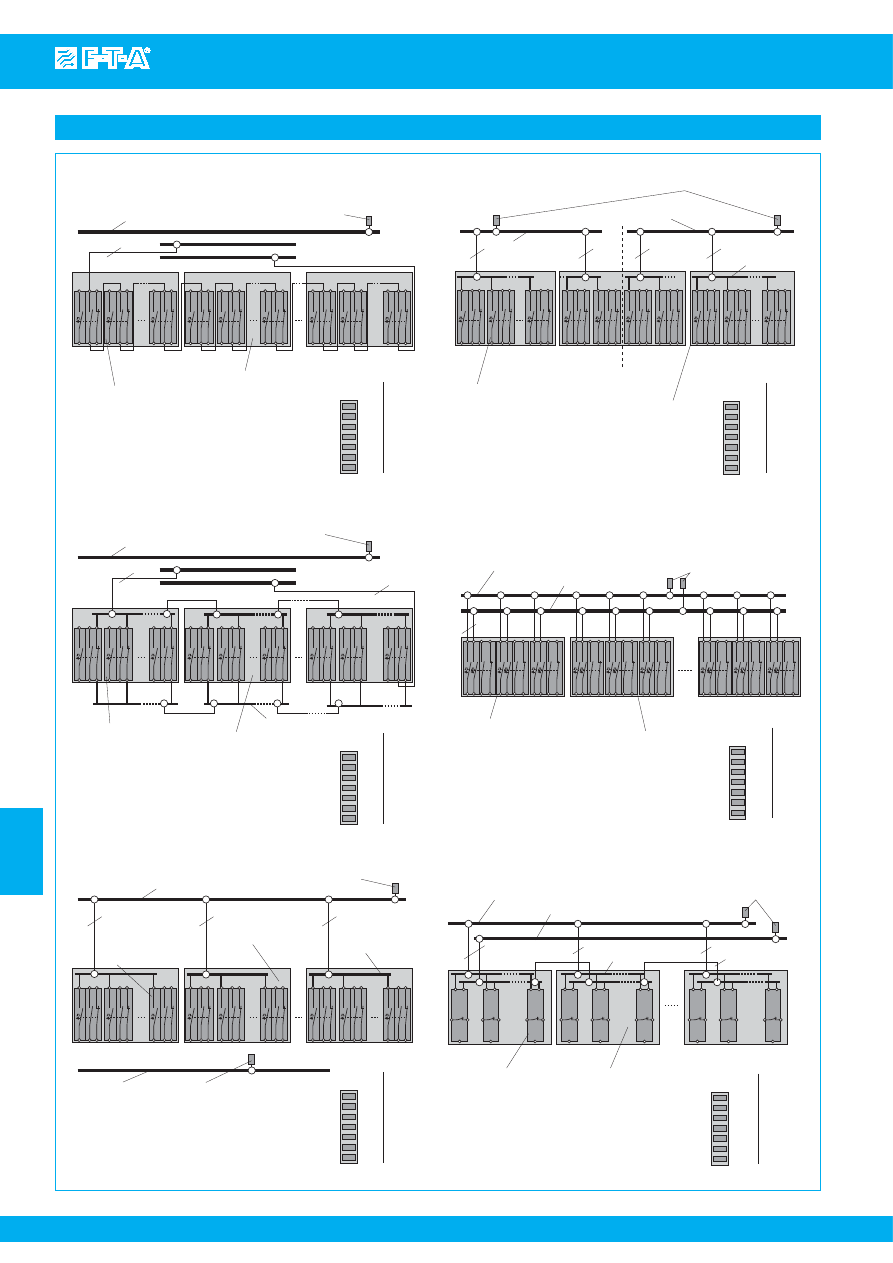
www.e-t-a.com
7
7
- 42
Issue B
Power-D-Box with sockets pre-wired
Termination
2
24 12
1
23 11
2
24 12
1
23 11
2
24 12
1
23 11
2
24 12
1
23 11
2
24 12
1
23 11
2
24 12
1
23 11
2
24 12
1
23 11
2
24 12
1
23 11
2
24 12
1
23 11
bu
s
bar X1 (max. 63 A)
pre-wiring of
s
ignali
s
ation,
group
s
ignali
s
ation -
s
erie
s
connection
line terminal X22150301
10...16 (25) mm
2
,
plug-on type (optional)
1 mm
2
s
ignal bu
s
bar X3
s
ignal bu
s
bar X4
F1
F2
F6
F7
F8
F12
F25
F26
F30
s
oc
k
et type 63-P10-
S
i (6-way)
circuit brea
k
er type
s
2210-
S
21x.../3600.../3900
plug-in type (not included)
2210
2
12
24
n.c.
23
11
1
3600/
3900
1
4
6
3
7
5
2
pin a
ss
ignment
s
oc
k
et 63-P10-
S
i
(per pole)
load terminal pin 1, blade terminal
s
6.3 mm
auxiliary contact terminal
s
:
11-12 ma
k
e contact, blade terminal
s
6.3 mm
auxiliary contact terminal
s
:
23-24 brea
k
contact, blade terminal
s
6.3 mm
19B
G
T-2-2210/3600-30A0-
B1
2
24 12
1
23 11
2
24 12
1
23 11
2
24 12
1
23 11
2
24 12
1
23 11
2
24 12
1
23 11
2
24 12
1
23 11
2
24 12
1
23 11
2
24 12
1
23 11
1 mm
2
F1
F2
F6
F7
F8
F12
F25
F26
F30
circuit brea
k
er type
s
2210-
S
21x.../3600.../3900...
plug-in type (not included)
2210
2
12
24
n.c.
23
11
1
3600/
3900
1
4
6
3
7
5
2
19B
G
T-2-2210/3600-30A0-
B2
2
24 12
1
23 11
1 mm
2
plugged-in bu
s
bar 6-way
2
24 12
1
23 11
2
24 12
1
23 11
2
24 12
1
23 11
2
24 12
1
23 11
2
24 12
1
23 11
2
24 12
1
23 11
2
24 12
1
23 11
2
24 12
1
23 11
pre-wiring of line feed,
1-pole protected by return bu
s
bar
F1
F2
F6
F7
F25
F26
F30
2210
2
12
24
n.c.
23
11
1
3600/
3900
1
4
6
3
7
5
2
load terminal
s
1. pole to PIN 1, blade terminal
s
6.3 mm
load terminal
s
2. pole to return bu
s
bar X2,
blade terminal
s
6.3 mm
auxiliary contact terminal
s
: 11-12 ma
k
e contact,
blade terminal
s
6.3 mm
auxiliary contact terminal
s
: 23-24 brea
k
contact,
blade terminal
s
6.3 mm
19B
G
T-2-2210/3600-30
A2
-B0
2
24 12
1
23 11
2.5 mm
2
2.5 mm
2
2.5 mm
2
F8
F12
return bu
s
bar X2
(max. 63 A)
2
24 12
1
23 11
2
24 12
1
23 11
2
24 12
1
23 11
2
24 12
1
23 11
2
24 12
1
23 11
2
24 12
1
23 11
2
24 12
1
23 11
2
24 12
1
23 11
A1
A2
A6
A15
B25
B30
2210
2
12
24
n.c.
23
11
1
3600/
3900
1
4
6
3
7
5
2
19B
G
T-2-2210/3600-30
R2
-B0
2
24 12
1
23 11
2.5 mm
2
2.5 mm
2
2.5 mm
2
A16
B1
2
24 12
1
23 11
B2
B26
2.5 mm
2
plugged-in bu
s
bar
6-way
group A
s
eparation line
F1
F2
F3
F4
F13
F14
F15
2210
2
12
24
n.c.
23
11
1
3600/
3900
1
4
6
3
7
5
2
load terminal
s
:
Pin 1 (+/-), Pin 3 (+/-), blade terminal 6.3 mm
auxiliary contact terminal
s
:
11-12 ma
k
e contact, blade terminal
s
6.3 mm
auxiliary contact terminal
s
:
23-24 brea
k
contact, blade terminal
s
6.3 mm
19B
G
T-2-2210/3600-30
A4
-B0
F5
F6
2
24 12
1
23 11
4
3
2
24 12
1
23 11
4
3
2
24 12
1
23 11
4
3
2
24 12
1
23 11
4
3
2
24 12
1
23 11
4
3
2
24 12
1
23 11
4
3
2
24 12
1
23 11
4
3
2
24 12
1
23 11
4
3
2
24 12
1
23 11
4
3
2.5
mm
2
+ /L
- /N
F1
F2
F6
F7
F25
F26
F30
electronic circuit brea
k
er type E
SS
20
or electronic circuit protector
plug-in type (not included)
E
SS
20
LINE
G
nd
S
C
n.c.
S
O
LOAD
E
S
X10
1LINE
11
G
nd
13
S
C
n.c.
14
S
O
2LOAD
load terminal
s
LOAD(+), blade terminal
s
6.3 mm
auxiliary contact terminal
s
S
C-
S
O ma
k
e contact,
blade terminal
s
6.3 mm
19B
G
T-2-E
SS
20/E
S
X10-30
A4
-B0
F8
F12
2.5 mm
2
S
C
Load (+
)
S
O
Load (+)
G
nd
E
SS
20
S
C
Load (+
)
S
O
Load (+)
G
nd
E
SS
20
S
C
Load (+
)
S
O
Load (+)
G
nd
E
SS
20
S
C
Load (+
)
S
O
Load (+)
G
nd
E
SS
20
S
C
Load (+
)
S
O
Load (+)
G
nd
E
SS
20
S
C
Load (+
)
S
O
Load (+)
G
nd
E
SS
20
S
C
Load (+
)
S
O
Load (+)
G
nd
E
SS
20
S
C
Load (+
)
S
O
Load (+)
G
nd
E
SS
20
S
C
Load (+
)
S
O
Load (+)
G
nd
E
SS
20
2.5 mm
2
2.5 mm
2
2.5 mm
2
pre-wiring of
s
ignali
s
ation,
group
s
ignali
s
ation - parallel connection
bu
s
bar X1 (max. 63 A)
line terminal X22150301
10...16 (25) mm
2
,
plug-on type (optional)
s
ignal bu
s
bar X3
s
ignal bu
s
bar X4
s
oc
k
et type 63-P10-
S
i (6-way)
load terminal pin 1, blade terminal
s
6.3 mm
auxiliary contact terminal
s
:
11-12 ma
k
e contact, blade terminal
s
6.3 mm
auxiliary contact terminal
s
:
23-24 brea
k
contact, blade terminal
s
6.3 mm
pin a
ss
ignment
s
oc
k
et 63-P10-
S
i
(per pole)
line terminal X22150301
25 mm
2
, plug-on type (optional)
bu
s
bar X1 (max. 63 A)
circuit brea
k
er type
s
2210-
S
21x...
/3600.../3900...
plug-in type
(not included)
s
oc
k
et type 63-P10-
S
i
(6-way)
plugged-in bu
s
bar
6-way
line terminal X22150301
25 mm
2
, plug-on type (optional)
pin a
ss
ignment
s
oc
k
et 63-P10-
S
i
(per pole)
pre-wiring of line feed,
1-pole protected, redundant
line terminal X22150301
25 mm
2
, plug-in type (optional)
bu
s
bar X2 (max. 63 A)
bu
s
bar X1 (max. 63 A)
group B
circuit brea
k
er type
s
2210-
S
21x.../3600.../3900
plug-in type (not included)
s
oc
k
et type
63-P10-
S
i (6-way)
load terminal pin 1, blade terminal
s
6.3 mm
auxiliary contact terminal
s
:
11-12 ma
k
e contact, blade terminal
s
6.3 mm
auxiliary contact terminal
s
:
23-24 brea
k
contact, blade terminal
s
6.3 mm
pin a
ss
ignment
s
oc
k
et 63-P10-
S
i
(per pole)
pre-wiring of line feed,
2-pole protected/
s
witched
bu
s
bar X1 (max. 63 A)
bu
s
bar X2 (max. 63 A)
line terminal X22150301
25 mm
2
, plug-in type (optional)
s
oc
k
et type
63-P10-
S
i (6-way)
pin a
ss
ignment
s
oc
k
et 63-P10-
S
i
(per pole)
circuit brea
k
er type
s
2210-
S
21x.../3600.../3900
plug-in type (not included)
pre-wiring of line feed,
1-pole protected
bu
s
bar X1 (max. 63 A)
bu
s
bar X2 (max. 63 A)
line terminal X22150301
10...16 (25) mm
2
,
plug-on type (optional)
plugged-in bu
s
bar
6-way
s
oc
k
et type
63-P10-
S
i (6-way)
pin a
ss
ignment
s
oc
k
et 63-P10-
S
i
(per pole)
Courtesy of Steven Engineering, Inc.-230 Ryan Way, South San Francisco, CA 94080-6370-Main Office: (650) 588-9200-Outside Local Area: (800) 258-9200-www.stevenengineering.com
87PDS-html.html
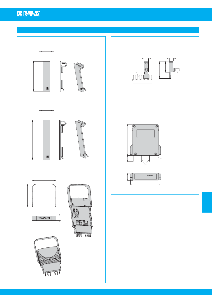
www.e-t-a.com
Blan
k
ing piece for Power-D-Bo
x
(type
s
3600/3900, 2210)
Y 308 563 01
52
12.5
68.5
67
65
12.5
with E
SS
20
.492
2.05
Blan
k
ing piece for Power-D-Bo
x
(type
s
E
SS
20/E
S
X10)
Y 308 563 41
12.5
.492
2.69
Withdrawal tool for E
SS
20/E
S
X10
Y 308 602 01
2.64
2.56
.492
with E
S
X10
Accessories
30
50
15
14
bu
s
bar X1, X2
blade terminal
s
6.3 mm
cable cro
ss
s
ection
10...25 mm
2
.551
.591
1.97
1.18
Jumper
to bypa
ss
looped through unu
s
ed auxiliary contact
s
(
s
erie
s
connection)
X 222 066 01
Line Terminal (ma
x
. 63 A)
X 221 503 01
max. tightening tor
q
ue 3.0 Nm
10
51
50
11.5
2.01
.394
1.97
.453
blade terminal
s
DIN 46244-A6.3-0.8
(QC .250)
terminal
s
1+2
no internal connection
terminal
s
6+7
internally bridged
1
4
6
3
7
5
2
X22206601
S
ignalbrüc
k
e
S
ignal loop
Caution: cable
s
mu
s
t not be connected with terminal plugged in
pull-out
max. 10 Nm
This is a metric design and millimeter dimensions take precedence ( mm )
inch
All dimensions without tolerances are for reference only. In the interest of improved design,
performance and cost effectiveness the right to make changes in these specifications
without notice is reserved.Product markings may not be exactly as the ordering codes.
Errors and omissions excepted.
7
7
- 43
Issue B
Power-D-Box with sockets pre-wired
Courtesy of Steven Engineering, Inc.-230 Ryan Way, South San Francisco, CA 94080-6370-Main Office: (650) 588-9200-Outside Local Area: (800) 258-9200-www.stevenengineering.com
87PDS-html.html
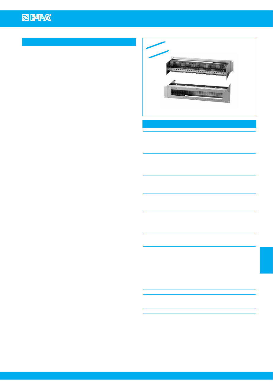
Power-D-Box with pcb-mounted sockets
www.e-t-a.com
Issue B
7
- 45
7
Description
Technical data
The compact 2U 19" Power-D-Box with sockets mounted on a pcb
and pre-connected features aluminium profiled cross members with an
anodised front plate. The panel cutout accommodates up to 30
positions numbered 1 to 30. It is possible to have 6, 12, 18, 24 or 30
prepared slots or to have a redundant distribution with up to 2 x 15
positions.
The Power-D-Box accommodates plug-in type circuit breakers 3600/
3900 and 2210, solid state remote power controller E-1048-700,
electronic circuit breaker type ESS20 and electronic circuit protector
ESX10. The required device must be specified in the ordering
information as both different installation depth and pcb pin
assignments must be allowed for.
The devices are plugged into corresponding sockets type 63-P10-Si (6
positions each), soldered onto the pcb and pre-connected.
The system is configured with redundancy as standard (2 x 15
positions), but the two groups may be interconnected so as to provide
a non-redundant system if required. Line entry within each group is
single pole or double pole.
With single pole line entry all slot numbers per group are combined and
connected via an M6 terminal stud by means of a ring cable lug.
With double pole line entry, odd and even slot numbers are integrated
into separate circuits each of which is connected via 10 mm
2
screw
terminals. This allows use of double pole circuit breakers.
Load outputs are connected by means of screw terminals up to 4 mm
2
on the rear of the pcb.
The system offers a number of signalisation possibilities and separation
for redundancy is also possible:
●
series connection of make contacts (group signalisation via closed
circuit current)
●
parallel connection of break contacts (double sided for group
signalisation via closed circuit current)
●
parallel connection of break contacts (only one-sided, second side
of break contacts will be connected individually with the terminals
for single signalisation via closed or open-circuit current)
Termination is on the rear side by means of screw terminals up to
1.5 mm
2
(group connection) and up to 1 mm
2
(single signalisation)
on the pcb. When using ESS20, ESX10 or E-1048-700, the required
Gnd terminals as well as control and reset signals will also be
connected via the terminals for group or single signalisation.
Upon request the group distribution (redundancy) can be cancelled
by means of jumpers. Additional terminals on the rear side of the
rack simplify connection. It is also possible to provide terminals for
return lines from the individual loads so as to integrate the
necessary external wiring into the rack.
Power-D-Box with pcb-mounted sockets
19"Power-D-Box
length: 84 modules (426.72 mm)
height: 2 U (88.90 mm)
depth: 205...295 mm
depending on the version
material: aluminium, partly anodized
Front cutout for
1 socket = 6 positions (no. 1 - 6)
30 positions, numbered
2 socket = 12 positions (no. 1 - 12)
1 through 30
3 sockets = 18 positions (no. 1 – 18)
4 sockets = 24 positions (no. 1 - 24)
5 sockets = 30 positions (no. 1 - 30)
Mounting socket
polarised mounting socket type 63-P10-Si
(6 positions) , soldered onto the pcb
from the rear with wiring
Contact load: 16 A continuously
Line entry X0
2 groups, single pole each
Single pole
(= 2 separate circuits)
2 x 100 A max. via terminal stud M6 for
ring cable lug
Supply feed X0
2 groups, double pole each
Double pole
(= 4 separate circuits)
4 x 40 A max. via screw terminal up to
10 mm
2
(max. 4 x 50 A at max. 40 °C
ambient temperature)
Load outputs X1
30 channels
16 A max. per pole via screw
terminals up to 4 mm
2
Signalisation
group signalisation X2
series connection of make contacts /
parallel connection of break contacts
(double sided) in 2 groups
(interconnectable by means of wire
bridges)
max. 1 A total current via screw terminal
up to 1.5 mm
2
max. 0.5 A single current via screw
terminal up to 1 mm
2
Rated voltage
AC 250 V; DC 65 V
Housing ground/earth
on the inside via M6 screw
by means of ring cable lug (two with
redundant systems)
Ambient temperature range 0...50 °C
W
E
N
Courtesy of Steven Engineering, Inc.-230 Ryan Way, South San Francisco, CA 94080-6370-Main Office: (650) 588-9200-Outside Local Area: (800) 258-9200-www.stevenengineering.com
87PDS-html.html

www.e-t-a.com
Issue B
7
- 46
Power-D-Box with pcb-mounted sockets
7
Ordering Information
Type number
19BGT
19" Power-D-Box with sockets pre-wired on pcb
Height
2
2 U = 88.90 mm
Device prepared for accommodation
3600
circuit breaker type 3600 or 3900
2210
circuit breaker type 2210-S
1048
solid state remote power controller E-1048-700
ESS20
electronic circuit breaker type ESS20
ESX10
electronic circuit breaker type ESX10
Number of positions
06
6 poles
12
12 poles
18
18 poles
24
24 poles
30
30 poles
Additional wiring and terminals for line feed
A0
without (only pcb with terminals)
R0
none (only pcb with terminals, redundant)
A2
line feed pre-wired 1-pole
(all positions = 1 circuit)
R2
line entry pre-wired single pole redundant
A3
line feed pre-wired 1-pole
(as A2 + return busbar)
R3
line feed pre-wired 1-pole + return busbar,
redundant
A4
line feed pre-wired 2-pole connected
(all positions = 2 circuits)
R4
line feed pre-wired 2-pole connected, redundant
Colour for additional wiring, line feed
(not with A0 + R0)
single pole wiring
SW
black
RT
red
BL
blue
multipole wiring
RB
1
st
pole red, 2nd pole blue
SB
1st pole black, 2nd blue
Auxiliary contact function
B1
auxiliary contacts connected in series
(group signalisation)
B2
auxiliary contacts connected in parallel
(group signalisation)
B3
auxiliary contacts connected in parallel
(single signalisation)
B5
as B1, with additional wiring (1 mm
2
)
to terminal (not with A0)
B6
as B2, with additional wiring (1 mm
2
)
to terminal (not with A0)
Colour of additional wiring of
auxiliary contacts
GR
grey (only with B5 or B6)
L
with printed circuit board
(pcb)
S...
suffix number
for customer specific
version
19BGT - 2 - 2210 - 24 A2 ... -
B1 ... -
L S...
ordering example
Courtesy of Steven Engineering, Inc.-230 Ryan Way, South San Francisco, CA 94080-6370-Main Office: (650) 588-9200-Outside Local Area: (800) 258-9200-www.stevenengineering.com
87PDS-html.html
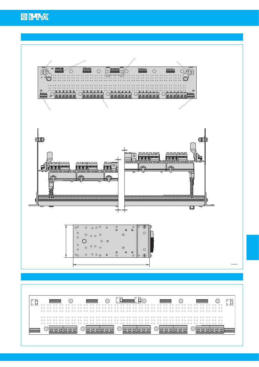
Power-D-Box with pcb-mounted sockets
www.e-t-a.com
Issue B
7
- 47
7
Pin assignment bus pcb (terminal side)
30 29 28 27 26 25
24 23 22 21 20 19
18 17 16 15 14 13
12 11 10 9 8 7
6 5 4 3 2 1
116
111
120
117
30
..
..
25
24
..
..
19
18
..
..
13
12
..
..
7
6
..
..
1
auxiliary contact
s
ingle
s
ignali
s
ation
max. 0.5 A
connection data
rigid
0.14 - 1.5 mm
2
flexible 0.14 - 1 mm
2
jumper to cancel redundancy
88.1
205
in
s
tallation depth depending on additional wiring
s
tandard depth 205/250/295 mm
line entry max. 100 A
terminal thread M6
auxiliary contact group
s
ignali
s
ation
max. 0.5 A
connection data
rigid
0.14 - 1.5 mm
2
flexible
0.14 - 1.5 mm
2
load output
s
max. 16 A each
connection data
rigid
0.2 - 6 mm
2
flexible
0.2 - 4 mm
2
auxiliary contact group
s
ignali
s
ation
max. 1 A
connection data
rigid
0.14 - 1.5 mm
2
flexible
0.14 - 1.5 mm
2
3.47
8.07
line entry max. 100 A
terminal thread M6
Dimensions
This is a metric design and millimeter dimensions take precedence ( mm )
inch
Courtesy of Steven Engineering, Inc.-230 Ryan Way, South San Francisco, CA 94080-6370-Main Office: (650) 588-9200-Outside Local Area: (800) 258-9200-www.stevenengineering.com
87PDS-html.html
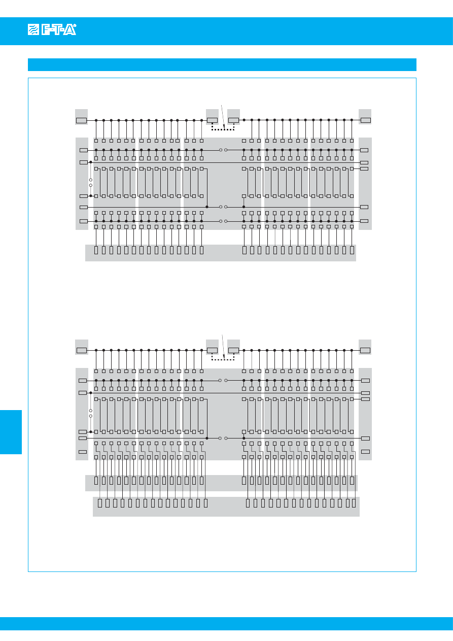
www.e-t-a.com
Issue B
7
- 48
7
Schematic diagrams
Power-D-Box with pcb-mounted sockets
a
ss
ignment 63-PR-
S
i
2210
3600/3900
E
SS
20
1 Line
2
1
Line (+)
2 Load
1
2
Load (+)
11
12
4
G
nd (-)
12
11
5
S
I
13
24
6
S
C
14
23
7
S
O
X0.1
X0.4
X2
X2
X1
120
118
B8
117
119
1 Line
11
B6
13
14
12
2 Load
B7
30 29 28 27 26 25 24 23 22 21 20 19 18 17 16
15 14 13 12 11 10 9
8
7
6
5
4
3
2
1
111
113
114
115
112
Bu
s
pcb (
s
ingle pole ver
s
ion)
X2
X2
X1
120
118
B8
117
119
1 Line
11
B6
13
14
12
2 Load
30 29 28 27 26 25 24 23 22 21 20 19 18 17 16
15 14 13 12 11 10 9
8
7
6
5
4
3
2
1
111
113
114
115
112
30 29 28 27 26 25 24 23 22 21 20 19 18 17 16
15 14 13 12 11 10 9
8
7
6
5
4
3
2
1
X3
Bu
s
pcb (
s
ingle pole ver
s
ion)
group A
X0.2
63-PR-
S
i
116
B11
X0.3
group B
jumper to cancel redundancy
group
s
ignali
s
ation (B1, B2, B5, B6)
X0.1
X0.2
X0.3
jumper to cancel redundancy
X0.4
B11
116
s
ingle
s
ignali
s
ation
Courtesy of Steven Engineering, Inc.-230 Ryan Way, South San Francisco, CA 94080-6370-Main Office: (650) 588-9200-Outside Local Area: (800) 258-9200-www.stevenengineering.com
87PDS-html.html
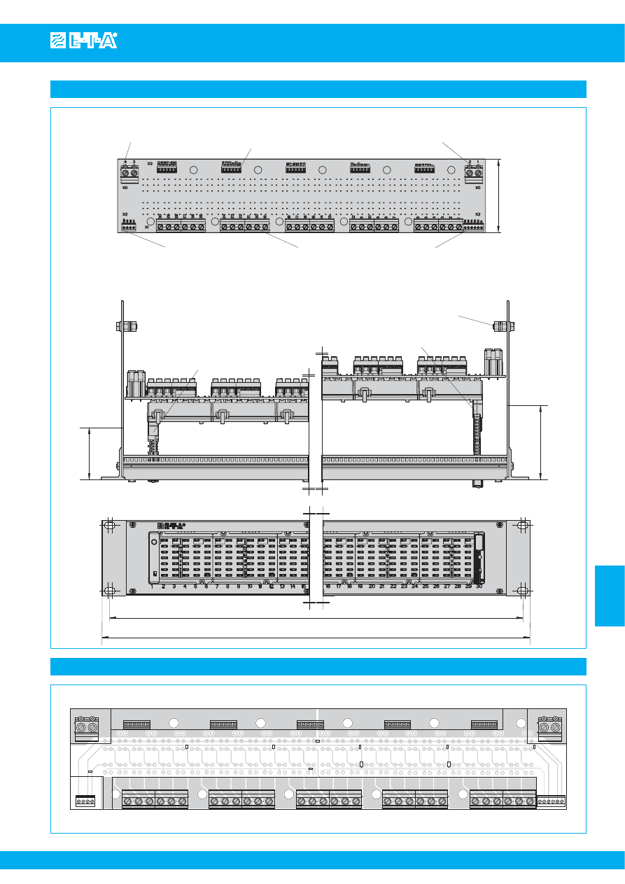
Power-D-Box with pcb-mounted sockets
www.e-t-a.com
Issue B
7
- 49
7
Dimensions
auxiliary contact
s
ingle
s
ignali
s
ation
max. 0.5 A
connection data
rigid
0.14 - 1.5 mm
2
flexible
0.14 - 1 mm
2
line entry max. 100 A (T
amb
< 40° C)
connection data
rigid
0.5 - 16 mm
2
flexible
0.5 - 10 mm
2
line entry max. 100 A (T
amb
≤ 40° C)
connection data
rigid
0.5 - 16 mm
2
flexible
0.5 - 10 mm
2
load output
s
max. 16 A each
connection data
rigid
0.2 - 6 mm
2
flexible
0.2 - 4 mm
2
85
fitted with E
S
X10 or 2210
fitted with E
SS
20
ground
s
tud
86.5
61
465
482.6
auxiliary contact group
s
ignali
s
ation
max. 1 A
connection data
rigid
0.14 - 1.5 mm
2
flexible
0.14 - 1.5 mm
2
auxiliary contact group
s
ignali
s
ation
max. 1 A
connection data
rigid
0.14 - 1.5 mm
2
flexible
0.14 - 1.5 mm
2
3.35
2.40
3.40
18.31
19
Pin assignment bus pcb (terminal side)
4
3
X0 X3
B8
B5
B4
B6
B7
B3
B9
B10
B2
B1
2
X0
1
X2
116
111
...
...
X2
120
119
118
117
X1
30 29 28 27 26 25
24 23 22 21 20 19
18 17 16 15 14 13
12 11 10
9
8
7
6
5
4
3
2
1
X20
X21
X22
X23
X24
30
..
..
25
24
..
..
19
18
..
..
13
12
..
..
7
6
..
..
1
X8
Courtesy of Steven Engineering, Inc.-230 Ryan Way, South San Francisco, CA 94080-6370-Main Office: (650) 588-9200-Outside Local Area: (800) 258-9200-www.stevenengineering.com
87PDS-html.html
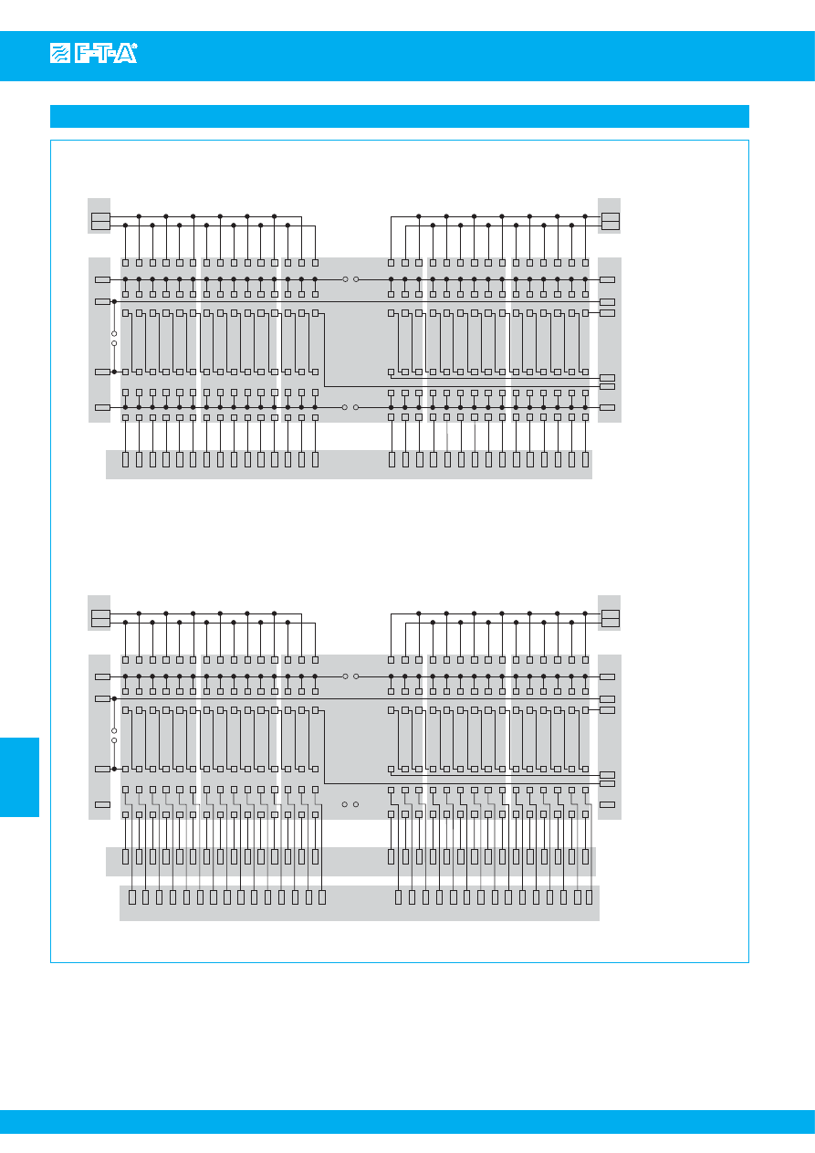
www.e-t-a.com
Issue B
7
- 50
Power-D-Box with pcb-mounted sockets
7
pin a
ss
ignment 63-P10-
S
i 2210
3600/3900
E
SS
20
1 Line
2
1
Line (+)
2 Load
1
2
Load (+)
11
12
4
G
nd (-)
12
11
5
S
I
13
24
6
S
C
14
23
7
S
O
3
4
X0
1
2
X0
X2
X2
X1
120
118
B8
117
119
1 Line
11
B6
13
14
12
2 Load
B7
30 29 28 27 26 25 24 23 22 21 20 19 18 17 16
15 14 13 12 11 10 9
8
7
6
5
4
3
2
1
111
113
114
115
116
112
Bu
s
pcb (
s
ignali
s
ation B1, B2, B5, B6)
3
4
X0
1
2
X0
X2
X2
X1
120
118
B8
117
119
1 Line
11
B6
13
14
12
2 Load
30 29 28 27 26 25 24 23 22 21 20 19 18 17 16
15 14 13 12 11 10 9
8
7
6
5
4
3
2
1
111
113
114
115
116
112
30 29 28 27 26 25 24 23 22 21 20 19 18 17 16
15 14 13 12 11 10 9
8
7
6
5
4
3
2
1
X3
Bu
s
pcb (
s
ignali
s
ation B3)
Schematic diagrams
Courtesy of Steven Engineering, Inc.-230 Ryan Way, South San Francisco, CA 94080-6370-Main Office: (650) 588-9200-Outside Local Area: (800) 258-9200-www.stevenengineering.com
87PDS-html.html
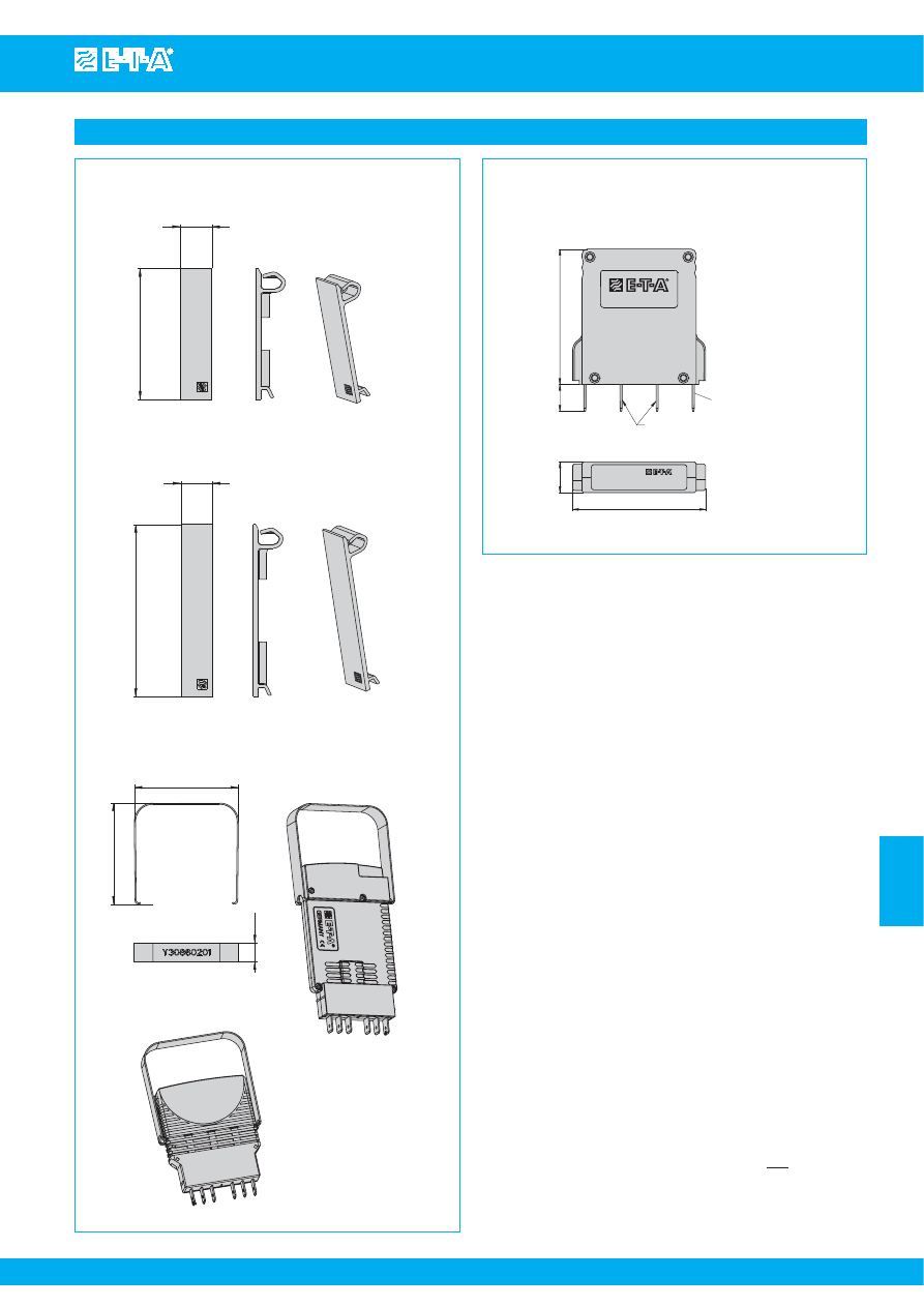
Power-D-Box with pcb-mounted sockets
www.e-t-a.com
Issue B
7
- 51
7
Blan
k
ing piece for Power-D-Bo
x
(type
s
3600/3900, 2210)
Y 308 563 01
52
12.5
68.5
67
65
12.5
with E
SS
20
.492
2.05
Blan
k
ing piece for Power-D-Bo
x
(type
s
E
SS
20/E
S
X10)
Y 308 563 41
12.5
.492
2.69
Withdrawal tool for E
SS
20/E
S
X10
Y 308 602 01
2.64
2.56
.492
with E
S
X10
Accessories
10
51
50
11.5
2.01
.394
1.97
.453
blade terminal
s
DIN 46244-A6.3-0.8
(QC .250)
S
ignalbrüc
k
e
S
ignal loop
X22206601
1
4
6
3
7
5
2
terminal
s
1+2
no internal connection
terminal
s
6+7
internally bridged
Jumper
to bypa
ss
looped through unu
s
ed auxiliary contact
s
(
s
erie
s
connection)
X 222 066 01
This is a metric design and millimeter dimensions take precedence ( mm )
inch
All dimensions without tolerances are for reference only. In the interest of improved design,
performance and cost effectiveness the right to make changes in these specifications
without notice is reserved.Product markings may not be exactly as the ordering codes.
Errors and omissions excepted.
Courtesy of Steven Engineering, Inc.-230 Ryan Way, South San Francisco, CA 94080-6370-Main Office: (650) 588-9200-Outside Local Area: (800) 258-9200-www.stevenengineering.com
87PDS-html.html
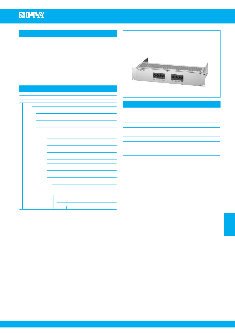
Modular Power-D-Box
www.e-t-a.com
Issue B
7
- 53
7
Description
Technical data
The Power-D-Box is a compact 2U power distribution system made
of aluminium.
The 19BGT-2-X is a compact 19" 2 U power distribution rack
incorporating E-T-A plug-in circuit breakers type 2210-S291 (for
19BGT-2-X2210-...), 8340-F (for 19BGT-2-X83S2/..S4/..Z4-...) or
8345-.01.-W0 (for 19BGT-2-X8345-...). These are installed in pre-
wired E-T-A power distribution rails type X2210-S, X8340-S02,
X8340-S04, X8340-SZ4 or X8345-D01. Options available include
separate circuits, redundant circuits and customer-specific marking.
Power-D-Box / High-Power
19" Power-D-Box
length:
426.72 mm
height:
2 U (88.90 mm)
material: aluminium
Voltage rating
AC 230 V; DC 110 V; DC 80 V; DC 65 V
Details of power distribution systems:
X2210-S...
pages
7
- 57 to
7
- 58
X8340-S02
pages
7
- 65 to
7
- 66
X8340-S04
pages
7
- 67 to
7
- 68
X8340-SZ4
pages
7
- 69 to
7
- 71
X8345-D01
pages
7
- 73 to
7
- 76
Ordering information
Type No.
19BGT
19" Modular Power-D-Box
Height
2
2 U = 88.90 mm
Distribution rails (pre-wired)
X2210
for X2210-S
Economy, max. 12 poles / 2 x 6 poles
X83S2
for X8340-S02 Economy, max. 16 poles / 2 x 8 poles
X83S4
for X8340-S04 Economy, max. 3 x 4 poles
X83Z4
for X8340-SZ4 Economy, max. 16 poles / 2 x 8 poles
X8345
for X8345-D01 High-Power, max. 18 poles / 2 x 7 poles
Number of slots (numbered)
02
2 poles
03
3 poles
04
4 poles
05
5 poles
06
6 poles
07
7 poles
08
8 poles
09
9 poles
10
10 poles
12
12 poles
14
14 poles
16
16 poles
18
18 poles
Pre-wired supply-feed
A0
without, with single power distribution system
R0
without, with redundant power distribution
system
Pre-wired auxiliary contacts (0.75 mm
2
)
B0
without
S...
special version
19BGT - 2 - X2210 - 18 A0 B0 - S...
ordering example
Courtesy of Steven Engineering, Inc.-230 Ryan Way, South San Francisco, CA 94080-6370-Main Office: (650) 588-9200-Outside Local Area: (800) 258-9200-www.stevenengineering.com
87PDS-html.html
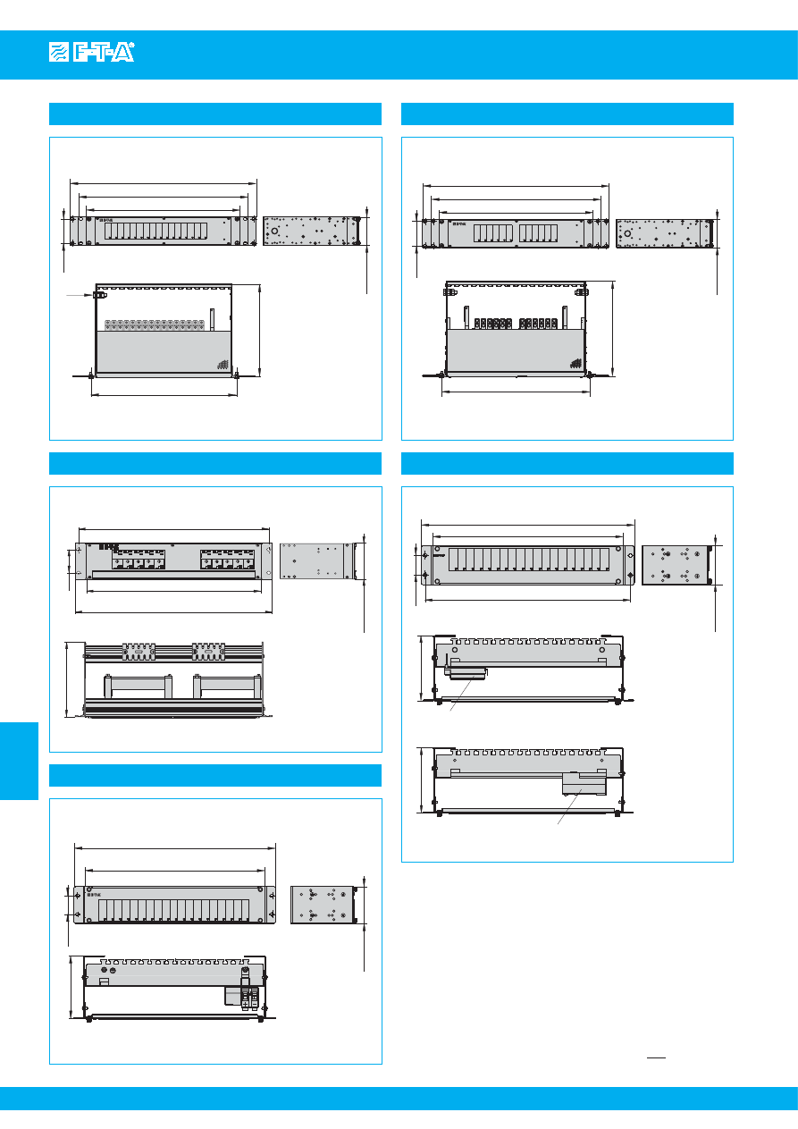
www.e-t-a.com
Issue B
7
- 54
Modular Power-D-Box
7
This is a metric design and millimeter dimensions take precedence ( mm )
inch
Dimensions 19BGT-2-X2210 (Economy)
465.4
426.4
482.6 (19
"
)
76.2
max. 88.9
183
ZL80
ZL80
7.2
3
18.32
16.79
max. 3.5
Dimensions 19BGT-2-X83S2 (Economy)
44.45
431
482.5
max. 88.9
150
19
16.97
1.75
5.90
max. 3.5
Dimensions 19BGT-2-X8345 (High-Power)
76.2
max. 88.9
482.6 (19
"
)
531.4 (ET
S
I) optional
584.2 (23
"
) optional
465
295
M10
3
max. 3.5
18.31
11.61
Dimensions 19BGT-2-X8345 (High-Power)
76.2
531.4 (ET
S
I) optional
584.2 (23”) optional
max. 88.9
482.6 (19”)
295
465
3
18.31
11.6
max. 3.5
Dimensions 19BGT-2-X83S4 / -X83Z4 (Economy)
150
44.45
431
482.6 (19”)
465
max. 88.9
150
power di
s
tribution
s
y
s
tem X8340-
S
Z4
16.97
18.31
1.75
max. 3.5
5.9
5.9
power di
s
tribution
s
y
s
tem X8340-
S
04
redundant
not redundant
Courtesy of Steven Engineering, Inc.-230 Ryan Way, South San Francisco, CA 94080-6370-Main Office: (650) 588-9200-Outside Local Area: (800) 258-9200-www.stevenengineering.com
87PDS-html.html
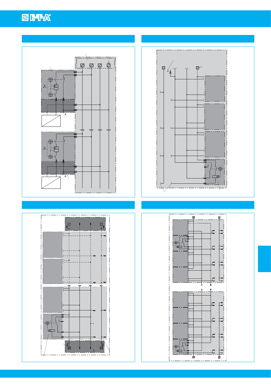
Modular Power-D-Box
www.e-t-a.com
Issue B
7
- 55
7
Schematic diagram X2210-S (Economy)
load
+
–
I >
0
I
load
+
–
I >
0
I
(U)
S
ig
(N)
–
+
circuit brea
k
er
terminal
bloc
k
di
s
tribution rail
Schematic diagram X8340-S02 (Economy)
1
C
2
I >
NC
NO
(L) –
(N) +
(L) –
(N) +
(L) –
S
ig
S
ig
(N) +
terminal-
bloc
k
module with circuit brea
k
er E-T-A 8340-F…
(L) –
S
ig
S
ig
(N) +
ground-
bridge
(optional)
module
load terminal
s
ground
s
tud
(optional)
Schematic diagram X8340-S04 (Economy)
(N) +
(N) +
(L) –
(L) –
(L) –
1
C
2
NC
NO
I >
(N) +
(N) +
(L) –
Module for 4 circuit brea
k
er
s
E-T-A circuit brea
k
er type 8340-F…
(N) +
S
ig
(L) –
s
crew terminal
S
ig
load terminal
s
ground bridge (optional)
Schematic diagram X8340-SZ4 (Economy)
Module with power
s
upply left-
s
ide
E-T-A circuit brea
k
er type 8340-F…
(L) –
(N) +
load terminal
s
on front and rear
s
ide
terminal for
s
ignali
s
ation
(L) –
(N) +
1
C
2
I >
NC
NO
(L) –
(N) +
(L) –
(N) +
(L) –
(N) +
(L) –
(N) +
(L) –
(N) +
(L) –
(N) +
(L) –
(N) +
1
C
2
I >
NC
NO
(N) +
(L) –
load terminal
s
on front and rear
s
ide
Module with power
s
upply right -
s
ide
(N) +
(L) –
E-T-A circuit brea
k
er type 8340-F…
Courtesy of Steven Engineering, Inc.-230 Ryan Way, South San Francisco, CA 94080-6370-Main Office: (650) 588-9200-Outside Local Area: (800) 258-9200-www.stevenengineering.com
87PDS-html.html
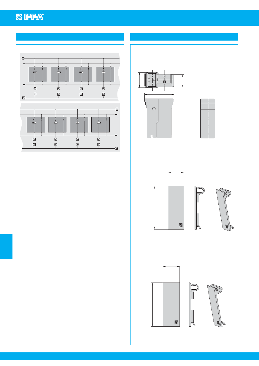
www.e-t-a.com
Issue B
7
- 56
Modular Power-D-Box
7
Schematic diagram X8345-D01 (High Power)
Module 1
S
ignali
s
ation
terminal
1
11
2
12
L(-)
L(-)
L(+)
Module 2
L(-)
L(+)
L(+)
Module 3
L(-)
L(+)
1
11
2
12
Module 4
L(-)
L(+)
1
11
2
12
1
11
2
12
Module 1
S
ignali
s
ation
terminal
L(-)
L(+)
L(-)
L(+)
1
11
2
12
L(-)
L(+)
1
11
2
12
Module 2
L(-)
L(+)
1
11
2
12
Module 3
L(-)
L(+)
1
11
2
12
Module 4
Accessories
This is a metric design and millimeter dimensions take precedence ( mm )
inch
All dimensions without tolerances are for reference only. In the interest of improved design,
performance and cost effectiveness the right to make changes in these specifications
without notice is reserved.Product markings may not be exactly as the ordering codes.
Errors and omissions excepted.
52
19
Blanking piece for Power-D-Bo
x
(circuit brea
k
er type
s
8340, 8345)
Y 308 563 11
52
20
9
7.3
18.15
Load output terminal protected again
s
t rever
s
e polarity
(
s
et: 4 moulded
s
leeve
s
, 8 blade terminal
s
6.3 x 0.8 mm)
X 222 847 01
for cable cro
ss
s
ection 0.7...2.0 mm
2
X 222 625 01
for cable cro
ss
s
ection 2.5...4.0 mm
2
X 222 848 01
for cable cro
ss
s
ection 4.0...6.0 mm
2
Blanking piece for Power-D-Bo
x
(circuit brea
k
er type
s
8340, 8345-D01)
Y 308 563 21
.787
2.05
2.05
.748
.714
.299
.354
Courtesy of Steven Engineering, Inc.-230 Ryan Way, South San Francisco, CA 94080-6370-Main Office: (650) 588-9200-Outside Local Area: (800) 258-9200-www.stevenengineering.com
87PDS-html.html
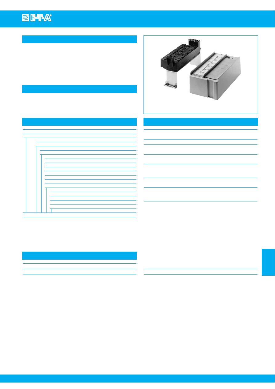
Distribution rail X2210-S06...
www.e-t-a.com
Issue B
7
- 57
7
Description
Typical applications
Accessories
Technical data
E-T-A rails distribute electrical power in telecommunications, automation,
data and control systems. They have been designed to industry
standard requirements and are suitable for mounting in ETSI control
cabinets. These distribution rails are supplied with mounting bracket,
cover, 6 blanks and withdrawal tool.
Live parts in terminal areas are protected against brush contact (VDE
106, part 100).
Telecommunications systems using ETSI racks; process control,
measuring and control systems.
X2210-S06... for 6 circuit breakers 2210-S291..
Terminal block
X 211 019 01
Withdrawal tool
X 211 018 01
Circuit breakers to be fitted
2210-S291-P9M2-410005
2210-S291-P9M2-410033
Voltage rating
AC 250 V; DC 65 V
Load
max. 25 A per position
max. 80 A for complete unit
Signalisation (N/C contact)
AC 240 V / DC 65 V
max. 1 A per position
Insulation co-ordination Rated impulse Pollution
(IEC 60664 and 60664A)
withstand voltage degree
2.5 kV
2
Flame retardance
(IEC 60695, part 2-2)
self-extinguishing
Terminal design
input
clamp-type terminal 2.5 to 25 mm
2
flexible
output
clamp-type terminal 0.5 to 2.5 mm
2
flexible
Typical volume resistances in main circuit
input terminal B + (N)
to output terminal + (N)
< 1.5x10
-3
Ω
input terminal B - (U)
to female contact 2 (k)
< 1.5x10
-3
Ω
input terminal B-Sig
to female contact 12
< 2x10
-3
Ω
output terminal - (U)
to female contact 1
< 1.5x10
-3
Ω
output terminal -
⊥
to female contact 11
< 2x10
-3
Ω
Mass X2210-S0606J
660 g
Ordering information
Type No.
X2210
Module for circuit breaker type 2210-S291-...
Version
S
distribution rail
Identification number
06
6 positions
Terminal block (intermediate element) (fitted)
00
without
01
1 x
02
2 x
03
3 x
04
4 x
05
5 x
06
6 x
Accessories (fitted)
G
without
H
with mounting bracket
J
with mounting bracket, cover and 6 blanks
R
without mounting bracket, with cover and 6 blanks
X2210 - S 06 06 J
ordering example
Courtesy of Steven Engineering, Inc.-230 Ryan Way, South San Francisco, CA 94080-6370-Main Office: (650) 588-9200-Outside Local Area: (800) 258-9200-www.stevenengineering.com
87PDS-html.html
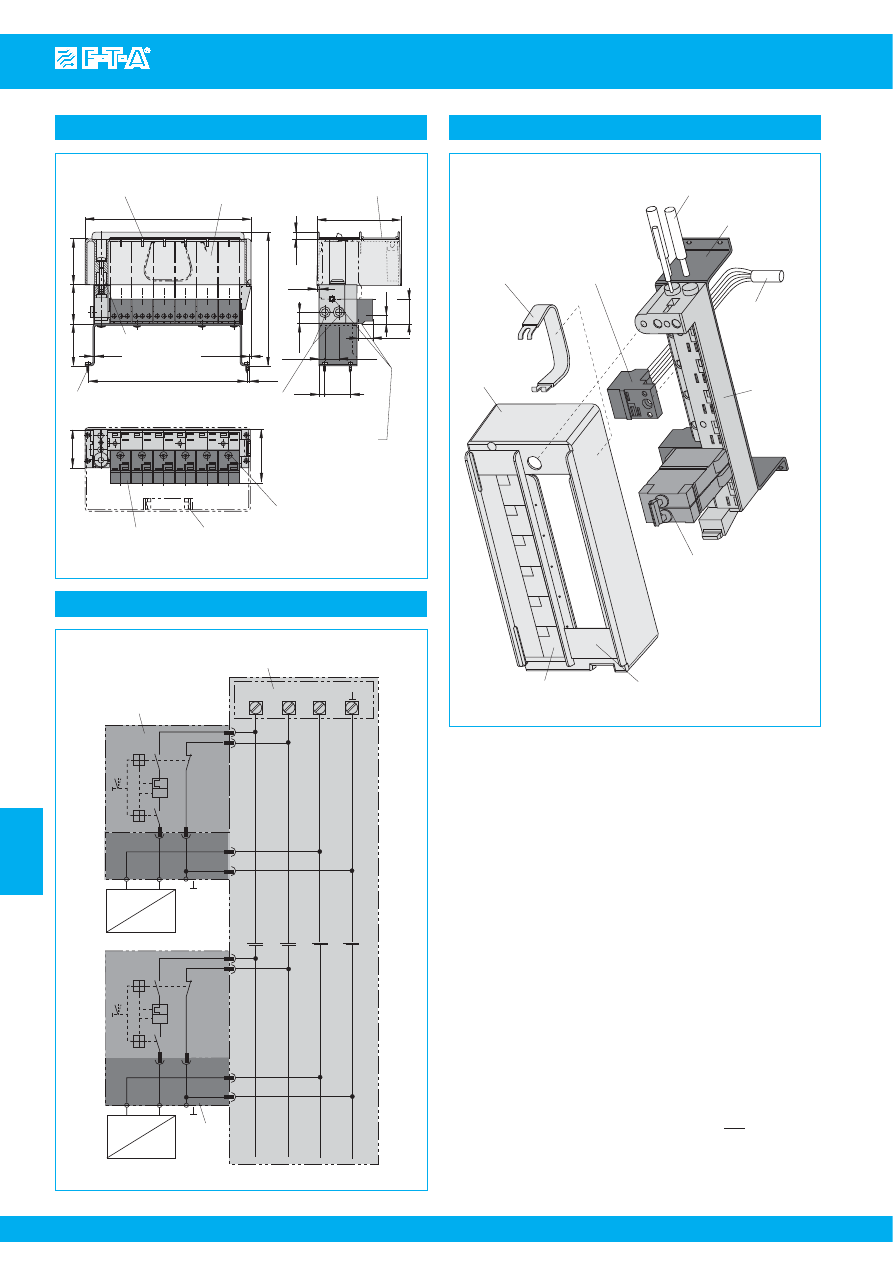
www.e-t-a.com
Issue B
7
- 58
Distribution rail X2210-S06...
7
Dimensions
S
ig
(N)
(U)
46
196
(158.3)
e.g. 2210-
S
291-P9M2-410005-…A
2210-
S
291-P9M2-410030-…A
blan
k
Phillip
s
s
crew M5
DIN 7985 (captive)
2.5
188
3
45
withdrawal tool
X 211 018 01
terminal bloc
k
X 211 019 01
Phillip
s
s
crew M4
DIN 7985
2
-1
50
29
8
54.3
2.6
8.5
17
13.5
7
16.4
6.5
30.5
25 mm
2
conductor
s
ize
cable to be
s
tripped
over 15 mm /.591 in.
2.5 mm
2
conductor
s
ize
Phillip
s
s
crew M2.5
DIN 41494 T1.5 (captive)
legend
s
trip
7.72
.315
2.14
.098
.079
-.039
1.81
1.97
.118
7.40
1.77
.102
(6.23)
.256
63.5
1.20
.531
.276
.646
.669
.335
1.14
99
3.90
2.50
withdrawal tool
X 211 018 01
voltage input
terminal bloc
k
X 211 019 01
circuit brea
k
er
06
05
04
03
02
01
(N)
(U)
+
-
S
ig
mounting brac
k
et
load input
di
s
tribution
rail
blan
k
legend
s
trip
cover
Installation example
+
–
I >
0
I
load
+
–
I >
0
I
(U)
S
ig
(N)
–
+
circuit brea
k
er
terminal
bloc
k
di
s
tribution rail
load
Internal connection diagram
This is a metric design and millimeter dimensions take precedence ( mm )
inch
All dimensions without tolerances are for reference only. In the interest of improved design,
performance and cost effectiveness the right to make changes in these specifications
without notice is reserved.Product markings may not be exactly as the ordering codes.
Errors and omissions excepted.
Courtesy of Steven Engineering, Inc.-230 Ryan Way, South San Francisco, CA 94080-6370-Main Office: (650) 588-9200-Outside Local Area: (800) 258-9200-www.stevenengineering.com
87PDS-html.html
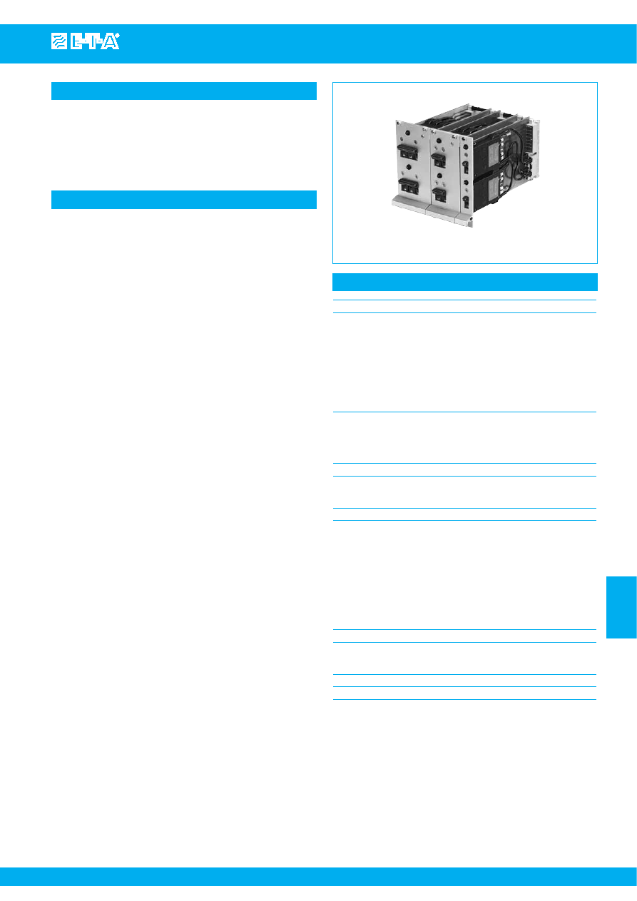
Thermal-Magnetic Circuit Breaker E2210-...
www.e-t-a.com
Issue B
7
- 59
7
Description
Typical applications
Technical data
Thermal-magnetic circuit breaker mounted on Euro Card for 19" rack
mounting, with one Euro Card accommodating one or two single pole,
double pole or three pole circuit breakers. Convenient toggle actuation
enables series 2210 additionally to be used as an ON/OFF switch. A red
LED is located in the front frame of the Euro Card, indicating the
switching status of the circuit breaker (via the auxiliary circuit).
Process control, measuring and control systems, telecommunications
E2210-...
Circuit breaker
Main circuit:
voltage rating
3 AC 433 V (50/60 Hz);
AC 250 V (50/60 Hz); DC 65 V
current rating range
0.1...16 A
standard current ratings
0.1
0.2
0.3
0.4
0.5
0.6
0.8 A
1
1.5
2
2.5 3
4
5 A
6
8
10
12 16
A
Auxiliary circuit:
voltage rating
AC 240 V; DC 65 V
current rating
1 A
Other data
see type 2210-S2..
Front plate
Dimensions
(1 module = 5.08 mm, 1 U = 44.45 mm)
Width:
one single pole circuit breaker
4 modules
one double pole circuit breaker
6 modules
one three pole circuit breaker
9 modules
two single pole circuit breakers
4 modules
two double pole circuit breakers
10 modules
two three pole circuit breakers
12 modules
Height:
3 U
Material
aluminium, anodized
LED
Voltage rating
DC 24 V / DC 60 V
Courtesy of Steven Engineering, Inc.-230 Ryan Way, South San Francisco, CA 94080-6370-Main Office: (650) 588-9200-Outside Local Area: (800) 258-9200-www.stevenengineering.com
87PDS-html.html
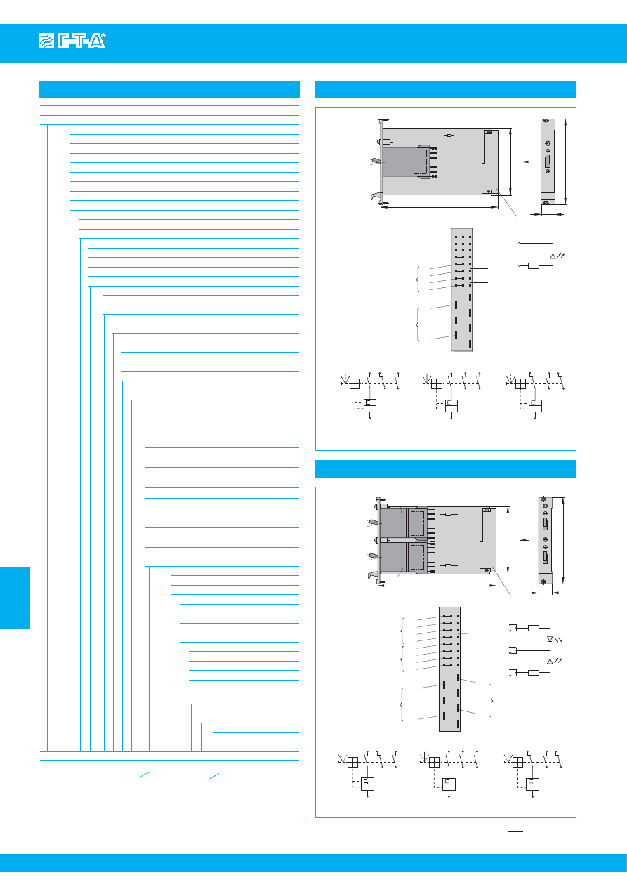
www.e-t-a.com
Issue B
7
- 60
7
Thermal-Magnetic Circuit Breaker E2210-...
Dimen
s
ion
s
Terminal
s
election
Internal connection diagram
3 U
4TE
multi-pin connector
(10/12)
(14/16)
-
+
R1
LED
174
100
I
0
LED
6.85
3.94
R1
E-T
-A
X
ON po
s
ition
0
(Z)
I
1
2(
k
)
11
12
23
24
OFF po
s
ition
0
(Z)
I
0
(Z)
I
I >
I >
1
2(
k
)
11
12
23
24
intermediate po
s
ition
1
2(
k
)
11
12
23
24
I >
line
load
view X
1
2(
k
)
22
26
30
12
24
23
11
d b z
2
4
6
8
10
12
14
16
LED
20
24
28
32
G I
G I
One single pole circuit breaker
Ordering information
Type No.
E2210
Mounting style
1
1 x single pole, central mounting (standard)
2
1 x single pole, top mounting
3
1 x single pole, bottom mounting
4
1 x double pole, central mounting (standard)
5
1 x three pole, central mounting (standard)
6
2 x single pole, symmetrical mounting (standard)
7
2 x double pole, symmetrical mounting (standard)
8
2 x three pole, symmetrical mounting (standard)
Front plate
1
aluminium (standard)
2
moulded (Intermas)
LED
1
red, DC 24 V (standard)
2
red, DC 60 V
3
green, DC 24 V
4
green, DC 60 V
Circuit breaker
Mounting
S
panel mounting
Actuator design
2
short toggle
Number of poles
1
1-pole protected
2
2-pole protected
3
3-pole protected
5
2-pole, protected on one pole only
Panel mounting
1
with M3 thread
Terminal design (main contacts) **
P1
blade terminals 6.3-0.8 (standard)
Characteristic curve**
01 F1
fast acting: therm. 1.01-1.4 x I
N
;
magn. 2-4 x I
N
DC (DC only)
02 M1
standard delay: therm. 1.01-1.4 x I
N
;
magn. 6-12 x I
N
AC; 7.8-15.6 x I
N
DC
03 T1
delayed:therm.1.01-1.4 x I
N
;
magn.10-20 x I
N
AC
04 T2
thermal only, 1.01-1.4 x I
N
05 M3
standard delay, low resistance:
therm.1.4-1.8 x I
N
AC;
magn.6-12 x I
N
AC; 7.8-15.6 x I
N
DC
F2
fast acting: therm. 1.1-1.4 x I
N
magn.3.5-6.5 x I
N
AC/DC
XX
different curves for multipole versions
to order*
Intermediate position**
H
without intermediate position (standard)
Z
with intermediate position
Auxiliary contacts**
1
with auxiliary contacts
(only with 1x1-pole, 2x1-pole)
5
with auxiliary contact only in the
last unit of multipole versions
Auxiliary contact function**
1
1 N/C, 1 N/O (standard)
2
1 N/O (23/24)
3
1 N/C (11/12)
4
1 N/O contact, closed in the
intermediate and ON position
(-Z only)
Auxiliary contact-terminal design
1
same as main terminals **
Current ratings***
0.1...16 A
E2210 - 6 1 1 - S 2 1 1 - 02 -
H 1 1 1 - 0.1 A
XX
0.1/0,2 A
only with 2x1-pole/2x2-pole/2x3-pole
*) Clearly add the desired specifications.
**) With mounting styles 6, 7 and 8: both circuit breakers must have the
same characteristics.
***) It is possible to fit circuit breakers of mixed current ratings on the
Euro Card.
R1
R2
E-T
-A
E
-T
-A
Dimen
s
ion
s
Terminal
s
election
Internal connection diagram
s
for unit
s
G I and G II
3 U
4TE
multi-pin connector
174
100
I
0
LED
6.85
3.94
X
ON po
s
ition
0
(Z)
I
1
2(
k
)
11
12
23
24
OFF po
s
ition
0
(Z)
I
0
(Z)
I
I >
I >
1
2(
k
)
11
12
23
24
intermediate po
s
ition
1
2(
k
)
11
12
23
24
I >
line
load
view X
unit I (G I)
unit II (G II)
I
0
LED
z(6/8)
z(10/12)
z(14/16)
R2
R1
LED G I
LED G II
+
-
+
12
24
23
11
12
24
23
11
2
4
6
8
10
12
14
16
20
24
28
32
2(
k
)
1
2(
k
)
1
22
26
30
d b z
G I
G II
G I
G II
G I LED
G I+G II
G II LED
Two single pole circuit breakers
This is a metric design and millimeter dimensions take precedence ( mm )
inch
Courtesy of Steven Engineering, Inc.-230 Ryan Way, South San Francisco, CA 94080-6370-Main Office: (650) 588-9200-Outside Local Area: (800) 258-9200-www.stevenengineering.com
87PDS-html.html
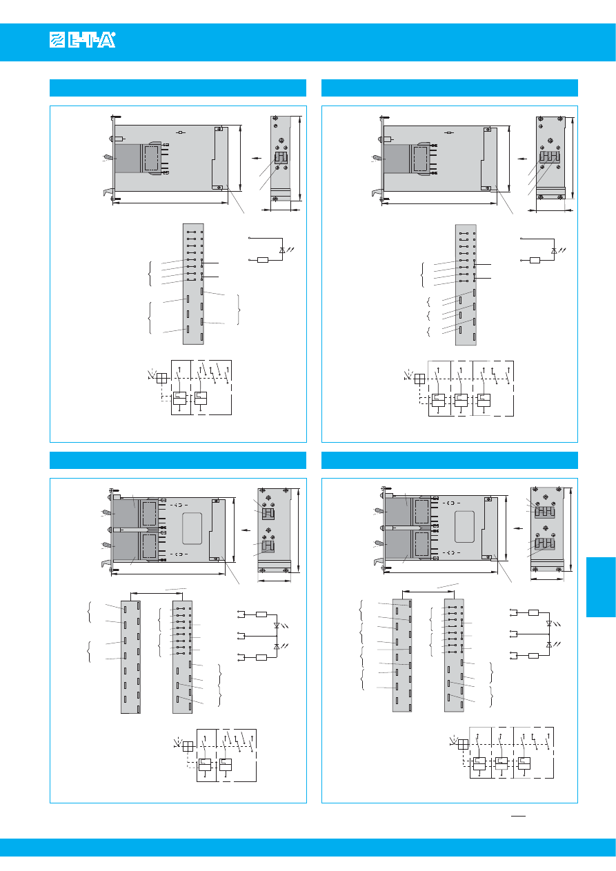
Thermal-Magnetic Circuit Breaker E2210-...
www.e-t-a.com
Issue B
7
- 61
7
61
G IA
G IB
1
2(
k
)
22
26
30
12
24
23
11
d b z
2
4
6
8
10
12
14
16
20
24
28
32
2(
k
)
1
LED
G IB
G IB
G IB
(10/12)
(14/16)
-
+
R1
LED
G IB
Dimen
s
ion
s
Terminal
s
election
Internal connection
diagram
view X
3 U
6TE
multi-pin connector
174
100
I
0
LED
6.85
3.94
R1
E-T
-A
X
G IA
G IB
load
load
line
I I
I I
I >
0
(Z)
I
I >
2(
k
)
2(
k
)
12 24
G IA
G IB
1
1 11
23
I I
I I
line
One double pole circuit breaker
G IB
G IA
G IIB
G IIA
10TE
d b z
6
10
14
18
22
26
30
4
8
12
16
20
24
28
32
12
24
23
11
12
24
23
11
GI
GII
2
4
6
8
10
12
14
16
20
24
28
32
22
26
30
2(
k
)
1
2(
k
)
1
G IIB
G IIA
2(
k
)
1
2(
k
)
1
G IB
G IA
G I LED
G I+G II
G II LED
R1
R2
E-T
-A
E-T
-A
Dimen
s
ion
s
Terminal
s
election
Internal connection diagram
for unit
s
1 (G I) and 2 (G II)
3 U
multi-pin connector
174
100
I
0
LED
6.85
3.94
X
view X
unit I (G I)
unit II (G II)
I
0
LED
z(6/8)
z(10/12)
z(14/16)
R2
R1
LED G I
LED G II
+
-
+
30.6
s
pace between
guide rail
s
1.20
G IA/G IIA G IB/G IIB
load
load
line
I I
I I
I >
0
(Z)
I
I >
2(
k
)
2(
k
)
12 24
1
1 11
23
I I
I I
line
Two double pole circuit breakers
line
load
load
load
line
line
I >
I >
2(
k
)
I >
2(
k
)
2(
k
)
1
1
1 11
23
12 24
G IA
0
(z)
I
G IB
G IC
I I
I I
I I
I I
I I
2(
k
)
G IB
G IC
G IC
22
26
30
12
24
23
11
d b z
2
4
6
8
10
12
14
16
20
24
28
32
LED
G IC
2(
k
)
1
1
2(
k
)
1
G IC
G IA
G IC
G IB
G IA
(10/12)
(14/16)
-
+
R1
LED
G IC
Dimen
s
ion
s
Terminal
s
election
Internal connection
diagram
view X
3 U
9TE
multi-pin connector
174
100
I
0
LED
6.85
3.94
R1
E-T
-A
X
One three-pole circuit breaker
G IA/G IIA
load
load
line
line
line
1
load
I >
0
I >
2(
k
)
I >
2(
k
)
2(
k
)
11
23
12 24
G IB/G IIB G IC/G IIC
I I
I I
(Z)
I
1
1
I I
I I
I I
d
40.6
b z
6
10
14
18
22
26
30
4
8
12
16
20
24
28
32
12
24
23
11
12
24
23
11
GI
GII
2
4
6
8
10
12
14
16
20
24
28
32
22
26
30
2(
k
)
1
2(
k
)
1
G IIA
G IC
2(
k
)
1
2(
k
)
1
G IB
G IA
G I LED
G I+G II
G II LED
2(
k
)
1
2(
k
)
1
G IIC
G IB
1.60
12TE
R1
R2
E-T
-A
E-T
-A
Dimen
s
ion
s
Terminal
s
election
Internal connection diagram
for unit
s
1 (G I) and 2 (G II)
3 U
multi-pin connector
174
100
I
0
LED
6.85
3.94
X
view X
unit I (G I)
unit II (G II)
I
0
LED
z(6/8)
z(10/12)
z(14/16)
R2
R1
LED G I
LED G II
+
-
+
s
pace between
guide rail
s
G IC
G IB
G IA
G IIC
G IIB
G IIA
Two three-pole circuit breakers
This is a metric design and millimeter dimensions take precedence ( mm )
inch
Courtesy of Steven Engineering, Inc.-230 Ryan Way, South San Francisco, CA 94080-6370-Main Office: (650) 588-9200-Outside Local Area: (800) 258-9200-www.stevenengineering.com
87PDS-html.html
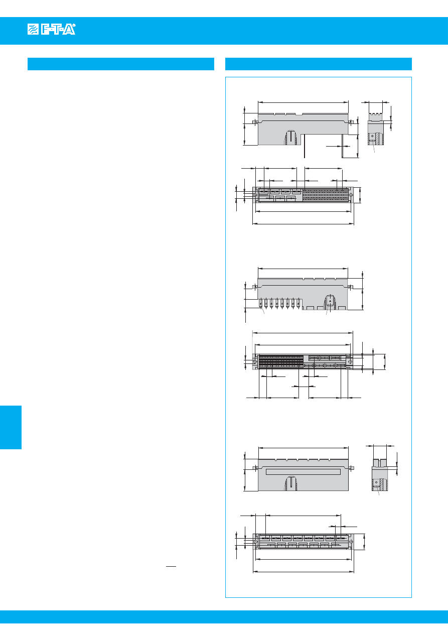
www.e-t-a.com
Issue B
7
- 62
Thermal-Magnetic Circuit Breaker E2210-...
7
Sockets for Euro Cards
Dimensions of sockets for Euro Cards
12.4
84.9
3.34
5.08
.200
7.62
.300
7x5.08=35.56
7x.200=1.40
ø2.8
.110
95
3.74
5.08
.200
6x5.08=30.48
6x.200=1.20
blade terminal
s
DIN 46244 A6.3x0.8
(QC .250)
blade terminal
s
DIN 46244 A2.8x0.8
(QC. 110)
20
10
81
0
90
5.62
5.62
6.5
14.8
.394
.787
.256
3.54
.583
.394
.221
.221
.488
.315
ø2.8
84.9
10.1
3.34
.398
12.4
.488
blade terminal
s
DIN46244 A6.3x0.8
(QC .250)
2.9
.114
20
14x5.08=71.12
8.17
14.8
5.08
6.5
90
95
.787
.200
14x.200=2.80
.322
.110
.256
3.54
3.74
.583
84.9
blade terminal
s
DIN46244 A6.3x0.8
(QC .250)
20
10.1
ø1
22
10
12.4
2.9
8.17
6x5.08=30.48
5.08
7.62
5.08
7x5.08=35.56
6.5
ø2.8
90
95
14.8
3.34
.488
.394
.866
.114
.039
.787
.398
.200
.200
.300
7x.200=1.40
6x.200=1.20
.322
.110
.256
3.54
3.74
.583
0Z041Z000004
0Z041Z000007
0Z041Z000005
Description
The following sockets may be used with single pole circuit
breakers:
0Z041Z000004
24/7-pole mixed socket to DIN 41612 - form M.
Connection: 7-pole for 6.3x0.8 mm connectors
and 24-pole midi-wire wrap posts (1 x 1 mm).
0Z041Z000007
24/7-pole mixed socket to DIN 41612 - form M.
Connection: 7-pole for 6.3x0.8 mm connectors
and 24-pole for 2.8x0.8 mm connectors.
0Z041Z000005
A 15-pole socket to DIN 41612, form H, for 6.3x0.8 mm
connectors is required in addition to the socket mentioned above, if
two double pole or two three pole circuit breakers are fitted on one
Euro Card.
This is a metric design and millimeter dimensions take precedence ( mm )
inch
All dimensions without tolerances are for reference only. In the interest of improved design,
performance and cost effectiveness the right to make changes in these specifications
without notice is reserved.Product markings may not be exactly as the ordering codes.
Errors and omissions excepted.
Courtesy of Steven Engineering, Inc.-230 Ryan Way, South San Francisco, CA 94080-6370-Main Office: (650) 588-9200-Outside Local Area: (800) 258-9200-www.stevenengineering.com
87PDS-html.html
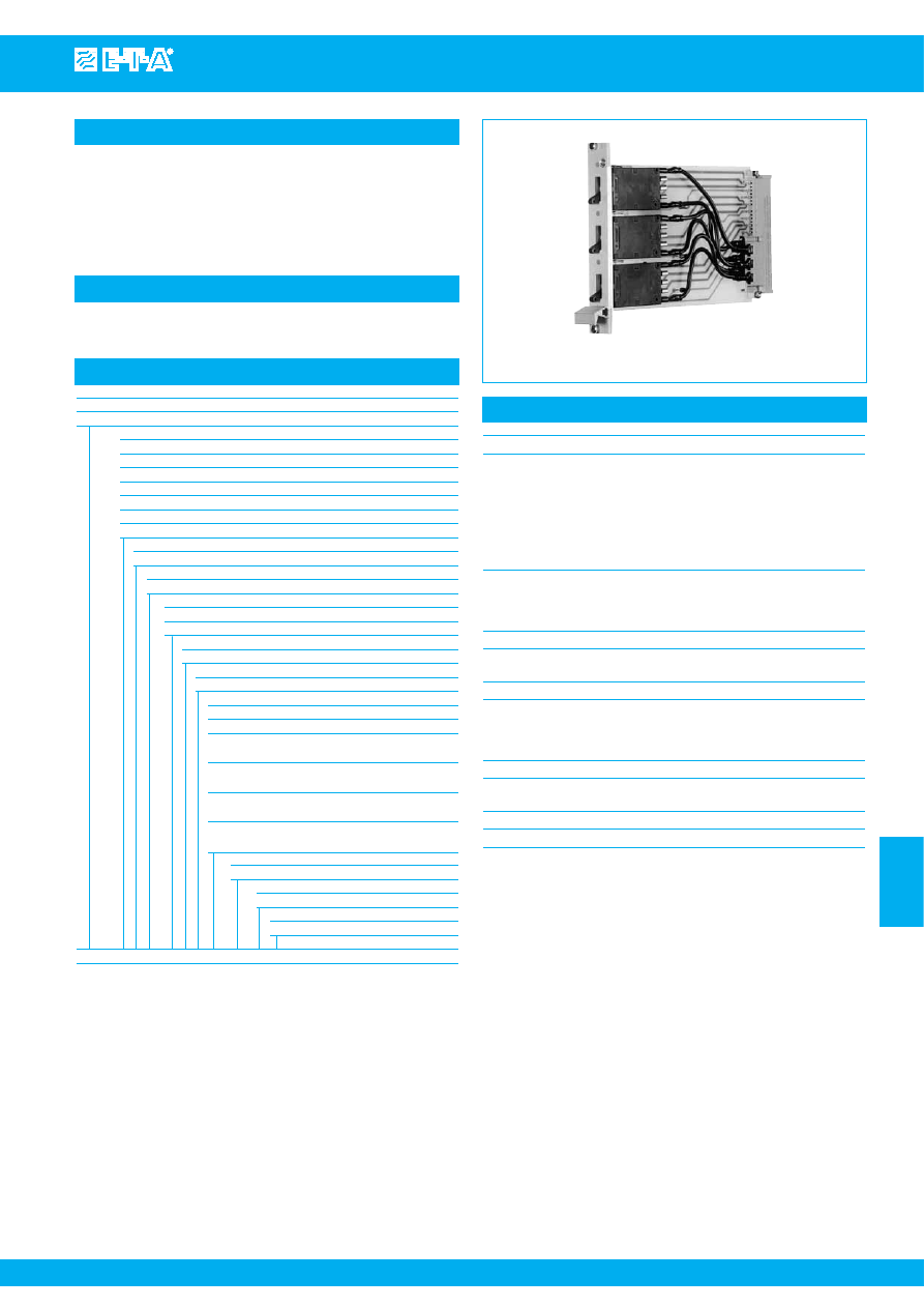
Thermal-Magnetic Circuit Breaker E2215
www.e-t-a.com
Issue B
7
- 63
7
Description
Typical applications
Thermal-magnetic circuit breaker mounted on Euro Card for 19" rack
mounting, with one Euro Card accommodating up to three circuit
breakers. Convenient toggle actuation enables series 2215 additionally
to be used as an ON/OFF switch. A red LED is located in the front
frame of the Euro Card, indicating the switching status of the circuit
breaker (via the auxiliary circuit).
Process control, measuring and control systems, telecommunications
E2215-...
Ordering information for circuit breakers only
Type No.
E2215
Mounting
1
3 x 1-pole, mounted symmetrically (standard)
2
2 x 1-pole, mounted centrally above and below
3
2 x 1-pole, mounted above and below
4
2 x 1-pole, mounted below and centrally
5
1 x 1-pole, mounted above
6
1 x 1-pole, mounted centrally
7
1 x 1-pole, mounted below
Handle
1
aluminium handle (standard)
LED
1
red LED, DC 24 V (standard)
Circuit breaker
Actuator design
L2
moulded toggle
Number of poles
1
single pole protected
Accessories
0
without
Terminal design
P1
blade terminals A6.3-0.8 (standard)
Characteristic curve
01
F1
fast acting: therm. 1.01 x 1.4 I
N
;
magn. 2-4 x I
N
DC (DC only)
02
M1
standard delay: therm. 1.01-1.4 x I
N
;
magn. 5-10 x I
N
DC; magn. 3.5-8 x I
N
DC
03
T1
delayed: therm. 1.01-1.4 x I
N
;
magn. 6-13 x I
N
AC
07
T3
delayed: therm. 1.01-1.4 x I
N
;
magn. 9.5-15.5 x I
N
AC
Auxiliary contacts
S1
with auxiliary contacts (change over)
Auxiliary contact - terminal design
1
same as main terminals
Current ratings
0.05...10 A
E2215
3 1 1 - L2 1 0 - 02 - S1 1 - 0.1 A
ordering example
Technical data
Circuit Breaker
Main circuit:
voltage rating
AC 250 V (50/60 Hz); DC 48 V
current rating range
0.05...10 A
standard current ratings
0.1
0.2
0.3
0.4
0.5
0.6 A
0.8
1
1.5
2
2.5
3 A
4
5 6
8
10 A
Auxiliary circuit:
voltage rating
AC 250 V/DC 28 V
current rating
1 A
Other data
see type 2215
Front plate
Dimensions:
width
4 modules (1 module = 5.08 mm)
height
3 U (1 U = 44.45 mm)
Material
aluminium, anodized
LED
Max. voltage rating
DC 24 V
Select the circuit breakers to above ordering information. For further
information please refer to group 2.
It is possible to fit circuit breakers of mixed current ratings on the
Euro Card.
Please add "Circuit breakers to be mounted on Euro Card" to the
circuit breaker designation when ordering so that the applicable suffix
number for the special version (E2215-...-L2..) can be determined .
19" racks may also be fitted with one or two circuit breakers by the
customer, using industry standard components such as base plates,
front plates with handle, sockets. Connection by means of blade
terminals 6.3x0.8 mm.
Courtesy of Steven Engineering, Inc.-230 Ryan Way, South San Francisco, CA 94080-6370-Main Office: (650) 588-9200-Outside Local Area: (800) 258-9200-www.stevenengineering.com
87PDS-html.html
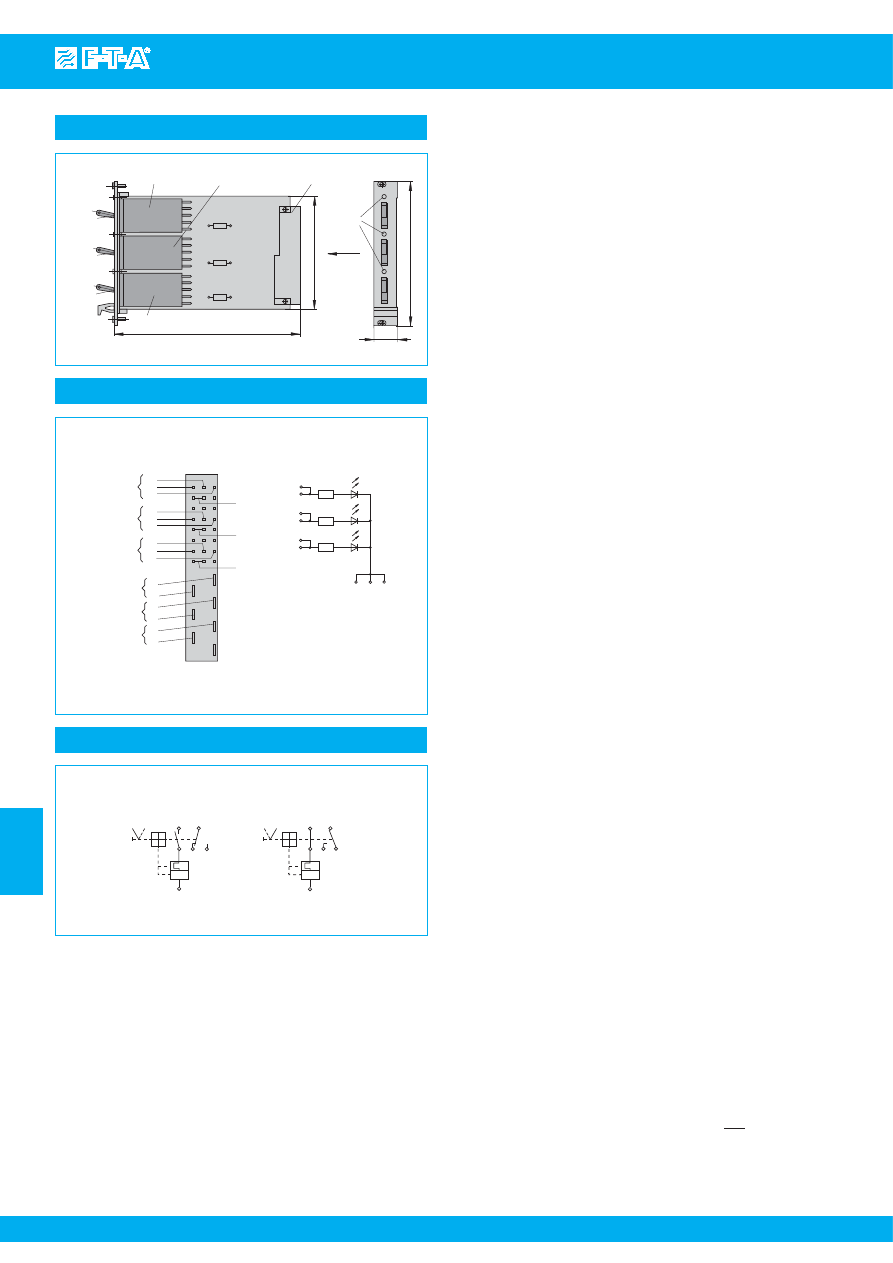
www.e-t-a.com
Issue B
7
- 64
Thermal-Magnetic Circuit Breaker E2215
7
12
line 1
2
11
OFF po
s
ition
0
I
I >
14
12
line 1
2
11
ON po
s
ition
0
I
I >
14
applicable to all circuit brea
k
er
s
GI to GIII
Dimensions
Terminal selection
4 TE
multi-pin connector
ON
OFF
ON
OFF
ON
OFF
unit I (GI)
R1
R2
R3
unit II (GII)
100
174
unit III (GIII)
3 U
I
X
LED
6.85
3.94
d b z
12
11
14
12
11
14
12
11
14
GI
GII
GIII
GI
GII
GIII
2
1
2
1
2
1
22
26
30
24
28
32
20
d4
b4
d10
b10
d16
b16
+
+
+
R1
R2
R3
z4 z10 z16
view X
2
4
6
8
10
12
14
16
wiring diagram for
LED-di
s
play
LED
Connection of the Euro Card DIN 41612 with
s
oc
k
et type H7/F24-F413.173
Connector of the 19” rac
k
to DIN 41494
LED GI
LED GII
LED GIII
Internal connection diagrams
All dimensions without tolerances are for reference only. In the interest of improved design,
performance and cost effectiveness the right to make changes in these specifications
without notice is reserved.Product markings may not be exactly as the ordering codes.
Errors and omissions excepted.
This is a metric design and millimeter dimensions take precedence ( mm )
inch
Courtesy of Steven Engineering, Inc.-230 Ryan Way, South San Francisco, CA 94080-6370-Main Office: (650) 588-9200-Outside Local Area: (800) 258-9200-www.stevenengineering.com
87PDS-html.html
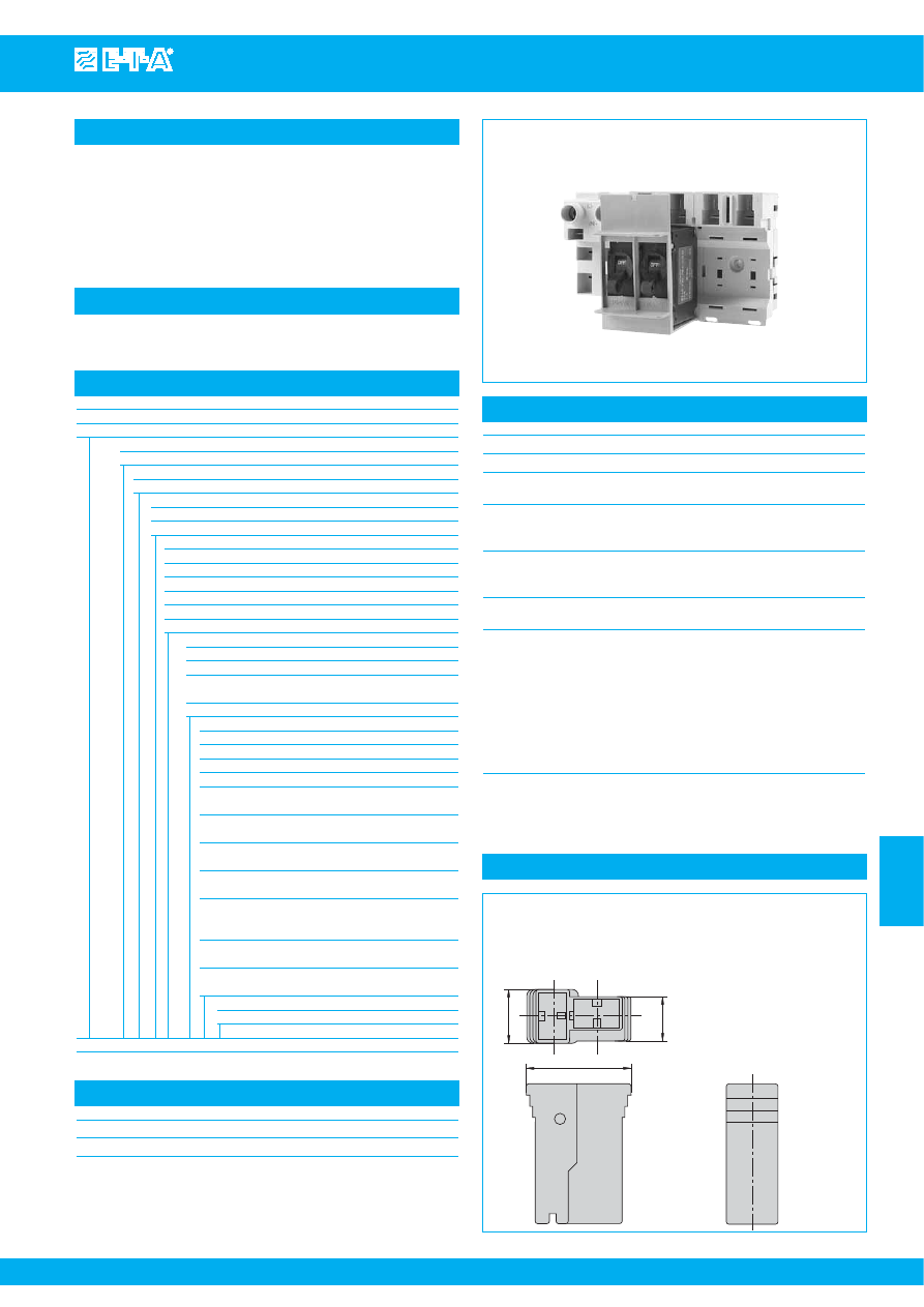
Distribution rail X8340-S02
www.e-t-a.com
Issue B
7
- 65
7
Description
Typical applications
Modular distribution rail, each module accommodating 2 magnetic or
hydraulic-magnetic circuit breakers type 8340-F... and associated
load terminals. Circuit breaker status indication (group signalisation)
is via 2 busbars. Power supply is via right- or left-side terminal block.
Live parts in the plug-in and supply feed terminal areas are protected
against brush contact. Circuit breakers may be replaced with power
on.
Telecommunications and cellular communication systems
X8340-S02
Ordering information
Type No.
X8340
Distribution rail for circuit breaker type 8340
Version
S
rail
Identification number
02
modular, for 2 circuit breakers
Power supply
L
left-side
R
right-side
Modules with power supply
1
1 module, 2-way
2
2 modules, 2-way each
3
3 modules, 2-way each
4
4 modules, 2-way each
5
5 modules, 2-way each
..
...
Signalisation
0
without signalisation
1
group signalisation
2
group signalisation, through-connected for right- or
left-side power supply (main current path separated)
3
single signalisation
Accessories
00
without
01
cover per module
02
ground bridge in first module
03
M4 mounting screw per module
04
cover per module + mounting screw M4
(bulk shipped)
05
cover per module
+ ground bridge in first module
06
ground bridge in first module
+ mounting screw M4 (bulk shipped)
07
cover + ground bridge + M4 mounting screw
(bulk shipped)
08
cover per module + ground bridge in first module
+ mounting screw M4 (bulk shipped)
+ ground stud M6
09
mounting screw M4 (bulk shipped)
+ ground stud M6
10
cover per module + mounting screw M4
(bulk shipped) + ground stud M6
Terminal marking
B
+ and - reversed
X8340 - S 02 L 5 - 1 01 B
ordering example
Approvals
Authority
Voltage ratings
Current ratings
UL 1801
AC 250 V; DC 80 V
100 A
Technical data
For circuit breaker type
8340-F.10-P1..-H...
Voltage rating
AC 230 V; DC 80 V
Load
25 A per position (30 A upon request)
132 A for complete unit
Signalisation (N/C)
6 A, AC 230 V
1 A, DC 80 V
per position
Insulation co-ordination
Rated impulse
Pollution
(IEC 60664 and 60664A)
withstand voltage
degree
2.5 kV
2
Flame retardance
(IEC 60695, part 2-2)
self-extinguishing
Supply terminal design
(terminal socket)
recessed screw/pressure plate
6...50 mm
2
, stranded
feed-in 6...35 mm
2
with connector sleeve
additional blade terminals 6.3x0.8
load (module)
blade terminals 6.3x0.8
load output terminal protected
against reverse polarity
signalisation (module)
blade terminals 4.8x0.8
Mass
terminal block
144 g
power distribution module
96 g
cover
12 g
9
7,3
18,15
Load output terminal protected again
s
t rever
s
e polarity
(
s
et: 4 moulded
s
leeve
s
, 8 blade terminal
s
6.3 x 0.8 mm)
X 222 847 01
for cable cro
ss
s
ection 0.7...2.0 mm
2
X 222 625 01
for cable cro
ss
s
ection 2.5...4.0 mm
2
X 222 848 01
for cable cro
ss
s
ection 4.0...6.0 mm
2
Internal connection diagrams
Courtesy of Steven Engineering, Inc.-230 Ryan Way, South San Francisco, CA 94080-6370-Main Office: (650) 588-9200-Outside Local Area: (800) 258-9200-www.stevenengineering.com
87PDS-html.html
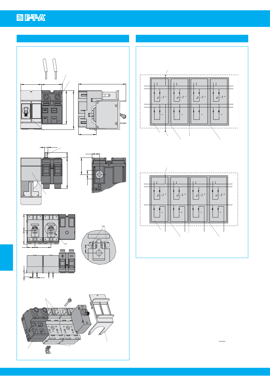
www.e-t-a.com
Issue B
7
- 66
Distribution rail X8340-S02
7
S
ingle
s
ignali
s
ation
ground
s
tud
optional
(09/10)
X8340-
S
02
(N)
(L)
+
-
(N)
(L)
+
-
(N)
(L)
+
-
(N)
(L)
+
-
(N)
(L)
+
-
S
ig
-F1
-F2
-F3
-F4
NC NO
C
1
2
S
ig
-F1
NC NO
C
-F2
-F3
-F4
8340-F
S
ig
module...
S
ig
divi
s
ion
S
ig
module...
S
ig
PE
NC NO
C
1
2
NC NO
C
1
2
NC NO
C
1
2
NC NO
C
NC NO
C
NC NO
C
(N)
(L)
+
-
Group
s
ignali
s
ation
X8340-
S
02
(N)
(L)
+
-
(N)
(L)
+
-
(N)
(L)
+
-
(N)
(L)
+
-
(N)
(L)
+
-
S
ig
S
ig
NC NO
C
1
2
NC NO
C
1
2
NC NO
C
1
2
NC NO
C
1
2
-F1
-F2
-F3
-F4
-F1
NC NO
C
-F2
NC NO
C
-F3
NC NO
C
-F4
NC NO
C
8340-7
ground bridge
optional
(02/05/06/07/08)
module...
PE
PE:1
module...
divi
s
ion
(N)
(L)
+
-
S
ig
S
ig
ground
s
tud
optional
(09/10)
Dimensions
9
M6
20
dimen
s
ion
s
of ground
s
tud
mounting
s
crew M4
tightening tor
q
ue max. 1.5 Nm
(optional)
module
Di
s
tribution rail,
s
hown with power
s
upply left-
s
ide
X8340-
S
02L-…
Di
s
tribution rail,
s
hown with power
s
upply right-
s
ide
X8340-
S
02R-…
41.1
90.6
terminal bloc
k
* E-T-A circuit brea
k
er type 8340-F…
(not
s
upplied with product)
40
40
63.1
74
S
ig
S
ig
(N)+
(L)-
1.57
1.57
3.57
2.48
2.91
1.62
Di
s
tribution rail, ground
s
tud M6 (optional)
load terminal
s
58.4
+
–
10
M6
load terminal
s
cover (optional)
ground bridge in fir
s
t module (optional)
ground connection between
s
ignali
s
ation and metal ba
s
e
terminal bloc
k
2.30
.354
.787
rece
ss
ed
s
crew M6
tightening tor
q
ue max. 5 Nm
ground
s
tud terminal
tightening tor
q
ue max. 3 Nm
.394
Di
s
tribution rail,
s
ingle
s
ignali
s
ation
20
.79
40
1.57
A
33.6
1.32
40.4
1.59
9.2
.362
10.5
.413
terminal to
DIN 46244 A2.8-0.8
A
2:1
terminal
s
twi
s
ted by 20°
7
»PA-M50/GF10«
»PA-M50/GF10«
»P
A-M50/GF10«
X8340-
S
02
Internal connection diagram
This is a metric design and millimeter dimensions take precedence ( mm )
inch
All dimensions without tolerances are for reference only. In the interest of improved design,
performance and cost effectiveness the right to make changes in these specifications
without notice is reserved.Product markings may not be exactly as the ordering codes.
Errors and omissions excepted.
Courtesy of Steven Engineering, Inc.-230 Ryan Way, South San Francisco, CA 94080-6370-Main Office: (650) 588-9200-Outside Local Area: (800) 258-9200-www.stevenengineering.com
87PDS-html.html
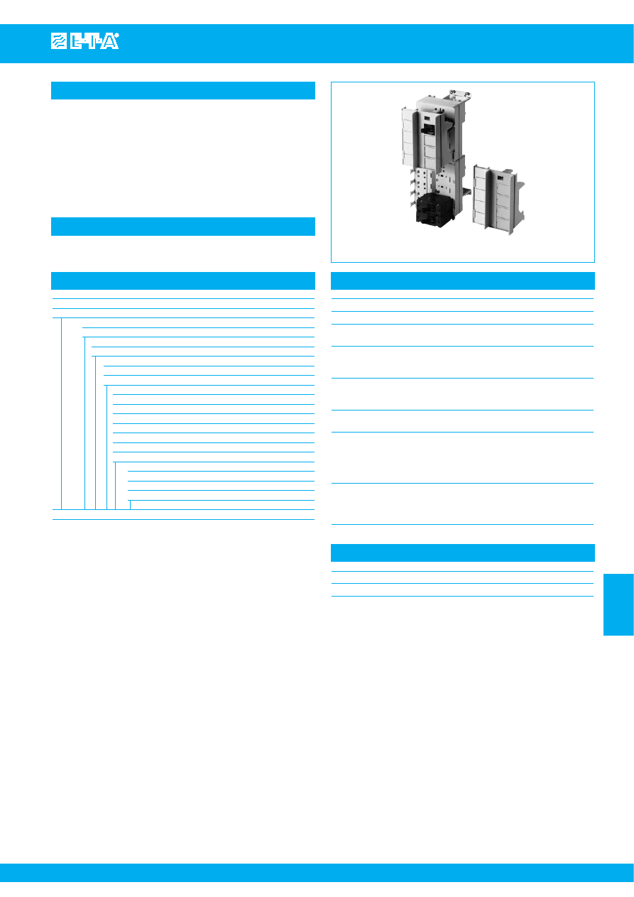
Distribution rail X8340-S04
www.e-t-a.com
Issue B
7
- 67
7
Description
Typical applications
Distribution rail for one or two modules suitable for ETSI control
cabinet and similar applications. One module comprises 4 positions
for magnetic or hydraulic-magnetic circuit breakers type 8340-F... and
associated line and load terminals. Circuit breaker status indication
(group signalisation) is via two busbars. The modular design facilitates
the operation of a single distribution rail at two different voltages.
Live parts in the plug-in and supply feed terminal areas are protected
against brush contact.
Expansion or circuit breaker replacement is possible with power on.
Telecommunications, measuring and control systems
X8340-S04
Ordering information
Type No.
X8340
Distribution rail for circuit breaker type 8340-F
Version
S
rail
Identification number
04
modular, for 4 circuit breakers
Modules with power supply
1
1 module, 4-way
2
2 modules, 4-way each
Accessories
0
without
1
mounting bracket, 2 modules + mounting screw
2
mounting bracket, 2 modules + cover + mounting screw
3
cover
4
mounting bracket, 1 module + cover + mounting screw
5
cover + mounting screw
6
mounting screw
Signalisation
0
without
1
group signalisation + ground connection
2
group signalisation
X8340 - S 04 2 1 - 1
ordering example
Approvals
Authority
Voltage ratings
Current ratings
UL 1801
AC 250 V; DC 80 V
80 A
Technical data
For circuit breakers
8340-F.10-P1...-..H...
Voltage rating
AC 230 V; DC 80 V
Load
20 A per position
80 A for module
Signalisation (N/C)
6 A, AC 230 V
1 A, DC 80 V
per position
Insulation co-ordination
Rated impulse
Pollution
(IEC 60664 and 60664A)
withstand voltage
degree
2.5 kV
2
Flame retardance
(IEC 60695, part 2-2)
self-extinguishing
Supply terminal design
recessed screw/pressure plate
feed 6...25 mm
2
, stranded or
6...16 mm
2
with connector sleeve
load and signalisation
screw-less connectors 0.5...2.5 mm
2
,
stranded, with connector sleeve
Mass
module
220 g
cover
35 g
bracket
145 g
Courtesy of Steven Engineering, Inc.-230 Ryan Way, South San Francisco, CA 94080-6370-Main Office: (650) 588-9200-Outside Local Area: (800) 258-9200-www.stevenengineering.com
87PDS-html.html
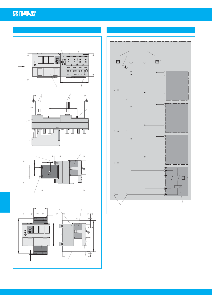
www.e-t-a.com
Issue B
7
- 68
Distribution rail X8340-S04
7
(N) +
(N) +
(L) –
(L) –
(L) –
1
C
2
NC
NO
I >
(N) +
(N) +
(L) –
Module for 4 circuit brea
k
er
s
E-T-A circuit brea
k
er type 8340-F…
(N) +
S
ig
(L) –
s
crew terminal
S
ig
load terminal
s
s
upply terminal
s
ground bridge (optional)
Dimensions
122
mar
k
ing
s
trip
81.8
3.7
30
48
41
* E-T-A circuit brea
k
er type 8340-F…
(not
s
upplied with product)
8.1
12
99
mounting brac
k
et
module
cover
108.5
2
0.9
1.18
1.89
.472
4.80
.146
3.22
.079
.319
.035
4.27
3.90
1.64
load terminal
s
mounting
s
pace 100
terminal for group
s
ignali
s
ation
81.8
+0.3
- 0.1
mar
k
ing
s
trip
99
+0.3
- 0.1
188
100
* E-T-A circuit brea
k
er type 8340-F…
(not
s
upplied with product)
96.3
14
158.8
ø4.6
30.5
48.4
8.4
85
4xnec
k
s
crew (Philip
s
) M2.5x11 (captive)
to DIN 41494 TL5
View X
X
mounting
brac
k
et
module
cover
di
s
tribution rail
s
upply 1
s
upply 2
mounting
s
pace 3.94
3.90
+.012
- .004
3.22
+.012
-
.004
7.40
3.94
.551
3.79
6.25
3.35
1.91
1.20
.181
.331
mounting
s
crew M4
tightening torque max.1.5 Nm
X8340-
S
0422 (right cover not repre
s
ented)
mounting
s
crew
X8340-
S
0414
ø3.5
.138
rece
ss
ed
s
crew M5
tightening torque max. 4 Nm
Internal connection diagram
All dimensions without tolerances are for reference only. In the interest of improved design,
performance and cost effectiveness the right to make changes in these specifications
without notice is reserved.Product markings may not be exactly as the ordering codes.
Errors and omissions excepted.
This is a metric design and millimeter dimensions take precedence ( mm )
inch
Courtesy of Steven Engineering, Inc.-230 Ryan Way, South San Francisco, CA 94080-6370-Main Office: (650) 588-9200-Outside Local Area: (800) 258-9200-www.stevenengineering.com
87PDS-html.html
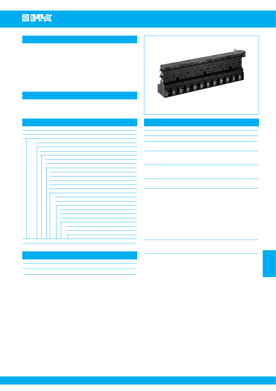
Distribution rail X8340-SZ4
www.e-t-a.com
Issue B
7
- 69
7
Description
Typical applications
Distribution rail with modules connected in series. One module provides
4 positions for magnetic or magnetic-hydraulic circuit breakers type
8340-F... and the pertinent line and load terminals on the front and rear
side of the rail. Supply feed is either on the right or left side with copper
busbars. Trip indication of the circuit breakers (group signalisation) is
possible via two signal busbars.
Live parts in the plug-in area of the load terminals are protected against
brush contact. Circuit breaker replacement is possible with power on.
Telecommunications, measuring and control systems
X8340-SZ4
Ordering information
Type No.
X8340
Distribution rail for circuit breaker type 8340-F
Version
S
rail
Identification number
Z4
module accommodating 4 circuit breakers (smallest unit)
Terminal (supply feed)
L
left side
R
right side
Power distribution modules
1
1 module
2
2 modules
3
3 modules
4
4 modules
5
5 modules
Signalisation
0
without
1
group signalisation
Accessories / variations
00
none
01
mounting screw M4 / module bulk shipped
A1
terminals twisted by 180°
Additional configuration
00
neutral
01
customer specified marking
X8340 - S Z4 R 3 - 1 00 - 00
ordering example
Approvals
Authority
Voltage ratings
Current ratings
UL 1059
AC 250 V; DC 80 V
150 A
Technical data
Plug-in type circuit breakers
8340-F110-P1...-..H...
Voltage rating
AC 230 V; DC 80 V
Load
25 A per position (30 A upon request)
150 A for the rail
Signalisation (N/C contact) 6 A, AC 230 V
1 A, DC 80 V
per position
Insulation co-ordination
Rated impulse
Pollution
(IEC 60664)
withstand voltage
degree
2.5 kV
2
Flame retardance
(IEC 60695, part 2-2)
self-extinguishing
Terminal design
supply feed
copper busbar 10x3 mm
with hole ø 5.3 mm dia.
current supply from the rear side
(left or right)
loads
blade terminals DIN 46244-A6.3x0.8mm
load output terminal protected
against reverse polarity
on front and rear side
signalisation
blade terminals DIN 46244-A6.3x0.8mm
plug-in direction as circuit breakers,
opposite to the main terminal side
Mass
module
200 g
every additional module
145 g
Courtesy of Steven Engineering, Inc.-230 Ryan Way, South San Francisco, CA 94080-6370-Main Office: (650) 588-9200-Outside Local Area: (800) 258-9200-www.stevenengineering.com
87PDS-html.html
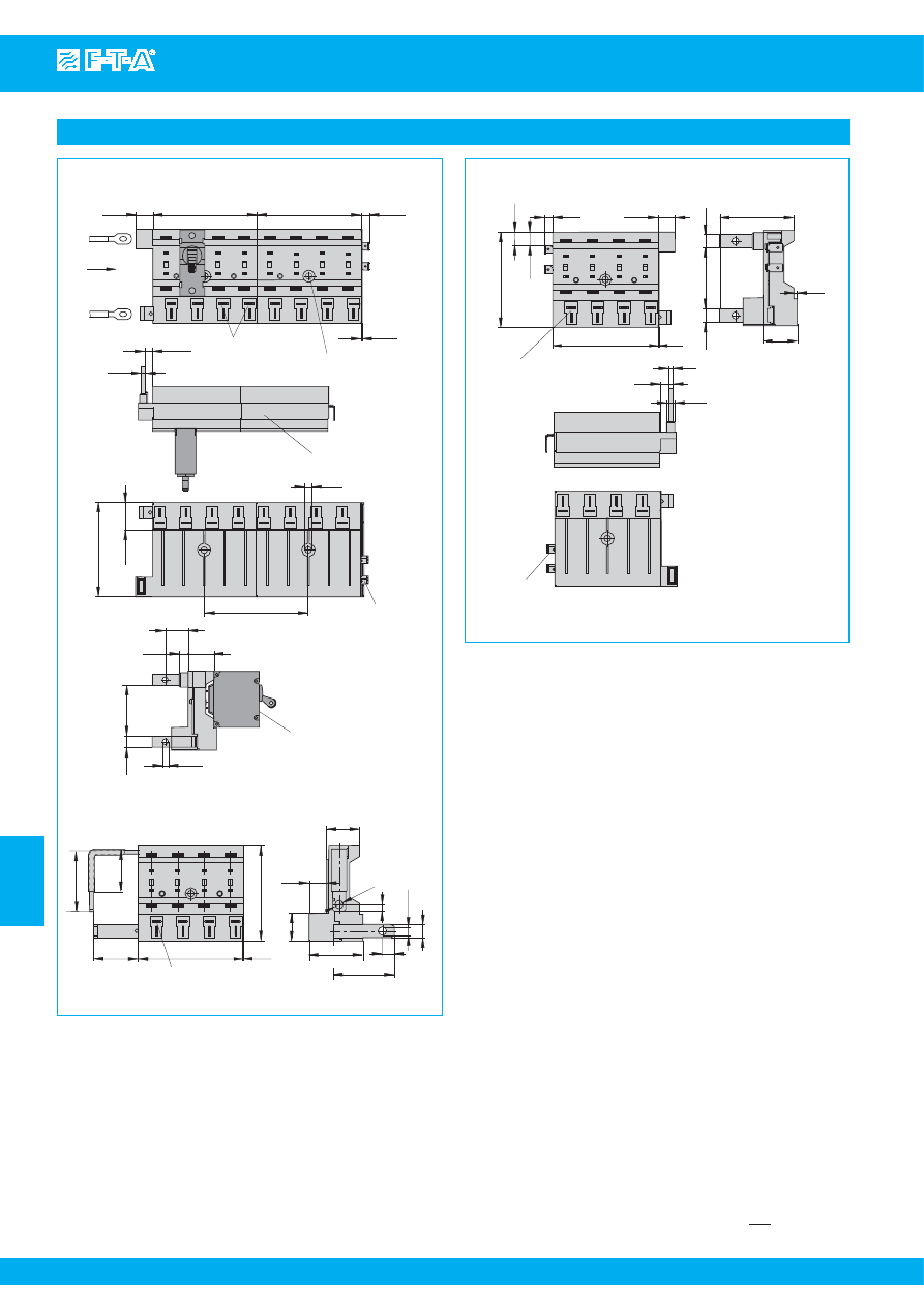
www.e-t-a.com
Issue B
7
- 70
Distribution rail X8340-SZ4
7
Dimensions
module
* E-T-A circuit brea
k
er type 8340-F…
(not
s
upplied with product)
21.1
80
ø5
6.94
3
-0.1
View X
X
10
46.3
ø5.3
20.75
25
12.9
80
80
6.3
0.9
72
8
1.61
load terminal
s
1.82
ø.244
.830
s
ignali
s
ation
1.34
.035
3.15
.528
.394
.197
1.83
.976
.354
2.83
load terminal
s
.394
.209
1.82
.315
.984
.817
3.15
-.004
.197
2.83
.831
.118
.273
.508
.248
.035
3.15
3.15
Di
s
tribution rail. Power
s
upply left-
s
ide
mounting
s
crew M4
tightening tor
q
ue 1.5 Nm
Di
s
tribution rail X8340-
S
Z4L1-0A1
80
72
34
0.9
31.5
46.5
ø6.2
46.2
40,8
9
21.1
5
10
24.8
13.4
1.24
ø.244
ø6.2
80
6.4
10
25.2
72
12.9
0.9
load terminal
s
6.2
6
3
s
ignali
s
ation
2.6
56.01
10
46.3
10
Di
s
tribution rail. Power
s
upply right-
s
ide
27.7
2.83
.992
.252
.394
3.15
.508
.035
1.82
.394
.394
2.21
.102
1.09
.118
.236
.244
This is a metric design and millimeter dimensions take precedence ( mm )
inch
Courtesy of Steven Engineering, Inc.-230 Ryan Way, South San Francisco, CA 94080-6370-Main Office: (650) 588-9200-Outside Local Area: (800) 258-9200-www.stevenengineering.com
87PDS-html.html
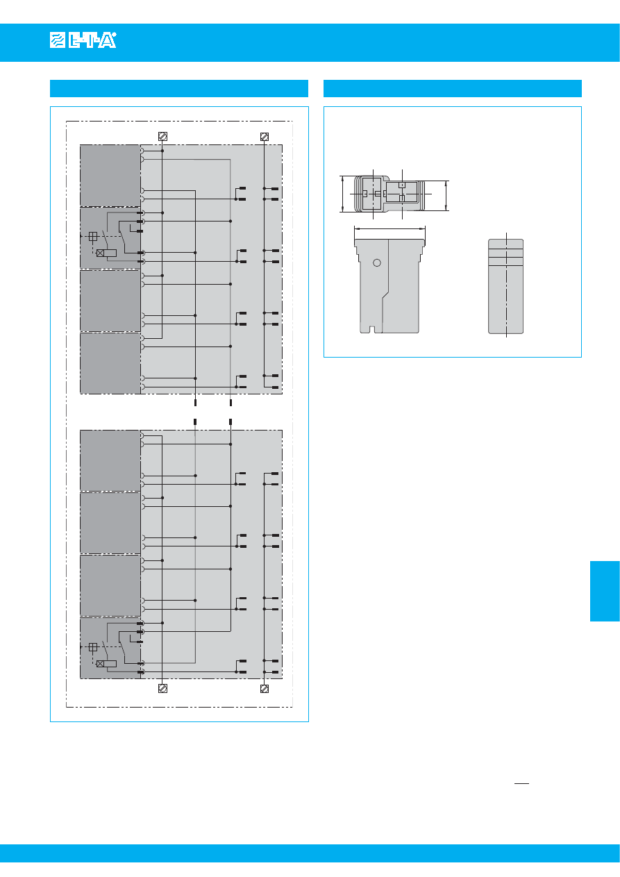
Distribution rail X8340-SZ4
www.e-t-a.com
Issue B
7
- 71
7
E-T
-A cir
cuit br
ea
k
er type 8340-F…
E-T
-A cir
cuit br
ea
k
er type 8340-F…
load terminal
s
on fr
ont and r
ear
s
ide
Module with power
s
upply left-
s
ide
(L) –
(N) +
terminal for
s
ignali
s
ation
(L) –
(N) +
1
C
2
I >
NC
NO
(L) –
(N) +
(L) –
(N) +
(L) –
(N) +
(L) –
(N) +
(L) –
(N) +
(L) –
(N) +
(L) –
(N) +
1
C
2
I >
NC
NO
(N) +
(L) –
Module with power
s
upply right-
s
ide
(N) +
(L) –
load terminal
s
on fr
ont and r
ear
s
ide
Internal connection diagram
This is a metric design and millimeter dimensions take precedence ( mm )
inch
All dimensions without tolerances are for reference only. In the interest of improved design,
performance and cost effectiveness the right to make changes in these specifications
without notice is reserved.Product markings may not be exactly as the ordering codes.
Errors and omissions excepted.
9
7,3
18,15
Load output terminal protected again
s
t rever
s
e polarity
(
s
et: 4 moulded
s
leeve
s
, 8 blade terminal
s
6.3 x 0.8 mm)
X 222 847 01
for cable cro
ss
s
ection 0.7...2.0 mm
2
X 222 625 01
for cable cro
ss
s
ection 2.5...4.0 mm
2
X 222 848 01
for cable cro
ss
s
ection 4.0...6.0 mm
2
Internal connection diagrams
Courtesy of Steven Engineering, Inc.-230 Ryan Way, South San Francisco, CA 94080-6370-Main Office: (650) 588-9200-Outside Local Area: (800) 258-9200-www.stevenengineering.com
87PDS-html.html
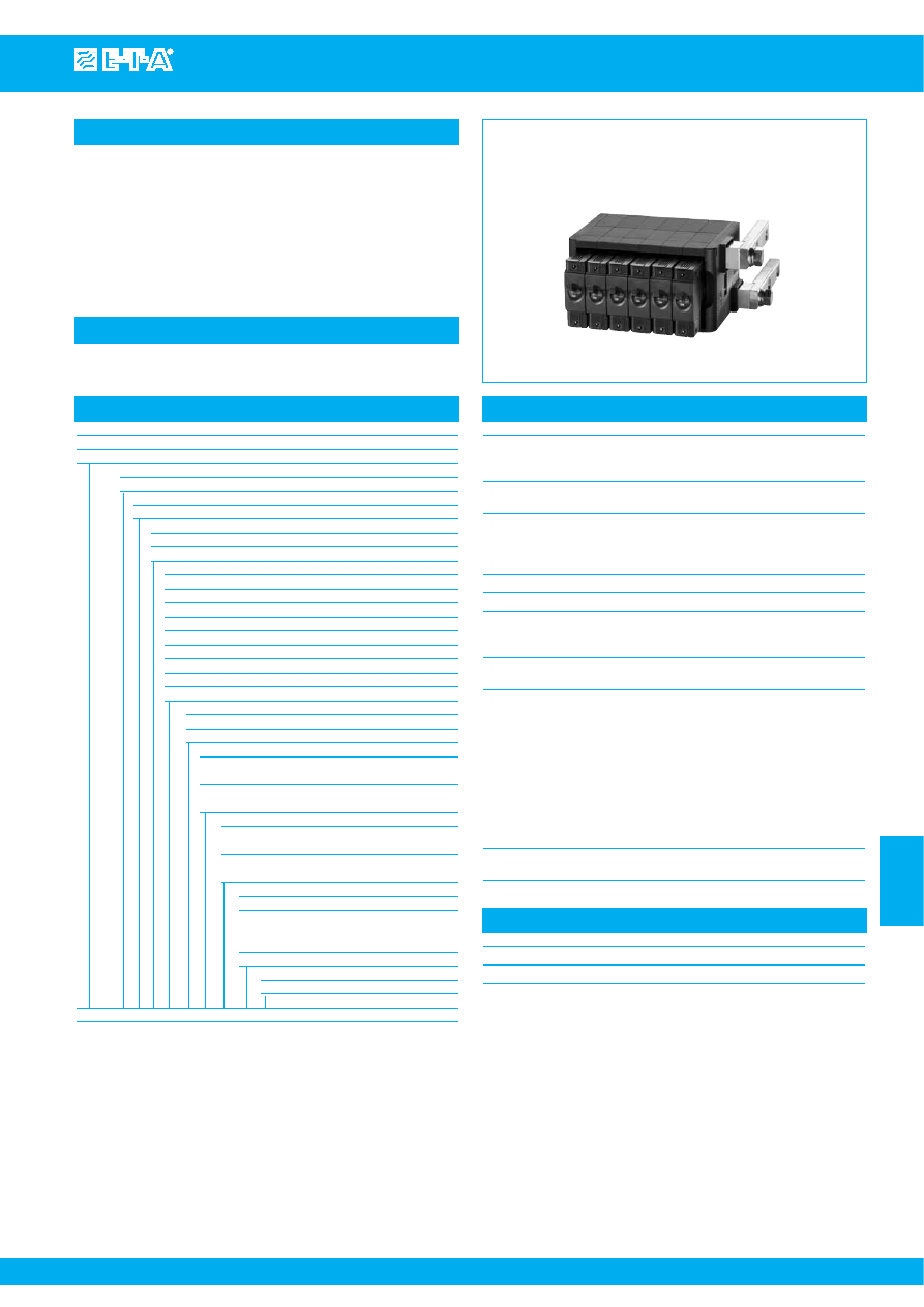
Distribution rail X8345-D01
www.e-t-a.com
Issue B
(220609)
7
- 73
7
Description
Typical applications
Distribution rail comprising series connected circuit breaker mounting
modules. Each module accommodates one magnetic or magnetic-
hydraulic circuit breaker type 8345 and the associated line and load
terminals on the rear side of the rail. Supply feed is either on the right
or left side with copper busbars. Trip indication of the circuit breakers
(group signalisation) is possible via two signal busbars.
Live parts in the plug-in area of the load terminals are protected against
brush contact (IP20). Replacement of circuit breakers (switched off) is
possible with power on.
Telecommunications, measuring and control systems
X8345-D01
Ordering information
Type No.
X8345
Distribution rail for circuit breaker type 8345
Version
D
rail
Identification number
01
module for 1 circuit breaker
Terminal (supply feed)
L
left side
R
right side
Power distribution modules
02
2 modules
03
3 modules
04
4 modules
05
5 modules
06
6 modules
07
7 modules
08
8 modules
09
9 modules
10
10 modules
Signalisation
0
without
1
group signalisation parallel connection
Terminal design of main circuitry
01
2xM12 hexagon head screws
for single-hole cable lug
03
2xM12 bent, hexagon head screws
for double-hole cable lug (300 A)
Terminal design of circuit breaker module
01
hexagon head screw M6
for single-hole cable lug
07
hexagon head screw M6
for single-hole cable lug, with barrier
Accessories
00
without
01
19”mounting bar and screws M5, for
module and frame, bulk shipped
(length = 431.4 mm)
02
mounting bar (length = 153.8 mm)
Marking
A
standard without marking
X8345 - D 01 L 05 - 1 - 01 01 -01 A
ordering example
Approvals
Authority
Voltage ratings
Current ratings
UL 60950
AC 277 V; DC 110 V
600 A
Technical data
Plug-in type circuit breakers
8345-.01.-W0..-D....
and auxiliary contact module
X8345-S01KW102-M
Voltage rating
DC 110 V
other ratings upon request
Max. load
125 A per position (total 160 A for
the two neighbouring positions
when a breaker rated > 80 A is used),
600 A per complete module
Ambient temperature
-30...+60 °C
Signalisation (N/C contact)
DC 80 V 0.5 A per position
Insulation co-ordination
Rated impulse
Pollution
(IEC 60664)
withstand voltage
degree
2.5 kV
2
Flame retardance
(IEC 60695, part 2-2)
self-extinguishing
Terminal design
supply feed
copper bar 20x25 mm
with M10 thread
current supply from the rear side
(left or right)
(tightening torque max. 15 Nm)
load
screw terminals M6
(tightening torque max. 7 Nm)
on rear side
signalisation
2 blade terminals
DIN 46244-A6.3x0.8mm
Mass
module
approx. 320 g
Courtesy of Steven Engineering, Inc.-230 Ryan Way, South San Francisco, CA 94080-6370-Main Office: (650) 588-9200-Outside Local Area: (800) 258-9200-www.stevenengineering.com
87PDS-html.html
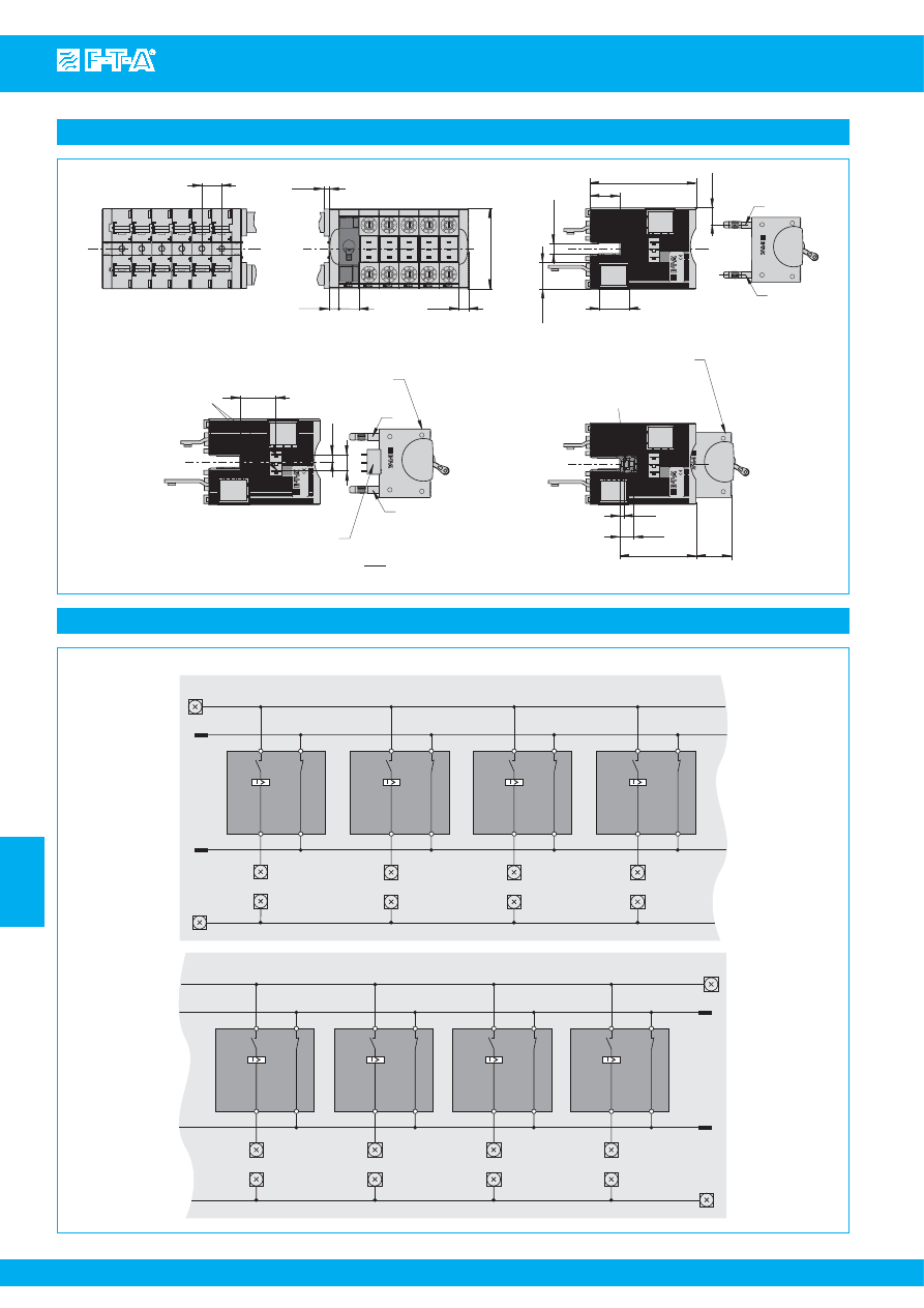
www.e-t-a.com
Issue B
(220609)
7
- 74
Distribution rail X8345-D01
7
Dimensions
20
10
20
5
10
80
29
16.55
GERMANY
LINE
LOAD
104
29.6
25.9
10.3
±
0.1
GERMANY
3.6
ob
s
erve in
s
tallation
di
s
tance
s
of circuit brea
k
er
hexnut
DIN EN I
S
O 4032 - M5 - 8 - AOP
tightening tor
q
ue for
mounting
s
crew M5 max. 3.0 Nm
14
75
33
S
ignali
s
ation 1
.787
.197
.394
.787
.394
3.15
4.09
1.14
.405
±
.004
1.02
1.16
.651
1.32
.269
.590
1.29
2.95
.551
.142
type: 8345-C01A-W0..-..
type: 8345-
S
01KW102M
33.5
blade terminal
s
IEC 61210 A6,3 x 0,8
with rever
s
e plug-in
protection
15
6.85
GERMANY
ob
s
erve in
s
tallation
di
s
tance
s
of circuit brea
k
er
LINE
LOAD
only for auxiliary contact
ver
s
ion
K
(
s
ymmetrical terminal
s
)
This is a metric design and millimeter dimensions take precedence ( mm )
inch
Internal connection diagrams
Module 1
S
ignali
s
ation
terminal
1
11
2
12
L(-)
L(-)
L(+)
Module 2
L(-)
L(+)
L(+)
Module 3
L(-)
L(+)
1
11
2
12
Module 4
L(-)
L(+)
1
11
2
12
1
11
2
12
Module 1
S
ignali
s
ation
terminal
L(-)
L(+)
L(-)
L(+)
1
11
2
12
L(-)
L(+)
1
11
2
12
Module 2
L(-)
L(+)
1
11
2
12
Module 3
L(-)
L(+)
1
11
2
12
Module 4
Courtesy of Steven Engineering, Inc.-230 Ryan Way, South San Francisco, CA 94080-6370-Main Office: (650) 588-9200-Outside Local Area: (800) 258-9200-www.stevenengineering.com
87PDS-html.html
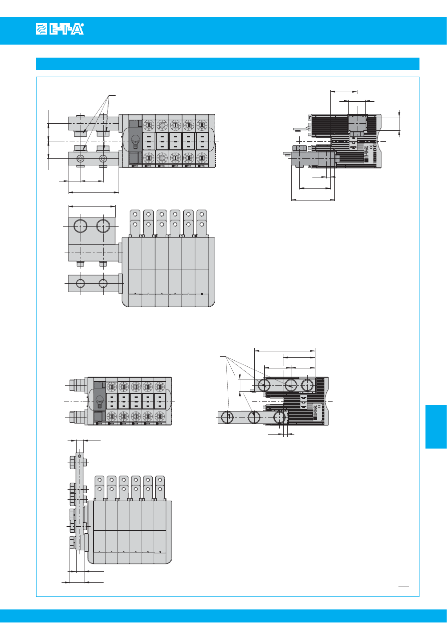
Distribution rail X8345-D01
www.e-t-a.com
Issue B
(220609)
7
- 75
7
hexagon head
s
crew DIN EN I
S
O 4017 - M12x25 - A4 and
wa
s
her DIN EN I
S
O 7092 - 12 - 200HV - A4 mounted
tightening tor
q
ue max 15.0 Nm
34
18
75.25
70
26.3
26.35
left-
s
ide
s
upply feed
right-
s
ide
s
upply feed al
s
o available
GERMANY
25
40
20
65
46
6
1.03
1.04
.709
1.34
2.96
2.75
1.57
.984
.787
.236
1.81
2.56
left-
s
ide
s
upply feed
right-
s
ide
s
upply feed al
s
o available
12
14.25
24.45
GERMANY
6.5
20
44.45
39.55
100
52.5
hexagon head
s
crew DIN EN I
S
O 4017 - M12x25 - A4 and
wa
s
her DIN EN I
S
O 7092 - 12 - 200HV - A4 mounted
tightening tor
q
ue max 15.0 Nm
.472
.561
.962
.787
.256
1.56
1.75
2.07
3.94
Terminal design
Main circuit 01
Main circuit 03
This is a metric design and millimeter dimensions take precedence ( mm )
inch
Courtesy of Steven Engineering, Inc.-230 Ryan Way, South San Francisco, CA 94080-6370-Main Office: (650) 588-9200-Outside Local Area: (800) 258-9200-www.stevenengineering.com
87PDS-html.html
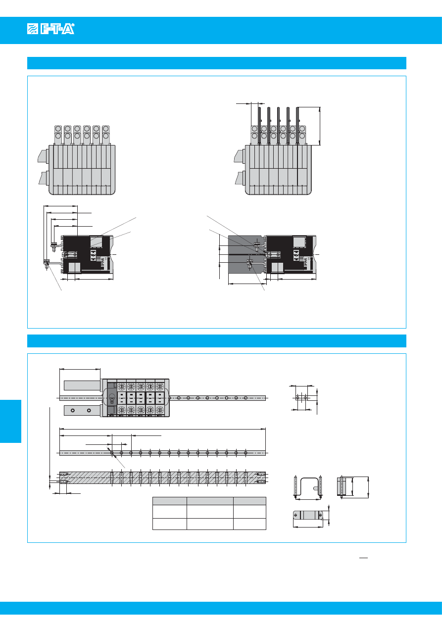
www.e-t-a.com
Issue B
(220609)
7
- 76
Distribution rail X8345-D01
7
All dimensions without tolerances are for reference only. In the interest of improved design,
performance and cost effectiveness the right to make changes in these specifications
without notice is reserved.Product markings may not be exactly as the ordering codes.
Errors and omissions excepted.
Accessories
left-
s
ide
s
upply feed
mounting bar
s
uitable for
left- and right-
s
ide
s
upply feed
M5
tightening tor
q
ue max. 7.0 Nm
Ø5.
5
15
110
20
±
0.1
A
85.25
part number
n = number of hole
s
A
Y 307 873 01
15
431.4
±
0.2
16.98
±
.007
Y 307 873 02
2
153.8
±
0.2
6.05
±
.007
(n x 20)
±
0.1
3.36
.590
Ø
.21
6
.787
±
.004
4.33
(n x .787)
±
.004
25
16
10
.394
.629
.984
52.3
36.8
44.1
61.8
18
Withdrawal tool
X 222 547 02
2.06
2.43
.709
1.45
1.73
This is a metric design and millimeter dimensions take precedence ( mm )
inch
Terminal design
15
80
GERMANY
16
79.5
hexagon head
s
crew
DIN EN I
S
O 4017 - M6x14 - A4
and wa
s
her
DIN EN I
S
O 7082 - 6 - 200HV - A4
mounted
tightening tor
q
ue max 7.0 Nm
70.2
63.7
55
48.5
GERMANY
16
79.5
wa
s
her
DIN EN I
S
O 7092 - 5 200HV - AOP
cylinder head
s
crew
DIN EN I
S
O 4762 - M5x35 - 8.8 - AOP
80
16.5
19.5
Circuit brea
k
er module 01
without barrier
Circuit brea
k
er module 07
with barrier
hexagon head
s
crew
DIN EN I
S
O 4017 - M6x14 - A4
and wa
s
her
DIN EN I
S
O 7082 - 6 - 200HV - A4
mounted
tightening tor
q
ue max 7.0 Nm
.590
3.15
.629
3.13
.629
3.13
3.15
.649
.768
1.91
2.16
2.51
2.76
Courtesy of Steven Engineering, Inc.-230 Ryan Way, South San Francisco, CA 94080-6370-Main Office: (650) 588-9200-Outside Local Area: (800) 258-9200-www.stevenengineering.com