background image

www.e-t-a.com

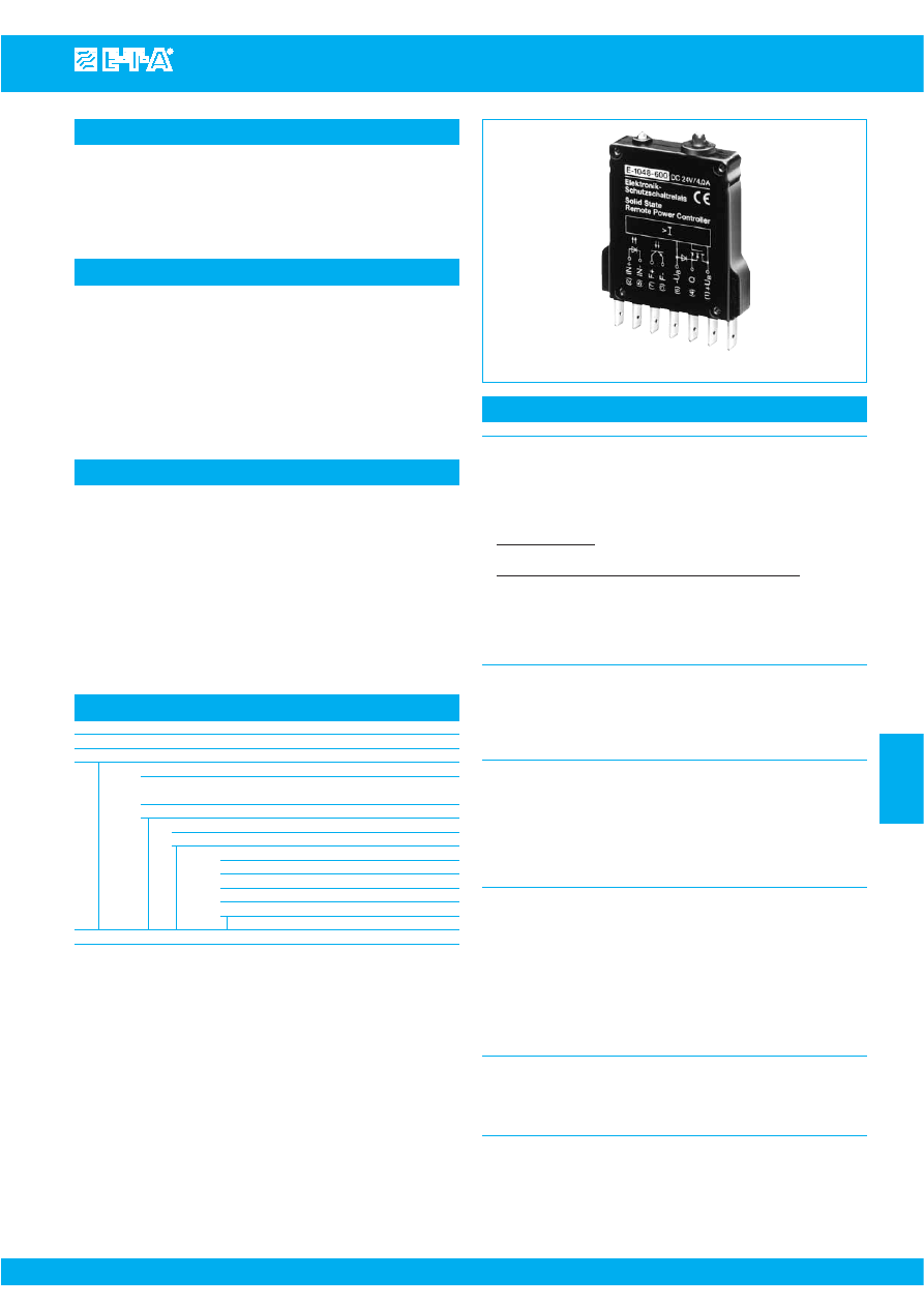
Solid State Remote Power Controller E-1048-60.

6

- 7

6

Issue B

(230709)

Description

Features

Technical data (T

ambient

= 25 °C; at U

N

)

Ordering information

E-1048-600

Load circuit

Voltage rating U

S

DC 24 V (18...36 V)

Current rating I

N

0.5 A; 1 A; 2 A; 4 A (other ratings to
special order)

Closed-circuit current I

Contr

typically 0.3 mA  

Min. load current 

Standard version:

I

load

> 1 mA

wire break indication in OFF condition
Option: wire break indication in OFF and ON condition

wire break ind. in OFF cond. R

load

> typ. 500 kΩ

wire break ind. in ON cond.

I

load

< typ. 130 mA (0.5/1 A unit)

I

load 

< typ. 500 mA (2/4 A unit)

Voltage drop U

DSmax

0.15 V; 0.3 V; 0.1 V; 0.2 V

Switch-on/switch-off time t

on

/t

off

typ. 300 µs/700 µs with resistive load

Overload disconnection 

approx. 1.5  (±0.3) x I

N

after approx.

100 ms Short-circuit current

max. 25 A (with 0.5 A and 1 A 

(self-limiting)

current ratings)
max. 75 A (with 2 A and 4 A current
ratings)

Short-circuit disconnection 

< 250 µs

Control circuit

Voltage rating 

DC 24 V 

Voltage controlled input U

E

DC 0 V < low level < 5 V
DC 8.5 V < high level < 36 V

Input current I

E

1...10 mA (8.5...36 V)

Max. switching frequency f

max

500 Hz

Reset time after short-
circuit/overload disconnection   1 ms

Fault indication output F 
(opto coupler)

Voltage rating range

DC 5...36 V

Voltage rating range          

DC 5...36 V

Max. load current             

100 mA (∆U < 2 V), with reverse 
polarity protection

Error indication

output F+ / F- conductive
- wire break in load circuit
- after short-circuit/overload 

disconnection

Parallel connection possible, as leakage current < 10 µA

General data

Temperature range

0 °C...+60 °C

Insulation voltage

2.5 kV

rms

(IEC 60664/VDE 0110)
Mass

28 g

Type No.
E-1048

Solid State Remote Power Controller

Version
600

wire break indication in OFF condition
(standard)  

602

with permanent wire break monitoring

Voltage rating
DC 24 V

DC 24 V (standard)

Current ratings
0.5 A
1.0 A
2.0 A
4.0 A

E-1048   -   600

DC24 V

1.0 A

ordering example 

Where remote control, wire break and LED indication is not required, please
contact us for a thermal-magnetic circuit breaker (e.g. types 2210, 3600,
3900).

The E-T-A Solid State Remote Power Controller (SSRPC) E-1048-60.
is an opto decoupled transistorised switching device providing both
protection and signalisation.
It may be used wherever safe switching and protection of resistive,
inductive or lamp loads in DC voltage systems is required.

Typical applications

Automation

- interface module providing inexpensive power amplification

at PLC outputs

- optimum protection of individual loads by monitoring the load

circuit

Protection and control of

- motors
- solenoids
- lamps

Optimum load protection. Available in current ratings of 0.5 A; 1 A;
2 A; 4 A. No derating required over entire temperature range!

Fast short-circuit limitation and disconnection

Time/current dependent overload disconnection (simulating 
thermal-magnetic CBE trip curve)

Remote control

Fault indication: LED and signal output for overload/short-circuit
signalisation, and wire break indication in the OFF condition 
(version -600) and in the OFF and ON condition (version -602)

Physically isolated fault indication.

Compact plug-in type

Courtesy of Steven Engineering, Inc.-230 Ryan Way, South San Francisco, CA 94080-6370-Main Office: (650) 588-9200-Outside Local Area: (800) 258-9200-www.stevenengineering.com

87SSPC-html.html
background image

10

20

1000

100

10

1

0.1

30

Trip time in m

s

I (A)

current limitation

I

N

20

40

1000

100

10

1

0.1

60

Trip time in m

s

I (A))

80

I

N

current limitation

0.5 A and 1 A 

2 A and 4 A 

www.e-t-a.com

Solid State Remote Power Controller E 1048-60.

Issue B

(230709)

- 8

6      

Technical description

Status indication

Dimensions

Connection diagram

Typical time/current characteristics (TA = 25 °C) 

7

3

2

5

control and
monitoring
electronic

s

F +

F -

control circuit

red

green

load

Q

-U

S

4

6

1

+U

S

E-1048-600

IN+

IN-

fault output

Fault indication output
       (opto coupler)

LED

green    red


non-conductive, no duty

conductive, normal duty

overload or 

s

hort circuit at the output

(and with option wire brea

k

 indication in

ON condition)

wire brea

k

, in the OFF po

s

ition

S

tatu

s

 indication

At the appropriate input level (>8.5 V), the opto decoupled input in the 
SSRPC will switch on a power transistor to connect the load to the
plus pole of the load circuit supply (U

S

).

The transistor will switch off when

- the control voltage (U

E

) is removed

- there is a short-circuit/overload in the load circuit.

Status indication is provided by two LEDs (red and green).
Thermal-magnetic style overload protection occurs at approx.
1.5  times rated current. See time/current characteristic curves.
The SSRPC is fitted with blade terminals DIN 46244-A6.3-0.8 and is
suitable for plug-in mounting with various E-T-A sockets (see
Accessories).

Control circuit
ON condition:

If a voltage higher than 8.5 V is applied to the input terminals (-IN,
+IN), the control current (from the PLC) will flow through the opto
coupler. The output transistor will be conductive, the green LED will
be lighted.

OFF condition:

A control voltage lower than 5 V will switch the output transistor off.

Load circuit

The load circuit switches depending on the control signal (“0” or “1”).
It is electronically monitored for faults. In the event of a  short-circuit
the circuit is disconnected after max. 250 µs whilst upon inadmissible
overload it is disconnected according to the time/current curves
shown.

Fault indication output

The fault indication circuit (F+, F-) is opto decoupled from the load and
control circuit.
In the OFF condition, this circuit will provide wire break indication,
with the transistor output being open.
In the ON condition, the circuit will provide short-circuit and overload
monitoring and indication.
Visual fault indication by red LED.

50

1

4

6

3

7

5

2

56

66

11.5

LED red 

LED green

2.21

2.60

.453

1.97

This is a metric design and millimeter dimensions take precedence (

mm 

)

inch

Courtesy of Steven Engineering, Inc.-230 Ryan Way, South San Francisco, CA 94080-6370-Main Office: (650) 588-9200-Outside Local Area: (800) 258-9200-www.stevenengineering.com

87SSPC-html.html
background image

www.e-t-a.com

Solid State Remote Power Controller E 1048-60.

6

- 9

6

Issue B

(230709)

Functional diagrams  E-1048-60. 

wire brea

k

Error indication

opto coupler

LED red

LED green

IN

U

S


Ver

s

ion

output

Error

0

1

0

1

Operating voltage i

s

 applied

E-1048-600

wire brea

k

age monitoring only in OFF condition

Functional diagram E-1048-60.

wire brea

k

 indication

wire brea

k

Error indication

opto coupler

LED red

LED green

IN

U

S


Ver

s

ion

output

Error

0

1

0

1

Operating voltage i

s

 applied

E-1048-602

wire brea

k

age monitoring in ON and OFF condition

0

1

*

Fault indication i

s

 re

s

et when control coltage i

s


s

witched off,

whether the failure i

s


s

till active or not.

IN = input 

s

et / output = 

s

witched through

LED light

s

overload /

s

hort-circuit

E-1048-600/-602

without fault 

s

torage

Error indication

n

opto coupler

LED red

LED green

Ver

s

ion

output

Error

Functional diagram E-1048-60.

overload /

s

hort-circuit indication

IN

U

S


0

1

0

1

Operating voltage i

s

 applied

*

Courtesy of Steven Engineering, Inc.-230 Ryan Way, South San Francisco, CA 94080-6370-Main Office: (650) 588-9200-Outside Local Area: (800) 258-9200-www.stevenengineering.com

87SSPC-html.html
background image

www.e-t-a.com

E-1048-60. - 

Accessories for E-1048-60.

Issue B

(230709)

- 10

6      

Accessories for E 1048-60.

9

5.4

125

17

.669

.213

.354

4.92

2

cylinder head 

s

crew

M4x4 I

S

O1207

nic

k

el plated  

wa

s

her

A 4.3 DIN 125
nic

k

el plated

female
connector

Phoenix terminal AKG 35
max.cro

ss


s

ection 35 mm

2

 (AWG 2)

M4

10

12.8

7

154.8

pre

ss

ure-relief joint

(1.1 mm (.043 in.)
thic

k

 con

s

triction)

Cu rail, tin-plated

.394

.079

.504

.276

6.09

blade terminal DIN 46244 part 2
C profile (2xA2.8-0.8) (QC 2x.110) 

depth
10 mm
(.394 in.)

adapter X20040901

s

ymmetrical rail

EN 50022-35x7.5

polarization rece

ss

G-profile
EN 50035-G32

8.5

25.8

6.5

80

33.3

10

5

1.4

12.5

41.3

45.8

retaining clip

1

11

23

2(

k

)

12

24

2(i)

1

11

23

2(

k

)

12

24

2(i)

1

.80

1.63

.335

.256

1.02

3.15

1.31

.055

.197

.492

.394

polarized blade terminal
DIN 46244-A6.3-0.8 (QC .250)

s

lot for fitting label

s

 from

Phoenix, Weidmüller

10

6.3

-P10

10

2.8

-P70

.394

.248

.394

.110

S

ingle mounting 

s

ocket

s

(with adapter)

(up to 16 A max. load)

17-P10-

S

i

17-P10-

S

i-20025

17-P70-

S

i

17-P70-

S

i-20025

(retaining clip Y 300 581 11 available on re

q

ue

s

t)

Bu

s

bar (10-way) 

(

s

upplied a

s

 a complete pac

k

age)

for type 17 

s

ocket

(for max. 100 A continuou

s

 load),

more po

s

ition

s

 available on re

q

ue

s

t

X 211 157 01 

with terminal

X 211 157 02 

without terminal


In

s

ulating 

s

leeving for bu

s

bar (10-way)

Y 303 824 01 

Connector bu

s

 link

s

 -P10

X 210 588 01

/ 1.5 mm

2

m , (AWG 16), brown  (up to 13 A max. load)  


X 210 588 02

/ 2.5 mm

2, 

(AWG 14), blac

k

 (up to 20 A max. load)

X 210 588 03

/ 2.5 mm

2,

  (AWG 14),  red (up to 20 A max. load)     

X 210 588 04

/ 2.5 mm

2

, (AWG 14), blau  (up to 20 A max. load)

2-way mounting 

s

ocket

23-P10-

S

i

(retaining clip Y 300 581 03 available on re

q

ue

s

t)

6-way mounting 

s

ocket

63-P10-

S

i

2 mounting clip

s

Y 300 504 02

(2 pc

s

 needed per unit)

In

s

tallation drawing with

mounting clip

s

 Y 300 504 02

6 x 6.8 = 40.8

6 x .268 = 1.61

  retaining

clip

22.2

21

10

2

             max. 30

6

3.5

6.8

7.4

4.4

64

50

57.4

25

12.5

4.4

7.4

12.5

6.25

64

50

75

12.5

polarized blade terminal

s

DIN 46244-A6.3-0.8 (QC .250)

polarized
rece

ss

.173

.291

2.52

1.97

2.26

.492

.984

.291

.173

.394

.827

.874

.079

.236

               max. 1.18

2.52

.492

1.97

2.95

50

1

.97

2

.26

57.4

.268

.138

.492

.246

~70

100 

q

uic

k

-connect tab

s

 6.3 (.250)

DIN 46247 tinned bra

ss

,

in

s

ulated   


~2.76

1.9

1

0.5

2

7.5

12.5

7.3

8

M4

8.5

60.4

50

16.5

20

2

.075

.039

.295

.079

.020

.079

.335

.287

.315

.492

.650

.787

2.38

1.97

All dimensions without tolerances are for reference only. In the interest of improved design,
performance and cost effectiveness the right to make changes in these specifications without
notice is reserved. Product markings may not be exactly as the ordering codes. Errors and
omissions excepted.

This is a metric design and millimeter dimensions take precedence (

mm 

)

inch

Pin selection 17-P10-Si fitted with E-1048-60.

E-1048-60.  17-P10-

S

i

IN +

(2)

(2)

[2(

k

)]

IN -

(5)

(5)

[12]

F +

(7)

(7)

[24]

F -

(3)

(3)

[2(i)]

-U

B

(6)

(6)

[23]

Q

(4)

(4)

[11]

+U

B

(1)

(1)

[1]

Courtesy of Steven Engineering, Inc.-230 Ryan Way, South San Francisco, CA 94080-6370-Main Office: (650) 588-9200-Outside Local Area: (800) 258-9200-www.stevenengineering.com

87SSPC-html.html
background image

www.e-t-a.com

Solid State Remote Power Controller E-1048-7..

Issue B

(230709)

6

- 11

6

Description

Features

Ordering information

E-1048-7..

The E-T-A Solid State Remote Power Controller E-1048-7.. is a
transistorised switching device providing both protection and
signalisation. It is suitable for all applications where the capabilities of
the existing PLC outputs are not sufficient or where no protection
against overload and short circuit or wire breakage monitoring of
connected loads is provided. The use of a costly, high-capacity output
card becomes superfluous when only one or two powerful outputs are
necessary.

Using the SSRPC E-1048-7.. in combination with the module 17plus
creates a new, very flexible system capable of being subsequently
changed or extended. Busbars, pre-wired signal contacts and spring-
loaded terminals reduce installation times considerably (see
accessories).

Typical applications

Automation

- interface module providing inexpensive power amplification

at PLC outputs

- optimum protection of individual loads by monitoring the load

circuit

Protection and control of

- motors
- solenoids
- lamps

Optimum load protection. Available in current ratings of 0.5 A; 
1 A; 2 A; 4 A; 5 A. No derating required over entire temperature
range!

Fast short-circuit limitation and disconnection

Time/current dependent overload disconnection (simulating 
thermal-magnetic CBE trip curve)

Remote control

Fault indication: LED and signal output for overload/short-circuit
signalisation, and wire break indication in the OFF condition 
(version -700 and -710) and in the OFF and ON condition 
(version -702 and -712)

Fault storage: version -710; -712 and -713

Physically isolated fault indication

Compact plug-in type

Plug-in design for use with power distribution system module 17plus

Integral pre-wiring of common supply and signal contacts

Type No.
E-1048

SSRPC for PLC outputs

Version
700

wire break indication in OFF condition 
(standard)  

710

wire break indication in OFF condition and
fault storage

702

permanent wire break indication

712

permanent wire break indication and fault storage

703

without wire break indication

713

without wire break indication with fault storage

Voltage rating
DC24 V

DC 24 V (standard)

Current ratings
0.5 A
1.0 A
2.0 A
4.0 A
5.0 A

E-1048 - 700

DC24 V

1.0 A   

ordering example 

Load circuit

Voltage rating U

DC 24 V (18...36 V)

Current rating I

N  

0.5 A; 1 A; 2 A; 4 A; 5 A 
(other ratings to special order)

Closed-circuit current I

Contr

typically 0.3 mA 

Min. load current             

Version -700/-710:

wire break indication in OFF condition

Optional: wire break indication in OFF and ON condition

wire break ind. in OFF cond. R

load

typically 500 kΩ

wire break ind. in ON cond.   I

load

< typ. 130 mA (0.5/1 A unit)

I

load

< typ. 500 mA (2/4/5 A unit) 

Voltage drop U

DSmax 

0.15 V; 0.3 V; 0.1 V; 0.2 V; 0.3 V

Switch-on/switch-off time t

on

/t

off

typ. 300 µs/700 µs with resistive 
load

Overload disconnection        

approx. 1.5 (± 0.3) x I

N

after 

approx. 100 ms

Short-circuit current         

max. 25 A (with 0.5 A and 1 A 

(self-limiting)

current ratings)
max. 75 A (with 2 A/4 A/5 A 
current ratings)

Short-circuit disconnection   

< 250 µs

Control input

Control level

between IN+ and GND

Voltage rating 

DC 24 V

Voltage controlled input U

E

DC 0 V < low level < 5 V
DC 8.5 V < high level < 36 V

Input current I

E

1...10 mA (8.5...36 V)

Max. switching frequency f

max

1 kHz

Reset time after short-circuit/
overload disconnection   

1 ms

Fault indication output F 
relay contact

max. switching voltage

DC 150 V

AC 125 V

max. interrupting capacity

DC 30 W

AC 60 W

limiting continuous current

1 A

General data

Temperature range

0 °C...+60 °C

Insulation voltage

DC 500 V > 10 MΩ

(IEC 60664/VDE 0110)
Mass

28 g

Technical data (T

ambient

= 25 °C; at U

N

Courtesy of Steven Engineering, Inc.-230 Ryan Way, South San Francisco, CA 94080-6370-Main Office: (650) 588-9200-Outside Local Area: (800) 258-9200-www.stevenengineering.com

87SSPC-html.html
background image

www.e-t-a.com

Solid State Remote Power Controller 1048-7..

Issue B

(230709)

6

- 12

6      

Technical description

Dimensions

50

1

4

6

3

7

5

2

56

66

11.5

LED red

LED yellow

2.21

2.60

.453

1.97

Connection diagram

Typical time/current characteristics (T

A

= 25 °C)

7

4

6

control and
monitoring
electronic

s

fault

indication

circuit

F

red

yellow

LOAD

G

ND

1

5

2

LINE +

E-1048-7..

IN+

10

20

1000

100

10

1

0.1

30

Trip time in m

s

I (A)

current limitation

20

40

1000

100

10

1

0.1

60

Trip time in m

s

I (A)

80

I

N

I

N

current limitation

0.5 A and 1 A

2 A and 4 A

At the correct input voltage (> 8.5 V), the SSRPC will switch on a power
transistor to connect the load to the plus pole of the load circuit
supply (U

S

).

The transistor will switch off when

- the control voltage (U

E

) is removed

- there is a short-circuit/overload in the load circuit.

Status indication is provided by two LEDs (red and yellow).
Simulated thermal-magnetic overload protection occurs at approx.
1.5 times rated current. See time/current characteristic curves.
The SSRPC is fitted with blade terminals DIN 46244-A6.3-0.8 and is
suitable for plug-in mounting with various E-T-A sockets or 

module

17plus

(see Accessories).

Control circuit
ON condition:

If a voltage higher than 8.5 V is applied to the input terminals (+I

N

against GND), the control current (from the PLC) will flow through the
opto coupler. The output transistor will be conductive, status
indication by yellow LED.

OFF condition:

A control voltage lower than 5 V will switch the output transistor off.

Load circuit

The load circuit switches depending on the control signal (“0” or “1”).
It is electronically monitored for faults. In the event of a  short-circuit
the circuit is disconnected after max. 250 µs whilst upon inadmissible
overload it is disconnected according to the time/current curves
shown.

Fault indication output F

The fault indication circuit is physically isolated from the load and
control circuits via a relay.
In the OFF condition, this circuit (with closed contact) will provide wire
break indication, with the transistor output being open.
The versions with fault storage (-702/-712 and -713) store the fault
signal until the control voltage is re-applied.
Visual fault indication by red LED.

This is a metric design and millimeter dimensions take precedence (

mm 

)

inch

Courtesy of Steven Engineering, Inc.-230 Ryan Way, South San Francisco, CA 94080-6370-Main Office: (650) 588-9200-Outside Local Area: (800) 258-9200-www.stevenengineering.com

87SSPC-html.html
background image

www.e-t-a.com

Solid State Remote Power Controller E-1048-7..

Issue B

(230709)

6

- 13

6

Functional diagrams E-1048-7..

Error indication

overload /

s

hort-circuit

overload /

s

hort-circuit

E-1048-7x0

with fault 

s

torage

E-1048-7x0

without fault 

s

torage

relay

LED red

LED yellow

Ver

s

ion

output

Error

Operating voltage i

s

 applied

Error indication

relay

LED red

LED yellow

Ver

s

ion

output

Error

IN = input 

s

et / output = 

s

witched through

LED light

s

Functional diagram E-1048-7..

overload /

s

hort-circuit indication

IN

U

S


0

1

0

1

IN

U

S


0

1

0

1

0

1

Operating voltage i

s

 applied

wire brea

k

Error indication

relay

LED red

LED yellow

IN

U

S


Ver

s

ion

output

Error

0

1

0

1

Operating voltage i

s

 applied

E-1048-7x0

wire brea

k

age monitoring in ON and OFF condition

wire brea

k

Error indication

relay

LED red

LED yellow

IN

U

S


Ver

s

ion

output

Error

0

1

0

1

Operating voltage i

s

 applied

E-1048-7x0

wire brea

k

age monitoring only in OFF condition

Functional diagram E-1048-7..

wire brea

k

 indication

Courtesy of Steven Engineering, Inc.-230 Ryan Way, South San Francisco, CA 94080-6370-Main Office: (650) 588-9200-Outside Local Area: (800) 258-9200-www.stevenengineering.com

87SSPC-html.html
background image

Issue B

(230709)

6

- 14

6      

2

>i

1

1

G

ND

11

14

bu

s

bar fitted

SS

RPC

E-1048-700

jumper

1

2

>i

>i

LINE + IN +

13

LINE + IN +

13

13

LOAD

12

12

LINE + IN +

13

14

G

ND

LOAD

14

G

ND

LOAD

14

load 1

load 2

11

2

2

load n

12

............

module 17plu

s

1

main circuit minu

s

 U

S

power 

s

upply

for PLC

PLC

power 

s

upply

 for load

I / O

s

ignali

s

ation circuit

control circuit

............

.......

+

+

main circuit
plu

s

 U

S

............

............

12

S

olid 

S

tate Remote Power Controller E-1048-700

with Module 17plu

s

1

2

E-1048-7..

G

ND

LINE  +

LOAD

IN +

>i

common power

s

upply

DC 24 V

PLC

Out

In

12

13

11

14

+

load

I/O

DC 24 V

+

-

Common power 

s

upply for load, PLC I/O and 

s

ignal loop

load

E-1048-7..

IN +

power 

s

upply

DC 24 V

PLC

Out

In

12

13

+

I/O

DC 24 V

+

-

S

eparate power 

s

upply for load, PLC I/O and 

s

ignal loop

1

2

G

ND

LINE +

LOAD

>i

11

14

power 

s

upply

for PLC

DC 24 V

+

alternatively

Cha

ss

i

s

 earth

connection directly
between the two
power 

s

upplie

s!

Caution:

If there i

s

 no firm cha

ss

i

s

 earth connection when u

s

ing 

s

everal 

s

eparate

power 

s

upplie

s

, the connected fault indication loop may lead to intermittent

operation of the 

SS

RPC and re

s

ultant operational hazard

s

.

Connection diagram

Wiring diagram 

Wiring diagram

E-1048-7.. -

Application examples

www.e-t-a.com

Courtesy of Steven Engineering, Inc.-230 Ryan Way, South San Francisco, CA 94080-6370-Main Office: (650) 588-9200-Outside Local Area: (800) 258-9200-www.stevenengineering.com

87SSPC-html.html
background image

Accessories for E-1048-7..

Description

Ordering information

17PLUS-Q02-00

Module 17plus, centre piece, two-way

17PLUS-QA0-LR

one each left- and right-side terminal block 
for supply feed from the side by means of 
screw terminal, connection of signalisation 
etc.

Technical data

Module 17plus is a power distribution system for use with SSRPC
E-1048-7.. for PLC outputs.
Each module  accommodates two SSRPCs with an individual housing
width of only 12.5 mm and fits onto all industry standard mounting
rails. The two-way modules can be interconnected to provide as
many ways as required with a terminal block fitted at each end for
connection of signalling circuits. A distribution busbar can be fitted
on the supply side of the modules (positive pole) though each pole of
multipole circuit breakers must be individually connected. Electrical
connections are by means of spring-loaded terminals. The reference
potential for the electronic amplifiers (GND pin 11) is also looped
through and to the terminals connected at the sides. Control of the
amplifiers (IN+), referenced to GND, is per channel via the separate
terminal 12 beside the LOAD terminal. The SSRPC has an integral signal
contact (break contact) used for group signalisation. Therefore the
terminals of all break contacts are connected in series in the module
17plus and are connected to the terminal blocks via two terminals
(13, 14). The module is designed to accommodate a probe for series
connection continuity tests. When multipole circuit breakers are fitted
auxiliary contacts are required for each pole. Individual circuit breaker
signalisation is achieved through use of the break contacts (which
close in the event of failure) connected in parallel by means of
terminals on each module. The signalling circuitry between modules
and the internal prewiring for the potential is automatically connected
when the modules are linked together.
Meets the requirements of UL60950.

Connection

Spring-loaded terminals for solid 
conductors and stranded cables with 
and without wire end ferrules. Please 
use appropriate screw driver size (SD)
for removing the spring loaded terminals.

LINE feed (1):

spring-loaded terminals for 
1.5-10 mm

2

, (AWG 20 - AWG 10) 

SD 2 (0.8x4.0)

LOAD output (2):

spring-loaded terminals for 
0.25-4 mm

2

, (AWG 24 - AWG 12)

SD 1 (0.6x3.5)

Reference potential GND and signalisation 
terminals (11, 13, 14):

spring-loaded terminals for 
0.25-2.5 mm

2

, (AWG 24 - AWG 14)

SD 1 (0.6x3.5)

control IN+
terminal (12)

spring-loaded terminal for 
0.25-1.5 mm

2

, (AWG 24 - AWG 16)

SD 0 (0.4x2.5)

Test probe for testing the group signal for line interruption: ≤ 2 mm ø 

Voltage rating
(without SSRPC):

AC 433 V; DC 65 V

Current rating
(without SSRPC)

LINE feed (1)

50 A

LOAD output (2)

25 A

Reference potential GND (11)

10 A

Control IN+ (12)

1 A

Group signal /(13-14)

1 A

Internal resistance values
(without SSRPC)

LINE-LOAD (1-2)

≤ 5 mΩ

Group signal (13-14) 

≤ 8 mΩ/per pole
+ 5 mΩ for each additional 
module

Busbar for power distribution

insulated busbar
(blue or red):

I

max

32 A

non-insulated busbar:

I

max

50 A

(The non-insulated busbar, too, meets brush contact safety 
standards when fitted.)

Dielectric strength

between main circuits (without busbar): 1,500 V
main circuit to auxiliary circuit:

1,500 V

between auxiliary circuits:

1,500 V

Mass: Module 17plus (centre piece)

approx. 85 g

terminal blocks (pair)

approx. 30 g

www.e-t-a.com

E-1048-7.. - 

Accessories Module 17plus

Issue B

(230709)

6

- 15

6

17plus

Courtesy of Steven Engineering, Inc.-230 Ryan Way, South San Francisco, CA 94080-6370-Main Office: (650) 588-9200-Outside Local Area: (800) 258-9200-www.stevenengineering.com

87SSPC-html.html
background image

www.e-t-a.com

E-1048-7.. - 

Accessories: Module 17plus

Issue B

(230709)

6

- 16

6      

Dimensions

module

right-

s

ide terminal bloc

k

left-

s

ide terminal bloc

k

R

1

4

6

3

7

5

2

s

lot for bu

s

bar

1.67

1.85

2.48

4.53

2.24

.984

.236

.984

1.46

2.60

s

lot for fitting label

s

 from

Phoenix, Weidmüller, Wieland

s

ymmetrical rail

EN 50022-35x7.5

63

115

42.5

66

57

25

11

14

17 plu

s

11

14

2

12

12

1 Line

1 Line

2

G

-profile

EN 50035-

G

32

47

6

25

37

R

1 4

6

3

7

5 2

In

s

tallation:

1 Clip 

module

s

 onto DIN rail

s

.

2 Pu

s

h module

s

 together (

s

ide-by-

s

ide).

S

nap on right-

s

ide and left-

s

ide terminal bloc

ks

.

4 Cut 

bu

s

bar to re

q

uired length and fit on 

s

upply 

s

ide of the module

s

.

5  Connect line feed with 

s

pring-loaded terminal

s

.

6 Plug 

in 

SS

RPC E-1048-7...

14

11

5

3

1

2

4

6

LO

AD

LO

AD

2

12

2

12

 L

IN

E

 L

IN

E

LO

AD

LO

AD

2

12

2

12

 L

IN

E

 L

IN

E

G

ERMA

NY

Modul 1

7 plu

s

13

11

3

11

13

11

14

2

12

12

1 Line 1 Line

2

11

11

1 Line 1 Line

Connection and di

s

connection of cable

s

 with 

s

crew driver

13

14

2

12

12

2

S

D 2

S

D 1

S

D 1

S

D 0

Installation example

13, 14

terminal

s

 for group 

s

ignali

s

ation

11

reference potential 

G

ND

12

control IN+

right-

s

ide terminal bloc

k

2

LOAD

2

LOAD

12

IN +

>i

1 LINE +

1 LINE +

11

G

ND

13

11

G

ND

14

s

olid 

s

tate remote

power controller
E-1048-700

1 LINE +

1 LINE +

te

s

t

terminal

2

LOAD

12

IN +

>i

12

IN +

>i

2

LOAD

12

IN +

module 1

module 2

bu

s

bar

left-

s

ide

terminal bloc

k

jumper

s

ide

bu

s

bar

Connection diagram

Pin selection, fitted with E-1048-7..  

E-1048-7..

 Module

17plu

s

LINE + (2)

(1)

G

ND

(5)

(11)

F 7

(7)

(13)


F 6

(6)

(14)

IN+

(4)

(12)

LOAD

(1)

(2)

This is a metric design and millimeter dimensions take precedence (

mm 

)

inch

Courtesy of Steven Engineering, Inc.-230 Ryan Way, South San Francisco, CA 94080-6370-Main Office: (650) 588-9200-Outside Local Area: (800) 258-9200-www.stevenengineering.com

87SSPC-html.html
background image

Accessories

Bu

s

bar 50 A

Y 307 016 11

 non-in

s

ulated, 500 mm/19.68 in.

Bu

s

bar 50 A

Y 307 016 01

 non-in

s

ulated, 500 mm/19.68 in.

Bu

s

bar 32 A

X 222 005 01

 blue in

s

ulation, 500 mm/19.68 in.

X 222 005 02

 red in

s

ulation, 500 mm/19.68 in.

X 222 005 03

 grey in

s

ulation, 500 mm/19.68 in.

Jumper
X 222 066 01

End bracket
X 222 004 01

S

crew 

terminal for bu

s

bar


X 211 156 01 

non in

s

ulated


blade terminal

s

DIN 46244-A6.3-0.8
(

Q

C .250)

51

10

terminal

s

 1+2

no connection

terminal

s

 6+7

bridged

11.5

50

2.01

.394

1.96

.453

S

ignalbrücke

S

ignal loop

X22206601

1

4

6

3

7

5

2

www.e-t-a.com

E-1048-7.. - 

Accessories: Module 17plus

Issue B

(230709)

6

- 17

6

This is a metric design and millimeter dimensions take precedence (

mm 

)

inch

mounting dimen

s

ion

s

60

Retaining clip for 

SS

RPC E-1048-7..

recommended for fitting the device

s

Y 300 581 11

30

ø1

5.5

44.4

45

.039

1.18

.217

2.36

1.74

1.77

Label

s

mar

k

ing area 6 x 10 mm

(pac

k

ing unit 10 pc

s

 = 1 

s

trip)

part. no. Y 307 942 61

Courtesy of Steven Engineering, Inc.-230 Ryan Way, South San Francisco, CA 94080-6370-Main Office: (650) 588-9200-Outside Local Area: (800) 258-9200-www.stevenengineering.com

87SSPC-html.html
background image

www.e-t-a.com

E-1048-7.. - 

Accessories for E-1048-7..

Issue B

(230709)

6

- 18

6      

Pin selection 17-P10-Si, fitted with E-1048-7..

Accessories for E-1048-7..

9

5.4

125

17

.669

.213

.354

4.92

2

cylinder head 

s

crew

M4x4 I

S

O1207

nic

k

el plated  

wa

s

her

A 4.3 DIN 125
nic

k

el plated

female
connector

Phoenix terminal AK

G

 35

max.cro

ss


s

ection 35 mm

2

 (AW

G

 2)

M4

10

12.8

7

154.8

pre

ss

ure-relief joint

(1.1 mm (.043 in.)
thic

k

 con

s

triction)

Cu rail, tin-plated

.394

.079

.504

.276

6.09

blade terminal DIN 46244 part 2
C profile (2xA2.8-0.8) (

Q

C 2x.110) 

depth
10 mm
(.394 in.)

adapter X20040901

s

ymmetrical rail

EN 50022-35x7.5

polarization rece

ss

G

-profile

EN 50035-

G

32

8.5

25.8

6.5

80

33.3

10

5

1.4

12.5

41.3

45.8

retaining clip

1

11

23

2(

k

)

12

24

2(i)

1

11

23

2(

k

)

12

24

2(i)

1

.80

1.63

.335

.256

1.02

3.15

1.31

.055

.197

.492

.394

polarized blade terminal
DIN 46244-A6.3-0.8 (

Q

C .250)

s

lot for fitting label

s

 from

Phoenix, Weidmüller

10

6.3

-P10

10

2.8

-P70

.394

.248

.394

.110

S

ingle mounting 

s

ocket

s

(with adapter)

(up to 16 A max. load)

17-P10-

S

i

17-P10-

S

i-20025

17-P70-

S

i

17-P70-

S

i-20025

(retaining clip Y 300 581 11 available on re

q

ue

s

t)

Bu

s

bar (10-way) 

(

s

upplied a

s

 a complete pac

k

age)

for type 17 

s

ocket

(for max. 100 A continuou

s

 load),

more po

s

ition

s

 available on re

q

ue

s

t

X 211 157 01 

with terminal

X 211 157 02 

without terminal


In

s

ulating 

s

leeving for bu

s

bar (10-way)

Y 303 824 01 

Connector bu

s

 link

s

 -P10

X 210 588 01

/ 1.5 mm

2

m , (AW

G

 16), brown  (up to 13 A max. load)  


X 210 588 02

/ 2.5 mm

2, 

(AW

G

 14), blac

k

 (up to 20 A max. load)

X 210 588 03

/ 2.5 mm

2,

  (AW

G

 14),  red (up to 20 A max. load)     

X 210 588 04

/ 2.5 mm

2

, (AW

G

 14), blau  (up to 20 A max. load)

2-way mounting 

s

ocket

23-P10-

S

i

(retaining clip Y 300 581 03 available on re

q

ue

s

t)

6-way mounting 

s

ocket

63-P10-

S

i

2 mounting clip

s

Y 300 504 02

(2 pc

s

 needed per unit)

In

s

tallation drawing with

mounting clip

s

 Y 300 504 02

6 x 6.8 = 40.8

6 x .268 = 1.61

  retaining

clip

22.2

21

10

2

             max. 30

6

3.5

6.8

7.4

4.4

64

50

57.4

25

12.5

4.4

7.4

12.5

6.25

64

50

75

12.5

polarized blade terminal

s

DIN 46244-A6.3-0.8 (

Q

C .250)

polarized
rece

ss

.173

.291

2.52

1.97

2.26

.492

.984

.291

.173

.394

.827

.874

.079

.236

               max. 1.18

2.52

.492

1.97

2.95

50

1

.97

2

.26

57.4

.268

.138

.492

.246

~70

100 

q

uic

k

-connect tab

s

 6.3 (.250)

DIN 46247 tinned bra

ss

,

in

s

ulated   


~2.76

1.9

1

0.5

2

7.5

12.5

7.3

8

M4

8.5

60.4

50

16.5

20

2

.075

.039

.295

.079

.020

.079

.335

.287

.315

.492

.650

.787

2.38

1.97

E-1048-7..  17-P10-

S

i

LINE + (2)

(2)

[2(

k

)]

G

ND

(5)

(5)

[12]

F 7

(7)

(7)

[24]

 (3)

[2(i)]

F 6

(6)

(6)

[23]

IN+

(4)

(4)

[11]

LOAD

(1)

(1)

[1]

All dimensions without tolerances are for reference only. In the interest of improved design,
performance and cost effectiveness the right to make changes in these specifications without
notice is reserved. Product markings may not be exactly as the ordering codes. Errors and
omissions excepted.

This is a metric design and millimeter dimensions take precedence (

mm 

)

inch

Courtesy of Steven Engineering, Inc.-230 Ryan Way, South San Francisco, CA 94080-6370-Main Office: (650) 588-9200-Outside Local Area: (800) 258-9200-www.stevenengineering.com

87SSPC-html.html
background image

www.e-t-a.com

Smart Power Relay E-1048-8C. (CUBIC)

6

- 19

6

Issue B

(120209)

Description

Features

Technical Data

(TU = 25 °C, US = DC 24 V) (TU = ambient temperature at UN)

E-1048-8C.  CUBIC

Power supply LINE +

Type

DC power supply with small  R

i

battery and generator etc.

Voltage ratings  U

N

DC 12 V / DC 24 V 

Operating voltage  U

S

:

DC 9...32 V

Load circuit LOAD

Load output

Power MOSFET, high side switching

Max. current rating  I

N

25 A 

Types of loads

resistive, inductive, capacitive, lamp 
loads, motors (depending on duration 
of inrush current) 

Current rating range  I

N

1 A...20 A (fixed ratings) 
up to  85 °C ambient without load 
reduction, 25 A up to 60 °C.
Two basic versions with factory pre-
set ratings:
version 1: 1 A / 2 A / 3 A / 5 A / 7.5 A / 10 A
version 2: 15 A / 20 A / 25 A

Induced current consumption  
I

0

of the unit (OFF condition)

< 1 mA

Typical voltage drop U

ON

at rated current I

N

(at 25 °C) I

N

U

ON

I

N

U

ON

1 A

50 mV

10 A

110 mV

2 A

55 mV

15 A

70 mV

3 A

60 mV

20 A

90 mV

5 A

80 mV

25 A

120 mV

7.5 A

90 mV

Switching point

typically 1.3 x I

N

(-40 °C...+85 °C: 1.1...1.5 x I

N

)

Trip time (standard curve)

typically 200 ms with switch-on onto 
overload and/or load increase on duty 

Current limitation

version 1: typically 75 A
version 2: typically 350 A

Temperature disconnection

power transistor > 150 °C

After trip 

- resettable via external control signal 

(low-high) at control input IN+

- reset of supply voltage

Parallel connection of channels for loads of 25 A plus, several units of 

identical current ratings may be 
connected in parallel. To ensure equal 
distribution of current between units,  
symmetrical design of the supply feed
is necessary (length and cross section).

Leakage current in OFF  

condition

version 1: max. 100 μA
version 2: max. 500 μA

Free-wheeling diode  

integral

for connected load

version 1: max. 40 A
version 2: max. 100 A

Delay time t

on

/ t

off 

typ. 5 ms / typ. 1.5 ms (EMC filter in 

(resistive load)

control input)

The Smart Power Relay E-1048-8C.- is a remotely controllable
electronic load disconnecting relay with three functions in a single unit:

electronic relay

electronic overcurrent protection

status indication

The 7 pin CUBIC version is designed for use with standard automotive
relay sockets. A choice of current ratings is available from 1 A
through 25 A. An operating voltage range of DC 9...32 V allows the
connection of DC 12 V and DC 24 V loads.

In order to switch and protect loads remotely, it has until now been
necessary to connect several discreet components together

- an electro-mechanic relay, control cable and integral contact 

to close the load circuit

- an additional protective element (circuit breaker or fuse) for cable

or equipment protection

- a device for current measurement (shunt)

Now type E-1048-8C combines all these functions in a single unit,
thus minimising the number of connections in the circuit and
thereby reducing the risk of failures.

Applications

Type E-1048-8C. is suited to all applications with DC 12 V or DC 24 V
circuits, where magnetic valves, motors or lamp loads have to be
switched, protected or monitored:

- road vehicles (utility vehicles, buses, special vehicles)
- rail vehicles
- marine industry (ships, boats, yachts etc.)

The Power Relay is also suitable for industrial use (process control,
machine-building, engineering) as an electronic coupling relay between
PLC and DC 12 V or DC 24 V load

with e1 appr

oval

Integral power electronics provide a wear-resistant switching
function, insensitive to shock and vibration.

Only a fraction of the control power needed by electro-mechanical
relays is required for switching loads. This is important for battery
buffered load circuits which have to remain controlled even with
the generator off line.

The extremely low induced current consumption of less than 1 mA
is absolutely necessary for battery buffered applications.

The load circuit is disconnected in the event of an overload or
short circuit, the trip curve is also suitable for smaller motor loads.

The load circuit is permanently monitored for wire breakage.

Two status outputs for control signal AS and group signal SF
provide status indication. For processing the actual value of the
current flow in a power management system an analogue output
from 0 to 5 V is provided. This voltage signal may also be used as
an input to a control circuit or to switch off the unit by means of
external control in the event of low load current value.

For switching and monitoring loads of 25 A plus it is possible to
connect several units in parallel. Uniform power distribution between
units must be ensured by symmetrical design of the supply cables
(length and cross section).

Coloured label, e. g. red = 10 A, see ordering information.

Courtesy of Steven Engineering, Inc.-230 Ryan Way, South San Francisco, CA 94080-6370-Main Office: (650) 588-9200-Outside Local Area: (800) 258-9200-www.stevenengineering.com

87SSPC-html.html
background image

www.e-t-a.com

Smart Power Relay E-1048-8C. (CUBIC)

Issue B

(120209)

6

- 20

6

Wire breakage monitoring in  wire breakage thresholds:
ON and OFF 

in OFF-condition (version 1): 

condition of load

R

load

> typically 100 kΩ 

in OFF-condition (version 2): 
R

load 

> typically 10 kΩ

in ON-condition: I

load

< typically 0.2 x I

N

indication via group fault signalisation 
FM (switching output) 
Fault indication will not be stored, i.e. 
after remedy of wire breakage fault 
indication will disappear
(possible options:
- wire breakage indication only in ON 

condition

- wire breakage indication only in OFF 

condition

- no wire breakage indication)

Short circuit, overload 

- disconnection of load, indication via 

in load circuit

group signal SF

- no automatic re-start
- after remedy of the fault unit has to 

be reset via control input IN+

Control input IN+

Control voltage IN+

0...5 V = “OFF”, 8.5...32 V = “ON”

Control current I

E

1...10 mA (8.5...DC 32 V)

Reset in the event of a failure - reset via external control signal (low 

- high) at control input IN+ 
- via reset of supply voltage

Dimmer operation

possible, see max. switching frequency

(e.g. PWM signal)

Switching frequency
at resistive or inductive load max. 100 Hz

Status and diagnostic functions

Control signal AS

transistor output minus switching (LSS),
open collector, short circuit and overload
proof, max. load: DC 32 V/2 A
0 V-level: when unit is set 
(at IN+ = 8.4...32 V)

Group signal SF

transistor output minus switching (LSS),
open collector, short circuit and overload
proof, load max. DC 32 V/2 A
0 V-level with overload and short circuit
disconnection, wire breakage indication

Analogue output U(I)

voltage output 0-5 V proportional
to load current: 
1 V = 0.2 x I

5 V = 1.0 x I

5 V... typically 6.5 V = overload range
tolerance: (for I

load

> 0.2 x I

N

)

± 8 % of I

N

max. output current 5 mA
load resistance  > 1 kΩ against GND

Trip times

response time when switching on a load:

definition of t

90

t

90

= typically 20 ms

reached 90% of final value

response time of load change on duty:
t

90

= typically 1 ms

Visual status indication

control signal AS

LED yellow

group fault signal SF

LED red

General data

Reverse polarity protection

Control circuit

yes

Load circuit

no (due to integral free-wheeling diode)

Status outputs

interference voltage resistance 
max. DC 32 V

Temperature range

ambient temperature

- standard: -40...+85 °C 

without load reduction (60 °C at 25 A)

- for other temperature ranges please 

see ordering key

Tests

Humid heat

combined test, 9 cycles with 
functional test
test to DIN EN 60068-2-30, Z/AD

Temperature change

min. temperature -40 °C, 
max. temperature +90 °C
test to DIN IEC 60068-2-14, Nb

Vibration (random)

in operation, with temperature change 
6 g eff. (10 Hz...2,000 Hz)
test to DIN EN 60068-2-64

Shock

25 g/11 ms, 10 shocks
test to DIN EN 60068-2-27

Corrosion

test to DIN EN 60068-2-52, severity 3

Protection class      

housing 

-8C4 IP30 to DIN 40050

housing 

-8C5 IP54 to DIN 40050,

higher protection class upon request

EMC requirements

EMC directive:
emitted interference EN 50081-1
noise immunity EN 61000-6-2
Automotive directive:
emitted interference, noise immunity:
72/245/EWG und 2006/28/EG

Terminals of CUBIC version
(7 pin, standard)

5 blade terminals 6.3 mm x 0.8 mm 
and 2 blade terminals 
2.8 mm x 0.6 mm to DIN 46244
Contact material CuZn37F44

Mounting:

- on automotive relay socket 7 pole or 

9 pole

Housing CUBIC

max. dimensions

30 x 30 x 40 mm when plugged in
30 x 30 x 51.6 mm including terminals

Materials

CUBIC: housing PA66-GF30

base plate PA6-GF30

Mass

approx. 23 g...43 g, depending on 
version

Approvals
CE, e1 logo

according to EU, EMC and automotive
directives, approvals no. 

e1

033880

Technical Data

(TU = 25 °C, US = DC 24 V) (TU = ambient temperature at UN)

Technical Data

(TU = 25 °C, US = DC 24 V) (TU = ambient temperature at UN)

Courtesy of Steven Engineering, Inc.-230 Ryan Way, South San Francisco, CA 94080-6370-Main Office: (650) 588-9200-Outside Local Area: (800) 258-9200-www.stevenengineering.com

87SSPC-html.html
background image

Type
E-1048-8C

Smart Power Relay DC 12 V/24 V - 1 A...20 A (25 A) 
in CUBIC housing

Housing / temperature range
4

with housing -40 °C...85 °C (60 °C at I

N

= 25 A)

5

with housing -40 °C...85 °C  (60 °C at I

N

= 25 A)

increased environmental 
requirements (IP protection class etc.)

Control input
C

with control input (+ control 8.5...32 V)

LEDs
0

without

3

2 LEDs: AS yellow, SF red

Status output minus-switching
A

without

D

with AS and SF

Contents of group fault signal SF/

LED indication SF

0

without

1

short circuit / overload

2

short circuit / overload + wire breakage off

3

short circuit / overload + wire breakage on

4

short circuit / overload + wire breakage 
off + wire breakage on

Analogue output
V0

without

V1

0...5 V

Characteristic curve
4

200 ms

standard
switch-off delay with 
overload)

Voltage rating
U3

DC 12/24 V

Current ratings / 
colour of label
1 A / 

black

2 A / 

grey

3 A / 

purple

5 A / 

light-brown

7.5 A / 

brown

10 A / 

red

15 A / 

blue

20 A / 

yellows

25 A / 

white

E-1048-8C

5   - C

3

D

4

V1 - 4

U3  - 20 A

ordering example 1: “DELUXE”-version 7 pin

E-1048-8C

4   - C

0

A

0

V0 - 4

U3  - 5 A

ordering example 2: “BASIC”-version 4 pin

Ordering Information 

www.e-t-a.com

Smart Power Relay E-1048-8C. (CUBIC)

6

- 21

6

Issue B

(120209)

Dimensions CUBIC (7 pin version)

2, 4, 5, 6 and 8 - blade terminal

s

 6.3 x 0.8

1 and 3

- blade terminal

s

 2.8 x 0.6

with all option

s

:  - LED indication

s

 A

S

/

S

F

      - 

s

ignal output

s

 A

S

/

S

F

      - analogue output U (I)

1.57

2.03

LED red

LED yellow

30

30

1.18

1.18

5

8

4

6

2

1

3

footprint
to I

S

O 7588

40

51.6

Dimensions BASIC (4 pin version) 

30

30

2, 4, 6 and 8 - blade terminal

s

 6.3 x 0.8

1.57

2.03

1.18

1.18

without option

s

: - LED indication A

S

/

S

F

     - 

s

ignal output

s

 A

S

/

S

F

     - analogue output U (I)       

8

4

6

2

footprint
to I

S

O 7588

40

51.6

This is a metric design and millimeter dimensions take precedence (

mm 

)

inch

Courtesy of Steven Engineering, Inc.-230 Ryan Way, South San Francisco, CA 94080-6370-Main Office: (650) 588-9200-Outside Local Area: (800) 258-9200-www.stevenengineering.com

87SSPC-html.html
background image

www.e-t-a.com

Smart Power Relay E-1048-8C. (CUBIC)

Issue B

(120209)

6

- 22

6

Connection diagram

Pin selection (7 pin = “DELUXE”)

Pin selection (4 pin = “BASIC”)

yellow

LOAD (+)

G

ND

LINE (+)
DC 12 V/24 V

IN+

red

A

S

 *

S

F *

A

S

 *

S

F *

U(I) *

=

max. 6,5 V

control input

group fault 

s

ignal

control 

s

ignal

analogue output 0 … 5 V

1…10 mA

max. 5 mA

max. 2 A

max. 2 A

* Optionally available:

- LED indication A

S

 / 

S

F

s

ignal output

s

 A

S

 / 

S

F

- analogue output U(I)

E-1048-8C. Cubic

A

S

(1) control 

s

ignal (^

=

 LED 

yellow)

LINE + (2) plu

s

 U

S

 (DC 12 V/24 V)

S

F

(3) group fault 

s

ignal (^

=

 LED 

red)

IN+

 (4)  control input

U(I)

(5) 0 … 5 V analogue output

G

ND

(6) minu

s

 U

S

LOAD

(8) load output

5

8

4

6

2

1

3

E-1048-8C. Cubic

(1)

LINE + (2) plu

s

 U

S

 (DC 12 V/24 V)

(3)

IN+ (4)          control input

(5)

G

ND

(6) minu

s

 U

S

LOAD

(8) load output

8

4

6

2

All dimensions without tolerances are for reference only. In the interest of improved design,
performance and cost effectiveness the right to make changes in these specifications without
notice is reserved. Product markings may not be exactly as the ordering codes. Errors and
omissions excepted.

Typical time/current characteristics (T

A

= 25 °C)

Ver

s

ion 2

: 15 A, 20 A and 25 A (

s

tandard 200 m

s

)

T

rip time in m

s

Ver

s

ion 1

: 1 A, 2 A, 3 A, 5 A, 7.5 A and 10 A (

s

tandard 200 m

s

)

1

2

1000

100

10

1

0.1

I (A)

0

1000

1

2

100

10

1

0.1

0

(typ. 75 A)

typ. 1.3 x I

N

I (A)

typ. 1.3 x I

N

(typ. 350 A)

current limitation

... time

s

 rated current I

N

T

rip time in m

s

current limitation

... time

s

 rated current I

N

Courtesy of Steven Engineering, Inc.-230 Ryan Way, South San Francisco, CA 94080-6370-Main Office: (650) 588-9200-Outside Local Area: (800) 258-9200-www.stevenengineering.com

87SSPC-html.html
background image

www.e-t-a.com

Smart Power Relay E-1048-8I. (INLINE)

Issue B

(230709)

6

- 23

6

Description

Features

Technical Data

(TU = 25 °C, US = DC 24 V) (TU =  ambient temperature at UN)

Power supply LINE +

Type

DC power supply with small  R

i

battery and generator etc.

Voltage ratings  U

N

DC 12 V / DC 24 V 

Operating voltage  U

S

:

DC 9...32 V

Load circuit LOAD

Load output

Power MOSFET, high side switching

Max. current rating  I

N

20 A 

Types of loads

resistive, inductive, capacitive, lamp 
loads, motors (depending on duration 
of inrush current) 

Current rating range  I

N

1 A...15 A (fixed ratings) 
up to 85 °C ambient without load 
reduction, 20 A up to 70 °C.
Two basic versions with factory pre-
set ratings:
version 1: 1 A / 2 A / 3 A / 5 A / 7.5 A / 10 A
version 2: 15 A / 20 A 

Induced current consumption
I

0

of the unit (OFF condition) < 1 mA 

Typical voltage drop U

ON

at rated current I

N

(at 25 °C) I

N

U

ON

I

N

U

ON

1 A

50 mV

7.5 A

90 mV

2 A

55 mV

10 A

110 mV

3 A

60 mV

15 A

60 mV

5 A

80 mV

20 A

60 mV

Switching point

typically 1.3 x I

N

(-40 °C...+85 °C: 1.1...1.5 x I

N

)

Trip time 

(standard curve)

typically 200 ms with switch-on onto 
overload and/or load increase on duty 

Current limitation 

version 1:  typically 75 A
version 2: typically 350 A

Temperature disconnection

power transistor > 150 °C

After trip 

- resettable via external control signal 

(low-high) at control input IN+

- reset of supply voltage

Parallel connection of channels for loads of 20 A plus, several units of 

identical current ratings may be 
connected in parallel. To ensure equal 
distribution of current between units, 
symmetrical design of the supply feed 
is necessary (length and cross section).

Leakage current in OFF 
condition

version 1: max. 100 µA
version 2: max. 500 µA

Free-wheeling diode  
for connected load

integral
version 1: max. 40 A

version 2: max. 100 A

The Smart Power Relay E-1048-8I.- is a remotely controllable electronic
load disconnecting relay with three functions in a single unit:

electronic relay

electronic overcurrent protection

status indication

The 7 pin INLINE version is designed for use with various E-T-A 
terminal blocks, e. g. 17-P10-Si. A choice of current ratings is available
from 1 A through 20 A. An operating voltage range of DC 9...32 V
allows the connection of DC 12 V and DC 24 V loads.

In order to switch and protect loads remotely, it has until now been
necessary to connect several discreet components together:

- an electro-mechanic relay, control cable and integral contact 

to close the load circuit

- an additional protective element (circuit breaker or fuse) for 

cable or equipment protection

- a device for current measurement (shunt)

Now type E-1048-8I. combines all these functions in a single unit,
thus minimising the number of connections in the circuit and
thereby reducing the risk of failures.

Applications

Type E-1048-8I. is suited to all applications with DC 12 V or DC 24 V
circuits, where magnetic valves, motors or lamp loads have to be
switched, protected or monitored:

- road vehicles (utility vehicles, buses, special vehicles)
- rail vehicles
- marine industry (ships, boats, yachts etc.)

The Power Relay is also suitable for industrial use (process control,
machine-building, engineering) as an electronic coupling relay
between PLC and DC 12 V or DC 24 V load

Integral power electronics provide a wear-resistant switching
function, insensitive to shock and vibration.

Only a fraction of the control power needed by electro-mechanical
relays is required for switching loads. This is important for battery
buffered load circuits which have to remain controlled even with
the generator off line.

The extremely low induced current consumption of less than 1 mA
is absolutely necessary for battery buffered applications.

The load circuit is disconnected in the event of an overload or
short circuit, the trip curve is also suitable for smaller motor loads.

The load circuit is permanently monitored for wire breakage.

Two status outputs for control signal AS and group signal SF
provide status indication. For processing the actual value of the
current flow in a power management system an analogue output
from 0 to 5 V is provided. This voltage signal may also be used as
an input to a control circuit or to switch off the unit by means of
external control in the event of low load current value.

For switching and monitoring loads of 20 A plus it is possible to
connect several units in parallel. Uniform power distribution between
units must be ensured by symmetrical design of the supply cables
(length and cross section).

Coloured label, e. g. red = 10 A, see ordering information.

E-1048-8I. INLINE                   

Courtesy of Steven Engineering, Inc.-230 Ryan Way, South San Francisco, CA 94080-6370-Main Office: (650) 588-9200-Outside Local Area: (800) 258-9200-www.stevenengineering.com

87SSPC-html.html
background image

www.e-t-a.com

Smart Power Relay E-1048-8I. (INLINE)

Issue B

(230709)

6

- 24

6      

Delay time t

on

/ t

off

typically 5 ms / typically 1.5 ms 

(resistive load)

(EMC filter in control input)

Wire breakage monitoring in  wire breakage thresholds:
ON and OFF 

in OFF-condition (version 1): 

condition of load

R

load

> typically 100 kΩ 

in OFF-condition (version 2): 
R

load 

> typically 10 kΩ

in ON-condition: I

load

< typically 0.2 x I

N

indication via group fault signalisation 
FM (switching output) 
Fault indication will not be stored, i.e. 
after remedy of wire breakage fault 
indication will disappear
(possible options:
- wire breakage indication only in ON 

condition

- wire breakage indication only in OFF 

condition

- no wire breakage indication)

Short circuit, overload 

- disconnection of load, indication via 

in load circuit

group signal SF

- no automatic re-start
- after remedy of the fault unit has to 

be reset via control input IN+

Control input IN+

Control voltage IN+

0...5 V = “OFF”, 8.5...32 V = “ON”

Control current I

E

1...10 mA (8.5...DC 32 V)

Reset in the event of a failure - reset via external control signal (low 

- high) at control input IN+ 
- via reset of supply voltage

Dimmer operation

possible, see max. switching frequency

(e.g. PWM signal)

Switching frequency
at resistive or inductive load max. 100 Hz

Status and diagnostic function

Control signal AS

transistor output minus switching (LSS),
open collector, short circuit and overload
proof, max. load: DC 32 V/2 A
0 V-level: when unit is set 
(at IN+ = 8.4...32 V)

Group signal SF

transistor output minus switching (LSS),
open collector, short circuit and overload
proof, load max. DC 32 V/2 A
0 V-level with overload and short circuit
disconnection, wire breakage indication

Analogue output U(I)

voltage output 0-5 V proportional 
to load current: 
1 V = 0.2 x I

5 V = 1.0 x I

5 V... typically 6.5 V = overload range
tolerance: (for I

load

> 0.2 x I

N

)

± 8 % of I

N

max. output current 5 mA
load resistance  > 1 kΩ against GND

Trip times

response time when switching on a load:

definition of t

90

t

90

= typically 20 ms

reached 90% of final value

response time of load change on duty:
t

90

= typically 1 ms

Visual status indication

Control signal AS

LED yellow

Group fault signal SF

LED red

General data

Reverse polarity protection

Control circuit

yes

Load circuit

no (due to integral free-wheeling diode)

Status outputs

interference voltage resistance 

max. DC 32 V

Temperature range

ambient temperature

- standard: -40...+85 °C 

without load reduction (70 °C at 20 A)

- for other temperature ranges please 

see ordering key

Tests

Humid heat

combined test, 9 cycles with 
functional test
test to DIN EN 60068-2-30, Z/AD

Temperature change

min. temperature -40 °C, 
max. temperature +90 °C
test to DIN IEC 60068-2-14, Nb

Vibration (random)

in operation, with temperature change 
6 g eff. (10 Hz...2,000 Hz)
test to DIN EN 60068-2-64

Shock

25 g/11 ms, 10 shocks
test to DIN EN 60068-2-27

Corrosion

test to DIN EN 60068-2-52, severity 3

Protection class      

housing IP30 to DIN 40050
higher protection class upon request

EMC requirements

EMC directive:
emitted interference EN 50081-1
noise immunity EN 61000-6-2
Automotive directive:
emitted interference, noise immunity:
72/245/EW6 und 95/54/E6

Terminals of INLINE version
(7 pin, standard)

7 blade terminals 6.3 mm x 0.8 mm 
to DIN 46244-A6.3-0.8
contact material CuZn37F37
copper-plated and tin-plated

Mounting:

- E-T-A socket type 17-P10-Si

(max. load 16 A)

- on a pc board with 6.3 mm 

receptacles

Housing

max. dimensions

INLINE:
11.5 x 50 x 56 mm when plugged in
11.5 x 50 x 66 mm including terminals

Materials

INLINE: Ultramid

Mass

approx. 23 g...33 g, depending on 
version

Approvals
CE, e1 logo

according to EU, EMC and automotive
directives

Technical Data

(TU = 25 °C, US = DC 24 V) (TU = ambient temperature at UN)

Technical Data

(TU = 25 °C, US = DC 24 V) (TU = ambient temperatureat UN)

Courtesy of Steven Engineering, Inc.-230 Ryan Way, South San Francisco, CA 94080-6370-Main Office: (650) 588-9200-Outside Local Area: (800) 258-9200-www.stevenengineering.com

87SSPC-html.html
background image

Type
E-1048-8I

Smart Power Relay DC 12 V/24 V - 1 A...20 A 
in INLINE housing

Housing / temperature range
3

with housing / 70 °C (without moisture condensation)

4

with housing / -40 °C...+85 °C (70 °C at I

N

= 20 A)

C

with control input (+ control 8.5...32 V)

LEDs
0

without LEDs

3

2 LEDs: AS yellow, SF red

Status output minus-switching
A

without

D

with AS and SF

Contents of group fault signal SF/

LED indication SF

0

without

1

short circuit / overload

3

short circuit / overload + wire breakage on

4

short circuit / overload + wire breakage 
off + wire breakage on

Analogue output
V0

without

V1

0...5 V

Characteristic curve
4

200 ms (switch-off delay with 

overload)

Voltage rating
U3

DC 12/24 V

Current ratings / 
colour of label
1 A / 

black

2 A / 

grey

3 A / 

purple

5 A / 

light-brown

7.5 A / 

brown

10 A / 

red

15 A / 

blue

20 A / 

yellow

Available configurations:

part number (without options = “BASIC”)

E-1048-8I

3

- C 0

A

0

V0 - 4 U3 - ... A

part number (various options)

E-1048-8I

4

- C 0

A

0

V0 - 4 U3 - ... A

E-1048-8I

4

- C 3

A

1

V0 - 4 U3 - ... A 

E-1048-8I

4

- C 3

D

1

V0 - 4 U3 - ... A 

E-1048-8I

4

- C 3

D

1

V1 - 4 U3 - ... A 

E-1048-8I

4

- C 3

D

3

V0 - 4 U3 - ... A 

E-1048-8I

4

- C 3

D

4

V0 - 4 U3 - ... A 

part number (all options = “DELUXE”)

E-1048-8I

4

- C 3

D

4

V1 - 4 U3 - ... A

Ordering Information 

www.e-t-a.com

Smart Power Relay E-1048-8I. (INLINE)

Issue B

(230709)

6

- 25

6

Connection diagram (all options = “DELUXE”)

Dimensions (all options = “DELUXE”)

Pin selection

yellow

red

control input

analogue output 0 … 5 V

* Optionally available:

s

ignal output

s

 A

S

 / 

S

F

- analogue output U(I)

LOAD (+)

G

ND

LINE (+)
DC 12 V/24 V

IN+

A

S

S

F

A

S

 *

S

F *

U(I) *

=

max. 6,5 V

1…10 mA

max. 5 mA

max. 2 A

max. 2 A

group fault 

s

ignal

control 

s

ignal

E-1048-8I.  17-P10-

S

i

LINE + (2)

(2)

[2(

k

)]

G

ND

(5)

(5)

[12]

S

F

(7)

(7)

[24]

U(I)

 (3) 

(3)

[2(i)]

A

S

(6)

(6)

[23]

IN+

(4)

(4)

[11]

LOAD

(1)

(1)

[1]

50

1

4

6

3

7

5

2

56

66

11.5

LED red

LED yellow

2.21

2.60

.453

1.97

This is a metric design and millimeter dimensions take precedence (

mm 

)

inch

Courtesy of Steven Engineering, Inc.-230 Ryan Way, South San Francisco, CA 94080-6370-Main Office: (650) 588-9200-Outside Local Area: (800) 258-9200-www.stevenengineering.com

87SSPC-html.html
background image

www.e-t-a.com

Smart Power Relay E-1048-8I. (INLINE)

Issue B

(230709)

6

- 26

6      

Typical time/current characteristics (T

A

= 25 °C)

Trip time in m

s

1

2

1000

I (A)

0

Ver

s

ion 1

: 1 A, 2 A, 3 A, 5 A, 7.5 A and 10 A (

s

tandard 200 m

s

)

Ver

s

ion 2

: 15 A and 20 A (

s

tandard 200 m

s

)

1000

1

2

100

10

1

0.1

0

current limitation

n

(typ. 75 A)

... time

s

 rated current I

N

typ. 1.3 x I

N

I (A)

typ. 1.3 x I

N

(typ. 350 A)

100

10

1

0.1

Trip time in m

s

current limitation

... time

s

 rated current I

N

Courtesy of Steven Engineering, Inc.-230 Ryan Way, South San Francisco, CA 94080-6370-Main Office: (650) 588-9200-Outside Local Area: (800) 258-9200-www.stevenengineering.com

87SSPC-html.html
background image

www.e-t-a.com

E-1048-8I. - 

Accessories for E-1048-8I.

Issue B

(230709)

6

- 27

6

Accessories for E-1048-8I.

Connector bu

s

 lin

ks

 -P10

X 210 588 01

/ 1.5 mm

2

,


(AW

G

 16), brown (up to 13 A max. load)

X 210 588 02

/ 2.5 mm

2

, (AW

G

 14), blac

k

 (up to 20 A max. load)

X 210 588 03

/ 2.5 mm

2

, (AW

G

 14), red  (up to 20 A max. load)

X 210 588 04

/ 2.5 mm

2

, (AW

G

 14), blue  (up to 20 A max. load)

2-way mounting 

s

oc

k

et

6-way mounting 

s

oc

k

et

23-P10-

S

i

63-P10-

S

i

(retaining clip Y 300 581 03 available on re

q

ue

s

t)

2 mounting clip

s

In

s

tallation drawing with

Y 300 504 02

(2 pc

s

 needed per unit)

mounting clip

s

 Y 300 504 02

6 x 6.8 = 40.8

6 x .268 = 1.61

retaining

clip

22.2

21

10

2

             max. 30

6

3.5

6.8

7.4

4.4

64

50

57.4

25

12.5

4.4

7.4

12.5

6.25

64

50

75

12.5

polarized blade terminal

s

DIN 46244-A6.3-0.8 (QC .250)

polarized

rece

ss

.173

.291

2.52

1.97

2.26

.492

.984

.291

.173

.394

.827

.874

.079

.236

             max. 1.18

2.52

.492

1.97

2.95

50

1

.97

2

.26

57.4

.268

.138

.492

.246

~70

100 

q

uic

k

-connect tab

s

 6.3 (.250)   

DIN 46247 tinned bra

ss

,

in

s

ulated

~2.76

1.9

1

0.5

2

7.5

12.5

7.3

8

M4

8.5

60.4

50

16.5     20

2

.075

.039

.295

.079

.020

.079

.335

.287

.315

.492

.650

.787

2.38

1.97

9

5.4

125

17

.669

.213

.354

4.92

2

cylinder head 

s

crew

M4x4 I

S

O1207

nic

k

el plated

wa

s

her

A 4.3 DIN 125
nic

k

el plated

female
connector

Phoenix terminal AK

G

 35

max. cro

ss


s

ection 35 mm

2

 (AW

G

 2)

M4

10

12.8

7

154.8

pre

ss

ure-relief joint

(1.1 mm (.043 in.)
thic

k

 con

s

triction)

Cu rail, tin-plated

.394

.079

.504

.276

6.09

blade terminal DIN 46244 part 2
C profile (2xA2.8-0.8) (QC 2x.110)

depth
10 mm
(.394 in.)

adapter X20040901

s

ymmetrical rail

EN 50022-35x7.5

polarization rece

ss

G

-profile

EN 50035-

G

32

8.5

25.8

6.5

80

33.3

10

5

1.4

12.5

41.3

45.8

retaining clip

1

11

23

2(

k

)

12

24

2(i)

1

11

23

2(

k

)

12

24

2(i)

1

.80

1.63

.335

.256

1.02

3.15

1.31

.055

.197

.492

.394

polarized blade terminal
DIN 46244-A6.3-0.8 (QC .250)

s

lot for fitting label

s

 from

Phoenix, Weidmüller

10

6.3

-P10

10

2.8

-P70

.394

.248

.394

.110

S

ingle mounting 

s

oc

k

et

s

(with adapter)

(up to 

16 A 

max. load) 


17-P10-

S

i

17-P10-

S

i-20025

17-P70-

S

i

17-P70-

S

i-20025

(retaining clip Y 300 581 11 available on re

q

ue

s

t)

Bu

s

bar (10-way)

 (

s

upplied a

s

 a complete pac

k

age)

for type 17 

s

oc

k

et

(for max. 100 A continuou

s

 load),

more po

s

ition

s

 available on re

q

ue

s

t

X 211 157 01

 with terminal

X 211 157 02

 without terminal

In

s

ulating 

s

leeving for bu

s

bar (10-way)

Y 303 824 01 

All dimensions without tolerances are for reference only. In the interest of improved design,
performance and cost effectiveness the right to make changes in these specifications without
notice is reserved. Product markings may not be exactly as the ordering codes. Errors and
omissions excepted.

This is a metric design and millimeter dimensions take precedence (

mm 

)

inch

Courtesy of Steven Engineering, Inc.-230 Ryan Way, South San Francisco, CA 94080-6370-Main Office: (650) 588-9200-Outside Local Area: (800) 258-9200-www.stevenengineering.com

87SSPC-html.html
background image

www.e-t-a.com

Smart Power Relay E-1048-8D. (DICE)

Issue B

6

- 29

6

Description

Features

Technical Data

(Tamb. = 25 °C, UN = DC 24 V) 

E-1048-8D.  DICE

Power supply LINE +

Type

DC power supply with small  R

i

battery and generator etc.

Voltage ratings  U

N

DC 12 V / DC 24 V 

Operating voltage  U

S

DC 9...32 V

Load circuit LOAD

Load output

Power MOSFET, high side switching

Max. current rating  I

N

25 A 

Types of loads

resistive, inductive, capacitive, lamp 
loads, motors (depending on duration 
of inrush current) 

Current rating range  I

N

1 A...20 A (fixed ratings) 
up to 85 °C ambient without load 
reduction, 25 A up to 60 °C

ENTRY version

Load output with short circuit protection

ENTRYprotect version

Load output with short circuit and 
overload protection (typically 200 ms
at I

Load

> typically 1.3 x I

N

)

I

N

= 1 A...10 A: see trip curve 1

I

N

= 15 A...25 A: see trip curve 2

Induced current consumption  
I

0

of the unit (OFF condition)

< 1 mA

Typical voltage drop U

ON

at rated current I

N

(at 25 °C) I

N

U

ON

I

N

U

ON

1 A

50 mV

10 A

110 mV

2 A

55 mV

15 A

70 mV

3 A

60 mV

20 A

90 mV

5 A

80 mV

25 A

120 mV

7.5 A

90 mV

Switching point

typically 1.3 x I

N

(only ENTRYprotect)

(-40 °C...+85 °C: 1.1...1.5 x I

N

)

Trip time (standard curve)

typically 200 ms with switch-on onto 

(only ENTRYprotect)

overload and/or load increase on duty 

Current limitation

I

N

= 1 A...10 A: typically 75 A

I

N

= 15 A...25 A: typically 350 A

Temperature disconnection

power transistor > 150 °C

After trip 

- resettable via external control signal 

(low-high) at control input IN+

- reset of supply voltage

Parallel connection of channels for loads of 25 A plus, several units of 

identical current ratings may be 
connected in parallel. To ensure equal 
distribution of current between units,  
symmetrical design of the supply feed
is necessary (length and cross section).

Leakage current in OFF  
condition

I

N

= 1 A...10 A: max. 100 μA

I

N

= 15 A...25 A: max. 500 μA

The Smart Power Relay E-1048-8D. is a remotely controllable electronic
load disconnecting relay with two functions in a single unit:

electronic relay

electronic overcurrent protection

The 4 pin DICE version is designed for use with standard automotive
relay sockets. A choice of current ratings is available from 1 A
through 25 A. An operating voltage range of DC 9...32 V allows the
connection of DC 12 V and DC 24 V loads.

In order to switch and protect loads remotely, it has until now been
necessary to connect several discreet components together:

- an electro-mechanic relay, control cable and integral contact 

to close the load circuit

- an additional protective element (circuit breaker or fuse) for

cable or equipment protection

Now type E-1048-8D. combines these two functions in a single
unit, thus minimising the number of connections in the circuit
and thereby reducing the risk of failures.

Applications

Type E-1048-8D. is suited to all applications with DC 12 V or DC 24 V
circuits, where magnetic valves, motors or lamp loads have to be
switched, protected or monitored:

- road vehicles (utility vehicles, buses, special vehicles)
- rail vehicles
- marine industry (ships, boats, yachts etc.)

The Power Relay is also suitable for industrial use (process control,
machine-building, engineering) as an electronic coupling relay between
PLC and DC 12 V or DC 24 V load

Integral power electronics provide a wear-resistant switching
function, insensitive to shock and vibration.

Only a fraction of the control power needed by electro-mechanical
relays is required for switching loads. This is important for battery
buffered load circuits which have to remain controlled even with
the generator off line.

The extremely low induced current consumption of less than 1 mA
is absolutely necessary for battery buffered applications.

The load circuit is disconnected in the event of a short circuit
(ENTRY version) or overload/short circuit (ENTRYprotect version).

For switching and monitoring loads of 25 A plus it is possible to
connect several units in parallel. Uniform power distribution between
units must be ensured by symmetrical design of the supply cables
(length and cross section).

Coloured label, e. g. red = 10 A, see ordering information.

Courtesy of Steven Engineering, Inc.-230 Ryan Way, South San Francisco, CA 94080-6370-Main Office: (650) 588-9200-Outside Local Area: (800) 258-9200-www.stevenengineering.com

87SSPC-html.html
background image

Type
E-1048-8D

Smart Power Relay DC 12 V/24 V, 1 A...25 A 
in DICE housing

Housing / temperature range
4

with housing -40 °C...85 °C (60 °C at I

N

= 25 A)

5

with housing -40 °C...85 °C  (60 °C at I

N

= 25 A)

increased environmental 
requirements (IP protection class etc.)

Control input
C0

with control input (+ control 8.5...32 V)

Options
A0

without options

Characteristic curve

0

ENTRY, short circuit protected

4

ENTRYprotect, 200 ms standard
switch-off delay with overload, short circuit 
protected

Voltage rating
U3

DC 12/24 V

Current ratings / colour of label
1 A / 

black

2 A / 

grey

3 A / 

purple

5 A / 

light-brown

7.5 A / 

brown

10 A / 

red

15 A / 

blue

20 A / 

yellow

25 A / 

white

E-1048-8D

4   - C0

A0 - 0

U3  - 10 A    

ordering example:

ENTRY version 4 pin

Ordering Information 

www.e-t-a.com

Smart Power Relay E-1048-8D. (DICE)

6      

Issue B

6

- 30

Free-wheeling diode  

integral

for connected load

I

N

= 1 A...10 A: max. 40 A

I

N

= 15 A...25 A: max. 100 A

Delay time t

on

/ t

off 

typically 0.5 ms / typically 1.5 ms (EMC

(resistive load)

filter in control input)

Short circuit, overload 

- disconnection of load

in load circuit

- no automatic re-start
- after remedy of the fault unit has to 

be reset via control input IN+

Control input IN+

Control voltage IN+

0...5 V = “OFF”, 8.5...32 V = “ON”

Control current I

E

typically 1 mA at 12 V / 
typically 5 mA at 24 V

Reset in the event of a failure

- reset via external control signal (low 
- high) at control input IN+ 
- via reset of supply voltage

Dimmer operation

possible, see max. switching frequency

(e.g. PWM signal)

Switching frequency
at resistive or inductive load

max. 100 Hz

Rising edge of IN+

< 5 ms

General data

Reverse polarity protection

Control circuit

yes

Load circuit

no (due to integral free-wheeling diode)

Temperature range

ambient temperature

- standard: -40...+85 °C 

without load reduction (60 °C at 25 A)

Tests

Humid heat

combined test, 9 cycles with 
functional test
test to DIN EN 60068-2-30, Z/AD

Temperature change

min. temperature -40 °C, 
max. temperature +90 °C
test to DIN IEC 60068-2-14, Nb

Vibration (random)

in operation, with temperature change 
6 g eff. (10 Hz...2,000 Hz)
test to DIN EN 60068-2-64

Shock

25 g/11 ms, 10 shocks
test to DIN EN 60068-2-27

Corrosion

test to DIN EN 60068-2-52, severity 3

Protection class      

housing  -8D4 IP30 to DIN 40050
housing  -8D5 IP54 to DIN 40050,
higher protection class upon request

EMC requirements

EMC directive:
emitted interference EN 50081-1
noise immunity EN 61000-6-2
Automotive directive:
emitted interference, noise immunity:
72/245/EWG und 95/54/EG

Terminals 
(4 pin)

4 blade terminals 6.3 mm x 0.8 mm 
contact material CuZn37F44

Mounting:

- on automotive relay socket 4-pole

Housing 

max. dimensions

30 x 30 x 30 mm when plugged in
30 x 30 x 41.6 mm including terminals

Materials

housing PA66-GF30
base plate PA6-GF30

Mass

approx. 20 g 

Approvals
CE

according to EMC directive

Technical Data

(TU = 25 °C, US = DC 24 V) (TU = ambient temperature at UN)

Dimensions DICE (4 pin version) 

30

30

2, 4, 6 and 8 - blade terminal

s

 6.3 x 0.8

1.18

1.18

8

4

6

2

footprint
to I

S

O 7588

30

41

1.61

1.18

This is a metric design and millimeter dimensions take precedence (

mm 

)

inch

Courtesy of Steven Engineering, Inc.-230 Ryan Way, South San Francisco, CA 94080-6370-Main Office: (650) 588-9200-Outside Local Area: (800) 258-9200-www.stevenengineering.com

87SSPC-html.html
background image

www.e-t-a.com

Smart Power Relay E-1048-8D. (DICE)

Issue B

6

- 31

6

Connection diagram

Pin selection DICE (4 pin)

LOAD (+)

G

ND

LINE (+)
DC 12 V/24 V

IN+

control input

1…10 mA

+

E-1048-8D. DICE

(1)

LINE + (2) plu

s

 U

S

 (DC 12 V/24 V)

(3)

IN+ (4)          control input

(5)

G

ND

(6) minu

s

 U

S

LOAD

(8) load output

8

4

6

2

All dimensions without tolerances are for reference only. In the interest of improved design,
performance and cost effectiveness the right to make changes in these specifications without
notice is reserved. Product markings may not be exactly as the ordering codes. Errors and
omissions excepted.

Typical time/current characteristics (T

A

= 25 °C) 

T

rip time in m

s

1

2

1000

100

10

1

0.1

T

rip time in m

s

I (A)

0

Trip curve 1 “ENTRYprotect”

1 A, 2 A, 3 A, 5 A, 7,5 A and 10 A (

s

tandard 200 m

s

)

1000

1

2

100

10

1

0.1

0

current limitation

(typ. 75 A)

... time

s

 rated current I

N

typ. 1.3 x I

N

... time

s

 rated current I

N

I (A)

typ. 1.3 x I

N

current limitation

(typ. 350 A)

Trip curve 2 “ENTRYprotect”

15 A, 20 A and 25 A (

s

tandard 200 m

s

)

Courtesy of Steven Engineering, Inc.-230 Ryan Way, South San Francisco, CA 94080-6370-Main Office: (650) 588-9200-Outside Local Area: (800) 258-9200-www.stevenengineering.com

87SSPC-html.html
background image

www.e-t-a.com

Solid State Remote Power Controller E-1071-073

Issue B

6

- 33

6

Description

Typical applications

Technical data (T

ambient

= 25 °C, U

S

= DC 24 V)

Features

Ordering information

E-1071-073

The E-T-A Remote Power Controller E-1071-073 is an electronic
ON/OFF control module with protective functions and is suitable for
resistive and inductive loads such as solenoids in rolling mills and
other large plant applications. It is specifically used in plant
modernization where the load circuit supply should be maintained at
DC 24 V.

Solid-state relay with protective functions

Solid-state switching avoids contact arcing and welding

Inrush current limitation

Overload and short-circuit proof output

Low control power

Control current indication by LED

Auxiliary contact

Control of hydraulic and pneumatic systems in production lines and
chemical plants.

Type No.
E-1071

SSRPC

073

with signal output

Voltage rating of load
DC 24 V

Current rating
3.0 A

E-1071 -

073  -

DC 24 V -

3.0 A 

ordering example

Voltage rating U

N

DC 24 V

Operating voltage U

S

DC 20...48 V

Current rating I

N

3 A

Current consumption 

typically 17 mA

(U

S

= DC 24 V, U

Contr

= “0”)

Residual ripple for all voltages max. 5 % (3 phase bridge)
Reverse polarity protection 

U

S

(terminals 1 and 2)

Physical isolation         

2-pole
- by circuit breaker hand release
- approx. 5 s after overload 

disconnection

Load circuit

Load output

NPN transistor, minus switching

Load rating

DC 24 V/0.2...3 A

Voltage drop at I

N

max. 1.75 V

Overload disconnection

approx. 1.1 x I

N

Storage time t

S

(at 2xI

N

)  

typically 20 ms

(see storage time curve)

Short-circuit limitation   

approx. 2.5 x I

N

Short-circuit response delay   approx. 4 μs
Load current monitoring    

GREEN LED (lights at I

load

> 0.2 A)

Current measuring terminals   2 x 2 mm dia. (0.1 Ω shunt ± 1 %)
Leakage current (U

Contr

= “0”) max. 3 mA

Free-wheeling diode        

integral

Control circuit

Control                   

opto coupler in control input

Control voltage U

Contr

“0” = 0...5 V
“1” = 8.5...35 V

Control current I

Contr

typically 5 mA

Switching frequency f

max

100 Hz

Control signal (U

Contr

= “1”)

YELLOW LED lights (IS flowing)

Protection                

reverse polarity protection (diode)

Signal output

Fault indication          

auxiliary contact (N/O)
- max. DC 30 V/3 A
- physically isolated
- closed with the circuit breaker 

tripped

General data

Ambient temperature       

0...+60 °C (without condensation)

Terminals                 

screw terminals 2 x 2.5 mm

2

to 

DIN 46288

Housing                 

clamping plate: polycarbonate GV, blue
cover: polycarbonate, black

Mounting                  

symmetric rail to EN 50022-35 

Self-extinguishing properties  to UL 94: V = 0; VDE 0304: grade 1
Degree of protection   

IP20 housing, terminals

(IEC 529/DIN 40050)
Mounting dimensions       

45 x 74 x 128 mm

Mass                      

approx. 240 g

Courtesy of Steven Engineering, Inc.-230 Ryan Way, South San Francisco, CA 94080-6370-Main Office: (650) 588-9200-Outside Local Area: (800) 258-9200-www.stevenengineering.com

87SSPC-html.html
background image

www.e-t-a.com

Solid State Remote Power Controller E-1071-073

Issue B

6

- 34

6

Solid State Remote Power Controller E-1071-073

In principle, the E-T-A SSRPC E-1071-073 operates like conventional
electro-mechanical relays, with additional protective and signal
functions. The control input replaces the magnetic coil and the power
transistor replaces the main contact.

Control circuit

The control current flows through the LED and the opto coupler
immediately a voltage higher than 8.5 V (= control signal “1”) is
applied at the input terminals (6 and 7). The opto coupler transmits the
signal to the load circuit, at the same time switching the load
transistor on. This signal is transmitted as a status signal to all
monitoring circuits. The input protection diode protects the control
voltage from incorrect polarization. Control current limitation is
provided by a constant current diode.

Load circuit

The load circuit is switched ON or OFF according to the control signal
(“0” or “1”), with electronic circuits monitoring the load circuit for faults
such as overload or short-circuit. Should one of these faults occur, the
monitoring circuitry will immediately react, causing the load transistor
to disconnect and the circuit breaker to trip. Transistor disconnection
occurs according to the storage time characteristics. The storage time
increases noise immunity avoiding disconnection of non-harmful
peaks such as those caused by inrush currents from lamp load
connection. Storage time is not a constant quantity but is inversely
proportional to the overcurrent factor.

Status indication

Status indication is provided by 2 LEDs (yellow and green) on the front
of the housing.

YELLOW LED =  correct control voltage

The LED indicates when the control voltage is 
higher than 8.5 V, with control current flowing.

GREEN LED  =  correct load current

The green LED indicates when the load current is 
higher than 0.2 A.

Faults such as too high a load resistance, wire break, poor contact, or
overload/short-circuit, are available when only the yellow LED
indicates. SSRPC E-1071-073 includes two current measuring
terminals (2 mm dia.) on the front. These terminals provide for load
current measurement in terms of voltage drop at the 0.1 Ω shunt in the
load circuit.

Storage time characteristic curve t

s

(T

A

= 25 °C)

time in m

s

(theoretical overcurrent factor)

I

N

2

10

100

5

3

1000

4

5  x  I

N

current limitation

20

Operating modes

Operating status 

Fault-free 

Short-circuit   Wire break

operation

on the load

Control input U

Contr

“0”

“1”

“1”

“0”

“1”

YELLOW LED -

0

1

1

0

1

control current

GREEN LED -  

0

1

0

0

0

load current monitoring

Auxiliary contact

open

open

closed

open  open

Remarks

load

load

circuit breaker

OFF

ON

tripped

1 - LED indicates
0 - LED does not indicate

Courtesy of Steven Engineering, Inc.-230 Ryan Way, South San Francisco, CA 94080-6370-Main Office: (650) 588-9200-Outside Local Area: (800) 258-9200-www.stevenengineering.com

87SSPC-html.html
background image

www.e-t-a.com

Solid State Remote Power Controller E-1071-073

Issue B

6

- 35

6

Dimensions

Terminal selection

20 … 48 V

3 A

Halbleiter-

relai

s

1071 - 073

6

7

8

9

10

1

2

3

4

5

I

S

t

MELDER

I

MIN

S

hunt

0.1

Ω

-

+

I

S

t

MELDER

I

MIN

S

hunt

0.1

Ω

-

+

20 … 48 V

45

Halbleiter-
relai

s

1071 - 073

124

73.2

70

6

7

8

9

10

1

2

3

4

5

1.77

2.76

4.88

2.88

Terminal

1

operating voltage +U

S

: DC 20...48 V

2

operating voltage -U

S

3

load (+)

4

load (-)

5      not used
6

control voltage +U

Contr

: max. DC 35 V

7

control voltage -U

Contr

8

auxiliary contact

9

auxiliary contact

10

not used

Basic circuit diagram

green

control
input

i

s

olator

electronic

s

S

hunt

0.1


Ω

8

9

1071 - 073

3

2 -

+ 1

7 -

+ 6

DC 8.5 … 35 V

 DC 20 … 48 V

yellow

4

R

L

I

MIN

This is a metric design and millimeter dimensions take precedence (

mm 

)

inch

All dimensions without tolerances are for reference only. In the interest of improved design,
performance and cost effectiveness the right to make changes in these specifications without
notice is reserved. Product markings may not be exactly as the ordering codes. Errors and
omissions excepted.

Courtesy of Steven Engineering, Inc.-230 Ryan Way, South San Francisco, CA 94080-6370-Main Office: (650) 588-9200-Outside Local Area: (800) 258-9200-www.stevenengineering.com

87SSPC-html.html
background image

www.e-t-a.com

Solid State Remote Power Controller E-1071-128

Issue B

6

- 37

6

Description

Technical data (T

ambient

= 25 °C, U

S

= DC 24 V) 

Typical applications

Ordering information

E-1071-128

Type No.
E-1071

SSRPC

128

Voltage rating of load
DC 24 V

Current rating
3.0 A

E-1071 -

128  -

DC 24 V  - 3.0 A     

ordering example      

Control of hydraulic and pneumatic systems in production lines and
chemical plants where check-back signals for process control systems
are needed.

The E-T-A Solid State Remote Power Controller E-1071-128 is an
electronic ON/OFF control module with protective and signalling
functions. It is suitable for inductive loads (solenoids, magnetic
brakes) when the load circuit supply cannot be increased to the
voltage level required (e. g. DC 36 V). The operating status of the
controller/load connected is continuously indicated and signalled via
opto coupler.

Features

Overcurrent and short-circuit proof switching output with electronic
current limitation

Switch-off current largely independent of operating voltage

Inrush current limitation

Physical isolation between control and load circuit via opto coupler

Low control power; control current indication by LED

Solid state switching avoids contact arcing and welding

2-pole physical isolation upon overload or when tripped manually

Opto decoupled ON and fault indication by LED

Setting of minimum current on front of housing, with minimum 
current indication (set at approx. 50 % of the load current rating)

Current measuring terminals on front of housing

Reverse polarity protection in control and load circuit

Voltage rating U

N

DC 24 V

Operating voltage U

S

DC 20...48 V

Current rating I

N

3 A

Current consumption      

typically 15 mA

(U

S

= DC 24 V, U

Contr

= “0”)

Residual ripple for all voltages max. 5 % (3 phase bridge)
Reverse polarity protection 

U

S

(terminals 1 and 2)

Physical isolation

2-pole
- by manual release (circuit breaker)
- approx. 5 s after overload 

disconnection

Load circuit

Load output                

NPN transistor, minus switching

Load rating 

DC 24 V/0.2...3 A

Voltage drop at I

N

max. 2 V

Overload disconnection     

approx. 1.1 x I

N

Storage time ts (at 2xI

N

)

typically 20 ms (see storage time curve)

Short-circuit limitation   

approx. 2.5 x I

N

Short-circuit response delay   approx. 4 μs
Load current monitoring I

min

GREEN LED lights at I

load 

> 0.2 I

min

(MIN monitoring, to be set by switch position I: 0.1...1.1 A  
potentiometer at 50 % of the switch position II: 1.1...2.1 A 
load current rating)
Current measuring terminals   2 x 2 mm dia. (shunt 0.1 Ω ± 1 %)
Leakage current (U

Contr

= “0”) max. 3 mA

Free-wheeling diode        

integral

Control circuit

Control                   

opto coupler in control input

Control voltage U

Contr

“0” = 0...5 V
“1” = 8.5...35 V

Control current I

Contr

typically 5 mA

Switching frequency f

max

10 Hz

Control signal (U

Contr

= “1”)

YELLOW LED lights (I

Contr

flowing)

Protection

reverse polarity protection (diode)

Status outputs

2 signal outputs 

ON indication/fault indication
- physically isolated by opto coupler
- transistor outputs plus switching
- max. DC 33 V/100 mA per output
- integral free-wheeling diode
- 20 ms time delay (eliminating false
signals before the minimum current 
is reached)

ON indication (terminal 8) 

U

Contr

= “0”: output non-conductive

U

Contr

= “1”: output connecting plus 

potential (terminal 10) to terminal 8

Fault indication (terminal 9)

fault: output non-conductive
no fault: output connecting plus
potential (terminal 10) to terminal 9

Courtesy of Steven Engineering, Inc.-230 Ryan Way, South San Francisco, CA 94080-6370-Main Office: (650) 588-9200-Outside Local Area: (800) 258-9200-www.stevenengineering.com

87SSPC-html.html
background image

Technical description

Storage time characteristic curve t

s

(T

A

= 25 °C)

In principle, the E-T-A SSRPC E-1071-128 operates like conventional
electro-mechanical relays, with additional protective and signalling
functions. The control input replaces the magnetic coil and the power
transistor replaces the main contact.
ON and fault indication outputs have more complex functions and
may not be compared with auxiliary contacts.

Control circuit

The control current flows through the LED and the opto coupler
immediately a voltage higher than 8.5 V (= control signal “1”)is applied
at the input terminals (6 and 7). The opto coupler transmits the signal
to the load circuit, at the same time switching the load transistor on.
This signal is transmitted as a status signal to all monitoring circuits.
The input protection diode protects the control voltage from incorrect
polarization. Control current limitation is provided by a constant
current diode.

Load circuit

The load circuit is switched ON or OFF according to the control signal
(“0” or “1”), with electronic circuits monitoring the load circuit for faults
such as overload or short-circuit. Should one of these faults occur, the
monitoring circuitry will immediately react, causing the load transistor
to disconnect and the circuit breaker to trip. Transistor disconnection
occurs according to the storage time characteristics. The storage time
increases noise immunity avoiding disconnection of non-harmful
peaks such as those caused by inrush currents from lamp load
connection. Storage time is not a constant quantity but is inversely
proportional to the overcurrent factor.

Signal circuit
The signal circuit includes two opto couplers signalizing either correct 
ON duty or a fault. These signals may be computer processed.
- The ON signal output indicates correct operating in the ON condition.

This output is conductive 

when control voltage is available

AND the load current is higher than the set minimum current
AND the circuit breaker has not tripped
AND there is no wire break.

- The fault signal output signalizes the fault source which must be

eliminated. This output is non-conductive when

the circuit breaker has tripped on overload or short-circuit

OR 

there is a wire break

OR 

control voltage is available AND the minimum current has not 
been reached

OR

no control voltage is applied although the load current is 
available.

The fault signal output operates on the closed-circuit principle, i.e. it
carries plus potential during fault-free operation.

time in m

s

(theoretical overcurrent factor)

I

N

2

10

100

5

3

1000

4

5  x  I

N

current limitation

20

Operating modes 

Operating status

Fault-free

Short-circuit

Wire break 

Load current

operation 

on the load

< minimum current

Control input US

“0”

“1”

“0”

“1”

“0”

“1”

“0”

“1”

YELLOW  LED  -

0

1

0

1

0

1

0

1

control current

GREEN LED - min.

0

1

0

0

0

0

0

0

current indication

GREEN LED -

0

1

0

0

0

0

0

0

ON indication

RED LED   - 

1

1

1

0

0

0

1

0

fault indication

Remarks

load   load phys. isolation no load

OFF     ON

after

connected,  

approx. 5 s

wire break

1 - LED indicates
0 - LED does not indicate

ON  

Fault

Remark

Terminal 8

Terminal 9

wire break or

0

0

load current < minimum current 
(switched on) or
short-circuit (switched on)

0

1

fault-free operation (switched off) 

1

1

fault-free operation (switched on)

1 - status output carries plus potential
0 - status output carries minus potential

Status outputs

www.e-t-a.com

Solid State Remote Power Controller E-1071-128

Issue B

6

- 38

6

Technical data (T

ambient

= 25 °C, U

S

= 24 V DC)  

General data

Ambient temperature

0...+60 °C (without condensation)

Terminals

screw terminals 2 x 2.5 mm

2

to 

DIN 46288

Housing

clamping plate: polycarbonate GV, blue
cover: polycarbonate, black

Mounting 

symmetric rail to EN 50022-35 

Burning behaviour (housing)  to UL 94: V = 0; VDE 0304: grade 1
Degree of protection  

IP20 housing, terminals
(IEC 529/DIN 40050)

Mounting dimensions       

45 x 74 x 128 mm

Mass                      

approx. 320 g

Courtesy of Steven Engineering, Inc.-230 Ryan Way, South San Francisco, CA 94080-6370-Main Office: (650) 588-9200-Outside Local Area: (800) 258-9200-www.stevenengineering.com

87SSPC-html.html
background image

www.e-t-a.com

Solid State Remote Power Controller E-1071-128

Issue B

6

- 39

6

Dimensions

Terminal selection

Basic circuit diagram

 I 

= 0.1 - 1.1 A

II = 1.1 - 2.1 A

24 V/3 A

1071 - 128

6

7

8

9

10

1

2

3

4

5

I

S

t

MELDER

I

S

hunt

0.1

Ω

-

+

B

S

1.1

I

II

0.9

0.7

0.1

0.3

0.5

I

S

oll

45

124

73.2

70

1.77

2.76

4.88

2.88

control
input

i

s

olator

electronic

s

S

hunt

0.1

 Ω

2 -

+ 1

7 -

+ 6

DC 8.5 … 35 V

 DC 20 … 48 V

yellow

R

L

min

logic

+ 10

9

8

-  5

1071 - 128

0.1 … 1.1 A
1.1 … 2.1 A

24 V/
100 mA

red

green

I

II

green

3

4

output

s

ON

fault

 I 

= 0.1 - 1.1 A

II = 1.1 - 2.1 A

24 V/3 A

1071 - 128

6

7

8

9

10

1

2

3

4

5

I

S

t

MELDER

I

S

hunt

0.1

Ω

-

+

B

S

1.1

I

II

0.9

0.7

0.1

0.3

0.5

I

S

oll

Terminal

1

operating voltage +U

S

: DC 20...48 V

2

operating voltage -U

S

3

load (+)

4

load (-)

5

auxiliary voltage -U

A

for status outputs

6

control voltage +U

Contr

: max. DC 35 V

7

control voltage -U

Contr

8

ON status output (max. 100 mA)

9

fault status output (max. 100 mA)

10

auxiliary voltage +U

A

for status outputs: max. DC 33 V

This is a metric design and millimeter dimensions take precedence (

mm 

)

inch

All dimensions without tolerances are for reference only. In the interest of improved design,
performance and cost effectiveness the right to make changes in these specifications without
notice is reserved. Product markings may not be exactly as the ordering codes. Errors and
omissions excepted.

Courtesy of Steven Engineering, Inc.-230 Ryan Way, South San Francisco, CA 94080-6370-Main Office: (650) 588-9200-Outside Local Area: (800) 258-9200-www.stevenengineering.com

87SSPC-html.html
background image

www.e-t-a.com

Solid State Remote Power Controller E-1071-343

Issue B

6

- 41

6

Description

Features

Typical applications

Ordering information

E-1071-343

The E-T-A Solid State Remote Power Controller E-1071-343 is a
double relay with protective function both for resistive and inductive

DC 48 V

loads. It is particularly suitable to control upward/downward

and forward/backward movements. 

Failure of one channel will also

cause the other channel to disconnect.

Small double relay with protective function

Overcurrent and short-circuit proof outputs

Two pole physical isolation of both channels
-  approx. 5 s after electronic fault disconnection
-  by manual release

Both part units are disconnected upon isolator tripping

Current load of each unit: max. 3 A; total current max. 4 A

Electrical isolation between control and load circuit by means of
opto coupler

Control current indication by RED LED

Load current indication by GREEN LED

With auxiliary contact (fault indication)

Temperature disconnection

- Valve timing gears for forward/backward or upward/downward 

movements (overlapping operation is possible)

- Parallel circuits which must be completely disconnected after 

failure of one of the circuits.

Type No.
E-1071

SSRPC

343

double unit

Voltage rating of load
DC 48 V

Current rating
3 A / 3 A

E-1071 -

343 - DC 48 V - 3 A / 3 A  

ordering example

Technical data (T

ambient

= 25 °C, U

S

= DC 48 V)

Voltage rating U

N

DC 48 V

Operating voltage U

S

DC 36...60 V

Current rating I

N

3 A/3 A (2 A + 2 A)

Current consumption

typically 21 mA

(U

S

= DC 48 V, U

Contr 

= “0”)

Residual ripple for all voltages max. 5 % (3 phase bridge)
Reverse polarity protection 

U

S

(terminals 1 and 2)

Physical isolation 

2-pole
- by manual circuit breaker release 
- approx. 5 s after overload 

disconnection

- upon thermal response 

(approx. +130 °C)

Load circuits (I/II)

Load output 

NPN transistor, minus switching

Load rating

DC 48 V/0.2...3 A per channel
with parallel duty of both channels:
max. 4 A (e. g. 2 A + 2 A)

Voltage drop at I

N

max. 1.8 V

Overload disconnection

approx. 1.1 x I

N

Storage time t

S

(at 2xI

N

)

typically 20 ms (see storage time 
curve)

Short-circuit limitation

approx. 2.5 x I

N

Short-circuit response delay

approx. 4 μs

Load current monitoring

GREEN LED lights at I

load

> 0.1 A

Current measuring terminals

3 x 4 mm dia. (shunt 0.1 Ω ± 1 %)

Leakage current (U

Contr

= “0”)  max. 3 mA

Free-wheeling diode        

integral

Control circuits (I/II)

Control

opto coupler in control input

Control voltage U

Contr

“0” = 0...5 V
“1” = 8.5...35 V

Control current           

typically 5 mA

Switching frequency f

max

100 Hz

Control signal (U

Contr

= “1”)  

RED LED lights (I

S

flowing)

Protection               

reverse polarity protection (diode)

Signal output

Fault indication          

auxiliary contact (N/O)
- max. DC 30 V/3 A
- physically isolated 
- closed when the circuit breaker

has tripped

General data

Ambient temperature 

0...+60 °C (without condensation)

Terminals                 

screw terminals 2 x 2.5 mm

2

to 

DIN 46288

Housing                   

clamping plate: polycarbonate GV, blue
cover: polycarbonate, black

Mounting                  

symmetric rail to EN 50022-35 

Self-extinguishing properties

to UL 94: V = 0; VDE 0304: grade 1

Degree of protection   

IP20 housing, terminals

(IEC 529/DIN 40050)
Mounting dimensions

45 x 74 x 128 mm

Mass                     

approx. 320 g

Courtesy of Steven Engineering, Inc.-230 Ryan Way, South San Francisco, CA 94080-6370-Main Office: (650) 588-9200-Outside Local Area: (800) 258-9200-www.stevenengineering.com

87SSPC-html.html
background image

www.e-t-a.com

Solid State Remote Power Controller E-1071-343

Issue B

6

- 42

6

Under normal operating conditions, the E-T-A SSRPC E-1071-343
allows the connection and disconnection of the load outputs of two
channels independent of each other.

Control circuits (I/II)

The control current flows through the LED and the opto coupler
immediately a voltage higher than 8.5 V (= control signal “1”) is
applied at the input terminals (6 and 7, or 10 and 7). The opto coupler
transmits the signal to the load circuit, at the same time switching the
load transistor on. This signal is transmitted as a status signal to all
monitoring circuits. The input protection diode protects the control
voltage from incorrect polarization. Control current limitation is
provided by a constant current diode.

Load circuits (I/II)

The load circuit is switched ON or OFF according to the control signal
(“0” or “1”), with electronic circuits monitoring the load circuit for faults
such as overload or short-circuit. Should one of these faults occur, the
monitoring circuitry will immediately react, causing the load transistor
to disconnect and the circuit breaker to trip. Transistor disconnection
occurs according to the storage time characteristics. The storage time
increases noise immunity avoiding disconnection of non-harmful
peaks such as those caused by inrush currents from lamp load
connection. Storage time is not a constant quantity but is inversely
proportional to the overcurrent factor.

After expiration of the storage time (see diagram) the load circuit
transistor will become non-conductive. After approx. 5 s the isolator
will switch off so as to disconnect the two load circuits. The common
auxiliary contact closes signalling the fault. After removal of the fault,
the SSRPC can be reactivated by pushing the isolator button.

Status outputs

Status indication is provided by 4 LEDs (2 x RED, 2 x GREEN).

RED LED
ON indication (I/II)
The red LED indicates when the control voltage is higher than 8.5 V,
with control current flowing.

GREEN LED
Current flow indication (I/II)
The green LED indicates when the load current is above 0.1 A.

Faults such as too high a resistance, wire break, poor contact, or
overload/short-circuit, are available when only the red LED indicates.

The SSRPC E-1071-343 includes three current  measuring terminals 
(4 mm dia.) on the front. These terminals provide for load current
measurement in terms of voltage drop at the 0.1 Ω shunt in the load
circuit (I/II).

Technical description

Storage time characteristic curve t

s

(T

A

= 25 °C)

Operating modes

time in m

s

(theoretical overcurrent factor)

I

N

2

10

100

5

3

1000

4

5  x  I

N

current limitation

20

Operating status 

Fault-free

Short-circuit  

Wire break

operation

on the load

Control input

“0”

“1”

“1”

“0”

“1”

RED LED -

0

1

1

0

1

Control current

GREEN LED - 

0

1

0

0

0   

Load current monitoring

Auxiliary contact

open

open closed

open    open

Remarks

load      load

both load circuits

OFF       ON    disconnected

1 - LED indicates
0 - LED does not indicate

^

Courtesy of Steven Engineering, Inc.-230 Ryan Way, South San Francisco, CA 94080-6370-Main Office: (650) 588-9200-Outside Local Area: (800) 258-9200-www.stevenengineering.com

87SSPC-html.html
background image

www.e-t-a.com

Solid State Remote Power Controller E-1071-343

Issue B

6

- 43

6

Terminal selection

Dimensions

Basic circuit diagram

48 V
3/3 A

Doppelhalb-
leiterrelai

s

1071 - 343

6

7

8

9

10

1

2

3

4

5

I

S

t

I

M

I

I

S

t

I

M

II

0.1

Ω

-

+

+

45

124

73.2

70

1.77

2.76

4.88

2.88

I

S

t

I

M

48 V

Doppelhalb-
leiterrelai

s

1071 - 343

6

7

8

9

10

1

2

3

4

5

I

S

t

I

M

I

II

0.1

Ω

-

+

+

green

0.1

 Ω

+

i

s

olator

logic

- 2

logic-

-I

K

  -I

total

   -T

max

-

+ 10

3

1071 - 3..

5

load 1

4

8

9

- 7

+ 6

red

green

red

+ 1

load 2

0.1

 Ω

+

I

II

I

II

This is a metric design and millimeter dimensions take precedence (

mm 

)

inch

All dimensions without tolerances are for reference only. In the interest of improved design,
performance and cost effectiveness the right to make changes in these specifications without
notice is reserved. Product markings may not be exactly as the ordering codes. Errors and
omissions excepted.

Terminal

1

operating voltage +U

S

: DC 36...60 V

2

operating voltage -U

S

3

load (+) (carrying plus potential)

CAUTION:

Do not connect to GND/-U

S

4

load I (-)

5

load II (-)

6

control voltage I +U

Contr

: max. DC 35 V

7

control voltage I, II  -U

Contr

8

auxiliary contact

9

auxiliary contact

10

auxiliary voltage II +U

Contr

: max. DC 35 V

Courtesy of Steven Engineering, Inc.-230 Ryan Way, South San Francisco, CA 94080-6370-Main Office: (650) 588-9200-Outside Local Area: (800) 258-9200-www.stevenengineering.com

87SSPC-html.html
background image

www.e-t-a.com

Solid State Remote Power Controller E-1071-353

Issue B

6

- 45

6

The E-T-A Solid State Remote Power Controller E-1071-353 is a double
relay with protective function both for resistive and inductive 

DC 24 V

loads. It is particularly suitable to control upward/downward and
forward/backward movements. 

Failure of one channel will also cause

the other channel to disconnect.

Description

E-1071-353

- Valve timing gears for forward/backward or upward/downward 

movements (overlapping operation is possible)

- Parallel circuits which must be completely disconnected upon 

failure of one of the circuits.

Typical applications

Features

Small double relay with protective function

Overcurrent and short-circuit proof outputs

Two pole physical isolation of both channels
-  approx. 5 s after electronic disconnection of a fault
-  by manual release

Both part units are disconnected upon the isolator tripping

Current load of each unit: max. 3 A; total current max. 4 A

Electrical isolation between control and load circuit by means of
opto coupler

Control current indication by RED LED

Load current indication by GREEN LED

With auxiliary contact (fault indication)

Temperature disconnection

Ordering information

Type No.
E-1071

SSRPC

353

double unit

Voltage rating of load
DC 24 V

Current rating
3 A / 3 A

E-1071 -

353   -

DC 24 V  - 3 A / 3 A

ordering example 

Technical data (T

ambient

= 25 °C, U

S

= DC 24 V)

Voltage rating U

N

DC 24 V

Operating voltage U

S

DC 20...48 V

Current rating I

N

3 A/3 A (2 A + 2 A)

Current consumption

typically 30 mA

(U

S

= DC 24 V, U

Contr

= “0”)

Residual ripple for all voltages max. 5 % (3 phase bridge)
Reverse polarity protection 

U

S

(terminals 1 and 2)

Physical isolation

2-pole
-  by manual circuit breaker release 
-  approx. 5 s after overload 

disconnection

-  upon thermal response 

(approx. +130 °C)

Load circuits (I/II)

Load output

NPN transistor, minus switching

Load rating                

DC 24 V/0.2...3 A per channel
with parallel duty of both channels:
max. 4 A (e. g. 2 A + 2 A)

Voltage drop at I

N

max. 1.8 V

Overload disconnection     

approx. 1.1 x I

N

Storage time t

S

(at 2xI

N

)  

typically 20 ms (see storage time curve)

Short-circuit limitation   

approx. 2.5 x I

N

Short-circuit response delay  approx. 4 μs
Load current monitoring    

GREEN LED lights at I

load

> 0.1 A

Current measuring terminals 3 x 4 mm dia. (shunt 0.1 Ω ± 1 %)
Leakage current (U

Contr

= “0”) max. 3 mA

Free-wheeling diode

integral

Control circuits (I/II)

Control                   

opto coupler in control input

Control voltage U

Contr

“0” = 0...5 V
“1” = 8.5...35 V

Control current I

Contr

typically 5 mA

Switching frequency f

max

100 Hz

Control signal (U

Contr

= “1“) 

RED LED lights (I

Contr

flowing)

Protection                

reverse polarity protection (diode)

Signal output

Fault indication          

auxiliary contact (N/O)
- max. DC 30 V/3 A
- physically isolated 
- closed when the circuit breaker has 

tripped

General data

Ambient temperature

0...+60 °C (without condensation)

Terminals

screw terminals 2 x 2.5 mm

2

to 

DIN 46288

Housing                   

clamping plate: polycarbonate GV, blue
cover: polycarbonate, black

Mounting

symmetric rail to EN 50022-35 

Self-extinguishing properties  to UL 94: V = 0; VDE 0304: grade 1
Degree of protection   

IP20 housing, terminals

(IEC 529/DIN 40050)
Mounting dimensions       

45 x 74 x 128 mm

Mass                      

approx. 320 g

Courtesy of Steven Engineering, Inc.-230 Ryan Way, South San Francisco, CA 94080-6370-Main Office: (650) 588-9200-Outside Local Area: (800) 258-9200-www.stevenengineering.com

87SSPC-html.html
background image

www.e-t-a.com

Solid State Remote Power Controller E-1071-353 

Issue B

6

- 46

6

Technical description

Storage time characteristic curve t

s

(T

A

= 25 °C)

Under normal operating conditions, the E-T-A SSRPC E-1071-353
allows the connection or disconnection of the load outputs of two
channels independent of each other.

Control circuits (I/II)

The control current flows through the LED and the opto coupler
immediately a voltage higher than 8.5 V (= control signal “1”) is
applied at the input terminals (6 and 7, or 10 and 7). The opto coupler
transmits the signal to the load circuit, at the same time switching the
load transistor on. This signal is transmitted as a status signal to all
monitoring circuits. The input protection diode protects the control
voltage from incorrect polarization. Control current limitation is
provided by a constant current diode.

Load circuits (I/II)

The load circuit is switched ON or OFF according to the control signal
(“0” or “1”), with electronic circuits monitoring the load circuit for faults
such as overload or short-circuit. Should one of these faults occur, the
monitoring circuitry will immediately react, causing the load transistor
to disconnect and the circuit breaker to trip. Transistor disconnection
occurs according to the storage time characteristics. The storage time
increases noise immunity avoiding disconnection of non-harmful
peaks such as those caused by inrush currents from lamp load
connection. Storage time is not a constant quantity but is inversely
proportional to the overcurrent factor.

After expiration of the storage time (see diagram) the load circuit
transistor will become non-conductive. After approx. 5 s the isolator
will switch off so as to disconnect the two load circuits. The common
auxiliary contact closes signalling the fault. After removal of the fault,
the SSRPC can be reactivated by pushing the isolator button.

Status outputs

Status indication is provided by 4 LEDs (2 x RED, 2 x GREEN).

RED LED
ON indication (I/II)
The red LED indicates when the control voltage is higher than 8.5 V,
with control current flowing.

GREEN LED
Current flow indication (I/II)
The green LED indicates when the load current is above 0.1 A.

Faults such as too high a resistance, wire break, poor contact, or
overload/short-circuit, are available when only the red LED indicates.

The SSRPC E-1071-353 includes three current measuring terminals
(4 mm dia.) on the front. These terminals provide for load current
measurement in terms of voltage drop at the 0.1 Ω shunt in the load
circuit (I/II).

time in m

s

(theoretical overcurrent factor)

I

N

2

10

100

5

3

1000

4

5  x  I

N

current limitation

20

Operating modes

Operating status  

Fault-free

Short-circuit  Wire break

operation

on the load

Control input

“0”

“1”

“1”

“0”

“1”

RED LED - 

0

1

1

0

1

control current

GREEN LED - 

0

1

0

0

0   

Load current monitoring

Auxiliary contact

open     open

closed

open     open

Remarks

load      load

both load circuits

OFF      ON

disconnected

1 - LED indicates
0 - LED does not indicate

^

Courtesy of Steven Engineering, Inc.-230 Ryan Way, South San Francisco, CA 94080-6370-Main Office: (650) 588-9200-Outside Local Area: (800) 258-9200-www.stevenengineering.com

87SSPC-html.html
background image

www.e-t-a.com

Solid State Remote Power Controller E-1071-353

Issue B

6

- 47

6

Dimensions

Terminal selection

Basic circuit diagram

24 V
3/3 A

Doppelhalb-
leiterrelai

s

1071 - 353

6

7

8

9

10

1

2

3

4

5

I

S

t

I

M

I

I

S

t

I

M

II

0.1

Ω

-

+

+

45

124

73.2

70

1.77

2.76

4.88

2.88

I

S

t

I

M

24 V

Doppelhalb-
leiterrelai

s

1071 - 353

6

7

8

9

10

1

2

3

4

5

I

S

t

I

M

I

II

0.1

Ω

-

+

+

green

0.1

 Ω

+

i

s

olator

logic

- 2

logic-

-I

K

  -I

total

   -T

max

-

+ 10

3

1071 - 3..

5

load 1

4

8

9

- 7

+ 6

red

green

red

+ 1

load 2

0.1

 Ω

+

I

II

I

II

Terminal

1

operating voltage + U

S

: DC 20...48 V

2

operating voltage -U

S

3

load (+) (carrying plus potential)

CAUTION:

Do not connect to GND/-U

S

4

load I (-)

5

load II (-)

6

control voltage I +U

Contr

: max. DC 35 V

7

control voltage I, II -U

Contr

8

auxiliary contact

9

auxiliary contact

10

auxiliary voltage II +U

Contr

: max. DC 35 V

This is a metric design and millimeter dimensions take precedence (

mm 

)

inch

All dimensions without tolerances are for reference only. In the interest of improved design,
performance and cost effectiveness the right to make changes in these specifications without
notice is reserved. Product markings may not be exactly as the ordering codes. Errors and
omissions excepted.

Courtesy of Steven Engineering, Inc.-230 Ryan Way, South San Francisco, CA 94080-6370-Main Office: (650) 588-9200-Outside Local Area: (800) 258-9200-www.stevenengineering.com

87SSPC-html.html
background image

www.e-t-a.com

Solid State Remote Power Controller E-1072-100

Issue B

6

- 49

6

E-1072-100

Description

The E-T-A Solid State Remote Power Controller E-1072-100 is a
double pole electronic switching amplifier suitable for resistive and
inductive loads (solenoids, magnetic brakes etc.) as well as for lamp
loads and capacitive loads.

The double pole electronic switching output eliminates
inadvertent start-up or dangerous machine movements as may
arise upon a ground fault in systems with ungrounded power
supply (‘IT systems’) (see Machinery Directive EN 60204 part 1,
para. 9.4.3.1).

Typical applications

Two pole actuator switching for machinery and plants.

Monitoring of the electrical functionability of these loads.

In-rush current limitation of lamp and capacitive loads.

Protection of load circuit cables.

ON and fault indication (by LEDs or RED trip button) and 
signalling (via potential-free auxiliary contacts).

Two pole physical isolation upon overload or when tripped
manually.

Features

PLC controllable electronic switching amplifier (max. 3 A) with
additional protective and control functions for DC 24 V loads (e.g.
solenoids, magnetic brakes, electromagnetic clutches, monitoring
and indicator lamps).

Overload and short-circuit proof double pole switching output with
in-rush current and short-circuit limitation.

Electronic disconnection upon
- an overload in the load circuit,
- short-circuit in the load (load+/load-, load+/-U

S

, and 

load-/+U

S

), followed by 2-pole isolation of the load circuit 

(via relay contacts).

Control input “In/Ctrl” with control current indication (YELLOW LED).

“O.K.” and availability indication (GREEN LED).

Short-circuit and overload indication (fault indication F and RED LED).

“Err1” group fault signalisation – all faults will be signalled: 
-  wire breakage in the load circuit 
- earth fault at switching output
- internal faults
- overload or short circuit in the load circuit

“Err2” fault signalisation: 
- only overload or short circuit in the load circuit
- reset required

Integral protection against reverse polarity and overvoltage for the
control and load circuit.

Ordering information

Type No.
E-1072

Solid State Remote Power Controller SSRPC

100

(trips only with overload or short circuit)

Voltage rating of load
DC 24 V

Current rating
3 A

E-1072    -

100   -

DC 24 V  - 3 A

Technical data (T

ambient

= 25 °C, U

S

= DC 24 V)

Voltage rating U

N

DC 24 V

Operating voltage U

DC 19.2...36 V

Current rating I

N

max. 3 A

Current consumption I

0

typically 24 mA

(U

Contr

= “0”)

Power loss P

max

(I

N

=3 A)

typically 3.5 W

Residual ripple for all voltages max. 5 % (3 phase bridge)
Reverse polarity protection U

S

integral -> fault release, LEDs not 
lighting
Caution: Ensure free travel of actuator 

button.

Insulation voltage           

AC 500 V (control circuit, load circuit,
fault indication “Err1” and “Err2”)

Load Circuit

Load output  

two pole switching output (minus and plus

(term. 31-term. 32)

switching), MOS transistors

Max. load data 

DC 24 V/3 A  (no derating over the 
entire temperature range!)

Min. load data 

DC 24 V / 50 mA  (wire break 
threshold 30 mA)

Voltage drop at I

N

typically  0.9 V (R

typically 300 mΩ)

Switch times (t

on

/ t

off

)

typically  2 ms (resistive load)

Overload disconnection 

approx 1.15 x I

N

(typically 3.45 A)

Trip time (I

load

= 2 x I

N

)

typically  400 ms

Short-circuit current I

K

typically 12 A current limitation

Trip time (upon I

K

)

typically 50 ms, 2-pole isolation of load
circuit after approx. 200 ms
–> RED LED indicates, fault indication F
“Err1” and “Err2”

Wire break monitoring

with the load switched on or off; RED LED
“Error” lighted, group fault signalisation 
“Err1”
(U

Contr

= “0”) wire break threshold R

load 

> 10 kΩ

(U

Contr

= “1”) minimum current I

load 

< 30 mA

Supervision of load circuit  with the load switched on, the load 

current is monitored via the two 
switching outputs GREEN LED indicates
(OK signal), I

load 

> 30 mA

Leakage current (U

Contr

= “0”) typically 1 mA

Free-wheeling circuitry   

integral

Load current measurement no isolation of load circuit required as a 
(term. 33: +shunt/

0.1 Ω/± 1 % measuring shunt is integral with

term. 34: -shunt)

the device.
Measurement by  voltmeter terminal 33 -
terminal 34 (100 mV = 1 A)

Isolation of load circuit

2-pole by relay contacts
- by manual release of RED button
- approx. 200 ms after electronic tripping

due to overload or short circuit (“OFF”)

Courtesy of Steven Engineering, Inc.-230 Ryan Way, South San Francisco, CA 94080-6370-Main Office: (650) 588-9200-Outside Local Area: (800) 258-9200-www.stevenengineering.com

87SSPC-html.html
background image

Operating status

Fault-free

Short circuit/ Wire break

Other

operation

overload 

in load circuit

faults

in load circuit

Control input

“0”

“1”

“1”

“0”

“1”

“0”

Load output

OFF

ON

OFF

OFF

ON

OFF

2-pole

2-pole

2-pole

2-pole

2-pole

2-pole

non-

non-

non-

non-

non-

conductive  conductive

conductive

conductive contuctive    conductive

Load circuit
isolated 2 pole

no

no

yes

no

no

no

(via relay contacts)

Status matrix

Indication

YELLOW LED
“In/Ctrl” 0

1

1

0

1

0

GREEN LED

1

1

0

0

0

0

“O.K.”

RED LED

0

0

1

1

1

1

“Error”

relay contacts 
“Err1”

open

open

closed

closed

closed

closed

auxiliary contacts
“Err2”

open

open

closed

open

open

open

RED operating/

ON

ON

OFF

ON

ON

ON

reset button

(“OFF”)

Remark

availability load:

RED

ground 

> 30 mA 

button to

fault in load

< 3 A    

be reset 

circuit or
internal  
fault

1 = LED lights
0 = LED does not light

Operating modes at:
- reverse polarity: indication of fault “Err2”; LEDs not illuminated!
- manual release “OFF” (RED button out): indication of fault “Err1” 

and “Err2”, additionally lighted LED RED “Error”.

- with U

S

= 0 V: not fault indication “Err1”.

www.e-t-a.com

Solid State Remote Power Controller E-1072-100

Issue B

6

- 50

6

Technical data (cont’d)

Control circuit

Control “In/Ctrl”

internal low-level signal relay in control 
input (with integral free-wheeling diode)

Control voltage U

Contr

“0” : 0...2.4 V
“1” : 18...32 V

Control voltage I

Contr

typically  5...10 mA

Switching frequency f

max

10 Hz

Control signal (U

Contr

“1”)

“In/Ctrl” YELLOW LED lights with I

Contr

flowing

Protection 

reverse polarity protection (diode), 
overvoltage protection (varistor)

Fault indication
“Err1”

group fault signalisation
potential-free relay contact N/O, 
DC 30 V/0.5 mA....1 A

Fault indication “Err1”

- wire breakage in the load circuit 
-  load current < 30 mA
- other faults (ground fault in load circuit

or internal fault)

-  overload/short circuit (= “Err2”)
-  LED RED “Error” lighted
-  LED GREEN “O.K.” not lighted
-  relay contact “Err1” closed

Signal delay

typically 600 ms

“Err2”

fault indication
potenial-free auxiliary contact, make contact
N/O,
DC 30 V/0.5 mA....1 A

Fault indication »Err2«

- overload or short circuit in the load circuit
- LED RED “Error” lighted
- LED GREEN “O.K.” not lighted
- relay contact “Err1” closed
- auxiliary contact “Err2” closed
- RED button “OFF”
- reset required
- load circuit isolated 2-pole
- manual release “OFF”
- reverse polarity of U

S

(LEDs not indicating)

Signal delay 

typically 200 ms

General data

Ambient Temperature

0...+50 °C (without condensation)

Storage temperature

-20 ...+70 °C

Terminals

COMBICON MSTBO 2.5/4 1x2.5 mm

2

max.

16-pole
Some are double terminals -> loop-through
possibility (continuous load max. 6 A)

Back-up protection 

circuit breaker for plus line

for SSRPC  

(term. 41/42):
depending on power supply capacity and
number of loop-through arrangements,
max. 12 A (= max. continuous load of the
COMBICON terminals)

Housing material

PA 66-FR

Mounting 

symmetric rail to EN 50022-35

Vibration

3 g, to IEC 60068-2-6 test Fc

Degree of protection 

IP20 housing

(IEC 529/DIN 40050) 

IP20 terminals

EMC

emitted interference EN 50081-1
interference suppression EN 61000-6-2

Mounting dimensions

22.5 x 99 x 122 mm (w x h x d)

Mass

approx. 130 g

Typical time/current characteristics (T

A

= 25 °C )

trip time in m

s

200

0

3

load current in A

400

600

800

1000

1200

1400

1600

1800

2000

2200

2400

3.5

4

4.5

5

5.5

6

6.5

7

7.5

8

8.5

9

9.5

10

10.5

11

11.5

12

current limitation

typical trip point: 1.15 x I

N

s

hort-circuit di

s

connection in typically 50 m

s

Courtesy of Steven Engineering, Inc.-230 Ryan Way, South San Francisco, CA 94080-6370-Main Office: (650) 588-9200-Outside Local Area: (800) 258-9200-www.stevenengineering.com

87SSPC-html.html
background image

www.e-t-a.com

Solid State Remote Power Controller E-1072-100

Issue B

6

- 51

6

Dimensions

Basic circuit diagram

Terminal selection

Connection diagram

99

8

s

ymmetrical rail

to DIN 50022-35

114

22.5

3.90

.315

4.49

.886

1072 -100-

DC 24V/ 3A

21

22

23

24

11

12

13

14

31

32

33

34

41

42

43

44

In/Ctrl

O.

K

.

Error

OFF

S

hown in OFF condition with no load (U

S

= 0 V)

and 

red

 button tripped (

OFF

).

yellow

-U

S

24

23

22

33

32

34

31

41

43

44 41

42

43

control electronic

s

OL/

S

C

0.1

Ω

1

%

s

hunt

load

-

+

21

11

13

14

+U

S

+U

Contr

-U

Contr

red

green

Error

Err2

Err1

OFF

In/Ctrl

In/Ctrl


- LED yellow

O.

K

.

- LED green

Error

- LED red

OFF

- red button

Err1

- relay contact

Err2

- auxiliary contact

Level   Terminal Remark

1

11

+U

Contr

(control voltage plus)

1

13 / 14

-U

Contr

(control voltage minus) 

DC 18...32 V

1

12

not  use 

2

21 

“Err2” fault indication OL/SC (signal contact  

NO

)

2

22 / 23

joint terminal “Err1”, “Err2”  

C

2

24

“Err1” group fault indication (relay contact 

NO

)

3

31

load (+) 

3

32

load (-)     

DC 24 V / max. 3 A

3

33 / 34

load current measurement by voltmeter
(shunt 0.1 Ω/± 1 % integral with device, 
100 mV = 1 A)  term. 33: shunt+ / term. 34: shunt-

4

41 / 42

+U

S

(operating voltage plus) 

4

43 / 44

-U

S

(operating voltage minus)

DC 19.2...36 V

^

21

22

23

24

11

12

13

14

31

32

33

34

41

42

43

44

    Top 

s

ide

LEVEL 2 (fault indication)

LEVEL 1 (control input)

LEVEL 3 (load circuit)

LEVEL 4 (voltage 

s

upply)

    Cable 

s

ide (bottom)

All dimensions without tolerances are for reference only. In the interest of improved design,
performance and cost effectiveness the right to make changes in these specifications without
notice is reserved. Product markings may not be exactly as the ordering codes. Errors and
omissions excepted.

This is a metric design and millimeter dimensions take precedence (

mm 

)

inch

Courtesy of Steven Engineering, Inc.-230 Ryan Way, South San Francisco, CA 94080-6370-Main Office: (650) 588-9200-Outside Local Area: (800) 258-9200-www.stevenengineering.com

87SSPC-html.html
background image

www.e-t-a.com

Solid State Remote Power Controller E-1072-2..

Issue B

6

- 53

6

E-1072-220

Description

The E-T-A Solid State Remote Power Controller E-1072-2..
complies with the EC Machinery Directive 98/37/EG and
meets the requirements of EN60204 part 1 “Electrical equipment of
machinery, safety of machinery” in ungrounded DC 24 V supply
systems (“IT systems”).

The E-1072-2.. is a double pole electronic switching amplifier for
magnetic valves (hydraulic and pneumatic mechanisms), magnetic
brakes and magnetic couplings with rated voltage DC 24 V and a
max. current rating of 1 A or 2 A. It combines true circuit breaker
characteristics with additional diagnostic functions.

Why use  the E-1072-2..

Features

Voltage rating  DC 24 V (19.2...36 V)

Current rating I

N

max. 1 A or 2 A (min. load current 30 mA)

Activates and monitors DC 24 V magnetic valves

PLC controllable 2 pole remote power controller with physical
isolation of control input
- Switching output with integral current limitation to 2 x I

N

- Disconnection of load in the event of short circuit or overload, 

followed by double pole physical isolation of load

- Permanent wire break monitoring of load circuit
- Group fault signalisation via relay contact “Err1”
- Additional signal contact “Err2” when integral circuit breaker 

has tripped due to short circuit or overload in the load circuit 

- LED displays:

LED green:

OK

LED red: 

Error

LED yellow

In/Ctrl (control current indication)

- Integral reverse polarity protection and overload protection for 

control and load circuit

- No back-up fuse required due to integral fail-safe element
- Track-mountable, width 22.5 mm

Additional feature 

E-1072-

210

- additional  “status indication” relay output to facilitate confirmation

to a PLC, for example, of activation and a load current > 30 mA.

Additional feature 

E-1072-

220 

(see fig. “inrush current curve magnetic valves”)

-  Analogue output 4-20 mA proportional to load current enables

permanent monitoring of magnetic valve circuits as well as 
recording of the load current via ET200 sub-assemblies or field 
bus modules (with analogue input). In addition it is possible to 
check the inrush current characteristic curve of a magnetic valve
to determine whether the armature of the valve has moved or is
stuck.

Voltage rating U

N

DC 24 V

Operating voltage U

DC 19.2...36 V

Current rating I

N

max. 1 A or 2 A

Current consumption I

0

typically 25 mA

(U

Contr

= “0”)

Power loss P

max

(I

N

= 1 A)

typically 1.6 W

Residual ripple for all voltages max. 5 % (3 phase bridge)
Reverse polarity protection U

S

integral -> fault release, LEDs not 
lighting
Caution: Ensure free travel of actuator 

button.

Insulation voltage           

AC 500 V (control circuit, load circuit,
fault indication “Err1” and “Err2”) 
indication “BM”

Load Circuit

Load output  

two pole switching output (minus and

(term. 31-term. 32)

plus switching), MOS transistors

Max. load data 

DC 24 V/1 A or 2 A (no derating over the
entire temperature range!)

Min. load data 

DC 24 V / 50 mA  (wire break 
threshold 30 mA)

Voltage drop at I

(with I

N

=1 A) typically 0.8 V 

Switching times (t

on

/ t

off

)

typically 1 ms (resistive load)

Overload disconnection 

approx 1.15 x I

N

Trip time (I

load 

= 1.5 x I

N

)

typically 1 s

Short-circuit current I

K

typically 2 x I

N

current limitation

Trip time (upon I

K

)

typically 300 ms at I

N

= 1 A, 

100 ms at I

N

= 2 A, 2-pole isolation of 

load circuit after approx. 20 ms
–> RED LED indicates, fault indication F
“Err1” and “Err2”

Wire break monitoring

with the load switched on or off; RED LED
“Error” lighted, group fault signalisation 
“Err1”
(U

Contr

= “0”)

wire break threshold Rload > 30 kΩ

(U

Contr

= “1”) minimum current Iload < 30 mA

Supervision of load circuit  with the load switched on, the load 

current is monitored via the two 
switching outputs GREEN LED indicates
(OK signal), I

load 

> 30 mA

Leakage current (U

Contr

= “0”)typically 1 mA

Free-wheeling circuitry   

integral

Load current measurement no isolation of load circuit required as a 
(term. 33: +shunt/

I

N

= 1 A: 0.2 Ω/1 %, I

N

= 2 A: 0.1 Ω/1 %

term. 34: -shunt)

measuring shunt is integral with the device.
Measurement by  voltmeter terminal 33 -
terminal 34 (200 mV = I

N

)

Isolation of load circuit

2-pole by relay contacts
- by manual release of RED button
- approx. 20 ms after electronic tripping
due to overload or short circuit (“OFF”)

for double pole switching of actuators (magnetic valves, magnetic
brakes) in machinery and equipment

for monitoring the electronic function of the loads and signal to the PLC

for preventing a voltage dip of the DC 24 V output voltage in a 
switch-mode power supply, in the event of a short circuit, as a 
true 2 pole, remotely controllable electronic circuit breaker

for protecting the cables of the load circuit

for status signalling and for visually indicating load circuit faults 
(LEDs or RED trip button) via potential-free signal contacts

for double-pole physical isolation of the load circuit  – manually 
or electrically in the event of a failure (short circuit/overload) 

Technical Data

(T

U

= 25 °C, U

S

= DC 24 V) (T

U

= ambient temperature at U

N

)

Courtesy of Steven Engineering, Inc.-230 Ryan Way, South San Francisco, CA 94080-6370-Main Office: (650) 588-9200-Outside Local Area: (800) 258-9200-www.stevenengineering.com

87SSPC-html.html
background image

Status matrix

Indication

YELLOW LED 
“In/Ctrl” 0

1

1

0

1

0

GREEN LED 

1

1

0

0

0

0

“O.K.”

RED LED 

0

0

1

1

1

1

“Error”

relay contacts 
“Err1”

closed

closed

open

open

open

open

(group fault)

auxiliary contacts
“Err2”

open

open

closed

open

open

open

(circuit breaker)

RED operating/

ON

ON

OFF

ON

ON

ON

reset button

“OFF”

relays contact 
“BM” indication

open

closed

open

open

open

open

option-210

analgo output

4 mA

4 mA...

> 20 mA

4 mA

4 mA

4 mA

option-220 

20 mA  

4 mA

Remark

available Iload:

RED

Iload:

ground 

> 30 mA

button to

< 30 mA fault in load

< 1 A or

be reset  

circuit or

2 A IN

internal 

fault

1 = LED lights
0 = LED does not light

Operating modes at:
- reverse polarity: indication of fault “Err2”; LEDs not illuminated!
- manual release “OFF” (RED button out): indication of fault “Err1”

and “Err2”, additionally lighted LED RED “Error”.

- with U

S

= 0 V: group fault signalisation »Err1« (closed circuit 

principle)

www.e-t-a.com

Solid State Remote Power Controller E-1072-2..

Issue B

6

- 54

6

Control circuit

Control “In/Ctrl”

internal low-level signal relay in control 
input (with integral free-wheeling diode)

Control voltage U

Contr

“0” : 0...2.4 V
“1” : 18...32 V

Control voltage I

Contr

typically  5...10 mA

Switching frequency f

max

10 Hz

Control signal (U

Contr 

“1”)

“In/Ctrl” YELLOW LED lights with I

Contr

flowing

Protection 

reverse polarity protection (diode), 
overvoltage protection (varistor)

Fault indication
“Err1”

group fault signalisation
potential-free relay contact N/O, (closed
circuit principle) DC 30 V/5 mA...1 A

Fault indication “Err1”

relay contact “Err1” open
- wire breakage in the load circuit 
-  load current < 30 mA
- other faults (ground fault in load circuit

or internal fault)

-  overload/short circuit (= “Err2”)
-  LED RED “Error” lighted
-  LED GREEN “O.K.” not lighted
-  relay contact “Err1” closed

Signal delay

typically 600 ms

“Err2”

fault indication
potenial-free auxiliary contact, make contact
N/O,
DC 30 V/5 mA....1 A

Fault indication “Err2”

signal contact “Err2” closed
- overload or short circuit in the load circuit
- LED RED “Error”  lighted
- LED GREEN “O.K.” not lighted
- relay contact “Err1” open
- auxiliary contact “Err2” closed
- RED button  “OFF”
- reset required
- 2-pole physical isolation in load circuit
- manual release “OFF”
- reverse polarity of U

S

(LEDs not indicating)

Option –210

with status indication “BM”
potential-free relay contact
DC 30 V / 5 mA...1 A

Function “BM”

relay contact closed, if I

load 

> 30 mA

relay contact open, with wire breakage 
and after trip of circuit breaker

Option –220

analogue output proportional to load current
“ANA” 4-20 mA, max. load 500 Ω on -U

S

(term. 44)
U

Contr

= “0” –> 4 mA

U

Contr

= “0” –> 4 mA with 0 A (load current)

20 mA with I

N

Accuracy: ± 5 % of measured value

General data

Ambient Temperature

0...+50 °C (without condensation)

Storage temperature

-20...+70 °C

Terminals

COMBICON MSTBO 2.5/4 1x2.5 mm

2

max.

16-pole
Some are double terminals -> loop-through
possibility (continuous load max. 6 A)

Back-up protection 

not required because of integral fail-safe 

for SSRPC  

element with VDE approval

Housing material

PA 66-FR

Mounting 

symmetric rail to EN 50022-35

Vibration

3 g, to IEC 60068-2-6 test Fc

Degree of protection 

IP20 housing

(IEC 529/DIN 40050) 

IP20 terminals

EMC

emitted interference EN 50081-1
interference suppression EN 61000-6-2

Mounting dimensions

22.5 x 99 x 122 mm (w x h x d)

Mass

approx. 130 g

Ordering information

Type 
E-1072

Solid State Remote Power Controller

Version
210

with additional option: status indication

220

with additional option: analogue output 4-20 mA

Voltage rating of load
DC 24 V

Current rating
1 A or 2 A

E-1072    -

210   -

DC 24 V  - 1 A

ordering example

Technical Data

(T

U

= 25 °C, U

B

= DC 24 V) (T

U

= ambient temperature at U

N

)

Operating status

Fault-free

Short circuit/ Wire break

Other

operation

overload 

in load circuit

faults

in load circuit

Control input

“0”

“1”

“1”

“0”

“1”

“0”

Load output

OFF

ON

OFF

OFF

ON

OFF

2-pole

2-pole

2-pole

2-pole

2-pole

2-pole

non-

conductive

non-

non-

non-

non-

conductive

conductive

conductive contuctive    conductive

Load circuit
isolated 2 pole

no

no

yes

no

no

no

(via relay contacts)

Courtesy of Steven Engineering, Inc.-230 Ryan Way, South San Francisco, CA 94080-6370-Main Office: (650) 588-9200-Outside Local Area: (800) 258-9200-www.stevenengineering.com

87SSPC-html.html
background image

www.e-t-a.com

Solid State Remote Power Controller E-1072-2..

Issue B

6

- 55

6

Dimensions

Basic circuit diagram -210

Connection diagram

99

8

s

ymmetrical rail

to DIN 50022-35

114

22.5

3.90

.315

4.49

.886

1072 -220-

DC 24V/ 1A

21

22

23

24

11

12

13

14

31

32

33

34

41

42

43

44

In/Ctrl

O.

K

.

Error

OFF

power

mo

s

fet

yellow

electronic control unit

OL/

S

C

I

= 1 A:

0.2

Ω/

1

%

I

= 2 A:

0.1

Ω/

1

%

s

hunt

load

red

green

Error

In/Ctrl

fail 

s

afe

S

hown in »OFF

«

 condition with no load (U

S

= 0 V)

and 

red button 

tripped.

»In/Ctrl

«


- LED yellow

»O.

K

.

«

- LED green

»Error

«

- LED red

»OFF

«

- red button

»Err1

«

- relay contact

»Err2

«

s

ignal contact

»BM

«

- relay contact

22

21

-U

S

24

23

42

33

32

34

44

+

41

11

13

14

+U

Contr

-U

Contr

»Err2

«

»Err1

«

»OFF

«

»BM

«

43

31

+U

S

s

tatu

s

Basic circuit diagram -220

22

21

power

mo

s

fet

yellow

-U

24

23

42

33

32

34

44

electronic control unit

OL/

S

C

I

= 1 A:

0.2

Ω/

1

%

I

= 2 A:

0.1

Ω/

1

%

s

hunt

load

+

41

11

13

14

+U

Contr

-U

Contr

red

green

Error

»Err2

«

»Err1

«

»OFF

«

In/Ctrl

fail 

s

afe

43

31

+U

S

S

hown in »OFF

«

 condition with no load (U

S

= 0 V)

and 

red button

 tripped.

-U

S

24

+

13

»In/Ctrl

«


- LED yellow

»O.

K

.

«

- LED green

»Error

«

- LED red

»OFF

«

- red button

»Err1

«

- relay contact

»Err2

«

s

ignal contact

»ANA

«

- analogue output
  4 … 20 mA

4 … 20 mA

-U

B

+

max.
500

 Ω

»ANA

«

Inrush current curve magnetic valve

approx. 40 m

s

time (t)

0 A

I

1 Inru

s

h current curve if armature of valve ha

s

 moved and reached it

s

 final po

s

ition.

2 Inru

s

h current curve if armature of valve ha

s

 not moved.

OFF

ON

control
input

1

2

load
current

This is a metric design and millimeter dimensions take precedence (

mm 

)

inch

Courtesy of Steven Engineering, Inc.-230 Ryan Way, South San Francisco, CA 94080-6370-Main Office: (650) 588-9200-Outside Local Area: (800) 258-9200-www.stevenengineering.com

87SSPC-html.html
background image

www.e-t-a.com

Solid State Remote Power Controller E-1072-2..

Issue B

6

- 56

6

Terminal selection

All dimensions without tolerances are for reference only. In the interest of improved design,
performance and cost effectiveness the right to make changes in these specifications without
notice is reserved. Product markings may not be exactly as the ordering codes. Errors and
omissions excepted.

}

21

22

23

24

11

12

13

14

31

32

33

34

41

42

43

44

    Top 

s

ide

LEVEL 2

LEVEL 1

LEVEL 3

LEVEL 4

    Cable 

s

ide (bottom)

di

s

connection

typ. 1.15 x I

N

s

hort circuit

di

s

connection

typ. 300 m

s

current limitation

typ. 2 x I

N

I

K

1

2

trip time in 

s

econd

s

… time

s

 rated current

100

10

1

0.1

0.01

3

max. 1.25 x I

N

min. 1.05 x I

N

0

5

1.5 x I

N

Typical time/current characteristics (T

A

= 25 °C)

Level

Terminal Remark

11

+U

Contr

(Control voltage plus)

1

12 not 

used

DC 18...32 V

13 / 14

-U

Contr

(Vontrol voltage minus)

21 option-210:               option-220:           Kl. 21

(+)

2

22 

status indication

“BM” analog output

(relay contact)

4-20 mA

Kl. 22  

(-)

23 / 24 “Err1” group fault signalisation 

(relay contact )

31

load (+) 

32

load (-)     

DC 24 V / 1 A (or 2 A)

33 / 34 load current measurement by voltmeter 

3

I

N

= 1 A: shunt 0.2 Ω/1 %

I

N

= 2 A: shunt 0.1 Ω/1 %

shunt integral with device 
Kl. 33: shunt+ / Kl. 34: shunt-

41 / 42 “Err2” indication of fault circuit breaker

(auxiliary contact)

4

43 +U

S

(operating voltage plus)

44

-U

S

(operating voltage minus)

DC 19.2...36 V

Courtesy of Steven Engineering, Inc.-230 Ryan Way, South San Francisco, CA 94080-6370-Main Office: (650) 588-9200-Outside Local Area: (800) 258-9200-www.stevenengineering.com

87SSPC-html.html
background image

www.e-t-a.com

www.e-t-a.com

Solid State Remote Power Controller E-1072-CF2

Issue B

6

- 57

6

E-1072-CF2-..

Description

The E-T-A Solid State Remote Power Controller E-1072 is a double
pole electronic switching amplifier suitable for resistive and inductive 
loads (solenoids, magnetic brakes etc.) as well as for lamp loads and 
capacitive loads.

The double pole electronic switching output eliminates
inadvertent start-up or dangerous machine movements as may
arise upon a ground fault in systems with ungrounded power
supply (“IT systems”) (see Machinery Directive EN 60204 part 1).

Typical applications

Technical data (T

ambient 

= 25 °C, U

S

= DC 24 V)

Two pole actuator switching for machinery and plants.

Monitoring of the electrical functionability of these loads.

In-rush current limitation of lamp and capacitive loads.

Protection of load circuit cables.

ON and fault indication (by LEDs or RED trip button) and 
signalling (via potential-free auxiliary contact).

Two pole physical isolation upon overload or when tripped
manually.

Features

PLC controllable electronic switching amplifier (max. 3 A) with
additional protective and control functions for DC 24 V loads (e. g.
solenoids, magnetic brakes, electromagnetic clutches, monitoring
and indicator lamps).

Overload and short-circuit proof double pole switching output with
in-rush current and short-circuit limitation.

Electronic disconnection upon
- an overload in the load circuit,
- short-circuit in the load (load+/load-, load+/-U

S

, and load-/+U

S

),

followed by 2-pole isolation of the load circuit (via relay contacts).

Control input with control current indication (YELLOW LED).

OK and availability indication (GREEN LED).

Short-circuit and overload indication (fault indication F and RED LED).

Continuous wire break monitoring of the load circuit (fault indication
F and ORANGE LED).

Additional supervision of the power transistors and load output
potential (e.g. ground fault) when not energized. Deviation from
required state is indicated as an internal fault (fault indication F,
RED + ORANGE LEDs).

Integral reverse polarity and overvoltage protection of control and
load circuits.

Integral fault indication F (wire break, short-circuit, overload,
ground fault, internal fault)
- switch contact (N/O) with external status indication (RED actuator

button tripped).

- internal fault storage (push RED button to reset).

Ordering information

Type No.
E-1072

Solid State Remote Power Controller SSRPC

CF2

Voltage rating of load
DC 24 V

Current rating
3 A

E-1072 - CF2   - DC 24 V - 3 A

Voltage rating U

N

DC 24 V

Operating voltage U

DC 19.2...36 V

Current rating I

N

max. 3 A

Current consumption I

0

typically 24 mA

(U

Contr

= “0”)

Power loss P

max

(I

N

=3 A)

typically 3.5 W

Residual ripple for all voltages max. 5 % (3 phase bridge)
Reverse polarity protection U

S

integral -> fault release, LEDs not lighting
Caution: Ensure free travel of actuator 

button.

Insulation voltage           

AC 500 V (control circuit, load circuit,
fault indication)

Load circuit

Load output  

two pole switching output (minus and plus

(term. 31-term. 32)

switching), MOS transistors

Max. load data 

DC 24 V / 3 A  (no derating over the entire 
temperature range!)

Min. load data 

DC 24 V / 50 mA  (wire break threshold 
30 mA)

Voltage drop at I

N

typically  0.9 V (R

typically  300 mΩ)

Switch times (t

on

/ t

off

)

typically  2 ms (resistive load)

Overload disconnection 

approx 1.15 x I

N

(typically 3.45 A)

Trip time (I

load 

= 2 x I

N

)

typically  400 ms

Short-circuit current I

K

typically 12 A current limitation

Trip time (upon I

K

)

typically 50 ms, 2-pole isolation of load
circuit after approx. 1 s
–> RED LED indicates, fault indication F

Wire break monitoring

with the load switched on or off; RED 
button trips after approx. 1 s
–> ORANGE LED indicates, fault indication F
(U

Contr 

=“0”) 

wire break threshold Rload > 120 kΩ

(U

Contr 

=“1”) minimum current Iload < 30 mA

Supervision of load circuit 

with the load switched on, the load current
is monitored via the two switching outputs
GREEN LED indicates (OK signal), I

load 

> 30 mA

Leakage current (U

Contr

= “0”) typically 1 mA

Free-wheeling circuitry   

integral
Option (on request): additional quick
release (max. 30 W load)

Load current measurement

no isolation of load circuit required as a 

(term. 33: +shunt/)

0.1 Ω/±1 % measuring shunt is integral with

(term. 34: -shunt)

he device.
Measurement by  voltmeter terminal 33 -
terminal 34 (100 mV = 1 A)

Isolation of load circuit

2 pole by relay contacts
- by manual release of RED button
- approx. 1 s after electronic fault sensing

(wire break, overload, short-circuit, 
internal fault)

Courtesy of Steven Engineering, Inc.-230 Ryan Way, South San Francisco, CA 94080-6370-Main Office: (650) 588-9200-Outside Local Area: (800) 258-9200-www.stevenengineering.com

87SSPC-html.html
background image

Indication

YELLOW LED
control current

0

1

1

0

1

0

GREEN LED

1

1

0

0

0

0

OK signal

ORANGE LED

0

0

0

1

1

1

wire break

RED LED

0

0

1

0

0

1

f

ault (short-circuit,

overload)

Fault 
auxiliary contacts

open

open

closed

closed

closed

closed

RED operating/

ON

ON

OFF

OFF 

OFF 

OFF

reset button

Remark

availability

load: RED

RED

RED

RED

> 30 mA 

button to

button to

button to

button to

< 3 A        be reset   

be reset  

be reset

be reset

1 = LED lights
0 = LED does not light

Faults indicated by the LEDs remain stored until the RED button
is reset!

Operating modes at:
- reverse polarity: indication of fault F; LEDs not illuminated!
- manual release (RED button out): indication of fault F, 

GREEN LED lights!

Operating status Fault-free

Load short

Wire break

Internal

operation

circuited

in load circuit

fault

Control input

“0”

“1”

“1”

“0”

“1”

“0”

Load output

OFF

ON

OFF

OFF

OFF

OFF

2-pole

2-pole

2-pole

2-pole

2-pole

2-pole

non-

conductive

non-

non-          non-

non-

conductive conductive

conductive conductive conductive

Load circuit
isolated 2 pole

no

no

yes

yes

yes

yes

(via relay contacts)

trip time in m

s

200

0

3

load current in A

400

600

800

1000

1200

1400

1600

1800

2000

2200

2400

3.5

4

4.5

5

5.5

6

6.5

7

7.5

8

8.5

9

9.5

10

10.5

11

11.5

12

current limitation

typical trip point: 1.15 x I

N

s

hort-circuit di

s

connection in typically 50 m

s

Typical time/current characteristics (T

A

= 25 °C)

Operating modes

www.e-t-a.com

Solid State Remote Power Controller E-1072-CF2

Issue B

6

- 58

6

Technical data (cont’d)

Control circuit

Control

via low-level signal relay in control input 
(with integral free-wheeling diode)

Control voltage U

Contr

“0” : 0...2.4 V
“1” : 18...32 V

Control voltage I

Contr

typically  5...10 mA

Switching frequency f

max

10 Hz

Control signal (U

Contr

“1”) YELLOW LED lights with I

Contr

flowing

Protection 

reverse polarity protection (diode), 
overvoltage protection (varistor)

Fault indication

Fault indication F

Potential-free auxiliary contact (hard gold 
plated N/O contact), DC 30 V/0.5 mA...1 A

Faults

Contact F1-F2 closed after RED button has tripped
upon
- wire break in load circuit (ORANGE LED indicates)
- overload/short-circuit in load circuit (RED

LED indicates)

- internal fault (RED + ORANGE LEDs indicate)

(e. g. ground fault in load circuit, power 
transistor failure)
Faults indicated by the LEDs remain stored 
until the RED button is reset!

- manual release (GREEN LED indicates)
-  reverse polarity of U

S

(LEDs not indicating)

Signal delay 

typically 1 s

General data

Ambient Temperature 0...+50 °C (without condensation)
Storage temperature

-20...+70 °C

Terminals

COMBICON MSTBO 2.5/4 1x2.5 mm

2

max. 

16-pole
Some are double terminals -> loop-through
possibility (continuous load max. 6 A)

Back-up protection

circuit breaker for plus line

for SSRPC  

(term. 41/42):
depending on power supply capacity and
number of loop-through arrangements,
max. 12 A (= max. continuous load of the
COMBICON terminals)

Housing material

PA 66-FR

Mounting 

symmetric rail to EN 50022-35

Vibration

3 g, to IEC 60068-2-6 test Fc

Degree of protection  IP20 housing
(IEC 529/DIN 40050)  IP20 terminals
EMC

to EN 61326-1 (01-1998)

Mounting dimensions 22.5 x 99 x 122 mm (w x h x d)
Mass

approx. 135 g

Courtesy of Steven Engineering, Inc.-230 Ryan Way, South San Francisco, CA 94080-6370-Main Office: (650) 588-9200-Outside Local Area: (800) 258-9200-www.stevenengineering.com

87SSPC-html.html
background image

www.e-t-a.com

www.e-t-a.com

Solid State Remote Power Controller E-1072-CF2

Issue B

6

- 59

6

Dimensions

Connection diagram

99

8

s

ymmetrical rail

to DIN 50022-35

114

22.5

3.90

.315

4.49

.886

control current

internal fault

wire brea

k

O.

K

.

F

21

22

23

24

11

12

13

14

31

32

33

34

41

42

43

44

1072 - CF2

-

DC 24V/ 3A

Basic circuit diagram

Terminal selection

yellow

-U

S

LED

yellow 

- control current

red

- overload/

s

hort circuit

orange

- wire brea

k

red+orange - internal fault/ground fault
green

- O.

K

.

24

23

22

33

32

34

31

41

43

44 41

42

43

control electronic

s

fault

control input

0.1

Ω

1

%

s

hunt

load

-

+

21

F1

F2

11

13

14

+U

S

+U

Contr

-U

Contr

S

hown in OFF condition with no load and

red actuator button tripped.

orange

red

green

Level

Terminal Remark

1

11

+U

Contr

(control voltage plus)

1

13 / 14

-U

Contr

(control voltage minus)   

DC 18...32 V

1

12

not  use 

2

21 / 22

F1 fault indication (circuit breaker contact)

2

23 / 24

F2 fault indication (circuit breaker contact)

NO 

3

31

load (+)

3

32

load (-)     

DC 24 V / max. 3 A

3

33 / 34

load current measurement by voltmeter

(shunt 0.1 Ω/1 % integral with device, 

100 mV = 1 A)  Kl. 33: shunt+ / Kl. 34: shunt-

4

41 / 42

+U

S

(operating voltage plus)

4

43 / 44

-U

S

(operating voltage minus)

DC 19.2...36 V

^

21

22

23

24

11

12

13

14

31

32

33

34

41

42

43

44

    Top 

s

ide

LEVEL 2 (fault indication)

LEVEL 1 (control input)

LEVEL 3 (load circuit)

LEVEL 4 (voltage 

s

upply)

    Cable 

s

ide (bottom)

All dimensions without tolerances are for reference only. In the interest of improved design,
performance and cost effectiveness the right to make changes in these specifications without
notice is reserved. Product markings may not be exactly as the ordering codes. Errors and
omissions excepted.

This is a metric design and millimeter dimensions take precedence (

mm 

)

inch

Courtesy of Steven Engineering, Inc.-230 Ryan Way, South San Francisco, CA 94080-6370-Main Office: (650) 588-9200-Outside Local Area: (800) 258-9200-www.stevenengineering.com