www.e-t-a.com
1
- 15
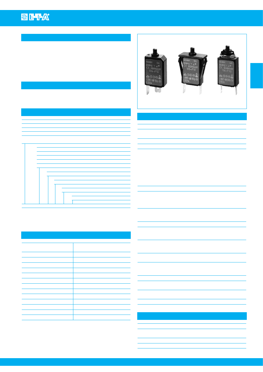
Thermal Overcurrent Circuit Breakers 104/105/106-...
Issue B
1
Current
Internal
Current
Internal
rating (A)
resistance (Ω)
rating (A)
resistance (Ω)
0.05
285
1.8
0.28
0.08
134
2
0.25
0.1
81
2.5
0.18
0.2
22
3
0.11
0.3
8.7
3.5
0.076
0.4
5.5
4
0.067
0.5
3.3
4.5
0.051
0.6
2.45
5
≤ 0.05
0.7
1.6
6
≤ 0.05
0.8
1.45
7
≤ 0.05
1
0.9
8
≤ 0.05
1.2
0.6
10
≤ 0.05
1.5
0.4
Description
Typical applications
Ordering information
Approvals
Technical data
Miniaturised single pole thermal circuit breaker with push-to-reset,
tease- free, trip-free, snap action mechanism (R-type TO CBE to EN
60934). Available in versions for PCB or panel mounting, snap-in or
threadneck, or as an integral type. Manual release facility optional for
type 105.
Approved to CBE standard EN 60934 (IEC 60934). For higher current
ratings see type 1140.
Motors, transformers, solenoids, printed circuit boards, hand-held
machines and appliances, marine applications, caravans.
104-... 105-...
106-...
For further details please see chapter: Technical Information
Voltage rating
AC 240 V; DC 48 V
(UL: AC 250 V; DC 48 V)
Current ratings
0.05...10 A
Auxiliary circuit
0.5 A, AC 240 V, DC 28 V
Typical life
AC 240 V
0.05...8 A
2,000 operations at 1 x I
N
, inductive
0.05...5 A
3,000 operations at 2 x I
N
, inductive
6...8 A: 500 operations at 2 x I
N
, inductive
DC 48 V
0.05...8 A
2,000 operations at 1 x I
N
, inductive
0.05...5 A
3,000 operations at 2 x I
N
, inductive
6...8 A: 500 operations at 2 x I
N
, inductive
10 A
200 operations at 1 x I
N
, inductive
10 A 50 operations at 2 x I
N
, inductive
Ambient temperature -20...+60 °C (-4...+140 °F) T 60
Insulation co-ordination rated impulse
pollution
(IEC 60664 and 60664 A) withstand voltage
degree
2.5 kV
2
reinforced insulation in operating area
Dielectric strength
test voltage
(IEC 60664 and 60664A)
operating area
AC 3,000 V
Insulation resistance
> 100 MΩ (DC 500 V)
Interrupting capacity I
cn
0.05...8 A
6 x I
N
AC
> 8...10 A
5 x I
N
AC
0.05...10 A
6 x I
N
DC
Interrupting capacity
I
N
U
N
(UL 1077)
0.05...10 A
AC 250 V
2,000 A
0.05...10 A
DC 48 V
200 A
Degree of protection
operating area IP40
(IEC 60529/DIN 40050) terminal area IP00
Vibration
10 g (57-500 Hz) ± 0.76 mm (10-57 Hz),
to IEC 60068-2-6, test Fc,
10 frequency cycles/axis
Shock
25 g (11 ms) to IEC 60068-2-27, test Ea
Corrosion
96 hours at 5 % salt mist,
to IEC 60068-2-11, test Ka
Humidity
240 hours at 95 % RH,
to IEC 60068-2-78, test Cab
Mass
approx. 10 g
Authority
Voltage ratings
Current ratings
VDE, SEV,
AC 240 V
0.05...8 A
Kema (EN 60934)
DC 48 V
0.05...10 A
CSA, UL
AC 250 V; DC 48 V
0.05...10 A
Circuit breakers with -Si51 not approved
Standard current ratings and typical internal resistance values
Type No.
104
PCB mounting type (-PR), or integral type (-P30/P10)
105
snap-in panel mounting
106
threadneck panel mounting with hex and knurled nut*
106-M2
threadneck panel mounting 3/8-27UNS with collar, hex nut and
knurled nut*
Terminal design
P10
blade terminals A6.3-0.8 (QC .250)
P30
blade terminals A2.8-0.8 (QC .110)
PR
solder terminal pins for PCB mounting (type 104 only)
PR2
PCB mounting (vertical), type 104 only up to 6 A
PR3
PCB mounting (vertical), type 104 only
Shunt terminal (optional)
A3
same as main terminals (up to I
N
6 A/3 A max. load)
Manual release facility (optional)
H
only with type 105
Auxiliary contacts (optional)
Si51
type 104 only
Current ratings
0.05...10 A
106 -
P30 - .. - .. -
.. - 5 A
= ordering example
The exact part number required can be built up from the table of choices shown
above. Ordering references for optional features should be omitted if not required.
* mounting hardware bulk shipped
Courtesy of Steven Engineering, Inc.-230 Ryan Way, South San Francisco, CA 94080-6370-Main Office: (650) 588-9200-Outside Local Area: (800) 258-9200-www.stevenengineering.com