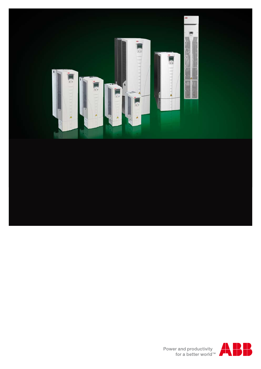
ABB general purpose drives
ACS550
0.75 to 355 kW/1 to 500 hp
Catalog
Low voltage AC drives