background image

Connectors

AB Connectors Limited Specification No. 528 
ABCIRP Connector Series Assembly and wiring Instructions 

Issue 10: March 2017
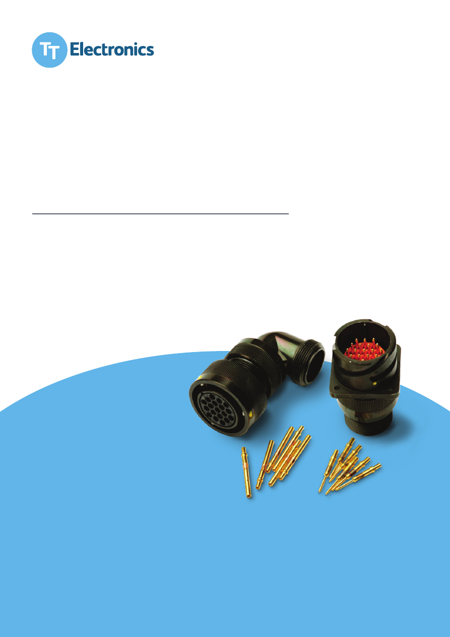
ABCIRP Series 

Circular Multi-pin Electrical Connector

ABCIRP-Assembly-Document-html.html
background image

Connectors

AB Connectors Limited Specification No. 528 

ABCIRP Connector Series Assembly and wiring Instructions 

Connectors Business Unit

© Copyright TT Electronics, 2017. All rights reserved. Subject to change without prior notification. Issue: 10. 2017

www.ttelectronics.com

AB Connectors Limited 

Specification No. 528 

ABCIRP Connector Series 

Assembly and wiring Instructions 

AB Connectors Limited                                                     Issue 9: July 2010

Page 2 of 41 

Table of contents 

1 Product 

Introduction 

       4 

1.1 


General 

         4 


1.2 


Typical 

Connector 


       6 

2 Connector 

Description 

and 

Terminology 

     7 

2.1 


ABCIRP 

Free 

Connector       7 

2.2 


ABCIRP 

Fixed 

Connector       8 


Backshells 

and 

Accessories 

      9 


Polarisation 

        10 

4.1 


Insert 

Orientation 


       10 

4.2 


Alignment 

Pin 

        11 


Individual 

Wire 

Termination 

      12 

5.2   

Individual Wire Termination (Crimping Cables) 

    13 

5.3   

Individual Wire Termination (Contact insertion 

Method 

1) 

   14 

5.4 

Individual Wire Termination (Contact insertion Method 

2) 

   16 


Contact 

Extraction 

       17 


Screen 

termination 

system 

      19 

7.2   

Method: A: Termination Procedure For In-line Wire 

Bundles 

  20 

7.3   

Procedure for a Fixed Connector with (SCHSA)      20 

7.4 


Method 

B: 

RFI 

Grounding       23 

7.5   

Procedure Shown Of Free Connector With ECHSA Accessory 

  23 

7.6 


Method 

C: 

Electrical 

Termination      24 

7.7   

Method D: Electrical Termination (90 Degree Elbow) 

   27 

ABCIRP-Assembly-Document-html.html
background image

Connectors

AB Connectors Limited Specification No. 528 

ABCIRP Connector Series Assembly and wiring Instructions 

Connectors Business Unit

© Copyright TT Electronics, 2017. All rights reserved. Subject to change without prior notification. Issue: 10. 2017

www.ttelectronics.com

AB Connectors Limited 

Specification No. 528 

ABCIRP Connector Series 

Assembly and wiring Instructions 

AB Connectors Limited                                                     Issue 9: July 2010

Page 3 of 41 

Appendices 

Appendix 

A: 


Tooling 

data. 

       28 

Appendix B: 

Dimensional positions of contacts in fixed & free shells   


33 

Appendix C: 

Guidance for the use of 90° backshells      34 

Appendix C:   Steel Band Termination Assembly Process 

   35 

Appendix 

D: 


Backshell 

Torque 

Values.      37 

Appendix 

E: 


Trouble 

Shooting       39 

Appendix 

F: 


Contact 

addresses 

      41 

ABCIRP-Assembly-Document-html.html
background image

Connectors

AB Connectors Limited Specification No. 528 

ABCIRP Connector Series Assembly and wiring Instructions 

Connectors Business Unit

© Copyright TT Electronics, 2017. All rights reserved. Subject to change without prior notification. Issue: 10. 2017

www.ttelectronics.com

AB Connectors Limited 

Specification No. 528 

ABCIRP Connector Series 

Assembly and wiring Instructions 

AB Connectors Limited                                                     Issue 9: July 2010

Page 4 of 41 

Product Introduction 

1.1 General 

1.1.1  The ABCIRP connector series is based on the MS Bayonet lock series of connectors 

conforming to MIL-C-5015 specification. They are interchangeable with all 

corresponding MS bayonet lock types and feature identical panel mounting 

dimensions. 

1.1.2  Designed to operate within a temperature range of -55°C to +125°C, the connector 

also meets the mechanical and environmental ratings of BS9522 F0032, VG95234 

and NF-F-61-030. 

1.1.3  Unlike other MIL-C-5015 bayonet connectors, which utilise insulators bonded into the 

shell and or bonded or rubber retained contacts, the ABCIRP connector series 

incorporates a Circlip retained solid plastic insulator and metal clip retained contacts. 


1.1.4  Stainless steel bayonet pins and rollers riding along the three cam tracks machined 

into the receptacle shell achieve the connector coupling. Coupling integrity is 

guaranteed by:  

  Firstly having three stainless steel pins at the critical wear points of the receptacle 

shell cam-tracks and secondly, by positive lock indicators in the form of  

  An audible click when fully mated.  

  Alignment of coloured dots when fully mated.  

1.1.5  ABCIRP connectors are available in 7 sizes from shell size 18 to shell size 40 with 

arrangements having 7 to 60 contacts. 


1.1.6  Crimp contacts are available in sizes 16, 12 and 8 AWG. 


1.1.7  Insulator angular orientation is available for occasions where like connectors are in 

close proximity and cross mating has to be avoided. This is achieved by aligning pre-

determined keyways in the insulator with the master key of the plug and receptacle 

shell. These angular positions are in accordance with the MIL-C-5015 specification 

thereby ensuring compatibility with existing equipment. 

1.1.8  The dynamic sealing ring at the base of the plug shell guarantees high reliability and 

anti-vibration characteristics including the stainless steel pins at the cam track critical 

wear points. 


1.1.9  Environmental sealing of mated connectors to IP67 is achieved by compression of 

the dynamic seal ring, while integrity at the rear is achieved by the use of an 

individual wire seal grommet with membranes being penetrated only when a wire is 

present. 

1.1.10  Electrical continuity between connectors is achieved by ensuring compression of the 

wavy and flat washer assembly at the base of the plug shell. 

ABCIRP-Assembly-Document-html.html
background image

Connectors

AB Connectors Limited Specification No. 528 

ABCIRP Connector Series Assembly and wiring Instructions 

Connectors Business Unit

© Copyright TT Electronics, 2017. All rights reserved. Subject to change without prior notification. Issue: 10. 2017

www.ttelectronics.com

AB Connectors Limited 

Specification No. 528 

ABCIRP Connector Series 

Assembly and wiring Instructions 

AB Connectors Limited                                                     Issue 9: July 2010

Page 5 of 41 

1.1.11  Screen termination is simplified by using one of a range of back shell/accessory 

combinations. 

1.1.12  In summary, the ABCIRP modular bayonet coupling connector offers several 

advantages to the user.  

  Metal clip retained removable crimp contacts.  

  Positive lock location of contacts.  

  Circlip retained removable insulator allowing for angular re-positioning.  

  Rapid coupling and uncoupling. 120° rotation of th e coupling nut.  

  Vibration resistant -loosening of the coupling nut under vibration or shock condition is 

prevented. 

  Inter-matable and interchangeable with other Mil-C-5015 bayonet types.  

ABCIRP-Assembly-Document-html.html
background image

Connectors

AB Connectors Limited Specification No. 528 

ABCIRP Connector Series Assembly and wiring Instructions 

Connectors Business Unit

© Copyright TT Electronics, 2017. All rights reserved. Subject to change without prior notification. Issue: 10. 2017

www.ttelectronics.com

AB Connectors Limited 

Specification No. 528 

ABCIRP Connector Series 

Assembly and wiring Instructions 

AB Connectors Limited                                                     Issue 9: July 2010

Page 6 of 41 

1.2 

Typical Connector

Fixed 

(Receptacle) 

Free 

(Plug) 

Standard Data

1.2.1 Materials 

Shell: 

  Aluminium 

Alloy 

Insulator: 


Hard Plastic, Low fire hazard 

Grommet: 


Rubber, Low fire hazard 

Contacts: 


Copper Alloy 

Retaining Clip:   

Beryllium Copper 

Accessory: 


Aluminium Alloy 

1.2.2  Plating Finishes 

Shell:   


Zinc Cobalt, Black Passivation 

Contacts: 


Gold or Silver 

Accessory: 


Zinc Cobalt, Black Passivation 

1.2.3  Environmental Ratings 

Shock: 

  75g 

Vibration: 


5 to 500Hz long endurance, 30 hour test at 10g 

Acceleration:  

50g 

Mechanical Endurance: 500 mating cycles minimum 

Stainless steel pins 

Stainless steel pins 

Alignment indicator 

ABCIRP-Assembly-Document-html.html
background image

Connectors

AB Connectors Limited Specification No. 528 

ABCIRP Connector Series Assembly and wiring Instructions 

Connectors Business Unit

© Copyright TT Electronics, 2017. All rights reserved. Subject to change without prior notification. Issue: 10. 2017

www.ttelectronics.com

AB Connectors Limited 

Specification No. 528 

ABCIRP Connector Series 

Assembly and wiring Instructions 

AB Connectors Limited                                                     Issue 9: July 2010

Page 7 of 41 

Connector Description and Terminology

2.1 

ABCIRP Free Connector

Exploded View of ABCIRP Free Connector

2.1.1 

Coupling Nut

 – Provides cam force when mating and unmating connectors. 

2.1.2 

Free Shell

 – Holds the insert and incorporates an alignment key to position the insert. 

The free shell accommodates either the socket or pin insert to reverse gender. 

2.1.3 

Insert (Pin or Socket)

 – Removable, orientatable, retains the contacts and can be 

used in either fixed or free shells. 

2.1.4 

Circlip

 – Retains the insert in the shell. 

2.1.5 

Contacts (Pin or Socket)

 – Crimped to the conductors. 

2.1.6 

Retaining clip

 – Retains the contacts in the insert. 

2.1.7 

Grommet

 – Resilient rubber seal for the individual wire terminations. It has a special 

cut out feature to help position onto the rear of the insert. It also has a sealing web so 

that when the connector is not fully populated, sealing still occurs. The grommet is ink 

marked with the hole position identification. 

Coupling nut 

and Free shell

Socket insert

Circlip

Socket contacts

Grommet

ABCIRP-Assembly-Document-html.html
background image

Connectors

AB Connectors Limited Specification No. 528 

ABCIRP Connector Series Assembly and wiring Instructions 

Connectors Business Unit

© Copyright TT Electronics, 2017. All rights reserved. Subject to change without prior notification. Issue: 10. 2017

www.ttelectronics.com

AB Connectors Limited 

Specification No. 528 

ABCIRP Connector Series 

Assembly and wiring Instructions 

AB Connectors Limited                                                     Issue 9: July 2010

Page 8 of 41 

2.2 

ABCIRP Fixed Connector

Exploded view of ABCIRP Fixed Connector

2.2.1 

Fixed Shell

 – The panel mounted half of the connector pair. Holds the insert and 

incorporates an alignment key to position the insert. The shell accommodates either 

the socket or pin insert to reverse gender. Coupling ramps provide cam action for 

coupling and uncoupling. Stainless Steel pins at the top of the ramps ensure positive 

locking and long service life. 

2.2.2 

Insert (Pin or Socket)

 – Removable, orientatable, retains the contacts and can be 

used in either fixed or free shells. 

2.2.3 

Circlip

 – Retains the insert in the shell. 

2.2.4 

Contacts (Pin or Socket)

 – Crimped to the conductors. 

2.2.5 

Retaining clip

 – Retains the contacts in the insert. 

2.2.6 

Grommet

 – Resilient rubber seal for the individual wire terminations. It has a special 

cut out feature to help position onto the rear of the insert. It also has a sealing web so 

that when the connector is not fully populated, sealing still occurs. The grommet is ink 

marked with the hole position identification. 

Fixed shell

Pin insert

Pin contacts 

Circlip

Grommet 

ABCIRP-Assembly-Document-html.html
background image

Connectors

AB Connectors Limited Specification No. 528 

ABCIRP Connector Series Assembly and wiring Instructions 

Connectors Business Unit

© Copyright TT Electronics, 2017. All rights reserved. Subject to change without prior notification. Issue: 10. 2017

www.ttelectronics.com

AB Connectors Limited 

Specification No. 528 

ABCIRP Connector Series 

Assembly and wiring Instructions 

AB Connectors Limited                                                     Issue 9: July 2010

Page 9 of 41 

Backshells and Accessories

3.1.1  A fully sealed connector is achieved by using a grommet in combination with an 

accessory. When assembled on the back of the connector the accessory compresses 

the grommet onto the individual wires and against the accessory body to obtain an 

IP67 seal. 

3.1.2  The accessory is assembled correctly when the teeth on the back of the connector 

shell mesh with those of the accessory. 

3.1.3  The spinning knurled locking nut prevents grommet twist when tightening. 

3.1.4  Accessories are available to take heat shrink boots, screening systems and conduit. 

Angled versions are also available, to guide cable routing. Please consult the 

catalogue or ask the sales desk for more information on the type available. 

Hint:

  When engaging the accessory onto the connector, linearly push the accessory onto 

the fixed or free shell while rotating the accessory nut. This will ease the assembly by allowing 

the threads to engage more naturally. Also continue to push the accessory inwards when 

tightening to ease the torque required. The same applies during strip down; push forward on 

the accessory to slacken thread. 

ABCIRP-Assembly-Document-html.html
background image

Connectors

AB Connectors Limited Specification No. 528 

ABCIRP Connector Series Assembly and wiring Instructions 

Connectors Business Unit

© Copyright TT Electronics, 2017. All rights reserved. Subject to change without prior notification. Issue: 10. 2017

www.ttelectronics.com

AB Connectors Limited 

Specification No. 528 

ABCIRP Connector Series 

Assembly and wiring Instructions 

AB Connectors Limited                                                     Issue 9: July 2010

Page 10 of 41 

4 Polarisation

4.1 

Insert Orientation

4.1.1  Depending on end user needs, the pin and socket inserts may be supplied separately 

to the fixed and free shells to allow the end user to specify the orientation of the 

insulator within the connector. 

 Insert Orientation Components

4.1.2  Insulator orientation is used to prevent cross mating of like connectors, which are in 

close proximity to each other. It is achieved by firstly having a location key cast into 

the fixed and free shells, and secondly by the insulator having a number of location 

keyways moulded into the outside shoulder for each desired orientation. Each 

position is marked on the insulator and can also be seen on either the front face or 

the location keyway. 

4.1.3  Before the circlip is used, it is best practice to bend the circlip through 90°, so that a 

spring washer effect is formed in the circlip. This will not only aid the assembly 

process, but will take up any linear movement of the insulator within the shell. 

4.1.4  Align the insulator orientation letter required with the key in the shell and press into 

place. There may be a slight interference, but it can be pushed to a stop, exposing 

the circlip groove in the fixed or free shell. 

4.1.5  Insert one end of the circlip into the circlip groove, and prize around using a small 

screwdriver until the circlip snaps into position. Attempt to push and twist the insulator 

to ensure that the circlip is seated correctly. 

4.1.6  The Insulator can also be easily removed to orientate it. Locate the chamfered end of 

the circlip. Using a small screwdriver prise the circlip out of its groove and “ride” the 

screwdriver under the circlip all the way around the shell and it will pop out. The 

AB Connectors Limited 

Specification No. 528 

ABCIRP Connector Series 

Assembly and wiring Instructions 

AB Connectors Limited                                                     Issue 9: July 2010

Page 10 of 41 

4 Polarisation

4.1 

Insert Orientation

4.1.1  Depending on end user needs, the pin and socket inserts may be supplied separately 

to the fixed and free shells to allow the end user to specify the orientation of the 

insulator within the connector. 

 Insert Orientation Components

4.1.2  Insulator orientation is used to prevent cross mating of like connectors, which are in 

close proximity to each other. It is achieved by firstly having a location key cast into 

the fixed and free shells, and secondly by the insulator having a number of location 

keyways moulded into the outside shoulder for each desired orientation. Each 

position is marked on the insulator and can also be seen on either the front face or 

the location keyway. 

4.1.3  Before the circlip is used, it is best practice to bend the circlip through 90°, so that a 

spring washer effect is formed in the circlip. This will not only aid the assembly 

process, but will take up any linear movement of the insulator within the shell. 

4.1.4  Align the insulator orientation letter required with the key in the shell and press into 

place. There may be a slight interference, but it can be pushed to a stop, exposing 

the circlip groove in the fixed or free shell. 

4.1.5  Insert one end of the circlip into the circlip groove, and prize around using a small 

screwdriver until the circlip snaps into position. Attempt to push and twist the insulator 

to ensure that the circlip is seated correctly. 

4.1.6  The Insulator can also be easily removed to orientate it. Locate the chamfered end of 

the circlip. Using a small screwdriver prise the circlip out of its groove and “ride” the 

screwdriver under the circlip all the way around the shell and it will pop out. The 

ABCIRP-Assembly-Document-html.html
background image

Connectors

AB Connectors Limited Specification No. 528 

ABCIRP Connector Series Assembly and wiring Instructions 

Connectors Business Unit

© Copyright TT Electronics, 2017. All rights reserved. Subject to change without prior notification. Issue: 10. 2017

www.ttelectronics.com

AB Connectors Limited 

Specification No. 528 

ABCIRP Connector Series 

Assembly and wiring Instructions 

AB Connectors Limited                                                     Issue 9: July 2010

Page 11 of 41 

insulator can now be removed and repositioned or replaced as required. 

4.2 Alignment Pin

4.2.1  For high density, symmetrical contact arrangements, where very few contacts are 

being used, additional devices may be necessary to completely remove the 

possibility of cross mating like connectors. These devices take the form of pins, 

which occupy key contact positions in the insulator depending on the size and 

complexity of the arrangement. 

4.2.2 

Note

. The additional polarising device is inserted into the pin insulator only. 

4.2.3  It is recommended that at least two of these pins be installed per connector. These 

alignment pins should not be removed once installed. 

Example of two 40-A35 Contact arrangements with X and Y orientations mated together. 25 

out of the 35 available contacts can misalign. 

Table showing optimum position for alignment pins.

Contact arrangement

Insulator Orientation

Alignment pin position

18-19 

All 

Any one hole 

20-15 

All 

Any one apart from G 

22-14 

All 

Hole K & R 

24-10 

All 

Any one hole apart from G 

28-21 

All 

Holes E & e 

32-A13 

All 

Hole 10  

36-A22 

All 

Holes 14 & 17 

40-A35 

All 

Holes 1 & 24 

40-A60 

Hole 3 & 51 

W, X, Y & Z 

Holes 26 & 59 

ABCIRP-Assembly-Document-html.html
background image

Connectors

AB Connectors Limited Specification No. 528 

ABCIRP Connector Series Assembly and wiring Instructions 

Connectors Business Unit

© Copyright TT Electronics, 2017. All rights reserved. Subject to change without prior notification. Issue: 10. 2017

www.ttelectronics.com

AB Connectors Limited 

Specification No. 528 

ABCIRP Connector Series 

Assembly and wiring Instructions 

AB Connectors Limited                                                     Issue 9: July 2010

Page 12 of 41 

Individual Wire Termination

Cable preparation lengths

1.1.1  Cut cables to the desired length, which must include: 

  The length of the grommet 

  The strip length, as shown in the table below 

  The assembly length of 40mm 

  Apply cable idents and push back from approximately 70mm from the 

end of the wire. 

5.1.2 

Contact Size 

AB Crimp Contact Part Number 

Dimension “L” mm 

Strip Length 

Pin 

Socket 

16/22 

ABCIRP1622KPK# ABCIRP1622KLK# 

5-6mm 

16/20 

ABCIRP1620KPK# ABCIRP1620KLK# 

5-6mm 

16 

ABCIRP16KPK# ABCIRP16KLK# 

5-6mm 

16/14 

ABCIRP1614KPK# ABCIRP1614KLK# 

5-6mm 

12/40 ABCIRP1240KPKP80# ABCIRP1240KLKP80#

7-8mm 

12/20 ABCIRP1220KPKP80# ABCIRP1220KLKP80#

7-8mm 

12/16 ABCIRP1216KPKP80# ABCIRP1216KLKP80#

7-8mm 

12 

ABCIRP12KPKP80# ABCIRP12KLKP80# 

7-8mm 

12/10 ABCIRP1210KPKP80# ABCIRP1210KLKP80#

7-8mm 

8/40 

ABBP840KPKP80# ABBP840KSKP80# 

12-13mm 

8/16 

ABBP816KPKP80# ABBP816KSKP80# 

12-13mm 

8/12 

ABBP812KPKP80# ABBP812KSKP80# 

12-13mm 

100 

ABBP100KPKP80# ABBP100KSKP80# 

12-13mm 

100/60 

ABBP10060KPKP80# ABBP10060KSKP80# 

12-13mm 

Strip Lengths

AB Connectors Limited 

Specification No. 528 

ABCIRP Connector Series 

Assembly and wiring Instructions 

AB Connectors Limited                                                     Issue 9: July 2010

Page 12 of 41 

Individual Wire Termination

Cable preparation lengths

1.1.1  Cut cables to the desired length, which must include: 

  The length of the grommet 

  The strip length, as shown in the table below 

  The assembly length of 40mm 

  Apply cable idents and push back from approximately 70mm from the 

end of the wire. 

5.1.2 

Contact Size 

AB Crimp Contact Part Number 

Dimension “L” mm 

Strip Length 

Pin 

Socket 

16/22 

ABCIRP1622KPK# ABCIRP1622KLK# 

5-6mm 

16/20 

ABCIRP1620KPK# ABCIRP1620KLK# 

5-6mm 

16 

ABCIRP16KPK# ABCIRP16KLK# 

5-6mm 

16/14 

ABCIRP1614KPK# ABCIRP1614KLK# 

5-6mm 

12/40 ABCIRP1240KPKP80# ABCIRP1240KLKP80#

7-8mm 

12/20 ABCIRP1220KPKP80# ABCIRP1220KLKP80#

7-8mm 

12/16 ABCIRP1216KPKP80# ABCIRP1216KLKP80#

7-8mm 

12 

ABCIRP12KPKP80# ABCIRP12KLKP80# 

7-8mm 

12/10 ABCIRP1210KPKP80# ABCIRP1210KLKP80#

7-8mm 

8/40 

ABBP840KPKP80# ABBP840KSKP80# 

12-13mm 

8/16 

ABBP816KPKP80# ABBP816KSKP80# 

12-13mm 

8/12 

ABBP812KPKP80# ABBP812KSKP80# 

12-13mm 

100 

ABBP100KPKP80# ABBP100KSKP80# 

12-13mm 

100/60 

ABBP10060KPKP80# ABBP10060KSKP80# 

12-13mm 

Strip Lengths

ABCIRP-Assembly-Document-html.html
background image

Connectors

AB Connectors Limited Specification No. 528 

ABCIRP Connector Series Assembly and wiring Instructions 

Connectors Business Unit

© Copyright TT Electronics, 2017. All rights reserved. Subject to change without prior notification. Issue: 10. 2017

www.ttelectronics.com

AB Connectors Limited 

Specification No. 528 

ABCIRP Connector Series 

Assembly and wiring Instructions 

AB Connectors Limited                                                     Issue 9: July 2010

Page 13 of 41 

1.2 

Individual Wire Termination (Crimping Cables) 

Size 16 contact  

Single sided clip. 

Size 12 contact  

Single sided clip.  

Size 8 contact with 

Retaining collet.

Crimp Contacts Types 

1.2.1  Inspect the conductor to ensure the insulator end is clean and square and the lay of 

the strands is not disturbed. 

Note: 

A damaged conductor or strand is not acceptable. Ensure the conductor is 

clean before assembly into the contact. 

1.2.2  Select the correct crimp tool and turret/locator for the contact to be crimped from the 

table in Appendix A, and install the turret/locator onto the crimp tool. 

1.2.3  Set the correct tool setting and tool position for the contact as shown in Appendix A. 

1.2.4  Insert the stripped conductor into the contact crimp bucket. Ensure conductor is fully  

pushed in and that insulation is tight to crimp bucket. 

1.2.5  Check inspection hole to see if the conductor strands are visible. If they are not 

visible, check the conductor strip length and check for foreign objects in the crimp 

bucket. 

1.2.6  Operate the empty crimp tool once to ensure the crimping dies are completely open 

and there is no misalignment. 

1.2.7  Insert the contact with the conductor installed into the contact-locating hole in the 

crimp tool until it 'bottoms' in the locator/turret. Applicable to size 12 & 16 only. 

Position the size 8 contact so that the crimp bucket rests on the bottom jaws of the 

die set with the back of the contact protruding approximately 2mm over the back of 

the die. 

1.2.8  Activate the crimp tool through one complete cycle. 

1.2.9 

Note:

 When crimping Size 8 Contacts ensure that the flats of the Hexagonal Die Set 

come together. 

5.2.10  Remove the crimped assembly from the tool and inspect the joint for the correct crimp 

location as below.  

ABCIRP-Assembly-Document-html.html
background image

Connectors

AB Connectors Limited Specification No. 528 

ABCIRP Connector Series Assembly and wiring Instructions 

Connectors Business Unit

© Copyright TT Electronics, 2017. All rights reserved. Subject to change without prior notification. Issue: 10. 2017

www.ttelectronics.com

AB Connectors Limited 

Specification No. 528 

ABCIRP Connector Series 

Assembly and wiring Instructions 

AB Connectors Limited                                                     Issue 9: July 2010

Page 14 of 41 

Completed crimp contact

5.2.11  Check that the conductor strands are visible through the inspection hole.  

Important Note: 

Loose conductor strands or cracks in the crimp area are not 

acceptable.  

The crimp joint must be re-made if there is any sign of damage. 

5.3  Contact Insertion – Method 1

5.3.1  Push the contacts through the grommet according to the wiring list / schedule and 

push the grommet up to, but not beyond the idents. Lubricant such as Pronatur or 

Isoproyl alcohol may be used. Important: Observe handling and operating safety 

instructions as supplied by manufacture.  

5.3.2  Locate the correct hole for the appropriate wire. Load the contact into the insert by 

hand. 

Note

: It is best practice to work from one side only, inserting from left to right or 

top to bottom in an orderly fashion. Some arrangements have a radial pattern where 

working from the centre and working outwards is best. Randomly inserting contacts is 

more likely to result in wiring errors and difficulty inserting contacts. 

5.3.3  Using the correct insertion tool for the contact as shown above, locate onto contact 

bucket and push the contact forward until fully inserted, when a ‘click’ will be heard 

and felt.  

Hint

: As each contact is inserted pull firmly on the cable to ensure that the contact has seated 

correctly. Any contact not seated correctly will pull back. If this happens use the insertion tool 

and reinsert the contact and repeat the pull test.

Inspection Hole

AB Connectors Limited 

Specification No. 528 

ABCIRP Connector Series 

Assembly and wiring Instructions 

AB Connectors Limited                                                     Issue 9: July 2010

Page 14 of 41 

Completed crimp contact

5.2.11  Check that the conductor strands are visible through the inspection hole.  

Important Note: 

Loose conductor strands or cracks in the crimp area are not 

acceptable.  

The crimp joint must be re-made if there is any sign of damage. 

5.3  Contact Insertion – Method 1

5.3.1  Push the contacts through the grommet according to the wiring list / schedule and 

push the grommet up to, but not beyond the idents. Lubricant such as Pronatur or 

Isoproyl alcohol may be used. Important: Observe handling and operating safety 

instructions as supplied by manufacture.  

5.3.2  Locate the correct hole for the appropriate wire. Load the contact into the insert by 

hand. 

Note

: It is best practice to work from one side only, inserting from left to right or 

top to bottom in an orderly fashion. Some arrangements have a radial pattern where 

working from the centre and working outwards is best. Randomly inserting contacts is 

more likely to result in wiring errors and difficulty inserting contacts. 

5.3.3  Using the correct insertion tool for the contact as shown above, locate onto contact 

bucket and push the contact forward until fully inserted, when a ‘click’ will be heard 

and felt.  

Hint

: As each contact is inserted pull firmly on the cable to ensure that the contact has seated 

correctly. Any contact not seated correctly will pull back. If this happens use the insertion tool 

and reinsert the contact and repeat the pull test.

Inspection Hole

ABCIRP-Assembly-Document-html.html
background image

Connectors

AB Connectors Limited Specification No. 528 

ABCIRP Connector Series Assembly and wiring Instructions 

Connectors Business Unit

© Copyright TT Electronics, 2017. All rights reserved. Subject to change without prior notification. Issue: 10. 2017

www.ttelectronics.com

AB Connectors Limited 

Specification No. 528 

ABCIRP Connector Series 

Assembly and wiring Instructions 

AB Connectors Limited                                                     Issue 9: July 2010

Page 15 of 41 

5.3.4  Checking the dimensions shown in Appendix B will verify that the contact is seated 

correctly. As an extra final visual check, all contacts should be around the same 

height with no visible differences in height from insert face. 

5.3.5  Repeat steps 5.3.4 to 5.3.6 until all wires are located into their respective holes.  

5.3.6  Slide the grommet down the cable and locate onto the insert. Lubricant such as 

Pronatur or Isoproponyl alcohol may be used. Observe handling and operating safety 

instructions as supplied by manufacturer.  

5.3.7  Tuck the grommet in between the connector shell and the insert until the shoulder on 

the grommet is pushed almost level with the top of the serrations on the shell. A 

simple tool is available to help when tucking the grommet into position. 

Hint:

 If you push forward on the back face of the grommet it should not buckle. If it does then 

the grommet has not been tucked into position correctly. This can cause the grommet to tare 

when the backshell is assembled and could affect sealing. 

5.3.8  To ensure that the correct wire number has been inserted into the correct hole, check 

that the lettering and step in the grommet align correctly. 

5.3.9  Any grommet hole that has been pierced accidentally will need to be filled with a 

grommet filler plug as shown. Unpierced holes can be left. 

5.3.10  Slide cable idents up to the back of the grommet and leave a 5 to 15mm gap. 

5.3.11  Assemble the accessory onto the connector and tighten to the recommended torque 

values as stated in Appendix D. 

Hint:

  When engaging the accessory to the connector, linearly push the accessory onto the  

fixed or free shell while rotating the accessory nut. This will ease the assembly by allowing the 

threads to engage more naturally. Also continue to push the accessory inwards when 

tightening to ease the torque required. The same applies during strip down; push forward on 

the accessory to slacken thread.

AB Connectors Limited 

Specification No. 528 

ABCIRP Connector Series 

Assembly and wiring Instructions 

AB Connectors Limited                                                     Issue 9: July 2010

Page 15 of 41 

5.3.4  Checking the dimensions shown in Appendix B will verify that the contact is seated 

correctly. As an extra final visual check, all contacts should be around the same 

height with no visible differences in height from insert face. 

5.3.5  Repeat steps 5.3.4 to 5.3.6 until all wires are located into their respective holes.  

5.3.6  Slide the grommet down the cable and locate onto the insert. Lubricant such as 

Pronatur or Isoproponyl alcohol may be used. Observe handling and operating safety 

instructions as supplied by manufacturer.  

5.3.7  Tuck the grommet in between the connector shell and the insert until the shoulder on 

the grommet is pushed almost level with the top of the serrations on the shell. A 

simple tool is available to help when tucking the grommet into position. 

Hint:

 If you push forward on the back face of the grommet it should not buckle. If it does then 

the grommet has not been tucked into position correctly. This can cause the grommet to tare 

when the backshell is assembled and could affect sealing. 

5.3.8  To ensure that the correct wire number has been inserted into the correct hole, check 

that the lettering and step in the grommet align correctly. 

5.3.9  Any grommet hole that has been pierced accidentally will need to be filled with a 

grommet filler plug as shown. Unpierced holes can be left. 

5.3.10  Slide cable idents up to the back of the grommet and leave a 5 to 15mm gap. 

5.3.11  Assemble the accessory onto the connector and tighten to the recommended torque 

values as stated in Appendix D. 

Hint:

  When engaging the accessory to the connector, linearly push the accessory onto the  

fixed or free shell while rotating the accessory nut. This will ease the assembly by allowing the 

threads to engage more naturally. Also continue to push the accessory inwards when 

tightening to ease the torque required. The same applies during strip down; push forward on 

the accessory to slacken thread.

AB Connectors Limited 

Specification No. 528 

ABCIRP Connector Series 

Assembly and wiring Instructions 

AB Connectors Limited                                                     Issue 9: July 2010

Page 15 of 41 

5.3.4  Checking the dimensions shown in Appendix B will verify that the contact is seated 

correctly. As an extra final visual check, all contacts should be around the same 

height with no visible differences in height from insert face. 

5.3.5  Repeat steps 5.3.4 to 5.3.6 until all wires are located into their respective holes.  

5.3.6  Slide the grommet down the cable and locate onto the insert. Lubricant such as 

Pronatur or Isoproponyl alcohol may be used. Observe handling and operating safety 

instructions as supplied by manufacturer.  

5.3.7  Tuck the grommet in between the connector shell and the insert until the shoulder on 

the grommet is pushed almost level with the top of the serrations on the shell. A 

simple tool is available to help when tucking the grommet into position. 

Hint:

 If you push forward on the back face of the grommet it should not buckle. If it does then 

the grommet has not been tucked into position correctly. This can cause the grommet to tare 

when the backshell is assembled and could affect sealing. 

5.3.8  To ensure that the correct wire number has been inserted into the correct hole, check 

that the lettering and step in the grommet align correctly. 

5.3.9  Any grommet hole that has been pierced accidentally will need to be filled with a 

grommet filler plug as shown. Unpierced holes can be left. 

5.3.10  Slide cable idents up to the back of the grommet and leave a 5 to 15mm gap. 

5.3.11  Assemble the accessory onto the connector and tighten to the recommended torque 

values as stated in Appendix D. 

Hint:

  When engaging the accessory to the connector, linearly push the accessory onto the  

fixed or free shell while rotating the accessory nut. This will ease the assembly by allowing the 

threads to engage more naturally. Also continue to push the accessory inwards when 

tightening to ease the torque required. The same applies during strip down; push forward on 

the accessory to slacken thread.

ABCIRP-Assembly-Document-html.html
background image

Connectors

AB Connectors Limited Specification No. 528 

ABCIRP Connector Series Assembly and wiring Instructions 

Connectors Business Unit

© Copyright TT Electronics, 2017. All rights reserved. Subject to change without prior notification. Issue: 10. 2017

www.ttelectronics.com

AB Connectors Limited 

Specification No. 528 

ABCIRP Connector Series 

Assembly and wiring Instructions 

AB Connectors Limited                                                     Issue 9: July 2010

Page 16 of 41 

5.4  Contact insertion – Method 2

5.4.1  This alternative method involves assembling the grommet onto the connector before 

inserting the contacts through the grommet and into the insert. The advantage of this 

method is that the contacts can be crimped onto the wires before the connector and 

accessories are touched, however: 

5.4.2  This method is not preferred since it requires that the contact and insertion tools 

penetrate the webs in the grommet. There is potential for the retaining clips on the 

contacts to damage the grommet sealing holes and effect the performance of the 

connector.  

5.4.3  Extra care must therefore be taken when using this method and the grommet must be 

inspected for damage after the contacts have been fitted. 

5.4.4  Prepare the parts as follows: 

  Strip and crimp the contacts as per sections 5.2 and 5.3 

  Slide the accessories over the wires in the correct order. 

5.4.5  Assemble the grommet onto the rear of the insulator, ensuring that the recess on the 

grommet aligns with the corresponding raised section on the insert. 

5.4.6  Tuck the grommet in between the connector shell and the insert until the shoulder on 

the grommet is pushed almost level with the top of the serrations on the shell. A 

simple tool is available to help when tucking the grommet into position. 

Hint:

 If you push forward on the back face of the grommet it should not buckle. If it does then 

the grommet has not been tucked into position correctly. This can cause the grommet to tare 

when the backshell is assembled and could affect sealing. 

5.4.7  Locate the required wire and feed it partially through the grommet. 

Note

: It is best 

practice to work from one side only, inserting from left to right or top to bottom in an 

orderly fashion. Some arrangements have a radial pattern where working from the 

centre and working outwards is best. Randomly inserting contacts is more likely to 

result in wiring errors and difficulty inserting contacts. 

5.4.8  Open the “Tweezers-type” insertion tool and close it around the crimp bucket of the 

selected contact, ensuring that the wire does not pinch the wire as the tool closes. 

Holding the tool as it close to the bucket as possible, apply a firm and even pressure, 

AB Connectors Limited 

Specification No. 528 

ABCIRP Connector Series 

Assembly and wiring Instructions 

AB Connectors Limited                                                     Issue 9: July 2010

Page 16 of 41 

5.4  Contact insertion – Method 2

5.4.1  This alternative method involves assembling the grommet onto the connector before 

inserting the contacts through the grommet and into the insert. The advantage of this 

method is that the contacts can be crimped onto the wires before the connector and 

accessories are touched, however: 

5.4.2  This method is not preferred since it requires that the contact and insertion tools 

penetrate the webs in the grommet. There is potential for the retaining clips on the 

contacts to damage the grommet sealing holes and effect the performance of the 

connector.  

5.4.3  Extra care must therefore be taken when using this method and the grommet must be 

inspected for damage after the contacts have been fitted. 

5.4.4  Prepare the parts as follows: 

  Strip and crimp the contacts as per sections 5.2 and 5.3 

  Slide the accessories over the wires in the correct order. 

5.4.5  Assemble the grommet onto the rear of the insulator, ensuring that the recess on the 

grommet aligns with the corresponding raised section on the insert. 

5.4.6  Tuck the grommet in between the connector shell and the insert until the shoulder on 

the grommet is pushed almost level with the top of the serrations on the shell. A 

simple tool is available to help when tucking the grommet into position. 

Hint:

 If you push forward on the back face of the grommet it should not buckle. If it does then 

the grommet has not been tucked into position correctly. This can cause the grommet to tare 

when the backshell is assembled and could affect sealing. 

5.4.7  Locate the required wire and feed it partially through the grommet. 

Note

: It is best 

practice to work from one side only, inserting from left to right or top to bottom in an 

orderly fashion. Some arrangements have a radial pattern where working from the 

centre and working outwards is best. Randomly inserting contacts is more likely to 

result in wiring errors and difficulty inserting contacts. 

5.4.8  Open the “Tweezers-type” insertion tool and close it around the crimp bucket of the 

selected contact, ensuring that the wire does not pinch the wire as the tool closes. 

Holding the tool as it close to the bucket as possible, apply a firm and even pressure, 

ABCIRP-Assembly-Document-html.html
background image

Connectors

AB Connectors Limited Specification No. 528 

ABCIRP Connector Series Assembly and wiring Instructions 

Connectors Business Unit

© Copyright TT Electronics, 2017. All rights reserved. Subject to change without prior notification. Issue: 10. 2017

www.ttelectronics.com

AB Connectors Limited 

Specification No. 528 

ABCIRP Connector Series 

Assembly and wiring Instructions 

AB Connectors Limited                                                     Issue 9: July 2010

Page 17 of 41 

inserting the contact into the insert until it clicks into place. When inserting a socket 

contact it is good practice to place a socket guide pin in the front of the contact to 

prevent any rubber from the grommet web entering the socket contact.  

5.4.9  Slide the tool out and remove the tool from the wire. 

Hint:

 When sliding the tool out lightly apply tweezers action to the open the tool. This 

will help prevent chafing the wire insulation on the tool. 

Hint

: As each contact is inserted pull firmly on the cable to ensure that the contact has seated 

correctly. Any contact not seated correctly will pull back. If this happens use the insertion tool 

and reinsert the contact and repeat the pull test. 

5.4.10  Repeat steps 5.5.8 to 5.5.9 for all wires. 

5.4.11  Checking the dimensions shown in Appendix B will verify that the contact is seated 

correctly. As an extra final visual check, all contacts should be around the same 

height with no visible differences in height from insert face. 

5.4.12  Assemble the rear backshells and accessories following steps 5.4.8 to 5.4.11. 

2.  Contact Extraction

2.1.1  The extraction tool can be utilised for both the size 16 and 12 contacts, by replacing 

the probe with the appropriate size. These probes can become damaged over time 

and therefore can be easily replaced. See Appendix A for details of the replacement 

probe part numbers. 

2.1.2  Loosen cable accessory and backshell. Slide these down the cable to allow easy 

access to the rear of the connector. Slide the grommet and cable idents back 

approximately 70mm.  

2.1.3  Working from the front face of the connector, position the extraction tool over the pin 

or socket contact. Carefully rotate the tool until the 3 slots in the tool align with the 3 

ribs in the insert cavity. Push the tool firmly into the insert closing the clip with the 

front collar. 

AB Connectors Limited 

Specification No. 528 

ABCIRP Connector Series 

Assembly and wiring Instructions 

AB Connectors Limited                                                     Issue 9: July 2010

Page 17 of 41 

inserting the contact into the insert until it clicks into place. When inserting a socket 

contact it is good practice to place a socket guide pin in the front of the contact to 

prevent any rubber from the grommet web entering the socket contact.  

5.4.9  Slide the tool out and remove the tool from the wire. 

Hint:

 When sliding the tool out lightly apply tweezers action to the open the tool. This 

will help prevent chafing the wire insulation on the tool. 

Hint

: As each contact is inserted pull firmly on the cable to ensure that the contact has seated 

correctly. Any contact not seated correctly will pull back. If this happens use the insertion tool 

and reinsert the contact and repeat the pull test. 

5.4.10  Repeat steps 5.5.8 to 5.5.9 for all wires. 

5.4.11  Checking the dimensions shown in Appendix B will verify that the contact is seated 

correctly. As an extra final visual check, all contacts should be around the same 

height with no visible differences in height from insert face. 

5.4.12  Assemble the rear backshells and accessories following steps 5.4.8 to 5.4.11. 

2.  Contact Extraction

2.1.1  The extraction tool can be utilised for both the size 16 and 12 contacts, by replacing 

the probe with the appropriate size. These probes can become damaged over time 

and therefore can be easily replaced. See Appendix A for details of the replacement 

probe part numbers. 

2.1.2  Loosen cable accessory and backshell. Slide these down the cable to allow easy 

access to the rear of the connector. Slide the grommet and cable idents back 

approximately 70mm.  

2.1.3  Working from the front face of the connector, position the extraction tool over the pin 

or socket contact. Carefully rotate the tool until the 3 slots in the tool align with the 3 

ribs in the insert cavity. Push the tool firmly into the insert closing the clip with the 

front collar. 

AB Connectors Limited 

Specification No. 528 

ABCIRP Connector Series 

Assembly and wiring Instructions 

AB Connectors Limited                                                     Issue 9: July 2010

Page 17 of 41 

inserting the contact into the insert until it clicks into place. When inserting a socket 

contact it is good practice to place a socket guide pin in the front of the contact to 

prevent any rubber from the grommet web entering the socket contact.  

5.4.9  Slide the tool out and remove the tool from the wire. 

Hint:

 When sliding the tool out lightly apply tweezers action to the open the tool. This 

will help prevent chafing the wire insulation on the tool. 

Hint

: As each contact is inserted pull firmly on the cable to ensure that the contact has seated 

correctly. Any contact not seated correctly will pull back. If this happens use the insertion tool 

and reinsert the contact and repeat the pull test. 

5.4.10  Repeat steps 5.5.8 to 5.5.9 for all wires. 

5.4.11  Checking the dimensions shown in Appendix B will verify that the contact is seated 

correctly. As an extra final visual check, all contacts should be around the same 

height with no visible differences in height from insert face. 

5.4.12  Assemble the rear backshells and accessories following steps 5.4.8 to 5.4.11. 

2.  Contact Extraction

2.1.1  The extraction tool can be utilised for both the size 16 and 12 contacts, by replacing 

the probe with the appropriate size. These probes can become damaged over time 

and therefore can be easily replaced. See Appendix A for details of the replacement 

probe part numbers. 

2.1.2  Loosen cable accessory and backshell. Slide these down the cable to allow easy 

access to the rear of the connector. Slide the grommet and cable idents back 

approximately 70mm.  

2.1.3  Working from the front face of the connector, position the extraction tool over the pin 

or socket contact. Carefully rotate the tool until the 3 slots in the tool align with the 3 

ribs in the insert cavity. Push the tool firmly into the insert closing the clip with the 

front collar. 

AB Connectors Limited 

Specification No. 528 

ABCIRP Connector Series 

Assembly and wiring Instructions 

AB Connectors Limited                                                     Issue 9: July 2010

Page 17 of 41 

inserting the contact into the insert until it clicks into place. When inserting a socket 

contact it is good practice to place a socket guide pin in the front of the contact to 

prevent any rubber from the grommet web entering the socket contact.  

5.4.9  Slide the tool out and remove the tool from the wire. 

Hint:

 When sliding the tool out lightly apply tweezers action to the open the tool. This 

will help prevent chafing the wire insulation on the tool. 

Hint

: As each contact is inserted pull firmly on the cable to ensure that the contact has seated 

correctly. Any contact not seated correctly will pull back. If this happens use the insertion tool 

and reinsert the contact and repeat the pull test. 

5.4.10  Repeat steps 5.5.8 to 5.5.9 for all wires. 

5.4.11  Checking the dimensions shown in Appendix B will verify that the contact is seated 

correctly. As an extra final visual check, all contacts should be around the same 

height with no visible differences in height from insert face. 

5.4.12  Assemble the rear backshells and accessories following steps 5.4.8 to 5.4.11. 

2.  Contact Extraction

2.1.1  The extraction tool can be utilised for both the size 16 and 12 contacts, by replacing 

the probe with the appropriate size. These probes can become damaged over time 

and therefore can be easily replaced. See Appendix A for details of the replacement 

probe part numbers. 

2.1.2  Loosen cable accessory and backshell. Slide these down the cable to allow easy 

access to the rear of the connector. Slide the grommet and cable idents back 

approximately 70mm.  

2.1.3  Working from the front face of the connector, position the extraction tool over the pin 

or socket contact. Carefully rotate the tool until the 3 slots in the tool align with the 3 

ribs in the insert cavity. Push the tool firmly into the insert closing the clip with the 

front collar. 

AB Connectors Limited 

Specification No. 528 

ABCIRP Connector Series 

Assembly and wiring Instructions 

AB Connectors Limited                                                     Issue 9: July 2010

Page 17 of 41 

inserting the contact into the insert until it clicks into place. When inserting a socket 

contact it is good practice to place a socket guide pin in the front of the contact to 

prevent any rubber from the grommet web entering the socket contact.  

5.4.9  Slide the tool out and remove the tool from the wire. 

Hint:

 When sliding the tool out lightly apply tweezers action to the open the tool. This 

will help prevent chafing the wire insulation on the tool. 

Hint

: As each contact is inserted pull firmly on the cable to ensure that the contact has seated 

correctly. Any contact not seated correctly will pull back. If this happens use the insertion tool 

and reinsert the contact and repeat the pull test. 

5.4.10  Repeat steps 5.5.8 to 5.5.9 for all wires. 

5.4.11  Checking the dimensions shown in Appendix B will verify that the contact is seated 

correctly. As an extra final visual check, all contacts should be around the same 

height with no visible differences in height from insert face. 

5.4.12  Assemble the rear backshells and accessories following steps 5.4.8 to 5.4.11. 

2.  Contact Extraction

2.1.1  The extraction tool can be utilised for both the size 16 and 12 contacts, by replacing 

the probe with the appropriate size. These probes can become damaged over time 

and therefore can be easily replaced. See Appendix A for details of the replacement 

probe part numbers. 

2.1.2  Loosen cable accessory and backshell. Slide these down the cable to allow easy 

access to the rear of the connector. Slide the grommet and cable idents back 

approximately 70mm.  

2.1.3  Working from the front face of the connector, position the extraction tool over the pin 

or socket contact. Carefully rotate the tool until the 3 slots in the tool align with the 3 

ribs in the insert cavity. Push the tool firmly into the insert closing the clip with the 

front collar. 

AB Connectors Limited 

Specification No. 528 

ABCIRP Connector Series 

Assembly and wiring Instructions 

AB Connectors Limited                                                     Issue 9: July 2010

Page 17 of 41 

inserting the contact into the insert until it clicks into place. When inserting a socket 

contact it is good practice to place a socket guide pin in the front of the contact to 

prevent any rubber from the grommet web entering the socket contact.  

5.4.9  Slide the tool out and remove the tool from the wire. 

Hint:

 When sliding the tool out lightly apply tweezers action to the open the tool. This 

will help prevent chafing the wire insulation on the tool. 

Hint

: As each contact is inserted pull firmly on the cable to ensure that the contact has seated 

correctly. Any contact not seated correctly will pull back. If this happens use the insertion tool 

and reinsert the contact and repeat the pull test. 

5.4.10  Repeat steps 5.5.8 to 5.5.9 for all wires. 

5.4.11  Checking the dimensions shown in Appendix B will verify that the contact is seated 

correctly. As an extra final visual check, all contacts should be around the same 

height with no visible differences in height from insert face. 

5.4.12  Assemble the rear backshells and accessories following steps 5.4.8 to 5.4.11. 

2.  Contact Extraction

2.1.1  The extraction tool can be utilised for both the size 16 and 12 contacts, by replacing 

the probe with the appropriate size. These probes can become damaged over time 

and therefore can be easily replaced. See Appendix A for details of the replacement 

probe part numbers. 

2.1.2  Loosen cable accessory and backshell. Slide these down the cable to allow easy 

access to the rear of the connector. Slide the grommet and cable idents back 

approximately 70mm.  

2.1.3  Working from the front face of the connector, position the extraction tool over the pin 

or socket contact. Carefully rotate the tool until the 3 slots in the tool align with the 3 

ribs in the insert cavity. Push the tool firmly into the insert closing the clip with the 

front collar. 

AB Connectors Limited 

Specification No. 528 

ABCIRP Connector Series 

Assembly and wiring Instructions 

AB Connectors Limited                                                     Issue 9: July 2010

Page 17 of 41 

inserting the contact into the insert until it clicks into place. When inserting a socket 

contact it is good practice to place a socket guide pin in the front of the contact to 

prevent any rubber from the grommet web entering the socket contact.  

5.4.9  Slide the tool out and remove the tool from the wire. 

Hint:

 When sliding the tool out lightly apply tweezers action to the open the tool. This 

will help prevent chafing the wire insulation on the tool. 

Hint

: As each contact is inserted pull firmly on the cable to ensure that the contact has seated 

correctly. Any contact not seated correctly will pull back. If this happens use the insertion tool 

and reinsert the contact and repeat the pull test. 

5.4.10  Repeat steps 5.5.8 to 5.5.9 for all wires. 

5.4.11  Checking the dimensions shown in Appendix B will verify that the contact is seated 

correctly. As an extra final visual check, all contacts should be around the same 

height with no visible differences in height from insert face. 

5.4.12  Assemble the rear backshells and accessories following steps 5.4.8 to 5.4.11. 

2.  Contact Extraction

2.1.1  The extraction tool can be utilised for both the size 16 and 12 contacts, by replacing 

the probe with the appropriate size. These probes can become damaged over time 

and therefore can be easily replaced. See Appendix A for details of the replacement 

probe part numbers. 

2.1.2  Loosen cable accessory and backshell. Slide these down the cable to allow easy 

access to the rear of the connector. Slide the grommet and cable idents back 

approximately 70mm.  

2.1.3  Working from the front face of the connector, position the extraction tool over the pin 

or socket contact. Carefully rotate the tool until the 3 slots in the tool align with the 3 

ribs in the insert cavity. Push the tool firmly into the insert closing the clip with the 

front collar. 

ABCIRP-Assembly-Document-html.html
background image

Connectors

AB Connectors Limited Specification No. 528 

ABCIRP Connector Series Assembly and wiring Instructions 

Connectors Business Unit

© Copyright TT Electronics, 2017. All rights reserved. Subject to change without prior notification. Issue: 10. 2017

www.ttelectronics.com

AB Connectors Limited 

Specification No. 528 

ABCIRP Connector Series 

Assembly and wiring Instructions 

AB Connectors Limited                                                     Issue 9: July 2010

Page 18 of 41 

2.1.4  Release the contact by pushing forward on the tool handle until a click can be heard. 

The contact is now released. 

2.1.5  Lightly pull on the cable to extract the contact from the insert cavity. Repeat steps 

7.1.4 to 7.1 5 as required.

2.1.6  At this stage contacts can be cut off and replaced or pushed back through the 

grommet to allow the contacts to be repositioned into a different hole.

 Important 

Note

 To prevent damage to the grommet when pushing the contact through the 

grommet hole, use the Grommet extraction tool.  

2.1.7  Simply place the contact fully into the tool into the tool. Using the tool push the 

contact through the grommet until the end of the tool in visible at the other end. 

Remove the contact from the tool. 

2.1.8  Repeat steps 6.1.3 to 6.1.7 as required. Re-insert the contacts into the connector 

following steps 5.4.1 to 5.4.4 as required. 

2.1.9 

NOTE

 Contacts can be extracted 30 times with out degradation to performance. 

Once 30 extractions have been performed it is recommended to change the contact. 

ABCIRP-Assembly-Document-html.html
background image

Connectors

AB Connectors Limited Specification No. 528 

ABCIRP Connector Series Assembly and wiring Instructions 

Connectors Business Unit

© Copyright TT Electronics, 2017. All rights reserved. Subject to change without prior notification. Issue: 10. 2017

www.ttelectronics.com

AB Connectors Limited 

Specification No. 528 

ABCIRP Connector Series 

Assembly and wiring Instructions 

AB Connectors Limited                                                     Issue 9: July 2010

Page 19 of 41 

3.  Screen Termination system.

3.1.1  Termination of shielded cables is necessary to provide R.F.I. or E.M.I. shielding 

protection. The ABCIR Connector series has various methods for attaching shield 

braid to the connector backshell. 

3.1.2  This section details assembly methods using four different backshell styles. They will 

be described as Method -A, B, C & D. 

3.1.3  The following items are required to complete the assemblies. 

3.1.4 

Braid Sock:

 Provides the overall screen and is secured to the connector backshell 

and the interwoven knitted mesh at the opposite end.

Typical Braided Sock 

Connector Shell Size 

Part Number 

Length/Diameter 

Up to shell size 32 

ABBMBS035015 

150mm / 35mm 

Shell sizes 36 & 40 

ABBMBS05015 

150mm / 50mm 

Braided Sock Lengths 

Note. 

Make certain the sock is expanded to the correct diameter before cutting to 

length. To aide this operation, the use of an inner storage tube of the appropriate 

diameter is recommended.  

3.1.5 

Knit Mesh

: Interwoven between individual cable screens. Ensures all screens are 

interconnected. Braid sock terminated to this component.


Knitmesh 

3.1.6  Stainless Steel Locking Securing Band: Used to terminate outer overall screen to 

backshell and interwoven knitted mesh.  

Connector Shell Size  

Part Number  

Up to shell size 32  

ABB600052  

Shell sizes 36 & 40  

ABB600090  

Shell Size with Securing Band

AB Connectors Limited 

Specification No. 528 

ABCIRP Connector Series 

Assembly and wiring Instructions 

AB Connectors Limited                                                     Issue 9: July 2010

Page 19 of 41 

3.  Screen Termination system.

3.1.1  Termination of shielded cables is necessary to provide R.F.I. or E.M.I. shielding 

protection. The ABCIR Connector series has various methods for attaching shield 

braid to the connector backshell. 

3.1.2  This section details assembly methods using four different backshell styles. They will 

be described as Method -A, B, C & D. 

3.1.3  The following items are required to complete the assemblies. 

3.1.4 

Braid Sock:

 Provides the overall screen and is secured to the connector backshell 

and the interwoven knitted mesh at the opposite end.

Typical Braided Sock 

Connector Shell Size 

Part Number 

Length/Diameter 

Up to shell size 32 

ABBMBS035015 

150mm / 35mm 

Shell sizes 36 & 40 

ABBMBS05015 

150mm / 50mm 

Braided Sock Lengths 

Note. 

Make certain the sock is expanded to the correct diameter before cutting to 

length. To aide this operation, the use of an inner storage tube of the appropriate 

diameter is recommended.  

3.1.5 

Knit Mesh

: Interwoven between individual cable screens. Ensures all screens are 

interconnected. Braid sock terminated to this component.


Knitmesh 

3.1.6  Stainless Steel Locking Securing Band: Used to terminate outer overall screen to 

backshell and interwoven knitted mesh.  

Connector Shell Size  

Part Number  

Up to shell size 32  

ABB600052  

Shell sizes 36 & 40  

ABB600090  

Shell Size with Securing Band

AB Connectors Limited 

Specification No. 528 

ABCIRP Connector Series 

Assembly and wiring Instructions 

AB Connectors Limited                                                     Issue 9: July 2010

Page 19 of 41 

3.  Screen Termination system.

3.1.1  Termination of shielded cables is necessary to provide R.F.I. or E.M.I. shielding 

protection. The ABCIR Connector series has various methods for attaching shield 

braid to the connector backshell. 

3.1.2  This section details assembly methods using four different backshell styles. They will 

be described as Method -A, B, C & D. 

3.1.3  The following items are required to complete the assemblies. 

3.1.4 

Braid Sock:

 Provides the overall screen and is secured to the connector backshell 

and the interwoven knitted mesh at the opposite end.

Typical Braided Sock 

Connector Shell Size 

Part Number 

Length/Diameter 

Up to shell size 32 

ABBMBS035015 

150mm / 35mm 

Shell sizes 36 & 40 

ABBMBS05015 

150mm / 50mm 

Braided Sock Lengths 

Note. 

Make certain the sock is expanded to the correct diameter before cutting to 

length. To aide this operation, the use of an inner storage tube of the appropriate 

diameter is recommended.  

3.1.5 

Knit Mesh

: Interwoven between individual cable screens. Ensures all screens are 

interconnected. Braid sock terminated to this component.


Knitmesh 

3.1.6  Stainless Steel Locking Securing Band: Used to terminate outer overall screen to 

backshell and interwoven knitted mesh.  

Connector Shell Size  

Part Number  

Up to shell size 32  

ABB600052  

Shell sizes 36 & 40  

ABB600090  

Shell Size with Securing Band

AB Connectors Limited 

Specification No. 528 

ABCIRP Connector Series 

Assembly and wiring Instructions 

AB Connectors Limited                                                     Issue 9: July 2010

Page 19 of 41 

3.  Screen Termination system.

3.1.1  Termination of shielded cables is necessary to provide R.F.I. or E.M.I. shielding 

protection. The ABCIR Connector series has various methods for attaching shield 

braid to the connector backshell. 

3.1.2  This section details assembly methods using four different backshell styles. They will 

be described as Method -A, B, C & D. 

3.1.3  The following items are required to complete the assemblies. 

3.1.4 

Braid Sock:

 Provides the overall screen and is secured to the connector backshell 

and the interwoven knitted mesh at the opposite end.

Typical Braided Sock 

Connector Shell Size 

Part Number 

Length/Diameter 

Up to shell size 32 

ABBMBS035015 

150mm / 35mm 

Shell sizes 36 & 40 

ABBMBS05015 

150mm / 50mm 

Braided Sock Lengths 

Note. 

Make certain the sock is expanded to the correct diameter before cutting to 

length. To aide this operation, the use of an inner storage tube of the appropriate 

diameter is recommended.  

3.1.5 

Knit Mesh

: Interwoven between individual cable screens. Ensures all screens are 

interconnected. Braid sock terminated to this component.


Knitmesh 

3.1.6  Stainless Steel Locking Securing Band: Used to terminate outer overall screen to 

backshell and interwoven knitted mesh.  

Connector Shell Size  

Part Number  

Up to shell size 32  

ABB600052  

Shell sizes 36 & 40  

ABB600090  

Shell Size with Securing Band

ABCIRP-Assembly-Document-html.html
background image

Connectors

AB Connectors Limited Specification No. 528 

ABCIRP Connector Series Assembly and wiring Instructions 

Connectors Business Unit

© Copyright TT Electronics, 2017. All rights reserved. Subject to change without prior notification. Issue: 10. 2017

www.ttelectronics.com

AB Connectors Limited 

Specification No. 528 

ABCIRP Connector Series 

Assembly and wiring Instructions 

AB Connectors Limited                                                     Issue 9: July 2010

Page 20 of 41 

8.2  

Method: A: Termination Procedure For In-line Wire Bundles 

8.2.1  Method A uses two stainless steel securing bands that concentrically close to 

mechanically grip and electrically terminate the overall shield to:- 

• The connector backshell, (RFI / Heat Shrink Ada

ptor)  

• The wire bundles or multi-core cables.  

8.3  

Procedure for a Fixed Connector with (SCHSA). 

8.3.1  Cut the braid sock to the required length and remove inner storage tube. Fold one 

end of the Braidsock back inside itself by approximately 15 to 20mm. 

as shown right. This provides a clean edge without sharp sections.  

8.3.2  Slide sock over threaded portion of RFI Adaptor.  

8.3.3  Terminate braid sock to the RFI adaptor, using a securing band 

shown in Appendix C.  

Termination of Braid Sock To RFI Adaptor 

8.3.4  Strip cable outer insulation exposing the screen for a length of 70mm, and trim off all 

of this exposed screen. 

8.3.5  Strip the cable outer insulation to a length of 170mm from the end of the cable, as 

shown below; which then gives a braid length of 100/125mm. 

SCHSA Insulation Strip Lengths

ABCIRP-Assembly-Document-html.html
background image

Connectors

AB Connectors Limited Specification No. 528 

ABCIRP Connector Series Assembly and wiring Instructions 

Connectors Business Unit

© Copyright TT Electronics, 2017. All rights reserved. Subject to change without prior notification. Issue: 10. 2017

www.ttelectronics.com

AB Connectors Limited 

Specification No. 528 

ABCIRP Connector Series 

Assembly and wiring Instructions 

AB Connectors Limited                                                     Issue 9: July 2010

Page 21 of 41 

8.3.6 Crimp the contacts on, load the connector and assemble the grommet as per the 

instructions on pages 7 to 11 inclusive.

Installation of Contacts Through Grommet 

8.3.6  Interweave the knitted mesh either between each individual cable screen or around 

each multi-core outer screen, and finally around the outside of the wire bundle. This 

should be over the braid, near the insulation, as shown on the previous page.  

8.3.8  Secure the knitted mesh with an appropriate tinned copper wire.  

8.3.9  Slide braid sock / RFI adaptor assembly forward over grommet and screw the adaptor 

on to the connector. Take care to ensure correct seating of the grommet. Tighten to 

recommended torque see Appendix D.  

8.3.10  Using a suitable shell holding fixture, gently draw the braid down the wire bundle to 

its' full length and terminate the braid over the knit mesh using the band tool as 

shown in appendix C.  

Hint: 

Terminating the screen as instructed in 10 above does not allow for any 

remakes of the connector. To allow remakes, the wire should be pushed into the 

accessory and sock area before applying the band. 


This also allows for a degree of linear strain relief on the wires.


ABCIRP-Assembly-Document-html.html
background image

Connectors

AB Connectors Limited Specification No. 528 

ABCIRP Connector Series Assembly and wiring Instructions 

Connectors Business Unit

© Copyright TT Electronics, 2017. All rights reserved. Subject to change without prior notification. Issue: 10. 2017

www.ttelectronics.com

AB Connectors Limited 

Specification No. 528 

ABCIRP Connector Series 

Assembly and wiring Instructions 

AB Connectors Limited                                                     Issue 9: July 2010

Page 22 of 41 

8.3.11  Dress the whole assembly. Check the securing band for correct assembly.  

8.3.12  Appropriate tape can be applied to protect ends of braid sock, if required. This will 

cover the braid if it has not been folded in on itself.


Method A - Completed

ABCIRP-Assembly-Document-html.html
background image

Connectors

AB Connectors Limited Specification No. 528 

ABCIRP Connector Series Assembly and wiring Instructions 

Connectors Business Unit

© Copyright TT Electronics, 2017. All rights reserved. Subject to change without prior notification. Issue: 10. 2017

www.ttelectronics.com

AB Connectors Limited 

Specification No. 528 

ABCIRP Connector Series 

Assembly and wiring Instructions 

AB Connectors Limited                                                     Issue 9: July 2010

Page 23 of 41 

8.4 Method B: RFI Grounding. 

8.4.1  Method B: allows for RFI grounding of wire bundles through 90°. It uses two 

stainless steel securing bands, which mechanically grip and electrically terminate the 

overall shield to:  

• The connector backshell, (90° RFI / Heat Shrink

 Adaptor).  

• The wire bundles or multi-core cables.  

8.5 Procedure Shown Of Free Connector With ECHSA Accessory. 

8.5.1  Strip cable outer insulation exposing the screen for a length of 

100mm, and trim off all of this exposed screen.  

8.5.2 

Strip the cable outer insulation to a length of 200mm from the end of 

the cable, as shown.

ECHSA Insulation Strip Length

8.5.3  Cut the braid sock to the required length and remove inner storage tube. Fold one 

end of the Braidsock back inside itself by approximately 15 to 20mm. as shown 

above. This provides a clean edge without sharp sections. 

8.5.4  Slide the braid sock onto the cable bundle then followed by the 90° RFI adaptor. 

8.5.5  Terminate the braid using the band, as detailed in Method A. 


90° RFI Adaptor Over Cable Bundle

8.5.6  The later stages of the assembly are as per that detailed in Method A. i.e. crimping 

the contacts, securing the Knitmesh etc. 


AB Connectors Limited 

Specification No. 528 

ABCIRP Connector Series 

Assembly and wiring Instructions 

AB Connectors Limited                                                     Issue 9: July 2010

Page 23 of 41 

8.4 Method B: RFI Grounding. 

8.4.1  Method B: allows for RFI grounding of wire bundles through 90°. It uses two 

stainless steel securing bands, which mechanically grip and electrically terminate the 

overall shield to:  

• The connector backshell, (90° RFI / Heat Shrink

 Adaptor).  

• The wire bundles or multi-core cables.  

8.5 Procedure Shown Of Free Connector With ECHSA Accessory. 

8.5.1  Strip cable outer insulation exposing the screen for a length of 

100mm, and trim off all of this exposed screen.  

8.5.2 

Strip the cable outer insulation to a length of 200mm from the end of 

the cable, as shown.

ECHSA Insulation Strip Length

8.5.3  Cut the braid sock to the required length and remove inner storage tube. Fold one 

end of the Braidsock back inside itself by approximately 15 to 20mm. as shown 

above. This provides a clean edge without sharp sections. 

8.5.4  Slide the braid sock onto the cable bundle then followed by the 90° RFI adaptor. 

8.5.5  Terminate the braid using the band, as detailed in Method A. 


90° RFI Adaptor Over Cable Bundle

8.5.6  The later stages of the assembly are as per that detailed in Method A. i.e. crimping 

the contacts, securing the Knitmesh etc. 


ABCIRP-Assembly-Document-html.html
background image

Connectors

AB Connectors Limited Specification No. 528 

ABCIRP Connector Series Assembly and wiring Instructions 

Connectors Business Unit

© Copyright TT Electronics, 2017. All rights reserved. Subject to change without prior notification. Issue: 10. 2017

www.ttelectronics.com

AB Connectors Limited 

Specification No. 528 

ABCIRP Connector Series 

Assembly and wiring Instructions 

AB Connectors Limited                                                     Issue 9: July 2010

Page 24 of 41 

8.6  

Method C: Electrical Termination 

8.6.1  Method C uses two stainless steel clamp bands that concentrically close to 

mechanically grip and electrically terminate the overall shield to:  

  The wire bundles or multi-core cables.  

  Connector backshell and ‘CRA’ accessory, providing an interface to a conduit 

system.  

8.6.2  The following outlines the procedure for the Fixed Connector With SCHSA & CRA 

Accessory.  

8.6.3  Strip cable outer insulation exposing the screen for a length of 170mm. 

8.6.4  Cut back the screen leaving a length of 100/125mm. 

8.6.5  Crimp the contacts on, load the connector and assemble the grommet as per the 

instructions on pages 7 to 11 inclusive.  

 Braid Sock Assembly

8.6.6.  Cut the braid sock to the required length and remove inner storage tube. Slide the 

braid sock over knurled section of the inner component of CRA accessory and 

terminate using a securing band shown in Appendix C. Ideally apply the band close to 

the end of the knurled section checking for a neat termination with no twisting of the 

band. Do not fold back braid screen when terminating braid to the CRA shell. When 

terminating, trim edges to produce a clean cut so as not to damage the ‘O’ring seal. 

8.6.7.  Slide the chosen conduit assembly down the cable and away from the work area. 

ABCIRP-Assembly-Document-html.html
background image

Connectors

AB Connectors Limited Specification No. 528 

ABCIRP Connector Series Assembly and wiring Instructions 

Connectors Business Unit

© Copyright TT Electronics, 2017. All rights reserved. Subject to change without prior notification. Issue: 10. 2017

www.ttelectronics.com

AB Connectors Limited 

Specification No. 528 

ABCIRP Connector Series 

Assembly and wiring Instructions 

AB Connectors Limited                                                     Issue 9: July 2010

Page 25 of 41 

8.6.8   Assemble the connector backshell and accessory to the cable in the following order.  

• SCHSA backshell. Ensure the ‘O’ ring seals are 

seated correctly.  

• CRA accessory braid sock assembly.  

• CRA accessory locking nut/conduit adaptor.  

.  

Installation of CRA and SCHSA Accessories

 Section showing O’ring and Braided Sock Position.

8.6.9  Secure Knitmesh as detailed in method A.  

Pre-Knitmesh Assembly

8.6.10   The later stages of the assembly are as per that detailed in Method A.  

ABCIRP-Assembly-Document-html.html
background image

Connectors

AB Connectors Limited Specification No. 528 

ABCIRP Connector Series Assembly and wiring Instructions 

Connectors Business Unit

© Copyright TT Electronics, 2017. All rights reserved. Subject to change without prior notification. Issue: 10. 2017

www.ttelectronics.com

AB Connectors Limited 

Specification No. 528 

ABCIRP Connector Series 

Assembly and wiring Instructions 

AB Connectors Limited                                                     Issue 9: July 2010

Page 26 of 41 

 Assembled Knitmesh 

8.6.11  Pull the conduit system forward over braid sock termination and secure to rear 

threads of the RFI / conduit adaptor.  

Completed Assembly  

ABCIRP-Assembly-Document-html.html
background image

Connectors

AB Connectors Limited Specification No. 528 

ABCIRP Connector Series Assembly and wiring Instructions 

Connectors Business Unit

© Copyright TT Electronics, 2017. All rights reserved. Subject to change without prior notification. Issue: 10. 2017

www.ttelectronics.com

AB Connectors Limited 

Specification No. 528 

ABCIRP Connector Series 

Assembly and wiring Instructions 

AB Connectors Limited                                                     Issue 9: July 2010

Page 27 of 41 

8.7  

Method D: Electrical Termination (90 Degree Elbow) 

8.7.1  This assembly procedure is as Method C, except for the change to a 90

connector 

backshell.  

8.7.2  Method D uses two stainless steel clamp bands that concentrically close to 

mechanically grip and electrically terminate the overall shield to:  

  The wire bundles or multi-core cables.  

  Connector, backshell and ‘CRA’ accessory, providing an interface to a conduit 

system.  

Example of finished Assembly (90° Degree Elbow)

ABCIRP-Assembly-Document-html.html
background image

Connectors

AB Connectors Limited Specification No. 528 

ABCIRP Connector Series Assembly and wiring Instructions 

Connectors Business Unit

© Copyright TT Electronics, 2017. All rights reserved. Subject to change without prior notification. Issue: 10. 2017

www.ttelectronics.com

AB Connectors Limited 

Specification No. 528 

ABCIRP Connector Series 

Assembly and wiring Instructions 

AB Connectors Limited                                                     Issue 9: July 2010

Page 28 of 41 

Appendix A: Tooling Data

Contact Size & Type 

Part Number  

Wire CSA 

Sq.mm 

Tool 

Setting 

Crimp 

Tool  

Turret/ 

Locator  

Tool 

Position  Insertion tool 

Extraction 

Tool 

Grommet 

extraction tool 

16/22 Pin  

ABCIRP1622KPK  

0.22 2 

AF8/WA27F

OR 

FT8/WA27E 

TH592  

Blue  

P80 16 ITL  P80 16 ET

P80 16 GET 

0.34 3 

16/22 Skt 

ABCIRP1622KLK 

0.22 2 

Red 

0.34 3 

16/20 Pin 

ABCIRP1620KPK 

0.50/0.75

Blue  

16/20 Skt 

ABCIRP1620KLK 

Red 

16/18 Pin 

ABCIRP1618KPK 

0,75/0,93

Blue  

16/18 Skt 

ABCIRP1618KLK 

Red 

16 Pin 

ABCIRP16KPK 

0.93/1.5 5 

Blue  

16 Skt 

ABCIRP16KLK 

Red 

16/14 Pin 

ABCIRP1614KPK  

1.94/2.08

Blue  

16/14 Skt 

ABCIRP1614KLK 

Red 

ABCIRP-Assembly-Document-html.html
background image

Connectors

AB Connectors Limited Specification No. 528 

ABCIRP Connector Series Assembly and wiring Instructions 

Connectors Business Unit

© Copyright TT Electronics, 2017. All rights reserved. Subject to change without prior notification. Issue: 10. 2017

www.ttelectronics.com

AB Connectors Limited 

Specification No. 528 

ABCIRP Connector Series 

Assembly and wiring Instructions 

AB Connectors Limited                                                     Issue 9: July 2010

Page 29 of 41 

Contact Size & Type 

Part Number  

Wire CSA 

Sq.mm 

Tool 

Setting 

Crimp 

Tool  

Turret/ 

Locator  

Tool 

Position  Insertion tool 

Extraction 

Tool 

Grommet 

Extraction tool

12/20 Pin 

ABCIRP1220KPKP80 

0.50/0.75

FT8/W27E 

TH592 

Yellow 

P80 12 ITL 

P80 12 ET 

N/A 

12/20 Skt 

ABCIRP1220KLKP80 

12/18 Pin 

ABCIRP1218KPKP80 

0,75/0,93

12/18 Skt 

ABCIRP1218KLKP80 

12/16 Pin 

ABCIRP1216KPKP80 

0.93 

1.5 

12/16 Skt 

ABCIRP1216KLKP80 

0.93 

1.5 

12/14 Pin 

ABCIRP1214KPKP80  

1.94/2.08

12/14 Skt 

ABCIRP1214KLKP80 

12 Pin 

ABCIRP12KPKP80 

2.50/3.00

12 Skt 

ABCIRP12KLKP80 

12/40 Pin 

ABCIRP1240KPKP80  

4 5 

M310 

12/40 Skt 

ABCIRP1240KLKP80 

12/10 Pin 

ABCIRP1210KPKP80 

4 5 

12/10 Skt 

ABCIRP1210KLKP80 

ABCIRP-Assembly-Document-html.html
background image

Connectors

AB Connectors Limited Specification No. 528 

ABCIRP Connector Series Assembly and wiring Instructions 

Connectors Business Unit

© Copyright TT Electronics, 2017. All rights reserved. Subject to change without prior notification. Issue: 10. 2017

www.ttelectronics.com

AB Connectors Limited 

Specification No. 528 

ABCIRP Connector Series 

Assembly and wiring Instructions 

AB Connectors Limited                                                     Issue 9: July 2010

Page 30 of 41 

Contact Size & 

Type  

Part Number  

Wire CSA 

Sq.mm 

Tool Setting   Crimp Tool  Turret/ Locator  Tool Position 

Insertion 

tool 

Extraction 

Tool 

100/60 Pin 

ABBP10060KPKP80 

N/A 

D55E/D51 

MRP31038 

N/A 

N/A 

P80 8 ETA

100/60 Skt 

ABBP10060KSKP80 

100 Pin 

ABBP100KPKP80 

10 

MRP0925 

100 Skt 

ABBP100KSKP80 

8/40  ABBP8/40KPKP80 4 

MRP31042 

8/40  ABBP8/40KSKP80 4 
8/16 

ABBP8/16KPKP80 0.93/1.50

Consult 

Factory 

M310 

Consult 

Factory 

Consult 

Factory 

8/16 

ABBP8/16KSKP80 0.93/1.50

8  ABBP8KPKP80 9 

N/A 

ERMA19600 

22390 N/A 

8  ABBP8KSKP80 9 

Table of P80 Contact Tooling Data

ABCIRP-Assembly-Document-html.html
background image

Connectors

AB Connectors Limited Specification No. 528 

ABCIRP Connector Series Assembly and wiring Instructions 

Connectors Business Unit

© Copyright TT Electronics, 2017. All rights reserved. Subject to change without prior notification. Issue: 10. 2017

www.ttelectronics.com

AB Connectors Limited 

Specification No. 528 

ABCIRP Connector Series 

Assembly and wiring Instructions 

AB Connectors Limited                                                     Issue 9: July 2010

Page 31 of 41 

Tooling guide

Main tools (Required)

Photo

Description

Part number

Use


Hand Crimp tool 

AF8 OR FT8 

FT8 Crimping contacts 

sizes 16 and 12. 

AF8 Crimping contacts 

sizes 16 only.

Pneumatic crimp tool 

WA27F or WA27E 

WA27E Crimping 

contacts sizes 16 and 

12.  

WA27F Crimping 

contacts sizes 16 

ONLY 

Alternative to AF8/FT8 


Turret Locator 

TH592 

Locating contacts in 

crimp tool 

Hand crimp tool 

D51 

Crimping size 100 

contacts 

Electric crimp tool 

D55E 

Crimping size 100 

contacts. Alternative to 

D51 

Die sets 

Various see crimping 

table 

Crimping size 100 

contacts 

Insertion tool 

P80 16 ITL             

P80 12 ITL 

Inserting contact into 

the plastic insert 


Extraction tool 

(Contains slotted and 

solid front sections) 

P80 16 ET               

P80 12 ET 

Extracting contact 

from the plastic insert 

Extraction Tool 

Replacement Fronts 

Pack of 2. Slotted and 

Solid 

P80 16 ETSA 

P80 12 ETSA 

Replacement front 

sections 

Extraction tool front 

individual Slotted

P80 16 ETS 2 

P80 12 ETS 2 

Replacement front 

sections 

Extraction tool front 

individual Solid

P80 16 ETS 3 

P80 12 ETS 3 

Replacement front 

sections 

Extraction tool 

P80 8 ET A 

Extracting contact 

from the plastic insert 

ABCIRP-Assembly-Document-html.html
background image

Connectors

AB Connectors Limited Specification No. 528 

ABCIRP Connector Series Assembly and wiring Instructions 

Connectors Business Unit

© Copyright TT Electronics, 2017. All rights reserved. Subject to change without prior notification. Issue: 10. 2017

www.ttelectronics.com

AB Connectors Limited 

Specification No. 528 

ABCIRP Connector Series 

Assembly and wiring Instructions 

AB Connectors Limited                                                     Issue 9: July 2010

Page 32 of 41 

Grommet extraction 

tool

P80 16 GET 

To allow extraction of 

contact back through 

the grommet without 

damaging sealing 

feature. 

Supplementary tooling

Photo

Description

Part number

Use

Contact retention 

tester 

HT250-3 

Applies a load to the 

front of the contact to 

ensure it is seated 

correctly. 

Contact pin retention 

test probe 

68 016 01 (size 16)      

68 012-01 (Size 12)   

Fits onto contact 

retention test probe to 

test socket contacts 

Contact socket 

retention test probe 

67 016 01 (Size 16)  

67 012 01 (Size 12) 

Fits onto contact 

retention test probe to 

test socket contacts 

Pin Contact alignment 

gauge 

P80 ## CAG (Where 

## = size and 

planform e.g. P80 

2821 CAG) 

To check that 

contacts have not 

bent during assembly, 

tool also straightens 

bent pins


ABCIRP-Assembly-Document-html.html
background image

Connectors

AB Connectors Limited Specification No. 528 

ABCIRP Connector Series Assembly and wiring Instructions 

Connectors Business Unit

© Copyright TT Electronics, 2017. All rights reserved. Subject to change without prior notification. Issue: 10. 2017

www.ttelectronics.com

AB Connectors Limited 

Specification No. 528 

ABCIRP Connector Series 

Assembly and wiring Instructions 

AB Connectors Limited                                                     Issue 9: July 2010

Page 33 of 41 

Appendix B: Dimensional Positions of Contacts in fixed and free Shells.

Dimensional Position of Contacts in Fixed & Free Shell Arrangements 

Note: 

All dimensions in millimetres (mm)  

Shell Size 

Pin ‘A’

Socket ‘B’  

Contact Size

Contact Size  

16  

12  

16 & 12  

+1.0  

+1.0  

+1.0  

-1.0  

-1.0  

-1.0  

18  

6,6  

3,0  

2,6  

20  

6,6  

3,0  

2,6  

22  

6,6  

3,0  

2,6  

28, 32  

6,6  

3,0  

2,6  

36, 40  

6,6  

3,0  

2,6  

Table Position of Contacts 

ABCIRP-Assembly-Document-html.html
background image

Connectors

AB Connectors Limited Specification No. 528 

ABCIRP Connector Series Assembly and wiring Instructions 

Connectors Business Unit

© Copyright TT Electronics, 2017. All rights reserved. Subject to change without prior notification. Issue: 10. 2017

www.ttelectronics.com

AB Connectors Limited 

Specification No. 528 

ABCIRP Connector Series 

Assembly and wiring Instructions 

AB Connectors Limited                                                     Issue 9: July 2010

Page 34 of 41 

Appendix C: Guidance for the use of 90° Backshells

It is important when specifying connector backshells that the correct backshell is used according 

to the application and cable routing. If the correct backshell is not used it could cause damage to 

the cables and put undue stress on the contacts. This in turn could affect its performance or 

shorten the service life of the connector. 

When routing cables through a 90° bend behind the c onnector. It is important to use a 90° outlet 

for this purpose. 

While it is recommended that a 90° outlet is used i n all such applications. This document provides 

a guide to the minimum bend that can be applied to a cable without the use of the correct 

backshell. 

The bend radius shown is through the centre of the connector body. 

It is important to note that the bend radius shown is for the connector in it’s uncoupled state as 

when the connector is uncoupled it reduces the bend radius of the cables. 

Shell Size 

Minimum Recommended 

Bend Radius “R” 

18 10mm 

20 10mm 

22 10mm 

24 15mm 

28 15mm 

32 20mm 

36 25mm 

40 30mm 

ABCIRP-Assembly-Document-html.html
background image

Connectors

AB Connectors Limited Specification No. 528 

ABCIRP Connector Series Assembly and wiring Instructions 

Connectors Business Unit

© Copyright TT Electronics, 2017. All rights reserved. Subject to change without prior notification. Issue: 10. 2017

www.ttelectronics.com

AB Connectors Limited 

Specification No. 528 

ABCIRP Connector Series 

Assembly and wiring Instructions 

AB Connectors Limited                                                     Issue 9: July 2010

Page 35 of 41 

AB Connectors Limited 

Specification No. 528 

ABCIRP Connector Series 

Assembly and wiring Instructions 

AB Connectors Limited                                                     Issue 9: July 2010

Page 35 of 41 

ABCIRP-Assembly-Document-html.html
background image

Connectors

AB Connectors Limited Specification No. 528 

ABCIRP Connector Series Assembly and wiring Instructions 

Connectors Business Unit

© Copyright TT Electronics, 2017. All rights reserved. Subject to change without prior notification. Issue: 10. 2017

www.ttelectronics.com

AB Connectors Limited 

Specification No. 528 

ABCIRP Connector Series 

Assembly and wiring Instructions 

AB Connectors Limited                                                     Issue 9: July 2010

Page 36 of 41 

Typical Torque and Strap Wrench. 

ABCIRP-Assembly-Document-html.html
background image

Connectors

AB Connectors Limited Specification No. 528 

ABCIRP Connector Series Assembly and wiring Instructions 

Connectors Business Unit

© Copyright TT Electronics, 2017. All rights reserved. Subject to change without prior notification. Issue: 10. 2017

www.ttelectronics.com

AB Connectors Limited 

Specification No. 528 

ABCIRP Connector Series 

Assembly and wiring Instructions 

AB Connectors Limited                                                     Issue 9: July 2010

Page 37 of 41 

Appendix E: Steel Band Termination Assembly Process

Hand Banding Tool -AB Part No. -ABB600058  

Prepare the band in the following manner: 

IMPORTANT: 

Due to the connector  / adaptor 

circumference, it may be necessary to prepare the band around the cable retention area. 
Roll band through the buckle slot 

twice

Pull on band until mark (>|) is within approximately 6.4mm of the buckle slot. the band may be 
tightened further if desired. 

Note: 

prepared band should have mark (>|) visible where approximately shown. 

Hand Banding Tool Step 1 

Squeeze gripper release lever and insert band into the front end of the opening of the tool.  

Important: 

The straight leg of looped band is to be installed with the circular portion of looped 

band facing downward towards the black handle.  

Hand Banding Tool Step 2 

Aligning the band and the tool with the shield termination area, squeeze black, pull-up handle 

repeatedly until it locks against the tool body. (This indicates the band is compressed to the pre-

calibrated tension). 

ABCIRP-Assembly-Document-html.html
background image

Connectors

AB Connectors Limited Specification No. 528 

ABCIRP Connector Series Assembly and wiring Instructions 

Connectors Business Unit

© Copyright TT Electronics, 2017. All rights reserved. Subject to change without prior notification. Issue: 10. 2017

www.ttelectronics.com

AB Connectors Limited 

Specification No. 528 

ABCIRP Connector Series 

Assembly and wiring Instructions 

AB Connectors Limited                                                     Issue 9: July 2010

Page 38 of 41 

Steel Banding Tool Step 3

Complete the clamping process by squeezing the grey cut-off handle. 

Steel Banding Tool Step 4

Remove excess band from the tool and inspect shield termination. 

ABCIRP-Assembly-Document-html.html
background image

Connectors

AB Connectors Limited Specification No. 528 

ABCIRP Connector Series Assembly and wiring Instructions 

Connectors Business Unit

© Copyright TT Electronics, 2017. All rights reserved. Subject to change without prior notification. Issue: 10. 2017

www.ttelectronics.com

AB Connectors Limited 

Specification No. 528 

ABCIRP Connector Series 

Assembly and wiring Instructions 

AB Connectors Limited                                                     Issue 9: July 2010

Page 39 of 41 

Appendix F: Trouble Shooting.

Symptom: 

Common Cause: 

Solution: 

Uneven contact heights in the connector 

The contact is not fully inserted in 

the insulator. However there is a 

small amount of movement, which is 

acceptable when the contact is 

correctly seated. 

Using the appropriate contact insertion tool, 

reapply pressure to fully locate the contact. If 

the problem persists, remove the contact 

and inspect the retaining clip for damage. 

Connector un-couples in use.

Connectors not fully coupled.

Rotate the coupling nut until an audible 

‘snap’ is heard and the coloured dots on the 

fixed and free shells are aligned. Depending 

on the size of the mating connectors, a 

mechanical device like a strap will ease the 

final stage of the coupling operation. 

Poor crimp performance, e.g. low cable pull 

out forces; high resistance etc.. 

Incorrect crimp tool settings or 

conductors cut during the stripping 

operation. 

Use correctly calibrated tools and settings. 

Adjust the stripping tool depth so that only 

the insulation is cut. 

Contacts short to shell or across contacts.

1.Foerign objects between insulator 

and grommet or connector faces. 

2. Water Ingress.

1. Check for swarf or conductor strands on 

connector faces. 

2. Dry out the connector, check the grommet 

and retighten the backshell to the specified 

torque value. 

Water Ingress to Backshell 

1. No grommet. 

2. Incorrect cable for grommet. 

3. Loose backshell/accessory 

4. Grommet damaged during contact 

insertion. 

5. Grommet not seated correctly. 

1. Fit Grommet. 

2. Build-up insulator diameter 3.Check for 

grommet/damage. 

4. Tighten to specified value. 

5. Reseat grommet fully.  

Securing band will not hold the screen 

Band only wrapped around once 

before tightening. 

Wrap the band twice around the backshell 

before tightening. 

Contacts push back when connectors are 

mated 

1. Contacts not fully inserted 

2. Attempting to couple connectors 

with different insulator orientations 

3. Contacts bent. 

4. Retention clip damaged during 

extraction. 

1.    Using the appropriate contact insertion 

tool, re-apply pressure to fully locate the 

contact. 

2.     Check orientations before mating. 

3.     Replace bent contacts. 

4.  Replace clip or contact. 

5.  If a push back occurs prior to connector 

mating (during push back check) then it 

is certain that the contact was not fully 

locked into position and can be simply 

pushed forward until it is locked.  

6.  If a push back contact occurs post 

connector mating, then it is not certain 

why the failure occurred, so the plastic 

insulator should be replaced in case 

any damage has occurred to the 

plastic. In addition, the contact should 

be checked for signs of damage, 

particular attention should be given to 

the retention legs. If the contact is 

damaged then it should also be 

replaced. 

ABCIRP-Assembly-Document-html.html
background image

Connectors

AB Connectors Limited Specification No. 528 

ABCIRP Connector Series Assembly and wiring Instructions 

Connectors Business Unit

© Copyright TT Electronics, 2017. All rights reserved. Subject to change without prior notification. Issue: 10. 2017

www.ttelectronics.com

AB Connectors Limited 

Specification No. 528 

ABCIRP Connector Series 

Assembly and wiring Instructions 

AB Connectors Limited                                                     Issue 9: July 2010

Page 40 of 41 

Connectors will not mate 

1.  Attempting to couple 

connectors with different 

insulator orientations 

2.  Contacts bent or damaged. 

3.  Socket contact clips damaged. 

1.  Ensure the connectors are the same 

orientation. Check coloured 

identification band. 

2.  Check contacts for signs of damage 

3.  Check socket contact clips for signs of 

damage.

High resistance, intermittent or no contact 

1.  Socket contact clips missing. 

2.  Poor crimp joints. 

3.  Wire broken or damaged. 

1.  Check contact for missing clip. 

2.  Check crimp and crimp tool settings 

3.  Check wire for signs of damage 

including very tight bend radii. 

Problem locking the backshell to the plug 

connector 

Connector difficult to grip due to 

rotating coupling nut. 

Mate the plug connector to a suitable fixture 

prior to tightening. 

ABCIRP-Assembly-Document-html.html
background image

Connectors

AB Connectors Limited Specification No. 528 

ABCIRP Connector Series Assembly and wiring Instructions 

Connectors Business Unit

© Copyright TT Electronics, 2017. All rights reserved. Subject to change without prior notification. Issue: 10. 2017

www.ttelectronics.com

AB Connectors Limited 

Specification No. 528 

ABCIRP Connector Series 

Assembly and wiring Instructions 

AB Connectors Limited                                                     Issue 9: July 2010

Page 41 of 41 

Appendix G: Contact Addresses

AB Connectors Ltd. 

UK 

AB Connectors Ltd

, Abercynon, Mountain Ash, Rhondda-Cynon-Taff, South Wales  CF45 4SF 

Tel:  

#44 (0) 1443 740331 

Fax:   #44 (0) 1443 741676 

Website: www.ttabconnectors.com 

e-mail:  websales@ttabconnectors.com 

USA  

AB Interconnect Inc, 

Business US 70 East, Smithfield, NC27577  

Tel:  

#01 919 934 5181   

Fax:   #01 919 934 5186  

Email: mailto:abconnectors@abautomotiveusa.com


France  

17 Rue du Kefir, Senia 418 94567 ORLY Cedex  

Tel:  

#33 (0) 1 46 87 38 89 

Fax:   #33 (0) 1 46 87 40 38  

Tooling 

UK  

Glenair Miles Roystone, 40 Lower Oakham Way, Oakham Business Park, Mansfield, Notts. 

NG18 5BY 

Tel:  

01623 638100  

Fax:   01623 638111 

USA  

Daniels Manufacturing Corp. 526 Thorpe Road, Orlando. FL32824-8133  

Tel:  

#01 407 855 6181  

Fax:   #01 407 855 6884  

Lubricant 

UK 

Pronatur Products Ltd 14a Spindus Road, Speke Hall Ind. Est., Speke, Liverpool L24 1YA 

Tel:  

01514 480088 

Fax: 

01514 480159 

Canada  

Orapi North America Ltd. 165 Bates. Montreal Quebec H3S 1A1  

Tel:  

(1): 01 514 735 3272  


(2): 01 1 800 361 3105