background image


Product Specification – February 6, 2017 V.3 


DATA SHEET 

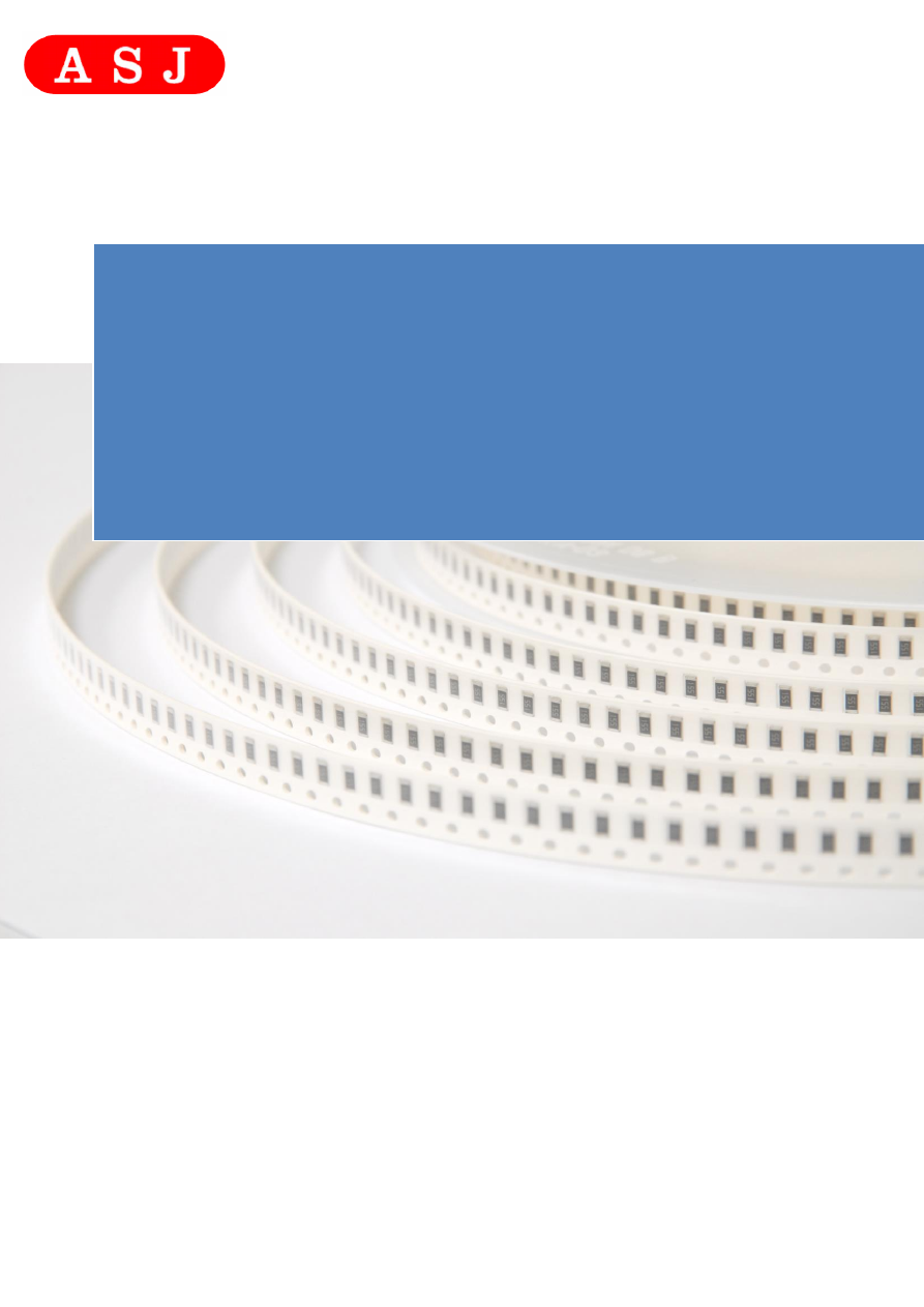
Mili Ohm Thick Film Chip Resistor 

CR Series 

1% TO 5%, TCR ±200 TO ±1500 

SIZE: 0402/0603/0805/1206/1210/2010/2512 

RoHs Compliant


Towards Excellence in 

Quality, Service & Innovation


ASJ DS_Milli Ohm Thick Film Chip Resistor-html.html
background image

MILI OHM THICK FILM CHIP RESISTOR


CR Series


DS-ENG-005                                                                                                                                  

Page: 

2 of 16


     Towards Excellence in 

Quality, Service & Innovation


Product Specification 

1.


SCOPE


1.1


This specification is applicable to lead and halogen free CR series precision thick film chip 
resistors. 

1.2


Lead free products mean lead free termination meets RoHS requirement. Pb contained in 
glass material of resistor element is exempted by RoHS directive. 

1.3


The products for 0402, 0603, 0805, 1206, 1210, 2010 and 2512 are tested and passed 
based on the test conditions and methods defined in AEC-Q200. 
 

2.


PART NUMBERING SYSTEM


 Part Numbering is made in accordance with the following system: 

CR

10

-

-

F

K

Type

Size

 (Inch / mm)

Resistance 

Tolerance

Packaging

Milli Ohm Thick 

Film Chip 

Resistors

10 (0402/1005)
16 (0603/1608)
21 (0805/2012)
32 (1206/3216)
40 (1210/3225)
50 (2010/5025)
63 (2512/6432)

Resistors

4 - digit

E96

0.022Ω = R022

0.03Ω = R030

F = ± 1%

G = ± 2%

J = ± 5%

E = 4000 pcs Lead Free
L = 5000 pcs Lead Free

K = 10,000 pcs Lead Free

Y = 20,000pcs Lead Free

Nominal Resistance 

RXXX


3.


RATING


3.1


Rated Power 


3.1.1


Resistor Rated Power 

Product Type 

Rated Power 

Maximum Rated 

Current 

Maximum Overload 

Current 

CR10 

1/16W 

1.58A 

3.95A 

CR16 

1/10W 

3.16A 

7.91A 

CR21 

1/8W 

3.53A 

8.82A 

CR32 

1/3W 

5.77A 

14.42A 

CR40 

1/2W 

7.07A 

17.67A 

CR50 

3/4W 

8.66A 

21.65A 

CR63 

1W 

10A 

25A 


ASJ DS_Milli Ohm Thick Film Chip Resistor-html.html
background image

MILI OHM THICK FILM CHIP RESISTOR


CR Series


DS-ENG-005                                                                                                                                  

Page: 

3 of 16


     Towards Excellence in 

Quality, Service & Innovation


Product Specification 

3.2


Power Derating Characteristics 

Rated Power shall be the load power corresponding to nominal wattage suitable for 
continuous use at 70

C ambient temperatures.  In case the ambient temperature exceeds 

70

C, reduce the load power in accordance with Derating curve in Fig. 1. 


Fig.1 Power Derating Characteristics 

3.3


Standard Atmospheric Condition 

Unless otherwise specified, the standard range of atmospheric conditions for making 
measurements and tests is as follows: 

Ambient Temperature   = + 5

C to +35

Relative Humidity 

= < 85% RH 

Air Pressure 


= 86 kPa to 106kPa 

If there may be any doubt about the results, measurement shall be made within the 
following limits: 

Ambient Temperature  = 20 

  2

Relative Humidity 

= 60 to 70% RH 

Air Pressure 


= 86 kPa to 106kPa 


3.4 

Operating Temperature Range 

-55

C to +155

C  


3.5 

Storage Temperature Range 

-5

C to + 40


3.6 

Flammability Rating 

Tested in accordance to UL-94, V-0 


3.7 

Moisture Sensitivity Level Rating: 

Level 1 


3.8 

Product Assurance ASJ resistor shall warranty 24 months from the date of shipment. 

ASJ DS_Milli Ohm Thick Film Chip Resistor-html.html
background image

MILI OHM THICK FILM CHIP RESISTOR


CR Series


DS-ENG-005                                                                                                                                  

Page: 

4 of 16


     Towards Excellence in 

Quality, Service & Innovation


Product Specification 

3.9


ASJ resistors are RoHS compliance in accordance to RoHS Directive 2011/65/EU. 

3.10


Resistance, Resistance Tolerance and Temperature Coefficient of Resistance. 


ASJ DS_Milli Ohm Thick Film Chip Resistor-html.html
background image

MILI OHM THICK FILM CHIP RESISTOR


CR Series


DS-ENG-005                                                                                                                                  

Page: 

5 of 16


     Towards Excellence in 

Quality, Service & Innovation


Product Specification 

3.11


Rated Voltage 

The rated voltage is calculated from the rated power and nominal resistance by the 
following formula: 


___ 

E    =  

 P.R 


Where   E :   Rated Voltage (V) 


P :   Rated Power (W) 
R :   Nominal Resistance (


In case the value calculated by the formula exceeds the maximum working voltage given in 
Section 3.1.2, the maximum working voltage in Section 3.1.2 shall be regarded as the rated 
voltage. 
 

3.12 

All product, product specifications and data are subject to change without notice to 
improve reliability, function or design or otherwise. 


4.


MARKING ON PRODUCT


The nominal resistance shall be marked on the surface of each resistor 

Part 

Number 

Color 

Marking on Product 

CR10 

(0402) 

No marking 

CR16 

(0603) 

Light Yellow 

1)  Tolerance : +/-1.0% (F) 
  

°

    Four Numerals Marking (E96 Series)     

CR21 

(0805) 

Light Yellow 


CR32 

(1206) 

Light Yellow / Black 


CR40 

(1210) 

Light Yellow 


CR50 

(2010) 

Light Yellow 


CR63 

(2512) 

Light Yellow 


4.1


Numeric Numbering 
 

4.1.1


1% Tolerance : 

Four Numerals  Marking


The Digits after R is significant figures. Letter R is decimal point.


Examples: 

Nominal Resistance 

Marking 

Remarks 

22m 


R022 

220 X 10

-3

  = 0.22


100m 


R100 

100 X 10

-3

  = 0.1


220m 


R220 

22 X 10

-3

  = 0.022


ASJ DS_Milli Ohm Thick Film Chip Resistor-html.html
background image

MILI OHM THICK FILM CHIP RESISTOR


CR Series


DS-ENG-005                                                                                                                                  

Page: 

6 of 16


     Towards Excellence in 

Quality, Service & Innovation


Product Specification 

I

I

I

I

5.


DIMENSIONS, CONSTRUCTIONS AND MATERIALS


5.1


Dimensions 


                                                                                                                           Unit: Inches (Millimeters) 

CODE 

I

1


I

2


CR10 

0.040±0.004 

0.020±0.002 

0.012±0.004 

0.010±0.004 

0.007±0.004 

(0402) 

(1.00±0.10) 

(0.50±0.05) 

(0.30±0.10) 

(0.25±0.10) 

(0.20±0.15) 

CR16 

0.063±0.004 

0.031±0.004 

0.018±0.004 

0.010±0.004 

0.014±0.004 

(0603) 

(1.60±0.10) 

(0.80±0.10) 

(0.45±0.10) 

(0.25±0.15) 

(0.35±0.15) 

CR21 

0.079±0.006 

0.049±0.004 

0.020±0.004 

0.014±0.008 

0.014±0.008 

(0805) 

(2.00±0.10) 

(1.25±0.10) 

(0.50±0.10) 

(0.35±0.20) 

(0.35±0.20) 

CR32 

0.118±0.004 

0.060±0.004 

0.020±0.004 

0.016±0.008 

0.025±0.004 

(1206) 

(3.05±0.10) 

(1.55±0.10) 

(0.50±0.10) 

(0.45±0.20) 

(0.65±0.15) 

CR40 

0.118±0.004 

0.100±0.004 

0.022±0.004 

0.020±0.008 

0.020±0.008 

(1210) 

(3.05±0.10) 

(2.55±0.10) 

(0.55±0.10) 

(0.50±0.20) 

(0.50±0.20) 

CR50 

0.200±0.008 

0.098±0.008 

0.024±0.004 

0.025±0.008 

0.025±0.008 

(2010) 

(5.00±0.20) 

(2.50±0.20) 

(0.60±0.10) 

(0.65±0.20) 

(0.65±0.20) 

CR63 

0.250±0.008 

0.126±0.008 

0.024±0.004 

0.025±0.008 

0.025±0.008 

(2512) 

(6.30±0.20) 

(3.20±0.20) 

(0.60±0.10) 

(0.65±0.20) 

(0.65±0.20) 


ASJ DS_Milli Ohm Thick Film Chip Resistor-html.html
background image

MILI OHM THICK FILM CHIP RESISTOR


CR Series


DS-ENG-005                                                                                                                                  

Page: 

7 of 16


     Towards Excellence in 

Quality, Service & Innovation


Product Specification 

6.


ELECTRICAL CHARACTERISTICS AND TEST CONDITIONS


CHARACTERISTICS  

SPECIFICATIONS 

TESTING CONDITIONS 

Resistance 

Resistance 
Temperature 
Coefficient 

Refer Section 3.5 Table 1 


MIL-STD-202 Method 304 

Measure R at t

o

=25

0

C and after 45 

minutes measure R at t=125

0

C. 

Calculation :  

TCR(ppm/

0

C)=R – R

0

   x  1   x 10

6


                            R

0  

        t-t

0   


Short Time 
Overload 

1%, 2%, 5%: ±(2.0%+0.001Ω) 

JIS C 5201-1 4.13 

Apply at 2.5 times rated voltage for 5 
seconds. 
Applied voltage shall not exceed 
maximum overload voltage or current. 

Insulation 
Resistance 

> 10G 


JIS C 5201-1 4.6 

Apply (100 

±15) 

VDC for 1 minute. 

Measured the insulation resistance 
between electrodes and insulating 
enclosure or between electrodes and 
base.   


Dielectric 
Withstanding 
Voltage 

No failure of resistor such as short-
circuit, burning, breakdown. 

JIS C 5201-1 4.7 

Apply 500VAC for 1 minute  
± 5secs. for chip 

 0805.   

Apply 300VAC for 1 minute  
± 5secs. for chip 0402 & 0603 
Apply 50Vac for 1 minute   
± 5secs for 0201 

±(5.0%+0.001Ω) 


The variation in relation to the initial 
resistance shall be within + 1%. 


ASJ DS_Milli Ohm Thick Film Chip Resistor-html.html
background image

MILI OHM THICK FILM CHIP RESISTOR


CR Series


DS-ENG-005                                                                                                                                  

Page: 

8 of 16


     Towards Excellence in 

Quality, Service & Innovation


Product Specification 

Intermittent 
Overload 

±(5.0%+0.001Ω) 

JIS C 5201-1 4.13 

Apply 2.5 times rated voltage for 1 secs 
ON and 25 secs OFF. 
Total 10 000


Applied voltage/current shall not exceed 
maximum intermittent overload voltage/ 
current. 

Noise 

1~9 
10~99 
100~999 
1K~9.9K 
10K~99.9K 
100K~999.9K 
>1M 

-10dB(0.32

v/v) 

- 5 dB(0.52

v/v) 

0   dB(1.0

v/v) 

10 dB(3.2

v/v) 

18 dB(5.6

v/v) 

20 dB(10

v/v) 

30 dB(32

v/v) 

JIS C 5201-1 4.12


V

0

(dB) = T-

f

(T-S)-D 


Terminal Strength 

Test 1 : No evidence of mechanical 
damage. 
 
Test 2 : ≥5N


JIS C 5201-1 4.16 / AEC Q200-005 

Test 1 : The resistor mounted on the 
board applied 5N pushing force on the 
sample rear for 10sec.  
Test 2 : The resistor mounted on the 
board slowly add force on the sample 
rear until the sample termination is 
breakdown.


Resistance to 
Solvent 

±(1.0%+0.001Ω) 
 

MIL-STD-202 Method 215


Immerse in 25

C±5

C Isopropyl 

Alcohol (IPA) for 5 minutes. 
 

Passed without any damaged to marking 
& protective material. 

10  Solderability 

> 95% Coverage at all terminal 

J-STD-002 

For both Leaded & SMD. Electrical 
test not required. 
Magnification 50 X. Conditions: 
Leaded: Method A @ 235°C, category 
3. 
 

11  Resistance to 

soldering heat 
 

Δ

R%=±(1.0%+0.001Ω) 

MIL-STD-202 Method 210 

Solder bath method 
Resistor dipped entirely in solder bath 
of 260

5

C for  

10    sec.  
After which the sample shall be left at 
ambient temperature for 1~ 2 hrs before 
measurement. 


+400 
- 0 

cycles. 

  +1 
   0  


ASJ DS_Milli Ohm Thick Film Chip Resistor-html.html
background image

MILI OHM THICK FILM CHIP RESISTOR


CR Series


DS-ENG-005                                                                                                                                  

Page: 

9 of 16


     Towards Excellence in 

Quality, Service & Innovation


Product Specification 


12  Vibration 

1%,2%,5%:±(1.0%+0.001Ω) 

JIS-C5201-1 4.22 

The resistor shall be mounted by its 
terminal leads to the supporting 
terminals on the solid table. 
The entire frequency range: from 10 Hz 
to 55 Hz and return to 10 
Hz, shall be transferred in 1 min. 
Amplitude :1.5 mm 
This motion shall be applied for a 
period of 2 hours in each 3 
mutually perpendicular directions (a 
total of 6 hrs)


13  Low Temperature 

Operation 

1%, 2%, 5%:±(1.0%+0.001Ω) 

MIL-R-55342D 4.7.4 

Put the tested resistor in the chamber at 
room temperature 25

C. Decreasing the 

temperature to -55

C and keep the 

temperature at -55

C for 1 hour. Then 

load the rated voltage for 45 minutes 
on, and 15 minutes off. Then leaving 
the tested resistor in room temperature 
for 8±1 hours, and measure its 
resistance variance rate. 

14  Resistance Dry 

Heat 

1%, 2%, 5%:±(1.0%+0.001Ω) 

JIS-C5201-1 4.25 

Put tested resistor in chamber under 
temperature 155±5

C for 

1000 +48/-0 hours. Then leaving the 
tested resistor in room 
temperature for 60 minutes, and 
measure its resistance variance 
rate. 

15  Loadlife 

1%, 2%, 5%: ±(2.0%+0.001Ω) 

MIL-STD-202 Method 108 

At 70

2

C Apply DC rated voltage at 

90minutes On, 30minutes Off  for 1000 
hours 
Sample shall be left at ambient 
temperature for 1~ 2 hrs after test 
before measuring final resistance. 

16  Loading Life in 

Moisture 

1%, 2%, 5%: ±(2.0%+0.001Ω) 

JIS-C5201-1 4.24 

Put the tested resistor in the chamber 
under temperature 40±2

C, relative 

humidity 90~95% and load the rated 
voltage for 90 minutes on, 30 minutes 
off, total 1000 hours. Then leaving the 
tested resistor in room temperature for 
60 minutes, and measure its resistance 
variance rate. 

ASJ DS_Milli Ohm Thick Film Chip Resistor-html.html
background image

MILI OHM THICK FILM CHIP RESISTOR


CR Series


DS-ENG-005                                                                                                                                  

Page: 

10 of 16


     Towards Excellence in 

Quality, Service & Innovation


Product Specification 

6.1


Soldering Profile 


6.1.1 

Wave Soldering  


6.1.2


Reflow Soldering 


245~260

C  

Double wave 4~6 seconds 

Soldering temperature 

40~60 seconds 

30~45 seconds 

Pre-heat zone 

Pre-heat temperature 

90~130

C  

(Soldering side) 

130~180

C

Reflow zone

30~40 seconds

Pre-heat zone 60~120 seconds

230

C ~ 250

C

ASJ DS_Milli Ohm Thick Film Chip Resistor-html.html
background image

MILI OHM THICK FILM CHIP RESISTOR


CR Series


DS-ENG-005                                                                                                                                  

Page: 

11 of 16


     Towards Excellence in 

Quality, Service & Innovation


Product Specification 

7.


TAPING 


7.1


Structure of Taping 


Paper Carrier


Embossed Plastic Carrier


ASJ DS_Milli Ohm Thick Film Chip Resistor-html.html
background image

MILI OHM THICK FILM CHIP RESISTOR


CR Series


DS-ENG-005                                                                                                                                  

Page: 

12 of 16


     Towards Excellence in 

Quality, Service & Innovation


Product Specification 

7.2


Dimension 


7.2.1 

Dimension of Punched Paper Tape Carrier System (CR -10) 


Remark : Pitch tolerance over any 10 pitches of Po is 

 0.2 mm 


               Dimension of Punched Paper Tape Carrier System (CR- 10) 
                                                                                                                         (Unit : mm) 

Code 

T1 

CR10  1.15

0.05  0.65

0.05  8.00

0.20  1.75

0.10  3.50

0.05 


Code 

T2 

P0 

10xP0 

P1 

CR10  0.40

0.05  2.00

0.10 

4.00

0.05  40.0

0.20  2.00

0.05 


7.2.2


Dimension of Punched Paper Tape Carrier System /Plastic Embossed 
Carrier System (CR16, 21, 32, 40, 50, 63) 


Dimension of Punched Paper Tape Carrier System (CR - 16, 21, 32, 40) 


Remark :  Pitch tolerance over any 10 pitches of Po is 

 0.2 mm 


+0.1 
- 0 

0.42 

ASJ DS_Milli Ohm Thick Film Chip Resistor-html.html
background image

MILI OHM THICK FILM CHIP RESISTOR


CR Series


DS-ENG-005                                                                                                                                  

Page: 

13 of 16


     Towards Excellence in 

Quality, Service & Innovation


Product Specification 


7.3


Packaging 


7.3.1


  Taping 

7.3.2 

Quantity – Tape and Reels 


Code 

Quantity 

Model 

Remarks 

CR10 

10000 pcs 

7” Reel 

10” Reel upon request 

CR16 


10” & 13” Reel for  

10 000 or 20 000 pcs 

on request 

CR21 

5000 pcs 

7” Reel


CR32 


CR40 

5000 pcs 

7” Reel 

CR50 

4000 pcs 

7” Reel 

CR63 

4000 pcs 

7” Reel 


ASJ DS_Milli Ohm Thick Film Chip Resistor-html.html
background image

MILI OHM THICK FILM CHIP RESISTOR


CR Series


DS-ENG-005                                                                                                                                  

Page: 

14 of 16


     Towards Excellence in 

Quality, Service & Innovation


Product Specification 

7.3.3


Identification 

Production  label  that  indicates  the  8  digits  lot  number,  product  type,  resistance  value 
and tolerance shall be pasted on the surface of each reel. 


7.3.4


Packaging Reel Box 


Dimension 

Reel Box 

Number of Reels 

185 × 60 × 186 mm 

25K Box 

185 × 120 × 186 mm 

50K Box 

10 


ASJ DS_Milli Ohm Thick Film Chip Resistor-html.html
background image

MILI OHM THICK FILM CHIP RESISTOR


CR Series


DS-ENG-005                                                                                                                                  

Page: 

15 of 16


     Towards Excellence in 

Quality, Service & Innovation


Product Specification 

7.3.5


Reel Dimensions 


W

t

A

r

D

C

B

B


Model 

W

7”Reel (5K) 
(except 0402 10K) 

178

2.0 

60min 

13

 0.2 

2.0

 0.5 

11

 0.1 

14.4 max 

1.0

 0.1 

1.0 

7”Reel (4K) 

178

2.0 

60min 

13

 0.2 

2.0

 0.5 

13

1.0 

14.4 max 

1.2

 0.1 

1.0 

10”Reel (10K) 

254

2.0 

60min 

13

 0.2 

2.0

 0.5 

11

 1.0 

14.4 max 

1.5

 0.1 

1.0 

13”Reel 
(20K, 50K) 

330

2.0 

60min 

13

 0.2 

2.0

 0.5 

11

 1.0 

14.4 max 

2.1

 0.1 

13”Reel (20K) 

330

1.0 

100±1 

13.5±0.5 

2~3±0.5 

10±0.5 


W

1


ASJ DS_Milli Ohm Thick Film Chip Resistor-html.html
background image

MILI OHM THICK FILM CHIP RESISTOR


CR Series


DS-ENG-005                                                                                                                                  

Page: 

16 of 16


     Towards Excellence in 

Quality, Service & Innovation


Product Specification 

SMC 

8.


SURFACE MOUNT LAND PATTERNS 


Product ( Type ) 

Land Dimension 


CR05 (0201) 

0.012 [0.3] 

0.04 [1.0] 

0.016 [ 0.4 ] 

CR10 (0402) 

0.020 [0.5] 

0.059 [1.5] 

0.024 [ 0.6 ] 

CR16 (0603) 

0.031 [0.8] 

0.083 [2.1] 

0.035 [ 0.9 ] 

CR21 (0805)  

0.047 [1.2] 

0.118 [3.0] 

0.051 [ 1.3 ] 

CR32 (1206) 

0.087 [2.2] 

0.165 [4.2] 

0.063 [ 1.6 ] 

CR40 (1210) 

0.087 [2.2] 

0.165 [4.2] 

0.110 [ 2.8 ] 

CR50 (2010) 

0.138 [3.5] 

0.240 [6.1] 

0.110 [ 2.8 ] 

CR63 (2512) 

0.149 [3.8] 

 0.315 [8.0] 

0.137 [ 3.5 ] 

ASJ DS_Milli Ohm Thick Film Chip Resistor-html.html
background image

MILI OHM THICK FILM CHIP RESISTOR


CR Series


DS-ENG-005                                                                                                                                  

Page: 

17 of 16


     Towards Excellence in 

Quality, Service & Innovation


Product Specification 

9.


REVISION HISTORY  


REVISION 

DATE 

    CHANGE NOTIFICATION         DESCRIPTION 

Version. 1 

February 
13,2015 


       Initial Release 

Version. 2 


Version 3 

June  
11,2015 


February  
6,2017 


Refer to PCN-ECO  

:01/2016 

Revise Clause 3.1.1,             
Power Rating : 

-


CR32  1/4W  

-


CR40 1/3W 

 
Typo error in clause 
2 “Part Numbering 
System” 
 
Typo error in clause 
6.1.1, 6.1.2, change 
IR Reflow to Wave 
Soldering, change 
wave to Reflow 
Soldering 
 
Update clause 7.2 
dimension 
information 
Update clause 7.3.5, 
insert 13” reel 
information