ASJ PTE LTD
14
CF
Carbon Film Resistors
INTRODUCTION
The Carbon Film Resistors are highly reliable. These resistors are pyrolytically deposited and
manufactured in streamlined automated assembly facilities under strict quality control procedures.
The stable performance is achieved with the technology of film deposition onto a ceramic core with
excellent thermal conductivity, mechanical strength and good electrical properties. Together with
multi layers of epoxy coatings, the Carbon Film Resistors offer stability with long term reliability.
FEATURES
• Small size with high power ratings.
• Excellent long term stability.
• Wide Resistance Range.
• Lead Free
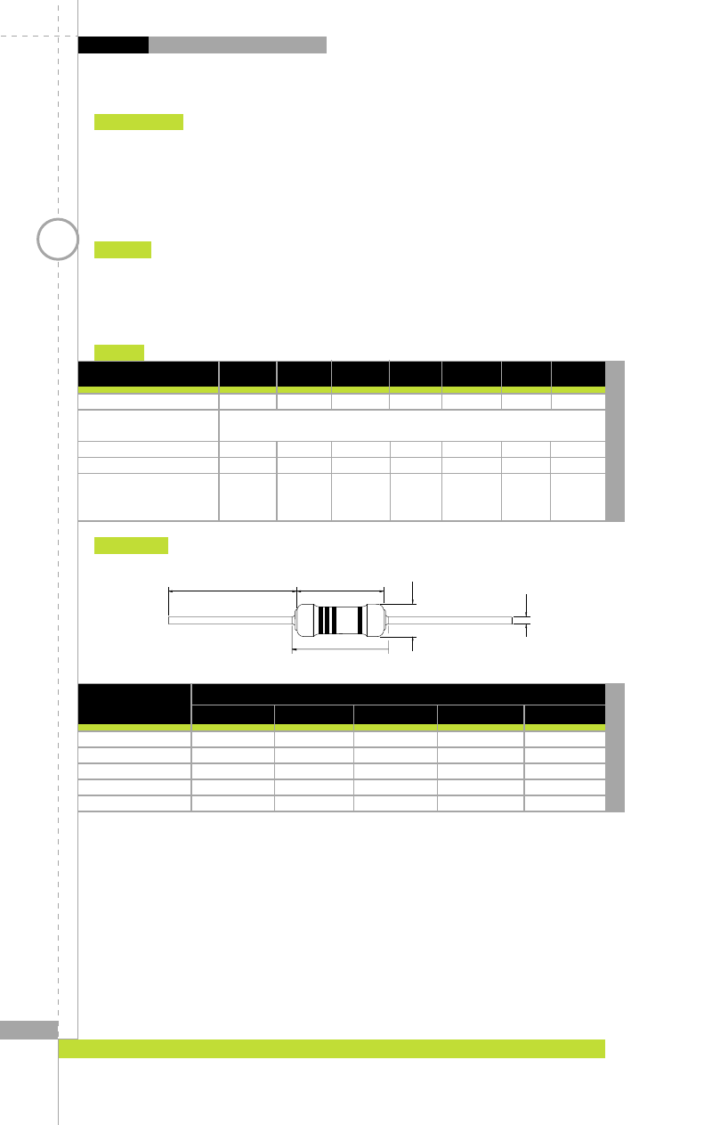
DIMENSIONS
Type
DIMENSIONS
L
C
D
l
d
CF1/6 / CF1/4SS
3.00
±
0.4
3.5 Max
1.70
±
0.2
28.0
±
3.0
0.45
±
0.05
CF1/4 / CF1/2SS
6.35
±
0.5
7.1 Max
2.30
±
0.3
28.0
±
3.0
0.60
±
0.05
CF1/2
9.00
±
0.5
11.8 Max
3.20
±
0.5
28.0
±
3.0
0.60
±
0.05
CF 1
12.00
±
1.0
15.0 Max
4.50
±
0.5
35.0
±
3.0
0.80
±
0.05
CF 2
16.00
±
1.0
22.0 Max
5.00
±
0.5
35.0
±
3.0
0.80
±
0.05
(Millimeters)
ød
øD
l
L
C
RATINGS
Type
CF 1/6 CF 1/4 CF1/4SS CF 1/2 CF1/2SS CF 1 CF 2
Power Rating @ 70ºC
1/6W 1/4W 1/4W 1/2W
1/2W 1W 2W
Operating Temp. Range
-55ºC to +155ºC
Derated to 0 Load at
+155ºC
Maximum Working Voltage
200V 250V 250V 350V
350V 500V 500V
Maximum Overload Voltage
400V 500V 500V 700V
700V 700V 1000V
Resistance Range
2%, E-24
10
Ω
-1M
Ω
10
Ω
-1M
Ω
10
Ω
-1M
Ω
10
Ω
-1M
Ω
10
Ω
-1M
Ω
10
Ω
-1M
Ω
10
Ω
-1M
Ω
5%, E-24
1
Ω
-22M
Ω
1
Ω
-22M
Ω
1
Ω
-22M
Ω
1
Ω
-22M
Ω
1
Ω
-22M
Ω
1
Ω
-22M
Ω
1
Ω
-22M
Ω