background image

CAPACITORS FOR AC AND SWITCH
MODE APPLICATIONS

These capacitors are made of a new dielectric compound
specially developed for AC or switch mode circuits that can
generate dielectric heat which is limiting factor on other
ceramic disc capacitors.

This new series adds the advantages of class I (low loss
factor) with the advantages of class II capacitors (small sizes
and lower costs).

The capacitors are epoxy coated, flame retardant class
UL 94-V0. They meet the standards of the telecom and
data processing industry. They are particularly suited for TV
deflection and power supply circuits.

21

Lead Spacing

Digit 8

F

5 (0.200)

A

N

6 (0.250)

E

X

7.5 (0.300)

B

R

Q

10 (0.400)

C

W

12.5 (0.500)

P

Disc Ceramic Capacitors

AC and Switch Mode Epoxy Coated

Measured at

1.0 kHz / 0.3 Vrms / 25ºC

Dissipation 

6LR / 6LS / 6LT 

0.3%

Factor

67S / 68S 

0.8%

6LR

6LS

6LT

67S

68S

Capacitance

±10%

X

X

X

Tolerance

±20%

X

X

X

X

-20 +50%

X

X

X

X

X

Insulation
Resistance

@ 500V 

→ ≥

10 G

Dielectric Strength
NOTE: Charging

1.5 x V

R

+ 500 (DC)

current limited

Between leads and body insulation

to 50 mA

Operating
Temperature

-40... +125

Range (ºC)

Climatic

30 / 085 / 56

Category

Max. Temp. rise on

Measured at

the external surface

20mm from

of the capacitor

the capacitor

related to ambient

PERFORMANCE CHARACTERISTICS
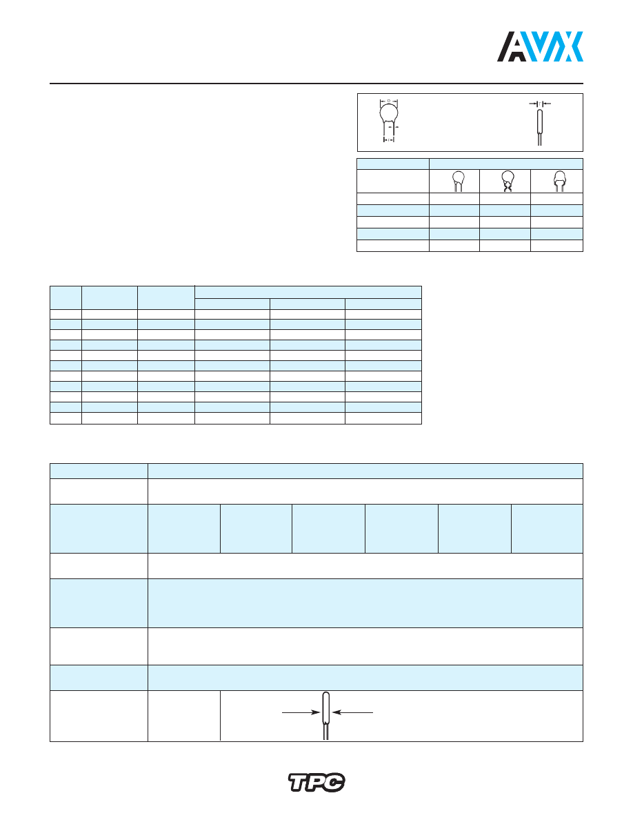
DIMENSIONS

millimeters (inches)

Note: Damp Heat Steady State: 90... 95% R.H. 40ºC / 56 days. No voltage to be applied.

Tamb

celsius

20 mm

Tmax

celsius

Tmax. = Tamb + 20ºC

Ø mm = 

0.6

± 0.1

(0.024) (0.004)

Ø mm =

0.8

± 0.1

(0.031) (0.004)

Digit 9

D ± 2

T max.

Available Lead Spacing

(ø)

(0.079)

Vn = 1000V

Vn = 2000V

Vn = 3000V

A

4.0 (0.157)

4.0 (0.157)

A,B,E,N,R

A,B,E,N,R

B,E

B

5.0 (0.197)

4.0 (0.157)

A,B,E,N,R,X

A,B,E,N,R

B,E

C

6.0 (0.236)

4.0 (0.157)

A,B,C,E,N,R,X

A,B,C,E,N,R,

B,C,E

D

7.0 (0.276)

4.0 (0.157)

A,B,C,E,N,Q,R,X

A,B,C,E,N,Q,R

B,C,E

E

8.0 (0.315)

4.0 (0.157)

A,B,C,E,N,Q,R,X

A,B,C,E,N,Q,R

B,C,E

F

9.0 (0.354)

5.0 (0.197)

A,B,C,E,N,R,X

A,B,C,E,N,R

B,C,E

G

10.0 (0.394)

5.0 (0.197)

A,B,C,E,N,R,X

A,B,C,E,N,R

B,C,E

H

11.0 (0.433)

5.0 (0.197)

A,B,C,E,N,P,R,W

A,B,C,E,N,P,R,W

B,C,E,P,W

J

13.0 (0.512)

6.0 (0.236)

B,C,N,P,R,W

B,CN,P,R,W

B,C,P,W

K

15.0 (0.591)

6.0 (0.236)

B,C,N,P,R,W

B,CN,P,R,W

B,C,P,W

M

19.0 (0.748)

7.0 (0.276)

B,C,P

B,C,P

B,C,P

(E), (X), (W): upon request

AVX_Disc_Ceramic_Capacitors_Dielectric_AC_SWITCH-html.html
background image

22

Disc Ceramic Capacitors

AC and Switch Mode Epoxy Coated

CAPACITANCE VS. DISC DIAMETER

millimeters (inches)

Temp.

Coefficient 

Y5P

Y5U

Y5V

Digits 1, 2, 3

of P.N.

6LR

6LS

6LT

67S

68S

Rated

1000 VDC

2000 VDC

3000 VDC

2000 VDC

2000 VDC

Voltage

(V

R

)

130 VAC

250 VAC

380 VAC

250 VAC

250 VAC

C

R

(pF)

220

7.0 (0.276)

7.0 (0.276)

270
330

7.0 (0.276)

390

8.0 (0.315)

9.0 (0.354)

470

9.0 (0.354)

10.0 (0.394)

560
680

8.0 (0.315)

10.0 (0.394)

11.0 (0.433)

820

13.0 (0.512)

1000

9.0 (0.354)

11.0 (0.433)

8.0 (0.315)

1200
1500

11.0 (0.433)

13.0 (0.512)

1800

15.0 (0.591)

2200

13.0 (0.512)

15.0 (0.591)

9.0 (0.354)

2700
3300

15.0 (0.591)

10.0 (0.394)

3900

19.0 (0.748)

19.0 (0.748)

4700

11.0 (0.433)

8.0 (0.315)

10000

11.0 (0.433)

Diameter (

φ

) = 9th Part Number Digit

AVX_Disc_Ceramic_Capacitors_Dielectric_AC_SWITCH-html.html
background image

4

5

General Purpose

5A = NP0 / I

*5B = P100 / I

*5C = N150 / I
*5D = N220 / I

*5E = N330 / I

*5F = N470 / I

5G = N750 / I

5H = N1500 / I

*5I = N2200 / I

*5J = N4700 / I

5K = SL

5M = Y5E / II

5N = Y5F / II

5O = Y5P / II

*5P = Y5R / II

*5Q = Y5T / II

5S = Y5U / II

5T = Y5V / II

5U = Z5V / II

*5V = Z4V / III
5W = Y5P / III

5Y = Y5U / III

5Z = Y5V / III

O

Professional Switch Mode

Safety

6A = NP0 / I

*6B = P100 / I

*6C = N150 / I
*6D = N220 / I

*6E = N330 / I

*6F = N470 / I

6G = N750 / I

*6H = N1500 / I

*6I = N2200 / I

6J = N4700 / I

61 = SAFETY
62 = SAFETY
65 = SAFETY
67 = Y5U / SM
68 = Y5V / SM
6L = Y5P / SM

6M = X5E / II

6N = X5F / II

6O = X5P / II

*6P = X5R / II

*6Q = X5T / II

6S = X5U / II

6T = X5V / II

6U = Z5V / II

*6V = Z4V / III
6W = Y5P / III

6Y = Y5U / III

6Z = Y5V / III

Q

Rated Voltage (dc)

D = 16V

F = 25V

H = 50V

K = 100V

N = SAFETY

O = SAFETY
Q = 500V

R = 1000V

S = 2000V

T = 3000V

U = 4000V

V = SAFETY

W = 5000V
*X = 6000V

*Y = 7500V

HOW TO ORDER

222

Capacitance

222 = 2.2 nF

Disc Ceramic Capacitors

Ordering Code

Capacitance = TPC code

1 pF = 1R0

1.2pF = 1R2
1.5pF = 1R5
1.8pF = 1R8
2.2pF = 2R2
2.7pF = 2R7
3.9pF = 3R9
4.7pF = 4R7
5.6pF = 5R6
6.8pF = 6R8
8.2pF = 8R2

10pF = 100
12pF = 120
15pF = 150
18pF = 180
22pF = 220
27pF = 270
33pF = 330
39pF = 390
47pF = 470
56pF = 560
68pF = 680
82pF = 820

Capacitance = TPC code

100pF = 101
120pF = 121
150pF = 151
180pF = 181
220pF = 221
270pF = 271
330pF = 331
390pF = 391
470pF = 471
560pF = 561
680pF = 681
820pF = 821

1nF = 102

1.2nF = 122
1.8nF = 182
2.2nF = 222
2.7nF = 272
3.3nF = 332
3.9nF = 392
4.7nF = 472
5.6nF = 562
6.8nF = 682
8.2nF = 822

10nF = 103
15nF = 153
22nF = 223
33nF = 333
47nF = 473

100nF = 104
200nF = 204

*Upon Request

AVX_Disc_Ceramic_Capacitors_Dielectric_AC_SWITCH-html.html
background image

5

M

Tolerance

C = ±0.25 pF
D = ±0.50 pF

J = ±5%

K = ±10%

M = ±20%

S = -20+50%

Z = -20+80%

P = 0+100%

A

E

Capacitor Diameter

± 2 (0.079)

A = 4 (0.157)
B = 5 (0.197)

C = 6 (0.236)
D = 7 (0.276)

E = 8 (0.315)
F = 9 (0.354)

G = 10 (0.394)
H = 11 (0.433)

J = 13 (0.512)

K = 15 (0.591)

M* = 19 (0.748)

A

A

Packaging

Disc Ceramic Capacitors

Ordering Code

Lead Forming

mm

inches

2.5 ±0.5

.1 ± .025

D

5

+0.6

.2 ± .025

A

O

N

-0.2

6

+0.6

.25 ± .025

E

X

-0.2

7.5

+1

.3 ± .05

B

R

Q

-0.5

10

+0.5

.4 ± .05

C

W

-1.0

12.5

+1

.5 ± .05

P

-0.5

Low Voltage

A =

(

General 

)

Q = Waxed phenolic

Phenolic

Purpose

S = Epoxy (Professional) cap. diameter 

8 (0.315)

D = Epoxy (Professional) cap. diameter

> 8 (0.315)

High Voltage

C = Epoxy wire diameter

0.6

±

0.1

(0.024)

(0.004)

I = Epoxy wire diameter

0.8

±

0.1

(0.031)

(0.004)

L = Phenolic wire diameter

0.6

±

0.1

(0.024)

(0.004)

Finishing

Coating does not
surpass the bend

Diam 

9 (0.354) and

F = 5.00 (0.197)

For every other:

Avisert

Panasert

H

L

L

J

L

L

F = Measured

from the
center of
leads

Cardboard Strips

A

Bulk

E

=  5 (0.197) ± 1 (0.039) free wire length

C

= 10 (0.394) ± 1 (0.039) free wire length

D

= 25 (0.984) ± 1 (0.039) free wire length 

Taping

Reel

Ammo

Pack

Please note that not all code combinations

are either possible or available.

*Wire 0.8 (0.031) recommended

Avisert

Panasert

I

M M

K

M

M

AVX_Disc_Ceramic_Capacitors_Dielectric_AC_SWITCH-html.html
background image

28

Disc Ceramic Capacitors

Marking

DIG. 2

O

TC / Class

General Purpose

A = NP0 / I

*B = P100 / I

*C = N150 / I

*D = N220 / I

*E = N330 / I

*F = N470 / I

G = N750 / I

H = N1500 / I

*I = N2200 / I

*J = N4700 / I

K = SL

M = Y5E / II

N = Y5F / II

O = Y5P / II

P = Y5R / II

Q = Y5T / II

S = Y5U / II

T = Y5V / II

U = Z5V / II

V = Z4V / III

*W = Y5P / II

*X = Y5R / II

Y = Y5U / II

Z = Y5V / II

Professional

A = NP0 / I

B = P100 / I

C = N150 / I

D = N220 / I

E = N330 / I

F = N470 / I

G = N750 / I

H = N1500 / I

I = N2200 / I

J = N4700 / I

7 = Y5U / SM

8 = Y5V / SM

L = Y5P / SM

M = X5E / II

N = X5F / II

O = X5P / II

P = X5R / II

Q = X5T / II

S = X5U / II

T = X5V / II

U = Z5V / II

V = Z4V / III

W = Y5P / III

X = Y5R / III

Y = Y5U / III

Z = Y5V / III

Capacitance

1pF = 109

1.2pF = 129

1.5pF = 159

1.8pF = 189

2.2pF = 229

2.7pF = 279

3.9pF = 399

4.7pF = 479

5.6pF = 569

6.8pF = 689

8.2pF = 829

10pF = 100

12pF = 120

15pF = 150

18pF = 180

22pF = 220

27pF = 270

39pF = 390

47pF = 470

56pF = 560

68pF = 680

82pF = 820

EIA

100pF = 101

120pF = 121

150pF = 151

180pF = 181

220pF = 221

270pF = 271

390pF = 391

470pF = 471

560pF = 561

680pF = 681

820pF = 821

1nF = 102

1.2nF = 122

1.8nF = 182

2.2nF = 222

2.7nF = 272

3.9nF = 392

4.7nF = 472

5.6nF = 562

6.8nF = 682

8.2nF = 822

10nF = 103

15nF = 153

22nF = 223

33nF = 333

47nF = 473

100nF = 104

200nF = 204

Logo: Only in diam. 

6mm

DIG. 3

Q

Rated Voltage

D = 16V

F = 25V

H = 50V

K = 100V

Q = 500V

R = 1000V

S = 2000V

T = 3000V

U = 4000V

W = 5000V

X = 6000V

Y = 7500V

Tolerance

C = ±0.25pF

D = ±0.5pF

J = ±5%

K = ±10%

M = ±20%

S = -20 +50%

Z = -20 +80%

P = 0 +100%

DIG. 7

M

Type

61V

620

65N

Tolerance

As above

Capacitance

As above

Safety
Front

Back: (Approval marks)

61V

471M

TC – Temperature coefficient.

DIG – for better understanding, check pages 3 and 4.

222

OQM

*Upon Request

AVX_Disc_Ceramic_Capacitors_Dielectric_AC_SWITCH-html.html
background image

29

29

Disc Ceramic Capacitors

Packaging

TAPED PARTS QUANTITY TABLE

millimeters (inches)

CARDBOARD STRIPS QUANTITY TABLE

millimeters (inches)

IDENTIFICATION AND TRACEABILITY

On all TPC ceramic capacitors

packages, you will find a bar code label

with the following information:

Rated Voltage

Diameter

Quantities

(Vr)

D

Ammopack

Reel

Vr <= 500V

7 (0.276)

2000

2500

7 < D 

11 (0.433)

2000

2000

500V<Vr<=2KV

11 (0.433)

1500

2000

2KV<Vr=5KV

11 (0.433)

1000

1500

Quantities for other package alternative, upon request.

Lot number

Manufacturing date

Quantity of parts per packaging

Product part number

Rated Voltage

Diameter

Lead Space

(Vr)

D

< = 5 (0.197)

> 5 (0.197)

Vr <= 500V

⬉ 

8 (0.315)

2500

1500

8 (0.315) 

⬉ 

D

⬉ 

11 (0.433)

1500

-

8 (0.315) 

⬉ 

D

⬉ 

13 (0.512)

-

1000

11 (0.433) 

⬉ 

D

⬉ 

15 (0.591)

1000

-

13 (0.512) 

⬉ 

D

⬉ 

19 (0.748)

-

500

⬉ 

19 (0.748)

500

-

500V<Vr<=2KV

⬉ 

9 (0.354)

1500

1000

9 (0.354) 

⬉ 

⬉ 

11 (0.433)

-

1000

9 (0.354) 

⬉ 

⬉ 

13 (0.512)

1000

-

11 (0.433) 

⬉ 

⬉ 

19 (0.748)

-

500

13 (0.512) 

⬉ 

⬉ 

19 (0.748)

500

-

2KV<Vr<=5KV

⬉ 

9 (0.354)

1500

-

Safety 65N 62O

⬉ 

11 (0.433)

-

1000

⬉ 

13 (0.512)

500

500

Safety

⬉ 

6 (0.236)

1500

1500

61V

7 (0.275) 

⬉ 

⬉ 

9 (0.354)

1000

1000

9 (0.354) 

⬉ 

D

500

500

AVX_Disc_Ceramic_Capacitors_Dielectric_AC_SWITCH-html.html
background image

30

Disc Ceramic Capacitors

Tape and Reel Specifications

Straight leads

Maximum pull force during insertion and lead cut

F

1

F

2

4 (0.157) 

D < 6 (0.236)

12N

20N

6 (0.236)

20N

25N

Crimped leads

Digit 11

Available Tapings

Digit 9 

L

Sizes

4 (0.157) 

11 (0.433)

A... H

M

J   H

Sizes

6 (0.236) 

11 (0.433)

C... H

K   I

There are two types of taped disc ceramic capacitors:
Straight or crimped leads.

Both types can be shipped on reels or ammopack.
The standard packaging quantities are shown bellow:

TPC Code     Digit 11

Packaging

Avisert

Panasert

H

FIGURE 1

L

FIGURE 2

L

FIGURE 3

I

FIGURE 1

M

FIGURE 2

M

FIGURE 3

J

FIGURE 1

L

FIGURE 2

L

FIGURE 3

K

FIGURE 1

M

FIGURE 2

M

FIGURE 3

Ammopack

Reel

Figure 2: Inside Crimp 100V... 1000V

Figure 3: Outside Crimp 1000V

Fig. 1

Fig. 2

Fig. 3

millimeters (inches)

AVX_Disc_Ceramic_Capacitors_Dielectric_AC_SWITCH-html.html
background image

31

Disc Ceramic Capacitors

Tape and Reel Specifications

Straight Leads

Crimped

Figure 1

Figure 2 & 3

Description of Symbols

A (Avisert)

P (Panasert)

Avisert & Panasert

Crimp angle

20º...45º

Crimp length

C

1.7 min.

Lead diameter

d

0.60 ± 0.1

Disc diameter

D

11 max.

Lead hole diameter

Do

4.0 ± 0.2

Disc thickness

T

See Catalog

Lead spacing

F

5.0

Component alignment, front-rear

h

0  ± 1

Height of component from tape center

H

19.5 ± 0.5

16.5 ± 0.5 - 0

Height from tape center to crimp

Ho

16 + 0.5 - 0

Component height

H1

32.25 max.

32.25 max.

Distance from component leads to tape bottom

1

12 max.

Tape width

W

18

Bonding tape width

W

3

5.5 min.

Feed hole position

W

1

9.0 ± 0.5

Pitch between discs

P

12.7 ± 1

Feed hole pitch

Po

12.7 ± 0.3

Hole center to lead

P1

3.85 ± 0.7

Feed hole center to component center

P2

6.35 ± 1

Tape + bonding tape thickness

t

0.7 ± 0.2

Total tape thickness. including lead

t

2

1.5 max.

millimeters (inches)

PACKAGING

SHIPPING CONTAINER

Ammopack

Reel

max. stacking: 10 boxes

max. stacking: 10 reels

8 Ammopack

5 Reel

This side up

during storage

and transportation

+0.6

-0.2

+1

-0.5

>23.5

<32.25