AAVID
THERMALLOY
PRODUCT SELECTION GUIDE
Condensed
AAVID
THERMALLOY
PRODUCT SELECTION GUIDE
Condensed

AAVID
THERMALLOY
Corporate Office: 80 Commercial Street • Concord, NH 03301
Tel. (603) 224-9988 • Fax (603) 223-1790
AAVID
THERMALLOY
PRODUCT SELECTION GUIDE
Condensed
This condensed catalog features the more popular devices and configurations that Aavid
Thermalloy produces today to cool high speed microprocessors and other commonly used semi
conductors. We offer a broad range of products and consulting services.These are the most popular
parts and we are adding new ones on a regular basis. Contact Aavid’s application engineering for the
latest designs.
More information is also available 24 hours a day by using our FastFacts™ System, fax retrieval system
at 603 223-1750, or see our web-site, http://www.aavid.com.
A-Dux™, Kon-Dux™, A- Pli™, In-Sil-8™, Sil-Free™, AavGard™, Kool Klips™,Ther-O-Bond™,Ther-A-Grip™,Ther-O-Link™,Wave-on™,
and Shur-Lock™ are trademarks of Aavid Thermalloy, LLC
PLEASE NOTE: Our customers are reminded that they bear the responsibility for testing Aavid Thermalloy products for proposed use. Any
information furnished by Aavid is believed to be accurate and reliable, but our customers must bear all responsibility for use and applications
of Aavid products.
AAVID MAKES NO WARRANTIES EXPRESSED OR IMPLIED, AS TO THE FITNESS, MERCHANT ABILITY, OR SUITABILITY OF ANY
AAVID PRODUCTS FOR ANY SPECIFIC OR GENERAL USES. AAVID SHALL NOT BE LIABLE FOR INCIDENTAL OR CONSEQUEN-
TIAL DAMAGES OF ANY KIND.
All Aavid products are sold pursuant to the Aavid Domestic Terms and Conditions of Sale in effect from time to time, a copy of which shall
be furnished upon request (8911A).
Copyright©Aavid Thermalloy, LLC December 1997 (Revision 1.0) All icons, drawings, illustrations, and trademarks are the property
of Aavid Thermalloy, LLC and may not be reproduced without express written permission. All rights reserved.
Pentium® is a registered trademark of Intel Corporation. Softface™ is a registered trademark of the Bergquist Company.

Corporate Office: 80 Commercial Street • Concord, NH 03301
1
Tel. (603) 224-9988 • Fax (603) 223-1790
AAVID
THERMALLOY
PRODUCT SELECTION GUIDE
Condensed
AAVID AROUND THE WORLD: COMPLETE COOLING SOLUTIONS
Aavid Thermal Technologies, Inc. is the global leader in advanced thermal management products, engineering services, and
design analysis software. Aavid has been developing and delivering cutting-edge thermal management products for more than
30 years. As a result of this unfailing dedication, Aavid ranks as the leader in providing totally integrated cooling solutions for
an ever expanding array of multi-national blue chip companies.
Aavid provides complete cooling solutions for a wide variety of customers including the computer, consumer entertainment,
communications, medical, power supply, controls, instrumentation, and transporation industries.
Applications that use Aavid designed thermal solutions range from cooling discrete semiconductors and microprocessors to
diesel-electric locomotives and from motor drives to wireless cellular base stations.
Aavid Thermal Technologies, Inc. is comprised of 3 separate operating companies working together to solve complex thermal
problems.
Aavid Thermalloy, an ISO certified manufacturing company is recognized worldwide for the exceptional quality of its cutting-
edge thermal management products offered in a vast selection of standard and custom shapes, sizes, and options to fit any
thermal challenge.
Aavid provides not only original designs for heat sinks, fan heat sinks, heat exchangers, attachment features, interface materials,
and liquid cold plate devices, but also comprehensive applications engineering services.
With over 8 factories strategically located worldwide, Aavid can supply you locally, wherever you are.
Applied Thermal Technologies, located in the heart of Silicon Valley, California, provides consulting design and analytical ser-
vices to augment your in-house thermal engineering expertise by developing problem-solution concepts and first article proto-
types. Using sophisticated computer design tools Applied's consultants become members of your design team to reduce time
to market while minimizing costs.
Fluent Incorporated is the world's leader in sophisticated computational fluid dynamic (CFD) software used to provide
complete, highly accurate system and component heat sink analysis. Fluent's unique analysis capabilities allows designers to
examine alternative designs for airflow, heat transfer and mass flow without the expense of building exact physical models.
Aavid's complete thermal solutions are reinforced by a global network of sales, manufacturing, distribution, and customer sup-
port services in North America, Europe, India, and the Pacific Rim.
With all this in place, Aavid is ready to work with you anytime, anywhere. Please call us so we can start creating cool new
options for your next generation products.
For more information on how to put our strengths to work for you, contact your local sales representative:
http://www.aavid.com/atp/globalSalesRep/globalSales.html or a distributor near you:
http://www.aavid.com/atp/globalDistrib/globalDistrib.html
for technical assistance, or placing an order.
Global offices: http://www.aavid.com

AAVID
THERMALLOY
Corporate Office: 80 Commercial Street • Concord, NH 03301
2
Tel. (603) 224-9988 • Fax (603) 223-1790
AAVID
THERMALLOY
PRODUCT SELECTION GUIDE
Condensed
CONTENTS
Corporate Profile
Aavid Around the World . . . . . . . . . . . . . . . . . . . . . . . . . . . . . . . . . . . . . . . . . . . 1
How to Select a Heat Sink
Technical Information . . . . . . . . . . . . . . . . . . . . . . . . . . . . . . . . . . . . . . . . . . . . . 3-4
Introduction
PC Board Level Heat Sinks, Options and Accessories . . . . . . . . . . . . . . . . . . . . 5
Fabricated Extrusions . . . . . . . . . . . . . . . . . . . . . . . . . . . . . . . . . . . . . . . . . . . . . . . 5
Ordering Information
For Standard Heat Sinks - Part Numbers, Options,
and Attachment Technologies . . . . . . . . . . . . . . . . . . . . . . . . . . . . . . . . . . . . . . 6
Options
Thermal Interface Materials:
Chart, Descriptions, and Technical Information . . . . . . . . . . . . . . . . . . . . . . 7-10
PC Board Level Heat Sinks
Part Number Indexes . . . . . . . . . . . . . . . . . . . . . . . . . . . . . . . . . . . . . . . . . . . 11-12
Heat Sinks for TO-3s,TO-5s,TO-126s,TO-127s,TO-202s,TO-218s,TO-220s,
DIPs, SIPs, Multiwatt BGA/OptiPin, Digital, DC-DC,
and Surface Mount. . . . . . . . . . . . . . . . . . . . . . . . . . . . . . . . . . . . . . . . . . . . 13-16
Thermal Information . . . . . . . . . . . . . . . . . . . . . . . . . . . . . . . . . . . . . . . . . . . . 17-25
Power Device and Systems Level Extrusions, Fabricated Extrusions
Part Number Index . . . . . . . . . . . . . . . . . . . . . . . . . . . . . . . . . . . . . . . . . . . . . . . 26
Extrusion Profiles . . . . . . . . . . . . . . . . . . . . . . . . . . . . . . . . . . . . . . . . . . . . . . 27-33
Thermal Information:
How to Use Published Data for Extrusion Profiles. . . . . . . . . . . . . . . . . . . . . 34
Reading a Thermal Performance Graph. . . . . . . . . . . . . . . . . . . . . . . . . . . . . . 36
For more information on how to put our strengths to work for you, contact your
local sales representative: http://www.aavid.com/atp/globalSalesRep/globalSales.html
or a distributor near you: http://www.aavid.com/atp/globalDistrib/globalDistrib.html
for technical assistance, or placing an order.
Global offices: http://www.aavid.com

AAVID
THERMALLOY
AAVID
THERMALLOY
PRODUCT SELECTION GUIDE
Condensed
HOW TO SELECT A
HEAT SINK
Heat sinks reduce and maintain device
temperature below the maximum
allowable temperature of the device
in its normal operating environment.
In selecting a heat sink to achieve this
goal, four fundamental parameters
must be known about the application:
• The amount of heat, Q, being gener-
ated by the semiconductor device
in watts (W).
• The maximum allowable junction
temperature,Tj, of the device in
degrees Celsius (°C): this informa-
tion is available from the semicon-
ductor manufacturer’s data book
or fact sheet.
• The maximum temperature of the
ambient cooling air,Ta, in °C.
• The type of convection cooling in the
area of the device: is it natural or
forced? If it is forced convection, the
air flow velocity, in linear feet per
minute, must be known.
BASIC FORMULAS:
Heat is a form of energy that flows
from a higher temperature location (i.e.
the semiconductor junction at Tj) to a
lower temperature location (i.e. the
surrounding ambient air at Ta). In semi-
conductor devices, heat will flow from
the device to ultimately the ambient air
through many paths, each of which rep-
resents resistance to the heat flow.This
resistance is called thermal resistance,
denoted as
θ
in °C/W, and is defined as
the ratio between the amount of total
heat being transferred and the temper-
ature difference that drives the heat
flow.The total thermal resistance of a
system for a given device can therefore
be expressed as
where
θ
is the thermal resistance in
degrees C per watt, where the subscript
ja represents junction-to-ambient.
Thermal resistance is a measure of rela-
tive performance: a low thermal resis-
tance represents better performance
than a high thermal resistance. A sys-
tem that has a lower thermal resistance
can either dissipate more heat for a
given temperature difference or dissi-
pate a given amount of heat with a
smaller temperature difference.
In cooling electronic devices, heat sinks
lower the overall junction to ambient
thermal resistance.The actual thermal
path runs through the heat sink when
it is mounted on the device by means
of an attachment mechanism. In this
case, the total thermal resistance,
θ
ja, is
the sum of all the individual resist-
ances which represent the physical
aspect of the thermal path.There are
three thermal resistances that are
commonly used to express the total
resistance: 1) the junction-to-case
resistance,
θ
jc, to account for the ther-
mal path across the internal structure
of the device, 2) the case-to-sink resis-
tance,
θ
cs, which is also called the
interface resistance, to account for the
path across the interface between the
device and the heat sink, and 3) the
sink-to-ambient resistance,
θ
sa, to
account for the thermal path between
θ
ja
Tj –
Q
Ta
the base of the heat sink to the ambi-
ent air. It follows that
θ
ja
θ
jc +
θ
cs +
θ
sa
Realistically, a typical thermal designer
has no access to the internal structure
of the device, and can only control two
resistances outside of the device:
θ
cs
and
θ
sa.Therefore, for a device with a
known
θ
jc obtained from the device
manufacturer’s data book, these
become the main design variables in
selecting a heat sink.
Thermal interface between the case
and the heat sink is controlled in a
variety of manners, with different heat
conducting materials.The interface
resistance associated with Aavid stan-
dard interface materials can be found
on pages 8-10 of this catalog. However,
when standard materials are not used,
the following information is useful:The
interface resistance between the case
and heat sink is dependent on three
variables: the thermal resistivity of the
interface material (
ρ
, °C/W•inch), the
average material thickness (t, inches)
and the area of the thermal contact
footprint (A, inch
2
).
The interface thermal resistance
is then expressed as:
NOTE:The thermal resistivity (
ρ
), of
any material, is the reciprocal of its
thermal conductivity (k).Therefore, if
the conductivity is known, its resistivity
can be calculated.The expression is:
when k is in units of
B
h
t
r
u
.
.
ft
2
in
.°
ch
F
ρ
273
k
.2
θ
cs
ρ
.
A
t
Corporate Office: 80 Commercial Street • Concord, NH 03301
3
Tel. (603) 224-9988 • Fax (603) 223-1790
Corporate Office: 80 Commercial Street • Concord, NH 03301
4
Tel. (603) 224-9988 • Fax (603) 223-1790
AAVID
THERMALLOY
PC BOARD LEVEL HEAT SINKS, OPTIONS & ACCESSORIES
TYPICAL VALUES FOR
THERMAL RESISTIVITY
ρ
(°C/W•INCH):
copper (pure)
0.10
aluminum (1100 series)
0.19
aluminum (5000 series)
0.28
aluminum (6000 series)
0.17
beryllium oxide
0.32
carbon steel
0.84
alumina
1.15
anodized finish
5.60
silicon rubber
81.00
mica
66.00
mylar
236.00
silicone grease
204.00
dead air
1200.00
Once the
θ
cs is calculated, the
required thermal resistance from the
sink to ambient (
θ
sa) is easily calculat-
ed by the following equation:
The above information will allow you
to use the catalog’s performance
graphs in choosing a standard, ready to
use, heat sink to meet your require-
ments.When your heat sink application
requires a custom fabricated extrusion,
the thermal resistance (
θ
sa) of any
profile can be calculated by using the
performance factors shown in table on
page 35.The heat sink’s performance
factor (PF) is determined by its expect-
ed length and air flow conditions.Then,
θ
sa is obtained using the PF and the
extrusion profile’s perimeter.
In conclusion, the lower the thermal
resistance, the better the cooling, and
the larger the overall surface area (or
perimeter), the better the cooling.
θ
sa
Tj –
Q
Ta –(
θ
jc +
θ
cs)
Example
A TO-220 to dissipate 13 watts:
Tj max = 150°C
Ta max = 50°C
θ
jc = 3.0°C/W
Air Velocity = 400 ft/min
Find a suitable heat sink.
Assume the use of a Kon-Dux™ pad
with a torque of 2 in-lb. From Aavid
data for this type of semiconductor, we
know that
θ
cs = 0.5°C/W.
Aavid 504222 has a thermal resistance
of 4.0°C/watt at an air velocity of 400
ft/min and therefore complies with the
requirements.

Corporate Office: 80 Commercial Street • Concord, NH 03301
5
Tel. (603) 224-9988 • Fax (603) 223-1790
AAVID
THERMALLOY
PC BOARD LEVEL HEAT SINKS, OPTIONS & ACCESSORIES
INTRODUCTION
AAVID’S CORE/70
®
PC BOARD LEVEL STANDARD PRODUCTS
With ever-increasing demands to shorten time-to market, Aavid’s highly responsive distribution network makes readily available
to its global audience of PC board level designers CORE/70 - a proven, versatile core of more than seventy of Aavid’s most
sought after standard PC board level products.
A full array of Aavid’s most popular installation options, including a variety of tabs, pins, interface materials, mounts and clips
are part of the CORE/70 product offering to enhance manufacturability in your applications.
To quickly find the exact answers you need now, simply consult this condensed catalog.The CORE/70 ordering system is quick
and easy to use. Remember, for thermal problem-solving at its fastest and most dependable, ask your distributor for Aavid’s
CORE/70 solutions - a flexible system of products and options designed to keep you in the lead.
AAVID’S EXTRUSION BASICS GET YOU UP AND RUNNING IN RECORD TIME
When your thermal design solutions call for the highest quality extruded parts, call for Aavid immediately. Aavid has assembled
for easy reference and rapid response a core of approximately 150 extrusions - a virtual guarantee that you will find the
answer you need in stock.
These are all popular extrusions that Aavid constantly maintains in stock for rapid response.There’s no long development
process to factor in, no design surprises; and small minimum orders - only the assurance that Aavid can deliver exactly what you
want, now.
Keep in mind too, these extrusions are just the tip of the Aavid cooling solution iceberg.The current family of Aavid extru-
sions expands far beyond the 3,000 mark, and Aavid is constantly adding new, innovative items to the list. Aavid truly is one
cool idea after another. We built our worldwide reputation on it, now let us help build yours.

AAVID
THERMALLOY
Finish (
DIGIT
7)
CODE
DESCRIPTION
B
Black Anodize
C
Gold Chromate
D
Tin Plated
S
AavGard
Corrosion Protection
L
Clear Chromate
N
Clear Anodize
T
Dielectric Coated
with Tin Plated Tabs
U
Unfinished
PC Board Mounting (
DIGITS
9, 10)
Tinned Staked on **Tabs™
CODE
PART#
28
Shur-Lock™ Tab
(.130 for .062” PC Boards)
30
Vertical triangular
(.093O/.125 L)
31
Centered horizontal
(.050 W x .130 L)
32
Centered vertical
(.062 W x .125 L)
33
Centered vertical
(.062 W x .340 L)
34
Vertical pair L & R
(.075 W x .170 L)
35
Vertical pair L & R
(.097 W x .200 L )
36
Centered vertical
(.095 W x .150 L )
37
Centered step
(.062 W x .250 L
with .125 wide step)
38
Centered horizontal
(.032 W x .130 L )
39
Centered vertical
(.050 W x .340 L )
40
Centered vertical
(.050 W x .220 L )
**See individual parts for tab code
Device Mounting (
DIGITS
11, 12)
to PCB Semiconductor Mounts
CODE
PART#
DESCRIPTION
01
n/a
#6-32 female
02
n/a
#4-40 female
03
n/a
3mm female
04
n/a
#6-32 male
05
n/a
#4-40 male
Kool-Klips™
CODE
PART#
50
115000
51
115100
52
115200
53
115300
54
115400
For Rail
Extrusions
TO Case
CODE PART#
DEVICE
SIDES
55
115500
TO-220
tapered
PC Board Mounting (
DIGITS
9, 10)
Heat Sink to Board Mounting
Tinned Wave-On™ Mounts
CODE STAND-OFF
THREAD
01
.100”
#6-32
02
.100”
#4-40
03
.045”
#4-40
04*
.100”
#6-32
05
.045”
#6-32
07
.100”
3.5mm
08*
.100”
3.5mm
09
.200”
#6-32
Tinned Steel Solder Pins
for Board Mounted Extrusions
25
.093” dia. x.156” exposed
* .090 PCB (Others .062”)
Device Type (
DIGITS
5, 6)
CODE
DEVICE
00
Blank
01
TO-218
02
TO-220,TO-216,TO-217
03
TO-3
04
TO-202
05
TO-5,TO-39
06
TO-66
08
TO-247
Pads (
DIGIT
8)
Interface Heat Sink to Device
CODE
DESCRIPTION
0
None
1
One Kon-Dux™ Pad
2
Two Kon-Dux™Pads
3
One In-Sil-8™ Pad
4
Two In-Sil-8™ Pad
5
One A-Dux™ Pad
Kon-Dux™ is both thermally and
electrically conductive.
In-Sil-8™ and A-Dux™ are thermally
conducting and electrically isolating.
ORDERING INFORMATION
Ordering by Part Number - A twelve digit part number defines Aavid’s standard parts.
To order a part from this catalog, you need to construct a 12 digit ordering code/part number using the following options.
Digits 1 through 4 are the part numbers listed on the catalog pages. Digits 5, and 6, designate the type of device. The 7th digit is
for the finish, the 8th digit is for the interface material, the 9th and 10th digits indicate the type of mounting and the 11th digit
defines the method of attachment to the device.
Many of the parts in the catalog show their most popular options. If you require an option not listed here, contact our
applications engineering group at any of our worldwide offices.
DIGIT #
1
2
3
4
5
6
7
8
9
10
11
12
Ordering
5
7
6
8
0
2
B
0
0
0
0
0
Codes
DESIGNATION
Basic Device
PC
Board
Device
Part #
Type
Finish
Pads
Mounting
Mounting
Corporate Office: 80 Commercial Street • Concord, NH 03301
6
Tel. (603) 224-9988 • Fax (603) 223-1790
AAVID
THERMALLOY
PRODUCT SELECTION GUIDE, Condensed
PC Board Level Heat Sinks, Options & Accessories
Corporate Office: 80 Commercial Street • Concord, NH 03301
7
Tel. (603) 224-9988 • Fax (603) 223-1790
AAVID
THERMALLOY
PRODUCT SELECTION GUIDE, Condensed
PC Board Level Heat Sinks, Options & Accessories
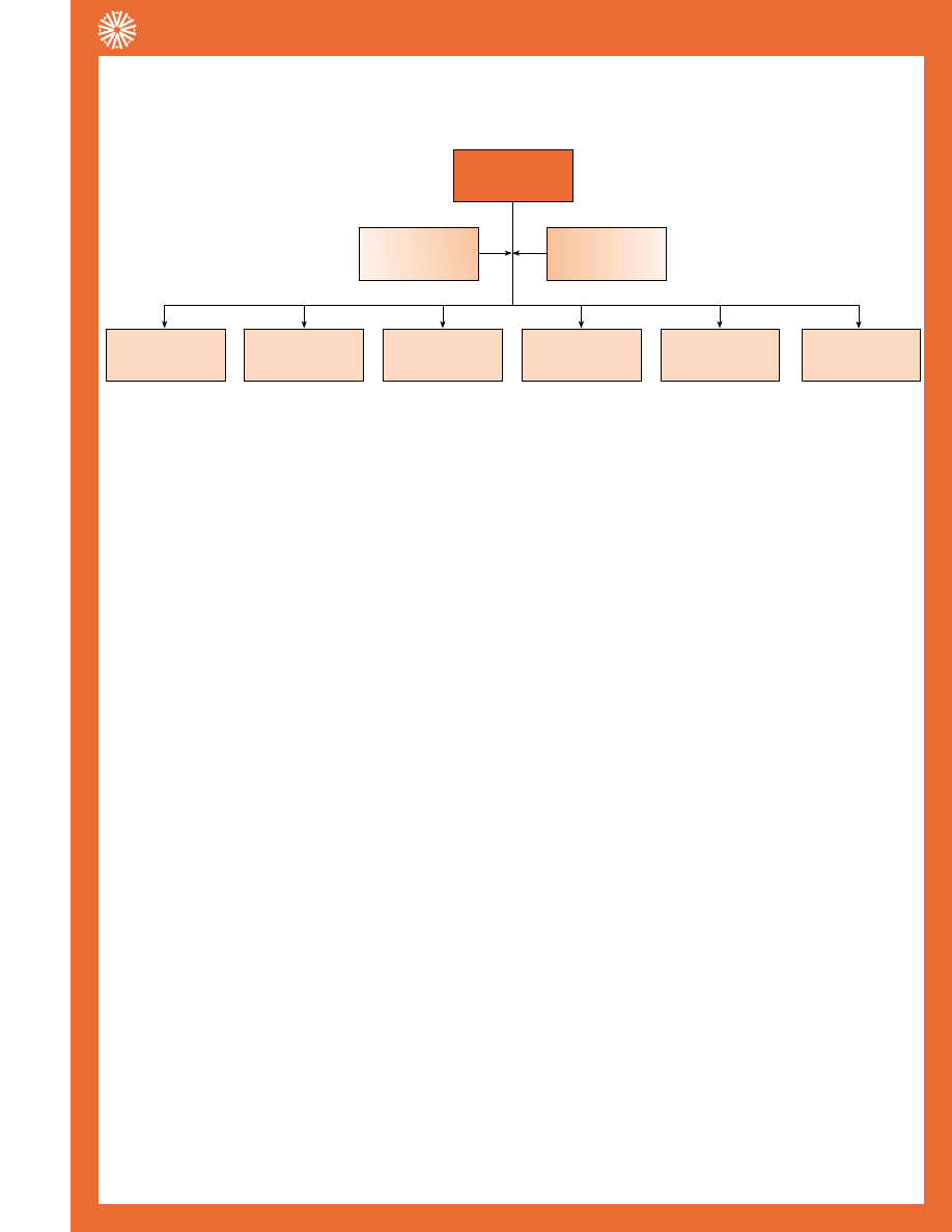
Interface
Materials
Interface
Materials
Electrically
Conductive
Electrical
Insulation
Thermal
Greases
Thermal
Adhesives
Thin Films
Gap Fillers
Double-Sided
Tapes
Insulating
Elastomeric
Reinforced Pads
Mechanical Aspects of Thermal Materials
• Ther-A-Grip™ 1050
• Ther-A-Grip™ 1070
• Sil-Free™
•Ther-O-Link™
• Ther-O-Bond™
1500
•Ther-O-Bond™
1600 & 2000
• A-Pli™ Series
• In-Sil-8™
• Softface™
• Kon-Dux™
• A-Dux™
A-Dux, when you need thermal conductivity but electrical isolation is important too, A-Dux fits the bill.With the perfor-
mance of a grease, A-Dux has a breakdown voltage of 250 volts/mil of thickness.This material significantly enhances thermal
conductivity between semiconductor packages and heat sinks, and withstands aqueous washing that may occur during the man-
ufacturing process. For faster manufacturing time, have Aavid pre-install A-Dux on your heat sink.
A-Pli Gap Filler, when you need to transfer heat across an irregular opening, the A-Pli series fills the gap.The flexible, elastic
nature of A-Pli allows it to blanket extremely uneven surfaces, either individually or as a group. A-Pli conducts heat away from
the individual components, or an entire PCB, into metal covers, frames, or spreader plates.
The size of the gap that can be filled depends upon the amount of mounting pressure used. Aavid offers a range of A-Pli prod-
ucts with different compression rates to solve your thermal needs.
This low durometer product comes with a slightly tacky surface (A-Pli 200), or a very tacky surface (A-Pli 200S).
There are A-Pli products to meet your requirements when your gap filler needs specific electric properties, too. A-Pli 274 sili-
cone elastomer materials conform to irregular gaps with good thermal conductivity, while providing electrical insulation (A-Pli
274T) or electrical conductivity (A-Pli 274A).
In-Sil-8 Pads, when you need thermal conductance and electrical isolation in one package, In-Sil-8 Pads offer you the best of
both.These silicone-based insulators come with thermally conductive fillers to isolate up to 6000 volts. In-Sil-8 pads withstand
the rigors of assembly, harsh environments, and aging under continuous use.You'll save time with these cost-effective pads too:
installation is 4 times faster than mica and grease, and they won't contaminate solder baths. Order In-Sil-8 Pads with or with-
out pressure-sensitive adhesive, and in standard or custom shapes.
Kon-Dux interface pads are a cost-effective alternative to thermally conductive grease compounds. Aavid pre-applies Kon-Dux
to your heat sink to enhance heat conductance from the semiconductor case and speed your manufacturing process. Kon-Dux
pads are the equivalent of Softface™ for low-volume applications.This material is ideal for use with small, discrete semiconductors.
Sil-Free Grease, when you need to enhance heat transfer between a semiconductor case and a heat sink without the
migration or contamination associated with silicone-based products, Sil-Free Grease offers an easy-to-apply solution.This
metal-oxide filled, synthetic grease reduces dry interface thermal resistance by 50% to 70% with proper application. Sil-Free
will not dry out, harden, melt, or run, even after long-term, continuous exposure to temperatures up to 200° C. Even in
a vacuum atmosphere (24 hours at 5-10 Torr and 100° C), Sil-Free exhibits virtually no "bleed" or evaporation.
Softface™ is a cost-effective alternative to thermally conductive grease compounds. Once applied to a heat sink, Softface™
speeds installation of the semiconductor device. Applied with commercial hot-stamping equipment, Softface™ yields excellent
thermal performance with no need for adhesive. For the best value of any interface material, allow Aavid to pre-apply
Softface™ to your heat sink at any one of its worldwide locations.
THERMAL INTERFACE MATERIALS
Corporate Office: 80 Commercial Street • Concord, NH 03301
8
Tel. (603) 224-9988 • Fax (603) 223-1790
AAVID
THERMALLOY
PRODUCT SELECTION GUIDE, Condensed
PC Board Level Heat Sinks, Options & Accessories
Ther-O-Bond Adhesives, when you need a thermally conductive adhesive,Ther-O-Bond Adhesives offer excellent heat
transfer and high voltage isolation.Ther-O-Bond 1500 and 1600 series epoxy adhesives offer low shrinkage, and coefficients of
thermal expansion comparable to copper or aluminum.They bond readily to metals, glass, ceramics, and most plastics.Ther-O-
Bond 1500 is ideal for large-scale applications, providing excellent heat transfer with dimensional stability over a wide tempera-
ture range. For smaller applications,Ther-O-Bond 1600 produces a strong, durable, high-impact bond, with good heat transfer
characteristics.
Ther-O-Bond 2000 Acrylic Adhesive cures rapidly at room temperature, while providing a repairable, thermally conductive
bond.
Ther-A-Grip 1050 and 1070, when you need to attach a heat sink to an electrical package, consider Ther-A-Grip double-
sided tape.Ther-A-Grip 1050 uses a thin, Kapton MT-filled, polydimide film coated on both sides with pressure-sensitive, acrylic
adhesive loaded with aluminum oxide for good thermal performance and excellent electrical isolation.Ther-A-Grip 1070 con-
sists of a thin aluminum foil coated with aluminum oxide-filled, acrylic adhesive for electrical conductivity and enhanced thermal
conductivity.
These easy-to-install tapes reduce the need for mechanical fasteners or messy epoxy adhesives.When Aavid pre-installs the
tape on your heat sink, you benefit with faster production time.With low cost and quick assembly combined with reparability,
Ther-A-Grip saves you time and money.
Ther-O-Link is a silicone-based thermal compound that cost effectively enhances the heat transfer between a semiconductor
case and a heat sink. Easy to apply,Ther-O-Link substantially reduces dry interface thermal resistance, while providing long life
under a variety of conditions.
TECHNICAL INFORMATION
Softface™
Thickness:
0.005 inch
(ASTM D374)
Color:
Black
Thermal Conductivity:
3.5 watt/m-°C
(ASTM D5470)
Thermal Impedance:
0.06 °C-in2/watt
(ASTM D5470)
Filler:
Graphite
Volume Resistivity:
10 Ohm-Cm
(ASTM D4496)
Dielectric Constant:
Non-Insulating
Dielectric Strength:
N/A
Storage Life:
1 year (min) @ 25°C
Cleanability:
Water and/or Isopropyl Alcohol (IPA)
Liner:
None
Kon-Dux
Thickness:
0.005 inch
Color:
Black (Metallic)
Thermal Impedance:
0.08 °C-in2/watt
Electrical Resistivity:
15 x 10
-6
Ohms
Compression Strength:
580 psi
for 10% reduction in thickness
Tensile Strength:
650 psi
Ultimate Compression
Strength:
12500 psi
Service Temperature:
-240 to +300 °C
Liner:
None
A-Dux
Color:
Gray
Thickness:
0.004 inch
Thermal Impedance:
0.16 °C-in2/watt
Electrical Resistivity:
1 x 10
-14
Ohm-cm
Tensile Strength:
700 psi
Service Temperature:
-50 to +200 °C
Liner:
Clear Mylar
Corporate Office: 80 Commercial Street • Concord, NH 03301
9
Tel. (603) 224-9988 • Fax (603) 223-1790
AAVID
THERMALLOY
PRODUCT SELECTION GUIDE, Condensed
PC Board Level Heat Sinks, Options & Accessories
A-Pli Gap Filler
A-Pli 210
A-Pli 220
A-Pli 260
Color:
Pink
Blue
White
Thickness:
0.010 inch
0.020 inch
0.060 inch
Thickness Tolerance:
+/- 0.001 inch
+/- 0.002 inch
+/- 0.010 inch
Filler:
Boron Nitride
Boron Nitride
Boron Nitride
Thermal Impedance
.12
.14
.28
(@ 10 psi min.) °C-in2/watt
Thermal Conductivity
6 Watt/(m-C)
8 Watt/(m-C)
10 Watt/(m-C)
Dielectric Strength
2000 Volts
4000 Volts
4000 Volts
Density
1.28 g/cc
1.28 g/cc
1.28 g/cc
Hardness (Shore A)
10
10
6
Liner:
Clear Mylar
Clear Mylar
Clear Mylar
Ther-A-Grip 1050 and 1070
Ther-A-Grip 1050
Ther-A-Grip 1070
Electrical Function:
Insulating
Conductive
Color:
Beige
White
Thickness:
0.005 inch
0.006 inch
Carrier:
Kapton
Aluminum
Thermal Impedance
0.58°C/watt
0.54°C/watt
Breakdown Voltage
5570 VAC
N/A
Volume Resistivity
3 x 10
14
Ohm-cm
N/A
UL Flammability
94V-O
94V-O
Rating
U.L. 94
U.L. 94
Lap Shear Adhesion
124 psi
134 psi
Die Shear Adhesion
Aluminum 25°C
130 psi
125 psi
Aluminum 150°C
50 psi
55 psi
Alum. Oxide 25°C
170 psi
145 psi
Alum. Oxide 150°C
50 psi
60 psi
Creep Adhesion
25°C @ 12 psi
> 50 days
> 50 days
150°C @ 12 psi
> 10 days
> 10 days
Ther-A-Grip passes the following Environmental testing:
• High Temperature / Humidity Resistance:
1000 hours @ 66°C, 85% relative humidity
• High Humidity: 1000 hours, 25°C, 95% relative humidity
• Conformal Coating Compatibility
• Heat Aging: 1000 hours, 150°C
• Mechanical Shock
• Potting Compound Compatibility
• Salt Spray
• Solvent Exposure
• Thermal Shock:
-60°C to 150°C for 10 cycles and 100 cycles
• Heat Aging,Vibration @ 25°C,Vibration @ 150°C
• Temperature Cycling: -50°C to 150°C, 1000 cycles
• Long Term Storage
143 North Main Street • Suite 206 • Concord, NH 03301
10
Tel. (603) 224-9988 • Fax (603) 223-1790
AAVID
THERMALLOY
PC BOARD LEVEL HEAT SINKS, OPTIONS & ACCESSORIES
Sil-Free Grease
Color:
White
Thermal Conductivity:
0.79 watt/(m-C)
Operating Temperature Range:
-40°C to 200°C
Volume Resistivity:
2.3 x 10
12
Ohm-cm
Dielectric Strength:
225 Volts/mil
Consistency:
Paste
Bleed (% after 24hr @ 200°C):
0.09 max
Specific Gravity
2.8
Shelf Life:
Indefinite (unopened)
Ther-O-Link
Color:
White
Thermal Conductivity:
0.73 watt/(m-K)
Operating Temperature Range:-
-40°C to 200°C
Volume Resistivity:
1.0 x 10
15
Ohm-cm
Dielectric Strength:
250 Volts/mil
Consistency:
Paste
Bleed (% after 24hr @ 200°C):
0.6 max
Specific Gravity
2.8
Shelf Life:
Indefinite
Ther-O-Bond Adhesives
2000
1599
1600
Color:
White
Black
Blue
Thermal Conductivity watt/(m-C):
0.48
1.26
0.85
C.T.E. (ppm/(C):
25
25
25
Tensile Strength (@25) :
2360 psi
9200 psi
9200 psi
Dielectric Strength (volts/mil):
220
800
500
Shelf Life:
12 months
12 months
12 months
In-Sil-8 Pads
1896
1897
1898
1899
Color:
Grey
Rust
Grey
Grey
Thickness (in):
0.006
0.009
0.007
0.009
Thermal Res. (C/watt)
TO-3
0.40
0.21
0.33
0.50
TO-220
1.40
0.63
1.25
1.50
TO-218
0.93
0.49
0.77
1.16
Breakdown Voltage
6000
5000
4000
5000
Dielectric Constant
5.5
4.5
5.5
5.5
143 North Main Street • Suite 206 • Concord, NH 03301
11
Tel. (603) 224-9988 • Fax (603) 223-1790
AAVID
THERMALLOY
PRODUCT SELECTION GUIDE, Condensed
PC Board Level Heat Sinks, Options & Accessories
Part #
Page
533002
14
534202
13
534302
13
551002
14
563002
14
566010
14
569003
15
573100
16
573300
16
573400
16
574004
15
574102
13
574204
15
574402
13
574502
13
574602
13
574902
13
575002
13
575102
13
576602
14
576802
13
577002
13
577102
13
577202
13
577304
15
577404
15
577500
15
578205
14
578305
14
Part #
Page
578622
14
579302
13
579402
14
579704
15
580200
14
590102
14
591302
13
592502
13
593002
13
593202
13
594302
13
D-PAK, D
2
, D
3
16
1" Morrlong
16
1.25” Morrison 16
Morrlong/
Morrison Clip
16
PC BOARD LEVEL
HEAT SINKS, OPTIONS &
ACCESSORIES PART
NUMBER INDEX
Part #
Page
022938
16
025417
16
026205
16
026350
16
026437
16
322505
14
364424
15
501200
14
501503
15
501603
15
504102
14
504222
14
507002
14
507102
13
507222
14
507302
15
523002
14
529801
15
529802
14
530002
14
530101
15
530102
15
530162
15
530613
13
530614
13
530714
13
531002
14
531102
14
531202
14
531302
14
TO-220
Part #
Page
551002
14
563002
14
574102
13
574402
13
574502
13
574602
13
574902
13
575002
13
575102
13
576602
14
576802
13
577002
13
577102
13
577202
13
578622
14
579302
13
579402
14
590102
14
591302
13
592502
13
593002
13
593202
13
594302
13
TO-220 and TO-218
530002
14
533002
14
TO-220 or TO-218
530101
15
530102
15
530162
15
DIPs and SIPs
Part #
Page
501200
14
580200
14
Multiwatt
566010
14
OptiPin™ for BGAs
364424
15
Digital
1" Morrlong
16
1.25” Morrison 16
Clip
16
025417
16
026437
16
Surface Mount
573100
16
(D-PAK/TO-252)
573300
16
(D2PAK/TO-263)
573400
16
(D3PAK/TO-268)
PC BOARD LEVEL
HEAT SINKS PART NUM-
BER INDEX BY SEMICON-
DUCTOR TYPE
TO-3
Part #
Page
501503
15
501603
15
569003
15
TO-5
322505
14
578205
14
578305
14
TO-126
and TO-127
507302
15
577500
15
TO-202
574004
15
574204
15
577304
15
577404
15
579704
15
TO-218
529801
15
TO-220
504102
14
504222
14
507002
14
507102
13
507222
14
523002
14
529802
14
530613
13
530614
13
530714
13
531002
14
531102
14
531202
14
531302
14
534202
13
534302
13
Corporate Office: 80 Commercial Street • Concord, NH 03301
12
Tel. (603) 224-9988 • Fax (603) 223-1790
AAVID
THERMALLOY
PRODUCT SELECTION GUIDE, Condensed
PC Board Level Heat Sinks, Options & Accessories
143 North Main Street • Suite 206 • Concord, NH 03301
13
Tel. (603) 224-9988 • Fax (603) 223-1790
AAVID
THERMALLOY
PRODUCT SELECTION GUIDE, Condensed
PC Board Level Heat Sinks, Options & Accessories
†
5These products have been patented by Aavid Thermal
Technologies, Inc.
With Sure-Lock
™
TabsforVert.Mounting.
With Solderable Tabs for Horiz.Mounting.
With Solderable Tab for Vert.Mounting:
577202B00000
0.500
24.4°C/W @2.5W
Ordering
Code:
Height:
θ
:
574102B00000
0.750
23.2°C/W @2.5W
Ordering
Code:
Height:
θ
:
574402B03200
0.395
23.2°C/W @2.5W
574402
†
, 574102
†
Ordering
Code:
Height:
θ
:
592502B03400
1.250
22.0°C/W @2.5W
592502
Ordering
Code:
Height:
θ
:
576802B04000
0.750
18.8°C/W @2.5W
576802
†
Ordering
Code:
Height:
θ
:
575102B00000
0.750
16.8°C/W @2.5W
575102
Ordering
Code:
Height:
θ
:
579302B00000
0.750
16.8°C/W @2.5W
579302
†
Ordering
Code:
Height:
θ
:
574902B03300
1.375
16.0°C/W @2.5W
Ordering
Code:
Height:
θ
:
591302B02800
0.790
26.8°C/W @2.8W
591302
†
Ordering
Code:
Height:
θ
:
530613B00000
0.500
16.7°C/W @4.5W
530613, 530614, 530714
Ordering
Code:
Height:
θ
:
530614B00000
0.500
16.7°C/W @4.5W
530614
†
Ordering
Code:
Height:
θ
:
575002B00000
1.180
13.6°C/W @5.0W
575002
Ordering
Code:
Height:
θ
:
SELF-LOCKING
With Solderable Tab for Vert.Mounting:
577202B04000
With Solderable Tabs for Vert. Mounting
With Solderable Tab for Horiz.Mounting:
576802B03100
507102B00000
.700
15.6ºC/W
507102
Ordering
Code:
Height:
θ
:
TO-220
With Solderable Tabs for Vert.Mounting.
574602B03300
0.690
21.6°C/W @2.5W
Ordering
Code:
Height:
θ
:
With Solderable Tab for Vert.Mounting.
MANUAL ATTACHMENT
574502B03300
0.750
21.2°C/W @2.5W
574502
†
, 574602
†
, 574902
†
Ordering
Code:
Height:
θ
:
With Solderable Tabs for Vert.Mounting.
577002B00000
0.250
32.0°C/W @2.5W
577002, 577102, 577202
Ordering
Code:
Height:
θ
:
577002B04000
577102B00000
0.380
25.9°C/W @2.9W
Ordering
Code:
Height:
θ
:
With Solderable Tab for Vert.Mounting:
577102B04000
534302B03553
2.000
10.4°C/W @5.0W
534302, 594302
†
Ordering
Code:
Height:
θ
:
With Solderable Tabs for Vert.Mounting.
593202B03500
2.000
10.0°C/W @5.0W
593202
Ordering
Code:
Height:
θ
:
With Solderable Tabs for Vert.Mounting.
530714B00000
0.500
20.3°C/W @3.7W
530714
†
Ordering
Code:
Height:
θ
:
594302B02853
2.000
8.8°C/W @8.5W
Ordering
Code:
Height:
θ
:
With Sure-Lock
™
Tabs and Kool-Klip
™
#115330 for Vert.Mounting.
534202B03453
1.180
13.0°C/W @5.0W
534202
Ordering
Code:
Height:
θ
:
With Solderable Tabs for Vert.Mounting:
593002B03400
1.180
13.4°C/W @5.0W
593002
Ordering
Code:
Height:
θ
:
With Sure-Lock
™
Tabs for Vert.Mounting:
593002B02800
1.Thermal resistance has been evaluated in
natural convection, at the power level which
results in a 75°C temperature rise above
ambient.
2. Height (in inches) designation is by refer-
ence to the part size, oriented to the board
in its most common configuration.
AAVID
THERMALLOY
Corporate Office: 80 Commercial Street • Concord, NH 03301
14
Tel. (603) 224-9988 • Fax (603) 223-1790
AAVID
THERMALLOY
PRODUCT SELECTION GUIDE, Condensed
PC Board Level Heat Sinks, Options & Accessories
†
5These products have been patented by Aavid Thermal
Technologies, Inc.
580200B00000
.410
38ºC/W @0.8W
580200
Ordering
Code:
Height:
θ
:
507222B00000
0.375
9.6°C/W @5.0W
507222
Ordering
Code:
Height:
θ
:
TO-220 Continued
507002B00000
0.375
15.6°C/W @5.0W
507002
Ordering
Code:
Height:
θ
:
563002B00000
1.180
13.0°C/W @5.0W
563002, 576602
Ordering
Code:
Height:
θ
:
504102B00000
0.850
15.6°C/W @5.0W
504102
Ordering
Code:
Height:
θ
:
523002B00000
1.180
13.6
523002
Ordering
Code:
Height:
θ
:
579402B00000
0.750
16.8
579402
Ordering
Code:
Height:
θ
:
504222B00000
1.450
6.4°C/W @11.8W
504222
Ordering
Code:
Height:
θ
:
529802B02500
1.500
3.7°C/W @20.0W
529802
Ordering
Code:
Height:
θ
:
With Solderable Pins for Vert.Mounting.
590102B03600
1.680
10.0°C/W @7.5W
590102
Ordering
Code:
Height:
θ
:
With Solderable Tabs for Vert.Mounting.
551002B00000
0.787
12.4°C/W @5.0W
551002
Ordering
Code:
Height:
θ
:
578622B03200
1.030
13.2°C/W @2.5W
578622
Ordering
Code:
Height:
θ
:
With Solderable Tabs for Vert.Mounting.
531002B02500
1.000
13.4°C/W @5.6W
531002, 531102, 531202, 531302
Ordering
Code:
Height:
θ
:
531102B02500
1.500
10.4°C/W @7.2W
531102
Ordering
Code:
Height:
θ
:
531202B02500
2.000
8.3°C/W @9.0W
531202
Ordering
Code:
Height:
θ
:
576602B00000
0.950
16.6°C/W @5.0W
576602
Ordering
Code:
Height:
θ
:
Multiwatt
566010B03400
1.220
11.5°C/W @6.5W
566010
Ordering
Code:
Height:
θ
:
With Sure-Lock
™
TabsforVert.Mounting:
566010B02800
531302B02500
2.500
8.0°C/W @5.0W
531302
Ordering
Code:
Height:
θ
:
DUAL MOUNTING
DIPs and SIPs
501200B00000
0.250
62.5°C/W @1.2W
501200
Ordering
Code:
Height:
θ
:
For 14 or 16 Pin DIPs
TO-5
322505B00000
0.400
56.0°C/W @1.25W
322505
Ordering
Code:
Height:
θ
:
578205B00000
0.500
38.0
578205, 578305
Ordering
Code:
Height:
θ
:
578305B00000
0.750
35.0°C/W @1.0W
Ordering
Code:
Height:
θ
:
†
5These products have been patented by
Aavid Thermal Technologies, Inc.
HIGH PERFORMANCE
AIR VELOCITY (FEET PER
OUNTING SURF
ACE TEMP
SE ABO
VE AMBIENT–(
°
C)
600
400
200
0
100
80
60
40
20
WITH FAN ON
533002B02551
1.000
13.0°C/W @5.0W
533002
†
Ordering
Code:
Height:
θ
:
With Solderable Pins and Kool-Klip
™
#115100 for Vert.Mounting.
530002B02500
2.500
3.8°C/W @10.0W
530002
†
Ordering
Code:
Height:
θ
:
AAVID
THERMALLOY
143 North Main Street • Suite 206 • Concord, NH 03301
15
Tel. (603) 224-9988 • Fax (603) 223-1790
AAVID
THERMALLOY
PRODUCT SELECTION GUIDE, Condensed
PC Board Level Heat Sinks, Options & Accessories
†
5These products have been patented by Aavid Thermal
Technologies, Inc.
574204
577500B00000
0.520
26.0°C/W @2.5W
577500
Ordering
Code:
Height:
θ
:
For TO-126.
TO-202
579704B03300
0.900
24.0°C/W @2.5W
579704
†
Ordering
Code:
Height:
θ
:
With Solderable Tabs for Vert.Mounting.
574004B00000
0.580
28.0°C/W @2.5W
574004
†
Ordering
Code:
Height:
θ
:
574204B00000
0.900
16.8
Ordering
Code:
Height:
θ
:
577404B00000
0.500
24.0°C/W @2.5W
577404
Ordering
Code:
Height:
θ
:
TO-3
501503B00000
1.000
6.3°C/W @12.0W
501503. 501603
Ordering
Code:
Height:
θ
:
501603B00000
1.250
5.4°C/W @14.0W
501603
Ordering
Code:
Height:
θ
:
TO-218
529801B02500
1.500
3.7°C/W @20.0W
529801
Ordering
Code:
Height:
θ
:
569003B00000
1.310
5.4°C/W @10.0W
569003
Ordering
Code:
Height:
θ
:
577304B00000
0.375
27.2°C/W @2.5W
577304, 577404
Ordering
Code:
Height:
θ
:
This condensed catalog
features the more popular
devices and configurations.
For other devices and
configurations, contact Aavid
Applications Engineering
to receive our full
Product Selection Guide.
More information is also
available 24 hours a day by
using our FastFacts System,
603 223-1750, or see our
web-site,
http://www.aavid.com.
530162B00162
1.750
4.4°C/W @17.0W
530162
†
Ordering
Code:
Height:
θ
:
With Solderable Mounts and Two Kool-Klips
™
#116200 for Vert.Mounting.
for Two TO-220s
TO-220/TO-218
for One TO-218
530101B00150
1.750
6.3°C/W@12.0W
530101
†
Ordering
Code:
Height:
θ
:
With Solderable Mounts and Kool-Klip
™
#115000 for Vert.Mounting.
530102B00150
1.750
6.3°C/W@12.0W
530102
†
Ordering
Code:
Height:
θ
:
With Solderable Mounts and Kool-Klip
™
#115000 for Vert.Mounting.
for One TO-220
364424B00032
.450
10.7°C/W
364424
Ordering
Code:
Height:
θ
:
OptiPin Heat Sinks for
BGA Devices
TO-126 and TO-127
507302B00000
0.375
24.0°C/W @2.5W
507302
Ordering
Code:
Height:
θ
:
For TO-126 & TO-127.
With preinstalled 1070 tape
364424B00000 without tape
AAVID
THERMALLOY
Corporate Office: 80 Commercial Street • Concord, NH 03301
16
Tel. (603) 224-9988 • Fax (603) 223-1790
AAVID
THERMALLOY
PRODUCT SELECTION GUIDE, Condensed
PC Board Level Heat Sinks, Options & Accessories
†
5These products have been patented by Aavid Thermal
Technologies, Inc.
D-PAK/T0-252
D
2
PAK/T0-263
D
3
PAK/T0-268
Bulk
Pkg.:
Bulk
Pkg.:
Bulk
Pkg.:
Surface Mount Components
Hot solder dipped coating
over highly conductive
copper for maximum heat
transfer in surface mount
applications. Tape and reel
packaged per EIA-481,
compatible with automatic
SMT placement. 250 pieces
per reel.
573400D00010
.400
14ºC/W
573300D00010
.400
18ºC/W
573100D00010
.400
26ºC/W
Ordering
Code:
Height:
θ
:
Ordering
Code:
Height:
θ
:
Ordering
Code:
Height:
θ
:
573100D00000
573100D00000
573400D00000
Digital
026205
1.000
3°C/W
1” Morrlong
Ordering
Code:
Height:
θ
:
026350
1.250
2.7°C/W
1.25” Morrison
Ordering
Code:
Height:
θ
:
022938
1.250
2.7°C/W
Morrlong/Morrison Clip
Ordering
Code:
Height:
θ
:
025417
1.250 0.68°C/W
Fan Heat Sinks for Pentium® MMX
Ordering
Code:
Height:
θ
:
025417
1.250
0.68°C/W
Ordering
Code:
Height:
θ
:
Fan Heat Sinks for AMD and Cyrix CPU’s
026437
1.200
0.66°C/W
Ordering
Code:
Height:
θ
:
573100, 573300, 573400
DC-DC Converters
Heat Sink
Call us for our latest offering:
Chris Soule (603) 223-1722
or email soule@aavid.com
AAVID
THERMALLOY
143 North Main Street • Suite 206 • Concord, NH 03301
17
Tel. (603) 224-9988 • Fax (603) 223-1790
AAVID
THERMALLOY
PRODUCT SELECTION GUIDE, Condensed
PC Board Level Heat Sinks,Thermal Information
THERMAL RESIST
ANCE FROM MTG
SURF
ACE T
O
AMBIENT
°
C/W
AT
T
AIR VELOCITY (FEET PER MINUTE)
MOUNTING SURF
ACE TEMP
RISE ABO
VE AMBIENT–(
°
C)
HEAT DISSIPATED (WATTS)
800
1,000
600
400
200
0
100
80
60
40
20
0
5
10
25
15
20
1.0
2.0
3.0
4.0
5.0
0
0
026205
P OW E R ( w a t t )
A I R F L OW ( f t / m i n )
TEMPERA
TURE
RISE ABO
VE AMBIENT
(
°
C)
THERMAL RESIST
ANCE C-A (
°
C/watt)
0
20
20
40
60
80
100
1
0
2
3
4
5
6
7
8
9
0
200
400
600
4
0
8
12
3364424
THERMAL RESIST
ANCE FROM MTG
SURF
ACE T
O
AMBIENT
°
C/W
AT
T
AIR VELOCITY (FEET PER MINUTE)
MOUNTING SURF
ACE TEMP
RISE ABO
VE AMBIENT–(
°
C)
HEAT DISSIPATED (WATTS)
800
1,000
600
400
200
0
100
80
60
40
20
0
5
10
25
15
20
1.0
2.0
3.0
4.0
5.0
0
0
026350
▲
▲
THERMAL RESIST
ANCE FROM MTG
SURF
ACE T
O
AMBIENT–
˚
C/W
AT
T
MOUNTING SURF
ACE TEMP
RISE ABO
VE AMBIENT–
˚
C
0
200
400
600
800
1000
AIR VELOCITY–FEET PER MINUTE
HEAT DISSIPATED–WATTS
0
0.4
0.8
1.2
1.6
2.0
0
20
40
60
80
100
0
20
40
60
80
100
▲
▲
501200
THERMAL RESIST
ANCE FROM MTG
SURF
ACE T
O
AMBIENT
°
C/W
AT
T
AIR VELOCITY (FEET PER MINUTE)
MOUNTING SURF
ACE TEMP
RISE ABO
VE AMBIENT–(
°
C)
HEAT DISSIPATED (WATTS)
800
1,000
600
400
200
0
100
80
60
40
20
0
5
10
25
15
20
1.0
2.0
3.0
4.0
5.0
0
0
WITH FAN ON
026437
▲
▲
THERMAL RESIST
ANCE FROM MTG
SURF
ACE T
O
AMBIENT–
˚
C/W
AT
T
MOUNTING SURF
ACE TEMP
RISE ABO
VE AMBIENT–
˚
C
0
200
400
600
800
1000
AIR VELOCITY–FEET PER MINUTE
HEAT DISSIPATED–WATTS
0
2
4
6
8
10
0
20
40
60
80
100
0
2
4
6
8
10
▲
▲
501503
THERMAL RESIST
ANCE FROM MTG
SURF
ACE T
O
AMBIENT
°
C/W
AT
T
AIR VELOCITY (FEET PER MINUTE)
MOUNTING SURF
ACE TEMP
RISE ABO
VE AMBIENT–(
°
C)
HEAT DISSIPATED (WATTS)
800
1,000
600
400
200
0
100
80
60
40
20
0
5
10
25
15
20
1.0
2.0
3.0
4.0
5.0
0
0
WITH FAN ON
025417
▲
▲
THERMAL RESIST
ANCE FROM MTG
SURF
ACE T
O
AMBIENT–
˚
C/W
AT
T
MOUNTING SURF
ACE TEMP
RISE ABO
VE AMBIENT–
˚
C
0
200
400
600
800
1000
AIR VELOCITY–FEET PER MINUTE
HEAT DISSIPATED–WATTS
0
0.5
1.0
1.5
2.0
2.5
0
20
40
60
80
100
0
10
20
30
40
50
▲
▲
322505
▲
▲
▲
▲
THERMAL RESIST
ANCE FROM MTG
SURF
ACE T
O
AMBIENT–
˚
C/W
AT
T
MOUNTING SURF
ACE TEMP
RISE ABO
VE AMBIENT–
˚
C
0
200
400
600
800
1000
AIR VELOCITY–FEET PER MINUTE
HEAT DISSIPATED–WATTS
0
2
4
6
8
10
0
20
40
60
80
100
0
2
4
6
8
10
504102
▲
▲
▲
▲
THERMAL RESIST
ANCE FROM MTG
SURF
ACE T
O
AMBIENT–
˚
C/W
AT
T
MOUNTING SURF
ACE TEMP
RISE ABO
VE AMBIENT–
˚
C
0
200
400
600
800
1000
AIR VELOCITY–FEET PER MINUTE
HEAT DISSIPATED–WATTS
0
2
4
6
8
10
0
20
40
60
80
100
0
2
4
6
8
10
507222
▲
▲
▲
▲
THERMAL RESIST
ANCE FROM MTG
SURF
ACE T
O
AMBIENT–
˚
C/W
AT
T
MOUNTING SURF
ACE TEMP
RISE ABO
VE AMBIENT–
˚
C
0
200
400
600
800
1000
AIR VELOCITY–FEET PER MINUTE
HEAT DISSIPATED–WATTS
0
2
4
6
8
10
0
20
40
60
80
100
0
2
4
6
8
10
504222
THERMAL RESIST
ANCE FROM MTG
SURF
ACE T
O
AMBIENT–
˚
C/W
AT
T
MOUNTING SURF
ACE TEMP
RISE ABO
VE AMBIENT–
˚
C
0
200
400
600
800
1000
AIR VELOCITY–FEET PER MINUTE
HEAT DISSIPATED–WATTS
0
1
2
3
4
5
0
20
40
60
80
100
0
4
8
12
16
20
▲
▲
▲
▲
507302
▲
▲
▲
▲
THERMAL RESIST
ANCE FROM MTG
SURF
ACE T
O
AMBIENT–
˚
C/W
AT
T
MOUNTING SURF
ACE TEMP
RISE ABO
VE AMBIENT–
˚
C
0
200
400
600
800
1000
AIR VELOCITY–FEET PER MINUTE
HEAT DISSIPATED–WATTS
0
2
4
6
8
10
0
20
40
60
80
100
0
2
4
6
8
10
507002
▲
▲
▲
▲
THERMAL RESIST
ANCE FROM MTG
SURF
ACE T
O
AMBIENT–
˚
C/W
AT
T
MOUNTING SURF
ACE TEMP
RISE ABO
VE AMBIENT–
˚
C
0
200
400
600
800
1000
AIR VELOCITY–FEET PER MINUTE
HEAT DISSIPATED–WATTS
0
2
4
6
8
10
0
20
40
60
80
100
0
2
4
6
8
10
523002
▲
▲
THERMAL RESIST
ANCE FROM MTG
SURF
ACE T
O
AMBIENT–
˚
C/W
AT
T
MOUNTING SURF
ACE TEMP
RISE ABO
VE AMBIENT–
˚
C
0
200
400
600
800
1000
AIR VELOCITY–FEET PER MINUTE
HEAT DISSIPATED–WATTS
0
2
4
6
8
10
0
20
40
60
80
100
0
2
4
6
8
10
▲
▲
501603
▲
▲
▲
▲
THERMAL RESIST
ANCE FROM MTG
SURF
ACE T
O
AMBIENT–
˚
C/W
AT
T
MOUNTING SURF
ACE TEMP
RISE ABO
VE AMBIENT–
˚
C
0
200
400
600
800
1000
AIR VELOCITY–FEET PER MINUTE
HEAT DISSIPATED–WATTS
0
4
8
12
16
20
0
20
40
60
80
100
0
2
4
6
8
10
507102
Corporate Office: 80 Commercial Street • Concord, NH 03301
18
Tel. (603) 224-9988 • Fax (603) 223-1790
AAVID
THERMALLOY
PRODUCT SELECTION GUIDE, Condensed
PC Board Level Heat Sinks,Thermal Information

143 North Main Street • Suite 206 • Concord, NH 03301
19
Tel. (603) 224-9988 • Fax (603) 223-1790
AAVID
THERMALLOY
PRODUCT SELECTION GUIDE, Condensed
PC Board Level Heat Sinks,Thermal Information
▲
▲
▲
▲
THERMAL RESIST
ANCE FROM MTG
SURF
ACE T
O
AMBIENT–
˚
C/W
AT
T
MOUNTING SURF
ACE TEMP
RISE ABO
VE AMBIENT–
˚
C
0
200
400
600
800
1000
AIR VELOCITY–FEET PER MINUTE
HEAT DISSIPATED–WATTS
0
4
8
12
16
20
0
20
40
60
80
100
0
1
2
3
4
5
529802
530162
▲
▲
▲
▲
THERMAL RESIST
ANCE FROM MTG
SURF
ACE T
O
AMBIENT–
˚
C/W
AT
T
MOUNTING SURF
ACE TEMP
RISE ABO
VE AMBIENT–
˚
C
0
200
400
600
800
1000
AIR VELOCITY–FEET PER MINUTE
HEAT DISSIPATED–WATTS
0
4
8
12
16
20
0
20
40
60
80
100
0
1
2
3
4
5
530002
THERMAL RESIST
ANCE FROM MTG
SURF
ACE T
O
AMBIENT–
˚
C/W
AT
T
MOUNTING SURF
ACE TEMP
RISE ABO
VE AMBIENT–
˚
C
0
200
400
600
800
1000
AIR VELOCITY–FEET PER MINUTE
HEAT DISSIPATED–WATTS
0
1
2
3
4
5
0
20
40
60
80
100
0
4
8
12
16
20
▲
▲
▲
▲
530613
▲
▲
▲
▲
THERMAL RESIST
ANCE FROM MTG
SURF
ACE T
O
AMBIENT–
˚
C/W
AT
T
MOUNTING SURF
ACE TEMP
RISE ABO
VE AMBIENT–
˚
C
0
200
400
600
800
1000
AIR VELOCITY–FEET PER MINUTE
HEAT DISSIPATED–WATTS
0
4
8
12
16
20
0
20
40
60
80
100
0
1
2
3
4
5
530101
THERMAL RESIST
ANCE FROM MTG
SURF
ACE T
O
AMBIENT–
˚
C/W
AT
T
MOUNTING SURF
ACE TEMP
RISE ABO
VE AMBIENT–
˚
C
0
200
400
600
800
1000
AIR VELOCITY–FEET PER MINUTE
HEAT DISSIPATED–WATTS
0
1
2
3
4
5
0
20
40
60
80
100
0
4
8
12
16
20
▲
▲
▲
▲
530614
▲
▲
▲
▲
THERMAL RESIST
ANCE FROM MTG
SURF
ACE T
O
AMBIENT–
˚
C/W
AT
T
MOUNTING SURF
ACE TEMP
RISE ABO
VE AMBIENT–
˚
C
0
200
400
600
800
1000
AIR VELOCITY–FEET PER MINUTE
HEAT DISSIPATED–WATTS
0
4
8
12
16
20
0
20
40
60
80
100
0
1
2
3
4
5
529801
▲
▲
▲
▲
THERMAL RESIST
ANCE FROM MTG
SURF
ACE T
O
AMBIENT–
˚
C/W
AT
T
MOUNTING SURF
ACE TEMP
RISE ABO
VE AMBIENT–
˚
C
0
200
400
600
800
1000
AIR VELOCITY–FEET PER MINUTE
HEAT DISSIPATED–WATTS
0
4
8
12
16
20
0
20
40
60
80
100
0
1
2
3
4
5
▲
▲
▲
▲
THERMAL RESIST
ANCE FROM MTG
SURF
ACE T
O
AMBIENT–
˚
C/W
AT
T
MOUNTING SURF
ACE TEMP
RISE ABO
VE AMBIENT–
˚
C
0
200
400
600
800
1000
AIR VELOCITY–FEET PER MINUTE
HEAT DISSIPATED–WATTS
0
4
8
12
16
20
0
20
40
60
80
100
0
1
2
3
4
5
530102
▲
▲
▲
▲
THERMAL RESIST
ANCE FROM MTG
SURF
ACE T
O
AMBIENT–
˚
C/W
AT
T
MOUNTING SURF
ACE TEMP
RISE ABO
VE AMBIENT–
˚
C
0
200
400
600
800
1000
AIR VELOCITY–FEET PER MINUTE
HEAT DISSIPATED–WATTS
0
2
4
6
8
10
0
20
40
60
80
100
0
2
4
6
8
10
531002
▲
▲
▲
▲
THERMAL RESIST
ANCE FROM MTG
SURF
ACE T
O
AMBIENT–
˚
C/W
AT
T
MOUNTING SURF
ACE TEMP
RISE ABO
VE AMBIENT–
˚
C
0
200
400
600
800
1000
AIR VELOCITY–FEET PER MINUTE
HEAT DISSIPATED–WATTS
0
2
4
6
8
10
0
20
40
60
80
100
0
2
4
6
8
10
533002
▲
▲
▲
▲
THERMAL RESIST
ANCE FROM MTG
SURF
ACE T
O
AMBIENT–
˚
C/W
AT
T
MOUNTING SURF
ACE TEMP
RISE ABO
VE AMBIENT–
˚
C
0
200
400
600
800
1000
AIR VELOCITY–FEET PER MINUTE
HEAT DISSIPATED–WATTS
0
2
4
6
8
10
0
20
40
60
80
100
0
2
4
6
8
10
531102
▲
▲
▲
▲
THERMAL RESIST
ANCE FROM MTG
SURF
ACE T
O
AMBIENT–
˚
C/W
AT
T
MOUNTING SURF
ACE TEMP
RISE ABO
VE AMBIENT–
˚
C
0
200
400
600
800
1000
AIR VELOCITY–FEET PER MINUTE
HEAT DISSIPATED–WATTS
0
2
4
6
8
10
0
20
40
60
80
100
0
2
4
6
8
10
534202
▲
▲
▲
▲
THERMAL RESIST
ANCE FROM MTG
SURF
ACE T
O
AMBIENT–
˚
C/W
AT
T
MOUNTING SURF
ACE TEMP
RISE ABO
VE AMBIENT–
˚
C
0
200
400
600
800
1000
AIR VELOCITY–FEET PER MINUTE
HEAT DISSIPATED–WATTS
0
2
4
6
8
10
0
20
40
60
80
100
0
2
4
6
8
10
531202
▲
▲
▲
▲
THERMAL RESIST
ANCE FROM MTG
SURF
ACE T
O
AMBIENT–
˚
C/W
AT
T
MOUNTING SURF
ACE TEMP
RISE ABO
VE AMBIENT–
˚
C
0
200
400
600
800
1000
AIR VELOCITY–FEET PER MINUTE
HEAT DISSIPATED–WATTS
0
2
4
6
8
10
0
20
40
60
80
100
0
2
4
6
8
10
534302
THERMAL RESIST
ANCE FROM MTG
SURF
ACE T
O
AMBIENT–
˚
C/W
AT
T
MOUNTING SURF
ACE TEMP
RISE ABO
VE AMBIENT–
˚
C
0
200
400
600
800
1000
AIR VELOCITY–FEET PER MINUTE
HEAT DISSIPATED–WATTS
0
1
2
3
4
5
0
20
40
60
80
100
0
4
8
12
16
20
▲
▲
▲
▲
530714
▲
▲
▲
▲
THERMAL RESIST
ANCE FROM MTG
SURF
ACE T
O
AMBIENT–
˚
C/W
AT
T
MOUNTING SURF
ACE TEMP
RISE ABO
VE AMBIENT–
˚
C
0
200
400
600
800
1000
AIR VELOCITY–FEET PER MINUTE
HEAT DISSIPATED–WATTS
0
2
4
6
8
10
0
20
40
60
80
100
0
2
4
6
8
10
531302
Corporate Office: 80 Commercial Street • Concord, NH 03301
20
Tel. (603) 224-9988 • Fax (603) 223-1790
AAVID
THERMALLOY
PRODUCT SELECTION GUIDE, Condensed
PC Board Level Heat Sinks,Thermal Information
143 North Main Street • Suite 206 • Concord, NH 03301
21
Tel. (603) 224-9988 • Fax (603) 223-1790
AAVID
THERMALLOY
PRODUCT SELECTION GUIDE, Condensed
PC Board Level Heat Sinks,Thermal Information
▲
▲
▲
▲
THERMAL RESIST
ANCE FROM MTG
SURF
ACE T
O
AMBIENT–
˚
C/W
AT
T
MOUNTING SURF
ACE TEMP
RISE ABO
VE AMBIENT–
˚
C
0
200
400
600
800
1000
AIR VELOCITY–FEET PER MINUTE
HEAT DISSIPATED–WATTS
0
2
4
6
8
10
0
20
40
60
80
100
0
2
4
6
8
10
563002
10
20
30
40
60
0
0.5
1.0
1.5
2.5
3.0
2.0
0
5
10
15
20
25
30
0
400
800
1,200
0
50
S M T D
2
PA K W E B - D E S I G N
TEMPERA
TURE
RISE ABO
VE AMBIENT
(Øca)
P OW E R ( WAT T S )
A I R F L OW ( L F M )
WITH HEAT SINK
WITHOUT HEAT SINK
THERMAL RESIST
ANCE CASE-AMBIENT (C/W)
573300
▲
▲
▲
▲
THERMAL RESIST
ANCE FROM MTG
SURF
ACE T
O
AMBIENT–
˚
C/W
AT
T
MOUNTING SURF
ACE TEMP
RISE ABO
VE AMBIENT–
˚
C
0
200
400
600
800
1000
AIR VELOCITY–FEET PER MINUTE
HEAT DISSIPATED–WATTS
0
2
4
6
8
10
0
20
40
60
80
100
0
2
4
6
8
10
566010
566010
15
45
0
0.5
1.0
1.5
2.5
3.0
2.0
0
15
20
100
450
5
10
0
25
35
800
THERMAL RESIST
ANCE CASE-AMBIENT (C/W)
TEMPERA
TURE
RISE ABO
VE AMBIENT
(Øca)
S M T D
3
PA K W E B - D E S I G N
P OW E R ( WAT T S )
A I R F L OW ( L F M )
WITH HEAT SINK
WITHOUT HEAT SINK
THERMAL RESIST
ANCE CASE-AMBIENT (C/W)
TEMPERA
TURE
RISE ABO
VE AMBIENT
(Øca)
S M T D
3
PA K W E B - D E S I G N
P OW E R ( WAT T S )
A I R F L OW ( L F M )
WITHOUT HEAT SINK
THERMAL RESIST
ANCE CASE-AMBIENT (C/W)
P OW E R ( WAT T S )
WITHOUT HEAT SINK
573400
▲
▲
THERMAL RESIST
ANCE FROM MTG
SURF
ACE T
O
AMBIENT–
˚
C/W
AT
T
MOUNTING SURF
ACE TEMP
RISE ABO
VE AMBIENT–
˚
C
0
200
400
600
800
1000
AIR VELOCITY–FEET PER MINUTE
HEAT DISSIPATED–WATTS
0
4
8
12
16
20
0
20
40
60
80
100
0
1
2
3
4
5
▲
▲
569003
▲
▲
▲
▲
THERMAL RESIST
ANCE FROM MTG
SURF
ACE T
O
AMBIENT–
˚
C/W
AT
T
MOUNTING SURF
ACE TEMP
RISE ABO
VE AMBIENT–
˚
C
0
200
400
600
800
1000
AIR VELOCITY–FEET PER MINUTE
HEAT DISSIPATED–WATTS
0
1
2
3
4
5
0
20
40
60
80
100
0
4
8
12
16
20
574004
▲
▲
▲
▲
THERMAL RESIST
ANCE FROM MTG
SURF
ACE T
O
AMBIENT–
˚
C/W
AT
T
MOUNTING SURF
ACE TEMP
RISE ABO
VE AMBIENT–
˚
C
0
200
400
600
800
1000
AIR VELOCITY–FEET PER MINUTE
HEAT DISSIPATED–WATTS
0
1
2
3
4
5
0
20
40
60
80
100
0
2
4
6
8
10
551002
40
80
160
200
0
0.5
1.0
1.5
2.5
3.0
2.0
0
10
30
40
50
0
400
20
0
120
800
THERMAL RESIST
ANCE CASE-AMBIENT (C/W)
TEMPERA
TURE
RISE ABO
VE AMBIENT
(Øca)
S M T D PA K W E B - D E S I G N
P OW E R ( WAT T S )
A I R F L OW ( L F M )
WITH HEAT SINK
WITHOUT HEAT SINK
573100

▲
▲
▲
▲
THERMAL RESIST
ANCE FROM MTG
SURF
ACE T
O
AMBIENT–
˚
C/W
AT
T
MOUNTING SURF
ACE TEMP
RISE ABO
VE AMBIENT–
˚
C
0
200
400
600
800
1000
AIR VELOCITY–FEET PER MINUTE
HEAT DISSIPATED–WATTS
0
1
2
3
4
5
0
20
40
60
80
100
0
4
8
12
16
20
574204
▲
▲
▲
▲
THERMAL RESIST
ANCE FROM MTG
SURF
ACE T
O
AMBIENT–
˚
C/W
AT
T
MOUNTING SURF
ACE TEMP
RISE ABO
VE AMBIENT–
˚
C
0
200
400
600
800
1000
AIR VELOCITY–FEET PER MINUTE
HEAT DISSIPATED–WATTS
0
1
2
3
4
5
0
20
40
60
80
100
0
2
4
6
8
10
574902
▲
▲
▲
▲
THERMAL RESIST
ANCE FROM MTG
SURF
ACE T
O
AMBIENT–
˚
C/W
AT
T
MOUNTING SURF
ACE TEMP
RISE ABO
VE AMBIENT–
˚
C
0
200
400
600
800
1000
AIR VELOCITY–FEET PER MINUTE
HEAT DISSIPATED–WATTS
0
1
2
3
4
5
0
20
40
60
80
100
0
4
8
12
16
20
574402
▲
▲
▲
▲
THERMAL RESIST
ANCE FROM MTG
SURF
ACE T
O
AMBIENT–
˚
C/W
AT
T
MOUNTING SURF
ACE TEMP
RISE ABO
VE AMBIENT–
˚
C
0
200
400
600
800
1000
AIR VELOCITY–FEET PER MINUTE
HEAT DISSIPATED–WATTS
0
2
4
6
8
10
0
20
40
60
80
100
0
2
4
6
8
10
575002
THERMAL RESIST
ANCE FROM MTG
SURF
ACE T
O
AMBIENT–
˚
C/W
AT
T
MOUNTING SURF
ACE TEMP
RISE ABO
VE AMBIENT–
˚
C
0
200
400
600
800
1000
AIR VELOCITY–FEET PER MINUTE
HEAT DISSIPATED–WATTS
0
1
2
3
4
5
0
20
40
60
80
100
0
4
8
12
16
20
▲
▲
▲
▲
574502
▲
▲
THERMAL RESIST
ANCE FROM MTG
SURF
ACE T
O
AMBIENT–
˚
C/W
AT
T
MOUNTING SURF
ACE TEMP
RISE ABO
VE AMBIENT–
˚
C
0
200
400
600
800
1000
AIR VELOCITY–FEET PER MINUTE
HEAT DISSIPATED–WATTS
0
1
2
3
4
5
0
20
40
60
80
100
0
4
8
12
16
20
▲
▲
575102
▲
▲
▲
▲
THERMAL RESIST
ANCE FROM MTG
SURF
ACE T
O
AMBIENT–
˚
C/W
AT
T
MOUNTING SURF
ACE TEMP
RISE ABO
VE AMBIENT–
˚
C
0
200
400
600
800
1000
AIR VELOCITY–FEET PER MINUTE
HEAT DISSIPATED–WATTS
0
1
2
3
4
5
0
20
40
60
80
100
0
4
8
12
16
20
574102
▲
▲
▲
▲
THERMAL RESIST
ANCE FROM MTG
SURF
ACE T
O
AMBIENT–
˚
C/W
AT
T
MOUNTING SURF
ACE TEMP
RISE ABO
VE AMBIENT–
˚
C
0
200
400
600
800
1000
AIR VELOCITY–FEET PER MINUTE
HEAT DISSIPATED–WATTS
0
1
2
3
4
5
0
20
40
60
80
100
0
4
8
12
16
20
574602
Corporate Office: 80 Commercial Street • Concord, NH 03301
22
Tel. (603) 224-9988 • Fax (603) 223-1790
AAVID
THERMALLOY
PRODUCT SELECTION GUIDE, Condensed
PC Board Level Heat Sinks,Thermal Information
143 North Main Street • Suite 206 • Concord, NH 03301
23
Tel. (603) 224-9988 • Fax (603) 223-1790
AAVID
THERMALLOY
PRODUCT SELECTION GUIDE, Condensed
PC Board Level Heat Sinks,Thermal Information
▲
▲
▲
▲
THERMAL RESIST
ANCE FROM MTG
SURF
ACE T
O
AMBIENT–
˚
C/W
AT
T
MOUNTING SURF
ACE TEMP
RISE ABO
VE AMBIENT–
˚
C
0
200
400
600
800
1000
AIR VELOCITY–FEET PER MINUTE
HEAT DISSIPATED–WATTS
0
1
2
3
4
5
0
20
40
60
80
100
0
2
4
6
8
10
591302
576802
▲
▲
▲
▲
THERMAL RESIST
ANCE FROM MTG
SURF
ACE T
O
AMBIENT–
˚
C/W
AT
T
MOUNTING SURF
ACE TEMP
RISE ABO
VE AMBIENT–
˚
C
0
200
400
600
800
1000
AIR VELOCITY–FEET PER MINUTE
HEAT DISSIPATED–WATTS
0
1
2
3
4
5
0
20
40
60
80
100
0
4
8
12
16
20
577304
THERMAL RESIST
ANCE FROM MTG
SURF
ACE T
O
AMBIENT–
˚
C/W
AT
T
MOUNTING SURF
ACE TEMP
RISE ABO
VE AMBIENT–
˚
C
0
200
400
600
800
1000
AIR VELOCITY–FEET PER MINUTE
HEAT DISSIPATED–WATTS
0
1
2
3
4
5
0
20
40
60
80
100
0
4
8
12
16
20
▲
▲
▲
▲
577002
▲
▲
▲
▲
THERMAL RESIST
ANCE FROM MTG
SURF
ACE T
O
AMBIENT–
˚
C/W
AT
T
MOUNTING SURF
ACE TEMP
RISE ABO
VE AMBIENT–
˚
C
0
200
400
600
800
1000
AIR VELOCITY–FEET PER MINUTE
HEAT DISSIPATED–WATTS
0
1
2
3
4
5
0
20
40
60
80
100
0
4
8
12
16
20
577404
THERMAL RESIST
ANCE FROM MTG
SURF
ACE T
O
AMBIENT–
˚
C/W
AT
T
MOUNTING SURF
ACE TEMP
RISE ABO
VE AMBIENT–
˚
C
0
200
400
600
800
1000
AIR VELOCITY–FEET PER MINUTE
HEAT DISSIPATED–WATTS
0
1
2
3
4
5
0
20
40
60
80
100
0
4
8
12
16
20
▲
▲
▲
▲
577102
▲
▲
THERMAL RESIST
ANCE FROM MTG
SURF
ACE T
O
AMBIENT–
˚
C/W
AT
T
MOUNTING SURF
ACE TEMP
RISE ABO
VE AMBIENT–
˚
C
0
200
400
600
800
1000
AIR VELOCITY–FEET PER MINUTE
HEAT DISSIPATED–WATTS
0
1
2
3
4
5
0
20
40
60
80
100
0
4
8
12
16
20
▲
▲
577500
▲
▲
▲
▲
THERMAL RESIST
ANCE FROM MTG
SURF
ACE T
O
AMBIENT–
˚
C/W
AT
T
MOUNTING SURF
ACE TEMP
RISE ABO
VE AMBIENT–
˚
C
0
200
400
600
800
1000
AIR VELOCITY–FEET PER MINUTE
HEAT DISSIPATED–WATTS
0
2
4
6
8
10
0
20
40
60
80
100
0
4
8
12
16
20
576602
THERMAL RESIST
ANCE FROM MTG
SURF
ACE T
O
AMBIENT–
˚
C/W
AT
T
MOUNTING SURF
ACE TEMP
RISE ABO
VE AMBIENT–
˚
C
0
200
400
600
800
1000
AIR VELOCITY–FEET PER MINUTE
HEAT DISSIPATED–WATTS
0
1
2
3
4
5
0
20
40
60
80
100
0
4
8
12
16
20
▲
▲
▲
▲
577202
▲
▲
THERMAL RESIST
ANCE FROM MTG
SURF
ACE T
O
AMBIENT–
˚
C/W
AT
T
MOUNTING SURF
ACE TEMP
RISE ABO
VE AMBIENT–
˚
C
0
200
400
600
800
1000
AIR VELOCITY–FEET PER MINUTE
HEAT DISSIPATED–WATTS
0
0.4
0.8
1.2
1.6
2.0
0
20
40
60
80
100
0
10
20
30
40
50
▲
▲
578305
▲
▲
▲
▲
THERMAL RESIST
ANCE FROM MTG
SURF
ACE T
O
AMBIENT–
˚
C/W
AT
T
MOUNTING SURF
ACE TEMP
RISE ABO
VE AMBIENT–
˚
C
0
200
400
800
1000
AIR VELOCITY–FEET PER MINUTE
HEAT DISSIPATED–WATTS
0
1
2
3
4
5
0
20
40
60
80
100
0
4
8
12
16
20
579704
600
579704
▲
▲
▲
▲
THERMAL RESIST
ANCE FROM MTG
SURF
ACE T
O
AMBIENT–
˚
C/W
AT
T
MOUNTING SURF
ACE TEMP
RISE ABO
VE AMBIENT–
˚
C
0
200
400
600
800
1000
AIR VELOCITY–FEET PER MINUTE
HEAT DISSIPATED–WATTS
0
1
2
3
4
5
0
20
40
60
80
100
0
2
4
6
8
10
578622
▲
▲
THERMAL RESIST
ANCE FROM MTG
SURF
ACE T
O
AMBIENT–
˚
C/W
AT
T
MOUNTING SURF
ACE TEMP
RISE ABO
VE AMBIENT–
˚
C
0
200
400
600
800
1000
AIR VELOCITY–FEET PER MINUTE
HEAT DISSIPATED–WATTS
0
0.4
0.8
1.2
1.6
2.0
0
20
40
60
80
100
0
4
8
12
16
20
▲
▲
580200
▲
▲
THERMAL RESIST
ANCE FROM MTG
SURF
ACE T
O
AMBIENT–
˚
C/W
AT
T
MOUNTING SURF
ACE TEMP
RISE ABO
VE AMBIENT–
˚
C
0
200
400
600
800
1000
AIR VELOCITY–FEET PER MINUTE
HEAT DISSIPATED–WATTS
0
1
2
3
4
5
0
20
40
60
80
100
0
4
8
12
16
20
▲
▲
579302
▲
▲
▲
▲
THERMAL RESIST
ANCE FROM MTG
SURF
ACE T
O
AMBIENT–
˚
C/W
AT
T
MOUNTING SURF
ACE TEMP
RISE ABO
VE AMBIENT–
˚
C
0
200
400
600
800
1000
AIR VELOCITY–FEET PER MINUTE
HEAT DISSIPATED–WATTS
0
1
2
3
4
5
0
20
40
60
80
100
0
2
4
6
8
10
590102
▲
▲
THERMAL RESIST
ANCE FROM MTG
SURF
ACE T
O
AMBIENT–
˚
C/W
AT
T
MOUNTING SURF
ACE TEMP
RISE ABO
VE AMBIENT–
˚
C
0
200
400
600
800
1000
AIR VELOCITY–FEET PER MINUTE
HEAT DISSIPATED–WATTS
0
0.4
0.8
1.2
1.6
2.0
0
20
40
60
80
100
0
10
20
30
40
50
▲
▲
578205
▲
▲
THERMAL RESIST
ANCE FROM MTG
SURF
ACE T
O
AMBIENT–
˚
C/W
AT
T
MOUNTING SURF
ACE TEMP
RISE ABO
VE AMBIENT–
˚
C
0
200
400
600
800
1000
AIR VELOCITY–FEET PER MINUTE
HEAT DISSIPATED–WATTS
0
1
2
3
4
5
0
20
40
60
80
100
0
4
8
12
16
20
▲
▲
579402
Corporate Office: 80 Commercial Street • Concord, NH 03301
24
Tel. (603) 224-9988 • Fax (603) 223-1790
AAVID
THERMALLOY
PRODUCT SELECTION GUIDE, Condensed
PC Board Level Heat Sinks,Thermal Information
143 North Main Street • Suite 206 • Concord, NH 03301
25
Tel. (603) 224-9988 • Fax (603) 223-1790
AAVID
THERMALLOY
PRODUCT SELECTION GUIDE, Condensed
PC Board Level Heat Sinks,Thermal Information
▲
▲
▲
▲
THERMAL RESIST
ANCE FROM MTG
SURF
ACE T
O
AMBIENT–
˚
C/W
AT
T
MOUNTING SURF
ACE TEMP
RISE ABO
VE AMBIENT–
˚
C
0
200
400
600
800
1000
AIR VELOCITY–FEET PER MINUTE
HEAT DISSIPATED–WATTS
0
1
2
3
4
5
0
20
40
60
80
100
0
4
8
12
16
20
592502
▲
▲
▲
▲
THERMAL RESIST
ANCE FROM MTG
SURF
ACE T
O
AMBIENT–
˚
C/W
AT
T
MOUNTING SURF
ACE TEMP
RISE ABO
VE AMBIENT–
˚
C
0
200
400
600
800
1000
AIR VELOCITY–FEET PER MINUTE
HEAT DISSIPATED–WATTS
0
2
4
6
8
10
0
20
40
60
80
100
0
2
4
6
8
10
594302
594302
▲
▲
▲
▲
THERMAL RESIST
ANCE FROM MTG
SURF
ACE T
O
AMBIENT–
˚
C/W
AT
T
MOUNTING SURF
ACE TEMP
RISE ABO
VE AMBIENT–
˚
C
0
200
400
600
800
1000
AIR VELOCITY–FEET PER MINUTE
HEAT DISSIPATED–WATTS
0
2
4
6
8
10
0
20
40
60
80
100
0
4
8
12
16
20
593002
▲
▲
▲
▲
THERMAL RESIST
ANCE FROM MTG
SURF
ACE T
O
AMBIENT–
˚
C/W
AT
T
MOUNTING SURF
ACE TEMP
RISE ABO
VE AMBIENT–
˚
C
0
200
400
600
800
1000
AIR VELOCITY–FEET PER MINUTE
HEAT DISSIPATED–WATTS
0
1
2
3
4
5
0
20
40
60
80
100
0
2
4
6
8
10
591302
591302
▲
▲
▲
▲
THERMAL RESIST
ANCE FROM MTG
SURF
ACE T
O
AMBIENT–
˚
C/W
AT
T
MOUNTING SURF
ACE TEMP
RISE ABO
VE AMBIENT–
˚
C
0
200
400
600
800
1000
AIR VELOCITY–FEET PER MINUTE
HEAT DISSIPATED–WATTS
0
2
4
6
8
10
0
20
40
60
80
100
0
2
4
6
8
10
593202
Corporate Office: 80 Commercial Street • Concord, NH 03301
26
Tel. (603) 224-9988 • Fax (603) 223-1790
AAVID
THERMALLOY
PRODUCT SELECTION GUIDE, Condensed
Heat Sinks for Extrusions
Part #
Page
61790
31
61915
32
62000
27
62030
32
62035
27
62200
29
62230
27
62335
33
62365
27
62375
31
62470
27
62500
28
62560
27
62580
29
62625
32
62645
33
62650
29
62725
32
62745
28
62805
32
62905
31
62925
27
62930
27
63020
29
63045
27
63130
28
63340
33
63380
28
63400
27
63455
27
63485
28
63620
27
63730
29
63815
31
63985
30
64635
28
64675
27
Part #
Page
64690
28
65175
31
65185
30
65245
27
65335
32
65340
33
65345
32
65445
32
65525
33
65550
28
65555
30
65605
32
65615
32
65795
28
65990
30
65995
30
66000
28
66385
28
66450
28
66505
30
67690
32
67895
31
68855
32
68995
31
70560
29
71275
29
71390
32
72070
29
72205
30
72385
31
72545
33
EXTRUSION INDEX
Part #
Page
60055
31
60080
30
60095
30
60130
27
60140
31
60180
28
60215
31
60230
31
60235
29
60250
29
60340
31
60520
33
60560
30
60585
30
60630
30
60760
29
60815
32
60825
30
60865
29
60955
29
60985
29
60995
32
61055
29
61070
32
61075
30
61080
28
61085
31
61090
30
61095
31
61155
33
61215
28
61315
29
61325
28
61585
30
61605
27
61745
31
61785
33
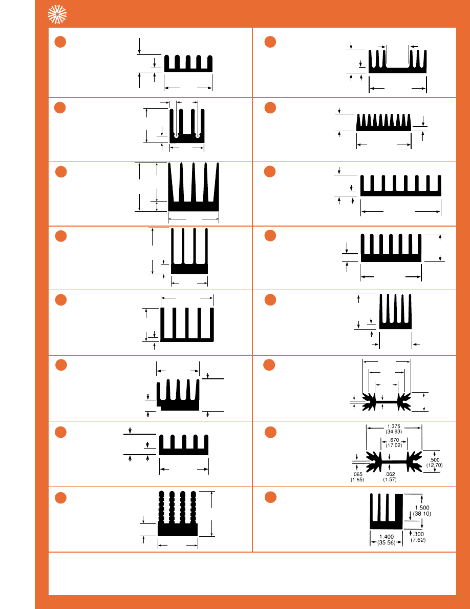
Corporate Office: 80 Commercial Street • Concord, NH 03301
27
Tel. (603) 224-9988 • Fax (603) 223-1790
AAVID
THERMALLOY
PRODUCT SELECTION GUIDE, Condensed
Heat Sinks for Extrusions
.640
(16.26)
.640
(16.26)
.136
(3.45)
.120
(3.05)
.400
(10.16)
62470
0.3lb/ft
12.0°C/W/3in
5.6 in
2
/in
.950
(24.13)
.170
(4.32)
.935
(23.75)
.765
(19.43)
64675
0.5lb/ft
7.1°C/W/3in
9.9 in
2
/in
1.250
(31.75)
1.000
(25.40)
.250
(6.35)
62560
0.6lb/ft
6.7°C/W/3in
10.5 in
2
/in
.750
(19.05)
1.060
(26.92)
.125
(3.18)
63400
0.4lb/ft
8.1°C/W/3in
8.6 in
2
/in
5
.800
(20.32)
1.060
(26.92)
.250
(6.35)
62930
0.6lb/ft
8.8°C/W/3in
7.9 in
2
/in
.280
(7.11)
1.187
30.15)
.050
(1.27)
63455
0.2lb/ft
11.4°C/W3/in
6.2 in
2
/in
.370
(9.40)
1.180
(29.97)
.085
(2.16)
63045
0.4lb/ft
8.6°C/W3/in
8.2 in
2
/in
.580
(14.73)
1.250
(31.75)
.156
(3.96)
62035
0.5lb/ft
8.0°C/W3/in
8.8 in
2
/in
1.650
(41.91)
1.260
(32.00)
.325
(8.26)
65245
1.3lb/ft
4.4°C/W3/in
15.9 in
2
/in
1.375
(34.93)
.500
(12.70)
.062
(1.57)
1.000
(25.40)
.625
(15.88)
.065
(1.65)
60130
0.4lb/ft
9.2°C/W/3in
7.6 in
2
/in
Note: The profiles are not to scale in relation to each other. Standard commercial extrusion tolerances apply (see our full line catalog, page 96).
Dimension in parenthesis are millimeters.
2
.400
(10.16)
.530
(13.46)
.040
(1.02)
62000
0.2lb/ft
14.6°C/W/3in
4.8 in
2
/in
1
.460
(11.68)
1.150
(29.21)
.110
(2.79)
.470
(11.94)
62365
0.3lb/ft
10.5°C/W/3in
6.8 in
2
/in
9
.450
(11.43)
1.060
(26.92)
.130
(3.30)
62925
0.3lb/ft
12.5°C/W/3in
5.6 in
2
/in
7
1.300
(33.02)
1.150
(29.21)
.350
(8.89)
62230
0.8lb/ft
5.1°C/W3/in
13.7 in
2
/in
8
3
4
6
11
10
12
13
14
63620
0.4lb/ft
9.2°C/W/3in
7.6 in
2
/in
15
61605
1.3lb/ft
5.4°C/W/3in
13.0 in
2
/in
16
Performance vs. Length
The thermal resistance of a heat sink changes significantly with length. For example, to convert the published natural con-
vection thermal resistance at a 3” length to a desired length, see page 35 for a length conversion table.
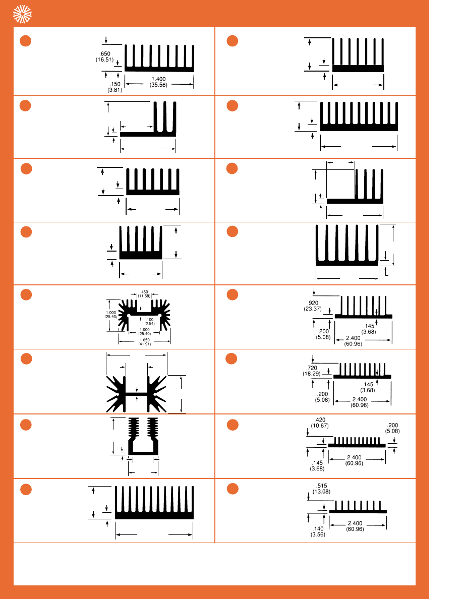
Corporate Office: 80 Commercial Street • Concord, NH 03301
28
Tel. (603) 224-9988 • Fax (603) 223-1790
AAVID
THERMALLOY
PRODUCT SELECTION GUIDE, Condensed
Heat Sinks for Extrusions
.900
(22.86)
1.400
(35.56)
.090
(2.29)
.840
(21.34)
63380
3.5lb/ft
9.5°C/W/3in
7.8 in
2
/in
.750
(19.05)
1.560
(39.62)
.125
(3.18)
61080
0.5lb/ft
5.7°C/W/3in
12.1 in
2
/in
1.630
(41.40)
.295
(7.49)
1.290
(32.77)
61215
1.3lb/ft
4.4°C/W/3in
15.9 in
2
/in
63485
0.8lb/ft
4.5°C/W/3in
15.4 in
2
/in
5
1.650
(41.91)
1.000
(25.40)
.062
(1.57)
.660
(16.76)
63130
0.6lb/ft
5.2°C/W/3in
13.4 in
2
/in
1.380
(35.05)
2.260
(57.40)
.190
(4.83)
1.150
(29.21)
61325
1.0lb/ft
4.8°C/W/3in
14.5 in
2
/in
.810
(20.57)
2.250
(57.15)
.180
(4.57)
64690
1.2lb/ft
3.7°C/W/3in
18.7 in
2
/in
1.500
(38.1)
2.310
(58.67)
.156
(3.96)
62500
1.4lb/ft
3.0°C/W/3in
23.7 in
2
/in
65550
0.9lb/ft
4.1°C/W/3in
17.2 in
2
/in
65795
0.9lb/ft
4.3°C/W/3in
16.2 in
2
/in
Note: The profiles are not to scale in relation to each other. Standard commercial extrusion tolerances apply (see our full line catalog, page 96).
Dimension in parenthesis are millimeters.
2
66450
0.5lb/ft
6.3°C/W/3in
11.2 in
2
/in
1
1.250
(31.75)
1.920
(48.77)
.250
(6.35)
62745
1.1lb/ft
3.8°C/W/3in
18.3 in
2
/in
9
2.250
(57.15)
1.750
(44.45)
.188
(4.78)
1.250
(31.75)
60180
2.1lb/ft
2.3°C/W/3in
27.5 in
2
/in
7
.643
(16.33)
1.846
(47.35)
.150
(3.81)
64635
0.7lb/ft
4.4°C/W/3in
15.8 in
2
/in
8
3
4
6
11
10
12
13
14
66000
0.7lb/ft
6.3°C/W/3in
11.1 in
2
/in
15
66385
0.6lb/ft
6.4°C/W/3in
10.9 in
2
/in
16
Temperature Rise Factor
The published thermal resistance assumes a 75°C temperature rise of the heat sink above the ambient temperature.
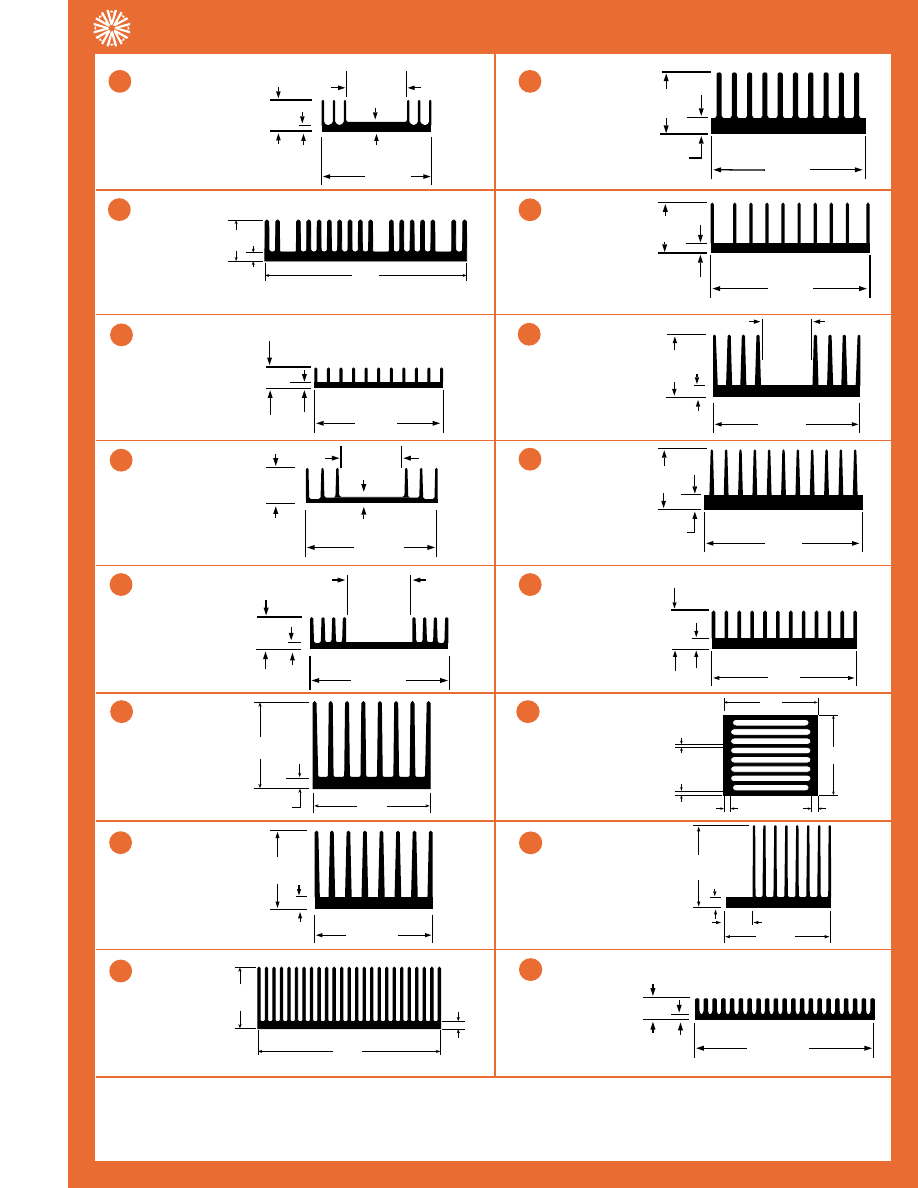
Corporate Office: 80 Commercial Street • Concord, NH 03301
29
Tel. (603) 224-9988 • Fax (603) 223-1790
AAVID
THERMALLOY
PRODUCT SELECTION GUIDE, Condensed
Heat Sinks for Extrusions
.500
(12.7)
2.509
(63.7)
.110
(2.8)
71275
.71lb/ft
4.0°C/W/3in
17.6 in
2
/in
.094
(2.39)
2.682
(68.12)
.400
(10.16)
60955
0.6lb/ft
5.7°C/W/3in
12.3 in
2
/in
.687
(17.45)
2.687
(68.25)
.125
(3.18)
1.297
(32.94)
60865
0.5lb/ft
5.1°C/W/3in
13.6 in
2
/in
1.375
(34.93)
.625
(15.88)
2.815
(71.50)
.109
(2.77)
60235
0.8lb/ft
4.8°C/W/3in
14.4 in
2
/in
5
.280
(7.112)
2.996
(76.1)
2.250
(57.15)
63730
2.8lb/ft
1.8°C/W/3in
38.1 in
2
/in
1.250
(31.75)
1.400
(35.56)
3.436
(87.27)
.200
(5.08)
61055
1.9lb/ft
2.5°C/W/3in
26.5 in
2
/in
.190
(4.83)
3.250
(82.55)
1.000
(25.40)
60760
1.6lb/ft
3.1°C/W/3in
22.7 in
2
/in
.295
(7.49)
3.450
(87.63)
1.290
(32.77)
60250
2.1lb/ft
2.4°C/W/3in
28.5 in
2
/in
.200
(5.08)
3.500
(88.90)
.850
(21.59)
62200
1.5lb/ft
3.0°C/W/3in
23.0 in
2
/in
3.520
(89.4)
3.000
(76.2)
.260
(6.6)
.150
(3.8)
.090
(2.3)
TYP 2
.260
(6.6)
TYP 7
70560
5.3lb/ft
1.1°C/W/3in
63.0 in
2
/in
Note: The profiles are not to scale in relation to each other. Standard commercial extrusion tolerances apply (see our full line catalog, page 96).
Dimension in parenthesis are millimeters.
2
.680
(17.27)
2.440
(61.98)
.120
(3.05)
1.300
(33.02)
.185
(4.70)
60985
0.8lb/ft
6.1°C/W/3in
11.5 in
2
/in
1
.312
(7.92)
3.120
(79.25)
1.250
(31.75)
61315
2.3lb/ft
2.7°C/W/3in
25.6 in
2
/in
9
2.000
(50.80)
2.996
(76.10)
.280
(7.11)
63020
2.3lb/ft
1.9°C/W/3in
34.1 in
2
/in
7
3.008
(76.4)
1.020
(25.9)
.120
(3.0)
72070
1.3lb/ft
1.4°C/W/3in
50.5 in
2
/in
8
3
4
6
11
10
12
13
14
2.705
(68.71)
3.520
(89.41)
.275
(6.99)
.900
(22.86)
62580
3.1lb/ft
1.5°C/W/3in
46.5 in
2
/in
15
.399
(10.13)
3.650
(92.71)
.080
(2.03)
62650
0.9lb/ft
3.4°C/W/3in
20.9 in
2
/in
16
Optimization
Optimization in either forced or natural convection can result in cost and size reduction of the heat sink. In forced
convection, optimization can reduce the size of the fan or blower.
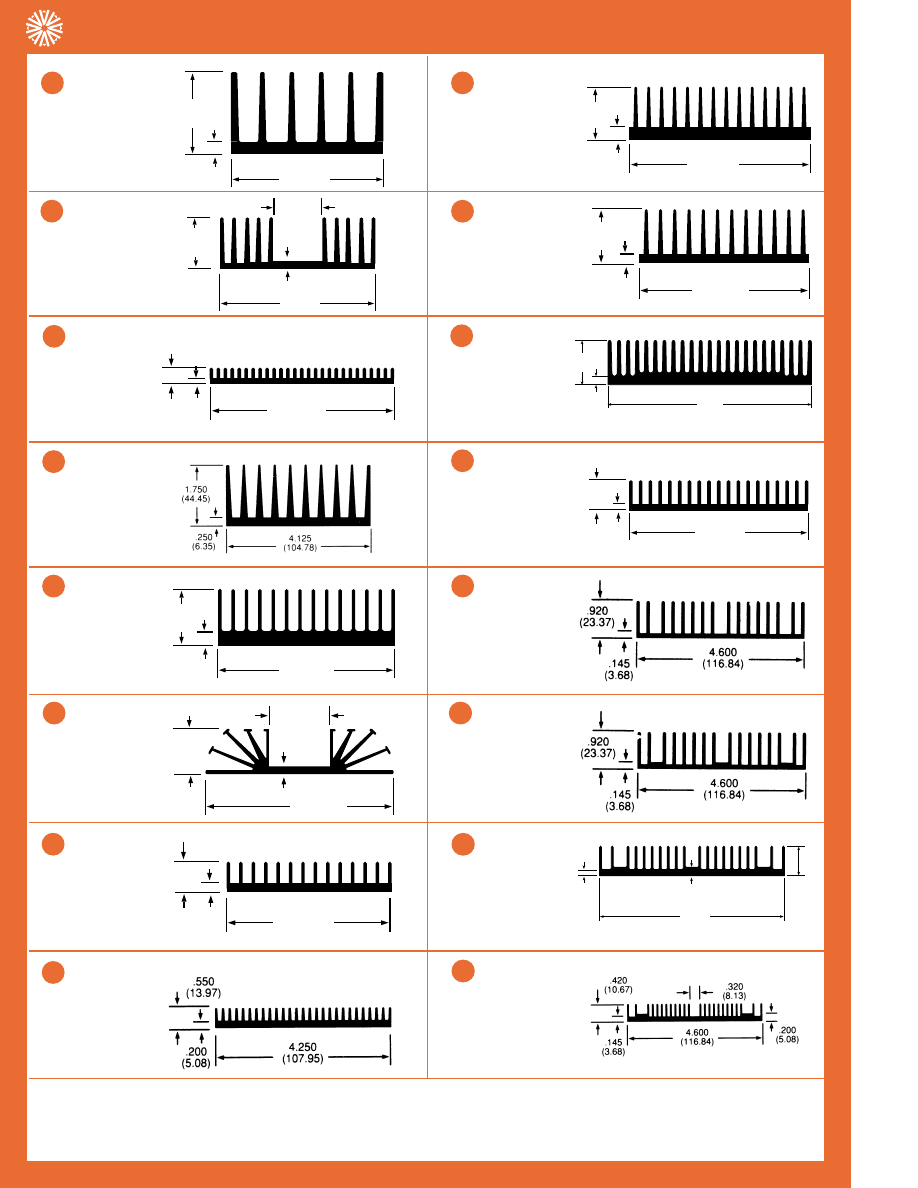
1.281
(32.54)
3.900
(99.06)
.150
(3.81)
1.312
(33.32)
60630
1.8lb/ft
2.3°C/W/3in
30.0 in
2
/in
.300
(7.62)
4.000
(101.60)
.060
(1.52)
61585
0.7lb/ft
3.3°C/W/3in
21.1 in
2
/in
60095
3.5lb/ft
1.8°C/W/3in
38.8 in
2
/in
1.312
(33.32)
4.125
(104.78)
.312
(7.92)
61090
3.0lb/ft
2.0°C/W/3in
36.9 in
2
/in
5
1.000
(25.40)
4.125
(104.78)
.187
(4.75)
1.335
(33.91)
60080
1.2lb/ft
2.9°C/W/3in
23.6 in
2
/in
1.000
(25.4)
4.550
(115.6)
.200
(5.1)
72205
2.5lb/ft
1.7°C/W/3in
42.3 in
2
/in
1.400
(35.56)
4.500
(114.30)
.200
(5.08)
61075
2.4lb/ft
1.7°C/W/3in
38.2 in
2
/in
.750
(19.05)
4.562
(115.87)
.125
(3.18)
60585
1.7lb/ft
2.2°C/W/3in
32.0 in
2
/in
65185
1.7lb/ft
2.0°C/W/3in
34.3 in
2
/in
65555
1.7lb/ft
2.1°C/W/3in
33.5 in
2
/in
Note: The profiles are not to scale in relation to each other. Standard commercial extrusion tolerances apply (see our full line catalog, page 96).
Dimension in parenthesis are millimeters.
2
2.000
(50.80)
3.850
(97.79)
.250
(6.35)
60825
2.9lb/ft
2.3°C/W/3in
30.0 in
2
/in
1
1.290
(32.77)
4.375
(111.13)
.295
(7.49)
60560
2.7lb/ft
1.8°C/W/3in
36.5 in
2
/in
9
.750
(19.05)
4.125
(104.78)
.250
(6.35)
63985
1.7lb/ft
3.1°C/W/3in
22.3 in
2
/in
7
66505
1.6lb/ft
2.7°C/W/3in
25.9 in
2
/in
8
3
4
6
11
10
12
13
14
4.600
(116.84)
.720
(18.29)
.200
(5.08)
.145
(3.68)
65990
1.6lb/ft
2.2°C/W/3in
31.2 in
2
/in
15
65995
1.3lb/ft
3.3°C/W/3in
21.3 in
2
/in
16
Technical Capabilities
Aavid Thermalloy Application Engineering Department has the capability to perform a full thermal analysis,
including optimization, in order to find the right Aavid heat sink for your application.
Corporate Office: 80 Commercial Street • Concord, NH 03301
30
Tel. (603) 224-9988 • Fax (603) 223-1790
AAVID
THERMALLOY
PRODUCT SELECTION GUIDE, Condensed
Heat Sinks Extrusions
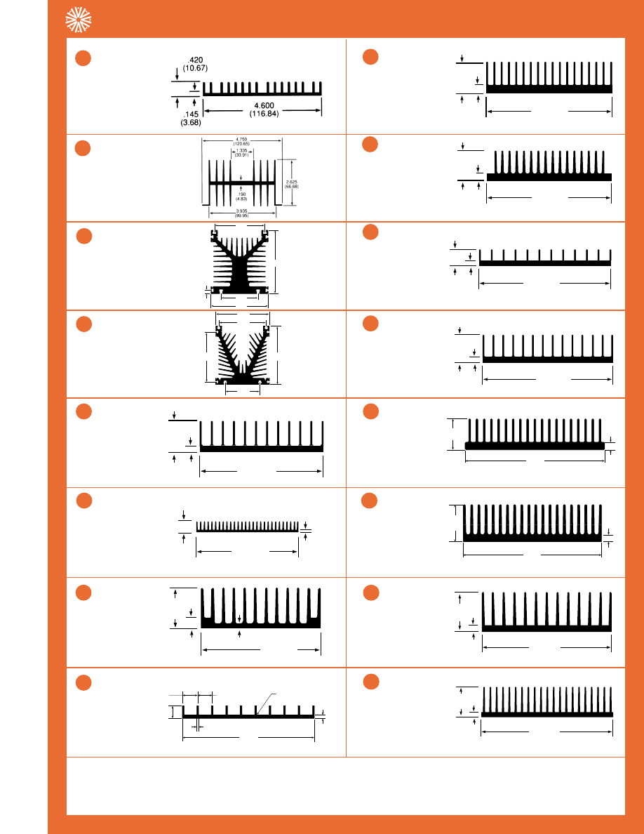
Corporate Office: 80 Commercial Street • Concord, NH 03301
31
Tel. (603) 224-9988 • Fax (603) 223-1790
AAVID
THERMALLOY
PRODUCT SELECTION GUIDE, Condensed
Heat Sinks Extrusions
60055
2.5lb/ft
1.5°C/W/3in
48.1 in
2
/in
4.921
(125.00)
5.374
(136.50)
4.331
(110.01)
3.150
(80.01)
.295
(7.49)
62375
12.8lb/ft
0.8°C/W/3in
91.3 in
2
/in
4.921
(124.99)
5.315
(135.00)
4.331
(110.01)
3.150
(80.01)
4.528
(115.01)
62905
11.1lb/ft
0.8°C/W/3in
91.2 in
2
/in
1.250
(31.75)
4.990
(126.75)
.250
(6.35)
61745
2.4lb/ft
2.0°C/W/3in
34.5 in
2
/in
5
.490
(12.45)
5.000
(127.00)
.120
(3.05)
67895
1.4lb/ft
2.4°C/W/3in
29.3 in
2
/in
1.312
(33.32)
5.561
(141.25)
.312
(7.92)
60215
4.2lb/ft
1.6°C/W/3in
43.6 in
2
/in
1.312
(33.32)
5.375
(136.53)
.312
(7.92)
61085
3.6lb/ft
1.5°C/W/3in
46.1 in
2
/in
6.000
(152.4)
1.312
(33.3)
.312
(7.9)
68995
3.6lb/ft
1.4°C/W/3in
49.7 in
2
/in
1.600
6.000
(152.4)
1.600
(40.6)
.300
(7.6)
72385
4.8lb/ft
1.1°C/W/3in
61.8 in
2
/in
Note: The profiles are not to scale in relation to each other. Standard commercial extrusion tolerances apply (see our full line catalog, page 96).
Dimension in parenthesis are millimeters.
2
65175
1.1lb/ft
3.9°C/W/3in
18.1 in
2
/in
1
2.120
(53.85)
5.100
129.54)
.500
(12.70)
.180
(4.57)
63815
3.9lb/ft
1.7°C/W/3in
41.7 in
2
/in
7
4.730
(120.14)
.187
(4.75)
.687
(17.45)
.062
(1.57)
.545
(13.84)
.520
(13.21)
.031 RAD
(.79)
TYP 10
TYP 2
TYP 7
TYP 18
61095
1.7lb/ft
3.5°C/W/3in
19.8 in
2
/in
8
3
4
6
10
9
13
14
1.750
(44.45)
6.080
(154.43)
.250
(6.35)
60140
4.1lb/ft
1.4°C/W/3in
50.3 in
2
/in
15
1.312
(33.32)
6.437
(163.50)
.312
(7.92)
60340
3.2lb/ft
1.2°C/W/3in
55.5 in
2
/in
16
Fabrication Capabilities Aavid has extensive manufacturing capabilities for the complete fabrication of heat sinks for
extrusions. The Aavid plant is equipped with high speed saws, a battery of CNC machining centers, and an automated
anodizing line incorporating the latest technology available in the world.
.687
(17.45)
5.750
(146.05)
.187
(4.75)
61790
1.7lb/ft
2.9°C/W/3in
23.9 in
2
/in
11
1.250
(31.75)
5.886
(149.50)
.250
(6.35)
60230
2.9lb/ft
1.8°C/W/3in
40.0 in
2
/in
12
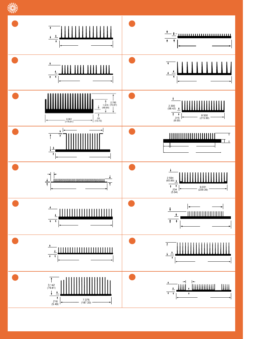
1.185
(30.10)
6.750
(171.45)
.125
(3.18)
60995
2.5lb/ft
1.4°C/W/3in
50.1 in
2
/in
65605
9.3lb/ft
0.7°C/W/3in
97.9 in
2
/in
2.390
(60.71)
7.200
(182.88)
.060
(1.52)
5.200
(132.08)
.270
(6.86)
62625
4.7lb/ft
0.9°C/W/3in
78.2 in
2
/in
.460
(11.68)
7.201
(182.91)
.080
2.03
.383
(9.73)
68855
1.7lb/ft
1.5°C/W/3in
46.3 in
2
/in
5
1.312
(33.32)
7.340
(186.44)
.312
(7.92)
65445
4.8lb/ft
1.1°C/W/3in
62.6 in
2
/in
65345
9.0lb/ft
0.8°C/W/3in
86.3 in
2
/in
2.000
(50.80)
8.350
(212.09)
.250
(6.35)
60815
6.0lb/ft
1.2°C/W/3in
56.8 in
2
/in
1.400
(35.6)
8.500
(215.9)
.913
(23.2)
.500
(12.7)
6.600
(167.6)
71390
6.78lb/ft
1.2°C/W/3in
58.1 in
2
/in
65615
9.0lb/ft
0.7°C/W/3in
104.5 in
2
/in
1.400
(35.56)
9.400
(238.76)
.500
(12.70)
6.600
(167.64)
65335
7.3lb/ft
1.2°C/W/3in
59.7 in
2
/in
Note: The profiles are not to scale in relation to each other. Standard commercial extrusion tolerances apply (see our full line catalog, page 96).
Dimension in parenthesis are millimeters.
2
1.600
(40.64)
6.500
(165.1)
.200
(5.08)
61070
3.4lb/ft
1.3°C/W/3in
56.0 in
2
/in
1
.575
(14.61)
8.034
(204.06)
.275
(6.99)
62805
3.1lb/ft
2.2°C/W/3in
32.2 in
2
/in
9
.875
(22.23)
7.340
(186.44)
.190
(4.83)
61915
2.9lb/ft
1.5°C/W/3in
47.9 in
2
/in
7
67690
6.6lb/ft
0.5°C/W/3in
129.6 in
2
/in
8
3
4
6
11
10
12
13
14
2.280
(57.91)
9.750
(247.65)
.280
(7.11)
62725
7.1lb/ft
0.7°C/W/3in
100.1 in
2
/in
15
1.312
(33.32)
9.870
(250.70)
.312
(7.92)
1.200
(30.48)
.200
(5.08)
62030
5.6lb/ft
1.0°C/W/3in
66.9 in
2
/in
16
Electronic Enclosures
Multi-function extruded electronic enclosures improve product appearance, reduce packaging costs, and extend electronic
system life. For more information, contact Aavid to request the Technical Design Guide for Electronic Enclosures.
Corporate Office: 80 Commercial Street • Concord, NH 03301
32
Tel. (603) 224-9988 • Fax (603) 223-1790
AAVID
THERMALLOY
PRODUCT SELECTION GUIDE, Condensed
Heat Sinks for Extrusions
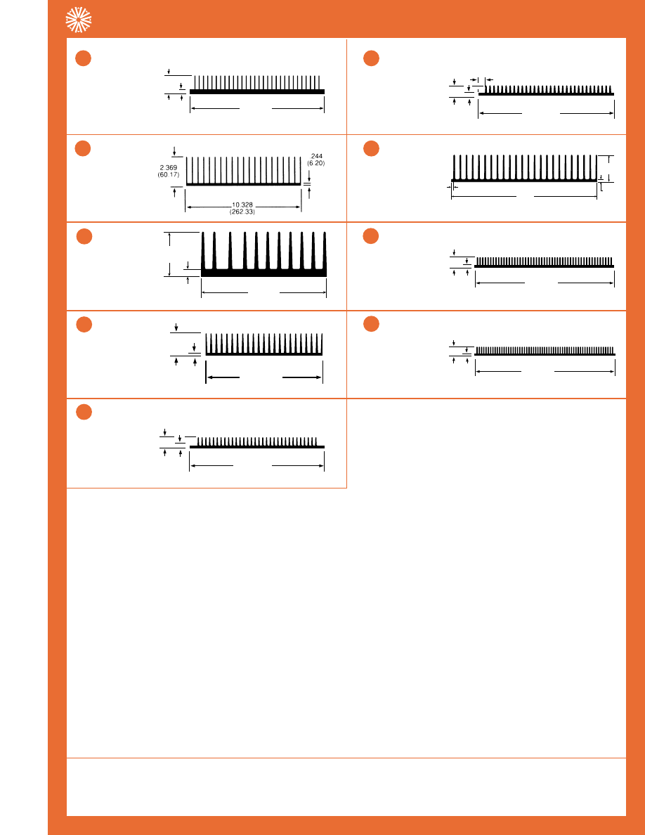
Corporate Office: 80 Commercial Street • Concord, NH 03301
33
Tel. (603) 224-9988 • Fax (603) 223-1790
AAVID
THERMALLOY
PRODUCT SELECTION GUIDE, Condensed
Heat Sinks for Extrusions
65525
8.1lb/ft
0.6°C/W/3in
108.9 in
2
/in
3.770
(95.76)
10.780
(273.81)
.620
(15.75)
61785
16.4lb/ft
0.8°C/W/3in
92.1 in
2
/in
2.300
(58.42)
11.000
(279.40)
.315
(8.00)
65340
11.8lb/ft
0.6°C/W/3in
110.4 in
2
/in
1.000
(25.40)
12.250
(311.15)
.250
(6.35)
61155
7.0lb/ft
1.0°C/W/3in
73.0 in
2
/in
5
1.312
(33.32)
17.000
(431.80)
.312
(7.92)
63340
10.4lb/ft
0.5°C/W/3in
136.6 in
2
/in
14.750
(374.7)
.250
(6.4)
2.750
(69.9)
.250
(6.4)
72545
11.9lb/ft
0.5°C/W/3in
144.8 in
2
/in
1.312
(33.32)
19.000
(482.60)
.312
(7.92)
62335
11.6lb/ft
0.4°C/W/3in
160.6 in
2
/in
Note: The profiles are not to scale in relation to each other. Standard commercial extrusion tolerances apply (see our full line catalog, page 96).
Dimension in parenthesis are millimeters.
2
1.312
(33.32)
9.875
(250.83)
.312
(7.92)
60520
6.7lb/ft
0.9°C/W/3in
80.4 in
2
/in
1
1.000
(25.40)
13.680
(347.47)
.250
(6.35)
.682
(17.32)
62645
8.7lb/ft
0.9°C/W/3in
75.9 in
2
/in
6
3
4
8
7
9
Performance vs. Length
The thermal resistance of a heat sink changes significantly with length. For example, to convert the published natural con-
vection thermal resistance at a 3” length to a desired length, see page 35 for a length conversion table.
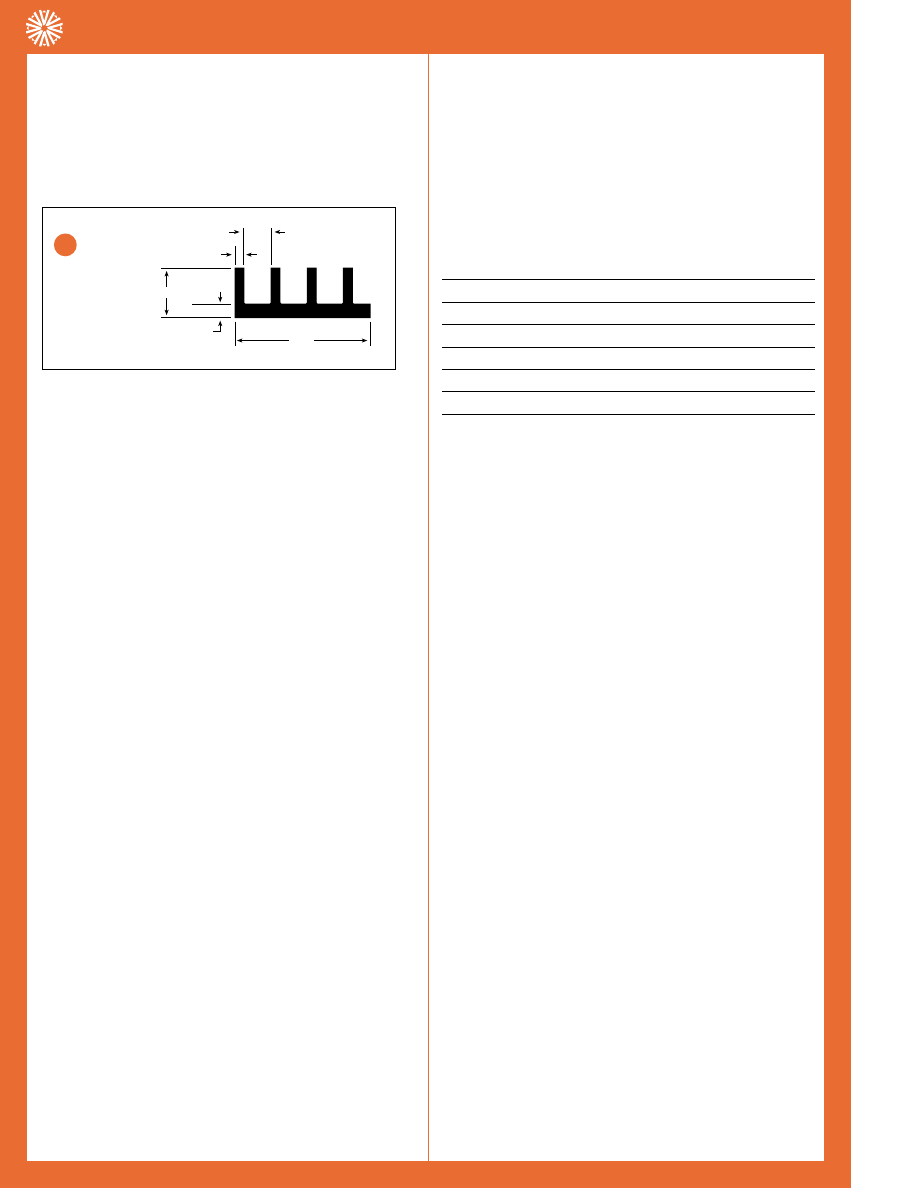
Corporate Office: 80 Commercial Street • Concord, NH 03301
34
Tel. (603) 224-9988 • Fax (603) 223-1790
AAVID
THERMALLOY
PRODUCTION SELECTION GUIDE, Condensed
Extrusion Thermal Information
HOW TO USE PUBLISHED DATA FOR
EXTRUSION PROFILES
Each extrusion profile is described in a separate box along
with its part number, dimensions, surface area (in
2
/in), weight
per foot of extrusion (lb/ft), and natural convection thermal
resistance for a three inch length of extrusion (°C/W/3”).
60270
The extrusion’s five digit base part number is listed
in the left hand corner.
In
2
/in
The perimeter of the cross-sectional profile of the extrusion
is also the outside surface area per inch of length (in
2
/in).The
perimeter is used to predict the thermal resistance (
θ
sa) in
the forced convection applications.The performance factor
table on page 35 provides thermal resistance of an extrusion
using two variables; air velocity and extrusion length.
EXAMPLE: Extrusion #65810 has a perimeter of
26.2 in
2
/in and will be cut to 4.0” long.The air flow is 600
LFM.Therefore, the performance factor is 18.70 (from the
table using 600 LFM and 4.0”) and its
θ
sa is 0.71 °C/W
(18.70/26.2)
lb/ft
The weight of the extrusion in pounds per foot (lb/ft) is used
as a relative indicator of extrusion cost when considering dif-
ferent extrusions for a particular application.This figure may
also be used to calculate the cross-sectional surface area (in
2
)
of an extrusion.
Area (cross-section) = 1.18 x lb/ft
°C/W/3”
The theoretical thermal resistance (°C/W) for a three inch
section of extrusion in natural convection is a calculated fig-
ure derived from surface area per inch of length (in
2
/in), a
sink-to-ambient temperature difference of 75°C, a black
anodize finish, and a single point heat source mounted at the
center of the three inch section (the length axis of the extru-
sion is vertical with respect to gravity).
TEMPERATURE CORRECTION
CONSIDERATIONS
Since natural convection heat sink efficiency degrades with
decreasing sink-to-ambient temperature differential, a cor-
rection factor must be applied to the published data if an
application requires a sink-to-ambient temperature rise of
less than 75°C.The corrected thermal resistance is obtained
by multiplying published °C/W/3” data by the appropriate
factor from the following table:
Temperature Rise (
∆
Tsa) Correction Factor
75°C
1.000
70°C
1.017
60°C
1.057
50°C
1.106
40°C
1.170
30°C
1.257
For any extrusion profile in natural convection, the thermal
resistance (°C/W) is more than 25% higher at
∆
Tsa = 30°C
than at
∆
Tsa = 75°C.
LENGTH CORRECTION CONSIDERATIONS
The published extrusion data shows natural convection per-
formance for a three inch section with a centrally located
point source heat load. Because the heat load is assumed to
be at a point rather than uniformly distributed, thermal resis-
tance does not change linearly with length. (The ends of a
very long extrusion would be cooler than the center and
therefore the transfer of heat to the surrounding air is little,
if any.) It is therefore necessary to apply a correction factor
to published data for extrusion lengths shorter or longer
than three inches.The corrected thermal resistance for dif-
ferent lengths
of extrusion is obtained by multiplying published °C/W/3”
data by the appropriate factor from the following table: (see
next page)
.120
.400
.256
1.125
.055
60270
4.7 in
2
/in
0.2 lb/ft
14.9°C/W/3in
12
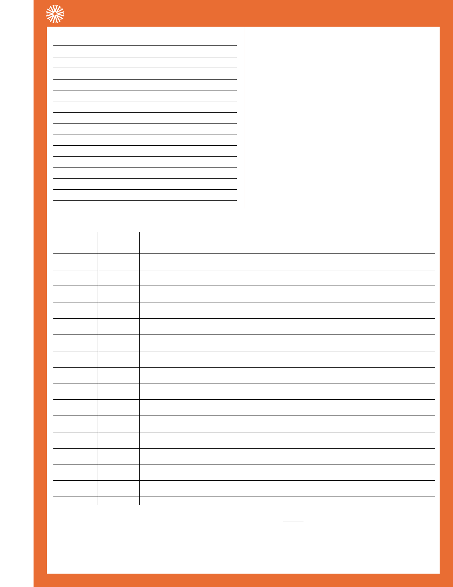
Corporate Office: 80 Commercial Street • Concord, NH 03301
35
Tel. (603) 224-9988 • Fax (603) 223-1790
AAVID
THERMALLOY
PRODUCTION SELECTION GUIDE, Condensed
Extrusion Thermal Information
Length of Heat Sink
Correction Factor
1.0”
1.80
2.0”
1.25
3.0”
1.00
4.0”
0.87
5.0”
0.78
6.0”
0.73
7.0”
0.67
8.0”
0.64
9.0”
0.60
10.0”
0.58
11.0”
0.56
12.0”
0.54
13.0”
0.52
14.0”
0.51
15.0”
0.50
This table may also be used to determine the appropriate
length of a preferred extrusion required to obtain a desired
thermal resistance. Merely divide the desired thermal resis-
tance by the published thermal resistance for a three inch
section to obtain a correction factor.
EXAMPLE: Extrusion 62465 has a thermal resistance of 8.0
°C/W/3 inch. A five inch piece will have a thermal resistance
of 6.24°C/W, using the appropriate length correction factor
of 0.78 [i.e. 8.0°C/W x 0.78 = 6.24°C/W].
Since the thermal resistance of 6.24°C/W is at a tempera-
ture rise of 75°C, the resistance of the heat sink at a temper-
ature rise of 50°C will be increased by the temperature cor-
rection factor of 1.106.There-fore the new natural convec-
tion thermal resistance is now 6.90°C/W [6.24°C/W x 1.106
= 6.90°C/W].
PERFORMANCE FACTOR TABLE
Extrusion
Natural
Forced Convection,Air Velocity (Ft/Min)
Length (In.)
Convection
100
200
300
400
500
600
700
800
900
1000
1100
1200
0.25
242.20
183.33 129.63 105.84
91.66
81.98
74.84
69.29
64.81
61.11 57.97
55.27
52.92
0.50
171.27
129.63
91.66
74.84
64.81
57.97
52.92
48.99
45.83
43.21 40.99
39.08
37.42
1.00
121.10
91.61
64.77
52.89
45.80
40.96
37.40
34.62
32.38
30.53 28.97
27.62
26.44
2.00
85.63
64.89
45.88
37.46
32.44
29.02
26.49
24.52
22.94
21.63 20.52
19.56
18.73
3.00
69.92
52.88
37.39
30.53 26.44
23.64
21.58
19.98
18.69
17.62 16.72
15.94 15.26
4.00
60.55
45.81
32.39
26.45 22.90
20.49
18.70
17.31
16.19
15.27 14.48
13.81 13.22
5.00
54.16
40.99
28.98
23.66 20.49
18.33
16.73
15.49
14.49
13.66 12.96
12.36 11.83
6.00
49.44
37.39
26.44
21.58 18.69
16.72
15.26
14.13
13.22
12.46 11.82
11.27 10.79
7.00
45.77
34.61
24.47
19.98 17.30
15.48
14.13
13.08
12.23
11.53 10.94
10.43
9.99
8.00
42.82
32.39
22.90
18.70 16.19
14.48
13.22
12.24
11.45
10.79 10.24
9.76
9.35
9.00
40.37
30.53
21.58
17.62 15.26
13.65
12.46
11.53
10.79
10.17
9.65
9.20
8.81
10.00
38.30
28.97
20.48
16.72 14.48
12.95
11.82
10.94
10.24
9.65
9.16
8.73
8.36
11.00
36.51
27.62
19.53
15.95 13.81
12.35
11.27
10.44
9.76
9.20
8.73
8.32
7.97
12.00
34.96
26.44
18.69
15.26 13.22
11.82
10.79
9.99
9.34
8.81
8.36
7.97
7.63
13.00
33.59
25.40
17.96
14.66 12.70
11.36
10.37
9.60
8.98
8.46
8.03
7.66
7.33
14.00
32.37
24.48
17.31
14.13 12.24
10.95
9.99
9.25
8.65
8.16
7.74
7.38
7.06
NOTE: For lengths and flow velocities not shown above, the equation
may be used.
P.F.
√
916
——
V•L
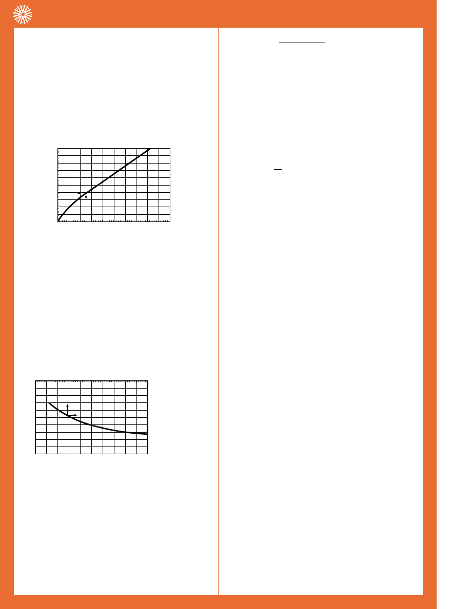
Corporate Office: 80 Commercial Street • Concord, NH 03301
36
Tel. (603) 224-9988 • Fax (603) 223-1790
AAVID
THERMALLOY
PRODUCTION SELECTION GUIDE, Condensed
Extrusion Thermal Information
READING A THERMAL
PERFORMANCE GRAPH
The performance graphs in the catalog are actually a com-
posite of two separate graphs which, as shown below, have
been combined to save space on the page.The small arrows
on each curve indicate to which axes the curve corresponds.
Thermal graphs are published assuming the device to be
cooled is properly mounted and the heat sink is in its nor-
mally used mounting position.
GRAPH A is used to show heat sink performance when
used in a natural convection environment (i.e. without forced
air).This graph starts in the lower left hand corner with the
horizontal axis representing the heat dissipation (watts) and
the vertical left hand axis representing the rise in heat sink
mounting surface temperature above ambient (°C). By know-
ing the power to be dissipated, the temperature rise of the
mounting surface can be predicted.Thermal resistance, in
natural convection, is determined by dividing this tempera-
ture rise by the power input (°C/W).
GRAPH B is used to show heat sink performance when
used in a forced convection environment (i.e. with forced air
flow through the heat sink).This graph has its origin in the
top right hand corner with the horizontal axis (top) repre-
senting air velocity over the heat sink (LFM) and the vertical
right hand axis representing the thermal resistance of the
heat sink (°C/W). Air velocity is calculated by dividing the
output volumetric flow rate of the fan by the cross- sectional
area of the outflow air passage.
THERMAL RESIST
ANCE FROM MTG
SURF
ACE T
O
AMBIENT –
°
C/W
AT
T
A I R V E L O C I T Y – F E E T P E R M I N U T E
0
8
16
20
4
12
0
600
200
400
800
1000
MOUNTING SURF
ACE TEMP
RISE ABO
VE AMBIENT
–
°
C
H E AT D I S S I PAT E D – WAT T S
0
40
80
100
20
60
0
3
5
1
2
4
Velocity (LFM) =
Volume (CFM)
area (ft
2
)
Although most fans are normally rated and compared at
their free air delivery at zero back pressure, this is rarely the
case in most applications. For accuracy, the volume of output
must be derated by 60% to 80% for the anticipation of back
pressure.
EXAMPLE: The output air volume of a fan is given as 80
CFM.The output area is 6 inches by 6 inches or
36 in
2
or .25 ft
2
.
To find velocity:
velocity = 80 = 320
0.25
Velocity is 320 LFM, which at 80%, derates to 256 LFM.
EXAMPLE A: Aavid part number 579802 (see page 51) is to
be used to dissipate 3 watts of power in natural convection.
Because we are dealing with natural convection, we refer to
the “A” part of the graph. Knowing that 3 watts are to be
dissipated, follow the grid line to the curve and find that at 3
watts there is a temperature rise of 75°C.To get the thermal
resistance, divide the temperature rise by the power dissipat-
ed, which yields 25°C/W.
EXAMPLE B: For the same application we add a fan which
blows air over the sink at a velocity of 400 LFM.
The addition of a fan means that we are dealing with forced
convection and therefore we refer to the “B” part of the
graph. Knowing the air flow, the thermal resistance is taken
from the graph.This resistance of 8.75°C/W is then multi-
plied by the power to be dissipated, 3 watts.This yields a
temperature rise of 26.25°C.
The difference between the natural convection cooling and
the forced air cooling at 400 feet/minute can be seen by
comparing the thermal resistance of the heat sink in these
environments, 25°C/W vs. 8.75°C/W respectively.
DESIGN ASSISTANCE
Aavid Thermal Technologies can assist in the design
of heat sinks for both forced and natural convection applica-
tions. Aavid’s technical staff can help in the selection of an
existing “near” optimum extrusion from over 3,000 shapes
that have been previously designed and tooled by Aavid
Thermal Technologies or can design a new extrusion which
best meets the requirements of the application.
Any thermal application needing an extruded heat sink
should be thermally defined as explicitly as possible before
an extrusion is selected or designed.

Corporate Office: 80 Commercial Street • Concord, NH 03301
37
Tel. (603) 224-9988 • Fax (603) 223-1790
AAVID
THERMALLOY
PRODUCT SELECTION GUIDE, Condensed
CORPORATE HEADQUARTERS
Aavid Thermalloy, LLC
80 Commercial Street
Concord, NH 03301
TEL: (603) 224-9988 • FAX: (603) 223-1790
For Fast, Accurate Results, Call Your Aavid Distributor Today!
Thermal Solutions Have Never Been Easier!
To quickly reference the Aavid family of thermal solutions, anytime day or
night, simply visit the Aavid web site at www.aavid.com or
call our FastFacts
™
automated fax retrieval system, (603) 223-1750.