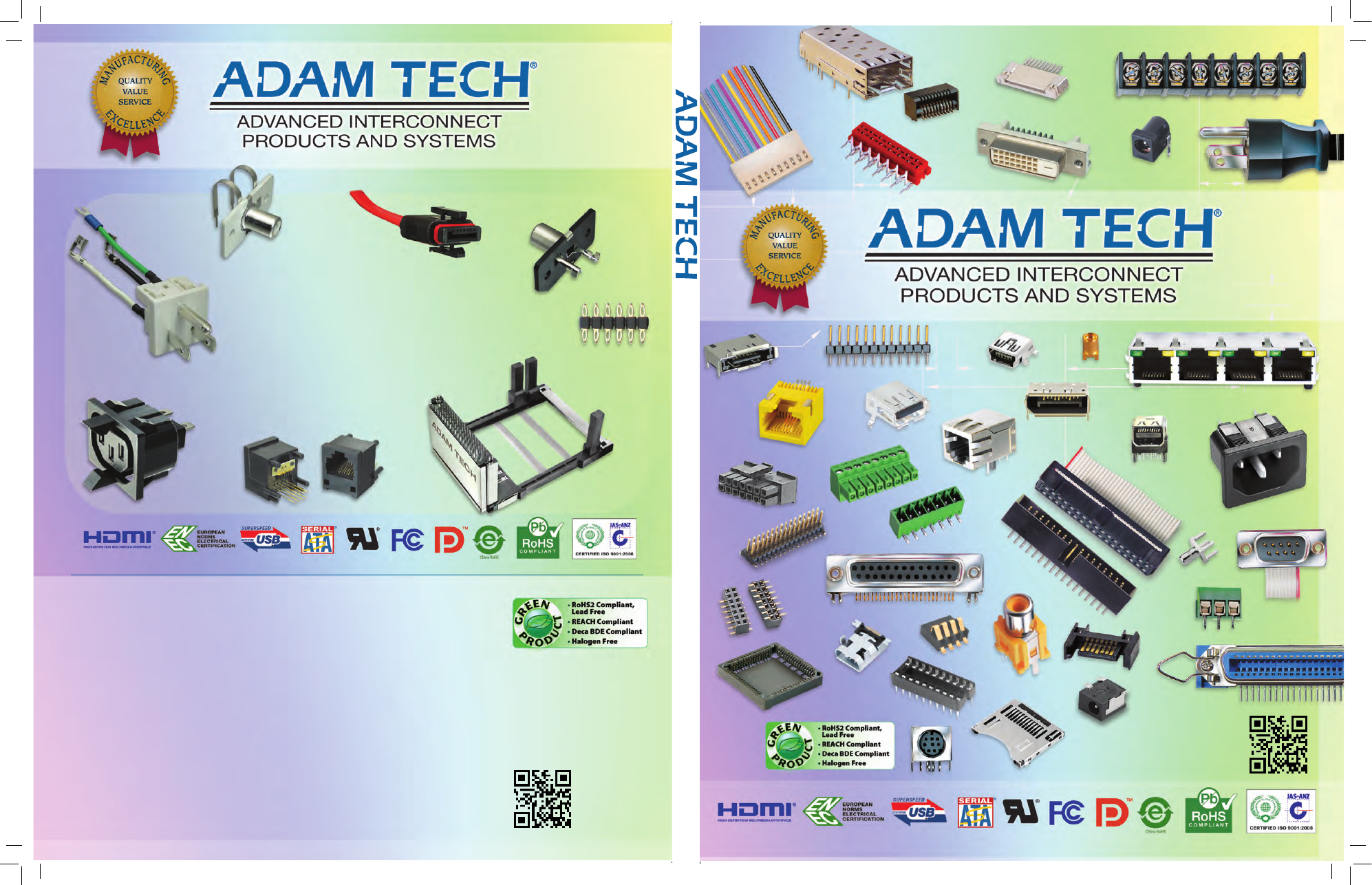
background image

Adam T

echnologies, Inc. 

Adam Tech


  USA 

909 Rahway Ave  

|

  Union, NJ 07083  

|

  USA 

Tel: 908.687.5000  

|

  Fax: 908.687.5710

Email: info@adam-tech.com

www.adam-tech.com 

Adam Tech


  TAiwAN

5F-17, No.14, Lane 609, Sec. 5, Chongsin Rd. 

New Taipei City  

|

  Taipei County 241  

|

  Taiwan (R.O.C.) 

Tel: 886-2 2999 8028  

|

  Fax: 886-2 2999 8062

Email: sales@adam-tech.com 

www.adam-tech.com.tw

Adam Tech


  CHiNA

Songgang Town industrial Park  

|

  Shenzhen City

Guangdong Province  

|

  China

Tel. 886-2 2999 8028  

|

  Fax. 886-2 2999 8062

Email: factory@adam-tech.com

www.adam-tech.com.cn

Adam Tech


  EUROPE

Somerset 

|

  UK

Email: europe@adam-tech.com

www.adam-tech.com

Adam Tech


  iNDiA

New Delhi  

|

  india

Email: india@adam-tech.com

www.adam-tech.com

Adam Tech


  BRAziL

São Paulo  

|

  Brazil

Email: brazil@adam-tech.com 

www.adam-tech.com

ADVANCED INTERCONNECT PRODUCTS AND SYSTEMS

info@adam-tech.com
www.adam-tech.com

info@adam-tech.com
www.adam-tech.com

Custom solutions

•  Providing service from concept through  

design to production

•  Improvements to quality or function
•  Solving capacity or lead time issues
•  Solution for single sourced components
•  Cost reduction specialist

Adam-Tech-Catalog-html.html
background image

www.adam-tech.com

®

Index by product 

ADVANCED INTERCONNECT PRODUCTS AND SYSTEMS

2002 / 95 / EC

Pb

RoHS

COMPLIANT

www.adam-tech.com

All text, photos and illustrations within this catalog are property of Adam Tech and may not be reproduced in any form without express written permission.
© 2014 Adam Tech. All rights reserved.
Adam Tech has taken reasonable efforts to insure that all drawings, illustrations, specifications, statements and safety agency approvals contained herein are accurate 

as of the date of publication. However, Adam Tech does not guarantee in any way the accuracy or specificity of any information contained herein. Adam Tech expressly 

disclaims all implied warranties regarding this information, including but not limited to any implied warranties or merchantability or fitness for a particular purpose. 
Adam Tech will in no case be liable for your use, or the results of your use of any Adam Tech products based upon written materials provided. IT IS YOUR RESPONSIBILITY 

TO VERIFY AND CONFIRM THE RESULTS OF YOUR USE OF THIS DATA AND PRODUCT IN YOUR OWN SPECIFIC ENGINEERING APPLICATION AND ENVIRONMENT AND YOU 

ASSUME ALL RISK OF DOING SO OR FAILING TO DO SO. Samples are free of charge and it is recommended that buyers request samples for evaluation to determine 

suitability prior to purchasing.
Specifications on any and all parts shown herein may be altered, without notice when deemed necessary, by Adam Tech. No oral or written information or advice given 

by Adam Tech or its distributors, agents or employees will operate to create any warranty or guarantee or vary any provision or information herein, and you may not 

rely on any such information or advice. As such, each end user is encouraged to test and evaluate each product for their specific intended use. Adam Tech shall not be 

deemed liable for any injury resulting from the use or inability to use any product herein even if Adam Tech has been advised of the possibility of such damages. In no 

event will Adam Tech’s liability to you for any cause whatsoever, and regardless of the form of action, exceed $500.

IntroductIon and PromIse

Adam Tech is pleased to present our full line of interconnect products and welcomes the chance to be your valued supplier. It is our 
continuing goal to offer a wide range of world class connectors and cable assemblies with one simple promise: We will provide you 
with the Highest Quality Product with the Best Service Available at the Lowest Possible Price.

caPabIlItIes

Adam Tech prides itself on the scope of our product offering which features innovative connector designs and manufacturing 
capabilities that reduce cost and improves performance in a broad range of applications. Our exclusive automated manufacturing 
processes provide consistent high quality product with low cost and short lead times. Adam Tech welcomes the opportunity to 
offer our experience to provide custom solutions to your application specific product requirements. We can develop concepts into 
designs, tooling and production. 

sales, servIce & avaIlabIlIty

Adam Tech has professionally staffed sales and engineering teams at our facilities in the USA, Taiwan, China & India. From these 
locations and forty representative offices throughout the Americas, Europe & Asia we provide worldwide service to our customers 
and their contract manufacturers. Adam Tech products are also available internationally through our network of experienced 
distributors who offer local stock and value added services. Please check our website for a complete listing of our representative 
offices and distributors.

envIronmental

Adam Tech acknowledges the need to eliminate hazardous materials which impact our 
environment and affect human health. We have taken strict measures to produce products 
that are lead-free and free from other hazardous materials. Adam Tech’s products are all fully 
compliant to RoHS2 Directive 2011/65/EU with no exemptions, China RoHS, REACH, Deca BDE and 
Halogen Free.

Adam Tech


 USA 

909 Rahway Ave 


|

  Union, NJ 07083  

|

  USA 

Tel: 908.687.5000 


|

  Fax: 908.687.5710

Email: info@adam-tech.com

www.adam-tech.com 

Adam Tech


  TAIWAN

5F-17, No.14, Lane 609, Sec. 5, Chongsin Rd. 

New Taipei City  

|

  Taipei County 241  

|

  Taiwan (R.O.C.) 

Tel: 886-2 2999 8028  

|

  Fax: 886-2 2999 8062

Email: sales@adam-tech.com 

www.adam-tech.com.tw

Adam Tech


  CHINA

Songgang Town Industrial Park  

|

  Shenzhen City

Guangdong Province  

|

  China

Tel. 886-2 2999 8028  

|

  Fax. 886-2 2999 8062

Email: factory@adam-tech.com

www.adam-tech.com.cn

Adam Tech


  EUROPE

Somerset 

|

  UK

Email: europe@adam-tech.com 

www.adam-tech.com

Adam Tech


  INDIA

New Delhi  

|

  India

Email: india@adam-tech.com

www.adam-tech.com

Adam Tech


  BRAzIL

São Paulo  

|

  Brazil

Email: brazil@adam-tech.com 

www.adam-tech.com

IAC Inlet, Outlet IEC-320 ............................... 129-141

Audio Jacks, 2.6mm & 3.5mm ...................... 184-190    

Audio Jacks, RCA .......................................... 194-198

Barrier Strips ................................................ 333-342

Battery Holders ............................................. 343-345

Battery Snaps .......................................................346

BNC ................................................................... 53-58

Board-to-Board ............................................. 191-193

Box Headers

.050” [1.27] ............................................ 254-259

.079” [2.00] ............................................ 268-271

.100” [2.54] ............................................ 283-289

Cable Assembles ..................................................350

Card Edge Connectors .................................. 154-155

Cat 5 ............................................................27-28, 33

Centronic ...................................................... 101-105

Champ .......................................................... 101-105

Coin Cell Holders ..................................................345

Compact Flash Sockets ................................ 245-247

D-Subs .............................................................. 59-98

DC Power Jacks ............................................ 179-183

DDR Socket ................................................... 170-172

Digital Video Interface..................................... 99-100

DIMM Socket ................................................ 170-171

DIN, 41612 .................................................... 210-217

DIN Jacks, Circular ....................................... 199-201

DIN Plugs ...................................................... 208-209

Disk Drive Connectors ..........................................327

Display Port  ................................................. 115-117

DVI Connectors ............................................... 99-100

Earphone Jacks ............................................ 184-190

Edge Card Connectors ................................. 154-15 5

EISA Connectors ........................................... 156-157

Euro Blocks  .................................................. 328-332

Euro DIN ........................................................ 210-217

EMI/RFI D-Subs .......................................................98

EMI/RFI Power Line Filters............................ 412-150

Female Pin Headers

031” [0.80] ............................................. 248-249

039” [1.00] ............................................. 248-249

050” [1.27] ............................................. 260-263

079” [2.00] ............................................. 272-275

100” [2.54] ............................................. 290-301

156” [3.96] ............................................. 237-240

Filters, Power Line ........................................ 142-150

Firewire ................................................................114

Flat Cable Box Header .................................. 314-316

Flat Cable Card Edge Connector ................... 312-313

Flat Cable D-Subs ............................................. 74-75

Flat Cable Latch Header ............................... 316-317

Flat Cable Sockets ........................................ 305-311

Flex Circuit Connectors ................................. 173-178

Flexible Flat Cable Connectors ..................... 173-178

FPC/FFC Connectors ..................................... 173-178

Hardware, D-Subs ............................................. 96-97

Headers, Pin

031” [0.80] ............................................. 248-249

039” [1.00] ............................................. 248-249

050” [1.27] ............................................. 250-252

079” [2.00] ............................................. 264-267

100” [2.54] ............................................. 276-280

156” [3.96] ............................................. 237-240

Header & Housing systems........................... 218-231

Headphone Jacks ......................................... 184-190

HD D-Subs ........................................................ 88-95

HDMI ............................................................. 118-122

High Density D-Subs ......................................... 88-95

High Density Card Edge ................................ 156-157

Housings, with IDC Contact .......................... 318-319

IC Sockets ..................................................... 163-165

IDC Box Headers ........................................... 314-316

IDC Card Edge ............................................... 312-313

IDC DIP Plugs .........................................307, 320-321

IDC D-Subs ....................................................... 74-75

IDC Headers .................................................. 314-316

IDC Sockets .................................................. 305-316

IDC Transition Plugs ...................................... 320-321

IEC 320 ......................................................... 129-141

IEEE 1394 ..............................................................114

Inlets, IEC-320 .............................................. 129-141

Jacks, Audio, 2.5mm & 3.5mm ..................... 189-190

Jacks, DIN ..................................................... 199-201

Jacks, Mini DIN ............................................. 202-205

Jacks, Phono ................................................ 184-190

Jacks, RCA .................................................... 194-198

Jacks, Stereo 2.5mm & 3.5mm .................... 184-190

Jacks, Modular ................................................... 9-49

Keystone Jacks .......................................................33

Latching Box Header

050” [1.27] ............................................. 256-259

.079” [2.00] ............................................ 270-271

.100” [2.54] ............................................ 288-289

Latching Header & Housing .......................... 232-233

LED Jacks, RJ45 ............................................... 29-31

LIF, Flex Circuit Connector ............................ 173-175

Locking Header & Housing ........................... 234-240

Magnetics Jacks ............................................... 40-45

Memory Sockets ........................................... 245-247

Memory Stick ............................................... 245-247

Micro Secure Digital ..................................... 245-247

Micro USB .............................................................113

Miniature Ribbon .......................................... 101-105

Mini DIN Jacks .............................................. 202-205

Mini DIN Plugs .............................................. 208-209

Mini Display Port  .......................................... 115-117

Mini Firewire .........................................................114

Mini Flex ....................................................... 241-244

Mini HDMI ..................................................... 118-122

Mini IEC ......................................................... 139-141

Mini IEEE 1394 ......................................................114

Mini PCI ........................................................ 151-153

Mini PCI Express ........................................... 151-153

Mini Shunts  ...........................................267, 281-282

Mini USB ...............................................................112

Mobile Battery ......................................................347

Modular Jacks  ................................................... 9-49

Modular Plugs  .................................................. 50-51

NEMA Receptacles ...............................................138

Outlets, IEC-320 ............................................ 129-141

PCIE .............................................................. 151-153

PCI Express ................................................... 151-153

Phone Jacks, Telephone ..................................... 9-49

Phono Jacks. 2.5mm & 3.5mm ..................... 184-190

Pico Flex ....................................................... 241-244

Pin Headers

.031” [0.80] ............................................ 248-249

.039” [1.00] ............................................ 248-249

.050” [1.27] ............................................ 250-252

.079” [2.00] ............................................ 264-267

.100” [2.54] ............................................ 276-280

.156” [3.96] ............................................ 237-240

PLCC Sockets ................................................ 158-163

Power Cords ................................................. 348-349

Power Jacks, DC Power ................................ 179-183

Power Jacks, Mini DIN, 3P/4P ....................... 206-207
Power Line Filters ......................................... 142-150
Power Outlets ............................................... 129-141
RCA Jacks ..................................................... 194-198
Receptacles, IEC-320 .................................... 129-141
Receptacle Strips for Pin Headers

.031” [0.80] ............................................ 248-249
.039” [1.00] ............................................ 248-249
.050” [1.27] ............................................ 260-263
.079” [2.00] ............................................ 272-275
.100” [2.54] ............................................ 290-301
.156” [3.96] ............................................ 237-240

Receptacles with Hooks ............................... 302-304
RF Connectors .................................................. 53-58
RJ-11 .................................................................. 9-49
RJ-14 .................................................................. 9-49
RJ-45 .................................................................. 9-49
SATA .............................................................. 123-128
Serial ATA ...................................................... 123-128
Screw Machine Sockets ............................... 166-169
Secure Digital Sockets.................................. 166-169
Shrink DIP Sockets  ...................................... 163-165
Shunts ...................................................267, 281-282
Sim Card Socket ........................................... 245-247
SMA .................................................................. 53-58
Small Form Factor ..................................................52
SMB .................................................................. 53-58
Sockets, DDR ................................................ 170-172
Sockets, DIMM .............................................. 170-171
Sockets, Flat Cable

.050” [1.27] ............................................ 305-306
.079” [2.00] ............................................ 308-309
.100” [2.54] ............................................ 310-311

Sockets, IC .................................................... 163-165
Sockets, IC, Machined Pin.....................................167
Sockets, PLCC ............................................... 158-162
Sockets, Female Pin Header

.031” [0.80] ............................................ 248-249
.039” [1.00] ............................................ 248-249
.050” [1.27] ............................................ 260-263
.079” [2.00] ............................................ 272-275
.100” [2.54] ............................................ 290-301
.156” [3.96] ............................................ 237-240

Sockets, Shrink DIP ...................................... 163-165
Stacked, D-Subs ............................................... 85-87
Stacked, RCA ................................................ 194-198
Stacked, SATA ............................................... 123-128
Stacked, Stereo Jacks .................................. 184-190
Stacked, Telephone Jacks ......................................39
Stacked, USB ................................................ 106-113
Stereo Jacks, 2.5mm & 3.5mm .................... 184-190
Telephone Jacks ................................................. 9-49
Telephone Jack Coupler .........................................49
Telephone Plugs ............................................... 50-51
Terminal Blocks ............................................ 333-342
Terminal Strips, Machined Contact ............... 174-177
Terminal Strips, Pin Headers ........................ 248-301
Transition Plugs, IDC ......................330, 331, 342-343
Universal Serial Bus...................................... 106-113
USB ............................................................... 106-113
VESA ............................................................. 156-157
Wire Leaded Jacks ........................................... 46-48
Wire to Board Connectors ............................. 218-240
zIF, Flex Circuit Connectors ........................... 176-178

®

Adam-Tech-Catalog-html.html
background image
Adam-Tech-Catalog-html.html
background image

www.adam-tech.com

1

INDEX

CATEGORY PAGE

MODULAR JACKS

  Ordering Information   .  .  .  .  .  .  .  .  .  .  .  .  .  .  .  .  .  .  .  .  .  .  .  .  .  .  .  .  .  .  .  .  .  .  .  .  .  .  .  .  .  .   9
  Side Entry Type 1  .  .  .  .  .  .  .  .  .  .  .  .  .  .  .  .  .  .  .  .  .  .  .  .  .  .  .  .  .  .  .  .  .  .  .  .  .  .  .  .  .  .  .  .  . 10
  Side Entry Type 0  .  .  .  .  .  .  .  .  .  .  .  .  .  .  .  .  .  .  .  .  .  .  .  .  .  .  .  .  .  .  .  .  .  .  .  .  .  .  .  .  .  .  .  .  . 11
  Internal Shield Low Profile SMT- Type Y   .  .  .  .  .  .  .  .  .  .  .  .  .  .  .  .  .  .  .  .  .  .  .  .  .  .  . 12
  Compact & Shielded Jack - 2, 2B & 2C   .  .  .  .  .  .  .  .  .  .  .  .  .  .  .  .  .  .  .  .  .  .  .  .  .  .  . 13
  Compact Type Q & Shielded Type 2B  .  .  .  .  .  .  .  .  .  .  .  .  .  .  .  .  .  .  .  .  .  .  .  .  .  .  .  .  . 14
  Top Entry, Open Body - Type 3   .  .  .  .  .  .  .  .  .  .  .  .  .  .  .  .  .  .  .  .  .  .  .  .  .  .  .  .  .  .  .  .  .  . 15
  Side Entry - Type 5    .  .  .  .  .  .  .  .  .  .  .  .  .  .  .  .  .  .  .  .  .  .  .  .  .  .  .  .  .  .  .  .  .  .  .  .  .  .  .  .  .  .  . 16
  Thru Hole Side Entry - Type 7   .  .  .  .  .  .  .  .  .  .  .  .  .  .  .  .  .  .  .  .  .  .  .  .  .  .  .  .  .  .  .  .  .  .  . 17
  Side Entry Type 9  .  .  .  .  .  .  .  .  .  .  .  .  .  .  .  .  .  .  .  .  .  .  .  .  .  .  .  .  .  .  .  .  .  .  .  .  .  .  .  .  .  .  .  .  . 18
  Top Entry, Enclosed Body - Type F   .  .  .  .  .  .  .  .  .  .  .  .  .  .  .  .  .  .  .  .  .  .  .  .  .  .  .  .  .  .  . 19
  Side Entry - Type G   .  .  .  .  .  .  .  .  .  .  .  .  .  .  .  .  .  .  .  .  .  .  .  .  .  .  .  .  .  .  .  .  .  .  .  .  .  .  .  .  .  .  . 20
  Side Entry, SMT - Type WA & WB  .  .  .  .  .  .  .  .  .  .  .  .  .  .  .  .  .  .  .  .  .  .  .  .  .  .  .  .  .  .  .  . 21
  Thru Hole & SMT - Type W   .  .  .  .  .  .  .  .  .  .  .  .  .  .  .  .  .  .  .  .  .  .  .  .  .  .  .  .  .  .  .  .  .  .  .  .  . 22
  Top Entry, SMT - Type H   .  .  .  .  .  .  .  .  .  .  .  .  .  .  .  .  .  .  .  .  .  .  .  .  .  .  .  .  .  .  .  .  .  .  .  .  .  .  . 23
  Top Entry, SMT -  Type K  .  .  .  .  .  .  .  .  .  .  .  .  .  .  .  .  .  .  .  .  .  .  .  .  .  .  .  .  .  .  .  .  .  .  .  .  .  .  . 24
  Top Entry, SMT - Type V   .  .  .  .  .  .  .  .  .  .  .  .  .  .  .  .  .  .  .  .  .  .  .  .  .  .  .  .  .  .  .  .  .  .  .  .  .  .  . 25
  Side Entry - Type E   .  .  .  .  .  .  .  .  .  .  .  .  .  .  .  .  .  .  .  .  .  .  .  .  .  .  .  .  .  .  .  .  .  .  .  .  .  .  .  .  .  .  . 26
  CAT 5, 5e, Top & Side Entry - Type A & T   .  .  .  .  .  .  .  .  .  .  .  .  .  .  .  .  .  .  .  .  .  .  .  .  .  . 27
  CAT 5, 5e, Single & Ganged - Type T   .  .  .  .  .  .  .  .  .  .  .  .  .  .  .  .  .  .  .  .  .  .  .  .  .  .  .  .  . 28
  LED Jacks - Type AA, AR & D  .  .  .  .  .  .  .  .  .  .  .  .  .  .  .  .  .  .  .  .  .  .  .  .  .  .  .  .  .  .  .  .  .  .  . 29
  LED Jacks, Single & Ganged - Type AR   .  .  .  .  .  .  .  .  .  .  .  .  .  .  .  .  .  .  .  .  .  .  .  .  .  .  . 30
  LED Jacks, Single & Ganged - Type G & J   .  .  .  .  .  .  .  .  .  .  .  .  .  .  .  .  .  .  .  .  .  .  .  .  . 31
  Ferrite Filtered and Shielded Jacks - Type M   .  .  .  .  .  .  .  .  .  .  .  .  .  .  .  .  .  .  .  .  .  .  . 32
  CAT . 3 & 5e Keystone Jacks   .  .  .  .  .  .  .  .  .  .  .  .  .  .  .  .  .  .  .  .  .  .  .  .  .  .  .  .  .  .  .  .  .  .  .  . 33
  Ganged & Stacked Jacks Ordering Information   .  .  .  .  .  .  .  .  .  .  .  .  .  .  .  .  .  .  .  .  . 34
  Ganged Jacks, Side Entry - Type 2,2B,2C   .  .  .  .  .  .  .  .  .  .  .  .  .  .  .  .  .  .  .  .  .  .  .  .  . 35
  Ganged Jacks, Top & Side Entry - Type 7    .  .  .  .  .  .  .  .  .  .  .  .  .  .  .  .  .  .  .  .  .  .  .  .  . 36
  Ganged Jacks, Low Profile, Thru Hole & SMT Type 5 & N  .  .  .  .  .  .  .  .  .  .  .  .  . 37
  Ganged Jacks, Side Entry - Type G    .  .  .  .  .  .  .  .  .  .  .  .  .  .  .  .  .  .  .  .  .  .  .  .  .  .  .  .  .  . 38
  Ganged & Stacked Side Entry Jack - Type J   .  .  .  .  .  .  .  .  .  .  .  .  .  .  .  .  .  .  .  .  .  .  . 39
  Integrated Magnetics Jacks - Type C, S, T & J    .  .  .  .  .  .  .  .  .  .  .  .  .  .  .  .  .  .  .  .  . 40-45
  Wire Leaded Jacks    .  .  .  .  .  .  .  .  .  .  .  .  .  .  .  .  .  .  .  .  .  .  .  .  .  .  .  .  .  .  .  .  .  .  .  .  .  .  .  .  .  .  . 46-48
  Line Cord Coupler   .  .  .  .  .  .  .  .  .  .  .  .  .  .  .  .  .  .  .  .  .  .  .  .  .  .  .  .  .  .  .  .  .  .  .  .  .  .  .  .  .  .  .  . 49
  Modular Plugs   .  .  .  .  .  .  .  .  .  .  .  .  .  .  .  .  .  .  .  .  .  .  .  .  .  .  .  .  .  .  .  .  .  .  .  .  .  .  .  .  .  .  .  .  .  .  . 50-51

SMALL FORM FACTOR 

  Ordering Information   .  .  .  .  .  .  .  .  .  .  .  .  .  .  .  .  .  .  .  .  .  .  .  .  .  .  .  .  .  .  .  .  .  .  .  .  .  .  .  .  .  . 52
  Pluggable Connector & Cage

RF CONNECTORS

  Ordering Information   .  .  .  .  .  .  .  .  .  .  .  .  .  .  .  .  .  .  .  .  .  .  .  .  .  .  .  .  .  .  .  .  .  .  .  .  .  .  .  .  .  . 53
  BNC, SMA, SMB, F, N, UHF, TNC, FME, Mini UHF, 
  MCX, MMCX, MHF, W . FL   .  .  .  .  .  .  .  .  .  .  .  .  .  .  .  .  .  .  .  .  .  .  .  .  .  .  .  .  .  .  .  .  .  .  .  .  .  . 54-58

Adam-Tech-Catalog-html.html
background image

www.adam-tech.com

2

INDEX

D-SUBMINIATURE CONNECTORS

  Right Angle  .318" [8 .08] Mount   .  .  .  .  .  .  .  .  .  .  .  .  .  .  .  .  .  .  .  .  .  .  .  .  .  .  .  .  .  .  .  .  .  . 59-60
  Right Angle  .318" [8 .08] Mounting Options  .  .  .  .  .  .  .  .  .  .  .  .  .  .  .  .  .  .  .  .  .  .  .  .  . 61
  Right Angle  .590" [15 .00] Mount   .  .  .  .  .  .  .  .  .  .  .  .  .  .  .  .  .  .  .  .  .  .  .  .  .  .  .  .  .  .  .  .  . 62-63
  Right Angle  .590" [15 .00] Mounting Options  .  .  .  .  .  .  .  .  .  .  .  .  .  .  .  .  .  .  .  .  .  .  .  . 64
  Combination Signal with COAX or Power    .  .  .  .  .  .  .  .  .  .  .  .  .  .  .  .  .  .  .  .  .  .  .  .  . 65-67
  Right Angle  .197" [5 .00] Slimline   .  .  .  .  .  .  .  .  .  .  .  .  .  .  .  .  .  .  .  .  .  .  .  .  .  .  .  .  .  .  .  .  . 68-69
  SMT Right Angle  .118" [3 .00] Slimline    .  .  .  .  .  .  .  .  .  .  .  .  .  .  .  .  .  .  .  .  .  .  .  .  .  .  .  . 70-71
  Right Angle with Machined Contacts   .  .  .  .  .  .  .  .  .  .  .  .  .  .  .  .  .  .  .  .  .  .  .  .  .  .  .  .  . 72-73
  IDC Flat Cable Termination   .  .  .  .  .  .  .  .  .  .  .  .  .  .  .  .  .  .  .  .  .  .  .  .  .  .  .  .  .  .  .  .  .  .  .  .  . 74-75
  Solder Cup Termination   .  .  .  .  .  .  .  .  .  .  .  .  .  .  .  .  .  .  .  .  .  .  .  .  .  .  .  .  .  .  .  .  .  .  .  .  .  .  .  . 76-77
  Crimp & Poke System   .  .  .  .  .  .  .  .  .  .  .  .  .  .  .  .  .  .  .  .  .  .  .  .  .  .  .  .  .  .  .  .  .  .  .  .  .  .  .  .  . 78-79
  Flush Mount Straight PCB Tail    .  .  .  .  .  .  .  .  .  .  .  .  .  .  .  .  .  .  .  .  .  .  .  .  .  .  .  .  .  .  .  .  .  . 80-81
  Straight & Wire Wrap PCB Tail    .  .  .  .  .  .  .  .  .  .  .  .  .  .  .  .  .  .  .  .  .  .  .  .  .  .  .  .  .  .  .  .  .  . 82-83
  High Profile Straight PCB Tail   .  .  .  .  .  .  .  .  .  .  .  .  .  .  .  .  .  .  .  .  .  .  .  .  .  .  .  .  .  .  .  .  .  .  . 84
  Dual Port, Right Angle     .  .  .  .  .  .  .  .  .  .  .  .  .  .  .  .  .  .  .  .  .  .  .  .  .  .  .  .  .  .  .  .  .  .  .  .  .  .  .  . 85-86
  Dual Port Variations   .  .  .  .  .  .  .  .  .  .  .  .  .  .  .  .  .  .  .  .  .  .  .  .  .  .  .  .  .  .  .  .  .  .  .  .  .  .  .  .  .  .  . 87

HIGH DENSITY D-SUBMINIATURE CONNECTORS

  Solder Cup Termination   .  .  .  .  .  .  .  .  .  .  .  .  .  .  .  .  .  .  .  .  .  .  .  .  .  .  .  .  .  .  .  .  .  .  .  .  .  .  .  . 88-89
  Straight PCB Tail   .  .  .  .  .  .  .  .  .  .  .  .  .  .  .  .  .  .  .  .  .  .  .  .  .  .  .  .  .  .  .  .  .  .  .  .  .  .  .  .  .  .  .  .  . 90-91
  Right Angle PCB Mount    .  .  .  .  .  .  .  .  .  .  .  .  .  .  .  .  .  .  .  .  .  .  .  .  .  .  .  .  .  .  .  .  .  .  .  .  .  .  . 92-93
  Crimp & Poke System     .  .  .  .  .  .  .  .  .  .  .  .  .  .  .  .  .  .  .  .  .  .  .  .  .  .  .  .  .  .  .  .  .  .  .  .  .  .  .  . 94-95
 Backshells 

 .  .  .  .  .  .  .  .  .  .  .  .  .  .  .  .  .  .  .  .  .  .  .  .  .  .  .  .  .  .  .  .  .  .  .  .  .  .  .  .  .  .  .  .  .  .  .  .  .  . 96

  Hardware and Accessories   .  .  .  .  .  .  .  .  .  .  .  .  .  .  .  .  .  .  .  .  .  .  .  .  .  .  .  .  .  .  .  .  .  .  .  .  . 97
  EMI Filter Option   .  .  .  .  .  .  .  .  .  .  .  .  .  .  .  .  .  .  .  .  .  .  .  .  .  .  .  .  .  .  .  .  .  .  .  .  .  .  .  .  .  .  .  .  . 98

DVI CONNECTORS (DIGITAL VIDEO INTERFACE)

  Ordering Information   .  .  .  .  .  .  .  .  .  .  .  .  .  .  .  .  .  .  .  .  .  .  .  .  .  .  .  .  .  .  .  .  .  .  .  .  .  .  .  .  .  . 99
  Digital Video Interface     .  .  .  .  .  .  .  .  .  .  .  .  .  .  .  .  .  .  .  .  .  .  .  .  .  .  .  .  .  .  .  .  .  .  .  .  .  .  .  . 100

MINIATURE RIBBON CONNECTORS CENTRONIC

  Ordering Information   .  .  .  .  .  .  .  .  .  .  .  .  .  .  .  .  .  .  .  .  .  .  .  .  .  .  .  .  .  .  .  .  .  .  .  .  .  .  .  .  .  . 101
  Right Angle PCB Mount    .  .  .  .  .  .  .  .  .  .  .  .  .  .  .  .  .  .  .  .  .  .  .  .  .  .  .  .  .  .  .  .  .  .  .  .  .  .  . 102 
  IDC Flat Cable Termination   .  .  .  .  .  .  .  .  .  .  .  .  .  .  .  .  .  .  .  .  .  .  .  .  .  .  .  .  .  .  .  .  .  .  .  .  . 103
  Straight PCB Tail   .  .  .  .  .  .  .  .  .  .  .  .  .  .  .  .  .  .  .  .  .  .  .  .  .  .  .  .  .  .  .  .  .  .  .  .  .  .  .  .  .  .  .  .  . 104
  Solder Terminals    .  .  .  .  .  .  .  .  .  .  .  .  .  .  .  .  .  .  .  .  .  .  .  .  .  .  .  .  .  .  .  .  .  .  .  .  .  .  .  .  .  .  .  .  . 105

USB, MINI USB, MICRO USB, FIREWIRE & MINI FIREWIRE 

  Ordering Information   .  .  .  .  .  .  .  .  .  .  .  .  .  .  .  .  .  .  .  .  .  .  .  .  .  .  .  .  .  .  .  .  .  .  .  .  .  .  .  .  .  . 106
  USB 3 .0 Type A & B    .  .  .  .  .  .  .  .  .  .  .  .  .  .  .  .  .  .  .  .  .  .  .  .  .  .  .  .  .  .  .  .  .  .  .  .  .  .  .  .  .  . 107
  USB Type A Single Port Ports   .  .  .  .  .  .  .  .  .  .  .  .  .  .  .  .  .  .  .  .  .  .  .  .  .  .  .  .  .  .  .  .  .  .  . 108-109
  USB Type A Stacked Ports   .  .  .  .  .  .  .  .  .  .  .  .  .  .  .  .  .  .  .  .  .  .  .  .  .  .  .  .  .  .  .  .  .  .  .  .  . 110
  USB Type B Connector & Plug   .  .  .  .  .  .  .  .  .  .  .  .  .  .  .  .  .  .  .  .  .  .  .  .  .  .  .  .  .  .  .  .  .  . 111
  Mini USB Type A, B4 & B5    .  .  .  .  .  .  .  .  .  .  .  .  .  .  .  .  .  .  .  .  .  .  .  .  .  .  .  .  .  .  .  .  .  .  .  .  . 112
  Mini USB AB, AB3, B & B3   .  .  .  .  .  .  .  .  .  .  .  .  .  .  .  .  .  .  .  .  .  .  .  .  .  .  .  .  .  .  .  .  .  .  .  .  . 113
  IEEE 1394 Firewire & Mini Firewire Thru-Hole & Surface Mount    .  .  .  .  .  .  .  . 114

Adam-Tech-Catalog-html.html
background image

www.adam-tech.com

3

INDEX

  
DISPLAY PORT & MINI DISPLAY PORT

  Ordering Information   .  .  .  .  .  .  .  .  .  .  .  .  .  .  .  .  .  .  .  .  .  .  .  .  .  .  .  .  .  .  .  .  .  .  .  .  .  .  .  .  .  . 115
  Display Port & Mini Display Port   .  .  .  .  .  .  .  .  .  .  .  .  .  .  .  .  .  .  .  .  .  .  .  .  .  .  .  .  .  .  .  .  . 116 -117

HDMI CONNECTORS

  Ordering Information   .  .  .  .  .  .  .  .  .  .  .  .  .  .  .  .  .  .  .  .  .  .  .  .  .  .  .  .  .  .  .  .  .  .  .  .  .  .  .  .  .  . 118
  HDMI, High Definition Multi-Media Interface .  .  .  .  .  .  .  .  .  .  .  .  .  .  .  .  .  .  .  .  .  .  .  . 119-122

SATA & ESATA CONNECTORS

  Ordering Information   .  .  .  .  .  .  .  .  .  .  .  .  .  .  .  .  .  .  .  .  .  .  .  .  .  .  .  .  .  .  .  .  .  .  .  .  .  .  .  .  .  . 123
  External Serial ATA  .  .  .  .  .  .  .  .  .  .  .  .  .  .  .  .  .  .  .  .  .  .  .  .  .  .  .  .  .  .  .  .  .  .  .  .  .  .  .  .  .  .  .  . 124
  Serial ATA  .  .  .  .  .  .  .  .  .  .  .  .  .  .  .  .  .  .  .  .  .  .  .  .  .  .  .  .  .  .  .  .  .  .  .  .  .  .  .  .  .  .  .  .  .  .  .  .  .  .  . 125-128

AC INLET/OUTLET IEC-320 & MINI IEC CONNECTORS

  Ordering Information   .  .  .  .  .  .  .  .  .  .  .  .  .  .  .  .  .  .  .  .  .  .  .  .  .  .  .  .  .  .  .  .  .  .  .  .  .  .  .  .  .  . 129
  IEC-320 Connectors    .  .  .  .  .  .  .  .  .  .  .  .  .  .  .  .  .  .  .  .  .  .  .  .  .  .  .  .  .  .  .  .  .  .  .  .  .  .  .  .  .  . 130-137
  NEMA Receptacles   .  .  .  .  .  .  .  .  .  .  .  .  .  .  .  .  .  .  .  .  .  .  .  .  .  .  .  .  .  .  .  .  .  .  .  .  .  .  .  .  .  .  . 138
  Mini IEC Connectors   .  .  .  .  .  .  .  .  .  .  .  .  .  .  .  .  .  .  .  .  .  .  .  .  .  .  .  .  .  .  .  .  .  .  .  .  .  .  .  .  .  . 139-141

EMI/RFI POWER LINE FILTERS

  Ordering Information   .  .  .  .  .  .  .  .  .  .  .  .  .  .  .  .  .  .  .  .  .  .  .  .  .  .  .  .  .  .  .  .  .  .  .  .  .  .  .  .  .  . 142
  Plastic Case PCB Mount  .  .  .  .  .  .  .  .  .  .  .  .  .  .  .  .  .  .  .  .  .  .  .  .  .  .  .  .  .  .  .  .  .  .  .  .  .  .  . 143
  Small Outline Chassis Mount    .  .  .  .  .  .  .  .  .  .  .  .  .  .  .  .  .  .  .  .  .  .  .  .  .  .  .  .  .  .  .  .  .  .  . 144
  Metal Case PCB Mount  .  .  .  .  .  .  .  .  .  .  .  .  .  .  .  .  .  .  .  .  .  .  .  .  .  .  .  .  .  .  .  .  .  .  .  .  .  .  .  . 145
  Screw-In Chassis Mount   .  .  .  .  .  .  .  .  .  .  .  .  .  .  .  .  .  .  .  .  .  .  .  .  .  .  .  .  .  .  .  .  .  .  .  .  .  .  . 146
  Medium Outline Chassis Mount    .  .  .  .  .  .  .  .  .  .  .  .  .  .  .  .  .  .  .  .  .  .  .  .  .  .  .  .  .  .  .  .  . 146
  Fused Inlet Socket with Flange Mounting  .  .  .  .  .  .  .  .  .  .  .  .  .  .  .  .  .  .  .  .  .  .  .  .  .  . 148
  Inlet Socket with Flange Mounting   .  .  .  .  .  .  .  .  .  .  .  .  .  .  .  .  .  .  .  .  .  .  .  .  .  .  .  .  .  .  . 149
  Flanged Module with Fuse & Switch  .  .  .  .  .  .  .  .  .  .  .  .  .  .  .  .  .  .  .  .  .  .  .  .  .  .  .  .  .  . 150

PCI EXPRESS, MINI PCI EXPRESS & MINI PCI 

  Ordering Information   .  .  .  .  .  .  .  .  .  .  .  .  .  .  .  .  .  .  .  .  .  .  .  .  .  .  .  .  .  .  .  .  .  .  .  .  .  .  .  .  .  . 151
  1 .00mm & 0 .8mm Card Edge Connector   .  .  .  .  .  .  .  .  .  .  .  .  .  .  .  .  .  .  .  .  .  .  .  .  .  . 152-153 

CARD EDGE CONNECTORS

  Ordering Information   .  .  .  .  .  .  .  .  .  .  .  .  .  .  .  .  .  .  .  .  .  .  .  .  .  .  .  .  .  .  .  .  .  .  .  .  .  .  .  .  .  . 154
   .100" x  .200" [2 .54 X 5 .08] Centerline   .  .  .  .  .  .  .  .  .  .  .  .  .  .  .  .  .  .  .  .  .  .  .  .  .  .  .  .  . 155

VESA/EISA, MICRO CHANNEL CONNECTOR

  Ordering Information   .  .  .  .  .  .  .  .  .  .  .  .  .  .  .  .  .  .  .  .  .  .  .  .  .  .  .  .  .  .  .  .  .  .  .  .  .  .  .  .  .  . 156
   .050" PCI / VESA Micro Channel    .  .  .  .  .  .  .  .  .  .  .  .  .  .  .  .  .  .  .  .  .  .  .  .  .  .  .  .  .  .  .  . 157

PLCC SOCKETS - SMT

  Ordering Information   .  .  .  .  .  .  .  .  .  .  .  .  .  .  .  .  .  .  .  .  .  .  .  .  .  .  .  .  .  .  .  .  .  .  .  .  .  .  .  .  .  . 158
  PLCC Sockets Surface Mount    .  .  .  .  .  .  .  .  .  .  .  .  .  .  .  .  .  .  .  .  .  .  .  .  .  .  .  .  .  .  .  .  .  . 159

PLCC SOCKETS - THRU HOLE

  Ordering Information   .  .  .  .  .  .  .  .  .  .  .  .  .  .  .  .  .  .  .  .  .  .  .  .  .  .  .  .  .  .  .  .  .  .  .  .  .  .  .  .  .  . 160
  PLCC Sockets Thru-Hole    .  .  .  .  .  .  .  .  .  .  .  .  .  .  .  .  .  .  .  .  .  .  .  .  .  .  .  .  .  .  .  .  .  .  .  .  .  . 161-162

Adam-Tech-Catalog-html.html
background image

www.adam-tech.com

4

INDEX

IC SOCKETS

  Ordering Information   .  .  .  .  .  .  .  .  .  .  .  .  .  .  .  .  .  .  .  .  .  .  .  .  .  .  .  .  .  .  .  .  .  .  .  .  .  .  .  .  .  . 163
  Single & Dual Row  .100" [2 .54] Centerline   .  .  .  .  .  .  .  .  .  .  .  .  .  .  .  .  .  .  .  .  .  .  .  .  . 164
   .070" [1 .78] Shrink DIP & Single Row Socket   .  .  .  .  .  .  .  .  .  .  .  .  .  .  .  .  .  .  .  .  .  .  . 165

SCREW MACHINE SOCKETS & TERMINAL STRIPS

  Ordering Information   .  .  .  .  .  .  .  .  .  .  .  .  .  .  .  .  .  .  .  .  .  .  .  .  .  .  .  .  .  .  .  .  .  .  .  .  .  .  .  .  .  . 166
   .100" [2 .54] Centerlines Dual Row .  .  .  .  .  .  .  .  .  .  .  .  .  .  .  .  .  .  .  .  .  .  .  .  .  .  .  .  .  .  .  . 167
  1 .00mm,  .050", 2 .00mm,  .100"   .  .  .  .  .  .  .  .  .  .  .  .  .  .  .  .  .  .  .  .  .  .  .  .  .  .  .  .  .  .  .  .  .  . 168-169

DIMM, S.O. DIMM & DDR SOCKET

  Ordering Information   .  .  .  .  .  .  .  .  .  .  .  .  .  .  .  .  .  .  .  .  .  .  .  .  .  .  .  .  .  .  .  .  .  .  .  .  .  .  .  .  .  . 170
  168P Latching Sockets   .  .  .  .  .  .  .  .  .  .  .  .  .  .  .  .  .  .  .  .  .  .  .  .  .  .  .  .  .  .  .  .  .  .  .  .  .  .  .  . 171
  DDR Socket 184P Straight & Angled    .  .  .  .  .  .  .  .  .  .  .  .  .  .  .  .  .  .  .  .  .  .  .  .  .  .  .  .  . 172

LIF FLEX CIRCUIT CONNECTORS

  Ordering Information   .  .  .  .  .  .  .  .  .  .  .  .  .  .  .  .  .  .  .  .  .  .  .  .  .  .  .  .  .  .  .  .  .  .  .  .  .  .  .  .  .  . 173
   .039" [1 .00] Centerline   .  .  .  .  .  .  .  .  .  .  .  .  .  .  .  .  .  .  .  .  .  .  .  .  .  .  .  .  .  .  .  .  .  .  .  .  .  .  .  .  . 174
   .049" [1 .25] &  .100" [2 .54] Centerline    .  .  .  .  .  .  .  .  .  .  .  .  .  .  .  .  .  .  .  .  .  .  .  .  .  .  .  .  . 175

ZIF FLEX CIRCUIT CONNECTORS

  Ordering Information   .  .  .  .  .  .  .  .  .  .  .  .  .  .  .  .  .  .  .  .  .  .  .  .  .  .  .  .  .  .  .  .  .  .  .  .  .  .  .  .  .  . 176
   .020" [0 .5] Centerline ZIF Sockets for FFC/FPC   .  .  .  .  .  .  .  .  .  .  .  .  .  .  .  .  .  .  .  .  . 177
  1 .00mm ( .039") & 1 .25mm ( .049") Centerline ZIF Sockets for FFC/FPC   .  . 178

DC POWER JACKS

  Ordering Information   .  .  .  .  .  .  .  .  .  .  .  .  .  .  .  .  .  .  .  .  .  .  .  .  .  .  .  .  .  .  .  .  .  .  .  .  .  .  .  .  .  . 179
  PC Board & Panel Mount    .  .  .  .  .  .  .  .  .  .  .  .  .  .  .  .  .  .  .  .  .  .  .  .  .  .  .  .  .  .  .  .  .  .  .  .  .  . 180-183

2.5mm & 3.5mm AUDIO JACKS

  Ordering Information   .  .  .  .  .  .  .  .  .  .  .  .  .  .  .  .  .  .  .  .  .  .  .  .  .  .  .  .  .  .  .  .  .  .  .  .  .  .  .  .  .  . 184
  Stereo & Mono Earphone Jacks   .  .  .  .  .  .  .  .  .  .  .  .  .  .  .  .  .  .  .  .  .  .  .  .  .  .  .  .  .  .  .  .  . 185-190

BOARD-TO-BOARD CONNECTORS

  Ordering Information   .  .  .  .  .  .  .  .  .  .  .  .  .  .  .  .  .  .  .  .  .  .  .  .  .  .  .  .  .  .  .  .  .  .  .  .  .  .  .  .  .  . 191
  0 .4mm, 0 .5mm, 0 .635mm, 0 .8mm & 1 .00mm    .  .  .  .  .  .  .  .  .  .  .  .  .  .  .  .  .  .  .  .  .  . 192-193

RCA JACKS

  Ordering Information   .  .  .  .  .  .  .  .  .  .  .  .  .  .  .  .  .  .  .  .  .  .  .  .  .  .  .  .  .  .  .  .  .  .  .  .  .  .  .  .  .  . 194
  Single, Right Angle Mount  .  .  .  .  .  .  .  .  .  .  .  .  .  .  .  .  .  .  .  .  .  .  .  .  .  .  .  .  .  .  .  .  .  .  .  .  .  . 195
  Single & Ganged   .  .  .  .  .  .  .  .  .  .  .  .  .  .  .  .  .  .  .  .  .  .  .  .  .  .  .  .  .  .  .  .  .  .  .  .  .  .  .  .  .  .  .  .  . 196
  Ganged and Stacked    .  .  .  .  .  .  .  .  .  .  .  .  .  .  .  .  .  .  .  .  .  .  .  .  .  .  .  .  .  .  .  .  .  .  .  .  .  .  .  .  . 197-198

CIRCULAR DIN JACKS

  Ordering Information   .  .  .  .  .  .  .  .  .  .  .  .  .  .  .  .  .  .  .  .  .  .  .  .  .  .  .  .  .  .  .  .  .  .  .  .  .  .  .  .  .  . 199
  Right Angle PCB Mount    .  .  .  .  .  .  .  .  .  .  .  .  .  .  .  .  .  .  .  .  .  .  .  .  .  .  .  .  .  .  .  .  .  .  .  .  .  .  . 200
  Straight PCB & Panel Mount   .  .  .  .  .  .  .  .  .  .  .  .  .  .  .  .  .  .  .  .  .  .  .  .  .  .  .  .  .  .  .  .  .  .  .  . 201

MINI DIN JACKS

  Ordering Information   .  .  .  .  .  .  .  .  .  .  .  .  .  .  .  .  .  .  .  .  .  .  .  .  .  .  .  .  .  .  .  .  .  .  .  .  .  .  .  .  .  . 202
  Single, Right Angle PCB Mount    .  .  .  .  .  .  .  .  .  .  .  .  .  .  .  .  .  .  .  .  .  .  .  .  .  .  .  .  .  .  .  .  . 203
  Stacked Right Angle PCB Mount    .  .  .  .  .  .  .  .  .  .  .  .  .  .  .  .  .  .  .  .  .  .  .  .  .  .  .  .  .  .  .  . 204
  Top Entry, Low Profile PCB Mount   .  .  .  .  .  .  .  .  .  .  .  .  .  .  .  .  .  .  .  .  .  .  .  .  .  .  .  .  .  .  . 205

Adam-Tech-Catalog-html.html
background image

www.adam-tech.com

5

INDEX

MINI DIN POWER JACKS & PLUGS

  Ordering Information   .  .  .  .  .  .  .  .  .  .  .  .  .  .  .  .  .  .  .  .  .  .  .  .  .  .  .  .  .  .  .  .  .  .  .  .  .  .  .  .  .  . 206
  Standard & Shielded PCB Mount   .  .  .  .  .  .  .  .  .  .  .  .  .  .  .  .  .  .  .  .  .  .  .  .  .  .  .  .  .  .  .  . 207

DIN, MINI DIN PLUGS

  Ordering Information   .  .  .  .  .  .  .  .  .  .  .  .  .  .  .  .  .  .  .  .  .  .  .  .  .  .  .  .  .  .  .  .  .  .  .  .  .  .  .  .  .  . 208
  DP, DS, MDP & MDS SERIES   .  .  .  .  .  .  .  .  .  .  .  .  .  .  .  .  .  .  .  .  .  .  .  .  .  .  .  .  .  .  .  .  .  .  . 209

DIN 41612 CONNECTORS

  Ordering Information   .  .  .  .  .  .  .  .  .  .  .  .  .  .  .  .  .  .  .  .  .  .  .  .  .  .  .  .  .  .  .  .  .  .  .  .  .  .  .  .  .  . 210
  Inverse Type R   .  .  .  .  .  .  .  .  .  .  .  .  .  .  .  .  .  .  .  .  .  .  .  .  .  .  .  .  .  .  .  .  .  .  .  .  .  .  .  .  .  .  .  .  .  .  . 211
  Standard Type C   .  .  .  .  .  .  .  .  .  .  .  .  .  .  .  .  .  .  .  .  .  .  .  .  .  .  .  .  .  .  .  .  .  .  .  .  .  .  .  .  .  .  .  .  . 212
  Inverse Type Q  .  .  .  .  .  .  .  .  .  .  .  .  .  .  .  .  .  .  .  .  .  .  .  .  .  .  .  .  .  .  .  .  .  .  .  .  .  .  .  .  .  .  .  .  .  .  . 213
  Standard Type B    .  .  .  .  .  .  .  .  .  .  .  .  .  .  .  .  .  .  .  .  .  .  .  .  .  .  .  .  .  .  .  .  .  .  .  .  .  .  .  .  .  .  .  .  . 214
  Inverse Type 1/2 R  .  .  .  .  .  .  .  .  .  .  .  .  .  .  .  .  .  .  .  .  .  .  .  .  .  .  .  .  .  .  .  .  .  .  .  .  .  .  .  .  .  .  .  . 215
  Standard Type 1/2 C   .  .  .  .  .  .  .  .  .  .  .  .  .  .  .  .  .  .  .  .  .  .  .  .  .  .  .  .  .  .  .  .  .  .  .  .  .  .  .  .  .  . 216
  4 Row Male & Female   .  .  .  .  .  .  .  .  .  .  .  .  .  .  .  .  .  .  .  .  .  .  .  .  .  .  .  .  .  .  .  .  .  .  .  .  .  .  .  .  . 217

HEADER & HOUSING SYSTEMS  

0.8mm, 1.00mm, 1.25mm, 2.00mm & 2.50mm 

  Ordering Information   .  .  .  .  .  .  .  .  .  .  .  .  .  .  .  .  .  .  .  .  .  .  .  .  .  .  .  .  .  .  .  .  .  .  .  .  .  .  .  .  .  . 218
  0 .8 & 1 .00mm    .  .  .  .  .  .  .  .  .  .  .  .  .  .  .  .  .  .  .  .  .  .  .  .  .  .  .  .  .  .  .  .  .  .  .  .  .  .  .  .  .  .  .  .  .  .  . 219
  1 .25mm Type A, Type B, Type C, Type D & Type G    .  .  .  .  .  .  .  .  .  .  .  .  .  .  .  .  .  . 220-223
  1 .5mm Type A   .  .  .  .  .  .  .  .  .  .  .  .  .  .  .  .  .  .  .  .  .  .  .  .  .  .  .  .  .  .  .  .  .  .  .  .  .  .  .  .  .  .  .  .  .  .  . 224
  1 .5mm Type B & 2 .0mm Type B   .  .  .  .  .  .  .  .  .  .  .  .  .  .  .  .  .  .  .  .  .  .  .  .  .  .  .  .  .  .  .  .  . 225
  2 .0mm Type C   .  .  .  .  .  .  .  .  .  .  .  .  .  .  .  .  .  .  .  .  .  .  .  .  .  .  .  .  .  .  .  .  .  .  .  .  .  .  .  .  .  .  .  .  .  .  . 226
  2 .0mm Type D & Type F    .  .  .  .  .  .  .  .  .  .  .  .  .  .  .  .  .  .  .  .  .  .  .  .  .  .  .  .  .  .  .  .  .  .  .  .  .  .  . 227 
  2 .0mm Type F & Type H    .  .  .  .  .  .  .  .  .  .  .  .  .  .  .  .  .  .  .  .  .  .  .  .  .  .  .  .  .  .  .  .  .  .  .  .  .  .  . 228
  2 .0mm & 2 .5mm Type J & Type E   .  .  .  .  .  .  .  .  .  .  .  .  .  .  .  .  .  .  .  .  .  .  .  .  .  .  .  .  .  .  .  . 229
  2 .5mm Type B & Type C   .  .  .  .  .  .  .  .  .  .  .  .  .  .  .  .  .  .  .  .  .  .  .  .  .  .  .  .  .  .  .  .  .  .  .  .  .  .  . 230 
   .100" (2 .54) MTE & MTF Series, Single & Dual Row   .  .  .  .  .  .  .  .  .  .  .  .  .  .  .  .  .  . 231

.100" LATCHING HEADER & HOUSING

  Ordering Information   .  .  .  .  .  .  .  .  .  .  .  .  .  .  .  .  .  .  .  .  .  .  .  .  .  .  .  .  .  .  .  .  .  .  .  .  .  .  .  .  .  . 232
  CDR, CDH, & CDH-C Series   .  .  .  .  .  .  .  .  .  .  .  .  .  .  .  .  .  .  .  .  .  .  .  .  .  .  .  .  .  .  .  .  .  .  .  . 233

100" HEADER & HOUSING CONNECTOR SYSTEM

  Ordering Information   .  .  .  .  .  .  .  .  .  .  .  .  .  .  .  .  .  .  .  .  .  .  .  .  .  .  .  .  .  .  .  .  .  .  .  .  .  .  .  .  .  . 234
  LHA, MTA, LHS & MTS Series  .  .  .  .  .  .  .  .  .  .  .  .  .  .  .  .  .  .  .  .  .  .  .  .  .  .  .  .  .  .  .  .  .  .  . 235-236

.156" HEADER & HOUSING

  Ordering Information   .  .  .  .  .  .  .  .  .  .  .  .  .  .  .  .  .  .  .  .  .  .  .  .  .  .  .  .  .  .  .  .  .  .  .  .  .  .  .  .  .  . 237
   .156" [3 .96] Centerline LHB, LHC, LHD & MTB Series     .  .  .  .  .  .  .  .  .  .  .  .  .  .  . 238-240

MINI FLEX CONNECTOR 

  Ordering Information   .  .  .  .  .  .  .  .  .  .  .  .  .  .  .  .  .  .  .  .  .  .  .  .  .  .  .  .  .  .  .  .  .  .  .  .  .  .  .  .  .  . 241
  Male & Female PCB Mount & SMT   .  .  .  .  .  .  .  .  .  .  .  .  .  .  .  .  .  .  .  .  .  .  .  .  .  .  .  .  .  .  . 242-243
  Flat Cable IDC   .  .  .  .  .  .  .  .  .  .  .  .  .  .  .  .  .  .  .  .  .  .  .  .  .  .  .  .  .  .  .  .  .  .  .  .  .  .  .  .  .  .  .  .  .  .  . 244

MEMORY SOCKETS

  Ordering Information   .  .  .  .  .  .  .  .  .  .  .  .  .  .  .  .  .  .  .  .  .  .  .  .  .  .  .  .  .  .  .  .  .  .  .  .  .  .  .  .  .  . 245
  Mini, Micro & Standard Secure Digital Sockets, Compact Flash Sockets  .  . 246
  Compact Flash Sockets, Memory Sticks & SIM Card Sockets    .  .  .  .  .  .  .  .  . 247

Adam-Tech-Catalog-html.html
background image

www.adam-tech.com

6

INDEX

0.8mm SUB MICRO & 1.00mm MICRO HEADERS

  Ordering Information   .  .  .  .  .  .  .  .  .  .  .  .  .  .  .  .  .  .  .  .  .  .  .  .  .  .  .  .  .  .  .  .  .  .  .  .  .  .  .  .  .  . 248
  Pin Headers 0 .8mm & 1 .00mm Centerline   .  .  .  .  .  .  .  .  .  .  .  .  .  .  .  .  .  .  .  .  .  .  .  .  . 249

.050" PIN HEADERS

  Ordering Information   .  .  .  .  .  .  .  .  .  .  .  .  .  .  .  .  .  .  .  .  .  .  .  .  .  .  .  .  .  .  .  .  .  .  .  .  .  .  .  .  .  . 250
   .050" [1 .27] Centerline, Single Row  .  .  .  .  .  .  .  .  .  .  .  .  .  .  .  .  .  .  .  .  .  .  .  .  .  .  .  .  .  .  . 251
   .050" [1 .27] Dual Row & Dual Insulator Headers    .  .  .  .  .  .  .  .  .  .  .  .  .  .  .  .  .  .  .  . 252
  Shrouded Mating Set, Thru-Hole & SMT    .  .  .  .  .  .  .  .  .  .  .  .  .  .  .  .  .  .  .  .  .  .  .  .  .  . 253

.050" BOX HEADERS

  Ordering Information   .  .  .  .  .  .  .  .  .  .  .  .  .  .  .  .  .  .  .  .  .  .  .  .  .  .  .  .  .  .  .  .  .  .  .  .  .  .  .  .  .  . 254
   .050" x  .050" &  .050" x  .100" Centerline  .  .  .  .  .  .  .  .  .  .  .  .  .  .  .  .  .  .  .  .  .  .  .  .  .  .  . 255

.050" LATCH HEADER

  Ordering Information   .  .  .  .  .  .  .  .  .  .  .  .  .  .  .  .  .  .  .  .  .  .  .  .  .  .  .  .  .  .  .  .  .  .  .  .  .  .  .  .  .  . 256
   .050" [1 .27] X  .050" [1 .27] Centerline    .  .  .  .  .  .  .  .  .  .  .  .  .  .  .  .  .  .  .  .  .  .  .  .  .  .  .  .  . 257
   .050" [1 .27] x  .100" [2 .54] Centerline    .  .  .  .  .  .  .  .  .  .  .  .  .  .  .  .  .  .  .  .  .  .  .  .  .  .  .  .  . 258-259

.050" RECEPTACLE STRIPS

  Ordering Information   .  .  .  .  .  .  .  .  .  .  .  .  .  .  .  .  .  .  .  .  .  .  .  .  .  .  .  .  .  .  .  .  .  .  .  .  .  .  .  .  .  . 260
   .079",  .085",  .181" &  .335" Height    .  .  .  .  .  .  .  .  .  .  .  .  .  .  .  .  .  .  .  .  .  .  .  .  .  .  .  .  .  .  . 261
   .134" &  .228" HEIGHT  .050" [1 .27] Centerline    .  .  .  .  .  .  .  .  .  .  .  .  .  .  .  .  .  .  .  .  .  . 262
   .085" &  .133" Height  .050" [1 .27] Centerline    .  .  .  .  .  .  .  .  .  .  .  .  .  .  .  .  .  .  .  .  .  .  . 263

2.00mm PIN HEADERS

  Ordering Information   .  .  .  .  .  .  .  .  .  .  .  .  .  .  .  .  .  .  .  .  .  .  .  .  .  .  .  .  .  .  .  .  .  .  .  .  .  .  .  .  .  . 264
   .079" [2 .00] Centerline Pin Headers    .  .  .  .  .  .  .  .  .  .  .  .  .  .  .  .  .  .  .  .  .  .  .  .  .  .  .  .  .  . 265-266
   .079" [2 .00] Shunts    .  .  .  .  .  .  .  .  .  .  .  .  .  .  .  .  .  .  .  .  .  .  .  .  .  .  .  .  .  .  .  .  .  .  .  .  .  .  .  .  .  .  . 267

2.00mm BOX HEADERS

  Ordering Information   .  .  .  .  .  .  .  .  .  .  .  .  .  .  .  .  .  .  .  .  .  .  .  .  .  .  .  .  .  .  .  .  .  .  .  .  .  .  .  .  .  . 268
   .079" [2 .00] Centerline Box Headers  .  .  .  .  .  .  .  .  .  .  .  .  .  .  .  .  .  .  .  .  .  .  .  .  .  .  .  .  .  . 269

2.00mm LATCH HEADER

  Ordering Information   .  .  .  .  .  .  .  .  .  .  .  .  .  .  .  .  .  .  .  .  .  .  .  .  .  .  .  .  .  .  .  .  .  .  .  .  .  .  .  .  .  . 270
   .079" [2 .00] Centerline Latch Headers    .  .  .  .  .  .  .  .  .  .  .  .  .  .  .  .  .  .  .  .  .  .  .  .  .  .  .  . 271

2.00mm RECEPTACLE STRIPS

  Ordering Information   .  .  .  .  .  .  .  .  .  .  .  .  .  .  .  .  .  .  .  .  .  .  .  .  .  .  .  .  .  .  .  .  .  .  .  .  .  .  .  .  .  . 272
   .169" &  .193" Height  .079" [2 .00] Centerline  .  .  .  .  .  .  .  .  .  .  .  .  .  .  .  .  .  .  .  .  .  .  .  . 273
   .110",  .169", &  .191" Height  .079" [2 .00] Centerline   .  .  .  .  .  .  .  .  .  .  .  .  .  .  .  .  .  . 274
   .106" &  .248" Height  .079" [2 .00] Centerline  .  .  .  .  .  .  .  .  .  .  .  .  .  .  .  .  .  .  .  .  .  .  .  . 275

.100" PIN HEADERS

  Ordering Information   .  .  .  .  .  .  .  .  .  .  .  .  .  .  .  .  .  .  .  .  .  .  .  .  .  .  .  .  .  .  .  .  .  .  .  .  .  .  .  .  .  . 276
   .100" [2 .54] Centerline    .  .  .  .  .  .  .  .  .  .  .  .  .  .  .  .  .  .  .  .  .  .  .  .  .  .  .  .  .  .  .  .  .  .  .  .  .  .  .  . 277-278
   .100" [2 .54] Surface Mount   .  .  .  .  .  .  .  .  .  .  .  .  .  .  .  .  .  .  .  .  .  .  .  .  .  .  .  .  .  .  .  .  .  .  .  .  . 279
   .100" [2 .54] Centerline Dual Insulator   .  .  .  .  .  .  .  .  .  .  .  .  .  .  .  .  .  .  .  .  .  .  .  .  .  .  .  .  . 280

MINI SHUNTS

  Ordering Information   .  .  .  .  .  .  .  .  .  .  .  .  .  .  .  .  .  .  .  .  .  .  .  .  .  .  .  .  .  .  .  .  .  .  .  .  .  .  .  .  .  . 281
   .100" [2 .54] Centerline   .  .  .  .  .  .  .  .  .  .  .  .  .  .  .  .  .  .  .  .  .  .  .  .  .  .  .  .  .  .  .  .  .  .  .  .  .  .  .  .  . 282

Adam-Tech-Catalog-html.html
background image

www.adam-tech.com

7

INDEX

.100" BOX HEADERS

  Ordering Information   .  .  .  .  .  .  .  .  .  .  .  .  .  .  .  .  .  .  .  .  .  .  .  .  .  .  .  .  .  .  .  .  .  .  .  .  .  .  .  .  .  . 283
   .100" X  .100" [2 .54 X 2 .54] Centerline    .  .  .  .  .  .  .  .  .  .  .  .  .  .  .  .  .  .  .  .  .  .  .  .  .  .  .  . 284
   .100" X  .100" Centerline [2 .54 X 2 .54] with Latches   .  .  .  .  .  .  .  .  .  .  .  .  .  .  .  .  .  . 285

.100" ELEVATED BOX HEADERS

   Ordering Information   .  .  .  .  .  .  .  .  .  .  .  .  .  .  .  .  .  .  .  .  .  .  .  .  .  .  .  .  .  .  .  .  .  .  .  .  .  .  .  .  .  . 286
   .100" X  .100" [2 .54 X 2 .54] Centerline  .  .  .  .  .  .  .  .  .  .  .  .  .  .  .  .  .  .  .  .  .  .  .  .  .  .  .  .  . 287

.100" LATCH HEADER

  Ordering Information   .  .  .  .  .  .  .  .  .  .  .  .  .  .  .  .  .  .  .  .  .  .  .  .  .  .  .  .  .  .  .  .  .  .  .  .  .  .  .  .  .  . 288
   .100" X  .100" [2 .54 X 2 .54] Centerline  .  .  .  .  .  .  .  .  .  .  .  .  .  .  .  .  .  .  .  .  .  .  .  .  .  .  .  .  . 289

.100" RECEPTACLE STRIPS

  Ordering Information   .  .  .  .  .  .  .  .  .  .  .  .  .  .  .  .  .  .  .  .  .  .  .  .  .  .  .  .  .  .  .  .  .  .  .  .  .  .  .  .  .  . 290-291
   .138" &  .205" Height   .  .  .  .  .  .  .  .  .  .  .  .  .  .  .  .  .  .  .  .  .  .  .  .  .  .  .  .  .  .  .  .  .  .  .  .  .  .  .  .  .  . 292
   .335" Height  .  .  .  .  .  .  .  .  .  .  .  .  .  .  .  .  .  .  .  .  .  .  .  .  .  .  .  .  .  .  .  .  .  .  .  .  .  .  .  .  .  .  .  .  .  .  .  .  . 293-294
  SMT  .283" Height    .  .  .  .  .  .  .  .  .  .  .  .  .  .  .  .  .  .  .  .  .  .  .  .  .  .  .  .  .  .  .  .  .  .  .  .  .  .  .  .  .  .  .  . 295
   .335" Height with Polarizing Bump   .  .  .  .  .  .  .  .  .  .  .  .  .  .  .  .  .  .  .  .  .  .  .  .  .  .  .  .  .  .  . 296
   .224" Height, Low Profile  .  .  .  .  .  .  .  .  .  .  .  .  .  .  .  .  .  .  .  .  .  .  .  .  .  .  .  .  .  .  .  .  .  .  .  .  .  .  . 297
   .260" Height, Four Sided Contact   .  .  .  .  .  .  .  .  .  .  .  .  .  .  .  .  .  .  .  .  .  .  .  .  .  .  .  .  .  .  .  . 298
   .197" Height Bottom, Pass Thru & Dual Entry    .  .  .  .  .  .  .  .  .  .  .  .  .  .  .  .  .  .  .  .  .  . 299
  Top, Bottom & Pass Thru Entry  .  .  .  .  .  .  .  .  .  .  .  .  .  .  .  .  .  .  .  .  .  .  .  .  .  .  .  .  .  .  .  .  .  . 300
  Elevated Sockets  .100" [2 .54]   .  .  .  .  .  .  .  .  .  .  .  .  .  .  .  .  .  .  .  .  .  .  .  .  .  .  .  .  .  .  .  .  .  .  . 301

.100" & .156" RECEPTACLE WITH BOARD HOOKS

  Ordering Information   .  .  .  .  .  .  .  .  .  .  .  .  .  .  .  .  .  .  .  .  .  .  .  .  .  .  .  .  .  .  .  .  .  .  .  .  .  .  .  .  .  . 302
   .100" Receptacle Strip w/Board Hooks    .  .  .  .  .  .  .  .  .  .  .  .  .  .  .  .  .  .  .  .  .  .  .  .  .  .  . 303
   .156" Receptacle Strip w/Board Hooks    .  .  .  .  .  .  .  .  .  .  .  .  .  .  .  .  .  .  .  .  .  .  .  .  .  .  . 304

.050" IDC CONNECTORS

  Ordering Information   .  .  .  .  .  .  .  .  .  .  .  .  .  .  .  .  .  .  .  .  .  .  .  .  .  .  .  .  .  .  .  .  .  .  .  .  .  .  .  .  .  . 305
   .050" Dual Row Flat Cable Sockets    .  .  .  .  .  .  .  .  .  .  .  .  .  .  .  .  .  .  .  .  .  .  .  .  .  .  .  .  .  . 306
  Flat Cable Plugs    .  .  .  .  .  .  .  .  .  .  .  .  .  .  .  .  .  .  .  .  .  .  .  .  .  .  .  .  .  .  .  .  .  .  .  .  .  .  .  .  .  .  .  .  . 307

2.00mm IDC SOCKET AND TRANSITION PLUG

  Ordering Information   .  .  .  .  .  .  .  .  .  .  .  .  .  .  .  .  .  .  .  .  .  .  .  .  .  .  .  .  .  .  .  .  .  .  .  .  .  .  .  .  .  . 308
  2 .00mm Flat Cable Sockets & Plugs  .  .  .  .  .  .  .  .  .  .  .  .  .  .  .  .  .  .  .  .  .  .  .  .  .  .  .  .  .  . 309

.100" IDC SOCKET

  Ordering Information   .  .  .  .  .  .  .  .  .  .  .  .  .  .  .  .  .  .  .  .  .  .  .  .  .  .  .  .  .  .  .  .  .  .  .  .  .  .  .  .  .  . 310
   .100" IDC Flat Cable Sockets   .  .  .  .  .  .  .  .  .  .  .  .  .  .  .  .  .  .  .  .  .  .  .  .  .  .  .  .  .  .  .  .  .  .  . 311

.100" FLAT CABLE CARD EDGE CONNECTOR      

  Ordering Information   .  .  .  .  .  .  .  .  .  .  .  .  .  .  .  .  .  .  .  .  .  .  .  .  .  .  .  .  .  .  .  .  .  .  .  .  .  .  .  .  .  . 312
  IDC Flat Cable Card Edge Connector   .  .  .  .  .  .  .  .  .  .  .  .  .  .  .  .  .  .  .  .  .  .  .  .  .  .  .  .  . 313

.100" FLAT CABLE BOX HEADER     

  Ordering Information   .  .  .  .  .  .  .  .  .  .  .  .  .  .  .  .  .  .  .  .  .  .  .  .  .  .  .  .  .  .  .  .  .  .  .  .  .  .  .  .  .  . 314
  Flat Cable Box Header    .  .  .  .  .  .  .  .  .  .  .  .  .  .  .  .  .  .  .  .  .  .  .  .  .  .  .  .  .  .  .  .  .  .  .  .  .  .  .  . 315

.100" IDC FLAT CABLE LATCH HEADER          

  Ordering Information   .  .  .  .  .  .  .  .  .  .  .  .  .  .  .  .  .  .  .  .  .  .  .  .  .  .  .  .  .  .  .  .  .  .  .  .  .  .  .  .  .  . 316
  Flat Cable Latch Header   .  .  .  .  .  .  .  .  .  .  .  .  .  .  .  .  .  .  .  .  .  .  .  .  .  .  .  .  .  .  .  .  .  .  .  .  .  .  . 317

Adam-Tech-Catalog-html.html
background image

www.adam-tech.com

8

INDEX

.100" & .156" MASS CONNECT IDC HOUSING W/CONTACTS

  Ordering Information   .  .  .  .  .  .  .  .  .  .  .  .  .  .  .  .  .  .  .  .  .  .  .  .  .  .  .  .  .  .  .  .  .  .  .  .  .  .  .  .  .  . 318
  MTD Series  .100" &  .156" Centerline    .  .  .  .  .  .  .  .  .  .  .  .  .  .  .  .  .  .  .  .  .  .  .  .  .  .  .  .  . 319

.100" IDC FLAT CABLE DIP & TRANSITION PLUGS

  Ordering Information   .  .  .  .  .  .  .  .  .  .  .  .  .  .  .  .  .  .  .  .  .  .  .  .  .  .  .  .  .  .  .  .  .  .  .  .  .  .  .  .  .  . 320
  DIP & Transition Plugs   .  .  .  .  .  .  .  .  .  .  .  .  .  .  .  .  .  .  .  .  .  .  .  .  .  .  .  .  .  .  .  .  .  .  .  .  .  .  .  .  . 321

WIRE TO BOARD CONNECTORS 

  Ordering Information   .  .  .  .  .  .  .  .  .  .  .  .  .  .  .  .  .  .  .  .  .  .  .  .  .  .  .  .  .  .  .  .  .  .  .  .  .  .  .  .  .  . 322
   .118" [3 .00],  .165" [4 .20] &  .118" [5 .08] Housing & Crimp Contact    .  .  .  .  .  . 323-327

EURO BLOCKS

  Ordering Information   .  .  .  .  .  .  .  .  .  .  .  .  .  .  .  .  .  .  .  .  .  .  .  .  .  .  .  .  .  .  .  .  .  .  .  .  .  .  .  .  .  . 328
  TS & EB Series Terminal Blocks   .  .  .  .  .  .  .  .  .  .  .  .  .  .  .  .  .  .  .  .  .  .  .  .  .  .  .  .  .  .  .  .  . 329-232

TERMINAL BLOCKS

  Ordering Information   .  .  .  .  .  .  .  .  .  .  .  .  .  .  .  .  .  .  .  .  .  .  .  .  .  .  .  .  .  .  .  .  .  .  .  .  .  .  .  .  .  . 333
   .250" [6 .35] Centerline Block  .  .  .  .  .  .  .  .  .  .  .  .  .  .  .  .  .  .  .  .  .  .  .  .  .  .  .  .  .  .  .  .  .  .  .  . 334
   .250" [6 .35] Closed Back Block .  .  .  .  .  .  .  .  .  .  .  .  .  .  .  .  .  .  .  .  .  .  .  .  .  .  .  .  .  .  .  .  .  . 335
   .325" [8 .25] Centerline Block  .  .  .  .  .  .  .  .  .  .  .  .  .  .  .  .  .  .  .  .  .  .  .  .  .  .  .  .  .  .  .  .  .  .  .  . 336-337
   .325" [8 .25] Closed Back Block .  .  .  .  .  .  .  .  .  .  .  .  .  .  .  .  .  .  .  .  .  .  .  .  .  .  .  .  .  .  .  .  .  . 338
   .374" [9 .50] Centerline Block  .  .  .  .  .  .  .  .  .  .  .  .  .  .  .  .  .  .  .  .  .  .  .  .  .  .  .  .  .  .  .  .  .  .  .  . 339
   .374" [9 .50] Closed Back Block .  .  .  .  .  .  .  .  .  .  .  .  .  .  .  .  .  .  .  .  .  .  .  .  .  .  .  .  .  .  .  .  .  . 340
  Euro Terminal Blocks   .  .  .  .  .  .  .  .  .  .  .  .  .  .  .  .  .  .  .  .  .  .  .  .  .  .  .  .  .  .  .  .  .  .  .  .  .  .  .  .  .  . 341
  Dual Row 10 AMP, 20 AMP & 30 AMP   .  .  .  .  .  .  .  .  .  .  .  .  .  .  .  .  .  .  .  .  .  .  .  .  .  .  .  . 342

BATTERY HOLDERS & SNAPS

  Ordering Information   .  .  .  .  .  .  .  .  .  .  .  .  .  .  .  .  .  .  .  .  .  .  .  .  .  .  .  .  .  .  .  .  .  .  .  .  .  .  .  .  .  . 343
  Alkaline Battery Holders    .  .  .  .  .  .  .  .  .  .  .  .  .  .  .  .  .  .  .  .  .  .  .  .  .  .  .  .  .  .  .  .  .  .  .  .  .  .  . 344
  Lithium Battery Coin Cell Holders   .  .  .  .  .  .  .  .  .  .  .  .  .  .  .  .  .  .  .  .  .  .  .  .  .  .  .  .  .  .  .  . 345
  9V Battery Snaps  .  .  .  .  .  .  .  .  .  .  .  .  .  .  .  .  .  .  .  .  .  .  .  .  .  .  .  .  .  .  .  .  .  .  .  .  .  .  .  .  .  .  .  .  . 346
  Mobile Battery Connector   .  .  .  .  .  .  .  .  .  .  .  .  .  .  .  .  .  .  .  .  .  .  .  .  .  .  .  .  .  .  .  .  .  .  .  .  .  . 347

POWER CORD SETS

  Ordering Information   .  .  .  .  .  .  .  .  .  .  .  .  .  .  .  .  .  .  .  .  .  .  .  .  .  .  .  .  .  .  .  .  .  .  .  .  .  .  .  .  .  . 348
  Power Cords   .  .  .  .  .  .  .  .  .  .  .  .  .  .  .  .  .  .  .  .  .  .  .  .  .  .  .  .  .  .  .  .  .  .  .  .  .  .  .  .  .  .  .  .  .  .  .  . 349

CUSTOM CABLE ASSEMBLIES 

  Custom Cable Assemblies    .  .  .  .  .  .  .  .  .  .  .  .  .  .  .  .  .  .  .  .  .  .  .  .  .  .  .  .  .  .  .  .  .  .  .  .  . 350

CUSTOM SOLUTIONS  

  Custom Connector Solutions    .  .  .  .  .  .  .  .  .  .  .  .  .  .  .  .  .  .  .  .  .  .  .  .  .  .  .  .  .  .  .  .  .  .  . 351

INDEX BY SERIES

   .  .  .  .  .  .  .  .  .  .  .  .  .  .  .  .  .  .  .  .  .  .  .  .  .  .  .  .  .  .  .  .  .  .  .  .  .  .  .  .  . 352

INDEX BY PRODUCT

   .  .  .  .  .  .  .  .  .  .  .  .  .  .  .  .  .  .  .  .  .  .  .  .  .  .  Inside Back Cover

Adam-Tech-Catalog-html.html
background image

®

www.adam-tech.com

9


ORDERING INFORMATION

INTRODUCTION:

Adam Tech MTJ series Modular Jacks are a complete line of PCB 
and wire leaded jacks which are UL approved and meet all required 

FCC rules and regulations . Adam Tech offers a multitude of sizes 
(4P2C thru 10P10C) with styles including single, ganged and stacked 
versions with options of ferrite or magnetic filtering and or metal 
shielding . Jacks with integral LED’s and combination hybrids such 
as MTJ/USB jacks are also available . These jacks are available in 
thru-hole or SMT mounting .

FEATURES:

UL 1863 recognized versions 
FCC compliant to No . 47 CFR part 68
Magnetic and Ferrite filtered types
4,6,8 and 10 positions available
Single, stacked or ganged
Hi-Temp and LED options
Unshielded or Metal Shielded
Thru-Hole or SMT mounting

Cat . 5 & 5e ANSI/TIA/EIA 568 .2 

MATING PLUGS:

Adam Tech modular plugs and all industry standard telephone plugs .

SPECIFICATIONS:
Material:

Standard Insulator: PBT, or ABS,  rated UL94V-0
Optional Hi-Temp Insulator: Nylon 6T rated UL94V-0
Insulator Colors: Black or medium gray
Contacts: Phosphor Bronze
Shield: Phosphor Bronze, Nickel plated

Contact Plating:

Flat contacts: Gold over Nickel underplate on contact area, Tin over 

Copper underplate on solder tails . 
Round contacts: Gold over Nickel underplate overall

Electrical:

Operating voltage: 150V AC max .
Current rating: 1 .5 Amps max .
Contact resistance: 20 mΩ max . initial
Insulation resistance: 500 MΩ min .
Dielectric withstanding voltage: 1000V AC for 1 minute

Mechanical:

Insertion force: 4 contacts: 17 .6N
             

6 contacts: 20 .6N


8 contacts: 22 .5N 


10 contacts: 24 .5N

Durability: 500 Cycles

Temperature Rating:

Operating temperature: -40°C to +85°C
Soldering process temperature: 
  Standard insulator: 235°C
    Hi-Temp insulator: 260°C

PACKAGING:

Anti-ESD plastic trays

SAFETY AGENCY APPROVALS:

UL Recognized File no . E224049

MODULAR JACKS

MTJ SERIES

OPTIONS:

Add designator(s) to end of part number

     S 

=  Face shielded jack (Body type 0 only)

  FSX

 =  Full metal shield (Use FSA, FSB, FSD, FSE) 

 SMT

 =  Surface mount tails, housings 0, 5, 9, G & W with  

Hi-Temp insulator

     N

 =  No panel stops (Types: 1, 0, 2, 3, D)

     K

 =  Keyed telephone jack

   HT

 =  Hi-Temp insulator for Hi-Temp soldering processes 

up to 260

°

(Add this option for thru-hole products 

only. All SMT products are manufactured with 
Hi-Temp insulators)

   PG

 =  Panel ground tabs

   KT

 =  Kapton Tape pickup when applicable

SERIES 
INDICATOR
MTJ

 = Modular  

telephone  
jack

HOUSING
PLUG SIZE

4, 6, 8 or 10

PLATING
X

 =  Gold Flash over 

Nickel underplate

Consult factory for 
additional plating 
options

BODY
COLOR
1

 = Black

2

 = Gray

NO. OF CONTACT
POSITIONS FILLED

2, 4, 6, 8 or 10

HOUSING TYPE

0, 1, 2, 2B, 2C, 3, 5, 7, 
9, A, E, F, G, H, K, M, T, 
V, W, WA, WB, Y, Q

MTJ

6

4

0

2

1

Adam-Tech-Catalog-html.html
background image

®

www.adam-tech.com

10


.157 [4.00]

.413

[10.50]

.622 

[15.80]

OPTIONAL

KEY

NO PANEL STOPS

OPTIONAL

.350 [8.89]

.100 

[2.54]

1

8

ø.035 [0.90]

ø.126 [3.20]

.450 [11.43]

.100 [2.54]

.350 [8.89]

.050 

[1.27]

.350 [8.89]

.047 [1.20]

.090 [2.30]

.810 [20.57]

.600 [15.24]

8

1

.700 [17.78]

.450 [11.43]

.350 [8.89]

.050 [1.27]

ø.035 [0.90]

ø.126 [3.20]

.050 [1.27]

.250 [6.35]

.100 [2.54]

.350 [8.89]

.400 [10.16]

6

1

6

1

.622 

[15.80]

NO PANEL STOPS

OPTIONAL

OPTIONAL

KEY

.250 [6.35]

.050 [1.27]

.520 [13.21]

.413

[10.50]

.350 [8.89]

.100 

[2.54]

.400 [10.16]

.620 [15.75]

.157 [4.00]

.047 [1.20]

.090 [2.30]

.810 [20.57]

.157 [4.00]

.413

[10.50]

.622 

[15.80]

OPTIONAL

KEY

NO PANEL STOPS

OPTIONAL

.350 [8.89]

.100 

[2.54]

1

8

ø.035 [0.90]

ø.126 [3.20]

.450 [11.43]

.100 [2.54]

.350 [8.89]

.050 

[1.27]

.350 [8.89]

.047 [1.20]

.090 [2.30]

.810 [20.57]

.600 [15.24]

8

1

.700 [17.78]

.450 [11.43]

.350 [8.89]

.050 [1.27]

ø.035 [0.90]

ø.126 [3.20]

.050 [1.27]

.250 [6.35]

.100 [2.54]

.350 [8.89]

.400 [10.16]

6

1

6

1

.622 

[15.80]

NO PANEL STOPS

OPTIONAL

OPTIONAL

KEY

.250 [6.35]

.050 [1.27]

.520 [13.21]

.413

[10.50]

.350 [8.89]

.100 

[2.54]

.400 [10.16]

.620 [15.75]

.157 [4.00]

.047 [1.20]

.090 [2.30]

.810 [20.57]

TYPE 1

6P6C 
6P4C

TYPE 1

8P8C 

ø.035 [0.90]

ø.126 [3.20]

.050 [1.27]

.250 [6.35]

.100 [2.54]

.350 [8.89]

.400 [10.16]

6

1

Recommended PCB Layout

MODULAR JACKS

 .622" HEIGHT, SIDE ENTRY - TYPE 1

MTJ SERIES

MTJ-661X1

MTJ-881X1

1

8

ø.035 [0.90]

ø.126 [3.20]

.100 [2.54]

.350 [8.89]

.050 

[1.27]

.350 [8.89]

.450 

[11.43]

Recommended PCB Layout

Ordering Information pg. 9

Ordering Information pg. 9

Adam-Tech-Catalog-html.html
background image

®

www.adam-tech.com

11

OPTIONAL

KEY

.600 [15.24]

.050 [1.27]

.350 [8.89]

.047 [1.20]

.090 [2.30]

.714 [18.15]

.700 [17.80]

.315

[8.00]

8

1

.450 [11.43]

.498 

[12.65]

.157 [4.00]

.100 

[2.54]

.350 [8.89]

.050 [1.27]

.250 [6.35]

1

8

ø.035 [0.90]

ø.126 [3.20]

.450 [11.43]

.100 [2.54]

.350 [8.89]

.050 

[1.27]

.350 [8.89]

ø.035 [0.90]

ø.126 [3.20]

.050 [1.27]

.250 [6.35]

.100 [2.54]

.350 [8.89]

.400 [10.16]

6

1

6

1

.498 

[12.65]

.525 [13.34]

.315

[8.00]

.350 [8.89]

.100 

[2.54]

.400 [10.16]

.622 [15.80]

.157 [4.00]

.047 [1.20]

.090 [2.30]

.714 [18.15]

NO PANEL

STOPS

OPTIONAL

NO PANEL

STOPS

OPTIONAL

MODULAR JACKS

 .498" HEIGHT, SIDE ENTRY - TYPE 0 

MTJ SERIES

TYPE 0

6P6C 
6P4C

SMT Option

1

8

ø.035 [0.90]

ø.126 [3.20]

.450 [11.43]

.100 [2.54]

.350 [8.89]

.050 

[1.27]

.350 [8.89]

Recommended PCB Layout

OPTIONAL

KEY

.600 [15.24]

.050 [1.27]

.350 [8.89]

.047 [1.20]

.090 [2.30]

.714 [18.15]

.700 [17.80]

.315

[8.00]

8

1

.450 [11.43]

.498 

[12.65]

.157 [4.00]

.100 

[2.54]

.350 [8.89]

.050 [1.27]

.250 [6.35]

1

8

ø.035 [0.90]

ø.126 [3.20]

.450 [11.43]

.100 [2.54]

.350 [8.89]

.050 

[1.27]

.350 [8.89]

ø.035 [0.90]

ø.126 [3.20]

.050 [1.27]

.250 [6.35]

.100 [2.54]

.350 [8.89]

.400 [10.16]

6

1

6

1

.498 

[12.65]

.525 [13.34]

.315

[8.00]

.350 [8.89]

.100 

[2.54]

.400 [10.16]

.622 [15.80]

.157 [4.00]

.047 [1.20]

.090 [2.30]

.714 [18.15]

NO PANEL

STOPS

OPTIONAL

NO PANEL

STOPS

OPTIONAL

TYPE 0

8P8C 

MTJ-880X1

Recommended PCB Layout

ø.035 [0.90]

ø.126 [3.20]

.050 [1.27]

.250 [6.35]

.100 [2.54]

.350 [8.89]

.400 [10.16]

6

1

Face Shield Option

MTJ-660X1

Ordering Information pg. 9

Ordering Information pg. 9

Adam-Tech-Catalog-html.html
background image

www.adam-tech.com

12

MODULAR JACKS

INTERNAL SHIELD LOW PROFILE SMT- TYPE Y

MTJ SERIES

Recommended PCB Layout

.250

[6.35]

.050

[1.27]

.030

[0.76]

.452

[11.50]

.043 [1.10]

.197 [5.00]

.710 [18.00]

.527

[13.40]

.307

[7.80]

.500 [12.70]

.050 [1.27]

.519

[13.20]

.389

[9.88]

.535

[13.60]

.250 

[6.35]

.281 [7.15]

.114

[2.90]

.350

[8.89]

.050

[1.27]

.030

[0.76]

.527

[13.40]

.043 [1.10]

.197 [5.00]

.710 [18.00]

.527

[13.40]

.307

[7.80]

.570 [14.50]

.050 [1.27]

ø.055

[ø1.40]

.535

[13.60]

.590

[15.00]

.467

[11.86]

.250 

[6.35]

.281 

[7.15]

.114

[2.90]

.452

[11.50]

.452

[11.50]

ø.055 [ø1.40]

Ordering Information pg. 9

TYPE Y

6P6C 
6P4C

TYPE Y

8P8C

Recommended PCB Layout

MTJ-66YX1

MTJ-88YX1

®

Adam-Tech-Catalog-html.html
background image

www.adam-tech.com

13


.590 [15.00] 

.591 [15.00] 

.472 [12.00] 

.472 [12.00] 

TYPE 2B

8P8C 

TYPE 2C

6P6C 

TYPE 2B

6P6C 

TYPE 2C

4P4C 

.394 [10.00] 

TYPE 2B

4P4C 

DIM. "A"

.281 [7.14] 8 CIRCUIT

ø .35

[ø .90]

.040 [1.02]

.120 [3.06] 4 CIRCUIT
.201 [5.10] 6 CIRCUIT

A

ø .094

[ø 2.40]

.091 [2.30]

.100 [2.54]

TYPE 2B 6 POS

TYPE 2C 6 POS

TYPE 2B 8 POS

TYPE 2C 4 POS

TYPE 2B 4 POS

.091 [2.30]

.100 

[2.54]

.236  [6.00]

.130 [3.30]

.571 

[14.50]

.512 [13.00]

.591 [15.00]

.590 

[15.00]

.591 [15.00]

.590 

[15.00]

.472 

[12.00]

.480 [12.20]

.472 

[12.00]

.394 

[10.00]

.480 [12.20]

.394 

[10.00]

.040 [1.02]

.120 [3.06] 4 CIRCUIT

.201 [5.10] 6 CIRCUIT

ø .092

[ø 2.36]

.091 [2.30]

ø .035

[ø .90]

.100 [2.54]

.472 [12.00]

.100 

[2.54]

.091 [2.30]

.236 [6.00]

.130 [3.30]

.571 [14.50]

.409 

[10.40]

.590 [15.00]

.480 [12.20]

.560 [14.20]

.472 [12.00]

.560 [14.20]
.480 [12.20]

.472 [12.00]

TYPE 2

.048

[1.22]

.090

[2.30]

NO PANEL

STOPS 

OPTIONAL

NO PANEL

OPTIONAL

STOPS 

MODULAR JACKS

COMPACT & SHIELDED JACK - TYPE 2, 2B & 2C

MTJ SERIES

Recommended PCB Layout

TYPE 2

4P4C 
6P6C 
6P4C

TYPE 2B & 2C

4P4C 
6P6C 
6P4C 
8P8C

TYPE 2

TYPE 2B & 2C

MTJ-442X2

MTJ-662X2

MTJ-442BX2

MTJ-662BX2

Ordering Information pg. 9

MTJ-882BX1

®

Adam-Tech-Catalog-html.html
background image

.472 

[12.00]

.506

[12.85]

NO SHIELD

.128 [3.25]

METAL

SHIELD

.540 

[13.71]

.250 

[6.30]

.590 

[15.00]

.145 [3.68]

.590 [15.00] 

.472 [12.00] 

TYPE 2B

8P8C 

TYPE 2B

6P6C 

DIM. "A"

.281 [7.14] 8 CIRCUIT

ø .31

[ø .79]

.040 [1.02]

.201 [5.10] 6 CIRCUIT

ø .094

[ø 2.40]

.091 [2.30]

.100 [2.54]

.590

[15.00]

.614

[15.60]

A

.145

[3.68]

6 POS

2B SHIELDED

2B SHIELDED

8 POS

.515

[13.10]

.452 [11.50]

.405

[10.30]

.472

[12.00]

.212 [5.40]

.118 [3.00]

.132

[3.36]

.100 [2.54]

.405

[10.30]

.132

[3.36]

.100 [2.54]

.040 [1.02]

ø.126
[3.02]

ø.035
[0.90]

®

www.adam-tech.com

14


MODULAR JACKS

COMPACT TYPE Q & SHIELDED- TYPE 2B 

MTJ  SERIES  


MTJ-662BX1-FS

MTJ-882BX1-FS

Ordering Information pg. 9

TYPE 2B

SHIELDED 

6P6C 
6P4C 
8P8C


TYPE Q

COMPACT JACK 

4P4C

MTJ-662BX1-FS

MTJ-882BX1-FS

MTJ-44QX1

Recommended PCB Layout

Recommended PCB Layout

Adam-Tech-Catalog-html.html
background image

®

www.adam-tech.com

15

MODULAR JACKS

 .645" HEIGHT, TOP ENTRY, OPEN BODY - TYPE 3

MTJ SERIES

ø.035 [0.91] (8x)

ø.126 [3.20] (2x)

ø.035 [0.91] (6x)

ø.126 [3.20] (2x)

ø.035 [0.91] (4x)

ø.126 [3.20] (2x)

.350 

[8.89]

.100 

[2.54]

.050 

[1.27]

.150 

[3.81]

.625 

[15.88]

.256 [6.50]

.138 [3.50]

.645 [16.38]

.300 

[7.62]

NO PANEL 

STOPS OPTIONAL

.550 [13.97]

.450 

[11.43]

.100 

[2.54]

.350 

[8.89]

.050 

[1.27]

.625 

[15.88]

.645 [16.38]

.138 [3.50]

.256 [6.50]

.250 

[6.35]

.400 

[10.16]

.530 [13.46]

.630 [16.00]

NO PANEL 

STOPS OPTIONAL

.450 

[11.43]

NO PANEL 

STOPS OPTIONAL

.700 [17.84]

.605 [15.36]

.050 

[1.27]

.350 

[8.89]

.256 [6.50]

.350 

[8.89]

.100 

[2.54]

.138 [3.50]

.645 [16.38]

.625 

[15.88]

.100 [2.54]

.300 [7.62]

.250 [6.35]

.050 [1.27]

.250 [6.35]

.400 [10.16]

.050 [1.27]

.100 [2.54]

.450 [11.43]

.250 [6.35]

.100 [2.54]

.050 [1.27]

TYPE 3

4P4C

TYPE 3

8P8C

4p4c

6p4c

6p6c

8p8c

Recommended PCB Layout

TYPE 3

6P4C

MTJ-443X1

MTJ-663X1

MTJ-883X1

Ordering Information pg. 9

Adam-Tech-Catalog-html.html
background image

Recommended PCB Layout

®

www.adam-tech.com

16

.708 [18.00]

OPTIONAL

KEY

.460 [11.70]

.100 [2.54]

.147 [3.73]

.311 

[7.90]

.350 

[8.89]

.450 

[11.43]

.600 [15.24]

.350 [8.89]

.050 [1.27]

.460 [11.70]

.147 [3.73]

OPTIONAL

KEY

.311 

[7.90]

.440 [11.18]

.300 

[7.62]

.100 [2.54]

.350 

[8.89]

.708 [18.00]

.150 [3.81]

.050 [1.27]

.050 [1.27]

.250 [6.35]

OPTIONAL

KEY

.520 [13.21]

.400 

[10.16]

.100 [2.54]

.350 

[8.89]

.311 

[7.90]

.460 [11.70]

.147 [3.73]

.708 [18.00]

.450 [11.43]

.350 

[8.89]

.050 

[1.27]

.100 [2.54]

ø.126 [3.20] (2x)

.250 

[6.35]

ø.035 [.89] (6x)

.300 [7.62]

.150 [3.81]

ø.126 [3.20] (2x)

.250 

[6.35]

.100 [2.54]

ø.035 [.89] (4x)

.050 [1.27]

.400 [10.16]

.250 

[6.35]

.100 [2.54]

.050 [1.27]

.250 

[6.35]

ø.035 [.89] (6x)

ø.126 [3.20] (2x)

MODULAR JACKS

 .460" HEIGHT, SIDE ENTRY - TYPE 5

MTJ SERIES

TYPE 5

4P4C

TYPE 5

6P4C
6P6C

TYPE 5

8P8C

Recommended PCB Layout

Recommended PCB Layout

.708 [18.00]

OPTIONAL

KEY

.460 [11.70]

.100 [2.54]

.147 [3.73]

.311 

[7.90]

.350 

[8.89]

.450 

[11.43]

.600 [15.24]

.350 [8.89]

.050 [1.27]

.460 [11.70]

.147 [3.73]

OPTIONAL

KEY

.311 

[7.90]

.440 [11.18]

.300 

[7.62]

.100 [2.54]

.350 

[8.89]

.708 [18.00]

.150 [3.81]

.050 [1.27]

.050 [1.27]

.250 [6.35]

OPTIONAL

KEY

.520 [13.21]

.400 

[10.16]

.100 [2.54]

.350 

[8.89]

.311 

[7.90]

.460 [11.70]

.147 [3.73]

.708 [18.00]

MTJ-445X1

.708 [18.00]

OPTIONAL

KEY

.460 [11.70]

.100 [2.54]

.147 [3.73]

.311 

[7.90]

.350 

[8.89]

.450 

[11.43]

.600 [15.24]

.350 [8.89]

.050 [1.27]

.460 [11.70]

.147 [3.73]

OPTIONAL

KEY

.311 

[7.90]

.440 [11.18]

.300 

[7.62]

.100 [2.54]

.350 

[8.89]

.708 [18.00]

.150 [3.81]

.050 [1.27]

.050 [1.27]

.250 [6.35]

OPTIONAL

KEY

.520 [13.21]

.400 

[10.16]

.100 [2.54]

.350 

[8.89]

.311 

[7.90]

.460 [11.70]

.147 [3.73]

.708 [18.00]

MTJ-665X1

.708 [18.00]

OPTIONAL

KEY

.460 [11.70]

.100 [2.54]

.147 [3.73]

.311 

[7.90]

.350 

[8.89]

.450 

[11.43]

.600 [15.24]

.350 [8.89]

.050 [1.27]

.460 [11.70]

.147 [3.73]

OPTIONAL

KEY

.311 

[7.90]

.440 [11.18]

.300 

[7.62]

.100 [2.54]

.350 

[8.89]

.708 [18.00]

.150 [3.81]

.050 [1.27]

.050 [1.27]

.250 [6.35]

OPTIONAL

KEY

.520 [13.21]

.400 

[10.16]

.100 [2.54]

.350 

[8.89]

.311 

[7.90]

.460 [11.70]

.147 [3.73]

.708 [18.00]

MTJ-885X1

SMT Option

Ordering Information pg. 9

Adam-Tech-Catalog-html.html
background image

®

www.adam-tech.com

17


MODULAR JACKS

THRU HOLE SIDE ENTRY - TYPE 7

MTJ SERIES

.128 [3.25]

.579 

[14.70]

.225 [5.72]

.625

[15.88]

.713 [18.10]

.480 

[12.20]

.732 [18.60]

.827 

[21.00]

.480 

[12.25]

.827 

[21.00]

.732 [18.60]

.225 [5.72]

.579 

[14.70]

.128 [3.25]

.713 [18.10]

.625

[15.88]

.480 

[12.20]

.480 

[12.25]

.630 

[16.00]

.625 

[15.88]

.720 [18.29]

.315 

[8.00]

.755 

[19.18]

.080 

[2.03]

.650 [16.51]

.100 

[2.54]

OPTIONAL

SHORTING BARS

ø.035 

[.90]

.281 

[7.14]

.040 [1.02]

.625 

[15.88]

.033 

[.840]

.100 

[2.54]

.040 [1.02]

.120 [3.06]

.100 [2.54]

.625 [15.88]

.024 

[.610]

ø.035 

[0.90]

ø.093

[2.36]

ø.091 

[2.30]

.024 

[.610]

.100 [2.54]

.200 [5.08]

.040 [1.02]

ø.093

[2.36]

.625 [15.88]

ø.035 

[0.90]

TYPE 7

4P4C

TYPE 7

8P8C

4p4c

6p4c

6p6c

8p8c

TYPE 7

6P4C
6P6C

MTJ-447X1

MTJ-647X1

MTJ-887X1

ÿ.035 

[ÿ.90]

.281 

[7.14]

.040 [1.02]

.625 

[15.88]

ÿ.091 

[ÿ2.30]

.033 

[.840]

.100 

[2.54]

.128 [3.25]

.579 

[14.70]

.225 [5.72]

.625

[15.88]

.713 [18.10]

.480 

[12.20]

.732 [18.60]

.827 

[21.00]

.480 

[12.25]

.827 

[21.00]

.732 [18.60]

.713 [18.10]

.225 [5.72]

.625

[15.88]

.579 

[14.70]

.128 [3.25]

.480 

[12.20]

.480 

[12.25]

.630 

[16.00]

.625 

[15.88]

.720 [18.29]

.315 

[8.00]

.755 

[19.18]

.080 

[2.03]

.650 [16.51]

.100 

[2.54]

.040 [1.02]

.120 [3.06]

.100 [2.54]

.625 [15.88]

.024 

[.610]

ÿ.035 

[0.90]

ÿ.093

[2.36]

OPTIONAL

SHORTING BARS

.024 

[.610]

.100 [2.54]

.200 [5.08]

.040 [1.02]

ÿ.093

[2.36]

.625 [15.88]

ÿ.035 

[0.90]

ÿ.035 

[ÿ.90]

.281 

[7.14]

.040 [1.02]

.625 

[15.88]

ÿ.091 

[ÿ2.30]

.033 

[.840]

.100 

[2.54]

.128 [3.25]

.579 

[14.70]

.225 [5.72]

.625

[15.88]

.713 [18.10]

.480 

[12.20]

.732 [18.60]

.827 

[21.00]

.480 

[12.25]

.827 

[21.00]

.732 [18.60]

.713 [18.10]

.225 [5.72]

.625

[15.88]

.579 

[14.70]

.128 [3.25]

.480 

[12.20]

.480 

[12.25]

.630 

[16.00]

.625 

[15.88]

.720 [18.29]

.315 

[8.00]

.755 

[19.18]

.080 

[2.03]

.650 [16.51]

.100 

[2.54]

.040 [1.02]

.120 [3.06]

.100 [2.54]

.625 [15.88]

.024 

[.610]

ÿ.035 

[0.90]

ÿ.093

[2.36]

OPTIONAL

SHORTING BARS

.024 

[.610]

.100 [2.54]

.200 [5.08]

.040 [1.02]

ÿ.093

[2.36]

.625 [15.88]

ÿ.035 

[0.90]

Ordering Information pg. 9

Recommended PCB Layout

Adam-Tech-Catalog-html.html
background image

www.adam-tech.com

18

Recommended PCB Layout

MODULAR JACKS

 .484" HEIGHT, SIDE ENTRY - TYPE 9

MTJ SERIES

.050 [1.27]

.350 [8.89]

FLAT CONTACTS

OPTIONAL

FLAT CONTACTS

OPTIONAL

.350 [8.89]

.732 [18.60]

.520 [13.20]

.327 [8.30]

.100 

[2.54]

.622 [15.80]

.450 

[11.43]

.350 [8.89]

.050 [1.27]

.681 [17.30]

.100 [2.54]

.138 [3.50]

.350 

[8.89]

.287 

[7.30]

.484 [12.30]

.590 [15.00]

.450 

[11.43]

.050 [1.27]

.250 [6.35]

.590 [15.00]

.450 

[11.43]

.100 [2.54]

.350 

[8.89]

.287 

[7.30]

.484 [12.30]

.138 [3.50]

.681 [17.30]

.120 [3.05]

.450 [11.43]

ø.063 [ø1.60]

ø.126 

[3.20] (2x)

.610 [15.50]

ø.035 [.89] (8x)

.050 

[1.27]

.250 

[6.35]

.350 

[8.89]

.100 [2.54]

.450 [11.43]

.350 

[8.89]

.050 

[1.27]

.100 [2.54]

ø.126 [3.20] (2x)

.250 

[6.35]

ø.035 [.89] (8x)

.450 [11.43]

.250 

[6.35]

.100 [2.54]

.050 [1.27]

.250 

[6.35]

ø.035 [.89] (6x)

ø.126 [3.20] (2x)

TYPE 9

6P4C 
6P6C

TYPE 9

8P8C

TYPE 9

8P8C

SHIELDED

SMT Option

MTJ-669X1

MTJ-889X1

MTJ-889X1-FSE

Recommended PCB Layout

Recommended PCB Layout

Ordering Information pg. 9

MTJ-889X1-FSE-PG

Shown with optional  

panel ground tabs
See page 20 for other  

Shield Pin Location Options 

®

Adam-Tech-Catalog-html.html
background image

www.adam-tech.com

19

Recommended PCB Layout

MODULAR JACKS

TOP ENTRY, ENCLOSED BODY - TYPE F      

MTJ SERIES

.389 

[9.88]

.660 

[16.77]

.136 

[3.45]

.638 [16.20]

.604 

[15.34]

.389 

[9.88]

.634 [16.1]

.350 [8.9]

.10 [2.54]

.12 [3.0]

.247 [6.27]

.128 [3.25]

.45 [11.43]

.25 [6.35]

.05 [1.27]

.35 [8.89]

ø.126 [ø3.20]

2 PLCS.

ø.031 [ø0.80]

6 PLCS.

.10 [2.54]

.634 [16.1]

.389 

[9.88]

.604 

[15.34]

.638 [16.20]

.136 

[3.45]

.10 [2.54]

.350 [8.9]

.247 [6.27]

.12 [3.0]

.128 [3.25]

.631 

[16.04]

.652 

[16.55]

.100 [2.54]

.350 

[8.9]

.261 

[6.63]

.126 [3.20]

.120 [3.05]

.120 [3.05]

.450 [11.43]

ø.063 [1.60]

ø.126 

[3.20] (2x)

.618 [15.69]

ø.031 [.80] (8x)

.050 

[1.27]

.250 

[6.35]

.350 

[8.89]

.100 [2.54]

.450 [11.43]

.350 

[8.89]

.050 

[1.27]

.100 [2.54]

ø.126 [3.20] (2x)

.250 

[6.35]

ø.031 [.80] (8x)

TYPE F

6P6C

TYPE F

8P8C

TYPE F

SHIELDED 

8P8C

Recommended PCB Layout

.100 [2.54]

.350 

[8.89]

.261 

[6.63]

.389 

[9.88]

.631 

[16.04]

.652 

[16.55]

.126 [3.20]

.660 

[16.77]

.136 

[3.45]

.638 [16.20]

.604 

[15.34]

.389 

[9.88]

.634 [16.1]

.10 [2.54]

.350 [8.89]

.247 [6.27]

.12 [3.0]

.604 

[15.34]

.634 [16.1]

.389 

[9.88]

.638 [16.20]

.136 

[3.45]

.128 [3.25]

.128 [3.25]

.12 [3.0]

.247 [6.27]

.350 [8.89]

.10 [2.54]

.120 [3.05]

.450

[11.43]

.450

[11.43]

.450

[11.43]

MTJ-66FX1

.100 [2.54]

.350 

[8.89]

.261 

[6.63]

.389 

[9.88]

.631 

[16.04]

.652 

[16.55]

.126 [3.20]

.660 

[16.77]

.136 

[3.45]

.638 [16.20]

.604 

[15.34]

.389 

[9.88]

.634 [16.1]

.10 [2.54]

.350 [8.89]

.247 [6.27]

.12 [3.0]

.604 

[15.34]

.634 [16.1]

.389 

[9.88]

.638 [16.20]

.136 

[3.45]

.128 [3.25]

.128 [3.25]

.12 [3.0]

.247 [6.27]

.350 [8.89]

.10 [2.54]

.120 [3.05]

.450

[11.43]

.450

[11.43]

.450

[11.43]

MTJ-88FX1

.100 [2.54]

.350 

[8.89]

.261 

[6.63]

.389 

[9.88]

.631 

[16.04]

.652 

[16.55]

.126 [3.20]

.660 

[16.77]

.136 

[3.45]

.638 [16.20]

.604 

[15.34]

.389 

[9.88]

.634 [16.1]

.10 [2.54]

.350 [8.89]

.247 [6.27]

.12 [3.0]

.604 

[15.34]

.634 [16.1]

.389 

[9.88]

.638 [16.20]

.136 

[3.45]

.128 [3.25]

.128 [3.25]

.12 [3.0]

.247 [6.27]

.350 [8.89]

.10 [2.54]

.120 [3.05]

.450

[11.43]

.450

[11.43]

.450

[11.43]

MTJ-88FX1-FS

Recommended PCB Layout

Recommended PCB Layout

Ordering Information pg. 9

®

Adam-Tech-Catalog-html.html
background image

.400 [10.16]

ø.126 [3.20]

.100 [2.54]

.250 [6.35]

.050 [1.27]

ø.035 [.90]

.350 [8.89]

ø.035 [.90]

.100 [2.54]

ø.126 [3.20]

.350 [8.89]

.050 [1.27]

.350 [8.89]

.450 [11.43]

.626 [15.9]

.450 [11.43]

.835 [21.2]

.350 [8.9]

.100 

[2.54]

.350 [8.89]

.050 [1.27]

ø.035 

[.90]

.100 

[2.54]

ø.126 

[3.20]

.450 [11.43]
.610 [15.50]

ø.063 [1.60]

A

.350 [8.89]

.835 [21.2]

.535 

[13.60]

A

.120 [3.05]

SHIELD PIN LOCATION OPTIONS

FSA  OPTION: A = .170 [4.32]
FSB  OPTION: A = .144 [3.66]
FSE  OPTION: A = .120 [3.05]

SHIELD PIN LOCATION

FSD  OPTION: A = .120 [3.05]

ø.063 

[1.60]

.350 [8.89]

.050 [1.27]

.100 

[2.54]

.350 [8.89]

.450 [11.43]
.610 [15.50]

ø.126 

[3.20]

ø.035 

[.90]

.120 [3.05]

.809 [20.54]

.128 [3.25]

.100 [2.54]

.520 [13.21]

.500 

[12.70]

.400

[10.16]

.415

[10.55]

.128 [3.25]

.100 [2.54]

.809 [20.54]

.600

[15.24]

.450

[11.43]

.415

[10.55]

.500

[12.70]

Panel 

Stops

www.adam-tech.com

20

Recommended PCB Layout

MODULAR JACKS

 .500" HEIGHT, SIDE ENTRY - TYPE G     

MTJ SERIES

PCB Layout (FSA, FSB, & FSE)

TYPE G

6P6C

TYPE G

8P8C

TYPE G

SHIELDED 

8P8C 

MTJ-66GX1

MTJ-88GX1

MTJ-88GX1-FSD

Shown with Full  

Metal Shield option

Recommended PCB Layout

Recommended PCB Layout (FSD)

Ordering Information pg. 9

Available with optional panel stops 

Add -PS to end of part No .

MTJ-88GX1-FSB-PG

Shown with Full Metal Shield 

& Panel Ground Tab options

®

Adam-Tech-Catalog-html.html
background image

www.adam-tech.com

21

.453 

[11.50]

.591 

[15.0]

.591 

[15.0]

.453 

[11.50]

.227 

[5.77]

.438 

[11.12]

.665 

[16.9]

.004 [0.1]

.004 

[0.10]

.079 

[2.0]

.020 [0.50]

.350 

[8.89]

.175 

[4.45]

.098 

[2.50]

.591 

[15.00]

.350 

[8.89]

.205 

[5.20]

0.10 

[2.54]

0.025 

[0.64]

.665 

[16.90]

.118 [3.0]

.335 [8.52]

.100 

[2.54]

.591 

[15.00]

.350 

[8.89]

.205 

[5.20]

0.025 

[0.64]

.335 [8.52]

.665 

[16.89]

.118 [3.0]

.071 

[1.80]

.020 

[0.50]

.350 

[8.89]

.175 

[4.45]

.098

[2.50]

.665 

[16.9]

.438 

[11.12]

.227 

[5.77]

.004

[0.10]

.004

[0.10]

MODULAR JACKS

 .453" HEIGHT, SIDE ENTRY, SMT  - TYPE W

MTJ SERIES

Recommended Solder Pad Layout

TYPE WA

 SMT TABS IN 

8P8C

TYPE WB

SMT TABS OUT 

8P8C

Recommended Solder Pad Layout

MTJ-88WAX1

MTJ-88WBX1

Ordering Information pg. 9

®

Adam-Tech-Catalog-html.html
background image

www.adam-tech.com

22

Recommended PCB Layout

.070  

[1.80] 

.050 

[1.27] 

.450 

[11.43] 

SHIELDED 

.128  

[3.25] 

.320 

[8.15] 

.120  

[3.05] 

.740 

[18.80] 

.070 

[1.80]

.820 [20.90] 

.626 [15.90] 

.157 [4.0] 

.017 [0.43] 

.724  

[18.4] 

.098  

[2.5] 

.583  

[14.8] 

.110 [2.79] 

.05 [1.27] 

.626 [15.90] 

.450  

[11.43] 

.626  

[15.90] 

ø .035 

[0.90] 

.612 

[15.55] 

.250 

[6.35] 

.120 

[3.05] 

.450 

[11.43] 

.050 

[1.27] 

ø .126 

[3.20] 

ø .063 

[1.60] 

.100[2.54] 

.450 

[11.43] 

.350  

[8.89] 

.110 [2.79] 

.017  

[0.43] 

.050  

[1.27] 

.450  

[11.43] 

.612  

[15.55] 

.120  

[3.05] 

ø .063 

[1.60] 

ø .126 

[3.20] 

.472  

[12.00] 

.740 [18.80]

.315  

[8.00] 

.157  

[4.00] 

.321  

[8.15] 

.120  

[3.05] 

.350  

[8.89] 

.350  

[8.89] 

.740 [18.80]

.472  

[12.00] 

.472  

[12.00] 

MODULAR JACKS

 .472" HEIGHT, THRU HOLE & SMT - TYPE W            

MTJ SERIES

TYPE W

SHIELDED, THRU HOLE 

8P8C

10P10C

TYPE W 

SHIELDED SMT WITH PLASTIC PEG 

8P8C

TYPE W 

SHIELDED TRUE SMT

8P8C

Recommended Solder Pad Layout

Recommended Solder Pad Layout

MTJ-88WX1-FSE

MTJ-88WX1-FSE-SMT

MTJ-88WX1-FS-TSMT

Ordering Information pg. 9

MTJ-88WX1-FSE-PG

Shown with optional  

panel ground tabs

MTJ-88WX1-FSE-SMT-PG

Shown with optional  

panel ground tabs

MTJ-88WX1-FS-TSMT-PG

Shown with optional  

panel ground tabs

See page 20 for  
Shield Pin Location Options 

See page 20 for  

Shield Pin Location Options 

See page 20 for  

Shield Pin Location Options 

®

Adam-Tech-Catalog-html.html
background image

www.adam-tech.com

23

MODULAR JACKS

 .504" HEIGHT, TOP ENTRY, SMT - TYPE H 

MTJ SERIES

.110 [2.80]

.574

[14.60]

.122

[3.10]

.050

[1.27]

.350

[8.89]

.030

[0.75]

.133 [3.40]

.362 [9.20]

.610

[15.50]

.118

[3.00]

.050 [1.27]

.315

[8.00]

.504

[12.80]

.551

[14.00]

.112

[2.85

.112

[2.85

.551

[14.00]

.504

[12.80]

.315

[8.00]

.050 [1.27]

.118

[3.00]

.520

[13.21]

.362 [9.20]

.133 [3.40]

.030

[0.75]

.250

[6.35]

.050

[1.27]

.122

[3.10]

.574

[14.60]

.110 [2.80]

.437

[11.10]

.118

[3.00]

.050 [1.27]

.315

[8.00]

.504

[12.80]

.551

[14.00]

.112

[2.85]

.110 [2.80]

.574

[14.60]

.122

[3.10]

.050 [1.27]

.150 [3.81]

.030 [0.75]

.133 [3.40]

.362 [9.20]

Ordering Information pg. 9

Recommended PCB Layout

TYPE H

4P4C

TYPE H

6P6C

TYPE H

8P8C

4p4c

6p6c

8p8c

MTJ-44HX1

MTJ-66HX1

MTJ-88HX1

MTJ-88HX1-FS

®

MTJ-88HX1

Adam-Tech-Catalog-html.html
background image

ø.076

[1.93]

ø.076

[1.93]

.300

[7.62]

.400

[10.16]

.050 [1.27]

.250

[6.35]

.250 [6.35]

.050 [1.27]

.300

[7.62]

.450 

[11.43]

.050 [1.27]

.197 [5.00]

.386 [9.80]

.017 [.43]

ø.076 

[1.93]

.597

[15.18]

.450 

[11.43]

.450

[11.43]

.598

[15.20]

.425 

[10.80]

.050 [1.27]

.626 

[15.90]

.350 

[8.89]

.626 

[15.90]

.425 

[10.80]

.518

[13.15]

.597

[15.18]

.017 [.43]

.386 [9.80]

.197 [5.00]

.050 [1.27]

.400 [10.16]

.050 [1.27]

.197 [5.00]

.386 [9.80]

.017 [.43]

.597

[15.18]

.098 

[2.50]

.611 

[7.90]

.430

[10.92]

.425 

[10.80]

.626 

[15.90]

.059 

[1.50]

.138 

[3.50]

.611 

[7.90]

.098 

[2.50]

.059 

[1.50]

.138 

[3.50]

.138 

[3.50]

.059 

[1.50]

.611 

[7.90]

.098 

[2.50]

4p4c

6p6c

8p8c

www.adam-tech.com

24

MODULAR JACKS

 .626" HEIGHT, TOP ENTRY, SMT - TYPE K

MTJ SERIES 

Ordering Information pg. 9

TYPE K

4P4C

TYPE K

6P4C 
6P6C 

TYPE K

8P8C

Recommended PCB Layout

MTJ-44KX1

MTJ-66KX1

MTJ-88KX1

®

Adam-Tech-Catalog-html.html
background image

.260 [6.62]

.260 [6.62]

.050 [1.27]

.250

[6.35]

.150

[3.81]

.050 [1.27]

.450 

[11.43]

.700

[17.78]

.618

[15.70]

.138 

[3.50]

.590

[15.00]

.098 

[2.50]

.728 [18.50]

.611 

[7.90]

.261 [6.62]

[3.00]

.118 SQ

.050 [1.27]

.425 

[10.80]

.350 

[8.89]

.626 

[15.90]

.122 [3.10]

.150 

[3.81]

ø.076 

[1.93]

.050 [1.27]

.017 [.430]

.017 [.43]

.050 [1.27]

ø.076 

[1.93]

.122 [3.10]

.118 SQ

[3.00]

.610

[15.50]

.400

[10.16]

.300

[7.62]

.531

[13.50]

[3.00]

.118 SQ

.122 [3.10]

ø.076 

[1.93]

.050 [1.27]

.017 [.43]

.626 

[15.90]

.425 

[10.80]

.059 

[1.50]

.648 

[16.46]

.590

[15.00]

.530

[13.48]

.452

[11.48]

.138 

[3.50]

.590

[15.00]

.098 

[2.50]

.568 

[14.45]

.611 

[7.90]

.059 

[1.50]

.425 

[10.80]

.626 

[15.90]

.150 

[3.81]

.150 

[3.81]

.098 

[2.50]

.611 

[7.90]

.138 

[3.50]

.059 

[1.50]

www.adam-tech.com

25

MODULAR JACKS

 .626" HEIGHT, TOP ENTRY, SMT - TYPE V

MTJ SERIES


Ordering Information pg. 9

TYPE V

4P4C

TYPE V

6P6C 
6P4C

TYPE V

8P8C

4p4c

6p6c

8p8c

Recommended PCB Layout

MTJ-44VX1-SMT

MTJ-66VX1-SMT

MTJ-88VX1-SMT

®

Adam-Tech-Catalog-html.html
background image

www.adam-tech.com

26


Recommended PCB Layout

.551 [14.00]

.098 

[2.50]

.335 

[8.50]

.008

[0.20]

.098 [2.50]

.118 [3.00]

.118

[3.00]

.551 

[14.00]

.402 

[10.20]

.504 [12.80]

.424 [10.76]

ø.094

[2.40]

.120 

[3.06]

.008 

[0.20]

.100 [2.54]

.040 

[1.02]

.424 [10.76]

ø.031 

[0.80]

.551 [14.00]

.118 [3.00]

.098 [2.50]

.335 

[8.50]

.008

[0.20]

.118

[3.00]

.551 

[14.00]

.504 [12.80]

.583 [14.80]

.098 

[2.50]

.480 [12.20]

.008 

[0.20]

.504 [12.80]

.100 [2.54]

.040 

[1.02]

.201 

[5.10]

ø.031 

[0.80]

ø.094

[2.40]

OPTIONAL

KEY

ø.094

[2.40]

ø.031 [0.80]

.040 

[1.02]

.281 

[7.14]

.100 [2.54]

.008 

[0.20]

.654 [16.60]

.098 

[2.50]

.008

[0.20]

.335 

[8.50]

.118 [3.00]

.098 [2.50]

.551 [14.00]

.118

[3.00]

.551 

[14.00]

.654 [16.60]

.630 [16.00]

.732 [18.60]

MODULAR JACKS

 .551" HEIGHT, SIDE ENTRY - TYPE E 

MTJ SERIES

Recommended PCB Layout

TYPE E

4P4C

TYPE E

6P4C
6P6C

TYPE E

8P8C

Recommended PCB Layout

MTJ-44EX1

MTJ-66EX1

MTJ-88EX1

Ordering Information pg. 9

®

Adam-Tech-Catalog-html.html
background image

www.adam-tech.com

27

Recommended PCB Layout

FSA, FSB & FSE

FSD = .120 [3.05]

.130 

[3.30]

.653 

[16.60]

.645 

[16.40]

.634 

[16.10]

.128 [3.25]

.450 

[11.43]

.600 [15.24]

.500 

[12.70]

.050 [1.27]

.809 [20.54]

.100 [2.54]

.413 

[10.50]

OPTIONAL
PANEL GROUND TABS

B

.428 

[10.87]

.100 [2.54]

A

.126 [3.20]

.839 [21.30]

.100 [2.54]

.428 

[10.87]

.839 [21.30]

.535 

[13.60]

.450 [11.44]

.630 [16.00]

.050 [1.27]

Dimensions A & B

SHIELD PIN LOCATION OPTIONS

FSA  OPTION: A = .170 [4.32]

FSB  OPTION: A = .144 [3.66]

FSE  OPTION: A = .120 [3.05]

FSD  OPTION: B = .120 [3.05]

.120 [3.05]

.450 [11.43]

.624 [15.85]

.100 [2.54]

.050 

[1.27]

.250 

[6.35]

ø.035 

[.90] (8x)

.350 

[8.89]

ø.126 

[3.20] (2x)

ø.063

[1.60]

ø .035 

[.90]

.050 [1.27]

.350 [8.89]

.100 

[2.54]

ø .126 

[ 3.20]

.450 [11.43]

.350 [8.89]

.350 [8.89]

.100 

[2.54]

ø .126 

[ 3.20]

.450 [11.43]
.610 [15.50]

ø .063 [1.60]

A

.350 [8.89]

.050 [1.27]

ø .035 

[.90]

.350 [8.89]

.100 

[2.54]

ø .126 

[ 3.20]

.450 [11.43]
.610 [15.50]

.120 [3.05]

ø .063 

[ 1.60]

.350 [8.89]

.050 [1.27]

ø .035 

[.90]

MODULAR JACKS

CAT . 5, SIDE & TOP ENTRY - TYPE A & T 

MTJ SERIES

TYPE A

CAT. 5, TOP ENTRY

8P8C

TYPE T

CAT. 5, SIDE ENTRY

8P8C

PCB Layout (FSD)

PCB Layout (FSA, FSB & FSE)

TYPE T

CAT. 5, SHIELDED 

8P8C

Recommended PCB Layout

MTJ-88AX1-FSE

MTJ-88TX1

MTJ-88TX1-FSE-PG

Available with or without  

panel ground tabs 

Ordering Information pg. 9

®

Adam-Tech-Catalog-html.html
background image

2.327 [59.10]

.550

[13.98]

2.100 [53.34]

.841

[21.35]

.543

[13.80]

.118 

[3.00]

.100

[2.54]

.180 

[4.57]

.047

[1.20]

.425

[10.80]

.350

[8.90]

.100 

[2.54]

.350

[8.89]

.180 [4.57]

2.100 [53.34]

2.319 [58.90]

Ø.063

[1.60]

Ø.126

[3.20]

.402 [10.20]

.550

[13.98]

.050

[1.27]

.100

[2.54]

Ø.063

[1.60]

Ø.035

[0.90]

RECOMMENDED PCB LAYOUT

.142 [3.60]

.630

[16.00]

.450

[11.43]

.841

[21.35]

.543

[13.80]

.118 
[3.00]

.100

[2.54]

.180

[4.57]

.047

[1.20]

.425

[10.80]

.350

[8.90]

.142 [3.60]

.100 
[2.54]

.350

[8.89]

.180 
[4.57]

.450 

[11.43]

.610 

[15.50]

Ø.063

[1.60]

Ø.126

[3.20]

.050

[1.27]

Ø.035

[0.90]

1 5 6 7

2 3 4 8

1 2 3 4 5 6 7 8

2 13 5 4 6 8 7

1 2 3 4 5 6 7 8

2 13 5 4 6 8 7

1 5 6 7

2 3 4 8

1 5 6 7

2 3 4 8

1 5 6 7

2 3 4 8

1 5 6 7

2 3 4 8

2.319 [58.90]

www.adam-tech.com

28


MODULAR JACKS

CAT . 5, 5e, SINGLE & GANGED - TYPE T 

MTJ SERIES

Recommended PCB Layout

Recommended PCB Layout

MTJ-88TX1-FSG-C5e

MTJ-88TX1-FSG-PG-C5e

MTJG-4-88TX1-FSG-C5e

TYPE T 

CAT. 5e, SHIELDED

TYPE T 

GANGED 

CAT. 5e, SHIELDED

MTJG-4-88TX1-FSG-PG-C5e

®

Adam-Tech-Catalog-html.html
background image

8P8C

TYPE AA

.552

[14.02]

.445

[11.30]

.171 

[4.35]

.142

[3.60]

.070 

[1.78]

.630 [16.00]

.281

[7.14]

.031 [0.80]

LED 1

.452

[11.48]

.630 [16.00]

.055

[1.41]

LED 2

.452

[11.48]

.057

[1.45]

.352

[8.94]

-

+

-

+

.649 

[16.50]

.441

[11.20]

.531

[13.50]

.177

[4.50]

.063 [1.60]

.594

[15.10]

.171

[4.35]

SHIELD

-

+

+ -

TYPE AR THRU HOLE

8P8C

.649 

[16.50]

.620

[15.75]

LED 1

OPTION

LED 2

OPTION

.212

[5.40]

.500

[12.70]

.135 [3.43]

.500 

[12.70]

.639 [16.25]

.540 [13.72]

.360

[9.14]

.281

[7.14]

.040

[1.02]

.070 

[1.78]

.360

[9.14]

SHIELD

.610

[15.50]

.500

[12.70]

.195

[4.95]

.230 [5.84]

.500

[12.70]

.085

[2.16]

.135 [3.43]

.230 [5.84]

.090 

[2.29]

.020

[0.51]

0.40

[1.02]

.720 [18.30]

.505

[12.83]

.620 [15.75]

.540

[13.72]

.100

[2.54]

.281

[7.14]

ø.128

[ø3.25]

ø.035 [0.90]

12 PLCS

TYPE D 

8P8C

LED 1

OPTION

LED 2 

OPTION

ø.063

[1.60]

.103 

[2.62]

.135 

[3.43]

.086 

[2.20]

.531

[13.50]

OPTION

OPTION

www.adam-tech.com

29

MODULAR JACKS WITH LEDs

LED JACKS - TYPE AA, AR & D

MTJ SERIES


JACKS WITH LEDs ORDERING INFORMATION

SERIES INDICATOR
MTJ

 = Modular  

telephone jack

BODY
COLOR
1

 = Black

2

 = Gray

HOUSING
PLUG SIZE

8 or 10

HOUSING TYPE

 AR, AA, D, G

NO. OF CONTACT
POSITIONS FILLED

6, 8 or 10

PLATING
X

 = Gold Flash

0

 = 15 µin gold

1

 = 30 

µ

in gold

2

 = 50 

µ

in gold

LED 
CONFIGURATION

See Chart
above 

Leave blank 
for no LEDs

Recommended PCB Layout

TYPE AA 

LED JACK BOTTOM TAB &  

BOTTOM LEDs THRU HOLE 

8P8C

TYPE D 

TOP ENTRY LED JACK .610" HEIGHT WITH LEDs, NON-SHIELDED 

8P8C

OPTIONS:
SMT

 =  Surface mount tails with Hi-Temp insulator 

  PG 

=  Panel Ground Tabs


  LX 

=  LEDs, use LA, LD, LG, LH, LI, see LED Configuration Chart

MTJ-88AAX1-FSV-LG

MTJ-88DX1-LG

YELLOW

YELLOW

LA
LD

GREEN

GREEN

LED 1

LED 2

SUFFIX

Add suffix to end of P/N:

See pg. 43 for additional LED options

LED  CONFIGURATION

TYPE AR

LED JACK .531" HEIGHT  

TOP TAB & TOP LEDs, THRU HOLE 

8P8C

MTJ-88ARX1-FS-LG

Also available with panel 

ground tabs 

MTJ

1

8

8

AR

2

LD

®

Adam-Tech-Catalog-html.html
background image

www.adam-tech.com

30


A = .620 [15.75] x No. of Ports + .029 [0.75]

B = .620 [15.75] x No. of Ports - 1 + .500 [12.70]
C = .620 [15.75] x No. of Ports - 1
D = .620 [15.75] x No. of Ports + .019 [0.50]

.618

[15.70]

.208

[5.28]

.516

[13.10]

.015

[0.38]

.740

[18.80]

.098 

[2.50]

.035

[0.90]

.067

[1.70]

-

+

-

+

.236 [5.99]

.500

[12.70]

ø.127

[ø3.23]

.393

[9.98]

.425

[10.80]

.236 

[5.99]

.120 X .024

[3.05 X 0.61]

.109

[2.77]

.050 [1.27]

.098

[2.49]

.153 [3.89]

.120 [3.05]

.040 [1.02]

.091

[2.31]

.531

[13.48]

.651

[16.55]

LED 1 

OPTION

.500

[12.70]

LED 2

OPTION

C

.135 [3.43]

.360 [9.14]

.400 [10.16]

.540

[13.72]

.360

[9.14]

.100 [2.54]

.110 [2.79]

.620

[15.75]

.070

[1.78]

.040

[1.02]

ø.035 [0.90]

3-ø.128 [3.25]

ø.035 [0.90]

4-ø.063

[1.60]

B

D

.529

[13.46]

.620

[15.75]

.103 [2.62]

.360 [9.14]

.214 [5.46]

.135 [3.43]

A

.620 [15.75]

.620

[15.75]

D

B

C

LED 1

LED 2

MODULAR JACKS WITH LEDs

SINGLE & GANGED LED JACKS - TYPE AR

MTJ SERIES

2, 4 & 8 Ports available

See pg . 43 for additional LED options

Recommended PCB Layout

Recommended PCB Layout

MTJ-88ARX1-FS-SMT-PG-LG

Also available without  

panel ground tabs 

MTJG-4-88ARX1-FSM-PG-LG

Shown with metal shield, panel ground tabs and LED options

Ordering Information pg. 29

TYPE AR

GANGED WITH METAL 

SHIELD, PANEL GROUND 

TABS AND  

LED OPTION 

8P8C

Ordering Information pg. 34

YELLOW

YELLOW

LA
LD

GREEN

GREEN

LED 1

LED 2

SUFFIX

Add suffix to end of P/N:

See pg. 43 for additional LED options

LED  CONFIGURATION

TYPE AR

WITH SMT OPTION 

8P8C

®

Adam-Tech-Catalog-html.html
background image

B

A

2, 4 & 6 PORTS AVAILABLE

1.108 [28.15]

.984

[25.00]

.215

[5.46]

MTJG-12-88JX1-FSM-LXX

MTJG-8-88JX1-FSM-LXX

2 X 6

[95.15]

3.74

2 X 4

[63.65]

2.50

[91.45]

3.600

[59.95]

2.360

MTJG-4-88JX1-FSM-LXX

MTJG-2-88JX1-FSM-LXX

PART NUMBER

2 X 1

2 X 2

1.265

[32.15]

[16.51]

PORTS

.650

A

[28.45]

[12.70]

1.120

DIMENSIONS

.500

B

.620 [15.75]

2.326 [59.10]

.685

[17.40]

2.100 [53.34]

.840

[21.35]

.543

[13.80]

.133 [3.40]

.425 [10.80]

.350[8.90]

.110 

[2.80]

.089 [2.28]
.159 [4.06]

.100 [2.54]

.550 [13.97]

LED 1

LED 2

LED 1

LED 2

.530 [13.46]

.622 [15.80]

.120 

[3.05]

.250 

[6.35]

.100 [2.54]

.050 [1.27]

.100 [2.54]

Ø.035 [.89] (8x)

.610 [15.50]

.450 [11.43]

.425 

[10.80]

.130 [3.30]

.100 [2.54]

.350 [8.89] 

.120 [3.05]

.839 [21.30]

.160 [4.06] 

.522 [13.26]

.322 [8.18]

Ø.123 [3.20]

Ø.062 [1.57]

www.adam-tech.com

31


MODULAR JACKS WITH LEDs

SINGLE & GANGED LED JACKS - TYPE G & J

MTJ SERIES

TYPE G GANGED

 WITH LEDs 

TYPE J STACKED

WITH LEDs 

Recommended PCB Layout

TYPE G

 WITH LEDs 

MTJ-88GX1-FSD-LH

MTJ-88GX1-FSD-LH-PG

MTJG-4-88GX1-FSD-PG-LG

Ordering Information pg. 29

Ordering Information pg. 34

YELLOW

YELLOW

LA
LD

GREEN

GREEN

LED 1

LED 2

SUFFIX

Add suffix to end of P/N:

See pg. 43 for additional LED options

LED  CONFIGURATION

®

Adam-Tech-Catalog-html.html
background image

www.adam-tech.com

32


Impedance Characteristics:

Impedance (ohms)

1

50

0

100

200

150

100

10

Frequency (Mhz)

1000

.100 [2.54]

ø.035 [.90]

.100 [2.54]

ø.035 [.90]

.450 [11.43]

.350 [8.89]

ø.128 [3.25]

.050 [1.27]

.450 [11.43]

.100 [2.54]

.120 [3.05]

.350 [8.89]

ø.035 [.90]

ø.063 

[1.60]

ø.035 [.90]

.100 [2.54]

ø.063 

[1.60]

.050 [1.27]

.598 [15.20]

.450 [11.43]

ø.128 

[3.25]

.450 [11.43]

.350 [8.89]

.050 [1.27]

ø.128 [3.25]

ø.128 

[3.25]

.350 [8.89]

.050 [1.27]

.120 [3.05]

.598 [15.20]

FERRITE

FILTER

.050 [1.27]

.128 [3.25]

.488 [12.40]

.310 

[7.87]

.550 [13.97]

.710 [18.03]

.100 [2.54]

.350 [8.89]

FSD Shield Pin Location

FSE Shield Pin Location

.050 [1.27]

FERRITE

FILTER

.120 

[3.05]

.120 

[3.05]

.500 

[12.70]

.128 [3.25]

.100 

[2.54]

.736 [18.70]

.350 

[8.89]

.579 [14.70]

.450 

[11.43]

.500 

[12.70]

.322 

[8.17]

.736 [18.70]

MODULAR JACKS

FERRITE FILTERED & SHIELDED JACKS- TYPE M

MTJ SERIES

Recommended PCB Layout

FILTERED MODULAR JACKS

Inductive filtered modular jacks improve signal 
integrity and are available in a variety of styles 
including tin plated copper shielding with a choice 
of magnetic transformer or ferrite filter . Adam 
Tech offers drop in equivalents to all industry 
standard filtered jacks

TYPE M

EMI FERRITE FILTERED JACK

EMI FERRITE FILTERED JACK

TYPE M

6P6C
6P4C

EMI FERRITE FILTERED & SHIELDED JACK

TYPE M

8P8C

No Shield

8p8c

FSD Shield

8p8c

FSE Shield

8p8c

Recommended PCB Layout

Recommended PCB Layout

Recommended PCB Layout

MTJ-88MX1

Non-Shielded

MTJ-88MX1-FSE

Metal Shielded

Ordering Information pg. 9

MTJ-88MX1-FSE-PG

Metal Shielded with  

panel ground tabs

MTJ-88MX1-FSE 

MTJ-88MX1-FSD 

No Shield

6p4c
6p6c

®

Adam-Tech-Catalog-html.html
background image

www.adam-tech.com

33


MODULAR JACKS

CAT . 3 & 5e  KEYSTONE JACKS

MTJ SERIES

.901 

[22.90]

.628

[15.95]

1.031 [26.20]

.492

[12.50]

.567

[14.40]

.632

[16.05]

.317

[8.05]

.866 

[22.00]

.572

[14.54]

1.244 [31.60]

.572

[14.54]

1.228 [31.20]

.317

[8.05]

.632

[16.05]

.866

[22.00]

.632

[16.05]

.567

[14.42]

.890

[22.62]

.634

[16.10]

.317

[8.05]

.317

[8.05]

.571

[14.50]

.898 

[22.82]

.897

[22.80]

.317

[8.05]

CAT. 3 KEYSTONE JACK

8 POSITION 8 CONTACT

MTJK-88-10 

CAT. 3 KEYSTONE JACK

6 POSITION 4 CONTACT

MTJK-64-29

CAT. 5E KEYSTONE JACK

8 POSITION 8 CONTACT

CAT. 5E KEYSTONE JACK

8 POSITION 8 CONTACT

MTJK-88-05-C5E

CAT. 5E KEYSTONE JACK

8 POSITION 4 CONTACT

MTJK-88-02-C5E 

MTJK-84-01-C5E

®

Adam-Tech-Catalog-html.html
background image

www.adam-tech.com

34


MODULAR JACKS

GANGED & STACKED JACKS 

MTJG SERIES - ORDERING INFORMATION 

2

SERIES INDICATOR
MTJG

 = Ganged  


 Telephone  


 Jack

NO. OF PORTS

2 thru 16

PORT SIZE / POSITIONS FILLED

64 = 6 position, 4 contacts (6P4C)
66 = 6 position, 6 contacts (6P6C)
88 = 8 position, 8 contacts (8P8C)

HOUSING TYPE

2, 2B, 2C, 5, 7H, 7V, 
AR, C, G, J, N

2

CONTACT PLATING

X  =  Gold flash
0  =  15 

µ

in . gold

1  = 30 

µ

in . gold

2  = 50 

µ

in . gold

ORDERING INFORMATION 

GANGED JACKS WITHOUT LEDs

1

HOUSING COLOR

1 = Black
2 = Medium Gray 
      (Housing Type 7 only)

64

2

OPTIONS:

Add as suffix to basic part no .

FSX

  =  Full metal shield

  PG

  =  Panel ground tabs

SMT

  =  Surface mount tails with Hi-Temp insulation for hi-temp 

soldering processes up to 260°C

MTJG

YELLOW

YELLOW

LA

LD

GREEN

GREEN

LG

YELLOW

GREEN

LH

GREEN

YELLOW

LI

ORANGE/

GREEN

LED 1

LED 2

SUFFIX

Add suffix to end of P/N:

LED  CONFIGURATION

ORANGE/

GREEN

2

SERIES INDICATOR
MTJG

 = Ganged  


 Telephone  


 Jack

NO. OF PORTS

2, 4, 6, 8, 12 or 16

PORT SIZE / POSITIONS FILLED

62 = 6 position, 2 contacts (6P2C)
64 = 6 position, 4 contacts (6P4C)
66 = 6 position, 6 contacts (6P6C)
88 = 8 position, 8 contacts (8P8C)

HOUSING TYPE

AR, G, J

2

CONTACT PLATING
X

  =  Gold flash

0

  =  15 

µ

in . gold

1

  = 30 

µ

in . gold

2

  = 50 

µ

in . gold

ORDERING INFORMATION

GANGED JACKS WITH LEDs

1

HOUSING COLOR

1 = Black

64

AR

MTJG

LD

LED CONFIGURATION

See Chart Below

MTJG-12-88JX1-FSG-PG

MTJG-2-88GX1-FSG

MTJG-4-88ARX1-FSM-PG-LG

MTJG-4-88GX1-FSB

MTJG-3-667HX2

®

Adam-Tech-Catalog-html.html
background image

.095 [2.41]

.048 [1.22]

.590 

[15.00]

C

A

.236 

[6.00]

B

.571 

[14.50]

.128 [3.25]

.100 

[2.54]

.433 

[11.00]

B

.236 

[6.00]

.571 

[14.50]

.095 [2.41]

.048 [1.22]

.512 

[13.00]

.100 

[2.54]

.128 [3.25]

A = .459 [11.65] x No. of Ports + .100 [2.54]

B = .459 [11.65] X No of Ports + .020 [0.50]
C = .459 [11.65] x No of Ports - 1

A = .433 [11.00] x No. of Ports + .100 [2.54]

B = .433 [11.00] X No of Ports + .020 [0.50]
C = .433 [11.00] x No of Ports - 1

C

A

.459 

[11.65]

C

B

.201 [5.10]

.040 [1.02]

.091 [2.30]

.100 

[2.54]

ø.035

[.90]

C

B

.091 [2.30]

.201 [5.10]

.040 [1.02]

.100 

[2.54]

ø.035

[.90]

ø.091

[2.30]

ø.091

[2.30]

A = .571 [14.50] X No. of ports + .122 [3.10]
B = .571 [14.50] X No. of Ports + .019 [0.50]
C = .571 [14.50] X No. of Port -1

.128 [3.25]

.050 [1.22]

.095 [2.41]

.571 

[14.50]

.236 

[6.00]

.100 

[2.54]

.512 

[13.00]

C

A

B

.571

[14.50]

.091 [2.30]

Ø.035

[0.90]

B

C

Ø.090

[2.30]

.100

[2.54]

.281

[7.14]

.040

[1.02]

www.adam-tech.com

35


Recommended PCB Layout

MODULAR JACKS

GANGED JACKS, SIDE ENTRY - TYPE 2, 2B & 2C

MTJG SERIES

TYPE 2

6P4C
6P6C

TYPE 2B

6P4C
6P6C

TYPE 2C

8P8C

MTJG-2-642X1

MTJG-2-642BX1

MTJG-2-882CX1

Recommended PCB Layout

Recommended PCB Layout

Ordering Information pg. 34

®

Adam-Tech-Catalog-html.html
background image

www.adam-tech.com

36


Recommended PCB Layout

ø.035 [.90]

.019 

[0.48]

ø.126 [3.20]

.040 [1.02]

.250 

[6.35]

.100 [2.54]

B
C

C

.098 

[2.50]

B

.433 

[11.00]

.157 

[4.00]

C

A

.606 

[15.40]

.082 [2.10]

.181 [4.60]

.630 [16.00]

.157 

[4.00]

.098 

[2.50]

B

C

A

.050 [1.27]

.350 [8.90]

.181 [4.60]

.082 [2.10]

.630 [16.00]

.606 

[15.40]

.433 

[11.00]

ø.126 [3.20]

ø.035 [.90]

.100 [2.54]

.250 

[6.35]

.019 

[0.48]

.040 [1.02]

B
C

.886

[22.00]

1.299

[33.00]

1.732

[44.00]

2.165

[55.00]

2.598

[66.00]

3.030

[77.00]

.433

[11.00]

1.425

[36.20]

1.858

[47.20]

2.291

[58.20]

2.724

[69.20]

3.157

[80.20]

3.590

[91.20]

.992

[25.20]

3.710

[94.20]

3.275

[83.20]

2.843

[72.20]

2.409

[61.20]

1.976

[50.20]

1.543

[39.20]

1.110

[28.20]

8

7

6

5

4

3

2

No of Ports

DIMENSION

C

B

A

MODULAR JACKS

GANGED JACK, TOP & SIDE ENTRY - TYPE 7  

MTJG SERIES


TYPE 7H 

RIGHT ANGLE ENTRY

6P4C
6P6C

TYPE 7V 

TOP ENTRY

6P4C
6P6C

MTJG-3-667HX2

MTJG-3-667VX2

TYPE 7V

C

.098 

[2.50]

B

.433 

[11.00]

.157 

[4.00]

C

A

.606 

[15.40]

.082 [2.10]

.181 [4.60]

.630 [16.00]

.886

[22.00]

1.299

[33.00]

1.732

[44.00]

2.165

[55.00]

2.598

[66.00]

3.030

[77.00]

.433

[11.00]

1.425

[36.20]

1.860

[47.20]

2.290

[58.20]

2.724

[69.20]

3.157

[80.20]

3.590

[91.20]

.992

[25.20]

3.710

[94.20]

3.275

[83.20]

2.842

[72.20]

2.410

[61.20]

1.976

[50.20]

1.543

[39.20]

1.110

[28.20]

8

7

6

5

4

3

2

No of Ports

DIMENSION

C

B

A

.157 

[4.00]

.098 

[2.50]

B

C

A

.050 [1.27]

.350 [8.90]

.181 [4.60]

.082 [2.10]

.630 [16.00]

.606 

[15.40]

.433 

[11.00]

TYPE 7H

Recommended PCB Layout

TYPE 7V

C

.098 

[2.50]

B

.433 

[11.00]

.157 

[4.00]

C

A

.606 

[15.40]

.082 [2.10]

.181 [4.60]

.630 [16.00]

.886

[22.00]

1.299

[33.00]

1.732

[44.00]

2.165

[55.00]

2.598

[66.00]

3.030

[77.00]

.433

[11.00]

1.425

[36.20]

1.860

[47.20]

2.290

[58.20]

2.724

[69.20]

3.157

[80.20]

3.590

[91.20]

.992

[25.20]

3.710

[94.20]

3.275

[83.20]

2.842

[72.20]

2.410

[61.20]

1.976

[50.20]

1.543

[39.20]

1.110

[28.20]

8

7

6

5

4

3

2

No of Ports

DIMENSION

C

B

A

.157 

[4.00]

.098 

[2.50]

B

C

A

.050 [1.27]

.350 [8.90]

.181 [4.60]

.082 [2.10]

.630 [16.00]

.606 

[15.40]

.433 

[11.00]

TYPE 7H

Ordering Information pg. 34

®

Adam-Tech-Catalog-html.html
background image

C

.017 [0.43]

.050 

[1.27]

.122 [3.10]

ø.126 

[3.20]

B

.394 

[10.00]

ø.031 

[0.80]

ø.126 

[3.20]

B

.100 

[2.54]

.250 

[6.35]

C

.250 

[6.35]

.250 

[6.35]

.039 X .126

[1.00 X 3.20]

.100 

[2.54]

ø.035 

[0.90]

.921 

[23.40]

.520 [13.20]

.250 [6.35]

www.adam-tech.com

37


Recommended PCB Layout

MODULAR JACKS

GANGED JACKS, LOW PROFILE 

THRU HOLE & SMT - TYPE 5 & N

MTJG SERIES 

TYPE N

METAL PEG

6P4C
6P6C

.712 [18.10]

.100 

[2.54]

.350 

[8.89]

.311 

[7.90]

.453 

[11.50]

1.035 [26.30]

.921 [23.40]

.520 [13.20]

.050 

[1.27]

.110 

[2.80]

.470 [12.00]

.472 

[11.70]

.708 [18.00]

.309 

[7.85]

C

B
A

.309 

[7.85]

.138 [3.50]

.708 [18.00]

.461 

[11.70]

C

A

B

.500 [12.70]

.500 [12.70]

MTJG-3-665X1

Recommended PCB Layout

Recommended PCB Layout

ADD -SP TO END  
OF PART NO . FOR 
SPLIT ROUND 
PLASTIC PEG OPTION

MTJG-2-66nx1

A =  .500 [12 .70] X (NO . OF PORTS -1) +  .519 [13 .20]
B =  .500 [12 .70] X (NO . OF PORTS -1) +  .400 [10 .16]
C =  .500 [12 .70] X NO . OF PORTS -1

A =  .500 [12 .70] X (NO . OF PORTS -1) +  .519 [13 .20]
B =  .500 [12 .70] X (NO . OF PORTS -1) +  .400 [10 .16]
C =  .500 [12 .70] X NO . OF PORTS -1

Ordering Information pg. 34

Ordering Information pg. 34

MTJG-3-885X1-SMT

Available in 6P6C or 8P8C Versions

TYPE 5

SMT

8P8C

TYPE 5

THRU HOLE

6P4C
6P6C

®

Adam-Tech-Catalog-html.html
background image

www.adam-tech.com

38


"E" DIM.
FSD = .120 [3.05]
FSR = .144 [3.65]

"D" DIM.
FSA = .170 [4.32]
FSB = .144 [3.65]

FSE = .120 [3.05]
FSG = .180 [4.57]

ø.034 [0.90]

.100 [2.54]

.050 [1.27]

ø.063 [1.60]

.550 

[13.98]

.350 

[8.89]

.401 

[10.20]

.550 

[13.98]

ø.126 [3.20]

D

C

B

ø.063 [1.60]

B

C

E

ø.126 [3.20]

.550 

[13.98]

.401 

[10.20]

.350 

[8.89]

.550 

[13.98]

ø.063 [1.60]

.050 [1.27]

.100 [2.54]

ø.034 [0.90]

ø.063 [1.60]

.106 [2.70]

MODULAR JACKS

GANGED JACK, SIDE ENTRY - TYPE G 

MTJG SERIES

Recommended PCB Layout for shield ground pin locations specified as  

FSA, FSB, FSG & FSE

Recommended PCB Layout for shield ground  

pin locations specified as FSD & FSR

MTJG-4-88GX1-FSB

.050 [1.27]

B

A

.550 [13.97]

.840 [21.35]

.543 [13.80]

E

D

.425 

[10.80]

.350 

[8.89]

.128 [3.25]

"D" DIM.

FSA = .170 [4.32]

FSB = .144 [3.65]

FSG = .180 [4.57]

FSE = .120 [3.05]

"E" DIM.

FSD = .120 [3.05]

FSR = .144 [3.65]

C

TYPE G 

GANGED

8P8C

A =  .550 [13 .97] X (NO . OF PORTS -1) +  .679 [17 .27]
B =  .550 [13 .97] X (NO . OF PORTS -1) +  .450 [11 .43]
C =  .550 [13 .97] X NO . OF PORTS -1

Ordering Information pg. 34

MTJG-4-88GX1-FSB-PG

®

Adam-Tech-Catalog-html.html
background image

www.adam-tech.com

39


PC Board Layout

MTJG-12-88JX1-FSG-PG

MTJG-8-88JX1-FSG-PG

PORTS

2 X 6

2 X 4

C

B

A

PART NUMBER

DIMENSIONS

2.750

[69.85]

3.200

[81.28]

3.43

[87.10]

2.33

[59.18]

1.650

[41.91]

2.100

[53.34]

MTJG-16-88JX1-FSG-PG 2 X 8

3.850

[97.79]

4.30

[109.22]

4.537

[115.25]

.360

[9.14]

.080 

[2.03]

ø.035 [ø.90]

.128 

[3.26]

.440

[11.17]

ø.063 [ø1.60]

.144 [3.66]

.488

[12.39]

.360 

[9.14]

.064 

[1.62]

.088 [2.23]

.320

[8.13]

ø.126 [ø3.20]

B

.080 [2.03]

1.126 [28.6]

.996 [25.3]

.425 [10.8]

.138 [3.5]

A

.550 

[13.97]

B

C

TYPE J

2 X 3

1.549

[39.34]

1.100

[27.94]

MTJG-6-88JX1-FSG-PG

1.780

[45.21]

PORTS

C

B

A

PART NUMBER

DIMENSIONS

MTJG-4-88JX1-FSG-PG

2 X 2

1.230

[31.25]

.550

[13.97]

1.00

[25.40]

2 X 1

.450

[11.43]

MTJG-2-88JX1-FSG-PG

.679

[17.25]

MODULAR JACKS

GANGED & STACKED SIDE ENTRY JACK - TYPE J

MTJG SERIES

.400

[10.16]

.100

[2.54]

.550

[13.98]

.160

[4.08]

.450

[11.43]

.230 [5.84]

.100

[2.54]

0.035 [0.90]

0.128 [03.05]

.180 [4.57]

.110 [2.79]  

.083 [2.12]

0.062 [01.57]

.610

[15.49]

.360

[9.14]

1.126 [28.6]

.996 [25.3]

A

.550 

[13.97]

B

.425 [10.8]

.138 [3.5]

C

TYPE J

8P8C

Recommended PCB Layout

Ordering Information pg. 34

MTJG-8-88JX1-FSG-PG

®

Adam-Tech-Catalog-html.html
background image

www.adam-tech.com

40


INTEGRATED MAGNETICS JACK

 INTEGRATED MAGNETICS & LEDs

10/100 BASE T & 1000 BASE T  

MTJ SERIES 

INTRODUCTION:

Adam Tech MTJ series RJ-45 connectors with integrated 
magnetics are designed to support Base 10, 100 and 1000-T 
applications such as hubs, routers, ADSL modems, and ATM 

transmission equipment .  The integrated magnetics allows the 
design engineer to save PC board real-estate and lower the 
total part count per system .  This series meets all applicable 
specifications for CAT 5, 5e, 6 and IEEE 802 .3 . The USB model 
meets all applicable USB 2 .0 specifications .   All configurations 
are available with optional LED’s .

FEATURES:

Single, stacked and ganged configurations available All products 
have a full metal shield to guard against electromagnetic 


interference . Hi-Temp option availableAll products are fully lead 
free and RoHS compliant

MATING PLUGS:

Adam Tech modular telephone plugs and all industry standard 
telephone plugs .

SPECIFICATIONS:

Material:

Insulator: PBT, glass filled, rated UL94V-0
Insulator Color: Black
Contacts: Phosphor Bronze or Brass
Shield: Copper Alloy, Nickel or Tin plated

Contact Plating:

Gold over Nickel underplate on contact area, Tin over Copper
underplate on solder tails .

ELECTRICAL:

Operating Voltage: 150V AC
Current Rating: 1 .5 Amps Max .
Contact Resistance: 20 mΩ Max .
Insulation Resistance: 500 MΩ Min .
Dielectric Withstanding Voltage: 1500V AC for 1 Minute
DC resistance: 1 .2 Ohms Max .
Interwinding capacitance: 35pF @ 1MHz
Insertion loss: 100KHz to 80MHz = -1 .1dB Min .
Return loss: 1MHz to 30MHz = -18dB Min .
30MHZ to 80MHz = -12dB Min .
Rise time: 30nS Max .
Cross talk: 1MHz to 100MHz = 40dB TYP .
Common to Common mode Attenuation: 35dB TYP .

MECHANICAL:

Insertion force: 8 Contacts:  22 .5N
10 Contacts: 24 .5N

TEMPERATURE RATING:

Operation Temperature: -40°C ~ +85°C

PACKAGING:

Anti-ESD plastic trays or tubes

SAFETY AGENCY APPROVALS:

UL Recognized File no . E224049

PLATING
X

 = Gold Flash

= 15 

µ

in gold

1

 = 30 

µ

in gold

2

 = 50 

µ

in gold

MAGNETICS TELEPHONE JACK ORDERING INFORMATION

NO. OF CONTACT
POSITIONS FILLED

8 or 10

HOUSING TYPE
C

 = Tab Up, Extended Body

S

 = Tab Up, Standard Body

T

 = Tab Down, Short Body 

BODY
COLOR

= Black

SHIELD PIN 
LOCATION OPTION 
FSD

 or 

FSP


(See drawing  
on page 41)

LED


  LX

 = Led Color  

          (See Chart on page 43)

RLX 

= Led with Resistor

SERIES INDICATOR
MTJ 

= Modular 

          Telephone Jack

HOUSING
PLUG SIZE

8 or 10

OPTIONS:

Add designator(s) to end of part number

PG

 = Panel ground tabs

TRANSFORMER 
TYPE M1

 Thru 

M20


(See page 44-45) 
Consult Factory if 
transformer type 
required is not shown

8

C

X

1

FSD

LD

MTJ

8

M5

®

Adam-Tech-Catalog-html.html
background image

.626 [15.90]

.840 [21.35]

.531

[13.50]

.137 [3.50]

.423

[10.75]

A

A

.423

[10.75]

.137 [3.50]

.531

[13.50]

.100 [2.54]

FSP DIMENSION: A = .125  [3.17]

.450

[11.43]

LED 1

OPTION

LED 2
OPTION

.450 [11.43]

.050 [1.27]

.450 [11.43]

.610 [15.50]

.523 [13.28]

.323 [5.20]

.100 [2.54]

.350

[8.89]

.159 [4.06]

ø.040 [1.02]

ø.063 [1.60]

ø.128 [3.25]

ø.035 [0.90]

LED 2
OPTION

LED 1

OPTION

.450

[11.43]

FSP DIMENSION: A = .125  [3.17]

.100 [2.54]

A

.137 [3.50]

.531

[13.50]

.637

[16.20]

.996 [25.30]

.423

[10.75]

.423

[10.75]

.996 [25.30]

.531

[13.50]

.137 [3.50]

A

ø.035 [0.90]

ø.128 [3.25]

ø.063 [1.60]

.350

[8.89]

.290 [7.37]

.323 [5.20]

.523 [13.28]

.610 [15.50]

.450 [11.43]

.450 [11.43]

ø.040 [1.02]

.653 [16.60]

.290 [7.37]

.100 [2.54]

.200 [5.08]

.423

[10.75]

1.283 [32.60]

.531

[13.50]

.137 [3.50]

A

.796

[20.22]

.796

[20.22]

A

.137 [3.50]

.531

[13.50]

1.283 [32.60]

.423

[10.75]

FSD DIMENSION: A = .120  [3.05]

SHIELD PIN LOCATION DIM. A

.080 [2.03]

ø.128 
[3.25]

ø.035 
[0.89]

ø.062
[1.57]

.500 

[12.70]

.635 [16.13]

.125 [3.18]

.696

[17.68]

.100 [2.54]

.050 

[1.27]

.100 

[2.54]

.280

[7.12]

.100 

[2.54]

AVAILABLE WITH MAGNETIC TRANSFORMERS: M1, M3, M4, M5, M6, M7, M9, M10, M11, M12 & M13. See pgs. 44-45

AVAILABLE WITH MAGNETIC TRANSFORMERS: M1, M3, M4, M5, M6, M7, M8, M9, M10, M11, M12, M13, M16 & M20. 

AVAILABLE WITH MAGNETIC TRANSFORMERS: M1, M3, M4, M5, M6, M7, M9, M10, M11, M12 & M13. See pgs. 44-45

8

1

8

1

1

8

LED 1

OPTION

LED 2
OPTION

1

FSP DIMENSION: A = .125  [3.17]

FSD DIMENSION: A = .120  [3.05]

SHIELD PIN LOCATION DIM. A

FSD DIMENSION: A = .120  [3.05]

SHIELD PIN LOCATION DIM. A

.840 [21.35]

www.adam-tech.com

41


Recommended PCB Layout 

FSP Option Shown

INTEGRATED MAGNETICS JACK

 INTEGRATED MAGNETICS & LEDs

10/100 BASE T & 1000 BASE T  


TYPE C

TAB UP & TOP LEDs,  

EXTENDED BODY

TYPE S

TAB UP & TOP LEDs,  

 STANDARD BODY

TYPE T

TAB DOWN & BOTTOM LEDs,  

SHORT BODY

Recommended PCB Layout 

FSP Option Shown

Recommended PCB Layout 

FSP Option Shown

MTJ-88CX1-FSP-PG-LG-M3

MTJ-88SX1-FSP-PG-LG-M7

MTJ-88TX1-FSP-PG-LG-M5

Tab Up Type also available

®

Adam-Tech-Catalog-html.html
background image

www.adam-tech.com

42


Recommended PCB Layout

INTEGRATED MAGNETICS JACK

WITH INTEGRATED MAGNETICS & LEDs

10/100 BASE T & 1000 BASE T  


B

A

.100

[2.54]

.100

[2.54]

1.10 [27.94]

B

C

.550 [13.97]

.509

[12.93]

.550 [13.97]

.040

[1.02]

.350

[8.89]

.100 [2.54]

.137 [3.5]

.531

[13.50]

.350

[8.89]

.423

[10.75]

.144 [3.68]

.840 [21.35]

.159

[4.06]

.145 [3.68]

.100 2.54]

.050 [1.27]

B

.550

[13.97]

 A

.140 [3.56]

.450 [11.43]

.509 [12.95]

.610

[15.49]

.350 [8.89]

.179 [4.57]

.996

[25.30]

1.107 [28.14]

AVAILABLE WITH MAGNETIC TRANSFORMERS: M1, M3, M4, 
M5, M6, M7, M9, M10, M11, M12 & M13. See pgs. 44-45

AVAILABLE WITH MAGNETIC TRANSFORMERS: M1, M3, M4, 
M5, M6, M7, M9, M10, M11, M12 & M13. See pgs. 44-45

LED 1

OPTION

LED 2

OPTION

LED 2

OPTION

LED 1

OPTION

LED 1

OPTION

LED 2

OPTION

A = .550 [13.97] X (NO OF PORTS -1) + .679 [17.27]
B = .550 [13.97] X (NO OF PORTS -1) + .450 [11.43]

2.100

1.00

.450

B

A

.677

1.227

2.331

2 X 4

2 X 2

2 X 1

DIMENSIONS

PORTS

[17.20]

[11.43]

[25.40]

[31.17]

[59.22]

[53.34]

[67.31]

2.650

[73.07]

2.876

2 X 5

[81.28]

3.200

[87.04]

3.426

2 X 6

[109.22]

[115.00]

2 X 8

4.527

4.300

B

ø

ø

ø

ø

D

s

.350 

[8.89]

.450 

[11.43]

.160 

[4.08]

ø.035 [.89] (64x)

.110 

[2.79]

.230 

[5.84]

.110 [2.79]

.110 [2.79]

.08 [2.03]

.610 

[15.49]

.180 [4.57]

.400 [10.16]

ø.126 [3.26] (2x)

ø.063 [1.6] (6x)

.550 

[13.97]

.100 [2.54] TYP.
.050 [1.27] TYP.

TYPE T

TAB DOWN, SHORT BODY 

MAGNETICS & LEDs


2, 4 & 5 PORTS GANGED 

TYPE J

STACKED

Recommended PCB Layout

.050 [1.27]

B

A

.550 [13.97]

.840 [21.35]

.543 [13.80]

E

D

.425 

[10.80]

.350 

[8.89]

.128 [3.25]

"D" DIM.

FSA = .170 [4.32]

FSB = .144 [3.65]

FSG = .180 [4.57]

FSE = .120 [3.05]

"E" DIM.

FSD = .120 [3.05]

FSR = .144 [3.65]

C

Ordering Information pg. 43

MTJG-4-88TX1-FSB-PG

Drawing shown with metal shield, panel  

ground tabs, LEDs and magnetics option

MTJG-8-88JX1-FSE-LD-M1

Drawing shown with metal shield, panel  

ground tabs & LEDs .

®

Adam-Tech-Catalog-html.html
background image

www.adam-tech.com

43


Recommended PCB Layout

INTEGRATED MAGNETICS JACK

WITH INTEGRATED MAGNETICS & LEDs

10/100 BASE T & 1000 BASE T  


1.075 [27.30]

.500

[12.68]

.306

[7.78]

1.220

[31.00]

.746

[18.95]

.517

[13.14]

.223

[5.68]

.103 [2.63]

.275

[7.00]

.078

[2.00]

.517

[13.14]

.736 [18.70]

.150

[3.81]

.050

[1.27]

.250 [6.35]

.350

[8.89]

.366

[9.30]

.566 [14.38]

.605

[15.38]

.100 [2.54]

8X ø.090 [2.30]

20X ø.035 [0.90]

1

USB 1

8

USB 2

AVAILABLE WITH MAGNETIC  
TRANSFORMERS M1, M3, M4, 
M5, M6, M7, M8, M9, M10, M11, 
M12,M13, M16 & M20 
See Pgs 44-45:  

LED 1

LED 2

LED CONFIGURATION (Add suffix to end of part no.)

SUFFIX

LA

LD

LG

LH

LI

ORANGE/GREEN

GREEN

YELLOW

GREEN

YELLOW

LED 1

LED 2

YELLOW

GREEN

GREEN

YELLOW

ORANGE/GREEN

5.5V / 20mA

FORWARD VOLT / CURRENT

WAVE LENGTH

565 nm

590 nm

YELLOW

GREEN

STANDARD LED

LED SPECIFICATION

5.5V / 20mA

TYP

5.0V

5.0V

YELLOW/GREEN

YELLOW/GREEN

LP

YELLOW/GREEN

LQ

GREEN

RED

L11

OTHER LED COLOR 
COMBINATIONS AVAILABLE

5.0V

5.5V / 20mA

610 nm

ORANGE

5.0V

5.5V / 20mA

637 nm

RED

_

ORDERING INFORMATION FOR JACKS WITH INTEGRATED MAGNETICS & LEDs

8

NO. OF 
CONTACT
POSITIONS
FILLED

8 or 10

T

HOUSING  
TYPE

T or J

PLATING
X

 = Gold Flash

0

 = 15 

µ

in gold

1

 = 30 

µ

in gold

2

 = 50 

µ

in gold

X

1

BODY
COLOR
1

 = Black

SHIELD PIN  
LOCATION  
FSD

 thru 

FSH


(See drawing  
on page 40)

FSD

LD

LED


  LX

 = Led Color 

RLX

 = Led with Resistor

MTJG

SERIES INDICATOR
MTJG

  = Magnetics 


Ganged             

 Jack

4

NO. OF PORTS

2 thru 8

M5

TRANSFORMER  
M1

 Thru 

M20 

(See page 44-45) 
Consult Factury  
for transformer 
types not shown

8

HOUSING
PLUG SIZE

8 or 10

MTJ-DUSB-88JX1-FS-PG-LL-M1

Combination Mod Jack & Dual USB  

with Integrated Magnetics

COMBINATION  

MOD JACK &  

DUAL USB WITH  

INTEGRATED  

MAGNETICS

OPTIONS:

Add designator(s) to end of part number

PG

 = Panel ground tabs

®

Adam-Tech-Catalog-html.html
background image

www.adam-tech.com

44


INTEGRATED MAGNETICS JACK

MAGNETIC TRANSFORMER TYPES 

10/100 BASE T & 1000 BASE T  


1CT : 1CT

J8

J7

J5

J4

J6

J3

J2

J1

75Ÿ

75Ÿ

75Ÿ

75Ÿ

.001 

µ

F

.001 

µ

F

75Ÿ

75Ÿ

75Ÿ

75Ÿ

8

1CT : 1CT

1CT : 1.41CT

8

75Ÿ

75Ÿ

75Ÿ

75Ÿ

.001 

µ

F

1CT : 1

1CT : 2

1CT : 1CT

1CT : 1CT

1CT : 1CT

1CT : 1

75Ÿ

75Ÿ

75Ÿ

75Ÿ

.001 

µ

F

75Ÿ

75Ÿ

75Ÿ

75Ÿ

1.25CT : 1CT

CHS

GND

.001 

µ

F

75Ÿ

75Ÿ

75Ÿ

75Ÿ

1CT : 1CT

P6

P5

P3

P2

P4

P1

P8

P8

P1

P2

P3

P4

P5

P6

CHS

GND

J1

J2

J3

J6

J4
J5

J7
J8

CHS

GND

P6

P5

P3

P2

P4

P1

P88

J8

J7

J5

J4

J6

J3

J2

J1

P7

J1

J2

J3

J6

J4
J5

J7
J8

P7

8

P8

P1

P4

P2

P3

P5

P6

CHS

GND

8

J8

J7

J5

J4

J6

J3

J2

J1

P5

CHS

GND

P8

P6

P7

P3

P2

P1

P4

J1

J2

J3

J6

J4
J5

J7
J8

P4

P5

P1

P3

P2

P7

P6

P8

CHS

GND

J8

J7

J5

J4

J6

J3

J2

J1

CHS

GND

P1

P3

P2

P7

P6

P8

P5

P4

CHS

GND

P8

P6

P7

P2

P3

P1

P5

P4

J8

J7

J5

J4

J6

J3

J2

J1

1CT : 1.25CT

75Ÿ

75Ÿ

75Ÿ

75Ÿ

1CT : 1

1CT : 1

1CT : 1CT

1CT : 1CT

J1

J2

J3

J6

J4
J5

J7
J8

P8

P7

P1

P4

P2

P3

P5

P6

1CT : 1

1CT : 1

M1

M3

M4

M5

M6

M7

M8

M9

M10

75Ω

75Ω

75Ω

75Ω

75Ω

75Ω

75Ω

75Ω

75Ω

75Ω

75Ω

75Ω

75Ω

75Ω

75Ω

75Ω

75Ω

75Ω

75Ω

75Ω

75Ω

75Ω

75Ω

75Ω

75Ω

75Ω

75Ω

75Ω

®

Adam-Tech-Catalog-html.html
background image

www.adam-tech.com

45


INTEGRATED MAGNETICS JACK

MAGNETIC TRANSFORMER TYPES

10/100 BASE T & 1000 BASE T  


1CT : 1

75Ÿ

75Ÿ

1CT : 1

1CT : 1CT

1CT : 1CT

RECEIVE

TRANSMIT

MX4-  P9

MXCT  P7

MX4+  P8

MX3-  P2

MXCT3  P1

MX3+  P3

J5  MX3-

J4  MX3+

1000 PF

3 KV

75Ÿ

75Ÿ

J7  MX4+

J8  MX4-

75Ÿ

J3  MX2+

J6  MX2-

MX2+  P4

MXCT2  P6

MX2-  P5

TRANSMIT

1CT : 1CT

75Ÿ

J1  MX1+

J2  MX1-

MX1+  P11

MXCT1  P12

MX1-  P10

TRANSMIT

1CT : 1CT

1CT : 1.41CT

1CT : 1CT

1CT : 1CT

1CT : 1CT

J8

J7

J5

J4

J6

J3

J2

J1

75Ÿ

75Ÿ

75Ÿ

75Ÿ

1000 PF

J6

J3

J2

J1

J1

J2

J3

J6

J4
J5

J7
J8

P7

P8

P1

P3

P2

P4

P5

P6

CHS

GND

P1

P2

P3

P6

P4

P5

P5

P4

P6

P1

P3

P2

P8

P9

P2

P8

P7

P1

Vc - P10

Vc + P6

J8

J7

J5

J4

J6

J3

J2

J1

1CT : 1

75Ÿ

1CT : 1

VC - P11

Vc + P5

75Ÿ

75Ÿ

75Ÿ

SHIELD

1000pF

2KV

4X 1000pF

100V

P8

P1

P5

P2

P3

P7

P6

1CT : 1CT

1000 pF

2KV

75Ÿ

75Ÿ

75Ÿ

75Ÿ

J1

J2

J3

J6

J4
J5

J7
J8

1CT : 1CT

SHIELD

POWER OVER ETHERNET

M11

M12

M13

M20

M16

M19

75Ω

75Ω

75Ω

75Ω

75Ω

75Ω

75Ω

75Ω

75Ω

75Ω

75Ω

75Ω

75Ω

75Ω

75Ω

75Ω

75Ω

75Ω

®

THE INTERNAL TRANSFORMER SCHEMATICS SHOWN 
ON THIS PAGE ARE A SAMPLING OF THE OVER 500 
TRANSFORMER TYPES CURRENTLY AVAILABLE

Adam-Tech-Catalog-html.html
background image

www.adam-tech.com

46


INTRODUCTION:

Adam Tech MTJP Series Wire Leaded Handset and Panel Jacks 
are conveniently prepared with wire leads ready for final assembly . 
This series has a multitude of housing shapes to fit many specific 
applications . They are offered in 4, 6 & 8 positions with choice of 
Stripped and Tinned leads or leads with Spade Terminals, Adam 
Tech Jacks are UL approved and meet all required FCC rules and 
regulations .

FEATURES:

UL approved
FCC compliant to No . 47 CFR part 68
Prepared for Final Assembly
4P, 6P and 8P versions
Custom Jacks available

MATING PLUGS:

All industry standard line cords manufactured with telephone plugs

SPECIFICATIONS:

Material:

Insulator: ABS, (Nylon 66 optional), rated UL94V-0
Insulator Colors: Medium gray or black
Contacts: Phosphor Bronze

Wires: 26 Awg, UL-1061, 80°C, VW-1, 300V . 

Contact Plating:

Gold over Nickel underplate on contact area . 

Electrical:

Operating voltage: 150V AC max .
Current rating: 1 .5 Amps max .
Contact resistance: 20 mΩ max . initial
Insulation resistance: 500 MΩ min .
Dielectric withstanding voltage: 500V AC for 1 minute

Mechanical:

Insertion force:  4 Contacts: 500g, 6 contacts 750g
8 contacts: 900g, 10 contacts: 1000g
Durability: 500 Cycles min .

Temperature Rating:

Operating temperature: -40°C to +85°C

PACKAGING:

Anti-ESD plastic bags

APPROVALS AND CERTIFICATIONS:

UL Recognized File no . E224049

WIRE LEADED JACKS

HANDSET & PANEL MOUNT

MTJP SERIES

.135 

[3.43]

MTJP

623K6

2

SERIES INDICATOR
MTJP

 =  Wire  Leaded 

Jack

HOUSING TYPE

616B, 616E, 616L, 
616M, 616P, 616W, 
623K4, 623K6, 
623P4, 623P6, 
623T4, 623T6, 
648K4, 648K6, 
641

WIRE LEAD TYPE
   A1

 = 7" Wire leads,  

stripped 1/4" and tinned


  A2

  = 7" Wire leads,  

with spade terminal 

2

HOUSING COLOR
1

  = Black

2

  = Medium Gray

ORDERING INFORMATION

WIRE LEADED JACKS

Wire Lead Options

Spade Terminal

A1

Stripped & Tinned

CONTACT PLATING

X = Gold Flash
0   =  15 

µ

in . gold

1  = 30 

µ

in . gold

2  = 50 

µ

in . gold

®

Adam-Tech-Catalog-html.html
background image

www.adam-tech.com

47


.310 

[7.82]

.400

[10.16]

.565

[14.35]

.400

[10.16]

.400 

[10.16]

.443 

[11.26]

.344

[8.76]

.308 

[7.82]

.400 

[10.16]

.605

[15.37]

.720 

[18.25]

.398 

[10.11]

.308 

[7.82]

.559 

[14.20]

0.16 [4.06]

.488 

[12.40]

.300 

[7.62]

.390 

[9.90]

.450 

[11.48]

.685 

[17.40]

.525 

[13.34]

.400 

[10.16]

.559 

[14.20]

.682 

[17.32]

.814 

[20.68]

.060 

[1.52]

.265 

[6.73]

37°

45°

Green

Yellow

Red

Black

Green

White

Red

Black

Black

Green

White

Red

Black

Green

Red

White

WIRE LEADED JACKS

HANDSET & PANEL MOUNT

MTJP SERIES

MTJP-616L

MTJP-616M

MTJP-616E

MTJP-616W

®

Adam-Tech-Catalog-html.html
background image

www.adam-tech.com

48


.518 

[13.16]

.665 [16.89]

.200 

[5.08]

.351 

[8.92]

.708 [17.98]

.570 [14.48]

.496 [12.60]

.530 

[13.46]

.823 

[20.90]

.628 

[15.98]

.200 

[5.08]

.401 

[10.20]

.540 

[13.72]

.266 

[6.75]

.720 

[18.29]

.386

[9.80]   

.485

[12.32]

.585 [14.86]

.350 

[8.89]

.270 

[6.83]

Black

Blue

Green

White

Yellow

Red

Black

Blue

Green

White

Yellow

Red

.300 [7.60]

.484 [12.30]

.386 [9.80]

.544 [13.82]

.490 

[12.45]

.840 

[21.34]

.605 

[15.37]

Red

Yellow

White

Green

Blue

Black

Black

.500 

[12.70]

Green

.630 

[16.00]

.730 [18.45]

.080 [2.03]

Yellow

Gray

Brown

Blue

Red

Orange

WIRE LEADED JACKS

HANDSET & PANEL MOUNT

MTJP SERIES

MTJP-623K4
MTJP-623K6

MTJP-623P4
MTJP-623P6

MTJP-648K4
MTJP-648K6

MTJP-641
MTJP-641

®

Adam-Tech-Catalog-html.html
background image

www.adam-tech.com

49

LINE CORD COUPLER 

PANEL MOUNT COUPLER

MTJC SERIES 


Single Wall Plate Mounting

Double Wall Plate Mounting

.729 [18.54]

.570 [14.48]

.690 [17.54]

.751 [19.09]

.635

[16.13]

.811

[20.60]

REF.

.757

[19.25]

REF.

.329

[8.37]

.061

[1.55]

1.081 [27.46]

1

8

1

8

PANEL THICKNESS .062 [1.57]

RECOMENDED PANEL CUT-OUT

.771 [19.60] MAX

.760 [19.30] MIN

.193 [14.90] MAX

.582 [14.80] MIN

MTJC Couplers can used 
in either of the following 
mounting applications

.570 [14.48]

.729 [18.54]

.635

[16.13]

.680 [17.29]

.741 [18.84]

.740

[18.80]

REF.

.319

[8.12]

.061

[1.55]

1.061 [26.96]

1

8

8

1

.078 [2.00]

.193 [14.90] MAX

.582 [14.80] MIN

.771 [19.60] MAX

.760 [19.30] MIN

RECOMENDED PANEL CUT-OUT

PANEL THICKNESS .062 [1.57]

ORDERING INFORMATION

SERIES INDICATOR
MTJC

 =   Modular Jack  

Coupler

HOUSING
SIZE

 = 8 

POSITIONS  
FILLED

4, 6, or 8

PLATING
X

 = Gold Flash

0

 = 15 

µ

in gold

1

 = 30 

µ

in gold

2

 = 50 

µ

in gold

INSULATOR COLOR


B

 = Black   

Y

= Yellow


W

 =  White   

R

 = Red

  IV

 =  Ivory 

  G

  = Green

GY

 = Gray 

BL 

= Blue

OPTIONS:

Add designator to end of part number

= Shielded

MTJC

8

6

0

B

MTJC-88-XB

PLASTIC HOUSING

MTJC-88-XBS

METAL SHIELDED

RECOMMENDED PANEL CUT-OUT

PANEL THICKNESS .062 [1.57]

RECOMMENDED PANEL CUT-OUT

PANEL THICKNESS .062 [1.57]

MTJC-88XIV 

MTJC-88XB-S 

®

Adam-Tech-Catalog-html.html
background image

®

www.adam-tech.com

50


INTRODUCTION:

Adam Tech MTP series Modular Plugs are manufactured to terminate 
flat oval or round cord to REA and Cat . 5 EIA/TIA specifications . Our 
double strain relief design, molded in polycarbonate, is manufactured 
with contacts pre-loaded in a variety of sizes and options including 
shielding and specific contacts for flat or round cable . Adam Tech is 
a major supplier of telephone line cords to the telecommunications 
industry .

FEATURES:

Preassembled Contacts
REA Compliant Terminations
Cat . 5 and 5E available
Contacts for Flat of Round wire
Short or Long body choices
Shielded versions

MATING TELEPHONE JACKS:

Adam Tech modular jack series and all industry standard telephone 

Jacks .

SPECIFICATIONS:

Material:

Insulator: Polycarbonate, rated UL94V-0
Insulator Color: Clear, (Blue optional)
Contacts: Phosphor Bronze

Contact Plating:

Gold over nickel underplate .

Electrical:

Operating voltage: 150V AC max .
Current rating: 1 .5 Amps max .
Contact resistance: 20 mΩ max . initial
Insulation resistance: 500 MΩ min .
Dielectric withstanding voltage: 1000V AC for 1 minute

Mechanical:

Cable to plug tensile strength: 7 .71 Kgs (17 lbs) min . 
Durability: 250 Cycles min .
Wire range: 26 to 28 Awg

Temperature Rating:

Operating temperature: -40°C to +70°C

PACKAGING:

Anti-ESD plastic bags

SAFETY AGENCY APPROVALS: 

UL Recognized File no . E224049

MODULAR PLUGS

MTP SERIES

OPTIONS:

Add designator(s) to end of part number
    

K

 = Molded in key (Plug size 8 & 10 only)


 S

 = Solid wire contacts 

EMI 

=  Metal shielded type (Plug size 8 or 10 only)

  OL

 = Offset Latch (Plug size 6 only)

 BU

  = Clear Blue insulater color

ORDERING INFORMATION

MTP

6

4

U

SERIES INDICATOR
  MTP

  = Modular 

telephone 
plug, standard 
oval wire type

MTPR

  = Modular 

telephone 
plug for round 
cable

PLUG SIZE

4, 6, 8 or 10

NO. OF CONTACTS

4, 6, 8 or 10

PLATING

U = 15 

µ

in gold

W = 30 

µ

in gold

G = 50 

µ

in gold

Adam-Tech-Catalog-html.html
background image

www.adam-tech.com

51

MODULAR PLUGS

MTP SERIES

Half Shield

Full Shield

SHIELD OPTIONS

Round Cable

Offset Latch

Flat Oval Cable

Offset Latch

Flat Oval 

Cable

Round Cable

CABLE OPTION

CONTACT OPTION

8P8C PLUG

10P10C PLUG

6P6C PLUG

4P4C PLUG

.845 [21.46]

.312 [7.92]

.460 [11.68]

.460 [11.68]

.022 

[0.56]

.128 [3.25]

.240 [6.10]

.128 [3.25]

.240 [6.10]

.260 [6.60]

.525 [13.34]

.380 [9.65]

.022 

[0.56]

.022 

[0.56]

.525 [13.34]

.260 [6.60]

.300 [7.62]

.197 [5.0]

.10 [2.52]

Stranded

Wire Contact

Solid

Wire Contact

MTP-44

4P4C PLUG

Contact Options

Plug Options

Plug with Metal EMI Shield Option

MTP-66

6P6C PLUG

MTP-88

8P8C PLUG


MTP-44-G

MTP-66-G 
MTP-64-G

MTP-88-G

MTP-1010-G

Standard Stranded 

Wire Contact

Optional Solid 

Wire Contact

MTP Series 

Oval Wire 

 Opening

MTPR Series 

Round Wire 

Opening

MTP Series 

Offset Latch 

Option

MTPR Series  

Offset Latch  

Option

MTP-88-G-EMI

Half Shield

Full Shield

SHIELD OPTIONS

MTP-1010

10P10C 
PLUG 

®

Adam-Tech-Catalog-html.html
background image

®

www.adam-tech.com

52


.361

[9.17]

.157

[4.00]

.370

[9.40]

.433 

[11.00]

.031

[0.80]

.378

[9.60]

.208

[5.30]

.134

[3.40]

A

2.490 [63.25]

1.00

[25.50]

.452

[11.50]

1.921 [48.80]

.571

[14.50]

.370

[9.40]

.561

[14.25]

.378

[9.60]

.453

[11.50]

.197

[5.00]

TYP.

.126

[3.20]

.453

[11.50]

.197

[5.00]

1.921 [48.80]

A

.372

[9.45]

B

B

1.122 [28.50]

.561 [14.25]

B

A

.571 [14.50]

1.132 [28.75]

2.254 [57.25]

2 X 4

2 X 2

2 X 1

DIMENSIONS

PORTS

3.366 [85.50]

3.376 [85.75] 

2 X 6

2.244 [57.00]

B

A

4

1

DIMENSIONS

PORTS

6

.561

[14.25]

8

4.498 [114.25] 4.488 [114.00]

3.376 [85.75]

3.366 [85.50]

2.254 [57.25]

2.244 [57.00]

.571 [14.501]

.561 [14.25]

.561

[14.25]

.315

[8.00]

SHOWN WITH OPTIONAL LIGHT PIPE (L3) 

SFC-1

2

1.132 [28.75]

1.122 [28.50]

SFC-2

SFC-4

SFC-6

SFC-8

PART NO.

SFCJ-2

SFCJ-4

SFCJ-8

SFCJ-12

PART NO.

2 X 1

2 X 2

CONFIGURATIONS

2 X 4

2 X 6

INTRODUCTION:

Adam Tech Small Form Factor connectors and cages 
are a popular interface for telecommunications and data 
communications applications .  Our 20 position surface mount 
connector interfaces to both fiber optic and copper networking 
modules .  Our cages are manufactured in single port and 
multiport configurations .  All of our cages are available in both 
press fit and through hole mounting .

FEATURES:

Industry standard compatibility 
Alignment posts on SMT connector allow for PC board stability
Standoffs allow for easy board cleaning 
Single, stacked or ganged cages 
Cages have multiple ground points for EMI shielding 

SPECIFICATIONS:

Material:

SMT Connector: 
Insulator: High temperature thermoplastic 
Contacts: Phosphor Bronze 
Plating: Gold over nickel underplate 
Cage: Nickel plated copper alloy 

Electrical:

SMT Connector: 
Operating voltage: 100VAC max 
Current rating: 1 Amp max 
Contact resistance: 40 ohms max 
Insulation resistance: 1000 Mohms min 
Dielectric withstanding voltage: 500 VAC for 1 minute 

Temperature rating: 

Operating temperature: -40˚C to +85˚C 
Soldering temperature: 260˚C for 5 seconds 

APPROVALS AND CERTIFICATIONS:

UL Recognized File no . E224053


SMALL FORM FACTOR  

PLUGGABLE CONNECTOR & CAGE

SFFP & SFPG SERIES

SFF CONNECTOR

SFC CAGE (MULTI PORT) 


SFCJ CONNECTOR WITH CAGE 

(STACKED)

SFF-20-SG

SFC-1

SFC-4

Adam-Tech-Catalog-html.html
background image

www.adam-tech.com

53


ORDERING INFORMATION

SERIES 
INDICATOR
RF

 =  

RF

 Connector

STYLE
 1

  =  BNC

 2

  =  SMA

 3

  =  SMB


4

  =  F

 5

  =  N

 6

  =  UHF


7

  =  TNC

 8

  =  FME

 9

  =  Mini UHF

11

  = MCX

12

  = MMCX

20

  = MHF

28

  = W . FL

RF

CABLE TYPE OR APPLICATION
 00

 = PCB Mount 

 01

 = 55U/58/58A/58C/140U/141/ 

     141A/142U/223U/303 

 02

 = 174U/188A/316U 

 03

 = 179U/187U 

 04

 = 59/59A/59B/62/62AU/62B/62C 210 

 05

 = RG 6/U 

 06

 = RG 213/U

 07

 =  .141-Semi-Rigid 

 08

 =  .085/ .086-Semi-Rigid  

AS

 = Adapter or Splitter

1

D

01

50

TYPE

01 thru 99

01

INTRODUCTION:

Adam Tech’s RFC series RF connectors are a comprehensive 
assortment of Radio Frequency signal connectors in standard, 

miniature, sub-miniature, micro miniature and surface mount styles .  
Included are BNC, TNC, FME, FMA, SMA, SMB, N, F, PAL, UHF,  
Mini-UHF, MCX, MMCX, MHF, W .FL & 1 .6/5 .6 coupling versions . 
Each has a standard industry interface . Most are ideal for 
applications where size and weight are important in densely 
populated applications . All afford excellent RF characteristics 

FEATURES:

Bodies available with gold or nickel plating 
Insulators available in Teflon, Delrin, and Polypropylene  
Standard availability of 50 or 75 ohms impedance
Through hole and SMT types for printed circuit board versions
Male and female types available in bulkhead and cable mount versions

MATING CONNECTORS:

Adam Tech RF series connectors and all industry
Standard RF connectors

SPECIFICATIONS:

Material:

Housing: Brass, Nickel plated
              Zinc diecast, Nickel plated
Standard Insulators: Delrin, Polypropylene or Teflon
Optional Hi-Temp Insulator: Teflon
Contacts: Beryllium copper, Gold plated 

Electrical:

Operating voltage: 150V AC max .
Contact resistance: 5 mΩ max . initial
Impedance: 50 or 75 ohms
Insulation resistance: 5000 M min .
Dielectric withstanding voltage: 1000V AC for 1 minute
VSWR: 1 .2 max
Frequency range: 0 – 6 GHZ

Mechanical:

Engagement force: 4 .5 lbs max
Disengagement force: 2 lbs min  
Cable retention: equal to breaking strength of cable employed
Durability: 500 cycles

Temperature Rating:

Operating temperature: -20°C to +85°C
Soldering process temperature:
    Standard insulator: 235°C

  Hi-Temp insulator: 260°C

PACKAGING:

Anti-ESD plastic trays or bags

APPROVALS AND CERTIFICATIONS:

UL Recognized File no . E224053

RF CONNECTORS

RFC SERIES

INSULATOR  
MATERIAL
T

 = Teflon 

D

 = Delrin

P

 = Polypropylene

IMPEDENCE
50

 = 50


Ohms

75

 = 75 Ohms

OPTIONS

:

Add as suffix to basic part no .

HT

 =  Hi-Temp insulator for hi-temp soldering  

processes up to 260°C


 G

 = Gold plated body and contact

®

Adam-Tech-Catalog-html.html
background image

www.adam-tech.com

54

®


1.37 [34.80]

.523 

[13.30]

Ø.38 

[9.60]

1/2" 28 UNEF

.515

[13.10]

1/2" 28 UNEF

Ø.38 

[9.60]

.523 

[13.30]

1.37 [34.80]

.622

[15.80]

.826 

[21.00]

1/2" 28 UNEF

1.390 [35.30]

Ø.38

[9.60]

.169

[4.30]

.400

[10.16]

.984 [25.00] REF.

Ø.570

[14.50]

RF CONNECTORS

BNC STYLE 

RFC SERIES

RF1 TYPE 01A

BNC HIGH PROFILE RIGHT ANGLE FEMALE PCB MOUNT

RF1 TYPE 03 

BNC MALE CRIMP

RF1 TYPE 01

BNC RIGHT ANGLE FEMALE PCB MOUNT

RF55 TYPE 01

FAKRA JACK FOR CABLE

RF55 TYPE 02

FAKRA JACK RIGHT ANGLE  
FOR CABLE

RF1 TYPE 01V

BNC STRAIGHT FEMALE PCB MOUNT

RF1-01-P-00-50

RF1-01V-P-00-75

RF1-03-D-05-75

RF1-01A-P-00-50

RF55 TYPE 05

FAKRA RIGHT ANGLE JACK 
FOR DIP PCB

RF55 TYPE 06

FAKRA RIGHT ANGLE PLUG  
FOR CABLE

RF55 TYPE 08

FAKRA SQUARE BNC PLUG   
FOR CABLE

RF55 TYPE 07

FAKRA SQUARE PLUG FOR 
CABLE

RF55 TYPE 03

FAKRA PLUG FOR CABLE  
ANTENNA TYPE 

RF55 TYPE 04

FAKRA RIGHT ANGLE JACK 
SQUARE BODY FOR SMT OR 
DIP PCB APPLICATIONS

FAKRA Automotive Connectors

Adam Tech produces a series of FAKRA Automotive 
connectors designed to satisfy RF requirements in various  
telematic and multimedia applications. Our connectors 
provide high performance, cost effective RF interface to 
FAKRA and USCAR standards. Their SMB based design 
include multiple color coded plastic housings for easy 
identification. Adam Tech FAKRA connectors are designed 
to operate at up to 4GHz and meet the operational and 
environmental requirements of Digital Satellite Radio 
(SDARS) and other standards such as GSM and GPS.

Adam-Tech-Catalog-html.html
background image

www.adam-tech.com

55

®


1.47 [37.55]

1.127

[28.65]

.708

[18.00

ø.380
[9.65]

ø.433

[11.00]

.539

[13.70]

.606

[15.40]

.334

[8.50]

.716 

[18.20]

.314

[8.00]

.275 SQ.

[7.00]

.594

[15.10]

.547

[13.90]

.665 [16.90]

.570 [14.50]

ø.38

[9.60]

.157

[4.00]

.629

[16.00]

.740 [18.80] REF.

1/4"-36 UNEF

1/4"-36 UNEF

1/4"-36 UNEF

]

.716 [18.20]

1/4"-36 UNEF

.657 [16.70]

.531 [13.50]

.157

[4.00]

RF CONNECTORS

SMA & BNC STYLE

RFC SERIES

RF2 TYPE 04

SMA FEMALE PC BOARD MOUNT 

RF2 TYPE 05

SMA FEMALE CHASSIS CRIMP

RF2 TYPE 06

SMA FEMALE BULKHEAD CRIMP

RF2 TYPE 01

SMA RIGHT ANGLE MALE CRIMP TYPE

RF1 TYPE 07

BNC FEMALE PC BOARD MOUNT

RF2 TYPE 02

SMA MALE CRIMP TYPE

RF2 TYPE 03

SMA RIGHT ANGLE FEMALE PC BOARD MOUNT

RF1 TYPE 06

BNC MALE “Y” ADAPTER

RF1-06-D-AS-50

RF1-07-T-00-75

RF2-01-T-02-50

RF2-02-T-02-50-G

RF2-03-T-00-50-G

RF2-04-T-00-50-G

RF2-05-T-00-50-G

RF2-06-T-02-50

Adam-Tech-Catalog-html.html
background image

www.adam-tech.com

56

®


.562

[14.30]

.696 [17.70] REF.

.578

[14.70]

.555 [14.10]

.433

[11.00]

.452 [11.50]

.275

[7.00]

1.106 [28.10]

.374 [9.50]

.633

[16.10]

REF.

.561

[14.25]

.496 [12.60]

.252

[6.40]

.153

[3.90]

.157

[4.00]

.196 [5.00]

.515 [13.10]

REF.

1/4"-36 UNEF

.625 [15.90] REF.

3/8-32 UNF

RF CONNECTORS

SMA, SMB & F STYLE

RFC SERIES

RF3 TYPE 01

SMB MALE CRIMP

RF3 TYPE 02

SMB FEMALE CRIMP

RF3 TYPE 03

SMB MALE RIGHT ANGLE CRIMP

RF3 TYPE 04

SMB RIGHT ANGLE MALE PCB MOUNT

RF3 TYPE 05

SMB FEMALE PCB MOUNT

RF3 TYPE 06

SMB RIGHT ANGLE FEMALE PCB MOUNT

RF4 TYPE 01

F FEMALE RIGHT ANGLE PCB MOUNT

RF2 TYPE 07

SMA DOUBLE FEMALE ADAPTOR

RF2-07-T-AS-50

RF3-01-T-01-50-G

RF3-02-T-01-50-G

RF3-03-T-03-75-G

RF3-04-T-00-50-G

RF3-05-T-00-50-G

RF3-06-T-00-50-G

RF4-01-T-00-75

Adam-Tech-Catalog-html.html
background image

www.adam-tech.com

57

®


1.106 [28.10]

ø.787

[20.00]

1.05 [26.7]

.433 HEX

[11.00]

1.05 [26.70]

1.00 SQ.

[25.50]

ø.14.5

ø.570

[14.50]

.996 [25.30] REF.

1.14 [29.00]

REF.

ø.433

[11.00]

1.00 [25.50] REF.

ø.472

[12.00]

M8-0.75 UNEF

5/8-24 UNEF

5/8-24 UNEF

7/16-28 UNEF

.885 [22.50] REF.

26.6

9.5 ON FLATS

3/8-24 UNEF

RF CONNECTORS

F, N, FME, TNC, UHF & MINI-UHF STYLES

RFC SERIES

RF5 TYPE 01

N MALE CRIMP TYPE

RF5 TYPE 02

N FEMALE PANEL RECEPTACLE

RF8 TYPE 01

FME MALE CRIMP

RF8 TYPE 02

FME MALE TO BNC MALE

RF9 TYPE 01

MINI UHF MALE CRIMP TYPE

RF6 TYPE 01

UHF DOUBLE FEMALE

RF4 TYPE 02

F MALE TO MALE

RF4-02-T-AS-75

RF5-01-D-01-50

RF5-02-D-01-50

RF8-01-T-01-50-G

RF8-02-T-AS-50

RF7-01-D-02-50

RF6-01-D-AS-50

RF7 TYPE 01

TNC MALE CRIMP

RF7-01-D-02-50

Adam-Tech-Catalog-html.html
background image

www.adam-tech.com

58

®


ø.177
[4.50]

.236

[6.00]

.236

[6.00]

.177 [4.50]

.236 [6.00]

.472 [12.00]

7/16-28 UNEF

1.200 [30.50]

.196

[5.00]

.135

[3.45]

.135

[3.45]

ø.027
[0.70]

.033

[0.85]

.066

[1.70]

.066

[1.70]

ø.055 [1.40]

.139 

[3.53]

ø.177
[4.50]

.131

[3.32]

.292 [7.41]

.177 
[4.5]

.118

[3.00]

.102

[2.60]

.122

[3.10]

.102

[2.60]

.049

[1.25]

ø.078 [2.00]

.064

[1.64]

.078

[2.00]

.047

[1.20]

CUSTOMER SPECIFIED

CUSTOMER SPECIFIED

.076

[1.93]

.118

[3.00]

.087

[2.20]

RF28 TYPE 01

W.FL SURFACE MOUNT

RF20 TYPE 01

MHF SURFACE MOUNT

RF12 TYPE 04

MMCX MALE VERTICAL PCB MOUNT

RF12 TYPE 05

MMCX PCB MOUNT

RF7 TYPE 08

TNC FEMALE CRIMP

RF11 TYPE 01

MCX FEMALE VERTICAL SMT MOUNT

RF28 TYPE 01 CABLE ASSEMBLY

MATES W.FL SMT CONNECTOR

RF20 TYPE 01 CABLE ASSEMBLY

MATES WITH MHF SMT CONNECTOR

RF CONNECTORS

W.FL, MHF, MMCX & MCX STYLES

RFC SERIES

RF28-01-T-00-50-G

Enlarged to show detail

 RF20-01-p-00-50-G

Enlarged to show detail

RF12-05-T-00-50-G

RF12-04-T-00-50-G

Enlarged to show detail

RF11-01-T-00-50-G

Enlarged to show detail

RF7-08-T-02-50-G

CA# 6993-XX

CA# 6994-XX

Adam-Tech-Catalog-html.html
background image


www.adam-tech.com

59

®

D-SUBMINIATURE

RIGHT ANGLE .318" [8.08] MOUNT

DPL & DSL SERIES

OPTIONS:

Add designator(s) to end of part number

  15 

= 15 

µ

in gold plating in contact area

  30

 = 30 

µ

in gold plating in contact area

EMI

 = Ferrite filtered version for EMI/RFI suppression

LPJ 

= Loose packed jackscrews

    F

 = Superior retention 4 prong boardlocks

  HT

 =  Hi-Temp insulator for Hi-Temp soldering processes  

up to 260°C

   R

  = Round jackscrews


ORDERING INFORMATION

INTRODUCTION:

Adam Tech right angle PCB mount .318" footprint D-Sub connectors 
are a popular interface for many I/O applications.  Offered in 9, 15, 
25 and 37 positions they are a good choice for a low cost industry 
standard connection. These connectors are manufactured with 
precision stamped contacts offering a choice of contact plating and 
a wide selection of mating and mounting options. 

FEATURES:

Industry standard compatibility
Durable metal shell design
Precision formed contacts 
Variety of Mating and mounting options

MATING CONNECTORS:

Adam Tech D-Subminiatures and all industry standard  
D-Subminiature connectors.

SPECIFICATIONS:

Material:

Standard insulator: PBT, 30% glass reinforced, rated UL94V-0
Optional Hi-Temp insulator: Nylon 6T
Insulator color: Black 
Contacts: Phosphor Bronze 
Shell: Steel, Tin or Zinc plated
Hardware: Brass, Nickel plated

Contact Plating:

Gold over Nickel underplate on contact area.  

Electrical:

Operating voltage: 250V AC / DC max.
Current rating: 5 Amps max.
Contact resistance: 20 mΩ max. initial
Insulation resistance: 5000 MΩ min.
Dielectric withstanding voltage: 1000V AC for 1 minute

Mechanical:

Insertion force:  0.75 lbs max
Extraction force: 0.44 lbs min
Temperature Rating:
Operating temperature: -55°C to +105°C
Soldering process temperature:

  Standard insulator: 235°C
  Hi-Temp insulator: 260°C

Packaging:

Anti-ESD plastic trays

Approvals and Certifications:

UL Recognized File no. E224053

DB25

SHELL SIZE/
POSITIONS
DE09

 =  9 Position

DA15

 = 15  Position

DB25

 =  25  Position

DC37

 =  37  Position 

CONTACT TYPE
PL

 = Plug, .318" Footprint

SL

 = Socket, .318" Footprint

MATING FACE
MOUNTING OPTIONS
3

 = #4-40 fixed jackscrews

4

 = #4-40 flush threaded 

   inserts

5

 = #4-40 flush threaded 

    inserts with removable 
    jackscrews installed

6

 = .120" non-threaded 

    mounting holes

*

 See Mounting Option  

   diagrams pg. 66

PCB MOUNTING OPTIONS
1

 = Wrap around ground 

    straps with thru holes

2

 = Forked board locks

3

 = Top side only ground 

    straps with thru holes

4

 = Top side only ground 

    straps with #4-40  
    threaded screw holes

*

 See Mounting Option  

   diagrams pg. 66

 2 

4

SL

Adam-Tech-Catalog-html.html
background image

www.adam-tech.com

60

®


.112

[2.84]

.720 [18.3]

.318 [8.08]

.109 [2.77]

A

B

C

.329 [8.36]

.494 [12.55]

#4-40 UNC

#4-40 UNC

A

B

C

.112

[2.84]

.109 [2.77]

.494 [12.55]

.311 [7.90]

.720 [18.3]

.318 [8.08]

.112

[2.84]

.109 [2.77]

ø.047 [ø1.19]

ø.126 [ø3.20]

2X

.125 [3.18]

.232 [5.9]

.232 [5.9]

.125 [3.18]

D-SUBMINIATURE

RIGHT ANGLE .318" [8.08] MOUNT

DPL & DSL SERIES

PLUG 

SOCKET 

DB25-PL-25

DB25-SL-24

Recommended PCB Layout

B

15

.994 [25.25]

37

25

2.182 [55.43]

1.534 [38.96]

DIMENSIONS

Pos.

9

 .666 [16.92]

A

1.541 [39.14]

2.729 [69.32]

2.088 [53.04]

C

1.213 [30.81]

1.312 [33.32]

2.500 [63.50]

1.852 [47.04]

.984 [24.99]

B

.971 [24.66]

2.159 [54.84]

1.511 [38.38]

 .643 [16.33]

A

PLUG

SOCKET

Unit: Inch [mm]

Adam-Tech-Catalog-html.html
background image

www.adam-tech.com

61

®


D-SUBMINIATURE

RIGHT ANGLE .318" [8.08] MOUNTING OPTIONS

MATING FACE & PCB MOUNTING OPTIONS 

OPTION 34

OPTION 23-R

#4-40 Rivited Round Jackscrew (Shown)

OPTION 27

#4-40 Rivited Hex Jackscrew (Not Shown)

OPTION 33

OPTION 24

OPTION 25

OPTION 24-F

OPTION 26

OPTION 35

OPTION 36

OPTION 43

FORKED BOARD 
LOCK

FORKED BOARD 
LOCK

FORKED BOARD 
LOCKS

4 PRONG
BOARD LOCK

#4-40 Rivited Round Jackscrew

#4-40 Threaded Insert with 
Removable Jackscrew

FORKED BOARD 
LOCK

#4-40 Threaded Insert

#4-40 Fixed Jackscrew

#4-40 Threaded

Top Side  Ground Strap 

Top Side  Ground Strap 

Top Side  Ground Strap 

Top Side  Ground Strap 

Top Side  Ground Strap 

Hole

#4-40 Threaded Insert

#4-40 Fixed Jackscrew

Removable Jackscrew

#4-40 Threaded Insert

#4-40 Threaded Insert 

* Standard Stocked Item

OPTION 23

* Standard Stocked Item

FORKED BOARD 
LOCK

#4-40 Fixed Jackscrew

ø.126 Thru Hole

Top Side  Ground Strap 

ø.126 Thru Hole

ø.126 Thru Hole

ø.126 Thru Hole

ø.120 Thru Hole

ø.126 Thru Hole

ø.120 Thru Hole

* Standard Stocked Item

Adam-Tech-Catalog-html.html
background image


www.adam-tech.com

62

®


INTRODUCTION:

Adam Tech right angle PCB mount .590" footprint D-Sub connectors 
are a popular interface for many I/O applications.  Offered in 9, 15, 25 
and 37 positions they are an excellent choice for a low cost industry 
standard connection.  They are available with full or half  size PCB 
side mounting flanges. Adam Tech connectors are manufactured 
with precision stamped contacts offering a choice of contact plating 
and a wide selection of mating and mounting options. 

FEATURES:

Half or Full flange options
Industry standard compatibility
Durable metal shell design
Precision formed contacts 
Variety of Mating and mounting options

MATING CONNECTORS:

Adam Tech D-Subminiatures and all industry standard  
D-Subminiature connectors.

SPECIFICATIONS:

Material:

Standard insulator: PBT, 30% glass reinforced, rated UL94V-0
Optional Hi-Temp insulator: Nylon 6T
Insulator Color: Black 
Contacts: Phosphor Bronze
Shell: Steel, Tin or Zinc plated
Hardware: Brass, Nickel plated

Contact Plating:

Gold over Nickel underplate on contact area.  

Electrical:

Operating voltage: 250V AC / DC max.
Current rating: 5 Amps max.
Contact resistance: 20 mΩ max. Initial
Insulation resistance: 5000 MΩ min.
Dielectric withstanding voltage: 1000V AC for 1 minute

Mechanical:

Insertion force:  0.75 lbs max
Extraction force: 0.44 lbs min

Temperature Rating:

Operating temperature: -55°C to +105°C
Soldering process temperature:

  Standard insulator: 235°C
  Hi-Temp insulator: 260°C

PACKAGING:

Anti-ESD plastic trays

APPROVALS AND CERTIFICATIONS:

UL Recognized File no. E224053

D-SUBMINIATURE

RIGHT ANGLE .590" [15.00] MOUNT

DPQ & DSQ SERIES

OPTIONS:

Add designator(s) to end of part number
   

15

 = 15 

µ

in gold plating in  

contact area


  30

 = 30 

µ

in gold plating in  


  contact area

 EMI

 = Ferrite filtered version  


  for EMI/RFI suppression


LPJ

 = Loose packed jackscrews


F

 = Superior retention 4 prong  


 boardlocks


HT

 =  Hi-Temp insulator for  

Hi-Temp soldering  
processes up to 260°C


R

 =  Round  jackscrews

ORDERING INFORMATION

DB25

SQ  SA   4

SHELL SIZE/
POSITIONS
DE09

 =   9 Position

DA15

 =  15  Position

DB25

 =  25  Position

DC37

 =  37  Position 

CONTACT TYPE
PQ

 =  Plug,   

   .590" Footprint

SQ

 =  Socket,   

   .590" Footprint

MATING FACE
MOUNTING OPTIONS
3

 = #4-40 fixed jack screws

4

 = #4-40 flush threaded 

  inserts

5

 = #4-40 flush threaded 

    inserts with removable 
    jack screws installed

6

 = .120" non-threaded 

    mounting holes

*

 See Mounting Option  

  diagrams page 64

PCB MOUNTING
OPTIONS
SA

 = Wrap around  


  ground straps  


  with thru holes 


  on half flange

SB 

= Wrap around  


  ground straps  


  with thru holes 


  on full flange

SC

 = Top side only  


  ground straps  


  with thru holes 


  on half flange

SD

 = Top side only  


  ground straps 


  with thru holes 


  on full flange


 F

 = Forked boardlocks  


  on half flange

  R

 = Forked boardlocks  


  on full flange

*

 See Mounting Option  

  diagrams page64

Adam-Tech-Catalog-html.html
background image

www.adam-tech.com

63

®


Half Flange PCB Layout for 

PCB mounting options

(SA, SC, F)

Full Flange PCB Layout 

for PCB mounting options

(SB, SD, R)

#4-40 UNC

#4-40 UNC

A

B

C

.109 [2.77]

.329 [8.36]

.494 [12.55]

.112 [2.84]

.990 [25.15]

.590 [15.00]

.232 [5.9]

.311 [7.90]

.494 [12.55]

A

B

C

.112 [2.84]

.109 [2.77]

.125

[3.18]

.125

[3.18]

.232 [5.9]

.990 [25.15]

.590 [15.00]

D-SUBMINIATURE

RIGHT ANGLE .590" [15.00] MOUNT

DPQ & DSQ SERIES

PLUG 

SOCKET

DB25-PQ-SB4

DB25-SQ-R5

15

.994 [25.25]

37

25

2.182 [55.43]

1.534 [38.96]

DIMENSIONS

Pos.

9

 .666 [16.92]

A

1.541 [39.14]

2.729 [69.32]

2.088 [53.04]

C

1.213 [30.81]

1.312 [33.32]

2.500 [63.50]

1.852 [47.04]

.984 [24.99]

B

.971 [24.66]

2.159 [54.84]

1.511 [38.38]

 .643 [16.33]

A

PLUG

SOCKET

Unit: Inch [mm]

#4-40 UNC

#4-40 UNC

A

B

C

.109 [2.77]

.329 [8.36]

.494 [12.55]

.112 [2.84]

.990 [25.15]

.590 [15.00]

.232 [5.9]

.311 [7.90]

.494 [12.55]

A

B

C

.112 [2.84]

.109 [2.77]

.125

[3.18]

.125

[3.18]

.232 [5.9]

.990 [25.15]

.590 [15.00]

.112 

[2.84]

ø.126 

[3.20]

ø.109 

[2.77]

ø.047 

[1.19]

ø.047 

[1.19]

ø.109 

[2.77]

ø.126 

[3.20]

.112 

[2.84]

.275 

[6.98]

B

B

PCB Edge

See pg. 64 for Mounting Options

Adam-Tech-Catalog-html.html
background image

www.adam-tech.com

64

®


D-SUBMINIATURE

RIGHT ANGLE .590" [15.00] MOUNTING OPTIONS

Mating Face & PCB Mounting Options 

#4-40 Fixed Jackscrew

#4-40 Threaded Insert

#4-40 Threaded Insert with 
Removable Jackscrew

OPTION SD6

OPTION F3

OPTION F4

OPTION R3

OPTION F6

OPTION F5

OPTION R6

OPTION R5

OPTION R4

#4-40 Threaded Insert

#4-40 Threaded Insert with 
Removable Jackscrew

Half Flange

Half Flange

Half Flange

Forked Board Lock

Top Side Ground
Strap, Half Flange

Top Side Ground
Strap, Half Flange

Top Side Ground
Strap, Half Flange

Top Side Ground
Strap, Half Flange

Top Side Ground
Strap, Half Flange

Top Side Ground
Strap, Half Flange

Top Side Ground
Strap, Half Flange

Top Side Ground
Strap, Half Flange

OPTION SC3

OPTION SC4

OPTION SC5

OPTION SC6

OPTION SD3

OPTION SD4

OPTION SD5

ø.120 Thru Hole

ø.126 Thru Hole

ø.126 Thru Hole

ø.126 Thru Hole

ø.126 Thru Hole

ø.126 Thru Hole

ø.126 Thru Hole

ø.126 Thru Hole

ø.126 Thru Hole

#4-40 Threaded Insert

ø.120 Thru Hole

#4-40 Fixed Jackscrew

#4-40 Fixed Jackscrew

Half Flange

ø.120 Thru Hole

#4-40 Threaded Insert with 
Removable Jackscrew

#4-40 Threaded Insert with 
Removable Jackscrew

Forked Board Lock

Forked Board Lock

Forked Board Lock

Forked Board Lock

Forked Board Lock

Forked Board Lock

Forked Board Lock

ø.120 Thru Hole

Full Flange

Full Flange

Full Flange

Full Flange

#4-40 Threaded Insert

#4-40 Fixed Jackscrew

Adam-Tech-Catalog-html.html
background image

www.adam-tech.com

65

®


D-SUBMINIATURE

COMBINATION SIGNAL WITH COAX OR POWER

DSC SERIES

ORDERING INFORMATION

INTRODUCTION:

Adam Tech Combination Signal/Coax D-Sub connectors are a 
popular interface for many mixed signal I/O applications.  Offered 
in five shell sizes they are a good choice for a low cost industry 
standard connection that requires utilization of standard signal and 
high performance, low impedance signals either in signal-coax or 
signal -power choices. Adam Tech connectors are manufactured with 
precision stamped standard signal contacts and precision turned 
coax contacts. These connectors are manufactured with precision 
stamped contacts offering a choice of contact plating and a wide 
selection of mating and mounting options.

Electrical:

Operating voltage: 250V AC / DC max.
Signal Current rating: 5 Amps max.
High Power contact current rating: 20 or 40 Amps.
Coaxial Impedance: 50Ω (75Ω optional)
Contact resistance: 20 mΩ max. initial
Insulation resistance: 5000 MΩ min.
Dielectric withstanding voltage: 1000V AC for 1 minute

APPROVALS AND CERTIFICATIONS:

UL Recognized File no. E224053

D13W3

SLP

2

SHELL 
CONFIGURATIONS

D1W1, D2W2, D3W3,
D5W1, D5W5, D7W2,
D8W8, D9W4N, 
D11W1, D13W3, 
D13W6, D17W2,
D17W5, D21W1,
D21W4, D24W7, 
D25W3, D27W2,
D36W4, D43W2

TYPE

SIGNAL-COAX
 

  PT

 = Plug, Straight PCB

   ST 

= Socket, Straight PCB

   PL 

= Plug, Right Angle PCB


  SL

 = Socket, Right Angle PCB

   PD

 = Plug, Solder Cup

   SD

 = Socket, Solder Cup

SIGNAL-POWER

 PTP

 = Plug, Straight PCB,  


   Power Contacts

 STP

 = Socket, Straight PCB,  


   Power Contacts

 PLP 

= Plug, Right Angle PCB,  


   Power Contacts

 SLP

 = Socket, Right Angle  


  PCB, Power Contacts

 PDP

= Plug, Solder Cup  


   Power Contacts

 SDP

= Socket, Solder Cup  


   Power Contacts

MOUNTING RIGHT ANGLE
   1

 = 120" non-threaded 

      mounting holes,  
      no bracket
 

  2

  =  Short Bracket with  

     #4-40 flush threaded 
     inserts in mounting  
     holes 


 2A

 =  Short Bracket with  

     #4-40 flush threaded 
     inserts in mounting  
     holes 

Jack Screws  


installed

   3

 =  Long Bracket with

     #4-40 flush threaded 
     inserts in mounting  
     holes 

3A

 =  Long Bracket with

     #4-40 flush threaded 
     inserts in mounting
      holes

 Jack Screws  


installed

MOUNTING STRAIGHT
 JS

 =  Riveted #4-40 Jack  

     Screws on top of flange

 SL

 =  Riveted #4-40 clinch 

     nuts on bottom of flange

 BL

 =  Riveted Board Locks

D13W3

D5W5

D9W4

D8W8

D5W1

D3W3

D17W2

D13W6

D7W2

D11W1

D1W1

D2W2

D27W2

D25W3

D17W5

D21W1

D36W4

D43W2

D21W4

D24W7

1

STYLE

SIGNAL- COAX

1

 = 50 Ohm

2

 = 75 Ohm 

SIGNAL-POWER

3

 = 10 Amps

4

 = 20 Amps

5

 = 30 Amps

6

 = 40 Amps

7

 = 50 Amps

SHELL CONFIGURATIONS

Adam-Tech-Catalog-html.html
background image

www.adam-tech.com

66

®


.570

[14.48]

 2.088 [53.04]

1.852 [47.04]
1.533 [38.96]

.494

[12.55]

ø.120 [3.05]

.329 [8.36]

.570

[14.48]

.236

[6.00]

.570

[14.48]

1.511 [38.38]

1.852 [47.04]

 2.088 [53.04]

.494

[12.55]

.236

[6.00]

.311 [7.90]

.570

[14.48]

ø.120 [3.05]

1.852 [47.04]
1.533 [38.96]

 2.088 [53.04]

.494

[12.55]

.236

[6.00]

.329 [8.36]

ø.120 [3.05]

.570

[14.48]

.570

[14.48]

.570

[14.48]

 2.088 [53.04]

1.852 [47.04]

.494

[12.55]

.236

[6.00]

ø.120 [3.05]

.570

[14.48]

.311 [7.90]

1.511 [38.38]

#4-40 THREADED

HOLES

.329 [8.36]

.494

[12.55]

.350

[8.89]

.519

[13.20]

.456

[11.60]

.570

[14.48]

.570

[14.48]

.200 [5.08]

.100 [2.54]

 2.088 [53.04]

1.852 [47.04]
1.533 [38.96]

.236

[6.00]

.519

[13.20]

 2.088 [53.04]

1.852 [47.04]

.570

[14.48]

.456

[11.60]

.494

[12.55]

#4-40 THREADED

HOLES

.311 [7.90]

.100 [2.54]
.200 [5.08]

.350

[8.89]

.570

[14.48]

.236

[6.00]

1.511 [38.38]

D-SUBMINIATURE

COMBINATION SIGNAL & COAX

DSC SERIES

Shown as 

D13W3-PT-1-1


Available in muiltiple  

shell configurations  

and mounting options

Shown as 

D13W3-ST-1-1 

Available in muiltiple 

shell configurations  

and mounting options

Shown as 

D13W3-PD-1-1 

Available in muiltiple 

shell configurations  

and mounting options

Shown as 

D13W3-SD-1-1 

Available in muiltiple 

shell configurations  

and mounting options

PLUG - 

RIGHT ANGLE PCB MOUNT SIGNAL-COAX

SOCKET - 

RIGHT ANGLE PCB MOUNT SIGNAL -COAX

SOCKET - 

STRAIGHT PCB MOUNT SIGNAL-COAX

PLUG - 

STRAIGHT PCB MOUNT SIGNAL-COAX

PLUG -

 STRAIGHT SOLDER CUP SIGNAL-COAX

SOCKET - 

STRAIGHT SOLDER CUP SIGNAL-COAX

Shown as  

D13W3-SL-1-3-BL 

with .350" footprint 

and .338" bracket.
Also available with 

.425" bracket.

Shown as  

D13W3-PL-1-3-BL 

with .350" footprint 

and .338" bracket.
Also available with 

.425" bracket.

Adam-Tech-Catalog-html.html
background image

www.adam-tech.com

67

®


.236

[6.00]

.329 [8.36]

.494

[12.55]

#4-40 THREADED

HOLES

.570

[14.48]

.456

[11.60]

.519

[13.20]

.350

[8.89]

.570

[14.48]

 2.088 [53.04]

1.852 [47.04]
1.533 [38.96]

.311 [7.90]

ø.120 [3.05]

.311 [7.90]

 2.088 [53.04]

1.533 [38.96]

.570

[14.48]

1.852 [47.04]
1.533 [38.96]

 2.088 [53.04]

.570

[14.48]

.494

[12.55]

.494

[12.55]

.236

[6.00]

.236

[6.00]

.570

[14.48]

.329 [8.36]

ø.120 [3.05]

.570

[14.48]

.329 [8.36]

ø.120 [3.05]

.570

[14.48]

.570

[14.48]

.570

[14.48]

 2.088 [53.04]

1.852 [47.04]
1.511 [38.38]

.494

[12.55]

.570

[14.48]

1.852 [47.04]
1.511 [38.38]

 2.088 [53.04]

.494

[12.55]

ø.120 [3.05]

.236

[6.00]

.236

[6.00]

.393 [10.00]

.393 [10.00]

ø.120 [3.05]

.494

[12.55]

.311 [7.90]

.570

[14.48]

.570

[14.48]

.456

[11.60]

.519

[13.20]

.350

[8.89]

.236

[6.00]

1.511 [38.38]

1.852 [47.04]

 2.088 [53.04]

1.852 [47.04]

D-SUBMINIATURE

COMBINATION SIGNAL & POWER

DSC SERIES

Shown as 

D13W3-PTP-3-1


Available in muiltiple 

shell configurations  

and mounting options

Shown as 

D13W3-STP-3-1


Available in muiltiple 

shell configurations  

and mounting options

Shown as 

D13W3-PDP-3-1


Available in muiltiple 

shell configurations  

and mounting options

Shown as 

D13W3-SDP-3-1


Available in muiltiple 

shell configurations  

and mounting options

PLUG - 

RIGHT ANGLE PCB MOUNT SIGNAL-POWER

SOCKET - 

RIGHT ANGLE PCB MOUNT SIGNAL-POWER

SOCKET - 

STRAIGHT PCB MOUNT SIGNAL-POWER

PLUG - 

STRAIGHT PCB MOUNT SIGNAL-POWER

PLUG - 

STRAIGHT SOLDER CUP SIGNAL-POWER

SOCKET - 

STRAIGHT SOLDER CUP SIGNAL-POWER

Shown as 

D13W3-PLP-3-3-BL 

with .350" footprint 

and .456" bracket.
Also available with 

.425" footprint 

and .338" bracket.

Shown as 

D13W3-SLP-3-3-BL 

with .350" footprint 

and .456" bracket.
Also available with 

.425" footprint 

and .338" bracket.

Shown as 

D13W3-SD-1-1 

Available in muiltiple 

shell configurations  

and mounting options

Adam-Tech-Catalog-html.html
background image


www.adam-tech.com

68

®

INTRODUCTION:

Adam Tech Right Angle Slimline PCB tail D-Sub connectors are a 
popular interface for many I/O applications.  Offered in 9, 15 and 25 
positions they are an excellent choice for a low cost industry standard 
connection and are ideal for low profile design requirements.  Adam 
Tech connectors are manufactured with precision stamped contacts 
offering a choice of contact plating and a wide selection of mating 
and mounting options.

FEATURES:

Short profile space saving design
Industry standard compatibility
Durable metal shell design
Precision formed contacts 
Variety of Mating and mounting options

MATING CONNECTORS:

Adam Tech D-Subminiatures and all industry standard 
D-Subminiature connectors.

SPECIFICATIONS:

Material:

Standard insulator: PBT, 30% glass reinforced, rated UL94V-0
Optional Hi-Temp insulator: Nylon 6T
Insulator Color: Black
Contacts: Phosphor Bronze
Shell: Steel, Tin or Zinc plated
Hardware: Brass, Nickel plated

Contact Plating:

Gold over Nickel underplate on contact area.  
 

Electrical:

Operating voltage: 250V AC / DC max.
Current rating: 5 Amps max.
Contact resistance: 20 mΩ max. initial
Insulation resistance: 5000 MΩ min.
Dielectric withstanding voltage: 1000V AC for 1 minute

Mechanical:

Insertion force:  0.75 lbs max
Extraction force: 0.44 lbs min

Temperature Rating:

Operating temperature: -55°C to +105°C
Soldering process temperature:

  Standard insulator: 235°C
  Hi-Temp insulator: 260°C

PACKAGING:

Anti-ESD plastic trays

APPROVALS AND CERTIFICATIONS:

UL Recognized File no. E224053

D-SUBMINIATURE

RIGHT ANGLE .197" [5.00] SLIMLINE

DPN & DSN SERIES

OPTIONS:

Add designator(s) to end of part number

  15

 = 15 

µ

in gold plating in contact area

  30

 = 30 

µ

in gold plating in contact area

LPJ

 = Loose packed jackscrews

  HT

 =  Hi-Temp insulator for Hi-Temp soldering  

processes up to 260°C

   R

  = Round jackscrews installed

ORDERING INFORMATION

DB25

SN

24

SHELL SIZE/
POSITIONS
DE09

 = 9 Positions

DB25

 = 25 Positions

HD15

  =   High  Density 

15 Positions

CONTACT / TYPE
PN

 = Plug, .197" Slimline

SN

 = Socket, .197" Slimline

MOUNTING OPTIONS
24

 = Forked Boardlocks  

    for PCB Retention and  
    #4-40 threaded inserts 
    in mounting holes

25

 = Forked Boardlocks 

    for PCB retention and 
    #4-40 threaded inserts  
    in mounting holes with 
    installed jackscrews

Adam-Tech-Catalog-html.html
background image

www.adam-tech.com

69

®

.200 [5.08]

.232 [5.9]

.125 [3.18]

.585 [14.85]

.112 [2.84]

C
B
A

.109 [2.77]

#4-40 UNC

2X

.494 [12.55]

.311 [7.90]

.585 [14.85]

.200 [5.08]

.125 [3.18]

.232 [5.9]

#4-40 UNC

2X

.494 [12.55]

.329 [8.36]

.112 [2.84]

.109 [2.77]

C
B
A

.200 [5.08]

.232 [5.9]

.125 [3.18]

.585 [14.85]

.112 [2.84]

C
B
A

.109 [2.77]

#4-40 UNC

2X

.494 [12.55]

.311 [7.90]

.585 [14.85]

.200 [5.08]

.125 [3.18]

.232 [5.9]

#4-40 UNC

2X

.494 [12.55]

.329 [8.36]

.112 [2.84]

.109 [2.77]

C
B
A

D-SUBMINIATURE

RIGHT ANGLE .197" [5.00] SLIMLINE

DPN & DSN SERIES

PLUG 

SOCKET 

1.541 [39.14]

1.312 [33.32]

15

.994 [25.25]

1.852 [47.04]

25

1.534 [38.96]

2.088 [53.04]

.984 [24.99]

DIMENSIONS

Positions

9

.666 [16.92]

A

C

1.213 [30.81]

B

.971 [24.66]

1.511 [38.38]

.643 [16.33]

A

PLUG

SOCKET

Unit: Inch [mm]

B

.109 [2.77]

ø.047 [1.20

]

(2X)ø.126 [3.20]

.100 [2.54]

Recommended PCB Layout

B

.109 [2.77]

ø.047 [1.20

]

(2X)ø.126 [3.20]

.100 [2.54]

Recommended PCB Layout

Adam-Tech-Catalog-html.html
background image


www.adam-tech.com

70

®


INTRODUCTION:

Adam Tech Right Angle SMT Slimline D-Sub connectors are a 
popular interface for many I/O applications.  Offered in 9, 15 and 25 
positions they are an excellent choice for a low cost industry standard 
connection and are ideal for low profile design requirements.  Adam 
Tech connectors are manufactured with precision stamped contacts 
offering a choice of contact plating and a wide selection of mating 
and mounting options.

FEATURES:

Short profile space saving design
Industry standard compatibility
Durable metal shell design
Precision formed contacts 
Variety of Mating and mounting options

MATING CONNECTORS:

Adam Tech D-Subminiatures and all industry standard 
D-Subminiature connectors.

SPECIFICATIONS:

Material:

Insulator: Hi-Temperature thermoplastic, rated UL94V-0
Insulator Color: Black
Contacts: Phosphor Bronze or Brass
Shell: Steel, Tin or Zinc plated
Hardware: Brass, Nickel plated

Contact Plating:

Gold over Nickel underplate on contact area.  

Electrical:

Operating voltage: 250V AC / DC max.
Current rating: 1 Amp max.
Contact resistance: 20 mΩ max. initial
Insulation resistance: 5000 MΩ min.
Dielectric withstanding voltage: 1000V AC for 1 minute

Mechanical:

Insertion force:  0.75 lbs max
Extraction force: 0.44 lbs min

Temperature Rating:

Operating temperature: -55°C to +105°C
Soldering process temperature: 260°C

PACKAGING:

Anti-ESD plastic trays

APPROVALS AND CERTIFICATIONS:

UL Recognized File no. E224053

D-SUBMINIATURE

RIGHT ANGLE SMT .118" [3.00] SLIMLINE

SMT SERIES

OPTIONS:

Add designator(s) to end of part number

15

  = 15 

µ

in gold plating in contact area

30

  = 30 

µ

in gold plating in contact area

 R

 = Round jackscrews

ORDERING INFORMATION

DB25

SS

24

SHELL SIZE/
POSITIONS
  DE09

  = 9 Positions


 DB25

  = 25 Positions

HDL15

 = High Density  


 15P

CONTACT / TYPE
PS

 = Plug Surface Mount

SS

 = Socket Surface Mount

MOUNTING OPTIONS
24

 = Forked Boardlocks  

    for PCB Retention and  
    #4-40 threaded inserts 
    in mounting holes

25

 = Forked Boardlocks 

    for PCB retention and 
    #4-40 threaded inserts  
    in mounting holes with 
    installed jackscrews

Adam-Tech-Catalog-html.html
background image

www.adam-tech.com

71

®

Recommended PCB Layout

.054

[1.385]

.329

[8.36]

1.213 [30.81]

.984 [24.99]

.643

[16.33]

.095

[2.41]

.436

[11.08]

.112 [2.84]

.118 [3.00]

.015 

[0.381]

ø.120

[ø3.05]

ø.059
[1.50]

.494

[12.55]

.236

[6.00]

#4-40 THD

.095

[2.41]

.984

[24.99]

.436

[11.08]

9 PLCS

[3.70 X 0.80]

.145 X .031

.626

[15.90]

.054

[1.385]

ø.055 [1.40]

.030

[0.76]

.420

[10.68]

.311

[7.90]

.608

[15.46]

1.213 [30.81]

.984 [24.99]

.643

[16.33]

.094

[2.41]

.078 [1.98]

.090

[2.29]

.118 [3.00]

.015 

[0.381]

ø.059
[1.50]

ø.120

[ø3.05]

.494

[12.55]

.236

[6.00]

#4-40 THD

.025 

[0.65]

.118 [3.0]

.420

[10.68]

.984

[24.99]

.608

[15.46]

15 PLCS

[3.70 X 0.30]

.145 X .012

.0948 [2.41]

.030

[0.76]

ø.055
[1.40]

1.498 [38.06]

1.308 [33.24]

2.088 [53.04]

1.852 [47.04]
1.534 [38.96]

.095

[2.41]

.112 [2.84]

.118 [3.00]

.054

[1.385]

.015 

[0.381]

PCB EDGE

.054

[1.385]

ø.059
[1.50]

ø.120

[ø3.05]

.494

[12.55]

.329

[8.36]

.236

[6.00]

#4-40 THD

1.852 [47.04]

1.498 [38.06]
1.308 [33.24]

.095

[2.41]

ø.055
[1.40]

.145 X .031
[3.70 X 0.80]

D-SUBMINIATURE

RIGHT ANGLE SMT .118" [3.00] SLIMLINE

SMT SERIES

9P PLUG

HD15 SOCKET

25P PLUG

Recommended PCB Layout

DE09-SS-24

HDL15-SS-25

DE09-PS-25

DB25-PS-24

Adam-Tech-Catalog-html.html
background image


www.adam-tech.com

72

®

INTRODUCTION

Adam Tech Right Angle .283" footprint D-Sub connectors with Screw 
Machine Contacts are a popular interface for many I/O applications.  
Offered in 9, 15, 25 and 37 positions they are a good choice for a 
high reliability industry standard connection. These connectors are 
manufactured with precision machine turned contacts and offer an 
exceptional high reliability connection. They are available in a choice 
of contact plating and a wide selection of mating and mounting 
options. 

FEATURES:

Exceptional Machine Contact connection
Industry standard compatibility
Durable metal shell design
Precision turned screw machined contacts 
Variety of Mating and mounting options

MATING CONNECTORS:

Adam Tech D-Subminiatures and all industry standard 
D-Subminiature connectors.

SPECIFICATIONS:

Material:

Standard insulator: PBT, 30% glass reinforced, rated UL94V-0
Optional Hi-Temp insulator: Nylon 6T rated UL94V-0
Insulator Colors: White (Black optional)
Contacts: Phosphor Bronze
Shell: Steel, Tin plated
Hardware: Brass, Nickel plated

Contact Plating:

Gold over Nickel underplate on contact area.   

Electrical:

Operating voltage: 250V AC / DC max.
Current rating: 5 Amps max.
Contact resistance: 20 mΩ max. initial
Insulation resistance: 5000 MΩ min.
Dielectric withstanding voltage: 1000V AC for 1 minute

Mechanical:

Insertion force:  0.75 lbs max
Extraction force: 0.44 lbs min

Temperature Rating:

Operating temperature: -55°C to +105°C
Soldering process temperature:

  Standard insulator: 235°C
  Hi-Temp insulator: 260°C

PACKAGING:

Anti-ESD plastic trays

APPROVALS AND CERTIFICATIONS:

UL Recognized File no. E224053

D-SUBMINIATURE

RIGHT  ANGLE  WITH  MACHINED  CONTACTS                                                                      

DPH & DSH SERIES

ORDERING INFORMATION

DB25

C

1

C

SHELL SIZE/
POSITIONS
DE09

  =   9 Positions

DA15

 =  15  Positions

DB25

 =  25  Positions

DC37

 =  37  Positions

DD50 

= 50


Positions

CONTACT TYPE
PH 

= Plug,  Right 


  Angle Machined  

   Contact

SH

 = Socket,  Right   


  Angle Machined 

   Contact

PCB MOUNTING 
OPTION
1

  = Without Bracket

2

 = Bracket with forked 

      boardlock

3

 = Bracket with .120"   

      PCB mounting hole

MATING FACE 
MOUNTING  
OPTIONS 

WITH BRACKET  
MOUNTING

   A

  =   Full  plastic   

bracket with  
#4-40 Threaded  
Inserts

 B

  =  Full plastic  

bracket  with  
#4-40 Threaded  
Inserts with    
removable    
Jackscrews

AM

  =   Metal  brackets   

with #4-40  
Threaded  
Inserts

BM

  =   Metal  brackets   

with #4-40  
Threaded  
Inserts with   
removable    
Jackscrews

WITHOUT BRACKET  
MOUNTING

 C

  =   .120"  

Non-Threaded  
holes

 D 

=   #4-40  Rear   

Clinch Nut

 E

  =  #4-40 Clinch Nut  

with removable 
Jackscrews

FOOTPRINT 
DIMENSION
C

 = .283" Footprint

G

 = .370" Footprint

SH

OPTIONS:

Add designator(s) to end of part number

15

  = 15 

µ

in gold plating in contact area

30

  = 30 

µ

in gold plating in contact area

BK

 = Black insulator

HT

 =  Hi-Temp insulator for Hi-Temp  

soldering processes up to 260°C

DB25-SH-C-2-B

DB25-PH-C-1-C

DB25-PH-C-3-AM

Adam-Tech-Catalog-html.html
background image

www.adam-tech.com

73

®

D-SUBMINIATURE

RIGHT  ANGLE  WITH  MACHINED  CONTACTS                                                                      

DPH & DSH SERIES

.112

[2.84]  

.125

[3.18]  

.112

[2.84

.405

[10.28]  

.494

[12.55]  

.329 

[8.36]  

.235 

[5.97]  

"X"

.112 [2.84]  

ø.120 

[3.05]  

.112 [2.84]


X

.235 

[5.97]  

.125

[3.18]  

#4-40 UNC

.329 

[8.36]  

.112

[2.84]  

.405

[10.28]  

ø.120 

[3.05]  

1.541 [39.14]

1.312 [33.32]

15

.994 [25.25]

2.500 [63.50]

1.852 [47.04]

37

25

2.182 [55.43]

1.534 [38.96]

2.729 [69.32]

2.088 [53.04]

.984 [24.99]

DIMENSIONS

Positions

9

  .666 [16.92]

A

C

1.213 [30.81]

B

.971 [24.66]

2.159 [54.84]

1.511 [38.38]

  .643 [16.33]

A

PLUG

SOCKET

2.402 [61.00]

50

2.790 [52.80]

2.646 [67.20]

2.016 [52.34]

Unit: Inch / mm

1.744 [44.32]

.436 [11.08]

D

1.310 [33.24]

1.963 [49.86]

.763 [19.39]

ø.043 [1.09] 

ø.125 [3.18] 

.109

[2.77]  

.109

[2.77]  

ø.125 [3.18]  

.112 

[2.84]  

.112 [2.84] 

"X" = FOOTPRINT DISTANCE

C = .283 [7.20] FOOTPRINT

G = .370 [9.40] FOOTPRINT

G = .370 [9.40] FOOTPRINT

C = .283 [7.20] FOOTPRINT

"X" = FOOTPRINT DISTANCE

ø.120

[3.05]

#4-40

UNC

#4-40

UNC

#4-40 UNC

]  

.494

[12.55] 


ø.043 [1.09] 


PLUG 

SOCKET 

Recommended PCB Layout 50 Position

Recommended PCB Layout 9, 15, 25 & 37 Position

PCB MOUNTING OPTIONS

MATING FACE MOUNTING OPTIONS

Option 1: Without Bracket

Option 2: Bracket with Board Lock

Option 3: Bracket with .120’’ Mounting Hole

Option C: .120’’ Mounting Hole

Option D: #4-40 Rear Clinch Nut

Option E: #4-40 Threaded Insert 

with removable Jack Screws

Choice of Plastic or Metal Bracket 

Metal Bracket version shown

Choice of Plastic or Metal Bracket  

Metal Bracket version shown

Adam-Tech-Catalog-html.html
background image


www.adam-tech.com

74

®

INTRODUCTION:

Adam Tech Flat Cable IDC D-Sub connectors are a popular interface 
for many I/O and cable assembly applications.  Offered in 9, 15, 
25, 37 and 50 positions they are an excellent choice for a low 
cost industry standard connection that terminates .050" flat cable 
quickly, easily and compactly. These connectors are manufactured 
with precision stamped contacts offering a choice of contact plating 
and a wide selection of mating and mounting options. 

FEATURES:

Quickly terminates to flat cable
Industry standard compatibility
Durable metal shell design
Integral strain relief available
Precision formed contacts 
Variety of Mating and mounting options

MATING CONNECTORS:

Adam Tech D-Subminiatures and all industry standard 
D-Subminiature connectors.

SPECIFICATIONS:

Material:

Insulator: PBT, 30% glass reinforced, rated UL94V-0
Insulator Colors: Black (Blue optional)
Contacts: Phosphor Bronze
Shell: Steel, Tin or Zinc plated
Hardware: Brass, Nickel plated

Contact Plating:

Gold over Nickel underplate on contact area.  

Electrical:

Operating voltage: 250V AC / DC max.
Current rating: 5 Amps max.
Contact resistance: 20 mΩ max. initial
Insulation resistance: 5000 MΩ min.
Dielectric withstanding voltage: 1000V AC for 1 minute

Mechanical:

Insertion force:  0.75 lbs max
Extraction force: 0.44 lbs min
Recommended cable size: 28 to 30 Awg.

Temperature Rating:

Operating temperature: -55°C to +105°C

PACKAGING:

Anti-ESD plastic trays

APPROVALS AND CERTIFICATIONS:

UL Recognized File no. E224053

D-SUBMINIATURE

IDC FLAT CABLE TERMINATION

DPF & DSF SERIES

ORDERING INFORMATION

DB25

SF

M

2

SHELL SIZE/
POSITIONS
DE09

 =    9 Position

DA15

 =  15 Position

DB25

 =  25 Position

DC37

 =  37  Position

DD50

 =  50  Position

CONTACT TYPE
PF 

= Plug, IDC

SF

 = Socket, IDC

STRAIN RELIEF  
PART NO.:


DSR-09 = 9 Position
DSR-15 = 15 Position
DSR-25 = 25 Position
DSR-37 = 37 Position
DSR-50 = 50 Position

BODY
CONSTRUCTION
 M

 = Metal shell

 P

  = All plastic body

MOUNTING OPTIONS
1

 = .130" mounting holes

2

 = #4-40 threaded 

     flush inserts  
    (Metal Shell only)

OPTIONS:

Add designator(s) to end of part number

15 

= 15 

µ

in. gold in contact area

30

 = 30 

µ

in. gold in contact area

BU

 =  Blue color insulator

Adam-Tech-Catalog-html.html
background image

www.adam-tech.com

75

®

.232 [5.90]

.232 [5.90]

D

.327 

[8.30]

C

.109 

[2.77]

A

B

.112 [2.84]

.492 

[12.50]

.232 [5.90]

D

.232 [5.90]

.109 

[2.77]

.311 

[7.90]

.492 

[12.50]

#4-40 Thread or

.130ø [3.30] Thru-Hole

C

A

B

.112 [2.84]

Metal Shell or

All Plastic

Metal Shell or

All Plastic

#4-40 Thread or

.130ø [3.30] Thru-Hole


D-SUBMINIATURE

IDC FLAT CABLE TERMINATION

DPF & DSF SERIES

PLUG 

SOCKET 

1.541 [39.14]

1.312 [33.32]

15

.994 [25.25]

2.500 [63.50]

1.852 [47.04]

37

25

2.182 [55.43]

1.534 [38.96]

2.729 [69.32]

2.088 [53.04]

.984 [24.99]

DIMENSIONS

Positions

9

 .666 [16.92]

A

C

1.213 [30.81]

B

.971 [24.66]

2.159 [54.84]

1.511 [38.38]

 .643 [16.33]

A

PLUG

SOCKET

Unit: Inch [mm]

1.213 [30.81]

2.414 [61.32]

1.755 [44.57]

D

.883 [22.44]

.232 [5.90]

.232 [5.90]

D

.327 

[8.30]

C

.109 

[2.77]

A

B

.112 [2.84]

.492 

[12.50]

.232 [5.90]

D

.232 [5.90]

.109 

[2.77]

.311 

[7.90]

.492 

[12.50]

#4-40 Thread or

.130ø [3.30] Thru-Hole

C

A

B

.112 [2.84]

Metal Shell or

All Plastic

Metal Shell or

All Plastic

#4-40 Thread or

.130ø [3.30] Thru-Hole

Adam-Tech-Catalog-html.html
background image


www.adam-tech.com

76

®

D-SUBMINIATURE

SOLDER CUP TERMINATION

DPD & DSD SERIES

OPTIONS:

Add designator(s) to end of part number

    15  

= 15 

µ

in gold plating in contact area

    30  

= 30 

µ

in gold plating in contact area

 WT 

= White Color Insulator

PD

SL

SHELL SIZE/ 
POSITIONS
DE09

 =  9 Position

DA15

 =  15 Position

DB25 

= 25 Position

DC37

 = 37 Position

DD50

 = 50 Position 

CONTACT TYPE
PD

 = Solder Cup, Plug

SD

 = Solder Cup, Socket

MOUNTING OPTIONS
 BLANK

 =  .120" Mounting  

Holes


SL

 =  Bottom Side  

Riveted, #4-40  
clinch nuts


JS

   =   Top Side  

Riveted, #4-40  
Jack Screws

DB25

ORDERING INFORMATION

INTRODUCTION:

Adam Tech Solder Cup D-Sub connectors are a popular interface for 
many I/O applications.  Offered in 9, 15, 25, 37 and 50 positions, they 
are an excellent choice for a low cost industry standard connection.  
These connectors are manufactured with precision stamped contacts, 
and offer a wide selection of mating and mounting options. Adam 
Tech Solder Cup connectors can be soldered to cable ends or 
mounted directly to a PCB card edge.

FEATURES:

Cable or edge card mounting
Industry standard compatibility
Durable metal shell design
Precision formed contacts 
Mating and mounting options   

MATING CONNECTORS:

Adam Tech D-Subminiatures and all industry standard  
D-Subminiature connectors.

SPECIFICATIONS:

Material:

Insulator: PBT, 30% glass reinforced, rated UL94V-0
Insulator Colors: Black (White optional)
Contacts: Phosphor Bronze
Shell: Steel, Tin or Zinc plated
Hardware: Brass, Nickel plated

Contact Plating:

Gold over Nickel underplate on contact area.  

Electrical:

Operating voltage: 250V AC / DC max.
Current rating: 5 Amps max.
Contact resistance: 20 mΩ max. initial
Insulation resistance: 5000 MΩ min.
Dielectric withstanding voltage: 1000V AC for 1 minute

Mechanical:

Insertion force:  0.75 lbs max
Extraction force: 0.44 lbs min

Temperature Rating:

Operating temperature: -55°C to +105°C

PACKAGING:

Anti-ESD plastic trays

APPROVALS AND CERTIFICATIONS:

UL Recognized File no. E224053

Adam-Tech-Catalog-html.html
background image

www.adam-tech.com

77

®

.228 [5.8]

.157 [4.0]

.112 

[2.84]

.311 [7.90]

A

B

C

.236 [6.0]

.421 [10.70]

.031 [0.8]

D

ø.118 [3.0]

ø.118 [3.0]

D

.421 [10.70]

.236 [6.0]

.031 [0.8]

.329 [8.36]

.112 

[2.84]

C

B
A

.494

[12.55]

.433

[11.0]

.494

[12.55]

.433

[11.0]

#4-40 THREAD

#4-40 THREAD

D-SUBMINIATURE

SOLDER CUP TERMINATION

DPD & DSD SERIES

PLUG

MOUNTING OPTIONS

SL Option

Bottom side riveted #4-40  

Clinch Nuts

JS Option

Top side riveted #4-40  

Jack Screws

SOCKET

1.541 [39.14]

1.312 [33.32]

15

.994 [25.25]

2.500 [63.50]

1.852 [47.04]

37

25

2.182 [55.43]

1.534 [38.96]

2.729 [69.32]

2.088 [53.04]

.984 [24.99]

DIMENSIONS

Positions

9

  .666 [16.92]

A

C

1.213 [30.81]

B

1.091 [27.70]

2.256 [57.30]

1.618 [41.10]

D

.756 [19.20]

.971 [24.66]

2.159 [54.84]

1.511 [38.38]

 .643 [16.33]

A

PLUG

SOCKET

2.406 [61.11]

50

2.079 [52.81]

2.637 [67.00]

2.169 [55.10]

2.064 [52.43]

Unit: Inch [mm]

Adam-Tech-Catalog-html.html
background image


www.adam-tech.com

78

®

DB25

SR

SL

SHELL SIZE/
POSITIONS
DE09

  =   9 Position

DA15

  = 15 Position

DB25

  = 25 Position

DC37

  = 37 Position

DD50

  = 50 Position 

CONTACT TYPE
PR

 = Plug, Crimp and Poke

SR

 = Socket, Crimp and Poke

 BLANK

 =  .120" diameter 

mounting holes

 SL

  =   Riveted  #4-40   

clinch nuts

 JS

  =   Riveted  #4-40   

jackscrews

DCP

01

R

CONTACT
WIRE RANGE
DCP

 =  Plug 


 Contact

DCS

 =  Socket   


 Contact

PACKAGING
R = 10,000 piece 
   reel

CONTACTS

CONTACT TYPE
01

 = 24-26  AWG 

02

 = 20-22  AWG

03

 = 28-30  AWG

INTRODUCTION:

Adam Tech Crimp and Poke D-Sub connectors are a popular 
interface for many I/O applications.  Offered in 9, 15, 25, 37 and 50 
positions they are a low cost alternative to soldering a connector to 
cable.  Contacts are crimped onto discrete wires and pushed into 
the connector body. The connector is comprised of a metal shell 
and plastic insulator and is available with a variety of mating options. 
The contacts are precision stamped and are available in a variety of 
platings.

FEATURES:

Low cost no solder alternative
Industry standard compatibility
Durable metal shell design
Precision formed contacts 
Variety of Mating and mounting options

MATING CONNECTORS:

Adam Tech D-Subminiatures and all industry standard 
D-Subminiature connectors.

SPECIFICATIONS:

Material:

Insulator: PBT, 30% glass reinforced, rated UL94V-0
Insulator Color: Black
Contacts: Phosphor Bronze
Shell: Steel, Tin or Zinc plated
Hardware: Brass, Nickel plated

Contact Plating:

Gold over Nickel underplate on contact area.  

Electrical:

Operating voltage: 250V AC / DC max.
Current rating: 5 Amps max.
Contact resistance: 20 mΩ max. initial
Insulation resistance: 5000 MΩ min.
Dielectric withstanding voltage: 1000V AC for 1 minute

Mechanical:

Insertion force:  0.75 lbs max
Extraction force: 0.44 lbs min

Temperature Rating:

Operating temperature: -55°C to +105°C

PACKAGING:

Anti-ESD plastic trays

APPROVALS AND CERTIFICATIONS:

UL Recognized File no. E224053

D-SUBMINIATURE

CRIMP AND POKE SYSTEM

DPR / DSR SERIES

OPTIONS:

Add designator(s) to end of part number

15 

= 15 

µ

in gold plating in contact area on crimp contacts

30

 = 30 

µ

in gold plating in contact area on crimp contacts

ORDERING INFORMATION 

HOUSING

Adam-Tech-Catalog-html.html
background image

www.adam-tech.com

79

®

D-SUBMINIATURE

CRIMP AND POKE HOUSINGS & CONTACTS

DPR / DSR SERIES

.157 [4.0]

.228 [5.8]

.031 [0.8]

D

.433 [11.0]

.232 [5.9]

.421 [10.70]

.283 [7.18]

.260 [6.60]

A

B

C

.109 [2.77]

.112 [2.84]

.329 [8.36]

.494 [12.55]

10°

ø.118 [3.0]

.031 [0.8]

D

.433 [11.0]

.283 [7.18]

.232 [5.9]

.260 [6.60]

.421 [10.70]

.494 [12.55]

.112 [2.84]

C
B

A

.109 [2.77]

.311 [7.90]

10°

ø.118 [3.0]

PLUG HOUSING

SOCKET HOUSING

MOUNTING OPTIONS

SL Option

Bottom side riveted #4-40  

Clinch Nuts

.324

[8.24]

.743 [18.87]

.118

[3.0]

.065

[1.66]

SEC A-A

SEC B-B

.070

[1.75]

ø.039

[1.00]

.084 

[2.14]

.089

[2.26]

.060

[1.54]

.118 

[3.0]

.367 [9.32]

.733 [18.62]

B A

B A

.066

[1.70]

SEC A-A

.084

[2.14]

SEC B-B

.070

[1.75]

.076

[1.95]

.067 [1.70]

.055

[1.40]

B

A

A

B

JS Option

Top side riveted #4-40  

Jack Screws


See Dimension table pg. 77

.324

[8.24]

.743 [18.87]

.118

[3.0]

.065

[1.66]

SEC A-A

SEC B-B

.070

[1.75]

ø.039

[1.00]

.084 

[2.14]

.089

[2.26]

.060

[1.54]

.118 

[3.0]

.367 [9.32]

.733 [18.62]

B A

B A

.066

[1.70]

SEC A-A

.084

[2.14]

SEC B-B

.070

[1.75]

.076

[1.95]

.067 [1.70]

.055

[1.40]

B

A

A

B

PLUG CRIMP CONTACTS

SOCKET CRIMP CONTACTS

Adam-Tech-Catalog-html.html
background image

www.adam-tech.com

80

®


INTRODUCTION:

Adam Tech Flush Mount Straight PCB tail D-Sub connectors are a 
popular interface for many limited space I/O applications.  Offered 
in 9, 15 and 25 positions they are an excellent choice for a low 
cost industry standard connection and are ideal for low profile 
design requirements. Adam Tech connectors are manufactured with 
precision stamped contacts offering a choice of contact plating and 
a wide selection of mating and mounting options.

FEATURES:

Low profile space saving design
Industry standard compatibility
Durable metal shell design
Precision formed contacts 
Variety of Mating and mounting options

MATING CONNECTORS:

Adam Tech D-Subminiatures and all industry standard
D-Subminiature connectors.

SPECIFICATIONS:

Material:

Standard insulator: PBT, 30% glass reinforced, rated UL94V-0
Optional Hi-Temp insulator: Nylon 6T
Insulator Color: Black 
Contacts: Phosphor Bronze
Shell: Steel, Tin or Zinc plated
Hardware: Brass, Nickel plated

Contact Plating:

Gold over Nickel underplate on contact area.  

Electrical:

Operating voltage: 250V AC / DC max.
Current rating: 5 Amps max.
Contact resistance: 20 mΩ max. Initial
Insulation resistance: 5000 MΩ min.
Dielectric withstanding voltage: 1000V AC for 1 minute

Mechanical:

Insertion force:  0.75 lbs max
Extraction force: 0.44 lbs min

Temperature Rating:

Operating temperature: -55°C to +105°C
Soldering process temperature:

  Standard insulator: 235°C
  Hi-Temp insulator: 260°C

PACKAGING:

Anti-ESD plastic trays

APPROVALS AND CERTIFICATIONS:

UL Recognized File no. E224053

D-SUBMINIATURE

FLUSH MOUNT STRAIGHT PCB TAIL

DPA & DSA SERIES

ORDERING INFORMATION

DB25

SA

SHELL SIZE/  
POSITIONS
DE09

 = 9 Position 

DA15

 = 15 Position 

DB25

 = 25 Position 

DC37

 = 37 Position 

CONTACT TYPE 
PA

 = Plug, Flush mount,  


  Straight PCB Tail

SA

 = Socket, Flush Mount, 


  Straight PCB Tail

          MOUNTING OPTIONS
 M1

 = Thru Hole Mounting 

 M2

 =  #4-40 Threaded 

mounting holes

 M1-R3

 =  Round Jackscrews 

on top side

 M2-R-BL

 =  Round Jackscrews 

on top side with 
Boardlocks 
underneath

 M2-JS

  =  #4-40 Threaded 

Holes with removable  
Jackscrews

 M2- BL 

=   Riveted  #4-40 

Internal Threaded 
Standoffs with 
Boardlocks

 M2-BL-JS 

=  Removable 

Jackscrews with 
Boardlocks

M2

OPTIONS:

Add designator[s] to end of part number

  15 

= 15 

µ

in gold plating in contact area

  30 

= 30 

µ

in gold plating in contact area

 PF

 = Press Fit Pins

 HT

 =  Hi-Temp insulator for hi-temp soldering  

processes up to 260°C

Adam-Tech-Catalog-html.html
background image

www.adam-tech.com

81

®

.494 [12.55]

.109 [2.77]

A

.112 [2.84]

.311 [7.90]

B

C

.189 [4.80]

.025 [0.64]

.031 [0.8]

.236 [6.00]

.242 [6.15]

.232 [5.9]

.112 [2.84]

B

.109 [2.77]

.189 [4.80]

.232 [5.9]

.236 [6.00]

.242 [6.15]

.025 [0.64]

.031 [0.8]

.494 [12.55]

.329 [8.36]

.112 [2.84]

.109 [2.77]

C

B
A

[2X] ø.118 [3.05]

[2X] ø.118 [3.05]

2X ø.126 [3.20]

ø.039 [1.0]

ø.120

[ø3.05]

Threaded

#4-40

Insert

Jackscrew

Removable

1.541 [39.14]

1.312 [33.32]

15

.994 [25.25]

1.852 [47.04]

25

1.534 [38.96]

2.088 [53.04]

.984 [24.99]

DIMENSIONS

Positions

9

 .666 [16.92]

A

C

1.213 [30.81]

B

.971 [24.66]

1.511 [38.38]

 .643 [16.33]

A

PLUG

SOCKET

Unit: Inch [mm]

Recommended PCB Layout

D-SUBMINIATURE

FLUSH MOUNT STRAIGHT PCB TAIL

DPA & DSA SERIES

SOCKET 

Press 

Fit PCB Tail 

Option

MOUNTING OPTIONS

M1-R3

Round  

Jackscrews

M2-R-BL 

Round Jackscrews  

with Boardlock

M2-BL

#4-40 Threaded  

Insert with Boardlock

M2-BL-JS 

Removable Jackscrew 

with Boardlock

.494 [12.55]

.109 [2.77]

A

.112 [2.84]

.311 [7.90]

B

C

.189 [4.80]

.025 [0.64]

.031 [0.8]

.236 [6.00]

.242 [6.15]

.232 [5.9]

.112 [2.84]

B

.109 [2.77]

.189 [4.80]

.232 [5.9]

.236 [6.00]

.242 [6.15]

.025 [0.64]

.031 [0.8]

.494 [12.55]

.329 [8.36]

.112 [2.84]

.109 [2.77]

C

B
A

[2X] ø.118 [3.05]

[2X] ø.118 [3.05]

2X ø.126 [3.20]

ø.039 [1.0]

ø.120

[ø3.05]

Threaded

#4-40

Insert

Jackscrew

Removable

M1 Option

Thru-Hole  

Mounting

M2 OPTION

Threaded Hole  

Mounting

M2-JS

Threaded Hole  

Mounting with 

removable 

Jack Screws

.494 [12.55]

.109 [2.77]

A

.112 [2.84]

.311 [7.90]

B

C

.189 [4.80]

.025 [0.64]

.031 [0.8]

.236 [6.00]

.242 [6.15]

.232 [5.9]

.112 [2.84]

B

.109 [2.77]

.189 [4.80]

.232 [5.9]

.236 [6.00]

.242 [6.15]

.025 [0.64]

.031 [0.8]

.494 [12.55]

.329 [8.36]

.112 [2.84]

.109 [2.77]

C

B
A

[2X] ø.118 [3.05]

[2X] ø.118 [3.05]

2X ø.126 [3.20]

ø.039 [1.0]

ø.120

[ø3.05]

Threaded

#4-40

Insert

Jackscrew

Removable

PLUG 

Adam-Tech-Catalog-html.html
background image

www.adam-tech.com

82

®


INTRODUCTION:

Adam Tech Straight PCB tail D-Sub connectors are a popular 
interface for many I/O applications.  Offered in 9, 15, 25, 37 and 
50 positions they are an excellent choice for a low cost, sturdy, full 
metal  body industry standard connection. These connectors 

are manufactured with precision stamped or machined turned 
contacts offering a choice of contact plating and a wide selection of 
mating and mounting options. 

FEATURES:

Industry standard compatibility
Durable metal shell design
Precision formed contacts 
Variety of Mating and mounting options

MATING CONNECTORS:

Adam Tech D-Subminiatures and all industry standard 
D-Subminiature connectors.

SPECIFICATIONS:

Material:

Standard insulator: PBT, 30% glass reinforced, rated UL94V-0
Optional Hi-Temp insulator: Nylon 6T
Insulator Colors: Black (White optional)
Contacts: Phosphor Bronze
Shell: Steel, Tin or Zinc plated
Hardware: Brass, Nickel plated

Contact Plating:

Gold over Nickel underplate on contact area.  

Electrical:

Operating voltage: 250V AC / DC max.
Current rating: 5 Amps max.
Contact resistance: 20 mΩ max. initial
Insulation resistance: 5000 MΩ min.
Dielectric withstanding voltage: 1000V AC for 1 minute

Mechanical:

Insertion force:  0.75 lbs max
Extraction force: 0.44 lbs min

Temperature Rating:

Operating temperature: -55°C to +105°C
Soldering process temperature:

  Standard insulator: 235°C
  Hi-Temp insulator: 260°C

PACKAGING:

Anti-ESD plastic trays

APPROVALS AND CERTIFICATIONS:

UL Recognized File no. E224053

D-SUBMINIATURE

STRAIGHT PCB & WIRE WRAP PCB TAIL

DPT, DST, DPE & DSE SERIES

OPTIONS:

Add designator(s) to end of part number

 EMI

   = Ferrite filtered version for EMI / RFI  


  suppression (Page 114)

  HT

 =  Hi-Temp insulator for hi-temp soldering  

processes up to 260°C

ORDERING INFORMATION

DB25

SL

SHELL SIZE/
POSITIONS
DE09

 =    9 Position

DA15

 =  15  Position

DB25

 =  25  Position

DC37

 =  37  Position

DD50

 =  50  Position 

CONTACT TYPE
PT 

= Plug, Straight PCB 

    Tail, Standard Profile

ST

 = Socket, Straight 

    PCB Tail, Standard 
   Profile

PE

 = Plug, Straight PCB 

    Tail, High Profile

SE

 = Socket, Straight 

    PCB Tail, High  
   Profile

MOUNTING OPTIONS
BLANK

 = .120"Mounting 

             Holes 
  

    SL

 = Bottom side 

             riveted #4-40
             Clinch Nuts
    

  JS

 = Top side 

             riveted #4-40
             Jackscrews

     BL

 =  Riveted #4-40 

             Internal Threaded 
                          Standoffs  with                         
             Boardlocks
       

 R

 = Riveted  Round                               

             Jack Screws
   

 JSL

 = Bottom side 

             riveted #4-40
             Clinch Nuts with 
             Jack Screws  
             installed

TAIL LENGTH
1

 =  Standard tail length for .062"-.125" PCB’s  

(

E

 = .189")


2

 = Wire wrap tail  

   (

E

 = .512")

ST

1

Adam-Tech-Catalog-html.html
background image

www.adam-tech.com

83

®


Recommended PCB Layout

D-SUBMINIATURE

STRAIGHT PCB & WIRE WRAP PCB TAIL

DPT & DST SERIES

#4-40 THREAD

2X

.236 [6.0]

#4-40 THREAD

2X

.157 [4.0]

#4-40 THREAD

2X

.157 [4.0]

.112 [2.84]

.109 [2.77]

ø.039 [ ø1.0]

ø.118 [ ø3.0]

2X

B

.311 [7.90]

.329 [8.36]

2X  ø.118 [3.0]

.494 [12.55]

C

B
A

.109 [2.77]

.112 [2.84]

E

.232 [5.9]

.031 [0.8]

.421 [10.70]

.433 [11.0]

.433 [11.0]

2X  ø.118 [3.0]

.494 [12.55]

.112 [2.84]

.421 [10.70]

E

.232 [5.9]

.031 [0.8]

.109 [2.77]

C

B
A

D

D

PLUG 

MOUNTING OPTIONS

SOCKET 

.112 

[2.84]

.109 

[2.77]

ø.039 [ø1.0]

B

ø.126

[3.20]

BL OPTION

.228 

[5.8]

THREAD

.157 

[4.0]

.512

[13.00]

#4-40

THREAD

#4-40

SL OPTION

JS OPTION

.236 

[6.0]

THREAD

#4-40

BL Option

#4-40 Threaded Boardlocks

Wire Wrap Tail Option

Tail length 2  

wire wrap tail

1.541 [39.14]

1.312 [33.32]

15

.994 [25.25]

2.500 [63.50]

1.852 [47.04]

37

25

2.182 [55.43]

1.534 [38.96]

2.729 [69.32]

2.088 [53.04]

.984 [24.99]

DIMENSIONS

Positions

9

  .666 [16.92]

A

C

1.213 [30.81]

B

1.091 [27.70]

2.256 [57.30]

1.618 [41.10]

D

.756 [19.20]

.971 [24.66]

2.159 [54.84]

1.511 [38.38]

 .643 [16.33]

A

PLUG

SOCKET

2.406 [61.11]

50

2.079 [52.81]

2.637 [67.00]

2.169 [55.10]

2.064 [52.43]

Unit: Inch [mm]

SL Option

Bottom side riveted #4-40  

Clinch Nuts

JS Option

Top side riveted #4-40  

Jack Screws


*E = .189" or .512"


*E = .189" or .512"

Adam-Tech-Catalog-html.html
background image

www.adam-tech.com

84

®

1.541 [39.14]

1.312 [33.32]

15

.994 [25.25]

2.500 [63.50]

1.852 [47.04]

37

25

2.182 [55.43]

1.534 [38.96]

2.729 [69.32]

2.088 [53.04]

.984 [24.99]

DIMENSIONS

Positions

9

 .666 [16.92]

A

C

1.213 [30.81]

B

1.091 [27.70]

2.256 [57.30]

1.618 [41.10]

D

.756 [19.20]

.971 [24.66]

2.159 [54.84]

1.511 [38.38]

 .643 [16.33]

A

PLUG

SOCKET

2.406 [61.11]

50

2.079 [52.81]

2.637 [67.00]

2.169 [55.10]

2.064 [52.43]

Unit: Inch [mm]


#4-40 THREAD 2X

.472  [12.0]

.433 [11.0]

.031

[0.8]

.157 [4.0]

.422 [10.72]

.263 [6.68]

.232 [5.9]

#4-40 THREAD 2X

.228 [5.8]

#4-40 THREAD 2X

.157 [4.0]

.112 [2.84]

.109 [2.77]

B

.263 [6.68]

.422 [10.72]

.232 [5.9]

.031

[0.8]

.157 [4.0]

.433 [11.0]

.329 [8.36]

.112 [2.84]

.109 [2.77]

C

B

A

2X ø.118 [ø3.0]

.494

[12.55]

.311 [7.90]

.494

[12.55]

C

B

A

.109 [2.77]

.112 [2.84]

2X ø.126 [ø3.20]

ø.039 [ø1.0]

D

D

2X ø.118 [ø3.0]

D-SUBMINIATURE

HIGH PROFILE STRAIGHT PCB TAIL

DPE & DSE SERIES

PLUG

MOUNTING OPTIONS

SOCKET

DB25-PE-1

DB25-SE-1

SL Option

Bottom side riveted #4-40  

Clinch Nuts

JS Option

Top side riveted #4-40  

Jack Screws

BL OPTION

#4-40 Threaded Boardlocks

Recommended PCB Layout

Adam-Tech-Catalog-html.html
background image


www.adam-tech.com

85

®


INTRODUCTION:

Adam Tech Dual Port D-Sub connectors are a popular space saving 
interface for many I/O applications. Offered in 9, 15, 25, 37 and 50 
positions they are a good choice for a low cost industry standard 
connection and are ideal for PCB space saving applications.  These 
connectors are manufactured with precision stamped contacts 
and are available in a number of connector combinations including 
same and mixed gender, mixed density and mixed interface. 

Options include a choice of contact plating and a variety of mating, 
mounting and grounding options.

FEATURES:

Stacked space saving design
Industry standard compatibility
Durable metal shell design
Precision formed contacts 
Variety of Mating and mounting options

MATING CONNECTORS:

Adam Tech D-Subminiatures and all industry standard 
D-Subminiature connectors.

SPECIFICATIONS:

Material:

Insulator: PBT, 30% glass reinforced, rated UL94V-0
Insulator Color: Black
Contacts: Phosphor Bronze
Shell: Steel, Tin or Zinc plated
Hardware: Brass, Nickel plated

Contact Plating:

Gold over Nickel underplate on contact area.  

Electrical:

Operating voltage: 250V AC / DC max.
Current rating: 5 Amps max.
Contact resistance: 20 mΩ max. initial
Insulation resistance: 5000 MΩ min.
Dielectric withstanding voltage: 1000V AC for 1 minute

Mechanical:

Insertion force:  0.75 lbs max
Extraction force: 0.44 lbs min

Temperature Rating:

Operating temperature: -55°C to +105°C

PACKAGING:

Anti-ESD plastic trays

APPROVALS AND CERTIFICATIONS:

UL Recognized File no. E224053

D-SUBMINIATURE

DUAL PORT, RIGHT ANGLE 

DPD SERIES

OPTIONS:

Add designator(s) to end of part number

 15

 = 15 

µ

in gold plating in contact area

 30 

= 30 

µ

in gold plating in contact area

 JS

 = #4-40 Jackscrews installed

 R

 = Rear boardlocks only


ORDERING INFORMATION

25

10

3

SERIES  
INDICATOR
DPD

 = Dual Port 


 D-Sub

POSITIONS
  09

 = 9 Position

  15

 = 15 Position

  25

 = 25 Position

  37

 = 37 Position

  50

 = 50 Position

X/X

  =    Mixed  positions 

customer 
specified

PORT SPACING
A

 = .900" (Dim. “E”)

B

 = .750" (Dim. “E”)

C

 = .625" (Dim. “E”)

BOARD
MOUNTING
OPTIONS
1

 = Through  

    holes only

2

 = #4-40  

  threaded  
  holes

3

 = Forked board 

  locks

TOP / BOTTOM GENDER
10

 = Plug top, receptacle bottom

11

 = Plug top and bottom

01

 = Receptacle top, plug bottom

00

 = Receptacle top and bottom

DPD

B

Adam-Tech-Catalog-html.html
background image

www.adam-tech.com

86

®


D-SUBMINIATURE

DUAL PORT, RIGHT ANGLE

DPD SERIES

.118 [3.0]

.236 [6.0]

1.00 [25.5]

.32 [8.1]

.112 [2.84]

#4-40 UNC

C

B

A

E

D

.109 [2.77]

.112 [2.84]

DUAL PORT, RIGHT ANGLE

1.541 [39.14]

1.312 [33.32]

15

.994 [25.25]

2.500 [63.50]

1.852 [47.04]

37

25

2.182 [55.43]

1.534 [38.96]

2.729 [69.32]

2.088 [53.04]

.984 [24.99]

DIMENSIONS

Positions

9

 .666 [16.92]

A

C

1.213 [30.81]

B

.971 [24.66]

2.159 [54.84]

1.511 [38.38]

  .643 [16.33]

A

PLUG

SOCKET

2.406 [61.11]

50

2.079 [52.81]

2.637 [67.00]

2.064 [52.43]

Unit: Inch [mm]

D

E

1.119 [28.42]

1.394 [35.41]

1.244 [31.60]

.900 [22.86]

.625 [15.88]

.750 [19.05]

PORT HEIGHTS

PORT TO PORT

CENTERLINE

Adam-Tech-Catalog-html.html
background image


www.adam-tech.com

87

®


D-SUBMINIATURE

DUAL PORT VARIATIONS

DPD SERIES

15P HD D-Sub over 15P HD D-Sub

15P HD D-Sub Elevated

15P HD D-Sub over Dual Mini DINs

25P D-Sub over HD 15P D-Sub

25P D-Sub over 9P D-Sub & HD 15P D-Sub

15P D-Sub over 9P D-Sub

25P D-Sub over 9P D-Sub

15P D-Sub over Ganged Stereo Jacks

25P D-Sub Elevated

25P D-Sub over 9P D-Sub & HD 15P D-Sub

44P HD D-Sub over 44P HD D-Sub

25P D-Sub over 50P SCSI II

Adam-Tech-Catalog-html.html
background image


www.adam-tech.com

88

®

INTRODUCTION:

Adam Tech Solder Cup High Density D-Sub connectors are a popular 
interface for many I/O applications.  Offered in 15, 26, 44, 62 and 78 
positions, they are a good choice for a low cost industry standard 
high density connection. Adam Tech connectors are manufactured 
with precision stamped contacts offering a choice of contact plating 
and a wide selection of mating and mounting options.

FEATURES:

High Density pin count in standard size shell
Industry standard compatibility
Durable metal shell design
Precision formed contacts 
Mating and mounting options

MATING CONNECTORS:

Adam Tech high density D-Subminiatures and all industry standard 
high density D-Subminiature connectors.

SPECIFICATIONS:

Material:

Insulator: PBT, 30% glass reinforced, rated UL94V-0
Insulator Colors: Black (White optional)
Contacts: Phosphor Bronze
Shell: Steel, Tin or Zinc plated
Hardware: Brass, Nickel plated

Contact Plating:

Gold over Nickel underplate on contact area.  

Electrical:

Operating voltage: 250V AC / DC max.
Current rating: 5 Amps max.
Contact resistance: 20 mΩ max. initial
Insulation resistance: 5000 MΩ min.
Dielectric withstanding voltage: 1000V AC for 1 minute

Mechanical:

Insertion force:  0.75 lbs max
Extraction force: 0.44 lbs min

Temperature Rating:

Operating temperature: -55°C to +105°C

PACKAGING:

Anti-ESD plastic trays

APPROVALS AND CERTIFICATIONS:

UL Recognized File no. E224053

HIGH DENSITY D-SUB

 SOLDER CUP TERMINATION

HDT SERIES

OPTIONS:

Add designator(s) to end of part number

 15

 = 15 

µ

in gold plating in contact area

 30

 = 30 

µ

in gold plating in contact area

 WT

  = White color insulator

 SL

 = Bottom side Riveted #4-40 Clinch Nuts

 JS

 = Top side riveted #4-40 Jack Screws

ORDERING INFORMATION

HDT

15

SD

SERIES INDICATOR
HDT

 = High Density  


 D-Sub 

POSITIONS

15, 26, 44, 62, 78

CONTACT TYPE
PD

 = Plug, Solder Cup

SD 

= Socket, Solder Cup 

Adam-Tech-Catalog-html.html
background image

www.adam-tech.com

89

®

HIGH DENSITY D-SUB

 SOLDER CUP TERMINATION

 HDT SERIES

.157 [4.0]

.228 [5.8]

A

B

C

.078 [1.98]

.329 [8.36]

.494 [12.55]

.031 [0.8]

.433 [11.00]

.232 [5.9]

.183 [4.66]

.421 [10.7]

ø.120 [3.05]

.078 [1.98]

C
B

.031 [0.8]

.183 [4.66]

.421 [10.70]

.494 [12.55]

.433 [11.00]

.311 [7.90]

A

.232 [5.9]

ø.120 [3.05]

D

D

MOUNTING OPTIONS

PLUG 

SOCKET 

1.541 [39.14]

1.312 [33.32]

26

.994 [25.25]

2.500 [63.50]

1.852 [47.04]

62

44

2.182 [55.43]

1.534 [38.96]

2.729 [69.32]

2.088 [53.04]

.984 [24.99]

DIMENSIONS

Positions

15

.666 [16.92]

A

C

1.213 [30.81]

B

.971 [24.66]

2.159 [54.84]

1.511 [38.38]

.643 [16.33]

A

PLUG

SOCKET

Unit: Inch [mm]

1.083 [27.51]

2.271 [57.70]

1.626 [41.30]

D

.759 [19.28]

2.406 [61.11]

78

2.079 [52.81]

2.635 [66.93]

2.064 [52.43]

2.099 [55.32]

SL Option

Bottom side riveted #4-40  

Clinch Nuts

JS Option

Top side riveted #4-40  

Jack Screws

.157 [4.0]

.228 [5.8]

A

B

C

.078 [1.98]

.329 [8.36]

.494 [12.55]

.031 [0.8]

.433 [11.00]

.232 [5.9]

.183 [4.66]

.421 [10.7]

ø.120 [3.05]

.078 [1.98]

C
B

.031 [0.8]

.183 [4.66]

.421 [10.70]

.494 [12.55]

.433 [11.00]

.311 [7.90]

A

.232 [5.9]

ø.120 [3.05]

D

D

Adam-Tech-Catalog-html.html
background image


www.adam-tech.com

90

®

INTRODUCTION:

Adam Tech Straight PCB tail High Density D-Sub connectors are a 
popular interface for many I/O applications.  Offered in 15, 26, 44, 
62 and 78 positions they are a good choice for a low cost industry 
standard high density connection. Adam Tech connectors are 
manufactured with precision stamped contacts offering a choice 
of contact plating and a wide selection of mating and mounting 
options.

FEATURES:

High Density pin count in standard size shell
Industry standard compatibility
Durable metal shell design
Precision formed contacts 
Variety of Mating and mounting options

MATING CONNECTORS:

Adam Tech high density D-Subminiatures and all industry standard 
high density D-Subminiature connectors.

SPECIFICATIONS:

Material:

Standard insulator: PBT, 30% glass reinforced, rated UL94V-0
Optional Hi-Temp insulator: Nylon 6T rated UL94V-0
Insulator Colors: Black (White optional)
Contacts: Phosphor Bronze
Shell: Steel, Tin or Zinc plated
Hardware: Brass, Nickel plated

Contact Plating:

Gold over Nickel underplate on contact area.  

Electrical:

Operating voltage: 250V AC / DC max.
Current rating: 5 Amps max.
Contact resistance: 20 mΩ max. initial
Insulation resistance: 5000 MΩ min.
Dielectric withstanding voltage: 1000V AC for 1 minute

Mechanical:

Insertion force:  0.75 lbs max
Extraction force: 0.44 lbs min

Temperature Rating:

Operating temperature: -55°C to +105°C
Soldering process temperature:

  Standard insulator: 235°C
  Hi-Temp insulator: 260°C

PACKAGING:

Anti-ESD plastic trays

APPROVALS AND CERTIFICATIONS:

UL Recognized File no. E224053

HIGH DENSITY D-SUB

 STRAIGHT PCB TAIL

HDT SERIES

OPTIONS

:

Add designator(s) to end of part number

 WT

 = White color insulator

  HT

 =  Hi-Temp insulator for Hi-Temp soldering  

processes up to 260°C

 SL

 = Riveted #4-40 Clinch Nuts

 JS

 = Riveted #4-40 Jackscrews

 BL

 =  Riveted #4-40 Internal Threaded Standoffs  

with Boardlocks

 EMI

 =  Ferrite filtered version for EMI / RFI  


suppression (Page 98)

ORDERING INFORMATION

15

SERIES INDICATOR
HDT

 = High Density  


 D-Sub 

POSITIONS

15, 26, 44, 62, 78

HDT

CONTACT TYPE
PT

  =   Plug,   

Straight PCB Tail

ST

  =   Socket,   

Straight PCB Tail


ST

Adam-Tech-Catalog-html.html
background image

www.adam-tech.com

91

®

D

10°

A

B

C

.031 [0.8]

.078 [1.98]

.421 [10.70]

.163 [4.15]

.433 [11.00]

.311 [7.90]

.494 [12.55]

.232 [5.9]

B

.078 [1.98]

.090 [2.29]

#4-40 UNC

#4-40 UNC

#4-40 UNC

A

B

C

D

.078 [1.98]

.329 [8.36]

.494 [12.55]

10°

.031 [0.8]

.433 [11.00]

.232 [5.9]

.163 [4.15]

.421 [10.70]

.157 [4.0]

.228 [5.8]

.236 [6.0]

ø.120 [3.05]

ø.120 [3.05]

 ø.126 [3.20]

 ø.039 [1.0]

Recommended PCB Layout

HIGH DENSITY D-SUB

 STRAIGHT PCB TAIL

 HDT SERIES

D

10°

A

B

C

.031 [0.8]

.078 [1.98]

.421 [10.70]

.163 [4.15]

.433 [11.00]

.311 [7.90]

.494 [12.55]

.232 [5.9]

B

.078 [1.98]

.090 [2.29]

#4-40 UNC

#4-40 UNC

#4-40 UNC

A

B

C

D

.078 [1.98]

.329 [8.36]

.494 [12.55]

10°

.031 [0.8]

.433 [11.00]

.232 [5.9]

.163 [4.15]

.421 [10.70]

.157 [4.0]

.228 [5.8]

.236 [6.0]

ø.120 [3.05]

ø.120 [3.05]

 ø.126 [3.20]

 ø.039 [1.0]

MOUNTING OPTIONS

BL Option

Bottom side riveted  

#4-40 Clinch Nuts  

with PCB Boardlocks

PLUG 

SOCKET 

1.541 [39.14]

1.312 [33.32]

26

.994 [25.25]

2.500 [63.50]

1.852 [47.04]

62

44

2.182 [55.43]

1.534 [38.96]

2.729 [69.32]

2.088 [53.04]

.984 [24.99]

DIMENSIONS

Positions

15

.666 [16.92]

A

C

1.213 [30.81]

B

.971 [24.66]

2.159 [54.84]

1.511 [38.38]

.643 [16.33]

A

PLUG

SOCKET

Unit: Inch [mm]

1.083 [27.51]

2.271 [57.70]

1.626 [41.30]

D

.759 [19.28]

2.406 [61.11]

78

2.079 [52.81]

2.635 [66.93]

2.064 [52.43]

2.099 [55.32]

SL Option

Bottom side riveted #4-40  

Clinch Nuts

JS Option

Top side riveted #4-40  

Jack Screws

Adam-Tech-Catalog-html.html
background image


www.adam-tech.com

92

®

INTRODUCTION:

Adam Tech right angle PCB mount High Density D-Sub connectors 
are a popular interface for many I/O applications.  Offered in 15, 
26, 44, 62 and 78 positions they are a good choice for a low cost 
industry standard high density connection. Adam Tech connectors 
are manufactured with precision stamped contacts offering a choice 
of contact plating and a wide selection of mating and mounting 
options.

FEATURES:

High Density in standard size shell
Industry standard compatibility
Durable metal shell design
Precision formed contacts 
Variety of Mating and mounting options

MATING CONNECTORS:

Adam Tech high density D-Subminiatures and all industry standard 
high density D-Subminiature connectors.

SPECIFICATIONS:

Material:

Standard insulator: PBT, 30% glass reinforced, rated UL94V-0
Optional Hi-Temp insulator: Nylon 6T rated UL94V-0

Insulator Colors:  HDL Series: Black


HDVG Series: Blue

Contacts: Phosphor Bronze
Shell: Steel, Tin or Zinc plated
Hardware: Brass, Nickel plated

Contact Plating:

Gold over Nickel underplate on contact area.  

Electrical:

Operating voltage: 250V AC / DC max.
Current rating: 5 Amps max.
Contact resistance: 20 mΩ max initial
Insulation resistance: 5000 MΩ min.
Dielectric withstanding voltage: 1000V AC for 1 minute

Mechanical:

Insertion force:  0.75 lbs max
Extraction force: 0.44 lbs min

Temperature Rating:

Operating temperature: -55°C to +105°C
Soldering process temperature:

  Standard insulator: 235°C
  Hi-Temp insulator: 260°C

PACKAGING:

Anti-ESD plastic trays

APPROVALS AND CERTIFICATIONS:

UL Recognized File no. E224053

HIGH DENSITY D-SUB

RIGHT ANGLE PCB MOUNT

HDL SERIES

OPTIONS: 


Add designator(s) to end of part number

   15

 = 15 

µ

in gold plating in contact area

   30 

= 30 

µ

in gold plating in contact area

 EMI

 =  Ferrite filtered version for EMI / RFI  


  suppression (Page 98)

    F

 =  Retention 4 prong boardlocks

  HT 

=  Hi-Temp insulator for Hi-Temp soldering  


  processes up to 260°C

    R 

 =  Round Riveted Jackscrews

ORDERING INFORMATION

HDL

15

SL

SERIES INDICATOR
  HDL

  = High Density  


 D-Sub 

HDVG 

= High Density  


 VESA 


 connector 


  with recessed  


  #9 pin and  


  blue insulator

POSITIONS

15, 26, 44, 62, 78

CONTACT TYPE
PL

 = Plug, Right  


  Angle Mount

SL

 = Socket, Right  


  Angle Mount

MOUNT 
OPTIONS  
A

 = #4-40 Jackscrews  

    and forked  
   boardlocks

B

 = #4-40 Flush  

    threaded inserts and 
    forked boardlocks

C

 = #4-40 Flush 

    threaded inserts 
    with removable 
    jackscrews and 
    forked boardlocks

D

 = Topside ground  

    straps with  
    screw holes

B

Adam-Tech-Catalog-html.html
background image

www.adam-tech.com

93

®

HIGH-DENSITY D-SUB

RIGHT ANGLE PCB MOUNT

HDL SERIES

A

B

C

.078 [1.98]

.311 [7.90]

.494 [12.55]

.232 [5.9]

.125 [3.18]

.450 [11.43]

.350 [8.89]

.874 [22.2]

C

.350 [8.89]

.494 [12.55]

.329 [8.36]

.874 [22.2]

.078 [1.98]

A

B

.450 [11.43]

.125 [3.18]

.232 [5.9]

9

4

13

.050 [1.27]

Recessed

B

D

E

.100 [2.54]

ø.047 [1.20]

ø.126

[3.20]

B

D

E

.100 [2.54]

ø.047 [1.20]

ø.126

[3.20]

#4-40 THREAD

#4-40 THREAD

HDVG-15-SL-B

PLUG 

SOCKET 

26, 44, 62 Position PCB Layout

Hi Density Video Graphics Connector

HDL15-PL-B

HDL15-SL-B

1.541 [39.14]

1.312 [33.32]

26

.994 [25.25]

2.500 [63.50]

1.852 [47.04]

62

44

2.182 [55.43]

1.534 [38.96]

2.729 [69.32]

2.088 [53.04]

.984 [24.99]

DIMENSIONS

Positions

15

.666 [16.92]

A

C

1.213 [30.81]

B

.971 [24.66]

2.159 [54.84]

1.511 [38.38]

.643 [16.33]

A

PLUG

SOCKET

Unit: Inch [mm]

.276 [7.00]

D

.277 [7.04]

2.406 [61.11]

78

2.079 [52.81]

2.635 [66.93]

2.064 [52.43]

.300 [7.63]

.095 [2.41]

E

.090 [2.29]

.095 [2.41]

.277 [7.04]

.090 [2.29]

.277 [7.04]

.090 [2.29]

15 Position PCB Layout

Adam-Tech-Catalog-html.html
background image


www.adam-tech.com

94

®

INTRODUCTION:

Adam Tech Crimp and Poke High Density D-Sub connectors are a 
popular interface for many I/O applications.  Offered in 15, 26, 44, 62 
and 78 positions they are a low cost alternative to soldering a high 
density connector to cable.  Contacts are crimped onto discrete wires 
and pushed into the connector body. The connector is comprised 
of a metal shell and plastic insulator and is available with a variety  
of mating options. The contacts are precision stamped and are 
available in a variety of platings.

FEATURES:

High Density in standard size shell
Low cost no solder alternative
Industry standard compatibility
Durable metal shell design
Precision formed contacts 
Variety of Mating and mounting options

MATING CONNECTORS:

Adam Tech high density D-Subminiatures and all industry standard 
high density D-Subminiature connectors.

SPECIFICATIONS:

Material:

Insulator: PBT, 30% glass reinforced, rated UL94V-0
Insulator Colors: Black (White optional)
Contacts: Phosphor Bronze
Shell: Steel, Tin or Zinc plated
Hardware: Brass, Nickel plated

Contact Plating:

Gold over Nickel underplate on contact area.  

Electrical:

Operating voltage: 250V AC / DC max.
Current rating: 5 Amps max.
Contact resistance: 20 mΩ max. initial
Insulation resistance: 5000 MΩ min.
Dielectric withstanding voltage: 1000V AC for 1 minute

Mechanical:

Insertion force:  0.75 lbs max
Extraction force: 0.44 lbs min
Recommended wire size: 22 to 28 Awg
Temperature Rating:
Operating temperature: -55°C to +105°C

PACKAGING:

Anti-ESD plastic trays

APPROVALS AND CERTIFICATIONS:

UL Recognized File no. E224053

HIGH DENSITY D-SUB

CRIMP AND POKE SYSTEM

HDT SERIES

OPTIONS:

Add designator(s) to end of part number

  15

 = 15 

µ

in gold plating in contact area

  30 

= 30 

µ

in gold plating in contact area

 WT

 = White color insulator.

 SL

 = Riveted #4-40 Clinch Nuts

 JS  

= Riveted #4-40 Jackscrews

HDT

15

PR

SERIES INDICATOR
HDT 

=  High Density  

   D-Sub
 

POSITIONS

15, 26, 44, 62, 78

CONTACT TYPE
PR

 =  Plug, Crimp 


  and Poke Housing

SR

 = Socket, Crimp and  


  Poke Housing 

HDCP

SERIES INDICATOR
HDCP

 =  Plug  Contact

HDCS

 =  Socket Contact

R

PACKAGING 
R

 = 10,000 piece  

    chain on reel

B

 = 1000 pieces  

    loose cut

01

CONTACT 
SIZE AWG:
01

 = 24-26  

02

 = 20-22

03

 = 28-30

ORDERING INFORMATION  

HOUSING

CRIMP CONTACT

Adam-Tech-Catalog-html.html
background image

www.adam-tech.com

95

®

HIGH DENSITY D-SUB

CRIMP AND POKE SYSTEM

HDT SERIES

.433 [11.00]

.421 [10.70]

.433 [11.00]

.031 [0.8]

.232 [5.9]

.433 [11.00]

.421 [10.70]

.232 [5.9]

.433 [11.00]

.031 [0.8]

10°

.492 [12.5]

.329 [8.36]

.078 [1.98]

C

B
A

ø.120 [3.05]

A

B

C

10°

.078 [1.98]

.311 [7.90]

.492 [12.5]

ø.120 [3.05]

D

D

.118 [3.0]

.283 [7.20]

.681 [17.30]

B A

B A

.063

[1.60]

SEC A-A

.073

[1.85]

SEC B-B

.053

[1.34]

.064

[1.63]

.035 [0.90]

.060

[1.52]

.300

[7.55]

.700 [17.60]

.118 [3.0]

.035

[0.90]

SEC A-A

SEC B-B

.053

[1.34]

ø.030

[0.76]

.071 

[1.80]

.065

[1.65]

.060

[1.52]

B A

A

B

PLUG 

SOCKET 

Socket Contact

Plug Contact

1.541 [39.14]

1.312 [33.32]

26

.994 [25.25]

2.500 [63.50]

1.852 [47.04]

62

44

2.182 [55.43]

1.534 [38.96]

2.729 [69.32]

2.088 [53.04]

.984 [24.99]

DIMENSIONS

Positions

15

.666 [16.92]

A

C

1.213 [30.81]

B

.971 [24.66]

2.159 [54.84]

1.511 [38.38]

.643 [16.33]

A

PLUG

SOCKET

Unit: Inch [mm]

1.083 [27.51]

2.271 [57.70]

1.626 [41.30]

D

.759 [19.28]

2.406 [61.11]

78

2.079 [52.81]

2.635 [66.93]

2.064 [52.43]

2.099 [55.32]

Adam-Tech-Catalog-html.html
background image

www.adam-tech.com

96

®

 DE09-HD 

PY 

TS 


Hood Size 

Hood Color 

Hardware

D-SUBMINIATURE

BACKSHELLS

DHD SERIES

ø.717 [ø18.20]

1.087 [27.60]

.850 [21.60]

1.575 [40.00]

1.732 [44.0]

#4-40 Thread

Grommet Tree


ø.630 [ø16.00]

1.594 [40.50]

.760 [19.20]

2.130 [54.10]

1.575 [40.00]

2.732 [69.40]

ø.512 [ø13.00]

1.520 [38.60]

1.976 [50.20]

ø.406 [ø10.31]

.807 [20.50]

.417 [36.00]

.465 [11.80]

1.209 [30.70]


.59 [15.0]

#4-40 Thread

2.732 [69.40]

Thumb screw

Short screw

ORDERING INFORMATION 

choose one from each category as shown in sample below

ø.717 [ø18.20]

.850 [21.60]

1.575 [40.00]

1.732 [44.0]

#4-40 Thread

Grommet Tree


ø.630 [ø16.00]

1.594 [40.50]

.760 [19.20]

2.130 [54.10]

1.575 [40.00]

2.732 [69.40]

ø.512 [ø13.00]

1.520 [38.60]

1.976 [50.20]

.807 [20.50]

.417 [36.00]

.465 [11.80]

1.209 [30.70]


.59 [15.0]

#4-40 Thread

2.732 [69.40]

1.087 [27.60]

ø.406 [ø10.31

DE09-HD-PN-(SS OR TS)

DA15-HD-PN-(SS OR TS)

DB25-HD-PN-(SS OR TS)

ø.717 [ø18.20]

.850 [21.60]

1.575 [40.00]

1.732 [44.0]

#4-40 Thread

Grommet Tree


ø.630 [ø16.00]

1.594 [40.50]

.760 [19.20]

2.130 [54.10]

1.575 [40.00]

2.732 [69.40]

ø.512 [ø13.00]

1.520 [38.60]

1.976 [50.20]

.807 [20.50]

.417 [36.00]

.465 [11.80]

1.209 [30.70]


.59 [15.0]

#4-40 Thread

2.732 [69.40]

1.087 [27.60]

ø.406 [ø10.31

DC37-HD-PN-(SS OR TS)

DD50-HD-PN-(SS OR TS)

PY - Gray Plastic
PB - Black  Plastic
PN  -   Bright  Chrome 

Plated Plastic

AL - Aluminum Cast 

SS -  Short Screw
TS  -   Thumb 

Screw

DE09-HD  - 9P Hood
DA15-HD - 15P Hood
DB25-HD - 25P Hood
DC37-HD - 37P Hood
DD50-HD - 50P Hood

Adam-Tech-Catalog-html.html
background image

www.adam-tech.com

97

®

D-SUBMINIATURE 

HARDWARE & ACCESSORIES

HDW SERIES

.100 [2.54] Min

Thread Depth

B

A

Inside Thread

#4-40 X .15 DP

Outside Thread

#4-40 X .15 DP

Across Flats

.188 [4.78]

37 position

Slide lock assembly kit

screws and washers,

Specify 9, 15, 25 or

includes slide lock,

HDW-043-XX

2 hex nuts

HDW-024

female jackscrews and

Set includes 2 #4-40

HDW-028

Screw retainer clip set

includes 2 screw

2 retainer screws

retainer clips and

Sliding lock posts

Set of 2

HDW-044

Slide lock post kit

washers and hex nuts

includes 2 posts,

HDW-045

HDW-043A

2 washers and 2 lock-washers

includes 2 posts,

Slide lock post set

washers and 2 hex nuts

flat washers, 2 split

HDW-023

female jackscrews 2

Set includes 2 #4-40

female jackscrews

Set includes 2 #4-40

HDW-031

Jackscrews

HDW-029

Screw lock kit includes

2 screw locks and 2

retainer screws


holding hardware

HDW-041

with holding hardware and

1 pair of spring latches

1 pair of notch clips with

Spring latch set includes

JS-01

JS-04

.465 [11.81]

.226 [5.70]

.313 [7.95]

.500 [12.70]

JS-03

.270 [6.86]

.467 [11.86]

JS-02

.226 [5.70]

.416 [10.60]

B

A

PART 

NUMBER

JACKSCREW DIMENSIONS

Adam-Tech-Catalog-html.html
background image

www.adam-tech.com

98

®


INTRODUCTION:

Adam Tech EMI filtered D-Sub option includes the addition of a 
high performance Ferrite Filter which surrounds each contact and 
provides a low cost EMI answer for high frequency interference. 
Our ferrite filtered D-Subs are direct drop-in replacements with our 
standard unfiltered D-Subs with the same footprint.

FEATURES:

Direct replacement for standard non-filtered parts
Low cost alternative to passive component types
Significant reduction of noise at high frequencies 

D-SUBMINIATURE

EMI FILTER OPTION

AdamTech offers a complete range of ferrite filtered D-Subs 
to satisfy EMI/RFI emissions in most applications. This series 
offers filtered connectors in a multitude of terminations, 
mating and mounting options. 

•  Drop in replacement for standard D-Subs

•  Low applied cost

• 

Significant reduction of noise at high frequencies

See pgs. 59, 62, 82, 90, 92, for ordering information

XC-

R-

XL-

1

29

0.879

56

0.814

131

29

424

332

1.082

80

76

105
122

122

224

300

400

500

600

700

800

1000

900

XC

100

1000

XL

R

10

1

0.1

IMPE

D

ANCE

37 POSITION

100

59

53

46

36

40

30

29

27

33

28

36

30

50

200

25

10

26

25

15

20

5

1

8.4

16

0.45

4.9

R-

XL-

XC-

FREQ (MHZ)

1

10

100

1000

XL-

R-

XC-

1000

0.986

900

0.851

800

0.762

34

65

150

600

400

300

500

394

65

119

115

81

79

210

147

356

700

0.983

XC

XL

R

200

100

50

40

30

25

10

5

55

35

27

26

24

22

18

14

4

59

46

36

33

29

26

15

8.4

XC-
XL-

R-

0.309

1

25 POSITION

FREQ (MHZ)

IMPE

D

ANCE

1000

100

10

1

0.1

1000

100

10

1

R=IMPEDANCE

XL=INDUCTIVE RE ACTION

XC=CAPACITANCE

XC-

R-

XL-

33

0.864

64

0.78

147

389

48

0.998

339

0.996

83

80

124

112

215

138

700

300

500

400

600

800

900

1000

XC

1000

100

XL

R

10

1

0.1

IMPE

D

ANCE

15 POSITION

200

100

62

54

49

36

50

40

39

28

35

27

30

25

31

25

28

24

10

5

16

19

15.9

8.4

1

R-

XC-
XL-

3.6

0.116

FREQ (MHZ)

1000

100

10

1

XL-

R-

XC-

1000

0.977

900

0.856

800

0.807

40

77

170

600

400

300

500

342

57

101
121

73
84

199

122

344

700

1.27

XC

XL

R

200

100

50

40

30

25

10

5

51

34

28

26

25

23

18

15

5.4

64

50

40

37

32

29

18

11

XC-
XL-

R-

0.656

1

9 POSITION

FREQ (MHZ)

IMPE

D

ANCE

1000

100

10

1

0.1

1000

100

10

1

XC-

R-

XL-

1

29

0.879

56

0.814

131

29

424

332

1.082

80

76

105
122

122

224

300

400

500

600

700

800

1000

900

XC

100

1000

XL

R

10

1

0.1

IMPE

D

ANCE

37 POSITION

100

59

53

46

36

40

30

29

27

33

28

36

30

50

200

25

10

26

25

15

20

5

1

8.4

16

0.45

4.9

R-

XL-

XC-

FREQ (MHZ)

1

10

100

1000

XL-

R-

XC-

1000

0.986

900

0.851

800

0.762

34

65

150

600

400

300

500

394

65

119

115

81

79

210

147

356

700

0.983

XC

XL

R

200

100

50

40

30

25

10

5

55

35

27

26

24

22

18

14

4

59

46

36

33

29

26

15

8.4

XC-
XL-

R-

0.309

1

25 POSITION

FREQ (MHZ)

IMPE

D

ANCE

1000

100

10

1

0.1

1000

100

10

1

R=IMPEDANCE

XL=INDUCTIVE RE ACTION

XC=CAPACITANCE

XC-

R-

XL-

33

0.864

64

0.78

147

389

48

0.998

339

0.996

83

80

124

112

215

138

700

300

500

400

600

800

900

1000

XC

1000

100

XL

R

10

1

0.1

IMPE

D

ANCE

15 POSITION

200

100

62

54

49

36

50

40

39

28

35

27

30

25

31

25

28

24

10

5

16

19

15.9

8.4

1

R-

XC-
XL-

3.6

0.116

FREQ (MHZ)

1000

100

10

1

XL-

R-

XC-

1000

0.977

900

0.856

800

0.807

40

77

170

600

400

300

500

342

57

101
121

73
84

199

122

344

700

1.27

XC

XL

R

200

100

50

40

30

25

10

5

51

34

28

26

25

23

18

15

5.4

64

50

40

37

32

29

18

11

XC-
XL-

R-

0.656

1

9 POSITION

FREQ (MHZ)

IMPE

D

ANCE

1000

100

10

1

0.1

1000

100

10

1

37 Position

25 Position

* Consult factory for specific part number impedance performance. 

Typical Performance

Adam-Tech-Catalog-html.html
background image


www.adam-tech.com

99

®

INTRODUCTION:

Adam Tech DVI series Digital Visual Interface connectors are the 
standard digital interface for flat panels, video graphics cards, 
monitors, and HDTV units. This series includes DVI-D (Digital), DVI-A 
(Analog) and DVI-I (Integrated Digital/Analog) Their unique crossing 
ground blades provide high speed performance at low cost. They 
are available in Straight or Right Angle PCB mount receptacles 
and mating male cable connectors. They support a data transfer 
rate of 4.95Gbps with a dielectric withstanding voltage of 500VAC.  
Each version features our specially designed contacts which 
improve signal performance and a zinc alloy shield that reduces 
electromagnetic interference (EMI).

FEATURES:

Supports Analog and Digital signals
Offers excellent EMI/RFI performance
Plug and Play interface
Supports high bandwidth up to 2.5 GHz analog signal
Variety of Mating and mounting options

MATING CONNECTORS:

Adam Tech DVI connectors and all industry standard 
DVI connectors.

SPECIFICATIONS:

Material:

Standard insulator: PA66, Glass filled, rated UL94V-0
Optional Hi-Temp insulator: Nylon 6T rated UL94V-0
Insulator Color: White, (Black optional)
Contacts: Phosphor Bronze
Shell: Steel, Nickel Plated

Contact Plating:

Gold over Nickel underplate on mating area,  
Tin over Copper underplate on tails 

Electrical:

Operating Voltage: 250V AC
Current Rating: 1.5 Amps max.
Contact Resistance: 20 mΩ max. initial
Insulation Resistance: 1000 MΩ min.
Dielectric Withstanding Voltage: 500V AC for 1 minute

Mechanical:

Insertion force:  10 lb max.
Withdrawal force: 2.2 lb. min.
Durability: 100 cycles

Temperature Rating:

Operating Temperature: -20°C to +85°C
Soldering process temperature:

  Standard insulator: 235°C
  Hi-Temp insulator: 260°C

PACKAGING:

Anti-ESD plastic trays

APPROVALS AND CERTIFICATIONS:

UL Recognized File no. E224053

DVI CONNECTOR

DIGITAL VIDEO INTERFACE

DVI SERIES

OPTIONS:

Add designator(s) to end of part number

BK 

= Insulator color black

JS 

= Jackscrews Installed

HT

  = Hi-Temp insulator for Hi-Temp soldering  

          processes up to 260°C

ORDERING INFORMATION

DVI

SL

24

1

SERIES INDICATOR
  DVI

 = Digital Video 

            Interface 
           Connector

BODY STYLE
SL

 = Socket, 

Right Angle  
PCB Tail

ST

 = Socket, 

Straight 
PCB Tail

POSITIONS

24

APPLICATION

1 = Digital
2 = Analog

Adam-Tech-Catalog-html.html
background image

www.adam-tech.com

100

®


Recommended PCB Layout

.354

[9.00]

ø .026 [0.66]

1.280 [32.51]

.110 [2.80]

1.210 [30.73]

1.210 [30.73]

.946 [24.03]

.075 [1.91]

1.280 [32.51]

1.480 [37.60]

.197 [5.00]

.386

[9.80]

2X #4-40

.150

[3.81]

Ø.110

[2.80]

.305

[7.76]

.050 [1.27]

.249

[6.32]

.695

[17.65]

1.480 [37.60]

.386

[9.80]

1.208 [30.70]

.750 [19.05]

.075

[1.905]

1.280 [32.51]

.946 [24.03]

.526 [13.37]

.075 [1.905]

.305

[7.76]

.108

[2.75]

.280

[7.11]

.250

[6.35]

Ø.067

[1.70]

2X #4-40

.695

[17.65]

1.480 [37.60]

.386

[9.80]

1.208 [30.70]

.750 [19.05]

.075

[1.905]

1.280 [32.51]

.946 [24.03]

.526 [13.37]

.075 [1.905]

.305

[7.76]

.108

[2.75]

.280

[7.11]

.250

[6.35]

Ø.067

[1.70]

2X #4-40

DVI CONNECTOR

DIGITAL VIDEO INTERFACE

DVI SERIES

Recommended PCB Layout

Recommended PCB Layout

DVI-ST-24-2

DVI-SL-24-2

DVI-SL-24-1

Adam-Tech-Catalog-html.html
background image


www.adam-tech.com

101

®


MR SERIES

Adam Tech MR Series Miniature Ribbon connectors come in a variety 
of terminations including Solder Terminals, Straight PCB Tails, Right 
Angle PCB mount, Flat Cable IDC and Straddle Mount Card Edge.  
These connectors with their high pressure, flat wiping contacts are 
a very popular widely used interface especially in telecommunication 
applications. Offered in 14, 24, 36 and 50 positions they are a good 
choice for high reliability positive latching connector applications.  
They combine an extremely reliable contact design with the popular, 
polarized D face. Adam Tech connectors are manufactured with 
precision stamped contacts and offer a wide selection of mating and 
mounting options. 

FEATURES:

Available in many termination styles 
High pressure blade contacts
Industry standard compatibility
Durable metal shell design
Variety of Mating and mounting options

MATING CONNECTORS:

Adam Tech Miniature Ribbon connectors and all industry standard 
miniature ribbon connectors.

SPECIFICATIONS:

Material:

Standard insulator: PBT, Glass filled, rated UL94V-0
Optional Hi-Temp insulator: Nylon 6T, rated UL94V-0
Insulator Color: Blue (Black optional)
Contacts: Phosphor Bronze
Shell: Steel, nickel plated

Contact Plating:

Gold over Nickel underplate on mating area, Tin over 
Copper underplate on tails 

Electrical:

Operating Voltage: 250V AC
Current Rating: 1 Amp max.
Contact Resistance: 35 mΩ max.
Insulation Resistance: 1000 MΩ min.
Dielectric Withstanding Voltage: 1000V AC for 1 minute

Mechanical:

Insertion force:  12 oz max.
Withdrawal force: 4.8 oz min.

Temperature Rating:

Operating Temperature: -55°C to +105°C
Soldering process temperature:

  Standard insulator: 235°C
  Hi-Temp insulator: 260°C

PACKAGING:

Anti-ESD plastic trays

APPROVALS AND CERTIFICATIONS:

UL Recognized File no. E224053

OPTIONS:

Add designator(s) to end of part number

 30

 = 30 

µ

in gold plating in contact area

BK

 = Black color insulator

  F

  = Forked boardlocks

HT

  =  Hi-Temp insulator for Hi-Temp soldering  

processes up to 260°C

 LI

  = Spring Latches Installed

ORDERING INFORMATION

MINIATURE RIBBON

STRAIGHT PCB TAIL

IDC FLAT CABLE

SOLDER TERMINALS

RIGHT ANGLE PCB MOUNT

MR SERIES

MR50

S

F

14

SHELL SIZE &
POSITIONS
MR14

 = 14 Contacts

MR24 

= 24 Contacts

MR36 

= 36 Contacts

MR50 

= 50 Contacts

CONTACT 
TYPE
P

 = Plug

S

 = Socket

MOUNTING
 1

 = Spring latches with  

     .120" diameter mounting 
     holes (socket only)

 14

 = Spring latches with #4-40  

     clinch nuts in mounting  
     holes (socket only)

 2

 = Notch Ears (plug only)

 3

 = .120" diameter mounting  

     holes only

 34

 = #4-40 threaded clinch  

     nuts in mounting holes  
     w/o spring latches

TERMINATION TYPE
A

 = Solder Terminals

C

 = Straight PCB Tail

D

 = Right Angle PCB Mount

E

 = IDC, All plastic shell

F

 = IDC, Metal Shell 

G

 = Straddle Mount Tails

Adam-Tech-Catalog-html.html
background image

www.adam-tech.com

102

®

.126 [3.2]

.335 [8.5]

.039 [1.0]

.591 [15.0]

.169 [4.29]

.468 [11.9]

ø

ø.136 [ 3.45] 2X

15°

.480 [12.2]

.468 [11.9]

.602 [15.3]

.085 [2.16]

B

A

15°

2X ø.126 [3.20]

ø.035 [0.9]

.468 [11.9]

.085 [2.16]

.039 [1.0]

.590 [15.0]

.170 [4.3]

.335 [8.5]

#4-40 UNC X2

.468 [11.9]

.169 [4.29]

.602 [15.3]

.085 [2.16]

.331 [8.40]

.300 [7.60]

B

A

B

.169

[4.29]

PCB EDGE


Recommended PCB Layout

MINIATURE RIBBON

RIGHT ANGLE PCB MOUNT

MR SERIES

Dimensions

A

B

1.750  [44.45]

2.175  [55.25]

MR50-SD

MR50-PD

3.280  [83.31]

2.685  [68.20]

1.417  [35.99]

1.842  [46.79]

2.947  [74.85]

2.352  [59.74]

RIGHT ANGLE PCB - SOCKET

Unit: Inch [mm]

PART NO. 

MR14-SD

MR14-PD

MR24-SD

MR24-PD
MR36-SD

MR36-PD

MR36-PD

MR36-SD-1-LI

RIGHT ANGLE PCB - PLUG

Ordering Information pg. 101

Adam-Tech-Catalog-html.html
background image

www.adam-tech.com

103

®

A

.472

[12.00]

.591

[15.00]

.085 [2.16]

.323 [8.20]

.413 [10.50]

.571

[14.50]

.512 

[13.00]

.335

[8.50]

B


MINIATURE RIBBON

IDC FLAT CABLE TERMINATION

MR SERIES

.469 [11.90]

.602 [15.30]

B

A

.335 

[8.50]

.472 [12.00]

.591 [15.00]

.335 [8.50]

.085 [2.16]

A

B

.120 

[3.05]


MR36-PF-2

MR36-SF-3

Ordering Information pg. 101

MR36-SF-1-LI

MR50-SF

MR50-PF

Unit: Inch [mm]

MR14-SF

MR14-PF

MR24-SF

MR24-PF
MR36-SF

MR36-PF

Dimensions

A

B

1.750  [44.45]

2.175  [55.25]

3.280  [83.31]

2.685  [68.20]

1.417  [35.99]

1.842  [46.79]

2.947  [74.85]

2.352  [59.74]

PART NO. 

IDC FLAT CABLE - PLUG

IDC FLAT CABLE - SOCKET

Adam-Tech-Catalog-html.html
background image

www.adam-tech.com

104

®


MINIATURE RIBBON

STRAIGHT PCB TAIL

MR SERIES

.335 [8.5]

.039 [1.0]

.563 [14.3]

.157 [4.0]

.480 [12.2]

.213 [5.4]

ø.120 [3.05]

.602 [15.3]

.469 [11.9]

.085 [2.16]

A
B

ø.126 [3.20]

ø.035 [.90]

B

.085 [2.16]

.157 [4.0]

.480 [12.2]

.335 [8.5]

.039 [1.0]

.563 [14.3]

.157 [4.0]

.602 [15.3]

.480 [12.2]

.213 [5.4]

ø.120 [3.05]

.085 [2.16]

A
B

.079

[2.0]

C

C

.335 [8.5]

.039 [1.0]

.563 [14.3]

.157 [4.0]

.480 [12.2]

.213 [5.4]

ø.120 [3.05]

.602 [15.3]

.469 [11.9]

.085 [2.16]

A
B

ø.126 [3.20]

ø.035 [.90]

B

.085 [2.16]

.157 [4.0]

.480 [12.2]

.335 [8.5]

.039 [1.0]

.563 [14.3]

.157 [4.0]

.602 [15.3]

.480 [12.2]

.213 [5.4]

ø.120 [3.05]

.085 [2.16]

A
B

.079

[2.0]

C

C

STRAIGHT PCB TAIL PLUG

STRAIGHT PCB TAIL SOCKET

MR50-SC-1-LI

MR50-PC-3

Dimensions

A

B

1.750  [44.45]

2.175  [55.25]

MR50-SC

MR50-PC

3.280  [83.31]

2.685  [68.20]

1.417  [35.99]

1.842  [46.79]

2.947  [74.85]

2.352  [59.74]

Unit: Inch [mm]

PART NO. 

MR14-SC

MR14-PC

MR24-SC

MR24-PC
MR36-SC

MR36-PC

A

.480  

[12.20] 

.602 

[15.30] 

C

.085 [2.16] 

.157 [4.00]

.335

[8.50]

C

B

.602 [15.30]

Ordering Information pg.  101

Recommended PCB Layout

MR36-PC-2

Adam-Tech-Catalog-html.html
background image

www.adam-tech.com

105

®


MINIATURE RIBBON

SOLDER TERMINALS

MR SERIES

SOLDER TERMINALS - PLUG

MR36-SA-1-LI

Dimensions

A

B

1.750  [44.45]

2.175  [55.25]

MR50-SA

MR50-PA

3.280  [83.31]

2.685  [68.20]

1.417  [35.99]

1.842  [46.79]

2.947  [74.85]

2.352  [59.74]

Unit: Inch [mm]

PART NO. 

MR14-SA

MR14-PA

MR24-SA

MR24-PA
MR36-SA

MR36-PA

A

.480  

[12.20] 

.602 

[15.30] 

C

.085 [2.16] 

.157 [4.00]

.335

[8.50]

C

B

.602 [15.30]

Ordering Information pg. 101

B

.039 [1.0]

.335 [8.50]

A

.464 [11.8]

.335 [8.50]

.602 [15.30]

.039 [1.0]

A
B

.469 [11.9]

C

C

.120

[3.05]

SOLDER TERMINALS - SOCKET

MR36-PA-2

Adam-Tech-Catalog-html.html
background image


www.adam-tech.com

106

®

USB, MINI USB, MICRO USB 

FIREWIRE & MINI FIREWIRE

UNIVERSAL SERIAL BUS & 

IEEE 1394 FIREWIRE

USB & FWC SERIES

OPTIONS:

Add as Suffix to basic part no.

 SMT

  =   Surface Mount Leads with Hi-Temp insulator for  

Hi-Temp soldering processes up to 260°C

TSMT

 =   True Surface Mount Leads with Hi-Temp insulator 

for Hi-Temp soldering processes up to 260°C


    30

  = 30 

µ

in gold plating in contact area

   WT

  =  White color insulator

    HT

  =   Hi-Temp insulator for Hi-Temp soldering processes 

up to 260°C 

(Add this option for thru-hole products only. 

All SMT products are manufactured with Hi-Temp insulators)

   T/R

  =  Tape & Reel packaging

SERIES INDICATOR
   USB

   =  Universal   


    Serial Bus 

MUSB

  = Mini USB 

  MCR

  = Micro USB 


FWC

  = IEEE 1394,  


  Firewire  

  MFW

  = Mini IEEE  


    1394, Firewire


PORTS
S

 = Single  port

= Dual port

T

 = Triple port

Q

 =  Quad  port

A

A3

B

B3

AB

B4
B5

C
D

P

AP
BP

AB1

MOUNTING ANGLE
RA

 = Right Angle

RU

 = Right Angle

 Upright 

VT

 = Vertical Mount

  S

 = Wire Termination  


(Plug Only)

INTRODUCTION:

Adam Tech USB, Mini USB & Micro USB (Universal Serial Bus) and 
IEEE 1394 (Firewire) Series connectors are a complete line of shielded, 
hot pluggable, high speed I/O interface connectors available in a 
variety of body styles,  sizes, positions and mounting orientations. 
Each is shielded for superior EMI/RFI protection and features spring 
contacts for exceptional connectivity properties. Specially designed 
shells with flares eliminate misconnection and kinked boardlocks add 
a strong, stable PCB attachment. An ideal solution for a low cost, 
high speed connection to peripheral devices.

FEATURES:

USB-IF Compatible
High Speed I/O applications
Variety of Circuit sizes
Variety of Body Styles
Standard and Mini versions
Shielded for EMI/RFI protection

MATING CONNECTORS:

Adam Tech USB, Mini USB & Micro USB and IEEE 1394 series 
connectors and all industry standard USB and IEEE 1394 connectors.

SPECIFICATIONS:

Material:

Standard insulator: PBT, Glass filled, rated UL94V-0
Optional Hi-Temp insulator: Nylon PA9T, rated UL94V-0
Insulator Color: Black (White optional)
Contacts: Phosphor Bronze or Brass
Shell: Steel, nickel plated

Contact Plating:

Gold over Nickel on mating area,  
Tin over Copper underplate on tails 

Electrical:

Operating Voltage: 30V AC
Current Rating: 1 Amp max.
Contact Resistance: 30 mΩ max.
Insulation Resistance: 1000 MΩ min.
Dielectric Withstanding Voltage: 100V AC for 1 minute

Mechanical:

Insertion force:  3 oz max.
Withdrawal force: 0.5 oz min.

Temperature Ratings:

Operating Temperature: -55°C to +85°C
Soldering process temperature:

  Standard insulator: 235°C
  Hi-Temp insulator: 260°C

PACKAGING:

Anti-ESD plastic trays or tubes

APPROVALS AND CERTIFICATIONS:

UL Recognized File no. E224053

= USB Type “A”
= USB 3.0 Type “A”
= USB Type “B”
= USB 3.0 Type “B”
= USB Type “AB” (Mini) mid-mount
= USB Type “B” (Mini) 4 pin
= USB Type “B” (Mini) 5 pin
= Firewire (IEEE 1394)
= Firewire (IEEE 1394B) Bilingual Type
= Firewire Plug (IEEE 1394)
= USB Type A Plug
= USB Type B Plug
= USB Type AB (Mini Top Mount) 

TYPE

USB

S

RA

A

ORDERING INFORMATION

Adam-Tech-Catalog-html.html
background image

www.adam-tech.com

107

®

.296

[7.52]

.649 [16.50]

.275

[7.00]

.059

[1.50]

.551

[14.00]

.610 [15.50]

.464

[11.80]

1.055

[26.80]

.642

[16.30]

.472 

[12.00]

.079 [2.00]

.098 [2.50]

.098 [2.50]

.315

[8.00]

1.437

[36.50]

.177 

[4.50]

.079 [2.00]

1.134

[28.80]

.636

[16.15]

1.419

[36.05]

.411

[10.44]

.291 [7.40]

.252 [6.39]

.039 [1.00]

.315 [8.00]

.230

[5.83]

.098 

[2.50]

.130 [3.29]

.517

[13.14]

.059

[1.50]

.079

[2.00]

.101

[2.57]

.315

[8.00]

.275

[7.00]

.121 [3.07]

.079 [2.00]

.098 [2.50]

Ø.090 [2.30]

Ø.027 [0.70]

.098 [2.50]

.187

[4.77]

.474

[12.04]

.098

[2.50]

.106 [2.71]

.079 [2.02]

.078 [2.00] 

.078 

[2.00]

.078 

[2.00]

5X Ø.027 
[0.70]

4X Ø.036 

[0.92]

Ø.090

[2.30]

.405

[10.30]

ref.

.722 [18.35]

.508

[12.90]

PIN 5

PIN 9

.098

[2.50]

.332

[8.45]

.425

[10.80]

.472

[12.00]

Recommended PCB Layout

Recommended PCB Layout

USB 3.0 CONNECTOR

TYPE A & B

USB SERIES 

USB-A3-S-RA

USB-B3-S-RA

USB-AP3-S

USB-BP3

USB 3.0, TYPE A  

RIGHT ANGLE THRU-HOLE 

USB 3.0, TYPE B

RIGHT ANGLE THRU-HOLE 

USB 3.0, TYPE A 

PLUG 

USB 3.0, TYPE B PLUG 

Adam-Tech-Catalog-html.html
background image

www.adam-tech.com

108

®


USB 2.0 CONNECTOR

TYPE A SINGLE PORT

USB SERIES

.670

[17.0]

.41

[10.3]

.224 

[5.7]

.492

[12.5]

.594 

[15.1]

.543

[13.8]

.024

[0.6]

.110

[2.8]

.634

[16.1]

ø.037 

[0.95]

ø.090 [2.3]

.224 [5.7]

.512

[13.0]

.079

[2.0]

.275

[7.0]

.104 [2.65]

.098 [2.5]

USB-A-S-VT

.492 

[12.5]

.570 

[14.5]

.11

[2.8]

.08 [2.0]

.28

[7.0]

.197 [5.0]

.275 

[7.0]

.094 [2.4]

.037 

[0.95]

ø.090

[2.3]

.517

[13.14]

.094 [2.4]

.079 [2.0]

.098

[2.5]

.275 [7.0]

.567

[14.4]

USB-A-S-RA-SMT

.024

[0.6]

.275

[7.0]

.492

[12.5]

.405

[10.3]

.202

[5.12]

.571

[14.5]

.06

[1.5]

.106

[2.7]

.405

[10.3]

.571

[14.5]

.275

[7.0]

.202

[5.12]

.024

[0.6]

.110 [2.8]

.563

[14.3]

.492

[12.50]

.118 X .035
[3.0 X 0.9]

ø.090 [2.3]

.275 [7.0]

.08 [2.0]

.098 

[2.5]

.517

[13.14]

.136

[3.45]

ø.037

[0.95]

ø.090

[2.3]

.079 [2.0]

.275 [7.0]

.107 [2.71]

.517 

[13.14]

USB-A-S-RA

.590

[15.00

.114

[2.90]

.080

[2.00]

.275

[7.00]

.201 [5.12]

.106 [2.70]

.571

[14.50]

.280

[7.12]

.492

[12.50]

.106 [2.70]

.517

[13.14]

.079 [2.00]

.275 [7.00]

.098

[2.50]

Ø.037

[0.95]

Ø.090

[2.30]

USB-A-S-VT

Recommended PCB Layout 

Recommended PCB Layout

Recommended PCB Layout

.492 

[12.50]

.277

[7.05]

.196

[5.00]

ø.043 
[1.10]

.3937

[10.00]

.272

[6.92]

.529 [13.45]

.057 

[1.45]

.637 [16.20]

.

023 

[0.60]

.

275 

[7.00]

.079 

[2.00]

.563 [14.30]

.059 

[1.50]

.104 

[2.65]

.193

[4.90]

.

113 [2.88]

.3937 

[10.00]

.252

[6.40]

.

496 [12.60]

.044 [1.12]

.275 

[7.00]

.079 

[2.00]

.197

[5.00]

Recommended PCB Layout 

USB 2.0, TYPE A  

RIGHT ANGLE THRU-HOLE 

USB 2.0, TYPE A  

RIGHT ANGLE SMT 

USB 2.0, TYPE A  

VERTICAL THRU-HOLE 

USB 2.0, TYPE A  

RIGHT ANGLE TRUE SMT

USB-A-S-RA-SMT

USB-A-S-RA

USB-A-S-RA-TSMT

Adam-Tech-Catalog-html.html
background image

www.adam-tech.com

109

®

USB 2.0 CONNECTOR

TYPE A SINGLE PORT

USB SERIES

ø.036 [0.92]

ø.053 [1.35]

.236 [6.00]

.157 [4.00]

.028 

[0.73]

.574

[14.60]

.214

[5.44]

.098 [2.50]

.760

[19.30]

.107

[2.72]

.214

[5.44]

.275

[7.00]

.079

[2.00]

.287

[7.30]

11.6

.275

[7.00]

.204

[5.20]

.271

[6.90]

.500

[12.70]

.523

[13.30]

ø.035 [0.90]

.079

[2.00]

.275

[7.00]

ø.039 [1.00]

.106 [2.70]

.082

[2.10]

.461 

[11.70]

.181

[4.60]

.740 [18.80]

.082 [2.10]

.275 

[7.00]

.098 

[2.50]

.039 

[1.00]

.461 

[11.70]

.181

[4.60]

.079 

[2.00]

.472

[12.00]

.177

[4.50]

ø.043

[1.10]

ø.039 [1.00]

.043 x .079

[1.1 x 2.00]

.461 

[11.70]

.275

[7.00]

.079

[2.00]

ø.043

[1.10]

.004

[0.10]

.177

[4.50]

.472

[12.00]

.079 

[2.00]

.181

[4.60]

.461 

[11.70]

.039 

[1.00]

.098 

[2.50]

.275 

[7.00]

.098 [2.50]

.740 [18.80]

.181

[4.60]

USB-A-S-RU

USB-AP-S-RA

USB-AP-S-RA-SMT

Recommended PCB Layout

Recommended PCB Layout

Recommended PCB Layout

Recommended PCB Layout 

USB 2.0, TYPE A  

ANGLE UPRIGHT, THRU-HOLE

USB 2.0, TYPE A PLUG  

 RIGHT ANGLE, THRU-HOLE

USB 2.0, TYPE A PLUG  

 RIGHT ANGLE, SMT

Adam-Tech-Catalog-html.html
background image

www.adam-tech.com

110

®

.657

[16.70]

.157

[4.00]

.079 

[2.00]

.275

[7.00]

.039

[1.00]

.570

[14.50]

.615

[15.62]

.112 [2.84]

.492

[12.50]

.267

[6.80]

.267 

[6.80]

.079 [2.00]

.275 [7.00]

.334 [8.50]

.018 [0.48]

ø.036 [0.92]

ø.090 [2.30]

.146 [3.71]

.670

[17.0]

.41

[10.3]

.224 

[5.7]

.492

[12.5]

.594 

[15.1]

.543

[13.8]

.024

[0.6]

.110

[2.8]

.634

[16.1]

ø.037 

[0.95]

ø.090 [2.3]

.224 [5.7]

.512

[13.0]

.079

[2.0]

.275

[7.0]

.104 [2.65]

.098 [2.5]

USB 2.0 CONNECTOR

TYPE A STACKED PORTS

USB SERIES

Recommended PCB Layout 

(Bottom View)

Recommended PCB Layout

USB 2.0, TYPE A, 2 PORT 

STACKED, RIGHT ANGLE, THRU-HOLE

USB 2.0, TYPE A, 2 PORT 

STACKED, VERTICAL, THRU-HOLE

USB-A-D-RA

USB-A-D-VT

Adam-Tech-Catalog-html.html
background image

www.adam-tech.com

111

®

USB 2.0 CONNECTOR

TYPE B CONNECTOR & PLUG

USB SERIES

PCB LAYOUT

RECOMMENDED

RECOMMENDED

PCB LAYOUT

.098x.039
[2.5x1.0]

.035 

[0.9]

.08 [2.0]

FWC-C-S-RA

USB-B-S-VT

ø.055 [1.40]

.079

[2.00]

.107

[2.71]

.405 

[10.28]

USB-B-S-RA-SMT

USB-B-S-RA

.390

[9.9]

.134x.238 
[3.4x6.04]

.028x.118 
[0.7x3.0]

ø.036 [0.92]

ø.063 [1.6]

.461 

[11.7]

.394 [10.0]

.197 

[5.0]

.039 [1.0]

.148 [3.75]

.049 [1.25]

.630

[16.0]

.378

[9.58]

.354

[9.0]

.216 

[5.5]

.670

[17.0]

ø.090

[2.3]

ø.036

[0.92]

.098

[2.5]

.474

[12.04]

.197

[5.0]

.461 [11.7]

.244

[6.2]

.445 [11.3]

.272

[6.9]

.079 [2.0]

.183 [4.65]

.331 [8.4]

.653 [16.6]

.516

[13.1]

.531

[13.5]

.366

[9.3]

.295

[7.5]

.118 

[3.0]

.098 

[2.5]

.633

[16.10]

.335

[8.5]

.439

[11.15]

.472

[12.0]

.638

[16.2]

.417 

[10.6]

.472

[12.0]

.024

[0.6]

.354

[9.0]

.630

[16.0]

.045 

[1.15]

.098 [2.5]

.504

[12.8]

.185 [4.71]

.634

[16.1]

.110

[2.8]

.024

[0.6]

.417

[10.6]

.474

[12.04]

.098

[2.5]

ø.036

[0.92]

.474

[12.04]

.126

[3.2]

.107 [2.71]

ø.090

[2.3]

Recommended PCB Layout

USB-B-S-RA

USB-B-S-RA-TSMT

USB-B-S-VT

Recommended PCB Layout

Recommended PCB Layout

(Component Side)

.570

[14.50]

.315

[8.00]

.285

[7.26]

.346

[8.80]

.315

[8.00]

1.48 [36.80]

USB 2.0, TYPE B 

RIGHT ANGLE, THRU-HOLE

USB 2.0, TYPE B 

RIGHT ANGLE, TRUE SMT

USB 2.0, TYPE B 

VERTICAL, THRU-HOLE

USB 2.0, TYPE B 

PLUG

USB-BP-S

Adam-Tech-Catalog-html.html
background image

www.adam-tech.com

112

®

.350 

[8.9]

PCB 

EDGE

.039

[1.0]

.303 

[7.70]

.091 x .020 
[2.5 x 2.0]

.098 x .079

[2.5 x 2.0]

ø.035 

[0.9]

.126 [3.2]

.207 

[5.25]

.173

[4.4]

.354 

[9.0]

.232 [5.90]

.362

[9.20]

.154

[3.90]

.173

[4.4]

.122 [3.1]

.031 

[0.8]

.272

[6.9]

.059 

[1.5]

.394

[10.00]

.216

[5.5]

.350 

[8.90]

.216

[5.50]

.059 

[1.5]

.272

[6.90]

.031 

[0.80]

.122 [3.10]

.173

[4.4]

.157

[4.00]

.366

[9.30]

.232 [5.90]

.354 

[9.00]

.173

[4.4]

.207 

[5.25]

.126 [3.20]

[0.90]

.035 

ø

.098x.079

[2.30x0.50]

.091x.020 

.303 

[7.70]

[1.00]

.039

EDGE

PCB 

ø.027
[0.70]

.047 [1.20]

.187 [4.75]

.075

[1.90]

.031 [0.80]

.323

[8.20]

.126 [3.20]

.047 [1.20]

.187 [4.75]

.151 [3.85]

.303

[7.70]

.224 [5.70]

.303 

[7.70]

.362

[9.20]

.154

[3.90]

.122 [3.1]

.031 

[0.8]

.272

[6.9]


MINI USB 2.0 CONNECTOR 

 TYPE A, B4 & B5

MUSB SERIES

MUSB-B5-S-RA-TSMT

Recommended PCB Layout

MUSB-A-S-RA-TSMT

MUSB-B5-S-RA

Recommended PCB Layout

Recommended PCB Layout

MINI USB 2.0, TYPE A 

RIGHT ANGLE, TRUE SMT

MINI USB 2.0, TYPE B (5 PIN) 

RIGHT ANGLE, TRUE SMT

MINI USB 2.0, TYPE B (5 PIN) 

RIGHT ANGLE, THRU-HOLE

Adam-Tech-Catalog-html.html
background image

www.adam-tech.com

113

®

.293 [7.45]

.187 [4.75]

.084 [2.15]

.197

[5.00]

.118 

[3.00]

.027

[0.70]

.094 [2.40]

.102 [2.60]

OPTIONAL 

PEGS

.293 [7.45]

.149

[3.80]

.084 [2.15]

.102

[2.60]

.307 [7.80]

.244 [6.20]

.025

[0.65]

.118 

[3.00]

.197

[5.00]

.094 

[2.40]

.027

[0.70]

.307 [7.80]

MCR-AB3-RA-SMT 

.149 [3.80]

.506 [12.85]

.197

[5.00]

.482 [12.25]

.264 [6.70]

.102 [2.60]

 .102 [2.60]

.085 [2.15]

.098

[2.50]

.220 [5.60]

.075 [1.90]

.264 [6.70]

.102 [2.60]

.016

[0.40]

.102 [2.60]

.053 [1.35]

.073 [1.85]

.132 

[3.35]

PIN 1

PIN 10

MCR-B3-RA-SMT 

.264

[6.70]

.197

[5.00]

.506 [12.85]

.263 [6.70]

.482 [12.25]

1

5

6

10

.213 
[5.40


.232 

[5.90] 

.098

[2.48]

.035 [0.90] 

.035 [0.90]

.110

[2.80]

.102 [2.60]

.016 

[0.40]

.106

[2.70]

.020 [0.50]

.445 [11.30]

.051 [1.30]

.053

[1.35]

.026 [0.65]

.016 [0.40]

.102 

[2.60]

.293 [7.45]

.118 [3.00] 

.017

[0.43]

.094 [2.40]

.102 [2.60]

Ø.031 

[0.80]


 .433 [11.00]

.315 [8.00] 

.025 [0.65]

.216 [5.50] 

Ø.027 [0.70]

.023 [0.60]

.216 

[5.50]

.071 [1.80]

.220 [5.58]


MICRO USB 2.0 & 3.0 CONNECTOR  

 TYPE AB, AB3, B & B3

MUSB SERIES


Recommended PCB Layout

Recommended PCB Layout

MICRO USB 2.0, TYPE B 

RIGHT ANGLE, TRUE SMT

MICRO USB 3.0, 

RIGHT ANGLE TRUE SMT

MICRO USB 3.0, 

RIGHT ANGLE SMT

MICRO USB 2.0, TYPE AB 

RIGHT ANGLE, TRUE SMT

MCR-B3-RA-SMT

MCR-AB-S-RA-TSMT

MCR-B-S-RA-TSMT

MCR-AB3-RA-TSMT

Adam-Tech-Catalog-html.html
background image


www.adam-tech.com

114

®

Recommended PCB Layout

(Bilingual)

.540

[13.7]

.516

[13.1]

.303

[7.7]

.085

[2.15]

.183 [4 .65]

.331 [8.4]

.244

[6.2]

.272

[6.9]

.445

[11.3]

.394

[10.0]

.461 

[11.7]

.653 [16.6]

.079

[2.00]

.323

[8.20]

.417

[10.60]

.437

[11.10]

.325

[8.25]

.177 

[4.50]

.435

[11.06]

.396

[10.05]

.205 [5.20]

.026

[0.65]

Ø.051 

[1.30]

.236

[6.00]

(2) Ø.047 

[1.20]

.291

[7.40]

.252

[6.40]

.189 

[4.80]

.215

[5.45]

.293

[7.45]

.425 [10.80]

.315 [8.00]

Ø.063

[1.60]

.291

[7.40]

.293

[7.45]

PCB EDGE

.039 [1.0]

.394 [10.0]

.183 
[4.65]

.333

[8.45]

.098x.039
[2.5x1.0]

Ø.063

[1.6]

.09x.027

[2.2x0.7]

.063x.140

[1.6x3.5]

PCB EDGE

.236

[6.00]

.291

[7.40]

.425 [10.80]

.3937

[10.00]

.409

[10.40]

.464 [11.80]

.177 [4.50]

.291

[7.40]

.124

[3.16]

.132

[3.36]

.0078 [0.20]

.085 [2.16]

.055

[1.40]

.315 [8.00]

.154 [3.91]

.204

[5.20]

ÿ.039 [1.00]

.048 [1.22]

.350 [8.9]

.710 [18.0]

.484

[12.3]

.130 
[3.3]

.258 [6.55]

.545

[13.85]

.244

[6.2]

.445 
[11.3]

.272

[6.9]

PCB EDGE

.283

[7.2]

.310

[7.8]

.258

[6.55]

.079 [2.0]

.079 [2.0]

.079 

[2.0]

Ø.031 [0.8]

.078x.039 [2.0x1.0]


IEEE 1394 FIREWIRE

SINGLE PORT, THRU-HOLE & SMT

FWC SERIES

FWC-C-S-RA-SMT

FWC-C-S-RU

Recommended PCB Layout

Recommended PCB Layout

Recommended PCB Layout

IEEE 1394,  

RIGHT ANGLE, SMT

IEEE 1394,  

RIGHT ANGLE UPRIGHT, THRU-HOLE

MINI IEEE 1394, RIGHT ANGLE, SMT

MINI IEEE 1394, RIGHT ANGLE, SMT

 MFW-D-S-RA-SMT-2A

MFW-D-S-RA-SMT-2

Adam-Tech-Catalog-html.html
background image


www.adam-tech.com

115

®

INTRODUCTION:

Adam Tech DisplayPort series is a new high band width digital 
interface connection designed to provide true digital imaging while 
providing a multitude of colors and crystal clear sound through one 
small plug which can also supply power. There are 4 main links, 
one auxiliary channel and one hot-plug signal line. Adam Tech 
DisplayPort connectors are designed to work on a broad array of 
devices, including computers, televisions, camcorders, cameras 


and  DVD players. Our DisplayPort connectors are fully compatible 
with industry standards and are backwards compatible to VGA,  
DVI & HDMI.

FEATURES:

Ultra small size package
Hot Pluggable
Supports color depth of 6, 8, 10, 12 and 16 bits per color components
Supports a maximum of 8.64 Gbit/s data rate over a 2 meter cable 
Can be used in applications up to 15 meters (49.21 feet)

MATING CONNECTORS:

Adam Tech Display Port custom cables and all industry standard 
Display Port Cables

SPECIFICATIONS:

Material:

Insulator: LCP, Glass filled, rated UL94V-0, color Black
Contacts: Copper Alloy
Shell: Copper Alloy, nickel plated

Contact Plating:

Gold over nickel underplate on mating area, Tin over Copper 
underplate on tails 

Electrical:

Operating Voltage: 40V AC
Current Rating: 0.5 Amps max.
Contact Resistance: 30 mø max.
Insulation Resistance: 100 Mø min.
Dielectric Withstanding Voltage: 500V AC for 1 minute

Mechanical:

Mating Cycles: 10,000 Cycles Min

Terperature Ratings:

Operating Temperature: -20°C to +85°C

PACKAGING:

Anti-ESD plastic trays or tubes

APPROVALS AND CERTIFICATIONS:

UL Recognized File no. E224053

  DISPLAY PORT &  

MINI DISPLAY PORT 

DPC SERIES


ORDERING INFORMATION

DISPLAY PORT CONNECTOR

SERIES 
INDICATOR
DPC

 =  

Display Port  
Male

DPC-F

 =  

Display Port 
Female

PORTS

= Single Port

ENTRY ANGLE
RA

  = Right Angle

MOUNTING TYPE
 BLANK  

= Thru-Hole  

 SMT   

= Surface Mount 

 TSMT   

= True Surface Mount


DPC

S

RA

MINI DISPLAY PORT CONNECTOR

SERIES INDICATOR
MDPC 

=  Mini Display 

Port 
Connector

PORTS

= Single Port

ENTRY ANGLE
RA

  = Right Angle

MDPC

RA

SMT

S

OPTIONS:

Add designator(s) to end of part number

MF

 = Mounting Flange (DPC series only)

Adam-Tech-Catalog-html.html
background image


www.adam-tech.com

116

®

.626 

[15.90]

.476 

[12.10]

.405 

[10.30]

.183 [4.66]

.727

[18.48]

.019

[0.50]

.487

[12.38]

.258

[6.56]

Mini Display Port Female

Mini Display Port Male Plug

.291

[7.40]

.896

[22.75]

.264

[6.70]

MDPC-F-S-RA

Display Port Male plug

DPC-PLUG

.327

[8.32]

.387

[9.85]

.465

[11.82]

.214

[5.43]

.341

[8.66]

.236

[6.00]

.023

[0.60]

.023

[0.60]

.315

[8.00]

P20

P19

P2

P1

.177

[4.50]

.121

[3.09]

.315

[8.00]

.312

[7.92]

.212

[5.40]

.023

[0.60]

1

19

.098

[2.49]

.047

[1.20]

.197

[5.00]

Ø.053

[1.35]

PCB EDGE


Recommended PCB Layout

    DISPLAY PORT &  

MINI DISPLAY PORT 

DPC SERIES


DISPLAY PORT MALE PLUG

MOLDING TYPE

MINI DISPLAY PORT, RIGHT ANGLE

MINI DISPLAY PORT, PLUG

MDPC-S-RA

MDPC-PLUG

DPC-PLUG

Adam-Tech-Catalog-html.html
background image


www.adam-tech.com

117

®

.705 

[17.90]

.187 [4.76]

.020

[0.50]

.634 [16.10]

.267

[6.78]

.039

[1.00]

.665 

[16.90]

.498

[12.65]

.650 

[16.50]

.059

[1.50]

.298

[7.56]

.421

[10.70]

.264

[6.70]

.039 

[1.00]

.014 [0.35]

.396

[10.06]

Ø.055

[1.40]

.165 

[4.18]

.420

[10.66]

.129 [3.28]

.596

[15.14]

.705 [17.90]

.567 

[14.39]

.243 

[6.18]

.634 [16.10]

.187 [4.76]

.039

[1.00]

.267

[6.78]

.374

[9.50]

.020

[0.50]

.650 

[16.50]

.094

[2.40]

.534

[13.56]

.431

[10.96]

.165 [4.18]

Ø.055

[1.40]

.325

[8.25]

.325

[8.25]

1

20

19

20

1

2

Ø.016

[0.40]

.374 

[9.50]

.020

[0.50]

.020

[0.50]

.650 

[16.50]

.129

[3.28]

PCB EDGE

.325

[8.25]

.325

[8.25]

  DISPLAY PORT &  

MINI DISPLAY PORT 

DPC SERIES


Recommended PCB Layout

Recommended PCB Layout

®

DPC-F-S-RA-SMT 

DPC-F-S-RA 

DISPLAY PORT, RIGHT ANGLE, THRU-HOLE

DISPLAY PORT, RIGHT ANGLE, SMT

Adam-Tech-Catalog-html.html
background image


www.adam-tech.com

118

®


HDMI CONNECTORS

HDMI, MINI HDMI & MICRO HDMI

HIGH DEFINITION MULTI-MEDIA INTERFACE

HDMI SERIES

INTRODUCTION

Adam Tech’s High Definition Multimedia Interface (HDMI) connectors 
and cable assemblies are a series of products that provide an 
uncompressed digital link between video and audio in a single digital 
interface connection. Typically they are used with digital versatile 
disc (DVD) players, digital television (DVI) players, set-top boxes and 
other audiovisual devices to consolidate interfaces and eliminate 
multiple cable assemblies. Adam Tech’s HDMI Series are small, easy 
to use interconnects that can carry up to 5 Gbps of combined video 
and audio in a single connector/cable.

FEATURES:

Sturdy, industry compatible design
Eliminates multiple connectors and cables
Up to 5 Gbps in single interface
Variety of mounting styles
Fully shielded for ESD protection
Compact 0.50mm (.019") pitch SMT design

MATING CONNECTORS:

All industry standard HDMI connectors.

SPECIFICATIONS:

Material:

Insulator: Hi-Temperature thermoplastic, glass filled, rated UL94V-0
Insulator Color: Black
Shell: Phosphor Bronze, Nickel plated
Contacts: Phosphor Bronze

Plating:

Gold over nickel underplate on mating area, tin over 
copper underplate on tails

Electrical:

Operating Voltage: 30V AC
Current Rating: 0.5 Amps Max.
Contact Resistance: 10 mΩ Max.
Insulation Resistance: 100 MΩ Min.
Dielectric Withstanding Voltage: 300V AC for 1 Minute

Mechanical:

Insertion force:  10.0 lbs max.
Withdrawal force: 2.2 lbs min.

Temperature Rating:

Operation Temperature: -55°C ~ +85°C

PACKAGING:

Anti ESD plastic trays or Tubes

APPROVALS AND CERTIFICATIONS:

UL Recognized File no. E224053

ORDERING INFORMATION

HDMI CONNECTOR

SERIES INDICATOR
 HDMI

  =  High Definition 

Multi-Media 
Interface

 MHDMI

  = Mini HDMI

 MCHDMI

  = Micro HDMI


PORTS

= Single

ENTRY ANGLE
RA

  = Right Angle

        MOUNTING
 1 

=  Thru-Hole  

 SMT  

=  SMT 


TSMT  

=  True SMT


HDMI

S

RA

1

OPTIONS:

Add designator(s) to end of part number

  15

  = 15 

µ

in gold plating in contact area

 MF

 = Mounting Flange

  R

 = Reverse Layout    

Adam-Tech-Catalog-html.html
background image


www.adam-tech.com

119

®

MCHDMI-S-RA-2-SMT

MICRO HDMI, RIGHT ANGLE, SMT

MICRO HDMI, RIGHT ANGLE, SMT

MICRO HDMI

HIGH DEFINITION MULTI-MEDIA CONNECTOR

HDMI SERIES

.142 [3.60]

.142 [3.60]

.016 [0.40]

.016 [0.40]

.006 [0.16]

.006 [0.16]

.295

[7.50]

.118 [3.00]

.256 [6.50]

.232

[5.90]

.244 [6.20]

.091

[2.30]

.295 [7.50]

.114

[2.90]

.022

[0.55]

.047 [1.20]

.071 [1.80]

.094 [2.40]

.272 [6.90]

.244 [6.20]

.059 [1.50]

.026 [0.65]

.238

[6.05]

.054 [1.38]

.094 [2.40]

.016 [0.40]

.008 [0.20]

.009 [0.23]

.033

[ 0.85]

.039

[1.00]

.172

[4.38]

 FRONT EDGE   

   OF PCB

.142 [3.60]

.187

[4.75]

.016 [0.40]

.006 [0.16]

.295

[7.50]

.118 [3.00]

.256 [6.50]

.232

[5.90]

.244 [6.20]

.091

[2.30]

.295 [7.50]

.114

[2.90]

.022

[0.55]

.047 [1.20]

.071 [1.80]

.094 [2.40]

.016 [0.40]

.008 [0.20]

.009 [0.23]

.033

[ 0.85]

.039

[1.00]

.142 [3.60]

.244 [6.20]

.126 [3.20]

.059 [1.50]

.026 [0.65]

.238

[6.05]

 FRONT EDGE   

   OF PCB

.187

[4.75]

.142 [3.60]

.142 [3.60]

.142 [3.60]

.016 [0.40]

.016 [0.40]

.006 [0.16]

.006 [0.16]

.295

[7.50]

.118 [3.00]

.256 [6.50]

.232

[5.90]

.244 [6.20]

.091

[2.30]

.295 [7.50]

.114

[2.90]

.022

[0.55]

.047 [1.20]

.071 [1.80]

.094 [2.40]

.272 [6.90]

.244 [6.20]

.059 [1.50]

.026 [0.65]

.238

[6.05]

.054 [1.38]

.094 [2.40]

.016 [0.40]

.008 [0.20]

.009 [0.23]

.033

[ 0.85]

.039

[1.00]

.172

[4.38]

 FRONT EDGE   

   OF PCB

.142 [3.60]

.187

[4.75]

.016 [0.40]

.006 [0.16]

.295

[7.50]

.118 [3.00]

.256 [6.50]

.232

[5.90]

.244 [6.20]

.091

[2.30]

.295 [7.50]

.114

[2.90]

.022

[0.55]

.047 [1.20]

.071 [1.80]

.094 [2.40]

.016 [0.40]

.008 [0.20]

.009 [0.23]

.033

[ 0.85]

.039

[1.00]

.142 [3.60]

.244 [6.20]

.126 [3.20]

.059 [1.50]

.026 [0.65]

.238

[6.05]

 FRONT EDGE   

   OF PCB

.187

[4.75]

.142 [3.60]

MCHDMI-S-RA-1-SMT

Adam-Tech-Catalog-html.html
background image


www.adam-tech.com

120

®

d

0.08

.441

[11.20]

.295

[7.50]

.311

[7.90]

.015

[0.40]

.283

[7.20]

.413

[10.50]

.098 [2.50]

.293

[7.45]

.283

[7.20]

.045 

[1.15]

Ø.040 

[1.00]

.177

[4.50]

.025X.047

[0.65X1.20]

PCB EDGE

.478

[12.15]

.590 [15.00]

.551 [14.00]

PIN 19

PIN 1

PIN 1

PIN 19

.570 [14.50]

.354 [9.00]

.050 

[1.27]

.181

[4.60]

.438

[11.15]

.243

[6.18]

.180

[4.59]

.234

[5.96]

.478

[12.15]

.590 [15.00]

.551 

[14.00]

PIN 19

PIN 1

.570 [14.50]

.354 [9.00]

.050 

[1.27]

.181

[4.60]

.295

[7.50]

Ø.102

M3 X 0.5

.438

[11.15]

.243

[6.18]

.180

[4.59]

.234

[5.96]

.388

[9.87] .283

[7.20]

.234

[5.96]

.354

[9.00]

.570 [14.50]

#19

#1

.019

[0.50]

.106

[2.70]

.082 [2.10]

PCB EDGE

.234

[5.96]

.354

[9.00]

.570 [14.50]

#19

#1

.019

[0.50]

.106

[2.70]

.082 [2.10]

Optional 

Flange


HDMI & MINI HDMI

HIGH DEFINITION MULTI-MEDIA CONNECTOR

HDMI SERIES 

Recommended PCB Layout

Recommended PCB Layout

MHDMI-S-RA-1-SMT

HDMI-S-RA-1

MINI HDMI, RIGHT ANGLE, SMT

 HDMI RIGHT ANGLE THRU-HOLE

Adam-Tech-Catalog-html.html
background image


www.adam-tech.com

121

®

PIN 19

PIN 1

.243 [6.18]

.181

[4.60]

.551 [14.00]

.590 [15.00]

.570 [14.50]

.438 [11.15]

.243

[6.18]

[2.10]

.082

[2.70]

.106

[3.30]

.130

[2.70]

.106

#1

#19

[0.50]

.019

.354 [9.00]

[0.28 ]

.011

[5.96]

.234

[2.60]

.102

[2.06]

.081

PCB EDGE

.059 [1.50]

.035 [0.90]

.570 [14.50]

.234

[5.96]

.180

[4.59]

.086 [2.20]

.354 [9.00]

.050 [1.27]

.478 [12.15]

.460

[11.70]

HDMI CONNECTOR

HIGH DEFINITION MULTI-MEDIA

HDMI SERIES


.388

[9.87]

.392

[9.97]

.283

[7.20]

.295 [7.50]

ø.102

M3 X 0.5

.460

[11.70]

.478 [12.15]

.050 [1.27]

.354 [9.00]

.086 [2.20]

.180

[4.59]

.234

[5.96]

.570 [14.50]

.035 [0.90]

.059 [1.50]

PCB EDGE

[2.06]

.081

[2.60]

.102

[5.96]

.234

[0.28 ]

.011

.354 [9.00]

[0.50]

.019

#19

#1

[2.70]

.106

[3.30]

.130

[2.70]

.106

[2.10]

.082

.243

[6.18]

.438 [11.15]

.570 [14.50]

.590 [15.00]

.551 [14.00]

.181

[4.60]

.243

[6.18]

PIN 1

PIN 19

Optional 
Flange

HDMI-S-RA-SMT

Recommended PCB Layout

Recommended PCB Layout

HDMI-S-RA-SMT-MF

RIGHT ANGLE SMT

RIGHT ANGLE SMT  

WITH MOUNTING FLANGE

Adam-Tech-Catalog-html.html
background image


www.adam-tech.com

122

®

HDMI CONNECTOR

HIGH DEFINITION MULTI-MEDIA

HDMI SERIES


.677 [17.20]

.354

[9.00]

.180 [4.59]

.234 [5.96]

.030 [0.76]

.354 [9.00]

.011

[0.28]

.234

[5.96]

.141

[3.59]

.081 [2.06]

.102 [2.60]

.354 [9.00]

.634 [16.10]

.019

[0.50]

ø.051
[1.30]

.098 

[2.50]

.460

[11.70]

.478

[12.15]

.050 [1.27]

.354 [9.00]

.590 [15.00]

.551 

[14.00]

.181

[4.60]

PIN 1

PIN 19

.063 [1.60]

.267

[6.80]

.438 

[11.15]

.243

[6.18]

.243

[6.18]

PCB EDGE

.295 [7.50]

.283

[7.20]

.392

[9.97]

.388

[9.87]

.234 [5.96]

.354

[9.00]

.677 [17.20]

.180 [4.59]

ø.102

M3 X 0.5

.098 

[2.50]

ø.051
[1.30]

.019

[0.50]

.634 [16.10]

.354 [9.00]

.102 [2.60]

.081 [2.06]

.141

[3.59]

.234

[5.96]

.011

[0.28]

.354 [9.00]

.030 [0.76]

PIN 19

PIN 1

.243

[6.18]

.181

[4.60]

.551 [14.00]

.590 [15.00]

.438 [11.15]

.243

[6.18]

.267

[6.80]

.063 [1.60]

.478

[12.15] .460

[11.70]

.354 [9.00]

.050 [1.27]

PCB EDGE

Optional 
Flange

HDMI-S-RA-TSMT

HDMI-S-RA-TSMT-MF

Recommended PCB Layout

Recommended PCB Layout

RIGHT ANGLE TRUE SMT

RIGHT ANGLE TRUE SMT  

WITH MOUNTING FLANGE

Adam-Tech-Catalog-html.html
background image


www.adam-tech.com

123

®

OPTIONS:

Add designator(s) to end of part number

 K

 = Key

 S

 = Side slots (type D)

30

 = 30 

µ

in gold plating in contact area

 P

  = Locating Pegs

INTRODUCTION:

Adam Tech SATA & eSATA series Serial ATA connectors combine 
hot-plug capability with a combination of power and signal contacts 
in a blind-mate design. They are ideal for connecting disk drives 
to backplanes in servers or network equipment. Adam Tech SATA 
connectors are designed with differential-pair signaling technology 
and are precision manufactured to consistently perform at speeds 
up to 3.0 Gbits/s.

FEATURES:

Meets SCA Interconnection Standards
40P Fiber Channel and 80P SCSI compatible
Intermatable Industry Standard Design

MATING CONNECTORS:

Adam Tech SATA & eSATA series plugs and all industry standard 
SATA plugs.

SPECIFICATIONS:

Material:

Insulator: Hi-Temp thermoplastic, glass filled, rated UL94V-0
Insulator Color: Black
Contacts: Phosphor Bronze

Plating:

Gold over nickel underplate on mating area, tin over 
copper underplate on tails 

Electrical:

Operating Voltage: 30V AC
Current Rating: 1.5 Amps Max.
Contact Resistance: 30 mΩ Max. initial
Insulation Resistance: 1000 MΩ Min.
Dielectric Withstanding Voltage: 500V AC for 1 Minute

Mechanical:

Insertion force:  10.20 lbs max.
Withdrawal force: 2.25 lbs min.

Temperature Rating:

Operating Temperature: -55°C to +85°C
Soldering process temperature: 260°C

PACKAGING:

Anti-ESD plastic trays or tubes

APPROVALS AND CERTIFICATIONS:

UL Recognized File no. E224053

SATA & eSATA  CONNECTORS  

SERIAL ATA & EXTERNAL SERIAL ATA

SATA SERIES

ORDERING INFORMATION

SATA

A

PL

SMT

BODY STYLE

A Thru M

POLARIZATION
PL

 = Left Polarization

PR

 = Right Polarization

PM

 = Type G

MOUNTING
  VT

  = Verticle  


   Thru-hole


 RT

  = Right Angle  


   Thru-hole

  SM

 = Straddle  


    mount

SMT

 = Surface  

           mount

  SERIES INDICATOR
  SATA

  =  Serial  ATA           

Connector

Adam-Tech-Catalog-html.html
background image


www.adam-tech.com

124

®

eSATA  CONNECTORS  

EXTERNAL SERIAL ATA

eSATA SERIES

.535

[13.60]

.220

[5.60]

.354

[9.00]

.591 

[15.00]

.831 [21.10]

.724 [18.40]

.185

[4.70]

.303

[7.70]

.567 [14.40]

.724 [18.40]
.567 [14.40]

.100

[2.54]

.050

[1.27]

Ø.067 [1.70]

.039

[1.00]

Ø.067 [1.70]

Ø.030

[0.75]

.133

[3.39]

.041 [1.05]

.220

[5.60]

.220

[5.60]

.374

[9.50]

.134 [3.40]

Ø.030 [0.75]

.146

[3.70]

.724 [18.40]

.567 [14.40]

.300

[7.62]

.050

[1.27]

.567 [14.40]

.591 [15.00]

.146

[3.70]

.291

[7.40]

.039

[1.00]

Ø.055

[1.40]

Ø.085
[2.15]

.100

[2.54]

.724 [18.40]

.050

[1.27]

.300

[7.62]

.039

[1.00]

.291

[7.40]

.093 [2.35]

.059

[1.50]

.050

[1.27]

.591 

[15.00]

.161

[4.10]

.185

[4.70]

.173

[4.40]

.784

[19.92]

.705 

[17.90]

.424

[10.77]

.300 [7.62]

.150 [3.81]

.050 [1.27]

.039 [1.00]

0.20 [0.50]

.295 [7.50]

.031 [0.80]

PCB EDGE

.173 [4.40]

.067 [1.70]

.077 [1.95]

Ø.030 [0.75]

.039 
[1.00]

SATA-W-NP-VT

SATA-W-NP-RA

SATA-W-NP-RU

Adam-Tech-Catalog-html.html
background image


www.adam-tech.com

125

®

.050 

[1.27]

.300 

[7.62]

.501 [12.74]

.250 

[6.35]

.035 x .079

[0.90 x 2.00]

ø.059 

[1.50]

.407 

[10.34]

.501 [12.74]

.453 [11.50]

.211 

[5.35]

.124 

[3.15]

.093 [2.36]

.050 [1.27]

.081 

[2.05]

.075

[1.90]

.157 [4.00]

.087 x .118

[2.20 x 3.00]

RECOMMENDED PCB LAYOUT

.217 

[5.50]

.572

[14.52]

.688

[17.47]

.242

[6.15]

.106

[2.68]

.157 

[4.0]

.183 

[4.65]

.251 
[6.37]

.093 
[2.36]

.035 [0.90]

.050 [1.27]

.300

[7.62]

.079

[2.0]

.502 [12.74]

.329

[8.35]

.501

[12.74]

Ø.059
[1.50]

.453

[11.50]

Recommended PCB Layout

SATA CONNECTORS 

SERIAL ATA

SATA SERIES

SATA-C-PR-SMT-K

Recommended PCB Layout

SATA-A

SINGLE R/A  
SMT

SATA-C

SINGLE R/A 
SMT

SATA-A-PL-SMT-K

Adam-Tech-Catalog-html.html
background image


www.adam-tech.com

126

®


SATA CONNECTORS 

SERIAL ATA

SATA SERIES

SATA-J

SHIELDED, R/A, SMT

SATA-B

SHIELDED, R/A, TRUE SMT

.610 [15.49]

.830 [21.10]

.535

[13.60]

.019

[0.50]

.567

[14.40]

.724 [18.40]

.185 [4.70]

.303

[7.70]

ø.059
[1.50]

.153

[3.90]

.220

[5.60]

.256 [5.60]

.352 [8.95]

.050

[1.27]

.567

[14.40]

.138 [3.40]

.724 [18.40]

.023X.067
[0.60X1.70]

.220

[5.60]

.078

[2.00]

SATA-J-NP-SMT-P-S-PG

Recommended PCB Layout

.764 [19.40]

.300 
[7.62]

.361 
[9.18]

.050 
[1.27]

.079 x .079
[2.00 x 2.00]

.035 x .079
[0.90 x 2.00]

.177 

[4.50]

.057 

[1.46]

.521 [13.25]

.410 [10.41]

.203 [5.15]

.811 [20.60]

.173 [4.40]

.453 

[11.51]

.716 [18.20]

.328 
[8.35]

.500 [12.70]

Ø.059 [1.50]

.501 [12.74]

Recommended PCB Layout

SATA-B-PL-SMT-K

Adam-Tech-Catalog-html.html
background image


www.adam-tech.com

127

®

.050 [1.27]

.453 

[11.50]

.273 
[6.95]

.331 

[8.40]

1.131 [28.74]

.251

[6.37]

.300

[7.62]

.079

[2.00]

.035

[0.90]

.050

[1.27]

TYP

.093 [2.36]

Ø.059

[1.50]

1.131 [28.74]

.110 [2.80]

.561 [14.25]

1.260 [32.00]

.630 [16.00]

.521 [13.25]

.480 [12.20]

.064

[1.63]

.331

[8.40]

Ø.059

[1.50]

Ø.026 [0.65]

.064

[1.63]

.130 [3.30]

.101 

[2.56]

.502 [12.74]

.300

[7.62]

.050

[1.27]

.551 

[14.00]

.275 

[7.00]

.501 [12.74]

.050 
[1.27]

.409 [10.41]

.561 [14.25]

.630 [16.00]

.549 

[13.95]

.331 
[8.40]

.381 [9.70]

.512 [13.0]


SATA CONNECTORS 

SERIAL ATA

SATA SERIES

SATA-D 

DUAL STACKED, SMT

Recommended PCB Layout

1.689 [42.90]

.020 [0.50]

.157 

[4.00]

.106 [2.68]

.147 

[3.72]

.050 [1.27]

.700 [17.78]

.094 [2.40]

.479 

[12.17]

.954 [24.23]

.279 

[7.09]

.554 [14.07]

.035 [0.90]

.300 

[7.62]

.250 

[6.35]

ø.089

[2.20]

ø.059

[1.50]

.093 [2.36]

ø.067

[1.70]

.327 

[8.30]

.386 

[9.80]

.079 

[2.00]

.050 [1.27]

.700 [17.78]

.954 [24.23]

.554 [14.07]

.300 [7.62]

.250 

[6.35]

.216 

[5.50]

.300 

[7.62]

.050 

[1.27]

1.346 [34.20]

.206 

[5.24]

.102 

[2.60]

.630

[16.00]

1.346 [34.20]

1.457 [37.00]

1.260 [32.00]

.407 [10.35]

.522 [13.26]

.311 [7.90]

.172 [4.37]

.300 

[7.62]

.050 

[1.27]

ø.067

[1.70]

ø.122

[3.10]

ø.026

[0.65]

Recommended PCB Layout

SATA-G

DUAL  
VERTICAL  
SMT

SATA-G-PM-SMT

SATA-D-PL-RT

Adam-Tech-Catalog-html.html
background image


www.adam-tech.com

128

®


SATA CONNECTORS 

SERIAL ATA

SATA SERIES


1.682 [42.73]

1.524 [38.73]

1.424 [36.19]

1.591 [40.43]

.050 

[1.27]

.321

[8.15]

.150

[3.83]

.017X.012

[0.45X0.30]

.116

[2.95]

.137

[3.50]

.197 [5.00]

1.682 [42.73]

.196 [5.00]

1.524 [38.73]

.700 [17.78]

.050 [1.27]

.250 [6.35]

.300

[7.72]

.137

[3.49]

Ø.102

[2.60]

Ø.027

[0.70]

1.801 [45.76]

1.683 [42.76]

1.619 [41.13]

.050 [1.27]

.700 [17.78]

.250

[6.35]

.300 

[7.62]

.200 [5.08]

.205

[5.20] .285

[7.25]

1.057 [26.85]

.658 [16.72]

.930 [23.63]

.530 [13.47]

.125 [3.18]

.700 [17.78]

.300

[7.62]

.154 [3.90]

.037x.098

[0.95x2.50]

.050 [1.27]

.079 [2.00]

.079

[2.00]

.148

[3.75]

.207

[5.27]

.236

[6.00]

THICKNESS .041 [1.04] +0.13 -0.08

.132 [3.35]

SATA-M

DUAL  

STRADDLE  

MOUNT

SATA-G

DUAL VERTICAL  

THRU-HOLE

SATA-G-PM-VT

SATA-M-PM-SMT

Recommended PCB Layout

Recommended PCB Layout

Adam-Tech-Catalog-html.html
background image


www.adam-tech.com

129

®


INTRODUCTION:

Adam Tech IEC & Mini IEC Series AC Inlets and Outlets are primary 
power receptacles designed, manufactured, tested and approved 
to UL, CSA, VDE and other applicable international specifications 
including IEC-60320 and CEE-22. Adam Tech offers a wide variety 
of body styles, shapes and orientations to accommodate most class  
I & II applications with two or three blade contacts in both IEC and 
Mini-IEC configurations. Mounting choices include screw holes and 
snap-in versions and four termination styles. Options of ganged 
ports or receptacle with integral fuse holder are also available.

FEATURES:

IEC & Mini-IEC types
IEC-60320, CEE-22 Compliant
UL, CSA and VDE approved
Multitude of Body Styles
Choice of terminations
Option of Integral Fuse Holder

MATING CONNECTORS:

Adam Tech PC series power cords and all standard international  
IEC 60320 power supply cords.

SPECIFICATIONS:

Material:

Insulator: Polycarbonate or Nylon 66, glass filled, rated UL94V-0
Insulator Color: Black
Contacts: Phosphor Bronze or Brass

Plating:

Nickel over copper underplate.  (Solder terminals: Tin over copper 
underplate)

Electrical:

Operating Voltage: 250V AC

Current Rating:  IEC - UL & CSA: 15 Amps Max, 


       VDE: 10 Amps Max.


Mini IEC - UL, CSA & VDE 2.5 Amps Max.

Insulation Resistance: 100 MΩ Min. @ 500V DC
Dielectric Withstanding Voltage: 2000V AC for 1 Minute

Temperature Rating:

Operation Temperature: -25°C ~ +70°C

PACKAGING:

Anti-ESD plastic trays

SAFETY AGENCY APPROVALS:

UL Recognized File Nos. E224051, E224052
ENEC Approved European Norm Electrical Certification


AC INLETS & OUTLETS

IEC 320 & MINI IEC CONNECTORS

IEC SERIES

SERIES
INDICATOR
IEC 

International 
inlet/outlet

TERMINALS
1

 =  .187" Quick-   

 connect 

 terminals 

2

 =  .250" Quick-   

 connect 

 terminals

3

 =  Solder 

 terminals 


.157" [4.0mm]

4

 =  Right Angle 

 PCB mount 

5

 = Solder 

 Terminals  

 .098" [2.5mm]

1

PANEL 
THICKNESS 


(for body styles 
C, D & J only)

Blank

 = Universal 

Snap

   080

  = 0.8mm 

Panel

   120

  = 1.2mm 

Panel

   150

  = 1.5mm 

Panel

   200

  = 2.0mm 

Panel

   300

  = 3.0mm 

Panel

150

A

IEC

ORDERING INFORMATION

   BODY STYLE


  = Male Inlet, Screw-on panel mount


= Female Outlet, Screw-on panel mount


= Male Inlet, Snap-in panel mount


= Female Outlet, Snap-in panel mount

 = Male Inlet, Right Angle PC board mount  


  with mounting flange (Specify EW, EX, EY or EZ)

 = Male Inlet, Screw on panel mount with 5 x 20mm fuse holder 


= Male Inlet, Snap-in panel mount with 5 x 20mm fuse holder


= Inlet/Outlet, snap-in panel mount


= Inlet/outlet, snap-in panel mount, right angle PCB mount


= Male inlet, right angle PCB & tail with snap-in panel mounting


= Mini-IEC right angle, snap-in


= Mini-IEC right angle, slide-in


= Mini-IEC right angle, slide-in with pegs


= Mini-IEC right angle, with flush flange


= Mini-IEC right angle, with extended face


= Mini-IEC right angle, with enclosed body


= Mini-IEC right angle, polarized with flange


= Mini-IEC right angle, with ground pin


= Mini-IEC right angle, flange mount with ground pin 


= Fused inlet with switch snap in panel mount 

             = Fused inlet with switch screw on panel mount

 = 

Female outlet, 20 AMP, Flanged


= Male inlet, 20 AMP, Snap-In

OPTIONS:
K

 = Keyed for 120˚ C (Body Styles A, C, E & J)

A

B

C

D

E

F

G

HS

HR

J

NA

NB

NB-A

NC

NC-A

ND

NF

NH

NH-A

GS 

FS

M

N

Adam-Tech-Catalog-html.html
background image


www.adam-tech.com

130

®

.945 [24.00]

1.205 [30.60]

1.575 [40.00]

.886 

[22.50]

.630 

[16.00]

1.575 [40.00]

.764 

[19.40]

R.138 

[3.50]

1.055 

[26.80]

.118 [3.00]

M2 or 

ø.138 

[3.50]

1.075 [27.30] Front Mounting

1.212 [30.80] Rear Mounting

.748 

[19.00]

.756 [19.20]

TERMINAL OPTIONS

1

.187 Q.C.

2

.250 Q.C.

3

.098 Solder

.157 Solder

4

1.575 [40.00]

1.205 [30.60]

.945 [24.00]

.886 

[22.50]

.630 

[16.00]

.118 [3.00]

1.055 [26.80]

.748 

[19.00]

.275 

[7.00]

ø.071

[1.80]

.031 [0.80]

.118 

[3.00]

.551 

[14.00]

1.968 [50.00]

1.063 [27.00]

1.574 [40.00]

.764 

[19.40]

R.137

[3.50]

R.197

[5.00]

1.574 [4.00]

1.212 [30.80]

.898 

[22.80]

M2 OR 

ø.140 

[3.50]

M2 OR 

ø.140 

[3.50]

Front Panel 

Mounting

Rear Panel Mounting

.126 [3.20]

1.969 [50.00]

.049 x .031

[1.25 x 0.80]


AC INLETS & OUTLETS

IEC 320 CONNECTORS

IEC SERIES

IEC-A

SCREW ON PANEL MOUNT

Recommended 

PCB Layout

IEC-A
SCREW ON PANEL  
RIGHT ANGLE PCB MOUNT

IEC-A-1

IEC-A-4

X

R.098 

[2.50]

TERMINAL OPTIONS

1

.187 Q.C.

2

.250 Q.C.

5

.098 Solder

.157 Solder

3

1.051 

[26.70]

.945 

[24.00]

1.220 [31.00]

.630 [16.00]

.945 [24.00]

.756 [19.20]

1.043 [26.50]

.031 [0.80]

.118 

[3.00]

.820 

[20.80]

.783 

[19.90]

.250 Q.C.

2

.187 Q.C.

1

TERMINAL OPTIONS

3

.157 Solder

.098 Solder

5

1.047 

[26.60]

R.098 

[2.50]

.783

[19.90]

.945 [24.00]

.630 [16.00]

1.220 [31.00]

.945 

[24.00]

.756 [19.20]

.031 

[0.80]

1.043 [26.50]

.820 

[20.80]

.775 

[19.70]

.118 

[3.00]

"A"

.272 [6.90]

.118 [3.00]

.059 [1.50]

IEC-C-X-300

.157 [4.00]

IEC-C-X-400

IEC-C-X-150

.031 [0.80]

DIM "A"

IEC-C-X-080

PART NUMBER

.031-.039 [0.8-1.0]

.039-.059 [1.0-1.5]

.079-.119 [2.0-3.0]

PANEL THICKNESS

.780 [19.8]

.784 [19.9]

.788 [20.0]

DIM X

3.0mm

4.0mm

1.5mm

0.8mm

PANEL THICKNESS

Adam-Tech-Catalog-html.html
background image


www.adam-tech.com

131

®

X

R.098 

[2.50]

TERMINAL OPTIONS

1

.187 Q.C.

2

.250 Q.C.

5

.098 Solder

.157 Solder

3

1.051 

[26.70]

.945 

[24.00]

1.220 [31.00]

.630 [16.00]

.945 [24.00]

.756 [19.20]

1.043 [26.50]

.031 [0.80]

.118 

[3.00]

.820 

[20.80]

.783 

[19.90]

.250 Q.C.

2

.187 Q.C.

1

TERMINAL OPTIONS

3

.157 Solder

.098 Solder

5

1.047 

[26.60]

R.098 

[2.50]

.783

[19.90]

.945 [24.00]

.630 [16.00]

1.220 [31.00]

.945 

[24.00]

.756 [19.20]

.031 

[0.80]

1.043 [26.50]

.820 

[20.80]

.775 

[19.70]

.118 

[3.00]

"A"

.272 [6.90]

.118 [3.00]

.059 [1.50]

IEC-C-X-300

.157 [4.00]

IEC-C-X-400

IEC-C-X-150

.031 [0.80]

DIM "A"

IEC-C-X-080

PART NUMBER

.031-.039 [0.8-1.0]

.039-.059 [1.0-1.5]

.079-.119 [2.0-3.0]

PANEL THICKNESS

.780 [19.8]

.784 [19.9]

.788 [20.0]

DIM X

3.0mm

4.0mm

1.5mm

0.8mm

PANEL THICKNESS


AC INLETS & OUTLETS

IEC 320 CONNECTORS

IEC SERIES

IEC-C

UNIVERSAL PANEL SNAP

Recommended Panel 

Thickness: 0.8mm - 3.0mm

Recommended 

Panel Cut-Out

IEC-C-1

IEC-C-1-150

Replace X with terminal option below

IEC-C

DEDICATED PANEL SNAP

Adam-Tech-Catalog-html.html
background image


www.adam-tech.com

132

®


1.220 [31.00]

.945 

[24.00]

.945 

[24.00]

.630 

[16.00]

.118 

[3.00]

.827 

[21.00]

1.043 [26.50]

Ø.071

[1.80]

.275 

[7.00]

.764 

[19.40]

.748 

[19.00]

.126 [3.20]

.945 

[24.00]

1.220 [31.00]

.630 

[16.00]

.945 

[24.00]

"A"

1.043 

[26.50]

.756 [19.20]

.275 

[7.00]

Ø.071

[1.80]

1.051 

[26.70]

.803

[20.40]

.059 [1.50]

PART NUMBER

IEC-J-4-120

DIM "A"

.047 [1.20]

IEC-J-4-150

IEC-J-4-200

.059 [1.50]

.079 [2.00]

.118 [3.00]

IEC-J-4-300

.031 

[0.80]

.272 [6.90]

.118 

[3.00]

.126 [3.20]

1.051 

[26.70]

R.098 

[2.50]

.803 

[20.40]

.551

[14.00]

.049 x .031

[1.25 x 0.80]

.551

[14.00]

.049 x .031

[1.25 x 0.80]

3.0mm

4.0mm

1.5mm

0.8mm

PANEL THICKNESS

AC INLETS & OUTLETS

IEC 320 CONNECTORS

IEC SERIES

IEC-J

DEDICATED PANEL SNAP  

RIGHT ANGLE PCB MOUNT

Recommended Panel 

Thickness: 0.80    - 3.0mm

Recommended Panel Cut-Out

Recommended PCB 

Layout

Recommended PCB 

Layout

IEC-J-4

IEC-J-4-150

IEC-J

UNIVERSAL PANEL SNAP 

RIGHT ANGLE PCB MOUNT

Adam-Tech-Catalog-html.html
background image


www.adam-tech.com

133

®


BODY STYLE "E"

IEC-EW

F

.287 [7.30]

IEC-EX
IEC-EY
IEC-EZ

.287 [7.30]
.382 [9.70]
.382 [9.70]

1.575 [40.00]

1.968 [50.00]

1.094 

[27.80]

W

.886 

[22.50]

Ø.134

[3.40]

.354 [9.00]

1.200 [30.50]

.118 

[3.00]

.748 

[19.00]

.079 [2.00]

.150 [3.90]

.866

[22.00]

.669 

[17.00]

.150 x .063

[3.80 x 1.60]

ø.134

[3.40]

R.197

[5.00]

1.212 

[30.80]

1.575 [40.00]

.898 

[22.80]

1.575 [40.00]

W

RECOMENDED

PCB LAYOUT

RECOMENDED PANEL CUT-OUT

F

W

.276 [7.00]
.358 [9.10]
.276 [7.00]
.358 [9.10]

DIMENSIONAL

Ø.134

[3.40]

.787 [20.00]

1.34 [34.00]

1.574 [40.00]

1.279 [32.50]

.964 

[24.50]

R.157

[4.00]

RECOMENDED

PANEL CUT-OUT

1.574 [40.00]

1.968 [50.00]

3

.157 Solder

.250 Q.C.

2

.187 Q.C.

1

TERMINAL OPTIONS

BODY STYLE "B"

.945 

[24.00]

.256 

[6.50]

1.165 

[29.60]

.126 

[3.20]

1.260 [32.00]

.720 

[18.30]

ø.126 

[3.20]

ø.137 

[3.50]

ø.059

[1.50]

PART NO.

AC INLETS & OUTLETS

IEC 320 CONNECTORS

IEC SERIES

IEC-E

FLANGED RIGHT ANGLE 
PCB MOUNT

Recommended Panel Cut-Out

Recommended Panel Cut-Out

Recommended PCB Layout

IEC-B-1

IEC-EW-4

IEC-B

FLANGED SCREW ON  
PANEL MOUNT

Cross Section

Adam-Tech-Catalog-html.html
background image


www.adam-tech.com

134

®


AC INLETS & OUTLETS

IEC 320 CONNECTORS

IEC SERIES

TERMINAL OPTIONS

1

.187 Q.C.

2

.250 Q.C.

.157 Solder

3

BODY STYLE "C"

1.280 [32.50]

1.004

[25.00]

R.098

[2.50]

.118 

[3.00]

1.043 

[26.50]

1.083 

[27.50]

1.378 [35.00]

1.272 [32.30]

.964 

[24.50]

.720 

[18.30]

.787 

[20.00]

1.181 

[30.00]

.905 [23.00]

RECOMMENDED PANEL

THICKNESS: 0.80mm - 3.0mm

TERMINAL OPTIONS

1

.187 Q.C.

2

.250 Q.C.

BODY STYLE F

1.240

[31.50]

1.083 [27.50]

1.417 [36.00]

Ø.150

[3.80]

Ø.150

[3.80]

.669 

[17.00]

.945 

[24.00]

1.122 [28.50]

1.299 

[33.00]

1.228 

[31.20]

.874 

[22.20]

.953 

[24.20]

.197 

[5.00]

.815 [20.70]

.079 

[2.00]

1.220 [31.00]

1.417 [36.00]

1.083 [27.50]

1.240 

[31.50]

1.417 [36.00]

RECOMENDED

PANEL CUT-OUT

1.417 [36.00]

1.220 [31.00]

.079 

[2.00]

.815 [20.70]

.197 

[5.00]

.953 

[24.20]

.874 

[22.20]

1.23 

[31.20]

1.299 

[33.00]

1.122 [28.50]

.945 

[24.00]

.669 

[17.00]

ø.138

[3.50]

ø.138

[3.50]

BODY STYLE "F"

Text: 
Helvetica Neue LT Std
6.5/7.8 (auto)

IEC-D

UNIVERSAL  

PANEL SNAP

IEC-F

FUSED, SCREW ON 

PANEL MOUNT

Recommended Panel Cut-Out

Recommended Panel Thickness: 

0.8mm - 3.0mm

IEC-D-1

IEC-F-1

Cross Section

Cross Section

Adam-Tech-Catalog-html.html
background image


www.adam-tech.com

135

®


AC INLETS & OUTLETS

IEC 320 CONNECTORS

IEC SERIES

1.378 [35.00]

.787 

[20.00]

1.378 [35.00]

.945 [24.00]

2.047 

[52.00]

1.260 [32.00]

.976 [24.80]

.118 

[3.00]

1.890 

[48.00]

.630 

[16.00]

1.327 

[33.70]

1.996 

[50.70]

.976

[24.80]

TERMINAL OPTIONS

1

.187 Q.C.

2

.250 Q.C.

.157 Solder

5

BODY STYLE "G"

.031-.071 [0.8-1.8]
.075-.126 [1.9-3.2]

PANEL THICKNESS

1.240 [31.50]
1.248 [31.70]

DIM X

A

1.063 [27.00]

.945 [24.00]

1.122 [28.50]

1.299 

[33.00]

1.23 

[31.20]

1.181 [30.00]

RECOMMENDED PANEL CUT-OUT

.079 [2.00]

.819 [20.80]

.197 

[5.00]

1.248 [31.70]

DIMENSIONS

PANEL

.031-.071

1.240 [31.50]

A

.075-.126

.699 

[17.00]

1.378

[35.00]

.079

[2.00]

.878

[22.30]

[0.80-1.80]

[1.90-3.20]

THICKNESS

Text: 
Helvetica Neue LT Std
6.5/7.8 (auto)

Recommended PCB Layout

TERMINAL OPTIONS

1

.187 Q.C.

2

.250 Q.C.

.157 Solder

3

X

1.063 [27.00]

.945 [24.00]

1.122 [28.50]

1.299 

[33.00]

1.220 

[31.00]

.878

[22.30]

.669 [17.00]

.079 

[2.00]

1.181 [30.00]

.197 [5.00]

.819 [20.80]

.079 [2.00]

.031-.071 [0.8-1.8]
.075-.126 [1.9-3.2]

PANEL THICKNESS

1.240 [31.50]
1.248 [31.70]

DIM X

PANEL CUTOUT

THICKNESS: 

0.80mm - 3.2mm

IEC-G 

FUSED WITH UNIVERSAL 

PANEL SNAP

IEC-HS

FUSED INLET & OUTLET  

WITH UNIVERSAL  

PANEL SNAP

Recommended Panel Cut-Out

Recommended Panel Cut-Out

IEC-G-1

IEC-HS-1

Cross Section

Adam-Tech-Catalog-html.html
background image


www.adam-tech.com

136

®


.945 [24.00]

.630

[16.00]

1.968

[50.00]

1.834

[46.60]

1.063 [27.00]

 SECTION.AA

1.200 [30.50]

"A"

A

.767

[19.50]

A

.118 [3.00]

R.059 

[1.50]

1.074

[27.30]

1.846  [46.90]

PART NUMBER

DIM "A"

.039 [1.00]

IEC-GS-1-100

IEC-GS-1-150

.059 [1.50]

.079 [2.00]

IEC-GS-1-200

USE ONLY WITH 250V FUSE


AC INLETS & OUTLETS

IEC 320 CONNECTORS

IEC SERIES


1.834

[46.60]

.630 

[16.00]

2.125

[54.00]

.130 [3.30]

.780 [19.80]

.177

[4.50]

1.141

[29.00]

1.574 [40.00]

.945 [24.00]

ø.236
[6.00]

IEC-GS-1

FUSED INLET WITH SWITCH, 

SNAP IN PANEL MOUNT

Recomended Panel Cut-Out

IEC-FS-1

FUSED INLET WITH SWITCH, 
SCREW ON  PANEL MOUNT

IEC-GS-1-100

IEC-FS-1

Adam-Tech-Catalog-html.html
background image


www.adam-tech.com

137

®


STACKED AC OUTLETS

IEC 320 CONNECTORS

IEC SERIES

IEC-D-S

STACKED OUTLETS WITH  

DEDICATED PANEL SNAPS

6

7

PORTS

2

4

5

3

2.007 [51.00]

A

DIMENSIONS

B

C

1.890 [48.00]

1.901 [48.30]

2.846 [72.30]

2.835 [72.00]

2.953 [75.00]

3.897 [99.00]

3.780 [96.00]

3.791 [96.30]

4.842 [123.00]

4.724 [120.00]

4.736 [120.30]

5.787 [147.00]

5.670 [144.00]

5.681 [144.30]

6.732 [171.00]

6.614 [168.00]

6.626 [168.30]

IEC-D-S2-150

IEC-D-S3-150

IEC-D-S4-150

IEC-D-S5-150

IEC-D-S6-150

IEC-D-S7-150

PART NUMBER

2 THRU 7 PORTS AVAILABLE

.118 X .063

[3.00 X 1.60]

.059

[1.50]    

.945 

[24.00]

A

.118 [3.00]

1.06 [27.00]

.79 [20.00]

1.260 [32.00]

B

R .098 

[2.50]

C

1.280 

[32.50]

1.38 [35.00]

.720 

[18.30]

RECOMENDED

PANEL CUT-OUT

SECTION A-A

Recommended Panel Cut-Out

IEC-D-S4-150

*PART NUMBERS SHOWN ARE FOR 1.5mm PANEL THICKNESS. CONSULT FACTORY FOR OTHER PANEL THICKNESSES REQUIREMENTS

Cross Section

Adam-Tech-Catalog-html.html
background image


www.adam-tech.com

138

®


1.031 [26.20]

DIM. A

THICKNESS

.945 [24.00]

.992 [25.20]

.968 [24.60]

.031 [0.80]

.063 [1.60]

.047 [1.20]

.039 [1.00]

PANEL

.945 

[24.00]

.710 

[18.00]

RECOMENDED

PANEL CUT-OUT

.846 

[21.50]

.468 

[11.90]

A

.417 

[10.60]

.866 

[22.00]

.500 [12.70]

1.063 [27.00]

1.063 

[27.00]

.700 [17.78]

1.180 [30.00]

.138 [3.50]

.846 [21.50]

.700 [17.78]

.945 

[24.00]

1.180 [30.00]

.138 [3.50]

RECOMENDED

PANEL CUT-OUT

.866 

[22.00]

.417 

[10.60]

.710 

[18.00]

A

.468 

[11.90]

.500 [12.70]

1.063 [27.00]

1.063 

[27.00]

.500 

[12.70]

.468 

[11.90]

1.063 

[27.00]

1.063 [27.00]

1.182 

[30.00]

RECOMENDED

PANEL CUT-OUT

.945 

[24.00]

.945 

[24.00]

.208 [5.30]

.945 

[24.00]

POWER OUTLET 

NEMA RECEPTACLES 

IEC SERIES 

NEMA-5-1-A

UNIVERSAL 

PANEL SNAP

NEMA-5-2

UNIVERSAL 

 PANEL SNAP

NEMA-5-3

UNIVERSAL  

PANEL SNAP

Recommended Panel Cut-Out For 

1.50mm Panel Thickness 

Recommended 

Panel Cut-Out For 

1.50mm Panel Thickness 

Recommended Panel Cut-Out For 

Panel 0.8mm - 1.50mm

NEMA-5-1-A

NEMA-5-1-B

Straight Ground

12-14 Awg Wire

NEMA-5-1

NEMA-5-3

NEMA-5-2

Adam-Tech-Catalog-html.html
background image


www.adam-tech.com

139

®


BODY STYLE "NA"

.338 

[8.60]

1.102 [28.00]

.630 

[16.00]

.102 

[2.60]

1.748 

[19.00]

.638 

[16.20]

.433 

[11.00]

RECOMENDED

PCB LAYOUT

.047 x .098

[1.20 x 2.50]

.768 [19.50]

.964 [24.50]

.492 

[12.50]

.295 

[7.50]

RECOMENDED

PANEL CUT-OUT

.886 

[22.50]

.433 

[11.00]

.047 x .098

[1.20 x 2.50]

.433 

[11.00]

.059 

[1.50]

1.748

[19.00]

.866 [22.00]

.338 

[8.60]

.590 

[15.00]

.638 

[16.20]

.886 

[22.50]

.433 

[11.00]

BODY STYLE "NB"

.756 

[19.20]

.480 

[12.20]

.059 [1.50]

RECOMENDED

PANEL CUT-OUT

.059 [1.50]

.480 

[12.20]

.756 

[19.20]

BODY STYLE "NB-A"

.059 

[1.50]

.787 [20.00]

.338 

[8.60]

.886 [22.50]

.689 

[17.50]

.539

[13.70]

.567 

[14.40]

.512 

[13.00]

.539 

[13.70]

.205 [5.20]

RECOMENDED

PCB LAYOUT

ø.118

[3.00]

.043 x .059

[1.10 x 1.50]

.362 [9.20]

.590 

[15.00]

Recommended 

PCB Layout

MINI AC OUTLETS

MINI IEC CONNECTORS

IEC SERIES

IEC-NA-4

UNIVERSAL PANEL SNAP

IEC-NB-4

DEDICATED PANEL SNAP

Recommended Panel Cut-Out

Recommended Panel Cut-Out

Recommended Panel Cut-Out

Recommended PCB Layout

Recommended PCB Layout

IEC-NB-A-4

SLIDE ON PANEL

Adam-Tech-Catalog-html.html
background image


www.adam-tech.com

140

®


1.378 [35.00]

.433 

[11.00]

.047 x .098

[1.20 x 2.50]

.827 [21.00]

1.102 [28.00]

ø.165

[4.20]

.488 

[12.39]

.807 [20.50]

.807 [20.50]

.157 [4.00]

.039 

[1.00]

.590 

[15.00]

.338 

[8.60

1.102 [28.00]

.433 

[11.00]

.472 

[12.00]

.646 

[16.40]

.756

[19.20]

ø.130 

[3.30]

ø.130 

[3.30]

.756

[19.20]

.646 

[16.40]

.472 

[12.00]

.433 

[11.00]

1.102 [28.00]

.338 

[8.60

.590 

[15.00]

.256 

[6.50]

.157 [4.00]

.807 [20.50]

.807 [20.50]

.488 

[12.39]

ø.165

[4.20]

1.102 [28.00]

.827 [21.00]

.047 x .098

[1.20 x 2.50]

.433 

[11.00]

.138 [3.50]

.138 [3.50]

.819 [20.80]

1.063 [27.00]

.520 [13.20]

R.079

[2.00]

ø.134 

[3.40]

.571 

[14.50]

.338 

[8.60]

1.063 [27.00]

.811 [20.60]

1.122 [28.50]

1.378 [35.00]

.256 [6.50]

.527 

[13.40]

.421 

[10.70]

.512 

[13.00]

.118 

[3.00]

.811 [20.60]

.433 

[11.00]

.134 x .173

[3.40 x 4.40]

.433 [11.00]

.472 

[12.00]

1.063 [27.00]

ø.138 

[3.50]

.043 x .098

[1.10 x 2.50]

2 PLCS

.055 x .126

[1.40 x 3.20]

2 PLCS

.087

1.378 [35.00]

.331 

[8.40]

MINI AC OUTLETS

MINI IEC CONNECTORS

IEC SERIES

IEC-NC-4

RIGHT ANGLE 

PANEL MOUNT

IEC-ND-4

RIGHT ANGLE  

PANEL MOUNT 

Recommended 

PCB Layout

Recommended 

PCB Layout

Recommended 

Panel Cut-Out

Recommended 

PCB Layout

Recommended 

Panel Cut-Out

Recommended 

Panel Cut-Out

IEC-NC-A-4

RIGHT ANGLE 

PANEL MOUNT

Adam-Tech-Catalog-html.html
background image


www.adam-tech.com

141

®


.819 [20.80]

1.063 [27.00]

.520 [13.20]

R.079

[2.00]

ø.134 

[3.40]

.571 

[14.50]

.338 

[8.60]

1.063 [27.00]

.811 [20.60]

1.122 [28.50]

1.378 [35.00]

.256 [6.50]

.527 

[13.40]

.421 

[10.70]

.512 

[13.00]

.118 

[3.00]

.811 [20.60]

.433 

[11.00]

.134 x .173

[3.40 x 4.40]

.433 [11.00]

.472 

[12.00]

1.063 [27.00]

ø.138 

[3.50]

.043 x .098

[1.10 x 2.50]

2 PLCS

.055 x .126

[1.40 x 3.20]

2 PLCS

.087

.394 

[10.00]

.567 

[14.40]

.748

[18.99]

ø.118

[3.00]

.043 x .059

[1.10 x 1.50]

.043 x .071

[1.10 x 1.80]

.787

[20.00]

.567

[14.40]

.394 

[10.00]

N

L

E

1.543 [39.20]
1.181 [30.00]

ø.126

[3.20]

.039 

[1.00]

1.181 [30.00]

.906 [23.00]

.705 

[17.90]

.205 [5.20]

.886 

[22.50]

.512

[13.00]

.059 

[1.50]

.362

[9.20]

.689

[17.50]

.539

[13.70]

.669 

[17.00]

.650 

[16.50]

.090 [2.30]

.539

[13.70]

.539

[13.70]

.205 [5.20]

.795

[20.20]

.059 [1.50]

.657

[16.70]

.138 

[3.50]

.610 

[15.50]

.669 

[17.00]

.539

[13.70]

.717

[18.20]

.539

[13.70]

.890

[22.60]

.098 

[2.50]

.689

[17.50]

MINI AC OUTLETS

MINI IEC CONNECTORS

IEC SERIES

IEC-NH-A-4

RIGHT ANGLE 

 SCREW ON PANEL MOUNT 

Recommended 

PCB Layout

Recommended 

Panel Cut-Out

Recommended 

PCB Layout

Recommended 

Panel Cut-Out

Recommended 

PCB Layout

Recommended 

Panel Cut-Out

IEC-NF-4

RIGHT ANGLE  

PANEL MOUNT

IEC-NH-4

RIGHT ANGLE 

SLIDE ON PANEL

Adam-Tech-Catalog-html.html
background image


142

®

www.adam-tech.com


INTRODUCTION:

Adam Tech PLF Series is a complete range of Power Line Filters 
designed for use in electric equipment that needs to meet FCC and 
other worldwide agency requirements for EMI/RFI emissions.  This 
series offers numerous termination styles and levels of filtering and 
circuit protection for specific applications. Included are chassis 
mount, chassis mount with IEC Power Connector, panel mount and 
power entry modules with integral fuse and or switch.  

FEATURES:

Modules offer compact space and cost effectiveness
Meets low leakage requirements
Superior common mode and differential mode attenuation.

MATING CONNECTORS:

Adam Tech PC series power cords and all international IEC 60320 
power supply cords.

SPECIFICATIONS:

Material:

Insulator: Polycarbonate or Nylon 66, glass filled, rated UL94V-0
Insulator Color: Black
Contacts: Phosphor Bronze
Casing: Thermoplastic rated UL94V-0 or Copper Alloy, nickel plated

Terminal Plating:

Quick connect: Nickel over copper underplate
Solder terminals: Tin over copper underplate
PC Pins: Tin over copper underplate

Electrical:

Operation Voltage: 120 / 250V AC

Current Rating:  UL & CSA: 15 Amps Max,  

VDE: 10 Amps Max.

Insulation Resistance: 3000 MΩ Min. 
Dielectric Withstanding Voltage: 1500V AC for 1 Minute
Leakage Current: 0.5mA Max 250V, 50Hz

Temperature Rating:

Operation Temperature: -25°C to +70°C

PACKAGING:

Anti-ESD plastic trays

SAFETY AGENCY APPROVALS:

UL Recognized File no. E244331

EMI/RFI POWER LINE FILTERS 

PCB & CHASSIS MOUNT FILTERS

PLF SERIES 

SERIES INDICATOR
PLF 

=   EMI/RFI 

Power Line Filter

PLF

3P4C

= Plastic Case PCB Mount 
= Metal Case PCB Mount
= Small Outline Chassis Mount
= Medium Outline Chassis Mount
= Screw In Chassis Mount
= Inlet Socket with Flange Mounting
= Fused Inlet Socket with Flange Mounting
= Flanged Module with Fuse & Switch

3PC4

1PC
2PC
3PC
6PC

1D3
3D3
6D3

10D32

6D1

10D1
15D1

3DZB21
6DZB21

10DZB21

15DZB2

1DZ2
3DZ2
6DZ2

10DZ2

1DZ2R
3DZ2R
6DZ2R

10DZ2R

1DZ2KR
3DZ2KR
6DZ2KR

10DZ2KR

ORDERING INFORMATION

BODY STYLE

Adam-Tech-Catalog-html.html
background image

www.adam-tech.com

143


®

.453

[11.50]

.453 

[11.50]

1.38

[35.00]

1.40 [35.50]

1.93 [49.0]

N

L

L mH

N

L mH

Cx

G

Cy

Cy

L

LOAD

LINE

1.06 [27.00]

.157 

[4.00]

ø.039

[1.00]

50

20

10

8

6

4

2

100 dB

80 dB

60 dB

40 dB

20 dB

 0 dB

FREQUENCY (HZ)

MHz

FREQUENCY (HZ)

80 dB

60 dB

 0 dB

20 dB

40 dB

50

MHz

10

6

4

2

8

20

100 dB

DL-1PC
DL-2PC
DL-3PC
DL-6PC

RATED

CURRENT

GROUND

CAPACITANCE

LEAKAGE

CURRENT

1 AMP
2 AMP
3 AMP
6 AMP

2.2 nF
2.2 nF
2.2 nF
3.3 nF

0.5mA MAX.
0.5mA MAX.
0.5mA MAX.
0.5mA MAX.

RATED

VOLTAGE

250V AC
250V AC
250V AC
250V AC

CIRCUIT DIAGRAM

DL-1PC

DL-2PC / DL-3PC

80 dB

 0 dB

20 dB

40 dB

60 dB

FREQUENCY (HZ)

2

20

10

6

4

8

50

MHz

100 dB

DL-1PC

DL-2PC / DL-3PC

PART 

NUMBER

FREQUENCY (HZ)

40 dB

 0 dB

0.4

0.15 0.20

0.8 1

0.6

20 dB

60 dB

100 dB

80 dB

MHz

4

2

8

6

10

50

20

0.4

0.15 0.20

0.8 1

0.6

0.4

0.15 0.20

0.8 1

0.6

0.4

0.15 0.20

0.8 1

0.6


EMI/RFI POWER LINE FILTERS 

PLASTIC CASE PCB MOUNT

PLF SERIES 

PLF-3PC4

RATED

CURRENT

GROUND

CAPACITANCE

LEAKAGE

CURRENT

3 AMP

2.2 nF

0.5mA MAX.

RATED

VOLTAGE

250V AC

PART 

NUMBER

Frequency (MHz)

DM

20

0.15

1

0.6

0.2

0.4

10

0

Attenuation (dB)

50
40
30

70
60

CM

100

90
80

Insertion Loss in dB (Measured in 50Ω systems, as IEC / cispr No. 17)

30

10

6 8

2

4

20

PLF-3PC4

PLF-3PC4

Adam-Tech-Catalog-html.html
background image

®

www.adam-tech.com

3 AMP

250V AC

PLF-3D3

10 AMP

6 AMP

250V AC

250V AC

PLF-6D3
PLF-10D32

1 AMP

250V AC

RATED

VOLTAGE

RATED

CURRENT

PLF-1D3

PART 

NUMBER

0.5mA MAX.

3.3 nF

N

0.5mA MAX.
0.5mA MAX.

3.3 nF
2.2 nF

N

Cy

L mH

CIRCUIT DIAGRAM

L

LINE

LEAKAGE

CURRENT

0.5mA MAX.

GROUND

CAPACITANCE

4.7 nF

L

G

LOAD

Cx

Cy

L mH

ø.150 [3.80]

.945 

[24.00]

.866 

[22.00]

2.440

[62.00]

2.126 

[54.00]

1.811

[46.00]

2.440 [62.00]

1.260 [32.00]

[6.30 x 0.80]

.250 x .031

Cx

EMI/RFI POWER LINE FILTERS 

SMALL OUTLINE CHASSIS MOUNT

PLF SERIES 

Insertion Loss in dB (Measured in 50Ω systems, as IEC / cispr No. 17)

Frequency (MHz)

0.6

1

0.2

0.15

0.4

30

20

8

6

10

4

2

50

Attenuation (dB)

40
30

0

10

20

100

90

70
60

80

CM

DM

Frequency (MHz)

0.6

1

0.2

0.15

0.4

30

20

8

6

10

4

2

50

Attenuation (dB)

40
30

0

10

20

100

90

70
60

80

CM

DM

Frequency (MHz)

0.6

1

0.2

0.15

0.4

30

20

8

6

10

4

2

50

Attenuation (dB)

40
30

0

10

20

100

90

70
60

80

CM

DM

Frequency (MHz)

0.6

1

0.2

0.15

0.4

30

20

8

6

10

4

2

50

Attenuation (dB)

40
30

0

10

20

100

90

70
60

80

CM

DM

PLF-1D3

PLF-1D3

PLF-3D3

PLF-10D32

PLF-6D3

144

Adam-Tech-Catalog-html.html
background image

www.adam-tech.com

145


®

2.2 nF

GROUND

CAPACITANCE

2.2 nF

3.3 nF

2.2 nF

250V AC

250V AC

250V AC

PLF-2PC

PLF-6PC

PLF-3PC

2 AMP

6 AMP

3 AMP

250V AC

RATED

VOLTAGE

PLF-1PC

1 AMP

RATED

CURRENT

0.5mA MAX.

0.5mA MAX.

0.5mA MAX.

0.5mA MAX.

LEAKAGE

CURRENT

.630 

[16.00]

.984 [25.00]

.984 [25.00]

.315 [8.00]

.315 [8.00]

A

.236 [6.00]

CIRCUIT DIAGRAM

N

L mH

Cy

N

L mH

L

LINE

L

Cy

Cx

LOAD

G

PART 

NUMBER

DIM "A"

PLF-1PC
PLF-2PC

PLF-6PC

PLF-3PC

.590 [15.00]
.787 [20.00]
.787 [20.00]
.787 [20.00]

Cx

EMI/RFI POWER LINE FILTERS 

METAL CASE PCB MOUNT

PLF SERIES 

Insertion Loss in dB (Measured in 50Ω systems, as IEC / cispr No. 17)

20

Frequency (MHz)

0.4

0.15 0.2

1

0.6

2

4

10

6 8

30

Attenuation (dB)

20

0

10

30

40

60

50

70

100

90

80

CM

DM

20

Frequency (MHz)

0.4

0.15 0.2

1

0.6

2

4

10

6 8

30

Attenuation (dB)

20

0

10

30

40

60

50

70

100

90

80

CM

DM

20

Frequency (MHz)

0.4

0.15 0.2

1

0.6

2

4

10

6 8

30

Attenuation (dB)

20

0

10

30

40

60

50

70

100

90

80

CM

DM

20

Frequency (MHz)

0.4

0.15 0.2

1

0.6

2

4

10

6 8

30

Attenuation (dB)

20

0

10

30

40

60

50

70

100

90

80

CM

DM

PLF-3PC

PLF-1PC

PLF-2PC

PLF-6PC

PLF-3PC

Adam-Tech-Catalog-html.html
background image

®

www.adam-tech.com

4.7 nF

0.5mA MAX.

PLF-6DZB21

6 AMP

250V AC

PLF-10DZB21
PLF-15DZB2

15 AMP

10 AMP

250V AC
250V AC

3.3 nF

3.3 nF

0.5mA MAX.

0.5mA MAX.

PLF-3DZB21

3 AMP

PART 

NUMBER

RATED

VOLTAGE

250V AC

RATED

CURRENT

4.7 nF

GROUND

CAPACITANCE

0.5mA MAX.

LEAKAGE

CURRENT

CIRCUIT DIAGRAM

2.050

[52.00]

1.45 [37.0]

2.047 [52.00]

2.835 [72.00]

1.575 

[40.00]

M3

[6.30 x 0.80]

.250 x .031

N

G

L

Cy

Cy

R

L mH

Cx

Cy

N

G

L mH

L

LOAD

LINE

EMI/RFI POWER LINE FILTERS 

SCREW IN CHASSIS MOUNT

PLF SERIES

Insertion Loss in dB (Measured in 50Ω systems, as IEC / cispr No. 

20
10

0.15

0

80

90

100

70

50

60

40
30

Attenuation (dB)

Frequency (MHz)

1

0.6

0.2

0.4

30

10

6 8

2

4

20

20
10

0.15

0

80

90

100

70

50

60

40
30

Attenuation (dB)

Frequency (MHz)

1

0.6

0.2

0.4

30

10

6 8

2

4

20

20
10

0.15

0

80

90

100

70

50

60

40
30

Attenuation (dB)

Frequency (MHz)

1

0.6

0.2

0.4

30

10

6 8

2

4

20

20
10

0.15

0

80

90

100

70

50

60

40
30

Attenuation (dB)

Frequency (MHz)

1

0.6

0.2

0.4

30

10

6 8

2

4

20

CM

DM

DM

CM

DM

CM

DM

CM

PLF-15DZB2

PLF-3DZB21

PLF-6DZB21

PLF-15DZB2

PLF-10DZB21

146

Adam-Tech-Catalog-html.html
background image

www.adam-tech.com

147


®

LINE

RATED

CURRENT

6 AMP

15 AMP

10 AMP

PLF-15D1

250V AC

250V AC

PLF-10D1

PART 

NUMBER

RATED

VOLTAGE

250V AC

PLF-6D1

0.5mA MAX.

0.5mA MAX.

3.3 nF

3.3 nF

0.5mA MAX.

LEAKAGE

CURRENT

GROUND

CAPACITANCE

3.3 nF

L mH

CIRCUIT DIAGRAM

LOAD

L mH

N

N

Cy

Cx

L

Cy

G

L

.945 

[24.00]

1.45 [37.00]

3.23 [82.00]

2.48 [63.00]

2.05 [52.00]

2.05

[52.00]

[6.30 x 0.80]

.250 x .031

ø.177 

[4.50]

Cx

EMI/RFI POWER LINE FILTERS 

MEDIUM OUTLINE CHASSIS MOUNT

PLF SERIES 

0.15

50

Attenuation (dB)

10

0

20

40
30

0

80

60

70

90

100

0.6

0.15 0.2

0.4

Frequency (MHz)

1

2

6

4

8 10

CM

Attenuation (dB)

60

30
20
10

50
40

DM

80
70

90

100

20 30

10

8

4

6

2

1

0.4

0.2

0.6

Frequency (MHz)

CM

DM

30

20

Insertion Loss in dB (Measured in 50Ω systems, as IEC / cispr No. 17)

10

0

0.4

0.2

0.15

Frequency (MHz)

1

0.6

2

4

6 8

60

Attenuation (dB)

30

10

20

40

CM

50

DM

70

80

100

90

20 30

PLF-10D1

PLF-6D1

PLF-10D1

PLF-15D1

Adam-Tech-Catalog-html.html
background image

®

www.adam-tech.com

250V AC

PLF-3DZ2R

3 AMP

0.5mA MAX.

250V AC
250V AC

PLF-6DZ2R
PLF-10DZ2R

10 AMP

6 AMP

0.5mA MAX.
0.5mA MAX.

CIRCUIT DIAGRAM

LOAD

RATED

VOLTAGE

250V AC

PART 

NUMBER

PLF-1DZ2R

RATED

CURRENT

GROUND

CAPACITANCE

1 AMP

2.2 nF

LINE

LEAKAGE

CURRENT

0.5mA MAX.

N

G

L

Cy

R

L mH

Cx

Cy

N

G

L mH

L

FUSE

2.2 nF
2.2 nF
2.2 nF

1.268 [32.20]

1.38 [35.00]

1.142

[29.00]

1.417 

[35.99]

1.811

[46.00]

N

P

E

.236

[6.00]

1.614 [41.00]

2.165 [55.00]

N

P

E

.250 x .031

[6.30 x 0.80]

ø.132

[3.35]

1.120 [36.00]

1.307

[33.20]

1.181 [30.00]

ø.138

[3.50]

EMI/RFI POWER LINE FILTERS 

FUSED INLET SOCKET WITH FLANGE MOUNTING

PLF SERIES 

90
80
70
60
50
40

0

10

20

30

100

0.15 0.2

Attenuation (dB)

0.4 0.6

1

2

4

6

10

20 30

8

Frequency (MHz)

80

0.15

10

0

20

Attenuation (dB)

50
40
30

60

70

90

100

4

6 8

0.6

1

2

0.2

0.4

Frequency (MHz)

30

20

10

80

0.15

10

0

20

Attenuation (dB)

50
40
30

60

70

90

100

4

6 8

0.6

1

2

0.2

0.4

Frequency (MHz)

30

20

10

80

0.15

10

0

20

Attenuation (dB)

50
40
30

60

70

90

100

4

6 8

0.6

1

2

0.2

0.4

Frequency (MHz)

30

20

10

CM

DM

CM

DM

CM

DM

CM

DM

Insertion Loss in dB (Measured in 50Ω systems, as IEC / cispr No. 17)

PLF-10DZ2R

Recommended Panel Cut-Out

PLF-1DZ2R

PLF-3DZ2R

PLF-10DZ2R

PLF-6DZ2R

148

Adam-Tech-Catalog-html.html
background image

www.adam-tech.com

149


®

N

LINE

L

PLF-6DZ2
PLF-10DZ2

PLF-3DZ2

250V AC
250V AC

250V AC

PLF-1DZ2

RATED

VOLTAGE

250V AC

N

Cy

CIRCUIT DIAGRAM

L mH

Cy

Cx

G

L mH

L

LOAD

6 AMP

10 AMP

3 AMP

3.3 nF
4.7 nF

3.3 nF

0.5mA MAX.
0.5mA MAX.

0.5mA MAX.

GROUND

CAPACITANCE

RATED

CURRENT

1 AMP

2.2 nF

LEAKAGE

CURRENT

0.5mA MAX.

1.181

[30.00]

1.575

[40.00]

1.968

[50.00]

.630 

[16.00]

.886 

[22.50]

.236

[6.00]

1.575

[40.00]

2.047

[52.00]

1.102

[28.00]

PART 

NUMBER

ø.138

[3.50]

4.72 [120.00]

WIRE LEAD OPTION

Medical Grade available, PLF-XDZW2

.250 x .031

[6.30 x 0.80]

3 PLCS.

1.575 [40.00]

RECOMENDED

PANEL CUT-OUT

.807 

[20.50]

1.122 [28.50]

R.118 

[3.0]

ø.138

[3.50]

Recommended Panel Cut-Out

EMI/RFI POWER LINE FILTERS 

INLET SOCKET WITH FLANGE MOUNTING

PLF SERIES 

Attenuation (dB)

50

4

2

8

6

0.6

0.4

0.2

1

Frequency (MHz)

0.15

10

0

20

40
30

80

Attenuation (dB)

40
30

50

70
60

90

100

80
70
60

90

100

4

2

8

6

0.6

0.4

0.2

1

Frequency (MHz)

0.15

10

0

20

Attenuation (dB)

Frequency (MHz)

1

10

30

20

50

30

40

20

0

10

0.15 0.2

0.4 0.6

2

20

6

10

8

4

30

Frequency (MHz)

1

100

90

60

70

50

30

40

Attenuation (dB)

80

10

30

20

0

10

0.15 0.2

0.4 0.6

100

90

60

70

80

20

2

20

6

10

8

4

30

Insertion Loss in dB (Measured in 50Ω systems, as IEC / cispr No. 17)

CM

DM

CM

DM

CM

DM

CM

DM

PLF-3DZ2

PLF-1DZ2

PLF-3DZ2

PLF-10DZ2

PLF-6DZ2

Adam-Tech-Catalog-html.html
background image

®

www.adam-tech.com


150

L mH

250V AC

RATED

VOLTAGE

250V AC

250V AC

250V AC

PLF-6DZ2KR
PLF-10DZ2KR

PLF-3DZ2KR

PART 

NUMBER

PLF-1DZ2KR

6 AMP

10 AMP

3 AMP

2.2 nF
2.2 nF

2.2 nF

RATED

CURRENT

1 AMP

GROUND

CAPACITANCE

2.2 nF

CIRCUIT DIAGRAM

LINE

0.5mA MAX.
0.5mA MAX.

0.5mA MAX.

N

LEAKAGE

CURRENT

0.5mA MAX.

G

L

Cx

SWITCH

L mH

R

LOAD

N

Cy

Cy

G

L

FUSE

2.560

[65.00]

1.575 [40.00]

1.968 [50.00]

E

L

N

I

O

.197 

[5.00]

1.575 [40.00]

2.165 [55.00]

ø.150

[3.80]

[6.30 x 0.80]

.250 x .031

EMI/RFI POWER LINE FILTERS 

FLANGED MODULE WITH FUSE & SWITCH

PLF SERIES 

6

Frequency (MHz)

0.4

0.2

0.15

2

1

0.6

4

10

20 30

8

100

90

70
60

30

40

50

Attenuation (dB)

20

0

10

80

6

Frequency (MHz)

0.4

0.2

0.15

2

1

0.6

4

10

20 30

8

100

90

70
60

30

40

50

Attenuation (dB)

20

0

10

80

6

Frequency (MHz)

0.4

0.2

0.15

2

1

0.6

4

10

20 30

8

100

90

70
60

30

40

50

Attenuation (dB)

20

0

10

80

6

Frequency (MHz)

0.4

0.2

0.15

2

1

0.6

4

10

20 30

8

100

90

70
60

30

40

50

Attenuation (dB)

20

0

10

80

CM

DM

CM

DM

CM

DM

DM

CM

Insertion Loss in dB (Measured in 50Ω systems, as IEC / cispr No. 17)

PLF-6DZ2KR

PLF-1DZ2KR

PLF-3DZ2KR

PLF-10DZ2KR

PLF-6DZ2KR

Adam-Tech-Catalog-html.html
background image

www.adam-tech.com

151


®


PCI EXPRESS,  

MINI PCI EXPRESS & MINI PCI

1.00mm & 0.8mm CARD EDGE CONNECTOR

PCIE SERIES


INTRODUCTION:

Adam Tech’s wide range of PCI Express, Mini PCI Express & Mini 
PCI connectors provide a low cost, highly scalable, general-purpose 
serial I/O interconnect that provides a unifying standard for a 
number of I/O solutions within one platform. They are typically used 
in high-speed serial link technology applications similar to that found 
in Gigabit1 Ethernet, Serial ATA (SATA), and Serial-Attached SCSI 
(SAS). The 36P version supports a single PCI express lane and can 
be used to replace standard PCI connectors. Our higher bandwidth 
4 & 8 lane versions are ideal to use in many server applications.

FEATURES:

Durable Long Life cycle contacts
High Pressure Contacts for Low Level Circuits
Hot plug and hot swap enabled 
Rated to run at up to 2.5Gbps
Supports 2.5Gbps data transfer and scalable for future 


band width increases.
Available in x1, x4, x8, and x16 lane configurations
Coexists with standard PCI 

MATING PC BOARDS:

All printed circuit boards with a thickness of 
.062" to .072"

SPECIFICATIONS:

Material:

Standard insulator: PPS, 30% glass reinforced, rated UL94V-0
Optional Hi-Temp insulator: Nylon 6T, rated UL94V-0
Insulator Color: Dark Brown (Black optional)
Contacts: Phosphor Bronze

Contact Plating:

Gold over Nickel underplate on contact area, tin over copper 
underplate on tails. 

Electrical:

Operating voltage: 125V AC max.
Current rating: 3 Amps max.
Contact resistance: 20 mΩ max. initial
Insulation resistance: 1000 MΩ min.
Dielectric withstanding voltage: 500V AC for 1 minute

Mechanical:

Insertion force:  7 oz max.
Withdrawal force: 0.9 oz min

Temperature Rating:

Operating temperature: -55°C to +105°C
Soldering process temperature:

  Standard insulator: 235°C
  Hi-Temp insulator: 260°C

PACKAGING:

Anti-ESD plastic trays

APPROVALS AND CERTIFICATIONS:

UL Recognized File no. E224053

ORDERING INFORMATION

PCI EXPRESS

PCIE

98

SERIES INDICATOR
PCIE

 =  PCI Express 


Card Edge 


connector

POSITIONS

36, 64, 98, 164

MOUNTING
1

 =  Thru-Hole PCB Tails  

.118 [3.0]

2

 =  Thru-Hole PCB Tails 

.098 [2.5] 

SM

 = Straddle Mount

1

OPTIONS:

Add designator(s) to end of part number

  30

 = 30 

µ

in gold plating in contact area

WT 

= White color insulation

HT 

= Hi-Temp insulator for Hi-Temp soldering processes 

         up to 260°C 

ORDERING INFORMATION

MINI PCI EXPRESS

See pg. 153 for Available Types

MINI PCI

See pg. 152 for Available Types

Adam-Tech-Catalog-html.html
background image

®

www.adam-tech.com

.343

[8.70]

.039 [1.00]

PIN 1

.070 [1.78]

.459

[11.65]

A

.394

[10.00]

.053 [1.35]

.398

[10.10]

.165

[4.20]

.039

[1.00]

.301 [7.65]

1.522 [38.65]

2.821 [71.65]

.852 [21.65]

PART NO. &

PCIE-36-1

POSITIONS

A

.984 [25.00]

2.205 [56.00]
3.504 [89.00]

1.535 [39.00]

.236 [6.00]

C

1.457 [37.00]

2.756 [70.00]

.787 [20.00]

DIMENSIONS

B

.872 [22.15]

2.840 [72.15]

1.541 [39.15]

.321 [8.15]

D

PCIE-64-1
PCIE-98-1

PCIE-164-1

.079 [2.00]

.009 [0.25]

.295 [7.50]

.079 [2.00]

.098 [2.50]

.033[0.85]

.156

[3.97]

.170

[4.32]

.012

[0.32]

X

 -1 = .118 [3.0]

 -2 = .098 [2.5]

.065 [1.65]

.071 [1.80]

B

C

.984 [25.0]

.035

[0.90]

ø.059

[1.50]

.340 

[8.65]

1.024 [26.0]

1.178 [29.90]

A

B

C

MPE-52-R-SMT-5.2-TR
MPE-52-R-SMT-5.6-TR
MPE-52-R-SMT-6.8-TR
MPE-52-R-SMT-8.0-TR
MPE-52-R-SMT-9.2-TR

5.20
5.60
6.80
8.00
9.20

2.80
3.20
4.40
5.60
6.80

3.20
3.80
4.90
6.10
7.30

PART NUMBER

DIM A

DIM B

DIM C

.535 [13.6]

.221[5.6]

.077 

[1.95]

.032 [0.80]

.093 [2.35]

1.57 [4.0]

.220 [5.6]

.536 [13.6]

.114 

[2.9]

.260 

[6.6]

.331

[8.4]

.047 

[1.2]

.177 [4.5]

.193 [4.9]

* Available in Straddle Mount


152

PCI EXPRESS &  

MINI PCI EXPRESS

1.00mm & 0.8mm CARD EDGE CONNECTOR

PCIE SERIES

PCI EXPRESS 

THRU HOLE PCB MOUNT

MINI PCI EXPRESS 

SURFACE MOUNT

PCIE-98-1

MPE-52-R-SMT-3.8

MPE-52-R-SMT-9.0

Adam-Tech-Catalog-html.html
background image

www.adam-tech.com

153


®


MINI PCI

CARD EDGE CONNECTOR

PCIE SERIES


.354

[9.00]

.177

[4.50]

2.165 [55.00]

1.889 [48.00]

2.358 [59.90]

1.059

[26.90]

.427

[10.85]

2.453 [62.30]

2.519 [64.00]

.197

[5.00]

X

Y

.031 [0.80]

Ø.036
[0.93]

Ø.058

[1.48]

.082 [2.10]

.065 [1.65]

PIN 124

PIN 2

PIN 1

.081

[2.05]

1.889 [48.00]

.031 [0.80] PITCH X 60

2.053 [52.15]

.057

[1.45]

.122 [3.10]

.122 3.10]

.852

[21.65]

2.165 [55.00]

1.889 [48.00]

.163 [4.15]

.095 [2.50]

.073 [1.85]

.161 [4.10]

.187

[4.75]

PIN 1

PIN 2

PIN 124

PIN 123

.079 X .019
[2.0 X 0.50]

Ø.063 [1.60]

Ø.043 [1.10]

.189 X .098

[4.80 X 2.50]

DO NOT MOUNT COMPONENTS IN THIS AREA

LEVER MOVEMENT AREA

PRINTED CIRCUITS ONLY 

.287 [7.30]

PART NO

X

.362 [9.20]

DIMENSIONS

Y

MPCI-124-2-SMT

STANDOFF HEIGHT

(SEE CHART)

MINI PCI

SURFACE MOUNT

MPCI-124-2-SMT

Recommended PCB Layout

Adam-Tech-Catalog-html.html
background image


154

®

www.adam-tech.com

INTRODUCTION:

Adam Tech CE Series Card Edge Connectors are precision 
engineered PCB mount connectors developed to mate with the 
plated fingers of a printed circuit daughter board. Their bifurcated, 
cantilever contacts are set in a dual readout configuration and they 
offer a reliable connection for a wide range of PCB thicknesses.  
Adam Tech’s sturdy solder tails with tapers allow easy insertion and 
rugged durability. 

FEATURES:

.100" x .200" centerlines
Selectively gold plated contacts
Wide selection of positions
Compatible with a wide range of PCB thicknesses  

MATING PC BOARDS:

All printed circuit boards with a thickness of .055" to .075"

SPECIFICATIONS:

Material:

Standard insulator: PBT, 30% glass reinforced, rated UL94V-0
Optional Hi-Temp insulator: Nylon 6T, rated UL94V-0
Insulator Color: Black
Contacts: Phosphor Bronze

Contact Plating:

Gold over Nickel underplate on contact area, tin over copper 
underplate on tails.

Electrical:

Operating voltage: 250V AC max.
Current rating: 3 Amps max.
Contact resistance: 30 mΩ max. initial
Insulation resistance: 3000 MΩ min.
Dielectric withstanding voltage: 500V AC for 1 minute

Mechanical:

Insertion force:  10 oz max.
Withdrawal force: 3 oz min

Temperature Rating:

Operating temperature: -55°C to +105°C
Soldering process temperature:

  Standard insulator: 235°C
  Hi-Temp insulator: 260°C

PACKAGING:

Anti-ESD plastic trays

SAFETY AGENCY APPROVALS:

UL Recognized File no. E224053

CARD EDGE CONNECTORS

.100" X .200" [2.54 X 5.08] CENTERLINE

CE SERIES

OPTIONS

:

Add designator(s) to end of part number

 30

  = 30 

µ

in gold plating in contact area

HT

  = Hi-Temp insulator for Hi-Temp soldering processes  

up to 260°C 

BR

 = Board retention tails

ORDERING INFORMATION

CE

98

U

CONTACT
PLATING:
U

  = Selectively   

    gold plated  
   contacts

SERIES INDICATOR
    CE 

 = Card Edge 


        Connector, 


        Vertical Mount

CERA

  = Card Edge 

     Connector, 


Right Angle 

     Mount

POSITIONS

4, 6, 8, 12, 16, 20, 24, 26, 28, 
30, 32, 34, 36, 38, 40, 44, 48,  
50, 60, 62, 64, 70, 72, 80, 86, 
98, 100, 108, 120

Adam-Tech-Catalog-html.html
background image

www.adam-tech.com

155


®

.200 [5.08]

1.700 [43.18]

3.00 [76.20]

5.100 [129.54]

.100 [2.54]

ø.039 [1.00]

.122 

[3.10]

5.381 [136.68]

.598

[15.20]

.022 x .014

[0.55 x 0.35]

.362 

[9.20]

.200 

[5.08]

1.700 [43.18]

3.00 [76.20]

5.100 [129.54]

5.300 [134.62]

5.460 [138.68]

RECOMENDED PCB LAYOUT

C

B

A

.200 

[5.08]

.362 

[9.20]

.022 x .014

[0.55 x 0.35]

.614

[15.60]

.177 

[4.50]

ø.039 [1.00]

.100 [2.54]

A

.200 [5.08]

RECOMENDED PCB LAYOUT

.100 [2.54]

A = .100 [2.54] X No. of spaces

B = A + .207 [5.28] 

C = A + .360 [9.14]

CARD EDGE CONNECTORS

.100" X .200" [2.54 X 5.08] CENTERLINE

CE SERIES

18P-100P

98P

Recommended PCB Layout

Recommended PCB Layout

Adam-Tech-Catalog-html.html
background image


156

®

www.adam-tech.com

INTRODUCTION:

Adam Tech HMCA & HDCE Series Card Edge Connectors include 
Standard and Express versions designed for PCB’s in Peripheral 
Component Interconnect (PCI) applications.  Each is manufactured 
in multiple row, high density package which is completely compatible 
to industry standards and has specially engineered contacts which 
provide a very short electrical path between boards. Adam Tech 
card edge connectors are designed for high performance with solid 
board pegs and precision located, selectively gold plated contacts 
which are ideal in high speed, increased bandwidth applications   

FEATURES:

HMCA: PCI and PCI Express Versions
HDCE: Compatible with PC, XT and AT
High density compact designs
Industry standard PCI compatible
Special contact design reduces electrical path
Selectively plated contacts
Open bottom for after solder cleaning

MATING PC BOARDS:

All .050" centerline printed circuit board pads with a thickness of 
.062" to .072"

SPECIFICATIONS:

Material:

Standard insulator: PPS, 30% glass reinforced, rated UL94V-0
Optional Hi-Temp insulator: Nylon 6T, rated UL94V-0
Insulator Color: Dark Brown (White for 120 pos.)
Contacts: Phosphor Bronze

Contact Plating:

Gold over Nickel underplate on contact area, tin over copper 
underplate on tails. 

Electrical:

Operating voltage: 125V AC max.
Current rating: 1 Amp max.
Contact resistance: 30 mΩ max. initial
Insulation resistance: 1000 MΩ min.
Dielectric withstanding voltage: 500V AC for 1 minute

Mechanical:

Insertion force:  7 oz max.
Withdrawal force: 0.9 oz min

Temperature Rating:

Operating temperature: -55°C to +105°C
Soldering process temperature:

  Standard insulator: 235°C
  Hi-Temp insulator: 260°C

PACKAGING:

Anti-ESD plastic trays

SAFETY AGENCY APPROVALS:

UL Recognized File no. E224053

HIGH DENSITY CARD EDGE

.050" [1.27] VESA & EISA STYLES

HMCA & HDCE SERIES

ORDERING INFORMATION

HMCA

112

G

SERIES INDICATOR
HMCA 

=  

VESA Micro-channel 
Card Edge connector

POSITIONS

112, 120, 132, 182, 184, 194

PLATING
G

 = Selectively  

    gold plated 
   contacts

A

PEGS


A

 = Plastic pegs

B

 = Metal boardlocks

OPTIONS

Add designator(s) to end of part number

30

  = 30 

µ

in gold plating in contact area

HT

  = Hi-Temp insulator for Hi-Temp soldering  

processes up to 260°C 

ORDERING INFORMATION

HDCE

188

G

SERIES INDICATOR
HDCE

 = EISA 


  Card Edge  


 Connector

POSITIONS

188

PLATING
G

 =  Selectively  gold   

    plated contacts

Adam-Tech-Catalog-html.html
background image

www.adam-tech.com

157


®

HIGH DENSITY CARD EDGE

.050" [1.27] VESA & EISA STYLES

HMCA & HDCE SERIES

.070 ]1.78]

B

C

A

D

E

.050 [1.27]

.118 
[3.00]

.610 

[15.50]

F

Ø.083 

[2.10]

.100 
[2.54]

.300 

[7.62]

.300 
[7.62]

.157 [4.00]

.023 [0.60]

.366 

[9.30]

.300 
[7.62]

.100 [2.54]

.200 [5.08]

5.463 [138.77]

.050 [1.27]

1.85 [47.00]

3.05 [77.47]

5.10 [129.55]

.617 

[15.68]

.118 
[3.00]

3.30 [83.82]

.060 

[1.52]

Unit: Inch [mm]

HDCE

HMCA

HMCA-X-112-G

A

B

HMCA-X-120-G

3.140  [79.76]

HMCA-X-132-G

3.340  [84.84]

HMCA-X-182-G

Part No. & 

Positions

4.890 [124.21]

3.740  [95.00]

0.625  [15.88]

0.625  [15.88]

2.175  [55.25]

0.625  [15.88]

2.325  [59.06]

2.525  [64.14]

2.525  [64.14]

2.925  [74.30]

0.500  [12.70]

2.050  [52.07]

1.834  [46.60]

2.200  [ 55.88]

2.400  [ 60.96]

2.232  [56.69]

2.550  [64.77]

2.050  [52.07]

2.200  [55.88]

2.550  [64.77]

2.350  [59.69]

C

D

E

F

0.500  [12.70]

HMCA-X-194-G

5.290 [134.37]

2.175  [55.25]

2.925  [74.30]

2.050  [52.07]

2.200  [55.88]

2.350  [55.88]

Dimensions

Replace X with A or B

Adam-Tech-Catalog-html.html
background image


158

®

www.adam-tech.com


INTRODUCTION:

Adam Tech SMT PLCC Series Sockets are low profile, thin wall 
sockets designed to convert plastic leaded chips to a thru-hole PCB 
format on a .100" centerline grid. They conform to JEDEC MS 016 
and MS 018 pin count standards. Adam Tech’s superior precision 
stamped contact design provides consistent, high retention contacts 
for all size chips. Chip exchanges or replacements are easily made 
with Adam Tech’s chip remover part no. PLCC-EXT.

FEATURES:

Full range of sizes from 20P ~ 100P
Consistent, uniform high retention contacts
Compatible with wide range of chip sizes
No solder wicking design
Hi Temp PPS insulator 
Open frame design for viewable solder joints

MATING PLASTIC LEADED CHIPS:

All EIA / JEDEC compliant PLCC

SPECIFICATIONS:

Material:

Standard Hi-Temp insulator: PPS, Glass reinforced, rated UL94V-0
Insulator Color: Brown
Contacts: Phosphor Bronze

Contact Plating:

Tin over copper underplate overall

Electrical:

Operating voltage: 250V AC max.
Current rating: 1 Amp max.
Contact resistance: 30 mΩ max. initial
Insulation resistance: 1000 MΩ min.
Dielectric withstanding voltage: 500V AC for 1 minute

Mechanical:

Insertion force:  6.35 oz max.
Withdrawal force: 1.0 oz min
Temperature Rating:
Operating temperature: -55°C to +105°C
Soldering process temperature: 260°C

PACKAGING:

Anti-ESD plastic tubes

APPROVALS AND CERTIFICATIONS:

UL Recognized File no. E224053

OPTIONS:

Add designator(s) to end of part number

P

  = With polarizing pegs

TR

  = Tape and reel packaging

ORDERING INFORMATION

PLCC SOCKETS

PLASTIC LEADED CHIP CARRIER SOCKET

SURFACE MOUNT

PLCC SERIES

PLCC

68

AT

SMT

SERIES
INDICATOR
PLCC

 =  Plastic   


 Leaded 


 Chip 


 Carrier 


 Socket

CONTACTS

20, 28, 32,
44, 52, 68, 84

PLATING

AT

  = Tin-plated

AG

 =  Gold-plated

BODY &  
CONTACT TYPE
SMT

 =   Low profile  

body, surface 
mount leads

Adam-Tech-Catalog-html.html
background image

www.adam-tech.com

159


®

PLCC SOCKETS

PLASTIC LEADED CHIP CARRIER SOCKET SURFACE 

MOUNT

PLCC SERIES

POSITION

52

84

68

28

44

32

20

.330 [8.37]

1.13 [28.73]

.930 [23.61]

.733 [18.61]

.630 [15.99]

.430 [10.91]

.430 [10.91]

1.13 [28.73]

.529 [13.46]

.630 [15.99]

.733 [18.61]

.930 [23.61]

.430 [10.91]

E

.330 [8.37]

F

F

.050 [1.27]

.070 [1.78]

E

.030 [.76]

.020 

[0.51]

1.402 [35.60]

1.00 [25.40]

1.00 

[25.40]

1.402 

[35.60]

.050 [1.27]

.173 

[4.40]

.008 

[.203]

.020 

[0.51]

1.202 [30.52]

.800 [20.32]

1.202 

[30.52]

.800 

[20.32]

.050 [1.27]

.008 

[.203]

.173 

[4.40]

.020 

[0.51]

.885 [22.48]

.500 [12.70]

.500 [12.70]

.885 

[22.48]

.173 [4.40]

.050 [1.27]

.008 [.203]

.020 

[0.51]

.008 [.203]

.173 [4.40]

.300 

[7.62]

.715 [18.16]

.816 

[20.72]

.400 

[10.16]

.050 [1.27]

PLCC-68-AT-SMT

PLCC-84-AT-SMT

PLCC-44-AT-SMT

PLCC-32-AT-SMT

POSITIONS

52

84

68

28

44

32

20

.050 

[1.27]

.070 

[1.78]

.030

[0.76]

.200 [5.08]

.500 [12.70]

1.000 [25.40]

.800 [20.32]

.600 [15.24]

.300 [7.62]

.300 [7.62]

1.000 [25.40]

.800 [20.32]

.600 [15.24]

.500 [12.70]

.200 [5.08]

.400 [10.16]

.300 [7.62]

F

E

E

F

.067 [1.70]

.067

[1.70]

Recommended Solder Pad Layout

32 Position Socket

68 Position Socket

44 Position Socket

84 Position Socket

Adam-Tech-Catalog-html.html
background image


160

®

www.adam-tech.com


INTRODUCTION:

Adam Tech PLCC Series Sockets are designed to convert plastic 
leaded chips to a thru-hole PCB format on a .100" centerline grid.  
They conform to JEDEC MS 016 and MS 018 pin count standards.  
Adam Tech’s superior precision stamped contact design provides 
consistent, high retention contacts for all size chips. Chip exchanges 
or replacements are easily made with Adam Tech’s chip remover 
part no. PLCC-EXT.

FEATURES:

Full range of sizes from 20P ~ 100P
Consistent, uniform high retention contacts
Compatible with wide range of chip sizes
No solder wicking design
Hi Temp PPS insulator version available 

MATING PLASTIC LEADED CHIPS:

All EIA / JEDEC plastic leaded chips

SPECIFICATIONS:

Material:

Standard Insulator: PBT, Glass reinforced, rated UL94V-0
Optional Hi-Temp insulator:  PPS
Insulator Color: Black (Brown for PPS)
Contacts: Phosphor Bronze

Contact Plating:

Tin over copper underplate overall

Electrical:

Operating voltage: 250V AC max.
Current rating: 1 Amp max.
Contact resistance: 30 mΩ max. initial
Insulation resistance: 1000 MΩ min.
Dielectric withstanding voltage: 500V AC for 1 minute

Mechanical:

Insertion force:  6.35 oz max.
Withdrawal force: 1.0 oz min

Temperature Rating:

Operating temperature: -20°C to +85°C
Soldering process temperature:

  Standard insulator: 235°C
  Hi-Temp insulator: 260°C

PACKAGING:

Anti-ESD plastic tubes

APPROVALS AND CERTIFICATIONS:

UL Recognized File no. E224053

OPTIONS:

Add designator(s) to end of part number

HT 

=  Hi-Temp Polyphenylene Sulfide (PPS) Insulator 

Material for hi-temp soldering process up to 260°C

ORDERING INFORMATION

PLCC SOCKETS

PLASTIC LEADED CHIP CARRIER SOCKET

THRU-HOLE

PLCC SERIES

PLCC

68

AT

SERIES INDICATOR
PLCC

 = Plastic Leaded

Chip Carrier Socket

CONTACTS

20, 28, 32, 44, 52, 68, 84,100

PLATING
AT

 = Tin-plated

AG

 =  Gold-plated

Adam-Tech-Catalog-html.html
background image

www.adam-tech.com

161


®

Recommended PCB Layout

.100 [2.54]

.200 [5.08]

.400 [10.16]

.200 [5.08]

ø.031 [ø.80]

.100 [2.54]

.300 [7.62]

.500 [12.70]

.300 [7.62]

.500 [12.70]

ø.031

 [ø.80]

.100 [2.54]

.400 [10.16]

.600 [15.24]

.300 [7.62]

Ø.031

 [Ø.80]

.050 [1.27]

.500 [12.70]

.925 [23.50]

.500

[12.70]

.925

[23.50]

.323

[8.2]

.700

[17.78]

.100

[2.54]

.291

[7.4]

.126

[3.2]

.100 [2.54]

.500 [12.70]

.700 [17.78]

.500 [12.70]

.700 [17.78]

Ø.031

[Ø.80]

.050 [1.27]

.300 [7.62]

.710 [18.04]

.400 [10.16] .811 [20.60]

.126 [3.2]

.600 [15.24]

.291

[7.4]

.323

[8.2]

.100

[2.54]

.050 [1.27]

.300 [7.62]

.710 [18.04]

.710 [18.04]

.126 [3.2]

.500 [12.70]

.291

[7.4]

.323

[8.2]

.100

[2.54]

.050 [1.27]

.200 [5.08]

.610 [15.50]

.200 [5.08] .610 [15.50]

.126 [3.2]

.400 [10.16]

.291

[7.4]

.323

[8.2]

.100

[2.54]

.300

 [7.62]

PLCC SOCKETS

PLASTIC LEADED CHIP CARRIER SOCKET 

THROUGH HOLE

PLCC SERIES

PLCC-20-AT

PLCC-28-AT

PLCC-32-AT

PLCC-44-AT

Recommended PCB Layout

Recommended PCB Layout

Recommended PCB Layout

20 Position Socket

28 Position Socket

20 Position Socket

28 Position Socket

32 Position Socket

32 Position Socket

44 Position Socket

44 Position Socket

Adam-Tech-Catalog-html.html
background image

®

www.adam-tech.com

Recommended PCB Layout

162

PLCC SOCKETS

PLASTIC LEADED CHIP CARRIER  

SOCKET THROUGH HOLE

PLCC SERIES

.600 [15.24]

.126 [3.2]

.291 [7.4]

.100

[2.54]

.800 [20.32]

.050 [1.27]

1.024 [26.00]

.600

[15.24]

1.024

[26.00]

.100 [2.54]

.600 [15.24]

.800 [20.32]

.600 [15.24]

Ø.031

[Ø.80]

.800 [20.32]

.323 [8.2]

.126 [3.2]

.291 [7.4]

.800 [20.32]

.050 [1.27]

.800 [20.32]

1.240 [31.50]

.800 [20.32]

1.240 [31.50]

.100 [2.54]

.800 [20.32]

1.000 [25.40]

.800 [20.32]

Ø.031

[Ø.80]

1.000 [25.40]

Ø.031

[Ø.80]

.323

[8.2]

.050 [1.27]

1.000 [25.40]

1.441 [36.60]

1.000 [25.4]

1.441 [36.60]

.323 [8.2]

.126 [3.2]

.291 [7.4]

.100 

[2.54]

1.200 [30.48]

.100 [2.54]

1.000

 [25.40]

1.200 [30.48]

1.000 [25.40]

1.200 [30.48]

.100 

 [2.54]

PLCC-68-AT

PLCC-84-AT

Recommended PCB Layout

Recommended PCB Layout

52 Position Socket

52 Position Socket

68 Position Socket

68 Position Socket

84 Position Socket

84 Position Socket

PLCC-52-AT

Adam-Tech-Catalog-html.html
background image

www.adam-tech.com

163


®


INTRODUCTION:

Adam Tech ICS Series IC Sockets are a low profile design available 
in single or dual row on .100" centerline pin spacing with .300" or 
.600" row spacing. Our ISD Series are fine pitched sockets on .070" 
centerlines with .300" or .600" row spacing.  All Adam Tech sockets 
are manufactured with our exclusive single beam dual wipe contact 
design which produces a high pressure wiping action for superior 
connectivity. In addition to an internal contact stop which prevents 
over stressing of the contact, each has a wide lead in to eliminate 
mis-mating and a closed bottom anti-solder wicking design.    

FEATURES:

High Pressure Contacts
Single Beam, Dual Wipe Contacts
Anti-Solder Wicking design
Machine Insertable
Single or Dual Row
Low Profile

MATING COMPONENTS:

All industry standard components with SIP or DIP leads

SPECIFICATIONS:

Material:

Standard insulator: PBT, Glass reinforced, rated UL94V-0
Insulator Color: Black
Contacts: Phosphor Bronze

Contact Plating:

Tin over copper underplate overall

Electrical:

Operating voltage: 250V AC max.
Current rating: 1 Amp max.
Contact resistance: 20 mΩ max. initial
Insulation resistance: 5000 MΩ min.
Dielectric withstanding voltage: 1000V AC for 1 minute

Mechanical:

Insertion force:  11.5 oz max with .024" X .006: leads
Withdrawal force: 0.85 oz min with .024" X .006" leads

Temperature Rating:

Operating temperature: -55°C to +85°C
Soldering process temperature:

  Standard insulator: 235°C
  Hi-Temp insulator: 260°C

PACKAGING:

Anti-ESD plastic tubes

SAFETY AGENCY APPROVALS:

UL Recognized File no. E224053

OPTIONS

:

Add designator(s) to end of part number

OF 

= Open Frame without center bar

ORDERING INFORMATION

IC SOCKETS

IC SOCKETS

SINGLE & DUAL ROW SOCKETS

ICS SERIES


ICS

6

28

T

SERIES INDICATOR
ICS

 = .100" IC Socket

ISD

 = .070" Shrink 

          Socket

ROW SPACING
3

 = .300" row spacing 

    Positions: 06, 08,  
     14, 16, 18, 20, 22,  
     24, 28

6

 = .600" row spacing 

    Positions: 24, 28,  
    32, 40, 42, 48 

POSITIONS

06 Thru 48

PLATING
T

 = Tin plated

SIS

08

T

SERIES
INDICATOR
SIS

 = Single 

Row Socket

POSITIONS

02-20

PLATING
T

 = Tin plated

ORDERING INFORMATION

SINGLE ROW SOCKETS

Adam-Tech-Catalog-html.html
background image

®

www.adam-tech.com


164

RECOMMENDED

PCB LAYOUT

PCB LAYOUT

RECOMMENDED

A = .100 [2.54] X No. of Positions Per Row

B = .100 [2.54] X No. of Spaces Per Row

A = .100 [2.54] X No. of Positions Per Row

B = .100 [2.54] X No. of Spaces Per Row

.600" Row Centerline Sockets
Positions: 20, 24, 28, 32, 40 & 48

OPTIONAL

OPTIONAL

.300" Row Centerline Sockets

Positions: 6, 8, 14, 16, 18, 20, 24 & 26

.024 X .006
[.60 X 0.15]

.100 [2.54]

.189 [4.80]

.100 [2.54]

A

.394 [10.00]

.300 [7.62]

.200 

[5.10]

.124 [3.15]

ø .031 [ ø 0.80]

B

.300 

[7.62]

.100 [2.54]

.200 

[5.10]

.124 [3.15]

.189 [4.80]

.600 [15.24] 

.024 X .006
[.60 X 0.15]

.100 [2.54]

.600 

[15.24]

A

.689 [17.50]

.100 [2.54]

.100 [2.54]

ø .031 [ ø 0.80]

B

IC SOCKETS

SINGLE & DUAL ROW .100" [2.54] CENTERLINE

ICS SERIES

ICS SERIES

.300" ROW CENTERLINE  
POSITIONS: 6, 8, 14, 16, 18, 20, 24, 26 & 28

ICS SERIES

.600" ROW CENTERLINE 
POSITIONS: 20, 24, 28, 32, 40 & 48

Recommended PCB Layout

Recommended PCB Layout

ICS-320-T

ICS-628-T

24P– 32P produced with center support bar.

Adam-Tech-Catalog-html.html
background image

www.adam-tech.com

165


®


.070

" HD 

IC SOCKETS

.070" [1.78] SHRINK DIP & SINGLE ROW SOCKET

ISD & SIS SERIES

RECOMMENDED

PCB LAYOUT

ø.024 [.610]

A = .100 [2.54] X No. of Positions
B = .100 [2.54] X No. of Spaces

A = .070 [1.78] X No. of Positions Per Row

B = .070 [1.78] X No. of Spaces

A

.118 [3.00]

.100 [2.54]

.024 X .006

[.60 X 0.15]

.189 [4.80]

.100 [2.54]

B

.100 [2.54]

ø.031 [ø0.80]

.157 [4.00]

B

.019 x .006 

[.48 x .15]

.187 [4.75]

.695 

[17.65]

.118 [3.00]

.070 

[1.78]

.039 [1.00]

.600 [15.24] 

B

.600 

[15.24]

.070 [1.78]

B

A

PCB LAYOUT

RECOMMENDED

.019 x .006 

.070 

A = .070 [1.78] X No. of Positions Per Row

B = .070 [1.78] X No. of Spaces

[1.78]

[.48 x .15]

ø.024 [.610]

.118 [3.00]

B

A

.187 [4.75]

.039 [1.00]

.070 [1.78]

B

.394 [10.00]

.300

[7.62]

.300 [7.62]

Recommended PCB Layout

Recommended PCB Layout

Recommended PCB Layout

SIS-12-T

ISD-642-T

ISD-320-T

ISD SERIES

.300" ROW CENTERLINE  

 SHRINK DIP SOCKETS  

POSITIONS: 24, 28, 30

ISD SERIES

.600" ROW CENTERLINE  

 SHRINK DIP SOCKETS  

POSITIONS: 40, 42

SIS SERIES

.100" SINGLE ROW 

POSITIONS: 2P-20P

Adam-Tech-Catalog-html.html
background image


166

®

www.adam-tech.com


INTRODUCTION:

Adam Tech ICM Series Machine Pin Sockets and Terminal Strips 

offer a full range of exceptional quality, high reliability DIP and SIP 

package Sockets and Terminal Strips.  Our sockets feature solid, 

precision turned sleeves with a closed bottom design to eliminate 

flux intrusion and solder wicking during soldering.  Adam Tech’s 

stamped spring copper insert provides an excellent connection and 

allows repeated insertion and withdrawals. Plating options include 

choice of gold, tin or selective gold plating. Our insulators are 

molded of UL94V-0 thermoplastic and both Sockets and Terminal 

Strips are XY stackable.

FEATURES:

High Pressure Contacts

Precision Stamped Internal Spring Contact

Anti-Solder Wicking design

Machine Insertable

Single or Dual Row

Low Profile

MATING COMPONENTS:

Any industry standard components with SIP or DIP leads

SPECIFICATIONS:

Material:

Standard insulator: PBT, Glass reinforced, rated UL94V-0
Optional Hi-Temp insulator: Nylon 6T, rated UL94V-0
Insulator Color: Black
Contacts: Phosphor Bronze

Contact Plating:

Gold over Nickel underplate and Tin over copper underplate

Electrical:

Operating voltage: 250V AC max.
Current rating: 1 Amp max.
Contact resistance: 30 mΩ max. initial
Insulation resistance: 1000 MΩ min.
Dielectric withstanding voltage: 500V AC for 1 minute

Mechanical:

Insertion force: 400 grams initial  max with .025 dia. leads
Withdrawal force: 90 grams initial  min with .025 dia. leads

Temperature Rating:

Operating temperature: -55°C to +85°C

Soldering process temperature:

  Standard insulator: 235°C

  Hi-Temp insulator: 260°C

PACKAGING:

ANTI-ESD PLASTIC TUBES

Approvals and Certifications:
UL Recognized File no. E224053

SCREW MACHINE SOCKETS

& TERMINAL STRIPS

ICM SERIES

ORDERING INFORMATION

OPEN FRAME SCREW MACHINE  

SOCKETS & TERMINALS

SMC

1

04

SERIES INDICATOR
1SMC

=  .039 (1.00mm) 

Screw machine 
contact socket

HSMC

=   .050 (1.27mm) 

Screw machine 
contact socket

2SMC

=   .078 (2.00mm) 

Screw machine 
contact socket

  SMC

=  .100 (2.54mm) 

Screw machine 
contact socket

BODY STYLE
  1

 = Single Row Straight

1R

 = Single Row Right Angle

  2

 = Dual Row Straight

2R

 = Dual Row Right Angle

POSITIONS

Single Row:   
    01 thru 40 
Dual Row:    
    02 thru 80

TAIL LENGTH
1

 =  Standard Lengh 

GT

PLATING
GT

 =  Gold plated  

inner contact 
Tin plated 
outer sleeve

TT

 =  Tin plated  

inner contact 
and sleeve

1

ICM

6

28

GT

SERIES INDICATOR
ICM

 =  Screw Machine  

           IC Socket

TMC

 = Screw Machine  

           DIP Terminals 

ROW SPACING

= .300" Row Spacing 

    Positions: 06, 08, 10, 14, 
      16, 18, 20, 24, 28

4

 = .400" Row Spacing 

       Positions: 20, 22, 24, 28, 32,

6

 = .600" Row Spacing 

     Positions: 24, 28, 32, 36, 40,  
     42, 48, 50, 52

9

 = .900" Row Spacing 

     Positions: 50 & 52

POSITIONS

06 Thru 52

PLATING
GT

 = Gold plated  

         inner contact 
         Tin plated 
         outer sleeve

TT

 =  Tin plated  

         inner contact
         Tin plated 
         outer sleeve

TAIL LENGTH
1

 = Standard  

      DIP Length

2

 = Wire wrap  

      tails

1

ORDERING INFORMATION

SCREW MACHINE SOCKETS

OPTIONS: (MCT series on pg. 191)

Add designator(s) to end of part number
  

  SMT

 = Surface mount leads Dual Row

SMT-A

 = Surface mount leads Type A

SMT-B

 = Surface mount leads Type B


    HT

  = Hi-Temp insulator for Hi-Temp  

   soldering   processes up to 260°C

SEE PG. 169

Adam-Tech-Catalog-html.html
background image

www.adam-tech.com

167


®


SCREW MACHINE SOCKETS 

& TERMINAL STRIPS

ICM SERIES

ICM-624-1-GT

1.40 [35.56]
1.60 [40.64]

32

28

.400 [10.16]

.700 [17.78]
.800 [20.32]

1.00 [25.40]

.900 [22.86]

14
16

20

18

8

POSITION

A

1.50 [38.10]

1.30 [33.02]

.900 [22.86]

.800 [20.32]

.700 [17.78]

.600 [15.24]

.300 [7.62]

B

.400 [10.16]

C

D

.700 [17.78]

.100 [2.54]

.163 [4.15]

.178 

[4.52]

C

ø.020 
[0.50]

ø .052 [1.32]

ø.017 
[0.44]

C

.118 [3.00]

.118 [3.00]

ø.017 
[0.44]

.470 

[11.96]

6

.300 [7.62]

.200 [5.08]

.400 [10.16]

10

.500 [12.70]

1.90 [48.26]

40

2.00 [50.80]

2.40 [60.96]

50

2.50 [63.50]

52

1.10 [27.94]

1.20 [30.48]

24

1.00 [25.40]

1.10 [27.94]

22

2.60 [66.04]

52

2.50 [63.50]

1.00 [25.40]

2.50 [63.50]

50

2.40 [60.96]

2.60 [66.04]

2.50 [63.50]

.500 [12.70]

ROW SPACING

.900 [22.86]

.400 [10.16]

.600 [15.24]

.300 [7.62]

24

1.20 [30.48]

1.10 [27.94]

28

1.40 [35.56]

1.30 [33.02]

20

1.00 [25.40]

.900 [22.86]

24
28
32

1.20 [30.48]
1.40 [35.56]
1.60 [40.64]

1.10 [27.94]
1.30 [33.02]
1.50 [38.10]

36

1.80 [45.72]

1.70 [43.18]

42

2.10 [53.34]

1.90 [48.26]

48

2.40 [60.96]

2.30 [58.42]

ø.027 ~ .035
[0.70 ~ 0.90]

.162

[4.13]

.118

[3.00]

.292

[7.43]

A

B

B

D

D

D

B

A

.100 [2.54]

.114 [2.91]

.118 [3.00]

MCT

1

04

SERIES INDICATOR
1MCT

= .039 (1.00mm) 

  Screw machine


     contact 

  terminal strip

HMCT

= .050 (1.27mm) 

  Screw machine


     contact 

  terminal strip

2MCT

= .078 (2.00mm) 

  Screw machine


     contact 

  terminal strip

  MCT

= .100 (2.54mm) 

  Screw machine


     contact 

  terminal strip

BODY STYLE
  1 

= Single Row Straight

1R

 = Single Row Right Angle

  2

 = Dual Row Straight

2R

 = Dual Row Right Angle

POSITIONS

Single Row:   
    01 thru 40 
Dual Row:    
    02 thru 80

TAIL LENGTH
1

 =  Standard Lengh

2

 =  Special Lengh, 

customer specified 
as tail length/  
total length

GT

PLATING
GT

 = Gold Internal 

Contact, Tin Sleeve

TT

 = Tin Overall

1

ORDERING INFORMATION

SCREW MACHINE TERMINAL STRIPS

TMC-624-1-GT

ICM SERIES

DUAL ROW 
SOCKET

TMC SERIES

DUAL ROW 
TERMINALS

Drawings Pg.168   

Adam-Tech-Catalog-html.html
background image


168

®

www.adam-tech.com


SCREW MACHINE SOCKETS 

& TERMINAL STRIPS

ICM SERIES

MCT Series

.100 [2.54] Pitch 

2MCT Series

.078 [2.00] Pitch 

HMCT Series

.050 [1.27] Pitch 

1MCT Series

.039 [1.00] Pitch 

A = .095 [2.43]
B = .098 [2.50]
C = .047 [1.20]
D = .086 [2.20]
øX = .015 [0.40]
øY = .015 [0.40]

A = .118 [3.00]
B = .118 [3.00]

C = .086 [2.20]
D = .086 [2.20]

øX = .017 [0.43]
øY = .017 [0.43]

A = .141 [3.60]
B = .114 [2.90]
C = .110 [2.80]
D = .086 [2.20]
øX = .018 [0.47]

øY = .019 [0.50]

POSITIONS: 1 THRU 40

A = .197 [5.00]
B = .118 [3.00]
C = .118 [3.00]

D = .100 [2.54]
øX = .030 [0.76]

øY = .029 [0.60]

POSITIONS: 1 THRU 40

POSITIONS: 1 THRU 40

POSITIONS: 1 THRU 40

CONFIGURATIONS


SINGLE ROW STRAIGHT

A

C

B

D

DUAL ROW STRAIGHT

D

E

C

E

A

C

A

F

B

SINGLE ROW RIGHT ANGLE 

E

D

E

C

A

F

E

B

DUAL ROW RIGHT ANGLE

E

D

D

G

B

SINGLE ROW SURFACE MOUNT

E

C

A

G

B

D

E

DUAL ROW SURFACE MOUNT

E

C

A

A = .118 [3.00]
B = .132 [3.35]
C = .078 [2.00]
D = .128 [3.25]
E = .050 [1.27]
G = .232 [5.90]
øX = .017 [0.43]
øY = .017 [0.43]

A = .141 [3.60]
B = .189 [4.80]
C = .110 [2.80]
D = .165 [4.20]
E = .078 [2.00]
G = .252 [6.40]
øX = .016 [0.47]
øY = .019 [0.50]

A = .197 [5.00]
B = .189 [4.80]
C = .118 [3.00]
D = .200 [5.08]
E = .100 [2.54]
G = .315 [8.00]
øX = .030 [0.76]
øY = .023 [0.60]


MCT-2-XX-1-G-SMT

2MCT-2-XX-1-G-SMT

HMCT-2-XX-1-G-SMT

POSITIONS: 2 THRU 80

POSITIONS: 2 THRU 80

POSITIONS: 2 THRU 80

A = .118 [3.00]
B = .132 [3.35]
C = .078 [2.00]
D = .086 [2.20]
E = .050 [1.27]
G = .182 [4.63]
øX = .017 [0.43]
øY = .017 [0.43]

A = .141 [3.60]
B = .189 [4.80]
C = .110 [2.80]
D = .086 [2.20]
E = .078 [2.00]
G = .173 [4.40]
øX = .016 [0.47]
øY = .019 [0.50]

A = .197 [5.00]
B = .189 [4.80]
C = .118 [3.00]
D = .100 [2.54]
E = .100 [2.54]
G = .173 [4.40]
øX = .030 [0.76]
øY = .023 [0.60]

MCT-1-XX-1-G-SMT

2MCT-1-XX-1-G-SMT

HMCT-1-XX-1-G-SMT

POSITIONS: 1 THRU 40

POSITIONS:  1 THRU 40

POSITIONS: 1 THRU 40

A = .118 [3.00]
B = .118 [3.00]
C = .082 [2.10]
D = .128 [3.25]
E = .050 [1.27]
F = .122 [3.10]
øX = .017 [0.43]
øY = .017 [0.43]

A = .141 [3.60]
B = .126 [3.20]
C = .110 [2.80]
D = .165 [4.20]
E = .078 [2.00]
F = .177 [4.50]
øX = .018 [0.47]
øY = .019 [0.50]

MCT-2R-XX-1-G

2MCT-2R-XX-1-G

HMCT-2R-XX-1-G

A = .197 [5.00]
B = .126 [3.20]
C = .118 [3.00]
D = .200 [5.08]
E = .100 [2.54]
F = .177 [4.50]
øX = .030 [0.76]
øY = .023 [0.60]

POSITIONS: 2 THRU 80

POSITIONS:  2 THRU 80

POSITIONS: 2 THRU 80

A = .118 [3.00]
B = .118 [3.00]
C = .086 [2.20]
D = .086 [2.20]
E = .050 [1.27]
F = .133 [3.40]
øX = .017 [0.43]
øY = .017 [0.43]

A = .141 [3.60]
B = .126 [3.20]
C = .110 [2.80]
D = .086 [2.20]
E = .078 [2.00]
F = .177 [4.50]
øX = .018 [0.47]
øY = .019 [0.50]

MCT-1R-XX-1-G

2MCT-1R-XX-1-G

HMCT-1R-XX-1-G

A = .197 [5.00]
B = .126 [3.20]
C = .118 [3.00]
D = .100 [2.54]
E = .100 [2.54]
F = .177 [4.50]
øX = .030 [0.76]
øY = .023 [0.60]

POSITIONS: 1 THRU 40

POSITIONS: 1 THRU 40

POSITIONS: 1 THRU 40

POSITIONS: 2 THRU 80

A = .118 [3.00]
B = .118 [3.00]
C = .078 [2.00]
D = .128 [3.25]
E = .050 [1.27]
øX = .017 [0.43]
øY = .017 [0.43]

A = .141 [3.60]
B = .114 [2.90]
C = .110 [2.80]
D = .165 [4.20]
E = .078 [2.00]
øX = .018 [0.47]
øY = .019 [0.50]

A = .197 [5.00]
B = .118 [3.00]
C = .118 [3.00]
D = .200 [5.08]
E = .100 [2.54]
øX = .030 [0.76]
øY = .023 [0.60]


MCT-2-XX-1-G


2MCT-2-XX-1-G


HMCT-2-XX-1-G

POSITIONS: 2 THRU 80

POSITIONS: 2 THRU 80

øX

øY

øX

øY

øY

øX

øX

øY

øY

øX

øX

øY

B

.100 [2.54] Pitch 

.078 [2.00] Pitch 

.050 [1.27] Pitch 

.100 [2.54] Pitch 

.078 [2.00] Pitch 

.050 [1.27] Pitch 

.100 [2.54] Pitch 

.078 [2.00] Pitch 

.050 [1.27] Pitch 

.100 [2.54] Pitch 

.078 [2.00] Pitch 

.050 [1.27] Pitch 

.100 [2.54] Pitch 

.078 [2.00] Pitch 

.050 [1.27] Pitch 

Order Information pg.167

Adam-Tech-Catalog-html.html
background image

www.adam-tech.com

169


®

SCREW MACHINE SOCKETS

& TERMINAL STRIPS

ICM SERIES 

A

C

A

A

B

A

C

B

A

D

A = .039 [1.00]
C = .086 [2.20]
D = .098 [2.50]
E = .197 [5.00]
øX = .015 [0.40]

E

F

D

E

F

E

F

E

A = .100 [2.54]
B = .100 [2.54]
C = .200 [5.08]
D = .118 [3.00]
E = .220 [5.60]
F = .282 [7.18]
øX = .024 [0.62]

POSITIONS: 2 THRU 80

A = .050 [1.27]
C = .086 [2.20]
D = .161 [4.10]
E = .252 [6.40]
øX = .018 [0.46]

A = .078 [2.00]
C = .086 [2.20]
D = .110 [2.80]
E = .291 [7.40]
øX = .021 [0.53]

POSITIONS: 1 THRU 40

A = .100 [2.54]
C = .100 [2.54]
D = .118 [3.00]
E = .292 [7.43]
øX = .020 [0.51]

POSITIONS: 1 THRU 40

POSITIONS: 1 THRU 40

POSITIONS: 1 THRU 40

POSITIONS: 2 THRU 80

E

C

POSITIONS: 2 THRU 80

POSITIONS: 2 THRU 80

SINGLE ROW STRAIGHT

DUAL ROW STRAIGHT

SINGLE ROW RIGHT ANGLE 

DUAL ROW RIGHT ANGLE

SINGLE ROW SURFACE MOUNT

DUAL ROW SURFACE MOUNT

F

A

C

CONFIGURATIONS

C

D

D

POSITIONS: 1 THRU 40

A = .100 [2.54]
C = .100 [2.54]
D = .118 [3.00]
E = .220 [5.60]
F = .182 [4.64]
øX = .024 [0.62]

A = .100 [2.54]
B = .100 [2.54]
C = .200 [5.08]
D = .118 [3.00]
E = .126 [3.20]
F = .220 [5.60]
øX = .024 [0.62]

POSITIONS: 2 THRU 80

A = .100 [2.54]
C = .100 [2.54]
D = .118 [3.00]
E = .126 [3.20]
F = .220 [5.60]
øX = .024 [0.62]

POSITIONS: 1 THRU 40

E

A = .100 [2.54]
B = .100 [2.54]
C = .200 [5.08]
D = .118 [3.00]
E = .292 [7.43]
øX = .020 [0.51]

A = .078 [2.00]
B = .078 [2.00]
C = .165 [4.20]
D = .110 [2.80]
E = .291 [7.40]
øX = .021 [0.53]

A = .050 [1.27]
B = .050 [1.27]
C = .128 [3.25]
D = .161 [4.10]
E = .252 [6.40]
øX = .018 [0.46]

A = .078 [2.00]
C = .086 [2.20]
D = .110 [2.80]
E = .126 [3.20]
F = .220 [5.60]
øX = .021 [0.53]

POSITIONS: 1 THRU 40

A = .050 [1.27]
C = .086 [2.20]
D = .161 [4.10]
E = .118 [3.00]
F = .208 [5.30]
øX = .018 [0.46]

POSITIONS: 1 THRU 40

A = .078 [2.00]
B = .078 [2.00]
C = .165 [4.20]
D = .110 [2.80]
E = .126 [3.20]
F = .220 [5.60]
øX = .021 [0.53]

A = .050 [1.27]
B = .050 [1.27]
C = .128 [3.25]
D = .161 [4.10]
E = .118 [3.00]
F = .208 [5.30]
øX = .018 [0.46]

POSITIONS: 2 THRU 80

POSITIONS: 2 THRU 80

C

B

D

A = .078 [2.00]
C = .086 [2.20]
D = .110 [2.80]
E = .228 [5.80]
F = .173 [4.40]
øX = .021 [0.53]

POSITIONS: 1 THRU 40

POSITIONS: 1 THRU 40

A = .050 [1.27]
C = .086 [2.20]
D = .161 [4.10]
E = .204 [5.20]
F = .134 [3.40]
øX = .018 [0.46]

A = .050 [1.27]
B = .050 [1.27]
C = .128 [3.25]
D = .161 [4.10]
E = .204 [5.20]
F = .193 [4.90]
øX = .018 [0.46]

POSITIONS: 2 THRU 80

POSITIONS: 2 THRU 80

A = .078 [2.00]
B = .078 [2.00]
C = .165 [4.20]
D = .110 [2.80]
E = .228 [5.80]
F = .252 [6.40]
øX = .021 [0.53]

SMC-2-XX-1-GT

SMC-1-XX-1-GT-SMT

SMC-2-XX-1-GT-SMT

SMC-1R-XX-1-GT

SMC-2R-XX-1-GT

2SMC-2-XX-1-GT

2SMC-1R-XX-1-GT

2SMC-2R-XX-1-GT

2SMC-1-XX-1-GT-SMT

2SMC-2-XX-1-GT-SMT

HSMC-2-XX-1-GT

HSMC-1R-XX-1-GT

HSMC-2R-XX-1-GT

HSMC-1-XX-1-GT-SMT

HSMC-2-XX-1-GT-SMT

øX

øX

øX

øX

øX

øX

.100 [2.54] Pitch 

.078 [2.00] Pitch 

.050 [1.27] Pitch 

.100 [2.54] Pitch 

.078 [2.00] Pitch 

.050 [1.27] Pitch 

.100 [2.54] Pitch 

.078 [2.00] Pitch 

.050 [1.27] Pitch 

.100 [2.54] Pitch 

.078 [2.00] Pitch 

.050 [1.27] Pitch 

.100 [2.54] Pitch 

.078 [2.00] Pitch 

.050 [1.27] Pitch 

D

1SMC Series

.039 [1.00] Pitch 

HSMC Series

.050 [1.27] Pitch 

2SMC Series

.078 [2.00] Pitch 

SMC Series

.100 [2.54] Pitch 

Order Information pg.166

Adam-Tech-Catalog-html.html
background image


170

®

www.adam-tech.com


INTRODUCTION:

Adam Tech DIMM (Dual in Line Memory Module) , S.O. DIMM (Small 
outline DIMM) & DDR (Double Data Rate) sockets are precision 
designed sockets for add-on memory modules. Offered in SMT 
& straight plug in mounting, their precision formed bellow style 
contacts are manufactured with extremely close tolerances for 
superior, precise alignment during mating. The DIMM and DDR 
latching sockets have a smooth actuation and a positive, audible 
sound to determine proper insertion.  

FEATURES:

184 contacts on high density .050" Centerlines
Complies with JEDEC specifications 
Available in five key versions
Latches function both as Lock & Ejector

MATING OPTIONS:

All industry standard memory modules

SPECIFICATIONS:

Material:

Standard insulator: Glass reinforced, rated UL94V-0
Optional Hi-Temp insulator: Nylon 6T, rated UL94V-0
Latch: Nylon 66 rated UL94V-0

Insulator color:  DIMM & DDR: Black
   

SO DIMM: White

Contacts: Phosphor Bronze

Contact Plating:

Gold over nickel underplate in contacts area, tin over copper 
underplate on solder tails

Electrical:

Operating voltage: 250V AC max.
Current rating: 0.5 Amp max.
Contact resistance: 30 mΩ max. initial
Insulation resistance: 1000 MΩ min.
Dielectric withstanding voltage: 500V AC for 1 minute

Mechanical:

Insertion Force: 4 oz max
Withdrawal Force: 1 oz min

Temperature Rating:

Operating temperature: -55°C to +105°C
Soldering process temperature:

  Standard insulator: 235°C
  Hi-Temp insulator: 260°C

PACKAGING:

Anti-ESD plastic trays

APPROVALS AND CERTIFICATIONS:

UL Recognized File no. E224053

DIMM SOCKET 

S.O. DIMM SOCKET

 & DDR SOCKET

MEMORY MODULE SOCKETS

OPTIONS:

Add designator(s) to end of part number

 30 

= 30 

µ

in gold plating in contact area

 HT 

= Hi-Temp insulator for Hi-Temp soldering 

         processes up to 260°C 

YW

 = Yellow insulator (DDR only)

PU

 = Purple insulator (DDR only)

ORDERING INFORMATION

DIMM

168

SERIES INDICATOR
 DIMM

  = DIMM Socket

 DDR

  =  Double  Data   

Rate Socket

POSITIONS
168

 =  DIMM

184

 =  DDR

200

 =  DDR

240

 =  DDR3

V

MOUNTING
V

 =  Straight  

    PCB Mount    
    (DIMM & DDR)

R

 =  Angled (DDR)

S

 =  SMT

VOLTAGE KEY

= 3.3V

=   5.0V (DIMM & DDR only)

= 2.5V

= 1.5V

= 1.8V

1

Adam-Tech-Catalog-html.html
background image

www.adam-tech.com

171


®


DIMM SOCKET & 

S.O. DIMM SOCKET

144P & 168P LATCHING SOCKETS

.039 [1.0]

1.12 [28.40]

2.82 [71.58]

2.613 [66.36]

PIN 1

PIN 2

PIN 143

PIN 144

CENTER POSITION OF KEY

DETAIL FOR KEY POSITIONS

3.3V DRAM

5.0V DRAM

.098 

[2.5]

.128 

[3.25]

.031±.002 [.80±.05]

.205 [5.2]

ø.055±.002 [ø1.40±.05]

.031 [.80]

2.480 [63.00]

.083 [2.10]

.913 [23.20]

.913 [23.20]

.031 [.80]

.098 [2.50]

1.291 [32.80]

1.291 [32.80]

.083 [2.1]

.098 [2.5]

1.801 [45.76]

1.683 [42.76]

1.619 [41.13]

.050 [1.27]

.700 [17.78]

.250

[6.35]

.300 

[7.62]

.200 [5.08]

.205

[5.20]

.285

[7.25]

1.057 [26.85]

.658 [16.72]

.930 [23.63]

.530 [13.47]

.125 [3.18]

.125 [3.18]

.700 [17.78]

.300

[7.62]

.154 [3.90]

.037x.098

[0.95x2.50]

.050 [1.27]

RECOMENDED PCB LAYOUT

.079 [2.00]

.079

[2.00]

.148

[3.75]

.207

[5.27]

.236

[6.00]

THICKNESS .041

[1.04]

+0.13 -0.08

.132

[3.35]

.450

[11.43]

.250 [6.35]

1.450 [36.83]

.250 [6.35]

2.150 [54.61]

.061 [1.55]

.050 [1.27] TYP

.297

[7.54]

5.559 [141.20]

5.031 [127.80]

4.800 [121.92]

.050 [1.27]

2.400 [60.96]

A

A'

.125 [3.18]

.125 [3.18]

.844

[21.45]

.553

[14.05]

.232

[5.90]

.224

[5.70]

.075

[1.90]

.118 

[3.00]

.157

[4.00]

SECTION: A-A

DIMM SOCKET 168 PIN

DIMM-168-V-1

Adam-Tech-Catalog-html.html
background image


172

®

www.adam-tech.com


RECOMMENDED PCB LAYOUT

DETAIL C-C

DETAIL B-B

C

B

A

DETAIL A-A

C

B

A

RECOMMENDED PCB LAYOUT

1

2.55 [64.77]

.024 [0.60]

5.567 [141.40] MAX

3.045 [77.34]

2.55 [64.77]

5.567 [141.40] MAX

2.87 [73.00]

3.045 [77.34]

2.55 [64.77]

5.856 [148.76] MAX

6.456 [164.00] MAX

5.069 [128.75]

.075 [1.91]

.225 [5.73]

ø.033 [0.85]

.984 

[25.00]

MAX

.299 [7.60] MAX

1.27

2.445 [62.11]

1.95 [49.53]

.126 

[3.20]

3.85±0.05

1.43±0.1

2.445 [62.11]

1.95 [49.53]

ø.098 [2.50]

.250 [6.35]

.050 [1.27]

.456 [11.60]

MIN.

.037 

[0.95]

.067 [1.70]

.071 [1.80]

.055 [1.40]

.061 [1.55]

1.95 [49.53]

2.350 [59.70]

.063 [1.60]

1.95 [49.53]

2.440 [61.99]

3.040 [77.23]

2.55 [64.77]

.250 [6.35]

ø.031 [0.79]

ø.093 [2.36]

PIN 92

PIN 184

.075 

[1.901]

.224 

[5.70]

PIN 1

PIN 93

3.040 [[77.23]

5.480 [139.20]

.275 [7.00]

.050 [1.27]

2.55 [64.77]

1.95 [49.53]

5.830 [148.10]

6.310 [160.20]

5.551 [141.00]

.638 

[16.22]

.497 

[12.62]

25°

25°

.500 

[12.70]

SECTION B-B

SECTION A-A

PIN 1

.112 [2.86]

DDR SOCKET

184P LATCHING SOCKETS

Recommended PCB Layout

Recommended PCB Layout

DDR SOCKET 184P-STRAIGHT

DDR-184-V-1

DDR SOCKET 184P-ANGLED

DDR-184-R-1

Adam-Tech-Catalog-html.html
background image

www.adam-tech.com

173


®


INTRODUCTION:

Adam Tech PCB Series Flexible Printed Circuit (FPC) and Flexible 
Flat Cable (FFC) connectors are a LIF (low insertion force) design 
that provides a low cost, fast, easy and reliable connection of 
flexible printed circuits to a PCB.  Adam Tech’s special contact 
design preserves conductor integrity while producing a stable, 
high pressure connection.  This series includes single and dual row 
versions in 2.54mm, 1.25mm, 1.00mm & 0.50mm centerlines with 
vertical or horizontal orientations.

FEATURES:

Superior contact design protects conductors
High pressure contacts 
Single or dual row versions
Choice of 2.54mm, 1.25mm, 1.00mm & 0.50mm centerlines

MATING FPC & FFC CABLE:

Mates with flat flexible cable and flexible printed circuits with 
thickness of  0.3mm

SPECIFICATIONS:

Material:

Standard insulator: PBT, Glass reinforced, rated UL94V-0
Optional Hi-Temp insulator: Nylon 6T, rated UL94V-0
Insulator color: Black
Contacts: Phosphor Bronze

Contact Plating:

Tin over copper underplate

Electrical:

Operating voltage: 100V AC max.

Current rating:  .039" Spacing: 0.5 Amp max.  

.049" Spacing: 1 Amp max 
.100" Spacing: 3 Amps max

Contact resistance: 30 mΩ max. initial
Insulation resistance: 500 MΩ min.
Dielectric withstanding voltage: 500V AC for 1 minute

Mechanical:

Insertion Force: 5 oz max
Withdrawal Force: 3 oz min

Temperature Rating:

Operating temperature: -40°C to +85°C
Soldering process temperature:

  Standard insulator: 235°C
  Hi-Temp insulator: 260°C

PACKAGING:

Anti-ESD plastic tubes or trays

APPROVALS AND CERTIFICATIONS:

UL Recognized File no. E224053

LIF FLEX CIRCUIT CONNECTOR

2.54mm [.100"] CENTERLINE
1.25mm [.049"] CENTERLINE
1.00mm [.039"] CENTERLINE
0.50mm [.020"] CENTERLINE

PCB SERIES

ORDERING INFORMATION

TYPE

= 2.54mm centerline  

     in-line footprint

B

 = 1.25mm  centerline   

    staggered footprint

C

 =  1.00mm  centerline   

    staggered footprint

D

 =  1.00mm  centerline   

    inline footprint

E

 = 0.50mm centerline  

    horizontal SMT

PCB

SERIES
INDICATOR
PCB

 =   

LIF Flex Circuit  
Connector

POSITIONS

02 thru 21

ENTRY ANGLE
T

  = Top entry

SA

 = Side entry

SB

 = Reverse side entry  

   (.100" centerline only)

ROW SPACING
BLANK

 = Single  Row


   20 

=  2.00mm PCB  


   Row Spacing  


    (Type C)

     25 

=  2.5mm PCB  


    Row Spacing 


    (Type B)

   SMT

 = Surface Mount 


    (Type B, C)

20

OPTIONS

Add designator(s) to end of part number

HT

=  Hi-Temp insulator for Hi-Temp soldering

        processes up to 260°C 

A

T

10

Adam-Tech-Catalog-html.html
background image

®

www.adam-tech.com


174

SIDE ENTRY .039" THRU-HOLE

TOP ENTRY .039" THRU-HOLE

A

B

C

.217

[5.50]

.039 [1.00]

.102 

[2.60]

.118

[3.00]

.217

[5.50]

.039 [1.00]

C
B
A

.102 

[2.60]

.118 [3.00]

TOP ENTRY .039" SMT

SIDE ENTRY .039" SMT

C

.217

[5.50]

.039 [1.00]

.110 

[2.80]

A

B

.220

[5.60]

.142

[3.60]

C

.217

[5.50]

B
A

.110 [2.80]

.295

[7.50]

.039 [1.00]

A

.023 X .090]

[0.60 X 2.30]

A

.039 [1.00]

.181

[4.60]

.023 X .090]

[0.60 X 2.30]

A = .039 [1.00] X No. of Spaces

B = A + .090 [2.30]

C = A + .157 [4.00]

A = .039 [1.00] X No. of Spaces

C = A + .157 [4.00]

B = A + .090 [2.30]

.079 [2.00]

A

.079 

[2.00]

RECOMENDED PCB LAYOUT

ø.028

[0.70]

A = .039 [1.00] X No. of Spaces

C = A + .157 [4.00]

B = A + .090 [2.30]

.079 [2.00]

RECOMENDED PCB LAYOUT

A

.079 

[2.00]

ø.028

[0.70]

A = .039 [1.00] X No. of Spaces

C = A + .157 [4.00]

B = A + .090 [2.30]

.010

[0.25]

.079

[2.00]

.079 [2.00]

.039 [1.00]

.039 [1.00]

Recommended PCB Layout

Recommended PCB Layout

Recommended PCB Layout

PCB-C

1.00 (.039") TOP ENTRY SMT 

PCB-C

1.00 (.039")  SIDE ENTRY SMT

PCB-C

1.00 (.039") TOP ENTRY THRU HOLE

PCB-C

1.00 (.039") SIDE ENTRY THRU HOLE

PCB-C-09-T-SMT

PCB-C-18-SA-SMT

PCB-C-12-SA-20

PCB-C-18-T-20

LIF FLEX CIRCUIT CONNECTOR

1.00mm [.039"] CENTERLINE

PCB SERIES

Recommended PCB Layout

Adam-Tech-Catalog-html.html
background image

www.adam-tech.com

175


®


.130 [3.30]

.265 

[6.73]

.020 [.52]

.100 [2.54]

.118 [3.00]

.177 

[4.50]

.039 [1.00]

.020 [.52]

.265 

[6.73]

.177 

[4.50]

.100 [2.54]

A

C

.039 

[1.00]

.098 [2.50]

.020 [.50]

.049 [1.25]

.110 

[2.80]

.049 [1.25]

.020 [.50]

.098 

[2.50]

.197 

[5.0]

.315 

[8.00]

A

B

C

.197 

[5.0]

.315 

[8.00]

.138 [3.5]

E

D

C

.256 

[6.5]

A = .049 [1.25] X No. of Spaces

C = A + .197 [5.00]

B = A + .098 [2.50]

A

.089 [2.50]

.098 

[2.50]

C = A + .197 [5.00]

B = A + .098 [2.50]

A = .049 [1.25] X No. of Spaces

.098 [2.50]

.098 

[2.50]

A

C = A + .315 [8.00]

B = A + .232 [5.90]

A

ø.030

[0.85]

A = .100 [2.54] x no. of Spaces

C = A + .315 [8.00]

B = A + .232 [5.90]

A = .100 [2.54] x no. of Spaces

ø.030

[0.85]

A

B

A

C

B

Recommended PCB Layout

LIF FLEX CIRCUIT CONNECTOR

1.25mm [.049"] & .100" [2.54] CENTERLINE

PCB SERIES

PCB-B

1.25 (.049") TOP ENTRY THRU HOLE

PCB-B

1.25 (.049") SIDE ENTRY THRU HOLE

PCB-A

.100" (2.54) TOP ENTRY 
 INLINE THRU HOLE

PCB-A

.100" (2.54) SIDE ENTRY  
INLINE THRU HOLE

Recommended PCB Layout

Recommended PCB Layout

Recommended PCB Layout

PCB-B-18-T-25

PCB-B-12-SA-25

PCB-A-10-T

PCB-A-13-SA

Adam-Tech-Catalog-html.html
background image


176

®

www.adam-tech.com

INTRODUCTION:

Adam Tech PCA Series Flexible Printed Circuit (FPC) and Flexible 
Flat Cable (FFC) connectors are ZIF (zero insertion force) connectors 
designed to provide a fast, easy, reliable method to make a 
connection of flexible printed circuits to a PCB. Adam Tech’s special 
contact design completely preserves conductor integrity by 
eliminating all wiping action while making connection.  Flex circuitry 
enters the connector and the connector cap is pressed down to 
capture the flex circuit producing a stable, high pressure connection. 
Raising the cap releases the pressure for exchange or replacement 
of circuitry. This series includes single and dual row versions in  
thru-hole or SMT mounting in vertical or horizontal orientations.

FEATURES:

Superior contact design protects conductors
High pressure contacts 
Single or dual row versions
Choice of .3mm, .5mm, .8mm, 1mm & 1.25mm centerlines

MATING FPC & FFC:

Mates with .3mm, .5mm, .8mm, 1mm & 1.25mm centerline
flat flexible circuits with thickness range of 0.1mm to 0.3mm

SPECIFICATIONS:

Material:

Hi-Temp Insulator: LCP, Glass reinforced, rated UL94V-0
Insulator color: Natural
Contacts: Phosphor Bronze

Contact Plating:

Tin over copper underplate overall

Electrical:

Operating voltage: 100V AC max.

Current rating:   .020" Spacing: 0.4 Amps max. 

031" & .039" Spacing: 0.5 Amps max 
.049" Spacing: 1 Amp max

Contact resistance: 30 mΩ max. initial
Insulation resistance: 500 MΩ min.
Dielectric withstanding voltage: 500V AC for 1 minute

Mechanical:

Insertion Force: 0 oz max
Withdrawal Force: 13 oz min

Temperature Rating:

Operating temperature: -40°C to +85°C
Soldering process temperature: 260°C

PACKAGING:

Anti-ESD plastic tubes or Tape and Reel

APPROVALS AND CERTIFICATIONS:

UL Recognized File no. E224053

ZIF FLEX CIRCUIT CONNECTOR

0.3mm [.012"] CENTERLINE

 0.5mm [.020"] CENTERLINE

 0.8mm [.031"] CENTERLINE 

 1.0mm [.039"] CENTERLINE

 1.25mm [.049"] CENTERLINE

PCA SERIES

PCA

1

V

SERIES  
INDICATOR
PCA

 =   

ZIF Flex
Circuit  
Connector

TYPE
  1

 =  1.25mm centerline thru-hole 


 2

 =  1.00mm centerline SMT  

         (body height 2.70mm)

2B

 =   1.00mm centerline SMT  

(body height 1.2mm)


 3

 =  1.00mm centerline thru-hole

  4

 =  1.25mm centerline SMT

  5

 =  .8mm centerline SMT

  6

 =  .5mm centerline SMT  


  (body height 2.0mm)

6A

 =  .5mm centerline SMT  


  (body height 1.5mm)

6B

 =  .5mm centerline SMT  


  (body height 1.2mm)

6C

 =  .5mm centerline SMT  


  (body height 1.0mm)

6F

 =  .5mm centerline SMT 


  (body height 1.0mm)


 7

 =  .3mm centerline SMT

ENTRY ANGLE
V

  = Top entry

HL

  =   Side  entry, 

lower contact

HU

 =  Side entry,   

upper contact

FLEX CIRCUIT THICKNESS
3

 = 0.1mm – 0.3mm  

(standard for all types)

PCB ROW 
SPACING
20

  = 2.0mm

Leave blank  
for SMT

10

POSITIONS

03 thru 30

3

20

ORDERING INFORMATION

OPTIONS

:

Add designator(s) to end of part number

  G

  =  Gold plated contacts

TR

  =  Tape and reel packaging

Adam-Tech-Catalog-html.html
background image

www.adam-tech.com

177


®


.154 

[3.90]

A

.020 

[0.50]

.008 

[0.20]

.126 

[3.20]

.224 

[5.70]

.169 

[4.30]

.110 [2.80]

.020 

[0.50]

.039 

[1.00]

B

.138 

[3.50]

.137 [3.48]

SIDE ENTRY .031" SMT

.059 

[1.50]

.031 [0.80]

A

.012 

[0.30]

.076 [1.95]

.275 

[7.00]

C = A + .228 [5.80]

A = .031 [0.80] X No. of Spaces

B = A + .081 [2.05]

B

.031 [0.80]

.020 

[0.50]

.086 

[2.20]

RECOMENDED PCB LAYOUT

.047

[1.20]

.098 X .091

[2.50 X 2.30]

B

TOP ENTRY .020" SMT

A = .020 [0.50] X No. of Spaces

B = A + .045 [1.14]

C = A + .189 [6.60]

.067 

[1.70]

.079 X .126

[2.00 X 3.20]

A = .020 [0.50] X No. of Spaces

C = A + .189 [6.60]

B = A + .045 [1.14]

B

A

A

.020

[0.50]

.051 [1.30]

.073 [1.85]

.150 [3.80]

.102

[2.60]

.079

[2.0]

.260

[6.60]

PC BOARD

PC BOARD

C

C

C

.020

[0.50]

PC BOARD

.012 X .059

[0.30 X 1.50]

135°

B

E

.023

[0.60]

.039 
[1.00]

.136

[3.45]

.012

[0.30]

C

FPC WIDTH

A

SHOWN WITH

LATCH OPEN

D

A = .012 [0.30] x No. of Spaces
B = A - .024 [0.60]

C = A + .025 [0.63]

D = A + .051 [1.30]
E = A + .071 [1.80]

.079 [2.00]

Recommended PCB Layout

CONTACT SECTION VIEWS

ZIF FLEX CIRCUIT CONNECTOR

 0.3mm, 0.5mm & 0.8mm CENTERLINE

PCA SERIES

Recommended PCB Layout

Recommended PCB Layout

UPPER CONTACT

LOWER CONTACT

PCA-7

.3mm (.012") SIDE ENTRY SMT

VERTICAL MOUNT

PCA-6

.5mm (.020") SIDE ENTRY SMT

PCA-5

.8mm (.031") SIDE ENTRY SMT

PCA-6

.5mm (.020") TOP ENTRY SMT

PCA-6-16-HU-3

PCA-5-24-HU-3

PCA-6-18-V-3

 PCA-7-18-HL-3

Adam-Tech-Catalog-html.html
background image

®

www.adam-tech.com


178

ZIF FLEX CIRCUIT CONNECTOR

 1.0mm [.039"] & 1.25mm [.049"] CENTERLINE

PCA SERIES

.197 

[5.00]

C
B

.049 [1.25]

.086 [2.20]

.394 [10.00]

.197 

[5.00]

.138 

[3.50]

.197 

[5.00]

.090 

[2.30]

.394 [10.00]

.049 

[1.25]

.096 [2.45]

.138 

[3.50]

.090 

[2.30]

.020 

[0.50]

C
B

C = A + .303 [7.70]

B = A + .106 [2.70]

A = .049 [1.25] X No. of Spaces

A = .049 [1.25] X No. of Spaces

C = A + .303 [7.70]

B = A + .106 [2.70]

.079 [2.00]

.098 

[2.50]

.049 [1.25]

ø.031 

[ ø0.80]

.098 

[2.50]

.049 [1.25]

.197 [5.00]

ø

[

ø

.031 

0.80]

A

.039 

[1.00]

.086 

[2.20]

.114 [2.90]

.106 [2.70]

.063 [1.60]

.295 

[7.50]

A = .039 [1.00] X No. of Spaces

C = A + .280 [7.10]

B = A + .090 [2.30]

A

.086 

[2.20]

.039 [1.00]

.024 [0.60]

.06 [1.50]

.039 

[1.00]

A

.138 [3.50]

.012 [.30]

B

.181 

[4.60]

.039 

[1.00]

.024 [0.60]

.177 [4.50]

.118 [3.00]

C

.142

[3.60]

A

C

B

A = .039 [1.00] X No. of Spaces

B = A + .090 [2.30]

C = A + .280 [7.10]

A

A

PCA-2

1.00mm (.039")  
TOP ENTRY SMT

PCA-1

1.25mm (.049")  
TOP ENTRY THRU HOLE 

PCA-1

1.25mm (.049")  
TOP ENTRY THRU HOLE 

PCA-2

1.00mm (.039")  
SIDE ENTRY SMT

Recommended PCB Layout

Recommended PCB Layout

Recommended PCB Layout

PCA-2-10-HU-3

PCA-2-18-V-3

PCA-1-08-V-3-20

PCA-1-10-HU-3-50

Recommended PCB Layout

Also Available in 1.2mm  
& 1.5mm Body heights

Adam-Tech-Catalog-html.html
background image

www.adam-tech.com

179


®


INTRODUCTION:

Adam Tech ADC Series DC Power Jacks are a complete line 
of miniature and sub-miniature power jacks primarily used for 
the transmission of wall current transformed to DC power, for 
detached and hand held instruments. Adam Tech power jacks are 
manufactured with a variety of center pin sizes for all standard 
applications including 1.00mm, 1.30mm, 2.00mm and 2.50mm. Our 
contact is designed using a wide spring grade plated copper alloy 
for exceptional plug retention and low contact resistance.  

FEATURES:

Low Profile designs
Superior contact system
Exceptional plug retention
Choice of Center pin sizes
Hi Temp Versions
Hi Current Versions

MATING PLUGS:

All industry standard 1.00mm, 1.30mm, 2.00mm, 2.35mm
and 2.50mm Plugs.

SPECIFICATIONS:

Material:

Standard insulator: PBT Glass reinforced, rated UL94V-0
Optional Hi-Temp insulator: Nylon 6T, rated UL94V-0
Insulator Color: Black
Center Pin: Brass, Nickel plated
Contacts: Copper alloy

Contact Plating:

Silver over nickel underplate

Electrical:

Operating voltage: 12V DC max.
Current rating: 1 Amp max.
Contact resistance: 30 mΩ max. initial
Insulation resistance: 50 MΩ min.
Dielectric withstanding voltage: 250V AC for 1 minute

Mechanical:

Insertion force:  3 kg max.
Withdrawal force: 0.3 kg min
Mating durability: 5000 cycles min.

Temperature Rating:

Operating temperature: -25°C to +85°C
Soldering process temperature:
  Standard insulator: 235°C
  Hi-Temp insulator: 260°C

PACKAGING:

Anti-ESD plastic bags or Tape and Reel

APPROVALS AND CERTIFICATIONS:

UL Recognized File no. E224053

DC POWER JACKS

PC BOARD AND PANEL MOUNT

ADC SERIES

OPTIONS:

Add designator(s) to end of part number


RT 

=  PC Board Retention Feature  


   (Type 007 & 009 only)


HT

  =   Hi-Temp insulator for Hi-Temp soldering  

processes up to 260°C


N

  =  Notch option, (ADC-002 only)  

 ADC-H

  =  DC Power Jack  Hi-Current 5 Amp Version 

ORDERING INFORMATION

ADC

002

1

    SERIES INDICATOR
    ADC

 = DC Power Jack

BODY STYLE

001 thru 042

CENTER PIN  
DIAMETER
1

 = 2.00mm  

2

 = 2.50mm  

3

 = 1.00mm 

= 1.30mm 

= 2.35mm

= 0.7mm

= 1.65mm

RT OPTION

NOTCH OPTION

Adam-Tech-Catalog-html.html
background image

®

www.adam-tech.com


180

DC POWER JACKS

PC BOARD AND PANEL MOUNT

ADC SERIES

.417

[10.60]

.059 

[1.50]

.256

[6.50]

.114

[2.90]

.209

[5.30]

.138

[3.50]

.315

[8.00]

.315 [8.00]

.106 

[2.70]

.205

[5.20]

.212 

[5.40]

.366 [9.30]

.197

[5.00]

.059

[1.50]

.197 

[5.00]

.278 

[7.05]

.457 

[11.60]

.250 

[6.35]

.340 [8.60]

.240 [6.10]

.437 [11.10]

.197

[5.00]

.291

[7.40]

ø.039 [1.00]

OR

ø.051 [1.30]

.453 [11.50]

.126

[3.20]

.185

[4.70]

.106 [2.70]

.340

[8.60]

RECOMENDED PCB LAYOUT

.106

[2.70]

.031 X .059

[0.80 X 1.50]

.437 [11.10]

RECOMENDED PCB LAYOUT

.031 X .059

[0.80 X 1.50]

.240 [6.10]

.340 [8.60]

.106

[2.70]

ø.039 [1.00]

OR

ø.051 [1.30]

.106 [2.70]

.335 [8.50]

.098

[2.50]

.217

[5.50]

.354 [9.00]

.118

[3.00]

.315

[8.00]

.059

[1.50]

ø.039 [1.00]

OR

ø.051 [1.30]

.300

[7.60]

.150 

[3.80]

RECOMENDED PCB LAYOUT

.118

[3.00]

.197

[5.00]

ø.047

[1.20]

.031 X .047

[0.80 X 1.20]

.051 

[1.30]

ø.039

[1.00]

RECOMENDED PCB LAYOUT

ø.039 [1.00]

OR

ø.051 [1.30]

ADC-007

ADC-009

ADC-011

Recommended PCB Layout

Recommended PCB Layout

Recommended PCB Layout

Recommended PCB Layout

ADC-021

ADC-007-3

ADC-009-3

ADC-011-3

ADC-021-3

Adam-Tech-Catalog-html.html
background image

www.adam-tech.com

181


®


DC POWER JACKS

PC BOARD AND PANEL MOUNT

ADC SERIES

.236

[6.00]

.079

[2.00]

.157

[4.0]

.031

[0.80]

.354 

[9.00]

.197 

[5.00]

.248

[6.30]

.098

[2.50]

.083 

[2.10]

.118 

[3.00]

.173 [4.40]

.307

[7.80]

.189 

[4.80]

.039 X .118

[1.00 X 3.00] 2X

.571 

[14.50]

.354 

[9.00]

.433 

[11.00]

ø.079 [2.00]

Or

ø.093 [2.35]

.543 [13.80]

.433 

[11.00]

.189

[4.80]

.039 X .138

[1.00 X 3.50]

.354 

[9.00]

.071

[1.80]

.256

[6.50]

.433

[11.00]

.583 

[14.80]

.433

[11.00]

.197 

[5.00]

.374 

[9.50]

.437 

[11.10]

.354

[9.00]

.512 

[13.00]

.106 [2.70]

ø.063 

[1.60]

ø.079 [2.00]

Or

ø.098 [2.50]

.334

[8.50]

.157

[4.00]

.157

[4.00]

.236

[6.00]

ø.047

[1.20]

.031X.047

[0.80X1.20]

ø.039 [1.00]

Or

ø.051 [1.30]

ø.071

[1.80]

2X .118X.031

[3.0X0.8]

.078 

[2.00]

.531 

[13.50]

.433 

[11.00]

.295

[7.50]

.118 [3.00]

.078 [2.00]

.189 [4.80]

.137X.031

[3.50X0.80]

.189 [4.80]

ø.252 [6.40]

.433

[11.00] .256

[6.50]

ø .078 [2.00]

.354

[9.00]

.531 

[13.50]

.295

[7.50]

.562 [14.30]

.433

[11.00]

2

3

1

ADC-029

ADC-002

ADC-024

ADC-028

Recommended PCB Layout

Recommended PCB Layout

Recommended PCB Layout

ADC-029-1

ADC-002-2

ADC-028-2

.433 [11.00]

.354 [9.00]

.393 [10.00]

.224 [5.70]

ø.027
[0.70]

ø.110
[2.80]

.118

[3.00]

.315

[8.00]

.216

[5.50]

.433 [11.00]

.118

[3.00]

.177 

[4.50]

.197

[5.00]

2X ø.071

[1.80]

5

.070 

[1.80]

.354

[9.00]

.047

 [1.2]

.204

[5.20]

Recommended PCB Layout

ADC-024-8-SMT

Recommended PCB Layout

Adam-Tech-Catalog-html.html
background image

®

www.adam-tech.com

ADC-085

ADC-027

Ø.425

[10.80]

Ø.078 or Ø.098

[Ø2.0 or Ø2.5]

.173 [4.40]

.149 [3.80]

.110 

[2.80]

Ø.315

[Ø8.00]

.394 [10.00]

.224

[5.70]

.228

[5.80]

M8 THREAD

OPTIONAL

ADC-086

ADC-087

2

3

1

.047

[1.20]

.098

[2.50]

.110 [2.80]

.059 [1.50]

.183

[4.65]

.137

[3.50]

.208

[5.30]

.559 [14.20]

.141

[3.60]

.374

[9.50]

.265

[6.75]

.441

[11.20]

Ø.079 [2.00]

or

Ø.098 [2.50]

.208

[5.30]

.394

[10.00]

.214

[5.45]

.496 [12.60]

.358

[9.10]

.460

[11.70]

.079

[2.00]

Ø.098 

[2.50]

.496 [12.60]

.214

[5.45]

.515 [13.10]

.224

[5.70]

PCB EDGE

.389

[9.90]

.120

[3.05]

.382

[9.70]

.110 [2.80]

.571 [14.50]

.456

[11.60]

.214

[4.55]

.315

[8.00]

.275

[7.00]

.110

[2.80]

.433

[11.00]

.275

[7.00]

.110

[2.80]

.177

[4.50]

.079

[2.00]

.118

[3.00]

.118

[3.00]

.315 

[8.00]

.177

[4.50]

.256

[6.00]

.175

[4.45]

.344

[8.75]

Ø.071 [1.80]

®


182

ADC-027-1-M8

ADC-027-2

ADC-085-1

ADC-086

ADC-087

 DC POWER JACKS

PC BOARD AND PANEL MOUNT

ADC SERIES

Recommended PCB Layout

Recommended PCB Layout

Recommended PCB Layout

ADC-027

ADC-085

ADC-086

ADC-087

Adam-Tech-Catalog-html.html
background image

www.adam-tech.com

183


®

.350 

[9.00]

.386

[9.80]

.430

[10.90]

.140

[3.50]

.575 [14.60]

.140 

[3.50]

.382

[9.70]

.598 [15.20]

.140

[3.50]

.547 [13.90]

.390

[9.90]

.382

[9.70]

.598 [15.20]

.386

[9.80]

ø.075

[1.90]

ø.043

[1.09]

RECOMENDED PCB LAYOUT

ø.079 [2.00]

or

ø.098 [2.50]

RECOMENDED PCB LAYOUT

1.260 

[32.00]

Z

øX

øY

Z

øY

øX

.800

[20.30]

.354

[9.00]

.421

[10.70]

.256

[6.50]

.138

[3.50]

.551

[14.00]

.692 [17.60]

.110 [2.80]

.208 [5.30]

.047

[1.20]

.098

[2.50]

.208

[5.30]

.137X.031

[3.50X0.80]

.110X.024
[2.80X0.60] 2X

ø.079 [2.00]

or

ø.098 [2.50]

.137

[3.50]

ADP-X/Y/Z

ø.137 [3.50]

ø.082 [2.10]

ø.039 [1.00]

.374 [9.50]

ADP-X/Y/Z

ADP-X/Y/Z

.374 [9.50]

.374 [9.50]

ø.216 [5.50]

ø.216 [5.50]

ø.098 [2.50]

.374 [9.50]

.374 [9.50]

.374 [9.50]

ADP-X/Y/Z-SR

ADP-X/Y/Z-SR

ADP-X/Y/Z-SR

PLUG WITH STRAIN RELIEF

ø.216 [5.50]

ø.098 [2.50]

ø.137 [3.50]

ø.216 [5.50]

ø.039 [1.00]

ø.082 [2.10]

X

Y

Z

PLUG WITHOUT  STRAIN RELIEF

X

Y

Z

.031X.078

[0.80X2.00]

.283

[7.20]

.126

[3.20]

.208

[5.30]

.405

[10.30]

.283

[7.20]

.149

[3.80]

.397

[10.10]

ø.078 [2.00]

or

ø.092 [2.35]

.456 [11.60]

.118

[3.00]

.141

[3.60]

.244

[6.20]

.118

[3.00]

.055 SQ.

[1.40]

.023X.078

[0.60X2.00]

.244

[6.20]

.141

[3.60]

.157

[4.00]

.126

[3.20]

.208

[5.30]

SHIELD

.043 [1.10]

DC POWER JACKS

PC BOARD AND PANEL MOUNT

ADC SERIES

ADC-010

Recommended PCB Layout

ADC-015

Recommended PCB Layout

Recommended PCB Layout

ADP-PLUG 

WITHOUT STRAIN RELEIF

ADC-045A

ADC-010-1

ADC-015-2

ADC-045A-1

ADP-PLUG 

WITH STRAIN RELEIF

Adam-Tech-Catalog-html.html
background image


184

®

www.adam-tech.com

INTRODUCTION:

Adam Tech ASJ Series Stereo Jacks are a broad range of 2.6mm 
and 3.5mm jacks used primarily in computer and multi-media 
audio applications. This series provides a multitude of sizes and 
configurations that are available in single or multiple switching forms.
Options include choice of full plastic or metal reinforced bodies, 
single, stacked or ganged versions and color-coded jacks for port 
identification.

FEATURES:

Broad range of sizes and configurations
Single or Multiple switching functions
Plastic or Metal reinforced bodies
Ganged and Stacked versions
Color Coded option for Port Identification

MATING PLUGS:

All industry standard 2.50mm and 3.50mm mono or stereo plugs.

SPECIFICATIONS:

Material:

Standard insulator: PBT or LCP, Glass reinforced, rated UL94V-0
Optional Hi-Temp insulator: Nylon 6T, rated UL94V-0
Insulator Color: Black
Bushing: Brass, Nickel plated
Contacts: Copper alloy

Contact Plating:

Tin over Copper underplate

Electrical:

Operating voltage: 12V DC max.
Current rating: 1 Amp max.
Contact resistance: 30 mΩ max. initial
Insulation resistance: 100 MΩ min.
Dielectric withstanding voltage: 500V AC for 1 minute

Mechanical:

Insertion force:  4.4 lbs max.
Withdrawal force: 0.3 kg min
Mating durability: 5000 cycles min.

Temperature Rating:

Operating temperature: -25°C to +85°C
Soldering process temperature:

  Standard insulator: 235°C
  Hi-Temp insulator: 260°C

PACKAGING:

Anti-ESD plastic bags or Tape and Reel

APPROVALS AND CERTIFICATIONS:

UL Recognized File no. E224053

2.5mm & 3.5mm AUDIO JACKS

STEREO & MONO EARPHONE JACKS

ASJ SERIES

OPTIONS:

Add designator(s) to end of part number

 E 

= No back cover (Type 1 only)

  M 

= M6 x 0.5 threaded bushing

 HT 

=  Hi-Temp Nylon 6T insulator for Hi-Temp soldering 

processes up to 260°C

 TR

 = Tape & Reel packaging

ORDERING INFORMATION

ASJ

1

3

SERIES
INDICATOR

ASJ = Stereo Jack

JACK TYPE

1, 5, 6, 7, 12, 15, 18, 37, 38, 40, 41, 
103, 104, 105, 106, 107, 108, 109, 
110, 111, 112, 113
(see page 185-190)

CONTACT FORMS

(see page 188-190 for 
individual schematics)

Adam-Tech-Catalog-html.html
background image

www.adam-tech.com

185

®

2.5mm AUDIO JACKS

STEREO & MONO EARPHONE JACKS

ASJ SERIES

øY

X

1.389 [35.30]

1.389 [35.30]

X

øY

ASP-2.5-S-SR

ASP-3.5-S-SR

.468 [11.90]

.590 [15.00]

X

Y

ø.098 [2.50]

ø.137 [3.50]

PART No.

ASP-3.5-M-SR

ASP-2.5-M-SR

PART No. 

ø.098 [2.50]

ø.137 [3.50]

.590 [15.00]

.468 [11.90]

X

Y

.197

[5.00]

ø.102

[2.60]

.453 

[11.50]

.276 

[7.00]

ø.157

[4.00]

.067 

[1.70]

.173 

[4.40]

.059 

[1.50]

.276 

[7.00]

.427 [10.85]

.197 [5.00]

.091 [2.30]

.067 

[1.70]

.031

[0.80]

.197

[5.00]

ø.157

[4.00]

ø.039

[1.00]

.472 [12.00]

.157

[4.00]

.059

[1.50]

.098

[2.50]

.295 [7.50]

.453 [11.50]

.340

[8.60]

.157

[4.00]

.299

[7.60]

.079 [2.00]

ø.047 

[1.20]

.291

[7.40]

.252

[6.40]

ø.102

[2.60]

.035

[0.90]

.110 [2.80]

2

1

5

4

3

.354 

[9.00]

.158 [4.00]

.394 

[10.00]

.157 

[4.00]

.295 

[7.50]

ø.157 

[4.00]

.197 

[5.00]

.197 

[5.00]

.157 

[4.00]

.295 

[7.50]

.295 

[7.00]

.216 

[5.50]

.236 

[6.00]

.531 [13.50]

ø.102

[2.60]

ASJ-38

ASJ-18

ASJ-18-4B

ASJ-38-5

ASJ-12

Recommended PCB Layout

Recommended PCB Layout

Recommended PCB Layout

ASJ-12-5

Adam-Tech-Catalog-html.html
background image


186

®

www.adam-tech.com

4 2

5

1

3

1

2 3

4

5

3

6

4

1

2

5

2

1
3

4

2

1

4

2

1
3

2

1
3

4

2

1
3

5

5

1

2

4

3

.256

[6.50]

.173

[4.40]

.354

[9.00]

Ø.197

[5.00]

.157

[4.00]

.197

[5.00]

.531

[13.50]

.086

[2.20]

.220

[5.60]

.378

[9.60]

.299

[7.60]

.405 [10.30]

Ø.102

[2.60]

Ø.039

[1.00]

.145X.059

[3.70X1.50]

.106X.059

[2.70X1.50]

.216

[5.50]

.197

[5.00]

.291

[7.40]

Ø.102

[2.60]

.535 

[13.60]

Ø.197

[5.00]

.079

[2.00]

.197

[5.00]

Ø.051

[1.30]

.079

[2.00]

.079

[2.00]

.295

[7.50]

.208

[5.30]

.224

[5.70]

1

3

5

2

4

1

3

2

4

ASJ-103-J

ASJ-103-M

1
3
2
4
5

ASJ-104-J

.228

[5.80]

Ø.102

[2.60]

.126

[3.20]

.047

[1.20]

ASJ-105-I

ASJ-105-A

ASJ-105-B

ASJ-105-D

ASJ-105-M

ASJ-106-B

ASJ-106-C

ASJ-106-D

ASJ-106-K

ASJ-106-P

1

4

3

6

5

2

1

3

6

5

2

1

3

5

2

1

3

2

1
4
3

2

.413 

[10.50]

.059

[1.50]

Ø.157

[4.00]

.307

[7.80]

.205

[5.20]

.073

[1.85]

.181

[4.60]

.390 [9.90]

.271 [6.90]

.059

[1.50]

.236

[6.00]

Ø.141

[3.60]

.173

[4.40]

.472 

[12.00]

.079

[2.00]

Ø.197

[5.00]

5

.118

[3.00]

.236

[6.00]

Ø.035

[0.90]

.354

[9.00]

.063

[1.60]

.205

[5.20]

.445 [11.30]

.102

[2.60]

.378

[9.60]

Ø.047

[1.20]

2.5mm & 3.5mm AUDIO JACKS

STEREO & MONO EARPHONE JACKS

ASJ SERIES

Recommended PCB Layout

Recommended PCB Layout

Recommended PCB Layout

Recommended PCB Layout

ASJ-103

ASJ-104

ASJ-105

ASJ-106

ASJ-103-J

ASJ-104-J

ASJ-105-A

ASJ-106-C

Adam-Tech-Catalog-html.html
background image

www.adam-tech.com

187

®

ø.142

[3.60]

.118 [3.00]

.236 

[6.00]

.118 [3.00]

.453

[11.50]

.402 [10.20]

.204

[5.20]

.208 

[5.30]

.693 [17.60]

.138 

[3.50]

ø.236

[6.00]

ø.236 

[6.00]

.126 [3.20]

.276 

[7.00]

.209 

[5.30]

.193 

[4.90]

ø.142 

[ø3.60]

.137 [3.50]

.354 

[9.00]

.394 

[10.00]

.472 [12.00]

.197 

[5.00]

.157 

[4.00]

.551 

[14.00]

.551 [14.00]

ø.236 

[6.00]

ø.142 

[3.60]

ø.142

[3.60]

.275 

[7.00]

ø.275

[7.00]

.276

[7.00]

.394 

[10.00]

.157 [4.00]

.315 [8.00]

.118 

[3.00]

.472

[12.00]

.059 

[1.50]

.138

[3.50]

.453

[11.50]

.118 

[3.00]

.453 [11.50]

.256 [6.50]

.157 [4.00]

.378 

[9.60]

.201 [5.10]

.177 [4.50]

1

3

11

10

2

1

10

2

3

1

2

3

11

1

2

1

2

3

1

10

2

SCHEMATIC

CONTACT FORM

FORM 2

FORM 3

FORM 3A

FORM 4A

FORM 4B

FORM 5

ASJ-1

ASJ-6

M6 THREAD

OPTIONAL

M6 THREAD

OPTIONAL

.020

[0.50]

.453 

[11.50]

RECOMENDED PCB LAYOUT

ø.059 

[3.50]

3 PLCS

.256 [6.50]

.157 

[4.00]

ø.051 [1.30]

.098 

[2.50]

.197 

[5.00]

.197 

[5.00]

RECOMMENDED PCB LAYOUT

ø.075 

[1.90]

.456 [11.60]

.317 [8.05]

.096 [2.45]

.045

[1.15]

.242 [6.15]

.047 

[1.20]

.033

[0.85]

.197

[5.00]

.210 

[5.30]

.531 [13.5]

.362 

[9.20]

RECOMMENDED PCB LAYOUT

.650 [16.51]

.476

[12.1]

.031X.071

[0.8X1.8]

CLEAR

TOP

RECOMMENDED PCB LAYOUT

.118

[3.00]

.197

[5.00]

ø.059

[1.50] 

POSTS

.197

[5.00]

.394

[10.00]

ø.051

[2.30]

ø.051[ø1.3](5X)

3.5mm AUDIO JACKS

STEREO & MONO EARPHONE JACKS

ASJ SERIES

ASJ-1

ASJ-5

ASJ-37

ASJ-6

Recommended PCB Layout

Recommended PCB Layout

Recommended PCB Layout

Recommended PCB Layout

CONTACT FORM

      FORM 2

       FORM 3

       FORM 3A

      FORM 4A

       FORM 4B

      FORM 5

SCHEMATIC

ASJ-1-3

ASJ-5-4A

ASJ-37-5-M

ASJ-6-5

Adam-Tech-Catalog-html.html
background image

188

®

www.adam-tech.com

A

B

C

.472 

[12.00]

.140 

[3.50]

.417 

[10.60]

.118 

[3.00]

.315 

[8.00]

.456 

[11.60]

ø.236

[6.00]

.236 

[6.00]

.492

[12.50]

1.456 [37.00]

.394 

[10.00]

.354 

[9.00]

.256 

[6.50]

.197 

[5.00]

ø.051

[1.30]

ø.059

[1.50]

POST (3X)

.197 

[5.00]

.354 

[9.00]

.275 

[7.00]

.256 

[6.50]

ø.236 

[6.00]

.118 

[3.00]

.394 

[10.00]

.197 

[5.00]

.197 

[5.00]

.118 

[3.00]

ø.142

[3.60]

.394 

[10.00]

AUDIO LINE OUT

.994 [25.25]

1.240 [31.50]

.748 [19.00]

3-ø3.6

[.141]

MICROPHONE

LIME

PINK

AUDIO LINE IN

LT BLUE

1.516 [38.50]

UNPLATED

THRU HOLE

.197

.098

.00

.197

.098

4-ø2.3

[.091]

0.00

.149 [3.80]

13-ø.039

.295 [7.50]

.197 [5.00]

.394 [10.00]

.050 [1.27]

.238 [6.05]

.050 [1.27]

.147 [3.73]

.147 [3.73] .238 [6.05]

.059 [1.50]

.496 [12.60]

.256 [6.50]

[1.00]

ø.142

[3.60]

.236

[6.00]

.197

[5.00]

ø.142

[3.60]

.276 

[7.00]

.670 [17.00]

.059

[1.50]

.138

[3.50]

.094

[2.40]

.461 [11.70]

.169 

[4.30]

.620 [15.75]

.189

[4.80]

.276

[7.00]

.114 

[2.90]

.390

[9.90]

ø.063

[1.60]

ASJ-7

ASJ-40

ASJ-41

ASJ-7-5

ASJ-40-4A

ASJ-41-5

ASJ-15

ASJ-15-4B

Recommended PCB Layout

Recommended PCB Layout

Recommended PCB Layout

Recommended PCB Layout

3.5mm AUDIO JACKS

STEREO & MONO EARPHONE JACKS

ASJ SERIES

Adam-Tech-Catalog-html.html
background image

www.adam-tech.com

189


®

1

2

3

4

5

6

5

7

4

9

3
2

8

1

3
2

1

5
4

3
2

1

6

7

3
2

1

5

9

3
2

1

6

3
2

8

1

6

5

7

4

3
2

1

6

5

7

4

9

3
2

1

5
4

9

3
2

1

6

7

3
2

8

1

5

3

4

1

2

2

2

1

4

5

3

4

1
3

2

1
3

5

4

1

3
2

1

3

4

5

2

.236

[6.00]

Ø.141

[3.60]

.197

[5.00]

Ø.059

[1.50]

.323

[8.20]

.571 [14.50]

.098

[2.50]

Ø.197

[5.00]

.138

[3.50]

.275

[7.00]

2

1
3
4

2

1

4

2

1

3

2

1

3

ASJ-107-A

ASJ-107-B

ASJ-107-C

ASJ-107-D

ASJ-107-F

5

2

1
3

4

5

.059

[1.50]

.169

[4.30]

.098

[2.50]

.460 [11.70]

.620 [15.75]

Ø.079

[2.00]

ASJ-109-A

ASJ-109-B

ASJ-109-D

ASJ-110-L

.476

[12.10]

.315

[8.00]

.425

[10.80]

Ø.141

[3.60]

.462

[11.75]

.128

[3.25]

Ø.271

[6.90]

.157

[4.00]

.098

[2.50]

.187

[4.75]

.187

[4.75]

.110 [2.80]

.086 [2.20]

.086 X .023

[2.2 X 0.6]

SHIELD

ASJ-108-A

ASJ-108-B

ASJ-108-C

ASJ-108-D

ASJ-108-G

ASJ-108-F

ASJ-108-L

ASJ-108-N

ASJ-108-K

ASJ-108-W

.512

[13.00]

.496

[12.60]

Ø.141

[3.60]

.590

[15.00]

.118

[3.00]

Ø.275

[7.00]

.157

[4.00]

.079

[2.00]

.394

[10.00]

.492

[12.50]

.271

[6.90]

Ø.141

[3.60]

Ø.236

[6.00]

.413

[10.50]

.157

[4.00]

.118

[3.00]

.149

[3.80]

.197

[5.00]

.224

[5.70]

.035

[0.90]

.173

[4.40]

.185

[4.70]

3.5mm AUDIO JACKS

STEREO & MONO EARPHONE JACKS

ASJ SERIES

Recommended PCB Layout

Recommended PCB Layout

Recommended PCB Layout

ASJ-107

ASJ-108

ASJ-109

ASJ-110

ASJ-107-B

ASJ-108-A

ASJ-109-A

ASJ-110-A

Adam-Tech-Catalog-html.html
background image

®

www.adam-tech.com


190

3

6

1

2
4

5

3

1

2
4

5

3

1

2
4

5
2

1

6

3

2

3

1

5
2

1
3

4

6

5

7

1

3
2

4

6

5

7

3

2

8

1

1

3
2

6
7

1

3
2

4

5

1

3
2

ØY

X

1.389 [35.30]

1.389 [35.30]

X

ØY

ASP-2.5-S

ASP-3.5-S

.468 [11.90]

.590 [15.00]

X

Y

Ø.098 [2.50]

Ø.137 [3.50]

DIMENSION

ASP-3.5-M

ASP-2.5-M

DIMENSION

Ø.098 [2.50]

Ø.137 [3.50]

.590 [15.00]

.468 [11.90]

X

Y

ASP-2.5-S3

ASP-3.5-S3

.468 [11.90]

.590 [15.00]

X

Y

Ø.098 [2.50]

Ø.137 [3.50]

DIMENSION

X

1.389 [35.30]

ØY

4
3

2

5

1

ASJ-111-1

ASJ-111-1A

1

2
3

4

5

8

1

5
2

3

4

.464

[11.80]

.394

[10.00]

.394

[10.00]

.256

[6.50]

Ø.141

[3.60]

.571 

[14.50]

Ø.275

[7.00]

.118

[3.00]

.315

[8.00]

.118

[3.00]

.315

[8.00]

.197 [5.00]

.394

[10.00]

6X Ø.047

[1.20]

2X Ø.059 [1.50]

Ø.141

[3.60]

.264

[6.70]

.503

[5.15]

.370

[9.40]

.079

[2.00]

.552 [14.00]

.079 [2.00]

.413 [10.50]

ASJ-112-I

ASJ-112-J

ASJ-112-M

ASJ-112-A

ASJ-112-B

ASJ-112-D

.110

[2.80]

.366

[9.30]

.453 [11.50]

.216

[5.50]

.417 [10.60]

.386

[9.80]

4

2

5

1

3

6

.433

[11.00]

.413

[10.50]

Ø.141

[3.60]

.394

[10.00]

.177

[4.50]

Ø.236

[6.00]

ASJ-113-B

ASJ-113-D

ASJ-113-K

ASJ-113-W

.508

[12.90]

.512

[13.00]

.090

[2.30]

.059

[1.50]

.052

[1.30]

.328

[8.35]

.157 [4.00]

.165 [4.20]

3.5mm AUDIO JACKS

STEREO & MONO EARPHONE JACKS

ASJ SERIES

Recommended PCB Layout

Recommended PCB Layout

Recommended PCB Layout

ASJ-111

ASJ-112

ASJ-113

MONO AUDIO PLUG

STEREO AUDIO PLUG

2 CHANNEL

STEREO AUDIO PLUG

3 CHANNEL

ASJ-111-1

ASJ-112-J

ASJ-113-B

Adam-Tech-Catalog-html.html
background image

www.adam-tech.com

191


®

BOARD-to-BOARD CONNECTORS

0.3mm, 0.4mm, 0.5mm, 0.635mm, 0.8mm & 1.00mm  

MALE & FEMALE SET

BBA SERIES

INTRODUCTION:

Adam Tech Board-to-Board connectors are a custom manufactured 
product generally tooled to a customer’s application specific 
requirements. Advantages include significant cost reductions, 
enhanced product features or special performance requirements. 
Design options include variable heights, extremely low profile types,  
SMT and polarized mated sets in five different pitches. Adam Tech 
provides experienced capabilities in a wide assortment of insulator 
and contact designs with cost, reliability and compatibility for 
automatic insertion machine pick up. These connectors are ideal 
for cell phones, pagers, video equipment, small portable equipment 
and anywhere an LCD display is used.  

FEATURES:

Designed for Multiple board stacking heights
Common pin counts can be tooled
Hi-Temp material designs
High reliability precision formed contact designs

SPECIFICATIONS:

Material:

Insulator: LCP or Nylon 6T
Contacts: Phosphor Bronze

Contact Plating:

Tin or Gold flash over copper underplate

Electrical:

Operating voltage: 50V AC max.
Current rating:
0.5mm: 0.3 Amps max
0.8mm: 0.5 Amps max.
Contact resistance: 40 mΩ max. initial
Insulation resistance: 1000 MΩ min.
Dielectric withstanding voltage: 500V AC for 1 minute

Mechanical:

Mating durability: 250 Cycles min.

Temperature Rating:

Operating temperature: -65°C to +155°C

PACKAGING:

Anti-ESD plastic trays or tubes
Tape and Reel with pick & place pad

APPLICATION & CONFIGURATION OVERVIEW

0.4mm Centerline Pitch 

Series BB4-PO/SO is a custom product which was 
developed to offer a fixed height of 0.039mm for the male 
connector matched with a fixed height 0.049mm female 
connector to provide a total stacking height of 1.5mm.  

Series BB4-PE/SE offers a fixed height 1.25mm male 
connector which is matched with a fixed height 1.25mm 
female providing a total stacking height of 1.5mm.

0.5mm Centerline Pitch 

Series BB5-PO/SO is a custom product which was 
developed to offer four different female connector heights 
(3.00, 3.50, 4.00, 6.00) to provide four choices of total 
stacking heights (4.00, 4.50, 5.00, 6.00) These sets are 
available in positions 10-100 (see details on drawing 
pages 192-193) 

Series BB5-PN/SN is a custom product which was 
developed to offer five different heights (2.20, 2.70, 3.00, 
3.20, 3.50) and a matched female connector in four 
different heights (3.00, 3.50, 4.00, 6.00) to provide four 
choices of total stacking heights (4.00, 4.50, 5.00, 6.00)  

0.635mm Centerline Pitch 

Series BB635-PE/SE is a custom product developed to 
offer a male connector in two different heights (4.00, 5.00) 
which is matched to a fixed height female connector 
(4.00) to provide a choice of two total stacking heights 
(5.00, 6.00). 

0.8mm Centerline Pitch 

Series BB8-PO/SO is a custom product which was 
developed to offer a fixed height (3.55mm) male connector 
which can be matched to four different female connector 
heights (3.55, 5.05, 5.45, 6.05) to provide four choices of 
total stacking heights (4.60, 6.00, 6.50, 7.00). 

Series BB8-PN/SN is a custom product which was 
developed to offer a male connector in two different 
heights (3.55, 4.05) which can be matched to five different 
female connector heights (3.65, 4.15, 4.70, 5.15, 5.65) to 
provide eight choices of total stacking heights (4.50, 5.00, 
5.15, 5.65, 6.00, 6.15, 6.50, 7.00) 

1.00mm Centerline Pitch 

Series BB10-PO/SO is a custom product which was 
developed to offer a male connector in three different 
heights (6.35, 7.35, 8.35) which can be matched to four 
different female connector heights (5.37, 7.37, 8.37, 
10.37) to provide eight choices of total stacking heights 
(8.00, 9.00, 10.00, 11.00, 12.00, 13.00, 14.00, 15.00) used. 

Adam-Tech-Catalog-html.html
background image

192

®

www.adam-tech.com

INTRODUCTION:

Adam Tech manufactures a range of application specific board 
stacking connectors which were designed and built to specific cus-
tomer requirements. 

Our experienced engineering staff has developed custom products 
in a variety of contact styles, pitches and stacking heights. Our 
designs range from new concepts to duplicating existing market 
products identically or with improvements. Many designs are 
produced using automated manufacturing processes to increase 
reliability and provide significant ongoing cost savings.

BOARD-to-BOARD CONNECTORS

0.3mm, 0.4mm, 0.5mm, 0.635mm, 0.8mm & 1.00mm  

CUSTOM MALE & FEMALE SETS

BBA SERIES

.016 [0.40]

.016 [0.40]

X=STACKED HEIGHT 

X

X=STACKED HEIGHT 

X

.020 [0.50]

SECTION A-A'

X

.020 [0.50]

X=STACKED HEIGHT 

.020 [0.50]

X.XX

X.XX

A1

H

X.XX

X H

A1

.020 [0.50]

0.4mm MALE

0.4mm FEMALE


0.5mm MALE

0.5mm FEMALE

0.5mm MALE

0.5mm FEMALE

FEATURES:

• Multiple board stacking heights  
• Broad range of pin counts
• Locating peg versions
• Hi-Temp material

•  High reliability precision formed contacts

Adam-Tech-Catalog-html.html
background image

www.adam-tech.com

193

®

BOARD-to-BOARD CONNECTORS

0.3mm, 0.4mm, 0.5mm, 0.635mm, 0.8mm & 1.00mm  

CUSTOM MALE & FEMALE SETS

BBA SERIES

X

X

.025 [0.635]

X

.025 [0.635]

X

D

D

.031 [0.80]

.031 [0.80]

X=STACKED HEIGHT 

X=STACKED HEIGHT 

.031 [0.80]

X

H

X.XX

A1

.031 [0.80]

.222

[5.65]

X.XX

A1 H

X

.039 [1.00]

X

.039 [1.00]

X=STACKED HEIGHT 

X=STACKED HEIGHT 

X=STACKED HEIGHT 

X=STACKED HEIGHT 

X=STACKED HEIGHT 

X=STACKED HEIGHT 

0.635mm MALE

0.635mm FEMALE

0.8mm MALE

0.8mm FEMALE

1.00mm MALE

1.00mm FEMALE

0.8mm MALE

0.8mm FEMALE

Adam-Tech-Catalog-html.html
background image


194

®

www.adam-tech.com

INTRODUCTION:

Adam Tech RCA Series RCA jacks are a popular choice for audio 
and visual output in electronic equipment applications.  Adam Tech 
offers a multitude of RCA jacks intended to satisfy most audio and 
visual applications.  This series offers choices of panel, PCB, and 
chassis mounting in single, dual, stacked and color coded versions 
with a number of shell plating options.  Adam Tech RCA jacks are 
precision engineered to provide intermatability and balance to a 
broad range of industry standard plugs. Manufactured with high 
quality UL94V-O ABS these jacks are an excellent choice for most 
audio and visual applications.

FEATURES:

Wide range of colors
Multiple port versions
Various body styles
Industry Standard compatibility

MATING PLUGS:

All industry standard RCA plugs.

SPECIFICATIONS:

Material:

Standard insulator: ABS or PBT glass filled, rated UL94-HB
Optional Hi-Temp insulator: Nylon 6T, rated UL94V-0
Insulator Colors: Red, Black, Yellow, White
Bushing: Brass, Nickel plated, (Gold optional)
Contacts: Brass

Contact  Plating:

Tin or Silver over Copper underplate

Electrical:

Operating voltage: 12V DC max.
Current rating: 1 Amp max.
Contact resistance: 30 mΩ max. initial
Insulation resistance: 100 MΩ min.
Dielectric withstanding voltage: 500V AC for 1 minute

Mechanical:

Insertion force:  6.6 lbs max.
Withdrawal force: 1.7 lbs min
Mating durability: 5000 cycles min.

Temperature Rating:

Operating temperature: -25°C to +85°C
Soldering process temperature:

  Standard insulator: 235°C
  Hi-Temp insulator: 260°C

PACKAGING:

Anti-ESD plastic bags

APPROVALS AND CERTIFICATIONS:

UL Recognized File no. E224053

RCA JACKS

SINGLE, GANGED & STACKED

RCA SERIES

OPTIONS:

Add designator(s) to end of part number

  G 

=  Gold plated barrels

 HT

 =   Hi-Temp insulator for Hi-Temp soldering  

processes up to 260°C 

ORDERING INFORMATION

RCA

2

3

B

SERIES 
INDICATOR
RCA

 = RCA Jack

BODY STYLE

1 thru 11

CIRCUIT TYPE

1 thru 4
See detail on 
drawing pages

COLOR

 = Black

 = Red

W

 = White

Y

  = Yellow

GANGED

:  

X/X =  
Left / Right Color
X/X/X =  
Left / Center / Right Color

Adam-Tech-Catalog-html.html
background image

www.adam-tech.com

195


®

.433

[11.0]

.468 

[11.9]

.264 

[6.7]

ø.327

[8.3]

.331

[8.4]

.264

[6.7]

.740

[18.8]

.394 

[10.0]

.512

[13.0]

.098 

[2.5]

.413 

[10.5]

ø.327

[8.3]

.157

[4.0]

.386

[9.8]

.394

[10.0]

.512

[13.0]

.295

[7.5]

ø.327

[8.3]

.177 

[4.5]

.157 

[4.0]

.205

[5.2]

.327

[8.3]

.430

[10.9]

ø.106 

[2.7]

RECOMMENDED

PCB LAYOUT

4

3

2

1

3

4

1

.157 [4.0]

.256

[6.5]

.148 

[3.75]

.413

[10.5]

.31

[8.0]

.401

[10.2]

.047x.087

[1.2x2.2]

.157 

[4.0]

.145 [3.7]

.295

[7.5]

.094x.039 

[2.4x1.0]

ø.067

[1.7]

CIRCUIT

RCA-1

CIRCUIT

1

2

1

2

1

2

3

4

3

CIRCUIT TYPE 1

RCA-2

CIRCUIT TYPE 2 CIRCUIT TYPE 3

RCA-3

CIRCUIT

1

2

1

4
3

2

RECOMMENDED PCB LAYOUT

(BOTTOM VIEW)

RECOMMENDED PCB LAYOUT

(BOTTOM VIEW)

1

2

CIRCUIT TYPE 1

.551 

[14.0]

.354 

[9.0]

.374 

[9.5]

.394 

[10.0]

.177 [4.5]

(2)  ø.051 
[1.3]

1

1

1

2

CIRCUIT TYPE 1 CIRCUIT TYPE 2

RCA JACKS

SINGLE, RIGHT ANGLE MOUNT

RCA SERIES

RCA-1

Recommended PCB Layout

RCA-2

Recommended PCB Layout

RCA-3

Recommended PCB Layout

RCA-1-1-Y

RCA-2-2-Y

RCA-3-1-R

Adam-Tech-Catalog-html.html
background image

®

www.adam-tech.com

.591 [15.00]

.984 [25.00]

.315 

[8.0]

.256 [6.50]

.512

[13.00]

.148 [3.75]

.354 [9.00]

.157 

[4.0]

.254

[6.45]

.327

[8.30]

.551

[14.00]

.59

[15.0]

.315 

[8.0]

.256 

[6.5]

.039 x. 098

[1.0 x 2.5]

2

1

1

2

A

B

.394

[10.0]

.453

[11.50]

.256

[6.50]

.768

[19.50]

.138

[3.50]

.343 [8.70]

.433

[11.0]

.256

[6.5]

.24

[6.2]

ø.327

[8.3]

.374

[9.5]

.157

[4.0]

1.043 [26.5]

.098 [2.5]

.138 [3.5]

.157 [4.0]

.039 [1.0]

.138 [3.5]

.02 

[0.5]

.039 x .087

[1.0 x 2.2]

.343 

[8.70]

.04x.08

[1.0x2.0]

.05x.09

[1.2x2.3]

1

2

2

1

CIRCUIT

1

4

1

3

1

3

2

4

2

CIRCUIT TYPE 1 CIRCUIT TYPE 2 CIRCUIT TYPE 3

CIRCUIT

1

2

CIRCUIT TYPE 1

CIRCUIT

1

2

CIRCUIT TYPE 1

1

2

.157 [4.0]

ø.327 

[8.30]

.512 [13.0]

.216 [5.5]

.060 

[1.5]


ø.075

[1.9]

ø.09 [2.2]

CIRCUIT

1

2

RCA-4-1

.394

[10.00]

.512

[13.00] .315

[8.00]

.374 

[9.50]

.138 [3.50]

.216 

[5.50]

.315 [8.00]

.039x.079

[1.00x2.00]

.047x.091

[1.20x2.30]

1

2

2

1

.165

[4.20]

ø.327 
[8.30]

.393 [10.00]

.098 [2.50]

196

RCA JACKS

SINGLE & GANGED

RCA SERIES

RCA-4

Recommended PCB Layout

(Bottom View)

RCA-5

Recommended PCB Layout

(Bottom View)

RCA-6

Recommended PCB Layout

(Bottom View)

RCA-4-1-B

RCA-5-2-R

RCA-6-1-R/Y

Adam-Tech-Catalog-html.html
background image

www.adam-tech.com

197


®

ø.327 

[8.3]

1.575 [40.0]

.590 

[15.0]

.315 

[8.0]

.216 

[5.5]

.590 

[15.0]

.157 [4.0]

.394 

[10.0]

.374

[9.5]

.197 [5.0]

.079 

[2.0]

.295 [7.5]

.590

[15.0]

.590

[15.0]

.197 

[5.0]

.551 

[14.0]

.157

[4.0]

.630

[16.0]

.138

[3.5]

.535 [13.6]

ø.3279

[8.3]

ø.4013

[10.2]

.197 [5.0]

.275

[7.0]

ø.087 [2.2]

PCB EDGE

2

1

3

.403 

[10.25]

.453 

[11.5]

.295 [7.5]

.315

[8.0]

RECOMMENDED PCB LAYOUT

(BOTTOM VIEW)

RCA-9

RCA-7

1

RCA-8

2

3

1

2

3

1

2

3

RECOMENDED PCB LAYOUT

(BOTTOM VIEW)

RECOMMENDED PCB LAYOUT

(BOTTOM VIEW)

.403 [10.25]

.453 [11.5]

.275 [7.0]

.118 x .067

[3.0 x 1.7]

.295 

[7.5]

1.76 [37.50]

.342 

[8.7]

CIRCUIT

1

2

3

CIRCUIT TYPE 4

.039 x. 079

[1.0 x 2.0]

.079 x .098

[2.0 x 2.5]

.047 x .098

[1.2 x 2.5]

.710 [18.0]

1.34 [34.0]

.551 

[14.0]

1.04 

[26.5]

.539 

[13.7]

.709 [18.0]

.280 

[7.1]

.264 

[6.7]

CIRCUIT

1

3
2

1

3
2

1

3
2

ø.327 

[8.3]

.472 [12.0]

.700 [17.8]

ø.067

[1.7]

.280 

[7.1]

1

2

3

CIRCUIT TYPE 4

1

2

3

CIRCUIT

CIRCUIT TYPE 2

RCA JACKS

GANGED & STACKED

RCA SERIES

RCA-7

Recommended PCB Layout (Bottom View)

RCA-8

Recommended PCB Layout (Bottom View)

RCA-9

Recommended PCB Layout (Bottom View)

RCA-7-2-Y/W/R

RCA-8-4-W/Y

RCA-9-4-Y/R

Adam-Tech-Catalog-html.html
background image

®

www.adam-tech.com

198

.709 

[18.00]

1.378 [35.00]

1.043

[26.50]

.551

[14.00]

.043 [1.10]

.315

[8.00]

.197 [5.00]

ø.327 
[8.30]

ø.402 

[10.20]

.059 [1.50]

.307

 [7.80]

.276 [7.00]

.404 [10.25]

.453 

[11.50]

1.346 [34.20]

.128

[3.25]

.315 [8.00]

.315 [8.00]

.709 

[18.00]

.295

[7.50]

ø.094
[2.40]

.049 

[1.25]

CIRCUIT TYPE 4

CIRCUIT

1

3

2

1

3

2

A

B

PCB EDGE

.709 

[18.00]

.709 

[18.00]

2.047 [52.00]

1.043

[26.50]

.551

[14.00]

.043 [1.10]

.709

[18.00]

.315

[8.00]

.197 [5.00]

ø.327 
[8.30]

ø.402 

[10.20]

.307 

[7.80]

.276 [7.00]

.404 [10.25]

.453 

[11.50]

.128

[3.25]

.315 [8.00]

.709 

[18.00]

.709 

[18.00]

.295 [7.50]

ø.094
[2.40]

.049 

[1.25]

ø.051 [1.30]

.118x.067
[3.00x1.70]

CIRCUIT TYPE 4

CIRCUIT

1

3

2

PCB EDGE

.118x.067
[3.0x1.7]

ø.051 [1.3]

3

2

1

2

3

1

.059 [1.5]

2.06 [52.2]

.315 

[8.00]

RCA JACKS

GANGED & STACKED

RCA SERIES

RCA-10

Recommended PCB Layout (Bottom View)

RCA-11

Recommended PCB Layout (Bottom View)

RCA-10-4-W/R

RCA-11-4-Y/W/R

Adam-Tech-Catalog-html.html
background image

www.adam-tech.com

199


®

INTRODUCTION:

Adam Tech DJ Series Circular DIN Jacks continue to be a popular 
interface for many applications. They are especially suitable for 
applications that require reliable transfer of low level signals. 
Available in a wide selection of positions they feature a choice of an 
all plastic body or a plastic body with metal face shield. Mounting 
selections include Right Angle or Vertical PCB mount and Panel 
Mount with or without mounting flange.  Adam Tech DJ series jacks 
features an exclusive high reliability contact design which utilizes 
a dual wipe, extended fork contact. The jacks overall contact area 
is increased primarily in the mating area which helps maintain a 
constant contact pressure for superior electrical performance.

FEATURES:

Wide range of styles
Offered in 3 thru 13 positions
Standard and shielded versions available 
Excellent for Low Level signal applications

MATING PLUGS:

All industry standard circular DIN plugs.

SPECIFICATIONS:
Material:

Standard insulator: PBT glass filled, rated UL94V-0
Optional Hi-Temp insulator: Nylon 6T, rated UL94V-0

Insulator Color: Black

Contacts: Brass

Shield: Copper Alloy, Bright Nickel plated

Contact Plating:

Tin over Copper underplate overall

Electrical:

Operating voltage: 20V DC max.
Current rating: 2 Amps max
Contact resistance: 20 mΩ max. initial
Insulation resistance: 500 MΩ min.
Dielectric withstanding voltage: 1000V AC for 1 minute

Mechanical:

Insertion force:  15 lb max.
Withdrawal force: 0.8 lb min
Mating durability: 5000 cycles min.

Temperature Rating:

Operating temperature: -55°C to +85°C
Soldering process temperature:
  Standard insulator: 235°C
  Hi-Temp insulator: 260°C

PACKAGING:

Anti-ESD plastic trays

APPROVALS AND CERTIFICATIONS:

UL Recognized File no. E224053

CIRCULAR DIN JACKS

PC BOARD AND PANEL MOUNT

DJ SERIES

DJ

005

S

SERIES INDICATOR
DJ

 = Right Angle,   


  PC board mount  

   DIN Jack 

POSITIONS

3P thru 13P  
shown as  
003 thru 013

FOOTPRINT/
SHIELDING
BLANK

  =   Non-shielded, 

10mm centerline  

front pins

 .5 

=   Non  shielded   

5mm centerline  

front pins

 S 

=   Metal  shield,   

10mm centerline  

front pins

 S.5 

= Metal shield, 


    5mm centerline 


    front pins

DJN

005

A

SERIES INDICATOR
DJP

 = Panel mount  


  w/ Mounting  


 Flange

DJN

 = Barrel type  


  straight PCB  


 mount 

TERMINATION

= Solder eyelet

= PCB pin

STRAIGHT PC BOARD MOUNT

AND PANEL MOUNT VERSIONS

ORDERING INFORMATION 

RIGHT ANGLE PC BOARD MOUNT

POSITIONS

3P thru 13P  
shown as  
003 thru 013

Adam-Tech-Catalog-html.html
background image

®

www.adam-tech.com

200

CIRCULAR DIN JACKS

RIGHT ANGLE PCB MOUNT

DJ SERIES

.098 [2.5]

.197 

[5.0]

X

ø.055 

[ø1.4]

.492

[12.5]

.098 

[2.5]

.590 

[15.0]

.394 [10.0]

.098

[2.50]

.098 

[2.50]

.197 [5.00]

ø0.2800

ø0.4720

ø0.5560

.770

[19.50]

.150

[3.80]

.590 [15.00]

.831 [21.10]

.756 [19.20]

ø.055 

[ø1.4]

X

.492

[12.5]

.098 

[2.5]

.590 

[15.0]

.197 

[5.0]

.098 [2.5]

.394 [10.0]

.752 [19.10]

.770

[19.50]

ø0.2800

ø0.4720

ø0.5560

.150

[3.80]

.590 [15.00]

.098

[2.50]

.098 

[2.50]

.197 [5.00]

.831 [21.10]

.118

[3.00]

X

.590

[15.00]

7-ø.055

[ø1.40]

.492

[12.50]

.590

[15.00]

.098

[2.50]

7-ø.055

[ø1.40]

.492

[12.50]

.590

[15.00]

X

.590

[15.00]

.610

[15.50]

.807

[20.50]

.496

[12.60]

.098

[2.50]

.098

[2.50]

.394 

[10.00]

X

.591

[15.00]

ø.275

[ø7.0]

ø.453

[ø11.50]

.770

[19.50]

.472

[12.0]

.118

[3.00]

.795

[20.20]

.098 [2.50]

X

ø.275

[ø7.0]

ø.453

[ø11.50]

.401 

[10.20]

.126 [3.20]

.807

[20.50]

ø.540

[ø13.70]

.591

[15.00]

POSITION

ARRANGEMENT

OF

CONTACTS

POSITION

POSITION

POSITION

POSITION

POSITION

.216 [5.5]

1

6

2

4

3

5

8

7

7

8

6

5

4

3

2

1

3

5

2

4

1

3

5

2

4

1

.787

[20.0]

3 THRU 8 POSITION 

SHIELDED

3 THRU 8 POSITION

X = PITCH .197 [5.00] OR .394 [10.00]

X = PITCH .197 [5.00] OR .394 [10.00]

5 POSITION

5 POSITION 

.394

[10.00]

.394

[10.00]

X = PITCH .197 [5.00] OR .394 [10.00]

X

X = PITCH .197 [5.00] OR .394 [10.00]

X

DIN JACK  

SHIELDED 5 POSITION

MATING 

FACE 

CONFIGURATIONS

3 Position

4 Position

5 Position

6 Position

7 Position

8 Position

DIN JACKS

NON-SHIELDED, POSITIONS: 3P, 4P, 6P,7P, 8P

DIN JACK 

SHIELDED, POSITIONS: 3P, 4P, 6P,7P, 8P

Recommended PCB Layout

Recommended PCB Layout

DIN JACK 

NON-SHIELDED 5 POSITION 

DJ-008

DJ-008-S

DJ-005-S.5

DJ-005-S

DJ-005-.5

DJ-005

Adam-Tech-Catalog-html.html
background image

www.adam-tech.com

201


®

CIRCULAR DIN JACKS

PC BOARD & PANEL MOUNT

DJ SERIES

.047 [1.20] X.169 [4.30]

ø.055 [1.40]

ø.055 [1.40]

ø.433 [11.00]

ø.433 [11.00]

45°

45°

.051 [1.30]

.177 [4.50]

45°

.051 [1.30]

.165 [4.20]

45°

ø .551

[ø 14.00]

ø .582

[ø 14.80]

ø .126

[ø 3.20]

ø .551

[ø 14.00]

ø .590

[ø 15.00]

ø .590

[ø 15.00]

ø .126

[ø 3.20]

ø .551

[ø 14.00]

.874 [22.2]

.748 

[19.00]

1.142 

[29.00]

.059 

[1.50]

.484 

[12.30]

.256 

[6.50]

.748 

[19.00]

1.142 

[29.00]

.874 [22.2]

.059 

[1.50]

.622 

[15.80]

.433 

[11.00]

.157 

[4.00]

.433 

[11.00]

ø .630 

[ø 16.00]

.157 

[4.00]

.622 

[15.80]

60°

45°

72°

DJP SERIES 

PANEL MOUNT DIN JACK WITH 
SOLDER EYELETS

DJP SERIES 

PCB MOUNT DIN JACK

Recommended PCB Layouts

3 Position

4 Position

5 Position

6 Position

7 Position

8 Position

DJN SERIES 

PCB MOUNT DIN JACK

DJP-008-A

DJP-008-B

DJN-005-B

DJN Series (Type A)

DJP Series

Adam-Tech-Catalog-html.html
background image

®

www.adam-tech.com

202


SERIES
INDICATOR
  MDJ

 =  Right Angle 


      PCB Mount 

MDJD

 =  Stacked     


      Right Angle 


      PCB Mount

SHIELDING
 BLANK 

= No  shield


S

 = Four sided shield

 FS

 = Five sided shield

MDJ

008

S

ORDERING INFORMATION

RIGHT ANGLE MOUNT

MDV

004

SERIES
INDICATOR
MDV

 =  Vertical, 


  PCB Mount

MOUNTING
 BLANK

  =   No  mounting   

provision


B

  =   Threaded  outer   

shell with  
mounting nut


E

  =   Flanges  with   

mounting holes 

VERTICAL MOUNT

006

W

SERIES INDICATOR
MDE

 =  Panel  Mount   


  Jack with Flange

TERMINATION


 W

  = 6" wire leads  


  stripped .250"

WS

 = 6" wire leads  


  with .250" spade  

   terminals

PANEL MOUNT


INTRODUCTION:

Adam Tech MDJ Series Mini DIN Jacks continue to be a popular, 
high density, low cost, low profile interconnect solution. Available 
in a multitude of styles and configurations, they are able to satisfy 
a broad range of applications. This series offers jacks in 3 thru 9 
positions with straight, right angle or panel mounting and offers 
choice of four different shielding and panel grounding options. 
Color-coded jacks for port identification are also available.  Adam 
Tech’s special contact design offers a high reliability connection with 
extremely low contact resistance. 

FEATURES:

Wide Range of Styles
Right Angle, Straight and Panel Mount types
Shielding Options for EMI/RFI suppression 
Color-Coded versions

MATING PLUGS:

All industry standard circular Mini DIN plugs.

SPECIFICATIONS:

Material:

Standard insulator: PBT glass filled, rated UL94V-0
Optional Hi-Temp insulator: Nylon 6T, rated UL94V-0
Insulator Color: Black standard, custom colors available
Contacts: Phosphor Bronze
Shield: Copper Alloy, Tin Plated

Contact Plating:

Gold over Nickel underplate on contact area, tin over Copper 
underplate on tails

Electrical:

Operating voltage: 100V AC / 12V DC max.
Current rating: 1 Amp max. / 2 Amps max
Contact resistance: 20 mΩ max. initial
Insulation resistance: 500 MΩ min.
Dielectric withstanding voltage: 500V AC for 1 minute

Mechanical:

Insertion force:  9.9 lbs max.
Withdrawal force: 0.8 lbs min
Mating durability: 5000 cycles min.

Temperature Rating:

Operating temperature: -55°C to +105°C
Soldering process temperature:

  Standard insulator: 235°C
  Hi-Temp insulator: 260°C

PACKAGING:

Anti-ESD plastic trays

APPROVALS AND CERTIFICATIONS:

UL Recognized File no. E224053

MINI DIN JACKS

PC BOARD & PANEL MOUNT

MDJ SERIES

OPTIONS:

Add designator(s) to end of part number
 

RT

  =   PC board retention feature. On shielded units, crimped  

shield legs. On non-shielded units, forked grounding pin.


PG

  =  Spring panel ground

 PG4

  =  Four finger panel ground


HT

  =   Hi-Temp insulator for Hi-Temp soldering processes  

up to 260°C 

 TGBP

  =   Top port color Green / Bottom port color Purple

B

POSITIONS

3P thru 8P  
shown as  
003 thru 008

POSITIONS

3P thru 6P  
shown as  
003 thru 006

POSITIONS

3P thru 9P  
shown as  
003 thru 009

MDE

Adam-Tech-Catalog-html.html
background image

®

www.adam-tech.com

203


MATING FACE CONFIGURATIONS

8 POSITION

7 POSITION

6 POSITION

5 POSITION

4 POSITION

3 POSITION

PCB EDGE

ø .087 [2.20]

ø .039 [1.00]

PCB EDGE

ø .087 [2.20]

ø .039 [1.00]

PCB EDGE

ø .087 [2.20]

ø .039 [1.00]

PCB EDGE

ø .087 [2.20]

ø .039 [1.00]

PCB EDGE

ø .087 [2.20]

ø .039 [1.00]

ø .087 [2.20]

ø .039 [1.00]

PCB EDGE

7

3 POSITION

4 POSITION

5 POSITION

6 POSITION

8 POSITION

7 POSITION

7

4

3

5

1

2

6

8

3

5

1

2

6

8

3

5

1

2

6

8

3

5

1

6

8

8

6

3

5

7

3

5

.551 

[14.00]

.492 

[12.50]

.508 

[12.90]

.185 [4.70]
.335 [8.50]

.433 [11.0]

.138 [3.50]

.268 

[6.80]

.504 

[12.80]

.555 

[14.10]

.512 

[13.00]

.268 

[6.80]

.150 [3.80]

.433 [11.0]

.335 [8.50]

.185 [4.70]
.217 [5.50]

.433 [11.0]

.512 

[13.00]

.512 

[13.00]

.268 

[6.80]

.150 [3.80]

.217 [5.50]

.185 [4.70]

.335 [8.50]

.555 

[14.10]

.531 [13.50]

.185 

[4.70]

.335 

[8.50].433 

[11.00]

.268 [6.80]

.217

[5.50]

.531 [13.50]

.217

[5.50]

.185 

[4.70]

.335 

[8.50].433 

[11.00]

.268 [6.80]

.531 [13.50]

.217

[5.50]

.185 

[4.70]

.335 

[8.50].433 

[11.00]

.268 [6.80]

.531 [13.50]

.217

[5.50]

.185 

[4.70]

.335 

[8.50].433 

[11.00]

.268 [6.80]

.531 [13.50]

.217

[5.50]

.185 

[4.70]

.335 

[8.50].433 

[11.00]

.268 [6.80]

.531 [13.50]

.217

[5.50]

.185 

[4.70]

.335 

[8.50].433 

[11.00]

.268 [6.80]

.102 [2.59]

Spring Clip Panel Ground

Panel Ground (4 Places)

MINI DIN JACKS

RIGHT ANGLE PCB MOUNT 

MDJ SERIES

3 Position

4 Position

5 Position

6 Position

7 Position

8 Position

3 Position

4 Position

5 Position

6 Position

7 Position

8 Position

MDJ-008

MDJ-009-S

MDJ-008-FS

MDJ-008-FS-PG4

MDJ-009-FS-PG

2

6

3

1

4

5

7

9 POSITION

8

9

6

2

1

3

9

8 7

9A POSITION

4

5

9A Position

9 Position

PANEL GROUND OPTIONS

MDJ SERIES

MINI DIN JACK-UNSHIELDED

MDJ SERIES

MINI DIN JACK WITH  
FOUR SIDED SHIELD

MDJ SERIES

MINI DIN JACK  
FULLY SHIELDED

Spring Panel Ground

Four Finger Panel Ground

Adam-Tech-Catalog-html.html
background image

®

www.adam-tech.com

204


STACKED MINI DIN JACK

 STACKED RIGHT ANGLE PCB MOUNT 

MDJD SERIES


.126 [3.20]

1.12 

[28.45]

.600 

[15.24]

.256 [6.50]

.551 

[14.00]

.783 

[19.90]

.532 [13.50]

6 POSITION

7 POSITION

8 POSITION

3 POSITION

4 POSITION

5 POSITION

6 POSITION

7

5

3

5

8

8

3

5

6

1

3

5

6

4 POSITION

3 POSITION

5 POSITION

2

1

3

8

6

7

3

2

1

5

8

6

7

1

2

5

4

3

8

6

7 POSITION

8 POSITION

.531

[13.5]

.102

[2.60]

.267

[6.80]

.098

[2.50]

.612

[15.55]

.216

[5.50]

.185

[4.70]

.334

[8.50]

.433

[11.00]

.193 

[4.90]

.224

[5.70]

.620

[15.75]

.342

[8.70]

.441

[11.20]

.098 [2.50]

.0826 

[2.10]

.267

[6.80]

PCB edge

Ø.086 [2.20]

.441

[11.20]

.224

[5.70]

.193 

[4.90]

PCB edge

.532 [13.50]

.342

[8.70]

Ø.086 [2.20]

.620

[15.75]

Ø.035 [0.90]

.098 [2.50]

.267

[6.80]

.102 

[2.60]

.102 

[2.60]

.267

[6.80]

.098 [2.50]

Ø.035 [0.90]

.620

[15.75]

Ø.086 [2.20]

.532 [13.50]

.193 

[4.90]

.224

[5.70]

.342

[8.70]

.441

[11.20]

PCB edge

.102 

[2.60]

.267

[6.80]

.098 [2.50]

Ø.035 [0.90]

.620

[15.75]

Ø.086 [2.20]

.532 [13.50]

.193 

[4.90]

.224

[5.70]

.342

[8.70]

.441

[11.20]

PCB edge

.441

[11.20]

.224

[5.70]

.193 

[4.90]

PCB edge

.532 [13.50]

.342

[8.70]

Ø.086 [2.20]

.620

[15.75]

Ø.035 [0.90]

.098 [2.50]

.267

[6.80]

.441

[11.20]

.224

[5.70]

.193 

[4.90]

PCB edge

.532 [13.50]

.342

[8.70]

Ø.086 [2.20]

.620

[15.75]

Ø.035 [0.90]

.098 [2.50]

.267

[6.80]

.185 

[4.70]

Ø.035 [0.90]

.126 [3.20]

1.12 

[28.45]

.600 

[15.24]

.256 [6.50]

.551 

[14.00]

.783 

[19.90]

.531

[13.5]

.102

[2.60]

.267

[6.80]

.098

[2.50]

.612

[15.55]

.216

[5.50]

.185

[4.70]

.334

[8.50]

.433

[11.00]

OPTIONAL

PANEL GND

.126 [3.20]

1.12 

[28.45]

.600 

[15.24]

.256 [6.50]

.551 

[14.00]

.783 

[19.90]

.532 [13.50]

6 POSITION

7 POSITION

8 POSITION

3 POSITION

4 POSITION

5 POSITION

6 POSITION

7

5

3

5

8

8

3

5

6

1

3

5

6

4 POSITION

3 POSITION

5 POSITION

2

1

3

8

6

7

3

2

1

5

8

6

7

1

2

5

4

3

8

6

7 POSITION

8 POSITION

.531

[13.5]

.102

[2.60]

.267

[6.80]

.098

[2.50]

.612

[15.55]

.216

[5.50]

.185

[4.70]

.334

[8.50]

.433

[11.00]

.193 

[4.90]

.224

[5.70]

.620

[15.75]

.342

[8.70]

.441

[11.20]

.098 [2.50]

.0826 

[2.10]

.267

[6.80]

PCB edge

Ø.086 [2.20]

.441

[11.20]

.224

[5.70]

.193 

[4.90]

PCB edge

.532 [13.50]

.342

[8.70]

Ø.086 [2.20]

.620

[15.75]

Ø.035 [0.90]

.098 [2.50]

.267

[6.80]

.102 

[2.60]

.102 

[2.60]

.267

[6.80]

.098 [2.50]

Ø.035 [0.90]

.620

[15.75]

Ø.086 [2.20]

.532 [13.50]

.193 

[4.90]

.224

[5.70]

.342

[8.70]

.441

[11.20]

PCB edge

.102 

[2.60]

.267

[6.80]

.098 [2.50]

Ø.035 [0.90]

.620

[15.75]

Ø.086 [2.20]

.532 [13.50]

.193 

[4.90]

.224

[5.70]

.342

[8.70]

.441

[11.20]

PCB edge

.441

[11.20]

.224

[5.70]

.193 

[4.90]

PCB edge

.532 [13.50]

.342

[8.70]

Ø.086 [2.20]

.620

[15.75]

Ø.035 [0.90]

.098 [2.50]

.267

[6.80]

.441

[11.20]

.224

[5.70]

.193 

[4.90]

PCB edge

.532 [13.50]

.342

[8.70]

Ø.086 [2.20]

.620

[15.75]

Ø.035 [0.90]

.098 [2.50]

.267

[6.80]

.185 

[4.70]

Ø.035 [0.90]

.126 [3.20]

1.12 

[28.45]

.600 

[15.24]

.256 [6.50]

.551 

[14.00]

.783 

[19.90]

.531

[13.5]

.102

[2.60]

.267

[6.80]

.098

[2.50]

.612

[15.55]

.216

[5.50]

.185

[4.70]

.334

[8.50]

.433

[11.00]

OPTIONAL

PANEL GND

4 POSITION

.126 [3.20]

1.12 

[28.45]

.600 

[15.24]

.256 [6.50]

.551 

[14.00]

.783 

[19.90]

.532 [13.50]

6 POSITION

7 POSITION

8 POSITION

3 POSITION

4 POSITION

5 POSITION

6 POSITION

7

5

3

5

8

8

3

5

6

1

3

5

6

4 POSITION

3 POSITION

5 POSITION

2

1

3

8

6

7

3

2

1

5

8

6

7

1

2

5

4

3

8

6

7 POSITION

8 POSITION

.531

[13.5]

.102

[2.60]

.267

[6.80]

.098

[2.50]

.612

[15.55]

.216

[5.50]

.185

[4.70]

.334

[8.50]

.433

[11.00]

.193 

[4.90]

.224

[5.70]

.620

[15.75]

.342

[8.70]

.441

[11.20]

.098 [2.50]

.0826 

[2.10]

.267

[6.80]

PCB edge

Ø.086 [2.20]

.441

[11.20]

.224

[5.70]

.193 

[4.90]

PCB edge

.532 [13.50]

.342

[8.70]

Ø.086 [2.20]

.620

[15.75]

Ø.035 [0.90]

.098 [2.50]

.267

[6.80]

.102 

[2.60]

.102 

[2.60]

.267

[6.80]

.098 [2.50]

Ø.035 [0.90]

.620

[15.75]

Ø.086 [2.20]

.532 [13.50]

.193 

[4.90]

.224

[5.70]

.342

[8.70]

.441

[11.20]

PCB edge

.102 

[2.60]

.267

[6.80]

.098 [2.50]

Ø.035 [0.90]

.620

[15.75]

Ø.086 [2.20]

.532 [13.50]

.193 

[4.90]

.224

[5.70]

.342

[8.70]

.441

[11.20]

PCB edge

.441

[11.20]

.224

[5.70]

.193 

[4.90]

PCB edge

.532 [13.50]

.342

[8.70]

Ø.086 [2.20]

.620

[15.75]

Ø.035 [0.90]

.098 [2.50]

.267

[6.80]

.441

[11.20]

.224

[5.70]

.193 

[4.90]

PCB edge

.532 [13.50]

.342

[8.70]

Ø.086 [2.20]

.620

[15.75]

Ø.035 [0.90]

.098 [2.50]

.267

[6.80]

.185 

[4.70]

Ø.035 [0.90]

.126 [3.20]

1.12 

[28.45]

.600 

[15.24]

.256 [6.50]

.551 

[14.00]

.783 

[19.90]

.531

[13.5]

.102

[2.60]

.267

[6.80]

.098

[2.50]

.612

[15.55]

.216

[5.50]

.185

[4.70]

.334

[8.50]

.433

[11.00]

OPTIONAL

PANEL GND

6 POSITION

.126 [3.20]

1.12 

[28.45]

.600 

[15.24]

.256 [6.50]

.551 

[14.00]

.783 

[19.90]

.532 [13.50]

6 POSITION

7 POSITION

8 POSITION

3 POSITION

4 POSITION

5 POSITION

6 POSITION

7

5

3

5

8

8

3

5

6

1

3

5

6

4 POSITION

3 POSITION

5 POSITION

2

1

3

8

6

7

3

2

1

5

8

6

7

1

2

5

4

3

8

6

7 POSITION

8 POSITION

.531

[13.5]

.102

[2.60]

.267

[6.80]

.098

[2.50]

.612

[15.55]

.216

[5.50]

.185

[4.70]

.334

[8.50]

.433

[11.00]

.193 

[4.90]

.224

[5.70]

.620

[15.75]

.342

[8.70]

.441

[11.20]

.098 [2.50]

.0826 

[2.10]

.267

[6.80]

PCB edge

Ø.086 [2.20]

.441

[11.20]

.224

[5.70]

.193 

[4.90]

PCB edge

.532 [13.50]

.342

[8.70]

Ø.086 [2.20]

.620

[15.75]

Ø.035 [0.90]

.098 [2.50]

.267

[6.80]

.102 

[2.60]

.102 

[2.60]

.267

[6.80]

.098 [2.50]

Ø.035 [0.90]

.620

[15.75]

Ø.086 [2.20]

.532 [13.50]

.193 

[4.90]

.224

[5.70]

.342

[8.70]

.441

[11.20]

PCB edge

.102 

[2.60]

.267

[6.80]

.098 [2.50]

Ø.035 [0.90]

.620

[15.75]

Ø.086 [2.20]

.532 [13.50]

.193 

[4.90]

.224

[5.70]

.342

[8.70]

.441

[11.20]

PCB edge

.441

[11.20]

.224

[5.70]

.193 

[4.90]

PCB edge

.532 [13.50]

.342

[8.70]

Ø.086 [2.20]

.620

[15.75]

Ø.035 [0.90]

.098 [2.50]

.267

[6.80]

.441

[11.20]

.224

[5.70]

.193 

[4.90]

PCB edge

.532 [13.50]

.342

[8.70]

Ø.086 [2.20]

.620

[15.75]

Ø.035 [0.90]

.098 [2.50]

.267

[6.80]

.185 

[4.70]

Ø.035 [0.90]

.126 [3.20]

1.12 

[28.45]

.600 

[15.24]

.256 [6.50]

.551 

[14.00]

.783 

[19.90]

.531

[13.5]

.102

[2.60]

.267

[6.80]

.098

[2.50]

.612

[15.55]

.216

[5.50]

.185

[4.70]

.334

[8.50]

.433

[11.00]

OPTIONAL

PANEL GND

4 POSITION

.126 [3.20]

1.12 

[28.45]

.600 

[15.24]

.256 [6.50]

.551 

[14.00]

.783 

[19.90]

.532 [13.50]

6 POSITION

7 POSITION

8 POSITION

3 POSITION

4 POSITION

5 POSITION

6 POSITION

7

5

3

5

8

8

3

5

6

1

3

5

6

4 POSITION

3 POSITION

5 POSITION

2

1

3

8

6

7

3

2

1

5

8

6

7

1

2

5

4

3

8

6

7 POSITION

8 POSITION

.531

[13.5]

.102

[2.60]

.267

[6.80]

.098

[2.50]

.612

[15.55]

.216

[5.50]

.185

[4.70]

.334

[8.50]

.433

[11.00]

.193 

[4.90]

.224

[5.70]

.620

[15.75]

.342

[8.70]

.441

[11.20]

.098 [2.50]

.0826 

[2.10]

.267

[6.80]

PCB edge

Ø.086 [2.20]

.441

[11.20]

.224

[5.70]

.193 

[4.90]

PCB edge

.532 [13.50]

.342

[8.70]

Ø.086 [2.20]

.620

[15.75]

Ø.035 [0.90]

.098 [2.50]

.267

[6.80]

.102 

[2.60]

.102 

[2.60]

.267

[6.80]

.098 [2.50]

Ø.035 [0.90]

.620

[15.75]

Ø.086 [2.20]

.532 [13.50]

.193 

[4.90]

.224

[5.70]

.342

[8.70]

.441

[11.20]

PCB edge

.102 

[2.60]

.267

[6.80]

.098 [2.50]

Ø.035 [0.90]

.620

[15.75]

Ø.086 [2.20]

.532 [13.50]

.193 

[4.90]

.224

[5.70]

.342

[8.70]

.441

[11.20]

PCB edge

.441

[11.20]

.224

[5.70]

.193 

[4.90]

PCB edge

.532 [13.50]

.342

[8.70]

Ø.086 [2.20]

.620

[15.75]

Ø.035 [0.90]

.098 [2.50]

.267

[6.80]

.441

[11.20]

.224

[5.70]

.193 

[4.90]

PCB edge

.532 [13.50]

.342

[8.70]

Ø.086 [2.20]

.620

[15.75]

Ø.035 [0.90]

.098 [2.50]

.267

[6.80]

.185 

[4.70]

Ø.035 [0.90]

.126 [3.20]

1.12 

[28.45]

.600 

[15.24]

.256 [6.50]

.551 

[14.00]

.783 

[19.90]

.531

[13.5]

.102

[2.60]

.267

[6.80]

.098

[2.50]

.612

[15.55]

.216

[5.50]

.185

[4.70]

.334

[8.50]

.433

[11.00]

OPTIONAL

PANEL GND

6 POSITION

MDJD SERIES

STACKED  
MINI DIN JACK  
FULLY SHIELDED

.126 [3.20]

1.12 

[28.45]

.600 

[15.24]

.256 [6.50]

.551 

[14.00]

.783 

[19.90]

.532 [13.50]

6 POSITION

7 POSITION

8 POSITION

3 POSITION

4 POSITION

5 POSITION

6 POSITION

7

5

3

5

8

8

3

5

6

1

3

5

6

4 POSITION

3 POSITION

5 POSITION

2

1

3

8

6

7

3

2

1

5

8

6

7

1

2

5

4

3

8

6

7 POSITION

8 POSITION

.531

[13.5]

.102

[2.60]

.267

[6.80]

.098

[2.50]

.612

[15.55]

.216

[5.50]

.185

[4.70]

.334

[8.50]

.433

[11.00]

.193 

[4.90]

.224

[5.70]

.620

[15.75]

.342

[8.70]

.441

[11.20]

.098 [2.50]

.0826 

[2.10]

.267

[6.80]

PCB edge

Ø.086 [2.20]

.441

[11.20]

.224

[5.70]

.193 

[4.90]

PCB edge

.532 [13.50]

.342

[8.70]

Ø.086 [2.20]

.620

[15.75]

Ø.035 [0.90]

.098 [2.50]

.267

[6.80]

.102 

[2.60]

.102 

[2.60]

.267

[6.80]

.098 [2.50]

Ø.035 [0.90]

.620

[15.75]

Ø.086 [2.20]

.532 [13.50]

.193 

[4.90]

.224

[5.70]

.342

[8.70]

.441

[11.20]

PCB edge

.102 

[2.60]

.267

[6.80]

.098 [2.50]

Ø.035 [0.90]

.620

[15.75]

Ø.086 [2.20]

.532 [13.50]

.193 

[4.90]

.224

[5.70]

.342

[8.70]

.441

[11.20]

PCB edge

.441

[11.20]

.224

[5.70]

.193 

[4.90]

PCB edge

.532 [13.50]

.342

[8.70]

Ø.086 [2.20]

.620

[15.75]

Ø.035 [0.90]

.098 [2.50]

.267

[6.80]

.441

[11.20]

.224

[5.70]

.193 

[4.90]

PCB edge

.532 [13.50]

.342

[8.70]

Ø.086 [2.20]

.620

[15.75]

Ø.035 [0.90]

.098 [2.50]

.267

[6.80]

.185 

[4.70]

Ø.035 [0.90]

.126 [3.20]

1.12 

[28.45]

.600 

[15.24]

.256 [6.50]

.551 

[14.00]

.783 

[19.90]

.531

[13.5]

.102

[2.60]

.267

[6.80]

.098

[2.50]

.612

[15.55]

.216

[5.50]

.185

[4.70]

.334

[8.50]

.433

[11.00]

OPTIONAL

PANEL GND

4 Position

.126 [3.20]

1.12 

[28.45]

.600 

[15.24]

.256 [6.50]

.551 

[14.00]

.783 

[19.90]

.532 [13.50]

6 POSITION

7 POSITION

8 POSITION

3 POSITION

4 POSITION

5 POSITION

6 POSITION

7

5

3

5

8

8

3

5

6

1

3

5

6

4 POSITION

3 POSITION

5 POSITION

2

1

3

8

6

7

3

2

1

5

8

6

7

1

2

5

4

3

8

6

7 POSITION

8 POSITION

.531

[13.5]

.102

[2.60]

.267

[6.80]

.098

[2.50]

.612

[15.55]

.216

[5.50]

.185

[4.70]

.334

[8.50]

.433

[11.00]

.193 

[4.90]

.224

[5.70]

.620

[15.75]

.342

[8.70]

.441

[11.20]

.098 [2.50]

.0826 

[2.10]

.267

[6.80]

PCB edge

Ø.086 [2.20]

.441

[11.20]

.224

[5.70]

.193 

[4.90]

PCB edge

.532 [13.50]

.342

[8.70]

Ø.086 [2.20]

.620

[15.75]

Ø.035 [0.90]

.098 [2.50]

.267

[6.80]

.102 

[2.60]

.102 

[2.60]

.267

[6.80]

.098 [2.50]

Ø.035 [0.90]

.620

[15.75]

Ø.086 [2.20]

.532 [13.50]

.193 

[4.90]

.224

[5.70]

.342

[8.70]

.441

[11.20]

PCB edge

.102 

[2.60]

.267

[6.80]

.098 [2.50]

Ø.035 [0.90]

.620

[15.75]

Ø.086 [2.20]

.532 [13.50]

.193 

[4.90]

.224

[5.70]

.342

[8.70]

.441

[11.20]

PCB edge

.441

[11.20]

.224

[5.70]

.193 

[4.90]

PCB edge

.532 [13.50]

.342

[8.70]

Ø.086 [2.20]

.620

[15.75]

Ø.035 [0.90]

.098 [2.50]

.267

[6.80]

.441

[11.20]

.224

[5.70]

.193 

[4.90]

PCB edge

.532 [13.50]

.342

[8.70]

Ø.086 [2.20]

.620

[15.75]

Ø.035 [0.90]

.098 [2.50]

.267

[6.80]

.185 

[4.70]

Ø.035 [0.90]

.126 [3.20]

1.12 

[28.45]

.600 

[15.24]

.256 [6.50]

.551 

[14.00]

.783 

[19.90]

.531

[13.5]

.102

[2.60]

.267

[6.80]

.098

[2.50]

.612

[15.55]

.216

[5.50]

.185

[4.70]

.334

[8.50]

.433

[11.00]

OPTIONAL

PANEL GND

6 Position

Recommended PCB Layout

MDJD-006-FS-RT

MDJD-006-FS-RT-PG

Adam-Tech-Catalog-html.html
background image

®

www.adam-tech.com

205


ø.039 [1.00]

ø.039 [1.00]

ø.039 [1.00]

ø.039 [1.00]

ø.039 [1.00]

3 POSITION

4 POSITION

5 POSITION

6 POSITION

7 POSITION

8 POSITION

.374 

[9.50]

.181 [4.60]

.370 [9.40]

.051 [1.30]

.039 [1.00]

.220 [5.60]

.039 

[1.00]

ø.472

[12.00]

ø.551

[14.00]

.039 

[1.00]

.063 [1.60]

.004 [0.10]

.075 

[1.90]

.039 [1.00]

M14

THD

.630

[16.00

.138 [3.50]

.138

[3.50]

.177

[4.50]

.138 [3.50]

.220 

[5.60]

0.1254

.370 

[9.40]

.016

[0.40]

ø.039

[1.00]

.027 X .051

[0.70 X 1.30]

.100 [2.54]

.665 

[16.90]

.016 [0.40]

.106 [2.70]

.094 [2.40]

.027X.051

[0.70X1.30]

.039 [1.00]

.220 [5.60]

.051 [1.30]

.027X.051

[0.70X1.30]

.094 [2.40]

.063 [1.60]

.075 

[1.90]

.370 [9.40]

.106 [2.70]

.181 [4.60]

.016 [0.40]

.039 [1.00]

.051 [1.30]

.220 [5.60]

.027X.051

[0.70X1.30]

.181 [4.60]

.106 [2.70]

.370 [9.40]

.016 [0.40]

.063 [1.60]

.094 [2.40]

.063 [1.60]

.220 

[5.60]

.039 [1.00]

.370 [9.40]

.106 [2.70]

.181 [4.60]

.016 [0.40]

.027X.051

[0.70X1.30]

.181 [4.60]

.370 [9.40]

.063 [1.60]

.220 

[5.60]

.016 [0.40]

.027X.051

[0.70X1.30]

7

5

3

3

5

8

6

5

3

1

8

6

4 POSITION

3 POSITION

5 POSITION

5

3

1

2

6

8

7

5

2

8

3

1

6

7

3

4

5

1

2

6

8

7 POSITION

6 POSITION

8 POSITION

MINI DIN JACKS

TOP ENTRY, LOW PROFILE PCB MOUNT

MDJ SERIES

MDV SERIES

VERTICAL MINI DIN JACK

MDV SERIES

VERTICAL MINI DIN JACK  
WITH THREADED SHELL

Recommended PCB Layouts

3 POSITION

4 POSITION

5 POSITION

6 POSITION

7 POSITION

8 POSITION

3 Position

4 Position

5 Position

6 Position

7 Position

8 Position

MATING 

FACE 

CONFIGURATIONS

MDV-008

MDV-005-B

Adam-Tech-Catalog-html.html
background image

®

www.adam-tech.com

206


SERIES INDICATOR
MP

 =  Mini  DIN 


  Power Plug

NO. OF POSITIONS
3P

 =  3  Positions

4P

 =  4  Positions

PACKAGING
D

 =  Disassembled

MP

3

D

POWER PLUG


INTRODUCTION:

Adam Tech Mini DIN Power Jack and Plug system is specifically 
designed to incorporate power and signal transmissions in the 
same small low-profile package. This combination eliminates the 
need of separate power and signal components on the PC Board. 
In addition to component savings, labor is reduced and aesthetic 
value is increased by the reduction of additional cables. This 
system features three or four contact versions and a quick-lock 
mating system.

FEATURES:

Combination signal and power
Small, compact light weight design
3P & 4P available
Shielded versions available

MATING OPTIONS:

Mates with all industry standard combination power jacks.

SPECIFICATIONS:

Material:

Standard insulator: PBT glass filled, rated UL94V-0
Optional Hi-Temp insulator: Nylon 6T, rated UL94V-0
Insulator Color: Black standard, custom colors available
Contacts: Phosphor Bronze
Plastic Shell: PVC
Shield: Copper Alloy, Tin Plated

Contact Plating:

Silver over Nickel underplate overall

Electrical:

Operating voltage: 30V DC max.
Current rating: Power contact: 7 Amps max.


         Signal contacts: 1 Amp max.

Contact resistance: 20 mΩ max. initial
Insulation resistance: 250 MΩ min.
Dielectric withstanding voltage: 500V AC for 1 minute

Mechanical:

Insertion force:  1.8 lbs max.
Withdrawal force: 0.22 lbs min

Temperature Rating:

Operating temperature: -25°C to +70°C
Soldering process temperature:

  Standard insulator: 235°C
  Hi-Temp insulator: 260°C

PACKAGING:

Anti-ESD plastic trays

APPROVALS AND CERTIFICATIONS:

UL Recognized File no. E224053

OPTIONS:

Add designator(s) to end of part number
 

  S

 = Shielded


HT

 =   Hi-Temp insulator for Hi-Temp soldering processes  

up to 260°C 

ORDERING INFORMATION

POWER JACK

MINI DIN POWER JACK & PLUG

MPJ & MP SERIES

MPJ-3P

MPJ-4P

MPJ-4P-S

SERIES INDICATOR
MPJ


=  Mini DIN  


  Power Jack

NO. OF 
POSITIONS
3P

  = 3 Positions, 2 Power  


  and 1 Signal Contact

4P

  = 4 Position, All Power  

   Contacts

MPJ

3P

MOUNTING ANGLE
 BLANK

 = Right Angle

 V

 = Vertical

V

Adam-Tech-Catalog-html.html
background image

®

www.adam-tech.com

207


3P

4P

POWER PLUG

.525 [13.34]

.525 [13.34]

.30 [7.4]

1.97 

[50.0]

ø.394 

[ø10.00]

Ø.071

[1.80]

2

3

.197[5.00]

.236 [6.00]

1

1

3

.157

[4.00]

.504 

[12.80]

.078

[2.00]

.236

[6.00]

.433 

[11.00]

.149 [3.80]

.303 [7.70]

Ø.504

[12.80]

2

.543

[13.80]

.071

[1.80]

.197

[5.00]

.591 

[15.00]

.303

[7.70]

.433 

[11.00]

.149 [3.80]

.137 [3.50]

.591 

[15.00]

.071

[1.80]

.189

[4.80]

.217

[5.50]

Ø.502

[12.74]

.157

[4.00]

.512 

[13.00]

.063 [1.60]
.138 [3.50]

.276 [7.00]

.425 

[10.80]

.622 

[15.80]

.559

[14.20]

.137 

[3.50]

Ø.504

[12.80]

.157 

[4.00]

.531 

[13.50]

.137 [3.50]
.275 [7.00]

.433 [11.00]

.472

[12.00]

.138 [3.50]

.276

[7.00]

.433

[11.00]

.472

12.00]

.197

[5.00]

.220

[5.60]

.606 [15.40]

9X .098X.039

[2.50X1.00]

.075

[1.90]

Ø.071

[1.80]

1

2

3

4

.276

[7.00]

.425

[10.80]

.189

[4.80]

.216

[5.50]

5X .098X.039

[2.50X1.00]

.063

[1.60]

2X Ø.071

[1.80]

1

2

3

4

.138 [3.50]

.075 [1.90]

.606

[15.40]

.197

[5.0]

.622 

[15.80]

.559

[14.20]

.137 

[3.50]

Ø.504

[12.80]

.157 

[4.00]

.669 

[13.4]

.137 [3.50]

.295 [7.50]

.433 [11.00]

.472

[12.00]

.138 [3.50]

.295

[7.50]

.433

[11.00]

.472

[12.00]

.197

[5.00]

.606 

[15.40]

7X .098X.039

[2.50X1.00]

.055

[1.40]

Ø.071

[1.80]

1

2

3

.055 [1.40]

.606

[15.40]

.236

[6.00]

.236

[6.00]

.537

[13.65]

.137

[3.50]

.078 [2.00]

3X .098X.039

[2.50X1.00]

.059X.031

[1.50X0.80]

.059X.031

[1.50X0.80]

1

3

2

MINI DIN POWER JACK

STANDARD & SHIELDED PCB MOUNT

MPJ SERIES

MPJ-3P 

UNSHIELDED

Recommended PCB Layout (Top View)

MPJ-4P

UNSHIELDED 

MPJ-3P-S

SHIELDED

MPJ-4P-S

SHIELDED

Recommended PCB Layout (Top View)

Recommended PCB Layout (Top View)

Recommended PCB Layout (Top View)

MP SERIES 

POWER 
PLUG

MP-3P-D

MP-4P-D

Adam-Tech-Catalog-html.html
background image

®

www.adam-tech.com

208


208


INTRODUCTION:

Adam Tech DP and MDP series male and female DIN and 
Mini DIN plugs are offered in an assembly version which contains 
a fitted two-piece snap-together metal shell with a slide over boot 
which surrounds the center contact pad or a molded version which 
has a one piece metal shell permanently attached to the contact 
pad which is used in over-molded cable production. Their simple yet 
extremely sturdy design make them perfect for most applications.

FEATURES:

DIN and Mini DIN styles
Easy two-piece metal shell assembly
Over-mold or assembly versions

MATING CONNECTORS:

All industry standard circular Mini DIN and DIN jacks.

SPECIFICATIONS:

Material:

Insulator: PBT glass filled, rated UL94V-0
Insulator Color: Black standard, custom colors available
Contacts: Brass
Shield: Copper Alloy, Tin Plated

Contact Plating:

Nickel on mating area, Tin over Copper underplate on solder area.

Electrical:

Operating voltage: 100V AC / 12V DC max.

Current rating:  Mini Din: 1 Amp max. 

Din: 2 Amps max

Contact resistance: 20 mΩ max. initial
Insulation resistance: 500 MΩ min.
Dielectric withstanding voltage: 500V AC for 1 minute

Mechanical:

Insertion force:  9.9 lbs max.
Withdrawal force: 0.8 lbs min
Mating durability: 5000 cycles min.

Temperature Rating:

Operating temperature: -25°C to +70°C

PACKAGING:

Anti-ESD plastic trays

APPROVALS AND CERTIFICATIONS:

UL Recognized File no. E224053

DIN & MINI DIN PLUGS

DP, DS, MDP & MDS SERIES

OPTIONS:

Add designator(s) to end of part number
 G = Gold plated contacts

 M = Single piece barrel and contact pad without 

plastic shell for molding applications

ORDERING INFORMATION

SERIES INDICATOR
 DP


= Male DIN Plug

 DS


= Female DIN Plug

 MDP


= Male Mini DIN Plug

 MDS 

= Female Mini DIN Plug

NO. OF POSITIONS

003 thru 008 (DP/DS)
003 thru 009 (MDP/MDS)

MDP

008

Adam-Tech-Catalog-html.html
background image

®

2.323 [59.0] REF.

.354 [9.0] REF.

Ø.622

2.323 [59.0] REF.

2.02 [51.3]

1.28 [32.5]

.248 [6.3]

1.50 [37.5]

[Ø15.8]

2.067 [52.5] REF.

Ø.622

[Ø15.8]

90°

90°

72°

45°

60°

45°

45°

90°

90°

45°

45°

45°

Ø.512

[Ø13.0]

Ø.583

[Ø14.8]

Ø.583

[Ø14.8]

3 PIN

4 PIN

5 PIN

6 PIN

7 PIN

8 PIN

9 PIN

Ø.354

[Ø9.0]

DIN & MINI DIN PLUGS

DP, DS, MDP & MDS SERIES

DP SERIES

DIN PLUG

DS SERIES

DIN SOCKET

MDP SERIES

MINI DIN PLUG

MDS SERIES 

MINI DIN SOCKET

003

004

005

006

007

008

003

004

005

006

007

008

3 Pin

4 pin

5 pin

6 pin

7 pin

8 pin

9 pin

DP-008

DS-008

MDP-006

MDS-008

www.adam-tech.com

209

Adam-Tech-Catalog-html.html
background image

®

www.adam-tech.com

210


DIN 41612  CONNECTORS

DNR SERIES

INTRODUCTION:

Adam Tech DNR Series DIN 41612 
connectors are a versatile two piece PCB 
connector set with features useful for 
many applications including connections 
between plug-in card and back-panel 
wiring, PCB to PCB attachment and 
peripheral connections for external 
interfaces. Features include a multitude 
of body sizes and styles with options that 
include selective contact loading, make 
and break contacts, contact lead length 
choices, and contact plating variations 
each in .100" [2.54] or .200" [5.08] 
centerline spacing.

FEATURES:

Industry Standard Compatible
Multiple Body Sizes
Contact Plating Options
Make and Break contacts
.100" or .200" Centerlines

Mating Options:

Adam Tech DNR series and All industry 
standard DIN 41612 Connectors.

SPECIFICATIONS:
Material:

Standard insulator: PBT, glass filled, 


rated UL94V-0
Optional Hi-Temp insulator: Nylon 6T, 
rated UL94V-0
Insulator Color: Beige
Contacts: Brass or Phosphor Bronze

Plating:

Gold over nickel underplate on  
contact area 
Tin over copper underplate on tails

Electrical:

Operating voltage: 500V AC max.
Current rating: 2 Amps max
Contact resistance: 30 mΩ max. initial
Insulation resistance: 1000 MΩ min.
Dielectric withstanding voltage: 1000V 
AC for 1 minute

Mechanical:

Insertion force: 20 lbs / contact max.
Withdrawal force: 0.033 lbs / contact min

Mating durability:  Class I: 500 cycles 

Class II: 250 cycles 
Class III: 100 cycles

Temperature Rating:
Operating temperature: -55°C to +125°C
Soldering process temperature:
  Standard insulator: 235°C
  Hi-Temp insulator: 260°C

PACKAGING:

Anti-ESD plastic trays or tubes

APPROVALS AND CERTIFICATIONS:

UL Recognized File no. E224053

BODY TYPE 
S22

 = Short body, 2 rows 


A & B Loaded

S32

 = Short body, 3 rows 


A & C Loaded

S33 

= Short body, 3 rows 


A, B & C Loaded

L22

 = Long body, 2 rows 


A & B Loaded

L32

 = Long body, 3 rows 


A & C Loaded

L33

 = Long body, 3 rows 


A, B & C Loaded 

L44

 = Long body, 4 rows 


A, B, C & D Loaded

ORDERING INFORMATION

GENDER


M

 = Male, Pin 

 Contacts

F

  = Female,  

 Socket 
 Contacts

R

MOUNTING ANGLE 
 S 

= Straight, PCB mount

 R

 = Right Angle, PCB mount 

L33

A

PITCH 

= .100" [2.54 mm]

B

 = .200" [5.08 mm]

SOLDER TAIL LENGTH 
1

 = Standard solder  

      tail length .157"

= Wire wrap 


.511" Solder 


tail (straight 


female only)

1

DIN

SERIES INDICATOR
DIN

 = DIN 41612 Connector

96

NO. OF CONTACTS

Short body 2 rows: 16, 32 
Short body 3 rows: 16, 32, 48


Long body 2 rows: 32, 64


Long body 3 rows: 32, 64, 96


Long body 4 rows: 100, 128, 160, 200, 240 


OPTIONS:

Add designator(s) to end of part number

 PF

 = Press Fit Tails (pg 241)

 HT

 = Hi-Temp insulator 260°C max.

 BL

 = Metal board locks in mounting holes

 C1

 = 

30u" Gold over nickel underplate

 C2


15u" gold over nickel underplate  

M

Adam-Tech-Catalog-html.html
background image

®


www.adam-tech.com

211


DIN 41612  CONNECTORS

INVERSE  TYPE  R                

DNR SERIES

ø.110 [2.80]

.02x.02 [0.60x0.50]

ø.11 [2.8]

ø.04 [1.0]

ø.04 [1.0]

3.50 [88.9]

3.100 [78.74]

.200 [5.08]

.100 [2.54]

.433

[11.00]

.200

[5.08]

.157 [4.00]

.114

[2.90]

.189 [4.80]

.252

[6.40]

3.46 [88.00]

3.74 [95.00]

.040 [1.00]

.342

[8.70]

3.354 [85.20]

3.10 [78.74]

3.54 [90.00]

.100 [2.54]

3.5 [90]

3.100 [78.74]

[2.54]

.100

3.70 [94.0]

.100x31=3.100 [2.54x31=78.74]

.25 [6.4]

3.50 [88.9]

3.35 [85.0]

.25 [6.4]

[8.50]

.330

.52 [13.2]

.11 [2.9]

.100 

[2.54]

.10 [2.5]

ø

.02 X .02 [0.6x0.5]

.413 [10.50]

.100 [2.54]

.100 [2.54]

.012 [0.3]

ø.11 [2.8]

DIN-96MS-L33-A1C1

INVERSE DIN TYPE R MALE 

3 ROW STRAIGHT

DIN-96FR-L33-A1C1

FEMALE TYPE R 

RIGHT ANGLE

Press Fit Option

Recommended PCB Layout - Male

Recommended PCB Layout - Female

Adam-Tech-Catalog-html.html
background image

®

www.adam-tech.com

212


.02x.02 [0.6x0.5]

ø.10 [2.5]

.02x.02 [0.6x0.5]

.44

[11.1]

.52

[13.2]

.11

[2.9]

.100 [2.54]

.100

[2.54]

.34 [8.7]

3.10 [78.74]

3.35 [85.2]

.04 [1.0]

.200 [5.08]

3.70 [94.0]

.19 [4.8]

.25

[6.4]

3.50 [88.9]

3.46 [88.0]

3.3 [85]

3.5 [90]

.46 [11.6]

.11 [2.9]

.200 [5.08]

.04 [1]

.33 [8.5]

.41

[10.5]

.1 [3]

ø.11 [2.8]

3.100 [78.74]

3.7 [95]

3.100 [78.74]

3.5 [90]

.100 [2.54]

.100 [2.54]

.200 [5.08]

3.100 [78.74]

3.50 [88.9]

.04 [1.0]

ø

.04 [1.0]

ø

.11 [2.8]

ø

ø.11 [2.8]

.012 [0.3]

.100 [2.54]

.100 [2.54]

.157 [4.00]

DIN 41612  CONNECTORS

STANDARD  TYPE  C            

DNR SERIES

DIN-96MR-L33-A1C1

STANDARD DIN TYPE C MALE 

3 ROW RIGHT ANGLE

DIN-96FS-L33-A1C1

STANDARD DIN TYPE C FEMALE 

3 ROW STRAIGHT

Press Fit Option

Recommended PCB Layout - Female

Recommended PCB Layout - Male

Adam-Tech-Catalog-html.html
background image

®

www.adam-tech.com

213


PCB LAYOUT

ø.11 [2.8]

ø.04 [1.0]

.02 X .02 [0.6x0.5]

ø.10 [2.5]

.100 [2.54]

.11 [2.9]

.52 [13.2]

.24

[6.0]

.25 [6.4]

3.35 [85.0]

3.50 [88.9]

.25 [6.4]

.100 x 31 = 3.100  [2.54 x 31 = 78.74]

3.70 [94.0]

.100

[2.54]

.100 x 31 = 3.100 [2.54 x 31 = 78.74]

3.50 [88.9]

.100 [2.54]

.100 [2.54]

[2.90]

.114

[11.60]

.456

[2.54]

.100

[8.60]

.338

3.54 [90.00]

3.10 [78.74]

3.354 [85.20]

[6.20]

.244

.040 [1.00]

3.74 [95.00]

3.46 [88.00]

[6.40]

.252

.189 [4.80]

.02x.02 [0.60x0.50]

.110 [2.80]

ø

3.100 [78.74]

3.5 [90]

.100 [2.54]

.04 [1.0]

ø

PCB LAYOUT - MALE

ø.11 [2.8]

.012 [0.3]

.157 [4.00]

DIN 41612  CONNECTORS

INVERSE  TYPE  Q                

DNR SERIES

DIN-64MS-L22-A1C1

INVERSE DIN TYPE Q MALE 

2 ROW STRAIGHT

DIN-64FR-L22-A3C1

INVERSE DIN TYPE Q FEMALE 

2 ROW RIGHT ANGLE

Recommended PCB Layout - Male

Recommended PCB Layout - Female

Adam-Tech-Catalog-html.html
background image

®

www.adam-tech.com

214


ø.11 [2.8]

ø.11 [2.8]

ø.04 [1.0]

.02 X .02 [0.6x0.6]

ø.11 [2.8]

ø.04 [1.0]

.02 X .02 [0.6x0.5]

ø.10 [2.5]

.100 [2.54]

3.50 [88.9]

3.47 [88.2]

3.70 [94.0]

3.35 [85.2]

.100 x 31 = 3.100 [2.54x31 = 78.74]

.19 [4.8]

.25

[6.4]

.34

[8.6]

.52 [13.2]

.28

[7.1]

.100

[2.54]

.11 [2.9]

.100

[2.54]

.24 [6.2]

.100

[2.54]

.100

[2.54]

3.50 [88.9]

.100 x 31 = 3.100 [2.54 x 31 = 78.74]

.04 [1]

3.74 [95.0]

3.5 [90]

.100 x 31 = 3.100 [2.54 x 31 = 78.74]

.04 [1]

.26

[6.5]

.20 [5.1]

3.35 [85.0]

.46 [11.6]

.100 [2.54]

.11

[2.9]

.31

[8.0]

.24

[6.0]

3.5 [90]

.100 x 31 = 3.100 [2.54 x 31 = 78.74]

.157 [4.00]


DIN 41612  CONNECTORS

STANDARD  TYPE  B             

DNR SERIES

DIN-64MR-L22-A1C1

STANDARD DIN TYPE B MALE 

2 ROW RIGHT ANGLE

DIN-64FS-L22-A1C1

STANDARD DIN TYPE B FEMALE 

2 ROW STRAIGHT

Recommended PCB Layout - Male

Recommended PCB Layout - Female

Adam-Tech-Catalog-html.html
background image

®

www.adam-tech.com

215


1b

1a

1c

1a

1b

1c

ø.110 [2.80]

.02x.02 [0.6x0.6]

.04 [1.0]

.200 [5.08]

.433 [11.00]

.342

[8.70]

1.968 [50.00]

1.50 [38.1]

1.76 [44.6]

2.165 [55.0]

1.89 [48.0]

.456 [11.60]

ø.11 [2.8]

ø.04 [1.0]

.100 [2.54]

.100

[2.54]

1.968 [50.00]

1.50 [38.1]

0.425

.492 [12.50]

1.748 [44.40]

1.900 [48.26]

.100 [2.54]

.100 [2.54]

.100 [2.54]

.100 [2.54]

1.900 [48.26]

ø.04 [1.00]

ø.110 [ ø2.8]

.114 [2.90]

0.417 [10.60]

.100 [2.54]

ø.098

[2.50]

.018 SQ [0.48 SQ.]

.012 [0.30]

.157 [4.00]

2.125 [54.00]

DIN 41612  CONNECTORS

INVERSE  TYPE  1/2  R           

DNR SERIES

DIN-48MS-S33-A1C1

INVERSE DIN TYPE 1/2 R MALE 

3 ROW STRAIGHT

DIN-48FR-S33-A1C1

INVERSE DIN TYPE 1/2 R FEMALE 

3 ROW STRAIGHT

Recommended PCB Layout - Male

Recommended PCB Layout - Female

Adam-Tech-Catalog-html.html
background image

®

www.adam-tech.com

216


ø.04 [1.0]

ø.110 [2.80]

.02 X .02 [0.6x0.6]

ø.110 [2.8]

ø.04 [1.0]

ø.11 [2.8]

.02x.02 [0.6x0.5]

1.50 [38.1]

1.76 [44.6]

2.125 [54.00]

1.900 [48.26]

1.846 [46.90]

.200 [5.08]

.340 [8.70]

.070

[12.90]

.400 [11.00]

.100 

[2.54]

.100 

[2.54]

.110 [2.90]

.200 [6.00]

1.50 [38.1]

1.900 [48.26]

.200 [5.08]

.330

[8.5]

.11

[2.9]

.410

[10.5]

.200 [5.08]

1.75 [44.4]

.200 [5.1]

.260

[6.5]

.040 [1.00]

1.50 [38.1]

1.968 [50.00]

2.165 [55.00]

.460 [11.6]

.100 x 15 = 1.50 [2.54 x 15 = 38.1]

1.943 [49.36]

.100 [2.54]

.100 [2.54]

.012 [0.30]

.100 [2.54]

.157 [4.00]


DIN 41612  CONNECTORS

STANDARD  TYPE  1/2  C       

DNR SERIES

DIN-48MR-S33-A1C1

STANDARD DIN TYPE 1/2 C MALE

3 ROW RIGHT ANGLE

Recommended PCB Layout - Female

Recommended PCB Layout - Male

DIN-48FS-S33-A1C1

STANDARD DIN TYPE 1/2 C FEMALE 

3 ROW STRAIGHT

Adam-Tech-Catalog-html.html
background image

®

www.adam-tech.com

217


B

.100

[2.54]

A

C

.460

[11.70]

.584

[14.85]

2.950 [74.93]

3.650  [92.71]

4.450 [113.03]

160

100

128

POSITIONS

3.900 [99.06]

4.750 [120.65]

2.400 [60.96]

3.100 [78.74]

3.250 [82.55]

3.950 [100.33]

A

B

C

5.450 [138.43]

200

4.900 [124.46]

5.750 [146.05]

6.450 [163.83]

240

5.900 [149.86]

6.750 [171.45]

DIMENSIONS

A

B

.100

[2.54]

.824

[20.93]

.605

[15.38]

.505

[12.84]

.300

[7.62]

Ø.110

[2.80]

.120

[3.05]

C
B

.100 [2.54]

.455

[11.56]

2.950 [74.93]

3.650  [92.71]

4.450 [113.03]

160

100

128

POSITIONS

3.900 [99.06]

4.750 [120.65]

2.400 [60.96]

3.100 [78.74]

3.250 [82.55]

3.950 [100.33]

A

B

C

5.450 [138.43]

200

4.900 [124.46]

5.750 [146.05]

6.450 [163.83]

240

5.900 [149.86]

6.750 [171.45]

DIMENSIONS

Ø.039
[1.00]

Ø.120
[3.05]

.100

[2.54]

.300

[7.62]

C
B

.100 [2.54]

Ø.039
[1.00]

Ø.120
[3.05]

.100

[2.54]

.300

[7.62]

.100

[2.54]

DIN 41612  CONNECTORS

4 ROW MALE & FEMALE 

DNR SERIES

Recommended PCB Layout - Female

Recommended PCB Layout - Female

DIN-240MS-L44-A1

4 ROW MALE STRAIGHT

DIN-240FR-L44-A1

4 ROW FEMALE RIGHT ANGLE

Adam-Tech-Catalog-html.html
background image

®

www.adam-tech.com

218


INTRODUCTION:

Adam Tech HHS Series of multiple pitch Headers and Housings are 

a matched set of Crimp Wire Housings and PCB mounted Shrouded 

Headers available in Straight, Right Angle or SMT orientation. 


Offered in various popular industry standard styles they provide 

a lightweight, fine pitched, polarized, high reliability connection 

system.  

FEATURES:

Multiple pitches and configurations 

Matched Housing & Header system

Straight, Right Angle or SMT Headers

Sure fit, Fine Pitched & Polarized

MATING CONNECTORS:

Each set has a male and female mate

SPECIFICATIONS:
Material:

Insulator:  Thru-hole: PBT, glass reinforced, rated UL94V-0


SMT: Nylon 46 or 6T, rated UL94V-0

Contacts: Brass

Plating:

Tin over copper underplate overall 

Electrical:

Operating voltage: 100V AC max.

Current rating: 0.5 - 5 Amps max.

Insulation resistance: 1000 MΩ min.

Dielectric withstanding voltage: 800V AC for 1 minute

Mechanical:

Insertion force: 1.28 lbs max

Withdrawal force: 0.180 lbs min.

Temperature Rating:

Operating temperature: -25°C to +85°C

SAFETY AGENCY APPROVALS:

UL Recognized File no. E224053

 HEADER & HOUSING SYSTEMS

.8mm, 1mm, 1.25mm, 1.5mm, 2mm & 2.5mm

HHS SERIES

2SH

B

04

TS

SERIES INDICATOR
 08SH

 = 0.80mm 


1SH 

= 1.00mm

 125SH

  =  1.25mm                           

 15SH

  =  1.50mm    

 2SH

 = 2.0mm 


25SH

 = 2.50mm

BODY STYLE
A thru W


POSITIONS

02 thru 25

PIN ANGLE
IDC

 = Pre-installed  

          crimp contacts

  TS

 = Straight PCB

  TR

 = Right Angle PCB

ORDERING INFORMATION 

SHROUDED HEADER

SERIES INDICATOR
 08CH

 = 0.80mm Single Row

 1CH

 = 1.00mm Single Row

125CH

 = 1.25mm Single Row

 15CH

 = 1.50mm Single Row

 2CH

 = 2.00mm Single Row


2CH2

 = 2.0mm Dual Row

 25CH

 = 2.50mm Single Row

BODY STYLE
A thru W


POSITIONS

02 Thru 15

ORDERING INFORMATION 

CRIMP HOUSING

OPTIONS:

Add designator(s) to end of part number

SMT

 = Surface mount leads with Hi-Temp insulator

2CH

B

04

2CTA

R

SERIES INDICATOR
 1CTA 

= 1.00mm Body Style “A” Contact

 125CTA

  = 1.25mm Body Style “A” Contact


125CTB

 = 1.25mm Body Style “B” Contact

 125CTC

 = 1.25mm Body Style “C” Contact

 15CTA

  = 1.50mm Body Style “A” Contact

 15CTB

  =  1.50mm Body Style “B” Contact

 2CTB

  =  2.00mm Body Style “B” Contact

 2CTC 

 =  2.00mm Body Style “C” Contact

 25CTB

  =  2.50mm Body Style “B” Contact

 25CTC

  =  2.50mm Body Style “C” Contact

PACKAGING

= 10,000 Piece Reel

ORDERING INFORMATION

CRIMP CONTACT

Adam-Tech-Catalog-html.html
background image

®

www.adam-tech.com

219


Replace (XX) with No. of positions

A=.039 [1.00] X No. of Positions -1

B=.039 [1.00] X No. of Positions + .118 [3.00]

.039 [1.00]

.110

[2.80]

.082

[2.10]

A

.004[0.12] 

.153 [3.90]

.019 [0.50]

.031 [0.80]

.061

[1.55]

.052

[1.34]

.005 [0.15]

.001 [0.05]

.014 

[0.38]

.009

[0.25]

.039 [1.00]

.114

[2.90]

A
B

.039 

[1.00]

.047

[1.20]

.027 [0.70]

.167

[4.25]

.023

[0.60]

.039 [1.00]

.218

[5.55]

.157

[4.00]

.078

[2.00]

.039 

[1.00]

.167

[4.25]

.039 [1.00]

A

.114

[2.90]

.039 [1.00]

.027

 [0.70]

.114

[2.90]

.078

[2.00]

.027 [0.70]

.047 

[1.20]

A

.031

 [0.80]

.053 [1.36]

.005 

[0.15]

.039 [1.00]

.023

[0.60]

.027

[0.70]

.047 [1.20]

.031 

[0.80]

.019

[0.50]

.064

[1.65]

.057

[1.45]

.049

[1.25]

.064

[1.65]

.057

[1.45]

.114

[2.90]

A

.031 [0.80]

A=.031 [0.80] X No. of Positions -1

Replace (XX) with No. of positions

B=.031 [0.80] X No. of Positions + .031 [0.80]

B=.039 [1.00] X No. of Positions + .078 [2.00]

Replace (XX) with No. of positions

A=.039 [1.00] X No. of Positions -1

B=.039 [1.00] X No. of Positions + .078 [2.00]

Replace (XX) with No. of positions

A=.039 [1.00] X No. of Positions -1

.061 [1.55]

.104

[2.65]

B=.031 [0.80] X No. of Positions + .031 [0.80]

Replace (XX) with No. of positions

A=.031 [0.80] X No. of Positions -1

.066 [1.70]

.167  [4.25]

.027

 [0.70]

B

B

B

.197

[5.00]

B

 HEADER & HOUSING SYSTEMS

0.8mm & 1.00mm 

HHS SERIES

08SH-A-XX-TS-SMT

0.8mm VERTICAL SMT HEADER

08CH-A-XX-IDC

0.8mm IDC HOUSING 

WITH PRE-INSTALLED 

CONTACTS

1CTA-R

1.00mm TERMINAL

1CH-A-XX 

1.00mm CRIMP HOUSING

1SH-A-XX-TR-SMT 

1.00mm RIGHT ANGLE SMT HEADER

1SH-A-XX-TS-SMT

 1.00mm VERTICAL SMT HEADER

Recommended 

PCB Layout

Recommended  

PCB Layout

Recommended 

PCB Layout

08CH-A-08-IDC  

08SH-A-08-TS-SMT  

1CTA-R 

1CH-A-04 

1SH-A-04-TR-SMT 

1SH-A-04-TS-SMT 

Recommended wire size 32-28 awg. 

PIN ANGLE
IDC

 = Pre-installed  

          crimp contacts

  TS

 = Straight PCB

  TR

 = Right Angle PCB

BODY STYLE
A thru W


1.00mm TYPE A

0.8mm TYPE A

Adam-Tech-Catalog-html.html
background image

®

www.adam-tech.com

220


HEADER & HOUSING SYSTEMS

1.25mm TYPE A

HHS SERIES

Recommended PCB Layout

.086 [2.20]

.129 [3.30]

A

.187 

[4.75]

.049 

[1.25]

.133 [3.40]

.023 

[0.60]

.045 [1.15]

.127 [3.25]

.082X.118

[2.10X3.00]

.031X.063

[0.80 X 1.60]

ø.019

[0.50]

ø.019

[0.50]

B=.049 [1.25] X No. of Positions + .068 [1.75]

Replace (XX) with No. of positions

A=.049 [1.25] X No. of Positions -1

Replace (XX) with No. of positions

A=.049 [1.25] X No. of Positions -1

B=.049 [1.25] X No. of Positions + .068 [1.75]

A

.049 

[1.25]

.049

 [1.25]

.163

[4.15]

A

.011 

[0.30]

.049 

[1.25]

.049

[1.25]

.141 

[3.60]

A

.052

[1.34]

.055

[1.40]

.052

[1.34]

.031 

[0.80]

.031 

[0.79]

.061

[1.55]

.031 [0.80]

.019 [0.50]

.153 [3.90]

.009

[0.25]

.049 

[1.25]

A

.049

 [1.25]

A

.187

[4.75]

.049 [1.25] 

A

.030

[0.77]

.090

[2.30]

.155

[3.95]

.125

[3.20]

B=.049 [1.25] X No. of Positions + .068 [1.75]

Replace (XX) with No. of positions

A=.049 [1.25] X No. of Positions -1

A-A

B-B

.090 [2.30]

A

A

B

B

B

B

C

B

A

.023 

[0.60]

A

.141 

[3.60]

.049

[1.25]

.031X.063
[0.80 X 1.60]

.082X.118
[2.10X3.00]

125SH-A-XX-TS-SMT

VERTICAL SMT HEADER

.133 [3.40]

.049  [1.25]

C

.163

[4.15]

.011  [0.30]

Recommended wire size 32-28 awg. 

B

B

Recommended PCB Layout

Recommended PCB Layout

Recommended PCB Layout

125CH-A-XX

1.25mm CRIMP HOUSING

125CTA-R

1.25mm CRIMP TERMINAL

125SH-A-XX-TS

1.25mm VERTICAL HEADER

125SH-A-XX-TS-SMT

1.25mm VERTICAL SMT HEADER

125SH-A-XX-TR-SMT

1.25mm RIGHT ANGLE  

SMT HEADER

125CTA-R

125CH-A-10

125SH-A-04-TS

125SH-A-04-TR

125SH-A-04-TR-SMT

125SH-A-04-TS-SMT

125SH-A-XX-TR

1.25mm RIGHT ANGLE HEADER

Adam-Tech-Catalog-html.html
background image

®

www.adam-tech.com

221


 HEADER & HOUSING SYSTEMS

1.25mm TYPE B

HHS SERIES

.145

[3.70]

.023

[0.60]

.031 X .062
[0.80 X 1.60]

.165

[4.20]

B-B

A-A

A

A

.041

[1.05]

.053

[1.35]

C=.049 [1.25] X No. of Positions + .068 [1.75]

B=.049 [1.25] X No. of Positions + .017 [0.45]

Replace (XX) with No. of positions
A=.049 [1.25] X No. of Positions -1

B=.049 [1.25] X No. of Positions + .068 [1.75]

Replace (XX) with No. of positions
A=.049 [1.25] X No. of Positions -1

Replace (XX) with No. of positions
A=.049 [1.25] X No. of Positions -1
B=.049 [1.25] X No. of Positions + .068 [1.75]
C=.049 [1.25] X No. of Positions + .202 [5.15]

.090 [2.30]

.129

[3.30]

.035 

[0.90]

.053 [1.35]

.039 [1.00]

.062 [1.60]

.049

[1.25]

.023

[0.60]

.062

[1.60]

.031

[0.80]

A

.141

[3.60]

.082

[2.10]

.118

[3.00]

.125 [3.20]

.133 [3.40]

.019

[0.50]

.031

[0.80]

.019 [0.50]

.057 [1.45]

.102

[2.60]

.165

[4.20]

.011

[0.30]

.061 [1.55]

.009

[0.25]

A

C

.183 

[4.65]

.011

[0.30]

.049

[1.25]

A

C

.049 [1.25]

A

.141

[3.60]

ø.019 [0.50]

.049 

[1.25]

A

.125  

[3.20]

.155

[3.95]

C

.049 [1.25]

A

C=.049 [1.25] X No. of Positions + .187 [4.75]

B=.049 [1.25] X No. of Positions + .068 [1.75]

Replace (XX) with No. of positions
A=.049 [1.25] X No. of Positions -1

B

B

B

B

B

Recommended wire size 32-28 awg. 

.125

[3.20]

.049 [1.25]

B

.165

[4.20]

.011 

[0.30]

A

.086

[2.20]

Recommended PCB Layout

Recommended  

PCB Layout

Recommended PCB Layout

Recommended 

PCB Layout

125CH-B-XX

1.25mm CRIMP HOUSING

125CTB-R

1.25mm CRIMP TERMINAL

125SH-B-XX-TS

1.25mm VERTICAL HEADER 

125SH-B-XX-TS-SMT

1.25mm VERTICAL SMT HEADER 

125SH-B-XX-TR-SMT

1.25mm RIGHT ANGLE SMT HEADER 

125SH-B-04-TR-SMT

125CH-B-10

125CTB-R

125SH-B-04-TS

125SH-B-04-TS-SMT

Adam-Tech-Catalog-html.html
background image

®

www.adam-tech.com

222


B-B

A-A

B

A

B

A

.129 

[3.30]

.145 [3.70]

.066 [1.70]

.062

[1.60]

.059

[1.50]

.047 [1.20]

.051 [1.30]

.125

[3.20]

.090

[2.30]

.157

[4.00]

.049 

[1.25]

A

B=.049 [1.25] X No. of Positions + .065 [1.65]

Replace (XX) with No. of positions
A=.049 [1.25] X No. of Positions -1

.049 [1.25]

ø.019 
[0.50]

.090 [2.30]

B=.049 [1.25] X No. of Positions + .049 [1.25]

Replace (XX) with No. of positions
A=.049 [1.25] X No. of Positions -1

.177

[4.50]

.141

[3.60]

.212

[5.40]

B

.049 

[1.25]

A

.049 

[1.25]

B=.049 [1.25] X No. of Positions + .049 [1.25]

Replace (XX) with No. of positions
A=.049 [1.25] X No. of Positions -1

ø.019 
[0.50]

A

B

.169

[4.30]

.133

[3.40]

.090 [2.30]

.049 

[1.25]

.027x.070

[0.70x1.80]

.133

[3.40]

C

ø.031 
[0.80]

.188

[4.80]

A

ø.035 
[0.90]

B

.122

[3.10]

.041 [1.05]

.049 [1.25]

A

C=.049 [1.25] X No. of Positions + .124 [3.15]

B=.049 [1.25] X No. of Positions + .065 [1.65]

Replace (XX) with No. of positions
A=.049 [1.25] X No. of Positions -1

.031

[0.80]

.027x.070

[0.70x1.80]

A

.059 [1.50]

C

.039

[3.60]

.196

[5.00]

A

B

C=.049 [1.25] X No. of Positions + .124 [3.15]

B=.049 [1.25] X No. of Positions + .065 [1.65]

Replace (XX) with No. of positions
A=.049 [1.25] X No. of Positions -1

.039[1.00]

.051[1.30]

.041[1.05]

.019[0.50]

B

B

B

.049 [1.25]

.059 [1.50]

.049 [1.25]

Recommended 

PCB Layout

Recommended 

PCB Layout

125CH-C-XX

1.25mm CRIMP HOUSING

125CTC-R

1.25mm CRIMP TERMINAL

125SH-C-XX-TS

1.25mm VERTICAL HEADER

125SH-C-XX-TR

1.25mm RIGHT ANGLE HEADER

125SH-C-XX-TS-SMT

1.25mm VERTICAL SMT HEADER

125SH-C-XX-TR-SMT

1.25mm RIGHT ANGLE SMT HEADER

Recommended 

PCB Layout

Recommended 

PCB Layout

 HEADER & HOUSING SYSTEMS

1.25mm TYPE C

HHS SERIES

125SH-C-08-TR-SMT

125SH-C-06-TS-SMT

125SH-C-05-TS

125SH-C-05-TR

125CTC-R

125CH-C-05

Recommended wire size 28-32 awg. 

Adam-Tech-Catalog-html.html
background image

®

www.adam-tech.com

223

Recommended wire size 28-32 awg. 

Recommended wire size 28-32 awg. 

HEADER & HOUSING SYSTEMS

1.25mm TYPE D & G

HHS SERIES

Recommended  

PCB Layout

PCB Layout

.049 [1.25]

A

B

CIRCUIT 1

.232

[5.90]

.059 [1.50]

.094 

[2.40]

B

A

.049 [1.25]

C

.098 [2.50]

.043 [1.10]

.224

[5.70]

.209

[5.30]

.102

[2.60]

.094 
[2.40]

.043

[1.10]

.102X.079

[2.60X2.00]

.096 

[2.45]

.049 

[1.25]

.087 [2.20]

 .077 [1.95]

.075 [1.90]

B

.039 [1.00] 

.217

[5.50]

A

.049

[1.25]

.132X.051 [3.35X1.30]

.037

[0.95]

.043

[1.10]

.197
[5.00]

.006 

[0.15]

.028 [0.70]

.035 [0.90]

.059

[1.50]

.067

[1.70]

A-A

C-C

.037

[0.95]

.220 [5.60]

.020

[0.50]

.118 

[3.00]

.024

[0.60]

.012

[0.30]

.110 [2.80]

.059 [1.50]

.067 [1.70]

.047 [1.20]

.063

[1.60]

.049

[1.25]

A

B

.248

[6.30]

.047

[1.20]

.071

[1.80]

B

B

A

A

SECTION A–A

SECTION B–B

A

A

B

B

C

C

B=.049 [1.25] X No. of Positions + .077 [1.95]

Replace (XX) with No. of positions
A=.049 [1.25] X No. of Positions -1

B=.049 [1.25] X No. of Positions + .244 [6.20]
C=.049 [1.25] X No. of Positions + .205 [5.20]

Replace (XX) with No. of positions
A=.049 [1.25] X No. of Positions -1

B=.049 [1.25] X No. of Positions + .252 [6.40]

Replace (XX) with No. of positions
A=.049 [1.25] X No. of Positions -1

B=.049 [1.25] X No. of Positions + .057 [1.45]

Replace (XX) with No. of positions
A=.049 [1.25] X No. of Positions -1

125CH-D-XX

1.25mm CRIMP HOUSING

125SH-D-XX-TR-SMT

1.25mm RIGHT ANGLE  

SMT HEADER

125CTG-X-R

1.25mm CRIMP TERMINAL

125CTD-R

1.25mm CRIMP TERMINAL

125CH-G

  1.25mm CRIMP HOUSING

125SH-G-XX-TR-SMT

1.2 5mm RIGHT ANGLE  

SMT HEADER

125SH-G-08

125SH-D-08

125SH-G-03-TR-SMT

125SH-D-06-TR-SMT

125CTD-R

125CTG-R

Adam-Tech-Catalog-html.html
background image

®

www.adam-tech.com

224


15CH-A-10


.055

[1.40]

.103

[2.70]

Replace (XX) with No. of positions
A=.059 [1.50] X No. of Positions -1

C=.059 [1.50] X No. of Positions + .118 [3.00]

.090 [2.30]

.059

[1.50]

.027 [0.70]

.137 [3.50]

. 019 

[0.50]

.145

[3.70]

.060 [1.50]

.145

[3.70]

.137

[3.50]

.060 

[1.50]

ø.027 
[0.70]

A

.060 

[1.50]

A

B=.019 [0.50] X NO. OF SPACES +.059 [1.50]

A=.019 [0.50] X NO. of Positions -1

ø.027 
[0.70]

.059

[1.50]

B-B

A-A

A

B

A

B

.019

[0.50]

.181

[4.60]

.104

[2.65]

.059 [1.50]

.177

[4.50]

.133

[3.40]

Replace (XX) with No. of positions
A=.059 [1.50] X No. of Positions -1

B=.059 [1.50] X No. of Positions + .059 [1.50]

.059 

[1.50]

A

.236

[6.00]

.059 

[1.50]

A

.145

[3.70]

.196

[5.00]

.137

[3.50]

.055

[1.40]

.027 [0.70]

.059

[1.50]

.090 [2.30]

B=.059 [1.50]  X No. OF SPACES +.059 [1.50]

Replace (XX) with No. of positions
A=.059 [1.50] X No. of Positions -1

.059 

[1.50]

.019

[0.50]

.106

[2.70]

.177

[4.50]

.157 [4.00]

.019

[0.50]

.040 [1.04]

.033

[0.84]

.047 [1.20]

.047 [1.20]

.062

[1.60]

.066

[1.70]

C=.059 [1.50] X No. of Positions + .118 [3.00]

Replace (XX) with No. of positions
A=.059 [1.50] X No. of Positions -1

B

B

B

B

B

.057 [1.45]

.145

[3.70]

.059 

[1.50]

Ø.027 [0.70] 

B=.059 [1.50] X No. OF SPACES +.118 [3.00]

Replace (XX) with No. of positions
A=.059 [1.50] X No. of Positions -1

.019

 [0.50]

A

A

 .181

  [4.60]

B

.103 [2.70]

.236

[6.00]

.197

[5.00]

Recommended 

PCB Layout

Recommended  

PCB Layout

15CH-A-XX

1.5mm CRIMP HOUSING

15CTA-R

1.5mm CRIMP TERMINAL

15SH-A-XX-TS

1.5mm VERTICAL HEADER

15SH-A-XX-TR

1.5mm RIGHT ANGLE HEADER

15SH-A-XX-TR-SMT

1.5mm RIGHT ANGLE SMT HEADER

Recommended 

PCB Layout

Recommended 

PCB Layout

 HEADER & HOUSING SYSTEMS

1.5mm TYPE A

HHS SERIES

15SH-A-04-TS

15SH-A-04-TR

15SH-A-04-TR-SMT

15SH-A-04-TS-SMT

Recommended wire size 26-30 awg. 

15SH-A-XX-TS-SMT

1.5mm VERTICAL  

SMT HEADER

1.5mm TYPE A

15CTA-R

Adam-Tech-Catalog-html.html
background image

®

www.adam-tech.com

225


B=.059 [1.50] X No. of Positions +.043 [1.10]

Replace (XX) with No. of positions
A=.059 [1.50] X No. of Positions -1

.131

[3.35]

.106 

[2.70]

.224

[5.70]

.059 

[1.50]

A

.055 [1.40]

.082 [2.10]

B-B

A-A

A

B

A

B

.033

[0.85]

.208

[5.30]

.059 [1.30]

.082 [2.10]

.042 

[1.07]

.027 

[0.70]

.295 [7.50]

.033

[0.85]

B=.059 [1.50] X No. of Positions +.051 [1.30]

Replace (XX) with No. of positions
A=.059 [1.50] X No. of Positions-1

.059    

[1.50]

A

.275 [7.00]

.236

[6.00]

.175

[4.45]

.059

[1.50]

A

.196

[5.00]

.226

[5.75]

.139

[3.55]

.275 [7.00]

A

.033

[0.85]

.059 

[1.50]

Replace (XX) with No. of positions
A=.059 [1.50] X No. of Positions -1
B=.059 [1.50] X No. of Positions +.051 [1.30]

.236

[6.00]

.175

[4.45]

.226

[5.75]

.196

[5.00]

.059  

[1.50]

A

Positions: 2 thru 15

Replace (XX) with No. of positions
A = .079 [2.00] x No. of Positions -1
B = .079 [2.00] x No. of Positions +.063 [1.60]

.079 [2.00]

.138 

[3.50]

.232 [5.90]

.177 

[4.50]

A

A

.040 

[1.02]

B

B

.067 

[1.70]

A

B-B

.059 

[1.50]

.077 

[1.95]

.061 

[1.55

.057 [1.45]

.091 

[2.30]

A-A

.201 

[5.10]

.084 [2.13]

Replace (XX) with No. of positions
A = .079 [2.00] x No. of Positions -1
B = .079 [2.00] x No. of Positions +.078 [2.00]

ø.031 
[0.80]

.240

[6.10]

.303 [7.70]

.197 

[5.00]

.246 [6.25]

.079 

[2.00]

A

.134 [3.40]

.079 

[2.00]

.079 

[2.00]

ø.031 
[0.80]

Replace (XX) with No. of positions
A = .079 [2.00] x No. of Positions -1
B = .079 [2.00] x No. of Positions +.078 [2.00]

A

.079 

[2.00]

.134 [3.40]

.240 

[6.10]

.185

[4.70]

.020 

[0.50]

B

B

B

B

B

B

B

B

Recommended 

PCB Layout

Recommended 

PCB Layout

15CTB-R

1.5mm CRIMP TERMINAL

15SH-B-XX-TS-SMT

1.5mm VERTICAL  

SMT HEADER

15SH-B-XX-TR-SMT

1.5mm RIGHT ANGLE  

SMT HEADER

2CH-B-XX

2mm CRIMP HOUSING

2CTB

2mm CRIMP TERMINAL

Recommended  

PCB Layout

2SH-B-XX-TS

2mm VERTICAL  

HEADER

2SH-B-XX-TR

2mm RIGHT ANGLE  

HEADER

Recommended 

PCB Layout

 HEADER & HOUSING SYSTEMS

1.5mm TYPE B  &  2.00mm TYPE B

HHS SERIES

2SH-B-10-TS 

2SH-B-10-TR  

15CH-B-05

15CTB-R

15SH-B-04-TS-SMT

15SH-B-04-TR-SMT

2CH-B-10

2CTB-R

Recommended wire size 28-24 awg. 

Recommended wire size 28-22 awg. 

2mm TYPE B

1.5mm TYPE B

15CH-B-XX

1.5mm CRIMP HOUSING

Adam-Tech-Catalog-html.html
background image

®

www.adam-tech.com

226


PCB Layout

PCB Layout

Positions: 2 thru 20

Replace (XX) with No. of positions
A = .079 [2.00] x No. of Positions -1
B = .079 [2.00] x No. of Positions + .071 [1.80]

.079 [2.00]

.13 4

[3.40]

A

.270 

[6.86]

.250 

[6.35]

.177 

[4.50]

B

B

A

B

A

B-B

.063 

[1.60]

.067 [1.70]

.051 

[1.30]

A-A

.110 [2.80]

.059 

[1.50]

.087 

[2.20]

.230 [5.85]

.082 [2.08]

.037 

[0.95]

ø.031 [0.80]

.079 

[2.00]

.073 [1.85]

.134 

[3.40]

.240 

[6.10]

.185

[4.70]

A

.079 [2.00]

.020 

[0.50]

Positions: 2 thru 20

Replace (XX) with No. of positions
A = .079 [2.00] x No. of Positions -1
B = .079 [2.00] x No. of Positions + .082 [2.10]

ø.031 [0.80]

Positions: 2 thru 20

Replace (XX) with No. of positions
A = .079 [2.00] x No. of Positions -1
B = .079 [2.00] x No. of Positions + .082 [2.10]

.067 [1.70]

.242

[6.14]

.303 

[7.70]

.197 

[5.00]

.246

[6.25] 

.079 [2.00]

 A

.130

[3.30]

.079 

[2.00]

.079 [2.00]

.039x.217 
[1.00x5.50]

.063x.118 
[1.60x3.00]

.086 [2.20]

.063 

[1.60]

.079 

[2.00]

.295 

[7.50]

.039 

[1.00]

A

.260 

[6.60]

.197 

[5.00]

Positions: 2 thru 16

Replace (XX) with No. of positions
A = .079 [2.00] x No. of Positions -1
B = .079 [2.00] x No. of Positions + .153 [3.90]

B

.079

[2.00]

Positions: 2 thru 16

Replace (XX) with No. of positions
A = .079 [2.00] x No. of Positions -1
B = .079 [2.00] x No. of Positions + .153 [3.90]

.039x.137 
[1.00x3.40]

.059x.134 
[1.50x3.40]

.220

 [5.60]

A

.236 

[6.00]

.102 [2.60]

.217 

[5.50]

B

B

B

B

B

B

.063 [1.60]

2CH-C-XX

2mm CRIMP HOUSING

2CTC-R

2mm CRIMP TERMINAL

2SH-C-XX-TS

2mm VERTICAL HEADER

2SH-C-XX-TR

2mm RIGHT ANGLE HEADER

PCB Layout

PCB Layout

 HEADER & HOUSING SYSTEMS

2.0mm TYPE C

HHS SERIES

2CH-C-10  

2SH-C-10-TS  

2SH-C-10-TR 

2SH-C-10-TS-SMT 

2SH-C-10-TR-SMT 

2CTC-R  

Recommended wire size 28-22 awg. 

2SH-C-XX-TR-SMT

2mm RIGHT ANGLE  

SMT HEADER

2SH-C-XX-TS-SMT

2mm VERTICAL  

SMT HEADER

2mm TYPE C

Adam-Tech-Catalog-html.html
background image

®

www.adam-tech.com

227


 HEADER & HOUSING SYSTEMS

2.0mm TYPE D & F

HHS SERIES

.059 [1.50]

.079 [2.00]

.051 [1.30]

.043

[1.10]

.083

[2.10]

.075

[1.90]

.059

[1.50]

.193

[4.90]

A-A

B-B

.079 [2.00]

A

B

.228

[5.80]

.132 [3.35]

.150

[3.80]

C

B

A

.079 [2.00]

.201

[5.10]

.157

[4.00]

.063

[1.60]

.267

[6.80]

.157

[4.00]

.079

[2.00]

A

B

.126 [3.20]

Ø.023

[0.60]

.114

[2.90]

.267

[6.80]

.346

[8.80]

.157

[4.00]

.079

[2.00]

A

B

.067

[1.70]

Ø.023
[0.60]

B-B

A-A

.173 
[4.40]

.075 [1.90]

.091

[2.30]

.075 [1.90]

.079

[2.00]

Positions: 2 thru 15

Replace (XX) with No. of positions
A = .079 [2.00] x No. of Spaces
B = .079 [2.00] x No. of Spaces + .114 [2.90]

Positions: 2 thru 15

Replace (XX) with No. of positions
A = .079 [2.00] x No. of Spaces
B = .079 [2.00] x No. of Spaces + .110 [2.80]
C = .079 [2.00] x No. of Spaces + .157 [4.00]

.079

[2.00]

Positions: 2 thru 15

Replace (XX) with No. of positions
A = .079 [2.00] x No. of Spaces
B = .079 [2.00] x No. of Spaces + .152 [3.85]

Ø.031 [0.80]

Ø.031 [0.80]

.079

[2.00]

B

B

A

A

B

B

A

A

Positions: 2 thru 15

Replace (XX) with No. of positions
A = .079 [2.00] x No. of Spaces
B = .079 [2.00] x No. of Spaces + .152 [3.85]

Recommended wire size 26-30 awg 

Recommended wire size 26-30 awg

2CH-D-XX

2.0mm CRIMP HOUSING

2SH-D-XX-TS

2.0mm VERTICAL HEADER

2CTD-R

 2.0mm CRIMP TERMINAL

2SH-D-XX-TR

2.0mm RIGHT ANGLE HEADER 

Recommended  

PCB Layout

Recommended  

PCB Layout

2CH-F-05 

2CH-D-03 

2CTD-R  

2SH-D-03-TS  

2SH-D-03-TR 

2CTF-R 

2CH-F-XX

2.0mm CRIMP HOUSING

2CTF-R

2.0mm CRIMP TERMINAL

2mm TYPE F

2mm TYPE D

Adam-Tech-Catalog-html.html
background image

®

www.adam-tech.com

228


 HEADER & HOUSING SYSTEMS

2.0mm TYPE F & H

HHS SERIES 

.079 

[2.00]

A

B

.024 [0.60]

.230

[5.85]

.171

[4.35]

.138 [3.50]

.065 [1.64]

Ø.035 [0.90]

.079

[2.00]

B

A

.079

[2.00] 

.287

[7.30]

.315

[8.00]

.177

[4.50]

.228

[5.80]

B

A

.303

[7.70]

.118

[3.00]

.079 [2.00]

.059 

[1.50]

A

.059 

[1.50]

Ø.043 

[1.10]

.067

[1.70]

.079

[2.00]

Ø.030

[0.75]

.075

[1.90]

.096 [2.45]

.061

[1.55]

.059 [1.50]

A-A

B-B

.079 
[2.00]

A

.024 [0.60]

B

.234 [5.95]

.299

[7.60]

.138

[3.50]

.262

[6.65]

.183

[4.65]

Ø.035 

[0.90]

.079

[2.00]

.209

[5.30]

.067 [1.70] 

.008 [0.20]

.128

[3.25]

.260 [6.60]

B

B

A

A

B

A

.079 

[2.00] 

.134 [3.40]    


.240 

[6.10] 

 .323
[8.00]

.461

[11.70]

A

.059 [1.50]

Ø.047 [1.20]

.083

[2.10]

.079 [2.00]

Ø.030
[0.75]

Positions: 2 thru 15

Replace (XX) with No. of positions
A = .079 [2.00] x No. of Positions -1
B = .079 [2.00] x No. of Positions +.157 [4.00]

Positions: 2 thru 15

Replace (XX) with No. of positions
A = .079 [2.00] x No. of Positions -1
B = .079 [2.00] x No. of Positions +.157 [4.00]

Positions: 2 thru 15

Replace (XX) with No. of positions
A = .079 [2.00] x No. of Positions -1
B = .079 [2.00] x No. of Positions +.035 [0.90]

Positions: 2 thru 15

Replace (XX) with No. of positions
A = .079 [2.00] x No. of Positions -1
B = .079 [2.00] x No. of Positions +.078 [2.00]

Positions: 2 thru 15

Replace (XX) with No. of positions
A = .079 [2.00] x No. of Positions -1
B = .079 [2.00] x No. of Positions +.078 [2.00] 

Recommended wire size 26-30 awg

2SH-H-XX-TS

2mm VERTICAL HEADER  

WITH PEG

2SH-H-XX-TR

2mm RIGHT ANGLE HEADER

Recommended PCB Layout

Recommended PCB Layout

Recommended  

PCB Layout

Recommended  

PCB Layout

2CH-H-XX

2mm CRIMP HOUSING 

2SH-F-XX-TS

2mm VERTICAL HEADER  

2SH-F-XX-TR

2mm RIGHT ANGLE HEADER

2CTH-R

2mm CRIMP TERMINAL

2SH-H-05-TS 

2SH-F-05-TS 

2SH-F-05-TR

2CH-H-05

2CTH-R 

2SH-H-05-TR 

2mm TYPE H

2mm TYPE F

Adam-Tech-Catalog-html.html
background image

®

www.adam-tech.com

229


A

.098

[2.50]

B

.153

[3.90]

.354

[9.00]

.185

[4.70]

.087 [2.20]

.091 [2.30]

.285 

[7.25]

.089

[2.25]

.067 [1.70]

.071 [1.80]

.043 [1.10]

.079 [2.00]

.059

[1.50]

A-A

B-B

D-D

A

.138 [3.50]

.232

[5.90]

.098 [2.50]

A

B

Ø.028 [0.70]

A

B

.232

[5.90] .311

[7.90]

.260

[6.60]

.138 [3.50]

.008

[0.20]

.193 [4.90]

B = .098 [2.50] x No. of Positions +.197 [5.00]

A = .098 [2.50] x No. of Positions -1

Positions: 2 thru 18
Replace (XX) with No. of positions

A

Ø.035 

[0.90]

.098
[2.50]

B = .098 [2.50] x No. of Positions +.197 [5.00]

A = .098 [2.50] x No. of Positions -1

Positions: 2 thru 18
Replace (XX) with No. of positions

.193 
[4.90]

.098 [2.50]

Ø.028

[0.70]

C

B = .098 [2.50] x No. of Positions +.130 [3.30]

A = .098 [2.50] x No. of Positions -1

Positions: 2 thru 18
Replace (XX) with No. of positions

C = .098 [2.50] x No. of Positions +.193 [4.90]

Recommended wire size 22-28 awg

B

D

A

B

D

A

B

A

.217

[5.50]

.138

[3.50]

.079 [2.00]

.020

[0.50]

.144

[3.65]

Ø.031 [0.80]

B = .098 [2.50] x No. of Positions +.157 [4.00]

A = .098 [2.50] x No. of Positions -1

Positions: 2 thru 18
Replace (XX) with No. of positions

B

A

.079 [2.00]

.165

[4.20]

Ø.031 [0.80]

B = .098 [2.50] x No. of Positions +.157 [4.00]

A = .098 [2.50] x No. of Positions -1

Positions: 2 thru 18
Replace (XX) with No. of positions

.020 [0.50]

.138 [3.50]

.222

[5.65]

Ø.035 [0.90]

 HEADER & HOUSING SYSTEMS

2.0mm & 2.5mm TYPE J & E

HHS SERIES

2SH-J-XX-TS

2.0mm VERTICAL HEADER

25CH-E-XX

2.0mm CRIMP HOUSING

25SH-E-XX-TS

2.5mm VERTICAL HEADER

2SH-J-XX-TR

2.0mm RIGHT ANGLE 

HEADER 

25CTE-R

 2.0mm CRIMP TERMINAL

25SH-E-XX-TR

2.5mm RIGHT ANGLE 

HEADER 

Recommended  

PCB Layout

Recommended  

PCB Layout

Recommended PCB Layout

PCB Layout

25SH-E-05-TS 

2SH-J-04-TS 

2SH-J-04-TR  

25CH-E-05 

25CTE-R 

25SH-E-05-TR

2.5mm TYPE E

2mm TYPE J

Adam-Tech-Catalog-html.html
background image

®

www.adam-tech.com

230


25CH-C-05

25SH-B-03-TR

25SH-B-03-TS

25CTB-R

25CH-B-03

B = .098 [2.50] x No. of Positions + .189 [4.80]

A = .098 [2.50] x No. of Positions -1

Positions: 2 thru 20

Replace (XX) with No. of positions

.161

[4.10]

.303

[7.70]

A

.098

[2.50]

.220
[5.6]

B-B

A-A

B

A

B

A

.112 [2.85]

.041

[1.05]

.061 [1.55]

.074

[1.90]

.025 

[0.65]

.090 [2.30]

.267

[6.80]

B = .098 [2.50] x No. of Positions + .102 [2.60]

A = .098 [2.50] x No. of Positions -1

Positions: 2 thru 20
Replace (XX) with No. of positions

.226

[5.75]

.098

[2.50]

B

A

.275
[7.0]

.133 [3.40]

.226

[5.75]

.025 [0.64]

.224 [5.70]

B = .098 [2.50] x No. of Positions + .102 [2.60]
Wire sizes 28-24 awg. 

A = .098 [2.50] x No. of Positions -1

Positions: 2 thru 20
Replace (XX) with No. of positions

.098

[2.50]

.025 [0.64]

A

B

.453

[11.50]

.139 

[3.40]

.280

[7.10]

A

.098 [2.50]

B = .098 [2.50] x No. of Positions + .178 [2.00]

Positions: 2 thru 20
Replace (XX) with No. of positions

A = .098 [2.50] x No. of Positions -1

.255

[6.50]

.150 [3.80]

A-A

B

A

B

A

B-B

.040 [1.02]

.067 [1.70]

.059 [1.50]

.102 [2.60]

.077 

[1.95]

.061 [1.55

.057 [1.45]

.091 

[2.30]

.201 [5.10]

.084 [2.13]

.039

[3.20]

.098

[2.50]

A

.236

[6.00]

.025 [0.64]

.150 [3.80]

B = .098 [2.50] x No. of Positions +.198 [2.50]

A = .098 [2.50] x No. of Positions -1

Positions: 2 thru 15
Replace (XX) with No. of positions

 A

.098 

[2.50]

.098

[2.50]

.125 [3.20]

A

B = .098 [2.50] x No. of Positions +.198 [2.50]

A = .098 [2.50] x No. of Positions -1

Positions: 2 thru 15
Replace (XX) with No. of positions

.236

[6.00]

.263

[6.70]

B

.079 [2.02]

.068 [1.75]

B

ø.039 

[1.00]

B

B

A

.098 

[2.50]
ø.039 

[1.00]

A

.098 

[2.50]
ø.039 

[1.00]

A

.098 

[2.50]
ø.039 

[1.00]

.126 [3.20]

.055 [1.40] 

.165 [4.20]


25CH-B-XX

2.5mm CRIMP HOUSING

25BTC-R

2.5mm CRIMP TERMINAL

25SH-B-XX-TR

2.5mm RIGHT ANGLE HEADER

25CH-C-XX

2.5mm CRIMP HOUSING

25CTC-R

2.5mm CRIMP TERMINAL

25SH-C-XX-TS

2.5mm VERTICAL HEADER

25SH-C-XX-TR

2.5mm RIGHT ANGLE HEADER 

PC B Layout

PCB Layout

PCB Layout

PCB Layout

 HEADER & HOUSING SETS

2.5mm TYPE B & C

HHS SERIES

25SH-C-04-TS

25SH-C-04-TR

25CTC-R

25SH-B-XX-TS

2.5mm VERTICAL HEADER

2.5mm TYPE C

2.5mm TYPE B

Adam-Tech-Catalog-html.html
background image

®

www.adam-tech.com

231


B

B

A

A

.070 

[1.80]

.100 

[2.54]

.090 

[2.30]

.060 [1.50]

.100 [2.54]

.070 [1.78]

.180 

[4.60]

.472 

[12.00]

Section A - A

Section B - B

.555 

[14.10]

.100 [2.54]

.100 

[2.54]

B

A

.200 

[5.08]

.555 

[14.10]

A
B

.100 

[2.54]

.100 [2.54]

.100 

[2.54]

A = .100 [2.54] X No. of SPACES

B = .100 [2.54] X No. of SPACES + .200 [5.08]


HEADER & HOUSING SETS

.100" [2.54] CENTERLINE SINGLE & DUAL ROW

HHS SERIES

MTE

SINGLE ROW

DUAL ROW

MTE-C 

CRIMP CONTACT

MTE-08

MTF-14

ORDERING INFORMATION  

MTE

10

SERIES INDICATOR
MTE

  =  Single row housing

MTF

 =  Dual row  housing

POSITIONS
SINGLE ROW

 (

MTE)

 02-40 

Positions

DUAL ROW

 (MTF)

 04-80 Positions

MTE-C

R

SERIES INDICATOR
MTE-C

 = Crimp contact

PACKAGING
R

 = 6,000 pieces on reel

CRIMP CONTACT

HOUSING

MTE-C-R

Recommended wire size 28-22 awg. 

Adam-Tech-Catalog-html.html
background image

®

www.adam-tech.com

232


INTRODUCTION:

Adam Tech CDR & CDH series latching header & housing sets were 
designed to attach wires to a PCB. This series features a latching 
housing which mates to a polarized, locking header. This set 
provides a secure, easy to mate connection with superior electrical 
characteristics.

FEATURES:

Secure, latching header & housing sets
Precision .025" sq. posts
Latching housing
Polarized anti-vibration design
Available in 2 - 12 positions

MATING CONNECTORS:

All industry standard .100 centerline compatible latching headers 
and housings

SPECIFICATIONS:

Material:

Insulator:   Nylon 66, rated UL94V-0
Insulator Color: Black (White optional)
Contacts: Brass 

Contact Plating:

Tin over copper underplate overall

Electrical:

Operating voltage: 250V AC max.
Current rating: 3 Amps max.
Insulation resistance: 1000 MΩ min.
Dielectric withstanding voltage: 500V AC for 1 minute

Mechanical:

Recommended wire size: 22 to 28 Awg with .059"
O.D. insulation max.
Temperature Rating:
Operating temperature: -25°C to +85°C

PACKAGING:

Anti-ESD plastic bags

SAFETY AGENCY APPROVALS:

UL Recognized File no. E224053

SERIES INDICATOR
CDH

 = Latching Housing

CDN

 = Non Latching

           Housing

POSITIONS

02 thru 12

CDH

04

HOUSING ORDERING INFORMATION

LATCHING HEADER & HOUSING

.100" [2.54] STRAIGHT  

& RIGHT ANGLE

CDR SERIES

SERIES INDICATOR
CDR

 =  Latching 

Shrouded 
Header

CDR2

 =  Dual Row 

Latching 
Shrouded 
Header

POSITIONS

02 thru 12     

06 thru 24    

MOUNTING
TS

 = Straight 

PCB Mount

TR

 = Right Angle 

PCB Mount

CDR

04

TS

HEADER ORDERING INFORMATION

SERIES INDICATOR
CDH-C

 = Crimp Contact

PACKAGING
B

 = Loose in bag

R

 = Chain on reel

CDH-C

R

CONTACT ORDERING INFORMATION

Adam-Tech-Catalog-html.html
background image

®

www.adam-tech.com

233


CDH-04

Recommended PCB Layout

.052 [1.32]

.060 [1.52]

.507 [12.88]

A = .100 [2.54] X No. of SPACES

B = .100 [2.54] X No. of SPACES + .200 [5.08]

A = .100 [2.54] X No. of SPACES

B = .100 [2.54] X No. of POSITIONS

B

B

Recommended

wire size 24-28 awg.

.100 

[2.54

A

.453

[11.50]

.200

[5.08]

.466

[11.85]

.266

[6.75]

.453

[11.50]

.100

[2.54]

A

.266

[6.75]

.134 [3.40]

.102 [2.60]

.600 

[15.24]

A

B

.100 

[2.54]

.102 [2.60]

.600 

[15.24]

A

B

.100 

[2.54]

.132

[3.35]

A = .100 [2.54] X No. of SPACES

B = .100 [2.54] X No. of SPACES + .200 [5.08]

.100

[2.54]

Ø.040

[1.02]

A

.100

[2.54]

Ø.040

[1.02]

A

A = .100 [2.54] X No. of SPACES

B = .100 [2.54] X No. of POSITIONS

.040

[1.02]

.040

[1.02]

Recommended PCB Layout

Recommended PCB Layout

Positions: 6 thru 68

A = .100 [2.54] x No. of Spaces per row

B = .100 [2.54] x No. of Positions per row+ .092 [2.34]
C = .100 [2.54] x No. of Positions per row+ .020 [0.50]

A
C

.100

[2.54]

.100 [2.54]

.384

[9.75]

B

.429

[10.90]

.100

[2.54]

Ø.040

[1.02]

.100 [2.54]

.114 [2.90]


LATCHING HEADER & HOUSING

CDR SERIES

CDR-06-TS

CDN

HOUSING

CDH-C-R

CONTACT

CDH

HOUSING

CDR

STRAIGHT  

PCB MOUNT

CDN-04-NL

CDR-06-TR

CDR2-14-TS

CDR

RIGHT ANGLE  

PCB MOUNT

CDR2

DUAL ROW  

PCB MOUNT

Adam-Tech-Catalog-html.html
background image

®

www.adam-tech.com

234


INTRODUCTION:

Adam Tech's Latching Header & Housing sets were designed to 
attach wires to a PCB. This series features a friction locking header 
which mates to a polarized wire housing with crimp contacts. 
This set provides a secure, easy to mate connection with superior 
electrical characteristics.

FEATURES:

Precision .025" sq. posts
Secure friction lock
Polarized anti-vibration design
Available in 2 - 20 positions

MATING CONNECTORS:

All industry standard .100 centerline compatible latching headers 
and housings

SPECIFICATIONS:

Material:

Insulator:   Nylon 66, rated UL94V-2
Insulator Color: White 
Contacts: Phosphor bronze and Brass

Contact Plating:

Tin over copper underplate overall

Electrical:

Operating voltage: 250V AC max.
Current rating: 3 Amps max.
Insulation resistance: 1000 MΩ min.
Dielectric withstanding voltage: 500V AC for 1 minute

Mechanical:

Recommended wire size: 22 to 28 Awg with .059"
O.D. insulation max.
Temperature Rating:
Operating temperature: -25°C to +85°C

PACKAGING:

Anti-ESD plastic bags

SAFETY AGENCY APPROVALS:

UL Recognized File no. E224053

.100" HEADER & HOUSING SETS  

.100" [2.54] CENTERLINE SINGLE & DUAL ROW

LHA, LHS, MTA, MTS & HHS SERIES

ORDERING INFORMATION

FRICTION LOCK HEADER

CRIMP CONTACT

LHA

TS

SERIES INDICATOR
LHA

 = Locking Header

LHS

 = Short Back  

          Locking Header

POSITIONS

2 thru 20

PIN ANGLE
  TS

 = Straight

TRA

 =  Right Angle

TRB

 =  Reverse  


  Right Angle

HOUSING

MTA

10

SERIES INDICATOR
MTA

 = Wire housing

MTS

 = Short back  

           wire housing

POSITIONS

2 thru 20

MTA-C

R

SERIES INDICATOR
MTA-C

 = Crimp contact

MTS-C

 = Crimp contact

PACKAGING
B

 = 1,000 piece loose cut

R

 = 6,000 pieces on reel

10

Adam-Tech-Catalog-html.html
background image

®

www.adam-tech.com

235


.453 

[11.50]

.453 

[11.50]

A = .100 [2.54] x No. of Spaces

B = .100 [2.54] X No. of Spaces + .100 [2.54]

C = .100 [2.54] X No. of Spaces + .122 [3.11]

SECTION B-B

SECTION A-A

B

B

A

A

PCB LAYOUT

.453 

[11.50]

A

B

.100

[2.54]

.134 [3.40]

.228

[5.80]

.100

[2.54]

.291 

[7.40]

.134 [3.40]

.025 [0.64] SQ. 

B

A

.100

[2.54]

.071 [1.80]

.130 

[3.30]

.193 [4.90]

.264 

[6.70]

.311 

[7.90]

.500 

[12.70]

.100 [2.54]

A

C

.130 

[3.30]

.087 

[2.20]

.075 [1.90]

.071 

[1.80]

.063 [1.60]

ø.047

[ ø1.20]

.126 [3.20]

.228

[5.80]

.275 

[7.00]

.025 

[0.64] SQ.

.291 

[7.40]

.025 

[0.64] SQ.

.126 [3.20]

B

A

.100

[2.54]

.130 

[3.30]

.071 [1.80]

.228

[5.80]

.535 [13.60]

.122 [3.10]


.100" HEADER & HOUSING SETS 

.100" [2.54] CENTERLINE 

LHA & MTA SERIES

LHA

STRAIGHT

MTA 

HOUSING

LHA 

RIGHT ANGLE

MTA-C

CONTACT

LHA

REVERSE RIGHT ANGLE

Recommended PCB Layout

LHA-08-TS

LHA-08-TRA

LHA-08-TRB

MTA-08

Adam-Tech-Catalog-html.html
background image

®

www.adam-tech.com

236


SECTION B-B

SECTION A-A

B

B

A

A

.327 

[8.30]

.122 

[3.10]

.327 

[8.30]

A

B

.100

[2.54]

.126 [3.20]

.252

[6.40]

.100

[2.54]

.299 

[7.60]

.134 [3.40]

.025 [0.64] SQ.

B

A

.100

[2.54]

.025 [0.64] SQ.

.264

[6.70]

.093 [2.35]

.134

[3.40]

.197 [5.00]

.252

[6.40]

.089 

[2.25]

.504 

[12.80]

.100 [2.54]

A

C

.130 

[3.30]

.244 

[6.20]

.087 

[2.20]

.075 [1.90]

.071 

[1.80]

.063 [1.60]

ø.047

[1.20]

.126 [3.20]

.252

[6.40]

A = .100 [2.54] x No. of Spaces
B = .100 [2.54] X No. of Spaces + .104 [2.65]

A = .100 [2.54] x No. of Spaces
B = .100 [2.54] X No. of Spaces + .104 [2.65]

A = .100 [2.54] x No. of Spaces
B = .100 [2.54] X No. of Spaces + .104 [2.65]

A = .100 [2.54] x No. of Spaces
B = .100 [2.54] X No. of Spaces + .104 [2.65]


.100" HEADER & HOUSING SETS 

.100" [2.54] CENTERLINE

LHS & MTS SERIES

Recommended PCB Layout

LHS

STRAIGHT PCB MOUNT

LHS 

RIGHT ANGLE PCB MOUNT

MTS 

HOUSING

MTS-C 

CRIMP CONTACTS

LHS-08-TS

LHS-08-TRA

MTS-C-R

MTS-08

Adam-Tech-Catalog-html.html
background image

®

www.adam-tech.com

237


INTRODUCTION:

Adam Tech .156" Headers and Housings are two matched sets of 
Crimp Wire Housings and PCB mounted Latching Headers available 
in Straight and  Right Angle orientation. This system is available with 
a front locking header, a rear locking header or without a locking 
feature. Each of the locking types are polarized to fit in only one 
direction with the housing. This system provides a sturdy, high 
current, high reliability connection with or without the polarized 
locking option. 

FEATURES:

Matched Latching Housing & Header system
Straight, Right Angle mounting Headers
Choice of Two Latching Types
Housings feature High pressure, Low insertion force contacts 

MATING CONNECTORS:

Adam Tech MTB series and all industry standard latching type
.156 [3.96mm] centers

SPECIFICATIONS:

Material:

Insulator:  Nylon 66, rated UL94V-2
Insulator Color: Natural
Contacts: Phosphor bronze and Brass
Contact Plating:
Tin over copper underplate overall

Electrical:

Operation voltage: 250V AC max.
Current rating: 5 Amp max.
Insulation resistance: 1000 MΩ min.
Dielectric withstanding voltage: 1000V AC for 1 minute

Mechanical:

Recommended wire size: 18 to 24 Awg

Environmental:

Operating temperature: -25°C to +85°C

PACKAGING:

Anti-static plastic bags

APPROVALS AND CERTIFICATIONS:

UL Recognized File no. E224053

.156" HEADER & HOUSING SETS 

.156" [3.96] CENTERLINE

LHB, LHC, LHD & MTB SERIES

HOUSING

MTB-C

SERIES INDICATOR
MTB-C

 = Crimp contact

MTC-C

 = Crimp contact

R

PACKAGING
B

  = 1000 pieces loose cut

R

  = 6000 pieces on reel

CRIMP CONTACT

LHB

SERIES
INDICATOR
LHB

 = Power  

           Header

POSITIONS

2 thru 20

PIN ANGLE

= Straight

B

 = Right Angle

FRICTION LOCK 
/ POLARIZER 
OPTION

1 = With Lock 
      Polarizer  
2 = Without Lock 
      Polarizer  
    

12

1

S

PIN TYPE

S = Square Post

POWER HEADER

POWER HEADER

SERIES INDICATOR
LHC 

= Locking Header

LHD

 =  Short Back  

Locking Header

POSITIONS

2 thru 20

PIN ANGLE
  TS

 = Straight

TRA

 =  Right Angle

TRB

 = Reverse  


  Right Angle

A

SERIES INDICATOR
MTB

 = Wire housing

MTC

 = Latching Housing

MTB

POSITIONS

2 thru 20

12

LHC

TS

10

Adam-Tech-Catalog-html.html
background image

®

www.adam-tech.com

238


.094 [2.40]

.083 

[2.10]

.539 [13.70]

A

B

A

B

.091 

[2.30]

SECTION B-B

.091 [2.30]

SECTION A-A

.126 

[3.20]

.134 [3.40]

.256 

[6.50]

A

B

.630 

[16.00]

.134 [3.40]

.500 

[12.70]

.203 

[5.17]

.402 [10.20]

.156 

[3.96]

A

B

.500 [12.70]

.045 SQ.

[1.14]

.130 

[3.30]

.220 [5.58]

.441 [11.20]

.144 [3.65]

.250 [6.35]

.045 SQ.

[1.14]

.126 

[3.20]

.156 

[3.96]

A

B

.402 [10.20]

.156 

[3.96]

.500 

[12.70]

.144 

[3.65]

.045 SQ.

[1.14]

.500 [12.70]

.130 

[3.30]

A

B

Ø.067

[Ø1.70]

A = .156 [3.96] x No. of Spaces
B = .156 [3.96] X No. of Positions

.156

[3.96]

.250 [6.35]

.156

[3.96]

A

B

.045 SQ.

[1.14]

.500

[12.70]

.144 [3.65]

.126

[3.20]


.156" HEADER & HOUSING SETS 

.156" [3.96] CENTERLINE

LHB & MTB SERIES

LHB 

STRAIGHT WITHOUT BACK

LHB 

STRAIGHT WITH BACK

LHB

RIGHT ANGLE WITHOUT BACK

LHB


RIGHT ANGLE WITH BACK

MTB

CRIMP HOUSING

MTB

CRIMP CONTACT

Recommended PCB Layout

LHB-08-SA2

LHB-08-SB2

LHB-09-SA1

LHB-09-SB1

MTB-04

Adam-Tech-Catalog-html.html
background image

®

www.adam-tech.com

239


A

B

B

A

.130 

[3.30]

A = .156 [3.96] x No. of Spaces

B = .156 [3.96] X No. of Spaces + .156 [3.96]

SECTION B-B

SECTION A-A

.156

[3.96]

ø.067

[1.70]

.370 

[9.40]

.185 

[4.70]

.315 

[8.00]

A

B

.156 

[3.96]

.130 

[3.30]

.146 [3.70]

.240 

[6.10]

B
A

.240 

[6.10]

.185 

[4.70]

.370 

[9.40]

.315 

[8.00]

.156 

[3.96]

.146 [3.70]

.161 [4.10]

.142 

[3.60]

.098 

[2.50]

.098 [2.50]

.118 

[3.00]

.039 

[1.00]

.161 

[4.1]

.083 

[2.1]

.146 

[3.70]

B

A

.156 

[3.96]

.528 

[13.40]

.287 [7.30]

.331 

[8.40]


.156" HEADER & HOUSING SETS 

.156" [3.96] CENTERLINE

LHC & MTC SERIES

LHC 

STRAIGHT WITH REAR LOCK

LHC 

RIGHT ANGLE WITH REAR LOCK

MTC


HOUSING

MTC-C


CRIMP CONTACTS

Recommended PCB Layout

LHC-06-TS

LHC-06-TRA

MTC-06

MTC-C-R

Adam-Tech-Catalog-html.html
background image

®

www.adam-tech.com

240


.156" HEADER & HOUSING SETS 

.156" [3.96] CENTERLINE

LHD & MTB SERIES


A = .156 [3.96] x No. of Positions

B = .156 [3.96] x No. of Spaces

.156

[3.96]

B

.300 [7.62]

A

.125 [3.18]

.120

[3.05]

.425

[10.80]

.448

[11.40]

.115

[2.92]

.141

[3.60]

.156

[3.96]

B

.300 [7.62]

A

.125 [3.18]

.120

[3.05]

.425

[10.80]

.448

[11.40]

.115

[2.92]

.141

[3.60]

.045 SQ.

[1.14]

.045 SQ.

[1.14]

.134 [3.40]

.126 

[3.20]

.091 [2.30]

.091 

[2.30]

.539 [13.70]

.083 

[2.10]

.094 [2.40]

A

B

A

B

SECTION A-A

SECTION B-B

MTB

LHD

.156

[3.96]

Ø.067

[Ø1.70]

.156

[3.96]

B

.300 [7.62]

A

.045 

[1.14] SQ.

.125 [3.18]

.120

[3.05]

.425

[10.80]

.125

[3.18]

.448

[11.40]

.630 

[16.00]

B

A

.256 

[6.50]

A = .156 [3.96] x No. of Positions

B = .156 [3.96] x No. of Spaces

A = .156 [3.96] x No. of Positions

B = .156 [3.96] x No. of Spaces

A = .156 [3.96] x No. of Positions

B = .156 [3.96] x No. of Spaces

PIN 1

PIN 1

PIN 1

Recommended PCB Layout

LHD 

STRAIGHT PBC MOUNT

LHD 

RIGHT ANGLE  

PCB MOUNT

LHD

REVERSE RIGHT ANGLE  

PCB MOUNT

MTB

HOUSING

MTC-C


CRIMP CONTACT

MTC-C-R

MTB-08

LHD-06-TS

LHD-06-TRA

LHD-06-TRB

Adam-Tech-Catalog-html.html
background image

®

www.adam-tech.com

241


INTRODUCTION:

Adam Tech’s Mini-Flex series of connectors include cable to board, 
wire to board and board to board choices. This series is designed 
with a dual contact point mating system and an array of locating 
posts and PCB pegs for positive alignment and friction lock mating. 
Rigid, staggered solder tails provide excellent stability for rugged 
use and feature kinked tails for PCB retention.

FEATURES:

Fine .050" Pitch for Hi-Density connection
Flat heavy gauge contact blades for positive connectivity
Equipped with Polarizing posts and locating pegs 
Positive Friction Locking mating
Kinked solder tails for PCB retention

SPECIFICATIONS:

Material:
Insulator: Polyester, glass filled, rated UL94V-0
Insulator Color: Red
Contacts: Phosphor Bronze or Brass

PLATING:

Tin over Copper underplate overall

ELECTRICAL:

Operating Voltage: 250V AC
Current Rating: 1.2 Amps Max.
Contact Resistance: 10 mΩ Max.
Insulation Resistance: 1000 MΩ Min.
Dielectric Withstanding Voltage: 750V AC for 1 Minute

TEMPERATURE RATING:

Operation Temperature: -25°C ~ +105°C

PACKAGING:

Anti ESD plastic trays or Tubes

SAFETY AGENCY APPROVALS:

UL Recognized

APPROVALS AND CERTIFICATIONS:

UL Recognized File no. E224053

MINI FLEX CONNECTOR

FLAT CABLE TO PCB SYSTEM

MF SERIES

MPH

SERIES INDICATOR
 MPH

 = Male  


 MPF

 = Female


MFC

 = Flat Cable  

             DIP Plug
 

T

PLATING 
SG

 = Selective Gold 

        plating in contact 
        area and Tin 
        plating on tails
 

 T

 = Tin Plated

20

POSITIONS

4, 6, 8, 10, 12, 14,
16, 18, 20, 24, 26

ORDERING INFORMATION

F

TYPE 
      F

 = Flat Cable IDC     


    V

 = Straight PCB  

          Mount
   

   H

 = Right Angle PCB  

          Mount

 SMT

  = Straight Surface  

          Mount

OPTIONS


  15

 = 15u" Gold on contact area

  30 

= 30u" Gold on contact area


= Locking Flange

Adam-Tech-Catalog-html.html
background image

®

www.adam-tech.com

242


MINI FLEX CONNECTOR

MALE & FEMALE PCB MOUNT

MF SERIES

ø

ø

OPTIONAL

LOCK

ø

OPTIONAL

LOCK

MPH

PCB MALE HEADER

MPF

PCB FEMALE HEADER

MPF

PCB FEMALE HEADER RIGHT ANGLE 

Recommended PCB Layout

Recommended PCB Layout

Recommended PCB Layout

MPH-20-V-SG

MPF-20-V-SG-L

MPF-20-H-SG

Adam-Tech-Catalog-html.html
background image

®

www.adam-tech.com

243


MINI FLEX CONNECTOR

MALE & FEMALE PCB-SMT

MF SERIES

MPH

PCB MALE HEADER SMT

Recommended PCB Layout

Recommended PCB Layout

MPH-20-SMT-SG

MPF-20-SMT-SG

MPF

PCB FEMALE HEADER SMT

Adam-Tech-Catalog-html.html
background image

®

www.adam-tech.com

244


MINI FLEX CONNECTOR

FLAT CABLE IDC

MF SERIES

B

Ø.031[0.80]

Recommended PCB Layout

MPH-20-F-SG

MPH

IDC MALE PLUG

MFC

FLAT CABLE TO PCB PLUG

MFC-20-F-SG

Adam-Tech-Catalog-html.html
background image

®

www.adam-tech.com

245


MEMORY SOCKETS

MEMORY STICK, SMART MEDIA,  

SECURE DIGITAL , SIM CARD,  

SMART CARD SOCKET, PCMCIA & 

COMPACT FLASH SOCKETS  

CF, MS AND SD SERIES

Compact Flash 

Compact Flash

Mini Secure Digital

Memory Stick

Micro Secure Digital 

(Push-Push Type)

SIM Card Sockets, Hinge Type, 

Push-Push, Top Mount SMT

INTRODUCTION:

Adam Tech’s Memory Connector series is a complete range of 
memory sockets for most memory card applications including 
Compact Flash, PCMCIA, Memory Stick and Secure Digital. Our 
advanced designs are focused on their ease of use, mating 
accuracy, card retention and cycle life. Precision engineered, 
extremely durable mating contacts and PCB leads contribute to a 
solid, high reliability, long life design.   

FEATURES:

Multitude of sockets to satisfy most applications
Precision, compact designs
Fine pitched, heavy duty contacts
Sockets conform to CFA, JEIDA, PCMCIA & JEDEC

MATING OPTIONS:

All industry standard memory cards

SPECIFICATIONS:

Material:

Insulator: PA9 or LCP, glass reinforced, rated UL94V-0 
Contacts: Phosphor Bronze
Frame / shield: Brass, nickel plated

Contact Plating:

Gold over nickel underplate on contact area, tin over copper 
underplate on tails.

Electrical:

Operation voltage: 250V AC max.
Current rating: 0.5 and 1 Amps max.
Contact resistance: 40 mΩ max. initial
Insulation resistance: 1000 MΩ min.
Dielectric withstanding voltage: 1000V AC for 1 minute

Mechanical:

Mating durability: 10,000 cycles min.

Temperature Rating:

Operating temperature: -20°C to +85°C

PACKAGING:

Anti-ESD plastic trays

SAFETY AGENCY APPROVALS:

UL Recognized File no. E224053

Adam-Tech-Catalog-html.html
background image

®

www.adam-tech.com

246


SECURE DIGITAL 

PUSH-PULL TYPE

TOP MOUNT SMT

Flash Memory Card connector  

Unshielded, reverse normal mount 

with/without locating pegs

SECURE DIGITAL

PUSH-PUSH TYPE 

TOP MOUNT SMT

Flash Memory Card connector  

Available Shielded and with normal 

or reverse normal mount and/or 

locating pegs

SECURE DIGITAL, 

PUSH-PULL TYPE, 

TOP MOUNT SMT

Flash Memory Card connector  

Available Shielded and with normal 

or reverse normal mount and/or 

locating pegs

MINI & MICRO 

SECURE DIGITAL SOCKETS

SECURE DIGITAL

COMPACT FLASH SOCKETS

50 PIN SLIM TYPE

COMPACT FLASH 

SLIM TYPE I/II 

TOP MOUNT SMT

Type I & II card connector in broad range of styles  

with multiple profiles  and slide options

COMPACT FLASH 

TYPE II, SHORT SLIDE 

TOP MOUNT SMT

Type II card connectors in broad range of styles with 

multiple profiles and slide options

MINI SECURE DIGITAL 

PUSH-PULL TYPE 

TOP MOUNT SMT

Mini Flash Memory Card 

connectors for portable devices 

and tight space applications 

MICRO SECURE DIGITAL 

HINGE & PUSH-PUSH OR PUSH-

PULL TYPES 

TOP MOUNT SMT

Micro Flash Memory Card connectors  

Extremely compact & Ultra miniature 

Push-push and hinge types with 

smooth and slow extraction

MINI SECURE DIGITAL 

PUSH-PUSH TYPE 

TOP MOUNT SMT

Mini Flash Memory Card 

connectors for portable devices 

such as digital cameras and 

handheld computers

MEMORY SOCKETS

MINI, MICRO & STANDARD SECURE DIGITAL

COMPACT FLASH SOCKETS

CF, MS AND SD SERIES

MSD SERIES

SDP SERIES

MSDPR SERIES

SD SERIES

MCSP SERIES

SD SERIES

CF SERIES

CF SERIES

Adam-Tech-Catalog-html.html
background image

®

www.adam-tech.com

247


MEMORY STICK &  

SIM CARD SOCKET

COMPACT FLASH SOCKETS

STRADDLE MOUNT & SURFACE MOUNT

COMPACT FLASH SOCKETS

COMPACT FLASH FEMALE SOCKET, 

STRADDLE MOUNT 68 PIN

CF straddle mount connector for  

68 pin CF cards to PC card adapters,  

meets CFA standards

COMPACT FLASH FEMALE SOCKET

SURFACE MOUNT 50 PIN

CF SMT connector for  

50 pin CF card adapters, 

meets CFA standards

COMPACT FLASH FEMALE SOCKET 

STRADDLE MOUNT 50 PIN

CF straddle mount connector for 

50 pin CF cards to PC card adapters, 

meets CFA standards

MEMORY SOCKETS

COMPACT FLASH SOCKETS, SIM CARD SOCKETS, 

MICRO & MEMORY STICKS

CF, MS AND SD SERIES

COMPACT FLASH 

TYPE I

 SHORT SLIDE 

TOP MOUNT SMT 50 PIN

Type I card connector in broad 

range of styles with multiple 

profiles and slide options

SIM CARD SOCKETS  

HINGE TYPE 

PUSH-PUSH  

TOP MOUNT SMT

Smart Card connectors for  

PCB host applications,  

 mini & micro types available

MEMORY STICK

TOP MOUNT SMT

Smart Card connector for  

PCB host applications,  

mini & micro types available

MICRO MEMORY STICK

PUSH-PUSH OR PUSH-PULL 

TOP MOUNT SMT

Wide range of connectors for  

Small Form Factor storage  

in media applications

COMPACT FLASH 

TYPE I EJECTOR

CF card ejector for  

headers with short guides,  

standard Compact Flash  

Type I applications

CF SERIES

CF SERIES

MMSP SERIES

CFS SERIES

MS SERIES

CFS SERIES

SCC SERIES

CFS SERIES

Adam-Tech-Catalog-html.html
background image

®

www.adam-tech.com

248


INTRODUCTION:

Adam Tech 0.8mm and 1.00mm Pin Header and Female Header 
series is a fine pitch, low profile, dual row, PCB mounted connector 
set intended for limited space applications or where total weight 
is a factor. Our specially tooled insulators and contacts maintain 
consistent  high quality through our automated production processes. 
Each series is available in thru-hole PCB or SMT mounting and 
plated tin, gold or selective gold as specified.

FEATURES:

0.8mm and 1.0mm versions

Pin Header and Female Header set

Lightweight and Compact

Hi Temp Insulators

MATING OPTIONS:

Mates with all industry standard 0.8mm & 1.0mm pitch headers and 

female headers

SPECIFICATIONS:

Material:

Standard Hi-Temp insulator: Nylon 6T, rated UL94V-0

Insulator Color: Black

Contacts: Phosphor Bronze

Plating:

  U  = Gold over nickel underplate

 SG =  Gold over nickel underplate on  

contact area, tin over copper underplate on tails.

  T  = Tin over copper underplate overall.

Electrical:

Operating voltage: 250V AC max.

Current rating: 1 Amp max

Contact resistance: 20 mΩ max. initial

Insulation resistance: 5000 MΩ min.

Dielectric withstanding voltage: 1000V AC for 1 minute

Mechanical:

Mating durability: 500 cycles min.

Temperature Ratings:

Operating temperature: -40°C to +105°C

Max process temp:  230°C for 30 ~ 60 seconds


(260°C for 10 seconds)

Soldering process temperature: 260°C

PACKAGING:

Anti-ESD plastic bags or tubes

APPROVALS AND CERTIFICATIONS:

UL Recognized File no. E224053

0.80mm SUB-MICRO HEADERS

1.00mm MICRO HEADERS

 .031" [0.80] & .039" [1.00] CENTERLINE

MPH & SPH / MRS & SRS

0.8mm MALE ORDERING INFORMATION

0.8mm FEMALE ORDERING INFORMATION

PLATING
 U

 = Gold plated

 SG

 = Selectively gold plated

 T

 = Tin plated

MOUNTING
 BLANK

  = Thru-hole


SMT

  =  Surface  mount

SERIES  
INDICATOR
SPH2

 =  

0.8mm Dual Row 
Female Header

POSITIONS

04 thru 80

PLATING
 U

 = Gold plated

 SG

 = Selectively gold plated

 T

 = Tin plated

MOUNTING
 BLANK

  = Thru-hole


SMT

  =  Surface   

mount

SERIES  
INDICATOR
SRS2

 =  

0.8mm Dual Row 
Female Header

SG

SMT

20

SPH2

SG

SMT

20

SRS2

POSITIONS

04 thru 80

1.0mm FEMALE ORDERING INFORMATION

1.0mm MALE ORDERING INFORMATION

POSITIONS

04 thru 80

PLATING
 U

 = Gold plated

 SG

 = Selectively gold plated

 T

 = Tin plated

MOUNTING
 BLANK

  = Thru-hole


SMT

  =  Surface  mount

SG

SMT

20

MPH2

SERIES  
INDICATOR
MPH2

 =  

1.0mm Dual Row  
Pin Header

POSITIONS

04 thru 80

PLATING
 U

 = Gold plated

 SG

 = Selectively gold plated

 T

 = Tin plated

MOUNTING
 BLANK

  = Thru-hole


SMT

  =  Surface  mount

SERIES  
INDICATOR
MRS2

 =  

1.0mm Dual Row 
Female Header

SG

SMT

20

MRS2

Adam-Tech-Catalog-html.html
background image

®

www.adam-tech.com

249


0.8mm SUB-MICRO HEADERS

1.00mm MICRO HEADERS

 .031" [0.8] & .039" [1.00] CENTERLINE

MPH & SPH / MRS & SRS

A = .031 [.80] X No of Positions Per Row

B = .031 [.80] X No of Spaces Per Row

A = .031 [.80] X No of Positions Per Row

B = .031 [.80] X No of Spaces Per Row

ø.025 

[ø0.65]

A = .031 [.80] X No of Positions Per Row

B = .031 [.80] X No of Spaces Per Row

C = .031 [.80] X No of Spaces - 1

.039 

[1.00]

A = .031 [.80] X No of Positions Per Row

*Also available 

without peg

B = .031 [.80] X No of Spaces Per Row

C = .031 [.80] X No of Spaces - 1

ø.025 

[ø0.65]

A = .039 [1.00] X No of Positions Per Row

B = .039 [1.00] X No of Spaces Per Row

A = .039 [1.00] X No of Positions Per Row

B = .039 [1.00] X No of Spaces Per Row

A = .039 [1.00] X No of Positions Per Row

B = .039 [1.00] X No of Spaces Per Row

A = .039 [1.00] X No of Positions Per Row

B = .039 [1.00] X No of Spaces Per Row

A

.120 

[3.05]

.047 

[1.20]

.031 [.80]

.073

[1.85]

.039 

[1.00]

.045 [1.15]

TYP.

.066 [1.68[

.159

[4.03]

B

.012 [0.30] SQ.

.084

[2.12]

.039

[1.00]

.110

[2.79]

.014 [.36]

.039 [1.00]

B

A

.100 

[2.54]

.125 

[3.17]

.012 [0.30] SQ.

B

.039 [1.00]

.075 [1.90]

.059

[1.49]

.039 

[1.00]

A

.125 

[3.17]

.039 [1.00]

.012 [0.30] SQ.

.075 [1.90]

.205 

[5.21]

.059 

[1.49]

.071 

[1.80]

.039 

[1.00]

A

B

.100

[2.54]

.039 [1.00]

.084

[2.12]

.014 [.36]

.150 

[3.81]

.087 [2.21]

B

A

.039

[1.00]

.120 

[3.05]

.031 [0.80]

.120 

[3.05]

.118

[3.00]

C

.031 [0.80]

.012 [0.30] SQ.

.078 [2.00]

.181 

[4.60]

.039 [1.00]

.051 [1.30]

.047 

[1.20]

.012 x .008

[0.3 x 0.2]

.039

[1.00]

C

.181 

[4.60]

.127 [3.25]

.118

[3.00]

.047

[1.20]

.120 

[3.05]

A

B

.012 [0.30] SQ.

B

.031 [0.80]

.078 [2.00]

B

A

.047

[1.20]

.039 [1.00]

.047 

[1.20]

.110

[2.79]

.012 x .010

[0.3 x 0.2]

.031 [0.80]

A

B

A

.127 [3.25]

.120 

[3.05]

.039 

[1.00]

.082 [2.10]

*Also available 

without peg

A = .031 [.80] X No of Positions Per Row

B = .031 [.80] X No of Spaces Per Row

A = .031 [.80] X No of Positions Per Row

B = .031 [.80] X No of Spaces Per Row

ø.025 

[ø0.65]

A = .031 [.80] X No of Positions Per Row

B = .031 [.80] X No of Spaces Per Row

C = .031 [.80] X No of Spaces - 1

.039 

[1.00]

A = .031 [.80] X No of Positions Per Row

*Also available 

without peg

B = .031 [.80] X No of Spaces Per Row

C = .031 [.80] X No of Spaces - 1

ø.025 

[ø0.65]

A = .039 [1.00] X No of Positions Per Row

B = .039 [1.00] X No of Spaces Per Row

A = .039 [1.00] X No of Positions Per Row

B = .039 [1.00] X No of Spaces Per Row

A = .039 [1.00] X No of Positions Per Row

B = .039 [1.00] X No of Spaces Per Row

A = .039 [1.00] X No of Positions Per Row

B = .039 [1.00] X No of Spaces Per Row

A

.120 

[3.05]

.047 

[1.20]

.031 [.80]

.073

[1.85]

.039 

[1.00]

.045 [1.15]

TYP.

.066 [1.68[

.159

[4.03]

B

.012 [0.30] SQ.

.084

[2.12]

.039

[1.00]

.110

[2.79]

.014 [.36]

.039 [1.00]

B

A

.100 

[2.54]

.125 

[3.17]

.012 [0.30] SQ.

B

.039 [1.00]

.075 [1.90]

.059

[1.49]

.039 

[1.00]

A

.125 

[3.17]

.039 [1.00]

.012 [0.30] SQ.

.075 [1.90]

.205 

[5.21]

.059 

[1.49]

.071 

[1.80]

.039 

[1.00]

A

B

.100

[2.54]

.039 [1.00]

.084

[2.12]

.014 [.36]

.150 

[3.81]

.087 [2.21]

B

A

.039

[1.00]

.120 

[3.05]

.031 [0.80]

.120 

[3.05]

.118

[3.00]

C

.031 [0.80]

.012 [0.30] SQ.

.078 [2.00]

.181 

[4.60]

.039 [1.00]

.051 [1.30]

.047 

[1.20]

.012 x .008

[0.3 x 0.2]

.039

[1.00]

C

.181 

[4.60]

.127 [3.25]

.118

[3.00]

.047

[1.20]

.120 

[3.05]

A

B

.012 [0.30] SQ.

B

.031 [0.80]

.078 [2.00]

B

A

.047

[1.20]

.039 [1.00]

.047 

[1.20]

.110

[2.79]

.012 x .010

[0.3 x 0.2]

.031 [0.80]

A

B

A

.127 [3.25]

.120 

[3.05]

.039 

[1.00]

.082 [2.10]

*Also available 

without peg

0.8mm SUB-MICRO HEADERS 

1.0mm MICRO HEADERS

0.8mm Male Header 

SPH2 Series

0.8mm Female Header 

SRS2 Series

0.8mm SMT Male Header 

SPH2 SMT Series

0.8mm SMT Female Header  

SRS2 SMT Series

1.0mm Male Header 

MPH2 Series

1.0mm Female Header 

MRS2 Series

1.0mm SMT Male Header 

MPH2-SMT Series

1.0mm SMT Female Header 

MRS2-SMT Series

SPH2-60-U

SRS2-60-U

SPH2-60-U-SMT

SRS2-60-U-SMT

MPH2-60-UA

MRS2-60-UA

MPH2-60-UA-SMT

MRS2-60-UA-SMT

Adam-Tech-Catalog-html.html
background image

®

www.adam-tech.com

250


.050" PIN HEADERS

.050" [1.27] CENTERLINE

HPH SERIES

OPTIONS

:

Add designator(s) to end of part number
    

  HT

 = Hi-Temp insulator for Hi-Temp soldering processes up to 260°C  


(Add this option for thru-hole products only. All SMT products are manufactured  

                 with Hi-Temp insulators)


  SMT

= Dual Row Surface Mount leads with Hi-Temp insulator for Hi-Temp  

               soldering processes up to 260°C

SMT-A

 = Single Row Surface Mount Leads Type A

SMT-B

 = Single Row Surface Mount Leads Type B


  P

 = Optional locating peg

HPH2

A

SERIES  
INDICATOR
HPH1

 =  

050" Single row 
Pin Header

HPH2

 =  

.050" Dual Row 
Pin Header

POSITIONS

01 thru 50
(single row)
04 thru 100
(dual row)

MATING/ 
SOLDER-TAIL 
LENGTH
A

  = Standard length 

B

 = Special length, 

    customer specified,  
    defined as tail  
    length/total length

SG

B

100

SG

.XXX"/.XXX"/.XXX"

   (C DIM)  (D DIM)  (E DIM)

SERIES  
INDICATOR
DHPH

 =   

Dual insulator  
.050" centerline
Pin Header

NO. OF ROWS
1

 = Single row .050"

2

 = Dual  row 

.050"x.100"

POSITIONS

01 thru 50 (single row)
04 thru 100 (dual row)

SPECIFIED IN INCHES 
AS: C DIM./D DIM./E DIM.

(replace D Dim. with SMT 
for surface mount option)

50

2

INSULATOR  
SIZE
A

 = 1.00mm insulator thickness  

    single or dual row 
    (dual row .050"x.050")

B

 = .100" insulator thickness 

    single or dual row 
    (dual row .050"x.100")

PLATING
SG

  =  Selective gold  


  plating in  


  contact area  


  Tin plating  


  on solder tails

  U

  =  Gold Plated

  T

  =  Tin Plated

PLATING
SG

 = Selective gold plating in  


  contact area and Tin  


  plating on solder tails

  U

  =  Gold Plated

  T

  =  Tin Plated

ORDERING INFORMATION

ORDERING INFORMATION

DHPH

INTRODUCTION:

Adam Tech .050" HPH Series Pin Headers are fine pitched, low profile, 
PCB mounted pin headers intended for limited space applications 
or where overall size is a factor. Our specially tooled insulators and 
contacts offer consistent high quality through automated production 
processes. This series offers an extensive range of single, dual 
and stacked versions.  Each is available in thru-hole PCB or SMT 
mounting with choice of tin, gold or selective gold plating.

FEATURES:

Single and Dual Row
Stacked, Thru-Hole and SMT mounting
Pin Header and Female Header sets
Lightweight and Compact
Hi Temp Insulator available
Choice of plating

MATING OPTIONS:

Mates with all industry standard .050" [1.27mm] pitch female 
headers  designed for use with 0.4mm Sq. pins and Low profile 
receptacle 

SPECIFICATIONS:

Material:

Standard Hi-Temp insulator: Nylon 6T or Nylon 46, rated UL94V-0
Insulator Color: Black
Contacts: Brass or Phosphor Bronze

Plating:

   U  = Gold over nickel underplate overall
 SG = Gold over nickel underplate on  
         contact area, tin over copper underplate on tails.
   T = Tin over copper underplate overall

Electrical:

Operating voltage: 250V AC max.
Current rating: 1 Amp max
Contact resistance: 20 mΩ max. Initial
Insulation resistance: 5000 MΩ min.
Dielectric withstanding voltage: 1000V AC for 1 minute

Mechanical:

Mating durability: 500 Cycles min.

Temperature Rating:

Operating temperature: -40°C to +105°C
Soldering process temperature: 260°C

PACKAGING:

Anti-ESD plastic bags

APPROVALS AND CERTIFICATIONS:

UL Recognized File no. E224053

Adam-Tech-Catalog-html.html
background image

®

www.adam-tech.com

251


.018 [0.46] SQ.

PIN 1

PCB Layout

.016 [0.40] SQ.

PIN 1

.018 [0.46] SQ.

.018 [0.46] SQ.

PIN 2

PIN 1

PIN 1

PIN 2

PIN 1

PIN 1

PCB Layout

ø .030 

[0.75]

.016 [0.40] SQ.

.016 [0.40] SQ.

PCB Layout

ø .030 

[0.75]

PCB Layout

ø .026 

[0.65]

PCB Layout

ø .026 

[0.65]

B

.050 [1.27]

.039 [1.00]

.082 [2.10]

B

A

.118 [3.00]

.090 [2.30]

.050 [1.27]

A

.039 [1.00]

.050 [1.27]

B

.136 [3.45]

.090 [2.30]

.118 [3.00]

B

.050 [1.27]

.050 

[1.27]

B

.050 [1.27]

.100 [2.54]

.100 [2.54]

.118 [3.00]

B

A

.050 [1.27]

.105 [2.66]

.100 [2.54]

A

.105 [2.66]

.100 [2.54]

B

.050 [1.27]

.118 [3.00]

.050 [1.27]

B

.100 

[2.54]

.197 

[5.00]

.082 [2.10]

.050 [1.27]

B

A

.039 [1.00]

.118 [3.00]

.105 [2.68]

.050 [1.27]

B

.189 [4.80]

.030 [.76]

.094 [2.40]

.242 [6.15]

B

.050 [1.27]

.094 [2.40]

.030 [.76]

.082 [2.10]

.118 [3.00]

.100 [2.54]

.150 [3.81]

A

B

.050 [1.27]

.050 [1.27]


.050" PIN HEADERS

.050" [1.27] CENTERLINE 

HPH SERIES

Recommended PCB Layout

HPH1-A-20-UA

HPH1-B-20-UA

HPH2-A-40-UA

A = .050 [1.27] X No. of Positions
B = .050 [1.27] X No. of Spaces

A = .050 [1.27] X No. of Positions
B = .050 [1.27] X No. of Spaces

A = .050 [1.27] X No. of Positions per row
B = .050 [1.27] X No. of Spaces

HPH2-B-40-UA

HPH1-A-20-UA-SMT

HPH1-B-20-UA-SMT

Recommended PCB Layout

A = .050 [1.27] X No. of Positions per row
B = .050 [1.27] X No. of Spaces

A = .050 [1.27] X No. of Positions 
B = .050 [1.27] X No. of Spaces

A = .050 [1.27] X No. of Positions 
B = .050 [1.27] X No. of Spaces

Recommended PCB Layout

Recommended PCB Layout

Recommended PCB Layout

Recommended PCB Layout

HPH1-A

SINGLE ROW STRAIGHT  

WITH 1.00mm INSULATOR

HPH1-B

SINGLE ROW STRAIGHT  

WITH .100" INSULATOR

 HPH2-A

DUAL ROW STRAIGHT  

WITH 1.00mm INSULATOR

HPH2-B

DUAL ROW STRAIGHT  

WITH .100" INSULATOR

HPH1-A (SMT)

SINGLE ROW STRAIGHT SMT  

WITH 1.00mm INSULATOR

HPH1-B (SMT)

SINGLE ROW STRAIGHT SMT  

WITH .100" INSULATOR

Adam-Tech-Catalog-html.html
background image

®

www.adam-tech.com

252


.050" PIN HEADERS

.050" [1.27] CENTERLINE

HPH SERIES

.018 [0.46] SQ.

PIN 2

PIN 1

.018 [0.46] SQ.

.018 [0.46] SQ.

.018 [0.46] SQ.

PIN 1

PIN 2

PIN 1

.018 [0.46] SQ.

[

ø .035 

0.90]

.016 [0.40]

SQ.

PIN 1

PIN 2

PIN 1

PIN 2

PIN 1

PCB Layout

PCB Layout

PCB Layout

ø.030

[0.75]

B

.050 [1.27]

.050 [1.27]

B

.100 

[2.54]

.050 [1.27]

B

.189 [4.80]

.030 [0.76]

.121 [3.08]

.136 [3.45]

A

B

.050 [1.27]

.039 [1.00]

ø .031 [ 0.80]

.050 [1.27]

optional peg

.217 [5.50]

.248 [6.30]

B

.050 [1.27]

.027 [0.70]

.094 [2.40]

.287 [7.30]

B

.027 [0.70]

.050 [1.27]

.121 [3.08]

.118 [3.00]

.066 

[1.68]

.200 

[5.08]

.118 [3.00]

.100 [2.54]

.050 [1.27]

B

A

.100 [2.54]

.287 [7.30]

.027 [0.70]

B

.050 [1.27]

.094 [2.40]

E

C

D

.100 [2.54]

.100 [2.54]

.100 [2.54]

A

B

E

D

C

.100 [2.54]

.197 [5.00]

B

A

.100 [2.54]

B

A

.100 [2.54]

C

.150 [3.81]

.150 

[3.81]

C

.100 [2.54]

.100 [2.54]

.197 [5.00]

E

E

A

B

ø.030

[0.75]

HPH2-A-40-UA-SMT

HPH2-B-40-UA-SMT

DHPH-1-20-U-.079/.079/.354

DHPH-2-40-U-.079/SMT/.3.54

Recommended PCB Layout

Recommended PCB Layout

A = .050 [1.27] X No. of Positions per row
B = .050 [1.27] X No. of Spaces

A = .050 [1.27] X No. of Positions per row
B = .050 [1.27] X No. of Spaces

A = .050 [1.27] X No. of Positions
B = .050 [1.27] X No. of Spaces

A = .050 [1.27] X No. of Positions per row
B = .050 [1.27] X No. of Spaces

A = .050 [1.27] X No. of Positions
B = .050 [1.27] X No. of Spaces

A = .050 [1.27] X No. of Positions per row
B = .050 [1.27] X No. of Spaces

Recommended PCB Layout

Recommended PCB Layout

Recommended PCB Layout

DHPH-2-32-U-.079/.079/.354

Dwg. shown with optional peg

Recommended PCB Layout

HPH2-A (SMT)

HPH2-B (SMT)

DHPH-1

DHPH-2

DHPH-1 (SMT)

DHPH-2 (SMT)

DHPH-1-10-U-.079/SMT-A/.3.54

Adam-Tech-Catalog-html.html
background image

®

www.adam-tech.com

253


PCB LAYOUT

PIN 2

PIN 1

ø .051

[ø 1.30]

.126 X .027

[3.20 X 0.70]

.126 X .027

[3.20 X 0.70]

ø .051

[ø 1.30]

PCB LAYOUT

A = .050 X No. of Spaces + .168 [4.27]

B = .050 X No. of Spaces + .074 [1.87]

C = .050 X No. of Spaces

D = .050 X No. of Spaces + .120 [3.05]

.016  [0.40] SQ.

PIN 1

PIN 2

A = .050 X No. of Spaces + .168 [4.27]

B = .050 X No. of Spaces + .074 [1.87]

C = .050 X No. of Spaces

ø .026 [ø 0.65]

PCB LAYOUT

.016  [0.40] SQ.

PIN 1

PIN 2

.050 [1.27]

C

B

.050 [1.27]

.130 [3.30]

A

.211 

[5.35]

.050 

[1.27]

.213 

[5.40]

.094 [2.40]

.050 [1.27]

C

C

B

A

.050 [1.27]

.213 

[5.40]

.211 

[5.35]

.236 

[6.00]

ø .027

[ø .70]

.039 

[1.00]

ø .039

[ø 1.00]

C

.050 [1.27]

D

.050 [1.27]

.050 [1.27]

B

.050 [1.27]

C

B

.216 

[5.50]

.050 [1.27]

B

A

.118 

[3.00]

.144

[3.65]

.054

[1.38]

C

ø .047 [ø1.20]

ø .033

[ø 0.85]

.173

[4.40]

.050

[1.27]

.016 X .005

[0.40 X 0.12]

.050 [1.27]

B

A

.025 [0.65]

.050 [1.27]

.106

[2.70]

.118

[3.00]

.144

[3.65]

.173 

[4.40]

.016 X .005

[0.40 X 0.12]

Standard: With key & without peg

Standard: With key & with peg

Standard: With key & without peg

Standard: With key & with peg

A = .050 X No. of Spaces + .068 [1.73]

B = .050 X No. of Spaces 

C = .050 X No. of Spaces + .120 [3.05]

A = .050 X No. of Spaces + .068 [1.73]

B = .050 X No. of Spaces 

C = .050 X No. of Spaces + .120 [3.05]

.050" MALE & FEMALE HEADER SET

.050" [1.27] CENTERLINE

HSH & HFH SERIES

MALE HEADER

FEMALE HEADER

SERIES  
INDICATOR
HSH

 =  

.050" Shrouded  
Male header

PLATING
   G 

= Gold plated


  T

 = Tin plated

SG

  = Gold plating 


  in contact  


  area, tin    

         plated  
 

  solder tails 

HSH

50

G

ORDERING INFORMATION

OPTIONS:
SMT

  = Surface mount leads 

with  


  Hi-Temp insulator


   P

  = Peg option (thru hole only)

OPTIONS:
SMT

  = Surface mount leads 


with Hi-Temp insulator

  NP

  = No peg

  NK

  = No Key

     P

  = Peg option (thru hole only)

TOTAL  
POSITIONS

10 thru 100

SERIES  
INDICATOR
HFH

 =  

.050" Female header

PLATING
   G 

= Gold plated


  T

 = Tin plated

SG

  = Gold plating 


  in contact  


  area, tin     

         plated  
 

  solder tails 

HFH

50

G

ORDERING INFORMATION

TOTAL  
POSITIONS

10 thru 100

Recommended PCB Layout

Recommended PCB Layout

Recommended PCB Layout

Recommended PCB Layout

HSH SERIES

SHROUDED MALE HEADER

HSH-SMT SERIES

SHROUDED MALE HEADER

HFH SERIES

SHROUDED FEMALE HEADER

HFH-SMT SERIES

SHROUDED FEMALE HEADER

Adam-Tech-Catalog-html.html
background image

®

www.adam-tech.com

254


HBHR SERIES

Adam Tech HBHR Series .050" Box Headers are fine pitched, dual 
row shrouded headers for use with dual row IDC female socket 
connectors. Our low profile, space saving design has a center slot 
for the socket’s polarization bump. Adam Tech’s Box Headers are 
available in Straight PCB Mount, Right Angle PCB Mount and SMT 
Mounting.  Plating options include choice of Gold, Tin or Selective 
Gold.  SMT versions are manufactured with a Hi-Temp insulator. 
Additional options include latches and custom pin lengths.

FEATURES:

Shrouded, insulated connection
Superior low profile design
Slot for IDC socket Polarization bump
Straight PCB, Right Angle PCB and SMT versions
Gold, Tin or Selective Gold plating
Options include Elevated types and integral latches
Hi-Temp insulator available

MATING RECEPTACLES:

Mates with all industry standard .050" [1.27mm] pitch dual row  
IDC sockets

SPECIFICATIONS:

Material:

Standard insulator: PBT, glass reinforced, rated UL94V-0

Optional Hi-Temp insulator: Nylon 6T, rated UL94V-0
Insulator Color: Black
Contacts: Brass

Plating:

  G  = Gold over nickel underplate overall
SG = Gold over nickel underplate on  
         contact area, tin over copper underplate on tails.
   T = Tin over copper underplate overall

Electrical:

Operating voltage: 250V AC max.
Current rating: 1 Amp max
Contact resistance: 20 mΩ max. initial
Insulation resistance: 5000 MΩ min.
Dielectric withstanding voltage: 500V AC for 1 minute

Temperature Rating:

Operating temperature: -40°C to +105°C
Soldering process temperature: 260°C

PACKAGING:

Anti-ESD plastic trays

APPROVALS AND CERTIFICATIONS:

UL Recognized File no. E224053

.050" BOX HEADERS

.050" X .050" & .050" X .100" CENTERLINE 

HBHR SERIES

OPTIONS:

Add designator(s) to end of part number     

  30

 = 30 

µ

in gold plating in contact area

 SMT

 = Surface mount leads with Hi-Temp insulator for  

Hi-Temp soldering processes up to 260°C

  HT 

= Hi-Temp insulator for Hi-Temp soldering processes  

up to 260°C 

(Add this option for thru-hole products only.  

All SMT products are manufactured with Hi-Temp insulators)

ORDERING INFORMATION

HBHR-B

20

V

POSITIONS

10, 20, 30, 40, 
50, 60, 70, 80, 
90, 100

MOUNTING 
ORIENTATION
V

  = Vertical  

   mount

H

  =  Right angle  

   mount

SG

PLATING
  G

 = Gold plated

SG

 = Selective 


  gold plating  


  in contact  


  area, tin  

   plated 
 

  solder tails

  T

  = Tin plated 

SERIES  
INDICATOR
HBHR-B

 =  

Box header 
.050" x .050"  

HBHR-A

 =  

Box header  
.050" x .100"  

This series is availabe in an
elevated version similar to 
our BHRE Series as shown 
on pgs. 286-287

Adam-Tech-Catalog-html.html
background image

®

www.adam-tech.com

255


C

A

.050 

[1.27]

.212 

[5.40]

.122 

[3.10]

.189 

[4.8]

B

.090 [2.30]

A = .050 [1.27] x No. of Spaces + .292 [7.43]

B = .050 [1.27] x No. of Spaces + .227 [5.77]

C = .050 [1.27] x No. of Spaces

A = .050 [1.27] x No. of Spaces + .292 [7.43]

B = .050 [1.27] x No. of Spaces + .227 [5.77]

C = .050 [1.27] x No. of Spaces

B

A

C

.122 

[3.10]

.212 

[5.40]

.189 

[4.8]

.050 [1.27]

.050 [1.27]

.050 

[1.27]

.118 

[3.0]

.016 [0.40] SQ.

.016 [0.40] SQ.

.050 [1.27]

.050 [1.27]

ø.032 [0.80]

ø.032 [0.80]

.050 [1.27]

.100 [2.54]

B

A

C

.249 

[6.32]

.216 

[5.50]

A = .050 [1.27] x No. of Spaces + .349 [8.87]

B = .050 [1.27] x No. of Spaces + .255 [6.47]

C = .050 [1.27] x No. of Spaces

.327 

[8.30]

.100 

[2.54]

A = .050 [1.27] x No. of Spaces + .349 [8.87]

B = .050 [1.27] x No. of Spaces + .255 [6.47]

C = .050 [1.27] x No. of Spaces

A = .050 [1.27] x No. of Spaces + .292 [7.43]

B = .050 [1.27] x No. of Spaces + .227 [5.77]

C = .050 [1.27] x No. of Spaces

.050 [1.27]

.126 [3.20]

.193 

[4.90]

.228 

[5.80]

.189 

[4.8]

.205 

[5.20]

B

A

C

.122 

[3.10]

C

A
B

.249 

[6.32]

.050 [1.27]

.216 

[5.50]

.327 

[8.30]

.100 [2.54]

.050 

[1.27]

.236 

[6.00]

.016 [0.40] SQ.

.016 [0.40] SQ.

.016 [0.40] SQ.

.030 

[0.76]

.094 

[2.40]

C

.050" BOX HEADERS

.050" X .050" & .050" X .100"  

CENTERLINE 

HBHR SERIES

Recommended PCB Layouts

HBHR-B

 .050" X .050" 

STRAIGHT  

PCB MOUNT

HBHR-A 

.050" X .100" 

STRAIGHT  

PCB MOUNT

HBHR-B

 .050" X .050" 

RIGHT ANGLE  

PCB MOUNT

HBHR-A 

.050" X .100" 

RIGHT ANGLE  

PCB MOUNT

HBHR-B 

.050" X .050" SMT

HBHR-B

HBHR-A

 SMT

Adam-Tech-Catalog-html.html
background image

®

www.adam-tech.com

256


.050" LATCH HEADERS

.050" X .050" & .050" X .100" CENTERLINE 

HMHR SERIES


INTRODUCTION:

Adam Tech HMHR Series .050" Latch Headers are dual row, PCB 
mounted, shrouded headers with latches for use with dual row 
IDC female socket connectors. In addition to providing a shock 
and vibration proof connection the locking latches also act as 
ejectors to remove the mating socket. Our low profile, space 
saving design has a center slot for the socket’s polarization 
bump. Adam Tech’s Latch Headers are available in Straight PCB 
Mount, Right Angle PCB and SMT Mounting. Plating options 
include choice of Gold, Tin or Selective Gold

FEATURES:

Integral Latches provide Shock and Vibration Proof connection
Slot for IDC socket Polarization bump
Straight PCB, Right Angle PCB and SMT versions
Gold, Tin or Selective Gold plating
Elevated option available
Hi-Temp insulator available

MATING SOCKETS:

.050" X .050" & .050" X .100" Dual row IDC sockets

SPECIFICATIONS:

Material:

Insulator: PBT, glass reinforeced, rated UL94V-0
Insulator Color: Black (Gray optional)
Contacts: Brass

Plating:

U = Gold over nickel underplate overall
SG = Gold over nickel on contact area, 
         Tin over copper underplate on tails.
T = Tin over copper underplate overall

Electrical:

Operating voltage: 250V AC max.
Current rating: 1 Amp max
Contact resistance: 20 mΩ max. initial
Insulation resistance: 5000 MΩ min.
Dielectric withstanding voltage: 500V AC for 1 minute

Mechanical:

Mating durability: 500 Cycles min.

Temperature Rating:

Operating temperature: -55°C to +105°C

PACKAGING:

Anti-ESD plastic trays

SAFETY AGENCY APPROVALS:

UL Recognized File no. E224053

OPTIONS:

Add designator(s) to end of part number

 SMT

 = Surface mount leads Dual row with Hi-Temp insulator

 HT

 = High-temp insulator for high-temp soldering processes

ORDERING INFORMATION

HMHR

26

V

U

A

L

SERIES  
INDICATOR
HMHR

 =  

.050" x .100"  
2 row PCB 

HMHR-A

 = 

.050" x .050"  
2 row PCB 

HMHR-B

 = 


.050" x .100" 
 4 row PCB 


POSITIONS

10, 16, 20, 26, 
30, 32, 34, 40, 
44, 50, 52, 60, 
64, 68, 70, 80, 
100

PIN LENGTHS
A

 = Standard length  

    solder tail

B

 = Special length,  

    customer specified

LATCHING 
FEATURES
S

 =  Short latches  

(for sockets  
w/o strain 
relief)

L

 =  Long latches  

(for sockets 
w/strain relief)

N

 = No latches

MOUNTING ANGLE

= Straight Mount

H

 = Right Angle Mount

CONTACT PLATING
  U

 = Gold plated

SG

 = Gold plating in  


  contact area, Tin  


  plated solder tails

  T

  = Tin plated

Adam-Tech-Catalog-html.html
background image

®

www.adam-tech.com

257


B

A

.050

[1.27]

.050

[1.27]

.050

[1.27]

.050 [1.27]

B

.050

[1.27]

C

.050

[1.27]

.220

[5.60]

SQ. .015 [0.40]

A = .050 [1.27] X No. of Spaces + .233 [5.92]
B = .050 [1.27] X No. of Spaces

.326

[8.30]

B

A

.050

[1.27]

.050

[1.27]

.220

[5.60]

.334

[8.50]

REF

.090

[2.30]

B

.050

[1.27]

.059

[1.50]

.248

[6.30]

.030 X .094

[0.76 X 2.40]

Ø.031

[0.80]

.050

[1.27]

.050

[1.27]

B

Ø.031

[0.80]

C

C

B

A

.050

[1.27]

.050

[1.27]

.220

[5.60]

.326

[8.30]

.326

[8.30]

SQ. .015 [0.40]

SQ. .015X [0.40]

C = .050 [1.27] X No. of Spaces + .621 [15.77]

A = .050 [1.27] X No. of Spaces + .233 [5.92]
B = .050 [1.27] X No. of Spaces
C = .050 [1.27] X No. of Spaces + .621 [15.77]

A = .050 [1.27] X No. of Spaces + .233 [5.92]
B = .050 [1.27] X No. of Spaces
C = .050 [1.27] X No. of Spaces + .621 [15.77]

.050" LATCH HEADERS

.050" X .050" CENTERLINE 

HMHR SERIES


Recommended PCB Layout

Recommended PCB Layout

Recommended PCB Layout

HMHR-A

 .050" X .050" 

RIGHT ANGLE PCB MOUNT

HMHR-A

 .050" X .050" 

VERTICAL SMT

HMHR-A-60-VUAS-SMT

HMHR-A-34-HUAS

HMHR-A-50-VUAS

HMHR-A

 .050" X .050" 

STRAIGHT PCB MOUNT

Adam-Tech-Catalog-html.html
background image

®

www.adam-tech.com

258


.050" LATCH HEADERS

.050" X .100" CENTERLINE 

HMHR SERIES


SQ. .018 [0.46]

B

A

.323

[8.20]

.100 [2.54]

.118

[3.00]

C

.050

[1.27]

.602

[15.30]

.807

[20.50]

.952

[24.20]

Header with 
Short Ejector/Latch 
for Sockets without 
Strain Reliefs 

Header with 
Long Ejector/Latch 
for Sockets with 
Strain Reliefs 

.075

[1.905]

.050

[1.27]

B

Ø.031

[0.80]

.225

[5.715]

A = .050 [1.27] X No. of Spaces + .306 [7.78]
B = .050 [1.27] X No. of Spaces
C = .050 [1.27] X No. of Spaces + .829 [21.07]

.075

[1.905]

SQ. .018 

[0.46]

B

A

.323

[8.20]

.100 [2.54]

C

.050

[1.27]

.602

[15.30]

A = .050 [1.27] X No. of Spaces + .306 [7.78]
B = .050 [1.27] X No. of Spaces
C = .050 [1.27] X No. of Spaces + .829 [21.07]

.075

[1.905]

.106

[2.70]

HMHR-B 

 .050" X .100" 4 ROW  

RIGHT ANGLE PCB MOUNT

Recommended PCB Layout

Latch Options

HMHR-B-60-HUAL

HMHR-B-50-VUAL

HMHR-B 

 .050" X .100" 

STRAIGHT PCB MOUNT

Adam-Tech-Catalog-html.html
background image

®

www.adam-tech.com

259


.050" LATCH HEADERS

.050" X .100" CENTERLINE 

HMHR SERIES


SQ. .018 [0.46]

B

A

.323

[8.20]

.100 [2.54]

.118

[3.00]

C

.050

[1.27]

.602

[15.30]

A = .050 [1.27] X No. of Spaces + .306 [7.78]
B = .050 [1.27] X No. of Spaces
C = .050 [1.27] X No. of Spaces + .829 [21.07]

.100

[2.54]

SQ. .018 

[0.46]

B

A

.323

[8.20]

.100 [2.54]

C

.050

[1.27]

.602

[15.30]

A = .050 [1.27] X No. of Spaces + .306 [7.78]
B = .050 [1.27] X No. of Spaces
C = .050 [1.27] X No. of Spaces + .829 [21.07]

.106

[2.70]

.100

[2.54]

.050

[1.27]

B

Ø.031

[0.80]

.807

[20.50]

.952

[24.20]

Header with 
Short Ejector/Latch 
for Sockets without 
Strain Reliefs 

Header with 
Long Ejector/Latch 
for Sockets with 
Strain Reliefs 

HMHR

 .050" X .100" 

RIGHT ANGLE PCB MOUNT

Recommended PCB Layout

Latch Options

HMHR-80-VUAS

HMHR-50-HUAL

HMHR

 .050" X .100" 

STRAIGHT PCB MOUNT

Adam-Tech-Catalog-html.html
background image

®

www.adam-tech.com

260


INTRODUCTION:

Adam Tech HRS Series .050" Receptacle Strips are offered in 
a multitude of sizes and profiles designed to satisfy most .050" 
socket requirements.  Available in Single and Dual rows they 
are offered in Straight,  Right  Angle, SMT, Bottom  Entry and 
Pass Through PCB mounting styles. Each type has a specially 
designed contact system which produces a high normal force 
connection and is available with gold, tin or selective gold 
plating.  All are available with standard or Hi-Temp thermoplastic 
insulators. Our SMT offering is available with optional pick and 
place pads and tape & reel packaging.  

FEATURES:

Broad range of sizes and profiles
Contact systems with high normal force 
Choice of contact plating
SMT pick & place option
Optional Tape & reel packaging 

MATING CONNECTORS:

Adam Tech HPH headers and all industry standard .050" pitch 
pin headers with .016" [0.4mm] square pins

SPECIFICATIONS:

Material:

Insulator: Hi-Temp insulator: Nylon 6T, rated UL94V-0
Insulator Color: Black
Contacts: Phosphor Bronze

Contact Plating:

  G  = Gold over nickel underplate overall
SG = Gold over nickel underplate on  
         contact area, tin over copper underplate on tails.
   T = Tin over copper underplate overall

Electrical:

Operating voltage: 250V AC max.
Current rating: 1 Amp max.
Contact resistance: 20 mΩ max. initial
Insulation resistance: 5000 MΩ min.
Dielectric withstanding voltage: 1000V AC for 1 minute

Mechanical:

Insertion force: 0.375 lbs per contact max.
Withdrawal force: 0.125 lbs per contact min.

Temperature rating:

Operating temperature: -40°C to +105°C

PACKAGING:

Anti-ESD trays or tubes
(Tape and Reel optional for SMT type)

SAFETY AGENCY APPROVALS:

UL Recognized File no. E224053

.050" RECEPTACLE STRIPS

.050" [1.27] CENTERLINE

HRS SERIES

OPTIONS

:

Add designator(s) to end of part number

30

 = 30 

µ

in gold plating in contact area

  P

  =   Guide Pegs 

  E

  =   End Pegs

G

NO. OF POSITIONS

Single Row: 02 thru 40
Dual Row: 04 thru 80

CONTACT 
PLATING
  G

 = Gold  plated

  T

  = Tin  plated

SG

 = Gold plated contact area,  


  tin plated solder tails

HRS

1A

A

NO. OF ROWS / PROFILE
1A

 = Single Row, Standard Profile 

1B

 = Single Row, Low Profile

1C

 = Single Row, .085" Height

2A

 = Dual Row, Standard 


  Profile .050"x.100"

2B

 = Dual Row, Low Profile

   .050"x.100"

2C

 = Dual Row, Low Profile

   .050"x.050"(SMT) or PCB

2F

 = Dual Row, Low Profile

   .050"x.100"(SMT)

1F

  =    Single  Row  (SMT) 

.228" Height

1G

 = Single Row, .079" Height,  


  Top Entry, (SMT)

2E

 = Dual Row, .134" Height  

   .050"x.050" (SMT or PCB)

2F

 = Dual Row, .230" Height  

   .050"x.100"

2G

 = Dual Row, .085" Height  

   .050"x.050" (SMT)

SERIES
INDICATOR
HRS 

= .050" 

Receptacle Strip

SOLDER  

TAIL LENGTH


     A

 =  Standard  

solder tail for 
.062"-.125" 
PCB thickness

   SMT

 =   Surface  mount 

leads (2C, 2E, 
2F, 2G only)

 SMT-A

  =   Surface  mount 

leads Type A 
(1F, 1G only)

SMT-B

 =   Surface  mount 

leadsType B 
(1F, 1G only)

ORDERING INFORMATION

50

Adam-Tech-Catalog-html.html
background image

®

www.adam-tech.com

261


.015x.015 

[0.38x0.38]

.015x.015 
[0.38x0.38]

.050

[1.27]

.050

[1.27]

.181

[4.60]

.050

[1.27]

ø.018

[0.46]

.102 [2.60]

.118 [3.00]

ø.018

[0.46]

.050

[1.27]

.181

[4.60]

.118 [3.00]

.100

[2.54]

.197

[5.00]

.050

[1.27]

.335

[8.50]

.098

[2.50]

.106

[2.70]

.335

[8.50]

.050

[1.27]

.106

[2.70]

.100

[2.54]

.197

[5.00]

.050 [1.27]

.050 [1.27]

.100

[2.54]

A

B

.050

[1.27]

B-.050 [1.27]

.120

[3.05]

.165

[4.18]

A

B

B

A

B

A

B

A

.085

[2.15]

.071 

[1.80]

A

B

PIN 1

TYPE B

TYPE A

B

PIN 1

.050

[1.27]

.079 [2.00]

.161

[4.10]

.050

[1.27]


.050" RECEPTACLE STRIPS

.079", .085", .181" & .335" HEIGHT 

HRS SERIES

HRS-1B

HRS-2B

HRS-2A

HRS-1A

HRS-1G-SMT

TOP ENTRY

HRS-2G-SMT

TOP ENTRY

HRS-1B-12-GA

HRS-2B-24-GA

HRS-1A-12-GA

HRS-2A-24-GA

HRS-1G-10-SG-SMT-B

HRS-2G-20-SG-SMT-P

Adam-Tech-Catalog-html.html
background image

®

www.adam-tech.com

262


B - .050 [1.27]

A = .050 [1.27] X No. of Positions per row + .018 [0.46]

B = .050 [1.27] X No. of Spaces

A

B

.050 [1.27]

.134 

[3.40]

A + .052 [1.32]

.120

[3.05]

.164 

[4.18]

.173

[4.40]

A = .050 [1.27] X No. of Positions per row + .018 [0.46]

B = .050 [1.27] X No. of Spaces

PEGS

OPTIONAL

.050 [1.27]

B

A

OPTIONAL

PEGS

.164 

[4.18]

.120

[3.05]

.134 

[3.40]

B - .050 [1.27]

.039 [1.0]

.050 [1.27]

B

A

.100 

[2.54]

.228 

[5.80]

.201 

[5.10]

.248 

[6.30]

PEGS

OPTIONAL

A

.228 

[5.80]

.146 

[3.70]

TYPE A

TYPE B

B

.050 [1.27]

A = .050 [1.27] X No. of Positions + .008 [0.20]

B = .050 [1.27] X No. of Spaces

B = .050 [1.27] X No. of Spaces

A = .050 [1.27] X No. of Positions per row + .008 [0.20]

RECOMENDED PCB LAYOUT

ø.027 

[0.70]

B - .050 [1.27]

.083 

[2.10]

.205 

[5.20]

B

.050 [1.27]

RECOMENDED PCB LAYOUT

ø.037 

[0.95]

ø.051 [1.30]

A + .052 [1.32]

.205 

[5.20]

.083 

[2.10]

B

.050 [1.27]

.024x.061

[0.60x1.55]

.024x.061

[0.60x1.55]

.050 [1.27]

.050 [1.27]

.098 

[2.50]

.016 x .005 [0.40 x 0.12]

.016 x .005 [0.40 x 0.12]

.017 x .008 [0.42 x 0.20]

.017 x .008 

[0.42 x 0.20]

.050" RECEPTACLE STRIPS

.134" & .228" HEIGHT .050" [1.27] CENTERLINE 

HRS SERIES

HRS-2E SMT

HRS-2E SMT

W/ OPTIONAL PEG

HRS-1F-SMT

HRS-2F-SMT

Recommended PCB Layout

Recommended PCB Layout

HRS-2E-20-SG-SMT-E

HRS-2E-20-SG-SMT

HRS-1F-12-SG-SMT-B

HRS-2F-24-SG-SMT

Ordering Information pg. 294

Shown with -E end  

peg option  

Adam-Tech-Catalog-html.html
background image

®

www.adam-tech.com

263


.0165 x .004 [0.40 x 0.10]

B = .050 [1.27] X No. of Spaces

A = .050 [1.27] X No. of Pos. + .018 [0.46]

.061 [1.55]

.071 

[1.80]

.085 

[2.15]

.050 [1.27]

.061 [1.55]

.050 [1.27]

.120 

[3.05]

.050 

[1.27]

.085 

[2.15]

.0165 x .004 [0.40 x 0.10]

B = .050 [1.27] X No. of Spaces

A = .050 [1.27] X No. of Pos. 
       + .018 [0.46]

.050 [1.27]

.050 [1.27]

.085 

[2.15]

A + .052 [1.32]

.120

[3.05]

.164 

[4.18]

.090

[2.30]

PEGS
OPTIONAL

A = .050 [1.27] X No. of Pos. + .018 [0.46]

B = .050 [1.27] X No. of Spaces

.050 [1.27]

.050 [1.27]

.120

[3.05]

.085 

[2.15]

.164 

[4.18]

B – .050 [1.27]

.039 [1.0]

Pegs
Optional

B = .050 [1.27] X No. of Spaces

A = .050 [1.27] X No. of Pos. + .018 [0.46]

.050 [1.27]

ø.024 
[0.60]

.050 [1.27]

ø.024 
[0.60]

.050 [1.27]

.050 [1.27]

.083 

[2.10]

.185 

[4.70]

A + .052 [1.32]

END PEG OPTION

ø.051 [1.30]

ø.037 
[0.95]

.020 x .051
[0.50 x 1.30]

.050 [1.27]

A = .050 [1.27] X No. of Pos. + .018 [0.46]

B = .050 [1.27] X No. of Spaces

.0165 x .004 [0.40 x 0.12]

.133 

[3.40]

.050 

[1.27]

.120 

[3.05]

.050 [1.27]

.094 [2.40]

ø.027 [0.70]

B - .050 [1.27]

BOTTOM PEG OPTION

B

B

B

A

A

A

B

A

B

A

B

B

B

B


.050 

[1.27]

 .050" RECEPTACLE STRIPS

.085" & .133" HEIGHT .050" [1.27] CENTERLINE 

HRS SERIES

HRS-2C

DUAL ROW

HRS-2C-SMT

DUAL ROW WITH UNDERSIDE PEGS

HRS-1C

SINGLE ROW

HRS-1C-13-GA

HRS-2C-26-GA

HRS-2C-20-SG-SMT

HRS-2C-SMT 

DUAL ROW WITH END PEGS

HRS-2C-20-SG-SMT-E

HRS-2E

DUAL ROW

HRS-1C  
PCB LAYOUT

HRS-2C & 2E 
PCB LAYOUT

HRS-2C SMT 
PCB LAYOUT

HRS-2E-20-GA

Ordering Information  

pg. 294

Adam-Tech-Catalog-html.html
background image

®

www.adam-tech.com

264


INTRODUCTION

Adam Tech 2PH & D2PH Series 2.0mm Pin Headers offer a full 
range of fine pitched headers in a variety of configurations including 
Single, Dual and Three rows, Straight & Right Angle in Thru-Hole or 
SMT mounting. Their close tolerance .020" sq. posts are smoothly 
finished and taper tipped to eliminate insertion damage to the PCB 
or mating connector. Adam Tech 2.0mm Pin Headers can be easily 
cut into exact sizes as required. Options include stacked insulator 
versions and choice of tin, gold or selective gold plating. This 
series is compatible with all industry standard 2.0mm pitch mating 
connectors. 

FEATURES:

Single, Dual or Three Row
Tin, gold or selective gold plating options
Thru-hole or SMT mounting
Stacked and Custom length versions available
Versatile Breakaway design 
Hi Temp Insulator available

MATING RECEPTACLES:

Mates with all industry standard .050" pitch female headers

SPECIFICATIONS:

Material:

Standard insulator: PBT, glass reinforced, rated UL94V-0
Optional Hi-Temp insulator: Nylon 6T, rated UL94V-0

Insulator Color: Black

Contacts: Brass

Plating:

  U  = Gold over nickel underplate overall

SG =  Gold over nickel underplate on  

contact area, tin over copper underplate on tails.

   T = Tin over copper underplate overall

Electrical:

Operating voltage: 250V AC max.
Current rating: 1 Amp max.
Contact resistance: 20 mΩ max. initial
Insulation resistance: 5000 MΩ min.
Dielectric withstanding voltage: 1000V AC for 1 minute

Mechanical:

Mating durability: 1,000 cycles

Temperature Rating:

Operating temperature: -40°C to +105°C
Soldering process temperature: 260°C

PACKAGING:

Anti-ESD plastic bags
(Tape and Reel available for SMT option)

APPROVALS AND CERTIFICATIONS:

UL Recognized File no. E224053

2.00mm PIN HEADERS

.079" [2.00] CENTERLINE

2PH SERIES

2PH1

U

A

SERIES INDICATOR
  2PH1

  =  2.00mm Single  


  Row Straight  


  Pin Header

  2PH2

  =  2.00mm Dual 


  Row Straight  


  Pin Header

2PH1R

 =  2.00mm Single  


  Row Right 


  Angle Pin 


 Header

2PH2R


=  2.00mm Dual  


  Row Right 


 Angle 


  Pin Header

POSITIONS
Single row

: 1 thru 40

Dual row

: 2 thru 80

POSITIONS
Single row

: 2 thru 40

Dual row

: 4 thru 80

PIN LENGTH
A

 = Standard  

  length

B

 = Special  

  length, 


  customer 


  specified 
    defined as:  
    tail dim/total  
  length

ORDERING INFORMATION

NO. OF ROWS
1

  =  Single row

2

  =  Dual row

PLATING
  U

  =  Gold plated

  T

  =  Tin plated

SG

  =   Gold plating  

in contact area 
tin plating on 
solder tails

STACKING DIMENSIONS

Specified In Inches As:
“C” Dim. / “D” Dim. / “E” Dim.
Replace “D” Dim. with “SMT” for 
Surface Mount Option

ORDERING INFORMATION

DUAL INSULATOR HEADERS

OPTIONS

:  Add designator(s) to end of part number

    SMT

 =  Surface Mount leads Dual Row 


SMT-A

 =  Surface Mount leads Type A 


SMT-B

 =  Surface Mount Leads Type B 


  HT

 =   Hi-Temp insulator for Hi-Temp soldering processes up to 

260°C  

(Add this option for thru-hole products only. All SMT products are 

manufactured with Hi-Temp insulators)


     L

  =  Low profile 1.5mm insulator thickness


   P

  =  Locating pegs


  BR

 =  Board retention solder tails

PLATING
  U

  =  Gold plated

  T

  =  Tin plated

SG

  =  Selective gold  


  plating in contact 


  area, tin plating  


  on solder tails

SERIES  
INDICATOR
D2PH

 =  2mm  Dual   


 Insulator 


  Pin Header

40

D2PH

1

40

SG

.xxx"/.xxx"/.xxx

 “C" DIM.    “D" DIM.    “E" DIM.

Adam-Tech-Catalog-html.html
background image

®

www.adam-tech.com

265


Recommended PCB Layout

A

PIN 2

PIN 1

.154 [3.90]

.110 [2.80]

B

A

.079 

[2.00]

.020 [0.51] .sq

A = .079" [2.00] x No. of positions

B = .079" [2.00] x No. of spaces

A = .079" [2.00] x No. of positions

B = .079" [2.00] x No. of spaces

A = .079" [2.00] x No. of positions

B = .079" [2.00] x No. of spaces

.110 [2.80]

.154 

[3.90]

.110 [2.80]

.154 [3.90]

.020 [0.51] .sq

B

.157 [4.00]

B

.020 [0.51] 

.079

 [2.00]

.079 [2.00]

.110 [2.80]

.154 [3.90]

.020 [0.51]

.079 

[2.00]

.079

[2.00]

B

PIN 1

A

.079 [2.00]

Ø .031 [0.80]

.079 [2.00]

B

ø.031 [0.80]

.079 [2.00]

B

PIN 1

A

.079 [2.00]

ø.031 [0.80]

.079 [2.00]

.079 [2.00]

B

.079 

[2.00]

B

.079 [2.00]

.079 [2.00]

ø.031 [0.80]

.079 [2.00]

.079 [2.00]

.118

[3.00]

.079 

[2.00]

PIN 1

PIN 2

.157 [4.00]

.079 

[2.00]

.118 [3.00]

A = .079" [2.00] x No. of positions

B = .079" [2.00] x No. of spaces

2.00mm PIN HEADERS

.079" [2.00] CENTERLINE

2PH SERIES

2PH1

2PH1R

2PH2

2PH2R

Recommended PCB Layout

Recommended PCB Layout

Recommended PCB Layout

2PH1-16-UA

2PH1R-16-UA

2PH2-32-UA

2PH2R-32-UA

Adam-Tech-Catalog-html.html
background image

®

www.adam-tech.com

266


2.00mm PIN HEADERS

.079" [2.00] CENTERLINE

2PH SERIES

D2PH-1

2PH2-SMT

2PH1-SMT

A = .079" [2.00] x No. of  positions

B = .079" [2.00] x No. of spaces

A = .079" [2.00] x No. of positions

B = .079" [2.00] x No. of spaces

A = .079" [2.00] x No. of positions

B = .079" [2.00] x No. of spaces

.079 [2.00]

B

A

E

C

D

.020 [0.50] Sq.

.079 [2.00]

C

D

A

.079 [2.00]

B

 .031 [0.80]

ø

B

.079 [2.00]

.079 [2.00]

 .031 [0.80]

ø

.079 [2.00]

.157 [4.00]

.079 [2.00]

.020 [0.50] Sq.

B

.079 [2.00]

E

.079 [2.00]

.079 [2.00]

.079 [2.00]

PIN 1

TYPE B

TYPE A

PIN 1

B

A

.059 

[1.50]

.079 [2.00]

.020  

[0.50] Sq.

.157 

[4.00]

.165 

[4.20]

.086 [2.20]

.086 [2.20]

.244 

[6.20]

.157 [4.00]

PIN 1

PIN 2

B

.079

[2.00]

.185 

[4.70]

.033 

[0.85]

B

.079 [2.00]

.033 

[0.85]

.092 [2.35]

.102 [2.60]

B

.033 [0.85]

.079 [2.00]

.264 

[6.70]

.079 [2.00]

A

B

.020  

[0.50] Sq.

.059 

[1.50]

.079 

[2.00]

A = .079" [2.00] x No. of positions

B= ..079" [2.00] x No. of spaces

.157 

[4.00]

.185 

[4.70]

.079 [2.00]

PIN 1

PIN 1

PIN 2

.079 [2.00]

Recommended PCB Layout

2PH1 (SMT)

Recommended PCB Layout

2PH2 (SMT)

SMT-A

SMT-B

Recommended PCB Layout

D2PH-1

Recommended PCB Layout

D2PH-2

2PH1-15-UA-SMT-A-L

2PH2-26-UA-SMT-L

D2PH-1-16-U-.235 /.100 /.400

D2PH-2-32-U-.235 /.100 /.400

Adam-Tech-Catalog-html.html
background image

®

www.adam-tech.com

267


2.00mm HEADERS & SHUNTS

.079" [2.00] CENTERLINE

2PH SERIES

D2PH-2-SMT

D2PH-1-SMT

A = .079" [2.00] x No. of positions

B = .079" [2.00] x No. of spaces

A = .079" [2.00] x No. of positions

B = .079" [2.00] x No. of spaces

RECOMENDED PCB LAYOUT

.079 [2.00]

.079 [2.00]

PIN 1

TYPE B

TYPE A

PIN 1

B

A

.079 [2.00]

.079 [2.00]

.020  

[0.50] Sq.

.157 [4.00]

PIN 1

PIN 2

B

.079 [2.00]

TYPE B

.033 

[0.85]

.033 

[0.85]

B

.079 [2.00]

.185 

[4.70]

TYPE A

.092 

[2.35]

.102 [2.60]

B

.033 [0.85]

.079 [2.00]

.264 

[6.70]

C

E

.129 [3.27]

.165 

[4.20]

.079 [2.00]

.079 [2.00]

A

E

.079 [2.00]

.020  

[0.50] Sq.

.079 [2.00]

B

.079 

[2.00]

.244

[6.20]

.129 [3.27]

MS2A

.197 

[5.00]

.157 

[4.00]

.138 

[3.50]

.078 [2.00]

.078 

[2.00]

.374 

[9.50]

.079 

[2.00]

.157 

[4.00]

.157 

[4.00]

.177 

[4.50]

.078 [2.00]

.079 

[2.00]

.157 

[4.00]

.177 

[4.50]

.079 [2.00]

.177 

[4.50]

.441 

[11.20]

.078 

[2.00]

.078 [2.00]

.079 [2.00]

MS2B

MS2H-2

.092 

[2.35]

C

.157 [4.00]

Recommended PCB Layouts

D2PH-1 (SMT)

Recommended PCB Layouts

D2PH-2 (SMT)

MS2C

MS2B

MS2A

MS2H-2

FLEXIBLE 
LONG  
HANDLE

MS2H-1

RIGID  
SHORT  
HANDLE

SMT-A

SMT-B

D2PH-1-12-U-.100/SMT-B/.240

D2PH-2-16-U-.145/SMT/.360

Adam-Tech-Catalog-html.html
background image

®

www.adam-tech.com

268


INTRODUCTION:

Adam Tech 2BHR Series 2.0mm Box Headers are dual row shrouded 
headers for use with dual row IDC female socket connectors. Our 
low profile, space saving design has a center slot for the socket’s 
polarization bump. Adam Tech’s Box Headers are available in 
Straight PCB Mount, Right Angle PCB Mount and SMT Mounting.  
Plating options include choice of Gold, Tin or Selective Gold.  SMT 
versions are manufactured with a Hi-Temp insulator. Additional 
options include latches and custom pin lengths.

FEATURES:

Shrouded, insulated connection
Superior low profile design
Slot for IDC socket Polarization bump
Straight PCB, Right Angle PCB and SMT versions
Gold, Tin or Selective Gold plating
Options include Elevated types and integral latches
Hi-Temp insulator available

MATING SOCKETS:

Adam Tech .079" [2.0mm] X .079" [2.0mm] dual row IDC sockets

SPECIFICATIONS:

Material:

Standard insulator: PBT, rated UL94V-0
Optional Hi-Temp insulator: Nylon 6T, rated UL94V-0
Insulator Color: Black
Contacts: Brass

Plating:

  U  = Gold over nickel underplate
SG = Gold over nickel underplate on  
         contact area, tin over copper underplate on tails.

   T = Tin over copper underplate overall     

Electrical:

Operating voltage: 250V AC max.
Current rating: 1 Amp max
Contact resistance: 20 mΩ max. initial
Insulation resistance: 5000 MΩ min.
Dielectric withstanding voltage: 1000V AC for 1 minute

Mechanical:

Mating durability: 500 cycles min.

Temperature Rating:

Operating temperature: -40°C to +105°C
Soldering process temperature:

  Standard insulator: 235°C
  Hi-Temp insulator: 260°C

PACKAGING:

Anti-ESD plastic trays

APPROVALS AND CERTIFICATIONS:

UL Recognized File no. E224053

OPTIONS

:

Add designator(s) to end of part number

 30 

= 30 

µ

in gold plating in contact area

GY 

=  Gray color insulator

HT 

=   Hi-Temp insulator for Hi-Temp soldering processes up 

to 260°C 

(Add this option for thru-hole products only. All SMT 

products are manufactured with Hi-Temp insulators)

ORDERING INFORMATION

2BHR

20

V

U

SERIES  
INDICATOR
2BHR

 = 

2mm Box Header

NO. OF POSITIONS

08, 10, 14, 16, 20,
24, 26, 30, 34, 40,
44, 50, 60, 64

CONTACT PLATING
  U

 = Gold Plated

  T

  = Tin Plated

SG

 = Gold Plating in contact  


  area, tin plated tails

PIN LENGTH
 A 

=  Standard   

solder tail

 B

  =  Special  length,  

customer  
specified

 SMT 

=  Surface 

Mount

MOUNTING ORIENTATION

= Straight Mount

H

 = Right Angle Mount

A


2.00mm BOX HEADERS

.079" [2.00] CENTERLINE

2BHR SERIES


This series is available in an
elevated version similar to 
our BHRE Series as shown 
on pgs. 286-287

Adam-Tech-Catalog-html.html
background image

®

www.adam-tech.com

269


A
B

.173 [4.40]

.216 

[5.50]

.110 [2.80]

.079 [2.00]

.079 [2.00]

.220 

[5.60]


.157 [4.00]

.020 [0.50] SQ.

B

.079 [2.00]

.079 [2.00]

ø.031 [0.80]

ø.031 [0.80]

.079 [2.00]

.079 [2.00]

B

B

A

.173 [4.40]

.216 

[5.50]

.220 

[5.60]

.157 [4.00]

.079 [2.00]

.114 [2.90]

.039 

[1.00]

.079 [2.00]

A
B

.173 [4.40]

.220 

[5.60]

.079 [2.00]

.020 [0.50] SQ.

.216 

[5.50]

.238 [6.05]

.256 

[6.50]

.079 [2.00]

B

.295 

[7.50]

.059 [1.50]

.039 [1.00]

.020 

[0.50] SQ.

B = .079 [2.00] X No. of Spaces

A = .079 [2.00] X No. of Spaces + .362 [9.20]

A = .079 [2.00] X No. of Spaces + .362 [9.20]
B = .079 [2.00] X No. of Spaces

A = .079 [2.00] X No. of Spaces + .362 [9.20]
B = .079 [2.00] X No. of Spaces

2.00mm BOX HEADERS

.079" [2.00] CENTERLINE

2BHR SERIES

2BHR 

STRAIGHT

Recommended 

PCB Layout

2BHR

RIGHT ANGLE

2BHR

SMT

Recommended 

PCB Layout

Recommended 

PCB Layout

2BHR-14-VUA

2BHR-14-HUA

2BHR-14-VUA-SMT

Adam-Tech-Catalog-html.html
background image

®

www.adam-tech.com

270


2.00mm LATCH HEADER

.079" [2.00] CENTERLINE

2MHR SERIES


INTRODUCTION:

Adam Tech 2MHR Series 2mm Latch Headers are dual row, PCB 
mounted, shrouded headers with latches for use with dual row 
IDC female socket connectors. In addition to providing a shock 
and vibration proof connection the locking latches also act as 
ejectors to remove the mating socket. Our low profile, space 
saving design has a center slot for the socket’s polarization 
bump. Adam Tech’s Latch Headers are available in Straight PCB 
Mount, Right Angle PCB and SMT Mounting. Plating options 
include choice of Gold, Tin or Selective Gold

FEATURES:

Integral Latches provide Shock and Vibration Proof connection
Slot for IDC socket Polarization bump
Straight PCB, Right Angle PCB and SMT versions
Gold, Tin or Selective Gold plating
Elevated option available
Hi-Temp insulator available

MATING SOCKETS:

2mm X 2mm Dual row IDC sockets

SPECIFICATIONS:

Material:

Insulator: PBT, glass reinforeced, rated UL94V-0
Insulator Color: Black (Gray optional)
Contacts: Brass

Plating:

U = Gold over nickel underplate overall
SG = Gold over nickel on contact area, 
         Tin over copper underplate on tails.
T = Tin over copper underplate overall

Electrical:

Operating voltage: 250V AC max.
Current rating: 1 Amp max
Contact resistance: 20 mΩ max. initial
Insulation resistance: 5000 MΩ min.
Dielectric withstanding voltage: 1000V AC for 1 minute

Mechanical:

Mating durability: 500 Cycles min.

Temperature Rating:

Operating temperature: -40°C to +105°C

PACKAGING:

Anti-ESD plastic trays

SAFETY AGENCY APPROVALS:

UL Recognized File no. E224053

OPTIONS

:

Add designator(s) to end of part number

HT

 = High-temp insulator for high-temp soldering processes

ORDERING INFORMATION

2MHR

44

V

A

L

SERIES
INDICATOR
2MHR 

2mm Shrouded 
Header w/Latches

POSITIONS

10, 12, 14, 16, 20, 22, 
24, 26, 30, 32, 34, 40, 
44, 48, 50, 60, 64, 68 

PIN LENGTHS
A

 = Standard length  

    solder tail

B

 = Special length,  

    customer specified

LATCHING 
FEATURES
 S

  =   Short  latches   

(for sockets  
w/o strain 
relief)

 L

  =   Long  latches   

(for sockets 
w/strain relief)

 N

 = No latches

MOUNTING ANGLE

= Straight Mount

H

 = Right Angle Mount

CONTACT PLATING
  U

 = Gold plated

SG

 = Gold plating in  


  contact area, Tin  


  plated solder tails

  T

  = Tin plated

This series is availabe in an
elevated version similar to 
our BHRE Series as shown 
on pgs. 322-323

U

Adam-Tech-Catalog-html.html
background image

®

www.adam-tech.com

271


A

B

.236

[6.00]

A

B

.079 [2.00]

.079

[2.00]

.236

[6.00]

[.394

[10.00]

.118

[3.00]

B

.079 [2.00]

.079

[2.00]

Ø.031

[0.80]

B

.079 [2.00]

.079

[2.00]

Ø.031

[0.80]

.236

[6.00]

[.394

[10.00]

A

B

.079

[2.00]

.299

[7.60]

.160[4.06]

.160 [4.06]

.160[4.06]

.079

[2.00]

.079

[2.00]

.079

[2.00]

.079

[2.00]

B

.047

[1.20]

.394

[10.00]

.157

[4.00]

.118

[3.00]

.079

[2.00]

A = .079 [2.00] X No. of Spaces + .697 [17.70]
B = .079 [2.00] X No. of Spaces

A = .079 [2.00] X No. of Spaces + .697 [17.70]
B = .079 [2.00] X No. of Spaces

A = .079 [2.00] X No. of Spaces + .697 [17.70]
B = .079 [2.00] X No. of Spaces

Y X

Y X

Y

X

[.394

[10.00]

LONG LATCH

SHORT LATCH

.775 [19.70]

.452 [11.50]

LATCH DIMENSIONS

Y

X

.342 [8.70]

.665 [16.90]

.079

[2.00]

LONG LATCH

SHORT LATCH

.775 [19.70]

.452 [11.50]

LATCH DIMENSIONS

Y

X

.342 [8.70]

.665 [16.90]

LONG LATCH

SHORT LATCH

.775 [19.70]

.452 [11.50]

LATCH DIMENSIONS

Y

X

.342 [8.70]

.665 [16.90]

2.00mm LATCH HEADER

.079" [2.00] CENTERLINE

2MHR SERIES


Recommended PCB Layout

Recommended PCB Layout

Recommended PCB Layout

2MHR

STRAIGHT PCB MOUNT 

2MHR-34-VUAS

2MHR-60-HUAS

2MHR-40-HUAS

2MHR

VERTICAL SMT MOUNT

2MHR

RIGHT ANGLE PCB MOUNT 

Adam-Tech-Catalog-html.html
background image

®

www.adam-tech.com

272


®


INTRODUCTION:

Adam Tech 2RS Series 2.00mm Receptacle Strips are offered in 
several sizes and profiles designed to satisfy most 2.00mm socket 
requirements. Available in Single and Dual rows, they are offered 
in Straight, Right Angle, SMT, Bottom Entry and Pass Through 
PCB mounting styles. Each type has a specially designed contact 
system which uses a wiping mating action and produces a high 
normal force connection with gold, tin or selective gold plating. All 
are available with Standard or Hi-Temp Thermoplastic insulators. 
Our SMT offering is available with optional pick and place pads and 
tape & reel packaging.  

FEATURES:

Single and dual row in straight, right angle and SMT mounting forms
Top, side and bottom entry versions
Plated full gold, full tin or duplex plated
Five different body heights
Standard PBT insulator or optional Hi Temp insulator
Tape and reel packaging available

MATING CONNECTORS:

Adam Tech 2PH headers and all industry standard 2.0mm pin 
headers with a .020" [0.5mm] square pin.

SPECIFICATIONS:

Material:

Insulator: PBT, glass reinforeced, rated UL94V-0
Optional Hi-Temp insulator: Nylon 6T, rated UL94V-0
Insulator Color: Black
Contacts: Phosphor Bronze

Contact Plating:

  G  = Gold over nickel underplate overall
SG = Gold over nickel underplate on  
         contact area, tin over copper underplate on tails.
   T = Tin over copper underplate overall

Electrical:

Operating voltage: 250V AC max.
Current rating: 1 Amp max.
Contact resistance: 20 mΩ max. initial
Insulation resistance: 5000 MΩ min.
Dielectric withstanding voltage: 1000V AC for 1 minute

Mechanical:

Insertion force: 0.313 lbs per contact max.
Withdrawal force: 0.175 lbs per contact min.

Temperature Rating:

Operating temperature: -40°C to +105°C

PACKAGING:

Anti-ESD plastic trays
(Tape and Reel optional for SMT option)

SAFETY AGENCY APPROVALS:

UL Recognized File no. E224053

2.00mm RECEPTACLE STRIPS

.079" [2.00] CENTERLINE

2RS SERIES

OPTIONS

:

Add designator(s) to end of part number
 

30

  =   30 

µ

in gold plating in contact area


SMT

 = SMT leads with Hi-Temp insulator dual row

 SMT-A

 = SMT Single Row Type A with Hi-Temp insulator

 SMT-B 

= SMT Single Row Type B with Hi-Temp insulator


P

 = Optional guide peg on SMT version


PP 

= Pick and place pad


HT 

= Hi-Temp insulator for Hi-Temp soldering processes  

up to 260°C 

(Add this option for thru-hole products only.  

All SMT products are manufactured with Hi-Temp insulators)

ORDERING INFORMATION

2RS1

40

G

SERIES INDICATOR
 2RS1

 =  2.00mm Single Row, 

Vertical Mount,  

Receptacle 

 2RS2

 =   2.00mm Dual Row,  

Vertical Mount,  

Receptacle 

 2RS1R

 =  2.00mm Single Row,  

Right Angle,  

Receptacle 

 2RS2R

 =  2.00mm Dual Row,  

Right Angle,  

Receptacle 

 2RS4

 =  2.00mm 4 Row,  

Vertical Mount,  

Receptacle 

 2RS2BR 

=  2.00mm Dual Row, Right Angle, 3-Sided  

Contact Receptacle 

 2RS1H

 =  2.00mm Single Row, Vertical Mount,   

.248" Height Receptacle 

 2RS2H 

=  2.00mm Dual Row, Vertical Mount,   

.248" Height Receptacle 


2RS2T

 =  2.00 mm Dual Row, Surface Mount, 

.106" Height, Top Entry Receptacle 

 2RS2B

 =  2.00mm Dual Row, Surface Mount,  

.106" Height, Bottom Entry Receptacle 

POSITIONS
SINGLE ROW

: 2 thru 40

DUAL ROW

:  4 thru 80

FOUR ROW

:  8 thru 120

PLATING
 G

 = Gold plated

 SG

  =   Gold  plated   

contact area, 
tin plated  
solder tails

 T

 = Tin plated

Adam-Tech-Catalog-html.html
background image

®

www.adam-tech.com

273


B

A

B

A = .079 [2.00] X No. of Positions
B = .079 [2.00] X No. of Spaces

.02x.008 [0.5x0.2] 

ø.028 [0.70] 

.079 [2.00]

.094 [2.40]

.094

[2.40]

.169

[4.30]

.079

[2.00]

B

A

.183 

[4.65]

.094 

[2.40]

.063 

[1.60]

.197 [5.00]

.024 X .006

[0.60 X 0.15]

.193 

[4.90]

.079 [2.00]

.079 

[2.00]

A = .079 [2.00] X No. of Positions per row + .008 [0.20]
B = .079 [2.00] X No. of Spaces

B

.183 

[4.65]

.079 [2.00]

ø.030
[0.79]

B

A

B

A = .079 [2.00] X No. of Positions per row
B = .079 [2.00] X No. of Spaces

ø.028 [.70]

.079 [2.00]

.079 [2.00]

.165

[4.20]

.079

[2.00]

.094

[2.40]

.05x.008 

[0.50x0.20]

.079

[2.00]

.169

[4.30]

.079

[2.00]

.094 

[2.40]

.094 [2.40]

B

A

.079

[2.00]

.169

[4.30]

.020X.008
[0.50X0.20]


2.00mm RECEPTACLE STRIPS

.169" & .193" HEIGHT .079" [2.00] CENTERLINE

2RS SERIES

2RS1

2RS2

2RS2BR

Recommended PCB Layout

Recommended PCB Layout

Recommended PCB Layout

2RS1-15-G

2RS2-32-G

2RS2BR-28-G

Adam-Tech-Catalog-html.html
background image

®

www.adam-tech.com

274


Optional

Guide Peg

A = .079 [2.00] X No. of Positions Per Row

B = .079 [2.00] x No of Spaces

A = .079 [2.00] X No. of Positions

B = .079 [2.00] x No of Spaces

.035 

[.90]

A = .079 [2.00] X No. of Positions Per Row

B = .079 [2.00] x No of Spaces

A = .079 [2.00] X No. of Positions

B = .079 [2.00] x No of Spaces

.02x.008 [0.50x0.20]

ø.047

[1.20]

.035x.098

[0.89x2.50] 

.035x.090
[0.89x2.29]

ø.028 [0.70]

ø.028 [0.70]

.02x.008 [0.50x0.20]

.020x.008 [0.50x0.20]

.02x.008 
[0.50x0.20]

B

A

B

B

B

B

A

B

A

B

2RS1R

2RS2R

2RS1-SMT

2RS2-SMT

ø.039 [1.00]

.100 [2.55]

B-.079 [2.00]

.079 [2.00]

.297

[7.55]

.200

[5.08]

.079 [2.00]

B

.079 [2.00]

.079 [2.00]

.236

[6.00]

.177

[4.50]

.165

[4.20]

B-.079 [2.00]

.142

[3.60]

.177

[4.50]

.079

[2.00]

.079

[2.00]

.079

[2.00]

.118

[3.00]

.079 [2.00]

.193

[4.90]

.191

[4.85]

.110 [2.80]

.161

[4.10]

.122 [3.10]

.169 [4.30]

.079 

[2.00]

.079 [2.00]

.079

[2.00]

.079

[2.00]

.169

[4.30]

.079 [2.00]

.079 [2.00]

.169

[4.30]

.283 [7.20]

.169 [4.30]

TYPE A


2.00mm RECEPTACLE STRIPS

.110", .169" & .191" HEIGHT .079" [2.00] CENTERLINE

2RS SERIES

2RS1R

2RS2R

2RS1-SMT

2RS2-SMT

Recommended PCB Layout

Recommended PCB Layout

Recommended PCB Layout

Recommended PCB Layout

2RS1R-14-G

2RS2R-32-G

2RS1-15-SG-SMT-A

2RS2-32-SG-SMT

Adam-Tech-Catalog-html.html
background image

®

www.adam-tech.com

275


A = .079 [2.00] X No. of Positions Per Row

B = .079 [2.00] x No of Spaces

A = .079 [2.00] X No. of Positions Per Row

B = .079 [2.00] x No of Spaces

A = .079 [2.00] X No. of Positions Per Row

B = .079 [2.00] x No of Spaces

A = .079 [2.00] X No. of Positions

B = .079 [2.00] x No of Spaces

B

[0.89x1.65] 

.035x.065

ø.047 [1.20]

Guide Peg

Optional

.02x.006 [0.50x0.15]

.02x.006 [0.50x0.15]

Guide Peg

Optional

[0.89x1.65] 

.035x.065

ø.047 [1.20]

B

B

.094 [2.40]

.157 

[4.00]

.248 

[6.30]

.079 [2.00]

A

B

.094 [2.40]

.079 

[2.00]

.248 

[6.30]

.079 [2.00]

A

B

.079 [2.00]

.079 [2.00]

.079 [2.00]

B

.079 [2.00]

.079 [2.00]

B-.079 [2.00]

.268 

[6.80]

.165 

[4.20]

ø.039 [1.00]

.228 [5.80]

.110 [2.80]

.106 [2.70]

B - .079 [2.00]

.039 

[1.00]

A

.079 

[2.00]

.079 [2.00]

B

.039 

[1.00]

B - .079 [2.00]

.106 [2.70]

.110 [2.80]

.228 [5.80]

ø.039 [1.00]

.165 

[4.20]

.079 [2.00]

A

.079 

[2.00]

B

.138 [3.50]

.079 [2.00]

.268 

[6.80]

ø.031 [0.80] 

ø.031 [0.80]

B-.079 [2.00]

.020 x.016 
[0.50x0.40]

.020 x.016 
[0.50x0.40]

2.00mm RECEPTACLE STRIPS

.106" & .248" HEIGHT .079" [2.00] CENTERLINE

2RS SERIES

2RS1H

2RS2H

2RS2T-SMT 

TOP ENTRY SOCKET

2RS2B-SMT 

BOTTOM ENTRY SOCKET

Recommended PCB Layout

Recommended PCB Layout

Recommended PCB Layout

Recommended PCB Layout

2RS1H-16-G

2RS2H-32-G

2RS2T-20-SG-SMT

2RS2B-20-SG-SMT

Adam-Tech-Catalog-html.html
background image

®

www.adam-tech.com

276


OPTIONS

:

Add designator(s) to end of part number

 SMT

 = Surface mount leads Dual row with Hi-Temp insulator

 SMT-A

 = Surface mount leads Type A with Hi-Temp insulator

 SMT-B

 = Surface mount leads Type B with Hi-Temp insulator


HT 

=  Hi-Temp insulator for Hi-Temp soldering processes  

up to 260°C 

(Add this option for thru-hole products only.  

All SMT products are manufactured with Hi-Temp insulators)


L

 = Low profile 1.50 mm insulator thickness 

PH1

A

SERIES INDICATOR
 PH1

 = Single Row,  


   Straight

 PH1RA

 = Single Row,  


   Right Angle,  


   High Profile

PH1RB

 =  Single  Row, 


   Right Angle,  


   Low Profile

 PH2

 = Dual Row,  


   Straight

 PH2RA

 = Dual Row, 


   Right Angle

 PH3

 = Three Row,  


   Straight

 PH3RA

 = Three Row, 


   Right Angle

POSITIONS
PH1

:  1 thru 40

PH2

:  2 thru 80

PH3

:  3 thru 120

MATING/TAIL
LENGTH
 A

  =   Mating  Length 

(“C” dim.) = .235" 
Solder Tail 
(“D” dim.) = .120"

 B

  =   Mating  Length 

(“C” dim.) = .318" 
Solder Tail Length 
(“D” dim.) = .120"

        Special lengths  

        available contact 

        factory

PLATING
  U

 =  Gold flash overall

  V

 =  15 

µ

in gold on mating  


  area 100 

µ

in tin on  


  solder tail

  W

 =  30 

µ

in gold on mating  


  area 100 

µ

in tin on  


  solder tail

  T

 =  100 

µ

in tin overall

SG

 =  Gold flash on 


  mating area 100 

µ

in 


  tin on solder tail

40

U


.100" PIN HEADERS

.100" [2.54] CENTERLINE

PH SERIES 

ORDERING INFORMATION

INTRODUCTION:

Adam Tech PH Series .100" Pin Headers are a full range headers in 
a variety of configurations including Single, Dual and Three rows, 
Straight or Right Angle in Thru-Hole or SMT mounting.  Their close 
tolerance .025" sq. posts are smoothly finished and taper tipped to 
eliminate insertion damage to the PCB or mating connector. Adam 
Tech Pin Headers can be easily cut into exact sizes as required. 
Options include stacked insulator versions and choice of tin, gold 
or selective gold plating. This series is compatible with all industry 
standard .100" pitch pin headers. 

FEATURES:

Single, Dual or Three Row
Tin, gold or selective gold plating options
Thru-hole or SMT mounting
Stacked and Custom length versions available
Versatile Breakaway design 
Hi Temp Insulator available

MATING RECEPTACLES:

Mates with all industry standard receptacles accepting a .025" 
square post on .100" [2.54mm] centerlines 

SPECIFICATIONS:

Material:

Insulator: PBT, glass reinforeced, rated UL94V-0
Optional Hi-Temp insulator: Nylon 6T, rated UL94V-0
Insulator Color: Black
Contacts: Brass

Plating:

  U  = Gold over nickel underplate
SG = Gold over nickel underplate on  
         contact area, tin over copper underplate on tails.
   T = Tin over copper underplate overall

Electrical:

Operating voltage: 250V AC max.
Current rating: 3 Amps max
Contact resistance: 20 mΩ max. initial
Insulation resistance: 5000 MΩ min.
Dielectric withstanding voltage: 1000V AC for 1 minute

Mechanical:

Insertion force:  2 oz lbs max.
Withdrawal force: .75 oz lbs min
Mating durability: 1000 cycles min.

Temperature Rating:

Operating temperature: -40°C to +105°C
Soldering process temperature:
  Standard insulator: 235°C
  Hi-Temp insulator: 260°C

PACKAGING:

Anti-ESD plastic bags

SAFETY AGENCY APPROVALS:

UL Recognized File no. E224053

Adam-Tech-Catalog-html.html
background image

®

www.adam-tech.com

277


A = .100 [2.54] X No. of Positions per row.

B = .100 [2.54] X No. of Spaces.

A = .100 [2.54] X No. of Positions per row.

B = .100 [2.54] X No. of Spaces.

A = .100 [2.54] X No. of Positions.

B = .100 [2.54] X No. of Spaces.

PIN 2

.295 

[7.50]

PIN 3

PIN 1

.200 

[5.08]

.100 [2.54]

D

C

.025 [0.64] SQ.

B

A

.100 [2.54]

.098 [2.50]

.200 

[5.08]

B

.100 [2.54]

.100 [2.54]

ø.040 [1.02]

.100 [2.54]

.100 [2.54]

B

ø.040 [1.02]

PIN 2

.197 [5.00]

PIN 1

.100 [2.54]

D

C

.025 [0.64] SQ.

.100 [2.54]

A
B

.098 [2.50]

ø .040 [1.02]

.100 [2.54]

B

D

C

.025 [0.64] SQ.

.100 [2.54]

.098 [2.50]

A
B

.098 [2.50]

PIN 1


Recommended PCB Layout

.100" PIN HEADERS

.100" [2.54] CENTERLINE

PH SERIES 

PH1

SINGLE ROW

PH2

DUAL ROW

PH3

TRIPLE ROW

Recommended PCB Layout

Recommended PCB Layout

PH1-16-UA

PH2-32-UA

PH3-48-UA

Adam-Tech-Catalog-html.html
background image

®

www.adam-tech.com

278


Recommended PCB Layout

.100" PIN HEADERS

.100" [2.54] CENTERLINE

PH SERIES 

PIN 2

C

.197 [5.00]

PIN 2

PIN 1

A
B

D

.025 [0.64] SQ.

.100 [2.54]

.098 [2.50]

.153 [3.90]

C

D

.153 [3.90]

PIN 3

A
B

.100 [2.54]

.098 [2.50]

.025 [0.64] SQ.

A = .100 [2.54] X No. of Positions per row.

B = .100 [2.54] X No. of Spaces.

A = .100 [2.54] X No. of Positions per row.

B = .100 [2.54] X No. of Spaces.

A = .100 [2.54] X No. of Positions.

B = .100 [2.54] X No. of Spaces.

PH3RA - TRIPLE  ROW

PH2RA - DUAL ROW

PCB LAYOUT

PCB LAYOUT

.200 

[5.08]

B

ø.040 [1.02]

.100 [2.54]

.100 [2.54]

.100 [2.54]

.100 [2.54]

B

ø.040 [1.02]

.295 [7.50]

PIN 1

C

.153 

[3.90]

D

A
B

PIN 1

.100 [2.54]

.098 [2.50]

.098 [2.50]

.025 [0.64] SQ.

PH1RA & PH1RB - SINGLE ROW

.100 [2.54]

B

ø.040

[1.02]

.100 [2.54]

.100 [2.54]

PH2RA

DUAL ROW

PH3RA

TRIPLE ROW

PH1RB

SINGLE ROW

D

C

PH1RA

Recommended PCB Layout

Recommended PCB Layout

PH1RB-16-UA

PH2RA-32-UA

PH3RA-48-UA

Adam-Tech-Catalog-html.html
background image

®

www.adam-tech.com

279


0.154

[3.90]

B

A

B

A

.098 [2.50]

C

A
B

.098 [2.50]

.098 [2.50]

.100 [2.54

.025 

[0.64] SQ

.098 [2.50]

C

.197 

[5.00]

.130 [3.30]

.098 [2.50]

.098 [2.50]

.180 [4.57]

.180 [4.57]

.098 [2.50]

.197 [5.00]

B

A

C

C

.100 [2.54]

.100 [2.54]

.079 [2.00]

RECOMENDED PCB LAYOUT

.025 [0.64] SQ.

PIN 1

.100 [2.54]

PIN 2

TYPE A

TYPE B

PIN 1

PIN 1

.295 

[7.50]

.130 [3.30]

.315

[8.00]

.100 [2.54]

.039 [1.00]

B

.197 [5.00]

.039 

[1.00]

TYPE A

.216 

[5.50]

.100 [2.54]

B

.079 [2.00]

.039 

[1.00]

TYPE B

.100 [2.54]

B

RECOMENDED PCB LAYOUT

PIN 1

.079 [2.00]

B

.039 [1.00]

.100 [2.54]

RECOMENDED PCB LAYOUT

PIN 1

PIN 2

.079 [2.00]

B

.039 [1.00]

.100 [2.54]

.216 

[5.50]

RECOMENDED PCB LAYOUT

A = .100 [2.54] X No. of Positions per row.

B = .100 [2.54] X No. of Spaces.

B = .100 [2.54] X No. of Spaces.

A = .100 [2.54] X No. of Positions.

B = .100 [2.54] X No. of Spaces.

A = .100 [2.54] X No. of Positions per row.

B = .100 [2.54] X No. of Spaces.

A = .100 [2.54] X No. of Positions.

.100 [2.54]

.100 [2.54]

.100" PIN HEADERS

.100" [2.54] SURFACE MOUNT

PH SERIES

Recommended PCB Layout

Recommended PCB Layout

Recommended PCB Layout

Recommended PCB Layout

PH1

SMT-SINGLE ROW 

STRAIGHT

PH2

SMT-DUAL ROW

STRAIGHT

PH1RB

SMT-SINGLE ROW

RIGHT ANGLE

PH2RA

SMT-DUAL ROW

RIGHT ANGLE

SMT-A

SMT-B

PH1-15-UA-SMT-B

PH1RB-10-UA-SMT

PH2RA-20-UA-SMT

PH2-26-UA-SMT

Adam-Tech-Catalog-html.html
background image

®

www.adam-tech.com

280


A

B

C

D

E

B

.098 [2.50]

.197 [5.00]

.098

[2.50]

.100

[2.54]

.100

[2.54]

.025 

[0.64] SQ.

.100

[2.54]

.100 [2.54]

.100

[2.54]

.100

[2.54]

.098 [2.50]

.098

[2.50]

.025 [0.64] SQ.

.100

[2.54]

.197 [5.00]

.100

[2.54]

.098

[2.50]

.100

[2.54]

.025 [0.64] SQ.

.100 [2.54]

.040

[1.00]

.217

[5.50]

.100 [2.54]

.040 [1.00]

.315

[8.00]

.059

[1.50]

.025 [0.64] SQ.

.100

[2.54]

.098

[2.50]

.098

[2.50]

B

.098

[2.50]

A

B

A

B

A

B

B

B

C

E

E

C

E

C

D

RECOMENDED PCB LAYOUT

RECOMMENDED PAD LAYOUT

RECOMENDED PAD LAYOUT

RECOMENDED PCB LAYOUT

RECOMMENDED PCB LAYOUT

ø.040 [1.02] 

ø.040 

[1.02] 

.295

[7.50]

.197

[5.00]

.100" PIN HEADERS

DUAL INSULATOR .100" [2.54] CENTERLINE

DPH SERIES

DPH-1

DPH-1-SMT

DPH-2

DPH-2-SMT

Recommended PCB Layout

Recommended PCB Layout

Recommended PCB Layout

Recommended PCB Layout

.XXX"/.XXX"/.XXX"

(C DIM)  (D DIM)  (E DIM)

SERIES INDICATOR
DPH

 = Dual insulator  

 .100" centerline

NO. OF ROWS
1

 = Single  row

2

 = Dual  row

3

 = Triple  row

POSITIONS
1

 thru 40 (single row)

4

 thru 80 (dual row)

3

 thru 120 (triple row)

SPECIFIED IN INCHES AS: 
C DIM. / D DIM. / E DIM.

(replace D Dim. with SMT  
for surface mount option)

PLATING
  U

  =  Gold plated

  T

  =  Tin plated

SG

  =  Gold plating  


  in contact 


  area, tin plating 


  on solder tails

ORDERING INFORMATION

DPH-1-12-U-.200/SMT/.220-B

DPH-2-22-U-.220/.100/.350

DPH-2-16-U-.250/SMT/.300

A = .100 [2.54] x No. of Positions.
B = .100 [2.54] x No. of Spaces.

SG

20

2

DPH

DPH-1-10-U-.220/.100/.350

Adam-Tech-Catalog-html.html
background image

®

www.adam-tech.com

281


BODY STYLE/HEIGHT
 MSA


= Closed top, .256"

 MSB

  = Open top, .236"

 MSC

 = Open top, .177"

 MSDA


= Closed top, .315"

 MSDB

 = Open top, .315"

 MSBH

 = Handle-top, .531"

 HMSA

 = .050" Mini Shunt (1 x 2)

 HMSB

 = .050" Mini Shunt (2 x 2)

 HMSC

 = .050" Mini Shunt, .118"   

 MSE

 = Closed top, 3 position

 MST

 = 10 piece strip

 MSBG


= Ganged, block type  


   (Specify # of positions, 2 thru 10)

2.00mm SHUNTS

 - pg. 267

MSB

G

INTRODUCTION:

Adam Tech MS Series Mini Shunts are available in .050", 2.0mm, 
.100" and .200" centerlines.  They quickly and easily jump individual 
pins on pin headers to perform manual programming on PCB’s. This 
series offers a broad range of sizes, shapes and colors.  Shunts 
are designed with detents at top for easy fingertip installation and 
removal. Options include integrated pull tabs and gang types which 
are molded in one piece.  This series is extremely low cost and 
is a highly economical, cost effective solution to replacing PCB 
switches. Adam Tech’s shunts are available in Gold or Tin plating. 

FEATURES:

Electrically connects two or more pin header posts
Wide variety of bodies and styles to choose from
Superior insulator design provides easy Fingertip extraction 
Pull Tab and Ganged options available
Choice of Gold or Tin-plated contact area
Side and end stackable

MATING OPTIONS:

Mates with .025" sq. pin headers on .100" centers and all industry 
standard pin headers with .025" square post on .100" [2.54mm] 
centerlines. 

SPECIFICATIONS:

Material:

Insulator: PBT, rated UL94V-0
Insulator Color: Black
Contacts: Phosphor Bronze

Contact Plating:

G = Gold over nickel underplate overall
T = Tin over copper underplate overall

Electrical:

Operating voltage: 250V AC max.
Current rating: 3 Amps max
Contact resistance: 20 mΩ max. initial
Insulation resistance: 5000 MΩ min.
Dielectric withstanding voltage: 1000V AC for 1 minute

Mechanical:

Insertion force:  1.57 lbs max.
Withdrawal force: .65 lbs min
Mating durability:   50 Cycles Gold 
                            20  Cycles Tin

Temperature Rating:

Operating temperature: -40°C to +105°C

PACKAGING:

Anti-ESD plastic bags

SAFETY AGENCY APPROVALS:

UL Recognized File no. E224053

MINI SHUNTS

.050", 2mm, .100" & .200" CENTERLINE

MS SERIES

OPTIONS:

Add designator(s) to end of part number
30 = 30 

µ

in gold plating in contact area

STANDARD INSULATOR COLOR IS BLACK
Other insulator colors available
Add designator(s) to end of part number

 R

  = Red *

 B

  = Blue *

 W

 = White *     

 Y

  = Yellow *     

 G

  = Green *

* Minimum order required

ORDERING INFORMATION

PLATING

= Gold plated

T

  = Tin plated

Adam-Tech-Catalog-html.html
background image

®

www.adam-tech.com

282


.200 [5.08]

.098 [2.50]

.256 

[6.50]

.299 [7.60]

.197 [5.00]

.248 [6.30]

.100 [2.54]

.094 [2.40]

.248 [6.30]

.197 [5.00]

2.43 

[61.70]

A - .100 [2.54] X No of Positions

B = .100 [2.54] X No of Spaces

A

B

.197 

[5.00]

.236 [6.00]

.100 [2.54]

.531 [13.50]

.094 [2.40]

.100 [2.54]

.197 [5.00]

.063 [1.60]

.096 [2.44]

.100 [2.54]

.315 [8.00]

.197 [5.00]

.094 [2.40]

.100 [2.54]

.315 [8.00]

.197 [5.00]

.055 [1.40]

.055 [1.40]

.100 [2.54]

.095 [2.40]

.177 [4.50]

.197 [5.00]

.100 [2.54]

.095 [2.40]

.236 [6.00]

.197 [5.00]

.100 [2.54]

.256 [6.50]

.095 [2.40]

.197 [5.00]

.098

[2.50]

.216

[5.50]

.216

[5.50]

.098

[2.50]

.078

[2.00]

.118

[3.00]

.118

[3.00]


.100" MINI SHUNTS

.100" [2.54] CENTERLINE

MS SERIES

MSA

.100"

MSB

.100"

MSC

.100"

MSDA

.100"

MSDB

.100"

MSBH

.100"

MST

.100" 10 PC.  STRIP

MSE

.200" 3P JUMPER

HMSA (1 X 2)

.050"

HMSB (2 X 2)

.050"

MSBG 

.100" GANGED BLOCK

Adam-Tech-Catalog-html.html
background image

®

www.adam-tech.com

283


.100" BOX HEADERS

.100" X .100" [2.54 X 2.54] CENTERLINE

BHR SERIES

INTRODUCTION:

Adam Tech BHR Series .100" Box Headers are a dual row shrouded 
header for use with dual row IDC female socket connectors. Our 
low profile, space saving design has a center slot for the socket’s 
polarization bump. Adam Tech’s Box Headers are available in 
Straight PCB Mount, Right Angle PCB Mount and SMT Mounting.  
Plating options include choice of Gold, Tin or Selective Gold.  SMT 
versions are manufactured with a Hi-Temp insulator. Additional 
options include latches and custom pin lengths.

FEATURES:

Superior low profile design
Slot for IDC socket Polarization bump
Straight PCB, Right Angle PCB and SMT versions
Gold, Tin or Selective Gold plating
Options include Elevated types and integral latches
Hi-Temp insulator available

MATING SOCKETS:

Adam Tech .100" X .100" dual row IDC sockets

SPECIFICATIONS:

Material:

Insulator: PBT, glass reinforeced, rated UL94V-0
Optional Hi-Temp insulator: Nylon 6T, rated UL94V-0
Insulator Color: Black (Gray optional)
Contacts: Brass

Plating:

  U  = Gold over nickel underplate
SG = Gold over nickel underplate on  
         contact area, tin over copper underplate on tails.
   T = Tin over copper underplate overall

Electrical:

Operating voltage: 250V AC max.
Current rating: 1 Amp max
Contact resistance: 20 mΩ max. initial
Insulation resistance: 5000 MΩ min.
Dielectric withstanding voltage: 1000V AC for 1 minute

Mechanical:

Mating durability: 500 cycles min.

Temperature Rating:

Operating temperature: -40°C to +105°C

PACKAGING:

Anti-ESD plastic trays

SAFETY AGENCY APPROVALS:

UL Recognized File no. E224053

OPTIONS

:

Add designator(s) to end of part number

 LL

 = Box header with long plastic latches

 SL

 = Box header with short plastic latches

 ML

 = Box header with long metal latches

 MS

 = Box header with short metal latches

  30

 =  30 

µ

in gold plating in contact area

 GY 

= Gray color insulator 


HT

 =  Hi-Temp insulator for Hi-Temp soldering processes  

up to 260°C 

(Add this option for thru-hole products only.  

All SMT products are manufactured with Hi-Temp insulators)

ORDERING INFORMATION

BHR

50

V

U

SERIES  
INDICATOR
BHR 

= .100"  

Box Header

NO. OF 
POSITIONS

08, 10, 14, 16, 
20, 24, 26, 30, 
34, 40, 44, 50, 
60, 64

CONTACT PLATING
   U

 = Gold Plated

   T

  =  Tin Plated

SG 

 = Gold Plating in contact  


   area, tin plated tails

PIN LENGTH
    A

 =  Standard  


  solder tail

    B 

 = Special length,  

     customer  
 

    specified

SMT

 = Surface 


    Mount

MOUNTING 
ORIENTATION
V

  = Straight  

       Mount

H

 = Right Angle  

       Mount

A

Adam-Tech-Catalog-html.html
background image

®

www.adam-tech.com

284


C

.100 [2.54]

.100 [2.54]

ø.040 [1.02]

.100 [2.54]

C

.413 

[10.50]

.060 [1.50]

.039 [1.00]

B

A

.177 [4.50]

.346 

[8.80]

.100 [2.54]

.130 [3.30]

.346 

[8.80]

.100 [2.54]

.358 

[9.10]

.356 

[9.05]

.072 [1.84]

.100 [2.54]

.134 [3.40]

.346 

[8.80]

.358 

[9.10]

.100 [2.54]

.346 

[8.80]

.177 [4.50]

.413 

[10.50]

.100 [2.54]

.346 

[8.80]

.346 

[8.80]

.177 [4.50]

.374 

[9.50]

.025 [0.64] SQ.

.025 [0.64] SQ.

.025 [0.64] SQ.

ø.040 [1.02]

.100 [2.54]

C

.100 

[2.54]

B = .100 [2.54] X No. of Positions /2 + .200 [5.08]
C = .100 [2.54] X No. of Spaces

A = .100 [2.54] X No. of Positions /2 + .300 [7.62]

C

B

A

B = .100 [2.54] X No. of Positions /2 + .200 [5.08]
C = .100 [2.54] X No. of Spaces

A = .100 [2.54] X No. of Positions /2 + .300 [7.62]

C

B

A

B = .100 [2.54] X No. of Positions /2 + .200 [5.08]
C = .100 [2.54] X No. of Spaces

A = .100 [2.54] X No. of Positions /2 + .300 [7.62]

C


.100" BOX HEADERS

.100" X .100" [2.54 X 2.54] CENTERLINE

BHR SERIES

BHR

STRAIGHT PCB MOUNT 

BHR

RIGHT ANGLE PCB MOUNT 

BHR 

 SURFACE MOUNT 

BHR-34-VUA

BHR-34-HUA

BHR-30-VSG-SMT

Recommended PCB Layout

Recommended PCB Layout

Recommended PCB Layout

Adam-Tech-Catalog-html.html
background image

®

www.adam-tech.com

285


.126

[3.20]

.100 

[2.54]

ø.040 [1.02]

.100 

[2.54]

.100 [2.54]

C

.901 [22.90]

1.035 [26.30]

LATCH TYPE

.405

[10.30]

.025 [0.64] SQ.

.100 [2.54]

.354

[9.00]

.429

[10.90]

.197 [5.00]

.126 [3.20]


A


C

 X

 Y

 X

 Y

SHORT LATCH (-MS)

LONG LATCH (-ML)

.405

[10.30]

.429

[10.90]

.354

[9.00]

.197 [5.00]

.025 [0.64] SQ.

.100 [2.54]

A = .100 [2.54] X No. of Positions /2 + .301 [7.66]

B = .100 [2.54] X No. of Positions /2 + .189 [4.80]

C = .100 [2.54] X No. of Positions /2 -1

A = .100 [2.54] X No. of Positions /2 + .301 [7.66]

B = .100 [2.54] X No. of Positions /2 + .189 [4.80]

C = .100 [2.54] X No. of Positions /2 -1

Y

DIMENSIONS

.417 [10.60]

.575 [14.60]

X


B


A


C


B


.100" BOX HEADER W/LATCHES

.100" X .100" [2.54 X 2.54] CENTERLINE

BHR SERIES

BHR 

STRAIGHT MOUNT BOX HEADER  

WITH LATCHES 

BHR 

RIGHT ANGLE MOUNT BOX HEADER  

WITH LATCHES 

Recommended PCB Layout

.354

[9.00]

Y

.126

[3.20]

.100 [2.54]

X

.100

[2.54]

.197

[5.00]

.405

[10.30]

.429

[10.90]

C

B

A

.405

[10.30]

.100

[2.54]

A

.354

[9.00]

.429

[10.90]

.197

[5.00]

B
C

X

Y

.126 [3.20]

.025 [0.64] SQ.

.025 [0.64] SQ.

.354

[9.00]

Y

.126

[3.20]

.100 [2.54]

X

.100

[2.54]

.197

[5.00]

.405

[10.30]

.429

[10.90]

C

B

A

.405

[10.30]

.100

[2.54]

A

.354

[9.00]

.429

[10.90]

.197

[5.00]

B
C

X

Y

.126 [3.20]

.025 [0.64] SQ.

.025 [0.64] SQ.

BHR-34-HUA-ML

BHR-34-VUA-ML

Adam-Tech-Catalog-html.html
background image

®

www.adam-tech.com

286


.100" ELEVATED BOX HEADERS

.100" X .100" [2.54 X 2.54] CENTERLINE

BHRE SERIES

INTRODUCTION:

Adam Tech BHRE Series Elevated Box Headers provide all of 
the advantages of our standard Box Headers such as our Low 
Profile design, snug fit & polarized mating but have additional 
plastic insulators in place to stabilize rows of pins for stacking 
applications.  This series is available in Straight, Right Angle & 
SMT mounting with standard or customer specified Stacking 
Heights and PCB tail lengths.

FEATURES:

Elevated for Stacking applications
Low Profile design
Straight, Right Angle & SMT mounting options
Standard or customer specified Stacking  
Heights & PCB tail lengths

MATING SOCKETS:

Adam Tech .100" X .100" dual row IDC sockets

SPECIFICATIONS:

Material:

Insulator: PBT, glass reinforeced, rated UL94V-0
Optional Hi-Temp insulator: Nylon 6T, rated UL94V-0
Insulator Color: Black (Gray optional)
Contacts: Brass

Plating:

  U  = Gold over nickel underplate
SG = Gold over nickel underplate on  
         contact area, tin over copper underplate on tails.
   T = Tin over copper underplate overall

Electrical:

Operating voltage: 250V AC max.
Current rating: 1 Amp max
Contact resistance: 20 mΩmax. initial
Insulation resistance: 5000 MΩmin.
Dielectric withstanding voltage: 1000V AC for 1 minute

Mechanical:

Mating durability: 500 cycles min.

Temperature Rating:

Operating temperature: -40°C to +105°C

PACKAGING:

Anti-ESD plastic trays

SAFETY AGENCY APPROVALS:

UL Recognized File no. E224053

OPTIONS

:

Add designator(s) to end of part number

 30

 = 30u" Gold on contact area

 GY

 = Gray color insulator

 HT

 =  Hi-Temp insulator for Hi-Temp soldering processes  

up to 260°C 

(Add this option for thru-hole products only.  

All SMT products are manufactured with Hi-Temp insulators)

ORDERING INFORMATION

BHRE

50

V

U

A

SERIES
INDICATOR
BHRE 

.100

"

  Elevated  

Box Header  
  

POSITIONS

10, 14, 16, 20, 
24, 26, 30, 34, 
40, 50, 60, 64

PIN LENGTHS
 A

  =   Standard   

solder tail

   B 

=   Special  length, 

solder tail  
customer specified

 SMT

 = Surface Mount

HEIGHT DIM X  

Customer 
specified  
in inches

MOUNTING ANGLE
V

 = Vertical

= Horizontal

CONTACT PLATING
  U

 = Gold plated

  T

  = Tin plated

SG

 = Gold plating in  


  contact area,  


    Tin on tails

XXX

Adam-Tech-Catalog-html.html
background image

®

www.adam-tech.com

287


.100" ELEVATED BOX HEADERS

.100" X .100" [2.54 X 2.54] CENTERLINE

BHRE SERIES

.200 [5.08]

BHRE

ELEVATED STRAIGHT  

PCB MOUNT 

BHRE-26-VUA-.477

BHRE-26-HUA-.477

BHRE-20-VU-SMT-.477

BHRE

 ELEVATED SMT

BHRE

ELEVATED RIGHT ANGLE 

 PCB MOUNT 

ø

.200 [5.08]

ø

.200 [5.08]

Adam-Tech-Catalog-html.html
background image

®

www.adam-tech.com

288


INTRODUCTION:

Adam Tech MHR Series .100" pitch Latch Headers are dual row, 
PCB mounted, shrouded headers with latches for use with dual 
row IDC female socket connectors. In addition to providing a 
shock and vibration proof connection the locking latches also act 
as ejectors to remove the mating socket. Our low profile, space 
saving design has a center slot for the socket’s polarization 
bump. Adam Tech’s Latch Headers are available in Straight PCB 
Mount, Right Angle PCB and SMT Mounting. Plating options 
include choice of Gold, Tin or Selective Gold

FEATURES:

Integral Latches provide Shock and Vibration Proof connection
Slot for IDC socket Polarization bump
Straight PCB, Right Angle PCB and SMT versions
Gold, Tin or Selective Gold plating
Elevated option available
Hi-Temp insulator available

MATING SOCKETS:

.100" X .100" Dual row IDC sockets

SPECIFICATIONS:

Material:

Insulator: PBT, glass reinforeced, rated UL94V-0
Insulator Color: Black (Gray optional)
Contacts: Brass

Plating:

U = Gold over nickel underplate overall
SG = Gold over nickel on contact area, 
         Tin over copper underplate on tails.
T = Tin over copper underplate overall

Electrical:

Operating voltage: 250V AC max.
Current rating: 3 Amps max
Contact resistance: 20 mΩ max. initial
Insulation resistance: 5000 MΩ min.
Dielectric withstanding voltage: 1000V AC for 1 minute

Mechanical:

Mating durability: 500 Cycles min.

Temperature Rating:

Operating temperature: -40°C to +105°C

PACKAGING:

Anti-ESD plastic trays

SAFETY AGENCY APPROVALS:

UL Recognized File no. E224053

.100" LATCH HEADER 

.100" X .100" [2.54 X 2.54] CENTERLINE

MHR SERIES

OPTIONS

:

Add designator(s) to end of part number

GY

 = Gray color insulator

HT

 = High-temp insulator for high-temp soldering processes

ORDERING INFORMATION

MHR

40

V

U

A

L

SERIES
INDICATOR
MHR

  = .100"  


Shrouded 


 Header 


 with 


 Latches

POSITIONS

10, 14, 16, 20, 
24, 26, 30, 34, 
40, 50, 60, 64

PIN LENGTHS

= Standard length  

    solder tail

B

 = Special length,  

    customer specified

LATCHING 
FEATURES
S

 = Short 

   latches 


    (for sockets  
    w/o strain  
   relief)

L

  = Long

   latches 


    (for sockets 
   w/strain
   relief)

N

 = No latches

MOUNTING ANGLE

= Straight Mount

H

 = Right Angle Mount

CONTACT PLATING
  U

 = Gold plated

SG

 = Gold plating in  


  contact area, Tin  


  plated solder tails

  T

  = Tin plated

This series is availabe in an
elevated version similar to 
our BHRE Series as shown 
on pgs. 322-323

Adam-Tech-Catalog-html.html
background image

®

www.adam-tech.com

289


Header with Long Ejector/Latch for

Sockets with Strain Reliefs

Header with Short Ejector/Latch for

Sockets without Strain Reliefs

.443

[11.27]

.578

[14.70

ø.040 [1.02]

C

.100 [2.54]

.100 [2.54]

C

.100 [2.54]

.134 

[3.40]

A

B

.331

[8.40]

.100 [2.54]

.171 [4.35]

.677 [17.20]

.025 [0.64] SQ.

.921 

[23.40]

1.094 

[27.80]

C

A

.331

[8.40]

.100 [2.54]

.025 [0.64] SQ.

B

.171 [4.35]

.677 [17.20]

.157 [4.00]

.100

[2.54]

.921 [23.40]

A = .100 [2.54] x No. of Spaces + .860 [21.84]

B = .100 [2.54] x No. of Spaces + .460 [11.68]

C = .100 [2.54] x No. of Spaces

A = .100 [2.54] x No. of Spaces + .860 [21.84]

B = .100 [2.54] x No. of Spaces + .460 [11.68]

C = .100 [2.54] x No. of Spaces


Latch Options

.100" LATCH HEADER 

.100" X .100" [2.54 X 2.54] CENTERLINE

MHR SERIES

MHR

STRAIGHT PCB 

MOUNT 

Recommended PCB Layout

MHR

RIGHT ANGLE PCB MOUNT 

MHR-26-VUAL

MHR-26-HUAL

Adam-Tech-Catalog-html.html
background image

®

www.adam-tech.com

290


OPTIONS:

Add designator(s) to end of part number

 SMT

 = SMT Dual row with Hi-Temp insulator

 SMT-A 

=  SMT Single Row Type A with Hi-Temp insulator

 SMT-B

 =  SMT Single Row Type B with Hi-Temp insulator

 30

 = 30 

µ

in gold plating in contact area

 P 

=  Optional guide peg on SMT version


HT

  =   Hi-Temp insulator for Hi-Temp soldering 

processes up to 260°C 

(Add this option for thru-hole 

products only. All SMT products are manufactured with 
Hi-Temp insulators)

ORDERING INFORMATION

INTRODUCTION:

Adam Tech RS Series .100" pitch Receptacle Strips are a series 
of sockets offered in a multitude of sizes and profiles designed to 
satisfy most .100" pitch socket requirements.  Available in Single, 
Dual and Triple row, they are offered in Straight, Right Angle, SMT, 
Bottom Entry and Pass Through PCB mounting styles. Each type 
has a specially designed contact system which uses a wiping mating 
action and produces a high normal force connection with gold, tin 
or selective gold plating.  All are available with Standard or Hi-Temp 
Thermoplastic insulators. Our SMT offering is available with optional 
pick and place pads and tape & reel packaging.  

FEATURES:

Broad range of sizes and profiles
Contact systems with high normal force 
Choice of contact plating
SMT pick & place option
Optional Tape & reel packaging 

MATING CONNECTORS:

Adam Tech PH series .100" pitch pin headers and all industry 
standard pin headers with a .025" (0.64mm] square pin.

SPECIFICATIONS:

Material:

Insulator: PBT, glass reinforeced, rated UL94V-0
Optional Hi-Temp insulator: Nylon 6T, rated UL94V-0
Insulator Color: Black
Contacts: Phosphor Bronze

Contact Plating:

  G = Gold over nickel underplate overall
 SG =  Gold over nickel underplate on contact area, tin over copper 

underplate on tails.

  T = Tin over copper underplate overall

Electrical:

Operating voltage: 250V AC max.
Current rating: 3 Amps max.
Contact resistance: 20 mΩ max. initial
Insulation resistance: 5000 MΩ min.
Dielectric withstanding voltage: 1000V AC for 1 minute

Mechanical:

Insertion force: 0.375 lbs per contact max.
Withdrawal force: 0.125 lbs per contact min.

Temperature Rating:

Operating temperature: -40°C to +105°C

PACKAGING:

Anti-ESD plastic trays
(Tape and Reel optional for SMT option)

SAFETY AGENCY APPROVALS:

UL Recognized File no. E224053

.100

"

 RECEPTACLE STRIPS

SINGLE AND DUAL ROW

.100" [2.54] CENTERLINE

RS SERIES

RS1

12

G

SERIES INDICATOR
  RS1

  =  Single  row  vertical      

mount receptacle

RS1R

 = Single row right  

angle mount  
receptacle

  RS2

 = Dual row vertical  

mount receptacle

RS2R

 = Dual row right  

angle mount  
receptacle

  RSB

 = Dual row straight 

PCB mount with 
polarization bump 
and keyed corner 
contacts

RSBR

 = Dual row right 

angle PCB mount 
with polarization 
bump and keyed 
corner contacts

RSE1

 = Single row 

elevated recepticle

RSE2

 = Dual row elevated 

recepticle

RSM1

 =  Single  row   

surface mount

RSM2

 =  Dual  row   

surface mount

POSITIONS

Single row: 1 thru 40
Dual row: 2 thru 80

PLATING
 G

 = Gold plated

 T

 = Tin plated

 SG

 =   Gold plating in     

contact area,  
Tin Plated  
solder tails

Adam-Tech-Catalog-html.html
background image

®

www.adam-tech.com

291


.100

"

 RECEPTACLE STRIPS

ORDERING INFORMATION

SERIES INDICATOR
 RS1B

 =  Single row, vertical 

mount 4-sided 
contact receptacle 
strip

 RS2B

 =  Dual row, vertical 

mount 4-sided 
contact receptacle 
strip


RS1BR

 =  Single row, right 

angle mount, 3-sided 
contact receptacle 
strip

 RS2BR 

=  Dual row, right angle 

mount, 3-sided 
contact receptacle 
strip

POSITIONS
 Single  row

: 2 thru 40

  Dual row

: 4 thru 80

PLATING
 G

  = Gold  plated


T

  = Tin  plated

 SG

  =  Gold plated contact 

area, tin plated 
solder tails

RS1B

26

G

RECEPTACLE STRIPS

FOUR SIDED CONTACT

PAGE 293, 294 & 298

SERIES INDICATOR
 RS1L

  =   Single  row, 

.224" body 
height

 RS2L

  =   Dual  row, 

.224" body 
height

POSITIONS
 Single  row

: 2 thru 40

  Dual row

: 4 thru 80

PLATING
 G

 = Gold plated


T

 = Tin plated

RS1L

34

G

RECEPTACLE STRIPS

LOW PROFILE 

PAGE 297

SERIES INDICATOR
 RS1BE

  =   Single  row, 

vertical mount, 
bottom, pass 
through or 
dual entry 
receptacle strip

 RS2BE

  =   Dual  row, 

vertical mount, 
bottom, pass 
through or 
dual entry 
receptacle strip


RS2BE-A

 =  Dual row, with 

single sided 
footprint, 
vertical mount, 
bottom, pass 
through  
or dual entry 
receptacle strip

POSITIONS
 Single  Row

: 2 thru 40

  Dual Row

: 4 thru 80

SOLDER TAIL FOOTPRINT
 A

  = .100" x .150"

 B

  = .100" x .200"

 C

  = .100" x .300"

 Blank

  = Single row

RS2BE

G

RECEPTACLE STRIPS

BOTTOM, PASS THROUGH OR DUAL ENTRY 

PLATING
G

 = Gold plated

2A

10

G

SERIES
INDICATOR
RSVL

 =  Vertical 

Mount, very 
low profile 
receptacle 
strip

POSITIONS
 Single  Row

: 2 Thru 36

  Dual Row

: 4 Thru 72

PROFILE / NO. OF ROWS
 1A

  =   Single  row,   

.138" body height


1B

  =   Single  row,   

.205" body height

 2A

  =   Dual  row,   

.138" body height


2B

  =   Dual  row,   

.205" body height

RSVL

RECEPTACLE STRIPS

VERY LOW PROFILE 

PAGE 292

PLATING
G

 = Gold plated

T

 = Tin plated

OPTIONS:

Add designator(s) to end of part number

= Type A PCB Layout

B

 = Type B PCB Layout

A

40

Adam-Tech-Catalog-html.html
background image

®

www.adam-tech.com

292


.100

"

 RECEPTACLE STRIPS

.138" & .205" HEIGHT SINGLE AND DUAL ROW

RS SERIES

A = .100 [2.54] X No. of Positions

B = .100 [2.54] X No. of Spaces

B

A

.216 [5.50]

.100 [2.54]

.130 [3.30]

.130 [3.30]

.016 

[0.40]

.100 [2.54]

.138 [3.50]

.118 [3.00]

A

B

.138 [3.50]

.100 [2.54]

.016 

[0.40]

B

ø.039 [1.00]

ø.039 [1.00]

B

.100 [2.54]

A = .100 [2.54] X No. of Positions Per Row

B = .100 [2.54] X No. of Spaces

B = .100 [2.54] X No. of Spaces

A = .100 [2.54] X No. of Positions Per Row

.100 [2.54]

B

ø.039 [1.00]

ø.039 [1.00]

B

.016 

[0.40]

.100 [2.54]

.205 [5.20]

B

A

.118 [3.00]

.205 [5.20]

.100 [2.54]

.016 

[0.40]

.130 [3.30]

.130 [3.30]

.100 [2.54]

.216 [5.50]

A

B

B = .100 [2.54] X No. of Spaces

A = .100 [2.54] X No. of Positions

.016x.022

[0.40x0.55]

.016x.022

[0.40x0.55]

.016x.022

[0.40x0.55]

.016x.022

[0.40x0.55]

Recommended PCB Layout

Recommended PCB Layout

Recommended PCB Layout

Recommended PCB Layout

RSVL-1A

RSVL-1B

RSVL-2B

RSVL-2A

RSVL-1A-18-G

RSVL-1B-18-G

RSVL-2B-36-G

Ordering Information pg. 291

RSVL-2A-38-G

Adam-Tech-Catalog-html.html
background image

®

www.adam-tech.com

293


B

.094 [2.40]

A

.335 [8.50]

.100 [2.54]

.024x.016

[0.60x0.40]

.114 

[2.90]

.063 [1.60]

ø.040 [1.02]

B

.100 [2.54]

.100 [2.54]

ø.040 [1.02]

B

.100 [2.54]

.197 

[5.00]

.100 

[2.54]

.118 [3.00]

B

.100 [2.54]

.100 [2.54]

A

.335 [8.50]

.024 x .016

[0.60 x 0.40]

.024x.016

[0.60x0.40]

.335 [8.50]

.118 [3.00]

A

.094 [2.40]

B

.100 [2.54]

B = .100 [2.54] X No. of Spaces

A = .100 [2.54] X No. of Positions +.020 [0.50]

B = .100 [2.54] x No. of Spaces

A = .100 [2.54] x No. of Positions per row +.020 [0.50]

.100 [2.54]

B

ø.040 [1.02]

B

.100 [2.54]

A

.125 

[3.18]

.138 

[3.50]

.310

[7.87]

.315

[8.00]

.310 [7.87]

B

.100 

[2.54]

ø.040

[1.02]

A = .100 [2.54] X No. of Positions +.020 [0.50]

B = .100 [2.54] X No. of Spaces

A = .100 [2.54] X No. of Positions

B = .100 [2.54] X No. of Spaces

B = .100 [2.54] x No. of Spaces

A = .100 [2.54] x No. of Positions per row 

.100 [2.54]

ø.040

[1.02]

.100 

[2.54]

B

.310 [7.87]

.315

[8.00]

.310

[7.87]

.138 

[3.50]

.174 

[4.43]

.230 

[5.85]

A

.100 [2.54]

B

.028X.010

[0.70X0.25]

.028 x .010

[.700 x .250]

.063 [1.60]

.114 

[2.90]

.197 

[5.00]

.335 [8.50]

.100 [2.54]

.100 [2.54]

A

B

.100 [2.54]

.100 [2.54]

B

ø.040 [1.02]

A = .100 [2.54] x No. of Positions per row +.020 [0.50]

B = .100 [2.54] x No. of Spaces

.024 x .016

[0.60 x 0.40]

Recommended PCB Layout

Recommended PCB Layout

RS1

RS1R

Recommended PCB Layout

RS1BR

RS1-12-G

RS1R-09-G

RS1BR-13-G

.100

"

 RECEPTACLE STRIPS

.335" HEIGHT, .100" [2.54] CENTERLINE

RS SERIES

Ordering Information pg. 290

Adam-Tech-Catalog-html.html
background image

®

www.adam-tech.com

294


B

.094 [2.40]

A

.335 [8.50]

.100 [2.54]

.024x.016

[0.60x0.40]

.114 

[2.90]

.063 [1.60]

ø.040 [1.02]

B

.100 [2.54]

.100 [2.54]

ø.040 [1.02]

B

.100 [2.54]

.197 

[5.00]

.100 

[2.54]

.118 [3.00]

B

.100 [2.54]

.100 [2.54]

A

.335 [8.50]

.024 x .016

[0.60 x 0.40]

.024x.016

[0.60x0.40]

.335 [8.50]

.118 [3.00]

A

.094 [2.40]

B

.100 [2.54]

B = .100 [2.54] X No. of Spaces

A = .100 [2.54] X No. of Positions +.020 [0.50]

B = .100 [2.54] x No. of Spaces

A = .100 [2.54] x No. of Positions per row +.020 [0.50]

.100 [2.54]

B

ø.040 [1.02]

B

.100 [2.54]

A

.125 

[3.18]

.138 

[3.50]

.310

[7.87]

.315

[8.00]

.310 [7.87]

B

.100 

[2.54]

ø.040

[1.02]

A = .100 [2.54] X No. of Positions +.020 [0.50]

B = .100 [2.54] X No. of Spaces

A = .100 [2.54] X No. of Positions

B = .100 [2.54] X No. of Spaces

B = .100 [2.54] x No. of Spaces

A = .100 [2.54] x No. of Positions per row 

.100 [2.54]

ø.040

[1.02]

.100 

[2.54]

B

.310 [7.87]

.315

[8.00]

.310

[7.87]

.138 

[3.50]

.174 

[4.43]

.230 

[5.85]

A

.100 [2.54]

B

.028X.010

[0.70X0.25]

.028 x .010

[.700 x .250]

.063 [1.60]

.114 

[2.90]

.197 

[5.00]

.335 [8.50]

.100 [2.54]

.100 [2.54]

A

B

.100 [2.54]

.100 [2.54]

B

ø.040 [1.02]

A = .100 [2.54] x No. of Positions per row +.020 [0.50]

B = .100 [2.54] x No. of Spaces

.024 x .016

[0.60 x 0.40]

.100

"

 RECEPTACLE STRIPS

.335" HEIGHT, .100" [2.54] CENTERLINE

RS SERIES

RS2

RS2R

Recommended PCB Layout

Recommended PCB Layout

Recommended PCB Layout

RS2BR

RS2-24-G

RS2R-14-G

RS2BR-28-G

Ordering Information pg. 290-291

Adam-Tech-Catalog-html.html
background image

®

www.adam-tech.com

295


A = .100 [2.54] x No. of Positions per row

B = .100 [2.54] x No. of Spaces

A = .100 [2.54] x No. of Positions

B = .100 [2.54] x No. of Spaces

TYPE A

TYPE B

.075 

[1.90]

.205 

[5.20]

.205 

[5.20]

.075 

[1.90]

.039 [1.00]

B

.100 [2.54]

.100 [2.54]

B

.039 [1.00]

B

B

.100 [2.54]

.165 

[4.20]

.295 [7.50]

.098 

[2.50]

.283 

[7.20]

A

.039 x .075

[1.00 x 1.90]

ø.047

[1.20]

.154 [3.90]

.303 

[7.70]

.020 x .010 [0.50 x 0.25]

Optional

Guide Peg

ø.039 [1.00]

B - .100 [2.54]

.100 [2.54]

B

.264 

[6.70]

.295 [7.50]

B - .100 [2.54]

.283 [7.20]

.197 

[5.00]

.100 [2.54]

B

.100 [2.54]

A

TYPE A

TYPE B

.020 x .010

[0.50 x 0.25]

.100

"

 RECEPTACLE STRIPS

SMT .283" HEIGHT, .100" [2.54] CENTERLINE

RS SERIES

RSM1

RSM2

Recommended PCB Layout

Recommended PCB Layout

Recommended PCB Layout

RSM1-10-SG-SMT-A

RSM2-20-SG-SMT

Ordering Information pg. 290

Adam-Tech-Catalog-html.html
background image

®

www.adam-tech.com

296


A

A = .100 [2.54] X No. of Positions + .300 [7.62]

B = .100 [2.54] X No. of Spaces

B = .100 [2.54] x No. of Spaces

A = .100 [2.54] x No. of Positions + .300 [7.62]

.100 [2.54]

.146 

[3.70]

A

.275 [7.00]

.236 [6.00]

.031 x .016
[0.80 x 0.40]

.100 

[2.54]

.126 [3.20]

.100 [2.54]

.100 [2.54]

ø.040 [1.02]

.100 [2.54]

.335 [8.50]

.146 

[3.70]

B

.236 [6.00]

.275 [7.00]

.063 

[1.60]

.126 

[3.20]

.031 x .016
[0.80 x 0.40]

.100 [2.54]

ø.040 [1.02]

B

.100 [2.54]

.100 [2.54]

B

B

.100 

[2.54]

.335 [8.50]


.100

"

 RECEPTACLE STRIPS

.335" HEIGHT WITH POLARIZING BUMP

RS SERIES

Recommended PCB Layout

Recommended PCB Layout

RSB

RSBR

RSB-36-G

RSBR-36-G

Ordering Information pg. 290

Adam-Tech-Catalog-html.html
background image

®

www.adam-tech.com

297


.028 x .016 

[0.70 x 0.40]

RS2L

RS1L

A = .100 [2.54] x No. of Positions per row

B = .100 [2.54] x No. of Spaces

A = .100 [2.54] x No. of Positions

B = .100 [2.54] x No. of Spaces

.028 x .016 [0.70 x 0.40]

A

.224 [5.70]

.100 [2.54]

.100

[2.54]

.110

[2.80]

.197

[5.00]

.100 [2.54]

.100 [2.54]

.110 [2.80]

.094

[2.40]

.224 [5.70]

.094 [2.40]

B

A

B

ø.040 [1.02]

B

.100 [2.54]

.100 [2.54]

ø.040 [1.02]

B

.100 [2.54]

.100

"

 RECEPTACLE STRIPS

.224" HEIGHT LOW PROFILE 

RS SERIES

RS1L

RS2L

Recommended PCB Layout

Recommended PCB Layout

RS1L-10-G

RS2L-20-G

Ordering Information pg. 291

Adam-Tech-Catalog-html.html
background image

®

www.adam-tech.com

298


RS2B

RS1B

A = .100 [2.54] X No. of Positions per row

B = .100 [2.54] X No. of Spaces

A = .100 [2.54] X No. of Positions

B = .100 [2.54] X No. of Spaces

ø.040 [1.02]

.026x.010 [0.65x0.25]

B

.100 [2.54]

.100 [2.54]

.125 [3.17]

.267 [6.80]

.138 [3.50]

A

ø.040 [1.02]

B

.100 [2.54]

.100 [2.54]

B

.100 [2.54]

B

A

.028x.008
[0.70x0.20]

.228 

[5.80]

.268

[6.80]

.138

[3.50]

.100

[2.54]

.100

"

 RECEPTACLE STRIPS

.260" HEIGHT FOUR SIDED CONTACT 

RS SERIES

RS1B

RS2B

Recommended PCB Layout

Recommended PCB Layout

RS1B-10-SG

RS2B-20-SG

Ordering Information pg. 291

Adam-Tech-Catalog-html.html
background image

®

www.adam-tech.com

299


.100

"

 RECEPTACLE STRIPS

BOTTOM, PASS THRU & DUAL ENTRY

RS SERIES


.200 

[5.08]

.100 [2.54]

A

TYPE B

TYPE A

B

.197 [5.00]

.100 

[2.54]

PIN 1

PIN 1

.100 [2.54]

.200 [5.08]

.100 [2.54]

ø.047 [1.20]

ø.040 [1.02]

TYPE B

.100 [2.54]

.200 [5.08]

ø.040 [1.02]

ø.047 [1.20]

.100 [2.54

TYPE A

B = .100 [2.54] X No. of Spaces

A = .100 [2.54] X No. of Positions

B

B

B

.118 [3.00]

.197 

[5.00]

.100

[2.54]

.100

[2.54]

.031x.010

[0.81x0.25]

A

B

.100 [2.54]

.100 [2.54]

B

ø.040 [1.02]

A = .100 [2.54] X No. of Positions

B = .100 [2.54] X No. of Spaces

ø.035 [0.89]

RS1BE-A/B

RS1BE

Recommended PCB Layouts

Recommended PCB Layout

RS1BE-B-10-SG-A

TYPE B

TYPE A

Ordering Information pg. 291

RS1BE-10-SG

Adam-Tech-Catalog-html.html
background image

®

www.adam-tech.com

300


ø.047 [1.20]

A = .100 [2.54] X No. of Positions per row

B = .100 [2.54] X No. of Spaces

A = .100 [2.54] X No. of Positions per row

B = .100 [2.54] X No. of Spaces

A = .100 [2.54] X No. of Positions per row

B = .100 [2.54] X No. of Spaces

ø.039 [1.00]

ø.037 [.95]

ø.039 [1.00]

B

A

.100 [2.54]

.118 [3.00]

.197

[5.00]

.100 [2.54]

B

A

.100 [2.54]

.118 [3.00]

.197

[5.00]

.100 [2.54]

B

.100 [2.54]

.100 [2.54]

.100 [2.54]

B

.200 [5.08]

.100 [2.54]

.300

[7.62]

.200

[5.08]

.200

[5.08]

.200

[5.08]

.150

[3.81]

.200

[5.08]

.100 [2.54]

.197

[5.00]

.118 [3.00]

.100 [2.54]

A

B

.031x.010 

[0.80x0.25]

.031x.010 

[0.80x0.25]

.031x.010 

[0.80x0.25]

ø.039 [1.00]

B

.150 [3.81]

.100 [2.54]

.100

"

 RECEPTACLE STRIPS

TOP, BOTTOM & PASS THRU ENTRY

RS SERIES

Recommended PCB Layout

RS2BE-A

TOP ENTRY

Recommended PCB Layout

RS2BE-B

TOP OR BOTTOM  

ENTRY

Recommended PCB Layout

RS2BE-C

TOP OR 

BOTTOM ENTRY

RS2BE-A-28-G

RS2BE-B-26-G

RS2BE-C-30-G

SINGLE ROW CONFIGURATION 

ALSO AVAILABLE

SINGLE ROW CONFIGURATION 

ALSO AVAILABLE

SINGLE ROW CONFIGURATION 

ALSO AVAILABLE

Ordering Information pg. 291

Adam-Tech-Catalog-html.html
background image

®

www.adam-tech.com

301


.024 X .016

[0.60 X 0.40]

[0.60 X 0.40]

.024 X .016

ø.040

[1.02]

PIN 1

A = .100" [2.54] x No. of  positions per row

B = .100" [2.54] x No. of spaces

.118 [3.00]

.433 [11.00]

.433 [11.00]

.433 [11.00]

1

RSE*-1-XX-SG-1

RSE*-3-XX-SG-3

3

.630 [16.00] .280 [7.10]

RSE*-3-XX-SG-2

3

.630 [16.00] .138 [3.50]

RSE*-2-XX-SG-2

2

.531 [13.50] .380 [9.65]

.190 [4.84]

.630 [16.00]

.531 [13.50]

.118 [3.00]

.090 [2.30]

.118 [3.00]

DIM. C

PART NUMBER INSULATORS

DIM. D

1

1

3

2

RSE*-1-XX-SG-3
RSE*-2-XX-SG-1

RSE*-3-XX-SG-1

RSE*-1-XX-SG-2

PIN 1

ø .040

[1.02]

A = .100" [2.54] x No. of  positions

B = .100" [2.54] x No. of spaces

.100 [2.54]

B

A

B

.100 [2.54]

.100 [2.54]

.098 [2.50]

.335 

[8.50]

C

D

.094 [2.40]

B

A

.100 [2.54]

B

C

.335 

[8.50]

.098 [2.50]

D

.100 [2.54]

.197 [5.00]

.100 [2.54]

.100 [2.54]

.100 [2.54]

.433 

[11.00]

.531 

[13.50]

.630 

[16.00]

.098 [2.50]

.098 [2.50]

.098 [2.50]

.098 [2.50]

* Replace with 1 (single row) or 2 (dual row)

.100

"

 RECEPTACLE STRIPS

ELEVATED SOCKETS .100" [2.54] CENTERLINE 

RS SERIES

Recommended PCB Layout

RSE1

RSE2

1 Insulator

2 Insulators

3 Insulators

RSE1-3-20-SG-3

RSE2-3-40-SG-3

ORDERING INFORMATION

SERIES INDICATOR
RSE1

  =   Single  row, 

vertical 
elevated 
socket strip

RSE2

  =   Dual  row, 

vertical 
elevated 
socket strip

HEIGHT

1 = .433 [11.00] 
2 = .531 [13.50] 
3 = .630 [16.00]

PLATING
SG 

 = Selective Gold  

          Plating in contact area,  
          Tin Plated tails

   T

 = Tin Plated

PIN LENGTH 
Dim. D 


See chart Dim.D

POSITIONS
Single Row  

01 thru 40

Dual Row 

02 thru 80

Recommended PCB Layout

PART NUMBER

RSEX-1-XX-SG-1

RSEX-1-XX-SG-2

RSEX-1-XX-SG-3

RSEX-2-XX-SG-1

RSEX-3-XX-SG-1

RSEX-3-XX-SG-2

3

1

1

1

2

3

INSULATORS

DIM. C

DIM. D

.433 [11.00]

.118 [3.00]

.433 [11.00]

.315 [8.00]

.433 [11.00] .448 [11.40]

.531 [13.50]

.216 [5.50]

.635 [16.12]

.118 [3.00]

.635 [16.12]

.252 [6.40]

*Replace “X” with “1” for single row or “2” for double row.
*Replace “XX” with total number of positions.

RSE1

2

20

SG

1

Adam-Tech-Catalog-html.html
background image

®

www.adam-tech.com

302


ORDERING INFORMATION

INTRODUCTION:

Adam Tech PCE & PCD Series receptacles are PCB mounted 
sockets that have integral PC Board hooks which wrap around 
the edge of the PCB for added stability. They are made with three 
mounting and mating configurations which include Top, Bottom & 
Side entry. Offered in pitches of .100" & .156" they contain a high 
reliability contact system that offers superior connectivity through  a 
set of long, wide, precision stamped contacts which provide ample 
contact pressure with a smooth wiping action.  

FEATURES:

.100" & .156" Centerlines
Hooks for stability to PCB
High normal force contacts
Low insertion  force
Three mounting orientation options 

MATING HEADERS:

Adam Tech PH & LHB headers and all industry standard .100" and 
.156" pitch pin headers with a .025" or .045" square or round pins

SPECIFICATIONS:

Material:

Insulator: Nylon 66, rated UL94V-0
Insulator Color: Natural
Contacts: Phosphor Bronze

Contact Plating:

Tin over copper underplate overall

Electrical:

Operating voltage: 250V AC max.
Current rating: .100 pitch: 3 Amp max.

                     .156 pitch: 7 Amps max.
Contact resistance: 10 mΩ max. Initial
Insulation resistance: 1000 MΩ min.
Dielectric withstanding voltage: 1500V AC for 1 minute

Mechanical:

Insertion force: 0.375 lbs max
Withdrawal force: 0.187 lbs min.
Recommended PCB Thickness: 0.063" (1.6mm]

Temperature Rating:

Operating temperature: -40°C to +105°C

PACKAGING:

Anti-ESD plastic trays

SAFETY AGENCY APPROVALS:

UL Recognized File no. E224053

.100

"

 & .156

"

 RECEPTACLE  

WITH BOARD HOOKS

.100" & .156" CENTERLINE

PCE SERIES

PCE

A

10

SERIES INDICATOR
PCE

   =   . 100" PCB 

Connector with 
board hooks 

PCD 

=    .156" PCB    

Connector with  
board hooks

ENTRY ANGLE
A

  = Top entry

B

  = Side entry

C

  = Bottom entry

POSITIONS

02 thru 20

OPTIONS

Add designator(s) to end of part number

NH

 = No Board hooks

Adam-Tech-Catalog-html.html
background image

®

www.adam-tech.com

303


.100 

[2.54]

B

A

.189 

[4.80]

.159 

[1.50]

.031 [0.80]

.425 

[10.80]

.315 [8.00]

.189 [4.80]

.156 [3.96]

.315 [8.00]

.276 [7.00]

.146 [3.70]

.100 

[2.54]

.150 [3.81]

ø.042 [1.06]

.070 [1.77]

A = .100 [2.54] x No. of Positions

B = .100 [2.54] x No. of Spaces

.100 

[2.54] TYP.

ø.042

[1.06]

A = .100 [2.54] x No. of Positions

B = .100 [2.54] x No. of Spaces

.100 

[2.54]

B

A

.159 

[1.50]

.189 

[4.80]

.210 [5.33]

.276 [7.00]

.315 [8.00]

.031 [0.80]

.315 

[8.00]

.126 

[3.20]

.189 [4.80]

A

B

.100 

[2.54]

.189 

[4.80]

.159 

[1.50]

.031 [0.80]

.315 

[8.00]

.150 [3.80]

.144 [3.65]

.276 

[7.00] .453 

[11.50]

A = .100 [2.54] x No. of Positions

B = .100 [2.54] x No. of Spaces

ø.042

[1.06]

.100 

[2.54] TYP.

SIDE ENTRY

PCE-B-07

.100

"

 RECEPTACLE  

WITH BOARD HOOKS

PCE SERIES

Recommended 

PCB Layout

Recommended 

PCB Layout

TOP ENTRY

PCE-A-05

Recommended 

PCB Layout

BOTTOM ENTRY

PCE-C-06

PCE-A

PCE-B

PCE-C

Adam-Tech-Catalog-html.html
background image

®

www.adam-tech.com

304


.156 

[3.96]

.134 [3.40]

ø.042 [1.06]

.102 [2.60]

A = .156 [3.96] x No. of Positions

B = .156 [3.96] x No. of Spaces

.156 

[3.96] TYP.

ø.063

[1.60]

A = .156 [3.96] x No. of Positions

B = .156 [3.96] x No. of Spaces

.156 

[3.96]

B

A

.244 

[6.20]

.311 [7.90]

.417 [10.60]

.051 [1.30]

.433 

[11.00]

.154 

[3.90]

.165 [4.20]

A = .156 [3.96] x No. of Positions

B = .156 [3.96] x No. of Spaces

.165 [4.20]

.433 

[11.00]

.051 [1.30]

.417 [10.60]

.244 

[6.20]

A

B

.156 

[3.96]

ø.063

[1.60]

.156 

[3.96] TYP.

.137 [3.50]

.156 

[3.96]

B

A

.244 

[6.20]

.417 [10.60]

.051 [1.30]

.165 

[4.20]

.122 [3.10]

.433 

[11.00]

.156

"

 RECEPTACLE

WITH BOARD HOOKS

PCD SERIES

Recommended PCB Layout

SIDE ENTRY

PCD-B-07

Recommended PCB Layout

TOP ENTRY

PCD-A-05

Recommended PCB Layout

BOTTOM ENTRY

PCD-C-06

PCD-A

PCD-B

PCD-C

Adam-Tech-Catalog-html.html
background image

®

www.adam-tech.com

305


INTRODUCTION:

Adam Tech .050" IDC Sockets and Transition Plugs are low profile, 
precision designed flat cable connectors that feature either .050" x 
.100" centerlines or .050" x .050" centerlines. These series quickly 
and easily mass terminate flat cable in one simple step.  Our superior  
contact design provides a smooth, high pressure wiping action to 
ensure excellent continuity. They are used with a single layer of .025" 
flat cable. Their small size, light weight and high density make them 
ideal for compact and limited space applications. 

FEATURES:

.050" x .050" or .050" x .100"
Low Profile and High Density
Uses Single layer .025" Flat Cable
Quickly and easily mass terminates standard Flat Cable
Smooth High Pressure Wiping Contacts 

MATING CONNECTORS:

Adam Tech .050" HBHR series box headers, latch headers or HPH2 
series pin headers

SPECIFICATIONS:

Material:

Insulator: PBT, glass reinforced, rated UL94V-0 
Insulator Color: Black
Contacts: Phosphor Bronze

Contact Plating:

Tin over copper underplate overall

Electrical:

Operating voltage: 250V AC max.
Current rating: 1 Amp max.
Contact resistance: 20 mΩ max. Initial
Insulation resistance: 5000 MΩ min.
Dielectric withstanding voltage: 1000V AC for 1 minute

Mechanical:

Insertion force: 0.312 lbs per contact max.
Withdrawal force: 0.094 lbs per contact min.
Recommended wire size: 28 Awg stranded
Cable retention: 22 lbs. min axial force per inch.
Mating durability: 500 cycles min.

Temperature Rating:

Operating temperature: -40°C to +105°C

PACKAGING:

Anti-ESD plastic trays

SAFETY AGENCY APPROVALS:

UL Recognized File no. E224053

.050

"

 IDC CONNECTORS

DUAL ROW SOCKETS & TRANSITION PLUGS

HFCS & HFDP SERIES

ORDERING INFORMATION

HFCS

50

SG

POSITIONS

    HFCS

: 10, 20, 30, 40,  

50, 60, 70, 80,  
90, 100

 HFCS-A

: 10, 20, 26, 34,  

40, 50

     HFDP

:  30, 50, 68,  

72, 80, 100

    HFTR

: 10, 12, 14, 16,  

20, 22, 26, 30,  
34, 40, 44, 50      

      FDH

: 10, 14, 16,  

20, 26, 34,  
40, 50, 60

PLATING
SG

 = Selective 


  gold plating  


  in contact  


  area, nickel  


  plating in  

   termination 


   area

   T

  =   Tin  plated   

(HFDP & 
FDH only)

SERIES INDICATOR
    HFCS

 =  Low profile  


 .050" x .100" IDC  


  Socket for single 


  layer .025"  


  Flat Cable

HFCS-A

 =  Low profile  


 .050" x .050" IDC  


  Socket for single 


  layer .025"  


  Flat Cable

    HFTR

 = .050" Transition   


    plug

    HFDP

 =  .050" Paddleboard 


  Connector for  


  single layer .025"  


  Flat Cable

     FDH

  =  4 Row  


  Transition plug


OPTIONS

Add designator(s) to end of part number

N

 =  No polarization bump (HFCS series)

HFCS SERIES STRAIN RELIEF

HFSR-X (replace X with number of positions)

Adam-Tech-Catalog-html.html
background image

®

www.adam-tech.com

306


USE DIMENSION CHART FRO OLD CAT.

.236 [6.00]

.050 [1.27]

B

A

.100 [2.54]

.307 [7.80]

STRAIN RELIEF

OPTIONAL

HFCS-B

HFCS-A

.118 [3.00]

.050 [1.27]

.050 [1.27]

A
B

.197 

[5.00]

.122 [3.10]

.157 

[4.00]

HFCS-A-50 SG

HFCS-A-40 SG

HFCS-A-34 SG

HFCS-A-26 SG

HFCS-A-20 SG

PART No. & 

POSITIONS

A

B

HFCS-A-10 SG

[16.90]

[29.60]
[35.90]

1.413

1.165

[25.80]

[20.70]

1.016

.815

.665

.413 [10.50]

[11.43]

1.200

.950

.800

.600

.450

[30.48]

[24.13]

[20.32]

[15.24]

.450

[5.08]

DIMENSIONS

.050

"

 IDC SOCKET

DUAL ROW FLAT CABLE SOCKETS

HFCS  SERIES

Dimensions

A

B

HFCS-20 SG

HFCS-30 SG

HFCS-40 SG

HFCS-50 SG

HFCS-60 SG

HFCS-70 SG

HFCS-80 SG

HFCS-90 SG

HFCS-100 SG

 0.200  [11.10]

 0.450  [17.45]

0.700  [23.80]

0.950  [30.15]

1.200  [36.50]

1.450  [42.85]

1.700  [49.20]

1.950  [55.55]

2.200  [61.90]

2.450  [68.25]

1.437  [30.48]

0.687  [11.43]

0.937  [17.78]

1.187  [24.13]

0.437  [5.08]

1.687  [36.83]

1.937  [43.18]

2.187  [49.53]

2.437  [55.88]

2.687  [62.23]

  HFCS-A 

.050

"

 X .050

"

  HFCS 

.050

"

 X .100

"

PART No. & 
POSITIONS

HFCS-10 SG

HFCS-A-34-SG

HFCS-40-SG

Adam-Tech-Catalog-html.html
background image

®

www.adam-tech.com

307


.050

"

 IDC CONNECTORS

FLAT CABLE PLUGS

HFTR, HFDP & FDH SERIES

ø.032 [0.81]

2

1

3

4

B

A
B

.100 [2.54]

.280

[7.10]

.275

.050 [1.27]

.303 [7.70]

.280 [7.10]

TERMINATED

HEIGHT

.094

[2.40]

.303 

[7.70]

.100 

[2.54]

.050 

[1.27]

.075

[1.90]

.075

[1.90]

.075 [1.90]

.075 

[1.90]

.075 

[1.90] .075

[1.90]

[7.00]

HFDP

FDH

Recommended PCB Layout

DIMENSIONS

62.23

2.450

2.688

68.28

Part No.

mm

30.48

17.78

in

1.200

0.700

B

49.53

1.950

1.650

41.91

in

1.438

0.938

A

2.188

1.888

mm

23.83
36.53
47.96
55.58

74.93

2.950

3.189

81.00

1.489

2.189
2.689

1.889

.989
1.189

.689
.889

31.75

1.250

37.82

1.650
1.950
2.450

55.60
68.30

47.98

49.53
62.23

41.91

.750

.450
.650

.950

25.12
30.20

17.50
22.58

19.05
24.13

11.43

16.51

Part No.

in

in

A

mm

B

mm

HFDP-30-T
HFDP-50-T
HFDP-68-T
HFDP-80-T
HFDP-100-T

FDH-26-T

FDH-60-T

FDH-40-T
FDH-50-T

FDH-34-T

FDH-20-T

FDH-16-T

FDH-14-T

FDH-10-T

HFDP

FDH 

DIMENSIONS

DIMENSIONS

62.23

2.450

2.688

68.28

Part No.

mm

30.48

17.78

in

1.200

0.700

B

49.53

1.950

1.650

41.91

in

1.438

0.938

A

2.188

1.888

mm

23.83
36.53
47.96
55.58

74.93

2.950

3.189

81.00

1.489

2.189
2.689

1.889

.989
1.189

.689
.889

31.75

1.250

37.82

1.650
1.950
2.450

55.60
68.30

47.98

49.53
62.23

41.91

.750

.450
.650

.950

25.12
30.20

17.50
22.58

19.05
24.13

11.43

16.51

Part No.

in

in

A

mm

B

mm

HFDP-30-T
HFDP-50-T
HFDP-68-T
HFDP-80-T
HFDP-100-T

FDH-26-T

FDH-60-T

FDH-40-T
FDH-50-T

FDH-34-T

FDH-20-T

FDH-16-T

FDH-14-T

FDH-10-T

HFDP

FDH 

DIMENSIONS

HFDP-80-T

FDH-34-T

.157 [4.00] 

.394  

[10.00] 

.228 [5.80] 

AFTER  

ASSEMBLY 

.050 [1.27] 

.300  

[7.62] 

.100 [2.54] 

.024 x .012 

[0.60 x 0.30] 

.050 [1.27] 

.300 [7.62] 

.100 

[2.54] 

ø.039 [1.00] 

24.13

.950

1.165

29.60

.712

.917
1.015

.815

.563
.665

.413
.464

12.70

.500

18.10

.600
.700
.800

23.30
25.80

20.70

17.78
20.32

15.24

.350

.200
.250

.450

14.30
16.90

10.50
11.80

8.89
11.43

5.08

6.35

Part No.

in

in

A

mm

B

mm

HFTR-22-T

HFTR-40-T

HFTR-30-T
HFTR-34-T

HFTR-26-T

HFTR-20-T

HFTR-16-T

HFTR-12-T

HFTR-10-T

HFTR-14-T

.515

13.10

.300

7.62

26.67

1.050

32.10

1.263

HFTR-44-T

30.48

1.200

35.90

1.413

HFTR-50-T

DIMENSIONS

B

A

.118 [3.00]

.126 [3.20]

.185 [4.70]

.118

[3.00]

.200 [5.10]

TERMINATED

HEIGHT

.050

[1.27]

B

.050 [1.27]

ø.027 [0.70]

Recommended PCB Layout

Recommended PCB Layout

HFTR-26-T

HFTR

Adam-Tech-Catalog-html.html
background image

®

www.adam-tech.com

308


INTRODUCTION:

Adam Tech 2FCS Series 2.00mm IDC Sockets are low profile, 
precision designed flat cable sockets that feature 2.00mm pin to 
pin and row to row centerlines.  These sockets quickly and easily 
mass terminate flat cable in one simple step. Their versatility allows 
them to mate with a multitude of 2.00mm pin headers.  Our superior 
selectively gold plated contact design provides a smooth, high 
pressure wiping action to ensure excellent continuity. They are used 
with a single layer of 1.00mm flat cable. Their small size, light weight 
and high density make them ideal for compact and limited space 
applications. 

FEATURES:

Low Profile and High Density
Uses Single layer 1.00mm Flat Cable
Quickly and easily mass terminates standard Flat Cable

MATING CONNECTORS:

Adam Tech 2.0mm 2BHR series box headers, 2MHR latch headers 
and 2PH series pin headers

SPECIFICATIONS:

Material:

Insulator: PBT, glass reinforced, rated UL94V-0 
Insulator Color: Black
Contacts: Phosphor Bronze

Contact Plating:

Gold flash (30 

µ

in

 optional) over nickel underplate on contact area, 

tin over copper underplate on IDC area

Electrical:

Operating voltage: 250V AC max.
Current rating: 1 Amp max.
Contact resistance: 20 mΩ max. initial
Insulation resistance: 3000 MΩ min.
Dielectric withstanding voltage: 500V AC for 1 minute

Mechanical:

Insertion force: 0.661 lbs per contact max.
Withdrawal force: 0.044 lbs per contact min.
Recommended wire size: 30 - 28 Awg stranded
Cable retention: 24 lbs. min axial force per inch.
Mating durability: 500 cycles min.

Temperature Rating:

Operating temperature: -40°C to +105°C

PACKAGING:

Anti-ESD plastic trays

SAFETY AGENCY APPROVALS:

UL Recognized File no. E224053

2.00mm IDC SOCKET &  

TRANSITION PLUG

.079" [2.00 X 2.00] CENTERLINE

2FCS & 2FTR SERIES

NOTE

:

Mating Box Headers for 2FCS series located on page 302-303

OPTIONS

:

Add designator(s) to end of part number

30

  = 30 

µ

in gold plating in contact area

PB

 =  Polarizing bump

ORDERING INFORMATION

2FCS

40

SG

SERIES INDICATOR
2FCS

  = 2.00mm


  Flat Cable 


  IDC Socket

2FTR

  = 2.00mm


  Flat Cable 


  Transition Plug

POSITIONS
2FCS

:

06, 08, 10, 12, 14, 16, 18, 20, 22, 
24, 26, 34, 36, 40, 44, 50, 60, 68 

2FTR

:

08, 10, 12, 14, 16, 20, 22, 24, 26, 
30, 34, 40, 44, 50, 68 

PLATING OPTIONS
SG

  = Selectively 

   Gold-Plated

Adam-Tech-Catalog-html.html
background image

®

www.adam-tech.com

309


2.00mm IDC SOCKET &  

TRANSITION PLUG

.079" [2.00 X 2.00] CENTERLINE

2FCS & 2FTR SERIES

2FCS

2FCS-20-SG

1.260

1.890

1.654

1.496

1.339

2.598

2.283

[55.10]

2.773

2.882

2.567

[73.20]

[65.20]

1.543

1.937

1.780

1.622

1.228

1.150

1.071

[39.20]

[49.20]

[45.10]

[41.20]

[31.00]

[29.20]

[27.20]

[48.00]

[66.00]

[58.00]

[32.00]

[24.00]

[22.00]

[20.00]

[42.00]

[38.00]

[34.00]

.945

.866

.787

DIMENSIONS

PART No. &

2FCS-20-SG

A

.992

[25.10]

[18.00]

.709

B

2FCS-22-SG

2FCS-24-SG

2FCS-26-SG

2FCS-34-SG

2FCS-36-SG

2FCS-40-SG

2FCS-44-SG

2FCS-50-SG

2FCS-60-SG

2FCS-68-SG

POSITIONS

A

.165 [4.20]

.079 [2.00]

.079 [2.00]

.118

[3.00]

OPTIONAL

POLARIZING

BUMP

.205 [5.20]

.335

[8.50]

.130 [3.30]

.185

[4.70]

.165

[4.20]

B

2FTR-20-T

2FTR-40-T

2FTR-50-T

2FTR-68-T

2FTR-44-T

2FTR-26-T

2FTR-34-T

2FTR-24-T

2FTR-22-T

POSITIONS

PART No. &

DIMENSIONS

A

B

2FTR-16-T

2FTR-14-T

2FTR-12-T

2FTR-10-T

2FTR-08-T

.480  [12.20]

.236  [6.00]

.559  [14.20]

.315  [8.00]

.637  [16.20]

.3937  [10.00]

.716  [18.20]

.472  [12.00]

.795  [20.20]

.551  [14.00]

.952  [24.20]

.629  [16.00]

1.031  [26.20]

.708  [18.00]

1.110  [28.20]

.866  [22.00]

1.189  [30.20]

.945  [24.00]

1.503  [38.20]

1.260  [32.00]

1.740  [44.20]

1.496  [38.00]

1.897  [48.20]

1.654  [42.00]

2.133  [54.20]

1.890  [48.00]

2.598  [66.00]

2.842  [72.20]

.079 [2.00]

B

A

.157

[4.00]

.126 [3.20]

.118 [3.00]

.079

[2.00]

.193 

[4.90]

.157

[4.00]

.079

[2.00]

.079 [2.00]

2FTR

2FTR-20-T

Recommended PCB Layout

Adam-Tech-Catalog-html.html
background image

®

www.adam-tech.com

310


INTRODUCTION:

Adam Tech FCS Series .100" IDC Sockets are extremely popular, 
low profile, precision designed flat cable sockets that feature .100" 
pin to pin and row to row centerlines. These sockets quickly and 
easily mass terminate flat cable in one simple step. Their versatility 
allows them to mate with a multitude of .025" sq. post pin headers. 
Our superior selectively gold plated contact design provides a 
smooth high pressure wiping action to ensure excellent continuity. 
They are used with a single layer of .050" flat cable. Their small size, 
light weight, low cost and high density make them ideal for use in 
many applications.

FEATURES:

Choice of Single or Dual beam contact design
Low Profile and High Density
Uses Single layer .050" standard Flat Cable
Quickly and easily mass terminates Flat Cable
Smooth High Pressure Wiping Contacts 

MATING CONNECTORS:

Adam Tech .100" BHR series box headers and PH2 series pin 
headers

SPECIFICATIONS:

Material:

Insulator: PBT, glass reinforced, rated UL94V-0 
Insulator Color: Black
Contacts: Phosphor Bronze

Contact Plating:

Gold flash (30 

µ

in

 optional) over nickel underplate on contact area, 

tin over copper underplate on IDC area

Electrical:

Operating voltage: 250V AC max.
Current rating: 1 Amp max.
Contact resistance: 30 mΩ max. initial
Insulation resistance: 1000 MΩ min.
Dielectric withstanding voltage: 500V AC for 1 minute

Mechanical:

Insertion force: FCS-D2: 0.5 lbs per contact max.
Withdrawal force: FCS-D2: 0.094 lbs per contact min.
Recommended wire size: 28 Awg stranded
Cable retention: 28 lbs. min axial force per inch.
Mating durability: 500 cycles min.

Temperature Rating:

Operating temperature: -40°C to +105°C

PACKAGING:

Anti-ESD plastic trays

SAFETY AGENCY APPROVALS:

UL Recognized File no. E224053

.100

"

 IDC SOCKET

.100" X .100" [2.54 X 2.54] CENTERLINE

FCS SERIES

STRAIN RELIEF:
FSR

-XX (XX = No. of Positions)

PULL TABS:
PT

-XX (No. of positions)

KEYING PLUGS:
FCS-K

  (Key plugs can also be molded into connector, 

consult factory)

OPTIONS

:

Add designator(s) to end of part number

 30

 = 30 

µ

in gold in contact area

GY

 = Gray color insulator

  N

 =  No polarization bump

ORDERING INFORMATION

SERIES INDICATOR 
     FCS

  =   Flat  Cable 

IDC Socket  
with standard  
single wipe  
contacts

FCS-D2

  =   Flat  cable   

IDC socket  
with dual  
wipe 
contacts


POSITIONS

06, 08, 10, 12, 14, 16, 20,
24, 26, 30, 34, 40,44, 50,  
56, 60, 62, 64

PLATING
SG

 = Selective  


  gold plating

SG

50

FCS

Note

:  Mating box headers 


for this series  


located on pages 283-289

Adam-Tech-Catalog-html.html
background image

®

www.adam-tech.com

311


A

.236 [6.00]

B

.100 [2.54]

.275 

[7.00]

.140 [3.55]

.236 

[6.00]

A

.236 

[6.00]

B

.140 [3.55]

.303 

[7.70]

B

A

.236 [6.00]

.100 [2.54]

.553 

[14.05]

.531 

[13.50]

FCS-D2 SERIES

DUAL- WIPE 

CONTACT

DETAIL

.100

"

 IDC SOCKET

.100" X .100" [2.54 X 2.54] CENTERLINE

FCS SERIES

10

14

0.400  

[10.16]

16

0.600

[15.24]

20

24

0.900

[22.86]

0.700

[17.78]

6

0.200
[5.08]

26

30

34

1.400

[35.56]

40

50

2.400

[60.96]

2.700

[68.58]

1.900

[48.26]

1.100

[27.94]

1.600

[40.64]

1.200

[30.48]

56

60

62

3.000

[76.20]

2.900

[73.66]

64

3.100

[78.74]

POSITIONS

B

8

0.300
[7.62]

12

0.500  

[12.70]

44

2.100

[53.34]

0.680  

[17.27]

0.480  

[12.19]

0.880

[22.35]

1.180  

[29.97]

0.980

[24.89]

1.380 

[35.05]

1.680  

[42.67]

2.680 

[68.07]

2.180  

[55.37]

1.880 

[47.75]

1.480  

[37.59]

3.280  

[83.31]

3.380 

[85.85]

    3.180   

[80.77]

2.980  

[75.69]

A

0.580  

[14.73]

0.780  

[19.81]

2.380 

[60.45]

FCS

SINGLE WIPE CONTACT

FCS STRAIN RELIEF: 

FSR-XX


(XX = NO. OF POSITIONS)

FCS-D2

DUAL WIPE CONTACT

FCS-D2 STRAIN RELIEF:


FSR-D2-XX


(XX = NO. OF POSITIONS)

DIMENSIONS

Adam-Tech-Catalog-html.html
background image

®

www.adam-tech.com

312


INTRODUCTION:

Adam Tech FCE Series IDC Card Edge Connectors are designed to 
quickly and easily mass terminate .050" flat cable and mate directly 
with the plated fingers of a PCB as a card edge connector. Our 
superior designed crimp cap features guides to reduce occurrence 
of mis-mating and our specially engineered contacts provide strong 
wiping action and high retention to the PCB.

FEATURES:

Available with or without mounting ears
Special “easy fit” cap reduces mis-mating
High Retention to PCB
Selectively Gold plated Bifurcated contacts

MATING OPTIONS:

Printed circuit boards with a thickness of .058" to .070"

SPECIFICATIONS:

Material:

Insulator: PBT, glass reinforced, rated UL94V-0 
Insulator Color: Black, (Gray optional)
Contacts: Phosphor Bronze

Contact Plating:

Gold flash (30 

µ

in

 optional) over nickel underplate on contact area, 

tin over copper underplate on IDC area

Electrical:

Operating voltage: 250V AC max.
Current rating: 1 Amp max.
Contact resistance: 30 mΩ max. initial
Insulation resistance: 1000 MΩ min.
Dielectric withstanding voltage: 500V AC for 1 minute

Mechanical:

PCB Insertion force: 0.406 lbs per contact max.


                 With .062 thick board 

Withdrawal force:     0.312 lbs per contact min.  
   

                 With .062 thick board

Recommended wire size: 28 Awg stranded
Cable retention: 28 lbs. min axial force per inch.
Mating durability: 500 cycles min.

Temperature Rating:

Operating temperature: -40°C to +105°C

PACKAGING:

Anti-ESD plastic trays

SAFETY AGENCY APPROVALS:

UL Recognized File no. E224053

.100

"

 IDC CARD EDGE

.100" [2.54] CENTERLINE

FCE SERIES

STRAIN RELIEF:
FCR

 - XX (XX= No. of Positions)

KEYING PLUGS

:

FCE-K

 (Key plugs can also be molded into connector,

consult factory)

OPTIONS:

Add designator(s) to end of part number

 30

 = 30 

µ

in gold plating in contact area

 GY

 = Gray color insulator

 E

 = Mounting ears with slotted mounting holes

ORDERING INFORMATION

FCE

34

SG

SERIES INDICATOR 
FCE

 = Card Edge, IDC 

POSITIONS  

10, 14, 16, 20,
26, 34,40, 50, 60, 62, 64

PLATING 
SG

 = Selective  


  gold plating

Adam-Tech-Catalog-html.html
background image

®

www.adam-tech.com

313


.100" IDC CARD EDGE

.100" [2.54] CENTERLINE

FCE SERIES

4.200

[106.68]

4.000

[101.60]

3.500

[88.90]

3.000

[76.20]

2.700

[68.58]

2.300

[58.42]

2.000

[50.80]

1.800

[45.72]

1.700

[43.18]

N / A

1.500

[38.10]

N / A

4.000

[101.60]

3.800

[96.52]

2.800

[71.12]

2.100

[53.34]

2.500

[63.50]

3.300

[83.82]

1.800

[45.72]

1.500

[38.10]

1.600

[40.64]

1.300

[33.02]

3.472

[88.19]

3.304

[90.73]

3.372

[85.65]

2.372

[60.25]

1.672

[42.47]

2.072

[52.63]

2.872

[72.95]

1.372

[34.85]

1.072

[27.23]

1.172

[29.77]

.872

[22.15]

3.204

[81.38]

3.304

[83.92]

3.104

[78.84]

2.104

[53.44]

1.404

[35.66]

1.804

[45.82]

2.604

[66.14]

1.1040

[28.04]

.804

[20.42]

.904

[22.96]

.604

[15.34]

3.100

[78.74]

3.000

[76.20]

2.900

[73.66]

2.400

[60.96]

1.900

[48.26]

1.600

[40.64]

1.200

[22.86]

.900

[22.86]

.700

[17.78]

.600

[15.24]

.400

[10.16]

64

62

60

50

40

34

26

20

16

14

10

E

D

C

B

A

POSITIONS

.630 

[16.0]

.670 [17.00]

After Assembly

.394 

[10.00]

.677 

[17.2]

.394 

[10.00]

A

.100 [2.54]

B

C

E

D

.126 [3.20]

.197 [5.00]

.705

[17.9]

.420 

[10.67]

.100 [2.54]

A
B

.050 [1.27]

DIMENSIONS

FCE

FCE

WITH MOUNTING  
EAR OPTION

FCE-20-SG

FCE-20-SG-E

Adam-Tech-Catalog-html.html
background image

®

www.adam-tech.com

314


INTRODUCTION:

Adam Tech FCP Series IDC Box Headers are designed to quickly 
and easily mass terminate to .050" flat cable.  The IDC termination 
is converted to a Shrouded Box Header output with a polarizing slot 
that mates with standard IDC sockets.  This connector is ideal for 
splicing and making “T” taps to a cable bus. Adam Tech’s sturdy 
design features solid, selectively gold plated .025"sq. copper alloy 
posts.  

FEATURES:

IDC Flat Cable to Shrouded Box Header
Mates with standard IDC sockets
Ideal for splicing and “T” taps to cable bus
Solid selectively gold plated contacts

MATING CONNECTORS:

Mates with Adam Tech FCS Series .100" [2.54mm] dual row IDC 
sockets

SPECIFICATIONS:

Material:

Insulator: PBT, rated UL94V-0
Insulator Color: Gray
Contacts: Brass

Contact Plating:

Gold flash (30 

µ

in

 optional) over nickel underplate on contact area, 

tin over copper underplate on IDC area

Electrical:

Operating voltage: 250V AC max.
Current rating: 1 Amp max
Contact resistance: 30 mΩ max. initial
Insulation resistance: 5000 MΩ min.
Dielectric withstanding voltage: 1000V AC for 1 minute

Mechanical:

Insertion force: 0.5 lbs per circuit max.
Withdrawal force: 0.094 lbs per circuit min
Mating durability: 500 cycles min.
Recommended cable size: 28 Awg stranded

Temperature Rating:

Operating temperature: -40°C to +105°C

PACKAGING:

Anti-ESD plastic trays

SAFETY AGENCY APPROVALS:

UL Recognized File no. E224053

.100" IDC BOX HEADER

.100" X .100" [2.54 X 2.54] CENTERLINE

FCP SERIES

OPTIONS:

Add designator(s) to end of part number

 E

 = Mounting Ears


30

 = 30 

µ

in gold plating in contact area


BK 

= Black color insulator

ORDERING INFORMATION

FCP

SG

SERIES INDICATOR
FCP 

= IDC Box Header 

POSITIONS

10, 14, 16, 20, 24, 26, 
30, 34, 40, 50, 60, 64

PLATING
SG

 = Selective gold plating

34

Adam-Tech-Catalog-html.html
background image

®

www.adam-tech.com

315


.100" IDC BOX HEADER

.100" X .100" [2.54 X 2.54] CENTERLINE

FCP SERIES

.025 [.640]
SQ

.025 [.640]
SQ

A

B

C

.118 [3.00]

.335

[8.50]

.100 [2.54]

.242 [6.15]

.620

[15.75]

.620

[15.75]

.100 [2.54]

.335 [8.50]

C

B

A

.100 [2.54]

.281

[7.15]

.280

[7.11]

1.208 [30.70]

1.908 [48.48]

1.508 [38.32]
1.708 [43.40]

1.408 [35.78]

3.208 [81.50]

2.708 [68.80]

2.208 [56.10]

3.408 [86.58]

60
64

50

34
40

30

24
26

20

3.100 [78.74]

2.900 [73.66]

2.400 [60.96]

1.600 [40.64]

1.200 [30.48]
1.400 [35.56]

.900 [22.86]

1.100 [27.94]

1.900 [48.26]

2.105 [53.48]

1.705 [43.32]

1.405 [35.70]

1.905 [48.40]

1.605 [40.78]

2.905 [73.80]

2.405 [61.10]

3.605 [91.58]

3.405 [86.50]

.708 [18.00]

1.008 [25.62]

.908 [23.08]

POS.

14
16

10

.400 [10.16]

.700 [17.78]

.600 [15.24]

A

1.105 [28.08]
1.205 [30.62]

.905 [23.00]

B

C

DIMENSIONS

FCP HEADER 

FCP HEADER 

WITH MOUNTING EAR OPTION

FCP-34-SG

FCP-34-SG-E

Adam-Tech-Catalog-html.html
background image

®

www.adam-tech.com

316


INTRODUCTION:

Adam Tech MHF Series IDC Latch Headers are designed to quickly 
and easily mass terminate to .050" flat cable.  The IDC termination 
is converted to a Shrouded Box Header with ejector/latches and 
a polarizing slot that mates with standard IDC sockets.  This 
connector is ideal for splicing and making “T” taps to a cable bus. 
Adam Tech’s sturdy design features solid, selectively gold plated 
.025"sq. copper alloy posts.  

FEATURES:

Latches for secure attachment
Latch ejection feature makes socket removal easy  
IDC Cable to Shrouded Box Header
Mates with standard IDC sockets
Ideal for splicing and “T” taps to cable bus
Solid selectively gold plated contacts

MATING CONNECTORS:

Mates with Adam Tech FCS Series .100" (2.54mm) dual row IDC 
sockets

SPECIFICATIONS:

Material:

Insulator: PBT, rated UL94V-0
Insulator Color: Gray
Contacts: Brass

Contact Plating:

Gold flash (30 

µ

in

 optional) over nickel on contact area, 

Tin over copper underplate on IDC area

Electrical:

Operating voltage: 250V AC max.
Current rating: 1 Amp max
Contact resistance: 20 mΩ max. initial
Insulation resistance: 5000 MΩ min.
Dielectric withstanding voltage: 1000V AC for 1 minute

Mechanical:

Insertion force: 0.5 lbs per circuit max.
Withdrawal force: 0.094 lbs per circuit min
Mating durability: 500 Cycles min.
Recommended cable size: 28 Awg stranded

Temperature Rating:

Operating temperature: -40°C to +105°C

PACKAGING:

Anti-ESD plastic trays

SAFETY AGENCY APPROVALS:

UL Recognized File no. E224053

OPTIONS

:

Add designator(s) to end of part number

E

 = Mounting ears

ORDERING INFORMATION

.100" IDC LATCH HEADER 

.100" X .100" [2.54 X 2.54] 

MHF SERIES

MHF

34

L

SERIES INDICATOR
MHF 

=  

IDC Latch Header

EJECTOR/LATCHES
S

 = Short ejector/  

    latches for sockets 
    without strain relief

L

  = Long ejector/  

    latches for sockets 
    with strain relief

POSITIONS

10, 14, 16, 20, 24, 26, 
30, 34, 40, 50, 60, 64

PLATING
SG

 = Selective  


gold plating

SG

Adam-Tech-Catalog-html.html
background image

®

www.adam-tech.com

317


A

B

C

X

.100

[2.54]

1.185

[30.10]

.756

[19.20]

.327

[8.30]

.327

[8.30]

.100

[2.54]

C

.197

[5.00]

B

A

3.560 [90.43]

3.360 [85.34]

2.860 [72.65]

2.360 [59.95]

2.060 [52.33]

1.860 [47.25]

1.660 [42.17]

1.560 [39.63]

1.360 [34.55]

1.160 [29.47]

3.100 [78.74]

2.900 [73.66]

2.400 [60.96]

1.900 [48.26]

1.600 [40.64]

1.400 [35.56]

1.200 [30.48]

MHF-64 3.966 [100.75]

MHF-60

3.766 [95.67]

MHF-50

3.266 [82.97]

MHF-40

2.766 [70.27]

MHF-34

2.466 [62.65]

MHF-30

2.266 [57.57]

MHF-26

2.066 [52.49]

MHF-24

1.966 [49.95]

1.100 [27.94]

MHF-20

1.766 [44.87]

.900 [22.86]

MHF-16

1.566 [39.79]

.700 [17.78]

MHF-14

1.466 [37.25]

1.060 [26.93]

.600 [15.24]

.400 [10.16]

DIMENSIONS

PART NO. &

POSITIONS

A

B

C

1.266 [32.17]

.860 [21.85]

MHF-10

.118 [3.00]

.299

[7.60]

X

1.185

[30.10]

1.185

[30.10]

.100" IDC LATCH HEADER 

.100" X .100" [2.54 X 2.54] 

MHF SERIES

MHF HEADER 

MHF HEADER 

WITH MOUNTING EAR OPTION

MHF-34-SG-L

Short Latch (No Strain Relief Type)
X= .236 [6.00] 

Long Latch (Strain Relief Type)
X= .315 [8.00]  


Adam-Tech-Catalog-html.html
background image

®

www.adam-tech.com

318


INTRODUCTION:

Adam Tech’s MTD Series .100" & .156" Housings with IDC contacts 
are designed to quickly and easily mass terminate discrete wires 
or pre-notched flat cable. Our  stamped contacts are designed to 
feature a precision, gas tight IDC connection at the wire end and 
a high pressure, smooth wiping action connection on the mating 
connector end. Both are available with optional cover in feed 
through or closed end styles.

FEATURES:

Easily mass terminates discrete wire and pre-notched flat cable
Housings have pre-inserted IDC contacts
High performance Gas tight IDC connection
Optional Feed through or Closed end cover

SPECIFICATIONS:

Material:

Insulator: Nylon 66, rated UL94V-2
Insulator Color: Natural
Contacts: Phosphor bronze and Brass

Contact Plating:

Tin over copper underplate overall

Electrical:

Operation voltage: 250V AC max.
Current rating: 
.100" centers: 4. Amp max.
.156" centers: 6 Amp max.
Insulation resistance: 1000 MΩ min.
Dielectric withstanding voltage: 1000V AC for 1 minute

Mechanical:

Mating force: 
.100" & .156"  Center: 1.3 lbs max
Unmating force:
.100" Center: 0.5 lbs min
.156" Center: 1.3 lbs min
.100" Centers: Wire size: 28 Awg to 22 Awg
.156" Centers: Wire size: 26 Awg to 18 Awg 

Temperature Rating:

Operating temperature: -40°C to +105°C

PACKAGING:

Anti-ESD plastic bags

APPROVALS AND CERTIFICATIONS:

UL Recognized File no. E224053

MASS CONNECT HOUSING

HOUSING WITH IDC CONTACTS

.100" & .156" CENTERLINE

MTD SERIES 

ORDERING INFORMATION

CONNECTOR

ORDERING INFORMATION

COVER

MTD

A

07

B

1

SERIES
INDICATOR
MTD

 =  

 IDC  Mass  Termination   
Housing

CENTERLINES
A

 = .100"

B

 = .156"

TYPE
1

 = Feed 

through
2 = Closed end

POSITIONS

02 Thru 28

WIRE AWG.

= 18 AWG.

B

 = 20 AWG.

C

 = 22 AWG.

D

 = 24 AWG.

E

 = 26 AWG.

F

 = 28 AWG.

MTD-AC

SERIES INDICATOR
MTD-AC

 =  Cover for  

.100" MTD-A IDC  
Mass Termination 
Housing

MTD-BC

 =  Cover for  

.156" MTD-B IDC  
Mass Termination 
Housing

10

POSITIONS

02 Thru 24

Adam-Tech-Catalog-html.html
background image

®

www.adam-tech.com

319


A = .100 [2.54] X No of Positions

B = .100 [2.54] X No of Spaces

A = .156 [3.96] X No of Positions

B = .156 [3.96] X No of Spaces

1

1

.100 [2.54]

.272 [6.90]

.571 [14.50]

B

A

.156 [3.96]

B

A

.331 [8.40]

.772 [19.60]

A

.100 [2.54]

.299 [7.60]

.252 [6.40]

.169 

[4.30]

A

.370 [9.40]

.311 [7.90]

.220

[5.80]

MASS CONNECT HOUSING

HOUSING WITH IDC CONTACTS

.100" & .156" CENTERLINE

MTD-B

MTD-A

.272

[6.90]

.571

[14.50]

.772

[19.60]

.331

[8.40]

MTD-B

MTD-A

.272

[6.90]

.571

[14.50]

.772

[19.60]

.331

[8.40]

MTD-A-07-D-1

Optional Cover

Optional Cover

MTD-AC-XX

MTD-BC-XX

MTD-A

.100" CENTERLINE

MTD-B

.156" CENTERLINE

Available wire sizes: 22, 24, 26 & 28 AWG.

Available wire sizes: 18, 20, 22, & 24 AWG.

MTD-B-07-B-1

MTD-A-04-D-1

Adam-Tech-Catalog-html.html
background image

®

www.adam-tech.com

320


INTRODUCTION:

Adam Tech’s Flat Cable DIP & Transition plugs are a one piece 
connector system that quickly and easily mass terminates flat cable 
then mounts directly to the PCB or PCB socket. These connectors 
are ideal for interconnecting PCB’s in a permanent flat cable 
transition or satisfying disconnect applications. Our low profile 
design allows an increased board to board stacking density. 

FEATURES:

Available in 8 – 64 positions
Eliminates need for two piece header & Socket set
Fast easy mass termination without stripping cable
Heavy duty Tin plated contacts
Low Profile, high density board to board stacking
Plugs into IC Socket or solders directly to PCB 

SPECIFICATIONS:

Material:
Insulator: PBT, glass reinforeced, rated UL94V-0
Optional Hi-Temp insulator: Nylon 6T, rated UL94V-0
Insulator Color: Black (Gray optional)
Contacts: Brass
Contact Plating:
G = Gold over nickel underplate on contact area, Tin over copper 
underplate on IDC area.
T = Tin over copper underplate overall
Electrical:
Operating voltage: 250V AC max.
Current rating: 3 Amp max
Contact resistance: 20 mΩ max. initial
Insulation resistance: 5000 MΩ min.
Dielectric withstanding voltage: 1000V AC for 1 minute
Mechanical:
Recommended cable size: 28 Awg stranded
Temperature Rating:
Operating temperature: -40°C to +105°C

PACKAGING

:

Anti-ESD plastic trays

SAFETY AGENCY APPROVALS:

UL Recognized File no. E224053

IDC DIP & TRANSITION PLUGS

.100" [2.54] CENTERLINE

FTR & FDP SERIES

OPTIONS:
Add designator(s) to end of part number
 30 = 30 

µ

in gold plating in contact area

GY = Gray color insulator
RT  = Board retention

ORDERING INFORMATION

FTR

40

T

SERIES INDICATOR 
   FTR

  =  IDC Flat Cable  


   Transition  Plug   

.100" X .100"  

FDP-3 

 =   IDC Flat Cable  

Dip Plug  
.100" X .300" 

FDP-6

 =   IDC Flat Cable  

Dip Plug  
.100" X .600" 

POSITIONS
FTR

: 08, 10, 14, 16, 20, 24, 26, 

28, 30, 34, 40, 50, 60, 64

FDP-3:

 .300" row spacing 

Positions: 08, 10, 14, 16, 18, 20, 24, 
26, 28, 34, 40

FDP-6:

 .600" row spacing 

Positions: 24, 26, 28, 32, 34, 36, 40

PLATING 

T  = Tin plated
G  = Gold plating  
    on tails

Adam-Tech-Catalog-html.html
background image

®

www.adam-tech.com

321


.023 X .012

[0.60 X 0.30]

.236 [6.00]

A

B

.100 [2.54]

.100 

[2.54]

.201 [5.10]

.291 [7.40]

AFTER CRIMPING

.283 

[7.20]

.130 [3.30]

ø .040 [1.02]

.100 

[2.54]

.100 

[2.54]

B

A = .100 [2.54] x No. of Positions per row +.310 [7.88]

B = .100 [2.54] x No. of Spaces per row 

B

.100 [2.54]

.137 [3.50]

.022 X .012
[0.55 X 0.30]

.236 [6.00]

AFTER CRIMPING

.300

[7.62]

.418

[10.61]

A

.228 [5.80]

.300 [7.62]

B

ø .040 [1.02]

.100 

[2.54]

.600

[15.24]

.236 [6.00]

AFTER CRIMPING

.718

[18.24]

.228 [5.80]

A

.100 [2.54]

.137 [3.50]

.022 X .012
[0.55 X 0.30]

ø .040 [1.02]

.600 [15.24]

.100 

[2.54]

B

B

IDC DIP & TRANSITION PLUGS

.100" [2.54] CENTERLINE

FTR & FDP SERIES

FTR SERIES  

.100" X .100"  (8P-64P)

FDP SERIES 


.100" X .300"  (8P-20P)

FDP SERIES 


.100" X .600"  (24P-40P)

Recommended PCB Layout

Recommended PCB Layout

Recommended PCB Layout

FTR-14-T

FDP-14-T

FDP-24-T

Adam-Tech-Catalog-html.html
background image

®

www.adam-tech.com

322


INTRODUCTION:

Adam Tech DMH & DMF Series Power Connectors consist of a 
receptacle and plug set in a variety of single and multiple row 
configurations with 165" centerlines. They are manufactured of 
Nylon 6/6 with a flammability rating of UL94V-2 or UL94V-0. This 
series is designed as a mated set with a PCB mounted header and a  
wire mounted socket which securely latches to header when mated. 
Our specially designed bodies provide polarization to eliminate 
mismating and our latching system resists heavy vibration. PCB 
mounted headers have molded pegs which align and brace the PCB 
tails for trouble free assembly and use.  

FEATURES:

High current rating
Polarized and Positive locking
Vibration resistant
Compatible with Wide Range of wires
Industry standard compatible

SPECIFICATIONS:

Material:

Insulator: Nylon 66, rated UL94V-2
Insulator Color: Natural or Black
Contacts: Brass, tin plated

Electrical:

Operating voltage: 300V AC / DC max.
Current Rating: 5 Amps max
Insulation resistance: 1000 MΩ min.
Dielectric withstanding voltage: 1500V AC for 1 minute

Temperature Rating:

Operating temperature: -25°C to +85°C

PACKAGING:

Anti-ESD plastic bags

SAFETY AGENCY APPROVALS:

UL Recognized File no. E224053

WIRE TO BOARD CONNECTORS

3.00mm, 4.14mm & 4.20mm CENTERLINES

 DMX SERIES


POSITIONS

02 THRU 24

DMH

08

OPTIONS:

Add designator(s) to end of part number

P

 = PCB Peg 

ORDERING INFORMATION

FEMALE WIRE HOUSING

SERIES
INDICATOR
DMF

 = PCB Male

POSITIONS
02 THRU 24

(Evenly numbered)

MOUNTING
 S

 = Straight PCB Mount

 R

 = Right Angle PCB Mount

 W

 = Crimp Housing

FLANGES


(RIGHT ANGLE ONLY)
BLANK

 = Straight Type

 F

  =   With  Flange   

(Right Angle 
Only)


DMF

24

S

F

ORDERING INFORMATION

MALE PCB HOUSING

SERIES INDICATOR
DMH

  = 4.2mm Pitch

DMW

  = 4.14mm Pitch

DMU

  = 3.0mm Pitch

DMT

  =  3.0mm Pitch

DML

   =  3.0mm Pitch

Contact factory  
for detail

Adam-Tech-Catalog-html.html
background image

®

www.adam-tech.com

323


WIRE TO BOARD CONNECTORS

3.00mm, 4.14mm & 4.20mm CENTERLINES

 DMX SERIES


DMT CRIMP HOUSING

DMT CRIMP CONTACT

DMU CRIMP HOUSING

DMU CRIMP CONTACT

DMT-14

DMT-A-C-F-T-R

DMU-12

.118 

[3.00]

.118 [3.00]

A

B

.272

[6.90]

.559

[14.20]

.673

[17.10]

.118 [3.00]

.118 [3.00]

A

.272

[6.90]

B

.140

[3.60]

.327

[8.30]

.256

[6.50]

.083 

[2.10]

.437 [11.10]

.043 [1.10]

.264 

[6.70]

PART #

WIRE
AWG

DMT-A-C-F-T-R

DMT-B-C-F-T-R

26 - 30

20 - 24

PART #

WIRE
AWG

DMU-A-C-M-T-R

DMU-B-C-M-T-R

26 - 30

20 - 24

.496 [12.60]

.081

[2.05]

.138

[3.50]

DIMENSIONS
A = .118 [3.00] X No. of Positions /2 - 1
B = .118 [3.00] X No. of Positions /2 + .151 [3.85]

DIMENSIONS
A = .118 [3.00] X No. of Positions /2 - 1
B = .118 [3.00] X No. of Positions /2 + .151 [3.85]

Adam-Tech-Catalog-html.html
background image

®

www.adam-tech.com

324


.118 [3.00]

.390

[9.90]

.291

[7.40]

.126 [3.20]

C

.118 [3.00]

.170

[4.32]

B

.270

[6.85]

Ø.039

[1.00]

Ø.039

[1.00]

.118 [3.00]

.118 [3.00]

.289 [7.35]

.118 [3.00]

.135 [3.43]

.050 

[1.27]

.085

[2.15]

.270

[6.86]

.118 

[3.00]

.390

[9.90]

B

A

Ø.095

[2.41]

B

.118 

[3.00]

A

.289

[7.35]

.134 [3.40]

.118 

.606 [15.40]

.181 [4.60]

B

.118 

[3.00]

A

.390

[9.90]

.606 [15.40]

.181 [4.60]

.118 [3.00]

.289

[7.35]

.079 

[2.00]

.050 

[1.27]

.037 

[0.94]

Ø.040 

[1.02]

.390

[9.90]

B

.118 

[3.00]

A

.118 [3.00]

.079

[2.00]

.270

[6.85]

.181

[4.60]

.118 [3.00]

.118 [3.00]

.118 [3.00]

Ø.095

[2.41]

.390

[9.90]

.118 [3.00]

A

.445

[11.30]

A = .118 [3.00] X No. of Positions /2 - 1

B = .118 [3.00] X No. of Positions /2 + .145 [3.70]

.118 [3.00]

.289 [7.35]

.118 

[3.00]

.135 

[3.43]

.050 [1.27]

.118 

[3.00]

.390

[9.90]

B

A

.445

[11.30]

A = .118 [3.00] X No. of Positions /2 - 1

B = .118 [3.00] X No. of Positions /2 + .145 [3.70]

.079 [2.00]

.221

[5.61]

.135

[3.43]

A = .118 [3.00] X No. of Positions /2 - 1

B = .118 [3.00] X No. of Positions /2 + .145 [3.70]

A = .118 [3.00] X No. of Positions /2 - 1

Replace (XX) with no. of positions

B = .118 [3.00] X No. of Positions /2 + .145 [3.70]

.289

[7.35]

.390

[9.90]

A = .118 [3.00] X No. of Positions /2 - 1

B = .118 [3.00] X No. of Positions /2 + .145 [3.70]

A = .118 [3.00] X No. of Positions /2 - 1

B = .118 [3.00] X No. of Positions /2 + .143 [3.65]

Replace (XX) with no. of positions

Replace (XX) with no. of positions

Replace (XX) with no. of positions

Replace (XX) with no. of positions

Replace (XX) with no. of positions

DML-10-A-V-T-SMT-BL

WIRE TO BOARD CONNECTORS

.118" [3.00] CENTERLINES

 DMX SERIES


Recommended  

PCB Layout

Recommended  

PCB Layout

Recommended  

PCB Layout

Recommended  

PCB Layout

DML-XX-A-V-T-TSMT

VERTICAL TRUE SMT

DML-XX-A-H-T-SMT-BL

RIGHT ANGLE SMT W/BOARDLOCKS

DML-XX-A-H-T-TSMT

RIGHT ANGLE TRUE SMT

DML-XX-A-H-T-BL

RIGHT ANGLE THRU HOLE

DML-XX-A-V-T-A

VERTICAL THRU HOLE MOUNT

DML-XX-A-V-T-SMT-BL

VERTICAL SMT W/BOARDLOCKS

DML-10-A-V-T-A

DML-12-A-V-T-TSMT

DML-12-A-H-T-BL

DML-10-A-H-T-SMT-BL

DML-08-A-H-T-TSMT

Adam-Tech-Catalog-html.html
background image

®

www.adam-tech.com

325


WIRE TO BOARD CONNECTORS

.165" [4.20] CENTERLINES

 DMX SERIES


.456

[11.60]

.165 [4.20]

.354

[9.00]

B = .165 [4.20] X No. of Positions / 2 + .055 [1.40]

DIMENSIONS:
A = .165 [4.20] X No. of Position /2 -1

B

A

.374 [9.50]

.775 

[19.70]

.165 [4.20]

.583 [14.80]

.492

[12.50]

.366

[9.30]

.067 [1.70]

DMH-A-C-F-R

PART #

AWG

16 ~ 18

18 ~ 22

22 ~ 24

WIRE

DMH-B-C-F-R

DMH-C-C-F-R

.454

[11.55]

.570 [14.50]

.661 [16.80]

.043 

[1.10]

DMF-B-C-M-R

WIRE

22 ~ 24

18 ~ 22

AWG

PART #

DMF-A-C-M-R

.165 [4.20]

DIMENSIONS:
A = .165 [4.20] X No. of Position /2 -1
B = .165 [4.20] X No. of Positions / 2 + .055 [1.40]

A

B

.944 

[24.00]

.378 

[9.60]

.165 

[4.20]

.456 

[11.60]

.472 

[12.00]

DMH CRIMP CONTACT

DMF CRIMP CONTACT

DMH-12

DMH

CRIMP HOUSING

DMF-06-W

DMF-12-W

DMF

CRIMP HOUSING

Adam-Tech-Catalog-html.html
background image

®

www.adam-tech.com

326


Recommended PCB Layout

ø .126

[ø 3.20]

ø .071

[ø 1.80]

.165 [4.20]

B

.165 [4.20]

.217 [5.50]

.181 

[4.60]

A = .165 [4.20] x No. of Positions + .213 [5.40]

B = .165 [4.20 ] x No. of Spaces

ø .100

[ø 2.54]

3.10

.244 [6.20]

3.40

.165 [4.20]

A

.197

[5.00]

B

.138 [3.50]

.217

[5.50]

.504

[12.80]

10.00

1.14 SQ.

.547 

[13.90]

ø .126

[ø 3.20]

ø .071

[ø 1.80]

.165 [4.20]

.217 [5.50]

B

.287 [7.30]

A = .165 [4.20] x No. of Positions + .213 [5.40]

B = .165 [4.20 ] x No. of Spaces

PEG OPTIONAL

.260 

[6.60]

A

.165 [4.20]

.165 [4.20]

B

.547

[13.90]

.504 [12.80]

.378 [9.60]

.138 

[3.50]

ø .126

[ø 3.20]

ø .071

[ø 1.80]

.165 [4.20]

B

.217 [5.50]

.019 [0.48]

.185 [4.70]

PEG OPTIONAL

A = .165 [4.20] x No. of Positions + .213 [5.40]

B = .165 [4.20 ] x No. of Spaces

A

B

.165 [4.20]

C

.165 [4.20]

.504 

[12.8]

.134 [3.40]

.378 [9.60]

WIRE TO BOARD CONNECTORS

.165" [4.20] CENTERLINES

DMH & DMF SERIES


DMF 

RIGHT ANGLE 

 WITH FLANGE

Recommended PCB Layout

Recommended PCB Layout

DMF-12-R-F

DMF-12-R-N

DMF-12-S-P

DMF

RIGHT ANGLE 

 WITHOUT FLANGE

DMF 

STRAIGHT MOUNT  

WITH PEG

Adam-Tech-Catalog-html.html
background image

®

www.adam-tech.com

327


.819 

[20.80]

1.00 [25.40]

.200 
[5.08]

.600 

[15.24]

.035 
[7.75]

.689 

[17.50]

.200 
[5.08]

.917 [23.30]

.327 
[8.30]

.472 

[12.00]

.055 x .022

[1.40 x 0.55]

.501 

[12.72]

.150 [3.80]

.200 
[5.08]

.933 [23.70]

.342 [8.70]

Ø.062 [1.60]

1.00 [25.40]

.398 

[10.10]

.409 

[10.40]

.142 
[3.60]

.528 

[18.50]

.728 

[18.50]

.933 

[23.70]

.945 

[24.00]

.200 [5.08]

.094 
[2.40]

.144 [2.90]

.126 [3.20]

.142 
[3.60]

.461 

[11.70]

.343

[8.70]

.200 [5.08]

.441 

[11.12]

.632 

[16.06]

.828 

[21.04]

.157 
[4.00]

.134 [3.40]

.094 [2.40]

.091 
[2.30]

.461 

[11.70]

.240

[6.10]

DDH-02

DDH-03

DDH-04

DDF-04

DDF-03

DDF-02

.200 [5.08]

.200 [5.08]

.200 [5.08]

.200 [5.08]

.295

[7.50]

B

B-B

A

B

A

A

B

A

B

B-B

A-A

A-A

WIRE TO BOARD CONNECTORS

.200" [5.08] CENTERLINES

DDC SERIES


DDR-04

DDS-04

DDH-04

DDF-04

DFW-04

DFW - FEMALE DISCRETE

IDC CONNECTOR

DDR - MALE R/A

PCB MOUNT

DDH - MALE HOUSING

DDR - MALE STRAIGHT

PCB MOUNT

DDF - FEMALE HOUSING

DMC - MALE CRIMP CONTACT

DFC - FEMALE CRIMP CONTACT

Adam-Tech-Catalog-html.html
background image

®

www.adam-tech.com

328


INTRODUCTION:

Adam Tech EB Series Euro Blocks are a broad range of PCB 
mounted blocks in various sizes and profiles with pitches ranging 
from 15.00mm down to 3.50mm. Included are types that have wire 
entry from Top, Side or Side Angle. Two piece ‘pluggable’ versions 
and 'Lever Actuated' styles are also available. Each contains our 
unique wire guard design and is precision manufactured for smooth 
operation and ease of use.

SPECIFICATIONS:

Material:

Insulator: PBT or Nylon, glass reinforced, rated UL94V-0
Insulator Color: Green, Black (Blue and Gray optional)
Metal cage: Brass, tin plated
Screw: Steel, Galvanized or Chromatized
Wire Guard: Stainless Steel, Tin plated

Electrical:

Operating voltage: 250V AC max.
Current rating: 7 to 15 Amp max
Contact resistance: 20 mΩ max. initial
Insulation resistance: 5000 MΩ min.
Dielectric withstanding voltage: 1500V AC for 1 minute

Mechanical:

Recommended wire size:
EBC & EBF Series: 16 to 26 Awg
EBA, EBB, EBD, EBE, & EBJ Series: 14 to 22 Awg
EBH & EBP Series: 12 to 24 Awg
EB108 Series: 18 to 24 Awg
EB109 Series: 10 to 24 Awg
Mating durability: 500 Cycles min.

Temperature Rating:

Operating temperature: -55°C to +105°C

PACKAGING:

Anti-ESD plastic trays

SAFETY AGENCY APPROVALS:

UL Recognized & CSA Certified, File no. E333935

EURO BLOCKS

EB SERIES

STANDARD BODY COLORS:
BLACK

: Series EBA, EBB, EBC, EBD, EBE, EBF, EBG, EBJ, EBT 

GREEN

:  Series EBH, EBP, EBQ, EBK, EBR, EBS, EBV, EBM,  

 EBN, EBW, TSE, EB108, EB109

Consult factory for additional colors

OPTIONS

:

Add designator(s) to end of part number

= Closed sides, body styles EBP & EBQ

= Mounting ears, body styles EBH & EBK

ORDERING INFORMATION

EBA

C

SERIES INDICATOR


EBA 

= .492" Straight

 EBB

 = .394" Straight

 EBC

 = .327" Straight

 EBD 

= .354" Right Angle

 EBE 

= .295" Right Angle

 EBF

 = .275" Right Angle

 EBG

 = .472" Angled

 EBH

 = .590" Plugable

 EBJ

 = .433" Plugable

 EBK

 = .440" Plugable 

 EBP

 = Pin Header, Straight   

 EBQ

 = Header, Right Angle

 EBR

 = Pin Header, Straight

 EBS

 = Header, Right Angle

 EBT 

= Pin Header, Straight

 EBV

 = Pin Header, Straight 

 EBW

 = .335" Straight

 EBV2

 = Stacked Euro Blocks

 EB108

 = .342" Straight

 EB109

 = .850" Straight

NO. OF POLES

02 thru 24

CENTERLINE  
SPACING

= .138" [3.50mm]

B

 = .150" [3.81mm]

C

 =  .197" [5.00mm]

D

 =  .200" [5.08mm]

E

 = .276" [7.00mm]

G

 =  .300" [7.62mm]

H

 =  .394" [10.00mm]

= .400" [10.16mm]

= .591" [15.00mm]

= .374" [9.50mm]

03

Adam-Tech-Catalog-html.html
background image

®

www.adam-tech.com

329


.248

[6.30]

.023

[.600]

.315 [8.00]

.342 

[8.70]

.100

[2.54]

.138 [3.50]

.756

[19.20]

.496

[12.60]

.260

[6.60]

.850

[21.60]

.177

[4.50]

.177

[4.50]

.374

[9.50]

'Y' X No 

of POLES

.027 [.68]

'Y'

ø.039

[1.00]

.197

[5.00]

.354

[9.00]

.492

[12.50]

'Y' X No

of POLES

'Y'

ø.039

[1.00]

.165 [4.20]

.295

[7.50]

.394

[10.00]

.165

[4.20]

.118 [3.00]

'Y'

.275

[7.00]

.327 [8.30]

.165

[4.20]

.157 

[4.00]

ø.035

[0.90]

'Y' X No

of POLES

'Y' X No

of POLES

.354

[9.00]

'Y'

.14 [3.5]

.492

[12.50]

.134 [3.40]

EBC

EBD

Available centerline spacings:

C = .197 [5.00]    H = .394 [10.00]    K = .591 [15.00]

.173 [4.40]

Available centerline spacings:

C = .197 [5.00]    D = .200 [5.08]    H = .394 [10.00]    J = .400 [10.16]

Available centerline spacings:

A = .138 [3.50]       E = .276 [7.00]   

.069 [1.75]

Available centerline spacings:

C = .197 [5.00]    H = .394 [10.00]  

Available Pitch .374 [9.50]

.248

[6.30]

.023

[.600]

.315 

[8.00]

.342 

[8.70]

.100

[2.54]

.138 
[3.50]

.756

[19.20]

.496 [12.60]

.260

[6.60]

.850

[21.60]

.177

[4.50]

.177 [4.50]

.374 [9.50]


EURO BLOCKS

EB SERIES

EBB

EBA

EBC

EBD

EBA-03-C

EBB-03-D

EBC-03-A

EBD-03-C

EB109-02-S

EB108-03-L

EB109

RATED 15A

EB108

Adam-Tech-Catalog-html.html
background image

®

www.adam-tech.com

330


EURO BLOCKS

EB SERIES


.492

[12.50]

.236

[6.00]

.169 [4.30]

.472

[12.00]

'Y' X No

of POLES

.098

[2.50]

ø.039 [1.00]

.027 [.70]

'Y' X No 

of POLES

.027 [.68]

'Y'

ø.039

[1.00]

.197

[5.00]

.354

[9.00]

.492

[12.50]

'Y' X No

of POLES

'Y'

ø.039

[1.00]

.165 [4.20]

.295

[7.50]

.394

[10.00]

.165

[4.20]

.118 [3.00]

'Y'

.275

[7.00]

.327 [8.30]

.165

[4.20]

.157 

[4.00]

ø.035

[0.90]

'Y' X No

of POLES

'Y' X No

of POLES

.354

[9.00]

'Y'

.14 [3.5]

.492

[12.50]

.134 [3.40]

'Y' X No

of POLES

'Y'

.165 [4.20]

.295

[7.50]

.394

[10.00]

.138 [3.50]

.106 [2.70]

.118 [3.00]

'Y'

.275 [7.00]

ø.035

[0.90]

.146 [3.70]

.327 [8.30]

.146 [3.70]

'Y'

'Y' X No

of POLES

.098 [2.50]

.590 [15.00]

.709 [18.00]

.329

[8.35]

SECTION A-A

A

A

'Y' X No

of POLES

.543

[13.80]

.386

[9.80]

.386 [9.80]

.157 [4.00]

SECTION A-A

A

A

'Y' X No

of PLOES

.335 [8.50]

'Y'

.291 

[7.40]

.374 [9.50]

.138 [3.50]

SECTION A-A

A

A

'Y' X No

of POLES

.098 [2.50]

.543 [13.80]

'Y'

.142 [3.60]

.031

[.80]

.386

[9.80]

SECTION A-A

A

A

'Y'

.098 

[2.50]

.472 [12.00]

.325

[8.25]

.146 

[3.70]

'Y' X No

of POLES

SECTION A-A

A

A

'Y'

'Y' X No

of POLES

.325

[8.25]

SECTION A-A

A

A

'Y'

'Y' X No

of POLES

.069 [1.75]

.440 

[11.10]

.614 [15.60]

.260

[6.60]

SECTION A-A

A

A

'Y'

.362 

[9.20]

.283

[7.20]

'Y' X No

of POLES

.134 [3.40]

SECTION A-A

A

A

.165 [4.20]

.208 [5.30]

'Y'

.535

[13.60]

.433 

[11.00]

'Y'

.492

[12.50]

.276

[7.00]

'Y' X No

of POS.

.079 

[2.00]

.106

[2.70]

ø.051

[1.30]

.291

[7.40]

.031

[.80]

'Y' X No

of POLES

.335 [8.50]

'Y'

A

A

.138 [3.50]

SECTION A-A

.590 

[15.00]

.244

[6.20]

A

A

.329

[8.35]

.71 [18.0]

SECTION A-A

.260

[6.60]

.244

[6.20]

.440 

[11.10]

.610 [15.60]

SECTION A-A

'Y'

'Y' X No

of POLES

.073 

[1.85]

A

A

'Y'

'Y' X No

of POLES

.047 

[1.20]

.283

[7.20]

A

SECTION A-A

'Y'

'Y' X No

of POLES

A

.188 

[4.80]

'Y' X No

of POLES

'Y' X No of PINS

+ .126 [6.40]

.327 [8.30]

EBP & EBQ

.472 [12.00]

EBP & EBQ

EBA

EBB

EBC

EBD

EBE

EBF

EBA

SERIES INDICATOR

EBA = EURO BLOCK

POSITIONS

2 thru 24 (2 and 3 pole 

are stackable)

2

PITCH

A = .138 [3.50]

B = .150 [3.81]

C = .197 [5.00]

D = .200 [5.08]

E = .276 [7.00]

G = .300 [7.62]

H = .394 [10.00]

J = .400 [10.16]

K = .591 [15.00]

C

COLOR

BLANK = Green

          B = Black

       BU = Blue

B

EBW

EBM

EBN

EBG

EBH

EBJ

EBT

EBR

EBS

EBV

EBP

EBQ

EBK

EBH WITH

MOUNTING EARS

.362 

[9.20]

.362 

[9.20]

EBK WITH

MOUNTING EARS

REPLACE 'Y' WITH PITCH

C = .197 [5.00]    H = .394 [10.00]    K = .591 [15.00]

.173 [4.40]

REPLACE 'Y' WITH PITCH

C = .197 [5.00]    D = .200 [5.08]    H = .394 [10.00]    J = .400 [10.16]

REPLACE 'Y' WITH PITCH

A = .138 [3.50]       E = .276 [7.00]   

.069 [1.75]

REPLACE 'Y' WITH PITCH

C = .197 [5.00]    H = .394 [10.00]  

REPLACE 'Y' WITH PITCH

C = .197 [5.00]    D = .200 [5.08]    H = .394 [10.00]    J = .400 [10.16]

ø.039 [1.00]

REPLACE 'Y' WITH PITCH

A = .138 [3.50]    E = .276 [7.00]    

'Y' X No

of POLES

REPLACE 'Y' WITH PITCH

C = .197 [5.00]    H = .394 [10.00]

'Y'

REPLACE 'Y' WITH PITCH

C = .197 [5.00]    D = .200 [5.08]    H = .394 [10.00]    J = .400 [10.16]

AVAILABLE PITCH 

.197 [5.00]   .200 [5.08]   .394 [10.00]   .400 [10.16]

.098 [2.50]

.031

[0.80]

'Y'

REPLACE 'Y' WITH PITCH

A = .138 [3.50]    B = .150 [3.81]    E = .276 [7.00]    G = .300 [7.62]

.069 [1.75]

REPLACE 'Y' WITH PITCH

C = .197 [5.00]    D = .200 [5.08]    H = .394 [10.00]    J = .400 [10.16]

REPLACE 'Y' WITH PITCH

A = .138 [3.50]    B = .150 [3.81]    E = .276 [7.00]    G = .300 [7.62]

.069 [1.75]

REPLACE 'Y' WITH PITCH

C = .197 [5.00]    D = .200 [5.08]    H = .394 [10.00]    J = .400 [10.16]

REPLACE 'Y' WITH PITCH

C = .197 [5.00]    D = .200 [5.08]    H = .394 [10.00]    J = .400 [10.16]

REPLACE 'Y' WITH PITCH

C = .197 [5.00]    D = .200 [5.08]    H = .394 [10.00]    J = .400 [10.16]

REPLACE 'Y' WITH PITCH

C = .197 [5.00]    D = .200 [5.08]    H = .394 [10.00]    J = .400 [10.16]

.157 

[4.00]

.472 [12.00]

.472 

[12.00]

REPLACE 'Y' WITH PITCH

A = .138 [3.50]    B = .150 [3.81]    E = .276 [7.00]    G = .300 [7.62]

REPLACE 'Y' WITH PITCH

A = .138 [3.50]    B = .150 [3.81]    E = .276 [7.00]    G = .300 [7.62]

REPLACE 'Y' WITH PITCH

A = .138 [3.50]    B = .150 [3.81]    E = .276 [7.00]    G = .300 [7.62]

.276 

[7.00]

REPLACE 'Y' WITH PITCH

A = .138 [3.50]    B = .150 [3.81]    E = .276 [7.00]    G = .300 [7.62]

.134 

[3.40]

.362 [9.20]

.362 

[9.20]

.090 [2.30]

REPLACE 'Y' WITH PITCH

C = .197 [5.00]    H = .394 [10.00]

'Y'

REPLACE 'Y' WITH PITCH

C = .197 [5.00]    H = .394 [10.00]

CLOSED SIDES OPTION 

EBP, EBQ, EBR & EBS SERIES

.285 [7.25]

EBR & EBS

.362 [9.20]

EBR & EBS

'Y' X No

of PINS

.492

[12.50]

.236

[6.00]

.169 [4.30]

.472

[12.00]

'Y' X No

of POLES

.098

[2.50]

ø.039 [1.00]

.027 [.70]

'Y' X No 

of POLES

.027 [.68]

'Y'

ø.039

[1.00]

.197

[5.00]

.354

[9.00]

.492

[12.50]

'Y' X No

of POLES

'Y'

ø.039

[1.00]

.165 [4.20]

.295

[7.50]

.394

[10.00]

.165

[4.20]

.118 [3.00]

'Y'

.275

[7.00]

.327 [8.30]

.165

[4.20]

.157 

[4.00]

ø.035

[0.90]

'Y' X No

of POLES

'Y' X No

of POLES

.354

[9.00]

'Y'

.14 [3.5]

.492

[12.50]

.134 [3.40]

'Y' X No

of POLES

'Y'

.165 [4.20]

.295

[7.50]

.394

[10.00]

.138 [3.50]

.106 [2.70]

.118 [3.00]

'Y'

.275 [7.00]

ø.035

[0.90]

.146 [3.70]

.327 [8.30]

.146 [3.70]

'Y'

'Y' X No

of POLES

.098 [2.50]

.590 [15.00]

.709 [18.00]

.329

[8.35]

SECTION A-A

A

A

'Y' X No

of POLES

.543

[13.80]

.386

[9.80]

.386 [9.80]

.157 [4.00]

SECTION A-A

A

A

'Y' X No

of PLOES

.335 [8.50]

'Y'

.291 

[7.40]

.374 [9.50]

.138 [3.50]

SECTION A-A

A

A

'Y' X No

of POLES

.098 [2.50]

.543 [13.80]

'Y'

.142 [3.60]

.031

[.80]

.386

[9.80]

SECTION A-A

A

A

'Y'

.098 

[2.50]

.472 [12.00]

.325

[8.25]

.146 

[3.70]

'Y' X No

of POLES

SECTION A-A

A

A

'Y'

'Y' X No

of POLES

.325

[8.25]

SECTION A-A

A

A

'Y'

'Y' X No

of POLES

.069 [1.75]

.440 

[11.10]

.614 [15.60]

.260

[6.60]

SECTION A-A

A

A

'Y'

.362 

[9.20]

.283

[7.20]

'Y' X No

of POLES

.134 [3.40]

SECTION A-A

A

A

.165 [4.20]

.208 [5.30]

'Y'

.535

[13.60]

.433 

[11.00]

'Y'

.492

[12.50]

.276

[7.00]

'Y' X No

of POS.

.079 

[2.00]

.106

[2.70]

ø.051

[1.30]

.291

[7.40]

.031

[.80]

'Y' X No

of POLES

.335 [8.50]

'Y'

A

A

.138 [3.50]

SECTION A-A

.590 

[15.00]

.244

[6.20]

A

A

.329

[8.35]

.71 [18.0]

SECTION A-A

.260

[6.60]

.244

[6.20]

.440 

[11.10]

.610 [15.60]

SECTION A-A

'Y'

'Y' X No

of POLES

.073 

[1.85]

A

A

'Y'

'Y' X No

of POLES

.047 

[1.20]

.283

[7.20]

A

SECTION A-A

'Y'

'Y' X No

of POLES

A

.188 

[4.80]

'Y' X No

of POLES

'Y' X No of PINS

+ .126 [6.40]

.327 [8.30]

EBP & EBQ

.472 [12.00]

EBP & EBQ

EBA

EBB

EBC

EBD

EBE

EBF

EBA

SERIES INDICATOR

EBA = EURO BLOCK

POSITIONS

2 thru 24 (2 and 3 pole 

are stackable)

2

PITCH

A = .138 [3.50]

B = .150 [3.81]

C = .197 [5.00]

D = .200 [5.08]

E = .276 [7.00]

G = .300 [7.62]

H = .394 [10.00]

J = .400 [10.16]

K = .591 [15.00]

C

COLOR

BLANK = Green

          B = Black

       BU = Blue

B

EBW

EBM

EBN

EBG

EBH

EBJ

EBT

EBR

EBS

EBV

EBP

EBQ

EBK

EBH WITH

MOUNTING EARS

.362 

[9.20]

.362 

[9.20]

EBK WITH

MOUNTING EARS

REPLACE 'Y' WITH PITCH

C = .197 [5.00]    H = .394 [10.00]    K = .591 [15.00]

.173 [4.40]

REPLACE 'Y' WITH PITCH

C = .197 [5.00]    D = .200 [5.08]    H = .394 [10.00]    J = .400 [10.16]

REPLACE 'Y' WITH PITCH

A = .138 [3.50]       E = .276 [7.00]   

.069 [1.75]

REPLACE 'Y' WITH PITCH

C = .197 [5.00]    H = .394 [10.00]  

REPLACE 'Y' WITH PITCH

C = .197 [5.00]    D = .200 [5.08]    H = .394 [10.00]    J = .400 [10.16]

ø.039 [1.00]

REPLACE 'Y' WITH PITCH

A = .138 [3.50]    E = .276 [7.00]    

'Y' X No

of POLES

REPLACE 'Y' WITH PITCH

C = .197 [5.00]    H = .394 [10.00]

'Y'

REPLACE 'Y' WITH PITCH

C = .197 [5.00]    D = .200 [5.08]    H = .394 [10.00]    J = .400 [10.16]

AVAILABLE PITCH 

.197 [5.00]   .200 [5.08]   .394 [10.00]   .400 [10.16]

.098 [2.50]

.031

[0.80]

'Y'

REPLACE 'Y' WITH PITCH

A = .138 [3.50]    B = .150 [3.81]    E = .276 [7.00]    G = .300 [7.62]

.069 [1.75]

REPLACE 'Y' WITH PITCH

C = .197 [5.00]    D = .200 [5.08]    H = .394 [10.00]    J = .400 [10.16]

REPLACE 'Y' WITH PITCH

A = .138 [3.50]    B = .150 [3.81]    E = .276 [7.00]    G = .300 [7.62]

.069 [1.75]

REPLACE 'Y' WITH PITCH

C = .197 [5.00]    D = .200 [5.08]    H = .394 [10.00]    J = .400 [10.16]

REPLACE 'Y' WITH PITCH

C = .197 [5.00]    D = .200 [5.08]    H = .394 [10.00]    J = .400 [10.16]

REPLACE 'Y' WITH PITCH

C = .197 [5.00]    D = .200 [5.08]    H = .394 [10.00]    J = .400 [10.16]

REPLACE 'Y' WITH PITCH

C = .197 [5.00]    D = .200 [5.08]    H = .394 [10.00]    J = .400 [10.16]

.157 

[4.00]

.472 [12.00]

.472 

[12.00]

REPLACE 'Y' WITH PITCH

A = .138 [3.50]    B = .150 [3.81]    E = .276 [7.00]    G = .300 [7.62]

REPLACE 'Y' WITH PITCH

A = .138 [3.50]    B = .150 [3.81]    E = .276 [7.00]    G = .300 [7.62]

REPLACE 'Y' WITH PITCH

A = .138 [3.50]    B = .150 [3.81]    E = .276 [7.00]    G = .300 [7.62]

.276 

[7.00]

REPLACE 'Y' WITH PITCH

A = .138 [3.50]    B = .150 [3.81]    E = .276 [7.00]    G = .300 [7.62]

.134 

[3.40]

.362 [9.20]

.362 

[9.20]

.090 [2.30]

REPLACE 'Y' WITH PITCH

C = .197 [5.00]    H = .394 [10.00]

'Y'

REPLACE 'Y' WITH PITCH

C = .197 [5.00]    H = .394 [10.00]

CLOSED SIDES OPTION 

EBP, EBQ, EBR & EBS SERIES

.285 [7.25]

EBR & EBS

.362 [9.20]

EBR & EBS

'Y' X No

of PINS

EBF

EBE

EBJ

EBT

EBE-03-C

EBF-03-A

EBT-03-C

EBJ-03-C

'Y' X No

of POLES

.098 [2.50]

.543 [13.80]

'Y'

.142 [3.60]

.031
[.80]

.401

[10.20]

SECTION A-A

A

A

'Y'

'Y' X No

of POLES

.325

[8.25]

SECTION A-A

A

A

'Y'

'Y' X No

of POLES

.090 [2.30]

.440 

[11.10]

.614 [15.60]

.260

[6.60]

SECTION A-A

A

A

.291

[7.40]

.031
[.80]

'Y' X No

of POLES

.335 [8.50]

'Y'

A

A

.145 [3.70]

SECTION A-A

.073 

[1.85]

.275

[7.00]

'Y' X No

of POLES

.275

[7.00]

'Y' X No

of POLES

.069 [1.75]

REPLACE 'Y' WITH PITCH
C = .197 [5.00]    D = .200 [5.08]    H = .394 [10.00]    J = .400 [10.16]

.205

[5.20]

.484 [12.30]

.472 

[12.00]

.150 

[3.80]

.307 

[7.80]

'Y'

.362

[9.20]

'Y'

.110

[2.80]

.362

[9.20]

REPLACE 'Y' WITH PITCH
C = .197 [5.00]    D = .200 [5.08]    H = .394 [10.00]    J = .400 [10.16]

REPLACE 'Y' WITH PITCH
A = .138 [3.50]    B = .150 [3.81]    E = .276 [7.00]    G = .300 [7.62]

REPLACE 'Y' WITH PITCH
A = .138 [3.50]    B = .150 [3.81]    E = .276 [7.00]    G = .300 [7.62]

REPLACE 'Y' WITH PITCH
A = .138 [3.50]    B = .150 [3.81]    E = .276 [7.00]    G = .300 [7.62]

REPLACE 'Y' WITH PITCH
A = .138 [3.50]    E = .276 [7.00]

'Y' X No

of POLES

.098 [2.50]

.543 [13.80]

'Y'

.142 [3.60]

.031
[.80]

.401

[10.20]

SECTION A-A

A

A

'Y'

'Y' X No

of POLES

.325

[8.25]

SECTION A-A

A

A

'Y'

'Y' X No

of POLES

.090 [2.30]

.440 

[11.10]

.614 [15.60]

.260

[6.60]

SECTION A-A

A

A

.291

[7.40]

.031
[.80]

'Y' X No

of POLES

.335 [8.50]

'Y'

A

A

.145 [3.70]

SECTION A-A

.073 

[1.85]

.275

[7.00]

'Y' X No

of POLES

.275

[7.00]

'Y' X No

of POLES

.069 [1.75]

REPLACE 'Y' WITH PITCH
C = .197 [5.00]    D = .200 [5.08]    H = .394 [10.00]    J = .400 [10.16]

.205

[5.20]

.484 [12.30]

.472 

[12.00]

.150 

[3.80]

.307 

[7.80]

'Y'

.362

[9.20]

'Y'

.110

[2.80]

.362

[9.20]

REPLACE 'Y' WITH PITCH
C = .197 [5.00]    D = .200 [5.08]    H = .394 [10.00]    J = .400 [10.16]

REPLACE 'Y' WITH PITCH
A = .138 [3.50]    B = .150 [3.81]    E = .276 [7.00]    G = .300 [7.62]

REPLACE 'Y' WITH PITCH
A = .138 [3.50]    B = .150 [3.81]    E = .276 [7.00]    G = .300 [7.62]

REPLACE 'Y' WITH PITCH
A = .138 [3.50]    B = .150 [3.81]    E = .276 [7.00]    G = .300 [7.62]

REPLACE 'Y' WITH PITCH
A = .138 [3.50]    E = .276 [7.00]

EBV

EBW

EBV-03-C

EBW-03-C

EBJ

.165 

[4.20]

.208 [5.30]

'Y'

.535

[13.60]

.433 

[11.00]

REPLACE 'Y' 
WITH PITCH

C = .197 [5.00]    
H = .394 [10.00]

'Y'

'Y' X No

of POLES

.188

[4.80]

'Y'

.362 

[9.20]

.283

[7.20]

'Y' X No

of POLES

.134 [3.40]

SECTION A-A

A

A

.165 [4.20]

.208 [5.30]

'Y'

.535

[13.60]

.433 

[11.00]

'Y'

.492

[12.50]

.276

[7.00]

'Y' X No

of POS.

.079 

[2.00]

.106

[2.70]

ø.051

[1.30]

.260

[6.60]

.244

[6.20]

.440 

[11.10]

.610 [15.60]

SECTION A-A

A

A

'Y'

'Y' X No

of POLES

.047 

[1.20]

.283

[7.20]

A

SECTION A-A

'Y'

'Y' X No

of POLES

A

.188 

[4.80]

'Y' X No

of POLES

EBJ

EBT

EBR

EBS

.362 

[9.20]

EBK WITH

MOUNTING EARS

REPLACE 'Y' WITH PITCH

A = .138 [3.50]    B = .150 [3.81]    E = .276 [7.00]    G = .300 [7.62]

REPLACE 'Y' WITH PITCH

A = .138 [3.50]    B = .150 [3.81]    E = .276 [7.00]    G = .300 [7.62]

.276 

[7.00]

REPLACE 'Y' WITH PITCH

A = .138 [3.50]    B = .150 [3.81]    E = .276 [7.00]    G = .300 [7.62]

.134 

[3.40]

.362 [9.20]

.362 

[9.20]

.090 [2.30]

REPLACE 'Y' WITH PITCH

C = .197 [5.00]    H = .394 [10.00]

'Y'

REPLACE 'Y' WITH PITCH

C = .197 [5.00]    H = .394 [10.00]

CLOSED SIDES OPTION AVAILABLE ON STRAIGHT OR 

RIGHT ANGLE HOUSING. EBR & EBS SERIES

Adam-Tech-Catalog-html.html
background image

®

www.adam-tech.com

331


'Y'

'Y' X No

of POLES

.590 

[15.00]

.709 

[18.00]

.329

[8.35]

'Y'

.098 

[2.50]

.472 

[12.00]

.338

[8.60]

'Y' X No

of POLES

.260

[6.60]

'Y' X No

of POLES

.275

[7.00]

.275

[7.00]

'Y' X No

of POLES

.440 

[11.10]

.073 

[1.85]

.338

[8.60]

A

'Y'

A

.090 [2.30]

'Y' X No

of POLES

'Y' X No

of POLES

'Y'

.614 [15.60]

.098 [2.50]

.149 [3.80]

REPLACE 'Y' WITH PITCH
C = .197 [5.00]    D = .200 [5.08]    
H = .394 [10.00]    J = .400 [10.16]

REPLACE 'Y' WITH PITCH
A = .138 [3.50]    B = .150 [3.81]    
E = .276 [7.00]    G = .300 [7.62]

.362

[9.20]

'Y'

'Y'

.150 [3.80]

.307 

[7.80]

.362

[9.20]

.472 

[12.00]

.472 

[12.00]

.157

[4.00]

.110 [2.80]

EURO BLOCKS

EB SERIES

EBP-04-C

PLUGABLE BLOCK WITH STRAIGHT OR RIGHT ANGLE HEADER

EBH-03-C

STRAIGHT HEADER 

STRAIGHT HEADER 

RIGHT ANGLE HEADER 

RIGHT ANGLE HEADER 

EBK-07-B

EBR-07-B

PLUGABLE BLOCK WITH STRAIGHT OR RIGHT ANGLE HEADER

EBS-07-B

EBQ-04--C

EBH 

EBP 

EBK 

EBR

EBQ

EBS

Adam-Tech-Catalog-html.html
background image

®

www.adam-tech.com

332


.400

[10.16]

.997

[25.30]

.100 [2.54]

.200 [5.08]

.038 [0.95]

.138 

[3.50]

.031

[0.80]

.193 

[4.90]

.600

[15.24]

.543

[13.80]

.020 [0.50]

.024 [0.60]

.600 

[15.24]

.020 [0.50]

.600

[15.24]

.020 [0.50]

.997

[25.30]

.193 

[4.90]

.031

[0.80]

.600

[15.24]

.038 [0.95]

.200 [5.08]

.200

[5.08]

.100 [2.54]

.543

[13.80]

.138 

[3.50]

.400 

[10.16]

.024 [0.60]

.400

[10.16]

.020 [0.50]

EURO BLOCKS

STACKED MODULAR BLOCKS

TS & EB SERIES


EBV2-02-D

2 POSITION STACKED BLOCK 

SLIDE TOGETHER SIDE STACKABLE

EBV2-03-D

3 POSITION STACKED BLOCK 

SLIDE TOGETHER SIDE STACKABLE

EBV2-02-D

EBV2-03-D

Adam-Tech-Catalog-html.html
background image

®

www.adam-tech.com

333


SERIES INDICATOR
TDA

 =  .374" Centerline  


  Dual Row Block

TDB

 =  .433" Centerline  


  Dual Row Block

TDC

 =  .551" Centerline  


  Dual Row Block

TDD

 =  .471" Centerline  


  Dual Row Block

TDG

 =  .315" Centerline  


  Dual Row Block

TDH

 =  .393" Centerline  


  Dual Row Block

TDJ

 = .571" Centerline  


  Dual Row Block

NO. OF 
POSITIONS  


02 Thru 56

TDA

02

TERMINAL BLOCKS

BULKHEAD & PC BOARD MOUNT

TB & TD SERIES

INTRODUCTION:

Adam Tech TB & TD series Terminal Blocks are a full range of Blocks 
which are most commonly used to terminate wires and eliminate 
splicing.  They are offered in five different centerlines with open or 
closed back option.  Each is available for bulkhead or PCB mounting 
with choice of Straight or Right Angle PCB terminals, Cliptite and 
or Turret Terminals. Our TB series is manufactured from flexible 
thermoplastic and resists cracking and breaking.  Our TD series 
is manufactured from Hi-Temp Phenolic and has current carrying 
capability up to 30 Amps.

FEATURES:

Wide range of sizes and profiles
Choice of open or closed back design
Choice of multiple terminations
Flexible Break resistant Thermoplastic.

SPECIFICATIONS:

Material:

Insulator: 
TB Series: PBT, rated UL94V-0
TD Series: Phenolic, glass reinforced, rated UL94V-0
Insulator Color: Black
Contacts: Brass, tin plated
Screws: Steel, nickel plated
Hardware: Brass, tin plated

Electrical:

Operation voltage: 300V AC max.

Current rating:  

TBA / TBB  / TDA series: 10 Amps max.

TBC / TBD / TBE / TBF / TBG / TBH series: 15 Amps max.

TDB series: 20 Amps max

TDC series: 30 Amps max

TDD series: 35 Amps max

TDG series: 6 Amps max 

TDH series: 15 Amps max 

TDJ series: 50 Amps max

Contact resistance: 20MΩ max

Insulation resistance: 500 MΩ min.

Dielectric withstanding voltage: 2000V AC for 1 minute

Mechanical:

Wire Range:

TBA / TBB Series: 22 – 16 Awg

TBC / TBE Series: 22 – 14 Awg

TBD Series: 22 – 14 Awg

TBF / TBG Series: 22 – 14 Awg

TDA / TDB / TDC Series: 18 - 12 Awg

TDD/TDH Series: 22 – 10 Awg

TDG Series: 22 – 12 Awg

TDJ Series: 16 – 8 Awg

Temperature Rating:

Operating temperature: -40°C to +105°C

PACKAGING:

Anti-ESD plastic bags

SAFETY AGENCY APPROVALS:

UL Recognized & CSA Certified,  
File no. E333935

ORDERING INFORMATION

TB SERIES TERMINAL BLOCKS

ORDERING INFORMATION

TD SERIES DUAL ROW BLOCKS

SERIES INDICATOR
TBA

 = 250" Centerline  


  Barrier Block

TBB

 = .250" Closed Side 


  Barrier Block

TBC

 =  .325" Centerline  


  Barrier Block 


  (Offset Tails)

TBD

 =  .325" Centerline  


  Barrier Block 


  (Centered Tails)

TBE

 = .325" Closed Side  


  Barrier Block

TBF

 = .374" Centerline  


  Barrier Block

TBG

 =  .374" Closed Side  


  Barrier Block

TBH

 =  .325" Centerline  


  Stacked Block 

NO. OF 
POSITIONS

02 Thru 30

MOUNTING 
ORIENTATION
B

 = Barrier End

M

 = Mount  End

TERMINAL TYPE
01

 = Straight PCB   

   Tail

02

 = Closed Side 


  Exit PCB Tail

03

 = Right Angle 


  PCB Tail

04

 = Cliptite 

   Terminal

05

 = Turrett 

   Terminal

06

 = Wire Wrap 

   Terminal

TBA

02

01

B

Adam-Tech-Catalog-html.html
background image

®

www.adam-tech.com

334


(2) ø.118 [3.00]

.039 

[1.00]

.138 

[3.50]

.217 [5.50]

.250 

[6.35]

(2) ø.118 [3.00]

.250 

[6.35]

.217 [5.50]

.551

[14.00]

.590 

[15.00]

.118 

[3.00]

.590 

[15.00]

.118 

[3.00]

.551

[14.00]

.197 [5.00]

.433 

[11.00]

A

B

A

B

TERMINAL BLOCKS

.250" [6.35] CENTERLINE BLOCK

TB SERIES

TBA

TBA

TBA-05-04-M

TBA-05-01-M

A = .250 [6.35] x No. of Poles + .545 [13.85]

B = .250 [6.35] x (No. of Poles + .250 [6.35])

A = .250 [6.35] x No. of Poles + .545 [13.85]

B = .250 [6.35] x (No. of Poles + .250 [6.35])

TBA-05-04-B

TBA-05-01-B

Adam-Tech-Catalog-html.html
background image

®

www.adam-tech.com

335


.551

[14.00]

.197 [5.00]

.197 [5.00]

ø.118 [3.00]

.504 

[12.80]

.157 [4.00]

.504 

[12.80]

.047 [1.20]

.157 [4.00]

.551

[14.00]

.250 [6.35]

ø.118 [3.00]

.197 [5.00]

.031 [0.80] sq

.252 [6.40]

.250 [6.35]

B

A

A

B

TERMINAL BLOCKS

.250" [6.35] CLOSED BACK BLOCK

TB SERIES

TBB

TBB

TBB-05-01-B

TBB-05-02-B

A = .250 [6.35] x No. of Poles + .557 [14.15]

B = .250 [6.35] x (No. of Poles + .250 [6.35])

A = .250 [6.35] x No. of Poles + .557 [14.15]

B = .250 [6.35] x (No. of Poles + .250 [6.35])

TBB-03-01-M

TBB-03-02-M

Adam-Tech-Catalog-html.html
background image

®

www.adam-tech.com

336


.520

[13.20]

.394 [10.00]

.512 [13.00]

.550 [.13.97]

.256 [6.50]

.045 [1.14]

.325 [8.25]

ø.118 [3.00]

.520

[13.20]

.39 [10.0]

.045 [1.14]

.197 [5.00]

.512 [13.00]

.325 [8.25]

.256 [6.50]

ø.118 [3.00]

A

B

A

B

TERMINAL BLOCKS

.325" [8.25] CENTERLINE BLOCK

TB SERIES

TBC

TBC

TBC-03-01-M

TBC-03-06-M

A = .325 [8.25] x No. of Poles + .728 [18.5]

B = .325 [8.25] x (No. of Poles + .325 [8.25])

A = .325 [8.25] x No. of Poles + .728 [18.5]

B = .325 [8.25] x (No. of Poles + .325 [8.25])

TBC-03-01-B

TBC-03-06-B

Adam-Tech-Catalog-html.html
background image

®

www.adam-tech.com

337


.551

[14.00]

.045 [1.14]

.394 

[10.00]

.591 [15.00]

ø.118 [3.00]

.256 [6.50]

.325 [8.25]

ø.118 [3.00]

.256 [6.50]

.325 [8.25]

.591 [15.00]

.197 [5.00]

.276 [7.00]

.551

[14.00]

ø.118 [3.00]

.256 [6.50]

.325 [8.25]

.045 [1.14]

.433 

[11.00]

.138 

[3.50]

A

B

B

A

A

B

.590 

[15.00]

.276 [7.00]

.551

[14.00]

TERMINAL BLOCKS

.325" [8.25] CENTERLINE BLOCK

TB SERIES

TBD

TBD

TBD

TBD-03-01-M

TBD-03-03-M

A = .325 [8.25] x No. of Poles + .728 [18.5]

B = .325 [8.25] x (No. of Poles + .325 [8.25]

A = .325 [8.25] x No. of Poles + .728 [18.5]

B = .325 [8.25] x (No. of Poles + .325 [8.25]

A = .325 [8.25] x No. of Poles + .728 [18.5]

B = .325 [8.25] x (No. of Poles + .325 [8.25]

TBD-03-04-M

TBD-03-04-B

TBD-03-01-B

TBD-03-03-B

Adam-Tech-Catalog-html.html
background image

®

www.adam-tech.com

338


.598

[15.20]

.276 [7.00]

ø.118 [3.00]

.325 [8.25]

.045 [1.14]

.496 [12.60]

.197 [5.00]

.276 [7.00]

ø.118 [3.00]

.325 [8.25]

.598

[15.20]

.598

[15.20]

.177 [4.50]

.157 [4.00]

.496 [12.60]

ø.118 [3.00]

.325 [8.25]

.276 [7.00]

.045 [1.14]

TBE SERIES

.157 [4.00]

.496 

[12.60]

.197 [5.00]

.394 [10.00]

.045 [1.14]

.236 [6.00]

B

A

B

A

A

B

TERMINAL BLOCKS

.325 [8.25] CLOSED BACK BLOCK

TB SERIES

TBE

TBE

TBE

A = .325 [8.25] x No. of Poles + .728 [18.5]
B = .325 [8.25] x (No. of Poles + .325 [8.25]

A = .325 [8.25] x No. of Poles + .728 [18.5]
B = .325 [8.25] x (No. of Poles + .325 [8.25]

A = .325 [8.25] x No. of Poles + .728 [18.5]
B = .325 [8.25] x (No. of Poles + .325 [8.25]

TBE-05-02-B

TBE-03-02-M

TBE-05-01-B

TBE-03-01-M

TBE-05-03-B

TBE-03-03-M

Adam-Tech-Catalog-html.html
background image

®

www.adam-tech.com

339


.315 [8.00]

A

B

ø.126 [3.20]

.374 [9.50]

.325 [8.25]

.045 [1.14]

.177 [4.50]

.650

[16.50]

.740 [18.80]

.118 [3.00]

A

.374 [9.50]

B

.315 [8.00]

ø.126 [3.20]

.740 [18.80]

.394 [10.00]

.325 [8.25]

.650

[16.50]

.118 [3.00]

A

.374 [9.50]

B

.315 [8.00]

ø.126 [3.20]

.740 [18.80]

.325 [8.25]

.650

[16.50]

.197 

[5.00]

TERMINAL BLOCKS

.374" [9.50] CENTERLINE BLOCK

TB SERIES

TBF

TBF

TBF

A = .374 [9.50] x No. of Poles + .803 [20.40]
B = .374 [9.50] x (No. of Poles + .374 [9.50]

A = .374 [9.50] x No. of Poles + .803 [20.40]
B = .374 [9.50] x (No. of Poles + .374 [9.50]

A = .374 [9.50] x No. of Poles + .803 [20.40]
B = .374 [9.50] x (No. of Poles + .374 [9.50]

TBF-05-03-B

TBF-05-03-M

TBF-05-05-M

TBF-05-05-B

TBF-05-01-M

TBF-05-01-B

Adam-Tech-Catalog-html.html
background image

®

www.adam-tech.com

340


CLOSED SIDE ENT RY

PCB TERMINAL

A

B

.374 [9.50]

ø .118 [3.00]

.315 [8.00]

.047 [1.20]

.693

[17.60]

.567 [14.40]

.197 [5.00]

.157 [4.00]

ø.118 [3.00]

.374 [9.50]

.315 [8.00]

.567 [14.70]

.693

[17.60]

B

A

.032 

[.80]

.236 [6.00]

.59 [15.0]

.315 [8.00]

.693

[17.60]

.197 [5.00]

B

.375 [9.50]

A

.032 [.81]

.374 [9.50]

TERMINAL BLOCKS

.374" [9.50] CLOSED BACK BLOCK

TB SERIES

TBG 

TBG

TBG

A = .374 [9.50] x No. of Poles + .807 [20.50]
B = .374 [9.50] x (No. of Poles + .374 [9.50]

A = .374 [9.50] x No. of Poles + .807 [20.50]
B = .374 [9.50] x (No. of Poles + .374 [9.50]

A = .374 [9.50] x No. of Poles + .807 [20.50]
B = .374 [9.50] x (No. of Poles + .374 [9.50]

TBG-05-02-B

TBG-05-01-B

TBG-05-03-B

TBG-03-02-M

TBG-03-01-M

TBG-03-03-M

Adam-Tech-Catalog-html.html
background image

®

www.adam-tech.com

341


EUROPA STRIPS

8.0mm, 10.0mm, 12.0mm & 14.50mm NYLON STRIPS  

TD SERIES

TDG-10

TDH-10

TDJ-10

TDD-10

.635

[16.13]

.256 [6.5]

.315 [8.00]

A

.307 
[7.80]

.527

[13.4]

.315 
[8.0]

Ø.110 [2.8]

SCREW M2.6

Positions 2 thru 12

A = .315 [8.00] x No. of Poles -1

.118

[3.00]

.787

[20.0]

.256 [6.5]

.393 [10.0]

A

.315 
[8.0]

.630

[16.0]

.393 
[10.0]

Ø.137 [3.5]

SCREW M3

Positions 2 thru 12

A = .393 [10.00] x No. of Poles -1

.118

[3.0]

.937

[23.8]

.472 [12.0]

.472 [12.0]

A

.748

.295

[7.50]

[19.0]

.472 [12.0]

Ø.153 [3.9]

SCREW M3.5

Positions 2 thru 12

A = .472 [12.00] x No. of Poles -1

.118 [3.0]

1.189

[30.20]

.512 

[13.0]

.571 [14.5]

A

.571

[14.50]

.996

[25.30]

.571 [14.5]

Ø.165 [4.2]

SCREW M4

Positions 2 thru 12

A = .571 [14.50] x No. of Poles -1

.220 [5.6]

TDH

10.0mm PITCH

TDG

8.0mm PITCH

TDD

12.0mm PITCH

TDJ

14.5mm PITCH

Adam-Tech-Catalog-html.html
background image

®

www.adam-tech.com

342


B

A

.433 [11.00]

.320

[8.13]

.520 [13.20]

1.10 [28.00]

(4) ø.16 [4.00]

.433 

[11.00]

.33 [8.50]

.433

[11.00]

A
B

(4) ø.217 [5.50]

.551 

[14.00]

.39 [10.00]

.511

[13.0]

1.34 [34.0]

.551 [14.00]

.669 [17.00]

.39

[10.00]

.393 [10.00]

.893 [22.68]

.315

[8.00]

.374 

[9.50]

.374 [9.50]

.263

[6.70]

A
B

(4) ø.16 [4.00]

.315 [8.00]

TERMINAL BLOCKS

DUAL ROW 10 AMP, 20 AMP & 30 AMP

TD SERIES

TDA-03

TDB-04

TDC-04

A = .374 [9.50] x No. of Poles + .670 [17.00]
B = .374 [9.50] x No. of Poles + .374 [9.50]

A = .433 [11.00] x No. of Poles + .815 [20.70]
B = .433 [11.00] x No. of Poles + .433 [11.00]

A = .551 [14.00] x No. of Poles + .1.04 [26.40]
B = .551 [14.00] x No. of Poles + .551 [14.00]

TDB

TDC

TDA 

Adam-Tech-Catalog-html.html
background image

®

www.adam-tech.com

343


BATTERY HOLDERS & SNAPS

ALKALINE, LITHIUM, MOBILE & SNAPS

BH & BS SERIES

INTRODUCTION:

Adam Tech BH and BS series Battery Holders, Mobile Battery 
Connectors and Battery Snaps are designed to contain batteries in 
electronic equipment. This series includes battery holders and coin 
cell holders for AAA, AA, C, D, 9V and lithium coin cells. Adam Tech 
produces this series in a variety of terminations such as thru-hole 
PCB leads, SMT leads, wire leads and solder lugs. Custom lead 
lengths on wired configurations are also available. Our superior 
retention holders are molded of UL94-VO or UL94-HB material with 
spring steel contacts and perform extremely well under normal or 
adverse environment conditions. 

BATTERY HOLDER 

SPECIFICATIONS:

Material:

Insulator: Impact resistant Polypropylene, rated UL94-HB
9V Holder, ABS, Glass filled rated UL94-HB
Insulator Color: Black
Spring: Spring Steel, Nickel plated
Contacts: Spring steel, Nickel plated
Snap terminals: Brass, Nickel plated
Wire: 26 Awg, PVC
Electrical:
Operating voltage: 1.5V to 9V DC max.
Temperature Rating:
Operating temperature: -55°C to +85°C

BATTERY SNAPS 

SPECIFICATIONS:

Material:

Soft PVC or rigid PP or PE
Snap terminals: Brass, nickel plated
Wire: 26 Awg stranded, UL1007, PVC insulation

Electrical:

Operating voltage: 9V max.

Temperature Rating:

Operating temperature: -55°C to +85°C

COIN CELL HOLDER & MOBILE BATTERY CONNECTOR 

SPECIFICATIONS:

Material:

Thru-hole: PBT Thermoplastic rated UL-94-VO
SMT: Hi-Temp Thermoplastic rated UL-94-VO

Electrical:

Operating voltage: 9V max.
Temperature Rating:
Operating temperature: -55°C to +85°C

SAFETY AGENCY APPROVALS:

Manufactured with UL Recognized Materials

ORDERING INFORMATION

BATTERY HOLDER

SERIES INDICATOR
BH 

=  Battery Holder

BH

TERMINATION
1

 = PCB Thru Hole

2

 = Male/Female Snaps

3

 = Solder Terminals

4

  =   Wire  Leads 

5.90  [150 .00]

5

 = SMT 

3

TYPE

01 thru 41

01

BATTERY SNAPS

BS

1

SERIES
INDICATOR
BS

 = Battery Snap

LEADS
1

 = Standard length

2

 = Special length 

TYPE

1 thru 6

1

MOBILE BATTERY CONNECTOR

MBC

A

SERIES
INDICATOR
MBC

 = Mobile 

Battery Connector

POSITIONS

2 thru 6

TYPE

P thru W

2

Adam-Tech-Catalog-html.html
background image

®

www.adam-tech.com

344


BATTERY HOLDERS

ALKALINE - AA, AAA, C, D & 9V 

BH SERIES

BH-01

1 CELL 

"AA" 

BH-03

2 CELL 

"AA" 

BH-01-3

BH-03-3

BH-05

4 CELL 

"AA" 

BH-08

8 CELL 

"AA" 

BH-05-3

BH-08-3

BH-10-3

BH-13

2 CELL 

"C" 

BH-13-3

BH-14

4 CELL 

"C" 

BH-14-3

BH-10

2 CELL 

"AAA" 

BH-22

8 CELL 

"D" 

BH-22-3

BH-21

6 CELL 

"D" 

BH-24

"9 VOLT"

BH-24-3

Length: 2.25"
Height: .580"
Width: .650"

Length: 2.26"
Height: .590"
Width: 1.23"

Length: 2.28"
Height: 1.10"
Width: 1.22"

Length: 4.24"
Height:   1.22"
Width:   1.10"

Length: 2.06"
Height: .500"
Width: .970"

Length: 2.41"
Width: .900"
Height: 2.21"

Length: 4.30"
Height: 1.01"
Width: 2.10"

Length: 2.68"
Height: 1.13"
Width: 2.85"

Length: 5.15"
Height: 2.58"
Width: 2.78"

Length: 2.13"
Height: .820"
Width: 1.19"

BH-21-3

Adam-Tech-Catalog-html.html
background image

®

www.adam-tech.com

345


.787 

[20.00]

.629 

[15.97]

.425

[10.80]

.787 

[20.00]

.374 

[9.50]

Ø1.053 

[26.75]

1.141

[29.00]

A

A

.213 

[5.40]

.173 

[4.40]

.441 

[11.20]

.220

[5.60]

Ø.039 

[1.00]

.256

[6.50]

.126

[3.20]

.382

[9.70]

Ø.512 

[13.00]

.295 

[7.50]

Ø.591

[15.00]

A

A

.441 

[11.20]

.220

[5.60]

Ø.039 

[1.00]

.256

[6.50]

.126

[3.20]

.382

[9.70]

Ø.512 

[13.00]

.295 

[7.50]

.315

[8.00]

.276 

[7.00]

Ø.591

[15.00]

1.260 

[32.00]

1.122 

[28.50]

.433 [11.00]

1.153 

[29.30]

.102 [2.60]

.137 [3.50]

.275 [7.00]

.630 

[16.00]

.807 

[20.50]

.256  [6.50]

Ø.900 

[22.80]

.256 [6.50]

.130 

[3.30]

Ø.748 

[19.00]

1.122 

[28.50]

.630 

[16.00]

1.06 [26.90]

.138 [3.50]

.100 

[2.54]

1.060 

[26.90]

Ø.039 

[1.00]

.212 

[5.40]

.212 

[5.40]

Ø.083

[2.12]

.807 

[20.50]

Ø.040

[1.02]

.787 

[20.00]

.629 

[15.97]

.425

[10.80]

.787 

[20.00]

.374 

[9.50]

Ø1.053 

[26.75]

1.141

[29.00]

A

A

.213 

[5.40]

.173 

[4.40]

.441 

[11.20]

.220

[5.60]

Ø.039 

[1.00]

.256

[6.50]

.126

[3.20]

.382

[9.70]

Ø.512 

[13.00]

.295 

[7.50]

Ø.591

[15.00]

A

A

.441 

[11.20]

.220

[5.60]

Ø.039 

[1.00]

.256

[6.50]

.126

[3.20]

.382

[9.70]

Ø.512 

[13.00]

.295 

[7.50]

.315

[8.00]

.276 

[7.00]

Ø.591

[15.00]

1.260 

[32.00]

1.122 

[28.50]

.433 [11.00]

1.153 

[29.30]

.102 [2.60]

.137 [3.50]

.275 [7.00]

.630 

[16.00]

.807 

[20.50]

.256  [6.50]

Ø.900 

[22.80]

.256 [6.50]

.130 

[3.30]

Ø.748 

[19.00]

1.122 

[28.50]

.630 

[16.00]

1.06 [26.90]

.138 [3.50]

.100 

[2.54]

1.060 

[26.90]

Ø.039 

[1.00]

.212 

[5.40]

.212 

[5.40]

Ø.083

[2.12]

.807 

[20.50]

Ø.040

[1.02]

 BATTERY HOLDERS

LITHIUM COIN CELL BATTERY HOLDERS

BH SERIES

BH-25-1

COIN CELL BATTERY HOLDER

BH-26-1

COIN CELL BATTERY HOLDER

BH-27-5

COIN CELL BATTERY HOLDER

BH-41A-1

COIN CELL BATTERY HOLDER

BH-32-1

COIN CELL BATTERY HOLDER

BH-41B-1

COIN CELL BATTERY HOLDER

BH-25-1

BH-26-1

Recommended PCB Layout

Recommended PCB Layout

Recommended PCB Layout

Recommended PCB Layout

Recommended PCB Layout

Recommended PCB Layout

BH-27-5

BH-41A-1

BH-41B-1

BH-32-1

Adam-Tech-Catalog-html.html
background image

®

www.adam-tech.com

346


9 VOLT BATTERY SNAPS 

BS SERIES

26 AWG

26 AWG

.508

[12.9]

.531

[13.5]

1.10

[28.0]

5.90

[150.0]

.157 [4.0]

STRIPPED

.157 [4.0]

STRIPPED

5.90

[150.0]

.157 [4.0]

STRIPPED

5.90

[150.0]

.157 [4.0]

STRIPPED

5.90

[150.0]

.157 [4.0]

STRIPPED

5.90

[150.0]

.157 [4.0]

STRIPPED

5.90

[150.0]

1.02

[26.0]

.508

[12.9]

1.02

[26.0]

.508

[12.9]

.512

[12.9]

.508

[12.9]

1.02 [26.0]

.708

[18.0]

.508

[12.9]

.531 

[13.5]

.315
[8.0]

1.06

[27.0]

.315
[8.0]

.508

[12.9]

1.02 [26.0]

.512

[13.0]

RIGID 

PVC

RIGID 

PVC

SOFT 

PVC

SOFT 

PVC

SOFT 

PVC

SOFT 

PVC

26 AWG

26 AWG

26 AWG

26 AWG

BS-2

BS-4

BS-6

BS-1

BS-3

BS-5

SOFT PVC BASE

SOFT PVC BASE

RIGID PVC BASE

RIGID PVC BASE

SOFT PVC BASE

SOFT PVC BASE

Adam-Tech-Catalog-html.html
background image

®

www.adam-tech.com

347


.031

[0.80]

.126

[3.20]

.098

[2.50]

.295 

[7.50]

.224

[5.70]

.098 [2.50]

.191

[4.85]

.157

[4.00]

.069

[1.75]

.378 [9.60]

.232

[5.90]

.071

[1.80]

.112

[2.85]

.335 

[8.50]

.028

[0.70]

.047

[1.20]

.075

[1.90]

.063

[1.60]

.197 

[5.00]

.055

[1.40]

.098 [2.50]

.150

[3.81]

.031

[0.80]

.396 [10.07]

.197 [5.00] 

.201

[5.10]

.148

[3.75]

.069

[1.75]

.079

[2.00]

.236 

[6.00]

.035

[0.90]

.196

[4.98]

.315 

[8.00]

.216 

[5.48]

.097 [2.47]

.009

[0.23]

.149 

[3.79]

.197 

[5.00]

.150

[3.80]

.098

[2.50]

.295 [7.50]

.472 [12.00]

.506 [12.85]

.315

[8.00]

.276

[7.02]

.087

[2.20]

.163

[4.15]

.098

[2.50]

A

B

C

.142

[3.60]

.071 

[1.80]

.097 [2.46]

Positions: 2 thru 8

A= .098 [2.50] x No. of Spaces

B= .098 [2.50] x No. of Spaces +.193 [4.90]
C= .098 [2.50] x No. of Spaces +.169 [4.30]

.177

[4.50]

.028

[0.70]

.488 [12.40]

.112

[2.85]

.071 

[1.80]

.031

[0.80]

.020

[0.50]

.093 [2.35]

.183

[4.65]

.098

[2.50]

.303 [7.70]

.346 [8.80]

.087

[2.20]

.037

[0.95]

.114 [2.90]

.067

[1.70]

.039

[1.00]

MBC-P

2.5mm SIDE CONTACT SMT

MBC-Q

2.5mm SIDE CONTACT SMT

MBC-T

2.5mm SIDE CONTACT SMT

MBC-V

2.5mm SIDE CONTACT SMT

MBC-U

2.5mm SIDE CONTACT SMT

MBC-W

2.5mm SIDE CONTACT SMT


MOBILE BATTERY CONNECTOR

BS SERIES

MBC-S

2.5mm SIDE CONTACT SMT

MBC-R

2.5mm SIDE CONTACT SMT

Adam-Tech-Catalog-html.html
background image

®

www.adam-tech.com

348


INTRODUCTION:

Adam Tech PC Series International Power Cordset series offers 
a wide range of cordsets with numerous international approvals 
for worldwide applications.  Each is approved for use by one 
or all of the major safety organizations such as UL, CSA & 
VDE.  This series is available in a wide range of cord types with 
choice of wire gauge and various shielding options.  We offer 
numerous standard Power Cords designed to comply with 
specific world market requirements and an unlimited variety of 
custom cords manufactured to our customers specifications. 

FEATURES:

Sturdy, high reliability designs
Worldwide Safety agency approvals
Standard and Custom Power Cords
Choice of cord types and shielding options

MATING CONNECTORS:

Adam Tech IEC series & power line filters, all international 
IEC 60320 power connectors.

SPECIFICATIONS:

Material:

Outer Jacket Color: Black, other colors optional

Temperature Rating:

Outer Jacket Temperature: 60°C  
(75°C and 105°C optional)

Safety Agency Approvals:

UL Recognized  
File no. E303525 & E256360
Consult factory for additional  
international safety agency approvals 

POWER CORDSETS 

NORTH AMERICAN & INTERNATIONAL  

POWER CORDS


ORDERING INFORMATION

060

LENGTH


(Specified in ft/in)

060

 = 6 FT 0 IN

076

 = 7 FT 6 IN

State length as required

A

CORD TYPE 

 A 

= SVT, 60°C 


B

 = SJT, 60°C 


C

 = SJTW


D

 = SJTW-A


E

 = SPT-1


F

 = SPT-2


G

 = SPT-3


H

 = H03VV-F 3X0.75mm


I

 = H05VV-F 3X0.75mm


J

 = H05VV-F 3X1.00mm


K

 = H03VV-H 2X0.75mm


L

 = H05VV-F 3X1.50mm


= SPT-1 NON-I NTEGRAL


N

 = SPT-2 NON-INTEGRAL


R

 = SJT, CEE


S

 = SVT, CEE


Q

 = SJT, 105°C


V

 = SVT, 105°C


= SJTO


X

 = H05VV-F 2X1.00mm


Y

 = H05RN-F 3x1.00mm


Z

 = SJO


A1

 = STW

 A3 

= ST


A4

 = STO


A5

 = SJT, CEE, 75°C


A6

 = SVT, CEE, 75°C


A7

 = SPT-2, 105°C


A8

 = SJTO, 105°C


A9

 = SJTOW, 105°C


B1

 = SJTW, 105°C


B2

 = SVT, CEE, 105°C

0

SHIELDING


0

 =   Non 

Shielded

F

 = Foil Shield

S

 =  Copper 

Braid and 
Foil Shield

JACKET 
COLOR


3

  = Black

 4 

 = Gray

 5 

 = Beige

 6 

 = White

 8 

= Brown

 11

 = Putty

3

PC

SERIES INDICATOR
PC

 = Power Cord

01   02

C

WIRE AWG 
J

  = 12 AWG

A

 = 14 AWG

B

 = 16 AWG

C

 = 18 AWG

G

 = H03 & H05

PLUG & SOCKET OPTIONS

 01

  =  American, NEMA 5-15P 

Straight

 01H

  =  North American Hospital 

Grade NEMA 5-15

01HB

   =  Color  Black

01HC 

=  Color Clear

01HG 

=  Color Gray

 02

  =  International Female,  

IEC C13 straight

 03

  =  International Female,  

IEC C13 R/A

 04

  =  International Male,  

IEC C14

 06

  =  European, CEE 7/7 

Straight 

 07

  =  European, CEE 7/7 R/A

 08

  =  United Kingdom Fused,  

BS 1363


10

  =  American, NEMA 1-15P 

Straight Non Polarized


11

  =  Swiss, SEV 1011 Straight


12

  =  Italian, CEI 23-16 Grounded


13

  =   Australian, AS 3112 

Grounded


15

 =   Jacket and Conductor 

Stripped, Jacket 2.0" / 
Conductors 0.37" (Consult 
factory for custom jacket 
and conductor strip lengths) 


16

 =  Blunt Cut


17

 =  International Female, IEC C7


25

 =  American, NEMA 5-15P R/A

 28

 =  European, CEE 7/16 Straight 

 29

 =  Italian, CEI 23-16


30

 =  International Female, IEC C5


31

 =  Danish, SRAF


32

 =  South African, BS-546

 33

 =  South African, BS-546 R/A


34

 =  Israel, SI-32 R/A


35

 =  Australian, AS 3112


38

 =  European, CEE 7/17 Straight

Adam-Tech-Catalog-html.html
background image

®

www.adam-tech.com

349


INTERNATIONAL  

MALE IEC C14

POWER CORDSETS 

NORTH AMERICAN & INTERNATIONAL  

POWER CORDS 

NORTH AMERICA   

NEMA 1-15P

NORTH AMERICA  

NEMA 5-15P

NORTH AMERICA NEMA 

5-15P RIGHT ANGLE

EURO PLUG CEE 7/17

EURO PLUG CEE 7/7 

RIGHT ANGLE

EURO PLUG CEE 7/7

SWITZERLAND SEV1011

ITALY CEI 23-16

INTERNATIONAL  

FEMALE IEC C13

INTERNATIONAL  

FEMALE R/A IEC C13

INTERNATIONAL  

FEMALE IEC C5

INTERNATIONAL  

FEMALE IEC C7

DENMARK SRAF

UK FUSED BS 1363

SOUTH AFRICA BS-546

SOUTH AFRICA  

R/A BS-546

ISRAEL SI-32

AUSTRALIA AS 3112

AUSTRALIA AS 3112

HOSPITAL GRADE  

NEMA 5-15P

JACKET & CONDUCTOR 

STRIPPED

BLUNT CUT

PLUG 10

PLUG 01

PLUG 25

PLUG 28

PLUG 38

PLUG 07

PLUG 06

PLUG 11

PLUG 12

PLUG 29

PLUG 02

PLUG 03

PLUG 30

PLUG 17

PLUG 04

PLUG 31

PLUG 08

PLUG 32

PLUG 33

PLUG 34

PLUG 35

PLUG 13

PLUG 01H

PLUG 15

PLUG 16

PLUG & SOCKET OPTIONS

FUSED 

VERSION 

AVAILABLE

FUSED 

VERSION 

AVAILABLE

ITALY CEI 23-16

EURO PLUG CEE 7/16

Adam-Tech-Catalog-html.html
background image

®

www.adam-tech.com

350


S TERMINAL / RCA ASSY.

S-VIDEO SPLITTER ASSY.

EMI USB-A TO USB-B

EMI USB TO EMI MINI-USB

MINI IEEE 1394 ASSY.

IEEE 1394 6P TO 6P ASSY.

RG174/U SMA CABLE

CABLE ASSEMBLIES 

CUSTOM CABLE ASSEMBLIES 


D-SUB MULTI CABLE

LED TWISTED WIRE

POWER TRANSFER ASSY.

2.36MM HOUSING ASSY

IDC SOCKET TO DIP PLUG

Adam Tech manufactures a wide selection of low cost, custom 
cable assemblies to exact customer specifications using our 
UL approved connectors, wire and cable. Our production 
lines utilize the most updated equipment and processes to 
provide our customers with the highest level of quality and 
reliability. Many application specific assembly types are 
shown below. Please provide us with your application details 
to recieve our competitive quotiation.

• 100% Tested & Guaranteed
• Many Custom Varations of Industry 

Standard Assemblies are Available

• "Zero Defect" QA Program

Custom Cable Assemblies

• HDMI    

• DVI & SVGA

• DisplayPort 

• Serial ATA

• USB  


• D-Sub

• Firewire   

• OBD II cables

• Network assemblies 
• Flat Ribbon cable assemblies
• Discrete Wire cable assemblies
• Power Cord cable assemblies
• Patch Cord cable assemblies, Cat 5, 5e, 6 
• RF Co-Axial: MHF, W.FL, MCX, MMCX


CAB-SS-232MT/LFH26-DB25

SCSI MD50 TO DB25X2

SCSI MD50 TO V.35-F

USB DC CONVERTER

USB-A TO MINI USB-A

D-SUB 25 TO CENTRONIC 50P

IPAQ 3600 DATA CABLE 

RG174/U MMCX & RG16 SMB

Adam-Tech-Catalog-html.html
background image

®

www.adam-tech.com

351


CUSTOM SOLUTIONS

Adam Tech can provide custom solutions from concept through production

Adam Tech utilizes almost 30 years of experience to create high quality and reliable Application Specific Interconnect 
Solutions. Send us your requirements and let our experienced team of design engineers provide solutions for you. 
We offer a ‘complete capability’ service which includes in-house engineering, component manufacturing, assembly 
& technical sales support. 

  • 

Providing service from concept through design to production

  • 

Improvements to quality or function

  • 

Solving capacity or lead time issues

  • 

Solution for single sourced components

  • 

Cost reduction specialist 

Our manufacturing is done at our ISO 9001 certified facilities using our UL approved components. All of our products 
are serviced by our worldwide network of Representatives and Authorized Distributors. 

Let us show you how quickly we can provide innovative, high quality, low cost solutions for any of your applications.

Adam-Tech-Catalog-html.html
background image

®

www.adam-tech.com

352


08CH ........................................ 218-219
08SH ........................................ 218-219
125CH ...................................... 218-223
125CTA..................................... 218-220
125SH ...................................... 218-223
15CH ........................................ 218-225
15SH ........................................ 218-225
1CH .......................................... 218-219
1CTA......................................... 218-219
1MCT ....................................... 166-167
1SH .......................................... 218-219
1SMC ....................................... 165-169
25CH ........................................ 218-230
25SH ........................................ 218-230
2BHR ........................................ 268-269
2CH .......................................... 218-228  
2CH2 ........................................ 218-219  
2CTA.................................................218
2FCS ........................................ 308-309
2FTR ........................................ 308-309
2MCT ....................................... 166-167
2MHR ....................................... 270-271
2PH* ......................................... 264-267
2RS* ......................................... 272-275
2SH .......................................... 218-231
2SMC ....................................... 166-169
ADC .......................................... 179-183
ADC-H ..............................................179
ADP ..................................................183
ASJ .......................................... 184-190
ASP ..................................................190
BB4 .......................................... 185-186
BB5 .......................................... 187-188
BB635 ..............................................189
BB8 .......................................... 190-191
BB10 ................................................192
BH ............................................ 343-345
BHR .......................................... 383-385
BHRE ........................................ 386-387
BS ....................................................343
CDH .......................................... 232-233
CDR .......................................... 232-233
CDR2 ........................................ 232-233
CE ............................................ 154-155
CERA ................................................154
D**W*........................................... 65-67
D***-HD..............................................96
D***-PA ........................................ 80-81
D***-PD ........................................ 76-77
D***-PE ........................................ 82-84
D***-PF ........................................ 74-75
D***-PH ........................................ 72-73
D***-PL ........................................ 59-61
D***-PN ........................................ 68-69
D***-PR ........................................ 78-79

D***-PQ ........................................ 62-64
D***-PT ........................................ 82-83
D***-SA ........................................ 80-81
D***-SD ........................................ 76-77
D***-SE ........................................ 82-84
D***-SF ........................................ 74-75
D***-SH ........................................ 72-73
D***-SL ........................................ 59-61
D***-SN ........................................ 68-69
D***-SQ ........................................ 62-64
D***-SR ........................................ 78-79
D***-ST ........................................ 82-83
D***-PS ........................................ 70-71
D***-SS ........................................ 70-71
DCP .............................................. 78-79
DCS .............................................. 78-79
DHPH........................................ 250-252
DIMM  ...................................... 170-171
DIN ........................................... 210-217
DJ ............................................ 199-200
DJN .......................................... 199-201
DJP .......................................... 199-201
DMF ......................................... 323-324
DMH ......................................... 323-324
D2PH ........................................ 264-267
DP ............................................ 170-171
DPC .......................................... 115-117
DPD .............................................. 85-87
DPH ..................................................280
DPH1 ................................................280
DPH2 ................................................280
DS ............................................ 208-209
DVI ............................................. 99-100
EB* ........................................... 328-332
EBV2 ........................................ 328-332
EMI .....................................................98
FCE .......................................... 312-313
FCP .......................................... 314-315
FCS .......................................... 310-311
FDH .......................................... 305-307
FDP .......................................... 320-321
FTR .......................................... 320-321
FWC ......................................... 106-114
HBHR ....................................... 254-255
HD15-PN ...................................... 68-69
HD15-SN ...................................... 68-69
HDCE ........................................ 156-157
HDCP ............................................ 94-95
HDL-PL/HDL-SL ........................... 92-93
HDL15-PS .................................... 70-71
HDL15-SS .................................... 70-71
HDMI-S .................................... 118-122
HDT**PD....................................... 88-89
HDT**PR ....................................... 94-95
HDT**PT ....................................... 90-91

HDT**SD ...................................... 88-89
HDT**SR....................................... 94-95
HDT**ST ....................................... 90-91
HDVG ............................................ 92-93
HDW ...................................................97
HFCS ........................................ 305-306
HFDP ........................................ 305-307
HFH ..................................................253
HFTR ........................................ 305-307
HMCA ....................................... 156-157
HMCT ....................................... 167-168
HMHR ....................................... 256-259
HPH1 ........................................ 250-251
HPH2 ........................................ 250-252
HRS .......................................... 260-263
HSH ..................................................253
HSMC ....................................... 166-169
ICM .......................................... 166-169
ICS ........................................... 163-164
IEC ........................................... 129-141
ISD ........................................... 163-165
JS.......................................................97
LHA .......................................... 234-235
LHB .......................................... 237-238
LHD .......................................... 237-240
LHC .......................................... 237-239
LHS ..................................................234
MBC ......................................... 343-347
MCR ......................................... 106-113
MCT ......................................... 167-168
MDE ......................................... 202-203
MDJ ......................................... 202-205
MDJD ....................................... 202-204
MDP ......................................... 208-209
MDPC ....................................... 115-116
MDS ......................................... 208-209
MDV ......................................... 202-205
MFC ......................................... 241-244
MFW.................................................114
MHF ......................................... 316-317
MHR ......................................... 288-289
MMSP ..............................................247
MP ........................................... 206-207
MPCI ................................................153
MPE .................................................152
MPF.......................................... 241-243
MPH2 ....................................... 248-249
MPH ......................................... 241-244
MPJ .......................................... 206-207
MR14** .................................... 101-105
MR24** .................................... 101-105
MR36** .................................... 101-105
MR50** .................................... 101-105
MRS2 ....................................... 248-249
MS* .......................................... 281-282

MSD .................................................246
MSDPR .............................................246
MSE ......................................... 281-282
MTA .......................................... 234-235
MTB ......................................... 237-238
MTC ......................................... 237-239
MTD ......................................... 318-319
MTE ..................................................231
MTF ..................................................231
MTJ ......................................9-32,40-41
MTJC ..................................................49
MTJG.................................34-39, 42-43
MTJK ..................................................33
MTJP ............................................ 46-48
MTP.............................................. 50-51
MTPR ........................................... 50-51
MTS ......................................... 234-236
MUSB ....................................... 106-112
NEMA ...............................................138
PC*** ........................................ 348-349
PCA .......................................... 176-178
PCB .......................................... 173-175
PCD .......................................... 302-304
PCE .......................................... 302-303
PCIE ......................................... 151-152
PH  ........................................... 276-279
PLCC ........................................ 164-168
PLF ........................................... 142-150
RCA .......................................... 194-198
RF ......................................................53
RS1 .......................................... 290-301
RS ............................................ 290-301
RS2 .......................................... 290-301
RSB .......................................... 290-301
RSE1 ................................................301
RSE2 ................................................301
SATA ......................................... 123-128
SCC ..................................................247
SD ....................................................246
SDM .................................................246
SDP ..................................................246
SFC ....................................................52
SFCJ ..................................................52
SFF.....................................................52
SMC ......................................... 166-169
SIS ........................................... 163-165
SPH2 ........................................ 248-249
SRS2 ........................................ 248-249
TB* ........................................... 333-340
TD* ........................................... 333-242
TMC  ........................................ 166-167
USB .......................................... 106-111

INDEX BY SERIES 

Adam-Tech-Catalog-html.html
background image

www.adam-tech.com

®

Index by product 

ADVANCED INTERCONNECT PRODUCTS AND SYSTEMS

2002 / 95 / EC

Pb

RoHS

COMPLIANT

www.adam-tech.com

All text, photos and illustrations within this catalog are property of Adam Tech and may not be reproduced in any form without express written permission.
© 2014 Adam Tech. All rights reserved.
Adam Tech has taken reasonable efforts to insure that all drawings, illustrations, specifications, statements and safety agency approvals contained herein are accurate 

as of the date of publication. However, Adam Tech does not guarantee in any way the accuracy or specificity of any information contained herein. Adam Tech expressly 

disclaims all implied warranties regarding this information, including but not limited to any implied warranties or merchantability or fitness for a particular purpose. 
Adam Tech will in no case be liable for your use, or the results of your use of any Adam Tech products based upon written materials provided. IT IS YOUR RESPONSIBILITY 

TO VERIFY AND CONFIRM THE RESULTS OF YOUR USE OF THIS DATA AND PRODUCT IN YOUR OWN SPECIFIC ENGINEERING APPLICATION AND ENVIRONMENT AND YOU 

ASSUME ALL RISK OF DOING SO OR FAILING TO DO SO. Samples are free of charge and it is recommended that buyers request samples for evaluation to determine 

suitability prior to purchasing.
Specifications on any and all parts shown herein may be altered, without notice when deemed necessary, by Adam Tech. No oral or written information or advice given 

by Adam Tech or its distributors, agents or employees will operate to create any warranty or guarantee or vary any provision or information herein, and you may not 

rely on any such information or advice. As such, each end user is encouraged to test and evaluate each product for their specific intended use. Adam Tech shall not be 

deemed liable for any injury resulting from the use or inability to use any product herein even if Adam Tech has been advised of the possibility of such damages. In no 

event will Adam Tech’s liability to you for any cause whatsoever, and regardless of the form of action, exceed $500.

IntroductIon and PromIse

Adam Tech is pleased to present our full line of interconnect products and welcomes the chance to be your valued supplier. It is our 
continuing goal to offer a wide range of world class connectors and cable assemblies with one simple promise: We will provide you 
with the Highest Quality Product with the Best Service Available at the Lowest Possible Price.

caPabIlItIes

Adam Tech prides itself on the scope of our product offering which features innovative connector designs and manufacturing 
capabilities that reduce cost and improves performance in a broad range of applications. Our exclusive automated manufacturing 
processes provide consistent high quality product with low cost and short lead times. Adam Tech welcomes the opportunity to 
offer our experience to provide custom solutions to your application specific product requirements. We can develop concepts into 
designs, tooling and production. 

sales, servIce & avaIlabIlIty

Adam Tech has professionally staffed sales and engineering teams at our facilities in the USA, Taiwan, China & India. From these 
locations and forty representative offices throughout the Americas, Europe & Asia we provide worldwide service to our customers 
and their contract manufacturers. Adam Tech products are also available internationally through our network of experienced 
distributors who offer local stock and value added services. Please check our website for a complete listing of our representative 
offices and distributors.

envIronmental

Adam Tech acknowledges the need to eliminate hazardous materials which impact our 
environment and affect human health. We have taken strict measures to produce products 
that are lead-free and free from other hazardous materials. Adam Tech’s products are all fully 
compliant to RoHS2 Directive 2011/65/EU with no exemptions, China RoHS, REACH, Deca BDE and 
Halogen Free.

Adam Tech


 USA 

909 Rahway Ave 


|

  Union, NJ 07083  

|

  USA 

Tel: 908.687.5000 


|

  Fax: 908.687.5710

Email: info@adam-tech.com

www.adam-tech.com 

Adam Tech


  TAIWAN

5F-17, No.14, Lane 609, Sec. 5, Chongsin Rd. 

New Taipei City  

|

  Taipei County 241  

|

  Taiwan (R.O.C.) 

Tel: 886-2 2999 8028  

|

  Fax: 886-2 2999 8062

Email: sales@adam-tech.com 

www.adam-tech.com.tw

Adam Tech


  CHINA

Songgang Town Industrial Park  

|

  Shenzhen City

Guangdong Province  

|

  China

Tel. 886-2 2999 8028  

|

  Fax. 886-2 2999 8062

Email: factory@adam-tech.com

www.adam-tech.com.cn

Adam Tech


  EUROPE

Somerset 

|

  UK

Email: europe@adam-tech.com 

www.adam-tech.com

Adam Tech


  INDIA

New Delhi  

|

  India

Email: india@adam-tech.com

www.adam-tech.com

Adam Tech


  BRAzIL

São Paulo  

|

  Brazil

Email: brazil@adam-tech.com 

www.adam-tech.com

IAC Inlet, Outlet IEC-320 ............................... 129-141

Audio Jacks, 2.6mm & 3.5mm ...................... 184-190    

Audio Jacks, RCA .......................................... 194-198

Barrier Strips ................................................ 333-342

Battery Holders ............................................. 343-345

Battery Snaps .......................................................346

BNC ................................................................... 53-58

Board-to-Board ............................................. 191-193

Box Headers

.050” [1.27] ............................................ 254-259

.079” [2.00] ............................................ 268-271

.100” [2.54] ............................................ 283-289

Cable Assembles ..................................................350

Card Edge Connectors .................................. 154-155

Cat 5 ............................................................27-28, 33

Centronic ...................................................... 101-105

Champ .......................................................... 101-105

Coin Cell Holders ..................................................345

Compact Flash Sockets ................................ 245-247

D-Subs .............................................................. 59-98

DC Power Jacks ............................................ 179-183

DDR Socket ................................................... 170-172

Digital Video Interface..................................... 99-100

DIMM Socket ................................................ 170-171

DIN, 41612 .................................................... 210-217

DIN Jacks, Circular ....................................... 199-201

DIN Plugs ...................................................... 208-209

Disk Drive Connectors ..........................................327

Display Port  ................................................. 115-117

DVI Connectors ............................................... 99-100

Earphone Jacks ............................................ 184-190

Edge Card Connectors ................................. 154-15 5

EISA Connectors ........................................... 156-157

Euro Blocks  .................................................. 328-332

Euro DIN ........................................................ 210-217

EMI/RFI D-Subs .......................................................98

EMI/RFI Power Line Filters............................ 412-150

Female Pin Headers

031” [0.80] ............................................. 248-249

039” [1.00] ............................................. 248-249

050” [1.27] ............................................. 260-263

079” [2.00] ............................................. 272-275

100” [2.54] ............................................. 290-301

156” [3.96] ............................................. 237-240

Filters, Power Line ........................................ 142-150

Firewire ................................................................114

Flat Cable Box Header .................................. 314-316

Flat Cable Card Edge Connector ................... 312-313

Flat Cable D-Subs ............................................. 74-75

Flat Cable Latch Header ............................... 316-317

Flat Cable Sockets ........................................ 305-311

Flex Circuit Connectors ................................. 173-178

Flexible Flat Cable Connectors ..................... 173-178

FPC/FFC Connectors ..................................... 173-178

Hardware, D-Subs ............................................. 96-97

Headers, Pin

031” [0.80] ............................................. 248-249

039” [1.00] ............................................. 248-249

050” [1.27] ............................................. 250-252

079” [2.00] ............................................. 264-267

100” [2.54] ............................................. 276-280

156” [3.96] ............................................. 237-240

Header & Housing systems........................... 218-231

Headphone Jacks ......................................... 184-190

HD D-Subs ........................................................ 88-95

HDMI ............................................................. 118-122

High Density D-Subs ......................................... 88-95

High Density Card Edge ................................ 156-157

Housings, with IDC Contact .......................... 318-319

IC Sockets ..................................................... 163-165

IDC Box Headers ........................................... 314-316

IDC Card Edge ............................................... 312-313

IDC DIP Plugs .........................................307, 320-321

IDC D-Subs ....................................................... 74-75

IDC Headers .................................................. 314-316

IDC Sockets .................................................. 305-316

IDC Transition Plugs ...................................... 320-321

IEC 320 ......................................................... 129-141

IEEE 1394 ..............................................................114

Inlets, IEC-320 .............................................. 129-141

Jacks, Audio, 2.5mm & 3.5mm ..................... 189-190

Jacks, DIN ..................................................... 199-201

Jacks, Mini DIN ............................................. 202-205

Jacks, Phono ................................................ 184-190

Jacks, RCA .................................................... 194-198

Jacks, Stereo 2.5mm & 3.5mm .................... 184-190

Jacks, Modular ................................................... 9-49

Keystone Jacks .......................................................33

Latching Box Header

050” [1.27] ............................................. 256-259

.079” [2.00] ............................................ 270-271

.100” [2.54] ............................................ 288-289

Latching Header & Housing .......................... 232-233

LED Jacks, RJ45 ............................................... 29-31

LIF, Flex Circuit Connector ............................ 173-175

Locking Header & Housing ........................... 234-240

Magnetics Jacks ............................................... 40-45

Memory Sockets ........................................... 245-247

Memory Stick ............................................... 245-247

Micro Secure Digital ..................................... 245-247

Micro USB .............................................................113

Miniature Ribbon .......................................... 101-105

Mini DIN Jacks .............................................. 202-205

Mini DIN Plugs .............................................. 208-209

Mini Display Port  .......................................... 115-117

Mini Firewire .........................................................114

Mini Flex ....................................................... 241-244

Mini HDMI ..................................................... 118-122

Mini IEC ......................................................... 139-141

Mini IEEE 1394 ......................................................114

Mini PCI ........................................................ 151-153

Mini PCI Express ........................................... 151-153

Mini Shunts  ...........................................267, 281-282

Mini USB ...............................................................112

Mobile Battery ......................................................347

Modular Jacks  ................................................... 9-49

Modular Plugs  .................................................. 50-51

NEMA Receptacles ...............................................138

Outlets, IEC-320 ............................................ 129-141

PCIE .............................................................. 151-153

PCI Express ................................................... 151-153

Phone Jacks, Telephone ..................................... 9-49

Phono Jacks. 2.5mm & 3.5mm ..................... 184-190

Pico Flex ....................................................... 241-244

Pin Headers

.031” [0.80] ............................................ 248-249

.039” [1.00] ............................................ 248-249

.050” [1.27] ............................................ 250-252

.079” [2.00] ............................................ 264-267

.100” [2.54] ............................................ 276-280

.156” [3.96] ............................................ 237-240

PLCC Sockets ................................................ 158-163

Power Cords ................................................. 348-349

Power Jacks, DC Power ................................ 179-183

Power Jacks, Mini DIN, 3P/4P ....................... 206-207
Power Line Filters ......................................... 142-150
Power Outlets ............................................... 129-141
RCA Jacks ..................................................... 194-198
Receptacles, IEC-320 .................................... 129-141
Receptacle Strips for Pin Headers

.031” [0.80] ............................................ 248-249
.039” [1.00] ............................................ 248-249
.050” [1.27] ............................................ 260-263
.079” [2.00] ............................................ 272-275
.100” [2.54] ............................................ 290-301
.156” [3.96] ............................................ 237-240

Receptacles with Hooks ............................... 302-304
RF Connectors .................................................. 53-58
RJ-11 .................................................................. 9-49
RJ-14 .................................................................. 9-49
RJ-45 .................................................................. 9-49
SATA .............................................................. 123-128
Serial ATA ...................................................... 123-128
Screw Machine Sockets ............................... 166-169
Secure Digital Sockets.................................. 166-169
Shrink DIP Sockets  ...................................... 163-165
Shunts ...................................................267, 281-282
Sim Card Socket ........................................... 245-247
SMA .................................................................. 53-58
Small Form Factor ..................................................52
SMB .................................................................. 53-58
Sockets, DDR ................................................ 170-172
Sockets, DIMM .............................................. 170-171
Sockets, Flat Cable

.050” [1.27] ............................................ 305-306
.079” [2.00] ............................................ 308-309
.100” [2.54] ............................................ 310-311

Sockets, IC .................................................... 163-165
Sockets, IC, Machined Pin.....................................167
Sockets, PLCC ............................................... 158-162
Sockets, Female Pin Header

.031” [0.80] ............................................ 248-249
.039” [1.00] ............................................ 248-249
.050” [1.27] ............................................ 260-263
.079” [2.00] ............................................ 272-275
.100” [2.54] ............................................ 290-301
.156” [3.96] ............................................ 237-240

Sockets, Shrink DIP ...................................... 163-165
Stacked, D-Subs ............................................... 85-87
Stacked, RCA ................................................ 194-198
Stacked, SATA ............................................... 123-128
Stacked, Stereo Jacks .................................. 184-190
Stacked, Telephone Jacks ......................................39
Stacked, USB ................................................ 106-113
Stereo Jacks, 2.5mm & 3.5mm .................... 184-190
Telephone Jacks ................................................. 9-49
Telephone Jack Coupler .........................................49
Telephone Plugs ............................................... 50-51
Terminal Blocks ............................................ 333-342
Terminal Strips, Machined Contact ............... 174-177
Terminal Strips, Pin Headers ........................ 248-301
Transition Plugs, IDC ......................330, 331, 342-343
Universal Serial Bus...................................... 106-113
USB ............................................................... 106-113
VESA ............................................................. 156-157
Wire Leaded Jacks ........................................... 46-48
Wire to Board Connectors ............................. 218-240
zIF, Flex Circuit Connectors ........................... 176-178

®

Adam-Tech-Catalog-html.html
background image

Adam T

echnologies, Inc. 

Adam Tech


  USA 

909 Rahway Ave  

|

  Union, NJ 07083  

|

  USA 

Tel: 908.687.5000  

|

  Fax: 908.687.5710

Email: info@adam-tech.com

www.adam-tech.com 

Adam Tech


  TAiwAN

5F-17, No.14, Lane 609, Sec. 5, Chongsin Rd. 

New Taipei City  

|

  Taipei County 241  

|

  Taiwan (R.O.C.) 

Tel: 886-2 2999 8028  

|

  Fax: 886-2 2999 8062

Email: sales@adam-tech.com 

www.adam-tech.com.tw

Adam Tech


  CHiNA

Songgang Town industrial Park  

|

  Shenzhen City

Guangdong Province  

|

  China

Tel. 886-2 2999 8028  

|

  Fax. 886-2 2999 8062

Email: factory@adam-tech.com

www.adam-tech.com.cn

Adam Tech


  EUROPE

Somerset 

|

  UK

Email: europe@adam-tech.com

www.adam-tech.com

Adam Tech


  iNDiA

New Delhi  

|

  india

Email: india@adam-tech.com

www.adam-tech.com

Adam Tech


  BRAziL

São Paulo  

|

  Brazil

Email: brazil@adam-tech.com 

www.adam-tech.com

ADVANCED INTERCONNECT PRODUCTS AND SYSTEMS

info@adam-tech.com
www.adam-tech.com

info@adam-tech.com
www.adam-tech.com

Custom solutions

•  Providing service from concept through  

design to production

•  Improvements to quality or function
•  Solving capacity or lead time issues
•  Solution for single sourced components
•  Cost reduction specialist