Bulletin No
L01 EB0
(Jan,2001)
Light Emitting Diodes
LED
Bulletin No
L01 EB0
(Jan,2001)
Light Emitting Diodes
LED
How to Order
Specify a multiple of the standard minimum package quantity when placing an order (100 diodes/package).
For the ordering quantity of taped products, see pages 61 to 63.
When ordering taped products, add a taping number (TP[ ]) to the end of the product number. (See pages
61 to 63.)
●
The information in this publication has been carefully checked and is believed to be accurate; how-
ever, no responsibility is assumed for inaccuracies.
●
Sanken reserves the right to make changes without further notice to any products herein in the inter-
est of improvements in the performance, reliability, or manufacturability of its products. Before plac-
ing an order, Sanken advises its customers to obtain the latest version of the relevant information to
verify that the information being relied upon is current.
●
Application and operation examples described in this catalog are quoted for the sole purpose of refer-
ence for the use of the products herein and Sanken can assume no responsibility for any infringement
of industrial property rights, intellectual property rights or any other rights of Sanken or any third
party which may result from its use.
●
When using the products herein, the applicability and suitability of such products for the intended
purpose or object shall be reviewed at the users’responsibility.
●
Although Sanken undertakes to enhance the quality and reliability of its products, the occurrence of
failure and defect of semiconductor products at a certain rate is inevitable. Users of Sanken products
are requested to take, at their own risk, preventative measures including safety design of the equip-
ment or systems against any possible injury, death, fires or damages to the society due to device
failure or malfunction.
●
Sanken products listed in this catalog are designed and intended for the use as components in gen-
eral purpose electronic equipment or apparatus (home appliances, office equipment, telecommunica-
tion equipment, measuring equipment, etc.). Before placing an order, the user’s written consent to the
specifications is requested.
When considering the use of Sanken products in the applications where higher reliability is required
(transportation equipment and its control systems, traffic signal control systems or equipment, fire/
crime alarm systems, various safety devices, etc.), please contact your nearest Sanken sales repre-
sentative to discuss and obtain written confirmation of your specifications.
The use of Sanken products without the written consent of Sanken in the applications where ex-
tremely high reliability is required (aerospace equipment, nuclear power control systems, life support
systems, etc.) is strictly prohibited.
●
Anti radioactive ray desigh is not considered for the products listed herein.
●
This publication shall not be reproduced in whole or in part without prior written approval from
Sanken.
●
Gallium arsenide is used in some of the products listed in this publication. These products are dan-
gerous if they are burned or smashed in the process of disposal. It is also dangerous to drink the
liquid or inhale the gas generated by such products when chemically disposed.
CAUTION/WARNING

1
Contents
■
Product Designation ............................................................... 2
■
Selection Guide ...................................................................... 4
■
Product Index by Part Number ............................................... 6
■
Application Notes ................................................................... 8
■
5
φ
Round Standard LED (With Stopper) .............................. 10
SEL1010 Series
■
5
φ
Round Standard LED ...................................................... 11
SEL1010M Series
■
5
φ
Round Wide-directivity LED ............................................ 12
SEL1010XM Series
■
5
φ
Round Narrow-directivity LED (Direct Mount) ................. 13
SEL1050M Series
■
5
φ
Round Narrow-directivity LED ......................................... 14
SEL1015 Series
■
5
φ
Cylindrical LED ................................................................ 15
SEL1011 Series
■
4.6
×
5.6
φ
Egg-shaped LED ................................................... 16
SEL1053M Series
■
4
φ
Round Standard LED ...................................................... 17
SEL4010 Series
■
4
φ
Round Wide-directivity LED (Direct Mount) .................... 18
SEL4014 Series
■
3
φ
Round LED (Direct Mount) .............................................. 19
SEL6010 Series
■
3
φ
Round Wide-directivity LED (Direct Mount) .................... 20
SEL6014 Series
■
3
φ
Round Narrow-directivity LED (Direct Mount) ................. 21
SEL6015 Series
■
3
φ
Round Standard LED ...................................................... 22
SEL2010 Series
■
3
φ
Round Narrow-directivity LED ......................................... 23
SEL2015 Series
■
3
φ
Cylindrical LED ................................................................ 24
SEL2011 Series
■
2
φ
Round Special-shaped LED ............................................ 25
SEL4017 Series
■
5
φ
Inverted-cone LED for surface illumination ..................... 26
SEL1013 Series
■
3
φ
Inverted-cone LED for surface illumination (Direct Mount) .... 27
SEL6013 Series
■
3
φ
Inverted-cone LED for surface illumination ..................... 28
SEL2013 Series
■
Lamp Casings Inverted-cone LED for surface illumination .. 29
■
3
×
5 Rectangular LED ........................................................... 30
SEL1021 Series
■
2.5
×
5 Rectangular LED ........................................................ 31
SEL1022 Series
■
2
×
5 Rectangular LED ........................................................... 32
SEL1020 Series
■
1
×
5 Rectangular LED ........................................................... 33
SEL1024 Series
■
2
×
4 Rectangular LED ........................................................... 34
SEL4025 Series
■
2
×
4 Rectangular LED (Direct Mount) ................................... 35
SEL4026 Series
■
4
φ
Bow-shaped LED ............................................................ 36
SEL4027 Series
■
3.1
φ
Bow-shaped LED ......................................................... 37
SEL4028 Series
■
3.1
φ
Bow-shaped LED (Direct Mount) ................................. 38
SEL4029 Series
■
4
φ
Bow-shaped LED (Direct Mount) .................................... 39
SEL6027 Series
■
5-mm Pitch Lead Rectangular LED (Direct Mount) .............. 40
SEL5020 Series
■
5-mm Pitch Lead 3
φ
Lens-type LED (Direct Mount) ............ 41
SEL5021 Series
■
5-mm Pitch Lead Bow-shaped LED (Direct Mount) ............. 42
SEL5023 Series
■
5-mm Pitch Lead Egg-shaped LED (Direct Mount) .............. 43
SEL5055 Series
■
5
φ
Round Standard Bicolor LED .......................................... 44
SML1016/10016 Series
■
5
φ
Round Bicolor LED .......................................................... 45
SML10051 Series
■
2.5
×
5 Rectangular Bicolor LED ............................................ 46
SML10060 Series
■
3.3
×
6 Rectangular Bicolor LED (Direct Mount) .................... 47
SML70020 Series
■
3.3
×
6 Bow-shaped Bicolor LED (Direct Mount) ................... 48
SML70023 Series
■
Egg-shaped Bicolor LED (Direct Mount) .............................. 49
SML70055 Series
■
3
×
1.5 Surface Mount LED (Flat Lens) ................................. 50
SEC1001 Series
■
3
×
1.5 Surface Mount LED (Inner Lens) ............................... 51
SEC1003 Series
■
3
×
2.5 Bicolor Surface Mount LED (Flat Lens) ..................... 52
SEC2002 Series
■
3
×
2.5 Bicolor Surface Mount LED (Inner Lens) ................... 53
SEC2004 Series
■
5
φ
Round Infrared LED - ...................................................... 54
SID1010M Series
■
5
φ
Round Infrared LED (Direct Mount) ................................ 55
SID1050M Series
■
5
φ
Round Infrared LED ........................................................ 56
SID300/1003 Series
■
3
φ
Round Infrared LED ........................................................ 57
SID2010 Series
■
Characteristic Curves ........................................................... 58
■
Taping Specifications ........................................................... 61
■
List of Discontinued Products .............................................. 64
2
Product Designation
SEL
Single-color LED
1
1
10
R
TP1
Lens color
(See next page)
Product type
SEL: General-purpose single-color LED
SELU/SELS: Ultra-high-intensity single-color LED
Structure
1: 5
φ
type
2: 3
φ
type
4: 4
φ
type
5: 5 mm pitch lead type - Direct mount
6: 3
φ
type - Direct mount
Emitting color
(See next page)
Taping number
(See taping list)
Ex:
SML
Bicolor LED
1
6
7
16
W
N
TP4
Product type
SML: General-purpose bicolor LED
SMLU/SMLS: Ultra-high-intensity bicolor LED
Structure
1: 5
φ
type
7: Direct mount
Lens color
(See next page)
Emitting color
(See next page)
In case of single digit
2: Red/green
5: Deep red/pure green
8: Amber/green
Common
- : Common cathode
N : Common anode
Taping number
(See taping list)
Ex:
SEC
Surface Mount LEDs
1
1
0
1
C
Lens color
(See next page)
Product type
SEC: General-purpose surface mount LED
SECU/SECS: Ultra-high-intensity surface mount LED
Emitting color
(See next page)
(Right-hand digit 0 for
single color LED)
Structure
1: Single color
2: Bilcolor
Shape
1,2: Flat lens type
3,4: Inner lens type
Product type
Ex:
Shape
Shape
3
Product Designation
R
Diffused red
W
Diffused white
S
Transparent red
C
Clear
D
Diffused orange
A
Transparent orange
Y
Diffused yellow
1
2
4
5
6
7
8
9
B
D
E
:
:
:
:
:
:
:
:
:
:
:
Deep red
Red
Green
Pure green
High-intensity red
Yellow
Amber
Orange
Blue
GaP
GaAsP
GaP
GaP
GaAlAs
GaP
GaAsP
GaAsP
GaN
700
630
560/558
555
660
570
610
587
430
Ultra-high-intensity red
Ultra-high-intensity yellow
Ultra-high-intensity amber
Ultra-high-intensity orange
Ultra-high-intensity light amber
Ultra-high-intensity pure green
Ultra-high-intensity blue
AlGaInP
AlGaInP
AlGaInP
AlGaInP
AlGaInP
InGaN
InGaN
635
572
615
590
600
525
470
Color code
Standard type
Emitting color
Chip
material
Peak
wavelength
(nm)
Ultra-high-intensity type
Emitting color
SID
Infrared LED (1)
1
0
10
C
M
TP7
Taping number
(See taping list)
Product type
SID: Infrared
Structure
1 : 5
φ
type
2 : 3
φ
type
Chip type
0 : Standard (
λ
P
=940 nm)
K : High output (
λ
P
=940 nm)
G : High output (
λ
P
=850 nm)
Lens color
(See below)
Lead frame shape
- : Standard
M : Straight
Ex:
SID
Infrared LED (2)
303
C
TP18
Taping number
(See taping list)
Product type
SID: Infrared
Lens color
(See below)
Ex:
K
Transparent yellow
G
Diffused green
E
Transparent green
B
Transparent blue
BR
Transparent dark blue
BP
Transparent Violet
BQ
Transparent light dark blue
Lens color
Shape
Shape
Chip
material
Peak
wavelength
(nm)
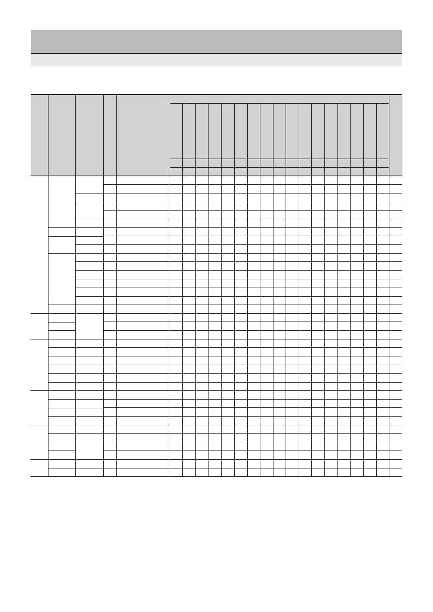
4
Selection Guide
Single-color LEDs/Single-color surface mount LEDs
Emitting color and peak wavelength
Y...Supported
N...Not supported
★
...Not supported
Shape
Color code
⇒
E
E
D
5
4
4
7
7
9
9
B
8
8
2
2
6
1
Peak wavelength[nm]
⇒
430
470
525
555
558
560
570
572
587
590
600
610
615
630
635
660
700
Standard
N
SEL1010
O
O
O
O
O
O
O
O
10
N
SEL1010M
O
O
O
O
O
O
11
5
φ
Wide directivity
N
SEL1010XM
O
O
O
O
12
Narrow
Y
SEL1050M
O
*
O
*
O
O
O
O
O
O
13
directivity
N
SEL1015
O
14
N
SEL1011
O
O
O
O
O
O
15
5.6
×
4.6
φ
Egg-shaped
N
SEL1053M
O
O
O
16
Round
4
φ
Standard
N
SEL4010
O
O
O
O
O
O
O
17
Wide directivity
Y
SEL4014
O
O
O
O
O
O
O
18
Standard
Y
SEL6010
O
O
O
O
O
O
O
19
Wide directivity
Y
SEL6014
O
O
O
O
O
O
O
O
20
3
φ
Narrow directivity
Y
SEL6015
O
O
O
O
O
21
Standard
N
SEL2010
O
O
O
O
O
O
O
O
O
O
O
O
22
Narrow directivity
N
SEL2015
O
O
O
O
O
O
23
N
SEL2011
O
O
O
24
2
φ
N
SEL4017
O
O
O
O
O
25
5
φ
N
SEL1013
O
O
O
O
O
O
26
Inverted
3
φ
For surface
Y
SEL6013
O
O
27
cone
3
φ
illumination
N
SEL2013
O
O
O
O
O
O
O
28
3
×
5
N
SEL1021
O
O
O
O
O
30
2.5
×
5
N
SEL1022
O
O
O
O
O
31
Rectangular
2
×
5
N
SEL1020
O
O
O
O
O
O
32
1
×
5
N
SEL1024
O
O
O
O
O
O
33
2
×
4
N
SEL4025
O
O
O
O
O
O
34
2
×
4
Y
SEL4026
O
O
O
O
O
35
4
φ
N
SEL4027
O
O
36
Bow shaped
3.1
φ
N
SEL4028
O
O
O
O
O
O
O
O
37
3.1
φ
Y
SEL4029
O
O
O
O
O
38
4
φ
Y
SEL6027
O
O
O
39
Rectangular
Y
SEL5020
O
O
O
O
O
O
O
40
3
φ
Narrow directivity
Y
SEL5021
O
O
O
O
O
O
41
Bow-shaped
Wide
Y
SEL5023
O
O
O
O
O
O
O
O
O
O
O
O
O
42
5.6
×
4.6
φ
directivity
Y
SEL5055
O
O
O
43
Surface
Flat lens
SMD
SEC1001
O
O
O
O
O
O
O
O
O
O
O
O
50
mount
Inner lens
SMD
SEC1003
O
O
O
O
O
O
O
O
O
O
O
51
5 mm
pitch lead
Lens diameter
Feature
Direct mount
Series
Blue
Ultra-high-intensity blue
Ultra-high-intensity pure green
Pure green
Deep green
Green
Yellow
Ultra-high-intensity yellow
Orange
Ultra-high-intensity orange
Ultra-high-intensity light amber
Amber
Ultra-high-intensity amber
Red
Ultra-high-intensity red
High-intensity red
Deep red
Page
5
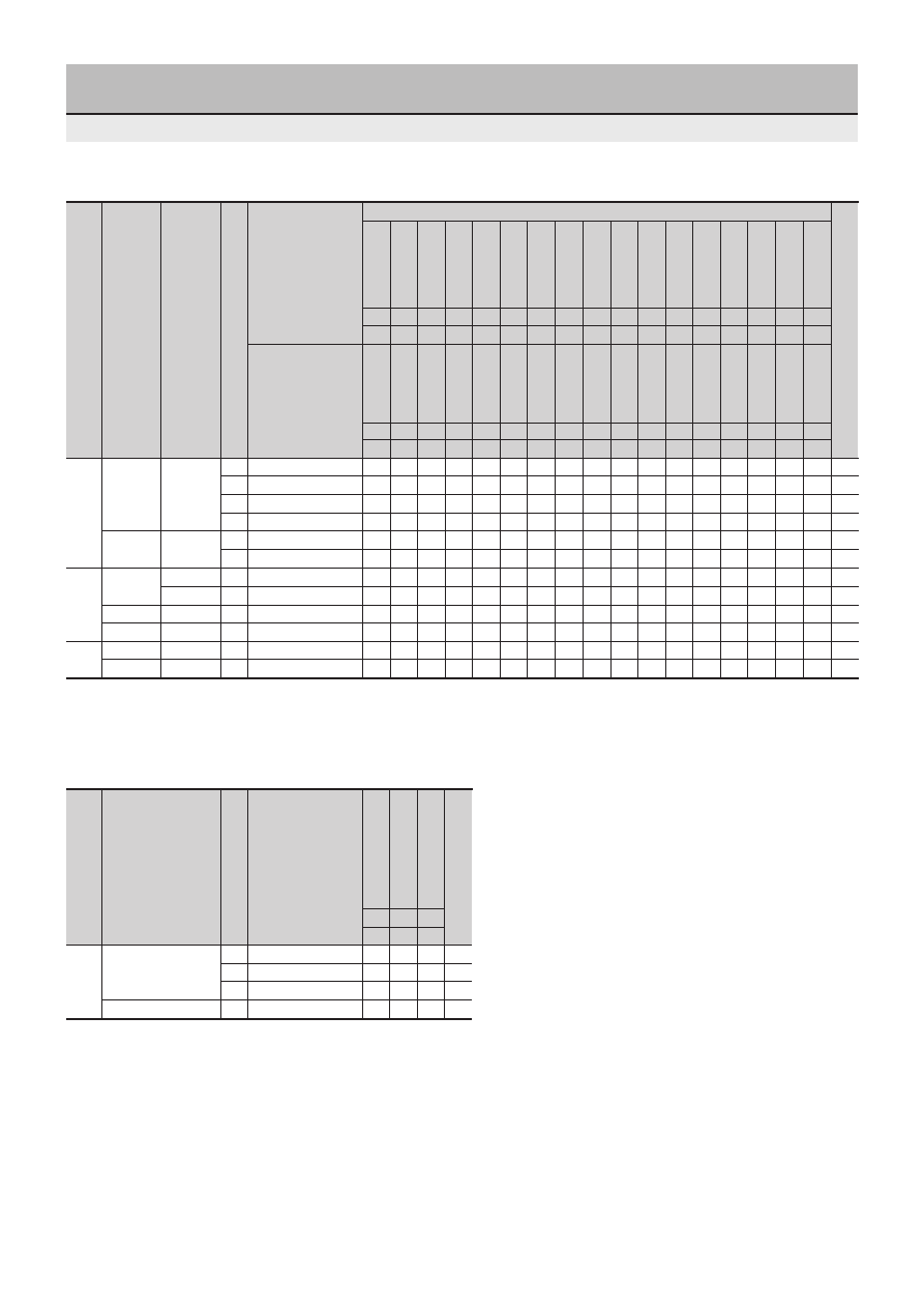
Selection Guide
Color code
⇒
5
4
4
4
7
9
7
7
7
7
2
7
4
5
4
5
7
Peak wavelength[nm]
⇒
555
560
560
560
570
587
570
572
570
572
630
570
560
555
560
555
570
N
SML1016/10016
O
O
O
O
44
5
φ
Standard
N
SML10016N
O
44
Round
N
SML10051
O
45
N
SML10051N
O
45
5.6
×
4.6
φ
Egg-shaped
Y
SML70055
O
O
O
O
O
49
Y
SML70055N
O
49
2.5
×
5
N
SML10060
O
O
46
Rectangular
N
SML10060N
O
46
3.3
×
6
Y
SML70020
O
O
O
47
Bow-shaped
Y
SML70023
O
O
O
O
O
48
Surface
Flat lens
SMD
SEC2002
O
O
O
O
O
O
O
52
mount
Inner lens
SMD
SEC2004
O
O
O
O
O
53
Emitting color and peak wavelength
Chip type
⇒
G
K
0
Peak wavelength[nm]
⇒
850
940 940
N
SID1010
O
O
54
Round
5
φ
Y
SID1050
O
55
N
SID300/1003
O
O
56
3
φ
N
SID2010
O
O
57
Bicolor LEDs/Bicolor surface mount LEDs
Infrared LED lamps
Color code
⇒
1
2
8
9
6
2
9
2
2
8
9
2
6
9
4
5
7
Peak wavelength[nm]
⇒
700
630
610
587
660
630
590
635
630
615
587
630
660
587
560
555
570
Y...Supported
N...Not supported
Y...Supported
N...Not supported
Shape
Lens diameter
Feature
Direct mount
Series
Series
Page
Deep red
Red
Red
Red
Red
Amber
Orange
Orange
Orange
High-intensity red
High-intensity red
Ultra-high-intensity orange
Ultra-high-intensity red
Red
Ultra-high-intensity amber
Orange
green
Pure green
Yellow
Pure green
Pure green
Pure green
green
green
green
green
green
Yellow
Yellow
Yellow
Yellow
Yellow
Ultra-high-intensity yellow
Ultra-high-intensity yellow
Profile
Lens diameter
Direct mount
Series
High-output infrared
High-output infrared
Infrared
Page
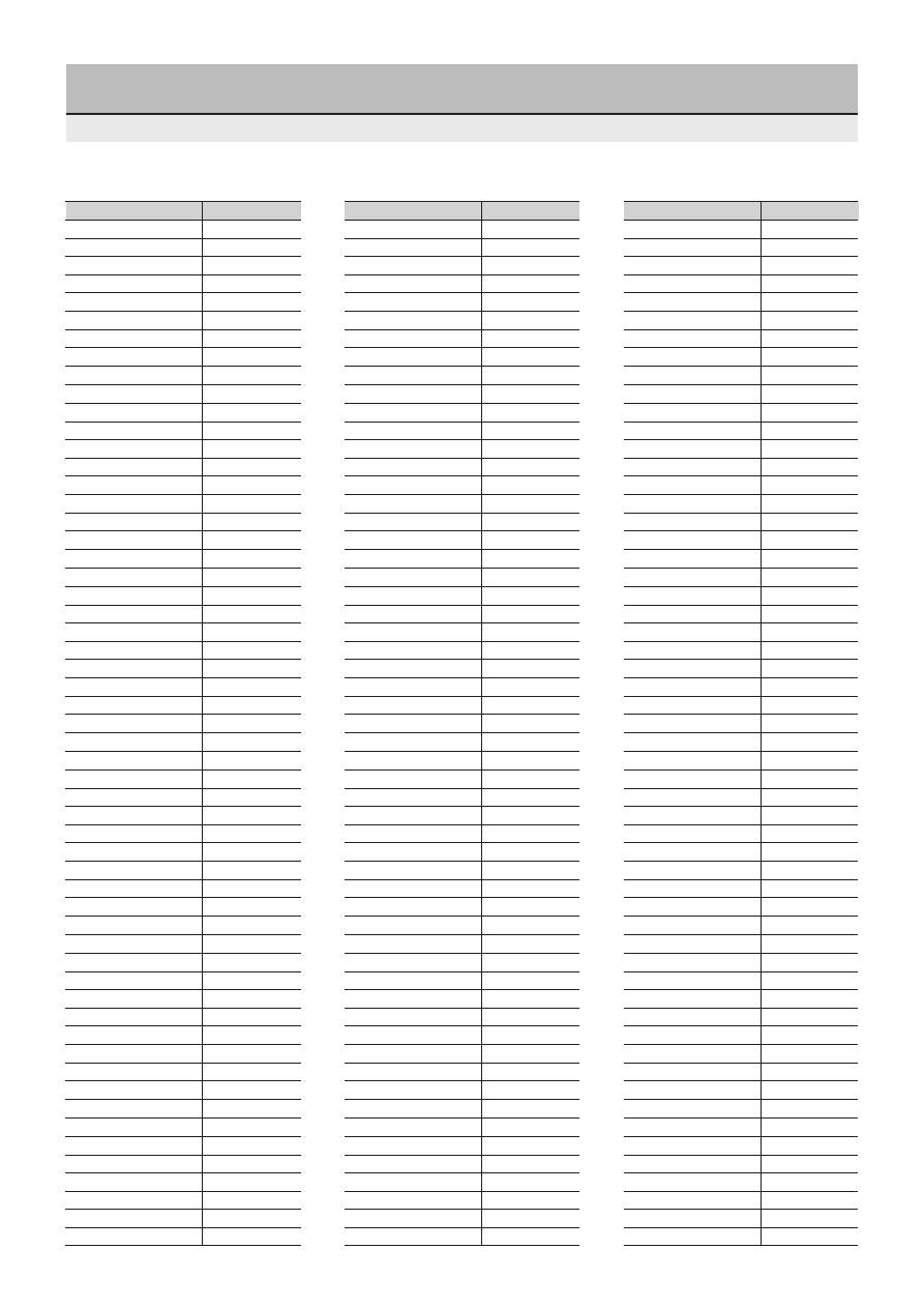
6
Product Index by Part Number
SEC1101C
50
SEC1201C
50
SEC1203C
51
SEC1401C
50
SEC1401E-TG
50
SEC1403C
51
SEC1403E-TG
51
SEC1501C
50
SEC1503C
51
SEC1601C
50
SEC1603C
51
SEC1701C-YG
50
SEC1703C
51
SEC1801C
50
SEC1803C
51
SEC1901C
50
SEC1903C
51
SEC1E01C
50
SEC2422C
52
SEC2442C
52
SEC2462C
52
SEC2484C
53
SEC2492C
52
SEC2494C
53
SEC2552C
52
SEC2554C
54
SEC2592C
52
SEC2762C-YG
52
SEC2764C
53
SEC2774C
54
SECS1203C
51
SECS1803C
51
SECS1903C
51
SECU1D01C
50
SECU1E01C
50
SEL1110R
10
SEL1110S
10
SEL1110W
10
SEL1111R
15
SEL1120R
32
SEL1121R
30
SEL1124R
33
SEL1210R
10
SEL1210RM
11
SEL1210S
10
SEL1210SM
11
SEL1211R
15
SEL1213C
26
SEL1220R
32
SEL1222R
31
SEL1250RM
13
SEL1250SM
13
SEL1410E
10
SEL1410EM
11
SEL1410G
10
SEL1410GM
11
SEL1411G
15
SEL1413E
26
SEL1420G
32
SEL1421G
30
SEL1422G
31
SEL1424G
33
SEL1450EKM
13
SEL1450GM-YG
13
SEL1453CEMKT
16
SEL1510C
10
SEL1510CM
11
SEL1513E
26
SEL1550CM
13
SEL1610C
10
SEL1610W
10
SEL1615C
14
SEL1710K
10
SEL1710KM
11
SEL1710Y
10
SEL1711Y
15
SEL1713K
26
SEL1720Y
32
SEL1721Y
30
SEL1722K
31
SEL1722Y
31
SEL1724Y
33
SEL1810A
10
SEL1810AM
11
SEL1810D
10
SEL1810DM
11
SEL1811D
15
SEL1813A
26
SEL1820D
32
SEL1821D
30
SEL1822D
31
SEL1824D
33
SEL1850AM
13
SEL1850DM
13
SEL1910A
10
SEL1910AM
11
SEL1910D
10
SEL1910DM
11
SEL1911D
15
SEL1913K
26
SEL1920D
32
SEL1921D
30
SEL1922D
31
SEL1924D
33
SEL1950KM
13
SEL2110R
22
SEL2110S
22
SEL2110W
22
SEL2111R
24
SEL2210R
22
SEL2210S
22
SEL2210W
22
SEL2213C
28
SEL2215R
23
SEL2215S
23
SEL2410E
22
SEL2410G
22
SEL2411G
24
SEL2413E
28
SEL2413G
28
SEL2415E
23
SEL2415G
23
SEL2510C
22
SEL2510G
22
SEL2513E
28
SEL2515C
23
SEL2610C
22
SEL2613CS-S
28
SEL2710K
22
SEL2710Y
22
SEL2713K
28
SEL2715K
23
SEL2715Y
23
SEL2810A
22
SEL2810D
22
SEL2813A
28
SEL2815A
23
SEL2815D
23
SEL2910A
22
SEL2910D
22
SEL2911D
24
SEL2913K
28
SEL2915A
23
SEL2915D
23
SEL2E10C
22
SEL4110R
17
SEL4110S
17
SEL4114R
18
SEL4114S
18
SEL4117R
25
SEL4210R
17
SEL4210S
17
SEL4214R
18
SEL4214S
18
SEL4225C
34
SEL4225R
34
SEL4226C
35
SEL4226R
35
SEL4227C
36
SEL4228C
37
SEL4229R
38
SEL4410E
17
SEL4410G
17
SEL4414E
18
SEL4414G
18
SEL4417G
25
SEL4425E
34
SEL4425G
34
Part Number
Page
Part Number
Page
Part Number
Page
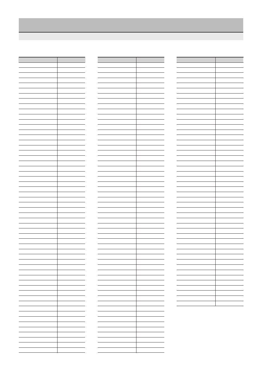
7
Product Index by Part Number
SEL4426E
35
SEL4426G
35
SEL4427EP
36
SEL4428B-TG
37
SEL4428E
37
SEL4429E
38
SEL4510C
17
SEL4514C
18
SEL4525C
34
SEL4528C
37
SEL4628C-S
37
SEL4710K
17
SEL4710Y
17
SEL4714K
18
SEL4714Y
18
SEL4717Y
25
SEL4725K
34
SEL4725Y
34
SEL4726K
35
SEL4726Y
35
SEL4728K
37
SEL4729KH
38
SEL4810A
17
SEL4810D
17
SEL4814A
18
SEL4814D
18
SEL4817D
25
SEL4825A
34
SEL4825D
34
SEL4826A
35
SEL4826D
35
SEL4828A
37
SEL4829A
38
SEL4910A
17
SEL4910D
17
SEL4914A
18
SEL4914D
18
SEL4917D
25
SEL4925A
34
SEL4925D
34
SEL4926A
35
SEL4926D
35
SEL4928A
37
SEL4929A
38
SEL5220S
40
SEL5221S
41
SEL5223S
42
SEL5255S
43
SEL5420E
40
SEL5421E
41
SEL5423E
42
SEL5520C
40
SEL5521C
41
SEL5523C
42
SEL5620C
40
SEL5721C
41
SEL5723C
42
SEL5755C
43
SEL5820A
40
SEL5821A
41
SEL5823A
42
SEL5920A
40
SEL5921A
41
SEL5923A
42
SEL5955A
43
SEL5E23C
42
SEL6110R
19
SEL6110S
19
SEL6210R
19
SEL6210S
19
SEL6214S
20
SEL6215S
21
SEL6227S
39
SEL6410E
19
SEL6410G
19
SEL6413E
27
SEL6414E
20
SEL6414E-TG
20
SEL6415E
21
SEL6427EP
39
SEL6510C
19
SEL6510G
19
SEL6513C
27
SEL6514C
20
SEL6515C
21
SEL6710K
19
SEL6710Y
19
SEL6714K
20
SEL6714W
20
SEL6715C
21
SEL6810A
19
SEL6810D
19
SEL6814A
20
SEL6910A
19
SEL6910D
19
SEL6914A
20
SEL6914W
20
SEL6915A
21
SEL6927A
39
SELS5223C
42
SELS5823C
42
SELS5923C
42
SELS5B23C
42
SELS6B14C
20
SELU1210CXM
12
SELU1250CM
13
SELU1253CMKT
16
SELU1810CXM
12
SELU1853CMKT
16
SELU1D10CXM
12
SELU1D50CM
13
SELU1E10CXM
12
SELU1E50CM
13
SELU2710C
22
SELU2D10C
22
SELU2E10C
22
SELU5723C
42
SELU5823C
42
SELU5E20C
40
SELU5E23C
42
SID1003BQ
56
SID1010CM
54
SID1010CXM
54
SID1050CM
55
SID1G307C
56
SID1K10CM
54
SID1K10CXM
54
SID2010C
57
SID2K10C
57
SID303C
56
SID307BR
56
SID313BP
56
SML11516C
44
SML1216C
44
SML1216W
44
SML12451W
45
SML12460C
46
SML1516W
44
SML16716CN
44
SML16716WN
44
SML16751WN
45
SML16760CN
46
SML1816W
44
SML19416W
44
SML19460C
46
SML72420C
47
SML72423C
48
SML72755C
49
SML72923C
48
SML76755WN
49
SML78420C
47
SML78423C
48
SML79255C
49
SML79420C
47
SML79423C
48
SML79455C
49
SMLS79723C
48
SMLU72755C
49
SMLU78755C
49
Part Number
Page
Part Number
Page
Part Number
Page
8
Sanken Electric’s light emitting diodes (LEDs) are all molded in
resin molds.
When using Sanken's LEDs, observe the following cautions:
■
Heat resistance of mold resin
Since an LED must emit internally generated light with high
efficiency, a highly transparent resin is used for molding. To
ensure high transparency, the molding material must be free from
the additives(silica, glass fiber, and others) that are used to
improve the heat and moisture resistance of other semiconductor
components(such as transistors).
Since the resin used for LEDs generally has a low heat resistance,
the following cautions must be fully considered.
Never apply an external force, stress, or excess vibration to the
terminals (leads) at high temperature. The glass transition point of
the epoxy resin used in LEDs is about 120 to 130
°
C. Beyond this
temperature range, the coefficient of linear thermal expansion
becomes more than double that at room temperature, and the
100
500
Terminal load (g)
160
140
120
100
Disconnection temperature (
°
C)
10
8
6
4
2
0
A
B
C
Fracture strength (kg)
Tensile direction
Tie-bar
cut
Application Notes
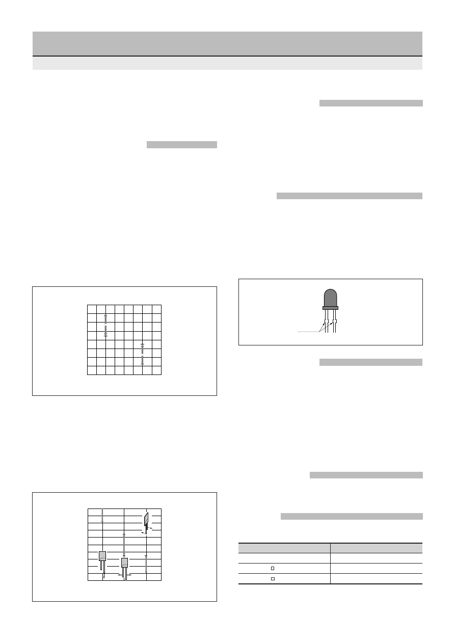
Fracture strength
Figure 1 Disconnection temperature - Terminal load
resin softens as well.
Under this condition, an external force or stress may budge the
terminals, and may result in disconnection of the internal wire.
Figure 1 shows reference data for the disconnection temperature
and terminal load for the SEL1010 Series.
●
Do not apply heat beyond the absolute maximum rating of the
storage temperature (100
°
C for ordinary LEDs, 90
°
C for chip
LEDs). (For soldering, see the soldering conditions.)
■
Mechanical strength
If an excessive mechanical force is applied between the lens resin
and the terminals, the lens resin or internal connections may be
damaged. The previous figure shows the fracture strength of the
SEL1000 Series according to the direction of the force applied to
the terminals. When aligning or forming the terminals after
soldering, do not bend or twist them with a force beyond the limits
shown in the diagram below.
■
Forming
1. Be sure to form terminals before soldering.
2. When forming the terminals, hold tightly them at a point closer
to the lens resin than the forming position to prevent stress from
being applied between the lens resin and the terminals.
3. Form the terminals only below the tie-bar cuts(protruding part of
the terminals).
4. Make the forming pitch equal to the board hole pitch.
■
Chemical resistance
For washing after soldering, the following chemicals are
recommended:
•
Isopropyl alcohol
•
Ethyl alcohol
In addition, keep the dip time within five minutes and work at room
temperature.
•
Freon-substitute cleaning liquid
Depending on the constituents, the chemicals may discolor the
resin. Make sure that there will be no problems before use.
■
Mounting method
Do not mount the LED in such a way that there is a residual stress
between the terminal and lens resin.
■
Soldering
1. Mounting holes
The recommended PCB hole diameters are as follows:
Lead diameter
PCB hole diameter
0.4
×
0.45mm
φ
0.9 to 1.0
0.5mm
φ
1.0 to 1.1
0.6mm
φ
1.0 to 1.2
9
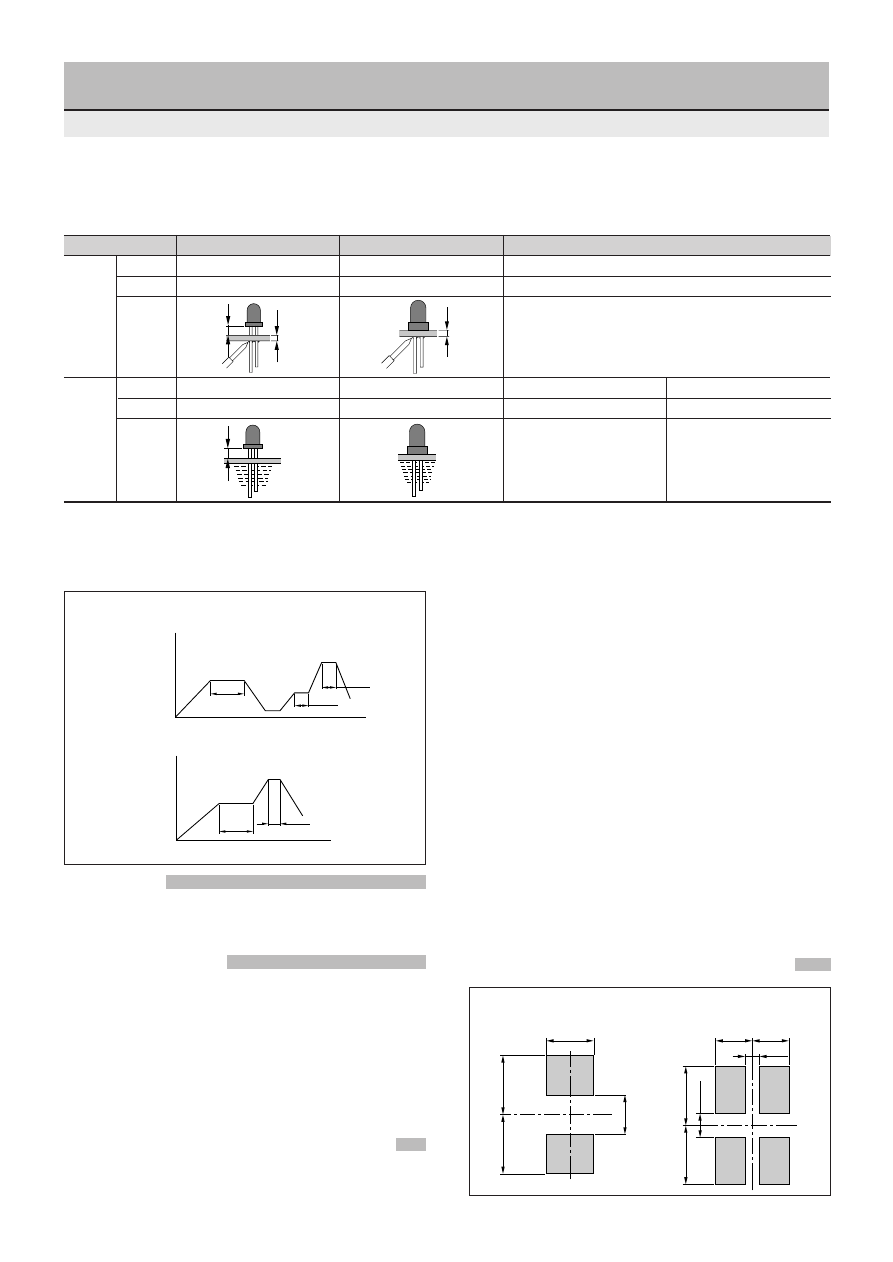
Part surface temperature (
°
C)
Time
120 sec.
5 sec.
150max
240max
Standard
Manual contact mount insertion
Automatic contact mount insertion
Temperature Iron bit: 320 to 340
°
C
Iron bit: 320 to 340
°
C
Time
3 sec. or less
3 sec. or less
Temperature Soldering Bath: 250
±
5
°
C
Soldering Bath: 250
±
5
°
C
Preheat: 90
°
C (back of the PCB) Soldering Bath: 250
°
C
Time
3 sec. or less
3 sec. or less
2 min. or less
3 sec. or less
5mm
1.6
1.6
2. Soldering conditions
●
Lamp Type
■
Overcurrent
Since an overcurrent may burn the LED, connect a protective
resistor in series to prevent a current in excess of 100 mA in the
case of a spontaneous pulse (excluding infrared LED).
■
Contact mount LEDs
•
Printed circuit board(PCB)
Single-faced PCBs are recommended. (Do not use through hole
types when using double-faced PCBs.) If chip components coexist
on the same board, insert the LEDs after curing the chip adhesive.
•
Conditions of insertion
Keep the insertion pressure as low as possible. The T pattern of
Pana-sert is recommended for cut & clinch. When using the N
pattern, maximize the clinch angle on the anode side of the LED.
■
Moisture-proof packaging of Surface Mount LEDs
1. Influence of moisture absorption on resin of chip LEDs
•
If the resin is unusually damp, solder dipping may cause interfacial
defoliation. This phenomenon, generally called "popcorn
5mm
Soldering
iron
Time
120 sec.
Room temperature
30 sec.
Pre-heating
120max
Hardening
of adhesive
150max
260max
Dip
5 sec.
Part surface temperature (
°
C)
Dip
Position
Position
Dip
Reflow
Soldering iron Iron bit temperature: 300
°
C max, 3 sec max
●
Surface Mount Type
Bicolor SEC2002/2004
Series
Application Notes
Single-color SEC1001/1003
Series
•
The heat resistance of the mold-resin of the direct mount type is almost equal to that of the standard type. Be careful not to apply a load when the LED is heated.
•
When thermally curing the adhesive of chip components on the same board after LED mounting, keep the temperature of the curing oven below 120
°
C and the curing
time to less than 60 seconds. (For soldering a Surface Mount LED, see the soldering conditions.)
•
When an LED is mounted by means of automatic contact mount insertion, note that soldering defects may occur depending on the conditions of insertion even under
the above conditions.
phenomenon", occurs when a drastic temperature change causes
moisture in the resin to evaporate and to swell.
•
Due to this defoliation, the efficiency of light emission might
worsen and the luminosity could lower.
2. Moisture-proof packaging
•
Surface Mount LEDs are protected by a moisture-proof packaging
(baked on by Sanken) to minimize moisture absorption by the
resin before use.
•
Aluminum laminates with high moisture resistance are used for
packaging.
•
Silica gel packs are enclosed in each package to further improve
moisture-proof efficiency.
3. Storage after opening
•
Once the package has been opened, solder dipping should be
carried out within seven days.
4. Handling of Remaining LED Chips
•
If some Surface Mount LEDs have not been used, put them back
into the moisture-proof packaging, seal the package completely
and store it in a dry place.
■
Reference mounting pattern for Surface Mount LED (Unit: mm)
1.5min
2.2
2.2
1.7
2.2
2.2
0.9min
1.4
1.4
0.5min
10
Forward voltage
V
F
Condition
(V)
I
F
typ
max
(mA)
2.0
1.75
1.9
1.9
1.9
2.0
2.0
2.0
SEL1110R
SEL1110W
SEL1110S
SEL1610W
SEL1610C
SEL1210R
SEL1210S
SEL1810D
SEL1810A
SEL1910D
SEL1910A
SEL1710Y
SEL1710K
SEL1410G
SEL1410E
SEL1510C
Part
Number
Lens color
Diffused red
Diffused white
Transparent red
Diffused white
Clear
Diffused red
Transparent red
Diffused orange
Transparent orange
Diffused orange
Transparent orange
Diffused yellow
Transparent yellow
Diffused green
Transparent green
Clear
Electrical Optical characteristics (Ta=25
°
C)
Reverse current
I
R
Condition
(
µ
A)
V
R
max
(V)
Intensity
I
V
Condition
(mcd)
I
F
typ
(mA)
Peak wavelength
λ
P
Condition
(nm)
I
F
typ
(mA)
Spectrum half width
∆λ
Condition
(nm)
I
F
typ
(mA)
2.5
2.2
2.5
2.5
2.5
2.5
2.5
2.5
10
10
10
10
10
10
10
10
50
100
50
50
50
50
50
50
5
20
20
10
10
10
20
20
10
10
10
10
10
10
10
10
700
660
630
610
587
570
560
555
100
30
35
35
33
30
20
20
10
10
10
10
10
10
10
10
3
3
3
3
3
3
3
3
2.8
2.8
4.5
1000
1200
26
75
18
37
14
25
22
65
32
84
50
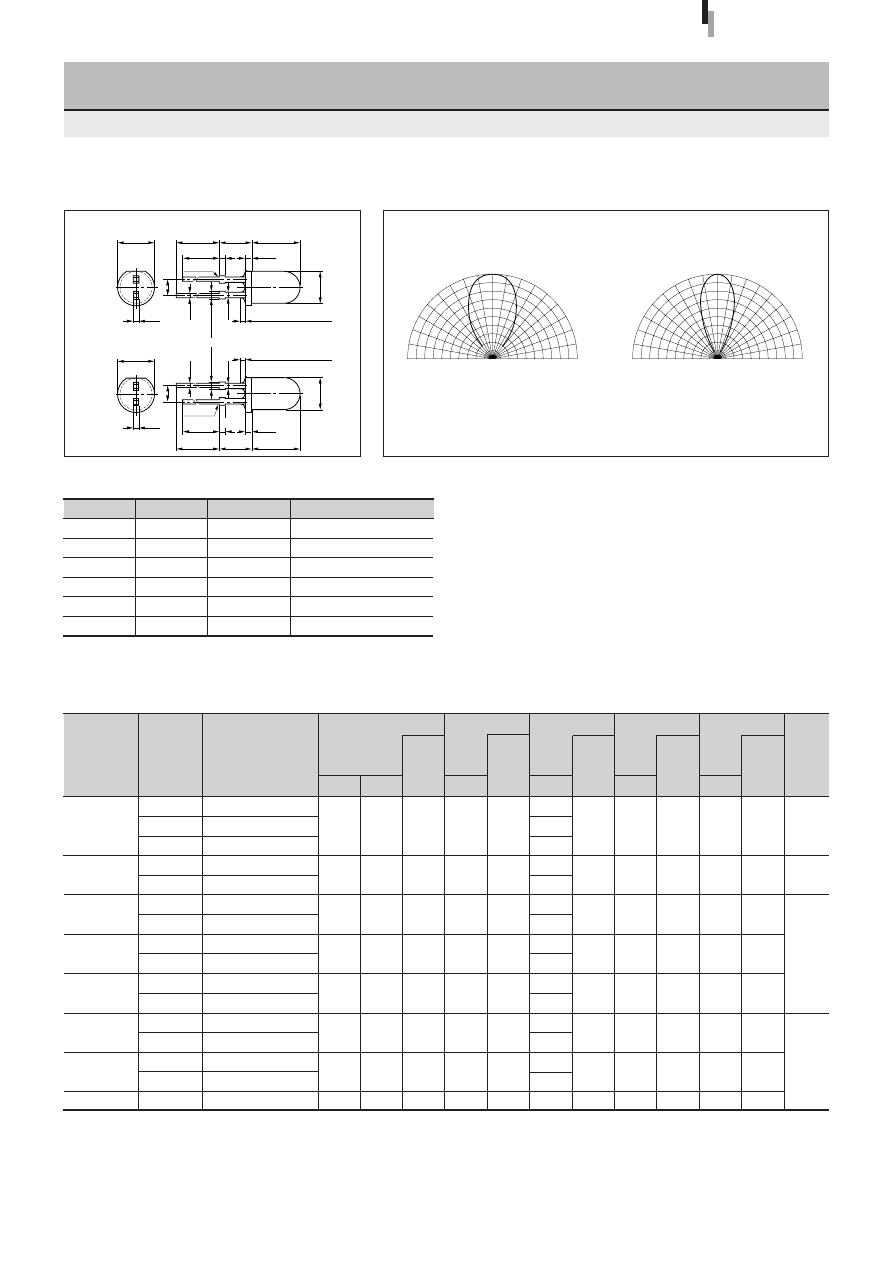
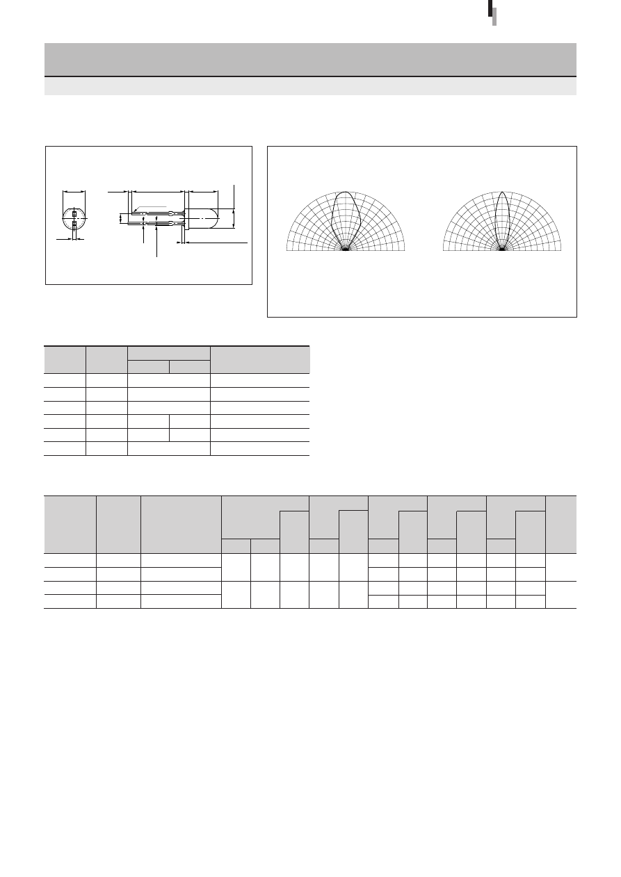
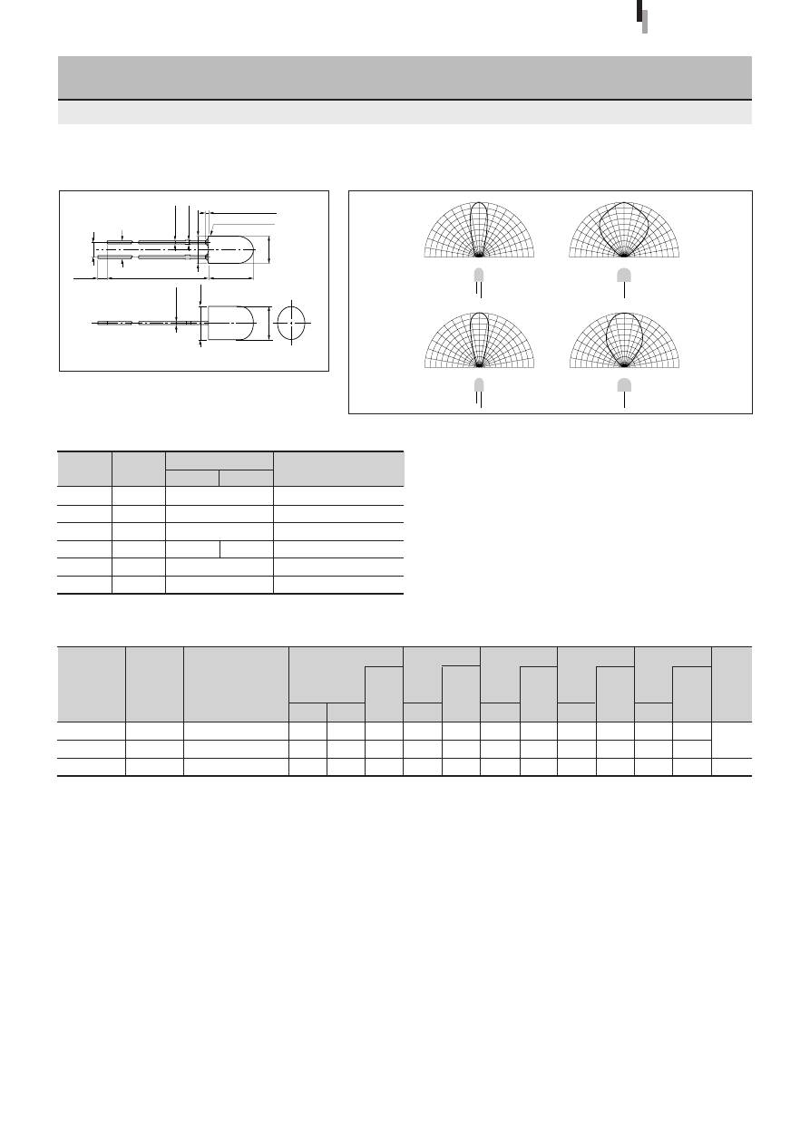
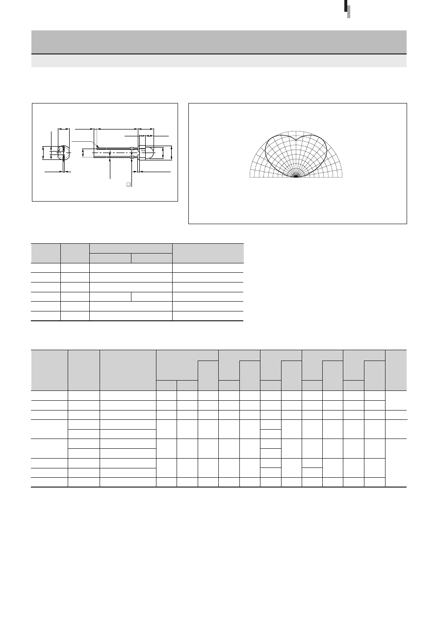
Directivity (Typical)
External Dimensions
Diffuse lens
Transparent lens
Symbol
Unit
Rating
Condition
I
F
mA
30
∆
I
F
mA/
°
C
−
0.45
Above 25
°
C
I
FP
mA
100
f=1kHz, tw
≤
100
µ
s
V
R
V
3
Top
°
C
−
30 to +85
Tstg
°
C
−
30 to +100
Absolute maximum ratings (Ta=25
°
C)
SEL1010 Series
ø
5.6
±
0.2
20.0min 5.0
±
0.5
7.6
±
0.2
20.0min 5.0
±
0.5
7.6
±
0.2
19.0min 0.8
(1.0)
19.0min 0.8
(1.0)
Cathode
Cathode
0.5
(2.54)
0.5
1.1max
0.8
(2.54)
0.5
1.1max
0.8
Resin heap 1.5max
ø
5.0
±
0.2
ø
5.0
±
0.2
ø
5.6
±
0.2
0.5
Resin heap 1.5max
90
°
60
°
30
°
0
°
90
°
60
°
30
°
0
50
100%
50
100%
90
°
60
°
30
°
0
°
90
°
60
°
30
°
0
50
100%
50
100%
5
φ
Round Standard LED
(With Stopper)
SEL1010 Series
Chip
material
GaP
GaAlAs
GaAsP
GaP
Deep red
Red
Amber
Orange
Yellow
Green
Pure green
Emitting color
Tolerance:
±
0.3
(Unit: mm)
(Other than GaAlAs chip)
(GaAlAs chip)
High-
intensity red
11
Forward voltage
V
F
Condition
(V)
I
F
typ
max
(mA)
Part
Number
Lens color
Reverse current
I
R
Condition
(
µ
A)
V
R
max
(V)
Intensity
I
V
Condition
(mcd)
I
F
typ
(mA)
Peak wavelength
λ
P
Condition
(nm)
I
F
typ
(mA)
Spectrum half width
∆λ
Condition
(nm)
I
F
typ
(mA)
Chip
material
Emitting color
1.9
1.9
1.9
2.0
2.0
2.0
SEL1210RM
SEL1210SM
SEL1810DM
SEL1810AM
SEL1910DM
SEL1910AM
SEL1710KM
SEL1410GM
SEL1410EM
SEL1510CM
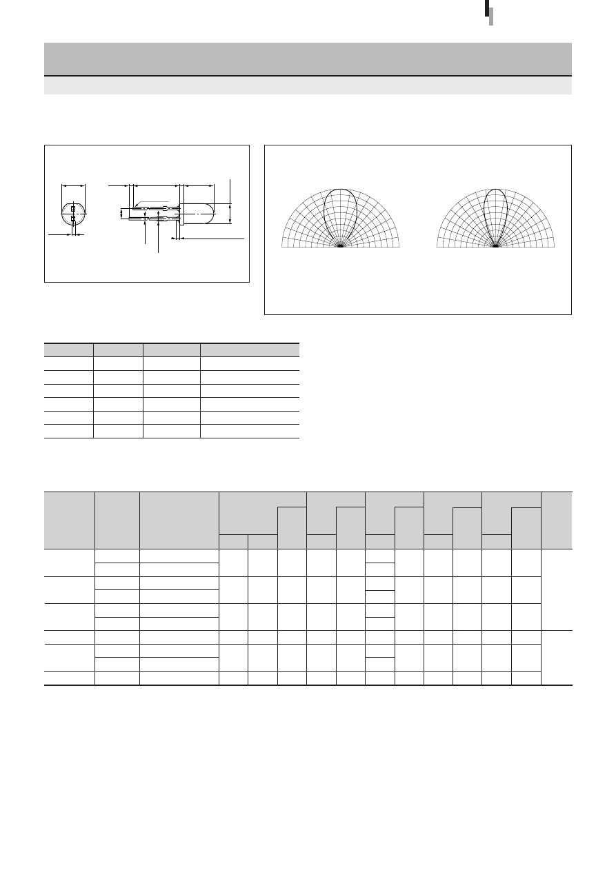
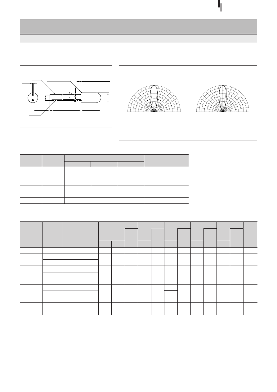
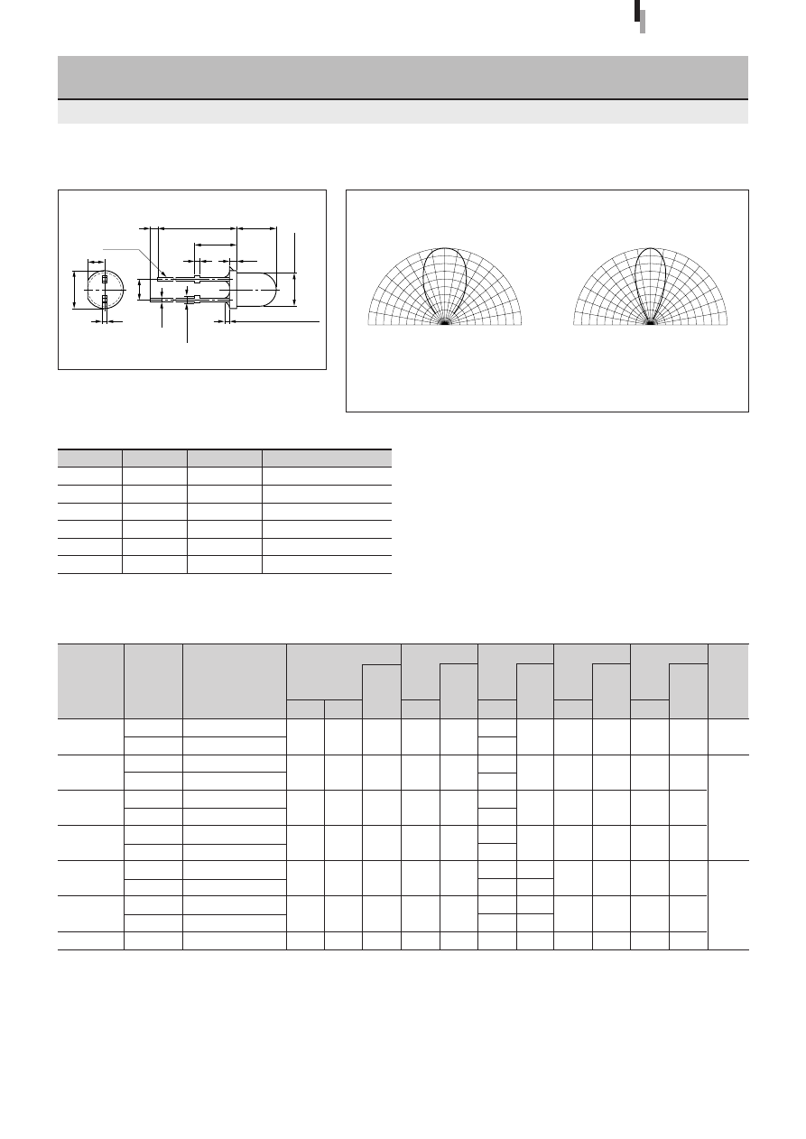
5
φ
Round Standard LED
SEL1010M Series
Diffused red
Transparent red
Diffused orange
Transparent orange
Diffused orange
Transparent orange
Transparent yellow
Diffused green
Transparent green
Clear
Electrical Optical characteristics (Ta=25
°
C)
36
75
18
37
19
34
65
30
84
50
Directivity (Typical)
External Dimensions
Symbol
Unit
Rating
Condition
I
F
mA
30
∆
I
F
mA/
°
C
−
0.45
Above 25
°
C
I
FP
mA
100
f=1kHz, tw
≤
100
µ
s
V
R
V
3
Top
°
C
−
30 to +85
Tstg
°
C
−
30 to +100
Absolute maximum ratings (Ta=25
°
C)
SEL1010 Series
2.5
2.5
2.5
2.5
2.5
2.5
10
10
10
10
10
10
50
50
50
50
50
50
3
3
3
3
3
3
20
10
10
10
20
20
630
610
587
570
560
555
10
10
10
10
10
10
35
35
33
30
20
20
10
10
10
10
10
10
Diffuse lens
Transparent lens
ø
5.6
±
0.2
23.0min
1.0min
7.6
±
0.2
Cathode
0.65max
Resin heap 1.5max
ø
5.0
±
0.2
0.5
±
0.1
0.5
±
0.1
(1.0)
(2.54)
90
°
60
°
30
°
0
°
90
°
60
°
30
°
0
50
100%
50
100%
90
°
60
°
30
°
0
°
90
°
60
°
30
°
0
50
100%
50
100%
GaAsP
GaP
Red
Amber
Orange
Yellow
Green
Pure green
Tolerance:
±
0.3
(Unit: mm)
12
Forward voltage
V
F
Condition
(V)
I
F
typ
max
(mA)
Part
Number
Lens color
Reverse current
I
R
Condition
(
µ
A)
V
R
max
(V)
Intensity
I
V
Condition
(mcd)
I
F
typ
(mA)
Peak wavelength
λ
P
Condition
(nm)
I
F
typ
(mA)
Spectrum half width
∆λ
Condition
(nm)
I
F
typ
(mA)
Chip
material
Emitting color
2.0
3.3
SELU1210CXM
SELU1810CXM
SELU1D10CXM
SELU1E10CXM
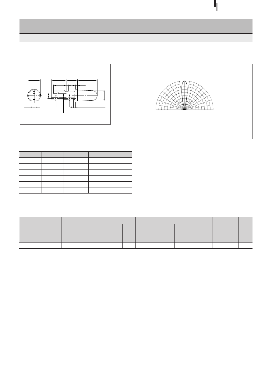
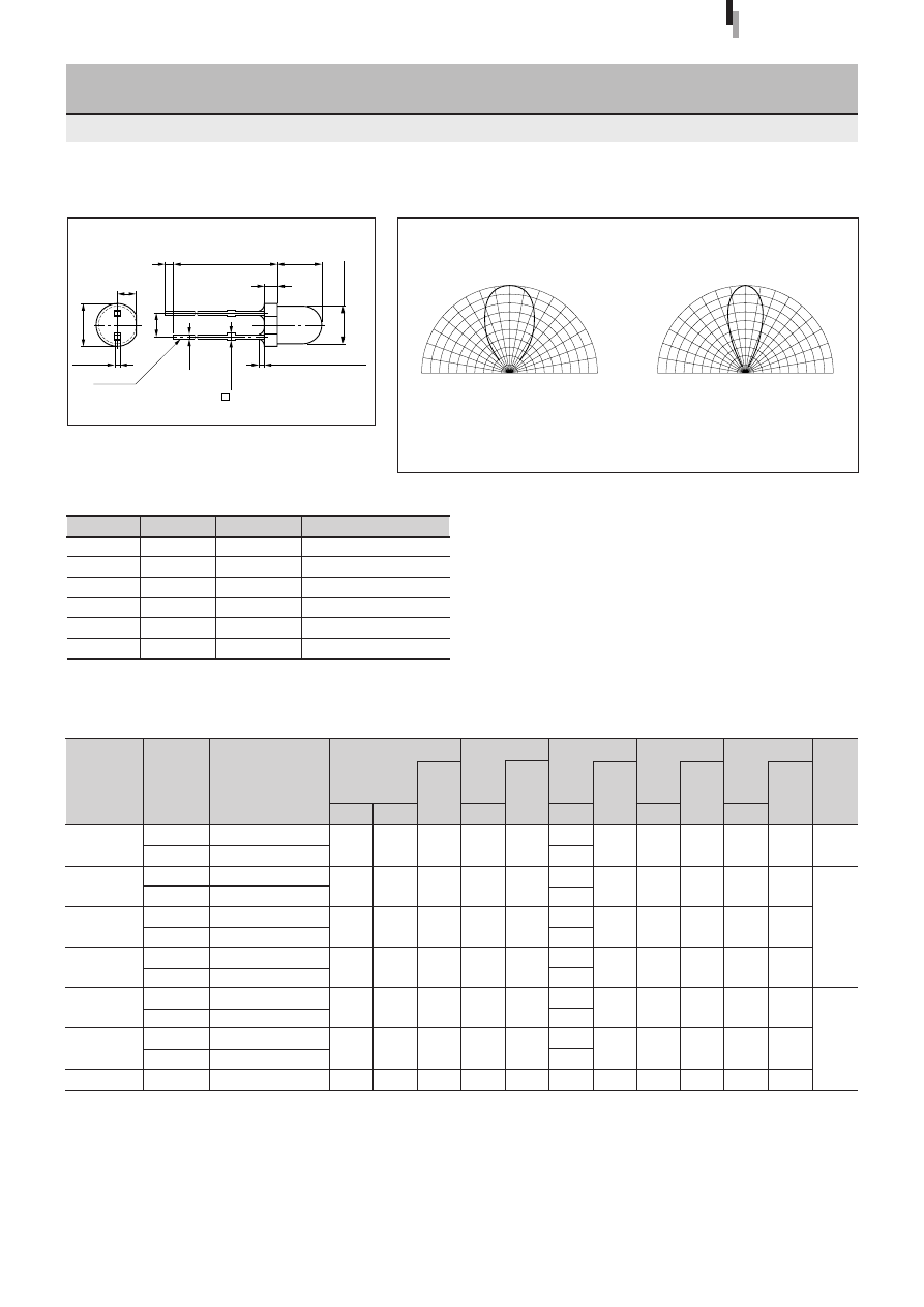
5
φ
Round Wide-directivity LED
SEL1010XM Series
Clear
Clear
Clear
Clear
Electrical Optical characteristics (Ta=25
°
C)
280
570
2000
600
Directivity (Typical)
External Dimensions
AlGaInP
InGaN
Symbol
Unit
Rating
Condition
AlGaInP
InGaN
I
F
mA
30
∆
I
F
mA/
°
C
−
0.45
Above 25
°
C
I
FP
mA
100
f=1kHz, tw
≤
100
µ
s
V
R
V
4
5
Top
°
C
−
30 to +85
−
25 to +85
Tstg
°
C
−
30 to +100
Absolute maximum ratings (Ta=25
°
C)
SEL1010 Series
2.5
4.0
10
20
100
10
4
5
20
20
20
20
635
615
525
470
10
10
10
10
15
15
35
35
10
10
10
10
ø
5.6
±
0.2
23.0min
1.0min
6.9
±
0.2
Cathode
0.65max
Resin heap 1.5max
ø
5.0
±
0.2
(2.54)
0.5
±
0.1
(1.0)
0.5
±
0.1
AlGaInP
InGaN
–90
°
–60
°
–30
°
0
90
°
60
°
30
°
100%
100%
–90
°
–60
°
–30
°
0
90
°
60
°
30
°
100%
100%
0
50
50
0
50
50
Tolerance:
±
0.3
(Unit: mm)
Ultra-high-
intensity red
Ultra-high-
intensity amber
Ultra-high-intensity
pure green
Ultra-high-
intensity blue
13
Forward voltage
V
F
Condition
(V)
I
F
typ
max
(mA)
Part
Number
Lens color
Reverse current
I
R
Condition
(
µ
A)
V
R
max
(V)
Intensity
I
V
Condition
(mcd)
I
F
typ
(mA)
Peak wavelength
λ
P
Condition
(nm)
I
F
typ
(mA)
Spectrum half width
∆λ
Condition
(nm)
I
F
typ
(mA)
Chip
material
Emitting color
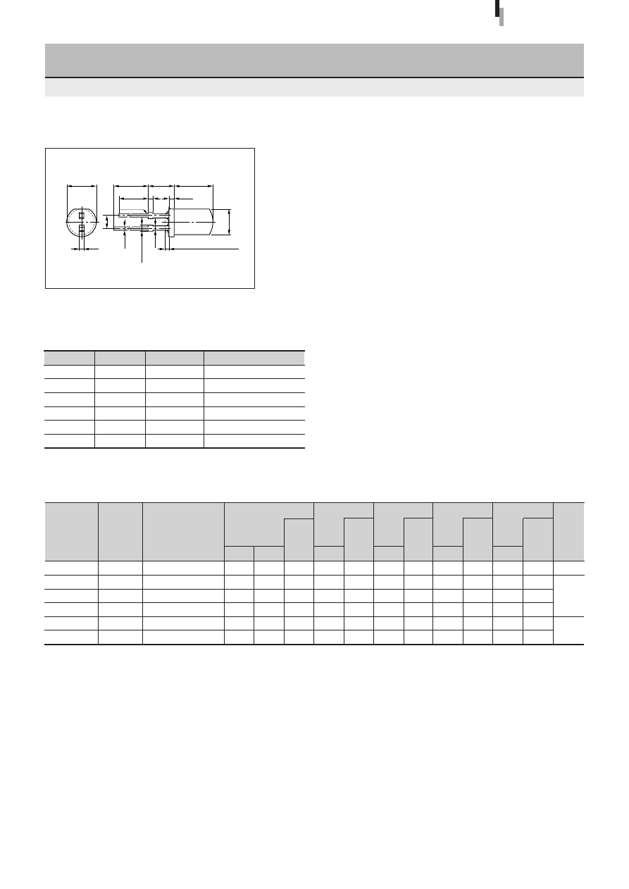
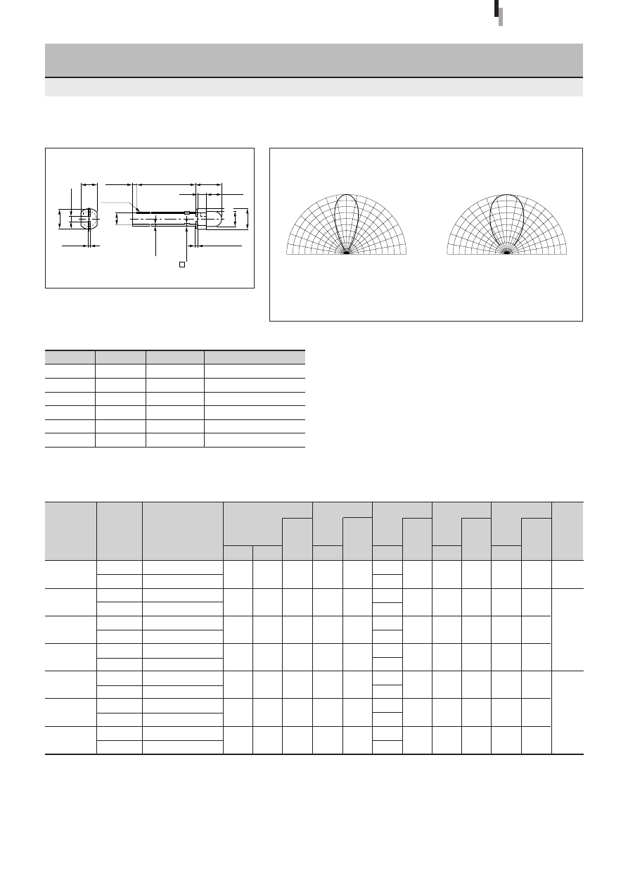
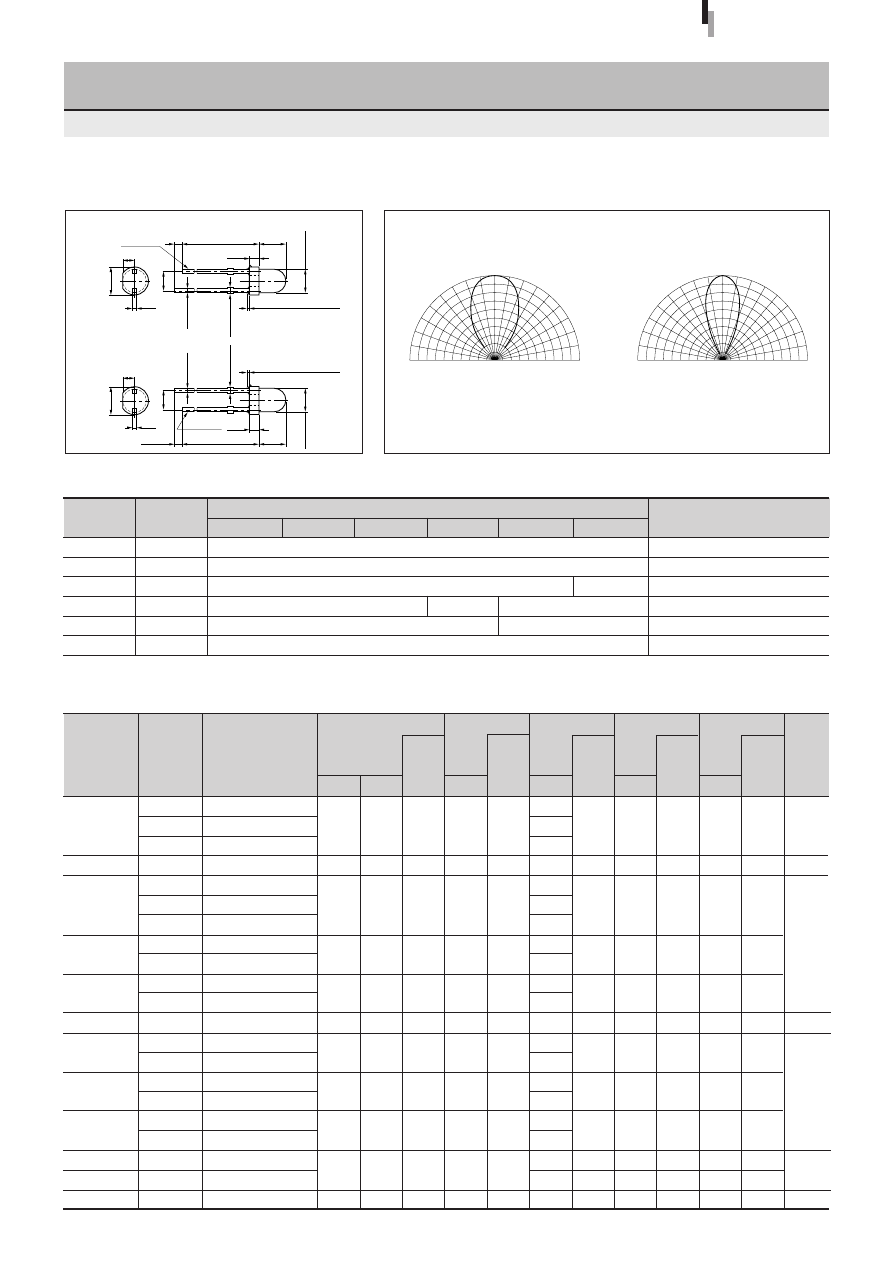
5
φ
Round Narrow-directivity LED
(Direct Mount)
SEL1050M Series
Electrical Optical characteristics (Ta=25
°
C)
Directivity (Typical)
External Dimensions
Transparent lens
Symbol
Unit
Rating
Condition
GaP/GaAsP
AlGaInP
InGaN
I
F
mA
30
∆
I
F
mA/
°
C
−
0.45
Above 25
°
C
I
FP
mA
100
f=1kHz, tw
≤
100
µ
s
V
R
V
3
4
5
Top
°
C
−
30 to +85
−
25 to +85
Tstg
°
C
−
30 to +100
Absolute maximum ratings (Ta=25
°
C)
SEL1050M Series
2.0
1.9
1.9
1.9
2.0
2.0
3.3
3.3
SELU1250CM
SEL1250SM
SEL1250RM
SEL1850AM
SEL1850DM
SEL1950KM
SEL1450EKM
SEL1450GM-YG
SEL1550CM
SELU1D50CM
SELU1E50CM
Clear
Transparent red
Diffused red
Transparent orange
Diffused orange
Transparent orange
Transparent green
Diffused green
Clear
Clear
Clear
900
75
48
90
60
96
190
120
72
6000
1850
2.5
2.5
2.5
2.5
2.5
2.5
4.0
4.0
10
10
10
10
10
10
20
20
100
50
50
50
50
50
10
10
4
3
3
3
3
3
5
5
20
20
20
20
20
20
20
20
635
630
610
587
560
555
525
470
10
10
10
10
10
10
10
10
15
35
35
33
20
20
35
35
10
10
10
10
10
10
10
10
0.5
±
0.1
Anode
Cathode
1.0min
21.0min
9.4
±
0.3
ø
5.0
±
0.2
Resin heap 0.8max
Resin burr 0.3max
0.65
max
0.5
±
0.1
(2.54)
Red
Amber
Orange
Green
Pure green
AlGalnP
GaAsP
GaAsP
GaP
InGaN
–90
°
–60
°
–30
°
0
90
°
60
°
30
°
100%
100%
0
50
50
90
°
60
°
30
°
0
°
90
°
60
°
30
°
0
50
100%
50
100%
Diffuse lens
Tolerance:
±
0.3
(Unit: mm)
Ultra-high-intensity
pure green
Ultra-high-
intensity blue
Ultra-high-
intensity red
14
Forward voltage
V
F
Condition
(V)
I
F
typ
max
(mA)
Part
Number
Lens color
Reverse current
I
R
Condition
(
µ
A)
V
R
max
(V)
Intensity
I
V
Condition
(mcd)
I
F
typ
(mA)
Peak wavelength
λ
P
Condition
(nm)
I
F
typ
(mA)
Spectrum half width
∆λ
Condition
(nm)
I
F
typ
(mA)
Chip
material
Emitting color
1.75
SEL1615C
5
φ
Round Narrow-directivity LED
SEL1015 Series
Clear
Electrical Optical characteristics (Ta=25
°
C)
700
Directivity (Typical)
External Dimensions
SEL1015 Series
2.2
10
100
3
20
660
10
30
10
Symbol
Unit
Rating
Condition
I
F
mA
30
∆
I
F
mA/
°
C
−
0.45
Above 25
°
C
I
FP
mA
100
f=1kHz, tw
≤
100
µ
s
V
R
V
3
Top
°
C
−
30 to +85
Tstg
°
C
−
30 to +100
Absolute maximum ratings (Ta=25
°
C)
90
°
60
°
30
°
0
°
90
°
60
°
30
°
0
50
100%
50
100%
ø
5.6
±
0.2
20.0min 5.5
±
0.5
8.2
±
0.2
19.0min 0.8
(1.0)
Cathode
0.5
±
0.1
1.1max
0.8
Resin heap 1.5max
ø
5.0
±
0.2
0.5
(2.54)
GaAIAs
Tolerance:
±
0.3
(Unit: mm)
High-
intensity red
15
Forward voltage
V
F
Condition
(V)
I
F
typ
max
(mA)
Part
Number
Lens color
Reverse current
I
R
Condition
(
µ
A)
V
R
max
(V)
Intensity
I
V
Condition
(mcd)
I
F
typ
(mA)
Peak wavelength
λ
P
Condition
(nm)
I
F
typ
(mA)
Spectrum half width
∆λ
Condition
(nm)
I
F
typ
(mA)
Chip
material
Emitting color
SEL1111R
SEL1211R
SEL1811D
SEL1911D
SEL1711Y
SEL1411G
5
φ
Cylindrical LED
SEL1011 Series
Diffused red
Diffused red
Diffused orange
Diffused orange
Diffused yellow
Diffused green
Electrical Optical characteristics (Ta=25
°
C)
1.4
12
8.0
8.0
13
30
External Dimensions
SEL1011 Series
10
20
10
10
10
20
700
630
610
587
570
560
10
10
10
10
10
10
100
35
35
33
30
20
10
10
10
10
10
10
Symbol
Unit
Rating
Condition
I
F
mA
30
∆
I
F
mA/
°
C
−
0.45
Above 25
°
C
I
FP
mA
100
f=1kHz, tw
≤
100
µ
s
V
R
V
3
Top
°
C
−
30 to +85
Tstg
°
C
−
30 to +100
Absolute maximum ratings (Ta=25
°
C)
2.0
1.9
1.9
1.9
2.0
2.0
2.5
2.5
2.5
2.5
2.5
2.5
10
10
10
10
10
10
50
50
50
50
50
50
3
3
3
3
3
3
ø
5.6
±
0.2
20.0min 5.0
±
0.5
7.9
±
0.2
19.0min 0.8
(1.0)
Cathode
0.5
(2.54)
0.5
±
0.1
1.1max
0.8
Resin heap 1.5max
ø
5.0
±
0.2
GaP
GaAsP
GaP
Deep red
Red
Amber
Orange
Yellow
Green
Tolerance:
±
0.3
(Unit: mm)
16
Forward voltage
V
F
Condition
(V)
I
F
typ
max
(mA)
Part
Number
Lens color
Reverse current
I
R
Condition
(
µ
A)
V
R
max
(V)
Intensity
I
V
Condition
(mcd)
I
F
typ
(mA)
Peak wavelength
λ
P
Condition
(nm)
I
F
typ
(mA)
Spectrum half width
∆λ
Condition
(nm)
I
F
typ
(mA)
Chip
material
Emitting color
SELU1253CMKT
SELU1853CMKT
SEL1453CEMKT
4.6
×
5.6
φ
Egg-shaped LED
SEL1053M Series
Electrical Optical characteristics (Ta=25
°
C)
200
450
140
Directivity (Typical)
External Dimensions
AlGaInP
SEL1053M Series
20
20
20
635
615
560
10
10
10
15
15
20
10
10
10
Symbol
Unit
Rating
Condition
GaP
AlGaInP
I
F
mA
30
∆
I
F
mA/
°
C
−
0.45
Above 25
°
C
I
FP
mA
100
f=1kHz, tw
≤
100
µ
s
V
R
V
3
4
Top
°
C
−
30 to +85
Tstg
°
C
−
30 to +100
Absolute maximum ratings (Ta=25
°
C)
2.0
2.0
2.0
2.5
2.5
2.5
10
10
10
100
100
50
4
4
3
AlGaInP
GaP
Clear
Clear
Transparent green
Green
–90
°
–60
°
–30
°
0
90
°
60
°
30
°
100%
100%
–90
°
–60
°
–30
°
0
90
°
60
°
30
°
100%
100%
0
50
50
0
50
50
–90
°
–60
°
–30
°
0
90
°
60
°
30
°
100%
100%
–90
°
–60
°
–30
°
0
90
°
60
°
30
°
100%
100%
0
50
50
0
50
50
GaP
Tolerance:
±
0.3
(Unit: mm)
5.6
±
0.2
Resin burr 0.3max
4.6
±
0.2
1.0min
23.5min
Cathode
Anode
7.7
±
0.5
(2.54)
0.65max
4.7
±
0.2
5.7
±
0.2
2-0.5
±
0.1
0.5
±
0.1
Resin heap 1.5max
Ultra-high-
intensity red
Ultra-high-
intensity amber
17
Forward voltage
V
F
Condition
(V)
I
F
typ
max
(mA)
Part
Number
Lens color
Reverse current
I
R
Condition
(
µ
A)
V
R
max
(V)
Intensity
I
V
Condition
(mcd)
I
F
typ
(mA)
Peak wavelength
λ
P
Condition
(nm)
I
F
typ
(mA)
Spectrum half width
∆λ
Condition
(nm)
I
F
typ
(mA)
Chip
material
Emitting color
2.0
1.9
1.9
1.9
2.0
2.0
2.0
SEL4110S
SEL4110R
SEL4210S
SEL4210R
SEL4810A
SEL4810D
SEL4910A
SEL4910D
SEL4710K
SEL4710Y
SEL4410E
SEL4410G
SEL4510C
4
φ
Round Standard LED
SEL4010 Series
Transparent red
Diffused red
Transparent red
Diffused red
Transparent orange
Diffused orange
Transparent orange
Diffused orange
Transparent yellow
Diffused yellow
Transparent green
Diffused green
Clear
Electrical Optical characteristics (Ta=25
°
C)
2.4
1.7
30
17
20
15
26
16
36
14
87
34
45
Directivity (Typical)
External Dimensions
Symbol
Unit
Rating
Condition
I
F
mA
30
∆
I
F
mA/
°
C
−
0.45
Above 25
°
C
I
FP
mA
100
f=1kHz, tw
≤
100
µ
s
V
R
V
3
Top
°
C
−
30 to +85
Tstg
°
C
−
30 to +100
Absolute maximum ratings (Ta=25
°
C)
SEL4010 Series
2.5
2.5
2.5
2.5
2.5
2.5
2.5
10
10
10
10
10
10
10
50
50
50
50
50
50
50
3
3
3
3
3
3
3
5
20
10
10
10
10
20
20
20
700
630
610
587
570
560
555
10
10
10
10
10
10
10
100
35
35
33
30
20
20
10
10
10
10
10
10
10
Diffuse lens
Transparent lens
2.2
ø
4.8
0.4
±
0.1
(2.54)
0.45
±
0.1
1.1max
Resin heap 1.5max
Cathode
1.0min
25.5min
5.0
±
0.2
6.5
±
0.5
0.8
1.5
ø
4.0
±
0.2
90
°
60
°
30
°
0
°
90
°
60
°
30
°
0
50
100%
50
100%
90
°
60
°
30
°
0
°
90
°
60
°
30
°
0
50
100%
50
100%
Deep red
Red
Amber
Orange
Yellow
Green
Pure green
GaP
GaAsP
GaP
Tolerance:
±
0.3
(Unit: mm)
18
Forward voltage
V
F
Condition
(V)
I
F
typ
max
(mA)
Part
Number
Lens color
Reverse current
I
R
Condition
(
µ
A)
V
R
max
(V)
Intensity
I
V
Condition
(mcd)
I
F
typ
(mA)
Peak wavelength
λ
P
Condition
(nm)
I
F
typ
(mA)
Spectrum half width
∆λ
Condition
(nm)
I
F
typ
(mA)
Chip
material
Emitting color
4
φ
Round Wide-directivity LED
(Direct Mount)
SEL4014 Series
Directivity (Typical)
External Dimensions
Symbol
Unit
Rating
Condition
I
F
mA
30
∆
I
F
mA/
°
C
−
0.45
Above 25
°
C
I
FP
mA
100
f=1kHz, tw
≤
100
µ
s
V
R
V
3
Top
°
C
−
30 to +85
Tstg
°
C
−
30 to 100
Absolute maximum ratings (Ta=25
°
C)
SEL4014 Series
2.0
1.9
1.9
1.9
2.0
2.0
2.0
SEL4114S
SEL4114R
SEL4214S
SEL4214R
SEL4814A
SEL4814D
SEL4914A
SEL4914D
SEL4714K
SEL4714Y
SEL4414E
SEL4414G
SEL4514C
Transparent red
Diffused red
Transparent red
Diffused red
Transparent orange
Diffused orange
Transparent orange
Diffused orange
Transparent yellow
Diffused yellow
Transparent green
Diffused green
Clear
Electrical Optical characteristics (Ta=25
°
C)
3.8
2.8
40
24
20
15
26
11
38
27
69
48
26
2.5
2.5
2.5
2.5
2.5
2.5
2.5
10
10
10
10
10
10
10
50
50
50
50
50
50
50
3
3
3
3
3
3
3
10
20
10
10
10
20
20
700
630
610
587
570
560
555
10
10
10
10
10
10
10
100
35
35
33
30
20
20
10
10
10
10
10
10
10
Diffuse lens
Transparent lens
90
°
60
°
30
°
0
°
90
°
60
°
30
°
0
50
100%
50
100%
90
°
60
°
30
°
0
°
90
°
60
°
30
°
0
50
100%
50
100%
2.2
ø
4.8
(2.54)
0.45
±
0.1
0.65max
Resin heap 0.8max
1.0min
24.5min
5.0
±
0.2
ø
4.0
±
0.2
(1.5)
0.4
±
0.1
Cathode
Deep red
Red
Amber
Orange
Yellow
Green
Pure green
GaP
GaAsP
GaP
Tolerance:
±
0.3
(Unit: mm)
19
Forward voltage
V
F
Condition
(V)
I
F
typ
max
(mA)
Part
Number
Lens color
Reverse current
I
R
Condition
(
µ
A)
V
R
max
(V)
Intensity
I
V
Condition
(mcd)
I
F
typ
(mA)
Peak wavelength
λ
P
Condition
(nm)
I
F
typ
(mA)
Spectrum half width
∆λ
Condition
(nm)
I
F
typ
(mA)
Chip
material
Emitting color
2.0
1.9
1.9
1.9
2.0
2.0
2.0
SEL6110S
SEL6110R
SEL6210S
SEL6210R
SEL6810A
SEL6810D
SEL6910A
SEL6910D
SEL6710K
SEL6710Y
SEL6410E
SEL6410G
SEL6510C
SEL6510G
3
φ
Round LED
(Direct Mount)
SEL6010 Series
Transparent red
Diffused red
Transparent red
Diffused red
Transparent orange
Diffused orange
Transparent orange
Diffused orange
Transparent yellow
Diffused yellow
Transparent green
Diffused green
Clear
Diffused green
Electrical Optical characteristics (Ta=25
°
C)
3.9
2.6
41
18
22
9.6
22
11
37
11
90
30
42
9.6
Directivity (Typical)
External Dimensions
Symbol
Unit
Rating
Condition
I
F
mA
30
∆
I
F
mA/
°
C
−
0.45
Above 25
°
C
I
FP
mA
100
f=1kHz, tw
≤
100
µ
s
V
R
V
3
Top
°
C
−
30 to +85
Tstg
°
C
−
30 to +100
Absolute maximum ratings (Ta=25
°
C)
SEL6010 Series
2.5
2.5
2.5
2.5
2.5
2.5
2.5
10
10
10
10
10
10
10
50
50
50
50
50
50
50
3
3
3
3
3
3
3
10
20
10
10
10
20
20
700
630
610
587
570
560
555
10
10
10
10
10
10
10
100
35
35
33
30
20
20
10
10
10
10
10
10
10
Diffuse lens
Transparent lens
Deep red
Red
Amber
Orange
Yellow
Green
Pure green
GaP
GaAsP
GaP
90
°
60
°
30
°
0
°
90
°
60
°
30
°
0
50
100%
50
100%
90
°
60
°
30
°
0
°
90
°
60
°
30
°
0
50
100%
50
100%
3.5
0.8
±
0.2
4.0
±
0.2
0.4
±
0.1
23.0min
1.0min
5.5
±
0.5
(1.7)
3.5
±
0.1
(2.54)
ø
3.1
±
0.1
4.4
0.45
±
0.1
0.65max
Resin heap
0.8max
Cathode
Tolerance:
±
0.3
(Unit: mm)
20
Forward voltage
V
F
Condition
(V)
I
F
typ
max
(mA)
Part
Number
Lens color
Reverse current
I
R
Condition
(
µ
A)
V
R
max
(V)
Intensity
I
V
Condition
(mcd)
I
F
typ
(mA)
Peak wavelength
λ
P
Condition
(nm)
I
F
typ
(mA)
Spectrum half width
∆λ
Condition
(nm)
I
F
typ
(mA)
Chip
material
Emitting color
3
φ
Round Wide-directivity LED
(Direct Mount)
SEL6014 Series
Directivity (Typical)
External Dimensions
SEL6014 Series
1.9
1.9
2.0
1.9
2.0
2.0
2.0
SEL6214S
SEL6814A
SELS6B14C
SEL6914A
SEL6914W
SEL6714K
SEL6714W
SEL6414E
SEL6414E-TG
SEL6514C
Transparent red
Transparent orange
Clear
Transparent orange
Diffused white
Transparent yellow
Diffused white
Transparent green
Transparent green
Clear
Electrical Optical characteristics (Ta=25
°
C)
18
9.0
120
8.0
5.0
66
30
42
18
12
2.5
2.5
2.5
2.5
2.5
2.5
2.5
20
10
20
10
20
20
20
630
610
600
587
570
560
558
555
Transparent lens
Red
Amber
Orange
Yellow
Green
Deep green
Pure green
GaAsP
AlGaInP
GaAsP
GaP
10
10
10
10
10
10
10
50
50
100
50
50
50
50
3
3
4
3
3
3
3
10
10
10
10
10
10
10
35
35
15
33
30
20
20
10
10
10
10
10
10
10
3.5
0.8
±
0.2
4.0
±
0.2
0.4
±
0.1
23.0min
1.0min
4.5
±
0.5
(1.6)
2.5
±
0.1
(2.54)
ø
3.5
4.4
0.45
±
0.1
0.65max
Resin heap
0.8max
Cathode
90
°
60
°
30
°
0
°
90
°
60
°
30
°
0
50
100%
50
100%
Tolerance:
±
0.3
(Unit: mm)
Symbol
Unit
Rating
Condition
GaAsP/GaP
AlGaInP
I
F
mA
30
∆
I
F
mA/
°
C
−
0.45
Above 25
°
C
I
FP
mA
100
f=1kHz, tw
≤
100
µ
s
V
R
V
3
4
Top
°
C
−
30 to +85
Tstg
°
C
−
30 to +100
Absolute maximum ratings (Ta=25
°
C)
Ultra-high-intensity
light amber

21
Forward voltage
V
F
Condition
(V)
I
F
typ
max
(mA)
Part
Number
Lens color
Reverse current
I
R
Condition
(
µ
A)
V
R
max
(V)
Intensity
I
V
Condition
(mcd)
I
F
typ
(mA)
Peak wavelength
λ
P
Condition
(nm)
I
F
typ
(mA)
Spectrum half width
∆λ
Condition
(nm)
I
F
typ
(mA)
Chip
material
Emitting color
1.9
1.9
2.0
2.0
2.0
SEL6215S
SEL6915A
SEL6715C
SEL6415E
SEL6515C
3
φ
Round Narrow-directivity LED
(Direct Mount)
SEL6015 Series
Transparent red
Transparent orange
Clear
Transparent green
Clear
Electrical Optical characteristics (Ta=25
°
C)
45
60
90
81
44
Directivity (Typical)
External Dimensions
Symbol
Unit
Rating
Condition
I
F
mA
30
∆
I
F
mA/
°
C
−
0.45
Above 25
°
C
I
FP
mA
100
f=1kHz, tw
≤
100
µ
s
V
R
V
3
Top
°
C
−
30 to +85
Tstg
°
C
−
30 to +100
Absolute maximum ratings (Ta=25
°
C)
SEL6015 Series
2.5
2.5
2.5
2.5
2.5
10
10
10
10
10
50
50
50
50
50
3
3
3
3
3
20
20
20
20
20
630
587
570
560
555
10
10
10
10
10
35
33
30
20
20
10
10
10
10
10
Transparent lens
Red
Orange
Yellow
Green
Pure green
GaAsP
GaP
90
°
60
°
30
°
0
°
90
°
60
°
30
°
0
50
100%
50
100%
3.5
5.5
0.8
±
0.2
4.0
±
0.2
0.4
±
0.1
23.0min
1.0min
(1.7)
3.5
±
0.1
(2.54)
ø
3.1
±
0.1
4.4
0.45
±
0.1
0.65max
Resin heap
0.8max
Resin burr
0.3max
Cathode mark
Cathode
Tolerance:
±
0.3
(Unit: mm)
22
3
φ
Round Standard LED
SEL2010 Series
Directivity (Typical)
External Dimensions
Symbol
Unit
Rating
Condition
GaP
GaAsP
GaAlAs
AlGaInP
InGaN
GaN
I
F
mA
30
∆
I
F
mA/
°
C
−
0.45
Above 25
°
C
I
FP
mA
100
70
f=1kHz, tw
≤
100
µ
s
V
R
V
3
4
5
Top
°
C
−
30 to +85
−
25 to +85
Tstg
°
C
−
30 to +100
Absolute maximum ratings (Ta=25
°
C)
SEL2010 Series
Electrical Optical characteristics (Ta=25
°
C)
Diffuse lens
Transparent lens
1.7
ø
3.8
0.4
0.4
1.0min
1.0min
25.8min
3.5
±
0.1
25.8min
3.5
±
0.1
(1.3)
(1.3)
0.45
±
0.1
0.65max
Resin heap 1.5max
0.45
±
0.1
0.65max
Resin heap 1.5max
ø
3.1
±
0.1
ø
3.1
±
0.1
Cathode
Cathode
(2.54)
(2.54)
1.7
ø
3.8
90
°
60
°
30
°
0
°
90
°
60
°
30
°
0
50
100%
50
100%
90
°
60
°
30
°
0
°
90
°
60
°
30
°
0
50
100%
50
100%
Tolerance:
±
0.3
(Unit: mm)
(Other than GaAlAs chip)
(GaAlAs)
Forward voltage
V
F
Condition
(V)
I
F
typ
max
(mA)
Part
Number
Lens color
Reverse current
I
R
Condition
(
µ
A)
V
R
max
(V)
Intensity
I
V
Condition
(mcd)
I
F
typ
(mA)
Peak wavelength
λ
P
Condition
(nm)
I
F
typ
(mA)
Spectrum half width
∆λ
Condition
(nm)
I
F
typ
(mA)
Chip
material
Emitting color
2.0
1.75
1.9
1.9
1.9
2.0
2.0
2.0
2.0
3.3
3.8
SEL2110S
SEL2110R
SEL2110W
SEL2610C
SEL2210S
SEL2210R
SEL2210W
SEL2810A
SEL2810D
SEL2910A
SEL2910D
SELU2710C
SEL2710K
SEL2710Y
SEL2410E
SEL2410G
SEL2510C
SEL2510G
SELU2D10C
SELU2E10C
SEL2E10C
Transparent red
Diffused red
Diffused white
Clear
Transparent red
Diffused red
Diffused white
Transparent orange
Diffused orange
Transparent orange
Diffused orange
Clear
Transparent yellow
Diffused yellow
Transparent green
Diffused green
Clear
Diffused green
Clear
Clear
Clear
4.0
1.8
1.8
350
40
15
15
22
9.0
16
8.0
270
40
14
77
20
43
8.2
1200
400
60
Deep red
Red
Amber
Orange
Yellow
Green
Pure green
Blue
GaP
GaAlAs
GaAsP
AlGaInP
GaP
InGaN
GaN
2.5
2.2
2.5
2.5
2.5
2.5
2.5
2.5
2.5
4.0
4.8
10
10
10
10
10
10
10
10
10
20
20
50
100
50
50
50
100
50
50
50
10
10
3
3
3
3
3
4
3
3
3
5
5
10
20
20
10
10
20
10
20
20
20
20
20
700
660
630
610
587
572
570
560
555
525
470
430
10
10
10
10
10
10
10
20
10
10
10
10
100
30
35
35
33
15
30
20
20
35
35
65
10
10
10
10
10
10
10
10
10
10
10
10
High-
intensity red
Ultra-high-
intensity yellow
Ultra-high-intensity
pure green
Ultra-high-
intensity blue

23
Forward voltage
V
F
Condition
(V)
I
F
typ
max
(mA)
Part
Number
Lens color
Reverse current
I
R
Condition
(
µ
A)
V
R
max
(V)
Intensity
I
V
Condition
(mcd)
I
F
typ
(mA)
Peak wavelength
λ
P
Condition
(nm)
I
F
typ
(mA)
Spectrum half width
∆λ
Condition
(nm)
I
F
typ
(mA)
Chip
material
Emitting color
3
φ
Round Narrow-directivity LED
SEL2015 Series
Directivity (Typical)
External Dimensions
Symbol
Unit
Rating
Condition
I
F
mA
30
∆
I
F
mA/
°
C
−
0.45
Above 25
°
C
I
FP
mA
100
f=1kHz, tw
≤
100
µ
s
V
R
V
3
Top
°
C
−
30 to +85
Tstg
°
C
−
30 to +100
Absolute maximum ratings (Ta=25
°
C)
SEL2015 Series
1.9
1.9
1.9
2.0
2.0
2.0
SEL2215S
SEL2215R
SEL2815A
SEL2815D
SEL2915A
SEL2915D
SEL2715K
SEL2715Y
SEL2415E
SEL2415G
SEL2515C
Transparent red
Diffused red
Transparent orange
Diffused orange
Transparent orange
Diffused orange
Transparent yellow
Diffused yellow
Transparent green
Diffused green
Clear
Electrical Optical characteristics (Ta=25
°
C)
45
38
80
60
81
53
130
110
110
72
52
2.5
2.5
2.5
2.5
2.5
2.5
10
10
10
10
10
10
50
50
50
50
50
50
3
3
3
3
3
3
20
10
10
10
20
20
630
610
587
570
560
555
10
10
10
10
10
10
35
35
33
30
20
20
10
10
10
10
10
10
Diffuse lens
Transparent lens
Red
Amber
Orange
Yellow
Green
Pure green
GaAsP
GaP
1.55
ø
3.8
0.4
±
0.1
1.0min
25.4min
4.0
±
0.1
(1.3)
(2.54)
0.45
±
0.1
0.65max
Resin heap 1.5max
ø
3.1
±
0.1
Cathode
90
°
60
°
30
°
0
°
90
°
60
°
30
°
0
50
100%
50
100%
90
°
60
°
30
°
0
°
90
°
60
°
30
°
0
50
100%
50
100%
Tolerance:
±
0.3
(Unit: mm)
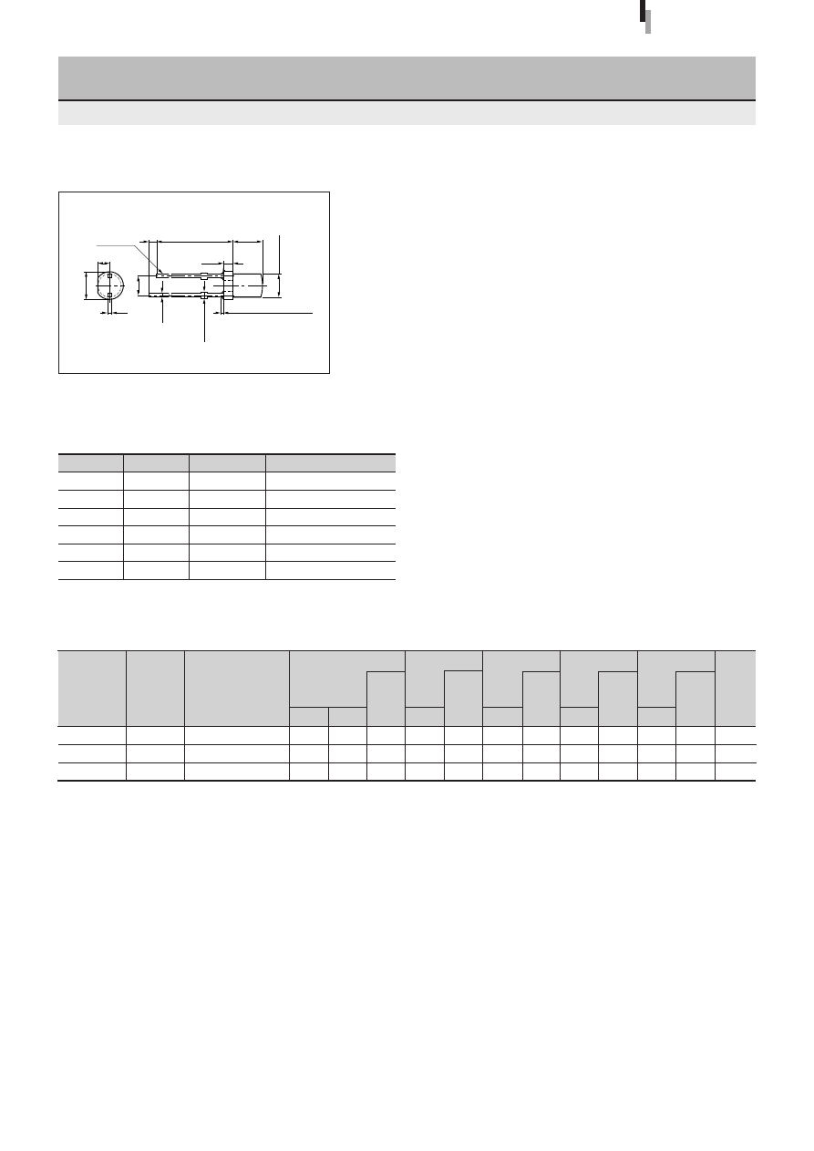
24
Forward voltage
V
F
Condition
(V)
I
F
typ
max
(mA)
Part
Number
Lens color
Reverse current
I
R
Condition
(
µ
A)
V
R
max
(V)
Intensity
I
V
Condition
(mcd)
I
F
typ
(mA)
Peak wavelength
λ
P
Condition
(nm)
I
F
typ
(mA)
Spectrum half width
∆λ
Condition
(nm)
I
F
typ
(mA)
Chip
material
Emitting color
2.0
1.9
2.0
SEL2111R
SEL2911D
SEL2411G
3
φ
Cylindrical LED
SEL2011 Series
Diffused red
Diffused orange
Diffused green
Electrical Optical characteristics (Ta=25
°
C)
0.7
3.3
18
External Dimensions
Symbol
Unit
Rating
Condition
I
F
mA
30
∆
I
F
mA/
°
C
−
0.45
Above 25
°
C
I
FP
mA
100
f=1kHz, tw
≤
100
µ
s
V
R
V
3
Top
°
C
−
30 to +85
Tstg
°
C
−
30 to +100
Absolute maximum ratings (Ta=25
°
C)
SEL2011 Series
2.5
2.5
2.5
10
10
10
50
50
50
3
3
3
10
10
20
700
587
560
10
10
10
100
33
20
10
10
10
Deep red
Orange
Green
GaP
GaAsP
GaP
1.7
ø
3.8
0.4
±
0.1
(2.54)
1.0min
25.8min
4.2
±
0.1
(1.3)
0.45
±
0.1
0.65max
Resin heap 1.5max
ø
3.1
±
0.1
Cathode
Tolerance:
±
0.3
(Unit: mm)
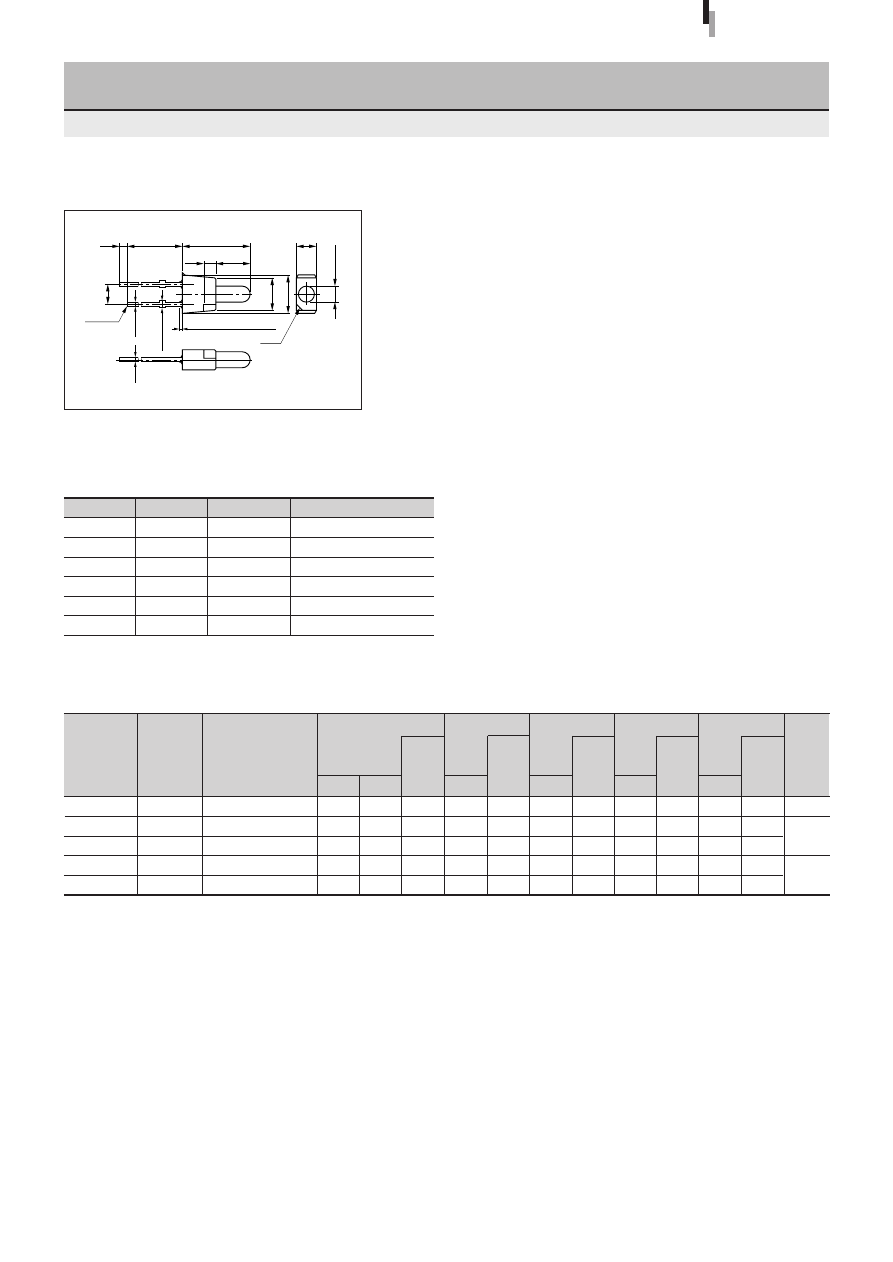
25
Forward voltage
V
F
Condition
(V)
I
F
typ
max
(mA)
Part
Number
Lens color
Reverse current
I
R
Condition
(
µ
A)
V
R
max
(V)
Intensity
I
V
Condition
(mcd)
I
F
typ
(mA)
Peak wavelength
λ
P
Condition
(nm)
I
F
typ
(mA)
Spectrum half width
∆λ
Condition
(nm)
I
F
typ
(mA)
Chip
material
Emitting color
2
φ
Round Special-shaped LED
SEL4017 Series
External Dimensions
Symbol
Unit
Rating
Condition
I
F
mA
30
∆
I
F
mA/
°
C
−
0.45
Above 25
°
C
I
FP
mA
100
f=1kHz, tw
≤
100
µ
s
V
R
V
3
Top
°
C
−
30 to +85
Tstg
°
C
−
30 to +100
Absolute maximum ratings (Ta=25
°
C)
SEL4017 Series
2.0
1.9
1.9
2.0
2.0
SEL4117R
SEL4817D
SEL4917D
SEL4717Y
SEL4417G
Diffused red
Diffused orange
Diffused orange
Diffused yellow
Diffused green
Electrical Optical characteristics (Ta=25
°
C)
1.1
7.5
7.5
14
16
2.5
2.5
2.5
2.5
2.5
10
10
10
10
10
50
50
50
50
50
3
3
3
3
3
10
10
10
20
20
700
610
587
570
560
10
10
10
10
10
100
35
33
30
20
10
10
10
10
10
Deep red
Amber
Orange
Yellow
Green
1.0min 23.0min
8.0
±
0.2
(1.5) 4.0
±
0.1
4.0
±
0.2
4.4
±
0.2
2.5
±
0.2
ø
2.0
±
0.1
(2.54)
0.45
±
0.1
0.65max
Resin heap 1.5max
0.4
±
0.1
Cathode
C1.0
Tolerance:
±
0.3
(Unit: mm)
GaP
GaAsP
GaP
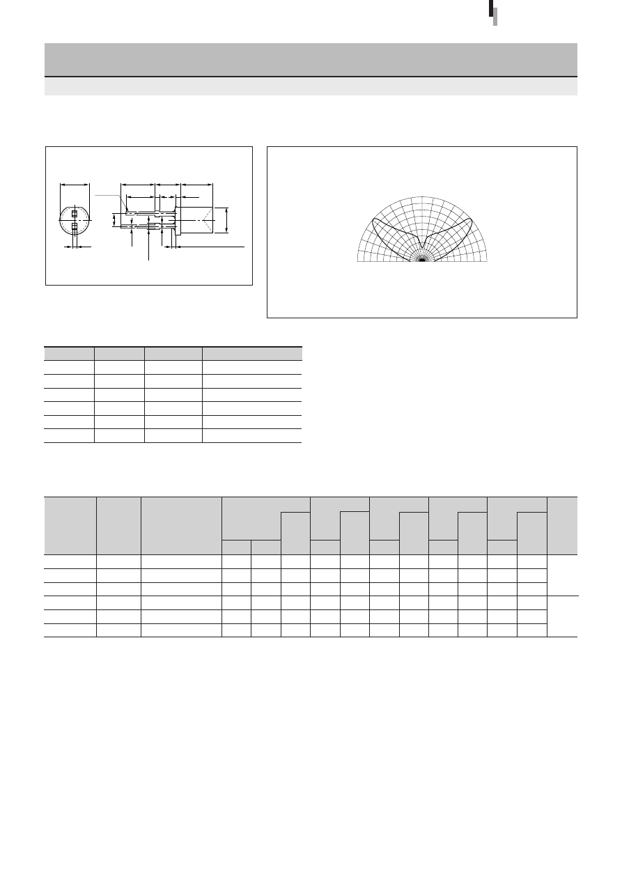
26
Forward voltage
V
F
Condition
(V)
I
F
typ
max
(mA)
Part
Number
Lens color
Reverse current
I
R
Condition
(
µ
A)
V
R
max
(V)
Intensity
I
V
Condition
(mcd)
I
F
typ
(mA)
Peak wavelength
λ
P
Condition
(nm)
I
F
typ
(mA)
Spectrum half width
∆λ
Condition
(nm)
I
F
typ
(mA)
Chip
material
Emitting color
5
φ
Inverted-cone LED for surface illumination
SEL1013 Series
Directivity (Typical)
External Dimensions
SEL1013 Series
(Unit: mm)
1.9
1.9
1.9
2.0
2.0
2.0
SEL1213C
SEL1813A
SEL1913K
SEL1713K
SEL1413E
SEL1513E
Clear
Transparent orange
Transparent light orange
Transparent yellow
Transparent green
Transparent light green
Electrical Optical characteristics (Ta=25
°
C)
2.5
2.5
2.5
2.5
2.5
2.5
Red
Amber
Orange
Yellow
Green
Pure green
10
10
10
10
10
10
3
3
3
3
3
3
7.0
8.0
8.0
15
12
5.0
20
20
20
20
20
20
630
610
587
570
560
555
35
35
33
30
20
20
GaAsP
GaP
50
50
50
50
50
50
10
10
10
10
10
10
10
10
10
10
10
10
Tolerance:
±
0.3
Symbol
Unit
Rating
Condition
I
F
mA
30
∆
I
F
mA/
°
C
−
0.45
Above 25
°
C
I
FP
mA
100
f=1kHz, tw
≤
100
µ
s
V
R
V
3
Top
°
C
−
30 to 85
Tstg
°
C
−
30 to 100
Absolute maximum ratings (Ta=25
°
C)
ø
5.6
±
0.2
20.0min 5.0
±
0.5
5.8
±
0.2
19.0min 0.8
(1.0)
0.5
0.5
±
0.1
1.1max
0.8
Resin heap 1.5max
ø
4.9
±
0.2
Cathode
(2.54)
90
°
60
°
30
°
0
°
90
°
60
°
30
°
0
50
100%
50
100%
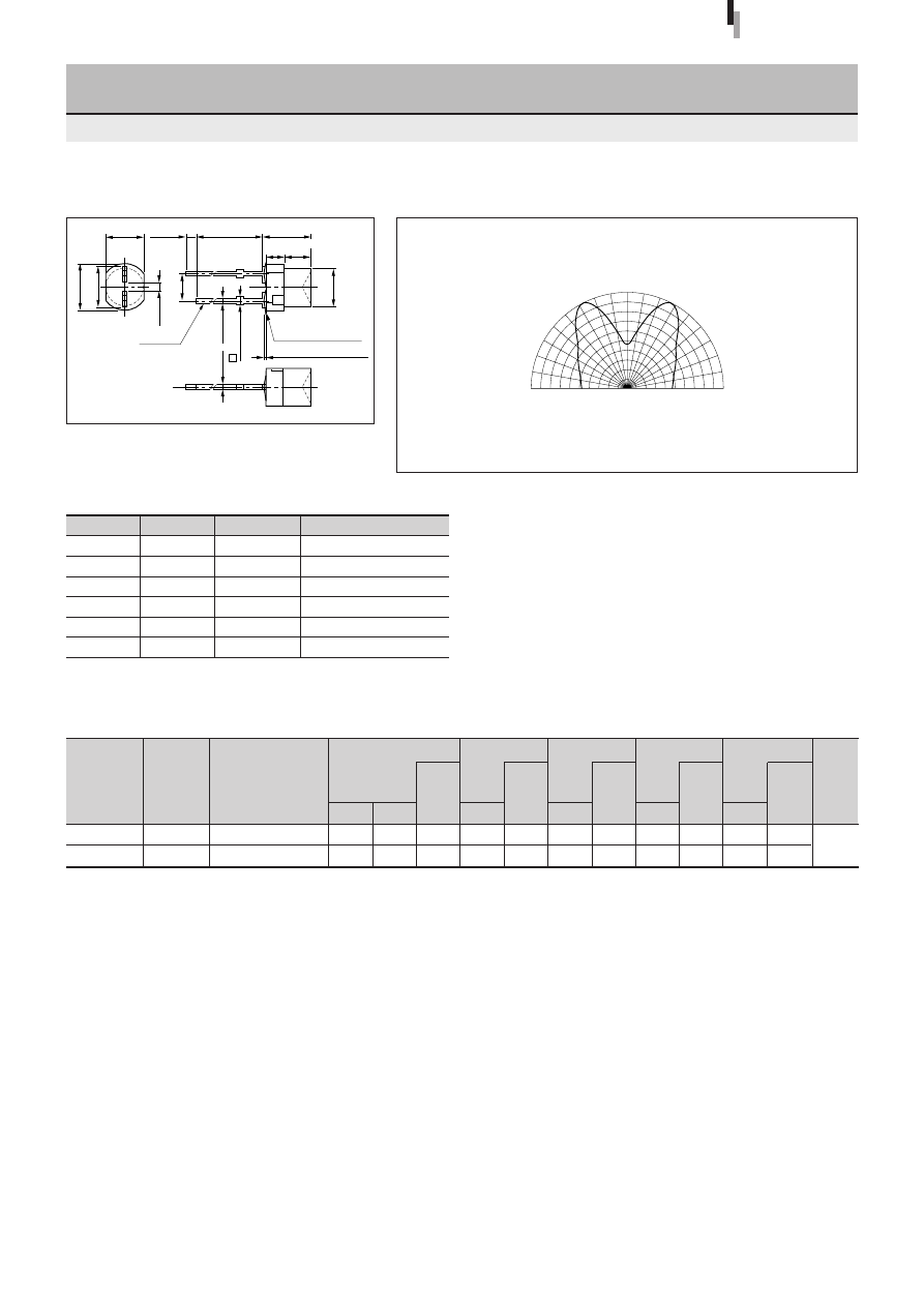
27
Forward voltage
V
F
Condition
(V)
I
F
typ
max
(mA)
Part
Number
Lens color
Reverse current
I
R
Condition
(
µ
A)
V
R
max
(V)
Intensity
I
V
Condition
(mcd)
I
F
typ
(mA)
Peak wavelength
λ
P
Condition
(nm)
I
F
typ
(mA)
Spectrum half width
∆λ
Condition
(nm)
I
F
typ
(mA)
Chip
material
Emitting color
3
φ
Inverted-cone LED for surface illumination
(Direct Mount)
SEL6013 Series
Directivity (Typical)
External Dimensions
Symbol
Unit
Rating
Condition
I
F
mA
30
∆
I
F
mA/
°
C
−
0.45
Above 25
°
C
I
FP
mA
100
f=1kHz, tw
≤
100
µ
s
V
R
V
3
Top
°
C
−
30 to +85
Tstg
°
C
−
30 to +100
Absolute maximum ratings (Ta=25
°
C)
SEL6013 Series
Tolerance:
±
0.3
(Unit: mm)
SEL6413E
SEL6513C
Electrical Optical characteristics (Ta=25
°
C)
14
5.0
20
20
560
555
10
10
20
20
10
10
2.0
2.0
2.5
2.5
10
10
50
50
3
3
GaP
Transparent green
Clear
Green
Pure green
90
°
60
°
30
°
0
°
90
°
60
°
30
°
0
50
100%
50
100%
23.0min
4.5
1.0min
3.5
2.5
±
0.1
(1.7)
0.45
±
0.1
0.8
±
0.2
4.0
±
0.2
4.4
0.65max
Resin heap 0.8max
Resin burr 0.3max
ø
3.5
±
0.1
(2.54)
0.4
±
0.1
Cathode
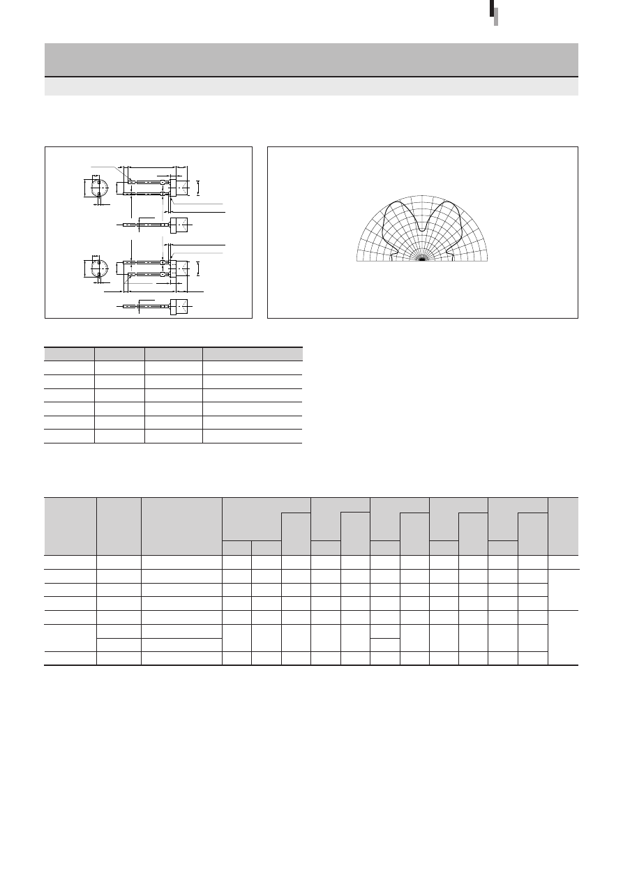
28
Forward voltage
V
F
Condition
(V)
I
F
typ
max
(mA)
Part
Number
Lens color
Reverse current
I
R
Condition
(
µ
A)
V
R
max
(V)
Intensity
I
V
Condition
(mcd)
I
F
typ
(mA)
Peak wavelength
λ
P
Condition
(nm)
I
F
typ
(mA)
Spectrum half width
∆λ
Condition
(nm)
I
F
typ
(mA)
Chip
material
Emitting color
3
φ
Inverted-cone LED for surface illumination
SEL2013 Series
Directivity (Typical)
External Dimensions
Symbol
Unit
Rating
Condition
I
F
mA
30
∆
I
F
mA/
°
C
−
0.45
Above 25
°
C
I
FP
mA
100
f=1kHz, tw
≤
100
µ
s
V
R
V
3
Top
°
C
−
30 to +85
Tstg
°
C
−
30 to +100
Absolute maximum ratings (Ta=25
°
C)
SEL2013 Series
Tolerance:
±
0.3
(Unit: mm)
1.7
1.9
1.9
1.9
2.0
2.0
2.0
SEL2613CS-S
SEL2213C
SEL2813A
SEL2913K
SEL2713K
SEL2413E
SEL2413G
SEL2513E
Transparent light red
Clear
Transparent orange
Transparent light yellow
Transparent yellow
Transparent green
Diffused green
Transparent green
Electrical Optical characteristics (Ta=25
°
C)
2.5
2.5
2.5
2.5
2.5
2.5
2.5
Red
Amber
Orange
Yellow
Green
Pure green
10
10
10
10
10
10
10
3
3
3
3
3
3
3
80
7.0
8.0
8.0
17
14
12
5.0
20
20
20
20
20
20
20
660
630
610
587
570
560
555
30
35
35
33
30
20
20
GaAlAs
GaAsP
GaP
100
50
50
50
50
50
50
10
10
10
10
10
10
10
10
10
10
10
10
10
10
1.7
3.8
±
0.1
0.4
(2.54)
1.0min
25.8min
2.6
±
0.1
(1.3)
0.45
±
0.1
0.65max
0.45
±
0.1
0.65max
Resin heap 1.5max
Resin burr 0.3max
ø
3.1
±
0.1
ø
3.1
±
0.1
Cathode
0.4
±
0.1
1.7
3.8
±
0.1
0.4
(2.54)
1.0min
25.8min
2.6
±
0.1
(1.3)
Resin heap 1.5max
Resin burr 0.3max
Cathode
0.4
±
0.1
90
°
60
°
30
°
0
°
90
°
60
°
30
°
0
50
100%
50
100%
(Other than GaAlAs chip)
(GaAlAs)
High-
intensity red
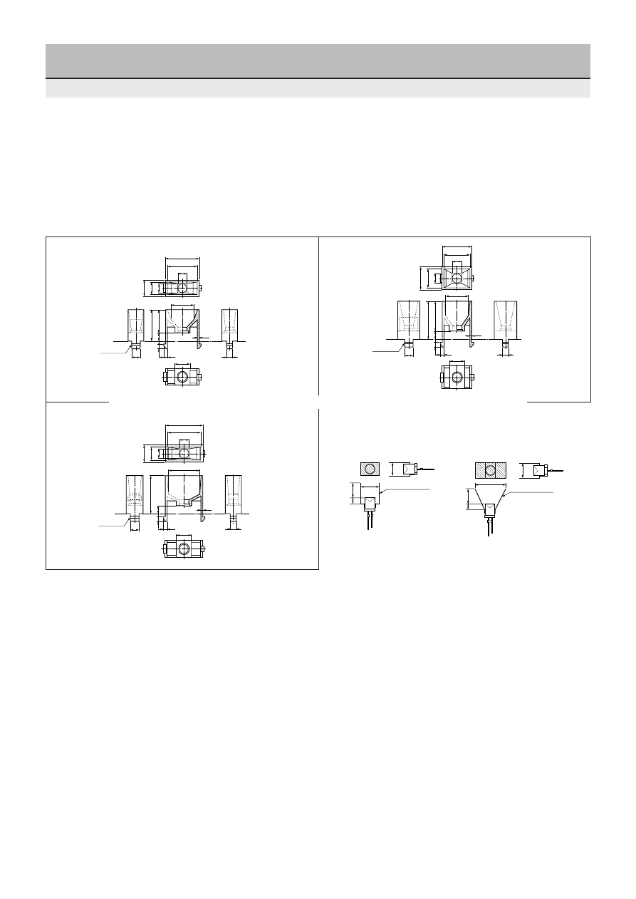
29
The following three types of standard lamp casings are provided for the area-illuminating LED (SEL1013 Series):
SEL9100 Casing (Illuminating area: 6.5
×
16.0)
SEL9101 Casing (Illuminating area: 10.0
×
14.0)
SEL9104 Casing (Illuminating area: 7.0
×
18.0)
These casings have tabs to assist positioning during printed wiring board mounting.
Lamp Casings Inverted-cone LED for surface illumination
SEL9100 Lamp Casing
SEL9101 Lamp Casing
Design examples of reflective surface
(The figures below show design examples of the reflective surface
of the housing.)
Example of 7
×
10 mm
Example of 8
×
16 mm
●
The standard housing is designed to accept an area-illuminating LED press-fit from the rear.
●
5.2
5.2
2.5
1.6
4.5
12
6.5
16.5
8.5
16.0
12.0
8.0
18.0
1.0
3.0
1.8
4.5
Cathode side
2.5
1.6
4.5
15.5
5.2
10.0
12.0
20.0
12.0
5.2
14.0
16.0
8.0
1.0
3.0
1.8
4.5
Cathode side
5.2
18.0
20.0
5.2
2.5
1.6
4.5
7.0
20.0
9.0
17.0
8.0
1.0
3.0
1.8
4.5
Cathode side
16.0
8.0
8.0
3.0
16.0
Reflective surface
Reflective surface
7.0
8.0
3.0
SEL9104 Lamp Casing
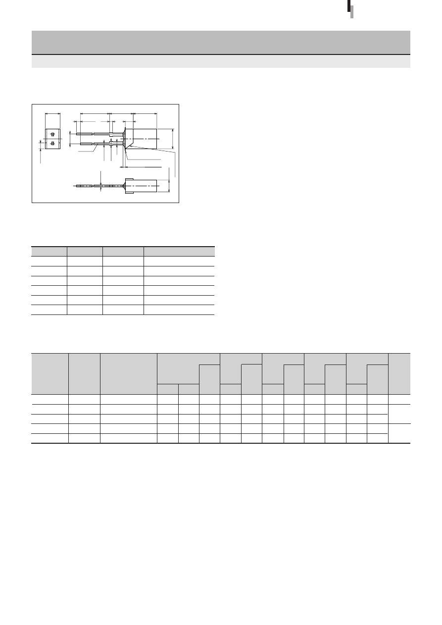
30
Forward voltage
V
F
Condition
(V)
I
F
typ
max
(mA)
Part
Number
Lens color
Reverse current
I
R
Condition
(
µ
A)
V
R
max
(V)
Intensity
I
V
Condition
(mcd)
I
F
typ
(mA)
Peak wavelength
λ
P
Condition
(nm)
I
F
typ
(mA)
Spectrum half width
∆λ
Condition
(nm)
I
F
typ
(mA)
Chip
material
Emitting color
3
×
5 Rectangular LED
SEL1021 Series
External Dimensions
Symbol
Unit
Rating
Condition
I
F
mA
30
∆
I
F
mA/
°
C
−
0.45
Above 25
°
C
I
FP
mA
100
f=1kHz, tw
≤
100
µ
s
V
R
V
3
Top
°
C
−
30 to +85
Tstg
°
C
−
30 to +100
Absolute maximum ratings (Ta=25
°
C)
SEL1021 Series
Tolerance:
±
0.3
(Unit: mm)
2.0
1.9
1.9
2.0
2.0
SEL1121R
SEL1821D
SEL1921D
SEL1721Y
SEL1421G
Diffused red
Diffused orange
Diffused orange
Diffused yellow
Diffused green
Electrical Optical characteristics (Ta=25
°
C)
0.9
3.0
3.8
7.0
12
2.5
2.5
2.5
2.5
2.5
10
10
10
10
10
50
50
50
50
50
3
3
3
3
3
10
10
10
10
20
700
610
587
570
560
10
10
10
10
10
100
35
33
30
20
10
10
10
10
10
Deep red
Amber
Orange
Yellow
Green
GaP
GaAsP
GaP
±
0.1
±
0.2
±
0.2
5.0
0.8
0.5
±
0.5
±
0.2
1.5
±
0.2
3.0
3.8
0.8
6.0
(2.0)
0.5
1.1max
Resin heap 1.5max
Resin burr 0.3max
6.0
20.0min
(2.54)
1.0min
±
0.2
Cathode mar
k
±
0.1
Cathode
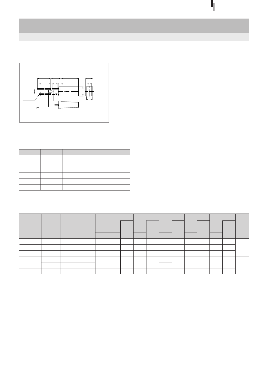
31
Forward voltage
V
F
Condition
(V)
I
F
typ
max
(mA)
Part
Number
Lens color
Reverse current
I
R
Condition
(
µ
A)
V
R
max
(V)
Intensity
I
V
Condition
(mcd)
I
F
typ
(mA)
Peak wavelength
λ
P
Condition
(nm)
I
F
typ
(mA)
Spectrum half width
∆λ
Condition
(nm)
I
F
typ
(mA)
Chip
material
Emitting color
2.5
×
5 Rectangular LED
SEL1022 Series
External Dimensions
SEL1022 Series
(Unit: mm)
1.9
1.9
1.9
2.0
2.0
SEL1222R
SEL1822D
SEL1922D
SEL1722Y
SEL1722K
SEL1422G
Diffused red
Diffused orange
Diffused orange
Diffused yellow
Transparent yellow
Diffused green
Electrical Optical characteristics (Ta=25
°
C)
9.0
4.8
4.5
7.8
12
7.2
2.5
2.5
2.5
2.5
2.5
10
10
10
10
10
50
50
50
50
50
3
3
3
3
3
20
10
10
10
20
630
610
587
570
560
10
10
10
10
10
35
35
33
30
20
10
10
10
10
10
Red
Amber
Orange
Yellow
Green
GaAsP
GaP
Symbol
Unit
Rating
Condition
I
F
mA
30
∆
I
F
mA/
°
C
−
0.45
Above 25
°
C
I
FP
mA
100
f=1kHz, tw
≤
100
µ
s
V
R
V
3
Top
°
C
−
30 to +85
Tstg
°
C
−
30 to +100
Absolute maximum ratings (Ta=25
°
C)
Tolerance:
±
0.3
20.0min
(2.54)
5.0
±
0.5
9.0
±
0.2
4.0
±
0.2
19.0min 0.8
(1.0)
2.5
±
0.15
0.5
±
0.1
1.1max
0.8
5.0
±
0.2
Cathode
3.0
±
0.15
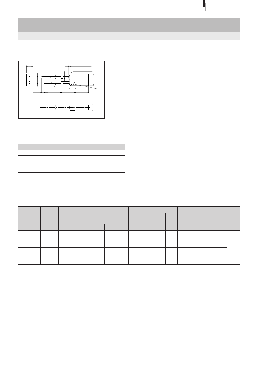
32
Forward voltage
V
F
Condition
(V)
I
F
typ
max
(mA)
Part
Number
Lens color
Reverse current
I
R
Condition
(
µ
A)
V
R
max
(V)
Intensity
I
V
Condition
(mcd)
I
F
typ
(mA)
Peak wavelength
λ
P
Condition
(nm)
I
F
typ
(mA)
Spectrum half width
∆λ
Condition
(nm)
I
F
typ
(mA)
Chip
material
Emitting color
External Dimensions
Symbol
Unit
Rating
Condition
I
F
mA
30
∆
I
F
mA/
°
C
−
0.45
Above 25
°
C
I
FP
mA
100
f=1kHz, tw
≤
100
µ
s
V
R
V
3
Top
°
C
−
30 to +85
Tstg
°
C
−
30 to +100
Absolute maximum ratings (Ta=25
°
C)
SEL1020 Series
2
×
5 Rectangular LED
SEL1020 Series
(Unit: mm)
SEL1120R
SEL1220R
SEL1820D
SEL1920D
SEL1720Y
SEL1420G
Diffused red
Diffused red
Diffused orange
Diffused orange
Diffused yellow
Diffused green
Electrical Optical characteristics (Ta=25
°
C)
0.9
4.8
3.0
3.8
7.0
11
10
20
10
10
10
20
700
630
610
587
570
560
10
10
10
10
10
10
100
35
35
33
30
20
10
10
10
10
10
10
2.0
1.9
1.9
1.9
2.0
2.0
2.5
2.5
2.5
2.5
2.5
2.5
10
10
10
10
10
10
50
50
50
50
50
50
3
3
3
3
3
3
GaP
GaAsP
GaP
Deep red
Red
Amber
Orange
Yellow
Green
Tolerance:
±
0.3
6.0
6.0
20.0min
1.0min
2.8
5.0
Cathode
(2.54)
2.0
Cathode mar
k
±
0.2
±
0.2
±
0.5
Resin heap 1.5max
(2.0)
±
0.2
0.5
±
0.1
1.1max
±
0.2
0.5
±
0.1
0.8
Resin burr 0.3max
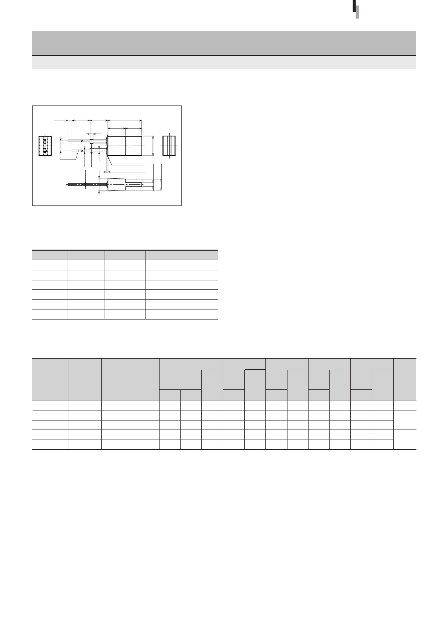
33
Forward voltage
V
F
Condition
(V)
I
F
typ
max
(mA)
Part
Number
Lens color
Reverse current
I
R
Condition
(
µ
A)
V
R
max
(V)
Intensity
I
V
Condition
(mcd)
I
F
typ
(mA)
Peak wavelength
λ
P
Condition
(nm)
I
F
typ
(mA)
Spectrum half width
∆λ
Condition
(nm)
I
F
typ
(mA)
Chip
material
Emitting color
1
×
5 Rectangular LED
SEL1024 Series
External Dimensions
SEL1024 Series
(Unit: mm)
2.0
1.9
1.9
2.0
2.0
SEL1124R
SEL1824D
SEL1924D
SEL1724Y
SEL1424G
Diffused red
Diffused orange
Diffused orange
Diffused yellow
Diffused green
Electrical Optical characteristics (Ta=25
°
C)
0.5
4.0
3.0
6.0
15
2.5
2.5
2.5
2.5
2.5
10
10
10
10
10
50
50
50
50
50
3
3
3
3
3
10
10
10
10
20
700
610
587
570
560
10
10
10
10
10
100
35
33
30
20
10
10
10
10
10
Deep red
Amber
Orange
Yellow
Green
GaP
GaAsP
GaP
Symbol
Unit
Rating
Condition
I
F
mA
30
∆
I
F
mA/
°
C
−
0.45
Above 25
°
C
I
FP
mA
100
f=1kHz, tw
≤
100
µ
s
V
R
V
3
Top
°
C
−
30 to +85
Tstg
°
C
−
30 to +100
Absolute maximum ratings (Ta=25
°
C)
Tolerance:
±
0.3
±
0.1
±
0.15
±
0.2
0.8
±
0.2
±
0.5
1.0min
4.5
4.5
3.2
±
0.2
±
0.1
Resin burr 0.3min
1.1max
Resin heap 1.5max
4.0
4.9
8.5
1.0
2.8
19.0min
0.5
0.5
(2.54)
0.8
Cathode
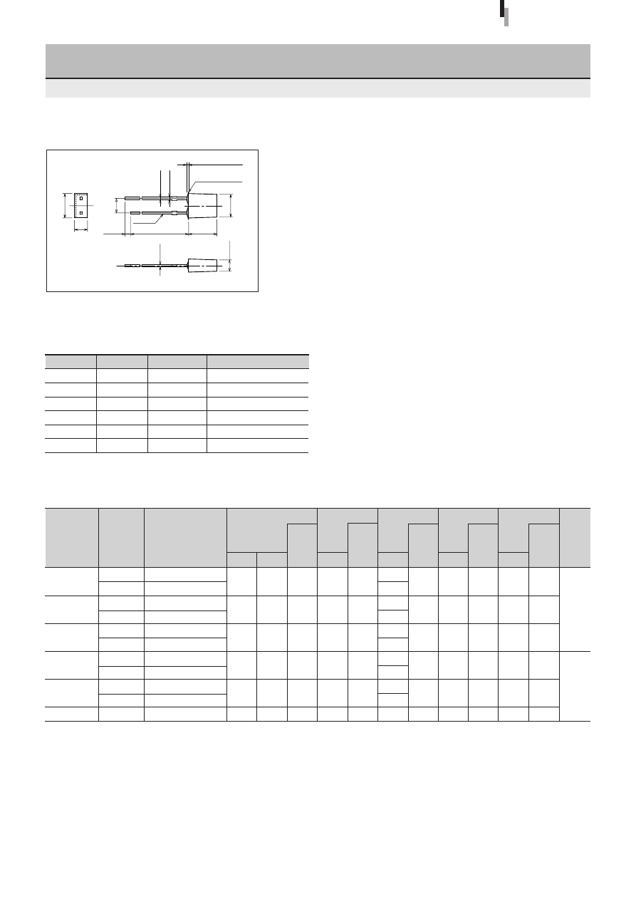
34
Forward voltage
V
F
Condition
(V)
I
F
typ
max
(mA)
Part
Number
Lens color
Reverse current
I
R
Condition
(
µ
A)
V
R
max
(V)
Intensity
I
V
Condition
(mcd)
I
F
typ
(mA)
Peak wavelength
λ
P
Condition
(nm)
I
F
typ
(mA)
Spectrum half width
∆λ
Condition
(nm)
I
F
typ
(mA)
Chip
material
Emitting color
2
×
4 Rectangular LED
SEL4025 Series
External Dimensions
SEL4025 Series
Symbol
Unit
Rating
Condition
I
F
mA
30
∆
I
F
mA/
°
C
−
0.45
Above 25
°
C
I
FP
mA
100
f=1kHz, tw
≤
100
µ
s
V
R
V
3
Top
°
C
−
30 to +85
Tstg
°
C
−
30 to +100
Absolute maximum ratings (Ta=25
°
C)
(Unit: mm)
1.9
1.9
1.9
2.0
2.0
2.0
SEL4225C
SEL4225R
SEL4825A
SEL4825D
SEL4925A
SEL4925D
SEL4725K
SEL4725Y
SEL4425E
SEL4425G
SEL4525C
Clear
Diffused red
Transparent orange
Diffused orange
Transparent orange
Diffused orange
Transparent yellow
Diffused yellow
Transparent green
Diffused green
Clear
Electrical Optical characteristics (Ta=25
°
C)
12
5.4
5.4
4.0
4.5
4.0
13
5.0
20
10
6.6
2.5
2.5
2.5
2.5
2.5
2.5
10
10
10
10
10
10
50
50
50
50
50
50
3
3
3
3
3
3
20
10
10
10
20
20
630
610
587
570
560
555
10
10
10
10
10
10
35
35
33
30
20
20
10
10
10
10
10
10
Red
Amber
Orange
Yellow
Green
Pure green
GaAsP
GaP
Tolerance:
±
0.3
±
0.2
Resin burr 0.3max
±
0.2
4.0
±
0.1
0.4
±
0.1
(2.54)
0.45
0.65max
4.3
Resin heap 0.8max
±
0.2
2.0
1.0min
2.3
5.0
23.0min
Cathode

35
Forward voltage
V
F
Condition
(V)
I
F
typ
max
(mA)
Part
Number
Lens color
Reverse current
I
R
Condition
(
µ
A)
V
R
max
(V)
Intensity
I
V
Condition
(mcd)
I
F
typ
(mA)
Peak wavelength
λ
P
Condition
(nm)
I
F
typ
(mA)
Spectrum half width
∆λ
Condition
(nm)
I
F
typ
(mA)
Chip
material
Emitting color
2
×
4 Rectangular LED
(Direct Mount)
SEL4026 Series
External Dimensions
SEL4026 Series
Symbol
Unit
Rating
Condition
I
F
mA
30
∆
I
F
mA/
°
C
−
0.45
Above 25
°
C
I
FP
mA
100
f=1kHz, tw
≤
100
µ
s
V
R
V
3
Top
°
C
−
30 to +85
Tstg
°
C
−
30 to +100
Absolute maximum ratings (Ta=25
°
C)
(Unit: mm)
1.9
1.9
1.9
2.0
2.0
SEL4226C
SEL4226R
SEL4826A
SEL4826D
SEL4926A
SEL4926D
SEL4726K
SEL4726Y
SEL4426E
SEL4426G
Clear
Diffused red
Transparent orange
Diffused orange
Transparent orange
Diffused orange
Transparent yellow
Diffused yellow
Transparent green
Diffused green
Electrical Optical characteristics (Ta=25
°
C)
12
10
5.4
4.5
6.0
4.5
14.0
8.6
20
14
2.5
2.5
2.5
2.5
2.5
10
10
10
10
10
50
50
50
50
50
3
3
3
3
3
20
10
10
10
20
630
610
587
570
560
10
10
10
10
10
35
35
33
30
20
10
10
10
10
10
Red
Amber
Orange
Yellow
Green
GaAsP
GaP
Tolerance:
±
0.3
±
0.2
±
0.2
Resin burr 0.3max
4.0
±
0.1
0.4
0.45
0.65max
±
0.1
(2.54)
4.3
Resin heap 0.8max
±
0.2
2.0
1.0min
2.3
21.0min
7.0
Cathode
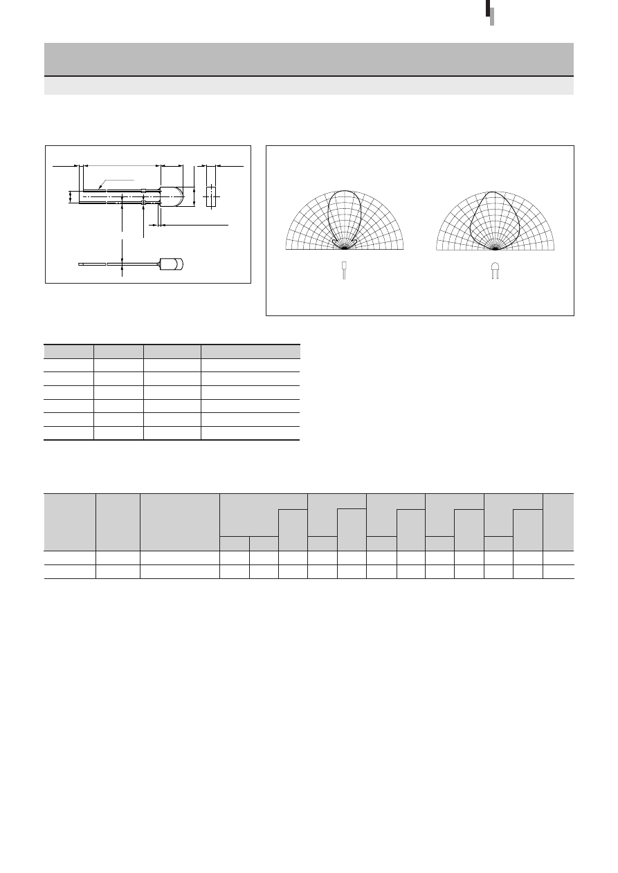
36
Forward voltage
V
F
Condition
(V)
I
F
typ
max
(mA)
Part
Number
Lens color
Reverse current
I
R
Condition
(
µ
A)
V
R
max
(V)
Intensity
I
V
Condition
(mcd)
I
F
typ
(mA)
Peak wavelength
λ
P
Condition
(nm)
I
F
typ
(mA)
Spectrum half width
∆λ
Condition
(nm)
I
F
typ
(mA)
Chip
material
Emitting color
4
φ
Bow-shaped LED
SEL4027 Series
Directivity (Typical)
External Dimensions
SEL4027 Series
(Unit: mm)
1.9
2.0
SEL4227C
SEL4427EP
Clear
Transparent green
Electrical Optical characteristics (Ta=25
°
C)
15
19
2.5
2.5
10
10
50
50
3
3
20
20
630
560
10
10
35
20
10
10
Red
Green
GaAsP
GaP
Symbol
Unit
Rating
Condition
I
F
mA
30
∆
I
F
mA/
°
C
−
0.45
Above 25
°
C
I
FP
mA
100
f=1kHz, tw
≤
100
µ
s
V
R
V
3
Top
°
C
−
30 to +85
Tstg
°
C
−
30 to +100
Absolute maximum ratings (Ta=25
°
C)
Tolerance:
±
0.3
90
°
60
°
30
°
0
°
90
°
60
°
30
°
0
50
100%
50
100%
90
°
60
°
30
°
0
°
90
°
60
°
30
°
0
50
100%
50
100%
0.45
±
0.1
0.4
±
0.1
0.65max
Resin heap 0.8max
1.0min
23.0min
5.0
±
0.2
4.0
±
0.2
Cathode
2.0
±
0.1
(2.54)
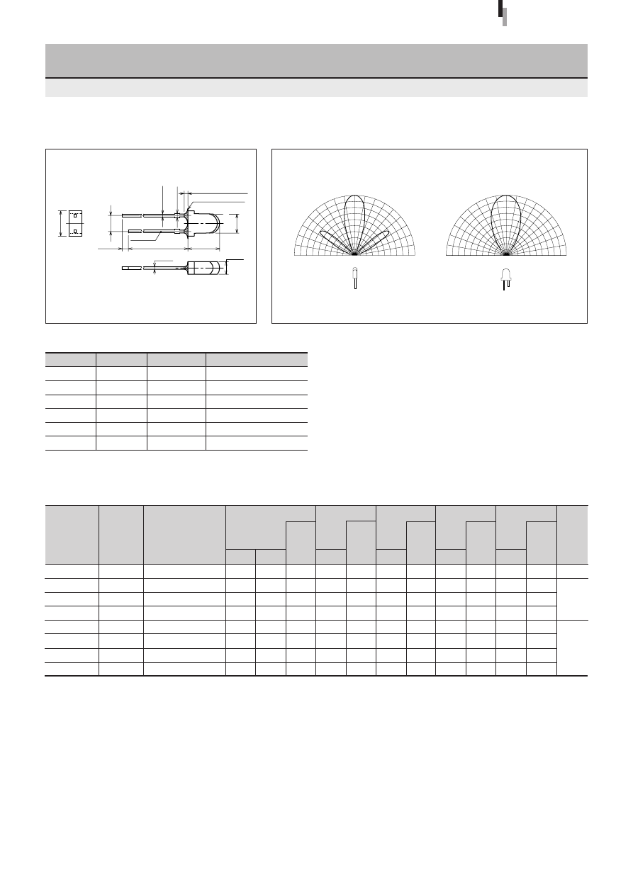
37
Forward voltage
V
F
Condition
(V)
I
F
typ
max
(mA)
Part
Number
Lens color
Reverse current
I
R
Condition
(
µ
A)
V
R
max
(V)
Intensity
I
V
Condition
(mcd)
I
F
typ
(mA)
Peak wavelength
λ
P
Condition
(nm)
I
F
typ
(mA)
Spectrum half width
∆λ
Condition
(nm)
I
F
typ
(mA)
Chip
material
Emitting color
3.1
φ
Bow-shaped LED
SEL4028 Series
Directivity (Typical)
External Dimensions
Symbol
Unit
Rating
Condition
I
F
mA
30
∆
I
F
mA/
°
C
−
0.45
Above 25
°
C
I
FP
mA
100
f=1kHz, tw
≤
100
µ
s
V
R
V
3
Top
°
C
−
30 to +85
Tstg
°
C
−
30 to +100
Absolute maximum ratings (Ta=25
°
C)
SEL4028 Series
Tolerance:
±
0.3
(Unit: mm)
SEL4628C-S
SEL4228C
SEL4828A
SEL4928A
SEL4728K
SEL4428E
SEL4428B-TG
SEL4528C
Clear
Clear
Transparent orange
Transparent orange
Transparent yellow
Transparent green
Transparent dark blue
Clear
Electrical Optical characteristics (Ta=25
°
C)
200
27
14
14
30
63
18
30
20
20
10
10
10
20
20
20
660
630
610
587
570
560
558
555
10
10
10
10
10
10
10
10
30
35
35
33
30
20
20
20
10
10
10
10
10
10
10
10
1.7
1.9
1.9
1.9
2.0
2.0
2.0
2.0
2.2
2.5
2.5
2.5
2.5
2.5
2.5
2.5
10
10
10
10
10
10
10
10
100
50
50
50
50
50
50
50
3
3
3
3
3
3
3
3
GaAlAs
GaAsP
GaP
Red
Amber
Orange
Yellow
Green
Deep green
Pure green
90
°
60
°
30
°
0
°
90
°
60
°
30
°
0
50
100%
50
100%
90
°
60
°
30
°
0
°
90
°
60
°
30
°
0
50
100%
50
100%
(2.54)
4.0
±
0.2
2.0
±
0.1
±
0.2
Resin heap 0.8max
Resin burr 0.3max
5.0
23.5min
1.0min
0.4
±
0.1
0.65max
0.45
±
0.1
Cathode
3.1
φ
±
0.2
High-
intensity red

38
Forward voltage
V
F
Condition
(V)
I
F
typ
max
(mA)
Part
Number
Lens color
Reverse current
I
R
Condition
(
µ
A)
V
R
max
(V)
Intensity
I
V
Condition
(mcd)
I
F
typ
(mA)
Peak wavelength
λ
P
Condition
(nm)
I
F
typ
(mA)
Spectrum half width
∆λ
Condition
(nm)
I
F
typ
(mA)
Chip
material
Emitting color
3.1
φ
Bow-shaped LED
(Direct Mount)
SEL4029 Series
Directivity (Typical)
External Dimensions
Symbol
Unit
Rating
Condition
I
F
mA
30
∆
I
F
mA/
°
C
−
0.45
Above 25
°
C
I
FP
mA
100
f=1kHz, tw
≤
100
µ
s
V
R
V
3
Top
°
C
−
30 to +85
Tstg
°
C
−
30 to +100
Absolute maximum ratings (Ta=25
°
C)
SEL4029 Series
Tolerance:
±
0.3
(Unit: mm)
SEL4229R
SEL4829A
SEL4929A
SEL4729KH
SEL4429E
Diffused red
Transparent orange
Transparent orange
Transparent yellow
Transparent green
Electrical Optical characteristics (Ta=25
°
C)
21
18
18
60
60
20
10
10
10
20
630
610
587
570
560
10
10
10
10
10
35
35
33
30
20
10
10
10
10
10
1.9
1.9
1.9
2.0
2.0
2.5
2.5
2.5
2.5
2.5
10
10
10
10
10
50
50
50
50
50
3
3
3
3
3
GaAsP
GaP
Red
Amber
Orange
Yellow
Green
90
°
60
°
30
°
0
°
90
°
60
°
30
°
0
50
100%
50
100%
90
°
60
°
30
°
0
°
90
°
60
°
30
°
0
50
100%
50
100%
0.45
0.65max
Resin heap 0.8max
1.0min
20.5min
8.0
±
0.2
3.1
±
0.2
Cathode
3.0
(1.0)
3.5
±
0.2
2.4
4.2
(2.54)
0.4
±
0.1

39
Forward voltage
V
F
Condition
(V)
I
F
typ
max
(mA)
Part
Number
Lens color
Reverse current
I
R
Condition
(
µ
A)
V
R
max
(V)
Intensity
I
V
Condition
(mcd)
I
F
typ
(mA)
Peak wavelength
λ
P
Condition
(nm)
I
F
typ
(mA)
Spectrum half width
∆λ
Condition
(nm)
I
F
typ
(mA)
Chip
material
Emitting color
4
φ
Bow-shaped LED
(Direct Mount)
SEL6027 Series
Directivity (Typical)
External Dimensions
Symbol
Unit
Rating
Condition
I
F
mA
30
∆
I
F
mA/
°
C
−
0.45
Above 25
°
C
I
FP
mA
100
f=1kHz, tw
≤
100
µ
s
V
R
V
3
Top
°
C
−
30 to +85
Tstg
°
C
−
30 to +100
Absolute maximum ratings (Ta=25
°
C)
SEL6027Series
(Unit: mm)
SEL6227S
SEL6927A
SEL6427EP
Transparent red
Transparent orange
Transparent green
Electrical Optical characteristics (Ta=25
°
C)
14
10
26
20
10
20
630
587
560
10
10
10
35
33
20
10
10
10
1.9
1.9
2.0
2.5
2.5
2.5
10
10
10
50
50
50
3
3
3
GaAsP
GaP
Red
Orange
Green
Tolerance:
±
0.3
90
°
60
°
30
°
0
°
90
°
60
°
30
°
0
50
100%
50
100%
90
°
60
°
30
°
0
°
90
°
60
°
30
°
0
50
100%
50
100%
±
0.2
±
0.2
Resin burr 0.3max
4.0
±
0.1
0.4
0.45
0.65max
(2.54)
±
0.1
0.8
4.4
4.0
±
0.2
±
0.2
Resin heap 0.8max
±
0.2
2.0
1.0min
2.1
4.6
4.9
23.0min
Cathode
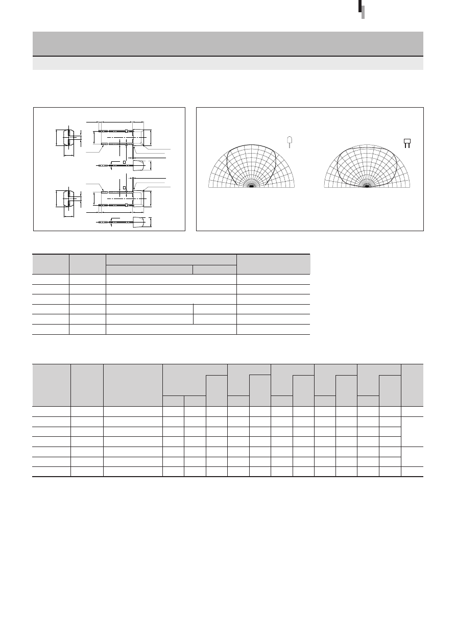
40
Forward voltage
V
F
Condition
(V)
I
F
typ
max
(mA)
Part
Number
Lens color
Reverse current
I
R
Condition
(
µ
A)
V
R
max
(V)
Intensity
I
V
Condition
(mcd)
I
F
typ
(mA)
Peak wavelength
λ
P
Condition
(nm)
I
F
typ
(mA)
Spectrum half width
∆λ
Condition
(nm)
I
F
typ
(mA)
Chip
material
Emitting color
5-mm Pitch Lead Rectangular LED
(Direct Mount)
SEL5020 Series
Directivity (Typical)
External Dimensions
SEL5020Series
(Unit: mm)
1.7
1.9
1.9
1.9
2.0
2.0
3.3
SEL5620C
SEL5220S
SEL5820A
SEL5920A
SEL5420E
SEL5520C
SELU5E20C
Clear
Transparent red
Transparent orange
Transparent orange
Transparent green
Clear
Clear
Electrical Optical characteristics (Ta=25
°
C)
2.2
2.5
2.5
2.5
2.5
2.5
4.0
Red
Amber
Orange
Green
Pure green
10
10
10
10
10
10
10
3
3
3
3
3
3
5
100
20
12
12
20
6.0
60
20
20
20
20
20
20
10
660
630
610
587
560
555
470
30
35
35
33
20
20
35
GaAIAs
GaAsP
GaP
InGaN
50
50
50
50
50
50
10
10
10
10
10
10
10
10
10
10
10
10
10
10
10
Symbol
Unit
Rating
Condition
GaP/GaAsP/GaAlAs
InGaN
I
F
mA
30
∆
I
F
mA/
°
C
−
0.45
Above 25
°
C
I
FP
mA
100
f=1kHz, tw
≤
100
µ
s
V
R
V
3
5
Top
°
C
−
30 to +85
−
25 to +80
Tstg
°
C
−
30 to +100
Absolute maximum ratings (Ta=25
°
C)
6.2
1.4
3.6
(5.0)
4.2
±
0.5
23.0min
1.0min
4.2
±
0.5
23.0min
1.0min
6.0
±
0.2
6.0
±
0.2
0.5
±
0.1
0.65max
Resin heap 0.8max
Resin heap 0.8max
Resin burr 0.3max
Resin burr 0.3max
Cathode
Cathode
3.3
±
0.2
0.5
±
0.1
3.3
±
0.2
0.5
±
0.1
Cathode mark
Cathode mark
0.5
±
0.1
0.65max
6.2
1.4
3.6
(5.0)
90
°
60
°
30
°
0
°
90
°
60
°
30
°
0
50
100%
50
100%
90
°
60
°
30
°
0
°
90
°
60
°
30
°
0
50
100%
50
100%
Tolerance:
±
0.3
(Other than GaAlAs chip)
(GaAlAs)
High-
intensity red
Ultra-high-
intensity blue
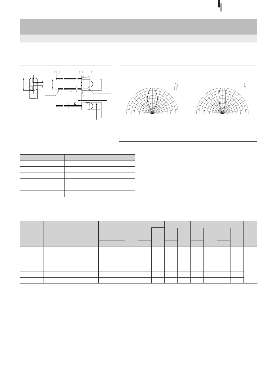
41
Forward voltage
V
F
Condition
(V)
I
F
typ
max
(mA)
Part
Number
Lens color
Reverse current
I
R
Condition
(
µ
A)
V
R
max
(V)
Intensity
I
V
Condition
(mcd)
I
F
typ
(mA)
Peak wavelength
λ
P
Condition
(nm)
I
F
typ
(mA)
Spectrum half width
∆λ
Condition
(nm)
I
F
typ
(mA)
Chip
material
Emitting color
5-mm Pitch Lead 3
φ
Lens-type LED
(Direct Mount)
SEL5021 Series
Directivity (Typical)
External Dimensions
Symbol
Unit
Rating
Condition
I
F
mA
30
∆
I
F
mA/
°
C
−
0.45
Above 25
°
C
I
FP
mA
100
f=1kHz, tw
≤
100
µ
s
V
R
V
3
Top
°
C
−
30 to +85
Tstg
°
C
−
30 to +100
Absolute maximum ratings (Ta=25
°
C)
SEL5021Series
Tolerance:
±
0.3
(Unit: mm)
1.9
1.9
1.9
2.0
2.0
2.0
SEL5221S
SEL5821A
SEL5921A
SEL5721C
SEL5421E
SEL5521C
Transparent red
Transparent orange
Transparent orange
Clear
Transparent green
Clear
Electrical Optical characteristics (Ta=25
°
C)
2.5
2.5
2.5
2.5
2.5
2.5
Red
Amber
Orange
Yellow
Green
Pure green
10
10
10
10
10
10
3
3
3
3
3
3
35
60
60
90
95
35
20
20
20
20
20
20
630
610
587
570
560
555
35
35
33
30
20
20
GaAsP
GaP
50
50
50
50
50
50
10
10
10
10
10
10
10
10
10
10
10
10
6.2
1.4
3.6
(5.0)
5.8
±
0.5
23.0min
1.0min
3.9
6.0
±
0.2
0.5
+0.1
0.65max
Resin heap 0.8max
Cathode mark
Cathode
0.5
±
0.1
3.2
±
0.2
ø
3.0
±
0.2
Resin burr 0.3max
90
°
60
°
30
°
0
°
90
°
60
°
30
°
0
50
100%
50
100%
90
°
60
°
30
°
0
°
90
°
60
°
30
°
0
50
100%
50
100%
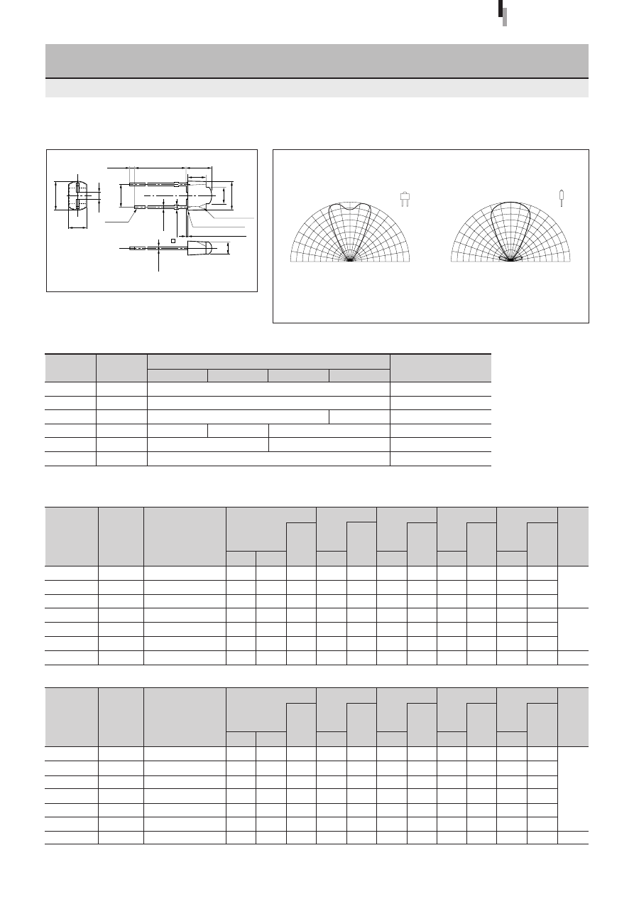
42
Forward voltage
V
F
Condition
(V)
I
F
typ
max
(mA)
Part
Number
Lens color
Reverse current
I
R
Condition
(
µ
A)
V
R
max
(V)
Intensity
I
V
Condition
(mcd)
I
F
typ
(mA)
Peak wavelength
λ
P
Condition
(nm)
I
F
typ
(mA)
Spectrum half width
∆λ
Condition
(nm)
I
F
typ
(mA)
Chip
material
Emitting color
Forward voltage
V
F
Condition
(V)
I
F
typ
max
(mA)
Part
Number
Lens color
Reverse current
I
R
Condition
(
µ
A)
V
R
max
(V)
Intensity
I
V
Condition
(mcd)
I
F
typ
(mA)
Peak wavelength
λ
P
Condition
(nm)
I
F
typ
(mA)
Spectrum half width
∆λ
Condition
(nm)
I
F
typ
(mA)
Chip
material
Emitting color
5-mm Pitch Lead Bow-shaped LED
(Direct Mount)
SEL5023 Series
Directivity (Typical)
External Dimensions
SEL5023Series
Tolerance:
±
0.3
(Unit: mm)
1.9
1.9
1.9
2.0
2.0
2.0
4.0
SEL5223S
SEL5823A
SEL5923A
SEL5723C
SEL5423E
SEL5523C
SEL5E23C
Transparent red
Transparent orange
Transparent orange
Clear
Transparent green
Clear
Clear
Electrical Optical characteristics (Ta=25
°
C)
2.5
2.5
2.5
2.5
2.5
2.5
4.8
Red
Amber
Orange
Yellow
Green
Pure green
Blue
10
10
10
10
10
10
10
3
3
3
3
3
3
5
25
35
35
60
40
13
20
20
20
20
20
20
20
20
630
610
587
570
560
555
430
35
35
33
30
20
20
65
GaAsP
GaP
GaN
50
50
50
50
50
50
10
10
10
10
10
10
10
10
10
10
10
10
10
10
10
2.0
2.0
2.0
2.0
2.0
2.0
3.6
SELS5223C
SELS5823C
SELU5823C
SELS5B23C
SELS5923C
SELU5723C
SELU5E23C
Clear
Clear
Clear
Clear
Clear
Clear
Clear
●
Ultra-high-intensity series
2.5
2.5
2.5
2.5
2.5
2.5
4.0
Red
Amber
Amber
Light amber
Orange
Yellow
Blue
10
10
10
10
10
10
10
4
4
4
4
4
4
5
100
130
185
135
145
155
110
20
20
20
20
20
20
10
635
615
615
600
590
572
470
15
15
15
15
15
15
35
AIGaInP
InGaN
100
100
100
100
100
100
10
10
10
10
10
10
10
10
10
10
10
10
10
10
10
Symbol
Unit
Rating
Condition
GaP/GaAsP
AlGaInP
InGaN
GaN
I
F
mA
30
∆
I
F
mA/
°
C
−
0.45
Above 25
°
C
I
FP
mA
100
70
f=1kHz, tw
≤
100
µ
s
V
R
V
3
4
5
Top
°
C
−
30 to +85
−
25 to +80
Tstg
°
C
−
30 to +100
Absolute maximum ratings (Ta=25
°
C)
6.2
1.4
3.6
(5.0)
5.8
±
0.5
23.0min
1.0min
3.9
0.5
+0.1
0.65max
Resin heap 0.8max
Resin burr 0.3max
Cathode mark
Cathode
0.5
±
0.1
3.6
±
0.2
6.0
±
0.2
3.1
90
°
60
°
30
°
0
°
90
°
60
°
30
°
0
50
100%
50
100%
90
°
60
°
30
°
0
°
90
°
60
°
30
°
0
50
100%
50
100%
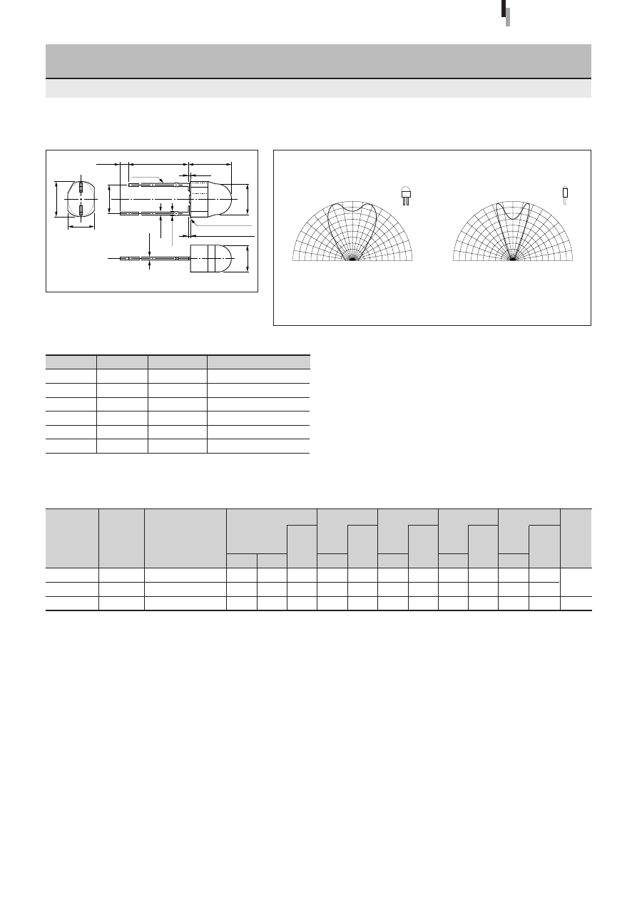
43
Forward voltage
V
F
Condition
(V)
I
F
typ
max
(mA)
Part
Number
Lens color
Reverse current
I
R
Condition
(
µ
A)
V
R
max
(V)
Intensity
I
V
Condition
(mcd)
I
F
typ
(mA)
Peak wavelength
λ
P
Condition
(nm)
I
F
typ
(mA)
Spectrum half width
∆λ
Condition
(nm)
I
F
typ
(mA)
Chip
material
Emitting color
5-mm Pitch Lead Egg-shaped LED
(Direct Mount)
SEL5055 Series
Directivity (Typical)
External Dimensions
Symbol
Unit
Rating
Condition
I
F
mA
30
∆
I
F
mA/
°
C
−
0.45
Above 25
°
C
I
FP
mA
100
f=1kHz, tw
≤
100
µ
s
V
R
V
3
Top
°
C
−
30 to +85
Tstg
°
C
−
30 to +100
Absolute maximum ratings (Ta=25
°
C)
SEL5055Series
Tolerance:
±
0.3
(Unit: mm)
SEL5255S
SEL5955A
SEL5755C
Electrical Optical characteristics (Ta=25
°
C)
35
25
140
20
20
20
630
587
570
10
10
10
35
33
30
10
10
10
1.9
1.9
2.0
2.5
2.5
2.5
10
10
10
50
50
50
3
3
3
GaAsP
GaP
Transparent red
Transparent orange
Clear
Red
Orange
Yellow
23.0min
(0.3)
1.0min
0.65max
6.2
±
0.2
(5.0)
5.6
±
0.2
4.55
±
0.2
4.65
±
0.2
7.3
±
0.5
0.5
±
0.1
0.5
±
0.1
Resin heap 0.8max
Resin burr 0.3max
Cathode
90
°
60
°
30
°
0
°
90
°
60
°
30
°
0
50
100%
50
100%
90
°
60
°
30
°
0
°
90
°
60
°
30
°
0
50
100%
50
100%
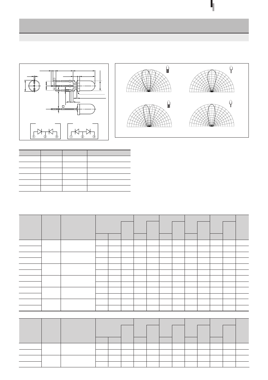
44
Forward voltage
V
F
Condition
(V)
I
F
typ
max
(mA)
Part
Number
Lens color
Reverse current
I
R
Condition
(
µ
A)
V
R
max
(V)
Intensity
I
V
Condition
(mcd)
I
F
typ
(mA)
Peak wavelength
λ
P
Condition
(nm)
I
F
typ
(mA)
Spectrum half width
∆λ
Condition
(nm)
I
F
typ
(mA)
Chip
material
Emitting color
Forward voltage
V
F
Condition
(V)
I
F
typ
max
(mA)
Part
Number
Lens color
Reverse current
I
R
Condition
(
µ
A)
V
R
max
(V)
Intensity
I
V
Condition
(mcd)
I
F
typ
(mA)
Peak wavelength
λ
P
Condition
(nm)
I
F
typ
(mA)
Spectrum half width
∆λ
Condition
(nm)
I
F
typ
(mA)
Chip
material
Emitting color
Directivity (Typical)
External Dimensions
Symbol
Unit
Rating
Condition
I
F
mA
30
∆
I
F
mA/
°
C
−
0.45
Above 25
°
C
I
FP
mA
100
f=1kHz, tw
≤
100
µ
s
V
R
V
4
Top
°
C
−
30 to +85
Tstg
°
C
−
30 to +100
Absolute maximum ratings (Ta=25
°
C)
SEL1016/10016Series
5
φ
Round Standard Bicolor LED
SML1016/10016 Series
(Unit: mm)
2.0
2.0
2.0
2.0
1.9
2.0
1.9
2.0
1.9
2.0
1.9
2.0
SML11516C
SML1516W
SML1216C
SML1216W
SML1816W
SML19416W
Clear
Diffused white
Clear
Diffused white
Diffused white
Diffused white
Absolute maximum ratings (Ta=25
°
C)
●
Common cathode (Internal wiring diagram 1)
2.5
2.5
2.5
2.5
2.5
2.5
2.5
2.5
2.5
2.5
2.5
2.5
Deep red
Pure green
Deep red
Pure green
Red
Green
Red
Green
Amber
Green
Orange
Green
10
10
10
10
10
10
10
10
10
10
10
10
4
4
4
4
4
4
4
4
4
4
4
4
15
50
6.0
20
65
90
60
60
50
60
45
60
20
20
20
20
20
20
20
20
20
20
20
20
700
555
700
555
630
560
630
560
610
560
587
560
100
20
100
20
35
20
35
20
35
20
33
20
GaP
GaP
GaP
GaP
GaAsP
GaP
GaAsP
GaP
GaAsP
GaP
GaAsP
GaP
10
10
10
10
10
10
10
10
10
10
10
10
10
10
10
10
10
10
10
10
10
10
10
10
10
10
10
10
10
10
10
10
10
10
10
10
1.7
2.4
1.7
2.4
SML16716CN
SML16716WN
Clear
Diffused white
●
Common anode (Internal wiring diagram 2)
2.2
3.0
2.2
3.0
Yellow
Yellow
10
10
10
10
4
4
4
4
100
140
50
70
20
20
20
20
660
570
660
570
30
30
30
30
GaAIAs
GaP
GaAIAs
GaP
10
10
10
10
10
10
10
10
10
10
10
10
1.0min
17.0min
10.6
±
0.5
1.5min
2.0
±
0.5
7.6
±
0.2
1.0
0.5
±
0.1
ø
5.8
±
0.2
(2.54)
(2.54)
Resin heap 1.5max
Resin burr 0.3max
ø
5.0
±
0.2
1.2
0.8
3
–
0.5
±
0.1
0.65max
90
°
60
°
30
°
0
°
A
B
90
°
60
°
30
°
0
50
100%
50
100%
Tolerance:
±
0.3
A
B
A
B
A
B
A
B
A
B
A
B
A
B
A
B
Internal wiring
diagram 1
Internal wiring
diagram 2
A
B
A
B
90
°
60
°
30
°
0
°
A
B
90
°
60
°
30
°
0
50
100%
50
100%
90
°
60
°
30
°
0
°
90
°
60
°
30
°
0
50
100%
50
100%
Transparent
Diffused white
90
°
60
°
30
°
0
°
90
°
60
°
30
°
0
50
100%
50
100%
High-
intensity red
High-
intensity red
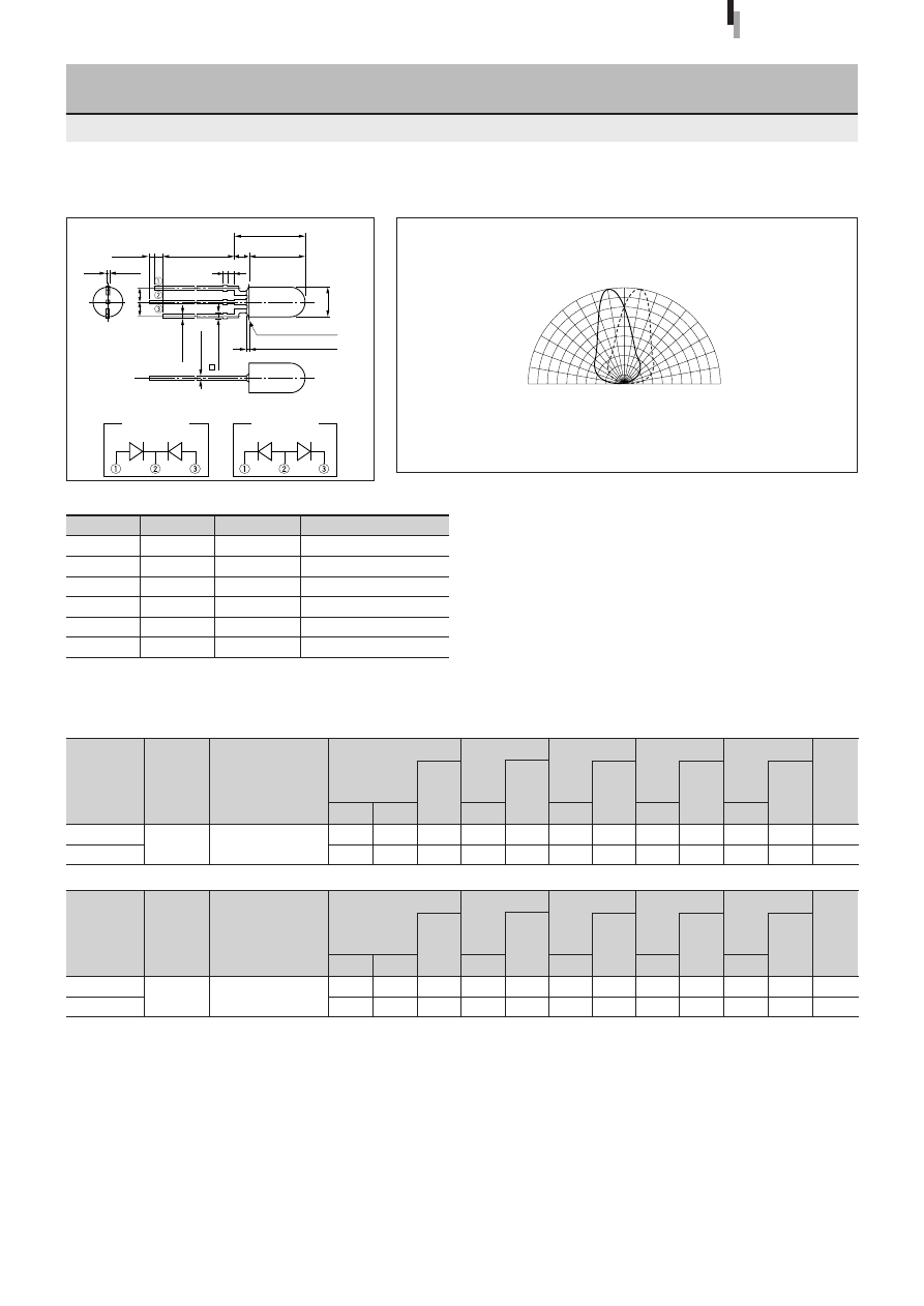
45
Forward voltage
V
F
Condition
(V)
I
F
typ
max
(mA)
Part
Number
Lens color
Reverse current
I
R
Condition
(
µ
A)
V
R
max
(V)
Intensity
I
V
Condition
(mcd)
I
F
typ
(mA)
Peak wavelength
λ
P
Condition
(nm)
I
F
typ
(mA)
Spectrum half width
∆λ
Condition
(nm)
I
F
typ
(mA)
Chip
material
Emitting color
Forward voltage
V
F
Condition
(V)
I
F
typ
max
(mA)
Part
Number
Lens color
Reverse current
I
R
Condition
(
µ
A)
V
R
max
(V)
Intensity
I
V
Condition
(mcd)
I
F
typ
(mA)
Peak wavelength
λ
P
Condition
(nm)
I
F
typ
(mA)
Spectrum half width
∆λ
Condition
(nm)
I
F
typ
(mA)
Chip
material
Emitting color
5
φ
Round Bicolor LED
SML10051 Series
Directivity (Typical)
External Dimensions
Symbol
Unit
Rating
Condition
I
F
mA
30
∆
I
F
mA/
°
C
−
0.45
Above 25
°
C
I
FP
mA
100
f=1kHz, tw
≤
100
µ
s
V
R
V
4
Top
°
C
−
30 to +85
Tstg
°
C
−
30 to +100
Absolute maximum ratings (Ta=25
°
C)
SEL10051Series
(Unit: mm)
1.9
2.0
SML12451W Diffused white
Electrical Optical characteristics (Ta=25
°
C)
●
Common cathode (Internal wiring diagram 1)
2.5
2.5
Red
Green
10
10
4
4
40
60
20
20
630
560
35
20
GaAsP
GaP
10
10
10
10
10
10
1.7
2.4
SML16751WN Diffused white
●
Common anode (Internal wiring diagram 2)
2.2
3.0
Yellow
10
10
4
4
50
60
20
20
660
570
30
30
GaAlAs
GaP
10
10
10
10
10
10
Resin heap1.5max
17.0min
(2.0)
0.5
±
0.1
(2.54)
(2.54)
3
–
0.5
±
0.1
0.65max
3
–
0.5
±
0.1
Resin burr 0.3max
1.0min 1.5min
ø
5.0
±
0.2
9.6
±
0.2
11.6
±
0.5
0.8 1.2
90
°
60
°
30
°
0
°
A
B
90
°
60
°
30
°
0
50
100%
50
100%
Tolerance:
±
0.3
A
B
A
B
Internal wiring
diagram 1
Internal wiring
diagram 2
A
B
A
B
High-
intensity red
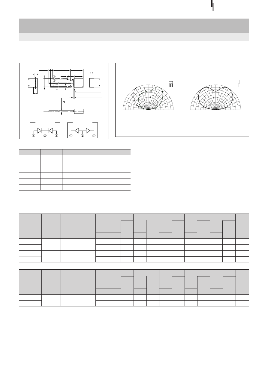
46
Forward voltage
V
F
Condition
(V)
I
F
typ
max
(mA)
Part
Number
Lens color
Reverse current
I
R
Condition
(
µ
A)
V
R
max
(V)
Intensity
I
V
Condition
(mcd)
I
F
typ
(mA)
Peak wavelength
λ
P
Condition
(nm)
I
F
typ
(mA)
Spectrum half width
∆λ
Condition
(nm)
I
F
typ
(mA)
Chip
material
Emitting color
Forward voltage
V
F
Condition
(V)
I
F
typ
max
(mA)
Part
Number
Lens color
Reverse current
I
R
Condition
(
µ
A)
V
R
max
(V)
Intensity
I
V
Condition
(mcd)
I
F
typ
(mA)
Peak wavelength
λ
P
Condition
(nm)
I
F
typ
(mA)
Spectrum half width
∆λ
Condition
(nm)
I
F
typ
(mA)
Chip
material
Emitting color
1.9
2.0
1.9
2.0
SML12460C
SML19460C
2.5
×
5 Rectangular Bicolor LED
SML10060 Series
Clear
Clear
Electrical Optical characteristics (Ta=25
°
C)
●
Common cathode (Internal wiring diagram 1)
10
25
15
25
Directivity (Typical)
External Dimensions
SEL10060Series
2.5
2.5
2.5
2.5
10
10
10
10
4
4
4
4
20
20
20
20
630
560
587
560
10
10
10
10
35
20
35
20
10
10
10
10
GaAsP
GaP
GaAsP
GaP
Red
Green
Orange
Green
(Unit: mm)
10
10
10
10
1.7
2.4
SML16760CN Clear
●
Common anode (Internal wiring diagram 2)
2.2
3.0
Yellow
10
10
4
4
30
40
20
20
660
570
30
30
GaAlAs
GaP
10
10
10
10
10
10
Symbol
Unit
Rating
Condition
I
F
mA
30
∆
I
F
mA/
°
C
−
0.45
Above 25
°
C
I
FP
mA
100
f=1kHz, tw
≤
100
µ
s
V
R
V
4
Top
°
C
−
30 to +85
Tstg
°
C
−
30 to +100
Absolute maximum ratings (Ta=25
°
C)
0.8
Resin heap 1.5max
0.5
±
0.1
5.2
(2.54)
(2.54)
Resin burr 0.3max
5.0
±
0.2
3
–
0.5
±
0.1
0.65max
3
–
0.5
±
0.1
2.8
1.2 (2.0)
2.5
±
0.2
1.0min
1.5min
17.0min
7.0
±
0.5
5.0
±
0.2
Tolerance:
±
0.3
90
°
60
°
30
°
0
°
A
B
90
°
60
°
30
°
0
50
100%
50
100%
90
°
60
°
30
°
0
°
90
°
60
°
30
°
0
50
100%
50
100%
A
B
A
B
A
B
Internal wiring
diagram 1
Internal wiring
diagram 2
A
B
A
B
High-
intensity red
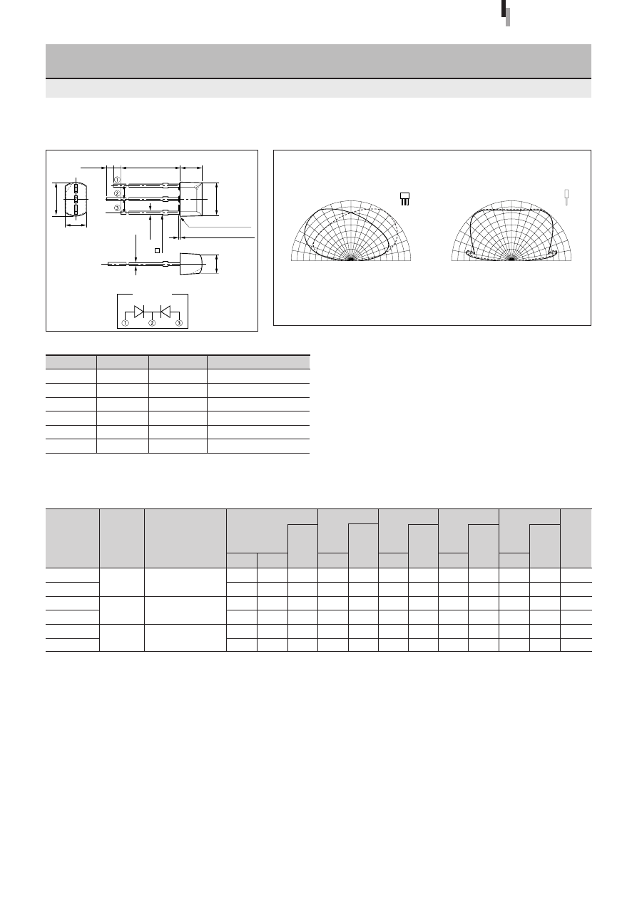
47
Forward voltage
V
F
Condition
(V)
I
F
typ
max
(mA)
Part
Number
Lens color
Reverse current
I
R
Condition
(
µ
A)
V
R
max
(V)
Intensity
I
V
Condition
(mcd)
I
F
typ
(mA)
Peak wavelength
λ
P
Condition
(nm)
I
F
typ
(mA)
Spectrum half width
∆λ
Condition
(nm)
I
F
typ
(mA)
Chip
material
Emitting color
3.3
×
6 Rectangular Bicolor LED
(Direct Mount)
SML70020 Series
Directivity (Typical)
External Dimensions
SEL70020Series
(Unit: mm)
Symbol
Unit
Rating
Condition
I
F
mA
30
∆
I
F
mA/
°
C
−
0.45
Above 25
°
C
I
FP
mA
100
f=1kHz, tw
≤
100
µ
s
V
R
V
4
Top
°
C
−
30 to +85
Tstg
°
C
−
30 to +100
Absolute maximum ratings (Ta=25
°
C)
1.9
2.0
1.9
2.0
1.9
2.0
SML72420C
SML78420C
SML79420C
Clear
Clear
Clear
Electrical Optical characteristics (Ta=25
°
C)
●
Common cathode
2.5
2.5
2.5
2.5
2.5
2.5
Red
Green
Amber
Green
Orange
Green
10
10
10
10
10
10
4
4
4
4
4
4
15
20
10
20
10
20
20
20
20
20
20
20
630
560
610
560
587
560
35
20
35
20
33
20
GaAsP
GaP
GaAsP
GaP
GaAsP
GaP
10
10
10
10
10
10
10
10
10
10
10
10
10
10
10
10
10
10
3.9
20.0min
1.0min
3.3
0.5
+0.1
6.0
±
0.2
6.2
1.5min
3.6
(2.54)
(2.54)
0.5
±
0.1
0.65max
Resin heap 1.5max
Resin burr 0.3max
90
°
60
°
30
°
0
°
A
B
90
°
60
°
30
°
0
50
100%
50
100%
90
°
60
°
30
°
0
°
90
°
60
°
30
°
0
50
100%
50
100%
Tolerance:
±
0.3
A
B
A
B
A
B
A
B
Internal wiring
diagram

48
Forward voltage
V
F
Condition
(V)
I
F
typ
max
(mA)
Part
Number
Lens color
Reverse current
I
R
Condition
(
µ
A)
V
R
max
(V)
Intensity
I
V
Condition
(mcd)
I
F
typ
(mA)
Peak wavelength
λ
P
Condition
(nm)
I
F
typ
(mA)
Spectrum half width
∆λ
Condition
(nm)
I
F
typ
(mA)
Chip
material
Emitting color
3.3
×
6 Bow-shaped Bicolor LED
(Direct Mount)
SML70023 Series
Directivity (Typical)
External Dimensions
SEL70023Series
Symbol
Unit
Rating
Condition
I
F
mA
30
∆
I
F
mA/
°
C
−
0.45
Above 25
°
C
I
FP
mA
100
f=1kHz, tw
≤
100
µ
s
V
R
V
4
Top
°
C
−
30 to +85
Tstg
°
C
−
30 to +100
Absolute maximum ratings (Ta=25
°
C)
(Unit: mm)
1.9
2.0
1.9
1.9
1.9
2.0
2.0
2.0
1.9
2.0
SML72423C
SML72923C
SML78423C
SMLS79723C
SML79423C
Clear
Clear
Clear
Clear
Clear
Electrical Optical characteristics (Ta=25
°
C)
●
Common cathode
2.5
2.5
2.5
2.5
2.5
2.5
2.5
2.5
2.5
2.5
Red
Green
Red
Orange
Amber
Green
Yellow
Orange
Green
10
10
10
10
10
10
10
10
10
10
4
4
4
4
4
4
4
4
4
4
25
35
25
25
25
35
150
40
25
35
20
20
20
20
20
20
20
20
20
20
630
560
630
587
610
560
590
570
587
560
35
20
35
33
35
20
15
30
33
20
GaAsP
GaP
GaAsP
GaAsP
GaAsP
GaP
AlGaInP
GaP
GaAsP
GaP
10
10
10
10
10
10
100
10
10
10
10
10
10
10
10
10
10
10
10
10
10
10
10
10
10
10
10
10
10
10
3.9
20.0min
1.0min
3.1
±
0.2
0.5
±
0.1
6.0
±
0.2
6.2
1.5min
3.6
(2.54)
(2.54)
0.5
±
0.1
0.65max
Resin heap 1.5max
Resin burr 0.3max
3.6
±
0.2
5.8
±
0.5
90
°
60
°
30
°
0
°
B
A
90
°
60
°
30
°
0
50
100%
50
100%
90
°
60
°
30
°
0
°
90
°
60
°
30
°
0
50
100%
50
100%
Tolerance:
±
0.3
A
B
A
B
A
B
A
B
A
B
A
B
Internal wiring
diagram
Ultra-high-
intensity orange
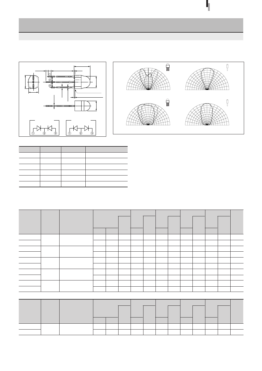
49
Forward voltage
V
F
Condition
(V)
I
F
typ
max
(mA)
Part
Number
Lens color
Reverse current
I
R
Condition
(
µ
A)
V
R
max
(V)
Intensity
I
V
Condition
(mcd)
I
F
typ
(mA)
Peak wavelength
λ
P
Condition
(nm)
I
F
typ
(mA)
Spectrum half width
∆λ
Condition
(nm)
I
F
typ
(mA)
Chip
material
Emitting color
Forward voltage
V
F
Condition
(V)
I
F
typ
max
(mA)
Part
Number
Lens color
Reverse current
I
R
Condition
(
µ
A)
V
R
max
(V)
Intensity
I
V
Condition
(mcd)
I
F
typ
(mA)
Peak wavelength
λ
P
Condition
(nm)
I
F
typ
(mA)
Spectrum half width
∆λ
Condition
(nm)
I
F
typ
(mA)
Chip
material
Emitting color
Egg-shaped Bicolor LED
(Direct Mount)
SML70055 Series
External Dimensions
SEL70055Series
Symbol
Unit
Rating
Condition
I
F
mA
30
∆
I
F
mA/
°
C
−
0.45
Above 25
°
C
I
FP
mA
100
f=1kHz, tw
≤
100
µ
s
V
R
V
4
Top
°
C
−
30 to +85
Tstg
°
C
−
30 to +100
Absolute maximum ratings (Ta=25
°
C)
(Unit: mm)
2.0
2.0
1.9
2.0
2.0
2.0
1.9
2.0
1.9
2.0
SMLU72755C
SML72755C
SMLU78755C
SML79255C
SML79455C
Clear
Clear
Clear
Clear
Clear
Electrical Optical characteristics (Ta=25
°
C)
●
Common cathode (Internal wiring diagram 1)
2.5
2.5
2.5
2.5
2.5
2.5
2.5
2.5
2.5
2.5
Red
Yellow
Orange
Red
Orange
Green
10
10
10
10
10
10
10
10
10
10
4
4
4
4
4
4
4
4
4
4
160
170
45
75
280
170
40
45
45
75
20
20
20
20
20
20
20
20
20
20
635
572
630
570
615
572
587
630
587
560
15
15
35
30
15
15
33
35
33
20
AIGaInP
AIGaInP
GaAsP
GaP
AIGaInP
AIGaInP
GaAsP
GaAsP
GaAsP
GaP
10
10
10
10
10
10
10
10
10
10
10
10
10
10
10
10
10
10
10
10
10
10
10
10
10
10
10
10
10
10
1.7
2.4
SML76755WN Diffused white
●
Common anode (Internal wiring diagram 2)
2.2
3.0
Yellow
10
10
4
4
50
50
20
20
660
570
30
30
GaAlAs
GaP
10
10
10
10
10
10
Tolerance:
±
0.3
20.0min
(0.3)
1.0min
1.5min
(2.54)
(2.54)
0.65max
6.2
±
0.2
5.6
±
0.2
4.55
±
0.2
4.65
±
0.2
7.3
±
0.5
0.5
±
0.1
0.5
±
0.1
Reisin heap 0.8max
Reisin burr 0.3max
90
°
60
°
30
°
0
°
90
°
60
°
30
°
0
50
100%
50
100%
90
°
60
°
30
°
0
°
B
A
90
°
60
°
30
°
0
50
100%
50
100%
Directivity (Typical)
A
B
A
B
A
B
A
B
A
B
A
B
Internal wiring
diagram 1
Internal wiring
diagram 2
A
B
A
B
90
°
60
°
30
°
0
°
90
°
60
°
30
°
0
50
100%
50
100%
90
°
60
°
30
°
0
°
B
A
90
°
60
°
30
°
0
50
100%
50
100%
Transparent
Diffused white
High-
intensity red
Ultra-high-
intensity yellow
Ultra-high-
intensity yellow
Ultra-high-
intensity amber
Ultra-high-
intensity red
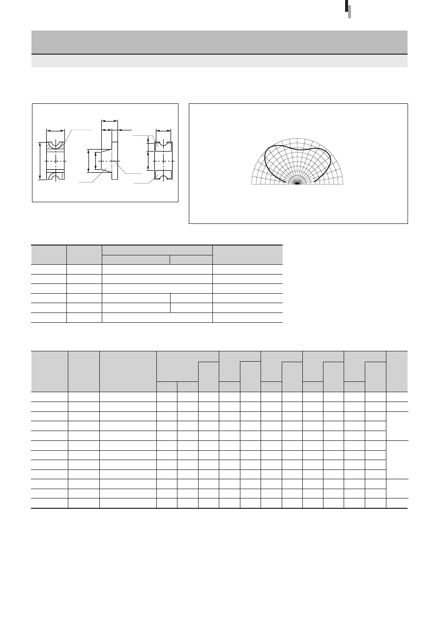
50
Forward voltage
V
F
Condition
(V)
I
F
typ
max
(mA)
Part
Number
Lens color
Reverse current
I
R
Condition
(
µ
A)
V
R
max
(V)
Intensity
I
V
Condition
(mcd)
I
F
typ
(mA)
Peak wavelength
λ
P
Condition
(nm)
I
F
typ
(mA)
Spectrum half width
∆λ
Condition
(nm)
I
F
typ
(mA)
Chip
material
Emitting color
3
×
1.5 Surface Mount LED
(Flat Lens)
SEC1001 Series
Directivity (Typical)
External Dimensions
SEC1001Series
Tolerance:
±
0.3
(Unit: mm)
Symbol
Unit
Rating
Condition
GaP/GaAsP/GaAlAs
GaN/InGaN
I
F
mA
30
∆
I
F
mA/
°
C
−
0.45
Above 25
°
C
I
FP
mA
70
f=1kHz, tw
≤
100
µ
s
V
R
V
4
5
Top
°
C
−
30 to +85
−
25 to +80
Tstg
°
C
−
30 to +100
Absolute maximum ratings (Ta=25
°
C)
2.0
1.7
1.9
1.9
1.9
2.0
2.0
2.0
2.0
3.3
3.3
3.9
SEC1101C
SEC1601C
SEC1201C
SEC1801C
SEC1901C
SEC1701C-YG
SEC1401C
SEC1401E-TG
SEC1501C
SECU1D01C
SECU1E01C
SEC1E01C
Clear
Clear
Clear
Clear
Clear
Clear
Clear
Transparent green
Clear
Clear
Clear
Clear
Electrical Optical characteristics (Ta=25
°
C)
2.5
2.2
2.5
2.5
2.5
2.5
2.5
2.5
2.5
4.0
4.0
4.8
Deep red
Red
Amber
Orange
Yellow
Green
Deep green
Pure green
Blue
10
10
10
10
10
10
10
10
10
20
20
20
4
4
4
4
4
4
4
4
4
5
5
5
1.5
100
10
16
13
25
22
11
8.0
150
50
6.0
20
20
20
20
20
20
20
20
20
20
20
20
700
660
630
610
587
570
560
558
555
525
470
430
100
30
35
35
33
30
20
20
20
35
35
65
GaP
GaAlAs
GaAsP
GaP
InGaN
GaN
100
100
100
100
100
100
100
100
100
10
10
10
10
10
10
10
10
10
10
10
10
20
20
20
10
10
10
10
10
10
10
10
10
20
20
20
1.5
3.0
Cathode
mark
2.0
1.5
0.9
(0.5)
1.4
Resin
P.C.B.
Anode
Cathode
1.6
0.6
1.3
90
°
60
°
30
°
0
°
90
°
60
°
30
°
0
50
100%
50
100%
High-
intensity red
Ultra-high-intensity
pure green
Ultra-high-
intensity blue

51
Forward voltage
V
F
Condition
(V)
I
F
typ
max
(mA)
Part
Number
Lens color
Reverse current
I
R
Condition
(
µ
A)
V
R
max
(V)
Intensity
I
V
Condition
(mcd)
I
F
typ
(mA)
Peak wavelength
λ
P
Condition
(nm)
I
F
typ
(mA)
Spectrum half width
∆λ
Condition
(nm)
I
F
typ
(mA)
Chip
material
Emitting color
3
×
1.5 Surface Mount LED
(Inner Lens)
SEC1003 Series
Directivity (Typical)
External Dimensions
SEC1003Series
Tolerance:
±
0.3
(Unit: mm)
1.7
1.9
1.9
1.9
1.9
1.9
1.9
2.0
2.0
2.0
2.0
SEC1603C
SECS1203C
SEC1203C
SECS1803C
SEC1803C
SECS1903C
SEC1903C
SEC1703C
SEC1403C
SEC1403E-TG
SEC1503C
Clear
Clear
Clear
Clear
Clear
Clear
Clear
Clear
Clear
Transparent green
Clear
Electrical Optical characteristics (Ta=25
°
C)
2.2
2.5
2.5
2.5
2.5
2.5
2.5
2.5
2.5
2.5
2.5
Red
Amber
Orange
Yellow
Green
Deep green
Pure green
10
20
10
3
10
3
10
10
10
10
10
4
4
4
4
4
4
4
4
4
4
4
150
100
15
10
20
10
15
35
33
15
10
20
20
20
3
20
3
20
20
20
20
20
660
635
630
615
610
590
587
570
560
558
555
30
35
35
35
35
35
33
30
20
20
20
GaAlAs
AlGaInP
GaAsP
AlGaInP
GaAsP
AlGaInP
GaAsP
GaP
100
100
100
10
100
10
100
100
100
100
100
10
20
10
3
10
3
10
10
10
10
10
10
20
10
3
10
3
10
10
10
10
10
1.5
3.0
2.0
1.7
1.4
(0.5)
0.9
1.6
0
.6
1.3
Lens
Resin
Anode
Cathode
Cathode
mark
P.C.B.
ø
1.0
90
°
60
°
30
°
0
°
90
°
60
°
30
°
0
50
100%
50
100%
Symbol
Unit
Rating
Condition
I
F
mA
30
∆
I
F
mA/
°
C
−
0.45
Above 25
°
C
I
FP
mA
70
f=1kHz, tw
≤
100
µ
s
V
R
V
4
Top
°
C
−
30 to +85
Tstg
°
C
−
30 to +100
Absolute maximum ratings (Ta=25
°
C)
Ultra-high-
intensity amber
Ultra-high-
intensity red
Ultra-high-
intensity orange
High-
intensity red
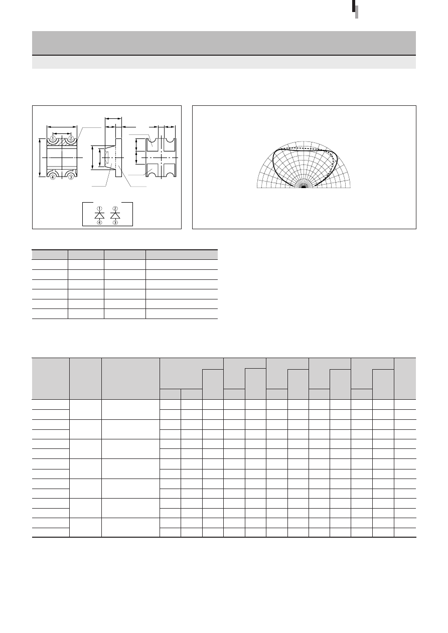
52
Forward voltage
V
F
Condition
(V)
I
F
typ
max
(mA)
Part
Number
Lens color
Reverse current
I
R
Condition
(
µ
A)
V
R
max
(V)
Intensity
I
V
Condition
(mcd)
I
F
typ
(mA)
Peak wavelength
λ
P
Condition
(nm)
I
F
typ
(mA)
Spectrum half width
∆λ
Condition
(nm)
I
F
typ
(mA)
Chip
material
Emitting color
3
×
2.5 Bicolor Surface Mount LED
(Flat Lens)
SEC2002 Series
Directivity (Typical)
External Dimensions
Symbol
Unit
Rating
Condition
I
F
mA
30
∆
I
F
mA/
°
C
−
0.45
Above 25
°
C
I
FP
mA
70
f=1kHz, tw
≤
100
µ
s
V
R
V
4
Top
°
C
−
30 to +85
Tstg
°
C
−
30 to +100
Absolute maximum ratings (Ta=25
°
C)
Tolerance:
±
0.3
(Unit: mm)
2.0
1.7
2.0
1.7
2.0
1.9
2.0
1.9
2.0
1.9
2.0
2.0
2.0
2.0
SEC2762C-YG
SEC2462C
SEC2422C
SEC2492C
SEC2592C
SEC2442C
SEC2552C
Electrical Optical characteristics (Ta=25
°
C)
2.5
2.2
2.5
2.2
2.5
2.5
2.5
2.5
2.5
2.5
2.5
2.5
2.5
2.5
Yellow
Green
Green
Red
Green
Orange
Pure green
Orange
Green
Green
Pure green
Pure green
10
10
10
10
10
10
10
10
10
10
10
10
10
10
4
4
4
4
4
4
4
4
4
4
4
4
4
4
20
20
20
20
20
10
20
10
5.0
10
20
20
5.0
5.0
20
20
20
20
20
20
20
20
20
20
20
20
20
20
570
660
560
660
560
630
560
587
555
587
560
560
555
555
30
30
20
30
20
35
20
33
20
33
20
20
20
20
GaP
GaAlAs
GaP
GaAlAs
GaP
GaAsP
GaP
GaAsP
GaP
GaAsP
GaP
GaP
GaP
GaP
100
100
100
100
100
100
100
100
100
100
100
100
100
100
10
10
10
10
10
10
10
10
10
10
10
10
10
10
10
10
10
10
10
10
10
10
10
10
10
10
10
10
SEC2002Series
Clear
Clear
Clear
Clear
Clear
Clear
Clear
2.5
1.5
3.0
2.0
1.5
1.4
±
0.1
1.0
1.0
0.9
0.6
±
0.1
P.C.B.
Anode
Cathode
Cathode
mark
0.9
(0.5)
Resin
90
°
60
°
30
°
0
°
90
°
60
°
30
°
0
50
100%
50
100%
A
B
A
B
A
B
A
B
A
B
A
B
A
B
A
B
Internal wiring
diagram
High-
intensity red
High-
intensity red
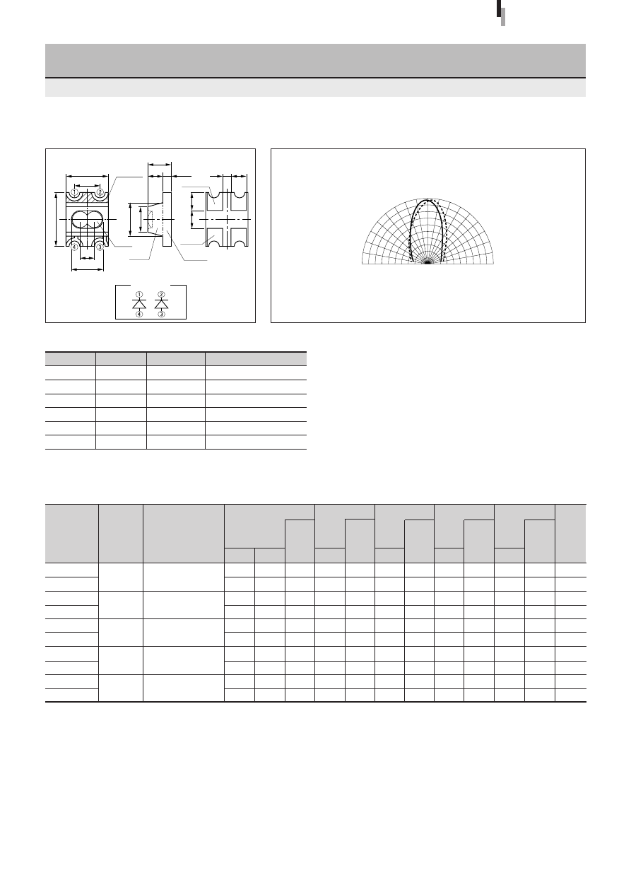
53
Forward voltage
V
F
Condition
(V)
I
F
typ
max
(mA)
Part
Number
Lens color
Reverse current
I
R
Condition
(
µ
A)
V
R
max
(V)
Intensity
I
V
Condition
(mcd)
I
F
typ
(mA)
Peak wavelength
λ
P
Condition
(nm)
I
F
typ
(mA)
Spectrum half width
∆λ
Condition
(nm)
I
F
typ
(mA)
Chip
material
Emitting color
3
×
2.5 Bicolor Surface Mount LED
(Inner Lens)
SEC2004 Series
Directivity (Typical)
External Dimensions
Symbol
Unit
Rating
Condition
I
F
mA
30
∆
I
F
mA/
°
C
−
0.45
Above 25
°
C
I
FP
mA
70
f=1kHz, tw
≤
100
µ
s
V
R
V
4
Top
°
C
−
30 to +85
Tstg
°
C
−
30 to +100
Absolute maximum ratings (Ta=25
°
C)
Tolerance:
±
0.3
(Unit: mm)
SEC2004Series
2.0
1.7
2.0
1.9
2.0
1.9
2.0
2.0
2.0
2.0
SEC2764C
SEC2484C
SEC2494C
SEC2774C
SEC2554C
Electrical Optical characteristics (Ta=25
°
C)
2.5
2.2
2.5
2.5
2.5
2.5
2.5
2.5
2.5
2.5
Yellow
Green
Amber
Green
Orange
Yellow
Yellow
Pure green
Pure green
10
10
10
10
10
10
10
10
10
10
4
4
4
4
4
4
4
4
4
4
50
50
30
20
30
20
50
50
10
10
20
20
20
20
20
20
20
20
20
20
570
660
560
610
560
587
570
570
555
555
30
30
20
35
20
33
30
30
20
20
GaP
GaAlAs
GaP
GaAsP
GaP
GaAsP
GaP
GaP
GaP
GaP
100
100
100
100
100
100
100
100
100
100
10
10
10
10
10
10
10
10
10
10
10
10
10
10
10
10
10
10
10
10
Clear
Clear
Clear
Clear
Clear
2.5
1.5
0.8
1.8
3.0
2.0
1.5
1.4
±
0.1
1.0
1.0
0.9
0.6
±
0.1
Lens
P.C.B.
Anode
Cathode
Cathode
mark
0.9
(0.5)
Resin
90
°
60
°
30
°
0
°
90
°
60
°
30
°
0
50
100%
50
100%
A
B
A
B
A
B
A
B
A
B
A
B
Internal wiring
diagram
High-
intensity red

54
Forward voltage
V
F
Condition
(V)
I
F
typ
max
(mA)
Part
Number
Reverse current
I
R
Condition
(
µ
A)
V
R
max
(V)
Optical Power
I
e
(mW/sr)
typ
Peak wavelength
λ
P
Condition
(nm)
I
F
typ
(mA)
Spectrum half width
∆λ
Condition
(nm)
I
F
typ
(mA)
Dimension A
(mm)
Lens color
Condition
5
φ
Round Infrared LED
SID1010M Series
Directivity (Typical)
External Dimensions
Symbol
Unit
Rating
Condition
I
F
mA
150
∆
I
F
mA/
°
C
−
1.33
Above 25
°
C
I
FP
mA
1000
f=1kHz, tw
≤
10
µ
s
V
R
V
5
Top
°
C
−
30 to +85
Tstg
°
C
−
30 to +100
Absolute maximum ratings (Ta=25
°
C)
SID1010Series
Tolerance:
±
0.3
(Unit: mm)
SID1010CM
SID1K10CM
SID1010CXM
SID1K10CXM
Electrical Optical characteristics (Ta=25
°
C)
130
200
60
110
940
940
940
940
50
50
50
50
50
50
50
50
50
50
50
50
1.3
1.3
1.3
1.3
1.5
1.5
1.5
1.5
50
50
50
50
10
10
10
10
5
5
5
5
GaAs
Clear
Clear
Clear
Clear
(Constant
voltage)
V
CC
=3V
R=2.2
Ω
ø
5.6
±
0.2
23.0min
1.0min
A
Cathode
0.65max
Resin heap 1.5max
Resin burr 0.3max
ø
5.0
±
0.2
0.5
±
0.1
0.5
±
0.1
(1.0)
(2.54)
0.5
±
0.1
90
°
60
°
30
°
0
°
90
°
60
°
30
°
0
50
100%
50
100%
90
°
60
°
30
°
0
°
90
°
60
°
30
°
0
50
100%
50
100%
SID1010M Series
SID1010XM Series
7.6
±
0.2
6.9
±
0.2
Chip
material

55
Forward voltage
V
F
Condition
(V)
I
F
typ
max
(mA)
Part
Number
Reverse current
I
R
Condition
(
µ
A)
V
R
max
(V)
Optical Power
I
e
(mW/sr)
typ
Peak wavelength
λ
P
Condition
(nm)
I
F
typ
(mA)
Spectrum half width
∆λ
Condition
(nm)
I
F
typ
(mA)
Lens color
Condition
Chip
material
5
φ
Round Infrared LED
(Direct Mount)
SID1050M Series
Directivity (Typical)
External Dimensions
Symbol
Unit
Rating
Condition
I
F
mA
150
∆
I
F
mA/
°
C
−
1.33
Above 25
°
C
I
FP
mA
1000
f=1kHz, tw
≤
10
µ
s
V
R
V
5
Top
°
C
−
30 to +85
Tstg
°
C
−
30 to +100
Absolute maximum ratings (Ta=25
°
C)
SID1050Series
Tolerance:
±
0.3
(Unit: mm)
SID1050CM
Electrical Optical characteristics (Ta=25
°
C)
250
940
50
50
50
1.3
1.5
50
10
5
GaAs
Clear
0.5
±
0.1
Anode
Cathode
1.0min
21.0min
9.4
±
0.3
ø
5.0
±
0.2
Resin heap 0.8max
Resin burr 0.3max
0.65
max
0.5
±
0.1
0.5
±
0.1
(2.54)
(Constant voltage)
V
CC
=3V, R=2.2
Ω
90
°
60
°
30
°
0
°
90
°
60
°
30
°
0
50
100%
50
100%
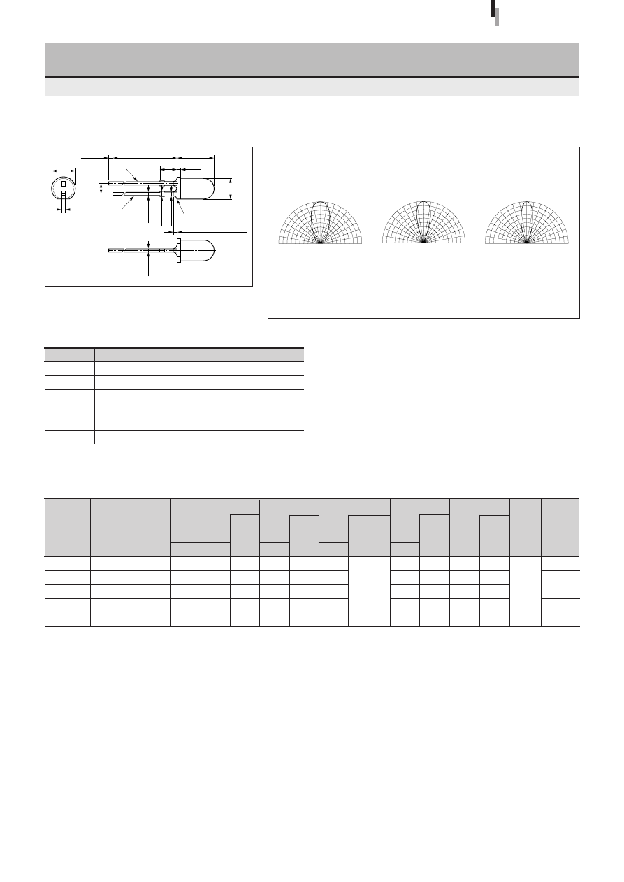
56
Forward voltage
V
F
Condition
(V)
I
F
typ
max
(mA)
Part
Number
Reverse current
I
R
Condition
(
µ
A)
V
R
max
(V)
Optical Power
I
e
(mW/sr)
typ
Peak wavelength
λ
P
Condition
(nm)
I
F
typ
(mA)
Spectrum half width
∆λ
Condition
(nm)
I
F
typ
(mA)
Dimension A
(mm)
Lens color
Condition
Chip
material
5
φ
Round Infrared LED
SID300/1003 Series
Directivity (Typical)
External Dimensions
Symbol
Unit
Rating
Condition
I
F
mA
150
∆
I
F
mA/
°
C
−
1.33
Above 25
°
C
I
FP
mA
1000
f=1kHz, tw
≤
10
µ
s
V
R
V
5
Top
°
C
−
30 to +85
Tstg
°
C
−
30 to +100
Absolute maximum ratings (Ta=25
°
C)
SID300/1003Series
Tolerance:
±
0.3
(Unit: mm)
SID303C
SID313BP
SID1003BQ
SID307BR
SID1G307C
Electrical Optical characteristics (Ta=25
°
C)
80
130
180
200
50
940
940
940
940
850
50
50
50
50
50
50
50
50
50
40
50
50
50
50
50
1.3
1.3
1.3
1.3
1.5
1.5
1.5
1.5
1.5
1.8
50
50
50
50
50
10
10
10
10
10
5
5
5
5
5
GaAs
Clear
Transparent light purple
Transparent light navy blue
Transparent dark navy blue
Clear
5.6
24.0min
8.5
±
0.5
Anode
(2.54)
0.6
±
0.1
1.1max
0.85
+0.1
Resin heap 1.5max
0.6
±
0.1
0.6
±
0.1
Resin burr 0.3max
ø
4.8
±
0.2
Cathode
2.0min
(0.8)
A
(Constant
voltage)
V
CC
=3V
R=2.2
Ω
I
F
=50mA
SID303C
SID313BP
SID1003BQ
SID307BR
SID1G307C
90
°
60
°
30
°
0
°
90
°
60
°
30
°
0
50
100%
50
100%
90
°
60
°
30
°
0
°
90
°
60
°
30
°
0
50
100%
50
100%
90
°
60
°
30
°
0
°
90
°
60
°
30
°
0
50
100%
50
100%
3.0
±
0.5
3.6
±
0.5
4.2
±
0.5

57
Forward voltage
V
F
Condition
(V)
I
F
typ
max
(mA)
Part
Number
Reverse current
I
R
Condition
(
µ
A)
V
R
max
(V)
Optical Power
I
e
(mW/sr)
typ
Peak wavelength
λ
P
Condition
(nm)
I
F
typ
(mA)
Spectrum half width
∆λ
Condition
(nm)
I
F
typ
(mA)
Lens color
Condition
Chip
material
3
φ
Round Infrared LED
SID2010 Series
Directivity (Typical)
External Dimensions
Symbol
Unit
Rating
Condition
I
F
mA
150
∆
I
F
mA/
°
C
−
1.33
Above 25
°
C
I
FP
mA
1000
f=1kHz, tw
≤
10
µ
s
V
R
V
5
Top
°
C
−
30 to +85
Tstg
°
C
−
30 to +100
Absolute maximum ratings (Ta=25
°
C)
SID2010Series
Tolerance:
±
0.3
(Unit: mm)
SID2010C
SID2K10C
Electrical Optical characteristics (Ta=25
°
C)
7.0
14
940
940
50
50
50
50
50
50
1.3
1.3
1.5
1.5
50
50
10
10
5
5
GaAs
Clear
Clear
I
F
=50mA
I
F
=50mA
1.7
ø
3.8
0.4
1.0min
25.8min
3.5
±
0.1
(1.3)
0.45
±
0.1
0.65max
Resin burr 0.3max
Resin heap 1.5max
ø
3.1
±
0.1
Cathode
(2.54)
0.4
±
0.1
90
°
60
°
30
°
0
°
90
°
60
°
30
°
0
50
100%
50
100%
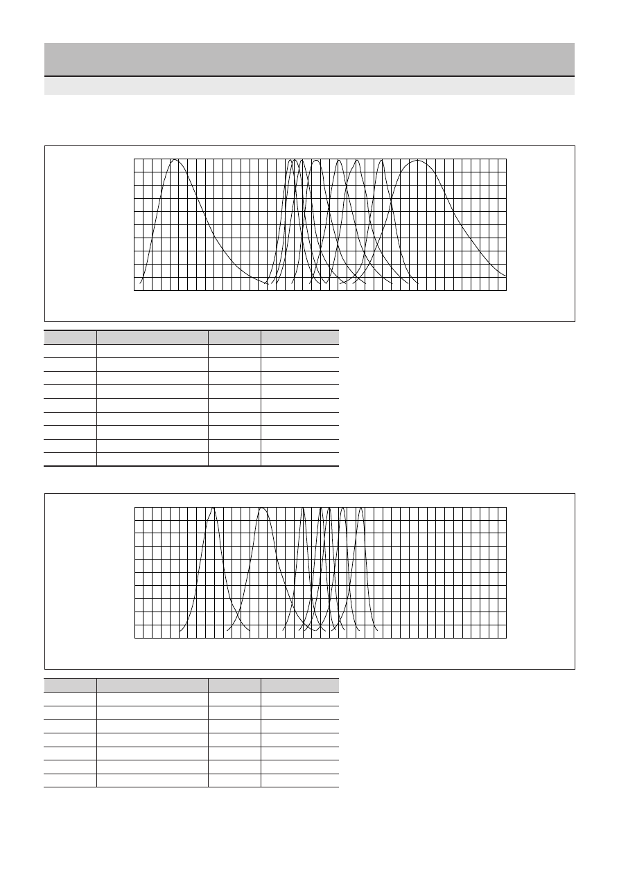
58
Characteristic Curves
Spectral distribution
Light color
Chip material Peak Wavelength(nm)
q
Ultra-high-intensity blue
InGaN
470
w
Ultra-high-intensity pure green
InGaN
525
e
Ultra-high-intensity yellow
AlGaInP
572
r
Ultra-high-intensity orange
AlGaInP
590
t
Ultra-high-intensity light amber
AlGaInP
600
y
Ultra-high-intensity amber
AlGaInP
615
u
Ultra-high-intensity red
AlGaInP
635
Light color
Chip material Peak Wavelength(nm)
q
Blue
GaN
430
w
Pure green
GaP
555
e
Green/deep green
GaP
560/558
r
Yellow
GaP
570
t
Orange
GaAsP
587
y
Amber
GaAsP
610
u
Red
GaAsP
630
i
High-intensity red
GaAlAs
660
o
Deep red
GaP
700
●
Ultra-high-intensity type
1.0
0.9
0.8
0.7
0.6
0.5
0.4
0.3
0.2
0.1
0.0
380
Relativ
e emission intensity
400 420 440
q
wer
t
y
u
i
o
460 480 500 520 540 560 580 600
Wavelength [nm]
620 640 660 680 700 720 740 760 780 800
1.0
0.9
0.8
0.7
0.6
0.5
0.4
0.3
0.2
0.1
0.0
380
Relativ
e emission intensity
400 420 440
q
w
e
r t y
u
460 480 500 520 540 560 580 600
Wavelength [nm]
620 640 660 680 700 720 740 760 780 800
●
Standard type
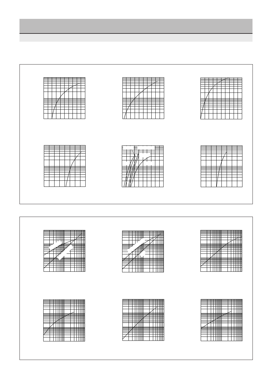
59
Characteristic Curves
■
Relative intensity - IF characteristic
0.1
1
0.01
1
100
10
10
Relative intensity
Forward current I
F
[mA]
0.1
1
0.01
1
100
10
10
Relative intensity
Forward current I
F
[mA]
0.1
1
0.01
1
100
Forward current I
F
[mA]
Deep red
Green/yellow
Relative intensity
10
10
0.1
1
0.01
1
100
10
10
Amber/orange
Red
Forward current I
F
[mA]
Relative intensity
0.1
1
0.01
1
100
10
10
Relative intensity
Forward current I
F
[mA]
GaP
GaAsP
GaAlAs
GaN
AlGaInP
InGaN
0.1
1
0.01
1
100
10
10
Forward current [mA]
Relative intensity
■
IF - VF characteristic
GaP
GaAsP
GaAlAs
GaN
AlGaInP
InGaN
100
10
1
Forward current I
F
[mA]
2.4
2.6
Forward voltage V
F
[V]
1.6
1.8
2.0
2.2
100
10
1
1.6
1.8
2.0
2.2
2.4
2.6
Forward current I
F
[mA]
Forward voltage V
F
[V]
100
10
1
1.6
1.8
2.2
2.0
2.4
2.6
Forward current I
F
[mA]
Forward voltage V
F
[V]
100
10
1
1.6
2.4
3.2
4.0
4.8
Forward current I
F
[mA]
Forward voltage V
F
[V]
100
10
1
1.6
1.8
2.0
2.2
2.4
2.6
Orange
Yellow
Amber
Light amber
Forward current I
F
[mA]
Forward voltage V
F
[V]
Red
100
10
1
1.6
2.4
3.2
4.0
4.8
Forward current I
F
[mA]
Forward voltage V
F
[V]
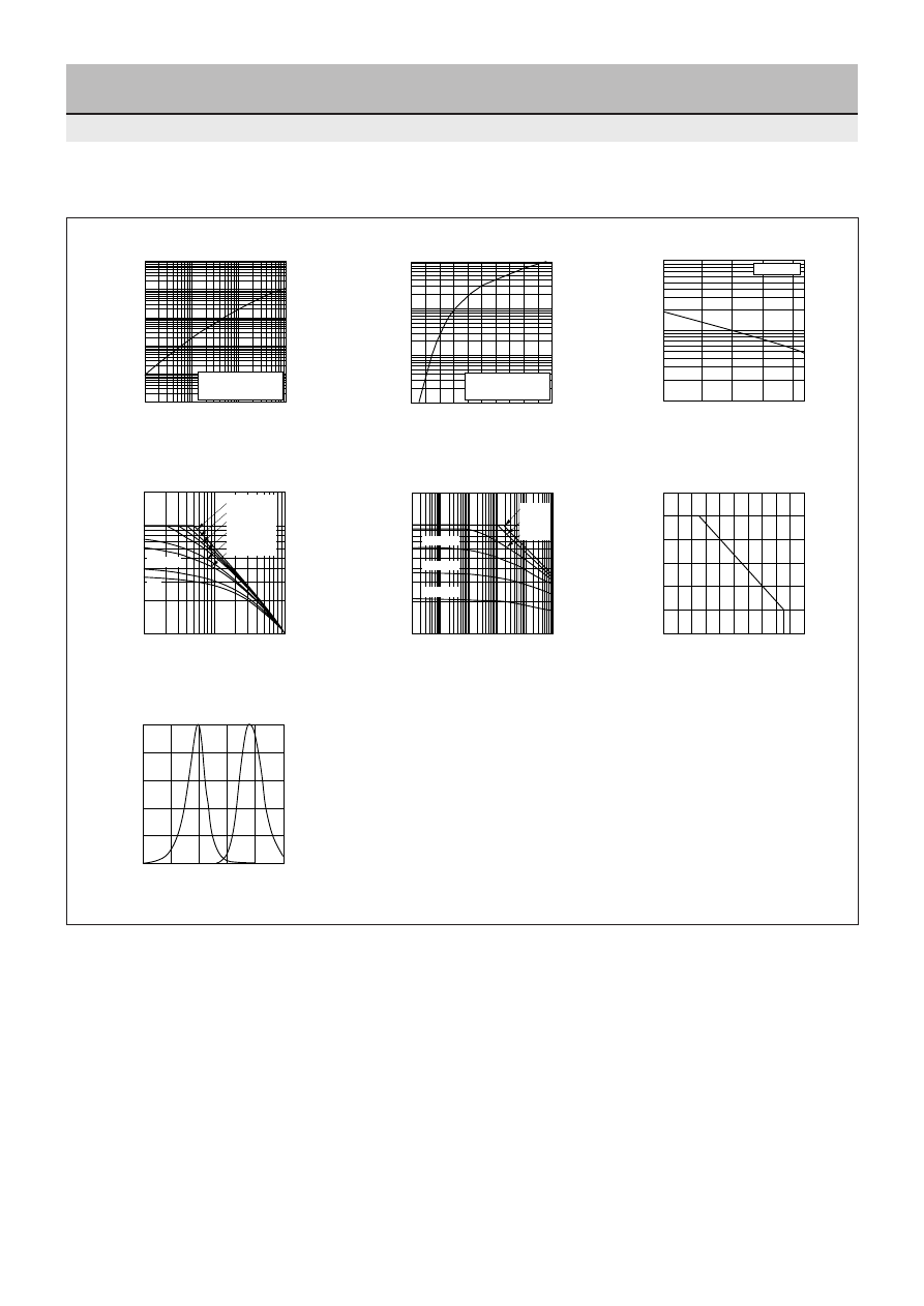
60
Characteristic Curves
I
FP
- Ie characteristic
V
FP
- IFP characteristic
0.1
1
0.01
0.001
1
100
1000
Pulse forward current I
FP
[mA]
Relative optical output Ie
100
10
10
Pulse width = 1ms
Duty
≤
10%
1000
1
1.0
1.8
2.0
1.6
Pulse forward voltage V
FP
[V]
Pulse forward current I
FP
[mA]
100
10
1.4
1.2
Pulse width = 1ms
Duty
≤
10%
10
0.1
–30
75 85
50
Ambient temperature Ta (
°
C)
Relative optical output Ie
5
2
1
0.2
0.5
25
0
I
F
=50mA
1000
2000
100
1
1s
500ms
50 100
10
Duty ratio D (%)
Acceptable forward pulse current I
FP
(mA)
5
100ms
50ms
10ms
5ms
1ms
PW=10 s
µ
1000
2000
100
10
100
1m 10m 100m
1
Pulse width PW (s)
Forward pulse current I
FP
(mA)
D=10%
D=20%
D=50%
D=1%
D=2%
D=5%
µ
µ
0
0
80
100
60
Ambient temperature Ta (
°
C)
Acceptable forward current I
F
(mA)
120
40
20
80
100
60
40
20
750
850
950
1.0
0.8
0.6
0.4
0.2
0
900
Wavelength
λ
(nm)
800
1000
Optical output (Relative value)
Ie - Ta characteristic
I
FP
- DR characteristic
I
FP
- PW characteristic
I
F
- Ta characteristic
Spectral distribution
■
Infrared LED
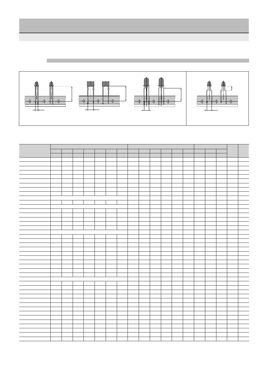
61
Taping Specifications
H
1
5.0
2.54
H
0
Lamp Types
1.Straight type
5.0
H
0
2. Forming (5 mm pitch) type
Forming standard shape
Straight standard shape
(5 mm pitch lead)
Bicolor straight standard shape
Straight standard shape
5.0
H
0
Taping compatibility table
TP1
TP2
TP3
TP6
TP7
TP8
TP19
TP4
TP5
TP15
TP16
TP17
TP18
TH8F
TH10D TH12E
4.5
7.5
6.0
3.5
5.0
9.0
7.4
17.0
20.5
20.5
19.0
23.5
25.0
SEL1010
O
O
O
O
2500
10
SEL1010M
O
O
O
O
O
O
2500
11
SEL1010XM
O
O
O
O
O
O
2500
12
SEL1050M
O
O
O
O
O
O
O
2500
13
SEL1015
O
O
O
O
2500
14
SEL1011
O
O
O
O
2500
15
SEL1053M
2500
16
SEL4010
O
O
O
O
3000
17
SEL4014
O
O
O
O
O
O
O
3000
18
SEL6010
Use SEL2010
O
O
O
4000
19
SEL6014
O
O
O
O
O
4000
20
SEL6015
Use SEL2015
O
4000
21
SEL2010
O
O
O
O
O
O
4000
22
SEL2015
O
O
O
O
O
O
4000
23
SEL2011
O
O
O
O
O
O
4000
24
SEL4017
O
O
O
O
O
O
4000
25
SEL1013
O
O
O
O
2500
26
SEL6013
Use SEL2013
O
4000
27
SEL2013
O
O
O
O
O
O
4000
28
SEL1021
O
O
O
O
2500
30
SEL1022
O
O
O
O
2500
31
SEL1020
O
O
O
O
3000
32
SEL1024
O
O
O
O
3000
33
SEL4025
O
O
O
O
O
O
6000
34
SEL4026
O
O
O
O
O
O
O
6000
35
SEL4027
O
O
O
O
O
O
6000
36
SEL4028
O
O
O
O
O
O
6000
37
SEL4029
O
O
O
O
O
O
6000
38
SEL6027
Use SEL4027
O
6000
39
SEL5020
O
O
4000
40
SEL5021
O
4000
41
SEL5023
O
4000
42
SEL5055
O
4000
43
SML1016/10016
O
2500
44
SML10051
O
2500
45
SML10060
O
6000
46
SML70020
O
4000
47
SML70023
O
4000
48
SML70055
O
3000
49
SID1010
O
O
O
O
O
O
2500
54
SID1050
O
O
O
O
O
O
O
2500
55
SID300/1003
O
O
O
2000
56
SID2010
3000
57
Taping shape (unit: mm)
Taping No.
⇒
H1 or H0 dimension
⇒
Forming (5 mm pitch) type
* The package contents for taping with holder are 1200.
With holder*
Series name
Straight type
Package
contents
Page
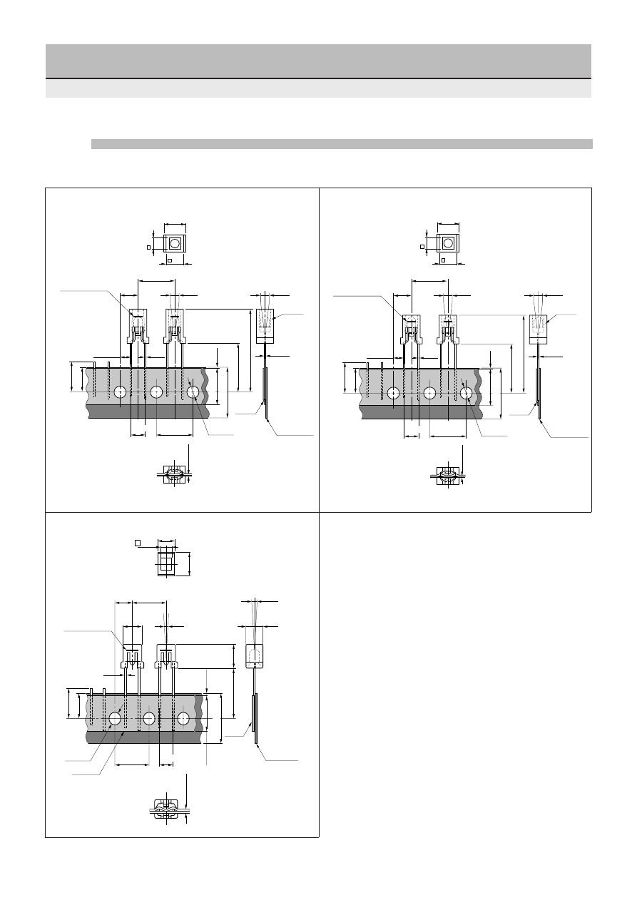
62
Features
•
This taping format saves the customer the trouble of attaching a holder.
•
Any available inserter can be used with the 5 mm lead pitch radial taping.
See the previous page for the product names and package contents (standard per box).
TH12E
12.7
±
1.0
6.0
7.5
6.35
±
0.5
±
2.0
18.0
+1.0 –0.5
17.5
+1.0 –0.5
MAX 11
9.0
±
0.5
ø
4.0
±
0.2
Holder
Tape
Marking (Black)
MIN
0.3
0.45
±
0.1
3.85
±
0.5
±
2.0
(Po)
12.7
±
0.2
0.4
±
0.1
MIN 13.0
29.5
+1.0 –0.5
Paperboard
Product tilt
5.0
±
0.5
0.7
±
0.2
4.0
12.7
±
1.0
6.35
±
0.5
±
2.0
18.0
+1.0 –0.5
17.5
+1.0 –0.5
MAX 11
9.0
±
0.5
ø
4.0
±
0.2
Holder
Marking (Black)
MIN
0.3
0.7
±
0.2
0.45
±
0.1
3.85
±
0.5
±
2.0
(Po)
12.7
±
0.2
0.4
±
0.1
MIN 13.0
27.5
+1.0 –0.5
5.0
±
0.5
6.0
7.5
4.0
Tape
Paperboard
Product tilt
12.7
±
1.0
(P)
6.35
±
0.5
(t)
0.7
±
0.2
6.0
0.5
8.4
6.0
4.0
13min
18.0
+1.0 –0.5
18.0
±
1
11.0max
9.0
±
0.5
(P0)
12.7
±
0.2
ø
4.0
±
0.2
Tape
Marking (black)
0.3min
5.0
±
0.5
7.2
8.0
0
±
2.0
0
±
2.0
Product tilt
(P
2
)
Cathode
Paperboard
TH10D
TH8F
Po: The cumulative pitch error is
±
1.0 mm per 20.
Dimensional tolerance:
±
0.3
Unit: mm
Taping Specifications
Taping with holder

63
Taping Specifications
0.2
±
0.05
Cathode
ø
1.5
+0.1
0
1.9
4.0
2.0
±
0.05
4.0
3.5
±
0.05
1.75
8.0
0.2
±
0.05
Cathode
ø
1.5
+0.1
0
1.9
4.0
2.0
±
0.05
4.0
3.5
±
0.05
1.75
8.0
ø180
+0
2.0
±
0.2
Label
Label
Rank
ø60
+1
ø22
–3
–0
ø10
30
°
P/N, Manufacturing
Date Code No, Q’ ty
11.4
±
1.0
9.0
±
0.3
General tolerance:
±
0.2
ø13
±
0.2
H
0
Chip type
Reel specifications
Single-color SEC1001/1003 Series
Bicolor SEC2002/2004 Series
Package contents: 3000
64
Part Number
Substitute
SEL1112R
SEL4117R
SEL1120RKT
SEL1120R
SEL1123R
SEL1124R
SEL1131R
−
SEL1132R
−
SEL1134R
−
SEL1142R
−
SEL1213CM
SEL1213C
SEL1215R
−
SEL1310E
SEL1410E
SEL1310G
SEL1410G
SEL1311G
SEL1411G
SEL1312G
SEL4417G
SEL1320G
SEL1420G
SEL1321G
SEL1421G
SEL1323G
SEL1424G
SEL1324G
SEL1424G
SEL1331G
−
SEL1332G
−
SEL1334G
−
SEL1342G
−
SEL1420GW
−
SEL152R
−
SEL1650CM
−
SEL1723Y
SEL1724Y
SEL1731Y
−
SEL1742Y
−
SEL1820W
−
SEL1823D
SEL1824D
SEL1842D
−
SEL1915C
−
SEL1923D
SEL1924D
SEL1942D
−
SEL1E10CM
SELU1E10CXM/SELU1E50CM
SEL2111W
−
SEL2111W
−
SEL2215RM
SEL2215R
SEL2310E
SEL2410E
SEL2310G
SEL2410G
SEL2311G
SEL2411G
SEL2710E
−
SEL2915DM
SEL2915D
SEL3110R
SEL2110R/SEL6210R
SEL3110S
SEL2110S/SEL6210S
SEL3210R
SEL2210R/SEL6210R
SEL3210S
SEL2210S/SEL6210S
SEL3213C
SEL2213C
SEL3410E
SEL2410E/SEL6410E
SEL3410G
SEL2410G
SEL3413E
SEL2413E
Part Number
Substitute
SEL3510C
SEL2510C/SEL6510C
SEL3510G
SEL2510G/SEL6510G
SEL352G
−
SEL3710K
SEL2710K/SEL6710K
SEL3710Y
SEL2710Y/SEL6710Y
SEL3713K
SEL2713K
SEL3810A
SEL2910A/SEL6810A
SEL3810D
SEL2910D/SEL6810D
SEL3813A
SEL2813A
SEL3910A
SEL2910A/SEL6910A
SEL3910D
SEL2910D/SEL6910D
SEL3913K
SEL2913K
SEL3E10C
SELU2E10C
SEL4110RT
SEL4110R
SEL4210RT
SEL4210R
SEL4225RM
SEL4225R
SEL4310E
SEL4410E
SEL4310G
SEL4410G
SEL4425GM
SEL4425G
SEL4427E
SEL4427EP
SEL4725CM
−
SEL4814W
−
SEL550ST
−
SEL650ST
−
SEL8301A
−
SEL8302A
−
SEL8701Y
−
SEL8701YB
−
SID1010BXM
−
SID1010CM2
−
SID1H10CXM
−
SID1K10CM2
−
SID1K10CM2
−
SLH30
−
SLH50
−
SLS34
−
SLS36
−
SLS54
−
List of Discontinued Products

Bulletin No
L01 EB0
(Jan,2001)
C
M
Y
K
Sanken Electric Co.,Ltd.
1-11-1 Nishi -Ikebukuro,Toshima-ku, Tokyo
PHONE: 03-3986-6164
FAX: 03-3986-8637
TELEX: 0272-2323(SANKEN J)
Overseas Sales Offices
Asia
Sanken Electric Singapore Pte.Ltd.
150 Beach Road,#14-03 The Gateway West,
Singapore 0718
PHONE: 291-4755
FAX: 297-1744
Sanken Electric Hong Kong Co.,Ltd.
1018 Ocean Centre, Canton Road,
Kowloon, Hong Kong
PHONE: 2735-5262
FAX: 2735-5494
TELEX: 45498 (SANKEN HX)
Sanken Electric Korea Co.,Ltd.
SK Life B/D 6F,
168 Kongduk-dong, Mapo-ku, Seoul, 121-705, Korea
PHONE: 82-2-714-3700
FAX: 82-2-3272-2145
North America
Allegro MicroSystems,Inc.
115 Northeast Cutoff, Box 15036
Worcester, Massachusetts 01615, U.S.A.
PHONE: (508)853-5000
FAX: (508)853-7861
Europe
Allegro MicroSystems Europe Limited.
Balfour House, Churchfield Road,
Walton-on-Thames, Surrey KT12 2TD, U.K.
PHONE: 01932-253355
FAX: 01932-246622
PRINTED in JAPAN H1-L01EB0-0101040ND