“EA” ALUMINUM
ELECTROLYTIC CAPACITORS
EXTREME APPLICATON
HIGHLIGHTS
APPLICATION
Capacitance –50-500,000
µ
F
U.P.S Systems
Voltage –15 to 500 WVDc
Inverters/P.C.U.s.
-10%, + 20% Tolerance and
Motor Special Controls
-10%, + 50%
Computers
Temperature Range -40ºC to +85ºC
Power Filtering
Case Sizes – 1 x 2-1/8 to 3 x 8.625 inches
Power Supplies
Grade – Computer Standard Application
X-Ray Equipments
Key Features – Safety Vent Construction
Welding Application
Wide Variety of Case Sizes
Energy Storage Applications
Choice of Terminals
Photo Flash
Long Life/High Ripple
Multiplier Circuits
Low ESR/Low Leakage Current
Strobe Applications
Rapid Discharge / High Current
Telecommunication
Broadcast Equipment
BETTER PERFORMANCE AND RIPPLE CAPACITY
The EA Capacitor is an extreme application long life aluminum electrolytic capacitor in a
rugged aluminum can wish a choice of mounting and terminal configurations. The Excels
in a electrical performance end high-ripple capability.
With capacitances up to 500,000
µ
F and ripple capability up to 50 amperes runs at 85ºC,
the EA handles extreme application requirements.
Included in this bulletin is a complete application guide, typical performance curves,
and full performance characteristics. For applications requiring ratings different from
these, contact DuraCap Controls, Division of Emerson Electronic Canada Limited.
Application_EA-html.html
APPLICATION GUIDE
1.1 RIPPLE CURRENT
The maximum ripple current recommended for EA capacitors is shown in the Standard
Ratings Table. Ripple current ratings are based on 120 Hz ripple and 85
°
C circulating
air. Maximum ripple current may be adjusted for operation at a frequency other than 120
Hz and a temperature other than 85
°
C by multiplying by the factors of Tables 1 and 2
below.
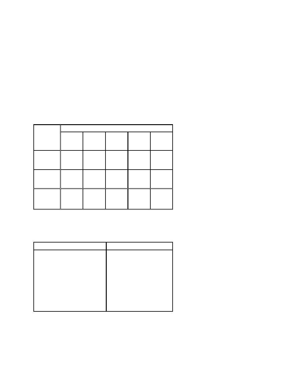
TABLE 1
Ripple Current Frequency Multipliers
Ripple Multipliers at
Rated
WVdc
60 Hz
120 Hz
400 Hz
1000 Hz
2500 Hz
3 to 50
0.8
1.0
1.05
1.10
1.14
51 - 150
0.8
1.0
1.08
1.13
1.16
151 & up
0.8
1.0
1.15
1.21
1.25
TABLE 2
Ripple Current Temperature Multipliers
Ambient Temperature
Ripple Multiplier
85
°
C
75
°
C
65
°
C
55
°
C
45
°
C
1.0
1.3
1.6
1.9
2.1
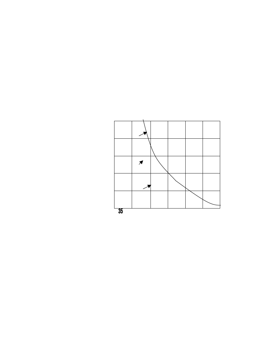
Multiplying Factors for temperatures not listed in Table 2 may be obtained from the
Ripple vs. Temperature Graph below.
Application_EA-html.html
RIPPLE VS.TEMPERATURE
2.0
1.5
1.0
AMBIENT TEMPERATURES 40 50 60 70 80
Ripple current capability depends upon case area and ESR because ripple current
dissipates power in the ESR and case area determines the core temperature rise. A
different capacitance from that listed in Standard Ratings Table will have a different
ESR and, therefore, a different ripple current rating. The ripple capability is proportional
to square root of capacitance for the same WVdc and case size.
1.2 CASE POTENTIAL
With standard EA construction all electrical connections are through the terminals and
the case is floating. The insulation resistance between the case and terminals is
indeterminate because electrolyte may contact the case. The case may be connected to
the same potential as the negative terminal but other possible connections should be
avoided by utilizing an insulating sleeve.
1.3 OPERATING LIFE
EA Capacitors are expected to provide a useful operating life of approximately 10 years
when subjected to normal computer power supply circuitry, duty cycle and ambient
temperature within the application conditions of this bulletin. Longer operating life can
be expected when operating voltage; ripple current and ambient temperature are
reduced.
Typically the capacitance will remain stable through life while the ESR will increase with
time - more rapidly toward the end of life. The amount of ESR increase, which can be
MULTIPLYING
FACTOR FOR 85ºC
RIPPLE CURRENT
Application_EA-html.html
tolerated in a circuit, determines the useful life. The DCL decreases in early life and
remains at low value unless operating voltage is applied infrequently.
1. APPLICATION GUIDE
continued
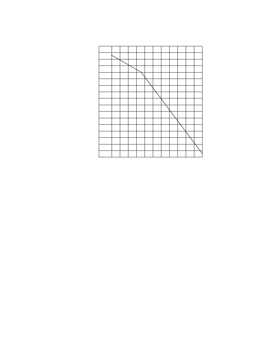
A typical performance curve showing normal expected life as a function of ambient
temperature is provided. The curve is derived for units operating in circulating air and
with the full ripple currents of the Standard Ratings Table.
RIPPLE LIFE VS. TEMPERATURE
Ripple Current as listed in Standard Ratings
85
75
450VDC
65
500V
55
45
360v
0 2 4 6 8 10
YEARS OPERATION 33% DUTY CYCLE
1.4. SHELF LIFE
EA Capacitors can generally withstand storage in excess of three years at less than
40
°
C without deterioration. Capacitors stored for long periods, especially at high
temperature, may show significantly increased DCL. The DCL can usually be decreased
to original limits by application of voltage increasing in steps to working voltage with the
d.c. supply power limited to not exceed the rated ripple power. [(I2 R) x ESR max).]
1.5. REVERSE VOLTAGE
A reverse voltage of up to 1.5 volts may be applied continuously to polarized EA
AMBIENT
DEGREES
CENTIGRADE
CIRCULATION
AIR
Application_EA-html.html
Capacitors without significantly affecting performance.
1.6. NONPOLAR/SEMI POLAR
Non-polar capacitors are available for most of the EA working voltage ratings. The
maximum capacitance available in a non-polar unit is less than for a polarized unit. To
determine the maximum capacitance available multiply the capacitance listed in the
Standard Rating Table by the appropriate multiplier of Table 4 below.
TABLE 4
Maximum Capacitance for Non-polar Capacitors
Rated
WVdc
Multiply Polarized Maximum
Capacitance by
5
10
15
20
25
.50
.47
.48
.46
.45
30
40
50-60
75-250
300-500
.44
.43
.42
.41
.42
The ESR for a non-polarized capacitor will be less than for the same capacitance rating
in a polarized unit. The ESR for the maximum non-polarized capacitance in a particular
case size will be greater than the ESR of the maximum polar capacitance in the same
case size because the non-polar capacitance is less.
1.7. SOLVENTS
EA Capacitors have aluminum cases, elastomer end seals, ink identification marking
and may have PVC sleeves. These materials are subject to chemical attack from some
Application_EA-html.html

cleaning solvents. Solvent residues on the capacitors after cleaning may attack the
aluminum cases. Solvent penetrating the capacitor end seal may cause internal
corrosion resulting in short life.
Cleaning methods for assemblies including EA Capacitors should be developed with the
solvent vendor. Alternately, the capacitors may be mounted after cleaning the
assemblies. Alcohol or water-detergent cleaning is not usually harmful but halogenated
cleaning solvents are not recommended and should be avoided.
1.8. MOUNTING
It is recommended that these Capacitors with silicone rubber safety vents be mounted
with terminals up. Other mounting orientations may affect useful life or DCL
performance due to mobility of the electrolyte.
If horizontal mounting necessary, vent plug should be at 9 o’clock or 12 o’clock position.
1.9. SAFETY VENT
All EA capacitors are equipped with safety-vents designed to rupture and release high
internal gas pressure generated by overheated electrolyte if reverse voltage is applied
to the capacitor or excessive voltage or current overload occurs. 1-inch diameter
capacitors are provided with a pressure-sensitive slit type safety-vent in the sidewall of
the container. All others are equipped with a silicone rubber safety-vent structure
located in the molded cover. Capacitors, which have vented should be removed from
equipment and discarded. All remaining capacitors should be tested for possible
deterioration.
Application_EA-html.html

2. PERFORMANCE CHARACTERISTICS
2.1. POLARITY - DC or NP
EA Capacitors are polarized (DC) or non-polarized (NP). The reverse voltage capability
of polarized capacitors is 1.5 volts.
2.2. TEMPERATURE RANGE - 40
°°°°
C to +85
°°°°
C
EA Capacitors have an operating temperature range of - 40
°
C to + 85
°
C (+65
°
C
maximum for 500 WVDC). Capacitors are capable of withstanding storage temperatures
from -55
°
C to +85
°
C.
2.3. CAPACITANCE TOLERANCE - +50/ -10% AND +20/-10%
The capacitance shall be within the following tolerances when measured per-Paragraph
3.8.
Voltage Rating 15 to 450, Tolerance -10,+ 50%; Voltage Rating 360 to 500, Tolerance -
10, + 20%, by specification.
2.4. WORKING VOLTAGE - 15 to 500 Volts
Working voltage, WVdc, is the maximum continuous DC voltage, which may be applied
at the rated temperature. Polarized and non-polarized capacitors are available from 3 to
500 WVdc.
2.5. SURGE VOLTAGE - 5 to 75 Volts Above WVdc
The DC surge voltage is the maximum voltage to which the capacitor can be subjected
under any conditions including transients and peak ripple at the highest line voltage.
Surge voltages are shown in the Standard Ratings Table.
Surge voltage capability may be tested under the conditions of Paragraph 2.8 as
follows:
Connect the capacitor in series with a current limiting resistor and apply the rated surge
voltage at room temperature for a period of 30 seconds then discharge the capacitor
through the resistor. This test shall be repeated at 10-minute intervals for a period of 24
hours. The leakage current measured before the surge test and four hours after
completion must not have increased but need not be less than 100 microamperes.
There should be no leakage of electrolyte from the seal or distortion of the container.
a. For capacitors up to 2500 µF the current-limiting resistor is 1000 ohms.
Application_EA-html.html

b. For capacitors greater than 2500 µF the current limiting resistor value is determined
by the following equation:
R=2.5x1000, 000 /C
Where:
C is in microfarads
R is in ohms
Example: for a 50,000 µF capacitor,
R = 2,500,000/50,000 = 50
ohms
One failure in 36 samples tested shall be permitted.
2.6. EQUIVALENT SERIES RESISTANCE
The equivalent series resistance (ESR) is a
single resistance representing all the ohmic
circuit losses in the capacitor. When tested per Paragraph 2.8, the ESR shall not
exceed the limits of the Standard Ratings Table.
2.7. LEAKAGE CURRENT - (DCL) MAX 6 MA.
Leakage current (DCL) is the DC current flowing through the capacitor. During
application of voltage to new capacitors the DCL decreases and will stabilize in from 1
to 10 days to a small fraction of the value measured after five minutes electrification.
DCL shall be tested under the conditions of Paragraph 2.8 as follows:
Pre-conditioning. Capacitors shall be preconditioned for DCL current measured by
applying rated working voltage for 30 minutes minimum at least 24 hours and not more
than 48 hours before test.
Measurement. Sufficient DC voltage shall be applied with a steady, regulated source of
power across a series combination which includes the capacitor being tested, a
millimeter and a current limiting resistor of a value which permits rated DC voltage to
appear across the capacitor within one minute. The maximum DCL current after five
minutes electrification time at rated working voltage and 25ºC +
Application_EA-html.html
- 5ºC shall not exceed the value as determined from the equation: I = .006
√
CV Where I
is the DCL in milliamperes, C is the measured value of capacitance in µF, V is the rated
DC voltage.
In no case, however, shall the DC leakage current exceed six milliamperes at +25ºC.
2.8. ELECTRICAL TEST CONDITIONS
The standard test frequency for AC measurements is 120 Hz. The AC test signal
amplitude shall be 1.0 V rms or less and DC voltage bias is not required. Standard test
conditions are 25ºC, 40% maximum relative humidity and test instruments shall have an
accuracy of +/- 2% or better.
2.9. LOW TEMPERATURE CHARACTERISTICS
The capacitance of the capacitor at reduced temperature and at 120 Hz shall not be
less than the following percentage of nominal rated room temperature ( +25ºC)
capacity:
Rated
DC Voltage
Percent of
Nominal Rated Capacitance
-20ºC -30ºC -40ºC
15 - 100
101 and up
80 65 35
85 75 45
2.10. Q.A. LIFE TEST
Capacitors shall be capable of operating at +85
°
C (65
°
C for 500 Volts) with rated DC
working voltage applied for 1000 hours in an air-circulating oven. The capacitors shall
be separated by at least one inch. Air circulation shall be sufficient to prevent the
temperature within 6" (152.4mm) of any capacitor from departing more than +0, -3
°
C
from the ambient temperature of the chamber. Capacitors shall not be exposed to direct
radiation from the heating elements.
On completion of the life test, the capacitors shall be returned to standard test
conditions and shall meet the following requirements. Not more than one defective in a
sample of twelve capacitors shall be permitted.
Application_EA-html.html

a. The capacitance shall not have decreased more than 10% nor increased more than
20% from the initial measured value.
2.The equivalent series resistance (ESR) shall not exceed 175% of the initial measured
value.
2.The DC leakage current, when measured per Paragraph 2.6 shall not exceed the
initial requirement.
3.There shall be no evidence of electrolyte leakage or deformation of the container.
Units submitted to life test shall not be subjected to vibration or container seal tests.
2.11. SHELF LIFE TEST - 100 Hours at + 85
°°°°
C
Capacitors shall be subjected to a maximum working temperature of 85
°
C, 65
°
C for 500
Volt, for 100 hours without application of voltage. The capacitors shall then be returned
to 25
°
C for at least 24 hours.
There shall be no evidence of electrolyte leakage or deformation of the container and
capacitance, ESR and DC leakage current shall meet specification requirements.
2.12. TERMINAL STRENGTH
Solder lug terminals will withstand 10 inch-pounds torque without loosening from the
aluminum inserts. Screw insert terminals will withstand 30 inch-pounds torque on
American Standard 10/32 screws when the screws are engaged .188 inches or more.
Screw length should be
selected to provide
.188 inches or more thread penetration depth. Molded capacitors tops including
terminals will withstand 20 inch-pounds torque without turning in the cans.
2.13. SLEEVING INSULATION – 100M
Ω
, 2000 Vdc
Insulating sleeving when supplied shall have minimum insulation resistance of 100 M
ohm and be capable of withstanding 2000 Volts DC. During test, the capacitor sleeve
shall be wrapped tightly with two turns of aluminum foil and three turns of AWG 18 bare
copper wire. The foil shall be no closer than ¼ inch from either end of the capacitor and
all terminals shall be shorted together.
2.14. VIBRATION - Low Frequency
Application_EA-html.html

EA Capacitors can withstand six hours of vibration over a frequency range of 10 to 55
cps and return, traversed within a period of one minute with maximum amplitude of
vibration of .03" (total excursion .06"). The capacitors shall be mounted by an approved
clamp.
At some period during the last hour of the test, each capacitor should be connected to a
bridge and observed for a continuous period of three minutes. It should be possible to
maintain a bridge balance with no evidence of intermittent contact during the test.
2.15. SEAL - BUBBLE TEST
Following the vibration test the capacitors shall be capable of passing container seal
test consisting of two temperature cycles in circulating air as follows:
1.Place capacitors in oven maintained at 85
°
C +/- 3
°
C and hold at that temperature for
15
minutes.
2.Allow capacitors to cool to room temperature.
3.Place capacitors in a cold chamber maintained at -20
°
C +/- 5
°
C an hold at that
temperature for 15 minutes.
4.Allow capacitors to return to room temperature.
Place capacitors in water maintained at 85
°
C to 95
°
C for a period of five minutes.
During this immersion there shall be no chain of repetitive bubbling from any part of the
capacitor.
Capacitors tested for vibration and seal shall not be subjected to life test.
2.16. MARKING
EA Capacitors are legibly marked as shown in the typical example below:
Application_EA-html.html
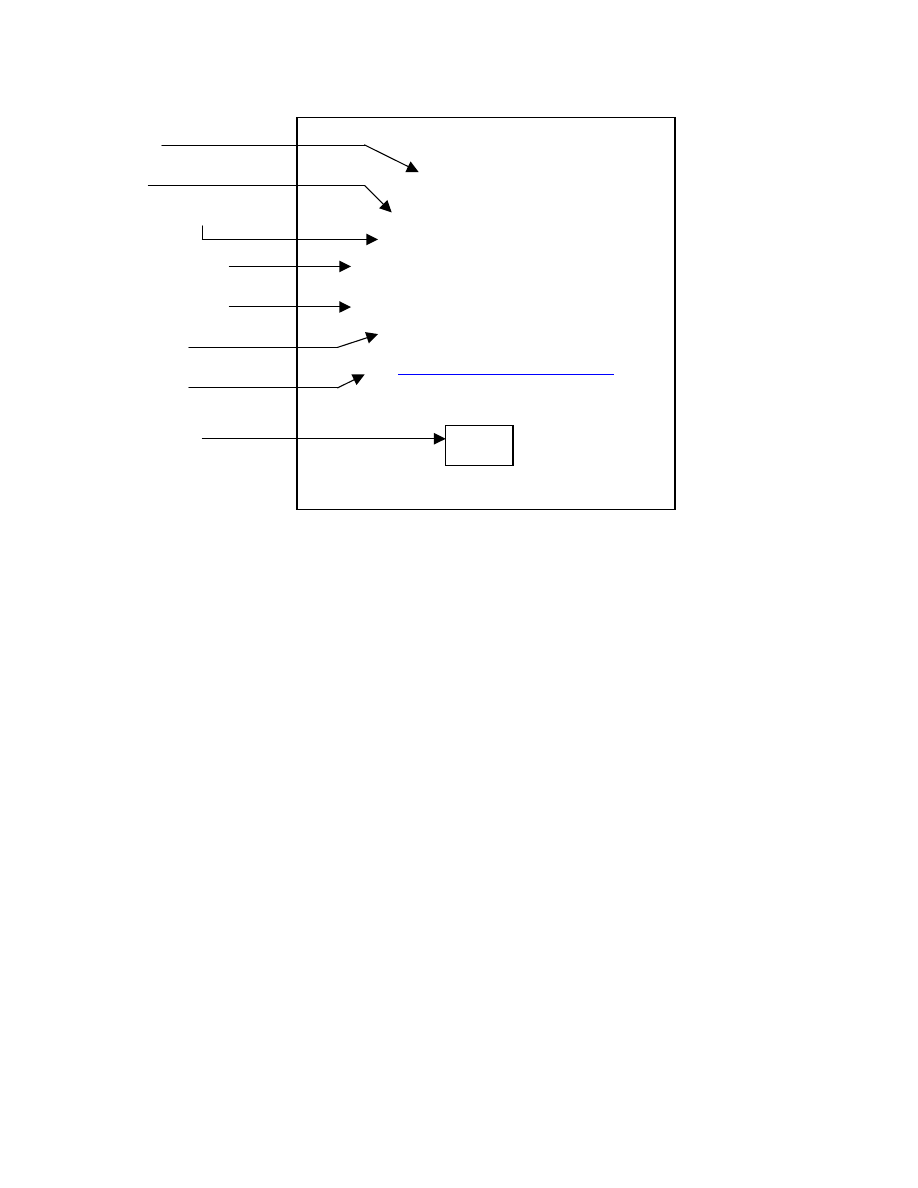
Name
Type
Capacitance & WVdc
Surge Voltage
Part Number
Country
Web site
Date Code
DuraCap
TYPE EAP 85°C
4400MFD 300VDC
MAX. SURGE 350VDC
EAP442X300X5L3PH
MADE IN CANADA
BY
www.duracap.com
CD
Application_EA-html.html
APPLICATION NOTE
RECONDITIONING ALUMINUM ELECTROLYTIC CAPACITORS
The DC leakage current of Aluminum Electrolytic Capacitors at rated voltage may
increase after extended storage, particularly at elevated temperatures.
To restore the leakage current to the minimal value as supplied by DuraCap
International Inc, proceed as follows:
In an ambient temperature of 25
°
C, apply 110% of the rated DC working voltage
through a current limiting series resistor to each capacitor separately.
Caution: Absolutely insure correct polarity of your power supply connections (i.e.
+ terminal of the power supply, through resistor, to the + terminal of the capacitor)
Rated WVDC Current Limiting Resistance (10-Watt)
15-100 1000 Ohms
101-250 10000 Ohms
251-450 25000 Ohms
Note: Pre-heating the capacitor before reconditioning to as high as 85
°
C is
recommended if capacitors have been stored at low temperature.
-
Reconditioning should take 2 or 3 hours. When the voltage across each capacitor is
about 5% above the rated working voltage, they may be considered reconditioned.
(Discard parts that will not recondition after several hours)
•
Proceed with caution - shock hazard is directly proportional to applied voltage
above 75 volts - high energy levels are present.
•
Turn off power and short circuit the output terminals of the power supply (also
discard parts that show a ruptured pressure vent or any evidence of liquid
leakage)
Note: Use a voltmeter to verify complete discharge of each capacitor before removing
parts from the reconditioning circuit.
- Since some heat may be generated internally during reconditioning, the capacitors
should be allowed to stabilize to 25
°
C for at least 8 hours before testing DC leakage
current as outlined in the technical information bulletin.
Your capacitors should now meet original specifications.
WARNING!!
Application_EA-html.html

DO NOT MISAPPLY ELECTROLYTIC CAPACITORS
1.0 MISAPPLICATION FORMS
The more common types of misapplication that result in failures are:
1.1 Reverse voltage in excess of specified limits.
1.2 Ripple current or voltage above specification.
1.3 Application voltages beyond surge voltage specified.
1.4 Temperature exposures beyond specified limits.
2.0 PERSONAL SAFETY
2.1 Electrical misapplication of electrolytic capacitors may be hazardous. Personal injury
or property damage may result from explosion of a capacitor or from the expulsion of
electrolyte due to mechanical disruption of a capacitor. In case of injury or skin or eye
exposure to electrolyte, contact a physician immediately.
2.2 Don’t dispose of capacitors in fire, explosion may result.
Before using capacitors in any application, please read this Technical Information
Bulletin carefully familiarizing yourself thoroughly with the information contained herein.
Special care should be taken to insure that the capacitors are proper for your
application and that warnings and instructions for use are followed.
DO CHECK the intended application and operating conditions of the
capacitor before use in any product to insure the capacitor is proper for
your application.
Email:
sales@duracap.com
Tel: 001-519-5394891
Fax: 001-519-5396684
D
URA
C
AP
INTERNATIONAL
INC.
P.O. Box 1579
Woodstock, Ontario
N4S 0A7 Canada
© DuraCap International,
1997.
All rights reserved.