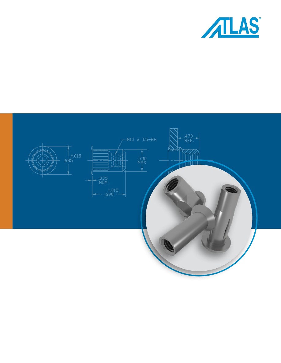
background image

CATALOG


ATLAS® BLIND

THREADED INSERTS

ATLAS® brand blind threaded inserts 
provide strong and reusable permanent 
threads in sheet materials where only one 
side is accessible for hardware installation.

Atlas-Catalog-html.html
background image

Company Info and Capabilities


4-5

ATLAS® Blind Threaded Inserts and Studs Overview


6

ATLAS® Insert Design Guide


7-9

SpinTite® Blind Threaded Inserts

AEL™ Low-Profile Head Inserts


10

•  Feature a large diameter, low-profile head and knurled shank

•  Offers highest all around strength

AEK™ Minimized-Profile Head Inserts


11


•  Same as the AEL but with a minimized-profile head
•  Allows near-flush installations with no need for special hole preparations such as countersinking or dimpling

AEH™ Half-Hex Shank Low Profile Head Inserts


12

•  Features a hex body design 
•  Improved torque-out resistance  

AEO™ Thin-Wall Low Profile Head Inserts


13

•  Features a low profile head design

•  Achieves near-flush installations with no need for countersink drilling or dimpling of the parent material

AET™ And Aew™ 360° Swaging Low-Profile Head Inserts


14-15

•  Works in any thickness over .029” / 0.76 mm including blind hole

•  High resistance to torque out

•  Minimal backside protrusion for restricted space applications

AES™ Blind Threaded Studs


16

•  Provide strong external threads in blind applications

•  Easy to install using spin-spin tooling 

•  Optional anti cross-threading feature available (see page 25)

SpinTite® Performance Data


17-18

ATLAS® FM™ Full Metric Blind Threaded Inserts

AETH™ Thin Head Semihex Body Hex Counterbore Inserts


19

•  Allows near-flush installations with no need for special hole preparations.

•  Semihex body for improved torque-out resistance.

AEFR™ Flat Head Round Body Inserts


20

•  Flat head design for high load applications.

AETR™ Thin Head Round Body Inserts


20

•  Allows near-flush installations with no need for special hole preparations.

AEFK™ Flat Head Knurled Round Body Inserts


21

•  Flat head design for high load applications. 
•  Knurled body for high torque applications.

AETK™ Thin Head Knurled Round Body Inserts


21

•  Allows near-flush installations with no need for special hole preparations.

•  Knurled body for high torque applications.

AEFH™ Flat Head Semihex Body Hex Counterbore Inserts


22

•  Flat head design for high load applications.

•  Semihex body for improved torque-out resistance.

AEFHH™ Flat Head Hex Body Round Counterbore Inserts


22

•  Flat head design for high load applications.

•  Full hex feature for high torque applications.

ATLAS-2


PennEngineering • 

www.pemnet.com

ATLAS® Blind Threaded Inserts

Index

© 2024 PennEngineering.

Atlas-Catalog-html.html
background image

ATLAS-3


PennEngineering • 

www.pemnet.com

ATLAS® Blind Threaded Inserts

Index

AETHH™ Thin Head Hex Body Round Counterbore Inserts


23

•  Allows near-flush installations with no need for special hole preparations.

•  Full hex feature for high torque applications.

AECR™ Countersunk Head Round Body Inserts


23

•  Countersunk head allows insert to be installed flush with sheet surface.

AECK™ Countersunk Head Knurled Round Body Inserts


24

•  Countersunk head allows insert to be installed flush with sheet surface.

•  Knurled body for high torque applications.

ATLAS® FM™ Material And Finish Specifications


24

ATLAS® Plus+Tite® Blind Threaded Inserts

Designed for superior pullout resistance in plastics and thin sheet metal


26-27

•  Internal formed threads are compatible with unified grade 5 or metric class 9.8 screws 

•  Shoulder provides self-locating feature
•  All surfaces are plated for superior corrosion resistance

ATLAS® MaxTite® Blind Threaded Inserts

Designed for high load applications


28-31

•  Thread sizes 632 - 1/2” and M4 - M12

•  Countersunk feature allow fastener to be installed flush with the surface of the sheet
•  Available with rib, key or full hex features for high torque applications

MaxTite® Performance Data


32

MaxTite® Specifications And Installation


33

ATLAS® Standard Full-hex Threaded Inserts

Standard Full-Hex


34

•  Designed for high load applications

•  Standard hex feature for high torque applications

Installation Tools


35-45

Tool Selector Guide


47

NAS Part Number Key


48

SpinTite®, ATLAS® FM™ and MaxTite® Part Number Keys


49-51

General Conversion Charts


52

Atlas-Catalog-html.html
background image

ATLAS-4


PennEngineering • 

www.pemnet.com

ATLAS® Blind Threaded Inserts

Company

ATLAS® operations are headquartered within the PennEngineering 225,000 square foot facility located in Danboro, Pennsylvania. 

PennEngineering companies provide fastener and fastener installation design and product solutions worldwide for diverse industries, 

including electronics, computer, data/telecom, medical, automotive, marine, aircraft, and general manufacturing.

Capabilities

Application Engineering Services 

From our factories or in the field we can provide you with application analysis/review, 3D modeling, product 

samples, on-site training and total engineering support.

Comprehensive website 

Our PEMNET.com fastening resource center provides the tools to help you determine which type of ATLAS® 

blind threaded insert or installation tool is right for you. It includes a complete CAD library, fastener selector 

tool, conversion tables, tutorials/animations/videos, literature, tech help, and environmental compliance 

references.

Custom Designs 

Our engineers can assist you in finding the most efficient solution to your application, and design the right 

fastener to meet your needs.

Installation Tools 

We can assess your application and recommend equipment that helps you achieve your 

lowest installed cost. Systems can be developed to address challenging component 

handling and fastener installation.

Prototype Development 

We’re equipped with the latest equipment to provide prototype samples and short run 

production quantities for your testing and analysis.

Technical Lab 

We have comprehensive testing facilities in each of our manufacturing locations. Our 

trained technicians worldwide can perform testing and provide complete analysis on 

pushout, pullout, spinout and assembly torque.

Atlas-Catalog-html.html
background image

ATLAS-5


PennEngineering • 

www.pemnet.com

ATLAS® Blind Threaded Inserts

Quality

At PennEngineering, our goal is 100% defect-free product. To this end, we have adopted a manufacturing strategy of defect 

prevention rather than defect detection. We use statistical tools throughout our manufacturing processes to monitor the 

performance and assure effective quality control of each process step. If a non-conforming situation arises, it is resolved 

immediately with the use of appropriate quality assurance tools.

Our fastener quality management system is IATF 16949 registered and Department of Defense QSLM approved, and we can support 

DFARS clause 252.225 requirements when specified. This further underscores our commitment to excellence as we continue to 

provide quality products and services that meet or exceed our customers’ expectations.

We are members of the Automotive Industry Action Group (AIAG) where we work together with other member companies to resolve 

issues critical to the automotive supply chain.

PennEngineering is also a registered member of the International Material Data System (IMDS).

Atlas-Catalog-html.html
background image

ATLAS-6


PennEngineering • 

www.pemnet.com

ATLAS® Blind Threaded Inserts

There are four types: 

SpinTite®

ATLAS® FM™

, MaxTite®, and 

Plus+Tite®

 fasteners.

The 

SpinTite®

 types are used for most applications where strong 

threads are required for blind applications. They are installed 

from one side using a spin-spin technique. In addition to high 

thread strength and torque-out, these fasteners have minimal 

inventory requirements since each size can accommodate many 

grip ranges (material thickness).

The 

ATLAS® FM™

 inserts have metric threads and dimensions 

and install into metric size round or hex holes to meet European 

design standards. These inserts are installed using “spin-pull” or 

“pull-to-pressure” installation tools.

The heavy duty 

MaxTite®

 types are designed for the most 

demanding applications. They are installed from one side using 

“spin-pull” or “pull-to-pressure” installation tools.

The blind 

Plus+Tite®

 inserts feature a slotted body that folds 

into four petals upon installation, gripping the backside of 

the parent material. These inserts can be installed into single, 

variable, or multiple thickness materials.

Typical industries that use blind threaded rivet technology:

•  Appliances

•  Automobiles and accessories

•  Aviation and aerospace

•  Electronics

•  Food service equipment

•  Furniture/fixtures/signs

•  Industrial equipment

•  Lawn and garden equipment

•  Lighting

•  Marine/boating

•  Medical equipment

•  Military equipment

•  Recreational equipment

•  Trucks and trailers

ATLAS® Blind threaded inserts are designed to provide strong 

threads in thin panel sections. They are called “blind” because they 

can be installed from one side of the panel. Access to both sides is 

not required. This convenient feature makes these fasteners ideally 

suited for tubing, extrusion, and other similar types of applications.

1

2

3

ATLAS® Blind Threaded Inserts And Studs Overview

Atlas-Catalog-html.html
background image

ATLAS-7


PennEngineering • 

www.pemnet.com

ATLAS® Blind Threaded Inserts

Advantages of ATLAS® blind threaded inserts:

•  Provide strong permanent threads in thin material.

•  Can be installed quickly and easily in panel sections with limited or no access to the back side.

•  Can be installed in close-to-edge applications.

•  Allow easy attachment to panels of any hardness such as metal, plastics, and fiberglass.

•  Installed with light, compact, cost-effective tooling.

•  Can assemble multiple dissimilar materials during installation.

•  Can replace weld nuts, cage nuts, tapped holes, self-tapping screws, and traditional through-bolted applications with loose hardware.

•  Stocked globally through our worldwide distribution network.

Application considerations

•  Panel material is not limited by hardness or type, but hole location and thickness must fall within the grip range of the specified fastener.

•  Hole locations are important when it comes to clearance on both the front side and back side of the panel. Allow adequate room for 

the head of the fastener, the bulbed portion of the fastener, as well as access for your chosen installation tooling. Also allow enough 

depth behind the panel to accept the fastener prior to the installation process.

Mounting hole considerations

•  Mounting holes can be prepared in many ways, but must be within the tolerances specified in the catalog or on the drawing.

•  Methods of hole preparation include but are not limited to punching, drilling, milling, laser or water jet cutting, and casting.  

Also available are the portable RIV990 and RIV991 hex cutter tools, used to transform round holes into hexagonal holes.  

Se

page 43


for more information.

•  Mounting holes do not necessarily need to be de-burred, but must allow for the fastener to seat properly and maintain position  

or perpendicularity when installed.

Application Examples

ATLAS® Insert Design Guide

Atlas-Catalog-html.html
background image

ATLAS-8


PennEngineering • 

www.pemnet.com

ATLAS® Blind Threaded Inserts

Picking the insert

• 

Round vs. Hex

 - For many applications a round insert such as the AEL or AEK series parts will suffice. Properly installed, these 

inserts will provide all the necessary spin out resistance. In critical applications, a hex hole may be desired as insurance against spin 

out. The RIV990 or RIV991 hex cutter tool can be used to create a hex hole in tubing. Tooling is only available for creating holes for 

the ATLAS® FM™ inserts.

• 

Plating

 - ATLAS inserts are available in a variety of platings. For normal applications, the standard zinc yellow or zinc clear is 

adequate. All ATLAS zinc platings are RoHS and REACH compliant. See www.pemnet.com for compliance certifications. For more 

extreme environments, the use of zinc nickel or tin zinc coatings may be desired. These coatings are rated for 1,000 hours salt spray 

protection per ASTM B117.

• 

Watertight

 - For applications on the exterior of vehicles or electronic cabinets that will be used outdoors, a PVC or 

Rimlex® (high temperature) sealant can be added under the head of the fastener. Normally a closed end insert is used 

for these applications. In most normal conditions this combination will provide a watertight or air tight seal. Sealant 

under head can reduce the effective grip range of the insert by .020" - .030" (0.5 - 0.76 mm).

• 

Stud

 - Inserts that have a male thread are available. These inserts are useful when used to mount a plate or cover that 

can be hung over the studs for ease of assembly.

• 

Stainless Steel

 - For extreme environments, the use of stainless steel may be required. All MaxTite® inserts are 

available in both 316 Stainless Steel and 430 Stainless Steel. While our SpinTite® parts can be manufactured in 

Stainless Steel, we recommend that the ATLAS FM™ designs be used for commercial applications since the body 

sizes are slightly smaller in diameter. This simplifies manufacturing  and can dramatically decrease the piece price.

• 

Thread Considerations

 - Our catalog shows the most popular thread sizes. Even if not shown, other sizes are available such as  

10-24, ¼-28 and 3/8-24. Minimum order quantities may apply.

  SpinTite®, Plus+Tite® and ATLAS® FM™ are Unified 2B and Metric 6H thread classes. MaxTite parts are Unified 3B and Metric 6H. Our 

fastener threads are compliant with these classes before they are installed but dependent upon the condition of the mandrel and the 

tool pressure and/ or other application considerations could have adverse reactions to the after installed condition and gaugeability 

of the threads.

  AET and AEW Swaging Inserts are tapped oversized to compensate for thread portion shrinkage during the installation process. 

They are not gaugeable prior to or after installation but will be compatible with Class 2A or 3A or Metric 6g screws after installation.

• 

Insert removal

 – Sometimes the insert has to be removed after it is installed for variety of reasons. When removal is required, the 

best method is to remove the fastener head. This can be accomplished by using an oversized drill bit and gently drilling into the 

counterbore until the head is removed. Then the body of the insert can be pushed through the mating material. Using a grinding 

wheel to carefully remove the head is another option. 

Installation Tooling

• 

Spin-spin

 – These tools work by running the mandrel into the insert until the air motor stalls. The 

rpm of the tool needs to be matched to the size of the insert. See the ATLAS tool selector guide for 

recommended tool models and air pressures. An air pressure regulator is always recommended.

• 

Spin-pull 

– These tools use a small air motor to place the insert on the mandrel. Insert the fastener 

into the mating hole and pull the trigger. The tool will axially pull the mandrel back to a pre-adjusted 

distance and then the air motor engages in reverse to complete the installation.

• 

Pull-to-pressure

 – Similar to spin-pull but with the addition of a pressure transducer that when 

adjusted properly, will sense the correct fastener installation and then complete the cycle. These 

tools are state-of-the-art for insert installation tools as they can properly install inserts across the 

full grip range quickly and consistently.

Rimlex® is a registered trademark of Inlex Locking Ltd.

ATLAS® Insert Design Guide

Atlas-Catalog-html.html
background image

ATLAS-9


PennEngineering • 

www.pemnet.com

ATLAS® Blind Threaded Inserts

Because of the variables regarding lubrication, plating, type and class of testing 

screw or bolt, we recommend that pilot testing should be conducted per the 

customer specific application requirements to achieve optimum performance values.

Mating part/bolts

•  Installation holes for ATLAS blind rivet nuts should be aligned to parent material to ensure a uniform backside formation. The hole 

size should meet the product tolerance and specification. The mating part should contact the head of the blind rivet nut to ensure 

optimum torque performance of the joint.

•  The mating screw should be Grade 5 or Metric Class 8.8 strength. ATLAS blind rivet nuts are designed to meet the torque, tensile 

and clamp load of the mating fasteners. Thread fit may be 2A, 3A or Metric 6G design. The mating screw thread length should 

engage all threads of the blind rivet nut to ensure optimum torque strength.

•  If an application requires a mating screw with a nylon patch, adhesive, or other thread locking mechanism, a hex body 

blind rivet nut in a hex hole will be needed to resist the prevailing torque created by the locking mechanism.

Test Guidelines

Test Bushing

PULLOUT

Pullout

 is the force required to pull the 

insert from the sheet.

APPLICATION TORQUE

Application Torque

 is the torque strength 

achieved by gradual tightening torque to failure 

of the insert in application.

INSTALLATION 

LOAD

Installation Load

 is the force required to 

collapse (bulb) the insert in the specified 

grip range (thickness of application).

PUSHOUT

Pushout

 is the force required to push the 

insert through the sheet.

Test Bushing

SPINOUT

Spinout

 is the measure of the torsional 

holding power of the fastener in the 

parent material after installation without 

inducing clamp load on the fastener.

ATLAS® Insert Design Guide

As with all air tools, the correct air pressure is critical to proper operation. Air pressure regulators 

are always recommended. 90-100 psi is the recommended maximum pressure for all tools. Please 

see the ATLAS catalog for recommended air pressures for our spin-spin tools. The spin-pull and 

pull-to-pressure tools should always be operated in the range of 85-100 psi.

Air tools in a manufacturing environment will wear and need repair from time to time. Please 

see the ATLAS website for a list of authorized tool repair locations. ATLAS tools have a one year 

warranty for manufacturing defects. Parts and labor are covered.

When a very large number of inserts have to be installed repetitively, the use of robotics 

or automation may be necessary. Please contact us to discuss the application details and 

possible custom solutions.

Atlas-Catalog-html.html
background image

ATLAS-10


PennEngineering • 

www.pemnet.com

ATLAS® Blind Threaded Inserts

All dimensions are in millimeters.

All dimensions are in inches.


Thread 

Part 

Grip                    Hole 

Size


Size x 

Number 

Range 

A  ØB  C  ØD  M Weight  A  ØB  C  ØD  K  M Weight 

In Sheet

 Pitch 

(1) (2)  (1)


±0.38 ±0.38 Nom.  Max.  Ref.  kg/1000  ±0.38 ±0.38 Nom.  Max.  Min.  Ref.  kg/1000 +0.15

  M4 x 0.7 

AELS8-470-2.0 

0.5 - 2 

10.67 

9.91 

0.76 

6.73 

7.75 

1.73 

18.8 

9.91 

0.76 

6.73 

11.6 

16.26 

3.37 

6.75

  M4 x 0.7 

AELS8-470-3.3 

2 - 3.3 

11.94 

9.91 

0.76 

6.73 

7.75 

1.56 

18.8 

9.91 

0.76 

6.73 

11.6 

14.73 

3.3 

6.75

  M5 x 0.8 

AELS8-580-3.3 

0.5 - 3.3 

12.07 

10.54 

0.76 

7.52 

2.19 

25.15 

10.54 

0.76 

7.52 

15.6 

21.46 

5.38 

7.6

  M5 x 0.8 

AELS8-580-5.7 

3.3 - 5.7 

14.86 

10.54 

0.76 

7.52 

2.16 

25.15 

10.54 

0.76 

7.52 

15.6 

18.67 

4.86 

7.6


M6 x 1 

AELS8-610-4.2 

0.7 - 4.2 

14.73 

12.7 

0.76 

9.91 

9.65 

3.97 

30.23 

12.7 

0.76 

9.91 

17.5 

25.53 

11.3 

10


M6 x 1 

AELS8-610-6.6 

4.2 - 6.6 

17.27 

12.7 

0.76 

9.91 

9.65 

4.29 

30.23 

12.7 

0.76 

9.91 

17.5 

22.99 

10.24 

10

  M8 x 1.25 

AELS8-8125-3.8 

0.7 - 3.8 

17.53 

17.4 

0.89 

13.46 

11.94 

8.5 

35.31 

17.4 

0.89 

13.46 

20.2 

29.85 

24.35 

13.5

  M8 x 1.25 

AELS8-8125-7.9 

3.8 - 7.9 

20.45 

17.4 

0.89 

13.46 

10.8 

9.13 

35.31 

17.4 

0.89 

13.46 

20.2 

26.04 

23.93 

13.5

  M10 x 1.5 

AELS8-1015-3.8 

0.7 - 3.8 

17.53 

17.4 

0.89 

13.46 

11.94 

7.13 

35.31 

17.4 

0.89 

13.46 

20.8 

29.85 

20.62 

13.5

  M10 x 1.5 

AELS8-1015-7.9 

3.8 - 7.9 

20.45 

17.4 

0.89 

13.46 

10.8 

8.11 

35.31 

17.4 

0.89 

13.46 

20.8 

26.04 

20.48 

13.5

  M12 x 1.75 

AELS8-12175-5.1 

1.6 - 5.1 

29.21 

21.97 

1.19 

17.4 

21.59 

21.78 

49.78 

21.97 

1.19 

17.4 

17.94 

42.29 

22.97 

17.47

  M12 x 1.75 

AELS8-12175-8.9 

5.1 - 8.9 

33.02 

21.97 

1.19 

17.4 

21.59 

23.43 

49.78 

21.97 

1.19 

17.4 

27.94 

38.48 

24.66 

17.47

A

ØB

C

ØD

Grip Range

M

OPEN END

CLOSED END

A

ØD

K

M

ØB

C


Thread  Part 

Grip                       Hole 

Size

 Size 

Number 

Range 

A  ØB C ØD M Weight A  ØB  C ØD K  M  Weight 

In Sheet


(1) 

(2) 

(1)


±.015  ±.015 Nom. Max.  Ref.  lbs./1000 ±.015  ±.015  Nom. Max.  Min.  Ref.  lbs./1000 

+.006 -.000


#6-32  AELS8-632-80  .020 

.080  .420  .390 .030 .265 .305  3.52  .740  .390  .030 .265  .43  .640  6.89 

.266


#6-32  AELS8-632-130  .080 

.130  .470  .390 .030 .265 .305  3.77  .740  .390  .030 .265  .43  .580  6.78 

.266


#8-32  AELS8-832-80  .020 

.080  .420  .390 .030 .265 .305  3.31  .740  .390  .030 .265  .43  .640  7.20 

.266


#8-32  AELS8-832-130  .080 

.130  .470  .390 .030 .265 .305  3.40  .740  .390  .030 .265  .43  .580  7.04 

.266

  #10-32 

AELS8-1032-130 

.020 - .130 

.475 

.415 

.030 

.296 

.315 

4.62 

.990 

.415 

.030 

.296 

.58 

.845 

11.63 

.297

  #10-32 

AELS8-1032-225 

.130 - .225 

.585 

.415 

.030 

.296 

.315 

4.83 

.990 

.415 

.030 

.296 

.58 

.735 

10.49 

.297

  1/4-20 

AELS8-420-165 

.027 - .165 

.580 

.500 

.030 

.390 

.380 

9.26 

1.190 

.500 

.030 

.390 

.70 

1.005 

29.30 

.391

  1/4-20 

AELS8-420-260 

.165 - .260 

.680 

.500 

.030 

.390 

.380 

9.39 

1.190 

.500 

.030 

.390 

.70 

.905 

21.53 

.391

  5/16-18 

AELS8-518-150 

.027 - .150 

.690 

.685 

.035 

.530 

.470 

19.51 

1.390 

.685 

.035 

.530 

.82 

1.175 

53.76 

.531

  5/16-18 

AELS8-518-312 

.150 - .312 

.805 

.685 

.035 

.530 

.425 

19.80 

1.390 

.685 

.035 

.530 

.82 

1.025 

53.25 

.531

  3/8-16 

AELS8-616-150 

.027 - .150 

.690 

.685 

.035 

.530 

.470 

16.81 

1.390 

.685 

.035 

.530 

.83 

1.175 

45.23 

.531

  3/8-16 

AELS8-616-312 

.150 - .312 

.805 

.685 

.035 

.530 

.425 

17.36 

1.390 

.685 

.035 

.530 

.83 

1.025 

44.92 

.531

  1/2-13 

AELS8-813-200 

.063 - .200 

1.150 

.865 

.047 

.685 

.850 

48.02 

1.960 

.865 

.047 

.685 

1.10 

1.665 

50.65 

.688

  1/2-13 

AELS8-813-350 

.200 - .350 

1.300 

.865 

.047 

.685 

.850 

51.65 

1.960 

.865 

.047 

.685 

1.10 

1.515 

54.40 

.688

  1/2-13 

AELS8-813-500 

.350 - .500 

1.450 

.865 

.047 

.685 

.850 

54.60 

1.960 

.865 

.047 

.685 

1.10 

1.315 

57.49 

.688

 Open 

Closed

 Open 

Closed

(1) Additional grip ranges and fine thread sizes such as 10-24, 1/4-28 and 3/8-24 are available. Minimum order quantities may apply.

(2) For closed end, add a “B” to the end of the part number.

ALSO AVAILABLE

AEL, AEK and AEH inserts are available in MONEL® alloy 400 and 

300 Series Stainless Steel. AEL inserts are also available in wedge 

head, or sealed head styles 

(see page 25)

.

Call for availability.

•  Feature a large diameter, low-profile head and knurled shank.

•  Offers highest all around strength.

MONEL® is a registered trademark of Special Metals Corporation.

For recommended installation tool,  

see tool selector guide on 

page 47

.

AEL™ SpinTite® Low-Profile Head Inserts

Part Number Designation

 AEL 

-  632  -  80 

B

 Type  Material  Finish    Thread    Max. 

Closed


  Code   Grip 

End


      Designation

See 

Page 49

 For More Details

Atlas-Catalog-html.html
background image

ATLAS-11


PennEngineering • 

www.pemnet.com

ATLAS® Blind Threaded Inserts

A

ØB

C

ØD

Grip Range

M

OPEN END

ØD

M

CLOSED END

A

K

ØB

C

(1)  Additional grip ranges and fine thread sizes such as 10-24, 1/4-28 and 3/8-24 are available. Minimum order quantities may apply.

(2) For closed end, add a “B” to the end of the part number.

All dimensions are in millimeters.

All dimensions are in inches.


Type 

Threads 

Standard Material 

Standard Finish


Unified, 2B per ASME B1.1 

Low Carbon Steel 

RoHS Compliant Zinc Yellow

  AELS / AEKS 

Metric, 6H per ASME B1.13M 


Plus Lubricant


Unified, 2B per ASME B1.1 

Stainless Steel 

Passivated and/or tested

  AELC / AEKC 

Metric, 6H per ASME B1.13M 


per ASTM A380


Unified, 2B per ASME B1.1 

Aluminum 

No finish

  AELA / AEKA 

Metric, 6H per ASME B1.13M


Unified, 2B per ASME B1.1 

Brass 

No finish

  AELB / AEKB 

Metric, 6H per ASME B1.13M

Material & Finish Specifications

•  Feature a minimized-profile head and knurled shank.

•  Allows near-flush installations with no need for special hole 

preparations such as countersinking or dimpling.


Thread  Part 

Grip                      Hole 

Size

 Size 

Number 

Range 

A  ØB C ØD M Weight A  ØB  C ØD K  M Weight 

In Sheet


(1)


(2)


(1)


±.015 ±.015 Nom. Max. Ref. lbs./1000 ±.015  ±.015 Nom. Max.  Min.  Ref.  lbs./1000 

+.006 -.000

  #6-32 

AEKS8-632-80 

.020 - .080 

.420 

.310 

.019 

.265 

.305 

3.5 

.740 

.310 

.019 

.265 

.43 

.640 

5.24 

.266

  #6-32 

AEKS8-632-130 

.080 - .130 

.470 

.310 

.019 

.265 

.305 

3.44 

.740 

.310 

.019 

.265 

.43 

.580 

5.06 

.266

  #8-32 

AEKS8-832-80 

.020 - .080 

.420 

.310 

.019 

.265 

.305 

3.3 

.740 

.310 

.019 

.265 

.43 

.640 

5.75 

.266

  #8-32 

AEKS8-832-130 

.080 - .130 

.470 

.310 

.019 

.265 

.305 

3.11 

.740 

.310 

.019 

.265 

.43 

.580 

5.57 

.266

  #10-32 

AEKS8-1032-130 

.020 - .130 

.475 

.340 

.019 

.296 

.315 

3.99 

.990 

.340 

.019 

.296 

.58 

.845 

10.93 

.297

  #10-32 

AEKS8-1032-225 

.130 - .225 

.585 

.340 

.019 

.296 

.315 

4.39 

.990 

.340 

.019 

.296 

.58 

.735 

10.59 

.297

  1/4-20 

AEKS8-420-165 

.027 - .165 

.580 

.455 

.022 

.390 

.380 

8.59 

1.190 

.455 

.022 

.390 

.70 

1.005 

23.4 

.391

  1/4-20 

AEKS8-420-260 

.165 - .260 

.680 

.455 

.022 

.390 

.380 

8.69 

1.190 

.455 

.022 

.390 

.70 

.905 

21.2 

.391

  5/16-18 

AEKS8-518-150 

.027 - .150 

.690 

.595 

.022 

.530 

.470 

17.98 

1.390 

.595 

.022 

.530 

.82 

1.175 

55.62 

.531

  5/16-18 

AEKS8-518-312 

.150 - .312 

.805 

.595 

.022 

.530 

.425 

19.27 

1.390 

.595 

.022 

.530 

.82 

1.025 

55.11 

.531

  3/8-16 

AEKS8-616-150 

.027 - .150 

.690 

.595 

.022 

.530 

.470 

15.58 

1.390 

.595 

.022 

.530 

.83 

1.175 

41.18 

.531

  3/8-16 

AEKS8-616-312 

.150 - .312 

.805 

.595 

.022 

.530 

.425 

16.28 

1.390 

.595 

.022 

.530 

.83 

1.025 

39.64 

.531

 Open 

Closed

  Thread  Part 

Grip                       Hole 

Size


Size x 

Number 

Range 

A  ØB C ØD M  Weight A  ØB C ØD  K  M Weight 

In Sheet

 Pitch 

(1)


(2)


(1)


±0.38  ±0.38 Nom.  Max.  Ref.  kg/1000  ±0.38 ±0.38 Nom.  Max.  Min.  Ref.  kg/1000 +0.15

  M4 x 0.7 

AEKS8-470-2.0 

0.5 - 2 

10.67 

7.87 

0.48 

6.73 

7.75 

1.5 

18.8 

7.78 

0.48 

6.73 

11.6 

16.26 

2.61 

6.75

  M4 x 0.7 

AEKS8-470-3.3 

2 - 3.3 

11.94 

7.87 

0.48 

6.73 

7.75 

1.44 

18.8 

7.87 

0.48 

6.73 

11.6 

14.73 

2.53 

6.75

  M5 x 0.8 

AEKS8-580-3.3 

0.5 - 3.3 

12.07 

8.64 

0.48 

7.52 

1.81 

25.15 

8.64 

0.48 

7.52 

15.6 

21.46 

4.96 

7.6

  M5 x 0.8 

AEKS8-580-5.7 

3.3 - 5.7 

14.86 

8.64 

0.48 

7.52 

1.99 

25.15 

8.64 

0.48 

7.52 

15.6 

18.67 

4.8 

7.6


M6 x 1 

AEKS8-610-4.2 

0.7 - 4.2 

14.73 

11.56 

0.55 

9.91 

9.65 

3.9 

30.23 

11.56 

0.55 

9.91 

17.5 

25.53 

10.61 

10


M6 x 1 

AEKS8-610-6.6 

4.2 - 6.6 

17.27 

11.56 

0.55 

9.91 

9.65 

3.94 

30.23 

11.56 

0.55 

9.91 

17.5 

22.99 

9.62 

10

  M8 x 1.25 

AEKS8-8125-3.8 

0.7 - 3.8 

17.53 

15.11 

0.55 

13.46 

11.94 

8.04 

35.31 

15.11 

0.55 

13.46 

20.2 

29.85 

25.23 

13.5

  M8 x 1.25 

AEKS8-8125-7.9 

3.8 - 7.9 

20.45 

15.11 

0.55 

13.46 

10.8 

8.79 

35.31 

15.11 

0.55 

13.46 

20.2 

26.04 

25 

13.5

  M10 x 1.5 

AEKS8-1015-3.8 

0.7 - 3.8 

17.53 

15.11 

0.55 

13.46 

11.94 

6.66 

35.31 

15.11 

0.55 

13.46 

20.8 

29.85 

18.68 

13.5

  M10 x 1.5 

AEKS8-1015-7.9 

3.8 - 7.9 

20.45 

15.11 

0.55 

13.46 

10.8 

6.93 

35.31 

15.11 

0.55 

13.46 

20.8 

26.04 

17.98 

13.5

Part Number Designation

 AEK 

-  632  -  80 

B

 Type  Material  Finish    Thread    Max. 

Closed


  Code   Grip 

End


      Designation

See 

Page 49

 For More Details

For recommended installation tool,  

see tool selector guide on 

page 47.

AEK™ SpinTite® Minimized-Profile Head Inserts

 Open 

Closed

Atlas-Catalog-html.html
background image

ATLAS-12


PennEngineering • 

www.pemnet.com

ATLAS® Blind Threaded Inserts

All dimensions are in millimeters.

(1) Additional grip ranges and fine thread sizes such as 10-24, 1/4-28 and 3/8-24 are available. Minimum order quantities may apply.

(2) For closed end, add a “B” to the end of the part number.

OPEN END

CLOSED END

A

ØB

C

D

Grip Range

HEX HOLE 

SIZE

M

A

ØB

C

M

K

Material & Finish Specifications

•  Feature a hex body design.

•  Improved torque-out resistance.

Part Number Designation

 AEH 

-  632  -  80 

B

 Type  Material  Finish    Thread    Max. 

Closed


  Code   Grip 

End


      Designation


Thread  Part 

Grip                      Hex 

Hole

 Size 

Number 

Range 

A ØB C D M Weight A ØB C D K M Weight 

Size In Sheet


(1) (2) 

(1)


±.015 ±.015 Nom. Max. Ref lbs./1000 ±.015 ±.015 Nom. Max. Min.  Ref.  lbs./1000 

+.006 -.000

  #6-32 

AEHS8-632-80 

.020 - .080 

.385 

.375 

.027 

.249 

.295 

3.59 

.740 

.375 

.027 

.249 

.43 

.640 

6.97 

.250

  #6-32 

AEHS8-632-130 

.080 - .130 

.435 

.375 

.027 

.249 

.295 

3.95 

.740 

.375 

.027 

.249 

.43 

.580 

7.28 

.250

  #8-32 

AEHS8-832-80 

.020 - .080 

.385 

.375 

.027 

.249 

.295 

3.38 

.740 

.375 

.027 

.249 

.43 

.640 

7.28 

.250

  #8-32 

AEHS8-832-130 

.080 - .130 

.435 

.375 

.027 

.249 

.295 

4.53 

.740 

.375 

.027 

.249 

.43 

.580 

8.82 

.250

  #10-32 

AEHS8-1032-130 

.020 - .130 

.435 

.390 

.027 

.280 

.275 

4.71 

1.030 

.390 

.027 

.280 

.58 

.845 

11.6 

.281

  #10-32 

AEHS8-1032-225 

.130 - .225 

.535 

.390 

.027 

.280 

.275 

5.04 

1.030 

.390 

.027 

.280 

.58 

.735 

12.51 

.281

  1/4-20 

AEHS8-420-165 

.027 - .165 

.585 

.510 

.030 

.374 

.400 

9.45 

1.190 

.510 

.030 

.374 

.70 

1.015 

23.07 

.375

  1/4-20 

AEHS8-420-260 

.165 - .260 

.685 

.510 

.030 

.374 

.400 

9.72 

1.190 

.510 

.030 

.374 

.70 

.915 

23.69 

.375

  5/16-18 

AEHS8-518-150 

.027 - .150 

.685 

.655 

.035 

.499 

.530 

18.75 

1.445 

.655 

.035 

.499 

.82 

1.235 

53.53 

.500

  5/16-18 

AEHS8-518-312 

.150 - .312 

.845 

.655 

.035 

.499 

.515 

21.25 

1.445 

.655 

.035 

.499 

.82 

1.220 

54.04 

.500

  3/8-16 

AEHS8-616-150 

.027 - .150 

.685 

.655 

.035 

.499 

.530 

17.24 

1.445 

.655 

.035 

.499 

.83 

1.235 

45.94 

.500

  3/8-16 

AEHS8-616-312 

.150 - .312 

.845 

.655 

.035 

.499 

.515 

19.65 

1.445 

.655 

.035 

.499 

.83 

1.220 

46.45 

.500

  1/2-13 

AEHS8-813-200 

.063 - .200 

1.150 

.865 

.050 

.688 

.950 

53.46 

— 

— 

— 

— 

— 

— 

— 

.689

  1/2-13 

AEHS8-813-350 

.200 - .350  

1.300 

.865 

.050 

.688 

.950 

55.00 

— 

— 

— 

— 

— 

— 

— 

.689

 Open 

Closed


Thread 

Part 

Grip                     Hex 

Hole


Size x 

Number 

Range 

A ØB  C D  M Weight A ØB C D K  M Weight 

Size In Sheet

 Pitch

 (1) (2)  (1)


±0.38 ±0.38  Nom.  Max.  Ref.  kg/1000  ±0.38 ±0.38 Nom.  Max.  Min.  Ref.  kg/1000 +0.15

  M4 x 0.7 

AEHS8-470-2.0 

0.5 - 2 

9.78 

9.53 

0.68 

6.35 

7.49 

1.77 

18.8 

9.53 

0.68 

6.35 

11.6 

16.26 

3.3 

6.35

  M4 x 0.7 

AEHS8-470-3.3 

2 - 3.3 

11.05 

9.53 

0.68 

6.35 

7.49 

1.89 

18.8 

9.53 

0.68 

6.35 

11.6 

14.73 

6.35

  M5 x 0.8 

AEHS8-580-3.3 

0.5 - 3.3 

11.05 

9.91 

0.68 

7.1 

6.99 

2.24 

26.16 

9.91 

0.68 

7.1 

15.6 

21.46 

5.26 

7.14

  M5 x 0.8 

AEHS8-580-5.7 

3.3 - 5.7 

13.59 

9.91 

0.68 

7.1 

6.99 

2.33 

26.16 

9.91 

0.68 

7.1 

15.6 

18.67 

5.67 

7.14


M6 x 1 

AEHS8-610-4.2 

0.7 - 4.2 

14.86 

12.96 

0.76 

9.5 

10.16 

4.05 

30.23  12.96 

0.76 

9.5 

17.5 

25.78 

10.46 

9.53


M6 x 1 

AEHS8-610-6.6 

4.2 - 6.6 

17.4 

12.96 

0.76 

9.5 

10.16 

4.45 

30.23  12.96 

0.76 

9.5 

17.5 

23.24 

10.75 

9.53

  M8 x 1.25 

AEHS8-8125-3.8 

0.7 - 3.8 

17.4 

16.64 

0.89 

12.7 

13.46 

8.51 

36.7 

16.64 

0.89 

12.7 

20.2 

31.37 

24.28 

12.7

  M8 x 1.25 

AEHS8-8125-7.9 

3.8 - 7.9 

21.46 

16.64 

0.89 

12.7 

13.08 

9.64 

36.7 

16.64 

0.89 

12.7 

20.2 

30.99 

24.51 

12.7

  M10 x 1.5 

AEHS8-1015-3.8 

0.7 - 3.8 

17.4 

16.64 

0.89 

12.7 

13.46 

7.82 

36.7 

16.64 

0.89 

12.7 

20.8 

31.37 

20.84 

12.7

  M10 x 1.5 

AEHS8-1015-7.9 

3.8 - 7.9 

21.46 

16.64 

0.89 

12.7 

13.08 

8.91 

36.7 

16.64 

0.89 

12.7 

20.8 

30.99 

21.07 

12.7

  M12 x 1.75 

AEHS8-12175-5.1 

1.6 - 5.1 

29.21 

21.97 

1.27 

17.48 

24.13 

26.00 

— 

— 

— 

— 

— 

— 

— 

17.5

  M12 x 1.75 

AEHS8-12175-8.9 

5.1 - 8.9 

33.02 

21.97 

1.27 

17.48 

24.13 

27.70 

— 

— 

— 

— 

— 

— 

— 

17.5

 Open 

Closed

All dimensions are in inches.


Type 

Threads 

Standard Material 

Standard Finish


Unified, 2B per ASME B1.1 

Low Carbon Steel 

RoHS Compliant Zinc Yellow


AEHS


Metric, 6H per ASME B1.13M 


Plus Lubricant


Unified, 2B per ASME B1.1 

Stainless Steel 

Passivated and/or tested


AEHC


Metric, 6H per ASME B1.13M 


per ASTM A380


Unified, 2B per ASME B1.1 

Aluminum 

No finish


AEHA


Metric, 6H per ASME B1.13M


Unified, 2B per ASME B1.1 

Brass 

No finish


AEHB


Metric, 6H per ASME B1.13M

AEH™ SpinTite® Half-Hex Shank Low-Profile Head Inserts

For recommended installation tool,  

see tool selector guide on 

page 47

.

See 

Page 49

 For More Details

Atlas-Catalog-html.html
background image

ATLAS-13


PennEngineering • 

www.pemnet.com

ATLAS® Blind Threaded Inserts

All dimensions are in millimeters.

All dimensions are in inches.

A

ØB

C

ØD

Grip Range

M


Thread 

Part 

Grip 

ØB 

ØD 

Hole Size 

Weight

 Size 

(1)

 Number Range

 (1)


±.015 

±.015 

Nom. 

Max. 

Ref. 

In Sheet 

lbs./1000


+.006 

-.000 


#6-32 

AEOS10-632-80 

.020 - .080 

.385 

.295 

.018 

.249 

.315 

.250 

2.61


#8-32 

AEOS10-832-80 

.020 - .080 

.385 

.295 

.018 

.249 

.315 

.250 

2.41


#10-24 

AEOS10-1024-130 

.020 - .130 

.440 

.320 

.020 

.280 

.330 

.281 


#10-32 

AEOS10-1032-130 

.020 - .130 

.440 

.320 

.020 

.280 

.330 

.281 

3.61


1/4-20 

AEOS10-420-165 

.030 - .165 

.580 

.425 

.022 

.374 

.440 

.375 

8.22


1/4-28 

AEOS10-428-165 

.030 - .165 

.580 

.425 

.022 

.374 

.440 

.375 


5/16-18 

AEOS10-518-200 

.040 - .200 

.690 

.560 

.022 

.499 

.540 

.500 

16.64


5/16-24 

AEOS10-524-200 

.040 - .200 

.690 

.560 

.022 

.499 

.540 

.500 


3/8-16 

AEOS10-616-200 

.040 - .200 

.690 

.560 

.022 

.499 

.540 

.500 

13.03


3/8-24 

AEOS10-624-200 

.040 - .200 

.690 

.560 

.022 

.499 

.540 

.500 


Thread 

Part 

Grip 

ØB 

ØD 

Hole Size 

Weight


Size x 

Number 

Range

 (1)


±0.38 

±0.25 

Nom. 

Max. 

Ref. 

In Sheet 

kg/1000

 Pitch 

(1)


+0.15


M4 x 0.7 

AEOS10-470-2.0 

0.5 - 2 

9.78 

7.49 

0.46 

6.32 

6.4 

1


M5 x 0.8 

AEOS10-580-3.3 

0.5 - 3.3 

11.18 

8.13 

0.51 

7.11 

8.38 

7.2 

1.64


M6 x 1 

AEOS10-610-4.2 

0.76 - 4.2 

14.73 

10.8 

0.56 

9.5 

11.18 

9.6 

3.87


M8 x 1.25 

AEOS10-8125-5.1 

1.02 - 5.1 

17.53 

14.22 

0.56 

12.67 

13.72 

12.7 

7.34


M10 x 1.5 

AEOS10-1015-5.1 

1.02 - 5.1 

17.53 

14.22 

0.56 

12.67 

13.72 

12.7 

5.75

(1) Additional grip ranges and fine thread sizes such as 10-24, 1/4-28 and 3/8-24 are available. Minimum order quantities may apply.

(2) Other materials available. See page 52 for details. Minimum quantities may apply.

 AEO 

10  -  632  -  80

   Type 

Material 

Finish    Thread    Max.


    Code    Grip

•  Features a low-profile head design.

•  Allows near-flush installations with no need for special hole 

preparations such as countersinking or dimpling.

Material & Finish Specifications

  Type 

Threads 

Standard Material

(2)


Standard Finish


Unified, 2B per ASME B1.1 

Low Carbon Steel 

RoHS Compliant Zinc Clear

  AEO 

Metric, 6H per ASME B1.13M 


Plus Lubricant

AEO™ SpinTite® Thin-Wall Low-Profile Head Inserts

See 

Page 49

 For More Details

Part Number Designation

For recommended installation tool,  

see tool selector guide on 

page 47

.

Atlas-Catalog-html.html
background image

ATLAS-14


PennEngineering • 

www.pemnet.com

ATLAS® Blind Threaded Inserts

Additional grip ranges and fine thread sizes such as 10-24, 1/4-28 and 3/8-24 are available. 

Minimum order quantities may apply.

NOTE:

 The internal threads are manufactured oversized to compensate for resulting thread 

portion shrinkage during the installation process. They are not gaugeable prior to or after 

installation but will be compatible with Class 2A/3A or 6g screws after installation.


Type 


         Installation Hole Size 


                 Open   


                                  Closed   


Blind


Thread


Thread                        Hole


Size


Code 

                  Grip Range 


Weight 


Depth


  Stain- Alum-


ØA  B  ØC  D   lbs./1000   ØA  B  ØC  D 

Min.


Steel less  inum

  .030 - .090  .091 - .124  .125 - .186  .187 - OVER  ±.005 ±.015  Max.  Ref.  AETS AETC AETA ±.005 ±.015  Max.  Ref.

 #4-40  AETS  AETC  AETA  440 

.188 

.194 

.194 

.196 

.211  .370  .1879  .205  0.99  0.99  0.33  .211  .660  .1875  .495  .400


#6-32  AETS AETC AETA 632  .219  .221  .228  .228  .240 .370 .2189 .205 1.48 1.48 0.49 .240 .675 .2185 .505 .400

 #8-32  AETS  AETC  AETA  832 

.250 

.257 

.266 

.266 

.269  .370  .2499  .205  1.98  1.98  0.65  .269  .675  .2495  .505  .400


#10-24  AETS AETC AETA 1024  .281  .290  .290  .297  .306 .370 .2809 .205 2.22 2.22 0.74 .306 .685 .2805 .520 .400

 #10-32  AETS  AETC  AETA  1032 

.281 

.290 

.290 

.297 

.306  .370  .2809  .205  2.23  2.23  0.74  .306  .685  .2805  .520  .400

 1/4-20  AETS  AETC  AETA  420 

.375 

.375 

.386 

.391 

.400  .515  .3749  .275  5.94  5.94  1.98  .400  1.005  .3745  .760  .540

 5/16-18  AETS  AETC  AETA  518 

.500 

.500 

.516 

.516 

.528  .615  .4999  .325  12.74  12.74  4.26  .528  1.065  .4995  .770  .640

 3/8-16  AETS  AETC  AETA  616 

.563 

.563 

.578 

.578 

.588  .745  .5619  .390  17.82  17.82  5.94  .588  1.450  .5615  1.095  .770

 1/2-13  AETS  AETC  AETA  813 

.750 

.766 

.781 

.790  .800  .935  .7489  .485  19.50  19.50  6.27  .800  NA  .7485  NA  .960

All dimensions are in millimeters.

All dimensions are in inches.

Material & Finish Specifications

  Type 

Standard Material

(1)


Standard Finish

  AETS 

Low Carbon Steel 

Cadmium Plate per SAE


AMS-QQ-P-416, Class III, Type I

  AETC 

300 Series Stainless Steel 

Cadmium Plate per SAE


AMS-QQ-P-416, Class III, Type I

  AETA 

Aluminum 

Cadmium Plate per SAE


AMS-QQ-P-416, Class III, Type I

See 

Page 49

 For More Details

(1) Other materials available. See 

page 49

 for details. Minimum quantities may apply.

•  Works in any thickness over .029”/0.76 mm including blind applications.

•  Minimal backside protrusion for restricted space applications.

*  None = Cadmium Plate (standard)

   9 = Tin/Zinc Plate (optional)

AET inserts  identification grooves

Steel: none

Stainless steel: 1

Brass: 2

Aluminum: 3


Type 


          Installation Hole Size 


Open 


                     Closed  


Blind


Thread      

Thread                        Hole

  Size x 


Code 

                   Grip Range 


Weight 


Depth

 Pitch 


Stain- Alum-


ØA B  ØC D  

kg/1000   ØA B ØC D 

Min.


Steel


less inum

  0.76 - 2.3  2.31 - 3.15  3.16 - 4.75  4.76 - OVER  ±0.13 ±0.38  Max.  Ref.  AETS AETC  AETA ±0.13 ±0.38 Max.  Ref.

 M3x0.5  AETS  AETC  AETA  350 

4.75 

4.9 

4.9 

4.97 

5.36  9.4 

4.76  5.21 

— 

— 

—  5.36  16.77  4.76  12.57  10.16

 M4x0.7  AETS  AETC  AETA  470 

6.35 

6.5 

6.74 

6.74 

6.83  9.4 

6.34  5.21  0.45  0.45  0.3  6.83  17.15  6.34  12.83  10.16

 M5x0.8  AETS  AETC  AETA  580 

7.14 

7.37 

7.4 

7.54 

7.77  9.4 

7.12  5.21  0.9  0.9  0.34  7.77 

17.4 

7.12  13.21  10.16

 M6x1  AETS AETC AETA  610  9.52  9.52 

9.8 

9.92  10.16 13.08  9.51 6.99 1.01  1.01  0.9 10.16 25.53 9.51  19.3 13.72

 M8x1.25  AETS  AETC  AETA  8125 

12.7 

12.7 

13.09 

13.09 

13.41  15.62  12.69  8.26  5.78  5.78  1.93  13.41  27.05  12.69  19.56  16.26

 M10x1.5  AETS  AETC  AETA  1015 

14.28 

14.28 

14.68 

14.68 

14.94  18.92  14.26  9.91  8.35  8.35  2.7  14.94  36.83  14.26  27.81  19.56


M12x1.75 AETS AETC AETA 12175 19.05  19.44  19.84  20.05 20.32 

23.75 19.01 12.32 8.85 8.85 2.84 20.32 NA 19.01 NA 24.38

ØA

ØC

D

Grip

Range

OPEN END

CLOSED END

Hole

Depth

ØC

D

B

B

ØA

Blind Hole

For recommended installation tool,  

see tool selector guide on 

page 47

.

AET™ SpinTite® 360˚ Swaging Low-Profile Head Inserts

 AET  S 

9  - 632 

B

  Type  Material  Finish*  Thread  Closed


   Code 

End


   Designation

Part Number Designation

Available in RoHS  

compliant Tin/Zinc plate.

Call for availablity.

Atlas-Catalog-html.html
background image

ATLAS-15


PennEngineering • 

www.pemnet.com

ATLAS® Blind Threaded Inserts


                         Type 


Installation 


Blind Hole 

  Weight


Thread 


Thread 

Hole Size 

ØA 

ØC 

Depth 

  lbs./1000

 Size 

Steel Brass 

Code 

+.005  -.000 

±.005 

±.015 

Max. 

Ref. 

Min. 

AEWS    AEWB

  #6-32 

AEWS 

AEWB 

632 

.234 

.255 

.370 

.233 

.205 

.400 

1.62   1.68

  #8-32 

AEWS 

AEWB 

832 

.266 

.285 

.370 

.264 

.205 

.400 

2.08   2.18

  #10-24 

AEWS 

AEWB 

1024 

.297 

.320 

.370 

.295 

.205 

.400 

2.47   2.47

  #10-32 

AEWS 

AEWB 

1032 

.297 

.320 

.370 

.295 

.205 

.400 

2.47   2.47

  1/4-20 

AEWS 

AEWB 

420 

.391 

.415 

.515 

.389 

.275 

.540 

6.04   6.69

  5/16-18 

AEWS 

AEWB 

518 

.531 

.550 

.615 

.528 

.325 

.640 

12.67   14.37

  3/8-16 

AEWS 

AEWB 

616 

.594 

.615 

.740 

.590 

.390 

.770 

17.22   20.09

All dimensions are in millimeters.

All dimensions are in inches.

•  Knurls under the head of the insert increase spinout resistance.

•  Works in any thickness over .062”/1.57 mm including blind applications.

•  Minimal backside protrusion for restricted space applications.

ØA

ØC

Grip

Range

Blind Hole

Hole

Depth

D

B

Material & Finish Specifications

  Type 

Standard Material

(1)


Standard Finish

  AEWS 

Low Carbon Steel 

Cadmium Plate per SAE


AMS-QQ-P-416, Class III, Type I

  AEWB 

Free-machining 

Cadmium Plate per SAE


Leaded brass 

AMS-QQ-P-416, Class III, Type I

See 

Page 49

 For More Details

Additional grip ranges and fine thread sizes such as 10-24, 1/4-28 and 3/8-24 are available. Minimum order quantities may apply.

NOTE:

 The internal threads are manufactured oversized to compensate for resulting thread portion shrinkage during the installation process. They are not 

gaugeable prior to or after installation but will be compatible with Class 2A/3A or 6g screws after installation.


Thread                                   Type 


Installation 


Blind 

Hole 


Weight


Size x 


Thread 

Hole Size 

ØA 

ØC 

Depth 

  kg/1000

 Pitch 

Steel Brass 

Code 

+0.13 

±0.13 

±0.38 

Max. 

Ref. 

Min. 

AEWS  AEWB


M4 x 0.7 

AEWS 

AEWB 

470 

6.75 

7.24 

9.4 

6.71 

5.21 

10.16 

0.94    0.99


M5 x 0.8 

AEWS 

AEWB 

580 

7.54 

8.13 

9.4 

7.5 

5.21 

10.16 

1.12 


1.12


M6 x 1 

AEWS 

AEWB 

610 

9.92 

10.54 

13.08 

9.88 

6.99 

13.72 

2.74    2.96


M8 x 1.25 

AEWS 

AEWB 

8125 

13.49 

13.97 

15.62 

13.41 

8.26 

16.26 

5.75    6.52


M10 x 1.5 

AEWS 

AEWB 

1015 

15 

15.62 

18.8 

14.99 

9.91 

19.56 

7.81   

9.11

(1) Other materials available. See 

page 52

 for details. Minimum quantities may apply.

 AEW  S 

9  -  632 

B

  Type  Material  Finish*  Thread  Closed


   Code 

End


   Designation

Part Number Designation

*  None = Cadmium Plate (standard)

   9 = Tin/Zinc Plate (optional)

AEW insert identification grooves

Steel: none

Stainless steel: 1

Brass: 2

Aluminum: 3

For recommended installation tool,  

see tool selector guide on 

page 47

.

AEW™ SpinTite® 360˚ Swaging Low-Profile Head Inserts

Available in RoHS  

compliant Tin/Zinc plate.

Call for availablity.

Atlas-Catalog-html.html
background image

ATLAS-16


PennEngineering • 

www.pemnet.com

ATLAS® Blind Threaded Inserts

All dimensions are in millimeters.

  Thread

 Grip


Grip 

Part Number


A  B  C  ØD M


Hole Size


Size x

  Code Range


Description


±0.51 ±0.38 Nom.  Max.  Ref.


In Sheet


Pitch    


       +0.15

  M4 x 0.7 

2.0 

0.5 - 2.0 

AESS-470-2.0-L 

12 / 

AES9025


15 / 

AES9026


20 /

 AES9027

  12.45  9.91  0.76  6.73 9.53 

6.75

  M4 x 0.7 

3.3 

2.0- 3.3 

AESS-470-3.3-L 

10.7 / 

AES9028


13.7 / 

AES9029


18.7 / 

AES9030

  13.72  9.91  0.76  6.73 9.53 

6.75

  M5 x 0.8 

3.3 

0.5 - 3.3 

AESS-580-3.3-L 

12 / 

AES9037


15 / 

AES9038


20 / 

AES9039

  13.85 10.54 0.76  7.52 9.78 

7.6

  M5 x 0.8 

5.7 

3.3 - 5.7 

AESS-580-5.7-L 

9.6 / 

AES9042


12.6 / 

AES9040


17.6 / 

AES9041

  16.64 10.54 0.76  7.52 9.78 

7.6


M6 x 1 

4.2 

0.7 - 4.2 

AESS-610-4.2-L 

15 / 

AES9043


20 / 

AES9044


25 / 

AES9045

  17.02  12.7  0.76  9.91 11.94 

10


M6 x 1 

6.6 

4.2 - 6.6 

AESS-610-6.6-L 

12.6 /

 AES9046


17.6 / 

AES9047


22.6 / 

AES9048

  19.56  12.7  0.76  9.91 11.94 

10

  M8 x 1.25 

3.8 

0.7 - 3.8 

AESS-8125-3.8-L 

16 / 

AES9061


22 /

 AES9062


28 / 

AES9063

  20.45  17.4  0.89  13.46 14.86 

13.5

  M8 x 1.25 

7.9 

3.8 - 7.9 

AESS-8125-7.9-L 

13 / 

AES9064


17.9 / 

AES9065


23.9 / 

AES9066

  23.37  17.4  0.89  13.46 13.72 

13.5

  M10 x 1.5 

3.8 

0.7 - 3.8 

AESS-1015-3.8-L 

20 / 

AES9001


25 / 

AES9002


30 / 

AES9003

  20.45  17.4  0.89  13.46 14.86 

13.5

  M10 x 1.5 

7.9 

3.8 - 7.9 

AESS-1015-7.9-L 

17 /

 AES9004


20.9 / 

AES9005


25.9 / 

AES9006

  23.37  17.4  0.89  13.46 13.72 

13.5

All dimensions are in inches.

A

B

C

ØD

M

L

Grip

NOTE: 

The “L” dimension is the height of 

the installed stud at max grip. The height 

of the stud will increase if it is installed 

into thinner material. To calculate “actual 

L” use this formula: max grip - actual grip 

+ L = “actual L”

Material & Finish Specifications

  Type 

Threads 

Standard Material

(1)


Standard Finish


AES


Unified, 2A per ASME B1.1  

Insert - Low Carbon Steel  

RoHS Compliant Zinc Yellow 


Metric, 6g per ASME B1.13M 

 Stud - Heat-treated carbon steel

Part Number Designation

 AES 

S  -  518  - 

150  -  625

 Type  Material    Thread   

Max.   

Stud


    Code    Grip   Length

No finish code for standard finish zinc yellow.

NOTE:

 The standard is assembled with an AEL insert but can also be assembled with an AEK or an AEH insert.

MAThread® is a trademark of MAThread, Inc.

(1) Other materials available. See 

page 49

 for details. Minimum quantities may apply.

•  Provides strong external threads in blind applications.

•  Easy to install using spin-spin or pull-to-pressure tooling.

•  Available with MAThread® anti cross-threading feature.


Thread Grip


Grip


Part Number


A  B  C  ØD M


Hole Size


Size Code  Range


Description


±.020 ±.015 Nom. Max.  Ref.


In Sheet


+.006 

-.000

  #6-32 

80 

.020 - .080 

AESS-632-80-L 

.500 / 

AES9058


.625 / 

AES9059


.750 / 

AES9060

  .490  .390  .030 .265 .375  .266

  #6-32 

130 

.080 - .130 

AESS-632-130-L 

.450 / 

AES9055


.575 / 

AES9056


.700 / 

AES9057

  .540  .390  .030 .265 .375  .266

  #8-32 

80 

.020 - .080 

AESS-832-80-L 

.500 / 

AES9070


.625 / 

AES9071


.750 / 

AES9072

  .490  .390  .030 .265 .375  .266

  #8-32 

130 

.080 - .130 

AESS-832-130-L 

.450 / 

AES9067


.575 / 

AES9068


.700 / 

AES9069

  .540  .390  .030 .265 .375  .266

  #10-24 

130 

.020 - .130 

AESS-1024-130-L 

.500 / 

AES9007


.625 / 

AES9008


.750 / 

AES9009


.545  .415  .030  .296 .385  .297

  #10-24 

225 

.130 - .225 

AESS-1024-225-L 

.405 / 

AES9010


.530 / 

AES9011


.655 / 

AES9012

  .655  .415  .030  .296 .385  .297

  #10-32 

130 

.020 - .130 

AESS-1032-130-L 

.500 / 

AES9013


.625 / 

AES9014


.750 / 

AES9015

  .545  .415  .030  .296 .385  .297

  #10-32 

225 

.130 - .225 

AESS-1032-225-L 

.405 / 

AES9016


.530 / 

AES9017


.655 / 

AAES9018

  .655  .415  .030  .296 .385  .297

  1/4-20 

165 

.027 - .165 

AESS-420-165-L 

.625 / 

AES9020


.8125 / 

AES9021


1.000 / 

AES9019

  .670  .500  .030 .390 .470 

.391

  1/4-20 

260 

.165 - .260 

AESS-420-260-L 

.530 / 

AES9022


.7175 / 

AES9023


.905 / 

AES9024

  .770  .500  .030 .390 .470 

.391

  5/16-18 

150 

.027 - .150 

AESS-518-150-L 

.625 / 

AES9032


.875 / 

AES9033


1.125 / 

AES9031

  .805  .685  .035  .530 .585 

.531

  5/16-18 

312 

.150 - .312 

AESS-518-312-L 

.530 / 

AES9034


.713 / 

AES9035


.963 / 

AES9036

  .920  .685  .035  .530 .540 

.531

  3/8-16 

150 

.027 - .150 

AESS-616-150-L 

.750 / 

AES9051


1.000 / 

AES9049


1.250 / 

AES9050

  .805  .685  .035  .530 .585 

.531

  3/8-16 

312 

.150 - .312 

AESS-616-312-L 

.588 / 

AES9053


.838 / 

AES9054


1.088 / 

AES9052

  .920  .685  .035  .530 .540 

.531

ATLAS Stocking  

Order Number

Stud Length “L” Nom.

(at Max. Grip)

ATLAS Stocking  

Order Number

Stud Length “L” Nom.

(at Max. Grip)

AES™ SpinTite® Blind Threaded Studs

For recommended installation tool,  

see tool selector guide on 

page 47

.

Atlas-Catalog-html.html
background image

ATLAS-17


PennEngineering • 

www.pemnet.com

ATLAS® Blind Threaded Inserts

NOTE:

 Published installation forces are for general reference. Actual set-up and confirmation of complete installation should be made by observing proper seating 

of fastener. Most testing performed in material thickness of 20 to 80% of fastener grip. All test were conducted using steel inserts and components. Other 

performance values reported are averages when all proper installation parameters and procedures are followed. Variations in mounting hole size, sheet material, 

and installation procedure may affect performance. Performance testing this product in your application is recommended.  We will be happy to provide technical 

assistance and/or samples for this purpose.

PULLOUT

Test Bushing

PUSHOUT

Test Bushing

Data applies to parts made from low carbon steel.


Near Minimum Grip 

Near Maximum Grip


Thread Max. 

Test 

Thickness 

Sheet 

Pullout 

Spinout 

Thickness 

Sheet 

Pullout                 Pushout (lbs.)


Size Grip  Sheet 

(in.) 

Hardness 

(lbs.) 

(in. lbs.) 

(in.) 

Hardness 

(lbs.) 

AEL AEK

   .080 

Aluminum 

.032 

HRB 48 

339 

—— 

.060 

HRB 67 

897 

—— 

——

  6-32 & 8-32 


Cold-rolled Steel 

.030 

HRB 37 

339 

13 

.071 

HRB 43 

969 

689 

390


.130 

Aluminum 

.090 

HRB 66 

1515 

—— 

.123 

HRB 63 

1684 

—— 

——


Cold-rolled Steel 

.087 

HRB 75 

1514 

17 

.115 

HRB 52 

1869 

689 

390


.130 

Aluminum 

.030 

HRB 28 

342 

—— 

.125 

HRB 57 

2284 

—— 

——

  10-32 & 10-24 


Cold-rolled Steel 

.029 

HRB 47 

469 

21 

.128 

HRB 49 

2429 

940 

408


.225 

Aluminum 

.136 

HRB 20 

2464 

—— 

.185 

HRB 57 

2220 

—— 

——


Cold-rolled Steel 

.165 

HRB 56 

2530 

21 

.187 

HRB 77 

2442 

940 

408


.165 

Aluminum 

.032 

HRB 48 

561 

—— 

.125 

HRB 57 

2441 

—— 

——


1/4-20 & 


Cold-rolled Steel 

.030 

HRB 43 

581 

39 

.165 

HRB 56 

3448 

744 

615


1/4-28 

.260 

Aluminum 

.185 

HRB 58 

2798 

—— 

.250 

HRB 60 

3796 

—— ——


Cold-rolled Steel 

.165 

HRB 56 

3028 

39 

.247 

HRB 96 

3370 

744 

615


5/16-18, 

.150 

Aluminum 

.032 

HRB 48 

668 

—— 

.125 

HRB 57 

3602 

—— 

——


5/16-24, & 


Cold-rolled Steel 

.030 

HRB 43 

687 

75 

.115 

HRB 52 

3478 

1505 

901


3/8-16 

.312 

Aluminum 

.185 

HRB 60 

5152 

—— 

.312 

HRB 52 

6451 

—— 

——


Cold-rolled Steel 

.165 

HRB 60 

4934 

60 

.312 

HRB 90 

5975 

1505 

901


Near Minimum Grip 

Near Maximum Grip


Thread Max. 

Test 

Thickness 

Sheet 

Pullout 

Spinout 

Thickness 

Sheet 

Pullout                   Pushout (kN)


Size Grip  Sheet 

(mm)  Hardness (kN)  (N•m)  (mm)  Hardness  (kN)  AEL AEK


2.0 

Aluminum 

0.8 

HRB 48 

1.5 

—— 

1.5 

HRB 67 

—— 

——


M4 


Cold-rolled Steel 

0.8 

HRB 37 

1.5 

1.8 

HRB 43 

4.3 

3.1 

1.7


3.3 

Aluminum 

2.3 

HRB 66 

6.7 

—— 

3.1 

HRB 63 

7.5 

—— 

——


Cold-rolled Steel 

2.2 

HRB 75 

6.7 

2.9 

HRB 52 

8.3 

3.1 

1.7


3.3 

Aluminum 

0.8 

HRB 28 

1.5 

—— 

3.1 

HRB 57 

10.2 

—— 

——


M5 


Cold-rolled Steel 

0.7 

HRB 47 

2.1 

2.3 

3.3 

HRB 49 

10.8 

4.2 

1.8


5.7 

Aluminum 

3.5 

HRB 20 

11 

—— 

4.7 

HRB 57 

9.9 

—— 

——


Cold-rolled Steel 

4.2 

HRB 56 

11.3 

2.3 

4.7 

HRB 77 

10.9 

4.2 

1.8


4.2 

Aluminum 

0.8 

HRB 48 

2.5 

—— 

3.2 

HRB 57 

10.9 

—— 

——


M6 


Cold-rolled Steel 

0.8 

HRB 43 

2.6 

4.4 

4.2 

HRB 56 

15.3 

3.3 

2.7


6.6 

Aluminum 

4.7 

HRB 58 

12.4 

—— 

6.4 

HRB 60 

16.9 

—— 

——


Cold-rolled Steel 

4.2 

HRB 56 

13.5 

4.4 

6.3 

HRB 96 

15 

3.3 

2.7


3.8 

Aluminum 

0.8 

HRB 48 

—— 

3.2 

HRB 57 

16 

—— 

——


M8 & M10 


Cold-rolled Steel 

0.8 

HRB 43 

3.1 

8.5 

2.9 

HRB 52 

15.5 

6.7 

4


7.9 

Aluminum 

4.7 

HRB 60 

22.9 

—— 

7.9 

HRB 52 

28.7 

—— 

——


Cold-rolled Steel 

4.2 

HRB 60 

21.9 

6.6 

7.9 

HRB 90 

26.6 

6.7 

4

Spinout

 is the measure of the torsional holding power 

of the fastener in the parent material after installation 

without inducing clamp load on the fastener.

Per Application

SPINOUT

AEL™ And AEK™ SpinTite® Performance Data

Pullout

 is the force required to 

pull the insert from the sheet.

(1) 

Pushout

 is the force required to push 

the insert through the sheet.

(2)

Atlas-Catalog-html.html
background image

ATLAS-18


PennEngineering • 

www.pemnet.com

ATLAS® Blind Threaded Inserts

 Max. 

Near Minimum Grip 

Near Maximum Grip


Thread 

Grip Test 

Thickness  Sheet  Pullout Thickness  Sheet  Pullout  Pushout


Size 

(mm) Sheet 

(mm) Hardness (kN)  (mm)  Hardness  (kN)  (kN) 

(1)


2.0


Aluminum 

0.8 

HRB 48 

1.5 

1.5 

HRB 67 

——


M4


Cold-rolled Steel 

0.8 

HRB 37 

1.5 

1.8 

HRB 43 

4.3 

3.1


3.3


Aluminum 

2.3 

HRB 66 

6.7 

3.1 

HRB 63 

7.5 

——


Cold-rolled Steel 

2.2 

HRB 75 

6.7 

2.9 

HRB 52 

7.9 

3.1


3.3


Aluminum 

0.8 

HRB 28 

1.5 

3.1 

HRB 57 

10.2 

——


M5


Cold-rolled Steel 

0.7 

HRB 47 

2.1 

3.3 

HRB 49 

10.8 

4.2


5.7


Aluminum 

3.5 

HRB 20 

11 

4.7 

HRB 57 

9.9 

——


Cold-rolled Steel 

4.2 

HRB 56 

11.3 

4.7 

HRB 77 

10.9 

4.2


4.2


Aluminum 

0.8 

HRB 48 

2.5 

3.2 

HRB 57 

10.9 

——


M6


Cold-rolled Steel 

0.8 

HRB 43 

2.6 

4.2 

HRB 56 

15.3 

3.3


6.6


Aluminum 

4.7 

HRB 58 

12.4 

6.4 

HRB 60 

16.9 

——


Cold-rolled Steel 

4.2 

HRB 56 

13.5 

6.3 

HRB 96 

15 

3.3


3.8


Aluminum 

0.8 

HRB 48 

3.2 

HRB 57 

16 

——


M8 & M10


Cold-rolled Steel 

0.8 

HRB 43 

3.1 

2.9 

HRB 52 

15.5 

6.7


7.9


Aluminum 

4.7 

HRB 60 

22.9 

7.9 

HRB 52 

28.7 

——


Cold-rolled Steel 

4.2 

HRB 60 

21.9 

7.9 

HRB 90 

26.6 

6.7

Test Bushing

Test Bushing

Pullout

 is the force required to 

pull the insert from the sheet.

PULLOUT

Pushout

 is the force required to 

push the insert through the sheet.

PUSHOUT

Data applies to parts made from low carbon steel.

For questions, e-mail Technical Support: 

techsupport@pemnet.com

(1)  Values reported are averages when all installation specifications and procedures are followed. Variations in mounting hole size and installation procedure will affect 

results. Performance testing of this product in your application is recommended. We will be happy to provide samples for this purpose.

 Max. 

Near Minimum Grip 

Near Maximum Grip


Thread 

Grip Test 

Thickness  Sheet  Pullout Thickness  Sheet  Pullout  Pushout


Size 

(in.) Sheet 

(in.)  Hardness (lbs.)  (in.)  Hardness  (lbs.) (lbs.) 

(1)


.080


Aluminum 

.032 

HRB 48 

339 

.060 

HRB 67 

897 

——


6-32


Cold-rolled Steel 

.030 

HRB 37 

339 

.071 

HRB 43 

969 

689


.130


Aluminum 

.090 

HRB 66 

1186 

.123 

HRB 63 

1186 

——


Cold-rolled Steel 

.087 

HRB 75 

1186 

.115 

HRB 52 

1186 

689


.080


Aluminum 

.032 

HRB 48 

339 

.060 

HRB 67 

897 

——


8-32


Cold-rolled Steel 

.030 

HRB 37 

339 

.071 

HRB 43 

969 

689


.130


Aluminum 

.090 

HRB 66 

1515 

.123 

HRB 63 

1684 

——


Cold-rolled Steel 

.087 

HRB 75 

1514 

.115 

HRB 52 

1828 

689


.130


Aluminum 

.030 

HRB 28 

342 

.125 

HRB 57 

2284 

——


10-24


Cold-rolled Steel 

.029 

HRB 47 

469 

.128 

HRB 49 

2429 

940


.225


Aluminum 

.136 

HRB 20 

2288 

.185 

HRB 57 

2220 

——


Cold-rolled Steel 

.165 

HRB 56 

2288 

.187 

HRB 77 

2288 

940


.130


Aluminum 

.030 

HRB 28 

342 

.125 

HRB 57 

2284 

——


10-32


Cold-rolled Steel 

.029 

HRB 47 

469 

.128 

HRB 49 

2429 

940


.225


Aluminum 

.136 

HRB 20 

2464 

.185 

HRB 57 

2220 

——


Cold-rolled Steel 

.165 

HRB 56 

2530 

.187 

HRB 77 

2442 

940


.165


Aluminum 

.032 

HRB 48 

561 

.125 

HRB 57 

2441 

——


1/4-20 & 


Cold-rolled Steel 

.030 

HRB 43 

581 

.165 

HRB 56 

3448 

744

 1/4-28 

.260


Aluminum 

.185 

HRB 58 

2798 

.250 

HRB 60 

3796 

——


Cold-rolled Steel 

.165 

HRB 56 

3028 

.247 

HRB 96 

3370 

744


5/16-18,


.150


Aluminum 

.032 

HRB 48 

668 

.125 

HRB 57 

3602 

——


5/16-24, &


Cold-rolled Steel 

.030 

HRB 43 

687 

.115 

HRB 52 

3478 

1505


3/8-16


.312


Aluminum 

.185 

HRB 60 

5152 

.312 

HRB 52 

6451 

——


Cold-rolled Steel 

.165 

HRB 60 

4934 

.312 

HRB 90 

5975 

1505

AES™ SpinTite® Performance Data

Atlas-Catalog-html.html
background image

ATLAS-19


PennEngineering • 

www.pemnet.com

ATLAS® Blind Threaded Inserts

All dimensions are in inches.

AETH™ Thin Head Semihex Body Hex Counterbore Inserts

All dimensions are in millimeters.

 Thread 

Type 


Open         Closed    

Hex

 Size 


Grip 

A  B  C  D M A  B  C  D M 

Hole Size


Steel 

Range 

±.010 ±.010 ±.005 Max. Ref. ±.010 ±.010 ±.005 Max. Ref. 

+.006 -.000


#8-32 

AETHS 

.020 - .080 

.437 

.260 

.018 

.235 

.256 

.667 

.260 

.018 

.236 

.484 

.236


#10-24 

AETHS 

.020 - .120 

.488 

.303 

.018 

.275 

.297 

.724 

.303 

.018 

.275 

.508 

.276


#10-24 

AETHS 

.120 - .220 

.587 

.303 

.018 

.275 

.297 

.823 

.303 

.018 

.275 

.508 

.276


#10-32 

AETHS 

.020 - .120 

.488 

.303 

.018 

.275 

.297 

.724 

.303 

.018 

.275 

.508 

.276


#10-32 

AETHS 

.120 - .220 

.587 

.303 

.018 

.275 

.297 

.823 

.303 

.018 

.275 

.508 

.276


1/4-20 AETHS


.020 - .120 

.587 

.394 

.020 

.353 

.309 

.898 

.394 

.020 

.354 

.654 

.354


.120 - .220 

.685 

.394 

.020 

.353 

.344 

.996 

.394 

.020 

.354 

.654 

.354


5/16-18 AETHS


.020 - .120 

.650 

.472 

.025 

.432 

.419 

.996 

.472 

.025 

.433 

.724 

.433


.120 - .220 

.748 

.472 

.025 

.432 

.419 

1.094 

.472 

.025 

.433 

.724 

.433

 Thread 

Type 


Open         Closed    

Hex


Size x 


Grip


A  B  C  D M A  B  C  D M 

Hole Size

 Pitch 

Steel 

Range


±0.25 ±0.25 ±0.13  Max. Ref. ±0.25 ±0.25 ±0.13 Max. Ref. +0.1


M3 x 0.5 

AETHS 

0.5 – 2.0 

10.05 

5.5 

0.46 

6.30 

14.40 

5.5 

0.46 

10.60 

5


M4 x 0.7 

AETHS 

0.5 – 2.5 

11.10 

6.6 

0.46 

5.98 

6.50 

16.95 

6.6 

0.46 

12.30 

6


M5 x 0.8 

AETHS


0.5 – 3.0 

12.40 

7.7 0.46 6.98

 7.55 18.40 

7.7  0.46  6.98 12.90 

7


3.0 – 5.5 

14.90 


6.95 

20.90


M6 x 1 

AETHS


0.5 – 3.0 

14.90 

10 0.50 8.98

  7.85 22.80 

10  0.50  8.98 16.60 

9


3.0 – 5.5 

17.40 


8.75 

25.30


M8 x 1.25 

AETHS


0.5 – 3.0 

16.50 

12  0.63 10.98

  10.65 25.30 

12  0.63  11 18.40 

11


3.0 – 5.5 

19.00 


9.65 

27.80


M10 x 1.5 

AETHS 

0.7 – 3.5 

20.30 

14.2 

0.74 

13 

12.25 

31.95 

14.2 

0.74 

13 

23.90 

13

The 

ATLAS® FM™

 inserts meet European design standards. The installation hole sizes are full 

metric and the standard finish on the inserts is zinc clear. Inserts with head style “T” provides 

virtually flush installation. These inserts are installed using “spin-pull” or “pull-to-pressure” 

installation tools. AETH inserts, shown below, are available in unified sizes. Other types are also 

available in unified thread sizes. Please call for availability.

• Install into metric size round or hex holes.

• Available in thread sizes M3 to M10.

• Available in a variety of head styles: Flat, thin, and countersunk.

• Available in a variety of body types: Round (smooth and knurled), half hex, and full hex.

• Available in a variety of materials: Steel, stainless steel, aluminum, and brass.

D

B

A

C

Open End

Closed End

M

Grip Range

A

C

M

Hex Hole Size

For recommended installation tool,  

see tool selector guide on 

page 47

.

Se

page 50

 for part number key.

ATLAS® FM™ Full Metric Blind Threaded Inserts

Transform round holes to hexagonal holes.  

See 

RIV990 and RIV991

 tools on 

page 46

.

Atlas-Catalog-html.html
background image

ATLAS-20


PennEngineering • 

www.pemnet.com

ATLAS® Blind Threaded Inserts

AEFR™ Flat Head Round Body Inserts

All dimensions are in millimeters.

 Thread 

Type 


    Open         Closed 


Hole Size


Size x 


Grip 

A  ØB  C  ØD M  A  ØB  C  ØD M 

In Sheet

 Pitch 

Steel 

Range  ±0.25 ±0.25 ±0.13 Max. Ref. ±0.25 ±0.25 ±0.13 Max. Ref. 

+0.1

  M3 X 0.5 

AEFRS 

0.5 – 2.0 

9.75 

0.75 

6.00 

14.1 

0.75 

10.35 

5

  M4 x 0.7 

AEFRS 

0.5 – 2.5 

10.75 

0.75 

6.15 

16.6 

0.75 

12.00 

6

  M5 x 0.8 

AEFRS 

0.5 – 3.0 

12.00 

10  1.0  7 6.55 

18.0 

10 1.0  7 

12.55 7


3.0 – 5.5 

14.50 


20.5


M6 x 1 

AEFRS 

0.5 – 3.0 

14.50 

13  1.5  9 8.35 

22.4 

13  1.5  9 16.25 

9


3.0 – 5.5 

17.00 


24.9

  M8 x 1.25 

AEFRS 

0.5 – 3.0 

16.00 

16  1.5  11 9.15 

24.8 

16  1.5  11 17.95 

11


3.0 – 5.5 

18.50 


27.3

  M10 x 1.5 

AEFRS 

0.7 – 3.5 

19.75 

19 

2.25 

13 

11.70 

31.4 

19 

2.25 

13 

23.35 

13

AETR™ Thin Head Round Body Inserts

All dimensions are in millimeters.

 Thread 

Type 


    Open         Closed 


Hole Size


Size x 


Grip 

A  ØB  C  ØD M  A  ØB  C  ØD M 

In Sheet

 Pitch 

Steel 

Range  ±0.25 ±0.25 ±0.13  Max. Ref. ±0.25 ±0.25 ±0.13 Max. Ref. +0.1


M3 x 0.5 

AETRS 

0.5 – 2.0 

10.05 

5.5 

0.46 

6.30 

14.40 

5.5 

0.46 

10.65 

5


M4 x 0.7 

AETRS 

0.5 – 2.5 

11.10 

6.6 

0.46 

6.50 

16.95 

6.6 

0.46 

12.35 

6


M5 x 0.8 

AETRS


0.5 – 3.0 

12.40 

7.7 0.46  7 6.95

 18.40 

7.7  0.46  7 12.95 

7


3.0 – 5.5 

14.90 


20.90


M6 x 1 

AETRS


0.5 – 3.0 

14.90 

10 0.50  9 8.75

 22.80 

10  0.50  9 16.65 

9


3.0 – 5.5 

17.40 


25.30


M8 x 1.25 

AETRS


0.5 – 3.0 

16.50 

12 0.63  11 9.65

 25.30 

12  0.63  11 18.45 

11


3.0 – 5.5 

19.00 


27.80


M10 x 1.5 

AETRS 

0.7 – 3.5 

20.30 

14.2 

0.74 

13 

12.25 

31.95 

14.2 

0.74 

13 

23.90 

13

ØD

ØB

A

C

Hole Size

Open End

Closed End

M

Grip Range

A

C

M

ØB

Open End

Closed End

ØD

ØB

A

C

Hole Size

M

Grip Range

A

C

M

ØB

ATLAS® FM™ Full Metric Blind Threaded Inserts

For recommended installation tool,  

see tool selector guide on 

page 47

.

Se

page 50

 for part number key.

Atlas-Catalog-html.html
background image

ATLAS-21


PennEngineering • 

www.pemnet.com

ATLAS® Blind Threaded Inserts

AEFK™ Flat Head Knurled Round Body Inserts

AETK™ Thin Head Knurled Round Body Inserts

All dimensions are in millimeters.

 Thread 

Type 


   Open         Closed 


Hole Size


Size x 


Grip 

A  ØB  C  ØD M A  ØB  C  ØD M 

In Sheet

 Pitch 

Steel 

Range  ±0.25 ±0.25 ±0.13  Max. Ref. ±0.25 ±0.25 ±0.13 Max. Ref. +0.1


M3 x 0.5 

AEFKS 

0.5 – 2.0 

9.75 

0.75 

6.00 

14.1 

0.75 

10.35 

5


M4 x 0.7 

AEFKS 

0.5 – 2.5 

10.75 

0.75 

6.15 

16.6 

0.75 

12.00 

6


M5 x 0.8 

AEFKS


0.5 – 3.0 

12.00 

10 1.0 6.98

 7.55 18.0 

10  1.0 6.98

 13.55 

7


3.0 – 5.5 

14.50 


6.55 

20.5 


12.35


M6 x 1 

AEFKS


0.5 – 3.0 

14.50 

13 1.5 8.98

 8.35 22.4 

13  1.5 8.98

 17.75 

9


3.0 – 5.5 

17.00 


8.55 

24.9 


16.95


M8 x 1.25 

AEFKS


0.5 – 3.0 

16.00 

16  1.5 10.98

 11.15 24.8 

16 1.5 11


17.95


11


3.0 – 5.5 

18.50 


11.35 

27.3


M10 x 1.5 

AEFKS 

0.7 – 3.5 

19.75 

19 

2.25 

12.98 

13.95 

31.4 

19 

2.25 

13 

23.35 

13

All dimensions are in millimeters.

 Thread 

Type 


   Open         Closed 


Hole Size


Size x 


Grip


A  ØB  C  ØD M A  ØB  C  ØD M 

In Sheet

 Pitch 

Steel 

Range

  ±0.25 ±0.25 ±0.13  Max. Ref. ±0.25 ±0.25 ±0.13 Max. Ref. 

+0.1


M3 x 0.5 

AETKS 

0.5 – 2.0 

10.05 

5.5 

0.46 

4.98 

6.30 

14.40 

5.5 

0.46 

10.65 

5


M4 x 0.7 

AETKS 

0.5 – 2.5 

11.10 

6.6 

0.46 

5.98 

6.40 

16.95 

6.6 

0.46 

12.35 

6


M5 x 0.8 

AETKS


0.5 – 3.0 

12.40 

7.7 0.46 6.98

 7.55 18.40 

7.7  0.46  6.98 12.95 

7


3.0 – 5.5 

14.90 


6.95 

20.90


M6 x 1 

AETKS


0.5 – 3.0 

14.90 

10 0.50 8.98

  7.85 22.80 

10  0.50  8.98 16.65 

9


3.0 – 5.5 

17.40 


8.75 

25.30

  M8 x 1.25 

AETKS


0.5 – 3.0 

16.50 

12  0.63 10.98

  10.65 25.30 

12  0.63  11 18.45 

11


3.0 – 5.5 

19.00 


9.65 

27.80 


M10 x 1.5 

AETKS 

0.7 – 3.5 

20.30 

14.2 

0.74 

12.98 

12.95 

31.95 

14.2 

0.74 

13 

23.90 

13

ØD

ØB

A

C

Hole Size

Open End

Closed End

M

Grip Range

A

C

M

ØB

Open End

Closed End

ØD

ØB

A

C

Hole Size

M

Grip Range

A

C

M

ØB

For recommended installation tool,  

see tool selector guide on 

page 47

.

Se

page 50

 for part number key.

ATLAS® FM™ Full Metric Blind Threaded Inserts

Atlas-Catalog-html.html
background image

ATLAS-22


PennEngineering • 

www.pemnet.com

ATLAS® Blind Threaded Inserts

AEFH™ Flat Head Semihex Body Hex Counterbore Inserts

All dimensions are in millimeters.

 Thread 

Type 


   Open         Closed    

Hex


Size x 


Grip 

A ØB C  D M A ØB C  D M 

Hole Size

 Pitch 

Steel Range 

±0.25 ±0.25 ±0.13  Max. Ref. ±0.25 ±0.25 ±0.13 Max. Ref. +0.1


M3 x 0.5 

AEFHS 

0.5 – 2.0 

9.75 

0.75 

6.00 

14.1 

0.75 

10.35 

5


M4 x 0.7 

AEFHS 

0.5 – 2.5 

10.75 

0.75 

6.20 

16.6 

0.75 

11.50 

6


M5 x 0.8 

AEFHS


0.5 – 3.0 

12.00 

10 1.0 6.98

 7.55 18.0 

10  1.0 6.98

 13.55 

7


3.0 – 5.5 

14.50 


6.55 

20.5 


12.55


M6 x 1 

AEFHS


0.5 – 3.0 

14.50 

13 1.5 8.98

 7.85 22.4 

13  1.5 8.98

 17.75 

9


3.0 – 5.5 

17.00 


8.75 

24.9 


16.95


M8 x 1.25 

AEFHS


0.5 – 3.0 

16.00 

16  1.5 10.98

 11.15 24.8 

16 1.5 11

 17.95 

11


3.0 – 5.5 

18.50 


11.35 

27.3


M10 x 1.5 

AEFHS 

0.7 – 3.5 

19.75 

19 

2.25 

13 

11.70 

31.4 

19 

2.25 

13 

23.35 

13

Open End

Closed End

D

ØB

A

C

Hex Hole Size

M

Grip Range

A

C

ØB

AEFHH™ Flat Head Hex Body Round Counterbore Inserts

All dimensions are in millimeters.

 Thread 

Type 


   Open         Closed    

Hex


Size x 


Grip 

A ØB C  D M A ØB C  D M 

Hole Size

 Pitch 

Steel 

Range 

±0.25 ±0.25 ±0.13  Max. Ref. ±0.25 ±0.25 ±0.13 Max. Ref. +0.1


M3 x 0.5 

AEFHHS 

0.5 – 2.0 

9.75 

0.75 

6.00 

14.1 

0.75 

10.35 

5


M4 x 0.7 

AEFHHS 

0.5 – 2.5 

10.75 

0.75 

6.15 

16.6 

0.75 

12.00 

6


M5 x 0.8 

AEFHHS


0.5 – 3.0 

12.00 

10  1.0  7 6.55

 18.0 

10  1.0  7 12.55 

7


3.0 – 5.5 

14.50 


20.5


M6 x 1 

AEFHHS


0.5 – 3.0 

14.50 

13  1.5  9 8.35

 22.4 

13  1.5  9 16.25 

9


3.0 – 5.5 

17.00 


24.9


M8 x 1.25 

AEFHHS


0.5 – 3.0 

16.00 

16  1.5  11 9.15

 24.8 

16  1.5  11 17.95 

11


3.0 – 5.5 

18.50 


27.3


M10 x 1.5 

AEFHHS 

0.7 – 3.5 

19.75 

19 

2.25 

13 

11.70 

31.4 

19 

2.25 

13 

23.35 

13

Open End

Closed End

D

ØB

A

C

M

Grip Range

A

C

M

Hex Hole Size

For recommended installation tool,  

see tool selector guide on 

page 47

.

Se

page 50

 for part number key.

ATLAS® FM™ Full Metric Blind Threaded Inserts

Transform round holes to hexagonal holes.  

See 

RIV990 and RIV991

 tools on 

page 46

.

Transform round holes to hexagonal holes.  

See 

RIV990 and RIV991

 tools on 

page 46

.

M

Atlas-Catalog-html.html
background image

ATLAS-23


PennEngineering • 

www.pemnet.com

ATLAS® Blind Threaded Inserts

AETHH™ Thin Head Hex Body Round Counterbore Inserts

All dimensions are in millimeters.

 Thread 

Type 


   Open         Closed    

Hex


Size x 


Grip 

A  B  C  D M A  B  C  D M 

Hole Size

 Pitch 

Steel Range ±0.25 ±0.25 ±0.13 Max. Ref. ±0.25 ±0.25 ±0.13 Max. Ref. +0.1


M3 x 0.5 

AETHHS 

0.5 – 2.0 

10.05 

5.5 

0.46 

6.30 

14.40 

5.5 

0.46 

10.65 

5


M4 x 0.7 

AETHHS 

0.5 – 2.5 

11.10 

6.6 

0.46 

6.50 

16.95 

6.6 

0.46 

12.35 

6


M5 x 0.8 

AETHHS


0.5 – 3.0 

12.45 

7.7 0.60 6.98

 8.05 18.45 

7.7  0.46  7 13.00 

7


3.0 – 5.5 

14.95 


7.00 

20.95


M6 x 1 

AETHHS


0.5 – 3.0 

15.05 

10 0.75 8.98

  9.35 22.95 

10  0.50  9 16.80 

9


3.0 – 5.5 

17.55 


8.90 

25.45


M8 x 1.25 

AETHHS


0.7 – 3.0 

16.60 

12  0.80 10.98

  10.65 25.40 

12  0.63  11 18.55 

11


3.0 – 5.5 

19.10 


9.75 

27.90


M10 x 1.5 

AETHHS 

0.7 – 3.5 

20.40 

14.2 

0.90 

13 

12.35 

32.05 

14.2 

0.90 

13 

24.00 

13

D

B

A

C

Open End

Closed End

M

Grip Range

A

C

M

Hex Hole Size

AECR™ Countersunk Head Round Body Inserts

All dimensions are in millimeters.

 Thread 

Type 


   Open         Closed 


Hole Size


Size x 


Grip 

A  ØB  C  ØD M A  ØB  C  ØD M 

In Sheet

 Pitch 

Steel 

Range 

±0.25 ±0.25 ±0.13  Max. Ref. ±0.25 ±0.25 ±0.13 Max. Ref. +0.1


M3 x 0.5 

AECRS 

1.7 – 3.5 

11.25 

7.2 

1.4 

6.00 

15.6 

7.2 

1.4 

10.35 

5


M4 x 0.7 

AECRS 

1.7 – 3.5 

11.5 

8.2 

1.4 

5.90 

17.6 

8.2 

1.4 

12.00 

6


M5 x 0.8


AECRS


1.7 – 4.0 

13 

9.4 1.5  7

 6.55 19.0 

9.4  1.5  7 12.55 

7


4.0 – 6.5 

16 


7.05 

21.5


M6 x 1


AECRS


1.7 – 4.5 

17 

11.5 1.6  9 9.35

 23.9 

11.5  1.6  9 16.25 

9


4.5 – 6.5 

19 


25.9


M8 x 1.25


AECRS


1.7 – 4.5 

19 

13.5  1.6  11 10.65

 26.3 

13.5  1.6  11 17.95 

11


4.5 – 6.5 

21 


28.3


M10 x 1.5 

AECRS 

1.7 – 4.5 

21 

15.5 

1.6 

13 

11.95 

32.4 

15.5 

1.6 

13 

23.35 

13

ØD

ØB

A

C

Hole Size

Open End

Closed End

M

Grip Range

A

C

M

90˚

ØB

ATLAS® FM™ Full Metric Blind Threaded Inserts

Transform round holes to hexagonal holes.  

See 

RIV990 and RIV991

 tools on 

page 46

.

Atlas-Catalog-html.html
background image

ATLAS-24


PennEngineering • 

www.pemnet.com

ATLAS® Blind Threaded Inserts

For recommended installation tool,  

see tool selector guide on 

page 47

.

Se

page 50

 for part number key.

AECK™ Countersunk Head Knurled Round Body Inserts

All dimensions are in millimeters.

 Thread 

Type 


    Open         Closed 


Hole Size


Size x 


Grip


A  ØB  C  ØD M  A  ØB  C  ØD M 

In Sheet

 Pitch 

Steel 

Range


±0.25 ±0.25 ±0.13  Max. Ref. ±0.25 ±0.25 ±0.13 Max. Ref. +0.1


M3 x 0.5 

AECKS 

1.7 – 3.5 

11.25 

7.2 

1.4 

6.00 

15.6 

7.2 

1.4 

10.35 

5


M4 x 0.7 

AECKS 

1.7 – 3.5 

11.5 

8.2 

1.4 

5.90 

17.6 

8.2 

1.4 

12.00 

6


M5 x 0.8 

AECKS 

1.7 – 4.0 

13 

9.4 

1.5 

6.55 19.0  9.4  1.5  7  12.55 

7


4.0 – 6.5 

16 


7.05 

21.5


M6 x 1 

AECKS 

1.7 – 4.5 

17 

11.5 

1.6 

9.35 

23.9 

11.5 

1.6 

16.25 

9


4.5 – 6.5 

19 


25.9

  M8 x 1.25 

AECKS 

1.7 – 4.5 

19 

13.5 

1.6 

11 

10.65 

26.3 

13.5 

1.6 

11 

17.95 

11


4.5 – 6.5 

21 


28.3


M10 x 1.5 

AECKS 

1.7 – 4.5 

21 

15.5 

1.6 

13 

11.95 

32.4 

15.5 

1.6 

13 

23.35 

13

ØD

ØB

A

C

Hole Size

Open End

Closed End

M

Grip Range

A

C

M

90˚

ØB

ATLAS® FM™ Material And Finish Specifications

  Code 

Material 

Threads 

Standard Finish

 A 

Aluminum

 Metric, 

None


6H per ASME B1.13M 


Low Carbon Steel


Metric, 

RoHS compliant zinc clear per ASTM B 633,


6H per ASME B1.13M 

Fe/Zn8, Type V


Stainless Steel

 Metric, 

Passivated


6H per ASME B1.13M 

 B 

Brass

 Metric, 

None


6H per ASME B1.13M

ATLAS® FM™ Full Metric Blind Threaded Inserts

Atlas-Catalog-html.html
background image

ATLAS-25


PennEngineering • 

www.pemnet.com

ATLAS® Blind Threaded Inserts

AEH

Photo shown with AES insert assembled in 

AEH insert. Can also  be assembled in an 

AEK insert.

Wedge Head

Wedges under the head provide greater 

torque, especially in soft or thin materials.

See 

page 52

 for ordering information.

MONEL® Alloy Inserts

AEK inserts are available in MONEL® alloy.  

They have superior corrosion resistance and 

are excellent for use in food and medical 

industries. Many sizes are in stock and 

available for immediate shipment.

Insert for Plastics

Special insert for plastics features an 

oversized head and anti rotational  wedges 

under the head. These features ensure a tight 

grip and superior spin out protection even if 

the plastic relaxes.

Self-locking Inserts

Addition of a nylon locking element or  

a mechanical squeeze can provide a 

prevailing torque locking feature.

Anti Cross-threading Feature

PennEngineering is a licensee for MAThread® 

anti cross-threading technology. Originally 

developed for the demands of the automotive 

industry, this patented design helps speed 

assembly and eliminates failures, repairs, 

scrap, downtime, and warranty service 

associated with thread damage.

Half Hex Stud

This insert combines a variety a features; a 

half-hex, dog point stud with a PVC form seal 

bonded to the underside of the head.

Sealed Head 

(1)

A PVC form seal is bonded to the underside 

of the head to provide a watertight seal. 

See 

page 52

 for ordering information.

Half Square Shank Insert

Half square shank for extremely high  
anti-rotation applications.

Insert for Composite Materials

This insert is designed to deal with the unique 

issues of fastening to composites.

ATLAS® ELASTITE™ Nut with Washer

This threaded metal insert and washer 

encased in a synthetic rubber bushing 

provides a vibration dampening attachment 

point in a variety of applications.

(1) Sealant under head can reduce the effective grip range of the insert by  

.020" - .030" (0.5 - 0.76 mm).

MONEL® is a registered trademark of Special Metals Corporation.

MAThread® is a trademark of MAThread, Inc.

Value-Added Options

Atlas-Catalog-html.html
background image

ATLAS-26


PennEngineering • 

www.pemnet.com

ATLAS® Blind Threaded Inserts

Metric Thread 

Identifier

Radial (Rad.) /  

Identification Marks

ØB

ØD

C

A

Grip

M

All dimensions are in inches.


Thread 

Part 

Grip 

Identification 

ØB 

ØD 

Hole Size 

Weight


Size 

Number 

Range 

Mark 

±.015 

Nom. 

Nom. 

Max. 

Ref. 

In Sheet 

lbs./1000


+.006 

-.000


#10-32 

AES10P175PBZYR 

.020 - .175 

None 

.781 

.500 

.038 

.329 

.425 

.336 

5.99


#10-32 

AES10P320PBZYR 

.175 - .320 

1 Rad. 

.921 

.500 

.038 

.329 

.425 

.336 

8.74


1/4-20 

AES25P280PBZYR 

.020 - .280 

None 

1.000 

.625 

.057 

.384 

.520 

.390 

14.87


1/4-20 

AES25P500PBZYR 

.280 - .500 

1 Rad. 

1.235 

.625 

.057 

.384 

.520 

.390 

16.81


5/16-18 

AES31P280PBZYR 

.020 - .280 

None 

1.141 

.750 

.062 

.495 

.775 

.500 

17.81


5/16-18 

AES31P500PBZYR 

.280 - .500 

1 Rad. 

1.375 

.750 

.062 

.495 

.775 

.500 

20.91


3/8-16 

AES37P280PBZYR 

.020 - .280 

None 

1.218 

.875 

.088 

.587 

.775 

.594 

19.21

Installs into single, variable, or multiple thickness materials.

 AE 

25 

280 

PB 

ZYR

 Type 

Material  Thread  Plus+Tite 

Max. 

Pre-bulbed 

Finish


Code 

  Designation  Grip  Designation

Part Number Designation

NOTE: 

The ATLAS® spin-spin or spin-pull tool can be used to install pre-bulbed inserts (see tool selector guide on 

page 48

). Material hardness will affect the published grip 

ranges. Trial installations of this product in your application are recommended. We will be happy to provide samples for this purpose. 

*Pre-bulbed inserts require less installation load than straight shank and require slightly larger mounting hole size.

All dimensions are in millimeters.


Thread 

Part 

Grip 

Identification 

ØB 

ØD 

Hole Size 

Weight


Size x 

Number 

Range 

Mark 

±0.38 

Nom. 

Nom. 

Max. 

Ref. 

In Sheet 

kg/1000


Pitch 


+0.15


M6 x 1 

AESM6P7.1PBZYR 

0.50 - 7.1 

None 

25.4 

15.88 

1.45 

9.8 

13.2 

10 

6.78


M6 x 1 

AESM6P12.7PBZYR 

7.1 - 12.7 

1 Rad. 

31.34 

15.88 

1.45 

9.8 

13.2 

10 

7.84


M8 x 1.25 

AESM8P7.1PBZYR 

0.50 - 7.1 

None 

29.25 

19.05 

1.57 

12.57 

19.69 

12.7 

8.71


M8 x 1.25 

AESM8P12.7PBZYR 

7.1 - 12.7 

1 Rad. 

34.93 

19.05 

1.57 

12.57 

19.69 

12.7 

9.6


M10 x 1.5 

AESM10P7.1PBZYR 

0.50 - 7.1 

None 

30.94 

22.2 

2.24 

14.91 

19.69 

15.09 

11.15

Material & Finish Specifications

  Type 

Threads 

Standard Material

(1)


Standard Finish


AES 

Unified, 2B per ASME B1.1 

Low Carbon Steel 

RoHS Compliant Zinc Yellow


Metric, 6H per ASME B1.13M

(1) Other materials and finishes available.

•  Designed for superior pullout resistance in plastics and thin sheet metal.

•  Pre-bulbed design requires less installation load.

For recommended installation tool,  

see tool selector guide on 

page 47

.

Plus+Tite® — Pre-Bulbed Insert*

Atlas-Catalog-html.html
background image

ATLAS-27


PennEngineering • 

www.pemnet.com

ATLAS® Blind Threaded Inserts

Metric Thread 

Identifier

Radial (Rad.) /  

Identification Marks

ØB

ØD

C

A

Grip

M

All dimensions are in inches.


Thread 

Part 

Grip 

Identification 

ØB 

ØD 

Hole Size 

Weight


Size 

Number 

Range 

Mark 

±.015 

Nom. 

Nom. 

Max. 

Ref. 

In Sheet 

lbs./1000


+.006 

-.000


#10-32 

AES10P175ZYR 

.020 - .175 

None 

.781 

.500 

.038 

.272 

.425 

.273 

7.93


#10-32 

AES10P320ZYR 

.175 - .320 

1 Rad. 

.921 

.500 

.038 

.272 

.425 

.273 

8.79


1/4-20 

AES25P280ZYR 

.020 - .280 

None 

1.000 

.625 

.058 

.346 

.505 

.347 

16.21


1/4-20 

AES25P500ZYR 

.280 - .500 

1 Rad. 

1.234 

.625 

.058 

.346 

.505 

.347 

18.55


5/16-18 

AES31P280ZYR 

.020 - .280 

None 

1.141 

.750 

.062 

.437 

.570 

.438 

28.32


5/16-18 

AES31P500ZYR 

.280 - .500 

1 Rad. 

1.375 

.750 

.062 

.437 

.570 

.438 

32.05


3/8-16 

AES37P280ZYR 

.020 - .280 

None 

1.218 

.875 

.088 

.514 

.605 

.515 

42.79


3/8-16 

AES37P500ZYR 

.280 - .500 

1 Rad. 

1.437 

.875 

.088 

.514 

.605 

.515 

46.82

NOTE:

 The ATLAS® spin-pull tool is recommended to install straight shank inserts (see tool selector guide on 

page 49

). Material hardness will affect the published grip 

ranges. Trial installations of this product in your application are recommended. We will be happy to provide samples for this purpose.

All dimensions are in millimeters.


Thread 

Part 

Grip 

Identification 

ØB 

ØD 

Hole Size 

Weight


Size x 

Number 

Range 

Mark 

±0.38 

Nom. 

Nom. 

Max. 

Ref. 

In Sheet 

kg/1000 


Pitch 


        +0.15


M6 x 1 

AESM6P7.1ZYR 

0.50 - 7.1 

None 

25.40 

15.87 

1.5 

8.79 

12.8 

8.8 

8.35


M6 x 1 

AESM6P12.7ZYR 

7.1 - 12.7 

1 Rad. 

31.32 

15.87 

1.5 

8.79 

12.8 

8.8 

8.36


M8 x 1.25 

AESM8P7.1ZYR 

0.50 - 7.1 

None 

28.95 

19.04 

1.57 

11.1 

14.47 

11.11 

13.07


M8 x 1.25 

AESM8P12.7ZYR 

7.1 - 12.7 

1 Rad. 

34.90 

19.04 

1.57 

11.1 

14.47 

11.11 

14.6


M10 x 1.5 

AESM10P7.1ZYR 

0.50 - 7.1 

None 

30.94 

22.23 

2.24 

13.06 

15.75 

13.07 

18.01


M10 x 1.5 

AES10P12.7ZYR 

7.1 - 12.7 

1 Rad. 

36.50 

22.23 

2.24 

13.06 

15.75 

13.07 

22.01

Installs into single, variable, or multiple thickness materials.

Part Number Designation

 AE 

 25   

  280  ZYR

 Type  Material  Thread    Plus+Tite   

Max. 

Finish


Code    Designation  

Grip

•  Designed for superior pullout resistance in plastics and thin sheet metal.

•  Straight shank design uses smaller mounting hole.

Material & Finish Specifications

  Type 

Threads 

Standard Material

(1)


Standard Finish


AES 

Unified, 2B per ASME B1.1 

Low Carbon Steel 

RoHS Compliant Zinc Yellow


Metric, 6H per ASME B1.13M

(1) Other materials and finishes available.

For recommended installation tool,  

see tool selector guide on 

page 47

.

Plus+Tite® — Straight Shank Insert

Atlas-Catalog-html.html
background image

ATLAS-28


PennEngineering • 

www.pemnet.com

ATLAS® Blind Threaded Inserts


Thread 

ØB 

C ØD E F 

Install        

  Pull


Size* 

Ref. 

Max. 

+.000 

Max. 

+.005 

Drill 

Size 

      P 

H  Up


-.004 


-.000 

(Ref.) 

Min. 

Max. 

Min. 

Max. 

+.003  -.000 


Factor

  #4-40 

.263 

.051 

.155 

.198 

.054 

5/32 

.155 

.157 

— 

— 

.062 

.046 - .048 

.055

  #6-32 

.323 

.063 

.189 

.240 

.054 

#12 

.189 

.193 

.196 

.200 

.062 

.056 - .058 

.065

  #8-32 

.355 

.063 

.221 

.271 

.054 

#2 

.221 

.226 

.227 

.233 

.062 

.056 - .058 

.065

  #10-32 

.391 

.065 

.250 

.302 

.054 

1/4 

.250 

.256 

.258 

.264 

.062 

.056 - .058 

.080

  1/4-20 

.529 

.089 

.332 

.382 

.054 

.332 

.338 

.343 

.349 

.062 

.056 - .058 

.095

  5/16-18 

.656 

.104 

.413 

.505 

.120 

.413 

.423 

.422 

.428 

.128 

.097 - .102 

.120

  3/8-16 

.770 

.124 

.490 

.597 

.120 

12.5 mm 

.490 

.500 

.500 

.510 

.128 

.110 - .115 

.155

 1/2-13 

(1)


.906 

.124 

.625 

.733 

.120 

5/8 

.625 

.635 

.640 

.650 

.128 

.110 - .115 

.185

Non-ribbed Inserts

Install Hole Size

Keyway Dimensions

* Both UNC and UNF threads available in No. 10 and larger thread sizes. Check for availability of other grip ranges and designs.

Weights:

 For brass fasteners, multiply weight of aluminum equivalent by 3.13. Weights for CH (4037 alloy steel) and SS (Type 430 stainless steel) same as steel.

Locking feature tested based upon first on locking torque (see page 49 for locking part number designation).

All dimensions are in inches.    Se

page 51

 for NAS1330 conversions and 

page 54

 for part number key.

 Thread- 

Grip Indent.

 Grip 

Range Mark 

Wt. (lbs./1000) 

Wt. (lbs./1000) 

Wt. (lbs./1000)

 Number 


±.015  Ref.  Alum.         Steel ±.015 Ref. Ref. Alum.         Steel ±.015 Ref. Ref. Alum.         Steel

Open End Keyed and Keyless


4-81 

.050 - .081 

Blank 

.370 

.235 

.4 

1.3 

.525 

.390 

.235 

.6 

1.9 

.525 

.390 

.235 

.6 

1.9


4-106 

.081 - .106 

1 Rad. 

.395 

.235 

.4 

1.3 

.550 

.390 

.235 

.6 

1.9 

.550 

.390 

.235 

.6 

1.9


4-131 

.106 - .131 

2 Rad. 

.420 

.235 

.4 

1.4 

.575 

.390 

.235 

.7 

2.0 

.575 

.390 

.235 

.7 

2.0


4-156 

.131 - .156 

3 Rad. 

.450 

.235 

.5 

1.4 

.600 

.390 

.235 

.7 

2.0 

.600 

.390 

.235 

.7 

2.0


4-181 

.156 - .181 

4 Rad. 

.475 

.235 

.5 

1.5 

.625 

.390 

.235 

.7 

2.1 

.625 

.390 

.235 

.7 

2.1


4-206 

.181 - .206 

5 Rad. 

.500 

.235 

.5 

1.5 

.650 

.390 

.235 

.7 

2.1 

.650 

.390 

.235 

.7 

2.1


6-106 

.065 - .106 

Blank 

.500 

.325 

.8 

2.5 

.687 

.510 

.325 

1.2 

3.6 

.812 

.635 

.425 

1.4 

4.2


6-161 

.106 - .161 

2 Rad. 

.500 

.280 

.8 

2.4 

.687 

.465 

.280 

1.2 

3.5 

.812 

.590 

.380 

1.3 

4.1


6-201 

.161 - .201 

4 Rad. 

.562 

.295 

.9 

2.6 

.687 

.420 

.260 

1.1 

3.4 

.812 

.545 

.335 

1.3 

4.0


6-241 

.201 - .241 

1 Circ. 

.625 

.315 

.9 

2.9 

.812 

.505 

.295 

1.3 

4.0 

.812 

.505 

.295 

1.3 

4.0


6-281 

.241 - .281 

2 Circ. 

.625 

.270 

.9 

2.8 

.812 

.465 

.265 

1.3 

3.9 

.812 

.465 

.265 

1.3 

3.9


6-321 

.281 - .321 

3 Circ. 

.687 

.290 

1.0 

3.0 

.844 

.455 

.265 

1.3 

4.0 

.844 

.455 

.265 

1.3 

4.0


8-106 

.065 - .106 

Blank 

.500 

.325 

1.0 

3.1 

.687 

.510 

.325 

1.5 

4.6 

.812 

.635 

.425 

1.8 

5.4


8-161 

.106 - .161 

2 Rad. 

.500 

.280 

1.0 

3.0 

.687 

.465 

.280 

1.5 

4.5 

.812 

.590 

.380 

1.7 

5.3


8-201 

.161 - .201 

4 Rad. 

.562 

.290 

1.1 

3.3 

.687 

.415 

.255 

1.4 

4.4 

.812 

.540 

.330 

1.7 

5.2


8-241 

.201 - .241 

1 Circ. 

.625 

.310 

1.2 

3.6 

.875 

.560 

.290 

1.8 

5.5 

.875 

.560 

.290 

1.8 

5.5


8-281 

.241 - .281 

2 Circ. 

.687 

.325 

1.1 

3.2 

.875 

.515 

.290 

1.8 

5.4 

.875 

.515 

.290 

1.8 

5.4


8-321 

.281 - .321 

3 Circ. 

.687 

.295 

1.2 

3.8 

.875 

.485 

.300 

1.7 

5.2 

.875 

.485 

.300 

1.7 

5.2


10-116 

.065 - .116 

Blank 

.578 

.395 

1.4 

4.3 

.828 

.645 

.395 

2.2 

6.7 

.828 

.645 

.395 

2.2 

6.7


10-166 

.116 - .166 

1 Rad. 

.625 

.385 

1.5 

4.6 

.875 

.635 

.385 

2.3 

6.9 

.875 

.635 

.385 

2.3 

6.9


10-216 

.166 - .216 

2 Rad. 

.687 

.400 

1.6 

4.9 

.938 

.650 

.400 

2.4 

7.2 

.938 

.650 

.400 

2.4 

7.2


10-266 

.216 - .266 

3 Rad. 

.734 

.390 

1.7 

5.1 

.984 

.640 

.390 

2.5 

7.5 

.984 

.640 

.390 

2.5 

7.5


10-316 

.266 - .316 

4 Rad. 

.781 

.385 

1.8 

5.4 

1.031 

.635 

.385 

2.5 

7.7 

1.031 

.635 

.385 

2.5 

7.7


10-366 

.316 - .366 

5 Rad. 

.844 

.400 

1.9 

5.7 

1.094 

.650 

.400 

2.6 

8.0 

1.094 

.650 

.400 

2.6 

8.0


25-151 

.089 - .151 

Blank 

.687 

.440 

3.2 

9.8 

1.000 

.750 

.435 

5.0 

15.1 

1.000 

.750 

.435 

5.0 

15.1


25-211 

.151 - .211 

1 Rad. 

.750 

.440 

3.4 

10.3 

1.062 

.750 

.435 

5.2 

15.7 

1.062 

.750 

.435 

5.2 

15.7


25-271 

.211 - .271 

2 Rad. 

.812 

.440 

3.6 

10.9 

1.125 

.750 

.435 

5.4 

16.3 

1.125 

.750 

.435 

5.4 

16.3


25-331 

.271 - .331 

3 Rad. 

.875 

.435 

3.8 

11.5 

1.187 

.750 

.435 

5.5 

16.9 

1.187 

.750 

.435 

5.5 

16.9


25-391 

.331 - .391 

4 Rad. 

.937 

.435 

4.0 

12.1 

1.250 

.750 

.435 

5.7 

17.5 

1.250 

.750 

.435 

5.7 

17.5


25-451 

.391 - .451 

5 Rad. 

1.000 

.445 

4.2 

12.7 

1.312 

.760 

.445 

5.9 

18.1 

1.312 

.760 

.445 

5.9 

18.1


31-181 

.106 - .181 

Blank 

.844 

.540 

5.9 

17.8 

1.218 

.915 

.540 

9.0 

27.5 

1.218 

.915 

.540 

9.0 

27.5


31-256 

.181 - .256 

1 Rad. 

.937 

.560 

6.3 

19.3 

1.312 

.935 

.560 

9.5 

28.9 

1.312 

.935 

.560 

9.5 

29.0


31-331 

.256 - .331 

2 Rad. 

1.000 

.550 

6.6 

20.1 

1.406 

.955 

.550 

10.0 

30.4 

1.406 

.955 

.550 

10.0 

30.5


31-406 

.331 - .406 

3 Rad. 

1.093 

.565 

7.1 

21.5 

1.468 

.940 

.565 

10.2 

31.1 

1.468 

.940 

.565 

10.2 

31.2


31-481 

.406 - .481 

4 Rad. 

1.156 

.555 

7.3 

22.3 

1.562 

.960 

.555 

10.7 

32.6 

1.562 

.960 

.555 

10.8 

32.7


31-556 

.481 - .556 

5 Rad. 

1.250 

.575 

7.8 

23.7 

1.625 

.950 

.575 

10.9 

33.3 

1.625 

.950 

.575 

11.0 

33.4

 37-211 

.125 

.211  Blank  .938 .580  8.9  27.0 1.375 1.020 .655 13.9 42.3 1.375 1.020 .655 13.9 42.4


37-296 

.211 - .296 

1 Rad. 

1.031 

.590 

9.4 

28.7 

1.468 

1.030 

.655 

14.5 

44.1 

1.468 

1.030 

.655 

14.5 

44.1


37-381 

.296 - .381 

2 Rad. 

1.125 

.600 

10.0 

30.5 

1.562 

1.040 

.675 

15.0 

45.8 

1.562 

1.040 

.675 

15.1 

45.9


37-466 

.381 - .466 

3 Rad. 

1.219 

.615 

10.6 

32.3 

1.656 

1.050 

.690 

15.6 

47.6 

1.656 

1.050 

.690 

15.7 

47.7


37-551 

.466 - .551 

4 Rad. 

1.312 

.625 

11.2 

34.0 

1.750 

1.065 

.705 

16.2 

49.4 

1.750 

1.065 

.705 

16.2 

49.5


37-636 

.551 - .636 

5 Rad. 

1.422 

.650 

11.9 

36.2 

1.859 

1.090 

.715 

16.9 

51.6 

1.859 

1.090 

.715 

17.0 

51.7


50-226 

.125 - .226 

Blank 

.984 

.610 

14.0 

43.2 

1.406 

1.030 

.610 

21.9 

66.6 

1.406 

1.030 

.610 

21.9 

66.6


50-326 

.226 - .326 

1 Rad. 

1.094 

.620 

15.0 

45.7 

1.515 

1.040 

.620 

22.9 

69.7 

1.515 

1.040 

.620 

22.9 

69.7


50-426 

.326 - .426 

2 Rad. 

1.218 

.640 

16.2 

49.2 

1.625 

1.050 

.640 

23.8 

72.6 

1.625 

1.050 

.640 

23.8 

72.6


50-526 

.426 - .526 

3 Rad. 

1.312 

.635 

16.9 

51.6 

1.750 

1.075 

.635 

25.0 

76.3 

1.750 

1.075 

.635 

25.0 

76.3

Closed End Keyless

Closed End Keyed

F

Radial Mark (Rad.) / 

Identification Marks

C

A

.004” Nom.

Key When Specified

ØD

L

K

J

M

Grip

Full Radius

Keyway Detail

P

H

Open End Type

Closed End Type

Typical Installation

Circumferential Mark (Circ.)

C

E

Max.

ØB

100˚

±1˚

Keyed Closed 

End Shown

•  Designed for high load applications. Countersunk feature allow fastener to be installed flush with sheet surface.

(1) Before ordering please contact the factory for further information regarding this thread size.

For recommended installation tool, see tool selector guide on 

page 50

.

Ribbed Inserts

Install Hole Size

MaxTite® Countersunk Head — Unified (NAS1330 / MS27130 Equivalent)

Atlas-Catalog-html.html
background image

ATLAS-29


PennEngineering • 

www.pemnet.com

ATLAS® Blind Threaded Inserts

All dimensions are in millimeters. 

      Se

page 54

 for part number key.

F

Radial Mark (Rad.) / 

Identification Marks

C

A

0.1mm Nom.

Key When Specified

ØD

L

K

J

M

Grip

Full Radius

Keyway Detail

P

H

Open End Type

Closed End Type

Typical Installation

C

Metric Thread

Identity

E

Max.

ØB

100˚

±1˚

Keyless 

Open End

Shown

 Thread- 

Grip Indent.

 Grip 

Range Mark 

Wt. (kg/1000) 

Wt. (kg/1000)

 Number 


±0.38 Ref. Alum.                Steel ±0.38 Ref.  Ref. Alum.                Steel


M3 - 2.1 

1.29 - 2.1 

Blank 

5.48 

0.3 

13 

9.52 

5.48 

0.5 

1.6


M3 - 2.86 

2.1 - 2.86 

1 Rad. 

9.75 

5.48 

0.4 

1.1 

13.75 

9.52 

5.48 

0.6 

1.7


M3 - 3.6 

2.86 - 3.6 

2 Rad. 

10.5 

5.48 

0.4 

1.2 

14.5 

9.52 

5.48 

0.6 

1.8


M3 - 4.36 

3.6 - 4.36 

3 Rad. 

11.25 

5.48 

0.4 

1.2 

15.25 

9.52 

5.48 

0.6 

1.8


M3 - 5.1 

4.36 - 5.1 

4 Rad. 

12 

5.48 

0.4 

1.2 

16 

9.52 

5.48 

0.6 

1.8


M3 - 5.86 

5.1 - 5.86 

5 Rad. 

12.75 

5.48 

0.4 

1.3 

16.75 

9.52 

5.48 

0.6 

1.9


M4 - 3.1 

1.6 - 3.1 

Blank 

12 

6.98 

0.45 

1.36 

16.5 

11.5 

6.98 

0.68 

2.09


M4 - 4.1 

3.1 - 4.1 

1 Rad. 

13 

6.98 

0.45 

1.45 

17.5 

11.5 

6.98 

0.73 

2.13


M4 - 5.1 

4.1 - 5.1 

2 Rad. 

14 

6.98 

0.5 

1.54 

18.5 

11.5 

6.98 

0.73 

2.18


M4 - 6.1 

5.1 - 6.1 

3 Rad. 

15 

6.98 

0.5 

1.59 

19.5 

11.5 

6.98 

0.73 

2.27


M4 - 7.1 

6.1 - 7.1 

4 Rad. 

16 

6.98 

0.54 

1.68 

20.5 

11.5 

6.98 

0.77 

2.36


M4 - 8.1 

7.1 - 8.1 

5 Rad. 

17 

6.98 

0.54 

1.72 

21.5 

11.5 

6.98 

0.82 

2.4


M5 - 3.6 

1.8 - 3.6 

Blank 

16 

9.98 

0.95 

2.86 

22 

15.97 

9.98 

1.41 

4.31


M5 - 5.1 

3.6 - 5.1 

1 Rad. 

17.5 

9.98 

2.99 

23.5 

15.97 

9.98 

1.45 

4.45


M5 - 6.6 

5.1 - 6.6 

2 Rad. 

19 

9.98 

1.04 

3.18 

25 

15.97 

9.98 

1.5 

4.58


M5 - 8.1 

6.6 - 8.1 

3 Rad. 

20.5 

9.98 

1.09 

3.31 

26.5 

15.97 

9.98 

1.54 

4.76


M5 - 9.6 

8.1 - 9.6 

4 Rad. 

22 

9.98 

1.13 

3.45 

28 

15.97 

9.98 

1.59 

4.9


M5 - 11.1 

9.6 - 11.1 

5 Rad. 

23.5 

9.98 

1.18 

3.63 

29.5 

15.97 

9.98 

1.68 

5.08


M6 - 4.1 

2.25 - 4.1 

Blank 

18 

10.96 

1.5 

4.58 

25 

17.97 

10.96 

2.27 

6.85


M6 - 5.6 

4.1 - 5.6 

1 Rad. 

19.5 

10.96 

1.59 

4.81 

26.5 

17.97 

10.96 

2.31 

7.08


M6 - 7.1 

5.6 - 7.1 

2 Rad. 

21 

10.96 

1.63 

5.03 

28 

17.97 

10.96 

2.41 

7.26


M6 - 8.6 

7.1 - 8.6 

3 Rad. 

22.5 

10.96 

1.72 

5.26 

29.5 

17.97 

10.96 

2.5 

7.48


M6 - 10.1 

8.6 - 10.1 

4 Rad. 

24 

10.96 

1.81 

5.53 

31 

17.97 

10.96 

2.54 

7.76


M6 - 11.6 

10.1 - 11.6 

5 Rad. 

25.5 

10.96 

1.91 

5.76 

32.5 

17.97 

10.96 

2.63 

8.03


M8 - 5.1 

2.69 - 5.1 

Blank 

20.5 

12.23 

2.36 

7.21 

28.5 

20.23 

12.23 

3.58 

10.98


M8 - 7.1 

5.1 - 7.1 

1 Rad. 

22.5 

12.23 

2.5 

7.58 

30.5 

20.23 

12.23 

3.77 

11.43


M8 - 9.1 

7.1 - 9.1 

2 Rad. 

24.5 

12.23 

2.63 

8.03 

32.5 

20.23 

12.23 

3.86 

11.79


M8 - 11.1 

9.1 - 11.1 

3 Rad. 

26.5 

12.23 

2.77 

8.44 

34.5 

20.23 

12.23 

4.04 

12.25


M8 - 13.1 

11.1 - 13.1 

4 Rad. 

28.5 

12.23 

2.9 

8.89 

36.5 

20.23 

12.23 

4.13 

12.61


M8 - 15.1 

13.1 - 15.1 

5 Rad. 

30.5 

12.23 

3.04 

9.25 

38.5 

20.23 

12.23 

4.31 

13.11


M10 - 6.1 

3.17 - 6.1 

Blank 

23 

12.72 

3.45 

10.48 

31.5 

21.47 

12.72 

5.17 

15.74


M10 - 8.6 

6.1 - 8.6 

1 Rad. 

25.5 

12.72 

3.63 

11.07 

34 

21.47 

12.72 

5.35 

16.33


M10 - 11.1 

8.6 - 11.1 

2 Rad. 

28 

12.72 

3.81 

11.66 

36.5 

21.47 

12.72 

5.53 

16.87


M10 - 13.6 

11.1 - 13.6 

3 Rad. 

30.5 

12.72 

4.04 

12.25 

39 

21.47 

12.72 

5.76 

17.51


M10 - 16.1 

13.6 - 16.1 

4 Rad. 

33 

12.72 

4.22 

12.88 

41.5 

21.47 

12.72 

5.94 

18.05


M12 - 6.1 

3.17 - 6.1 

Blank 

27 

16.35 

6.44 

19.6 

35 

24.34 

16.35 

9.21 

27.99


M12 - 8.6 

6.1 - 8.6 

1 Rad. 

29.5 

16.35 

6.85 

20.87 

37.5 

24.34 

16.35 

9.57 

29.21


M12 - 11.1 

8.6 - 11.1 

2 Rad. 

32 

16.35 

7.21 

21.91 

40 

24.34 

16.35 

9.93 

30.3


M12 - 13.6 

11.1 - 13.6 

3 Rad. 

34.5 

16.35 

7.67 

23.31 

42.5 

24.34 

16.35 

10.39 

31.66


M12 - 16.1 

13.6 - 16.1 

4 Rad. 

37 

16.35 

8.03 

24.45 

45 

24.34 

16.35 

10.8 

32.93

Open End Keyed and Keyless

Closed End Keyed and Keyless

Weights:

 For brass fasteners, multiply weight of aluminum equivalent by 3.13. Weights for CH (4037 alloy steel) and SS (Type 430 stainless steel) same as steel.

•  Designed for high load applications. Countersunk feature allow fastener to be installed flush with sheet surface.

For recommended installation tool, see tool selector guide on 

page 50

.

 Thread 

ØB 

ØD 

Install 


Pull

  Size x 

Ref. 

Max. 

-0.1 

Max. 

+0.13 

Drill Size 


Up


Pitch 


(Ref.) 


Min.  Max.  Min. Max. +0.08 


Factor

  M3 x 0.5 

6.68 

1.29 

3.93 

5.03 

1.37 

3.94 

4.01 

— 

— 

1.57 

1.17 - 1.22 

1.4

  M4 x 0.7 

9.01 

1.6 

5.61 

6.88 

1.37 

5.6 

5.6 

5.74 

5.77 

5.87 

1.57 

1.42 - 1.47 

1.9

  M5 x 0.8 

11.17 

1.83 

7.13 

8.73 

1.85 

7.2 

7.2 

7.3 

7.4 

7.5 

2.06 

1.7 - 1.75 

2.4

  M6 x 1 

13.43 

2.26 

8.43 

10.33 

2.23 

8.5 

8.5 

8.6 

8.71 

8.86 

2.44 

2.06 - 2.13 

2.92

  M8 x 1.25 

16.65 

2.64 

10.48 

12.82 

3.05 

10.5 

10.5 

10.75 

10.72 

10.87 

3.25 

2.46 - 2.59 

3.18

  M10 x 1.5 

19.50 

3.15 

12.44 

15.15 

3.05 

12.5 

12.5 

12.7 

12.78 

12.95 

3.25 

2.79 - 2.92 

3.94

  M12 x 1.75 

22.79 

3.15 

15.88 

18.6 

3.05 

15.9 

15.9 

16.13 

16.26 

16.51 

3.25 

2.79 - 2.92 

4.7

Non-ribbed Inserts

Install Hole Size

Keyway Dimensions

Ribbed Inserts

Install Hole Size

MaxTite® Countersunk Head — Metric

Atlas-Catalog-html.html
background image

ATLAS-30


PennEngineering • 

www.pemnet.com

ATLAS® Blind Threaded Inserts


Thread 

ØB C 

ØD E F G 

Install 


  Pull


Size* 

±.015 

Nom. 

+.000 

Max. 

+.005 

Max. 

Drill 

Size 

     P 

H  Up


  -.004    -.000    (Ref.)  Min. Max. Min. Max. 

+.003  -.000 


Factor


#4-40 

.270 

.025 

.155 

.198 

.054 

.023 

5/32 

.155 

.157 

— 

— 

.062 

.046 - .048 

.055


#6-32 

.325 

.032 

.189 

.240 

.054 

.023 

#12 

.189 

.193 

.196 

.200 

.062 

.056 - .058 

.065


#8-32 

.357 

.032 

.221 

.271 

.054 

.023 

#2 

.221 

.226 

.227 

.233 

.062 

.056 - .058 

.065


#10-32 

.406 

.038 

.250 

.302 

.054 

.023 

1/4 

.250 

.256 

.258 

.264 

.062 

.056 - .058 

.080


1/4-20 

.475 

.058 

.332 

.382 

.054 

.035 

.332 

.338 

.343 

.349 

.062 

.056 - .058 

.095


5/16-18 

.665 

.062 

.413 

.505 

.120 

.040 

.413 

.423 

.422 

.428 

.128 

.097 - .102 

.120


3/8-16 

.781 

.088 

.490 

.597 

.120 

.040 

12.5 mm 

.490 

.500 

.500 

.510 

.128 

.110 - .115 

.155

 1/2-13

 (1)


.906 

.085 

.625 

.733 

.120 

.040 

5/8 

.625 

.635 

.640 

.650 

.128 

.110 - .115 

.185

Keyway Dimensions

All dimensions are in inches. See 

page 51

 for NAS1329 conversions and 

page 54

 for part number key.

 Thread- 

Grip 

Indent.


Grip 

Range 

Mark 

Wt. (lbs./1000) 

Wt. (lbs./1000) 

Wt. (lbs./1000)

 Number 


±.015  Ref.  Alum.          Steel ±.015  Ref. Ref. Alum.          Steel ±.015 Ref.  Ref. Alum.          Steel

Open End Keyed and Keyless


4-60 

.010 - .060 

Blank 

.345 

.230 

.4 

1.3 

.500 

.385 

.230 

.6 

1.9 

.500 

.385 

.230 

.6 

1.9


4-85 

.060 - .085 

1 Rad. 

.370 

.230 

.4 

1.4 

.525 

.385 

.230 

.7 

2.0 

.525 

.385 

.230 

.7 

2.0


4-110 

.085 - .110 

2 Rad. 

.400 

.230 

.5 

1.4 

.555 

.390 

.230 

.7 

2.0 

.555 

.390 

.230 

.7 

2.0


4-135 

.110 - .135 

3 Rad. 

.425 

.230 

.5 

1.5 

.580 

.385 

.230 

.7 

2.1 

.580 

.385 

.230 

.7 

2.1


4-160 

.135 - .160 

4 Rad. 

.450 

.230 

.5 

1.5 

.605 

.385 

.230 

.7 

2.1 

.605 

.385 

.230 

.7 

2.1


4-185 

.160 -.185 

5 Rad. 

.480 

.230 

.5 

1.6 

.635 

.385 

.230 

.7 

2.2 

.635 

.385 

.230 

.7 

2.2


6-75 

.010 - .075 

1 Rad. 

.438 

.300 

.8 

2.4 

.625 

.490 

.305 

1.2 

3.5 

.750 

.615 

.405 

1.4 

4.1


6-120 

.075 - .120 

3 Rad. 

.500 

.315 

.9 

2.6 

.625 

.440 

.255 

1.1 

3.4 

.750 

.565 

.355 

1.3 

4.0


6-160 

.120 - .160 

5 Rad. 

.500 

.270 

.9 

2.6 

.750 

.520 

.260 

1.3 

4.0 

.750 

.520 

.310 

1.3 

4.0


6-200 

.160 - .200 

1 Circ. 

.562 

.290 

.9 

2.8 

.750 

.480 

.260 

1.3 

3.9 

.750 

.480 

.260 

1.3 

3.9


6-240 

.200 - .240 

2 Circ. 

.625 

.310 

1.0 

3.0 

.750 

.435 

.260 

1.3 

3.8 

.750 

.435 

.260 

1.3 

3.8


6-280 

.240 - .280 

3 Circ. 

.687 

.330 

1.1 

3.3 

.812 

.455 

.265 

1.3 

4.1 

.812 

.455 

.265 

1.3 

4.1


8-75 

.010 - .075 

1 Rad. 

.438 

.300 

1.0 

3.0 

.625 

.490 

.305 

1.5 

4.5 

.750 

.615 

.405 

1.7 

5.3


8-120 

.075 - .120 

3 Rad. 

.500 

.315 

1.1 

3.3 

.625 

.440 

.255 

1.4 

4.4 

.750 

.565 

.355 

1.7 

5.2


8-160 

.120 - .160 

5 Rad. 

.500 

.270 

1.1 

3.2 

.750 

.520 

.260 

1.7 

5.1 

.750 

.520 

.310 

1.7 

5.1


8-200 

.160 - .200 

1 Circ. 

.625 

.350 

1.3 

3.9 

.750 

.475 

.265 

1.6 

5.0 

.750 

.475 

.265 

1.6 

5.0


8-240 

.200 - .240 

2 Circ. 

.625 

.305 

1.2 

3.8 

.875 

.555 

.310 

1.9 

5.6 

.875 

.555 

.310 

1.9 

5.6


8-280 

.240 - .280 

3 Circ. 

.687 

.340 

1.3 

4.1 

.875 

.530 

.290 

1.8 

5.6 

.875 

.530 

.290 

1.8 

5.6


10-80 

.010 - .080 

Blank 

.531 

.380 

1.5 

4.5 

.781 

.630 

.380 

2.3 

6.8 

.781 

.630 

.380 

2.3 

6.8


10-130 

.080 - .130 

1 Rad. 

.594 

.390 

1.6 

4.9 

.843 

.640 

.390 

2.4 

7.2 

.843 

.640 

.390 

2.4 

7.2


10-180 

.130 - .180 

2 Rad. 

.641 

.390 

1.7 

5.1 

.891 

.640 

.390 

2.4 

7.4 

.891 

.640 

.390 

2.4 

7.4


10-230 

.180 - .230 

3 Rad. 

.703 

.395 

1.8 

5.4 

.953 

.645 

.395 

2.6 

7.8 

.953 

.645 

.395 

2.6 

7.8


10-280 

.230 - .280 

4 Rad. 

.750 

.395 

1.9 

5.7 

1.000 

.645 

.395 

2.6 

8.0 

1.000 

.645 

.395 

2.6 

8.0


10-330 

.280 - .330 

5 Rad. 

.797 

.385 

1.9 

5.9 

1.047 

.630 

.385 

2.7 

8.2 

1.047 

.630 

.385 

2.7 

8.2


25-80 

.020 - .080 

Blank 

.625 

.450 

3.2 

9.7 

.937 

.760 

.440 

4.9 

15.1 

.937 

.760 

.440 

5.0 

15.1


25-140 

.080 - .140 

1 Rad. 

.687 

.450 

3.4 

10.3 

1.000 

.760 

.440 

5.1 

15.7 

1.000 

.760 

.440 

5.1 

15.7


25-200 

.140 - .200 

2 Rad. 

.750 

.450 

3.6 

10.9 

1.062 

.760 

.440 

5.3 

16.2 

1.062 

.760 

.440 

5.3 

16.3


25-260 

.200 - .260 

3 Rad. 

.812 

.445 

3.8 

11.5 

1.125 

.755 

.445 

5.5 

16.8 

1.125 

.755 

.445 

5.5 

16.8


25-320 

.260 - .320 

4 Rad. 

.875 

.445 

4.0 

12.0 

1.187 

.755 

.445 

5.7 

17.4 

1.187 

.755 

.445 

5.7 

17.4


25-380 

.320 - .380 

5 Rad. 

.937 

.445 

4.1 

12.6 

1.250 

.755 

.445 

5.9 

18.0 

1.250 

.755 

.445 

5.9 

18.0


31-125 

.030 - .125 

Blank 

.750 

.505 

6.0 

18.2 

1.187 

.940 

.550 

9.6 

29.1 

1.187 

.940 

.550 

9.6 

29.2


31-200 

.125 - .200 

1 Rad. 

.875 

.555 

6.7 

20.3 

1.281 

.960 

.555 

10.1 

30.6 

1.281 

.960 

.555 

10.1 

30.7


31-275 

.200 - .275 

2 Rad. 

.937 

.540 

6.9 

21.1 

1.343 

.950 

.560 

10.3 

31.4 

1.343 

.950 

.560 

10.3 

31.5


31-350 

.275 - .350 

3 Rad. 

1.032 

.560 

7.4 

22.6 

1.437 

.965 

.570 

10.8 

32.9 

1.437 

.965 

.570 

10.8 

32.9


31-425 

.350 - .425 

4 Rad. 

1.125 

.580 

7.9 

24.0 

1.531 

.985 

.575 

11.3 

34.3 

1.531 

.985 

.575 

11.3 

34.4


31-500 

.425 - .500 

5 Rad. 

1.187 

.565 

8.2 

24.9 

1.593 

.975 

.580 

11.5 

35.1 

1.593 

.975 

.580 

11.6 

35.2


37-115 

.030 - .115 

Blank 

.844 

.585 

9.7 

29.7 

1.281 

1.020 

.660 

14.8 

45.0 

1.281 

1.020 

.660 

14.8 

45.1


37-200 

.115 - .200 

1 Rad. 

.938 

.595 

10.3 

31.4 

1.375 

1.030 

.670 

15.4 

46.8 

1.375 

1.030 

.670 

15.4 

46.9


37-285 

.200 - .285 

2 Rad. 

1.031 

.605 

10.9 

33.2 

1.468 

1.040 

.680 

15.9 

48.5 

1.468 

1.040 

.680 

16.0 

48.6


37-370 

.285 - .370 

3 Rad. 

1.125 

.615 

11.5 

34.9 

1.562 

1.050 

.690 

16.5 

50.3 

1.562 

1.050 

.690 

16.5 

50.4


37-455 

.370 - .455 

4 Rad. 

1.218 

.630 

12.0 

36.7 

1.656 

1.065 

.710 

17.1 

52.1 

1.656 

1.065 

.710 

17.1 

52.2


37-540 

.455 - .540 

5 Rad. 

1.312 

.635 

12.6 

38.5 

1.750 

1.075 

.715 

17.7 

53.8 

1.750 

1.075 

.715 

17.7 

53.9

 50-150  .050 

.150  Blank  .906 .605 14.0  42.6 1.328 1.030 .605 21.9 66.6 1.328 1.030 .605 21.9 66.6


50-250 

.150 - .250 

1 Rad. 

1.031 

.630 

15.2 

46.3 

1.453 

1.055 

.630 

23.1 

70.3 

1.453 

1.055 

.630 

23.1 

70.3


50-350 

.250 - .350 

2 Rad. 

1.141 

.640 

16.2 

49.2 

1.562 

1.060 

.640 

24.0 

73.2 

1.562 

1.060 

.640 

24.0 

73.2


50-450 

.350 - .450 

3 Rad. 

1.250 

.650 

17.1 

52.2 

1.671 

1.070 

.650 

25.0 

76.1 

1.671 

1.070 

.650 

25.0 

76.1

Closed End Keyless

Closed End Keyed

F

E Max.

ØB

Circumferential Mark (Circ.)

Radial Mark (Rad.) / 

Identification Marks

C

A

G Max.

Key When Specified

ØD

L

K

J

M

Grip

Full Radius

Keyway Detail

P

H

Open End Type

Closed End Type

Typical Installation

Keyless

Open End

Shown

* Both UNC and UNF threads available in No. 10 and larger thread sizes. Check for availability of other grip ranges and designs.

Weights: 

For brass fasteners, multiply weight of aluminum equivalent by 3.13. Weights for CH (4037 alloy steel) and SS (Type 430 stainless steel) same as steel.

Locking feature tested based upon first on locking torque (see page 49 for locking part number designation).

•  Designed for high load applications. Available with rib, key or full hex features for high torque applications.

(1) Before ordering please contact the factory for further information regarding this thread size.

Non-ribbed Inserts

Install Hole Size

Ribbed Inserts

Install Hole Size

MaxTite® Flathead — Unified (NAS1329 / MS27131 Equivalent)

For recommended installation tool, see tool selector guide on 

page 50

.

Atlas-Catalog-html.html
background image

ATLAS-31


PennEngineering • 

www.pemnet.com

ATLAS® Blind Threaded Inserts

All dimensions are in millimeters.    

Se

page 54

 for part number key.

 Thread- 

Grip Indent.

 Grip 

Range Mark 

A M 

Wt. (kg/1000) 

L  J K 

Wt. (kg/1000)

 Number 


±0.38 

Ref. 

Alum.               Steel 

±0.38 

Ref. 

Ref. 

Alum.               Steel

Open End Keyed and Keyless


M3 - 1 

0.25 - 1 

Blank 

5.61 

0.3 

12 

9.62 

5.61 

0.5 

1.6


M3 - 1.75 

1 - 1.75 

1 Rad. 

8.75 

5.61 

0.4 

1.1 

12.75 

9.62 

5.61 

0.5 

1.7


M3 - 2.5 

1.75 - 2.5 

2 Rad. 

9.5 

5.61 

0.4 

1.1 

13.5 

9.62 

5.61 

0.6 

1.7


M3 - 3.25 

2.5 - 3.25 

3 Rad. 

10.25 

5.61 

0.4 

1.2 

14.24 

9.62 

5.61 

0.6 

1.7


M3 - 4 

3.25 - 4 

4 Rad. 

11 

5.61 

0.4 

1.2 

15 

9.62 

5.61 

0.6 

1.8


M3 - 4.75 

4 - 4.75 

5 Rad. 

11.75 

5.61 

0.4 

1.3 

15.75 

9.62 

5.61 

0.6 

1.9


M4 - 2.0 

0.25 - 2 

Blank 

11 

7.08 

0.45 

1.41 

16 

12.08 

7.08 

0.73 

2.27


M4 - 3.0 

2 - 3 

1 Rad. 

12 

7.08 

0.5 

1.5 

17 

12.08 

7.08 

0.77 

2.36


M4 - 4.0 

3 - 4 

2 Rad. 

13 

7.08 

0.5 

1.54 

18 

12.08 

7.08 

0.82 

2.4


M4 - 5.0 

4 - 5 

3 Rad. 

14 

7.08 

0.54 

1.59 

19 

12.08 

7.08 

0.82 

2.5


M4 - 6.0 

5 - 6 

4 Rad. 

15 

7.08 

0.54 

1.68 

20 

12.08 

7.08 

0.86 

2.59


M4 - 7.0 

6 - 7 

5 Rad. 

16 

7.08 

0.59 

1.72 

21 

12.08 

7.08 

0.86 

2.63


M5 - 2.0 

0.25 - 2 

Blank 

14.5 

10.09 

2.99 

20 

15.6 

10.09 

1.36 

4.22


M5 - 3.5 

2 - 3.5 

1 Rad. 

16 

10.09 

1.04 

3.13 

21.5 

15.6 

10.09 

1.45 

4.35


M5 - 5.0 

3.5 - 5 

2 Rad. 

17.5 

10.09 

1.09 

3.27 

23 

15.6 

10.09 

1.45 

4.49


M5 - 6.5 

5 - 6.5 

3 Rad. 

19 

10.09 

1.13 

3.4 

24.5 

15.6 

10.09 

1.54 

4.67


M5 - 8.0 

6.5 - 8 

4 Rad. 

20.5 

10.09 

1.18 

3.58 

26 

15.6 

10.09 

1.59 

4.81


M5 - 9.5 

8 - 9.5 

5 Rad. 

22 

10.09 

1.22 

3.72 

27.5 

15.6 

10.09 

1.63 

5.04


M6 - 2.0 

0.75 - 2 

Blank 

15.5 

10.58 

1.54 

4.67 

23 

18.07 

10.58 

2.31 

7.03


M6 - 3.5 

2 - 3.5 

1 Rad. 

17 

10.58 

1.59 

4.85 

24.5 

18.07 

10.58 

2.4 

7.26


M6 - 5.0 

3.5 - 5 

2 Rad. 

18.5 

10.58 

1.68 

5.08 

26 

18.07 

10.58 

2.45 

7.48


M6 - 6.5 

5 - 6.5 

3 Rad. 

20 

10.58 

1.72 

5.31 

27.5 

18.07 

10.58 

2.54 

7.71


M6 - 8.0 

6.5 - 8 

4 Rad. 

21.5 

10.58 

1.81 

5.53 

29 

18.07 

10.58 

2.59 

7.94


M6 - 9.5 

8 - 9.5 

5 Rad. 

23 

10.58 

1.91 

5.76 

30.5 

18.07 

10.58 

2.68 

8.17


M8 - 3.0 

0.75 - 3 

Blank 

18 

11.83 

2.36 

7.21 

26 

19.82 

11.83 

3.58 

10.89


M8 - 5.0 

3 - 5 

1 Rad. 

20 

11.83 

2.59 

7.67 

28 

19.82 

11.83 

3.72 

11.34


M8 - 7.0 

5 - 7 

2 Rad. 

22 

11.83 

2.68 

8.12 

30 

19.82 

11.83 

3.9 

11.79


M8 - 9.0 

7 - 9 

3 Rad. 

24 

11.83 

2.81 

8.62 

32 

19.82 

11.83 

4.04 

12.34


M8 - 11.0 

9 - 11 

4 Rad. 

26 

11.83 

2.95 

8.94 

34 

19.82 

11.83 

4.13 

12.61


M8 - 13.0 

11 - 13 

5 Rad. 

28 

11.83 

3.08 

9.43 

36 

19.82 

11.83 

4.31 

13.06


M10 - 3.0 

1 - 3 

Blank 

20 

13.2 

3.63 

11.11 

29 

22.18 

13.2 

5.53 

16.92


M10 - 5.5 

3 - 5.5 

1 Rad. 

22.5 

13.2 

3.86 

11.75 

31.5 

22.18 

13.2 

5.72 

17.42


M10 - 8.0 

5.5 - 8 

2 Rad. 

25 

13.2 

4.04 

12.25 

34 

22.18 

13.2 

5.94 

17.92


M10 - 10.5 

8 - 10.5 

3 Rad. 

27.5 

13.2 

4.22 

12.88 

36.5 

22.18 

13.2 

6.08 

18.6


M10 - 13.0 

10.5 - 13 

4 Rad. 

30 

13.2 

4.4 

13.43 

39 

22.18 

13.2 

6.26 

19.1


M12 - 3.0 

1 - 3 

Blank 

24 

16.45 

6.76 

20.64 

32 

24.44 

16.45 

9.57 

29.08


M12 - 5.5 

3 - 5.5 

1 Rad. 

26.5 

16.45 

7.21 

21.91 

34.5 

24.44 

16.45 

9.93 

30.26


M12 - 8.0 

5.5 - 8 

2 Rad. 

29 

16.45 

7.53 

23 

37 

24.44 

16.45 

10.3 

31.43


M12 - 10.5 

8 - 10.5 

3 Rad. 

31.5 

16.45 

7.98 

24.27 

39.5 

24.44 

16.45 

10.71 

32.61


M12 - 13.0 

10.5 - 13 

4 Rad. 

34 

16.45 

8.39 

25.54 

42 

24.44 

16.45 

11.11 

33.88

Closed End Keyed and Keyless

 Thread 

ØB 

C  ØD  E 

G  Install 


Pull


Size x 

±0.38 

Nom. 

-0.1 

Max. 

+0.13 

Max. 

Drill Size 


P H Up


Pitch          (Ref.) 

Min.  Max. Min.  Max. 

+0.08   Factor


M3 x 0.5 

6.68 

0.63 

3.93 

5.03 

1.37 

0.58 

3.94 

4.01 

— 

— 

1.57 

1.17 - 1.22 

1.4


M4 x 0.7 

9.01 

0.81 

5.61 

6.88 

1.37 

0.58 

5.6 

5.6 

5.74 

5.77 

5.87 

1.57 

1.42 - 1.47 

1.9


M5 x 0.8 

11.17 

1.22 

7.13 

8.73 

1.85 

0.58 

7.2 

7.2 

7.3 

7.4 

7.5 

2.06 

1.7 - 1.75 

2.4


M6 x 1 

13.43 

1.47 

8.43 

10.33 

2.23 

0.89 

8.5 

8.5 

8.6 

8.71 

8.86 

2.44 

2.06 - 2.13 

2.9


M8 x 1.25 

16.65 

1.57 

10.48 

12.82 

3.05 

1.02 

10.5 

10.5 

10.75 

10.72 

10.87 

3.25 

2.46 - 2.59 

3.18


M10 x 1.5 

19.5 

2.23 

12.44 

15.15 

3.05 

1.02 

12.5 

12.5 

12.7 

12.78 

12.95 

3.25 

2.79 - 2.92 

3.94


M12 x 1.75 

22.79 

2.23 

15.88 

18.6 

3.05 

1.02 

15.9 

15.9 

16.13 

16.26 

16.51 

3.25 

2.79 - 2.92 

4.7

Keyway Dimensions

Keyed

Open End

shown

F

E Max.

ØB

C

A

G Max.

Key When Specified

ØD

L

K

J

M

Full Radius

Keyway 

Detail

P

H

Open End Type

Closed End Type

Typical Installation

Metric Thread

Identity

Grip

Radial Mark (Rad.) / 

Identification Marks

•  Designed for high load applications. Available with rib, key or full hex features for high torque applications.

For recommended installation tool, see tool selector guide on 

page 50

.

Non-ribbed Inserts

Install Hole Size

Ribbed Inserts

Install Hole Size

MaxTite® Flathead — Metric

Weights:

 For brass fasteners, multiply weight of aluminum equivalent by 3.13. Weights for CH (4037 alloy steel) and SS (Type 430 stainless steel) same as steel.

Atlas-Catalog-html.html
background image

ATLAS-32


PennEngineering • 

www.pemnet.com

ATLAS® Blind Threaded Inserts

Torque Strength Data - Torque-Axial Load Relationship

When used with a non-rotating mating part, these fasteners may be safely loaded to a torque equivalent of their maximum upset 

loads. Surpassing these loads will cause the screw to break, or the fastener will continue to upset until ultimate strip load is attained.
Because of the many variables such as type of lubrication, plating, type and grade of screw or bolt, it is recommended that a pilot test 

be conducted to determine the optimum application torque.


Application Torque (in. lbs.) 

(1)


Thread Size 

Fastener Material


Aluminum 

Brass 

Steel 

Stainless Steel

 #4-40 

15 

15 

15

 #6-32 

12 

24 

24 

30

 #8-32 

16 

40 

38 

45

 #10-32 

25 

45 

45 

60

 1/4-20 

60 

130 

130 

160

 5/16-18 

100 

156 

156 

260

 3/8-16 

190 

345 

344 

400

 1/2-13 

350 

— 

660 

Torque Strength

(1) These values are averages only.

Maximum

Grip

Torque Applied

to Bolt

Hardened Steel Plate 

Held Stationary


Application Torque (N•m) 

(1)


Thread Size 

Fastener Material


Aluminum 

Brass 

Steel 

Stainless Steel

 M3 

0.9 

1.7 

1.7 

1.7

 M4 

1.8 

4.5 

4.3 

5.1

 M5 

2.8 

5.1 

5.1 

6.8

 M6 

6.8 

14.7 

14.7 

18.1

 M8 

11.3 

17.6 

17.6 

29.4

 M10 

21.5 

39 

38.9 

45.2

 M12 

39.6 

— 

74.6 


Aluminum 

Brass 

Steel 

Stainless Steel


Thread Size


Min. Grip 

Max. Grip 

Min. Grip 

Max. Grip 

Min. Grip 

Max. Grip 

Min. Grip 

Max. Grip

 M3 

1.8 

3.1  3.6  3.1  3.6  3.6  4

 M4 

2.7  3.1  5.8  6.7  4.4  5.6  6.2  7.3

 M5 

3.3  3.6  7.1 

8  5.8  6.7  8.4  8.9

 M6 

5.8  6.4  11.4  12.8  10.2  11.6  14.7  15.1

 M8 

8.4  9.6  17.2  18.7  14.7  16.2  21.3  24.9

 M10 

11.4 

12  20.5  22  22.1  23.7  27.1  29.6

 M12 

17.8  19.6  — 

—  29.8  32 

— 

Aluminum fasteners tested in aluminum plates. Steel and brass fasteners tested in steel plates. Stainless steel fasteners tested in stainless steel plates. These values are averages 

only and based on controlled tests - certain variations must be expected in actual practice. Performance testing of this product in your application is recommended. We will be 

happy to provide samples for this purpose.


Aluminum 

Brass 

Steel 

Stainless Steel


Thread Size


Min. Grip 

Max. Grip 

Min. Grip 

Max. Grip 

Min. Grip 

Max. Grip 

Min. Grip 

Max. Grip

 #4-40 

400  450  700 

800  700  800  800  900

 #6-32 

500  600  800  950  850  1000  1000  1300

 #8-32 

600  700  1300  1500  1000  1250  1400  1650

 #10-32 

750 

800  1600  1800  1300  1500  1900  2000

 1/4-20 

1300  1450  2570  2880  2300  2610  3300  3400

 5/16-18 

1900  2150  3870  4210  3300  3650  4800  5600

 3/8-16 

2570  2700  4620  4940  4965  5325  6100  6660

 1/2-13 

4000  4400  — 

—  6700  7200  — 

Upset Load (lbs.) / (kN)

Look for the “AE” on 

ATLAS® Plus+Tite® 

and MaxTite® inserts.

MaxTite®  Performance Data

Atlas-Catalog-html.html
background image

ATLAS-33


PennEngineering • 

www.pemnet.com

ATLAS® Blind Threaded Inserts

MaxTite® Material & Finish Specifications

NOTE:

 AESS and AENM parts ordered per specifications NAS1329 or NAS1330 will be pickled and passivated per AMS2700.

(1)  Closed end MaxTite and closed end NAS parts in all unified thread sizes, have thread length greater than 1.5 times nominal diameter, therefore the minor diameter 

tolerance is expanded to 125% of class 3B standard tolerance per ASME B1.1 section 5.6.1. Thread acceptability per gaging system 21 prior to installation.

(2)  Not all sizes available in this material. Contact us at atlas@pemnet.com.

NOTE: For open end fasteners, the pull-up stud tip protrudes beyond the end of the MaxTite fastener. On closed end fasteners, screw the pull-up stud into the fastener 

minimum of seven turns. Be sure the anvil rests on the fastener head.

MaxTite® Installation

STEP 1 

 The fastener is threaded onto 

the pull-up stud of an installation tool.

STEP 2 

 The fastener, on the pull-up 

stud, is inserted into the drilled or 

punched hole.

STEP 3 

 The pull-up stud retracts and 

bulges the unthreaded portion of the 

fastener shank against the flat undersurface.

STEP 4 

 The installation tool stud is 

removed, leaving the fastener secure 

and ready for the attachment screw.

MaxTite® Countersunk Hole Preparation

Machining Method

To obtain a precision hole and countersink, follow these steps:

STEP 1

  Drill an undersized hole in the sheet. Refer to pages 28 and 29 for hole sizes.

STEP 2

  Countersink the hole using a 100 +/-1 degree countersink tool. Adjust the hole 

depth to allow for the fastener to be flush to .005" proud.

STEP 3

  Drill the finished hole in the sheet that meets the "Install Hole Size" dimensions 

shown on pages 28 and 29.

STEP 4

  If keyed fastener is to be used, cut a keyway to the "Keyway Dimensions" 

shown on pages 28 and 29.

STEP 5

  Install fastener using spin-pull or pull-to-pressure tools.

Dimpling Method

Sheets thinner than a fastener head thickness require a dimple countersink installation.
The ideal bulge on any fastener installation will always be formed against a flat under-surface. The 

bell-mouth that results from ordinary dimpling will not permit the fastener to form a proper bulge 

and these fasteners will form a weak bulge, a spread shank, and may possibly shear.
A ledge at the bottom of the dimpling die must be used to provide a flat surface in the dimpling 

operation. The “flat” on the dimple will save costly deburring before dimpling and enables the 

fastener to form normally, providing maximum strength.

Flat

Ledge

1
2

3

4

5

Round Body


Code Material 

Threads 

(1)


Standard Finish


Raw Material Min. Tensile Strength


(PSI Ultimate) - Reference Only

  A 

6053 Aluminum or 

Unified, 3B per ASME B1.1 

Anodized in accordance with 

25,000


6061 Aluminum 

Metric, 6H per ASME B1.13M 

MIL-PRF-8625, Type II, Class 1 plus lubricant

 S 

Low Carbon Steel 

Unified, 3B per ASME B1.1 

Cadmium Plate - .0003” minimum 

42,000


Metric, 6H per ASME B1.13M 

thickness per SAE AMS-QQ-P-416 Class 2, Type II

 CH 

4037 Alloy Steel 

(2)


Unified, 3B per ASME B1.1 

Cadmium Plate - .0003” minimum 

55,000 (No. 4 & No. 6 Thread Size)


Metric, 6H per ASME B1.13M 

thickness per SAE AMS-QQ-P-416 Class 2, Type II 

85,000 (No. 8 to 1/2” Thread Sizes)

  SS 

430 Stainless Steel 

Unified, 3B per ASME B1.1 

Passivated and/or tested per ASTM A380 plus lubricant 

67,000

  NM 

300 Series Stainless Steel 

Metric, 6H per ASME B1.13M 

Passivated and/or tested per ASTM A380 plus lubricant 

80,000

 BR 

Alloy No. 260 Brass 

(2)


Unified, 3B per ASME B1.1 

None - bright as machined 

50,000


Metric, 6H per ASME B1.13M

MaxTite® Specifications And Installation

Atlas-Catalog-html.html
background image

ATLAS-34


PennEngineering • 

www.pemnet.com

ATLAS® Blind Threaded Inserts

All dimensions are in inches. 

See 

page 54

 for part number key.

A

C

D

B

M

Grip

Hex Hole

Size

Typical Installation

Metric

Thread

Identity


Thread 

Part 

Grip 

Identification 

Hex Hole 

Weight


Size 

Number 

Range 

Mark 

±.015 

±.015 

Nom. 

Max. 

Ref. 

Size In Sheet 

lbs./1000


(1)


(2)


(1)


+.005  -.000


#10-32 

AES10H85ZYR 

.010 - .085 

Blank 

.344 

.344 

.043 

.223 

.200 

.224 

2.4


#10-32 

AES10H135ZYR 

.085 - .135 

1 Rad. 

.406 

.344 

.043 

.223 

.210 

.224 

2.64


#10-32 

AES10H185ZYR 

.135 - .185 

2 Rad. 

.453 

.344 

.043 

.223 

.210 

.224 

2.78


1/4-20 

AES25H85ZYR 

.020 - .085 

Blank 

.406 

.437 

.043 

.296 

.245 

.297 

4.71


1/4-20 

AES25H145ZYR 

.085 - .145 

1 Rad. 

.469 

.437 

.043 

.296 

.250 

.297 

5.11


1/4-20 

AES25H205ZYR 

.145 - .205 

2 Rad. 

.531 

.437 

.043 

.296 

.250 

.297 

5.5


5/16-18 

AES31H105ZYR 

.030 - .105 

Blank 

.562 

.562 

.048 

.368 

.375 

.369 

9.66


5/16-18 

AES31H175ZYR 

.105 - .175 

1 Rad. 

.640 

.562 

.048 

.368 

.380 

.369 

10.42


5/16-18 

AES31H245ZYR 

.175 - .245 

2 rad. 

.703 

.562 

.048 

.368 

.375 

.369 

11


3/8-16 

AES37H115ZYR 

.030 - .115 

Blank 

.625 

.656 

.058 

.437 

.400 

.438 

13.85


3/8-16 

AES37H205ZYR 

.115 - .205 

1 Rad. 

.718 

.656 

.058 

.437 

.405 

.438 

15


3/8-16 

AES37H295ZYR 

.205 - .295 

2 Rad. 

.812 

.656 

.058 

.437 

.410 

.438 

16.11

All dimensions are in millimeters.


Thread 

Part 

Grip 

Identification 

Hex Hole 

Weight


Size 

Number 

Range 

Mark 

±0.38 

±0.38 

Nom. 

Max. 

Ref. 

Size In Sheet 

kg/1000


(1)


(2)


(1)


   +0.13


M5 x 0.8 

AESM5H215ZYR 

0.5 - 2.15 

Blank 

10.3 

9.52 

1.09 

6.35 

6.72 

6.36 

1.54


M5 x 0.8 

AESM5H355ZYR 

2.15 - 3.55 

1 Rad. 

11.9 

9.52 

1.09 

6.35 

6.72 

6.36 

1.66


M5 x 0.8 

AESM5H505ZYR 

3.55 - 5.05 

2 Rad. 

13.48 

9.52 

1.09 

6.35 

6.72 

6.36 

1.72


M6 x 1 

AESM6H215ZYR 

0.5 - 2.15 

Blank 

10.3 

11.09 

1.09 

7.52 

6.22 

7.54 

2.14


M6 x 1 

AESM6H365ZYR 

2.15 - 3.65 

1 Rad. 

11.9 

11.09 

1.09 

7.52 

6.22 

7.54 

2.47


M6 x 1 

AESM6H520ZYR 

3.65 - 5.2 

2 Rad. 

13.48 

11.09 

1.09 

7.52 

6.22 

7.54 

2.64


M8 x 1.25 

AESM8H255ZYR 

0.5 - 2.55 

Blank 

15.86 

15.07 

1.57 

10.08 

10.35 

10.11 

6.28


M8 x 1.25 

AESM8H455ZYR 

2.5 - 4.55 

1 Rad. 

17.84 

15.07 

1.57 

10.08 

10.35 

10.11 

6.79


M8 x 1.25 

AESM8H660ZYR 

4.55 - 6.6 

2 Rad. 

19.82 

15.07 

1.57 

10.08 

10.35 

10.11 

7.23


M10 x 1.5 

AESM10H295ZYR 

0.75 - 2.95 

Blank 

15.88 

17.48 

1.57 

11.89 

13.08 

11.91 

7.58


M10 x 1.5 

AESM10H520ZYR 

2.95 - 5.2 

1 Rad. 

18.24 

17.48 

1.57 

11.89 

13.08 

11.91 

8.22


M10 x 1.5 

AESM10H750ZYR 

5.2 - 7.5 

2 Rad. 

20.62 

17.48 

1.57 

11.89 

13.08 

11.91 

8.86

(1)  Additional thread sizes and grip ranges are available.

(2) Other materials available. See 

page 51

 for details. Cadmium finish available upon request.

Radial Mark (Rad.) / 

Identification Marks

•  Designed for high load applications. 

•  Full hex feature for high torque applications.

Material & Finish Specifications

  Type 

Material 

Threads 

Standard Finish 

Min. Tensile Strength (PSI Ult.)


AES 

Low Carbon Steel 

Unified, 3B per ASME B1.1 

RoHS Compliant Zinc Yellow 

45,000


Metric, 6H per ASME B1.13M

Note:

 See 

page 52

 for part number key.

Standard Full-Hex

For recommended installation tool,  

see tool selector guide on 

page 47

.

Atlas-Catalog-html.html
background image

Uni

fie

d

Me

tric

PSI

BAR

S

ATLAS-35


PennEngineering • 

www.pemnet.com

ATLAS® Blind Threaded Inserts

(1) Also available - 900 RPM Series 805 tool.  (2) For reference only. 

NOTE:

 The air supplied to the 800 and 900 series tools should be dry and free of contamination to prevent premature wear and tear of the internal components. We suggest use 

of a filter, pressure regulator, and oiler system to be located in close proximity to the tool. All available thread sizes may not be listed. Contact us for availability. Optional mandrel 

lengths are also available for all product families. 

The air settings reported are suggested guidelines. Adjustments may be necessary for your application.

ATLAS® Series 800 And 900 Spin-Spin Tools

•  Totally pneumatic tool that installs ATLAS SpinTite® and pre-bulbed Plus+Tite®  fasteners into various material thickness.


Air Settings 


Stud


Fastener Material 


Nose Assembly Components


Series


Complete 


Steel & Brass 

Aluminum 

MONEL® 


For Internally Threaded Nuts   

Part No.


Complete 

Tool Part No. 

(1)


Dynamic 

Dynamic 

Dynamic 

Part No. For 

Mandrel 

Bearing 

For

  Thread 

Tool Part No. 

901, 902 

Tool 

Air Pressure 

Air Pressure 

Air Pressure 

Complete Nose 

Socket Head 

Set 

Nose


Size 

Series 800 

903 & 904 

RPM 

Settings 

Settings 

Settings 

Assembly 

Cap Screw 

(2)

 (P/N)  Assembly


#4-40 

AE801-440 

AE901-440 

3000 

35 - 45 

30 - 40 

35 - 45 

AENP-440 

440 x 1.50” 

AEPB-4 

AESNP-440


#6-32 

AE801-632 

AE901-632 

3000 

70 - 80 

60 - 80 

70 - 80 

AENP-632 

632 x 1.50” 

AEPB-6 

AESNP-632


#8-32 

AE801-832 

AE901-832 

3000 

70 - 90 

50 - 70 

70 - 90 

AENP-832 

832 x 1.50” 

AEPB-8 

AESNP-832

  #10-24 

AE802-1024 

AE902-1024 

1500 

60 - 90 

40 - 70 

60 - 90 

AENP-1024 

1024 x 1.75” 

AEPB-10 

AESNP-1024

  #10-32 

AE802-1032 

AE902-1032 

1500 

60 - 90 

40 - 70 

60 - 90 

AENP-1032 

1032 x 1.75” 

AEPB-10 

AESNP-1032


1/4-20 

AE803-2520 

AE903-2520 

600 

70 - 90 

60 - 80 

70 - 95 

AENP-2520 

420 x 1.50” 

AEPB-25 

AESNP-2520


1/4-28 

AE803-2528 

AE903-2528 

600 

70 - 90 

60 - 80 

70 - 95 

AENP-2528 

428 x 1.50” 

AEPB-25 

AESNP-2528

  5/16-18 

AE804-3118 

AE904-3118 

400 

70 - 110 

60 - 90 

70 - 110 

AENP-3118 

518 x 2.00” 

AEPB-31 

AESNP-3118

  5/16-24 

AE804-3124 

AE904-3124 

400 

70 - 110 

60 - 90 

70 - 110 

AENP-3124 

524 x 2.00” 

AEPB-31 

AESNP-3124


3/8-16 

AE804-3716 

AE904-3716 

400 

70 - 110 

60 - 90 

70 - 110 

AENP-3716 

616 x 2.00” 

AEPB-37 

AESNP-3716

  3/8-24 

AE804-3724 

AE904-3724 

400 

70 - 110 

60 - 90 

70 - 110 

AENP-3724 

624 x 2.00” 

AEPB-37 

AESNP-3724


1/2-13 

AE808-5013 

— 

275 

75 - 120 

60 - 90 

75 - 110 

AENP-5013 

813 x 2.50” 

AEPB-50 


1/2-20 

AE808-5020 

— 

275 

75 - 120 

60 - 90 

75 - 110 

AENP-5020 

820 x 2.50” 

AEPB-50 


M3 

AE801-M3 

AE901-M3 

3000 

2.4 - 3.1 

2.1 - 2.7 

2.4 - 3.1 

AENP-M3 

M3 x 40mm 

AEPB-M3 

AESNP-M3


M4 

AE801-M4 

AE901-M4 

3000 

2.4 - 3.1 

3.4 - 4.8 

4.8 - 6.2 

AENP-M4 

M4 x 40mm 

AEPB-M4 

AESNP-M4


M5 

AE802-M5 

AE902-M5 

1500 

4.8 - 5.5 

2.7 - 4.8 

4.1 - 6.2 

AENP-M5 

M5 x 45mm 

AEPB-M5 

AESNP-M5


M6 

AE803-M6 

AE903-M6 

600 

4.1 - 5.5 

4.1 - 5.5 

4.8 - 6.5 

AENP-M6 

M6 x 40mm 

AEPB-M6 

AESNP-M6


M8 

AE804-M8 

AE904-M8 

400 

4.8 - 6.2 

4.1 - 6.2 

4.8 - 7.5 

AENP-M8 

M8 x 50mm 

AEPB-M8 

AESNP-M8


M10 

AE804-M10 

AE904-M10 

400 

4.1 - 7.5 

4.1 - 6.2 

4.8 - 7.5 

AENP-M10 

M10 x 50mm 

AEPB-M10 

AESNP-M10


M12 

AE808-M12 

— 

275 

4.1 - 7.5 

4.1 - 6.2 

5.1 - 7.5 

AENP-M12 

M12 x 60mm 

AEPB-M12 

Series 800 tools

Also available Series 806 tool 

with adjustable clutch to install 

#4-40 to 1/4-20 thread sizes.

901 902, 903 and 904 In-line tools

911, 912 and 913

Right angle tools


Air Settings 


Stud


Fastener Material  


Nose Assembly Components


Series


Complete 


Steel & Brass 

Aluminum 

MONEL® 


For Internally Threaded Nuts


Part No.


Tool Part No. 

(1)


Dynamic 

Dynamic 

Dynamic 

Part No. For 

Mandrel 

Bearing 

For


Thread 

911, 

Tool 

Air Pressure 

Air Pressure 

Air Pressure 

Complete 

Socket Head 

Set 

Nose


Size 

912 & 913 

RPM 

Settings 

Settings 

Settings 

Nose Assembly 

Cap Screw 

(2)

 (P/N)  Assembly


#4-40 

AE911-440 

2200 

35 - 45 

30 - 40 

35 - 45 

AENP-440 

440 x 1.50” 

AEPB-4 

AESNP-440


#6-32 

AE911-632 

2200 

60 - 80 

40 - 70 

60 - 80 

AENP-632 

632 x 1.50” 

AEPB-6 

AESNP-632


#8-32 

AE911-832 

2200 

60 - 90 

40 - 70 

60 - 90 

AENP-832 

832 x 1.50” 

AEPB-8 

AESNP-832

  #10-24 

AE911-1024 

2200 

60 - 90 

40 - 70 

60 - 90 

AENP-1024 

1024 x 1.75” 

AEPB-10 

AESNP-1024

  #10-32 

AE911-1032 

2200 

60 - 90 

40 - 70 

60 - 90 

AENP-1032 

1032 x 1.75” 

AEPB-10 

AESNP-1032

  1/4-20 

AE912-2520 

1100 

60 - 90 

50 - 80 

70 - 95 

AENP-2520 

420 x 1.50” 

AEPB-25 

AESNP-2520

  1/4-28 

AE912-2528 

1100 

70 - 90 

50 - 80 

70 - 95 

AENP-2528 

428 x 1.50” 

AEPB-25 

AESNP-2528

  5/16-18 

AE913-3118 

400 

70 - 110 

60 - 90 

70 - 110 

AENP-3118 

518 x 2.00” 

AEPB-31 

AESNP-3118

  5/16-24 

AE913-3124 

400 

70 - 110 

60 - 90 

70 - 110 

AENP-3124 

524 x 2.00” 

AEPB-31 

AESNP-3124

  3/8-16 

AE913-3716 

400 

70 - 110 

60 - 90 

70 - 110 

AENP-3716 

616 x 2.00” 

AEPB-37 

AESNP-3716

  3/8-24 

AE913-3724 

400 

70 - 110 

60 - 90 

70 - 110 

AENP-3724 

624 x 2.00” 

AEPB-37 

AESNP-3724


M3 

AE911-M3 

2200 

2.4 - 3.1 

2.1 - 2.7 

2.4 - 3.1 

AENP-M3 

M3 x 40mm 

AEPB-M3 

AESNP-M3


M4 

AE911-M4 

2200 

2.4 - 3.1 

2.7 - 4.8 

4.1 - 6.2 

AENP-M4 

M4 x 40mm 

AEPB-M4 

AESNP-M4


M5 

AE911-M5 

2200 

4.1 - 5.5 

2.7 - 4.8 

4.1 - 6.2 

AENP-M5 

M5 x 45mm 

AEPB-M5 

AESNP-M5


M6 

AE912-M6 

1100 

4.1 - 5.5 

4.1 - 5.5 

4.8 - 7.5 

AENP-M6 

M6 x 40mm 

AEPB-M6 

AESNP-M6


M8 

AE913-M8 

400 

4.8 - 6.2 

4.1 - 6.2 

4.8 - 7.5 

AENP-M8 

M8 x 50mm 

AEPB-M8 

AESNP-M8


M10 

AE913-M10 

400 

4.1 - 7.5 

4.1 - 6.2 

4.8 - 7.5 

AENP-M10 

M10 x 50mm 

AEPB-M10 

AESNP-M10

ATLAS® Installation Tools

Atlas-Catalog-html.html
background image

Uni

fie

d

Me

tric

ATLAS-36


PennEngineering • 

www.pemnet.com

ATLAS® Blind Threaded Inserts

NEW!

Faster spinning

on and off

ATLAS® RIV938P

Pull-To-Pressure Tool

The  newly redesigned ATLAS® RIV938P pull-to-pressure tool has  

a 13% faster spin on speed and a 29% faster spin off speed than  

the previous tool.
•  Pressure controlled setting allows the installation of the same insert 

into various material thickness without any adjustment of the tool.

•  Pull-to-pressure feature extends mandrel life.

•  Mandrel is a hardened socket head cap screw which is easy to 

replace when necessary.

•  The auto-reverse feature after installation increases production rate.

•  Eliminates over installing and double installing ensuring fastener 

thread integrity.

•  Installs ATLAS stud series.

(1)  With nose piece.

(2) Dynamic air pressure for unified tool is 70 to 100 PSI and 5 to 7 BAR for the metric tool. Do not exceed these values or tool can be damaged. The use of a pressure 

regulator is recommended. See preset in-line pressure regulator on 

page 47

.


Thread


Part No. For 

Part No. For 

Mandrel


Size


Complete Insert 

Complete Stud 

Socket Head


Nose Assembly 

Nose Assembly 

Cap Screw


#4-40 

4326700 

— 

4-40 x 1.25"


#6-32  

3755100 

— 

6-32 x 1.5"


#8-32  

3755500 

4361900 

8-32 x 1.5"

 #10-24 

3755900 

(3)


4555100 

10-24 x 2.25"

  #10-32  

3755900 

4362000 

10-32 x 2.25"


1/4-20 

3756100 

4362100 

1/4-20 x 2.25"

 1/4-28 

3756100

(3)


— 

1/4-28 x 2.25"

  5/16-18 

3756300 

4362200 

5/16-18 x 2.25"

 5/16-24 

3756300

(3)


— 

5/16-24 x 2.25"


3/8-16 

3756700 

— 

3/8-16 x 2.5"

  3/8-24 

— 

— 

3/8-24 x 2.5"

Unified Nose Assembly Part Numbers

Metric Nose Assembly Part Numbers

RIV938P (4439600 tool only)

 - nose pieces sold separately.

RIV938P-UN (4439600-UN unified kit)

 - includes a gun and tooling to install thread sizes 

#6-32, #8-32, #10-32, 1/4-20, 5/16-18, and 3/8-16.

RIV938P-MT (4439600-MT metric kit)

 - includes a gun and tooling to install thread sizes 

M4 through M10.


Thread


Part No. For 

Part No. For 

Mandrel


Size


Complete Insert 

Complete Stud 

Socket Head


Nose Assembly 

Nose Assembly 

Cap Screw


M3 

3441100 

— 

M3 x 35


M4  

3441200 

3442300 

M4 x 50


M5  

3441300 

3442400 

M5 x 55


M6 

3441400 

3442500 

M6 x 55


M8  

3441500 

3442600 

M8 x 60


M10 

3441600 

4601900 

M10 x 65

Air pressure 

regulator.


Thread Sizes 

Weight 

(1)

 Air 

(2)


Air Use


Tool 

Minimum 

Max. Axial 

Max. 


Speed 

Hose Size I.D. 

Pulling Load 

Stroke


#4 to 3/8” (female threaded inserts) 

4.6 lbs. 

90 PSI  

305 cu. in.


2250 rpm 

3/8” 

4271 lbs. @ 90 PSI 

.256”


#8 to 5/16” (male threaded inserts) 


@ 90 PSI


M3 to M10 (female threaded inserts) 

2.1 kg. 

6 BAR 

5 liters


2250 rpm 

9.5 mm 

19 kN @ 6 BAR 

6.5 mm


M4 to M8 (male threaded inserts) 


@ 6 BAR

2.76”/

70mm

11.61”/

295mm

11.61”/

295mm

Ø3.94”/

Ø100mm

Ø1.02”/

Ø26mm

(3) Use this nose assembly with properly sized socket head cap screw.

ATLAS® Installation Tools

Anti-scratch wing protection

Part Number 4217600.

Security cap for air pressure regulator

Part Number FE-TS-938-SC-S

Available on request

Tool Specifications

Atlas-Catalog-html.html
background image

ATLAS-37


PennEngineering • 

www.pemnet.com

ATLAS® Blind Threaded Inserts

Uni

fie

d

Me

tric

1.97”/

50mm

10.24”/

260mm

7.36”/

187mm

Ø3.94”/

Ø100mm

Ø0.79”/

Ø20mm

ATLAS® RIV938S

Small, Lightweight Pull-To-Pressure Tool

The pressure controlled installation of the ATLAS® 

RIV938S pull-to-pressure tool assures consistent 

installations and improves mandrel life.
•  Pressure controlled setting allows the installation 

of the same insert into various material thickness 

without any adjustment of the tool.

•  Pull-to-pressure feature extends mandrel life.

•  Mandrel is a hardened socket head cap screw which 

is easy to replace when necessary.

•  The auto-reverse feature after installation increases 

production rate.

•  Eliminates over installing and double installing 

ensuring fastener thread integrity.

RIV938S (4143500 tool only)

 - nose pieces sold separately.


Thread Sizes 

Weight

(1)

 Air

(2)


Air Use 

Minimum 

Max. Axial 

Max. 


Hose Size I.D. 

Pulling Load 

Stroke


#6 to 1/4” (female threaded inserts) 

3.7 lbs. 

90 PSI  

 305.1 cu. in. 

3/8” 

3147 lbs. @ 90 PSI 

.256”


M3 to M6 (female threaded inserts) 

1.7 kg. 

6 BAR 

5 liters 

9.5 mm 

14 kN @ 6 BAR 

6.5 mm


Thread


Part No. For 

Mandrel


Size


Complete Insert 

Socket Head


Nose Assembly 

Cap Screw


#4-40 

4362400 

4-40 x 1.25"


#6-32  

4362500 

6-32 x 1.5"


#8-32 

4362600 

8-32 x 1.5"

 #10-24 

4362700

(3)


10-24 x 2.25"


#10-32 

4362700 

10-32 x 2.25"


1/4-20 

4362800 

1/4-20 x 2.25"

 1/4-28 

4362800

(3)


1/4-28 x 2.25"

Unified Nose Assembly Part Numbers

Metric Nose Assembly Part Numbers


Thread


Part No. For 

Mandrel


Size


Complete Insert 

Socket Head


Nose Assembly 

Cap Screw


M3  

3758400 

M3 x 35


M4  

3758500 

M4 x 50


M5 

3758600 

M5 x 55


M6  

3758700 

M6 x 55

Air pressure 

regulator.

(1)  With nose piece.

(2)  Dynamic air pressure for unified tool is 70 to 100 PSI and 5 to 7 BAR for the metric tool. Do not exceed these values or tool can be damaged. The use of a pressure 

regulator is recommended. See preset in-line pressure regulator on 

page 47

.

Anti-scratch wing protection

Part Number 4217600.

Security cap for air pressure regulator

Part Number FE-TS-938-SC-S

Available on request

(3) Use this nose assembly with properly sized socket head cap screw.

ATLAS® Installation Tools

Tool Specifications

Atlas-Catalog-html.html
background image

Uni

fie

d

Me

tric

ATLAS-38


PennEngineering • 

www.pemnet.com

ATLAS® Blind Threaded Inserts

ATLAS® RIV912

Pull-To-Stroke Spin-Pull Tool

The ATLAS® RIV912 spin-pull tool provides powerful spin-pull 

action to easily install ATLAS MaxTite® fasteners.
•  One-position trigger mechanism to start automatic stroke.

•  Plastic casing and aluminum piston and cylinder make the 

tool lighter and easier to use.

•  Mandrel is a hardened socket head cap screw which is 

easy to replace when necessary.


Thread Sizes 

Weight 

(1)

 Air 

(2)


Air Use


Minimum 

Max. Axial 

Max. 


Hose Size I.D. 

Pulling Load 

Stroke


#4 to 1/2” (female threaded inserts) 

5 lbs. 

90 PSI  

457.5 cu. in. 

3/8” 

4721 lbs. @ 90 PSI 

.256”


#8 to 5/16” (male threaded inserts)


M3 to M12 (female threaded inserts) 

2.3 kg. 

6 BAR 

7.5 liters 

9.5 mm 

21 kN @ 6 BAR 

6.5 mm


M4 to M8 (male threaded inserts)

Unified Nose Assembly Part Numbers

Metric Nose Assembly Part Numbers

6.5”/165mm

2.68”/

68mm

3.54”/

90mm

1.02”/

Ø26mm

Available on request:

Extended sleeve part no. 3446600

Internal extension part no. 3446900

11.61”/

295mm

4.13”/

105mm

11.42”/

290mm

11.61”/

295mm

Ø4.13”/

Ø105mm

Ø0.98”/

Ø25mm

RIV912 (3440900 tool only)

 - nose pieces sold separately.

RIV912-UN (3440900-UN unified kit)

 - includes a gun and 

tooling to install thread sizes #6-32, #8-32, #10-32, 1/4-20, 5/16-18, 

and 3/8-16.

RIV912-MT (3440900-MT metric kit)

 - includes a gun and 

tooling to install thread sizes M4 through M12.


Thread


Part No. For 

Part No. For 

Mandrel


Size


Complete Insert 

Complete Stud 

Socket Head


Nose Assembly 

Nose Assembly 

Cap Screw


#4-40 

4326700 

— 

4-40 x 1.25"


#6-32  

3755100 

— 

6-32 x 1.5"


#8-32  

3755500 

4361900 

8-32 x 1.5"

 #10-24 

3755900 

(3)


4555100 

10-24 x 2.25"

  #10-32  

3755900 

4362000 

10-32 x 2.25"


1/4-20 

3756100 

4362100 

1/4-20 x 2.25"

 1/4-28 

3756100 

(3)


— 

1/4-28 x 2.25"

  5/16-18 

3756300 

4362200 

5/16-18 x 2.25"

 5/16-24 

3756300 

(3)


— 

5/16-24 x 2.25"


3/8-16 

3756700 

— 

3/8-16 x 2.5"

  3/8-24 

— 

— 

3/8-24 x 2.5"


1/2-13 

4361600 

— 

1/2-13 x 2.5"


Thread


Part No. For 

Part No. For 

Mandrel


Size


Complete Insert 

Complete Stud 

Socket Head


Nose Assembly 

Nose Assembly 

Cap Screw


M3 

3441100 

— 

M3 x 35


M4  

3441200 

3442300 

M4 x 50


M5  

3441300 

3442400 

M5 x 55


M6 

3441400 

3442500 

M6 x 55


M8  

3441500 

3442600 

M8 x 60


M10 

3441600 

4601900 

M10 x 65


M12 

3441700 

— 

M12 x 65

(1)  With nose piece.

(2)  Dynamic air pressure for unified tool is 70 to 100 PSI and 5 to 7 BAR for the metric tool. Do not exceed these values or tool can be damaged. The use of a pressure 

regulator is recommended. See preset in-line pressure regulator on 

page 47

.

(3) Use this nose assembly with properly sized socket head cap screw.

Installs ATLAS  

stud series

ATLAS® Installation Tools

Tool Specifications

Atlas-Catalog-html.html
background image

Uni

fie

d

Me

tric

ATLAS-39


PennEngineering • 

www.pemnet.com

ATLAS® Blind Threaded Inserts

ATLAS® RIV916

Pull-To-Stroke Tool For Plus+Tite® Inserts

The ATLAS® RIV916 tool is designed with a long stroke 

to easily install ATLAS straight shank and pre-bulbed 

Plus+Tite® fasteners.
•  One-position trigger mechanism to start automatic stroke.

•  Mandrel is a hardened socket head cap screw which is 

easy to replace when necessary.

•  The auto-reverse feature after installation increases 

production rate.

10.83”/

275mm

4.13”/

105mm

11.42”/

290mm

11.61”/

295mm

Ø4.13”/

Ø105mm

Ø0.98”/

Ø25mm

Tool Specifications


Thread Sizes 

Weight 

(1)

 Air 

(2)


Air Use


Minimum 

Max. Axial 

Max. 


Hose Size I.D. 

Pulling Load 

Stroke


#10 to 3/8” (female threaded inserts) 

5 lbs. 

90 PSI  

457.5 cu. in. 

3/8” 

2923 lbs. @ 90 PSI 

.630”


M4 to M10 (female threaded inserts) 

2.3 kg. 

6 BAR 

7.5 liters 

9.5 mm 

13 kN @ 6 BAR 

16 mm


Thread


Part No. For 

Mandrel


Size


Complete Insert 

Socket Head


Nose Assembly 

Cap Screw

 #10-24 

4362900

 (3)


10-24 x 2.25"


#10-32  

4362900 

10-32 x 2.25"


1/4-20 

4363000 

1/4-20 x 2.25"

 1/4-28 

4363000

 (3)


1/4-28 x 2.25"


5/16-18 

4363100 

5/16-18 x 2.25"

 5/16-24 

4363100

 (3)


5/16-24 x 2.25"


3/8-16 

4363300 

3/8-16 x 2.5"

Unified Nose Assembly Part Numbers

Metric Nose Assembly Part Numbers


Thread


Part No. For 

Mandrel


Size


Complete Insert 

Socket Head


Nose Assembly 

Cap Screw


M4  

4186300 

M4 x 50


M5  

4186500 

M5 x 55


M6 

4186700 

M6 x 55


M8  

4186900 

M8 x 60


M10 

4187100 

M10 x 65

(1)  With nose piece.

(2)  Dynamic air pressure for unified tool is 70 to 100 PSI and 5 to 7 BAR for the metric tool. Do not exceed these values or tool can be damaged. The use of a pressure 

regulator is recommended. See preset in-line pressure regulator on 

page 47

.

(3) Use this nose assembly with properly sized socket head cap screw.

ATLAS® Installation Tools

RIV916 (4154500 tool only)

 - nose pieces sold separately.

Atlas-Catalog-html.html
background image

Uni

fie

d

Me

tric

ATLAS-40


PennEngineering • 

www.pemnet.com

ATLAS® Blind Threaded Inserts

ATLAS® RIV949 Vertical Hydropneumatic Tool

Pull-to-pressure or stroke tool

One pull is enough to start the automatic stroke of the RIV949 

tool. When hung on a balancer, this innovative tool makes vertical  

applications quicker and easier especially.

•  Two systems of regulation for inserting inserts, pull-to-pressure 

or stroke.

•  Installs blind threaded inserts M3 to M12 and blind threaded 

studs from M4 to M8.

RIV949 (4560800 tool only)

 - nose pieces sold separately.

(1) With nose piece.

(2) Dynamic air pressure for unified tool is 70 to 100 PSI and 5 to 7 BAR for metric tool. Exceeding these values can damage tool. The use of a pressure regulator is recommended.


Thread


Part No. For 

Part No. For 

Mandrel


Size


Complete Insert 

Complete Stud 

Socket Head


Nose Assembly 

Nose Assembly 

Cap Screw


#4-40 

4326700 

— 

4-40 x 1.25"


#6-32  

3755100 

— 

6-32 x 1.5"


#8-32  

3755500 

4361900 

8-32 x 1.5"

 #10-24 

3755900

 (3)


4555100 

10-24 x 2.25"

  #10-32  

3755900 

4362000 

10-32 x 2.25"


1/4-20 

3756100 

4362100 

1/4-20 x 2.25"

 1/4-28 

3756100 

 (3)


— 

1/4-28 x 2.25"

  5/16-18 

3756300 

4362200 

5/16-18 x 2.25"

 5/16-24 

3756300 

 (3)


— 

5/16-24 x 2.25"


3/8-16 

3756700 

— 

3/8-16 x 2.5"

 3/8-24 

3756700 

 (3)


— 

3/8-24 x 2.5"

Unified Nose Assembly Part Numbers

Metric Nose Assembly Part Numbers


Thread


Part No. For 

Part No. For 

Mandrel


Size


Complete Insert 

Complete Stud 

Socket Head


Nose Assembly 

Nose Assembly 

Cap Screw


M3 

3441100 

— 

M3 x 35


M4  

3441200 

3442300 

M4 x 50


M5  

3441300 

3442400 

M5 x 55


M6 

3441400 

3442500 

M6 x 55


M8  

3441500 

3442600 

M8 x 60


M10 

3441600 

4601900 

M10 x 65


M12 

3441700 

— 

M12 x 65

Tool Specifications


Thread Sizes 

Weight 

Total 

Hose 

Air 

(2)


Max. Axial 

Max. 

Box


(without handle) 

Weight 

(1)


Length 


Pulling Load 

Stroke 

Dimensions 

Vibrations


#4 to 3/8” (inserts) 

4.41 lbs. 

44.1 lbs. 

8.2 Feet 

90 PSI  

4721 lbs. @ 90 PSI 

.256” 

19.7” x 11.8” x 9.3” 

< 5.6 mi/(h.s)


#8 to 5/16” (studs)


M3 to M12 (inserts) 

2 Kg. 

20 kg. 

2.5 meters 

6 BAR 

21 kN @ 6 BAR 

6.5 mm 

500 x 300 x 210 mm


< 2.5 m/s2


M4 to M10 (studs)

Noise level: 76.0 dB (A)

Other arms available for unique requirements. 

Contact us for more information.

FlexArm™ assembly arm solutions allows a higher level of consistent quality to be 

maintained. The following arms are available:

  Part No. 

Max. Motor 

Working 

Max. Tool


Torque 

Range  Weight


FAV-14 

10 lbs. 

19” to 37” 

10 lbs.


FAV-18 

10 lbs. 

21” to 46” 

10 lbs.

  FAV-24 

10 lbs. 

30” to 57” 

10 lbs.

(3) Use this nose assembly with properly sized socket head cap screw.

ATLAS® Installation Tools

Installs ATLAS  

stud series

Atlas-Catalog-html.html
background image

Uni

fie

d

Me

tric

ATLAS-41


PennEngineering • 

www.pemnet.com

ATLAS® Blind Threaded Inserts

ATLAS® RIV916B Heavy-Duty Tool For Large Thread Sizes

The ATLAS® RIV916B spin-pull tool provides powerful spin-pull action to easily install 

large thread size ATLAS inserts.

RIV916B (4194400 tool only)

 - nose pieces sold separately.

Tool Specifications


Thread Sizes 

Total 

Handle 

Hose 

Oil Pressure 

Air 

(2)


Air Use 

Minimum 

Max. Axial 

Cylinder 


Weight Weight 

(1)


Length 

@ 6 BAR 


Hose Size I.D. 

Pulling Load 

Stroke


5/16” to 5/8” 

79.2 lbs. 

 5.9 lbs. 

2.73 yards 

4351 PSI 

90 PSI  

 305.1 cu. in. 

3/8” 

18000 lbs. 

.04 - .59”

  (female threaded inserts) 


@ 100 PSI


M8 and M16 

36 kg. 

2.7 kg. 

2.5 meters 

300 BAR 

6 BAR 

5 liters 

9.5 mm 

80 kN 

1 - 15 mm 

  (female threaded inserts) 


@ 6 BAR


Thread 

Part No. For Complete Insert

 Size 

(3)


Nose Assembly


 5/8-11 

4355400

Unified Nose Assembly Part Numbers

Metric Nose Assembly Part Numbers


Thread


Part No. For 

Part No. For


Size

(3)


Complete Insert 

Replacement


Nose Assembly 

Mandrel

 M8 

4228600 

4227600

 M10 

4228800 

4227900

 M12 

4228900 

4228200

 M14 

4229000 

4228500


M16  

4208800 

4209000

(1)  With nose piece.

(2) Dynamic air pressure for unified tool is 70 to 100 PSI and 5 to 7 BAR for the metric tool. Do not exceed these values or tool can be damaged. The use of a pressure 

regulator is recommended. See preset in-line pressure regulator on 

page 47

.

ATLAS® Installation Tools

Atlas-Catalog-html.html
background image

ATLAS-42


PennEngineering • 

www.pemnet.com

ATLAS® Blind Threaded Inserts

ATLAS® RIV938 AND RIV939 Process Monitoring

With increasing quality and process requirements in today’s manufacturing world, it’s important to know that the work you’re performing 

meets the customer’s standards. The Atlas Process Monitoring tool will provide the assurance and peace of mind needed for repetitive and 

reliable installations of blind threaded inserts.

These units monitor the functions of our RIV938 and RIV939 tools providing immediate feedback at the point of installation. Having 

slight modifications, these proven tools will meet all the specifications found on 

pages 36 and 37

 and use the standard nosepieces and 

mandrels.

Set up is simple, and once the unit learns your specific installation requirements, it will compare all subsequent installations to the 

parameters established. Instant feedback and defect detection is now right at your fingertips.

These systems are ready to go right out of the box, but can also be customized to deliver data to external devices including PLCs.

Part numbers for tool with control basic unit: 

RIV938CB - 4640300     RIV939CB - 4814900

Features And Benefits

•  Monitor the operation of our standard RIV938 and RIV939 installation tools.

•  An affordable process monitoring system, priced at a fraction of the competition.

•  Visual and audible alarms for correct or incorrect installation.

•  Piece counters and batch counters insure the proper number of parts are installed.

•  Adjustments are easily made on the Electronic Module.

•  Password protected intervention levels prevent unauthorized changes to tool settings.

Failed installations will shut down the tool, assuring the needed corrections  

are made prior to moving on.

We also offer blind rivet tools 

with blind process monitoring 

capabilities. Call our Sales 

department for more information.

Control Basic shown with 

the RIV939CB Tool

ATLAS® Installation Tools

Atlas-Catalog-html.html
background image

ATLAS-43


PennEngineering • 

www.pemnet.com

ATLAS® Blind Threaded Inserts

ATLAS® RIV990 and RIV991

Hexcutter Tools For Hexagonal Holes

These tools are used to transform

round holes to hexagonal holes.


Min. 

Max. Axial 

Max. 


Min. 

Max. Axial 

Max.

 Weight 

(1)

 Air 

(2)


Air Use 

Hose 

Pulling Load I.D. 

Stroke 

Weight 

(3) 

Air 

(2)


Air Use 

Hose 

Pulling Load I.D. 

Stroke


Size 


Size

  5.07 lbs. 

90 PSI  

 152.6 cu. in. 

3/8” 

4271 lbs. @ 90 PSI 

.236” 

5.29 lbs. 

90 PSI 

152.6 cu in. 

3/8” 

4721 lbs. @ 90 PSI 

.472”

  2.3 kg. 

6 BAR 

2.5 liters 

9.5 mm 

19 kN @ 6 BAR 

6 mm 

2.4 kg. 

6 BAR 

2.5 liters 

9.5 mm 

21 kN @ 6 BAR 

12 mm

Punch And Die Part Numbers


Hexagonal

 Insert 

Punch Die 

Tool


#8-32 / M4 

4196900 

(4)

 — 

RIV990

  #10-32 / M5 

2974900 

2975300 

RIV990 / RIV991

  1/4-20 / M6 

2925000 

2925100 

RIV990 / RIV991

  5/16-18 / M8 

2975000 

2975400 

RIV990 / RIV991

  3/8-16 / M10 

4631900 

(4)

 — 

RIV991

  1/2-13 / M12 

4669200 

(4)

 — 

RIV991

* Hole sizes are for the ATLAS® FM™ full metric inserts. 

Plate Thickness - RIV990 Tool

Hole sizes are for the

ATLAS® FM™

full metric inserts. 

(1)  With nose piece.

(2) Dynamic air pressure for unified tool is 70 to 100 PSI and 5 to 7 BAR for the metric tool. Do not exceed these values or tool can be damaged. The use of a pressure 

regulator is recommended. See preset in-line pressure regulator on 

page 47

.

(3) Without nose piece.

(4)  Kit supplied with hexagonal punch and die.

4.09”/ 104mm

11.02”/

280mm

9.84”/ 250mm

Ø1.89”/

Ø48mm

Ø1.02”/

Ø26mm

Ø3.94”/ Ø100mm

RIV990

RIV991

4.53”/

115mm

12.4”/

315mm

10.83”/ 275mm

Ø1.89”/

Ø48mm

Ø1.02”/

Ø26mm

Ø4.72”/ Ø120mm

RIV990 (2986300 tool only)

Cuts hex hole sizes for

#8 to 5/16”

and M4 to M8

Nose pieces sold 

separately.

RIV991 (4630400 tool only)

Cuts hex hole sizes for

#10-32 to 1/2”

and M5 to M12

Tool Specifications

 RIV990 

RIV991


Size 

Aluminium 

Steel 

Stainless Steel


inches  /  mm 

inches  /  mm 

inches  /  mm

  #8-32 / M4 

.020-.098 / 0.5-2.5 

.020-.059 / 0.5-1.5 

.020-.059 / 0.5-1.5

  #10-32 / M5 

.020-.177 / 0.5-4.5 

.020-.118 / 0.5-3.0 

.020-.059 / 0.5-1.5

  1/4-20 / M6 

.020-.177 / 0.5-4.5 

.020-.118 / 0.5-3.0 

.020-.059 / 0.5-1.5

  5/16-18 / M8 

.020-.177 / 0.5-4.5 

.020-.118 / 0.5-3.0 

.020-.059 / 0.5-1.5

Plate Thickness - RIV991 Tool


Size 

Aluminium 

Steel 

Stainless Steel


inches  /  mm 

inches  /  mm 

inches  /  mm

  #10-32 / M5 

.020-.197 / 0.5-5.0 

.020-.118 / 0.5-3.0 

.020-.059 / 0.5-1.5

  1/4-20 / M6 

.020-.236 / 0.5-6.0 

.020-.118 / 0.5-3.0 

.020-.059 / 0.5-1.5

  5/16-18 / M8 

.020-.236 / 0.5-6.0 

.020-.118 / 0.5-3.0 

.020-.059 / 0.5-1.5

  3/8-16 / M10 

.020-.236 / 0.5-6.0 

.020-.118 / 0.5-3.0 

.020-.059 / 0.5-1.5

  1/2-13 / M12 

.020-.236 / 0.5-6.0 

.020-.118 / 0.5-3.0 

.020-.059 / 0.5-1.5

ATLAS® Installation Tools


Pre-drilled * 

Hexagon *


Size 

inches / mm 

inches / mm 

Tool


#8-32 / M4 

.246 / 6.25 

.236 / 6 

RIV990


#10-32 / M5 

.285 / 7.25 

.276 / 7 

RIV990 / RIV991


1/4-20 / M6 

.364 / 9.25 

.354 / 9 

RIV990 / RIV991

  5/16-18 / M8 

.443 / 11.25 

.433 / 11 

RIV990 / RIV991

  3/8-16 / M10 

.522 / 13.25 

.512 / 13 

RIV991


1/2-13 / M12 

.640 / 16.25 

.630 / 16 

RIV991

Atlas-Catalog-html.html
background image

ATLAS-44


PennEngineering • 

www.pemnet.com

ATLAS® Blind Threaded Inserts

ATLAS® RIV901 Hand Tool

RIV901CU - Part number 4516100 (weight: 2 lbs.).

 Unified kit in case installs #8-32, #10-32, and 1/4-20.

RIV901CV - Part number 4560200 (weight: 910 grams).

 Metric kit in case installs M3, M4, M5 and M6.

ATLAS® RIV903 Hand Tool

 Thread 

Mandrel 

Anvil


Size 

Part No. 

Part No.

 #8-32 

4516300 

4517400

  #10-24  

4518900 

4517600

 #10-32 

4516500 

4517600

 1/4-20 

4516400 

4517500

 1/4-28 

4519000 

4517500

Unified Nose Pieces


Thread Mandrel 

Anvil


Size 

Part No. 

Part No.

 M3 

3706800 

3707200

 M4 

3706900 

3707300


M5  

3707000 

3707400

 M6 

3707100 

3707500

Metric Nose Pieces

 Thread 

Mandrel 

Anvil


Size 

Part No. 

Part No.

 #6-32 

4516700 

4517800

 #8-32 

4516800 

4517900


#10-24  

4519100 

4518100

 #10-32 

4517000 

4518100

 1/4-20 

4516900 

4518000

 1/4-20 

(1)

 4527800 4518000

 1/4-28 

4519200 

4518000

 5/16-18 

4517100 

4518200

 5/16-18 

(1)

 4527900 4518200

 5/16-24 

4527600 

4518200

 3/8-16 

4517200 

4518300

 3/8-16 

(1)

 4528000 4518300

 3/8-24 

4527700 

4518300

Unified Nose Pieces


Thread Mandrel 

Anvil


Size 

Part No. 

Part No.

 M3 

3707600 

3708200

 M4 

3707700 

3708300

 M5 

3707800 

3708400

 M6 

3707900 

3708500

 M6 

(1)

 4193900  3708500

 M8 

3708000 

3708600

 M8 

(1)

 4194000  3708600

 M10 

3708100 

3708700

Metric Nose Pieces

Unified Nose Assembly Part Numbers

Metric Nose Assembly Part Numbers

RIV905 (4318900 tool only)

 - nose pieces sold separately.

Spare nose pieces sold separately.

RIV903CU - Part number 4516600 (weight: 4.85 lbs.).

 Unified kit in case installs #6-32, #8-32, #10-32, 1/4-20, 5/16-18 and 3/8-16.

RIV903C - Part number 3675800 (weight: 2200 grams).

 Metric kit in case installs M3, M4, M5, M6, M8 and M10.

(1) Longer screw for Plus+Tite nut installation.

Installs

ATLAS®


Stud

Series


Thread


Part No. For 

Part No. For 

Mandrel


Size


Complete Insert 

Complete Stud 

Socket Head


Nose Assembly 

Nose Assembly 

Cap Screw


#4-40 

4326700 

— 

4-40 x 1.25"


#6-32  

3755100 

— 

6-32 x 1.5"


#8-32  

3755500 

4361900 

8-32 x 1.5"

 #10-24 

3755900 

(3)


4555100 

10-24 x 2.25"

  #10-32  

3755900 

4362000 

10-32 x 2.25"


1/4-20 

3756100 

4362100 

1/4-20 x 2.25"

 1/4-28 

3756100 

(3)


— 

1/4-28 x 2.25"

  5/16-18 

3756300 

4362200 

5/16-18 x 2.25"

 5/16-24 

3756300 

(3)


— 

5/16-24 x 2.25"


3/8-16 

3756700 

4772500 

3/8-16 x 2.5"

 3/8-24 

3756700 

(3)


— 

3/8-24 x 2.5"


1/2-13 

4361600 

— 

1/2-13 x 2.5"


Thread 

Part No. For 

Part No. For 

Mandrel


Size 

Complete Insert 

Complete Stud 

Socket Head


Nose Assembly 

Nose Assembly 

Cap Screw


M3 

3441100 

— 

M3 x 35


M4  

3441200 

3442300 

M4 x 50


M5  

3441300 

3442400 

M5 x 55


M6 

3441400 

3442500 

M6 x 55


M8  

3441500 

3442600 

M8 x 60


M10 

3441600 

4601900 

M10 x 65


M12 

3441700 

— 

M12 x 65

(3) Use this nose assembly with properly sized socket head cap screw.

ATLAS® RIV905 Hydraulic Hand Tool

•  Simple to operate and easy to handle.

•  Hydraulic force allows for installation of high-strength rivet nuts.

ATLAS® Installation Tools

Atlas-Catalog-html.html
background image

ATLAS-45


PennEngineering • 

www.pemnet.com

ATLAS® Blind Threaded Inserts

  Thread 

Complete Tool


Size 

Part Number

 #4-40 

L-845-440

 #6-32 

L-845-632

 #8-32 

L-845-832

 #10-24 

L-845-1024

 #10-32 

L-845-1032

 1/4-20 

L-845-2520

 1/4-28 

L-845-2528

 5/16-18 

L-722-3118

 5/16-24 

L-722-3124

 3/8-16 

L-722-3716

 3/8-24 

L-722-3724

 1/2-13 

L-722-5013

 1/2-20 

L-722-5020

L-845/722 Hex Wrench Installation Tool

•  Designed for installing SpinTite® and  


MaxTite® fasteners.

•  Great for field installations or repair work.

•  Ideal for prototype applications.

•  Comes with hex key.

Model L-845

 - Installs nuts #4-40 to 1/4” and M4 to M6

Model L-722

 - Installs nuts 5/16” to 1/2” and M8 to M10 

  Thread 

Complete Tool


Size 

Part Number

 M4 

L-845-M4

 M5 

L-845-M5

 M6 

L-845-M6

 M8 

L-722-M8

 M10 

L-722-M10

ATLAS® Speed Ratchet Tool

•  Designed for installing nuts from #6-32 to 

1/2-13 and M4 to M12.

•  Tool comes complete with mandrels and 

nose pieces.

•  Stroke: 0 to 0.28" / 0 to 7 mm.

•  Tool weight: 2.43 lbs. / 1.1 kg.

 Thread 

Anvil 

Mandrel


Size 

Part No. 

Part No.

 #6-32 

P00632 

A00632S

 #8-32 

P00832 

A00832S

  #10-24  

P001024 

A001024S

 #10-32 

P001032 

A001032S

 1/4-20 

P001420 

A001420S

 1/4-28 

P001428 

A001428S

  5/16-18  

P0051618 

A0061618S

 5/16-24 

P0051624 

A0051624S

 3/8-16 

P002818 

A003816S

 3/8-24 

P003824 

A003824S

 1/2-13 

P001213 

A001213S


Thread Anvil  Mandrel


Size 

Part No. 

Part No.

 M4 

P00304-00  A00277-00

 M5 

P00308-00  A-00276-00


M6  

P-00307-00 

A00275-00

 M8 

P00306-00  A00274-00


M10  

P00378-00 

A00273-00

 M12 

P00377-00 

A00272-00

Part numbers:

AERT-UN:

 Includes 10-32, 1/4-20, 5/16-18 and 

3/8-16 mandrels and nose pieces.

AERT-MT:

 Includes M5, M6, M8 and M10 

mandrels and nose pieces.

ATLAS® Installation Tools

Atlas-Catalog-html.html
background image

ATLAS-46


PennEngineering • 

www.pemnet.com

ATLAS® Blind Threaded Inserts

For more information on our installation tools

and any troubleshooting questions,

check our web site

www.pemnet.com

Preset In-Line Pressure Regulator

The in-line pressure regulator is designed to protect intermittently operated 

air tools against damage caused by over-pressurization. The regulator is 

preset at the factory for tamper-proof operation.

Features

•  Setting will not change due to vibration

•  Compact size is lightweight and is designed to be 

part of the tool.

•  Accurate factory setting eliminates need of gauge.

•  In port screen helps filter out harmful debris.

Specifications

Maximum Supply Pressure   . . . . . .150 PSI

Operating Pressure Range   . . . . . .Preset

Maximum Operating Temp   . . . . . .175˚ F

Material   . . . . . . . . . . . . . . . . . . . . . . . .Brass

Accuracy   . . . . . . . . . . . . . . . . . . . . . . .±2.5 PSI

Dimensions and Weights

 Length  .. . . . . . . . . . . . . . . . . . . . . .2.88”

 Diameter  .. . . . . . . . . . . . . . . . . . . .0.88”

 Weight  .. . . . . . . . . . . . . . . . . . . . . .3 oz.

  Size 

PSI 

Part number

  1/4” 

90 PSI 

4214-90PS

  1/4”   100 PSI 

4214-100PS

ATLAS® Installation Tools

Atlas-Catalog-html.html
background image

ATLAS-47


PennEngineering • 

www.pemnet.com

ATLAS® Blind Threaded Inserts

SpinTite® Inserts

Stud Series Inserts

Various applications may affect ATLAS insert installation. We recommend this tooling guide be used as a reference only. Please contact our 

ATLAS Customer Service department with questions regarding your specific installation tooling requirements.

ATLAS® FM™ Inserts

The installation tool can reliably install all material types.
The installation tool is rated for Steel, Aluminum, MONEL®, and Brass.

The installation tool conditions must be optimal for reliable installation.
This combination of tool and insert is not recommended.
This is the best tool to use with this insert and thread size.


AE801 AE802 AE803 AE804


Insert 

Thread 

AE901 

AE902 

AE903 

AE904 


  Type 

Size 

AE911  AE911  AE912  AE913  AE806  AE808  RIV938P RIV939P RIV949  RIV942  RIV998V RIV938S  RIV916  RIV916B RIV990  RIV991

   #4-40, M3
  AEFR, AETR #6-32
  AEFK, AETK  #8-32, M4
  AEFH, AETH  #10, M5
  AEFHH, 

1/4”, M6

  AETHH, 

5/16”, M8

  AECR, AECK  3/8”, M10
  AETHC M12
  

1/2"

ATLAS® Tool Selector Guide

MaxTite® Inserts


AE801 AE802 AE803 AE804


Insert 

Thread 

AE901 

AE902 

AE903 

AE904 


  Type 

Size 

AE911  AE911  AE912  AE913  AE806  AE808  RIV938P RIV939P  RIV949  RIV942  RIV998V RIV938S  RIV916  RIV916B  RIV990  RIV991


#4-40, M3


#6-32


#8-32, M4


#10, M5


AE 

1/4”, M6


5/16”, M8


3/8”, M10


M12


1/2"

Plus+Tite® Inserts


AE801 AE802 AE803 AE804


Insert 

Thread 

AE901 

AE902 

AE903 

AE904 


  Type 

Size 

AE911  AE911  AE912  AE913  AE806  AE808  RIV938P RIV939P  RIV949  RIV942  RIV998V RIV938S  RIV916  RIV916B  RIV990  RIV991


#10, M5

  Straight 

1/4”, M6

  Shank 

5/16”, M8


3/8”, M10


#10, M5

  Pre-bulbed  1/4”, M6


5/16”, M8


3/8”, M10


AE801 AE802 AE803 AE804

 Insert 

Thread  AE901  AE902  AE903  AE904   


  Type 

Size 

AE911  AE911  AE912  AE913  AE806  AE808  RIV938P RIV939P  RIV949  RIV942  RIV998V  RIV938S  RIV916  RIV916B  RIV990  RIV991


#4-40, M3


#6-32


#8-32, M4

  AEL, AEK 

#10, M5

 AEH, AEO  1/4”, M6
 AET, AEW  5/16”, M8


3/8”, M10


M12


1/2"


AE801 AE802 AE803 AE804


Insert 

Thread 

AE901 

AE902 

AE903 

AE904 


  Type 

Size 

AE911  AE911  AE912  AE913  AE806  AE808 RIV938P RIV939P RIV949 RIV942 RIV998V RIV938S RIV916 RIV916B RIV990 RIV991


#4-40, M3


#6-32


#8-32, M4


AES 

#10, M5


1/4”, M6


5/16”, M8


3/8”, M10

Atlas-Catalog-html.html
background image

ATLAS-48


PennEngineering • 

www.pemnet.com

ATLAS® Blind Threaded Inserts

NAS1329  S 5E KB 125  L

Thread locking feature based upon first on locking torque. Available on alloy steel (see 

material and finish code “H” below).

Grip range. Se

pages 28 and 30

. The number shown is the max grip in thousands of an inch.

 Code 

Key 

Thread  End

 – 

No 

Open

 K 

Yes 

Open

 B 

No 

Closed

 KB 

Yes 

Closed

Thread Code:

04  =  #4-40

06  =  #6-32

08  =  #8-32

3E  =  #10-24

3  =  #10-32

4E  =  1/4-20

4  =  1/4-28

5E  =  5/16-18

5  =  5/16-24

6E  =  3/8-16

6  =  3/8-24

8E  =  1/2-13

8  =  1/2-20

NAS Material and Finish Code: 

(ATLAS material and finish see 

pages 33

)

A = Aluminum alloy, anodized per MIL-PRF-8625 Type II, Class I

S = Carbon steel, cadmium plated per SAE AMS-QQ-P-416 Class II, Type II

Z = Carbon steel, zinc plated per ASTM B 633, FE/ZN 5, Type II

H = Alloy steel, cadmium plated per SAE AMS-QQ-P-416 Class II, Type II

C = Type 430 CRES material, pickled and passivated per AMS2700, Method I, Class 4

N = Type 316 CRES material, pickled and passivated per AMS2700, Method I, Class 4

G = Brass, no additional finish

NAS1329   =  Flathead (see 

pages 30

)

NAS1330   =  Countersunk head (see 

pages 28

)

NAS Part Number Key

Atlas-Catalog-html.html
background image

ATLAS® SpinTite® Part Number Key

ATLAS-49


PennEngineering • 

www.pemnet.com

ATLAS® Blind Threaded Inserts

 AE 

–  420 

– 

165 

W

W

 is for wedge head.

B

 here indicates closed end thread, 

S

 indicates sealant under the head

(1)

BS

 is closed end w/sealant under head, 

NW

 indicates no wax,

 blank


is open end. 

Numbers preceeded by a dash

 in this position is the 

nominal stud length when installed in max grip. For parts with Unified 

threads, the number shown is the max grip in thousands of an inch. For 

parts with Metric threads, the number shown is the max grip in millimeters.

Grip Range Code:

For parts with Unified threads, the number shown is the max grip in 

thousands of an inch. For parts with Metric threads, the number shown is 

the max grip in millimeters.

Thread Code:

 See Thread Code Comparison Chart on 

pages 55

. Can 

also be used to determine if part is SpinTite® or MaxTite®/Plus+Tite®. 

Thread acceptability per gaging system 21 prior to installation.

Finish Code Number:

None = No finish

2   =  Cadmium and clear chromate (standard on type T, but not shown)

3   =  Zinc Nickel (Silver color) (RoHS compliant)

4   =  Zinc Nickel (Black color) (RoHS compliant)

5   =  Zinc and black chromate (RoHS compliant)

6   =  Tin plate (RoHS compliant)

7   =  Cadmium and yellow chromate

8   =   Zinc and yellow chromate (RoHS compliant) 

(standard on all but AET and AEO). For AES leave blank.

9   =  Tin/zinc plate (RoHS compliant) 

10 =  Zinc and clear chromate (standard on AEO) (RoHS compliant)

Material Code:

S  

=   Low Carbon Steel

A   =   Aluminum

B   =   Brass

M   =   MONEL® alloy 400 (AEL and AEK only)

C   =   300 Series Stainless Steel

Head and Shank Type Code

K  

=   Round ribbed shank, minimum-profile head

L  

=   Round ribbed shank, low-profile head

H   =   Half hex shank, low-profile head

O   =   Thin wall, smooth round shank, low-profile head

T  

=   360˚ swaging, low-profile head

S  

=   Externally threaded stud installed into AEL insert

W  =  360˚ swaging diamond knurl

All ATLAS® part numbers

 begin with AE for 

A

TLAS 

E

ngineering.

(1) Sealant under head can reduce the effective grip range of the insert by .020" - .030" (0.5 - 0.76 mm).

MONEL® is a registered trademark of Special Metals Corporation.

Atlas-Catalog-html.html
background image

ATLAS® FM™ Part Number Key

ATLAS-50


PennEngineering • 

www.pemnet.com

ATLAS® Blind Threaded Inserts

 AE F 

S – 

M4 – 3.0 B ZI

Finish Code:

ZI - RoHS compliant zinc clear per ASTM B633, Fe/Zn 8, Type V

ZC - RoHS compliant zinc yellow per ASTM B633, Fe/Zn 8, Type VI

ZN - Zinc Nickel

B

 here indicates closed end thread.

S

 here indicates sealant under the head.

(1)

Grip Range Code:

The number shown is the max grip in millimeters.

Thread Code.


Unified threads available on special order.

Material Code:

C   = 300 Series Stainless Steel

S   =  Low Carbon Steel

B   =  Alloy No. 260 Brass

A   =  6053-T4 or 6061-T4 Aluminum

Body Type:

H   =   Half hex shank

R   =   Round, smooth

K  

=   Round, knurled

HH   =   Full hex shank, round counterbore

Head Style:

F = Flat

T = Thin

C = Countersunk

All ATLAS® part numbers

 begin with AE for 

A

TLAS 

E

ngineering.

(1) Sealant under head can reduce the effective grip range of the insert by .020" - .030" (0.5 - 0.76 mm).

Atlas-Catalog-html.html
background image

ATLAS-51


PennEngineering • 

www.pemnet.com

ATLAS® Blind Threaded Inserts

ATLAS® MaxTite® PART NUMBER KEY

AE  S 25  KB  151  CSI  S

S

 here indicates sealant under the head.

(1)


Finishes:

NO SUFFIX


• Cadmium and clear chromate (standard on Steel)


• Anodized (standard on Aluminum)


• Passivated and/or tested per ASTM A380 (standard on Stainless Steel)


• No additional finish (standard on Brass)


• Cadmium and yellow chromate (standard on Alloy Steel)

CSI   =   Cadmium and yellow hexavalent chromate

ZN   =   Zinc and clear hexavalent chromate (inactive for new designs)

ZY   =   Zinc and hexavalent yellow chromate (inactive for new designs)

ZNR  =   Zinc and clear trivalent chromate (RoHS compliant)

ZYR  =   Zinc and trivalent yellow chromate (RoHS compliant)

ZNB  =  Zinc Nickel (Black color)

Grip Range and MaxTite® Head Style Code:

For parts with Unified threads, the number shown is the max grip in thousands 

of an inch. For parts with Metric threads, the number shown is the max grip in 

millimeters. Grip range codes ending with a 0 or 5  

indicate a flathead product. Grip range codes ending with a 1 or 6  

indicate a countersunk head product. All Plus+Tite inserts have a flat head, 

regardless of last character of grip range code.

Key/No Key, Thread End Type and Shank Type Code  

per table below:

Thread Code:


See Thread Code Comparison Chart on 

pages 55

. Can also 

be used to determine if part is SpinTite® or MaxTite®. Thread acceptability per 

gaging system 21 prior to installation.

Material Code:

S  

=   Low Carbon Steel

A   =   Aluminum

NM   =   300 Series stainless steel (

N

on 

M

agnetic)

SS   =   Type 430 stainless steel

BR   =   Brass

CH   =   4037 Alloy Steel

All ATLAS® part numbers

 begin with AE for 

A

TLAS 

E

ngineering.


Code 

Key 

Thread End 

Shank Type


– 

No 

Open 

Smooth round


Yes 

Open 

Smooth round


No 

Closed 

Smooth round


KB 

Yes 

Closed 

Smooth round


No 

Open 

Ribbed round


No 

Open 

Full-hex body

(1) Sealant under head can reduce the effective grip range of the insert by .020" - .030" (0.5 - 0.76 mm).

Atlas-Catalog-html.html
background image

Uni

fie

d

Me

tric

ATLAS-52


PennEngineering • 

www.pemnet.com

ATLAS® Blind Threaded Inserts

General Conversion Charts

Decimal Equivalents Of Standard Gauge Sheet Aluminum 

And Sheet Metal

LINEAR

Multiply INCHES 

by 25.4 

to get MILLIMETERS (mm)

Multiply MILLIMETERS (mm) 

by .03937 

to get INCHES

Multiply INCHES 

by 2.54 

to get CENTIMETERS (cm)

Multiply CENTIMETERS (cm) 

by .3937 

to get INCHES

TORQUE

Multiply INCH-POUNDS 

by 0.11298 

to get NEWTON-METERS (Nm)

Multiply NEWTON-METERS (Nm)  by 8.851 

to get INCH-POUNDS

Multiply FOOT-POUNDS 

by 1.3558 

to get NEWTON-METERS (Nm)

Multiply NEWTON-METERS (Nm)  by 0.7376 

to get FOOT-POUNDS

FORCE

Multiply POUNDS 

by .00445 

to get KILONEWTONS (kN)

Multiply KILONEWTONS (kN) 

by 224.72 

to get POUNDS

PRESSURE

Multiply PSI 

by .069 

to get BARS

Multiply BARS 

by 14.5 

to get PSI

METRIC CONVERSIONS

Suggested Assembly Torque Values To Produce 

Corresponding Bolt Loads

 Common 

Alternate 

ATLAS® SpinTite®


ATLAS® MaxTite®/

 Industry 

Industry 

Thread Code

 Plus+Tite® 


Standard 

Standard 


Thread Code


#4-40 

.112 - 40 

440 

4


#4-48 

.112 - 48 

448 

448


#5-40 

.125 - 40 

540 

5


#5-44 

.125 - 44 

544 

544


#6-32 

.138 - 32 

632 

6


#6-40 

.138 - 40 

640 

640


#8-32 

.164 - 32 

832 

8


#8-36 

.164 - 36 

836 

836


#10-24 

.190 - 24 

1024 

1024


#10-32 

.190 - 32 

1032 

10


#12-24 

.216 - 24 

1224 

12


#12-28 

.216 - 28 

1228 

1228


1/4-20 

.2500 - 20 

420 

25


1/4-28 

.2500 - 28 

428 

2528


5/16-18 

.3125 - 18 

518 

31


5/16-24 

.3125 - 24 

524 

3124


3/8-16 

.3750 - 16 

616 

37


3/8-24 

.3750 - 24 

624 

3724


7/16-14 

.4375 - 14 

714 

43


7/16-20 

.4375 - 20 

720 

4320


1/2-13 

.5000 - 13 

813 

50


1/2-20 

.5000 - 20 

820 

5020


5/8-11 

.6250 -11 

1011 


5/8-18 

.6250 - 18 

1018 


3/4-10 

.7500 - 10 

1210 


3/4-16 

.7500 - 16 

1216 


M3 x 0.5 

— 

350 

M3

  M3.5 x 0.6 

— 

3560 

M3.5


M4 x 0.7 

— 

470 

M4


M5 x 0.8 

— 

580 

M5


M6 x 1 

— 

610 

M6


M8 x 1.25 

— 

8125 

M8


M8 x 1 

— 

810 

Special


M10 x 1.5 

— 

1015 

M10

  M10 x 1.25 

— 

10125 

Special


M10 x 1 

— 

1010 

Special

  M12 x 1.75 

— 

12175 

M12


M14 x 2 

— 

1420 

M14


M16 x 2 

— 

1620 

M16

Thread Code Comparison Chart

  No. 

      Gauge   

No. 

    Gauge   

No. 

       Gauge

 of  Alum.   Steel of Alum.   Steel of Alum.   Steel

  Gauge 

(B&S)    (US Std.) 

Gauge 

(B&S)    (US Std.)  Gauge 

(B&S)    (US Std.)

  10 

.1019   .1345 

17 

.0453   .0538 

24 

.0201    .0239

  11 

.0907   .1196 

18 

.0403   .0478 

25 

.0179    .0209

  12 

.0808   .1046 

19 

.0359    .0418 

26 

.0159    .0179

  13 

.0720   .0897 

20 

.0320   .0359 

27 

.0142    .0164

  14 

.0641   .0747 

21 

.0285   .0329 

28 

.0126    .0149

  15 

.0571   .0673 

22 

.0253   .0299 

29 

.0113    .0135

  16 

.0508   .0598 

23 

.0226    .0269 

30 

.0100    .0120


SAE Grade 5 Bolts


Thread Size


Clamp Load

                                     Assembly Torque


                  Dry 

                      Plated

  (Unified) 

(Metric) 

(lbs.) 

(kN) 

(in. lbs.) 

(N•m) 

(in. lbs.) 

(N•m)

 #4-40 

M3 

380  1.69 

0.9 

0.68

 #6-32 

— 

580 

— 

16 

— 

12 

 #8-32 

M4 

900 

30 

3.39 

22 

2.49

 #10-24 

— 

1120 

— 

43 

— 

32 

 #10-32 

M5 

1285 

5.7 

49 

5.54 

36 

4.07

 1/4-20 

— 

2000  — 

96 

— 

75 

 1/4-28 

M6 

2300  10.22 

120 

13.56 

86 

9.72

 5/16-18 

— 

3350 

— 

204 

— 

156 

 5/16-24 

M8 

3700  16.44 

228 

25.4 

168 

18.98

 3/8-16 

— 

4950  — 

360 

— 

276 

 3/8-24 

M10  5600  24.89 

420 

47.46 

300 

33.9

 1/2-13 

— 

9000  — 

900 

— 

675 

 1/2-20 

M12  10200  45.37  1020  115.2 

765 

86.4

Atlas-Catalog-html.html
background image

ATLAS-53


PennEngineering • 

www.pemnet.com

ATLAS® Blind Threaded Inserts

NOTES

Atlas-Catalog-html.html
background image

ATLAS-54


PennEngineering • 

www.pemnet.com

ATLAS® Blind Threaded Inserts

NOTES

Atlas-Catalog-html.html
background image

ATLAS-55


PennEngineering • 

www.pemnet.com

ATLAS® Blind Threaded Inserts

NOTES

Atlas-Catalog-html.html
background image

ATLAS-56


PennEngineering • 

www.pemnet.com

ATLAS® Blind Threaded Inserts

7/16/24

North America: 

Danboro, Pennsylvania USA 

|

 E-mail

info@pemnet.com


|

 Tel: +1-215-766-8853 

|

 800-237-4736 (USA)

Europe:

 Galway, Ireland 

|

 E-mail: 

europe@pemnet.com


|

 Tel: +353-91-751714

Asia/Pacific: 

Singapore 

|

 E-mail

singapore@pemnet.com


|

 Tel: +65-6-745-0660

Shanghai, China:

 E-mail: 

china@pemnet.com


|

 Tel: +86-21-5868-3688

Visit our PEMNET™ Resource Center a

www.pemnet.com


 Technical support e-mail

techsupport@pemnet.com

All PEM® products meet our stringent quality standards. If you require additional industry or other specific 

quality certifications

, special procedures and/or part numbers 

are required. Please contact your local sales office or representative for further information. 

Regulatory 

compliance information

 is available in Technical Support section of our website. Specifications subject to change without notice. See our website for the most 

current version of this bulletin.

NOTES