© BURNDY LLC, 2017
M
as
te
r C
atal
og
Item # 591717
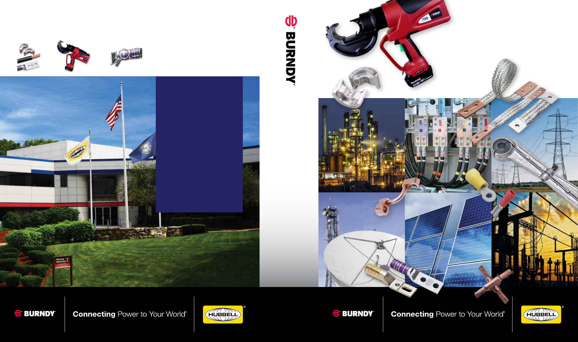
Dies and
connectors
Tools
Safe, easy and
inspectable connection
+
=
Trust the BURNDY
®
Engineered System
The BURNDY
®
Engineered System of coordinating dies, connectors and tools are always
designed to work together and engineered to meet stringent, accepted quality standards.
Master Catalog
www.burndy.com
|
1-800-346-4175
Customer Service Department
7 Aviation Park Drive
Londonderry, NH 03053
1-800-346-4175
1-800-451-4956 (Technical Services)
1-603-647-5299 (International)
Canada
1-800-361-6975 (Quebec)
1-800-387-6487 (All other provinces)
Mexico
011-52-722-265-4400
Brazil
011-55-11-5515-7225
Tool Service Center
Littleton Industrial Park
Littleton, NH 03561
1-800-426-8720
M
C-1
7
MC-17