BURNDY
®
Products
Grounding
D-1
TABLE OF CONTENTS
HYGROUND™ IRREVERSIBLE COMPRESSION GROUNDING
AND INSTALLATION TOOLING
Type
YGIB
.....................
D-20 - D-21
Type
GSTUD-HY
.......................
D-22
Types
YGT & YTTAG
................
D-23
Type
YG-B
..................................
D-24
MECHANICAL GROUNDING
Types
KC, K2C
.........................
D-25
Types
KC22J12T13,
EQC632C, KS-DB
..................
D-26
Types
KS, GKA,
KPB, CL50-1
............................
D-27
Type
GAR
......................
D-28 - D-29
Types
GAR-BU & GAR
3900 Series & GAR-RB
.........
D-30
Type
GAR-TC
...........................
D-31
HYGROUND™ Features
and Benefits
...................
D-5 - D-6
Type
YGL-C
................................
D-7
Type
YGLR-C
..............................
D-8
Type
YGHP-C
.............................
D-9
Type
YGHP-C
...........................
D-10
Type
YGHC-C
...........................
D-11
Type
YGC
..................................
D-12
Type
YSHG
................................
D-13
Type
YGHR-C
..........................
D-14
Type
YGHR-C
..........................
D-15
Type
YGHA
...............................
D-16
Type
YGHS
...............................
D-16
Type
YGA
..................................
D-17
Type
YGS
..................................
D-18
Type
YGF
..................................
D-19
LIGHTNING PROTECTION INFO.
Basic rules for selection are:
1. Must be like material to the conductor.
2. Two bolts to ground rod –– minimum, for mechanical.
3. Cable to cable connections can be installed with – one bolt,
two bolt, or compression.
4. Cable to steel structure must have 8 in.
2
contact with steel.
5. Heavy duty stacks –– mechanical only.
6. On all connectors with heavy duty stack rating, we must
offer 1/16
thick lead plating as an option. Reason is closest
25 ft. to stack opening must use lead coated product.
7. UL 96 Listing.
Burndy-Grounding-Connectors-catalog-html.html
BURNDY
®
Products
Grounding
D-2
TABLE OF CONTENTS
MECHANICAL GROUNDING (Continued)
Types
GC, GCM
........................
D-47
Type
GL
....................................
D-48
Type
GZ
....................................
D-48
Type
GC-CT
..............................
D-49
Type
GIE-G
...............................
D-50
Rail Connector
..........................
D-51
Type
QGFL
...............................
D-52
Type
GA-H
................................
D-52
Type
GRF
..................................
D-53
Raised Floor Grounding
Types
GP-G1, GPRT
..................
D-54
Raised Floor Grounding
Type
GD
....................................
D-32
Type
GP
....................................
D-33
Type
GK
....................................
D-33
Water Pipe Grounding
..
D-34 - D-39
Type
GC-A
................................
D-40
Type
GG
....................................
D-41
Type
GQ
....................................
D-42
Type
GX
....................................
D-43
Types
GRC, GRL
......................
D-44
Type
B
............................
D-45 - D-46
Types
GB, GBM
........................
D-47
Burndy-Grounding-Connectors-catalog-html.html
BURNDY
®
Products
Grounding
D-3
TABLE OF CONTENTS
BURNDYWeld™
BURNDY Weld™
Introduction ................................
D-56
Making a BURNDYWeld™
Connection
..........................
D-57
WELD METAL
..........................
D-58
Type
BCC-1
..............................
D-59
Type
BCC-2
..............................
D-60
Type
BCC-4
..............................
D-61
Type
BCC-11
............................
D-62
Type
BCC-6
..............................
D-63
Type
BCC-14
............................
D-63
Type
BCC-7
..............................
D-64
Type
BCR-1
................................
D-65
Type
BCR-2
.............................
D-66
Type
BCR-3
.............................
D-67
Type
BCR-17
............................
D-68
Type
BCR-24
............................
D-69
Type
BCS-1
...............................
D-71
Type
BCS-8
...............................
D-71
Type
BCS-2
...............................
D-72
Type
BCS-9
...............................
D-72
Type
BCS-3
...............................
D-73
Type
BCS-23
.............................
D-74
Type
BCS-4
...............................
D-75
Type
BCS-6
...............................
D-75
Type
BCS-7
................................
D-76
Type
BCS-18
.............................
D-76
Type
BCS-5
...............................
D-77
Type
BCRE-1
............................
D-78
Type
BCRE-2
............................
D-79
Burndy-Grounding-Connectors-catalog-html.html

BURNDY
®
Products
Grounding
D-4
TABLE OF CONTENTS
BURNDYWeld™ (Continued)
Type
BCRE-3
............................
D-80
Type
BCRE-4
............................
D-81
Type
BCRE-6
............................
D-82
BURNDYWeld™ FILL
..............
D-83
BURNDYWeld™ SET
...............
D-85
BURNDYWeld™
Prefabricated
Wire Mesh
.............................
D-87
Types
B-106 & B-107
Handle Clamps
.....................
D-89
B40-0106-75
Handle Attachment
...............
D-89
Mold Support Clamp
.................
D-89
Vertical Magnetic
Clamps
..................................
D-90
Horizontal & Vertical
Chain Clamps
.......................
D-90
SINGLE SHOT MOLDS
Type
BCR-1
..............................
D-70
Type
BCR-2
..............................
D-70
Type
BCR-24
............................
D-70
Type
BCR-25
............................
D-70
ACCESSORIES
B38-0330-00
Cable Clamp
.......
D-91
Cable Cleaning Brush
...............
D-91
Card Cloth Brush
......................
D-91
Mold Cleaning Brush
................
D-91
Mold Cleaners
...........................
D-91
Packing Material
........................
D-91
BURNDYWeld™
Tool Kit
..........
D-92
BURNDYWeld™
Tools
..............
D-92
B38-0101-00
Rasp
....................
D-92
B38-0309-00
Flint Ignitor
..........
D-92
Ground Rod
Driving Sleeves
.....................
D-93
Shim Stock and
Adapter Sleeves
....................
D-93
Tips
..................................
D-94 - D95
Burndy-Grounding-Connectors-catalog-html.html
BURNDY
®
Products
Grounding
THE HYGROUND™
IRREVERSIBLE
COMPRESSION
SYSTEM
BURNDY
®
has developed an irreversible
compression ground system which meets the
most stringent safety and performance
requirements, including those of OSHA and
nuclear power plant design. Performance
excellence and long life expectancy are the
system’s basic design guidelines. It is a com-
plete system which consists of connectors for
grid cross connections, taps, splices, cable to
ground rod, ground plates and terminations.
Our irreversible compression ground connec-
tors employ well-proven design principles
and technology that have been in existence
for over 60 years.
Connectors are just one component of our
Irreversible Compression Ground System.
Installation tooling is also an integral part of
this system. BURNDY
®
pioneered the com-
pression connector principle and continues
today to be the leader in compression tech-
nology. Our tooling package is the most
extensive in the industry and affords the user
many options.
D-5
Burndy-Grounding-Connectors-catalog-html.html

BURNDY
®
Products
Grounding
THE HYGROUND™
IRREVERSIBLE
COMPRESSION
SYSTEM
(Continued)
D-6
Features and Benefits
• Irreversible compression.
9
Meets 1999 NEC code, section 250-50
and 250-64.
• Material-pure wrought copper extrusions,
rod and seamless tubing––identical
material to the conductor.
9
Completely eliminates the possibility of
corrosion due to dissimilar metals.
• Heavy duty connector design.
9
All connectors will carry the equivalent
or greater current carrying capacity
of the conductor while maintaining
high mechanical strength and
electrical integrity.
• Range taking design––minimum number of
connector combinations required to install
a conductor range of #6 solid to 500 kcmil
plus 1/2
, 5/8
, 3/4
, and 1
ground rods
and rebar.
9
Inventories are kept to a minimum and
product selection is simplified.
• System engineered tooling.
9
Each tooling recommendation has
been designed to ensure reliability
of the connection.
• Irreversible compression connectors
can be installed in all kinds of weather.
9
Eliminates costly construction delays
and enables the installer to better
schedule his job.
• May be installed without special training
or special tools. Y750 crimps entire range.
9
Low installed cost.
Simplified installation.
• Each connection can be made in less than
3 minutes.
9
Low installed cost.
Simplified installation.
• Each connector is clearly marked with
catalog number, conductor size and
installation die information.
9
Easy and accurate identification.
• Inspection ports are provided to assure
proper insertion of the conductor.
9
Built-in quality assurance.
• The die index number is embossed on the
connector after completion of the crimp.
9
Facilitates speedy inspection of installed
connectors to insure consistently reliable
and sound connections.
• Most HYGROUND™ irreversible compres-
sion elements are prefilled with
PENETROX™ and individually sealed
in clear polyethylene sheet.
9
Ensures that all contact surfaces are in
the proper condition for installation.
9
Ensures the electrical integrity of the
finished connection by inhibiting moisture
and contaminates from entering the
contact area.
• All HYGROUND™ irreversible compres-
sion connectors are Listed in conformance
with Underwriters Laboratories Standard
UL467 and conform to applicable sections
of the National Electrical Code.
9
May be used in direct burial or concrete
embedded grounding applications.
• All HYGROUND™ irreversible connectors
(with the exception of type YGA and YGS)
have been tested successfully according
to requirements of Standard IEEE 837
latest revision.
9
Meets tough industry performance
requirements.
9
UPRECRIMP™ dies give added
mechanical strength. UPRECRIMP™ 34
for 3/4
rod, UPRECRIMP™ 12 for 1/2
rod, and UPRECRIMP™ 58 for 5/8
rod
(now includes undersized U.S. market
place rods).
• Allows connection to most sizes of
structural steel with no drilling, tapping,
or welding.
9
Safely installed at low cost. Hot work per-
mits are not required to install in
hazardous areas
Burndy-Grounding-Connectors-catalog-html.html
BURNDY
®
Products
Grounding
D-7
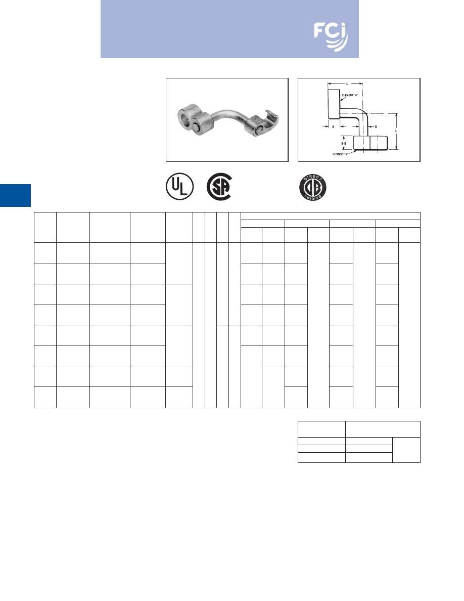
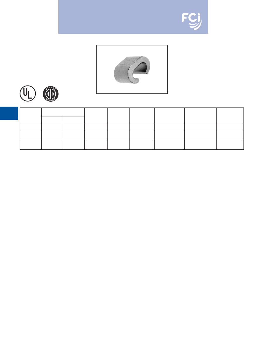
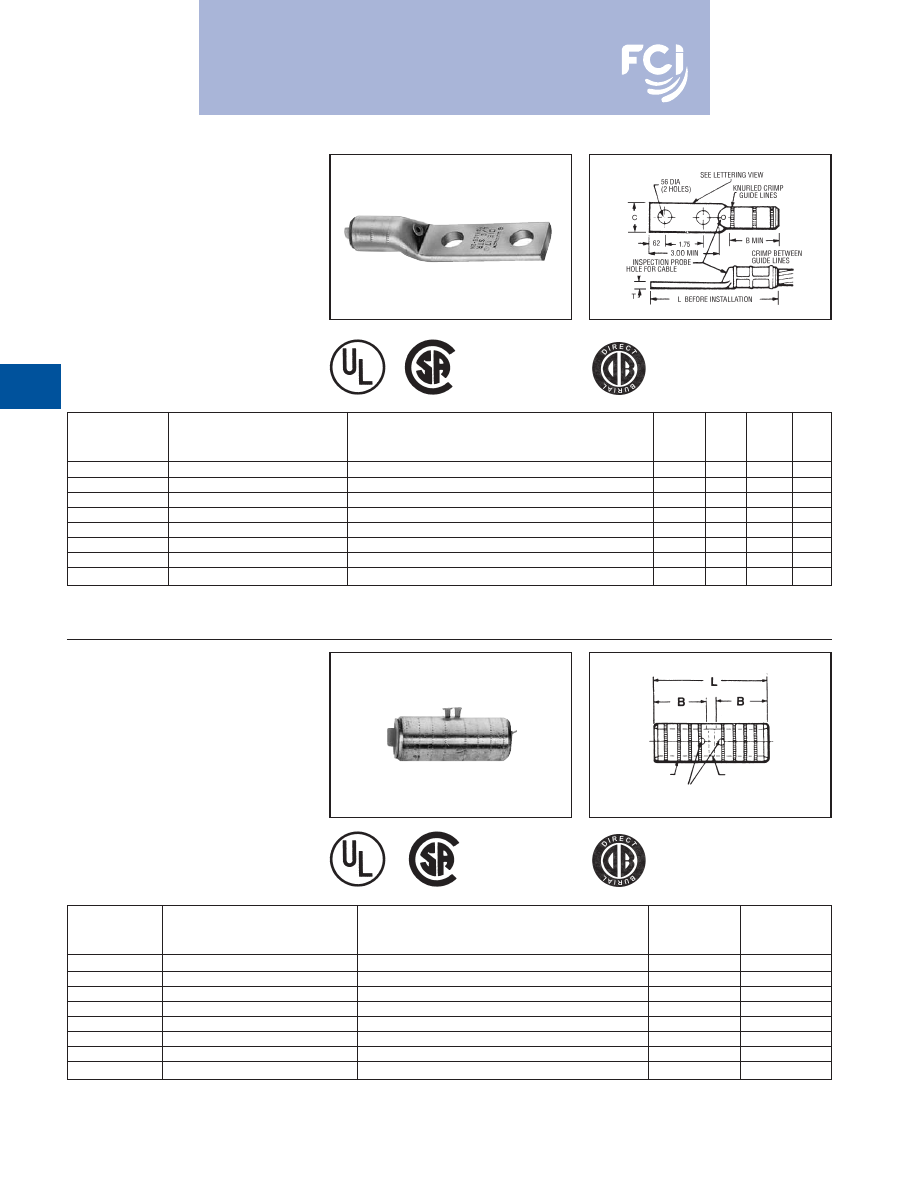
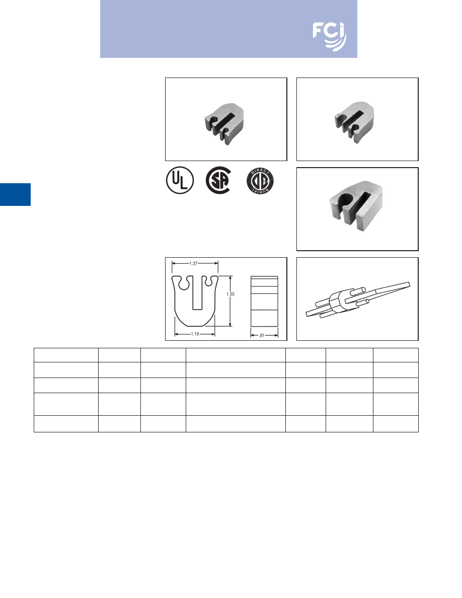
TYPE YGL-C
HYGRID CROSS CONNECTOR
An irreversable compression ground grid
cross connector which allows adjustment of
the compression elements prior to installa-
tion. Only six connectors and four dies are
required to install all combinations from #6
solid through 500 kcmil. UL467 Listed.
Acceptable for direct burial in earth and con-
crete. Prefilled with PENETROX™ compound
and strip sealed.
NOTES:
• Before crimping, both connector elements can
be turned on rod diameter "D" to any desired
position.
• Clean rust and/or protective coatings from rebar
prior to installation.
• When attaching connector to ground rod, ground
rod must be embossed with appropriate PRE-
CRIMP™ die. For connections that must meet
IEEE 837 requirements UPRECRIMP™ - type
PRE crimp dies must be used for maximum
clamping retention.
ORDERING INFORMATION
1.
Where a "U" or "PU" die is recommended with Y45
HYPRESS™, a PT6515 adapter must be used.
2. Where a "U" or "PU" die is recommended with the Y46
HYPRESS™, a PUADP-1 adapter must be used.
➂
Polarized die for the PAT750-18V.
UL96 Listed for Lightning Protection.
467
96
CATALOG
CABLE TO CABLE
CABLE TO GROUND ROD
TO REBAR
NUMBER
ELEMENT “A”
ELEMENT “B”
ELEMENT “A”
ELEMENT “B”
ELEMENT “A”
YGL2C2
#6 SOL. (.162) – #2 STR. (.292)
{59500} – {59500}
#6 SOL. (.162) – #2 STR. (.292)
YGL29C2
#1 STR. (.332) – 250 kcmil (.575)
{59500} – {59500}
#6 SOL. (.162) – #2 STR. (.292)
3/8
"
– 1/2
"
{98500} – {131500}
1/2
"
– 5/8
"
Rod
YGL29C29
#2 STR. (.292) – 250 kcmil (.575)
#2 STR. (.292) – 250 kcmil (.575)
#2 STR. (.292) – 250 kcmil (.575)
#3 – 4 Rebar
{65500} – {131500}
{65500} – {131500}
YGL34C2
#6 SOL. (.162) – #2 STR. (.292)
#6 SOL. (.162) – #2 STR. (.292)
5/8
"
– 3/4
"
YGL34C29
250 kcmil (.575) – 500 kcmil (.813)
#2 STR. (.292) – 250 kcmil (.575)
5/8
"
– 3/4
"
Rod
#2 STR. (.292) – 250 kcmil (.575)
YGL34C34
250 kcmil (.575) – 500 kcmil (.813)
250 kcmil (.575) – 500 kcmil (.813)
#5 – 6 Rebar
Dimensions in brackets { } represent lightning
protection conductors.
* These connectors can only be installed using the Y750,
Y45, or Y46 HYPRESS™ with the recommended dies.
These connectors CANNOT be installed with the Y35 and
Y39 HYPRESS™.
INSTALLATION TOOLS, DIE SET CAT. NO. (NUMBER OF CRIMPS)
CATALOG
Y750/Y35/Y39 HYPRESS
PAT750-18V
Y45 HYPRESS
Y46 HYPRESS
NUMBER
ELEMENT “A” ELEMENT “B”
ELEMENT “A”
ELEMENT “B”
ELEMENT “A”
ELEMENT “B”
ELEMENT “A”
ELEMENT “B”
YGL2C2
U-0 (1)
U-0 (1)
U-0 (1)
U-0 (1)
U-0 (1)
U-0 (1)
U-0 (1)
U-0 (1)
YGL29C2
U997 (1)
U-0 (1)
➂
U997P (1)
U-0 (1)
U997 (1)
U-0 (1)
U997 (1)
U-0 (1)
YGL29C29
U997 (1)
U997 (1)
➂
U997P (1)
➂
U997P (1)
U997 (1)
U997 (1)
U997 (1)
U997 (1)
S998 or
P998 or
YGL34C2*
PU998 (1)
U-0 (1)
PU998 (1)
U-0 (1)
PU998 (1)
U-0 (1)
PU998 (1)
U-0 (1)
S998 or
PU998 or
YGL34C29*
PU998 (1)
U997 (1)
PU998 (1)
➂
U997P (1)
PU998 (1)
U997 (1)
PU998 (1)
U997 (1)
YGL34C34*
U1011 (3)
U1011 (3)
U1011 (3)
U1011 (3)
S1011 (3)
S1011 (3)
P1011 (3)
P1011 (3)
CATALOG
NUMBER
B
B-B
C
C-C
D
L
R
YGL2C2
1.09
YGL29C2
1.09
.313
.31
YGL29C29
.75
.75
1.66
1.66
.500
.50
YGL34C2
1.09
.313
2.50
.31
YGL34C29
2.09
1.66
.500
.50
YGL34C34
1.10
1.10
2.28
2.28
.750
.75
GROUND ROD
DIA.
PRECRIMP DIES
1/2
UPRECRIMP 12
5/8
UPRECRIMP 58
U2CABT
3/4
UPRECRIMP 34
MEETS ALL
IEEE
837 REQUIREMENTS
Burndy-Grounding-Connectors-catalog-html.html
BURNDY
®
Products
Grounding
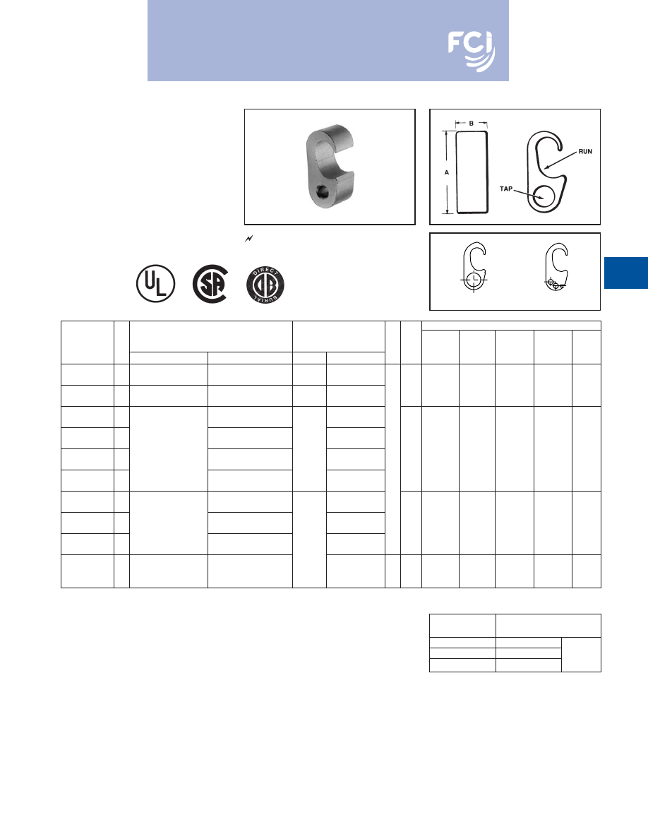
TYPE YGLR-C
GRIDLOK
High Strength
Irreversible
Compression Ground Rod to
Grid Connector
Ground grid connector for a wide range of
copper cable to ground rod. Provides high
torque strength on ground rod. UL467
Listed. Acceptable for direct burial in earth
and concrete. Prefilled with PENETROX™
compound and strip sealed.
D-8
When attaching connector to ground rod, ground
rod must be embossed with appropriate PRE-
CRIMP™ die. For connections that must meet IEEE
837 requirements UPRECRIMP™ - type PRE crimp
dies must be used for maximum clamping retention.
NOTES:
1. Before crimping, both connector elements can be
turned on rod diameter 'D' to any desired position.
2. Grooves are filled with PENETROX™
.
3. Suitable for direct burial in earth or concrete.
4. The catalog numbers shown are for unplated
copper connectors for use on copper clad or
stainless steel ground rod. To order electro-tin
plated connectors for use on galvanized steel
ground rod add suffix "TN" to the catalog number,
only if the Figure 8 connector (Element “B”) is tin
plated, the Figure 6 connector (Element “A”) is
unplated. Note: The ground rod hole diameter is
larger for galvanized steel ground rod in the tin
plated connector.
Element B
Element A
5. Ground rod must be pre-crimped with die
U2CABT (Index No. 348) when crimping the
ground rod element (Element “B”) with the PU998
dies in the Y750, Y35, Y39, Y45, or Y46 tools. Pre-
crimping is not required when the S1012, P1011
or U1011 dies are used. See precrimp die chart.
6. Where a 'U' or 'PU' die is recommended with the
Y45 HYPRESS™, a PT6515 adapter must be
used.
7. Where a 'U' or 'PU' die is recommended with the
Y46 HYPRESS™, a PUADP-1 adapter must be
used.
8. Dimensions in bracket [ ] are in millimeters.
9. Die "1011" appears on Element "B" of the
connector only.
GROUND ROD
DIA.
PRECRIMP DIES
1/2
UPRECRIMP 12
5/8
UPRECRIMP 58
U2CABT
3/4
UPRECRIMP 34
COMMERCIAL
INSTALLATION TOOLS, DIE SET CAT. NO., (NUMBER OF CRIMPS)
COPPER
METRIC COPPER
COPPER WELD
GROUND ROD
Y35/Y39 HYPRESS™
Y750/PAT750
Y45 HYPRESS™
Y46 HYPRESS™
CATALOG
CABLE RANGE
CABLE RANGE
CABLE RANGE
DIA.
ELEMENT
ELEMENT
ELEMENT
ELEMENT
ELEMENT
ELEMENT
ELEMENT
ELEMENT
NUMBER
ELEMENT “A”
ELEMENT “A”
ELEMENT “A”
ELEMENT “B”
B
B-B
D
L
“A”
“B”
“A”
“B”
“A”
“B”
“A”
“B”
#2 Str. (.292 Dia.)
35mm
2
(7.62mm Dia.)
91.65 kcmil (.343 Dia.)
YGLR29C12
thru
thru
thru
U997 (1)
PU998 (1)
U997 (1)
U997 (1)
U997 (1)
250 kcmil (.575 Dia.)
120 mm
2
(14.40mm Dia.)
248.8 kcmil (.572 Dia.)
1/2
250 kcmil (.575 Dia.)
120 mm
2
(14.40mm Dia.)
248.8 kcmil (.572 Dia.)
[12.7]
U1011
S998
P998
YGLR34C12
thru
thru
thru
—
or
or
or
500 kcmil (.813 Dia.)
240 mm
2
(20.35mm Dia.)
498.8 kcmil (.810 Dia.)
.313
2.53
PU998 (1)
PU998 (1)
PU998 (1)
#2 Str. (.292 Dia.)
35 mm
2
(7.62mm Dia.)
91.65 kcmil (.343 Dia.)
[7.9]
[64.3]
YGLR29C58
thru
thru
thru
U997 (1)
PU998 (1)
U997 (1)
U997 (1)
U997 (1)
250 kcmil (.575 Dia.)
120 mm
2
(14.40mm Dia.)
248.8 kcmil (.572 Dia.)
5/8
250 kcmil (.575 Dia.)
120 mm
2
(14.40mm Dia.)
248.8 kcmil (.572 Dia.)
[15.9]
U1011
S998
P998
YGLR34C58
thru
thru
thru
—
or
U1011 (2)
or
S1012 (2)
or
P1011(2)
500 kcmil (.813 Dia.)
240 mm
2
(20.35mm Dia.)
498.8 kcmil (.810 Dia.)
.75
.88
PU998 (1)
or
PU998 (1)
or
PU998 (1)
or
#2 Str. (.292 Dia.)
35 mm
2
(7.62mm Dia.)
91.65 kcmil (.343 Dia.)
[19.1] [22.4]
PU998 (1)
PU998 (1)
PU998 (1)
YGLR29C34
thru
thru
thru
U997 (1)
PU998 (1)
U997 (1)
U997 (1)
U997 (1)
250 kcmil (.575 Dia.)
120 mm
2
(14.40mm Dia.)
248.8 kcmil (.572 Dia.)
3/4
250 kcmil (.575 Dia.)
120 mm
2
(14.40mm Dia.)
248.8 kcmil (.572 Dia.)
[19.1]
U1011 (2)
U1011 (2)
U1011 (2)
YGLR34C34
thru
thru
thru
or
or
or
500 kcmil (.813 Dia.)
240 mm
2
(20.35mm Dia.)
496.8 kcmil (.810 Dia.)
.500
2.63
PU998
PU998
PU998
#2 Str. (.292 Dia.)
35 mm
2
(7.62mm Dia.)
91.65 kcmil (.343 Dia.)
[12.7]
[66.8]
YGLR29C100
thru
thru
thru
1
—
U997 (1)
U997 (1)
U997 (1)
250 kcmil (.575 Dia.)
120 mm
2
(14.40mm Dia.)
248.8 kcmil (.572 Dia.)
[25.4]
250 kcmil (.575 Dia.)
120 mm
2
(14.40mm Dia.)
248.8 kcmil (.572 Dia.)
—
U1011 (2)
U1011 (2)
U1011 (2)
YGLR34C100
thru
thru
thru
1
or
or
or
500 kcmil (.813 Dia.)
240 mm
2
(20.35mm Dia.)
498.8 kcmil (.810 Dia.)
[25.4]
PU998 (1)
PU998
PU998
MEETS ALL
IEEE
837 REQUIREMENTS
Burndy-Grounding-Connectors-catalog-html.html
BURNDY
®
Products
Grounding
D-9
TYPE YGHP-C
HYTAP™ CONNECTOR
Irreversible compression ground tap figure 6
can be used as a tap connector or as a tap
splice connector. Four die sets and eight con-
nectors can accommodate a conductor range
from #8 solid through 500 kcmil plus 1/2
, 5/8
,
and 3/4
copper bonded ground rods. UL467
Listed. Acceptable for direct burial in earth and
concrete.
Prefilled with PENETROX™
compound and strip sealed.
NOTES:
➀
When using #6 Sol. in tap, fold conductor double to improve
fill in YGHP2C2.
➁
For YGHP29C29 when using 3/0 in tap, minimum run
conductor is 2/0 STR.
➂
Where a 'U' or 'PU' die is recommended with the Y45
HYPRESS™, a PT6515 adapter must be used.
➃
Where a 'U' or 'PU' die is recommended with the Y45
HYPRESS™, a P-UADP-1 adapter must be used.
For increased rotational resistance on ground rods,
pre-crimp ground rod with U2CABT die Index 348 or
uprecrimp dies may be used for even greater rota-
tion and vibration resistance on ground rods.
CABLE TO GROUND ROD
CABLE TO REBAR
CABLE TO CABLE
FOR CONCRETE ENCASED
ELECTRODE GROUNDING
APPLICATIONS
Fig. 1
Fig. 2
UL96 Listed for Lightning Protection.
INSTALLATION DATA
➄
DIE
Y750/Y35
➂
➃
CATALOG
FIG.
ACCOMMODATES
CABLE TO REBAR
INDEX
Y39
Y45
Y46
NO. OF
NUMBER
NO.
RUN
TAP
RUN
TAP
B
NO. HYPRESS™ PAT750-18V HYPRESS™ HYPRESS™
CRIMPS
YGHP2C2
1
#6 SOL. (0.162) {59500} –
➀
#6 SOL. (0.162) {#2 STR.} –
—
—
#2 STR. (0.292) {59500}
#2 STR. (0.292) {#2 STR.}
0
U0
U0
U0
U0
1
YGHP2C6W6W
➇
2
#6 SOL. (0.162) –
#8 SOL. (0.128) –
—
—
#2 STR. (0.292)
6 STR. (0.184) QTY. 2
YGHP29C6W6W
➇
2
#8 SOL. (0.128) –
#8 SOL. – 6 STR.
6 STR. (0.184) QTY. 2
#3 REBAR
YGHP29C2
1
1/0 STR. (0.372) {98500} –
#4 SOL. (0.204) {#4 SOL.} –
3/8
#2 STR.
250 kcmil (0.575) {131500}
#2 STR. (0.292) {#2 STR.}
997
U997
➆
U997P
U997
U997
1
YGHP29C26
1
1/2
"
– 5/8
"
ROD
1/0 STR. (0.372) {98500} –
THRU
1/0 STR. – 2/0 STR.
.75
2/0 STR. (0.419) {98500}
1/2
[19]
YGHP29C29
➁
1
3/0 STR. (0.470) {131500} –
#4 REBAR
3/0 STR. – 250 kcmil
250 kcmil (0.575) {211500}
YGHP34C2
➅
1
#4 SOL. (0.204) –
#5 REBAR
—
#2 STR. (0.292)
5/8
YGHP34C26
➅
1
250 kcmil (0.575) {250 kcmil} –
1/0 STR. (0.372) {98500} –
1/0 STR. – 2/0 STR.
998
PU998
PU998
PU998 or
PU998 or
1
500 kcmil (0.813) {500 kcmil}
2/0 STR. (0.419) {98500}
S998
P998
YGHP34C29
➅
1
5/8
"
– 3/4
"
ROD
3/0 STR. (0.470) {131500} –
THRU
3/0 STR. – 250 kcmil
250 kcmil (0.575) {211500}
250 kcmil (0.575) –
350 kcmil (0.681) –
3/4
1.10
YGHP34C34
➅
1
500 kcmil (0.813)
#6 REBAR
350 kcmil – 500 kcmil
1011
➅
U1011
U1011
S1011
P1011
3
5/8
"
– 3/4
"
ROD
500 kcmil (0.843)
[28]
Dimensions in brackets { } represent lightning protection
conductors.
467
96
➄
Clean rust and protective coatings from rebar before con-
nector installation to provide a proper ground connection.
Precrimping is not required.
➅
These connectors can only be installed using the Y750, Y45
or Y46 HYPRESS™ with the recommended dies. These
connectors can not be installed with the Y35 and Y39
HYPRESS™.
➆
Polarized die for the PAT750-18V.
➇
Not UL96/CSA.
GROUND ROD
DIA.
PRECRIMP DIES
1/2
UPRECRIMP 12
5/8
UPRECRIMP 58
U2CABT
3/4
UPRECRIMP 34
MEETS ALL
IEEE
837 REQUIREMENTS
Burndy-Grounding-Connectors-catalog-html.html
BURNDY
®
Products
Grounding
D-10
TYPE YGHP-C
HYTAP™ CONNECTOR
High Strength
Copper Irreversible
Compression
Ground Rod Tap
Connector
Type YGHP-C irreversible compression
ground tap figure 6 can be used as a ground
rod tap connector for both continuous run and
tapping applications. An open groove allows
ground rod to be connected to a continuous
run or tap. The second groove is for a tap
only. Prefilled with PENETROX-E™ and strip
sealed. UL467 Listed for direct burial in earth
or concrete.
Features and Benefits
• Tap (A) accepts a continuous run on
tap conductor
Tap (B) accepts a tap conductor only.
9
One connector style can be used for
many applications, reducing number
of connectors in inventory.
• Material is high conductivity wrought
copper extrusion, identical material to
the conductor.
9
High-conductivity copper minimizes
resistance and voltage drop. Eliminates
the possibility of corrosion due to
dissimiliar metals.
• System engineered tooling.
9
The tooling recommendation has been
designed to ensure a reliable, depend-
able connection every time.
• The die index number is embossed on
conductor after completion of crimp.
9
Faciliates speedy inspection of installed
connectors to insure consistently reliable
and dependable connections.
NOTE:
A 12" bend radius is recommended for the conductor.
• Use PUADP-1 with ‘U’-dies in Y46.
▲
See tooling section in Master Catalog for complete tool and
die listing.
+ Either tap position may be left void when fewer than (2)
conductors are used.
SINGLE TAP
CONTINUOUS RUN
CONTINUOUS RUN AND TAP
PATENTED
TAP (A)
TAP (B)
PREFILLED WITH
PENETROX-E
DIE INDEX
AND CONDUCTOR
INFORMATION
“THIRD HAND”
• Prefilled with PENETROX™ and individual-
ly sealed in clear polyethylene sheet.
9
Ensures the electrical integrity of the
finished connection by inhibiting moisture
and contaminates from entering the
contact area. Maintains long-term
high-conductivity.
• UL467 Listed.
9
May be used in direct burial or concrete
embedded grounding applications.
Provides quality assurance to recognized
industry NEC standards from an
independent party.
• “Third Hand” constrains conductors while
installer completes crimp. Included with
each connector.
9
Simplifies installation, reducing
installed cost.
■
Ground rod must be precrimped with die U2CABT (Index
No. 348).
For even greater rotational resistance use U-PRECRIMP
die.
For Galvanized Steel Rods order YGHP58C2W-2TN.
▲
INSTALLATION TOOLING
Y35/Y750/PAT750
Y46
•
CATALOG
GROUND
DIMENSIONS
DIE
NO. OF
DIE
NO. OF
DIE
NUMBER
ROD DIA.
■
TAP CONDUCTOR +
H
B
W
NO.
CRIMPS
NO.
CRIMPS
INDEX
YGHP58C2W-2
#2 Sol. - #6 Sol. Copper
1/2
- 5/8
(1) Continuous run and (1) Tap or
1.90
.75
.94
U997
(1)
U997
(1)
997
YGHP58C2W-2TN
up to (2) taps may be connected.
MEETS ALL
IEEE
837 REQUIREMENTS
Burndy-Grounding-Connectors-catalog-html.html
BURNDY
®
Products
Grounding
D-11
TYPE YGHC-C
HYTAP™ CONNECTOR
Irreversible compression ground tap figure
"C" connectors. Accomodates all cable
combinations from #6 solid through 500
kcmil. "C"- shaped opening permits placing
two continuous parallel cables into conductor
groove. UL 467 Listed. Acceptable for direct
burial in earth or concrete. Prefilled with
PENETROX™ compound and strip sealed.
NOTES:
➀
Where a "U" or "PU" die is recommended with
the Y45 HYPRESS™, PT6515 adapter must be
used.
➁
Where a "U" or "PU" die is recommended with
the Y46 HYPRESS™, a PUADP-1 adapter must
be used.
3. Listed under UL486A for copper wire connec-
tors
4. Dimensions in brackets [ ] are in millimeters.
UL96 Listed for Lightning Protection.
467
96
INSTALLATION DATA
COMMERCIAL COPPER
STRANDED COPPER
DIE
Y750/Y35/
➀
➁
CATALOG
CABLE RANGE
CABLE RANGE
INDEX
PAT750/Y39
Y45
Y46
NO. OF
NUMBER
RUN
TAP
RUN
TAP
A
B
NO.
HYPRESS™
HYPRESS™
HYPRESS™
CRIMPS
YGHC2C2
#6 SOL. (0.162)
#6 SOL. (0.162)
10 mm
2
(4.12 mm)
10 mm
2
(4.12 mm)
1.16
0.75
C
U-C
U-C
U-C
1
#2 STR. (0.292)
#2 STR. (0.292)
35 mm
2
(7.62 mm)
35 mm
2
(7.62 mm)
[30]
[19]
1 STR. (0.328)
#6 SOL. (0.162)
35 mm
2
(7.62 mm)
10 mm
2
(4.12 mm)
YGHC26C2
{98500}
{#6 SOL.}
1.41
0.75
0
U-O
U-O
U-O
1
2/0 STR. (0.419)
#2 STR. (0.292)
70 mm
2
(10.9 mm)
35 mm
2
(7.62 mm)
[36]
[19]
{98500}
{#2 STR.}
1 STR. (0.328)
1 STR. (0.328)
35 mm
2
(7.62 mm)
35 mm
2
(7.62 mm)
YGHC26C26
{98500}
{98500}
1.54
0.75
0
U-O
U-O
U-O
1
2/0 STR. (0.419)
2/0 STR. (0.419)
70 mm
2
(10.9 mm)
70 mm
2
(10.9 mm)
[39]
[19]
{98500}
{98500}
3/0 STR. (0.470)
6 SOL. (0.419)
95 mm
2
(12.5 mm)
10 mm
2
(4.12 mm)
YGHC29C26
{3/0 STR.}
{59500}
1.97
0.75
997
U997
U997
U997
1
250 kcmil (0.575) 2/0 STR. (0.419)
120 mm
2
(14.4 mm) 70 mm
2
(10.9 mm)
[50]
[19]
{250 kcmil}
{98500}
YGHC29C29
3/0 STR. (0.470)
3/0 STR. (0.470)
95 mm
2
(12.5 mm)
95 mm
2
(12.5 mm)
2.06
0.88
997
U997
U997
U997
1
250 kcmil (0.575) 250 kcmil (0.575)
120 mm
2
(14.4 mm) 120 mm
2
(14.4 mm)
[52]
[22]
300 kcmil (0.630) #6 SOL. (0.162)
150 mm
2
(16 mm)
10 mm
2
(4.12 mm)
YGHC34C26
➅
{300 kcmil}
{59500}
2.42
0.88
1011
U1011
S1011
P1011
2
500 kcmil (0.813)
2/0 STR. (0.419)
240 mm
2
(20.35 mm) 70 mm
2
(10.9 mm)
[62]
[22]
{500 kcmil}
{98500}
YGHC34C29
➅
300 kcmil (0.630) 3/0 STR. (0.470)
150 mm
2
(16 mm)
95 mm
2
(12.5 mm)
2.67
0.88
1011
U1011
S1011
P1011
2
500 kcmil (0.813)
250 kcmil (0.575)
240 mm
2
(20.35 mm)
120 mm
2
(14.4 mm)
[66]
[22]
YGHC34C34
➅
300 kcmil (0.630) 300 kcmil (0.630)
150 mm
2
(16 mm)
150 mm
2
(16 mm)
2.91
1.1
1011
U1011
S1011
P1011
3
500 kcmil (0.813)
500 kcmil (0.813)
240 mm
2
(20.35 mm) 240 mm
2
(20.35 mm)
[74]
[28]
Dimensions in brackets { } represent lightning protection conductors.
5. In referencing connectors without PENETROX™
oxide inhibitor add suffix "NP" to the end of the
Catalog Number.
➅
These connectors can only be installed using
the Y750, Y45 or Y46 HYPRESS™ with the
recommended dies.
These connectors cannot be installed with the
Y35 and Y39 HYPRESS™.
MEETS ALL
IEEE
837 REQUIREMENTS
Burndy-Grounding-Connectors-catalog-html.html
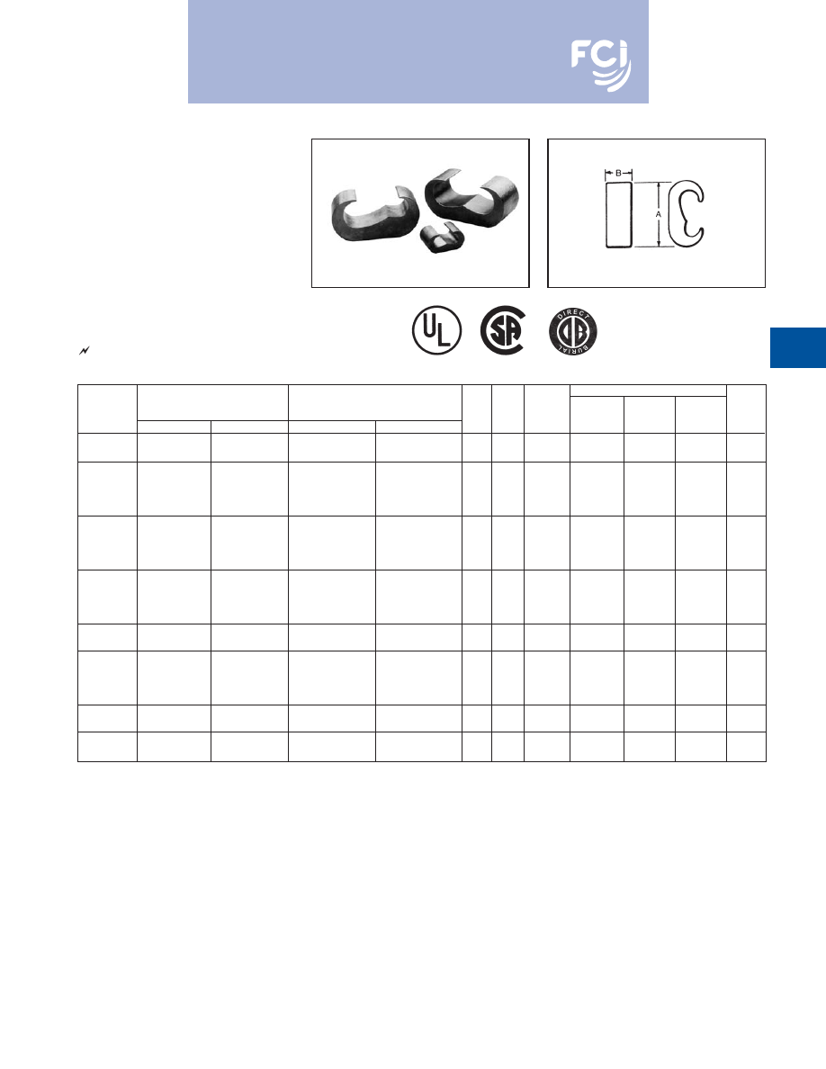
BURNDY
®
Products
Grounding
D-12
TYPE YGC
COPPER CRIMPIT™
UL 467 Listed for direct burial in earth or
concrete. Prefilled with PENETROX™ E2
oxide inhibitor.
COPPER
CATALOG
CONDUCTOR
NUMBER
RUN
TAP
H
L
INDEX
OUR840
MD6/MD7
CRIMPS
#8 SOL.
#8 SOL.
YGC8C8
#8 STR.
#8 STR.
.46
.52
162
W162
W162
2
#6 SOL.
#8 SOL.
YGC6C8
#6 STR.
#8 STR.
.73
.62
BG
XBG
WBG
2
#6 SOL.
#6 SOL.
YGC6C6
#6 STR.
#6 STR.
.76
.62
BG
XBG
WBG
2
Burndy-Grounding-Connectors-catalog-html.html
BURNDY
®
Products
Grounding
D-13
TYPE YSHG
HIGH STRENGTH
COPPER IRREVERSIBLE
COMPRESSION
Double H-Tap Connector
Type YSHG Double H-Tap grounding series is
comprised of five connectors designed to
accommodate wire range sizes #14 through
500 kcmil, including ground rod sizes: 3/4
,
1
, and rebar sizes: #6, #8 and #9. Prefilled
with PENETROX™ E2 and strip sealed.
Features and Benefits
• UL467 Listed.
9
Suitable for direct burial in earth
or concrete.
• Material is high conductivity
copper extrusion.
9
Minimizes resistance, eliminates
corrosion due to dissimilar metals.
* NOTE: Not for use on 1
steel ground rod.
† Use PUADP-1 adapter.
Fig. 1
Fig. 2
Fig. 3
• Grooves are prefilled with PENETROX™ E2
oxide inhibitor and individually sealed.
9
Inhibits moisture and contaminants
ensuring electrical integrity.
Tooling
Index
Catalog
Fig.
Conductor Sizes
(number of crimps)
Emboss-
W
T
L
Number
No.
Main
Tap 1
Tap 2
Tap 3
PAT750/Y750
Y46
ment
.06
.04
.06
#9 & #8 Rebar, 1
[25] Ground
3.22
1.70
2.44
YSHG4429
3
Rod
250 - 2
PYFR (2)
K-R
[82]
[43]
[62]
1
[25] Cu Clad Ground Rod
2.97
1.50
2.94
* YSHG3939
1
500 kcmil Copper
500 - 350
PYFR (2)
K-R
[75]
[38]
[75]
#6 Rebar, 1
[25] Cu Clad
* YSHG3931
2
Ground Rod, 3/4
Ground Rod
4/0 - 1/0
1 - 6
2 - 14
PYFR (2)
K-R
2.97
1.50
2.34
500 - 350 kcmil Copper
[75]
[38]
[59]
#6 Rebar, 3/4
[19] Ground Rod
P1104 (2)
2.43
1.15
2.44
YSHG3434
1
400 - 250 kcmil COPPER
400 - 4/0
U1104 (4)
†U1104 (4)
1104
[62]
[29]
[62]
#6 Rebar, 3/4
[19] Ground Rod
P1104 (2)
2.23
1.31
2.44
YSHG3429
2
400 - 4/0 kcmil Copper
3/0 - 1/0
1 - 4
8 - 14
U1104 (4)
†U1104 (4)
1104
[57]
[33]
[62]
Burndy-Grounding-Connectors-catalog-html.html
BURNDY
®
Products
Grounding
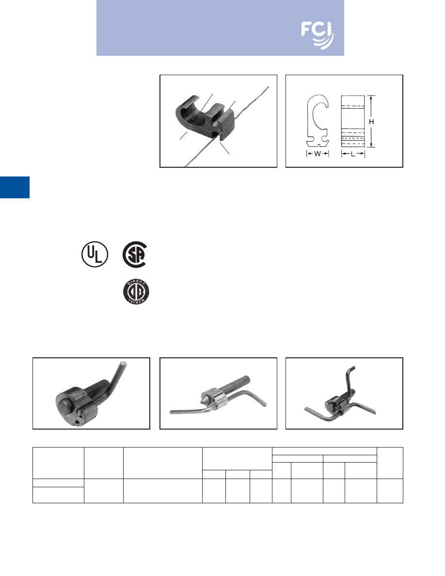
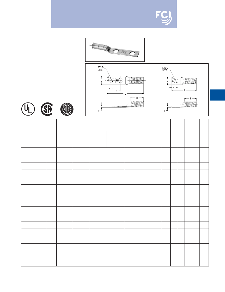
TYPE YGHR-C
HYTAIL™
High Strength
Irreversible
Compression Ground Rod Tap
Connectors
High torque strength ground rod connectors.
Accommodates a wide range of copper
conductors to ground rod. UL467 Listed.
Acceptable for direct burial in earth or con-
crete. Prefilled with PENETROX™ compound
and strip sealed.
D-14
NOTES:
•
The catalog numbers shown are for unplated copper
connectors for use on copper clad or stainless steel ground
rod. To order electro-tin plated connectors for use on
galvanized steel ground rod add suffix "TN" to the catalog
number. Note: The ground rod hole diameter is larger for
galvanized steel ground rod in the tin plated connector.
①
Ground rod must be pre-crimped with die U2CABT (Index
No. 348) when the PU998 dies are used in the Y750, Y35,
Y39, Y45, or Y46 tools. Pre-crimping is not required when
the P1011, S1011, S1012 or U1011 dies are used. UPRE-
CRIMP™ dies may be used for additional mechanical resis-
tance on ground rods.
➁
Where a PU998 die is recommended with the Y45
HYPRESS™, a PT6515 adapter must be used.
➂
Where a PU998 die is recommended with the Y46
HYPRESS™, a PUADP-1 adapter must be used.
➃
These die numbers do not appear on the connector.
*
These connectors can only be installed using the Y750, Y45
or the Y46 HYPRESS™ with the recommended dies. These
connectors CAN NOT be installed with the Y35 and Y39
HYPRESS™. When attaching connector to ground rod,
ground rod must be embossed with appropriate PRE-
CRIMP™ die. For connections that must meet IEEE 837
requirements UPRECRIMP™ - type PRE crimp dies must
be used for maximum clamping retention.
CATALOG
NUMBER
H
B
YGHR26C12
1.94
[49.3]
YGHR26C58
1.97
[50.0]
YGHR26C34
2.19
[55.6]
YGHR26C100
2.55
[56.2]
YGHR29C12
1.94
[49.3]
.88
YGHR29C58
2.14
[54.4]
YGHR29C34
2.19
[55.6]
[22.4]
YGHR29C100
2.45
[62.2]
YGHR34C58
2.14
[54.4]
YGHR34C34
2.44
[62.0]
YGHR34C100
2.70
[68.6]
CATALOG
COMMERCIAL COPPER
NOMINAL GROUND
INSTALLATION TOOLS, DIE SET CAT. NO. (NUMBER OF CRIMPS)
NUMBER
CABLE RANGE
ROD DIA.
PAT750/Y750/Y35/Y39
①
Y45 HYPRESS
①
Y46 HYPRESS
①
YGHR26C12
1/2
[12.7]
S1012 (2)
YGHR26C58
#2 STR. (.292 DIA.)
5/8
[15.9]
➃
YGHR26C34
thru
3/4
[19.0]
PU998 (1)
②
2/0 STR. (.419 DIA.)
S1011 (2) S1012 (2)
YGHR26C100*
1
[25.4]
PU998 (1)
YGHR29C12
1/2
[12.7]
U1011 (2)
S1012 (2)
P1011 (2)
YGHR29C58
#4/0 STR. (.528 DIA.)
5/8
[15.9]
➃
➃
➃
YGHR29C34
thru
3/4
[19.0]
PU998 (1)
PU998 (1)
②
PU998 (1)
250 kcmil (.575 DIA.)
S1011 (2) S1012 (2)
③
YGHR29C100*
1
[25.4]
➃
PU998 (1)
YGHR34C58
300 kcmil (.630 DIA.)
5/8
[15.9]
S1012 (2)
YGHR34C34*
thru
3/4
[19.0]
➃
PU998 (1)
②
YGHR34C100*
500 kcmil (.813 DIA.)
1
[25.4]
S1011 (2)
P1011 (2)
MEETS ALL
IEEE
837 REQUIREMENTS
Burndy-Grounding-Connectors-catalog-html.html
BURNDY
®
Products
Grounding
D-15
TYPE YGHR-C
HYTAIL™
High Strength
Irreversible
Compression Ground Rod Tap
Connectors
Type YGHR-C irreversible compression
grounding connector is engineered specifical-
ly for the Telecommunications Industry for
(1, 2 or 3) #2 solid, tinned or bare conductor
taps. UL467 Listed. Acceptable for direct burial
in earth or concrete. BURNDY
®
has designed
this connector to meet the stringent require-
ments of OSHA, the National Electric Code
(NEC), UL, and the Telecommunications
Industry. Performance and long life are this
connector’s basic design guidelines.
Features and Benefits
• Tap side 1, 2 or 3 conductors.
9
One connector style can be used for
many applications.
• Material is high conductivity wrought
copper extrusion, identical material to
the conductor.
9
High-conductivity copper minimizes
resistance and voltage drop. Eliminates
the possibility of corrosion due to
dissimilar metals.
• System engineered tooling.
9
Each tooling recommendation has
been designed to provide a reliable,
dependable connection.
• Contact BURNDY
®
for other ground rod diameters.
* PU998 and U1011 die sets require PUADP-1 adapter for
use in the Y46 HYPRESS™.
Tap positions may be left void when fewer than (3) conduc-
tors are used.
+ To order electro-tin plated connector for use on galvanized
steel ground rod add suffix -“TN” to the catalog number.
NOTE:
The ground rod hole diameter is larger for galvanized
steel ground rod in the tin plated connector.
TAP
TAP
RUN
RUN
AND
• The die index number is embossed on
connector after completion of crimp.
9
Facilitates speedy inspection of installed
connectors to ensure consistently
reliable and dependable connections.
• Prefilled with PENETROX™ and individually
sealed in clear polyethylene sheet.
9
Ensures the electrical integrity of the
finished connection by inhibiting moisture
and contaminates from entering the
contact area. Maintains long-term
high-conductivity.
• UL 467 Listed. Acceptable for direct burial.
9
May be used in direct burial or concrete
embedded grounding applications.
Provides quality assurance to recognized
industry NEC standards from an
independent party.
† Ground rod must be precrimped with die U2CABT (Index
No. 348) when PU998 die set is used in the Y35, Y750 or
Y46
▲
HYPRESS™ tools. For even greater mechanical resistance
use UPRECRIMP™ 58 dies.
** The Y750 utilizes PU dies and the U1011 die. The Y35 only
uses PU998 die set.
NOTE:
A 12" bend radius is recommended for the conductor.
INSTALLATION TOOLING
PAT750/Y35/Y750**
Y46*
CATALOG
GROUND ROD
DIE
NO. OF
DIE
NO. OF
DIE
NUMBER+
DIAMETER •
TAP CONDUCTOR
▲
NO.
CRIMPS
NO.
CRIMPS
INDEX
PU998†
(1)
#2 Sol. Copper 1, 2, or 3
PU998†
(1)
U1011
(2)
998 or
YGHR58C2W-3
5/8
may be connected
P998
(1)
1011
U1011
(2)
P1011
(2)
Burndy-Grounding-Connectors-catalog-html.html
BURNDY
®
Products
Grounding
D-16
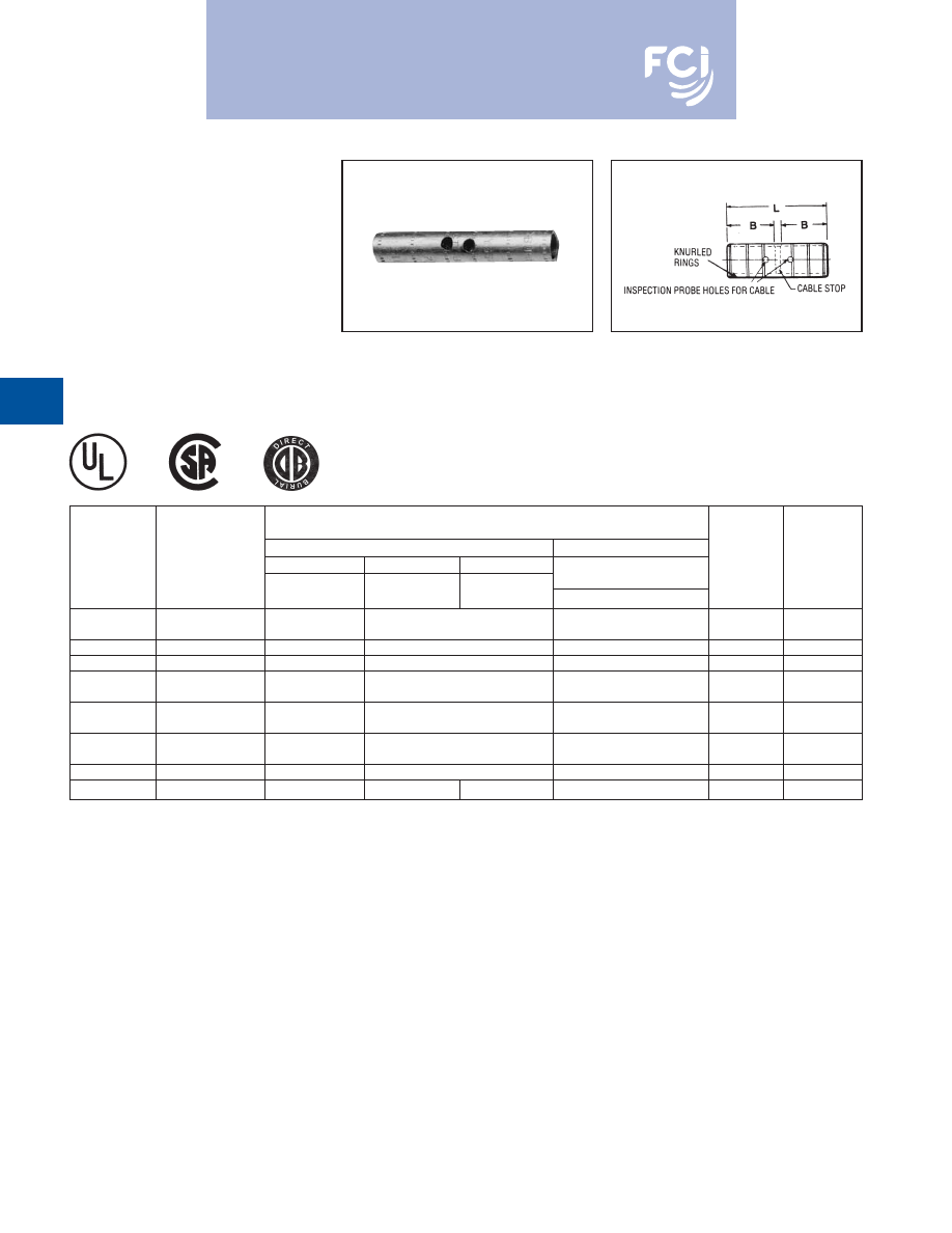
TYPE YGHA
HYLUG™
Heavy Duty Irreversible
Compression Terminals
Heavy duty HYLUG™ irreversible compres-
sion terminals designed not only to carry
short circuit load, but to also withstand high
mechanical stress. Each conductor element
has an inspection probe hole to insure proper
cable insertion. UL467 Listed. Acceptable for
direct burial in earth or concrete. UL486A
Listed. Prefilled with PENETROX™ com-
pound and strip sealed.
TYPE YGHS
HYLINK™
Heavy Duty Irreversible
Compression Terminals
Heavy duty HYLINK™
ground splice
designed not only to carry short circuit load,
but to also withstand high mechanical stress.
Each conductor element has an inspection
probe hole and a center stop to ensure
proper cable insertion.
UL467 Listed.
Acceptable for direct burial in earth or
concrete. UL486A Listed. Prefilled with
PENETROX™ compound and strip sealed.
①
Where a “U” or “PU” die is recommended with the Y45
HYPRESS™, a PT6515 adapter must be used.
➁
Where a “U” or “PU” die is recommended with the Y46
HYPRESS™, a PUADP-1 adapter must be used.
①
Where a “U” or “PU” die is recommended with the Y45
HYPRESS™, a PT6515 adapter must be used.
➁
Where a “U” or “PU” die is recommended with the Y46
HYPRESS™, a PUADP-1 adapter must be used.
INSPECTION PROBE HOLES
FOR CABLE STOP
KNURLED
RINGS
MEETS ALL
IEEE
837 REQUIREMENTS
MEETS ALL
IEEE
837 REQUIREMENTS
INSTALLATION TOOLS, DIE SET CAT. NO.,
CATALOG
AND (NUMBER OF CRIMPS)
NUMBER
COPPER CONDUCTOR SIZE
HYPRESS™ Y35/Y39/Y45
①
/Y46
②
/Y750 /PAT750
B
C
L
T
YGHA2C-2N
2 str.
U1CRT (1)
.75
.97
4.21
.26
YGHA25-2N
1/0 str.
U27RT (1)
.83
.91
4.60
.19
YGHA26-2N
2/0 str.
U28RT (1)
.83
.97
4.38
.26
YGHA27-2N
3/0 str.
U29RT (1)
1.18
1.08
4.94
.29
YGHA28-2N
4/0 str.
U30RT (2)
1.18
1.22
4.94
.30
YGHA29-2N
250 kcmil
U31RT (2)
1.18
1.28
4.94
.34
YGHA31-2N
350 kcmil
U34RT (2)
1.18
1.62
5.00
.43
YGHA34-2N
500 kcmil
U36RT (3)
1.48
1.72
5.42
.40
INSTALLATION TOOLS, DIE SET CAT. NO.,
CATALOG
AND (NUMBER OF CRIMPS)
NUMBER
COPPER CONDUCTOR SIZE
HYPRESS™ Y35/Y39/Y45
①
/Y46
②
/Y750 /PAT750
B
L
YGHS2C
2 str.
U1CRT (1)
.75
1.73
YGHS25
1/0 str.
U27RT (1)
.83
1.89
YGHS26
2/0 str.
U28RT (1)
.83
1.89
YGHS27
3/0 str.
U29RT (1)
1.18
2.59
YGHS28
4/0 str.
U30RT (2)
1.18
2.59
YGHS29
250 kcmil
U31RT (2)
1.18
2.59
YGHS31
350 kcmil
U34RT (2)
1.18
2.59
YGHS34
500 kcmil
U36RT (3)
1.48
3.19
Burndy-Grounding-Connectors-catalog-html.html
BURNDY
®
Products
Grounding
D-17
TYPE YGA
HYLUG™
Grounding Irreversible
Compression Terminals
Irreversible compression HYLUG™ Ground
terminal specifically designed for grounding
applications. Each connector has an inspec-
tion probe hole to insure proper cable inser-
tion. UL467 Listed. Acceptable for direct
burial in earth or concrete. UL486A Listed.
Prefilled with PENETROX™ compound and
strip sealed.
①
Where a “U” or “PU” die is recommended with the Y45
HYPRESS™, a PT6515 adapter must be used.
Fig. 1
Fig. 2
Installation Tools, Die Set Cat. No., and
(number of crimps)
Mechanical
Hydraulic
Y35/Y39/Y45/PAT750
①
Copper
Y2MR
MD7-34R
OUR840
/Y46
②
/Y750
Catalog
Fig.
Conductor Die # (# of
Die # (# of
Die # (# of
Die # (# of
Stud
Number
No.
Size
crimps)
crimps)
crimps)
crimps)
Size
B
C
L
T
E
W8CVT (2)
YGA8C-TC10
2
8 sol./8 str.
Red (4)
X8CRT (2)
U8CRT (2)
#10
.81
.41
1.57
.08
—
W8CVT (2)
YGA8C-TC14
2
8 sol./8 str.
Red (4)
X8CRT (2)
U8CRT (2)
1/4
.81
.44
1.69
.08
—
W8CVT (2)
YGA8C-TC516
2
8 sol./8 str.
Red (4)
X8CRT (2)
U8CRT (2)
5/16
.81
.51
1.75
.06
—
W8CVT (2)
YGA8C-2N
1
8 sol./8 str.
Red (4)
X8CRT (2)
U8CRT (2)
1/2
.81
.71
4.09
.05
—
W5CVT (2)
YGA6C-TC10
2
6 sol./6 str.
Blue (4)
X5CRT (2)
U5CRT (2)
#10
1.12
.42
1.89
.09
—
W5CVT (2)
YGA6C-TC14
2
6 sol./6 str.
Blue (4)
X5CRT (2)
U5CRT (2)
1/4
1.12
.45
2.02
.08
—
W5CVT (2)
YGA6C-TC516
2
6 sol./6 str.
Blue (4)
X5CRT (2)
U5CRT (2)
5/16
1.12
.51
2.08
.07
—
W5CVT (2)
YGA6C-2TC38E2G1
1
6 sol./6 str.
Blue (4)
X5CRT (2)
U5CRT (2)
3/8
1.12
.58
3.42
.06
.75
W5CVT (2)
YGA6C-2N
1
6 sol./6 str.
Blue (4)
X5CRT (2)
U5CRT (2)
1/2
1.12
.83
4.40
.12
1.75
W2CVT (2)
YGA2C-2TC38
1
2 sol./2 str.
Brown (4)
X2CRT (2)
U2CRT (2)
3/8
1.25
.60
3.48
.12
1.00
W2CVT (2)
YGA2C-2TC38E2G1
1
2 sol./2 str.
Brown (4)
X2CRT (2)
U2CRT (2)
3/8
1.25
.60
3.66
.12
.75
W2CVT (2)
YGA2C-2N
1
2 str.
Brown (4)
X2CRT (2)
U2CRT (2)
1/2
1.22
.81
4.71
.12
1.75
W25VT (4)
YGA25-2N
1
1/0 str.
—
X25RT (4)
U25RT (2)
1/2
1.35
.81
4.91
.12
1.75
W26VT (4)
YGA26-2N
1
2/0 str.
—
X26RT (4)
U26RT (2)
1/2
1.45
.81
4.89
.12
1.75
W28VT (4)
YGA28-2N
1
4/0 str.
—
X28RT (4)
U28RT (2)
1/2
1.57 1.00 5.06
.14
1.75
YGA29-2N
1
250 kcmil
—
W29VT (4)
U29RT (2)
1/2
1.57 1.09 5.16
.16
1.75
YGA34-2N
1
500 kcmil
—
W34VT (4)
U34RT (4)
1/2
2.20 1.52 5.94
.23
1.75
➁
Where a “U” or “PU” die is recommended with the Y46
HYPRESS™, a PUADP-1 adapter must be used.
Burndy-Grounding-Connectors-catalog-html.html
BURNDY
®
Products
Grounding
D-18
TYPE YGS
HYLINK™
Grounding Irreversible
Compression Splices
Irreversible compression HYLINK™ ground
splices specifically designed for grounding
applications. Each conductor element has an
inspection probe hole and a center stop to
ensure proper cable insertion. UL467 Listed.
Acceptable for direct burial in earth or
concrete. UL486A Listed. Prefilled with
PENETROX™ compound and strip sealed.
①
Where a “U” or “PU” die is recommended with the Y45
HYPRESS™, a PT6515 adapter must be used.
➁
Where a “U” or “PU” die is recommended with the Y46
HYPRESS™, a PUADP-1 adapter must be used.
③
Use "X" with OUR840, "W" with MD6/MD7.
INSTALLATION TOOLS, DIE SET CAT. NO., AND
(NUMBER OF CRIMPS)
MECHANICAL
HYDRAULIC
COPPER
Y2MR
MD7-34R
OUR840
Y35/Y39/Y45
①
CATALOG
CONDUCTOR
DIE # (# OF
DIE # (# OF
DIE # (# OF
/Y46
②
/Y750/PAT750
NUMBER
SIZE
CRIMPS)
CRIMPS)
CRIMPS)
DIE # (# OF CRIMPS)
B
L
W2CVT (2)
YGS2C
2 str.
Brown (4)
X2CRT (2)
U2CRT (2)
1.22
2.67
YGS8C
#8 sol./str.
—
X8CRT, W8CRT, W8CVT
➂
U8CRT (2)
.78
1.75
YGS6C
#6 sol./str.
—
X5CRT, W5CRT, W5CVT
➂
U6CRT (2)
1.09
2.38
W25VT (4)
YGS25
1/0 str.
—
X25RT (4)
U25RT (2)
1.35
2.97
W26VT (4)
YGS26
2/0 str.
—
X26RT (4)
U26RT (2)
1.45
3.13
W28VT (4)
YGS28
4/0 str.
—
X28RT (4)
U28RT (2)
1.57
3.37
YGS29
250 kcmil
—
W29VT (4)
U29RT (2)
1.57
3.37
YGS34
500 kcmil
—
W34VT (4)
—
U34RT (4)
2.20
4.63
Burndy-Grounding-Connectors-catalog-html.html
BURNDY
®
Products
Grounding
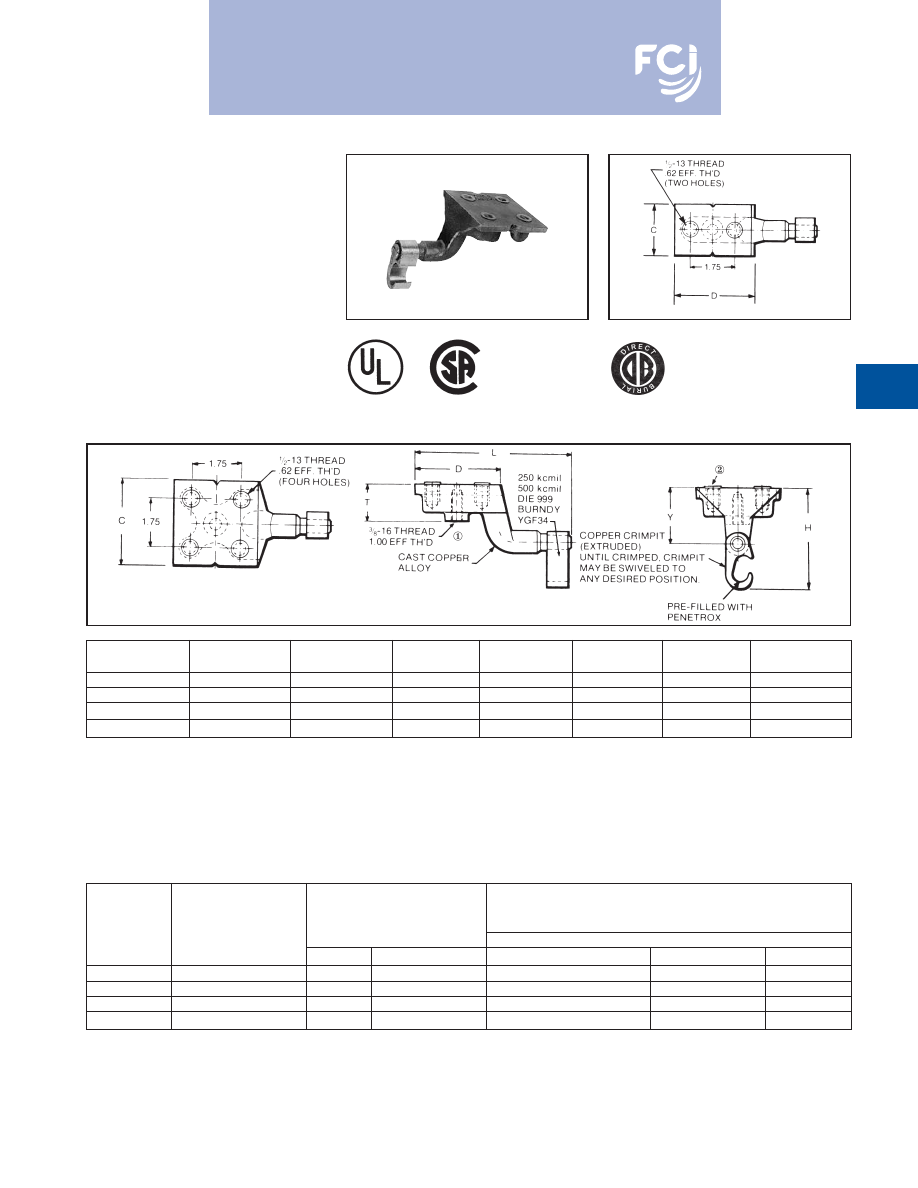
TYPE YGF
GROUNDING PLATE
The irreversible compression ground plate is
designed to withstand the rigors of concrete
construction. The ground plates are made of
high strength, high-conductivity cast copper
alloy body with a pure wrought copper
compression element. In addition to the
tapped NEMA size holes and spacing on the
face, the plate comes with a tapped hole on
the underside for ease of positioning prior to
pouring the concrete.
UL467 Listed.
Acceptable for direct burial in earth or
concrete.
Prefilled with PENETROX™
compound and strip sealed.
D-19
NOTES:
①
This tapped hole may be used to position the grounding
plate on a threaded rod prior to placement of the concrete.
ORDERING INFORMATION
①
Where a “U” or “PU” die is recommended
with the Y45 HYPRESS™, a PT6515
adapter must be used.
Fig. 1
Fig. 2
MEETS ALL
IEEE
837 REQUIREMENTS
①
3/8-16 thread with 1.00 EFF. Thread is standard. If other
thread is required, add appropriate Code No. to Catalog No.
for desired thread.
-50 (1/2 -13, .94 EFF. Thread), -62 (5/8 -11, .94 EFF.
Thread) and -75 (3/4 -10, .81 EFF. Thread)
Example: YGF34-4N-50 is YGF34-4N with 1/2 -13 Thread
②
Plastic plugs are provided to keep dirt out of the threaded
holes until the attachment of grounding terminals.
Catalog
Number
Fig. No.
C
D
H
L
T
Y
YGF29-2N
1
2.00
3.25
3.62
5.78
1.31
2.00
YGF29-4N
2
3.25
3.25
3.62
5.78
1.31
2.00
YGF34-2N
1
2.00
3.25
4.62
5.40
1.31
2.19
YGF34-4N
2
3.75
3.75
4.62
5.90
1.31
2.19
Installation Tools,
Die Set Cat. No., and
(number of crimps)
Catalog
Copper
Tapped Holes
HYPRESS™
Number
Conductor Range
Size
Hole Centers
PAT750/Y750/Y35/Y39
Y45
①
Y46
②
YGF29-2N
2 - 250 kcmil
1/2 - 13
1-3/4
U997 (1)
U997 (1)
U997 (1)
YGF29-4N
2 - 250 kcmil
1/2 - 13
1-3/4
U997 (1)
U997 (1)
U997 (1)
YGF34-2N*
250 - 500 kcmil
1/2 - 13
1-3/4
U1011 (3)
S1011 (2)
P1011 (2)
YGF34-4N*
250 - 500 kcmil
1/2 - 13
1-3/4
U1011 (3)
S1011 (2)
P1011 (2)
➁
Where a “U” or “PU” die is recommended
with the Y46 HYPRESS™, a PUADP-1
adapter must be used.
* These connectors can only be installed
using the Y750, Y45 or Y46 HYPRESS™
with recommended dies. These connec-
tors CAN NOT be installed with the Y35 or
Y39 HYPRESS™.
Burndy-Grounding-Connectors-catalog-html.html
BURNDY
®
Products
Grounding
D-20
NOTES:
1.
Terminal conector to be ordered separately. When I-beam
connector is used with type "YGHA" terminal, the connec-
tion meets IEEE 837-1989 requirements. YGA-2N, YA-2N
and other BURNDY
®
2-hole NEMA copper terminals are
suitable.
2.
Order "TMHG" Terminal Mounting Hardware Kit separate-
ly. Kit consists of 2 studs, 2 flat washers, 2 lockwashers
and 2 hex nuts.
3.
Using the 1/4 hex key wrench, screw the stud into the
connector until stud bottoms out in connector. Install a
"YGHA" terminal, flat washer, lockwasher and hex nut
onto stud. Tighten and torque to 480 pound-inches.
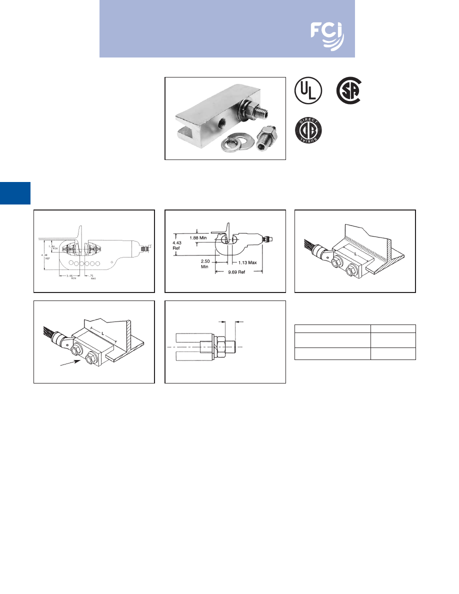
TYPE YGIB
GROUNDLINK™ CONNECTOR
An irreversible compression ground connec-
tion which allows attachment to a structural
steel standard (angled) or wide flange
(parallel) beam. Installed with a required
5-piece die set, Catalog PIBEAMKIT or
UIBEAMKIT.
Die index 1105.
GROUNDLINK™ connectors are made of
high-conductivity wrought copper and come
pre-filled with PENETROX™ E compound
and strip sealed. Order terminal mounting
hardware separately.
NOTE:
Use TMHG-92 to double stack lugs.
Fig. 1
Fig. 2
Connector shipped with thread protection studs only. Order
TMHG kits separately.
1.84 IN. Minimum flange depth.
3.06 IN. Minimum flange width.
STANDARD BEAMS
(FLANGE ANGLED) USE YGIBS
WIDE FLANGE BEAMS
(FLANGE PARALLEL) USE YGIBW
TERMINAL
MOUNTING HARDWARE
“T” REF MAXIMUM
TERMINAL PAD
THICKNESS
Y46 SERIES
USE PIBEAMKIT
Y750 SERIES
USE UIBEAMKIT
2 HOLE NEMA
SPACING
➃
➃
MEETS ALL
IEEE
837 REQUIREMENTS
➃
Dimensions shown reflect the minimum dimensions
required on a beam to properly install the I-beam
connector.
5.
To correctly determine the appropriate YGIB connector to
use based on flange thickness, order either
YGIBGAUGE1 or YGIBKIT1 (KIT1 contains wiremike).
CATALOG NUMBER
“T”
TMHG-42
.42
TMHG-92
.92
Burndy-Grounding-Connectors-catalog-html.html
BURNDY
®
Products
Grounding
D-21
TYPE YGIB
(Continued)
GROUNDLINK™ CONNECTOR
COPPER
iBEAM
CONDUCTOR
FIG.
FLANGE
SUGGESTED TERMINALS
RANGE
CATALOG NUMBER
NO.
“L”
“J”
THICKNESS
COPPER CONDUCTOR
TERMINAL
“T” REF.
#2 STR. AWG
YGHA2C-2N
.26
YGIBS28-338-2N
1
3.00
1/0 STR. AWG
YGHA25-2N
.19
2 - 4/0 AWG
.250
2/0 STR. AWG
YGHA26-2N
.26
YGIBW28-338-2N
2
3.00
to
4/0 STR. AWG
YGHA28-2N
.30
YGIBS34-338-2N
1
.338
250 kcmil
YGHA29-2N
.34
250 - 500 kcmil
YGIBW34-338-2N
2
6.00
500 kcmil
YGHA34-2N
.40
#2 STR. AWG
YGHA2C-2N
.26
YGIBS28-400-2N
1
3.00
1/0 STR. AWG
YGHA25-2N
.19
2 - 4/0 AWG
.338
2/0 STR. AWG
YGHA26-2N
.26
YGIBW28-400-2N
2
3.00
to
4/0 STR. AWG
YGHA28-2N
.30
YGIBS34-400-2N
1
.400
250 kcmil
YGHA29-2N
.34
250 - 500 kcmil
YGIBW34-400-2N
2
6.00
500 kcmil
YGHA34-2N
.40
#2 STR. AWG
YGHA2C-2N
.26
YGIBS28-462-2N
1
3.00
1/0 STR. AWG
YGHA25-2N
.19
2 - 4/0 AWG
.400
2/0 STR. AWG
YGHA26-2N
.26
YGIBW28-462-2N
2
3.00
to
4/0 STR. AWG
YGHA28-2N
.30
YGIBS34-462-2N
1
.462
250 kcmil
YGHA29-2N
.34
250 - 500 kcmil
YGIBW34-462-2N
2
6.00
500 kcmil
YGHA34-2N
.40
1/2 - 13
#2 STR. AWG
YGHA2C-2N
.26
YGIBS28-550-2N
1
3.00
1/0 STR. AWG
YGHA25-2N
.19
2 - 4/0 AWG
4.62
2/0 STR. AWG
YGHA26-2N
.26
YGIBW28-550-2N
2
3.00
to
4/0 STR. AWG
YGHA28-2N
.30
YGIBS34-550-2N
1
.550
250 kcmil
YGHA29-2N
.34
250 - 500 kcmil
YGIBW34-550-2N
2
6.00
500 kcmil
YGHA34-2N
.40
#2 STR AWG
YGHA2C-2N
.26
YGIBS28-613-2N
1
3.00
1/0 STR. AWG
YGHA25-2N
.19
2 - 4/0 AWG
.550
2/0 STR. AWG
YGHA26-2N
.26
YGIBW28-613-2N
2
3.00
to
4/0 STR. AWG
YGHA28-2N
.30
YGIBS34-613-2N
1
.613
250 kcmil
YGHA29-2N
.34
250 - 500 kcmil
YGIBW34-613-2N
2
6.00
500 kcmil
YGHA34-2N
.40
#2 STR. AWG
YGHA2C-2N
.26
YGIBS28-675-2N
1
3.00
1/0 STR. AWG
YGHA25-2N
.19
2 - 4/0 AWG
.613
2/0 STR. AWG
YGHA26-2N
.26
YGIBW28-675-2N
2
3.00
to
4/0 STR. AWG
YGHA28-2N
.30
YGIBS34-675-2N
1
.675
250 kcmil
YGHA29-2N
.34
250 - 500 kcmil
YGIBW34-675-2N
2
6.00
500 kcmil
YGHA34-2N
.40
Burndy-Grounding-Connectors-catalog-html.html
BURNDY
®
Products
Grounding
D-22
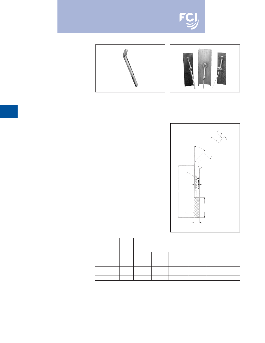
TYPE GSTUD-HY
VERSITAIL™
Structural Steel Grounding
Connector
INSTALLATION
1. Weld the VERSITAIL™ to the steel
member.
2. Select the proper connector for your
specific application.
a. FOR COMPRESSION CONNECTORS
Select the proper BURNDY
®
“YGHP,”
connector. Clean the conductor, join the
VERSITAIL™ and the grounding con-
ductor together with the recommended
tool and die set, then crimp the connec-
tor over the knurled area of the VERSI-
TAIL™.
b. FOR MECHANICAL CONNECTORS
Select the properly sized BURNDY
®
connector. Clean the conductor, then
apply PENETROX™ E oxide inhibiting
compound on the contact area for
increased effectiveness and service life.
Put the connector over the knurled area
of the VERSITAIL™ and apply the
recommended torque value for correct
installation.
SPECIFICATIONS
• Low Carbon, hot rolled steel.
• Pure copper plated finish.
FEATURES
• The VERSITAIL™ may be welded to steel
surfaces quickly and easily with normal
construction equipment.
• The VERSITAIL™ eliminates costly disk
grinding and the need to expose virgin
metal. The welding process burns through
the oxidation and “scale” to establish
excellent electrical grounding continuity.
• The VERSITAIL™ may be installed by the
welder in the field or at the steel fabricator
based on customer preference.
• The VERSITAIL™ pure copper coating over
low carbon, hot rolled steel is compatible
with standard welding processes.
No toxic gasses are generated.
• The VERSITAIL™
knurled surface is
copper plated and specifically designed to
ensure excellent mechanical gripping and
electrical integrity for BURNDY
®
compres-
sion and mechanical connectors in all
grounding applications.
• The VERSITAIL™ may be installed during
adverse weather conditions thus eliminating
costly construction delays.
BENEFITS
Low installation cost.
• No drilling . . . No cleaning . . .
• No special preparation
* This is the equivalent rating for continuous service. Larger
conductors may be connected using both compression and
bolted connectors in potential ground fault applications.
A (STOCK
DIA.)
KNURLED
END
B (DIA. OVER KNURL)
T
(FLATTENING
RESULTANT)
1.25
[32]
TYPICAL
LETTERING
2.19
[56]
L
45°
ELECTRICAL
EQUIVALENT
NOM.
DIMENSIONS
COPPER
CATALOG
ROD
A
B
L
T
CONDUCTOR SIZE
NUMBER
SIZE
IN. [MM]
IN. [MM]
IN. [MM]
IN. [MM]
(AWG.)*
GSTUD14HY
1/4
.25 [6.3]
.26 [6.6]
4.81 [122.2]
.19 [4.8]
#6
GSTUD38HY
3/8
.38 [9.7]
.39 [9.9]
5.81 [147.6]
.25 [6.4]
#3
GSTUD916HY
5/8
.56 [14.2]
.57 [14.5]
5.68 [144.3]
.38 [9.7]
1/0
GSTUD34HY
3/4
.75 [19.0]
.76 [19.3]
5.81 [147.6]
.51 [13.0]
4/0
Burndy-Grounding-Connectors-catalog-html.html
BURNDY
®
Products
Grounding
D-23
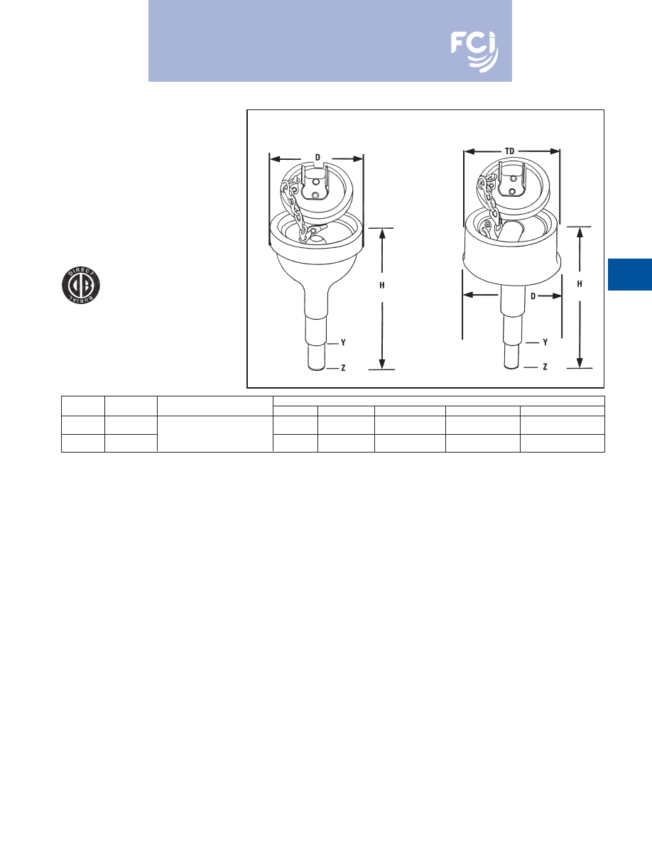
TYPES YGT & YTTAG
STATIC GROUNDING
RECEPTACLE
Type YGT static grounding receptacles are
designed for static grounding of equipment.
The receptacle is connected to the ground
grid with HYGROUND™
compression
connectors and finished flush with surface to
provide a permanent corrosion proof ground-
ing point.
* When using U or PU dies with Y46 HYPRESS™, a PUADP-1
adapter is required.
NOTES:
1. Ground rod must be pre-crimped with U2CABT die set when
PU998 die is used or for even higher mechanical resistance
use special UPRECRIMP™ dies on ground rods.
2. Pre-crimping of ground is not necessary when P1011 die is
used. Install YGHR or YGLR on hub Y. Hub Z is inserted into
1/2" rigid conduit. The conduit is driven into earth to provide
support and provide correct level of receptacle prior to
cement pour.
Type YTTAG Combination
Static Grounding Receptacle
and Aircraft Tie Down Bar
Type YGT Static
Grounding Receptacle
with Cover
Fig. 1
Fig. 2
Catalog
Figure
Dimensions
Number
Number
* HYGROUND Connector
H
D
Y Dia.
Z Dia.
“TD”
YGT275
1
Select suitable YGHR or
5.5
2.75
.75
.56
—
YGLR for 3/4
ground rod and
YTTAG388
2
sized to ground conductor.
6.5
4.75
.75
.56
4.3
Burndy-Grounding-Connectors-catalog-html.html
BURNDY
®
Products
Grounding
D-24
TYPE YG-B
BUS BAR CONNECTOR
BURNDY’s YG14B2TC2C6C Compression
Bus Bar Connector is ideally suited for cellu-
lar tower applicatons and is easier to use than
exothermic connections. This high conduc-
tivity wrought copper connector allows
attachment of the ground conductor to the
ground bus with just one crimp using the
BURNDY
®
Y750 HYPRESS™ Hydraulic
Compression tool and the U1105 die set. This
exclusive patent pending design allows the
user to attach #2 AWG sol./str. and/or #6
sol./str. copper conductor to 1/4" thick copper
bus bar. This connection is suitable using (1)
or (2) conductors for power, grounding and
bonding applictions. UL Listed to both UL486
and UL467 (suitable for direct burial) ensures
that this connector will meet the rigors of
either application.
Prefilled with PEN-
ETROX™ E compound and strip sealed.
GROUND BAR
BUS BAR
INSTALLATION
CATALOG NUMBER
FIG NO.
THICKNESS
TAP CONDUCTORS
TOOLING
DIE NO.
NO. OF CRIMPS
YG14B2TC2C6C
1
1/4"
#2 SOL/and/or STR COPPER
#6 SOL/and/or STR COPPER
PAT750, Y750
U1105
1
YG14B2TC2C2C*
2
1/4"
#2
#2
PAT750, Y750
U1105
1
#1 FLEX CABLE
YG14BTC26
3
1/4"
through
PAT750, Y750
U1105
1
2/0 FLEX CABLE
4/0 AWG STR to 1/0
YG14BTC28
3
1/4”
AWG STR COPPER
PAT750, Y750
U1105
1
NOTE:
Suitable for use with either (1) or (2) conductors
(excluding YG14BTC26 and YG14BTC28).
* For continuous uncut conductor applications.
Fig. 1
Fig. 2
Fig. 3
Burndy-Grounding-Connectors-catalog-html.html
BURNDY
®
Products
Grounding
D-25
MECHANICAL
GROUNDING
CONNECTORS
More than 60 years of technological innova-
tion has made BURNDY
®
mechanical
grounding connectors one of the most widely
used, highly respected lines in the industry.
There is virtually no grounding application
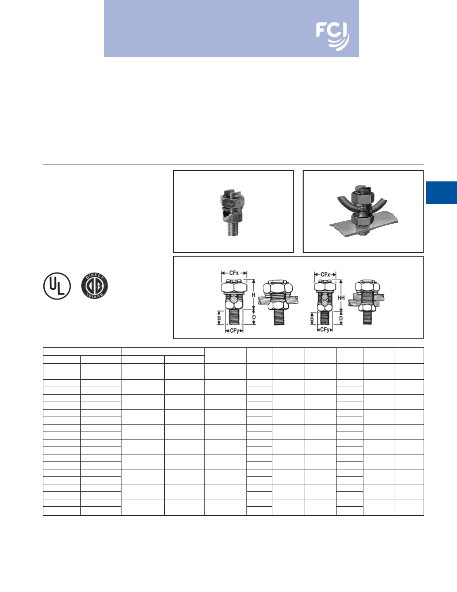
TYPES KC, K2C
SERVIT POST™
For Copper Cable to Flat
SERVIT POST™ used to ground one or two
cables to steel structures, fence posts, trans-
formers. Also used to tap one or two cables
from bus bar. One-wrench installation.
KC
K2C
problem that this diversified line cannot help
solve.
All BURNDY
®
mechanical grounding connec-
tors have been designed for easy installation
and for outstanding durability. Only the finest
† For 1 conductor.
‡ For 1 or 2 conductors.
Add “NSP” suffix to have connector supplied w/split lockwasher
and nut.
high copper alloys are used in their manufac-
ture, ensuring top performance under the
most extreme environmental conditions.
UL467 Listed for direct burial applications in
earth or concrete.
Catalog Number
Conductor
Stud
Type KC †
Type K2C ‡
Stranded
Solid
Diameter
B
CFx
CFy
D
H
HH
KC15
K2C15
3/8
1/2
KC15B1
K2C15B1
12 - 9
12 - 8
1/4 - 20
7/8
1/2
3/8
1
5/8
7/8
KC17
K2C17
3/8
1/2
KC17B1
K2C17B1
10 - 7
10 - 6
1/4 - 20
7/8
5/8
7/16
1
7/8
1
KC20
K2C20
13/32
5/8
KC20B1
K2C20B1
10 - 5
10 - 4
5/16 - 18
27/32
11/16
1/2
1
7/8
1-1/8
KC22
K2C22
15/32
5/8
KC22B1
K2C22B1
10 - 3
10 - 2
3/8 - 16
31/32
3/4
5/8
1-1/8
1
1-1/4
KC23
K2C23
15/32
5/8
KC23B1
K2C23B1
8 - 2
10 - 1
3/8 - 16
31/32
13/16
5/8
1-1/8
1
1-3/8
KC25
K2C25
9/16
3/4
KC25B1
K2C25B1
2 - 1/0
2 - 2/0
1/2 - 13
1-1/16
15/16
3/4
1-1/4
1-1/8
1-5/8
KC26
K2C26
17/32
3/4
KC26B1
K2C26B1
2 - 2/0
2 - 3/0
1/2 - 13
1-1/16
1
7/8
1-1/4
1-3/8
1-7/8
KC28
K2C28
3/4
1
KC28B1
K2C28B1
1 - 4/0
1 - 4/0
5/8 - 11
1-1/4
1-1/2
1-3/16
1-1/2
1-3/4
2-1/4
KC31
K2C31
3/4
1
KC31B1
K2C31B1
1 - 350
—
5/8 - 11
1-1/4
1-11/16
1-3/8
1-1/2
2-1/4
2-7/8
KC34
K2C34
1
1-1/4
KC34B1
K2C34B1
3/0 - 500
—
3/4 - 10
1-1/2
2
1-5/8
1-3/4
2-3/8
3-1/4
Burndy-Grounding-Connectors-catalog-html.html
BURNDY
®
Products
Grounding
D-26
TYPE KS
SERVIT™
For Copper
UL467 Listed for direct burial applications in
earth or concrete. Compact, high-strength,
high copper alloy SERVIT™ split-bolt has
free-running threads and easy to grip wrench
flats. Highly resistant to cracking and
corrosion.
TYPES KC22J12T13,
EQC632C
TRANSFORMER GROUND
CONNECTORS
For Copper
Fits all standard EEI NEMA distribution
transformers as a tank grounding terminal.
Both, one-wrench installation.
Type EQC632C
Type KC22J12T13
Stud Size =
1
⁄
2
” - 13
.6
CATALOG NUMBER
RANGES
KC22J12T13
8 Sol. - 2 Sol.
KC26
2 Sol. - 2/0 Str.
KC34J12T13
3/0 - 500 Str.
EQC632C
8 Sol. - 2 Str.
Catalog
Copper Conductor Range
Rebar w/ (1)
Recommended
Number
Cross Flats
L
W
(Sol. - Str.)
No. 8 Sol. Cu
Torque In. Lb.
KS15
.50
.85
.38
12 AWG - 8 AWG
N/A
80
KS17
.63
1.14
.45
8 AWG - 6 AWG
N/A
165
KS20
.69
1.20
.51
8 AWG - 4 AWG
N/A
165
KS22
.75
1.50
.60
6 AWG - 3 AWG
N/A
275
KS23
.82
1.54
.62
6 AWG - 2 AWG
N/A
275
KS25
.94
1.77
.73
4 AWG - 1/0
N/A
385
2 AWG - 2/0
#3
KS26
1.05
1.94
.82
6 AWG - 8 AWG Str./Sol.
(3/8
)
385
KS27
1.36
1.86
1.17
1 AWG - 3/0
N/A
500
1 AWG - 250 kcmil
#4
KS29
1.36
2.07
1.17
6 AWG - 8 AWG Str./Sol.
(1/2
)
650
1/0 AWG - 350 kcmil
#5
KS31
1.70
2.51
1.41
6 AWG - 8 AWG Str./Sol.
(5/8
)
650
2/0 AWG - 500 kcmil
#6
KS34
1.82
2.79
1.48
6 AWG - 8 AWG Str./Sol.
(3/4
)
825
Burndy-Grounding-Connectors-catalog-html.html
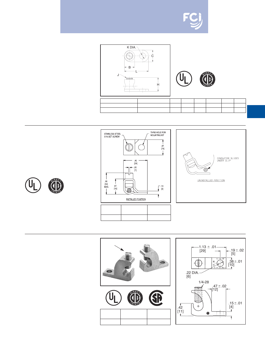
BURNDY
®
Products
Grounding
D-27
TYPE GKA
For Copper
UL467 Listed for direct burial applications in
earth or concrete. One-piece forged body
construction insures mechanical integrity in
an underground environment. Supplied with a
stainless steel headless screw.
TYPE KPB
For Copper
UL467 Listed for direct burial in earth or con-
crete. UL 486 listed. This exclusive BURNDY
®
design accommodates #10 - #4 copper
where continuous conductor runs are
preferable.
1. To be assembled with TMH322 stainless steel hardware kit.
Ordered separately.
TYPE CL50-1
COPPER LAY-IN QIKLUG™
For Copper
The Lay-In QIKLUG™ is manufactured from
high strength pure electrolytic copper to
ensure maximum strength and conductivity.
UL467 Listed for direct burial in earth or con-
crete. The open-faced design allows for fast
lay-in of the conductor without the need for
cutting or breaking.
CATALOG
WIRE RANGE
NUMBER
COPPER
STUD HOLE
CL50-1
#14 - #4 CU
#10
CATALOG
NUMBER
RANGE
STUD HOLE
KPB4CG1
#10 - #4 CU
#10
1
1. To be assembled with TMH322 stainless steel hardware kit.
Ordered separately.
CATALOG NUMBER
CABLE RANGE
B
C
H
J
K
L
GKA8C
1
#10 SOL. - #8 STR.
.31
.38
.58
#10 - 32
.21
.81
GKA4C
2
#14 SOL. - #4 STR.
.46
.54
.71
5/16 - 24
.28
1.13
2. To be assembled with TMH 323 stainless steel hardware kit.
Ordered separately.
Stainless Steel Screw
Burndy-Grounding-Connectors-catalog-html.html
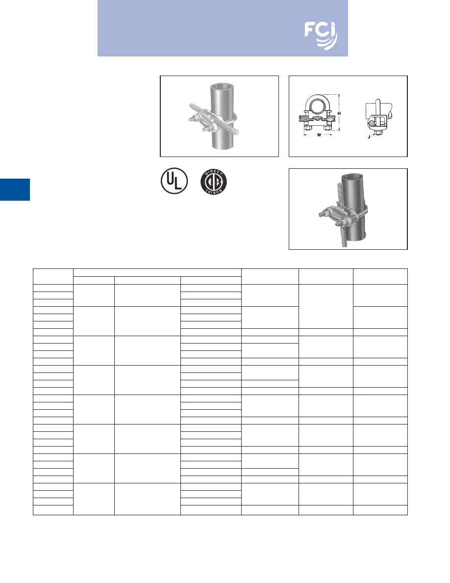
BURNDY
®
Products
Grounding
D-28
TYPE GAR
FENCE POST GROUNDING
CONNECTOR
For Parallel or 90°
Copper Cable
Connection
To Rod or Pipe with
the Same Connector
High copper alloy ground connector for join-
ing a range of cable, parallel or at right angles
to rod or tube. Especially good for fence
posts. High copper alloy cast body with
DURIUM™ U-bolts, nuts and lockwashers,
permit entire connection to be buried in
ground or concrete without danger of
corrosion.
• One-wrench installation.
• UL467 Listed.
• Acceptable for direct burial.
Catalog
Conductor
Number
Tube I.P.S.
Rod Size or O.D. Range
Cable
H
J
W
GAR114C
8 Sol. - 4 Str.
GAR1126
1/4
1/2
4 Sol. - 2/0 Str.
2-1/2
1-7/8
GAR1129
2/0 Sol. - 250
GAR644C
8 Sol. - 4 Str.
3/8
GAR6426
4 Sol. - 2/0 Str.
2-7/8
2-1/8
GAR6429
3/8
5/8 - 3/4
2/0 Sol. - 250
GAR6434
300 - 500
3-1/2
1/2
2-1/2
GAR144C
8 Sol. - 4 Str.
2-3/4
GAR1426
4 Sol. - 2/0 Str.
3/8
2-3/8
GAR1429
1/2 - 3/4
7/8 - 1
2/0 Sol. - 250
3
GAR1434
300 - 500
3-3/4
1/2
2-3/4
GAR154C
8 Sol. - 4 Str.
GAR1526
4 Sol. - 2/0 Str.
2-7/8
3/8
2-5/8
GAR1529
1
1-1/8 - 1-1/4
2/0 Sol. - 250
3-3/8
GAR1534
300 - 500
4-1/2
1/2
GAR164C
8 Sol. - 4 Str.
GAR1626
4 Sol. - 2/0 Str.
3-1/2
3/8
3
GAR1629
1-1/4
1-3/8 - 1-1/2
2/0 Sol. - 250
GAR1634
300 - 500
4-1/4
1/2
3-3/8
GAR174C
8 Sol. - 4 Str.
GAR1726
4 Sol. - 2/0 Str.
4
3/8
3-1/4
GAR1729
1-1/2
1-5/8 - 1-7/8
2/0 Sol. - 250
GAR1734
300 - 500
4-5/8
1/2
2-5/8
GAR184C
8 Sol. - 4 Str.
GAR1826
4 Sol. - 2/0 Str.
4-1/4
3/8
3-3/4
GAR1829
2
2 - 2-3/8
2/0 Sol. - 250
4-1/2
GAR1834
300 - 500
5-1/4
1/2
4-1/8
GAR194C
8 Sol. - 4 Str.
GAR1926
4 Sol. - 2/0 Str.
5
3/8
4-1/4
GAR1929
2-1/2
2-1/2 - 7/8
2/0 Sol. - 250
GAR1934
300 - 500
5-5/8
1/2
4-5/8
Burndy-Grounding-Connectors-catalog-html.html
BURNDY
®
Products
Grounding
D-29
TYPE GAR
(Continued)
FENCE POST GROUNDING
CONNECTOR
Contact BURNDY
®
for additional pipe and wire size
combinations not shown.
Catalog
Conductor
Number
Tube I.P.S.
Rod Size or O.D. Range
Cable
H
J
W
GAR204C
8 Sol. - 4 Str.
5-5/8
3/8
4-3/4
GAR2026
4 Sol. - 2/0 Str.
GAR2029
3
3 - 3-1/2
2/0 Sol. - 250
GAR2034
300 - 500
6-3/8
1/2
5-1/4
GAR214C
8 Sol. - 4 Str.
GAR2126
4 Sol. - 2/0 Str.
6-1/4
3/8
5-3/8
GAR2129
3-1/2
3-1/2 - 4
2/0 Sol. - 250
GAR2134
300 - 500
6-3/4
1/2
5-3/4
GAR224C
8 Sol. - 4 Str.
GAR2226
4 Sol. - 2/0 Str.
6-3/8
3/8
5-7/8
GAR2229
4
4 - 4-1/2
2/0 Sol. - 250
GAR2234
300 - 500
6-7/8
1/2
6-1/4
GAR244C
8 Sol. - 4 Str.
GAR2426
4 Sol. - 2/0 Str.
7-3/4
3/8
6-7/8
GAR2429
5
—
2/0 Sol. - 250
GAR2434
300 - 500
8-5/8
1/2
7-1/4
GAR8629
6
—
2/0 Sol. - 250
8-13/16
1/2
8-3/8
Burndy-Grounding-Connectors-catalog-html.html
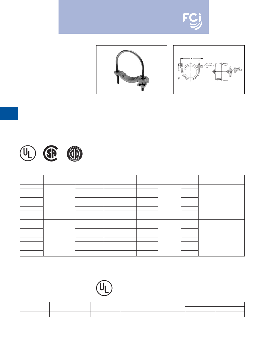
BURNDY
®
Products
Grounding
D-30
TYPES GAR-BU AND
GAR3902 SERIES
GROUND CONNECTORS
Type GAR-BU is a high-conductivity copper
ground connector for connecting a small to
medium range copper ground conductor to
water pipe as well as structural and reinforc-
ing rod shapes. Universal acceptance of
several sizes of cylindrical shapes makes this
suitable for industrial construction and main-
tenance work as well as cathodic protection.
Cable clamp swivels to permit parallel
grounding of one pipe or 90° degree cable
run for grounding several parallel pipes.
Single wrench installation. UL467 Listed and
CSA certified.
TYPE GAR-RB
For Reinforcement Bar
* Type GAR-BU is supplied with DURIUM™ silicon bronze
hardware and is listed for direct burial.
UL467 listed for direct burial in earth or concrete.
Features and benefits
• Cable clamp swivels at 90°.
9
Permits parallel grounding of one pipe
or a 90° cable run for grounding several
parallel pipes.
• One-wrench installation.
9
Simplified installation.
• DURIUM™ silicon bronze hardware (-BU
Series)*.
9
Long lasting corrosion resistance and
acceptable for direct burial in earth
or concrete.
• UL467 Listed.
9
Provides quality assurance to recognized
industry NEC standards from an
independent party.
*
CATALOG
RECOMMENDED
NUMBER *
CABLE RANGE
IPS SIZE
O.D. RANGE
H
J
W
TIGHTENING TORQUE
GAR3902-BU
1/2
- 1
.840 - 1.32
3.50
3.25
GAR3903-BU
1-1/4
- 2
1.66 - 2.38
4.00
4.25
GAR3904-BU
2-1/2
- 3-1/2
2.88 - 4.00
6.50
6.00
GAR3905-BU
4
- 5
4.50 - 5.56
7.50
7.50
GAR3906-BU
#4 - 4/0 AWG
6
6.62
8.50
3/8
- 16
8.62
240 in. - lbs.
GAR3907-BU
8
8.62
10.00
10.62
GAR3908-BU
10
10.75
12.00
12.75
GAR3909-BU
12
12.75
14.00
14.75
GAR3902
1/2
- 1
.840 - 1.32
3.50
3.25
GAR3903
1-1/4
- 2
1.66 - 2.38
4.00
4.25
GAR3904
2-1/2
- 3-1/2
2.88 - 4.00
6.50
6.00
GAR3905
4
- 5
4.50 - 5.56
7.50
7.50
GAR3906
#4 - 4/0 AWG
6
6.62
8.50
3/8
- 16
8.62
240 in. - lbs.
GAR3907
8
8.62
10.00
10.62
GAR3908
10
10.75
12.00
12.75
GAR3909
12
12.75
14.00
14.75
CATALOG
COPPER CONDUCTOR
NUMBER
REBAR
IPS SIZE
O.D. RANGE
ROD
MIN.
MAX.
GAR644C-RB
#3 - 6 (.375 - .750)
3/8
.625 - .75
5/8 - 3/4
8 Sol.
4 Str.
Burndy-Grounding-Connectors-catalog-html.html
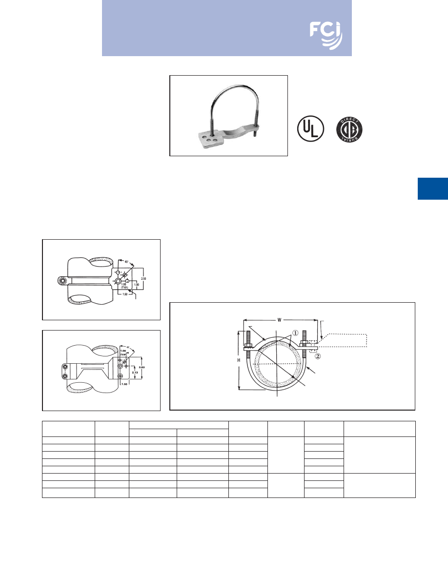
BURNDY
®
Products
Grounding
D-31
TYPE GAR-TC
WATER PIPE GROUND
CONNECTOR
Type GAR-TC is a high-conductivity copper
ground connector that features a pre-drilled
pad, allowing a 2-hole compression terminal
to be directly connected to water pipe as well
as structural and reinforcing rod shapes.
Universal acceptance of several sizes of
cylindrical shapes makes this suitable for
industrial construction and maintenance work
as well as telecommunications grounding.
Terminal may be mounted parallel, 45° or 90°
degrees to the pipe. Acceptable for direct
burial.
Features and Benefits
• Large, smooth connector contact area
between pipe and ground clamp
9
Provides large surface contact area
to maximize contact area between
connector and pipe.
• The GAR-TC mounting pad permits
parallel, 45° or 90° angle connections
to the pipe.
9
Provides maximum flexibility for
field installation.
• Pre-drilled pad for (2) 3/8
bolts on
1
centers.
9
Allows direct mounting of (2) hole
compression terminals up to 750 kcmil
to pipe.
①
Add suffix “-TNET” for electro-tin plated connector and
electro-tin plated DURIUM™ silicon bronze hardware. Tin
plated catalog number includes mounting hardware for
second bolt hole.
②
TMH-289 includes (1) 38 x 125 HEB, (1) 38 CHEN, (1) 38
SW and (2) 38 FW. Order separately.
Fig. 1
Fig. 2
PATENTED
MOUNTING PAD
FOR (2) 3/8"
BOLTS - 1" L
J
MOUNTING PAD
DURIUM 3/8"
SILICON BRONZE
HARDWARE
• DURIUM™ silicon bronze hardware.
9
Provide long lasting corrosion resistance
acceptable for direct burial in earth
or concrete.
• One-wrench installation.
9
Simplified installation.
• UL467 Listed.
9
Provides quality assurance to recognized
industry NEC standards from an
independent party. Type GAR-TC is
acceptable for direct burial
PIPE DIA.
CAST HIGH COPPER ALLOY SADDLE
COMPRESSION LUG WITH PAD
FOR (2) 3/8" DIA. BOLTS
ON 1" CENTERS. 750 KCMIL MAX.
CATALOG
FIG.
ACCOMMODATES
RECOMMENDED
NUMBER
NO.
I.P.S.
O.D. SIZE
H
J
W
TIGHTENING TORQUE
GAR3902TC
1
1/2
- 1
.840 - 1.32
3.50
3.75
GAR3903TC
1
1-1/4
- 2
1.66 - 2.38
4.00
4.75
GAR3904TC
1
2-1/2
- 3-1/2
2.88 - 4.00
6.50
3/8
- 16
6.50
240 in.-lbs.
GAR3905TC
1
4
- 5
4.50 - 5.56
7.50
8.00
GAR3906TC
1
6
6.62
8.50
9.12
GAR3907TC
2
8
8.62
10.00
11.25
GAR3908TC
2
10
10.75
12.00
3/8
- 16
13.25
240 in.-lbs.
GAR3909TC
2
12
12.75
14.00
15.25
NOTE:
Clean pipe surface beneath saddle until virgin metal is
exposed, install GAR-TC ground connector and for
maximum
conductivity, apply PENETROX
®
-E oxide inhibiting
compound around perimeter of the saddle.
Burndy-Grounding-Connectors-catalog-html.html
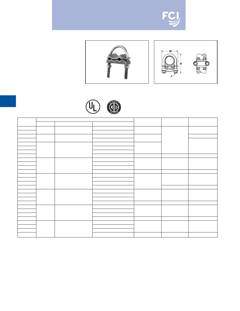
BURNDY
®
Products
Grounding
D-32
TYPE GD
CABLE TO ROD/TUBE
GROUND CONNECTOR
For Two Copper Cables to Rod
or Tube
High copper alloy ground connector for join-
ing a range of two parallel cables to rod or
pipe. Especially good for grounding fence
posts. High copper alloy cast body with
DURIUM™ U-bolts, nuts, and lockwashers
make the GD suitable for burial in ground or
concrete. One-wrench installation. UL467
Listed. Acceptable for direct burial in earth
or concrete.
Complies with NFPA 78-86 HEAVY DUTY stacks.
(Order: LD for lead plating for HEAVY DUTY stack
applications.)
Catalog
Conductor
Number
Tube I.P.S.
Rod Size or O.D. Range
Cable
H
J
W
GD1526
4 Sol. - 2/0 Str.
GD1529
1
1-1/8 - 1-1/4
2/0 Sol. - 250
3-3/8
2-5/8
GD1626
4 Sol. - 2/0 Str.
3
GD1629
1-1/4
1-3/8 - 1-1/2
2/0 Sol. - 250
3-1/2
3/8
GD174C
8 Sol. - 4 Str.
GD1726
4 Sol. - 2/0 Str.
4
3-1/4
GD1729
1-1/2
1-5/8 - 1-7/8
2/0 Sol. - 250
GD1734
300 - 500
4-5/8
1/2
3-5/8
GD184C
8 Sol. - 4 Str.
GD1826
4 Sol. - 2/0 Str.
4-3/8
3/8
3-3/4
GD1829
2
2 - 2-3/8
2/0 Sol. - 250
GD1834
300 - 500
5-3/8
1/2
4-1/8
GD194C
8 Sol. - 4 Str.
GD1926
4 Sol. - 2/0 Str.
3/8
4-1/4
GD1929
2-1/2
2-1/2 - 2-7/8
2/0 Sol. - 250
5
GD1934
300 - 500
1/2
4-5/8
GD204C
8 Sol. - 4 Str.
GD2026
4 Sol. - 2/0 Str.
5-5/8
3/8
4-7/8
GD2029
3
3 - 3-1/2
2/0 Sol. - 250
GD2034
300 - 500
6-3/8
1/2
5-1/4
GD214C
8 Sol. - 4 Str.
GD2126
4 Sol. - 2/0 Str.
6-1/4
3/8
5-3/8
GD2129
3-1/2
3-1/2 - 4
2/0 Sol. - 250
GD2134
300 - 500
6-7/8
1/2
5-3/4
GD224C
8 Sol. - 4 Str.
GD2226
4 Sol. - 2/0 Str.
6-3/8
3/8
5-7/8
GD2229
4
4 - 4-1/2
2/0 Sol. - 250
GD2234
300 - 500
6-7/8
1/2
6-1/4
Burndy-Grounding-Connectors-catalog-html.html
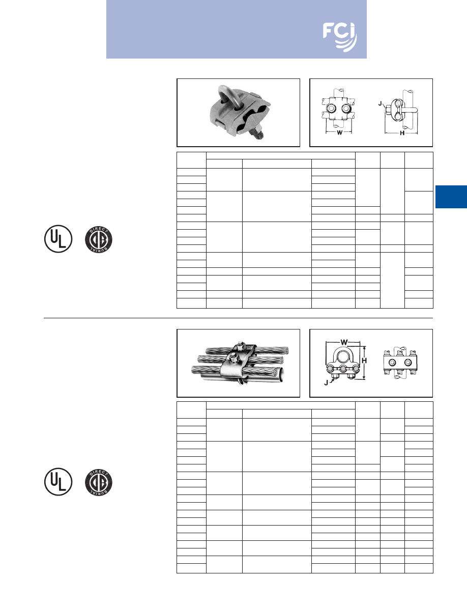
BURNDY
®
Products
Grounding
D-33
TYPE GP
GROUND CONNECTOR
For Two Copper Cables
to Rod or Pipe
High copper alloy ground connector for join-
ing a range of parallel cables perpendicular to
rod, pipe or column. Also used with one
groove for run, the other for tap to equipment.
High copper alloy cast body and DURIUM™
U-bolts, nuts, and lockwashers make the GP
suitable for direct burial in the ground or
concrete. One-wrench installation. UL467
Listed. Acceptable for direct burial in earth
or concrete.
TYPE GK
GROUND CONNECTOR
For Three Copper Cables to
Rod or Pipe
High copper alloy ground connector for join-
ing three equal cables to rod or tube. Cable
grooves take a wide range of cable. High
copper alloy cast body and DURIUM™
U-bolts, nuts, and lockwashers make the GK
suitable for direct burial in soil or concrete.
One-wrench installation.
UL467 Listed.
Acceptable for direct burial in earth or
concrete.
Catalog
Conductor
Number
Tube I.P.S.
Rod Size or O.D. Range
Cable
H
J
W
GP114C
8 Sol. - 4 Str.
GP1126
1/4
1/2
4 Sol. - 2/0 Str.
1-7/8
GP1129
2/0 Sol. - 250
2-1/2
GP644C
8 Sol. - 4 Str.
3/8
GP6426
4 Sol. - 2/0 Str.
2-1/8
GP6429
3/8
5/8 - 3/4
2/0 Sol. - 250
2-7/8
GP6434
300 - 500
3-1/2
1/2
2-1/2
GP144C
8 Sol. - 4 Str.
2-3/4
GP1426
4 Sol. - 2/0 Str.
38
2-3/8
GP1429
1/2 - 3/4
7/8 - 1
3/0 Sol. - 250
3
GP1434
300 - 500
3-3/4
1/2
2-3/4
GP164C
8 Sol. - 4 Str.
GP1629
1-1/4
1-5/8
2/0 Sol. - 250
3-1/2
3
GP1726
1-1/2
1-7/8
4 Sol. - 2/0 Str.
4
3-1/4
GP184C
8 Sol. - 4 Str.
4-1/8
3/8
GP1826
2
2-3/8
4 Sol. - 2/0 Str.
4-3/8
3-11/16
GP2026
3
3-1/2
4 Sol. - 2/0 Str.
5-1/2
4-13/16
GP2226
4
4-1/2
4 Sol. - 2/0 Str.
6-3/8
5-13/16
Catalog
Conductor
Number
Tube I.P.S.
Rod Size or O.D. Range
Cable
H
J
W
GK114C
8 Sol. - 4 Str.
2-1/2
GK1126
1/4
1/2
4 Sol. - 2/0 Str.
2-1/2
3/8
2-3/4
GK1129
2/0 Sol. - 250
1/2
3-3/8
GK644C
8 Sol. - 4 Str.
2-5/8
GK6426
4 Sol. - 2/0 Str.
2-7/8
3/8
3
GK6429
3/8
5/8 - 3/4
2/0 Sol. - 250
3-1/2
GK6434
300 - 500
3-1/2
1/2
4
GK1426
4 Sol. - 2/0 Str.
2-3/4
38
3-1/4
GK1429
1/2 - 3/4
7/8 - 1
2 Sol. - 250
3-7/8
GK1434
300 - 500
3-3/4
1/2
4-3/8
GK1526
4 Sol. - 2/0 Str.
3-3/8
3/8
3-1/2
GK1529
1
1-1/8 - 1-1/4
2/0 Sol. - 250
3-3/4
1/2
4-1/8
GK1626
4 Sol. - 2/0 Str.
3-1/2
3/8
3-7/8
GK1629
1-1/4
1-3/8 - 1-1/2
2/0 Sol. - 250
4-1/4
1/2
4-1/2
GK1726
4 Sol. - 2/0 Str.
4
3/8
4-1/8
GK1729
1-1/2
1-5/8 - 1-7/8
2/0 Sol. - 250
4-5/8
1/2
4-3/4
GK1826
4 Sol. - 2/0 Str.
4-1/4
3/8
4-5/8
GK1829
2
2 - 2-3/8
2/0 Sol. - 250
4-3/8
1/2
5-1/8
GK1926
4 Sol. - 2/0 Str.
5
3/8
5-1/8
GK1929
2-1/2
2-1/2 - 2-7/8
2/0 Sol. - 250
5
1/2
5-5/8
Burndy-Grounding-Connectors-catalog-html.html
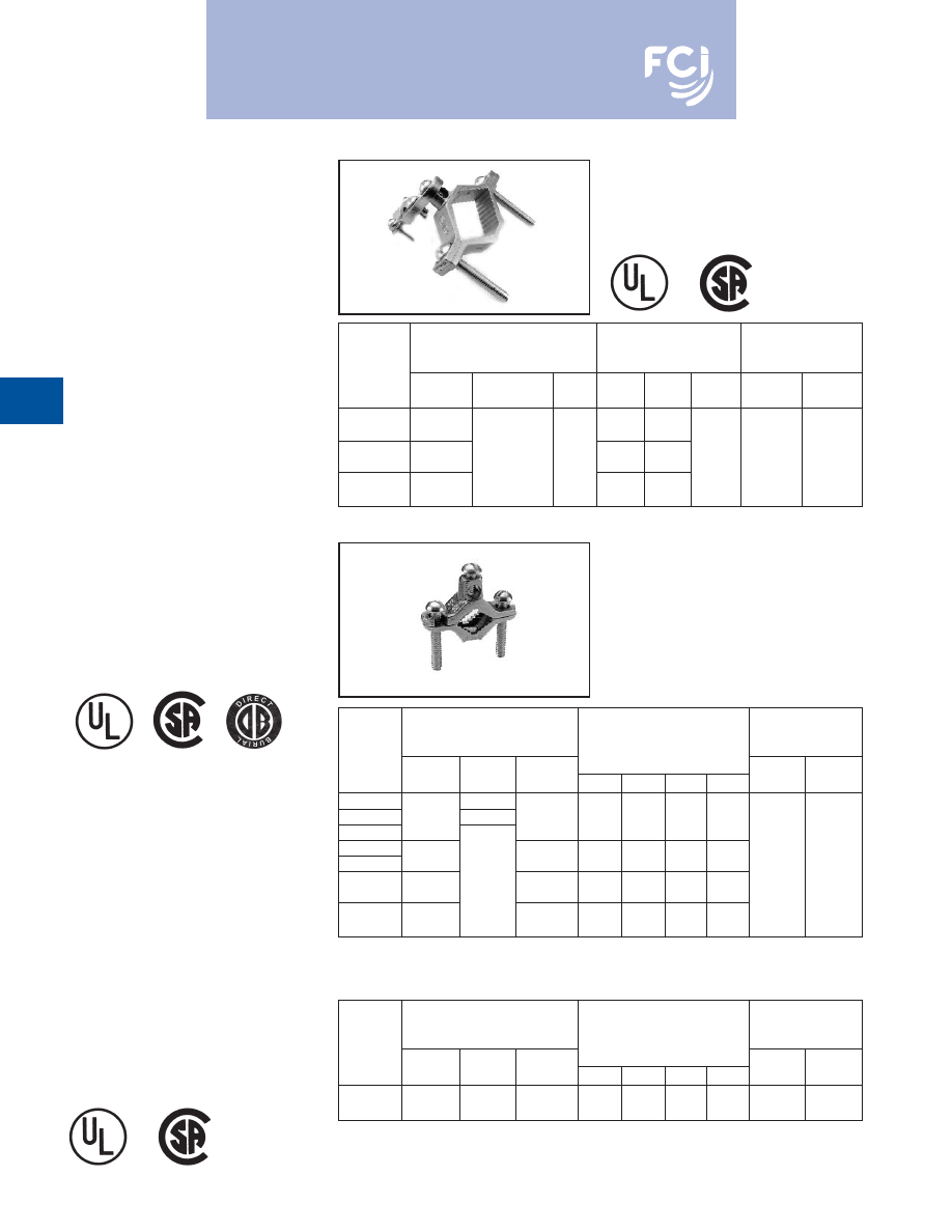
BURNDY
®
Products
Grounding
D-34
CAST BRONZE
CLAMPS FOR
CONDUIT
Pressure bar type conduit hub adjusts for
1/2
, 3/4
EMT or 1/2
rigid conduit. Hub
swings 360° for easy alignment. Zinc plated
hardware.
CAST BRONZE
GROUND CLAMPS
For connecting grounding conductor to water
pipe or copper tube. "D" indicates UL467
Listed for direct burial in earth and concrete
and are supplied with silicon bronze hard-
ware. "B" indicates brass hardware.
BUDGET PRICE
CAST BRONZE
GROUND CLAMP
Similar to above but lighter duty.
RECOMMENDED
ACCOMMODATES
REFERENCE
SCREW TORQUE
CONDUCTOR RANGE
DIMENSIONS
“INCH POUNDS”
CATALOG
WATER
HUB
PIPE
WIRE
NUMBER
PIPE
GROUND
SIZE
H
L
W
CLAMP
CLAMP
1/2 - 1
2.07
3.19
C-11JPT
[13 - 25]
[53]
[81]
1-1/4 - 2
10 - 6
1/2
2.70
3.83
2.70
C-22JPT
[32 - 51]
Sol.
[13]
[69]
[97]
[69]
50 in.-lb.
50 in.-lb.
2-1/2 - 4
4.39
5.15
C-4JPT
[64 - 102]
[112]
[131]
RECOMMENDED
ACCOMMODATES
SCREW TORQUE
CONDUCTOR RANGE
“INCH POUNDS”
CATALOG WATER
REFERENCE DIMENSIONS
PIPE
WIRE
NUMBER
PIPE
REBAR
GROUND
H
L
W
C
CLAMP
CLAMP
C-11N
—
C-11D
1/2 - 1
#4 - #6
10 - 2
1.81
2.25
.63
.63
C-11B
[13 - 25]
Str.
[46]
[56]
[16]
[16]
C-22
1-1/4 - 2
10 - 2
2.38
3.63
.75
1.00
C-22D
[32 - 51]
Str.
[60]
[92]
[19]
[25]
50 in.-lb.
50 in.-lb.
2-1/2 - 4
—
10 - 2
4.13
6.25
.96
1.88
C-4
[64 - 114]
Str.
[105]
[159]
[24]
[48]
4-1/2 - 6
10 - 2
4.29
8.34
1.25
1.88
C-8
[114 - 165]
Str.
[109]
[212]
[32]
[48]
RECOMMENDED
ACCOMMODATES
SCREW TORQUE
CONDUCTOR RANGE
“INCH POUNDS”
CATALOG WATER
REFERENCE DIMENSIONS
PIPE
WIRE
NUMBER
PIPE
REBAR
GROUND
H
L
W
C
CLAMP
CLAMP
C-5
1/2 - 1
10 - 2
1.56
2.25
.56
.50
(JUNIOR)
[13 - 25]
—
Str.
[40]
[56]
[14]
[13]
50 in.-lb.
50 in.-lb.
Burndy-Grounding-Connectors-catalog-html.html
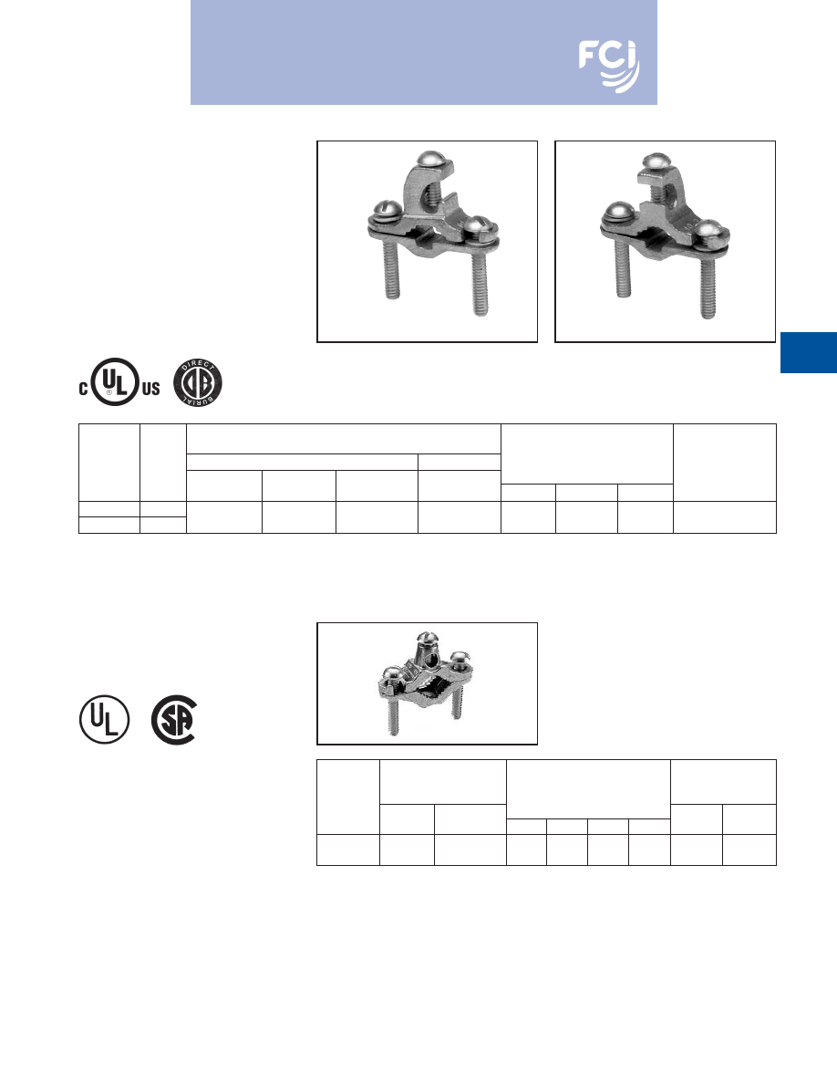
BURNDY
®
Products
Grounding
D-35
CAST BRONZE
GROUND CLAMPS
With Lay-in Feature
For connecting grounding conductor to water
pipe, copper tube, ground rod or rebar. The
open face design allows for fast lay-in of the
tap conductor without the need for cutting.
Simply reverse bottom clamp for smaller size
rebar or rod. Connectors are provided with
Silicon Bronze hardware.
ACCOMMODATES
CONDUCTOR RANGE
MAIN
TAP
REFERENCE
RECOMMENDED
CATALOG
WATER
GROUND
DIMENSIONS
SCREW TORQUE
NUMBER
FIG #
PIPE
REBAR
ROD
GROUND
H
L
W
“INCH POUNDS”
C11K16D
Fig 1
1/2
- 1
#10 - #2
C11K17D
Fig 2
[13 - 25]
#4 - #6
3/8
- 1
Str.
1.64
2.28
0.66
50 in.-lbs.
Fig. 2
DIE CAST CLAMPS
Die cast zinc with zinc plated screws.
RECOMMENDED
ACCOMMODATES
SCREW TORQUE
CONDUCTOR RANGE
“INCH POUNDS”
CATALOG
WATER
REFERENCE DIMENSIONS
PIPE
WIRE
NUMBER
PIPE
GROUND
H
L
W
C
CLAMP
CLAMP
1/2 - 1
10 - 2
1.56
2.25
.56
.50
CZ-11
[13 - 25]
Str.
[40]
[56]
[14]
[13]
50 in.-lb.
50 in.-lb.
Fig. 1
Burndy-Grounding-Connectors-catalog-html.html
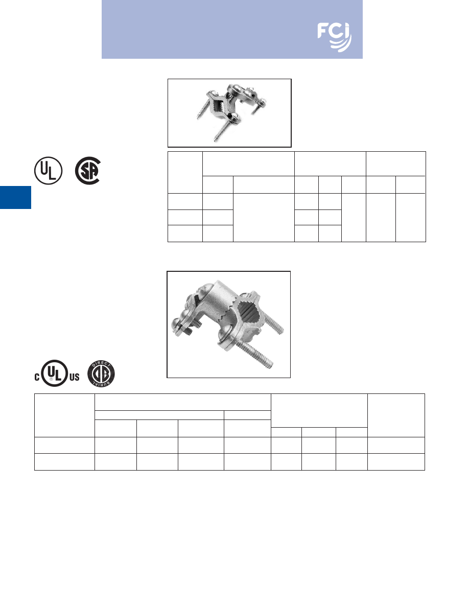
BURNDY
®
Products
Grounding
D-36
CAST BRONZE
GROUND CLAMPS
For connecting grounding conductor, EMT or
rigid conduit to water pipe, copper tube,
ground rod or rebar. Hub swings 360° for
easy alignment. Simply reverse bottom clamp
for smaller size rebar or rod. Connectors are
provided with Silicon Bronze hardware.
ACCOMMODATES
CONDUCTOR RANGE
MAIN
TAP
REFERENCE
RECOMMENDED
CATALOG
WATER
GROUND
DIMENSIONS
SCREW TORQUE
NUMBER
PIPE
REBAR
ROD
GROUND
H
L
W
“INCH POUNDS”
1/2
- 1
#8 - 4/0
C11HD4/0DB
[13 - 25]
#4 - #6
3/8
- 1
AWG
2.25
2.65
1.56
50 in.-lbs.
1-1/4
- 2
#8 - 4/0
C22HD4/0DB
[32 - 51]
—
—
AWG
2.70
3.60
1.56
50 in.-lbs.
CAST BRONZE
CLAMPS
To connect armored cable to water pipe. Zinc
plated screws. Pressure bar grips armor or
outer cable insulation. 360° swing hub for
easy alignment.
RECOMMENDED
ACCOMMODATES
REFERENCE
SCREW TORQUE
CONDUCTOR RANGE
DIMENSIONS
“INCH POUNDS”
CATALOG
WATER
ARMORED
PIPE
WIRE
NUMBER
PIPE
CONDUCTOR
H
L
W
CLAMP
CLAMP
1/2 - 1
1.38
3.05
C-11JA
[13 - 25]
[35]
[77]
1-1/4 - 2
10 - 6
2.60
3.69
1.41
C-22JA
[32 - 51]
Sol.
[66]
[94]
[36]
50 in.-lb.
50 in.-lb.
2-1/2 - 4
4.29
5.01
C-4JA
[64 - 102]
[109]
[128]
Burndy-Grounding-Connectors-catalog-html.html
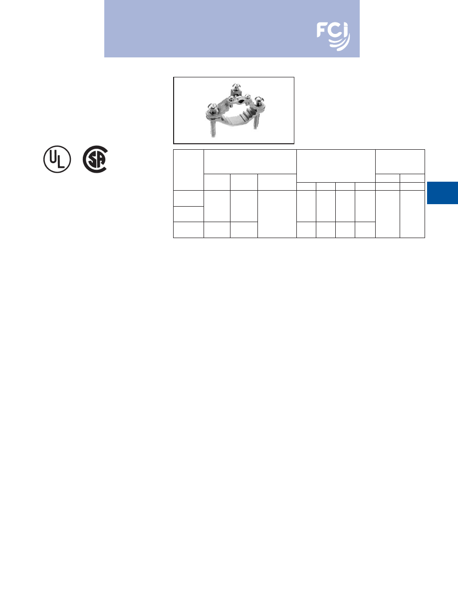
BURNDY
®
Products
Grounding
D-37
CAST BRONZE
CLAMPS
For connecting armored cable to water pipe.
Zinc plated screws. "D" indicates UL467 for
direct burial in earth and concrete, supplied
with silicon bronze hardware.
RECOMMENDED
ACCOMMODATES
SCREW TORQUE
CONDUCTOR RANGE
“INCH POUNDS”
CATALOG
WATER
GROUND
REFERENCE DIMENSIONS
PIPE
WIRE
NUMBER
PIPE
GROUND
CLAMP
H
L
W
C
CLAMP
CLAMP
C-6
1/2 - 1
10 - 2
Bare Armored
1.60
2.34
1.06
.63
[13 - 25]
Str.
Unarmored
[41]
[59]
[27]
[16]
C-6D
Wire Cables
50 in.-lb.
50 in.-lb.
1-1/4 - 2
10 - 2
or Cords
2.38
3.62
.94
1.00
C-7
[32 - 51]
Str.
[60]
[92]
[24]
[25]
Burndy-Grounding-Connectors-catalog-html.html
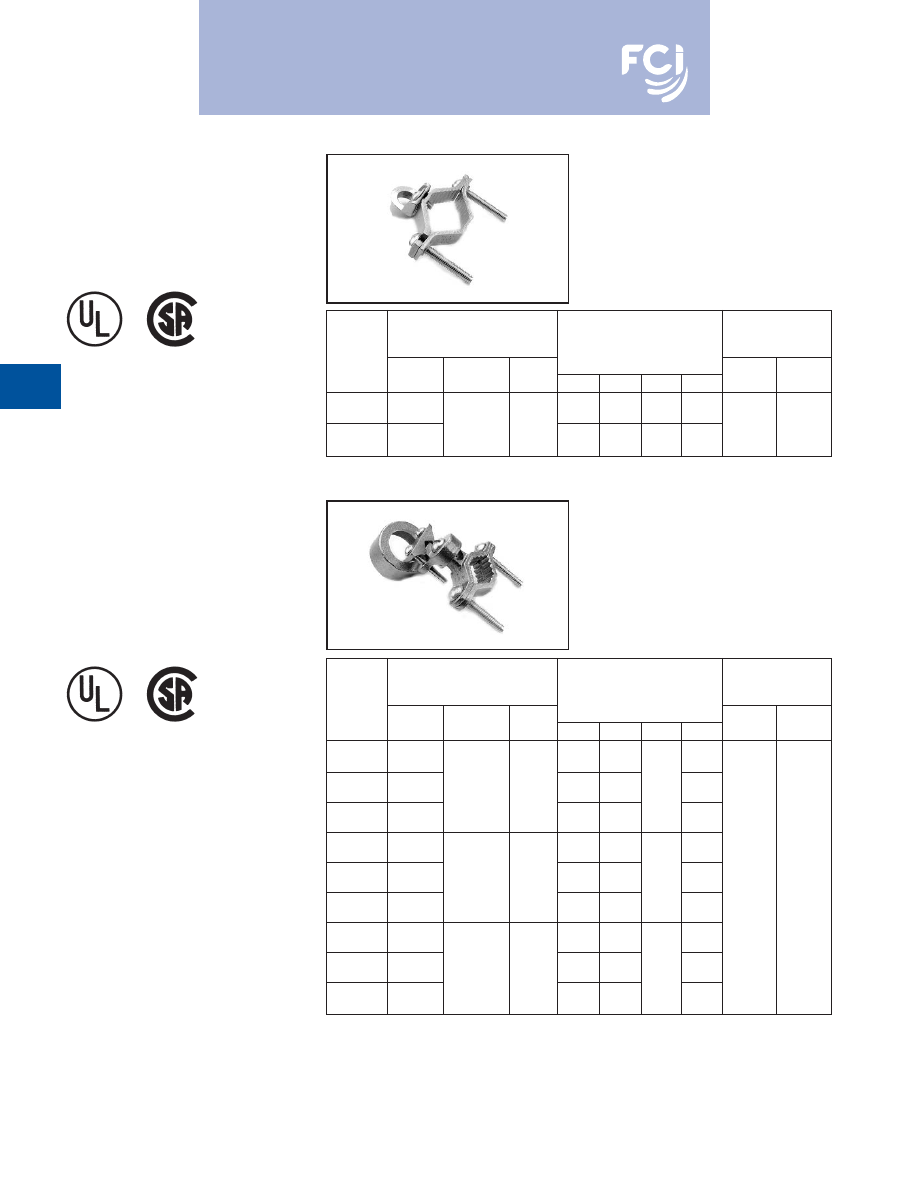
BURNDY
®
Products
Grounding
D-38
CAST BRONZE
CLAMP FOR
RIGID CONDUIT
For grounding rigid conduit systems.
Zinc plated screws.
CAST BRONZE
CLAMPS FOR
CONDUIT
For grounding rigid conduit systems.
Continuity from rigid conduit systems to
ground provided by cast bronze threaded
conduit hub. Zinc plated screws.
RECOMMENDED
ACCOMMODATES
SCREW TORQUE
CONDUCTOR RANGE
“INCH POUNDS”
CATALOG WATER
HUB
REFERENCE DIMENSIONS
PIPE
WIRE
NUMBER
PIPE
GROUND
SIZE
H
L
W
C
CLAMP
CLAMP
1/2 - 1
2.07
2.34
1.34
1.06
C-61
[13 - 25]
#6 Sol.
1/2
[53]
[59]
[34]
[27]
1-1/4 - 2
Max.
[13]
2.69
3.62
1.34
1.40
50 in.-lb.
50 in.-lb.
C-66
[32 - 51]
[68]
[92]
[34]
[36]
RECOMMENDED
ACCOMMODATES
SCREW TORQUE
CONDUCTOR RANGE
“INCH POUNDS”
CATALOG WATER
HUB
REFERENCE DIMENSIONS
PIPE
WIRE
NUMBER
PIPE
GROUND
SIZE
H
L
W
C
CLAMP
CLAMP
1/2 - 1
2.25
3.23
.97
C-11LH-1
[13 - 25]
[57]
[83]
[25]
1-1/4 - 2
10 Str. -
1/2
2.88
3.50
.69
1.34
C-22LH-1
[32 - 51]
6 Sol.
[13]
[73]
[89]
[18]
[34]
2-1/2 - 4
4.56
4.82
2.44
C-4LH-1
[54 - 102]
[116]
[122]
[62]
1/2 - 1
2.56
2.86
1.13
C-11LH-2
[13 - 25]
[65]
[73]
[29]
1-1/4 - 2
2/0 - 10
3/4
3.19
3.50
1.00
1.50
C-22LH-2
[32 - 51]
Str.
[19]
[65]
[89]
[25]
[38]
50 in.-lb.
50 in.-lb.
2-1/2 - 4
4.88
4.82
2.38
C-4LH-2
[64 - 102]
[124]
[122]
[60]
1/2 - 1
2.69
2.86
1.19
C-11LH-3
[13 - 25]
[68]
[73]
[30]
1-1/4 - 2
3/0 - 10
1
3.32
3.50
1.13
1.56
C-22LH-3
[32 - 51]
Str.
[25]
[59]
[89]
[29]
[40]
2-1/2 - 4
5.01
4.82
2.44
C-4LH-3
[63 - 102]
[127]
[122]
[62]
Burndy-Grounding-Connectors-catalog-html.html
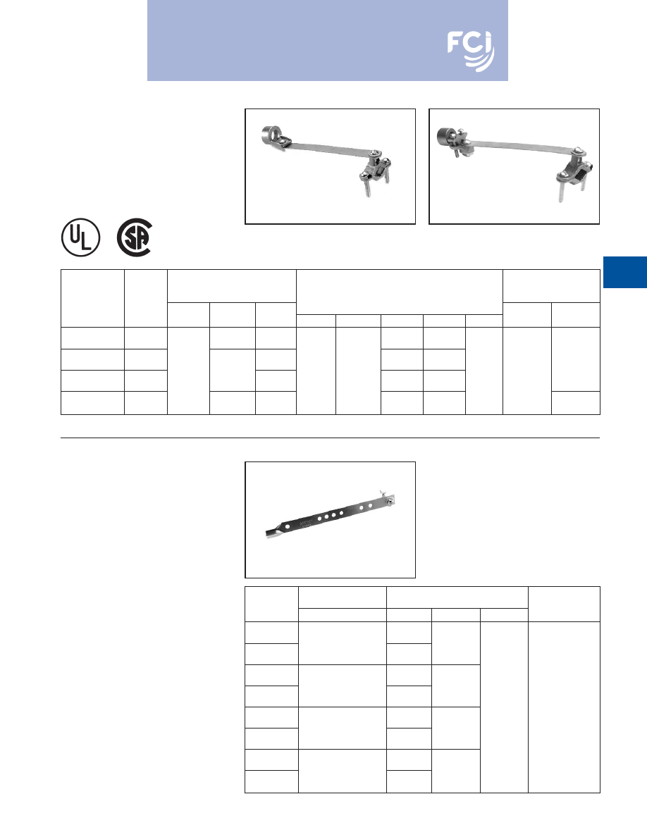
BURNDY
®
Products
Grounding
D-39
CAST BRONZE
CLAMP WITH
COPPER STRAP
For grounding rigid conduit systems. Strap
helps protect conduit system from water
system vibrations. Zinc plated screws. Strap
ETP copper.
GROUND STRAPS,
ADJUSTABLE
BURNDY
®
adjustable ground straps are
made from pure annealed copper. The heavy
type is .050
thick and 3/4
wide. The light
type is .025
thick and 3/4
wide. The bolts,
nuts and washers are plated steel. Four sizes
cover a ground pipe range of 3/8
to 4
.
Ground wire connection can be soldered or
solderless.
RECOMMENDED
ACCOMMODATES
SCREW TORQUE
CONDUCTOR RANGE
“INCH POUNDS”
CATALOG
WATER
HUB
REFERENCE DIMENSIONS
PIPE
WIRE
NUMBER
FIG. #
PIPE
GROUND
SIZE
H
L
W
C
D
CLAMP
CLAMP
6 Sol.
1/2
1.06
1.06
C-11CSH-1
Fig. 1
Max.
[13]
[27]
[27]
3/4
1.25
1.50
C-11CSH-2
Fig. 1
1/2 - 1
4/0 Str.
[19]
1.75
8.50
[32]
[38]
6.12
50 in.-lb.
[13 - 25]
Max.
1
[44]
[216]
1.50
1.75
[155]
50 in.-lb.
C-11CSH-3
Fig. 1
[25]
[38]
[44]
#10 - 2/0
1/2
1.18
1.06
C11CSLH12
Fig. 2
AWG
[13]
[27]
45 in.-lb.
RECOMMENDED
CATALOG
ACCOMMODATES
REFERENCE DIMENSIONS
SCREW TORQUE
NUMBER
WATER PIPE
H
L
W
“INCH POUNDS”
.050
GS1T50
3/8 - 1
[1]
5.61
[10 - 25]
.025
[142]
GS1T25
[1]
.050
GS2T50
3/8 - 2
[1]
9.38
[10 - 51]
.025
[238]
GS2T25
[1]
.75
.050
[19]
50 in.-lb.
GS3T50
3/8 - 3
[1]
13.20
[10 - 76]
.025
[335]
GS3T25
[1]
.050
GS4T50
3/8 - 4
[1]
17.00
[10 - 102]
.025
[432]
GS4T25
[1]
Fig. 1
Fig. 2
Burndy-Grounding-Connectors-catalog-html.html
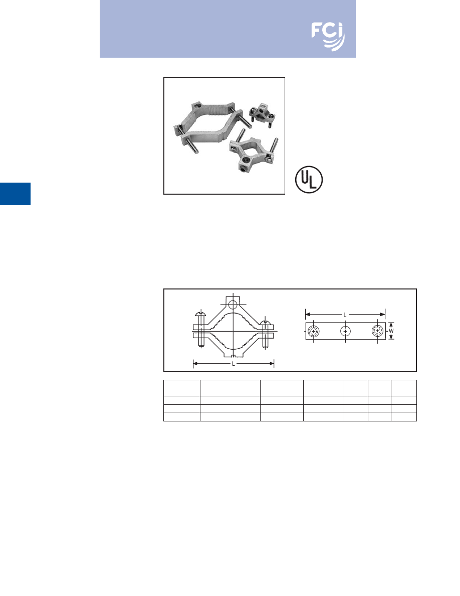
BURNDY
®
Products
Grounding
D-40
TYPE GC-A
DUAL RATED
GROUND CLAMP
For Copper and
Aluminum Cable
GC-A ground clamps are UL Listed for use
with either copper or aluminum conductors to
copper water pipe, galvanized pipe or steel
conduit. All clamps are constructed from tin
plated high-strength extruded aluminum alloy.
PENETROX™ oxide inhibiting joint com-
pounds are recommended for all aluminum
applications.
Features and Benefits
• Clamps are dual rated for both copper
and aluminum conductors.
9
Maximum flexibility of application.
• All connectors are tin plated.
9
Provide low contact resistance and
prevents galvanic corrosion.
• All clamps are range taking.
9
Only 3 catalog numbers covers complete
range of applications from 1/2 - 4 inches.
Catalog
Conduit, Pipe, or
Wire
Screw
Hex
Number
Water Tube Size
Range
Type
W
L
Size
GC15A
1/2 - 3/4 - 1
1/0 - 14
Slotted
11/16
2-1/4
S
GC18A
1-1/4 - 1-1/2 - 2
250 MCM - 6
Hex Socket
13/16
3-3/4
5/16
GC22A
2-1/2 - 3 - 3-1/2 - 4
250 MCM - 6
Hex Socket
1
6-5/16
5/16
Burndy-Grounding-Connectors-catalog-html.html
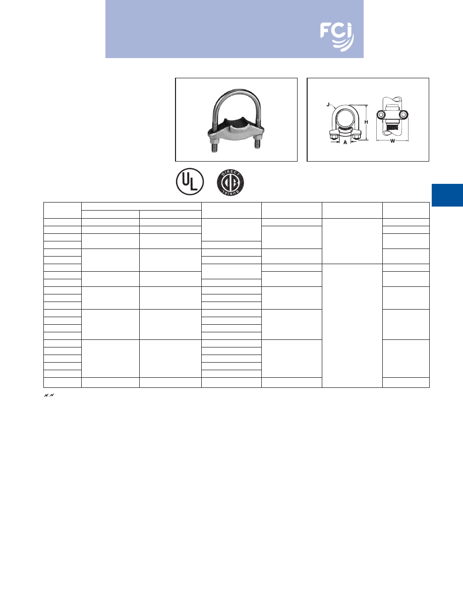
BURNDY
®
Products
Grounding
D-41
TYPE GG
GROUND CONNECTOR
For Copper Bar, Strap, Braid or
Cable to Rod or Tube
High copper alloy ground connector for join-
ing bar, strap, braid or cable to rod or tube.
High copper alloy cast body, DURIUM™
U-bolts, nuts and lockwashers make the GG
particularly effective for use with braid for
ground rods, switch handles, fence posts and
gates. One-wrench installation.
See note page D-1
Catalog
Conductor
Number
Tube I.P.S.
Rod
A
H
J
W
GG15-1
1
1-1/8 - 1-1/4
3-3/8
2-5/8
GG16-1
1-1/4
1-3/8 - 1-1/2
1
3
GG17-1
3-1/2
GG17-15
1-1/2
1-5/8 - 1-7/8
1-1/2
3/8
3-1/4
GG18-1
1
GG18-15
2
2 - 2-3/8
1-1/2
4-1/4
3-3/4
GG18-2
4-3/8
4-1/8
GG19-2
2
GG19-25
2-1/2
2-1/2 - 2-7/8
2-1/2
5
4-5/8
GG20-2
2
GG20-25
3
3 - 3-1/2
2-1/2
6-3/8
5-1/4
GG20-3
3
GG21-2
2
GG21-25
2-1/2
GG21-3
3-1/2
3-1/2 - 4
3
5-7/8
1/2
5-3/4
GG21-35
3-1/2
GG22-2
2
GG22-25
2-1/2
GG22-3
4
4 - 4-1/2
3
6-1/2
6-1/4
GG22-35
3-1/2
GG22-4
4
GG24-2
5
—
2
7-5/8
7-1/4
Burndy-Grounding-Connectors-catalog-html.html
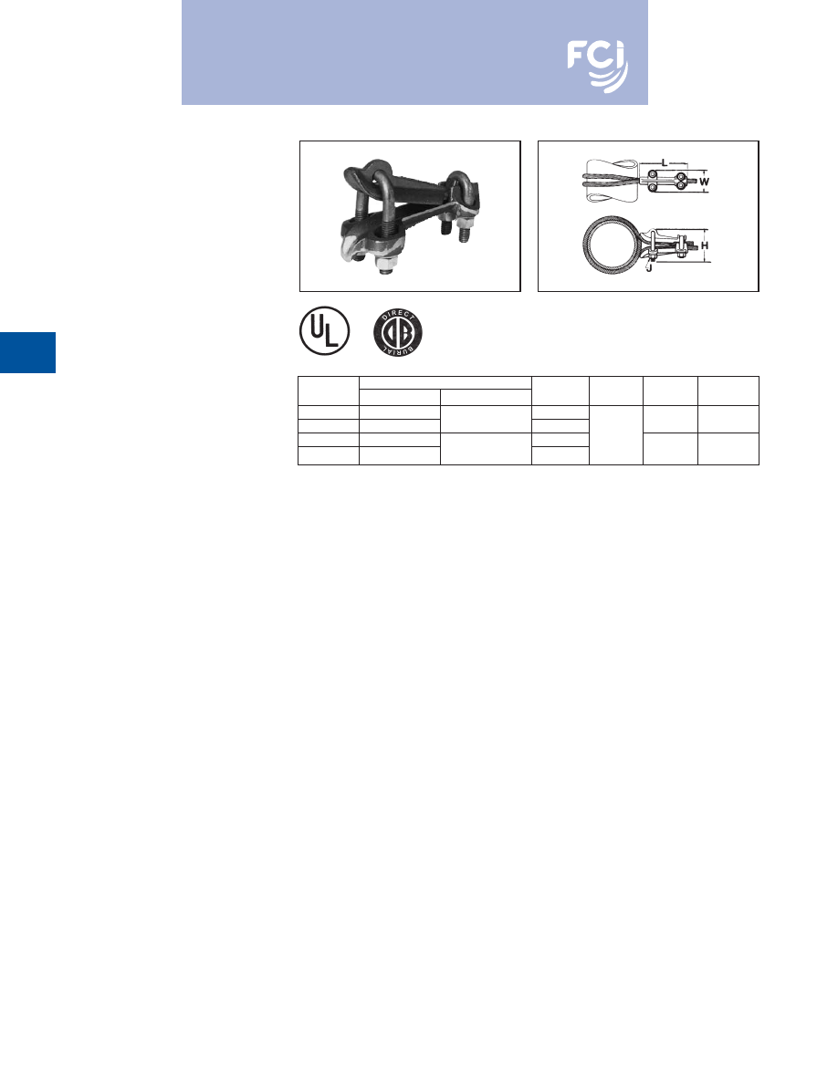
BURNDY
®
Products
Grounding
D-42
TYPE GQ
GROUND CONNECTOR
For Copper Cable to Tube
High copper alloy ground connector for cross
connecting a wide range of cable. High
copper alloy, cast body, DURIUM™ U-bolts,
nuts, and lockwashers make the GQ suitable
for burial in soil or concrete. One-wrench
installation. UL467 Listed. Acceptable for
direct burial in earth or concrete.
Catalog
Conductor
Number
Tube I.P.S.
Cable
H
J
L
W
GQ2626
6
Max.
4-1/2
GQ26-1
Above 6
4 Str. - 2/0 Str.
7-1/8
5
2-1/2
GQ2929
6
Max.
4-1/8
1/2
GQ29-1
Above 6
2/0 Str. - 250
7-1/2
6
2-3/4
Burndy-Grounding-Connectors-catalog-html.html
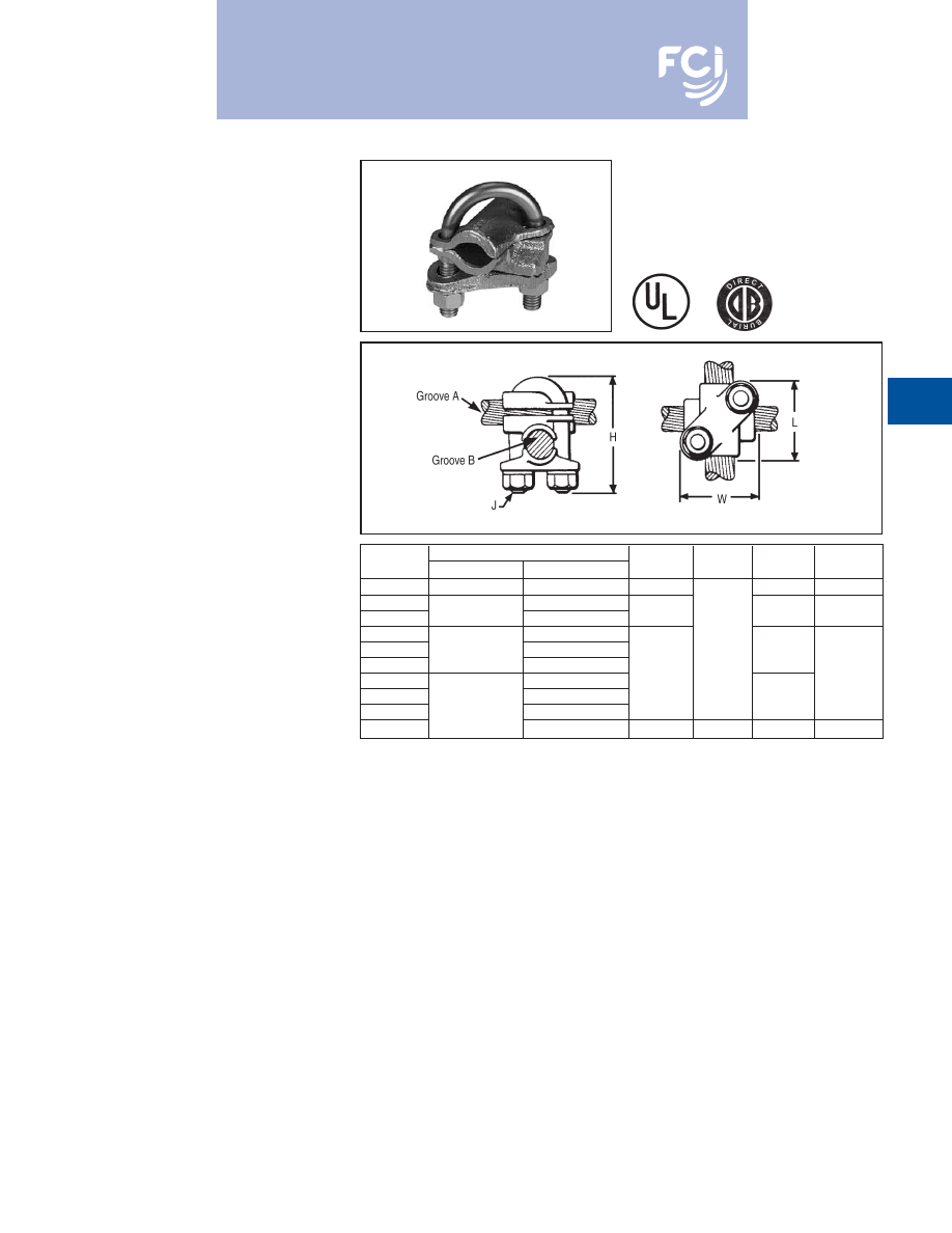
BURNDY
®
Products
Grounding
D-43
TYPE GX
GROUND CONNECTOR
For Copper Cables
High copper alloy ground connector for cross
connecting a wide range of cable. The high
copper alloy cast body, DURIUM™ U-bolts,
nuts, and lockwashers make the GX suitable
for burial in soil or concrete. One-wrench
installation. UL467 Listed. Acceptable for
direct burial in earth or concrete.
Catalog
Conductor
Number
Groove A
Groove B
H
J
L
W
GX4C4C
8 Sol. - 4 Str.
8 Sol. - 4 Str.
1-7/8
1-5/8
1-5/8
GX264C
8 Sol. - 4 Str.
GX2626
4 Sol. - 2/0 Str.
4 Sol. - 2/0 Str.
2-1/2
1-3/4
1-3/4
GX294C
8 Sol. - 4 Str.
GX2926
2/0 Sol. - 250
4 Sol. - 2/0 Str.
3/8
1-7/8
GX2929
2/0 Sol. - 250
GX344C
8 Sol. - 4 Str.
2-3/4
1-7/8
GX3426
4 Sol. - 2/0 Str.
2-1/8
GX3429
300 - 500
2/0 Sol. - 250
GX3434
300 - 500
4-1/4
1/2
2-5/8
2-5/8
Burndy-Grounding-Connectors-catalog-html.html
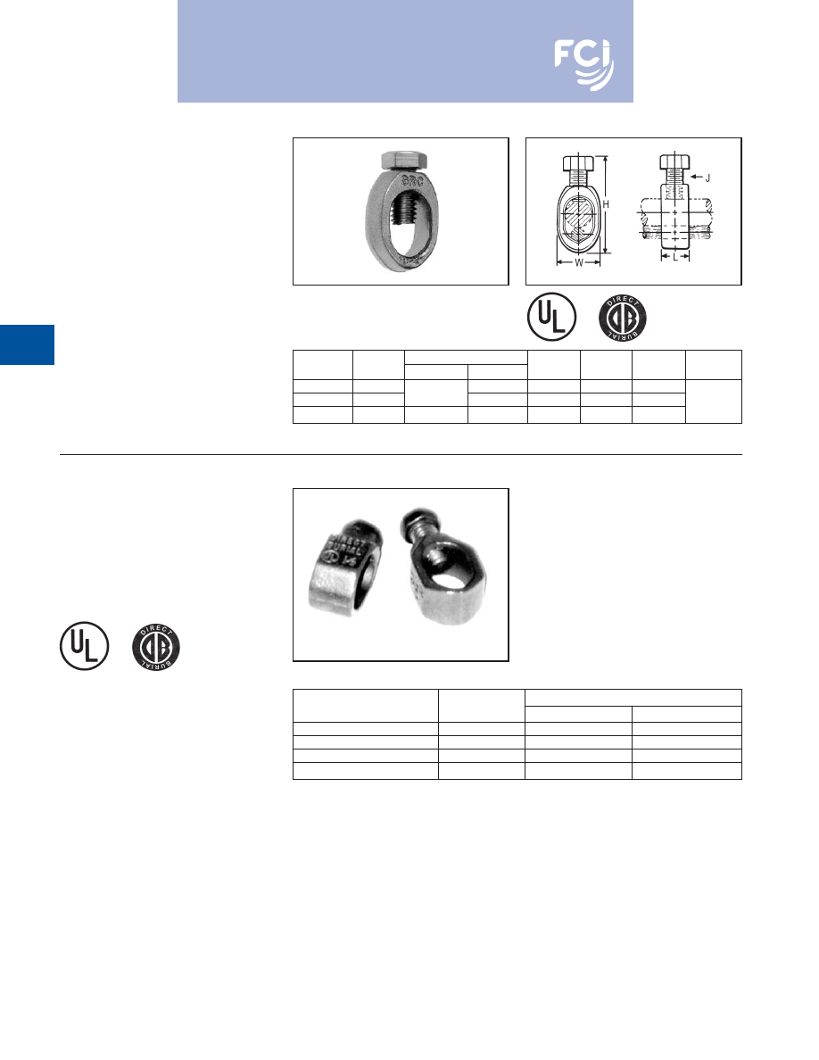
BURNDY
®
Products
Grounding
D-44
TYPE GRC
HIGH STRENGTH
GROUND ROD CLAMP
For Copper Cable to Rod
High copper alloy ground connector for
joining a range of cable to copper clad,
galvanized steel, and stainless steel ground
rods. Slips over end of rod, one-wrench
installation. UL467 Listed for direct burial in
earth and concrete.
REA LISTED
Catalog
Drive
Conductor Range
Number
Rod
Min.
Max.
H
W
L
J
GRC12
1/2
2 Str.
2.00
.89
.63
GRC58
5/8
10 Sol.
1 Str.
2.19
.95
.63
3/8
GRC34
3/4
8 Sol.
1/0 Str.
2.47
1.09
.65
TYPE GRL
LIGHT DUTY
ECONOMICAL GROUND ROD
CLAMP
UL 467 Listed. Acceptable for direct burial.
Conductor Range
Catalog Number
Rod Size
Minimum
Maximum
GRL3
*
3/8
10 AWG
4 AWG
GRL4
1/2
10 AWG
2 AWG
GRL5
5/8
10 AWG
2 AWG
GRL6
3/4
10 AWG
2 AWG
* GRL3 not UL Listed.
Burndy-Grounding-Connectors-catalog-html.html
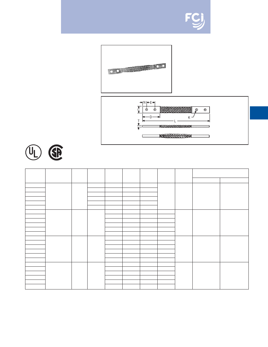
BURNDY
®
Products
Grounding
D-45
TYPE B
FLEXIBLE COPPER BRAID
Flexible copper braid jumpers designed to
take up linear expansion and contraction,
compensate for misalignment and absorb
vibratory movement of electrical equipment
and devices.
Made of flat extra flexible, tinned, pure copper
braid, with unplated, seamless, pure copper
ferrules formed into a rectangular shape on
each end.
Last two numbers in catalog number indicate
total length of braid in inches (e.g., BD12N or
BD12 is 12
long braid jumper).
Other lengths, plating and drilling are
available. Refer to factory.
* This rating may vary with ambient conditions, orientation of
the braid and other service conditions.
** Tongue drilled per (2) hole NEMA standard.
NUMBER OF
APPROXIMATE
CATALOG
BRAIDS IN
AMPERE RATING
NUMBER
FERRULES
C
D
E
K
L
N
T
INDOOR
OUTDOOR
BD12
†
2.50
1.25
.44
12
BD12N
** †
3.00
1.75
.56
12
BD18
†
2.50
1.25
.44
18
BD18N
** †
1
.94
3.00
1.75
.56
18
.62
.13
190
225
BD24
†
2.50
1.25
.44
24
BD24N
** †
3.00
1.75
.56
24
BE12
†
1.50
.44
12
.75
BE12N** †
1.75
.56
12
.62
BE18
†
1.50
.44
18
.75
BE18N
** †
1
1.50
3.00
1.75
.56
18
.62
.17
340
405
BE24
†
1.50
.44
24
.75
BE24N** †
1.75
.56
24
.62
BF12 †
1.50
.44
12
.75
BF12N** †
1.75
.56
12
.62
BF18 †
1.50
.44
18
.75
BF18N** †
1
1.19
3.00
1.75
.56
18
.62
.25
360
430
BF24 †
1.50
.44
24
.75
BF24N** †
1.75
.56
24
.62
BG12
1.50
.44
12
.75
BG12N**
1.75
.56
12
.62
BG18
1.50
.44
18
.75
BG18N
**
1
1.50
3.00
1.75
.56
18
.62
.25
415
495
BG24
1.50
.44
24
.75
BG24N
**
1.75
.56
24
.62
Note:
All sizes are listed to UL467 and specific sizes (†) are
certified to CSA C22.2, No. 41 Grounding and Bonding
Equipment Standards. Equivalent sizes may be designated
by suffix letters representing variations in length, mounting
configurations, pad size and finish. Contact factory for
details.
Burndy-Grounding-Connectors-catalog-html.html
BURNDY
®
Products
Grounding
D-46
FLEXIBLE COPPER
BRAID
(Continued)
TYPE B
* This rating may vary with ambient conditions, orientation of
the braid and other service conditions.
** Tongue drilled per (2) hole NEMA standard.
NUMBER OF
APPROXIMATE
CATALOG
BRAIDS IN
AMPERE RATING
NUMBER
FERRULES
C
D
E
K
L
N
T
INDOOR
OUTDOOR
B2D12
†
2.50
1.25
.44
12
.62
B2D12N** †
.94
3.00
1.75
.56
12
.62
.25
380
455
B2E12
3.00
1.50
.44
12
.75
B2E12N
**
1.62
3.00
1.75
.56
12
.62
.25
530
635
B2F12
2
3.00
1.50
.44
12
.75
B2F12N**
1.38
3.00
1.75
.56
12
.62
.38
600
720
B2G12
3.00
1.50
.44
12
.75
B2G12N**
1.50
3.00
1.75
.56
12
.62
.50
700
840
B3D12 †
2.50
1.25
.44
12
.62
B3D12N** †
1.19
3.00
1.75
.56
12
.62
.25
470
560
B3E12
3.00
1.50
.44
12
.75
B3E12N**
1.64
3.00
1.75
.56
12
.62
.31
700
840
B3F12
3
3.00
1.50
.44
12
.75
B3F12N**
1.44
3.00
1.75
.56
12
.62
.56
820
980
B3G12
3.00
1.50
.44
12
.75
B3G12N**
1.69
3.00
1.75
.56
12
.62
.69
960
1150
B4D12
2.50
1.25
.44
12
.62
B4D12N**
1.19
3.00
1.75
.56
12
.62
.32
600
720
B4E12
3.00
1.50
.44
12
.75
B4E12N**
1.64
3.00
1.75
.56
12
.62
.36
850
1020
B4F12
4
3.00
1.50
.44
12
.75
B4F12N**
1.50
3.00
1.75
.56
12
.62
.78
1000
1200
B4G12
3.00
1.50
.44
12
.75
B4G12N**
1.69
3.00
1.75
.56
12
.62
.94
1200
1440
Note:
All sizes are listed to UL467 and specific sizes (†) are
certified to CSA C22.2, No. 41 Grounding and Bonding
Equipment Standards. Equivalent sizes may be designated
by suffix letters representing variations in length, mounting
configurations, pad size and finish. Contact factory for
details.
Burndy-Grounding-Connectors-catalog-html.html
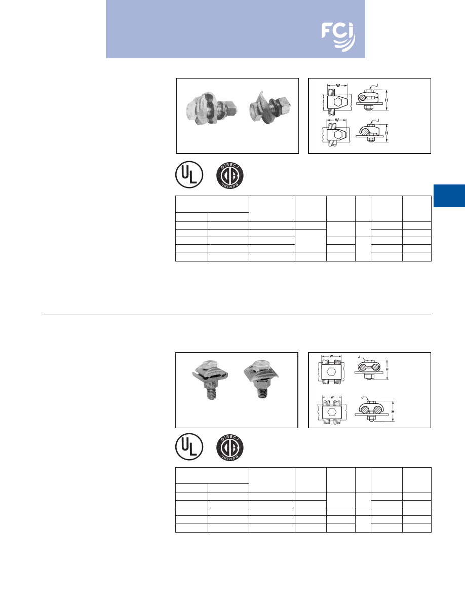
BURNDY
®
Products
Grounding
D-47
TYPES GB, GBM
GROUND CONNECTOR
For Copper Cable to Bar
High copper alloy ground connector for
joining a range of cable to 1/4
thick bar.*
Type GB separates cable from bar, GBM
clamps cable directly on bar surface.
One-wrench installation. UL467 Listed. The
high copper alloy cast body and DURIUM™
bolts, nuts, and lockwashers make the GB
and GBM suitable for direct burial in concrete
or ground.
TYPES GC, GCM
GROUND CONNECTOR
For Two Copper
Cables to Bar
High copper alloy ground connector for
joining a wide range of two parallel cables to
1/4
thick bar.* Type GC separates cable from
bar, GCM clamps cable to bar surface.
One-wrench installation. UL467 Listed. The
high copper alloy cast body and DURIUM™
bolts, nuts, and lockwashers make the GC
and GCM suitable for direct burial in concrete
or ground.
+ GBL30 is not UL listed.
Add "GS" suffix for galvanized steel hardware.
* For other bar thicknesses see note at bottom of page D-46.
Smooth oval-shank bolts are available upon request for cable-
tray applications (example: GC30G3). Also refer to type GC-CT.
Add "GS" suffix for galavanized steel hardware.
* For other bar thicknesses see note at bottom of page D-44.
Type
GC
Type
GCM
Type
GB
Type
GBM
Type
GBM
Type
GB
Type
GC
Type
GCM
H
H
W
W
Catalog Number
Type
Type
Type
Type
Type GB
Type GBM
Conductor
GB/GBL
GBM
J
GB/GBL
GBM
GB4C
GBM4C
8 Sol. - 4 Str.
1-1/2
1-1/4
1-1/4
GB26
GBM26
4 Sol. - 2/0 Str.
1-1/2
3/8
1-1/2
1-1/2
+GBL30
4 Sol. - 300
2
7/8
0
GB29
GBM29
2/0 Sol. - 250
2
1/2
2
2
GB34
GBM34
300 - 500
3
2-1/4
2-3/8
2-3/8
H
H
W
W
Catalog Number
Type
Type
Type
Type
Type GC
Type GCM
Conductor
GC/GCL
GCM
J
GC/GCL
GCM
GC4C4C
GCM4C
8 Sol. - 4 Str.
1-1/2
1-3/8
1
GC2626
GCM26
4 Sol. - 2/0 Str.
2
1-1/2
3/8
1-3/4
1-3/8
GCL30
GCM30
4 Str. - 300
2
—
—
1
—
GC2929
GCM29
2/0 Sol. - 250
2-1/4
2
—
2-1/4
2
GC3434
GCM34
300 - 500
2-7/8
2-1/4
1/2
2-7/8
2-5/8
Burndy-Grounding-Connectors-catalog-html.html
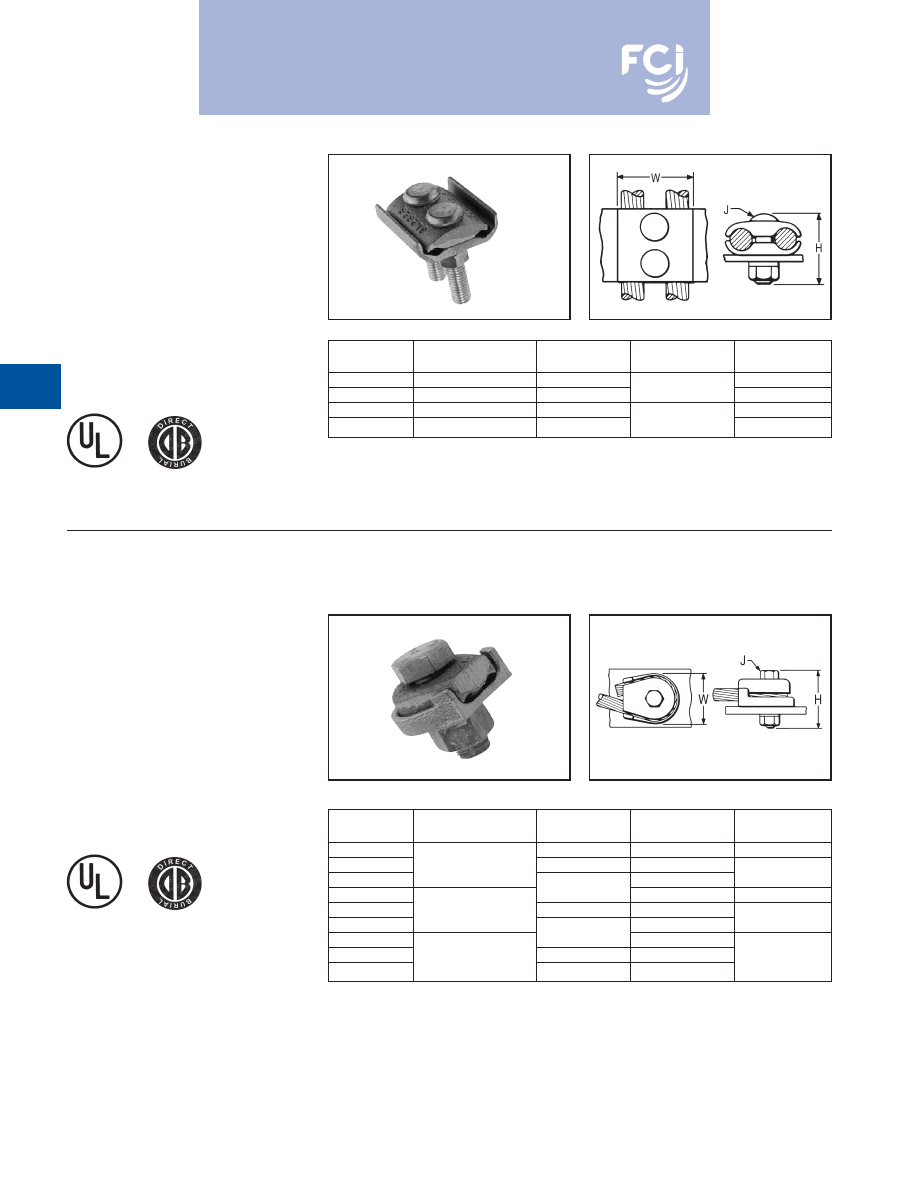
BURNDY
®
Products
Grounding
D-48
TYPE GL
GROUND CONNECTOR
For Two Copper
Cables to Bar
High copper alloy ground connector for join-
ing a wide range of two parallel cables to 1/4
thick bar.* Two-bolt design, separates cable
from bar. One-wrench installation. UL467
Listed. The high copper alloy cast body and
DURIUM™ bolts, nuts, and lockwashers
make them suitable for direct burial in
concrete or ground.
TYPE GZ
GROUND CONNECTOR
For Copper Cable to Bar
High copper alloy ground connector for
joining a wide range of cable to 1/4
thick
bar*. Cable is gripped by curving it around the
clamping bolt in connector groove. UL467
Listed. The high copper alloy cast body and
DURIUM™ bolts, nuts, and lockwashers
make them suitable for direct burial in
concrete or ground.
* For other bar thicknesses see note at bottom of page.
N
OTE:
* The GB, GBM, GC, GCM, GL and GZ are all
used for joining a range of cable to bar. The
catalog numbers in each table accommodate the
indicated cable range and up to 1/4
thick bar.
Optional bolt lengths are available to accommo-
date up to 1
thick bar. For bar thicknesses from
1/4
to 1/2
, add the suffix “T4” to the catalog
number in the table. For bar thicknesses from
1/2
to 1
, add the suffix “T8” to the catalog
number in the table.
Catalog
Number*
Conductor
H
J
W
GL4C4C
8 Sol. - 4 Str.
1-1/2
1-3/8
GL2626
4 Sol. - 2/0 Str.
2
3/8
1-3/4
GL2929
2/0 Sol. - 250
2-1/4
2-1/4
GL3434
300 - 500
2-7/8
1/2
2-7/8
Catalog
Number*
Conductor
H
J
W
GZ4C-38
1-1/2
3/8
1-1/8
GZ4C-12
8 Str. - 4 Str.
1-7/8
1/2
GZ4C-58
5/8
1-3/4
GZ26-38
2
3/8
1-5/8
GZ26-12
3 Str. - 2/0 Str.
2-1/8
1/2
GZ26-58
5/8
1-3/4
GZ29-38
2-1/4
3/8
GZ29-12
3/0 Str. - 250
2-3/8
1/2
2-1/4
GZ29-58
2-1/2
5/8
Burndy-Grounding-Connectors-catalog-html.html
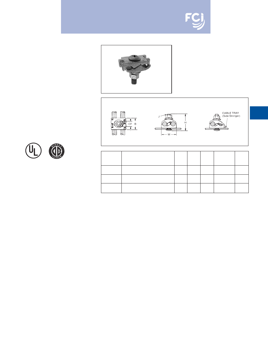
BURNDY
®
Products
Grounding
D-49
TYPE GC-CT
CABLETRAY
GROUND CLAMP
This unique connector incorporates features
which are unmatched. Made of tin-plated cast
copper alloy, it accommodates either one or
two conductors, copper or aluminum cable. In
addition to a low profile head with a deep
Phillips recess, the galvanized steel bolt has
a ribbed neck which prevents rotation during
installation when installed in a .44 diameter
hole. When used on aluminum conductor, the
cable must be scratch brushed and
PENETROX™ A joint compound must be
used on cable and connector.
UL467 Listed for copper conductor only.
Suitable for direct burial in concrete or earth.
NOTE:
The bolt head is mounted on the inside wall of cabletray to avoid
damage to the cable insulation.
May be used with aluminum or galvanized steel cable tray.
ACCOMMODATES COPPER OR
CATALOG
ALUMINUM CONDUCTOR
NUMBER
IN EITHER GROOVE
B
CF
H
J
W
#6 Sol. (.162 Dia.) -
GC2525CT
1/0 Str. (.372 Dia.)
1.12
.56
1.95
3/8” - 16
1.45
#2 Sol. (.258 Dia.) -
GC2626CT
2/0 Str. (.419 Dia.)
1.12
.56
1.95
3/8” - 16
1.70
2/0 Str. (.414 Dia.) -
GC2929CT
250 kcmil (.575 Dia.)
1.12
.56
2.20
3/8” - 16
1.98
Burndy-Grounding-Connectors-catalog-html.html
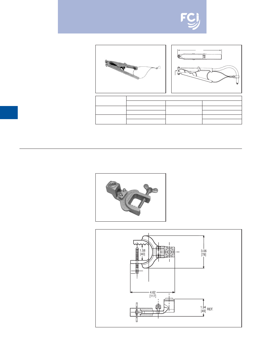
BURNDY
®
Products
Grounding
D-50
TYPE GIE-G
GROUND CONNECTOR
For Vehicle Grounding
Heavy Duty Construction
High-strength copper alloy ground clamps for
grounding gasoline trucks, tank cars, aircraft
and other vehicles where danger of explosion
due to static electricity exists. Corrosion resis-
tant and supplied with nonsparking,
adjustable, replaceable contact grip screws.
Automatic safety release disconnects should
a vehicle unexpectedly move from the
grounded area. Accommodates 4 Str. flexible
copper cable.
1.2
MAX.
OPENING
TYPE GIE-G
GROUND CONNECTOR
Accommodates flexible rubber sheath cable
ranging from #6 to #2 conductor.
Catalog Number:
GIE2CG3
8
1
⁄
8
Replaceable Contact Grip Screws
Catalog Number
Catalog Number
Material
Point Configuration
GIE4CG3P5
Cone Point
GIE4CG3
GIE4CG3P7
Beryllium Copper
Cup Point
GIE4CG4P5
Cone Point
GIE4CG4
GIE4CG4P7
Stainless Steel
Cup Point
Burndy-Grounding-Connectors-catalog-html.html
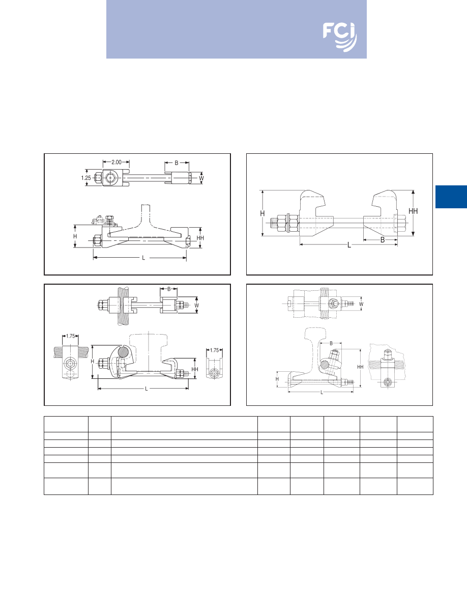
BURNDY
®
Products
Grounding
D-51
RAIL CONNECTOR
Mechanical clamp connectors designed for
use in power, contact or running rail appli-
cations. Connectors are cast of a high
conductivity copper alloy, tin-plated, and
assembled with high-strength DURIUM™
hardware. Connectors designed for extended
service life.
* Tin-plated.
Fig. 1
Fig. 2
Fig. 3
Fig. 4
Catalog
Fig.
Number
No.
Accomodates
B
H
HH
L
W
J278
1
100 LBS. A.R.E.A. RUNNING RAIL
1.81
1.88
1.72
7.50
.88
J279
1
75 or 90 LBS. RUNNING RAIL
1.81
1.71
1.55
7.50
.88
J280
1
150 LBS. CONTACT RAIL
2.12
2.08
1.92
7.00
1.25
J295
2
150 LBS. THIRD RAIL
2.62
3.50
3.50
7.75
3.00
150 LBS. NMC CONTACT RAIL and
RGC44G1*
3
(1) 800-1000 kcmil CU CABLE
1.75
2.82
2.25
10.00
1.75
115 LBS. CONTACT or RUNNING RAIL and
RGC39G1*
4
(1) 500-750 kcmil CU CABLE
2.75
2.00
4.78
8.32
1.25
Burndy-Grounding-Connectors-catalog-html.html
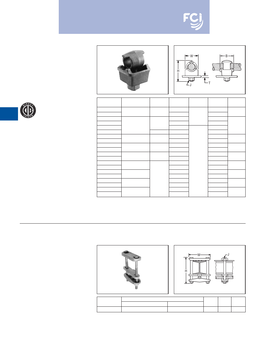
BURNDY
®
Products
Grounding
D-52
TYPE QGFL
BARTAP™
For Copper Cable to
Flat Bar or Pad
High copper alloy BARTAP™ for joining a
range of cable to bar or pad. One-wrench
installation. DURIUM™ nut and lockwasher.
TYPE GA-H
GROUND CONNECTOR
For Copper Cable
to “H” Beam
High copper alloy ground connector for join-
ing a wide range of cable parallel to “H”
beams or square tube.
Hardware is
made from DURIUM™ for superior corrosion
protection.
* Can be installed side by side or in line on NEMA drilled bar.
Catalog
T
Number
Conductor
B
H
J
(Max.)
W
QGFL1CB1
1-7/8
1/4
QGFL1CB1T6
10 Sol. - 1 Str.
1-1/8
2-3/8
3/4
1
QGFL26B1
2-1/8
3/8
1/4
QGFL26B1T6
1-1/4
2-5/8
3/4
QGFL26B2
*
8 Sol. - 2/0 Str.
1-1/2
1/4
1-1/8
QGFL26B2T6
*
1-1/2
2-7/8
3/4
QGFL29B1
*
2-5/8
1/4
QGFL29B1T6
*
6 Str. - 250
1-5/8
3-1/8
3/4
1-3/8
QGFL31B1
*
2-7/8
1/4
QGFL31B1T6
*
2 Sol. - 350
1-3/4
3-1/4
3/4
1-5/8
QGFL34B1
3-1/8
1/4
QGFL34B1T6
1/0 Sol. - 500
2
3-5/8
3/4
1-3/4
QGFL39B1
3-1/4
1/2
1/4
QGFL39B1T6
350 - 750
3-5/8
3/4
1-3/4
QGFL44B1
3-3/8
1/4
QGFL44B1T6
750 - 1000
4-1/8
3/4
2-1/8
QGFL46B1
2-1/4
4
1/4
QGFL46B1T6
1000 - 1500
4-1/2
3/4
2-1/2
QGFL48B1
4-3/4
1/4
QGFL48B1T6
1500 - 2000
5-1/4
3/4
3
CATALOG
CONDUCTOR
NUMBER
“H” BEAM
CABLE
H
J
W
GA25H26
1-7/8
1-7/8
- 2-1/2
2-1/2
4 Sol. - 2/0 Str.
4-3/4
3/8
4
Burndy-Grounding-Connectors-catalog-html.html
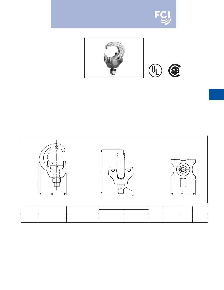
BURNDY
®
Products
Grounding
D-53
TYPE GRF
UNIGROUND
®
RAISED FLOOR
GROUNDING CONNECTOR
The BURNDY
®
UNIGROUND™ is a universal
grounding clamp, specifically designed for all
raised flooring systems. It can be installed on
round or square pedestals and can
accommodate one or two grounding wires to
make an efficient grid. The underfloor signal
reference grid provides the low impedance
ground path that attenuates high frequency
static and 60 Hz transient noise for cleaner
data output. UL467 Listed.
Features and Benefits
• One connector fits all applications.
9
Ease of specification and installation.
• Single bolt design.
9
Ease of installation:
9
— No need to disassemble.
9
— Single wrench installation.
• Accepts 1 or 2 ground conductors.
9
Requires less connectors to install
signal reference grid.
• Tin plated cast bronze construction.
9
Resists corrosion and provides extended
life ground connection.
• Grounds all pedestals (round or square).
Will handle up to 7/8
square and 1
round.
9
Ease of installation. One connector
does it all
• Serves 3 needs:
1. Signal Reference Grid.
2. Static Ground.
3. Fault Current Ground.
9
UNIGROUND™ solves all possible
grounding problems found in computer
applications today.
CATALOG
NUMBER OF
CONDUCTOR
PEDESTAL TYPE
NUMBER
CONDUCTORS
SIZE SOL. & STR.
ROUND
SQUARE
B
H
J
W
GRF4C-3
1 or 2
#8 - #2
Up to 1
Up to 7/8
1.96
3.14
3/8
1.76
GRF4C-4
1 or 2
#8 - #2
Up to 3/4
Up to 5/8
1.79
3.13
3/8
1.40
Burndy-Grounding-Connectors-catalog-html.html
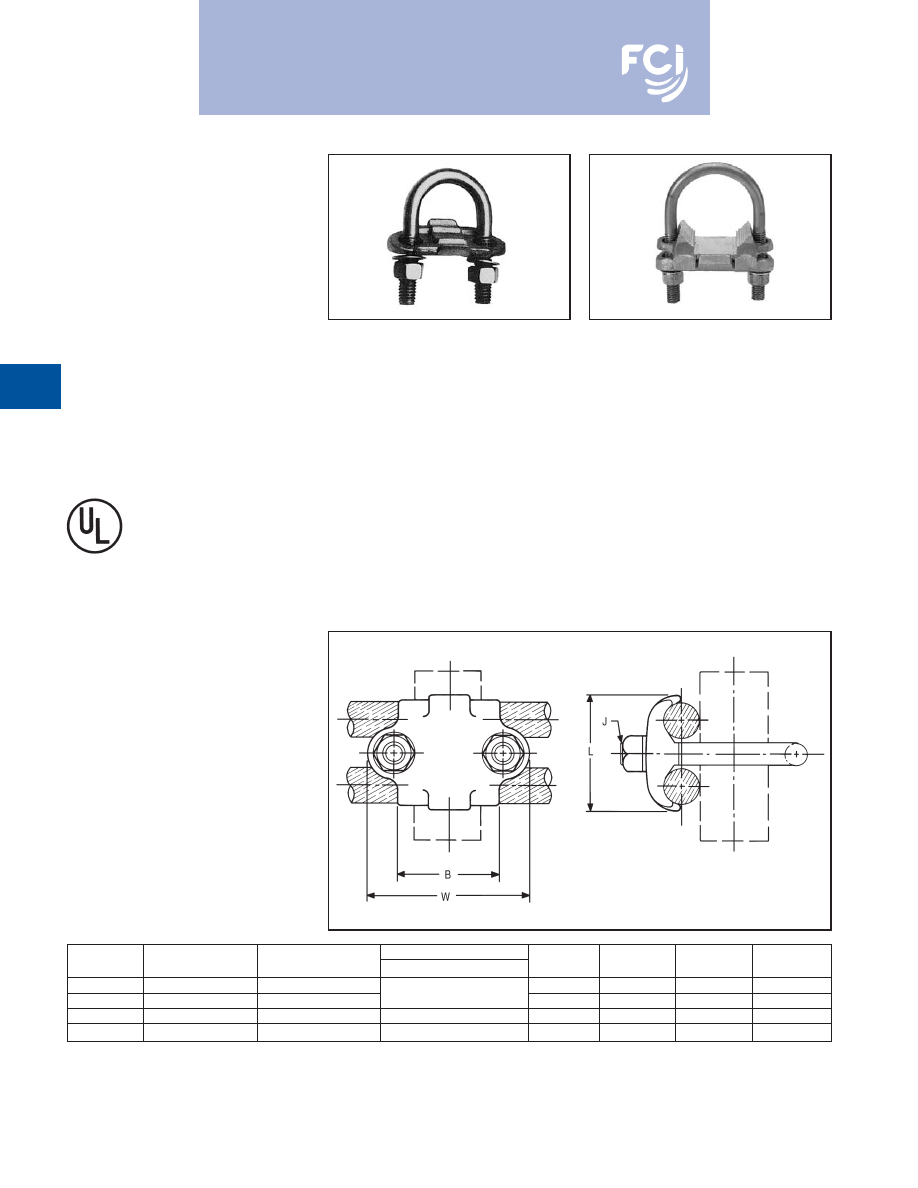
BURNDY
®
Products
Grounding
D-54
TYPES GP-G1, GP-RT
RAISED FLOOR
GROUNDING CLAMPS
High copper alloy ground connector for raised
floor computer grounding applications. These
connectors can be installed on round and
square pedestal applications and will accom-
modate one or two grounding wires to make
an efficient grid. The underfloor signal refer-
ence grid provides the low impedance ground
path that attenuates high frequency static and
60 Hz transient noise for cleaner data output.
UL467 Listed.
In addition we offer the GP1726RT, which is
especially designed for penetrating epoxy
paint on pedestals. This patented connector
offers a low impedance, time saving connec-
tion between conductors and the Pedestal.
Features and Benefits
• Accepts 1 or 2 Ground Conductors
9
Requires less connectors to install signal
reference grid.
• Made of copper alloy.
• DURIUM™ U-Bolts, nuts and lockwashers.
9
Provides a low impedance ground path
for maximum performance.
• Grounds all pedestals (round or square).
• Will handle from
3
⁄
4
to 1
round or square.
9
Ease of installation.
• Serves 3 needs.
1. Signal Reference Grid.
2. Static Ground.
3. Fault Current Ground.
9
Connectors solves all possible
grounding problems found in computer
applications today.
GP1726RT
CATALOG
NUMBER OF
CONDUCTOR
PEDESTAL TYPE
NUMBER
CONDUCTORS
SIZE SOL. & STR.
ROUND OR SQUARE
B
J
L
W
GP654CG1
1 or 2
#8 Sol. - 4 Str.
3/4
- 1
Round
1.5
3/8
1.31
2.38
GP64526G1
1 or 2
#4 Sol. - 2/0 Str.
3/4
- 7/8
Square
1.5
3/8
1.69
2.38
GP1526G1
1 or 2
#4 Sol. - 2/0 Str.
1-1/4
Round
1.75
3/8
1.69
2.62
GP1726RT
1 or 2
#6 Sol. - 2/0 Str.
2
Round
2.12
3/8
1.50
3.22
Burndy-Grounding-Connectors-catalog-html.html
BURNDY
®
Products
Grounding
D-55
TABLE OF CONTENTS
BURNDYWeld™
BURNDY Weld™
Introduction ................................
D-56
Making a BURNDYWeld™
Connection
..........................
D-57
WELD METAL
..........................
D-58
Type
BCC-1
..............................
D-59
Type
BCC-2
..............................
D-60
Type
BCC-4
..............................
D-61
Type
BCC-11
............................
D-62
Type
BCC-6
..............................
D-63
Type
BCC-14
............................
D-63
Type
BCC-7
..............................
D-64
Type
BCR-1
................................
D-65
RUS Accepted
Type
BCR-2
.............................
D-66
Type
BCR-3
.............................
D-67
Type
BCR-17
............................
D-68
Type
BCR-24
............................
D-69
Type
BCS-1
...............................
D-71
Type
BCS-8
...............................
D-71
Type
BCS-2
...............................
D-72
Type
BCS-9
...............................
D-72
Type
BCS-3
...............................
D-73
Type
BCS-23
.............................
D-74
Type
BCS-4
...............................
D-75
Type
BCS-6
...............................
D-75
Type
BCS-7
................................
D-76
Type
BCS-18
.............................
D-76
BURNDYWeld™ FILL
..............
D-83
BURNDYWeld™ SET
...............
D-85
BURNDYWeld™
Prefabricated
Wire Mesh
..............................
D-87
For mold types or BURNDYWeld™ items not shown, please
contact factory or refer to full BURNDYWeld™ catalog.
Burndy-Grounding-Connectors-catalog-html.html
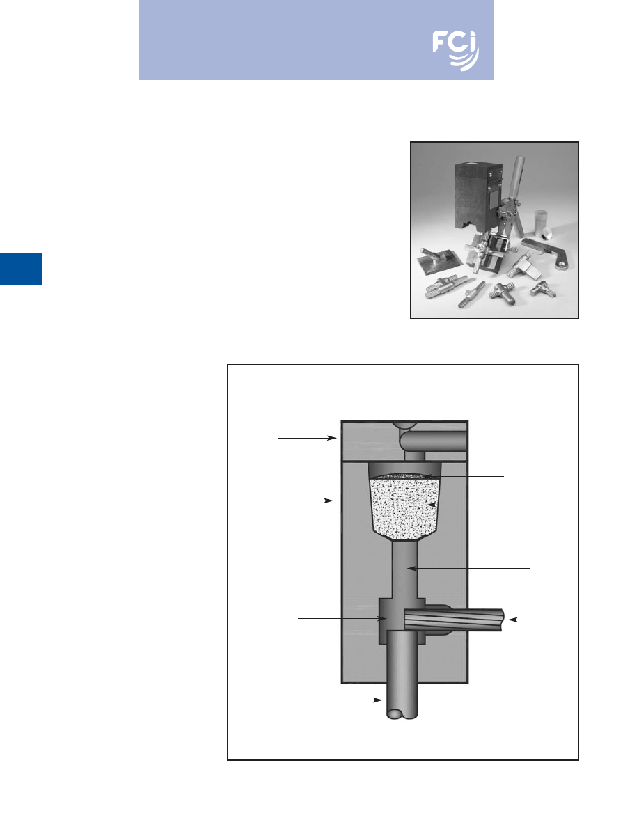
BURNDY
®
Products
Grounding
D-56
BURNDYWeld™
The BURNDYWeld™ connection process is a
simple, efficient method of welding copper to
copper or copper to steel. One advantage is
that NO outside power is required when using
the BURNDYWeld™ exothermic process. The
BURNDYWeld™ process uses high tempera-
ture reaction of powdered copper oxide and
aluminum. The reaction takes place in a semi-
permanent graphite mold. These molds will
last for fifty or more welds if proper care is
given. The reaction takes place very rapidly,
therefore the total amount of heat applied to
the conductors or surfaces is considerably
less than that of brazing or soldering. It is
important to remember this when welding to
insulated cable or thin wall pipe.
This system is very field friendly, since it is
light and portable and requires no outside
power source. It requires very little time or
skill to obtain an efficient, maintenance free
connection when using the BURNDYWeld™
process.
For more information visit our website at
www.fciconnect.com
The BURNDYWeld™ process has been used
to weld materials other than copper for elec-
trical purposes. Materials welded include:
Stainless Steel
Columbium
Brass
Copperweld®
Plain Steel
Bronze
Nichrome V
Everdur®
Niobium
Galvanized Steel
Kama
Chromax
Silcone Bronze
Steel Rail
Cast Iron
Copper Clad Steel
Cor-Ten®
Monel
When welding to galvanized steel it is recom-
mended to resurface exposed bare steel.
The BURNDYWeld™ connection is a molec-
ular weld. The weld metal has the same
melting point as copper. These factors along
with the increased cross section of the
connection, BURNDYWeld™ connections:
1. Will not be affected by a high current
surge. Tests have shown that the electrical
conductor will melt before the
BURNDYWeld™ connection when sub-
jected to high short circuit current. Consult
IEEE Standard 837-1989.
2. Will not loosen or corrode at the point of
weld. There are no contact surfaces or
mechanical pressures involved.
A
BURNDYWeld™ connection becomes an
integral part of the conductor.
3. Have a current-carrying capacity equal to
or greater than that of the conductors.
Lid
Graphite Mold
Weld Cavity
Ground Rod
Cable
Tap Hole
Weld Metal
Starting Powder
For mold types or BURNDYWeld™ items not shown, please
contact factory or refer to full BURNDYWeld™ catalog.
Burndy-Grounding-Connectors-catalog-html.html
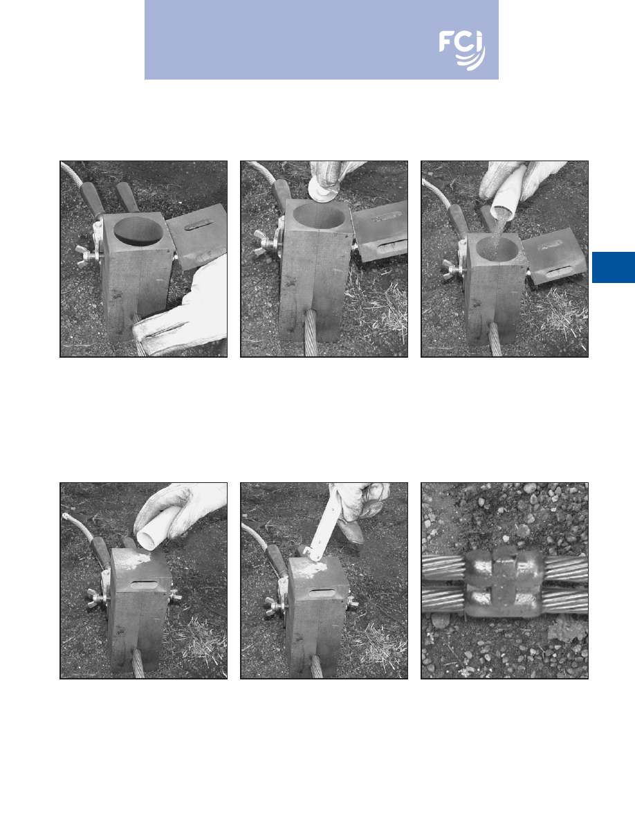
BURNDY
®
Products
Grounding
D-57
Making a BURNDYWeld™ Connection
Step 1
Position cleaned conductors in mold after
making sure mold is dry, by pre-heating or
making a test joint.
Step 2
Place metal disc in bottom of mold crucible.
Step 3
Dump powder into crucible, being careful not
to loosen all the starting powder.
Step 4
Close lid and place a small amount of start-
ing powder in the ignition pocket.
Step 6
Wait 15 seconds, then remove weld and
clean mold before making next connection.
Step 5
Ignite the starting powder with the Flint
Ignitor.
For mold types or BURNDYWeld™ items not shown, please
contact factory or refer to full BURNDYWeld™ catalog.
Burndy-Grounding-Connectors-catalog-html.html
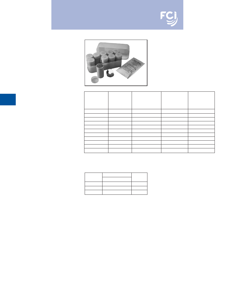
BURNDY
®
Products
Grounding
D-58
WELD METAL
BURNDYWeld™ Weld Metal is packed in
moisture-resistant plastic cartridges that have
tight fitting caps. These cartridges, along with
the necessary steel discs, are then packed in
boxes that are hermetically-sealed. This
ensures the powder arriving in good condi-
tion, always dry and ready for fast positive
ignition.
BURNDYWeld™ Weld Metal comes in sever-
al types; one for welding copper to copper,
copper to steel, copper to rail, copper to cast
iron and one for welding copper to steel for
cathodic protection. The size and weight (in
grams) of the cartridge are marked on each
individual cartridge.
Cathodic
Standard
Cast Iron
Protection
Rail
Cartridge
Cartridge
Cartridge
Cartridge
Cartridges
Size
Size
Size
Size
Per Box
15
15Cl
15CP
15R
20
25
25Cl
25CP
25R
20
32
32Cl
32CP
32R
10
45
45Cl
45CP
45R
20
65
65Cl
65CP
65R
20
90
90Cl
—
90R
10
115
115Cl
—
115R
10
150
—
—
150R
10
200
—
—
200R
10
250
—
—
250R
10
500
—
—
500R
10
BURNDYWeld™ Weld Metal is sold in box quantities only.
Weld
Catalog Number
Package
Metal Size
Steel Discs Only
Quantity
15 to 65
B370320-01
20
90 to 115
B370320-02
10
150 to 500
B370320-03
10
Steel Discs Sold Separately
For mold types or BURNDYWeld™ items not shown, please
contact factory or refer to full BURNDYWeld™ catalog.
Burndy-Grounding-Connectors-catalog-html.html
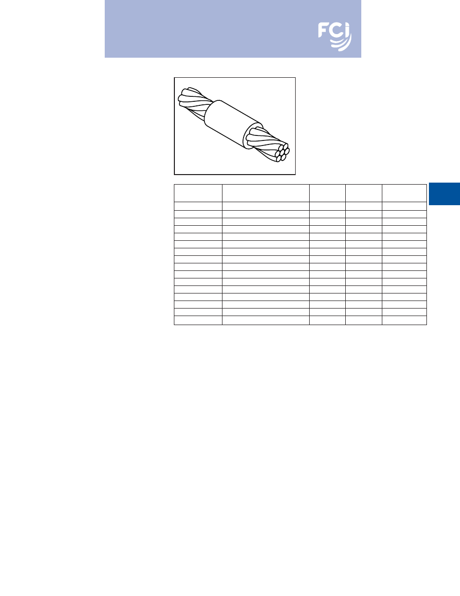
BURNDY
®
Products
Grounding
D-59
BCC-1 TYPE MOLDS
Horizontal End to End
BCC-1 Type Molds are used for horizontal
end to end cable connections.
Size range is #6 through 1000 MCM solid or
concentric stranded copper conductors.
Contact BURNDY
®
Products for information
on molds for conductors not listed below.
Price
Weld
Handle
Cable
Mold Number
Key
Metal
Clamps
#8
Use Type BCC-14 On Page 16
—
—
—
#6
Use Type BCC-14 On Page 16
—
—
—
#4
B-5623
18 † *
25
N/A
#3
B-5624
18 † *
32
N/A
#2
B-5625
18 † *
32
N/A
#1
B-5626
18 † *
32
N/A
1/0
B-205
4
45
B-106
2/0
B-206
4
65
B-106
3/0
B-207
4
90
B-106
4/0
B-208
4
90
B-106
250 MCM
B-209
4
115
B-106
300 MCM
B-210
4
115
B-106
350 MCM
B-211
4
150
B106
500 MCM
B-213
4
200
B-107
750 MCM
B-214
5
2-150
B-107
1000 MCM
B-215
5
2-200
B-107
• For sizes not listed, contact BURNDY
®
Products.
• Molds listed are for concentric stranded cable. Add suffix
“-S” to mold number for solid conductors.
• For heavy duty molds, molds with wear plates or molds for
Copperweld
®
cable, contact BURNDY
®
Products.
• For expedited service, contact BURNDY
®
Products.
Required Tools:
Handle Clamps (see chart for correct handles)
† Sold complete with handles
*
B38-0309-00
Flint Ignitor (included)
Other recommended accessories:
B38-3922-00
Mold Cleaning Brush (pg D-85)
B38-0135-00
Cable Cleaning Brush (pg D-85)
B38-0330-00
Cable Clamp (pg D-85)
For mold types or BURNDYWeld™ items not shown, please
contact factory or refer to full BURNDYWeld™ catalog.
Burndy-Grounding-Connectors-catalog-html.html
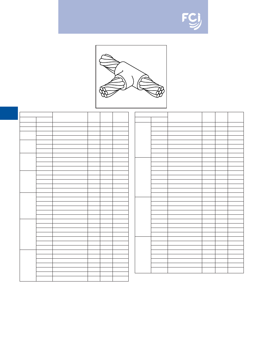
BURNDY
®
Products
Grounding
D-60
TYPE BCC-2 MOLDS
Horizontal Cable Tap to
Horizontal Cable Run
Type BCC-2 Molds are used to join horizontal
cable tap to a horizontal run cable.
Size range is #6 through 750 MCM solid or
concentric stranded copper conductors.
Contact BURNDY
®
Products for information
on molds for conductors not listed below.
Cable
Price Weld
Handle
Run
Tap
Mold Number
Key
Metal
Clamps
#6
#6
Use Type BCC-14 on Page 16
—
—
—
#4
#4
B-221
4
32
B-106
#2
B-223
4
45
B-106
#2
#4
B-224
4
45
B-106
#1
B-225
4
45
B-106
#1
#2
B-226
4
45
B-106
#4
B-227
4
45
B-106
1/0
B-228
4
90
B-106
#1
B-229
4
45
B-106
1/0
#2
B-230
4
45
B-106
#4
B-231
4
45
B-106
2/0
B-232
4
90
B-106
1/0
B-233
4
90
B-106
2/0
#1
B-234
4
45
B-106
#2
B-235
4
45
B-106
#4
B-5475
4
45
B-106
3/0
B-236
4
115
B-106
2/0
B-237
4
90
B-106
1/0
B-238
4
90
B-106
3/0
#1
B-239
4
45
B-106
#2
B-240
4
45
B-106
#4
B-5574
4
45
B-106
4/0
B-241
4
150
B-106
3/0
B-242
4
115
B-106
2/0
B-243
4
90
B-106
4/0
1/0
B-244
4
90
B-106
#1
B-245
4
90
B-106
#2
B-246
4
90
B-106
#4
B-5021
4
90
B-106
250 MCM
B-247
4
150
B-106
4/0
B-248
4
150
B-106
3/0
B-249
4
150
B-106
250 MCM
2/0
B-250
4
90
B-106
1/0
B-251
4
90
B-106
#1
B-252
4
90
B-106
#2
B-253
4
90
B-106
Cable
Price
Weld
Handle
Run
Tap
Mold Number
Key
Metal
Clamps
300 MCM
B-254
4
200
B-106
250 MCM
B-255
4
150
B-106
4/0
B-256
4
150
B-106
3/0
B-257
4
150
B-106
300 MCM
2/0
B-258
4
90
B-106
1/0
B-259
4
90
B-106
#1
B-260
4
90
B-106
#2
B-261
4
90
B-106
350 MCM
B-262
4
200
B-106
300 MCM
B-263
4
200
B-106
250 MCM
B-264
4
200
B-106
4/0
B-265
4
150
B-106
350 MCM
3/0
B-266
4
150
B-106
2/0
B-267
4
90
B-106
1/0
B-268
4
90
B106
#1
B-269
4
90
B-106
#2
B-270
4
90
B-106
500 MCM
B-280
4
2-150
B-106
350 MCM
B-282
4
200
B-106
300 MCM
B-283
4
200
B-106
250 MCM
B-284
4
200
B-106
500 MCM
4/0
B-285
4
150
B-106
2/0
B-286
4
90
B-106
1/0
B-287
4
90
B-106
#1
B-288
4
90
B-106
#2
B-289
4
90
B-106
750 MCM
B-290
5
500
B-107
500 MCM
B-291
5
2-200
B-107
350 MCM
B-293
4
250
B-106
300 MCM
B-294
4
200
B-106
750 MCM
250 MCM
B-295
4
200
B-106
4/0
B-296
4
150
B-106
2/0
B-297
4
150
B-106
1/0
B-298
4
150
B-106
• For sizes not listed, contact BURNDY
®
Products.
• Molds listed are for concentric stranded cable. Add suffix “-S” to mold number for solid
conductors.
• For heavy duty molds, molds with wear plates or molds for Copperweld
®
cable, contact
BURNDY
®
Products.
• For expedited service, contact BURNDY
®
Products.
Required Tools:
Handle Clamps (see chart for correct handles)
B38-0309-00
Flint Ignitor
Other recommended accessories:
B40-0319-01
Mold Cleaner for cartridge sizes #15-#65 (pg D-85)
B40-0319-03
Mold Cleaner for cartridge sizes #90-#500 (pg D-85)
B38-3922-00
Mold Cleaning Brush (pg D-85)
B38-0135-00
Cable Cleaning Brush (pg D-85)
B38-0330-00
Cable Clamp (pg D-85)
For mold types or BURNDYWeld™ items not shown, please
contact factory or refer to full BURNDYWeld™ catalog.
Burndy-Grounding-Connectors-catalog-html.html
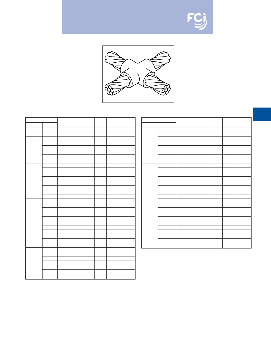
BURNDY
®
Products
Grounding
D-61
TYPE BCC-4 MOLDS
Horizontal to Horizontal
Cable Cross
Type BCC-4 Molds are used to join two hori-
zontal cables at right angles. One cable is cut
and the other is a through run.
Size range is #6 through 500 MCM solid or
concentric stranded copper conductors.
Contact BURNDY
®
Products for information
on molds for conductors not listed below.
Cable
Price Weld
Handle
Run
Tap
Mold Number
Key
Metal
Clamps
#6
#6
Use Type BCC-11 on page 16
#4
#4
B-423
4
45
B-106
#3
#3
B-424
4
45
B-106
#2
B-425
4
65
B-106
#2
#4
B-426
4
65
B-106
#1
B-427
4
65
B-106
#1
#2
B-428
4
65
B-106
#4
B-429
4
65
B-106
1/0
B-430
4
90
B-106
#1
B-431
4
90
B-106
1/0
#2
B-432
4
90
B-106
#4
B-433
4
90
B-106
2/0
B-434
4
115
B-106
1/0
B-435
4
115
B-106
2/0
#1
B-436
4
115
B-106
#2
B-437
4
115
B-106
3/0
B-438
4
150
B-106
2/0
B-439
4
150
B-106
3/0
1/0
B-440
4
115
B-106
#1
B-441
4
115
B-106
#2
B-442
4
115
B-106
4/0
B-443
4
200
B-106
3/0
B-444
4
200
B-106
2/0
B-445
4
150
B-106
4/0
1/0
B-442
4
150
B-106
#1
B-447
4
115
B-106
#2
B-448
4
115
B-106
250 MCM
B-449
4
200
B-106
4/0
B-450
4
200
B-106
3/0
B-451
4
200
B-106
250 MCM
2/0
B-452
4
150
B-106
1/0
B-453
4
150
B-106
#1
B-454
4
115
B-106
#2
B-455
4
115
B-106
Cable
Price Weld
Handle
Run
Tap
Mold Number
Key
Metal
Clamps
300 MCM
B-456
4
250
B-106
250 MCM
B-457
4
250
B-106
4/0
B-458
4
200
B-106
3/0
B-459
4
200
B-106
300 MCM
2/0
B-460
4
150
B-106
1/0
B-461
4
150
B-106
#1
B-462
4
115
B-106
#2
B-463
4
115
B-106
350 MCM
B-464
4
250
B-106
300 MCM
B-465
4
250
B-106
250 MCM
B-466
4
250
B-106
4/0
B-467
4
200
B-106
350 MCM
3/0
B-468
4
200
B-106
2/0
B-469
4
200
B-106
1/0
B-470
4
200
B-106
#1
B-471
4
150
B-106
#2
B-472
4
150
B-106
500 MCM
B-483
5
500
B-107
350 MCM
B-485
5
2-200
B-107
300 MCM
B-486
5
2-200
B-107
250 MCM
B-487
5
2-150
B-107
4/0
B-488
5
2-150
B-107
500 MCM
3/0
B-489
5
2-150
B-107
2/0
B-490
4
250
B-106
1/0
B-491
4
250
B-106
#1
B-492
4
200
B-106
#2
B-493
4
200
B-106
• For sizes not listed, contact BURNDY
®
Products.
• Molds listed are for concentric stranded cable. Add suffix “-S” to mold number for solid
conductors.
• For heavy duty molds, molds with wear plates or molds for Copperweld
®
cable, contact
BURNDY
®
Products.
• For expedited service, contact BURNDY
®
Products.
Required Tools:
Handle Clamps (see chart for correct handles)
B38-0309-00
Flint Ignitor
Other recommended accessories:
B40-0319-01
Mold Cleaner for cartridge sizes #15-#65 (pg D-85)
B40-0319-03
Mold Cleaner for cartridge sizes #90-#500 (pg D-85)
B38-3922-00
Mold Cleaning Brush (pg D-85)
B38-0135-00
Cable Cleaning Brush (pg D-85)
B38-0330-00
Cable Clamp (pg D-85)
For mold types or BURNDYWeld™ items not shown, please
contact factory or refer to full BURNDYWeld™ catalog.
Burndy-Grounding-Connectors-catalog-html.html
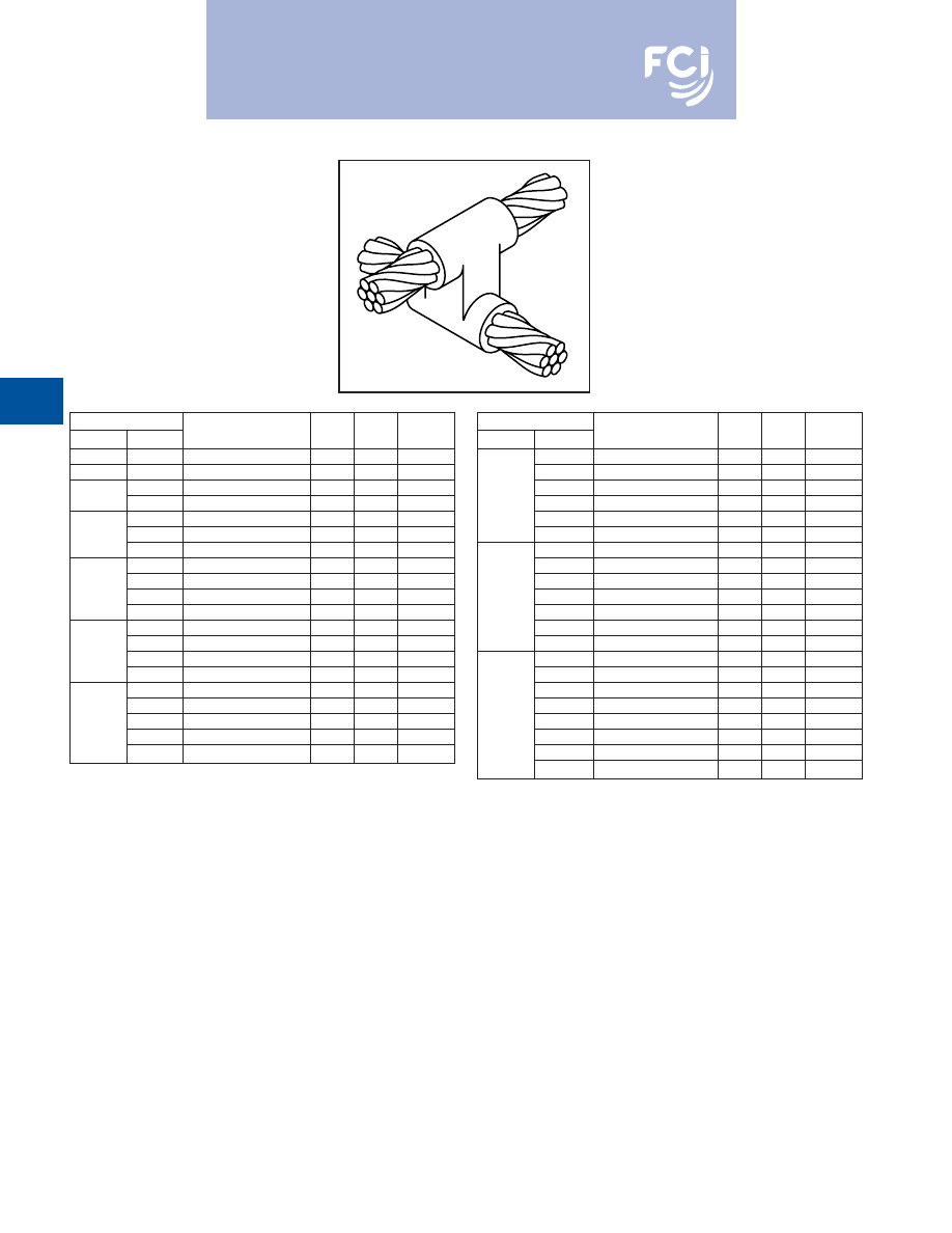
BURNDY
®
Products
Grounding
D-62
TYPE BCC-11 MOLDS
Horizontal to Horizontal
Cable Cross
Type BCC-11 Molds are used to join uncut
horizontal cables at right angles to each
other.
Size range is #6 through 500 MCM solid or
concentric stranded copper conductors.
Contact BURNDY
®
Products for information
on molds for conductors not listed below.
Cable
Price Weld
Handle
Run
Tap
Mold Number
Key
Metal
Clamps
#6
#6
B-5432
191*
45
N/A
#4
#4
B-2687
4
65
B-106
#2
B-2689
4
90
B-106
#2
#4
B-2690
4
65
B-106
#1
B-2691
4
115
B-106
#1
#2
B-2692
4
90
B-106
#4
B-2693
4
90
B-106
1/0
B-2694
22
150
B-106
#1
B-2695
22
150
B-106
1/0
#2
B-2696
22
115
B-106
#4
B-2697
22
115
B-106
2/0
B-2698
22
200
B-106
1/0
B-2699
22
200
B-106
2/0
#1
B-2700
22
150
B-106
#2
B-2701
22
150
B-106
3/0
B-2702
22
250
B-106
2/0
B-2703
22
200
B-106
3/0
1/0
B-2704
22
200
B-106
#1
B-2705
22
150
B-106
#2
B-2706
22
150
B-106
Cable
Price Weld
Handle
Run
Tap
Mold Number
Key
Metal
Clamps
4/0
B-2707
22
250
B-106
3/0
B-2708
22
250
B-106
2/0
B-2709
22
200
B-106
4/0
1/0
B-2710
22
200
B-106
#1
B-2711
22
150
B-106
#2
B-2712
22
150
B-106
250 MCM
B-2713
22
2-150
B-106
4/0
B-2714
22
2-150
B-106
3/0
B-2715
22
2-150
B-106
250 MCM
2/0
B-2716
22
250
B-106
1/0
B-2717
22
150
B-106
#1
B-2718
22
200
B-106
#2
B-2719
22
150
B-106
500 MCM
B-2747
23
3-250
B-107
250 MCM
B-2751
23
500
B-107
4/0
B-2752
23
500
B-107
3/0
B-2753
23
500
B-107
500 MCM
2/0
B-2754
23
2-200
B-107
1/0
B-2755
22
2-150
B-106
#1
B-2756
22
250
B-106
#2
B-2757
22
250
B-106
• For sizes not listed, contact BURNDY
®
Products.
• Molds listed are for concentric stranded cable. Add suffix “-S” to mold number for solid
conductors.
• For heavy duty molds, molds with wear plates or molds for Copperweld® cable, contact
BURNDY
®
Products.
• For expedited service, contact BURNDY
®
Products.
Required Tools:
Handle Clamps (see chart for correct handles)
† Sold complete with handles
*
B38-0309-00
Flint Ignitor
Other recommended accessories:
B40-0319-01
Mold Cleaner for cartridge sizes #15-#65 (pg D-85)
B40-0319-03
Mold Cleaner for cartridge sizes #90-#500 (pg D-85)
B38-3922-00
Mold Cleaning Brush (pg D-85)
B38-0135-00
Cable Cleaning Brush (pg D-85)
B38-0330-00
Cable Clamp (pg D-85)
For mold types or BURNDYWeld™ items not shown, please
contact factory or refer to full BURNDYWeld™ catalog.
Burndy-Grounding-Connectors-catalog-html.html
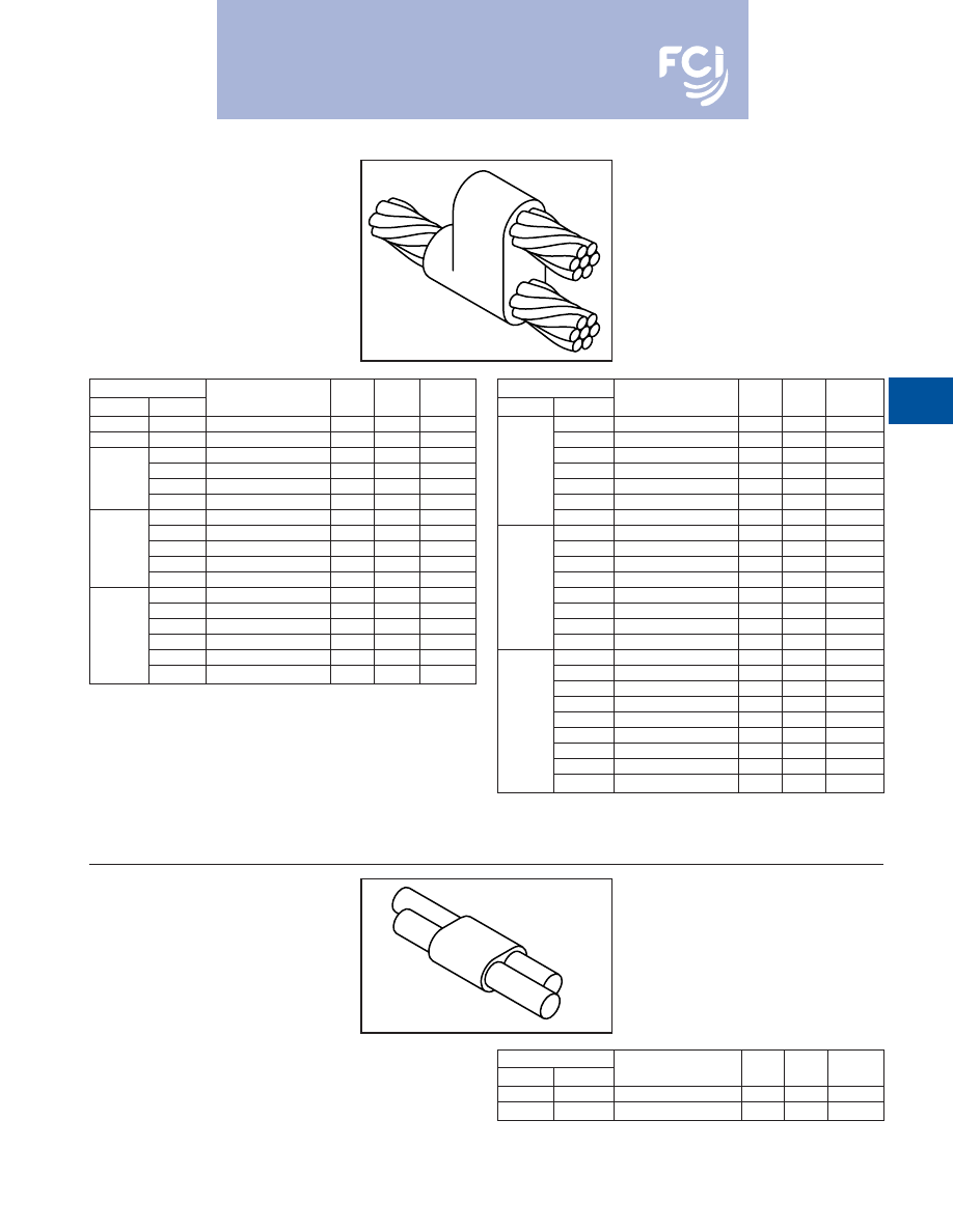
BURNDY
®
Products
Grounding
D-63
BCC-6 TYPE MOLDS
Horizontal Parallel Tap
BCC-6 Type Molds are used to join horizontal
parallel tap to run connections. The tap cable
is over the run cable.
Size range is #6 through 4/0 solid or concen-
tric stranded copper conductors.
Contact BURNDY
®
Products for information
on molds for conductors not listed below.
Cable
Price Weld
Handle
Run
Tap
Mold Number
Key
Metal
Clamps
#6 Sol
#6 Sol
B-1270
4
25
B-106
#6
#6
B-1271
4
25
B-106
#4
B-1272
4
32
B-106
#6
B-1273
4
32
B-106
#4
#6 Sol
B-1274
4
32
B-106
#8 Sol
B-1275
4
32
B-106
#2
B-1276
4
65
B-106
#4
B-1277
4
45
B-106
#2
#6
B-1278
4
32
B-106
#6 Sol
B-1279
4
32
B-106
#8 Sol
B-1280
4
32
B-106
#1
B-1281
4
65
B-106
#2
B-1282
4
65
B-106
#4
B-1283
4
45
B-106
#1
#6
B-1284
4
45
B-106
#6 Sol
B-1285
4
45
B-106
#8 Sol
B-1286
4
45
B-106
Cable
Price Weld
Handle
Run
Tap
Mold Number
Key
Metal
Clamps
1/0
B-1287
4
90
B-106
#1
B-1288
4
90
B-106
#2
B-1289
4
65
B-106
1/0
#4
B-1290
4
65
B-106
#6
B-1291
4
45
B-106
#6 Sol
B-1292
4
45
B-106
#8 Sol
B-1293
4
45
B-106
2/0
B-1294
4
115
B-106
1/0
B-1295
4
115
B-106
#1
B-1296
4
90
B-106
#2
B-1297
4
90
B-106
2/0
#4
B-1298
4
65
B-106
#6
B-1299
4
65
B-106
#6 Sol
B-1300
4
65
B-106
#8 Sol
B-1301
4
65
B-106
4/0
B-1302
4
150
B-106
2/0
B-1303
4
115
B-106
1/0
B-1304
4
115
B-106
#1
B-1305
4
115
B-106
4/0
#2
B-1306
4
115
B-106
#4
B-1307
4
90
B-106
#6
B-1308
4
90
B-106
#6 Sol
B-1309
4
90
B-106
#8 Sol
B-1310
4
90
B-106
• For sizes not listed, contact BURNDY
®
Products.
• Molds listed are for concentric stranded cable. Add suffix “-S” to mold number for solid
conductors.
• For heavy duty molds, molds with wear plates or molds for Copperweld
®
cable, contact
BURNDY
®
Products.
• For expedited service, contact BURNDY
®
Products.
Required Tools:
Handle Clamps (see chart for correct handles)
Sold complete with handles
B38-0309-00
Flint Ignitor
Other recommended accessories:
B38-3922-00
Mold Cleaning Brush (pg D-85)
B38-0135-00
Cable Cleaning Brush (pg D-85)
B38-0330-00
Cable Clamp (pg D-85)
BCC-14 TYPE MOLDS
Horizontal Parallel through
Cables
BCC-14 Type Molds are used to join horizon-
tal parallel through run cables. Cables run
side by side in the mold.
Size range is #8 through #6 solid or concen-
tric stranded copper conductors.
Contact BURNDY
®
Products for information
on molds for conductors not listed.
Cable
Price Weld
Handle
Run
Tap
Mold Number
Key
Metal
Clamps
#8
#8
B-5709
18+
15
N/A
#6
#6
B-5618
18+
25
N/A
For mold types or BURNDYWeld™ items not shown, please
contact factory or refer to full BURNDYWeld™ catalog.
Burndy-Grounding-Connectors-catalog-html.html
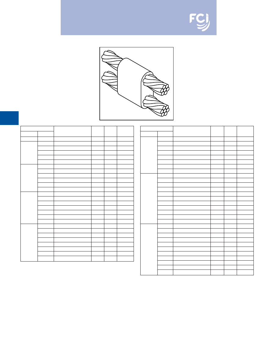
BURNDY
®
Products
Grounding
D-64
BCC-7 TYPE MOLDS
Horizontal Parallel through
Cables
BCC-7 Type Molds are used to join horizontal
parallel through run cables. One cable runs
above the other cable in the mold.
Size range is #6 through 4/0 solid or concen-
tric stranded copper conductors.
Contact BURNDY
®
Products for information
on molds for conductors not listed below.
Cable
Price Weld
Handle
Run
Tap
Mold Number
Key
Metal
Clamps
#6
#6
Use Type BCC-14 on Page 16
—
—
—
#4
B-1311
4
32
B-106
#6
B-5627
4
32
B-106
#4
#6 Sol
B-8882
4
32
B-106
#8
B-5629
4
32
B-106
#8 Sol
B-5630
4
32
B-106
#2
B-1313
4
65
B-106
#4
B-1314
4
65
B-106
#6
B-5631
4
45
B-106
#2
#6 Sol
B-5632
4
45
B-106
#8
B-5634
4
45
B-106
#8 Sol
B-5635
4
45
B-106
#1
B-1315
4
65
B-106
#2
B-1316
4
65
B-106
#4
B-1317
4
65
B-106
#1
#6
B-5636
4
65
B-106
#6 Sol
B-5637
4
65
B-106
#8
B-5638
4
45
B-106
#8 Sol
B-5639
4
45
B-106
1/0
B-1318
4
90
B-106
#1
B-1319
4
65
B-106
#2
B-1320
4
65
B-106
#4
B-1321
4
65
B-106
1/0
#6
B-5642
4
65
B-106
#6 Sol
B-1208
4
65
B-106
#8
B-5644
4
65
B-106
#8 Sol
B-5645
4
65
B-106
Cable
Price Weld
Handle
Run
Tap
Mold Number
Key
Metal
Clamps
2/0
B-1322
4
115
B-106
1/0
B-1323
4
115
B-106
#1
B-1324
4
90
B-106
#2
B-1325
4
90
B-106
2/0
#4
B-5659
4
90
B-106
#6
B-5342
4
90
B-106
#6 Sol
B-5652
4
90
B-106
#8
B-5668
4
65
B-106
#8 Sol
B-5943
4
65
B-106
3/0
B-1326
4
150
B-106
2/0
B-1327
4
150
B-106
1/0
B-1328
4
115
B-106
#1
B-1329
4
115
B-106
3/0
#2
B-1330
4
115
B-106
#4
B-6046
4
115
B-106
#6
B-5676
4
90
B-106
#6 Sol
B-5679
4
90
B-106
#8
B-5680
4
90
B-106
#8 Sol
B-5682
4
90
B-106
4/0
B-1331
4
200
B-106
3/0
B-1332
4
200
B-106
2/0
B-1333
4
150
B-106
1/0
B-1334
4
150
B-106
#1
B-1335
4
150
B-106
4/0
#2
B-1336
4
150
B-106
#4
B-5340
4
150
B-106
#6
B-5684
4
90
B-106
#6 Sol
B-6552
4
90
B-106
#8
B-5686
4
90
B-106
#8 Sol
B-5688
4
90
B-106
• For sizes not listed, contact BURNDY
®
Products.
• Molds listed are for concentric stranded cable. Add suffix “-S” to mold number for solid
conductors.
• For heavy duty molds, molds with wear plates or molds for Copperweld® cable, contact
BURNDY
®
Products.
• For expedited service, contact BURNDY
®
Products.
Required Tools:
Handle Clamps (see chart for correct handles)
B38-0309-00
Flint Ignitor
Other recommended accessories:
B38-3922-00
Mold Cleaning Brush (pg D-85)
B38-0135-00
Cable Cleaning Brush (pg D-85)
B38-0330-00
Cable Clamp (pg D-85)
For mold types or BURNDYWeld™ items not shown, please
contact factory or refer to full BURNDYWeld™ catalog.
Burndy-Grounding-Connectors-catalog-html.html
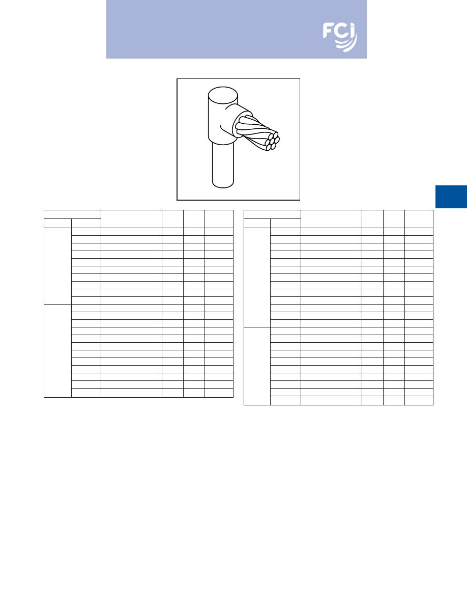
BURNDY
®
Products
Grounding
D-65
TYPE BCR-1 MOLDS
Horizontal Cable Terminal to
Ground Rod
Type BCR-1 Molds are used to terminate hor-
izontal copper cable at the top of a vertical
ground rod.
Size range is #6 through 1000 MCM solid or
concentric stranded copper conductors; 1/2
through 1
for the ground rod.
Contact BURNDY
®
Products for information
on molds for conductors not listed below.
Cable
Price Weld
Handle
Grd Rod
Tap
Mold Number
Key
Metal
Clamps
#6
B-8402
18†*
25
N/A
#4
B-8403
18†*
25
N/A
#2
B-495
4
65
B-106
#1
B-496
4
65
B-106
1/0
B-497
4
90
B-106
1/2
2/0
B-498
4
90
B-106
3/0
B-499
4
90
B-106
4/0
B-500
4
90
B-106
250 MCM
B-501
4
90
B-106
300 MCM
B-502
4
90
B-106
#6
B-8414
18†
32
N/A
#4
B-8415
18†
32
N/A
#2
B-503
4
65
B-106
#1
B-504
4
65
B-106
1/0
B-505
4
90
B-106
5/8
2/0
B-506
4
90
B-106
3/0
B-507
4
90
B-106
4/0
B-508
4
90
B-106
250 MCM
B-509
4
90
B-106
300 MCM
B-510
4
115
B-106
350 MCM
B-511
4
115
B-106
500 MCM
B-513
4
150
B-106
Cable
Price Weld
Handle
Grd Rod
Tap
Mold Number
Key
Metal
Clamps
#6
B-8422
181*
32
N/A
#4
B-8426
191*
45
N/A
#2
B-5781
4
90
B-106
#1
B-514
4
90
B-106
1/0
B-515
4
90
B-106
2/0
B-516
4
90
B-106
3/4
3/0
B-517
4
90
B-106
4/0
B-518
4
90
B-106
250 MCM
B-519
4
90
B-106
300 MCM
B-520
4
115
B-106
350 MCM
B-521
4
115
B-106
500 MCM
B-523
4
150
B-106
750 MCM
B-524
4
250
B-106
1/0
B-525
4
150
B-106
2/0
B-526
4
150
B-106
3/0
B-527
4
150
B-106
4/0
B-528
4
150
B-106
250 MCM
B-529
4
150
B-106
1
300 MCM
B-530
4
200
B-106
350 MCM
B-531
4
200
B-106
500 MCM
B-533
4
200
B-106
750 MCM
B-534
4
250
B-106
1000 MCM
B-535
5
2-150
B-106
• For sizes not listed, contact BURNDY
®
Products.
• Molds listed are for concentric stranded cable. Add suffix “-S” to mold number for solid
conductors.
• Molds listed are for copperclad ground rods. For welding to steel, stainless steel or galva-
nized steel ground rods add suffix “-N” to mold number.
• For heavy duty molds, molds with wear plates or molds for Copperweld
®
cable, contact
BURNDY
®
Products.
• For expedited service, contact BURNDY
®
Products.
Required Tools:
Handle Clamps (see chart for correct handles)
† Sold complete with handles
*
B38-0309-00
Flint Ignitor (included)
Other recommended accessories:
B38-3922-00
Mold Cleaning Brush (pg D-85)
B38-0135-00
Cable Cleaning Brush (pg D-85)
B38-0304-00
File (pg D-85)
B38-0330-00
Cable Clamp (pg D-85)
For mold types or BURNDYWeld™ items not shown, please
contact factory or refer to full BURNDYWeld™ catalog.
RUS Accepted
Burndy-Grounding-Connectors-catalog-html.html
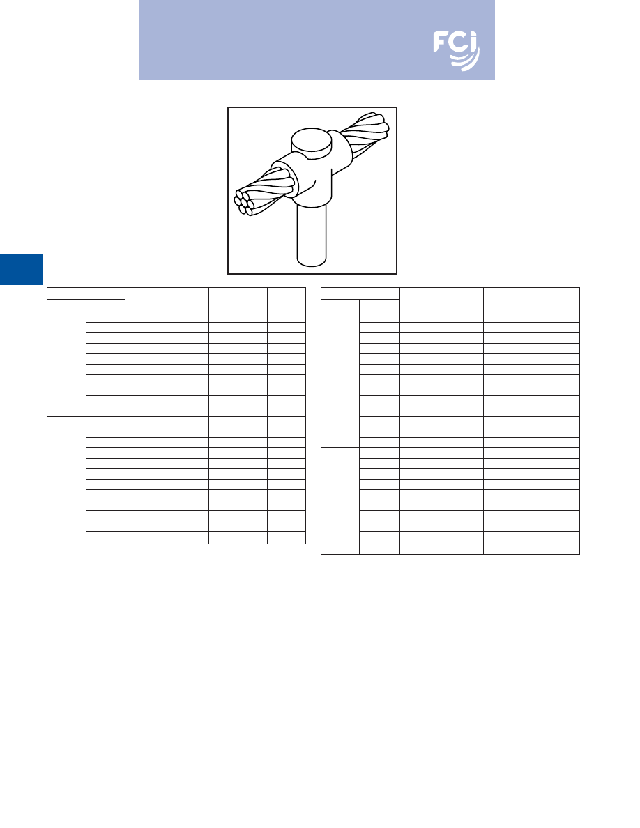
BURNDY
®
Products
Grounding
D-66
TYPE BCR-2 MOLDS
Horizontal Cable to
Ground Rod
Type BCR-2 Molds are used to join horizontal
through copper cable to the top of a vertical
ground rod.
Size range is #6 through 1000 MCM solid or
concentric stranded copper conductors; 1/2
through 1
for the ground rod.
Contact BURNDY
®
Products for information
on molds for conductors not listed below.
Cable
Price Weld
Handle
Grd Rod
Tap
Mold Number
Key
Metal
Clamps
#6
B-8434
181†*
32
N/A
#4
B-8435
18†*
32
N/A
#2
B-537
4
90
B-106
#1
B-538
4
90
B-106
1/0
B-539
4
90
B-106
1/2
2/0
B-540
4
90
B-106
3/0
B-541
4
115
B-106
4/0
B-542
4
115
B-106
250 MCM
B-543
4
150
B-106
300 MCM
B-544
4
200
B-106
#6
B-8441
18†*
32
N/A
#4
B-8442
18†*
32
N/A
#2
B-545
4
90
B-106
#1
B-546
4
90
B-106
1/0
B-547
4
90
B-106
2/0
B-548
4
115
B-106
5/8
3/0
B-549
4
115
B-106
4/0
B-550
4
115
B-106
250 MCM
B-551
4
150
B-106
300 MCM
B-532
4
200
B-106
350 MCM
B-553
4
200
B-106
500 MCM
B-555
4
250
B-106
Cable
Price Weld
Handle
Grd Rod
Tap
Mold Number
Key
Metal
Clamps
#6
B-8452
19†*
45
N/A
#4
B-8454
19†*
65
N/A
#2
B-556
4
90
B-106
#1
B-557
4
90
B-106
1/0
B-558
4
115
B-106
2/0
B-559
4
115
B-106
3/4
3/0
B-560
4
115
B-106
4/0
B-561
4
115
B-106
250 MCM
B-562
4
150
B-106
300 MCM
B-563
4
200
B-106
350 MCM
B-564
4
200
B-106
500 MCM
B-566
4
250
B-106
750 MCM
B-567
5
2-200
B-107
1/0
B-569
4
150
B-106
2/0
B-570
4
150
B-106
3/0
B-571
4
150
B-106
4/0
B-572
4
150
B-106
250 MCM
B-573
4
200
B-106
1
300 MCM
B-574
4
200
B-106
350 MCM
B-575
4
200
B-106
500 MCM
B-577
4
250
B-106
750 MCM
B-578
5
2-200
B-107
1000 MCM
B-579
5
500
B-107
• For sizes not listed, contact BURNDY
®
Products.
• Molds listed are for concentric stranded cable. Add suffix “-S” to mold number for solid
conductors.
• Molds listed are for copperclad ground rods. For welding to steel, stainless steel or
galvanized steel ground rods add suffix “-N” to mold number.
• For heavy duty molds, molds with wear plates or molds for Copperweld
®
cable, contact
BURNDY
®
Products.
• For expedited service, contact BURNDY
®
Products.
Required Tools:
Handle Clamps (see chart for correct handles)
† Sold complete with handles
*
B38-0309-00
Flint Ignitor (included)
Other recommended accessories:
B38-3922-00
Mold Cleaning Brush (pg D-85)
B38-0135-00
Cable Cleaning Brush (pg D-85)
B38-0304-00
File (pg D-85)
B38-0330-00
Cable Clamp (pg D-85)
For mold types or BURNDYWeld™ items not shown, please
contact factory or refer to full BURNDYWeld™ catalog.
Burndy-Grounding-Connectors-catalog-html.html
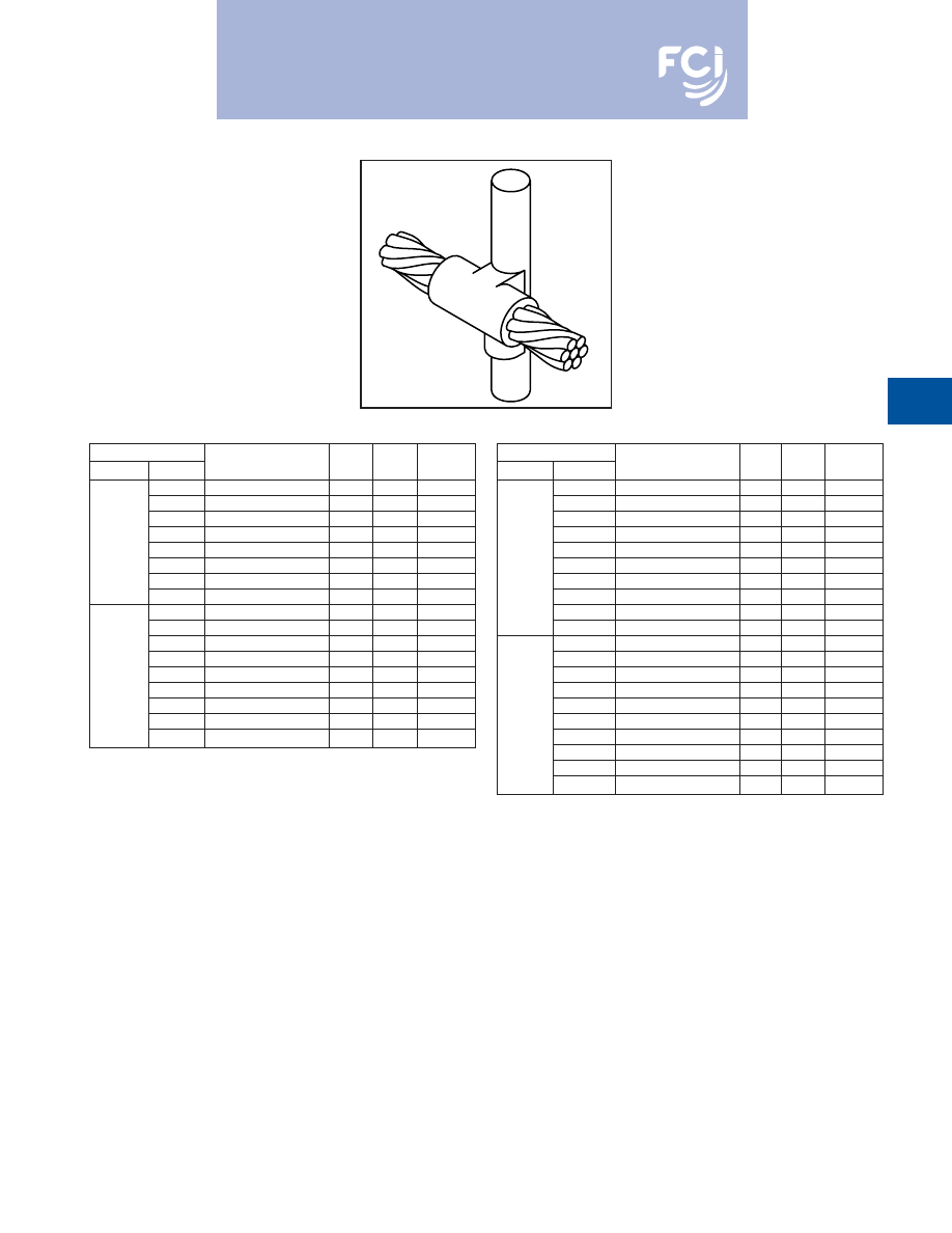
BURNDY
®
Products
Grounding
D-67
TYPE BCR-3 MOLDS
Horizontal Through Cable to
Ground Rod
Type BCR-3 Molds are used to join horizontal
through run cable to the side of a vertical
ground rod.
Size range is #6 through 1000 MCM solid or
concentric stranded copper conductors; 1/2
through 1
for the ground rod.
Contact BURNDY
®
Products for information
on molds for conductors not listed below.
Cable
Price Weld
Handle
Grd Rod
Tap
Mold Number
Key
Metal
Clamps
#6
B-5321
24
65
B-106
#4
B-2154
24
90
B-106
#2
B-2155
24
90
B-106
1/2
#1
B-2156
24
115
B-106
1/0
B-1581
24
115
B-106
2/0
B-1582
24
115
B-106
4/0
B-1583
24
150
B-106
250 MCM
B-1584
24
150
B-106
#6
B-5660
24
65
B-106
#4
B-2157
24
90
B-106
#2
B-2158
24
90
B-106
#1
B-2159
24
115
B-106
5/8
1/0
B-1586
24
115
B-106
2/0
B-1587
24
115
B-106
4/0
B-1588
24
150
B-106
250 MCM
B-1589
24
150
B-106
500 MCM
B-1593
13
2-200
B-107
Cable
Price Weld
Handle
Grd Rod
Tap
Mold Number
Key
Metal
Clamps
#6
B-6630
24
65
B-106
#4
B-2160
24
90
B-106
#2
B-2161
24
90
B-106
#1
B-2162
24
115
B-106
1/0
B-1594
24
115
B-106
3/4
2/0
B-1595
24
115
B-106
#4
B-1596
24
150
B-106
250 MCM
B-1597
24
200
B-106
500 MCM
B-1601
13
500
B-107
750 MCM
B-1602
13
3-250
B-107
#6
B-6906
24
90
B-106
#4
B-2163
24
90
B-106
#2
B-2164
24
90
B-106
#1
B-2165
24
115
B-106
1
1/0
B-1603
24
15
B-106
2/0
B-1604
24
115
B-106
4/0
B-1605
24
150
B-106
250 MCM
B-1606
24
200
B-106
500 MCM
B-1610
13
500
B-107
750 MCM
B-1611
13
3-250
B-107
• For sizes not listed, contact BURNDY
®
Products.
• Molds listed are for concentric stranded cable. Add suffix “-S” to mold number for solid
conductors.
• Molds listed are for copperclad ground rods. For welding to steel, stainless steel or
galvanized steel ground rods add suffix “-N” to mold number.
• For heavy duty molds, molds with wear plates or molds for Copperweld
®
cable, contact
BURNDY
®
Products.
• For expedited service, contact BURNDY
®
Products.
Required Tools:
Handle Clamps (see chart for correct handles)
B38-0309-00
Flint Ignitor
Other recommended accessories:
B38-3922-00
Mold Cleaning Brush (pg D-85)
B38-0135-00
Cable Cleaning Brush (pg D-85)
B38-0330-00
Cable Clamp (pg D-85)
B38-0304-00
File (pg D-85)
For mold types or BURNDYWeld™ items not shown, please
contact factory or refer to full BURNDYWeld™ catalog.
Burndy-Grounding-Connectors-catalog-html.html
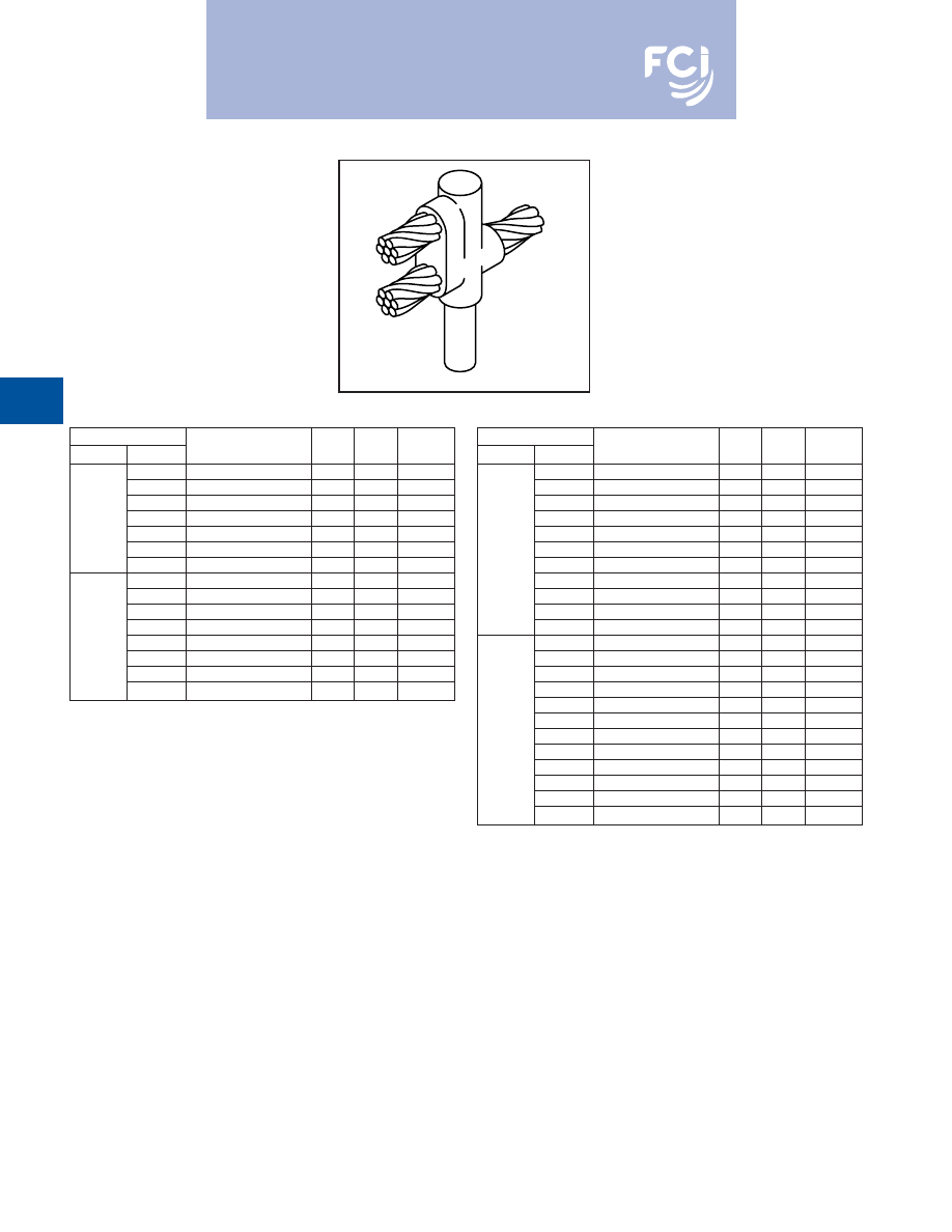
BURNDY
®
Products
Grounding
D-68
TYPE BCR-17 MOLDS
Horizontal Run and Tap
Cables to Ground Rod
Type BCR-17 Molds are used to join horizon-
tal run and tap cables to the top of a vertical
ground rod.
Size range is #4 through 750 MCM solid or
concentric stranded copper conductors; 1/2
through 1
for the ground rod.
Contact BURNDY
®
Products for information
on molds for conductors not listed below.
Cable
Price Weld
Handle
Grd Rod
Tap
Mold Number
Key
Metal
Clamps
#4
B-5416
4
90
B-106
#2
B-6165
4
90
B-106
#1
B-5830
4
90
B-106
1/2
1/0
B-5940
4
115
B-106
2/0
B-5850
4
150
B-106
3/0
B-5833
4
200
B-106
4/0
B-5380
4
200
B-106
#4
B-5972
4
90
B-106
#2
B-5935
4
115
B-106
#1
B-5699
4
115
B-106
1/0
B-5746
4
150
B-106
5/8
2/0
B-5963
4
200
B-106
3/0
B-5734
4
250
B-106
4/0
B-5732
4
250
B-106
250 MCM
B-5722
5
2-150
B-107
Cable
Price Weld
Handle
Grd Rod
Tap
Mold Number
Key
Metal
Clamps
#4
B-5698
4
90
B-106
#2
B-5294
4
115
B-106
#1
B-5390
4
115
B-106
1/0
B-6025
4
150
B-106
2/0
B-5738
4
200
B-106
3/4
3/0
B-6003
4
250
B-106
4/0
B-2566
4
250
B-106
250 MCM
B-5904
5
2-150
B-107
300 MCM
B-5857
5
2-200
B-107
350 MCM
B-5777
5
2-200
B-107
500 MCM
B-5961
5
3-200
B-106
#4
B-5556
4
115
B-106
#2
B-5555
4
150
B-106
#1
B-6048
4
150
B-106
1/0
B-5992
4
200
B-106
2/0
B-5877
4
250
B-106
3/0
B-5821
5
2-150
B-107
1
4/0
B-5820
5
2-150
B-107
250 MCM
B-5804
5
2-200
B-107
300 MCM
B-5803
5
500
B-107
350 MCM
B-5561
5
500
B-107
500 MCM
B-5515
6
3-250
B-107
750 MCM
B-5513
6
2-500
B-107
• For sizes not listed, contact BURNDY
®
Products.
• Molds listed are for concentric stranded cable. Add suffix “-S” to mold number for solid
conductors.
• Molds listed are for copperclad ground rods. For welding to steel, stainless steel or
galvanized steel ground rods add suffix “-N” to mold number.
• For heavy duty molds, molds with wear plates or molds for Copperweld
®
cable, contact
BURNDY
®
Products.
• For expedited service, contact BURNDY
®
Products.
Required Tools:
Handle Clamps (see chart for correct handles)
B38-0309-00
Flint Ignitor
Other recommended accessories:
B38-3922-00
Mold Cleaning Brush (pg D-85)
B38-0135-00
Cable Cleaning Brush (pg D-85)
B38-0330-00
Cable Clamp (pg D-85)
B38-0304-00
File (pg D-85)
For mold types or BURNDYWeld™ items not shown, please
contact factory or refer to full BURNDYWeld™ catalog.
Burndy-Grounding-Connectors-catalog-html.html
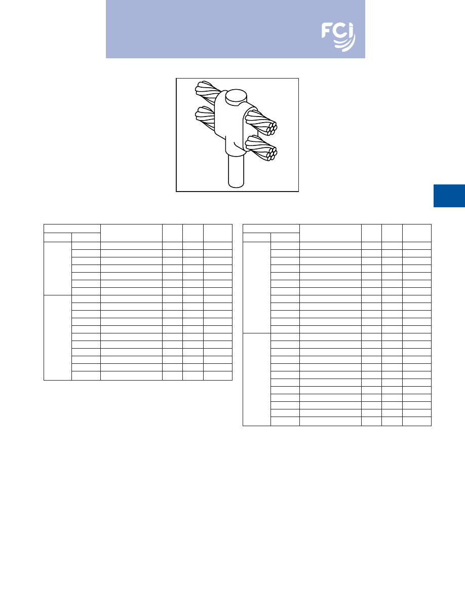
BURNDY
®
Products
Grounding
D-69
TYPE BCR-24 MOLDS
Horizontal Parallel Run Cables
to Ground Rod
Type BCR-24 Molds are used to join horizon-
tal parallel cables to the top of a vertical
ground rod.
Size range is #4 through 750 MCM solid or
concentric stranded copper conductors; 1/2
through 1
for the ground rod.
Contact BURNDY
®
Products for information
on molds for conductors not listed below.
Cable
Price Weld
Handle
Grd Rod
Tap
Mold Number
Key
Metal
Clamps
#4
B-5640
4
115
B-106
#2
B-5667
4
115
B-106
#1
B-6002
4
115
B-106
1/2
1/0
B-5767
4
150
B-106
2/0
B-5604
4
200
B-106
3/0
B-5560
4
250
B-106
4/0
B-6766
4
250
B-106
#4
B-6208
4
115
B-106
#2
B-5702
4
150
B-106
#1
B-5517
4
150
B-106
1/0
B-5573
4
200
B-106
2/0
B-8451
4
250
B-106
5/8
3/0
B-2510
5
2-150
B-107
4/0
B-5428
5
2-150
B-107
250 MCM
B-1212
5
2-200
B-107
300 MCM
B-2084
5
500
B-107
350 MCM
B-2558
5
500
B-107
500 MCM
B-2450
5
3-250
B-107
Cable
Price Weld
Handle
Grd Rod
Tap
Mold Number
Key
Metal
Clamps
#4
B-8011
4
115
B-106
#2
B-2320
4
150
B-106
#1
B-2235
4
150
B-106
1/0
B-6051
4
200
B-106
2/0
B-8802
4
250
B-106
3/0
B-8726
5
2-150
B-107
3/4
4/0
B-5677
5
2-150
B-107
250 MCM
B-8461
5
2-200
B-107
300 MCM
B-8428
5
500
B-107
350 MCM
B-6294
5
500
B-107
500 MCM
B-8214
5
3-250
B-107
750 MCM
B-8027
6
2-500
B-107
#4
B-5330
4
150
B-106
#2
B-5332
4
200
B-106
#1
B-5333
4
200
B-106
1/0
B-5334
4
250
B-106
2/0
B-5335
5
2-150
B-107
3/0
B-5336
5
2-200
B-107
1
4/0
B-5337
5
2-200
B-107
250 MCM
B-5338
5
500
B-107
300 MCM
B-5341
5
3-200
B-107
350 MCM
B-5351
5
3-200
B-107
500 MCM
B-5352
6
2-500
B-107
750 MCM
B-5353
64
5-250
B-107
• For sizes not listed, contact BURNDY
®
Products.
• Molds listed are for concentric stranded cable. Add suffix “-S” to mold number for solid
conductors.
• Molds listed are for copperclad ground rods. For welding to steel, stainless steel or
galvanized steel ground rods add suffix “-N” to mold number.
• For heavy duty molds, molds with wear plates or molds for Copperweld
®
cable, contact
BURNDY
®
Products.
• For expedited service, contact BURNDY
®
Products.
Required Tools:
Handle Clamps (see chart for correct handles)
B38-0309-00
Flint Ignitor
‡ Crucible B-181 required
Other recommended accessories:
B38-3922-00
Mold Cleaning Brush (pg D-85)
B38-0135-00
Cable Cleaning Brush (pg D-85)
B38-0330-00
Cable Clamp (pg D-85)
B38-0304-00
File (pg D-85)
For mold types or BURNDYWeld™ items not shown, please
contact factory or refer to full BURNDYWeld™ catalog.
Burndy-Grounding-Connectors-catalog-html.html
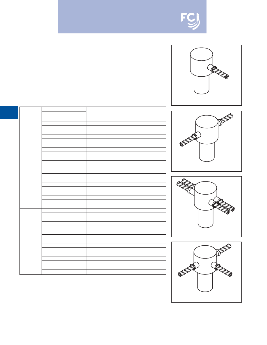
BURNDY
®
Products
Grounding
D-70
SINGLE SHOT MOLDS
RUS Accepted
BURNDYWeld™ Single Shot Molds are an
economical way to make cable connections
onto the top of a ground rod. The Single Shot
is a disposable single use ceramic mold that
comes complete with everything required
except the Flint Ignitor.
Ground
Cable Size
Mold
Cadweld
®
Rod Size
Solid
Stranded
Type
Number
Part #
#6, #8
#8
BCR-1
BS-2009
GR1-141G
#3, #4
#4, #6
BCR-1
BS-2010
GR1-141L
#1, #2
#2, #3
BCR-1
BS-2011
GR1-141V
1/2
#6, #8
#8
BCR-2
BS-2024
GT1-141G
#3, #4
#4, #6
BCR-2
BS-2025
GT1-141L
#1, #2
#2, #3
BCR-2
BS-2026
GT1-141V
#6, #8
#8
BCR-1
BS-2012
GT1-161G
#3, #4
#4, #6
BCR-1
BS-2013
GT1-141L
#1, #2
#2, #3
BCR-1
BS-2014
GR1-161V
2/0, 1/0
1/0, #1
BCR-1
BS-2015
GR1-162C
2/0
BCR-1
BS-2016
GR1-162G
#6, #8
#8
BC R-2
BS-2027
FRT1-161G
#3, #4
#4, #6
BCR-2
BS-2028
GT1-161L
5/8
#1, #2
#2, #3
BCR-2
BS-2029
GT1-161V
2/0, 1/0
1/0, #1
BCR-2
BS-2030
GT1-162C
#6, #8
#8
BCR-24
BS-2105
NX1-161G
#3, #4
#4, #6
BCR-14
BS-2106
NX1-161L
#1, #2
#2, #3
BCR-24
BS-2107
NX1-161V
#6, #8
#8
BCR-25
BS-2006
NT1-161G
#3, #4
#4, #6
BCR-25
BS-2007
NT1-161L
#1, #2
#2, #3
BCR-25
BS-2008
NT1-161V
#6, #8
#8
BCR-1
BS-2017
GR1-181G
#3, #8
#4, #6
BCR-1
BS-2018
GR1-181L
#1, #2
#2, #3
BCR-1
BS-2019
GR1-181V
2/1, 1/0
1/0, #1
BCR-1
BS-2020
GR1-182C
2/0
BCR-1
BS-2021
GR1-182G
#6, #8
#8
BCR-2
BS-2031
GT1-181G
#3, #4
#4, #6
BCR-2
BS-2032
GT1-181L
3/4
#1, #2
#2, #3
BCR-2
BS-2033
GT1-181V
2/0, 1/0
1/0, #1
BCR-2
BS-2034
T1-182C
#6, #8
#8
BCR-24
BS-2108
NX1-181G
#3, #4
#4, #6
BCR-24
BS-2109
NX1-181L
#1, #2
#2, #3
BCR-24
BS-2110
NX1-181V
#6, #8
#8
BCR-25
BS-2068
NT1-181G
#3, #4
#4, #6
BCR-25
BS-2069
NT1-181L
#1, #2
#2, #3
BCR-25
BS-2070
NT1-181V
BCR-1
BCR-2
BCR-24
BCR-25
Cadweld
®
is a registered trademark of the Erico International Corporation
For mold types or BURNDYWeld™ items not shown, please
contact factory or refer to full BURNDYWeld™ catalog.
Burndy-Grounding-Connectors-catalog-html.html
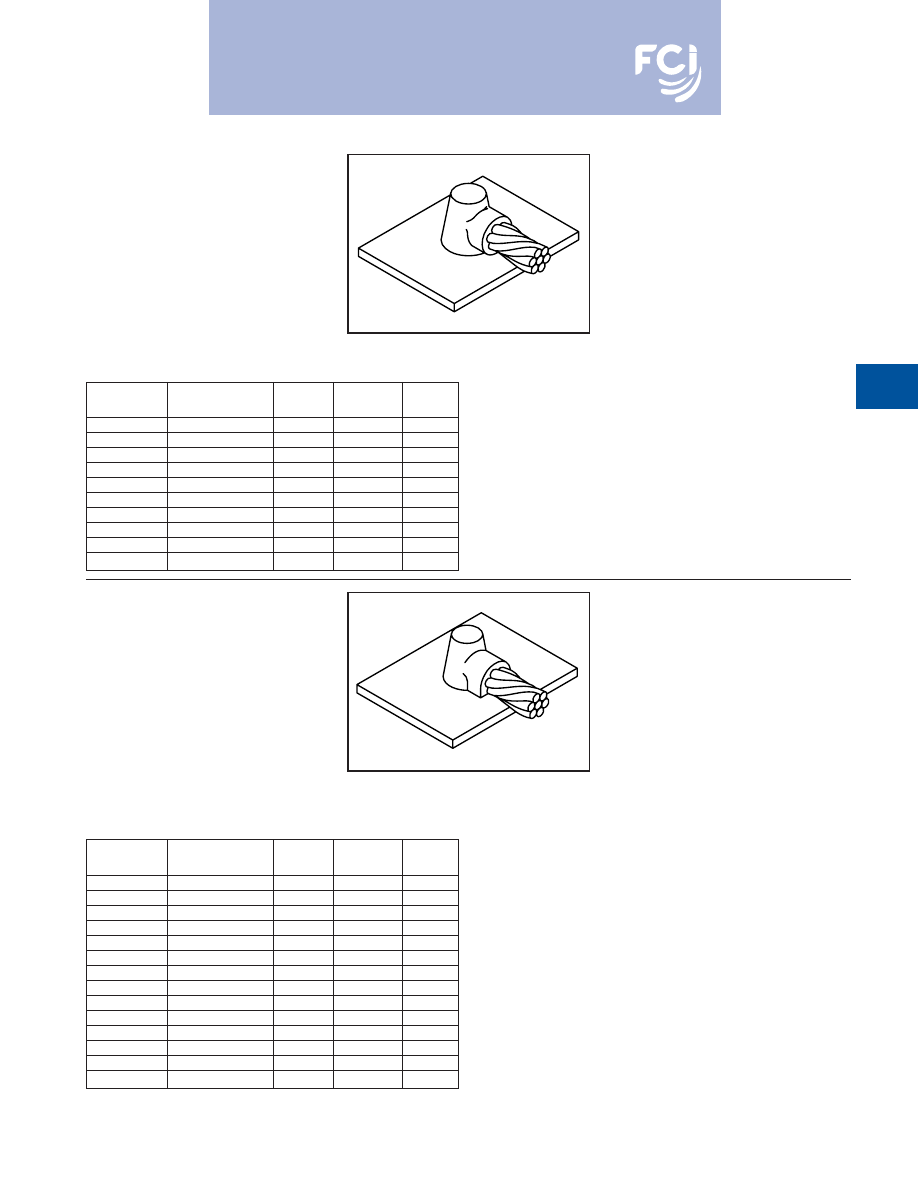
BURNDY
®
Products
Grounding
D-71
TYPE BCS-1 MOLDS
Horizontal Cable to Horizontal
Steel Surface
Type BCS-1 Molds are used to terminate a
horizontal copper cable to any horizontal steel
surface. Note that the cable is
OFF
the surface.
Size range is 1/0 through 1000 MCM solid or
concentric stranded copper conductors.
Contact BURNDY
®
Products for information
on molds for conductors not listed below.
Price
Weld
Handle
Cable Size
Mold Number
Key
Metal
Clamps
1/0
B-644
4
90
B-106
2/0
B-645
4
90
B-106
3/0
B-646
4
115
B-106
4/0
B-647
4
115
B-106
250 MCM
B-648
4
115
B-106
300 MCM
B-649
4
150
B-106
350 MCM
B-650
4
200
B-106
500 MCM
B-652
4
200
B-106
750 MCM
B-653
5
2-150
B-106
1000 MCM
B-654
5
2-200
B-107
Price
Weld
Handle
Cable Size
Mold Number
Key
Metal
Clamps
#6
B-628
3†**
45
N/A
#4
B-629
3†*
45
N/A
#2
B-630
3†*
45
N/A
#1
B-631
3†*
65
N/A
1/0
B-7146
4
90
B-106
2/0
B-7075
4
90
B-106
3/0
B-2199
4
115
B-106
4/0
B-6114
4
115
B-106
250 MCM
B-2200
4
115
B-106
300 MCM
B-2506
4
150
B-106
350 MCM
B-2507
4
200
B-106
500 MCM
B-2509
4
200
B-106
750 MCM
B-2542
5
2-150
B-107
1000 MCM
B-2511
5
2-200
B-107
• For sizes not listed, contact BURNDY
®
Products.
• Molds listed are for concentric stranded cable. Add suffix “-S” to mold number for solid
conductors.
• For heavy duty molds, molds with wear plates or molds for Copperweld
®
cable, contact
BURNDY
®
Products.
• For expedited service, contact BURNDY
®
Products.
Required Tools:
Handle Clamps (see chart for correct handles)
B38-0309-00
Flint Ignitor
Other recommended accessories:
B38-3922-00
Mold Cleaning Brush (pg D-85)
B38-0135-00
Cable Cleaning Brush (pg D-85)
B38-0330-00
Cable Clamp (pg D-85)
B38-0101-00
Rasp (pg D-85)
• For sizes not listed, contact BURNDY
®
Products.
• Molds listed are for concentric stranded cable. Add suffix “-S” to mold number for solid
conductors.
• For heavy duty molds, molds with wear plates or molds for Copperweld
®
cable, contact
BURNDY
®
Products.
• For expedited service, contact BURNDY
®
Products.
Required Tools:
Handle Clamps (see chart for correct handles)
† Sold complete with frame
*
B38-0309-00
Flint Ignitor (included)
Other recommended accessories:
B38-3922-00
Mold Cleaning Brush (pg D-85)
B38-0135-00
Cable Cleaning Brush (pg D-85)
B38-0330-00
Cable Clamp (pg D-85)
B38-0101-00
Rasp (pg D-85)
TYPE BCS-8 MOLDS
Horizontal Cable to Horizontal
Steel Surface
Type BCS-8 Molds are used to terminate a
horizontal copper cable to any horizontal
steel surface. Note that the cable is
ON
the
surface.
Size range is #6 through 1000 MCM solid or
concentric stranded copper conductors.
Contact BURNDY
®
Products for information
on molds for conductors not listed below.
For mold types or BURNDYWeld™ items not shown, please
contact factory or refer to full BURNDYWeld™ catalog.
Burndy-Grounding-Connectors-catalog-html.html
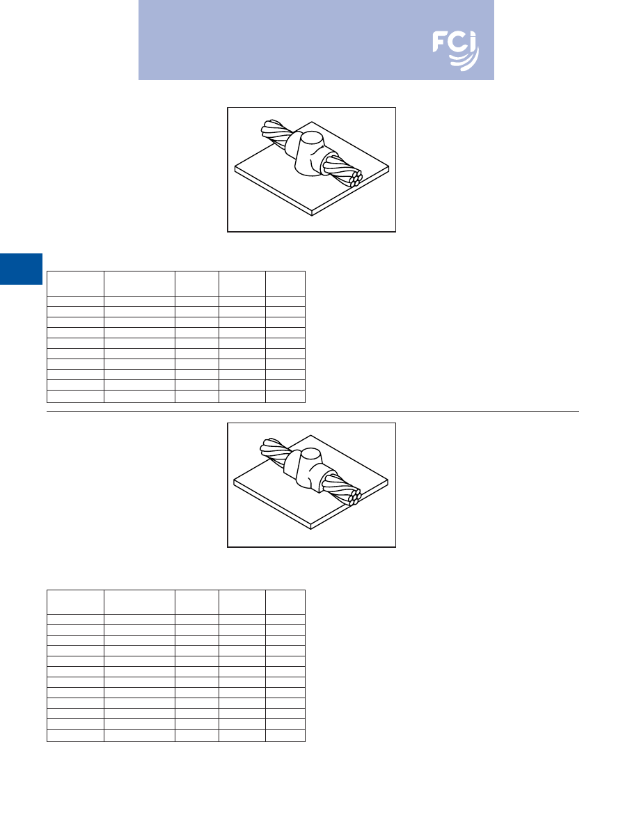
BURNDY
®
Products
Grounding
D-72
TYPE BCS-2 MOLDS
Horizontal Through Cable to
Horizontal Steel Surface
Type BCS-2 Molds are used to join horizontal
through copper cable to any horizontal steel
surface. Note the cable is
OFF
the surface.
Size range is 1/0 through 1000 MCM solid or
concentric stranded copper conductors.
Contact BURNDY
®
Products for information
on molds for conductors not listed below.
Price
Weld
Handle
Cable Size
Mold Number
Key
Metal
Clamps
1/0
B-616
4
90
B-106
2/0
B-617
4
115
B-106
3/0
B-618
4
115
B-106
4/0
B-619
4
150
B-106
250 MCM
B-620
4
150
B-106
300 MCM
B-621
4
200
B-106
350 MCM
B-622
4
250
B-106
500 MCM
B-624
5
2-150
B-107
750 MCM
B-625-H
5
3-250
B-107
1000 MCM
B-626-H
5
2-500
B-107
Price
Weld
Handle
Cable Size
Mold Number
Key
Metal
Clamps
#6
B-602
3†*
45
N/A
#4
B-603
3†*
45
N/A
#2
B-604
3†*
45
N/A
#1
B-605
3†*
65
N/A
1/0
B-8379
4
90
B-106
2/0
B-5331
4
115
B-106
3/0
B-8381
4
115
B-106
4/0
B-7192
4
150
B-106
250 MCM
B-8413
4
150
B-106
300 MCM
B-8423
4
200
B-106
350 MCM
B-8410
4
250
B-106
500 MCM
B-5065
5
2-150
B-107
• For sizes not listed, contact BURNDY
®
Products.
• Molds listed are for concentric stranded cable. Add suffix “-S” to mold number for solid
conductors.
• For heavy duty molds, molds with wear plates or molds for Copperweld® cable, contact
BURNDY
®
Products.
• For expedited service, contact BURNDY
®
Products.
Required Tools:
Handle Clamps (see above for correct handles)
B38-0309-00
Flint Ignitor
Other recommended accessories:
B38-3922-00
Mold Cleaning Brush (pg D-85)
B38-0135-00
Cable Cleaning Brush (pg D-85)
B38-0101-00
Rasp (pg D-85)
• For sizes not listed, contact BURNDY
®
Products.
• Molds listed are for concentric stranded cable. Add suffix “-S” to mold number for solid
conductors.
• For heavy duty molds, molds with wear plates or molds for Copperweld
®
cable, contact
BURNDY
®
Products.
• For expedited service, contact BURNDY
®
Products.
Required Tools:
Handle Clamps (see chart for correct handles)
† Sold complete with handle frame
*
B38-0309-00
Flint Ignitor (included)
Other recommended accessories:
B40-0319-01
Mold Cleaner for cartridge sizes #15-#65 (pg D-85)
B40-0319-03
Mold Cleaner for cartridge sizes #90-#500 (pg D-85)
B38-3922-00
Mold Cleaning Brush (pg D-85)
B38-0135-00
Cable Cleaning Brush (pg D-85)
B38-0101-00
Rasp (pg D-85)
TYPE BCS-9 MOLDS
Horizontal Through Cable to
Horizontal Steel Surface
Type BCS-9 Molds are used to join horizontal
through copper cable to any horizontal steel
surface. Note the cable is
ON
the surface.
Size range is #6 through 500 MCM solid or
concentric stranded copper conductors.
Contact BURNDY
®
Products for information
on molds for conductors not listed below.
For mold types or BURNDYWeld™ items not shown, please
contact factory or refer to full BURNDYWeld™ catalog.
Burndy-Grounding-Connectors-catalog-html.html
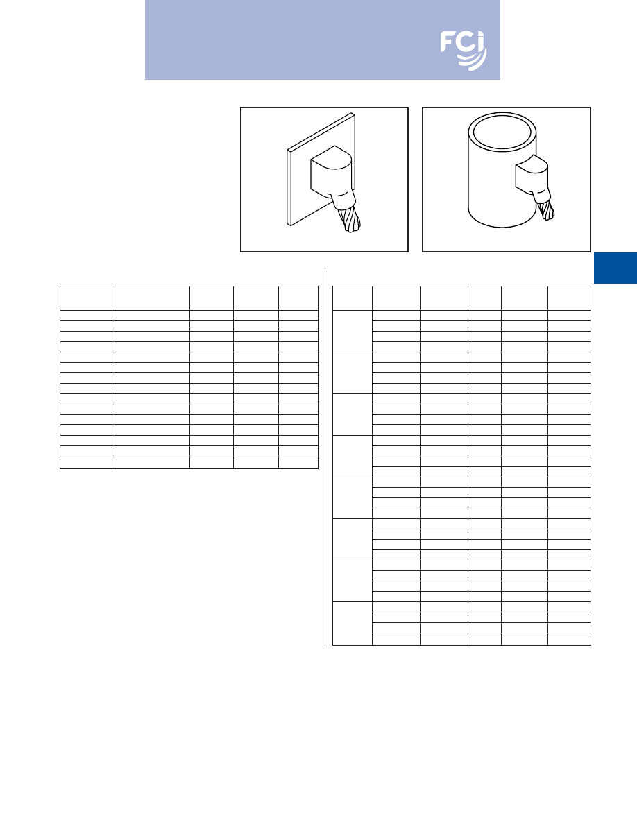
BURNDY
®
Products
Grounding
D-73
TYPE BCS-3 MOLDS
Angular Cable Drop to Vertical
Steel Surface
Type BCS-3 Molds are used to join the end of
a copper cable at a 45˚ angle to a vertical
steel surface.
Size range is #6 through 1000 MCM solid or
concentric stranded copper conductors.
Contact BURNDY
®
Products for information
on molds for conductors not listed below.
Price
Weld
Handle
Cable Size
Mold Number
Key
Metal
Clamps
#6
B-585
4
45
B-106
#4
B-586
4
45
B-106
#3
B-587
4
45
B-106
#2
B-588
4
45
B-106
#1
B-589
4
65
B-106
1/0
B-590
4
90
B-106
2/0
B-591
4
90
B-106
3/0
B-592
4
115
B-106
4/0
B-593
4
115
B-106
250 MCM
B-594
4
115
B-106
300 MCM
B-595
4
150
B-106
350 MCM
B-596
4
200
B-106
500 MCM
B-598
4
200
B-106
750 MCM
B-599
5
2-150
B-107
1000 MCM
B-600
5
2-200
B-107
Cable
Pipe
Mold
Price
Weld
Handle
Size
Size
Number
Key
Metal
Clamps
1-1/4
to 4
B-2476
4
45
B-106
4
to 6
B-2477
4
45
B-106
#4
6
to 10
B-2478
4
45
B-106
12
& up
B-586
‡
4
45
B-106
1-1/4
to 4
B-9233-S
4
45
B-106
4
to 6
B-2480-S
4
45
B-106
#2 Sol
6
to 10
B-2583-S
4
45
B-106
12
& up
B-588-S
‡
4
45
B-106
1-1/4
to 4
B-9233
4
45
B-106
4
to 6
B-2480
4
45
B-106
#2
6
to 10
B-2688
4
45
B-106
12
& up
B-588
‡
4
45
B-106
1-1/4
to 4
B-2482
4
65
B-106
4
to 6
B-2483
4
65
B-106
#1
6
to 10
B-2484
4
65
B-106
12
& up
B-589
‡
4
65
B-106
1-1/4
to 4
B-2486
4
90
B-106
4
to 6
B2487
4
90
B-106
1/0
6
to 10
B-2488
4
90
B-106
12
& up
B-590
‡
4
90
B-106
1-1/4
to 4
B-8833
4
90
B-106
4
to 6
B-2490
4
90
B-106
2/0
6
to 10
B-2491
4
90
B-106
12
& up
B-591
‡
4
90
B-106
1-1/4
to 4
B-2493
4
115
B-106
4
to 6
B-2494
4
115
B-106
3/0
6
to 10
B2495
4
115
B-106
12
& up
B-592
‡
4
115
B-106
1-1/4
to 4
B-9021
4
115
B-106
4
to 6
B2497
4
115
B-106
4/0
6
to 10
B2498
4
115
B-106
12
& up
B593
‡
4
115
B-106
• For sizes not listed, contact BURNDY
®
Products.
• Molds listed are for concentric stranded cable. Add suffix “-S” to mold number for solid
conductors.
• For heavy duty molds, molds with wear plates or molds for Copperweld
®
cable, contact
BURNDY
®
Products.
• For expedited service, contact BURNDY
®
Products.
Required Tools:
Handle Clamps (see chart for correct handles)
B38-0309-00
Flint Ignitor
Other recommended accessories:
Magnetic Clamps to hold molds against vertical steel (pg D-84)
B38-3922-00
Mold Cleaning Brush (pg D-85)
B38-0135-00
Cable Cleaning Brush (pg D-85)
B38-0101-00
Rasp (pg D-85)
• For sizes not listed, contact BURNDY
®
Products.
• Molds listed are for concentric stranded cable. Add suffix “-S” to mold number for solid
conductors.
• For heavy duty molds, molds with wear plates or molds for Copperweld® cable, contact
BURNDY
®
Products.
• For expedited service, contact BURNDY
®
Products.
Required Tools:
Handle Clamps (see chart for correct handles)
B38-0309-00
Flint Ignitor
Other recommended accessories:
B106-32
Vertical Chain Clamp w/ B-106 Handles for 4
Pipe & smaller
B40-0106-27
20
Chain Extension for 4
to 10
Pipe
Use (2) 20
Chain Extensions for pipe sizes between 10
and 16
B38-3922-00
Mold Cleaning Brush (pg D-85)
B38-0135-00
Cable Cleaning Brush (pg D-85)
B38-0101-00
Rasp (pg D-85)
‡ Flat Surface Mold
Cable to Flat Steel
Cable to Pipe
Cable to Flat Steel
Cable to Pipe
For mold types or BURNDYWeld™ items
not shown, please contact factory
or refer to full BURNDYWeld™ catalog.
Burndy-Grounding-Connectors-catalog-html.html
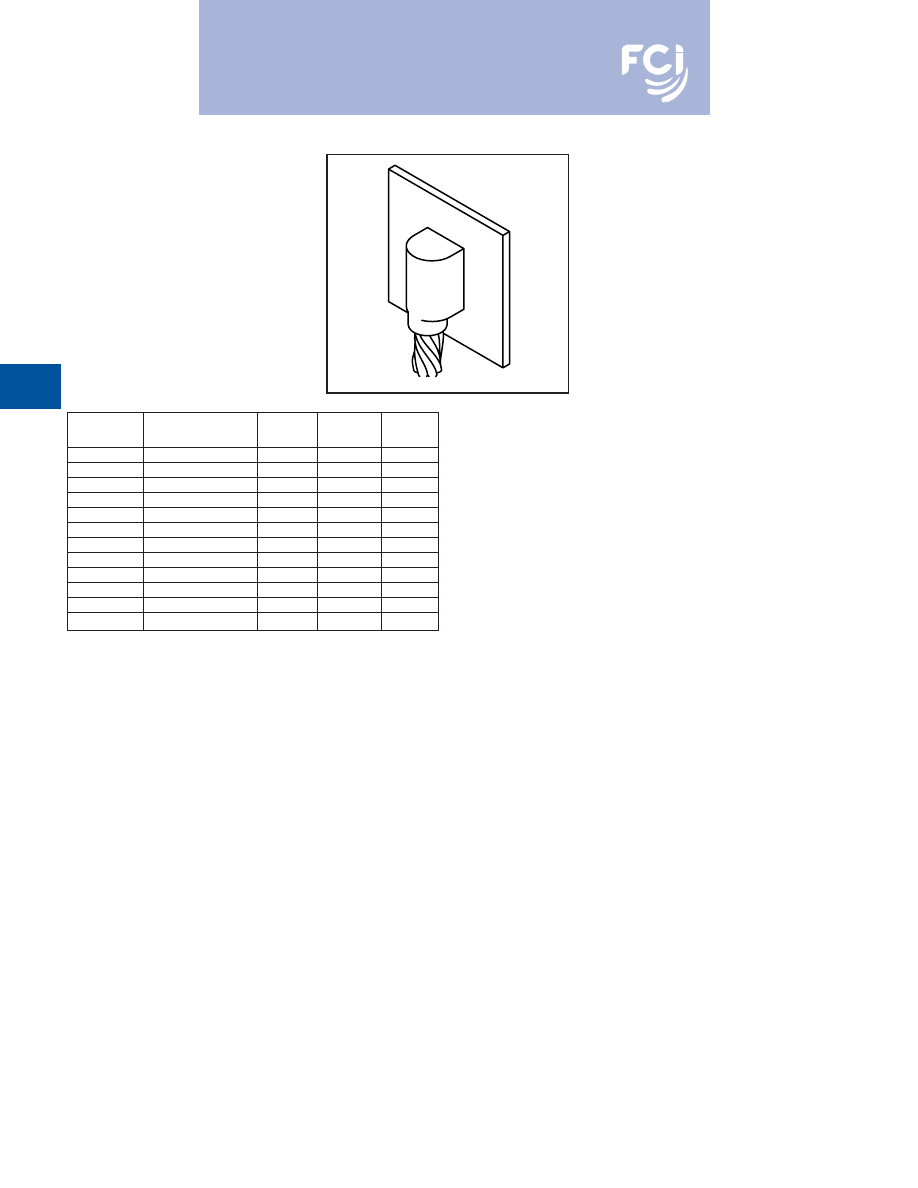
BURNDY
®
Products
Grounding
D-74
TYPE BCS-23 MOLDS
Vertical Cable Drop to
Vertical Steel Surface
Type BCS-23 Molds are used to join vertical
cable down to a vertical steel surface. Note
that the cable is
OFF
the surface.
Size range is #6 through 500 MCM solid or
concentric stranded copper conductors.
Contact BURNDY
®
Products for information
on molds for conductors not listed below.
Price
Weld
Handle
Cable Size
Mold Number
Key
Metal
Clamps
#6
B-5389
4
45
B-106
#4
B-5359
4
65
B-106
#2
B-2781
4
65
B-106
#1
B-5361
4
90
B-106
1/0
B-2189
4
115
B-106
2/0
B-2540
4
115
B-106
3/0
B-5362
4
150
B-106
4/0
B-8718
4
150
B-106
250 MCM
B-8165
4
200
B-106
300 MCM
B-5363
4
200
B-106
350 MCM
B-9029
4
250
B-106
500 MCM
B-8512
17
2-150
B-106
• For sizes not listed, contact BURNDY
®
Products.
• Molds listed are for concentric stranded cable. Add suffix “-S” to mold number for solid
conductors.
• For heavy duty molds, molds with wear plates or molds for Copperweld
®
cable, contact
BURNDY
®
Products.
• For expedited service, contact BURNDY
®
Products.
Required Tools:
Handle Clamps (see chart for correct handles)
B38-0309-00
Flint Ignitor
Other recommended accessories:
Magnetic Clamps to hold molds against vertical steel
B38-3922-00
Mold Cleaning Brush (pg D-85)
B38-0135-00
Cable Cleaning Brush (pg D-85)
B38-0101-00
Rasp (pg D-85)
For mold types or BURNDYWeld™ items not shown, please
contact factory or refer to full BURNDYWeld™ catalog.
Burndy-Grounding-Connectors-catalog-html.html
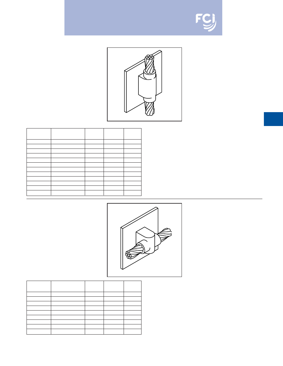
BURNDY
®
Products
Grounding
D-75
TYPE BCS-4 MOLDS
Vertical Through Cable to
Vertical Steel Surface
Type BCS-4 Molds are used to join a vertical
through copper cable to a vertical steel sur-
face. Note that the cable is
OFF
the surface.
For molds with the cable on the surface, con-
tact BURNDY
®
Products.
Size range is #6 through 500 MCM solid or
concentric stranded copper conductors.
Contact BURNDY
®
Products for information
on molds for conductors not listed below.
Price
Weld
Handle
Cable Size
Mold Number
Key
Metal
Clamps
#6
B-1215
4
90
B-106
#4
B-1216
4
90
B-106
#2
B-1218
4
115
B-106
#1
B-1219
4
115
B-106
1/0
B-1220
17
200
B-106
2/0
B-1221
17
200
B-106
3/0
B-1222
17
250
B-106
4/0
B-1223
17
250
B-106
250 MCM
B-1224
17
250
B-106
300 MCM
B-1225-H
6
500
B-107
350 MCM
B-1226-H
6
3-200
B-107
500 MCM
B-1228-H
6
3-250
B-107
Price
Weld
Handle
Cable Size
Mold Number
Key
Metal
Clamps
#6
B-1626
4
65
B-106
#4
B-1627
4
65
B-106
#2
B-1628
4
65
B-106
#1
B-1629
4
90
B-106
1/0
B-1630
4
115
B-106
2/0
B-1631
4
115
B-106
3/0
B-1632
4
150
B-106
4/0
B-1633
4
150
B-106
250 MCM
B-1634
4
150
B-106
• For sizes not listed, contact BURNDY
®
Products.
• Molds listed are for concentric stranded cable. Add suffix “-S” to mold number for solid
conductors.
• For heavy duty molds, molds with wear plates or molds for Copperweld
®
cable, contact
BURNDY
®
Products.
• For expedited service, contact BURNDY
®
Products.
Required Tools:
Handle Clamps (see chart for correct handles)
B38-0309-00
Flint Ignitor
Other recommended accessories:
Magnetic Clamps to hold molds against vertical steel
B38-3922-00
Mold Cleaning Brush (pg D-85)
B38-0135-00
Cable Cleaning Brush (pg D-85)
B38-0101-00
Rasp (pg D-85)
• For sizes not listed, contact BURNDY
®
Products.
• Molds listed are for concentric stranded cable. Add suffix “-S” to mold number for solid
conductors.
• For heavy duty molds, molds with wear plates or molds for Copperweld
®
cable, contact
BURNDY
®
Products.
• For expedited service, contact BURNDY
®
Products.
Required Tools:
Handle Clamps (see chart for correct handles)
B38-0309-00
Flint Ignitor
Other recommended accessories:
B40-0319-01
Mold Cleaner for cartridge sizes #15-#65 (pg D-85)
B40-0319-03
Mold Cleaner for cartridge sizes #90-#500 (pg D-85)
B38-3922-00
Mold Cleaning Brush (pg D-85)
B38-0135-00
Cable Cleaning Brush (pg D-85)
B38-0101-00
Rasp (pg D-85)
TYPE BCS-6 MOLDS
Horizontal Through Cable to
Vertical Steel Surface
Type BCS-6 Molds are used to join horizontal
through copper cable to a vertical steel sur-
face. Note that the cable is OFF the surface.
Size range is #6 through 250 MCM solid or
concentric stranded copper conductors.
Contact BURNDY
®
Products for information
on molds for conductors not listed below.
For mold types or BURNDYWeld™ items not shown, please
contact factory or refer to full BURNDYWeld™ catalog.
Burndy-Grounding-Connectors-catalog-html.html
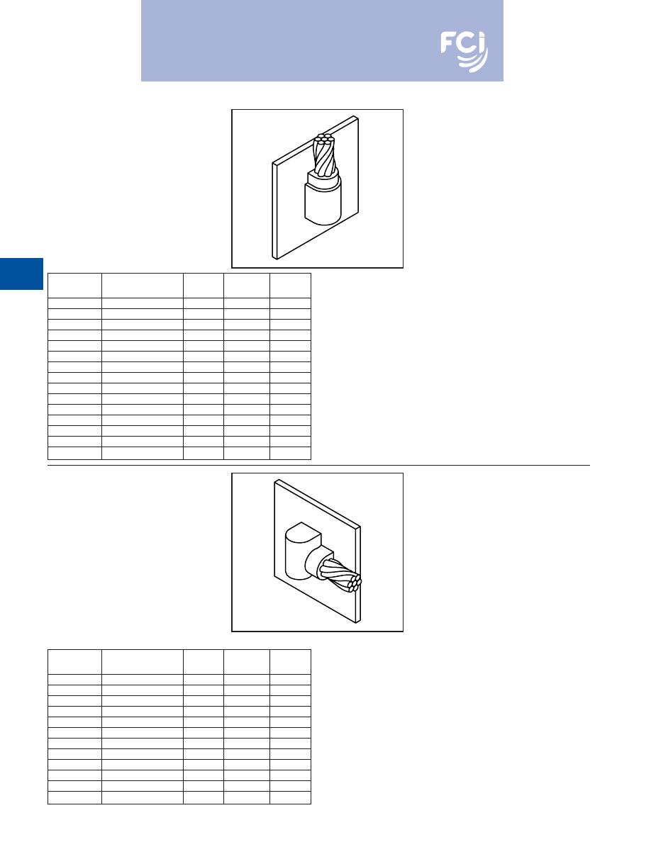
BURNDY
®
Products
Grounding
D-76
TYPE BCS-7 MOLDS
Overhead Vertical Tap Cable
to Vertical Steel Surface
Type BCS-7 Molds are used to join an over-
head vertical copper conductor drop tap to a
vertical steel surface.
Size range is #6 through 1000 MCM solid or
concentric stranded copper conductors.
Contact BURNDY
®
Products for information
on molds for conductors not listed below.
Price
Weld
Handle
Cable Size
Mold Number
Key
Metal
Clamps
#6
B-1635
4
65
B-106
#4
B-1636
4
65
B-106
#3
B-1637
4
65
B-106
#2
B-1638
4
65
B-106
#1
B-1639
4
90
B-106
1/0
B-1640
4
150
B-106
2/0
B-1641
4
150
B-106
3/0
B-1642
17
200
B-106
4/0
B-1643
17
200
B-106
250 MCM
B-1644
17
200
B-106
300 MCM
B-1645
17
250
B-106
350 MCM
B-1646
6
2-150
B-107
500 MCM
B-1648
6
2-200
B-107
750 MCM
B-1649
6
500
B-107
1000 MCM
B-1650
6
3-200
B-107
Price
Weld
Handle
Cable Size
Mold Number
Key
Metal
Clamps
#6
B-5910
4
45
B-106
#4
B-2761
4
45
B-106
#2
B-2569
4
45
B-106
#1
B-6060
4
65
B-106
1/0
B-5419
4
90
B-106
2/0
B-2567
4
90
B-106
3/0
B-6072
4
115
B-106
4/0
B-9253
4
115
B-106
250 MCM
B-2568
4
115
B-106
300 MCM
B-6061
4
150
B-106
350 MCM
B-6067
4
200
B-106
500 MCM
B-8359
4
200
B-106
• For sizes not listed, contact BURNDY
®
Products.
• Molds listed are for concentric stranded cable. Add suffix “-S” to mold number for solid
conductors.
• For heavy duty molds, molds with wear plates or molds for Copperweld
®
cable, contact
BURNDY
®
Products.
• For expedited service, contact BURNDY
®
Products.
Required Tools:
Handle Clamps (see chart for correct handles)
B38-0309-00
Flint Ignitor
Other recommended accessories:
Magnetic Clamps to hold molds against vertical steel
B38-3922-00
Mold Cleaning Brush (pg D-85)
B38-0135-00
Cable Cleaning Brush (pg D-85)
B38-0101-00
Rasp (pg D-85)
NOTE:
Add (-R) to mold number for right hand mold or (-L) for left hand mold. Right hand (-R)
mold will be furnished if not specified.
• For sizes not listed, contact BURNDY
®
Products.
• Molds listed are for concentric stranded cable. Add suffix “-S” to mold number for solid
conductors.
• For heavy duty molds, molds with wear plates or molds for Copperweld
®
cable, contact
BURNDY
®
Products.
• For expedited service, contact BURNDY
®
Products.
Required Tools:
Handle Clamps (see chart for correct handles)
B38-0309-00
Flint Ignitor
Other recommended accessories:
Vertical Chain Clamps
B38-3922-00
Mold Cleaning Brush (pg D-85)
B38-0135-00
Cable Cleaning Brush (pg D-85)
B38-0101-00
Rasp (pg D-85)
TYPE BCS-18 MOLDS
Horizontal Tap Cable to
Vertical Steel Surface
Type BCS-18 Molds are used to connect a
horizontal conductor to a vertical steel sur-
face. Note that the cable is
ON the surface.
Size range is #6 through 500 MCM solid or
concentric stranded copper conductors.
Contact BURNDY
®
Products for information
on molds for conductors not listed below.
For mold types or BURNDYWeld™ items
not shown, please contact factory
or refer to full BURNDYWeld™ catalog.
For mold types or BURNDYWeld™ items
not shown, please contact factory
or refer to full BURNDYWeld™ catalog.
Burndy-Grounding-Connectors-catalog-html.html
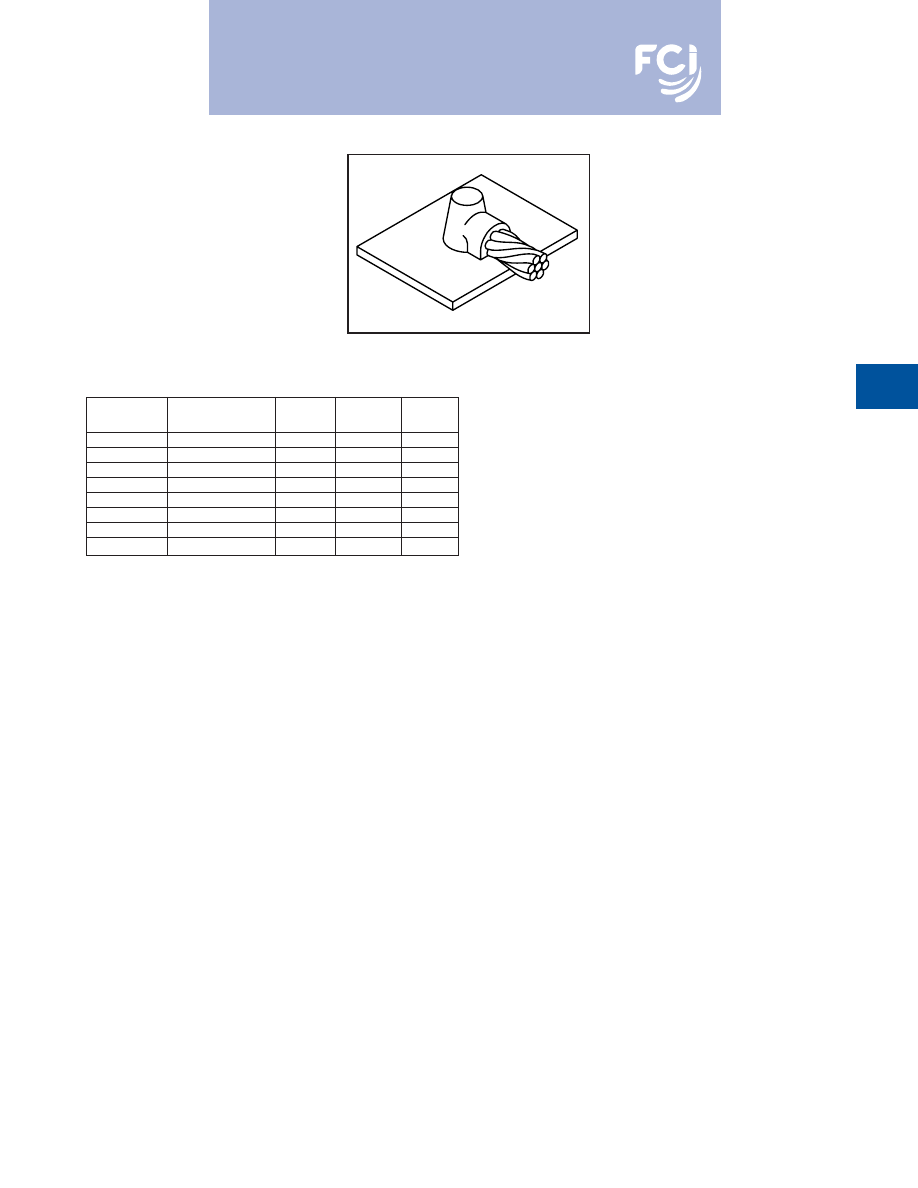
BURNDY
®
Products
Grounding
D-77
TYPE BCS-5 MOLDS
Horizontal Cable Tap to
Horizontal Cast Iron Surface
Type BCS-5 Molds are used to join horizontal
cable taps to horizontal cast iron surfaces.
Note that the cable is
ON
the surface.
Size range is #6 through #1 solid or concen-
tric stranded copper conductors.
Contact BURNDY
®
Products for information
on molds for conductors not listed below.
Price
Weld
Handle
Cable Size
Mold Number
Key
Metal
Clamps
#6 Sol
B-1613
3+
2SCI
N/A
#6
B-1614
3+
25CI
N/A
#4 Sol
B-1615
3+
45CI
N/A
#4
B-1616
3+
45CI
N/A
#2 Sol
B-1617
3+
45CI
N/A
#2
B-1618
3+
45CI
N/A
#1 Sol
B-1619
3+
65CI
N/A
#1
B-1620
3+
65CI
N/A
• For sizes not listed, contact BURNDY
®
Products.
• Molds listed are for concentric stranded cable. Add suffix “-S” to mold number for solid
conductors.
• For heavy duty molds, molds with wear plates or molds for Copperweld
®
cable, contact
BURNDY
®
Products.
• For expedited service, contact BURNDY
®
Products.
Required Tools:
† Sold complete with frame
B38-0309-00
Flint Ignitor (included)
Other recommended accessories:
B38-3922-00
Mold Cleaning Brush (pg D-85)
B38-0135-00
Cable Cleaning Brush (pg D-85)
B38-0101-00
Rasp (pg D-85)
DO NOT use Type BCS-5 molds on Soil Pipe (ASTM A74-82). A
test weld should be made on a section of the pipe being used
to determine the possibility of detrimental metallurgical effects.
For mold types or BURNDYWeld™ items not shown, please
contact factory or refer to full BURNDYWeld™ catalog.
Burndy-Grounding-Connectors-catalog-html.html
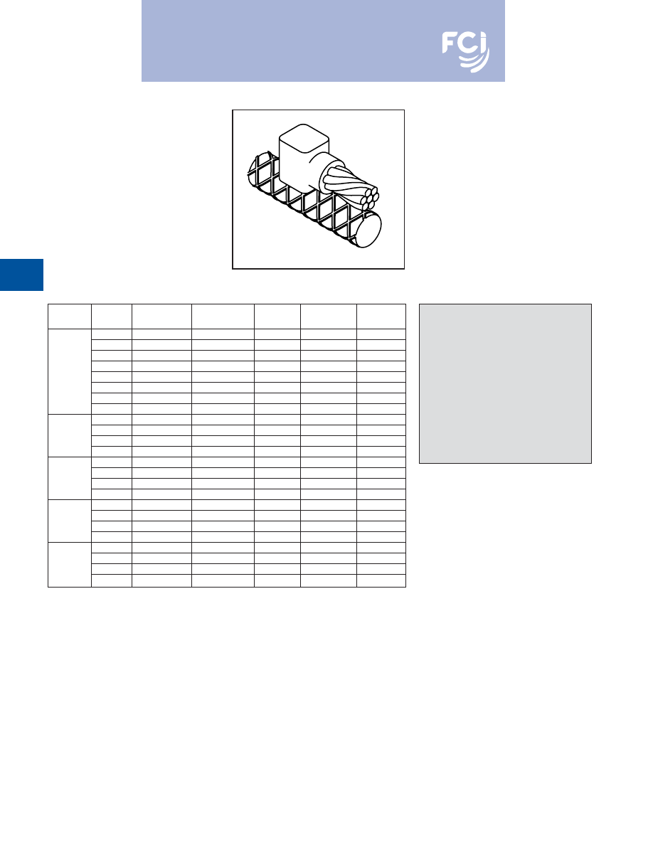
BURNDY
®
Products
Grounding
D-78
TYPE BCRE-1 MOLDS
Horizontal Parallel Tap
to Rebar
Type BCRE-1 Molds are recommended for
parallel, horizontal connections for solid or
concentric stranded conductors #6 through
4/0 joined to reinforcing bars #3 through #6
and larger. The high copper content joint has
a higher current carrying capacity than the
conductors being joined and is impervious to
vibration and moisture.
Contact BURNDY
®
Products for information
on molds for conductors not listed below.
Rebar
Cable
Mold
Packing
Price
Weld
Handle
Size
Size
Number
Material ‡
Key
Metal
Clamps
#6
B-7500
B38-4060-00
4
25
B-106
#4
B-7501
B38-4060-00
4
32
B-106
#2
B-7502
B38-4060-00
4
45
B-106
#1
B-7503
B38-4060-00
4
65
B-106
#3
1/0
B-7504
B38-4060-00
4
90
B-106
2/0
B-7505
B38-4060-00
4
90
B-106
3/0
B-7506
B38-4060-00
4
115
B-106
4/0
B-7507
B38-4060-00
4
115
B-106
#6
B-7508
B38-4061-00
3+
25
N/A
#4
#4
B-7509
B38-4061-00
3+
32
N/A
&
#2
B-7510
B38-4061-00
3+
45
N/A
Larger
#1
B-7511
B38-4061-00
3+
65
N/A
1/0
B-7512
B38-4060-00
4
90
B-106
2/0
B-7513
B38-4060-00
4
90
B-106
#4
3/0
B-7514
B38-4060-00
4
115
B-106
4/0
B-7515
B38-4060-00
4
115
B-106
1/0
B-7520
B38-4060-00
4
90
B-106
2/0
B-7521
B38-4060-00
4
90
B-106
#5
3/0
B-7522
B38-4060-00
4
115
B-106
4/0
B-7523
B38-4060-00
4
115
B-106
1/0
B-7528
B38-4062-00
14+
90
N/A
#6
2/0
B-7529
B38-4062-00
14+
90
N/A
&
3/0
B-7530
B38-4062-00
14+
115
N/A
Larger
4/0
B-7531
B38-4062-00
14+
115
N/A
• For sizes not listed, contact BURNDY
®
Products.
• Molds listed are for concentric stranded cable. Add suffix “-S” to mold number for solid
conductors.
• For heavy duty molds, molds with wear plates or molds for Copperweld
®
cable, contact
BURNDY
®
Products.
• For expedited service, contact BURNDY
®
Products.
Required Tools:
Handle Clamps (see chart for correct handles)
† Sold complete with frame
B38-0309-00
Flint Ignitor
Other recommended accessories:
B38-3922-00
Mold Cleaning Brush (pg D-85)
B38-0135-00
Cable Cleaning Brush (pg D-85)
B38-0304-00
File (pg D-86)
‡ PACKING MATERIAL NOTE
A packing pad is necessary when mak-
ing BURNDYWeld™ connections to
Rebar. Packing Material B38-4060-00 is
a special, patented copper-wool packing,
with enough in each bag to do between
40 and 50 connections. Packing Material
No.’s B38-4061-00, B38-4062-00 and
B38-4063-00 are a ceramic fiber materi-
al and can be used for
one
connection
only. Be sure to specify Packing Material
No. when ordering Mold and Weld Metal.
For mold types or BURNDYWeld™ items not shown, please
contact factory or refer to full BURNDYWeld™ catalog.
Burndy-Grounding-Connectors-catalog-html.html
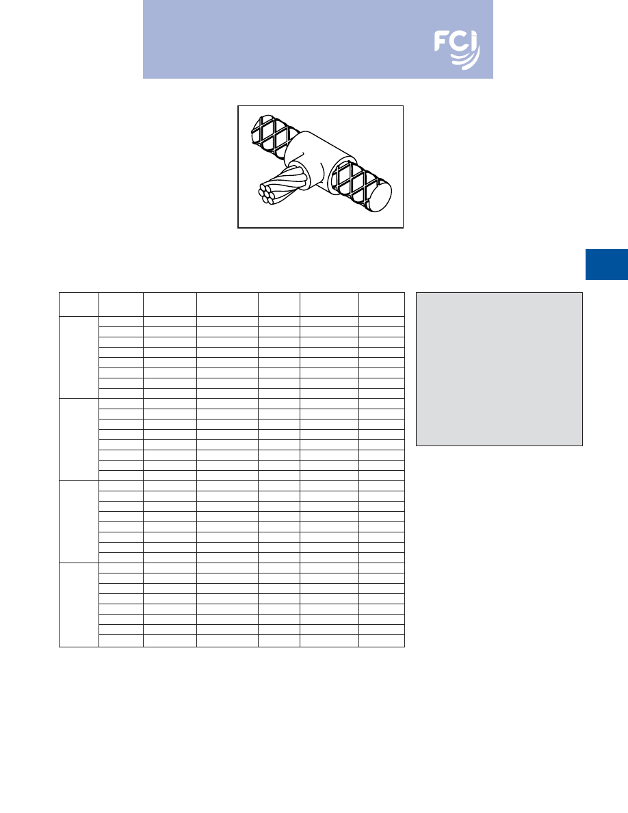
BURNDY
®
Products
Grounding
D-79
TYPE BCRE-2 MOLDS
Horizontal Cable Tap to
Horizontal Rebar Run
Type BCRE-2 Molds are recommended for
right angle, horizontal connections for solid or
concentric stranded conductors #6 through
4/0 joined to reinforcing bars #3 through #6.
The high copper content joint has a higher
current carrying capacity than the conductors
being joined and is impervious to vibration
and moisture.
Contact BURNDY
®
Products for information
on molds for conductors not listed below.
Rebar
Cable
Mold
Packing
Price
Weld
Handle
Size
Size
Number
Material ‡
Key
Metal
Clamps
#6
B-7588
B38-4060-00
4
45
B-106
#4
B-7589
B38-4060-00
4
45
B-106
#2
B-7590
B38-4060-00
4
65
B-106
#1
B-7591
B38-4060-00
4
65
B-106
#3
1/0
B-7592
B38-4060-00
4
90
B-106
2/0
B-7593
B38-4060-00
4
90
B-106
3/0
B-7594
B38-406000
4
115
B-106
4/0
B-7595
B38-4060-00
4
115
B-106
#6
B-7596
B38-4060-00
4
45
B-106
#4
B-7597
B38-4060-00
4
45
B-106
#2
B-7598
B38-4060-00
4
65
B-106
#1
B-7599
B38-4060-00
4
65
B-106
#4
1/0
B-7600
B38-4060-00
4
90
B-106
2/0
B-7601
B38-4060-00
4
90
B-106
3/0
B-7602
B38-4060-00
4
115
B-106
4/0
B-7603
B38-4060-00
4
115
B-106
#6
B-7604
B38-4606-00
4
90
B-106
#4
B-7605
B38-4060-00
4
90
B-106
#2
B-7606
B38-4060-00
4
90
B-106
#1
B-7607
B38-4060-00
4
90
B-106
#5
1/0
B-7608
B38-4060-00
4
115
B-106
2/0
B-7609
B38-4060-00
4
115
B-106
3/0
B-7610
B38-4060-00
4
150
B-106
4/0
B-7611
B38-4060-00
4
150
B-106
#6
B-7612
B38-4060-00
4
90
B-106
#4
B-7613
B38-4060-00
4
90
B-106
#2
B-7614
B384060-00
4
90
B-106
#1
B-7615
B38-4060-00
4
90
B-106
#6
1/0
B-7616
B38-4060-00
4
115
B-106
2/0
B-7617
B38-4060-00
4
115
B-106
3/0
B-7618
B38-4060-00
4
150
B-106
4/0
B-7619
B38-4060-00
4
150
B-106
• For sizes not listed, contact BURNDY
®
Products.
• Molds listed are for concentric stranded cable. Add suffix “-S” to mold number for solid
conductors.
• For heavy duty molds, molds with wear plates or molds for Copperweld
®
cable, contact
BURNDY
®
Products.
• For expedited service, contact BURNDY
®
Products.
Required Tools:
Handle Clamps (see chart for correct handles)
B38-0309-00
Flint Ignitor
Other recommended accessories
B40-0319-01
Mold Cleaner for cartridge sizes #15-#65 (pg D-85)
B40-0319-03
Mold Cleaner for cartridge sizes #90-#500 (pg D-85)
B38-3922-00
Mold Cleaning Brush (pg D-85)
B38-0135-00
Cable Cleaning Brush (pg D-85)
B38-0304-00
File (pg D-86)
‡ PACKING MATERIAL NOTE
A packing pad is necessary when mak-
ing BURNDYWeld™ connections to
Rebar. Packing Material B38-4060-00 is
a special, patented copper-wool pack-
ing, with enough in each bag to do
between 40 and 50 connections.
Packing Material No.’s B38-4061-00,
B38-4062-00 and B38-4063-00 are a
ceramic fiber material and can be used
for
one
connection only. Be sure to spec-
ify Packing Material No. when ordering
Mold and Weld Metal.
For mold types or BURNDYWeld™ items
not shown, please contact factory
or refer to full BURNDYWeld™ catalog.
Burndy-Grounding-Connectors-catalog-html.html
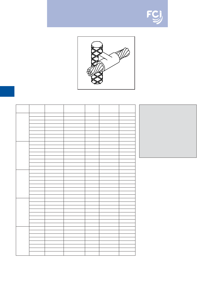
BURNDY
®
Products
Grounding
D-80
TYPE BCRE-3 MOLDS
Horizontal through Cable to
Vertical Rebar
Type BCRE-3 Molds are recommended for
horizontal conductors to vertical rebar con-
nections for solid or concentric stranded con-
ductors #6 through 4/0 joined to reinforcing
bars #3 through #7 & larger. The high copper
content joint has a higher current carrying
capacity than the conductors being joined
and is impervious to vibration and moisture.
Contact BURNDY
®
Products for information
on molds for conductors not listed below.
Rebar
Cable
Mold
Packing
Price
Weld
Handle
Size
Size
Number
Material ‡
Key
Metal
Clamps
#6
B-7620
B38-4060-00
24
90
B-106
#4
B-7621
B38-4060-00
24
90
B-106
#2
B-7622
B38-4060-00
24
90
B-106
#1
B-7623
B38-4060-00
24
115
B-106
#3
1/0
B-7624
B38-4060-00
24
115
B-106
2/0
B-7625
B38-4060-00
24
115
B-106
3/0
B-7626
B38-4060-00
24
150
B-106
4/0
B-7627
B38-4060-00
24
150
B-106
#6
B-7628
B38-4060-00
24
90
B-106
#4
B-7629
B38-4060-00
24
90
B-106
#2
B-7630
B38-4060-00
24
90
B-106
#1
B-7631
B38-4060-00
24
115
B-106
#4
1/0
B-7632
B38-4060-00
24
115
B-106
2/0
B-7633
B38-4060-00
24
115
B-106
3/0
B-7634
B38-4060-00
24
150
B-106
4/0
B-7635
B38-4060-00
24
150
B-106
#6
B-7636
B38-4060-00
24
90
B-106
#4
B-7637
B38-4060-00
24
90
B-106
#2
B-7638
B38-4060-00
24
90
B-106
#1
B-7639
B38-4060-00
24
115
B-106
#5
1/0
B-7640
B38-4060-00
24
115
B-106
2/0
B-7641
B38-4060-00
24
115
B-106
3/0
B-7642
B38-4060-00
24
150
B-106
4/0
B-7643
B38-4060-00
24
150
B-106
#6
B-7644
B38-4060-00
24
90
B-106
#4
B-7645
B38-4060-00
24
90
B-106
#2
B-7646
B38-4060-00
24
90
B-106
#1
B-7647
B38-4060-00
24
115
B-106
#6
1/0
B-7648
B38-4060-00
24
115
B-106
2/0
B-7649
B38-4060-00
24
115
B-106
3/0
B-7650
B38-4060-00
24
150
B-106
4/0
B-7651
B38-4060-00
24
150
B-106
#6
B-7652
B38-4063-00
4+
90
B-106-41
#4
B-7653
B38-4063-00
4+
90
B-106-41
#2
B-7654
B38-4063-00
4+
90
B-106-41
#7
#1
B-7655
B38-4063-00
4+
115
B-106-41
&
1/0
B-7656
B38-4063-00
4+
115
B-106-41
Larger
2/0
B-7657
B38-4063-00
4+
115
B-106-41
3/0
B-7658
B38-4063-00
4+
150
B-106-41
4/0
B-7659
B38-4063-00
4+
150
B-106-41
• For sizes not listed, contact BURNDY
®
Products.
• Molds listed are for concentric stranded cable. Add suffix
“-S” to mold number for solid conductors.
• For heavy duty molds, molds with wear plates or molds for
Copperweld
®
cable, contact BURNDY
®
Products.
• For expedited service, contact BURNDY
®
Products.
Required Tools:
Handle Clamps (see chart for correct handles)
B38-0309-00
Flint Ignitor
Other recommended accessories:
Vertical Chain Clamps
†
B40-0319-03
Mold Cleaner for cartridge sizes #90-#500
(pg D-85)
B38-3922-00
Mold Cleaning Brush (pg D-85)
B38-0135-00
Cable Cleaning Brush (pg D-85)
B38-0304-00
File (pg D-85)
‡ PACKING MATERIAL NOTE
A packing pad is necessary when mak-
ing BURNDYWeld™ connections to
Rebar. Packing Material B38-4060-00 is
a special, patented copper-wool pack-
ing, with enough in each bag to do
between 40 and 50 connections.
Packing Material No.’s B38-4061-00,
B38-4062-00 and B38-4063-00 are a
ceramic fiber material and can be used
for
one
connection only. Be sure to spec-
ify Packing Material No. when ordering
Mold and Weld Metal.
For mold types or BURNDYWeld™ items
not shown, please contact factory
or refer to full BURNDYWeld™ catalog.
Burndy-Grounding-Connectors-catalog-html.html
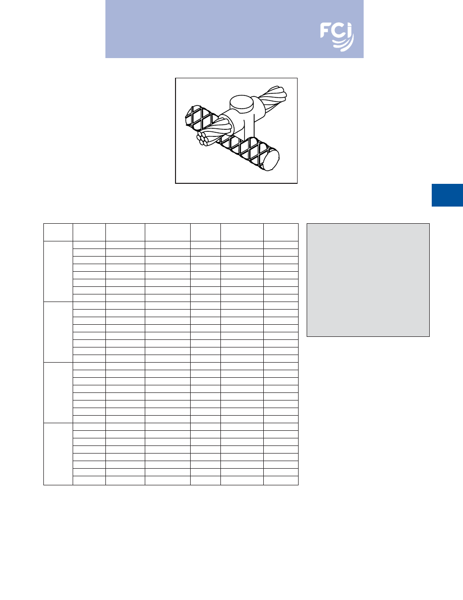
BURNDY
®
Products
Grounding
D-81
TYPE BCRE-4 MOLDS
Horizontal through Cable to
Horizontal Rebar
Type BCRE-4 Molds are recommended for
horizontal through conductors to horizontal
rebar at right angle connections for solid or
concentric stranded conductors #6 through
4/0 joined to reinforcing bars #3 through #6 &
larger. The high copper content joint has a
higher current carrying capacity than the con-
ductors being joined and is impervious to
vibration and moisture.
Contact BURNDY
®
Products for information
on molds for conductors not listed below.
Rebar
Cable
Mold
Packing
Price
Weld
Handle
Size
Size
Number
Material ‡
Key
Metal
Clamps
#6
B-7708
B38-4060-00
4
90
B-106
#4
B-7709
B38-4060-00
4
90
B-106
#2
B-7710
B38-4060-00
4
90
B-106
#1
B-7711
B38-4060-00
4
115
B-106
#3
1/0
B-7712
B38-4060-00
22
115
B-106
2/0
B-7713
B38-4060-00
22
115
B-106
3/0
B-7714
B38-4060-00
22
150
B-106
4/0
B-7715
B38-4060-00
22
150
B-106
#6
B-7716
B38-4060-00
4
90
B-106
#4
B-7717
B38-4060-00
4
90
B-106
#2
B-7718
B38-4060-00
4
90
B-106
#1
B-7719
B38-4060-00
22
115
B-106
#4
1/0
B-7720
B38-4060-00
22
115
B-106
2/0
B-7721
B38-4060-00
22
115
B-106
3/0
B-7722
B38-4060-00
22
150
B-106
4/0
B-7723
B38-4060-00
22
150
B-106
#6
B-7724
B38-4060-00
4
90
B-106
#4
B-7725
B38-4060-00
4
90
B-106
#2
B-7726
B38-4060-00
4
90
B-106
#1
B-7727
B38-4060-00
22
115
B-106
#5
1/0
B-7728
B38-4060-00
22
115
B-106
2/0
B-7729
B38-4060-00
22
115
B-106
3/0
B-7730
B38-4060-00
22
150
B-106
4/0
B-7731
B38-4060-00
22
150
B-106
#6
B-7732
B38-4061-00
14+
90
N/A
#4
B-7733
B38-4061-00
14+
90
N/A
#2
B-7734
B38-4061-00
14+
90
N/A
#6
#1
B-7735
B38-406100
14+
115
N/A
&
1/0
B-7736
B38-4062-00
14+
115
N/A
Larger
2/0
B-7737
B38-4062-00
14+
115
N/A
3/0
B-7738
B38-4062-00
14+
150
N/A
4/0
B-7739
B38-4062-00
14+
150
N/A
• For sizes not listed, contact BURNDY
®
Products.
• Molds listed are for concentric stranded cable. Add suffix
“-S” to mold number for solid conductors.
• For heavy duty molds, molds with wear plates or molds for Copperweld
®
cable, contact BURNDY
®
Products.
• For expedited service, contact BURNDY
®
Products.
Required Tools:
Handle Clamps (see chart for correct handles)
† Sold complete with frame
B38-0309-00
Flint Ignitor
Other recommended accessories:
B40-0319-03
Mold Cleaner for cartridge sizes #90-#500 (pg D-85)
B38-3922-00
Mold Cleaning Brush (pg D-85)
B38-0135-00
Cable Cleaning Brush (pg D-85)
B38-0304-00
File (pg D-86)
‡ PACKING MATERIAL NOTE
A packing pad is necessary when mak-
ing BURNDYWeld™ connections to
Rebar. Packing Material B38-4060-00 is
a special, patented copper-wool pack-
ing, with enough in each bag to do
between 40 and 50 connections.
Packing Material No.’s B38-4061-00,
B38-4062-00 and B38-4063-00 are a
ceramic fiber material and can be used
for
one
connection only. Be sure to spec-
ify Packing Material No. when ordering
Mold and Weld Metal.
For mold types or BURNDYWeld™ items
not shown, please contact factory
or refer to full BURNDYWeld™ catalog.
Burndy-Grounding-Connectors-catalog-html.html
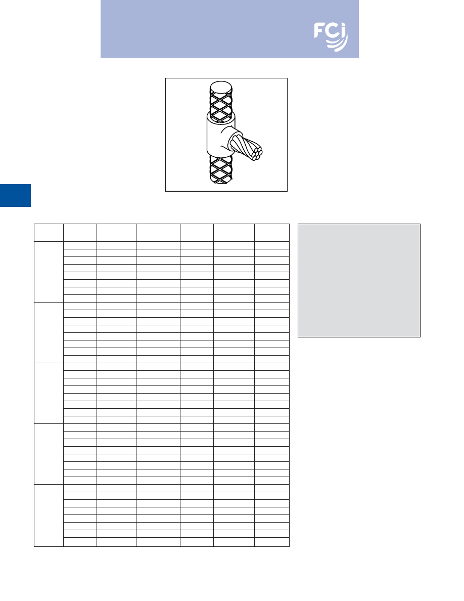
BURNDY
®
Products
Grounding
D-82
TYPE BCRE-6 MOLDS
Horizontal Cable Tap to
Vertical Rebar
Type BCRE-6 Molds are recommended for
horizontal conductors terminating at right
angles to vertical rebar connections for solid
or concentric stranded conductors #6 through
4/0 joined to reinforcing bars #3 through #7
and larger. The high copper content joint has
a higher current carrying capacity than the
conductors being joined and is impervious to
vibration and moisture.
Contact BURNDY
®
Products for information
on molds for conductors not listed below.
Rebar
Cable
Mold
Packing
Price
Weld
Handle
Size
Size
Number
Material ‡
Key
Metal
Clamps
#6
B-7884
B38-4060-00
4
90
B-106
#4
B-7885
B38-4060-00
4
90
B-106
#2
B-7886
B38-4060-00
4
90
B-106
#1
B-7887
B38-4060-00
4
115
B-106
#3
1/0
B-7888
B38-4060-00
4
115
B-106
2/0
B-7889
B38-4060-00
4
115
B-106
3/0
B-7890
B38-4060-00
4
150
B-106
4/0
B-7891
B38-4060-00
4
150
B-106
#6
B-7892
B38-4060-00
4
90
B-106
#4
B-7893
B38-4060-00
4
90
B-106
#2
B-7894
B38-4060-00
4
90
B-106
#1
B-7895
B38-4060-00
4
115
B-106
#4
1/0
B-7896
B38-4060-00
4
115
B-106
2/0
B-7897
B38-4060-00
4
115
B-106
3/0
B-7898
B38-4060-00
4
150
B-106
4/0
B-7899
B38-4060-00
4
150
B-106
#6
B-7900
B38-4060-00
4
90
B-106
#4
B-7901
B38-4060-00
4
90
B-106
#2
B-7902
B38-4060-00
4
90
B-106
#1
B-7903
B38-4060-00
4
115
B-106
#5
1/0
B-7904
B38-4060-00
4
115
B-106
2/0
B-7905
B38-4060-00
4
115
B-106
3/0
B-7906
B38-4060-00
4
150
B-106
4/0
B-7907
B38-4060-00
4
150
B-106
#6
B-7908
B38-4060-00
4
90
B-106
#4
B-7909
B38-4060-00
4
90
B-106
#2
B-7910
B38-4060-00
4
90
B-106
#1
B-7911
B38-4060-00
4
115
B-106
#6
1/0
B-7912
B38-4060-00
4
115
B-106
2/0
B-7913
B38-4060-00
4
115
B-106
3/0
B-7914
B38-4060-00
4
150
B-106
4/0
B-7915
B38-4060-00
4
150
B-106
#6
B-7916
B38-4063-00
4
90
B-106-32
#4
B-7917
B38-4063-00
4
90
B-106-32
#2
B-7918
B38-4063-00
4
90
B-106-32
#7
#1
B-7919
B38-4063-00
4
115
B-106-32
&
1/0
B-7920
B38-4063-00
4
115
B-106-32
Larger
2/0
B-7921
B38-4063-00
4
115
B-106-32
3/0
B-7922
B38-4063-00
4
150
B-106-32
4/0
B-7923
B38-4063-00
4
150
B-106-32
• For sizes not listed, contact BURNDY
®
Products.
• Molds listed are for concentric stranded cable. Add suffix
“-S” to mold number for solid conductors.
• For heavy duty molds, molds with wear plates or molds for
Copperweld
®
cable, contact BURNDY
®
Products.
• For expedited service, contact BURNDY
®
Products.
Required Tools:
Handle Clamps (see chart for correct handles)
B38-0309-00
Flint Ignitor
Other recommended accessories:
B38-3922-00
Mold Cleaning Brush (pg D-85)
B38-0135-00
Cable Cleaning Brush (pg D-85)
B38-0304-00
File (pg D-86)
‡ PACKING MATERIAL NOTE
A packing pad is necessary when mak-
ing BURNDYWeld™ connections to
Rebar. Packing Material B38-4060-00 is
a special, patented copper-wool pack-
ing, with enough in each bag to do
between 40 and 50 connections.
Packing Material No.’s B38-4061-00,
B38-4062-00 and B38-4063-00 are a
ceramic fiber material and can be used
for one connection only. Be sure to spec-
ify Packing Material No. when ordering
Mold and Weld Metal.
*The B106-32 comes complete with a B-106 handle clamp
and B40-0106-76 vertical chain clamp. Although good for use
on all sizes of rebar, vertical chain clamps are strongly recom-
mended on large size rebar as they hold the mold to the rebar
securely. If you already have a B-106 handle clamp, you can
purchase the vertical chain clamps separately. See page 76
for a variety of options.
For mold types or BURNDYWeld™ items not shown, please
contact factory or refer to full BURNDYWeld™ catalog.
Burndy-Grounding-Connectors-catalog-html.html
BURNDY
®
Products
Grounding
D-83
BURNDYWeld FILL*
BURNDYWeld™ FILL is an economical solu-
tion for areas with very difficult grounding
issues. BURNDYWeld™ FILL is highly con-
ductive in a wet or dry application and does
not require moisture to lower the resistance of
your grounding system. BURNDYWeld™
FILL contains a corrosion inhibitor which
forms a film on copper, creating a barrier
against corrosion.
BURNDYWeld™ FILL can be poured in dry or
pumped in slurry form. No tamping required.
It is very contractor friendly. No special tools
required.
*BURNDYWeld™ FILL is the catalog number.
BURNDYWeld™ FILL
Advantages:
• Easy to install.
• Electrically conductive.
• Environmentally friendly.
• Will not leach into the ground.
• Positive low resistance, electrical connec-
tion to earth.
• Does not contain any hazardous chemicals.
• Compatible with all copper grounding
systems.
• Contains a corrosion inhibitor to protect
copper.
• Will not expand or shrink.
• Not affected by freezing.
• Excellent shelf life.
• Typical resistivity <10 Ohm-cm
Material Required Per Linear Foot of Trench
Width of Trench (Inches)
4
6
8
10
12
14
16
18
20
22
24
2
4.1
6.2
8.1
10.1
12.1
14.1
16.2
18.2
20.2
22.2
24.2
3
6.2
9.3
12.1
15.2
18.2
21.2
24.2
27.3
30.3
33.3
36.4
4
8.2
12.3
16.2
20.2
24.2
28.3
32.3
36.4
40.4
44.5
48.5
5
10.3
15.4
20.2
25.3
30.3
35.4
40.4
45.5
50.5
55.6
60.6
6
12.3
18.5
24.2
30.3
36.4
42.4
48.5
54.6
60.6
66.7
72.7
7
14.4
21.6
28.3
35.4
42.4
49.5
56.6
63.7
70.7
77.8
84.9
8
16.4
24.7
32.3
40.4
48.5
56.0
64.7
72.7
80.8
88.9
97.0
9
18.5
27.8
36.4
45.5
54.6
63.7
72.7
81.8
90.9
100.0
109.1
10
20.6
30.8
40.4
50.5
60.6
70.7
80.8
90.9
101.0
111.1
121.2
Thickness of
BURNDYWeld™ FILL
(Inches)
To calculate the lbs. of material required to fill a trench:
• Determine desired thickness.
• Move to the right until you are under the known width of the trench. This number will be the
weight of the material in lbs./linear ft.
• Take this number and multiply by the length of the trench in feet.Your answer will be the amount
of BURNDYWeld™ FILL material required to fill the trench to the desired level in lbs.
Example:
Thickness:
=
6 inches
Width
=
18 inches
54.6 lbs. per linear ft. (from the table above)
Answer
=
54.6 lbs. per linear ft. x 25 ft. trench = 1,365 lbs. of BURNDYWeld™ FILL
=
28 (50 lb.) bags of BURNDYWeld™ FILL
For mold types or BURNDYWeld™ items not shown, please
contact factory or refer to full BURNDYWeld™ catalog.
Burndy-Grounding-Connectors-catalog-html.html
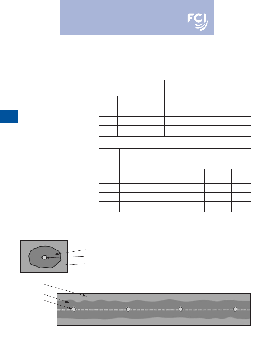
BURNDY
®
Products
Grounding
D-84
BURNDYWeld™ FILL*
Application Information
*BURNDYWeld™ FILL is the catalog number.
Vertical Installation
Drill or bore a hole the desired diameter and
depth. Suspend ground electrode in center of
hole to be filled. Pour BURNDYWeld™ FILL
until desired level is obtained. No tamping is
required.
Dry Volume of
Ground Resistance
BURNDYWeld™ FILL
Comparison of
vs. Hole Size
Bare Rod vs.
Lbs. of
Hole Size with
Percent Resistance
Hole
BURNDYWeld™ FILL
5/8
x 10
Rod in
Compared to Rod
Size
Per Ft.
Center of 15
Hole
Only (100%)
4
6.5
4
52%
6
14.5
6
47%
8
25.8
8
44%
10
40.4
10
42%
12
58.1
12
40%
Steady State Leakage Resistance‡ Using 4/0 Copper Wire vs. BURNDYWeld™ FILL
Percentage of Resistance with .475
Wire Plus BURNDYWeld™ FILL in
Various Diameters Compared
.475
Diameter
to Wire Only (100%)
Length
Wire Only
2
3
4
6
25
100%
83%
78%
74%
69%
50
100%
85%
81%
77%
73%
75
100%
86%
82%
79%
75%
100
100%
87%
83%
80%
77%
150
100%
88%
84%
82%
78%
200
100%
88%
85%
83%
79%
250
100%
89%
85%
83%
80%
300
100%
89%
86%
84%
80%
Horizontal or Grid
Construction†
Pour into horizontal trench until level of
ground wire is reached. Place ground wire.
Pour in additional BURNDYWeld™ FILL until
wire is covered to desired height. Cover with
fill. No tamping required.
For grid construction, pour BURNDYWeld™
FILL and spread over ground grid until
desired thickness is achieved. Cover with fill.
† Entire grounding system should be surrounded by
BURNDYWeld™ FILL. Conductors should be
insulated as they exit BURNDYWeld™ FILL
column.
‡ The use of BURNDYWeld™ FILL around the
grounding system will also reduce surge imped-
ance by increasing the effective contact area of
the electrode to soil.
Horizontal Construction
BURNDYWeld™ FILL
Copper Wire
Earth or Fill
Earth or Fill
BURNDYWeld™ FILL
Copper Wire
Grid Construction
For mold types or BURNDYWeld™ items not shown, please
contact factory or refer to full BURNDYWeld™ catalog.
Burndy-Grounding-Connectors-catalog-html.html
BURNDY
®
Products
Grounding
D-85
BURNDYWeld SET*
Certain applications require a permanent hard-
ening grounding material. BURNDYWeld™
SET is the product of choice. BURNDYWeld™
SET is compatible with all standard copper
grounding systems. It is an economical solu-
tion to difficult grounding issues in hard to
deal with areas. BURNDYWeld™ SET is
manufactured from environmentally safe
material and is extremely stable. When mixed
with water or exposed to moisture,
BURNDYWeld™ SET attains the hardening
characteristics of cement while retaining its
highly conductive properties. BURNDYWeld™
SET will remain highly conductive during a
drought or when exposed to extremely low
temperatures. Since BURNDYWeld™ SET
does not have any shrinkage or expansion
properties it will remain in constant contact
with the earth.
BURNDYWeld™ SET can be poured in dry or
pumped in slurry form. No tamping required.
It is very contractor friendly. No special tools
required.
*BURNDYWeld™ SET is the catalog number.
BURNDYWeld™ SET
Advantages:
• Easy to install.
• Will attain a hardened state.
• Electrically conductive.
• Environmentally friendly.
• Will not leach into the ground.
• Positively low resistance, electrical connec-
tion to the earth.
• Does not contain any hazardous chemicals.
• Compatible with all copper grounding sys-
tems.
• Will not expand or shrink.
• Not effected by freezing.
• Excellent shelf life.
• Typical resistivity <10 Ohm-cm
Material Required Per Linear Foot of Trench
Width of Trench (Inches)
4
6
8
10
12
14
16
18
20
22
24
2
3.6
5.4
7.2
9.0
10.8
12.6
14.4
16.2
18.0
19.7
21.5
3
5.4
8.1
10.8
13.5
16.2
18.8
21.5
24.2
26.9
29.6
32.3
4
7.2
10.8
14.4
18.0
21.5
25.1
28.7
32.3
35.9
39.5
43.1
5
9.0
13.5
18.0
22.4
26.9
31.4
35.9
40.4
44.9
49.4
53.9
6
10.8
16.3
21.5
26.9
32.3
37.7
43.1
48.5
53.9
59.2
64.6
7
12.6
19.0
25.1
31.4
37.7
44.0
50.3
56.5
62.8
69.1
75.4
8
14.4
21.7
28.7
35.9
43.1
50.3
57.4
64.6
71.8
79.0
86.2
9
16.3
24.4
32.3
40.4
48.5
56.5
64.6
72.7
80.8
88.9
96.9
10
18.1
27.1
35.9
44.9
53.9
62.8
71.8
80.8
89.8
98.7
107.7
Thickness of
BURNDYWeld™ SET
(Inches)
To calculate the lbs. of material required to fill a trench:
• Determine desired thickness of BURNDYWeld™ SET.
• Move to the right until you are under the known width of the trench. This number will be the
weight of the material in lbs./linear ft.
• Take this number and multiply by the length of the trench in feet.Your answer will be the amount
of BURNDYWeld™ SET material required to fill the trench to the desired level in lbs.
Example:
Thickness:
=
6 inches
Width
=
18 inches
48.5 lbs. per linear ft. (from the table above)
Answer
=
48.5 lbs. per linear ft. x 25 ft. trench = 1,212.5 lbs. of BURNDYWeld™ SET
=
24 (50 lb.) bags of BURNDYWeld™ SET
For mold types or BURNDYWeld™ items not shown, please
contact factory or refer to full BURNDYWeld™ catalog.
Burndy-Grounding-Connectors-catalog-html.html
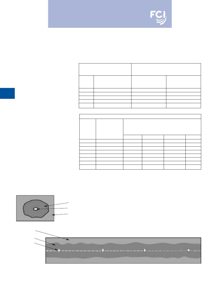
BURNDY
®
Products
Grounding
D-86
BURNDYWeld™ SET*
Application Information
*BURNDYWeld™ SET is the catalog number.
Vertical Installation
Drill or bore a hole to the desired diameter
and depth. Suspend ground electrode in cen-
ter of hole to be filled. Pour BURNDYWeld™
SET until desired level is obtained. Remove
excess water prior to pumping. If necessary,
BURNDYWeld™ SET may be premixed and
pumped under water.
Dry Volume of
Ground Resistance
BURNDYWeld™ SET
Comparison of
vs. Hole Size
Bare Rod vs.
Lbs. of
Hole Size with
Percent Resistance
Hole
BURNDYWeld™ SET
5/8
x 10
Rod in
Compared to Rod
Size
Per Ft.
Center of 15
Hole
Only (100%)
4
5.7
4
52%
6
12.8
6
47%
8
22.7
8
44%
10
35.5
10
42%
12
51.1
12
40%
Steady State Leakage Resistance‡ Using 4/0 Copper Wire vs. BURNDYWeld™ SET
Percentage of Resistance with .475
Wire Plus BURNDYWeld™ SET in
Various Diameters Compared
.475
Diameter
to Wire Only (100%)
Length
Wire Only
2
3
4
6
25
100%
83%
78%
74%
69%
50
100%
85%
81%
77%
73%
75
100%
86%
82%
79%
75%
100
100%
87%
83%
80%
77%
150
100%
88%
84%
82%
78%
200
100%
88%
85%
83%
79%
250
100%
89%
85%
83%
80%
300
100%
89%
86%
84%
80%
Horizontal or Grid
Construction†
Pour into horizontal trench until level of
ground wire is reached. Place ground wire.
Pour in additional BURNDYWeld™ SET until
wire is covered to desired height. Cover with
fill. No tamping required. Remove excess
water prior to installation.
For grid construction, pour BURNDYWeld™
SET and spread over ground grid until
desired thickness is achieved. Cover with fill.
Use ground staples to maintain ground wire
in center of BURNDYWeld™ SET.
† Entire grounding system should be surrounded by
BURNDYWeld™ SET. Conductors should be
insulated as they exit BURNDYWeld™ SET
column. BURNDYWeld™ SET should be used as
a ground enhancement material when a setting fill
is specified.
‡ The use of BURNDYWeld™ SET around the
grounding system will also reduce surge imped-
ance by increasing the effective contact area of
the electrode to soil.
Horizontal Construction
BURNDYWeld™ FILL
Copper Wire
Earth or Fill
Earth or Fill
BURNDYWeld™ FILL
Copper Wire
Grid Construction
For mold types or BURNDYWeld™ items not shown, please
contact factory or refer to full BURNDYWeld™ catalog.
Burndy-Grounding-Connectors-catalog-html.html
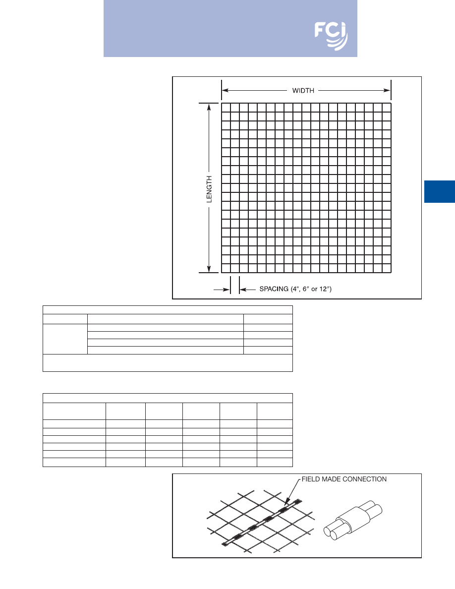
BURNDY
®
Products
Grounding
D-87
Prefabricated Wire Mesh
Part Number
Description
Weight/Sq Ft.
#10 Solid Copper Wire Mesh on 4
Centers
0.192
Contact
#6 Solid Copper Wire Mesh on 4
Centers
0.487
Factory
#6 Solid Copper Wire Mesh on 6
Centers
0.325
#6 Solid Copper Wire Mesh on 12
Centers
0.163
Copperclad Wire Mesh may be ordered
contact factory for part numbers
When ordering, specify wire type and size, width, length and
spacing.
Molds for Connecting Prefabricated Wire Mesh
Weld
Mold
Price
Handle
Weld
Wire Size
Type
Number
Key
Clamp
Metal
#6 Sol Copper
BCC-14
B-6205
18
included
#25
#6 Sol Copperweld
BCC-14
B-6207
18
included
#15
#8 Sol Copper
BCC-14
B-6209
18
included
#15
#8 Sol Copperweld
BCC-14
B-6210
18
included
#15
#10 Sol Copper
BCB-34
B-6211
18
included
#15
#10 Sol Copperweld
BCB-34
B-6212
18
included
#15
BURNDYWeld™
PREFABRICATED
WIRE MESH
Grounding, Personal Safety
Mats, Equipotential Planes,
Signal Reference Grid
Prefabricated wire mesh is:
• manufactured from bare solid copper or
copperclad conductors.
• spaced on 4
, 6
or 12
centers.
• factory silver brazed at each crossover
using 35% silver and a non-corrosive flux.
• furnished in sections with widths from 2 ft
to 18 ft (length limited by weight).
• shipped on tubes and protected for trans-
porting.
• interconnected in the field using
BURNDYWeld™ molds and powder.
Adjoining sections of mesh are to be
exothermically welded by installer using
BURNDYWeld™ molds and powder.
For mold types or
BURNDYWeld™ items not
shown, please contact
factory or refer to full
BURNDYWeld™ catalog.
Burndy-Grounding-Connectors-catalog-html.html

BURNDY
®
Products
Grounding
D-88
BURNDYWeld™
PREFABRICATED
WIRE MESH
The prefabricated wire mesh is a convenient,
efficient and economical means of improving
grounding systems at facilities where large
area grounds are required.
Wire Choices
Wire mesh is made from solid wire, either
copper clad steel or pure copper. Copper
clad steel wire has the strength of steel com-
bined with the higher conductivity and corro-
sion resistance of copper. The two metals are
permanently bonded and act as a single
material.
Silver Brazed Joints
The long wires and cross wires of wire mesh
are silver brazed at their crossing points. This
method provides joints with a breaking
strength strong enough to resist separation
during installation and strong enough to bear
the traffic of heavy vehicles.
Like the wire itself, the silver brazed joints are
highly resistant to corrosion. Moreover, elec-
trical continuity of a silver brazed joint is
excellent.
Installation
Wire mesh is easily and economically
installed. No expensive, special equipment is
necessary, and there are no time consuming
special handling procedures. The strong, pli-
able mesh is simply unrolled over the ground,
interconnected using BURNDYWeld™ con-
nections to attach adjacent sections of mesh,
and BURNDYWeld™ to the main ground grid
or ground rods. The mesh may be covered
with a layer of earth or crushed stone.
When used to control step and touch poten-
tials in an electrical substation, the mesh
does not replace the main ground grid.
However, the main grid can be installed to
control the station resistance without regard
to the step and touch potentials. A properly
designed system employing prefabricated
mesh which is periodically interconnected to
the main grid, will control the step and touch
potentials.
Interconnecting
The BURNDYWeld™ process provides a
rapid, economical, permanent, and highly
conductive method of interconnecting wire
mesh in the field.
The BURNDYWeld™ process is a controlled
reaction involving molten, superheated cop-
per. It is ideal for connecting mesh because
the reaction occurs quickly which fuses the
wires together into a solid mass. The resulting
weld is permanent and corrosion resistant.
The large weld area provides current carrying
capacity equal to the mesh conductors.
A semipermanent graphite mold is used in
making the BURNDYWeld™ connections.
The mold controls the direction and speed of
the molten metal and determines the shape
of the weld. The equipment is lightweight,
portable and easy to use. No outside source
of heat or power is needed, and only a mini-
mum of training is necessary. The mesh can
be interconnected by this process even under
adverse working conditions.
The adjacent mesh sections are best joined
by the exothermic parallel type BCC-14
connection.
For mold types or BURNDYWeld™ items not shown, please
contact factory or refer to full BURNDYWeld™ catalog.
Burndy-Grounding-Connectors-catalog-html.html
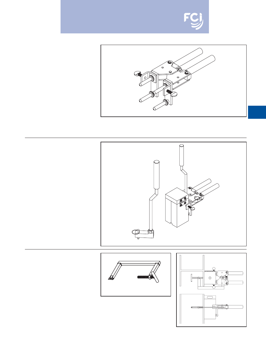
BURNDY
®
Products
Grounding
D-89
B-106 & B-107
HANDLE CLAMPS
BURNDYWeld™ Handle Clamps make possi-
ble the use of many different sizes and types
of molds with only two different clamps. The
two handle clamps are catalog numbers
B-106 and B-107. These will fit 95% of all
standard BURNDYWeld™ molds.
1. Use B-106 clamps for all molds having a
price key 4, 7, 17, 22 or 24. These molds
are a nominal 3 1/8
x 3 1/8
square.
2
Use B-107 clamps for all molds having a
price key 5, 6, 8 or 23. These molds are a
nominal 4
x 4
square.
3. All molds having a price key 2, 3, 9, 10,
11, 12, 14, 15 or 16 have an attached
frame; separate handles are not required.
B40-0106-75 HANDLE
ATTACHMENT
This Handle Attachment is used to hold Price
Key-14 molds in position. It easily attaches to
the B-106 Handle Clamp. This Handle
Attachment can be used with weld types
BCRE-1 and BCRE-4.
Catalog Number
B40-0106-75
MOLD SUPPORT
CLAMP
The Mold Support Clamp is used to hold a
mold in position on a vertical steel column or
angle. It is easily attached to the Handle
Clamps. The Mold Support Clamp can be
used with weld types BCS-3, BCS-18,
BCS-23 and BCS-27.
Catalog Number
B40-3657-00
B40-0106-75
B40-0106-75
Shown Attached
to
B-106
Handle Clamps
For mold types or BURNDYWeld™ items not shown, please
contact factory or refer to full BURNDYWeld™ catalog.
Burndy-Grounding-Connectors-catalog-html.html
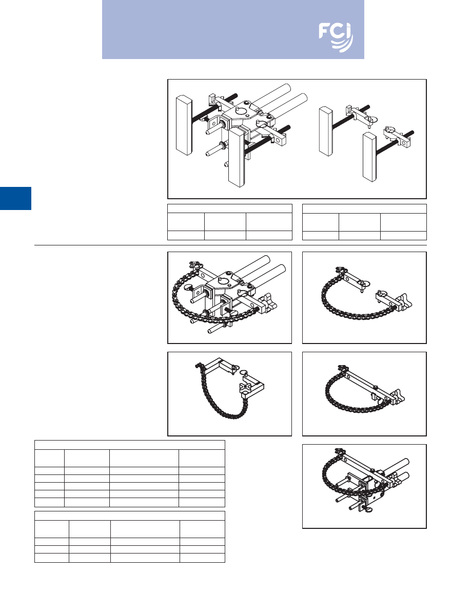
BURNDY
®
Products
Grounding
D-90
Chain Clamp Only (Handle Clamps Not Included)
Catalog
Fits Handle
For Use With
Number
Clamp
Weld Types
Pipe Position
B40-0106-76
B-106 & B-107
BCS-3, 4, 7, 23 & BCRE-6
Vertical
B40-0106-78
B-106 & B-107
BCS-1, 2, 5, 8 & 9
Horizontal
B40-0106-77
B-106 & B-107
BCS-6, 18 & BCRE-3
Vertical
VERTICAL MAGNETIC
CLAMPS
Magnetic Clamps are used to hold a mold in
position on a vertical steel surface. The mag-
netic clamp can be purchased complete with
B-106 Handle Clamps or if you already have
a set of handle clamps, you can order just the
magnetic mounting assembly. The mounting
assembly can easily be mounted on the
prongs of your existing B-106 handle clamps.
A minimum of 10
is required.
Magnetic Clamps With B106 Handle
Catalog
Fits Molds
For Use With
Number
W/Price Key
Weld Types
8404431-00
4 & 17
BCS-3, 4, 7 & 23
Chain Clamps
Catalog
Fits Molds
For Use With
Number
W/Price Key
Weld Types
Pipe Position
B106-32
4, 17, 22 & 24
BCS-3, 4, 7, 23 & BCRE-6
Vertical
B107-32
5, 6 & 23
BCS-3, 4, 7 & 23
Vertical
B106-37
4, 17, 22 & 24
BCS-1, 2, 5, 8 & 9
Horizontal
B107-37
5, 6 & 23
BCS-1, 2, 5, 8 & 9
Horizontal
B106-41
4, 17
BCS-6, 18 & BCRE-3
Vertical
HORIZONTAL &
VERTICAL
CHAIN CLAMPS
Chain Clamps are used to hold a mold in posi-
tion on horizontal or vertical pipe up to 4
in
diameter. For larger pipe a 20
chain extension
is available to allow the chain clamps to be
used on pipe up to 10
in diameter. The chain
clamp can be purchased complete with B-106
or B-107 Handle Clamps or if you already
have a set of handle clamps, you can order
just the chain clamp and mounting assembly.
The mounting assembly can easily attached to
your existing handle clamps. 20
Chain
Extension catalog number
B40-0106-27
.
B40-4431-00
B40-4431-01
Magnetic Clamp Only
Catalog
Fits Handle
For Use With
Number
Clamps
Weld Types
840-4431-01
B-106 & B-107
BCS-3, 4, 7 & 23
B106-32/B107-32
B40-0106-76
B40-0106-78
B40-0106-77
B106-41/B107-41
For mold types or BURNDYWeld™ items
not shown, please contact factory or
refer to full BURNDYWeld™ catalog.
Burndy-Grounding-Connectors-catalog-html.html
BURNDY
®
Products
Grounding
D-91
BURNDYWeld™ ACCESSORIES
CABLE CLEANING AND
CARD CLOTH BRUSH
The Cable Cleaning Brush is recommended
for cleaning heavily oxidized cables. The
V-shape brushes permit their use over a wide
range of cable sizes. Brush assembly con-
sists of a handle with two stiff wire bristle
brushes that are rotatable, for longer life and
are replaceable.
The Card Cloth Brush is used for cleaning
large conductors and bus bar. It has short stiff
bristles. These brushes are for cleaning cable
only, not molds.
The Mold Cleaning Brush B38-3922-00 is
used to clean the graphite mold without
scratching the mold.
MOLD CLEANERS
Mold Cleaners are used to clean the slag
from molds that are not split through the
crucible.
B40-0319-01
for cartridge sizes #15
through #65
B40-0319-03
for cartridge sizes #90
through #500
B38-0330-00 CABLE CLAMP
The BURNDYWeld™ Cable Clamp is recom-
mended for holding a wide range of cables
properly in place in molds when welding
cables that are under tension. This prevents
the cables from pulling out of the mold when
the weld is made.
B38-0135-00
B38-0306-00
B38-3922-00
PACKING MATERIAL
Packing material is used to prevent the
molten weld metal from leaking out of the
mold. When the cable opening becomes worn
from heavy use, the packing material may be
used to prolong mold use. It is also used
around 7 strand cable to prevent leaking.
Packing material comes in a 1 lb. or 5 lb.
package.
Catalog Number
Description
B38-4129-00
1 lb. package
B38-4129-05
5 lb. package
Cable Cleaning Brush
B38-0135-00
Replacement Brush
B38-0135-01
Card Cloth Brush
B38-0306-00
Mold Cleaning Brush
B38-3922-00
For mold types or BURNDYWeld™ items not shown, please
contact factory or refer to full BURNDYWeld™ catalog.
Burndy-Grounding-Connectors-catalog-html.html
BURNDY
®
Products
Grounding
D-92
BURNDYWeld™ ACCESSORIES
BURNDYWeld™ TOOL KIT
B38-0302-00
Tool Kit with Tools Shown
except Rasp
B38-0302-02
Tool Kit with Tools Shown
and Rasp
B38-0303-00
Tool Box only
B38-0309-00 FLINT IGNITOR
The B38-0309-00 Flint Ignitor is used to ignite
the starting powder. Each mold that is sold
with a frame has a Flint Ignitor included. For
added safety a Flint Ignitor extension is avail-
able, catalog number
B38-0904-00
, that
attaches to the B38-0309-00 Flint Ignitor. This
allows installers to stay approximately 36
away from the mold.
To order replacement flints, specify part
number
B38-0309-01
.
BURNDYWeld™ TOOLS
B38-0309-00
Flint Ignitor
B38-0304-00
8
File
B38-0307-00
Crimping Tool
B38-3922-00
Mold Cleaning Brush
B38-0308-00
6
Screwdriver
B38-0305-00
Wire Brush
B38-0101-00
Rasp
B38-0306-00
Card Cloth Brush
B38-0101-00 RASP
This tempered steel, curved rasp is recom-
mended for removing rust and mill scale from
steel and cast iron surfaces. The blade is
replaceable. To order replacement rasp blade,
specify catalog number
B38-0101-01
.
Not recommended for use on galvanized
surfaces.
For mold types or BURNDYWeld™ items not shown, please
contact factory or refer to full BURNDYWeld™ catalog.
Burndy-Grounding-Connectors-catalog-html.html
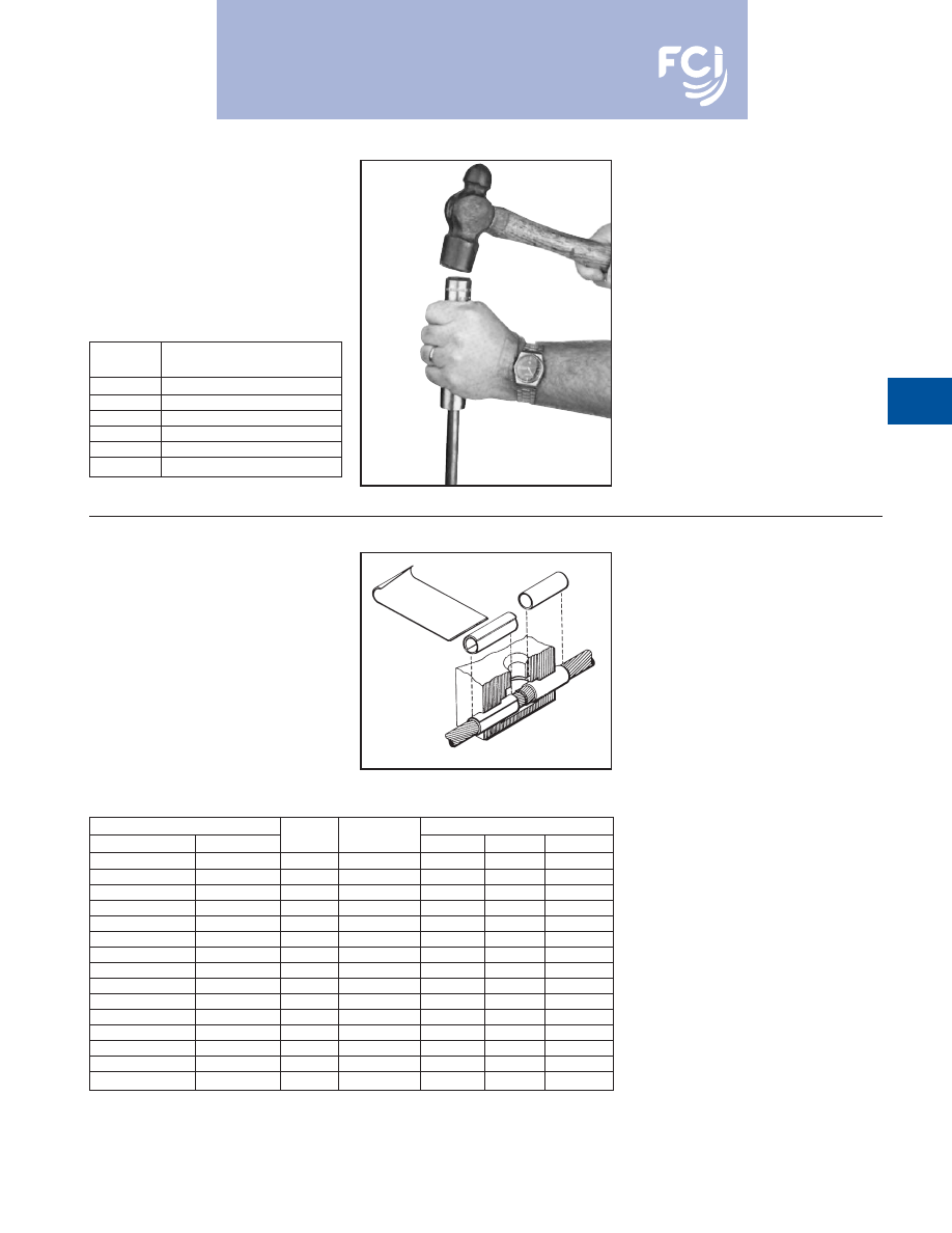
BURNDY
®
Products
Grounding
D-93
GROUND ROD
DRIVING SLEEVES
Ground Rod Driving Sleeves are placed over
the top of a ground rod while driving it into the
ground. This prevents the top from mush-
rooming or flaring out. Ground rod driving
sleeves are available in sizes to fit all stan-
dard unthreaded ground rods.
Catalog
Number
For Use On
B38-3662-01
1/2
Copper Clad or Steel Ground Rod
B38-3662-02
5/8
Copper Clad Ground Rod
B38-3662-05
5/8
Steel Ground Rod
B38-3662-03
3/4
Copper Clad Ground Rod
B38-3662-06
3/4
Steel Ground Rod
B38-3662-04
1
Copper Clad Ground Rod
For Use on Cable Size
Part
Use in
Sleeve Dimensions
Stranded
Solid
No.
Mold Size
O.D.
I.D.
Length
#12, #14
#10, #12, #14
BA-200
#6 STR & Sol
.156
.111
1.00
#9. #10
#8. #9. #10
BA-208
#4 Sol
.203
.140
1.00
#7, #8, #10
#6, #8
BA-201
#4
.227
.177
1.00
#6
#5
BA-202
#2
.292
.198
1.00
#4, #5
#3, #4
BA-207
#2
.302
.246
1.00
#4
#2
BA-204
#1
.340
.246
1.00
#2
#1
BA-203
1/0
.370
.307
1.00
#1
1/0
BA-209
2/0
.420
.359
1.00
1/0, #1
2/0
BA-205
3/0 & 4/0 Sol
.469
.385
1.00
2/0, 1/0
3/0
BA-240
4/0
.524
.437
1.50
4/0
—
BA-211
300 MCM
.625
.545
1.25
250 MCM
—
BA-212
350 MCM
.677
.595
1.25
350,400 MCM
—
BA-213
500 MCM
.811
.762
1.50
250, 300, 350 MCM
—
BA-214
500 MCM
.811
.700
1.50
750,800 MCM
—
BA-215
1000 MCM
1.156
1.05
1.50
SHIM STOCK AND
ADAPTER SLEEVES
BURNDYWeld™ molds designed for larger
cable sizes can be used on smaller diameter
cables if copper adapter sleeves or shim
stock are utilized. The copper shim stock,
.0108
x 1-1/2
x 3
, is normally wrapped
around cable until the diameter is about equal
to the cable opening. A tight fit is not neces-
sary as the shim stock will unwrap slightly
and prevent leakage of weld metal. To order
shim stock use part number
B38-0329-00
.
Shim stock comes 100 pieces per box.
For mold types or BURNDYWeld™ items not shown, please
contact factory or refer to full BURNDYWeld™ catalog.
Burndy-Grounding-Connectors-catalog-html.html

BURNDY
®
Products
Grounding
D-94
PROBLEM
PROBABLE CAUSE
CORRECTION TO MAKE
Insufficient metal to
Worn mold resulting in
Replace mold. If only worn around conductor opening,
make weld.
leaking weld metal.
use duct seal around conductor. Do not get duct seal
into mold cavity.
Wrong size cartridge for mold.
Check ID plate for mold and compare with number
on bottom of cartridge.
Too much spillage when
Carefully open lid while holding over crucible and dump.
dumping powder.
Wrong mold for conductor
Replace with correct mold. In some applications, shim
being used.
stock or adapter sleeves can be used to enlarge cable
to fit mold.
Mold does not close tightly
Handle clamps not properly adjusted.
Remove cotter pin between the handles of the mold and
causing weld metal to leak out.
adjust handle tension by backing out the eye bolt.
Dirt or slag stuck in parting
Clean mold thoroughly between connections.
line of mold.
Bent or out-of-round cable.
Straighten or cut out bad section of cable.
Handle clamps will not lock
Handle clamps not properly adjusted.
Remove cotter pin between the handles of the mold and
closed.
adjust handle tension by backing out the eye bolt.
Excessively high weld, bubbly or
Moisture in mold.
Pre-heat mold to above 220˚ F with a propane torch,
gassy appearance, poor weld.
or ignite a sacrificial shot in mold with pieces of
scrap conductor in it. If it is a horizontally split mold,
shoot 3/4 of the recommended cartridge to make sure
you do not lock up mold.
Oil, grease, moisture or foreign
Pre-heat conductors with propane torch then use a clean
material on conductors.
wire brush on conductor to remove any residue left on
conductors. If welding to cast iron or steel surface,
weld area must be cleaned down to bright metal.
Duct seal in weld cavity.
Take special precautions to keep duct seal out of weld cavity.
Weld powder has gotten wet.
Replace with fresh, dry weld powder.
Weld metal blows out top of mold.
Mold worn or chipped around disc
Replace mold.
seal allowing powder to leak into
mold cavity.
Forgot to use steel disc or did not
Make sure disc is seated at bottom of crucible
seat it properly at bottom of crucible.
before pouring the powder into crucible.
TROUBLE SHOOTING TIPS
Burndy-Grounding-Connectors-catalog-html.html
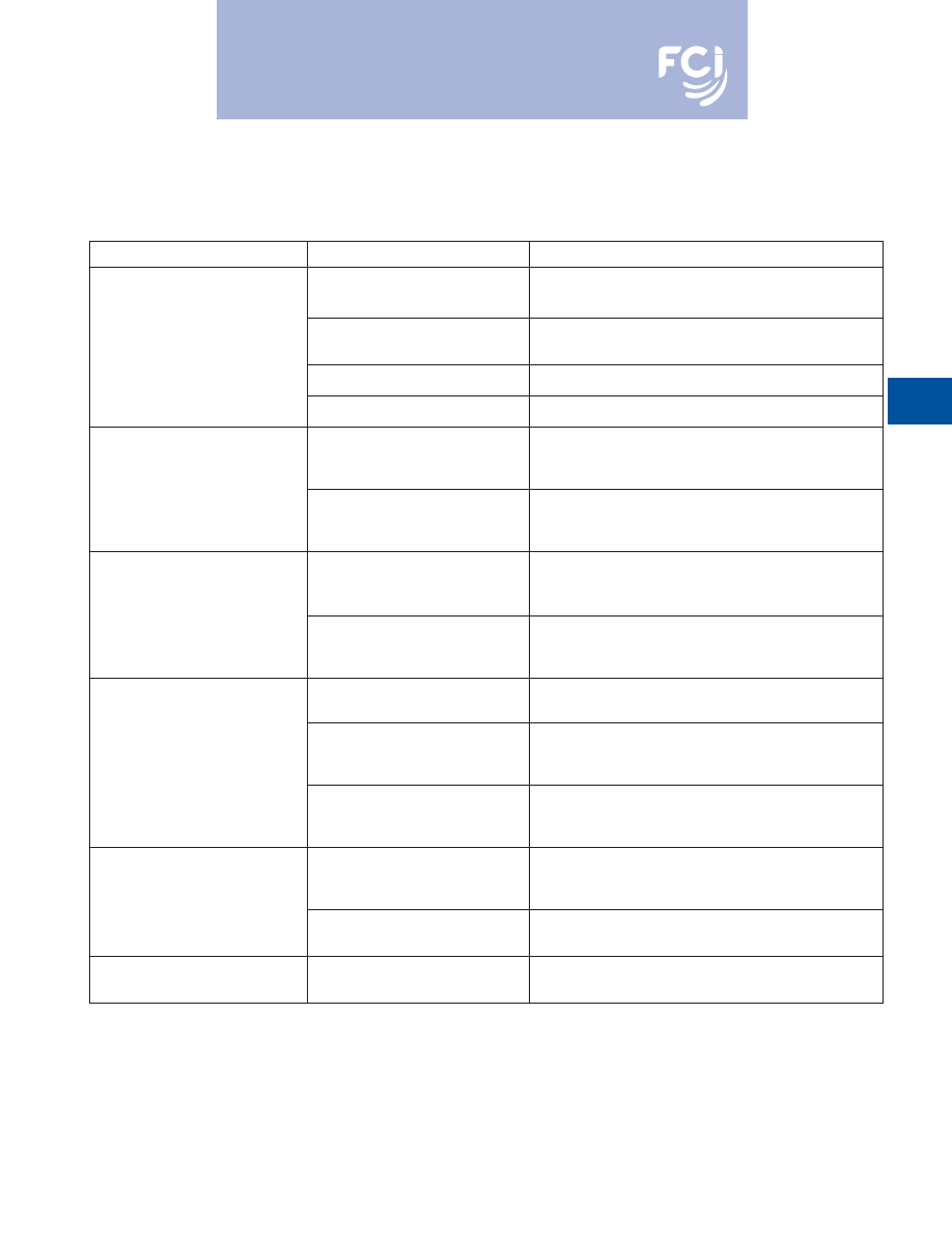
BURNDY
®
Products
Grounding
D-95
TROUBLE SHOOTING TIPS
(continued)
PROBLEM
PROBABLE CAUSE
CORRECTION TO MAKE
Cannot ignite powder.
Insufficient starting powder
Place at least half of starting powder in ignition pocket of
in ignition pocket on mold lid.
mold lid. Use all starting powder for each connection.
Flint ignitor not shooting
Clean flint ignitor according to directions on box or replace
enough spark.
flint ignitor.
Starting powder lumped together.
Break up starting powder on lid with edge of powder tube.
Starting powder has gotten wet.
Remove shot from mold and replace with a dry cartridge.
Mold wearing out too fast.
Improper cleaning of mold.
Use mold cleaner, soft natural bristle brush or clean rag
to clean mold between shots. Do not use wire brush or
screwdriver on molds.
Bent or out of round cable causes
Use caution when closing mold. Do not force mold shut
chipping and premature wear of
around bent, twisted or out of round conductors.
the mold.
Poor weld to ground rod.
Weight of mold not supported
Use locking pliers on ground rod under mold to support
during reaction causing mold to
the weight of the mold during the reaction.
slip when cable melts.
Moisture or contaminant on
Pre-heat conductors with propane torch then use a
cable or ground rod.
clean wire brush on conductors to remove any residue
left on conductors.
Weld will not stick to steel surface.
Improperly cleaned area on steel.
An area larger than the weld area should be cleaned down
to bright clean metal.
Moisture or contaminant on cable
Pre-heat conductors with propane torch then use a
or ground rod.
clean wire brush on conductors to remove any residue
left on conductors.
Cable is improperly positioned in
Position cable in mold in accordance with directions for
mold, blocking the flow of weld metal.
mold. If directions are not available, position top of cable
in the center of where the liquid weld metal hits the steel.
Weld will not stick to cast iron
All of the causes listed under
surface.
welding to steel surface also
apply to this section.
Not using CI (Cast Iron) powder.
Specify “CI” behind cartridge when ordering
powder (i.e. 25 CI).
Cable pulls out of mold when
Cables are either twisted or
Use B38-0330-00 cable clamp or other method to remove
it is fired.
under tension.
tension. Cut out severely twisted cable.
Burndy-Grounding-Connectors-catalog-html.html
01
234
523
78
92
!"#$
%&
'()
*'($
+,-
$
./00123
4
4
4
4
4
!"#$
516"7*)
67&
3
4
4
4
4
4
4
!"#$
./(021,,)
/*3
4
4
4
4
4
8
8
8 8
88 8
88 8
88 8
88 8
88 8
Burndy-Grounding-Connectors-catalog-html.html

0123
4
5
3
67
3
8
3
7
6
8
6
3
4
8
!""#$%
&'()*+,'
-)./
&'(0
12/+,'
34/+,0
45
&'60
12'
-)789-/0
:0
/;
&'<4.0
+,'
/)'
3470
=95
4/+'
89,0
71'
0
7./45
5
4/0
)7
&'>945
?
,4/+8'
@),'
9.+'
0
7'
A0
?
B+/45
5
0
-'
C==5
0
-4/0
)7.
D#EF
EF
%
&'<4.;'
/)'
0
7./45
5
&'>)+.'
7)/'
,+G90
,+'
.=+-0
45
'
0
7./45
5
4/0
)7'
/))5
0
71
&'H+9.4I5
+
&'C--)33)84/+.'
4'
*0
8+'
,471+'
)@'
-4I5
+
&'J7+'
*,+7-2'
0
7./45
5
4/0
)7
&'60
12'
3+-2470
-45
'
./,+71/2
!"$#
!%
&'K
,,+:+,.0
I5
+'
0
7./45
5
4/0
)7
&'60
12'
2)5
80
71'
./,+71/2
&'B++/.'
0
789./,;'
./4784,8.
&'60
12'
G945
0
/;'
-)77+-/0
)7.'
4/'
4'
5
)*'
0
7./45
5
+8'
-)./
&'L)77+-/),'
I4,,+5
.'
=,+?
M5
5
+8'
*0
/2'
N<O<PHJQ
R'
'
'
'
)S0
8+'
0
720
I0
/0
71'
-)3=)978'
/)'
30
70
30
T+'
145
:470
-'
'
'
'-),,).0
)7
' '
&'
N<O<PHJQ
R
'
-)7/40
7.'
2)3)1+7+)9.5
;'
'
'' '.9.=+78+8'
3+/45
5
0
-'
=4,/0
-5
+.'
/24/'
'' '=+7+/,4/+'
/2+'
*0
,+U
.'
)S0
8+.'
/)'
+./4I5
0
.2'
' '
'' '+S-+5
5
+7/'
-)7/0
790
/;'
I+/*++7'
/2+'
'' '0
780
:0
8945
'
./,478.'
478'
/2+'
-)77+-/),'
I4,,+5
'
'
'
'' '@),'
4'
5
)*'
,+.0
./47-+'
-)77+-/0
)7V
Burndy-Grounding-Connectors-catalog-html.html
Burndy-Grounding-Connectors-catalog-html.html
Burndy-Grounding-Connectors-catalog-html.html
Burndy-Grounding-Connectors-catalog-html.html

012
2
456
789
!
"#
$%$&%
'(
)$$*
%+,*
+-&
./(
)$$*
%+,*
0)1,
)(
$$
2
3
)(
$$
2
45
2
3
.
6789:;
8<=
>
?<@7AB
?CD7A@C;
:E>
CF>
GHI
J
KLMNOP
Q
>
8CR@<:S>
CT7AT;
7D
?OG>
H<E<=
CU>
CF>
V=
WR;
:WR>
HC::78ECAB
?CD7A@C;
:E>
CF>
V=
WR;
:WR>
X=
78EA;
8<=
>
HC::78E;
C:B
GVYZ
B
V[[;
E;
C:<=
>
HC:E<8E>
;
:FCAR<E;
C:
012
1\4\]\
2
456
^_`2
a
-&%$
b
'
c
d
e'!
f
2-1g0
hd
i
4
f
'(
)$$*
%+,*
+-&
f
!
j
i
k
'(
)$$*
%)*
,+)
./(
+-,*
&-*
)&$0
(
%$
2
3
&(
%$
2
45
2
3
.