Bulk Metal
®
Foil Technology High Precision, Current Sensing, Power
Surface Mount, Metal Strip Resistor with Improved Stability 0.05 %,
Resistance Value from 10 m
, Rated Power to 2 W and TCR to 0 ± 20 ppm/°C
CSM3637S
Vishay Foil Resistors
Document Number: 63168
For any questions, contact:
foil@vishaypg.com
www.vishayfoilresistors.com
Revision: 4-Sep-12
1
INTRODUCTION
The CSM3637S is a low value current sense resistor,
providing power and precision in a four terminal, surface
mount configuration. Its all welded construction is made up
of a Bulk Metal
®
resistive element with plated copper
terminations.
There are many current sense resistors on the market, until
now the combination of very stable and precise resistors
with low TCR as much as 0 ppm/°C ± 20 ppm/°C, tight
tolerance of ± 0.2 % and excellent load life stability of
± 0.05 % (2000 h, + 70 °C at rated power) were not easily
available.
The key performance of the new CSM3637S is stability,
which is the ability of this resistor to maintain its value with
time under nominal load at various environmental
conditions.
These specifications are based on tests performed in
accordance with methods prescribed by appropriate
MIL-PRF standards.
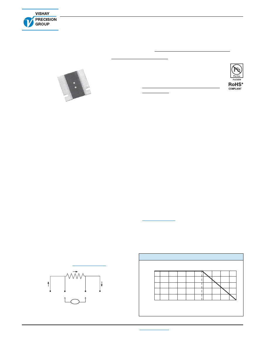
The four terminal device separates the current leads from
the voltage drop sensing leads. This configuration
eliminates the effect of the lead wire resistance from points
A to B and C to D.
A key feature of the CSM3637S is its low thermal EMF
design. The welded terminals make intimate contact with
the chip thereby minimizing temperature variations.
Vishay Foil Resistors’ application engineering department is
available to advise and make recommendations.
For non-standard technical requirements and special
applications, please contact:
foil@vishaypg.com
I
A
R
Z
in
I
D
V
=~
∞
B
C
FEATURES
Temperature coefficient of resistance (TCR):
(- 55 °C to + 125 °C, + 25 °C ref.)
± 20 ppm/°C maximum
Load life stability to ± 0.05 % (70 °C, 2000 h
at rated power)
Power rating: 2 W
Resistance tolerance: ± 0.2 %
Resistance range: 10 m
to 100 m
Vishay Foil resistors are not restricted to standard values;
specific “as required” values can be supplied at no extra
cost or delivery (e.g. 10.2345 m
vs. 10 m
)
Short time overload: 0.1 %
Proprietary processing technique produces extremely low
resistance values with improved stability
All welded construction
Solderable terminations
Very low inductance 0.5 nH to 5 nH
Excellent frequency response to 50 MHz
Low thermal EMF (< 3 µV/°C)
Maximum current: up to 14 A
Four terminal (Kelvin) design: allows for precise and
accurate measurements
Terminal finishes available: lead (Pb)-free or tin/lead alloy
Prototype quantities available in just 5 working days
or sooner. For more information, please contact
foil@vishaypg.com
Screening in accordance with EEE-INST002 available
(per MIL-PRF-55342 and MIL-PRF-49465; see 303144
and 303145 datasheets)
For better performances please contact Application
Engineering
FIGURE 1 - POWER DERATING CURVE
- 65 - 50
- 25
0
25
50
75
100
125
150
170
Ambient Temperature (°C)
100
80
60
40
20
0
Rated Power (%)
+ 70 °C
* Pb containing terminations are RoHS compliant, exemptions may apply