background image

DEFENSE AEROSPACE OPRERATIONS

ACT

Mil-C-38999 Series III Composite

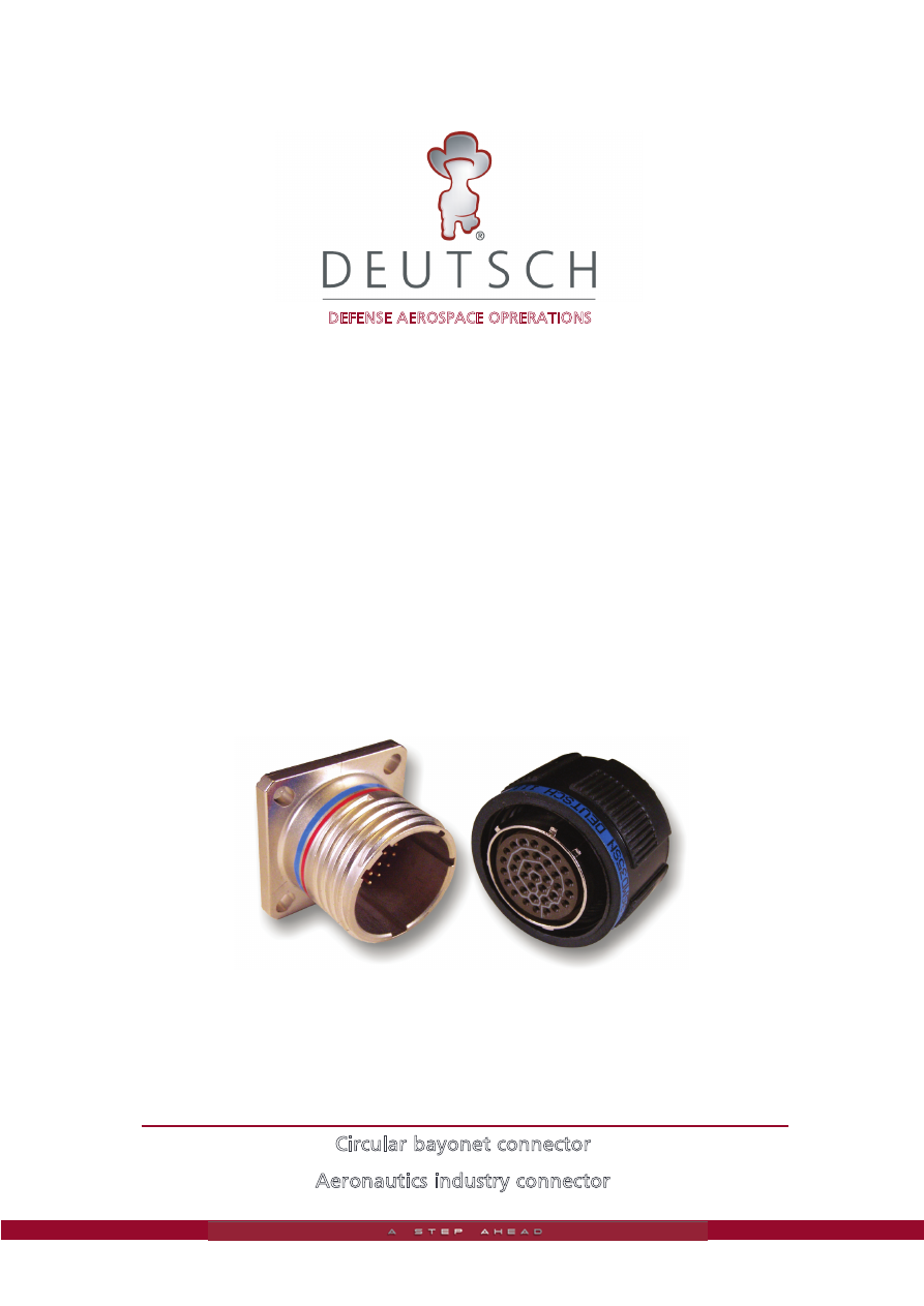
Circular bayonet connector

Aeronautics industry connector

Connecteur-EN3645-html.html
background image

Introduction

1

Advantages

2

Technical Specifications

3

ACT Summary

4

Dimensions

5-6

Insert Arrangements

7

Key Orientation

8

Contacts

9

ACT

Contents

Part Numbering System

10

Connecteur-EN3645-html.html
background image

1

ACT

Introduction

4

1

5

2

3

6

7

1

-

Deutsch proven dielectric retention system provides superior
contact retention under severe vibration.

2

-

The

ACT

 series provides 100

% thread

 to

thread

 bottoming for

maximum EMI grounding protection.

3

-

Grounding fingers provide excellent EMI protection.

4

-

Non-reflective olive drab cadmium or nickel shell plating
provides

2000

 hours salt spray corrosion protection.

5

-

Threaded coupling with self locking

feature.

6

-

Elongated mounting holes permit the

ACT

 connector to

intermount with existing standard MIL

-C -

38999 box or wall

mount receptacles, giving it a design replacement advantage.

7

-

Deutsch uses superior silicone seals providing maximum tear
resistance and sealing memory.

Connecteur-EN3645-html.html
background image

2

ACT

Deutsch's MIL-C-38999 Series III  ACT with triple start,
self locking, threaded coupling and crimp-type terminations.

Advantages

Threaded coupling with self locking.

• 

100 % scoop-proof shells.

Corrosion : 2000 + hours salt spray protection for class W and class M.

R.F.I. fingers.

Plugs  and  receptacles  are  equiped  with  termoplastic  and  elastomer
insert.

Thermoplastic clips molded directly with insert.

Removable crimping contacts (MIL-C 39029).

Sealing receptacle with contacts for printed circuit.

Connector in accordance with specifications MIL-C 38999 series III.

Connector QPL (to order as per QPL).

The  Deutsch  ACT  is  a  high  performance 

composite  connector  qualifid  to  MIL-C-

38999.  What  Deutsch  Defense  /  Aerospace 

does better than anyone else is make wire 

termination devices for demanding applica-

tions.  Deutsch  utilized  its  unprecedented 

achievements in the area of Defense / Aero-

space composite technology, enabling us to 

design  and  produce  the  latest  version  of 

MIL-C-38999  connectors.  The  superior 

design  of  the  ACT  deliberately  took  into 

consideration  the  connector,  its  contacts 

and the respective strain reliefs to favorably 

influence  intra-system  life-cycle  perfor-

mance and costs.

The total performance of the ACT connector 

is matched by individual components within 

the system. For example, the use of compos-

ite  materials  has  increased  the  durabilty  of 

the connector housing and coupling mecha-

nism  to  1500  cycles.  Deutsch  developed  an 

extended  life  MIL-C-38999  contact  to  meet 

the  increasd  performance  requirements  of 

today's systems. The ACT eliminates the larg-

est contributing factor in advanced systems 

malfunction...  corrosion,  which  is  the  main 

cause of mechanical, electrical and EMI deg-

radation. Galvanic action is eliminated resut-

ing  in  a  system  that  withstands  over  2000 

hours of salt spray.

Connecteur-EN3645-html.html
background image

3

ACT

Technical Specifications

Mechanical

Electrical

Dielectric withstanding voltage                   at sea level 

: Service M: 1300 VAC (rms)

at 50,000 ft. 

:  Service I: 1800 VAC (rms)
: 3Service II: 2300 VAC (rms)

:  Mated Connector 


Unmated Connector

Insulation resistance

: 5000 megaohms min. at + 25

º

C (+ 77

º

F) @ 65% Rel.H max.

Contacts maximum current

: Service M: 800 VAC (rms)                     Service M: 350VAC (rms)

Service I: 1000 VAC (rms)  

              Service I:  400VAC (rms) 

Service II: 1000VAC (rms)                     Service II: 500VAC (rms)

Contact millivolt drop

: Size 22 : 73 millivolts at 5.0 amps

Size 20 : 55 millivolts at 7.5 amps
Size 16 : 49 millivolts at 12.0 amps
Size 12 : 42 millivolts at 23.0 amps

EMI Shielding

: Per MIL-DTL-38999

Shell

Material   


       : Composite

Plating                           


       : W - Olive Drab cadmium

M -  Nickel coating

Silicone Insert 

Material

: Thermoplastic and fluorinated silicone elastomer

Contact

Material

: Copper alloy

Service Temperature

: Cadmium plating 

Corrosion

: (Class W) 2000 hours salt spary per MIL-DTL-38999

Vibration

: Per MIL-DTL-38999

Thermal Shock

: Per MIL-DTL-38999

Shock

:  300 Gs, 3ms in 3 axes

Flat gasket and o

ring

: Flouronited silicone elastomer

Plating                           


       : Gold

Type

: Crimp type or printed ciruit pin (contact Deutsch)

- 65

º

C to + 175

º

C (- 85

º

F to + 347

º

F)

: Nickel plating 

- 65

º

C to + 200

º

C (- 85

º

F to + 392

º

F)

: (Class M) 2000 hours salt spary per MIL-DTL-38999

Durability

: 1500 coupling/uncoupling cycles

at 70,000 ft.

Size 8 :  26 millivolts at 46.0 amps

Connecteur-EN3645-html.html
background image

4

ACT

ACT Summary

SEALED RECEPTICLES

4 hole square wall

mounting

TYPE 

96

PLUG

Single hole mounting

TYPE 

TYPE 90

Connecteur-EN3645-html.html
background image

5

ACT

Dimensions

C1
C2

P

PP

1.240 max.

D

E

Ø R Ø S

G

E

B

G

0.200


0.540


±

 .004

0.528 max.

F

F

0.528 max.

1.260 max.

With PCB contacts

G

G

F

F

E

E

Ø R Ø S

1.30 max.

1.30 max.

.528 max.

.528 max.

.904 max.

.904 max.

B

M

Ø A

.200 

.4824 

±

 0.024

Size

B

C1

C2

D

E

F

G

P

PP

Wt.

.

.

± 0.010

min.      max.

± 0.004   ± 0.004    ± 0.004     ± 0.008        

max.

A    

   .937   

.719     .594     .768 

.144   

.630     .476 

.128 

.216 

.280

B

1.031   

.812     .719     .768 

.144   

.756     .596 

.128 

.194    

.385

C

1.126   

.906     .812     .768 

.144   

.884     .716 

.128 

.194    

.490

D

1.220         .969     .906     .768 

.144 

1.010     .876 

.128 

.173    

.630

E

1.311 

1.062    .969      .768 

.144 

1.198     .996 

.128 

.194   

.805

F

1.437 

1.156  1.062      .768 

.144 

1.262  1.116 

.128 

.194   

.910

G

1.563 

1.250  1.156      .736 

.171 

1.388  1.236 

.128 

.194 

1.850

H

1.689 

1.375  1.250      .736 

.171 

1.516  1.356 

.154 

.242 

1.260

J

1.811 

1.500  1.375      .736 

.171 

1.644  1.476 

.154 

.242 

1.505

Size

A

B

E

F

G

M

Mass

+ 0.028

..

± 0.011    ± 0.016

- 0.004 ± 0.004   ± 0.004                            max.

A

1.189 

1.080 

.120    .630   

.476    .873    .385

B

1.374 

1.272 

.120    .756   

.596  1.000    .490

C

1.500 

1.396 

.120    .884   

.716  1.191    .630

E

1.752 

1.652 

.120  1.198   

.996  1.445  1.015

F

1.937 

1.840 

.148  1.262 

1.116  1.570  1.225

G

2.063 

1.968 

.148  1.388 

1.236  1.699  1.330

H

2.189 

2.096 

.148  1.516 

1.356  1.824  1.610

J

2.311 

2.224 

.148  1.644 

1.476  1.970  1.925

Contact

R

S

Size 

+ 0

..

- 0.002

± 0.002

22

0.420

20

0.060         0.028

.

16

0.104         0.046

Contact

R

S

Size 

+ 0

..

- 0.002

± 0.002

22

.420

20

.060 

.028

16

.104 

.046

With PCB contacts

0.002

0.002

oz. 

Square Flange Recepticle

Jam Nut Recepticle

oz. 

D

1.626 

1.524 

.120     1.010   

.876  1.316    .805

Connecteur-EN3645-html.html
background image

6

ACT

Dimensions

Plug

Mounting Cutouts

.063 to .128 max.

.128 max.

Type  90

Type  94

Front panel 

mounting

Panel cutouts

V

R1

R1

V1

E

Ø F

Ø A

Size

.

.

Back  Front

.

x

.

A

  .719   

.594   

.656    

.516 

.128  

.984 

1.112         .670         .700        30/36

B

  .812   

.719   

.795    

.625 

.128       1.080 

1.304         .771         .825        40/45

C

  .906   

.812   

.922    

.750 

.128       1.208 

1.440         .955       1.010        55/60

D

  .989   

.989 

1.047   

.908 

.128       1.332 

1.584       1.085       1.135       70/75

E

1.082   

.989 

1.219 

1.016 

.128       1.460 

1.732        1.210       1.260       80/85

F

1.156 

1.082 

1.297 

1.141 

.128       1.572 

1.880        1.335       1.385      90/95

G

1.250 

1.156 

1.442 

1.286 

.128       1.700 

2.024        1.460       1.510    100/110

H

1.375 

1.250 

1.547 

1.375 

.154       1.828 

2.168        1.585       1.635    110/120

J

1.500 

1.375 

1.672 

1.485 

.150       1.952 

2.388        1.710       1.760    120/130

G

S


Ø

F

1.22 max.

Size

F

G

S

Wt.

max. max. max.

max.

A

  .736    

.476     .858          .315

B    

  .844    

.596     .984   

.455

C

1.016   

.716  1.157   

.635

D

1.148   

.876  1.280   

.805

E

1.288   

.996  1.406   

.875

F

1.396 

1.116  1.516 

1.120

G

1.524 

1.236  1.642 

1.225

H

1.644 

1.356  1.768 

1.435

J

1.772 

1.476  1.890 

1.680

Ø AA

R2

R2

Back panel 

mounting

4 x T

Inch

lbs

Torque

±  .13

A            AA

R1            R2

max        max

min        min

T

Dia

V            V1

min        min

E            F

+ .00

- .25

+ .25

- .00

Connecteur-EN3645-html.html
background image

7

ACT

Insert Arrangements

Note: For additional insert arrangements consult factory.

This information is for reference only. Consult factory for envelope

drawings, updated specifications and additions to the product line.

               A-35

6 contacts size 22

             A-98 

3 contacts size 20

B         A 

              B-02

2 contacts size 16

                B-35

13 contacts size 22

                B-98

6 contacts size 20

                 C-04

4 contacts size 16

               C-08

8 contacts size 20

                C-35

22 contacts size 22

                C-98

10 contacts size 20

                D-05

5 contacts size 16

               D-15

14 contacts size 20

1 contacts size 16

                D-19

19 contacts size 20

               D-35

37 contacts size 22

                E-02

38 contacts size 22

1 contacts size 8

               E-26

26 contacts size 20

             E-35

55 contacts size 22

                F-11

11 contacts size 16

               F-32

32 contacts size 20

                G-11

11 contacts size 12

               G-39

2 contacts size 16

37 contacts size 20

               G-41

41 contacts size 20

                G-75

4 contacts size 8

               H-53

53 contacts size 20

                J-04

48 contacts size 20

8 contacts size 16

               J-7

97 contacts size 22

2 contacts size 8

                D-18

18 contacts size 20

30

11

6

1

17

                E-06

6 contacts size 12

1

7

16

22

29

64

72

79

85

94

99

93

84

78

28

21

15

6

26

76

53

46

19

82

33

68

42

41 59

81

18

74

24

67

32

60

              J-8

8 contacts size 8

H

H

              J-19

19 contacts size 12

                J-61 

61 contacts size 20

h

 _

w

 _ 

z

 _ 

e_

f_

d_

g_

y_

r_

x_

k_

n_

s_

t_

u_

m

__

v_

c_

a_

b_

q

 _

q

 _

              J-90 

40 contacts size 20

4 contacts tsize 16

2 contacts tsize 8

h

 _

w

 _ 

i_

u_

f_

d_

j_

y_

r_

x_

k_

n_

o_

m

__

v_

c_

q

 _

q

 _

              J-43

23 contacts size 20
20 contacts size 16

                J-35

128 contacts size 22

               J-29

29 contacts size 16

               J-24

12 contacts size 16
12 contacts size 12

                 J-20

10 contacts tsize 20
13 contacts tsize 16

4 contacts tsize 12

3 contacts size 8

                H-21

21 contacts size 16

              H-35

100 contacts size 22

                H-55

55 contacts size 20

               G-16

16 contacts size 16

                F-35

66 contacts size 22

               E-99

21 contacts size 20

2 contacts size 16

               G-35

79 contacts size 22

                D-97

8 contacts size 20
4 contacts size 16

               E-08 

8 contacts size 16

                B-99

7 contacts size 20

               B-05

5 contacts size 20

Connecteur-EN3645-html.html
background image

8

ACT

Key Orientation

Size

Orientation

Polarization in degrees

A

B

C

D

N

105

140

215

265

A

102

132

248

320

B

80

118

230

312

9

C

35

140

205

275

D

64

155

234

304

E

91

131

197

240

N

95

141

208

236

A

113

156

182

292

B

90

145

195

252

11 thru 15

C

53

156

220

255

D

119

146

176

298

E

51

141

184

242

N

80

142

196

293

A

135

170

200

310

B

49

169

200

244

17 thru 25

C

66

140

200

257

D

62

145

180

280

E

79

153

197

272

Connecteur-EN3645-html.html
background image

ACT

Contacts

9

DATABUS CONTACTS SIZE 8 (TWISTED PAIR) AS PER MIL-C 38999 SERIES I, III AND IV STANDARD

CONTACTS

CABLES

SLEEVE

TOOLS

Crimping tool

Part-number Type Size               Color

Type                  Conductor                Braid

Types

Conductor                Ferrule

Extraction

code

max. section

Ø max.

182-0034-03

P

Thermosetting

TDB-CT-HEX

114-008 or

182-0035-03

S

8

Brown-red

braid simple

0,86 mm

2

3,48

and silicone

TDB-CT-08

Mark C

M 81969/14-06

182-0034-04

P

Hight immunity

Thermosetting

TDB-CT-HEX

114-008 or

182-0035-04

S

8

Red-red

double braid

0,86 mm

2

3,91

and silicone

TDB-CT-08

Mark D

M 81969/14-06

Nota   :

Standard contacts delivered with connector.

Size 8 and Bus contacts are delivered with protect sleeve.

DEUTSCH EXTENDED LIFE FINISH

Part number

Military                      Type           Size

Color code

part number

1

2

3

12331-22

MIL-C 39029/107-620

p

Blue

Red

Black

182-0447-12

MIL-C 39029/106-614

S

22

Blue

Brown

Yellow

182-0441-20

MIL-C 39029/107-621

P

Blue

Red

Bown

182-0447-20

MIL-C 39029/106-614

S

20

Blue

Brown

Green

12331-16

MIL-C 39029/107-622

P

Blue

Red

Red

12333-16

MIL-C 39029/106-616

S

16

Blue

Brown

Blue

12331-12

MIL-C 39029/107-623

P

Blue

Red

Orange

12333-12

MIL-C 39029/106-617

S

12

Blue

Brown

Violet

Color code

1 2 3

Color code

1

2

3

CONTACTS

CABLES

SEALING PLUG

Commercial   Type Size

Color code

Observations


Section

AWG

Ø over 

P/N

Color

Part-number

1

2

mm

2

wire

sheath

L

724-0001-22

P

Orange

Blue

Black

Standard

724-0007-22

S

22

Orange

Yellow

Grey

contact

   0.10 to 0.38

22 - 28

0.76 to 1.37              5,00 to 5,80 028-0102-22

Yellow

724-0001-20

P

Orange

Blue

Orange

Standard

724-0007-20

S

20

Orange

Green

Brown

contact

   0.21 to 0.60

20 - 24

1.02 to 2.11              5,80 to 6,60 006-0893-20

Red

724-0001-16

P

Orange

Blue

Yellow

Standard

724-0007-16

S

16

Orange

Green

Red

contact

   0.60 to 1.34

16 - 20

1,65 to 2.77              5,80 to 6,60 006-0893-16

Blue

724-0001-12

P

Orange

Blue

Green

Standard

724-0007-12

S

12

Orange

Green

Orange

contact

   1.93 to 3.18

12 - 14

2.46 to 3.61               5,80 to 6,60 006-0892-12

Yellow

182-0003-08              S

8

-

-

-

contact

   5.30 to 8.98

8

4.50 to 5.80              9,20 to 9,80 182-0061-08

-

182-0068-20              P

Yellow

Purple

Green

Alumel

182-0009-20              S

20

Yellow

Grey

Purple

contact

   0.21 to 0.60

20 - 24

1.02 to 2.11                5,80 to 6,60 006-0893-20

Red

182-0069-20              P

Yellow

Purple

Blue

Chromel

182-0010-20              S

20

Yellow

Grey

Grey

contact

   0.21 to 0.60 20 - 24

1.02 to 2.11                 5,80 to 6,60 006-0893-20

Red

182-0068-22              P

Yellow

Purple

Brown

Alumel

182-0009-22              S           22          Yellow

White

Green

contact

   0.10 to 0.38

22 - 28

0.76 to 1.37                 5,00 to 5,80 028-0102-22

Yellow

182-0069-22              P                          Yellow

Purple

Red

Chromel

182-0010-22              S           22           Yellow

White

Blue

contact

   0.10 to 0.38

22 - 28

0.76 to 1.37                 5,00 to 5,80 028-0102-22

Yellow

color code

For contact P as per MIL-DTL 38999

L

Sealing plug

Male contact

Female contact

Wires strip length

Connector rear face

Standard gold 500 cycles contact (3025)

1500 cycle contact

182-0003-08              P                                                                                                   Power

Connecteur-EN3645-html.html
background image

ACT

Part Numbering System

ACT          XX       X        X        XX       X        X     -     XXXX

D38999/

XX

X        X

XX

X

X

DEUTSCH ACT CONNECTOR PART NUMBERS

DEUTSCH MILITARY COMPOSITE NUMBERS

BASIC IDENTIFIER ACT 

A

DVANCED 

C

OMPOSITE

T

ECHNOLOGY

SHELL STYLE

90: Square flange 

94: Jam Nut Mounting

96: Straight Plug 

98: Lanyard Plug

SHELL STYLE

20: Square flange 

24: Jam Nut Mounting

26: Straight Plug

31: Lanyard Plug

CLASS & FINISH

W : Olive Drab

Cadmium

M : Nickel Coated

CLASS & FINISH

SHELL SIZES

A(9), B(11), C(13), D(15), E(17)

F(19), G(21), H(23), J(25)

SHELL SIZE (9 thru 25)

INSERT

ARRANGEMENTS

(See page 7)

INSERT

ARRANGEMENTS

(See page 7)

CONTACT TYPE

P : Extended Life Pin Std.

Extended Life Socket Std.

CONTACT TYPE

SHELL KEYING

(See page 8)

SHELL KEYING
N, A, B, C, D, E

BASIC MILITARY IDENTIFIER

10

MODIFICATIONS

3025 = Standard Gold Cycle Contact

91: Inline Recepticle **

** Consult factory regarding availability

S :

J : Olive Drab

Cadmium

M : Nickel Coated

A(9), B(11), C(13), D(15), E(17)

F(19), G(21), H(23), J(25)

P : Std. Pin 500 cycle

Std. Socket 500 cycle

Pin, Extended Life

1500 cycle contact

Socket, Extended Life

1500 cycle contact

S :

H :

J :

Connecteur-EN3645-html.html
background image