
ECM SERVICE GUIDE
A Regal Brand
©2014 Regal-Beloit Corporation
REG9971_ECM_Service_Guide_4-10-14.indd 1
4/10/14 10:48 AM
ECM SERVICE GUIDE
A Regal Brand
©2014 Regal-Beloit Corporation
REG9971_ECM_Service_Guide_4-10-14.indd 1
4/10/14 10:48 AM

WA R N I N G
Working on the motor with power connected may
result in electrical shock or other conditions that may
cause personal injury, death or property damage.
On models 2.0/ 2.3/ 2.5/ Eon/ X13/ 3.0 always
disconnect the power from the HVAC system and
wait at least 5 minutes before opening the motor, i.e.
removing the two bolts from the motor control (end
bell) and disconnecting the 3-pin plug to the motor.
This is to allow the capacitors to dissipate for safety.
WA R N I N G
Always disconnect the power from the HVAC system before
removing or replacing connectors, servicing the motor,
removing the high voltage plug, and before reconnecting.
WA R N I N G
Disconnect AC power from the system and make
sure the blower wheel or fan blade has come to a
complete stop before servicing the motor.
WA R N I N G
Do not operate motor without blower wheel or fan
blade attached. Such operation will cause the motor
to oscillate up and down.
WA R N I N G
You must have the correct replacement module
and/or motor from the manufacturer that is a direct
replacement for the failed module and/or motor.
USING THE WRONG MODULE AND/OR MOTOR
VOIDS ALL PRODUCT WARRANTIES AND MAY
PRODUCE UNEXPECTED RESULTS.
WA R N I N G
WA R N I N G
Genteq does not condone the repair of any individual
components in the motor control or motor of their
ECM products. This practice is unsafe and may cause
personal injury, death, or property damage.
REG9971_ECM_Service_Guide_4-10-14.indd 2
4/10/14 10:48 AM
TABLE OF CONTENTS
Using the ECM Service Guide
Motor Diagnostics & Replacement
ECM SERVICE GUIDE
About the Company
Start Here:
Using the ECM Service Guide
HVAC System Troubleshooting Basics
Tech Tips
Motor Identification Chart
1
3
4
6
7
10
26
37
50
53
Variable Speed Motors
Premium ECM Motor Diagnostics
X13 Motor
Standard ECM Motor Diagnostics
Evergreen Replacement Motors or Retrofit
Retrofit Motor Diagnostics
Outdoor Motors
Motor Identification Chart
Final Checks
REG9971_ECM_Service_Guide_4-10-14.indd 3
4/10/14 10:48 AM
1
Introduction
The ECM Service Guide provided by Genteq
®
is a troubleshooting tool like no other. It covers
over 20 years worth of OEM (Original Equipment
Manufacturer) and aftermarket residential HVAC
ECM motors including the Variable Speed indoor
blower motor models 2.0, 2.3, Eon, and 3.0,
Constant Torque indoor blower motor model
X13, Constant Speed outdoor fan motor model
142 and 142R, and the Constant Torque indoor
blower motor Evergreen. Genteq motors have
been used almost exclusively in OEM equipment
including fossil fuel furnaces, electric air handlers,
geothermal and package systems. Regardless
of the manufacturer of the appliance, this
guide will help troubleshoot the Genteq ECM
motor driving it. It is our hope that this guide
will provide a simple and accurate process for
troubleshooting all of our motors.
About the Company
In 1987 General Electric introduced ECM
technology to the residential HVAC industry.
This technology is predominantly used in variable
speed indoor blower motors, constant speed
induced draft motors and condensing fan motors.
These innovative motors changed the industry by
providing unmatched efficiency as well as comfort
options not possible with PSC induction motors.
In 2004 the Regal Beloit Corporation acquired
General Electric’s Commercial and HVACR
Motors and Capacitors businesses with the
right to use the GE brand through 2009. These
divisions were named GE ECM by Regal Beloit,
GE Commercial Motors by Regal Beloit and GE
Capacitors by Regal Beloit.
In 2009, Regal Beloit announced the rebranding
of those GE branded businesses under the name
Genteq, for markets that include residential and
REG9971_ECM_Service_Guide_4-10-14.indd 4
4/10/14 10:48 AM
2
commercial HVAC equipment and electrical
applications that utilize capacitors. With this
rebranding, the Genteq logo took the place
of GE ECM, GE Commercial Motors and GE
Capacitors logos on all branded products,
sales and marketing materials, Web sites,
communications documents, signage and other
related items.
This rebranding reflects the company’s reputation
for innovation and speaks to the future. We want
to assure customers that this rebranding is an
exciting, progressive step. Genteq continues
providing unparalleled service and developing
the progressive, innovative HVACR solutions for
which this company has always been known. Even
if you are not familiar with the name Regal Beloit,
you are most likely familiar with one or more of
the motor brands they own such as Marathon,
Lincoln, Leeson and Fasco. Regal Beloit is
a leading manufacturer of mechanical and
electrical motion control and power generation
products serving markets throughout the world.
Regal Beloit is headquartered in Beloit, Wis., and
has manufacturing, sales, and service facilities
throughout the United States, Canada, Mexico,
Europe and Asia.
Genteq will continue to create innovative,
premium comfort and electrical components.
Our proven reputation for high quality,
highly reliable products and strong customer
relationships make us the preferred brand
throughout the industry.
For more information on our company, Please
visit our Web site at jointhegeneration.com. For
technical information and training on our OEM
products please visit theDealerToolbox.com.
For information and training on Evergreen visit
EvergreenDealer.com. And for information on
homeowner benefits and tax rebates please
visit genteqcomfort.com.
REG9971_ECM_Service_Guide_4-10-14.indd 5
4/10/14 10:48 AM
The purpose of this guide is to help you
accurately and efficiently troubleshoot
Genteq ECM-driven systems. For ease of
troubleshooting and to avoid misdiagnosis, it is
strongly recommended that each step of this
guide be used in the following order:
START HERE:
Using the ECM Service Guide
Read this section before using
Motor Diagnostics & Replacement
Using the ECM Service Guide
Begin with the “HVAC System
Troubleshooting Basics” section on the
opposite page.
If the answer to the problem is not solved
there, read all of the Tech Tips on page 6.
After reading all of the Tech Tips, go to the
“Motor ID” section of this guide on page 7 to
be sure you use the procedures for the
correct motor.
After determining which motor you are
working on from the “Motor ID” chart on
page 7, go to the section in this guide for the
motor model you are working on and follow
the instructions listed there.
1.
2.
3.
4.
3
REG9971_ECM_Service_Guide_4-10-14.indd 6
4/10/14 10:48 AM
ST
AR
T HERE
Before troubleshooting the ECM motor, check
these system basics if applicable:
HVAC System
Troubleshooting Basics
Confirm that the correct thermostat input
and ONLY the correct input voltage is
present at the interface or main control
board on the furnace/air handler or outdoor
unit. Loose or broken low-voltage wires are
also potential problem areas and can cause
intermittent problems.
For the heating and/or cooling systems,
use the manufacturers guide to confirm
proper demands (heat or cool), especially
on multi-stage systems. Use the “Sequence
of Operation” charts and the “Thermostat
Wiring Diagrams,” found in these guides to
confirm proper wiring and operation.
When checking low-voltage connections,
always use the C terminal on the board,
never ground.
Check the setting of the jumper pins
or switches or menu selections on the
manufacturer’s control board or system
interface. Do not assume they are correct;
use the manufacturer’s guide to select the
proper airflow, delays, and profiles.
Always
disconnect the main power to the unit
when making these adjustments, unless
required for interface operation.
1.
2.
3.
4
REG9971_ECM_Service_Guide_4-10-14.indd 7
4/10/14 10:48 AM
Check all terminal/plug connections both
at the furnace/air-handler or outdoor unit
control board and at the motor.
Always
disconnect power to the system before
disconnecting and reconnecting plugs
.
Look for:
Loose plugs and/or loose pin connections
in the plug.
Burnt, bent or loose pins or seats.
Confirm there are no limits, rollouts or
safeties tripped. Also check for any fault
codes present on the furnace/air-handler or
outdoor unit control boards.
If fault codes are present, follow the
manufacturer’s recommendations to resolve
the problem.
If these checks do not solve the problem, or if
a fault code reveals a motor problem, read the
Tech Tips on page 6, and go to the “Motor ID”
section on page 7 to identify the motor. Then
go to the corresponding motor section in this
guide for additional diagnostics.
4.
5.
6.
5
REG9971_ECM_Service_Guide_4-10-14.indd 8
4/10/14 10:48 AM
TE
CH TIP
S
Tech Tips
Do not automatically assume the ECM motor
has failed
. Follow this guide completely before
replacing it.
When it is necessary to disconnect the power
from the HVAC system, it is always good
practice to
verify that voltage has been
disconnected
with a voltmeter.
A True- RMS meter is not needed to check high
voltage or low voltage (communication voltage)
to the motor.
Always pull on the connector and not the
wires.
Most connectors are also keyed.
Reconnecting a connector the wrong way could
damage the motor.
When checking any plug connector, the meter
leads are most likely larger than the terminals
or socket. Using thin leads will prevent the
terminals from being damaged by voltage
checks. Thinner leads are also available in a 90º
angle as needed. Go to
thedealertoolbox.com
for part numbers and ordering information if
needed.
TECH TIP #1
TECH TIP #2
TECH TIP #3
TECH TIP #4
TECH TIP #5
6
REG9971_ECM_Service_Guide_4-10-14.indd 9
4/10/14 10:48 AM
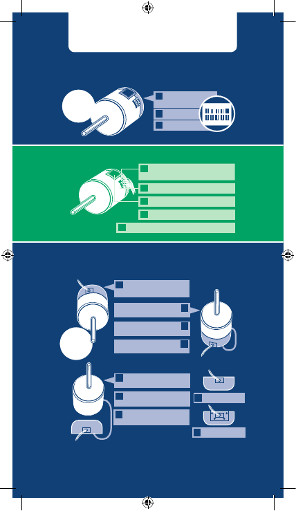
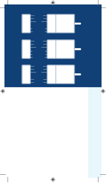
ECM X13
OEM Constant Torque Indoor Blower Motor
Evergreen Aftermarket Constant Torque Indoor Blower Motor
Identification
Sticker
Heat sink
Speed taps
All Evergreen Motors are aftermarket replacements
All Evergreen Motors are Painted Green
Evergreen CM, AH & EM
have a missing
wire upper plug
Evergreen IM
has a white or yellow voltage jumper
All Evergreen Motors have a heat sink here
OEM Constant Speed Outdoor Fan Motor
Sha down application
rounded end of control up
Sha up application
remote located control
Cover plate over
open end of control
Umbilical cord from motor
shell to cover plate
ECM 142 Control
ECM 142 Control
R
Sha up application
rounded end of control up
Cover plate over open
end of control
Umbilical cord from motor
shell to cover plate
ECM 142
R
C L G N
1 2 3 4 5
7
Motor Identification Chart
REG9971_ECM_Service_Guide_4-10-14.indd 10
4/10/14 10:48 AM
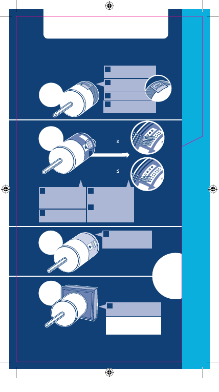
MO
TOR
ID
ECM 3.0
& Eon
ECM
2.3/2.5
2.3
6
wires
2.5
5
wires
Identification
Sticker
Heat sink
3.0 uses 4-pin
connector
Eon uses 16-pin
connector
Identification
Sticker
2.3
- 6 or more
wires in the
16-pin connector
2.5
- 5 or less
wires in the
16-pin connector
Painted, steel
motor control
Unpainted,
cast aluminum
motor control
Square motor
control
NOTE: Early models do not
have indentification stickers.
NOTE: ECM
1.0, 2.0,
2.3 & 2.5
motors are
no longer in
production
NOTE: See HVAC
manufacturer’s service guide
for 1.0 motor diagnostics.
ECM 2.0
ECM 1.0
OEM Variable Speed Indoor Blower Motor
8
Motor Identification Chart
REG9971_ECM_Service_Guide_4-10-14.indd 11
4/10/14 10:48 AM
9
WA R N I N G
Working on the motor with power connected may
result in electrical shock or other conditions that may
cause personal injury, death or property damage.
On models 2.0/ 2.3/ 2.5/ Eon/ 3.0 always disconnect
the power from the HVAC system and wait at least
5 minutes before opening the motor, i.e. removing
the two bolts from the motor control (end bell) and
disconnecting the 3-pin plug to the motor. This is to
allow the capacitors to dissipate for safety.
WA R N I N G
Always disconnect the power from the HVAC system before
removing or replacing connectors, servicing the motor,
removing the high voltage plug, and before reconnecting.
WA R N I N G
Disconnect AC power from the system and make
sure the blower wheel or fan blade has come to a
complete stop before servicing the motor.
WA R N I N G
Do not operate motor without blower wheel or fan
blade attached. Such operation will cause the motor
to oscillate up and down.
WA R N I N G
You must have the correct replacement module and/
or motor from the HVAC unit manufacturer that
is a direct replacement for the failed module and/
or motor. USING THE WRONG MODULE AND/OR
MOTOR VOIDS ALL PRODUCT WARRANTIES AND
MAY PRODUCE UNEXPECTED RESULTS.
WA R N I N G
WA R N I N G
Genteq does not condone the repair of any individual
components in the motor control or motor of their
ECM products. This practice is unsafe and may cause
personal injury, death, or property damage.
REG9971_ECM_Service_Guide_4-10-14.indd 12
4/10/14 10:48 AM
10
VARIABLE SPEED
M
OTO
RS
11
15
16
19
24
Models 2.0 / 2.3 / 2.5 / Eon / 3.0
Premium ECM Motor Diagnostics
TECINspect
TECINspect Usage Chart
Troubleshooting with the TECINspect
Module Replacement
ECM Control Module
ECM Motor Module
Variable Speed
Models 2.0 / 2.3 / 2.5 / Eon / 3.0
Premium ECM Motors
See the Motor ID Chart on page 8 if needed.
REG9971_ECM_Service_Guide_4-10-14.indd 13
4/10/14 10:48 AM
It is normal for the motor to rock back and
forth on start up. Do not replace the motor
if this is the only symptom identified.
If the system is excessively noisy, does not
appear to change speeds in response to a
demand (Heat or Cool), or is having symptoms
during the cycle such as a tripping limit or
freezing coil, check the following:
Wait for programmed delays to time out. If
delays are too long, then reset them using the
manufacturer’s charts.
Ensure the airflow settings are correct for
the installed system using the manufacturer’s
charts. Remember that the change in airflow
between continuous-fan speed and low stages
of operation may be very slight depending
on the size of the system. If the system is
operating normally in each stage, then there is
no problem.
Remove the filter and check that all of the
dampers, registers, and grills are open and
free flowing. If removing the filter corrects
the problem, clean or replace with a less
restrictive filter. Also check and clean as
needed the blower wheel, secondary heat
exchanger (if applicable) and evaporator coil
(if applicable).
If this does not correct the problem then:
Check the external static pressure. If it is
higher than the manufacturer’s recommendations,
correct the airflow restriction.
Models 2.0 / 2.3 / 2.5 / Eon / 3.0
Premium ECM Motor Diagnostics
IF THE MOTOR IS RUNNING
11
1.
2.
REG9971_ECM_Service_Guide_4-10-14.indd 14
4/10/14 10:48 AM
If the motor does not shut off at the end of
the cycle, check the delay times and wait for
the delays to time out. Also, make sure that
there is no call for “Continuous fan” on the
“G” terminal. This motor may take a while to
come to a complete stop with selected delays
and the normal ramp down.
If the 2.0 / 2.3 / Eon / 3.0 motor
has
proper high voltage and ground at the 5-pin
connector, go to the “Troubleshooting with
the TECINspect” section on page 16. If
the 2.5 motor has proper high voltage and
ground at the 5-pin connector, the equipment
manufacturer’s checks, located in their service
manuals, must be referenced. This guide
cannot troubleshoot the communication
to the 2.5 motor. The TECINspect is not
designed for use on the 2.5 motor.
Checking the high voltage on the 5-pin
connector is outlined in step 1 on page 13.
12
3.
4.
REG9971_ECM_Service_Guide_4-10-14.indd 15
4/10/14 10:48 AM
IF THE MOTOR IS NOT RUNNING
Check for proper high voltage and ground
at the 5-pin connector at the motor. Correct
any voltage issues before proceeding to the
next step. These are dual voltage motors
capable of operating in 120 or 240VAC
systems. On 120VAC systems there should
be a jumper between terminals 1 and 2 (see
Figure 1). On 240VAC systems the jumper
should be removed (see Figure 2). If a motor
is operating at 240VAC with the jumper
in place, the motor will be permanently
damaged. Input voltage within plus or minus
10% of the nominal 120VAC or 240VAC is
acceptable.
If the 2.0 / 2.3 / Eon / 3.0 motor has
proper high voltage and ground at the
5-pin connector, go to the “Troubleshooting
with the TECINspect” section on page 16.
If the 2.5 motor has proper high voltage
and ground at the 5-pin connector, the
equipment manufacturer’s checks, located in
their service manuals, must be referenced.
This guide cannot troubleshoot the
communication to the 2.5 motor.
The TECINspect is not designed for use on
the 2.5 motor.
If further troubleshooting identifies a failed
control module, go to “Replacing the ECM
Control Module” section on page 24 of this
guide for replacement steps.
1.
2.
3.
13
REG9971_ECM_Service_Guide_4-10-14.indd 16
4/10/14 10:48 AM
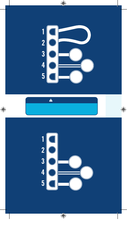
GROUND
120VAC
LINE 1
120VAC
LINE 2
GROUND
NEUTRAL
120VAC
LINE 1
Figure 1
Models 2.0 / 2.3 / 2.5 / Eon / 3.0
120VAC SYSTEM
Figure 2
240VAC SYSTEM
14
Always disconnect the power from the system before
removing the high voltage plug, and before reconnecting.
WA R N I N G
Models 2.0 / 2.3 / 2.5 / Eon / 3.0
REG9971_ECM_Service_Guide_4-10-14.indd 17
4/10/14 10:48 AM
15
TECINspect
USAGE CHART
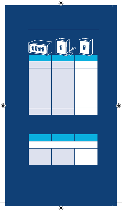
TECMate XL
TECMate PRO
TECINspect
4 Switches
1 Switch
1 Switch
16-pin connector
1st Generation
16-pin connector
2nd Generation
16-pin connector
with supplied 16-4
pin adapter
3rd Generation
16 & 4 pin
connector harness
16&4 pin
connector harness
No change from
TECMate PRO
3rd generation
Out of Production
Out of Production
Current Model
In 2013 the TECMate Pro service tool was rebranded to TECINspect.
TECINspect Service Tool Generational Growth
Applicable Motors
2.0, 2.3, EON, 3.0
Model 3.0
diagnostics require a
16-4 pin adaptor
1 , 2
Model 3.0
diagnostics may
require a 16-4 pin
adaptor
1
TECMate XL
TECMate PRO
TECINspect
TECINspect Application Chart
These service tools will properly diagnose applicable Genteq indoor
blower motors in all HVAC OEM equipment.
The TECINspect service tools are not designed for use on Genteq
models 1.0, 2.5, X13 or Evergreen. The TECINspect service tools are
not designed for use on Genteq outdoor fan motors.
1
The 16-4 pin adapter can be ordered from thedealertoolbox.com
2
The TECMate XL may not accuratly troubleshoot Carrier/Bryant 2.0/2.3 models.
REG9971_ECM_Service_Guide_4-10-14.indd 18
4/10/14 10:48 AM
Troubleshooting with the TECINspect
(Models 2.0 / 2.3 / Eon / 3.0 only)
See Motor ID Chart on page 8, if needed.
See the Usage Chart on the opposite page for
motors applicable to the TECINspect.
The TECINspect is capable of identifying a
motor control failure versus another HVAC
system controller or wiring failures.
Connect the TECINspect to the
communication plug on the motor
On Models 2.0/2.3/Eon remove the 5-pin
AC power connector first to make accessing
the 16-pin communication connector locking
tab easier. Remove the 16-pin connector
from the motor, and connect the 16-pin
connector from the TECINspect to the motor.
Reconnect the 5-pin AC power connector.
On Model 3.0 remove the 4-pin connector
from the motor (do not remove the 5-pin
ACpower connector). Connect the 4-pin
connector from the TECINspect to the motor.
Use the 16-4 pin adaptor (p15) with early model
TECMate tools.
1.
(see below).
16
4-pin
16-pin
4-pin
16-pin
Disconnect AC power from the system and make
sure the blower wheel has come to a complete stop
before servicing the motor.
WA R N I N G
Do not operate motor without blower wheel
attached. Such operation will cause the motor to
oscillate up and down.
WA R N I N G
REG9971_ECM_Service_Guide_4-10-14.indd 19
4/10/14 10:48 AM
ECM MOTOR
TECINspect
24VAC
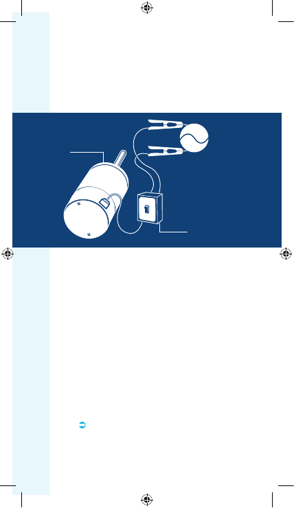
Connect the two alligator clips from the
TECINspect to a constant 24VAC
(24VAC
terminal and Common terminal)
source
such as the transformer low-voltage terminals
or terminal strip on the manufacturer’s
control board (see Figure 3 below). These
connections are not polarity sensitive.
Figure 3
NOTE: The high voltage
5-Pin connector must be
connected to the motor for
TECINspect tests.
Place the TECINspect switch(es) in the
OFF position.
Reconnect the AC power to the system. The
green LED light on the TECINspect should
be on when connected properly to 24VAC.
If the green LED light is not on, there is no
power to the TECINspect or the TECINspect
has failed. Do not continue until the green
LED is on by correcting low voltage issue/
connections or replacing the TECINspect.
Refer to the table on the back of the
TECINspect for operation guidelines.
Observe the motor for a minimum of 15
seconds.
If using a TECMate XL on Models
2.0/2.3/Eon,
make sure to set the switches
according to the instructions on the back for
each demand test to eliminate misdiagnosing
the problem.
2.
3.
4.
17
REG9971_ECM_Service_Guide_4-10-14.indd 20
4/10/14 10:48 AM
If using a TECMate XL on Model 3.0
, the
only switch necessary to test the motor is the
furthest switch to the right (labeled BK/PWM
on the XL or DH on the Troubleshooter).
When testing is finished, place the TECINspect
switch(es) in the OFF position and wait for
the motor to completely stop. (Based on the
manufacturer’s program, the motor may not
shut off immediately after a test; this is normal).
If the motor operates using TECINspect,
both the control module and the motor
module are ok.
The motor may operate at a
reduced speed during the TECINspect test, this
is normal. Turn off the power to the unit, remove
the 16-pin or 4-pin communication harness
from both the motor and the manufacturer’s
control board. Perform a continuity check
on each individual wire of the harness. Some
manufacturers use a different style connector
on the control board side of the harness. Follow
the wires to be sure of checking the proper
pins. Replace the communication harness if
any wires fail the continuity check, if any of the
pins are bent beyond rapair or damaged and
check the system operation again. If the harness
is good or a new harness does not solve the
problem, troubleshoot the communication out
of the manufacturer’s control board with their
troubleshooting guide. Always troubleshoot the
communication at the motor end of the harness.
If the motor does not operate with the
TECINspect,
confirm high voltage (pages
13-14) is present before replacing the control
module. Follow the next section on “Replacing
the ECM Control Module” on page 19.
5.
18
REG9971_ECM_Service_Guide_4-10-14.indd 21
4/10/14 10:48 AM
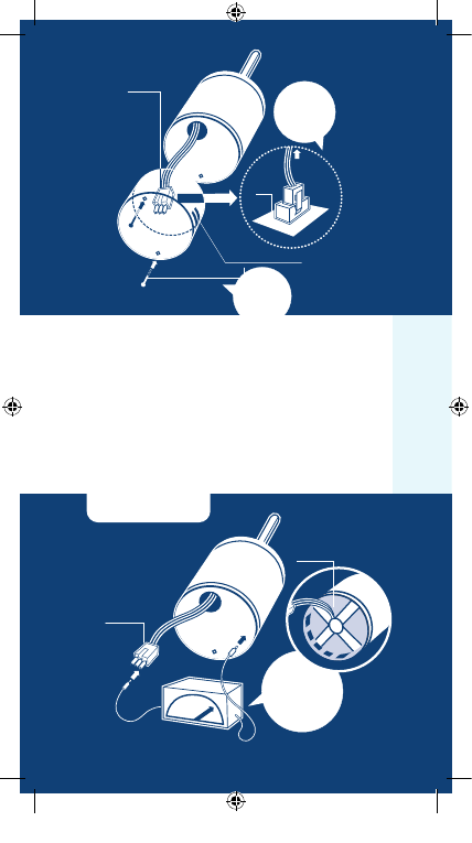
Before replacing the electronic-control module,
you must test the motor module to ensure it
is not also damaged. Installing a new control
on a failed motor will result in no operation,
improper operation and/or potential failure
of the new control. Procedures for testing the
motor module are included below.
Replacing the
ECM Control Module
(Models 2.0/ 2.3/ 2.5/ Eon/ 3.0 Only)
Disconnect AC power from the HVAC system.
Unplug the 16-pin or 4-pin communication
connector and the 5-pin connector from the
motor control.
Remove the blower assembly from the HVAC
system if needed.
ONLY after the system AC power has been
off for 5 minutes
, remove the two (2) hex-
head screws from the back of the control.
Unplug the 3-pin connector from the inside
of the control by squeezing the latch and
gently pulling on the connector (see Figure 4
on the next page). Now you’re ready to
test the motor.
19
Disconnect AC power from the system and make
sure the blower wheel has come to a complete
stop before servicing the motor.
WA R N I N G
You must have the correct replacement module
and/or motor from the manufacturer that is a direct
replacement for the failed module and/or motor.
USING THE WRONG MODULE AND/OR MOTOR
VOIDS ALL PRODUCT WARRANTIES AND MAY
PRODUCE UNEXPECTED RESULTS.
WA R N I N G
1.
2.
3.
4.
REG9971_ECM_Service_Guide_4-10-14.indd 22
4/10/14 10:48 AM
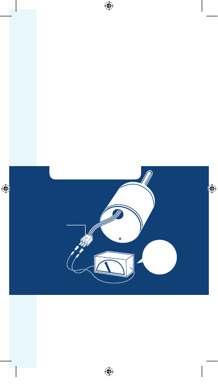
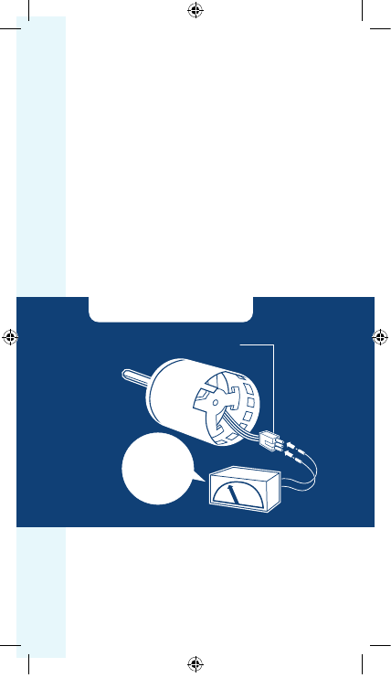
MOTOR MODULE TESTS
A.
The Winding Test (see Figure 5)
Set ohm meter to the highest possible setting
and measure resistance between each of the
three motor leads to the unpainted part of
the end shield (or x-brace on model Eon &
3.0). The motor passes the test if the meter
indicates greater than 100k ohms.
MOTOR CONNECTOR
(3-PIN)
16-PIN & 5-PIN CONNECTORS
FROM
MOTOR
CIRCUIT
BOARD
HEX HEAD SCREWS
Push until latch
seats over ramp
Only remove
Hex Head Bolts
Figure 4
MOTOR CONNECTOR
(3-PIN)
WINDING
TEST
MOTOR
OK
WHEN
R
>
100k ohm
Figure 5
20
X-BRACE
REG9971_ECM_Service_Guide_4-10-14.indd 23
4/10/14 10:48 AM
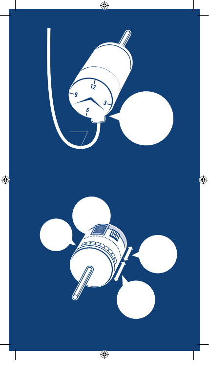
B.
The Phase-to-Phase Test
(see Figure 6 below)
Set ohm meter to lowest possible setting
and measure the motor phase to phase
resistance by checking these combinations
of the 3-pin motor connector with an
ohm meter:
Lead 1 to lead 2
Lead 1 to lead 3
Lead 2 to lead 3
For the purpose of this test, either end of the
3-pin plug is lead 1. Resistance values should
be less than 20 ohms and each of the three
values should be the same (plus or minus
10%). If the measured resistance is outside of
these parameters, the motor fails the test.
MOTOR CONNECTOR
(3-PIN)
PHASE - TO - PHASE
TEST
MOTOR
OK
WHEN
R
<
20 ohm
(lead to lead)
Figure 6
21
C.
If the motor passes both of these tests
and the shaft spins freely when rotated
by hand,
then the motor is ok and only the
control must be replaced. Continue with
replacing the ECM control module in step 5.
REG9971_ECM_Service_Guide_4-10-14.indd 24
4/10/14 10:48 AM
D.
If the motor fails either of these tests
or does not spin freely when rotated by
hand,
replace the motor and control module
following the guidelines on page 24.
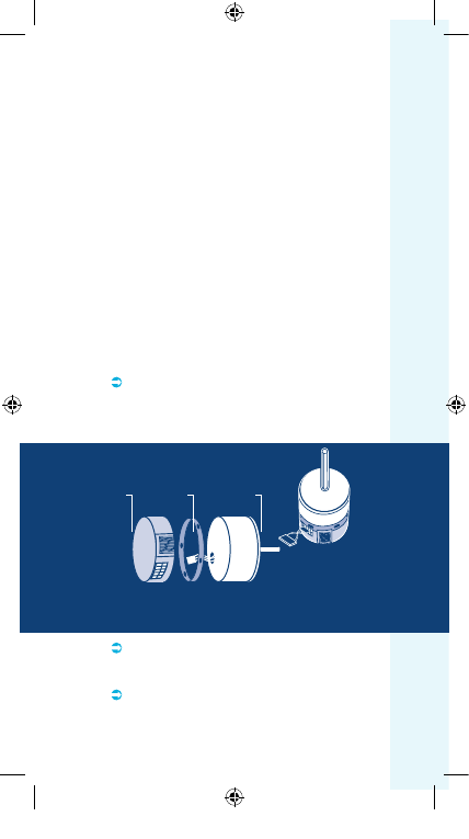
Insert the 3-pin connector back into the new
control module. A slight click will be heard
when inserted properly. This connector is
keyed for proper connection.
Attach the new control module with the plug
connections oriented down (see figure 7,
page 23), insert the appropriate bolts and
tighten. Due to model replacements, some
motors may need to be rotated in their
mount to orient the plug connectors properly.
See below for model specific notes and/or
follow any OEM instructions included with
the new control.
Model 2.0 & 2.3 - These models are no
longer available and can only be replaced
with an OEM Eon kit that includes a motor
adapter ring (see below).
Model Eon - This model can only be
replaced with with an OEM Eon.
Model 2.5 - This model is no longer in
production. It can only be replaced with an
OEM 3.0 kit that includes a 16-4 pin wiring
adapter and a motor adapter ring.
5.
6.
22
16-4 Pin Adapter
Completed Assembly
Adapter Ring
Eon Control
Model 2.0 or
2.3 Motor
REG9971_ECM_Service_Guide_4-10-14.indd 25
4/10/14 10:48 AM
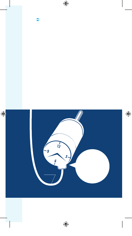
DRIP LOOP
DRIP LOOP
Connection Orientation
Between 4 and 8 o’clock
Model 3.0 - This model can only be
replaced with an OEM 3.0.
Reinstall the blower/motor assembly
into the HVAC system by following the
manufacturer’s guidelines.
Plug the 16-pin or 4-pin communication
connector and the 5-pin connector back
into the motor. The connectors are keyed.
Observe proper orientation.
Be certain to form a drip loop so that water
cannot enter the motor by draining down the
cables (see Figure 7 below).
Go to the “Final Installation Checks” on
pages 53-54.
Figure 7
7.
8.
9.
10.
23
REG9971_ECM_Service_Guide_4-10-14.indd 26
4/10/14 10:48 AM
Replacing the
ECM Motor and Control Modules
(Models 2.0 / 2.3 / 2.5 / Eon / 3.0)
28
The most efficient way to install the motor is to
have the control already attached.
If the new motor and control are not already
bolted together use the OEM instructions or
steps 5 and 6 on page 22.
Make sure the belly band mount is on the
motor module only and is not covering any of
the motor shell holes. Typically the belly band
is located between the two sets of motor
shell holes.
Before tightening down the belly band, rotate
the motor until the connectors in the control
are facing down or at least between the 4 and
8 o’clock position in the blower housing, as it
will mount into the HVAC system (see figure
7 page 23).
Center the blower wheel in the blower housing
and tighten the blower wheel hub bolt on the
flat portion of the motor shaft.
Reinstall the blower/motor assembly into the
HVAC system by following the
manufacturer’s guidelines.
Plug the 16-pin or 4-pin communication
connector and the 5-pin connector back into
the motor. The connectors are keyed. Observe
proper orientation.
Be certain to form a drip loop so that water
cannot enter the motor by draining down the
cables (see figure 7 page 23).
Go to the “Final Installation Checks” on
pages 53-54.
24
1.
2.
3.
4.
5.
6.
7.
8.
REG9971_ECM_Service_Guide_4-10-14.indd 27
4/10/14 10:48 AM
25
WA R N I N G
Working on the motor with power connected may
result in electrical shock or other conditions that may
cause personal injury, death or property damage.
Always disconnect the power from the HVAC system before
removing or replacing connectors, servicing the motor,
removing the high voltage plug, and before reconnecting.
WA R N I N G
Disconnect AC power from the system and make
sure the blower wheel has come to a complete stop
before servicing the motor.
WA R N I N G
Do not operate motor without blower wheel
attached. Such operation will cause the motor to
oscillate up and down.
WA R N I N G
You must have the correct replacement motor from
the manufacturer that is a direct replacement for
the failed motor. USING THE WRONG MOTOR
VOIDS ALL PRODUCT WARRANTIES AND MAY
PRODUCE UNEXPECTED RESULTS.
WA R N I N G
Always disconnect the power from the HVAC
system and wait at least 5 minutes before opening
the motor, i.e. removing the two bolts from the
motor control (end bell) and disconnecting the 3-pin
plug to the motor. This is to allow the capacitors to
dissipate for safety.
WA R N I N G
WA R N I N G
Genteq does not condone the repair of any individual
components in the motor control or motor of their
ECM products. This practice is unsafe and may cause
personal injury, death, or property damage.
REG9971_ECM_Service_Guide_4-10-14.indd 28
4/10/14 10:48 AM
X13 MO
TOR
Model X13
Standard ECM Motor Diagnostics
See the Motor ID Chart on page 7 if needed.
It is normal for the motor to rock back and
forth on start up. Do not replace the motor
if this is the only problem identified.
If the system is excessively noisy, does
not appear to change speeds in response
to a demand (Heat or Cool), or is having
symptoms during the cycle such as a tripping
limit or freezing coil, check the following:
Wait for programmed delays to time out.
If delays are too long, reset them using the
manufacturer’s charts.
Ensure the airflow settings are correct for
the installed system using the manufacturer’s
charts. If the system is operating normally in
each mode, there is no problem.
Remove the filter and check that all of the
dampers, registers, and grills are open and
free flowing. If removing the filter corrects
the problem, clean or replace with a less
restrictive filter. Also check and clean as
needed the blower wheel, secondary heat
exchanger (if applicable) and evaporator coil
(if applicable).
If this does not correct the problem then:
Check the external static pressure.
If it is higher than the manufacturer’s
recommendations, correct the airflow
restriction.
IF THE MOTOR IS RUNNING
26
1.
2.
REG9971_ECM_Service_Guide_4-10-14.indd 29
4/10/14 10:48 AM
If the motor does not shut off at the end of
the cycle, check the delay times and wait for
the delays to time out. Also make sure that
there is no call for “Continuous fan” on the “G”
terminal. This motor may take a while to come
to a complete stop with selected delays.
If the above diagnostics do not solve the
problem, confirm the voltage checks in
the next section below, then continue
diagnostics in the section, “Model X13
Standard ECM Motor Communication
Diagnostics.” The TECINspect is not
designed for use on this motor.
IF THE MOTOR IS NOT RUNNING
Check for proper high voltage and ground
at the (L)(G)(N) connections at the motor
(see Figure 8 on the next page). Correct any
voltage issues before proceeding to the next
step. The X13 motor is voltage specific. Only
the correct voltage should be applied to the
proper motor. Input voltage within plus or
minus 10% of the nominal 115VAC, 230VAC,
277VAC or 460VAC is acceptable.
Always disconnect the power from the system before
removing the high voltage plug, and before reconnecting.
WA R N I N G
27
1.
3.
4.
The TECINspect is not needed for use
on this motor. If the motor has proper
high voltage and ground at the (L)(G)(N)
connections, continue diagnostics in the next
section, “Model X13 Standard ECM Motor
Communication Diagnostics.”
2.
REG9971_ECM_Service_Guide_4-10-14.indd 30
4/10/14 10:48 AM
115VAC MOTOR
NEUTRAL
GROUND
115VAC
LINE 1
C L G N
1 2 3 4 5
230VAC MOTOR
115VAC
LINE 1
115VAC
LINE 2
C L G N
1 2 3 4 5
GROUND
460VAC MOTOR
GROUND
277VAC
LINE 1
277VAC
LINE 2
C L G N
1 2 3 4 5
277VAC MOTOR
GROUND
277VAC
LINE 1
NEUTRAL
C L G N
1 2 3 4 5
Figure 8
28
REG9971_ECM_Service_Guide_4-10-14.indd 31
4/10/14 10:48 AM
Model X13
Standard ECM
Motor Communication Diagnostics
Start with the manufacturer’s literature to
confirm proper set-up, connections and
voltage. It is not required that all terminals
on the motor have a program. If the low-
voltage communication is applied to an
unprogrammed terminal, the motor will not
operate, which is normal.
Initiate a demand from the thermostat and
check the voltage between the common and
the appropriate motor terminal 1- 5. Confirm
the meter is set to the voltage identified
from the manufacturer’s literature (see
Figures 9 and 10 on the next page).
If the low voltage communication is
not present, check the demand from the
thermostat. Also check the output terminal
and wire(s) from the manufacturer’s control
board or relays to the motor.
If the motor has proper high voltage as
identified in the previous section, and proper
low voltage to a programmed terminal, and
is not operating, follow the next section on
“Replacing the ECM Control Module” on
page 31.
The X13 motor can be communicated through
AC or DC low voltage. AC voltage is typically
24VAC and DC voltage can be between
9-23VDC (see Figures 9 and 10 on the next page).
29
1.
2.
Figure 4
REG9971_ECM_Service_Guide_4-10-14.indd 32
4/10/14 10:48 AM
30
AC
VOLTAGE
CONTROL
INPUTS
AC VOLTS
V
COM
24 VAC
C L G N
1 2 3 4 5
DC
VOLTAGE
CONTROL
INPUTS
DC VOLTS
V
COM
9-23 VAC
C L G N
1 2 3 4 5
Figure 9
Figure 10
REG9971_ECM_Service_Guide_4-10-14.indd 33
4/10/14 10:48 AM

Before replacing the electronic-control module,
you must test the motor module to ensure it
is not also damaged. Installing a new control
on a failed motor will result in no operation,
improper operation and/or potential failure
of the new control. Procedures for testing the
motor module are included below.
Replacing the
ECM Control Module
(Model X13)
Disconnect AC power from the HVAC
system. Unplug all wires and/or connectors.
Note tap position of all individual wires from
the motor control.
Remove the blower assembly from the HVAC
system if needed.
ONLY after the system AC power has been
off for 5 minutes
, remove the two (2) hex-
head screws from the back of the control.
Unplug the 3-pin connector from the inside
of the control by squeezing the latch and
gently pulling on the connector (see Figure 11
on the next page). Now you’re ready to
test the motor.
31
Disconnect AC power from the system and make
sure the blower wheel has come to a complete
stop before servicing the motor.
WA R N I N G
You must have the correct replacement module
and/or motor from the manufacturer that is a direct
replacement for the failed module and/or motor.
USING THE WRONG MODULE AND/OR MOTOR
VOIDS ALL PRODUCT WARRANTIES AND MAY
PRODUCE UNEXPECTED RESULTS.
WA R N I N G
1.
2.
3.
4.
REG9971_ECM_Service_Guide_4-10-14.indd 34
4/10/14 10:48 AM
MOTOR MODULE TESTS
A.
The Winding Test (see Figure 12)
Set ohm meter to the highest possible setting
and measure resistance between each of the
three motor leads to the unpainted part of
the x-brace. The motor passes the test if the
meter indicates greater than 100k ohms.
MOTOR CONNECTOR
(3-PIN)
4-PIN & 5-PIN CONNECTORS
HEX HEAD SCREWS
FROM
MOTOR
CIRCUIT
BOARD
Push until latch
seats over ramp
Figure 11
MOTOR CONNECTOR
(3-PIN)
WINDING
TEST
MOTOR
OK
WHEN
R
>
100k ohm
Figure 12
32
REG9971_ECM_Service_Guide_4-10-14.indd 35
4/10/14 10:48 AM
B.
The Phase-to-Phase Test
(see Figure 13 below)
Set ohm meter to lowest possible setting
and measure the motor phase to phase
resistance by checking these combinations
of the 3-pin motor connector with an
ohm meter:
Lead 1 to lead 2
Lead 1 to lead 3
Lead 2 to lead 3
For the purpose of this test, either end of the
3-pin plug is lead 1. Resistance values should
be less than 20 ohms and each of the three
values should be the same (plus or minus
10%). If the measured resistance is outside of
these parameters, the motor fails the test.
PHASE - TO - PHASE
TEST
MOTOR CONNECTOR
(3-PIN)
MOTOR
OK
WHEN
R
<
20 ohm
(lead to lead)
Figure 13
33
C.
If the motor passes both of these tests
and the shaft spins freely when rotated
by hand,
then the motor is ok and only the
control must be replaced. Continue with
replacing the ECM control module in step 5.
REG9971_ECM_Service_Guide_4-10-14.indd 36
4/10/14 10:48 AM

D.
If the motor fails either of these tests
or does not spin freely when rotated by
hand,
replace the motor and control modules
following the guidelines on page 36.
Insert the 3-pin connector back into the new
control module. A slight click will be heard
when inserted properly. This connector is
keyed for proper connection.
Attach the new control module with the plug
connections oriented down (see figure 14,
page 35), insert the appropriate bolts and
tighten.
Reinstall the blower/motor assembly into the
HVAC system by following the manufacturer’s
guidelines.
Reconnect all wires and/or connectors. Make
sure individual wires are connected to proper
taps.
Be certain to form a drip loop so that water
cannot enter the motor by draining down the
cables (see Figure 14 below).
Go to the “Final Installation Checks” on
pages 53-54.
5.
6.
34
7.
8.
9.
10.
REG9971_ECM_Service_Guide_4-10-14.indd 37
4/10/14 10:48 AM
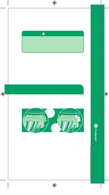
ECM X13
2.75” BELLYBAND
KEEP OUT AREA
RECOMMENDED
BELLYBAND AREA
DO NOT
COVER VENTS
DRIP LOOP
DRIP LOOP
Connection Orientation
Between 4 and 8 o’clock
Figure 14
35
Figure 15
REG9971_ECM_Service_Guide_4-10-14.indd 38
4/10/14 10:48 AM

Replacing the
ECM Motor and Control Modules
(Model X13)
The most efficient way to install the motor is to
have the control already attached.
If the new motor and control are not already
bolted together use the OEM instructions or
steps 5 and 6 on page 34.
When replacing the X13 motor with a belly
band for mounting, the band should not be
located in the area identified in Figure 15.
Before tightening down the belly band, rotate
the motor until the connectors in the control
are facing down or at least between the 4 and
8 o’clock position in the blower housing, as it
will mount into the HVAC system (see figure
14 page 35).
Center the blower wheel in the blower housing
and tighten the blower wheel hub bolt on the
flat portion of the motor shaft.
Reinstall the blower/motor assembly into the
HVAC system by following the manufacturer’s
guidelines.
Reconnect all wires and/or connectors.
Make sure individual wires are connected to
proper taps.
Be certain to form a drip loop so that water
cannot enter the motor by draining down the
cables (see figure 14 page 35).
Go to the “Final Installation Checks” on
pages 53-54.
36
1.
2.
3.
4.
5.
6.
7.
8.
REG9971_ECM_Service_Guide_4-10-14.indd 39
4/10/14 10:48 AM
37
Introduction:
Evergreen is an ECM designed as an
aftermarket replacement of existing PSC
(Permanent Split Capacitor), direct drive,
indoor blower motors for the purpose of
increasing efficiency and comfort. For more
information on this motor please visit www.
thedealertoolbox.com. There you will also find
the complete installation manual, training
videos and other valuable information.
Evergreen motors are not approved to replace
existing ECM Variable Speed or X13 motors,
should not be used on twinned systems and
should not be used on belt drive systems.
There are two Evergreen Models. Please make sure
to use the appropriate troubleshooting information.
See the Motor ID chart on page 7 if needed.
Evergreen IM (page 38)
This motor is dual voltage 120-240VAC,
reversible, multi-horsepower, and designed for
all residential HVAC systems less than 5 ton of
cooling and 150k BTUh of heating.
Evergreen AH (page 45)
This motor is 208-230VAC only, non reversible,
and designed for any air handler application
including package systems that do not
incorporate fossil fuel.
Evergreen
Indoor Blower Motor Diagnostics
See the Motor ID Chart on page 7 if needed.
REG9971_ECM_Service_Guide_4-10-14.indd 40
4/10/14 10:48 AM
Evergreen • IM Diagnostics
Note: Please read the introduction on page 37
before using these diagnostics
IMPORTANT NOTE:
There must be proper voltage at the
High
Voltage POWER and High Voltage SIGNAL
connections for the motor to operate. Skipping
any of the troubleshooting in this section
could result in misdiagnosis of the motor and/
or HVAC system.
W A R N I N G
ALWAYS DISCONNECT MAIN HVAC SYSTEM
POWER BEFORE DIS-CONNECTING OR
RE-CONNECTING ANY WIRES OR
CONNECTORS TO THE EVERGREEN MOTOR.
Check that the proper Line Voltage jumper
is installed.
For 230VAC systems the yellow jumper
should be installed. For 115VAC systems the
white jumper should be installed.
NOTE:
If
the motor was powered with 230VAC while the
white jumper was installed, the motor may be
permanently damaged and need to be replaced.
Continue troubleshooting here after proper
jumper is installed.
38
230VAC
115VAC
Yellow Jumper
White Jumper
IF THE MOTOR IS NOT RUNNING
REG9971_ECM_Service_Guide_4-10-14.indd 41
4/10/14 10:48 AM
39
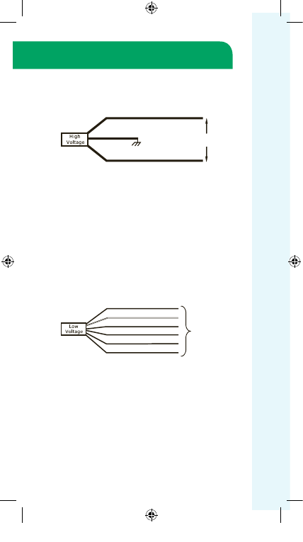
Confirm proper system line voltage is
connected. Measure the voltage at the
High
Voltage POWER connections L1 (black) and L2
(white). On 115VAC systems, Neutral should
be connected to L2. The power connected to
these taps should be continuous un-switched
line voltage.
This voltage alone will not operate
the motor. If proper voltage is not present,
troubleshoot the HVAC system. Continue
troubleshooting here after proper voltage has
been confirmed.
Confirm there is a 115VAC demand on
any one or all of the
High Voltage SIGNAL
connections. The High Voltage SIGNAL
connections of the motor should only be
connected to the HVAC Systems 115VAC
fan controls (fan relay or circuit
board) connections.
On 230VAC systems, the voltage switched
by the fan controls must be the same line
voltage that is connected to the L1 High
Voltage POWER connection.
If 115VAC L1 and Neutral or 230VAC L1
and L2 was powered to these connections, the
motor may be permanently damaged and need
to be replaced.
If proper voltage is not present, troubleshoot
the HVAC System.
IF THE MOTOR IS NOT RUNNING
(continued)
REG9971_ECM_Service_Guide_4-10-14.indd 42
4/10/14 10:48 AM

40
IF THE MOTOR IS NOT RUNNING
(continued)
Final Diagnosis – If there is a 115VAC demand
on one or more of the High Voltage SIGNAL
connections, the correct Line Voltage Jumper
is installed, there is proper voltage on the High
Voltage POWER connections and the motor is
not operating, replace the motor.
Sequence of Operation
A
Low Voltage SIGNAL demand from the HVAC
Systems thermostat connection alone will
not operate the motor. The motor will turn
on when it receives its
High Voltage SIGNAL
demand from the HVAC Systems fan controls
(fan relay or circuit board) connections. The
High Voltage POWER connections must be
powered continuously from the proper line
voltage. Constant fan operation does not
require a Low Voltage SIGNAL demand. The
special low constant fan speed will operate
with a High Voltage SIGNAL demand alone.
REG9971_ECM_Service_Guide_4-10-14.indd 43
4/10/14 10:48 AM
41
IF THE MOTOR IS RUNNING
If the motor is running but there is an
airflow issue causing improper performance,
undesired comfort or HVAC System failure,
check the following:
Confirm the proper HVAC System 24VAC
thermostat demand is connected to a
Low
Voltage SIGNAL (speed) tap. Any voltage above
30VAC could permanently damage the motor.
This voltage alone will not operate the motor
(See the Sequence of Operation section on
page 40). Confirm there is proper 24VAC
between the selected Low Voltage SIGNAL
(speed) tap and the BLUE Common tap on the
motor. (see schematic on page 40) If more or
less airflow is required, change this connection
to a higher or lower speed tap. If the highest or
lowest speed tap does not achieve the required
airflow, the horse power (Hp) selection may
need to be adjusted. If proper 24VAC is not
present, troubleshoot the HVAC System.
Continue troubleshooting here if this does not
solve the problem.
CAUTION:
Adjusting the Horse Power (Hp) selection will
change the airflow value of all Low Voltage
SIGNAL (speed) taps. If the Hp selection is
changed, airflow in all demands will need to be
checked and adjusted as needed.
REG9971_ECM_Service_Guide_4-10-14.indd 44
4/10/14 10:48 AM
42
IF THE MOTOR IS RUNNING
(continued)
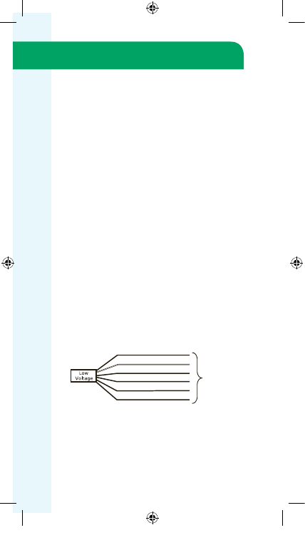
To achieve the proper horse power (Hp) the
High Voltage SIGNAL connections must be
connected to the HVAC Systems fan controls
according to the diagrams on page 43. When
the motor was installed it should have been
configured to match the Hp of the replaced
motor. To increase or decrease the Hp
selection, see the chart below.
HV1 & HV2 = 1/2 - 1/3 Hp operation
1/2 Hp Motor
HV1
= 1/3 - 1/4 Hp operation
HV2
= 1/4 - 1/5 Hp operation
HV1 & HV2 = 3/4 Hp operation
1 Hp Motor
HV1
= 3/4 – 1/2 Hp operation
HV2
= 1/2 Hp operation
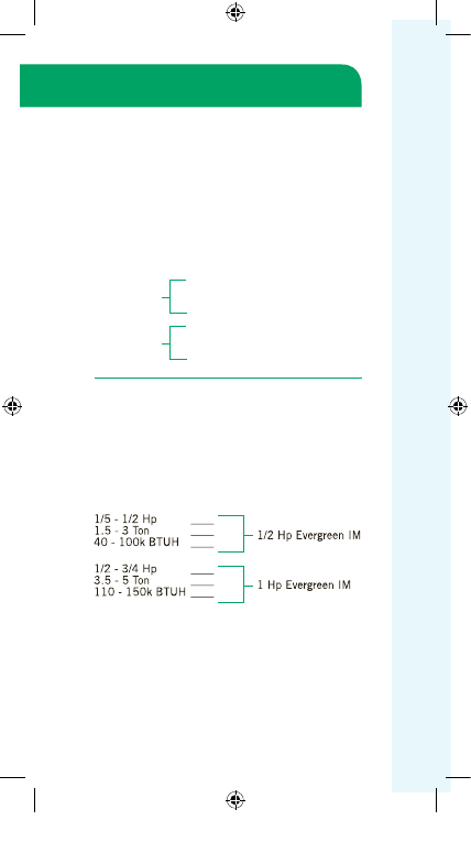
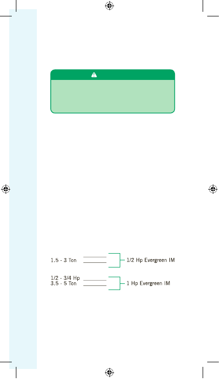
If the highest or lowest Hp setting does not
achieve the required airflow, the motor size
may be incorrect. This motor is designed to
replace multiple motors based on Hp and
system sizing. If the sizing of the motor is in
question, see the selection chart below.
REG9971_ECM_Service_Guide_4-10-14.indd 45
4/10/14 10:48 AM
The
High Voltage SIGNAL connections are
connected together with all the 115VAC fan
outputs from the HVAC Systems controls to
communicate to the motor when to turn on
and at what horse power to operate at.
43
IF THE MOTOR IS RUNNING
(continued)
REG9971_ECM_Service_Guide_4-10-14.indd 46
4/10/14 10:48 AM

44
Airflow restrictions can be caused by any one
or more of the following:
Dirty filters
Dirty blower wheel, secondary heat
exchanger and/or evaporator
Too many registers, grilles and/or
balancing dampers are closed.
Dirty, damaged, or poorly constructed
ductwork.
All of these issues can be solved by visual
inspection and cleaning. If this does not solve
the problem check the Total External Static
Pressure (TESP). If the TESP is above .8,
there is an issue with the ductwork or filter
sizing that must be corrected. After correcting
one or more airflow restrictions, it may be
necessary to adjust the speed selection and/or
horse power selection.
If the diagnostics provided here do not solve
your problem, please go to
thedealertoolbox.com
and download
the full installation manual for further support.
Technical Support is also available on the
Evergreen Hotline at 1-866-503-8566.
IF THE MOTOR IS RUNNING
(continued)
•
•
•
•
REG9971_ECM_Service_Guide_4-10-14.indd 47
4/10/14 10:48 AM
45
Evergreen • AH Diagnostics
Note: Please read the introduction on page 37
before using these diagnostics
W A R N I N G
ALWAYS DISCONNECT MAIN HVAC SYSTEM
POWER BEFORE DIS-CONNECTING OR
RE-CONNECTING ANY WIRES OR
CONNECTORS TO THE EVERGREEN MOTOR.
Evergreen • AH Selection Data
Check the HVAC systems existing PSC motor
horse power (Hp) and tonnage of the outdoor
unit to determine the Evergreen sizing. If only
one checkmark falls in each Evergreen sizing
use the larger motor.
1/6 - 1/2 Hp
IMPORTANT NOTE:
There must be proper voltage at the
High
Voltage POWER and the Low Voltage (Speed
Tap) connections for the motor to operate.
Skipping any of the troubleshooting in this
section could result in misdiagnosis of the
motor and/or HVAC system.
REG9971_ECM_Service_Guide_4-10-14.indd 48
4/10/14 10:48 AM
IF THE MOTOR IS NOT RUNNING
Step 1.
Confirm 208-240 VAC between the
two black leads of the motor.
If there is not proper voltage at these leads,
correct the problem before the motor. If the
motor still does not operate after this step has
been corrected, go to
Step 2.
If there is proper voltage at these leads,
go to
Step 2.
Step 2.
Confirm 24 VAC between any one of
the speed taps (Green, Orange, Brown, White
or Yellow) and the Blue lead (24 VAC common
connection)
If there is not proper voltage at one or all of
these leads during proper system demand,
correct the problem before the motor. The
motor should operate with 24 VAC supplied
to any of its speed taps, with proper 24 VAC
common supplied to the blue lead of the
motor. If the motor still does not operate
after this has been corrected, replace the
motor.
46
YEL
HIGH
BRN
MED -LOW
ORN
LOW
GRN
CONST FAN
BLU
24V COM
WHT
MED
-HI
To thermos tat
connections
24 V AC O NL Y
GRN w / Y EL
BLK
BLK
L 1
L 2
G round
208 - 240 V AC
REG9971_ECM_Service_Guide_4-10-14.indd 49
4/10/14 10:48 AM
Symptom:
47
IF THE MOTOR IS RUNNING
If the motor is running but there is an airflow
issue causing improper performance,
undesired comfort or HVAC System failure,
check the following:
Step 1.
Check all of the airside components
such as registers, diffusers, grilles, filters,
blower wheel, and indoor coil for dirt or other
restrictions. Check filter sizing, especially
aftermarket filters.
Clean any dirt or debris on the airside
components. Open and clear all registers,
diffusers and grilles. Replace filters with
proper size according to manufacturer specs.
Aftermarket filters may need to be larger than
the original specs. If this does not correct the
problem go to step 2.
Step 2.
Confirm that the proper speed tap has
been selected for the proper demand by checking
the airflow using one of the methods covered in
the “Airflow Tests” section of the Evergreen
AH manual. This manual can be downloaded
from thedealertoolbox.com.
If the airflow needs to be increased or
decreased, select the speed tap that produces
the proper airflow for the system tonnage.
YEL
HIGH
BRN
MED -LOW
ORN
LOW
GRN
CONST FAN
BLU
24V COM
WHT
MED
-HI
To thermos tat
connections
24 V AC O NL Y
REG9971_ECM_Service_Guide_4-10-14.indd 50
4/10/14 10:48 AM
48
IF THE MOTOR IS RUNNING
(continued)
If the LOW speed is too much airflow or HIGH
speed is not enough airflow, check the motor
sizing using the selection chart on page 45.
Install the correct size motor if needed and
repeat step 2.
(See note below first) If this
does not correct the problem go to Step 3.
NOTE:
Do not oversize the motor to correct airflow
problems. If the motor installed matches the
motor selection chart recommendation, select
the speed that produces the best possible
airflow and proceed to Step 3.
Step 3.
Check the system’s Total External
Static Pressure (Total ESP).
If the total ESP is higher than the system
manufacturer recommends, the problem is
most likely a restricted or undersized duct
system. Correct the duct issues.
If the Total ESP is lower than the system
manufacturer recommends, the problem
is most likely a disconnected or improper
opening in the duct system. Correct the
duct issues.
If the diagnostics provided here do not solve
your problem, please go to
thedealertoolbox.com
and download
the full installation manual for further support.
Technical Support is also available on the
Evergreen Hotline at 1-866-503-8566.
REG9971_ECM_Service_Guide_4-10-14.indd 51
4/10/14 10:48 AM
29
49
WA R N I N G
Working on the motor with power connected may
result in electrical shock or other conditions that may
cause personal injury, death or property damage.
Always disconnect the power from the HVAC system before
removing or replacing connectors, servicing the motor,
removing the high voltage plug, and before reconnecting.
WA R N I N G
Disconnect AC power from the system and make
sure the fan blade has come to a complete stop
before servicing the motor.
WA R N I N G
Do not operate motor without fan blade attached.
Such operation will cause the motor to oscillate
up and down.
WA R N I N G
You must have the correct replacement motor from
the manufacturer that is a direct replacement for
the failed motor.
USING THE WRONG MOTOR VOIDS ALL
PRODUCT WARRANTIES AND MAY PRODUCE
UNEXPECTED RESULTS.
WA R N I N G
WA R N I N G
Genteq does not condone the repair of any individual
components in the motor control or motor of their
ECM products. This practice is unsafe and may cause
personal injury, death, or property damage.
REG9971_ECM_Service_Guide_4-10-14.indd 52
4/10/14 10:48 AM
OUTDOOR
M
OTO
R
It is normal for the motor to rock back and
forth on start up. Do not replace the motor if
this is the only symptom identified.
If the system is working properly but the
motor appears to run slower than it should,
the motor is good. High efficiency systems,
especially those with optimized fan blades,
will run the motor slower to decrease noise.
If the system is noisy, freezing up, running
a high head pressure, tripping the high
pressure switch or the compressor overload,
check the following:
Clean the condensing coil and any
shrouds thoroughly including in between
two pass coils (this may require some unit
disassembly) following the manufacturer’s
recommendations. This motor will not
compensate for lack of airflow through
dirty coils.
Confirm all fan blades are shaped the
same, in good condition and not rubbing
on the shroud. Also confirm the fan blade
hub bolt is secure on the motor shaft. Also
confirm the motor is secure in its mount and
the mount legs are secure to the unit.
Use the next section “If the motor is not
running” for voltage checks to determine if
the motor is getting the proper inputs.
If the motor does not appear to be running
at the proper speed or does not shut off,
refer to the next section for voltage checks
to determine if the motor is getting the
proper inputs.
1.
2.
3.
4.
Models 142 and 142R ECM
Outdoor Fan Motor Diagnostics
See the Motor ID chart on page 7 if needed.
IF THE MOTOR IS RUNNING
50
REG9971_ECM_Service_Guide_4-10-14.indd 53
4/10/14 10:48 AM
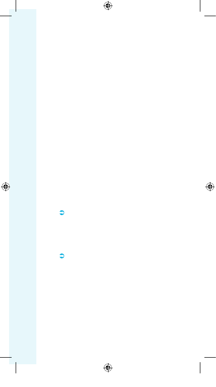
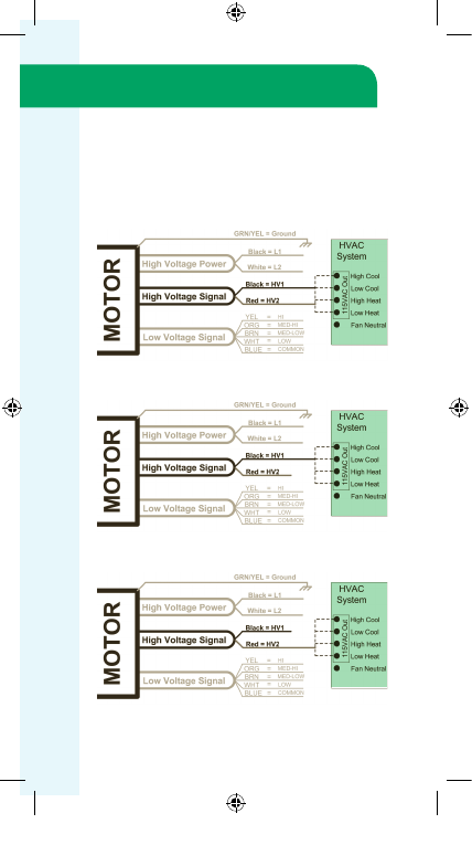
Check for proper high voltage and ground.
Using the OEM schematics, locate the L1,
L2, and Ground connections and confirm
voltage is 208-230 10%. Correct any voltage
issues, worn or broken connections.
This motor is energized and de-energized
with communication inputs. Model variations
include Single Speed 24VAC communication,
Multi-speed 24VAC communication and
Single or Multi-speed PWM communication.
See example figures on p52. Using the OEM
schematic, identify the communication type
and check for proper voltage. PWM taps are
diagnosed with DC voltage specified by the
HVAC unit OEM.
If the motor IS NOT receiving any
communication,
troubleshoot the
communication issue using the manufacturer’s
troubleshooting guides. The control board in
the outdoor unit will need the proper demand
call (low voltage or communication) from
the indoor controls to provide the proper
communication to the motor. Confirm these
demand(s) are there before checking the
communication to the motor.
If the motor IS receiving proper
communication
(and proper high voltage
power) and is not running, proceed to the
next section on Motor Replacement.
1.
2.
IF THE MOTOR IS NOT RUNNING
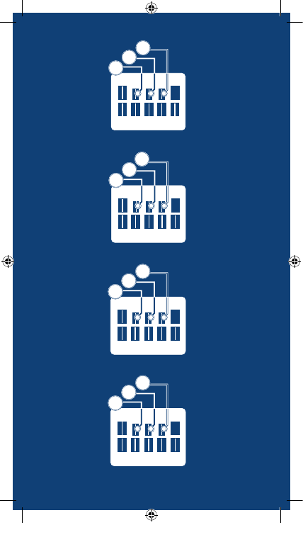
This motor uses a 5 or 6 wire harness with wire
colors specified by the OEM. Therefore the
OEM schematic for the particular unit you are
working on will be necessary to identify motor
connections on the system controls.
51
REG9971_ECM_Service_Guide_4-10-14.indd 54
4/10/14 10:48 AM
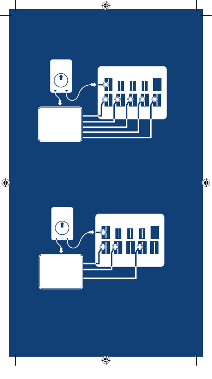
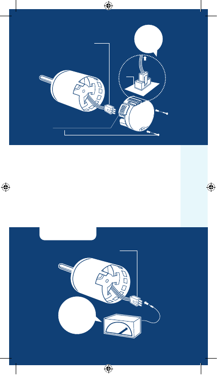
Replacing the Motor
This motor is replaced in one piece. The control
cannot be replaced separately from the motor.
Even if the control is remotely located, the
replacement part will be a new control with
harness and new motor.
You must have the correct replacement
motor from the manufacturer that is a direct
replacement for the failed motor. USING THE
WRONG MOTOR VOIDS ALL PRODUCT
WARRANTIES AND MAY PRODUCE
UNEXPECTED RESULTS.
Always mount the replacement motor and
control (if mounted separately) according to the
manufacturer’s specifications using all required
hardware to reduce vibration. Make sure all
wires are free of the fan blade and not pinched
in mountings or cabinet through points.
52
OEM
CONTROL
L1 (115VAC)
L2 (115VAC)
Ground
Speed Tap (24VAC)
Common (24VAC)
OEM
CONTROL
OEM
CONTROL
24VAC Communicated
Single Speed Models
142 & 142
R
24VAC Communicated
Multi-Speed Models
142 & 142
R
PWM Communicated
Models 142 & 142
R
L1 (115VAC)
L2 (115VAC)
Ground
Speed Tap(24VAC)
Speed Tap(24VAC)
Common (24VAC)
L1 (115VAC)
L2 (115VAC)
Ground
PWM (VDC)
PWM (VDC)
REG9971_ECM_Service_Guide_4-10-14.indd 55
4/10/14 10:48 AM
Indoor Motor
Final Installation Checks
Check all wiring and connections,
especially those removed while servicing.
Clear all condensate drain and traps.
Check and plug leaks in return ducts and
equipment cabinet.
Verify that the system is running quietly
and smoothly, producing proper air flow in
all modes (heating, cooling, and continuous
fan) and all stages (if applicable).
Return all thermostat settings to the
customer’s preference.
If any evidence of moisture, then correct
the issue.
If the area is subject to high amounts of
lightning strikes, then use of additional
transient protection may be helpful.
53
Ensure the system is set up as follows:
REG9971_ECM_Service_Guide_4-10-14.indd 56
4/10/14 10:48 AM
FINAL
CHE
CK
S
Good Practices:
Outdoor Motor
Final Installation Checks
54
Before energizing the HVAC system,
confirm the fan blade is free of all
obstructions, including the system shroud
and compressor.
Check all wiring and connections,
especially those removed while servicing.
Verify the system is running quietly and
smoothing in all modes and stages if
applicable.
Check the refrigerant level only after
confirming proper indoor airflow as well.
Bent coil fins restrict airflow; correct if
possible without damaging the coil or
other fins.
Return all thermostat settings to the
customer’s preference.
Finish all service calls by checking all
safeties, and perform a visual inspection of
the overall job to prevent call-backs.
Check the level of Carbon Monoxide (CO)
in the vent(s) and living spaces of all homes
with fossil-fuel appliances.
Recommend annual maintenance.
REG9971_ECM_Service_Guide_4-10-14.indd 57
4/10/14 10:48 AM
1946 WEST COOK ROAD
:
FORT WAYNE, IN 46818
ph :
260 416 5400
fx :
260 416 5499
GTQ-8001 Version 3.0
©2014
Regal-Beloit Corporation
thedealertoolbox.com
Visit
to learn more
A Regal Brand
©2014 Regal-Beloit Corporation
REG9971_ECM_Service_Guide_4-10-14.indd 58
4/10/14 10:48 AM