Product catalogue 2008
Relays with forcibly
guided contacts
Product catalogue 2008
Relays with forcibly
guided contacts
2
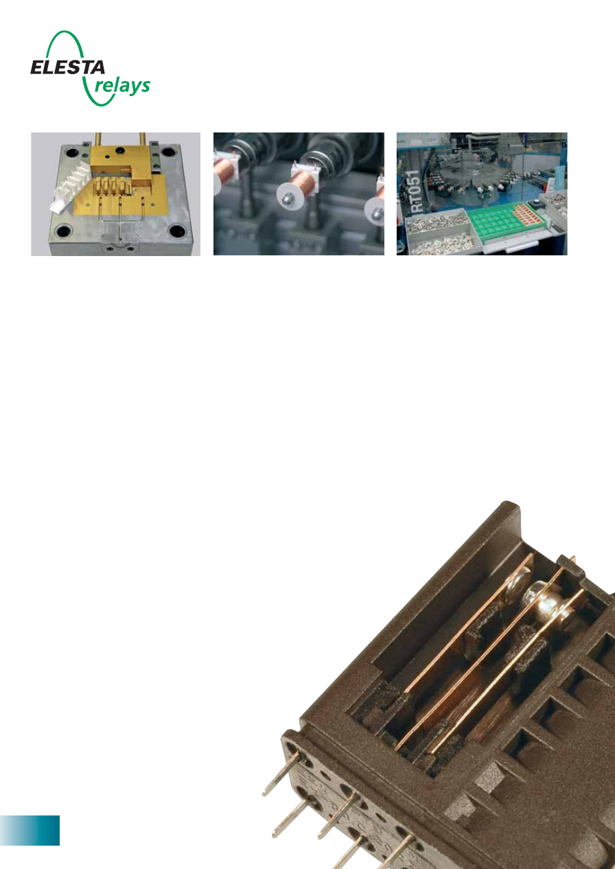
Depending on the type of relay, our
production sequences are fully or
partly automated, whereby highest
quality is also guaranteed in the few
manual operations. All products are
made exclusively at our factory in
Bad Ragaz, Switzerland.
The company
ELESTA relays GmbH established in
the Swiss town of Bad Ragaz is one
of the leading producers in the field
of safety relays with forcibly guided
contacts. A very comprehensive pro-
gramme of safety relays enables
ELESTA relays to offer the right
product for just about all application
areas.
Specializing in relays with forcibly
guided contacts, ELESTA relays
impresses its customers and the
market over and over again with
innovation which sets distinct bench-
marks in the world of safety relays.
Products
Relays made by ELESTA are used in
safety applications all over the world.
The application areas are highly
diverse and range from e.g. emer-
gency-off switching devices over
transport systems (lifts, escalators,
etc.) right to complex machine con-
trols. The focus is on ELESTA relays
wherever humans and expensive
equipment need to be protected
from injuries and damage, respec-
tively.
ELESTA relays attaches great
importance to quality. With a rigid
quality programme applied during
the entire production process and
100% inspection before delivery we
combine “Safety without compro-
mises“ and “Quality without com-
promises“.
ELESTA relays - Swiss High-Tech
Injection moulding die
Coil fabrication
Assembly station
ELESTA relays GmbH, Heuteilstrasse 18,
CH - 7310 Bad Ragaz, Switzerland
Phone: +41 (0)81 303 54 00
Fax:
+41 (0)81 303 54 01
3
Safety requirements
Relays with forcibly guided contacts
are used in safety-oriented applica-
tions for the decoupling of differ-
ent voltage potentials. These relays
permit implemention of self-moni-
toring systems. Complying with
the European standard EN50205,
a relay with forcibly guided con-
tacts consists of at least one N.C.
and one N.O. contact. Break and
make contact must never be closed
at the same time during the entire
life of the relay. In case of a fault
the contact gap must be at least
0.5 mm. Additionally, the insula-
tion values are subject to higher
standards and pollution degree 2
is defined for relays with forcibly
guided contacts. For the contact
spring assemblies and other con-
ducting parts in the relay it must be
ensured that no short circuits or con-
ducting connections result in case
such parts should ever fracture or
become loose.
Our strengths
As an acknowledged specialist in
the production of relays with forci-
bly guided contacts ELESTA relays
offers its customers a comprehen-
sive range covering virtually all appli-
cation cases. Permanent observa-
tion of the market, the participation
in standardization committees and
a close cooperation with suppliers,
research institutions and directly
with the users enable us to offer
our clientele innovative products
to suit their requirements in good
time. With our outstanding custom-
er support, high flexibility and on
time deliveries we provide the serv-
ices which buyers of such products
rightly expect. Our strengths are:
• Relays for switching currents from
5mA to 16A
• 2 to 10 contacts
• Minimum coil capacities
• Minimum space requirements
• Wide coil working ranges
• High insulation values
• Customized relay variants
• RoHS-conforming and safe at higher
solder process temperatures
• Reliable and rapid support
• Short delivery times
All statements made in this catalogue are
believed to be true and are not legally binding.
We reserve the right to make technical altera-
tions.
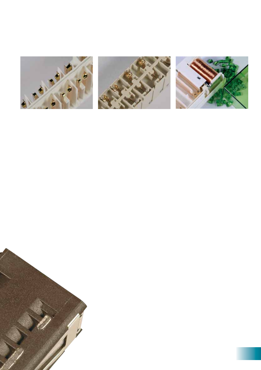
in performance and safety
Set of contacts
Set of contacts with actuator
Open relay
Customer value
With ELESTA relays, however, the
high quality is not only reflected in
the products. Our maxim must stand
up to highest demands also in the
close cooperation with our custom-
ers. The majority of our deliveries,
for example, are shipped within one
week from receipt of the order, and
we promise to deal with your techni-
cal enquiries within 24 hours.
An intensive cooperation with our
customers is very important to us.
Our specialists are ready to support
you in the choice of the correct
relays for your application, train your
personnel in matters of safety relays
and make their know-how available
to you in complex cases.
ELESTA relays GmbH, Heuteilstrasse 18,
CH - 7310 Bad Ragaz, Switzerland
Phone: +41 (0)81 303 54 00
Fax:
+41 (0)81 303 54 01
E-Mail: admin@elestarelays.com
Internet: http://www.elestarelays.com
4
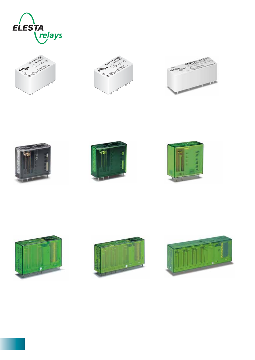
SIR 4 Contacts
SIR 4 Contacts „
P
ower“
SIR 4 Contacts sensitive
- PCB relay with forcibly guided con-
tacts and protective separation
between coil/control contacts and
output contacts (> 10mm) as well
as protective separation between
the output contacts themselves
(> 8mm)
- 4 contacts for 10mA...10A
SIS 3 Contacts
SIS 3 Contacts sensitive
- PCB relay with forcibly guided con-
tacts and protective separation
between coil/control contact and
output contacts (> 8mm).
- 3 contacts for 5mA...6A
SIS 4 Contacts
- PCB relay with forcibly guided
contacts and protective separa-
tion between coil/control contacts
and output contacts (> 8mm) and
output contacts in one row
(> 5.5mm).
- 4 contacts for 5mA...6A
Products for every application –
page 7-8
page 9
SIM 2 Contacts
- PCB relay with forcibly guided con-
tacts and protective separation
between coil and contacts (leakage
and creeping distances > 14mm);
protective separation between left
and right contact side (leakage and
creeping distances > 5.5mm)
- 2 contacts for 10mA...8A
page 17
SIR 8 Contacts
- PCB relay with forcibly guided con-
tacts and protective separation
between coil/contacts (> 10mm)
and contacts in one row (> 8mm)
and as left to right contact side (>
10mm)
- 8 contacts for 10mA...10A
page 26
ELESTA relays GmbH, Heuteilstrasse 18,
CH - 7310 Bad Ragaz, Switzerland
Phone: +41 (0)81 303 54 00
Fax:
+41 (0)81 303 54 01
E-Mail: admin@elestarelays.com
Internet: http://www.elestarelays.com
SIS 2 Contacts
- PCB relay with forcibly guided con-
tacts and protective separation
between coil/control contact and
output contacts (> 10mm).
- 2 contacts for 5mA...6A
page 6
SIR 6 Contacts
SIR 6 Contacts sensitive
- PCB relay with forcibly guided con-
tacts and protective separation
between coil/control contacts and
output contacts (> 10mm) as well
as protective separation between
the output contacts themselves
(> 8mm)
- 6 contacts for 10mA...10A
page 24-25
page 21-23
SGR282Z (2 CO)
SGR282Z (2 CO) sensitive
- PCB relay with forcibly guided con-
tacts and protective separation
between coil and contacts (leakage
and creepage distance > 14mm);
protective separation between the
contacts facing each other
- 2 change-over contacts for 10mA...6A
SIR282 (2 CO)
SIR282 (2 CO) sensitive
- PCB relay with forcibly guided con-
tacts and protective separation
between coil and contacts (leakage
and creepage distance > 14mm);
protective separation between the
contacts facing each other
- 2 change-over contacts for 10mA...8A
page 15-16
page 13-14
5
SIS 6 Contacts
- PCB relay with forcibly guided
contacts and protective separa-
tion between coil/control contacts
and output contacts (> 8mm) and
output contacts in one row
(> 5.5mm).
- 6 contacts for 5mA...6A
multifunctional and safety
page 10
SIM 3 Contacts
- PCB relay with forcibly guided con-
tacts and protective separation
between coil and contacts (leakage
and creeping distances > 14mm);
protective separation between left
and right contact side (leakage and
creeping distances > 5.5mm)
- 3 contacts for 10mA...8A
page 18 SIM 4 Contacts
- PCB relay with forcibly guided con-
tacts and protective separation
between coil and contacts (leakage
and creeping distances > 14mm);
protective separation between left
and right contact side (leakage and
creeping distances > 5.5mm)
- 4 contacts for 10mA...8A
page 19
SIR 10 Contacts
- PCB relay with forcibly guided
contacts and protective separa-
tion between coil/control contacts
and output contacts (> 8mm) and
output contacts in one row (> 8mm)
and as left to right contact side
(> 10mm)
- 10 contacts for 10mA...10A
page 27 SIP 6 Contacts
- PCB relay with forcibly guided
contacts and protective separa-
tion between coil/control contacts
and output contacts (> 8mm) and
output contacts in one row
(> 8mm).
- 2 control contacts for 5mA...6A
- 4 output contacts for 10mA...16A
page 28
SLR 4 Contacts
- PCB relay with forcibly guided con-
tacts and protective separation
between coil/control contacts and
output contacts (> 8mm) as well as
protective separation between the
output contacts themselves
(> 10mm)
- 4 contacts for 10mA...10A
page 20
ELESTA relays GmbH, Heuteilstrasse 18,
CH - 7310 Bad Ragaz, Switzerland
Phone: +41 (0)81 303 54 00
Fax:
+41 (0)81 303 54 01
E-Mail: admin@elestarelays.com
Internet: http://www.elestarelays.com
pages 29-31
Certificate
Accessories
- Plug sockets for print assembly or
DIN rail assembly and module
page 32
SIF 4 Contacts
- PCB relay with forcibly guided con-
tacts and protective separation
between coil/contacts (> 5.5mm)
and contacts side by side
(> 5.5mm)
- 4 contacts for 5mA...8A
page 11 SIF 6 Contacts
- PCB relay with forcibly guided con-
tacts and protective separation
between coil/contacts (> 5.5mm)
and contacts side by side
(> 5.5mm)
- 6 contacts for 5mA...8A
page 12
SIF 4 Contacts
- PCB relay with forcibly guided con-
page 11
Ma
de
in Sw
itze
rland
060
2
c
us
S
E-Nr
. 301053
SIF312
24
V
8A
250V~AC1
DC
ww
w.e
lest
arelay
s.co
m
43
44
23
24
A1
A2
34
33
12
11
Ty
pe A
SIF 6 Contacts
PCB relay with forcibly guided con
page 12
Made in
Switzerland
0549
c
us
S
E-Nr
. 300997
SIF422
24V
8A
250V~AC1
DC
www
.elestarela
ys.com
53
54
63
64
34
33
43
44
12
11
21
22
A1
A2
Ty
pe A
6
ELESTA relays GmbH, Heuteilstrasse 18,
CH - 7310 Bad Ragaz, Switzerland
Phone: +41 (0)81 303 54 00
Fax:
+41 (0)81 303 54 01
E-Mail: admin@elestarelays.com
Internet: http://www.elestarelays.com
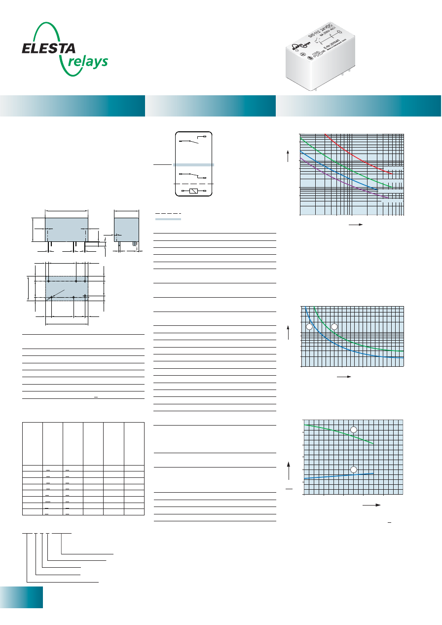
- PCB relay with forcibly guided contacts
- Protective separation between control and
load circuit (leakage and creepage distances
> 10mm)
- EN 50205, type A
- Double and reinforced insulation between
the contacts
- Contact mounting: SIS112 1NO/1NC
- Small external dimensions
- Mean coil power 0.27W
- Holding power 0.08 W
- for Railway Applications: EN 50155
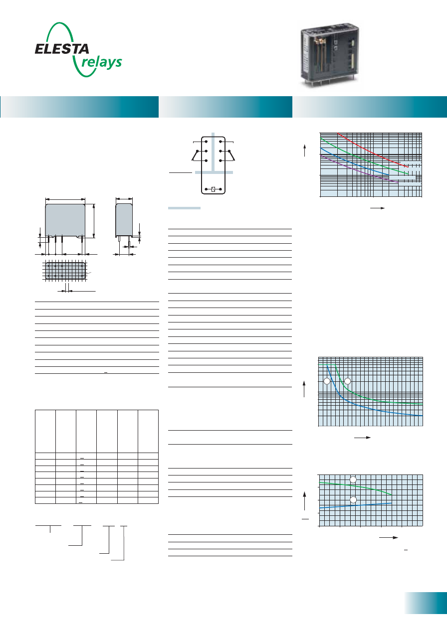
SIS 2 Contacts
U
U
B
N
Ambient temperature °C
0
0
20
40
60
2,0
1,5
1,0
0,5
1
2
80
100
2,5
3,0
SIS112
Control
side
Output
side
Double or reinforced insulation
Basic insulation
10
50
100
1000
500
10000
5000
0,1
0,5
1
2
3 4 5
10
6 789
DC1: 24V
DC13: 24V
AC1: 230V
AC15: 230V
No. of operations x 1
0
0
0
Switching current (A)
Current (A)
Voltage (VDC)
0,6
0,4
0,1
0,3
0,2
0,8
1
2
3
4
6
0
50
100
150
200
250
1
2
Standard coils for direct current
(other voltages on request)
Circuit diagram (view on relay upper side)
Nominal v
olt
age
VDC
Min. pic
k-up
volt
age at 20°C
Drop-out v
olt
age
at 20 °C
Nominal cur
rent
in mA
R
esist
ance in
Ohm at 20 °C
Tolerance in %
5
< 3,5
> 0,5
54,9
91
± 10
6
< 4,2
> 0,6
46,1
130
± 10
9
< 6,3
> 0,9
30,5
295
± 10
12
< 8,4
> 1,2
23,0
520
± 10
18
< 12,6 > 1,8
15,2
1‘180
± 10
24
< 16,8 > 2,4
11,4
2‘100
± 10
48
< 33,6 > 4,8
5,7
8‘350
± 13
60
< 42,0 > 6,0
4,5
13‘100
± 15
Contact material
AgCuNi+0,2-0,4
μ
m Au
Type of contact
Single contact
with notched crown
Rated switching capacity 250VAC 6A AC1 1’500VA
Electr. life AC1 (360 cycles/h) approx.100’000
Inrush current max.
30A for 20ms
Switching voltage range
5 to 250VDC/VAC
Switching current range*
5mA to 6A
Switching capacity range* 60mW to 1’500W (VA)
Contact resistance (as delivered) <100m
Ω
/28V/100 mA
* Guide values
Mechanical life
> 10 x 10
6
operations
Switching frequency, mechanical
15Hz
Response time (NO closed)
typically 10ms
Drop-out time** (NC closed)
typically 3ms
Bounce time of NO contact
typically 2ms
Bounce time of NC contact
typically 15ms
Shock resistance 16ms
NO contact 17g
NC contact 7g
Vibration resistance
NO contact 7g
10-200Hz
NC contact 2g
Test voltage
coil/control contact
2’500Veff 1min
Test voltage
5’000Veff 1min
coil- control contact/output contact
Test voltage contact open
1’500Veff 1min
Insulation resistance at Up 500V
10
8
Ω
Creepage resistance
CTI 175
Weight approx.
18g
Mounting position
any
Ambient temperature
-40°C to +70°C
Type of protection
RT III
Solder bath temperature
270°C/5s
Thermal resistance
55K/W
Temperature limit for coil
120°C
Pollution degree
2
Overvoltage category
III
Resistance to short
1’000A SCPD 6A
circuiting gL/gG
(pre-fuse)
** without spark suppression
Insulation terms
Coil to control contact: Basic insulation
Coil/control contact to output contact:
Double or reinforced insulation > 10mm
Tests, regulations
Approvals
SEV, UL, cUL, TÜV
UL File E188953
Sec. 5
Insulation class IEC 60664-1
250VAC
Protection class II
VDE 0106
Fire protection requirements
UL 94 / V0
Max. switching characteristics (determined
acc. to DIN EN 60947-4-1 / EN 60947-5-1):
AC 1: 250V/6A
AC 15: 230V/3A
DC 1: 24V/6A
DC 13: 24V/5A/0,1 Hz
UL 508: B300 / R300
Contact lifetime
1) Max. excitation voltage with contact load < 2A
2) Min. excitation voltage (guaranteed values)
without previous operation
No heat accumulation due to intrinsic heating
of other components.
Continuous duty 100%.
Excitation voltage range
1) Inductive load, L/R 40 ms
2) Resistive load
Load limit curve with direct current
Ordering example
Relay data
General data
Diagrams
29,2
0,2
16,5
0,4
0,3
0,4
2,8
16,6
1
2,2
18,7
6
2,3
3,3
3,3
16,6
11
2,3
4,2
15
7,7
2,3
3,3
29,2
10
[mm]
Ø
1,3
1,6
1,6
1,6
1,6
±0,2
SIS 1 1 2 24VDC
Soldering tags
Number of NC contacts
Number of NO contacts
Type designation
Coil voltage
7
ELESTA relays GmbH, Heuteilstrasse 18,
CH - 7310 Bad Ragaz, Switzerland
Phone: +41 (0)81 303 54 00
Fax:
+41 (0)81 303 54 01
E-Mail: admin@elestarelays.com
Internet: http://www.elestarelays.com
29,2
2 25,2
2
0,2
0,4
0,3
0,4
2,8
16,6
1
0,2
2,2
6,5 12,2 6
2,3
3,3
3,3
1
6
,6
11
2,3
4,2
6,5 8,5 7,7
2,3
3,3
29,2
10
[mm]
Ø
1,3
16,5
±0,2
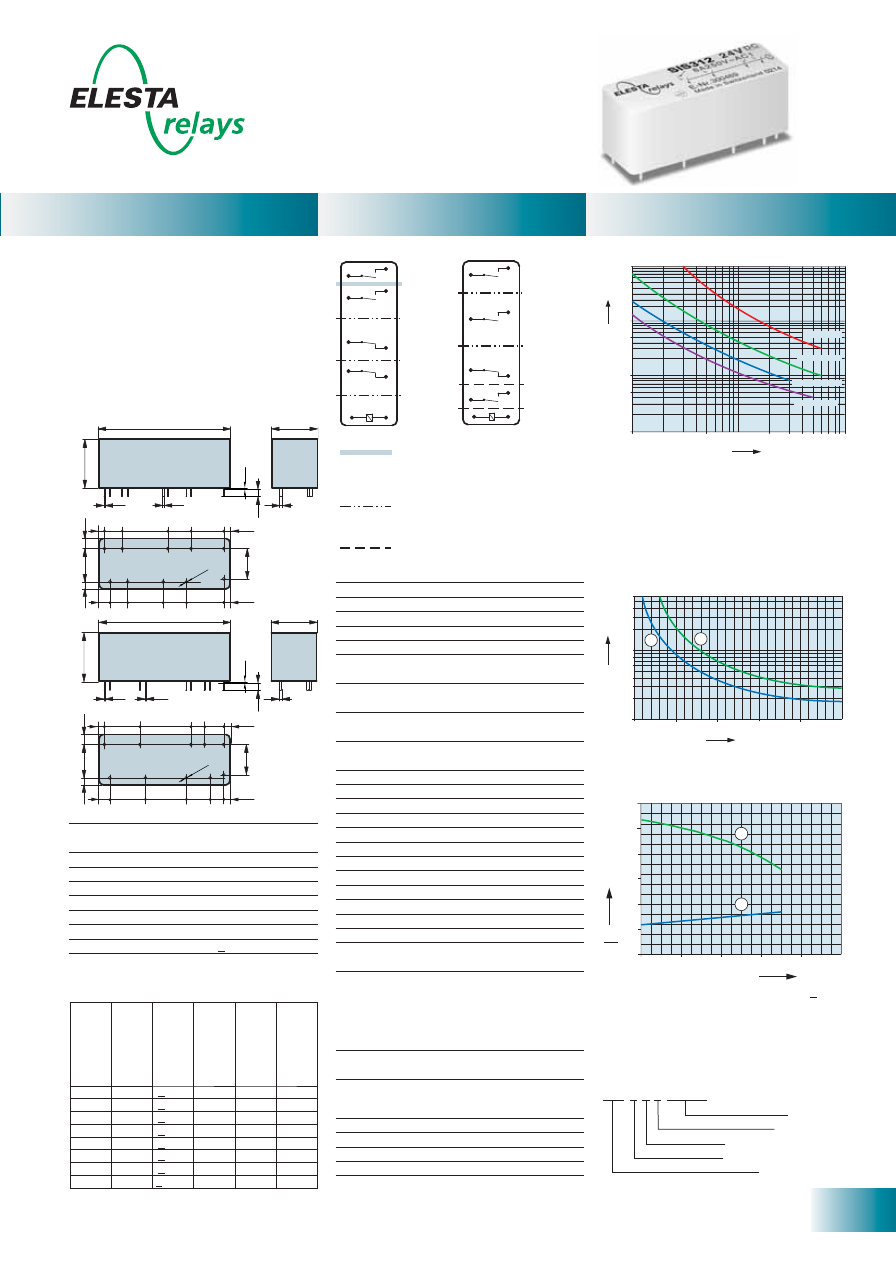
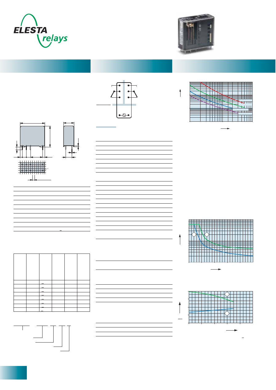
SIS 3 Contacts
0
0
20
40
60
2,0
1,5
1,0
0,5
1
2
80
100
2,5
Ambient temperature °C
U
U
B
N
70
SIS212
Control
side
Output
side
Double or reinforced insulation
Basic insulation
10
50
100
1000
500
10000
5000
0,1
0,5
1
2
3 4 5
10
6 7 89
DC1:
24V
DC13:
24V
AC1:
230V
AC15:
230V
No. of operations x 1
0
0
0
Switching current (A)
Current (A)
Voltage (VDC)
0,6
0,4
0,1
0,3
0,2
0,8
1
2
3
4
6
0
50
100
150
200
250
1
2
Relay data
General data
Diagrams
Standard coils for direct current
(other voltages on request)
Circuit diagram (view on relay upper side)
Nominal v
olt
age
VDC
Min. pic
k-up
volt
age at 20°C
Drop-out v
olt
age
at 20 °C
Nominal cur
rent
in mA
R
esist
ance in
Ohm at 20 °C
Tolerance in %
5
< 3,5
> 0,5
120,0
41,5
± 10
9
< 6,3
> 0,9
66,6
135
± 10
12
< 8,4
> 1,2
50,0
240
± 10
18
< 12,6 > 1,8
33,3
540
± 10
24
< 16,8 > 2,4
25,0
960
± 10
48
< 33,6 > 4,8
12,5
3’840
± 10
60
< 42,0 > 6,0
10,0
6’000
± 13
110
< 77,0 > 11,0
5,4
20’150
± 15
Contact material
AgCuNi+0.2-0.4
μ
m Au
Type of contact
Single contact
with notched crown
Rated switching capacity 250VAC 6A AC1 1’500VA
Electr. life AC1 (360 cycles/h) approx.100’000
Inrush current max.
30A for 20ms
Switching voltage range
5 to 250VDC/VAC
Switching current range*
5mA to 6A
Switching capacity range* 60mW to 1’500W (VA)
Contact resistance (as delivered) < 100m
Ω
/
28V/100mA
* Guide values
Mechanical life
> 10 x 10
6
operations
Switching frequency, mechanical
15Hz
Response time (all NO closed) typically 10ms
Drop-out time** (all NC closed) typically 3ms
Bounce time of NO contact
typically 2ms
Bounce time of NC contact
typically 15ms
Shock resistance 16ms
NO contact 17g
NC contact 10g
Vibration resistance
NO contact 7g
10-200Hz
NC contact 3g
Test voltage
coil/control contact
2’500Veff 1min
Test voltage
4’000Veff 1min
output contacts as against each other
Test voltage contact open
1’500Veff 1min
Insulation resistance at Up 500V
10
8
Ω
Creepage resistance
CTI 175
Weight approx.
20g
Mounting position
any
Ambient temperature
-40°C to +70°C
Type of protection
RT III
Solder bath temperature
270°C/5s
Thermal resistance
55K/W
Temperature limit for coil
120°C
Pollution degree
2
Overvoltage category
III
Resistance to short
1’000A SCPD 6A
circuiting gG
(pre-fuse)
** without spark suppression
Insulation terms
Coil to control contact: Basic insulation
Coil/control contact to output contacts:
Double or reinforced insulation > 8mm
Tests, regulations
Approvals
SEV, UL, cUL, TÜV
UL File E188953
Sec. 5
Insulation class IEC 60664-1
250VAC
Protection class II
VDE 0106
Fire protection requirements
UL 94 / V0
Max. switching characteristics (determined
acc. to DIN EN 60947-4-1 / EN 60947-5-1):
AC 1: 250V/6A
AC 15: 230V/3A
DC 1: 24V/6A
DC 13: 24V/5A/0,1 Hz
UL 508: B300 / R300
Contact lifetime
Maximal contact load at AC 1 with 230V:
2 contacts each with 6A
1) Max. excitation voltage with contact load < 2A
2) Min. excitation voltage (guaranteed values)
without previous operation
No heat accumulation due to intrinsic heating
of other components.
Continuous duty 100%.
Excitation voltage range
1) Inductive load, L/R 40 ms
2) Resistive load
Load limit curve with direct current
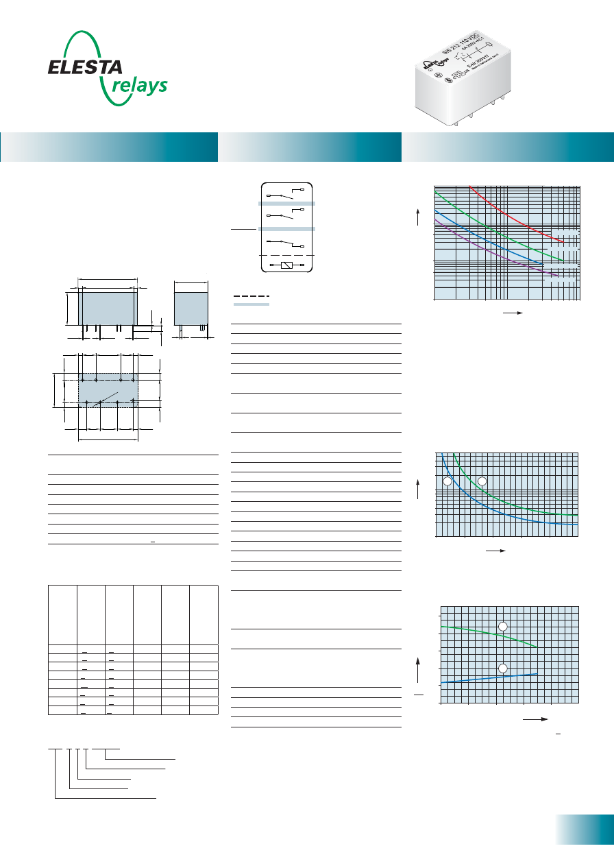
- PCB relay with forcibly guided contacts
- Protective separation between control and
load circuit (leakage and creepage distance
> 8mm)
- EN 50205, type A
- Double and reinforced insulation between
the contacts
- Contact mounting: SIS212 2NO/1NC
- Small external dimensions
- Mean coil power 0.6W
- Holding power 0.18 W
Ordering example
Soldering tags
Number of NC contacts
Number of NO contacts
Type designation
Coil voltage
SIS 2 1 2 24VDC
8
ELESTA relays GmbH, Heuteilstrasse 18,
CH - 7310 Bad Ragaz, Switzerland
Phone: +41 (0)81 303 54 00
Fax:
+41 (0)81 303 54 01
E-Mail: admin@elestarelays.com
Internet: http://www.elestarelays.com
SIS 3 Contacts sensitive
0
0
20
40
60
2,0
1,5
1,0
0,5
1
2
80
100
2,5
Ambient temperature °C
U
U
B
N
70
SIS212
Control
side
Output
side
Double or reinforced insulation
Basic insulation
10
50
100
1000
500
10000
5000
0,1
0,5
1
2
3 4 5
10
6 7 89
DC1:
24V
DC13:
24V
AC1:
230V
AC15:
230V
No. of operations x 1
0
0
0
Switching current (A)
Current (A)
Voltage (VDC)
0,6
0,4
0,1
0,3
0,2
0,8
1
2
3
4
6
0
50
100
150
200
250
1
2
29,2
2 25,2
2
0,2
0,4
0,3
0,4
2,8
16,6
1
0,2
2,2
6,5 12,2 6
2,3
3,3
3,3
1
6
,6
11
2,3
4,2
6,5 8,5 7,7
2,3
3,3
29,2
10
[mm]
Ø
1,3
16,5
±0,2
Standard coils for direct current
(other voltages on request)
Circuit diagram (view on relay upper side)
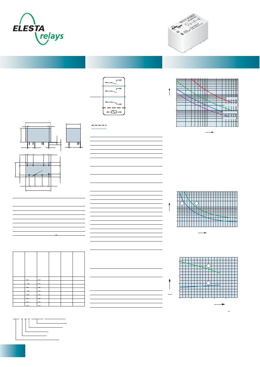
- PCB relay with forcibly guided contacts
- Protective separation between control and
load circuit (leakage and creepage distance
> 8mm)
- EN 50205, type A
- Double and reinforced insulation between
the contacts
- Contact mounting: SIS212 2NO/1NC
- Small external dimensions
- Mean coil power 0.4W
- Holding power 0.14 W
- For Railway Applications: EN 50155
Contact material
AgCuNi+0.2-0.4
μ
m Au
Type of contact
Single contact
with notched crown
Rated switching capacity 250VAC 6A AC1 1’500VA
Electr. life AC1 (360 cycles/h) approx.100’000
Inrush current max.
30A for 20ms
Switching voltage range
5 to 250VDC/VAC
Switching current range*
5mA to 6A
Switching capacity range* 60mW to 1’500W (VA)
Contact resistance (as delivered) <100m
Ω
/28 V/100mA
* Guide values
Nominal v
olt
age
VDC
Min. pic
k-up
volt
age at 20°C
Drop-out v
olt
age
at 20 °C
Nominal cur
rent
in mA
R
esist
ance in
Ohm at 20 °C
Tolerance in %
5
< 3,75 > 0,5
80,0
62,5
± 10
6
< 4,5
> 0,6
66,6
90
± 10
9
< 6,75 > 0,9
44,5
202
± 10
12
< 9,0
> 1,2
33,3
360
± 10
18
< 13,5 > 1,8
22,2
810
± 10
24
< 18,0 > 2,4
16,6
1’440
± 10
48
< 36,0 > 4,8
8,3
5’750
± 13
60
< 45,0 > 6,0
6,6
9’000
± 15
Mechanical life
> 10 x 10
6
operations
Switching frequency, mechanical
15Hz
Response time (all NO closed) typically 10ms
Drop-out time** (all NC closed) typically 3ms
Bounce time of NO contact
typically 2ms
Bounce time of NC contact
typically 15ms
Shock resistance 16ms
NO contact 17g
NC contact 10g
Vibration resistance
NO contact 7g
10-200Hz
NC contact 3g
Test voltage
coil/control contact
2’500Veff 1min
Test voltage
4’000Veff 1min
output contacts as against each other
Test voltage contact open
1’500Veff 1min
Insulation resistance at Up 500V
10
8
Ω
Creepage resistance
CTI 175
Weight approx.
20g
Mounting position
any
Ambient temperature
-40°C to +70°C
Type of protection
RT III
Solder bath temperature
270°C/5s
Thermal resistance
55K/W
Temperature limit for coil
120°C
Pollution degree
2
Overvoltage category
III
Resistance to short
1’000A SCPD 6A
circuiting gG
(pre-fuse)
** without spark suppression
Insulation terms
Coil to control contact: Basic insulation
Coil/control contact to output contacts:
Double or reinforced insulation > 8mm
Tests, regulations
Approvals
SEV, UL, cUL, TÜV
UL File E188953
Sec. 5
Insulation class IEC 60664-1
250VAC
Protection class II
VDE 0106
Fire protection requirements
UL 94 / V0
Max. switching characteristics (determined
acc. to DIN EN 60947-4-1 / EN 60947-5-1):
AC 1: 250V/6A
AC 15: 230V/3A
DC 1: 24V/6A
DC 13: 24V/5A/0,1 Hz
UL 508: B300 / R300
Contact lifetime
1) Max. excitation voltage with contact load < 2A
2) Min. excitation voltage (guaranteed values)
without previous operation
No heat accumulation due to intrinsic heating
of other components.
Continuous duty 100%.
Excitation voltage range
1) Inductive load, L/R 40 ms
2) Resistive load
Load limit curve with direct current
Maximal contact load at AC 1 with 230V:
2 contacts each with 6A
Relay data
General data
Diagrams
Ordering example
Soldering tags
Number of NC contacts
Number of NO contacts
Type designation
Coil voltage
sensitive coil
SIS 2 1 2 24VDC SEN
9
ELESTA relays GmbH, Heuteilstrasse 18,
CH - 7310 Bad Ragaz, Switzerland
Phone: +41 (0)81 303 54 00
Fax:
+41 (0)81 303 54 01
E-Mail: admin@elestarelays.com
Internet: http://www.elestarelays.com
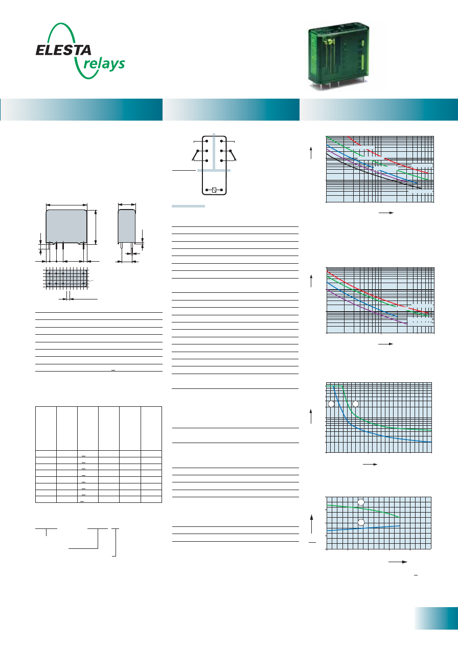
SIS 4 Contacts
Ambient temperature °C
U
U
B
N
0
0
20
40
60
2,0
1,5
1,0
0,5
1
2
80
100
2,5
3,0
Double or reinforced insulation for
mains circuits
> 8mm leakage distance,
> 5,5mm creeping distance
Basic insulation
> 4mm leakage and creeping distance
Double or reinforced insulation for safety
low voltage
> 8mm leakage and creeping distance
SIS222
SIS312
0,6
0,4
0,1
0,3
0,2
0,8
1
2
3
4
6
0
50
100
150
200
250
1
2
Current (A)
Voltage (VDC)
16,6
48
0,3
0,4
13
18,7
5
7
13
15
8,7
5
2,3
2
10
2,3
4
11
3,3
2,3
[mm]
16,5
±0,2
16,6
1
48
0,3
0,4
6,5
16,7
8,5
12
6,5
13
8,5
13,7
2,3
2
10
2,3
4
11
3,3
2,3
SIS222
SIS312
Ø
1,3
Ø
1,3
16,5
±0,2
0,2
2,8
0,2
2,8
1
Relay data
General data
Diagrams
Standard coils for direct current
(other voltages on request)
- PCB relay with forcibly guided contacts
- Protective separation between control and
load circuit (leakage and creepage distance
> 8mm)
- EN 50205, type A
- Double and reinforced insulation between
the contacts
- Contact mounting:
SIS312 3NO/1NC SIS222 2NO/2NC
- Small external dimensions
- Mean coil power 0.5W
- Holding power 0.15 W
- For Railway Applications: EN 50155
10
50
100
1000
500
10000
5000
0,1
0,5
1
2
3 4 5
10
6 7 89
DC1:
24V
DC13:
24V
AC1:
230V
AC15:
230V
No. of operations x 1
0
0
0
Switching current (A)
Contact lifetime
Contact material
AgCuNi+0,2-0,4
μ
m Au
Type of contact
Single contact
with notched crown
Rated switching capacity 250VAC 6A AC1 1’500VA
Electr. life AC1 (360 cycles/h) approx.100’000
Inrush current max.
30A for 20ms
Switching voltage range
5 to 250VDC/VAC
Switching current range*
5mA to 6A
Switching capacity range* 60mW to 1’500W (VA)
Contact resistance (as delivered) <100m
Ω
/28 V/100mA
* Guide values
Nominal v
olt
age
VDC
Min. pic
k-up
volt
age at 20°C
Drop-out volt
age
Nominal cur
rent
in mA
R
esist
ance in
Ohm at 20 °C
Tolerance in %
5
3,5
> 0,5
100
50
± 10
9
6,3
> 0,9
56,2
160
± 10
12
8,4
> 1,2
42,1
285
± 10
18
12,6
> 1,8
28,1
640
± 10
24
16,8
> 2,4
20,8
1’150
± 10
48
33,6
> 4,8
10,4
4’600
± 13
60
42,0
> 6,0
8,3
7’200
± 13
110
77,0
> 11,0
4,5
24’200
± 15
Mechanical life
> 10 x 10
6
operations
Switching frequency, mechanical
15Hz
Response time (all NO closed) typically 15ms
Drop-out time** (all NC closed) typically 5ms
Bounce time of NO contact
typically 2ms
Bounce time of NC contact
typically 15ms
Shock resistance 16ms
NO contact 10g
NC contact 10g
Vibration resistant
NO contact 10g
10-200Hz
NC contact 4g
Test voltage
coil/control contacts***
2’500Veff 1min
Test voltage
4’000Veff 1min
output contacts as against each other
Test voltage contact open
1’500Veff 1min
Insulation resistance at Up 500V
10
8
Ω
Creepage resistance
CTI 175
Weight approx.
30g
Mounting position
any
Ambient temperature
-40°C to +70°C
Type of protection
RT III
Solder bath temperature
270°C/5s
Thermal resistance
45K/W
Temperature limit for coil
120°C
Pollution degree
2
Overvoltage category
III
Resistance to short
1’000A SCPD 6A
circuiting gG
(pre-fuse)
** without spark suppression
*** SIS222 4000Veff 1min
Insulation terms
Coil/control contacts: Basic insulation SIS312
Double or reinforced insulation > 8mm SIS222
Coil/control contacts to output contacts:
Double or reinforced insulation > 8mm
Tests, regulations
Approvals
SEV, UL, cUL, TÜV
UL File E188953
Sec. 5
Insulation class IEC 60664-1
250VAC
Protection class II
VDE 0106
Fire protection requirements
UL 94 / V0
Circuit diagram (view on relay upper side)
Ordering example
Maximal contact load at AC 1 with 230V:
2 contacts each with 6A / 3 contacts each with 4A
1) Max. excitation voltage with contact load < 2A
2) Min. excitation voltage (guaranteed values)
without previous operation
No heat accumulation due to intrinsic heating of
other components.
Continuous duty 100%.
Excitation voltage range
1) Inductive load, L/R 40 ms
2) Resistive load
Load limit curve with direct current
Max. switching characteristics (determined
acc. to DIN EN 60947-4-1 / EN 60947-5-1):
AC 1: 250V/6A
AC 15:
230V/3A
DC 1: 24V/6A
DC 13: 24V/5A/0.1 Hz
UL 508: B300 / R300
Soldering tags
Number of NC contacts
Number of NO contacts
Type designation
Coil voltage
S I S 3 1 2 24VDC
10
ELESTA relays GmbH, Heuteilstrasse 18,
CH - 7310 Bad Ragaz, Switzerland
Phone: +41 (0)81 303 54 00
Fax:
+41 (0)81 303 54 01
E-Mail: admin@elestarelays.com
Internet: http://www.elestarelays.com
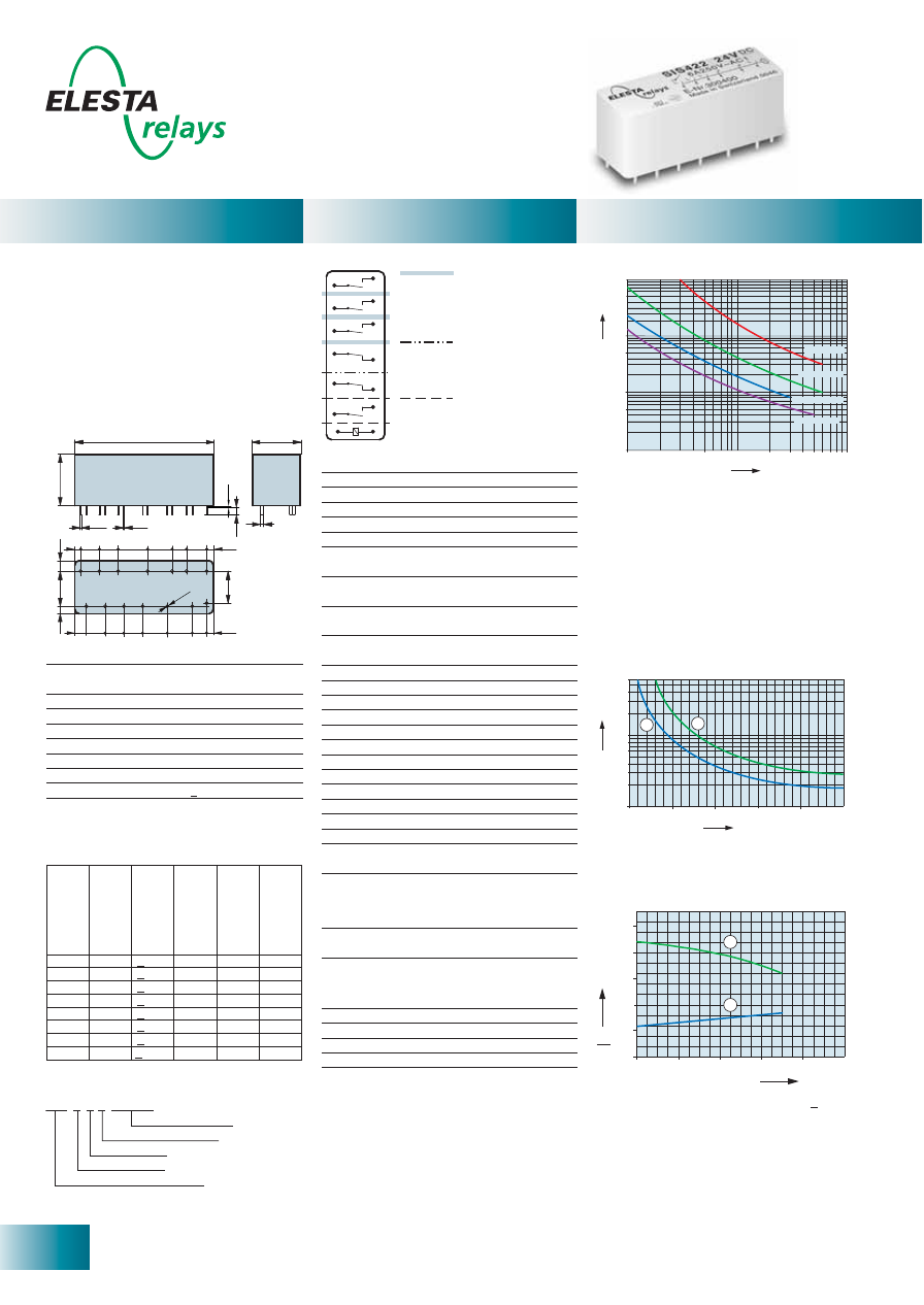
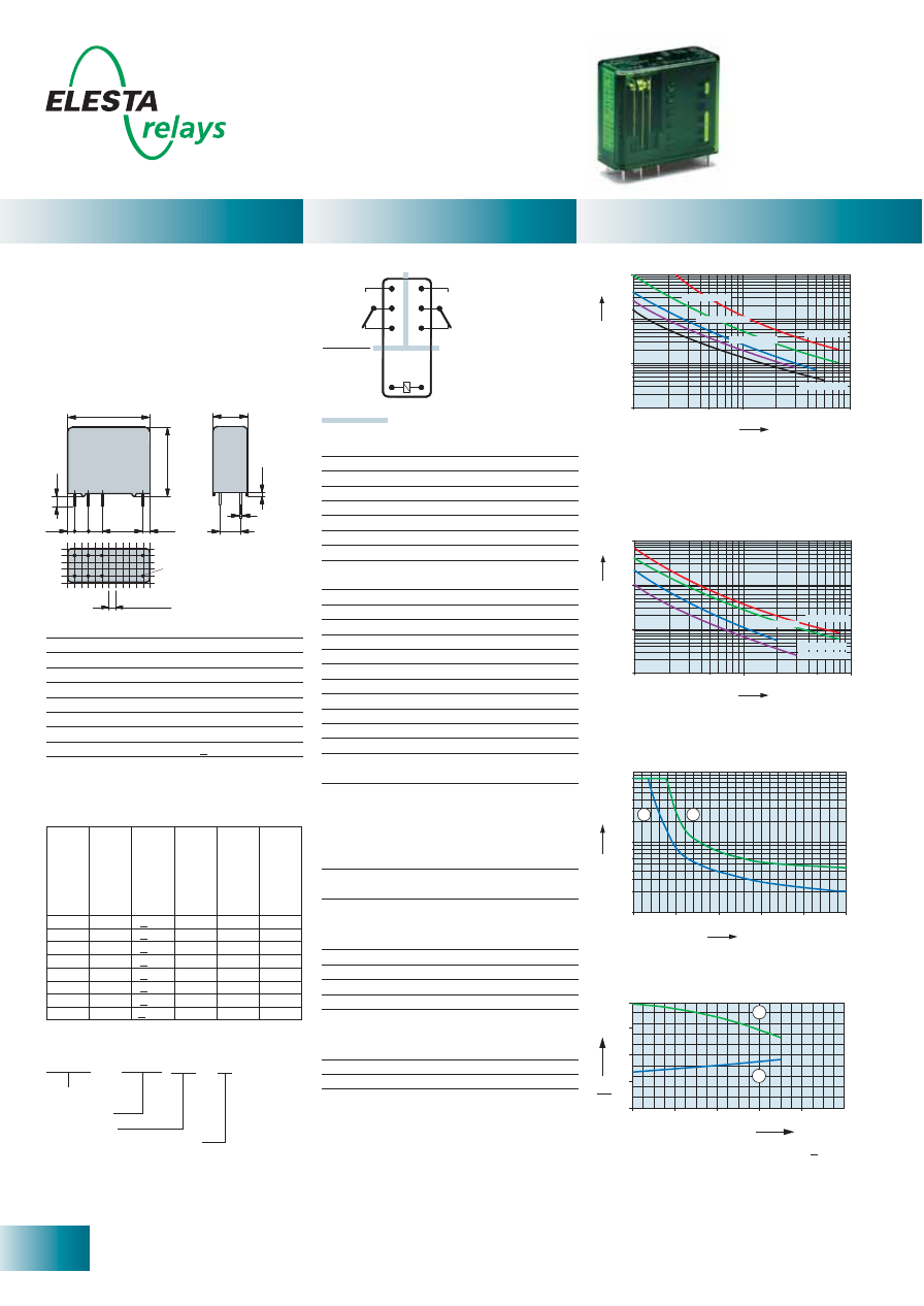
SIS 6 Contacts
0
0
20
40
60
2,0
1,5
1,0
0,5
1
2
80
100
2,5
Ambient temperature °C
U
U
B
N
70
Double or reinforced insulation for
mains circuits
> 8mm leakage distance,
> 5,5mm creeping distance
Basic insulation
> 4mm leakage and creeping distance
Double or reinforced insulation for
safety low voltage
> 8mm leakage and creeping distance
SIS422
0,6
0,4
0,1
0,3
0,2
0,8
1
2
3
4
6
0
50
100
150
200
250
1
2
Current (A)
Voltage (VDC)
16,6
1
48
0,3
0,4
6,5 6,5
10,2
8,5
5
7
6,5 6,5 6,5
8,5
8,7
5
2,3
2
10
2,3
4
11
3,3
2,3
[mm]
Ø
1,3
16,5
±0,2
0,2
2,8
Standard coils for direct current
(other voltages on request)
- PCB relay with forcibly guided contacts
- Protective separation between control and
load circuit (leakage and creepage distance
> 8mm)
- EN 50205, type A
- Double and reinforced insulation between
the contacts
- Contact mounting: SIS422
4NO/2NC
- Small external dimensions
- Mean coil power 0.66W
- Holding power 0.20W
- For Railway Applications: EN 50155
10
50
100
1000
500
10000
5000
0,1
0,5
1
2
3 4 5
10
6 7 89
DC1:
24V
DC13:
24V
AC1:
230V
AC15:
230V
No. of operations x 1
0
0
0
Switching current (A)
Contact lifetime
Contact material
AgCuNi+0.2-0.4
μ
m Au
Type of contact
Single contact
with notched crown
Rated switching capacity 250VAC 6A AC1 1’500VA
Electr. life AC1 (360 cycles/h) approx.100’000
Inrush current max.
30A for 20ms
Switching voltage range
5 to 250VDC/VAC
Switching current range*
5mA to 6A
Switching capacity range* 60mW to 1’500W (VA)
Contact resistance (as delivered) < 100m
Ω
/ 28 V / 100mA
* Guide values
Nominal v
olt
age
VDC
Min. pic
k-up
volt
age at 20°C
Drop-out v
olt
age
at 20 °C
Nominal cur
rent
in mA
R
esist
ance in
Ohm at 20 °C
Tolerance in %
5
3,5
> 0,5
133
37,5
± 10
9
6,3
> 0,9
73,7
122
± 10
12
8,4
> 1,2
55,8
215
± 10
18
12,6
> 1,8
37,1
485
± 10
24
16,8
> 2,4
29,7
860
± 10
48
33,6
> 4,8
13,9
3’450
± 10
60
42,0
> 6,0
11,1
5’400
± 13
110
77,0
> 11,0
6,0
18’300
± 15
Mechanical life
> 10 x 10
6
operations
Switching frequency, mechanical
15Hz
Response time (all NO closed) typically 15ms
Drop-out time** (all NC closed) typically 5ms
Bounce time of NO contact
typically 2ms
Bounce time of NC contact
typically 15ms
Shock resistance 16ms
NO contact 10g
NC contact 9g
Vibration resistant
NO contact 10g
10-200Hz
NC contact 3g
Test voltage
coil/control contacts
2’500Veff 1min
Test voltage
4’000Veff 1min
output contacts as against each other
Test voltage contact open
1’500Veff 1min
Insulation resistance at Up 500V
10
8
Ω
Creepage resistance
CTI 175
Weight approx.
35g
Mounting position
any
Ambient temperature
-40°C to +70°C
Type of protection
RT III
Solder bath temperature
270°C/5s
Thermal resistance
45K/W
Temperature limit for coil
120°C
Pollution degree
2
Overvoltage category
III
Resistance to short
1’000A SCPD 6A
circuiting gG
(pre-fuse)
** without spark suppression
Insulation terms
Coil/control contacts: Basic insulation
Coil/control contacts to output contacts:
Double or reinforced insulation > 8mm
Tests, regulations
Approvals
SEV, UL, cUL, TÜV
UL File E188953
Sec. 5
Insulation class IEC 60664-1
250VAC
Protection class II
VDE 0106
Fire protection requirements
UL 94 / V0
Maximal contact load at AC 1 with 230V:
2 contacts each with 6A
3 contacts each with 4A
4 contacts each with 3A
1) Max. excitation voltage with contact load < 2A
2) Min. excitation voltage (guaranteed values)
without previous operation
No heat accumulation due to intrinsic heating
of other components.
Continuous duty 100%.
Excitation voltage range
1) Inductive load, L/R 40 ms
2) Resistive load
Load limit curve with direct current
Relay data
General data
Diagrams
Ordering example
Max. switching characteristics (determined
acc. to DIN EN 60947-4-1 / EN 60947-5-1):
AC 1: 250V/6A
AC 15:
230V/3A
DC 1: 24V/6A
DC 13: 24V/5A/0.1 Hz
UL 508: B300 / R300
Soldering tags
Number of NC contacts
Number of NO contacts
Type designation
Coil voltage
S I S 4 2 2 24VDC
Circuit diagram (view on relay upper side)
11
ELESTA relays GmbH, Heuteilstrasse 18,
CH - 7310 Bad Ragaz, Switzerland
Phone: +41 (0)81 303 54 00
Fax:
+41 (0)81 303 54 01
E-Mail: admin@elestarelays.com
Internet: http://www.elestarelays.com
SIF 4 Contacts
Relay data
General data
Diagrams
Circuit diagram (view on relay upper side)
- PCB relay with forcibly guided contacts
- Protective separation between coil and
contacts (> 5.5 mm) and contacts side by
side (> 5.5 mm)
- EN 50205 type A
- Double and reinforced insulation
- SMD arrangement below relay possible
- Contact mounting: SIF312 3AK/1RK
- Compact height: only 10.9mm
- Mean coil power 0.70W
- Holding power 0.21 W
- For Railway Applications: EN 50155
Nominal v
olt
age
VDC
Min. pic
k-up
volt
age at 20°C
VDC
Drop-out v
olt
age
at 20 °C VDC
Nominal cur
rent
in mA
R
esist
ance in
Ohm at 20 °C
Tolerance in %
5
< 3.5
> 0.5
140.0
35.7
± 10
12
< 8.4
> 1.2
58.5
205
± 10
18
< 12.6 > 1.8
39.1
460
± 10
20
< 14.0 > 2.0
35.0
570
± 10
24
< 16.8 > 2.4
29.2
820
± 10
48
< 33.6 > 4.8
14.6
3‘280
± 10
60
< 42.0 > 6.0
11.7
5‘100
± 13
110
< 77,0 > 11,0
6,3
17‘250
± 13
Contact material
AgCuNi + 0.2
μ
m Au
Type of contact
Single contact
with notched crown
Rated switching capacity 250VAC 8A AC1 2‘000VA
Electr. life AC1 (360 S/h)
approx.100‘000
Inrush current max
30A for 20ms
Switching voltage range
5 to 250VDC/VAC
Switching current range*
5mA to 8A
Switching capacity range* 60mW to 2‘000W (VA)
Contact resistance (as delivered) < 100m
Ω
/28 V/100mA
* Guide values
Mechanical life
> 10 x 10
6
operations
Switching frequency, mechanical
15Hz
Response time
typically 12ms
Drop-out time**
typically 5ms
Bounce time of NO contact
typically 3ms
Bounce time of NC contact
typically 12ms
Shock resistance
NO contact 15g
NC contact 6g
Vibration resistance
NO contact 10g
10-200Hz
NC contact 2g
Test voltage
coil to contacts
4‘000V
eff
1min
Test voltage
4’000V
eff
1min
contacts against each other
Test voltage contact open
1’500V
eff
1min
Insulation resistance at Up 500V
10
8
Ω
Creepage resistance
CTI 175
Weight approx.
20g
Mounting position
any
Ambient temperature
-40°C to +70°C
Type of protection
RT II
Solder bath temperature
270°C/5s
Thermal resistance
60K/W
Temperature limit for coil
120°C
Pollution degree
2
Overvoltage category
III
Resistance to
1‘000A SCPD 10A
short circuiting
gL/gG (pre-fuse)
** without spark suppression
Insulation terms
Double or reinforced insulation >5.5mm
between all current circuits
Tests, regulations
Approvals
SEV, UL, cUL, TÜV
UL File E188953
Sec. 6
Insulation class IEC 60664-1
250VAC
Protection class II
VDE 0106
Fire protection requirements
UL 94 / V0
Max. switching characteristics
(DIN EN 60947-4-1/ EN 60947-5-1):
AC 1: 250V/8A
AC 15: 230V/6A
DC 1: 24V/8A
DC 13: 24V/5A/0.1Hz
UL508: B300/R300
Maximal contact load at AC 1with 230V:
2 contacts each with 8A
3 contacts each with 6A
Contact lifetime
1) Max. excitation voltage with contact load < 6A
2) Min. excitation voltage (guaranteed values)
without previous operation
No heat accumulation due to intrinsic heating
of other components.
Continuous duty 100%.
Excitation voltage range
Load limit curve with direct current
(Resistive load)
Ordering example
Ma
de
in S
witz
erlan
d 060
2
c
us
S
E-Nr
. 301053
SIF312
24
V
8A
250V~AC1
DC
ww
w.elest
arelay
s.com
43
44
23
24
A1
A2
34
33
12
11
Type A
Standard coils for direct current
(other voltages on request)
Soldering tags
Number of NC contacts
Number of NO contacts
Type designation
Coil voltage
SIF 3 1 2 24VDC
SIF-312
A1
A2
11
12
23
24
33
34
43
44
Double or reinforced insulation
100
1000
10000
10
No. of operations x 1000
0.5
0.1
1
2
3 4 5 6 7 8 910
Switching current (A)
500
300
200
100
70
50
30
20
10
0.1 0.2 0.3 0.5 0.7 1.0 2 3 4 5 6 7 8 10
Current (A)
10 W
20 W
40 W
60 W
80 W
100 W
150 W
200 W
250 W
300 W
V
oltage (VDC)
0
0
20 40 60
2.0
1.5
1.0
0.5
80
1 0 0
2.5
2
1
Ambient temperature °C
U
B
N
U
70
1
4,2
41
10,9
1,5
1,6
37,8
2,2
2,9
7,6
5,1
29,4
23,2
3,1
3,1
4,2
1,2
15,8
18,2
23,2
7,5 7,5 7,5
6,4
21
4,2
4,2
3,1
3,1
15,4
3,1
1,5 1,6
0,3
[mm]
10,5
4,8
Ø1,3
28,3
7,6
5,1
*
*
*
*
*Do not drill when SMD arrangement.
12
ELESTA relays GmbH, Heuteilstrasse 18,
CH - 7310 Bad Ragaz, Switzerland
Phone: +41 (0)81 303 54 00
Fax:
+41 (0)81 303 54 01
E-Mail: admin@elestarelays.com
Internet: http://www.elestarelays.com
SIF 6 Contacts
Relay data
General data
Diagrams
Circuit diagram (view on relay upper side)
- PCB relay with forcibly guided contacts
- Protective separation between coil and
contacts (> 5.5 mm) and contacts side by
side (> 5.5 mm)
- EN 50205 type A
- Double and reinforced insulation
- SMD arrangement below relay possible
- Contact mounting: SIF422 4NO/2NC
- Compact height: only 10.9mm
- Mean coil power 0.66W
- Holding power 0.20 W
- For Railway Applications EN50155
Nominal v
olt
age
VDC
Min. pic
k-up
volt
age at 20°C
VDC
Drop-out v
olt
age
at 20 °C VDC
Nominal cur
rent
in mA
R
esist
ance in
Ohm at 20 °C
Tolerance in %
5
< 3.5
> 0.5
133.3
37.5
± 10
12
< 8.4
> 1.2
55.8
215
± 10
18
< 12,6 > 1,8
38,9
462
± 10
20
< 14.0 > 2.0
33.3
600
± 10
24
< 16.8 > 2.4
27.5
870
± 10
48
< 33.6 > 4.8
13.8
3‘460
± 10
60
< 42.0 > 6.0
11.1
5‘400
± 13
110
< 77.0 > 11.0
6.0
18‘300
± 15
Contact material
AgCuNi + 0.2
μ
m Au
Type of contact
Single contact
with notched crown
Rated switching capacity 250VAC 8A AC1 2‘000VA
Electr. life AC1 (360 S/h)
approx.100‘000
Inrush current max.
30A for 20ms
Switching voltage range
5 to 250VDC/VAC
Switching current range*
5mA to 8A
Switching capacity range* 60mW to 2‘000W (VA)
Contact resistance (as delivered)) < 100m
Ω
/ 28 V / 100mA
* Guide values
Mechanical life
> 10 x 10
6
operations
Switching frequency, mechanical
15Hz
Response time
typically 20ms
Drop-out time**
typically 8ms
Bounce time of NO contact
typically 3ms
Bounce time of NC contact
typically 12ms
Shock resistance
NO contact 10g
NC contact 6g
Vibration resistance
NO contact 10g
10-200Hz
NC contact 2g
Test voltage
coil to contacts
4‘000V
eff
1min
Test voltage
contacts against each other 4’000V
eff
1min
Test voltage contact open
1’500V
eff
1min
Insulation resistance at Up 500V
10
8
Ω
Creepage resistance
CTI 175
Weight approx.
35g
Mounting position
any
Ambient temperature
-40°C to +70°C
Type of protection
RT II
Solder bath temperature
270°C/5s
Thermal resistance
47K/W
Temperature limit for coil
120°C
Pollution degree
2
Overvoltage category
III
Resistance to
1‘000A SCPD 10A
short circuiting
gL/gG (pre-fuse)
** without spark suppression
Insulation terms
Double or reinforced insulation >5.5mm
between all current circuits
Tests, regulations
Approvals
SEV, UL, cUL, TÜV
UL File E188953
Sec. 6
Insulation class IEC 60664-1
250VAC
Protection class II
VDE 0106
Fire protection requirements
UL 94 / V0
Ordering example
[mm]
10,9
3,1
2,9
2,2
53,6
7,5
7,5
15,4
1,6
1,5
3,1
3,1
4,1
4,1
15,8
15,8
15,8
33,5
30,4
1,6 1,5
1
0,3
3,1
47,4
Ø1,3
0,5
0,4
1,2
3,1
3,3
*
*
*
*
Max. switching characteristics
(DIN EN 60947-4-1/ EN 60947-5-1):
AC 1: 250V/8A
AC 15: 230V/6A
DC 1: 24V/8A
DC 13: 24V/5A/0.1Hz
UL508: B300/R300
Maximal contact load at AC 1 with 230V:
2 contacts each with 8A
3 contacts each with 6A
4 contacts each with 4.5A
Contact lifetime
1) Max. excitation voltage with contact load < 6A
2) Min. excitation voltage (guaranteed values)
without previous operation
No heat accumulation due to intrinsic heating
of other components.
Continuous duty 100%.
Excitation voltage range
Load limit curve with direct current
(Resistive load)
Made in
Switzerland
0549
c
us
S
E-Nr
. 300997
SIF422
24V
8A
250V~AC1
DC
www
.elestarelays.com
53
54
63
64
34
33
43
44
12
11
21
22
A1
A2
Ty
pe
A
Standard coils for direct current
(other voltages on request)
SIF 4 2 2 24VDC
Soldering tags
Number of NC contacts
Number of NO contacts
Type designation
Coil voltage
SIF-422
Double or reinforced insulation
A1
A2
12
22
11
21
34
44
33
43
54
64
53
63
500
300
200
100
70
50
30
20
10
0.1 0.2 0.3 0.5 0.7 1.0 2 3 4 5 6 7 8 10
Current (A)
10 W
20 W
40 W
60 W
80 W
100 W
150 W
200 W
250 W
300 W
V
oltage (VDC)
0
0
20 40 60
2.0
1.5
1.0
0.5
80
1 0 0
2.5
2
1
Ambient temperature °C
U
B
N
U
70
*Do not drill when SMD arrangement.
100
1000
10000
10
No. of operations x 1000
0.5
0.1
1
2
3 4 5 6 7 8 910
Switching current (A)
13
ELESTA relays GmbH, Heuteilstrasse 18,
CH - 7310 Bad Ragaz, Switzerland
Phone: +41 (0)81 303 54 00
Fax:
+41 (0)81 303 54 01
E-Mail: admin@elestarelays.com
Internet: http://www.elestarelays.com
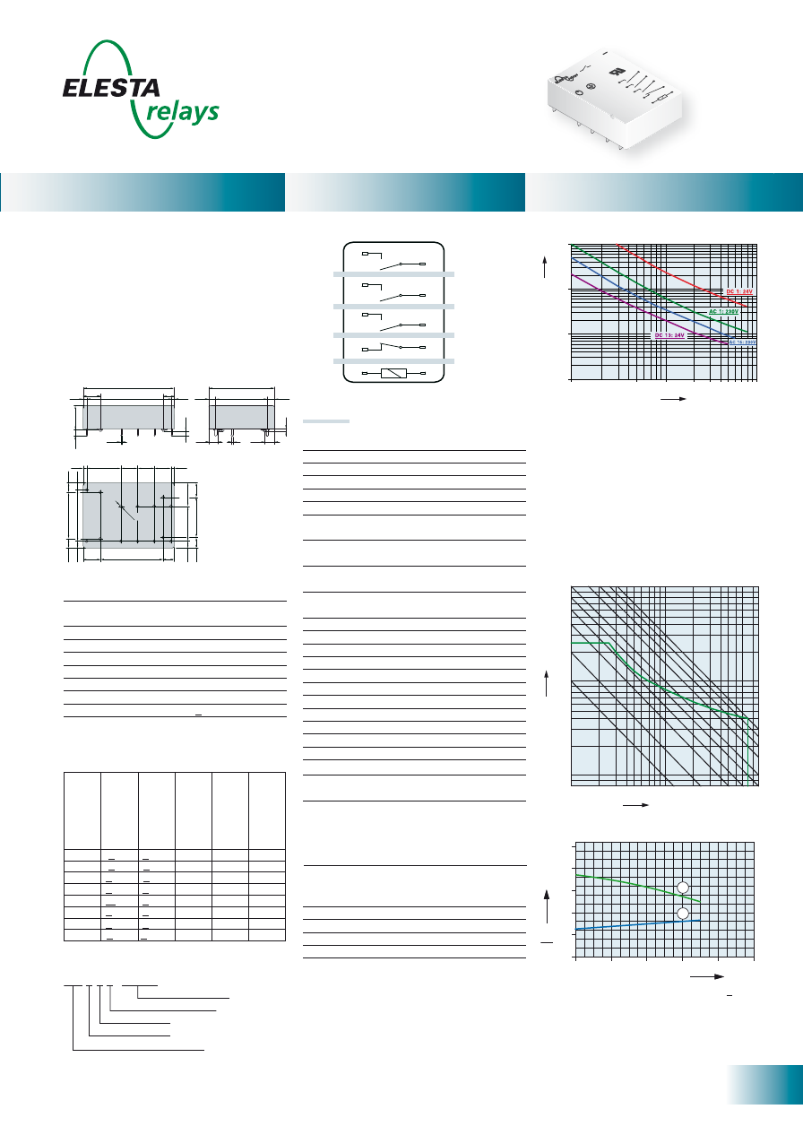
SGR282Z
Double or reinforced insulation
Control
side
Output
side
SGR282Z
30,2
12,7
25,6
3,7
2,6
15
5
5
2,6
1
7,5
0,
3
2,5 / 2,54
Ø
1,3
[mm]
10 000
1000
100
10
10
1.0
0.5
0.1
DC 1: 24V
5.0
AC 1: 230V
AC 15: 230V
DC 13: 24V
Switching current (A)
No. of operations x 1
0
0
0
Current (A)
Voltage (VDC)
0,6
0,4
0,1
0,3
0,2
0,8
1
2
3
4
6
8
0
50
100
150
200
250
1
2
Standard coils for direct current
(other voltages on request)
- PCB relay with forcibly guided contacts
- Protective separation between coil and
contacts (leakage and creepage distances
> 14mm); protective separation diagonally
between left and right contact side (leakage
and creeping distances > 5.5mm)
- EN 50205, type B
- 2 CO contacts
- Mean coil power 1 W
- Holding power 0.31 W
Contact material
AgCuNi
Type of contact
Single contact
Rated switching capacity 250VAC 6A AC1 1’500VA
Electr. life AC1 (360 cycles/h) approx.100’000
Inrush current max.
15A for 20ms
Switching voltage range 50 to 250 VDC/VAC
Switching current range*
20mA to 6A
Switching current range**
10mA to 6A
Switching capacity range* 0.12VA(W) to 1’500VA
Switching capacity range** 0.06VA(W) to 1’500VA
Contact resistance (as delivered) < 100m
Ω
/ 28 V / 100mA
* Guide values
** Values for AgCuNi + 4-6
μ
m Au
Nominal v
olt
age
VDC
Min. pic
k-up
volt
age at 20°C
Drop-out v
olt
age
at 20 °C
Nominal cur
rent
in mA
R
esist
ance in
Ohm at 20 °C
Tolerance in %
5
3,75
> 0,5
181,8
27,5
± 10
6
4,5
> 0,6
166,6
36
± 10
12
9,0
> 1,2
85,7
140
± 10
18
13,5
> 1,8
66,6
270
± 10
24
18,0
> 2,4
33,3
720
± 10
48
36,0
> 4,8
20,8
2’300
± 10
60
45,0
> 6,0
13,6
4’400
± 13
110
82,5
> 11,0
11,0
10’000
± 15
Circuit diagram (view on relay upper side)
Tests, regulations
Approvals
SEV, UL, cUL, TÜV
UL File E188953
Sec. 1
Insulation class IEC 60664-1
250VAC
Protection class II
VDE 0106
Fire protection requirements
UL 94 / V1
Mechanical life
> 50 x 10
6
operations
Switching frequency, mechanical
20Hz
Response time
typically 12ms
Drop-out time***
typically 5ms
Bounce time of NO contact
typically 4ms
Bounce time of NC contact
typically 8ms
Vibration resistance 10-55Hz, AK 10g, RK 1.5g
Test voltage coil/contacts
5’000Veff 1min
Test voltage
contact set/contact set
4’000Veff 1min
Test voltage contact open
1’500Veff 1min
Insulation resistance
10
11
Ω
Creepage resistance
CTI 550
Weight approx.
20g
Mounting position
any
Ambient temperature
-40°C to +70°C
Type of protection
RT II / RT III optionally
Solder bath temperature
270°C/5s
Thermal resistance
50K/W
Temperature limit for coil
120°C
Pollution degree
2
Resistance to
1‘000A SCPD 6A
short circuiting
gL/gG (pre-fuse)
*** without spark suppression
Options, accessories
Contact material
SGR282Z..VDC AgCuNi
+4 - 6
μ
m Au
PCB socket, DIN rail socket
see page 29
Wash-resistant with O-Ring
Sealed RT III
on request
Insulation terms
Coil/contacts: Double or reinforced insulation
> 14mm
Left to right contact side:
Double or reinforced insulation > 5.5mm
Gold contacts with 4-6
μ
m layer thickness
When high voltages and currents are
switched, the layer of gold is destroyed
already after a few switching operations.
Once the gold layer is damaged due to the
switching of high loads, such a contact must
not be used any more for signal and control
current circuits.
Safe contact making is then only possible at
high loads with the formation of sparks.
Contact lifetime for AgCuNi
Max. switching characteristics
(acc. to DIN EN 60947-5-1 table C2):
AC 15: 230V/3A, DC13: 24V/4A
UL 508: C300
Load limit curve with direct current
1) Inductive load, L/R 40 ms
2) Resistive load
Ambient temperature °C
U
U
B
N
0
0
40
60
2,0
1,5
1,0
0,5
1
2
80
100
20
Excitation voltage range
1) Max. excitation voltage with contact load < 2A
2) Min. excitation voltage (guaranteed values)
without previous operation
No heat accumulation due to intrinsic heating
of other components.
Continuous duty 100%.
Ordering example
Relay data
General data
Diagrams
Maximal contact load at AC 1 with 230V:
2 contacts each with 6A
Type designation
Coil voltage
Gold plating 4 - 6μm Au
Wash-resistant / with O-ring
SGR282Z 24VDC AU6 08
14
ELESTA relays GmbH, Heuteilstrasse 18,
CH - 7310 Bad Ragaz, Switzerland
Phone: +41 (0)81 303 54 00
Fax:
+41 (0)81 303 54 01
E-Mail: admin@elestarelays.com
Internet: http://www.elestarelays.com
SGR282Z sensitive
Ambient temperature °C
U
U
B
N
0
0
40
60
2,0
1,5
1,0
0,5
1
2
80
100
20
Double or reinforced insulation
Control
side
Output
side
SGR282Z
10 000
1000
100
10
10
1.0
0.5
0.1
DC 1: 24V
5.0
AC 1: 230V
AC 15: 230V
DC 13: 24V
Switching current (A)
No. of operations x 1
0
0
0
Current (A)
Voltage (VDC)
0,6
0,4
0,1
0,3
0,2
0,8
1
2
3
4
6
8
0
50
100
150
200
250
1
2
30,2
12,7
25,6
3,7
2,6
15
5
5
2,6
1
7,5
0,
3
2,5 / 2,54
Ø
1,3
[mm]
Relay data
General data
Diagrams
1) Max. excitation voltage with contact load < 2A
2) Min. excitation voltage (guaranteed values)
without previous operation
Nominal v
olt
age
VDC
Min. pic
k-up
volt
age at 20°C
Drop-out v
olt
age
at 20 °C
Nominal cur
rent
in mA
R
esist
ance in
Ohm at 20 °C
Tolerance in %
5
3,75
> 0,5
144,0
34,7
± 10
6
4,5
> 0,6
120,0
50
± 10
12
9,0
> 1,2
60,0
200
± 10
18
13,5
> 1,8
40,0
450
± 10
24
18,0
> 2,4
30,0
800
± 10
48
36,0
> 4,8
15,0
3’200
± 10
60
45,0
> 6,0
12,0
5’000
± 13
110
82,5
> 11,0
6,5
16’800
± 15
- PCB relay with forcibly guided contacts
- Protective separation between coil and
contacts (leakage and creepage distances
> 14mm); protective separation diagonally
between left and right contact side (leakage
and creeping distances > 5.5mm)
- EN 50205, type B
- 2 CO contacts
- Mean coil power 0.7 W
- Holding power 0.21 W
Contact material
AgCuNi
Type of contact
Single contact
Rated switching capacity 250VAC 6A AC1 1’500VA
Electr. life AC1 (360 cycles/h) approx.100’000
Inrush current max.
15A for 20ms
Switching voltage range
5 to 250 VDC/VAC
Switching current range*
20mA to 6A
Switching current range**
10mA to 6A
Switching capacity range* 0.12VA(W) to 1’500VA
Switching capacity range** 0.06VA(W) to 1’500VA
Contact resistance (as delivered) <100m
Ω
/28 V/100mA
* Guide values
** Values for AgCuNi + 4-6
μ
m Au
Mechanical life
> 50 x 10
6
operations
Switching frequency, mechanical
20Hz
Response time
typically 12ms
Drop-out time***
typically 5ms
Bounce time of NO contact
typically 4ms
Bounce time of NC contact
typically 8ms
Vibration resistance 10-55Hz, AK 10g, RK 1.5g
Test voltage coil/contacts
5’000Veff 1min
Test voltage
contact set/contact set
4’000Veff 1min
Test voltage contact open
1’500Veff 1min
Insulation resistance
10
11
Ω
Creepage resistance
CTI 550
Weight approx.
20g
Mounting position
any
Ambient temperature
-40°C to +70°C
Type of protection
RT II / RT III optionally
Solder bath temperature
270°C/5s
Thermal resistance
50K/W
Temperature limit for coil
120°C
Pollution degree
2
Resistance to
1‘000A SCPD 6A
short circuiting
gL/gG (pre-fuse)
*** without spark suppression
Circuit diagram (view on relay upper side)
Tests, regulations
Approvals
SEV, UL, cUL, TÜV
UL File E188953
Sec. 1
Insulation class IEC 60664-1
250VAC
Protection class II
VDE 0106
Fire protection requirements
UL 94 / V1
Insulation terms
Coil/contacts: Double or reinforced insulation
> 14mm
Left to right contact side:
Double or reinforced insulation > 5.5mm
Options, accessories
Contact material
SGR282Z..VDC S AgCuNi
+4 - 6
μ
m Au
PCB socket, DIN rail socket
see page 29
Wash-resistant with O-Ring
Sealed RT III
on request
Max. switching characteristics
(acc. to DIN EN 60947-5-1 table C2):
AC 15: 230V/3A, DC13: 24V/4A
UL508: C300
Contact lifetime for AgCuNi
1) Inductive load, L/R 40 ms
2) Resistive load
Gold contacts with 4-6
μ
m layer thickness
When high voltages and currents are
switched, the layer of gold is destroyed
already after a few switching operations.
Once the gold layer is damaged due to the
switching of high loads, such a contact must
not be used any more for signal and control
current circuits.
Safe contact making is then only possible at
high loads with the formation of sparks.
Load limit curve with direct current
Excitation voltage range
Standard coils for direct current
(other voltages on request)
No heat accumulation due to intrinsic heating
of other components.
Continuous duty 100%.
Ordering example
Maximal contact load at AC 1 with 230V:
2 contacts each with 6A
SGR282Z 24VDC SEN AU6 08
Type designation
Coil voltage
sensitive coil
Gold plating 4 - 6μm Au
Wash-resistant / with O-ring
15
ELESTA relays GmbH, Heuteilstrasse 18,
CH - 7310 Bad Ragaz, Switzerland
Phone: +41 (0)81 303 54 00
Fax:
+41 (0)81 303 54 01
E-Mail: admin@elestarelays.com
Internet: http://www.elestarelays.com
Relay data
General data
Diagrams
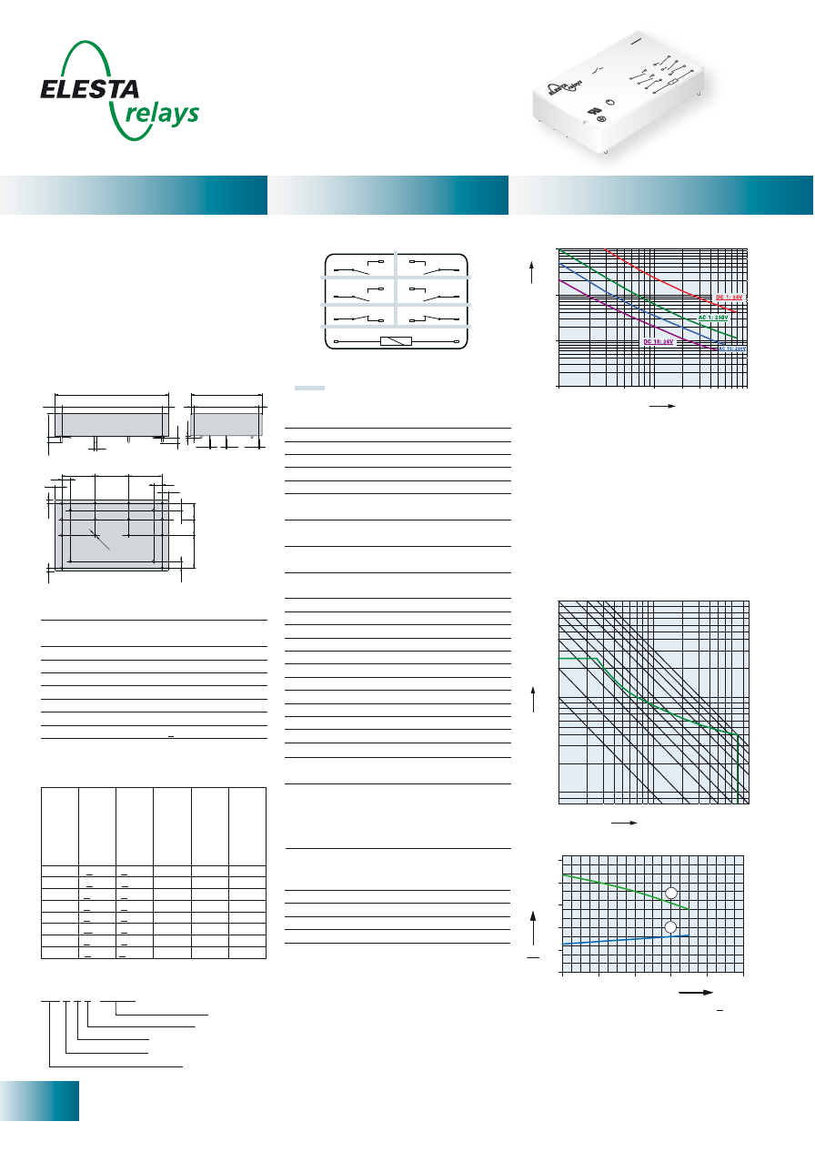
SIR282
0
0
20
40
60
2,0
1,5
1,0
0,5
1
2
80
100
Ambient temperature °C
U
U
B
N
SIR282
Double or reinforced insulation
Control
side
Output
side
30,2
12,7
25,6
3,7
2,6
15
5
5
2,6
1
7,5
0,3
2,5 / 2,54
Ø
1,3
[mm]
10
000
1000
100
10
10
5.0
1.0
0.5
0.1
No. of operations x 1
0
0
0
Switching current (A)
DC
1:
24V
DC
13:
24V
AC
1:
230V
AC
1:
400V
AC
15:
230V
No. of operations x 1
0
0
0
Switching current (A)
10
000
1000
100
10
10
5.0
1.0
0.5
0.1
DC
1:
24V
DC
13:
24V
AC
1:
230V
AC
15:
230V
0,6
0,4
0,1
0,3
0,2
0,8
1
2
3
4
6
8
0
50
100
150
200
250
1
2
Current (A)
Voltage (VDC)
1) Max. excitation voltage with contact load < 2A
2) Min. excitation voltage (guaranteed values)
without previous operation
Nominal v
olt
age
VDC
Min. pic
k-up
volt
age at 20°C
Drop-out v
olt
age
at 20 °C
Nominal cur
rent
in mA
R
esist
ance in
Ohm at 20 °C
Tolerance in %
5
3,75
> 0,5
181,0
27,5
± 10
6
4,5
> 0,6
166,0
36
± 10
12
9,0
> 1,2
85,7
140
± 10
18
13,5
> 1,8
66,6
270
± 10
24
18,0
> 2,4
33,3
720
± 10
48
36,0
> 4,8
20,8
2’300
± 10
60
45,0
> 6,0
13,6
4’400
± 13
110
82,5
> 11,0
11,0
10’000
± 15
- PCB relay with forcibly guided contacts
- Protective separation between coil and
contacts (leakage and creepage distances
> 14mm); protective separation diagonally
between left and right contact side (leakage
and creeping distances > 5.5mm)
- EN 50205, type B
- 2 CO contacts
- Mean coil power 1W
- Holding power 0.31 W
Contact material
AgSnO
2
+0.2
μ
m Au
Type of contact
Single contact
Rated switching capacity 250VAC 8A AC1 2’000VA
Electr. life AC1 (360 cycles/h) approx.100’000
Inrush current max.
15A for 20ms
Switching voltage range
5 to 250 VDC/VAC
Switching current range*
10mA to 8A
Switching capacity range* 0.12VA(W) to 2’000VA
Contact resistance (as delivered) <100m
Ω
/28 V/100mA
* Guide values
Standard coils for direct current
(other voltages on request)
Mechanical life
> 50 x 10
6
operations
Switching frequency, mechanical
20Hz
Response time
typically 12ms
Drop-out time**
typically 5ms
Bounce time of NO contact
typically 4ms
Bounce time of NC contact
typically 8ms
Vibration resistance 10-55Hz, AK 10g, RK 1.5g
Test voltage coil/contacts
5’000Veff 1min
Test voltage
contact set/contact set
4’000Veff 1min
Test voltage contact open
1’500Veff 1min
Insulation resistance
10
11
Ω
Creepage resistance
CTI 550
Weight approx.
20g
Mounting position
any
Ambient temperature
-40°C to +70°C
Type of protection
RT II / RT III optionally
Solder bath temperature
270°C/5s
Thermal resistance
50K/W
Temperature limit for coil
120°C
Pollution degree
2
Resistance to
1‘000A SCPD 10A
short circuiting
gL/gG (pre-fuse)
** without spark suppression
Circuit diagram (view on relay upper side)
Options, accessories
Wash-resistant with O-Ring
Sealed RT III
on request
PCB socket, DIN rail socket
see page 29
Tests, regulations
Approvals
SEV, UL, cUL, TÜV
UL File E188953
Sec. 1
Insulation class IEC 60664-1
250VAC
Protection class II
VDE 0106
Fire protection requirements
UL 94 / V1
Max. switching characteristics
(acc. to DIN EN 60947-5-1 table C2):
AC 15: 230V/5A, DC13: 24V/6A; UL 508: C300
Maximal contact load at AC 1 with 230V:
2 contacts each with 8A
1) Inductive load, L/R 40 ms
2) Resistive load
Contact lifetime for NO contact
Max. switching characteristics
(acc. to DIN EN 60947-5-1 table C2):
AC 15: 230V/2A, DC13: 24V/3A
Contact lifetime for NC contact
Load limit curve with direct current
Excitation voltage range
Insulation terms
Coil/contacts: Double or reinforced insulation
> 14mm
Left to right contact side:
Double or reinforced insulation > 5.5mm
No heat accumulation due to intrinsic heating of
other components. Continuous duty 100%.
SIR282 24VDC 08
Type designation
Coil voltage
Wash-resistant / with O-ring
Ordering example
16
ELESTA relays GmbH, Heuteilstrasse 18,
CH - 7310 Bad Ragaz, Switzerland
Phone: +41 (0)81 303 54 00
Fax:
+41 (0)81 303 54 01
E-Mail: admin@elestarelays.com
Internet: http://www.elestarelays.com
SIR282 sensitive
Ambient temperature °C
U
U
B
N
0
0
40
60
2,0
1,5
1,0
0,5
1
2
80
100
20
SIR282
Double or reinforced insulation
Control
side
Output
side
30,2
12,7
25,
6
3,7
2,6
15
5
5
2,6
1
7,5
0,
3
2,5 / 2,54
Ø
1,3
[mm]
10
000
1000
100
10
10
5.0
1.0
0.5
0.1
No. of operations x 1
0
0
0
Switching current (A)
DC
1:
24V
DC
13:
24V
AC
1:
230V
AC
1:
400V
AC
15:
230V
0,6
0,4
0,1
0,3
0,2
0,8
1
2
3
4
6
8
0
50
100
150
200
250
1
2
Current (A)
Voltage (VDC)
Relay data
General data
Diagrams
Circuit diagram (view on relay upper side)
Nominal v
olt
age
VDC
Min. pic
k-up
volt
age at 20°C
Drop-out v
olt
age
at 20 °C
Nominal cur
rent
in mA
R
esist
ance in
Ohm at 20 °C
Tolerance in %
5
3,75
> 0,5
144,0
34,7
± 10
6
4,5
> 0,6
120,0
50
± 10
12
9,0
> 1,2
60,0
200
± 10
18
13,5
> 1,8
40,0
450
± 10
24
18,0
> 2,4
30,0
800
± 10
48
36,0
> 4,8
15,0
3’200
± 10
60
45,0
> 6,0
12,0
5’000
± 13
110
82,5
> 11,0
6,5
16’800
± 15
Standard coils for direct current
(other voltages on request)
1) Max. excitation voltage with contact load < 2A
2) Min. excitation voltage (guaranteed values)
without previous operation
Excitation voltage range
No. of operations x 1
0
0
0
Switching current (A)
10
000
1000
100
10
10
5.0
1.0
0.5
0.1
DC
1:
24V
DC
13:
24V
AC
1:
230V
AC
15:
230V
- PCB relay with forcibly guided contacts
- Protective separation between coil and
contacts (leakage and creepage distances
> 14mm); protective separation diagonally
between left and right contact side (leakage
and creeping distances > 5.5mm)
- EN 50205, type B
- 2 CO contacts
- Mean coil power 0.7W
- Holding power 0.21 W
Contact material
AgSnO
2
+0.2
μ
m Au
Type of contact
Single contact
Rated switching capacity 250VAC 8A AC1 2’000VA
Electr. life AC1 (360 cycles/h) approx.100’000
Inrush current max.
15A for 20ms
Switching voltage range
5 to 250 VDC/VAC
Switching current range*
10mA to 8A
Switching capacity range* 0.12VA(W) to 2’000VA
Contact resistance (as delivered) <100m
Ω
/28 V/100mA
* Guide values
Mechanical life
> 50 x 10
6
operations
Switching frequency, mechanical
20Hz
Response time
typically 12ms
Drop-out time**
typically 5ms
Bounce time of NO contact
typically 4ms
Bounce time of NC contact
typically 8ms
Vibration resistance 10-55Hz, AK 10g, RK 1.5g
Test voltage coil/contacts
5’000Veff 1min
Test voltage
contact set/contact set
4’000Veff 1min
Test voltage contact open
1’500Veff 1min
Insulation resistance
10
11
Ω
Creepage resistance
CTI 550
Weight approx.
20g
Mounting position
any
Ambient temperature
-40°C to +70°C
Type of protection
RT II / RT III optionally
Solder bath temperature
270°C/5s
Thermal resistance
50K/W
Temperature limit for coil
120°C
Pollution degree
2
Resistance to
1‘000A SCPD 10A
short circuiting
gL/gG (pre-fuse)
** without spark suppression
Tests, regulations
Approvals
SEV, UL, cUL, TÜV
UL File E188953
Sec. 1
Insulation class IEC 60664-1
250VAC
Protection class II
VDE 0106
Fire protection requirements
UL 94 / V1
Options, accessories
Wash-resistant with O-Ring
Sealed RT III
on request
PCB socket, DIN rail socket
see page 29
Max. switching characteristics
(acc. to DIN EN 60947-5-1 table C2):
AC 15: 230V/5A, DC13: 24V/6A; UL 508: C300
Maximal contact load at AC 1 with 230V:
2 contacts each with 8A
Max. switching characteristics
(acc. to DIN EN 60947-5-1 table C2):
AC 15: 230V/2A, DC13: 24V/3A
1) Inductive load, L/R 40 ms
2) Resistive load
Contact lifetime for NO contact
Contact lifetime for NC contact
Load limit curve with direct current
Insulation terms
Coil/contacts: Double or reinforced insulation
> 14mm
Left to right contact side:
Double or reinforced insulation > 5.5mm
No heat accumulation due to intrinsic heating of
other components. Continuous duty 100%.
SIR282 24VDC SEN 08
Type designation
Coil voltage
sensitive coil
Wash-resistant / with O-ring
Ordering example
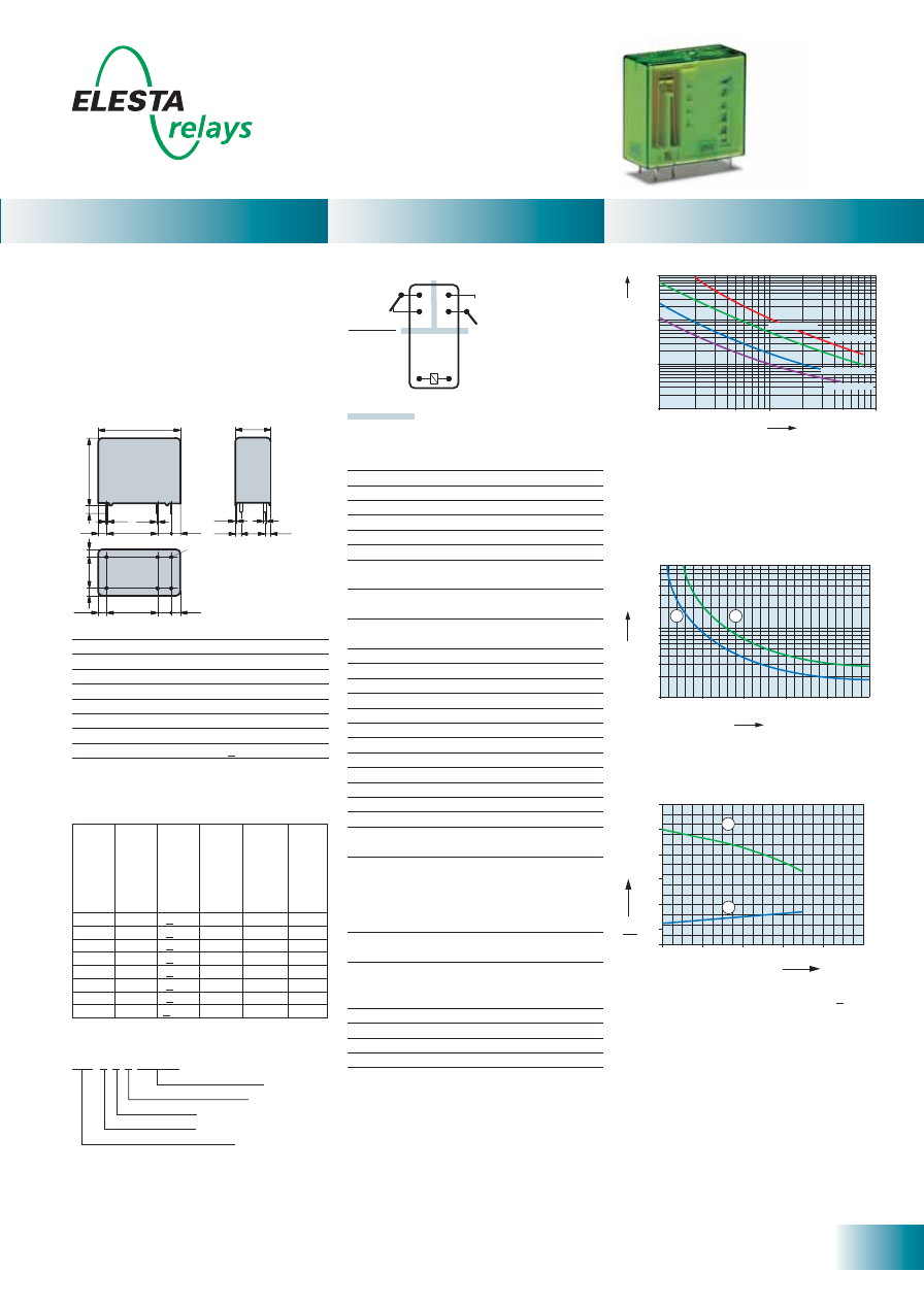
17
ELESTA relays GmbH, Heuteilstrasse 18,
CH - 7310 Bad Ragaz, Switzerland
Phone: +41 (0)81 303 54 00
Fax:
+41 (0)81 303 54 01
E-Mail: admin@elestarelays.com
Internet: http://www.elestarelays.com
SIM 2 Contacts
0
0
20
40
60
2,0
1,5
1,0
0,5
1
2
80
100
2,5
3,0
Ambient temperature °C
U
U
B
N
SIM112
Double or reinforced insulation
Control
side
Output
side
10 000
1000
100
10
10
5.0
1.0
0.5
0.1
DC 1: 24V
AC 1: 230V
AC 15: 230V
DC 13: 24V
No. of operations x 1
0
0
0
Switching current (A)
0,6
0,4
0,1
0,3
0,2
0,8
1
2
3
4
6
8
0
50
100
150
200
250
1
2
Current (A)
Voltage (VDC)
27,4
12,5
26,2
2,9
3,7
5
15,9
2,8
1
0,5
7,5
0,3 0,4
2,5
2,5
3,7
5
15,9
2,8
2,5
7,5
2,5
Ø
1,3
[mm]
Standard coils for direct current
(other voltages on request)
Circuit diagram (view on relay upper side)
Excitation voltage range
- PCB relay with forcibly guided contacts
- Protective separation between coil and
contacts (leakage and creepage distances
> 14mm); protective separation between left
and right contact side (leakage and creeping
distances > 5.5mm)
- EN 50205, type A
- Contact mounting: SIM112 1NO/1NC
- Small external dimensions
- Mean coil power 0.5W
- Holding power 0.15 W
Contact material
AgSnO
2
+0.2
μ
m Au
Type of contact
Crest contact
Rated switching capacity 250VAC 8A AC1 2’000VA
Electr. life AC1 (360 cycles/h) approx.100’000
Inrush current max.
20A for 20ms
Switching voltage range
5 to 250 VDC/VAC
Switching current range*
10mA to 8A
Switching capacity range* 0.06VA(W) to 2’000VA
Contact resistance (as delivered) <100m
Ω
/28V/100mA
* Guide values
Nominal v
olt
age
VDC
Min. pic
k-up
volt
age at 20°C
Drop-out v
olt
age
at 20 °C
Nominal cur
rent
in mA
R
esist
ance in
Ohm at 20 °C
Tolerance in %
5
3,5
> 0,5
111,0
45
± 10
6
4,2
> 0,6
85,7
70
± 10
12
8,4
> 1,2
44,4
270
± 10
21
14,7
> 2,1
23,8
880
± 10
24
16,8
> 2,4
21,8
1’100
± 10
48
33,6
> 4,8
10,9
4’400
± 13
60
42,0
> 6,0
8,7
6’850
± 15
110
77,0
> 11,0
5,5
20’000
± 15
Mechanical life
> 10 x 10
6
operations
Switching frequency, mechanical
15Hz
Response time
typically 10ms
Drop-out time**
typically 3ms
Bounce time of NO contact
typically 6ms
Bounce time of NC contact
typically 12ms
Shock resistance 16ms
NO contact > 10g
Vibration resistance
10-200Hz
NO contact > 10g
Test voltage
coil/contacts
5’000Veff 1min
Test voltage
left to right contact sides
4’000Veff 1min
Test voltage contact open
1’500Veff 1min
Insulation resistance
10
11
Ω
Creepage resistance
CTI 250
Weight approx.
20g
Mounting position
any
Ambient temperature
-40°C to +70°C
Type of protection
RT II
Solder bath temperature
270 °C/5s
Thermal resistance
55K/W
Temperature limit for coil
120°C
Pollution degree
2
Overvoltage category
III
Resistance to short
1’000A SCPD 10A
circuiting gG
(pre-fuse)
** without spark suppression
Insulation terms
Coil/contacts:
Double or reinforced insulation > 14mm
Left to right contact side:
Double or reinforced insulation > 5.5mm
Tests, regulations
Approvals
SEV, UL, cUL, TÜV
UL File E188953
Sec. 3
Insulation class IEC 60664-1
250VAC
Protection class II
VDE 0106
Fire protection requirements
UL 94 / V0
Max. switching characteristics
(determined acc. to DIN EN 60947-5-1 table C2):
AC 15: 230V/3A
DC 13: 24V/4A
DC 13: 24V/6A/0,1Hz
UL 508: C150/R300
1) Inductive load, L/R 40 ms
2) Resistive load
Contact lifetime for NO contact
Load limit curve with direct current
1) Max. excitation voltage with contact load < 2A
2) Min. excitation voltage (guaranteed values)
without previous operation
No heat accumulation due to intrinsic heating
of other components.
Continuous duty 100%.
Relay data
General data
Diagrams
Ordering example
Soldering tags
Number of NC contacts
Number of NO contacts
Type designation
Coil voltage
SIM 1 1 2 24VDC
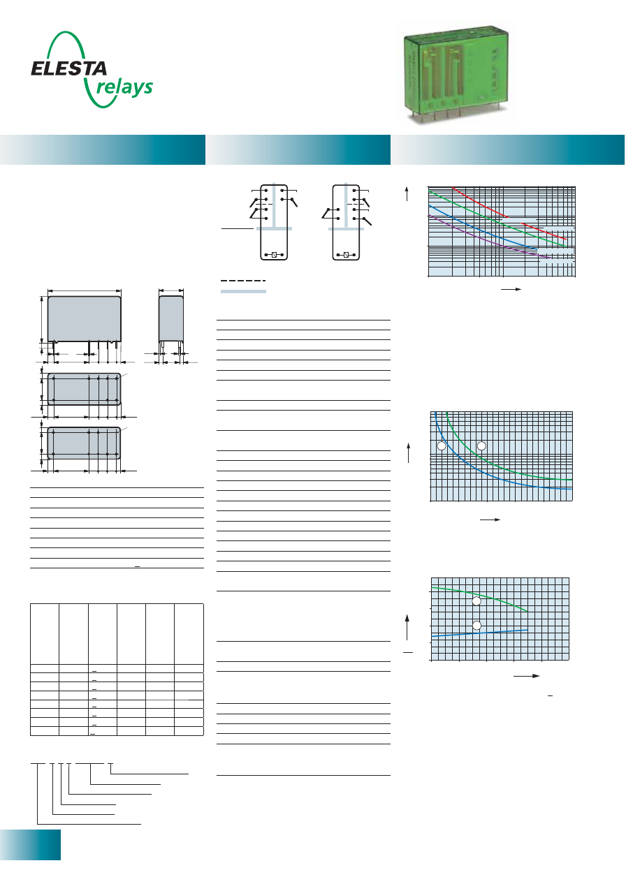
18
ELESTA relays GmbH, Heuteilstrasse 18,
CH - 7310 Bad Ragaz, Switzerland
Phone: +41 (0)81 303 54 00
Fax:
+41 (0)81 303 54 01
E-Mail: admin@elestarelays.com
Internet: http://www.elestarelays.com
SIM 3 Contacts
0
0
20
40
60
2,0
1,5
1,0
0,5
1
2
80
100
Ambient temperature °C
U
U
B
N
SIM212
Double or reinforced insulation
Control
side
Output
side
Basic insulation
SIM212
Variante 1
Standard
Variante 2
KV2
10 000
1000
100
10
10
5.0
1.0
0.5
0.1
DC 1: 24V
AC 1: 230V
AC 15: 230V
DC 13: 24V
No. of operations x 1
0
0
0
Switching current (A)
0,6
0,4
0,1
0,3
0,2
0,8
1
2
3
4
6
8
0
50
100
150
200
250
1
2
Current (A)
Voltage (VDC)
Relay data
General data
Diagrams
Standard coils for direct current
(other voltages on request)
Circuit diagram (view on relay upper side)
Ordering example
1) Max. excitation voltage with contact load < 2A
2) Min. excitation voltage (guaranteed values)
without previous operation
- PCB relay with forcibly guided contacts
- Protective separation between coil and
contacts (leakage and creepage distances
> 14mm); protective separation between left
and right contact side (leakage and creeping
distances > 5.5mm)
- EN 50205, type A
- Contact mounting: SIM212
2NO/1NC
- Small external dimensions
- Mean coil power 0.75W
- Holding power 0.21 W
Contact material
AgSnO
2
+0.2
μ
m Au
Type of contact
Crest contact
Rated switching capacity 250VAC 8A AC1 2’000VA
Electr. life AC1 (360 cycles/h) approx.100’000
Inrush current max.
20A for 20ms
Switching voltage range
5 to 250 VDC/VAC
Switching current range*
10mA to 8A
Switching capacity range* 0.06VA(W) to 2’000VA
Contact resistance (as delivered) <100m
Ω
/28 V/100mA
* Guide values
Nominal v
olt
age
VDC
Min. pic
k-up
volt
age at 20°C
Drop-out v
olt
age
at 20 °C
Nominal cur
rent
in mA
R
esist
ance in
Ohm at 20 °C
Tolerance in %
5
3,75
> 0,5
151,0
33
± 10
6
4,5
> 0,6
125,0
48
± 10
12
9,0
> 1,2
63,1
190
± 10
21
15,75
> 2,1
35,5
590
± 10
24
18,0
> 2,4
30,0
800
± 10
48
36,0
> 4,8
15,4
3’100
± 10
60
45,0
> 6,0
12,5
4’800
± 13
110
82,5
> 11,0
6,8
16’000
± 15
Mechanical life
> 10 x 10
6
operations
Switching frequency, mechanical
15Hz
Response time
typically 10ms
Drop-out time**
typically 4ms
Bounce time of NO contact
typically 6ms
Bounce time of NC contact
typically 12ms
Shock resistance 16ms
NO contact > 10g
Vibration resistance
10-200Hz
NO contact > 10g
Test voltage coil/contacts
5’000Veff 1min
Test voltage
left to right contact sides
4’000Veff 1min
Test voltage
contacts as one after the other 2’500Veff 1min
Test voltage contact open
1’500Veff 1min
Insulation resistance
10
11
Ω
Creepage resistance
CTI 250
Weight approx.
25g
Mounting position
any
Ambient temperature
-40°C to +70°C
Type of protection
RT II
Solder bath temperature
270 °C/5s
Thermal resistance
50K/W
Temperature limit for coil
120°C
Pollution degree
2
Overvoltage category
III
Resistance to short
1’000A SCPD 10A
circuiting gG
(pre-fuse)
** without spark suppression
Insulation terms
Coil/contacts: Double or reinforced insulation
> 14mm
Left to right contact side:
Double or reinforced insulation > 5.5mm
Contacts in one row: Basic insulation
Tests, regulations
Approvals
SEV, UL, cUL, TÜV
UL File E188953
Sec. 3
Insulation class IEC 60664-1
250VAC
Protection class II
VDE 0106
Fire protection requirements
UL 94 / V0
Max. switching characteristics
(determined acc. to DIN EN 60947-5-1 table C2):
AC 15: 230V/3A
DC 13: 24V/4A
DC 13: 24V/6A/0,1Hz
UL 508: C150/R300
1) Inductive load, L/R 40 ms
2) Resistive load
Contact lifetime for NO contact
Maximal contact load at AC 1 with 230V:
2 contacts each with 8A
Load limit curve with direct current
Excitation voltage range
No heat accumulation due to intrinsic heating
of other components.
Continuous duty 100%.
SIM 2 1 2 24VDC 2
KV2
Soldering tags
Number of NC contacts
Number of NO contacts
Type designation
Coil voltage
Options, accessories
PCB socket, DIN rail socket
see page 30
[mm]
36,1
12,5
26,2
2,9
2,4
5
5 5
15,9
2,8
1
0,5
7,5
0,3 0,4
2,5
2,5
2,4
5 5 5
15,9
2,8
2,5
7,5
2,5
Ø
1,3
2,4
5
5 5
15,9
2,8
2,5
7,5
2,5
Ø
1,3
Variante 1
Standard
Variante 2
KV2
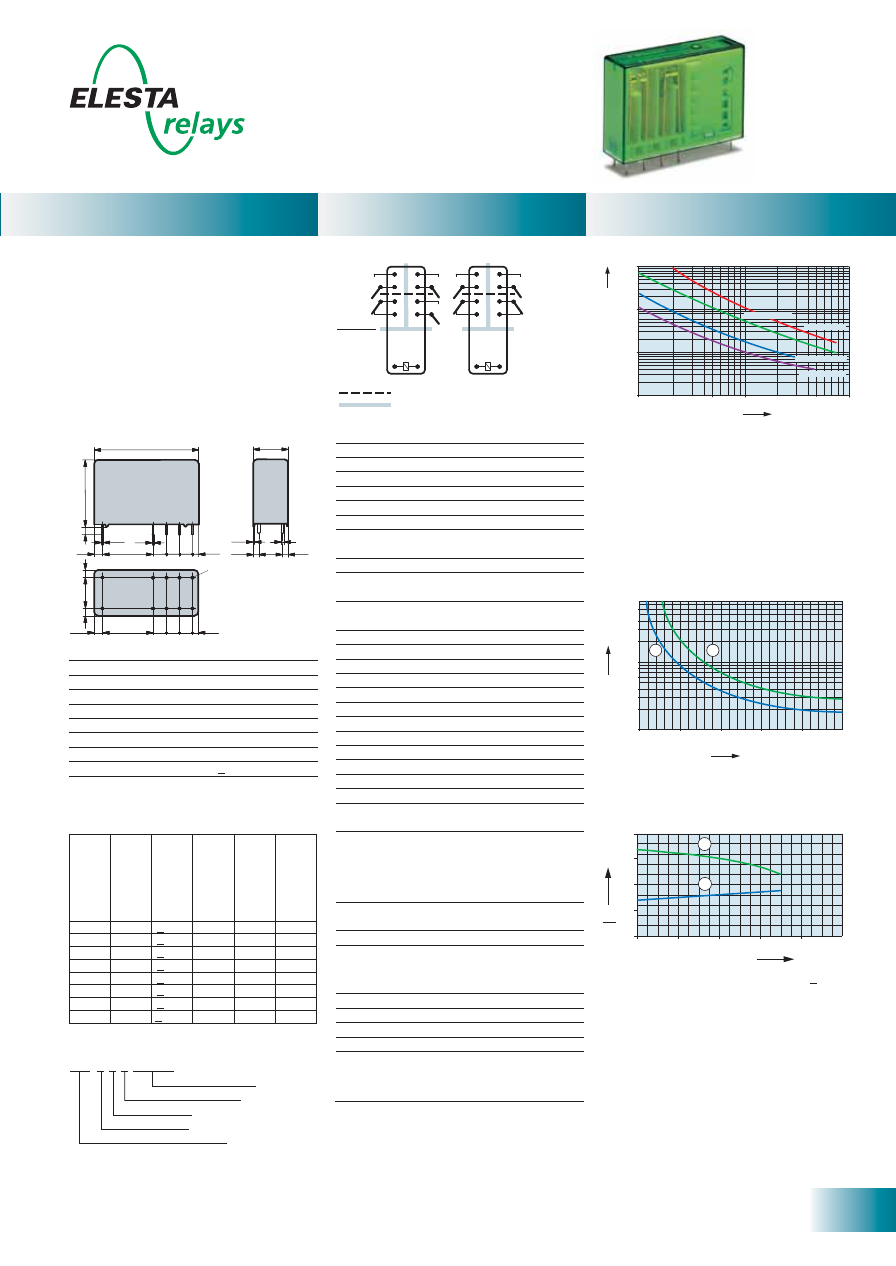
19
ELESTA relays GmbH, Heuteilstrasse 18,
CH - 7310 Bad Ragaz, Switzerland
Phone: +41 (0)81 303 54 00
Fax:
+41 (0)81 303 54 01
E-Mail: admin@elestarelays.com
Internet: http://www.elestarelays.com
SIM 4 Contacts
Ambient temperature °C
U
U
B
N
0
0
40
60
2,0
1,5
1,0
0,5
1
2
80
100
20
Double or reinforced insulation
Basic insulation
SIM312
SIM222
Control
side
Output
side
10 000
1000
100
10
10
5.0
1.0
0.5
0.1
DC 1: 24V
AC 1: 230V
AC 15: 230V
DC 13: 24V
No. of operations x 1
0
0
0
Switching current (A)
0,6
0,4
0,1
0,3
0,2
0,8
1
2
3
4
6
8
0
50
100
150
200
250
1
2
Current (A)
Voltage (VDC)
36,1
12,5
26,2
2,9
2,4
5
5 5
15,9
2,8
1
0,5
7,5
0,3
0,4
2,5
2,5
2,4
Ø
1,3
5 5 5
15,9
2,8
2,5
7,5
2,5
[mm]
Standard coils for direct current
(other voltages on request)
Circuit diagram (view on relay upper side)
1) Max. excitation voltage with contact load < 2A
2) Min. excitation voltage (guaranteed values)
without previous operation
- PCB relay with forcibly guided contacts
- Protective separation between coil and
contacts (leakage and creepage distances
> 14mm); protective separation between left
and right contact side (leakage and creeping
distances > 5.5mm)
- EN 50205, type A
- Contact mounting:
SIM312 3NO/1NC
SIM222 2NO/2NC
- Small external dimensions
- Mean coil power 1W
- Holding power 0.29W
Contact material
AgSnO
2
+0,2
μ
m Au
Type of contact
Crest contact
Rated switching capacity 250VAC 8A AC1 2’000VA
Electr. life AC1 (360 cycles/h) approx.100’000
Inrush current max.
20A for 20ms
Switching voltage range
5 to 250 VDC/VAC
Switching current range*
10mA to 8A
Switching capacity range* 0,06VA(W) to 2’000VA
Contact resistance (as delivered) <100m
Ω
/28 V/100mA
* Guide values
Nominal v
olt
age
VDC
Min. pic
k-up
volt
age at 20°C
Drop-out v
olt
age
at 20 °C
Nominal cur
rent
in mA
R
esist
ance in
Ohm at 20 °C
Tolerance in %
5
3,75
> 0,5
181,8
27,5
± 10
6
4,5
> 0,6
166,0
36
± 10
12
9,0
> 1,2
85,7
140
± 10
21
15,75
> 2,1
46,6
450
± 10
24
18,0
> 2,4
40,0
600
± 10
48
36,0
> 4,8
20,8
2’300
± 10
60
45,0
> 6,0
16,6
3’600
± 13
110
82,5
> 11,0
9,6
12’000
± 15
Mechanical life
> 10 x 10
6
operations
Switching frequency, mechanical
15Hz
Response time
typically 8ms
Drop-out time**
typically 4ms
Bounce time of NO contact
typically 6ms
Bounce time of NC contact
typically 12ms
Shock resistance 16ms
NO contact > 10g
Vibration resistance
10-200Hz
NO contact > 10g
Test voltage coil/contacts
5’000Veff 1min
Test voltage
left to right contact sides
4’000Veff 1min
Test voltage
contacts as one after the other 2’500Veff 1min
Test voltage contact open
1’500Veff 1min
Insulation resistance
10
11
Ω
Creepage resistance
CTI 250
Weight approx.
25g
Mounting position
any
Ambient temperature
-40°C to +70°C
Type of protection
RT II
Solder bath temperature
270 °C/5s
Thermal resistance
50K/W
Temperature limit for coil
120°C
Pollution degree
2
Overvoltage category
III
Resistance to short
1’000A SCPD 10A
circuiting gG
(pre-fuse)
** without spark suppression
Tests, regulations
Approvals
SEV, UL, cUL, TÜV
UL File E18895
Sec. 3
Insulation class IEC 60664-1
250VAC
Protection class II
VDE 0106
Fire protection requirements
UL 94 / V0
Insulation terms
Coil/contacts:
Double or reinforced insulation > 14mm
Left to right contact side:
Double or reinforced insulation > 5.5mm
Contacts in one row: Basic insulation
Ordering example
Max. switching characteristics
(determined acc. to DIN EN 60947-5-1 table C2):
AC 15: 230V/3A
DC 13: 24V/4A
DC 13: 24V/6A/0,1Hz
UL 508: C150/R300
Contact lifetime for NO contact
1) Inductive load, L/R 40 ms
2) Resistive load
Maximal contact load at AC 1 with 230V:
2 contacts each with 8A
3 contacts each with 6A
Load limit curve with direct current
Excitation voltage range
No heat accumulation due to intrinsic heating
of other components.
Continuous duty 100%.
Relay data
General data
Diagrams
Soldering tags
Number of NC contacts
Number of NO contacts
Type designation
Coil voltage
SIM 3 1 2 24VDC
Options, accessories
PCB socket, DIN rail socket
see page 30
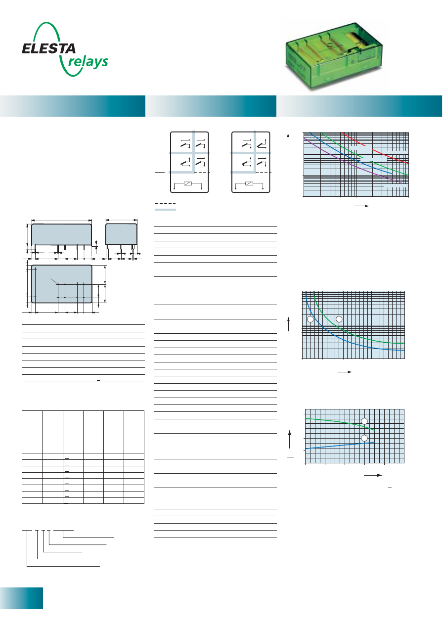
20
ELESTA relays GmbH, Heuteilstrasse 18,
CH - 7310 Bad Ragaz, Switzerland
Phone: +41 (0)81 303 54 00
Fax:
+41 (0)81 303 54 01
E-Mail: admin@elestarelays.com
Internet: http://www.elestarelays.com
SLR 4 Contacts
Ambient temperature °C
U
U
B
N
0
0
20
40
60
2,0
1,5
1,0
0,5
1
2
80
100
Double or reinforced insulation
Basic insulation
Control
side
Output
side
SLR222
SLR312
No. of operations x 1
0
0
0
Switching current (A)
10 000
1000
100
10
10
5.0
1.0
0.5
0.1
DC 1: 24V
AC 1: 230V
AC 15: 230V
DC 13: 24V
Current (A)
Voltage (VDC)
0,6
0,4
0,1
0,3
0,2
0,8
1
2
3
4
6
8
0
50
100
150
200
250
1
2
10
53,3
33,4
16,5
2,9
6,4
6,4
20,5
2,9
0,6
13,7
0,4
3
6,4
10,7
1,4
4
11,3
1
0,3
20,5
3
25
5,4
2,9
6,4 10,7 6,4 6,4
12,7
4
16,7
16,7
[mm]
Ø
1,3
Relay data
General data
Diagrams
Standard coils for direct current
(other voltages on request)
Circuit diagram (view on relay upper side)
1) Max. excitation voltage with contact load < 2A
2) Min. excitation voltage (guaranteed values)
without previous operation
- PCB relay with forcibly guided contacts
- Protective separation between coil/control
contacts and output contacts (> 8mm) as
well as protective separation between the
output contacts themselves (> 10mm)
- EN 50205, type A
- Contact mounting:
SLR312 3NO/1NC
SLR222 2NO/2NC
- Small external dimensions
- Mean coil power 0.6W
- Holding power 0.18W
- For Railway Applications: EN 50155
Contact material
AgSnO
2
+0,2
μ
m Au
Type of contact
Crest contact
Rated switching capacity 250VAC 10A AC1 2’500VA
Electr. life AC1 (360 cycles/h) approx.100’000
Inrush current max.
25A for 20ms
Switching voltage range
5 to 250 VDC/VAC
Switching current range*
10mA to 10A
Switching capacity range* 0.06VA(W) to 2’500VA
Contact resistance (as delivered) <100m
Ω
/28V/100mA
* Guide values
Nominal v
olt
age
VDC
Min. pic
k-up
volt
age at 20°C
Drop-out v
olt
age
at 20 °C
Nominal cur
rent
in mA
R
esist
ance in
Ohm at 20 °C
Tolerance in %
5
3,5
> 0,5
121,0
41
± 10
6
4,2
> 0,6
100,0
60
± 10
12
8,4
> 1,2
50,0
240
± 10
18
12,6
> 1,8
33,3
540
± 10
24
16,8
> 2,4
25,2
950
± 10
48
33,6
> 4,8
12,6
3’800
± 10
60
42,0
> 6,0
10,0
6’000
± 13
110
77,0
> 11,0
5,5
20’000
± 15
Mechanical life
> 10 x 10
6
operations
Switching frequency, mechanical
15Hz
Response time
typically 15ms
Drop-out time**
typically 4ms
Bounce time of NO contact
typically 6ms
Bounce time of NC contact
typically 12ms
Shock resistance 16ms
NO contact > 10g
NC contact 6g
Vibration resistance
NO contact > 5g
10-200Hz
NC contact 1.5g
Test voltage
coil/control contacts
2’500Veff 1min
Test voltage
5’000Veff 1min
coil-control contacts/output contacts
Test voltage output contacts
as against each other
4’000Veff 1min
Test voltage contact open
1’500Veff 1min
Insulation resistance
10
11
Ω
Creepage resistance
CTI 250
Weight approx.
30g
Mounting position
any
Ambient temperature
-40°C to +70°C
Type of protection
RT II
Solder bath temperature
270 °C/5s
Thermal resistance
55K/W
Temperature limit for coil
120°C
Pollution degree
2
Overvoltage category
III
Resistance to short
1’000A SCPD 10A
circuiting gG
(pre-fuse)
** without spark suppression
Insulation terms
Coil/control contacts NO: Basic insulation
Coil/control contacts to output contacts:
Double or reinforced insulation > 8mm
Output contacts as against each other:
Reinforced insulation > 10mm
Tests, regulations
Approvals
SEV, UL, cUL, TÜV
UL File E188953
Sec. 3
Insulation class IEC 60664-1
250VAC
Protection class II
VDE 0106
Fire protection requirements
UL 94 / V0
Ordering example
Max. switching characteristics
(determined acc. to DIN EN 60947-5-1 table C2):
AC 15: 230V/5A
DC 13: 24V/7.5A/0.1 Hz
UL 508: C600/R300
Maximal contact load at AC 1 with 230V:
2 contacts each with 10A
3 contacts each with 8.4A
Contact lifetime
1) Inductive load, L/R 40 ms
2) Resistive load
Load limit curve with direct current
No heat accumulation due to intrinsic heating
of other components.
Continuous duty 100%.
Excitation voltage range
Soldering tags
Number of NC contacts
Number of NO contacts
Type designation
Coil voltage
SLR 3 1 2 24VDC

21
ELESTA relays GmbH, Heuteilstrasse 18,
CH - 7310 Bad Ragaz, Switzerland
Phone: +41 (0)81 303 54 00
Fax:
+41 (0)81 303 54 01
E-Mail: admin@elestarelays.com
Internet: http://www.elestarelays.com
SIR 4 Contacts
Ambient temperature °C
U
U
B
N
0
0
20
40
60
2,0
1,5
1,0
0,5
1
2
80
100
SIR312
SIR222
Control
side
Output
side
Double or reinforced insulation
Basic insulation
No. of operations x 1
0
0
0
Switching current (A)
10 000
1000
100
10
10
5.0
1.0
0.5
0.1
DC 1: 24V
AC 1: 230V
AC 15: 230V
DC 13: 24V
Current (A)
Voltage (VDC)
0,6
0,4
0,1
0,3
0,2
0,8
1
2
3
4
6
8
0
50
100
150
200
250
1
2
10
46,4
16
30,7
2,9
3
5
10,5
5
21
1,9
1
10
0,7
0,4
3
3
3
10,5 5
5
21
1,9
31
0
3
[mm]
Ø
1,3
Standard coils for direct current
(other voltages on request)
Circuit diagram (view on relay upper side)
Ordering example
- PCB relay with forcibly guided contacts
- Protective separation between coil/control
contacts and output contacts (> 10mm) as
well as protective separation between the
output contacts themselves (> 8mm)
- EN 50205, type A
- Contact mounting:
SIR312 3NO/1NC
SIR222 2NO/2NC
- Small external dimensions
- Mean coil power 0.6W
- Holding power 0.18W
- For Railway Applications: EN 50155
Contact material
AgSnO
2
+0.2
μ
m Au
Type of contact
Crest contact
Rated switching capacity 250VAC 10A AC1 2’500VA
Electr. life AC1 (360 cycles/h) approx.100’000
Inrush current max.
25A for 20ms
Switching voltage range
5 to 250 VDC/VAC
Switching current range*
10mA to 10A
Switching capacity range* 0.06VA(W) to 2’500VA
Contact resistance (as delivered) <100m
Ω
/28 V/100mA
* Guide values
Nominal v
olt
age
VDC
Min. pic
k-up
volt
age at 20°C
Drop-out v
olt
age
at 20 °C
Nominal cur
rent
in mA
R
esist
ance in
Ohm at 20 °C
Tolerance in %
5
3,5
> 0,5
121,0
41
± 10
6
4,2
> 0,6
100,0
60
± 10
12
8,4
> 1,2
50,0
240
± 10
18
12,6
> 1,8
33,3
540
± 10
24
16,8
> 2,4
25,2
950
± 10
48
33,6
> 4,8
12,6
3’800
± 10
60
42,0
> 6,0
10,0
6’000
± 13
110
77,0
> 11,0
5,5
20’000
± 15
Mechanical life
> 10 x 10
6
operations
Switching frequency, mechanical
15Hz
Response time
typically 15ms
Drop-out time**
typically 4ms
Bounce time of NO contact
typically 6ms
Bounce time of NC contact
typically 12ms
Shock resistance 16ms
NO contact > 10g
NC contact 6g
Vibration resistance
NO contact > 5g
10-200Hz
NC contact 1,5g
Test voltage
coil/control contacts
2’500Veff 1min
Test voltage
5’000Veff 1min
coil-control contacts/output contacts
Test voltage output contacts
as against each other
4’000Veff 1min
Test voltage contact open
1’500Veff 1min
Insulation resistance
10
11
Ω
Creepage resistance
CTI 250
Weight approx.
30g
Mounting position
any
Ambient temperature
-40°C to +70°C
Type of protection
RT II
Solder bath temperature
270 °C/5s
Thermal resistance
55K/W
Temperature limit for coil
120°C
Pollution degree
2
Overvoltage category
III
Resistance to short
1’000A SCPD 10A
circuiting gG
(pre-fuse)
** without spark suppression
Tests, regulations
Approvals
SEV, UL, cUL, TÜV
UL File E188953
Sec. 3
Insulation class IEC 60664-1
250VAC
Protection class II
VDE 0106
Fire protection requirements
UL 94 / V0
Insulation terms
Coil to control contacts: Basic insulation
Coil/control contacts to output contacts:
Double or reinforced insulation > 10mm
Output contacts as against each other:
Double or reinforced insulation > 8mm
1) Inductive load, L/R 40 ms
2) Resistive load
Contact lifetime
Max. switching characteristics
(determined acc. to DIN EN 60947-5-1 table C2):
AC 15: 230V/5A
DC 13: 24V/7.5A/0.1 Hz
UL 508: C600/R300
Maximal contact load at AC 1 with 230V:
2 contacts each with 10A
3 contacts each with 8.4A
Load limit curve with direct current
1) Max. excitation voltage with contact load < 2A
2) Min. excitation voltage (guaranteed values)
without previous operation
No heat accumulation due to intrinsic heating
of other components.
Continuous duty 100%.
Excitation voltage range
Relay data
General data
Diagrams
SIR 3 1 2 24VDC
Soldering tags
Number of NC contacts
Number of NO contacts
Type designation
Coil voltage
Options, accessories
PCB socket
see page 31
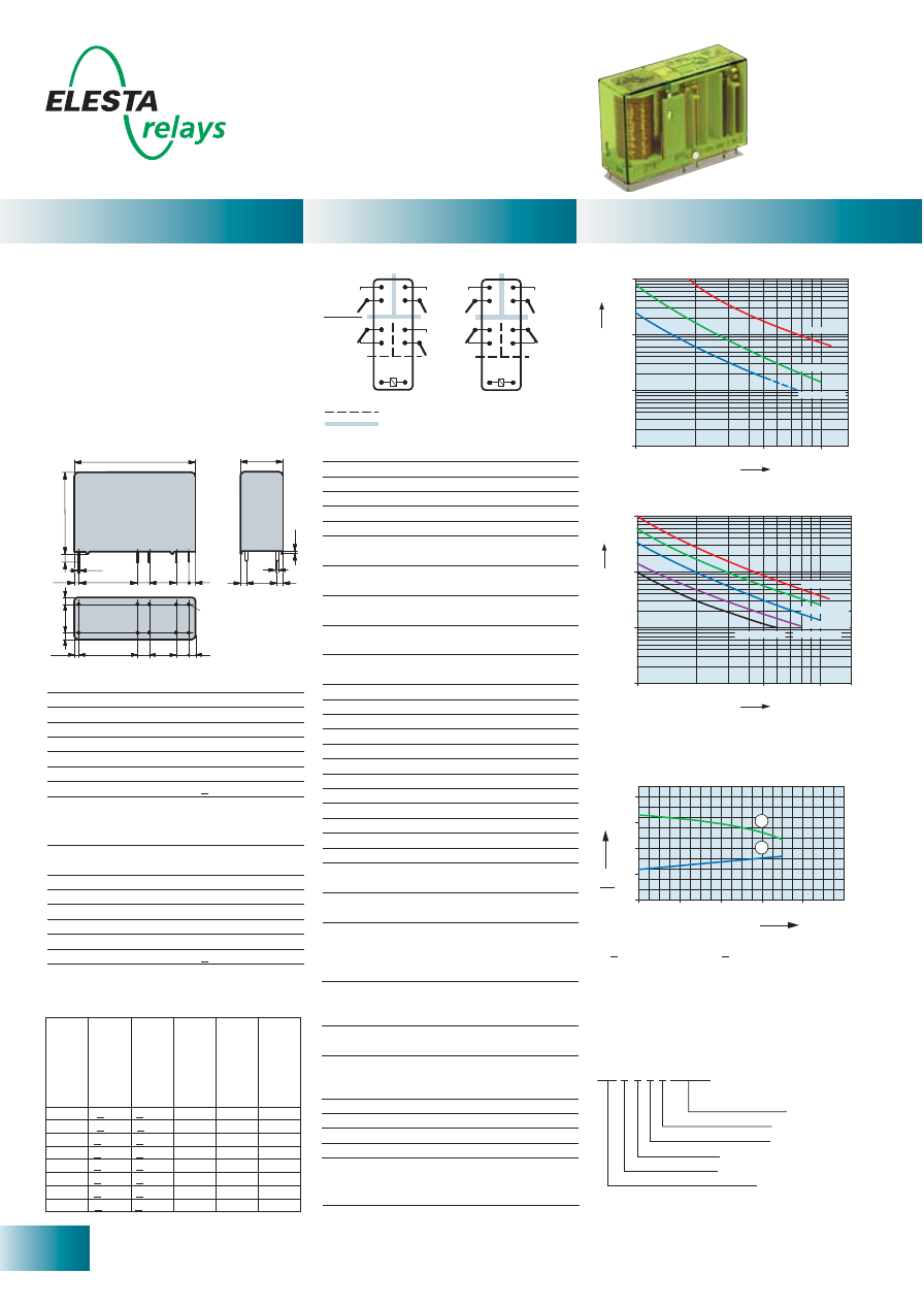
22
ELESTA relays GmbH, Heuteilstrasse 18,
CH - 7310 Bad Ragaz, Switzerland
Phone: +41 (0)81 303 54 00
Fax:
+41 (0)81 303 54 01
E-Mail: admin@elestarelays.com
Internet: http://www.elestarelays.com
SIR 4 Contacts „
P
ower“
U
U
B
N
Ambient temperature °C
0
0
20 40 60
2,0
1,5
1,0
0,5
1
2
80
100
SIR312P
SIR222P
Control
side
Output
side
Double or reinforced insulation
Basic insulation
DC-13: 24V
10 000
1000
100
10
DC-13: 24V
DC 14: 24V
DC 1: 24V
16
10
5
1
No. of operations x 1
0
0
0
Switching current (A)
10 000
1000
100
10
16
10
5
1
AC 1: 230V
AC 1: 400V
AC 3: 230V
AC 3: 400V
AC15: 230V
No. of operations x 1
0
0
0
Switching current (A)
46,4
16
30,7
2,9
3
5
10,5
5
21
1,9
1
10
0,7
0,4
3
3
3
10,5 5
5
21
1,9
31
0
3
[mm]
Ø
1,3
Standard coils for direct current (examples)
other voltages on request
Circuit diagram (view on relay upper side)
Ordering example
- PCB relay with forcibly guided contacts
- Protective separation between coil/control
contacts and output contacts (> 10mm) and
output contacts side by side (> 8mm)
- EN 50205, type A
- Contact mounting:
SIR312
P
„
P
ower“ Control contacts 1NO/1NC
Output
contacts
2NO
SIR222
P
„
P
ower“ Control contacts
2NC
Output
contacts
2NO
- Inrush current 60A / continuous current 12A
- Mean coil power 0.75W
- Holding power 0.23 W
Control Contacts
Contact material
AgSnO
2
+0.2
μ
m Au
Rated switching capacity 250VAC 6A AC1 1‘500VA
Electr. life AC1 (360 cycles/h) approx.100’000
Inrush current max.
15A for 20ms
Switching voltage range
5 to 250 VDC/VAC
Switching current range*
5mA to 6A
Switching capacity range* 60mW to 1’500W (VA)
Contact resistance (as delivered) <100m
Ω
/28 V/100mA
* Guide values
Nominal v
olt
age
VDC
Min. pic
k-up
volt
age at 20°C
VDC
Drop-out v
olt
age
at 20 °C VDC
Nominal cur
rent
in mA
R
esist
ance in
Ohm at 20 °C
Tolerance in %
5
< 3.5
> 0.5
151.0
33
± 10
12
< 8.4
> 1.2
63.1
190
± 10
18
< 12,6 > 1,8
41,6
432
± 10
20
< 14.0 > 2.0
37.7
530
± 10
24
< 16.8 > 2.4
31.5
760
± 10
48
< 33.6 > 4.8
15.7
3‘050
± 10
60
< 42.0 > 6.0
12.5
4‘800
± 10
110
< 77.0 > 11.0
6.8
16‘000
± 15
Mechanical life
> 10 x 10
6
operations
Switching frequency, mechanical
15Hz
Response time
typically 15ms
Drop-out time**
typically 4ms
Bounce time of NO contact
typically 6ms
Bounce time of NC contact
typically 12ms
Shock resistance 16ms
NO contact 17g
NC contact 7g
Vibration resistance
NO contact 10g
10-200Hz
NC contact 4,5g
Test voltage
coil/control contacts
2’500Veff 1min
Test voltage
5’000Veff 1min
coil-control contacts/output contacts
Test voltage output contacts
as against each other
4’000Veff 1min
Test voltage contact open
1’500Veff 1min
Insulation resistance
10
11
Ω
Creepage resistance
CTI 250
Weight approx.
32g
Mounting position
any
Ambient temperature
-40°C to +70°C
Type of protection
RT II
Solder bath temperature
270 °C/5s
Thermal resistance
55K/W
Temperature limit for coil
120°C
Pollution degree
2
Overvoltage category
III
Resistance to short circuiting 1‘000A SCPD 6A
control contacts
gG (pre-fuse)
Resistance to short circuiting 1‘000A SCPD 16A
output contacts
gL/gG (pre-fuse)
** without spark suppression
Tests, regulations
Approvals
SEV, UL, cUL, TÜV
UL File E188953
Sec. 3
Insulation class IEC 60664-1
250VAC
Protection class II
VDE 0106
Fire protection requirements
UL 94 / V0
Insulation terms
Coil to control contacts: Basic insulation
Coil/control contacts to output contacts:
Double or reinforced insulation
> 10mm
Output contacts as against each other:
Double or reinforced insulation > 8mm
contacts each with (output contacts)
Maximal contact load at AC 1 with 230V:
2 contacts each with 12A
Contact lifetime (output contacts)
1) Max. excitation voltage with contact load
< 2A control contacts / < 10A output contacts
2) Min. excitation voltage (guaranteed values)
without previous operation
No heat accumulation due to intrinsic heating
of other components.
Continuous duty 100%.
Excitation voltage range
SIR 3 1 2
P
24VDC
Coil voltage
Soldering tags
Number of NC contacts
Number of NO contacts
Type designation
Power version
Options, accessories
PCB socket:
see page 31
Output contacts
Contact material
AgSnO
2
Rated switching capacity 250VAC
(440VAC)
12A
AC1
3‘000VA
Electr. life AC1 (360 cycles/h) approx. 250‘000
Inrush current max.
60A for 20ms
Switching voltage range
5 to 480 VDC/VAC
Switching current range*
10mA to 12A
Switching capacity range* 120mW to 3‘000W (VA)
Contact resistance (as delivered) <100m
Ω
/28 V/100mA
* Guide values
Relay data
General data
Diagrams
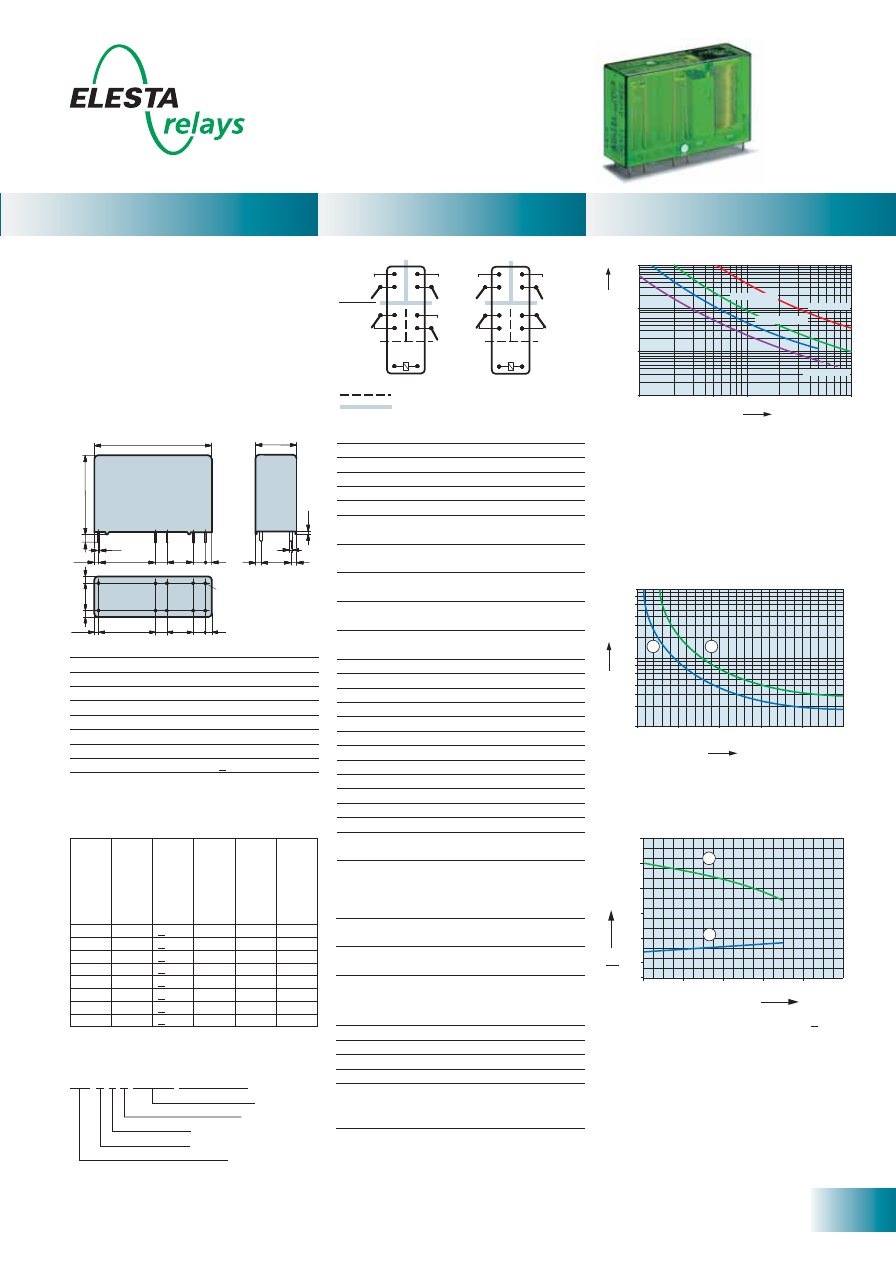
23
ELESTA relays GmbH, Heuteilstrasse 18,
CH - 7310 Bad Ragaz, Switzerland
Phone: +41 (0)81 303 54 00
Fax:
+41 (0)81 303 54 01
E-Mail: admin@elestarelays.com
Internet: http://www.elestarelays.com
SIR 4 Contacts sensitive
0
0
20
40
60
2,0
1,5
1,0
0,5
1
2
80
100
2,5
3,0
Ambient temperature °C
U
U
B
N
SIR312
SIR222
Control
side
Output
side
Double or reinforced insulation
Basic insulation
No. of operations x 1
0
0
0
Switching current (A)
10 000
1000
100
10
10
5.0
1.0
0.5
0.1
DC 1: 24V
AC 1: 230V
AC 15: 230V
DC 13: 24V
Current (A)
Voltage (VDC)
0,6
0,4
0,1
0,3
0,2
0,8
1
2
3
4
6
8
0
50
100
150
200
250
1
2
10
46,4
16
30,7
2,9
3
5
10,5
5
21
1,9
1
10
0,7
0,4
3
3
3
10,5 5
5
21
1,9
31
0
3
[mm]
Ø
1,3
Standard coils for direct current
(other voltages on request)
Circuit diagram (view on relay upper side)
Ordering example
- PCB relay with forcibly guided contacts
- Protective separation between coil/control
contacts and output contacts (> 10mm) as
well as protective separation between the
output contacts themselves (> 8mm)
- EN 50205, type A
- Contact mounting:
SIR312 3NO/1NC
SIR222 2NO/2NC
- Small external dimensions
- Mean coil power 0.36W
- Holding power 0.12W
- For Railway Applications: EN 50155
Contact material
AgSnO
2
+0.2
μ
m Au
Type of contact
Crest contact
Rated switching capacity 250VAC 10A AC1 2’500VA
Electr. life AC1 (360 cycles/h) approx.100’000
Inrush current max.
25A for 20ms
Switching voltage range
5 to 250 VDC/VAC
Switching current range*
10mA to 10A
Switching capacity range* 0.06VA(W) to 2’500VA
Contact resistance (as delivered) <100m
Ω
/28 V/100mA
* Guide values
Nominal v
olt
age
VDC
Min. pic
k-up
volt
age at 20°C
Drop-out v
olt
age
at 20 °C
Nominal cur
rent
in mA
R
esist
ance in
Ohm at 20 °C
Tolerance in %
5
3,75
> 0,5
72,0
69,4
± 10
6
4,5
> 0,6
60,0
100
± 10
9
6,75
> 0,9
40,0
225
± 10
12
9,0
> 1,2
30,0
400
± 10
18
13,5
> 1,8
20,0
900
± 10
24
18,0
> 2,4
15,0
1’600
± 10
48
36,0
> 3,6
7,5
6’400
± 13
60
45,0
> 4,5
6,0
10’000
± 15
Mechanical life
> 10 x 10
6
operations
Switching frequency, mechanical
15Hz
Response time
typically 18ms
Drop-out time**
typically 5ms
Bounce time of NO contact
typically 6ms
Bounce time of NC contact
typically 12ms
Shock resistance 16ms
NO contact > 10g
NC contact 6g
Vibration resistance
NO contact > 5g
10-200Hz
NC contact 1,5g
Test voltage
coil/control contacts
2’500Veff 1min
Test voltage
5’000Veff 1min
coil-control contacts/output contacts
Test voltage output contacts
as against each other
4’000Veff 1min
Test voltage contact open
1’500Veff 1min
Insulation resistance
10
11
Ω
Creepage resistance
CTI 250
Weight approx.
30g
Mounting position
any
Ambient temperature
-40°C to +70°C
Type of protection
RT II
Solder bath temperature
270 °C/5s
Thermal resistance
55K/W
Temperature limit for coil
120°C
Pollution degree
2
Overvoltage category
III
Resistance to short
1’000A SCPD 10A
circuiting gG
(pre-fuse)
** without spark suppression
Tests, regulations
Approvals
SEV, UL, cUL, TÜV
UL File E188953
Sec. 3
Insulation class IEC 60664-1
250VAC
Protection class II
VDE 0106
Fire protection requirements
UL 94 / V0
Insulation terms
Coil to control contacts: Basic insulation
Coil/control contacts to output contacts:
Double or reinforced insulation > 10mm
Output contacts as against each other:
Double or reinforced insulation > 8mm
1) Inductive load, L/R 40 ms
2) Resistive load
Contact lifetime
Max. switching characteristics
(determined acc. to DIN EN 60947-5-1 table C2):
AC 15: 230V/5A
DC 13: 24V/7.5A/0.1 Hz
UL 508: C600/R300
Maximal contact load at AC 1 with 230V:
2 contacts each with 10A
3 contacts each with 8.4A
Load limit curve with direct current
1) Max. excitation voltage with contact load < 2A
2) Min. excitation voltage (guaranteed values)
without previous operation
No heat accumulation due to intrinsic heating
of other components.
Continuous duty 100%.
Excitation voltage range
Relay data
General data
Diagrams
SIR 3 1 2 24VDC
Soldering tags
Number of NC contacts
Number of NO contacts
Type designation
Coil voltage
Sensitive coil
SEN
Options, accessories
PCB socket
see page 31
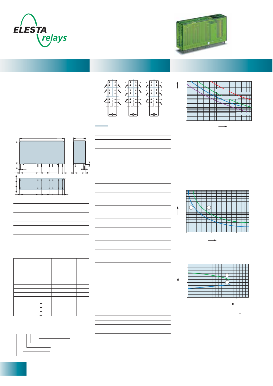
24
ELESTA relays GmbH, Heuteilstrasse 18,
CH - 7310 Bad Ragaz, Switzerland
Phone: +41 (0)81 303 54 00
Fax:
+41 (0)81 303 54 01
E-Mail: admin@elestarelays.com
Internet: http://www.elestarelays.com
SIR 6 Contacts
Ambient temperature °C
U
U
B
N
0
0
20
40
60
2,0
1,5
1,0
0,5
1
2
80
100
Control
side
Output
side
Double or reinforced insulation
Basic insulation
SIR332
SIR422 SIR512
No. of operations x 1
0
0
0
Switching current (A)
10 000
1000
100
10
10
5.0
1.0
0.5
0.1
DC 1: 24V
AC 1: 230V
AC 15: 230V
DC 13: 24V
Current (A)
Voltage (VDC)
0,6
0,4
0,1
0,3
0,2
0,8
1
2
3
4
6
8
0
50
100
150
200
250
1
2
10
58,9
16
30,7
2,9
3
5
7,5
5
21
1,9
1
10
0,
7
0,4
3
5
10,5
3
3
10,5
5
5
21
1,9
31
0
3
5
7,5
[mm]
Ø
1,3
Relay data
General data
Diagrams
Standard coils for direct current
(other voltages on request)
Circuit diagram (view on relay upper side)
1) Max. excitation voltage with contact load < 2A
2) Min. excitation voltage (guaranteed values)
without previous operation
No heat accumulation due to intrinsic heating
of other components.
Continuous duty 100%.
Excitation voltage range
- PCB relay with forcibly guided contacts
- Protective separation between coil/control
contacts and output contacts (> 10mm) as
well as protective separation between the
output contacts themselves (> 8mm)
- EN 50205, type A
- Contact mounting:
SIR332 3NO/3NC
SIR422 4NO/2NC
SIR512 5NO/1NC
- Small external dimensions
- Mean coil power 0.75W
- Holding power 0.22W
- For Railway Applications: EN 50155
Contact material
AgSnO
2
+0.2
μ
m Au
Type of contact
Crest contact
Rated switching capacity 250VAC 10A AC1 2’500VA
Electr. life AC1 (360 cycles/h) approx.100’000
Inrush current max.
25A for 20ms
Switching voltage range
5 to 250 VDC/VAC
Switching current range*
10mA to 10A
Switching capacity range* 0.06VA(W) to 2’500VA
Contact resistance (as delivered) <100m
Ω
/28 V/100mA
* Guide values
Nominal v
olt
age
VDC
Min. pic
k-up
volt
age at 20°C
Drop-out v
olt
age
at 20 °C
Nominal cur
rent
in mA
R
esist
ance in
Ohm at 20 °C
Tolerance in %
5
3,5
> 0,5
151,0
33
± 10
6
4,2
> 0,6
125
48
± 10
12
8,4
> 1,2
63,1
190
± 10
18
12,6
> 1,8
41,6
432
± 10
24
16,8
> 2,4
31,5
760
± 10
48
33,6
> 4,8
15,7
3’050
± 10
60
42,0
> 6,0
12,5
4’800
± 13
110
77,0
> 11,0
6,8
16’000
± 15
Mechanical life
> 10 x 10
6
operations
Switching frequency, mechanical
15Hz
Response time
typically 15ms
Drop-out time**
typically 4ms
Bounce time of NO contact
typically 6ms
Bounce time of NC contact
typically 12ms
Shock resistance 16ms
NO contact > 10g
NC contact 6g
Vibration resistance
NO contact > 5g
10-200Hz
NC contact 2g
Test voltage
coil/control contacts
2’500Veff 1min
Test voltage
5’000Veff 1min
coil-control contacts/output contacts
Test voltage output contacts
as against each other
4’000Veff 1min
Test voltage contact open
1’500Veff 1min
Insulation resistance
10
11
Ω
Creepage resistance
CTI 250
Weight approx.
35g
Mounting position
any
Ambient temperature
-40°C to +70°C
Type of protection
RT II
Solder bath temperature
270 °C/5s
Thermal resistance
55K/W
Temperature limit for coil
120°C
Pollution degree
2
Overvoltage category
III
Resistance to short
1’000A SCPD 10A
circuiting gG
(pre-fuse)
** without spark suppression
Insulation terms
Coil to control contacts: Basic insulation
Coil/control contacts to output contacts:
Double or reinforced insulation
> 10mm
Output contacts as against each other:
Double or reinforced insulation > 8mm
Tests, regulations
Approvals
SEV, UL, cUL, TÜV
UL File E188953
Sec. 3
Insulation class IEC 60664-1
250VAC
Protection class II
VDE 0106
Fire protection requirements
UL 94 / V0
Max. switching characteristics
(determined acc. to DIN EN 60947-5-1 table C2):
AC 15: 230V/5A
DC 13: 24V/7.5A/0.1 Hz
UL 508: C600/R300
Maximal contact load at AC 1 with 230V:
2 contacts each with 10A
3 contacts each with 8.4A
4 contacts each with 7.3A
5 contacts each with 6A
1) Inductive load, L/R 40 ms
2) Resistive load
Contact lifetime
Load limit curve with direct current
Ordering example
Options, accessories
PCB socket
see page 31
SIR 4 2 2 24VDC
Soldering tags
Number of NC contacts
Number of NO contacts
Type designation
Coil voltage
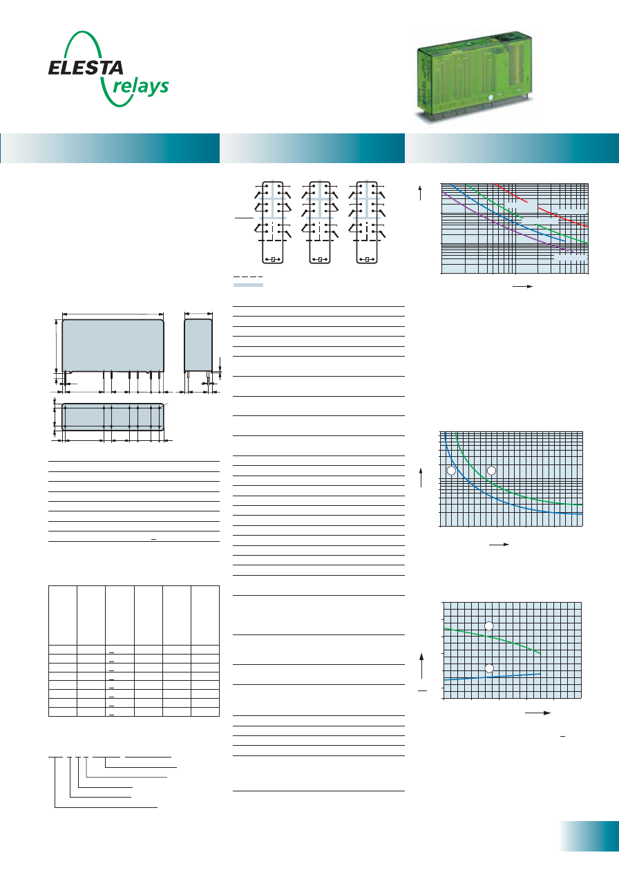
25
ELESTA relays GmbH, Heuteilstrasse 18,
CH - 7310 Bad Ragaz, Switzerland
Phone: +41 (0)81 303 54 00
Fax:
+41 (0)81 303 54 01
E-Mail: admin@elestarelays.com
Internet: http://www.elestarelays.com
SIR 6 Contacts sensitive
0
0
20
40
60
2,0
1,5
1,0
0,5
1
2
80
100
2,5
3,0
Ambient temperature °C
U
U
B
N
Control
side
Output
side
Double or reinforced insulation
Basic insulation
SIR332
SIR422 SIR512
No. of operations x 1
0
0
0
Switching current (A)
10 000
1000
100
10
10
5.0
1.0
0.5
0.1
DC 1: 24V
AC 1: 230V
AC 15: 230V
DC 13: 24V
Current (A)
Voltage (VDC)
0,6
0,4
0,1
0,3
0,2
0,8
1
2
3
4
6
8
0
50
100
150
200
250
1
2
10
58,9
16
30,7
2,9
3
5
7,5
5
21
1,9
1
10
0,7
0,4
3
5
10,5
3
3
10,5
5
5
21
1,9
31
0
3
5
7,5
[mm]
Ø
1,3
Relay data
General data
Diagrams
Standard coils for direct current
(other voltages on request)
Circuit diagram (view on relay upper side)
1) Max. excitation voltage with contact load < 2A
2) Min. excitation voltage (guaranteed values)
without previous operation
No heat accumulation due to intrinsic heating
of other components.
Continuous duty 100%.
Excitation voltage range
- PCB relay with forcibly guided contacts
- Protective separation between coil/control
contacts and output contacts (> 10mm) as
well as protective separation between the
output contacts themselves (> 8mm)
- EN 50205, type A
- Contact mounting:
SIR332 3NO/3NC
SIR422 4NO/2NC
SIR512 5NO/1NC
- Small external dimensions
- Mean coil power 0.50W
- Holding power 0.18W
- For Railway Applications: EN 50155
Contact material
AgSnO
2
+0.2
μ
m Au
Type of contact
Crest contact
Rated switching capacity 250VAC 10A AC1 2’500VA
Electr. life AC1 (360 cycles/h) approx.100’000
Inrush current max.
25A for 20ms
Switching voltage range
5 to 250 VDC/VAC
Switching current range*
10mA to 10A
Switching capacity range* 0.06VA(W) to 2’500VA
Contact resistance (as delivered) <100m
Ω
/28 V/100mA
* Guide values
Nominal v
olt
age
VDC
Min. pic
k-up
volt
age at 20°C
Drop-out v
olt
age
at 20 °C
Nominal cur
rent
in mA
R
esist
ance in
Ohm at 20 °C
Tolerance in %
5
3,75
> 0,5
100,0
50
± 10
6
4,5
> 0,6
83,3
72
± 10
9
6,75
> 0,9
56,2
160
± 10
12
9,0
> 1,2
41,6
288
± 10
18
13,5
> 1,8
27,7
648
± 10
24
18,0
> 2,4
20,8
1’150
± 10
48
36,0
> 3,6
10,4
4’600
± 13
60
45,0
> 4,5
8,3
7’200
± 15
Mechanical life
> 10 x 10
6
operations
Switching frequency, mechanical
15Hz
Response time
typically 18ms
Drop-out time**
typically 5ms
Bounce time of NO contact
typically 6ms
Bounce time of NC contact
typically 12ms
Shock resistance 16ms
NO contact > 10g
NC contact 6g
Vibration resistance
NO contact > 5g
10-200Hz
NC contact 2g
Test voltage
coil/control contacts
2’500Veff 1min
Test voltage
5’000Veff 1min
coil-control contacts/output contacts
Test voltage output contacts
as against each other
4’000Veff 1min
Test voltage contact open
1’500Veff 1min
Insulation resistance
10
11
Ω
Creepage resistance
CTI 250
Weight approx.
35g
Mounting position
any
Ambient temperature
-40°C to +70°C
Type of protection
RT II
Solder bath temperature
270 °C/5s
Thermal resistance
55K/W
Temperature limit for coil
120°C
Pollution degree
2
Overvoltage category
III
Resistance to short
1’000A SCPD 10A
circuiting gG
(pre-fuse)
** without spark suppression
Insulation terms
Coil to control contacts: Basic insulation
Coil/control contacts to output contacts:
Double or reinforced insulation
> 10mm
Output contacts as against each other:
Double or reinforced insulation > 8mm
Tests, regulations
Approvals
SEV, UL, cUL, TÜV
UL File E188953
Sec. 3
Insulation class IEC 60664-1
250VAC
Protection class II
VDE 0106
Fire protection requirements
UL 94 / V0
Max. switching characteristics
(determined acc. to DIN EN 60947-5-1 table C2):
AC 15: 230V/5A
DC 13: 24V/7.5A/0.1 Hz
UL 508: C600/R300
Maximal contact load at AC 1 with 230V:
2 contacts each with 10A
3 contacts each with 8.4A
4 contacts each with 7.3A
5 contacts each with 6A
1) Inductive load, L/R 40 ms
2) Resistive load
Contact lifetime
Load limit curve with direct current
Ordering example
Options, accessories
PCB socket
see page 31
SIR 4 2 2 24VDC
Soldering tags
Number of NC contacts
Number of NO contacts
Type designation
Coil voltage
Sensitive coil
SEN
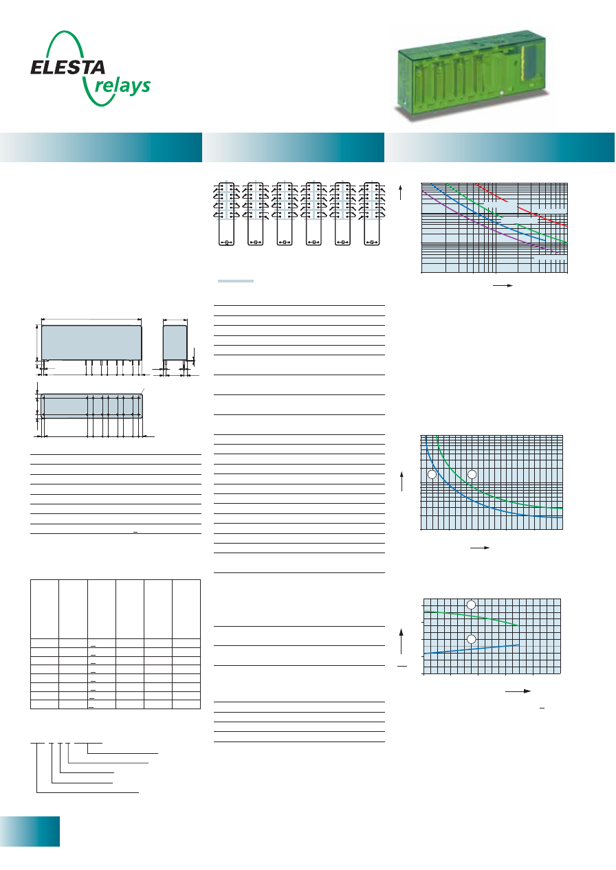
26
ELESTA relays GmbH, Heuteilstrasse 18,
CH - 7310 Bad Ragaz, Switzerland
Phone: +41 (0)81 303 54 00
Fax:
+41 (0)81 303 54 01
E-Mail: admin@elestarelays.com
Internet: http://www.elestarelays.com
SIR 8 Contacts
0
0
20
40
60
2,0
1,5
1,0
0,5
1
2
80
100
Ambient temperature °C
U
U
B
N
No. of operations x 1
0
0
0
Switching current (A)
10 000
1000
100
10
10
5.0
1.0
0.5
0.1
DC 1: 24V
AC 1: 230V
AC 15: 230V
DC 13: 24V
Current (A)
Voltage (VDC)
0,6
0,4
0,1
0,3
0,2
0,8
1
2
3
4
6
8
0
50
100
150
200
250
1
2
10
85,5
20
32
1
0,5
12,5
0,
3
3,75
3,75
2,9
3,1
5
7,5
7,5
5
5
37,9
2
0,4
5
3,1
5
37,9
2
3,75
12,5
3,75
5 5
5
7,5 7,5 7,5
7,5
Ø
1,3
[mm]
Standard coils for direct current
(other voltages on request)
Circuit diagram (view on relay upper side)
Double or reinforced insulation
SIR262
SIR352
SIR442
SIR622
SIR532
SIR712
- PCB relay with forcibly guided contacts
- Protective separation between coil and
output contacts (> 10mm) and contacts in
one row (> 8mm) and as left to right contact
side (> 10mm)
- EN 50205, type A
- Contact mounting:
SIR262 2NO/6NC SIR352 3NO/5NC
SIR442 4NO/4NC SIR532 5NO/3NC
SIR622 6NO/2NC
SIR712 7NO/1NC
- Small external dimensions
- Mean coil power 1.3W
- Holding power 0.39W
- For Railway Applications: EN 50155
Contact material
AgSnO
2
+0,2
μ
m Au
Type of contact
Crest contact
Rated switching capacity 250VAC 10A AC1 2’500VA
Electr. life AC1 (360 cycles/h) approx.100’000
Inrush current max.
25A for 20ms
Switching voltage range
5 to 250 VDC/VAC
Switching current range*
10mA to 10A
Switching capacity range* 0,06VA(W) to 2’500VA
Contact resistance (as delivered) <100m
Ω
/28 V/100mA
* Guide values
Nominal v
olt
age
VDC
Min. pic
k-up
volt
age at 20°C
Drop-out v
olt
age
at 20 °C
Nominal cur
rent
in mA
R
esist
ance in
Ohm at 20 °C
Tolerance in %
6
4,2
> 0,6
218
27,5
± 10
12
8,4
> 1,2
109
110
± 10
18
12,6
> 1,8
72
250
± 10
24
16,8
> 2,4
54,5
440
± 10
48
33,6
> 4,8
27,2
1’760
± 10
60
42,0
> 6,0
11,8
2’750
± 10
110
77,0
> 11,0
6,8
9’250
± 13
220
154,0 > 22,0
5,9
37’000
± 15
Mechanical life
> 10 x 10
6
operations
Switching frequency, mechanical
15Hz
Response time
typically 15ms
Drop-out time**
typically 4ms
Bounce time of NO contact
typically 6ms
Bounce time of NC contact
typically 12ms
Shock resistance 16ms
NO contact > 10g
NC contact 6g
Vibration resistance
NO contact > 5g
10-200Hz
NC contact 2g
Test voltage
5’000Veff 1min
coil- contacts
Test voltage contacts
as against each other
4’000Veff 1min
Test voltage contact open
1’500Veff 1min
Insulation resistance
10
11
Ω
Creepage resistance
CTI 250
Weight approx.
60g
Mounting position
any
Ambient temperature
-40°C to +70°C
Type of protection
RT II
Solder bath temperature
270 °C/5s
Thermal resistance
40K/W
Temperature limit for coil
125°C
Pollution degree
2
Overvoltage category
III
Resistance to short
1’000A SCPD 10A
circuiting gG
(pre-fuse)
** without spark suppression
Insulation terms
Coil to contacts:
Double or reinforced insulation > 10mm
All contacts in one row:
Double or reinforced insulation > 8mm
All contacts as left to right contact side:
Double or reinforced insulation > 10mm
Tests, regulations
Approvals
SEV, UL, cUL, TÜV
UL File E188953
Sec. 3
Insulation class IEC 60664-1
250VAC
Protection class II
VDE 0106
Fire protection requirements
UL 94 / V0
Max. switching characteristics
(determined acc. to DIN EN 60947-5-1 table C2):
AC 15: 230V/5A
DC 13: 24V/7.5A/0.1 Hz
UL 508: C600/R300
1) Max. excitation voltage with contact load < 2A
2) Min. excitation voltage (guaranteed values)
without previous operation
No heat accumulation due to intrinsic heating
of other components.
Continuous duty 100%.
Excitation voltage range
1) Inductive load, L/R 40 ms
2) Resistive load
Contact lifetime
Load limit curve with direct current
Maximal contact load at AC 1 with 230V:
2 contacts each with 10A
3 contacts each with 8.4A
4 contacts each with 7.3A
5 contacts each with 6.5A
6 contacts each with 6A
Relay data
General data
Diagrams
Ordering example
SIR 3 5 2 24VDC
Soldering tags
Number of NC contacts
Number of NO contacts
Type designation
Coil voltage
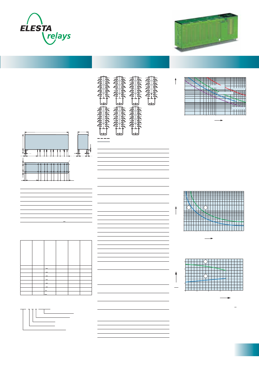
27
ELESTA relays GmbH, Heuteilstrasse 18,
CH - 7310 Bad Ragaz, Switzerland
Phone: +41 (0)81 303 54 00
Fax:
+41 (0)81 303 54 01
E-Mail: admin@elestarelays.com
Internet: http://www.elestarelays.com
SIR 10 Contacts
0
0
20
40
60
2,0
1,5
1,0
0,5
1
2
80
100
Ambient temperature °C
U
U
B
N
Double or reinforced insulation
Basic insulation
SIR372
SIR732
SIR822
SIR912
SIR552
SIR462
SIR642
No. of operations x 1
0
0
0
Switching current (A)
10 000
1000
100
10
10
5.0
1.0
0.5
0.1
DC 1: 24V
AC 1: 230V
AC 15: 230V
DC 13: 24V
Current (A)
Voltage (VDC)
0,6
0,4
0,1
0,3
0,2
0,8
1
2
3
4
6
8
0
50
100
150
200
250
1
2
10
[mm]
85,5
20
32
2,9
3,1
5
7,5
7,5
7,5
5
5
5
25,4
2,0
1
0,5
12,5
0,
3
0,4
3,75
5
3,75
3,1
7,5 5
5
25,4
2,0
3,75
12,5
3,75
5
5
5
7,5
7,5
7,5
7,5
Ø
1,3
Relay data
General data
Diagrams
Standard coils for direct current
(other voltages on request)
Circuit diagram (view on relay upper side)
Tests, regulations
Approvals
SEV, UL, cUL, TÜV
UL File E188953
Sec. 3
Insulation class IEC 60664-1
250VAC
Protection class II
VDE 0106
Fire protection requirements
UL 94 / V0
- PCB relay with forcibly guided contacts
- Protective separation between coil/control
contacts and output contacts (> 8mm) and
output contacts in one row (> 8mm) and as
left to right contact side (> 10mm)
- EN 50205, type A
- Contact mounting:
SIR372 3NO/7NC SIR462 4NO/6NC
SIR552 5NO/5NC SIR642 6NO/4NC
SIR732 7NO/3NC SIR822 8NO/2NC
SIR912 9NO/1NC
- Small external dimensions
- Mean coil power 1.3W
- Holding power 0.39W
Nominal v
olt
age
VDC
Min. pic
k-up
volt
age at 20°C
Drop-out v
olt
age
at 20 °C
Nominal cur
rent
in mA
R
esist
ance in
Ohm at 20 °C
Tolerance in %
6
4,2
> 0,6
218
27,5
± 10
12
8,4
> 1,2
109
110
± 10
18
12,6
> 1,8
72
250
± 10
24
16,8
> 2,4
54,5
440
± 10
48
33,6
> 4,8
27,2
1’760
± 10
60
42,0
> 6,0
11,8
2’750
± 10
110
77,0
> 11,0
6,8
9’250
± 13
220
154,0 > 22,0
5,9
37’000
± 15
Contact material
AgSnO
2
+0.2
μ
m Au
Type of contact
Crest contact
Rated switching capacity 250VAC 10A AC1 2’500VA
Electr. life AC1 (360 cycles/h) approx.100’000
Inrush current max.
25A for 20ms
Switching voltage range
5 to 250 VDC/VAC
Switching current range*
10mA to 10A
Switching capacity range* 0.06VA(W) to 2’500VA
Contact resistance (as delivered) <100m
Ω
/28 V/100mA
* Guide values
Mechanical life
> 10 x 10
6
operations
Switching frequency, mechanical
15Hz
Response time
typically 18ms
Drop-out time**
typically 5ms
Bounce time of NO contact
typically 8ms
Bounce time of NC contact
typically 12ms
Shock resistance 16ms
NO contact > 10g
NC contact 8g
Vibration resistance
NO contact > 10g
10-200Hz
NC contact 5g
Test voltage
coil/control contacts
2’500Veff 1min
Test voltage
5’000Veff 1min
coil-control contacts/output contacts
Test voltage output contacts
as against each other
4’000Veff 1min
Test voltage contact open
1’500Veff 1min
Insulation resistance
10
11
Ω
Creepage resistance
CTI 250
Weight approx.
60g
Mounting position
any
Ambient temperature
-40°C to +70°C
Type of protection
RT II
Solder bath temperature
270 °C/5s
Thermal resistance
40K/W
Temperature limit for coil
125°C
Pollution degree
2
Overvoltage category
III
Resistance to short circuiting output contacts
1’000A SCPD 10A gG (pre-fuse)
** without spark suppression
Insulation terms
Coil to control contacts: Basic insulation
Coil/control contacts to output contacts:
Double or reinforced insulation > 8mm
All output contacts in one row:
Double or reinforced insulation > 8mm
All output contacts as left to right contact side:
Double or reinforced insulation > 10mm
Max. switching characteristics
(determined acc. to DIN EN 60947-5-1 table C2):
AC 15: 230V/5A
DC 13: 24V/7.5A/0.1 Hz
UL 508: C600/R300
Maximal contact load at AC 1 with 230V:
2 contacts each with 10A
3 contacts each with 8.4A
4 contacts each with 7.3A
5 contacts each with 6.5A
6 contacts each with 6A
8 contacts each with 5A
9 contacts each with 4.2A
1) Max. excitation voltage with contact load < 2A
2) Min. excitation voltage (guaranteed values)
without previous operation
No heat accumulation due to intrinsic heating
of other components.
Continuous duty 100%.
Excitation voltage range
1) Inductive load, L/R 40 ms
2) Resistive load
Contact lifetime
Load limit curve with direct current
Ordering example
SIR 5 5 2 24VDC
Soldering tags
Number of NC contacts
Number of NO contacts
Type designation
Coil voltage
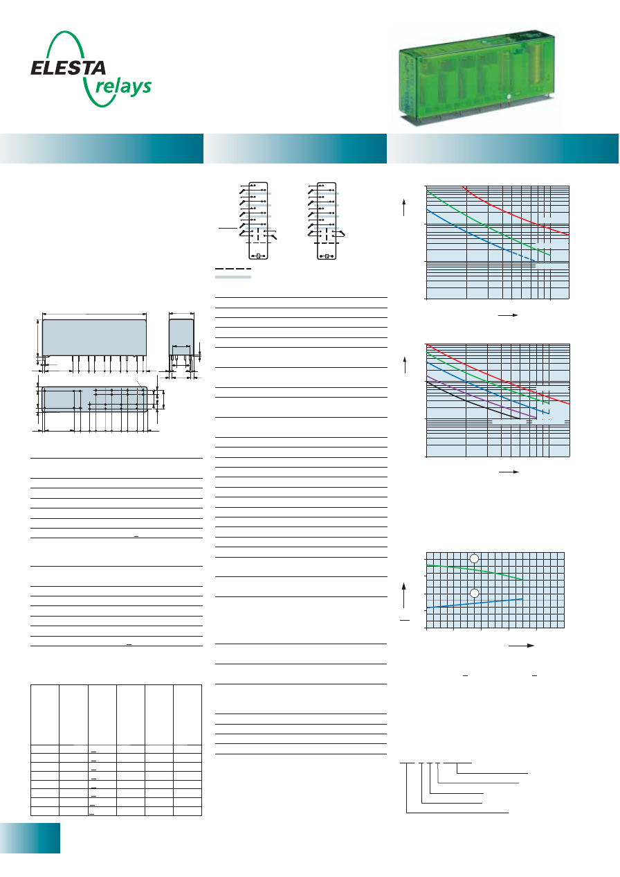
28
ELESTA relays GmbH, Heuteilstrasse 18,
CH - 7310 Bad Ragaz, Switzerland
Phone: +41 (0)81 303 54 00
Fax:
+41 (0)81 303 54 01
E-Mail: admin@elestarelays.com
Internet: http://www.elestarelays.com
SIP 6 Contacts
0
0
20
40
60
2,0
1,5
1,0
0,5
1
2
80
100
Ambient temperature °C
U
U
B
N
Control
side
Output
side
Double or reinforced insulation
Basic insulation
SIP512
SIP422
10
000
1000
100
10
DC-13:
24V
DC
14:
24V
DC
1:
24V
16
10
5
1
Switching current (A)
No. of operations x 1
0
0
0
No. of operations x 1
0
0
0
Switching current (A)
10
000
1000
100
10
16
10
5
1
AC
1:
230V
AC
1:
400V
AC
3:
230V
AC
3:
400V
AC15:
230V
12,5
6,5
3,75
3,75
84,6
20
32
2,9
4,1
5
6,5
6,5
8,5
5
5
5
25,4
2,1
1
0,5
14
0,
3
0,4
3
5
3
4,1
8,5 5
5
25,4
2,1
3,75
12,5
3,75
5
5
5
6,5
6,5
6,5
6,5
SIP512
6,5
14
[mm]
Ø
1,3
Standard coils for direct current
(other voltages on request)
Circuit diagram (view on relay upper side)
- PCB relay with forcibly guided contacts
- Protective separation between coil/control
contacts and output contacts (> 8mm) and
output contacts in one row (> 8mm).
- EN 50205, type A
- Contact mounting:
SIP512 Control
contacts 1NO/1NC
Output
contacts
4NO
SIP422 Control
contacts
2NC
Output
contacts
4NO
- Small external dimensions
- Mean coil power 1.3W
- Holding power 0.39W
- For Railway Applications: EN 50155
Control contacts
Contact material
AgSnO
2
+0.2
μ
m Au
Rated switching capacity
250VAC 6A AC1 1’500VA
Electr. life AC1 (360 cycles/h) approx.100’000
Inrush current max.
15A for 20ms
Switching voltage range
5 to 250 VDC/VAC
Switching current range*
5mA to 6A
Switching capacity range* 0.06VA(W) to 1’500VA
Contact resistance (as delivered) <100m
Ω
/28 V/100mA
Output contacts
Contact material
AgSnO
2
Rated switching capacity
250VAC (440VAC) 16A AC1 4’000VA
Electr. life AC1 (360 cycles/h) approx. 250’000
Inrush current max.
60A for 20ms
Switching voltage range
5 to 480 VDC/VAC
Switching current range*
10mA to 16A
Switching capacity range* 0.12VA(W) to 4’000VA
Contact resistance (as delivered) < 100m
Ω
/ 28 V / 100mA
* Guide values
Nominal v
olt
age
VDC
Min. pic
k-up
volt
age at 20°C
Drop-out v
olt
age
at 20 °C
Nominal cur
rent
in mA
R
esist
ance in
Ohm at 20 °C
Tolerance in %
6
4,2
> 0,6
218
27,5
± 10
12
8,4
> 1,2
109
110
± 10
18
12,6
> 1,8
72,5
248
± 10
24
16,8
> 2,4
54,5
440
± 10
48
33,6
> 4,8
27,2
1’760
± 10
60
42,0
> 6,0
11,8
2’750
± 10
110
77,0
> 11,0
6,8
9’250
± 13
220
154,0 > 22,0
5,9
37’000
± 15
Insulation terms
Coil to control contacts: Basic insulation
Coil/control contacts to output contacts:
Double or reinforced insulation > 8mm
All output contacts in one row:
Double or reinforced insulation > 8mm
Mechanical life
> 10 x 10
6
operations
Switching frequency, mechanical
15Hz
Response time
typically 18ms
Drop-out time**
typically 5ms
Bounce time of NO contact
typically 8ms
Bounce time of NC contact
typically 12ms
Shock resistance 16ms
NO contact > 10g
NC contact 8g
Vibration resistance
NO contact > 10g
10-200Hz
NC contact 5g
Test voltage coil/control contacts 2’500Veff 1min
Test voltage
5’000Veff 1min
coil-control contacts/output contacts
Test voltage output contacts
as against each other
4’000Veff 1min
Test voltage contact open
1’500Veff 1min
Insulation resistance
10
11
Ω
Creepage resistance
CTI 250
Weight approx.
60g
Mounting position
any
Ambient temperature
-40°C to +70°C
Type of protection
RT II
Solder bath temperature
270°C/5s
Thermal resistance
40K/W
Temperature limit for coil
125°C
Pollution degree
2
Overvoltage category
III
Resistance to short circuiting control contacts
1’000A SCPD 6A gG (pre-fuse)
Resistance to short circuiting output contacts
1’000A SCPD 16A gG (pre-fuse)
** without spark suppression
Tests, regulations
Approvals
SEV, UL, cUL, TÜV
UL File E188953
Sec. 4
Insulation class IEC 60664-1
250VAC
Protection class II
VDE 0106
Fire protection requirements
UL 94 / V0
UL 508: A600/R150
Maximal contact load at AC 1 with 230V:
2 contacts each with 16A
3 contacts each with 12A
4 contacts each with 10A
Contact lifetime (output contacts)
Contact lifetime (output contacts)
Ordering example
1) Max. excitation voltage with contact load:
Control contacts <2A, output contacts <5A
2) Min. excitation voltage (guaranteed values)
without previous operation
No heat accumulation due to intrinsic heating
of other components.
Continuous duty 100%.
Excitation voltage range
Relay data
General data
Diagrams
S I P 4 2 2 24VDC
Soldering tags
Number of NC contacts
Number of NO contacts
Type designation
Coil voltage
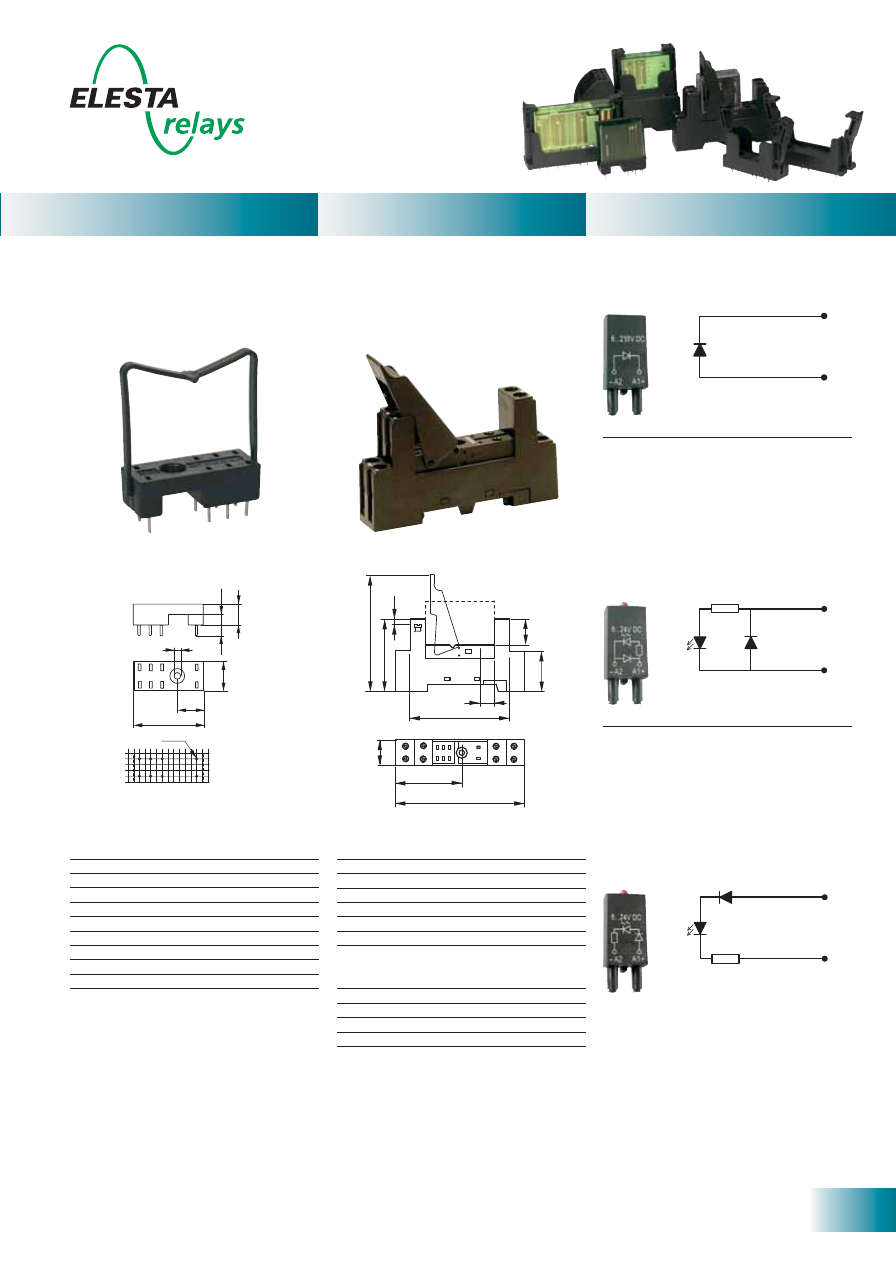
29
ELESTA relays GmbH, Heuteilstrasse 18,
CH - 7310 Bad Ragaz, Switzerland
Phone: +41 (0)81 303 54 00
Fax:
+41 (0)81 303 54 01
E-Mail: admin@elestarelays.com
Internet: http://www.elestarelays.com
PCB socket SRP-SGR2
4,8
9,0
4,8
12,7
31
10,8
[mm]
Ø
1,5
3,2
Technical data
Rated current
2x8A
Rated voltage
300VAC
Test voltage coil/contacts
5’000Veff
Insulation class (IEC 60664-1)
250VAC
Creepage resistance
CTI 250
Weight approx.
4g
Ambient temperature
-40°C to +80°C
Packing unit
100 pcs
Approvals UL,
cUL
UL File E113714
- PCB socket for SGR282Z, SIR282
- With hold down clip
- Soldering tags for PCB
- 2.5mm pinning
DIN rail socket SRD-SGR2
21
11
24
14
CO
M
NO
COIL
NC
A2
A1
22
12
60
6
15
24
68,5
42,5
≤ 3
75
37,5
15,5
[mm]
- DIN rail socket for SGR282Z, SIR282
- With plastic grip and marking tag (1 pc)
- Screw terminals
- 5mm pinning
- Assembly on DIN rail 35mm or single-hole
mounting with M3 screw
Technical data
Rated current
2x8A
Rated voltage
300VAC
Test voltage coil/contacts
4’000Veff
Insulation class (IEC 60664-1)
250VAC
Creepage resistance
CTI 250
Weight approx.
40g
Ambient temperature
-25°C to +80°C
Cross sections for connection with
- wires
2x2.5mm
2
- end sleeves for strands
2x1.5mm
2
Torque max.
0,8 Nm
Packing unit
20 pcs
Approvals UL,
cUL
UL File E113714
Modules for DIN rail sockets
Accessories
Module SRD-SGR2-M02
- For DIN rail socket SRD-SGR2
- Diode with red Led,
6VDC to 24VDC (+ on terminal A1)
Module SRD-SGR2-M03
- For DIN rail socket SRD-SGR2
- Diode with green Led,
6VDC to 24VDC (+ on terminal A1)
Module SRD-SGR2-M04
- For DIN rail socket SRD-SGR2
- Red Led, 6VDC to 24VDC
(+ on terminal A1)
Module SRD-SGR2-M05
- For DIN rail socket SRD-SGR2
- Green Led, 6VDC to 24VDC
(+ on terminal A1)
A1 +
A2 -
A1 +
A2 -
A1 +
A2 -
Module SRD-SGR2-M01
- For DIN rail socket SRD-SGR2
- Diode 6VDC to 230VDC
(+ on terminal A1)
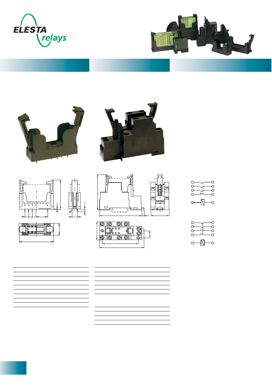
30
ELESTA relays GmbH, Heuteilstrasse 18,
CH - 7310 Bad Ragaz, Switzerland
Phone: +41 (0)81 303 54 00
Fax:
+41 (0)81 303 54 01
E-Mail: admin@elestarelays.com
Internet: http://www.elestarelays.com
Accessories
31
71
4,1
60
A1
A2
11
12
1
1,5
60
31
[mm]
75,1
34
33
44
43
23/22
24/21
43
33
23
11
A1
44
34
24
12
A2
SRD-SIM4 (SIM312...)
43
33
21
11
A1
44
34
22
12
A2
SRD-SIM4 (SIM222...)
DIN rail socket SRD-SIM4
PCB socket SRP-SIM4
7,5
3,4
5 5 5
15,9
0,5
40,2
SA-SIM4
ELESTA
16
46,7
[mm]
Ø
1,5
- PCB socket for SIM 3 and 4 Contacts
- With integrated retaining/ejector handles
- Soldering tags for PCB
- DIN rail socket for SIM 3 and 4 Contacts
- With integrated retaining/ejector handles
- Screw terminals
- Assembly on DIN rail 35mm or with 2xM3
screws
Technical data
Rated current
7A
Rated voltage
250VAC
Test voltage coil/contacts
4’000Veff
Insulation class (IEC 60664-1)
250VAC
Creepage resistance
CTI 250
Weight approx.
11g
Ambient temperature
-25°C to +70°C
Packing unit
20 pcs
Approvals UL,
cUL
UL File E301947
Technical data
Rated current
8A
Rated voltage
250VAC
Test voltage coil/contacts
2’500Veff
Insulation class (IEC 60664-1)
250VAC
Creepage resistance
CTI 250
Weight
approx. 65g
Ambient temperature
-25°C to +70°C
Cross sections for connection with
- wires
2x2.5mm
2
- end sleeves for strands
2x1.5mm
2
Torque max.
0.8 Nm
Packing unit
10 pcs
Approvals UL,
cUL
UL File E301947
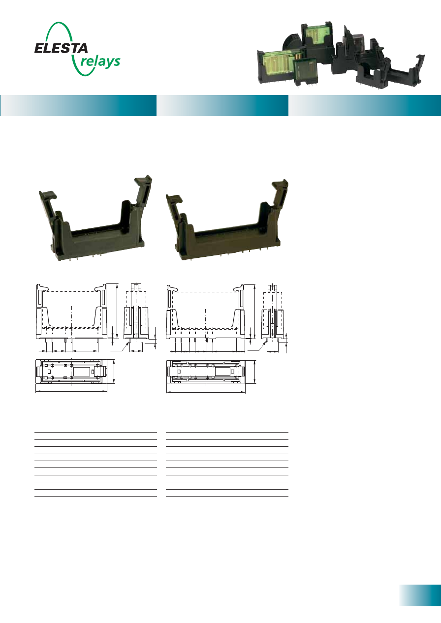
31
ELESTA relays GmbH, Heuteilstrasse 18,
CH - 7310 Bad Ragaz, Switzerland
Phone: +41 (0)81 303 54 00
Fax:
+41 (0)81 303 54 01
E-Mail: admin@elestarelays.com
Internet: http://www.elestarelays.com
Accessories
10
3,4
SR-SIR6
ELESTA
69,5
19,4
44,7
0,5
7,2
21
5
5
5 7,5
10,5
[mm]
Ø
1,5
PCB socket SRP-SIR6
PCB socket SRP-SIR4
10
SR-SIR4
ELESTA
57
19,4
21
10,5
5
5
0,5
44,7
[mm]
3,4
Ø
1,5
- PCB socket for SIR 4 Contacts
- With integrated retaining/ejector handles
- Soldering tags for PCB
- PCB socket for SIR 6 Contacts
- With integrated retaining/ejector handles
- Soldering tags for PCB
Technical data
Rated current
7A
Rated voltage
250VAC
Test voltage coil/contacts
4’000Veff
Insulation class (IEC 60664-1)
250VAC
Creepage resistance
CTI 250
Weight approx.
15g
Ambient temperature
-25°C to +70°C
Packing unit
20 pcs
Approvals UL,
cUL
UL File E301947
Technical data
Rated current
7A
Rated voltage
250VAC
Test voltage coil/contacts
4’000Veff
Insulation class (IEC 60664-1)
250VAC
Creepage resistance
CTI 250
Weight approx.
17g
Ambient temperature
-25°C to +70°C
Packing unit
20 pcs
Approvals UL,
cUL
UL File E301947
ELESTA relays GmbH
Heuteilstrasse 18
CH - 7310 Bad Ragaz
Switzerland
Certificate of environmental compatibility
Compatibility with the environment is of particular importance to ELESTA relays GmbH.
All materials we process, the consumables, packaging products, cleaning agents etc.
we use have been selected with a view to their eco-friendliness already for many
years. Careful handling of the natural resources, lowest possible energy consumption,
pendulum systems for input and auxiliary materials as well as optimized recycling
processes are a matter of course for us. They extend far beyond what legislation
demands.
Conformity with the EU guideline 2002/95/EG of 27 January 2003
(RoHS)
Our products comply with the legal requirements according to the EU guideline
2002/95/EG dated 27 January 2003 (RoHS: Restriction of Hazardous Substances).
None or our products contain any of the substances listed below:
• Lead, mercury, cadmium, hexavalent chromium
• Polybromated biphenyle (PBB), polybromated diphenyle ether (PBDE)
Soldering processes and suitability for the process
Our products are suitable for all common soldering processes based on higher
temperatures. It is the user‘s responsibility, however, to check and confirm the
suitability for the particular process in the individual case.
Application consultancy
ELESTA relays GmbH offers its customers comprehensive application consultancy also
in the context of the RoHS directives and the environmental compatibility of ELESTA
relays products.
Bad Ragaz, 01 March 2005
Martin Kunschert
Markus Gloor
General Manager
Quality Manager
Phone: +41 (0)81 303 54 00
Fax:
+41 (0)81 303 54 01
E-Mail: admin@elestarelays.com
Internet: http://www.elestarelays.com
CERTIFICATE
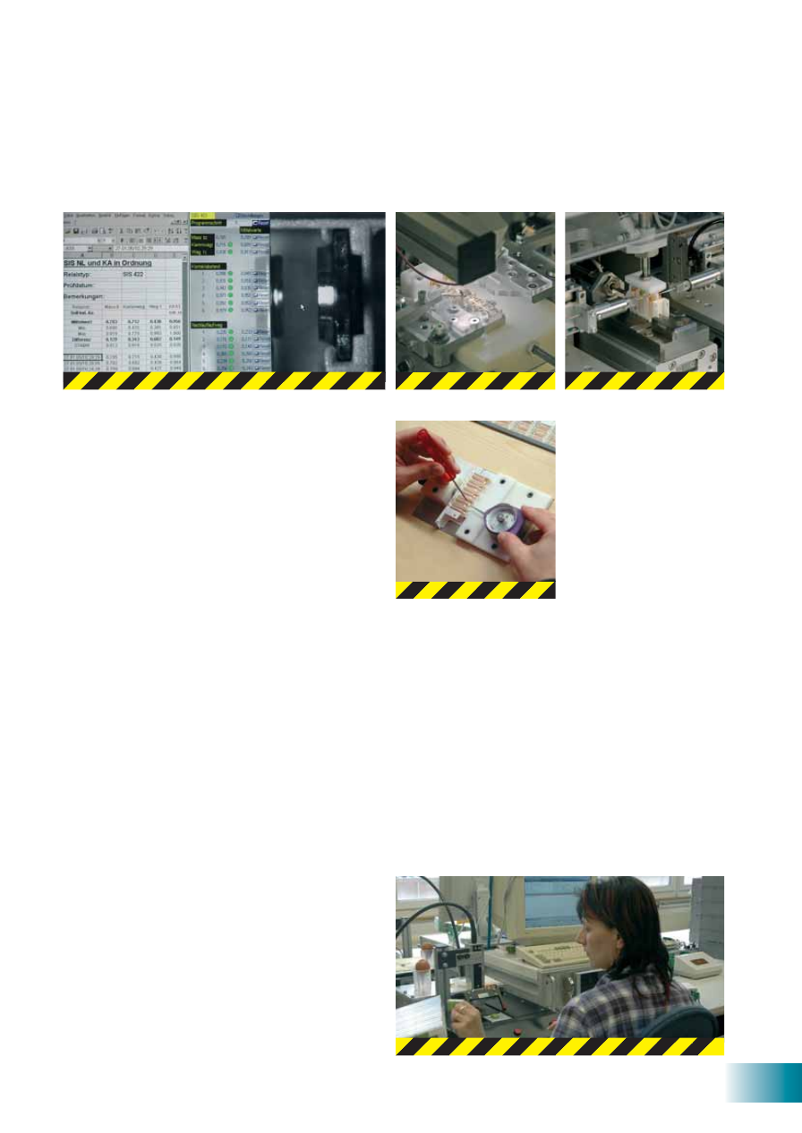
33
Quality without compromises
Being specialized in the production of safety relays,
we protect humans and equipment alike and assume
a particular responsibility for our products. Every
employee of ELESTA relays GmbH is aware of this
obligation in his/her daily work. In numerous recorded
inspection steps from the incoming materials over
the production process with 100% checking right to
dispatch we guarantee the safety and product quality
required for relays with forcibly guided contacts –
for the benefit of man and machine!
Production mostly on the premises, sophisticated
equipment and an experienced as well as highly
motivated workforce ensure that our products are of
highest quality. Extremely short delivery times are
possible thanks to highly flexible order processing,
even when special coils and customized relay varia-
tions or supplies of samples and pilot series are con-
cerned.
It is a matter of course for us to develop products
with and for our clientele. In this way we guarantee
that our customers get the right products for their
specific applications.
Our innovation leadership in relays with forcibly guided
contacts is evident in the development, production,
logistics as well as the selection of available relays
and our competent application consultancy – for the
benefit of our customers!
Our process-oriented management system guarantees
flat structures and short decision making. Continuous
improvement processes, further education, contribu-
tion to standardizations and close contact to custom-
ers and suppliers are firmly in place. „Swiss Quality“
is a reality at ELESTA relays GmbH.
34
Notes
35
Notes

Er 05060
1 en / 1
1.20
07
International sales
Your ELESTA relays - partner:
Switzerland
Germany
Worldwide
Phone: +41 (0)81 303 54 00
Fax:
+41 (0)81 303 54 01
E-Mail: admin@elestarelays.com
Internet: http://www.elestarelays.com
Phone: +49 (0)6182 7876854
Fax:
+49 (0)6182 7876857
E-Mail: admin@elestarelays.com
Internet: http://www.elestarelays.com
Phone: +49 (0)34293 473818
Fax:
+49 (0)34293 459988
E-Mail: admin@elestarelays.com
Internet: http://www.elestarelays.com
http://www.elestarelays.com
ELESTA relays GmbH
Heuteilstrasse 18
CH-7310 Bad Ragaz
Switzerland
ELESTA relays GmbH
Sales office Frankfurt
Grabenstraße 15
D-63500 Seligenstadt
Germany
ELESTA relays GmbH
Sales office Leipzig
Unterer Haselberg 32
D-04683 Nauenhof
Germany
See internet: