2
415 Howe Avenue, Suite LL160, Shelton, CT 06484-3168 U.S.A.
■
1-800-831-5383
Phone: (203) 922-1182
■
FAX: (203) 922 -8231
■
Web Site: http://www.e-markinc.com
E-Mark’s
business philosophy centers upon providing
each of its customers with
maximum value
.
This includes product
quality
appropriate for the application,
accurate delivery
competitive pricing
.
Company Profile
was established in
1985
and is classified by the U.S. Government as a small,
woman-owned business. The company specializes in interconnect products and
operates out of its facility in Shelton, Connecticut.
In addition to importing and distributing standard and custom products, the company also has
several products it sells manufactured to its specifications.
E-Mark’s
suppliers are carefully chosen and most
of them carry approvals relevant to their individual products including ISO 9000, CECC, UL, VDE, etc.
Cataloged products are stocked at
E-Mark’s
Connecticut location for
immediate shipment.
markets its products through a network of manufacturer’s representatives and
through local or regional distributors. Most of the company’s customers are OEMs involved in
the manufacture of a variety of electronic equipment including data processing equipment,
telecom equipment, ATE products, machine controls, etc.
Banking and trade references are available on request.
We would be pleased to put you in contact with individuals at any of our current customers
who can provide you with information confirming our
excellent service, quality
product value.
&
&

3
415 Howe Avenue, Suite LL160, Shelton, CT 06484-3168 U.S.A.
■
1-800-831-5383
Phone: (203) 922-1182
■
FAX: (203) 922 -8231
■
Web Site: http://www.e-markinc.com
Test Points ............................................................................................................................................ 4
SMT Ball and Socket Connectors ......................................................................................................... 5
Pin Headers
2 mm Spacing ........................................................................................................................ 6
2 mm Dual Row SMB Socket ................................................................................................. 7
Shunts for 0.1” Headers ........................................................................................................ 8
Square Pin Headers ............................................................................................................... 9
PCB Board-to-Board Spacers .............................................................................................. 10
PCB Sockets, Vertical & Horizontal .................................................................................................... 11
DIP Sockets ........................................................................................................................................ 12
Terminal Blocks
Selection Guide .................................................................................................................... 13
Front Wire Inlet, 12.5 mm ................................................................................................... 13
Front Wire Inlet, Low Profile, 10 mm .................................................................................. 14
Top Wire Inlet, 9 mm ........................................................................................................... 14
Top Wire Inlet, Low Profile, 7.5 mm .................................................................................... 15
45º Wire Inlet, 12.5 mm ....................................................................................................... 16
Pluggable Wire Inlets, 5 mm ............................................................................................... 16
Quick Clamp ......................................................................................................................... 17
Top Wire Inlet, 3.5 mm ........................................................................................................ 18
Thumb Grip Lever Type ....................................................................................................... 19
Pluggable Terminal Blocks - Right Angle ............................................................................. 20
Pluggable Terminal Blocks - Vertical .................................................................................... 21
Header - Right Angle, Open End .......................................................................................... 22
Header - Vertical, Open End ................................................................................................. 23
Header - Right Angle, Closed End ........................................................................................ 24
Header - Vertical, Closed End .............................................................................................. 25
Modular Barrier Strips With Integral Molded Covers ........................................................... 26
DIP Switches
Trinary Type ......................................................................................................................... 28
Jumper Type ........................................................................................................................ 31
Connectors
Space Saving D-Subs .......................................................................................................... 32
.8 mm Pitch Stacking Connectors ....................................................................................... 33
Table Of Contents
4
415 Howe Avenue, Suite LL160, Shelton, CT 06484-3168 U.S.A.
■
1-800-831-5383
Phone: (203) 922-1182
■
FAX: (203) 922 -8231
■
Web Site: http://www.e-markinc.com
Dimensions
Ordering Information
PART
BEAD
HOLE
MIN.
Dimensions mm (inches)
PCB
NUMBER
COLOR
SIZE
CENTERS
A
B
C
D
E
F
Thickness
01-1013
White
01-1014
Yellow
01-1015
Black
01-1016
Brown
1.32
3.20
2.8 - 3.1
2.0 - 2.2
2.9 - 3.1
1.5 - 1.8
0.8
2.8
1.58
01-1017
Blue
(.052")
(.126")
(.110 - .122") (.079- .087") (.114- .122") (.059- .070")
(.032")
(.110")
(.062")
01-1018
Pink
01-1036
Green
01-1037
Red
01-1019
White
01-1020
Yellow
01-1021
Black
01-1022
Brown
1.02
2.5
3.1- 3.3
1.3- 1.5
2.2- 2.5
1.1- 1.3
0.5
2.8
1.58
01-1023
Blue
(.040")
(.098")
(.122- .130") (.051- .059") (.087- .098") (.043- .051")
(.02")
(.110")
(.062")
01-1024
Pink
01-1034
Green
01-1035
Red
01-1101
White
01-1102
Yellow
01-1103
Black
01-1104
Brown
1.32
3.20
2.8 - 3.1
2.0 - 2.2
2.9 - 3.1
1.5 - 1.8
0.8
3.57
2.38
01-1105
Blue
(.052")
(.126")
(.110 - .122")
(.079- .087)
(.114- .122") (.059- .070")
(.032")
(.141")
(.094")
01-1106
Pink
01-1107
Green
01-1108
Red
Dimensions
Each terminal is insulated with a Boro
Silicate, sintered glass bead which is
available in eight different colors to
enable color coding.
Applications include points of attachment
for test equipment, raising hot compo-
nents above the PCB surface and for
mounting components which may need
frequent replacement. Groups of test
points may also be used to allow for field
configurability of PCB functions.
Three sizes are available, one for a 1.02
mm (.040") diameter hole and two for a
1.32 mm (.052") diameter hole (one of
which offers extended leads). The pin
itself is manufactured from tinned,
phosphor bronze. All terminals listed
below are supplied in packs of 100 pieces.
Features
■
Working temperature up to 475
O
C
■
Eight colors allow color coding
■
Spring design allows firm attachment
to PCB without damage to plated
through holes
■
Ring top allows firm attachment
of probes, etc.
■
Three sizes available
Designed to function as test points on
PCB’s, these terminals have a unique
spring type design which allows them to
be inserted and held firmly in place even
when reversed for soldering without
damaging plated through holes.
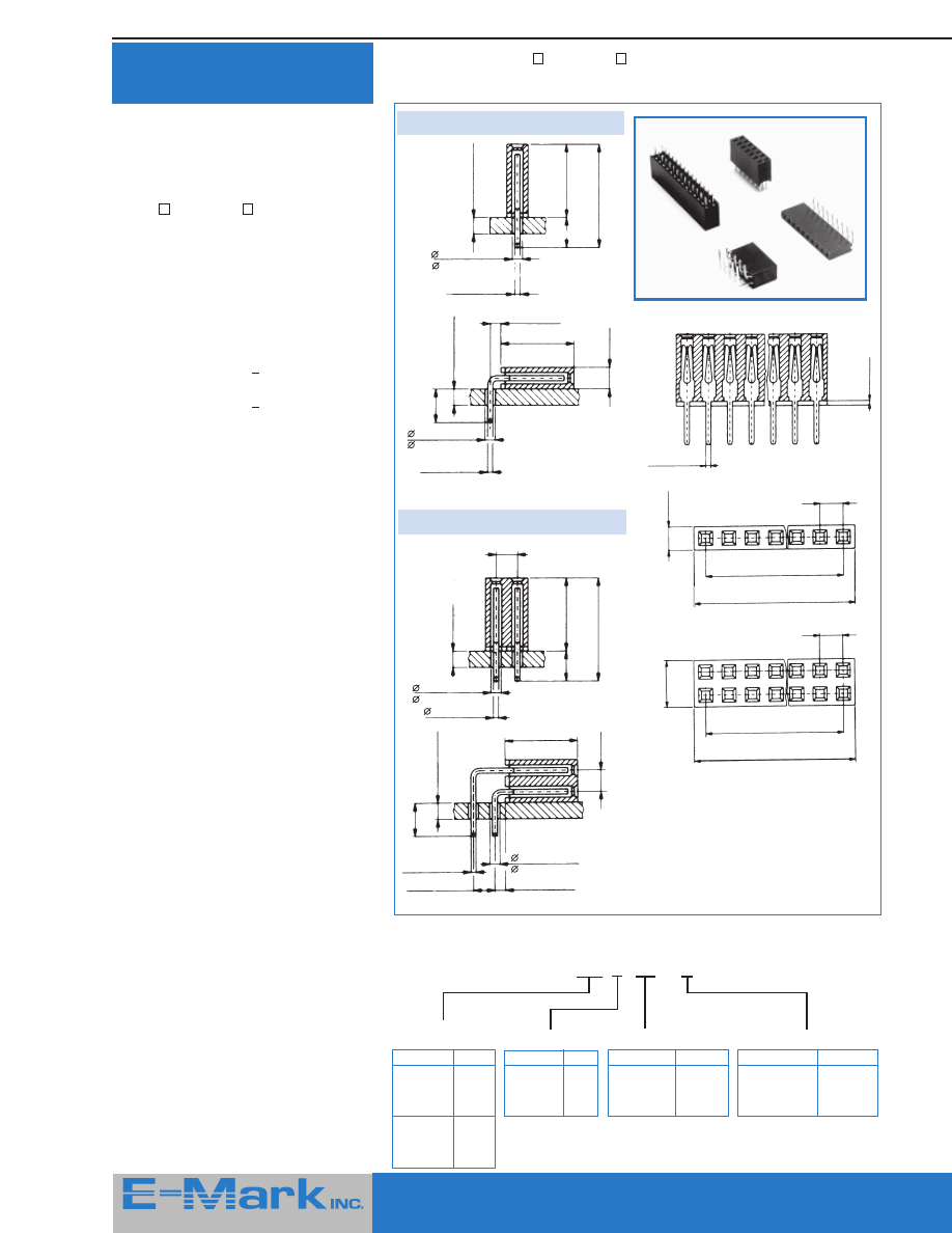
Test Points
With Glass Insulator
Compliant Test Points
Figure 1
Figure 2
Figure 3
Part Number
Description
Figure
“A”
02-1002
Straight Pin
1
6.0 (.236)
02-1003
Slotted Head
2
3.1 (.122)
02-1004
Turret Head
3
4.0 (.158)
02-1005
Turret Head
3
6.0 (.236)
Ordering Information
0.9 (.035) Dia.
1.6 (.063)
2.8 (.110)
A
B
E
D
A
F
C
1.6 (.063)
1.9 (.075)
A
2.8 (.110)
Slot 0.7 (.028)
A
1.6 (.063)
2.8 (.110)
Each of these test points incorporate an
ingenious kinked pin design used as a
microminiature retention mechanism. This
prevents damage to through-plated holes
during insertion while providing sufficient
retention for wave or hand soldering.
Minimum suitable board thickness for these
pins is 1.4 mm (.055”) and PCB hole sizes
after plating should measure 0.96 to 1.12
mm (.041 ±.003”).
All pins have a contact resistance of
less than 5 milliohms and solderability
exceeds the requirements of MIL-STD-750.
Standard package size is 100 pieces.
Material
Test Point:
Phosphor Bronze.
Finish:
Tin.
as of 06/01/2006
5
415 Howe Avenue, Suite LL160, Shelton, CT 06484-3168 U.S.A.
■
1-800-831-5383
Phone: (203) 922-1182
■
FAX: (203) 922 -8231
■
Web Site: http://www.e-markinc.com
SMT Ball And Socket
Connector
Features
■
Designed for fast, consistent testing and
connection of SMT assemblies
■
Quick connect/ disconnect with
click
lock
feature
■
Wide range of movement allows
flexibility in applications.
■
Two heights of test points available
■
Supplied loose or on tape and reel for
production applications using pick and
place equipment
Specifications
Electrical and Mechanical
Recommended
Pad Size:
2 mm
Contact resistance
(including socket):
2 m
Ω
(max)
Socket insulation
resistance:
10,000 M
Ω
Operating
temperature:
- 55
o
to +125
o
C
Current rating:
3A
Max angular movement
before disconnection:
±30
o
Retention force (typ):
2 Kg.
Retention torque (typ): 200 gcm.
Tape and Reel (02-105X only)
Reel sizes: 7" (2K & 3K test points)
13" (10K test points)
Tape:
4mm spacing, 8mm width
Dimensions
SMT Test Points
These test point are designed to facilitate
the connection of test probes to PCBs
which are primarily surface mount in
design. Supplied on tape and reel, these
test points are readily inserted with most
common pick and place equipment.
Note: Tops of test points are not plated.
Be sure to orient properly before soldering.
Specifications
Electrical
Contact resistance: <50m
Ω
Current rating:
2A
Operating
temperature:
- 55
o
to +125
o
C
Materials & Finishes
Material:
Stainless Steel
(SUS 304)
Finish:
SnCu
Packaging:
Parts on 4mm
pitch / 8mm tape
width. 2,000
3.2mm
(0.126”)
11.5mm (0.453”)
Connecting Wire
1.3mm
(0.051”) Max
0.4mm
(0.016”)
1.4mm
(0.055”)
2mm
(0.079”)
1.5mm
(0.059”)
1.5mm
(0.059”)
0.5mm
(0.020”)
2mm
(0.079”)
0.5mm
(0.020”)
89-1057
0.063
0.045
See View
A
0.031
0.009
0.009
89-1065
0.126
0.079
0.063
0.002
0.001
89-1058
0.079
0.057
See View
A
0.049
0.018
0.009
View A
Stainless Steel
Ni Plating
SnCu
See View
A
* Quanties less than 2,000
pieces are supplied on tape
cut from reel.
1.0mm
(.039")
P/N
Lead-Free
Description
Length
Width
Height
89-1057
0603 Test Point
.063” (1.6 mm)
.031” (0.8 mm)
.045” (1.15 mm)
89-1058
0805 Test Points
.079” (2.0 mm) .049” (1.25 mm) .057” (1.45 mm)
89-1065
1206 Test Points
.126” (3.2 mm)
.063” (1.6 mm)
.079” (2.0 mm)
Ordering Information
Description
Unit of Sale
Part Number
Socket, white
Each
02-1033
Test point, H = 2mm
Each
02-1032
Test point, H = 1.4mm Each
02-1049
Test point, H = 1.4mm Reel, 3K pcs.
02-1050
Test point, H = 2mm
Reel, 2K pcs.
02-1080
Ordering Information
6
415 Howe Avenue, Suite LL160, Shelton, CT 06484-3168 U.S.A.
■
1-800-831-5383
Phone: (203) 922-1182
■
FAX: (203) 922 -8231
■
Web Site: http://www.e-markinc.com
Ordering Information
M22 - X X X XX XX
Single row, Vertical = 201
Plating:
05 = Gold, 06 = Tin
Single row, Horizontal = 203
Number of Positions:
02 - 50 max
Double row, Vertical = 202
Double row, Horizontal = 204
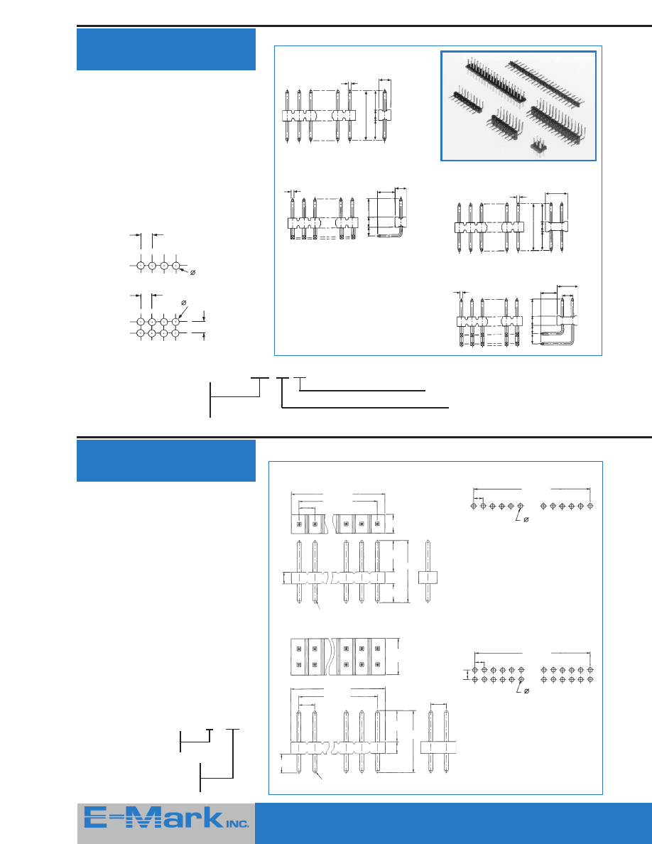
Pin Headers —
2mm Spacing
Features
■
Single or double row on 2.0 mm centers
■
Phospher bronze pins, 0.5 mm square
■
Choice of gold or tin finish
Specifications
Current rating:
2A
Insulation resistance: 1 x 10
4
M
Ω
Voltage proof:
650 V mrs
@ 50 Hz
Recommended PCB Patterns
for Headers & Sockets
Single Row
Double Row
Single Row
Vertical
Horizontal
Dimensions
Features
■
Selective gold / tin plating*
■
Copper Alloy Pins .5mm square
■
Single row 2-40 pins
■
Double row 4-80 pins
■
Mates with M22-611 / 612 or
20035A series
Specifications
Current rating:
1.5A max.
Voltage rating:
150 V AC
Dielectric strength: 500 V one minute
Insulator:
Nylon UL 94 V-0
Contact:
Brass 65 / 35
*
Alternative finishes available in produc-
tion quantities
Ordering Information
2001XS - X X G2T
Single row = 0
Double row = 2
Number of Pins Total
Single row = 02 - 40
Double row = 04 - 80
EXAMPLE: M22-202 04 06 = Double Row,
Vertical Pin Header with 4 positions
(8 pins), Tin Finish
B = (No. Pins-1)* 2mm
Single Row
Recommended P.C.B. Layout
Double Row
Recommended P.C.B. Layout
B = (No. Pins ÷ 2)* 2mm
Hole
0.8
2.00
2.00
Hole
0.8
2.00
2.0
Max.
0.5 Sq.
8.8
3.5
1.8
3.5
1.5
1.8
3.5
2.0
Max.
0.5 Sq.
2.8
Pin Headers —
2mm “200” Series
0.9 ± 0.1
B ± 0.1
2.0
0.9 ± 0.1
B ± 0.1
2.0
2.0
A ± 0.5
B ± 0.1
2.0
2.4 ± 0.1
1.5
4.0 ± 0.15
2.4 ± 0.15
7.9 ± 0.2
0.5 Sq.
4.6 ± 0.15
A ± 0.5
B ± 0.1
2.0
0.5 Sq.
4.0 ± 0.15
1.5
7.9 ± 0.3
2.0
Double Row
Vertical
Horizontal
4.0
Max.
0.5 Sq.
8.8
3.5
1.8
3.5
2.0
1.5
1.8
3.5
4.0
Max.
0.5 Sq.
2.8
2.0
2.4 ± 0.15
7
415 Howe Avenue, Suite LL160, Shelton, CT 06484-3168 U.S.A.
■
1-800-831-5383
Phone: (203) 922-1182
■
FAX: (203) 922 -8231
■
Web Site: http://www.e-markinc.com
Plating:
22 = Selective Gold, 06 = Tin
2.0mm Dual Row
SMD Socket
PCB Sockets —
2mm Spacing
Single Row
Double Row
Dimensions
A = Number of Postions x 2.0 mm
B = A - 2.0 mm
Features
■
Single and double row vertical sockets
on 2 mm centers
■
Tapered Entry
■
Anti-wicking, twin leaf phosphor bronze
contacts
■
Choice of tin or selective gold finish
Specifications
Current rating:
2A
Contact resistance:
2 m
Ω
Insulation resistance:
1 x 10
4
M
Ω
Voltage proof:
650 V mrs @
50 Hz
Insertion force:
1.5 N max.
(5.4 oz)
Withdrawal force:
0.3 N min.
(1.1 oz)
Number of cycles
Gold: 300
Tin:
50
Recommended PCB Pattern — See Above
Ordering Information
M22 - X X X XX XX
Single row = 611
Double row = 612
Number of Positions: 02 - 25 max
A
2.0
B
4.5
3.0
0.6
Contact
Point
1.0
4.0
Part Number
DimA
DimB
DimC
20035A - 28XX
28.0
26.0
24.0
20035A - 30XX
30.0
28.0
26.0
20035A - 32XX
32.0
30.0
28.0
20035A - 34XX
34.0
32.0
30.0
20035A - 36XX
36.0
34.0
32.0
20035A - 38XX
38.0
36.0
34.0
20035A - 40XX
40.0
38.0
36.0
20035A - 42XX
42.0
40.0
38.0
20035A - 44XX
44.0
42.0
40.0
20035A - 46XX
46.0
44.0
42.0
20035A - 48XX
48.0
46.0
44.0
20035A - 50XX
50.0
48.0
46.0
Part Number
DimA
DimB
DimC
20035A - 04XX
4.0
2.0
—
20035A - 06XX
6.0
4.0
—
20035A - 08XX
8.0
6.0
4.0
20035A - 10XX
10.0
8.0
6.0
20035A - 12XX
12.0
10.0
8.0
20035A - 14XX
14.0
12.0
10.0
20035A - 16XX
16.0
14.0
12.0
20035A - 18XX
18.0
16.0
14.0
20035A - 20XX
20.0
18.0
16.0
20035A - 22XX
22.0
20.0
18.0
20035A - 24XX
24.0
22.0
20.0
20035A - 26XX
26.0
24.0
22.0
Dimensional Information
Number
of pins
Plating:
G2
*
- Indicate gold flash
G3* - 10
μ
" gold over nickel
G4* - 15
μ
" gold over nickel
G5* - 30
μ
" gold over nickel
Ordering Information
20035A - XX - XX - T
* Certain minimums apply
A reliable dual row 2mm socket with
location pegs. Available on tape and reel
for production applications.
Mates with 20012 Series Headers.
See page 6.
Specifications
4-50 Curcuits
Insulator Material:
Black high temp.
plastic
Temperature Range: - 40
o
to +105
o
C
Terminal Material:
Phosphor bronze
Plating:
Contact - Selective
gold/tin plated
Max. Current Rating: 1.5A
Voltage Rating:
150V AC
Dielectric Strength:
500V (Min.
60 seconds)
Recommended P.C.B. Layout
Dimensions
3.0
2.0
C ± 0.1
B ± 0.1
0.8
2.75
8.5
1.1 x 2
A ± 0.3
B ± 0.1
2.00
0.45 ± 0.03
2.00
4.20
7.40 ± 0.3
4.50 ± 0.15
1.60 ± 0.15
Double Contact
1.5 Max.
(Contact
Point)
0.20
X X’ Section
1.3
C ± 0.1
1.00 x 2
X
X’
A
2.0
B
4.5
3.0
0.6
Contact
Point 1.0
Selective Plate
8
415 Howe Avenue, Suite LL160, Shelton, CT 06484-3168 U.S.A.
■
1-800-831-5383
Phone: (203) 922-1182
■
FAX: (203) 922 -8231
■
Web Site: http://www.e-markinc.com
Open Top
Closed Top With Handle
Dimensions
COLOR
OPEN TOP
CLOSED TOP WITH HANDLE
PART NUMBER
PART NUMBER
Light Grey
M7565- XX
M7965-XX
Red
M7566-XX
M7966-XX
Black
M7567-XX
M7967-XX
Blue
M7571-XX
M7971-XX
Plating Option: 05 = Gold, 06 = Tin
Example:
M7565- 05 = Open Top
Shunt with gold finish
Open Housing Version
Closed Housing Version
Ordering Information
Please replace ‘X’ with appropriate coding listed in table below
2 8 0 - X 1 - X 0
Features
■
Easiest way of programming by simply
connecting 2 contact points together
■
Two different versions:
1. Closed housing
2. Housing with opening for test pin
■
Reliable contact due to 2 indepen-
dent contact points per pin
■
Side stackable / end stackable
Specifications
Electrical
Current rating:
3 Amp. max.
Contact resistance:
<15 m
Ω
Insulation resistance:
>1000 M
Ω
Withstanding voltage: 650 V RMS
Mechanical
Mechanical life cycle
Gold plated: 100
Tin plated:
75
Operating temperatures:
-55
o
C to +125
o
C
-62
o
F to +257
o
F
Material
Contact (clip):
Phosphor bronze
Surface of contact:
See Plating Code
Insulator body
(housing):
Glass filled polyester
P.B.T. (UL 94 V-0)
Color Black*
Dimensions: mm / inches
Jumper Version (type)
Definition
Code
Closed
housing
0
Open
housing
1
Surface of contact
Definition
Code
Tin plated
5 um / 200u"
0
Gold flash
1
Specifications
Contact:
pho. bronze
Insulator:
P.B.T. UL94V-0
Plating:
Gold or Tin
Current rating:
1.5A Max.
Voltage rating:
150 V AC
Dielectric strength: 500V AC one minute
Temperature range: -20
o
C to +105
o
C
Ordering Information
Tin — White:
Part Number
20060-T1
Gold — Black:
Part Number
20060-G2
Top
Bottom
End
Side
Shunts For
0.1” Headers
Features
■
End and side stackable on 0.1" grid
■
Plugs on 0.025" square or round posts
■
Tapered entry for pin insertion
■
High pressure double-sided contact
■
Can be fitted and removed by hand
■
Choice of colors and plating finish
Specifications
Housing:
Glass filled polyester
UL94V - 0
Socket contact:
Phosphor bronze
Plating finish:
Gold or tin over nickel
Current rating:
3A at 50
O
C
Contact
resistance:
20 m
Ω
maximum
Insertion force:
3 N (11 ozs)
Withdrawal force: 2 N (7 ozs)
Number of insertions
Gold: 300
Tin:
50
2.0mm Mini-Jumper
4.0
0.8 Ref.
3.0
4.0
2.0
Economy Shunt For
0.1” Headers
.197
.248
.098
Direction of
pin insertion
Pin Insertion
Length
.226 Max.
.167 Min.
.098
.197
A
A
.406
Ordering Information
*Alternative colors available on request
14 / .055”
2.5 -
0
2.5 - 01
2.5 -
0
.098” - .003”
5 -
0
5 - 02
5 -
0
.196” - .007”
2.54 /
.100”
6 / .236”
2.54 / .100”
3.8 / .149”
Contact Point
2.54 / .100”
3.8 / .149”
Contact Point
6.5 / .255”
+.005
-.02
5
+.001
-.007
.196
2.5 -
0
2.5 - 01
2.5 -
0
.098” - .003”
2.0
9
415 Howe Avenue, Suite LL160, Shelton, CT 06484-3168 U.S.A.
■
1-800-831-5383
Phone: (203) 922-1182
■
FAX: (203) 922 -8231
■
Web Site: http://www.e-markinc.com
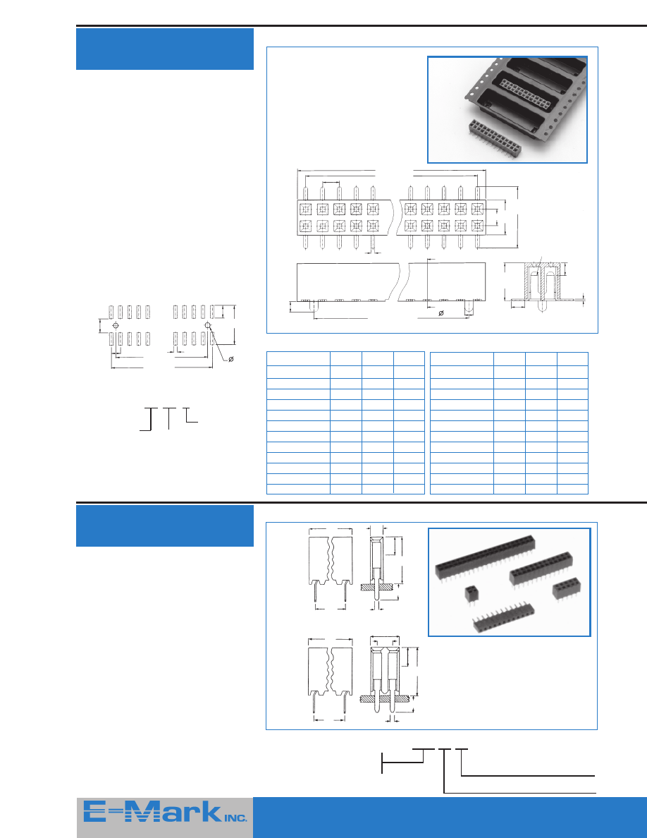
Square Pin Headers
0.635mm / .025”
Pitch 2.54mm/ .100”
Single or double row — angled or
straight
Features
■
Pin headers can be supplied in straight
or right angle versions
■
Each one available in strips of:
1 row = 1 to 40 pins
2 rows = 4 to 80 pins
■
Different platings such as full gold or
full tin, or selective gold are available
■
Designed for soldering into a PC board
or between two PCB’s
Specifications
Electrical/ Mechanical
Operating temperatures:
-40
o
C to +105
o
C
-40
o
F to +221
o
F
Press fit of pin into
the insulator body:
>8.8 N ( 31 oz. )
Max. soldering Temperature:
+260
o
C, 10 seconds
+500
o
F, 10 seconds
Material
Pin:
Copper Alloy
*
Surface of contact:
2
μ
m (80
μ
”) Nickel,
Gold and Tin plated;
Insulator: Black glass filled
Insulator:
polyamid 6.6 (UL 94 V-0)
Table 1
E0X - XX0 - XXX - 10X
Pin Length
Metric
Inches
Code
(mm)
Single,
double row
A
B
C
A
B
C
01
5.84
2.79
11.17
.230
.110
.440
05
8.08
2.79
13.41
.318
.110
.528
Table 2
E1X - XX0 - XXX - 10X
Pin Length
Metric
Inches
Code
(mm)
Single,
double row
A
B
C
A
B
C
11
5.84
2.79
11.17
.230
.110
.440
15
8.08
2.79
13.41
.318
.110
.528
Dimensions: mm/ inches
Ordering Information
Please replace ‘X’ with appropriate coding listed in table below
E X X - X X 0 - X X X - 10 X
Header Series
Definition
Code
single row
straight
01
double row
straight
02
single row
angled
11
double row
angled
12
Pin Length Code
See Table
1
1
2
2
No. of Contacts
Definition
Code
single row
001 to 040
double row
004 to 080
Contact Plating
Definition
Code
Full Tin Sn 3
μ
m/120
μ
”
1
Full Gold Flash
2
Other plating available
upon request
n = number of contacts
Single Row
Double Row
*
Alternate base material available —
contact factory
n-1 x 2.54 / .100”
2.54 / .100”
1.27 / .050”
4.98 / .196”
2.44 / .096”
0.635 / .025”
0.635 / .025”
2.5 / .098”
C1
A
A
B
C
B
1.27 / .050”
0.25 / .010”
0.25 / .010”
2.44 / .096”
n-1 x 2.54 / .100”
0.635 / .025”
1.27 / .050”
2.54 / .100”
2.54 / .100”
2.5 / .098”
0.635 / .025”
0.635 / .025”
2.54 / .100”
1.27 / .050”
0.25 / .010”
B
0.25 / .010”
A
C
B
C2
4.98 / .196”
2.54 / .100”
2.5 / .038”
A
0.635 / .025”
415 Howe Avenue, Suite LL160, Shelton, CT 06484-3168 U.S.A.
■
1-800-831-5383
Phone: (203) 922-1182
■
FAX: (203) 922 -8231
■
Web Site: http://www.e-markinc.com

10
415 Howe Avenue, Suite LL160, Shelton, CT 06484-3168 U.S.A.
■
1-800-831-5383
Phone: (203) 922-1182
■
FAX: (203) 922 -8231
■
Web Site: http://www.e-markinc.com
PCB Board-To-Board
Spacers
E-Mark pin headers of all pitches are available as custom board spacers allowing
the user great flexibility in product design. In addition to simply varying the pin
and insulator lengths, E-Mark offers selective pin loading where required.
For a quick estimate of cost, simply complete the appropriate section below
and
FAX
back:
(203) 922 -8231
NAME
COMPANY
ADDRESS / MAIL STOP
CITY / STATE / ZIP
2mm Pitch Board Spacers
.1 ” Pitch Board Spacers
(
)
PHONE
FAX
(
)
Specifications
Materials
Pin:
Copper Alloy
Insulator:
Hi-Temp Plastic
(UL 94 V-0)
Electrical /
Environmental
Current rating: 1.5 A
Voltage rating: 150 VAC
Operating
temperatures:
-40
o
C to +105
o
C
Specifications
Materials
Pin:
Copper Alloy
Insulator:
Glass filled PBT
(UL 94 V-0)
Electrical /
Environmental
Current rating: 3 A
Voltage rating: 250 VAC
Operating
temperatures:
-40
o
C to +105
o
C
1.5
0.5mm Sq.
A
C
B
2.0 (Typ)
2.4
4.6
2.0
Single Row
Double Row
Total Number of Positions (not pins) =
Plating:
Tin
Gold Flash
10
μ
” Gold
Quantity:
(1-40 max)
Pin 1
Pin N
Selectively Remove The Following Pins =
*
Alternative plating available,
certain minimums apply.
*
1.00
.025mm Sq.
A
C
B
1.0 (Typ)
.100
.200
.100
Single Row
Double Row
Total Number of Positions (not pins) =
Plating:
Tin
Gold Flash
10
μ
” Gold
Quantity:
(1-40 max)
Pin 1
Pin N
Selectively Remove The Following Pins =
*
Alternative plating available,
certain minimums apply.
*
11
415 Howe Avenue, Suite LL160, Shelton, CT 06484-3168 U.S.A.
■
1-800-831-5383
Phone: (203) 922-1182
■
FAX: (203) 922 -8231
■
Web Site: http://www.e-markinc.com
Vertical & Horizontal
PCB Sockets
For square post headers
0.635 mm /
.025"
Single or double row — straight or angled — tin / gold — solder tail
Features
■
A quality Socket Header designed for
parallel or angled PCB to PCB applica-
tions
■
Mates with square post headers
0.635 mm /
.025"
■
Protected fork contacts (stamped)
■
Maximum number of contacts are 40 for
single row, and 80 for double row
Specifications
Electrical
Current rating: 3 Amps / contact max.
Contact
resistance:
< 20 m
Ω /
contact
Insulation
resistance:
> 100 M
Ω
Operating
voltage:
60 V
eff
Dielectric
withstanding
voltage:
1000 V AC / minute
Mechanical
Average
insertion force:
0.8 N (3 oz.)
Average
withdrawal force: 0.8 N (3 oz.)
Mechanical
life cycle:
min. 100
Operating temperatures:
-40
o
C to +105
o
C
-40
o
F to +221
o
F
Sodering temperatures:
+260
o
C, 10 seconds
+500
o
F, 10 seconds
Material
Contact:
Phosphor bronze
Insulator body: Glass filled
polyester UL 94 V-0
(black)
Single Row
Dimensions: mm / inches
Ordering Information
Please replace ‘X’ with appropriate coding listed in table below
26X - X - X X 10 - X
Number of rows
Definition
Code
single row
1
double row
2
No. of Contacts
Definition
Code
single row
1 - 40
double row
4 - 80
Surface of Contact
Definition
Code
Tin plated
1
Gold plated
2
Female
Header Series
Definition
Code
single row
straight
double row
262
straight
single row
angled
double row
263
angled
Double Row
1.4 - 2
.055” - .079”
0.9 - 1.1
.035”-.043”
3.15
.125”
8.5 / .335”
11.65 / .460”
0.45 / .018”
1.52 / .060”
8.5 / .335”
1.4 - 2
.055” - .079”
3.15
.125”
2.43
.096”
0.9 - 1.1
.035”-.043”
0.45 / .018”
2.54 / .100”
0.9 - 1.1
.035”-.043”
1.4 - 2
.005”-.079”
0.45 / .018”
3.15
.125”
8.5 / .335”
11.65 /.460”
2.54
.100”
8.5 /.335”
1.4 - 2
.055”-.079”
3.15
.125”
0.9 - 1.1
.035”-.043”
1.52 / .060”
2.54 / .100”
0.45 / .018”
0.77 / 0.30”
0.4 / .016”
2.54 / .100”
2.43
.096”
2.54 / .100” x Spaces
2.54 / .100”
2.54 / .100” x Spaces +3.05 / .120”
4.94 / .195”
2.54 / .100” x Spaces +3.05 / .120”
2.54 / .100” x Spaces
415 Howe Avenue, Suite LL160, Shelton, CT 06484-3168 U.S.A.
■
1-800-831-5383
Phone: (203) 922-1182
■
FAX: (203) 922 -8231
■
Web Site: http://www.e-markinc.com
12
415 Howe Avenue, Suite LL160, Shelton, CT 06484-3168 U.S.A.
■
1-800-831-5383
Phone: (203) 922-1182
■
FAX: (203) 922 -8231
■
Web Site: http://www.e-markinc.com
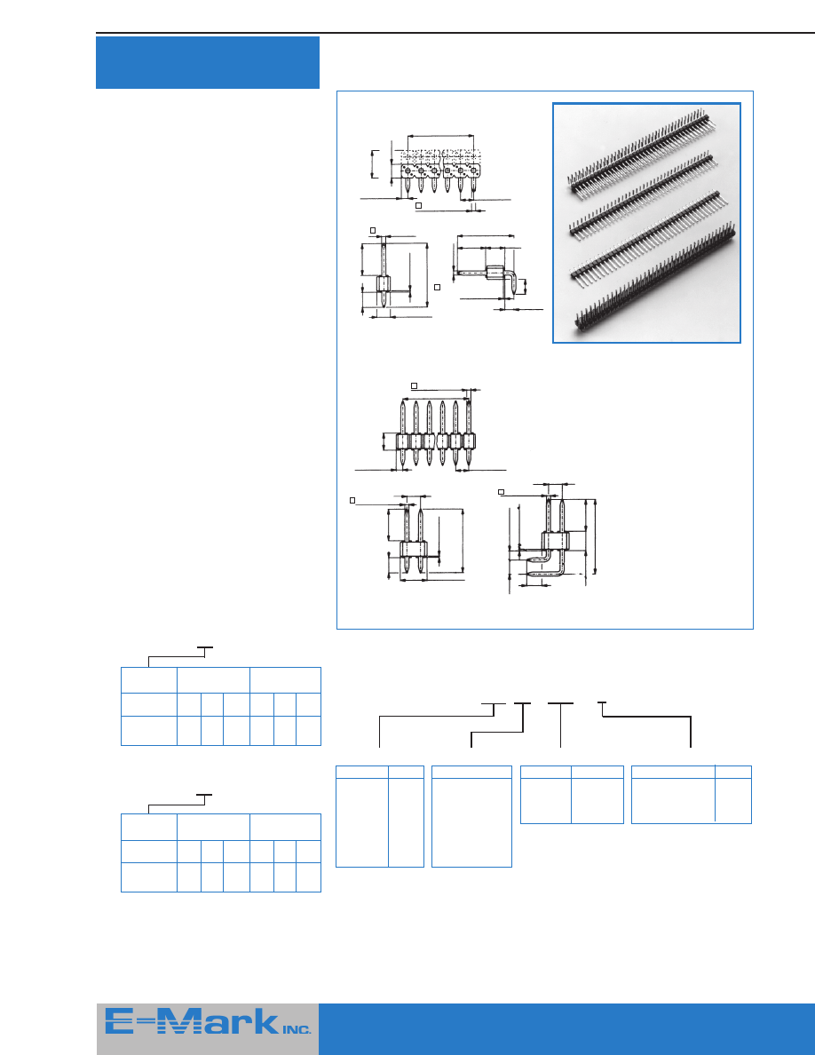
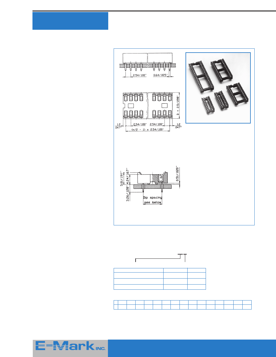
Production DIP Socket
Dimensions: mm/ inches
Ordering Information
Please replace ‘X’ with appropriate coding listed in table below
E6 1-X X X -10 - 11
Number of Contacts
No. of contact = Code
06, 08, 14, 16, 18, 20, 22, 24, 28
22, 24
24, 28, 32, 40, 42, 48
Dip Spacing D
Definition
Code
7.62 / .300"
3
10.16 / .400"
4
15.24 / .600"
6
Straight tail version
n = number of contacts
Standard Packing Units
A
06 (.3) 08 (.3) 14 (.3) 16 (.3) 18 (.3) 20 (.3) 22 (.3) 22 (.4) 24 (.3) 24 (.6) 28 (.6) 32 (.6)
40 (.6)
42 (.6) 48 (.6)
T
80
60
34
30
26
24
22
18
20
20
17
15
12
11
10
Legend: A = Number of contacts (and Dip Spacing)
Legend:
T = Number of Sockets per T (Tube)
Dual-in-line IC Sockets with stamped and
formed “Dual beam” contacts
Features
■
Most popular IC Sockets from
6 to 48 contacts
■
Low profile
■
Double sided contacts “Dual beam”
■
Wide entry for easy IC insertion
■
Overstress protection
■
Manually and automatically insertable
Specifications
Electrical
Current rating
(continuous):
1 Amp/ contact
Contact resistance:
≤
10 m
Ω
Insulation resistance:
≥
10
10
Ω
Operating voltage:
60 V
eff.
Contact capacity
(between 2 contacts): 0.5 pF
Overload voltage:
≥
600 V
eff.
Mechanical
Insertion force:
2.0 N max.
(7 oz.)
Withdrawal force:
0.5 N min.
(2 oz.)
Mechanical life cycle: 50 min.
Operating temperatures:
55
o
C to +150
o
C
-67
o
F to +369
o
F
Soldering temperature:
+220
o
C, 10 seconds
+428
o
F, 10 seconds
Material
Contact:
Phosphor bronze
Surface of
contact:
Tin plated; 3 to 5
μ
m/
120 to 196
μ
”
Insulator:
Black glass filled polyester
(UL 94 V-0)
415 Howe Avenue, Suite LL160, Shelton, CT 06484-3168 U.S.A.
■
1-800-831-5383
Phone: (203) 922-1182
■
FAX: (203) 922 -8231
■
Web Site: http://www.e-markinc.com
13
415 Howe Avenue, Suite LL160, Shelton, CT 06484-3168 U.S.A.
■
1-800-831-5383
Phone: (203) 922-1182
■
FAX: (203) 922 -8231
■
Web Site: http://www.e-markinc.com
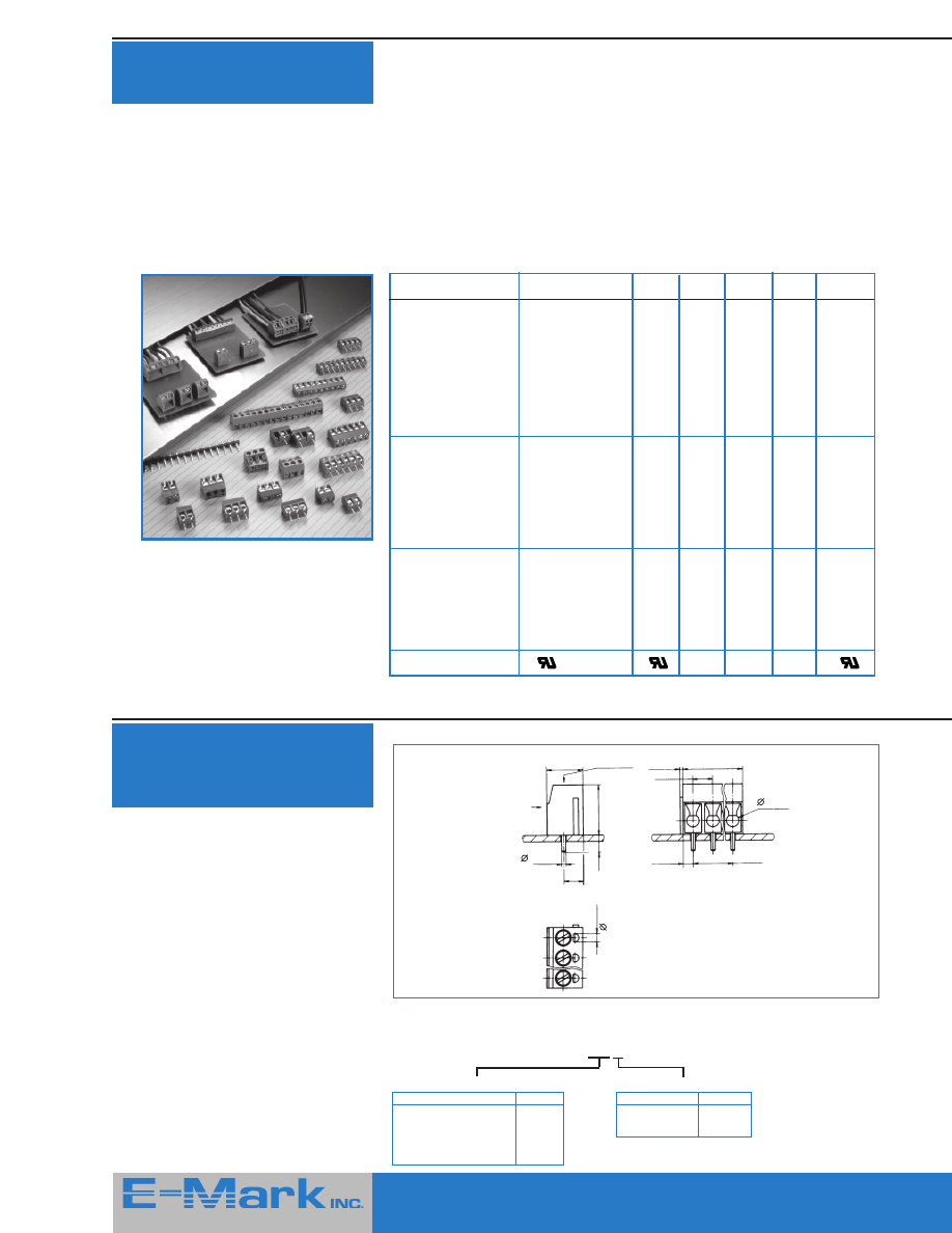
Terminal Block Section
Features
■
5 mm or 10 mm contact spacing
■
2 & 3 position blocks slide together
to form longer lengths
■
Wire guards
■
Access holes for test probes
Specifications
Specification
Series 300
301
310
311
320
332
Material
Contact
Brass, tin plated
=
=
=
=
=
Screw
Zinc plated steel,
clear chromate
Wire guard
Copper alloy
=
=
=
=
BeCu
S.T. plating
Tin
=
=
=
=
=
Insulator
Polyester,
G/F UL 94-VO
=
=
=
=
=
Insulator color
Blue
Blue
Blue
Blue
Blue
Blue
Electrical
Voltage rating
per VDE 0110
Group A:
5 mm spacing
380 V
250 V
380 V
250 V
125 V
125 V
10 mm spacing
750 V
380 V
750 V
380 V
380 V
380 V
Current rating:
16A
=
=
=
=
10A/POS
Mechanical
Operating temp.
-33 to +120 C
=
=
=
=
=
Soldering temp.
+260 C (10 S. max)
=
=
=
=
=
Max wire cross
section in MM
2
2.5
1.5
2.5
1.5
1.5
1.5
Terminal screw size
M3
M2.6
M3
M2.6
M2.6
M2.6
Approval
®
®
®
Dimensions: mm / inches
n = number of contacts
Notice:
To avoid accumulated tolerance-variations
of Terminal-Blocks to PC-Board spacing,
limit the number of contacts to not more
than 30 contacts per row
Recommended PC-Board-holes diameter:
∅
1.2 mm to
∅
1.4 mm
∅
.047" to
∅
.055"
Ordering Information:
Please replace ‘X’ with appropriate coding listed in table below
3 0 0 - X X X - 1 6 0 0
Number of Contacts
Definition
Code
2 contacts
02
3 contacts
03
(2 and 3 blocks are the
standard version with
multiples thereof available
etc.
Pitch (Pin Spacing)
Definition
Code
5 mm / .197"
1
10 mm / .394"
2
300 Series —
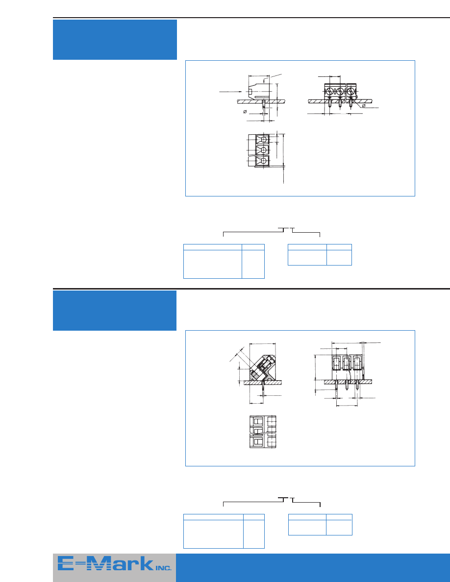
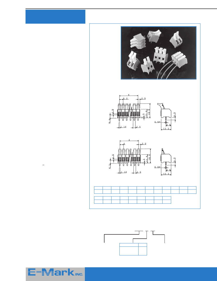
Front Wire Inlet 12.5mm
(.492”) High
E-Mark terminal blocks are an economic
and reliable solution for wire to PCB
connections. The range includes top,
front and angled wire entry versions as
well as a two-part, pluggable version.
All E-Mark terminal blocks are supplied in 2
and 3 position modules which may be
linked together to form any combination of
positions. Most terminal blocks also
feature access holes for test probes and all
feature wire guards to prevent direct
pressure of the screws on conductors.
Cable Inlet
Screw
Accessability
9 / .354”
1 / .039”
5 / .197”
12.5 / .492”
4.5 / .177”
2.5 / .098”
3.1 / .122”
0.7 / .027”
5 / .196”
n x 5 / n x .197”
(n-1) x 5 / (n-1) x .197”
2.1 / .083”
415 Howe Avenue, Suite LL160, Shelton, CT 06484-3168 U.S.A.
■
1-800-831-5383
Phone: (203) 922-1182
■
FAX: (203) 922 -8231
■
Web Site: http://www.e-markinc.com
14
415 Howe Avenue, Suite LL160, Shelton, CT 06484-3168 U.S.A.
■
1-800-831-5383
Phone: (203) 922-1182
■
FAX: (203) 922 -8231
■
Web Site: http://www.e-markinc.com
Ordering Information
Please replace ‘X’ with appropriate coding listed in table below
3 0 1 - X X X - 1 6 0 0
Dimensions: mm / inches
n = number of contacts
Number of Contacts
Definition
Code
2 contacts
02
3 contacts
03
(2 and 3 blocks are the
standard version with
multiples thereof available
etc.
Pitch (Pin Spacing)
Definition
Code
5 mm / .197"
1
10 mm / .394"
2
Ordering Information
Please replace ‘X’ with appropriate coding listed in table below
3 1 0 - X X X - 1 6 0 0
Dimensions: mm / inches
Notice:
To avoid accumulated tolerance-variations
of Terminal-Blocks to PC-Board spacing,
limit the number of contacts to not more
than 30 contacts per row.
Recommended PC-Board-holes diameter:
∅
1.2 mm to
∅
1.4 mm
∅
.047" to
∅
.055"
n = number of contacts
Number of Contacts
Definition
Code
2 contacts
02
3 contacts
03
(2 and 3 blocks are the
standard version with
multiples thereof available
etc.
Pitch (Pin Spacing)
Definition
Code
5 mm / .197"
1
10 mm / .394"
2
Notice:
To avoid accumulated tolerance-variations
of Terminal-Blocks to PC-Board spacing,
limit the number of contacts to not more
than 30 contacts per row
Recommended PC-Board-holes diameter:
∅
1.2 mm to
∅
1.4 mm
∅
.047" to
∅
.055"
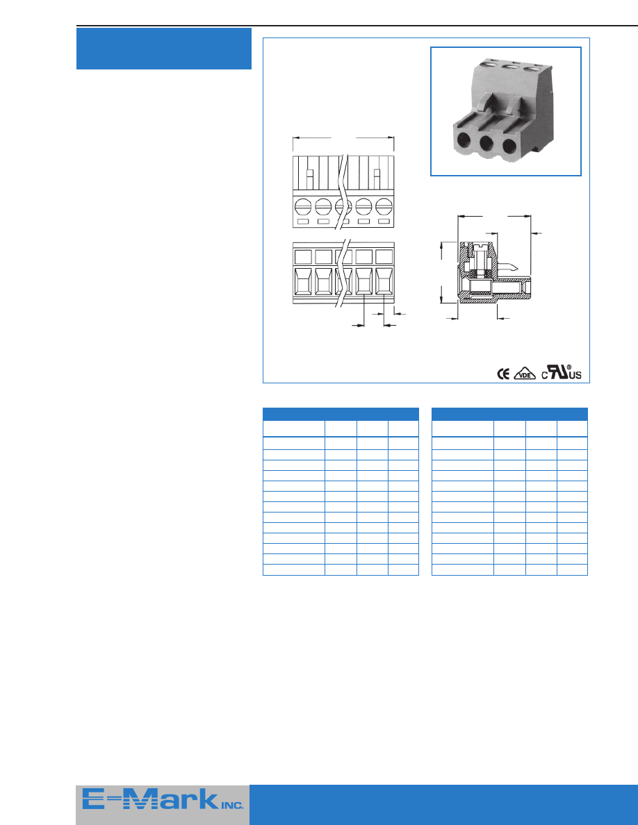
301 Series —
Low Profile Front Wire
Inlet 10mm (.394”) High
310 Series —
Top Wire Inlet
9mm (.354”) High
Cable Inlet
Screw
Accessability
Cable Inlet
Screw
Accessability
1 / .039”
2.5 / .098”
(n-1) x 5 / (n-1) x .197”
3.5 / .138”
7.5 / .295”
4.5 / .177”
10 / .394”
5 / .196”
2.6 / .102”
n x 5 / n x .197”
0.6 / .023”
1.1 / .043”
1 / .039”
3.4 / .133”
12.5 / .492”
4.5 / .177”
9 / .354”
0.7 / .027”
3.1 / .122”
(n-1) x 5 / (n-1) x .197”
2.1 / .083”
n x 5 / n x .197”
2.5 / .098”
5 / .196”
15
415 Howe Avenue, Suite LL160, Shelton, CT 06484-3168 U.S.A.
■
1-800-831-5383
Phone: (203) 922-1182
■
FAX: (203) 922 -8231
■
Web Site: http://www.e-markinc.com
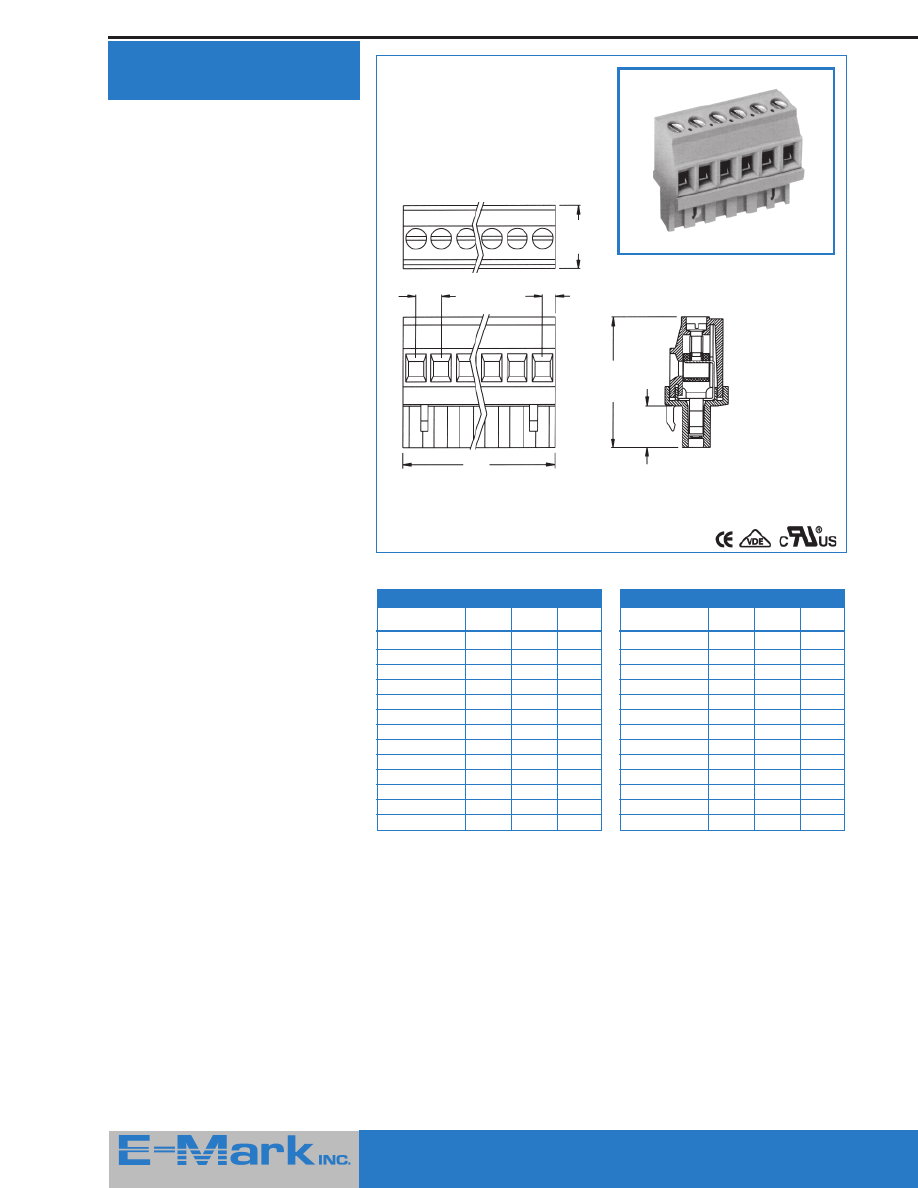
320 Series —
45
o
Wire Inlet
12.5mm (.492”) High
311 Series —
Low Profile Top Wire
Inlet 7.5mm (.295”) High
Ordering Information
Please replace ‘X’ with appropriate coding listed in table below
3 1 1 - X X X - 1 6 0 0
Dimensions: mm / inches
n = number of contacts
Number of Contacts
Definition
Code
2 contacts
02
3 contacts
03
(2 and 3 blocks are the
standard version with
multiples thereof available
etc.
Pitch (Pin Spacing)
Definition
Code
5 mm / .197"
1
10 mm / .394"
2
Ordering Information
Please replace ‘X’ with appropriate coding listed in table below
3 2 0 - X X X - 1 6 0 0
Dimensions: mm / inches
Notice:
To avoid accumulated tolerance-variations
of Terminal-Blocks to PC-Board spacing,
limit the number of contacts to not more
than 30 contacts per row
Recommended PC-Board-holes diameter:
∅
1.3 mm to
∅
1.5 mm
∅
.051" to
∅
.059"
n = number of contacts
Number of Contacts
Definition
Code
2 contacts
02
3 contacts
03
(2 and 3 blocks are the
standard version with
multiples thereof available
etc.
Pitch (Pin Spacing)
Definition
Code
5 mm / .197"
1
10 mm / .394"
2
Notice:
To avoid accumulated tolerance-variations
of Terminal-Blocks to PC-Board spacing,
limit the number of contacts to not more
than 30 contacts per row
Recommended PC-Board-holes diameter:
∅
1.2 mm to
∅
1.4 mm
∅
.047" to
∅
.055"
Cable Inlet
Screw
Accessability
1 / .039”
10 / .394”
2.7 / .106”
3.7 / .145”
7.5 / .295”
2.5 / .098”
5 / .196”
1.1 / .043”
(n-1) x 5 / (n-1) x .197”
2.6 / .102”
0.6 / .023”
n x 5 / n x .197”
12.5 / .492”
0.8 / .031”
6.5 / .255”
5.8 / .288”
2.5 / .098”
15 / .590”
5 / .196”
0.6 / .023”
2.6 / .102”
1.1 / .043”
4.5 / .177”
12.5 / .492”
(n-1) x 5 / .196”
415 Howe Avenue, Suite LL160, Shelton, CT 06484-3168 U.S.A.
■
1-800-831-5383
Phone: (203) 922-1182
■
FAX: (203) 922 -8231
■
Web Site: http://www.e-markinc.com
16
415 Howe Avenue, Suite LL160, Shelton, CT 06484-3168 U.S.A.
■
1-800-831-5383
Phone: (203) 922-1182
■
FAX: (203) 922 -8231
■
Web Site: http://www.e-markinc.com
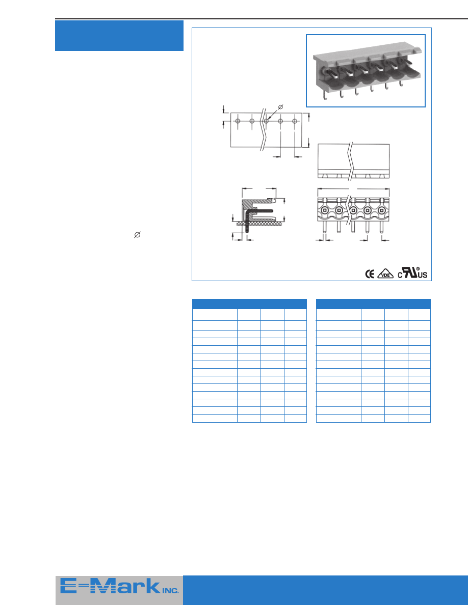
332 Series —
(Pluggable) Front Or
Top Wire Inlet Headers /
Pins Ordered Separately
Pin Header Strips
Spacing 5 mm / .197"
Part Number:
299-1-001-XXX-1
replace XXX with desired
Number of contacts, which can
be cut down to required
number (24 max.)
Spacing 10 mm / .394"
Part Number:
299-1-002-XXX-1
replace XXX with desired
Number of contacts, which can
be cut down to required
number
Loose Pins
(single)
Part Number:
909-9001
Ordering Information
Please replace ‘X’ with appropriate coding listed in table below
3 3 2 - X X X - 1 6 0 0
Number of Contacts
Definition
Code
2 contacts
02
3 contacts
03
(2 and 3 blocks are the
standard version with
multiples thereof available
etc.
Pitch (Pin Spacing)
Definition
Code
5 mm / .197"
1
10 mm / .394"
2
Dimensions: mm / inches
Dimensions: mm / inches
Recommended PC-Board-holes
diameter:
∅
1.5 mm
∅
.059"
n = number of contacts
415 Howe Avenue, Suite LL160, Shelton, CT 06484-3168 U.S.A.
■
1-800-831-5383
Phone: (203) 922-1182
■
FAX: (203) 922 -8231
■
Web Site: http://www.e-markinc.com
17
415 Howe Avenue, Suite LL160, Shelton, CT 06484-3168 U.S.A.
■
1-800-831-5383
Phone: (203) 922-1182
■
FAX: (203) 922 -8231
■
Web Site: http://www.e-markinc.com
Quick Clamp
Terminal Block
Features
■
Vertical or horozontal wire inlet
■
The screwless terminals are suitable for
both solid and stranded wire
■
A spring made of stainless strip steel
guarantees permanent and safe contact
■
Operated by pushing a screwdriver on
the lever. This lever is fully integrated
into the body
■
Equipped with a cover for easy hand
adjustment
Specifications
Mechanical/ Electrical
Operating temperature:
-33
o
C to +120
o
C
Soldering temperature:
+250
o
C, 5 seconds max.
Wire size:
24 - 16 AWG.
Current rating:
15 Amp. - @ 300 V AC
Insulation withstands voltage:
200 V AC min.
Insulation resistance:
> 500 m
Ω
at 500 V DC
Material
Contact:
Brass (CU ZN) CU/NI,
tin plated
Spring:
Stainless strip steel
Solder tail:
Tin plated
Insulator body,
lever, cover:
Green polyester
(glass filled)
(UL 94V-0)
Vertical Wire Inlet - 351 Series
Horizontal Wire Inlet - 352 Series
Ordering Information
Please replace ‘X’ with appropriate coding listed in table below
XX X - X X X - 1500
Series
Definition
Code
Vertical Wire
Inlet
351
Horizontal
Wire Inlet
352
No. of Contacts
Definition
Code
2 contacts
02
4 contacts
04
etc..
Pitch
Definition
Code
5mm/.197"
1
10mm/.394"
3
All Dimensions in mm
Pitch 5.00mm x 7.62mm /
.197" x .300"
2.35
5
13
3.66
13
10.25
13.90
7.62
1.5
2.50
0.5 x 1.0
1.0
3.10
3
5
14
3.66
10.25
0.5
0.9
7.5
5.0
7.62
3.2
13.0
14.0
415 Howe Avenue, Suite LL160, Shelton, CT 06484-3168 U.S.A.
■
1-800-831-5383
Phone: (203) 922-1182
■
FAX: (203) 922 -8231
■
Web Site: http://www.e-markinc.com
18
415 Howe Avenue, Suite LL160, Shelton, CT 06484-3168 U.S.A.
■
1-800-831-5383
Phone: (203) 922-1182
■
FAX: (203) 922 -8231
■
Web Site: http://www.e-markinc.com
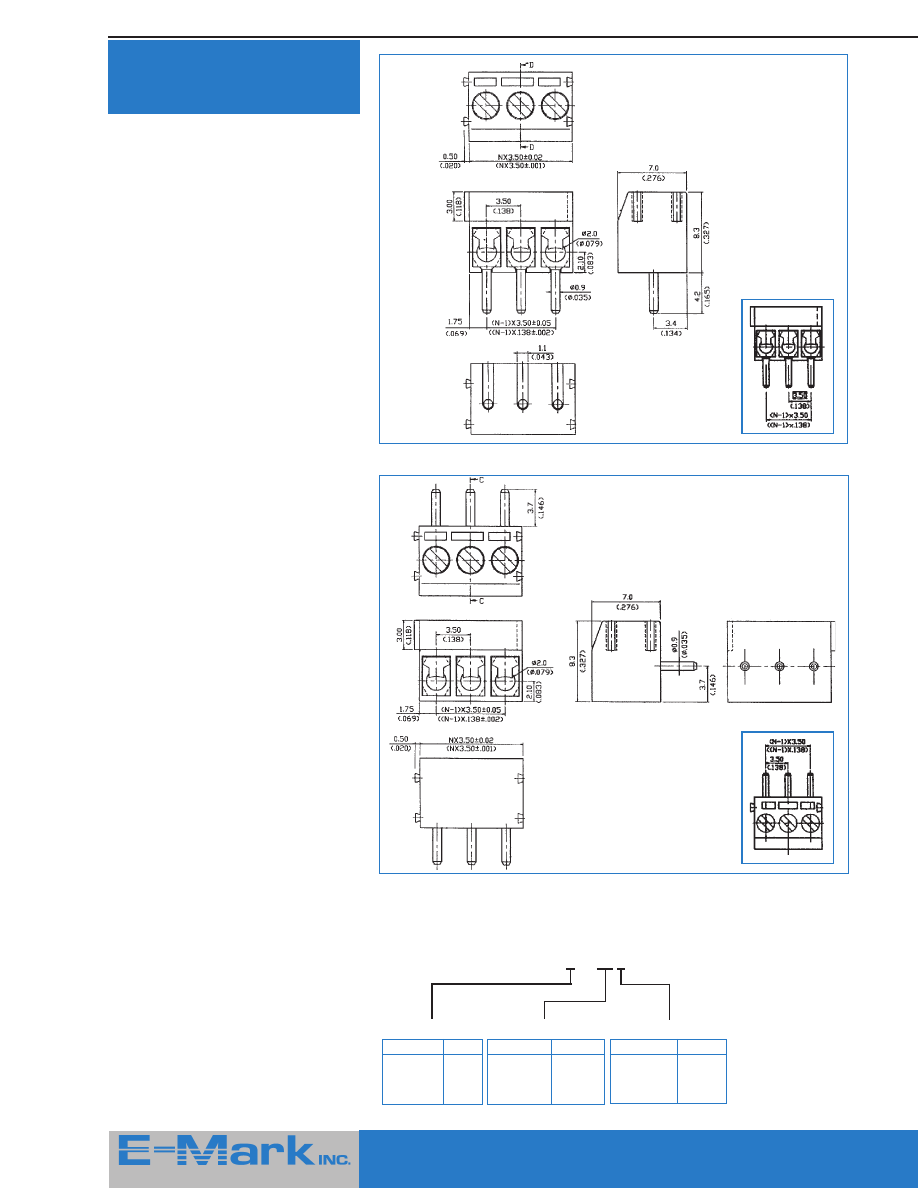
302 / 312 Series
Top or Front Wire Inlet
3.5mm Spacing / 7.0mm High
Dimensions
Dimensions
302 Series - 3.5mm Terminal Blocks
312 Series - 3.5mm Terminal Blocks
Features
■
Center to center spacing of only 3.5 mm
■
2 and 3 position modular blocks
assemble to make any size required
■
Only 7.0 mm height off PCB
Specifications
Mechanical/ Electrical
Operating temperature:
-30
o
C to +120
o
C
Soldering temperature:
+260
o
C, 10 seconds max.
Wire size:
16- 26 AWG.
Current rating:
10 Amp.
Insulation resistance:
5000 M
Ω
(min.)/1500 V
Contact resistance:
15 M
Ω
(max.)
Material
Contact:
Brass
Terminal
screw:
Zinc plated steel,
clear chromate finish
Wire guard: Stainless steel
Solder tail:
Tin plated
Insulator:
Glass filled polyester
(UL 94V-0), blue
Ordering Information
Please replace ‘X’ with appropriate coding listed in table below
3 X 2 - X X X - 1600
Series
Definition
Code
Front Cable
Inlet Type
0
Top Wire
Inlet Type
1
No. of Contacts
Definition
Code
2 contacts
02
(standard)
3 contacts
03
(basic blocks)
Pitch (Pin Spacing)
Definition
Code
3.5 mm/.138"
1
7.00mm/.276"
2
wtc.
19
415 Howe Avenue, Suite LL160, Shelton, CT 06484-3168 U.S.A.
■
1-800-831-5383
Phone: (203) 922-1182
■
FAX: (203) 922 -8231
■
Web Site: http://www.e-markinc.com
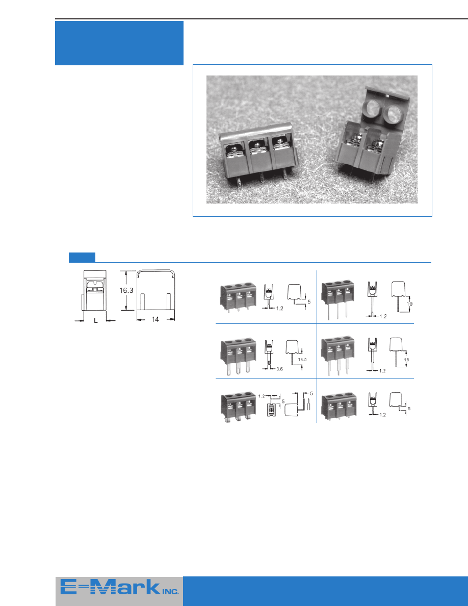
HA-52 Series
Terminal Block
Features
■
No tools necessary for operation
■
Choice of flat or thumb grip levers
■
Superior shock resistant contact
design
■
PCB standoffs for flux removal
Ideal for applications where end users must
interface with equipment or where field
changes may need to be made, the HA-52
series of terminal blocks brings new
meaning to the tern convenience!
Available with either flat or thumb grip style
levers, these terminal blocks require no
tools at all for wire connection. In addition
to being convenient for inexperienced or
poorly equipped users, experienced users
will benefit from the increased productivity
which they afford.
A superior anti-shock contact design
assures reliability of connections and
molded-in standoffs aid in flux removal.
Both styles are available in sizes from 2
through 20 poles.
Specifications
Mechanical/ Electrical
Wire range:
18- 22 AWG. stranded
Contact rating:
10 Amp. - @ 300 V AC
Dielectric Strength:
2000 V AC
Insulation resistance:
> 500 m
Ω
at 500 V
Material
Body material: Thermoplastic rated
UL94-VO, color green
Terminal:
Brass, Tin plated
Cam lever:
Thermoplastic rated
UL94-VO, color white
All Dimensions in mm
Ordering Information
Please replace ‘X’ with appropriate coding listed in table below
HA-52 - X - XX
Series
Definition
Code
Thumb Grip Lever
1
Flat Lever
2
Number of Poles (02-20)
Dimension: Pitch 5 mm
Pole
2
3
4
5
6
7
8
9
10
11
12
A
5
10
15
20
25
30
35
40
45
50
55
Pole
13
14
15
16
17
18
19
20
A
60
65
70
75
80
85
90
95
20
415 Howe Avenue, Suite LL160, Shelton, CT 06484-3168 U.S.A.
■
1-800-831-5383
Phone: (203) 922-1182
■
FAX: (203) 922 -8231
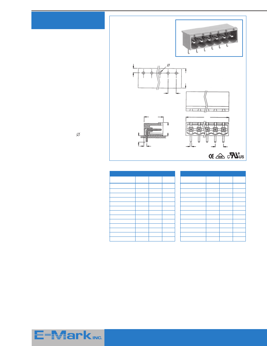
■
Web Site: http://www.e-markinc.com
Pluggable Terminal
Blocks - Right Angle
Specifications
Materials & Finishes
Cage clamp:
Brass, Ni plated
Contact:
Phosphor bronze,
Tin plated, 0.4t
Insulating body:
Polyamide 66
(UL94V-0)
Screw:
M3.0, steel,
Zinc plated
Color:
Green
Environmental
Operation
temperature:
- 55
o
C to +105
o
C
Short-time
temperature:
up to 250
o
C
(+482
o
F)
Electrical
Current rating:
16 Amp AC300V
Insulation
withstanding
voltage:
AC2000V min
Insulation
resistance:
>5000 m
Ω
DC500V
Wide strip length:
4mm - 5mm
Wire range:
14 - 24 AWG
Screws torque:
4.5lb.-inch
Type MC100-500
(5 mm/0.197" pitch)
Type MC100-508
(5.08 mm/0.200" pitch)
Dimensional Information
A
9.80
(0.386”)
15.00
(0.591”)
18.00
(0.709”)
8.20
(0.323”)
Pitch: 5.00 mm (0.197 inch)
Part Number
Poles
A (mm)
A (inch)
MC100-50002
2
10.00
0.394
MC100-50003
3
15.00
0.591
MC100-50004
4
20.00
0.787
MC100-50005
5
25.00
0.984
MC100-50006
6
30.00
1.181
MC100-50007
7
35.00
1.378
MC100-50008
8
40.00
1.575
MC100-50009
9
45.00
1.772
MC100-50010
10
50.00
1.969
MC100-50011
11
55.00
2.165
MC100-50012
12
60.00
2.362
MC100-50024
24
120.00
4.724
Pitch: 5.08 mm (0.200 inch)
Part Number
Poles
A (mm)
A (inch)
MC100-50802
2
10.16
0.400
MC100-50803
3
15.24
0.600
MC100-50804
4
20.32
0.800
MC100-50805
5
25.40
1.000
MC100-50806
6
30.48
1.200
MC100-50807
7
35.56
1.400
MC100-50808
8
40.64
1.600
MC100-50809
9
45.72
1.800
MC100-50810
10
50.80
2.000
MC100-50811
11
55.88
2.200
MC100-50812
12
60.96
2.400
MC100-50824
24
120.92
4.800
5.00
(0.197”)
MC100-500:
5.08
(0.200”)
MC100-508:
B =
2.50
(0.098”)
MC100-500:
2.54
(0.100”)
MC100-508:
C =
B
C
3.5 mm and 3.81 mm types also available.
Contact factory for details.
21
415 Howe Avenue, Suite LL160, Shelton, CT 06484-3168 U.S.A.
■
1-800-831-5383
Phone: (203) 922-1182
■
FAX: (203) 922 -8231
■
Web Site: http://www.e-markinc.com
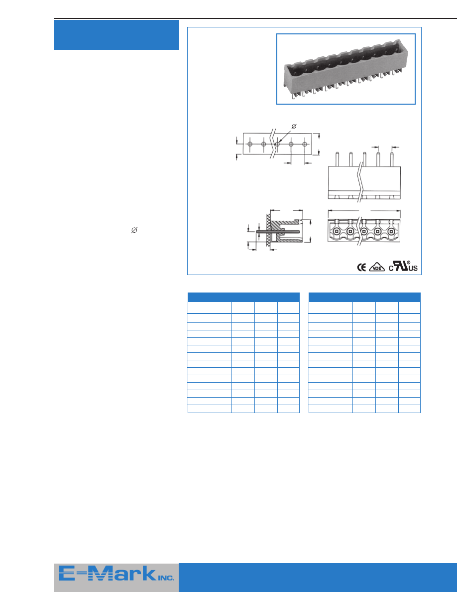
Pluggable Terminal
Blocks - Vertical
Specifications
Materials & Finishes
Cage clamp:
Brass, Ni plated
Contact:
Phosphor bronze,
Tin plated, 0.4t
Insulating body:
Polyamide 66
(UL94V-0)
Screw:
M2.6, steel,
Zinc plated
Color:
Green
Environmental
Operation
temperature:
- 55
o
C to +105
o
C
Short-time
temperature:
up to 250
o
C
(+482
o
F)
Electrical
Current rating:
16 Amp AC300V
Insulation
withstanding
voltage:
AC2000V min
Insulation
resistance:
>5000 m
Ω
DC500V
Wide strip length:
7mm
Wire range:
14 - 24 AWG
Screws torque:
4.5lb.-inch
Type MC200-500
(5 mm/0.197" pitch)
Type MC200-508
(5.08 mm/0.200" pitch)
Dimensional Information
5.00
(0.197”)
A
8.20
(0.323”)
25.80
(1.016”)
12.50
(0.709”)
MC200-500:
5.08
(0.200”)
MC200-508:
Pitch: 5.00 mm (0.197 inch)
Part Number
Poles
A (mm)
A (inch)
MC200-50002
2
10.00
0.394
MC200-50003
3
15.00
0.591
MC200-50004
4
20.00
0.787
MC200-50005
5
25.00
0.984
MC200-50006
6
30.00
1.181
MC200-50007
7
35.00
1.378
MC200-50008
8
40.00
1.575
MC200-50009
9
45.00
1.772
MC200-50010
10
50.00
1.969
MC200-50011
11
55.00
2.165
MC200-50012
12
60.00
2.362
MC200-50024
24
120.00
4.724
Pitch: 5.08 mm (0.200 inch)
Part Number
Poles
A (mm)
A (inch)
MC200-50802
2
10.16
0.400
MC200-50803
3
15.24
0.600
MC200-50804
4
20.32
0.800
MC200-50805
5
25.40
1.000
MC200-50806
6
30.48
1.200
MC200-50807
7
35.56
1.400
MC200-50808
8
40.64
1.600
MC200-50809
9
45.72
1.800
MC200-50810
10
50.80
2.000
MC200-50811
11
55.88
2.200
MC200-50812
12
60.96
2.400
MC200-50824
24
121.92
4.800
B
C
B =
2.50
(0.098”)
MC200-500:
2.54
(0.100”)
MC200-508:
C =
3.5 mm and 3.81 mm types also available.
Contact factory for details.
415 Howe Avenue, Suite LL160, Shelton, CT 06484-3168 U.S.A.
■
1-800-831-5383
Phone: (203) 922-1182
■
FAX: (203) 922 -8231
■
Web Site: http://www.e-markinc.com
22
415 Howe Avenue, Suite LL160, Shelton, CT 06484-3168 U.S.A.
■
1-800-831-5383
Phone: (203) 922-1182
■
FAX: (203) 922 -8231
■
Web Site: http://www.e-markinc.com
Header - Right Angle,
Open End
Specifications
Materials & Finishes
Solder pin:
1.0 mm square,
Brass Tin plated
Insulating body:
Polyamide 66
(UL94V-0)
Color:
Green
Environmental
Operation
temperature:
- 55
o
C to +105
o
C
Short-time
temperature:
up to 250
o
C
(+482
o
F)
Electrical
Current rating:
12 Amp AC300V
Insulation
withstanding
voltage:
AC2000V min
Insulation
resistance:
>5000 m
Ω
DC500V
PCB hole diameter:
1.5 mm
Type ME010-500
(5 mm/0.197" pitch)
Type ME010-508
(5.08 mm/0.200" pitch)
Dimensional Information
A
1.00
(0.039”)
8.30
(0.327”)
1.80
(0.071”)
Pitch: 5.00 mm (0.197 inch)
Part Number
Poles
A (mm)
A (inch)
ME010-50002
2
10.00
0.394
ME010-50003
3
15.00
0.591
ME010-50004
4
20.00
0.787
ME010-50005
5
25.00
0.984
ME010-50006
6
30.00
1.181
ME010-50007
7
35.00
1.378
ME010-50008
8
40.00
1.575
MC200-50009
9
45.00
1.772
ME010-50010
10
50.00
1.969
ME010-50011
11
55.00
2.165
ME010-50012
12
60.00
2.362
ME010-50024
24
120.00
4.724
Pitch: 5.08 mm (0.200 inch)
Part Number
Poles
A (mm)
A (inch)
ME010-50802
2
10.16
0.400
ME010-50803
3
15.24
0.600
ME010-50804
4
20.32
0.800
ME010-50805
5
25.40
1.000
ME010-50806
6
30.48
1.200
ME010-50807
7
35.56
1.400
ME010-50808
8
40.64
1.600
ME010-50809
9
45.72
1.800
ME010-50810
10
50.80
2.000
ME010-50811
11
55.88
2.200
ME010-50812
12
60.96
2.400
ME010-50824
24
121.92
4.800
B
12.00
(0.472”)
1.80
(0.071”)
12.00
(0.472”)
4.50
(0.177”)
C
1.50
(0.059”)
5.00
(0.197”)
ME010-500:
5.08
(0.200”)
ME010-508:
B =
5.00
(0.197”)
ME010-500:
5.08
(0.200”)
ME010-508:
C =
415 Howe Avenue, Suite LL160, Shelton, CT 06484-3168 U.S.A.
■
1-800-831-5383
Phone: (203) 922-1182
■
FAX: (203) 922 -8231
■
Web Site: http://www.e-markinc.com

23
415 Howe Avenue, Suite LL160, Shelton, CT 06484-3168 U.S.A.
■
1-800-831-5383
Phone: (203) 922-1182
■
FAX: (203) 922 -8231
■
Web Site: http://www.e-markinc.com
Header -
Vertical, Open End
Specifications
Materials & Finishes
Solder pin:
1.0 mm square,
Brass Tin plated
Insulating body:
Polyamide 66
(UL94V-0)
Color:
Green
Environmental
Operation
temperature:
- 55
o
C to +105
o
C
Short-time
temperature:
up to 250
o
C
(+482
o
F)
Electrical
Current rating:
12 Amp AC300V
Insulation
withstanding
voltage:
AC2000V min
Insulation
resistance:
>5000 m
Ω
DC500V
PCB hole diameter:
1.5 mm
Type ME020-500
(5 mm/0.197" pitch)
Type ME020-508
(5.08 mm/0.200" pitch)
Dimensional Information
5.00
(0.197”)
A
1.00
(0.039”)
8.30
(0.327”)
3.80
(0.150”)
ME020-500:
5.08
(0.200”)
ME020-508:
Pitch: 5.00 mm (0.197 inch)
Part Number
Poles
A (mm)
A (inch)
ME020-50002
2
10.00
0.394
ME020-50003
3
15.00
0.591
ME020-50004
4
20.00
0.787
ME020-50005
5
25.00
0.984
ME020-50006
6
30.00
1.181
ME020-50007
7
35.00
1.378
ME020-50008
8
40.00
1.575
MC020-50009
9
45.00
1.772
ME020-50010
10
50.00
1.969
ME020-50011
11
55.00
2.165
ME020-50012
12
60.00
2.362
ME020-50024
24
120.00
4.724
Pitch: 5.08 mm (0.200 inch)
Part Number
Poles
A (mm)
A (inch)
ME020-50802
2
10.16
0.400
ME020-50803
3
15.24
0.600
ME020-50804
4
20.32
0.800
ME020-50805
5
25.40
1.000
ME020-50806
6
30.48
1.200
ME020-50807
7
35.56
1.400
ME020-50808
8
40.64
1.600
ME020-50809
9
45.72
1.800
ME020-50810
10
50.80
2.000
ME020-50811
11
55.88
2.200
ME020-50812
12
60.96
2.400
ME020-50824
24
121.92
4.800
B
B =
5.00
(0.197”)
ME020-500:
5.08
(0.200”)
ME020-508:
C =
8.30
(0.327”)
4.50
(0.177”)
12.00
(0.472”)
3.80
(0.150”)
C
1.50
(0.059”)
415 Howe Avenue, Suite LL160, Shelton, CT 06484-3168 U.S.A.
■
1-800-831-5383
Phone: (203) 922-1182
■
FAX: (203) 922 -8231
■
Web Site: http://www.e-markinc.com
24
415 Howe Avenue, Suite LL160, Shelton, CT 06484-3168 U.S.A.
■
1-800-831-5383
Phone: (203) 922-1182
■
FAX: (203) 922 -8231
■
Web Site: http://www.e-markinc.com
Header -
Right Angle, Closed End
Specifications
Materials & Finishes
Solder pin:
1.0 mm square,
Brass Tin plated
Insulating body:
Polyamide 66
(UL94V-0)
Color:
Green
Environmental
Operation
temperature:
- 55
o
C to +105
o
C
Short-time
temperature:
up to 250
o
C
(+482
o
F)
Electrical
Current rating:
12 Amp AC300V
Insulation
withstanding
voltage:
AC2000V min
Insulation
resistance:
>5000 m
Ω
DC500V
PCB hole diameter:
1.5 mm
Type ME030-500
(5 mm/0.197" pitch)
Type ME030-508
(5.08 mm/0.200" pitch)
Dimensional Information
5.00
(0.197”)
A
1.80
(0.071”)
8.30
(0.327”)
1.80
(0.071”)
ME030-500:
5.08
(0.200”)
ME030-508:
Pitch: 5.00 mm (0.197 inch)
Part Number
Poles
A (mm)
A (inch)
ME030-50002
2
11.60
0.457
ME030-50003
3
16.60
0.654
ME030-50004
4
21.60
0.850
ME030-50005
5
26.60
1.047
ME030-50006
6
31.60
1.244
ME030-50007
7
36.60
1.441
ME030-50008
8
41.60
1.638
MC030-50009
9
46.60
1.835
ME030-50010
10
51.60
2.031
ME030-50011
11
56.60
2.228
ME030-50012
12
61.60
2.425
ME030-50024
24
121.60
4.787
Pitch: 5.08 mm (0.200 inch)
Part Number
Poles
A (mm)
A (inch)
ME030-50802
2
11.76
0.463
ME030-50803
3
16.84
0.663
ME030-50804
4
21.92
0.863
ME030-50805
5
27.00
1.063
ME030-50806
6
32.08
1.263
ME030-50807
7
37.16
1.463
ME030-50808
8
42.24
1.663
ME030-50809
9
47.32
1.863
ME030-50810
10
52.40
2.063
ME030-50811
11
57.48
2.263
ME030-50812
12
62.56
2.463
ME030-50824
24
123.52
4.863
B
B =
5.00
(0.197”)
ME030-500:
5.08
(0.200”)
ME030-508:
C =
12.00
(0.472”)
4.50
(0.177”)
12.00
(0.472”)
C
1.50
(0.059”)
3.5 mm and 3.81 mm types also available.
Contact factory for details.
25
415 Howe Avenue, Suite LL160, Shelton, CT 06484-3168 U.S.A.
■
1-800-831-5383
Phone: (203) 922-1182
■
FAX: (203) 922 -8231
■
Web Site: http://www.e-markinc.com
Specifications
Materials & Finishes
Solder pin:
1.0 mm square,
Brass Tin plated
Insulating body:
Polyamide 66
(UL94V-0)
Color:
Green
Environmental
Operation
temperature:
- 55
o
C to +105
o
C
Short-time
temperature:
up to 250
o
C
(+482
o
F)
Electrical
Current rating:
12 Amp AC300V
Insulation
withstanding
voltage:
AC2000V min
Insulation
resistance:
>5000 m
Ω
DC500V
PCB hole diameter:
1.5 mm
Type ME040-500
(5 mm/0.197" pitch)
Type ME040-508
(5.08 mm/0.200" pitch)
Dimensional Information
5.00
(0.197”)
A
8.30
(0.327”)
3.80
(0.150”)
ME040-500:
5.08
(0.200”)
ME040-508:
Pitch: 5.00 mm (0.197 inch)
Part Number
Poles
A (mm)
A (inch)
ME040-50002
2
11.60
0.457
ME040-50003
3
16.60
0.654
ME040-50004
4
21.60
0.850
ME040-50005
5
26.60
1.047
ME040-50006
6
31.60
1.244
ME040-50007
7
36.60
1.441
ME040-50008
8
41.60
1.638
MC040-50009
9
46.60
1.835
ME040-50010
10
51.60
2.031
ME040-50011
11
56.60
2.228
ME040-50012
12
61.60
2.425
ME040-50024
24
121.60
4.787
Pitch: 5.08 mm (0.200 inch)
Part Number
Poles
A (mm)
A (inch)
ME040-50802
2
11.76
0.463
ME040-50803
3
16.84
0.663
ME040-50804
4
21.92
0.863
ME040-50805
5
27.00
1.063
ME040-50806
6
32.08
1.263
ME040-50807
7
37.16
1.463
ME040-50808
8
42.24
1.663
ME040-50809
9
47.32
1.863
ME040-50810
10
52.40
2.063
ME040-50811
11
57.48
2.263
ME040-50812
12
62.56
2.463
ME040-50824
24
123.52
4.863
B
B =
5.00
(0.197”)
ME040-500:
5.08
(0.200”)
ME040-508:
C =
8.30
(0.327”)
12.00
(0.472”)
C
1.50
(0.059”)
1.00
(0.039”)
4.50
(0.177”)
3.80
(0.150”)
3.5 mm and 3.81 mm types also available.
Contact factory for details.
Header -
Vertical, Closed End
415 Howe Avenue, Suite LL160, Shelton, CT 06484-3168 U.S.A.
■
1-800-831-5383
Phone: (203) 922-1182
■
FAX: (203) 922 -8231
■
Web Site: http://www.e-markinc.com
26
415 Howe Avenue, Suite LL160, Shelton, CT 06484-3168 U.S.A.
■
1-800-831-5383
Phone: (203) 922-1182
■
FAX: (203) 922 -8231
■
Web Site: http://www.e-markinc.com
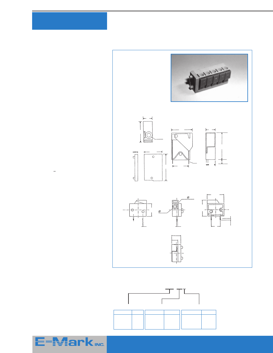
Modular Barrier Strips
With Integral
Molded Covers
E-Mark proudly introduces an entirely
new concept in barrier strips —
modular strips with integrally molded
covers. Available in two and three pole
sizes which slide together to make
almost any number of positions. Their
integrally molded covers increase
safety in every application!
Features
■
Barrier & Tri-barrier types
■
Six contact styles
■
Two pitches:
.30" (7.62 mm)
.375" (9.5 mm)
■
Short lead times
■
Access holes permit adjustment
when covers are closed
C31M
PCB Barrier Termainal Block Modular Type
Specifications
Pitch (mm):
7.62
Poles:
M2, M3
Rated Current:
10A AC300V
Terminal:
Brass, Tin Plated,
0.8t
Wire Range
(AWG)
:
16-22
Insulator Body:
Polyamide 66
(UL 94V-0),
Green/Black
Screw:
M3.0, Steel,
Ni Plated
Dimension
(L x W x H mm):
Length (L) =
7.62 x Poles
C31MBM11-03
C31MBM14-03
C31MBM23-03
C31MBM32-03
C31MBP32-03
C31MBS11-03
27
415 Howe Avenue, Suite LL160, Shelton, CT 06484-3168 U.S.A.
■
1-800-831-5383
Phone: (203) 922-1182
■
FAX: (203) 922 -8231
■
Web Site: http://www.e-markinc.com
Modular Barrier Strips With
Integral Molded Covers
Continued
C34M
PCB Barrier Termainal Block Modular Type
Specifications
Pitch (mm):
9.50
Poles:
M2, M3
Rated Current:
15A AC300V
Terminal:
Brass, Tin Plated, 0.8t
Wire Range (AWG):
14-22
Insulator Body:
Polyamide 66
(UL 94V-0), Green/Black
Screw:
M3.0, Steel, Ni Plated
Dimension
(L x W x H mm):
Length (L) = 9.50 x Poles
C34MBM11-03
C34MBM14-03
C34MBM23-03
C34MBM32-03
C34MBP32-03
C34MBS11-03
C44M
PCB Tri Barrier Terminal Block Modular Type
Specifications
Pitch (mm):
9.50
Poles:
M2, M3
Rated Current:
15A AC300V
Terminal:
Brass, Tin Plated, 0.8t
Wire Range (AWG):
14-22
Insulator Body:
Polyamide 66
(UL 94V-0), Green/Black
Screw:
M3.0, Steel, Ni Plated
Dimension
(L x W x H mm):
Length (L) = 9.50 x Poles
C41M
PCB Tri Barrier Terminal Block Modular Type
Specifications
Pitch (mm):
7.62
Poles:
M2, M3
Rated Current:
10A AC300V
Terminal:
Brass, Tin Plated, 0.8t
Wire Range (AWG):
16-22
Insulator Body:
Polyamide 66
(UL 94V-0), Green/Black
Screw:
M3.0, Steel, Ni Plated
Dimension
(L x W x H mm):
Length (L) = 7.62 x Poles
C41MBM11-03
C41MBB11-03
C41MBM23-03
C41MBM32-03
C41MBP32-03
C41MBS11-03
C44MBM11-03
C44MBM14-03
C44MBM23-03
C44MBM32-03
C44MBP32-03
C44MBS11-03
415 Howe Avenue, Suite LL160, Shelton, CT 06484-3168 U.S.A.
■
1-800-831-5383
Phone: (203) 922-1182
■
FAX: (203) 922 -8231
■
Web Site: http://www.e-markinc.com
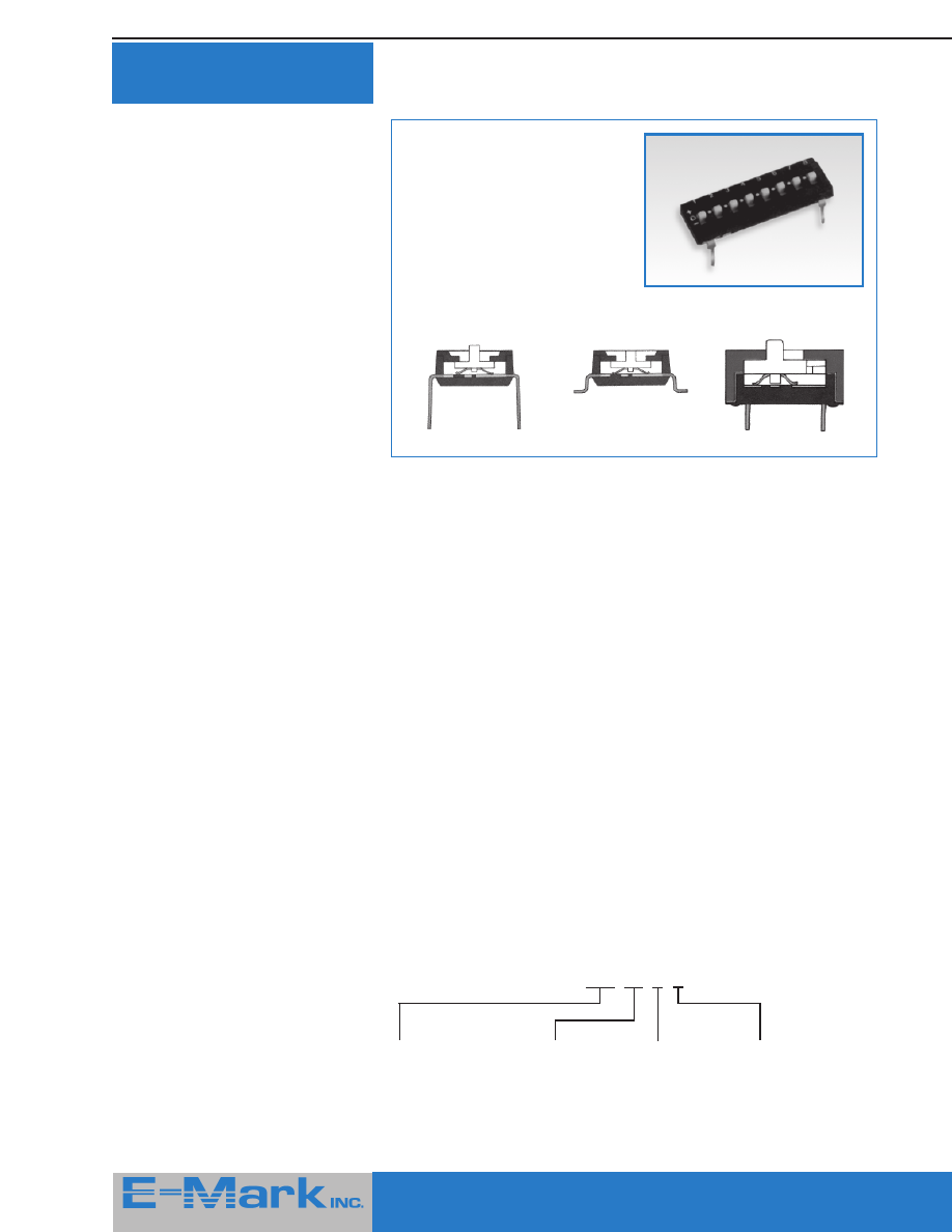
28
415 Howe Avenue, Suite LL160, Shelton, CT 06484-3168 U.S.A.
■
1-800-831-5383
Phone: (203) 922-1182
■
FAX: (203) 922 -8231
■
Web Site: http://www.e-markinc.com
E-Mark TRINARY
Dip Switches
Features
■
Three actuator settings (1, open, 0)
■
Bottom sealed as standard to prevent
flux contamination (Top Seal Option)
■
Three styles available (standard thru-
hole, auto insertion compatible, SMT
compatible)
■
Twin, gold plated contacts for
reliability
Application
E-Mark's TRINARY switches are ideal for
coding telecom, transceiving, remote
control, alarm equipment, etc. which use
ICs with TRINARY coding. Each contact
offers the user three settings (1, open, or
0) which vastly increases the number of
codes possible compared to two state
(1,0) operation. For example, 9 bits with
TRINARY yields 19,683 (3
9
) codes while
two state yields 512 (2
9
) codes... an
increase of 38X!
E-Mark TRINARY switches are available
in three styles to suite any application.
ETD style:
Normal thru-hole mounting
ETA style:
Automatic insertion compatible
ETS style:
SMT compatible
All switches are manufactured from the
highest quality components including
UL-94V0 plastics.
ETA
ETS
ETD
Specifications
Electrical
Contact Rating
Switching: 25mA, 24 VDC
Non-switching: 100mA, 50 VDC
Contact Resistance
Initial:
50 m
Ω
max.
After life test:
100 m
Ω
max.
Insulation Resistance:
1,000 M
Ω
min. at 100 VDC
Dielectric Strengh:
500 VDC min. for 1 minute
Capacitance between adjacent switches
5pF max.
Mechanical and Environmental
Temperature Rating
Operating:
-25
o
to +70
o
C
Storage:
-40
o
to +85
o
C
Operation Force:
800 g max.
Operation Life:
2,000 Operations
Humidity:
95% RH, 40
o
C for 96 Hrs.
Vibration:
Per MIL-STD-202F, Method 204D
Solderability:
After flux 230 ± 5
o
C for 5 ± 0.5
second 95% coverage
Soldering Heat
For ETA, ETD Type:
260 ± 5
o
C for 5 ± 1 second
For ETS Type:
260 ± 5
o
C for 10 ± 1 second
260 ± 5
o
C for 2 ± 0.5 second
(Resistance to IR
(
Reflow Soldering Heat)
Ordering Information
ETD - 08 - E - X
Series Name:
ETD: Bottom Epxoy
Sealed type
ETA: Automatic
Inserting type
ETS: Surface
Mounting type
Number of
Positions
Actuator:
E: Extended
Actuator
L: Low Profile
Actuator
Option:
Blank: Non-Top Tape
Sealed
T: Top Tape Sealed
415 Howe Avenue, Suite LL160, Shelton, CT 06484-3168 U.S.A.
■
1-800-831-5383
Phone: (203) 922-1182
■
FAX: (203) 922 -8231
■
Web Site: http://www.e-markinc.com
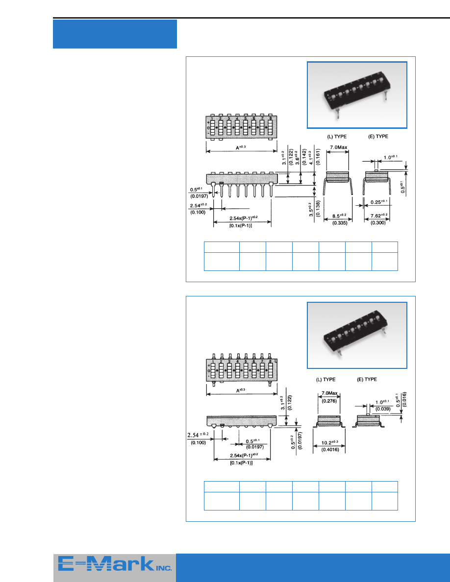
29
415 Howe Avenue, Suite LL160, Shelton, CT 06484-3168 U.S.A.
■
1-800-831-5383
Phone: (203) 922-1182
■
FAX: (203) 922 -8231
■
Web Site: http://www.e-markinc.com
ETA
Dimension A
Positions
4
5
7
8
9
10
A
11.76
14.3
19.38
21.92
24.46
27.00
(0.463)
(0.563)
(0.763)
(0.863)
(0.963)
(1.063)
ETS
Dimension A
Positions
4
5
7
8
9
10
A
11.76
14.3
19.38
21.92
24.46
27.00
(0.463)
(0.563)
(0.763)
(0.863)
(0.963)
(1.063)
E-Mark TRINARY
Dip Switches
Continued
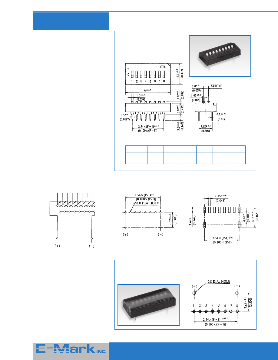
30
415 Howe Avenue, Suite LL160, Shelton, CT 06484-3168 U.S.A.
■
1-800-831-5383
Phone: (203) 922-1182
■
FAX: (203) 922 -8231
■
Web Site: http://www.e-markinc.com
E-Mark TRINARY
Dip Switches
Continued
Circuit Diagram
P.C.B. Layout (Top View)
(ETD / ETA)
P.C.B. Pattern
(ETS)
Options
Tape Sealed
Reverse P.C.B. Layout available
ETD
Dimension A
Positions
4
5
7
8
9
10
A
15.30
17.84
22.92
25.46
28.00
30.54
(0.602)
(0.702)
(0.902)
(1.002)
(1.102)
(1.202)
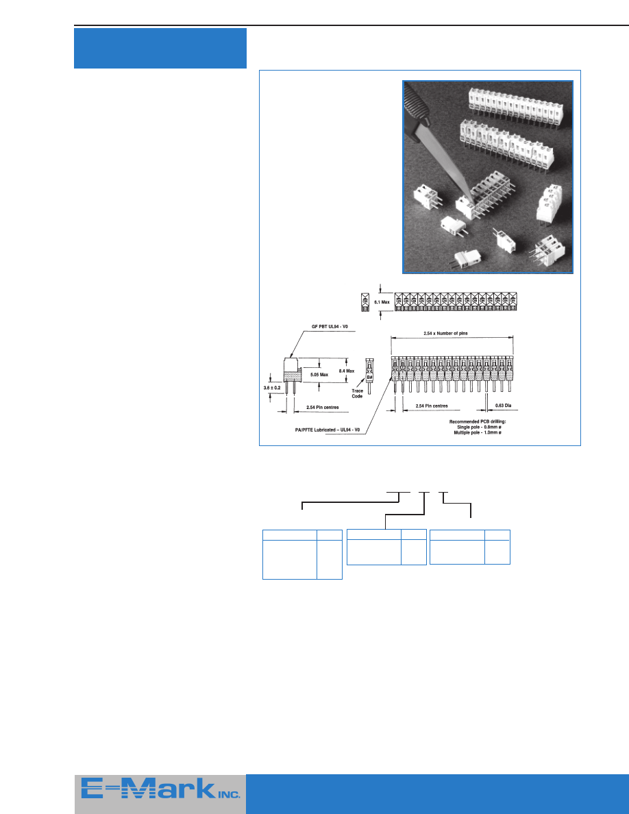
31
415 Howe Avenue, Suite LL160, Shelton, CT 06484-3168 U.S.A.
■
1-800-831-5383
Phone: (203) 922-1182
■
FAX: (203) 922 -8231
■
Web Site: http://www.e-markinc.com
Jumper-Switch
TM
Features
■
Drop-in replacement for jumpers
■
Secured in the ON or OFF setting
■
0.1” mounting pitch
■
1 thru 16 ON / OFF contacts
■
Hard gold plated wiping contacts
A switchable jumper on 0.1” pitch that
securely switches PCB track signals ON /
OFF with a positive contact action. Supplied
in units of 1 through 16 poles they provide
an alternative to jumpers without the need
for exposed bare pins.
Longer units (up to 16 poles) save loading
time in production. In the design state they
can be cut with a utility knife to achieve any
combination required to provide flexible
switching with the least routing on a PCB.
Options available including sliders of
different colors in the EIA range, a mixture
of colors for sliders in multi-pole versions
and slider numbering.
Reliable switching of the gold over nickel
plated, phosphor bronze contacts is
guaranteed with the 4 point wiping contact
design. The contacts never rub over any
plastic part and every one is tested before
shipment. The positive detent action
guarantees good shock resistance.
The deep ‘V’ slots positively locate any
operating probe.
Jumper-Switch
TM
has been designed for
use on hand or flow soldered and washed
PCBs. The tight pin fit prevents any wicking.
Users should evaluate that their particular
processes are compatible with the unsealed
contact design concept.
All Dimensions in mm
Ordering Information
Please replace ‘X’ with appropriate coding listed in table below
JSA4 - XX - XX
Series
Jumper-Switch
TM
Definition
Code
Number of sliders
01 - 16
Specifications
Contact Ratings
Non-Switching: 100 VAC, 5A
Switching:
1
μ
V to 100V, 1
μ
A to
1A, 1O VA
Contacts are shipped in “ON” position
Initial Contact Resistance
Typical:
10m
Ω
Max:
15m
Ω
(at 10VA,
10mA max)
Insulation
resistance:
1,000 M
Ω
at
500 VDC min
Life:
Minimum 1,000
operations
Dielectric Strengths
1 minute:
50OVrms 50 Hz
Capacitance
between
open contacts: <5pf. at 1KHz
Temperature
Operating range for continuous
electrical use and manual operation is
restricted to -55
o
to +85
o
C for
standard products
Operating Force
(per pole):
Max. 5N
Humidity
Damp Heat
Steady State:
56 days
Solderability:
<2 seconds to wet at
235
o
C as per IEC 68
and BS2011 Test T,
solder bath method.
Resistance to soldering heat as per IEC
69 and BS2011 10 seconds satisfactory
at 260
o
C when mounted on 1.5mm PCB.
Samples available on request.
Definition
Code
2 rows of pins -
ON / OFF
A
Slider Color
Yellow (standard)
4
Gold Thickness
Definition
Code
Standard 0.1
μ
G0
Special 0.1
μ
G1
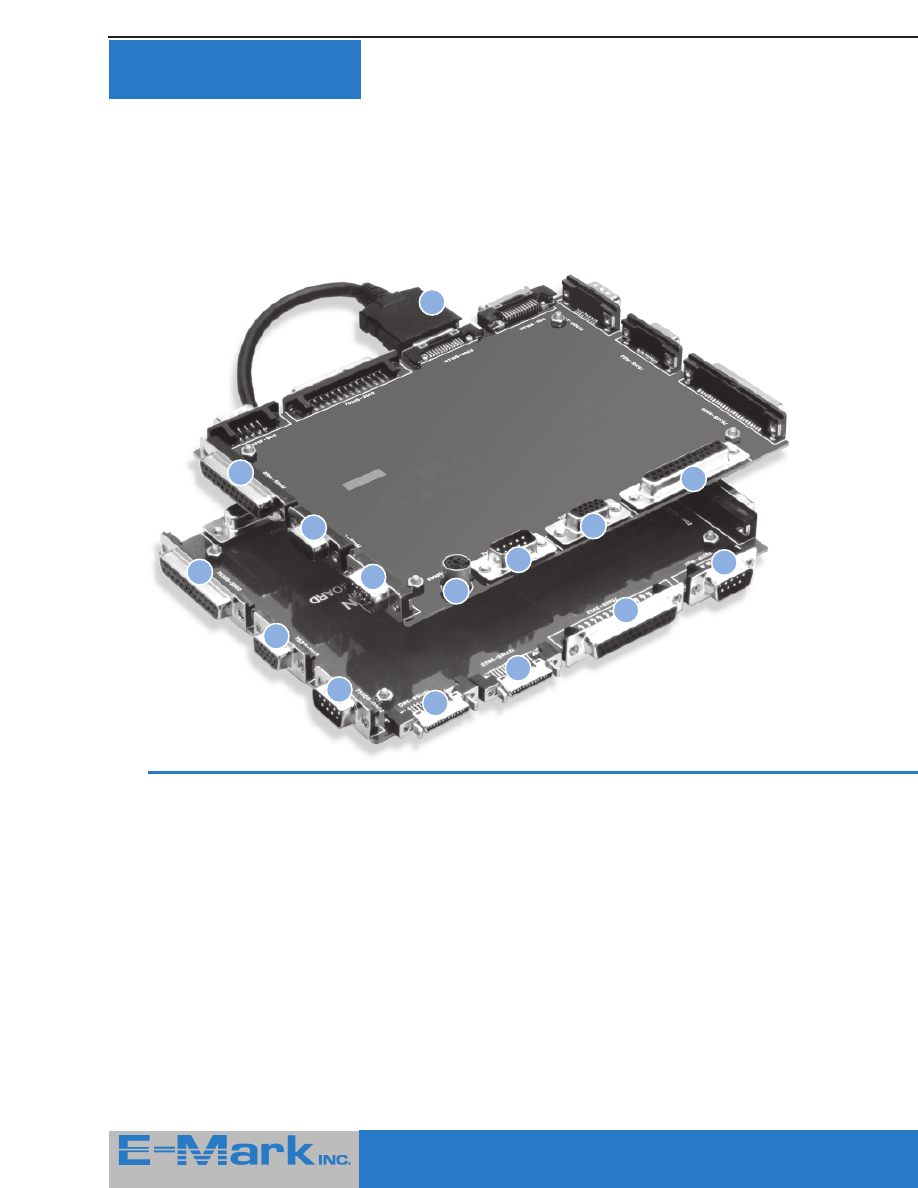
32
415 Howe Avenue, Suite LL160, Shelton, CT 06484-3168 U.S.A.
■
1-800-831-5383
Phone: (203) 922-1182
■
FAX: (203) 922 -8231
■
Web Site: http://www.e-markinc.com
1
2
3
4
5
6
7
8
15
14
13
12
11
10
9
Space Saving D-Sub
Connectors for I /O
If you’ve ever wondered where you can
obtain the space saving D-Sub
connectors used in notebook comput-
ers and other space sensitive equip-
ment, this is the place you’ll find them.
For example, comparing volume, our
25 contact D-Sub female consumes
only 20% of the volume required by
standard D-Sub females!
Illustrated below is a wide variety of
specialized D-Sub connectors available
as SMD parts or through hole types.
Start saving space today!
Request our separate
D-Sub
connector
catalog by calling the toll-free number
shown below or through the E-Mark
web site.
11111 .....
Half Pitch Ultra Thin D-Sub
Male solder type with cover
2.
2.
2.
2.
2.
Slim D-Sub Right Angle P.C.B.
Mount
Female type 2.0 mm
3.
3.
3.
3.
3.
Slim D-Sub Right Angle P.C.B.
Mount
High Density female type 2.0 mm
4.
4.
4.
4.
4.
Slim D-Sub Right Angle P.C.B.
Mount
Male type 2.0 mm
5.
5.
5.
5.
5.
Mini DIN
6.
6.
6.
6.
6.
Ultra Thin D-Sub Straight
P.C.B. Mount
Male type
7.
7.
7.
7.
7.
Ultra Thin D-Sub Straight
P.C.B. Mount
High Density female type
8.
8.
8.
8.
8.
Ultra Thin D-Sub Straight
P.C.B. Mount
Female type
9.
9.
9.
9.
9.
Ultra Thin D-Sub
Female S.M.D. type
10.
10.
10.
10.
10.
Ultra Thin D-Sub High Density
Female S.M.D. type
11.
11.
11.
11.
11.
Ultra Thin D-Sub
Male S.M.D. type
12.
12.
12.
12.
12.
Half Pitch Ultra Thin D-Sub Right
Angle P.C.B. Mount
Female type
13.
13.
13.
13.
13.
Half Pitch Ultra Thin D-Sub Edge
Mount
Female type
14.
14.
14.
14.
14.
Ultra Thin D-Sub Edge Mount
Female type
15.
15.
15.
15.
15.
Ultra Thin D-Sub Edge Mount
Male type
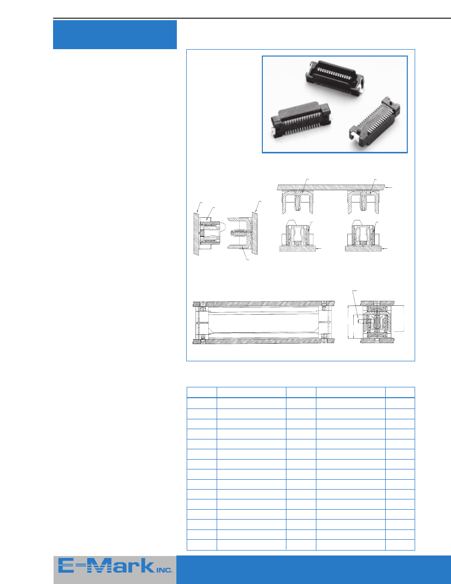
33
415 Howe Avenue, Suite LL160, Shelton, CT 06484-3168 U.S.A.
■
1-800-831-5383
Phone: (203) 922-1182
■
FAX: (203) 922 -8231
■
Web Site: http://www.e-markinc.com
.8 mm Pitch Stacking
Connectors
E-Mark is pleased to introduce a new
range of SMD compatible, stacking
connectors featuring 0.8 mm pitch and
designed for board to board connec-
tions. Their small footprint and high pin
density make them ideal for demanding
applications where space is tight.
Available in sizes from 10 to 200
contacts, the plugs and sockets in this
range feature strong, reinforcing solder
clips and are polarized to prevent
mismating. These connectors can be
supplied in tubes or on tape and reel
for automatic placement.
Shown at right are a few typical
configurations using the
800 Series
connectors as well as a chart showing
the standard stacking heights which
are able to be achieved using different
combinations of plugs and sockets.
Request the separate
800 Series
connector catalog by calling the toll-
free number shown below or through
the E-Mark web site.
H
Receptacle
H1
Plug
H2
5.0
80060A - XXXXXX
4.0
80030A - XXXXXX
4.6
6.0
80060A - XXXXXX
4.0
80031A - XXXXXX
5.6
7.0
80060A - XXXXXX
4.0
80032A - XXXXXX
6.6
8.0
80060A - XXXXXX
4.0
80033A - XXXXXX
7.6
9.0
80062A - XXXXXX
6.0
80032A - XXXXXX
6.6
10.0
80040A - XXXXXX
7.4
80050A - XXXXXX
8.0
11.0
80040A - XXXXXX
7.4
80051A - XXXXXX
9.0
12.0
80040A - XXXXXX
7.4
80052A - XXXXXX
10.0
13.0
80040A - XXXXXX
7.4
80053A - XXXXXX
11.0
14.0
80042A - XXXXXX
9.4
80052A - XXXXXX
10.0
15.0
80040A - XXXXXX
7.4
80055A - XXXXXX
13.0
16.0
80043A - XXXXXX
10.4
80053A - XXXXXX
11.0
17.0
80042A - XXXXXX
7.4
80055A - XXXXXX
13.0
18.0
80043A - XXXXXX
10.4
80055A - XXXXXX
13.0
20.0
80045A - XXXXXX
12.4
80055A - XXXXXX
13.0
Dimensional Of Board To Board Heights
Dimensions
Receptacle
Plug
H2
Contact Area = 0.8 Min
H1
H
Board To Board Height
PCB
8004 X A
8006 X A
8003 X A
8005 X A
PCB
FPC
8003 X A
8005 X A
8003 X A
8005 X A
PCB
PCB
8004 X A
8006 X A
8004 X A
8006 X A
415 Howe Avenue, Suite LL160
Shelton, CT 06484-3168 U.S.A.
1- 800-831-5383
Phone: (203) 922-1182
■
FAX: (203) 922 -8231
Web Site: http://www.e-markinc.com
Represented / Distributed By -