Ultra High Precision Z1-Foil Technology Gold Wire Bondable Chip
Resistor for Hybrid Circuits for High Temperature Applications
up to +240°C, Long Term Stability of 0.05%,TCR to ± 1ppm/°C
HTHG* (Z1-Foil)
Vishay Foil Resistors
Document Number: 63221
For any questions, contact:
foil@vishaypg.com
www.vishayfoilresistors.com
Revision: 13-Dec-12
1
INTRODUCTION
Vishay Foil Resistors (VFR) introduces a new line of Ultra
Precision Bulk Metal
®
Z1-Foil technology: hybrid chip
resistors, connected using gold wire bonding. The HTHG
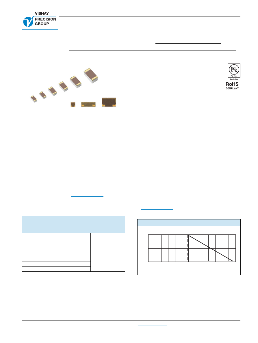
series features two different layouts of chip designs
according to the sizes (see figure 3 and table 4). These new
types of hybrid chips were especially designed for high
temperature applications up to + 240°C
(1)
(working power: to
150mW at + 220°C), and include gold plated terminals.
The HTHG series is available in any value within the
specified resistance range. VFR's application engineering
department is available to advise and make
recommendations.
For non-standard technical requirements and special
applications, please contact
foil@vishaypg.com
.
TABLE 1 - TOLERANCE AND TCR VS.
RESISTANCE VALUE
(1)(2)
(- 55 °C to + 220 °C, + 25 °C Ref.)
RESISTANCE
VALUE
(
)
TOLERANCE
(%)
TCR Typical
(ppm/°C)
100
to 125K
± 0.02
± 2.5
50
to < 100
± 0.05
25
to < 50
± 0.1
10
to < 25
± 0.25
5
to 10
± 0.5
Notes
(1)
Performances obtained with ceramic PCB.
(2)
For tighter performances or non-standard values up to 150 k
,
please contact VFR's application engineering department by
sending an e-mail to the address in the footer below.
FEATURES
Temperature coefficient of resistance (TCR):
±1 ppm/°C typical (- 55 °C to + 125 °C, + 25 °C ref.)
±2.5 ppm/°C typical (- 55 °C to + 220 °C, + 25 °C
ref.)
Resistance range: 5
to 125 k
(for higher
or lower values, please contact VFR's application
engineering department)
Resistance tolerance: to ± 0.02 %
Connection method: gold wire bonding
Working power: to 150mW at + 220°C
Long term stability: to ± 0.05 % at + 240°C for 2000h, no
power
Load life stability: to 0.05% at + 220°C for 2000h at
working power
Vishay Foil resistors are not restricted to standard values;
specific "as required" values can be supplied at no extra
cost or delivery (e.g. 1K2345 vs. 1K)
Thermal stabilization time < 1 s (nominal value achieved
within 10 ppm of steady state value)
Electrostatic discharge (ESD) at least to 25 kV
Non inductive, non capacitive design
Rise time: 1 ns effectively no ringing
Current noise: 0.010 µV (RMS)/Volt of applied voltage
(< - 40 dB)
Voltage coefficient: < 0.1 ppm/V
Non inductive: < 0.08 µH
Non hot spot design
Terminal finish available: gold plated (lead (Pb)-free alloy)
Prototype quantities available in just 5 working days
or sooner. For more information, please contact
foil@vishaypg.com
FIGURE 1 - POWER DERATING CURVE
100
75
50
25
0
-75
-50
-25
0
+25
+50
+75
+100 +125 +150
+200 +225 +250
+175
Ambient Temperature (°C)
Percent of Rated Power
+70°C
-55°C
+240
* HTHG was previously named HTH