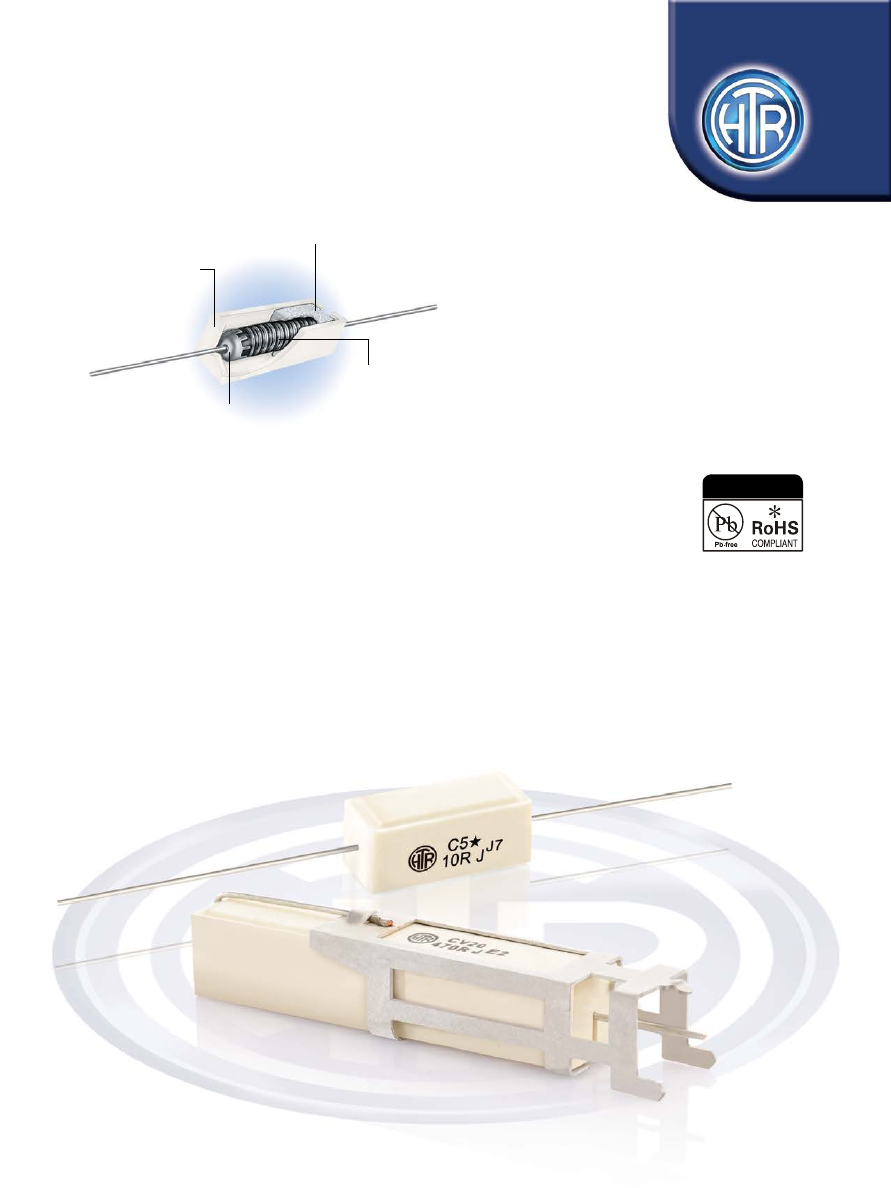
background image

Flame Proof

High Temperature

Ceramic Housing

Inorganic Fire Retardant

Encapsulant

Alloy Wire Wound

Element On 

Fibre Glass/Ceramic

Substrate

Mechanically Crimped

Termination Assembly

• Moisture resistant

• Very high degree of insulation

• Low surface temperature

• 1W to 20W

• R05 to 56K

WIRE WOUND RESISTORS 

CERAMIC ENCASED TYPE

HCA/HCV

SERIES

POWER TYPE

Ceramic Encased

Wire Wound Resistors

Fire Proof

e : info@htr-india.com

www.htr-india.com

Rev Date : 22/11/2016

As per  AEC-Q200

HTR-India-Products-Wire-Wound-Resistors-Ceramic-Encased-Resistor-HCA-English1-html.html
background image

PHYSICAL CONFIGURATION

HTR

TYPE

POWER

RATING at

70°C

L

±1.5

W

±1

d

±0.05

DIMENSIONS (mm)

RESISTANCE RANGE

TYPICAL

WEIGHT 

PER PC (gms)

 min 

max

H

±1

*

LM

±1

C-1A 

1W 

13.0 

5.5 

5.5 

0.8 

35 

R20 

3K3 

 1.4

C-1 

1W 

15.0 

7.5 

6.5 

0.8 

35 

R05 

4K7 

 1.9

C-2 

2W 

17.5 

7.5 

7.0 

0.8 

40 

R05 

7K5 

 3.0

C-3 

3W 

22.0 

8.0 

8.0 

0.8 

45 

R05 

11K 

 4.0

C-5 

5W 

22.0 

9.5 

9.5 

0.8 

45 

R05 

11K 

 4.9

C-7 

7W 

35.0 

9.5 

9.5 

0.8 

55 

R05 

30K 

 6.9

C-10 

10W 

48.0 

9.5 

9.5 

0.8 

70 

R05 

43K 

 9.3

C-15 

15W (25

0

C) 

48.0 

12.5 

12.5 

1.0 

70 

R05 

43K 

 16.2

C-20 

20W (25

0

C) 

63.5 

12.5 

12.5 

1.0 

85 

R10 

56K 

 21.0

*  For resistance values less than R10 and tolerance less than ±2%, please measure resistance over centered ength LM.

•  Resistance values < 1R0 and tolerance < 5% are wound on ceramic substrate.


A bead of potting compound may be observed at the point where the termination emerges.

∆  


∆ 

HCA SERIES

WIRE WOUND 

RESISTORS

CERAMIC

ENCASED 

TYPE

HCA/

HCV

HTR

TYPE

POWER

RATING

at

70°C

L

1

DIMENSIONS (mm)

RESISTANCE 

RANGE 

TYPICAL

WEIGHT 

PER PC

(gms)

    min        max

CV-7 

7W 

60±1.5 

5±0.5 

7±1 

2.1±0.15 

11±1 

9.5±1 

10±1 

2.1±0.15 

10±1  0.8 

R05 

30K 

10.0

CV-10 

10W 

67±1.5 

5±0.5 

7±1 

2.1±0.15 

11±1 

9.5±1 

10±1 

2.1±0.15 

10±1  0.8 

R05 

43K 

13.3

CV-15  15W (25

C)  62.5±2 

4.5±0.2  6.5±1 

2.5±0.15 

14±1  12.5±1.2  13±1.2 

2.5±0.15 

13±1  1.0 

R05 

43K 

22.1

CV-20  20W (25

C)  

78±2 

4.5±0.2  6.5±1 

2.5±0.15 

14±1  12.5±1.2  13±1.2 

2.5±0.15 

13±1  1.0 

R10 

56K 

26.4

•  In order to facilitate vertical mounting of the large 7W to 20W resistors in HCA series on heavily populated PCB’s they can be supplied 

on request with mounting brackets as shown in HCV series.

L

2

L

3

H

1

H

2

H

3

W

1

W

2

W

3

d±0.1

HCV SERIES

PHYSICAL CONFIGURATION

e : info@htr-india.com

www.htr-india.com

Rev Date : 22/11/2016

HTR-India-Products-Wire-Wound-Resistors-Ceramic-Encased-Resistor-HCA-English1-html.html
background image

ELECTRICAL CHARACTERISTICS / DATA

Power Rating (Rated Ambient Temperature) 

Upto 10W, full power dissipation at 70 °C and 15W / 20W full power  


dissipation at 25°C and linearly derated to zero at +275 °C 


(See Derating curve above)


Operating Temperature Range (Ambient) 

-55°C to +275°C with suitable derating as per Derating Curve


Voltage Rating / Limiting Voltage / Max Working Voltage 

V =    PxR  

Maximum Overload Voltage  

Varies depending on resistance value, duration of over load and  


type of pulse waveform (contact factory for details)


Resistance Tolerances Available JIS- C - 5202 para 5.1 

±10% (K) ; ±5% (J) ; ±3% (H) ; ±2% (G) and ±1% (F)

PARAMETER/PERFORMANCE TEST & TEST METHOD 

PERFORMANCE REQUIREMENTS

WIRE WOUND 

RESISTORS

CERAMIC

ENCASED 

TYPE

HCA/

HCV

ELECTRICAL AND ENVIRONMENTAL CHARACTERISTICS / DATA

MECHANICAL SPECIFICATIONS

Short Time Overload 

JIS - C - 5202 Para 5.5  

R ± [2% + R05]


Upto 3W - condition A (RV x 2.5 for 5 secs) 


5W and above - condition B (voltage 


corresponding to 10 times power for 5 secs)

Dielectric Withstanding  

JIS - C - 5202 Para 5.7 

R ± [1% + R05] (No flashover,

Voltage / Voltage Proof 

Condition F (Limiting Voltage x 2 or 500V) 

arcing or  insulation breakdown)

Temperature Co-efficient  

JIS - C - 5202 Para 5.2 

± 90 ppm/°C  [>10R]

of Resistance      


± 80 ppm/°C [<10R]


± 200 ppm/°C [<R10]

Insulation Resistance 

JIS - C - 5202 Para 5.6 (condition F)   

>1000M

 (min)

Pulse Overload /  

JIS - C - 5202 Para 5.8 (Limiting Voltage x 4) 

R ± [2% + R05]

Intermittent Overload 

1 sec on / 25 off 10,000 cycles ± 200 cycles 

Endurance - under load  

JIS - C - 5202 Para 7.9 1000 hours at 40°C ±2°C, 95% R.H 

R ± [5% + R05]

with humidity  

with limiting voltage (1.5 hours on / 0.5 hours off)

Load Life 

JIS - C - 5202 Para 7.10  

R ± [5% + R05]


1000 hours at 70°C with limiting voltage 


(1.5 hours on/0.5 hours off)

Temperature Cycling 

JIS - C - 5202 Para 7.4 

R ± [2% + R05]


[Room Temperature 


-55°C


Room Temperature


      155°C


Room Temperature for 5 cycles] 

Damp Heat (Steady State) 

JIS - C - 5202 Para 7.5 

R ± [3% + R05]

Solvent Resistance  

JIS - C - 5202 Para 6.9 Solvent A - IPA for 60 secs  ±10 secs  No effect on case filling or marking

Pull Test / Robustness of 

Direct Load for 15 secs 2 to 4.5 kgs  

No effect

Terminations 

depending on size

Solderability 

JIS - C - 5202 Para 6.5   

∆R ± [1% + R05] Continuous and


satisfactory (95% Min coverage)

PARAMETER/PERFORMANCE TEST    

TEST METHOD- DETAILS 

PERFORMANCE REQUIREMENTS

PARAMETER/PERFORMANCE TEST    

TEST METHOD- DETAILS 

PERFORMANCE REQUIREMENTS

TYPICAL APPLICATIONS

HCA / HCV series resistors are almost universally used in the far east for almost all radio, TV and industrial equipment applications. This 

series enjoys the following distinct advantages over normal coated resistors:

1.  As the resistive element is hermetically sealed in a ceramic case using a cement which enjoys flame retardant properties even at high  

  overload, no damage can be caused to neighbouring components.

2.  Due to very high degree of insulation and low surface temperature, these resistors can be mounted with their bodies relatively                      

  closer to the PCB.

3.  These resistors are also commonly referred to in the far east as cement resistors owing to the nature of their construction.

4.  In certain markets, these resistors are also wrongly called fusible resistors.
Note : 

1.  The ceramic cases used may be steatite ceramic or corderite ceramic or high alumina ceramic. 

  Hence the ceramic cases may be off-white or variations of brown / grey, colours which are inherent to these ceramic material.

2.  Types C-10, C-15 and C-20 may have cases with bottom bumps as per international practice. 


Series 

Type 

Packing 

Resistance Value 

Tolerance 


HCA [HCV] 

C7 / C7* 

Bulk C7 / C7* 

100R 

J


CV7 / CV7 *  

CV7 / CV7 * 

ORDERING INFORMATION

1. For RoHS version - C7 * ; [CV7 *] 

e : info@htr-india.com

www.htr-india.com

Rev Date : 22/11/2016