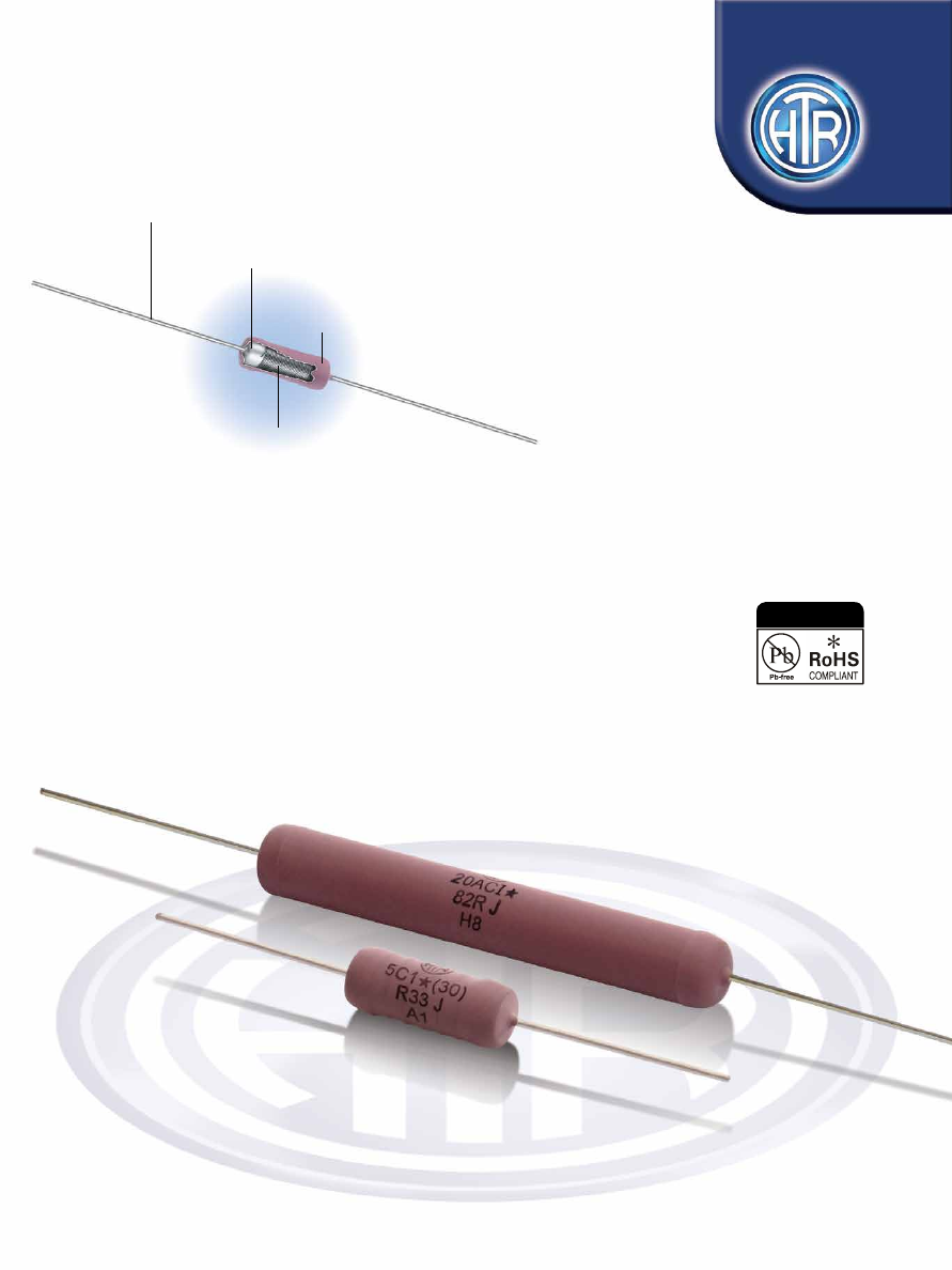
background image

Flame Retardant

Thermocoat

Tin Plated Copper Clad 

Steel-Copper Weld®

Alloy Resistance Wire Wound

To Specific Parameters On

High Thermal Conductivity

Ceramic Core

Fully Welded 

Construction

WIRE WOUND RESISTORS

SILICONE COATED TYPE

VHIA

SERIES

HIGH SURFACE TEMPERATURE

Power Silicone “Thermo Coat” 

Wire Wound Resistors

Industrial / Professional Applications

• Flame retardant coating compatible 


with UL standards

 Small Size : Power Ratio.

• 0.5W to 25 Watts (at 40°C)

• Tolerances as close as 1%.

• R01 to 150K.

• TCR as low as +20ppm/°C available depending

on application and resistance value.

• Pulse applications as per 

IEC 61000-4-5.

e : info@htr-india.com

www.htr-india.com

Rev Date :23/09/2022

AEC-Q200 Qualified

HTR-India-Products-Wire-Wound-Resistors-Silicone-Coated-Resistors-VHIA-English-html.html
background image

PHYSICAL CONFIGURATION

0.5 

MC 

0.5W 7.0  2.7 38  0.5 30  R10  1K6 0.21

MC  1W  10.9 3.2 38  0.5 30  R10  4K0 0.36

AC  1W 11.50 4.5 38  0.8 35  R01  6K2 0.75

2.5 

C 2.5W 13.0 5.5 38  0.8 35  R01  10K 1.2

2.5 

C1 2.5W 13.0 5.5 38  1.0 35  R01  10K 1.8

MC  3W  12.5 5.1 38  0.8 35  R01  7K6 0.8

C  3W  15.2 6.0 38  0.8 40  R01  14K 1.2

C  4W  16.2 6.9 38  1.0 40  R01  15K 2.0

AC  4W  16.5 5.5 38  0.8 40  R01  11K 1.25

MC  4W  13.2 5.5 38  0.8 35  R01  10K 1.0

CL  4W  23.0 7.2 38  0.8 45  R01  33K 2.9

AC  5W  17.5 7.5 38  0.8 40  R01  29K 1.8

C1  5W  23.5 8.7 38  1.0 45  R01  47K 3.6

C  5W  23.5 8.7 38  0.8 45  R01  47K 3.1

AC  7W  25.5 7.5 38  0.8 45  R01  39K 3.6

C1  7W  32.5 9.5 38  1.0 55  R10  68K 5.3

10 

AC 10W 44.0 8.5 38  0.8 65  R10  88K 6.9

10 

C1 10W 44.0 9.8 38  1.0 65  R10 100K 8.3

10 

C  10W 44.0 9.8 38  0.8 65  R10 100K 7.3

13 C1 

13W 

47.0 

10.0 

38 

1.0 

70 

R10 

100K 

7.6

15AC  15W  50.0 10.0 38  0.8  70  R10  100K 8.2
15AC1 15W  50.0  10.0  38  1.0  70  R10  100K  8.6
20AC  20W  67.0  10.0  38  0.8  90  R10  120K 11.5
20AC1 20W  67.0  10.0  38  1.0  90  R10  120K 12.0
25AC1 25W  73.0  10.0  38  1.0  95  1R0  150K 13.5

TYPE

POWER

RATING

at 40°C

(Ambient)

L

(max)

D

(max)

l

±1.5

d

±0.05

LM

±1

DIMENSIONS (mm)

RESISTANCE RANGE 


min             

max

TYPICAL

WT. 

PER PC

(gms)

Note : 

1. The standard terminals in this series is tinned Copper Weld®. 2. For Pulse capability please refer to Electrical data / characteristics section.

NON-INDUCTIVE RESISTORS

Low inductance Aryton - Perry winding type resistors are available in this series. 

For non-inductive types reduce maximum resistance values shown to 50% and the 

continuous working voltage to 70%. 

WIRE WOUND 

RESISTORS

SILICONE 

COATED TYPE

VHIA

PRE-FORMED LEADS


The resistors terminations can be bent and cut as per requirements for quick PCB mounting. 

Please send detailed drawings of the type of preforming required.

Rev Date :23/09/2022

For non-inductive types and for resistance values <1R0, +0.8mm allowed.
Coating overflow on each lead not to exceed half of ‘D’.
For resistance values less than R10 and tolerance less than ±2%, please measure resistance over centered length LM. 
Special Resistance values available on request.

*

TAPING

Taping : Types 0.5MC, 1MC, 1AC, 4C, 3C, 3MC, 4MC, 2.5C1, 2.5C, 5C1, 5AC, 5C, 7AC, 4CL, 7C1, 10AC, 10C, 10C1, 15AC, 15AC1 are available
in taped form. Please refer Tape / Ammo specifications. Tape / Reel on request.

HTR-India-Products-Wire-Wound-Resistors-Silicone-Coated-Resistors-VHIA-English-html.html
background image

0.5 MC 

0.5W 

10 

52 

64 

100 

R10 

1K6 

0.21

1 MC 

1W 

10 

52 

64 

100 

R10 

4K0 

0.36

1 AC 

1W 

10 

52 

64 

100 

R01 

6K2 

0.75

2.5 C 

2.5W 

10 

63 

75 

100 

R01 

10K 

1.2

2.5 C1 

2.5W 

10 

63 

75 

100 

R01 

10K 

1.8

3 MC 

3W 

10 

63 

75 

100 

R01 

7K6 

0.8

3 C 

3W 

10 

63 

75 

100 

R01 

14K 

1.2

4 C 

4W 

10 

63 

75 

100 

R01 

15K 

2.0

4 AC 

4W 

10 

63 

75 

100 

R01 

11K 

1.25

4 MC 

4W 

10 

63 

75 

100 

R01 

10K 

1.0

CL 4W 6 10 74 86 

100 R01 33K 

2.9

5 AC 

5W 

10 

74 

86 

100 

R01 

29K 

1.8

5 C1 

5W 

10 

74 

86 

100 

R01 

47K 

3.6

5 C 

5W 

10 

74 

86 

100 

R01 

47K 

3.1

7 AC 

7W 

10 

74 

86 

100 

R01 

39K 

3.6

7 C1 

7W 

15 

74 

86 

150 

R10 

68K 

5.3

10 AC 

10W 

15 

79 

91 

150 

R10 

88K 

6.9

10 C1 

10W 

15 

79 

91 

150 

R10 

100K 

8.3

10 C 

10W 

15 

79 

91 

150 

R10 

100K 

7.3

13 C1 

13W 

15 

90 

102 

150 

R10 

100K 

7.6

15AC  15W  6  15  90  102 150  R10  100K  8.2
15AC1 15W  6  15  90  102  150  R10  100K  8.6

TYPE

POWER

RATING

at 40°C

(Ambient)

a

±1

s

±0.05

b

±0.05

c

±2

10x

S±2

DIMENSIONS (mm)

RESISTANCE RANGE 


min             

max

TYPICAL

WT. 

PER PC

(gms)

WIRE WOUND 

RESISTORS

SILICONE 

COATED TYPE

VHIA

Rev Date :23/09/2022

Note: Dimension are applied for Tape A & Ammo/Tape a& Real
Table 1.2 :

Where
a’ stands for width of the tape
b’ stands for inner distance between two tapes
e’ stands for the inner distance of the reel
f’ stands for the total width of the reel
S’ stands for the pitch between resistors

Note
The maximum difference between D1 & D2 is 1.40 mm | All dimensions stated below are in mm
Dimensions ‘e’ & ‘f’ are given as approximate guidelines only

30

3.0

f

e

a

b

c

s

D2

D1

330

±5

HTR-India-Products-Wire-Wound-Resistors-Silicone-Coated-Resistors-VHIA-English-html.html
background image

WIRE WOUND 

RESISTORS

SILICONE 

COATED TYPE

VHIA

Rev Date :23/09/2022

HTR

TYPE

BULK PACKING

(For Dimension Refer to Table 1.1)

Number of Pieces

TAPE & AMMO PACKING

(For Dimension Refer to Table 1.2)

Number of Pieces

TAPE & REEL PACKING

(For Dimension Refer to Table 1.2)

Number of Pieces

PACKING CONFIGURATION

0.5 MC 

500 

1000 2500

1 MC 

500 

1000 2500

1  AC  

500 

1000 2500

2.5 C 

500 

750 1500

2.5 C1 

500 

750 1500

3 MC 

500 

750 1500

3 C   

500 

750 1250

4 C   

500 

750 1250

4  AC  

500 

750 1250

4 MC 

500 

750 1500

4 CL  

600 

300 800

5  AC  

500 

300 800

5 C1  

500 

300 800

5 C   

500 

300 800

7  AC  

200 

300 800

7 C1  

125 

175 450

10 AC 

100 

175 450

10  C 1 

100 

175 450

10 C  

100 

175 450

13 C1 

100 

175 450

15 AC 

100 

175 450

15 AC1 

100 

175 450

20 AC 

100 

N.A. N.A.

20 AC1 

100 

N.A. N.A.

25AC1 100 

N.A. 

N.A.

Resistor Temperature rise as a function of applied power
[See graph displayed ]
The graph provided is general in nature and reflects temperature 
rise of a few selected types for the general guidance of the design 
engineer. Exact reading for any particular HTR type and specific 
resistance value can be obtained from factory on request. 

ELECTRICAL DATA / CHARACTERISTICS

Rated Ambient Temperature 

Full Power dissipation at 40°C and linearly derated  


down to zero at 350°C - [Refer Derating curve above].
Voltage Rating / Limiting Voltage / Max Working Voltage 

V =   PxR

Dielectric Withstanding Voltage / Voltage Proof Max. 

R ± (1% + R05). No flashover, mechanical   

[Test method no. 301 of MIL 202F] - Based on limiting 

damage, arcing or insulation breakdown.

voltage x 2 or 500V whichever is applicable.
Insulation Resistance 

> 1000M (dry) > 100M (wet)

[Test method no. 302 of MIL 202F]
Short Time Overload [Test Method - 5 secs at 5 times rated power for Max.

 ∆

R ± (2% + R05)

3 watts and smaller; 5 secs at 10 times rated power for 4 watts and larger]
Resistance Tolerances Available 

±10%[K]; ±5% [J]; ±3%[H]; ±2%[G]; ±1%[F]

PARAMETER/PERFORMANCE TEST & TEST METHOD 

           PERFORMANCE REQUIREMENTS

HTR-India-Products-Wire-Wound-Resistors-Silicone-Coated-Resistors-VHIA-English-html.html
background image

WIRE WOUND 

RESISTORS

SILICONE 

COATED TYPE

VHIA

Pulse Capability :

For the design engineer HTR has selected a few types and provided below, vital data in the form of charts / graphs which illustrate two 

important characteristics of the pulse version of these HTR types.

Pulse On Regular Basis - The maximum allowable peak pulse power (W) as a function of pulse duration (T) in seconds. (Repetetive Pulse) 

- tp repetition time of the pulses / ti - impulse time-duration of pulse.

1 AC

Peak P

ulse P

ow

er (

W

)

Time (Seconds)

1R5

Peak P

ulse P

ow

er (

W

)

3 MC

Time (Seconds)

e : info@htr-india.com

www.htr-india.com

Rev Date :23/09/2022

Peak P

ulse P

ow

er (

W

)

4 AC

Time (Seconds)

HTR-India-Products-Wire-Wound-Resistors-Silicone-Coated-Resistors-VHIA-English-html.html
background image

WIRE WOUND 

RESISTORS

SILICONE 

COATED TYPE

VHIA

Peak P

ulse P

ow

er (

W

)

5 AC

7 AC

Peak P

ulse P

ow

er (

W

)

Time (Seconds)

Time (Seconds)

10 AC

Peak P

ulse P

ow

er (

W

)

Time (Seconds)

e : info@htr-india.com

www.htr-india.com

Rev Date :23/09/2022

HTR-India-Products-Wire-Wound-Resistors-Silicone-Coated-Resistors-VHIA-English-html.html
background image

WIRE WOUND 

RESISTORS

SILICONE 

COATED TYPE

VHIA

1 AC

3 MC

Pulse Capability - Energy (J) as a function of R


(W) 

(Single Pulse)

J

J

4 AC

J

e : info@htr-india.com

www.htr-india.com

Rev Date :23/09/2022

HTR-India-Products-Wire-Wound-Resistors-Silicone-Coated-Resistors-VHIA-English-html.html
background image

5 AC

7AC

10 AC

J

J

J

WIRE WOUND 

RESISTORS

SILICONE 

COATED TYPE

VHIA

e : info@htr-india.com

www.htr-india.com

Rev Date :23/09/2022

HTR-India-Products-Wire-Wound-Resistors-Silicone-Coated-Resistors-VHIA-English-html.html
background image

1. RoHS version - 0.5 MC *
2. Non  inductive winding - N 0.5 MC
3. Impulse type - 0.5 MC I
4. Tape & Ammo pack - 0.5 MC T
5. Tape & Reel pack - 0.5 MC TR

Pull test / Robustness of Terminations  

No mechanical damage

[Force supplied from 2 to 4.5 Kgs depending on size]
Solderability 

Continuous and satisfactory 

[Test method no. 208F of MIL 202F] 

R < ± [1% + R05]

Temperature Co-efficient  

± 120ppm/°C for < R10; ± 80ppm/°C for < 1R0; 

[Test method 304 of MIL 202F] 

± 60ppm/°C for < 100R; ± 90ppm/°C or 

[TCR figures given are based on the usage of normally  

± 30ppm/°C for > 100R, depending on wire selected

effective resistance elements and can be 

significantly lowered on request] 
Damp Heat (Steady State) 

Max. 

R ± [5% + R05]

[Test method no. 103B of MIL 202F and test condition ‘D’] 

No mechanical damage.

Load Life Max. 

R ± [5% + R05]

[Test method no. 108A of MIL 202F] 

No mechanical damage

MECHANICAL SPECIFICATIONS

ENVIRONMENTAL SPECIFICATIONS

The design engineer is cautioned that these graphs are general in nature solely provided for his general guidance for selection of the 
required power rating and resistance of the device to be used for circuit protection.
It is essential that this must be validated in actual trials and HTR will be pleased to provide the necessary samples for validation and 
homologation.

Please suffix the HTR type with the alphabet ‘I’ when a pulse version of the device is required.

 PARAMETER/PERFORMANCE TEST & TEST METHOD 

PERFORMANCE REQUIREMENTS

PARAMETER/PERFORMANCE TEST & TEST METHOD 

PERFORMANCE REQUIREMENTS


Series 

Type 

Packing 

Resistance Value 

Tolerance 


VHIA 

5AC / 5AC* 

Bulk 5AC / 5AC* 

100R 

J


Tape & Ammo 5ACT / 5AC*T 


Tape & Reel 5ACTR / 5AC*TR 

ORDERING INFORMATION

WIRE WOUND 

RESISTORS

SILICONE

COATED TYPE

VHIA

e : info@htr-india.com

www.htr-india.com

Rev Date :23/09/2022

Item code will differ from ordering  information.