WIRE WOUND RESISTORS
SILICONE COATED TYPE
TM
Alloy Resistance Wire, wound
On Fibre Glass Core
Flame Retardant
Silicone Coating
Mechanically Crimped,
Tin Plated,
PCB Type Termination
HFP
S E R I E S
Silicone Coated Wire Wound Resistors
Plug In Style
FIBRE GLASS SUBSTRATE
Choice of terminals which are suitable
for wave soldering.
APPLICABLE
STANDARDS
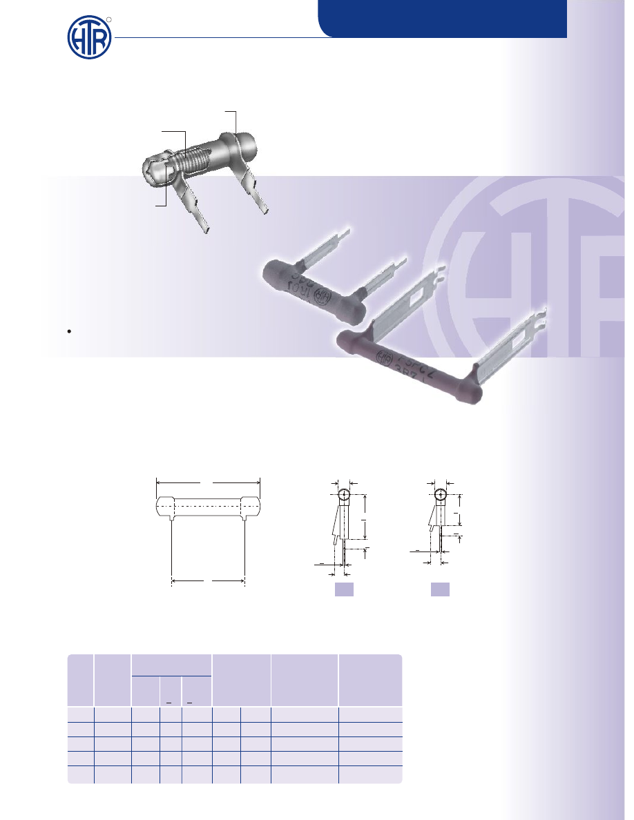
PHYSICAL CONFIGURATION
If the longer stand-off terminal is
required, suffix the type with '0'.
e.g. F-2 P-0 to F-8 P-0.
If the shorter stand-off terminal is
required, suffix the type with '1'
e.g. F-2 P-1 to F-8 P-1.
The resistance range given is
applicable to the standard HFP
series resistors.
Pulse type
resistors available.
Please
consult factory.
IS 8909 and - IEC - Pub 266
L
P
CHOICE OF TERMINALS
+
8 0.5
4+0.2
D
1.6(max.)
1.1+0.1
D
17+0.5
3(max.)
1.1+0.1
0
1
4.3+0.2
F-2P 2.5W
18.2 5.0 10.2
R10
10K
1.38
1.05
F-4P
4W
23.3 5.0 15.2
R10
15K
1.70
1.25
F-5P
5W
33.4 5.0 25.4
R10
27K
2.10
1.90
F-7P 6.5W
43.5 5.0 35.4
R10
39K
2.80
2.50
F-8P
8W
53.7 5.0 45.7
R10
56K
3.10
2.91
HTR
TYPE
POWER
RATING
at 70°C
DIMENSIONS (mm) RESISTANCE
RANGE
min max
L
+2/-1
P
+1.0
TYPICAL
WT. PER PC '0’
TERMINAL
(gms)
TYPICAL
WT. PER PC '1'
TERMINAL
(gms)
D
+1