2008
Surge Protection
Surge Protection
Low Voltage Power Systems
Data / Signal Systems
Telecommunication Systems
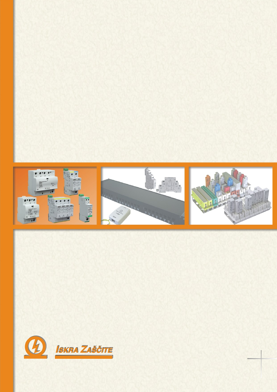
Low Voltage Power Systems
Data / Signal Systems
Telecommunication Systems
2008
Surge Protection
Surge Protection
Low Voltage Power Systems
Data / Signal Systems
Telecommunication Systems
Low Voltage Power Systems
Data / Signal Systems
Telecommunication Systems