
Installation and Programming Instructions
KSC-2
High-Performance Signal Conditioner for Kulite
Sensor Products
October 25, 2015
Rev. A
KULITE SEMICONDUCTOR PRODUCTS, INC.
One Willow Tree Road
Leonia, New Jersey 07605
www.kulite.com
Installation and Programming Instructions
KSC-2
High-Performance Signal Conditioner for Kulite
Sensor Products
October 25, 2015
Rev. A
KULITE SEMICONDUCTOR PRODUCTS, INC.
One Willow Tree Road
Leonia, New Jersey 07605
www.kulite.com

Revision Record
Rev Level
Date
Description of Change
-
7/30/2015
Initial release
A
10/25/2015
Corrected Notes about CAL mode; Corrected recommended COM port
Flow Control setting in Troubleshooting section
Software Copyright Information
Kulite KSC-2 System Control Software Copyright © 2015 Kulite Semiconductor
Products, Inc. All Rights Reserved.
Trademark Information
The following terms and names are trademarks of Kulite Semiconductor Products,
Inc., in the United States and/or other countries.
•
Rezcomp and the Rezcomp logo
The following trademarks from other companies that may be used in this manual are
listed below:
•
Adobe, the Adobe logo, Acrobat and Reader are registered trademarks or trade-
marks of Adobe Systems Incorporated in the United States and/or other countries.
•
Microsoft, Windows, Excel and the Windows logo are trademarks of Microsoft
Corporation in the United States, other countries, or both.

Rev. A
KSC-2 Signal Conditioner Installation and Programming Instructions
KULITE SEMICONDUCTOR PRODUCTS, INC.
KSC-2 Safety Guidelines
Page
i
Safety Guidelines
This document describes how to use the KSC-2 Signal Conditioner and includes
product information, installation and programming instructions, and contact informa-
tion for support and service.
The safety guidelines and product information in this document are specific to the
KSC-2 Signal Conditioner. The other components in your system might not meet the
same safety rating and specifications. Please read and understand the documentation
for each component in your system to determine the safety rating and specifications
of the entire system.
CAUTION
A CAUTION statement describes a hazard. It calls attention to a
procedure, practice, or condition that, if not correctly performed
or adhered to, could result in damage to the product or loss of
data. Do not proceed beyond a CAUTION statement until the
conditions are fully understood and met.
Safety Information
General
Do not use this product in any manner not specified by the manufacturer. The protec
-
tive features of this product may be impaired if it is used in a manner not specified in
this document. Do not install substitute parts or perform any unauthorized modifica
-
tion to the product.
Return the product for service and repair to ensure that safety features are maintained.
See Section 7 of this manual,
Support and Service
, for information on how to contact
Kulite Semiconductor Products, Inc.
KSC-2 Safety Guidelines
Page ii
KSC-2 Signal Conditioner Installation and Programming Instructions
Rev. A
KULITE SEMICONDUCTOR PRODUCTS, INC.
Safety Symbols
Chassis Ground
Signal Ground
Direct Current
Risk of Electric Shock
Refer to Manual for Additional Safety Information
On Supply
Off Supply

Rev. A
KSC-2 Signal Conditioner Installation and Programming Instructions
KULITE SEMICONDUCTOR PRODUCTS, INC.
KSC-2 Table of Contents
Page
iii
Table of Contents
Introduction . . . . . . . . . . . . . . . . . . . . . . . . . . . . . . . . . . . . . . . . . . . . . . . . . . . . . . . . . . . . . . . . . . . . . . . .1
Description . . . . . . . . . . . . . . . . . . . . . . . . . . . . . . . . . . . . . . . . . . . . . . . . . . . . . . . . . . . . . . . . . . . . . . . . .2
Features . . . . . . . . . . . . . . . . . . . . . . . . . . . . . . . . . . . . . . . . . . . . . . . . . . . . . . . . . . . . . . . . . . . . . . . . . . . .3
Excitation Type . . . . . . . . . . . . . . . . . . . . . . . . . . . . . . . . . . . . . . . . . . . . . . . . . . . . . . . . . . . . . . . . .3
Input Stage . . . . . . . . . . . . . . . . . . . . . . . . . . . . . . . . . . . . . . . . . . . . . . . . . . . . . . . . . . . . . . . . . . . . .3
Input Shield . . . . . . . . . . . . . . . . . . . . . . . . . . . . . . . . . . . . . . . . . . . . . . . . . . . . . . . . . . . . . . . . . . . .3
Input Modes . . . . . . . . . . . . . . . . . . . . . . . . . . . . . . . . . . . . . . . . . . . . . . . . . . . . . . . . . . . . . . . . . . . .4
Flat/Pulse Low-Pass Filters. . . . . . . . . . . . . . . . . . . . . . . . . . . . . . . . . . . . . . . . . . . . . . . . . . . . . . .4
Flat Mode Low-Pass Filters . . . . . . . . . . . . . . . . . . . . . . . . . . . . . . . . . . . . . . . . . . . . . . . . . . .5
Pulse Mode Low-Pass Filters. . . . . . . . . . . . . . . . . . . . . . . . . . . . . . . . . . . . . . . . . . . . . . . . . .6
Anti-Aliasing Applications . . . . . . . . . . . . . . . . . . . . . . . . . . . . . . . . . . . . . . . . . . . . . . . . . . . .7
REZCOMP. . . . . . . . . . . . . . . . . . . . . . . . . . . . . . . . . . . . . . . . . . . . . . . . . . . . . . . . . . . . . . . . . . . . . . .8
Distributed Gain . . . . . . . . . . . . . . . . . . . . . . . . . . . . . . . . . . . . . . . . . . . . . . . . . . . . . . . . . . . . . . . .8
Overload Detectors . . . . . . . . . . . . . . . . . . . . . . . . . . . . . . . . . . . . . . . . . . . . . . . . . . . . . . . . . . . . .9
KSC-2 Control . . . . . . . . . . . . . . . . . . . . . . . . . . . . . . . . . . . . . . . . . . . . . . . . . . . . . . . . . . . . . . . . . . .9
Input Wiring . . . . . . . . . . . . . . . . . . . . . . . . . . . . . . . . . . . . . . . . . . . . . . . . . . . . . . . . . . . . . . . . . . .10
Constant Voltage Excitation Supply. . . . . . . . . . . . . . . . . . . . . . . . . . . . . . . . . . . . . . . . . . . . .10
Input Characteristics . . . . . . . . . . . . . . . . . . . . . . . . . . . . . . . . . . . . . . . . . . . . . . . . . . . . . . . . . . .11
Optional KSC-2 Transducer Compensator (C3) Characteristics . . . . . . . . . . . . . . . . . . . .12
Filter Characteristics. . . . . . . . . . . . . . . . . . . . . . . . . . . . . . . . . . . . . . . . . . . . . . . . . . . . . . . . . . . .13
Output Characteristics . . . . . . . . . . . . . . . . . . . . . . . . . . . . . . . . . . . . . . . . . . . . . . . . . . . . . . . . .14
General Characteristics. . . . . . . . . . . . . . . . . . . . . . . . . . . . . . . . . . . . . . . . . . . . . . . . . . . . . . . . .14
ISO/IEC Conformity. . . . . . . . . . . . . . . . . . . . . . . . . . . . . . . . . . . . . . . . . . . . . . . . . . . . . . . . . . . . . . . . .15
Accessories . . . . . . . . . . . . . . . . . . . . . . . . . . . . . . . . . . . . . . . . . . . . . . . . . . . . . . . . . . . . . . . . . . . . . . . .16

KSC-2 Table of Contents
Page iv
KSC-2 Signal Conditioner Installation and Programming Instructions
Rev. A
KULITE SEMICONDUCTOR PRODUCTS, INC.
Storage Requirements . . . . . . . . . . . . . . . . . . . . . . . . . . . . . . . . . . . . . . . . . . . . . . . . . . . . . . . . .18
Transport Requirements. . . . . . . . . . . . . . . . . . . . . . . . . . . . . . . . . . . . . . . . . . . . . . . . . . . . . . . .19
Shipment Requirements . . . . . . . . . . . . . . . . . . . . . . . . . . . . . . . . . . . . . . . . . . . . . . . . . . . . . . .19
Vertically Mounting Two or More Units. . . . . . . . . . . . . . . . . . . . . . . . . . . . . . . . . . . . . . . . . 20
Horizontally Mounting Two or More Units. . . . . . . . . . . . . . . . . . . . . . . . . . . . . . . . . . . . . . .21
Horizontal Rack Mounting. . . . . . . . . . . . . . . . . . . . . . . . . . . . . . . . . . . . . . . . . . . . . . . . . . . . . .21
KSC-2 Input Connectors . . . . . . . . . . . . . . . . . . . . . . . . . . . . . . . . . . . . . . . . . . . . . . . . . . . . 23
Input Cabling and Input Shielding . . . . . . . . . . . . . . . . . . . . . . . . . . . . . . . . . . . . . . . . . . .24
KSC-2 Full-Bridge 4-Wire Connections . . . . . . . . . . . . . . . . . . . . . . . . . . . . . . . . . . . . . . .24
KSC-2 Full-Bridge 6-Wire Connections . . . . . . . . . . . . . . . . . . . . . . . . . . . . . . . . . . . . . . 25
Other Bridge Input Configurations Using External Completion Resistors . . . . . .26
Voltage Input Configuration. . . . . . . . . . . . . . . . . . . . . . . . . . . . . . . . . . . . . . . . . . . . . . . . .26
CAL Input Connector. . . . . . . . . . . . . . . . . . . . . . . . . . . . . . . . . . . . . . . . . . . . . . . . . . . . . . . .26
5th Wire . . . . . . . . . . . . . . . . . . . . . . . . . . . . . . . . . . . . . . . . . . . . . . . . . . . . . . . . . . . . . . . . . . . .27
Communication USB 2.0 Connector. . . . . . . . . . . . . . . . . . . . . . . . . . . . . . . . . . . . . . . . . 28
Output Connectors . . . . . . . . . . . . . . . . . . . . . . . . . . . . . . . . . . . . . . . . . . . . . . . . . . . . . . . . 28
Signal Ground Selection. . . . . . . . . . . . . . . . . . . . . . . . . . . . . . . . . . . . . . . . . . . . . . . . . . . . 28
Bank Isolation . . . . . . . . . . . . . . . . . . . . . . . . . . . . . . . . . . . . . . . . . . . . . . . . . . . . . . . . . . . . . 28
Power Connector . . . . . . . . . . . . . . . . . . . . . . . . . . . . . . . . . . . . . . . . . . . . . . . . . . . . . . . . . . 29
Applying Power. . . . . . . . . . . . . . . . . . . . . . . . . . . . . . . . . . . . . . . . . . . . . . . . . . . . . . . . . . . . . . . 30
Autobalance Indicators and Reset Button . . . . . . . . . . . . . . . . . . . . . . . . . . . . . . . . . . . . . . .31
Overload Indicators and Reset Button . . . . . . . . . . . . . . . . . . . . . . . . . . . . . . . . . . . . . . . . . .31

Rev. A
KSC-2 Signal Conditioner Installation and Programming Instructions
KULITE SEMICONDUCTOR PRODUCTS, INC.
KSC-2 Table of Contents
Page
v
Antivirus Software . . . . . . . . . . . . . . . . . . . . . . . . . . . . . . . . . . . . . . . . . . . . . . . . . . . . . . . . . . . . .33
Installing the KSC-2 Control GUI Software . . . . . . . . . . . . . . . . . . . . . . . . . . . . . . . . . . . . . . .33
Uninstalling the KSC-2 Control GUI Software . . . . . . . . . . . . . . . . . . . . . . . . . . . . . . . . . . . .35
Starting the KSC-2 Control GUI Software . . . . . . . . . . . . . . . . . . . . . . . . . . . . . . . . . . . . . . . .35
Connecting Multiple KSC-2 Units to the Control GUI . . . . . . . . . . . . . . . . . . . . . . . . . . . .35
Open . . . . . . . . . . . . . . . . . . . . . . . . . . . . . . . . . . . . . . . . . . . . . . . . . . . . . . . . . . . . . . . . . . . . . . .37
Save. . . . . . . . . . . . . . . . . . . . . . . . . . . . . . . . . . . . . . . . . . . . . . . . . . . . . . . . . . . . . . . . . . . . . . . .37
Save As . . . . . . . . . . . . . . . . . . . . . . . . . . . . . . . . . . . . . . . . . . . . . . . . . . . . . . . . . . . . . . . . . . . . .37
Exit. . . . . . . . . . . . . . . . . . . . . . . . . . . . . . . . . . . . . . . . . . . . . . . . . . . . . . . . . . . . . . . . . . . . . . . . 38
System Configuration . . . . . . . . . . . . . . . . . . . . . . . . . . . . . . . . . . . . . . . . . . . . . . . . . . . . . . 38
Compensation Filters . . . . . . . . . . . . . . . . . . . . . . . . . . . . . . . . . . . . . . . . . . . . . . . . . . . . . . .39
Device. . . . . . . . . . . . . . . . . . . . . . . . . . . . . . . . . . . . . . . . . . . . . . . . . . . . . . . . . . . . . . . . . . . . . .41
5th-Wire Readings . . . . . . . . . . . . . . . . . . . . . . . . . . . . . . . . . . . . . . . . . . . . . . . . . . . . . . . . . .42
Commands . . . . . . . . . . . . . . . . . . . . . . . . . . . . . . . . . . . . . . . . . . . . . . . . . . . . . . . . . . . . . . . . .42
Options. . . . . . . . . . . . . . . . . . . . . . . . . . . . . . . . . . . . . . . . . . . . . . . . . . . . . . . . . . . . . . . . . . . . 44
Re-sync Device Communications . . . . . . . . . . . . . . . . . . . . . . . . . . . . . . . . . . . . . . . . . . . .45
Device:Channel . . . . . . . . . . . . . . . . . . . . . . . . . . . . . . . . . . . . . . . . . . . . . . . . . . . . . . . . . . . . . . . 46
Serial Number . . . . . . . . . . . . . . . . . . . . . . . . . . . . . . . . . . . . . . . . . . . . . . . . . . . . . . . . . . . . . . . . 46
Channel Name . . . . . . . . . . . . . . . . . . . . . . . . . . . . . . . . . . . . . . . . . . . . . . . . . . . . . . . . . . . . . . . . 46
Excitation Fault . . . . . . . . . . . . . . . . . . . . . . . . . . . . . . . . . . . . . . . . . . . . . . . . . . . . . . . . . . . . . . . 46
Excitation Value (V) . . . . . . . . . . . . . . . . . . . . . . . . . . . . . . . . . . . . . . . . . . . . . . . . . . . . . . . . . . . 46
Excitation Type . . . . . . . . . . . . . . . . . . . . . . . . . . . . . . . . . . . . . . . . . . . . . . . . . . . . . . . . . . . . . . . 46
Sense. . . . . . . . . . . . . . . . . . . . . . . . . . . . . . . . . . . . . . . . . . . . . . . . . . . . . . . . . . . . . . . . . . . . . . . . . 46
Balance Voltage (mV). . . . . . . . . . . . . . . . . . . . . . . . . . . . . . . . . . . . . . . . . . . . . . . . . . . . . . . . . . .47
Autobalance . . . . . . . . . . . . . . . . . . . . . . . . . . . . . . . . . . . . . . . . . . . . . . . . . . . . . . . . . . . . . . . . . . .47
Coupling . . . . . . . . . . . . . . . . . . . . . . . . . . . . . . . . . . . . . . . . . . . . . . . . . . . . . . . . . . . . . . . . . . . . . .47
Shield . . . . . . . . . . . . . . . . . . . . . . . . . . . . . . . . . . . . . . . . . . . . . . . . . . . . . . . . . . . . . . . . . . . . . . . . .47
Input Mode . . . . . . . . . . . . . . . . . . . . . . . . . . . . . . . . . . . . . . . . . . . . . . . . . . . . . . . . . . . . . . . . . . . 48

KSC-2 Table of Contents
Page vi
KSC-2 Signal Conditioner Installation and Programming Instructions
Rev. A
KULITE SEMICONDUCTOR PRODUCTS, INC.
Overload Mode . . . . . . . . . . . . . . . . . . . . . . . . . . . . . . . . . . . . . . . . . . . . . . . . . . . . . . . . . . . . . . . 48
Pregain . . . . . . . . . . . . . . . . . . . . . . . . . . . . . . . . . . . . . . . . . . . . . . . . . . . . . . . . . . . . . . . . . . . . . . . 48
Filter Type . . . . . . . . . . . . . . . . . . . . . . . . . . . . . . . . . . . . . . . . . . . . . . . . . . . . . . . . . . . . . . . . . . . . .49
Filter Cutoff (Hz). . . . . . . . . . . . . . . . . . . . . . . . . . . . . . . . . . . . . . . . . . . . . . . . . . . . . . . . . . . . . . . .49
Resonance Compensation. . . . . . . . . . . . . . . . . . . . . . . . . . . . . . . . . . . . . . . . . . . . . . . . . . . . . .49
Postgain . . . . . . . . . . . . . . . . . . . . . . . . . . . . . . . . . . . . . . . . . . . . . . . . . . . . . . . . . . . . . . . . . . . . . . .49
Output Overload (V) . . . . . . . . . . . . . . . . . . . . . . . . . . . . . . . . . . . . . . . . . . . . . . . . . . . . . . . . . . .49
Overloads . . . . . . . . . . . . . . . . . . . . . . . . . . . . . . . . . . . . . . . . . . . . . . . . . . . . . . . . . . . . . . . . . . . . .49
Settings . . . . . . . . . . . . . . . . . . . . . . . . . . . . . . . . . . . . . . . . . . . . . . . . . . . . . . . . . . . . . . . . . . . . . . 50
KSC-2 High-Level Command Set 51
Introduction . . . . . . . . . . . . . . . . . . . . . . . . . . . . . . . . . . . . . . . . . . . . . . . . . . . . . . . . . . . . . . . . . . . . . . .51
Communication Configuration . . . . . . . . . . . . . . . . . . . . . . . . . . . . . . . . . . . . . . . . . . . . . . . . . . . . .51
Command Format . . . . . . . . . . . . . . . . . . . . . . . . . . . . . . . . . . . . . . . . . . . . . . . . . . . . . . . . . . . . . . . . .52
Excitation Commands . . . . . . . . . . . . . . . . . . . . . . . . . . . . . . . . . . . . . . . . . . . . . . . . . . . . . . . . . .53
Input Commands . . . . . . . . . . . . . . . . . . . . . . . . . . . . . . . . . . . . . . . . . . . . . . . . . . . . . . . . . . . . . 54
Filter Commands. . . . . . . . . . . . . . . . . . . . . . . . . . . . . . . . . . . . . . . . . . . . . . . . . . . . . . . . . . . . . . .55
Output Commands . . . . . . . . . . . . . . . . . . . . . . . . . . . . . . . . . . . . . . . . . . . . . . . . . . . . . . . . . . . 56
Offset Commands. . . . . . . . . . . . . . . . . . . . . . . . . . . . . . . . . . . . . . . . . . . . . . . . . . . . . . . . . . . . . 56
Overload Detector Commands . . . . . . . . . . . . . . . . . . . . . . . . . . . . . . . . . . . . . . . . . . . . . . . . .57
Bridge Commands . . . . . . . . . . . . . . . . . . . . . . . . . . . . . . . . . . . . . . . . . . . . . . . . . . . . . . . . . . . . 58
Introduction . . . . . . . . . . . . . . . . . . . . . . . . . . . . . . . . . . . . . . . . . . . . . . . . . . . . . . . . . . . . . . . . . . . . . . 63
KSC-2 Does Not Turn On. . . . . . . . . . . . . . . . . . . . . . . . . . . . . . . . . . . . . . . . . . . . . . . . . . . . . . . . . . . 63
KSC-2 GUI Does Not Recognize the System . . . . . . . . . . . . . . . . . . . . . . . . . . . . . . . . . . . . . . . . . 63
Overload Indicators Are Red . . . . . . . . . . . . . . . . . . . . . . . . . . . . . . . . . . . . . . . . . . . . . . . . . . . . . . . 64
KSC-2 Unit LEDs Are Out of Sync with the GUI . . . . . . . . . . . . . . . . . . . . . . . . . . . . . . . . . . . . . . 64

Rev. A
KSC-2 Signal Conditioner Installation and Programming Instructions
KULITE SEMICONDUCTOR PRODUCTS, INC.
KSC-2 General Information
Page
1
1
KSC-2 General Information
1.1 Introduction
This manual,
KSC-2 Installation and Programming Instructions
, contains informa-
tion specific to the configuration, installation, and programming of the KSC-2 signal
conditioner. Refer to this document and to the documentation supplied with each
component in your system to understand how to operate your entire system safely and
correctly.
The
KSC-2 Installation and Programming Instructions
manual comprises the
following chapters and supplement:
KSC-2 General Information
(this chapter) provides an overview and specifications of
the KSC-2 system, along with environmental requirements, ISO/IEC conformity, and
available accessories
.
KSC-2 Installation and Operation
contains location and power requirements,
installation instructions, cable connections, and operating instructions.
KSC-2 Control Software Programming Instructions
describes how to install and
operate the stand-alone KSC-2 Control Graphical User Interface (GUI) software.
KSC-2 High-Level Command Set
describes the high-level commands that can control
the KSC-2 unit using the command interface via USB 2.0.
KCS-2 Troubleshooting
offers steps to deal with common problems, such as when the
unit does not turn on or when the GUI fails to recognize the system.
Support and Service
tells you where to get technical support and how to obtain
service or repair.

KSC-2 General Information
Page 2
KSC-2 Signal Conditioner Installation and Programming Instructions
Rev. A
KULITE SEMICONDUCTOR PRODUCTS, INC.
1.2 Description
The KSC-2 is a compact, rugged dual-channel high precision filter/amplifier with
programmable constant voltage excitation optimized for conditioning Kulite pres
-
sure sensors and microphone products. Fully programmable bipolar excitation with
remote sense provides voltage for bridge-type sensors, and a unipolar excitation
mode is supplied to condition sensors that have internal regulation. The unit supports
automatic and manual balance modes.
A low-noise, high common mode rejection balanced differential input is supplied with
programmable AC/DC input coupling. Sharp, programmable precision low-pass filters
support two response characteristics, which are optimized for making time- domain
or frequency-domain measurements. Amplification is distributed as pre- and post-
filter gain, allowing for elimination of out-of-band energy such as transducer resonant
peaking, which can cause nonlinearities due to clipping of the amplifier. Overload
detectors alert the user to output overloads as well as prefilter overloads that may be
masked by the low-pass filter.
The KSC-2 features optional, patent-pending REZCOMP
TM
transducer resonant
compensation technology, which extends the usable frequency response of sensors
with recess mounting, device packaging, or seismic resonances. Based on a charac
-
terization of the sensor Q and resonant frequency, the REZCOMP technique extends
the usable sensor bandwidth to as much as 80% of the sensor resonant frequency or, in
some cases, even beyond the sensor resonant frequency.
A high-level command interface can control the KSC-2 via USB 2.0. In addition, a
spreadsheet-style graphical user interface is supplied to control up to eight KSC-2
units as a single system. Configurations may be saved and recalled from the host
computer. Settings may be saved to nonvolatile memory for field deployment without
a host computer. Front-panel LED indicators alert the user to overloads, excitation
faults, and auto balance status. In addition, autobalance can be initiated via a momen
-
tary switch on the front panel. The KSC-2 is supplied with an external AC-to-DC
universal supply or may be powered using an external 10 to 30 VDC input.

Rev. A
KSC-2 Signal Conditioner Installation and Programming Instructions
KULITE SEMICONDUCTOR PRODUCTS, INC.
KSC-2 General Information
Page
3
1.3 Features
1.3.1 Excitation Type
The KSC-2 may be configured for bipolar or unipolar excitation operation. Bridge-
type pressure transducers without internal amplification will generally be interfaced
to the KSC-2 in bipolar mode. The bipolar excitation voltage is fully programmable
from 0 to 12.5 Vdc in 1.25 mV steps. The excitation supply is connected across to the
sensor +/− excitation leads, and the KSC-2 differential amplifier signal leads measure
the sensor output. A four-wire connection to the bridge may be used when precise reg
-
ulation of the excitation voltage at the transducer is not critical. The excitation sense
leads can be run to the bridge (6-wire connection) for precise regulation of the excita
-
tion supply at the transducer load; these should be connected as close to the sensor as
is practical.
Unipolar excitation mode is intended for use with internally amplified sensors. The
unipolar excitation supply is 14 Vdc.
1.3.2 Input Stage
The KSC-2 features an ultra low-noise, low-drift, high common mode rejection
differential input stage for making low-level AC and DC measurements. In bipolar
excitation mode, a fully automatic bridge balance circuit is used to zero the sensor DC
output for zero measurand.
For unipolar excitation mode, the zero suppress mode may be used to zero the initial
sensor DC output. When only the dynamic portion of the signal is to be measured,
the programmable AC input coupling feature of the KSC-2 is useful to block any DC
voltages on the input in order to emphasize the low-level AC portion of the signal by
applying programmable gain.
1.3.3 Input Shield
The KSC-2 has a programmable input shield termination for each channel. The shield
may be terminated in ground, float (AC terminated in 0.1 uF), or driven. In general, it
is recommended that the cable shield be terminated at only one end of the cable to pre
-
vent ground loop pickup. A driven shield may be employed to guard the differential
amplifier input leads (± SIG) to enhance common mode rejection at low frequencies.
KSC-2 General Information
Page 4
KSC-2 Signal Conditioner Installation and Programming Instructions
Rev. A
KULITE SEMICONDUCTOR PRODUCTS, INC.
1.3.4 Input Modes
The KSC-2 amplifier stage input is software configurable to facilitate
in situ
calibration or diagnostics. Three input modes are available:
•
OPERATE is the normal operating mode. It connects the sensor signal input pins
to the amplifier input.
•
SHORT mode disconnects the sensor and internally shorts the amplifier inputs to
signal ground. This is a useful diagnostic test mode to measure and document the
DC offset and noise contribution of the KSC-2 internal circuitry.
Note:
Any DC voltage injected to execute an automatic or manual bridge balance
is temporarily removed while in SHORT mode.
•
CAL mode disconnects the sensor input and internally connects the KSC-2 ampli
-
fier to the CAL INPUT on the KSC-2 front panel. CAL mode is a useful feature to
accurately measure the AC or DC gain of the KSC-2 amplifier.
Note:
The signal on the KSC-2 CAL input can be distorted if the prefilter gain
stage is driven into heavy saturation by the test signal. This could corrupt a
calibration reading on a second channel connected to the same CAL signal. To
prevent false calibrations, the KSC-2 GUI allows multiple channels to be in CAL
mode only if all channels have the same prefilter gain setting. To further safe
-
guard against false calibrations, the KSC-2 GUI does not allow changes to pre-
filter gain while in CAL input mode.
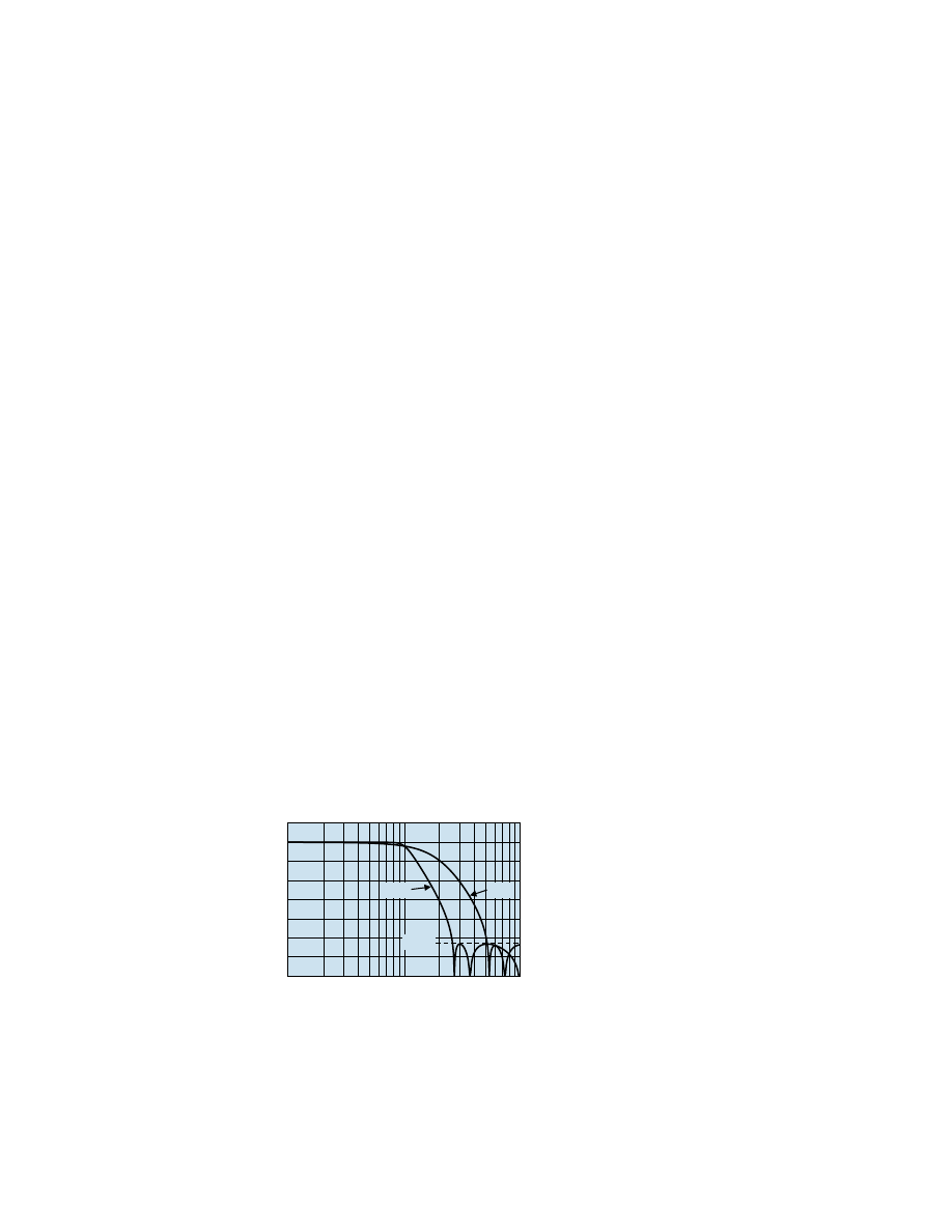
1.3.5 Flat/Pulse Low-Pass Filters
The KSC-2 has a flexible, high-performance 6-pole low-pass filter characteristic that
can be optimized for time- or frequency-domain measurements. Simply program the
filter characteristic to match your measurement requirements.
Gain (dB)
Normalized Frequency (f/Fc)
LP6F and LP6P Amplitude Response
0
–15
–30
–45
–60
–75
–90
–105
0.1
0.2
0.7
0.4
10
1
2
4
7
LP6F
–80dB
LP6P
Figure 1
LP6F and LP6P Amplitude Response
Rev. A
KSC-2 Signal Conditioner Installation and Programming Instructions
KULITE SEMICONDUCTOR PRODUCTS, INC.
KSC-2 General Information
Page
5
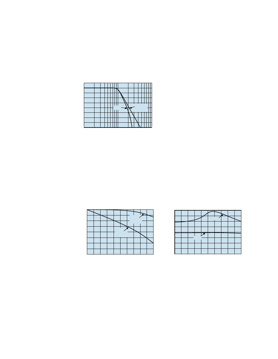
Flat Mode Low-Pass Filters
The LP6F FLAT mode characteristic has a pass-band amplitude response nearly iden
-
tical to the 6-pole Butterworth filter, yet with much sharper roll-off characteristics,
as shown in Figure 2. This makes the LP6F a good choice for spectral analysis or for
anti-aliasing applications.
Gain (dB)
Normalized Frequency (f/Fc)
LP6F vs. 6-Pole Butterworth Amplitude Response
0
–10
–20
–30
–40
–50
–70
–60
–80
0.1
0.2
0.7
0.4
10
1
2
4
7
LP6F
6-Pole
Butterworth
Figure 2
LP6F vs. 6-Pole Butterworth Amplitude
Response
Like the Butterworth low-pass filter, the LP6F has a nonlinear phase response with 60
degrees of phase distortion at the cutoff frequency. See Figure 3.
The nonlinear phase characteristics of the LP6F result in an input-to-output time
delay that is not constant versus frequency. Filters with linear phase, such as the LP6P,
have constant delay for all frequencies in the pass-band, as shown in Figure 4.
Phase
Distortion
Phase
Response
LP6F Phase Response and Phase Distortion
Phase Distor
tion (Deg
rees)
–45
0
–90
Phase (Deg
rees)
–45
–90
–135
–180
–225
–270
–315
–360
Normalized Frequency (f/Fc)
0
0.1
0.3
0.2
0.8 0.9 1.0
0.4 0.5 0.6 0.7
0
Figure 3
LP6F Phase Response and Phase
Distortion
LP6F & LP6P Phase Delay
Phase Dela
y x F
c (Sec x Hz)
0.7
0.8
0.6
0.5
0.4
0.3
0.2
0.1
0
Normalized Frequency (f/Fc)
0
0.4 0.6
0.2
1.6 1.8 2.0
0.8 1.0 1.2 1.4
LP6P
LP6F
Figure 4
LP6F and LP6P Phase Delay
KSC-2 General Information
Page 6
KSC-2 Signal Conditioner Installation and Programming Instructions
Rev. A
KULITE SEMICONDUCTOR PRODUCTS, INC.
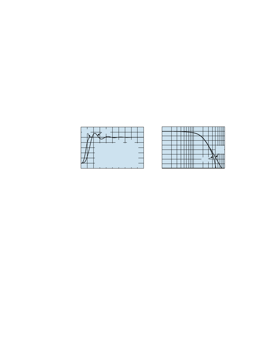
Pulse Mode Low-Pass Filters
For the time domain, the LP6P PULSE mode low-pass filter has excellent transient
response and phase linearity required for time-domain applications such as transient
(shock) measurements and time-domain waveform analysis.
A quantitative measure of a filter's transient behavior to evaluate the response to a unit
step function input in the time domain. As Figure 5 shows, the LP4F step response
exhibits under damped characteristics with 16% overshoot and notable ring-down as
the output decays to its final value. In contrast, the LP4P is nearly critically damped
and thus exhibits little overshoot and fast settling time in response to a step input.
When compared to a 6-pole Bessel filter, the LP6P has similar pass-band characteris
-
tics, yet with a much sharper transition slope from pass-band to stop-band (Figure 6).
LP6F & LP6P Step Response
Response/Final V
alue
1.2
1.0
0.8
0.6
0.4
0.2
0
Settling Time x Fc (Sec-Hz)
0.0 0.5
1.5
1.0
5.0
2.0 2.5 3.0 3.5
4.5
4.0
LP6F
LP6P
10-90% Rise (Sec)
50% Delay (Sec)
% Overshoot
10% Error (Sec)
5% Error (Sec)
1% Error (Sec)
0.5% Error (Sec)
LP6F
0.501/Fc
0.639/Fc
15.8%
1.26/Fc
1.52/Fc
2.80/Fc
3.31/Fc
LP6P
0.350/Fc
0.385/Fc
1.1%
0.57/Fc
0.61/Fc
0.84/Fc
0.93/Fc
Figure 5
LP6F and LP6P Step Response
Gain (dB)
Normalized Frequency (f/Fc)
LP6P vs. 6-Pole Bessel Amplitude Response
0
–10
–20
–30
–40
–50
–70
–60
–80
0.1
0.2
0.7
0.4
10
1
2
4
7
LP6P
6-Pole
Bessel
Figure 6
LP6P vs. 6-Pole Bessel Amplitude
Response
Rev. A
KSC-2 Signal Conditioner Installation and Programming Instructions
KULITE SEMICONDUCTOR PRODUCTS, INC.
KSC-2 General Information
Page
7
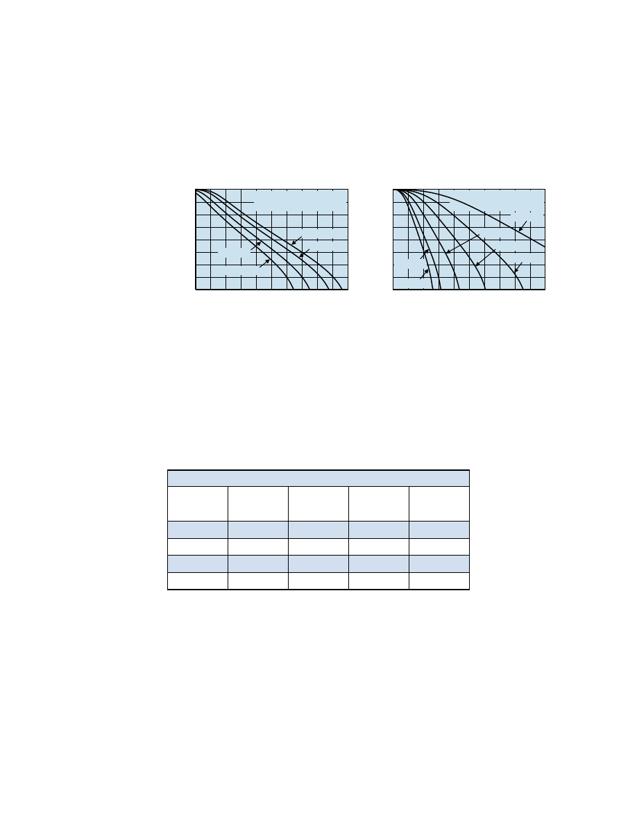
Anti-Aliasing Applications
When used for anti-aliasing applications, the LP6F provides more usable bandwidth
for a given sampling frequency. In exchange for linear phase and excellent transient
response, the LP6P is less selective and thus requires a higher sampling frequency
than the LP6F.
LP6F Attenuation of Aliases vs Sampling Frequency
Minim
um Atten
uation of Aliases (dB)
–10
0
–20
–30
–40
–50
–60
–70
–80
Sampling Frequency/Fh
2.00
2.50 2.75
2.25
4.00 4.25 4.50
3.00 3.25 3.50 3.75
α
= 3.01 dB
α
= 1.0 dB
α
= 0.1 dB
α
= 0.25 dB
Fh = Highest Frequency of Interest
α
= Attenuation at Fh
Figure 7
LP6F Attenuation of Aliases vs.
Sampling Frequency
LP6P Attenuation of Aliases vs Sampling Frequency
Minim
um Atten
uation of Aliases (dB)
–10
0
–20
–30
–40
–50
–60
–70
–80
Sampling Frequency/Fh
1
5
7
3
17
19
21
9
11
13
15
α
= 3.01 dB
α
= 2.0 dB
α
= 0.1 dB
α
= 0.25 dB
α
= 0.5 dB
α
= 1.0 dB
Fh = Highest Frequency of Interest
α
= Attenuation at Fh
Figure 8
LP6P Attenuation of Aliases vs.
Sampling Frequency
Table 1 compares attenuation of aliases versus sampling frequency for the LP6P,
6-pole Bessel (BE6), LP6F, and the 6-pole Butterworth (BU6). The table shows that
much lower sampling frequencies are required for the KSC-2 LP6P and LP6F than for
traditional filter characteristics.
Table 1 Sampling Frequency for −3.01 dB Attenuation at Fh
Alias Attn.
BE6
LP6P
BU6
LP6F
20
3.4Fc
3.4Fc
2.5Fc
2.4Fc
40
4.6Fc
4.5Fc
3.2Fc
2.9Fc
60
6.4Fc
5.5Fc
4.2Fc
3.3Fc
80
9.0Fc
6.2Fc
5.6Fc
3.6Fc

KSC-2 General Information
Page 8
KSC-2 Signal Conditioner Installation and Programming Instructions
Rev. A
KULITE SEMICONDUCTOR PRODUCTS, INC.
1.3.6 REZCOMP
The frequency response of a pressure transducer is influenced by numerous factors:
•
Natural resonance of the sensor structure
•
Spatial resolution of the sensor due to its diaphragm size
•
Sensor packaging
•
Signal conditioning
•
Mounting at the measurement location
In particular, the resonance of the sensor and aerodynamically driven resonances
related to sensor packaging and/or mounting can distort dynamic pressure measure
-
ments within the range of greatest interest (10 Hz–20 kHz). This typically results in
erroneous amplification. Unknown resonant frequencies and damping factors (quality
factors) make such errors hard to quantify, so correcting for these errors within the
frequency response of a pressure transducer or measurement system can be a chal
-
lenge. However, with the ability to fully characterize resonant frequencies that lie
within 10 Hz–50 kHz using Kulite’s proprietary dynamic pressure characterization
methodology or other methods, it is possible to apply electrical filtering to substan
-
tially extend the flat (0 ± 2 dB) frequency response of a transducer before any digital
signal conversion.
REZCOMP, optional with the KSC-2, is a real-time frequency response compensation
scheme that uses electrical filtering to correct for aerodynamically driven packaging-
or mounting-related resonances while preventing signal distortion caused by sensor
resonances. The compensation extends the usable, flat amplitude bandwidth of the
transducer while correcting the phase response to maintain constant time delay over
the extended bandwidth.
1.3.7 Distributed Gain
Amplifier gain of the KSC-2 is distributed as pre- and postfilter gain. Gain may be
apportioned around the compensator and filter to provide headroom for out-band
signals that would otherwise clip against the internal ±10 V supply rails of the KSC-2.
After removal of the out-band energy by the KSC-2 filters, the postfilter gain is used
to achieve the desired full-scale output.

Rev. A
KSC-2 Signal Conditioner Installation and Programming Instructions
KULITE SEMICONDUCTOR PRODUCTS, INC.
KSC-2 General Information
Page
9
1.3.8 Overload Detectors
Input overload detectors alert the user to an out-band overvoltage condition that would
clip against the internal ±10 V supply rails of the KSC-2 and could be masked by the
filter.
An output overload detector is provided with a programmable threshold. This is useful
for providing visibility to output signals approaching the full-scale capability of the
attached recording device.
1.3.9 KSC-2 Control
Remote Interface
The KSC-2 unit has a USB 2.0 type B interface that uses a high-level command set
protocol. Section 5 of this manual,
KSC-2 High-Level Command Set
, discusses these
commands and how to use them.
Nonvolatile Memory
The KSC-2 module’s programmed state can be saved to nonvolatile memory to retain
settings through the power cycle or to deploy in the field without a control computer
attached.
To save settings to nonvolatile memory, use the Tool menu’s Save All command (see
Section 4.4.4,
Tools
).
KSC-2 Control Software
The KSC-2 comes with spreadsheet-style software for use with Windows OS. Using
the GUI, you can control up to eight KSC-2 units as a system. Configurations can be
saved to and retrieved from the control computer. Section 4 of this manual,
KSC-2
Control Software Programming Instructions,
explains how to use the GUI Control
software.
Front Panel Controls and Indicators
Each channel has LEDs to monitor the following conditions:
•
Input or output overload
•
Excitation fault (short or overvoltage)
•
Balance mode status
Momentary switches let you clear overload detectors in latching mode and initiate
a balance/suppress operation. A successful balance or suppress operation turns the
front-panel AUTO BALANCE light green. Remote commands or the GUI control
panel allows you to lock the front-panel switches.
KSC-2 General Information
Page 10
KSC-2 Signal Conditioner Installation and Programming Instructions
Rev. A
KULITE SEMICONDUCTOR PRODUCTS, INC.
1.4 Specifications
1.4.1 Input Wiring
Input Connector:
9-pin female D-sub at front panel (2 each)
Channel Input Wires:
±SIG (2); ±EXC (2); ±SEN (2); SHLD (1); GND; 5
th
wire sensor temperature output (1)
1.4.2 Constant Voltage Excitation Supply
Type:
Programmable constant voltage excitation
Mode:
Programmable bipolar or unipolar
Bipolar Mode:
Level:
0 to 12.5 V in 1.25 mV steps
Accuracy:
±0.1% of setting ±5 mV
Current:
30 mA, short circuit protected
Noise:
100 μVrms, 3 Hz to 100 kHz
Drift:
±0.0025%/ºC of setting or ±50 μV/ºC
Stability:
±0.005% or ±250 μV for 8 hours
Load Regulation:
±0.03% or ±200 μV, whichever is greater, no load to full load
Sense:
Programmable local or remote. Sense boost limited to 3 V above programmed
setting.
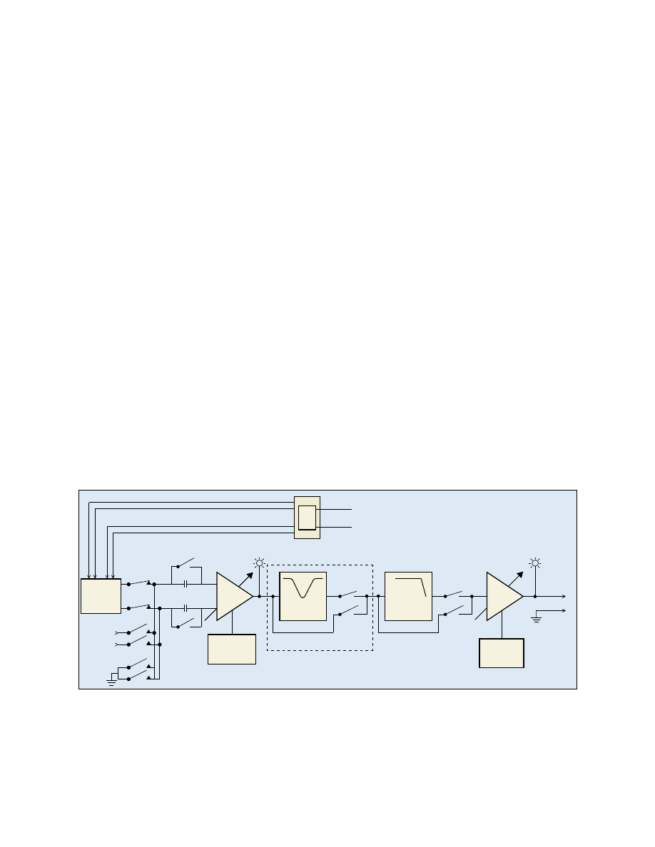
Option C3
Compensator
In
Compensator
Out
Post-Filter Gain
AC/DC Coupling
Resonance
Compensator
Prog.
Buffered
Amp
Cal
Input
Pre-Filter
Gain
Power
Reg
Bipolar \ Unipolar Excitation Supply
Auto Calibrate
Gain & Offset
Auto Balance/
Zero Suppress
LP6F or
LP6P
Filter In
Filter Out
Programmable
6-Pole
Input
Overload
Output
Overload
Input
2-6 Wire
w/Shield
Output
Figure 9
KSC-2 Channel Block Diagram

Rev. A
KSC-2 Signal Conditioner Installation and Programming Instructions
KULITE SEMICONDUCTOR PRODUCTS, INC.
KSC-2 General Information
Page
11
Autobalance (Bipolar EXC Mode Only):
On command, bridge DC output is automatically balanced using voltage
insertion at amplifier input.
Modes:
Automatic or manual entry
Range (RTI):
Prefilter Gain ≥16:
±32 mV/V with 1 µV/V resolution
Prefilter Gain <16:
±512 mV/V with 16 µV/V resolution
Unipolar Mode:
Level:
14 Vdc ±5%
Current:
30 mA, short circuit protected
Suppress (Unipolar EXC Mode Only):
Transducer DC output is automatically suppressed using voltage insertion at
the amplifier input.
Modes:
Automatic or manual entry
Range (RTI):
Prefilter Gain ≥16:
±320 mV with 10 µV resolution
Prefilter Gain <16:
±5.12 V with 160 µV resolution
1.4.3 Input Characteristics
Type:
Balanced differential input with programmable AC/DC coupling
Maximum Input Level:
±10 Vpk (common mode and normal mode signals)
Level vs. Frequency:
±10 Vpk for f ≤ 127.5 kHz; ±10 Vpk x (127.5 kHz/f) for f >127.5 kHz
Input Impedance:
10 MΩ per side
Drift:
1 µV/°C, RTI
CMRR (input gain >x16):
110 dB, DC to 1000 Hz
Spectral Noise:
7 nV/ √Hz at 1 kHz and prefilter gain >64
Programmable AC Coupling Frequency:
0.25 Hz (−3.01 dB), 2-pole
Input Protection:
24 V continuous

KSC-2 General Information
Page 12
KSC-2 Signal Conditioner Installation and Programming Instructions
Rev. A
KULITE SEMICONDUCTOR PRODUCTS, INC.
1.4.4 Optional KSC-2 Transducer Compensator (C3) Characteristics
Transducer Cavity Resonance Compensator:
Patent-pending transducer cavity resonance compensation for sensor as
characterized by Q and resonant frequency (Fr)
Compensation Q:
1 to 20 in 0.1 steps; 20 to 50 in 0.5 steps
Compensation Frequencies (Fr):
Low Range:
10 Hz to 2.55 kHz in 10 Hz steps
Mid Range:
2.6 kHz to 51 kHz in 200 Hz steps
High Range:
52 kHz to 255 kHz in 1 kHz steps
Accuracy:
Low Range:
±0.1 dB DC to 0.8 Fr; 1.25 Fr
≤
f
≤
10 kHz
Q
≤
10: ±0.2 dB; 0.8 Fr < f < 1.25 Fr
Q > 10: ±0.02 dB * Q; 0.8 Fr < f < 1.25 Fr
Mid Range:
±0.15 dB DC to 0.8 Fr; 1.25 Fr
≤
f
≤
100 kHz
Q
≤
10: ±0.25 dB; 0.8 Fr < f < 1.25 Fr
Q > 10: ±0.025 dB * Q; 0.8 Fr < f < 1.25 Fr
High Range:
±0.2 dB; DC to 0.6 Fr;
±0.5 dB; 1.7 Fr
≤
f
≤
255 kHz
Q
≤
10: ±1.25 dB; 0.6 Fr < f < 1.7 Fr or 255 kHz, whichever is less
Q > 10: ±0.125 dB * Q; 0.6 Fr < f < 1.7 Fr or 255 kHz, whichever is less
Phase Match:
±2°, DC to 0.8 Fr low and mid ranges;
DC to 0.6 Fr high range
Amplitude Match:
±0.2 dB, DC to 0.8 Fr low and mid ranges; DC to 0.6 Fr high range
Compensator Off:
Compensator may be removed from the signal path.

Rev. A
KSC-2 Signal Conditioner Installation and Programming Instructions
KULITE SEMICONDUCTOR PRODUCTS, INC.
KSC-2 General Information
Page
13
1.4.5 Filter Characteristics
Type:
Programmable flat/pulse low-pass 6-pole, 6-zero low-pass filter. See Table 2.
Programmable for maximally flat pass-band (LP6F) or linear phase (LP6P)
Cutoff Frequencies:
500 Hz to 127.5 kHz in 500 Hz steps
Pass-Band Accuracy:
±0.2 dB maximum to 0.8 Fc
Amplitude Match:
±0.2 dB maximum to 0.8 Fc
Phase Match:
±2° maximum to 0.8 Fc
Wideband Mode:
Filter may be removed from the signal path, resulting in 3-pole Butterworth
wideband amplifier frequency response with nominal –3 dB frequency at 500 kHz.
Table 2 LP6F vs. LP6P Filter Characteristics
Specification
LP6F 6-Pole
Maximally
Flat Low-Pass
Filter
LP6P 6-Pole
Constant Time
Delay Low-Pass
Filter
Cutoff Frequency Amplitude
–3.01 dB
–3.01 dB
DC Gain
0.00 dB
0.00 dB
Pass-Band Ripple
0.00 dB
0.00 dB
Stop-Band Frequency
2.6113 Fc
5.1923 Fc
Cutoff Frequency Phase
–270.0 deg
–140.3 deg
Phase Distortion (DC to Fc)
< 60 deg
< 1.45 deg
Zero Frequency Group Delay
0.5834/Fc
0.3924/Fc
Percent Overshoot
15.8%
1.1%
1% Settling Time
2.80/Fc
0.84/Fc
0.1 % Settling Time
4.36/Fc
1.02/Fc
–0.1 dB Frequency
0.766 Fc
0.193 Fc
–1 dB Frequency
0.9080 Fc
0.5983 Fc
–2 dB Frequency
0.9624 Fc
0.8293 Fc
–3.01 dB Frequency
1.0000 Fc
1.0000 Fc
–20 dB Frequency
1.3822 Fc
2.3616 Fc
–40 dB Frequency
1.8546 Fc
3.5115 Fc
–60 dB Frequency
2.3206 Fc
4.5462 Fc
–80 dB Frequency
2.6113 Fc
5.1923 Fc

KSC-2 General Information
Page 14
KSC-2 Signal Conditioner Installation and Programming Instructions
Rev. A
KULITE SEMICONDUCTOR PRODUCTS, INC.
1.4.6 Output Characteristics
Type:
DC coupled, single-ended output, short circuit protected
Impedance:
10 Ω
Max Output:
±10 Vpk, ±25 mA pk
Offset:
< 5 mV after auto-adjust at any gain setting
Offset Drift:
1 µV/°C, RTI + 150 µV /°C RTO, typical
Noise:
2.8 µV rms RTI + 60 µV rms RTO, 3 Hz to 100 kHz
Crosstalk:
–80 dB, DC to 100 kHz
1.4.7 General Characteristics
Size:
12.5 x 8.6 x 1.75 inches (L x W x H)
Weight:
3.5 lb. net
Temperature:
0°C to 55°C (operating); –20°C to 85°C (storage)
Humidity:
10% to 90% noncondensing
Input Connectors:
2 each 9-pin D-sub on front panel
Output Connectors:
2 each isolated BNC on rear panel
Cal Input Connector:
Isolated BNC on front panel
Ground:
Signal ground post at rear panel. Slider switch connects chassis ground to signal
ground or isolates signal ground to accommodate external ground reference.
Chassis ground is referenced to ground pin on power input connector.
Power Entry Connector:
Mini DIN

Rev. A
KSC-2 Signal Conditioner Installation and Programming Instructions
KULITE SEMICONDUCTOR PRODUCTS, INC.
KSC-2 General Information
Page
15
1.5 ISO/IEC Conformity
Product Category:
Electrical equipment for measurement, control, and laboratory use conforms to the
directives and standards listed below.
Council Directive 2004/108/EC, Electromagnetic Compatibility,
IEC 61326-1:2005
Emission, group 1 equipment measured on a test site:
• CISPR 11:2010 Conducted emissions: Class B, 150 kHz to 30 MHz.
• CISPR 11:2010 Radiated emissions: Class B, 30 MHz to 1 GHz.
• 61000-3-2:2009 Harmonics
• 61000-3-3:2008 Flicker
Immunity, equipment intended for use in industrial locations:
• IEC 61000-4-2:2009 Electrostatic discharge: Performance Criteria B, 4 kV
by contact, 8 kV by air discharge
• IEC 61000-4-3:2010 Radiated immunity: Performance Criteria B, 10 V/m,
80 MHz to 2.7 GHz, 80% AM with 1 kHz sine wave modulation, 200 Hz pulsed
modulation
• IEC 61000-4-4:2011 Electrical fast transient/burst: Performance Criteria B,
1 kV to AC power line, Ethernet communication line, signal lines
• IEC 61000-4-5:2005 Surge: Performance Criteria B, 1 kV line to line/2 kV line to
ground for AC power port, 1 kV for I/O signal/control lines, including functional earth
lines
• IEC 61000-4-6:2008 Conducted immunity: Performance Criteria B, 10 V,
150 kHz to 80 MHz
• IEC 61000-4-11:2004 Voltage dips: Performance Criteria B, AC power port,
0% during half cycle, 0% during 1 cycle, 70% during 25 cycles for 50 Hz test, 70%
during 30 cycles for 60 Hz test
• IEC 61000-4-11:2004 Voltage interrupts: Performance Criteria C, AC power port, 0%
during 25 cycles for 50 Hz test, 0% during 30 cycles for 60 Hz test
Council Directive 2006/95/EC, Low-Voltage Safety
• IEC 61010-1:2010 Product meets the essential requirements for low-voltage safety.

KSC-2 General Information
Page 16
KSC-2 Signal Conditioner Installation and Programming Instructions
Rev. A
KULITE SEMICONDUCTOR PRODUCTS, INC.
1.6 Accessories
200-B-84801
Link kit for joining two KSC-2 units
200-B-84802
Rack mount ear kit
910-A-84803
Spare external AC/DC power supply (one included with KSC-2 unit)
908-A-84792
Mating power entry connector for KSC-2
220-A-84804
9-pin mating input connector with metal backshell and gold-plated screw
machined crimp contacts
220-A-84805
9-pin mating input connector with metal backshell and gold-plated screw
machined solder cup contacts
908-A-84797
9-pin mating input connector with metal backshell and screw terminal
connections
910-A-84798
Locking USB cable accessory (72")
Standard (nonlocking) type A USB connector for host computer to locking type B
USB connector for KSC-2
910-A-84799
USB Cable Accessory (36”)
High-speed, double-shielded type A USB connector for host computer to type B
USB connector for KSC-2 (one included with KSC-2 unit)

Rev. A
KSC-2 Signal Conditioner Installation and Programming Instructions
KULITE SEMICONDUCTOR PRODUCTS, INC.
KSC-2 Installation
Page
17
2
KSC-2 Installation and Operation
2.1 Introduction
This section contains instructions for installing and operating the KSC-2 signal
conditioner: unpacking, location and power requirements, mounting options,
connecting cables, and basic operation.
Before installing the system, read the complete procedure to become familiar with the
steps. After installation, the system must be configured using the system configura
-
tion instructions in Section 4 of this manual,
KSC-2 Control Software Programming
Instructions
.
2.2 Site Preparation
This section describes the preparations that are necessary before you install the
system.
2.2.1 Power Requirements
The KSC-2 unit includes one external AC/DC power supply. The input power
connector is located on the left side of the rear panel.
The KSC-2 requires input power of 10–30 VDC, 25 W maximum, applied at the rear
panel POWER IN connector. Mating power entry connectors (KPPX-4P-30) and spare
external AC/DC power supplies (KSC-2-ACPS) are available.
2.2.2 Location Requirements
KSC-2 units must be installed and operated in an area that meets and can maintain the
environmental specifications listed below:
•
Maximum temperature: 55°C (131°F)
•
Minimum temperature: 0°C (32°F)
•
Relative humidity: 10% to 90% (noncondensing)
2.2.3 Physical Requirements
The KSC-2 unit weighs 3.5 lb. net. The frame can be bench or rack mounted. The unit
is 12.5 inches long by 8.6 inches wide by 1.75 inches high. Provide adequate room
behind the unit for connecting cables to the rear panel.

KSC-2 Installation
Page 18
KSC-2 Signal Conditioner Installation and Programming Instructions
Rev. A
KULITE SEMICONDUCTOR PRODUCTS, INC.
CAUTION
Use only the supplied flat-head Phillips screws when installing the
mounting ears. Longer screws will damage the system hardware.
2.3 Unpacking
Before shipment, this KSC-2 unit was free of electrical and mechanical defects. It was
fully tested and burned in.
2.3.1 Shipping Container
Inspect shipping containers immediately upon receipt for evidence of mishandling
during transit. If a shipping container has been damaged in any way, have the carrier’s
agent present when the equipment is unpacked.
If the equipment is damaged, file a claim with the carrier and forward a copy to
Kulite. Kulite will notify you of the disposition of the equipment and will arrange for
repair or replacement without waiting for a settlement of the claim against the carrier.
Retain the shipping container and packing material for the carrier’s inspection or for
reuse.
NOTE: Need Kulite’s procedure for this.
2.3.2 Chassis Inspection
Make a visual check of the unit’s exterior to ensure that there are no broken controls
or connectors and that the panel surfaces are free of dents and scratches.
2.4 Storage, Transport, and Shipment
The following environmental conditions must be maintained during storage, trans-
port, or shipment of KSC-2 units:
•
Maximum temperature: 85°C (185°F)
•
Minimum temperature: −20°C (−4°F)
•
Relative humidity: 10% to 90% (noncondensing)
2.4.1 Storage Requirements
The unit can be stored or remain in an equipment rack. For prolonged storage, protect
the unit with a cover to prevent dust accumulation. The storage area should be free of
dust and must meet the environmental conditions described in Section 2.4.

Rev. A
KSC-2 Signal Conditioner Installation and Programming Instructions
KULITE SEMICONDUCTOR PRODUCTS, INC.
KSC-2 Installation
Page
19
2.4.2 Transport Requirements
The unit may be transported over a short distance if vibration and shock are held to
an absolute minimum. Before transport, remove cables. The environmental conditions
described in Section 2.4 must be maintained.
2.4.3 Shipment Requirements
Always use the original packaging materials to ship system components. A new
container can be purchased from Kulite. The environmental conditions described in
Section 2.4 must be maintained.
KSC-2 Installation
Page 20
KSC-2 Signal Conditioner Installation and Programming Instructions
Rev. A
KULITE SEMICONDUCTOR PRODUCTS, INC.
2.5 Mounting the KSC-2
The KSC-2 can be mounted individually on a desk or counter. It has four nonskid feet
for stability. In addition, KSC-2 units can be connected vertically or horizontally or
mounted to a rack, as described in the following sections.
For optimal performance, maintain airflow around the KSC-2 to allow adequate
cooling. For example:
•
When multiple units are stacked on a bench, the units’ sides should remain
unobstructed to facilitate airflow between the boxes.
•
If a unit’s side is obstructed, the top panel should remain open to airflow.
•
When an array of KSC-2 units are rack mounted, the top, bottom, and side of the
array should allow for airflow.
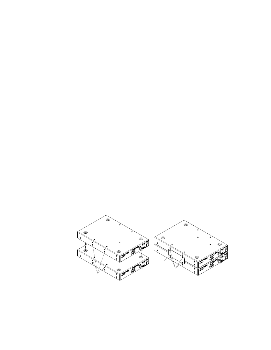
2.5.1 Vertically Mounting Two or More Units
The top panel of each KSC-2 unit contains four dimples, one near each corner, that
correspond to the positions of the unit’s feet. These dimples allow the units to fit
together snugly when stacked vertically. The KSC-2 link kit (KSC-2-LINK) consists
of two plates, each with four holes. The KSC-2 chassis side panels come with eight
preinstalled flat-head Phillips screws to secure the plates.
To mount two KSC-2 units vertically, remove the preinstalled mounting screws. Place
one unit on top of another, aligning the upper unit’s feet with the dimples on the top
panel of the lower unit. See Figure 10. Align a link plate with the side panels’ pre-
drilled holes and secure the plate with the supplied installation screws (Figure 11).
Install the second plate on the units’ other side in the same manner.
Mounting
Screws
Mounting
Screws
Link Plate
Figure 10
Vertically Mounting Two KSC-2 Units
Figure 11
Vertical Mounting: Attaching the
Link Plate
Rev. A
KSC-2 Signal Conditioner Installation and Programming Instructions
KULITE SEMICONDUCTOR PRODUCTS, INC.
KSC-2 Installation
Page
21
CAUTION
Use only the preinstalled flat-head Phillips screws when installing
the link plates. Other screws may damage the system hardware.
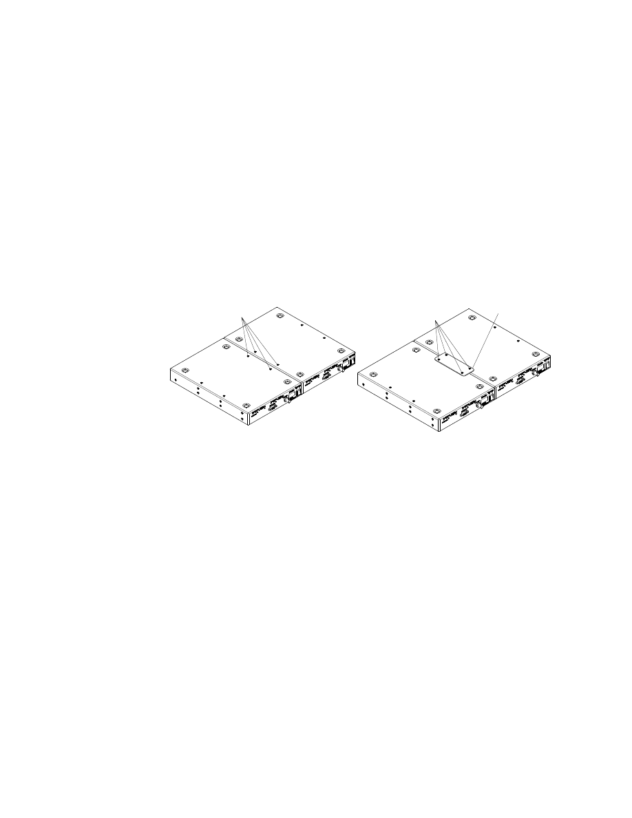
2.5.2 Horizontally Mounting Two or More Units
Two or more KSC-2 units can be connected side by side. The KSC-2 link kit (KSC-
2-LINK) consists of two plates, each with four holes. The KSC-2 frame’s top and
bottom panels come with eight preinstalled screws for attaching the plates.
To mount two KSC-2 units side by side, remove the preinstalled mounting screws and
place the units beside each other. See Figure 12. Align a link plate with the top panels’
predrilled holes and secure the plate with four of the supplied installation screws (Fig-
ure 13). Install the second plate on the units’ bottom panels in the same manner.
Mounting
Screws
Mounting
Screws
Link Plate
Figure 12
Horizontally Mounting Two KSC-2
Units
Figure 13
Horizontal Mounting: Attaching the
Link Plate
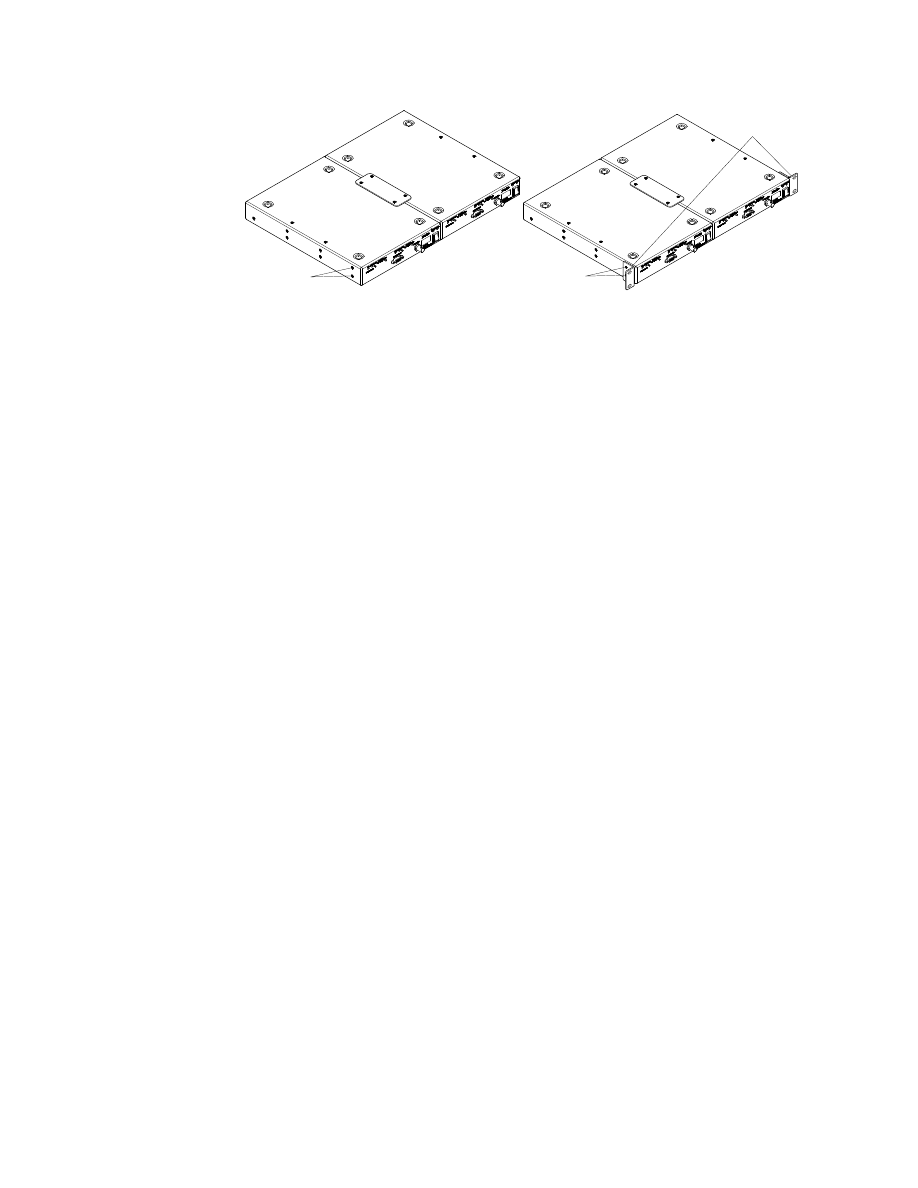
2.5.3 Horizontal Rack Mounting
The KSC-2 rack mount kit (KSC-2-RM) consists of a pair of mounting ears. The
KSC-2 chassis side panels come with four preinstalled flat-head Phillips screws to
secure the mounting ears.
To rack mount two KSC-2 units, connect two units horizontally as described in the
previous section. Remove the preinstalled screws on the exposed side panels (see
Figure 14 for the locations). Align the rack mounting ears with the holes and secure
the ears with the supplied installation screws (Figure 15). Attach the mounting ears to
the rack.
KSC-2 Installation
Page 22
KSC-2 Signal Conditioner Installation and Programming Instructions
Rev. A
KULITE SEMICONDUCTOR PRODUCTS, INC.
Mounting
Screws
Mounting
Screws
Rack
Mounting Ears
Figure 14
Rack-Mounting Two KSC-2 Units
Figure 15
Installing Rack Mounting Ears
CAUTION
Use only the preinstalled flat-head Phillips screws when installing
the link plates. Other screws may damage the system hardware.
Rev. A
KSC-2 Signal Conditioner Installation and Programming Instructions
KULITE SEMICONDUCTOR PRODUCTS, INC.
KSC-2 Installation
Page
23
2.6 Install Cables
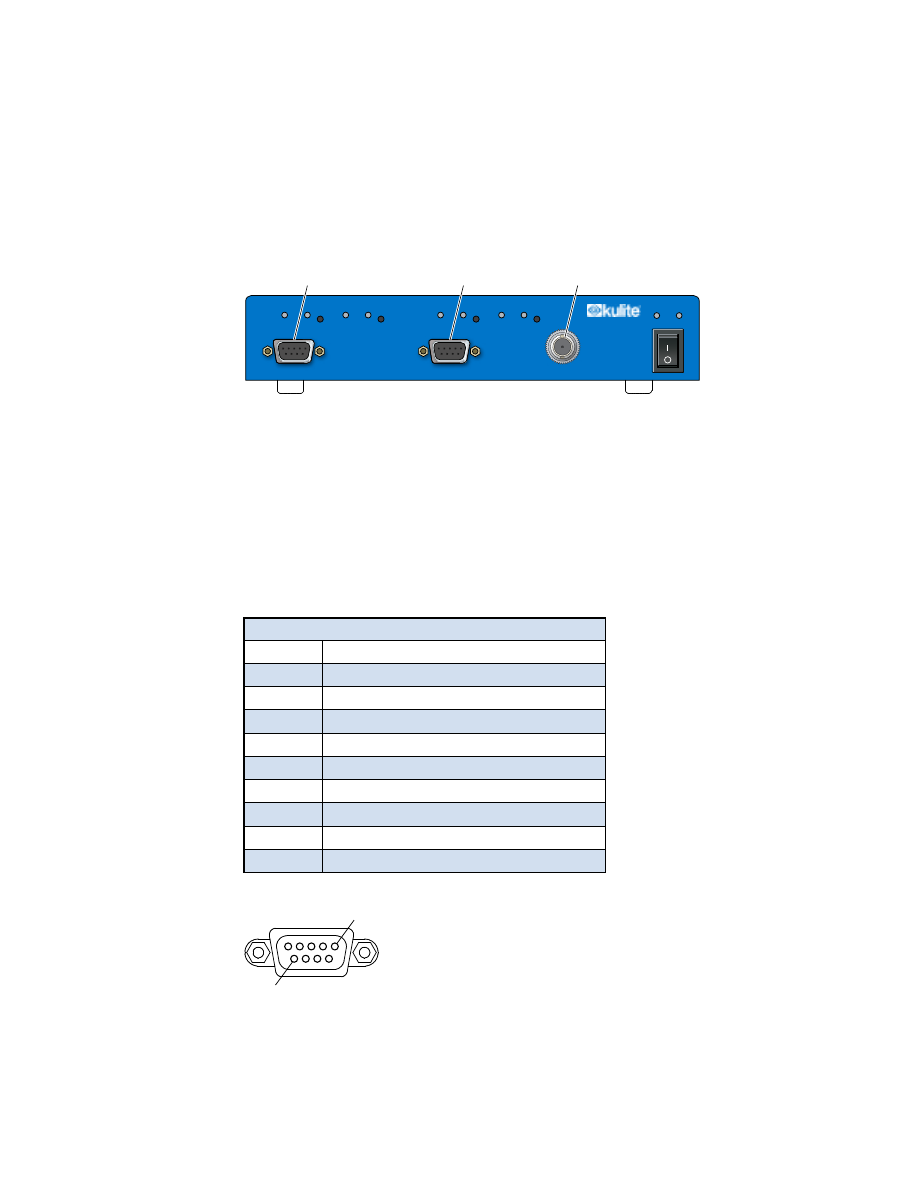
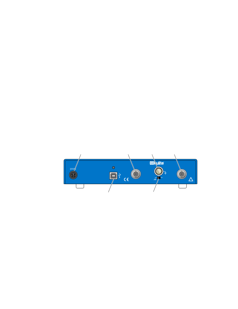
2.6.1 Front-Panel Input Connections
This section provides information about installing the input signal cables for KSC-2
units. Figure 16 shows the front-panel input connectors.
AUTO BALANCE
IN
INPUT CHANNEL 2
INPUT CHANNEL 1
OUT
IN
OUT
STATUS POWER
CAL INPUT
EXC
OVERLOAD
AUTO BALANCE
EXC
RESET
OVERLOAD RESET
Input Connector
Channel 1
Input Connector
Channel 2
Calibation Input
Connector
KSC-2
Signal Conditioner
Figure 16
KSC-2 Front Panel
KSC-2 Input Connectors
The KSC-2 provides two conditioning channels, labeled INPUT CHANNEL 1 and
INPUT CHANNEL 2. Two industry-standard DB-9 female input connectors, shown
in Figure 17, extend through openings on the front panel of the chassis. Table 3 lists
the input connector pin assignments.
Table 3 Input Connector Pin Assignments
Pin
Description
1
Excitation +
2
In +
3
Sense –
4
Signal Ground
5
5th Wire
6
Sense +
7
In –
8
Excitation –
9
Shield
Pin 1
Pin 9
Figure 17
Input Connector Pin Assignments
KSC-2 Installation
Page 24
KSC-2 Signal Conditioner Installation and Programming Instructions
Rev. A
KULITE SEMICONDUCTOR PRODUCTS, INC.
Input Cabling and Input Shielding
Twisted and shielded cable should be used for all signal inputs (In+, In−), especially in
high-noise environments. The shield should be connected at one end only (i.e., either
at the transducer or at the instrument) but not at both ends.
Avoid running signal leads near—or especially in parallel with—current-carrying
power cables. In situations where twisted/shielded cable cannot be used, exercise care
to avoid any large loop area (separation) in the input wiring pairs.
Twisted and shielded cable is preferred for + and – excitation and for + and – sense
lines to minimize noise pickup. If the bridge configuration is physically unbalanced,
noise pickup in the excitation or sense leads can degrade signal-to-noise ratio.
CAUTION
It is necessary to provide a high-quality instrument ground to the
KSC-2 system. The KSC-2 input is rated for operation at a signal-
plus-common-mode level of 10 V and is protected for a signal-
plus-common-mode level of 24 V relative to instrument ground.
Note:
The upcoming section “Signal Ground Selection” explains how to optimize
signal ground quality.
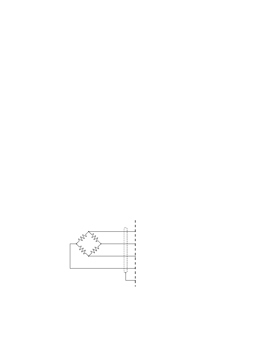
KSC-2 Full-Bridge 4-Wire Connections
For full-bridge measurements using a 4-wire configuration, the KSC-2 connections
should be made as shown in Figure 18. To set up the KSC-2 for 4-wire full bridge
measurements, the excitation sense must be set to Local in the GUI or via remote
command.
In +
Excitation +
In –
Excitation –
Shield
Amplifier
1
2
8
7
9
Figure 18
KSC-2 Full Bridge with Local Sense (4-Wire + Shield)
Rev. A
KSC-2 Signal Conditioner Installation and Programming Instructions
KULITE SEMICONDUCTOR PRODUCTS, INC.
KSC-2 Installation
Page
25
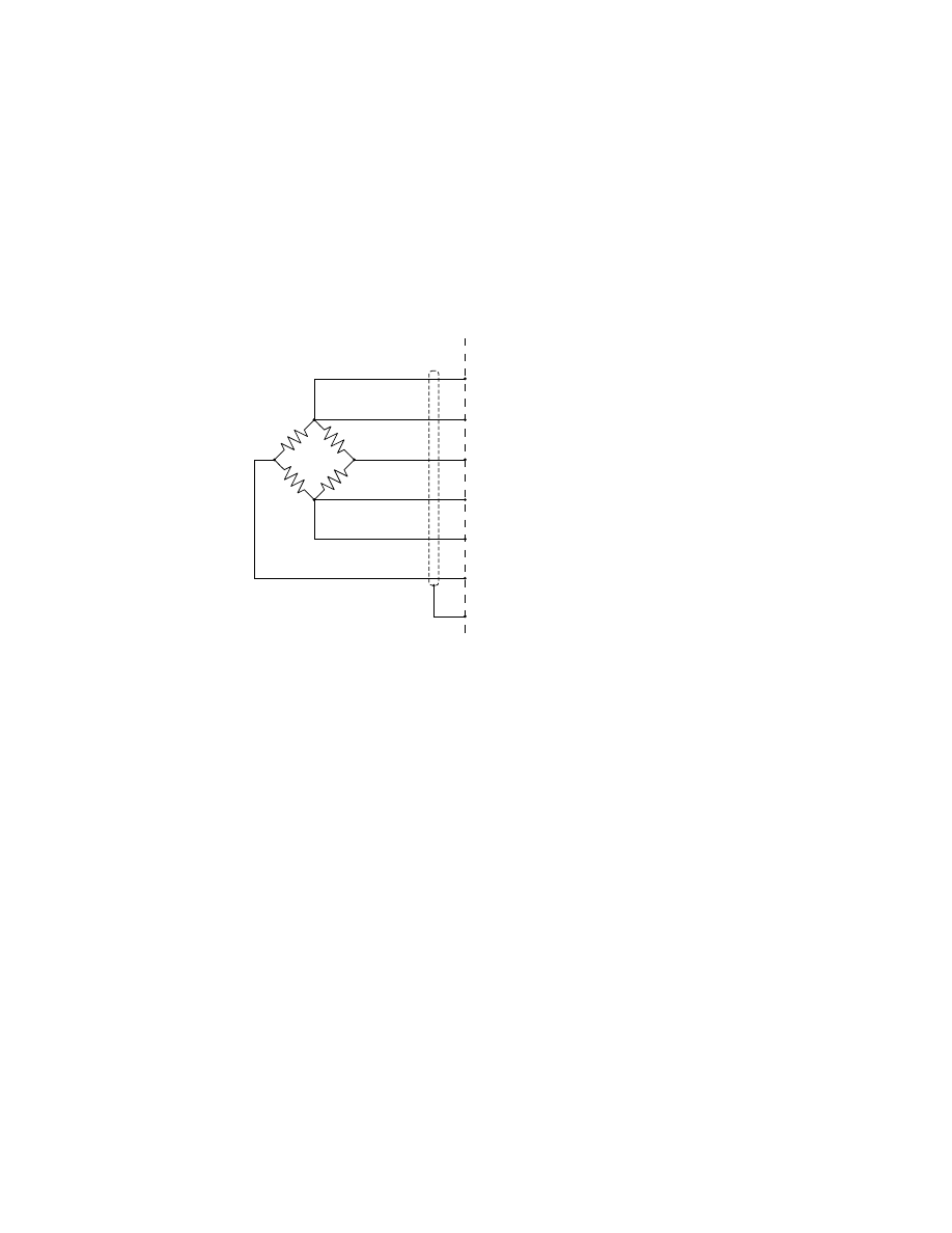
KSC-2 Full-Bridge 6-Wire Connections
Resistance in the excitation leads produces error in excitation delivered to the bridge.
Remote excitation sense leads may be used to sense the excitation at the bridge in
order to correct for the lead resistance drops.
Figure 19 shows the 6-wire configuration that uses the + and – SENSE leads. To set
up the KSC-2 for 6-wire full-bridge measurements, the excitation sense must be set to
Remote in the GUI or via remote command.
Sense +
IN +
Excitation +
Sense –
In –
Excitation –
Shield
Amplifier
6
1
2
8
3
7
9
Figure 19
KSC-2 Full Bridge with Local Sense (6-Wire +
Shield)
KSC-2 Installation
Page 26
KSC-2 Signal Conditioner Installation and Programming Instructions
Rev. A
KULITE SEMICONDUCTOR PRODUCTS, INC.
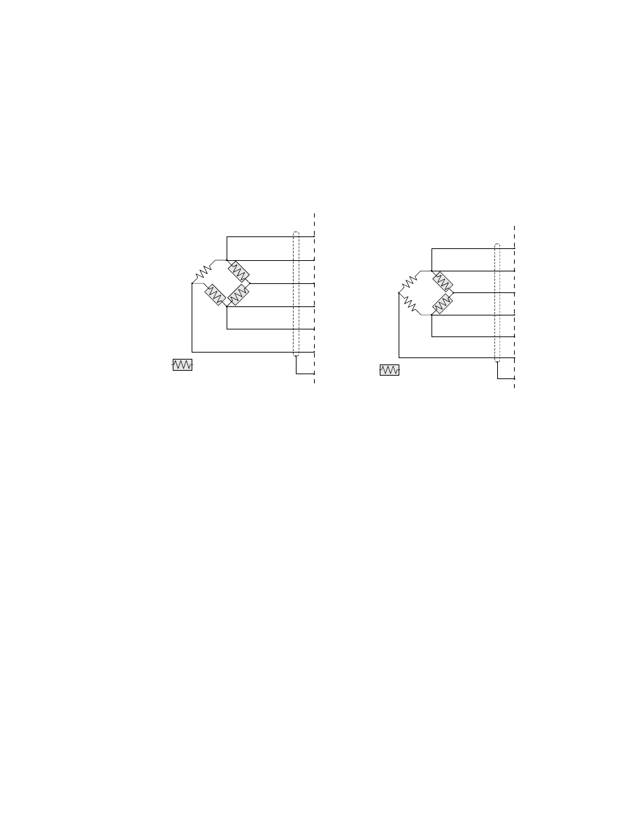
Other Bridge Input Configurations Using External Completion Resistors
The KSC-2 does not provide bridge completion; however, the user may wish to
provide external completion resistors for quarter- and half-bridge configurations.
The completion resistors should be located as close to the active gage as possible to
keep the circuit physically balanced and minimize interfering noise sources. Figure
20 shows a typical configurations for a quarter bridge. Figure 21 shows a typical
configuration for a half bridge.
Sense +
In +
Excitation +
Sense –
In –
Excitation –
Shield
Amplifier
= User supplied
completion resistors
R
GAGE
6
1
2
8
3
7
9
Sense +
In +
Excitation +
Sense –
In –
Excitation –
Shield
Amplifier
= User supplied
completion resistors
R
GAGE 2
or
Dummy
R
GAGE 1
6
1
2
8
3
7
9
Figure 20
KSC-2 Quarter Bridge with
Remote Sense & User-Supplied
Completion Resistors
Figure 21
KSC-2 Half Bridge with
Remote Sense & User-Supplied
Completion Resistors
Voltage Input Configuration
The KSC-2 may be used as a low-noise voltage filter/amplifier by connecting a voltage
output device to the + and − SIGNAL inputs.
CAL Input Connector
The KSC-2’s front panel has an isolated BNC calibration input connector labeled CAL
INPUT.
Rev. A
KSC-2 Signal Conditioner Installation and Programming Instructions
KULITE SEMICONDUCTOR PRODUCTS, INC.
KSC-2 Installation
Page
27
5th Wire
The Kulite 5th wire transducer was developed to allow customers to obtain data
about the bridge temperature of the pressure transducer in order to compensate the
sensor for thermal errors. Using this temperature signal correctly can result in a very
accurate pressure measurement—even over a wide temperature range.
The Kulite 5th wire voltage is proportional to the temperature of the silicon die.
The output is approximately 5 V at room temperature and increases by 2 mV/°F
nominal. Refer to Kulite application note
Kulite 5th Wire Combination Pressure and
Temperature Transducers
for more details.
The KSC-2 features a 5th wire input that allows measurement of the 5th wire voltage
with an internal analog-to-digital converter.
2.6.2 Rear-Panel Connections
The rear panel contains output connectors, a port for a type B locking USB connector,
and a power-in connector. It also has the KSC-2’s ground configuration switch. See
Power In
Connector
Locking Type B
USB Connector
Ground Configuration
Switch
Output Connector
Channel 2
Output Connector
Channel 1
Signal
Gound Post
CHASSIS GROUND
ISOLATED
SIGNAL
GROUND
OUTPUT CHANNEL 2
OUTPUT CHANNEL 1
!
POWER IN
10 – 30 VDC
25 W MAX
KSC-2 Signal Conditioner
Figure 22
KSC-2 Rear Panel
Before operating the KSC-2 unit, connect the external power supply to the rear panel.
Use the supplied USB cable to connect the unit to the host computer. Insert the Type B
USB connector into the KSC-2 unit’s rear-panel USB port. Insert the standard Type A
connector into the desired USB port of the host computer.

KSC-2 Installation
Page 28
KSC-2 Signal Conditioner Installation and Programming Instructions
Rev. A
KULITE SEMICONDUCTOR PRODUCTS, INC.
Communication USB 2.0 Connector
For protection against accidental cable disconnection, Kulite offers an accessory cable
with a locking type B USB connector (Kulite P/N 910-A-84798). The USB-A/B-6
locking USB cable accessory is a 72-inch cable with a standard (nonlocking) type A
connector for the host computer and a locking type B USB connector for the KSC-2.
Output Connectors
Two isolated BNC connectors are labeled OUTPUT CHANNEL 1 and OUTPUT
CHANNEL 2. The KSC-2 has a single-ended output stage with 10
Ω
output imped-
ance. The rear-panel BNC shell is connected to signal ground.
Signal Ground Selection
For optimal data quality, it is important to provide a low-noise, low-impedance, earth
ground reference to internal amplifier circuitry. As shown in Figure 22, the KSC-2 has
rear-panel features to optimize the signal ground used for internal circuits. As shipped
from the factory, the amplifier signal ground is connected to the KSC-2 chassis
(switch in left position). This provides a convenient ground connection through the
attached KSC-2 input power cord to earth ground via the third wire earth ground at
the wall outlet.
If the chassis ground connection is found to be unsuitable due to excessive noise on fa-
cility earth ground connection, the KSC-2 signal ground can be isolated from chassis
ground by moving the rear-panel ground configuration switch to the ISOLATED
(right) position and using the rear-panel ground post to connect to a more suitable
ground connection. For optimal performance, this ground post should be connected to
a quality ground source with a low-impedance connection directly to earth ground.
Bank Isolation
The KSC-2’s ISOLATED mode can be used to reference both channels to a remote
reference other than earth ground. Called bank isolation, this can be useful if a distant
ground causes the common source (to both channels) to be at some potential beyond
the ±10 V input range allowable by the KSC-2 amplifier.
If you are using bank isolation in this manner, follow these rules:
•
The remote ground potential must not be more than 20 V from the chassis ground
of the KSC-2.
•
The input signals to each of the two channels must not differ by more than ±10 V
from the remote ground reference.
•
Any recording device connected to the KSC-2 outputs must also have sufficient
isolation capability.

Rev. A
KSC-2 Signal Conditioner Installation and Programming Instructions
KULITE SEMICONDUCTOR PRODUCTS, INC.
KSC-2 Installation
Page
29
•
If input cabling connects the overall cable shield to the shell of the DB9 input
connector, this will connect the shield to the remote ground potential through the
chassis connection. To prevent ground loop currents, do not terminate the cable
shield at the sensor end.
Power Connector
One KSC-2-ACPS external AC/DC power supply is provided with each KSC-2
system. The input power connector (Figure 23) is located on the left side of the unit’s
rear panel.
The KSC-2 requires input power of 10–30 VDC, 25 W maximum, applied at the rear
panel POWER IN connector. Mating power entry connectors (KPPX-4P-30) and spare
external AC/DC power supplies (KSC-2-ACPS) are available.
Pin 1: +12 V
Pin 3: Shell (GND)
Pin 2: +12 V Return
Pin 4: N/C
Ground
Figure 23
KSC-2 Power Connector
KSC-2 Installation
Page 30
KSC-2 Signal Conditioner Installation and Programming Instructions
Rev. A
KULITE SEMICONDUCTOR PRODUCTS, INC.
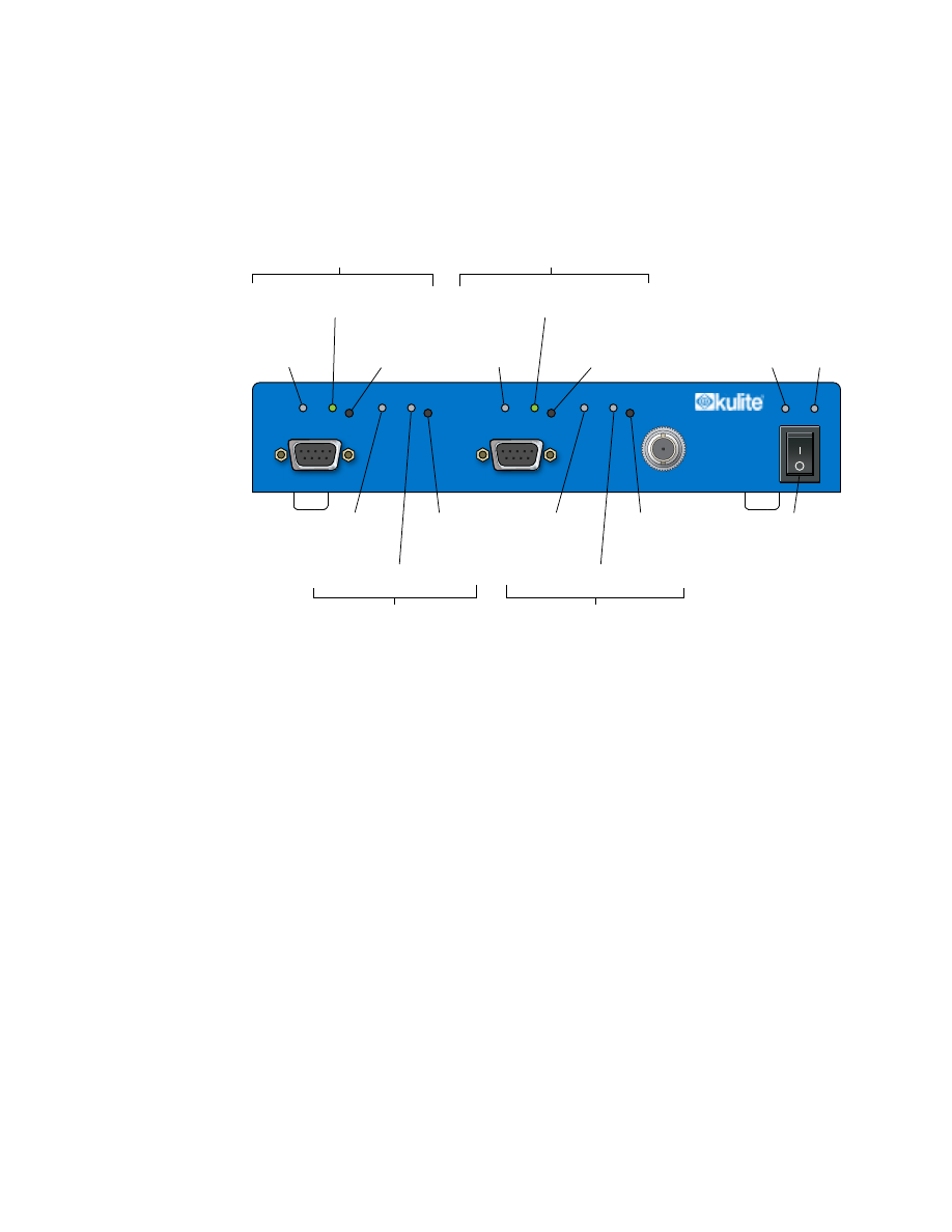
2.7 KSC-2 Front-Panel Operation
Figure 24 illustrates the front-panel indicators and switches used during KSC-2 oper-
ation.
AUTO BALANCE
IN
INPUT CHANNEL 2
INPUT CHANNEL 1
OUT
IN
OUT
STATUS POWER
CAL INPUT
EXC
OVERLOAD
AUTO BALANCE
EXC
RESET
OVERLOAD RESET
Excitation
Fault
LED
Auto Balance
Status LED
Auto Balance
Operation
Switch
Channel 1
LED Indicators and Switch
Overload
Reset
Switch
Input
Overload
LED
Output Overload LED
Overload
Reset
Switch
Input
Overload
LED
Output Overload LED
Excitation
Fault
LED
Auto Balance
Status LED
Auto Balance
Operation
Switch
Power
LED
Power
Switch
Status
LED
Channel 2
LED Indicators and Switches
Channel 1 Overload
LED Indicators and Switch
Channel 2 Overload
LED Indicators and Switch
KSC-2
Signal Conditioner
Figure 24
KSC-2 Front Panel Switches and Indicators
2.7.1 Applying Power
To apply power, be sure that the external power supply is connected to the rear panel
and plugged in. On the front panel, move the right-hand power switch to the On posi-
tion (|). The upper-right POWER light turns green. The green STATUS light indicates
that the KSC-2 unit has initialized.

Rev. A
KSC-2 Signal Conditioner Installation and Programming Instructions
KULITE SEMICONDUCTOR PRODUCTS, INC.
KSC-2 Installation
Page
31
2.7.2 Autobalance Indicators and Reset Button
The KSC-2’s autobalance function measures any imbalance inherent in the bridge and
provides appropriate compensation to the circuit. Front-panel LEDs for each channel
indicate the channel’s balance mode status: in progress (yellow), successful (green), or
failed (red).
To initiate a balance/suppress operation for a channel, press the momentary switch
to the right of the channel’s AUTO BALANCE LED. You can also initiate an auto-
balance from the KSC-2 Control GUI (see Section 4.5.9) or via remote commands (see
Section 5.4.7).
Note:
Autobalance is disabled when the KSC-2 unit is AC coupled.
The front-panel switches may be locked out using the Options panel in the GUI (see
Tools
in Section 4) or remote commands (see
Device Control and Information
in
Section 5).
2.7.3 Overload Indicators and Reset Button
For each channel, front-panel LEDs indicate input or output overload and excitation
faults (short or overvoltage). Overload indicators, labeled IN and OUT to show input
and output overloads, respectively, turn red in an overload condition:
•
The IN overload detection circuit is located following the prefilter gain stage and
prior to the filter stage.
•
The OUT overload detection circuit is located following the postfilter gain stage.
To clear the overload detectors while in Latching mode, press the RESET switch for
the desired channel. For more information about Latching and Continuous modes, see
Section 4.5.13.
When an excitation fault is detected, the EXC indicator turns red. The LED remains
lit until the excitation fault is corrected.
The front-panel switches may be locked out via a control panel in the GUI (see
Tools
in Section 4
) or remote commands (see
Device Control and Information
in Section 5).

KSC-2 Installation
Page 32
KSC-2 Signal Conditioner Installation and Programming Instructions
Rev. A
KULITE SEMICONDUCTOR PRODUCTS, INC.
This page intentionally left blank.

Rev. A
KSC-2 Signal Conditioner Installation and Programming Instructions
KULITE SEMICONDUCTOR PRODUCTS, INC.
KSC-2 Control Software Programming Instructions
Page
33
3
KSC-2 Control Software Programming
Instructions
3.1 Introduction
The KSC-2 Control Graphical User Interface (GUI) provides an easy-to-use
spreadsheet-style interface for control and configuration of the KSC-2 signal
conditioner. The GUI can control up to eight KSC-2 units as a system. This section
describes how to install the GUI on a Windows OS computer and use it to operate
KSC-2 units.
3.2 GUI Installation
This section contains instructions for installing the KSC-2 Control GUI software on a
Windows-based host computer.
3.2.1 Antivirus Software
All software is routinely scanned for computer viruses using the latest antivirus soft
-
ware and has been found to be free of viruses and malicious software.
If your antivirus program is reporting a problem and blocking the installation of the
KSC-2 Control GUI software, disable the antivirus program and retry the installation.
3.2.2 Installing the KSC-2 Control GUI Software
The KSC-2 Control GUI software is distributed on the KSC-2 Signal Conditioner
Software Distribution CD. Install and run the GUI program as described in this
section.
Note:
It is strongly recommended that you exit all programs before you run
the KSC-2 Control installer. Applications that run in the background, such as
virus-scanning utilities, could lengthen the amount of time required for the
installation.
KSC-2 Control Software Programming Instructions
Page 34
KSC-2 Signal Conditioner Installation and Programming Instructions
Rev. A
KULITE SEMICONDUCTOR PRODUCTS, INC.
Step 1
Insert the CD into a Windows-compatible computer, open the
KSC-2 GUI
folder and then open the
Installer
folder.
Double-click the
setup.exe
file to start the GUI software installer.
The start-up panel briefly displays while the installer initializes.
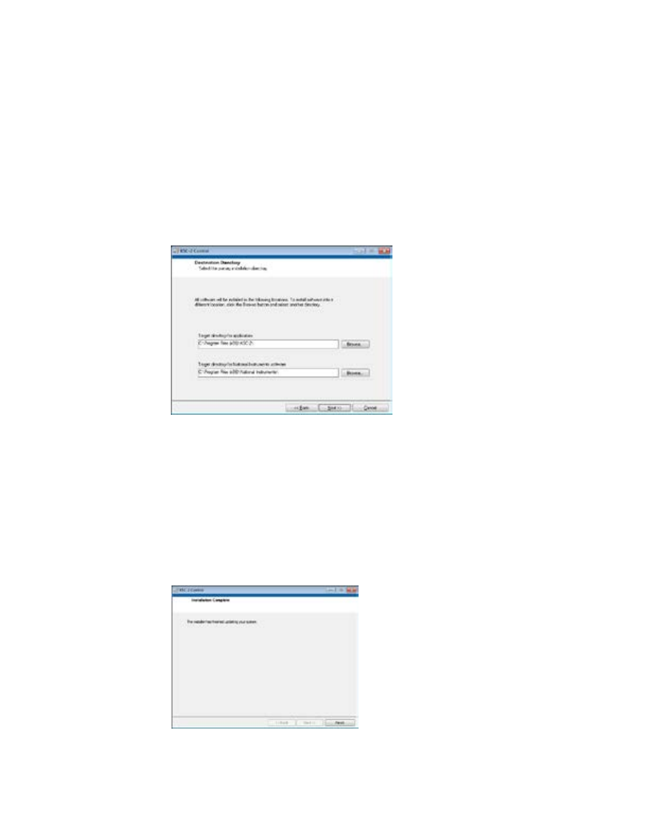
Step 2
In the Destination Directory panel, shown in Figure 25, select the
destination folder for the software program.
The default destination for the KSC-2 GUI is
C:\Program Files\KSC-2\
.
Click Next to continue.
Figure 25
Destination Directory Panel
Step 3
Review the License Agreement in the License Agreement pane. Select “I
accept the License Agreement” and click Next.
Step 4
Review the Start Installation summary panel and click Next.
The Progress panel displays, showing the installation’s progress.
Step 5
When you see the Installation Complete panel (Figure 26), click Finish.
Step 6
You must restart your computer to finish the installation. Click the Restart
button on the Restart panel.
Figure 26
Installation Complete Panel

Rev. A
KSC-2 Signal Conditioner Installation and Programming Instructions
KULITE SEMICONDUCTOR PRODUCTS, INC.
KSC-2 Control Software Programming Instructions
Page
35
3.2.3 Uninstalling the KSC-2 Control GUI Software
Uninstall the KSC-2 Control GUI software through the Windows Control Panel.
Click the Start button and select Control Panel. In the Control Panel’s list of programs,
find and select
KSC-2 Control
. Click Uninstall/Change. Confirm that you want to
remove the program from the host computer by clicking Yes in the confirmation panel,
and Windows uninstalls the software.
3.2.4 Starting the KSC-2 Control GUI Software
Follow the steps below to open the KSC-2 Control GUI software:
Step 1
Ensure the KSC-2 unit is properly connected to the host computer and
powered up.
Step 2
From the Windows Start, All Programs menu, click the KSC-2 icon to start
the GUI program. Figure 27 shows what the start-up screen looks like the
first time you open the program.
Figure 27
Initial KSC-2 Control Screen (Partial)
3.2.5 Connecting Multiple KSC-2 Units to the Control GUI
To connect one or more KSC-2 units to the GUI, connect each unit’s USB cable to a
USB hub and connect the USB hub to your host computer. In the KSC-2 Control GUI
select Edit, System Configuration. See Section 3.4.2 for information about working
with the System Configuration panel.
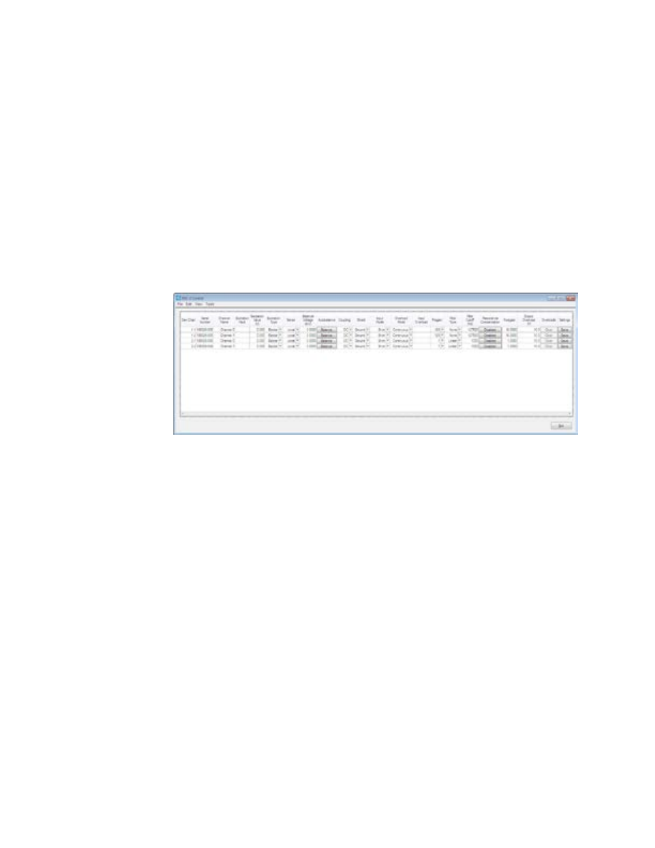
KSC-2 Control Software Programming Instructions
Page 36
KSC-2 Signal Conditioner Installation and Programming Instructions
Rev. A
KULITE SEMICONDUCTOR PRODUCTS, INC.
3.3 KSC-2 Control GUI Interface and Settings
This section introduces the KSC-2 Control software interface and provides a ref-
erence for the commands and functions used to control and operate KSC-2 signal
conditioners.
3.3.1 KSC-2 Control Screen
The main screen of the KSC-2 Control GUI is a spreadsheet-style interface with a
menu bar across the top, columns for different settings and controls, and a row for
each connected KSC-2 channel. The GUI can control up to eight KSC-2 units as a
system (for a total of up to 16 channels). Figure 28 shows an example of the KSC-2
Control GUI with two units connected.
Figure 28
KSC-2 Control Main Screen

Rev. A
KSC-2 Signal Conditioner Installation and Programming Instructions
KULITE SEMICONDUCTOR PRODUCTS, INC.
KSC-2 Control Software Programming Instructions
Page
37
3.4 Main Menu
The main menu is located in the menu bar at the top of the KSC-2 Control GUI
screen. This section describes the main menu commands.
3.4.1 File
The File menu contains commands related to the handling of files: Open, Save, and
Save As. It also contains the Exit command for closing the KSC-2 Control GUI pro
-
gram. To select one of these commands, click File and then choose the command you
want from the drop-down menu.
Note:
The KSC-2 Control GUI stores system configuration files and sensor data-
base files in .csv format. This file format, which holds tabular data in plain-text
form, consists of sequences of records in which each record contains an iden
-
tical list of fields. The .csv file can be opened in a spreadsheet program such as
Microsoft Excel.
Open
To open a saved file, select File, Open, and choose one of these options:
•
System Configuration
If you want to apply the saved settings for a specific saved system configuration,
select this option.
•
Sensor Database
The sensor database contains information about various Kulite sensors and, for
each, helps you to determine the Q factor for various resonance frequencies.
Navigate to the folder that holds the file you want to open. Choose the file and click
the Select button to open it.
Save
The active configuration can be saved at any time by selecting File, Save on the menu
bar. The GUI provides a confirmation prompt before overwriting the current configu
-
ration file.
Save As
Select File, Save As to save the existing system configuration in a new file. The GUI
provides a prompt where you specify the location and name of the configuration file to
be saved.
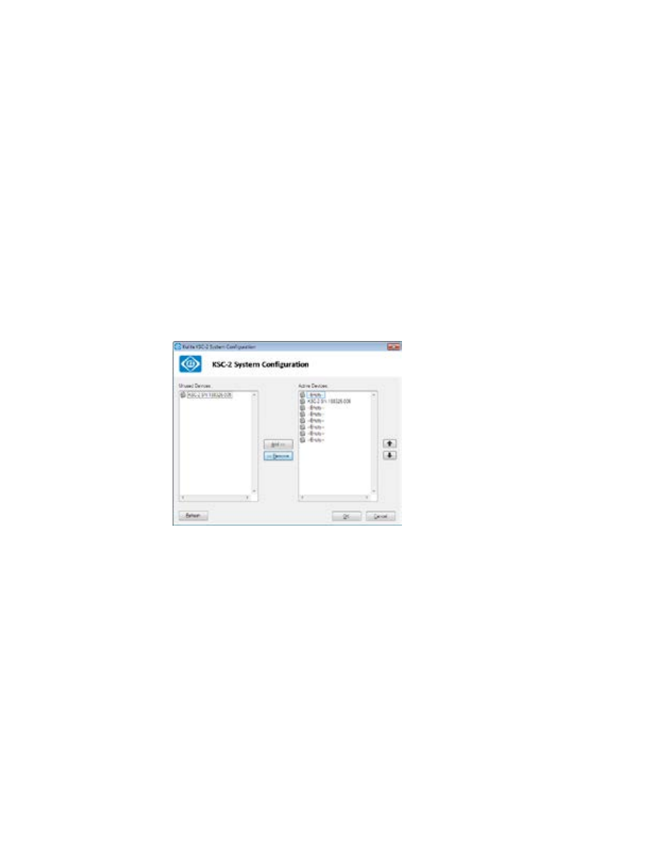
KSC-2 Control Software Programming Instructions
Page 38
KSC-2 Signal Conditioner Installation and Programming Instructions
Rev. A
KULITE SEMICONDUCTOR PRODUCTS, INC.
Exit
To close the KSC-2 Control GUI program, select File, Exit from the menu bar. Alter
-
natively, you can close the program by clicking the upper-right Close symbol (
X
) or
the lower-right Exit button.
Note:
When the KSC-2 unit is field deployed without a host computer, exit the
GUI first and then power off the KSC-2.
3.4.2 Edit
System Configuration
The KSC-2 System Configuration panel, shown in Figure 29, is where you add or
remove devices from the system or change their order. To open the panel, select Edit,
System Configuration. This panel lists unused devices on the left and active devices
on the right.
Figure 29
KSC-2 System Configuration Panel
•
To activate a device, select it in the Unused Devices list and click Add. The device
moves to the Active Devices list.
•
To deactivate a device, select it in the Active Devices list and click Remove. The
device moves to the Unused Devices list.
•
To change the order of the devices in the Active Devices list, select the device you
want to move. Use the right-hand up and down arrows to move the device to its
new position.
•
If you do not see a connected KSC-2 unit in the System Configuration panel, click
the Refresh button. The program searches for and displays all connected KSC-2
units.
When you have finished editing the system configuration, click OK to apply your
changes and close the panel.
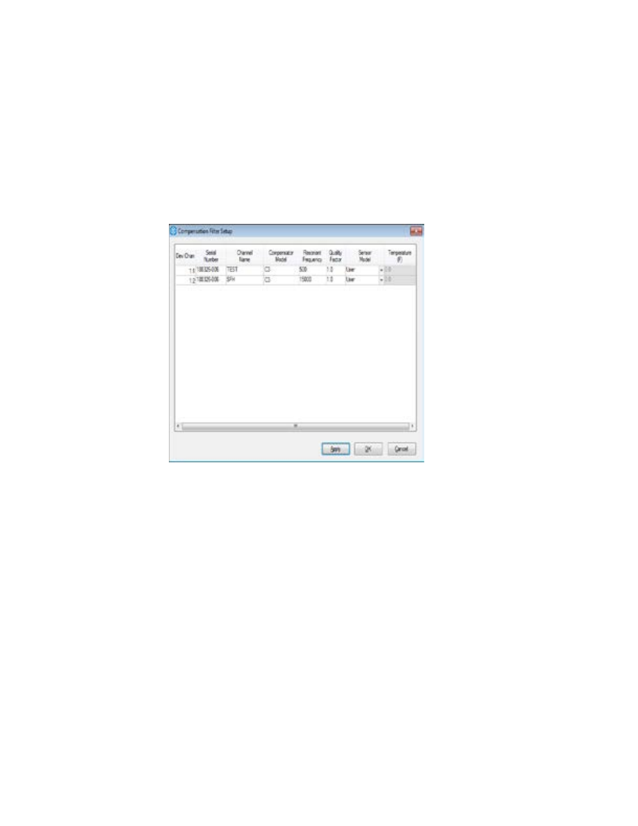
Rev. A
KSC-2 Signal Conditioner Installation and Programming Instructions
KULITE SEMICONDUCTOR PRODUCTS, INC.
KSC-2 Control Software Programming Instructions
Page
39
Compensation Filters
The KSC-2’s optional, patent-pending REZCOMP transducer resonance compensa
-
tion can extend the usable bandwidth of resonant sensors to as much as 80% of the
sensor resonant frequency (or in some cases, beyond the sensor resonant frequency).
If your KSC-2 is equipped with REZCOMP option C3, select Edit, Compensation Fil
-
ters to open the Compensation Filter Setup panel (Figure 30) to get information about,
program, and configure the compensation filters.
Figure 30
Compensation Filter Setup Panel
The Compensation Filter Setup panel contains these fields:
•
Dev:Chan
The Dev:Chan column shows each device number and channel number. 1:1 is de
-
vice 1, channel 1; 1:2 is device 1, channel 2; 2:1 is device 2, channel 1; and so on.
•
Serial Number
This column displays the serial number of each connected device.
•
Channel Name
This column shows the name of each channel.
•
Compensator Model
This column displays C3, the model name of the detected compensation filter.
•
Resonant Frequency
Resonant frequency depends on the sensor being used. Enter the desired resonant
frequency here.

KSC-2 Control Software Programming Instructions
Page 40
KSC-2 Signal Conditioner Installation and Programming Instructions
Rev. A
KULITE SEMICONDUCTOR PRODUCTS, INC.
Resonant compensation frequencies are programmable as shown in Table 4.
Table 4 Compensation Frequencies
Low Range
10 Hz to 2.55 kHz in 10 Hz steps
Mid Range
2.6 kHz to 51 kHz in 200 Hz steps
High Range
52 kHz to 255 kHz in 1 kHz steps
•
Quality Factor
The compensation quality factor (Q) is programmable from 1 to 20 in 0.1 steps,
and from 20 to 50 in 0.5 steps. For low-, mid-, and high-range frequency response
accuracy for different quality factors, see Section 1.4.4, “Optional KSC-2 Trans
-
ducer Compensator (C3) Characteristics.”
•
Sensor Model
This field shows the sensor model connected to the channel.
•
Temperature (F)
This column displays the temperature. The default units are °F.
Note:
To change the units in the Temperature display, select Tools, Options. In the
Options panel’s Units section, click the Temperature Scale drop-down arrow and
select Fahrenheit or Celsius.
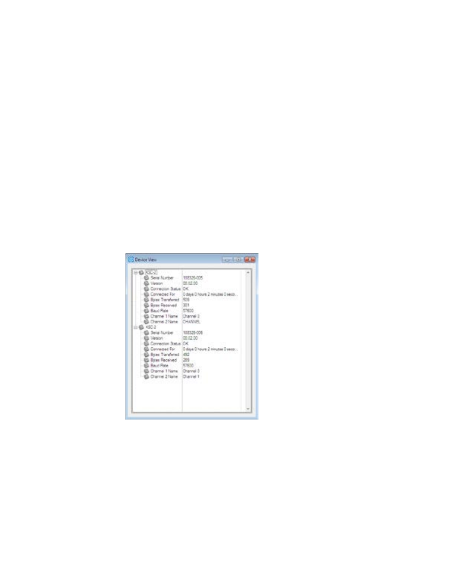
Rev. A
KSC-2 Signal Conditioner Installation and Programming Instructions
KULITE SEMICONDUCTOR PRODUCTS, INC.
KSC-2 Control Software Programming Instructions
Page
41
3.4.3 View
Device
Selecting View, Devices opens the Device View panel (Figure 31), which gives infor
-
mation about the KSC-2 units connected to the Control GUI. For each unit, Device
view supplies the following information:
•
Serial number
•
Firmware version
•
Connection status
•
Connected for (length of time the device has been connected)
•
Bytes transferred
•
Bytes received
•
Baud rate
•
Channel 1 name
•
Channel 2 name
Figure 31
Device View Panel
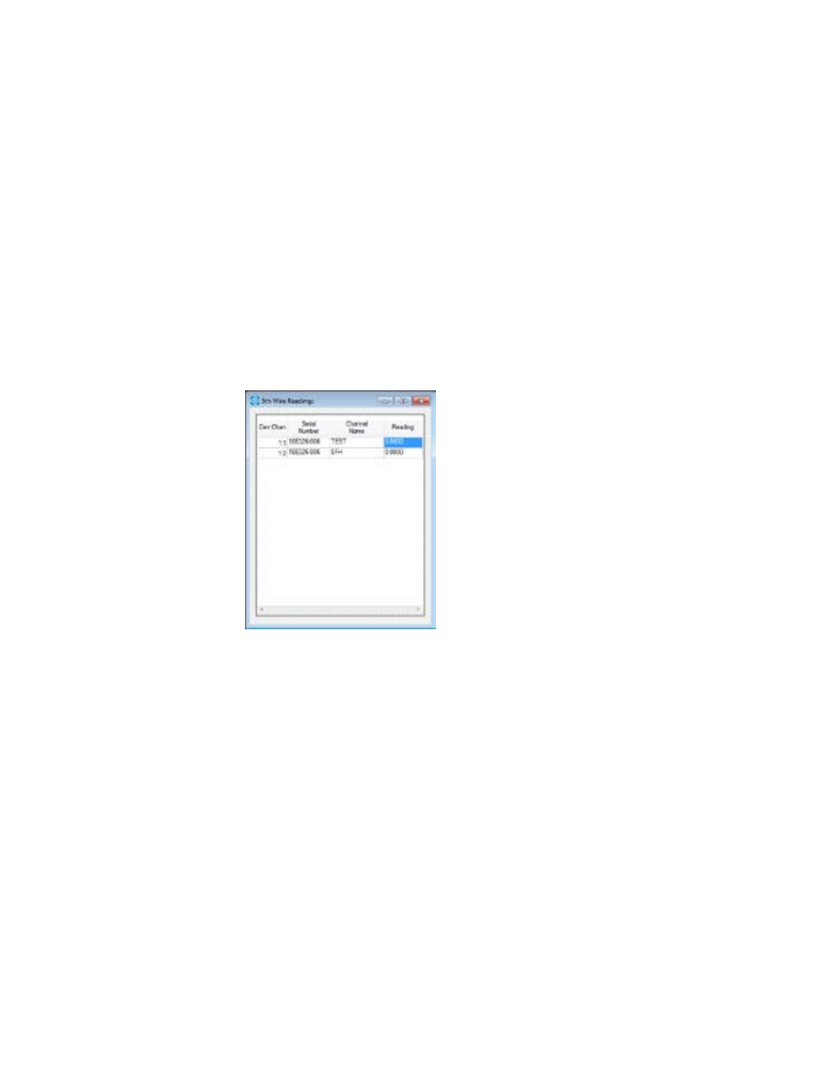
KSC-2 Control Software Programming Instructions
Page 42
KSC-2 Signal Conditioner Installation and Programming Instructions
Rev. A
KULITE SEMICONDUCTOR PRODUCTS, INC.
5th-Wire Readings
The Kulite 5th wire transducer was developed to allow customers to obtain data
about the bridge temperature of the pressure transducer in order to compensate the
sensor for thermal errors. Using this temperature signal correctly can result in a very
accurate pressure measurement—even over a wide temperature range.
The Kulite 5th wire voltage is proportional to the temperature of the silicon die.
The output is approximately 5 V at room temperature and increases by 2 mV/°F
nominal. Refer to Kulite application note
Kulite 5th Wire Combination Pressure and
Temperature Transducers
for more details.
To open the 5th Wire Readings panel (Figure 32), select View, 5th Wire Readings.
Here you can see each channel’s voltage reading on the transducer’s fifth wire in volts.
Figure 32
5th Wire Readings Panel
3.4.4 Tools
Commands
Select Tools, Commands and choose an option from the flyout menu to execute one of
the following commands:
•
Balance All
The autobalance function measures any bridge imbalance inherent in the bridge
and provides appropriate compensation to the circuit. This command initiates an
autobalance cycle on the bridge sensor for all channels.
•
Clear All Overloads
This command clears the both the input and the output overload detectors for all
channels.

Rev. A
KSC-2 Signal Conditioner Installation and Programming Instructions
KULITE SEMICONDUCTOR PRODUCTS, INC.
KSC-2 Control Software Programming Instructions
Page
43
•
Save All
This command saves all channels’ configurations to the device’s nonvolatile mem
-
ory so that settings can be retained through power cycle or for field deployment
without an attached control computer.
•
Calibrate All Offsets
The auto offset procedure assures DC accuracy of the amplifier/filter channel
by eliminating all sources of internal error throughout the channel circuit. This
command initiates an offset correction routine for all channels. When you select
Tools, Commands, Calibrate All Offsets, a Confirm panel appears, warning you
that offset adjustment can take some time and asking whether you want to proceed.
Click Yes to perform the offset adjustment.
Note:
Offsets drift with temperature. Ensure the system is warmed up for at least
30 minutes before running the routine.
•
Reset All to Default Values
This command changes all settings for the selected channel back to their original,
factory-set values, as follows:
•
Excitation Type: Bipolar
•
Excitation Value: 0
•
Balance Voltage: 0
•
Coupling: DC
•
Pregain: 1
•
Postgain: 1
•
Sense: Remote
•
Shield: GND
•
Input Mode: Operate
•
Compensation Filter: Off
•
Compensation Filter Cutoff: 10 KHz
•
Compensation Quality Factor: 1
•
Filter Cutoff: 10 KHz
•
Filter: None
•
Output Overload Limit: 10
•
Overload Mode: Continuous
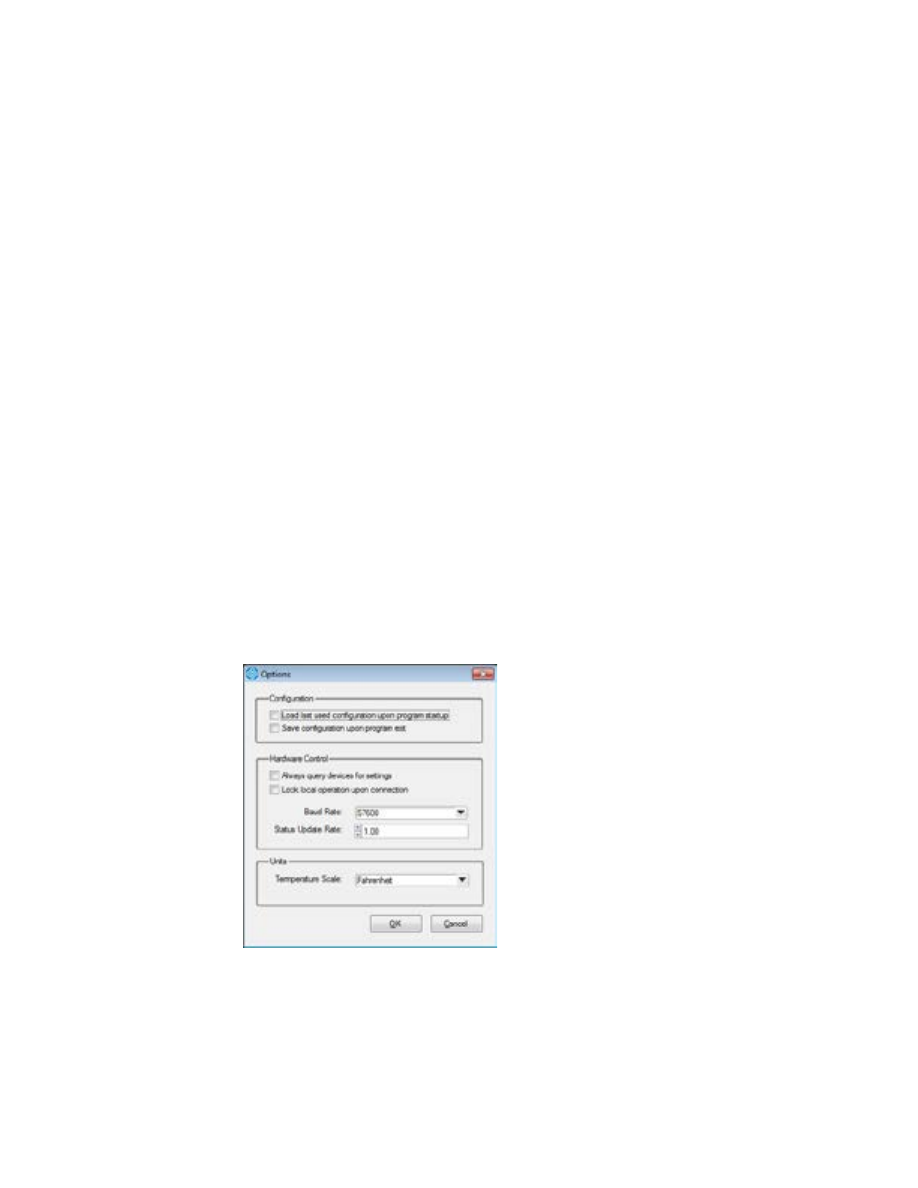
KSC-2 Control Software Programming Instructions
Page 44
KSC-2 Signal Conditioner Installation and Programming Instructions
Rev. A
KULITE SEMICONDUCTOR PRODUCTS, INC.
Options
When you select Tools, Options, the Options panel (Figure 33) offers the following
selections:
•
Configuration
This section of the Options panel gives you two choices:
•
Whether to load the last used configuration when the GUI starts
•
Whether to automatically save the current system configuration when you
close the program
•
Hardware Control
This section of the panel contains four options:
•
Tell the system to always check devices for their settings, which is helpful
after field tests to see whether those settings have changed
•
Lock local operation when the program connects, disabling the front-panel
autobalance and overload reset buttons
•
Set the baud rate to 9600, 19200, or 57600 (the default)
•
Set the status update rate in steps of 0.25 second (the default rate is 1.00)
Units
In this section of the Options panel, select Fahrenheit or Celsius as the system’s
temperature scale.
After you’ve made your selections, click OK to apply them and exit the Options panel.
Figure 33
Options Panel

Rev. A
KSC-2 Signal Conditioner Installation and Programming Instructions
KULITE SEMICONDUCTOR PRODUCTS, INC.
KSC-2 Control Software Programming Instructions
Page
45
Re-sync Device Communications
When a device becomes out of sync with the Control GUI, the control’s background
turns yellow. To get the device and the software back in sync, select Tools, Re-sync
Device Communications.
3.4.5 Help
About
Select Help, About to view the version number of the installed software.

KSC-2 Control Software Programming Instructions
Page 46
KSC-2 Signal Conditioner Installation and Programming Instructions
Rev. A
KULITE SEMICONDUCTOR PRODUCTS, INC.
3.5 KSC-2 Settings
3.5.1 Device:Channel
The Dev:Chan column shows the device number and channel number. 1:1 is device 1,
channel 1; 1:2 is device 1, channel 2; 2:1 is device 2, channel 1; and so on.
3.5.2 Serial Number
This column displays the serial number of each KSC-2 unit.
3.5.3 Channel Name
This column shows the name of each channel. To give a channel a unique name, click
in this field and type the name you want to assign.
3.5.4 Excitation Fault
If there is an excitation fault in one or more channels, this field turns red. The EXC
LED on the unit’s front panel also turns red for the affected channel. The field and the
LED remain red until the excitation fault is corrected.
3.5.5 Excitation Value (V)
This column shows the constant voltage excitation value, in volts, for each channel. In
bipolar mode, excitation value is programmable from 0 to 12.5 V in 1.25 mV steps. To
program the excitation value, click inside the field and type the desired value.
3.5.6 Excitation Type
The KSC-2 supports both bipolar and unipolar excitation modes. (See Section 1.3.1 for
more information about these modes.)
This column displays each channel’s excitation type. To change the excitation type,
click the drop-down arrow and select Bipolar or Unipolar.
Note:
In unipolar excitation mode, up to 5 V of zero suppress is available. Zero
suppress allows the use of more gain to emphasize small gage fluctuations and
provides an accurate means to balance a full bridge.
3.5.7 Sense
This column shows whether a channel’s sense is local or remote. To change the Sense
setting, click a field’s drop-down arrow and choose Local or Remote.
Note:
Sense lines are relevant only to bipolar excitation. Do not use sense lines
with unipolar excitation. In unipolar mode, sense is automatically set to local.

Rev. A
KSC-2 Signal Conditioner Installation and Programming Instructions
KULITE SEMICONDUCTOR PRODUCTS, INC.
KSC-2 Control Software Programming Instructions
Page
47
3.5.8 Balance Voltage (mV)
This column displays the bridge balance voltage in mV. To set the bridge balance
voltage, click in this field and type the desired number of millivolts.
3.5.9 Autobalance
Channels can be autobalanced when the system is in bipolar excitation mode. Click
the Balance button in this column to automatically balance the bridge DC output
using voltage insertion at the amplifier input.
During an autobalance operation, the front-panel LED for the channel being balanced
is yellow. When the operation completes successfully, the LED turns green. If the
autobalance is unsuccessful, the LED turns red.
Note:
An alternative method to initiate an autobalance is to press the front-panel
Auto Balance button to the right of the LED Auto Balance indicator on the chan
-
nel(s) you want to balance. If you press more than one Auto Balance button, the
channels balance one at a time in the order in which you pressed the buttons.
Note:
To autobalance all channels, go to the GUI’s menu bar and select Tools,
Commands, Balance All.
Note:
Autobalance is disabled when the KSC-2 unit is AC coupled.
3.5.10 Coupling
This column shows each channel’s input coupling as either DC or AC. To change the
input coupling, click the drop-down arrow and select AC or DC.
Note:
AC coupling is useful for dynamic applications where the DC bias on the
transducer, which can limit dynamic range, can be coupled out of the signal.
3.5.11 Shield
This column shows the channel’s shield configuration. The shield can be set to ground
at the conditioner, open (floating) at the conditioner, or driven by the common mode
signal on the channel.
•
If Shield is set to Ground, the shield line must not be grounded at the gage.
•
If Shield is set to Float, the shield line should be grounded at the gage.
•
If Shield is set to Drive, the shield line should not be grounded at the gage.
To change the shield configuration, click the drop-down arrow and choose Ground,
Float, or Drive.

KSC-2 Control Software Programming Instructions
Page 48
KSC-2 Signal Conditioner Installation and Programming Instructions
Rev. A
KULITE SEMICONDUCTOR PRODUCTS, INC.
3.5.12 Input Mode
The KSC-2 amplifier stage input is software configurable to facilitate
in situ
calibra-
tion or diagnostics. Three input modes are available:
•
OPERATE is the normal operating mode. It connects the sensor signal input pins
to the amplifier input.
•
SHORT mode disconnects the sensor and internally shorts the amplifier inputs to
signal ground. This is a useful diagnostic test mode to measure and document the
DC offset and noise contribution of the KSC-2 internal circuitry.
Note:
Any DC voltage injected to execute an automatic or manual bridge balance
is temporarily removed while in SHORT mode.
•
CAL mode disconnects the sensor input and internally connects the KSC-2 ampli
-
fier to the CAL INPUT on the KSC-2 front panel. CAL mode is a useful feature to
accurately measure the AC or DC gain of the KSC-2 amplifier.
Note:
The signal on the KSC-2 CAL input can be distorted if the prefilter gain
stage is driven into heavy saturation by the test signal. This could corrupt a
calibration reading on a second channel connected to the same CAL signal. To
prevent false calibrations, the KSC-2 GUI allows multiple channels to be in CAL
mode only if all channels have the same prefilter gain setting. To further safe
-
guard against false calibrations, the KSC-2 GUI does not allow changes to pre-
filter gain while in CAL input mode.
Choose the mode you want from the drop-down list in this field.
3.5.13 Overload Mode
The KSC-2 has two overload modes: latching and continuous. In Latching mode,
the overload detector holds an overload condition until reset by the operator. In
Continuous mode, the overload indicator LED lights only while an overload condition
is present in the channel. Overlaod latching does not latch the amplifier output. That
is, latching does change the output of the amplifier; it simply notes a condition, which
may be temporary.
To change the Overload mode for a channel, click a field’s drop-down arrow and select
Latching or Continuous.
3.5.14 Pregain
This column displays each channel’s prefilter gain. You can program prefilter gain
from ×1 to ×128 in ×2 steps. To change a channel’s prefilter gain, click the field’s drop-
down arrow and choose the desired gain.

Rev. A
KSC-2 Signal Conditioner Installation and Programming Instructions
KULITE SEMICONDUCTOR PRODUCTS, INC.
KSC-2 Control Software Programming Instructions
Page
49
3.5.15 Filter Type
This column shows each channel’s filter type:
•
None: To bypass the filter completely
•
Pulse: For time-domain measurements
•
Flat: For frequency-domain measurements
Click a field’s drop-down arrow to choose a filter type. Section 1.3.5 explains more
about flat vs. pulse mode.
3.5.16 Filter Cutoff (Hz)
This column shows the filter’s cutoff frequency in Hz, with a range from 500 Hz to
127,500 Hz in 500 Hz steps. To configure the filter cutoff frequency, click in a field
and type the desired frequency.
3.5.17 Resonance Compensation
The KSC-2’s optional REZCOMP transducer resonance compensation technology
extends the usable frequency of sensors with recess mounting, device packaging, or
seismic resonances. This column shows whether resonance compensation is enabled
or disabled. Click the button to toggle resonance compensation on or off.
Note:
REZCOMP is available only for KSC-2 units with the C3 option.
3.5.18 Postgain
This column shows each channel’s vernier postfilter gain value. Postfilter gain ranges
from ×1/16 to ×16. To configure a channel’s postfilter gain, click in this field and type
the desired value.
3.5.19 Output Overload (V)
This column shows the output overload detector level in volts. You can set this level
between 0.1 V and 10 V, in 0.1 V steps. To change the output overload detector level
for a channel, click in this field and type the desired voltage.
3.5.20 Overloads
If an overload condition is detected in a channel’s input or output, an LED indicator
for the affected channel glows red on the front panel of the KSC-2 unit. If the unit is
in Latching mode, reset the indicator by clicking the Clear button in the Overloads
column of the GUI or pressing the channel’s front-panel RESET button. See Section
3.5.13 for information about Latching and Continuous modes.

KSC-2 Control Software Programming Instructions
Page 50
KSC-2 Signal Conditioner Installation and Programming Instructions
Rev. A
KULITE SEMICONDUCTOR PRODUCTS, INC.
Note:
To clear multiple overloads simultaneously while in Latching mode, select
Tools, Commands, Clear All Overloads from the menu bar.
3.5.21 Settings
To save a channel’s current configuration to the KSC-2 unit’s nonvolatile memory,
click the Save button in this column for the desired channel(s).
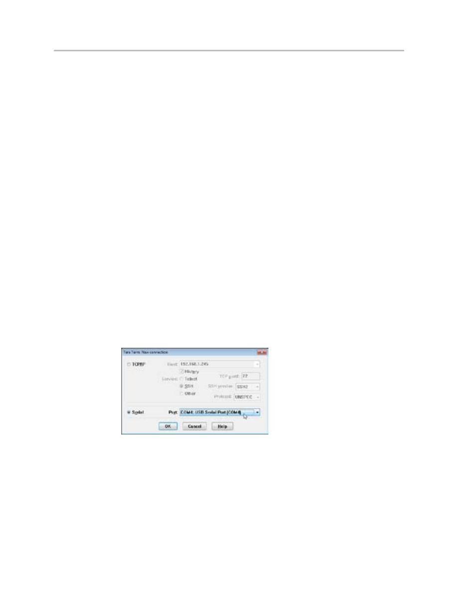
Rev. A
KSC-2 Signal Conditioner Installation and Programming Instructions
KULITE SEMICONDUCTOR PRODUCTS, INC.
KSC-2 Command Protocol
Page
51
4
KSC-2 High-Level Command Set
4.1 Introduction
This section describes the high-level command set for the KSC-2 signal conditioner.
The format of the commands is a channel number and colon followed by the com-
mand to be executed. Each command returns the actual setting of the hardware. An
unrecognized command returns
UNKNOWN COMMAND.
4.2 Communication Configuration
The KSC-2 system operates as a single-connection server. Only one client can ex-
ercise control of the system at any point. The active connection precludes any other.
This is done to protect the system from multiple origin control.
Open a terminal emulator communication program, such as Tera Term Pro, that can
support terminal operations. Tera Term Pro is a free software terminal emulator
(communication program) for MS Windows. It supports Telnet connection, serial port
connection, and VT100 emulation.
The terminal emulator program will provide a panel similar to the one shown in Fig-
ure 34. Select Serial and then, from the drop-down list, choose the COM port for your
USB serial port. Click OK.
Figure 34
Tera Term New Connection Panel
Note:
You can find the COM port for your USB serial port using Windows Device
Manager. Click the Start button and then select Control Panel, System, Device
Manager.

KSC-2 Command Protocol
Page 52
KSC-2 Signal Conditioner Installation and Programming Instructions
Rev. A
KULITE SEMICONDUCTOR PRODUCTS, INC.
The terminal emulator program provides a terminal setup panel (in Tera Term select
Setup, Terminal) similar to the one shown in Figure 35. Choose CR+LF from the
Transmit drop-down menu. Select Local Echo to have commands reflected on the
control display.
Figure 35
Tera Term Terminal Setup
Note:
If you're having trouble connecting to the terminal emulator, check the baud
rate. (In Tera Term, select Setup, Serial port and click the Baud rate drop-down
list.) This rate should be 57600.
4.3 Command Format
Commands to the KSC-2 system are sequences of ASCII characters. Each command
consists of a channel number followed by a colon, a keyword, and optional parame-
ters. To process the command, press the Enter key.
The ASCII codes for delete and other process type codes are ignored.
Commands are not case sensitive: Commands and operators may be entered with
mixed upper- and lower-case alphabetic characters.
Numeric command values are automatically rounded to the nearest correct setting.
Commands are followed by a response, which reports the system response to the com-
mand and verifies that the command was processed.
The command specifications in this manual use specific symbols to define the com
-
mand syntax and semantics. The symbol "..." is the "and so on" or range operator, and
the symbol "|" is the logical OR operator.

Rev. A
KSC-2 Signal Conditioner Installation and Programming Instructions
KULITE SEMICONDUCTOR PRODUCTS, INC.
KSC-2 Command Protocol
Page
53
The format of a command is a channel number followed by a colon and the command
to be executed. For example, the command below sets the excitation value of channel
1 to 10 V:
1:EXC=10
A command that is not recognized by the system returns
UNKNOWN COMMAND
.
4.3.1 Command to Return Current Value
A command immediately followed by a question mark (?) returns the current value
for the specified channel and setting. For example, the command below returns the
current voltage excitation value for channel 1:
1:EXC?
4.4 Command Set
4.4.1 Excitation Commands
The
EXC
command, shown below, sets the constant voltage excitation for the desired
channel. Levels are specified in volts. The system returns the hardware coerced value.
CHAN:EXC=0, 0.00125, 0.0025, …, 12.5
The following command returns the current voltage excitation value for the specified
channel:
CHAN:EXC?
To configure a channel's excitation to operate in bipolar or unipolar mode, use the
EXCTYPE
command:
CHAN:EXCTYPE=BIPOLAR
|
UNIPOLAR
The following command returns the excitation mode (bipolar or unipolar) to which a
channel is currently set:
CHAN: EXCTYPE?
The
SENSE
command sets the excitation supply to use either local or remote sense:
CHAN:SENSE=LOCAL
|
REMOTE

KSC-2 Command Protocol
Page 54
KSC-2 Signal Conditioner Installation and Programming Instructions
Rev. A
KULITE SEMICONDUCTOR PRODUCTS, INC.
The following command returns a channel's current sense setting:
CHAN:SENSE?
Note:
Sense lines are relevant only to bipolar excitation. Do not use sense lines
with unipolar excitation. In unipolar mode, sense is automatically set to local.
To check for an excitation fault in a channel, use the
EXCFAULT
command:
CHAN:EXCFAULT?
This command returns
1
if the excitation supply is in a fault condition,
0
if not.
4.4.2 Input Commands
To set the specified channel's input coupling as either DC or AC, use the
COUPLING
command as shown below:
CHAN:COUPLING=DC
|
AC
The following command returns the value to which input coupling is currently set:
CHAN:COUPLING?
The
SHIELD
command lets you configure the specified channel's shield. The shield
can be set to ground at the conditioner, open (floating) at the conditioner, or driven by
the common mode signal on the channel.
•
If
SHIELD
is set to "ground", the shield line should not be grounded at the gage.
•
If
SHIELD
is set to "float", the line should be grounded at the gage end.
•
If
SHIELD
is set to "drive", do not connect the shield line to ground at the gage.
CHAN:SHIELD=GROUND
|
FLOAT
|
DRIVE
The following command returns the shield’s current setting:
CHAN:SHIELD?
Use the
PREGAIN
command to configure the channel’s prefilter gain to a fixed step:
CHAN:PREGAIN=1
|
2
|
4
|
8
|
16
|
32
|
64
|
128

Rev. A
KSC-2 Signal Conditioner Installation and Programming Instructions
KULITE SEMICONDUCTOR PRODUCTS, INC.
KSC-2 Command Protocol
Page
55
The following command returns the current prefilter gain value for the channel:
CHAN:PREGAIN?
To set the channel to operate in one of three prescribed modes (operate, short, or cali-
brate), use the
MODE
setting:
•
OPERATE
is the normal operating mode.
•
SHORT
grounds the amplifier input stage to measure noise and DC offset.
• CAL
disconnects the signal from the input connector and injects the signal on the
CAL INPUT BNC at the amplifier input.
CHAN:MODE=OPERATE
|
SHORT
|
CAL
The following command returns the current
MODE
setting:
CHAN:MODE?
4.4.3 Filter Commands
The
FILTER
command sets the channel’s filter type to either flat mode (for
frequency-domain measurements) or pulse mode (for time-domain measurements). A
setting of
NONE
bypasses the filter completely.
CHAN:FILTER=FLAT
|
PULSE
|
NONE
The following command returns the channel’s
FILTER
setting:
CHAN:FILTER?
To configure the 6-pole LP filter’s cutoff frequency from 500 Hz to 127.5 KHz in 500
Hz steps, use the
FC
command. The system returns the hardware coerced value.
CHAN:FC=500
|
1000
|
…
|
127500
The following command returns the current filter cutoff frequency value:
CHAN:FC?
The
COMPFILT
command enables or disables the cavity compensation filter for the
specified channel. Use
ON
to enable the filter or
OFF
to disable it:
CHAN:COMPFILT=ON
|
OFF

KSC-2 Command Protocol
Page 56
KSC-2 Signal Conditioner Installation and Programming Instructions
Rev. A
KULITE SEMICONDUCTOR PRODUCTS, INC.
The following command tells you whether the cavity compensation filter is currently
on or off:
CHAN:COMPFILT?
You can set the cavity compensation filter’s center frequency from 10 Hz to
2.55 kHz in 10 Hz steps, from 2.6 kHz to 51 kHz in 200 Hz steps, and from 52 kHz to
255 kHz in 1 kHz steps with the
COMPFILTFC
command. The system returns the
hardware coerced value.
CHAN:COMPFILTFC=10 | 20 | … | 255000
The following command returns the current center frequency of the cavity compensa-
tion filter:
CHAN:COMPFILTFC?
The
COMPFILTQ
command sets the cavity compensation filter’s quality factor from
1 to 20 in 0.1 steps and from 20 to 50 in 0.5 steps. The system returns the hardware
coerced value.
CHAN:COMPFILTQ=1
|
1.1
|
…
|
50
The following command returns the current value for the cavity compensation filter's
quality factor:
CHAN:COMPFILTQ?
4.4.4 Output Commands
To configure the specified channel's vernier postfilter gain to a supplied value, use the
POSTGAIN
command. The system returns the hardware coerced value.
CHAN:POSTGAIN=0.0625
|
…
|
16
The following command returns the current vernier postfilter gain value for a channel:
CHAN:POSTGAIN?
4.4.5 Offset Commands
The auto offset procedure assures DC accuracy of the amplifier/filter channel by
eliminating all sources of internal error throughout the channel circuit.
Offsets drift with temperature. Ensure the system is warmed up before you run the

Rev. A
KSC-2 Signal Conditioner Installation and Programming Instructions
KULITE SEMICONDUCTOR PRODUCTS, INC.
KSC-2 Command Protocol
Page
57
routine.
Use the
OFFSETADJ
command to initiate an offset correction routine for the spec-
ified channel. This command returns
PASSED
if all of the offsets were adjusted
correctly and
FAILED
otherwise.
CHAN:OFFSETADJ
4.4.6 Overload Detector Commands
Overload detectors alert the user to overvoltage conditions. To learn the status of the
input overload detector, use the following command:
CHAN:INOVLD?
The system returns
1
if an overload condition exists and
0
if not.
The
OUTOVLDLIM
command sets the output overload detector level from 0.1 V to
10 V in 0.1 V steps. The system returns the hardware coerced value.
CHAN:OUTOVLDLIM=0.1
|
0.2
|
…
|
10
The following command returns the output overload detector's current level:
CHAN:OUTOVLDLIM?
The following command returns the status of the output overload detector:
1
if the
channel is overloaded and
0
otherwise.
CHAN:OUTOVLD?
In latching mode, the overload detector holds an overload condition until it is reset by
the user. In continuous mode, the system autoresets after an overload condition. The
OVLDMODE
command turns latching mode on or off for the specified channel’s
input and output overload detectors:
CHAN:OVLDMODE=LATCHING
|
CONTINUOUS
The following command tells you whether or not a channel is in latching mode:
CHAN:OVLDMODE?
The
OVLDCLEAR
command clears the both the input and the output overload
detectors for the specified channel:

KSC-2 Command Protocol
Page 58
KSC-2 Signal Conditioner Installation and Programming Instructions
Rev. A
KULITE SEMICONDUCTOR PRODUCTS, INC.
CHAN: OVLDCLEAR
4.4.7 Bridge Commands
The autobalance function measures any bridge imbalance inherent in the bridge and
provides appropriate compensation to the circuit.
To initiate an autobalance cycle on the bridge sensor, use the
AUTOBAL
command.
The system returns
PASSED
if the balance was successful and
FAILED
otherwise. It
make take several minutes for the autobalance to complete.
CHAN:AUTOBAL
Note:
The KSC-2 unit's front-panel Autobalance LED indicators respond to the
AUTOBAL
command: yellow while the balance operation is in progress, green if
the balance was successful, and red if the balance operation failed.
Note:
Autobalance is disabled when the KSC-2 unit is AC coupled.
The
AUTOBALSTAT?
command returns the status of the bridge balance
for the channel. The system returns
BALANCED
(if the bridge is balanced),
UNBALANCED
(if the bridge is unbalanced), or
INVALID
(if the state of the bridge
balance is unknown):
CHAN:AUTOBALSTAT?
To set the balance level as a ratio of bridge offset to excitation in mV\V, use the
BALRATIO
command. The system returns the hardware coerced value.
CHAN:BALRATIO=X
The following command returns the balance level in terms of a ratio of bridge offset
to excitation in mV\V:
CHAN:BALRATIO?
BALVOLT s
ets the bridge balance voltage in mV. The system returns the hardware
coerced value.
CHAN:BALVOLT=X
The following command returns the current balance voltage in mV:
CHAN:BALVOLT?

Rev. A
KSC-2 Signal Conditioner Installation and Programming Instructions
KULITE SEMICONDUCTOR PRODUCTS, INC.
KSC-2 Command Protocol
Page
59
To see the voltage read on the fifth wire of the transducer in volts, use the following
command:
CHAN:5THWIRE?
Device Control and Information
The
SAVE
command saves the current device configuration to nonvolatile memory.
When the action is complete, the system returns
DONE
.
SAVE
LOCK
locks or unlocks user control of the front panel switches. Individual switches
can be specified in the order of channel 2 overload clear, channel 2 autobalance,
channel 1 overload clear, channel 1 autobalance.
1
locks the switch, and
0
unlocks it.
LOCK=XXXX
For example, the command
LOCK=1100
locks the overload clear and autobalance for
channel 2, while leaving these switches unlocked for channel 1.
The following command returns the current locked status of the front panel switches:
LOCK?
To see the device’s serial number (in the format XXXXXX-XXX), use the
SN
command:
SN?
The
VER
command returns the device’s firmware version number (in the format
XX.XX.XX):
VER?
The
IDN
command returns the model (KSC-2) associated with the device:
IDN?
STATUS?
returns the status of the overload and excitation fault monitors for both
channels of the device.
STATUS?

KSC-2 Command Protocol
Page 60
KSC-2 Signal Conditioner Installation and Programming Instructions
Rev. A
KULITE SEMICONDUCTOR PRODUCTS, INC.
The following table shows the meaning of each number that may be returned by the
system in response to the
STATUS
command.
System
Response
Ch. 2
Excitation
Ch. 2
Output
Overload
Ch. 2
Input
Overload
Ch. 1
Excitation
Ch. 1
Output
Overload
Ch. 1
Input
Overload
0
N
N
N
N
N
N
1
N
N
N
N
N
Y
2
N
N
N
N
Y
N
3
N
N
N
N
Y
Y
4
N
N
N
Y
N
N
5
N
N
N
Y
N
Y
6
N
N
N
Y
Y
N
7
N
N
N
Y
Y
Y
8
N
N
Y
N
N
N
9
N
N
Y
N
N
Y
10
N
N
Y
N
Y
N
11
N
N
Y
N
Y
Y
12
N
N
Y
Y
N
N
13
N
N
Y
Y
N
Y
14
N
N
Y
Y
Y
N
15
N
N
Y
Y
Y
Y
16
N
Y
N
N
N
N
17
N
Y
N
N
N
Y
18
N
Y
N
N
Y
N
19
N
Y
N
N
Y
Y
20
N
Y
N
Y
N
N
21
N
Y
N
Y
N
Y
22
N
Y
N
Y
Y
N
23
N
Y
N
Y
Y
Y
24
N
Y
Y
N
N
N
25
N
Y
Y
N
N
Y
26
N
Y
Y
N
Y
N
27
N
Y
Y
N
Y
Y
28
N
Y
Y
Y
N
N
29
N
Y
Y
Y
N
Y
30
N
Y
Y
Y
Y
N
31
N
Y
Y
Y
Y
Y
32
Y
N
N
N
N
N
33
Y
N
N
N
N
Y
34
Y
N
N
N
Y
N
Y = yes (a fault/overload condition exists); N = no (no fault/overload condition detected).

Rev. A
KSC-2 Signal Conditioner Installation and Programming Instructions
KULITE SEMICONDUCTOR PRODUCTS, INC.
KSC-2 Command Protocol
Page
61
System
Response
Ch. 2
Excitation
Ch. 2
Output
Overload
Ch. 2
Input
Overload
Ch. 1
Excitation
Ch. 1
Output
Overload
Ch. 1
Input
Overload
35
Y
N
N
N
Y
Y
36
Y
N
N
Y
N
N
37
Y
N
N
Y
N
Y
38
Y
N
N
Y
Y
N
39
Y
N
N
Y
Y
Y
40
Y
N
Y
N
N
N
41
Y
N
Y
N
N
Y
42
Y
N
Y
N
Y
N
43
Y
N
Y
N
Y
Y
44
Y
N
Y
Y
N
N
45
Y
N
Y
Y
N
Y
46
Y
N
Y
Y
Y
N
47
Y
N
Y
Y
Y
Y
48
Y
Y
N
N
N
N
49
Y
Y
N
N
N
Y
50
Y
Y
N
N
Y
N
51
Y
Y
N
N
Y
Y
52
Y
Y
N
Y
N
N
53
Y
Y
N
Y
N
Y
54
Y
Y
N
Y
Y
N
55
Y
Y
N
Y
Y
Y
56
Y
Y
Y
N
N
N
57
Y
Y
Y
N
N
Y
58
Y
Y
Y
N
Y
N
59
Y
Y
Y
N
Y
Y
60
Y
Y
Y
Y
N
N
61
Y
Y
Y
Y
N
Y
62
Y
Y
Y
Y
Y
N
63
Y
Y
Y
Y
Y
Y
Y = yes (a fault/overload condition exists); N = no (no fault/overload condition detected).
The
BLINKLEDS
command, which is useful for identifying individual devices,
causes all of the front-panel LEDs to blink three times. This command returns
DONE
when the action is complete:
BLINKLEDS

KSC-2 Command Protocol
Page 62
KSC-2 Signal Conditioner Installation and Programming Instructions
Rev. A
KULITE SEMICONDUCTOR PRODUCTS, INC.
This page intentionally left blank.

Rev. A
KSC-2 Signal Conditioner Installation and Programming Instructions
KULITE SEMICONDUCTOR PRODUCTS, INC.
KSC-2 Troubleshooting
Page
63
5
KSC-2 Troubleshooting
5.1 Introduction
This section contains troubleshooting tips for issues commonly encountered when
using a KSC-2 unit.
5.2 KSC-2 Does Not Turn On
When power is applied to a KSC-2 unit, the POWER indicator light turns green. If the
unit does not turn on when you move the Power switch to the On (|) position, check to
make sure that the power cable is:
•
Connected to the POWER IN connector on the left side of the unit’s rear panel
•
Plugged into an electrical outlet
5.3 KSC-2 GUI Does Not Recognize the System
If the installed KSC-2 Control GUI software does not recognize the system, use this
checklist:
•
Ensure that the power cable is connected and the unit is turned on.
•
Check that the USB cable connects the unit to the host computer.
•
Ensure that no terminal emulator program (such as Tera Term) is already running
and connected to the KSC-2 unit.
•
Open Windows Device Manger to make sure the KSC-2 software is installed. To
open Device Manager, click the Start button and select Control Panel, System,
Device Manager.
•
Make sure the device driver for the KSC-2 unit is installed. Look for it in the
Windows Device Manager (Start, Control Panel, System, Device Manager). If the
driver does not appear in Device Manager, try the following:
•
Run the installation program on the KSC-2 Signal Conditioner Software
Distribution CD that came with your unit (see Section 4.2.2).
•
Restart your computer.
•
Disconnect the USB cable from your computer and then plug it into a different
USB port. Windows will detect the device and install its driver. If the driver fails
to install properly, Windows shows a notification panel.
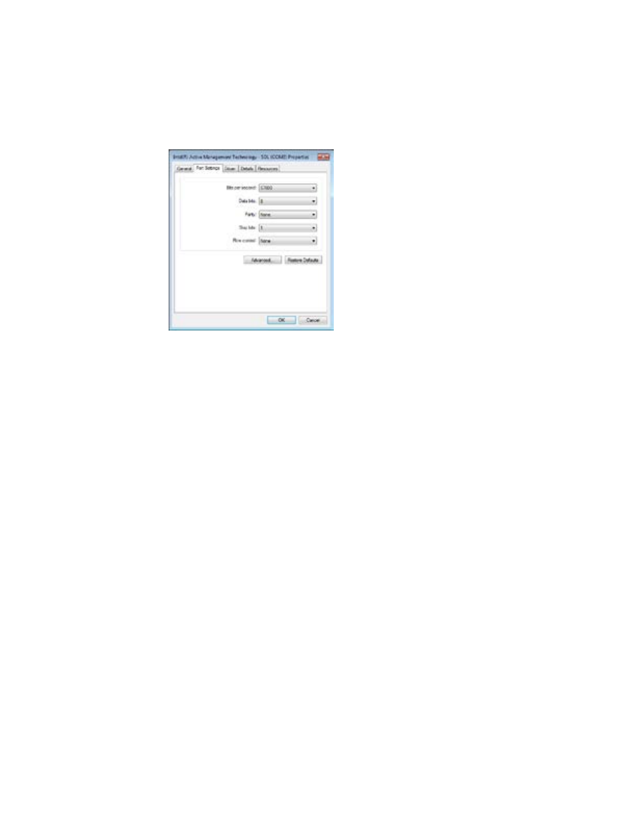
KSC-2 Troubleshooting
Page 64
KSC-2 Signal Conditioner Installation and Programming Instructions
Rev. A
KULITE SEMICONDUCTOR PRODUCTS, INC.
•
Check your computer’s COM port settings. Open Device Manager (Start, Control
Panel, System, Device Manager). In the Device Manager list, click the arrow to the
left of Ports to expand that section. Right-click the COM port you want and select
Properties. In the Properties panel (Figure 36), click the Port Settings tab.
Figure 36
Device Manager COM Port Properties Panel
Make sure the COM port is configured with the following settings:
•
Bits per second:
57600
• Data bits:
8
•
Parity:
None
• Stop bits:
1
•
Flow control:
XON/XOFF
5.4 Overload Indicators Are Red
The front panel of the KSC-2 unit has input and output overload indicators for each
channel. See Section 2.6.3,
Overload Indicators and Reset Button
, for more informa-
tion about overload indicators.
5.5 KSC-2 Unit LEDs Are Out of Sync with the GUI
If you are in the process of entering data in a GUI field, you may notice that the LEDs
on the front panel of the KSC-2 unit do not match those in the GUI. This is a tempo-
rary condition that happens while data is being entered in the GUI.
To resync the KSC-2 unit and the GUI, finish data entry and press the Enter key.

Rev. A
KSC-2 Signal Conditioner Installation and Programming Instructions
KULITE SEMICONDUCTOR PRODUCTS, INC.
Support and Service
Page
65
6
Support and Service
6.1 Technical Support
Kulite provides full technical support from installing a new system to troubleshooting
existing set-ups before or during a measurement test.
Technical support is available by phone, E-mail or by fax.
Technical Support Phone:
(201) 461-0900
Customer Service E-Mail:
KSCsupport@kulite.com
Fax:
(201) 461-0990
6.2 Service and Repair
If equipment is being returned to Kulite for service or repair, contact the factory for a
Return Authorization Number.
To obtain a Return Authorization Number contact Kulite by one of these methods:
Phone:
(201) 461-0900
E-mail:
KSCsupport@kulite.com
Fax:
(201) 461-0990
Include the following information with the equipment:
•
Owner’s name, company, address and telephone number.
•
A detailed description of the service or repair.
•
The instrument model and serial numbers.
•
The Return Authorization Number issued by Kulite clearly marked on the outside
of the shipping container.
Equipment should be shipped in the best available packing materials. Factory
packaging is available. Contact Kulite for more information.

Support and Service
Page 66
KSC-2 Signal Conditioner Installation and Programming Instructions
Rev. A
KULITE SEMICONDUCTOR PRODUCTS, INC.
This page intentionally left blank.