background image

®

E L E C T R O N I C S

C O R P.

RoHS COMPLIANT

ISO 9001:2015 QMS

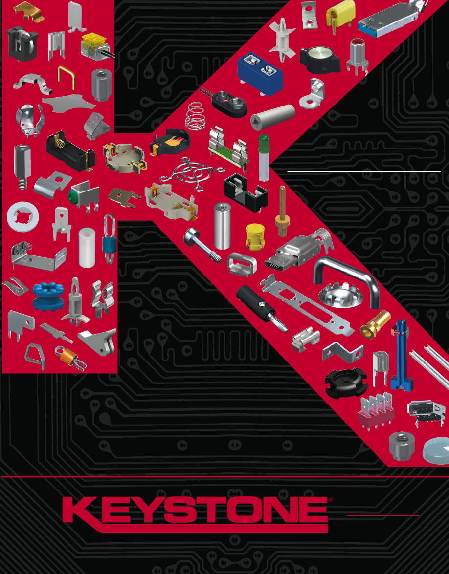
Dynamic Catalog M70 at keyelco.com

PRODUCT DESIGN GUIDE

M70

DESIGNERS & MANUFACTURERS OF

ELECTRONIC COMPONENTS & HARDWARE

Keystone-M70-FullVersion-html.html
background image

Coin Cell Holders & Retainers

pages 2-11

Coin Cell Enclosure Contacts

page 12

SMT & THM Battery Clips

page 13

SMT & THM Battery Holders

pages 24-30

IP65 Water Resistant Battery Holders

page 31

UL Recognized Auto Fuse Clips & Holders

pages 46-49

Battery Contacts

pages 14-21

Fuse Clips Supplied on Tape & Reel

with Kapton Tape

pages 48-53

UL Recognized Fuse Clips & Holders

pages 50-53

Jumpers & Zero Ohm Jumpers

page 60

SMT & THM Test Points

pages 61-63

Keystone-M70-FullVersion-html.html
background image

UL Recognized Quick-Fit Terminals

pages 64-69

SMT Quick Fit Terminals

page 66

Quick-Fit Terminals Bulk & Continuous Reel

pages 64-69

Panel Hardware

pages 101-107

Micro Jacks & Pins

pages 112-115

Grommets & Rubber Bumpers

pages 141-142

Edge Connectors

page 69

PC Board Guides

page 135

Color Coded Screw Terminals

pages 73-77

SMT Standoffs & Spacers, Threaded Inserts

page 86

Extreme Temperature Nylon Standoffs

page 86

Keystone-M70-FullVersion-html.html
background image

ALLIGATOR CLIPS

. . . . . . . . . . . . . . . . . . . . . . . . . . . . . . . . . 62

ALUMINUM & STEEL BATTERY HOLDERS

. . . . . . . . . . . . . . 23

AUDIO JACKS

. . . . . . . . . . . . . . . . . . . . . . . . . . . . . . . . . . . 121

AUTOMOTIVE BLADE FUSE CLIPS & HOLDERS

Low Profile Auto Fuse Clip & Holder . . . . . . . . . . . . 47-49

MAXI Auto Blade Fuse Clip & Holder. . . . . . . . . . . . . . . 46

Mini Auto Blade Fuse Clip & Holder . . . . . . . . . . . . 48-49

Standard Auto Blade Holder . . . . . . . . . . . . . . . . . . 46-49

Standard Auto Blade Clip . . . . . . . . . . . . . . . . . . . . 46-49

BATTERY CONTACTS & CLIPS

Accessories. . . . . . . . . . . . . . . . . . . . . . . . . . . . . . . . . . 38

Battery Insulators (Pull Tabs). . . . . . . . . . . . . . . . . . . . . 38

Button Cell Retainers . . . . . . . . . . . . . . . . . . . . . . . . . . . 8

Coin Cell Retainers/Contacts (SMT/THM) . . . . . . . . . 9-12

Coin Cell Retainers, Insulated (SMT/THM) . . . . . . . . . . . 9

Contacts for Off Board Applications . . . . . . . . . . . . . . . 15

Cylindrical Cell (SMT/THM) . . . . . . . . . . . . . . . . . . . 13-16

Cylindrical Cell (Molded Case) . . . . . . . . . . . . . . . . 17-21

Steel Clips & Contacts . . . . . . . . . . . . . . . . . . . . . . . . . 22

9 Volt Snaps & Contacts. . . . . . . . . . . . . . . . . . . . . . . . 34

BATTERY HOLDERS

Aluminum/Steel . . . . . . . . . . . . . . . . . . . . . . . . . . . . . . 23

Coin Cell . . . . . . . . . . . . . . . . . . . . . . . . . . . . . . . . . . . 2-7

Covered (Densi-Pak)  . . . . . . . . . . . . . . . . . . . . . . . . . . 31

IP65 Water & Dust Resistant Holder . . . . . . . . . . . . . . . 31

Lithium-Ion  . . . . . . . . . . . . . . . . . . . . . . . . . . . . . . . 24-30

Plastic -Ecconomical . . . . . . . . . . . . . . . . . . . . . . . . 32-33

Plastic - Enclosed . . . . . . . . . . . . . . . . . . . . . . . . . . . . . 31

Polarized . . . . . . . . . . . . . . . . . . . . . . . . . . . . . . . . . 26-30

PC Mount (Surface & Thru Hole Mount) . . . . . . . . . 24-30

9 Volt Holders . . . . . . . . . . . . . . . . . . . . . . . . . . . . . . . . 37

9 Volt Straps . . . . . . . . . . . . . . . . . . . . . . . . . . . . . . 35-36

BATTERY ACCESSORIES

. . . . . . . . . . . . . . . . . . . . . . . . . . . . 38

BATTERY CONTACT LAYOUTS & MOUNTING DETAILS

. . . 39-42

BANANA PLUGS & JACKS

. . . . . . . . . . . . . . . . . . . . . . 122-123

BINDING POSTS

Mini- THM mount . . . . . . . . . . . . . . . . . . . . . . . . . . . . . 78

Rivet Mount. . . . . . . . . . . . . . . . . . . . . . . . . . . . . . . . . . 79

BOARD GUIDES, P.C.

. . . . . . . . . . . . . . . . . . . . . . . . . . 134-135

BRACKETS

(Mounting). . . . . . . . . . . . . . . . . . . . . . . . . 132-133

BRACKETS

(Computer) . . . . . . . . . . . . . . . . . . . . . . . . 136-137

BUMBERS

, Adhesive Backing . . . . . . . . . . . . . . . . . . . . . . . 142

BUMPERS

, Rubber . . . . . . . . . . . . . . . . . . . . . . . . . . . . . . . 142

BUSHINGS

, Nylon & Rubber . . . . . . . . . . . . . . . . . . . . 140-141

CABLE CLAMPS

. . . . . . . . . . . . . . . . . . . . . . . . . . . . . . 138-139

CABLE TIES

. . . . . . . . . . . . . . . . . . . . . . . . . . . . . . . . . . . . . 139

CABLE TIE ROUTING CLIP

. . . . . . . . . . . . . . . . . . . . . . . . . . 139

CARD EJECTORS, PC

. . . . . . . . . . . . . . . . . . . . . . . . . . . . . . 134

CLIPS

Alligator. . . . . . . . . . . . . . . . . . . . . . . . . . . . . . . . . . . . . 62

Battery . . . . . . . . . . . . . . . . . . . . . . . . . . . . . . . . . . . . . 22

Fuse – Automotive . . . . . . . . . . . . . . . . . . . . . . . . . . 46-49

Fuse – Cylindrical . . . . . . . . . . . . . . . . . . . . . . . . . . 52-53

Key Hole . . . . . . . . . . . . . . . . . . . . . . . . . . . . . . . . . . . 145

COIN/BUTTON CELL BATTERY

Enclosure Contacts . . . . . . . . . . . . . . . . . . . . . . . . . . . . 12

Holders  . . . . . . . . . . . . . . . . . . . . . . . . . . . . . . . . . . . . 2-7

Locking Retainers (SMT & THM) . . . . . . . . . . . . . . . . . . . 9

Positive & Negative Contacts . . . . . . . . . . . . . . . . . . . . 12

Retainers (SMT & THM) . . . . . . . . . . . . . . . . . . . . . . . 8-11

COMPUTER

Board Guides . . . . . . . . . . . . . . . . . . . . . . . . . . . 134-135

Card Ejectors . . . . . . . . . . . . . . . . . . . . . . . . . . . . . . . 134

Jack Screws . . . . . . . . . . . . . . . . . . . . . . . . . . . . . . . . 100

Keystone (RJ45/8P8C) Jacks  . . . . . . . . . . . . . . . . . . 125

Mounting Brackets . . . . . . . . . . . . . . . . . . . . . . . 132-133

Network/Intranet (RJ45/8P8C) . . . . . . . . . . . . . 124-125

PC104 Standoffs . . . . . . . . . . . . . . . . . . . . . . . . . . . . . 84

USB Connectors . . . . . . . . . . . . . . . . . . . . . . . . . 118-120

COMPUTER BRACKETS

. . . . . . . . . . . . . . . . . . . . . . . . 136-137

CONNECTORS

Audio . . . . . . . . . . . . . . . . . . . . . . . . . . . . . . . . . . . . . 121

Banana Plugs & Jacks . . . . . . . . . . . . . . . . . . . . 122-123

“F” Coaxial Connector . . . . . . . . . . . . . . . . . . . . . . . . . 124

Keystone (RJ45/8P8C) Jacks  . . . . . . . . . . . . . . . . . . 125

Micro Jacks & Pins . . . . . . . . . . . . . . . . . . . . . . . 112-115

Phono Jacks & Plugs . . . . . . . . . . . . . . . . . . . . . . . . . 128

Screw Terminals. . . . . . . . . . . . . . . . . . . . . . . . . . . . 73-79

USB . . . . . . . . . . . . . . . . . . . . . . . . . . . . . . . . . . 118-120

CRIMP TERMINALS

. . . . . . . . . . . . . . . . . . . . . . . . . . . . . 70-71

DENSI-PAK BATTERY HOLERS

Covered Battery Holders . . . . . . . . . . . . . . . . . . . . . . . . 31

Water & Dust Resistant Holders (IP65). . . . . . . . . . . . . 31

EYELETS

. . . . . . . . . . . . . . . . . . . . . . . . . . . . . . . . . . . . . . . . 146

EYELET STAKING TOOL

. . . . . . . . . . . . . . . . . . . . . . . . . . . . 146

EDGE CONNECTORS

. . . . . . . . . . . . . . . . . . . . . . . . . . . . . . . 69

FAN/FINGER GUARDS

. . . . . . . . . . . . . . . . . . . . . . . . 104-105

FIBER WASHERS

(Flat & Shoulder). . . . . . . . . . . . . . . 144-145

FUSE BLOCKS

. . . . . . . . . . . . . . . . . . . . . . . . . . . . . . . . . . . . 51

FUSE CLIPS & HOLDERS

Automotive Blade Clips & Holders . . . . . . . . . . . . . 46-49

Cylindrical Clips. . . . . . . . . . . . . . . . . . . . . . . . . . . . 52-53

Cylindrical Holders (3AG & 5mm). . . . . . . . . . . . . . 50-51

Midget (SPF) Clips & Holders . . . . . . . . . . . . . . . . . . . . 51

Subminiature . . . . . . . . . . . . . . . . . . . . . . . . . . . . . . . . 51

FUSE CONTACTS LAYOUT & MOUNTING DETAILS

. . . . . . 54-56

GROMMETS

Anti-Vibration . . . . . . . . . . . . . . . . . . . . . . . . . . . . . . . 141

Rubber . . . . . . . . . . . . . . . . . . . . . . . . . . . . . . . . . . . . 141

Universal. . . . . . . . . . . . . . . . . . . . . . . . . . . . . . . . . . . 141

HANDLES, INSTRUMENTATION

. . . . . . . . . . . . . . . . . . . . . . 103

HARDWARE

Bumpers. . . . . . . . . . . . . . . . . . . . . . . . . . . . . . . . . . . 142

Captive Panel Screws . . . . . . . . . . . . . . . . . . . . . . . . . 101

Cable Ties . . . . . . . . . . . . . . . . . . . . . . . . . . . . . . . . . . 139

Eyelets/Rivets . . . . . . . . . . . . . . . . . . . . . . . . . . . . . . . 146

Jack Screws . . . . . . . . . . . . . . . . . . . . . . . . . . . . . . . . 100

Machine Screws & Nuts . . . . . . . . . . . . . . . . . . . . . . . 143

Panel Hardware & Nuts . . . . . . . . . . . . . . . . . . . . . . . 108

Shoulder Screws. . . . . . . . . . . . . . . . . . . . . . . . . . . . . 102

Thumb Screws . . . . . . . . . . . . . . . . . . . . . . . . . . . . . . 101

Washers . . . . . . . . . . . . . . . . . . . . . . . . . . . . . . . 144-145

HOLE PLUGS

. . . . . . . . . . . . . . . . . . . . . . . . . . . . . . . . . . . . 140

IDC CONNECTORS, i-CLAMP

. . . . . . . . . . . . . . . . . . . . . . . . . 72

ISOLATED GROMMETS

. . . . . . . . . . . . . . . . . . . . . . . . . . . . 141

INSTRUMENTATION CASES

. . . . . . . . . . . . . . . . . . . . . . . . . 108

INSULATED CABLE CLAMPS

. . . . . . . . . . . . . . . . . . . . . . . . 138

INSULATED COIN CELL RETAINERS

. . . . . . . . . . . . . . . . . . . . 9

INSULATING HARDWARE

Bushings. . . . . . . . . . . . . . . . . . . . . . . . . . . . . . . 140-141

Ceramic Standoffs . . . . . . . . . . . . . . . . . . . . . . . . . . . . 88

Fiber Washers . . . . . . . . . . . . . . . . . . . . . . . . . . . 144-145

Mica Insulators . . . . . . . . . . . . . . . . . . . . . . . . . . . . . . 126

Nylon Spacers  . . . . . . . . . . . . . . . . . . . . . . . . . . . . 88-90

Nylon Washers . . . . . . . . . . . . . . . . . . . . . . . . . . 144-145

Spacer Supports (Nylon). . . . . . . . . . . . . . . . . . . . . 91-93

INSTALLATION TOOLS

Eyelet . . . . . . . . . . . . . . . . . . . . . . . . . . . . . . . . . . . . . 146

Rivet . . . . . . . . . . . . . . . . . . . . . . . . . . . . . . . . . . . . . . 147

Staking . . . . . . . . . . . . . . . . . . . . . . . . . . . . . . . . . . . . 147

IP65 BATTERY HOLDERS

. . . . . . . . . . . . . . . . . . . . . . . . . . . . 31

IP68 NETWORK JACKS

. . . . . . . . . . . . . . . . . . . . . . . . . . . . 124

JACKS

Audio . . . . . . . . . . . . . . . . . . . . . . . . . . . . . . . . . . . . . 121

Banana. . . . . . . . . . . . . . . . . . . . . . . . . . . . . . . . . . . . 123

Insulated. . . . . . . . . . . . . . . . . . . . . . . . . . . . . . . . . . . 117

Keystone (RJ45) . . . . . . . . . . . . . . . . . . . . . . . . . . . . . 125

Micro. . . . . . . . . . . . . . . . . . . . . . . . . . . . . . . . . . 112-113

Phono. . . . . . . . . . . . . . . . . . . . . . . . . . . . . . . . . . . . . 128

Test . . . . . . . . . . . . . . . . . . . . . . . . . . . . . . . . . . . 116-117

USB . . . . . . . . . . . . . . . . . . . . . . . . . . . . . . . . . . 118-120

JACK SCREWS

Nylon Patch . . . . . . . . . . . . . . . . . . . . . . . . . . . . . . . . 100

Standard - SEMS . . . . . . . . . . . . . . . . . . . . . . . . . . . . 100

Turnable . . . . . . . . . . . . . . . . . . . . . . . . . . . . . . . . . . . 100

JUMPERS

THM  . . . . . . . . . . . . . . . . . . . . . . . . . . . . . . . . . . . . . . . 60

SMT . . . . . . . . . . . . . . . . . . . . . . . . . . . . . . . . . . . . . . . 60

Zero OHM Chip Resistor Jumper . . . . . . . . . . . . . . . . . . 60

KNOBS, POINTERS

. . . . . . . . . . . . . . . . . . . . . . . . . . . . . . . 102

KEY HOLE CLIPS

. . . . . . . . . . . . . . . . . . . . . . . . . . . . . . . . . 145

A

B

C

(cont.)

E

F

D

G

J

K

I

Tel (516) 328-7500

Fax (516) 328-1080

(800) 221-5510

kec@keyelco.com

www.keyelco.com

55 S. Denton Avenue, New Hyde Park, NY 11040

RoHS COMPLIANT

~

ISO 9001 CERTIFIED

®

H

Keystone-M70-FullVersion-html.html
background image

KEY-PAD DOMES

. . . . . . . . . . . . . . . . . . . . . . . . . . . . . . . 98-99

LITHIUM-ION BATTERY HOLDERS

. . . . . . . . . . . . . . . . . . 24-30

LED HARDWARE

Holders . . . . . . . . . . . . . . . . . . . . . . . . . . . . . . . . . . . . 106

LENS Caps . . . . . . . . . . . . . . . . . . . . . . . . . . . . . . . . . 106

Spacer Mounts . . . . . . . . . . . . . . . . . . . . . . . . . . . . . . 107

LOCKING COIN CELL RETAINERS

. . . . . . . . . . . . . . . . . . . . . . 9

LUGS

(SOLDER) . . . . . . . . . . . . . . . . . . . . . . . . . . . . . . . . . . . 80

MAXI AUTOMOTIVE FUSE CLIPS & HOLDERS

. . . . . . . . . . . 44

MICA TRANSISTOR INSULATORS

. . . . . . . . . . . . . . . . . . . . 126

MICRO JACKS

. . . . . . . . . . . . . . . . . . . . . . . . . . . . . . . 112-113

MICRO PINS

. . . . . . . . . . . . . . . . . . . . . . . . . . . . . . . . 114-115

MINI AUTOMOTIVE FUSE CLIPS & CONTACTS

. . . . . . . . 46-47

MIDGET FUSE HOLDER

. . . . . . . . . . . . . . . . . . . . . . . . . . . . . 51

MINI/MICRO USB SOCKETS & PLUGS

. . . . . . . . . . . 118-120

MOUNTING BRACKETS

. . . . . . . . . . . . . . . . . . . . . . . . 132-133

NEGATIVE & POSITIVE COIN CELL CONTACTS

. . . . . . . . . . . 12

NETWORK JACKS

. . . . . . . . . . . . . . . . . . . . . . . . . . . . . 124-125

9 VOLT BATTERY CONTACTS & STRAPS

. . . . . . . . . . . . . . 34-37

NUTS, MACHINE

. . . . . . . . . . . . . . . . . . . . . . . . . . . . . . . . . 143

NYLON CABLE CLAMPS

. . . . . . . . . . . . . . . . . . . . . . . . . . . 139

NYLON PC SPACERS/SUPPORTS

. . . . . . . . . . . . . . . . . . 91-93

NYLON SCREWS

. . . . . . . . . . . . . . . . . . . . . . . . . . . . . . . . . 143

NYLON SNAP RIVETS

. . . . . . . . . . . . . . . . . . . . . . . . . . . . . . 146

NYLON SPACERS

. . . . . . . . . . . . . . . . . . . . . . . . . . . . . . . . . . 90

NYLON STANDOFFS

. . . . . . . . . . . . . . . . . . . . . . . . . . . . . . . . 84

NYLON WASHERS

. . . . . . . . . . . . . . . . . . . . . . . . . . . . 144-145

PANEL BEARINGS

. . . . . . . . . . . . . . . . . . . . . . . . . . . . . . . . 108

PANEL HARDWARE

Captive Panel Screws . . . . . . . . . . . . . . . . . . . . . . . . . 101

Panel Nuts & Bearings . . . . . . . . . . . . . . . . . . . . . . . . 108

Shoulder Screws. . . . . . . . . . . . . . . . . . . . . . . . . . . . . 102

Thumb Screws . . . . . . . . . . . . . . . . . . . . . . . . . . . . . . 101

PC BATTERY CONTACTS

. . . . . . . . . . . . . . . . . . . . . . . . . . 12-16

PHONO PLUGS & JACKS

. . . . . . . . . . . . . . . . . . . . . . . . . . . 128

PINS, MICRO

. . . . . . . . . . . . . . . . . . . . . . . . . . . . . . . . 114-115

PLUGS

Banana. . . . . . . . . . . . . . . . . . . . . . . . . . . . . . . . 122-123

Hole . . . . . . . . . . . . . . . . . . . . . . . . . . . . . . . . . . . . . . 140

Shorting . . . . . . . . . . . . . . . . . . . . . . . . . . . . . . . . . . . 115

Tips & Plugs . . . . . . . . . . . . . . . . . . . . . . . . . . . . 116-117

PULL TABS

(Battery Insulators) . . . . . . . . . . . . . . . . . . . . . . . 38

QUICK-FIT COMPONENTS

Boots . . . . . . . . . . . . . . . . . . . . . . . . . . . . . . . . . . . . . . 70

Continous Reeled  . . . . . . . . . . . . . . . . . . . . . . . . . . . . 66

Headers . . . . . . . . . . . . . . . . . . . . . . . . . . . . . . . . . . . . 67

PC Mount Female Terminals . . . . . . . . . . . . . . . . . . 68-69

PC Mount Male Terminals . . . . . . . . . . . . . . . . . . . . 64-67

Rivet Mount. . . . . . . . . . . . . . . . . . . . . . . . . . . . . . . . . . 67

Surface Mount Terminals. . . . . . . . . . . . . . . . . . . . . . . . 68

RIVETS

. . . . . . . . . . . . . . . . . . . . . . . . . . . . . . . . . . . . . . . . . 146

RJ45 (KEYSTONE) JACKS

. . . . . . . . . . . . . . . . . . . . . . 124-125

RUBBER BUMPERS & GROMMETS

. . . . . . . . . . . . . . 141-142

RETAINING SPACERS

. . . . . . . . . . . . . . . . . . . . . . . . . . . . . . . 90

RETAINING WASHERS

. . . . . . . . . . . . . . . . . . . . . . . . . . . . . 144

SCREWS

Colored Head . . . . . . . . . . . . . . . . . . . . . . . . . . . . . 73-78

Handle Mounting . . . . . . . . . . . . . . . . . . . . . . . . . . . . 103

Jack Screw . . . . . . . . . . . . . . . . . . . . . . . . . . . . . . . . . 100

Machine Screw . . . . . . . . . . . . . . . . . . . . . . . . . . . . . . 143

Metric Screws . . . . . . . . . . . . . . . . . . . . . . . . . . . . . . . 143

Panel Screw . . . . . . . . . . . . . . . . . . . . . . . . . . . . . . . . 108

Self-Tapping . . . . . . . . . . . . . . . . . . . . . . . . . . . . . . . . 143

Shoulder Screw. . . . . . . . . . . . . . . . . . . . . . . . . . . . . . 102

Thumb Screw . . . . . . . . . . . . . . . . . . . . . . . . . . . . . . . 101

SCREW TERMINALS

Slim-Line  . . . . . . . . . . . . . . . . . . . . . . . . . . . . . . . . . . . 73

Horizantal & Vertical – 15 Amp . . . . . . . . . . . . . . . . 74-75

Heavy Duty – 30 Amp . . . . . . . . . . . . . . . . . . . . . . . . . . 75

SEMS Screw - 15/30 Amp. . . . . . . . . . . . . . . . . . . . . . 76

Metric Thread . . . . . . . . . . . . . . . . . . . . . . . . . . . . . . . . 77

SHAFT LOCKS/EXTENDERS

. . . . . . . . . . . . . . . . . . . . . . . . 108

SHORTING PINS, PLUGS & JACKS

. . . . . . . . . . . . . . . . . . . 115

SHOULDER SCREWS

. . . . . . . . . . . . . . . . . . . . . . . . . . . . . . 102

SOCKETS

Keystone (RJ45) . . . . . . . . . . . . . . . . . . . . . . . . . 124-125

Micro. . . . . . . . . . . . . . . . . . . . . . . . . . . . . . . . . . 112-113

Phono. . . . . . . . . . . . . . . . . . . . . . . . . . . . . . . . . . . . . 128

Transistor. . . . . . . . . . . . . . . . . . . . . . . . . . . . . . . . . . . 127

USB . . . . . . . . . . . . . . . . . . . . . . . . . . . . . . . . . . 118-120

SOLDER LUGS & TERMINALS

. . . . . . . . . . . . . . . . . . . . . . . . 80

SPACERS

Aluminum, Brass, Nylon, Phenolic. . . . . . . . . . . . . . . . . 88

Force Fit . . . . . . . . . . . . . . . . . . . . . . . . . . . . . . . . . . . . 87

LED  . . . . . . . . . . . . . . . . . . . . . . . . . . . . . . . . . . . . . . 107

Organizer Kits . . . . . . . . . . . . . . . . . . . . . . . . . . . . . . . . 94

PC Board (Lock-In, Adhesive) . . . . . . . . . . . . . . . . . . . . 93

Self Retaining (Nylon) . . . . . . . . . . . . . . . . . . . . . . . . . . 90

Swage Mount . . . . . . . . . . . . . . . . . . . . . . . . . . . . . . . . 87

Surface Mount . . . . . . . . . . . . . . . . . . . . . . . . . . . . . . . 86

STANDARD AUTOMOVE FUSE CLIPS & HOLDERS

. . . . . 46-49

STANDOFFS

Aluminum, Brass, Ceramic, Nylon, Stainless Steel . . . . 85

Extreme Temperature Nylon. . . . . . . . . . . . . . . . . . . . . . 86

Force Fit . . . . . . . . . . . . . . . . . . . . . . . . . . . . . . . . . . . . 87

Hinged . . . . . . . . . . . . . . . . . . . . . . . . . . . . . . . . . . . . . 90

Metric . . . . . . . . . . . . . . . . . . . . . . . . . . . . . . . . . . . . . . 89

Male - Female. . . . . . . . . . . . . . . . . . . . . . . . . . . . . . . . 84

Organizer Kits . . . . . . . . . . . . . . . . . . . . . . . . . . . . . . . . 94

PC 104 . . . . . . . . . . . . . . . . . . . . . . . . . . . . . . . . . . . . . 84

Swage Mount . . . . . . . . . . . . . . . . . . . . . . . . . . . . . . . . 87

Surface Mount . . . . . . . . . . . . . . . . . . . . . . . . . . . . . . . 86

Threaded Insert. . . . . . . . . . . . . . . . . . . . . . . . . . . . . . . 86

STURDI-MOUNT QUICK-FIT TERMINALS

. . . . . . . . . . . . . 64-67

TAPE & REEL COMPONENTS

Audio Jacks. . . . . . . . . . . . . . . . . . . . . . . . . . . . . . . . . 121

Battery Contacts . . . . . . . . . . . . . . . . . . . . . . . . . . . . 9-14

Coin Cell Holders . . . . . . . . . . . . . . . . . . . . . . . . . . . . . 2-7

Coin Cell Retainers/Contacts. . . . . . . . . . . . . . . . . . . 8-12

Edge Connectors. . . . . . . . . . . . . . . . . . . . . . . . . . . . . . 69

Fuse Clips . . . . . . . . . . . . . . . . . . . . . . . . . . . . . . . . 48-49

Fuse Holders . . . . . . . . . . . . . . . . . . . . . . . . . . . . . . 48-49

Jumpers  . . . . . . . . . . . . . . . . . . . . . . . . . . . . . . . . . . . . 60

Key Pad Dome Switches . . . . . . . . . . . . . . . . . . . . . 98-99

Quick-Fit Female Terminals . . . . . . . . . . . . . . . . . . . . . . 69

Spacers & Standoffs. . . . . . . . . . . . . . . . . . . . . . . . . . . 86

Test Points. . . . . . . . . . . . . . . . . . . . . . . . . . . . . . . . . . . 61

USB Plugs & Sockets . . . . . . . . . . . . . . . . . . . . . 118-120

TERMINALS

Binding Post Terminal . . . . . . . . . . . . . . . . . . . . . . . 78-79

Lugs (Solder) . . . . . . . . . . . . . . . . . . . . . . . . . . . . . . . . 80

Micro Jacks. . . . . . . . . . . . . . . . . . . . . . . . . . . . . 112-113

Quick-Fit . . . . . . . . . . . . . . . . . . . . . . . . . . . . . . . . . 64-68

Screw Terminals. . . . . . . . . . . . . . . . . . . . . . . . . . . . 73-79

Solderless (Crimp) . . . . . . . . . . . . . . . . . . . . . . . . . 70-71

Sturdi-Mount, Quick-Fit . . . . . . . . . . . . . . . . . . . . . . 64-67

TEST POINTS

Color Keyed, THM . . . . . . . . . . . . . . . . . . . . . . . . . . . . . 62

Color Keyed, SMT . . . . . . . . . . . . . . . . . . . . . . . . . . . . . 61

PC Mount . . . . . . . . . . . . . . . . . . . . . . . . . . . . . . . . . . . 62

Surface Mount . . . . . . . . . . . . . . . . . . . . . . . . . . . . . . . 61

Slotted & Loop . . . . . . . . . . . . . . . . . . . . . . . . . . . . . . . 63

TEST TIPS, PLUGS & JACKS

. . . . . . . . . . . . . . . . . . . . 116-117

THUMB SCREWS

. . . . . . . . . . . . . . . . . . . . . . . . . . . . . . . . . 101

TRANSISTOR COVERS

. . . . . . . . . . . . . . . . . . . . . . . . . . . . . 127

TRANSISTOR SOCKETS/MOUNTS

. . . . . . . . . . . . . . . . . . . . 127

USB PLUGS & SOCKETS

. . . . . . . . . . . . . . . . . . . . . . . 118-120

VERTICAL COIN CELL HOLDERS

. . . . . . . . . . . . . . . . . . . . . 3,7

VERTICAL PC BOARD GUIDE

. . . . . . . . . . . . . . . . . . . . . . . . 135

VIBRATION (ANTI) GROMMETS

. . . . . . . . . . . . . . . . . . . . . . 141

WASHERS

Internal Tooth . . . . . . . . . . . . . . . . . . . . . . . . . . . . . . . 144

Lock Washers . . . . . . . . . . . . . . . . . . . . . . . . . . . . . . . 144

Fibre (Flat & Shoulder) . . . . . . . . . . . . . . . . . . . . 144-145

Nylon (Flat & Shoulder) . . . . . . . . . . . . . . . . . . . 144-145

Self-Retaining . . . . . . . . . . . . . . . . . . . . . . . . . . . . . . . 144

ZERO OHM JUMPERS

. . . . . . . . . . . . . . . . . . . . . . . . . . . . . . 60  

Q (cont.)

S (cont.)

P

N

K (cont.)

L

M

Q

R

S

T

W

Z

V

U

Tel (516) 328-7500

Fax (516) 328-1080

(800) 221-5510

kec@keyelco.com

www.keyelco.com

55 S. Denton Avenue, New Hyde Park, NY 11040

RoHS COMPLIANT

~

ISO 9001 CERTIFIED

®

Keystone-M70-FullVersion-html.html
background image

QUALITY POLICY

KEYSTONE ELECTRONICS CORP. is committed to meeting or exceeding our customer's

expectations and satisfying all applicable requirements, as well as meeting or exceeding

our annual quality goals and objectives by working together to continually improve our

ISO 9001:2015 Quality Management System.

— Troy David, President/CEO

Keystone components are guaranteed to be free from defects in material and workmanship for
a reasonable period of time after delivery. Our liability shall be limited to replacement of defec-
tive material only. Neither seller or manufacturer shall be liable for any injury, loss or damage,
direct  or  consequential,  rising  out  of  the  use  of  or  the  inability  to  use  the  products.  Before
using, user shall determine the suitability of the product for their intended use, user assumes
all risk and liability whatsoever in connection therewith.

We reserve the right to change specifications on any and all items shown in this Product Design
Guide or any supplements without prior notice providing the performance or appearance will not
change the function of the item.
Keystone has carefully prepared this Product Design Guide. The specifications contained here-
in,  are  for  reference  only,  any  inaccuracies  may  be  due  to  typographical  errors  or  changes
made after publication. Please refer to our Dynamic Catalog at keyelco.com for updated infor-
mation and specifications.
© Copyright 2019 by Keystone Electronics Corp. Printed in U.S.A.

All products unconditionally guaranteed against defects in material and workmanship.

FEDERAL SUPPLY CODE

FSCM

91833

Keystone-M70-FullVersion-html.html
background image

BATTERY CLIPS, CONTACTS & HOLDERS

SECTION 1

PAGE 1

FUSE CLIPS & HOLDERS

TERMINALS & TEST POINTS

SPACERS & STANDOFFS

PANEL HARDWARE

PINS, PLUGS, JACKS & SOCKETS

MULTI-PURPOSE HARDWARE

SECTION 2

PAGE 45

SECTION 3

PAGE 59

SECTION 4

PAGE 83

SECTION 5

PAGE 97

SECTION 6

PAGE 111

SECTION 7

PAGE 131

Keystone-M70-FullVersion-html.html
background image

Our battery clips, contacts and holders are designed with leading edge

technology in mind, to accommodate all major manufacturers’ batteries.
Available in a wide range of materials and mounting styles including 
surface mount, thru hole and off board, some of the applications include:

Telecommunications and Video power back-up

Laptop and Mobile computing applications 

Communication system’s power requirements 

Microcomputer and memory hold

Preprogrammed electronic and video games 

Emergency power systems

Industrial and commercial security and alarm systems

Miniature battery power devices

Computer memory, power transfer and back-up systems

Personal medical monitoring devices

Our quality system is ISO 9001:2015 certified. Our products are in 

compliance with the RoHS and REACH directives. We provide 3D modeling,
CAD andother application-engineering support for modifications, special
designs or assemblyrequirements to assist you in choosing the right 
Keystone product for your application.

BATTERY CLIPS, CONTACTS & HOLDERS

Keystone-M70-FullVersion-html.html
background image

BA
T

T

E

R


CL
IP

S

, CO
N

T

A

CT
S

 &

 HO
L

D

E

RS

1

COIN/BUTTON CELL RETAINERS

Button Cell..........................................................................8
Coin Cell...........................................................................8-11
Insulated.............................................................................9
Locking.................................................................................9
Positive & Negative Contacts........................................12

CLIPS/CONTACTS

Alkaline & Lithium Battery Clips, Rivet Mount ........22
Alkaline & Lithium Clip, THM & SMT ............................13
PC Battery Contacts...............................................14-16
Molded Case Contacts, Alkaline.............................17-21
Molded Case Contacts, Coin Cell..................................12

HOLDERS

Aluminum & Steel ..........................................................23
Coin Cell............................................................................2-7
Lithium Cell ...............................................................24-30
IP65 Water & Dust Resistant.....................................31
PC Mount –SMT & THM.......................................24-26
Plastic Economical..................................................32-33

9 VOLT BATTERY

9 Volt Snaps & Contacts.......................................34-35
9 Volt Holders ...........................................................35,37
9 Volt Battery Straps...........................................35-36

MOUNTING DETAILS .............................................39-42

SECTION 1 CONTENTS

Keystone-M70-FullVersion-html.html
background image

Tel (516) 328-7500

Fax (516) 328-1080

(800) 221-5510

kec@keyelco.com

www.keyelco.com

55 S. Denton Avenue, New Hyde Park, NY 11040

RoHS COMPLIANT

~

ISO 9001 CERTIFIED

®

THRU-HOLE (THM) & SURFACE MOUNT (SMT) COIN CELL HOLDERS

1

2

mm

 to

 1

6

mm

 CO

IN

 CE

L

L

 HO

L

D

E

RS

2

DESIGN ADVANTAGES…

Reliable spring tension assures low contact resistance 

Retains battery securely to withstand shock and vibration 

Base material UL Rated 94V-0. Impervious to most industrial solvents 

Operating temperature range: -60°F to +293°F (-51°C to +145°C)

IDEALLY SUITED FOR…

Computer memory, power transfer and back-up systems 

Video and telecommunications power back-up 

Microprocessors and Microcomputer memory hold (desktop and laptop applications)

Industrial and commercial security and alarm systems 

PC 104 application

.048 [1.2] DIA.

x .060 [1.52] L.

.570 [14.5]

.430 [10.9]

.506 [12.9]

REF.

.540 [13.7]

.748 [19.0]

.125 [3.2] TYP.

BATTERY
RELEASE

MATERIAL:

Base:

High Temperature Nylon 46, UL Rated 94V-0

Contacts:

.012 (.30) Phosphor Bronze, Gold Plate (Flash)

Mounting Detail

Pad Layout

.156 [4.0]

.125 [3.2]

.053 [1.3] DIA.

.748

[19.0]

.121 [3.1]

.240 [6.1]

.053 [1.3] DIA.

.031 [0.79]

.047 [1.2]

DIA. (2) PLS

.240 [6.1]

.450 [11.40]

-----MATERIAL:

Base:

High Temperature Nylon 46, UL Rated 94V-0

Contacts: 

.012 (.30) Phosphor Bronze, Gold Plate (Flash)

.038 [.97] WIDE 

PIN (2) PLS.

BATTERY
RELEASE 

.430 [10.9]

.507 [12.9]

REF.

.048 [1.2] DIA.

x .060 [1.52] L.

.540 [13.7]

.570 [14.5]

.450 [11.4]

Tape & Reel Spec’s:

32mm wide; 20mm pitch; 13 inch reel (500 per reel)

.088
[2.24]

.042 [1.07] DIA.

.295 [7.5]

.480 [12.2]

.144 [3.7]MIN.

.102 [2.6] MIN.

.055 [1.40]

DIA.

Pad Layout

MATERIAL:

Base:

Glass Filled PPS. UL Rated 94V-0

Contacts:

.008 (.20) Phosphor Bronze, Gold Plate (Flash)

.040 [1.0] DIA

(2) PLS.

.393

[10.0]

.061 [1.5]

Mounting Detail

NEGITIVE

.062 [1.57] DIA.

LEG (3) PLS. ON

.375 [2.5] CIR. DIA.


POSITIVE

.497 [12.6] I.D.

.750 [19.1]

.196 [5.0]

.593 [15.1]

 O.D.

H

.035 [0.9]

.120 [3.0] MIN.

.393

 [10.0]

.036 [0.91]
DIA. LEG

.048 [1.22]
DIA. LEG

.157 [4.0]

.740 

[18.8]

.071 [1.8]

(2) PLS

.567

[14.4]

.591

[15.0]

DIA.

MATERIAL:

Base:

PBT,  UL Rated 94V-0

Positive Contact:

.015 (.38) Spring Steel, Tin-Nickel Plate

Negative Contact:

.035 (.89) Dia. Steel, Tin-Nickel Plate

Tape & Reel Spec’s:

44mm wide; 24mm pitch; 13 inch reel (450 per reel)

.250 [6.4]
SQUARE ZONE
FOR OPTIONAL
ADHESIVE

1.129 [28.7] MIN.

.138 [3.51]

.111

[2.82]

Pad Layout

MATERIAL:

Base:

Glass Filled LCP, UL Rated 94V-0

Contacts:

.006 (.15) Phosphor Bronze, Gold Plate (Flash)

MATERIAL:

Base:

PA9T, Black

Contacts:

.004 (.10) Phosphor Bronze 

Contact Area:

Gold Plate (Flash)

Solder Tails:

Matte Tin Plate

.061 [1.5]

.463

[11.8]

.040 [1.0] DIA

(2) PLS.

Mounting Detail

NEGITIVE

.062 [1.57] DIA.

LEG (3) PLS. ON

.375 [2.5] CIR. DIA.

POSITIVE

.635 [16.1] I.D.

.120 [3.0] MIN.

H

.196 [5.0]

.750 [19.0]

O.D.

.463

 [11.8]

.897 [22.8]

.035 [0.9]

CAT.

HEIGHT

NO.

(H)

CELLS

BATTERY REFERENCE

500

.280 (7.1)

1

BR1212, CR1216, CL1220, CR1225

501

.380 (9.7)

2

BR1212, CR1216, CL1220, CR1225

CAT.

NO.

CELLS

BATTERY REFERENCE

503

1

DL1/3N, K58L, CR1/3N

2

SR44, 357, MS76, G-13, 303, V313, PX76A

CAT. NO.

ON TAPE

BULK

& REEL

CELLS

BATTERY REFERENCE

498

498TR

1

DL1/3N, K58L, CR1/3N

2

SR44, 357, MS76, G-13, 303, V313, PX76A

Tape & Reel Spec’s:

44mm wide; 20mm pitch; 13 inch reel (200 pieces per reel)

THRU HOLE MOUNT

SURFACE MOUNT

THRU HOLE MOUNT

SURFACE MOUNT

SURFACE MOUNT

THRU HOLE MOUNT

CAT. NO.

ON TAPE

BULK

& REEL

CELLS

BATTERY REFERENCE

504

504TR

1

BR1625, CR1632

CAT. NO.

ON TAPE

BULK

& REEL

CELLS

BATTERY REFERENCE

1056

1056TR

1

CR1220, BR1220, CL1220

CAT.

HEIGHT

NO.

(H)

CELLS

BATTERY REFERENCE

502

.285 (7.3)

1

CR1612, CL1616, CL1620

2

CR1612

502-3

1

BR1625, CR1632

.330 (8.4)

2

BR1616, CR1620, CL1620

MATERIAL:

Base:

Glass Filled LCP, UL Rated 94V-0

Positive Contact:

.015 (.38) Spring Steel, Tin-Nickel Plate

Negative Contact:

.035 (.89) Dia. Steel, Tin-Nickel Plate

.630 [16.0]

.212 [5.4]

.677 [17.2]

1.129 [28.7]

.138 [3.5]

(2) PLS

.315 [8.0]

.146 [3.7]

.628 [16.0]

.047 [1.2]

(2) PLS

.028 [0.7]

(2) PLS

.033 [0.85] DIA.

.021 [0.5] DIA.

.028 [.7]

.043 [1.1]

.315 [8.0]

.079 [2.0]

(2) PLS

.660 [16.8]

.330 [8.4]

.060 [1.5]

(2) PLS

Pad Layout

AVAILABLE ON TAPE AND REEL

1/3N

12mm

16mm

12mm AUTO-IN

SURFACE MOUNT

Tape & Reel Spec’s:

44mm wide; 24mm pitch; 13 inch reel (450 per reel)

CAT. NO.

ON TAPE

BULK

& REEL

CELLS

BATTERY REFERENCE

1072

1072TR

1

CR1220, BR1220, CR1225

AVAILABLE ON TAPE AND REEL

AVAILABLE ON TAPE AND REEL

AVAILABLE ON TAPE AND REEL

Keystone-M70-FullVersion-html.html
background image

Tel (516) 328-7500

Fax (516) 328-1080

(800) 221-5510

kec@keyelco.com

www.keyelco.com

55 S. Denton Avenue, New Hyde Park, NY 11040

RoHS COMPLIANT

~

ISO 9001 CERTIFIED

®

1

6

mm

 &

 2

0

mm

 CO
IN

 CE
L

L

 HO
L

D

E

RS

3

Mounting Detail

.055 [1.4]

.300 [7.6]

.280 [7.1]

-

+

.094 [2.4]

DIA

.047 [1.19] DIA.

Accepts all manufactures of 20mm coin cell batteries

Retains cells securely, withstands shock and vibration

Polarity clearly marked

Mounts securely for wave soldering

Operating Temperature Range: 
-60°F to 293°F (-51°C to 145°C)

.118 [3.0]

.295 [7.5]

.515 [13.1]

.600 [15.2]

.315 [8.0]

.060 [1.52] DIA.

.136 [3.5]DIA.

Mounting Detail

.394 [10.00]

.149 [3.80]

.051 [Ø1.30]

DIA. (3) PLS

Mounting Detail

Molded notch prevents improper insertion of 2032 size cells

Polarized holder, protects circuit from improper insertion of cells.

MATERIAL:

Contacts:

.016 (.41) Spring Steel, Tin-Nickel Plate

Base:

PBT, UL Rated 94V-0

MATERIAL:

Contacts: 

.012 (.30) Spring Steel, Tin-Nickel Plate

Base:

PBT, UL Rated 94V-0

.060 [1.57] DIA x

.062 [1.57] L. LEG 

.038 [1.0]

.875 [22.2]

.300 [7.6]

.140 [3.6]

.785 [19.9]

.670 [17.0]

.280

 [7.1]

.531 [13.5]

(2) PLS

NEG

POS

1.000

 [25.4]

REF.

.918 [23.3]

.238 [6.0]

.920 [23.4]

1.040 [26.4]

.150 [3.8]

.070

 [1.8]

.600 [15.2]

.300 [7.6]

.515

[13.1]

.050 [1.3]

.045 [1.14]

.145 [3.7]

.795

[20.2]

DIA.

+

CAT. NO.

BATTERY REFERENCE

1065

BR2012, CR2016, DL2020, CL2025, CR2032

MATERIAL:

Contacts:

..010 (.25) Brass, Tin Plate

Base:

Nylon 6/6, Black

CAT. NO.

BATTERY REFERENCE

1074

CR2032

CAT. NO.

BATTERY REFERENCE

1067

CR2016, DL2020, CL2025, CR2032

20mm SLIM-LINE

20mm SLIM-LINE

THRU-HOLE MOUNT (THM) VERTICAL VIBRA-FIT CELL HOLDERS

20mm COMPACT

MATERIAL:

Base:

PBT, UL Rated 94V-0

Contacts:

.010 (.25) Steel, Tin-Nickel Plate

Battery Reference:

(1) cell:

BR1612, CR1616, CL1620,

CR1625, BR1632

CAT. NO. 1069

.680 [17.3]

REF.

.478 [12.1]

.050 [1.3]
.045 [1.1]

.640

[16.3]

DIA.

.270 [6.9]

.200 [5.1]

.145

[3.7] DIA.

.070

[1.8]

.832 [21.1]

.728 [18.5]

.422

[10.7]

.125

 [3.2]

.047 [1.2]

.174 [4.4]

.136 [3.5]

.422 [10.7]

.136 [3.5]

(2) PLS

.060 [1.5]

(2) PLS

.478 [12.1]

+

Pad Layout

16mm VERTICAL

.516

[13.1]

.394

 [10.0]

.122 [3.1]

.028 [0.7]

(3) PLS

.240 [6.1]

.720 [18.3]

.149 [3.8]

.905 [23.0]

Stabilizing pins assure vertical positioning & reduce solder joint stress.

Polarized holder protects circuit from improper use.

Top loading.

Keystone-M70-FullVersion-html.html
background image

Tel (516) 328-7500

Fax (516) 328-1080

(800) 221-5510

kec@keyelco.com

www.keyelco.com

55 S. Denton Avenue, New Hyde Park, NY 11040

RoHS COMPLIANT

~

ISO 9001 CERTIFIED

®

THRU-HOLE (THM) & SURFACE MOUNT (SMT) VIBRA-FIT HOLDERS

2

0

mm

 CO

IN

 CE

L

L

 HO

L

D

E

RS

4

Tape & Reel Spec’s: 

44mm wide; 20mm pitch; 13 inch reel (500 pieces per reel)

.102 [2.6] MIN.

.433 [11.0] X .276 [7.0]
OPTIONAL ADHESIVE
ZONE 

1.154 [29.3]

.142

 [3.6]

Pad Layout

MATERIAL:

Contacts:

.006 (.15) Phosphor Bronze, Gold Plate (Flash)

Base:

Glass Filled LCP, UL Rated 94V-0

• 

Extremely rugged, holds battery securely under shock and vibration applications

Polarized holder protects circuit from improper battery insertion

Polarity clearly marked

Safe for all soldering and reflow operations

Designed for manual insertion of battery 

Glass Filled LCP base material UL Rated 94V-0 
impervious to most industrial solvents

Operating Temperature Range: -60°F to 293°F (-51°C to 145°C)

Compatible with vacuum and mechanical pick & place assembly systems

All conductive polystyrene carrier tape meets ANSI/EIA-481 standards

Viewable solder tails allows for easy solder joint inspection

CAT. NO.

ON TAPE

BULK

& REEL

BATTERY REFERENCE

1060

1060TR

CR2025, DL2032

CAT.

NO.

BATTERY REFERENCE

1059

CR2025, DL2032

MATERIAL:

Contacts:

.006 (.15) Phosphor Bronze, Tin Plate

Base:

Glass Filled LCP, UL Rated 94V-0

.100

 [2.5]

1.060 [26.9]

.038

 [0.97]

Mounting Detail

.130 [3.3]

1.060 [26.9]

.630

[16.0]

1.118 [28.4]

.866 [22.0]

.217 [5.5]

Tin plated contacts compatible with wave solder and manual soldering process

1.256 [31.9]

142 [3.6]

.866 [22.0]

1.118 [28.4]

.630

[16.0]

.217 [5.5]

Surface Mount

Thru Hole Mount

2025 / 2032 THRU HOLE MOUNT HOLDER

2025 / 2032 SURFACE MOUNT HOLDER

1.256 [31.9] MIN.

.325 [8.2]

.138 [3.5]

(2) PLS

.100 [2.5]

.280
[7.0]

ZONE FOR OPTIONAL
ADHESIVE FIXATION

Pad Layout

MATERIAL:

Contacts:

.006 (.15) Phosphor Bronze, Gold Plate (Flash)

Base:

Glass Filled LCP, UL Rated 94V-0

Designed for applications where the battery will be 
automatically inserted via a vacuum or mechanical 
pick-and-place device

All conductive polystyrene carrier tape meets ANSI/EIA-481
standards

Viewable solder tails allows for easy solder joint inspection

Gold plated contacts assure low contact resistance

Ideal for retaining cells securely under shock and vibration

Compatible with most vacuum and mechanical pick-and-place
assembly systems

KEC

.630 [16.0]

.880 [22.4] DIA.

.138 [3.5]

(2) PLS

1.256 [31.90]

.200 [5.1]

2032 LOW PROFILE HOLDER

CAT. NO.

ON TAPE

BULK

& REEL

BATTERY REFERENCE

1058

1058TR

CR2032

CAT. NO.

ON TAPE

BULK

& REEL

BATTERY REFERENCE

1057

1057TR

CR2032

Surface Mount

2032 ULTRA LOW PROFILE HOLDER

MATERIAL:

Contacts:

.009 (.23) Phosphor Bronze, Gold Plate (Flash)

Base:

Glass filled LCP

UL Rated 94V-0

Ideal when circuit board height is a critical design parameter

Rises only 2mm above the PCB surface by mounting the holder 
thru a hole in the PCB, allowing the holder to sit through the PCB

Built-in stabilization tabs add mounting security

.900 [23.0]

1.060 [27.0] MIN.

.290 [7.4]

(2) PLS

1.15 [29.2]

CUT OUT

.138 [3.5]

(2) PLS

1.300 [33.2] MIN.

Pad Layout

1057

KEYSTONE

.200 [5.1]

.138 [3.5]

(2) PLS

1.300 [33.2]

.880 [22.4] DIA.

.128 [3.2]

(2) PLS

.790

 [20.1]

.942

 [23.9]

Tape & Reel Spec’s:

56mm wide; 32mm pitch; 13 inch reel (400 pieces per reel)

SURFACE MOUNT (SMT) AUTO-IN HOLDERS

AVAILABLE ON TAPE AND REEL

AVAILABLE ON TAPE AND REEL

AVAILABLE ON TAPE AND REEL

Keystone-M70-FullVersion-html.html
background image

Tel (516) 328-7500

Fax (516) 328-1080

(800) 221-5510

kec@keyelco.com

www.keyelco.com

55 S. Denton Avenue, New Hyde Park, NY 11040

RoHS COMPLIANT

~

ISO 9001 CERTIFIED

®

2

0

mm

 CO
IN

 CE
L

L

 HO
L

D

E

RS

5

MATERIAL:

Contacts: 

.020 (.50) Spring Steel, Tin-Nickel Plate

Base:

PBT, UL Rated 94V-0

Mounting Detail

.807

[20.5]

.070 [1.78]

.050 [1.27] DIA.

+

-

CAT. NO.

BATTERY REFERENCE

NO. OF CELLS

101

BR2012, CR2016, CL2020,

(1) cell (any 20mm)

CR2025, CR2032

(2) 2012, (2) 2016

.062 [1.57] DIA. LEG (3) PLS.
ON .750 [19.00] CIRCLE DIA.

.050 [1.27]
.045 [1.14]

.807 [20.5]

AT TIP

L

H

.179 [4.5]

179 [4.6]

NEG

.250 [6.3]

+

O.D.

Designed to maximize PC Board Capacity

Unique raised mounting design allows components to be
placed underneath the holder

Ideal when board space is more important than board
height; such as PC 104 applicatons

Advanced air-flow design enhances air circulation 
around battery

Reliable spring tension assures low contact resistance

Unique notched slots assure quick and easy battery 
insertion and replacement

Retains battery securely to withstand shock and vibration

THRU-HOLE (THM) & SURFACE MOUNT (SMT) COIN CELL HOLDERS

MATERIAL:

Contacts:

.015 (.38)  Steel

Base:

High Temperature, Nylon 46, UL Rated 94V-0

D MIN.

.093

 [2.36]

MIN.

.703

[17.6]

MAX.

Pad Layout

NEG

D

D

H

.896

[22.8]

.703

[17.9]

.931

 [23.65]

.437

[11.1]

.125

[3.2]

Tin-Nickel Plate

Gold Plate (Flash)

CAT. NO. ON TAPE CAT. NO. ON TAPE

D

H

BATTERY

BULK

& REEL

BULK

& REEL

PAD SIZE

HIEGHT

NO. OF CELLS

REFERENCE

1061

1061TR

1081

1081TR

.156 (4.0)

(1) Cell (any 20mm)

CR2012, CL2016,

1063

1063TR

1093

1093TR

.278 (7.1)

.290 (7.4)

(2) 2012, (2) 2016

BR2020, DL2032

1062

1062TR

1082

1082TR

.156 (4.0)

(2) 2020, (2) 2025, (2) 2032

CR2032

1064

1064TR

1094

1094TR

.278 (7.1)

.406 (10.3)

(3) 2012, (3) 2016

Tape & Reel Spec’s:

44mm wide; 32mm pitch; 13 inch reel (200 pieces per reel)

Polarity clearly marked (+)

Compatible with vacuum and mechanical
pick & place assembly systems 

SMT solder tail with “Flow-Hole” design
for increased joint strength

Viewable solder tails assures reliable
joint inspection

Safe for all soldering & reflow operations

DESIGN ADVANTAGES…

Reliable spring tension assures low contact 
resistance 

Retains battery securely to withstand shock
and vibration 

All conductive polystyrene carrier tape meets
ANSI/EIA - 481 standard

Base material UL Rated 94V-0. Impervious 
to most industrial solvents 

Operating temperature range:
-60°F to +293°F (-51°C to +145°C)

IDEALLY SUITED FOR…

Computer memory, power transfer and 
back-up systems 

Video and telecommunications power back-up 

Microprocessors and Microcomputer memory
hold (desktop and laptop applications)

Industrial and commercial security and 
alarm systems 

Communications power sources 

PC 104 applications

20mm SURFACE MOUNT COIN CELL HOLDER

20mm THRU-HOLE MOUNT CON CELL HOLDER

20mm RAISED MOUNT COIN CELL HOLDER

MATERIAL:

Contacts: 

.020 (.50) Spring Steel, Tin-Nickel Plate

Base:

PBT, UL Rated 94V-0


.062 [1.57] DIA. LEG (3) PLS.
ON .750 [19.00] CIRCLE DIA.

.050 [1.27]
.045 [1.14]

.807 [20.5]

AT TIP

.896 [22.8]

O.D.

1.130 [28.7]

.414 [10.5]

.179 [4.5]

.179 [4.6]

NEG

.250 [6.3]

+

Mounting Detail

.807 [20.5]

.070 [1.78]

.050 [1.27] DIA.

+

-

CAT. NO.

H

L

O.D.

NO. OF CELLS

BATTERY REFERENCE

103

.335 (8.5) 1.130 (28.7)

.896 (22.8)

(1) cell (any 20mm)

BR2012,CR2012, CR2016, CL2016, DL2020, CL2025, BR2025, CR2032, CL2032

(2) 2012, (2) 2016

106

.335 (8.5) 1.219 (31.0) 1.093 (27.8)

(1) cell (any 20mm)

BR2012,CR2012, CR2016, CL2016, DL2020, CL2025, BR2025, CR2032, CL2032

(2) 2012, (2) 2016

1026

.452 (11.5) 1.219 (31.0) 1.093 (27.8) (2) 2020, (2) 2025, (2) 2032

DL2020, CR2020, CL2025, BR2025, CR2032, CL2032

AVAILABLE ON TAPE AND REEL

Keystone-M70-FullVersion-html.html
background image

Tel (516) 328-7500

Fax (516) 328-1080

(800) 221-5510

kec@keyelco.com

www.keyelco.com

55 S. Denton Avenue, New Hyde Park, NY 11040

RoHS COMPLIANT

~

ISO 9001 CERTIFIED

®

THRU HOLE (THM) & SURFACE MOUNT (SMT) 20mm EZ-OUT HOLDERS

2

0

mm

 &

 2

3

mm

 CO

IN

 CE

L

L

 HO

L

D

E

RS

6

Mounting Detail

.035 [.89] DIA.

.094 [2.4]

.787

[20.0]

Pad Layoutl

.138 [3.5] SQR

MIN. (2) PLS

.960 [24.4] MIN.

.673 [11.1]

MAX.

Designed for manual insertion of battery.

Mounts securely for wave soldering

MATERIAL:

Contacts: 

.016 (.41) Phosphor Bronze, Tin Plate

Base:

Nylon UL Rated 94V-0

MATERIAL:

Contacts: 

.009 (.23) Phosphor Bronze, Gold Plate (Flash)

Base:

High temperature Nylon 4/6, UL Rated 94V-0

.059 [1.50] DIA. LEG (3) PLS.
ON .730 [18.5] CIRCLE DIA.

.023 [.58]

.906 [23.0]

.122 [3.10]

.807 [20.5]

.787

[20.0]

.388 [9.85]

1.089 [27.7]

Designed for automatic vertical insertion of battery via a vacuum or
mechanical pick-and-place device

Compatible with vacuum and mechanical pick & place assembly systems

All conductive polystyrene carrier tape meets ANSI/EIA-481 standards

Top loading for compact applications

Finger pressure against leaver will release battery

No tools required

Holds battery securely under shock and vibration applications

Nylon base material UL Rated 94V-0, impervious to most
industrial solvents

Operating Temperature Range: 
-60°F to 293°F (-51°C to 145°C)

CAT. NO.

BATTERY REFERENCE

1066

BR2025, CR2032

SMT AUTO-IN/EZ-OUT COIN CELL HOLDER

THRU HOLE (THM) & SURFACE MOUNT (SMT) 23mm COIN CELL HOLDERS

Tape & Reel Spec’s: 

44mm Wide, 24mm Pitch, 13 inch reel 

(400 pieces per reel)

CAT. NO.

ON TAPE

BULK

& REEL

BATTERY REFERENCE

1070

1070TR

CR2032

KEC

P/N 1070

1.117 [28.4]

.790 [20.1]

.235 [6.0]

.133 [3.4]

(2) PLS

.138 [3.5]

(2) PLS

.880 [22.4] 

DIA.

THM EZ-OUT COIN CELL HOLDER

EZ-OUT 

Release Tab

EZ-OUT 

Release Tab

SMT solder tail with “Flow-Hole” design for increased joint strength

Viewable solder tails assures reliable joint inspection

All conductive polystyrene carrier tape meets ANSI/EIA - 481 standard

NEG

.290

[7.4]

1.000

[25.4]

.931

 [23.6]

.125

 [3.2]

.437

 [11.1]

D

D

.703

 [17.9]

D MIN.

.125
[3.2]
MIN.

.703

[17.9]

Pad Layout

MATERIAL: 

Contacts:

.015 (.38) Steel

Base:

High Temp Nylon 46, UL Rated 94V-0

Operating Temperature:

-60°F to +293°F (-51°C to +145°C)

CAT. NO. ON TAPE CAT. NO. ON TAPE

D

BATTERY

BULK

& REEL

BULK

& REEL

PAD SIZE

REFERENCE

1071

1071TR

1091

1091TR

.156 (4.0) CR2320, CL2325, 

1073

1073TR

1083

1083TR

.278 (7.1) DL2330, CR2335

Tin-Nickel Plate

Gold Plate (Flash)

Surface Mount

MATERIAL:

Contacts:

.020 (.50) Spring Steel, Tin-Nickel Plate

Base:

PBT,  UL Rated 94V-0

Operating Temperature:

-60°F to +293°F (-51°C to +145°C)

Mounting Detail

.055 [1.4] DIA

(2) PLS.

.807

 [20.5]

CAT.

NO. OF

BATTERY

NO.

H

L

O.D.

CELLS

REFERENCE

104

.335 (8.5) 1.150 (29.2) 1.000 (25.4)

(1) Cell (Any 23mm)

BR2320, CR2320,

107

.335 (8.5) 1.219 (31.0) 1.093 (27.8)

(1) Cell (Any 23mm) 

CL2325, DL2330,

(1) 2354

CL2354, CR2335

1027

.452 (11.5) 1.219 (31.0) 1.093 (27.8)

(2) 2320, (2) 2325, (2) 2330

.062 [1.57] DIA. LEG

(3) PL ON .750 [19.1]

CIRCLE DIA.

.807

[20.5]

.050 [1.3]
.045 [1.1]

.187 [4.8]

NEG

.911 [23.1]

I.D.

O.D.

H

L

Thru Hole Mount

Advanced air-flow design enhances air circulation around battery 

Unique notched slots assure quick and easy battery insertion 
and replacement

AVAILABLE ON TAPE AND REEL

AVAILABLE ON TAPE AND REEL

Keystone-M70-FullVersion-html.html
background image

Tel (516) 328-7500

Fax (516) 328-1080

(800) 221-5510

kec@keyelco.com

www.keyelco.com

55 S. Denton Avenue, New Hyde Park, NY 11040

RoHS COMPLIANT

~

ISO 9001 CERTIFIED

®

2

4

mm

 to
 3

0

mm

 CO
IN

 CE
L

L

 HO
L

D

E

RS

THRU-HOLE (THM) & SURFACE MOUNT (SMT) COIN CELL HOLDERS

Battery “Pop-in” from Top for
automated assembly

No tools required 

• 

Finger pressure battery release

Polarized holder

Low profile for densely packed PCB’s

Compatible with vacuum and mechanical
pick & place systems

Conductive carrier tape meets 
ANSA/EIA- 481 standard

.055 [1.4] DIA

(2) PLS.

L

C

Mounting Detail

.055 [1.4] DIA

(2) PLS.

L

C

Mounting Detail

1.433 [36.4] MIN.

OPTIONAL 
ADHESIVE ZONE

.138 [3.5] MIN.

.433

[11.0]

.111 [2.8] MIN.

.276
[7.0]

Mounting Detail

.807

[20.5]

.070

[1.77]

.055 [1.4] DIA

(2) PLS.

Mounting Detail

.055 [1.40]

DIA. (2) PLS.

.136 [3.45] DIA.

.162
[4.2]

.405

[10.3]

.185 [4.7]

.620

[15.7]

.810

[20.6]

Mounting Detail

CAT.

NO. OF

BATTERY

NO.

C

H

L

CELLS

REFERENCE

105

.074 (1.9) .335 (8.5)

.805 (20.5) (1) 2430

1025

.074 (1.9) .452 (11.5) .805 (20.5)

(1) 2450

CR2430, CL2430,

(2) 2430

BR2450, CR2477

1025-7

.074 (1.9) .503 (12.8) .805 (20.5)

(1) 2477

(2) 2430

CAT. NO. ON TAPE

BULK

& REEL

BATTERY REFERENCE

1052

1052TR

(1) CR2450

CAT. NO.

BATTERY REFERENCE

1068

(1) CR2450, (1) CL2450

CAT. NO.

BATTERY REFERENCE

301

BR3032

CAT.

BATTERY

NO.

L

C

REFERENCE

1053

.788 (20.0) .048 (1.2)

(1) CR2450

MATERIAL:

Base:

PBT,  UL Rated 94V-0

Contacts:

.020 (.50) Spring Steel, Tin-Nickel Plate

Operating Temperature:

-60°F to +293°F (-51°C to +145°C)

MATERIAL:

Base:

LCP, UL Rated 94V-0

Contacts:

.006 (.15) Phosphor Bronze, Gold Plate (Flash)

Operating Temperature:

-60°F to +293°F (-51°C to +145°C)

MATERIAL:

Base:

PBT,  UL Rated 94V-0

Contacts:

.020 (.50) Spring Steel, Tin-Nickel Plate

Operating Temperature:

-60°F to +293°F (-51°C to +145°C)

MATERIAL:

Contacts:

.008 (.20) Phosphor Bronze, Nickel Plate

Base:

High Temp Nylon 46, UL Rated 94V-0

Operating Temperature:

-60°F to +293°F (-51°C to +145°C)

.187 [4.8]

.050 [1.3]
.045 [1.1]

1.219 [31.0]

.985 [24.0]

I.D.

NEG

1.093

[27.8]

H

L

.062 [1.57] DIA. LEG

(3) PL ON .750 [19.1]

CIRCLE DIA. 

1.059 [26.9]

.630

 [16.0]

.138 [3.5]

1.433 [36.4]

.294

[7.47]

1.292 [32.8]

.810 [20.6]

.370 [9.4]

1.027

[26.1]

1.255
[31.9]

.070

[1.8]

.232 [5.9]

1.135

[28.9]

.770

[19.6]

DIA.

.150

[3.8]

.145

[3.7]

.050 [1.3]
.045 [1.1]

.620

[15.7]

1.090

[27.7]

REF.

Polarized holder 

Mounts securely for wave soldering

Reliable spring tension assures low
contact resistance

Advanced air-flow design enhances air circulation around battery 

Unique notched slots assure quick and easy battery insertion
and replacement

NEG

.062 [1.57] DIA. LEG

(3) PL ON .953 [24.2]

CIRCLE DIA.

1.187
[30.1]

I.D.

.335 [8.5]

.050 [1.27]
.045 [1.14]

.187 [4.8]

1.425 [36.2]

1.297
[32.9]

.807 [20.5]

+

Tape & Reel Spec’s:

56mm wide; 20mm pitch; 13 inch reel, (400 pieces per reel)

MATERIAL:

Contacts:

.020 (.50) Spring Steel, Tin-Nickel Plate

Base:

PBT,  UL Rated 94V-0

Operating Temperature:

-60°F to +293°F (-51°C to +145°C)

.008

[0.20]

.974 [24.8] I.D.

.425 [10.8]

.374 [9.5]

1.053

[26.8]

O.D.

.035 [.89]

.016

[0.41]

1.155 [29.4]

.150 [3.2]

MIN

L

Thru Hole Mount

Thru Hole Mount

Surface Mount

Thru Hole Mount

24mm

24mm VERTICAL

30mm

Thru Hole Mount

24mm TOP Loading

7

24mm AUTO-IN/EZ-OUT

AVAILABLE ON TAPE AND REEL

Keystone-M70-FullVersion-html.html
background image

Tel (516) 328-7500

Fax (516) 328-1080

(800) 221-5510

kec@keyelco.com

www.keyelco.com

55 S. Denton Avenue, New Hyde Park, NY 11040

RoHS

Tel (516) 328-7500

Fax (516) 328-1080

(800) 221-5510

kec@keyelco.com

www.keyelco.com

55 S. Denton Avenue, New Hyde Park, NY 11040

RoHS COMPLIANT

~

ISO 9001 CERTIFIED

®

.249

[6.3]

.125 [3.2]

.052 [1.3] DIA.

.526 [13.4]

.346 [8.8]

STAMP (+)
AS SHOWN

.225 [5.7]

4

.8

mm

 to

 1

0

mm

 BUT

T

O

N

 CE

L

L

 RE

T

A

IN

E

RS

SURFACE MOUNT (SMT) & THRU HOLE (THM) BUTTON CELL RETAINERS

MATERIAL:

.006 (.15) Phosphor Bronze,

Tin-Nickel Plate

MATERIAL:

.010 (.25) Phosphor Bronze

.062

[1.6]

DIA.

.116 [3.0]

.138 [3.5]

.634 [16.1]

.418 [10.6]

.339

[8.6]

STAMP (+)

AS SHOWN

.062

[1.6]

.116 [3.0]

.180 [4.6]

.339

[8.6]

.195

[5.0]

.482

[12.2]

.418 [10.6]

STAMP (+)
AS SHOWN

• 

Available in Thru Hole Mount (THM) or Surface Mount 
(SMT) configurations

• 

Retains battery securely to withstand shock and vibration

STAMP (+)
AS SHOWN

.315 [8.0]

.125 [3.2]

.158 [4.0]

.315

[8.0]

.215

[5.5]

.062 [1.6]

.380

[9.7]

.336

[8.5]

.320 [8.1]

.030 [0.8]

.346 [8.8]

.225 [5.7]

.038

[1.0]

.249 [6.3]

.125 [3.2]

STAMP (+)
AS SHOWN

R.032

[R0.8]

.120 [3.0]

.315 [8.0]

.315 [8.0]

.060 [1.5]

.421 [10.7]

STAMP (+)

AS SHOWN

.138 [3.5]

.110 [2.8]

.356 [9.0]

.250 [6.4]

.157

[4.0]

.235 [6.0]

STAMP (+)

AS SHOWN

STAMP (+)
AS SHOWN

.110 [2.8]

.157 [4.0]

.235 [6.0]

.240 [6.1]

.030 [0.8]

.138 [3.5]

.203 [5.2]

CAT. NO. ON TAPE

BATTERY

BULK

& REEL

REFERENCE

2986

2986TR

379, 317

CAT.

BATTERY

NO.

REFERENCE

2987

379, 317

CAT. NO. ON TAPE

BULK

& REEL

FINISH

BATTERY REFERENCE

2998

2998TR

Tin-Nickel

MC621, V364, SC621, DR13H,

3098

3098TR

Matte Tin

DR77, V13AT, 377

Tape & Reel Spec’s:

16mm wide; 8mm pitch; 13 inch reel (1500 pieces per reel)

Tape & Reel Spec’s:

24mm wide; 12mm pitch; 13 inch reel (1000 pieces per reel)

MATERIAL:

.010 (.25) 

Phosphor Bronze, Tin-Nickel Plate

MATERIAL:

.010 (.25) 

Phosphor Bronze, Tin-Nickel Plate

CAT.

NO.

BATTERY REFERENCE

2999

MC621, V364, SC621, DR13H, DR77, V13AT, 377

CAT.

NO.

BATTERY REFERENCE

2989

Size 13, DA13, AZ13E, 393, SR754, SR48

MATERIAL:

.006 (.15) Phosphor Bronze,

Tin-Nickel Plate

CAT. NO. ON TAPE

BATTERY

BULK

& REEL

FINISH

REFERENCE

3030

3030TR

Tin-Nickel

3050

3050TR

Matte Tin

CR927, CR1025

Tape & Reel Spec’s:

24mm wide; 12mm pitch; 13 inch reel (1500 pieces per reel)

MATERIAL:

.010 (.25) Phosphor Bronze,

Gold Plate (Flash)

CAT. NO. ON TAPE

BATTERY

BULK

& REEL

REFERENCE

2988

2988TR

Size 13, DA13, AZ13E,
393, SR754, SR48

Tape & Reel Spec’s:

24mm wide; 12mm pitch; 13 inch reel (800 pieces per reel)

MATERIAL:

.006 (.15)

Phosphor Bronze, Tin-Nickel Plate

CAT.

BATTERY

NO.

REFERENCE

3031

CR927, CR1025

Economical and reliable SMT and THM coin cell retainers specifically designed for miniature electronic applications with limited board space.

NEG. CONTACT (PAD)

.125 [3.2] SQR. MIN

.047 [1.2] DIA.

.240
[6.1]

Mounting Detail

NEG. CONTACT (PAD)

.125 [3.2] SQR. MIN

.138 [3.5]

.053
[1.4]

.356 [9.1]

Mounting Detail

.073

[1.9]

DIA.

NEG. CONTACT (PAD)

.156 [4.0] SQR. MIN.

.315

 [8.0]

Mounting Detail

.200
[5.1]

.070

[1.8]

.440 [11.2]

NEG. CONTACT (PAD)

.156 [4.0] SQR. MIN.

Mounting Detail

.047 [1.2]

DIA.

.336 [8.53]

NEG. CONTACT (PAD)

.125 [3.17] SQ. MIN.

Mounting Detail

NEG. CONTACT (PAD)

.156 [4.0] SQR. MIN.

.138

 [3.5]

.634 [16.1]

.114 [2.9]

Mounting Detail

NEG. CONTACT (PAD)

.156 [4.0] SQR. MIN.

.073 [1.85]

DIA.

.418

[10.60]

Mounting Detail

• 

THM legs maintain relative position during and after soldering

• 

Ideally suited for High Density packaging

• 

Reliable spring tension assures low contact resistance

• 

SMT solder tail with “flow-hole” design for increased joint strength

• 

Solder tail located outside of retainer body which facilitates
visual inspection of the solder joints

Surface Mount

Thru Hole Mount

Thru Hole Mount

Thru Hole Mount

Thru Hole Mount

Surface Mount

Surface Mount

Surface Mount

NEG. CONTACT (PAD)

.125 [3.2] SQR. MIN.

.125 [3.2]

.080 [2.0]

.526 [13.4]

Mounting Detail

5.8mm

6.8mm

7.9mm

9 - 10mm

MATERIAL:

.006 (.15) 

Phosphor Bronze,
Tin-Nickel Plate

8

MATERIAL:

.006 (.15) Phosphor Bronze,

Gold Plate (Flash)

.157 [4.0]

.100 [2.5]

.065 [1.7]

.202 [5.1]

.315

 [8.0]

STAMP (+)
AS SHOWN

.202 [5.1]

.137

 [3.5]

.030

[0.8]

.116 [3.0]

.065 [1.7]

.157 [4.0]

.196

 [5.0]

.038

 [1.0]

STAMP (+)
AS SHOWN

CAT. NO. ON TAPE

BATTERY

BULK

& REEL

REFERENCE

2994

2994TR

ML414

CAT.

BATTERY

NO.

REFERENCE

2995

ML414

Tape & Reel Spec’s:

16mm wide; 8mm pitch; 13 inch reel (1500 pieces per reel)

NEG. CONTACT (PAD)

.060 [1.5] SQR. MIN

.196

 [5.0]

.047

 [1.2]

DIA.

Mounting Detail

NEG. CONTACT (PAD)

.060 [1.5] SQR. MIN

.100 [2.5]

.060
[1.5]

.315 [8.0]

Mounting Detail

Surface Mount

Thru Hole Mount

4.8mm

MATERIAL:

.006 (.15) 

Phosphor Bronze, Tin-Nickel Plate

AVAILABLE ON TAPE AND REEL

AVAILABLE ON TAPE AND REEL

AVAILABLE ON TAPE AND REEL

AVAILABLE ON TAPE AND REEL

AVAILABLE ON TAPE AND REEL

Keystone-M70-FullVersion-html.html
background image

Tel (516) 328-7500

Fax (516) 328-1080

(800) 221-5510

kec@keyelco.com

www.keyelco.com

55 S. Denton Avenue, New Hyde Park, NY 11040

RoHS COMPLIANT

~

ISO 9001 CERTIFIED

®

1

2

mm

 to
 2

0

mm

 CO
IN

 CE
L

L

 RE
T

A

IN

E

RS

LOCKING COIN CELL RETAINERS

Coin cell is secured even in shock & vibration applications

Battery can be removed without use of tools

Compatible with all wave and reflow soldering processes

Tin-Nickel plating is ideal for High temperature, lead free, soldering

MATERIAL:

.010 (.25) Phosphor Bronze, Tin-Nickel Plate

SMT

THM

9

.200 [5.1]

1.339 [34.0]

.939 [23.9]

.093 [2.4] DIA.

BATTERY RELEASE
(2) PLS

L

.532

 [13.5]

H

MATERIAL:

Contacts:

.010 (.25) Phosphor Bronze

Insulator:

High Temperature, 

Nylon 46, 

UL Rated 94V-0

• 

Ideal for 6 volt or 3 volt applications

• 

Two coin cell batteries can be installed in series

• 

Plastic insulator prevents shorting of battery, within 
the holder, when installed improperly

• 

Low profile

• 

Battery release ports for easy battery replacement

• 

Refer to pages 8 & 11 for a complete offering of
coin cell retainers

.200 [5.1]

SQ. MIN.

1.339 [34.0] MIN.

NEG. CONTACT (PAD)
.156 [3.96] SQ. MIN.

Pad Layout

SURFACE MOUNT (SMT) & THRU-HOLE (THM) INSULATED RETAINERS

Mounting Detail

.073 [1.85]
DIA. (2) PLS

.939

[23.9]

NEG. CONTACT (PAD) *
.156 [3.96] SQ. MIN.

BATTERY RELEASE
(2) PLS.

.940 [23.9]

1.004 [25.5]

H

L

.110 [2.8]

.535 [13.6]

Tin-Nickel Plate

Matte Tin Plate

BATTERY REFERENCE

Tin-Nickel Plate

CAT. NO. CAT. NO. ON TAPE

CAT. NO. CAT. NO. ON TAPE

6 VOLT

3 VOLT

CAT. NO. CAT. NO.

LOOSE*

BULK

& REEL

LOOSE*

BULK

& REEL

L

H

(2) CELLS

(1) CELL

L

H

LOOSE*

BULK

3020-2

3020

3020TR

3070-2

3070

3070TR

.890 (22.6) .156 (4.0) 2012, 2016

2020, 2025

.890 (22.6) .156 (4.0)

3021-2

3021

3022-2

3022

3022TR

3072-2

3072

3072TR

.877 (22.3) .240 (6.1) 2020, 2025

2032

.877 (22.3) .240 (6.1)

3023-2

3023

3024-2

3024

3024TR

3074-2

3074

3074TR

.877 (22.3) .295 (7.5)

2032

Not Applicable .877 (22.3) .295 (7.5)

3025-2

3025

Surface Mount

Thru Hole Mount

Tape & Reel Spec’s:

56mm wide; 28mm pitch; 13 inch reel: 

3020TR, 3070TR 

400 pieces per reel; 

3022TR, 3072TR 

250 pieces per reel; 

3024TR, 3074TR 

250 pieces per reel

* Supplied Unassembled

Surface Mount

Thru Hole Mount

20mm CELLS

Surface Mo  unt

Thru Hole Mount

CAT. NO. ON TAPE

BATTERY

CAT. NO.

BULK

& REEL

A

H

L

W

CELL DIA.

REFERENCE

BULK

2894

2894TR

.520 (13.2)

.106 (2.7)

.494 (12.5)

.700 (17.8)

12mm

CR1220

2895

2896

2896TR

.670 (17.0)

.171 (4.3)

.620 (15.8)

.920 (23.4)

16mm

BR1632

2897

2898

2898TR

.830 (21.1)

.171 (4.3)

.771 (19.6) 1.210 (30.7)

20mm

CR2032

2899

1. Tilt battery so that top edge of battery will slide under

retaining tab.

2. Level battery and slide into retainer until retaining tab

snaps over battery.

Toolless Battery installation:

Battery will stay retained even in severe shock applications such as hand held

devices. Battery can be removed by lifting retaining tab and pushing battery from

back end of retainer.

Locking Retainer

:

Flow hole solder tail designed for increased joint strength

Compatible with most vacuum and mechanical pick and place assembly systems

All conductive polystyrene carrier tape meets ANSI/EIA-481 standard

Snap-In legs will maintain positioning prior and during soldering

Compatible with wave solder application

POLARITY STAMP

F

W

H

L

A

H

W

E

A

L

POLARITY STAMP

Mounting Detail

NEG. CONTACT PAD
.156 [4.0] SQUARE.

W

.072 [ 1.83]

Mounting Detail

NEG. CONTACT PAD
.156 [4.0] SQUARE.

SOLDER PADS

W

Surface Mount

Thru Hole Mount

AVAILABLE ON TAPE AND REEL

AVAILABLE ON TAPE AND REEL

Keystone-M70-FullVersion-html.html
background image

Tel (516) 328-7500

Fax (516) 328-1080

(800) 221-5510

kec@keyelco.com

www.keyelco.com

55 S. Denton Avenue, New Hyde Park, NY 11040

RoHS COMPLIANT

~

ISO 9001 CERTIFIED

®

MATERIAL:

.010 (.25) Phosphor Bronze, Tin-Nickel Plate

Snap-In legs maintain relative positioning prior and during soldering

Compatible with wave soldering processes

Thru hole solder legs provides excellent mechanical strength

Lowest profile mounting as compared to coin cell holders

Economical design allows for PCB pads to be used as negative contacts

Tin Nickel plating provides low contact resistance and will hold up to high 
temperature lead free soldering

Battery can be easily replaced without any tools  

Mounting Detail

.073 [1.85] DIA (2) PLS.

NEG. CONTACT (PAD)
.156 [3.96] SQ. MIN.

A MIN.

POLARITY
MARKING (+)

.062

[1.57]

A

L

W

H

B

E

W

A

L

H

MARKING

POLARITY

W

A

L

H

MARKING

POLARITY

Mounting Detail

.073 [1.85] DIA (2) PLS.

NEG. CONTACT (PAD)
.156 [3.96] SQ. MIN.

A MIN.

Mounting Detail

NEG. CONTACT (PAD)
.156 [3.96] SQ. MIN. *

.073 [1.85] DIA (2) PLS.

A MIN.

FIG. 1 - 

Compact

FIG. 2 - 

Low Profile

*Negative pad can be 
replaced with THM negative
contact. See page 12.

THRU HOLE (THM) COIN CELL RETAINERS

1

1

.6

mm

to

3

0

mm

CO

IN

 CE

L

L

 RE

T

A

IN

E

RS

10

THRU HOLE (THM) ULTRA LOW PROFILE COIN CELL RETAINER

MATERIAL:

.010 (.25) Phosphor Bronze, Tin-Nickel Plate

Slim design - saves valuable board space

Narrow face allows for quick and easy battery replacement

Designed for specific batteries - lowest height design

The Ultra Low Profile Coin Cell retainers are designed specifically for the most popular 20mm &
24mm coin cells. It will provide reliable contact as well as retain the coin cell with the minimum
space needed. Ideal for small applications such as remote controls or active RFID tags.

CELL

CAT. NO.

FIG.

A

H

L

W

DIA.

BATTERY REFERENCE

2997

2

.520 (13.2)

.235 (6.0)

.475 (12.1)

.585 (14.9)

11.6mm

SR43, 186, 386, A76, LR44, 357, MS76, PX76A, G-13, 303, V313

3001

2

.520 (13.2)

.118 (3.0)

.475 (12.1)

.585 (14.9)

12mm

CR1216, BR1220, CL1225, SR1120,  D381, 391, 191

3013

2

.664 (16.9)

.156 (4.0)

.594 (15.1)

.723 (18.4)

16mm

BR1616, CR1612, CR1616, CR1620, CR1632

3027

1

.831 (21.1)

.085 (2.2)

.782 (19.9)

.890 (22.6)

20mm

BR2016, CR2016, DL2016

3003

2

.831 (21.1)

.156 (4.0)

.782 (19.9)

.890 (22.6)

20mm

BR2320, CL2330, CR2320, BR2325, CR2325, DL2325

3005

2

.939 (23.9)

.156 (4.0)

.832 (21.1) 1.004 (25.5)

23mm

BR2320, CL2330, CR2320, BR2325, CR2325, DL2325

3011

2

.939 (23.9)

.240 (6.1)

.819 (20.8) 1.004 (25.5)

23mm

CR2354, DL2354

3007

1

1.000 (25.4)

.156 (4.0)

.918 (23.3) 1.055 (26.8)

24mm

CR2430, DL2430

3009

2

1.000 (25.4)

.230 (5.8)

.890 (22.6) 1.059 (26.9)

24mm

CR2450, DL2450

3039

2

1.000 (25.4)

.336 (8.5)

.890 (22.6) 1.059 (26.9)

24mm

CR2477, DL2477

3047

2

1.227 (31.2)

.167 (4.2)

1.020 (25.9) 1.340 (34.0)

30mm

CR3032

CELL

CAT. NO.

A

H

L

W

DIA.

BATTERY REFERENCE

3029

.831 (21.1)

.067 (1.7)

.618 (15.7)

.890 (22.6)

20mm

CR2012, DL2012

3035*

.835 (21.2)

.170 (4.3)

.600 (15.2)

.880 (22.3)

20mm

CR2032 also CR2025, CR2020

3033

1.000 (25.4)

.067 (1.7)

.681 (17.3)

1.055 (26.8)

24mm

CR2412, BR2412

THM Negative contact not
recommended for Ultra Low
Profile Retainers

* Nickel Plate

Keystone-M70-FullVersion-html.html
background image

Tel (516) 328-7500

Fax (516) 328-1080

(800) 221-5510

kec@keyelco.com

www.keyelco.com

55 S. Denton Avenue, New Hyde Park, NY 11040

RoHS COMPLIANT

~

ISO 9001 CERTIFIED

®

1

1

.6

  mm

 to
 3

0

mm

 CO
IN

 CE
L

L

 RE
T

A

IN

E

RS

11

SURFACE MOUNT (SMT) COIN CELL RETAINERS

Compatible with reflow soldering processes

Solder tails located outside of retainer which facilitates visual inspection of solder joint

Compatable with most vacuum and mechanical pick & place assembly system

All conductive carrier tape meets ANSA/EIA-481 standards

Economical design allows for PCB pads to be used as negative contacts

Matte Tin Plate for lower soldering temperaturres.  Ideal when other temperature sensitive
components are being used

Tin Nickel plating provides low contact resistance and will hold up to high temperature lead
free soldering

Dual spring contact assures battery will have proper contact with PCB

Battery can be easily replaced without any tools  

Pad Layout

NEG. CONTACT (PAD)
.156 [3.96] SQ. MIN.

.050 [5.1]

MIN.

W MIN.

.200 [5.1]

MIN.

MATERIAL:

.010 (.25) Phosphor Bronze

SURFACE MOUNT (SMT)

All conductive polystyrene carrier tape meets ANSI/EIA-481 standards

MARKING

POLARITY

H

A

L

W

POLARITY
MARKING

L

A

W

H

POLARITY
MARKING

L

A

W

H

Pad Layout

NEG. CONTACT (PAD)
.156 [3.96] SQ. MIN.

W MIN.

F SQ. MIN.

Pad Layout

NEG. CONTACT (PAD)
.156 [3.96] SQ. MIN. *

W MIN.

F SQ. MIN.

FIG. 1 - 

Compact

FIG. 2 -  

Low Profile

FIG. 3 - 

Ultra Low

*Negative pad can be replaced
with SMT negative contact. 
See page 12.

*SMT negative contact pads
not recommended for 
compact retainers.

Slim design - saves valuable board space

Narrow face allows for quick and easy battery replacement

Designed for specific batteries - lowest height design

SURFACE MOUNT (SMT) ULTRA LOW PROFILE COIN CELL RETAINER

TIN-NICKEL PLATE

MATTE TIN PLATE


CAT. NO. ON TAPE

CAT. NO. ON TAPE

CELL

BATTERY

BULK

& REEL

BULK

& REEL

FIG.

A

H

L

W

DIA.

REFERENCE

TAPE & REEL SPEC’S

2996

2996TR

3096

3096TR

2

.520 (13.2)

.235 (6.0)

.475 (12.1)

.700 (17.8)

11.6mm

SR43, 186, 386, A76, LR44, 357, MS76,

32mm wide; 16mm pitch; 600/reel


PX76A, G-13, 303, V313

3000

3000TR

3080

3080TR

2

.520 (13.2)

.125 (3.2)

.475 (12.1)

.745 (18.9)

12mm

CR1216, BR1220, CL1225, SR1120,  

32mm wide; 16mm pitch; 1000/reel

D381, 391, 191

3012

3012TR

3092

3092TR

2

.664 (16.9)

.156 (4.0)

.594 (15.1)

.914 (23.2)

16mm

BR1612, CR1616, CR1620, DL1632

44mm wide; 24mm pitch; 600/reel

3026

3026TR

3078

3078TR

1

.831 (21.1)

.085 (2.2)

.782 (19.9)

1.210 (30.7)

20mm

BR2016, CR2016, DL2016

44mm wide; 24mm pitch; 1000/reel

3002

3002TR

3082

3082TR

2

.831 (21.1)

.156 (4.0)

.782 (19.9)

1.210 (30.7)

20mm

BR2016, DL2020, CR2025, CR2032

44mm wide; 24mm pitch; 500/reel

3004

3004TR

3084

3084TR

2

.939 (23.9)

.156 (4.0)

.832 (21.1) 1.339 (34.0)

23mm

BR2320, CL2325, CR2330, DL2335

56mm wide; 32mm pitch; 400/reel

3010

3010TR

3090

3090TR

2

.939 (23.9)

.240 (6.1)

.819 (20.8) 1.339 (34.0)

23mm

CR2354, DL2354

56mm wide; 32mm pitch; 200/reel

3006

3006TR

3086

3086TR

1

1.000 (25.4)

.156 (4.0)

.918 (23.3) 1.400 (35.6)

24mm

CR2430, DL2430

56mm wide; 32mm pitch; 400/reel

3008

3008TR

3088

3088TR

2

1.000 (25.4)

.230 (5.8)

.890 (22.6) 1.400 (35.6)

24mm

CR2450, DL2450

56mm wide; 32mm pitch; 200/reel

3046

3046TR

2

1.227 (14.3)

.167 (4.2)

1.020 (25.9)

1.627 (41.3)

30mm

CR3032

56mm wide; 32mm pitch; 400/reel

TIN-NICKEL PLATE

MATTE TIN PLATE


CAT. NO. ON TAPE

CAT. NO. ON TAPE

CELL

BATTERY

BULK

& REEL

BULK

& REEL

FIG.

A

H

L

W

DIA.

REFERENCE

TAPE & REEL SPEC’S

3028

3028TR

3038

3038TR

3

.831 (21.1)

.067 (1.7)

.618 (15.7)

.911 (23.1)

20mm

BR2012, CR2012, DL2012

44mm wide; 24mm pitch; 1000/reel

3034*

3034TR*

3044*

3044TR*

3

.835 (21.2)

.160 (4.1)

.635 (16.1)

0.915 (23.1)

20mm

BR2016, DL2020, CR2025, CR2032

44mm wide; 24mm pitch; 1000/reel

3032

3032TR

3042

3042TR

3

1.000 (25.4)

.067 (1.7)

.681 (17.3)

1.080 (27.4)

24mm

BR2412, CR2412

44mm wide, 24mm pitch, 1000/reel

MATERIAL:

.010 (.25) Phosphor Bronze, Tin-Nickel Plate

*SMT negative contact pads 
not recommended for Ultra
Low Profile retainers.

Ultra Low Profile Coin Cell Retainers are designed specifically for the most popular coin cells.
It will provide reliable contact as well as retain the coin cell with the minimum space needed.
Ideal for small applications such as remote controls or active RFID tags.

*Nickel Plate

AVAILABLE ON TAPE AND REEL

AVAILABLE ON TAPE AND REEL

Keystone-M70-FullVersion-html.html
background image

Tel (516) 328-7500

Fax (516) 328-1080

(800) 221-5510

kec@keyelco.com

www.keyelco.com

55 S. Denton Avenue, New Hyde Park, NY 11040

RoHS COMPLIANT

~

ISO 9001 CERTIFIED

®

SURFACE MOUNT (SMT) COIN CELL ENCLOSURE CONTACTS

1

2

mm

 to

3

0

mm

CO

IN

 CE

L

L

 CO

N

T

A

CT

S

Contacts for Enclosure cases with self contained 
battery compartments

Design facilitates easy battery access, removal & installation

•    

Suitable for industrial and consumer product applications

Spring contacts adjust to variations in battery diameter for a
dependable connection

Posititve and Negative contacts can be used as a design pair
or individually on a PCB

Accomodates cell diameters from 12mm to 30mm

MATERIAL:

.006 (.15) Stainless Steel, Gold Plate (Flash)

12

SURFACE MOUNT (SMT) & THRU-HOLE (THM) NEGATIVE BATTERY CONTACTS

L

DIA.

.062 [1.54]

.016 [.41]

.030 [.76] DIA.

.105 [2.7]

.360 [9.1]

.031 [.78] DIA

(3) PLS

.112 [2.8]

.625 [15.9]

.127 [3.2]

DWG. 1   

MATERIAL:

.

008 (.20) Brass

DWG. 2  

MATERIAL

.

010 (.25) Phospher Bronze

MATERIAL:

.

008 (.20) Phosphor

Bronze, Tin-Nickel Plate

.308 [7.8]

.373 [9.5]

.128 [3.3]

.062 [1.57]

.212 [5.4]

.250 [6.4] DIA.

.079

 [2.01]

CAT. NO. 2990

Assures proper
contact

CAT. NO. ON TAPE

CAT. NO. ON TAPE

BULK

& REEL

BULK

& REEL

DWG.

L

DIA.

TAPE & REEL SPECS

2991

2991TR

2981

2981TR

1

.368 (9.4)

.250 (6.4)

16mm wide, 8mm pitch, 1500/7 reel

2992

2992TR

2982

2982TR

1

.289 (7.4)

.186 (4.7)

16mm wide, 12mm pitch, 1000/7 reel

2993

2993TR

2983

2983TR

2

.625 (15.9)

24mm wide, 16mm pitch, 1000/13 reel

TIN-NICKEL PLATE

MATTE TIN PLATE

Assures proper 
contact

Assures proper 
contact

SMT SPRING CONTACT*

THM SNAP IN*

SMT COMPACT*

*Note:

Cannot be used with Cat. No. 3028, 3029, 3032, 3038, 3042, 3026, 3078.

POSITIVE

NEGATIVE

NEGATIVE CONTACT
P/N’s 112 or 118

POSITIVE CONTACT
P/N’s 110, 120
or 122

COIN CELL

.138

[3.5]

.137 

[3.5]

.125 [3.2]

.072 [1.8]

.072 [1.8]

.125 [3.2]

.137

[3.5]

.138

[3.5]

.157 [4.0]

.236 [6.0]

.070 [1.8]

.053 [1.3]

.140
[3.6]

.040 [1.0] REF.

.156 [4.0]

.388 [9.9]

DIMPLE (4) PLS

DIMPLE (2) PLS

.140 [3.6]

.040 [1.0] REF.

156 [4.0]

.309 [7.8]

CONTACT SELECTION GUIDE

BATTERY

BATTERY 

CAT. NO.

MOUNTING

DIAMETER

REFERENCE

REFERENCE

DETAIL

Accomodates

CR1212, CR1216, CR1220, CR1612, CR1616, CR1620

120 (Pos) & 118 (Neg)

See page 38

12mm to 16mm

CR1225, CR1625, CR1632

110 (Pos) & 118 (Neg)

See page 38

Accomodates

CR2012, CR2016, CR2020, CR2320, CR2412

120 (Pos) & 112 (Neg)

See page 38

CR2025, CR2032, CR2325, CR2330, CR2430, CR3032

110 (Pos) & 112 (Neg)

See page 38

20mm to 30mm

CR2050, CR2335, CR2354, CR2430, CR2440, CR2450, CR2477, CR3048

122 (Pos) & 112 (Neg)

See page 38

LOW BATTERY HEIGHT

1.2mm to 2.0mm

MEDIUM BATTERY HEIGHT

2.0mm to 3.2mm

TALL BATTERY HEIGHT

3.5mm to 7.7mm

BATTERY DIAMETER

20mm to 30mm

BATTERY DIAMETER

12mm to 16mm

CAT. NO. 120 

Bulk 

CAT. NO. 120TR

Tape & Reel

CAT. NO. 110 

Bulk 

CAT. NO. 110TR

Tape & Reel

CAT. NO. 122 

Bulk 

CAT. NO. 122TR

Tape & Reel

CAT. NO. 112 

Bulk 

CAT. NO. 112TR

Tape & Reel

CAT. NO. 118 

Bulk 

CAT. NO. 118TR

Tape & Reel

Tape & Reel Spec’s: 

16mm wide,

8mm pitch, 13 inch reel, 
3000 pieces per reel

Tape & Reel Spec’s: 

16mm wide,

8mm pitch, 13 inch reel, 
2000 pieces per reel

Tape & Reel Spec’s: 

16mm wide,

8mm pitch, 13 inch reel, 
1000 pieces per reel

Tape & Reel Spec’s: 

24mm wide,

8mm pitch, 13 inch reel, 
5000 pieces per reel

Tape & Reel Spec’s: 

24mm wide,

8mm pitch, 13 inch reel, 
5000 pieces per reel

Refer to page 38 for Mounting Details

.062

 [1.57]

MIN. SQR.

L

 MIN.

Pad Layout

.112 [2.7]

.625 [15.9]

Pad Layout

Mounting Detail

.300 [7.6]

.073 [1.9] DIA.
(2) PLS

AVAILABLE ON TAPE AND REEL

P/N’s 112 or 118

P/N’s 110, 120
or 122

"L"

AVAILABLE ON TAPE AND REEL

Keystone-M70-FullVersion-html.html
background image

Tel (516) 328-7500

Fax (516) 328-1080

(800) 221-5510

kec@keyelco.com

www.keyelco.com

55 S. Denton Avenue, New Hyde Park, NY 11040

RoHS COMPLIANT

~

ISO 9001 CERTIFIED

®

CAT.

BATTERY

BATTERY

NO.

FIG.

SIZE

DIAMETER

H

L

W

51

1

AAAA

” • “

A27

.300 - .350 (7.6 - 8.9)

.320 (8.1)

.194 (4.9)

.226 (5.7)

82

2

AAA

” • “

N

” • “

A23

.375 - .460 (9.5 - 11.7)

.525 (13.3)

.228 (5.8)

.296 (7.5)

52*

2

AA

” • “

CR2

No Ears

.525 (13.3)

.228 (5.8)

.250 (6.4)*

92

2

AA

” • “

CR2

.531 - .665 (13.5 - 16.9)

.593 (15.1)

.228 (5.8)

.369 (9.4)

2915**

2

AA

” • “

CR2

.531 - .665 (13.5 - 16.9)

.593 (15.1)

.228 (5.8)

.375 (9.5)

54

3

A

” • 

17500 • 18350 • 18650

.630 - 748 (16.0 - 19.0)

.653 (16.6)

.300 (7.6)

.438 (11.1)

247

3

20700 • 21700

.787 - .827 (20.0 - 21.0)

.703 (17.9)

.378 (9.6)

.516 (13.1)

THRU HOLE MOUNT (THM) BATTERY CLIPS

P

C

 BA
T

T

E

R

Y

 CL
IP

S

Mounts securely to the PC board with advanced Snap-In
design for thru hole mounting

Reliable spring tension assures low contact resistance

Low profile, economical design

Retains battery securely to withstand shock and vibration

13

* No Ears to hold battery
** Heavy Duty Clip; .015 (.38) thick material

MATERIAL:

Spring Steel, Tin-Nickel Plate

Refer to page 40 for Battery Contact 

Layout & Mounting Details

“AAA” • “N” • “A23” • “AA” • “CR2”

“A” • “17500” • “18350” 

• “18650” • “20700” • “21700”

“AAAA” • “A27”

Flow-Hole SMT solder tail design for increased
joint strength

Tin-Nickel plating is ideal for lead free, high
temperature soldering

Matte Tin Plate for lower soldering temperatures
ideal where other temperature 
sensitive components are being used

SURFACE MOUNT (SMT) BATTERY CLIPS/CONTACTS

Refer to page 39 for Battery Contact Layout & Mounting Details

TIN-NICKEL PLATE

MATTE TIN PLATE


CAT. NO. ON TAPE

CAT. NO. ON TAPE

BATTERY

BATTERY

BULK

& REEL

BULK

& REEL

FIG.

SIZE

DIAMETER

H

L

W

50

50TR

550

550TR

4

AAAA

”• “

A27

.300 - .350 (7.6 - 8.9)

.320 (8.1)

.400 (10.2)

.226 (5.7)

55

55TR

555

555TR

5

AAA

” • “

N

” • “

A23

.375 - .460 (9.5 - 11.7)

.498 (12.7)

.671 (17.0)

.296 (7.5)

56*

56TR

556

556TR

5

AA

” • “

CR2

No Ears

.396 (10.1)

.613 (15.6)

.250 (6.4)*

53

53TR

553

553TR

5

AA

” • “

CR2

.531 - .665 (13.5 - 16.9)

.593 (15.1)

.662 (16.8)

.369 (9.4)

57*

57TR

557

557TR

5

AA

” • “

CR2

No Ears

.466 (11.87)

.613 (15.6)

.250 (6.4)*

254

254TR

6

A

” • 

17500 • 18350 • 18650

.630 - 748 (16.0 - 19.0)

.653 (16.6)

.783 (19.9)

.438 (11.1)

246

246TR

6

20700 • 21700

.787 - .827 (20.0 - 21.0)

.703 (17.9)

.969 (24.6)

.516 (13.1)

* No Ears to hold battery

H

W

L

L

W

H

L

W

H

L

H

W

H

W

L

W

L

H

MATERIAL:

Spring Steel, Tin-Nickel Plate

FIG. 1

FIG. 2

FIG. 3

FIG. 4

FIG. 5

FIG. 6

“AAA” • “N” • “A23” • “AA” • “CR2”

“AAAA” • “A27”

AVAILABLE ON TAPE AND REEL

“A” • “17500” • “18350” 

• “18650” • “20700” • “21700”

Keystone-M70-FullVersion-html.html
background image

Tel (516) 328-7500

Fax (516) 328-1080

(800) 221-5510

kec@keyelco.com

www.keyelco.com

55 S. Denton Avenue, New Hyde Park, NY 11040

RoHS COMPLIANT

~

ISO 9001 CERTIFIED

®

.545 

.109 [2.8] 

[13.8] 

.435 

 [11.0] 

REF. 

.300 [7.6] 

.200

 [5.1]

.098 [2.5] DIA. 

.300 [7.6] 

Economical & reliable contacts are ideal for surface mount applications

Unique spring tension contacts adjust to variations in battery length

Reliable spring tension contacts assure low contact resistance

SMT solder tail with “flow-hole” design for increased joint strength

Tape and Reel Spec’s:

24mm wide; 12mm pitch; 13 inch reel (400 pieces per reel)

Tape and Reel Spec’s: 

32mm wide; 16mm pitch; 13 inch reel (250 pieces per reel)

[9.9]

.200

 [5.1]

.388

.109 [2.8]

.098 [2.5] DIA.

.200 [5.1]

.270

 [6.9]

REF.

.300 [7.6]

MATERIAL:

.010 (.25) Spring Steel

MATERIAL:

.010 (.25) Spring Steel

TIN-NICKEL PLATE

MATTE TIN PLATE

CAT. NO. ON TAPE

CAT. NO. ON TAPE

BULK

& REEL

BULK

& REEL

5230

5230TR

5330

5330TR

P

C

MO

UN

T

 BA

T

T

E

R

Y

 CO

N

T

A

CT

S

14

SURFACE MOUNT LEAF-SPRING CONTACTS

PC BUTTON & SPRING CONTACTS

MATERIAL:

Frame:

.015 (.38)

Steel, Tin-Nickel Plate

MATERIAL:

Frame:

.015 (.38) Steel,

Tin-Nickel Plate

MATERIAL:

Frame:

.015 (.38) Steel,

Matte Tin Plate

MATERIAL:

Frame:

.015 (.38)

Steel,Matte Tin Plate

MATERIAL:

.012 (.30) Spring Steel, Tin-Nickel Plate

.410 [10.4]

.180 [4.6]

.190 [4.8]

.100 [2.5]

(3) PLS

.380 [9.7]

.015 [0.4]

.265

 [6.7]

.175

[4.5]

DIA.

.190 [4.8]

.100 [2.5]

(3) PLS

.410

[10.4]

.290

 [7.4]

.380 [9.7]

.180 [4.6]

.265 [6.7]

.210

 [5.3]

DIA.

.015 [0.4]

.380 [9.7]

.062

 [1.6]

(3) PLS

.550 [14.0]

.156

 [4.0]

.120 [3.0]

.350 [8.9]

.550

 [14.0]

.120 [3.0]

.350 [8.9]

.338

[8.6]

.290

 [7.4]

.156 [4.0]

.055 [1.4]

(3) PLS

.160 [4.1]

REF.

.200 [5.1]

.450 [11.4]

.360

[9.1]

.250

 [6.3]

.416

[10.6]

REF.

.325 [8.2]

REF.

.045 [1.1]

.250

[6.4]

DIA.

.360

[9.1]

.416

[10.6]

REF.

.045 [1.1]

.150 [3.8]

.275 [7.0]

.015 [0.4]

.450 [11.4]

.250

[6.3]

(+) POSITIVE BUTTON

(+) POSITIVE BUTTON

MATERIAL:

.010 (.25) Spring Steel, Tin-Nickel Plate

.232

[5.9]

DIA.

.416

 [10.6]

REF.

.360

[9.1]

.350 [8.9]

.045 [1.1]

.150 [3.8]

.015 [0.4]

.200 [5.1]

.250

 [6.3]

.350 [8.9]

.160 [4.1]

REF.

.150 [3.8]

.416

[10.6]

REF.

.045 [1.1]

.360 [9.1]

.200 [5.1]

.250

 [6.3]

.202 [5.1]

REF.

(-) NEGATIVE SPRING

(-) NEGATIVE SPRING

CAT. NO. 595

CAT. NO. 628

CAT. NO. 637

CAT. NO. 629

CAT. NO. 591

CAT. NO. 597

CAT. NO. 590

CAT. NO. 596

“AA” • “CR2” • “A”

COIL SPRING

LEAF SPRING

Space saving design installs directly onto the PC board

Suitable for .062 (1.57) to .093 (2.36) PC boards

Reliable spring tension assures low contact resistance

Ideal for self-contained battery compartments

“AAA” • “N” • “A23”

“AAA” • “N” • “A23”

“AA” • “CR2” • “A”

Refer to page 40 for Battery Contact Layout & Mounting Details

“AA” • “CR2” •“A” • “9V”

“AAA” • “AAAA” • “A23” • “N”

Refer to page 39 for Battery Contact Layout & Mounting Details

TIN-NICKEL PLATE

MATTE TIN PLATE

CAT. NO. ON TAPE

CAT. NO. ON TAPE

BULK

& REEL

BULK

& REEL

5231

5231TR

5331

5331TR

AVAILABLE ON TAPE AND REEL

Keystone-M70-FullVersion-html.html
background image

Tel (516) 328-7500

Fax (516) 328-1080

(800) 221-5510

kec@keyelco.com

www.keyelco.com

55 S. Denton Avenue, New Hyde Park, NY 11040

RoHS COMPLIANT

~

ISO 9001 CERTIFIED

®

S

L

ID

E

-I

N

 P

C

 MO

UN

T

 CO
N

T

A

CT
S

15

SLIDE-IN PC MOUNT CONTACTS

MATERIAL

:

.

008 (.20) Spring Steel, Nickel Plate

CAT. NO. 230-1

“Off-Board” edge mounting design
frees up valuable board space

MATERIAL

:

.

012 (.30) Spring Steel, Nickel Plate

CAT. NO. 108-2

.528 [13.4]

.055 [1.4]

.200 [5.1]

.050 [1.3]

.025 [0.6]

.187 [4.75]

.500

[12.7]

.466 [11.8]

.110 [2.8]

H

.300 [7.6]

.050 [1.3]

CAT.

BATTERY

NO.

(H) Height

REFERENCE

109-2

.840 (21.3)

“AA”

“A” • “17500” • “18350” • “18650”• “C”

109-3

1.000 (25.4)

“20700” • “21700” • “D”

.038 [1.0]

.720 [18.3]

.550 [14.0]

.343 [8.7]

.350

[8.9]

.156 

[4.0]

.030 

[0.8]

Finish

Tin-Nickel Plate

“AAA” • “AAAA” • “N” • “12V”

CAT. NO. 1107-1

“AA” • “A” • “17500” • “18350” • “18650” • “C” • “D”

“AAA” • “N” • “AA” • “CR2” • “A”

.250

[6.4]

.538

[13.7]

.300

[7.6]

.156 [4.0]

.070 [1.8] DIA.

Finish

Tin-Nickel Plate

.170 [4.3]

.250

[6.4]

.038  [1.0]

.030

[0.8]

H

Finish

Tin-Nickel Plate

BUTTON CONTACT

LEAF SPRING

COIL SPRING

BUTTON CONTACT

LEAF SPRING

COIL SPRING

.038 [1.0]

H

.250

[6.4]

.170 [4.3]

.040 [1.02]

.038 [1.0]

H

.250

[6.4]

.170 [4.3]

L

Finish

Tin-Nickel Plate

Finish

Tin-Nickel Plate

Finish

Gold Plate (Flash)

H

.250

[6.4]

A

Finish

Gold Plate (Flash)

.250

[6.4]

L

H

A

Finish

Gold Plate (Flash)

L

H

A

Reliable spring tension assure low contact resist-
ance and dependable connection

Symmetrical design allows these contacts to func-
tion both as a positive and negative contacts

Economical and reliable contacts 

MATERIAL

:

.

012 (.30) Stainless Steel

Refer to pages 39 & 41 for Battery Contact Layout

& Mounting Details

Designed for direct placement onto PCB, no wire 
leads required

Unique spring tension adjusts to variations in battery length

Stainless Steel contacts provide superior 
corrosion resistance

SURFACE MOUNT

THRU HOLE MOUNT

CAT.

BATTERY

NO.

SIZE

H

1021-1

“AAA”

.405 (10.3)

1017-1

“AA”

.545 (13.8)

CAT.

BATTERY

NO.

SIZE

H

L

A

1076-2

“AAA”

.435 (11.1)

.325 (8.3) .250 (6.4)

1088-2

“AA”

.578 (14.9) .313 (8.0) .289 (7.3)

CAT.

BATTERY

NO.

SIZE

H

L

1075-2

“AAA”

.395 (10.0) .326 (8.3)

1087-2

“AA”

.545 (13.8) .313 (8.0)

CAT.

BATTERY

NO.

SIZE

H

A

1075-1

“AAA”

.435 (11.1) .250 (6.4)

1087-1

“AA”

.578 (14.9) .289 (7.3)

CAT.

BATTERY

NO.

SIZE

H

1076-1

“AAA”

.395 (10.0)

1088-1

“AA”

.545 (13.8)

CAT.

BATTERY

NO.

SIZE

H

A

1020-1

“AAA”

.435 (11.1) .250 (6.4)

1016-1

“AA”

.578 (14.9) .289 (7.3)

Solder Lug

Keystone-M70-FullVersion-html.html
background image

Tel (516) 328-7500

Fax (516) 328-1080

(800) 221-5510

kec@keyelco.com

www.keyelco.com

55 S. Denton Avenue, New Hyde Park, NY 11040

RoHS COMPLIANT

~

ISO 9001 CERTIFIED

®

CAT.

CELL

NO.

H

A

B

C

MATERIAL

SIZE

211

.290 (7.4)

.335 (8.5)

.100 (2.5) .140 (3.6) .025 (.64) Dia. Spring Steel,

“2/3 A” • “AA”

Nickel Plate

211-C

.550 (14.0) .490 (12.4) .118 (3.0) .256 (6.5) .040 (1.0) Dia. Spring Steel,

“C”

Nickel Plate

211-D

.850 (21.6) .650 (16.5) .162 (4.1) .300 (7.6) .040 (1.0) Dia. Spring Steel,

“D”

Nickel Plate

SLIDE-IN PC MOUNT CONTACTS

P

C

CO

IL

 S

P

RI

N

G

 CO

N

T

A

CT

S

16

Economical and reliable contacts 

Designed for direct placement onto PCB, no wire leads required

Unique spring tension adjusts to variations in battery length

Reliable spring tension assure low contact resistance and 
dependable connection

Refer to page 41 for Battery Contact Layout

& Mounting Details

CAT. NO. 181

CAT. NO. 244

CAT. NO. 179

.284
[7.2]

.275
[7.0]

.413 [10.5]

.571 [14.5]

.299
[7.6]

.350
[8.9]

.787

[20.0]

.275
[7.0]

MATERIAL

:

.

024 (.60) Music Wire,

Nickel Plate

MATERIAL

:

.

024 (.60) Music Wire,

Nickel Plate

CAT. NO. 242

CAT. NO. 180

CAT. NO. 243

“AA”

“AA” • “CR2” • “A” • “17500” • “18350” • “18650”

“AAA”

“AAAA” • “A23” • “A27” • “AAA” • “N”

“AAAA” • “A23” • “A27” • “AAA” • “N”

.984

[25.0]

.350
[8.9]

.299

[7.6]

.350
[8.9]

.984

[25.0]

.787

[20.0]

.275
[7.0]

.284
[7.2]

MATERIAL

:

.

024 (.60) Music Wire,

Nickel Plate

MATERIAL

:

.

024 (.60) Music Wire,

Nickel Plate

MATERIAL

:

.

024 (.60) Music Wire,

Nickel Plate

MATERIAL

:

.

024 (.60) Music Wire,

Nickel Plate

BATTERY SPRING CONTACTS

Easy to assemble with eyelets or rivets. Refer to page 146.

(FRONT) CONTACT

(BACK) CONTACT

B

C

H

A

RIVET MOUNT

THRU-HOLE MOUNT - “AA” • “CR2”

CAT. NO. 240

CAT. NO. 241

NEGATIVE

POSITIVE

.299 [7.6]

.157 [4.0]

.350 [8.9]

O.D.

.157 [4.0]

.350 [8.9]

O.D.

.055 [1.4] REF.

Solders directly to PCB, no wiring required

MATERIAL:

.024 (.60) Dia Spring Steel,

Nickel Plate

“AA” • “CR2” • “A” • “17500” • “18350” • “18650”

Keystone-M70-FullVersion-html.html
background image

Tel (516) 328-7500

Fax (516) 328-1080

(800) 221-5510

kec@keyelco.com

www.keyelco.com

55 S. Denton Avenue, New Hyde Park, NY 11040

RoHS COMPLIANT

~

ISO 9001 CERTIFIED

®

SPRING & BUTTON CONTACTS

MATERIAL:

Plate: 

.020 (.51) Steel, Nickel Plate  

Spring: 

Spring Steel, Nickel Plate

Economical and reliable contacts are ideal for  molded cases with self-contained
battery compartments

“Solder Tab” design for either wire lead or PC mounting

Unique spring contacts adjust to variations in battery lengths

Reliable spring contacts assure low contact resistance and a dependable 
connection

Space saving, economical, excellent mechanical construction

.228

[5.8]

.425 [10.8]

.445

[11.3]

.061

[1.55]

.050

[1.27]

.236

[6.0]

.062 [1.57] DIA.

.055

[1.40]

DIA.

.280

[7.1]

.098 [2.5] DIA.
(2) PLS

.500

[12.7]

.100 [2.5]

(2) PLS

.551 [14.0]

.970 [24.6]

.250

[6.4]

.250

[6.4]

.970 [24.6]

.551 [14.0]

.140 [3.6]

.414 [10.5]

.500

[12.7]

.098 [2.5] DIA.

Refer to page 42 for Battery Contact Layout & Mounting Details

(+) POSITIVE BUTTON

DUAL SPRING CONTACT

DUAL BUTTON CONTACT

(-) NEGATIVE SPRING

.228

[5.8]

.425 [10.8]

.445

[11.3]

.334

 [8.5]

.061

[1.55]

.050

[1.27]

.062 [1.57] DIA.

.055

[1.40]

DIA.

CAT. NO. 5224

CAT. NO. 5202

CAT. NO. 5228

CAT. NO. 5227

BA
T

T

E

R

Y

 CO
N

T

A

CT
S

 F

O

R

 MO

L

D

E

D

 CA
S

E

S

17

.049

[1.24]

DIA.

.055 [1.40] DIA.
DIMPLE

.055

[1.40]

.295

[7.5]

.157

 [4.0]

.043

[1.09]

.315

[8.0]

.315

[8.0]

(-) NEGATIVE SPRING

CAT. NO. 5203

(+) POSITIVE BUTTON WITH TAB

CAT. NO. 5226

.051 [1.30] DIA.

.062 [1.57] DIA.

.669

[17.0]

.197

[5.0]

.118 [3.0]

.059 [1.50]

.362 [9.2]

.409

[10.4]

.032

[0.81]

.217

[5.5]

.049

[1.24]

DIA.

.055

[1.40]

.055 [1.40] DIA.
DIMPLE

.125

[3.2]

.157

 [4.0]

.043

[1.09]

.315

[8.0]

.315

[8.0]

(+) POSITIVE BUTTON

CAT. NO. 5225

.827 [21.0]

.433

[11.0]

.295

 [7.5]

.453 [11.5]

.378 [9.6]

(2) PLS

.070 [1.78]

.177 [4.5]

(2) PLS

.059

 [1.50]

.276

 [7.01]

.295

 [7.5]

DUAL CONTACT (RIGHT)

CAT. NO. 5213

.062 [1.57] DIA.
.051 [1.30] DIA.

.118 [3.0]

.032

[0.81]

.409

[10.4]

.059 [1.50]

.362 [9.2]

.334
[8.5]

.217
[5.5]

.669

[17.0]

(-) NEGATIVE SPRING WITH TAB

CAT. NO. 5204

.295

 [7.5]

.276

 [7.0]

.059 [1.50]

.177 [4.5]

(2) PLS

.070 [1.78]

.378 [9.6]

(2) PLS

.453 [11.5]

.295

 [7.5]

.433

[11.0]

.827 [21.0]

DUAL CONTACT (LEFT)

CAT. NO. 5214

“AAA” • “AAAA” • “N” • “12V”

“AA”

“AA” • “CR2” • “A” • “17500” • “18350” • “18650”

Keystone-M70-FullVersion-html.html
background image

Tel (516) 328-7500

Fax (516) 328-1080

(800) 221-5510

kec@keyelco.com

www.keyelco.com

55 S. Denton Avenue, New Hyde Park, NY 11040

RoHS COMPLIANT

~

ISO 9001 CERTIFIED

®

SPRING & BUTTON CONTACTS

MATERIAL:

Plate: 

.020 (.51) Steel, Nickel Plate  

Spring: 

Spring Steel, Nickel Plate

.250
[6.4]

.098 [2.5] DIA.

.970 [24.6]

.551 [14.0]

.414 [10.5]

.500

[12.7]

.140 [3.6]

.280

[7.1]

DIA.

.057 [1.4]

.055

[1.40]

DIA.

.500

[12.7]

.425

[10.8]

.062 [1.57] DIA.

.250

[6.4]

.062 [1.57] DIA.

.055

[1.4]

DIA.

.425

[10.8]

.250

[6.4]

.414

[10.5]

.500

[12.7]

.906 [23.0]

.551 [14.0]

.295

 [7.5]

.472

 [12.0]

.157 [4.0]

.728

[18.5]

.414 [10.5]

.067 [1.70] 

DIA.

.079 [2.00] DIA.

.236

 [6.0]

DIA.

.057 [1.4]

.722

 [18.3]

.275

 [7.0]

.118

 [3.0]

.472

 [12.0]

.441

[11.2]

.067 [1.70] DIA.

.060 [1.52] DIA.

.060 [1.52] DIA.

.472

 [12.0]

.414

[10.5]

.722

 [18.3]

.118

 [3.0]

.441

 [11.2]

.275

[7.0]

.067 [1.70] DIA.

.470

[11.9]

.414 [10.52]

.728

[18.5]

.067 [1.70] DIA.

.079 [2.00] DIA.

.295

[7.5]

.157 [4.0]

.551 [14.0]

.970 [24.6]

.472

[12.0]

.236

[6.0]

DIA.

.441

 [11.2]

.057 [1.4]

.275

[7.0]

.118

[3.0]

.722

[18.3]

.067 [1.70] DIA.

.060 [1.52] DIA.

.414

[10.5]

.441

[11.2]

.472

[12.0]

.118

[3.0]

.275
[7.0]

[18.3]

.722

.067 [1.70] DIA.

.060 [1.52] DIA.

BA

T

T

E

R

Y

 CO

N

T

A

CT

S

 F

O

R

 MO

L

D

E

D

 CA

S

E

S

Refer to page 42 for Battery Contact Layout & Mounting Details

(-) NEGATIVE SPRING

(+) POSITIVE BUTTON

DUAL CONTACT (“AA” ONLY)

DUAL CONTACT (“AA” ONLY)

(-) NEGATIVE SPRING WITH TAB

(+) POSITIVE BUTTON WITH TAB

DUAL CONTACT WITH TAB (“AA” ONLY)

(-) NEGATIVE SPRING WITH TAB/LANCE

(+) POSITIVE BUTTON WITH TAB/LANCE

CAT. NO. 5222

CAT. NO. 5221

CAT. NO. 5201

CAT. NO. 5223

CAT. NO. 5220

CAT. NO. 5219

CAT. NO. 5218 

Left 

CAT. NO. 521O

Left 

18

CAT. NO. 5212

Left or Right

CAT. NO. 5211

Right (Shown)

Economical and reliable contacts are ideal for  molded cases with 
self contained battery compartments

“Solder Tab” design for either wire lead or PC mounting

Unique spring contacts adjust to variations in battery lengths

Reliable spring contacts assure low contact resistance and 
a dependable connection

Space saving, economical, excellent mechanical construction

CAT. NO. 5217

Right (Shown)

“AA” • “CR2” • “A” • “17500” • “18350” • “18650”

Keystone-M70-FullVersion-html.html
background image

Tel (516) 328-7500

Fax (516) 328-1080

(800) 221-5510

kec@keyelco.com

www.keyelco.com

55 S. Denton Avenue, New Hyde Park, NY 11040

RoHS COMPLIANT

~

ISO 9001 CERTIFIED

®

SPRING & BUTTON CONTACTS

MATERIAL:

Plate: 

.020 (.51) Steel, Nickel Plate  

Spring: 

Spring Steel, Nickel Plate

Economical and reliable contacts are ideal for  molded cases with self
contained battery compartments

”Spring Tab” design for either wire lead or PC mounting

Unique spring contacts adjust to variations in battery lengths

Reliable spring contacts assure low contact resistance and a
dependable connection

Space saving, economical, excellent mechanical construction

.750

 [19.0]

.062

[1.6]

.750

[19.0]

.750 [19.0]

.750

[19.0]

.646 [16.4]

1.319 [33.5]

.847 [21.5]

2.224 [56.5]

1.087

[27.6]

.413

[10.5]

.059 [1.5]

1.260

[32.0]

.157 [4.0]

.392 

[10.0]

.905

[23.0]

.728

[18.5]

.157 [4.0]

.905

[23.0]

.394

[10.0]

1.260

[32.0]

.728 [18.5]

.059 [1.5]

.847 [21.5]

Refer to page 42 for Battery Contact Layout & Mounting Details

(+) POSITIVE BUTTON

(+) POSITIVE BUTTON

DUAL CONTACT

DUAL CONTACT

(-) NEGATIVE SPRING

(-) NEGATIVE SPRING

.984 [25.0]

.646

[16.4]

1.654 [42.0]

.750

[19.0]

CAT. NO. 5240

CAT. NO. 5241

CAT. NO. 5242

CAT. NO. 5250

CAT. NO. 5251

CAT. NO. 5253 

Left 

CAT. NO. 5252

Right (Shown)

BA
T

T

E

R

Y

 CO
N

T

A

CT
S

 F

O

R

 MO

L

D

E

D

 CA
S

E

S

19

“A” CELL

“D” CELL

“C” CELL

.414

[10.5]

.709 [18.0]

1.127 [28.6]

.500

[12.7]

.425

 [10.8]

.500

[12.7]

.057

[1.4]

.500

[12.7]

.414

 [10.5]

.425

 [10.8]

CAT. NO. 5222

CAT. NO. 5221

CAT. NO. 5207

Keystone-M70-FullVersion-html.html
background image

Tel (516) 328-7500

Fax (516) 328-1080

(800) 221-5510

kec@keyelco.com

www.keyelco.com

55 S. Denton Avenue, New Hyde Park, NY 11040

RoHS COMPLIANT

~

ISO 9001 CERTIFIED

®

BA

T

T

E

R

Y

 CO

N

T

A

CT

S

 F

O

R

 MO

L

D

E

D

 CA

S

E

S

20

SNAP-ON CONTACTS

Economical and reliable contacts are ideal for molded cases with self contained battery compartments

Solder “ear” to facilitate soldering of wire lead

Unique spring tension contact adjusts to variations in battery length

Reliable spring tension contacts assure low contact resistance

Clips easily onto .060 (1.52) to .070 (1.78) wall

Sharp barbs securely anchor contact in place

MATERIAL

.

010 (.25) Spring Steel, Nickel Plate

MATERIAL

:

.

010 (.25) Spring Steel, Nickel Plate

MATERIAL

.

010 (.25) Spring Steel, Nickel Plate

MATERIAL

.

010 (.25) Stainless Steel, Nickel Plate

MATERIAL

.

010 (.25) Stainless Steel, Nickel Plate

MATERIAL

:

.

010 (.25) Spring Steel, Nickel Plate

CAT. NO. 204

CAT. NO. 238

CAT. NO. 202

CAT. NO. 294

.358 

[9.1] 

.322 

[8.2] 

.062 

 [1.57] 

.250 

[6.4] 

.195

[5.0]

REF.

.187 

 [4.8] 

.109 [2.8] 

Refer to page 42 for Battery Contact Layout & Mounting Details

.234

[5.9]

.187 [4.8]
DIA.

.125 [3.2]

DIA.

.180

[4.6]

.047

 [1.19]

.281 [7.1]

REF.

.011 [.29]

.338

[8.6]

.250 [6.4] TYP.

.410 [10.4]

.358
[9.1]

.660 [16.8]

.358

[9.1]

.341

[8.7]

.187 [4.8]

REF.

.302

[7.7]

.180
[4.6]

.021 [.53]

.125 [3.18] DIA.

.187 [4.76] DIA.

.410 [10.4]

.300 [7.6]

.660 [16.8]

.338
[8.6]

CAT. NO. 295

CAT. NO. 296

.250 [6.4] TYP.

.410 [10.4]

.660 [16.8]

.358

[9.1]

.341

[8.7]

.021 [.53]

.180

[4.6]

.187 [4.8]

REF.

.410 [10.4]

.341

[8.7]

.180

 [4.6]

.660 [16.8]

.250 [6.4] TYP.

.021 [.53]

.187 [4.8]

REF.

.358
[9.1]

MATERIAL: 

012 (.30) Spring Steel, Nickel Plate

CAT. NO. 209

CAT. NO. 292

CAT. NO. 228

CAT. NO. 291

Right

MATERIAL: 

010 (.25) Stainless Steel, Nickel Plate

MATERIAL: 

010 (.25) Stainless Steel, Nickel Plate

CAT. NO. 290

Left (shown)

MATERIAL: 

012 (.30) Spring Steel, Nickel Plate

MATERIAL: .

012 (.30) Spring Steel, Nickel Plate

CAT. NO. 288

MATERIAL: 

012 (.30) Spring Steel, Nickel Plate

CAT. NO. 210

The (2) two leaf contacts are held together by a web. 
This design offers greater stability

.

.476

 [12.1]

.250

 [6.4]

.062 [1.6]

.312

[7.9]

.254

 [6.5]

REF.

.150 [3.8] DIA.

.820 [20.8]

.450

 [11.4]

.240

 [6.1]

.035 [.89]

.375 [9.5]

REF.

.570 [14.5]

.370

 [9.4]

.250

 [6.3]

.820 [20.8]

.250

 [6.3]

.570 [14.5]

.175 [4.4] DIA.

.027 [0.7]

.449

 [11.4]

.250

[6.4]

REF.

.256

 [6.5]

.240 [6.1]

.254

[6.5]

REF.

.250

 [6.3]

.250

 [6.3]

.820 [20.8]

.570 [14.5]

.055 [1.4]

.256

 [6.5]

.461

[11.7]

.062 [1.57]

.375 [9.5]

REF

.025 [0.6]

.450

 [11.4]

.240

 [6.1]

.175 [4.4]

DIA.

.312

[7.9]

.250

 [6.3]

.250

 [6.3]

.820 [20.8]

.570 [14.5]

.254

[6.5]

REF.

.055 [1.4]

.256

 [6.5]

.461

[11.7]

The (2) two leaf contacts are separate, allowing a divider
between the batteries.

“AAA”  • “N” • “A23” • “A27”

“AAA”

“AA”

“AA” • “CR2” • “A” • “17500” • “18350” • “18650”

Keystone-M70-FullVersion-html.html
background image

Tel (516) 328-7500

Fax (516) 328-1080

(800) 221-5510

kec@keyelco.com

www.keyelco.com

55 S. Denton Avenue, New Hyde Park, NY 11040

RoHS COMPLIANT

~

ISO 9001 CERTIFIED

®

.079 [2.01]
DIA.

.300 [7.6]

MIN.

.197 [5.0]

.276

[7.0]

.827

[21.0]

.428

[10.9]

REF.

.611

[15.5]

.062 [1.6]

.394 [10.0]

.276 [7.0]

.060 [1.5]

.944 [24.0]

.826 [21.0]

.551

[14.0]

.335

[8.5]

.062 [1.6]

.394

[10.0]

.428

[10.9]

REF.

.276 [7.0]

(2) PLS

.060 [1.52] DIA.

.300

[7.6]

SNAP-ON COIL SPRING CONTACTS

MATERIAL:

.012 (.30) Phosphor Bronze, Nickel Plate

MATERIAL:  

.012 (.30) Phosphor Bronze, Nickel Plate

BA
T

T

E

R

Y

 CO
N

T

A

CT
S

 F

O

R

 MO

L

D

E

D

 CA
S

E

S

CAT. NO. 5209

CAT. NO. 5208

SERRATED SURFACE

.048

 [1.2]

.200 [5.08]

REF.

.500

[12.7]

REF.

.437

 [11.1]

.300 [7.6]

.500

 [12.7]

REF.

.300

[7.6]

.875 [22.2]

.200 [5.1]

REF.

SERRATED SURFACE

.437

 [11.1]

.048

 [1.2]

MATERIAL:

.012 (.30) Spring Steel, Nickel Plate

MATERIAL:  

.012 (.30) Spring Steel, Nickel Plate

CAT. NO. 5205

CAT. NO. 5206

SLIDE-IN MOUNT CONTACTS

Ideal for applications that have a self contained battery compartment

Coil Springs will rebound after drop

Reliable tension against battery help to assure low contact assistance

CAT. NO. 293

CAT. NO. 297

CAT. NO. 228

CAT. NO.289

CAT. NO. 287

CAT. NO. 299

CAT. NO. 238

CAT. NO. 267

MATERIAL

:

Steel, Nickel Plate

.240 [6.1]

.400

[10.2]

.570 [14.5]

.439 [11.2]

.440

[11.2]

.820 [20.8]

.175 [4.4] DIA.

.064 [1.6] DIA.

SOLDER HOLE

.375

[9.5]

.400

[10.2]

.420 [10.7]

.240 [6.1]

.050 [1.3] DIA.
SOLDER HOLE 

.272

[6.9]

.295

[7.5]

.346

[8.8]

.180 [4.6]

.021 [.5]

.281

[7.1]

.234

[5.9]

.338

[8.6]

.180

[4.6]

.125 [3.2]

DIA.

“AA”

“AAA”

“AA”

Refer to page 42 for Battery Contact Layout

& Mounting Details

.180 [4.6]

.346

[8.8]

.410 [10.4]

.660 [16.8]

.295

[7.5]

.135 [3.4] DIA.

.295

[7.5]

.660 [16.8]

.410 [10.4]

.180 [4.6]

.346

[8.8]

.135 [3.4] DIA.

.312

[7.9]

.450 [11.4]

.175 [4.4]
DIA.

.240

[6.1]

.015 [.4]

.375 [9.5]

.820 [20.8]

.440 [11.2]

.175 [4.4] DIA.

.570 [14.5]

.400

[10.2]

.240 [6.1]

Sharp barbs securely anchor contact in place

Clips easily over .060 (1.5) to 0.70 (1.8) wall

Long spring will accommodate variations in battery lengths

21

“AA” • “CR2” • “A” • “9V” • “17500” • “18350” • “18650”

Keystone-M70-FullVersion-html.html
background image

Tel (516) 328-7500

Fax (516) 328-1080

(800) 221-5510

kec@keyelco.com

www.keyelco.com

55 S. Denton Avenue, New Hyde Park, NY 11040

RoHS COMPLIANT

~

ISO 9001 CERTIFIED

®

ALUMINUM & STEEL CLIPS

BA

T

T

E

R

Y

 &

 CO

MP

O

N

E

N

T

 CL

IP

S

22

80
95

97
98

217
218
219
220
221

90
91
93

222

78

94

69
70 
71

79 

MATERIAL:

Steel Clips:

Spring Steel, Nickel Plate  

Aluminum Clips:

2024-T3

BATTERY RETAINER CLIPS

Prevents battery from loosening in
battery holder

Retainer clip slips on the ears of
the battery holder clip

RUGGED STEEL BATTERY CLIPS

• 

Available with and without insulated contact

• 

Non-Insulated contact will ground battery connection

• 

Insulated Contacts supplied with brass solder lug

• 

Ideal for creating custom battery holders

86
89
99

87
88

100

Refer to page 41 for Battery Contact Layout & Mounting Details

“AA” • “C” • “D”

CAT.

CELL

NO.

FIGURE

L

W

H

SIZE

99

Non-Insulated

.703 (17.9)

.359 (9.1)

.609 (15.5)

“AA”

100

Insulated

86

Non-Insulated

.703 (17.9)

.606 (15.4)

.953 (24.2)

C”

87

Insulated

89

Non-Insulated

.780 (19.8) .606 (15.4) 1.160 (29.5)

D”

88

Insulated

Base: 

Steel, Nickel Plate

Contacts: 

Brass, Nickel Plate

L

H

W

MATERIAL:

.016 (.41) Spring Steel, Nickel Plate

ECONOMY CONTACTS

Designed for mounting in self-contained,
non-metallic battery compartments

Reliable spring tension assures low contact
resistance

Recessed contact holds battery in place

All clips have anti-rotation tab

W

L

H

Refer to page 41 for Battery 

Contact Layout & Mounting Details

“AA” • “C” • “D”

CAT.

CELL 

NO.

L

W

H

SIZE

206

.625 (15.9)

.375 (9.5)

.500 (12.7)

AA”

207

.687 (17.4)

.375 (9.5)

.875 (22.2)

C”

208

.750 (18.1)

.687 (17.5)

1.260 (32.0)

D”

CAT.

NO.

DESCRIPTION

MATERIAL

AAAA” Cell (7.5 - 8.5mm Dia)

251

One cell

Steel

AAA” Cell (9.5 - 12mm Dia)

90

One cell

Aluminum

“AA”, “CR2” Cell (13.5 - 17.0mm Dia)

91

One cell

Aluminum

69

Two Cell

Steel

A” Cell (16.0- 18.0mm Dia)

70

Two Cell

Aluminum

CAT.

NO.

DESCRIPTION

MATERIAL

Sub C Cell (22.0 - 23.0mm Dia)

221

One cell

Steel

C Cell (22.0 - 29.0mm Dia)

222

One cell

Steel

93

One cell

Aluminum

97

Two Cell

Aluminum

D Cell (30.0 - 35.0mm Dia)

94

One cell

Aluminum

78

One cell

Steel

98

Two Cell

Aluminum

CAT.

NO.

DESCRIPTION

MATERIAL

NiCd Cell

217

One cell, 35-38mm Dia.

Steel

218

One cell, 36-43mm Dia.

Steel

219

One cell, 51-64mm Dia.

Steel

9V Cell

71

Horizontal, Low Profile

Steel

79

Horizontal

Steel

80

Vertical

Steel

95

Vertical

Aluminum

66

Horizontal,  Lithium-Ion

Steel

CAT.

CAN BE USED 

NO.

CELL

WITH CAT. NO.s

61

“AA”, “CR2” 91, 92, 95, 99, 100, 2915

62

“C”

86, 87, 93, 222

63

“D”

78, 88, 89 94

Non-Insulated

Insulated

Keystone-M70-FullVersion-html.html
background image

LITHIUM “2/3 A” OR “CR123” BATTERY

1103

1

1

“AA” CELL

“D” CELL

“C” CELL

CAT.

HOLDS NO. 

NO.

OF CELLS

“AA” CELL

146

1

147

2

148

3

“C” CELL

149

1

150

2

151

3

“D” CELL

152

1

153

2

158

3

Tel (516) 328-7500

Fax (516) 328-1080

(800) 221-5510

kec@keyelco.com

www.keyelco.com

55 S. Denton Avenue, New Hyde Park, NY 11040

RoHS COMPLIANT

~

ISO 9001 CERTIFIED

®

RUGGED BATTERY HOLDERS

An established design that has gained wide acceptance for commercial and military applications. Bat-
teries are held under constant spring tension assuring low contact resistance. Retainer clips are avail-
able to lock batteries in place and prevent shifting or loosening. Refer to page 22. Recommended for
use where shock or severe vibration is encountered. Special fabrication for more than four batteries or
variations from standard stock parts can be assembled to meet your requirements.

FIG. 1  

STEEL 

FIG. 1  

ALUMINUM

FIG. 2  

STEEL, PHENOLIC BASE 

FIG. 2  

ALUMINUM

ONE CONTACT

ALL CONTACTS

INSULATED

INSULATED

ALL CONTACTS

INSULATED

1139

2139

1

1

139

1189

2189

2

1

140

2140

*

2

2

189

1191

2191

3

1

171

2171

*

3

2

1194

2194

4

1

182

2182

*

4

2

192

6

2

193

1173

2173

1

1

173

1185

2185

2

1

174

2174

*

2

2

185

1195

2195

3

1

187

2187

*

3

2

1198

2198

4

1

2188

*

4

2

196

6

2

197

1

1

137

2

1

138

3

1

169

4

1

170

“AAA” CELL

FIG.

NO.

HOLDS
NO. OF

CELLS

CAT. NO.

CAT. NO.

CAT. NO.

A

L

UMI

N

UM

 &

 S

T

E

E

L

 BA
T

T

E

R

Y

 HO
L

D

E

RS

23

STEEL

ALUMINUM

CONNECTED IN SERIES

1175

2175

1

1

175

1186

2186

2

1

176

2176

*

2

2

186

1199

2199

3

1

190

2190

*

3

2

1162

2162

4

1

2192

*

4

2

200

6

2

201

WITH PC LUGS

Features pre-connected jumper strap insulated from the Alumimun base.
Batteries held in series circuit without need of additional wiring.

For printed circuitry we have standardized our most popular holders with PC Lugs.
Choice of single or multiple holders “AA” assembled with PC solder lugs.

ALUMINUM

STEEL

1

1

132

“1/2 AA” LITHIUM CELL

HOLDS NO. 

CAT. NO.

OF CELLS

CAT.NO.

“AA” CELL

2222

1

2228

2223

2

2229

C” CELL

2224

1

2230

2225

2

2231

D” CELL

2226

1

2232

2227

2

2233

“1/2AA” CELL

1

2103

“2/3A” CELL

131

1

DL223A - 6 Volt

224

1

2 CELL

3 CELL

SPECIFICATIONS:

Base: 

Stainless Steel, Phenolic, Aluminum

Contacts:

Brass, Nickel Plate

Solder Lugs: 

Brass, Tin Plate

SPECIFICATIONS:

Base: 

Aluminum

Contacts:

Brass, Nickel Plate

Solder Lugs: 

Brass, Tin Plated Jumper,

Brass, Nickel Plate

SPECIFICATIONS:

Base: 

Steel, Phenolic or Aluminum

Contacts:

Brass, Nickel Plate

Solder Lugs: 

Brass, Tin Plate Jumper,

Brass, Nickel Plate

STEEL HOLDERS

ALUMINUM HOLDERS

ALUMINUM

HOLDERS

STEEL

HOLDERS

*Dual cell, Steel holders will have 

Phenolic base

Keystone-M70-FullVersion-html.html
background image

Tel (516) 328-7500

Fax (516) 328-1080

(800) 221-5510

kec@keyelco.com

www.keyelco.com

55 S. Denton Avenue, New Hyde Park, NY 11040

RoHS COMPLIANT

~

ISO 9001 CERTIFIED

®

DWG. 3

Mounting Detail

.050DIA. x
.050 L.LEG

A

W

B

H

(REF)

L

.140 [3.6]

.038 [0.97]

THM LOW PROFILE LITHIUM-ION & ALKALINE CELL HOLDERS

T

HM

 BA

T

T

E

R

Y

 HO

L

D

E

RS

Mounting Detail

.047 [1.19] DIA.

.078 [1.98] DIA.

G

L

RETAINER

COVERS

1024C

108C

1028C

1029LC

RETAINER

COVERS

Mounting Detail

SPECIFICATIONS

Base/Retainer Cover:

PBT, UL 94V-0

Contacts:

.012 (.30) Stainless Steel, Tin-Nickel Plate

Operating Temp Range:

-60ºF to +293ºF (-51°C to +145°C)

FEATURES

Snap-In PC contact holds firmly in position for wave soldering

Tin Nickel contacts for excellent solderability and durability

Polarity clearly marked for orientation

Snap-on retainer cover (optional) retains battery  securely to withstand
shock and vibration. Helps protect against shorting

APPLICATIONS

• 

Computer memory, power backup systems

• 

Telecommunications

• 

Residential, industrial and commercial security systems

• 

PLC and industrial controls

THM LOW PROFILE

THM ULTRA LOW PROFILE

DWG. 1

DWG. 2

BATTERY RELEASE
(2) PLS.

H (REF)

W

B

.025 [.64]

(2) PLS

.050 [1.22]

x .060 [1.52] L.

.178 [4.5]

L

F

L

.047 [1.2] DIA. HOLE

(4) PLS

G

.078 [2.0]

DIA. HOLE


L

B

W

F

H

REF

.140 [3.6]

.050 [1.3] DIA. x
.050 [1.3]L. LEG

.038 [0.97]

.032 [.81] DIA
(2) PLS.

.031 [.79]

.053 [1.35] DIA 

G

L

1020C
1024C

RETAINER

COVERS

1022C
1012C

1018C

SPECIFICATIONS

Base:

High Temp Nylon 46, UL 94V-0

Contacts:

.012 (.30) Stainless Steel, Tin-Nickel Plate

Operating Temp Range:

-60ºF to +293ºF (-51°C to +145°C)

24

Contacts:

.012 (.30) Phosphor Bronze, Gold Plate

.140

[3.56]

.125 [3.2] DIA.

 (2) PLS.

.062 [1.57] DIA.

X .062 [1.57] L. LEG

A

F

L

B

H

REF.

.038 [0.97]

W

Mounting Detail

.047 [1.19]

 DIA.

.094 [2.39] 

DIA.

G

L

“1/3N” • “AAA” • “1/2AA • “CR2” • “AA” • “2/3A”

“1/3N”

SINGLE

DUAL

HOLDER COVER

CAT.

CAT.

H

CELL

PACKAGING

NO.

NO.

L

W

(Ref. Dim)

A

B

F

G

SIZE

SPECS

BATTERY CROSS REFERENCE

Energizer

544, CR2, 

Duracell

PX28L, CR2, 

Kodak

K28A  

108

108C

1.160 (29.5) .640 (16.3)

.633 (16.1) 1.030 (26.2)

1.360 (34.5)

.610 (15.5) .279 (7.1)

“1/2 AA”

50 pieces

& KS28,CR2, 

Panasonic

CR14250, CR2, 

Saft

LCP3, 

“CR2”

per tray

Maxell

4LR44, CR2,

Sanyo

CR14250SE, CR2

1028

1024C

50 pieces

Energizer, Duracell, Panasonic, 

1028C

2.160 (54.9) .640 (16.3)

.633 (16.1) 2.040 (51.8)

2.360 (59.9) 1.610 (40.9) .279 (7.1)

“AA”

per tray

Sanyo, Varta, Rayovac, Tadiran

1029

1029C

1.500 (38.1) .720 (18.3)

.712 (18.1) 1.375 (34.9)

1.700 (43.2)

.950 (24.1) .320 (8.1)

“2/3 A”

50 pieces

Duracell

DL2/3A, 

Kodak

K123L, 

Panasonic

CR123A, 

1029LC

per tray

Saft

450SC & VR0450, 

Sanyo

CR17335SE

HOLDER COVER

CAT.

CAT.

DWG

H

CELL

PACKAGING

NO.

NO.

NO.

L

W

(Ref. Dim)

B

F

G

SIZE

SPECS

BATTERY CROSS REFERENCE

1021

1020C

1

1.933 (49.1) .500 (12.7)

.445 (11.3)

2.140 (54.4)

.209 (5.3)

AAA

50 pieces per tray

All Major Manufacturers

1023

1022C

2

1.933 (49.1) .875 (22.2)

.445 (11.3)

2.140 (54.4) .430 (10.9) .182 (4.6)

AAA

25 pieces per tray

1015

1024C

1

2.161 (54.9) .612 (15.5)

.603 (15.3) 2.359 (59.9)

.265 (6.7)

AA

50 pieces per tray

All Major Manufacturers

1013* 1012C

2

2.161 (54.9) 1.180 (30.0)

.603 (15.3) 2.359 (59.9) .568 (14.4) .265 (6.7)

AA

25 pieces per tray

1017

1024C

1

1.156 (29.4) .612 (15.5)

.603 (15.3) 1.360 (34.5)

.265 (6.7) “

1/2 AA

” 50 pieces per tray

Energizer

544, 

Duracell

PX28L, 

Kodak

K28A & KS28,   

Saft

LCP3, 

Maxell

4LR44, 

Sanyo

CR14250SE

1019* 1018C

1

1.487 (37.8)

.720 (18.3)

.682 (17.3)

1.690 (42.9)

.319 (8.1)

2/3 A

” 50 pieces per tray

Duracell 

DL2/3A, 

Kodak

K123L, 

Saft

450SC & VR0450, 

1099*

2

1.487 (37.8) 1.440 (36.6)

.682 (17.3)

1.690 (42.9) .720 (18.3) .319 (8.1)

2/3 A

” 25 pieces per tray

Sanyo

CR17335SE

503

3

.450 (11.4)

.540 (13.7)

.506 (12.9)

.570 (14.5)

.240 (6.1) “

1/3 N

” 300 pieces per tray

Duracell

DL1/3N, 

Sanyo

K58L, 

Energizer

CR1/3N

*Base Material: PBT UL 94V-0

1029C

Keystone-M70-FullVersion-html.html
background image

CAT. 

DWG

H

CELL

PACKAGING

NO.

COVER

NO.

L

W

(REF)

B

F

G

SIZE

SPECS

BATTERY CROSS REFERENCE

1020

1020C

1

2.421 (61.5)

.500 (12.7)

.445 (11.3)

2.140 (54.4)

.209 (5.3)

“AAA”

50 pieces per tray

1022

1022C

2

2.421 (61.5)

.875 (22.2)

.445 (11.3)

2.140 (54.4)

.430 (10.9) .182 (4.6)

“AAA”

25 pieces per tray

All Major Manufacturers

1024

1024C

1

2.711 (68.9)

.612 (15.5)

.603 (15.3)

2.359 (59.9)

.265 (6.7)

“AA”

50 pieces per tray

1012

1012C

2

2.711 (68.9) 1.180 (30.0)

.603 (15.3)

2.359 (59.9)

.568 (14.4) .265 (6.7)

“AA”

25 pieces per tray

All Major Manufacturers

1018

1018C

1

2.062 (52.3)

.720 (18.3)

.682 (17.3)

1.690 (42.9)

.319 (8.1)

“2/3A”

50 pieces per tray

Duracell DL2/3A, Kodak K123L, Saft 450SC & VR0450

1100

2

2.062 (52.3) 1.440 (36.6)

.682 (17.3)

1.690 (42.9)

.720 (18.3) .319 (8.1)

“2/3A”

25 pieces per tray

Sanyo CR17335SE

498

3

.748 (19.0)

.540 (13.7)

.506 (12.9)

.570 (14.5)

.240 (6.1)

“1/3N”

300    pieces per tray

Duracell DL1/3N, Sanyo K58L, Energizer CR1/3N

Tel (516) 328-7500

Fax (516) 328-1080

(800) 221-5510

kec@keyelco.com

www.keyelco.com

55 S. Denton Avenue, New Hyde Park, NY 11040

RoHS COMPLIANT

~

ISO 9001 CERTIFIED

®

S

MT

 BA
T

T

E

R

Y

 HO
L

D

E

RS

25

SMT LOW PROFILE LITHIUM-ION & ALKALINE CELL HOLDERS

Mounting Detail

.250 [6.4] MIN

.289 [7.3] MIN.

.078 [2.0]

DIA. HOLE.

G

L MIN.

.050 [1.3] DIA. x

.050 [1.3]L. LEG

B

L

.200 [5.1]

(2) PLS.

H

REF.

W

B

.125 [3.2] (2) PLS

L

W

H

REF.

BATTERY RELEASE
(2) PLS. 

.050 [1.3] DIA. x

.050 [1.3]L. LEG

B

L

.200 [5.1]

(2) PLS.

H

REF.

W

.050 [1.3] DIA. x

.050 [1.3]L. LEG

L

B

W

F

H

REF.

SPECIFICATIONS

Base:

High Temp Nylon 46, UL 94V-0

Contacts:

.012 (.30) Stainless Steel, Gold Plate (Flash)

Operating Temp: 

-60°F to +293°F (-51°C to +145°C)

Packaging Spec’s:

Supplied in trays

FEATURES

• 

Low profile surface mount holders for Cylindrical 
Lithium and Alkaline batteries

• 

UL 94V-0 Heat resistant Nylon Housings well suited  
for reflow soldering

• 

Designed for vacuum pick and place assembly

• 

Gold-plated Phosphor Bronze contacts assure 
low contact resistance and are readily solderable

• 

Ideal for both lead free solder and traditional
solder process

• 

Battery installation and removal does  not require tools

• 

Securely holds battery in place

• 

Polarity clearly marked for orientation

• 

Operating temp range:
-60ºF 

to +

293ºF (-51ºC 

to +

145ºC)

APPLICATIONS

• 

Computer memory, power backup systems

• 

Telecommunications

• 

Residential, industrial and commercial security systems

• 

PLC and industrial controls

DWG 1

SPECIFICATIONS

Base:

High Temp Nylon 46, UL 94V-0

Contacts:

.012 (.30) Stainless Steel, Gold Plate (Flash)

DWG 2

DWG 3

SMT ULTRA LOW PROFILE

SMT ULTRA LOW PROFILE

1024C

RETAINER

COVER

1018C

RETAINER

COVER

Mounting Detail

.200 [5.1]

.078 [2.0]
DIA. HOLE

G

.250 [6.4] MIN.

L MIN.

F

Mounting Detail

.200 [5.1]

MIN

.078 [1.98]

DIA. HOLE

G

.250 [6.4] MIN

L MIN

Mounting Detail

.053 [1.3] DIA

G

.118 [3.0]

L

.125 [3.2]

.156 [4.0]

1020C

RETAINER

COVER

1022C
1012C

RETAINER

COVERS

“1/3N” • “AAA” • “1/2AA” • “AA” • “ 2/3A”

SINGLE

“1/3N”

DUAL

Contacts:

.012 (.30) Phosphor Bronze,

Gold Plate (Flash)

CAT. 

H

CELL

PACKAGING

NO.

COVER

L

W

(REF)

B

G

SIZE

SPECS

BATTERY CROSS REFERENCE

1016

1024C

1.723 (43.8) .612 (15.5) .603 (15.3) 1.360 (34.5) .265 (6.7)

“1/2AA”

Energizer

544, 

Duracell

PX28L, 

Kodak

K28A & KS28, 

Panasonic

CR14250,

50 pieces per tray

Saft

LCP3, 

Maxell

1024

1024C

2.711 (68.9) .612 (15.5) .603 (15.3) 2.359 (59.9) .265 (6.7)

“AA”

50 pieces per tray

Energizer

Duracell, Panasonic, Sanyo, Varta, Rayovac, Tadiran, 

1018

1018C

2.062 (52.3) .720 (18.3) .682 (17.3) 1.690 (42.9) .319 (8.1)

“2/3A”

50 pieces per tray

Duracell

DL2/3A, 

Kodak

K123L, 

Saft

450SC & VR0450, 

Sanyo

CR17335SE

Keystone-M70-FullVersion-html.html
background image

Tel (516) 328-7500

Fax (516) 328-1080

(800) 221-5510

kec@keyelco.com

www.keyelco.com

55 S. Denton Avenue, New Hyde Park, NY 11040

RoHS COMPLIANT

~

ISO 9001 CERTIFIED

®

SMT & THM POLARIZED LITHIUM-ION & ALKALINE CELL HOLDERS

S

MT

 &

 T

HM

 CO

IL

 S

P

RI

N

G

 BA

T

T

E

R

Y

 HO

L

D

E

RS

FEATURES

UL 94V-0 Heat resistant nylon housing well suited for reflow
and wave soldering operations

Coil Spring will rebound after severe shock load

• 

Polarized holder offers circuit protection against improper
battery installation

Ideal for both lead free and traditional solder processes

Operating temp range: -60ºF to 293ºF (-51ºC to 145ºC)

APPLICATIONS:

Computer memory, power backup systems

Telecommunications

Residential, Industrial and commercial security systems

PLC and industrial controls

THM

26

SPECIFICATIONS

Base:

High Temp Nylon 46 - UL94V-0

Contacts:

.012 (.30) Stainless Steel .020 (0.50) Dia. Music Wire - Gold Plate (Flash)

Operating Temp Range:

-60ºF to 293ºF (-51ºC to 145ºC)

Packaging Spec’s:

Supplied in trays

SPECIFICATIONS

Base:

High Temp Nylon 46 - UL94V-0

Contacts:

.012 (.30) Stainless Steel .020 (0.50) Dia. Music Wire - Nickel Plate

Packaging Spec’s:

Supplied in trays

DWG. 3

DWG. 1

DWG. 4

TAB (4) PLS.

B

W

H (REF.)

.050 [1.27] DIA. x

.050[1.27] L. LEG

L

Mounting Detail

TAB (2) PLS.

.078 [2.0] DIA. HOLE.

G

L MIN.

TAB (4) PLS.

W

H (REF.)

F

L

B

.050 [1.27] DIA. x

.050[1.27] L. LEG

Mounting Detail

TAB (4) PLS.

F

L MIN.

G

.078 [2.0] DIA. HOLE.

DWG. 2

L

B

W

.050 [1.27] DIA. x

.050[1.27] L. LEG

H (REF.)

Mounting Detail

L

G

.078 [2.0]

DIA. HOLE.

.047 [1.19] 

DIA. HOLE

(2) PLS

L

B

.050 [1.27] DIA. x

.050[1.27] L. LEG

F

H (REF.)

W

Mounting Detail

F

L

G

.078 [2.0] DIA. HOLE

.047 [1.19] DIA. HOLE

(4) PLS

1029C
1018C

1024C
1020C

1022C
1012C

HOLDER COVER

CAT.

DWG

H

CELL

PACKAGING

NO.

COVER

NO.

L

W

(Ref. Dim)

B

F

G

SIZE

SPECS

BATTERY CROSS REFERENCE

1075

1020C

3

1.933 (49.1) .500 (12.7) .445 (11.3) 2.140 (54.4)

.209 (5.3)

“AAA”

50 pieces per tray

All Major Manufacturers

1077

1022C

4

1.933 (49.1) .875 (22.2) .445 (11.3) 2.140 (54.4) .430 (10.9) .182 (4.6)

“AAA”

25 pieces per tray

1087

1024C

3

2.145 (54.5) .612 (15.5) .603 (15.3) 2.359 (59.9)

.265 (6.7)

“AA”

50 pieces per tray

All Major Manufacturers

1089* 1012C

4

2.145 (54.5) 1.180 (30.0) .603 (15.3) 2.359 (59.9) .568 (14.4) .265 (6.7)

“AA”

25 pieces per tray

1127

1024C

3

1.156 (29.4) .612 (15.5) .603 (15.3) 1.360 (34.5)

.265 (6.7)

“1/2 AA”

50 pieces per tray

Energizer

544, 

Duracell

PX28L, 

Kodak

K28A & KS28,

Saft

LCP3, 

Maxell 4LR44, Sanyo

CR14250SE

1129* 1018C

3

1.487 (37.8)

.720 (18.3) .682 (17.3) 1.690 (42.9)

.319 (8.1)

CR123A

50 pieces per tray

Duracell

DL123A, 

Kodak

K123LA, 

Panasonic

CR123A, 

1055*

4

1.487 (37.8) 1.440 (36.6) .682 (17.3) 1.690 (42.9) .720 (18.3) .319 (8.1)

CR123A

25 pieces per tray

Varta

CR1213A, 

Sanyo

CR123A

SMT

HOLDER COVER

CAT.

DWG

H

CELL

PACKAGING

NO.

COVER

NO.

L

W

(Ref. Dim)

B

F

G

SIZE

SPECS

BATTERY CROSS REFERENCE

1076

1020C

1

2.421 (61.5) .500 (12.7) .445 (11.3) 2.140 (54.4)

.209 (5.3)

“AAA”

50 pieces per tray

All Major Manufacturers

1078

1022C

2

2.421 (61.5) .875 (22.2) .445 (11.3) 2.140 (54.4) .430 (10.9) .182 (4.6)

“AAA”

25 pieces per tray

1088

1024C

1

2.711 (68.9) .612 (15.5) .603 (15.3) 2.359 (59.9)

.265 (6.7)

“AA”

50 pieces per tray

All Major Manufacturers

1090

1012C

2

2.711 (68.9) 1.180 (30.0) .603 (15.3) 2.359 (59.9) .568 (14.4) .265 (6.7)

“AA”

25 pieces per tray

1126

1024C

1

1.723 (43.8) .612 (15.5) .603 (15.3) 1.360 (34.5)

.265 (6.7)

“1/2 AA”

50 pieces per tray

Energizer

544, 

Duracell

PX28L, 

Kodak

K28A & KS28,

Saft

LCP3, 

Maxell

4LR44, 

Sanyo

CR14250SE

1128

1018C

1

2.062 (52.3) .720 (18.3) .682 (17.3) 1.690 (42.9)

.319 (8.1)

“CR123A”

50 pieces per tray

Duracell

DL2/3A, 

Kodak

K123L, 

Panasonic

CR123A,

Saft

450SC & VR0450,

1014

2

2.062 (52.3) 1.440 (36.6) .682 (17.3) 1.690 (42.9) .720 (18.3) .319 (8.1)

“CR123A”

25 pieces per tray

Sanyo

CR17335SE

*Base Material: PBT UL 94V-0

RETAINER

COVERS

Keystone-M70-FullVersion-html.html
background image

HOLDER COVER

CAT.

DWG

CELL

NO.

COVER

NO.

W

H

B

F

G

SIZE

BATTERY CROSS REFERENCE

1115

1024C

1

.612 (15.5)

.603 (15.3) 2.359 (59.9)

.265 (6.7)

“AA”

Energizer, Duracell, Panasonic, Sanyo, Varta, Rayovac, Tadiran

1114* 1012C

2

1.180 (30.0) .603 (15.3) 2.359 (59.9) .568 (14.4)

.265 (6.7)

“AA”

Energizer, Duracell, Panasonic, Sanyo, Varta, Rayovac, Tadiran

1117

1024C

1

.612 (15.5)

.603 (15.3) 1.360 (34.5)

.265 (6.7)

“1/2 AA”

Energizer 544, Duracell PX28L, Kodak K28A & KS28, Saft LCP3, 
Maxell 4LR44, Sanyo CR14250SE

1119* 1018C

1

.720 (18.3)

.682 (17.3)

1.690 (42.9)

.319 (8.1)

“2/3 A”

Duracell DL2/3A, Kodak K123L, Saft 450SC & VR0450

1120*

2

1.440 (36.6) .682 (17.3)

1.690 (42.9)

.720 (18.3)

.319 (8.1)

“2/3 A”

Sanyo CR17335SE

Tel (516) 328-7500

Fax (516) 328-1080

(800) 221-5510

kec@keyelco.com

www.keyelco.com

55 S. Denton Avenue, New Hyde Park, NY 11040

RoHS COMPLIANT

~

ISO 9001 CERTIFIED

®

THM & SMT POLARIZED “CR2” • “CR123A” CELL HOLDERS

FEATURES

• 

Battery installation and removal does not require tools

• 

UL 94V-0 Heat resistant Nylon Housings well suited for
reflow or wave soldering

• 

Securely holds battery in place

• 

Polarized holder offers circuit protection against
improper battery installation

APPLICATIONS

Computer memory, power backup systems

Telecommunications/Security Systems

PLC and industrial controls

SPECIFICATIONS

Base:

High Temp Nylon 46, UL Rated 94V-0

Operating temp range:

-60°F to 293°F (-51°C to 145°C)

Contacts:

.012 (.30) Stainless Steel, Gold Plate (Flash) - SMT 

Contacts: 

.012 (.30) Stainless Steel, Tin-Nickel Plate - THM

Mounting Detail

.047 [1.19] DIA. HOLE

(2) PLS

.078 [1.98] DIA.


B

L

Mounting Detail

.078 [1.98] DIA.

.250 [6.4] MIN. TYP

.289 [7.3] MIN. TYP

L

B

1018C

RETAINER

COVER

FITS ALL

HOLDERS

H

(REF)

.250 [6.35]

B

L

H

(REF)

.038 [0.97] TYP.

.140 [3.6]

B

W

L

CAT. NO.1080

Surface Mount (SMT)

Thru-Hole Mount (THM)

T

HM

 &

 S

MT

 L

IT

HI
UM-

IO

N

 BA
T

T

E

R

Y

 HO
L

D

E

RS

IN-LINE LITHIUM-ION & ALKALINE HOLDER  S

THM

1.690 [42.9]

.720

[18.3]

1.490 [37.8]

1.440 [36.6]

.712 [18.1]

REF.

.038 [1.0] TYP.

.140 [3.6]

.050 [1.25] x

.050 [1.25] LEG

1.690 [42.9]

2.062 [52.34]

.720 [18.3]

.050 [1.25] x

.050 [1.25] LEG

.712 [18.1]

REF.

.250 [6.4] TYP.

1.440 

[36.6]

.050 [1.27] DIA. x

.050[1.27] L. LEG

B MAX.

W

H (REF.)

G

F

B MAX.

.050 [1.27] DIA. x

.050[1.27] L. LEG

H (REF.)

W

G

Mounting Detail

.047 [1.2] DIA 

HOLE (2) PLS.

.319 [8.1]

1.490 [37.8]

.720 [18.3]

.078 [2.0] DIA.


Mounting Detail

.720 [18.3]

2.062 [52.3] MIN.

.319
[8.1]

.289 [7.3] x

.250 [6.4] (4) PLS

.078 [2.0] DIA.

SMT

SMT DUAL CR123A

THM DUAL CR123A

DUAL

SINGLE

Packaging Spec’s:

25 pieces per tray

SPECIFICATIONS

Contacts:

.012 (.30) Phosphor Bronze,  Tin-Nickel Plate

CAT.

MOUNTING

CELL

PACKAGING

NO.

STYLE

L

W

H (Ref)

B

G

SIZE

SPEC’S

1010

SMT

1.723 (43.8)

.612 (15.5) .661 (16.8) 1.360 (34.5) .265 (6.7)

CR2

1011

THM

1.156 (29.4)

50 pieces per tray

1050

SMT

2.062 (52.4)

.720 (18.3) .712 (18.1) 1.690 (42.9) .319 (8.1)

CR123A

1051*

THM

1.487 (37.8)

CAT. NO. 1079*

DWG. 2

DWG. 1

*Base material: PBT UL 94V-0

*Base material: PBT UL 94V-0

*Base material: PBT UL 94V-0

27

Keystone-M70-FullVersion-html.html
background image

Tel (516) 328-7500

Fax (516) 328-1080

(800) 221-5510

kec@keyelco.com

www.keyelco.com

55 S. Denton Avenue, New Hyde Park, NY 11040

RoHS COMPLIANT

~

ISO 9001 CERTIFIED

®

“18350” LITHIUM-ION BATTERY HOLDERS

1

8

3

5

0

 L

IT

HI

UM-

IO

N

 BA

T

T

E

R

Y

 HO

L

D

E

RS

28

CAT. NO. 1110 

Coil Spring Polarized

FEATURES

Low profile surface mount holder for Cylindrical
Lithium and alkaline batteries

UL 94V-0 heat resistant nylon housing well
suited for reflow soldering

Battery installation and removal does not 
require tools

Securely holds battery in place

SPECIFICATIONS

Base:

High Temp Nylon 46, UL 94V-0

Contacts:

.012 (.30) Stainless Steel, 

Gold Plate (Flash)

*Dual Cell Not Shown

1.200 [30.5]

1.748 [44.4]

.630 

[16.0]

.813 [20.7]

.250 [6.3]

.709 [18.0]

REF.

2.100 [53.3]

Pad Layout 

.094 [2.4]

DIA.

.250 [6.4]

MIN.

.136 [3.5] DIA.

.289 [7.3] MIN.

2.100 [53.3] MIN.

.630 [16.0]

1.200 [30.5]

.753

[19.1]

1.778 [45.2]

2.130 [54.1]

.709 [18.0]

REF

1.566 [39.8]

1.378 [35.0]

1.200 [30.5]

.250 [6.3]

(4) PLS

1.750 [44.39]

1.200 [30.5]

.630

[16.0]

.813 [20.7]

.709 [18.0]

REF

1.536 [39.0]

Mounting Detail

.136 [.45] DIA

1.536 [39.0]

.047 [1.2] DIA.

.094 [2.4] DIA.

1.200 [30.5]

.630

[16.0]

.753 [19.1]

.709 [18.0]

REF

1.566 [39.8]

1.378 [35.0]

1.200 [30.5]

1.568 [39.8]

1.778 [45.2]

Mounting Detail

1.568 [39.8]

.136 [3.5] DIA.

(2) PLS

.047 [1.2] DIA

(4) PLS

.094 [2.4]

DIA.

.753 [19.1]

1.200 [30.5]

1.378 [35.0]

Pad Layout 

.250 [6.4]

MIN.

1.200 [30.5]

.753

[19.1]

1.378
[35.0]

.094 [2.4] DIA.

.136 [3.5] DIA

(2) PLS

.289 [7.3]

MIN.

2.130 [54.1] MIN.

SURFACE MOUNT

THRU HOLE MOUNT

SPECIFICATIONS

Base:

High Temp Nylon 46, UL 94V-0

Contacts:

.012 (.30) Stainless Steel,

Gold Plate (Flash)

Accomodates cells with or without built-in PCB
protection circuits

Polarity clearly marked for orientation

Polarized holders available for protection against
improper battery installation

SINGLE CELL

DUAL CELL

PC Battery Clip

Available

See Page 13.

CAT. NO. 1096P 

Leaf Spring Polarized

CAT. NO. 1136 

Coil Spring Polarized

CAT. NO. 1098P  

Leaf Spring Polarized

SPECIFICATIONS

Base:

High Temp Nylon 46, UL 94V-0

Contacts:

.012 (.30) Stainless Steel, 

Tin-Nickel Plate

CAT. NO. 1111 

Coil Spring Polarized

CAT. NO. 1095P 

Leaf Spring Polarized

CAT. NO. 1096 

Leaf Springs

CAT. NO. 1095 

Leaf Springs

CAT. NO. 1101 

Solder Lugs

Packaging Spec’s:

25 pieces per tray

SPECIFICATIONS

Base:

High Temp Nylon 46, UL 94V-0

Contacts:

.012 (.30) Stainless Steel, 

Tin-Nickel Plate

CAT. NO. 1137 

Coil Spring Polarized

CAT. NO. 1097P 

Leaf Spring Polarized

CAT. NO. 1098  

Leaf Springs

CAT. NO. 1097 

Leaf Springs

CAT. NO. 1102 

Solder Lugs

Packaging Spec’s:

50 pieces per tray

Packaging Spec’s:

50 pieces per tray

Packaging Spec’s:

25 pieces per tray

Leaf Springs

Leaf Spring Polarized

Leaf Spring Solder Lugs

Coil Spring Polarized

1095*

1095P*

1101*

1110*

SPECIFICATIONS

Operating Temp Range:

-60ºF to +293ºF (-51ºC to +145ºC)

Base:

High Temp Nylon 46, UL 94V-0

Contacts:

Stainless Steel/Music Wire

SMT - Gold Plate (Flash)
THM - Tin-Nickel Plate

Keystone-M70-FullVersion-html.html
background image

Tel (516) 328-7500

Fax (516) 328-1080

(800) 221-5510

kec@keyelco.com

www.keyelco.com

55 S. Denton Avenue, New Hyde Park, NY 11040

RoHS COMPLIANT

~

ISO 9001 CERTIFIED

®

“18650” LITHIUM-ION BATTERY HOLDERS

1

8

6

5

0

 L

IT

HI
UM-

IO

N

 BA
T

T

E

R

Y

 HO
L

D

E

RS

29

FEATURES

Low profile surface mount holder for Cylindrical
Lithium and alkaline batteries

UL 94V-0 heat resistant nylon housing well
suited for reflow soldering

Battery installation and removal does not 
require tools

Securely holds battery in place

D


.145 [3.7] DIA.

.062 [1.57] DIA.

x .062 [1.6] L.

2.175 [55.2]

.709 [18.0]

.630

[16.0]

.130 [3.3]

2.710 [68.9]

3.034 [77.1]

.813 

[20.7]

3.386 [86.0]

Pad Layout 

3.386 [86.0] MIN.

.136 [3.5] DIA.

(2) PLS

.094 [2.4] DIA.

.630 [16.0]

2.175 [55.2]

.289 [7.3] MIN.

.250 
[6.4]

 MIN.

.125 [3.2] DIA.

(2) PLS

.709 [18.0]

.062 [1.57] DIA.

X .062 [1.57] L.

.130 [3.3]

.145 [3.7]

DIA.

2.175 [55.2]

.753 [19.1]

2.710 [68.9]

3.034 [77.1]

1.566 [39.8]

1.378 [35.0]

3.386 [86.0]

.140 [3.6]

TYP.

2.710 [68.9]

.709 [18.0]

.813 

[20.7]

.145 [3.7] DIA.

.062 [1.57] DIA.

x .062 [1.6] L.

.130 [3.3]

2.175 [55.2]

3.034 [77.1]

.630

[16.0]

2.822 [71.6]

Mounting Detail

.136 [3.45]

(2) PLS

2.175 [55.2]

.094 [2.39]

.047 [1.19]

(2) PLS

.630 

[16.0]

2.822 [71.6]

.125 [3.2] DIA.

(2) PLS

.709 [18.0]

1.566 [39.8]

.062 [1.57] DIA.

X .062 [1.57] L.

1.378 [35.0]

.130 [3.3]

.145 [3.7] DIA.

2.175 [55.2]

2.710 [68.9]

3.034 [77.1]

.753 [19.1]

2.822 [71.6]

Mounting Detail

.125 [3.18] DIA.

(2) PLS

2.175 [55.2]

.753 [19.1]

.047 [1.2] DIA. (4) PLS

2.822 [71.6]

.136 [3.45] (2) PLS

.094 [2.4]

DIA.

1.378

[35.0]

Pad Layout 

2.175 [55.2]

.289 [7.3] MIN.

.125 [3.2] DIA.

(2) PLS.

.250
[6.4]
MIN.

.094 [2.4]

DIA.

.136 [3.5] DIA.

(2) PLS.

.753

[19.1]

1.378

[35.0]

3.386 [86.0] MIN.

SURFACE MOUNT

THRU HOLE MOUNT

Accomodates cells with or without built-in PCB
protection circuits

Polarity clearly marked for orientation

Polarized holders available for protection against
improper battery installation

SINGLE CELL

DUAL CELL

SPECIFICATIONS

Base:

High Temp Nylon 46, UL 94V-0

Contacts:

.012 (.30) Stainless Steel, 

Gold Plate (Flash)

SPECIFICATIONS

Base:

High Temp Nylon 46, UL 94V-0

Contacts:

.012 (.30) Stainless Steel, 

Tin-Nickel Plate

SPECIFICATIONS

Base:

High Temp Nylon 46, UL 94V-0

Contacts:

.012 (.30) Stainless Steel,

Gold Plate (Flash)

CAT. NO. 1130 

Coil Spring Polarized

CAT. NO. 1042P  

Leaf Spring Polarized

CAT. NO. 1134 

Coil Spring Polarized

CAT. NO. 1135 

Coil Spring Polarized

CAT. NO. 1048P 

Leaf Spring Polarized

CAT. NO. 1049P 

Leaf Spring Polarized

CAT. NO. 1048  

Dual Springs

CAT. NO. 1049 

Dual Springs

Packaging Spec’s:

50 pieces per tray

Packaging Spec’s:

50 pieces per tray

Packaging Spec’s: 

25 pieces per tray

Packaging Spec’s:

25 pieces per tray

CAT. NO. 1047 

Solder Lugs

CAT. NO. 1131 

Coil Spring Polarized

CAT. NO. 1043P 

Leaf Spring Polarized

CAT. NO. 1042  

Leaf Springs

CAT. NO. 1043 

Leaf Springs

CAT. NO. 1044 

Solder Lugs

*Dual Cell Not Shown

Leaf Springs

Leaf Spring Polarized

Leaf Spring Solder Lugs

Coil Spring Polarized

SPECIFICATIONS

Base:

High Temp Nylon 46, UL 94V-0

Contacts:

.012 (.30) Stainless Steel, 

Tin-Nickel Plate

PC Battery Clip

Available

See Page 13.

1043*

1043P*

1044*

1042*

SPECIFICATIONS

Operating Temp Range:

-60ºF to +293ºF (-51ºC to +145ºC)

Base:

High Temp Nylon 46, UL 94V-0

Contacts:

Stainless Steel/Music Wire 

SMT - Gold Plate (Flash)
THM - Tin-Nickel Plate

Keystone-M70-FullVersion-html.html
background image

Tel (516) 328-7500

Fax (516) 328-1080

(800) 221-5510

kec@keyelco.com

www.keyelco.com

55 S. Denton Avenue, New Hyde Park, NY 11040

RoHS COMPLIANT

~

ISO 9001 CERTIFIED

®

POLARIZED 20700 & 21700 CELL HOLDERS

FEATURES

• 

Battery installation and removal does not require tools

• 

UL 94V-0 Heat resistant Nylon Housings well suited for
reflow or wave soldering

• 

Securely holds battery in place

• 

Polarized holder offers circuit protection against
improper battery installation

APPLICATIONS

Computer memory, power backup systems

Telecommunications/Security Systems

PLC and industrial controls

SPECIFICATIONS

Base:

High Temp Nylon 46, UL Rated 94V-0

Operating temp range:

-60°F to 293°F (-51°C to 145°C)

Contacts:

.012 (.30) Stainless Steel, Gold Plate (Flash) - SMT 

Contacts: 

.012 (.30) Stainless Steel, Tin-Nickel Plate - THM

Mounting Detail

.140 [3.6] DIA

(2) PLS

3.004 [76.3]

2.175 [55.2]

.708 [18.0]

.094 [2.4] DIA

.414 [10.53]

.052 [1.3] DIA

(2) PLS

Mounting Detail

.297 [7.5] MIN.
(2) PLS

.136 [3.5] DIA.
(2) PLS

2.175 [55.2]

3.592 [91.2] MIN.

.415 [10.6]

.250 [6.4] MIN.
(2) PLS

.708[18.0]

.094 [2.4] DIA

.803 [20.4]
.850 [21.6]

2.912 [74.0]

.708 [18.0]

2.175 [55.2]

.908

[23.1]

3.592 [91.2]

3.004 [76.3]

.803 [20.4]
.850 [21.6]

.908 [23.1]

2.175 [55.2]

.708 [18.0]

2.912 [74.0]

3.236 [82.2]

CAT. NO.1124 

Polarized

L

IT

HI

UM-

IO

N

 BA

T

T

E

R

Y

 HO

L

D

E

RS

SMT & IN-LINE “26650” LITHIUM-ION HOLDER  S

THM

SPECIFICATIONS

SMT Base:

High Temperature Nylon 4/6, UL Rated 94V-0

SMT Contacts:

.012 (03) Stainless Steel, Gold Plate (Flash)

Inline Base:

PBT, UL Rated 94V-0

Inline Solder Lugs:

.012 (.3) Stainless Steel, Nickel Plate

.803 [20.4]
.850 [21.6]

2.912 [74.0]

1.576 [40.0]

2.175 [55.2]

1.776 [45.1]

3.236 [82.2]

.888 [22.6]

3.004 [76.3]

3 [20.4]
0 [21.6]

2.175 [55.2]

2.912 [74.0]

1.576 [40.0]

1.776 [45.1]

3.592 [91.2]

.888 [22.6]

Mounting Detail

.297 [7.5] MIN.
(2) PLS

.136 [3.5] DIA.
(2) PLS

2.175 [55.2]

3.592 [91.2] MIN.

.415 [10.6]

.250 [6.4] MIN.
(2) PLS

.708[18.0]

.094 [2.4] DIA

Mounting Detail

.297 [7.5]MIN.
(2) PLS

.136 [3.5] DIA.

(2) PLS

.094 [2.4] DIA.

1.576 [40.0]

2.175 [55.2]

3.592 [91.2] MIN.

.250 [6.4] MIN.
(2) PLS

.415 [10.6]

.888 [22.6]

3.026 [76.8]

.138 [3.5]

1.142

[29.0]

.250 [6.4]

TYP.

1.024 [26.0]

REF.

1.024 [26.0]

REF.

.250 [6.4]

TYP.

2.200

[55.9]

.138 [3.5]

3.026 [76.8]

1.058 [26.9]

CUT OUT

.250 [6.4]

3.390 [86.2] MIN.

3.046 [77.4]

W

C

Mounting Detail

SMT

SMT

THM

DUAL

SINGLE

CAT. NO. 1123 

Polarized

CAT. NO.1122 

Polarized

CAT. NO. 1121 

Polarized

Thru board design saves on total product height

CAT.

FIG. HOLDS NO.  SMT MOUNTING PAD LAYOUT

NO.

MTG.

NO.

OF CELLS

W

C

1107

Solder Lugs

1

1

1109

2

2

1106

SMT

1

1

1.142 (29.0)

On Center

1108

2

2

2.200 (55.9)

1.058 (26.9)

1106

SMT

1107

Solder Lugs

1108

SMT

1109

Solder Lugs

DWG. 2 

SMT version shown

DWG. 1 

SMT version shown

30

Keystone-M70-FullVersion-html.html
background image

Tel (516) 328-7500

Fax (516) 328-1080

(800) 221-5510

kec@keyelco.com

www.keyelco.com

55 S. Denton Avenue, New Hyde Park, NY 11040

RoHS COMPLIANT

~

ISO 9001 CERTIFIED

®

IP65 WATER & DUST RESISTANT DENSI-PAK

®

BATTERY HOLDERS

D

E

N

S

I-

P

A

K

®

BA
T

T

E

R

Y

 HO
L

D

E

RS

31

CAT. NO. 2438 

Wire Leads with On/Off Switch

CAT. NO. 2439 

Wire Leads with On/Off Switch

CAT. NO. 2440 

Wire Leads with On/Off Switch

“AA”

2.950 [75.0]

.468 [19.5]

SCREW (4) PLS

1.380 [35.0]

2.950 [75.0]

1.970 [50.0]

SCREW (4) PLS

.468 [19.5]

2.950 [75.0]

SCREW (4) PLS

2.560 [65.0]

.468 [19.5]

DENSI-PAK

®

BATTERY HOLDERS

SPECIFICATIONS

Holder: 

ABS

Springs:

Spring Steel, Nickel Plate

Wires (Red & Black):

6.0 (152) long, #26 AWG,

Stripped and pretinned ends, UL/CSA1007

3 Pin Locking PC Connector:

Housing:

Nylon 6/6

Contacts:

Phosphor Bronze, Tin Plate

Supports high density packaging

Batteries securely held in place to assure a positive connection
and maintain a low contact resistance

Contact springs self-adjust to variations in battery length

Snap-on cover protects and secures batteries

Withstands shock and vibration

2.687 [68.3] 

1.394 [35.4] 

.709 [18.0] 

FOR SELF-TAPPING SCREW 

1.476 [37.5] 

2.126 [54.0] 

.591 [15.0] 

1.024 [26.0] 

.630 [16.0] 

2.480 [63.0] 

1.890 [48.0]

2.697 [68.5]

.728 [18.5]

FOR
SELF-TAPPING 

SCREW

Two (2) Cells - In Series

Three (3) Cells - In Series

Three (3) Cells - In Series

Two (2) Cells - In Series

CAT. NO. 2490CN 

Wire Leads w/PC Connector

“AA”

“AAA”

Water and dust resistant to IP65 standards

Sealed on/off switch included

Ideal for outdoor use such as holiday lighting or automotive
emergency markers or harsh manufacturing environments 

Batteries securely held in place to assure a positive connection
and low contact resistance

Coil springs accommodate variations in battery lengths

Withstands shock and vibration

SPECIFICATIONS

Holder: 

ABS Plastic

Springs:

Spring Steel, Nickel Plate

Wires:

6.0 (152) long, #26 AWG Stripped and pretinned ends, UL/CSA 1007

Temperature Range:

50°F to 194°F (10°C to 90°C)

CAT. NO. 2490 

Wire Leads Only

CAT. NO. 2487CN 

Wire Leads w/PC Connector

CAT. NO. 2490SW 

Wire Leads with On/Off Switch

CAT. NO. 2487SW 

Wire Leads with On/Off Switch

CAT. NO. 2487 

Wire Leads Only

CAT. NO. 2489CN 

Wire Leads w/PC Connector

CAT. NO. 2489 

Wire Leads Only

CAT. NO. 2484CN 

Wire Leads w/PC Connector

CAT. NO. 2489SW 

Wire Leads with On/Off Switch

CAT. NO. 2484SW 

Wire Leads with On/Off Switch

CAT. NO. 2484 

Wire Leads Only

Three (3) Cells - In Series

Two (2) Cells - In Series

Four (4) Cells - In Series

SUPPLIED WITH

ON/OFF  SWITCH

ON/OFF SWITCH

OPTIONAL

See page 33 for
Mating PC Jacks

Keystone-M70-FullVersion-html.html
background image

Tel (516) 328-7500

Fax (516) 328-1080

(800) 221-5510

kec@keyelco.com

www.keyelco.com

55 S. Denton Avenue, New Hyde Park, NY 11040

RoHS COMPLIANT

~

ISO 9001 CERTIFIED

®

SPECIFICATIONS

Base:

Polypropylene

Spring:

Spring Steel, Nickel Plate

PC Pins:

Brass, Nickel Plate

Wire Leads:

6.0 (152), #26 AWG Stripped and Tinned, UL/CSA 1007

Ribbon:

Woven Nylon, Red

PC Connector:

Nylon 6/6, Phosphor Bronze, Tin Plate

P

L

A

S

T

IC

 BA

T

T

E

R

Y

 HO

L

D

E

RS

32

CAT. NO. 2460

PC Mount

CAT. NO. 2460RB

PC Mount w/Ribbon

CAT. NO. 2461

Wire Leads Only

CAT. NO. 2461CN

Leads w/PC Connector

CAT. NO. 2462

PC Mount

CAT. NO. 2462RB

PC Mount w/Ribbon

CAT. NO. 2463

Wire Leads Only

CAT. NO. 2463CN

Leads w/PC Connector

CAT. NO. 2464

PC Mount

CAT. NO. 2464RB

PC Mount w/Ribbon

CAT. NO. 2465

Wire Leads Only

CAT. NO. 2465CN

Leads w/PC Connector

CAT. NO. 2477

PC Mount

CAT. NO. 2477RB

PC Mount w/Ribbon

CAT. NO. 2478

Wire Leads Only

CAT. NO. 2478CN

Leads w/PC Connector

CAT. NO. 2466

PC Mount

CAT. NO. 2466RB

PC Mount w/Ribbon

CAT. NO. 2467

Wire Leads Only

CAT. NO. 2467CN

Leads w/PC Connector

CAT. NO. 2468

PC Mount

CAT. NO. 2468RB

PC Mount w/Ribbon

CAT. NO. 2469

Wire Leads Only

CAT. NO. 2469CN

Leads w/PC Connector

CAT. NO. 2479

PC Mount

CAT. NO. 2479RB

PC Mount w/Ribbon

CAT. NO. 2480

Wire Leads Only

CAT. NO. 2480CN

Leads w/PC Connector

CAT. NO. 2481

PC Mount

CAT. NO. 2481RB

PC Mount w/Ribbon

CAT. NO. 2482

Wire Leads Only

CAT. NO. 2482CN

Leads w/PC Connector

Coil spring contacts will adjust to different battery lengths

Batteries securely held in place to assure a positive connection and low
contact resistance

Withstands shock and vibration

Holders for multiple cell are prewired in series

Custom designs welcome, Ex: Parallel wiring, custom wiring, combing any
of the available options

One (1) Cell

Two (2) Cells - In Series

Three (3) Cells - In Series

Four (4) Cells - In Series

Four (4) Cells - In Series

Three (3) “AAA” Cells - In Series

Two (2) Cells - In Series

One (1) Cell

.098 [2.5] DIA. 

(2) PLS 

.665 

[16.9] 

.547 

 [13.9] 

.500 

 [12.7] 

2.047 [52.0] 

2.244 [57.0] 

+

.500 

[12.7] 

1.760 [44.7] 

1.968 [50.0] 

.590 

[15.0] 

.512 

[13.0] 

+

.968 

[24.6] 

.500 

 [12.7] 

(3) PLS 

.115 [2.9] DIA. 

.512 [13.0]

2.086 [53.0] 

THIS SIDE ONLY

TERMINALS

.500 

 [12.7] 

-


+

.500 

 [12.7] 

2.050 [52.7] 

(2) PLS 

.125 [3.2] DIA. 

.512 [13.0]

TERMINALS
THIS SIDE ONLY

.500 

 [12.7] 

1.476 

[37.5] 

-


+

1.980 

[50.3] 

2.100 [53.0] 

.500 

 [12.7] 

(2) PLS 

.093 [2.36] DIA. 

.512 [13.0]

TERMINALS
THIS SIDE ONLY

.500 

 [12.7] 

-


+

.590

[15.0]

1.296

[32.9]

.650 [16.0]

.500

 [12.7]

.120 [3.1] DIA.

(2) PLS

2.343 [59.5]

TERMINALS
THIS SIDE ONLY

-

 
+

(2) PLS 

.130 [3.3] DIA. 

1.901 

[48.3] 

.500 [12.7] 

.669 [17.0] 

2.283 [58.0] 

TERMINALS
THIS SIDE ONLY

.500 

 [12.7] 

-


+

.115 [2.9] DIA. 

(2) PLS 

2.480 

[63.0] 

2.283 [58.0] 

.630 [16.0] 

THIS SIDE ONLY

TERMINALS

.500 

 [12.7] 

.500 

 [12.7] 

+

ECONOMICAL PLASTIC BATTERY HOLDERS

“AA”

“AAA”

PC Mount

PC pins eliminate wiring.
Solders directly to PC for
compact applications.

PC Mount with Ribbon (RB)

Ribbon wraps under batteries during
battery instillation. For easy battery
removal, pulling up on ribbon will
dislodge batteries from holder.

6” Wire Leads

Allows battery holder to
be place remotely from
PC freeing up valuable
board space.

6” Wire Leads with 3 Pin

Locking PC Connector (CN)

PC connector eliminates hand 
soldering of wire leads to PC. 
Battery holder can be quickly 
added or removed from PC.

Keystone-M70-FullVersion-html.html
background image

Tel (516) 328-7500

Fax (516) 328-1080

(800) 221-5510

kec@keyelco.com

www.keyelco.com

55 S. Denton Avenue, New Hyde Park, NY 11040

RoHS COMPLIANT

~

ISO 9001 CERTIFIED

®

PC BATTERY HOLDER CONNECTOR JACKS

ECONOMICAL PLASTIC BATTERY HOLDERS (CONT’D)

Same quality features as our wired & PC mount battery holders

Features separable “Snap-On/Snap-Off” battery connector (9 Volt type)
to assurereliable connections

Easily disconnect battery holder from your device - no tools required

Batteries securely held in place to maintain a positive contact and a low
contact resistance

Battery contact springs self adjust to variations in battery length

Mates with Keystone 9 Volt battery straps and connectors (Refer to pages 36)

SPECIFICATIONS

Holder:

Polypropylene

Male/Female Contacts:

Brass, Nickel Plate

Springs:

Spring Steel, Nickel Plate

2.283 [58.0]

1.250 [31.8]

.630 [16.0]

.500

 [12.7]

.130 [3.3] DIA.
(3) PLS

2.283 [58.0]

1.200 [30.5]

1.100 [28.0]

.500

 [12.7]

PLASTIC BATTERY HOLDERS WITH SNAP-ON CONNECTORS

Two Cells - in Series

Three (3) Cells - in Series

Four (4) Cells - in Series

1.901 [48.3]

.500

 [12.7]

2.283 [58.0]

.669 [17.0]

.130 [3.3] DIA.
(2) PLS

P

L

A

S

T

IC

 BA
T

T

E

R

Y

 HO
L

D

E

RS

33

CAT. NO. 2474

CAT. NO. 2475

CAT. NO. 2476

“AA”

CAT. NO. 2485

PC Mount

CAT. NO. 2485RB

PC Mount w/Ribbon

CAT. NO. 2486

6” Wire Leads

CAT. NO. 2486CN

Wire Leads w/PC Connector

“1/2 AA” Cell -or “CR2” Cell

“N” Cell - 1.5V or “12V” Cell

Two (2) “N” or Two (2) “12V” Cells - In Series

.472 [12.0]

.602

 [15.3]

1.358 [34.5]

1.162 [29.5]

.689

[17.5]

+

.500 

[12.7] 

1.400 [35.0] 

1.200 [30.0] 

.590 

[15.0] 

.512 

[13.0] 

+

.531

[13.5]

.550 [14.0] 

.590 

[15.0] 

THIS SIDE ONLY

TERMINALS

(4) PLS 

1.500 [38.1] 

.093 [2.36] DIA. 

1.062 

[27.0] 

-


+

CAT. NO. 2470

PC Mount

CAT. NO. 2470RB

PC Mount w/Ribbon

CAT. NO. 2471

6” Wire Leads

CAT. NO. 2471CN

Wire Leads w/PC Connector

CAT. NO. 2472

PC Mount

CAT. NO. 2472RB

PC Mount w/Ribbon

CAT. NO. 2473

6” Wire Leads

CAT. NO. 2473CN

Wire Leads w/PC Connector

“1/2AA” • “CR2” • “N” • “12V”

Available in SMT and THM versions

Vertical and horizontal entry options

SMT version supplied on tape and reel for vacuum pick and place assembly

Used to connect any battery holder with PC connector (CN suffix)

Wiring harness locks onto jack for assured connectivity

SPECIFICATIONS

Body: 

Nylon 6/6, UL94V-0

Pins:

Brass, Tin Plate

Current Rating:

3 Amps, 100V max

Temperature Range:

-13°F (-25°C) to 185°F (85°C)

CAT. NO. 974

CAT. NO. 975

CAT. NO. 976

CAT. NO. 977

.394

[10.0]

.354 [9.0]

.224 [5.7]

.157 [4.0]

PIN 1

PIN 1

.157 [4.0]

.394

[10.0]

.224 [5.7]

.307

[7.8]

.315

[8.0]

.256

[6.5]

.134 [3.4]

.461 [11.7]

.157 [4.0]

PIN 1

.315

 [8.0]

.209

 [5.3]

PIN 1

.118 [3.0]

.157 [4.0]

.302 [7.7]

SMT

THM

HORIZONTAL

VERTICAL

HORIZONTAL

VERTICAL

Tape and Reel Spec’s:

13 inch reel (500 pieces per reel)

Tape and Reel Spec’s:

13 inch reel (1000 pieces per reel)

SUPPLIED ON TAPE AND REEL

Keystone-M70-FullVersion-html.html
background image

CAT.

FIG

NO.

NO.

DIA

H

L

SIZE

MATERIAL

263*

3

.225 (5.7)

.170 (4.3)

.790 (20.1)

Junior*

Stud: Steel, Nickel Plate

271*

4

.205 (5.2)

.200 (5.1)

.790 (20.1)

Lug: Brass, Tin Plate

264

3

.283 (7.2)

.185 (4.7)

.840 (21.3)

Senior

Stud: Brass, Nickel Plate

272

4

.265 (6.7)

.185 (4.7)

.835 (21.2)

Lug: Brass, Tin Plate

Tel (516) 328-7500

Fax (516) 328-1080

(800) 221-5510

kec@keyelco.com

www.keyelco.com

55 S. Denton Avenue, New Hyde Park, NY 11040

RoHS COMPLIANT

~

ISO 9001 CERTIFIED

®

HORIZONTAL 9 VOLT PC SNAP-ON CONTACTS

9

 VO

LT

 BA

T

T

E

R

Y

 CO

N

T

A

CT

S

34

HORIZONTAL 9 VOLT PC LEAF-SPRING CONTACT

To Mount Battery “On” PC Board

Use Cat. No. 593 and Cat. No. 594

Mounting Detail for Two Contacts

To Mount Battery “Off” PC Board

Use Cat. No. 635 and Cat. No. 636

Space saving design installs directly onto the PC board  

• 

Suitable for .062 (1.57) to .093 (2.36) PC boards  

•  

Ideal for self-contained battery compartments

MATERIAL:

Frame:

.015 (.38) Steel, Tin Plate;  

Contacts:

Steel, Nickel Plate

MATERIAL:

.012 (.30) Spring Steel, Tin-Nickel Plate

.550

[14.0]

.120 [3.0]

.062 [1.55]

(3) PLS

.350 [8.9]

.380 [9.7]

.156

[4.0]

.045 [1.15]

.047 [1.20]

.450 [11.4]

.120 [3.0]

.160 [4.1]

REF.

.200 [5.1]

.360 [9.1]

.250 [6.3]

.150 [3.8]

.416 [10.6]

REF.

.125 [3.2]

.325 [8.2]

REF.

.550

[14.0]

.350 [8.9]

.380 [9.7]

.156

[4.0]

.062 [1.55]

(3) PLS

.120 [3.0]

.380 [9.7]

.410 [10.4]

.100 [2.5]

(3) PLS

.180 [4.6]

.190 [4.8]

.265

 [6.7]

.180 [4.6]

.380 [9.7]

.100 [2.5]

(3) PLS

.190 [4.8]

.410 [10.4]

.265

 [6.7]

.365 [9.3]

.118 [3.0]

.070 [1.80]
DIA. TYP.

.500 [12.7]

Mounting Detail for Two Contacts

Mounting Detail for Two Contacts

.225 [5.7]

.030 [.75]

TYP.

.415 [10.5]

.110 [2.8]

TYP.

.500 [12.7]

.500 [12.7]

.052 [1.30]
DIA. TYP.

.120 [3.0]

.365 [9.3]

CAT. NO. 590

CAT. NO. 593 

(Male) 

CAT. NO. 594 

(Female) 

CAT. NO. 636 

(Female)

CAT. NO. 635 

(Male) 

• 

Reliable leaf-spring assures low contact resistance

• 

Ideal for self-contained battery compartments

• 

Snap-in mounting legs holds contact secure during 

wave soldering

Ideal “Slide-In”  contact for easy installation and removal 
of 9 Volt batteries

Space saving design installs directly onto the PC board

Suitable for .062 (1.57) to .093 (2.36) PC boards

*Use Jr. Socket and stud for standard 9 Volt Battery 

DIMENSIONS ARE FOR REFERENCE ONLY

*Use Jr. Socket and stud for standard 9 Volt Battery

BATTERY SNAP-ONS

For most electronic applications requiring a quick connect and disconnect of circuit. Commonly used with 9 Volt or other batteries designed with snap fasteners. Ideal for
temporary or permanent means of connecting without soldering. Can be cascaded together for multiple connections.

FIG. 1

FIG. 2

FIG. 4

FIG. 3

Stud only

Stud w/Crimp Lug

Socket only

Socket w/Crimp Lug

CAT.

FIG

NO.

NO.

DIA

H

B

HOLE

SIZE

MATERIAL

261*

1

.224 (5.7)

.135 (3.4) .312 (7.9) .097 (2.5)

Junior*

Steel, Nickel Plate

269*

2

.210 (5.3)

.150 (3.8) .250 (6.4) .096 (2.4)

262

1

.283 (7.2)

.143 (3.6) .423 (10.7) .125 (3.2)

Senior

Brass, Nickel Plate

270

2

.261 (6.6)

.145 (3.7) .312 (7.9) .125 (3.2)

DIA

DIA

DIA

H

L

DIA

L

H

H

B

B

H

Mounts Directly to Printed Circuit Board

“Off-Board”

“On-Board”

SOCKET OR STUD W/CRIMP LUG

SOCKET OR STUD ONLY

Keystone-M70-FullVersion-html.html
background image

Protects 9 Volt batteries and battery packs when they are not in use

Snap-fits onto battery contacts

Protects the battery contacts from damage due to dust, dirt and contamination

MATERIAL:

Impact Resistant Polypropylene, Black

.500 [12.7]

.375 [9.5]

CAT. NO. 96

• 

Space saving, economical

• 

Excellent mechanical strength

• 

Low contact resistance

• 

Durable fibre base  

• 

Wave solderable  

• 

Anti-Wicking Design

Mounting Detail

CAT. NO. 239

1.025 [26.0] 

.500 [12.7] 

.535 [13.6] 

L

.080 [2.05] 

SPECIFICATIONS

Base:

.062 (1.57) Fibre

Contacts:

Steel, Nickel Plate

Pins:

Brass, Tin Plate

L

CAT. NO.

LENGTH

967

(with PC Pins)

.120 (3.0)

968

(with PC Pins)

.400 (10.2)

68

(without PC Pins)

9

 VO
LT

 BA
T

T

E

R

Y

 S

T

RA

P

S

 &

 CO
N

T

A

CT
S

35

DENSI-PAK

®

9 VOLT BATTERY HOLDER

VERTICAL 9 VOLT PC SNAP-ON CONTACT

9 VOLT BATTERY RETAINER

SPECIFICATIONS

Contacts:

Steel, Nickel Plate

Wire:

7.0 (177.8)#22 AWG, UL/CSA #1061

End Strip:

.375 (9.5) Long, Tinned

DUAL 9 VOLT BATTERY STRAP

This dual battery strap is pre-wired for connecting two 9 Volt 
batteries. Base made from fibre material with steel, nickel plated
contacts. Wires have tinned copper conductors, PVC insulation
and the ends are stripped for easy connection. Wires meet
UL/CSA #1061 requirements.

.079 [2.00] DIA.
   (2) PLS

.212 [5.4]

.062 [1.55]

.900 [22.9]

.500 [12.7]

1.100 [28.0]

BLACK

RED

.700

[17.8]

PROTECTIVE BATTERY CAP

.500

[12.7]

.086 [2.20] DIA.

(2) PLS 

PARALLEL

CAT. NO. 227

CAT. NO. 245

Holds battery securely in place

Positions anywhere for easy access
to battery

Clearance on end for 9 Volt battery
strap

MATERIAL:

Polypropylene

1.142 [29.0]

1.181 [30.0]

.126 [3.2] DIA.

(3) PLS

.787 [20.0]

1.929 [49.0]

Positions anywhere for easy access to battery

Battery held securely in place

Snap-on cover protects and secures battery
against shorting 

Economical design

Battery contacts provide reliable low resistance
connection

Materials:

Body:

ABS plastic

Contacts:

Brass, Nickel Plate

Wire Leads:

6.0 (152), #26 AWG,

Tinned and stripped, UL/CSA 1007

FOR SELF-TAPPING SCREW

.830 [21.0]

1.300 [33.0]

2.700 [69.0]

Tel (516) 328-7500

Fax (516) 328-1080

(800) 221-5510

kec@keyelco.com

www.keyelco.com

55 S. Denton Avenue, New Hyde Park, NY 11040

RoHS COMPLIANT

~

ISO 9001 CERTIFIED

®

Keystone-M70-FullVersion-html.html
background image

Tel (516) 328-7500

Fax (516) 328-1080

(800) 221-5510

kec@keyelco.com

www.keyelco.com

55 S. Denton Avenue, New Hyde Park, NY 11040

RoHS COMPLIANT

~

ISO 9001 CERTIFIED

®

SHIELDED 9 VOLT BATTERY STRAPS

ECONOMY 9 VOLT BATTERY STRAPS

9

 VO

LT

 S

T

RA

P

S

36

MOLDED

MOLDED

CAT.

*LEAD

CAT.

NO.

LENGTH

NO.

84-4

4.00 (102)

81-4

84-6

6.00 (152)

81-6

84-8

8.00 (203)

81-8

I

STYLE

T

STYLE

Insulates and shields 9 Volt battery snap-on connector contacts

Assures safe secure use, reduces the potential of short circuits and 
prevents tampering with battery contacts

Protects circuits, prevents unwanted electrical discharge due to 
unintended grounding

Protects battery contacts from dust, dirt, and physical damage

Ideal for rugged applications, made of high impact molded plastic 
with integral wire lead strain relief

.960

[24.4]

.500

[12.7]

.312 [7.9]

.500 [12.7]

RED

BLK

.512

[13.0]

.500 [12.7]

.984 [25.0]

.335 [8.5]

RED

BLK

STRAIN
RELIEF

SPECIFICATIONS

Base:

ABS 

Male/Female Contacts:

Brass, Nickel Plate

Wires (Red & Black):

#26 AWG, Tinned, .187 (4.8) end strip, UL/CSA 1007

*Tolerance on lead length +/-.250 (6.4)

Modifications available with different wire lengths

.

84-4
84-6
84-8

81-4
81-6
81-8

MOLDED

MOLDED

CAT.

*LEAD

CAT.

NO.

LENGTH

NO.

2238

4.00 (102)

2241

2239

6.00 (152)

2242

2240

8.00 (203)

2243

• 

Fully Assembled  

• 

Rigid Assembly 

Ideal for rugged applications, made of high impact molded plastic with integral wire lead strain relief

Rigidly constructed. Nickel plate, male and female contacts. Female contacts are spring temper. Accepts numerous
insertions to meet U.L. approved standards. Provides excellent mechanical strength and low contact resistance.
Wires have tinned copper conductors, PVC insulation and the ends are stripped for easy connection. 

Wires are rated to +176°F (+80°C) and 300V and meet UL/CSA 1007 requirements.

Modifications available with different wire lengths.

SPECIFICATIONS

Contacts:

Phosphor Bronze, Nickel Plate

Wire:

#26 AWG, UL/CSA 1007

End Strip:

.250 (6.4) Long, Tinned

Base:

Polyethylene

*Tolerance on lead length +/-.250 (6.4)

Base Size: 

1.062 (27.0) 

×

.512 (13.0)

Base Size: 

1.00 (25.4) 

×

.512 (13.0)

2241
2242
2243

2238
2239
2240

I

STYLE

T

STYLE

MOLDED VINYL

MOLDED VINYL

CAT.

CAT.

*LEAD

CAT.

CAT.

NO.

NO.

LENGTH

NO.

NO.

232-M

232

4.00 (102)

235-M

235

233-M

233

6.00 (152)

236-M

236

234-M

234

8.00 (203)

237-M

237

I

STYLE

T

STYLE

When product cost is of the utmost importance these economy battery straps will suit your needs. Brass
contacts, nickel plated with vinyl or ABS covering. Wires have tinned copper conductors, PVC insulation 
and the ends are stripped for easy connection. Wires meet UL/CSA 1007 requirements.

Modifications available with different wire lengths

• 

Fully Assembled  

• 

Rigid Assembly

Vinyl Base Size: 

1.125 (28.6) 

×

.531 (13.5)

Vinyl Base Size: 

1.000 (24.5) 

×

.532 (13.5)

SPECIFICATIONS

Contacts:

Brass, Nickel Plate

Wire:

#26 AWG, UL/CSA 1007

End Strip:

.250 (6.4) Long, Tinned

*Tolerance on lead length +/-.250 (6.4)

Molded ABS Base Size: 

.984 (25.0) 

×

.469 (11.9)

(Strain Relief)

Molded ABS Base Size: 

.965 (25.0) 

×

.528 (13.4)

(Strain Relief)

232-M
233-M
234-M

232
233
234

235-M
236-M
237-M

235
236
237

PREMIUM 9 VOLT BATTERY STRAPS

Keystone-M70-FullVersion-html.html
background image

Tel (516) 328-7500

Fax (516) 328-1080

(800) 221-5510

kec@keyelco.com

www.keyelco.com

55 S. Denton Avenue, New Hyde Park, NY 11040

RoHS COMPLIANT

~

ISO 9001 CERTIFIED

®

ALUMINUM 9 VOLT BATTERY HOLDERS

PC Terminals

Quick-Fit Terminals 

MOLDED 9 VOLT BATTERY HOLDERS

Holds any size, any shape, standard 9 Volt battery.
Eliminates need to specify an exact battery brand,
size or shape. Ideal for power source or memory
back-up use in PLC, telecommunications, data
processing, security systems, clocks, radios,
toys and appliances.

Male-female snap-in terminals assure positive
contact and proper polarity

Durable, rugged construction

Excellent spring retention — holds battery
in place

Withstands severe shock and vibration

Operating temperature range:
-40°F to +266°F (-40°C to +130°C)

Impervious to most industrial solvents

L

1.900 [48.3] 

.128 [3.25] DIA. (4) PLS 

.875 [22.2] 

.218 [5.5] 

1.125 

 [28.6] 

[12.7] 

.500 

.500 

 [12.7] 

.750 

[19.1] 

1.125 [28.6] 

H

.500 

 [12.7] 

H

1.125 [28.6] 

9

 VO
LT

 HO
L

D

E

RS

37

.450

 [11.4]

.187 [4.8] TAB

.205 [5.2] TAB

SPECIFICATIONS

Body: 

Molded from high impact, 

Glass Filled Nylon

Terminals:

Brass, Tin Plate

Contacts:

Steel, Nickel Plate

2.120 [53.9]

.875 [22.2]

.500

[12.7]

.600

[15.2]

.130 [3.3] DIA.
(4) PLS

.938

 [23.8]

1.164

 [29.6]

2.000 [50.8]

.128 [3.3] DIA. (4) PLS

.875 [22.3]

.312 [7.9]

1.125

 [28.6]

.500

[12.7]

POLARIZING WASHER
(+) BATTERY SIDE

1.375 [34.9]

.500

 [12.7]

.562

[14.3]

1.125 [28.6]

.500

 [12.7]

.750

[19.1]

1.125 [28.6]

.562

[14.3]

SPECIFICATIONS

Frame: 

Aluminum

Solder Terminals:

Brass, Tin Plate

PC Terminals:

Brass, Tin Plate

Contacts & Clips:

Steel, Nickel Plate

Insulation:

Resin Impregnated 

Polarizing Washer:

Polyethylene

For use with standard 9 Volt battery. Battery snaps in place to insure positive
contact. Ideal where severe shock and vibration are encountered. Available with
standard solder lugs or printed circuit lugs.

PC Terminals

Solder Terminals

1294

1295

Mounting Detail

1291-79

1290-79

1290

1291

303-P

203-P

CAT. NO. 1294

CAT. NO. 1295

CAT. NO. 203-P

CAT. NO. 303-P

.750

[19.1]

.800

[20.3]

Slide-in battery for 
quick installation 
and replacement

• 

Polarity clearly marked

.875 [22.2]

.938

[23.8]

.500 [12.7]

.130 [3.3]

 (4) PLS.

.080 [2.0]

 (2) PLS.

.600 [15.2]

1.625
[41.3]

.875 

[22.2] 

.500 [12.7] 

.130 [3.3] 

 (4) PLS. 

.080 [2.0] 

 (2) PLS. 

L

Mounting Detail

CAT. NO.

CAT. NO.

H

L

BATTERY REFERENCE

DESCRIPTION

1291

1290

.718 (18.2) 1.375 (34.9)

Alkaline

Low Profile

1291-79

1290-79

.812 (20.6) 1.375 (34.9)

Alkaline

Snap Fit

1291-66

1290-66

.857 (21.8) 1.250 (31.8)

Lithium-Ion

Snap Fit

Keystone-M70-FullVersion-html.html
background image

Tel (516) 328-7500

Fax (516) 328-1080

(800) 221-5510

kec@keyelco.com

www.keyelco.com

55 S. Denton Avenue, New Hyde Park, NY 11040

RoHS COMPLIANT

~

ISO 9001 CERTIFIED

®

INSULATED POLARIZING WASHERS

B

A

T

T

E

R

Y

 A

C

C

E

S

S

O

R

IE

S

 &

 E

N

C

L

O

S

U

R

E

 C

O

N

TA

C

T

 L

A

Y

O

U

T

S

Prevents improper connection of battery which may
cause damage to electronic equipment

Washers hold securely when snapped over eyelets

Used on our standardized battery holders

For “AA”, “C” & “D” cells.

MATERIAL:

Molded Polyethylene

No gluing or wetting needed 

Pressure sensitive adhesive back

Economical

Adheres to all surfaces

1.375 [34.9] 

.250 [6.4] 

CAT. NO. 59 

(RED)

CAT. NO. 60

(BLACK)

POLARITY INDICATING LABEL

COIN CELL ENCLOSURE CONTACT LAYOUTS

BATTERY INSULATORS (PULL TABS)

Battery insulator will protect battery and circuitry during
shipping and storage

Insulator to be pulled out from product when it is time to
activate 

Lettering and arrow provide intuitive markings for proper
use  

Thin, flexible, strong insulator can be pulled from battery
compartment even if the battery compartment is closed

MATERIAL:

.007 Mineral Reinforced Polypropylene, white

CAT. NO. 121 

(Bulk)

CAT. NO. 119

(Bulk)

“AA” & LARGER

BUTTON CELL & “AAA”

2.000 [50.8]

.500 [12.7]

REMOVE


BEFORE

 USE

.217 [5.5]

2.000 [50.8]

REMOVE 

CAT. NO. 58

38

CAT. NO. 117 

1000 pieces per roll

CAT. NO. 111 

1000 pieces per roll

MATERIAL:

.007 Mineral Reinforced Polypropylene, white

MATERIAL:

.005 Polyester, clear

MATERIAL:

.005 Polyester, clear

2.000 [50.8]

.500 [12.7]

REMOVE


BEFORE

 USE

2.000 [50.8]

.500 [12.7]

.217 [5.5]

REMOVE

BEFORE

USE

CAT. NO.

BATTERY REFERENCE

L

120 & 118

CR1216, CR1220

.178 (4.5)

CR1612, CR1616, CR1620

.256 (635)

CAT. NO. 112 & 118

CAT. NO. 110 & 118

CAT. NO. 120 & 112

CAT. NO. 110 & 112

CAT. NO. 122 & 112

.157 [4.0] 

x .053 [1.4]

.157 [4.0]
x .140 [3.56]

"

L

"

.138 [3.5] SQR

.157 [4.0]
x .140 [3.56]

"

L

"

.157 [4.0]

 x .140 [3.6]

.138 [3.5] SQR

"

L

"

"

L

"

.157 [4.0] 

x .053 [1.4]

.157 [4.0]
x .140 [3.56]

"

L

"

.157 [4.0] 

x .053 [1.4]

.157 [4.0]
x .140 [3.56]

CAT. NO.

BATTERY REFERENCE

L

110 & 118

CR1225

.213 (5.4)

CR1632

.291 (7.4)

CAT. NO.

BATTERY REFERENCE

L

CR2012, CR2016, CR2020

.336 (8.5)

120 & 112

CR2320

.395 (10.0)

CR2412

.414 (10.5)

CAT. NO.

BATTERY REFERENCE

L

CR2025, CR2032

.370 (9.4)

110 & 112

CR2325, CR2330

.429  (10.9)

CR2430

.448  (11.4)

CR2032

.567 (14.4)

CAT. NO.

BATTERY REFERENCE

L

CR2354

.429 (10.9)

120 & 112

CR2450, CR2477

.448 (11.4)

CR3032

.567 (14.4)

Refer to page 12 for Part Details

Negative

Positive 

Keystone-M70-FullVersion-html.html
background image

Tel (516) 328-7500

Fax (516) 328-1080

(800) 221-5510

kec@keyelco.com

www.keyelco.com

55 S. Denton Avenue, New Hyde Park, NY 11040

RoHS COMPLIANT

~

ISO 9001 CERTIFIED

®

SMT BATTERY CONTACT & PAD LAYOUTS

BA
T

T

E

R

Y

 CO
N

T

A

CT
 L

A

YO

UT
S

 &

 MO

UN

T

IN

G

 D

E

T

A

IL

S

NOTE: ALL MOUNTING DIMENSIONS ARE FOR REFERENCE ONLY. PLEASE VERIFY YOUR BATTERY LAYOUT PRIOR TO FABRICATION.

“L” DIMENSION

CAT.

For “AAA”

For “N”

For “A23”

For “A27”

For “AAAA”

NO.

0.41 (10.4) 

× 

1.75 (44.5)

0.45 (11.4) 

× 

1.14 (29.0)

0.40 (10.2) 

× 

1.10 (27.9)

0.30 (7.6) 

× 

1.10 (27.9)

0.33 (8.4) 

× 

1.67 (42.4)

5230

1.96 (49.8)

1.35 (34.3)

1.31 (33.3)

1.31 (33.3)

1.86 (47.2)

5330

5231
5331
5230
5330

53

553

“L” DIMENSION

CAT.

For “AA”

For “2/3 A”

For “CR2”

NO.

0.56 (14.2) 

×

1.98 (50.3) 0.67 (17.0) 

×

1.36 (34.5) 0.60 (15.2) 

×

1.05 (26.7)

53

2.05 (52.1)

1.38 (35.1)

1.04 (26.4)

553

“L” DIMENSION

CAT.

For “AAAA”

For “A27”

NO.

0.33 (8.4) 

×

1.67 (42.4) 0.30 (7.6) 

×

1.10 (28.0)

50

0.89 (22.6)

0.32 (8.1)

550

.124 [3.1] MIN.

.790 [20.1]

.360 [9.1]

MIN.

.360 [9.1]

MIN.

Pad Layout

.200 [5.1]

MIN.

'

L

' DIM.

.156 [4.0]

MIN.

.092

 [2.3]

MIN.

.156

 [4.0]

MIN.

.671 [17.0]

MIN.

Pad Layout

.200 [5.1]

MIN.

'L' 

DIM.

.156 [4.0]

MIN.

.092
[2.3]
MIN.

.156
[4.0]
MIN.

.662 [16.8]

 MIN.

Pad Layout

'L'

 DIM.

.613 [15.6]

 MIN.

.156
[4.0]
MIN.

.092
[2.3]
MIN.

.200 [5.1]

MIN.

.156 [4.0]

MIN.

Pad Layout

.200 [5.1]

MIN.

'

L

' DIM.

.300
[7.6]
MIN.

.300

 [7.6]

MIN.

Pad Layout

50

550

“L” DIMENSION

CAT.

For “AA”

For “2/3 A”

For “CR2”

NO.

0.56 (14.2) 

×

1.98 (50.3)

0.67 (17.0) 

×

1.36 (34.5) 0.60 (15.2) 

×

1.05 (26.7)

57

1.90 (48.3)

1.23 (31.2)

0.97 (24.6)

557

“L” DIMENSION

CAT.

For “AA”

For “2/3 A”

For “CR2”

NO.

0.56 (14.2) 

×

1.98 (50.3)

0.67 (17.0) 

×

1.36 (34.5)

0.60 (15.2) 

×

1.05 (26.7)

5231

2.38 (60.5)

1.71 (43.4)

1.53 (24.6)

5331

“L” DIMENSION

CAT.

For “AAA”

For “N”

For “A23”

NO.

0.41 (10.4) 

×

1.75 (44.5)

0.45 (11.4) 

×

1.14 (29.0)

0.4 (10.2) 

×

1.10 (27.9)

56

1.67 (42.4)

1.07 (27.2)

1.02 (25.9)

556

55

555

“L” DIMENSION

CAT.

For “AAA”

For “N”

For “A23”

NO.

0.41 (10.4) 

×

1.75 (44.5)

0.45 (11.4) 

×

1.14 (29.0)

0.40 (10.2) 

×

1.10 (27.9)

55

1.76(44.7)

1.15 (29.2)

1.11 (28.2)

555

“L” dimensions reflect initial insertion deflection.

56

556

57

557

“L” DIMENSION

CAT.

For “AAA”

For “N”

For “A27”

For “A23”

For “AAAA”

NO.

0.41 (10.4) 

×

1.75 (44.5) 0.45 (11.4) 

×

1.14 (29.0)

0.30 (.76) 

×

1.10 (27.9)

0.33 (8.4) 

×

1.67 (42.4)

0.33 (8.4) 

×

1.67 (42.4)

1020-1
1076-1

2.42 (61.5)

1.81 (46.0)

1.77 (44.9)

2.34 (59.4)

2.34 (59.4)

1076-2

254
246

“L” DIMENSION

CAT.

For “2/3 A”

For “18350”

For “18650”

NO.

0.67(17.0) 

×

1.36 (34.5)

0.71(18.0) 

×

1.38(35.0)

0.71(18.0) 

×

2.56(65.0)

254

.270 (6.9)

.324 (8.2)

1.58 (40.2)

“L” DIMENSION

CAT.

For “20600”

For “20700”

For “21700”

NO.

0.79(20.0) 

×

2.36 (60.0)

0.79(20.0) 

×

2.76(70.0)

0.83(21.0) 

×

2.76(70.0)

246

1.10 (28.0)

1.50 (38.0)

1.49 (38.0)

“L” DIMENSION

CAT.

For “AA”

For “2/3 A”

For “CR2”

NO.

0.56 (14.2) 

×

1.98 (50.3) 0.67 (17.0) 

×

1.36 (34.5) 0.60 (14.2) 

×

1.05 (26.7)

1016-1
1088-1

2.72 (69.1)

2.10 (53.3)

1.79 (45.5)

1088-2

1016-1
1020-1

1076-2
1088-2

1076-1
1088-1

.205 [5.2]

MIN.

.130 [3.3]

MIN.

.167 [4.2]

MIN. 

.073 [1.9] DIA.

.798 [20.3]

MIN.

.630 [16.0]

.167[4.3]

MIN.

'

L

'

Pad Layout

.130 [3.3]

MIN.

.205 [5.2]

MIN.

.787 [20.0]

.073 [1.9] DIA.

.205 [5.2]

MIN. 

.180[4.6]

MIN.

.984 [25.0]

MIN.

'

L

'

Pad Layout

.200 [5.1] MIN.

.250 [6.4] MIN.

'

L

' DIM.

Pad Layout

.250 [6.4] MIN.

'

L

' DIM.

.289 [7.4] MIN.

Pad Layout

39

Refer to page 13 for Part Details

Refer to page 13 for Part Details

Refer to page 13 for Part Details

Refer to page 13 for Part Details

Refer to page 13 for Part Details

Refer to page 14 for Part Details

Refer to page 15 for Part Details

Keystone-M70-FullVersion-html.html
background image

Tel (516) 328-7500

Fax (516) 328-1080

(800) 221-5510

kec@keyelco.com

www.keyelco.com

55 S. Denton Avenue, New Hyde Park, NY 11040

RoHS COMPLIANT

~

ISO 9001 CERTIFIED

®

“L” DIMENSION

CAT.

For “AA”

For “2/3 A”

For “CR2”

NO.

0.56(14.2) 

×

1.98(50.3)

0.67 (17.0) 

×

1.36(34.5)

0.60 (15.2)

× 

1.05(26.7)

596 with 590

2.07 (52.6)

N/A

1.14 (29.0)

590 with 590

2.15 (54.6)

1.50 (38.1)

1.22 (31.0)

“L” DIMENSION

CAT.

For “AAA”

For “N”

For “A23”

NO.

0.41 (10.4)

× 

1.75 (44.5)

0.45(11.4)

× 

1.14(29.0)

0.40 (10.2)

× 

1.10(27.9)

637 with 629

1.88 (47.8)

1.27 (32.3)

1.23 (31.2)

“L” DIMENSION

CAT.

For “2/3 A”

For “CR2”

For “AA”

NO.

0.67 (17.0)

× 

1.36 (34.5) 0.60 (15.2)

× 

1.05(26.7) 0.56 (14.2)

× 

1.98 (50.3)

595 with 628

1.46 (37.1)

1.18 (30.0)

2.08 (52.8)

“L” DIMENSION

CAT.

For “18650”

For “18350”

For “2/3 A”

For “17500”

NO.

0.71 (18.4) 

×

2.56 (65.0)

0.73 (18.5) 

×

1.38 (35.0) 0.67 (17.0) 

×

1.36 (34.5)

0.67 (17.0) 

×

1.97 (50.0)

54

1.85 (47.0)

0.57 (14.5)

0.57 (14.5)

1.22 (30.9)

Mounting Detail

.055 [1.4] DIA. HOLE

'L' DIM.

.236

[6.0]

.236

[6.0]

Mounting Detail

NOTE: ALL MOUNTING DIMENSIONS ARE FOR REFERENCE ONLY. VERIFY YOUR BATTERY LAYOUT PRIOR TO FABRICATION.

THM BATTERY CLIP & CONTACT LAYOUTS AND MOUNTING DETAILS

52

82
92

2915

51

.070 [1.8]

DIA. HOLE

'L' DIM.

.118 [3.0]

.365 [9.3]

Mounting Detail

Mounting Detail

.052 [1.3]
DIA. HOLE

'L' DIM.

.120 [3.0]

.350 [8.9]

Mounting Detail

.110 [2.8]

DIA. HOLE.

'L' DIM.

.156 [4.0]

.395 [10.0]

595

628

637

629

596
597

590
591

BA

T

T

E

R

Y

 CO

N

T

A

CT

 L

A

YO

UT

S

 &

 MO

UN

T

IN

G

 D

E

T

A

IL

S

.073 [1.9] DIA. HOLE

'L' DIM.

.300

[7.6]

.300

[7.6]

“L” DIMENSION

CAT.

For “AAA”

For “N”

For “A23”

NO.

0.41 (10.4)

× 

1.75 (44.5)

0.45 (11.4)

× 

1.14 (29.0)

0.40 (10.2)

× 

1.10 (27.9)

597 with 591

1.83 (46.5)

1.22 (31.0)

1.18 (30.0)

591 with 591

1.91 (48.5)

1.30 (33.0)

1.26 (32.0)

.072 [1.8] DIA. HOLE

.200 [5.1]

.300

[7.6]

.300

[7.6]

'L' DIM.

Mounting Detail

“L” DIMENSION

CAT.

For “AAA”

For “N”

For “A23”

NO.

0.41 (10.4) 

×

1.75 (44.5)

0.45 (11.4) 

×

1.14 (29.0)

0.40 (10.2) 

×

1.10 (27.9)

82

1.08 (27.4)

0.47 (11.9)

0.43 (10.9)

“L” DIMENSION

CAT.

For “AA”

For “2/3 A”

For “CR2”

NO.

0.56 (14.2) 

×

1.98 (50.3)

0.67 (17.0) 

×

1.36 (34.5)

0.60 (15.2) 

×

1.05 (26.7)

52

1.32 (33.5)

0.67 (17.0)

0.39 (9.9)

92

1.32 (33.5)

0.39 (9.9)

2915

1.32 (33.5)

0.39 (9.9)

“L” DIMENSION

CAT.

For “AAAA”

For “A27”

NO.

0.33 (8.4) 

×

1.67 (42.4)

0.300 (7.6) 

×

1.10 (27.9)

51

1.07 (27.2)

0.50 (12.7)

54

“L” dimensions reflect initial insertion deflection.

247

'

L

'

.200 [5.2]

.378

[9.6]

.076 [1.9] DIA.

TYP.

Mounting Detail

“L” DIMENSION

CAT.

For “20600 A”

For “20700”

For “21700”

NO.

0.79 (20.0) 

×

2.36 (60.0) 0.79 (20.0) 

×

2.76 (70.0) 0.83 (21.0) 

×

2.76 (70.0)

247

1.46 (37.0)

1.85 (47.0)

1.85 (47.0)

40

Refer to page 13 for Part Details

Refer to page 13 for Part Details

Refer to page 13 for Part Details

Refer to page 13 for Part Details

Refer to page 14 for Part Details

Refer to page 14 for Part Details

Refer to page 14 for Part Details

Keystone-M70-FullVersion-html.html
background image

Tel (516) 328-7500

Fax (516) 328-1080

(800) 221-5510

kec@keyelco.com

www.keyelco.com

55 S. Denton Avenue, New Hyde Park, NY 11040

RoHS COMPLIANT

~

ISO 9001 CERTIFIED

®

BATTERY CONTACT LAYOUTS AND MOUNTING DETAILS

BA
T

T

E

R

Y

 CO
N

T

A

CT
 L

A

YO

UT
S

 &

 MO

UN

T

IN

G

 D

E

T

A

IL

S

NOTE: ALL MOUNTING DIMENSIONS ARE FOR REFERENCE ONLY. PLEASE VERIFY YOUR BATTERY LAYOUT PRIOR TO FABRICATION.

Fig. 3 PC Mount

L dimensions reflect initial insertion deflection.

'L'

 DIM.

(OUTSIDE)

EDGE OF
BOARD

'L'

 DIM.

.055 [1.39]

DIA. (2) PLS

.175 [4.4]

109-2
109-3

108-2

1017-1
1021-1

5209

5206
5208

5205

230-1

Fig. 5 Off-Board Mount

L DIMENSION

For “AA”

For “CR2” For “2/3 A” For “17500”* For “18350”* For “18650”*

CAT.

FIG.

0.56 (14.2)

0.60 (15.2)

0.67 (17.0) 

0.67 (17.0) 

0.71 (18.0)

0.71 (18.0)

NO.

NO.

¥ 

1.98 (50.3)

¥ 

1.05 (26.7)

¥ 

1.36 (34.5)

¥ 

1.97 (50.0)

¥ 

1.38 (35.0)

¥ 

2.56 (65.0)

5205

3

2.28 (57.9)

1.35 (34.3)

1.66 (42.1)

2.27 (57.7)

1.68 (42.7)

2.86 (72.6)

5205 with 5206

3

2.28 (57.9)

N/A

N/A

N/A

N/A

N/A

5209

3

2.34 (59.4)

1.41 (35.8)

1.72 (43.6)

2.33 (59.2)

1.74 (44.2)

2.92 (74.2)

5209 with 5208

3

2.34 (59.4)

N/A

N/A

N/A

N/A

N/A

1017-1
1087-1

3

2.19 (55.6)

1.26 (32.0)

1.57 (39.8)

2.18 (55.4)

1.59 (40.4)

2.77 (70.4)

1087-2

L DIMENSION

For “AA”

For “CR2”

For “2/3 A” For “17500”* For “18350”* For “18650”*

For “C”

For “26650” 

For “D”

CAT. 

FIG.

0.56 (14.2) 

0.60 (15.2) 

0.67 (17.0)

0.67 (17.0)

0.71 (18.0)

0.71 (18.0)

0.99 (25.0)

1.02 (26.0)

1.30 (33.0)

NO.

NO.

¥

1.98 (50.3)

¥

1.05 (26.7)

¥

1.24 (31.5)

¥

1.97 (50.0)

¥

1.38 (35.0)

¥

2.56 (65.0)

¥

1.97 (50.0)

¥

2.56 (65.0)

¥

2.24 (56.9)

1107-1

3

2.19 (55.6)

1.26 (32.0)

1.52 (38.6)

2.18 (55.4)

1.59 (40.4)

2.77 (70.4)

2.18 (55.4)

2.77 (70.4)

2.45 (62.2)

109-2

3

2.22 (56.4)

1.29 (32.8)

1.55 (39.4)

2.21 (56.1)

1.62 (41.1)

2.80 (71.1)

N/A

N/A

N/A

109-3

3

N/A

N/A

N/A

N/A

N/A

N/A

2.21 (56.1)

1.62 (41.1)

2.48 (63.0)

*Built in circuit protection may increase length of battery, check battery specifications for exact battery length

*Built in circuit protection may increase length of battery, check battery specifications for exact battery length

L DIMENSION

CAT.

FIG.

For “AAAA”

For “A27”

For “A23”

For “AAA”

For “N”

NO.

NO.

0.33 (8.4) 

¥

1.67 (42.4) 0.30 (7.6) 

¥

1.10 (27.9) 0.40 (10.2) 

¥

1.10 (27.9) 0.41 (10.4) 

¥

1.75 (44.5) 0.45 (11.4) 

¥

1.14 (29.0)

1021-1
1075-1

3

1.88 (47.8)

1.31 (33.3)

1.31 (33.3)

1.96 (49.8)

1.35 (34.3)

1075-2

L DIMENSION

CAT.

FIG.

For “AAA”

For “N”

For “AA”

For “CR2”

For “2/3A”

NO.

NO.

0.41 (10.4) 

¥

1.75 (44.5) 0.45 (11.4) 

¥

1.14 (29.0) 0.56 (14.2) 

¥

1.98 (50.3) 0.60 (15.2) 

¥

1.05 (26.7) 0.67 (17.0) 

¥

1.24 (31.5)

108-2

3

1.99 (50.5)

1.38 (35.0)

2.22 (56.4)

1.29 (32.8)

1.55 (39.4)

L DIMENSION

CAT.

FIG.

For “AAAA”

For “A27”

For “A23”

For “AAA”

For “N”

NO.

NO.

0.33 (8.4) 

¥

1.67 (42.4) 0.30 (7.6) 

¥

1.10 (27.9) 0.40 (10.2) 

¥

1.10 (27.9) 0.41 (10.4) 

¥

1.75 (44.5) 0.45 (11.4) 

¥

1.14 (29.0)

230-1

5

1.67 (42.4)

1.10 (27.9)

1.10 (27.9)

1.73 (43.9)

1.14 (29.0)

207
209

206

.128 [3.25] DIA.

'

L

' DIM.

.375
[9.5]

.375
[9.5]

Mounting Detail

“L” DIMENSION

CAT.

For “AA”

For “C”

For “D”

NO.

0.56 (14.2) 

¥

1.98 (50.3) 1.00 (25.4) 

¥

1.97 (50.0)

1.30 (33.0) 

¥

2.42 (61.5)

206

1.10 (27.9)

207

0.81 (20.6)

208

1.25 (31.8)

“L” DIMENSION

CAT.

For “AA”

For “C”

For “D”

NO.

0.56 (14.2) 

¥

1.98 (50.3) 1.00 (25.4) 

¥

1.97 (50.0)

1.30 (33.0) 

¥

2.42 (61.5)

99

0.91 (23.0)

100

86

0.91 (23.0)

87
88

1.19 (30.2)

89

.098 [2.5] DIA.

'

L'

 DIM.

.437

[11.1]

.437

[11.1]

Mounting Detail

86
89
99

87
88

100

181
244

179
242

180
243

L DIMENSION

CAT.

For “AAAA”

For “A27”

For “A23”

For “AAA”

For “N”

NO.

0.33 (8.4) 

¥

1.67 (42.4)

0.30 (7.6) 

¥

1.10 (27.9)

0.40 (10.2) 

¥

1.10 (27.9)

0.41 (10.4) 

¥

1.75 (44.5)

0.45 (11.4) 

¥

1.14 (29.0)

179
180

1.88 (47.8)

1.27 (32.3)

1.23 (31.2)

1.23 (31.2)

1.80 (45.7)

181

L DIMENSION

CAT.

For “AA”

For 2/3 “A”

For “CR2”

For “17500”

For “18350”

For “18650”

NO.

0.56 (14.2) × 1.98 (50.3) 0.67 (17.0) × 1.36 (34.5) 0.60 (14.2) × 1.05 (26.7) 0.671(17.0) × 1.97(50.0)

0.71(18.0) × 1.38(35.0)

0.71(18.0) × 2.56(65.0)

242
243

2.12 (53.8)

1.50 (38.1)

1.19 (30.2)

2.12 (53.8)

1.52 (38.6)

2.70 (68.6)

244

41

1075-1
1087-1

1075-2
1087-2

Refer to page 15 & 21 for Part Details

Refer to page 15 for Part Details

Refer to page 16 for Part Details

Refer to page 22 for Part Details

Refer to page 22 for Part Details

Keystone-M70-FullVersion-html.html
background image

L DIMENSION

FIG.

For “AAAA”

For “A 27”

For “A23”

For “AAA”

For N”

CAT. NO.

NO.

0.33 (8.4) 

¥

1.67 (42.4) 0.30 (7.7) 

¥

1.10 (28.0) 0.39 (10.0) 

¥

1.10 (28.0) 0.41 (10.4) 

¥

1.75 (44.5) 0.45 (11.4) 

¥

1.14 (29.0)

204 with 238

1

1.79 (45.5)

1.22 (31.0)

1.22 (31.0)

1.87 (47.5)

1.26 (32.0)

204,238 with 295, 296

1

N/A

N/A

N/A

1.87 (47.5)

N/A

202 with 294

1

N/A

N/A

N/A

1.87 (47.5)

N/A

204 with 204

2

1.89 (48.0)

1.32 (33.5)

1.32 (33.5)

1.97 (50.0)

1.36 (34.5)

204 with 202

2

N/A

N/A

N/A

1.97 (50.0)

N/A

267 with 238

3

1.86 (47.2)

1.29 (32.8)

1.29 (32.8)

1.94 (49.3)

1.33 (33.8)

267, 238 with 299, 287

3

N/A 

N/A 

N/A 

1.94 (49.3)

N/A 

Tel (516) 328-7500

Fax (516) 328-1080

(800) 221-5510

kec@keyelco.com

www.keyelco.com

55 S. Denton Avenue, New Hyde Park, NY 11040

RoHS COMPLIANT

~

ISO 9001 CERTIFIED

®

NOTE: ALL MOUNTING DIMENSIONS ARE FOR REFERENCE ONLY. VERIFY YOUR BATTERY LAYOUT PRIOR TO FABRICATION.

BATTERY LAYOUTS FOR MOLDED CASE CONTACTS

BA

T

T

E

R

Y

 CO

N

T

A

CT

 L

A

YO

UT

S

 &

 MO

UN

T

IN

G

 D

E

T

A

IL

S

'L'

 DIM.

'L'

 DIM.

Fig. 4

Fig. 5

5213, 5214

5201, 5220, 5204

5202, 5222
5241, 5203

5210, 5211
5218, 5219

5219, 5223, 5226

5221, 5224
5240, 5225

5227

5212
5242

5228

5250

5252
5253

5251

“L” DIMENSION

FIG. 

For “AAAA”

“For “A27”

For “A23”

For “AAA”

For “N”

CAT. NO.

NO.

0.33 (8.4) × 1.67 (42.4)

0.30 (7.6) 

¥

1.10 (27.9)

0.40 (10.2) 

¥

1.10 (27.9)

0.41 (10.4) 

¥

1.75 (44.5)

0.45 (11.4) 

¥

1.14 (29.0)

5203 with 5225

4

1.87 (47.5)

1.30 (33.0)

1.30 (33.0)

1.95 (49.5)

1.34 (34.0)

5204 with 5226

4

1.87 (47.5)

1.30 (33.0)

1.30 (33.0)

1.95 (49.5)

1.34 (34.0)

5214,5213 with 5203, 5225

5

N/A

N/A

N/A

1.95 (49.5)

N/A

“L” DIMENSION

FIG.

For “AA”

For “CR2”

For “2/3 A”

For “17500*”

For “18350*”

For “18650*”

CAT. NO.

NO.

0.56 (14.2) 

¥

1.98 (50.3)

0.60 (15.2) 

¥

1.05 (26.7)

0.67 (17.0) 

¥

1.36 (34.5)

0.67 (17.0) 

¥

1.97 (50.0)

0.71 (18.0) 

¥

1.38 (35.0)

0.71 (18.0) 

¥

2.56 (65.0)

5202 with 5224

4

2.23 (56.6)

1.30 (33.0)

1.61 (40.9)

2.22 (56.5)

1.63 (41.4)

2.81 (71.4)

5222 with 5221

4

2.24 (56.9)

1.31 (33.3)

1.62 (41.1)

2.23 (56.6)

1.64 (41.7)

2.82 (71.6)

5201 with 5223

4

2.24 (56.9)

1.31 (33.3)

1.62 (41.1)

2.23 (56.6)

1.64 (41.7)

2.82 (71.6)

5220 with 5219

4

2.24 (56.9)

1.31 (33.3)

1.62 (41.1)

2.23 (56.6)

1.64 (41.7)

2.82 (71.6)

5201, 5223 with 5210, 5211

5

2.24 (56.9)

N/A

N/A

N/A

N/A

N/A

5222, 5221 with 5212

5

2.24 (56.9)

N/A

N/A

N/A

N/A

N/A

5220, 5219 with 5217, 5218

5

2.24 (56.9)

N/A

N/A

N/A

N/A

N/A

5227 with 5228

5

2.24 (56.9)

N/A

N/A

N/A

N/A

N/A

*Built in circuit protection may increase length of battery, check battery specifications for exact battery length

“L” DIMENSION

FIG. 

For “C”

For “26650”*

For “D”

CAT. NO.

NO.

0.99 (25.0) 

¥

1.97 (50.0)

1.02 (26.0) 

¥

2.56 (65.0)

1.30 (33.0) 

¥

2.24 (56.9)

5240 with 5241

4

2.25 (57.2)

3.07 (78.0)

N/A

5250 with 5251

4

N/A

N/A

2.75 (69.9)

5240, 5241 with 5242

5

2.25 (57.2)

N/A

N/A

5250, 5251 with 5252. 5253

5

N/A

N/A

2.75 (69.9)

204
209

238
228

202
288
210

295, 296
290, 291

294
292

289
267

Fig. 1 Spring-Button

L dimensions reflect initial insertion deflection.

Fig. 2 Spring-Spring

L dimensions reflect initial insertion deflection.

'L' DIM.

(INSIDE)

'L' DIM.

(INSIDE)

Fig. 3 Spring-Button

L dimensions reflect initial insertion deflection.

'L' DIM.

(INSIDE)

*Built in circuit protection may increase length of battery, check battery specifications for exact battery length

299, 287
293, 297

42

L DIMENSION

FIG.

For “AA”

For “CR2”

For “2/3 A”*

For “17500”

For “18350”

For “18650”

CAT. NO.

NO.

0.56 (14.2) 

¥

1.98 (50.3)

0.60 (14.2) 

¥

1.05 (26.7)

0.67 (17.0) 

¥

1.34 (34.5)

0.671 (17.0) 

¥

1.97 (50.0)

0.71 (18.0) 

¥

1.38 (35.0)

0.71 (18.0) 

¥

2.56 (65.0)

209 with 228

1

2.13 (54.1)

1.20 (30.5) 

1.46 (37.1)

2.12 (53.8)

1.53 (38.8)

2.71 (68.8)

209, 228 with 290,291

1

2.13 (54.1)

N/A

N/A

N/A

N/A

N/A

288, 210 with 292

1

2.13 (54.1)

N/A

N/A

N/A

N/A

N/A

209 with 209

2

2.27 (57.7)

1.34 (34.0)

1.60 (40.6)

2.26 (57.4)

1.67 (42.3)

2.85 (72.3)

209 with 288, 210

2

2.27 (57.7)

N/A

N/A

N/A

N/A

N/A

289 with 228

3

2.24 (56.9)

1.31 (33.3)

1.62 (41.1)

2.23 (56.6)

1.64 (41.6)

2.82 (71.6)

289, 228 with 293,297

3

2.24 (56.9)

N/A

N/A

N/A

N/A

N/A

Refer to pages 20 & 21 for Part Details

Refer to pages 17 thru 19 for Part Details

Keystone-M70-FullVersion-html.html
background image

N

O

T

E

S

43

NOTES

www.keyelco.com

Keystone-M70-FullVersion-html.html
background image

FUSE CLIPS & HOLDERS

Our comprehensive line of fuse clips, contacts and holders are ideally

suited for use in today’s industrial, electronic and automotive devices. 
Applications include:

Delicate microcircuitry

Consumer Electronics

Telecom and Datacom devices

Mini, Low Profile, Standard & Maxi Blade Automotive Fuses

High Shock and Vibration applications

High Amperage applications

Solar and Wind applications

UL approved devices

Our quality system is ISO 9001:2015 certified. Our products are in 

compliance with the RoHS and REACH directives. We provide 3D modeling,
CAD and other application-engineering support for modifications, special
designs or assembly requirements to assist you in choosing the right 
Keystone product for your application.

Keystone-M70-FullVersion-html.html
background image

27

F

US
E

 CL
IP

S

 &

 HO
L

D

E

RS

45

AUTOMOTIVE FUSE CLIPS

Low Profile ..............................................47-49
Maxi ..............................................................46
Mini .........................................................47-49
Standard................................................47-49

AUTOMOTIVE FUSE HOLDERS

Low Profile ..............................................47-49
Maxi ..............................................................46
Mini .........................................................47-49
Standard ...............................................46-49

CYLINDRICAL FUSE COVERS.......................51

CYLINDRICAL FUSE CLIPS

5mm ..............................................................52
2AG thru 8AG .......................................52-23
5AG, Midget, SPF........................................52

CYLINDRICAL FUSE HOLDERS

5mm..............................................................50
2AG thru 8AG........................................50-51
5AG, Midget, SPF ........................................51

SUBMINIATURE FUSE HOLDERS

Cylindrical, Rectangular...............................51

MOUNTING DETAILS...............................54-56

SECTION 2 CONTENTS

Keystone-M70-FullVersion-html.html
background image

Tel (516) 328-7500

Fax (516) 328-1080

(800) 221-5510

kec@keyelco.com

www.keyelco.com

55 S. Denton Avenue, New Hyde Park, NY 11040

RoHS COMPLIANT

~

ISO 9001 CERTIFIED

®

MODULAR AUTOMOTIVE BLADE FUSE HOLDERS

AUTOMOTIVE BLADE FUSE CLIP & HOLDERS

SPECIFICATIONS

Contacts:

Brass, Tin Plate 

Body: 

Nylon  

Current Rating:

30 Amps @ 500V AC (Non-UL Rated)

Temperature Rating:

-58ºF to +292ºF (-50ºC to +145ºC)

.089 [2.26] DIA.
(2) PLS

.360 [9.2]

Mounting Detail

.650 [16.5]

.360 [9.2]

.089 [2.26] DIA.
(4) PLS

Mounting Detail

For Two Holders

Designed for standard auto blade fuses

Fully insulated compact design

Mounts easily in pre-drilled or
punched hole

Holder has pocket to hold spare fuse

Safety lever release clip will not open 
under shock or vibration

Fuses are installed and removed easily

May be used individually or easily

interlocked for multiple mounting

.382 [9.7]

.969 [24.6]

.360 [9.2]

.417 [10.6]

.394 [10.0]

.059 [1.50]

x .075 [1.90]

(2) PLS

.890 [22.6]

1.067 [27.1]

COVER SHOWN

OPEN.

A

UT

O

 F

US

E

 CL

IP

S

 &

 HO

L

D

E

RS

46

CAT. NO. 3559 

(In Line)

*

3559 (14 gauge

wire lead must 

be cut and spliced

for in-line use)

FOR .205 (5.2) 

×

.025 (.64) STANDARD BLADE FUSES

For Littelfuse ATOF 287 series/Bussmann ATC series or equivalent

For Littelfuse Maxi 299 series/Bussmann Max series or equivalent

CAT. NO. 3560

(PC Mount)

*

“MAXI” AUTOMOTIVE FUSE CLIP & HOLDER

.392 [10.0] 

.180 [4.6] 

.422 

 [10.7] 

.375 

 [9.5] 

.109

 [2.8]

.106 [2.7] 

.578 

 [14.7] 

.180 [4.6] 

.328

[8.4]

.328

[8.4]

.500

[12.7]

.152 [3.9] DIA. (4) PLS

Thru hole PC mountable, maintains position during wave soldering

Holder design prevents solder wicking

CAT. NO. 3555 

CAT. NO. 3555-2 

SPECIFICATIONS

Contacts: 

.020 (.51) Copper, Tin-Nickel Plate

Insulator: 

Glass filled Nylon, UL Rated 94V-0

UL Current Rating: 

50 Amps @ 500V AC

UL Temperature Rating: 

-58ºF to +292ºF 

(-50ºC to+145ºC)

.442 [11.3]

.136 [3.5]

.230 [5.9]

1.410 [35.8]

.180

[4.6]

.067

[1.70]

Mounting Detail For Two Clips 

Withstands the rigors of shock and vibration

Holds fuse securely, even after multiple insertions

.156 [4.0]

.125 [3.2]

.359 [9.1]

.359 [9.1]

.390 [9.9]

.140 [3.6]

.162 [4.1]

(7) PLS

.519 [13.2]

.032 [0.81]

(4) PLS

.375 [9.5]

.062 [1.57]

(2) PLS

Mounting Detail For Two Holders

.032 [0.81]

(2) PLS

.519 [13.2]

.140 [3.6]

.062 [1.57]

(2) PLS

.110 [2.8]

.162 [4.1]

(4) PLS

.282 [7.2]

.375 [9.5]

Mounting Detail

CAT. NO. 3558

*

Fully insulated fuse mount

Designed for standard auto blade fuses

Mounts easily in punched hole

Fuses are installed and removed easily

May be used individually or easily

interlocked for multiple mounting

SPECIFICATIONS

Contacts:

Brass, Tin Plate 

Body: 

Nylon

Current Rating:

30 Amps @ 500V AC (Non-UL Rated)

Temperature Rating:

-58ºF to +292ºF (-50ºC to +145ºC)

.984 [25.0]

.519 [13.2]

REF.

.362 [9.2]

.157 [4.0]

(2) PLS

.157 [4.0]

1.299 [33.0]

REF.

.375 [9.6]

.394 [10.0]

3560 (Shown with 
two 3560 holders,

interlocked)

FOR .312 (7.9) 

×

.032 (.80) MAXI BLADE FUSES

Underwriters Laboratories, Inc.

Recognized Component Program —

UL File Number E354010

UL file number E354010 has been assigned 

to Keystone Electronics’ automotive fuse clip and
holders. (Refer to pages 44-47) Indicating recog-
nition by Underwriters Laboratories Inc. that they
are in compliance with their component program.

®

®

Clips & holders available for Mini, Standard, Low Profile & Maxi Auto Blade fuses

Horizontal and vertical fuse clips and holder options

Holds fuse securely, even after multiple insertions

THM components maintain position during wave soldering

SMT components available on tape and reel for automated assembly

©

*

Modular Fuse Holders are not UL recognized

Keystone-M70-FullVersion-html.html
background image

Tel (516) 328-7500

Fax (516) 328-1080

(800) 221-5510

kec@keyelco.com

www.keyelco.com

55 S. Denton Avenue, New Hyde Park, NY 11040

RoHS COMPLIANT

~

ISO 9001 CERTIFIED

®

FOR .205 (5.2) 

×

.025 (.64) STANDARD BLADE FUSES

For Littelfuse ATOF 287 series/Bussmann ATC series or equivalent

For Littelfuse ATOF 287 series/Bussmann ATC series,

Littelfuse Low Profile Mini (LP) series or equivalents

For Littelfuse ATOF 287 series/Bussmann ATC series,

Littelfuse Mini 297 or 997 series/Bussmann ATM series, 

Littelfuse Low Profile Mini (LP) series or equivalents

VERTICAL FUSE ENTRY

CAT. NO. 3522-2 

CAT. NO. 3522 

Tin-Nickel Plate

SPECIFICATIONS

Contacts: 

.016 (.41) Brass, Tin-Nickel Plate

Insulator:

Glass filled Nylon, UL Rated 94V-0

UL Current Rating:

20 Amps @ 500V AC

UL Temperature Rating:

-58ºF to +292ºF 

(-50ºC to +145ºC)

CAT. NO. 3522-3

Holds fuse securely, even after multiple insertions

Thru hole-mount, maintains position during wave soldering

Withstands the rigors of shock and vibration

Holder design prevents solder wicking

Mounting Detail For Two Clips

.200

 [5.1]

.160 [4.1]

.100 [2.6] DIA. (4) PLS

.200

 [5.1]

Mounting Detail For Two Clips

.200 [5.1] (3) PLS.

.100 [2.6] DIA. (4) PLS

.160 [4.1] (2) PLS.

.212

[5.40]

.062

 [1.55]

.240 [6.10]

.100 [2.55]

.180 [4.55]

.098 [2.50]

.400 [10.15]

.062

 [1.55]

.250

[6.35]

.400 

[10.2] 

.363 [9.2] 

.104 [2.64] 
DIA. (2) PLS 

Mounting Detail For Two Clips

.393 [10.0]

.400 [10.2] 


.062 [1.6] 

(2) PLS 

.363 [9.2]

.820 [20.8]

.145 [3.7] 

.245 [6.2] 


.100 [2.6] 

(2) PLS 

CAT. NO. 3550 

Tin-Nickel Plate

CAT. NO. 3550-2 

Tin Plate

SPECIFICATIONS

Contacts: 

.012 (.30) Brass

Insulator:

Nylon, UL Rated 94V-0

UL Temperature Rating:

-58ºF to +292ºF (-50ºC to +145ºC)

HORIZONTAL FUSE ENTRY

Designed for low height clearance applications

Fuse will be inserted parallel to board

Thru hole mount, maintains position during wave soldering

Fuse holder fully insulates clips to protect fuse from shorting

Holder assures proper spacing and reduces assembly time

Polarized legs assure proper orientation of clips onto board

Low insertion force

Fuse holder fully insulates clips to protect fuse from shorting

Holder assures proper spacing and reduces assembly time

Thru hole PC mountable, maintains position during wave soldering

Accepts most Auto-Blade Fuses

Low insertion force

Thru hole PC mountable, maintains position 
during wave soldering 

Mounting Detail

.185 [4.7]

.150 [3.8]

.134 [3.4]

.400 [10.2]

.150 [3.8]

.062 [1.57]

.027 [0.69]

.130 [3.3]

.062 [1.57] (2) PLS

.134

 [3.4]

.530 [13.5]

.110 [2.8]

.780 [19.8]

.290 [7.4]

.265 [6.8]

3522-2

3522-3

SPECIFICATIONS

Contacts: 

.016 (.41) Brass, Tin-Nickel Plate

Insulator: 

Nylon 4/6, UL Rated 94V-0

UL Current Rating:

30 Amps @ 500V AC

UL Temperature Rating:

-58ºF to +292ºF (-50ºC to +145ºC)

2 IN 1 FUSE HOLDER

UNIVERSAL CLIP

CAT. NO. 3577

- Bottom Entry

CAT. NO. 3557

- Top Entry

.070

[1.78]

.125 
[3.2]

.281

[7.2]

.437

[11.1]

.076 [1.92]

.271 [6.9]

.250

[6.4]

.134 [3.4]

W

.063 [1.60] DIA. (4) PLS

STANDARD AUTOMOTIVE BLADE FUSE CLIPS & HOLDERS

A

UT
O

 F

US
E

 CL
IP

S

 &

 HO
L

D

E

RS

47

.134 [3.4] 

.063 [1.6] DIA. (4) PLS

.530 [13.5] 

Mounting Detail

CAT. NO. 3573 

Matte Tin Plate

Mounting Detail For Two Clips

.200
[5.1]

.100 [2.6] DIA. (4) PLS

.200
[5.1]

.160 [4.1]

.175 [4.5]

.300 [7.6]

.137 [3.5]

.050

 [1.27]

.125

 [3.2]

.760 [19.3]

.175 [4.5]

.300 [7.6]

.100 [2.6]

.050

 [1.27]

.125

 [3.2]

.260 [6.6]

1.125 [28.6]

.156 [4.0]

REF.

.102 [2.6]

.054 [1.4]

.292 [7.4]

.200

 [5.1]

.150 [3.8]

.330 [8.4]

SPECIFICATIONS

Contacts: 

.016 (.41) Brass

UL Current Rating:

30 Amps @ 500 VAC

VERTICAL ENTRY

LOW INSERTION FORCE

Fuse

W

Mini

.383 (9.7)

Standard .530 (13.5)

®

®

®

UL Current Rating:

20 Amps @ 500V AC

UL Current Rating:

30 Amps @ 500V AC

All colors UL rated for 30 Amp.

CAT. NO.

COLOR

FUSE REF.

3557-2

Black

3557-10

Red

10 Amp

3557-15

Blue

15 Amp

3557-20

Yellow

20 Amp

Keystone-M70-FullVersion-html.html
background image

Tel (516) 328-7500

Fax (516) 328-1080

(800) 221-5510

kec@keyelco.com

www.keyelco.com

55 S. Denton Avenue, New Hyde Park, NY 11040

RoHS COMPLIANT

~

ISO 9001 CERTIFIED

®

A

UT

O

 F

US

E

 CL

IP

S

 &

 HO

L

D

E

RS

48

.280 [7.1]

.156 [4.0]

.070 [1.80]

.040

 [1.00]

.400 [10.2]

.075 [1.90]

.100 [2.6]

.062

 [1.55]

.212

[5.4]

.091 [2.30]

.244 [6.2]

.236 [6.0]

.079 [2.00]

.197 [5.0]

.320 [8.2]

.270

 [6.9]

.120 [3.1] DIA.
(2) PLS

.094 [2.4] DIA.
(4) PLS

MATERIAL:

.016 (.41) Brass, Matte Tin Plate

UL Current Rating:

15 Amps @ 500V AC

Mounting Detail 

For Two Clips

.075 [1.90]

.086 [2.20]

.062 [1.55]

.440 [11.2]

.144 [3.7]

.125 [3.2]

.156 [4.0]

.196

 [5.0]

Mounting Detail For Two Clips

.100 [2.6]

.578 [14.7]

.125 [3.2]

.138

 [3.5]

.340 [8.7]

.187 [4.8]

.176 [4.5]

.144

 [3.7]

.065 [1.65] DIA. (4) PLS

.144

 [3.7]

Mounting Detail For Two Clips

VERTICAL FUSE ENTRY

MINI FUSE HOLDER

LOW PROFILE MINI FUSE HOLDER

Surface Mount

Thru Hole Mount

.236 [6.0]

.125 [3.2]

.250 [6.3]

.400 [10.2]

.091 [2.3] MIN.

.236 [6.0]

MIN.

.432 [11.0]

MIN.

.320 [8.1]

.120 [3.0]

DIA.

Low Profile

Low Profile

.406 [10.3]

.700 [17.8]

.394

[10.0]

.070 [1.8] 

(2) PLS 

.295 [7.5]

.040 [1.0] 

(2) PLS 

.145 [3.7] 

.228 [5.8] 

.400 

[10.2] 

.295 [7.5]

.076 [1.93] 
DIA. (2) PLS 

.046 [1.17] 
DIA. (2) PLS 

Mounting Detail

.134 

[3.40] 

.390

[9.9]

.063 [1.60]
DIA. (4) PLS

Mounting Detail

.134 [3.4] 

.063 [1.60] DIA. (4) PLS

.530 [13.5] 

Pad Layout

For Two Clips

HORIZONTAL FUSE ENTRY

CAT. NO. 3549 

Nickel Plate

CAT. NO. 3564

CAT. NO. 3583 

(Bulk)

CAT. NO. 3549-2

Tin Plate

SPECIFICATIONS

Material: 

.012 (.30) Brass

Insulator: 

Glass filled Nylon, UL Rated 94V-0

UL Temperature Rating:

-58°F to+292°F (-50°C to+145°C)

CAT. NO. 3583KTR 

(Tape & Reel)

For .110 (2.8) 

×

.032 (.80) MINI BLADE FUSES

For Littelfuse Mini 297 or 997 series/Bussmann ATM series or equivalent

For Littelfuse Low Profile

Mini (LP) series or equivalent

For Littelfuse Mini 297 or

997 series/Bussmann ATM

or equivalents

Tape & Reel Spec’s:

24mm wide; 12mm pitch;

13 inch reel (1500 pieces per reel)

“MINI” AUTOMOTIVE FUSE CLIPS & HOLDERS

SPECIFICATIONS

Contacts: 

.012 (.30) Brass 

Insulator: 

Nylon 6/6, UL Rated 94V-0

UL Temperature Rating:

-58°F to+292°F (-50°C to+145°C)

Low insertion force

Thru hole PC mountable, maintains position during wave soldering 

Fuse holder fully insulates  clips to protect fuse from shorting

Holder assures proper spacing and reduces assembly time

Refer to page 45

for Cat. No. 3557

Clip details

.062 [1.57] (2) PLS

.134

 [3.4]

.530 [13.5]

.110 [2.8]

.780 [19.8]

.290 [7.4]

.265 [6.8]

.265 [6.73]

.630 [16.00]

.110 [2.79]

.390 [9.9]

.062 [1.57] TYP

.290 [7.37]

.134

 [3.41]

SPECIFICATIONS

Contacts: 

.016 (.41) Brass,

Tin-Nickel Plate

Insulator:

Nylon 4/6, UL Rated 94V-0

UL Current Rating:

30 Amps @ 500V AC

UL Temperature Rating:

-58°F to+292°F 

(-50°C to+145°C)

For Littelfuse Mini 297 or 997 series/Bussmann ATM series or equivalent

CAT. NO. 3544  

Tin-Nickel Plate

CAT. NO. 3544-2  

Tin Plate

®

®

®

UL Current Rating:

30 Amps @ 500V AC

UL Current Rating:

20 Amps @ 500V AC

UL Current Rating:

30 Amps @ 500V AC

UL Current Rating:

20 Amps @ 500V AC

All colors UL rated for 30 Amp.

All colors UL rated for 30 Amp.

CAT. NO.

COLOR

FUSE REF.

3557-2

Black

3557-10

Red

10 Amp

3557-15

Blue

15 Amp

3557-20

Yellow

20 Amp

CAT. NO.

COLOR

FUSE REF.

3568

Black

3568-10

Red

10 Amp

3568-15

Blue

15 Amp

3568-20

Yellow

20 Amp

AVAILABLE ON TAPE AND REEL

Keystone-M70-FullVersion-html.html
background image

CAT. NO.

ON TAPE

BULK

& REEL

COLOR FUSE REF.

3587

3587TR

Black

3587-10 3587-10TR

Red

10 Amp

3587-15 3587-15TR

Blue

15 Amp

3587-20 3587-20TR

Yellow

20 Amp

Tel (516) 328-7500

Fax (516) 328-1080

(800) 221-5510

kec@keyelco.com

www.keyelco.com

55 S. Denton Avenue, New Hyde Park, NY 11040

RoHS COMPLIANT

~

ISO 9001 CERTIFIED

®

Compatible with most vacuum and mechanical pick and
place assembly systems

KTR parts have Kapton Tape added to top service for 
vacuum pick & place

Accepts Standard and Mini blade Automotive blade fuses

Clip with Matte-Tin plate is ideal for low temperature
soldering applications, for other temperature sensitive
components

Clips with Tin-Nickel plate are ideal for lead free, high
temperature soldering applications

Pad Layout For Two Clips

.185

[4.7]

.150

[3.8]

.250

[6.4]

.282

[7.2]

.100

[2.5]

.062 [1.6]

.046[1.2]

SPECIFICATIONS

Material: 

.016 (.41) Brass, 

Matte Tin Plate

UL Current Rating:

15 Amps @ 500V AC

SPECIFICATIONS

Material: 

.016 (.41) Brass, 

Tin-Nickel Plate

UL Current Rating:

30 Amps @ 500V AC

VERTICAL ENTRY

VERTICAL ENTRY

For Mini:

Littelfuse: MIN series/Bussmann

ATM series or equivalent

For Mini:

Littelfuse: MIN series/

Bussmann ATM series or equivalent

CAT. NO. 3586 

(Bulk)

.091 [2.3] MIN.

.236 [6.0]

MIN.

.432 [11.0]

MIN.

.320 [8.1]

.120 [3.0]

DIA.

SMT “AUTO” BLADE FUSE CLIPS

SMT “AUTO” BLADE FUSE HOLDERS

.325 [8.3]

.345 [8.8]

.630 [16.0]

.290 [7.4]

.062 [1.6] TYP.

.390

 [9.9]

.111 [2.8]

.062 [1.6]

.350

 [8.8]

.390

 [9.9]

Mounting Detail

HORIZONTAL ENTRY

2 in 1 FUSE HOLDER

MINI FUSE HOLDER

.325 [8.3]

.345 [8.8]

.530 [13.5]

.780 [19.8]

.062 [1.6] TYP.

.290 [7.4]

.265

[6.7]

Mounting Detail

.530

 [13.5]

.111 [2.8]

.350

 [8.8]

.062 [1.6]

SPECIFICATIONS

Contacts: 

.016 (.41) Brass, Matte Tin Plate

Insulator: 

High Temperature Nylon 46, UL 94V-0

UL Temperature Rating:

-58°F to+292°F (-50°C to+145°C)

UL Current Rating:

20 Amps @ 500V AC

.100 [2.5]

.312 [7.9]

.250 [6.4]

.075 [1.9]

.156

[4.0]

.105 [2.7]

TYP.

.090 [2.3]

L = .562 [14.3] FOR MINI FUSE
L = .750 [19.0] FOR STANDARD 

.260 [6.6]

.105

[2.7]

.067

[1.7]

.067

[1.7]

.176

[4.5]

L

Pad Layout For Two Clips

.100

[2.5]

.110 [2.8]

.320 [8.1]

.312

[7.9]

Mounting Detail 

For Two Clips

SPECIFICATIONS

Material: 

.012 (.30) 

Brass, Matte Tin Plate

UL Current Rating:

20 Amps @ 500V AC

CAT. NO. 3583KTR 

(Tape & Reel)

CAT. NO. 3583

Tape & Reel Spec’s: 

24mm wide, 12mm pitch, 

13 inch reel (1500 pieces per reel)

CAT. NO. 3586KTR 

(Tape & Reel)

CAT. NO. 3569 

(Bulk)

CAT. NO. 3569TR 

(Tape & Reel)

Tape & Reel Spec’s: 

16mm wide, 12mm pitch, 

13 inch reel (750 pieces per reel)

Tape & Reel Spec’s: 

24mm wide, 8mm pitch, 13 inch reel (1000 pieces per reel)

Tape & Reel Spec’s:

32mm wide, 16mm pitch, 

13 inch reel (500 pieces per reel)

Tape & Reel Spec’s:

32mm wide, 16mm pitch, 

13 inch reel (500 pieces per reel)

For Mini:

Littelfuse:

MIN series/Bussmann

ATM series or equivalent

For Mini:

Littelfuse: MIN series/Bussmann ATM series. 

For Standard:

Littelfuse: ATOF series/Bussmann ATC series.

For Low Profile:

Littelfuse: 891 series/Bussmann ATM-LP series

For Low Profile:

Littelfuse: 891 series/

Bussmann ATM-LP

series

For Standard: 

Littelfuse:

ATOF series/ Bussmann

ATC series.

S

MT

 “

A

UT
O

 F

US
E

 CL
IP

S

 &

 HO
L

D

E

RS

49

.236 [6.0]

.125 [3.2]

.250 [6.3]

.400 [10.2]

®

®

®

®

Compatible with most vacuum and mechanical pick and place assembly systems

Fully insulated clips to protect fuses against shorting 

One piece assembly reduces assembly time 

Withstands shock and vibration

All colors UL rated for 20 Amp.

CAT. NO.

ON TAPE

BULK

& REEL

COLOR FUSE REF.

3588

3588TR

Black

3588-10 3588-10TR

Red

10 Amp

3588-15 3588-15TR

Blue

15 Amp

3588-20 3588-20TR

Yellow

20 Amp

All colors UL rated for 20 Amp.

.178 [4.52]

.185 [4.70]

.150 [3.81]

.250 [6.35]

SPECIFICATIONS

Material: 

.018 (.41) Brass, 

Tin-Nickel Plate

UL Current Rating:

30 Amps @ 500V AC

VERTICAL ENTRY

CAT. NO. 3584* 

(Bulk)

L = .580 [14.7] FOR MINI FUSES

L = .768 [19.5] FOR STANDARD
 

AND LOW PROFILE FUSES

.185

[4.7]

.150 

[3.8]

L

Pad Layout For Two Clips

CAT. NO. 3584KTR* 

(Tape & Reel)

Tape & Reel Spec’s: 

16mm wide, 12mm pitch, 

13 inch reel (750 pieces per reel)

For Mini:

Littelfuse: MIN series/Bussmann ATM series. 

For Standard:

Littelfuse: ATOF series/Bussmann ATC series.

For Low Profile:

Littelfuse: 891 series/Bussmann ATM-LP series

Cat. No. 3584 is not UL Listed

AVAILABLE ON TAPE AND REEL

AVAILABLE ON TAPE AND REEL

Keystone-M70-FullVersion-html.html
background image

Tel (516) 328-7500

Fax (516) 328-1080

(800) 221-5510

kec@keyelco.com

www.keyelco.com

55 S. Denton Avenue, New Hyde Park, NY 11040

RoHS COMPLIANT

~

ISO 9001 CERTIFIED

®

5mm x 20mm FUSE HOLDERS

3AG FUSE HOLDERS

5

mm

 &

 3

A

G

 F

US

E

 HO

L

D

E

RS

.953 [24.2]

.375
[9.6]

.156 [4.0]

.047 [1.20]

.354 [9.0]

.472

[12.0]

.886 [22.5]

.130 [3.3] DIA.

Optional cover with window protects 
and insulates fuse

Flame Retardant

Not UL rated

SPECIFICATIONS

Base & Cover:

Nylon, 

UL Rated 94V-0

Clips:

Brass, Tin Plate 

Rated:

5 Amps @ 250V AC

.951 [24.2]

.860 [21.9]

.051 [1.30]

.382 [9.7]

.467

[11.9]

.425

[10.8]

.167 [4.3]

SPECIFICATIONS

Base & Cover:

Nylon, 

UL Rated 94V-0

Clips:

Brass, Tin Plate 

Rated:

5 Amps @ 250V AC

• 

Low profile, space saving design

• 

Optional cover protects and insulates fuse

• 

Flame Retardant

Not UL rated

.900 [22.9]

.920 [23.4]

.070 [1.80]

.062

[1.55]

.

5

00

[12.7]

.220

[

5

.6]

• 

Snap-in design for wave soldering

• 

Flame Retardant

• 

Optional cover protects and 

insulates fuse -

Cat. No. 3527C

SPECIFICATIONS

Base:

.062 (1.57) FR-4, UL Rated 94V-0

Clips:

Brass, Tin Plate

UL Rated:

6.3 Amps @ 250V AC

SPECIFICATIONS

Base:

.062 (1.57) FR-4, UL Rated 94V-0

Clips:

Brass, Tin Plate

UL Rated:

15 Amps @ 500VAC

SPECIFICATIONS

Base:

.062 (1.57) FR-4, UL Rated 94V-0

Clips:

Brass, Tin Plate

UL Rated:

15 Amps @ 500VAC

SPECIFICATIONS

Base:

.032 (.79) FR-4, UL Rated 94V-0

Clips:

Brass, Tin Plate

UL Rated:

15 Amps @ 500VAC

.140 [3.6]

1.000 [25.4]

.040 [1.00]

Mounting Detail

Mounting Detail

Mounting Detail

1.375 [35.0] 

.300 [7.6] (2) PLS 

.070 [1.78] DIA. (4) PLS

.070 [1.78] DIA. (4) PLS

.300 [7.6] (2) PLS 

1.375 [35.0] 

SLIM LINE

LOW PROFILE

FULLY INSULATED

PC SNAP-IN 

Optional cover available - 

Cat. No. 4245C

Optional cover available - 

Cat. No. 4245C

Optional cover available - 

Cat. No. 4245C

Optional cover available - 

Cat. No. 4245C

CAT. NO. 4628

Holder

CAT. NO. 4628C

Cover only

(with window)

CAT. NO. 4525

Mounting Detail


.886 [22.5]

.052 [1.30] DIA. (2) PLS

.


Mounting Detail

.860 [21.9]

.052 [1.30] DIA. (2) PLS

Mounting Detail

.900 [22.9]

.078 [2.00] DIA. (2) PLS

CAT. NO. 3526

CAT. NO. 4245

CAT. NO. 4250

.281

[7.2]

.310

 [7.9]

.450

[11.4]

.125 [3.2]

1.380 [35.1]

1.000 [25.4]

.078 [1.98]
DIA.

.140 [3.6]

DIA. HOLE

1.375 [34.9]

.060

[1.50]

.188

 [4.8]

.430

[10.9]

.300 [7.6] (2) PLS

.420

[10.7]

1.375 [34.9]

.060

[1.50]

.130

 [3.3]

.300 [7.6] (2) PLS

PRESS-FIT, IDEAL FOR WAVE SOLDERING

TERMINATION LUGS CAN BE USED 

WITH WIRES OR PC MOUNT

SNAP-IN DESIGN ASSURES

STABILITY DURING WAVE SOLDERING

MOLDED CASE

• 

Supplied unassembled

• 

Shock resistant

• 

Fuse can be accessed from board edge

• 

Fuse is completely enclosed, protecting 
use from shorting and breaking

Not UL rated

CAT. NO. 4527

Holder

CAT. NO. 4527C

Cover only

CAT. NO. 3527

Holder

SPECIFICATIONS

Base:

PBT

Contacts:

Brass, Tin Plate

Rated:

10 Amps @ 250V AC

Mounting Detail

.492 [12.5]

.052 [1.30] DIA. (2) PLS

.417

[10.6]

.047 [1.20]

.413 [10.5]

DIA.

.492 [12.5]

.020 [.50]

(2) PLS

.866 [22.0]

1.142 [29.0] REF.

.089 [2.25]

.197 [5.0]

.217 [5.5]

50

.468 [11.9]

.312 [7.9]

DIA C'BORE

.144 [3.7]
DIA. HOLE

.250 [6.4]

1.650
[41.9]

.703

 [17.9]

REF.

SPECIFICATIONS 

Base:

LCP, UL Rated 94V-0

Clips:

Brass - Nickel Plated

UL Rated:

15 Amps @ 250 VAC

CAT. NO. 3523

Mounting Hole:

.144 (3.7) Dia.

®

®

Keystone-M70-FullVersion-html.html
background image

Tel (516) 328-7500

Fax (516) 328-1080

(800) 221-5510

kec@keyelco.com

www.keyelco.com

55 S. Denton Avenue, New Hyde Park, NY 11040

RoHS COMPLIANT

~

ISO 9001 CERTIFIED

®

L

W

H

.690

[17.5]

1.978[50.2]

REF.

1.695 [43.1]

.200 [5.1]

.714

 [18.2]

1.500 [38.1]

.158 [4.0]

.690 [17.6]

.125
[3.2]

.714

 [18.14]

1.695 [43.1]

BLACK

FIBER-

HOLDS

PHENOLIC

GLASS

NO. OF

CAT. NO. CAT. NO.

FUSES

W

3536*

3540*

1

.500 (12.7)

3537*

3541*

2

1.125 (28.6)

3538*

3542*

3

1.750 (44.5)

3539*

3543*

4

2.375 (60.3)

MIDGET, SPF (5AG) FUSE HOLDER

3AG FUSE BLOCKS

.140

 [3.6]

DIA.

.250 [6.4]

.453

 [11.5]

.125 [3.2]

1.625

[41.3]

W

.625 [15.9]

TYP.

• 

Designed for SPF (Solar Protection Fuse) 

• 

Optional cover will protect and insulate fuse 

• 

Flame resistant

Available with fiberglass or phenolic base

Fuse clips riveted to base for rugged applications

SPECIFICATIONS 

Base & Cover:

Nylon 46, UL Rated 94V-0

Clips:

.030 (.76) Brass, Matte Tin Plate

SPECIFICATIONS 

Phenolic Base:

XP, Black UL Rated 94-HB

Fiberglass Base:

GPO-3 UL Rated 94 V-0 

Clips:

.020 (.51) Brass - Nickel Plated

Rated:

15 Amps @ 500 VAC

Operating Temp. Range:

-58°F to +292°F

(-50°C to +145°C)

MATERIAL:

PVC, UL Listed 94V-0

MATERIAL:

ABS, UL Rated 94V-0

FUSE COVERS

CAT. NO. 3552

*

CAT. NO. 3576C

Cover only

CAT. NO. 3576

Holder

CAT. NO. 3556

*

.335 (8.5) 

¥

.158 (4.0) FUSE

For Littelfuse 392/395 Type TE5®

Bussmann: PC Series

or equivalent

.335 (8.5) DIA. FUSE

For Littelfuse 370 Type TR5®

Bussmann: BK-EFF series

or equivalent

CAT. NO. 3553

*

CAT. NO. 3554

*

.100 [2.6]

.300 [7.6]

.121 [3.1]

.020 [.50]

DIA. (2) PLS.

.200

 [5.1]

.169 [4.3]

.100 [2.6]

.300 [7.6]

.290 [7.4]

.020 [.50]

DIA. (2) PLS.

.200

 [5.1]

.100 [2.6]

.374 [9.5]

DIA.

.200

[5.1]

45°

.020 [.50]

DIA. (2) PLS.

.169 [4.3]

.118 [3.0]

.374 [9.5]

DIA.

.020 [.50]

DIA. (2) PLS.

.220 [5.6]

.118 [3.0]

.200

 [5.1]

45°

SUBMINIATURE FUSE HOLDERS

Reliable spring tension assures low contact resistance   

Fuse holders allow for quick changing of subminiature fuses 

Ideal for high density circuit board applications

CAT. NO.

FUSE SIZE

L

W

H

3527C

5mm 

¥

20mm .945 (24.0)

.314 (8.0)

.512 (13.0)

3521C

2AG

.787 (20.0)

.295 (7.5)

.452 (11.5)

4245C

3AG

1.319 (33.5)

.472 (12.0)

.591 (15.0)

CAT. NO.

FUSE SIZE

3517C

5mm 

¥

20mm

SPECIFICATIONS 

Base:

Thermoplastic, UL Rated 94V-0

Springs:

Beryllium Copper, Gold Plate

Pins:

Brass, Tin Plate 

Current Rating:

5 Amps @ 250V AC

LOW PROFILE

STURDI-MOUNT

LOW PROFILE

STURDI-MOUNT

.400 [10.2]

1.000 [25.4]

.428

[10.9]

.098 [2.5] DIA.

 HOLE (2) PLS.

.375 [9.5]

.039 [1.00]

 DIA.

.200

 [5.1]

Mounting Detail

Can be used with

clips or fuse holders

F

US
E

 HO
L

D

E

RS
 &

 CO
VE
RS

51

Can be used with clips

3512, 3512P, 3517 

and 3518

• 

Made from flame retardant material

• 

Protects fuse from shorting
and minor bumps

CAT. NO. 3576C

Cover only

CAT. NO. 3574

Holder

.140 [3.6] x .050 [1.3]

1.500 [38.1]

Mounting Detail

.200 [5.1] SQR

MIN. (2) PLS

1.985 [50.4] MIN.

Mounting Detail

UL Rated:

30 Amps @ 500 VAC

UL Operating Temp. Range:

-58°F to +292°F (-50°C to +145°C)

Optional Cover 

Cat. No. 3576C

fits Cat. No. 3576 & 3574

3574  (SMT)

3576  (THM)

®

®

*

3AG Fuse Blocks & Subminiature Fuse Holders are not UL recognized

Keystone-M70-FullVersion-html.html
background image

Tel (516) 328-7500

Fax (516) 328-1080

(800) 221-5510

kec@keyelco.com

www.keyelco.com

55 S. Denton Avenue, New Hyde Park, NY 11040

RoHS COMPLIANT

~

ISO 9001 CERTIFIED

®

.140 [3.6] 

.266 

[6.8] 

.250 [6.4] 


.246 

 [6.3] 

.343 [8.7] 

.064 

[1.65] 

FUSE CLIPS

.200 [5.1]

.230 [5.9]

.437 [11.1]

.250 [6.4]

.085 [2.15]

.300

 [7.6]

REF.

.280
[7.1]

.070 [1.80]

.040 [1.00]

.100 [2.5] DIA.

.200

[5.1]

.173 [4.4]

.140 [3.6]

.250

 [6.4]

REF.

.360

[9.2]

.173 [4.4]

.047 [1.20]

.079 [2.00]

.200

 [5.1]

.049 [1.24] DIA.

.343 [8.7] 


.246 

 [6.3] 

.250 [6.4] 

.266 

[6.8] 

.140 [3.6] 

MATERIAL:

.020 (.51) Brass, Tin Plate

UL Current Rating:

15 Amps

MATERIAL:

.016 (.41) Brass, Tin Plate

UL Current Rating:

6.3 Amps

MATERIAL:

.016 (.41) Brass, Tin Plate

UL Current Rating:

15 Amps

MATERIAL:

.020 (.51) Brass, Tin Plate

UL Current Rating:

15 Amps

With or Without Orientation Legs

With or Without Orientation Legs

CAT. NO.

A

B

3512

.060 (1.5)

.060  (1.5)

3512P

.060 (1.5)

.093  (2.4)

CAT. NO.

A

B

3517

.060 (1.5)

.060 (1.5)

3518P

.060 (1.5)

.093 (2.4)

.197

[5.00]

.240

[6.10]

.472

[12.00]

.197

[5.00]

.157 [4.00]

.396

[10.05]

.472 [12.00]

.047 [1.20]

.205

[5.20]

REF.

.067 [1.7] DIA.

(3561, 3622 ONLY)

.197

[5.00]

.

148

[3.75]

.288

[7.30]

.043

[1.10]

.156

[3.95]

.165

[4.2]

.047 [1.19] DIA.

.197

 [5.00]

.205

 [5.20]

.062 [1.57] DIA.

MATERIAL:

.016 (.41) Brass, Tin Plate

UL Current Rating:

15 Amps

MATERIAL:

.016 (.41) Brass, Tin Plate

UL Current Rating:

15 Amps

3521

3561

Mounting Detail

Mounting Detail

Mounting Detail

Cat. No. 3521 &

3621 Only

F

US

E

 CL

IP

S

52

.416

[10.55]

.312 [7.90]

.303

[7.70]

.100 [2.55] DIA.

MATERIAL:

.020 (.51) Brass, Nickel Plate

UL Current Rating:

15 Amps

.413

 [10.5]

.089 [2.25] DIA.

Mounting Detail

MATERIAL:

.030 (.76) Brass, Tin Plate

UL Current Rating:

30 Amps

5mm/3AG

2AG, 5mm PC Clips

2AG or 5mm

4AG (9/32 Dia.)

5AG (13/32 Dia.) - Solar Protection Fuse

.436 [11.1]

.484 [12.3]

.079 [2.00]

.413 [10.5]

.748 [19.0]

.146 [3.7]

.135 [3.5] DIA.

CAT. NO. 3562

CAT. NO. 3520

CAT. NO. 3519

CAT. NO. 3565 

(Without End Stops)

*

CAT. NO. 3566

With snap-in PC legs

3517

3518P

3512

3512P

Available for 5mm, 1AG, 2AG, 3AG, 5AG, 
7AG & 8AG sizes

Low profile, space saving

Low contact resistance

Withstands shock and vibration

Rated 6.3 to 30 Amps

Custom designs and modifications 
available to your specifications

PC THRU MOUNT TYPES

Snap-fit design enhances assembly and PC retention
for wave soldering

Available with orientation legs to assure proper 
PC installation

Available with or without end stops

SURFACE MOUNT & RIVET TYPES

KTR parts have Kapton Tape added to top service for
vacuum pick & place

CAT. NO. ON TAPE

BULK

& REEL

PC LEGS

END STOP

3521

YES

YES

3621

YES

NO

*

3561

3561KTR

NO

YES

3622

3622KTR

NO

NO

*

Refer to pages 54-56 for Fuse Clip Layout and Mounting Details

Optional cover available - 

Cat. No. 3517C

Optional cover available - 

Cat. No. 3517C

Underwriters Laboratories, Inc.

Recognized Component Program —

UL File Number E354010

®

UL file number E354010 has been assigned to Keystone Electronics’

fuse clips and holders with end stops. (Refer to pages 48-51) Indicating
recognition by Underwriters Laboratories Inc. that they are in compliance
with their component program.

*

Fuse clips without end stops are not UL recognized

®

®

THM

SMT

Tape & Reel Spec’s:

16m wide, 12mm pitch, 13 inch reel (500 pieces per reel)

®

Keystone-M70-FullVersion-html.html
background image

Tel (516) 328-7500

Fax (516) 328-1080

(800) 221-5510

kec@keyelco.com

www.keyelco.com

55 S. Denton Avenue, New Hyde Park, NY 11040

RoHS COMPLIANT

~

ISO 9001 CERTIFIED

®

A

B

.421 [10.7]

.325

[8.3]

.140 [3.6]

.300

 [7.6]

.280

[7.1]

.064

[1.63]

.250 (6.4) DIAMETER FUSE CLIPS

MATERIAL:

.020 (.51) Brass, Tin Plate

UL Current Rating: 

15 Amps

MATERIAL:

.020 (.51) Brass, Tin Plate

UL Current Rating: 

15 Amps

MATERIAL:

.020 (.51) Brass, Nickel Plate

UL Current Rating: 

20 Amps

MATERIAL:

.020 (.51) Brass, Nickel Plate

UL Current Rating: 

15 Amps

MATERIAL:

.020 (.51) Brass, Tin Plate 

UL Current Rating: 

15 Amps

MATERIAL:

.020 (.51) Brass, Tin Plate

UL Current Rating: 

15 Amps

With or Without Orientation Legs

Mounting Detail

WITH SNAP-IN PC LEGS 

WITH STRAIGHT PC LEGS 

SMT & RIVET MOUNT WITH LUG

SMT & RIVET MOUNT

WITH STRAIGHT PC LEGS

.430 [10.9]

.060 [1.50]

.175 [4.5]

.228

 [5.8]

.280 [7.1]

.325

[8.5]

.098 [2.5] DIA.

.300

[7.6]

.067 [1.70] DIA.

Mounting Detail

.437 [11.1]

.335

[8.5]

.270 [6.9]

.100 [2.6]

.062 [1.55]

.312 

[7.9]

.067 [1.70] DIA.

.270

 [6.9]

.245

[6.2]

.150 [3.8]

.060 [1.5]

.288 [7.3]

.410 [10.4]

.102 [2.6] DIA.

.320 [8.1]

.437

[11.1]

.335

[8.5]

.136 [3.5] DIA.

NO END STOPS

3567
WITH

END STOPS

3532
WITH

.312
[7.9]

.312

[7.9]

.415

[10.6]

.130 [3.3] DIA.

.312 [7.9]

H

L

.060 [1.52]

.300

 [7.6]

.325

[8.3]

WITH

3510, 3511

NO END STOPS

WITH

3514, 3529

END STOPS

.280

[7.1]

CAT. NO.

A

B

3515

.060 (1.5)

.060 (1.5)

3515P

.060 (1.5)

.093 (2.4)

3516P

.060 (1.5)

.120 (3.0)

CAT. NO.

END STOPS

3532

YES

3567

NO

*

WITH SNAP-IN PC LEGS 

MATERIAL:

.020 (.51) Brass, Nickel Plate

UL Current Rating: 

15 Amps

F

US
E

 CL
IP

S

CAT. NO. 3513

CAT. NO. 3530

CAT. NO. 3531 

(Without End Stops)

*

1AG, 3AG, 7AG, 8AG

THRU HOLE MOUNT TYPES

SNAP-IN WITH END STOP

SMT & RIVET MOUNT, LOW PROFILE

Mounting Detail

.300

[7.6]

.067 [1.70] DIA.

3515

3516P

3532

3567

3529

3514

Refer to pages 54-56 for Fuse Clip Layout and Mounting Details

53

*

Fuse clips without end stops are not UL recognized

®

®

®

CAT. NO.

H

L

END STOPS

3510

.421 (10.7)

.140 (3.6)

NO

*

3529

.421 (10.7)

.140 (3.6)

YES

3511

.430 (10.9)

.250 (6.4)

NO

*

3514

.430 (10.9)

.250 (6.4)

YES

CAT. NO.

A

B

3533

Flat

.656 (16.7)

3535

45°

.562 (14.3)

3570

NO TAB

MATERIAL:

.020 (.51) Brass, Nickel Plate

Current Rating: 

15 Amps

A

B

.156 [4.0]

.453

[11.5]

.280 [7.1]

.310

[7.9]

.312

[7.9]

.135 [3.5] DIA.

.100 [2.6] DIA.

3533

3535

3570

CAT. NO. 3500

Mounting Detail


.067 [1.7] DIA.

.300
[7.6]

Keystone-M70-FullVersion-html.html
background image

Tel (516) 328-7500

Fax (516) 328-1080

(800) 221-5510

kec@keyelco.com

www.keyelco.com

55 S. Denton Avenue, New Hyde Park, NY 11040

RoHS COMPLIANT

~

ISO 9001 CERTIFIED

®

REFER TO PAGE 52 FOR PART DETAILS

F

US

E

 CL

IP

 L

A

YO

UT

 &

 MO

UN

T

IN

G

 D

E

T

A

IL

S

54

NOTE: ALL MOUNTING DIMENSIONS ARE FOR REFERENCE ONLY. PLEASE VERIFY YOUR FUSE LAYOUT PRIOR TO FABRICATION.

.067 [1.70] DIA. 

'

L

' DIM. 

.266 [6.8] 

.266 [6.8] 

.096 [2.5] DIA. 

Mounting Detail

'

L

'

 DIM.

.040 [1.02]

.246 [6.3]

.062 [1.6]

.246 [6.3]

Mounting Detail

.246 [6.3]

.095 [2.4]

(2) PLS

.062 [1.57]

(2) PLS

.246 [6.3]

.040 [1.02] (4) PLS

'

L

DIM

.

Mounting Detail

.130 [3.3]

.130 [3.3]

'

L

DIM

.

.100 [

2

.

6

DIA

.

.0

78

 [1.

98

DIA

.

Mounting Detail

CAT. NO. 3517

FUSE SIZE

L DIM.

5mm 

×

20mm

.910 (23.1)

CAT. NO. 3518P

FUSE SIZE

L DIM.

5mm 

×

20mm

.910 (23.1)

CAT. NO. 3512

FUSE SIZE

L DIM.

5mm 

×

20mm

.910 (23.1)

CAT. NO. 3512P

FUSE SIZE

L DIM.

5mm 

×

20mm

.910 (23.1)

CAT. NO. 3520

FUSE SIZE

L DIM.

5mm 

×

20mm

.900 (22.9)

.266 [6.8]

.266 [6.8]

'

L

DIM

.

.

0

6

7

 [

1

.

70

DIA

.

Mounting Detail


.200 [5.1]

'

L

DIM

.

.0

49

 [1.2

4

DIA

.

Mounting Detail

CAT. NO. 3519

FUSE SIZE

L DIM.

5mm 

×

20mm

.650 (16.5)


3517

3518P

3512

3512P

3520

3519

Keystone-M70-FullVersion-html.html
background image

Tel (516) 328-7500

Fax (516) 328-1080

(800) 221-5510

kec@keyelco.com

www.keyelco.com

55 S. Denton Avenue, New Hyde Park, NY 11040

RoHS COMPLIANT

~

ISO 9001 CERTIFIED

®

F

US
E

 CL
IP

 L

A

YO

UT
 &

 MO

UN

T

IN

G

 D

E

T

A

IL

S

55

NOTE: ALL MOUNTING DIMENSIONS ARE FOR REFERENCE ONLY. VERIFY YOUR FUSE LAYOUT PRIOR TO FABRICATION.

REFER TO PAGE 52 FOR PART DETAILS

.197 [5.0]

'

L

DIM

.

.0

4

7 [1.19] 

DIA

.

Mounting Detail

.157 [4.0] MIN.

.197 [5.0]

MIN.

'

L

' DIM. 

.197 [5.0]

MIN.

Pad Layout

'L' DIM. 

.062 [1.57] DIA.

.205 [5.2] 

Mounting Detail

CAT. NO. 3521, 3621

FUSE SIZE

L DIM.

2AG

.514 (13.1)

5mm 

×

20mm

.710 (18.0)

CAT. NO. 3561, 3622

FUSE SIZE

L DIM.

2AG

.354 (9.0)

5mm 

×

20mm

.500 (12.7)

CAT. NO. 3562

FUSE SIZE

L DIM.

5mm 

×

20mm

.820 (20.8)

3AG


5mm

3AG

CAT. NO. 3565

DESIGNATION

FUSE SIZE

L DIM.

4AG

.281 (7.1) 

×

1.250 (31.8)

1.000 (25.4)

.413 [10.5]

.413 [10.5]

'

L

DIM

.

.0

89

 [

2

.

26

DIA

.

Mounting Detail

'L' DIM.

.100 [2.5] DIA. FOR RIVET

Mounting Detail

CAT. NO. 3566

DESIGNATION

FUSE SIZE

L DIM.

SM/SS

.406 (10.3) 

×

1.375 (34.9)

1.515 (38.5)

5AG

.406 (10.3) 

×

1.500 (38.1)

1.640 (41.7)

3521

3561

3562

3565

3566

Keystone-M70-FullVersion-html.html
background image

Tel (516) 328-7500

Fax (516) 328-1080

(800) 221-5510

kec@keyelco.com

www.keyelco.com

55 S. Denton Avenue, New Hyde Park, NY 11040

RoHS COMPLIANT

~

ISO 9001 CERTIFIED

®

Pad Layout

FOR CAT. NO. 3530

DESIGNATION

FUSE SIZE

L DIM.

1AG

.250 (6.4)

×

.625 (15.9)

.450 (11.4)

7AG

.250 (6.4)

×

.875 (22.2)

.700 (17.8)

8AG

.250 (6.4)

×

1.000 (25.4)

.825 (21.0)

3AG

.250 (6.4)

×

1.250 (31.8)

1.075 (27.3)

FOR CAT. NO. 3531, 3533, 3535, 3570

DESIGNATION

FUSE SIZE

L DIM.

1AG

.250 (6.4)

×

.625 (15.9)

.450 (11.4)

7AG

.250 (6.4)

×

.875 (22.2)

.700 (17.8)

8AG

.250 (6.4)

×

1.000 (25.4)

.825 (21.0)

3AG

.250 (6.4)

×

1.250 (31.8)

1.075 (27.3)

FOR CAT. NO. 3531, 3533, 3535, 3570 

DESIGNATION

FUSE SIZE

L DIM.

1AG

.250 (6.4)

×

.625 (15.9)

.120 (3.0)

7AG

.250 (6.4)

×

.875 (22.2)

.365 (9.3)

8AG

.250 (6.4)

×

1.000 (25.4)

.490 (12.4)

3AG

.250 (6.4)

×

1.250 (31.8)

.740 (18.8)

FOR CAT. NO. 3532, 3567

DESIGNATION

FUSE SIZE

L DIM.

1AG

.250 (6.4)

×

.625 (15.9)

.195 (5.0)

7AG

.250 (6.4)

×

.875 (22.2)

.445 (11.3)

8AG

.250 (6.4)

×

1.000 (25.4)

.570 (14.5)

3AG

.250 (6.4)

×

1.250 (31.8)

.820 (20.8)

.136 [3.5] DIA.

'

L

' DI

M

.

Mounting Detail

.270 [6.9]

.067 [1.70] DIA.

'

L

' DI

M

.

Mounting Detail

.312 [7.9]

MIN.

'

L

D

IM.

.312 [7.9]

MIN.

.312 [7.9]

MIN.

.335 [8.5]

MIN.

.312 [7.9]

MIN.

'

L

D

IM.

.312 [7.9]

MIN.

Pad Layout


REFER TO PAGE 53 FOR PART DETAILS

F

US

E

 CL

IP

 L

A

YO

UT

 &

 MO

UN

T

IN

G

 D

E

T

A

IL

S

56

NOTE: ALL MOUNTING DIMENSIONS ARE FOR REFERENCE ONLY. PLEASE VERIFY YOUR FUSE LAYOUT PRIOR TO FABRICATION.

'

L

'

 DIM.

.300 [7.6]

.300 [7.6]

.067 [1.70] DIA.

Mounting Detail

'

L

'

 DIM.

.040 [1.02] (4) PLS

.280 [7.1]

.062 [1.57]

(2) PLS

W

.280 [7.1]

Mounting Detail

RIVET MOUNT

CAT. NO. 3510, 3511, 3513, 3514, 3529

DESIGNATION

FUSE SIZE

L DIM.

1AG

.250 (6.4)

×

.625 (15.9)

.750 (19.1)

7AG

.250 (6.4)

×

.875 (22.2)

1.000 (25.4)

8AG

.250 (6.4)

×

1.000 (25.4)

1.125 (28.6)

3AG

.250 (6.4)

×

1.250 (31.8)

1.375 (34.9)

CAT. NO. 3515, 3515P, 3516P

DESIGNATION

FUSE SIZE

L DIM.

1AG

.250 (6.4)

×

.625 (15.9)

.735 (18.7)

7AG

.250 (6.4)

×

.875 (22.2)

.985 (25.0)

8AG

.250 (6.4)

×

1.000 (25.4)

1.100 (28.0)

3AG

.250 (6.4)

×

1.250 (31.8)

1.360 (34.6)

ORIENTATION LEGS

CAT. NO.

W

3515

.062 (1.6)

3515P

.095 (2.4)

3516P

.122 (3.1)

3530

3529

SURFACE MOUNT

3535

3533

3532

Keystone-M70-FullVersion-html.html
background image

N

O

T

E

S

57

NOTES

www.keyelco.com

Keystone-M70-FullVersion-html.html
background image

TERMINALS & TEST POINTS

Today’s high tech electronics require space saving, low cost methods for

connecting and testing circuitry. Our complete line of PC terminals, screw
terminals, headers, wire-to-wire IDC connectors and test points are
designed to meet the interconnect and testing challenges for electronic
and electrical component termination points. Applications include:

Multi-Insertion applications

Replacement for pc screw edge connectors, blocks or strips

Surface mount and thru-hole PCB designs

Wire-to-Wire connections

UL approved devices

Our quality system is ISO 9001:2015 certified. Our products are in 

compliance with the RoHS and REACH directives. We provide 3D model-
ing, CAD and other application-engineering support for modifications,
special designs or assembly requirements to assist you in choosing the
right Keystone product for your application.

Keystone-M70-FullVersion-html.html
background image

TERMINALS 

& TEST 

POINTS

59

ALLIGATOR CLIPS

 . . . . . . . . . . . . . . . . . . . . . . . . . .62

EDGE CONNECTORS, SMT . . . . . . . . . . . . . . . . .69
i-CLAMP IDC CONNECTORS  . . . . . . . . . . . . . . . .72
JUMPERS

THM  . . . . . . . . . . . . . . . . . . . . . . . . . . . . . . . . . . . . . . .60
SMT . . . . . . . . . . . . . . . . . . . . . . . . . . . . . . . . . . . . . . . .60
Zero Ohm . . . . . . . . . . . . . . . . . . . . . . . . . . . . . . . . . . .60

QUICK-FIT TERMINALS

Female, SMT  . . . . . . . . . . . . . . . . . . . . . . . . . . . . . . .69
Female, THM  . . . . . . . . . . . . . . . . . . . . . . . . . . . . . . .68
Headers  . . . . . . . . . . . . . . . . . . . . . . . . . . . . . . . . . . . .67
Male, Rivet Mount  . . . . . . . . . . . . . . . . . . . . . . . . . .67
Male, SMT . . . . . . . . . . . . . . . . . . . . . . . . . . . . . . . . . .67
Male, THM  . . . . . . . . . . . . . . . . . . . . . . . . . . . . .64-66
Male, THM, Continuous Reel . . . . . . . . . . . . . . . .66

SCREW TERMINALS

Slim-Line  . . . . . . . . . . . . . . . . . . . . . . . . . . . . . . . . . . .73
Color Coded, THM  . . . . . . . . . . . . . . . . . . . . . . .73-77
SEMS Screw  . . . . . . . . . . . . . . . . . . . . . . . . . . . . . . .76
Metric Thread . . . . . . . . . . . . . . . . . . . . . . . . . . . . . . .77
Swage (Panel) Mount   . . . . . . . . . . . . . . . . . . .78-79
Binding Post  . . . . . . . . . . . . . . . . . . . . . . . . . . . . . . . .79
Binding Post, Mini . . . . . . . . . . . . . . . . . . . . . . . . . . .78

SOLDER LUGS  . . . . . . . . . . . . . . . . . . . . . . . . . . . . . .80
SOLDERLESS (CRIMP) TERMINALS  . . .70-71
TEST POINTS

Color Coded SMT . . . . . . . . . . . . . . . . . . . . . . . . . . . .61
Color Coded THM  . . . . . . . . . . . . . . . . . . . . . . . . . . .62
SMT  . . . . . . . . . . . . . . . . . . . . . . . . . . . . . . . . . . . . . . . .61
THM . . . . . . . . . . . . . . . . . . . . . . . . . . . . . . . . . . . . . . . .62
Slotted & Loop Types (THM) . . . . . . . . . . . . . . . .63

SECTION 3 CONTENTS

Keystone-M70-FullVersion-html.html
background image

Tel (516) 328-7500

Fax (516) 328-1080

(800) 221-5510

kec@keyelco.com

www.keyelco.com

55 S. Denton Avenue, New Hyde Park, NY 11040

RoHS COMPLIANT

~

ISO 9001 CERTIFIED

®

SMT PRINTED CIRCUIT BOARD JUMPERS

Designed to link circuit board traces in applications where 
thru hole jumpers are not possible

All conductive polystyrene carrier meets ANSA/EIA-481 standard

Low profile/space saving design 

Minimal PCB footprint

MATERIAL: 

.020 (.50) Dia.

Phospher Bronze, Silver Plate

MATERIAL: 

..020 [.50] Dia.

Phospher Bronze, Silver Plate

.200 [5.08]

.300 [7.6]

REF.

SHOWN AS

INSTALLED INTO

TWO .040 [1.02] DIA

MOUNTING HOLE

.100 [2.54]

.200 [5.1]

REF.

SHOWN AS

INSTALLED INTO

TWO .040 [1.02] DIA.

MOUNTING HOLE

SMT

 &

 THM

 JUMPERS

60

CAT. NO. 5025

CAT. NO. 5026

.100 SPACING

.200 SPACING

.040 [1.0] (2) PLS.

.100 [2.5]

Mounting Detail

.200 [5.1]

.040 [1.0] (2) PLS.

Mounting Detail

.040 [1.02]

DIA.

.261 [6.6]

'

A

'

MATERIAL:

Brass, Gold Plate

CAT. NO.

A Dim.

1430-1

.200 (5.1)

1430-2

.250 (6.4)

1430-4

.400 (10.2)

1430-5

.500 (12.7)

MATERIAL:

.020 (.51) Copper, Silver Plate

Power Rating

:

0.5 Watts at 158ºF (70ºC), with a current of 20 Amps

and a connection temperature at 221ºF (105ºC or less)

.270 [6.86]

.100 [2.54]

.079 [2.00]

.100 [2.54]

.050 [1.27] (2) PLS

.039 [1.00]

.079 [2.00] TYP.

.079 [2.00]

.270 [6.85]

.100 [2.54] (2) PLS

.484 [12.30]

.217 [5.50]

.091 [2.30] (2) PLS

.071 [1.80] TYP.

.071 [1.80]

.118 [3.00]

.075 [1.91]

.300 [7.62]

.075 [1.90] MIN.

Mounting Detail

.114 [2.90]

.118 [3.00]

.310 [7.85]

.020

[0.50]

MIN.

Mounting Detail

.020

[0.50]

MIN.

.110 [2.80]

.318 [8.10]

.523 [13.30]

Mounting Detail

HIGH CURRENT “TRUE” ZERO OHM SMT JUMPER

“True” Zero ohm high current SMT Jumpers, designed to replace Zero ohm resistors without changing board designs
or layouts. These new devices are uniquely suited as true zero ohm resistor replacements.

Tape & Reel Spec’s:

12mm Wide, 4mm Pitch, 1,000 pieces

per 7" reel meets ANSI/EIA-481 standards

MATERIAL:

Copper, Silver Plate

Power Rating

:

0.5 Watts at 158ºF (70ºC), with a current of 20 Amps

and a connection temperature at 221ºF (105ºC or less)

.020 [0.50]

.010 [0.25]

(2) PLS

.020 [0.50]

.040 [1.00]

.049 [1.24]

.079 [2.01]

.015 [0.38]

(2) PLS

.028 [0.71]

.015 [0.38]

(2) PLS

.067 [1.70]

.120 [3.05]

.028 [0.71]

THM JUMPERS

Unique wave leg design retains jumper in thru hole for
wave soldering

May be used as a test point location

Shorting Pin may be used in applications that require
precise location of the legs

May also be used with micro-jacks (see pages 102-103)

COMPACT

MICRO-MINIATURE

MINIATURE

CAT. NO. 5100TR 

- 500 pieces per reel

CAT. NO. 5100

CAT. NO. 5102TR 

- 500 pieces per reel

CAT. NO. 5102

CAT. NO. 5104TR 

- 2500 pieces per reel

CAT. NO. 5104

CAT. NO. 5112

.028 [0.71]

.061

[1.55]

.033 [0.85]

.015 [0.38]

(2) PLS

CAT. NO. 5110

CAT. NO. 5106

CAT. NO. 5108

0402 JUMPER

0603 JUMPER

0805 JUMPER

1206 JUMPER

.200-.500 SPACING

SUPPLIED ON TAPE AND REEL

AVAILABLE ON TAPE AND REEL

Keystone-M70-FullVersion-html.html
background image

Tel (516) 328-7500

Fax (516) 328-1080

(800) 221-5510

kec@keyelco.com

www.keyelco.com

55 S. Denton Avenue, New Hyde Park, NY 11040

RoHS COMPLIANT

~

ISO 9001 CERTIFIED

®

(SMT) SURFACE MOUNT TEST POINTS ON TAPE & REEL

MICRO MINIATURE

HYBRID MOUNT

SPECIFICATIONS

Material:

.010 (.25) Phosphor Bronze, Silver Plate

SPECIFICATIONS

Material:

.010 (.25) Phosphor Bronze, Silver Plate

SPECIFICATIONS

Material:

.015 (.38) Phosphor Bronze, Silver Plate

.064 [1.6]

.120 [3.0]

Ideal for use with miniature probes, clips and hooks

Ultra low profile, ideal for advanced surface mount 
PCB applications

Ideal for use with most standard probes, clips and hooks

Unique design provides exceptional strength and durability

Pad Layout

Pad Layout

.070 [1.8]

.135 [3.4]

Pad Layout

.137 [3.5]

.040 [1.0]

.160 [4.1]

.036

[.9]

.040 [1.0]

.060 [1.5]

.040 [1.0]

.105 [2.7]

MINIATURE

CAT. NO. 5015 

- 1000 pieces per reel

CAT. NO. 5027 

- 800 pieces per reel

CAT. NO. 5017 

- 5000 pieces per reel

CAT. NO. 5019 

- 1000 pieces per reel

CAT. NO. 5029 

- 5000 pieces per reel

.032 [.8]

.064

 [1.6]

.120 [3.0]

.072 [1.8]

SMT

 TEST

 POINTS

61

SPECIFICATIONS

Material:

.015 (.38) Phosphor Bronze, Silver Plate

.135 [3.4]

.185 [4.7]

Ideal for use with standard probes, clips and hooks

Unique design provides exceptional strength
and durability

Pad Layout

COLOR KEYED

CAT. NO. 5016 

- 1000 pieces per reel

CAT. NO. 5018 

- 5000 pieces per reel

.112 [2.8]

.150 [3.8]

.090 [2.3]

.040 [1.0]

Manufactured using flat wire to provide a large mounting surface area

Efficient, safe, board level testing

Simplifies testing on dense circuit boards

Compatible with vacuum and mechanical pick & place assembly systems

All conductive polystyrene carrier tape meets ANSA/EIA-481 standards

Locating Pin provides positive location during assembly process

Increased solder strength

Can be used as a SMT test point or when used with a .032 [.81]
board, as a THM test point

.160 [4.1]

.037 [1.0]

.120 [3.0]

.132 [3.3]

Tape & Reel Spec’s:

8mm Wide, 4mm Pitch

Tape & Reel Spec’s:

12mm Wide, 4mm Pitch

Tape & Reel Spec’s:

12mm Wide, 4mm Pitch

Tape & Reel Spec’s:

12mm Wide, 4mm Pitch

COMPACT

Ideal for use with most standard probes, clips and hooks

Color keyed for visibility and quick identification

MATERIAL

Terminal:

.008 (.20) Phosphor Bronze,

Silver Plate

Base:

LCP UL Rated 94V-0

Tape & Reel Spec’s:

12mm Wide, 4mm Pitch, 1,000 pieces per 7" reel

CAT. NO.

Base Color

CAT. NO.

Base Color

5190TR

RED

5195TR

BROWN

5191TR

BLACK

5196TR

GREEN

5192TR

WHITE

5197TR

BLUE

5193TR

ORANGE

5198TR

GREY

5194TR

YELLOW

5199TR

PURPLE

.118 [3.0]

.059 [1.5]

Pad Layout

.098 [2.5]

.094 [2.4]

.118 [3.0]

.098 [2.5]

AVAILABLE ON TAPE AND REEL

Keystone-M70-FullVersion-html.html
background image

Tel (516) 328-7500

Fax (516) 328-1080

(800) 221-5510

kec@keyelco.com

www.keyelco.com

55 S. Denton Avenue, New Hyde Park, NY 11040

RoHS COMPLIANT

~

ISO 9001 CERTIFIED

®

(THM) THRU HOLE MOUNT TEST POINTS - COLOR KEYED

Color keyed for visibility and quick identification

Economical choice for PC test point terminations

Snap-fit mounting provides positive retention for wave soldering

Wire form loop for safe, non-slip testing

Space saving, ultra low and low profile designs

High profile design for difficult to reach applications

Suitable for high density packaging on .062 (1.57) and .093 (2.36) PC boards

Practical replacement for wire-wrap posts and turrets

Secure grip for J hooks, EZ hooks, grabbers, alligator clips, tips or probes

High temperature nylon base ideal for reflow soldering

Ideal for reliable production testing and field service troubleshooting 

SPECIFICATIONS

Terminal: 

.010 (.25) 

×

.020 (.51) Phosphor Bronze,

Silver Plate

Base:

Nylon 46, UL Rated 94V-0

Mtg. Hole: 

.040 (1.0) Diameter

.350

[8.9]

.120

[3.0]

.220

[5.6]

.070 [1.80] I.D.

.125 [3.2] DIA.

COMPACT

COLOR KEYED

MINIATURE

MULTIPURPOSE

SPECIFICATIONS

Terminal:

.015 (.38) 

×

.032 (.81) Phosphor Bronze,

Silver Plate

Base:

Nylon 46, UL Rated 94V-0

Mtg. Hole:

.063 (1.6) Diameter

SPECIFICATIONS

Terminal:

.015 (.38) 

× 

.032 (.81) Phosphor Bronze,

Silver Plate

Base:

Nylon 46, UL Rated 94V-0

Mtg. Hole:

.063 (1.6) Diameter

MATERIAL: 

.017 (.43) Dia.

Phosphor Bronze Silver Plate

Mtg Hole:

.040 (1.0)

MATERIAL: 

.020 (.50) Dia.

Phosphor Bronze Silver Plate

Mtg Hole:

.073 (1.9)

MATERIAL: 

.016 (.40) 

×

.028 (.71)

Phosphor Bronze Silver Plate

Mtg Hole:

.040 (1.0)

MATERIAL: 

.020 (.50) Dia.

Phosphor Bronze Silver Plate

Mtg Hole:

.114 (2.9)

ULTRA LOW PROFILE

.200 [5.1]

REF.

.350

[8.9]

.094 [2.4] DIA.

SHOWN AS

INSTALLED INTO
.040 [1.02] DIA.

MOUNTING HOLE

.100 [2.5]

REF.

.200 [5.1]

.100 [2.5] DIA.

SHOWN AS

INSTALLED INTO
.040 [1.02] DIA.

MOUNTING HOLE

SHOWN AS

INSTALLED INTO

.112 [2.84] TO .116 [2.95] DIA.

MOUNTING HOLE

.150 [3.8]

.400

 [10.2]

.250 [6.4]

REF.

SHOWN AS

INSTALLED INTO

.067 [1.70] TO .078 [1.98] DIA.

MOUNTING HOLE

.100 [2.5]

.350

 [8.9]

.200 [5.1]

REF.

LOW PROFILE

.180

[4.6]

.120

[3.0]

.300

[7.6]

.100 [2.5] DIA.

.050 [1.25] I.D.

.445

[11.3]

.120

[3.0]

.320

[8.1]

.070 [1.80] I.D.

.125 [3.2] DIA.

CAT.

BASE

CAT.

BASE

NO.

COLOR

NO.

COLOR

5000

RED

5115

BROWN

5001

BLACK

5116

GREEN

5002

WHITE

5117

BLUE

5003

ORANGE

5118

GREY

5004

YELLOW

5119

PURPLE

CAT.

BASE

CAT.

BASE

NO.

COLOR

NO.

COLOR

5005

RED

5120

BROWN

5006

BLACK

5121

GREEN

5007

WHITE

5122

BLUE

5008

ORANGE

5123

GREY

5009

YELLOW

5124

PURPLE

CAT.

BASE

CAT.

BASE

NO.

COLOR

NO.

COLOR

5010

RED

5125

BROWN

5011

BLACK

5126

GREEN

5012

WHITE

5127

BLUE

5013

ORANGE

5128

GREY

5014

YELLOW

5129

PURPLE

THM

 TEST

 POINTS

62

CAT. NO. 5021

CAT. NO. 5020

CAT. NO. 5023

CAT. NO. 5024

STANDARD

LARGE

CAT. NO.

INSULATOR 

COLOR

5044

NONE

5045

RED

5046

BLACK

5048*

NONE

MATERIAL: 

Clip:

Steel, Nickel Plate;  

Insulator: 

Vinyl

JAW SPREAD

.236 (6.0) max.

JAW SPREAD

.315 (8.0) max.

ALLIGATOR CLIPS

CAT. NO.

INSULATOR 

COLOR

5033

NONE

5034

RED

5035

BLACK

5036

GREEN

5037

YELLOW

CAT. NO.

INSULATOR 

COLOR

5038

NONE

5039

RED

5040

BLACK

JAW SPREAD

.236 (6.0) max.

1.97 (50.0)

5048 only

.445

(11.3)

1.40 (35.6)

.335 (8.5)

1.06 (27.0)

.295 (7.5)

SMALL CLIP

MEDIUM CLIP

LARGE CLIP

Solder connection with strain relief

Insulated or non-insulated

Large clip also accepts standard banana plug

*with screw

Keystone-M70-FullVersion-html.html
background image

Tel (516) 328-7500

Fax (516) 328-1080

(800) 221-5510

kec@keyelco.com

www.keyelco.com

55 S. Denton Avenue, New Hyde Park, NY 11040

RoHS COMPLIANT

~

ISO 9001 CERTIFIED

®

THM TEST POINTS - SLOTTED & LOOP TYPES

THM

 TEST

 POINT

 TERMINALS

63

CAT. NO. 1033

CAT. NO. 680

CAT. NO. 4954

CAT. NO. 1039

CAT. NO. 1045

CAT. NO. 4951

CAT. NO. 1040

CAT. NO. 1034

CAT. NO. 1038

CAT. NO. 1035

CAT. NO. 1250

CAT. NO. 1037

CAT. NO. 1036

CAT. NO. 4953

CAT. NO. 1032

Low profile, space saving designs for dense packaging

Wide variety of configurations to suit most applications

Safe, practical, economical replacement for wire-wrap posts

Easy mount design, ideal for wave soldering

Re-fit PC boards without need for re-design

Provides easy access for production testing and field service troubleshooting

Positive grip when using J hooks, EZ hooks, grabbers, clips, tips and probes

Custom test point terminals can be manufactured to your specifications

Other platings and materials available upon request

.070 [1.78]

L

.032 [.81]

DIA. (2) PLS.

.035 [.89]

.075 [1.90]

.114

 [2.9]

.121 [3.1]

.196 [5.0]

.078 [1.98]

.032 [.81]

.312

[7.9]

.035 [.90]

DIA.

.060 [1.52]

.039 [1.00]

CAT. NO. 4950

.047 [1.19]

DIA.

.097 [2.5]

.039 [.99]

.044

[1.12]

.115 [2.9]

.275

[7.0]

.050 [1.27]

.093 [2.4]

.047 [1.19]

DIA.

.130

 [3.30]

.078 [1.98]

.039 [1.00]

.125 [3.18]

.100 [2.5]

.062 [1.57]

.039 [1.00]

.117 [3.0]

.218 [5.5]

.169

 [4.3]

.060 [1.52]

.100 [2.5]

.047 [1.19]

.218 [5.5]

.047 [1.19]

.110 [2.8]

.100 [2.5]

.043 [1.09]

.125 [3.2]

.105 [2.7]

.039 [1.00]

.177

[4.5]

.050 [1.27]

.055 [1.40] X .087 [2.20]

.055

[1.40]

.200

[5.1]

.400

[10.2]

.114 [2.9]

.039 [1.00]

.115 [2.9]

.275 [7.0]

.040 [1.02]

.118 [3.0]

.047 [1.19]

.110 [2.8]

.098 [2.5]

.035 [.89]

.039

 [1.00]

.126

 [3.2]

.071 [1.80]

.047

 [1.19]

.157 [4.0]

.355 [9.0]

.047 [1.19]

X .078 [1.98]

.094 [2.4]

.047 [1.19]

.060 [1.52] X
.100 [2.5]

.355 [9.0]

.150 [3.8]

.110 [2.8]

L

.067 [1.70]

.063 [1.60]

.197 [5.0]

.050 [1.30] x
.098 [2.50]

.417 [10.6]

.156 [4.0]

.110 [2.8]

.060 [1.52]

.060 [1.52]

.156 [4.0]

.239 [6.1]

.070 [1.78]

DIA (2) PLS.

.110 [2.8]

.110 [2.8]

.069 [1.75]

.047 [1.20] x
.098 [2.5]

.275 [7.0]

.039 [1.00]

.118 [3.0]

.055 [1.40]

.138 [3.5]

.047 [1.19]

.195 [5.0]

.250 [6.4]

.118 [3.0]

W

H

.047 [1.19]

X .093 [2.36]

.054

[1.37]

.125 [3.2]

.171

[4.3]

.118 [3.0]

.064

[1.63] DIA

.234

[5.9]

.055 [1.40]

.160 [4.1]

.156 [4.0]

.051 [1.30]

.138 [3.5]

.125 [3.2]

DIA.

.118 [3.0]

.047 [1.19]

.236 [6.0]

.531

[13.5]

.256

[6.5]

.130 [3.3]

DIA.

.062 [1.57]

.156 [4.0]

.312 [7.9]

.562

[14.3]

.390

[9.9]

CAT. NO.

L

1030

.120 (3.0)

1031

.156 (4.0)

CAT. NO.

L

1041

.275 (7.0)

1046

.150 (3.8)

CAT. NO.

W

H

1249

.047 (1.19) .087 (2.21)

4952

.063 (1.60) .098 (2.49)

CUSTOM

TERMINALS

Custom  terminals  can  be
machined  to  your  exact
specifications.  Standard
and  special  terminals  can
be  staked  onto  special
boards.  Please  email/fax
your 

design 

to 

our

Engineering Department. 

MATERIAL: 

.025 (.64) Brass

MATERIAL: 

.016 (.41) Brass

MATERIAL: 

.025 (.64) Brass

MATERIAL: 

.020 (.51) Brass

MATERIAL: 

.025 (.64) Brass

MATERIAL: 

.020 (.51) Brass

MATERIAL: 

.025 (.64) Brass

MATERIAL: 

.025 (.64) Brass

MATERIAL: 

.025 (.64) Brass

MATERIAL: 

.024 (.61) Brass

MATERIAL: 

.020 (.51) Brass

MATERIAL: 

.020 (.51) Brass

MATERIAL: 

.025 (.64) Brass

MATERIAL: 

.025 (.64) Brass

MATERIAL: 

.025 (.64) Brass

MATERIAL: 

.025 (.64) Brass

MATERIAL: 

.020 (.51) Brass

MATERIAL: 

.015 (.38) Brass

MATERIAL: 

.032 (.81) Brass

MATERIAL: 

Brass, Tin Plate

Keystone-M70-FullVersion-html.html
background image

Tel (516) 328-7500

Fax (516) 328-1080

(800) 221-5510

kec@keyelco.com

www.keyelco.com

55 S. Denton Avenue, New Hyde Park, NY 11040

RoHS COMPLIANT

~

ISO 9001 CERTIFIED

®

CAT. NO.

MATERIAL

MTG. HOLES

4905*

.020 (.50) Brass, Tin Plate

.046 (1.2) Dia.

4909*

.032 (.81) Brass, Tin Plate

.052 (1.3) Dia.

CAT. NO.

MATERIAL

MTG. HOLES

1286-ST

.020 (.50) Brass, Tin Plate

.046 (1.2) Dia.

1213-ST

.032 (.81) Brass, Tin Plate

.052 (1.3) Dia.

CAT. NO.

MATERIAL

MTG. HOLES

1286

.020 (.50) Brass, Tin Plate

.046 (1.2) Dia.

1213

.032 (.81) Brass, Tin Plate

.052 (1.3) Dia.

CAT. NO.

MATERIAL

MTG. HOLES

4900

.020 (.50) Brass, Tin Plate

.043 (1.1) Dia.

CAT. NO.

MATERIAL

MTG. HOLE

1267

.020 (.50) Brass, Tin Plate

.046 (1.2) Dia.

1211

.032 (.81) Brass, Tin Plate

.052 (1.3) Dia.

Underwriters Laboratories, Inc.

Recognized Component Program — 

UL File Number E201546

UL file number E201546 has been assigned to

Keystone Electronics’ “Quick-Fit” terminals
(Refer to pages 64-68) indicating recognition by
Underwriters Laboratories Inc. that they are in compliance
with their component program.

Underwriters Laboratories Inc. component program

assures that “Quick-Fit” terminals meet the dimensional
and performance requirements of the National Electrical
Manufacturers Association specification number 
NEMA2-1982-(1988) and UL310.

PC

QUICK-FIT

 MALE

 TERMINALS

PC QUICK-FIT MALE TERMINALS

CAT. NO.

MATERIAL

MTG. HOLES

4903

.020 (.50) Brass, Tin Plate

.046 (1.2) Dia.

4906

.032 (.81) Brass, Tin Plate

.052 (1.3) Dia.

CAT. NO.

MATERIAL

MTG. HOLES

4904

.020 (.50) Brass, Tin Plate

.046 (1.2) Dia.

4907

.032 (.81) Brass, Tin Plate

.052 (1.3) Dia.

.187 (4.8) TAB

.187 (4.8) TAB

.187 (4.8) TAB

.110 (2.8) TAB

.205 (5.2) TAB

.205 (5.2) TAB

.187 (4.8) TAB

STURDI-MOUNT

STURDI-MOUNT

STURDI-MOUNT

.125 [3.2] 

.205 [5.2] 

.150 [3.8] 

.500 

[12.7] 

.250 [6.4] 

.200 [5.1] 

.045 [1.14] 

.050 [1.27] 

.070 [1.80] DIA. 

.140 [3.6] 

.510 

[13.0] 

.050 [1.27] 

.045 [1.14] 

.200 [5.1] 

.250 [6.4] 

.205 [5.2] 

.125 [3.2] 

.120 

 [3.1] 

 REF. 

.281 [7.15] 

.070 [1.80] DIA. 

.250 [6.4] 

.570 

[14.5] 

.187 [4.8] 

.256 [6.5] 

.177 [4.5] 

.040 [1.00] 

.080 [2.1] 

.416 

[10.6] 

.125 [3.2] 

DIA. 

.051 [1.30] 

.187 [4.8] 

.200 [5.1] 

.150 [3.8] 

.125 [3.2] 

.050 [1.27] 

.045 [1.14] 

.055 [1.40] DIA. 

.250 [6.4] 

H

.156 [4.0] 

.110 [2.8] 

.062 [1.55] 

.542 

[13.8] 

.280 [7.1] 

.187 [4.8] 

.050 [1.27] 

.045 [1.14] 

.048 [1.20] DIA. 

.110 [2.8] 

.285 [7.3] 

.150 [3.8] 

.057 [1.45] 

.525 [13.4] 

.048 [1.20] 
DIA. 

.045 [1.14] 

.050 [1.27] 

.200 [5.1] 

.340 [8.7] 

.187 [4.8] 

.245 [6.2] 

.150 [3.8] 

.120 [3.1] 

.560 [14.2] 

.045 [1.14] 

.050 [1.27] 

.200 [5.1] 

 .055  
[1.40] 
 DIA. 

CAT. NO.

MATERIAL

MTG. HOLES

1285-ST

.020 (.50) Brass, Tin Plate

.046 (1.2) Dia.

1212-ST

.032 (.81) Brass, Tin Plate

.052 (1.3) Dia.

.205 (5.2) TAB

.205 [5.2] 

.250 [6.4] 

.150 [3.8] 

.340 [8.7] 

.560 [14.2] 

.125 [3.2] 

.200 [5.1] 

.050 [1.27] 

.045 [1.14] 

.070 [1.80] 
DIA. 

.187 [4.8] 

.120 

 [3.1] 

 REF. 

.125 [3.2] 

.200 [5.1] 

.281 [7.15] 

.140 [3.6] 

.045 [1.14] 

.050 [1.27] 

.510 

[13.0] 

.055 [1.40] DIA. 

.250 [6.4] 

.110 (2.8) TAB

.110 (2.8) TAB

A

.187(4.8) TAB

CAT. NO.

ANGLE

CAT. NO

4915*

4918*

4916*

30°

4919*

4917*

60°

4920*

.110 (2.8) & .187 (4.8) TAB

MATL

MTG.

CAT. NO.

H

THICK

HOLES

1285

.500 (12.7)

.020 (.50) .046 (1.2) Dia.

1212

.500 (12.7)

.032 (.81) .052 (1.3) Dia.

1216

.860 (21.8)

.032 (.81)  .052 (1.3) Dia.

Material:

Brass, Tin Plate

Material:

.020 (.50) Brass, Tin Plate

Mtg Holes:

.046 (1.2) Dia.

*

Not UL Recognized

.04

8 [1

.2]

DIA

. HO

LE

.06

2 [1

.6]

.125 [3.2]

.220

 [5.6]

.200 [5.1]

.040 [1.0]

TAB

.200

 [5.1]

.21

5

 [5.5

]

64

Keystone-M70-FullVersion-html.html
background image

Tel (516) 328-7500

Fax (516) 328-1080

(800) 221-5510

kec@keyelco.com

www.keyelco.com

55 S. Denton Avenue, New Hyde Park, NY 11040

RoHS COMPLIANT

~

ISO 9001 CERTIFIED

®

.250 (6.4) PC QUICK-FIT MALE TERMINALS

PC

QUICK-FIT

 MALE

 TERMINALS

65

.250 (6.4) TAB

.250 (6.4) TAB

.250 (6.4) TAB

CAT. NO.

MATERIAL

MTG. HOLES

1266

.032 (.81) Brass, Tin Plate .052 (1.3) Dia.

.350 [8.9]

.250 [6.4]

.200 [5.1]

.056 [1.42]
.051 [1.30]

.312 [7.9]

.150 [3.8]

.590 [15.0]

.070 [1.80]
DIA.

.178 [4.5]

.789 [20.1]

.312 [7.9]

.250 [6.4]

.178 [4.5]

.350 [8.9]

.150 [3.8]

.045 [1.14]

.050 [1.27]

.200 [5.1]

.070 [1.80] DIA.

.580 [14.8]

.985 [25.0]

.437

[11.1]

.280 [7.1]

.250 [6.4]

.178 [4.5]

.110 [2.8]

.093 [2.4]

.312 [7.9]

.106 [2.7]

.040 [1.00]
DIA.

.070 [1.80] DIA.

CAT. NO.

MATERIAL

MTG. HOLES

4966

.032 (.81) Brass, Tin Plate

.056 (1.4) Dia.

DUAL .110 (2.8)/.250 (6.4) TAB

.250 (6.4) TAB

.250 (6.4) TAB

.250 (6.4) TAB

.250 (6.4) TAB

CAT. NO.

MATERIAL

MTG. HOLES

1287

.032 (.81) Brass, Tin Plate

.052 (1.3) Dia.

CAT. NO.

MATERIAL

MTG. HOLES

1287-ST

.032 (.81) Brass, Tin Plate

.052 (1.3) Dia.

.250 (6.4) TAB

.250 (6.4) TAB

STURDI-MOUNT

STURDI-MOUNT

STURDI-MOUNT

STURDI-MOUNT

STURDI-MOUNT

.250 (6.4) TAB

.250 (6.4) TAB

.156
[4.0] 

.138 [3.5]

.335

 [8.5]

.172

 [4.4]

.060 [1.52]

.312

[7.9]

.537

 [13.7]

CAT NO.

4901

.250

 [6.4]

.379 [9.7]

CAT NO.

4914

.070 [1.80] DIA.

.187

 [4.8]

A

.610

[15.5]

.273 [7.0]

.438

[11.2]

.156 [4.0]

.250 [6.4]

.070 [1.80]

DIA.

.187 [4.8]

.060 [1.52]

.138 [3.5]

.150 [3.8]

.050 [1.27]

.070 [1.80] DIA.

.250 [6.4]

.091 [2.3]

.312 [7.9]

.200 [5.1]

.178 [4.5]

.045 [1.14]

L

/  

.710

[18.1]

.470

[12.0]

.120

 [3.1]

REF.

.050 [1.27]
.045 [1.14]

.200 [5.1]

.150 [3.8]

.312 [7.9]

.178 [4.5]

.250 [6.4]

.070 [1.80] DIA.

CAT. NO.

MATERIAL

MTG. HOLES

1282

.032 (.81) Brass, Tin Plate

.052 (1.3) Dia.

CAT. NO.

MATERIAL

MTG. HOLES

4902

.032 (.81) Brass, Tin Plate

.067 (1.7) Dia.

CAT. NO.

MATERIAL

MTG. HOLES

1289-ST

.032 (.81) Brass, Tin Plate

.052 (1.3) Dia.

.200 [5.1]

.045 [1.14]

.070 [1.80] DIA.

.371

[9.4]

.552

[14.0]

.312

[7.9]

.250 [6.4]

.178 [4.5]

.050 [1.27]

.150 [3.8]

.312 [7.9]

.120

 [3.1]

REF.

.552

[14.0]

.050 [1.27]

.045 [1.14]

.200 [5.1]

.312 [7.9]

.150 [3.8]

.178 [4.5]

.250 [6.4]

.070 [1.80] DIA.

.312

[7.9]

.250 [6.4]

.110 [2.8]

.280

[7.1]

.552

[14.0]

.371

[9.4]

.048 [1.20] DIA.

.312 [7.9]

.062 [1.57]

.178 [4.5]

.150 [3.8]

.200 [5.1]

.045 [1.14]

.050 [1.27]

.312 [7.9]

.312 [7.9] 

.150 [3.8] 

.312 [7.9] 

.125 [3.2] 

.200 [5.1] 

.045 [1.14] 

.050 [1.27] 

.178 [4.5] 

.070 [1.80] DIA. 

.250 [6.4] 

.515 

[13.1] 

1.220 

[31.0] 

.06

2 [1

.6] D

IA.

.25

0 [6

.4]

.430 [10.9]

.125 [3.2]

.200 [5.1]

A

.040 [1.02](3)

.17

8 [4

.5]

.200

 [5.1]

.312

 [7.9]

.31

2 [7

.9]

.280 [7.1]

CAT. NO.

ANGLE A

MTG. HOLES

4910

4908

30°

.052 (1.3) Dia.

4912

60°

CAT. NO.

ANGLE A

MTG. HOLES

4901

4914

90°

.067 (1.7) Dia.

MATERIAL:

.032 (.81) Brass, Matte Tin Plate

MATERIAL:

.032 (.81) Brass, Matte Tin Plate

MATERIAL:

.032 (.81) Brass, Matte Tin Plate

CAT. NO.

MATERIAL

MTG. HOLES

1265*

.032 (.81) Brass, Tin Plate

.106 (2.7) Dia.

CAT. NO.

MATERIAL

MTG. HOLES

1281

.032 (.81) Brass, Tin Plate

.052 (1.3) Dia.

*

Not UL Recognized

CAT. NO.

“L”

MTG. HOLES

1289

.540 (13.7)

1203

.657 (16.7)

.052 (1.3) Dia.

1292

.710 (18.0)

1225

1.039 (26.4)

NOTE: see page 66 for continuous reel packaging

NOTE: see page 66 for continuous reel packaging

NOTE: see page 66 for continuous reel packaging

Keystone-M70-FullVersion-html.html
background image

Tel (516) 328-7500

Fax (516) 328-1080

(800) 221-5510

kec@keyelco.com

www.keyelco.com

55 S. Denton Avenue, New Hyde Park, NY 11040

RoHS COMPLIANT

~

ISO 9001 CERTIFIED

®

REELED .250 (6.4) PC QUICK-FIT MALE TERMINALS

PC

 QUICK-FIT

 MALE

 TERMINALS

66

.250 (6.4) TAB

CAT. NO.

MATERIAL

MTG. HOLES

1287

.032 (.81) Brass, Tin Plate

.052 (1.3) Dia.

CAT. NO.

MATERIAL

MTG. HOLES

1287-ST

.032 (.81) Brass, Tin Plate

.052 (1.3) Dia.

CAT. NO.

MATERIAL

MTG. HOLES

1289

.032 (.81) Brass, Tin Plate

.052 (1.3) Dia.

.250 (6.4) TAB

STURDI-MOUNT

.200 [5.1]

.045 [1.14]

.070 [1.80] DIA.

.371

[9.4]

.552

[14.0]

.312

[7.9]

.250 [6.4]

.178 [4.5]

.050 [1.27]

.150 [3.8]

.312 [7.9]

.120

 [3.1]

REF.

.552

[14.0]

.050 [1.27]

.045 [1.14]

.200 [5.1]

.312 [7.9]

.150 [3.8]

.178 [4.5]

.250 [6.4]

.070 [1.80] DIA.

.312

[7.9]

BULK .250 (6.4) PC QUICK-FIT MALE TABS

.250 (6.4) TAB

.250 (6.4) TAB

CAT. NO.

MATERIAL

MTG. HOLES

1287-R

.032 (.81) Brass, Tin Plate .052 (1.3) Dia.

CAT. NO.

MATERIAL

MTG. HOLES

1287-STR

.032 (.81) Brass, Tin Plate

.052 (1.3) Dia.

.250 (6.4) TAB

STURDI-MOUNT

STURDI-MOUNT

CAT. NO.

MATERIAL

MTG. HOLES

1289-STR

.032 (.81) Brass, Tin Plate

.052 (1.3) Dia.

.250

 [6.4]

.150 [3.8]

.312

[7.9]

.552

[14.0]

.050 [1.3]

.200

[5.1]

.120

[3.1]

.050 [1.3]

.552

[14.0]

.312

[7.9]

.150 [3.8]

.250

[6.4]

.200

[5.1]

.120

[3.1]

.250

[6.4]

.312

[7.9]

.710

[18.0]

.050 [1.3]

.150 [3.8]

.200

[5.1]

Underwriters Laboratories, Inc.

Recognized Component Program — 

UL File Number E201546

UL file number E201546 has been assigned to

Keystone Electronics’ “Quick-Fit” terminals
(Refer to pages 64-68) indicating recognition by
Underwriters Laboratories Inc. that they are in compliance
with their component program.

Underwriters Laboratories Inc. component program

assures that “Quick-Fit” terminals meet the dimensional
and performance requirements of the National Electrical
Manufacturers Association specification number 
NEMA2-1982-(1988) and UL310.

Supplied in continuous reel for automated pick and place insertion

SMT .250 (6.4) QUICK-FIT TERMINALS

CAT. NO. ON TAPE

BULK

& REEL

MATERIAL

4928*

4928TR*

.032 (.81) Brass, Tin Plate

Designed for automated assembly processing

Available on tape and reel for automated
assembly. Pick-up cap added to reeled parts to
accommodate vacuum pick and place assembly

Reflow solder compatible. Plastic pick-up cap will
survive reflow temperatures

.250 (6.4) TAB

VERTICAL – MALE

.230
[5.8]

.240
[6.1]

.413 

[10.5]

.060 [1.5]

(3) PLS

.115 

[3.00]

.245

[6.22]

MIN.

.065 [1.65] 
MIN. (3) PLS

.240[6.10]

MIN.

Mounting Detail

Tape & Reel Spec’s: 

16mm wide, 12mm pitch, 13 inch reel (750 pieces per reel)

.250 (6.4) TAB

.150 [3.8]

.050 [1.27]

.070 [1.80] DIA.

.250 [6.4]

.091 [2.3]

.312 [7.9]

.200 [5.1]

.178 [4.5]

.045 [1.14]

.540

[13.7]

Tape & Reel Spec’s: 

12,500 per 15 inch reel

Tape & Reel Spec’s: 

15,000 per 24 inch reel

Tape & Reel Spec’s: 

15,000 per 24 inch reel

AVAILABLE ON TAPE AND REEL

Keystone-M70-FullVersion-html.html
background image

Tel (516) 328-7500

Fax (516) 328-1080

(800) 221-5510

kec@keyelco.com

www.keyelco.com

55 S. Denton Avenue, New Hyde Park, NY 11040

RoHS COMPLIANT

~

ISO 9001 CERTIFIED

®

.250 (6.4) “STURDI-MOUNT” PC QUICK-FIT HEADERS

MATERIAL: 

.032 (.81) Bright Brass

Ideal for rugged multi-insertion applications

Pre-assembled header reduces PC assembly costs

Increases PC board retention strength

Keeps terminals perpendicular

Maintains position for wave soldering

SPECIFICATIONS

Material:

.032 (.81) Brass or Steel, Tin Plated

Insulator:

Thermoplastic, UL Rated 94V-0

Current Rating:

15 Amps @ 500V AC

Temperature Rating:

-58°F to +292°F (-50°C to +145°C)

LOW PROFILE

HORIZONTAL

VERTICAL

CAT. NO.

TAB

HOLE

4005

.205 (5.2)

.132 (3.4) 

×

.070 (1.78) Slot

4095

.187 (4.7)

.078 (1.98) Dia. Hole

.157 [4.0]

.433 [11.0]

.200 [5.1]

.787 [20.0]

.045 [1.1]

.250 [6.4]

.200 [5.1]

L

L

.157 [4.0]

.200 [5.1]

.045 [1.1]

.200 [5.1]

.827 [21.0]

.250

 [6.3]

.197 [5.0]

.039 [1.0]

L

.197 [5.0]

.591 [15.0]

.138 [3.5]

.250

 [6.4]

 .218 

 [5.5] 

.619 

 [15.7] 

REF. 

.110 [2.8] 

.109 [2.8] 

.375 

[9.5] 

.062 

[1.55] 

.109 [2.7] 

DIA. 

.048 [1.20] 

DIA. 

.343 

[8.7] 

HOLE

TAB

.125 [3.2]

45° 

.296 [7.5] 

.250 [6.4] 

.265 

[6.7] 

.135 [3.4] DIA. 

RIVET MOUNT QUICK-FIT TERMINALS

.110 (2.8) - .187(4.8) - .250 (6.4) TABS

MULTIPLE .250 (6.4) TAB

BRASS

STEEL 

NO.

TABS

TABS 

OF

CAT. NO. CAT. NO.

TABS

DIM.

7802

7822

2

.362 (8.2)

7803

7823

3

.562 (14.3)

7804

7824

4

.762 (19.4)

7805

7825

5

.962 (24.4)

7806

7826

6

1.162 (29.5)

AVAILABLE IN BRASS OR STEEL TABS

W

HOLE

L

TAB

L

HOLE

TAB

W

L

.406 

[10.3] 

.343 

[8.7] 

.250 [6.4] 

.375 [9.5] 

.130 [3.3]

MATERIAL:

.020 (.51) Brass, Tin Plate

MATERIAL:

.020 (.51) Brass, Tin Plate

.187 (4.8) - .205 (6.4) TABS

.110 (2.8) TAB

45° TAB

.110 (2.8) - .187 (4.8) - .250 (6.4) TABS

CAT 

TAB

NO.

PAIRS

L

SIZE

1005

2

.687 (17.4)

1006

3

1.062 (27.0)

.250 (6.4)

1007

4

1.441 (36.6)

1008

5

1.820 (46.2)

BRIGHT

BRASS

UL recognized bright brass Quick-Fit terminals

• 

Rivet mount male tab versions meet NEMA 2-E201546 & UL 310 specifications

• 

Designed for repeated mating cycles 

• 

For tabs 0.110 (2.8mm) to 0.250 (6.4mm)

CAT. NO.

ANGLE

1269

1270

30°

MATTE TIN

BRIGHT BRASS

A = 45°

A = 90°

TAB

MAT’L

W

HOLE

A = 45°

A = 90°

CAT. NO. CAT. NO.

SIZE

THICK

TAB

WIDTH

DIA.

CAT. NO. CAT. NO.

2005

2003

.110 (2.8) .020 (.51) .360 (9.1) .180 (4.6) .096 (2.4)

1240

1227

1263

1262

.187 (4.8) .020 (.51) .315 (8.0) .250 (6.4) .100 (2.5)

1241

1228

1258

1257

.250 (6.4) .032 (.81) .400 (10.1) .306 (7.8) .130 (3.3)

1242

1229

MATTE TIN

BRIGHT BRASS

BRASS

STEEL

NO.

TABS

TABS

OF

CAT. NO. CAT. NO.

TABS

DIM.

7812

7832

2

.362 (8.2)

7813

7833

3

.562 (14.3)

7814

7834

4

.762 (19.4)

7815

7835

5

.962 (24.4)

7816

7836

6

1.162 (29.5)

BRASS

STEEL 

NO.

TABS

TABS

OF

CAT. NO. CAT. NO.

TABS

DIM.

7817

7827

2

.320 (.81)

7818

7828

3

.517 (13.1)

7819

7829

4

.713 (18.1)

7820

7830

5

.910 (23.1)

7821

7831

6

1.107 (28.1)

A = 45°

A = 90°

TAB

MAT’L

W

HOLE

A = 45°

A = 90°

CAT. NO. CAT. NO.

SIZE

THICK

TAB

WIDTH

DIA.

CAT. NO. CAT. NO.

2004

2002

.110 (2.8) .020 (.51) .365 (9.3) .180 (4.6) .096 (2.4)

1233

1220

1271

1261

.187 (4.8) .020 (.51) .375 (9.5) .250 (6.4) .100 (2.5)

1234

1221

1280

1256

.250 (6.4) .032 (.81) .406 (10.3) .306 (7.8) .130 (3.3)

1235

1222

QUICK-FIT

 MALE

 TERMINALS

67

Keystone-M70-FullVersion-html.html
background image

Tel (516) 328-7500

Fax (516) 328-1080

(800) 221-5510

kec@keyelco.com

www.keyelco.com

55 S. Denton Avenue, New Hyde Park, NY 11040

RoHS COMPLIANT

~

ISO 9001 CERTIFIED

®

PC QUICK-FIT FEMALE TERMINALS

ACCEPTS .110 (2.8) TAB

VERTICAL ENTRY

VERTICAL ENTRY

ACCEPTS .187 (4.8) TAB

VERTICAL ENTRY

ACCEPTS .110 (2.8) TAB

HORIZONTAL ENTRY

ACCEPTS .187 (4.8), .205 (5.2), .250 (6.4) TAB

HORIZONTAL ENTRY

Mounting Detail

MATERIAL:

.012 (.30) Brass, Tin-Nickel Plate

Mounting Detail

MATERIAL:

.016 (.41) Brass, Tin-Nickel Plate

MATERIAL:

Brass, Tin-Nickel Plate

Mounting Detail

Mounting Detail

MATERIAL:

.016 (.41) Brass, Tin-Nickel Plate

CAT. 

NO.

ACCEPTS TAB

3525

.205 (5.2)

¥

.020 (.51)

3575*

.205 (5.2)

¥

.032 (.81)

CAT. NO.

ACCEPTS TAB

3528

.250 (6.4)

¥

.032 (.81)

.400 [10.1]

.046 [1.15] DIA.

.076 [1.9] DIA.

.400 [10.1] 

.067 [1.70] DIA. 

.104 [2.6] DIA. 

.146 [3.7] 

.232 [5.9] 

W (Ref)

 .420 

 [10.7] 

.150 [3.8] 

.050 [1.25] 

.200 [5.1] 

.200 [5.1]

.052 [1.30] DIA. 

CAT. NO.

ACCEPTS TAB

3545

.110 (2.8)

¥

.020 (.51)

3549

.110 (2.8)

¥

.032 (.81)

.212 

[5.4] 

 .062 

 [1.55] 

.100 [2.5] 

.075 [1.90] 

.400 [10.2] 

 .040 

 [1.00] 

.070 [1.80] 

.156 [4.0] 

.280 [7.1] 

.070 [1.80]

.125 [3.2]

.281 [7.1]

.437

 [11.1]

.076 [1.90]

.271 [6.9]

.120 [3.0]

 .250

 [6.3]

Mounting Detail

.200 [5.1]

.100 [2.54] DIA. 

Mounting Detail

.200 [5.1]

.089 [2.3]

Mounting Detail

.328 [8.35]

.152 [3.86] DIA. 

MATERIAL:

.016 (.41) Brass, Tin-Nickel Plate

ACCEPTS .205 (5.2) TAB

VERTICAL ENTRY

ACCEPTS .250 (6.4) TAB

CAT. NO.

ORIENTATION

3557

top & side entry

MATERIAL:

.016 (.41) Brass, Tin-Nickel Plate

CAT. NO.

ORIENTATION

3577

bottom entry

MATERIAL:

.016 (.41) Brass, Tin-Nickel Plate

MATERIAL:

.020 (.51) Copper, Tin-Nickel Plate

VERTICAL OR HORIZONTAL ENTRY

CAT. NO. 3555

ACCEPTS .312 (7.9) TAB

OVER SIZED

.032 [0.8]

.062 [1.6]

.400

 [10.2]

.134 [3.4]

.150 [3.8]

.150 [3.8]

.185 [4.7]

Underwriters Laboratories, Inc.

Recognized Component Program

— UL File Number E201546

CAT.

MATL

NO.

ACCEPTS TAB

“W”

“A”

THICK

3571

.187 (4.8)

¥

.020 (.51)

.222 (5.6) .162 (4.1) .012 (.30)

3572*

.187 (4.8)

¥

.032 (.81)

3546

.205 (5.2)

¥

.020 (.51)

.240 (6.1) .180 (4.6) .012 (.30)

3550

.205 (5.2)

¥

.032 (.81)

3547

.250 (6.4)

¥

.032 (.81) .291 (7.4) .205 (5.2) .016 (.41)

.392 [10.0] 

.180 [4.6] 

.422 

 [10.7] 

.375 

 [9.5] 

.109

 [2.8]

.106 [2.7] 

.578 

 [14.7] 

.180 [4.6] 

.144 [3.7]

.065 [1.30] DIA. 

PC

 QUICK-FIT

 FEMALE

 TERMINALS

68

Mounting Detail

.134 [3.4]

.063 [1.6]

DIA. (2)PLS.

Mounting Detail

.063 [1.6]

DIA. (2)PLS.

TERMINAL

CLEARENCE

.040 [1.0]

.134 [3.4]

.062 [1.6]


.212

[5.4]

.062

 [1.55]

W

.100 [2.5]

A

.098 [2.5]

.400 [10.2]

.062

 [1.55]

.250

[6.4]

MATERIAL:

.012 (.30) Brass, Tin-Nickel Plate

.050 [1.3]

.125 [3.2] 

.281 [7.1] 

.437 

 [11.1] 

.091 [2.3]

.291 [7.4]

.110 [2.8]

 .250 

 [6.3] 

.086 [2.2] 

.062 [1.55] 

W (Ref)

.440 

[11.2] 

.156 [4.0] 


.144 

 [3.7] 

.125 [3.2] 

.196 
[5.0] 

CAT.

NO.

ACCEPTS TAB

W

3534

.110 (2.8)

¥

.020 (.51) .070 (1.80)

3544

.110 (2.8)

¥

.032 (.81) .075 (1.92)

†Low insertion force design

CAT. NO.

ACCEPTS TAB

“W”

3548

.187 (4.8)

¥

.020 (.51) .093 (2.36)

3578

.187 (4.8)

¥

.020 (.51) .093 (2.36)

3551

.187 (4.8)

¥

.032 (.81) .102 (2.59)

* Not UL Recognized

ACCEPTS ALL TABS

.110 (2.8) TO .250 (6.4) 

¥

.020 (.50) TO .032 (.81)

BOTTOM ENTRY

.032 [0.8]

.062 [1.6]

.400

 [10.2]

.134 [3.4]

.150 [3.8]

.150 [3.8]

.185 [4.7]

Keystone-M70-FullVersion-html.html
background image

Tel (516) 328-7500

Fax (516) 328-1080

(800) 221-5510

kec@keyelco.com

www.keyelco.com

55 S. Denton Avenue, New Hyde Park, NY 11040

RoHS COMPLIANT

~

ISO 9001 CERTIFIED

®

SMT LOW PROFILE EDGE CONNECTORS

SMT

 EDGE

 CONNECTORS

69

SMT QUICK-FIT FEMALE TERMINALS

CAT. NO. 6100TR 

(Tape & Reel)

Designed to pass signals or power across boards

Generous lead-in guide aid in board assembly

Gold plating provides superior solderability as well as low contact resistance

Compatible with most automated assembly processes

SMT EDGE PIN

SMT EDGE SOCKET

SPECIFICATIONS

Material: 

Phosphor Bronze, Gold Plate

Current Rating:

10 Amps

Operating Temperature:

-40°F to +257°F

(-40°C to 125°C)

Life:

100 cycles

CAT. NO. 6100 

Bulk

CAT. NO. 6102TR 

(Tape & Reel)

CAT. NO. 6102 

Bulk

Pad Layout

.071 [1.80]

MIN.

.071 [1.80]

MIN.

Pad Layout

.151[3.84]

MIN.

.071 [1.80]

MIN.

.071 [1.8]

.110 [2.8]

.110 [2.8]

.130 [3.3]

.047 [1.2]

106 [2.7]

.151 [3.8]

REF.

.071 [1.8]

.110 [2.8]

Designed to pass signals or voltage across boards

Generous lead-in guide aid in board assembly

Designed to be used with 

Cat. No. 3569

.110 tab design also allows standard crimp 

terminals to be used, see page 70

Compatible with most automated assembly 

processes

SPECIFICATIONS

Material: 

Brass, Tin Plate

Current Rating:

10 Amps

Operating Temperature:

-40°F to +257°F

(-40°C to 125°C)

Life:

100 cycles

CAT. NO. 3579TR 

(Tape & Reel)

CAT. NO. 3579 

Bulk

Pad Layout

.110 [2.80]

MIN.

.110 [2.80]

MIN.

.114 [2.9]

.110 [2.8]

.110 [2.8]

.130 [3.3]

Tape & Reel Spec’s: 

16mm wide, 8mm pitch,

7 inch reel (500 pieces per reel)

Tape & Reel Spec’s: 

12mm wide, 4mm pitch,

7 inch reel (500 pieces per reel)

Tape & Reel Spec’s: 

24mm wide, 8mm pitch,

13 inch reel (1000 pieces per reel)

ACCEPTS .110 (2.8) 

×

.032 (.81) TAB

HORIZONTAL ENTRY

VERTICAL OR HORIZONTAL ENTRY

.312 [7.9]

.062 [1.6]

.250

 [6.4]

.100 [2.54]

.075 [1.9]

.105

 [2.7]

.156

 [4.0]

.150 [3.8]

.242 [6.2]

.282 [7.2]

.062 [1.6]

.100 [2.5]

.185 [4.7]

.250 [6.4]

.176 [4.5]

SPECIFICATIONS

Material: 

.012 (.30) Brass, Matte Tin Plate

Current Rating:

15 Amps @ 500V AC

SPECIFICATIONS

Material: 

.016 (.41) Brass, Tin-Nickel Plate

Current Rating:

15 Amps @ 500V AC

Tape & Reel Spec’s: 

16mm wide, 12mm

pitch, 13 inch reel (750 pieces per reel)

Tape & Reel Spec’s: 

24mm wide, 8mm

pitch, 13 inch reel (2000 pieces per reel)

CAT. NO. 3569 

(Bulk)

CAT. NO. 3569TR 

(Tape & Reel)

CAT. NO. 3586KTR 

(Tape & Reel)

CAT. NO. 3586 

(Bulk)

ACCEPTS ALL TABS

VERTICAL OR HORIZONTAL ENTRY

.178
[4.5]

.150
[3.8]

.250
[6.4]

.185
[4.7]

SPECIFICATIONS

Material: 

.016 (.41) Brass, Tin-Nickel Plate

Current Rating:

15 Amps @ 500V AC

Tape & Reel Spec’s: 

16mm wide, 12mm

pitch, 13 inch reel (750 pieces per reel)

CAT. NO. 3584KTR 

(Tape & Reel)

CAT. NO. 3584 

(Bulk)

ACCEPTS ALL TABS

SMT .110 (2.8) TAB EDGE CONNECTOR

KTR parts have

Kapton Tape

added to top

surface for 

vacuum pick

& place

AVAILABLE ON TAPE AND REEL

Cat. No. 3569

Cat. No.

3579

Cat. No.

6100

Cat. No.

6102

AVAILABLE ON TAPE AND REEL

AVAILABLE ON TAPE AND REEL

Keystone-M70-FullVersion-html.html
background image

Tel (516) 328-7500

Fax (516) 328-1080

(800) 221-5510

kec@keyelco.com

www.keyelco.com

55 S. Denton Avenue, New Hyde Park, NY 11040

RoHS COMPLIANT

~

ISO 9001 CERTIFIED

®

WIRE

BARREL

MAX. 

CAT.

RANGE

MALE TAB

.250 (6.4)

INSUL.

NO.

(AWG)

WIDTH 

×

THICK

L

W

D

LENGTH

I.D.

DIA.

8296

22

/

18 .187 (4.8) 

×

.020 (.51) .87 (22.1) .37 (9.4) .30 (7.6) .24 (6.1) .080 (2.03) .145 (3.7)

8297

(Red) .250 (6.4) 

×

.032 (.81) .95 (24.1) .44 (11.2) .30 (7.6) .25 (6.4) .065 (1.65) .145 (3.7)

8298

16

/

14 .187 (4.8) 

×

.020 (.51) .87 (22.1) .37 (9.4) .30 (7.6) .24 (6.1) .080 (2.03) .170 (4.3)

8299

(Blue) .250 (6.4) 

×

.032 (.81) .95 (24.1) .44 (11.2) .30 (7.6) .25 (6.4) .085 (2.16) .170 (4.3)

8300

12

/

10 

.250 (6.4) 

×

.032 (.81) 1.05 (26.7) .47 (11.9) .39 (9.9) .25 (6.4) .150 (3.81) .250 (6.4)

(Yellow)

WIRE

MATES WITH

BARREL

MAX. 

CAT.

RANGE

MALE TAB

.250 (6.4)

INSUL.

NO.

(AWG)

WIDTH 

×

THICK

L

W

D

I.D.

DIA.

8291

22

/

18

.187 (4.8) 

×

.020 (.51) .81 (20.6) .30 (7.6) .23(5.8) .085 (2.16) .145 (3.7)

8292

(Red)

.250 (6.4) 

×

.032 (.81) .87 (22.1) .37 (9.4) .23(5.8) .080 (2.03) .145 (3.7)

8293

16

/

14

.187 (4.8) 

×

.020 (.51) .81 (20.6) .30 (7.6) .23(5.8) .085 (2.16) .145 (3.7)

8294

(Blue)

.250 (6.4) 

×

.032 (.81) .87 (22.1) .37 (9.4) .23(5.8) .080 (2.03) .170 (4.3)

8295

12

/

10

.250 (6.4) 

×

.032 (.81) .99 (25.1) .39 (9.9) .32(8.1) .165 (4.19) .250 (6.4)

(Yellow)

CAT.

MATES WITH MALE TAB

AWG

MAT’L

NO.

WIDTH  

×

THICK

L

SIZE

THICK

1252

.110 (2.8) 

×

.020 (.51) 

.606 (15.4) 18-22 .010 (.25)

1264

.187 (4.8) 

×

.020 (.51)

.576 (14.6) 16-22 .013 (.33)

4469

.205 (5.2) 

×

.020 (.51)

.640 (16.3) 16-20 .013 (.33)

4470

.250 (6.4) 

×

.032 (.81)

.750 (19.1) 16-20 .016 (.41)

CAT.

BOOT

NO.

COLOR

4471

CLEAR

4472

RED

4473

BLUE

WIRE

MATES WITH

BARREL 

CAT.

RANGE

MALE TAB

.250 (6.4)

NO.

(AWG)

WIDTH  

×

THICK

L

I.D.

8272

22

/

18

.187 (4.8) 

×

.020 (.51)  .58 (14.7)

.085 (2.16)

8273

.250 (6.4) 

×

.032 (.81)

.66 (16.8)

.080 (2.03)

8274

16

/

14

.187 (4.8) 

×

.020 (.51)

.58 (14.7)

.085 (2.16)

8275

.250 (6.4) 

×

.032 (.81)

.66 (16.8)

.080 (2.03)

VINYL BOOT

QUICK-FIT FEMALES

SOLDERLESS QUICK-FIT TERMINALS

MATERIAL:

Tinned  Brass

Easily slips over terminal

Insulates and protects

WIRE

MATES WITH

BARREL

MAX  

CAT.

RANGE

MALE TAB

.250 (6.4) INSULATION

NO.

(AWG)

WIDTH 

×

THICK

L

I.D.

DIAMETER

8276

22

/

18

.187 (4.8) 

×

.020 (.51)

.78 (19.8)

.085 (2.16)

.145 (3.7)

8277

(Red)

.250 (6.4) 

×

.032 (.81) .87 (22.1) .080 (2.03)

8278

16

/

14

.187 (4.8) 

×

.020 (.51)

.78 (19.8)

.085 (2.16)

.145 (3.7)

8279

(Blue)

.250 (6.4) 

×

.032 (.81) .87 (22.1) .080 (2.03)

8280

12

/

10

.250 (6.4) 

×

.032 (.81) .96 (24.4)

.165 (4.19)

.250 (6.4)

(Yellow)

WIRE

MAX  

CAT.

RANGE

MALE TAB

BARREL

INSULATION

NO.

(AWG)

WIDTH 

×

THICK

L

LENGTH

I.D.

DIAMETER

8286

22

/

18  .187 (4.8) 

×

.020 (.51)

.85 (21.6) .24 (6.1) .080 (2.03)

.145 (3.7)

8287

(Red)

.250 (6.4) 

×

.032 (.81)

.93 (23.6) .25 (6.4) .065 (1.65)

.145 (3.7)

8288

16

/

14  .187 (4.8) 

×

.020 (.51)

.85 (21.6) .24 (6.1) .080 (2.03)

.145 (3.7)

8289

(Blue)

.250 (6.4) 

×

.032 (.81)

.93 (23.6) .25 (6.4) .085 (2.16)

.170 (4.3)

8290

12

/

10

.250 (6.4) 

×

.032 (.81) 1.05 (26.7) .25 (6.4) .150 (3.81)

.250 (6.4)

(Yellow)

L

WIDTH

L

L

WIDTH

WIDTH

L

WIDTH

L

WIDTH

L

D

W

WIDTH

L

D

W

WIDTH

SOLDERLESS

TERMINALS

70

FEMALE NON-INSULATED

For .250 (6.4) QUICK-FITS

FEMALE NON-INSULATED

FEMALE VINYL INSULATED

MALE NON-INSULATED

MALE VINYL INSULATED

FEMALE FULLY INSULATED NYLON

MALE FULLY INSULATED NYLON

Boot and Quick-Fit sold separately

.298 [7.6]

.920

[23.4]

.354 [9.0]

.187
[4.7]

.131 [3.3]

.140 [3.5] DIA.

L

TAB SIZE

WIRE

CAT.

RANGE

MALE TAB

BARREL

NO.

(AWG)

FIG. WIDTH  

×

THICK

L

LENGTH

I.D.

8281

22

/

18

2

.187 (4.8) 

×

.020 (.51) .64 (16.3) .24 (6.1) .080 (2.03)

8282

1 .250 (6.4) 

×

.032 (.81) .73 (18.5) .25 (6.4) .065 (1.65)

8283

16

/

14

2

.187 (4.8) 

×

.020 (.51) .64 (16.3) .24 (6.1) .080 (2.03)

8284

1 .250 (6.4) 

×

.032 (.81) .73 (18.5) .25 (6.4) .085 (2.16)

8285

12

/

10

1 .250 (6.4) 

×

.032 (.81) .75 (19.1) .25 (6.4) .150 (3.81)

FIG. 2

FIG. 1

SPECIFICATIONS:

Terminals:

EPT Copper  

Insulation:

Vinyl

Keystone-M70-FullVersion-html.html
background image

Tel (516) 328-7500

Fax (516) 328-1080

(800) 221-5510

kec@keyelco.com

www.keyelco.com

55 S. Denton Avenue, New Hyde Park, NY 11040

RoHS COMPLIANT

~

ISO 9001 CERTIFIED

®

BARREL

WIRE

FOR

.250 (6.4)

MAX.

CAT.

RANGE STUD

MATL

LONG

INSUL.

NO.

(AWG) SIZE

W

L

E

THICK

I.D.

DIA.

8209

22

/

18

6

.25 (6.4) .80 (20.3) .67 (17.0)

8210

(Red)

8

.33 (8.4) .90 (22.9) .74 (18.8) .030 (.76) .070 (1.78)

.145 (3.7)

8211

10

.33 (8.4) .90 (22.9) .74 (18.8)

8212

16

/

14

6

.25 (6.4) .80 (20.3) .67 (17.0)

8213

(Blue)

8

.33 (8.4) .90 (22.9) .74 (18.8) .030 (.76) .090 (2.29)

.170 (4.3)

8214

10

.33 (8.4) .90 (22.9) .74 (18.8)

8215

12

/

10

6

.28 (7.1) .98 (24.9) .84 (21.3)

8216

(Yellow)

8

.38 (9.7) 1.03 (26.2) .84 (21.3) .040 (1.02) .135 (3.43)

.250 (6.4)

8217

10

.38 (9.7) 1.03 (26.2) .84 (21.3)

WIRE

FOR

FLANGED

CAT.

RANGE STUD

MATL

BARREL

CAT.

NO.

(AWG) SIZE

W

L

E

THICK

I.D.

NO.

8218

6

8236

8219

22/18

8

.30 (7.6) .65 (16.5) .50 (12.7) .030 (.76) .090 (2.29)

8237

8220

10

8238

8221

6

8239

8222

16/14

8

.30 (7.6) .65 (16.5) .50 (12.7) .030 (.76) .090 (2.29)

8240

8223

10

8241

8224

6

8242

8225

12/10

8

.32 (8.1) .73 (18.5) .54 (13.7) .040 (1.02) .135 (3.43)

8243

8226

10

8244

WIRE

FOR

BARREL

CAT.

RANGE

STUD

MATL

NO.

(AWG)

SIZE

W

L

E

THICK

I.D.

8200

6

.25 (6.4) .60 (15.2) .47 (11.9)

8201

22

/

18

8

.33 (8.4) .70 (17.8) .54 (13.7) .030 (.76) .070 (1.78)

8202

10

.33 (8.4) .70 (17.8) .54 (13.7)

8203

6

.25 (6.4) .60 (15.2) .47 (11.9)

8204

16

/

14

8

.33 (8.4) .70 (17.8) .54 (13.7) .030 (.76) .090 (2.29)

8205

10

.33 (8.4) .70 (17.8) .54 (13.7)

8206

6

.28 (7.1) .68 (17.3) .54 (13.7)

8207

12/10

8

.38 (9.7) .73 (18.5).54 (13.7) .040 (1.02).135 (3.43)

8208

10

.38 (9.7) .73 (18.5).54 (13.7)

WIRE

FOR

CAT.

RANGE

STUD

MATL

BARREL

NO.

(AWG)

SIZE

W

L

E

THICK

I.D.

8254

6

.25 (6.4)

8255

22

/

18

8

.30 (7.6) .68 (17.3) .50 (12.7) .030 (.76) .070 (1.78)

8256

10

.32 (8.1)

8257

6

.25 (6.4)

8258

16

/

14

8

.30 (7.6)

.68 (17.3) .50 (12.7) .030 (.76) .090 (2.29)

8259

10

.32 (8.1)

8260

6

.28 (7.1)

8261

12

/

10

8

.32 (8.1) .73 (18.5) .53 (13.5) .040 (1.02) .135 (3.43)

8262

10

.32 (8.1)

BARREL

WIRE

FOR

.250 (6.4)

MAX.

CAT.

RANGE STUD

MATL

LONG

INSUL.

NO.

(AWG) SIZE

W

L

E

THICK

I.D.

DIA.

8263

22

/

18

6

.25 (6.4)

8264

(Red)

8

.30 (7.6)

.88 (22.4) .70 (17.8) .030 (.76)

.070 (1.78) .145 (3.7)

8265

10

.32 (8.1)

8266

16

/

14

6

.25 (6.4)

8267

(Blue)

8

.30 (7.6)

.88 (22.4) .70 (17.8) .030 (.76)

.090 (2.29) .170 (4.3)

8268

10

.32 (8.1)

8269

12

/

10

6

.28 (7.1)

8270

(Yellow)

8

.32 (8.1) 1.03 (26.2) .83 (21.2) .040 (1.02) .135 (3.43) .250 (6.4)

8271

10

.32 (8.1)

L

W

E

.250

[6.4]

E

E

L

.250

[6.4]

E

E

.250

[6.4]

L

E

RING TONGUE NON-INSULATED

Flanged

Flanged

SOLDERLESS

 TERMINALS

SOLDERLESS TERMINALS

71

RING TONGUE INSULATED

BLOCK SPADE NON-INSULATED

BLOCK SPADE INSULATED

SNAP SPADE NON-INSULATED

SNAP SPADE INSULATED

Slots for looping
solid wire

Confined trapezoid-type crimping
dies for insulated terminals

Indentor-type crimping die 
for non-insulated terminals

Anvil-type wire cutter
is precision ground

“F” type crimping die 7-8 mm
for automotive terminals

Wire Stripper is also
handy wire gauge
(#22 thru #8 AWG)

Precision ground
scissors action
wire cutter

Threaded bolt cutter 
for five common sizes

Crimping die for 
non-insulated terminals

CAT. NO. 1345

BARREL

WIRE FOR

.250 (6.4) MAX. FLANGED

CAT.

RANGE STUD

MATL

LONG

INSUL.

CAT.

NO.

(AWG) SIZE

W

L

E

THICK

I.D.

DIA.

NO.

8227

22

/

18

6

8245

8228

(Red)

8

.30 (7.6) .85 (21.6) .70 (17.8) .030 (.76) .070 (1.78) .145 (3.7)

8246

8229

10

8247

8230

16

/

14

6

8248

8231

(Blue)

8

.30 (7.6) .85 (21.6) .70 (17.8) .030 (.76) .090 (2.29) .175 (4.4)

8249

8232

10

8250

8233

12

/

10

6

8251

8234

(Yellow)

8

.32 (8.1) 1.03 (26.2) .84 (21.3) .040 (1.02) .135 (3.43) .255 (6.5)

8252

10

8253

HAND CRIMP TOOL

SPECIFICATIONS:

Terminals:

EPT Copper  

Insulation:

Vinyl

Keystone-M70-FullVersion-html.html
background image

Tel (516) 328-7500

Fax (516) 328-1080

(800) 221-5510

kec@keyelco.com

www.keyelco.com

55 S. Denton Avenue, New Hyde Park, NY 11040

RoHS COMPLIANT

~

ISO 9001 CERTIFIED

®

i-Clamps

IDC

 CONNECTORS

72

i-Clamps – IDC WIRE-TO-WIRE CONNECTORS

i-Clamp Insulation Displacement wire connectors provide a quick and secure method of connecting wires
and devices. The i-Clamps easily pierces the wire insulation to make a tamper proof and reliable connec-
tion without the need to cut, strip or otherwise secure the wires. Without having to strip or prepare the
wires,  installations  time  is  dramatically  reduced  while  connection  security  is  enhanced.  i-Clamps  are
made from translucent Polycarbonate which makes these devices durable in shock and vibration environ-
ments as well as provide the ability to visually inspect the connections. Once secured, the connection is
permanent and tamper proof without the need to worry about wire exposure or nuts and tape falling off
over time.

One-Way Series 

T-Series 

Two-Way Series 

Quick/easy splice for up to four lines

i-Clamp hinges open to allow main wire to be ran
thru connector without any cuts or stripping

Dual wire clamp allows for i-Clamp to be preassembled
onto fixture at factory.  Splice can be completed on site

Pre-assembly eliminates risk of i-Clamp being lost during
fixture insulation

Specifications:

Housing:

Polycarbonate, UL 94V-0

Contact/Jumper:

High Performance Copper Alloy, Nickel Plate

UL Listed:

E490622/E490623

Voltage Rating:

277 VAC

CAT.

# OF WIRE RUNS/

WIRE RANGE 

NO.

TAPS

(IN/OUT)

COLOR CODE

CURRENT RATING

8360

1 Wire

#16-14 AWG (In) / #16-14 AWG (Out)

Yellow

10 Amps @ 277 VAC

8361

2 Wires

#18 AWG (In)  / #18 AWG (Out)

Blue

10 Amps @ 277 VAC

8362

2 Wires

#14 AWG (In)  /  #20-18 AWG (Out)

Yellow / Blue

5 Amps @ 277 VAC

8363

3 Wires

#14 AWG (In)  /  #20-18 AWG (Out)

Yellow / Blue

5 Amps @ 277 VAC

CAT.

# OF WIRE RUNS/

WIRE RANGE 

NO.

TAPS

(IN/OUT)

COLOR CODE

CURRENT RATING

8370

2 Wires

8371

3 Wires

#14 AWG 

Yellow

20 Amps @ 277 VAC

8372

4 Wires

8373

4 wire, 2 circuit

#14 AWG 

Yellow/Blue

20 Amps @ 277 VAC

8374

2 Wires

8375

3 Wires

#14-12 AWG 

Orange

20 Amps @ 277 VAC

8377

4 Wires

INPUT
GROUND

INPUT
HOT

INPUT
NEUTRAL

OUTPUT HOT

OUTPUT NEUTRAL

OUTPUT GROUND

FIXTURE

For Adding Fixtures or Components

GROUND  (INPUT/OUTPUT)

HOT  (INPUT/OUTPUT)

NEUTRAL  (INPUT/OUTPUT)

For Splicing Lines

For Branching a Wire

INPUT GROUND
RUNS THROUGH

INPUT HOT
RUNS THROUGH

INPUT NEUTRAL
RUNS THROUGH

OUTPUT NEUTRAL TAP

OUTPUT HOT TAP

OUTPUT GROUND TAP

FIXTURE

CAT.

# OF WIRE RUNS/

WIRE RANGE 

NO.

TAPS

(IN/OUT)

COLOR CODE

CURRENT RATING

8380

1 Run / 1 Tap

#14 AWG (In) / #16 AWG (Out)

Green

15 Amps @ 277 VAC

8381

1 Run / 1 Tap

#12-10 AWG (In) / #16-14 AWG (Out)

Yellow

15 Amps @ 277 VAC

8382

1 Run / 1 Tap

#12-10 AWG (In) / #14-12 AWG (Out)

Orange

20 Amps @ 277 VAC

8383

1 Run / 1 Tap

#16-14 AWG (In) / #22-18 AWG (Out)

Blue

5 Amps @ 277 VAC

Note: Product suitability to your application must be determined prior to use.
All appropriate electrical codes should be followed.

Keystone-M70-FullVersion-html.html
background image

Tel (516) 328-7500

Fax (516) 328-1080

(800) 221-5510

kec@keyelco.com

www.keyelco.com

55 S. Denton Avenue, New Hyde Park, NY 11040

RoHS COMPLIANT

~

ISO 9001 CERTIFIED

®

60° Angle

90° Angle

SLIM-LINE PC SCREW TERMINALS

SLIM-LINE

 SCREW

 TERMINALS

73

HEAD COLOR

SUFFIX

RED

-2

BLACK

-3

WHITE

-4

BLUE

-5

GREEN

-6

YELLOW

-7

NICKEL

none

COLOR SELECTION:

Select desired screw terminal 

and add color suffix to the 

screw terminal Cat. No.

BINDING HEAD SCREWS – COLORED HEAD

Ideal for quick identification of screw ter-
minal. Reduces errors in wiring of cables. 
See pages 73-77 for screw terminals
with colored screws installed. Only head
is painted, provides reliable electrical
contact to terminal.

THREAD

MATERIAL:

Brass, Nickel Plate with Painted Color Head

M4 ×

M3 × 

6-32 ×

6.3mm L

6mm L

.250 (6.3) L

CAT. NO.

CAT. NO.

HEAD COLOR

CAT. NO.

7799-1

7689-1

NICKEL

8190-1

9192-2

9191-2

RED

9190-2

9192-3

9191-3

BLACK

9190-3

9192-4

9191-4

WHITE

9190-4

9192-5

9191-5

BLUE

9190-5

9192-6

9191-6

GREEN

9190-6

9192-7

9191-7

YELLOW

9190-7

These easy to mount multi-purpose screw terminals are a practical low cost alternative to PC edge connectors. Will accept solid
& stranded wire or wire crimp terminals. Supplied unassembled or with screw installed and captivated. These screw terminals
have the same mounting hole pattern as quick fit terminals which allows instant change between quick fit and screw terminals.

Features:

Same mounting hole pattern as most quick fit terminals

Color coded screws available for quick identification

Stable no rock design

Accepts #14-22 AWG solid or stranded wire, 
crimp terminals or lugs

Ideally suited for high density packaging

Easy accessible for PC board assembly
and troubleshooting

CAT. NO. 7837 

(No Screw Supplied)

CAT. NO. 8183 

(Screw Supplied Unassembled)

CAT. NO. 7757 

(Screw Installed & Captivated)

Specifications:

Current Rating: 

15 Amps

Terminal:

Brass, Matte Tin Plate

Binding Head Screw:

Brass, Nickel Plate

Color coded screws

available (add color

screw suffix to Cat No.)

6-32 SCREW

.150 [3.8]

.050 [1.27]
.045 [1.14]

.315

[8.0]

.421 [10.7]

.078 [2.0]

.200

 [5.1]

.052 [1.3] DIA.

.200 [5.1]

Mounting Detail

45° Angle

CAT. NO. 7838 

(No Screw Supplied)

CAT. NO. 8184 

(Screw Supplied Unassembled)

CAT. NO. 7758 

(Screw Installed & Captivated)

Specifications:

Current Rating: 

15 Amps

Terminal:

Brass, Matte Tin Plate

Binding Head Screw:

Brass, Nickel Plate

Color coded screws

available (add color

screw suffix to Cat No.)

6-32 SCREW

.050 [1.27]
.045 [1.14]

.315

[8.0]

.150 [3.8]

.197

[5.0]

60°

.360 [9.16]

.200

[5.1]

.052 [1.3] DIA.

.200 [5.1]

Mounting Detail

CAT. NO. 7839 

(No Screw Supplied)

CAT. NO. 8185 

(Screw Supplied Unassembled)

CAT. NO. 7759 

(Screw Installed & Captivated)

Specifications:

Current Rating: 

15 Amps

Terminal:

Brass, Matte Tin Plate

Binding Head Screw:

Brass, Nickel Plate

Color coded screws

available (add color

screw suffix to Cat No.)

6-32 SCREW

.200

[5.1]

.050 [1.27]
.045 [1.14]

.197

[5.0]

.315

[8.0]

.150 [3.8]

.360 [9.16]

45°

.200 [5.1]

.052 [1.3] DIA.

Mounting Detail

Keystone-M70-FullVersion-html.html
background image

Tel (516) 328-7500

Fax (516) 328-1080

(800) 221-5510

kec@keyelco.com

www.keyelco.com

55 S. Denton Avenue, New Hyde Park, NY 11040

RoHS COMPLIANT

~

ISO 9001 CERTIFIED

®

SCREW

 TERMINALS

74

Mounting Detail

.073 [1.85] DIA.

(4) PLS

.295 [7.5]

.197 [5.0]

These easy-to-mount, multipurpose screw type terminals are a practical, 
low-cost alternative to PC screw type edge connectors, barrier blocks, terminal
boards and terminal strips. Steadfast and easy to install, will accommodate
solid or stranded wire, crimp type terminals or lugs. Multi-placement of these
low-profile terminals make them ideally suited for high density packaging.
Supplied unassembled or with screw installed and captivated.

PRINCIPAL FEATURES

Low profile

Stable, no-rock design with exclusive anti-rotational feature

Easily mounts with four legs into pre-drilled or punched holes

Accepts #14-22 AWG solid or stranded wire, crimp type terminals or lugs

Ideally suited for high-density packaging

Available in horizontal or vertical mounting

Space-saving and time saving

Easy accessibility for PC board testing

Binding screw is positioned above board level to avoid wicking during 
wave soldering

Terminals are made of Brass with Tin Plate

Supplied with a combination drive 6-32 binding head screw 

SPECIFICATIONS

Rated:

15 Amps

Terminal:

.032 (.81) Brass, Matte Tin Plate

Binding Head Screw:

Brass, Nickel Plate

.073 [1.85] DIA.

(4) PLS

.197 [5.0]

.276 [7.0]

SPECIFICATIONS

Rated:

15 Amps

Terminal:

.032 (.81) Brass, Matte Tin Plate

Binding Head Screw:

Brass, Nickel Plate

SNAP-IN

PC MOUNT

PC MOUNT

PC MOUNT

SNAP-IN

PC MOUNT

Mounting Detail

.073 [1.85] DIA.

(4) PLS

.200 [5.1]

.295 [7.5]

Mounting Detail

.452 [11.5]

6-32 x .250 [6.3] L.

SCREW

.197 [5.0]

.512

[13.0]

.060 [1.52]

(4) PLS

.312
[7.9]

.138

 [3.5]

.327

[8.3]

.280

[7.1]

.295

[7.5]

.312
[7.9]

.060 [1.52]

(4) PLS

.512

[13.0]

.280

[7.1]

.327

[8.3]

.295

[7.5]

.452 [11.5]

.138

 [3.5]

.197 [5.0]

6-32 x .250 [6.3] L.

SCREW

.210 [5.4]

.276 [7.0]

.440

[11.2]

.187 [4.8]

.310 [7.9]

.310 [7.9]

6-32 x .250 [6.3] L.

SCREW

.060 [1.52]

(4) PLS

.197 [5.0]

.310 [7.9]

.210 [5.4]

.197 [5.0]

.310 [7.9]

.440

[11.2]

.276 [7.0]

6-32 x .250 [6.3] L.

SCREW

.197 [5.0]

.060 [1.52]

(4) PLS

6-32 x .250 [6.3] L.

SCREW

.295
[7.5]

REF.

.450 [11.5]

.200 [5.1]

45°

.412

[10.5] .555

[14.1]

.190 [4.9]

.037 [1.0]

.130 [3.3]

.125

 [3.2]

REF.

.060 [1.52]

(4) PLS

SPECIFICATIONS

Rated:

15 Amps

Terminal:

.032 (.81) Brass, Matte Tin Plate

Binding Head Screw:

Brass, Nickel Plate

PC MOUNT

Color coded screws available

(add color screw suffix to Cat. No.)

Color coded screws available

(add color screw suffix to Cat. No.)

PC SCREW TERMINALS

HORIZONTAL TYPE

VERTICAL TYPE

45°

MINI

CAT. NO. 7780 

(No Screw Supplied)

CAT. NO. 7691 

(Screw Supplied Unassembled)

CAT. NO. 7693 

(Screw Installed & Captivated)

CAT. NO. 7782 

(No Screw Supplied)

CAT. NO. 8191 

(Screw Supplied Unassembled)

CAT. NO. 7701 

(Screw Installed & Captivated)

CAT. NO. 7779 

(No Screw Supplied)

CAT. NO. 7690 

(Screw Supplied Unassembled)

CAT. NO. 7692 

(Screw Installed & Captivated)

CAT. NO. 7781 

(No Screw Supplied)

CAT. NO. 8190 

(Screw Supplied Unassembled)

CAT. NO. 7700 

(Screw Installed & Captivated)

COLOR SELECTION:

Select desired screw terminal 

and add color suffix to the 

screw terminal Cat. No.

HEAD COLOR

SUFFIX

RED

-2

BLACK

-3

WHITE

-4

BLUE

-5

GREEN

-6

YELLOW

-7

NICKEL

none

7693-5

7700

7700-3

7701

7702-7

CAT. NO. COLOR SUFFIX

Ex:

XXXX

-X

CAT. NO. 7783 

(No Screw Supplied)

CAT. NO. 8189 

(Screw Supplied Unassembled)

CAT. NO. 7702 

(Screw Installed & Captivated)

7693-4

7692-2

Color coded screws 
available (add color 
screw suffix to Cat. No.)

Color coded screws 
available (add color 
screw suffix to Cat. No.)

Color coded screws 
available (add color 
screw suffix to Cat. No.)

Color coded screws 
available (add color 
screw suffix to Cat. No.)

Color coded screws 
available (add color 
screw suffix to Cat. No.)

[5.4]

.200 [5.1]

.214

.062 [1.57] DIA.

 (4) PLS

Mounting Detail

.180 [4.6]

.180 [4.6]

.350 [8.9]

[6.4]

.214 [5.4]

.200

[5.1]

.050

[1.3]

(4) PLS

.250

4-40 X .250 [6.3] L.

SCREW

CAT. NO. 7774 

(No Screw Supplied)

CAT. NO. 7773 

(Screw Supplied Unassembled)

7773

SNAP-IN

PC MOUNT

Keystone-M70-FullVersion-html.html
background image

Tel (516) 328-7500

Fax (516) 328-1080

(800) 221-5510

kec@keyelco.com

www.keyelco.com

55 S. Denton Avenue, New Hyde Park, NY 11040

RoHS COMPLIANT

~

ISO 9001 CERTIFIED

®

SCREW

 TERMINALS

COLOR CODED GUIDE

PC SCREW TERMINALS

75

.067 [1.7] DIA.

(2) PLS

.312 [7.9]

Mounting Detail

.187 [4.7]

.276

[7.0]

.144 [3.7]
DIA.

.062 [1.57] DIA. (4) PLS

Mounting Detail

.341 [8.7]

.197

[5.0]

.073 [1.85] DIA.

 (4) PLS

Mounting Detail

.076 [1.93] DIA. (6) PLS

.394

[10.0]

.197

[5.0]

.276

[7.0]

SPECIFICATIONS

Rated:

15 Amps

Terminal:

.032 (.81) Brass, Matte Tin

Plate

Binding Head Screw: 

Brass, Nickel Plate

SPECIFICATIONS

Rated:

15 Amps

Terminal:

.032 (.81) Brass, Mattte Tin Plate

Binding Head Screw: 

Brass, Nickel Plate

.310

[7.9]

.059 [1.5]

(4) PLS

.197 [5.0]

6-32 x .250 [6.3] L.

SCREW

.197 [5.0]

.134 [3.4]

.276 

[7.0]

.310 [7.9]

SPECIFICATIONS

Rated:

30 Amps

Terminal:

.032 (.81) Brass, Matte Tin Plate

Binding Head Screw:

Brass, Nickel Plate

Mounting Detail

SPECIFICATIONS

Rated:

30 Amps

Terminal:

.045 (1.14) Brass, Matte Tin Plate

Screw:

Stainless Steel

.101 [2.6] DIA. (6) PLS

.425
10.8

.410

[10.4]

.205

[5.2]

.055 [1.4]

(2) PLS

.312

[7.9]

.250 [6.3]

6-32 X .250 [6.3] L.

SCREW

.187 [4.7]

.250 [6.4]

.343 [8.7]

Color coded screws 
available (add color 
screw suffix to Cat. No.)

10-32 x .375 [9.5] L.

SCREW

.060 [1.5] (6) PLS

.453 [11.5]

.226 [5.7]

.410 [10.4]

.470 [11.9]

.425

[10.8]

.205

[5.2]

.470 [11.9]

.410

[10.4]

.060 [1.5]

.205 [5.2]

.410 [10.4]

.670 [17.0]

.500 [12.7]

.425 [10.8]

.200 [5.1]

.470

[11.9]

6-32 x .250 [6.3] L.

SCREW

.394

[10.0]

.507 [12.9]

.250 [6.3]

.197

[5.0]

.310 [7.9]

.210 [5.3]

.060 [1.5] (6) PLS

.276

7.0

CAT. NO. 7784 

(No Screw Supplied)

CAT. NO. 8198

(Screw Supplied Unassembled)

CAT. NO. 7778 

(Screw Installed & Captivated)

CAT. NO. 7785 

(No Screw Supplied)

CAT. NO. 8195 

(Screw Supplied Unassembled)

CAT. NO. 7775 

(Screw Installed & Captivated)

CAT. NO. 7787 

(No Screw Supplied)

CAT. NO. 8196 

(Screw Supplied Unassembled)

CAT. NO. 7786 

(No Screw Supplied)

CAT. NO. 8197 

(Screw Supplied Unassembled)

CAT. NO. 8199 

(Screw Installed & Captivated)

Mounting Detail

8199-6

8196

EXTENDED

HEAVY DUTY

VERTICAL

.382 [9.7]

.060

 [1.5]

.383 [9.7]

.209 [5.3]

.375 [9.5]

10-32 X .375 [9.5] L.

SCREW

.197

 [5.0]

.341 [8.7]

CAT. NO. 7791 

(No Screw Supplied)

CAT. NO. 8174 

(Screw Supplied Unassembled)

CAT. NO. COLOR SUFFIX

Ex:

XXXX

-X

COLOR SELECTION:

Select desired screw terminal 

and add color suffix to the 

screw terminal Cat. No.

7778-7

HEAD COLOR

SUFFIX

RED

-2

BLACK

-3

WHITE

-4

BLUE

-5

GREEN

-6

YELLOW

-7

NICKEL

none

Refer to page 69 for color screws only

30 AMP - HEAVY DUTY

VERTICAL TYPE

LOW PROFILE VERTICAL TYPE

Color coded screws 
available (add color 
screw suffix to Cat. No.)

Color coded screws 
available (add color 
screw suffix to 
Cat. No.)

Color coded screws 
available (add color
screw suffix to Cat. No.)

.276 [7.0]

.197 [5.0]

.073 [1.85] DIA.

(4) PLS

Mounting Detail

.310 [7.9]

.197 [5.0]

.718

 [18.3]

.310 [7.9]

.276

 [7.0]

.060 [1.52]

(4) PLS

.197 [5.0]

.947

[24.1]

6-32 x .250 [6.3] L.

SCREW

PC MOUNT

CAT. NO. 7789 

(No Screw Supplied)

CAT. NO. 7697 

(Screw Supplied Unassembled)

CAT. NO. 7699 

(Screw Installed & Captivated)

7699-6

7775-2

8174

30 AMP

HORIZONTAL

CAT. NO. 7801 

(No Screw Supplied)

CAT. NO. 8166 

(Screw Supplied Unassembled)

7801

Keystone-M70-FullVersion-html.html
background image

Tel (516) 328-7500

Fax (516) 328-1080

(800) 221-5510

kec@keyelco.com

www.keyelco.com

55 S. Denton Avenue, New Hyde Park, NY 11040

RoHS COMPLIANT

~

ISO 9001 CERTIFIED

®

SEMS

 SCREW

 TERMINALS

76

SPECIFICATIONS

Terminal:

.032 (.81) Brass, Matte Tin Plate

Screw & Washer:

Steel, Nickel Plate

REF.

(4) PLS

.295

[7.49]

[11.43]

.450

45°

SEMS SCREW

.555

[14.1]

.412

[10.5]

.060 [1.52]

.200 [5.1]

(4) PLS

6-32 SEMS

SCREW

.718

[18.3]

.197

[5.0]

.276

[7.01]

.947

[24.1]

.197 [5.0]

.060 [1.52]

PC MOUNT

CAT. NO. 7697-SEMS 

(Screw Supplied Unassembled)

CAT. NO. 7699-SEMS 

(Screw Installed & Captivated)

SEMS SCREW TERMINALS

30 AMP

CAT. NO. 8189-SEMS 

(Screw Supplied Unassembled)

CAT. NO. 7702-SEMS

(Screw Installed & Captivated)

(6) PLS

6-32 SEMS 

.460 [11.7]

.060 [1.52]

.197 [5.0]

SCREW

.507 [12.9]

.394 [10.0]

.276

[7.0]

THREAD

.310 [7.9]

.266 [6.8]

DIA.

SQUARE

LENGTH

CAT. NO. 8197-SEMS 

(Screw Supplied Unassembled)

CAT. NO. 8199-SEMS 

(Screw Installed & Captivated)

.512

.452 [11.5]

.138 [3.5]

[13.0]

.197 [5.00]

.060 [1.52]

SEMS SCREW 

.280

[7.1]

.295

[7.5]

.312

[7.9]

(4) PLS

SEMS SCREW

.452 [11.5]

.512

[13.0]

.060 [1.52]

.197 [5.0]

.308

[7.8]

.312

[7.9]

CAT. NO. 8195-SEMS 

(Screw Supplied Unassembled)

CAT. NO. 7775-SEMS 

(Screw Installed & Captivated)

CAT. NO. 8198-SEMS 

(Screw Supplied Unassembled)

CAT. NO. 7778-SEMS 

(Screw Installed & Captivated)

SEMS Screw Terminals provide quick and secure attachment of wire leads. SEMS screw has 
captivated, free spining lock washer, eliminated twisting of wire when tightening lead to terminal.
Washer will rise with head of screw when unscrewed.

6-32 SEMS

SCREW 

.331 [8.4]

.059 [1.50]
(4) PLS

.134 [3.4]

.276

[7.01]

.232

[5.9]

(2) PLS

6-32 SEMS

SCREW

.312

[7.9]

.437

[11.1]

.055 [1.40]

.250

[6.4]

15 AMP

(4) PLS

SEMS SCREW 

.060 [1.52]

.187 [4.8]

.440

[11.2]

.197

[5.0]

.276

[7.0]

(4) PLS

SEMS SCREW 

[7.0]

.197 [5.0]

.060 [1.52]

.440

[11.2]

.276

.197 [5.0]

CAT. NO.

THREAD

LENGTH

9920

6-32

.250 (6.4)

9923

M3

.188 (4.8)

SEMS SCREW ONLY

6-32 THREAD

M3 THREAD

CAT. NO.

CAT. NO.

8191-SEMS

Screw Supplied Unassembled

7771-SEMS

7701-SEMS

No Screw Supplied

7772-SEMS

6-32 THREAD

M3 THREAD

CAT. NO.

CAT. NO.

7681-SEMS

Screw Supplied Unassembled

7698-SEMS

7693-SEMS

No Screw Supplied

7696-SEMS

6-32 THREAD

M3 THREAD

CAT. NO.

CAT. NO.

8190-SEMS

Screw Supplied Unassembled

7761-SEMS

7700-SEMS

No Screw Supplied

7762-SEMS

6-32 THREAD

M3 THREAD

CAT. NO.

CAT. NO.

7690-SEMS

Screw Supplied Unassembled

7699-SEMS

7692-SEMS

Screw Installed & Captivated

7695-SEMS

Keystone-M70-FullVersion-html.html
background image

Tel (516) 328-7500

Fax (516) 328-1080

(800) 221-5510

kec@keyelco.com

www.keyelco.com

55 S. Denton Avenue, New Hyde Park, NY 11040

RoHS COMPLIANT

~

ISO 9001 CERTIFIED

®

CAT. NO.

7807

No Screw Supplied

7808

Screw Supplied Unassembled

CAT. NO.

7798

No Screw Supplied

7799

Screw Supplied Unassembled

7800

Screw Installed & Captivated

M3 THREAD

M4 THREAD

CAT. NO.

CAT. NO.

7770

No Screw Supplied

7767

7771

Screw Supplied Unassembled

7768

7772

Screw Installed & Captivated

7769

M3 THREAD

M4 THREAD

CAT. NO.

CAT. NO.

7788

No Screw Supplied

7795

7698

Screw Supplied Unassembled

7796

7696

Screw Installed & Captivated

7797

M3 THREAD

M4 THREAD

CAT. NO.

CAT. NO.

7760

No Screw Supplied

7764

7761

Screw Supplied Unassembled

7765

7762

Screw Installed & Captivated

7766

M3 THREAD

M4 THREAD

CAT. NO.

CAT. NO.

7790

No Screw Supplied

7792

7689

Screw Supplied Unassembled

7793

7695

Screw Installed & Captivated

7794

Mounting Detail

7.50

5.00

1.85 DIA. HOLE

(4) PLS

5.00

7.00

1.85 DIA. HOLE

(4) PLS

SNAP-IN

PC MOUNT

PC MOUNT

PC MOUNT

SNAP-IN

PC MOUNT

SNAP-IN

PC MOUNT

Mounting Detail

6.00 LONG

SCREW

5.00

1.52

11.50

6.60

5.08

5.10

7.90

7.11

 6.00 LONG

 SCREW

7.11

7.81

5.00

5.08

1.52

5.10

7.90

11.50

6.00 LONG

 SCREW

8.00

1.52

5.00

4.75

6.45

7.00

8.00

6.00 LONG

 SCREW

8.00

1.52

5.00

5.00

6.45

7.00

8.00

SPECIFICATIONS

Rated:

15 Amps

Terminal:

.81 Brass, Matte Tin Plate

Screw:

Brass, Nickel Plate

SPECIFICATIONS

Rated:

15 Amps

Terminal:

.81 Brass, Matte Tin Plate

Screw:

Brass, Nickel Plate

Color coded screws 
available (add color 
screw suffix to Cat. No.)

METRIC PC SCREW TERMINALS

VERTICAL TYPE

30 AMP - VERTICAL TYPE

M4

M5

HEAD COLOR

SUFFIX

RED

-2

BLACK

-3

WHITE

-4

BLUE

-5

GREEN

-6

YELLOW

-7

NICKEL

none

7693-5

PRINCIPAL FEATURES

Compact, heavy duty design

Six snap-in legs for total stability

Serrated top surface secures connec

tion

1.93  DIA. HOLE

(6) PLS

10.00

7.00

5.00

SPECIFICATIONS

Rated:

30 Amps

Terminal:

.81 Brass, Matte Tin Plate

Screw:

Brass, Nickel Plate

Mounting Detail

SPECIFICATIONS

Rated:

30 Amps

Terminal:

1.14 Brass, Matte Tin Plate

Screw:

Brass, Nickel Plate

5.21

10.80

2.57 DIA. HOLE

(6) PLS

10.41

M5 x 10.00 L.

 SCREW

11.94

17.02

1.52

10.80

11.94

10.41

11.51

12.88

6.35

11.68

1.52

10.00

7.00

7.87

M4 x 6.00 L.

 SCREW

Mounting Detail

These  easy-to-mount,  multipurpose  screw  type  terminals  are  a  practical,
low-cost alternative to PC screw type edge connectors, barrier blocks, termi-
nal boards and terminal strips. Steadfast and easy to install, will accommo-

date solid or stranded wire, crimp type terminals or lugs. Multi- placement
of  these  low-profile  terminals  make  them  ideally  suited  for  high  density
packaging. Supplied unassembled or with screw installed and captivated.

COLOR SELECTION:

Select desired screw terminal 

and add color suffix to the 

screw terminal Cat. No.

PRINCIPAL FEATURES

Stable, no-rock design with exclusive anti-rotational feature

Easily mounts with four legs into pre-drilled or punched holes

Accepts #14-22 AWG solid or stranded wire, crimp type 
terminals or lugs

Ideally suited for high-density packaging

Easy accessibility for PC board testing

Binding screw is positioned above board level to avoid 
wicking during wave soldering

All dimensions appear in millimeters

METRIC

 SCREW

 TERMINALS

77

Refer to page 69

for color screws only

HORIZONTAL TYPE

SNAP-IN

PC MOUNT

7695-2

7762-3

7696-4

7772-6

7800

7808

Color coded screws 
available (add color 
screw suffix to Cat. No.)

Color coded screws 
available (add color 
screw suffix to Cat. No.)

Color coded screws 
available (add color 
screw suffix to Cat. No.)

Color coded screws 
available (add color 
screw suffix to Cat. No.)

Keystone-M70-FullVersion-html.html
background image

Tel (516) 328-7500

Fax (516) 328-1080

(800) 221-5510

kec@keyelco.com

www.keyelco.com

55 S. Denton Avenue, New Hyde Park, NY 11040

RoHS COMPLIANT

~

ISO 9001 CERTIFIED

®

CAT. NO. 1209 

(Screw Installed)

CAT. NO. 1207 

(Screw Supplied Unassembled)

CAT. NO. 1205 

(No Screw Supplied)

CAT. NO. 1283 

(Screw Installed)

CAT. NO. 1208 

(Screw Supplied Unassembled)

CAT. NO. 1206 

(No Screw Supplied)

CAT. NO. 1299 

(Screw Supplied Unassembled)

CAT. NO. 1202 

(Screw Installed & Captivated)

CAT. NO. 1201 

(Screw Installed & Captivated)

CAT. NO. 1298 

(Screw Supplied Unassembled)

MINI BINDING POSTS

SCREW

 TERMINALS

78

HEAVY DUTY SCREW TERMINALS - 30 AMP

These sturdy, low cost screw terminals, feature an anti-rotation tab for use with spade terminals.
They are available with the screw installed and captivated, the screw unassembled or without a screw.

.093

 [2.36]

.187 [4.8]

.406 [10.3]

.375 [9.6]

.437 [11.1]

DIA.

.250 [6.4]

.125 [3.2]

10-32 x .250 [6.3] L.

SCREW

.156 [4.0]

PRINCIPLE FEATURES

Easy to connect using solid or stranded wire,
crimp lugs or terminals

Anti-rotation tab for use with spade terminals

Supplied with screw installed and captivated,
with screw unassembled, or without screw

Stainless Steel screw will not wick

SPECIFICATIONS

Rated:

15 Amps

Terminal: 

.032 (.81) Brass, Matte Tin Plate 

Screw:

Stainless Steel

SPECIFICATIONS

Rated:

30 Amps

Terminal: 

.062 (1.6) Brass, Matte Tin Plate 

Screw:

Stainless Steel

Mounting Detail

Mounting Detail

These heavy duty terminals are available with the screw installed or unassembled, and
feature easy access to connect solid or stranded wire, crimp type lugs or terminals.

.375 [9.5] DIA.

8-32 x .375 [9.5] L.

SCREW

.115 [2.9]

.531

[13.5]

.437

[11.1]

.140

[3.6]

.297

[7.6]

.406 [10.3]

.109 [2.8]

45°

45°

.109 [2.8]

.406 [10.3]

.297

[7.6]

.140

[3.6]

.437

[11.1]

.531

[13.5]

.115 [2.9]

10-32 x .375 [9.5] L.

SCREW

.375 [9.5] DIA.

.210 [5.3] DIA.

.077 [1.96]

.126 [3.2]

.470 [12.0]

SPECIFICATIONS

Rated:

15 Amps

Terminal: 

.064 (1.6) Brass, Matte Tin Plate

Screw:

Brass, Nickel Plate

SPECIFICATIONS

Rated:

30 Amps

Terminal: 

.064 (1.6) 

Brass, Matte Tin Plate

Screw:

Steel, Nickel Plate

Mounting Detail

.470 [12.0]

.126 [3.2]

.077 [1.96]

.210 [5.3] DIA.

Mounting Detail

PRINCIPLE FEATURES

Anti-rotation tab for use with spade terminals

Below the board notched leg, to facilitate mechanical
and solder connections

Easy to connect using solid or stranded wire, 
crimp lugs or terminals

Available with screw installed, unassembled, or without screw

.187 [4.7] DIA.

.110

[2.8]

.340 [8.7]

.210 [5.3] DIA.

.075 [1.9]

.142 [3.6]

.472 [12.0]

.156 [4.0]

.328

[8.4]

.187 [4.8]

.094

 [2.4]

.375 [9.5] DIA.

.100 [2.6]

.062

 [1.57]

6-32 x .250 [6.3] L.

SCREW

LOW PROFILE SCREW TERMINALS

10-32

8-32

CAT. NO. 1284 

(No Screw Supplied)

CAT. NO. 1293 

(No Screw Supplied)

10-32

6-32

THRU HOLE

CAT. NO. 8730 

(Screw Installed)

.102 [2.6]

.039 [1.00]

DIA.

.187 [4.8]

.197 [5.0]

.157 [4.0]

SQUARE

M2.5 x .156 [4.0] L.
SCREW

.110 [2.8] DIA.

HOLE THRU

HORIZONTAL

M2.5 SCREW

.157 [4.0]

.039 [1.0]

.197 [5.0]

.108 [2.7]
DIA. HOLE

THRU

.187 [4.8]

SQR.

SPECIFICATIONS

Terminal:

Brass, Tin Plate

Screw:

Steel, Zinc Plate

Mounting Hole:

.047 (1.2)

Current Rating:

15 AMP

CAT. NO. 8734 

(Screw Installed)

SPECIFICATIONS

Terminal:

Brass, Tin Plate

Screw:

Steel, Zinc Plate

Mounting Hole:

.047 (1.2)

Current Rating:

15 AMP

WIRE CONTACT

CAT. NO. 8737 

(Screw Installed)

CONTACT

.197 [5.0]

.039 [1.0]

.192 [4.9]

.105 [2.7] DIA.

THRU.

.158 [4.0]

SQUARE

M2.5 X 4.0 L. 

SCREW

SPECIFICATIONS

Terminal:

Brass, Tin Plate

Screw:

Steel, Zinc Plate

Contact:

Phosphor Bronze, Tin Plate

Mounting Hole:

.047 (1.2)

Current Rating:

15 AMP

Keystone-M70-FullVersion-html.html
background image

Tel (516) 328-7500

Fax (516) 328-1080

(800) 221-5510

kec@keyelco.com

www.keyelco.com

55 S. Denton Avenue, New Hyde Park, NY 11040

RoHS COMPLIANT

~

ISO 9001 CERTIFIED

®

SCREW TERMINALS

BINDING POST TERMINALS (RIVET TYPE)

CAT. NO. 1215

Mounting Hole:

.220 (5.6)

Mounting Hole:

.225 (5.7)

Mounting Hole:

.255 (6.5)

SPECIFICATIONS

Terminal:

.020 (.51) Steel, Tin Plate

Screw:

Steel, Zinc Plate, 

(Screw Installed & Captivated)

Rated:

15 Amps

SPECIFICATIONS

Terminal:

.020 (.51) Steel, Tin Plate

Screw:

Steel, Zinc Plate, 

(Screw Installed & Captivated)

Rated:

15 Amps

SPECIFICATIONS

Terminal:

.032 (.81) Steel, Tin Plate

Screw:

Steel, Nickel Plate

(Screw Installed & Captivated)

Rated:

15 Amps

SPECIFICATIONS

Terminal:

.032 (.81) Steel, Tin Plate

Screw:

Steel, Nickel 

Plate (Screw Installed 
& Captivated)

Rated:

15 Amps

.312 [7.9] 

.125 [3.2] 

.156 [4.0] 

.203 [5.2] 

.187 [4.8] 

.562 [14.3] 

.100 

[2.6] 

.375 [9.5] 

DIA. 

.093 [2.36] 

.062 

[1.57] 

.093 

[2.36] 

DIA. 

6-32 x .375 [9.5] L.

SCREW

.312 [7.9] 

.156 [4.0] 

.203 [5.2] 

.125 [3.2] 

.187 [4.8] 

.562 [14.3] 

.093 [2.36] 

.093 

[2.36] 

DIA. 

.062 

[1.57] 

.100 

[2.6] 

.375 [9.5] 

DIA. 

SCREW 

6-32 x .375 [9.5] L. 

.330

[8.4]

.280
[7.1]

.125 [3.2]

.110

[2.8]

.210

[5.4]

Mounting Detail

.187 [4.7]

[14.3]

.562

.100 [2.5]

.308
[7.8]

.375 [9.5]

.937

[23.8]

[14.3]

.562

.100 [2.54]

.308
[7.8]

.375 [9.5]

.308

[7.8]

.375 [9.5]

.308

[7.8]

.375 [9.5]

6-32 SCREW

6-32 SCREW

SCREW

 TERMINALS

79

CAT. NO. 1248

CAT. NO. 1272 

CAT. NO. 1273 

CAT. NO. 1536

CAT. NO. 1535

CAT. NO. 1537

OFFSET LEG

STRAIGHT LEG

SOLDER TAB

QUICK FIT

4-40

6-32

8-32

SOLDER


.216 [5.5] 

KNURL 

.125 [3.2] 


.141 

 [3.6] 

.140 [3.6] 

.187 [4.8] 

.281 [7.2]

 BODY DIA.

4-40 x 

.187 [4.7] L. 

SCREW 

.220 [5.6]

KNURL

.250 [6.4]

.125 [3.2]

.140

[3.6]

.172 [4.4]

.312 [7.9]

BODY DIA.

6-32 x 

.187 [4.7] L 

SCREW

.145 [3.7] 


.250 [6.4] 

KNURL 

.204 [5.2] 


.171 

 [4.4] 

.312 [7.9] 

.343 [8.7]

 BODY DIA.

8-32 x 

.187 [4.7] L. 

SCREW 

SPECIFICATIONS

Terminal:

Brass, Tin Plate

Screw:

Steel, Zinc Plate (Screw Supplied Unassembled)

FOR .093 (2.38) BOARD

FOR .093 (2.38) BOARD

FOR .125 (3.2) BOARD

SPECIFICATIONS

Terminal:

.032 (.81) Steel,Tin Plate

Screw:

Steel, Nickel Plate

(Screw Installed & Captivated)

Rated:

15 Amps

CAT. NO. 1232

.312 [7.9] 

.203 [5.2] 

.562 [14.3] 

.093 

[2.36] 

.156 [4.0] 

.187 [4.8] 

.093 [2.36] 

.062 

[1.57] 

.093 

[2.35] 

DIA. 

.375 [9.5] 

DIA. 


.100 

 [2.6] 

6-32 x .312 [7.9] L. 

SCREW 

.333 [8.5]

.110

[2.8]

.187 [4.7] DIA.

Mounting Detail

SPECIFICATIONS

Terminal:

.032 (.81) Brass, Tin Plate

Screw:

Steel, Nickel Plate

(Screw Installed & Captivated)

Rated:

15 Amps

SPECIFICATIONS

Material:

.032 (.81) Brass, NIckel Plate

Rated:

15 Amps

CAT. NO. 1217

(2) PLS

.100 [2.54]

6-32 x .375 [9.5] L.
SCREW

.093 [2.36]

.250 [6.35]

.375 [9.5]

DIA.

.203 [5.16]

.563

[14.30]

.156 [3.96]

.125 [3.18]

.062

[1.57]

.312 [7.92]

125 [3.17]

.280

[7.11]

.330

[8.38]

.270

[6.90]

.110 [2.79]

Mounting Detail

.072

[1.83]

(4) PLS

.329

[8.4]

.217 [5.5]

.291

[7.4]

.144

[3.7]

Mounting Detail

QUICK-FIT

Mounting Detail

.312 [7.9]

SQR.

.216
[5.5]

.250

[6.4]

.064 [1.6]

(4) PLS.

.108 [2.7]

.365

[9.3]

6-32

THREAD

.070

[1.8]

.178 [4.5]

Supplied

Unassembled

CAT. NO. 1251 

(Screw Supplied)

CAT. NO. 1247 

(No Screw Supplied)

Keystone-M70-FullVersion-html.html
background image

Tel (516) 328-7500

Fax (516) 328-1080

(800) 221-5510

kec@keyelco.com

www.keyelco.com

55 S. Denton Avenue, New Hyde Park, NY 11040

RoHS COMPLIANT

~

ISO 9001 CERTIFIED

®

CAT. NO. 

H

STUD SIZE

7325

.120 (3.1)

#4

7326

.140 (3.6)

#6

7327

.171 (4.3)

#8

7340

.196 (5.0)

#10

CAT. NO. 

H

STUD SIZE

7328

.120 (3.1)

#4

7329

.140 (3.6)

#6

7330

.171 (4.3)

#8

CAT. NO. 

H

STUD SIZE

7311

.120 (3.1)

#4

7312

.140 (3.6)

#6

7313

.171 (4.3)

#8

CAT. NO. 

H

STUD SIZE

909

.120 (3.1)

#4

916

.140 (3.6)

#6

917

.171 (4.3)

#8

MATERIAL: 

.018 (.46) Brass, Tin Plate

CAT. NO. 

H

STUD SIZE

903

.120 (3.1)

#4

904

.140 (3.6)

#6

905

.171 (4.3)

#8

913

.196 (5.0)

#10

CAT. NO. 

H

STUD SIZE

910

.120 (3.1)

#4

918

.140 (3.6)

#6

906

.171 (4.3)

#8

LOCKWASHER TERMINAL LUGS

TERMINAL

 LUGS

80

MATERIAL: 

.020 (.51)  Brass, Tin Plate

SOLDER TERMINAL LUGS

H

.281 [7.2]

.531

[13.5]

.080 [2.03]
RADIUS

.312

[7.9]

.076 [1.93]
DIA.

PC TERMINAL LUGS

MATERIAL: 

.016 (.41) Brass, Tin Plate

.250 [6.4]

.312

[7.9]

.515

[13.1]

.080 [2.03]
RADIUS

.093 [2.36]
DIA.

.136 [3.0]

H

.437

[11.1]

.687

[17.5]

.265 [6.8]

.140 [3.6]

.078 [1.98]
DIA.

H

.625

[15.9]

.875

[22.3]

.312 [7.9]

.171 [4.4]

.093 [2.36]
DIA.

.296

[7.5]

.464

[11.8]

.180 [4.6]

.093 [2.35]
I. DIA.

.078 [1.98]
RADIUS

.078 [1.98]
DIA.

H

.312 [7.9]

.234 [6.0]

.250

[6.4]

.640

[16.3]

.093 [2.36]
RADIUS

.093 [2.36]
DIA. (2) PLS

H

.218

[5.6]

.729

[18.6]

.312 [7.9]

.158 [4.1]

.156 [4.0]

.093 [2.36]
DIA.

H

.265

[6.8]

.312 [7.9]

.812

[20.6]

.234 [6.0]

.093 [2.36]
DIA.

.086 [2.17]
RADIUS

H

.312 [7.9]

.343
[8.7]

.718

[18.3]

.093 [2.36]
DIA. (2) PLS

.093 [2.36]
RADIUS

.125 [3.2]

H

.312 [7.9]

.500

[12.7]

.734

[18.7]

.156 [4.0]

.093 [2.36]
DIA.

H

.312 [7.9]

.625

[15.9]

.875

[22.2]

.171 [4.4]

.093 [2.36]
DIA.

MATERIAL: 

.015 (.38) Brass, Tin Plate

MATERIAL: 

.016 (.41) Brass, Tin Plate

MATERIAL: 

.020 (.51) Brass, Tin Plate

MATERIAL: 

.020 (.51) Brass, Tin Plate

MATERIAL: 

.018 (.46) Brass, Tin Plate

MATERIAL:

.018 (.46) Brass, Tin Plate

CAT. NO. 680

CAT. NO. 4004

MATERIAL: 

.018 (.46) Brass, Tin Plate

MATERIAL: 

.013 (.33) Brass, Tin Plate

MATERIAL: 

.018 (.46) Brass, Tin Plate

MATERIAL: 

.018 (.46) Brass, Tin Plate

MATERIAL: 

.018 (.46) Brass, Tin Plate

CAT. NO. 907

H

.312 [7.9]

.375
[9.5]

.625

[15.9]

.093 [2.36]
RADIUS

.093 [2.36]
DIA.

.062 [1.57]

.156 [4.0]

.312 [7.9]

.390

[9.9]

.562

[14.3]

.130 [3.3]
DIA.

L

.075 [1.91]

.312 [7.9]

.130 [3.3]
DIA.

CAT. NO. 

L

4000

.500 (12.7)

4001

.562 (14.3)

4002

.750 (19.1)

4003

1.000 (25.4)

CAT. NO. 

H

STUD SIZE

908

.

120 (3.1)

#4

914

.140 (3.6)

#6

915

.171 (4.3)

#8

CAT. NO. 

H

STUD SIZE

7331

.120 (3.1)

#4

7332

.140 (3.6)

#6

7333

.171 (4.3)

#8

7310

.196 (5.0)

#10

CAT. NO. 

H

STUD SIZE

7314

.120 (3.1)

#4

7315

.140 (3.6)

#6

7316

.171 (4.3)

#8

CAT. NO. 

H

STUD SIZE

7317

.120 (3.1)

#4

7318

.140 (3.6)

#6

7319

.171 (4.3)

#8

4704

.196 (5.0)

#10

Keystone-M70-FullVersion-html.html
background image

NOTES

81

NOTES

www.keyelco.com

Keystone-M70-FullVersion-html.html
background image

SPACERS & STANDOFFS

Designed for reliability and close tolerance dimensions our diverse 
selection of spacers and standoffs provide solutions for any design
requirements. Available in a wide range of materials and styles, some of 
the applications include:

Mechanical support

Component-to-Board mounting requirements

Board-to-Board PCB mounting

Board-to-Chassis device mounting

Eliminate the cost and bulk of backplanes
and card cages

PC 104 & PC 104 plus module mounting

Extreme Temperature conditions

Commercial, Military & Industrial environments

Our quality system is ISO 9001:2015 certified. Our products are in
compliance with the RoHS and REACH directives. We provide 3D modeling,
CAD and other application-engineering support for modifications, special
designs or assembly requirements to assist you in choosing the right
Keystone product for your application.

Keystone-M70-FullVersion-html.html
background image

SP
ACERS 


ST
ANDOFFS

83

ASSORTMENT / MOUNT KITS

. . . . . . . . . . . 94

EXTREME TEMPERATURE NYLON . . . . . 

86

INSERTS, THREADED SMT

. . . . . . . . . . . . . . 86

PC SPACERS, NYLON

Adhesive, Lock-In. . . . . . . . . . . . . . . . . . . . . . . . . 93
Lock-in. . . . . . . . . . . . . . . . . . . . . . . . . . . . . . . 92-93
Lock-in - Release . . . . . . . . . . . . . . . . . . . . . 92-93
Reverse Chasis Mount. . . . . . . . . . . . . . . . . . . . 93
Support . . . . . . . . . . . . . . . . . . . . . . . . . . . . . . . . . 93
Threaded . . . . . . . . . . . . . . . . . . . . . . . . . . . . . . . . 92

PC 104 MOUNTING KITS

. . . . . . . . . . . . . . . . . 84

SPACERS

Clear Hole . . . . . . . . . . . . . . . . . . . . . . . . . . . . . . . 88
Economy . . . . . . . . . . . . . . . . . . . . . . . . . . . . . . . . 88
Force Fit . . . . . . . . . . . . . . . . . . . . . . . . . . . . . . . . . 87

Retaining, Nylon . . . . . . . . . . . . . . . . . . . . . . . . . 90
Surface Mount . . . . . . . . . . . . . . . . . . . . . . . . . . 86
Swage . . . . . . . . . . . . . . . . . . . . . . . . . . . . . . . . . . . 87

THREADED STANDOFFS

Ceramic . . . . . . . . . . . . . . . . . . . . . . . . . . . . . . . . . 88
Female - Female . . . . . . . . . . . . . . . . . . . . . . . . . . 85
Force Fit . . . . . . . . . . . . . . . . . . . . . . . . . . . . . . . . . 87
Hinged . . . . . . . . . . . . . . . . . . . . . . . . . . . . . . . . . . 90
Male -Female . . . . . . . . . . . . . . . . . . . . . . . . . . . . 84
Metric. . . . . . . . . . . . . . . . . . . . . . . . . . . . . . . . . . . 89
Swage . . . . . . . . . . . . . . . . . . . . . . . . . . . . . . . . . . . 87
Surface Mount . . . . . . . . . . . . . . . . . . . . . . . . . . 86
Nylon. . . . . . . . . . . . . . . . . . . . . . . . . . . . . . . . . . . . 84

SECTION 4 CONTENTS

FOR CUSTOM DESIGNS:

Visit our online Part Builder

at keyelco.com

Keystone-M70-FullVersion-html.html
background image

Tel (516) 328-7500

Fax (516) 328-1080

(800) 221-5510

kec@keyelco.com

www.keyelco.com

55 S. Denton Avenue, New Hyde Park, NY 11040

RoHS COMPLIANT

~

ISO 9001 CERTIFIED

®

.250 [6.4]

THREAD

THREAD

A

A

L

4-40 THREAD

STAINLESS

L

STEEL

BRASS

ALUMINUM

LENGTH

CAT NO.

CAT NO.

CAT NO.

.250 (6.4)

***

8715

8716

8717

.375 (9.5)

**

2119

7210

8413

.500 (12.7)

2120

1952

8414

.625 (15.9)

2121

1953

8415

.750 (19.1)

2122

1954

8416

.875 (22.2)

2123

7211

8417

1.000 (25.4)

2124

1644

8418

1.125 (28.6)

2125

7212

8419

1.250 (31.8)

2126

1955

8420

1.375 (34.9)

2127

1956

8421

1.500 (38.1)

2128

1645

8422

1.625 (41.3)

2129

7214

8423

1.750 (44.5)

2130

7215

8424

2.000 (50.8)

2131

1646

8425

THREAD SIZE

L

4-40

6-32

8-32

LENGTH

CAT. NO. CAT. NO.

CAT. NO.

.250  (6.4)

***

4800

4814

4828

.375  (9.5)

4801

4815

4829

**

.500 (12.7)

4802

4816

4830

.600 (15.2)

*

4799

-

-

.625 (15.9)

4803

4817

4831

.750 (19.1)

4804

4818

4832

.875 (22.2)

4805

4819

4833

1.000 (25.4)

4806

4820

4834

1.125 (28.6)

4807

4821

4835

1.250 (31.8)

4808

4822

4836

1.375 (34.9)

4809

4823

4837

1.500 (38.1)

4810

4824

4838

1.625 (41.3)

4811

4825

4839

1.750 (44.5)

4812

4826

4840

2.000 (50.8)

4813

4827

4841

THREAD 

SIZE

A

4-40

.187 (4.7)

6-32

250 (6.4)

8-32

.375 (9.5)

8-32 THREAD

STAINLESS

L

STEEL

BRASS

ALUMINUM

LENGTH

CAT NO.

CAT NO.

CAT NO.

.250 (6.4)

***

8731

8732

8733

.375 (9.5)

**

2149

7220

8426

.500 (12.7)

2150

1957

8427

.625 (15.9)

2151

1958

8428

.750 (19.1)

2152

1959

8429

.875 (22.2)

2153

7221

8430

1.000 (25.4)

2154

1960

8431

1.125 (28.6)

2155

7222

8432

1.250 (31.8)

2156

1961

8433

1.375 (34.9)

2157

1962

8434

1.500 (38.1)

2158

1963

8435

1.625 (41.3)

2159

7224

8436

1.750 (44.5)

2160

7225

8437

2.000 (50.8)

2161

1964

8438

2.500 (63.5)

2180

1965

8439

3.000 (76.2)

2181

1966

8440

6-32 THREAD

STAINLESS

L

STEEL

BRASS

ALUMINUM

LENGTH

CAT NO.

CAT NO.

CAT NO.

.250 (6.4)

***

8712

8713

8714

.375 (9.5)

2087

7200

8400

.500 (12.7)

2088

1944

8401

.600 (15.2)

*

5799

8799

6799

.625 (15.9)

2089

1945

8402

.750 (19.1)

2090

1946

8403

.875 (22.2)

2091

7201

8404

1.000 (25.4)

2092

1947

8405

1.125 (28.6)

2093

7202

8406

1.250 (31.8)

2094

1948

8407

1.375 (34.9)

2095

1949

8408

1.500 (38.1)

2096

1950

8409

1.625 (41.3)

2097

7203

8410

1.750 (44.5)

2098

7205

8411

2.000 (50.8)

2099

1951

8412

CHOICE OF:

Stainless: 

ASTM A581/A582

Brass: 

ASTM-B16

Aluminum: 

ASTM B211

Plating:

Nickel (QQ-N-290) 

Plating:

Clear Iridite (Mil-C-5541)

MALE/FEMALE THREADED STANDOFFS

HEX

 MALE

/

FEMALE

 ST

ANDOFFS

84

MATERIAL:

Nylon 6/6

PC 104 MOUNTING KITS

NYLON STANDOFFS

MALE/FEMALE STANDOFFS

* PC 104 Standard Length
** Internal Thread .250 (6.4) Deep
*** Internal Thread .130 (3.3)/.150 (3.8) Deep

* Aluminum and brass kits supplied with steel hardware.

*PC 104 Standard Length
***Internal Thread .130 (3.3)/.150 (3.8) Deep

**  Internal Thread .250 (6.4) Deep
*** Internal Thread .130 (3.3)/.150 (3.8) Deep

**  Internal Thread .250 (6.4) Deep
*** Internal Thread .130 (3.3)/.150 (3.8) Deep

.250 [6.4]

THREAD

THREAD

L

A

TL

Application Note:

For PC 104 applications
use 

CAT. NO. 4799

THREAD 

TL 

SIZE

EXTERNAL

INTERNAL

4-40

.187 (4.7)

.250 (6.4)

6-32

.250 (6.4)

.375 (9.5)

8-32

.375 (9.5)

.375 (9.5)

Application Note:

For PC 104 applications use
length .600 (15.2) 4-40 Thread

®

Designed to ease the assembly of new modules and multi-board stacks

Each kit includes all the hardware that is required to mount a single-board

Complete Kit

Includes Four (4) each:

CAT. NO.

Kit Description

Standoff

Screw

Nut

4799-4

Nylon

4799

9328

9605

5799-4

Stainless Steel

5799

9901

7248-3

6799-4

Aluminum 

6799

9301*

9600*

8799-4

Brass

8799

9301*

9600*

4-40 SCREW

4-40 HEX NUT

PC104 STANDOFF

.600 [15.2]

.187 [4.7]

.375 [9.5]

Keystone-M70-FullVersion-html.html
background image

Tel (516) 328-7500

Fax (516) 328-1080

(800) 221-5510

kec@keyelco.com

www.keyelco.com

55 S. Denton Avenue, New Hyde Park, NY 11040

RoHS COMPLIANT

~

ISO 9001 CERTIFIED

®

CHOICE OF:

Nylon V2: 

Standard Nylon

Stainless: 

ASTM A581/A582

Brass: 

per ASTM-B16

Aluminum: 

ASTM B211

Nylon V0: 

Flame Resistant

Plating:

Zinc ASTM B633

Plating:

Clear Iridite Finish

.312

(7.9)

FEMALE THREADED STANDOFFS

THREADED

 ST
ANDOFFS

85

HEX

THREAD

THREAD

L

HEX

O.D.

ROUND

NOTE:

All standoffs over 1.000 (25.4) are tapped .375 (9.5) min. both ends, except 4-40 standoffs which are tapped .250 (6.4) min.

.156

(3.9)

.187

(4.7)

.250

(6.3)

.250

(6.3)

.250

(6.3)

.156

(3.9)

.187

(4.7)

.250

(6.3)

.250

(6.3)

.250

(6.3)

2-56 THREAD

2-56 THREAD

4-40 THREAD

6-32 THREAD

8-32 THREAD

.312

(7.9)

10-32 THREAD

HEX

ROUND

HEX

NYLON V2

NYLON V0

STAINLESS

BRASS

ALUMINUM

BRASS

ALUMINUM

O.D.

CAT. NO.

CAT. NO.

CAT. NO.

CAT. NO.

CAT. NO.

LENGTH

CAT. NO.

CAT. NO.

1798A

1797A

.187 (4.7)

1802A

1801A

1798B

1797B

.250 (6.4)

1802B

1801B

1798C

1797C

.312 (7.9)

1802C

1801C

1798D

1797D

.375 (9.5)

1802D

1801D

1450

1891

.250 (6.4)

1547

2025

1803

1892

.375 (9.5)

1864

2026

1656

1893

.500 (12.7)

1657

2027

1804

1894

.625 (15.9)

1865

2028

1656A

1895

.750 (19.1)

1657A

2029

1805

1896

.875 (22.2)

1866

2030

1656B

1897

1.000 (25.4)

1657B

2031

1902A

8440A

1921

1450A

2201

.250 (6.4)

1547A

3478

1902B

8440B

1921A

1450B

2202

.375 (9.5)

1547B

3479

1902C

8440C

1921B

1450C

2203

.500 (12.7)

1547C

3480

1902F

8440D

1829

1808

.625 (15.9)

1867

1839

1902D

8440E

1921C

1450D

2204

.750 (19.1)

1547D

3481

1902G

8440F

1830

1809

.875 (22.2)

1876

1846

1902E

8440G

1921D

1450E

2205

1.000 (25.4)

1547E

3482

1921E

1831

2206

1.500 (38.1)

1877

3483

1921F

1832

2207

2.000 (50.8)

1878

3484

1903A

8441A

1922

1451A

2208

.250 (6.4)

1548A

3485

1903B

8441B

1922A

1451B

2209

.375 (9.5)

1548B

3486

1903C

8441C

1922B

1451C

2210

.500 (12.7)

1548C

3487

1903F

8441D

1451D

1813

.625 (15.9)

1548D

1847

1903D

8441E

1922C

1451E

2211

.750 (19.1)

1548E

3488

1903G

8441F

1833

1816

.875 (22.2)

1879

1848

1903E

8441G

1922D

1635

2212

1.000 (25.4)

1548F

3489

1636

1818

1.250 (31.8)

1881

1853

1922E

1637

2213

1.500 (38.1)

1882

3490

1638

1819

1.750 (44.5)

1883

1855

1922F

1639

2214

2.000 (50.8)

1884

3491

1642

1820

2.250 (57.2)

1885

1856

1643

1825

2.500 (63.5)

1886

1857

1904A

8442A

1923

1474A

2215

.250 (6.4)

1692A

3492

1904B

8442B

1923A

1474B

2216

.375 (9.5)

1692B

3493

1904C

8442C

1923B

1474C

2217

.500 (12.7)

1692C

3494

1904F

8442D

1834

1827

.625 (15.9)

1887

1858

1904D

8442E

1923C

1474D

2218

.750 (19.1)

1692D

3495

1904G

8442F

1836

1828

.875 (22.2)

1888

1859

1904E

8442G

1923D

1474E

2219

1.000 (25.4)

1692E

3496

1923E

1837

2220

1.500 (38.1)

1889

3497

1923F

1838

2221

2.000 (50.8)

1899

3498

1475A

1822A

1821A

.375 (9.5)

3499A

3500A

1475B

1822B

1821B

.500 (12.7)

3499B

3500B

1475C

1822C

1821C

.625 (15.9)

3499C

3500C

1475D

1822D

1821D

.750 (19.1)

3499D

3500D

1475F

1822F

1821F

1.000 (25.4)

3499F

3500F

Keystone-M70-FullVersion-html.html
background image

Tel (516) 328-7500

Fax (516) 328-1080

(800) 221-5510

kec@keyelco.com

www.keyelco.com

55 S. Denton Avenue, New Hyde Park, NY 11040

RoHS COMPLIANT

~

ISO 9001 CERTIFIED

®

SURFACE MOUNT STANDOFFS & SPACERS

ST

ANDOFFS

86

SMT Standoffs & Spacers are supplied on tape and reel with Kapton tape added to the top surface. This allows
for  the  standoff  to  be  placed  on  the  circuit  board  using  standard  vacuum  pick  and  place  equipment.
Attachment of the standoff to the PCB is completely controlled. Costly scrapping of populated board due to
improper installation of swage or broaching spacer is eliminated.

EXTREME TEMPERATURE NYLON STANDOFFS

HIGH PERFORMANCE MALE/FEMALE

L

4-40

6-32

8-32

LENGTH

CAT. NO.

CAT. NO.

CAT. NO.

.250 (6.4)

4940

4970

4980

.375  (9.5)

4941

4971

4981

.500 (12.7)

4942

4972

4982

.750 (19.1)

4944

4974

4984

1.000 (25.4)

4946

4976

4986

Keystone’s high performance nylon standoffs will stand up to harsh conditions such as automotive under hood appli-
cations. The standoffs are manufactured with a material that was specifically designed to survive the most extreme
conditions. The plastic is designed to stay pliable and maintain its tensile strength in extreme cold and heat.

MATERIAL:

High Performance Nylon Blend. Black

Operating Temperature:

-20°F (-29°C) thru 365°F (185°C)

MATERIAL:

Steel, Tin Plate

PACKAGING:

Supplied on 13 inch

reels with Kapton tape added to top

surface of standoff for vacuum pickup

H

THRU HOLE

.060 [1.5]

O.D.

H

THREAD

.060 [1.5]

O.D.

THREAD

.060 [1.5]

.012 [0,30]

O.D.

SOLDER PAD

DIA.

MOUNTING 

HOLE

SOLDER MASK 
WIDTH

Mounting Hole

THREAD

TL

4-40

.187 (4.7)

6-32

.250 (6.4)

8-32

.375 (9.5)

† .140 (3.56) Internal Thread Depth

HIGH PERFORMANCE FEMALE/FEMALE 

L

4-40

6-32

8-32

LENGTH

CAT. NO. CAT. NO.

CAT. NO.

.250 (6.4)

4842

4874

4932

.375 (9.5)

4843

4875

4933

.500 (12.7)

4844

4876

4934

.750 (19.1)

4846

4878

4936

1.000 (25.4)

4848

4880

4938

THREAD

TL

THREAD

TL

L

.250 [6.4]

.250 [6.4]

L

THREAD THRU

Zero Height SMT Threaded Inserts

OUTSIDE

CAT. 

DIA.

H

PARTS/

NO.

THREAD

(O.D.)

HEIGHT

REEL

4929

2-56

.219 (5.6)

2439

4-40

.219 (5.6) .012 (.30)

1500

4949

6-32

.281 (7.1)

Metric Standoffs

OUTSIDE

CAT. 

H

PARTS/

DIA.

NO.

HEIGHT

REEL THREAD

(O.D.)

24881

2.00 (.080) 1500

24882

3.00 (.118)

1000

24883

4.00 (.157)

900

M3

5.56 (.219)

24884

6.00 (.236)

650

24885

8.00 (.315)

375

24886

10.00 (.394)

300

THREADED STANDOFFS

CLEAR HOLE SPACER

Zero height threaded inserts sit just .012 (0.30) above the board for an easy
method of adding threads to PCB. Can be installed using same equipment and
processes as any SMT product.

SURFACE MOUNT THREADED INSERTS

MATERIAL:

Steel, Tin Plate

PACKAGING:

Supplied on 13 inch reels with Kapton tape

added to top surface of standoff for vacuum pick-up

SUPPLIED ON TAPE AND REEL

SUPPLIED ON TAPE AND REEL

Note: Cut away view

SOLDER

MOUNTING 

SOLDER

MASK

THREAD

HOLE

PAD DIA.

WIDTH

2-56

.147 (3.7)

.244 (6.2)

.049 (1.2)

4-40

.166 (4.2) 

.244 (6.2)

.039 (1.0)

6-32

.213 (5.41)

.306 (7.8)

.047 (1.2)

M3

.166 (4.2) 

.244 (6.2)

.039 (1.0)

SOLDER

MOUNTING 

SOLDER

MASK

THREAD

HOLE

PAD DIA.

WIDTH

2-56

.147 (3.7)

.244 (6.2)

.049 (1.2)

4-40

.166 (4.2) 

.244 (6.2)

.039 (1.0)

6-32

.213 (5.41)

.306 (7.8)

.047 (1.2)

SOLDER PAD

DIA.

MOUNTING 

HOLE

SOLDER MASK 
WIDTH

Mounting Hole

THREADED CLEAR HOLE 

STANDOFFS

SPACERS

SMT STANDOFFS & SPACERS

OUTSIDE

CAT.

CAT. 

H

PARTS/

DIA. 

NO.

NO.

HEIGHT

REEL* THREAD

(O.D.)

4871

.062 (1.57)

1500

2-56

.219 (5.6)

4873

.250 (6.35)

650

4881

4886

.062 (1.57)

1500

4882

4887

.125 (3.18)

1000

4-40

.219 (5.6)

4883

4888

.250 (6.35)

650

4884

4889

.375 (9.52)

300

4891

4896

.062 (1.57)

1500

4892

4897

.125 (3.18)

1000

6-32

.281 (7.1)

4893

4898

.250 (6.35)

650

4894

4899

.375 (9.53)

300

Keystone-M70-FullVersion-html.html
background image

H

C

CAT. NO.

HEIGHT ABOVE PANEL

HOLE

5058-2

.125 (3.2)

5060-2

.250 (6.4)

.120 (3.0)

5061-2

.375 (9.5)

For # 4

5062-2

.500 (12.7)

5059-2

.125 (3.2)

5063-2

.250 (6.4)

.140 (3.5)

5064-2

.375 (9.5)

For # 6 

5065-2

.500 (12.7)

ROUND

H

L.D. SHANK

HEX

CAT. NO.

HEIGHT ABOVE PANEL

DIAMETER

CAT NO.

2-56 THREAD 

×

.156 (4.0) O.D.

1589-2

.125 (3.2)

.125 (3.2)

1731-2

1590-2

.187 (4.7)

.125 (3.2)

1734-2

1591-2

.250 (6.4)

.125 (3.2)

1740-2

1596-2

.375 (9.5)

.125 (3.2)

1743-2

4-40 THREAD 

×

.187 (4.7) O.D.

2260-2

.125 (3.2)

.139 (3.5)

2270-2

2261-2

.187 (4.7)

.139 (3.5)

2271-2

2262-2

.250 (6.4)

.139 (3.5)

2272-2

2263-2

.375 (9.5)

.139 (3.5)

2273-2

2264-2

.500 (12.7)

.139 (3.5)

2274-2

4-40 THREAD 

× 

.250 (6.4) O.D.

1560A

.125 (3.2)

.187 (4.7)

1653-2

1790-2

.187 (4.7)

.187 (4.7)

1746-2

1650-2

.250 (6.4)

.187 (4.7)

1627-2

1651-2

.375 (9.5)

.187 (4.7)

1628-2

1623-2

.500 (12.7)

.187 (4.7)

1629-2

1624-2

.625 (15.9)

.187 (4.7)

1654-2

1625-2

.750 (19.1)

.187 (4.7)

1655-2

1792-2

.875 (22.2)

.187 (4.7)

1749-2

1652-2

1.000 (25.4)

.187 (4.7)

1630-2

6-32 THREAD 

×

.250 (6.4) O.D.

1560B

.125 (3.2)

.187 (4.7)

1620-2

1612-2

.187 (4.7)

.187 (4.7)

1752-2

1546

.250 (6.4)

.187 (4.7)

1621-2

1561B

.375 (9.5)

.187 (4.7)

1622-2

1604-2

.500 (12.7)

.187 (4.7)

1758-2

1605-2

.625 (15.9)

.187 (4.7)

1759-2

1608-2

.750 (19.1)

.187 (4.7)

1761-2

1796-2

.875 (22.2)

.187 (4.7)

1775-2

1609-2

1.000 (25.4)

.187 (4.7)

1784-2

CLEAR HOLE

L

CAT. NO.

LENGTH

O.D.

A

HOLE

4850

.065 (1.7)

.219 (5.6)

.184 (4.7)

4851

.125 (3.2)

.219 (5.6)

.184 (4.7)

4852

.250 (6.4)

.219 (5.6)

.184 (4.7)

.116 (2.9)

4853

.375 (9.5)

.219 (5.6)

.184 (4.7)

For # 4

4854

.

500 (12.7)

.219 (5.6)

.184 (4.7)

4855

.065 (1.7)

.281 (7.1)

.231 (5.9)

4856

.125 (3.2)

.281 (7.1)

.231 (5.9)

4857

.250 (6.4)

.281 (7.1)

.231 (5.9)

.143 (3.6)

4858

.375 (9.5)

.281 (7.1)

.231 (5.9)

For # 6

4859

.500 (12.7)

.281 (7.1)

.231 (5.9)

SWAGE THREADED STANDOFFS

SW

AGE

/

FORCE

 FIT
 ST
ANDOFFS

87

FORCE-FIT STANDOFFS

MOUNTING HOLES:

.147 (3.7) hole for 2-56

.166 (4.2) hole for 4-40

.213 (5.4) hole for 6-32

TOLERANCE ON MOUNTING HOLES:

+

.003/-.000

A  broaching-type  fastener/standoff  for  installation  in  panels  and  circuit  boards 
.062  (1.57)  and  thicker  made  of  plastic  and  other  non-ductile  materials.  Available
threaded or with clearance holes. Easy to install, presses into punched or drilled holes.

MATERIAL:

Stainless Steel per ASTM-A581/A582

ROUND

HEX

ROUND

O.D.

H

L.D.

.105 (2.7)

T

H

REA

D

HEX

L.D.

THREAD

H

.105 (2.7)

A

O.D.

L

.060

[1.52]

MAX.

O.D.

A

.060

[1.52]

MAX.

L

Threaded

Clear Hole

MATERIAL:

Brass, ASTM-B16,

Ductile Nickel Plate (QQ-N-290)

For .062 (1.57) boards

SWAGE CLEAR HOLE SPACERS

SWAGE STAKING TOOLS

MATERIAL:

Brass, ASTM-B16, Ductile Nickel Plate (QQ-N-290)

For .062 (1.57) boards

*Thread depth .375 (9.5)

Precision made staking tool kits are made from .250
(6.4) diameter heat treated steel, zinc plated. Each kit
includes  the  correct  swage  top  staking  tool  anvil  to 
create a professional appearance. These tools may be
used with an arbor press or hand tapped.

CAT. NO.

STANDOFF DIA.

THREAD

HOLE SIZE

TL-19

.156 (4.0)

2-56

TL-22

.187 (4.7)

4-40

TL-20

.250 (6.4)

4-40

TL-21

.250 (6.4)

6-32

.120 (3.0)

.109 [2.8]

.187 [4.8] 

C


.250 

 [6.4] 

H

THREADED

L

CAT. NO.

LENGTH

O.D.

A

THREAD

4860

.065 (1.7)

.219 (5.6)

.165 (4.2)

2-56

4861

065 (1.7)

.219 (5.6)

.184 (4.7)

4862

.125 (3.2)

.219 (5.6)

.184 (4.7)

4718

.187 (4.7)

.219 (5.6)

.184 (4.7)

4863

.250 (6.4)

.219 (5.6)

.184 (4.7)

4-40

4864

.375 (9.5)

.219 (5.6)

.184 (4.7)

4865

*

.500 (12.7)

.219 (5.6)

.184 (4.7)

4866

.065 (1.7)

.281 (7.1)

.231 (5.9)

4867

.

125 (3.2)

.281 (7.1)

.231 (5.9)

4722

.187 (4.7)

.281 (7.1)

.231 (5.9)

6-32

4868

.250 (6.4)

.281 (7.1)

.231 (5.9)

4869

.375 (9.5)

.281 (7.1)

.231 (5.9)

4870

*

.500 (12.7)

.281 (7.1)

.231 (.59)

Tel (516) 328-7500

Fax (516) 328-1080

(800) 221-5510

kec@keyelco.com

www.keyelco.com

55 S. Denton Avenue, New Hyde Park, NY 11040

RoHS COMPLIANT

~

ISO 9001 CERTIFIED

®

Keystone-M70-FullVersion-html.html
background image

Tel (516) 328-7500

Fax (516) 328-1080

(800) 221-5510

kec@keyelco.com

www.keyelco.com

55 S. Denton Avenue, New Hyde Park, NY 11040

RoHS COMPLIANT

~

ISO 9001 CERTIFIED

®

SPACER FOR

I.D.

O.D. REF.

# 4

.120 (3.0)

.167 (4.2)

# 6

.148 (3.8)

.193 (4.9)

# 8

.176 (4.5)

.232 (5.9)

SCREW CLEARANCE

L

# 4 

# 6 

# 8

LENGTH

CAT.  NO.  CAT.  NO.  CAT.  NO.

.750 (19.1)

418

425

432

.875 (22.2)

419

426

1.000 (25.4)

420

427

434

1.250 (31.8)

421

428

435

1.500 (38.1)

422

429

436

1.750 (44.5)

430

437

2.000 (50.8)

438

CAT.

L                          

D                

NO.

LENGTH

O.D.

THREAD

DEPTH

7710

.250 (6.4)

.250 (6.4)

6-32

THRU

7711

.500 (12.7)

.250 (6.4)

6-32

.156 (4.0)

7712

.375 (9.5)

.375 (9.5)

6-32

.156 (4.0)

7713

.500 (12.7)

.375 (9.5)

6-32

.156 (4.0)

7714

.500 (12.7)

.500 (12.7)

6-32

.140 (3.6)

7715

.750 (19.1)

.500 (12.7)

6-32

.250 (6.4)

7716

1.000 (25.4)

.500 (12.7)

6-32

.375 (9.5)

7717

1.500 (38.1)

.500 (12.7)

6-32

.562 (14.3)

7718

2.500 (63.5)

.500 (12.7)

6-32

.500 (12.7)

7719

2.500 (63.5)

.750 (19.1)

1/4 - 20

.750 (19.1)

7720

4.000 (101.6

.750 (19.1)

1/4 - 20

.750 (19.1)

CAT.

L                         

T

D                

NO.

LENGTH

O.D.

THREAD

DEPTH

NL #

7661

.500 (12.7)

.375 (9.5)

6-32

.156 (4.0)

NL523W01-004

7662

.625 (15.9)

.375 (9.5)

6-32

.250 (6.4)

NL523W01-005

7663

.625 (15.9)

.500 (12.7)

8-32

.187 (4.7)

NL523W02-005

7664

.750 (19.1)

.375 (9.5)

6-32

.250 (6.4)

NL523W01-006

7665

.750 (19.1)

.500 (12.7)

8-32

.250 (6.4)

NL523W02-006

7666

1.000 (25.4)

.375 (9.5)

6-32

.375 (9.5)

NL523W01-008

7667

1.000 (25.4)

.500 (12.7)

8-32

.375 (9.5)

NL523W02-008

7668

1.000 (25.4)

.750 (19.1)

10-32

.375 (9.5)

NL523W03-008

7669

1.250 (31.8)

.375 (9.5)

6-32

.375 (9.5)

NL523W01-010

7670

1.250 (31.8)

.500 (12.7)

8-32

.375 (9.5)

NL523W02-010

7671

1.250 (31.8) 1.000 (25.4)

1/4 - 20

.437 (11.1) NL523W04-010

7672

1.500 (38.1)

.375 (9.5)

6-32

.375 (9.5)

NL523W01-012

7673

1.500 (38.1)

.500 (12.7)

8-32

.375 (9.5)

NL523W02-012

7674

1.500 (38.1)

.750 (19.1)

10-32

.375 (9.5)

NL523W03-012

7675

1.500 (38.1) 1.000 (25.4)

1/4 - 20

.500 (12.7) NL523W04-012

7676

2.000 (50.8)

.375 (9.5)

6-32

.375 (9.5)

NL523W01-016

7677

2.000 (50.8)

.500 (12.7)

8-32

.375 (9.5)

NL523W02-016

7678

2.000 (50.8)

.750 (19.1)

10-32

.375 (9.5)

NL523W03-016

ROUND CLEAR HOLE SPACERS

ALUMINUM ECONOMY SPACERS

CERAMIC STANDOFFS

SP

ACERS

 &

 ST

ANDOFFS

88

Made of flat strip aluminum and rolled on precision equipment 

Assures maximum bearing surface, square ends 

Tight Joint on Outside Diameter

MATERIAL:

Brass: 

ASTM-B16, Nickel Plate (QQ-N-290)

Aluminum:

ASTM B211, Clear Iridite (MIL-C-5541) 

Nylon: 

Nylon 6/6, UL Rated 94V-2

MATERIAL:

Aluminum

MATERIAL:

Grade L5 Ceramic

Ideal for very high temperature conditions

Commercial and military types available

Military types meet MIL-1-010, 
NL # clearly marked

Exceptional strength in compression and tension

Withstands very high voltage without flashover

Special sizes available upon request

SCREW CLEARANCE

L

# 4 

# 6 

# 8 

LENGTH

CAT.  NO.  CAT.  NO.  CAT.  NO. 

.187 (4.7)

397

.250 (6.4)

398

405

412

.312 (7.9)

399

406

413

.375 (9.5)

400

407

414

.437 (11.1)

401

408

415

.500 (12.7)

402

409

416

.625 (15.9)

403

410

417

BRASS

NYLON

COMMERCIAL

MILITARY

L

O.D.

HOLE

I.D.

O.D.

L

L

O.D.

D

D

THREAD

ALUMINUM 

* Visit our Parts Builder System online (www.keyelco.com) to see all of our spacer offerings.

CLEAR

L

BRASS

ALUMINUM

NYLON

HOLE

O.D.

LENGTH

CAT. NO.

CAT. NO.

CAT. NO.

.125 (3.2)

1909

2036

875

.250 (6.4)

1454A

3457

776

.375 (9.5)

1454B

3458

877

.500 (12.7)

1454C

3459

878

.120 (3.0)

.250 (6.4)

.625 (15.9)

1919

2314

879

For #4

.750 (19.1)

1454D

3460

880

.875 (22.2)

1920

3402

881

1.000 (25.4)

1454E

3461

882

1.500 (38.1)

1924

3462

779

2.000 (50.8)

1925

3463

.125 (3.2)

1934

3403

883

.250 (6.4)

1457A

3464

884

.375 (9.5)

1457B

3465

885

.500 (12.7)

1457C

3466

886

.140 (3.5)

.250 (6.4)

.625 (15.9)

1935

3429

887

For #6

.750 (19.1)

1457D

3467

888

.875 (22.2)

1936

3438

889

1.000 (25.4)

1457E

3468

890

1.500 (38.1)

1937

3469

789

2.000 (50.8)

1938

3470

CLEAR

L

BRASS

ALUMINUM

NYLON

HOLE

O.D.

LENGTH

CAT. NO.

CAT. NO.

CAT. NO.

.125 (3.2)

1942

4258

891

.250 (6.4)

1480

3471

892

.375 (9.5)

1481

3472

893

.500 (12.7)

1482

3473

894

.170 (4.3)

.250 (6.4)

.625 (15.9)

3032

4259

895

For #8

.750 (19.1)

1483

3474

896

.875 (22.2)

2033

4260

897

1.000 (25.4)

1484

3475

898

1.500 (38.1)

2034

3476

799

2.000 (50.8)

2035

3477

.250 (6.4)

1662

4261

790

.375 (9.5)

1663

4262

791

.500 (12.7)

1664

4263

792

.196 (5.0)

.312 (7.9)

.625 (15.9)

1665

4264

793

For #10

.750 (19.1)

1666

4265

794

.875 (22.2)

1667

4266

795

1.000 (25.4)

1668

4267

796

1.500 (38.1)

1669

4268

797

2.000 (50.8)

1672

4269

Keystone-M70-FullVersion-html.html
background image

Tel (516) 328-7500

Fax (516) 328-1080

(800) 221-5510

kec@keyelco.com

www.keyelco.com

55 S. Denton Avenue, New Hyde Park, NY 11040

RoHS COMPLIANT

~

ISO 9001 CERTIFIED

®

MALE/FEMALE

FEMALE

CAT. NO.

L

CAT. NO.

5.0 HEX (M3 THREAD)

6.0

25508

8.0

25509

25501

10.0

25510

25502

12.0

25511

25503

15.0

25512

25504

18.0

25513

25505

20.0

25514

25506

25.0

25515

6.0

25528

8.0

25529

25521

10.0

25530

25522

12.0

25531

25523

15.0

25532

25524

18.0

25533

25525

20.0

25534

25526

25.0

25535

METRIC

 ST
ANDOFFS

 AND

 SUPPOR

TS

6.0 HEX DIA. (M4 THREAD)

5.0

24490

24410

24450

6.0

24491

24411

24451

8.0

24492

24412

24452

24301

**

24325

**

24349

**

10.0

24493

24413

24453

24302

*

24326

*

24350

*

12.0

24494

24414

24454

24303

24327

24351

15.0

24495

24415

24455

24304

24328

24352

18.0

24496

24416

24456

24305

24329

24353

20.0

24497

24417

24457

24306

24330

24354

25.0

24498

24418

24458

5.5 HEX DIA. (M3 THREAD)

5.0

24480

24400

24440

6.0

24481

24401

24441

8.0

24482

24402

24442

24295

24319

24343

10.0

24483

24403

24443

24296

24320

24344

12.0

24484

24404

24444

24297

24321

24345

15.0

24485

24405

24445

24298

24322

24346

18.0

24486

24406

24446

24299

24323

24347

20.0

24487

24407

24447

24300

24324

24348

25.0

24488

24408

24448

5.0 HEX DIA. (M3 THREAD)

5.0

24470

24390

24430

6.0

24471

24391

24431

8.0

24472

24392

24432

24289

24313

24337

10.0

24473

24393

24433

24290

24314

24338

12.0

24474

24394

24434

24291

24315

24339

15.0

24475

24395

24435

24292

24316

24340

18.0

24476

24396

24436

24293

24317

24341

20.0

24477

24397

24437

24294

24318

24342

25.0

24478

24398

24438

THREAD 

SIZE

TL

A

M2.5

4.0

5.0

M3

8.0

8.0

M4

10.0

11.0

MALE/FEMALE

* Internal Thread: 8.0mm deep

** Internal Thread: 6.0mm deep

THREAD 

SIZE

A

M3

8.0

M4

9.5

Material:

Nylon 6/6, UL Rated 94V-2

Choice of:

Steel, Zinc Plate 

• 

Nylon: 6/6, UL Rated 94V-2

CAT. NO.

L DIM

8843

3.0

8844

4.0

8845

6.0

8846

8.0

8847

10.0

8848

12.0

8849

14.0

8850

16.0

8851

18.0

One end locks into chassis, the other end locks into the PC Board.

CHOICE OF:

Stainless: 

ASTM A581/A582

Brass: 

ASTM-B16

Aluminum: 

ASTM B211 

Plating: 

Nickel 

Plating:

Clear Iridite 

(QQ-N-290)

(Mil-C-5541)

L

FOR 1,57

THICK PCB

FOR 1,57

CHASSIS

4,83

3,18

6,00

FOR 4,00 DIA.
MOUNTING HOLE

FOR 4,00 DIA.
MOUNTING HOLE

Material:

Nylon 6/6, UL Rated 94V-0

See page 131 for metric nuts

FEMALE 

MALE/FEMALE

FEMALE 

MALE/FEMALE

FEMALE

STAINLESS BRASS ALUMINUM

STAINLESS BRASS ALUMINUM

CAT. NO.

CAT. NO.

CAT. NO.

L

CAT. NO.

CAT. NO.

CAT. NO.

4.5 HEX DIA. (M2.5 THREAD)

5.0

24460

24380

24420

6.0

24461

24381

24421

8.0

24462

24382

24422

24283

24307

24331

10.0

24463

24383

24423

24284

24308

24332

12.0

24464

24384

24424

24285

24309

24333

15.0

24465

24385

24425

24286

24310

24334

18.0

24466

24386

24426

24287

24311

24335

20.0

24467

24387

24427

24288

24312

24336

25.0

24468

24388

24428

L

A

TL

THREAD

THREAD

A

L

A

HEX

THREAD

HEX

THREAD

L

L

THREAD

HEX

THREAD

HEX

THREAD

L

Note: Female standoffs longer than 19mm may be tapped from both ends

METRIC STANDOFFS

METRIC NYLON STANDOFFS

METRIC NYLON LOCK-IN SUPPORT

METRIC SCREWS

Note: Female standoffs longer than
19mm may be tapped from both ends

6.0 HEX (M4 THREAD)

STEEL

NYLON 6/6

CAT. NO.

L

CAT. NO.

M2.5 THREAD

29300

4.00

29330

29301

6.00

29331

29304

12.00

29334

29306

16.00

29336

M3 THREAD

29311

6.00

29341

29314

12.00

29344

29316

16.00

29346

29318

25.00

29348

M4 THREAD

29321

6.00

29351

29324

12.00

29354

29326

16.00

29356

29328

25.00

29358

89

Keystone-M70-FullVersion-html.html
background image

Tel (516) 328-7500

Fax (516) 328-1080

(800) 221-5510

kec@keyelco.com

www.keyelco.com

55 S. Denton Avenue, New Hyde Park, NY 11040

RoHS COMPLIANT

~

ISO 9001 CERTIFIED

®

NYLON RETAINING SPACERS

HINGED STANDOFFS

R

E

T

A

IN

IN

G

 S

P

A

C

E

R

S

 &

 H

IN

G

E

D

 S

T

A

N

D

O

F

F

S

Similar to our standard spacers, but with a specially
configured I.D. designed to grip the outside of the
screw shank. The spacer slides on the screw easily,
but is retained on the screw. For use in applications
requiring pre-assembly of the screw and spacer, to
reduce final assembly cost.

OD

ID

CLEAR HOLE

L

CAT. 

L

D

T

NO.

LENGTH

S

P

DIAMETER THREAD

357

.500 (12.7)

.250 (6.4)

.250 (6.4)

.187 (4.7)

4-40

358

.500 (12.7)

.312 (7.9)

.250 (6.4)

.250 (6.4)

6-32

359

.500 (12.7)

.312 (7.9)

.250 (6.4)

.250 (6.4)

8-32

CAT. 

D

T

NO.

LENGTH

U

P

DIAMETER THREAD

351

.750 (19.1)

.172 (4.4)

.375 (9.5)

352

1.000 (25.4)

.250 (6.4)

.625 (15.9)

.187 (4.7)

4-40

330

1.250 (31.8)

.250 (6.4)

.625 (15.9)

353

.750 (19.1)

.172 (4.4)

.375 (9.5)

354

1.000 (25.4)

.250 (6.4)

.625 (15.9)

.250 (6.4)

6-32

331

1.250 (31.8)

.250 (6.4)

.625 (15.9)

355

.750 (19.1)

.172 (4.4)

.375 (9.5)

356

1.000 (25.4)

.250 (6.4)

.625 (15.9)

.250 (6.4)

8-32

332

1.250 (31.8)

.250 (6.4)

.625 (15.9)

Applications unlimited

Time saving 

Space saving

Interconnect circuits or services without danger of shorting

MATERIAL:

Brass, ASTM-B16. Zinc Plate and Yellow Chromate

FEMALE/FEMALE

MALE/MALE

MALE/FEMALE

D

.250

[6.4]

S

U

T

L

P

S

T

S

D

90°

L

CAT. 

L

D

T

NO.

LENGTH

S

U

DIAMETER THREAD

333

.625 (15.9)

.250 (6.4)

.172 (4.4)

334

.875 (22.2)

.250 (6.4)

.250 (6.4)

.187 (4.7)

4-40

335

.625 (15.9)

.312 (7.9)

.172 (4.4)

336

.875 (22.2)

.312 (7.9)

.250 (6.4)

.250 (6.4)

6-32

337

.625 (15.9)

.312 (7.9)

.172 (4.4)

.250 (6.4)

8-32

338

.875 (22.2)

.312 (7.9)

.250 (6.4)

U

P

D

U

T

L

CAT.

.198 (5.0) Clear Hole for #6 Screw

NO.

LENGTH

O.D.

I.D.

2361

.125 (3.2)

2362

.250 (6.4)

2363

.375 (9.5)

2364

.500 (12.7)

.312

.128

2365

.625 (15.9)

(7.9)

(3.3)

2366

.750 (19.1)

2367

.875 (22.2)

2368

1.00 (25.4)

CAT.

.240 (6.1) Clear Hole for #8 Screw

NO.

LENGTH

O.D.

I.D.

2381

.125 (3.2)

2382

.250 (6.4)

2383

.375 (9.5)

2384

.500 (12.7)

.375

.152

2385

.625 (15.9)

(9.5)

(3.8)

2386

.750 (19.1)

2387

.875 (22.2)

2388

1.00 (25.4)

CAT.

.277 (7.0) Clear Hole for #10 Screw

NO.

LENGTH

O.D.

I.D.

2391

.125 (3.2)

2392

.250 (6.4)

2393

.375 (9.5)

2394

.500 (12.7)

.500

.177

2395

.625 (15.9)

(12.7)

(4.5)

2396

.750 (19.1)

2397

.875 (22.2)

2398

1.00 (25.4)

CAT.

.156 (3.9) Clear Hole for #4 Screw

NO.

LENGTH

O.D.

I.D.

2341

.125 (3.2)

2342

.250 (6.4)

2343

.375 (9.5)

2344

.500 (12.7)

.250

.102

2345

.625 (15.9)

(6.4)

(2.6)

2346

.750 (19.1)

2347

.875 (22.2)

2348

1.00 (25.4)

90

Keystone-M70-FullVersion-html.html
background image

Tel (516) 328-7500

Fax (516) 328-1080

(800) 221-5510

kec@keyelco.com

www.keyelco.com

55 S. Denton Avenue, New Hyde Park, NY 11040

RoHS COMPLIANT

~

ISO 9001 CERTIFIED

®

CAT.

L

NO.

LENGTH

8871

.187 (4.7)

8872

.250 (6.4)

8873

.375 (9.5)

8874

.500 (12.7)

8875

.625 (15.9)

INSULATED PC SPACER/SUPPORTS

• 

Board will be electrically insulated, eliminates need for insulating washers 

No tool required for installation

• 

Easy snap-in assembly

• 

One pieces design eliminates the need for additional screws and nuts

• 

Fits snug onto board  

• 

Accommodates varying board thicknesses 

• 

Flame retardant

One end permanently attaches to .070 (1.78) max. thick chassis

Other end tension fits to .062 (1.57) max. thick PC board

Board is easily releasable for repairs or upgrades

Low insertion force

SLIM-LINE TENSION-FIT

SLIM-LINE LOCK-IN

STURDY TENSION-FIT

STURDY LOCK-IN

STURDY LOCK-IN RELEASE

SLIM-LINE LOCK-IN RELEASE

One end permanently attaches to .070 (1.78) max. thick chassis

Other end permanently attaches to .062 (1.57) max. thick
PC board

Low insertion force

Small footprint frees up board space

One end permanently attaches to .031(.79) - .078 (2.0) thick
chassis

Other end tension fits to .062 (1.57) max. thick PC board

Board is easily releasable for repairs or upgrades

Sturdy support due to high contact area

Both ends permanently attaches to .031 (.79) - .078 (2.0)
thick chassis or board

Sturdy support due to high contact area

Locks onto .062 (1.57) thick PC board

Board is positively locked until manually released

Board is easily releasable for repairs or upgrades

Sturdy support due to high contact area with chassis

Locks onto .062 (1.57) thick PC board

Board is positively locked until manually unlocked

Board is easily releasable for repairs or upgrades

Compact design uses smaller mounting holes

CAT.

L

NO.

LENGTH

8807

.187 (4.7)

8808

.250 (6.4)

8809

.375 (9.5)

8810

.500 (12.7)

8811

.625 (15.9)

8812

.750 (19.1)

8813

.875 (22.2)

8814

1.000 (25.4)

CAT.

L

NO.

LENGTH

8800

.187 (4.7)

8801

.250 (6.4)

8802

.375 (9.5)

8803

.500 (12.7)

8804

.625 (15.9)

8805

.750 (19.1)

8806

.875 (22.2)

CAT.

L

NO.

LENGTH

8815

.187 (4.7)

8816

.250 (6.4)

8817

.375 (9.5)

8818

.500 (12.7)

8819

.625 (15.9)

8820

.750 (19.1)

8821

.875 (22.2)

CAT.

L

NO.

LENGTH

1927B

.250 (6.4)

1928B

.375 (9.5)

1929B

.500 (12.7)

1930B

.625 (15.9)

1931B

.750 (19.1)

1932B

.875 (22.2)

1933B

1.000 (25.4)

CAT.

L

NO.

LENGTH

1927A

.250 (6.4)

1928A

.375 (9.5)

1929A

.500 (12.7)

1930A

.625 (15.9)

1931A

.750 (19.1)

1932A

.875 (22.2)

1933A

1.000 (25.4)

L

.546 

[13.9] 

.400 [10.2] 

.203 [5.2] 

.275 

[7.0] 

 
FOR .187 [4.8] DIA. 
MOUNTING HOLE 

FOR .062 [1.57] 

THICK PCB 

 
FOR .156 [4.0] DIA. 
MOUNTING HOLE 

CHASSIS 

.070 [1.78] 

MAX. 

.280 

[7.1] 

.400 [10.2] 

.562 [14.3] 

L

FOR .187 [4.8] DIA. 

MOUNTING HOLE 

FOR .156 [4.0] DIA. 
MOUNTING HOLE 

FOR .062 [1.57] 

THICK PCB 

.100 

 [2.6] 

FOR .062 [1.57] 

CHASSIS 

.400 [10.2] 

L

.280 

[7.1] 

FOR .062 [1.57] 

THICK PCB 

.562 [14.3] 

FOR .062 [1.57] 

CHASSIS 

.218 [5.6] 

FOR .156 [4.0] DIA. 
MOUNTING HOLE 

FOR .187 [4.8] DIA. 

MOUNTING HOLE 

L

.280 

[7.1] 

.562 [14.3] 

.218 [5.6] 

FOR 

.062 [1.57] 

CHASSIS 

FOR .156 [4.0] DIA. 

MOUNTING HOLE 

.218 [5.6] 

FOR 

.062 [1.57] 

THICK PCB 

FOR .156 [4.0] DIA. 
MOUNTING HOLE 

.350 [8.9] 

.546 

 [13.9] 

L

.203 [5.2] 

.275 

[7.0] 

FOR .156 [4.0] DIA. 
MOUNTING HOLE 

FOR .062 [1.57] 

THICK PCB 

FOR .187 [4.8] DIA. 
MOUNTING HOLE 

CHASSIS 

.070 [1.78] 

MAX. 

FOR .125 [3.2] DIA. 

MOUNTING HOLE 

FOR .125 [3.2] DIA. 
MOUNTING HOLE 

.156 [4.0] 

FOR .062 [1.57] 

CHASSIS 

FOR .062 [1.57] 

THICK PCB 

.171 [4.4] 

L

.343 [8.7] 

.375 [9.5] 

MATERIAL:

Nylon 6/6, UL Rated 94V-0

MATERIAL: 

Nylon 6/6, UL Rated 94V-0

MATERIAL:

Nylon 6/6, UL Rated 94V-0

MATERIAL:

Nylon 6/6, UL Rated 94V-0

MATERIAL:

Nylon 6/6, UL Rated 94V-0

MATERIAL:

Nylon 6/6, UL Rated 94V-0

INSULA

TED

 PC
 SP
ACERS

/

SUPPOR

TS

.187 (4.8)

.187 (4.8)

.187 (4.8)

.125 (3.2)

.187 (4.8)

.156 (4.0)

.156 (4.0)

.156 (4.0)

.156 (4.0)

.156 (4.0)

.156 (4.0)

.125 (3.2)

91

Keystone-M70-FullVersion-html.html
background image

Tel (516) 328-7500

Fax (516) 328-1080

(800) 221-5510

kec@keyelco.com

www.keyelco.com

55 S. Denton Avenue, New Hyde Park, NY 11040

RoHS COMPLIANT

~

ISO 9001 CERTIFIED

®

INSULA

TED

 PC

 SP

ACERS

/

SUPPOR

TS

92

CAT.

L

Outside

Inside Mounting  Screw

NO.

LENGTH

Diameter Diameter

Hole

Size

8829

.125 (3.2)

8830

.187 (4.7)

8831

.250 (6.4)

.260

.125

.187

#4 

8832

.375 (9.5)

(6.6)

(3.2)

(4.7)

8833

.500 (12.7)

8834

.625 (15.9)

8835

.250 (6.4)

8836

.375 (9.5)

.312

.153

.234

#6

8837

.500 (12.7)

(7.9)

(3.9)

(5.9)

8838

.625 (15.9)

8839

.250 (6.4)

8840

.375 (9.5)

.312

.169

.234

#8

8841

.500 (12.7)

(7.9)

(4.3)

(5.9)

8842

.625 (15.9)

• 

Board will be electrically insulated, eliminates need for insulating washers 

Easy snap-in assembly 

No tool required for installation 

Designed for .062 (1.57) thick boards

STACKING SPACERS

THRU HOLE SPACERS

• 

One piece design eliminates the need for additional screws and nuts 

• 

Slim design frees up board space

• 

Both ends permanently attach to chassis and board

• 

Secure mounting end design allows for taller spacing

L

.150 [3.8] 


FOR .062 [1.57] 

THICK PCB 

 
FOR .100 [2.6] DIA. 
MOUNTING HOLE 

.150 [3.8] 


FOR .062 [1.57] 

THICK CHASSIS 

FOR .100 [2.6] DIA. 
MOUNTING HOLE 

.171 

[4.4] 

L

O.D.

I.D.

.125 [3.2] 

FOR .062 [1.57] 

THICK PCB 

• 

Spacers can be stacked for multiple level
PC board applications

• 

Self-aligning

• 

Base has larger surface area. Will not deform
under heavy pre-load

.400 [10.2]

.312

[7.9]*

FOR NO. 6 [M3.5]
SELF-TAPPING SCREW 

FOR .156 [4.0] DIA.
MOUNTING HOLE

FOR .062 [1.57]

THICK PCB

.312 [7.9]

HEX.

8-32 THREAD

.250

[6.4]

L

L

INSULATED PC SPACERS

/

SUPPORTS

TENSION-FIT

EASY LOCK-IN

• 

One end permanently attaches to chassis

• 

Other end secures board with tension fit

• 

Board easily releasable for repairs or upgrades

• 

Both ends permanently attach to chassis and board

• 

Teardrop style mounting end eases assembly

• 

Low protrusion above board and under chassis

• 

One end attaches to  
chassis with screw or
tapped hole

• 

Other end snap locks onto
.062 (1.6) board

• 

Board is releasable for easy
repair or upgrades

CAT.

L

NO.

LENGTH

8879

.125 (3.2)

8880

.187 (4.7)

8881

.250 (6.4)

8882

.375 (9.5)

8883

.500 (12.7)

8884

.625 (15.9)

8885

.750 (19.1)

8886

.875 (22.2)

8887

1.000 (25.4)

CAT.

L

NO.

LENGTH

8888

.125 (3.2)

8889

.187 (4.7)

8890

.250 (6.4)

8891

.375 (9.5)

8892

.500 (12.7)

8893

.625 (15.9)

CAT.

L

NO.

LENGTH

9018

.125 (3.2)

9019

.187 (4.7)

9020

.250 (6.4)

9021

.375 (9.5)

9022

.500 (12.7)

9023

.625 (15.9)

9024

.750 (19.1)

9025

.875 (22.2)

9026

1.000 (25.4)

LOCK-IN

THREADED

One end locks into panel. Clear hole designs for #4, #6 or #8 screw.

One end locks into panel. Clear hole designs for #4, #6 or #8 screw.

SELF-ALIGNING 
C'BORE 

.125 [3.2] 

L

FOR .062 [1.57] 

THICK PCB 

O.D. 

I.D. 

FOR .125 [3.2] DIA. 
MOUNTING HOLE 


FOR .062 [1.57] 

THICK CHASSIS 

.140 [3.6] 

 
FOR .125 [3.2] DIA. 
MOUNTING HOLE 


FOR .062 [1.57] 

THICK PCB 

.150 [3.8] 

L

.180 

[4.6] 

L

.140 [3.6] 


FOR .062 [1.57] 

THICK PCB 

 
FOR .125 [3.2] DIA. 
MOUNTING HOLE 

.140 [3.6] 


FOR .062 [1.57] 

THICK CHASSIS 

FOR .125 [3.2] DIA. 
MOUNTING HOLE 

.180 

[4.6] 

CAT.

L

Outside

Inside Mounting  Screw

NO.

LENGTH  Diameter Diameter

Hole

Size

9027

.125 (3.2)

9028

.187 (4.7)

9029

.250 (6.4)

.260

.125

.187

#4

9030

.375 (9.5)

(6.6)

(3.2)

(4.7)

9031

.500 (12.7)

9032

.625 (15.9)

9033

.250 (6.4)

9034

.375 (9.5)

.281

.153

.234

#6

9035

.500 (12.7)

(7.1)

(3.9)

(5.9)

9036

.625 (15.9)

9037

.250 (6.4)

9038

.375 (9.5)

.281

.169

.234

#8

9039

.500 (12.7)

(7.1)

(4.3)

(5.9)

9040

.625 (15.9)

MATERIAL:

Nylon 6/6, UL Rated 94V-0

MATERIAL:

Nylon 6/6, UL Rated 94V-0

MATERIAL:

Nylon 6/6, UL Rated 94V-0

MATERIAL: 

Nylon 6/6, UL Rated 94V-0

MATERIAL:

Nylon 6/6, 

UL Rated 94V-0

MATERIAL:

Nylon 6/6, 

UL Rated 94V-0

.125 (3.2)

.100 (2.6)

.100 (2.6)

.125 (3.2)

.125 (3.2)

.125 (3.2)

.156 (4.0)

THREAD 

MALE

L

FEMALE

CAT. NO.

LENGTH

CAT. NO.

9048

.250 (6.4)

9041

9049

.375 (9.5)

9042

9050

.500 (12.7)

9043

9051

.625 (15.9)

9044

9052

.750 (19.1)

9045

9053

.875 (22.2)

9046

9054

1.000 (25.4)

9047

Keystone-M70-FullVersion-html.html
background image

Tel (516) 328-7500

Fax (516) 328-1080

(800) 221-5510

kec@keyelco.com

www.keyelco.com

55 S. Denton Avenue, New Hyde Park, NY 11040

RoHS COMPLIANT

~

ISO 9001 CERTIFIED

®

CAT.

L

NO.

LENGTH

8822

.187 (4.7)

8823

.250 (6.4)

8824

.375 (9.5)

8825

.500 (12.7)

8826

.625 (15.9)

8827

.750 (19.1)

8828

.875 (22.2)

CAT.

L

NO.

LENGTH

9055

.125 (3.2)

9056

.187 (4.7)

9057

.250 (6.4)

9058

.375 (9.5)

9059

.500 (12.7)

9060

.625 (15.9)

INSULA

TED

 PC
 SP
ACERS

/

SUPPOR

TS

93

• 

Board will be electrically insulated, eliminates need for insulating washers 

No tool required for installation 

Easy snap-in assembly 

REVERSE CHASSIS MOUNT SUPPORTS

One end attaches to chassis with self adhesive pads

No drilling to chassis required leaving outside in perfect condition 

Other end snap into .062 (1.57) board

Board is easily releasable for repair or upgrade

FOR .156 [4.0] DIA

MOUNTING HOLE

FOR .062 [1.57]

THICK PCB

.400 [10.2]

.700 [17.8]

SQUARE

ADHESIVE TAPE 

.109

 [2.8]

.280 [7.1]

L

• 

One end permanently attaches to .062 (1.57) chassis

• 

Accommodates varying board thicknesses

• 

Sturdy support due to large contact area

.280 [7.1] 

L

.562 [14.3] 


FOR .187 [4.8] DIA. 

MOUNTING HOLE 


FOR .062 [1.57] 

CHASSIS 

.218 [5.6] 

FOR .062 [1.57]

THICK PCB

L

ADHESIVE TAPE WITH TAB

FOR .125 [3.2] DIA

MOUNTING HOLE

.109 [2.8]

.344 [8.8]

.500 [12.7]

SQUARE

.172 [4.4]

• 

One end permanently attaches to .062 (1.57) chassis

• 

Low protrusion under chassis

• 

Small diameter frees up space on PC board

ADHESIVE LOCK-IN RELEASE SUPPORTS


.070 

 [1.8] 

.500 [12.7] 


FOR .062 [1.57] 

THICK PCB 

.203 [5.2] 

L

.400 [10.2] 

FOR .213 [5.4] DIA. 
MOUNTING HOLE 

 
FOR .156 [4.0] DIA. 
MOUNTING HOLE 

• 

End locks onto .062 (1.57) PC board

• 

Board is positively locked until manually released

• 

Board is easily releasable for repairs or upgrades

• 

End permanently attaches to .062 (1.57) PC board

• 

Small footprint frees up PC board space

FOR .100 [2.6] DIA. 
MOUNTING HOLE 


FOR .062 [1.57] 

THICK CHASSIS 

.171 [4.4] 

.150 [3.8] 

L

INSULATED PC SPACERS

/

SUPPORTS

ADHESIVE MOUNT

ADHESIVE MOUNT SLIMLINE

STURDY SUPPORT

SLIMLINE SUPPORT

• 

Permanently attaches to .059 (1.51) - .065 (1.65) thick case from outside

• 

Provides flat clean cosmetic appearance 

• 

Ideal for low clearance applications or for mounting directly to case walls

LOCK-IN RELEASE

SLIMLINE LOCK-IN

FOR .187 [4.8] DIA.


MOUNTING HOLE 

.187 [4.8] 

L

.171 

[4.4] 

.375 [9.5] 


.060 

 [1.5] 


FOR .062 [1.57] 

THICK PCB 

 
FOR .125 [3.2] DIA. 
MOUNTING HOLE 

CAT.

L

NO.

LENGTH

9080

.187 (4.7)

9081

.250 (6.4)

9082

.375 (9.5)

9083

.500 (12.7)

9084

.625 (15.9)

PC SPACER SUPPORTS

• 

One end locks into chassis 

• 

Other end supports the PC Board 

• 

Ideal for mid supports of large boards

• 

Simplifies assembly for multiple support applications 

• 

Reduces the amount of holes required in PC board

CAT.

L

NO.

LENGTH

9061

.250 (6.4)

9062

.375 (9.5)

9063

.500 (12.7)

9064

.625 (15.9)

CAT.

L

NO.

LENGTH

9065

.250 (6.4)

9066

.375 (9.5)

9067

.500 (12.7)

9068

.625 (15.9)

Material:

Nylon 6/6, UL Rated 94V-0

Material:

Nylon 6/6, UL Rated 94V-0

Material:

Nylon 6/6, UL Rated 94V-0

Material:

Nylon 6/6, UL Rated 94V-0

Material:

Nylon 6/6, UL Rated 94V-0

Material:

Nylon 6/6, UL Rated 94V-0

.156 (4.0)

.125 (3.2)

.156 (4.0)

.213 (5.4)

.125 (3.2)

.187 (4.8)

.187 (4.8)

.100 (2.8)

CAT.

L

NO.

LENGTH

9070

.187 (4.7)

9071

.250 (6.4)

9072

.375 (9.5)

9073

.500 (12.7)

9074

.625 (15.9)

Keystone-M70-FullVersion-html.html
background image

Tel (516) 328-7500

Fax (516) 328-1080

(800) 221-5510

kec@keyelco.com

www.keyelco.com

55 S. Denton Avenue, New Hyde Park, NY 11040

RoHS COMPLIANT

~

ISO 9001 CERTIFIED

®

SPACERS/STANDOFF ORGANIZER KITS

SP

ACERS/ST

ANDOFF

KITS

94

ENGINEERING DESIGN KITS

SPACER ASSORTMENT KITS

Maintain a neat complete inventory of the most frequently used spacers

and standoffs in day-to-day operations. Choice of 14 different kits of the
most popular spacers and standoffs. An assortment of various sizes and
styles in Brass, Aluminum and Nylon with tapped or thru hole. Supplied with
clear draw cabinet labeled for easy identification.

Kits combine the most frequently used spacers or standoffs for stacking

and a multi-stacking prototyping.

Assortment of 400 total standoffs: Female-Female standoffs 
and Male–Female standoffs both Aluminum and Nylon, with 
lengths of .250, .500, .750 and 1.000. 

25 pieces of each size. Complete with cabinet and 

25 machine screws with matching thread.

Brass kit is an assortment of 750 pieces of .500, .750, 1.000,
and 1.500 long standoffs with 4-40, 6-32 and 8-32 thread. 

Complete with cabinet.

Stainless kit is an assortment of 250 pieces of .250, .500,
.750, and 1.000 long standoffs with 4-40, 6-32 and 
8-32 thread.

Complete with cabinet and 

25 pieces of each screw size.

Assortment of 1500 pieces in .250, .375, .500, .750 and 1.000
lengths, with clearance holes for #4, #6 and #8. 

100 pieces of each size. Complete with cabinet.

Assortment of 400 total spacers: Brass, Aluminum, Nylon, 
Rolled Aluminum, with lengths of .250, .500, .750 and 1.000. 

25 pieces of each size. Complete with cabinet.

CAT.

NO.

KIT SUPPLIED WITH

STR-15

Round Brass Zinc Plated Standoffs

STR-35

Round Aluminum Standoffs with Iridite Finish

STH-14

Hex Brass Zinc Plated Standoffs

STH-22

Hex Aluminum Standoff with Iridite Finish

CAT.

NO.

KIT SUPPLIED WITH

SPR-13

Brass Nickel Plated Spacers

SPR-34

Aluminum Spacers with Iridite Finish

SPR-8

Nylon 6/6 Spacers

CAT.

NO.

KIT SUPPLIED WITH

SCR-4

#4 Clear Hole Spacers

SCR-6

#6 Clear Hole Spacers

SCR-8

#8 Clear Hole Spacers

CAT.

NO.

KIT SUPPLIED WITH

STR-440

4-40 Threaded Standoffs

STR-632

6-32 Threaded Standoffs

STR-832

8-32 Threaded Standoffs

Assortment of 425 total pieces. Female-Female standoffs and
Male-Female standoffs both aluminum and nylon, with lengths
of 10mm, 12mm, 15mm and 20mm. 

25 pieces of each size. Complete with cabinet and 

25 machine screws with matching threads.

CLEAR HOLE SPACER KITS

THREADED STANDOFF KITS

METRIC STANDOFF KITS

HEX STANDOFF KITS

FEMALE-FEMALE STANDOFF KITS

MALE-FEMALE STANDOFF KITS

CIRCUIT BOARD SPACER/SUPPORT ENGINEERING DESIGN KITS

SELF-RETAINING SPACER ENGINEERING DESIGN KIT

Assortment of 1500 pieces in .250, .375, .500, .750 and 1.000
lengths, with thread sizes of 4-40, 6-32, and 8-32.

100 pieces of each size. Complete with cabinet.

CAT.

NO.

KIT SUPPLIED WITH

STR-M3

M3 Threaded Standoffs

STR-M4

M4 Threaded Standoffs

Assortment of 400 total pieces per kit of Self Retaining Round
Nylon Spacers.  Lengths of  .125, .250, .500 and .750 

25 pieces of each size/style. 

Complete with cabinet.

CAT.

NO.

KIT SUPPLIED WITH

CBH-1

SlimLine Products – Tension Fit; Lock-In, 
Easy Lock and Single Sided

CBH-2

Lock-In Products - Tension Fit; Lock-In, 
Easy Lock and Single Sided

CBH-3

Stacking Products – Thru-Hole and Self Aligning

Assortment of 400 total pieces per kit of  a variety of Circuit
Board Hardware in .125, .250, .375 and .500 lengths in
Nylon 6/6 material.

25 pieces of each size/style. 

Complete with cabinet.

CAT.

NO.

KIT SUPPLIED WITH

SCR-10

#4, #6, #8 & #10 Spacers

CAT.

NO.

KIT SUPPLIED WITH

STH-18

Aluminum-Clear Iridite Standoffs

STH-19

Brass-Nickel Plate Standoffs

STH-20

Stainless Steel Standoffs

Keystone-M70-FullVersion-html.html
background image

N

O

T

E

S

95

NOTES

www.keyelco.com

Keystone-M70-FullVersion-html.html
background image

PANEL HARDWARE

Our diverse selection of panel hardware is second to none in the 
marketplace. Our Handles, Screws, Knobs, Fan Guards, Dome Switches
and LED lens and mounting spacers provides the right solution for a 
variety of applications, including:

Rack Mounted Equipment

Carrying Cases

Low Friction Assemblies

Key Pad & Tactile Switch Arrays

D Subminiature connector Hardware

Instrumentation Panels and Gauges

Environments where mounting hardware is subject to loss

For protection from damage or debris

To dress up chassis access panels, racks or controls

Our quality system is ISO 9001:2015 certified. Our products are in
compliance with the RoHS and REACH directives. We provide 3D modeling,
CAD and other application-engineering support for modifications, special
designs or assembly requirements to assist you in choosing the right
Keystone product for your application.

Keystone-M70-FullVersion-html.html
background image

P

A

N

E

L

 HA
RD

W
A

RE

97

SECTION 5 CONTENTS

CASES, INSTRUMENTATION

 . . . . . . . . . . .108

COMPUTER HARDWARE

Captive Panel  . . . . . . . . . . . . . . . . . . . . . . . . . . . .101
Jack Screw  . . . . . . . . . . . . . . . . . . . . . . . . . . . . .100
Panel Mounting . . . . . . . . . . . . . . . . . . . . . . . . . .100
Precision Shoulder Screws  . . . . . . . . . . . . . . .102
Thumb Screw  . . . . . . . . . . . . . . . . . . . . . . . . . . . .101

FAN FILTER & GUARDS

 . . . . . . . . . . . . .104-105

INSTRUMENTATION HANDLES

 . . . . . . . . .103

KEY PAD DOMES  . . . . . . . . . . . . . . . . . . . . . .98-99

KNOBS, INSTRUMENTATION

 . . . . . . . . . . .102

LED HARDWARE

Holders . . . . . . . . . . . . . . . . . . . . . . . . . . . . . . . . .106
Lens & Caps . . . . . . . . . . . . . . . . . . . . . . . . . . . . .106
LED Spacer Mounts  . . . . . . . . . . . . . . . . . . . . .107

PANEL HARDWARE

Shaft Coupling  . . . . . . . . . . . . . . . . . . . . . . . . . .108
Shaft Locks . . . . . . . . . . . . . . . . . . . . . . . . . . . . .108
Panel Nuts  . . . . . . . . . . . . . . . . . . . . . . . . . . . . . .108
Panel Bearing  . . . . . . . . . . . . . . . . . . . . . . . . . . .108
Volume Control Extenders  . . . . . . . . . . . . . . .108

Keystone-M70-FullVersion-html.html
background image

Tel (516) 328-7500

Fax (516) 328-1080

(800) 221-5510

kec@keyelco.com

www.keyelco.com

55 S. Denton Avenue, New Hyde Park, NY 11040

RoHS COMPLIANT

~

ISO 9001 CERTIFIED

®

ME

T

A

L

 “

KE

Y

-P

A

D

 D

O

ME

 S

WI

T

CHE

S

98

METAL “KEY-PAD”  DOME SWITCHES

“Key-Pad” Domes are ideal for Keypad arrays that require long life or a sealed interface. These
snap action switches provide positive feedback with an audible and tactile click. “Key-Pad”
domes are made from nickel plated stainless steel which provides a very reliable user interface
(over one million cycles). “Key-Pad” domes can be placed directly to a PCB which will save on
assembly cost and increase reliability. Available on tape and reel for automated pick and place
assembly applications, as well as packed stacked in tubes. For pack stacked in tubes, the 
contour of the dome keeps an air pocket in between each dome. The air pocket allows only 
one dome to be picked off the stack eliminating double stacked domes.

The "Key-Pad" dome is designed to be placed on the PCB, not
soldered. The domes are held in place by using a "Key-Pad"
adhesive spacer (Cat. No. 5200) which requires cut outs to be
added in the proper locations. If the top sealing surface has an
adhesive bottom side, it will help to keep the dome in the
proper location (optional).

Protective Cover

Adhesive Spacer

Key-Pad Dome

PC Board

The low profile of the dome is ideal for thin, lightweight applications or applications
that need to be sealed or easily cleaned. The domes can be activated from finger 
pressure thru a thin flexible membrane that can be sealed against the product chassis
so cleaning fluids, dust or weather will not damage the circuitry.

If the device has a thicker or sculpted exterior package, the dome can be activated 
with an actuator. The actuator will give the "Key-Pad" dome a more conventional push
button feel. 

A "Key-Pad" Dome is available for almost any application with trip forces ranging from
8 oz. to 14 oz. and dome diameters from 8.4mm to 12.2mm. Trip forces are consistent
from switch to switch per batch. This insures that a switch array will have a consistent
feel from switch to switch. "Key-Pad" domes have a large sweet spot which allows the
dome to be easily activated even though it was pushed off center. Gold plated domes
are available upon request.

Exceptional tactile feel for single or double-sided printed circuit boards

Ideal for keypad arrays

“Key-Pad” Domes float on PCB, no soldering recommended

Supplied on tape and reel compatible with vacuum and mechanical
pick and place systems

Adhesive backed spacer material for creating custom “Key-Pad” arrays is
also available

  Provides the proper spacing between the ciruit board, the dome and the
device graphic layer

Specifications:

Material:

Stainless Steel, Nickel Plated. 

Gold plating available.

Operating Temperature:

-40°F to 220°F (-40°C to 104°C)

Storage Temperature:

-67°F to 257°F (-55°C to 125°C) 

Electrical:

Contact Resistance:

less then 100 mOhm

Switching Voltage:

0.1 to 100VDC

Switching Current:

5 µAmp to 100 mAmp DC

Switching Capacity: 

1 Watt

COMPLETE

DOME ASSEMBLIES

AVAILABLE

For quote, please forward 
dome sketch layout to:
sales@keyelco.com

Keystone-M70-FullVersion-html.html
background image

Tel (516) 328-7500

Fax (516) 328-1080

(800) 221-5510

kec@keyelco.com

www.keyelco.com

55 S. Denton Avenue, New Hyde Park, NY 11040

RoHS COMPLIANT

~

ISO 9001 CERTIFIED

®

ADHESIVE SPACER – SINGLE SIDED

CAT. NO.

WIDTH

LENGTH

THICKNESS

5200

36.00 (970)

24.00 (610)

.009 (235

m

m)

TAPE & REEL (5000 PER)

MINI SERIES - .330 (8.40) DIAMETER

CAT.

NO.

HEIGHT ±.004 (±0.10)

TRIP FORCE

REBOUND FORCE

CLICK RATIO

5133TR

.018 (0.45)

7.8 oz (220g)

3.2 oz (90g)

40%-70%

5134TR

.020 (0.50)

9.9 oz (280g)

3.2 oz (90g)

50%-80%

5135TR

.022 (0.55)

12.0 oz (340g)

4.6 oz (130g)

50%-80%

5136TR

.

022 (0.55)

14.1 oz (400g)

5.3 oz (150g)

50%-80%

MAXI SERIES - .480 (12.20) DIA 

COMPACT SERIES KEY-PAD DOME SWITCHES - .394 (10.0) DIA

MINI SERIES KEY-PAD DOME SWITCHES - .331 (8.4) DIA

Click Ratio: (Trip Force - Rebound Force)/Trip Force. Choose a higher click ratio for switches that will click or snap when activated. Use lower click ratios for a more conventinal feeling switch.

METAL “KEY-PAD”  DOME SWITCHES

ME

T

A

L

 “

KE
Y

-P

A

D

 D

O

ME

 S

WI
T

CHE

S

99

Click Ratio: (Trip Force - Rebound Force)/Trip Force. Choose a higher click ratio for switches that will click or snap when activated. Use lower click ratios for a more conventinal feeling switch.

Click Ratio: (Trip Force - Rebound Force)/Trip Force. Choose a higher click ratio for switches that will click or snap.

TAPE & REEL (4000 PER)

COMPACT SERIES - .394 (10.00) DIAMETER

CAT.

NO.

HEIGHT ±.004 (±0.10)

TRIP FORCE

REBOUND FORCE

CLICK RATIO

5153TR

.030 (0.75)

7.8 oz (220g)

3.2 oz (90g)

40%-70%

5154TR

.030 (0.75)

9.9 oz (280g)

3.2 oz (90g)

50%-80%

5155TR

.031 (0.80)

12.0 oz (340g)

3.5 oz (100g)

60%-80%

5156TR

.031 (0.80)

14.1 oz (400g)

3.5 oz (100g)

60%-85%

TAPE & REEL (4000 PER)

MAXI SERIES - .480 (12.20) DIAMETER

CAT.

NO.

HEIGHT ±.004 (±0.10)

TRIP FORCE

REBOUND FORCE

CLICK RATIO

5173TR

.026 (0.65)

7.8 oz (220g)

3.0 oz (85g)

40%-70%

5174TR

.030 (0.75)

9.9 oz (280g)

3.2 oz (90g)

50%-80%

5175TR

.030 (0.75)

12.0 oz (340g)

3.5 oz (100g)

50%-80%

5176TR

.031 (0.80)

14.8 oz (420g)

4.2 oz (120g)

50%-80%

* Key-Pad Domes are designed to be placed on board, not soldered

HEIGHT

 .315 [8.0]

MOUNTING

DIAMETER

.331

[8.4]

.275

[7.0]

Mounting Detail

.374 [9.5]

MOUNTING

DIAMETER

.118 [3.0]

PAD DIAMETER

(5) PLACES

.039 [1.00]
TRACE TYP.

* Key-Pad Domes are designed to be placed on board, not soldered

HEIGHT

 .374 [9.5]

MOUNTING

DIAMETER

.394

[10.0]

.331

[8.4]

Mounting Detail

.374 [9.5]

MOUNTING

DIAMETER

.118 [3.0]

PAD DIAMETER

(5) PLACES

.039 [1.00]
TRACE TYP.

* Key-Pad Domes are designed to be placed on board, not soldered

HEIGHT

.461 [11.7]

MOUNTING

DIAMETER

.480

[12.2]

.390

[9.9]

Mounting Detail

.461 [11.7]

MOUNTING

DIAMETER

.138 [3.5]

PAD DIAMETER

(5) PLACES

.039 [1.00]
TRACE TYP.

ADHESIVE SPACER

SUPPLIED ON TAPE AND REEL

SUPPLIED ON TAPE AND REEL

SUPPLIED ON TAPE AND REEL

Keystone-M70-FullVersion-html.html
background image

Tel (516) 328-7500

Fax (516) 328-1080

(800) 221-5510

kec@keyelco.com

www.keyelco.com

55 S. Denton Avenue, New Hyde Park, NY 11040

RoHS COMPLIANT

~

ISO 9001 CERTIFIED

®

CO

MP

UT

E

R

 HA

RD

W

A

RE

100

TURNABLE JACK SCREWS

MATERIAL:

Steel, Nickel Plate

DIRECT ACCESS

.187 [4.8] 

.187 [4.8] 

LOCKWASHER 

FLAT WASHER 

4-40 THREAD 

SEMS JACK 
SCREW 

4-40 THREAD
.100 [2.5] MIN. DEEP

NUT 

.187 [4.8] 

4-40 THREAD
.100 [2.5] MIN. DEEP

NUT 

JACK SCREW 

(2) FLAT 
WASHERS 

LOCKWASHER 

4-40 THREAD 

.187 [4.8] 

.187 [4.8] 

4-40 THREAD

.100 [2.5] MIN. DEEP

NUT 

JACK SCREW 

(2) FLAT 
WASHERS 

LOCKWASHER 

4-40 THREAD 

.187 [4.8] 

SCREWDRIVER 

SLOT 

STRAIGHT KNURL

SLIM-LINE

MATERIAL:

Steel, Black Oxide

MATERIAL:

Steel, Zinc Plate & Clear Chromate

WITHOUT SLOT

WITH SLOT

CAT. NO.

CAT. NO.

2072

2073

.140

 [3.6]

.078 [1.98] DIA.

KNURL

.375  [9.5]

1.800 [45.7]

.410  [10.4]

.187 [4.8] DIA.

4-40
THREAD

WITHOUT SLOT

WITH SLOT

T

L

CAT. NO.

CAT. NO.

DIM.

DIM.

2064

2065

.125 (3.2) .250 (6.4)

2066

2067

.250 (6.4) .437 (11.1)

WITHOUT SLOT

WITH SLOT

H

CAT. NO.

CAT. NO.

DIM.

2068

2069

1.250 (31.8)

2070

2071

1.750 (44.5)

YELLOW

CLEAR

L

YELLOW

CLEAR

CAT. NO.

CAT. NO

LENGTH

CAT. NO.

CAT. NO.

7270

7275

.250 (6.4)

7290

7295

7271

7276

.312 (7.9)

7291

7296

7272

7277

.375 (9.5)

7292

7297

7273

7278

.500 (12.7)

7293

7298

7274

7279

.625 (15.9)

7294

7299

JACK WITH HARDWARE*

JACK ONLY

.187 [4.8] 

.187 [4.8] 

4-40 THREAD
.100 [2.5] MIN. DEEP

NYLON PATCH 

L

T

.375 [9.5]

.078 [1.98] DIA.

KNURL

2.000 [50.8]

.187 [4.8] DIA.

4-40
THREAD

JACK SCREWS

JACK WITH NYLON PATCH

YELLOW

CLEAR

STAINLESS

L

CAT. NO.

CAT. NO.

CAT. NO.

LENGTH

7260

7261

7262

.250 (6.4)

7263

7264

7265

.312 (7.9)

7266

7267

7268

.375 (9.5)

STANDARD JACK SCREWS

SEMS JACK SCREWS

JACK SCREWS WITH NYLON PATCH

SLOTTED JACK SCREWS

JACK WITH HARDWARE*

JACK ONLY

MATERIAL:

Clip & Screw:

Steel, Zinc Plate 

& Yellow Chromate

“U” CLIP

MATERIAL:

Clip & Screw:

Steel, Zinc Plate 

& Yellow Chromate

4-40 THREAD

.012 [0.30]

.265 [6.8]

.280 [7.1]

.250 [6.4]

Supplied Unassembled

MATERIAL:

Clip & Screw:

Steel, Zinc Plate 

& Yellow Chromate

.203 [5.2]

CLEARANCE
HOLE

4-40 THREAD

.365 [9.3]

.068 [1.73]

.437 [11.1]

Supplied Unassembled

SADDLE WASHER

CAT. NO. 2062

CAT. NO. 2063

“BOW TIE” RETAINING CLIP

CAT. NO.

L

2060

.250 (6.4)

2061

.281 (7.1)

.187 [4.8]

.550 [14.0]

L

.

2

00 [5.1]

MAX

.

4

-

40 

THREAD

Supplied Unassembled

H

.218

 [5.6]

4-40
THREAD

KNURL

.625  [15.9]

.516 [13.1]

.093 [2.36] DIA.

.156 [4.0] DIA.

.125 [3.2] DIA.

.235  [6.0]

PANEL MOUNTING HARDWARE

Captivated helical spring lockwasher, simplifies use

• 

Nylon patch holds jack
firmly in vibration 
applications.

• 

Slot provides ability
to install jack with 
a screwdriver.

*Hardware supplied unassembled in bulk

*Hardware supplied unassembled in bulk

*Hardware supplied unassembled in bulk

Equivalent to AMP, CANNON & TRW Jack Screws  

“D” subminiature connector mounting screw  

Custom lengths available  

Hardware supplied unassembled and in bulk

SPECIFICATIONS: 

YELLOW:

Steel, Zinc Plate and Yellow Chromate; 

CLEAR:

Steel, Zinc Plate and Clear Chromate; 

STAINLESS:

Stainless Steel 

SEMS JACK ONLY

SEMS JACK WITH HARDWARE*

CLEAR

L

CLEAR

CAT. NO.

LENGTH

CAT. NO.

7235

.285 (7.2)

7236

7237

.347 (8.8)

7238

7239

.660 (16.8)

7240

YELLOW

CLEAR

STAINLESS

L

YELLOW 

CLEAR

STAINLESS

CAT. NO. CAT. NO.

CAT. NO.

LENGTH

CAT. NO. CAT. NO. CAT. NO.

7226

7226-5

7246

.187 (4.8)

7227

7227-5

7247

7228

7228-5

7248

.250 (6.4)

7229

7229-5

7249

7230

7230-5

7250

.312 (7.9)

7231

7231-5

7251

7241

7241-5

7252

.375 (9.5)

7242

7242-5

7253

7243

7243-5

7254

.500 (12.7)

7244

7244-5

7255

7232

7232-5

7256

.625 (15.9)

7233

7233-5

7257

Keystone-M70-FullVersion-html.html
background image

Tel (516) 328-7500

Fax (516) 328-1080

(800) 221-5510

kec@keyelco.com

www.keyelco.com

55 S. Denton Avenue, New Hyde Park, NY 11040

RoHS COMPLIANT

~

ISO 9001 CERTIFIED

®

CAPTIVE PANEL SCREWS

MATERIAL

:

Stainless Steel per  ASTM-A581/A-582

4-40 

6-32 

8-32 

CAT. NO.

LENGTH

2415

.531 (13.5)

2416

.593 (15.1)

2417

.

656 (16.7)

STAINLESS

BRASS

NYLON

THUMB SCREWS

CAT. NO.

LENGTH

THREAD

DIA

2400

.312 (7.9)

2401

.375 (9.5)

4-40

.312 (7.9)

2402

.437 (11.1)

2403

.500 (12.7)

2404

.312 (7.9)

2405

.375 (9.5)

6-32

.312 (7.9)

2406

.437 (11.1)

2407

.500 (12.7)

2408

.375 (9.5)

2409

.437 (11.1)

8-32

.375 (9.5)

2410

.500 (12.7)

TH'D 

82° 

.281 [7.2] 

S.D. 

S.L. 

.187 [4.8] 

.062 [1.57] 

.312 [7.9]

DIA.

STRAIGHT 
KNURL 

TH'D 

S.D. 

T.L. 

P.L. 

90° 

P.D. 

.046 [1.2] 

.312 [7.9] 

.078 [1.98] 

S.L. 

STRAIGHT 
KNURL 

.312 [7.9]

DIA.

LENGTH

.125 [3.2] 


.078 [2.0] 

DIA. 

.046 [1.17] 

.187 
[4.8] 

.250 [6.4] 

DIA. 

4-40 
THREAD 

.046 [1.17] 


.095 [2.4] 

DIA. 

.125 [3.2] 

.281 [7.2] 

DIA. 

.046 [1.17] 

.218 

[5.6] 

6-32 
THREAD 

.046 [1.17] 

LENGTH

.156 [4.0] 

.120 [3.1] 

DIA. 

.312 [7.9] 

DIA. 

.062 [1.57] 

.250 

[6.4] 

8-32 
THREAD 

.062 [1.6] 

LENGTH

THREAD

DIA.

A

LENGTH

H

THREAD

LENGTH

DIA.

.187 [4.8]

CAT. NO.

LENGTH

2413

.469 (11.9)

2414

.531 (13.4)

CAT.

T.L.

S.D.

S.L.

P.D.

P.L.

NO.

THREAD

±.015 (.38)

±.005 (.13)

± .010 (.25)

+000. -.016 (-.40)

± .015 (.38)

8706

4-40

.125 (3.2)

.078 (2.0)

.171 (4.3)

.078 (2.0)

.078 (2.0)

8707

4-40

.125 (3.2)

.078 (2.0)

.296 (7.5)

.078 (2.0)

.078 (2.0)

8708

4-40

.125 (3.2)

.078 (2.0)

.421 (10.7)

.078 (2.0)

.078 (2.0)

8709

6-32

.218 (5.5)

.095 (2.4)

.187 (4.7)

.095 (2.4)

.093 (2.36)

8710

6-32

.218 (5.5)

.095 (2.4)

.312 (7.9)

.095 (2.4)

.093 (2.36)

8711

6-32

.218 (5.5)

.095 (2.4)

.437 (11.1)

.095 (2.4)

.093 (2.36)

CAT. NO.

LENGTH

2418

.

656 (16.7)

2419

.

718 (18.2)

2420

.

781 (19.8)

CAT.

S.D.

S.L.

W

NO.

THREAD

± .005 (.13)

± .010 (.25)

+ .015 (+.38)-.000

8700

4-40

.078 (2.0)

.

375 (9.5)

.036 (.91)

8701

4-40

.078 (2.0)

.500 (12.7)

.036 (.91)

8702

4-40

.078 (2.0)

.625 (15.9)

.036 (.91)

8703

6-32

.095 (2.4)

.375 (9.5)

.045 (1.14)

8704

6-32

.095 (2.4)

.500 (12.7)

.045 (1.14)

8705

6-32

.095 (2.4)

.625 (15.9)

.045 (1.14)

P

A

N

E

L

 S

C

R

E

W
S

101

CAT. NO.

THREAD

1708

6-32

1709

8-32

1710

10-32

MATERIAL:

Brass, Nickel Plate

MATERIAL:

Stainless Steel

MATERIAL:

Nylon 6/6, UL Rated 94V-2

THREAD

.437 [11.1]

DIA.

.781 [19.9]

.125 [3.2]

.250 [6.4]

CAT. NO.

LENGTH THREAD

DIA.

H

A

2500

.250 (6.4)

2501

.375 (9.5)

4-40

.300 (7.6)

.280 (7.1) .125 (3.2)

2502

.500 (12.7)

2503

.250 (6.4)

2504

.375 (9.5)

6-32

.360 (9.1) .275 (7.0) .125 (3.2)

2505

.500 (12.7)

2506

.250 (6.4)

2507

.375 (9.5)

8-32

.425 (10.8) .305 (7.7) .140 (3.6)

2508

.500 (12.7)

Keystone-M70-FullVersion-html.html
background image

102

Tel (516) 328-7500

Fax (516) 328-1080

(800) 221-5510

kec@keyelco.com

www.keyelco.com

55 S. Denton Avenue, New Hyde Park, NY 11040

RoHS COMPLIANT

~

ISO 9001 CERTIFIED

®

102

4-40 

6-32 

8-32 

PRECISION GROUND SHOULDER SCREWS

SLOTTED

SOCKET

CAT. NO.

LENGTH

CAT. NO.

2421

.125

(3.2)

2441

2422

.250

(6.4)

2442

2423

.375

(9.5)

2443

2424

.500

(12.7)

2444

SLOTTED

SOCKET

CAT. NO.

LENGTH

CAT. NO.

2425

.125 (3.2)

2445

2426

.250 (6.4)

2446

2427

.375 (9.5)

2447

2428

.500 (12.7)

2448

SLOTTED

SOCKET

CAT. NO.

LENGTH

CAT. NO.

2431

.125 (3.2)

2451

2432

.250 (6.4)

2452

2433

.375 (9.5)

2453

2434

.500 (12.7)

2454

2435

.625 (15.9)

2455

.312 [7.9]

DIA.

.156 [4.0] 

.187 

[4.8] 

8-32 
THREAD 

.032 [0.81] x 
.005 [0.13] DEEP 

.187 [4.8] 

DIA. 

.125 [3.2] 

.156 

[4.0] 

.250 [6.4]

DIA.

4-40 
THREAD 

.032 [0.81] x 
.005 [0.13] DEEP 

.124 [3.2] 

DIA. 

.281 [7.1]

DIA.

.125 [3.2] 

.187 
[4.8] 

6-32 
THREAD 

.032 [0.81] x 
.005 [0.13] DEEP 

.156 [4.0] 

DIA. 

Shoulder ground to +.000/-.001 Dia, +.002 /-.000 Length. 

Material:

Stainless Steel, ASTM A581/A582

INSTRUMENTATION POINTER KNOBS

SHAFT 

ATTACHMENT DETAILS

NUT CLEARANCE

CAT.

SHAFT

D

H

L

B

I.D.

C (C’BORE

NO.

(DIA.)

(DIA.)

(HEIGHT) 

(MAX.)

(LOCATION)

(DEPTH)

(DIA.)

DEPTH)

8554

.125 (3.2)

.500 (12.7)

.660 (16.8)

.320 (8.1)

.570 (14.5)

.360 (9.1)

.170 (4.3)

8555

.250 (6.4)

.700 (17.8)

.780 (19.8)

.360 (9.1)

.680 (17.3)

.500 (12.7)

.180 (4.6)

8556

.250 (6.4)

.920 (23.4) 1.010 (25.7)

.460 (11.7)

.910 (23.1)

.640 (16.3)

.330 (8.4)

8557

.250 (6.4)

1.250 (31.8)

.828 (21.0)

.400 (10.2)

.700 (17.8)

1.010 (25.7)

.250 (6.4)

8558

.125 (3.2)

.500 (12.7)

.660 (16.8)

.915 (23.4)

.320 (8.1)

.570 (14.5)

.360 (9.1)

.170 (4.3)

8559

.250 (6.4)

.700 (17.8)

.780 (19.8)

1.150 (29.2)

.357 (9.1)

.660 (16.7)

.480 (12.2)

.180 (4.6)

8560

.250 (6.4)

.920 (23.4) 1.010 (25.7)

1.520 (38.6)

.500 (12.7)

.910 (23.1)

.640 (16.3)

.240 (6.1)

8561

.250 (6.4)

1.250 (31.8)

.920 (23.4)

1.860 (47.2)

.470 (11.9)

.800 (20.3)

.780 (19.8)

.350 (8.9)

8567

.125 (3.2)

.500 (12.7)

.500 (12.7)

.610 (15.5)

.160 (4.0)

.405 (10.3)

.410 (10.4)

.030 (0.8)

8568

.250 (6.4)

.700 (17.8)

.625 (15.9)

.820 (20.8)

.210 (5.3)

.480 (12.2)

.468 (11.9)

.030 (0.8)

8569

.250 (6.4)

.920 (23.4)

.780 (19.8)

1.090 (27.7)

.240 (6.1)

.660 (16.8)

.640 (16.3)

.100 (2.5)

8565

.250 (6.4)

700 (17.8)

.630 (16.0)

1.187 (30.2)

.210 (5.3)

.510 (13.0)

.570 (14.5)

.030 (0.8)

8566

.250 (6.4)

.920 (23.4)

.640 (16.3)

1.510 (38.6)

.260 (6.6)

.540 (13.7)

.730 (18.5)

.120 (3.1)

L

B

I.D.

D

C

H

SPECIFICATIONS

Knob: 

ABS

Inlay: 

Spun Aluminum

Insert: 

Brass, Nickel Plate

All knobs supplied with brass insert and two set screws to hold knob securely to shaft

I.D. 

D

M

H

I.D.

D

M

H

I.D.

D

M

H

I.D.

D

C

H

COLOR

KNOB DIMENSIONS

NUT CLEARANCE

CAT.

SHAFT

D

H

I.D.

C

NO.

OUTSIDE

INSIDE

(DIA.)

(DIA.)

(HEIGHT) 

(DIA.)

(C’BORE DEPTH)

8570

Black

Yellow

8571

Black

Red

.250 (6.4)

.610 (15.5)

.550 (14.0)

.430 (10.9)

.090 (2.3)

8572

Black

Gray

8573

Black

Black

SPECIFICATIONS

Material: 

Colored Polypropylene hub. Thermoplastic

Elastomer (TPE) - Soft-Touch gripping surface

Insert: 

Brass, Nickel Plate

S

H

O

U

L

D

E

R

 S

C

R

E

W

S

 &

 P

O

IN

T

E

R

 K

N

O

B

S

Keystone-M70-FullVersion-html.html
background image

Tel (516) 328-7500

Fax (516) 328-1080

(800) 221-5510

kec@keyelco.com

www.keyelco.com

55 S. Denton Avenue, New Hyde Park, NY 11040

RoHS COMPLIANT

~

ISO 9001 CERTIFIED

®

HANDLE MOUNTING SCREWS

INSTRUMENTATION HANDLES

THREAD

D

W

H

Philips drive pan head machine screws

MATERIAL:

Stainless Steel

HANDLES

FERRULES

BRASS

ALUMINUM

W

H

D

BRASS

ALUMINUM

CAT. NO.

CAT. NO.

MTG. CTRS.

HEIGHT

THREAD DIAMETER

CAT. NO.

CAT. NO.

7140

7170

1.250 (31.8)

1.000 (25.4)

7141

7171

2.000 (50.8)  1.000 (25.4)

4-40 

.156 (4.0)

7176

7192

7142

7172

3.000 (76.2)

1.000 (25.4)

9100

9110 

1.250 (31.8)

.625 (15.9)

9101

9111

1.500 (38.1) 

.625 (15.9)

9104

9114

1.500 (38.1) 

.750 (19.1)

4-40 

.187 (4.7)

9120

9122

9102

9112

1.750 (44.5)

.625 (15.9)

9105

9115

1.750 (44.5)

.750 (19.1) 

9103

9113

2.000 (50.8) 

.625 (15.9)

9106

9116

1.250 (31.8)

1.000 (25.4)

9107

9117

1.500 (38.1)  1.000 (25.4)

6-32

.187 (4.7)

9121

9123

9108

9118

2.000 (50.8)  1.000 (25.4)

9109

9119

3.000 (76.2)

1.000 (25.4)

7143

7173

3.000 (76.2)

1.500 (38.1) 

485

515

3.000 (76.2)

1.750 (44.5)

480

510

3.500 (88.9)

1.500 (38.1) 

7144

7174

4.000 (101.6) 1.500 (38.1) 

486

516

4.000 (101.6) 1.750 (44.5)

481

511

4.500 (114.3) 1.500 (38.1)

8-32

.250 (6.4)

7163

7193

487

517

4.500 (114.3) 1.750 (44.5)

482

512

5.000 (127.0) 1.500 (38.1) 

488

518

5.000 (127.0) 1.750 (44.5)

483

513

5.500 (139.7) 1.500 (38.1) 

484

514

6.000 (152.4) 1.500 (38.1) 

489

519

6.000 (152.4) 1.750 (44.5)

7145

7175

3.000 (76.2)

1.500 (38.1) 

7146

7176

4.000 (101.6) 1.500 (38.1) 

493

523

4.000 (101.6) 1.750 (44.5)

490

520

4.500 (114.3) 1.500 (38.1) 

494

524

4.500 (114.3) 1.750 (44.5)

7147

7177

4.562 (115.9)

1.500 (38.1)

10-32

.312 (7.9)

7164

7194

491

521

5.000 (127.0) 1.500 (38.1) 

495

525

5.000 (127.0) 1.750 (44.5)

492

522

5.500 (139.7) 1.500 (38.1) 

7148

7178

6.000 (152.4) 1.500 (38.1) 

496

526

6.000 (152.4) 1.750 (44.5)

7149

7179

6.437 (163.5) 1.750 (44.5)

7150

7180

4.000 (101.6) 1.375 (34.9)

10-32

.375 (9.5)

7151

7181

6.000 (152.4) 1.375 (34.9)

MATERIAL:

Brass: 

ASTM-B16, Nickel Plate

Aluminum:

6061-T6, Black Anodized

MATERIAL:

Aluminum:

6061-T6, Black Anodized

CAT. NO.

MTG. CTRS.

HEIGHT

7186

4.000 (101.6) 1.750 (44.5)

544

4.000 (101.6) 2.000 (50.8)

540

4.500 (114.3) 1.750 (44.5)

545

4.500 (114.3) 2.000 (50.8)

541

5.000 (127.0) 1.750 (44.5)

546

5.000 (127.0) 2.000 (50.8)

542

5.500 (139.7) 1.375 (34.9)

547

5.500 (139.7) 2.000 (50.8)

7187

6.000 (152.4) 1.375 (34.9)

543

6.000 (152.4) 1.750 (44.5)

548

6.000 (152.4) 2.000 (50.8)

7188

6.437 (163.5) 1.750 (44.5)

THREAD

MTG. CTRS

HEIGHT

.281 [7.2] X .625 [15.9] OVAL

L

THREAD

CAT.

L

NO.

LENGTH

THREAD

9900

.250 (6.4)

9901

.375 (9.5)

4-40 

9902

.500 (12.7)

9903

.250 (6.4)

9904

.375 (9.5)

6-32

9905

.500 (12.7)

9906

.375 (9.5)

9907

.500 (12.7)

8-32

9908

.750 (19.1)

9909

.375 (9.5)

9910

.500 (12.7)

10-32

9911

.750 (19.1)

HANDLES

FERRULES

ROUND

OVAL

IN

S

T

R

U

M

E

N

T

A

T

IO

N

 H

A

N

D

L

E

S

103

Keystone-M70-FullVersion-html.html
background image

Tel (516) 328-7500

Fax (516) 328-1080

(800) 221-5510

kec@keyelco.com

www.keyelco.com

55 S. Denton Avenue, New Hyde Park, NY 11040

RoHS COMPLIANT

~

ISO 9001 CERTIFIED

®

P

L

A

S

T

IC

 F

A

N

 F

IL

T

E

R

 A

S

S

E

MBL

IE

S

104

FAN GUARD & FILTER ASSEMBLIES

FAN GUARDS

PLASTIC FAN FILTER ASSEMBLIES

A unique package consisting of guard, filter media and retainer. The guard and retainer
are manufactured with UL Rated 94V-HB material. The filter media is made of polyester
foam and aluminum mesh which allows free passage of air (24 CFM) with minimum air
resistance and pressure drop. A major feature of this assembly is that when the filter
media requires maintenance you simply remove the snap-fit retainer to clean or replace
the filter, leaving the guard and fan in place. This assures protection to the fan blades and
eliminates damage to the fan or equipment during cleaning.

RETAINER

MATERIAL:

Glass filled Nylon 6/6, UL Rated HB

Snap-fit construction

Designed for minimum air restriction

MEDIA

MATERIAL:

White Polyester foam and Aluminum screen

Constructed to allow free passage of air with mimimum resistance 
and pressure drop  (24 CFM)

Has a high surface-area contact for impingement of dust particles 

Helps reduce external fan noise

Easily cleaned by vacuuming or washing with mild soap, detergent 
or cleaning solvent

Replacement media available

GUARD

MATERIAL:

Glass filled Nylon 6/6, UL Rated HB

.250 (6.4) maximum ring spacing

Decreased noise level

Countersunk mounting holes (4)

Withstands high impact

GUARD

MEDIA

FAN 

(Customer

Supplied)

SNAP-FIT

MEDIA

RETAINER

.177 [4.5] DIA.

MTG. HOLES

.177 [4.5] DIA.

MTG. HOLES

HEIGHT

WIDTH

MTG.

CENTERS

HEIGHT

WIDTH

MTG.

CENTERS

FILTER 

ASSEMBLY

FIG.

FOR

HEIGHT/

MTG.

MEDIA ONLY 

CAT. NO.

NO.

FAN SIZE

WIDTH

THICKNESS

CENTERS

CAT. NO.

8443

1

1.50 (40mm)

1.839 (46.7)

.327 (8.3)

1.260 (32.0)

8443-MO

8444

2

2.50 (60mm)

2.559 (65.0)

.488 (12.4)

1.970 (50.0)

8444-MO

8487

2

3.12 (80mm)

3.408 (86.6)

.488 (12.4)

2.840 (72.0)

8487-MO

8488

2

3.62 (92mm)

3.815 (96.9)

.488 (12.4)

3.250 (82.5)

8488-MO

8489

2

4.50 (120mm)

4.961 (126.0)

.496 (12.6)

4.130 (105.0)

8489-MO

.177 [4.5] DIA.

MTG. HOLES

.177 [4.5] DIA.

MTG. HOLES

MTG.

CENTERS

HEIGHT

WIDTH

HEIGHT

WIDTH

MTG.

CENTERS

MTG. HOLE

GUARD

FIG.

FOR

HEIGHT/

CENTER

CAT. NO.

NO.

FAN SIZE

WIDTH

THICKNESS

SPACING

8445

3

1.50 (40mm)

1.681 (42.7)

.169 (4.3)

1.260 (32.0)

8446

4

2.50 (60mm)

2.378 (60.4)

.236 (6.0)

1.970 (50.0)

8497

4

3.12 (80mm)

3.177 (80.7)

.236 (6.0)

2.840 (72.0)

8498

4

3.62 (92mm)

3.634 (92.3)

.236 (6.0)

3.250 (82.5)

8499

4

4.50 (120mm)

4.741 (120.4)

.244 (6.2)

4.130 (105.0)

Fig. 1

Fig. 2

Fig. 3

Fig. 4

Keystone-M70-FullVersion-html.html
background image

Tel (516) 328-7500

Fax (516) 328-1080

(800) 221-5510

kec@keyelco.com

www.keyelco.com

55 S. Denton Avenue, New Hyde Park, NY 11040

RoHS COMPLIANT

~

ISO 9001 CERTIFIED

®

METAL FAN GUARDS

FITS 1.50” (40mm) FANS

Made of high quality steel wire which combines strength with superior
forming. The units offer clean, strong butt welds with minimum flash and
have consistent guard diameters to enhance maximum air-flow and
venting.

Available for most popular size fans

Protects fingers as well as fan blades

Same mounting hole pattern as standard fans

Chrome Plate offers a high luster finish

.189

 [4.8]

1.150 [29.2]
DIA.

1.260 [32.0]

SQUARE

.160 [4.1] DIA.
(4) PLS

2.087 [53.0] DIA.

1.970 [50.0]

SQUARE

.196

 [5.0]

.180 [4.6] DIA.
(4) PLS

2.810 [71.4]

SQUARE

.195

 [5.0]

.180 [4.6] DIA.
(4) PLS

3.000 [76.2] DIA.

3.540 [89.9] DIA.

.180 [4.6] DIA.
(4) PLS

.195

[5.0]

3.250 [82.6]

SQUARE

.180 [4.6] DIA.

(4) PLS

.217

[5.5]

4.125 [104.8]

SQUARE

4.380 [111.3] DIA.

.223

[5.7]

4.125 [104.8]

SQUARE

.192 [4.9] DIA.
(4) PLS

4.220 [107.2] DIA.

.217

[5.5]

.180 [4.6] DIA.
(4) PLS

4.551 [115.6] DIA.

4.125 [104.8]

SQUARE

6.380

[162.1]

.250

[6.4]

6.070 [154.2]

DIA.

.200 [5.1] DIA.
(2) PLS

6.850 [174.0]

SQUARE

.250

[6.4]

.180 [4.6] DIA.
(4) PLS

8.750 [222.3] DIA.

FITS 2.50” (60mm) FANS

FITS 3.12” (80mm) FANS

FITS 3.62” (92mm) FANS

FITS 4.50” (120mm) FANS

FITS 4.50” (120mm) FANS

FITS 4.50” (120mm) FANS

FITS 6.00” (150mm) FANS

FITS 10.00” (250mm) FANS

CAT. NO. 8447

CAT. NO. 8449

CAT. NO. 8450

CAT. NO. 8451

CAT. NO. 8448

CAT. NO. 8452

CAT. NO. 8453

CAT. NO. 8455

CAT. NO. 8457

CONSTRUCTION

Rings:

.063 (1.60) wire diameter

Ribs: 

.063 (1.60) wire diameter

CONSTRUCTION

Rings:

.063 (1.60) wire diameter

Ribs: 

.063 (1.60) wire diameter

CONSTRUCTION

Rings:

.063 (1.60) wire diameter

Ribs: 

.063 (1.60) wire diameter

CONSTRUCTION

Rings:

.063 (1.60) wire diameter

Ribs: 

.063 (1.60) wire diameter

CONSTRUCTION

Rings:

.063 (1.60) wire diameter

Ribs: 

.063 (1.60) wire diameter

CONSTRUCTION

Rings:

.071 (1.80) wire diameter

Ribs: 

.091 (2.31) wire diameter

CONSTRUCTION

Rings:

.091 (2.31) wire diameter

Ribs: 

.091 (2.31) wire diameter

CONSTRUCTION

Rings:

.071 (1.80) wire diameter

Ribs: 

.091 (2.31) wire diameter

CONSTRUCTION

Rings:

.071 (1.80) wire diameter

Ribs: 

.071 (1.80) wire diameter

MATERIAL:

Steel, Nickel Chrome Plate

M

E

T

A

L

 F

A

N

/F

IN

G

E

R

 G

U

A

R

D

S

105

Keystone-M70-FullVersion-html.html
background image

Tel (516) 328-7500

Fax (516) 328-1080

(800) 221-5510

kec@keyelco.com

www.keyelco.com

55 S. Denton Avenue, New Hyde Park, NY 11040

RoHS COMPLIANT

~

ISO 9001 CERTIFIED

®

L

E

D

 L

E

N

S

 CA

P

S

 &

 HO

L

D

E

RS

106

ROUND CAPS

MATERIAL:

Polycarbonate

Available in Red, Green, Yellow and Clear

MATERIAL:

Nylon 6/6, Black

Designed  for  use  with  T-1  or  T-1  3/4  LEDs,  these  Lens  Caps  are  available  in  round 
or square configurations. They snap-mount through the front panel for easy, light-finger pres-
sure, intsallation. The LED is inserted into the cap from behind the panel and held securely
in place.

The Lens Cap protects the LED from physical damage while guarding the components from
electrostatic discharge (ESD), up to 16KV. More economical than indicator light assemblies,
the caps feature striated lines and fresnel rings which permit up to 180 viewing angles with
either diffused or non-diffused LED’s. They provide exceptionally high contrast and visibility.

LED LENS CAPS

Note: When m

ounting T-1 3/4 Low Profile Caps (Fig. 4 or Fig. 7) in panels .125 (3.2) thick or less a spacer must be used. 

Spacer

CAT. NO. 8692

MATERIAL:

White Nylon .360 (9.1) O.D.

× 

1/4 I.D.

×

1/8 Lg.

SQUARE CAPS

“SNAP-IN” T-1 & T-1 3/4 LED HOLDERS

FIG. 1   

T-1

FIG. 2   

T-1 3/4

FIG. 3   

T-1

FIG. 4   

T-1 3/4

FIG. 6   

T-1

FIG. 7   

T-1 3/4

Designed for use with T-1 or T-1 3/4 LED’s in .060 (1.52) - .070 (1.78) thick panels. The
holder snaps into the front panel with easy, light-finger pressure. The LED snaps into the
holder from behind the panel and is held securely in place.

.030

 [0.76]

C

DIA

.

DIA

.

A

B

STANDARD HEIGHT

LOW PROFILE

.250 [6.4] SQ. 

.220 

 [5.6] 

.430 [10.9] 

.280 [7.1] 

SQ. 

.290 [7.4]

.190

 [4.9]

SQ.

.060

 [1.52]

.171 [4.4] DIA.

.280 [7.1]

SQ.

.430 [10.9]

.070

 [1.78]

.250 [6.4] DIA.

.290 [7.4]

.190

 [4.9]

DIA.

.150

 [3.8]

.171 [4.4] DIA.

.250 [6.4] DIA.

.220

 [5.6]

.430 [10.9]

.280 [7.1]

DIA.

.290 [7.4] 

.190 

 [4.9] 

DIA. 

.060 

 [1.52] 

.171 [4.4] DIA. 

.250 [6.4] DIA. 

.070 

 [1.78] 

.430 [10.9] 

.280 [7.1] 

DIA. 

CAT.

FIG.

LED

MTG. HOLE MIN. MTG. 

PANEL

NO.

COLOR

NO.

SIZE

SIZE

CENTERS

THICKNESS

8650

RED

8651

GREEN

1

T-1

.171 (4.3)

.250 (6.4)

.031 - .062 (.79/1.57)

8652

YELLOW

8653

CLEAR

8662

RED

8663

GREEN

2

T-1 3/4

.250 (6.4)

.375 (9.5)

.062 - .125 (1.57/3.18)

8664

YELLOW

8665

CLEAR

CAT.

FIG.

LED

MTG. HOLE MIN. MTG. 

PANEL

NO.

COLOR

NO.

SIZE

SIZE

CENTERS

THICKNESS

8656

RED

8657

GREEN

3

T-1

.171 (4.3)

.250 (6.4)

.062 - .125 (1.57/3.18)

8658

YELLOW

8659

CLEAR

8668

RED

8669

GREEN

4

T-1 3/4

.250 (6.4)

.375 (9.5)

.031 - .250 (.79/6.4)

8670

YELLOW

8671

CLEAR

(See Note)

LOW PROFILE

CAT.

FIG.

LED

MTG. HOLE MIN. MTG. 

PANEL

NO.

COLOR

NO.

SIZE

SIZE

CENTERS

THICKNESS

8674

RED

8675

GREEN

6

T-1

.171 (4.3)

.250 (6.4)

.062 - .125 (1.57/3.18)

8676

YELLOW

8677

CLEAR

8686

RED

8687

GREEN

7

T-1 3/4

.250 (6.4)

.375 (9.5)

.031 - .250 (.79/6.4)

8688

YELLOW

8689

CLEAR

(See Note)

STANDARD HEIGHT

CAT.

FIG.

LED

MTG. HOLE MIN. MTG. 

PANEL

NO.

COLOR

NO.

SIZE

SIZE

CENTERS

THICKNESS

8680

RED

8681

GREEN

5

T-1 3/4

.250

.375 (9.5) .062 - .125 (1.57/3.18)

8682

YELLOW

(6.4)

8683

CLEAR

SQUARE

CAT.

LED

MTG. HOLE

NO.

SIZE

A

B

C

SIZE

8309

T-1

.114 (2.9) .232 (5.9) .188 (4.8)

.171 (4.3)

8310

T-1 3/4 .200 (5.0) .315 (8.0) .274 (6.9)

.250 (6.4)

FIG. 5   

T-1 3/4

Keystone-M70-FullVersion-html.html
background image

Tel (516) 328-7500

Fax (516) 328-1080

(800) 221-5510

kec@keyelco.com

www.keyelco.com

55 S. Denton Avenue, New Hyde Park, NY 11040

RoHS COMPLIANT

~

ISO 9001 CERTIFIED

®

“SELF-ALIGNING” FOR BI-LEAD T-1 & T-1 3/4

“UNIVERSAL” FOR T-1 & T-1 3/4

Unique design separates leads and retains Tri-Lead 
and Bi-Lead components

Designed for PC board mounting of Tri-Lead and
Bi-Lead T-1 and T-1 3/4 LEDS

Provides height control, lead retention and stability

Also suitable for mounting lamps, resistors, transistors,
diodes, capacitors, etc.

MATERIAL:

Black PVC, UL Rated 94V-0

This features an internally tapered barrier which guides the leads and 
eliminates crimping or shorting

The bottom bosses serve the dual purpose of heat dissipation and easy
post soldering cleanup

FOR T-1 and T-1 3/4

CAT.

L

CAT.

L

NO.

LENGTH

NO.

LENGTH

8900

.120 (3.0)

8916

.400 (10.2)

8901

.140 (3.6)

8917

.420 (10.7)

8902

.160 (4.1)

8918

.440 (11.2)

8903

.180 (4.6)

8919

.450 (11.4)

8904

.200 (5.1)

8920

.460 (11.7)

8905

.220 (5.6)

8921

.480 (12.2)

8906

.240 (6.1)

8922

.500 (12.7)

8907

.250 (6.4)

8923

.550 (14.0)

8908

.260 (6.6)

8924

.600 (15.2)

8909

.280 (7.1)

8925

.650 (16.5)

8910

.300 (7.6)

8926

.700 (17.8)

8911

.320 (8.1)

8927

.750 (19.1)

8912

.340 (8.6)

8928

.800 (20.3)

8913

.350 (8.9)

8929

.850 (21.6)

8914

.360 (9.1)

8930

.900 (22.9)

8915

.380 (9.7)

8931

.925 (23.5)

T-1 3/4

T1 & T-1 3/4

T-1

T-1

T-1 3/4

CAT.

CAT.

L

A

NO.

NO.

LENGTH

REF.

7351

8311

.120 (3.0)

7352

8312

.140 (3.6)

7353

8313

.160 (4.1)

.075 (1.9)

7354

8314

.180 (4.6)

7355

8315

.200 (5.1)

7356

8316

.220 (5.6)

7357

8317

.240 (6.1)

7358

8318

.250 (6.4)

7359

8319

260 (6.6)

.190 (4.8)

7360

8320

.280 (7.1)

7361

8321

.300 (7.6)

7362

8322

.320 (8.1)

7363

8323

.340 (8.6)

.200 (5.1)

7364

8324

.350 (8.9)

7365

8325

.360 (9.1)

7366

8326

.380 (9.7) .325 (8.3)

T-1

T-1 3/4

CAT.

CAT.

L

A

NO.

NO.

LENGTH

REF.

7367

8327

.400 (10.2)

7368

8328

.420 (10.7)

7369

8329

.440 (11.2)

.325 (8.3)

7370

8330

.450 (11.4)

7371

8331

.460 (11.7)

7372

8332

.480 (12.2)

7373

8333

.500 (12.7)

7374

8334

.550 (14.0) .450 (11.4)

7375

8335

.600 (15.2)

7376

8336

.650 (16.5)

.575 (14.6)

7377

8337

.700 (17.8)

7378

8338

.750 (19.1)

7379

8339

.800 (20.3)

7380

8340

.850 (21.6) .690 (17.5)

7381

8341

.900 (22.9)

7382

8342

.925 (23.5)

KEY FEATURES

Positive self-alignment of leads on .100 (.25) centers.

No special tools required

.025 [0.64] DIA.

.040 [1.02]

x .065 [1.65]

SLOT (4) PLS

L

.255 [6.5]

DIA.

.208 [5.3]

TYP.

.093 [2.4]

.133 [3.4]

DIA.

.100 [2.5]

.045 [1.1]

DIA BOSSES

(6) PLS.

.032 [0.81]

SQUARE

[2] PLS

.197

 [5.0]

DIA.

A

L

.020 [0.5]

.045 [1.1]

DIA BOSSES

(6) PLS.

.157 [4.0]

DIA.

.100 [2.5]

.020 [0.5]

.197

[5.0]

DIA.

A

L

.032 [0.81]

SQUARE

[2] PLS

L

E

D

 S

P

A

CE
R

 MO

UN

T

S

107

MATERIAL:

Natural Nylon, UL Rated 94V-2

Keystone-M70-FullVersion-html.html
background image

Tel (516) 328-7500

Fax (516) 328-1080

(800) 221-5510

kec@keyelco.com

www.keyelco.com

55 S. Denton Avenue, New Hyde Park, NY 11040

RoHS COMPLIANT

~

ISO 9001 CERTIFIED

®

CAT. NO.

FOR

THREAD DIAMETER THICKNESS

1448

Mounting

1/4 -32

.375 Hex

.093 (2.36)

1449

Mini. Control 1/4 -32

.312 Hex

.078 (1.98)

1456

Vol. Control

3/8 -32

.500 Hex

.093 (2.36)

1458

Switch

15/32 -32

.562 Hex

.078 (1.98)

1459

Switch Ring 15/32-32 .625 Knurled

.062 (1.57)

1472

Filter

5/16 -32

.375 Hex

.093 (2.36)

SHAFT LOCKS 

For .250 (6.4) volume control shafts having
.375-32 threaded bushings.

MATERIAL:

Brass, Nickel Plate

MATERIAL:

Brass, Nickel Plate

CAT. NO. 1701

CAT. NO. 1702

For .250 (6.4) SHAFT

For .250 (6.4) SHAFT

CAT. NO.

A

B (HEX)

C

D

E THREAD

1705

.253  (6.4)

.437 (11.1)

.500 (12.7) .437 (11.1) .375–32 Standard

1706

.128 (3.3)

.343 (8.7)

.437 (11.1)

.375 (9.5)

.250–32 Miniature

.250 (6.4) SHAFT COUPLING

VOLUME CONTROL EXTENDERS

MATERIAL:

Brass, Nickel Plate

Set Screws:

Steel, Zinc Plate

Supplied unassembled

CAT. NO. 1453

MATERIAL:

Brass, Nickel Plate  

Supplied unassembled

MATERIAL:

Brass,Nickel Plate

STANDARD and MINIATURE

.437 [11.1]

HEX LOCKNUT

.375-32 THREAD

FOR .250 [6.4]

DIA. SHAFT

.375-32
THREAD

.218

[5.6]

.500

[12.7]

.500 [12.7]
HEX SHAFT

.375-32 THREAD

.500 [12.7]

HEX

1.00 [25.4]

DIA. KNURL

LOCKNUT

.500

[12.7]

.187

 [4.8]

FOR .250 [6.4]

DIA. SHAFT

.375-32
THREAD

PANEL BEARINGS

PANEL NUTS

.750 [19.1]

.500 [12.7]

DIA.

.253 [6.5]

DIA.

.437 [11.1]

.156 [4.0]

6-32 SET
SCREW

B

A

.375-32 THREAD

.500 [12.7]

.253 [6.5]

DIA.

D

C

A

B HEX.
NUT

E TH'D

CAT. NO.

A

B

1464

.

625 (15.9)

.250 (6.4)

1465

.

625 (15.9)

.375 (9.5)

1466

.

687 (17.4)

.500 (12.7)

1467

.

750 (19.1)

.250 (6.4)

MATERIAL:

Brass, Nickel Plate

For Volume Controls, Switches, Tip Jacks, etc.

Two set screws hold shaft
securely

PHENOLIC INSTRUMENT CASES

MATERIALS:

Phenolic Cases: 

.125 (3.2) Wall thickness,

Molded Glossy Black Phenolic, MIL-M-14, CFG

PHENOLIC CASE

THREAD

CAT. NO.

A

B

C

SIZE AND TYPE

715

2.500 (63.5)

3.500 (88.9)

1.250 (31.8)

4-40 TAPPED

703

2.875 (73.0)

4.000 (101.6)

1.562 (39.7)

4-40 TAPPED

705

2.875 (73.0)

4.000 (101.6)

1.562 (39.7)

USE #4 SELF TAPPING SCREW

704

3.125 (79.4)

5.875 (149.2)

2.250 (57.2)

4-40 TAPPED

700

3.750 (95.3)

6.250 (158.8)

2.000 (50.8)

6-32 BRASS INSERT

716

4.250 (108.0)

5.000 (127.0)

1.750 (44.5)

6-32 BRASS INSERT

701

5.250 (133.4)

6.812 (173.0)

2.312 (58.7)

6-32 BRASS INSERT

702

7.375 (187.3)

8.375 (212.7)

3.000 (76.2)

6-32 BRASS INSERT

*

.093 (2.36)

COVER PANEL

PHENOLIC ALUMINUM

PANEL

PANEL

CAT. NO.

CAT. NO.

2050

2051

2042

2044

2042

2044

2043

2045

2037*

2046

2052*

2053

2038*

2047

2039*

2048

B

C

MATERIALS:

Phenolic Panels: 

.062 (1.57) Glossy Black Phenolic, 

MIL-P3115C

Aluminum Panels: 

.062 (1.57), 5052-H34 per QQ 318 C;

Bright finished surface with pressure sensitive protective
covering tape

Cases and panels are sold separately

Covers available in Phenolic or Aluminum

Covers can be machined to accept dials, switches, displays

Panel mounting screws available - Refer to page 131

Sturdy case can be machined for wiring access

Ideal for prototype or lab use

P

A

N

E

L

HA

RD

W

A

RE

 &

 I

N

S

T

RUME

N

T

 CA

S

E

S

108

Keystone-M70-FullVersion-html.html
background image

N

O

T

E

S

109

NOTES

www.keyelco.com

Keystone-M70-FullVersion-html.html
background image

PINS, PLUGS, JACKS & SOCKETS

Our PCB pins & receptacles, solder terminals, tip, test, banana and binding
post receptacles & terminals, transistor mounting hardware, RJ45 and
USB connectors and sockets offer the most versatility for virtually any

device requirements such as:

Audio Circuitry

Home theaters

Electronic test equipment

Telephone switchboards

High Speed computer network connections

Telecommunication hook ups

CATV equipment hook ups

Our quality system is ISO 9001:2015 certified. Our products are in 
compliance with the RoHS and REACH directives. We provide 3D modeling,
CAD and other application-engineering support for modifications, special 
designs or assembly requirements to assist you in choosing the right 
Keystone product for your application.

Keystone-M70-FullVersion-html.html
background image

P

IN

S

, P

L

UG

S

, JA
CKS

 &

 S

O

CKE

T

S

111

SECTION 6 CONTENTS

AUDIO JACKS

. . . . . . . . . . . . . . . . . . . . . . . . . . . . . . 121

BANANA PLUGS & JACKS

Mini, Standard, Large. . . . . . . . . . . . . . . . . . 122-123

BINDING POSTS. . . . . . . . . . . . . . . . . . . . . . . . . . . . . 121

MICRO PINS & JACKS

Micro Jacks. . . . . . . . . . . . . . . . . . . . . . . . . . . . 112-113
Micro Pins . . . . . . . . . . . . . . . . . . . . . . . . . . . . . 114-115
Shorting Pins & Jacks . . . . . . . . . . . . . . . . . . . . . . 115

NETWORK / ETHERNET JACKS  . . . . . . . . 124-125

PHONO PLUGS & JACKS . . . . . . . . . . . . . . . . . . . 128

TEST PINS & JACKS

Jacks, Panel Mount. . . . . . . . . . . . . . . . . . . . . . . . . 116
Jacks, PC Mount . . . . . . . . . . . . . . . . . . . . . . . . . . . 117
Jacks, PTFE Insulated . . . . . . . . . . . . . . . . . . . . . . 117
Pins, Test (Tip Plugs) . . . . . . . . . . . . . . . . . . . . . . . 116

TRANSISTOR  SOCKETS & HARDWARE

Mica Insulators. . . . . . . . . . . . . . . . . . . . . . . . . . . . 126
Mounting Kits . . . . . . . . . . . . . . . . . . . . . . . . . . . . . 126
Sockets . . . . . . . . . . . . . . . . . . . . . . . . . . . . . . . . . . . 127

USB PLUGS & SOCKETS

USB 2.0 . . . . . . . . . . . . . . . . . . . . . . . . . . . . . . . 118-119
USB 3.0 . . . . . . . . . . . . . . . . . . . . . . . . . . . . . . . . . . 120
USB 3.1 (Type C). . . . . . . . . . . . . . . . . . . . . . . . . . . 120

Keystone-M70-FullVersion-html.html
background image

Tel (516) 328-7500

Fax (516) 328-1080

(800) 221-5510

kec@keyelco.com

www.keyelco.com

55 S. Denton Avenue, New Hyde Park, NY 11040

RoHS COMPLIANT

~

ISO 9001 CERTIFIED

®

MICRO JACKS

MI

CRO

 JA

CKS

112

Space saving design for high 
density packaging

Beryllium Copper multi-spring 
contact maintains retention after
multiple insertions

Ideal for mounting transistors, re-
sistors, diodes, IC’s and similar
miniature components 

Custom micro jacks manufactured
to your specifications

Other platings available 
upon request

.016 [0.41]

.083 [2.11]

.055 [1.40]

L

3

-FINGER


CLOSED

ENTRY


CONTACT

.038 [0.

9

6]

.038

[0.

9

6]

HEX

.

.020 [0.50]

.130 [3.3]

.095 [2.4]

L

.0

7

2 [1.9]

.045 [1.14]

4

-FINGER


CLOSED

ENTRY


CONTACT

.05

6

 [1.42]

.049 [1.24]

.041 [1.04]

.063 [1.60]

4-FINGER CLOSED

ENTRY CONTACT

.205

[5.2]

.089 [2.23]

.248

[6.3]

4-FINGER CLOSED 

ENTRY CONTACT 

.120 [3.1] 

.259 [6.6] 

.233 [5.9] 

.060 [1.52] DIA.

.014 [0.4] 

.077 [2.0] DIA. 

.015 (.38 ) - .021 (.53) PIN - SOLDER MOUNT

.015 (.38) - .021 (.53) PIN - PRESS FIT

.015 (.38) - .025 (.64) PIN - TAPER-FIT

.022 (.56 ) - .032 (.81) PIN - SOLDER MOUNT

.015 (.38) - .025 (.64) PIN - SOLDER MOUNT

.015 (.38) - .025 (.64) PIN - SOLDER MOUNT

.022 (.56) - .034 (.86) PIN - PRESS FIT

.025 (.64) - .037 (.94) PIN - PRESS FIT

.025 (.64) - .037 (.94)  PIN - SOLDER MOUNT

.055 [1.39]

.072 [1.83]

.016 [0.41]

4-FINGER CLOSED

ENTRY CONTACT

.093 [2.36]

.142 [3.6]

.161 [4.1]

RoHS

NON-RoHS

Mtg.

GOLD/GOLD TIN/TIN TIN/GOLD

L

Hole

CAT. NO.

CAT. NO. CAT. NO.

Length

Dia.

1411-1

1431-1 1420-1

.140 (3.6)

.042

1411-2

1431-2 1420-2

.170 (4.3) (1.07)

RoHS

NON-RoHS

Mtg.

GOLD/GOLD TIN/TIN TIN/GOLD

L

Hole

CAT. NO. CAT. NO. CAT. NO.

Length

Dia.

1412-1

1432-1 1468-1

.140 (3.6)

.040

1412-2

1432-2 1468-2

.170 (4.3)

(1.02)

1412-3

1432-3 1468-3

.282 (7.2)

RoHS

NON-RoHS

Mtg.

GOLD/GOLD TIN/TIN TIN/GOLD

L

Hole

CAT. NO.

CAT. NO. CAT. NO.

Length

Dia.

1415-1

1435-1 1469-1

.160 (4.1)

.055

1415-2

1435-2 1469-2

.190 (4.8) (1.40)

RoHS

NON-RoHS

Mtg.

GOLD/GOLD TIN/TIN TIN/GOLD

Hole

CAT. NO. CAT. NO. CAT. NO.

Dia.

1693

1694

1695

.063 (1.60)

RoHS

NON-RoHS

Mtg.

GOLD/GOLD TIN/TIN TIN/GOLD

Hole

CAT. NO. CAT. NO. CAT. NO.

Dia.

1413

1433

1470

.059 (1.50)

RoHS

NON-RoHS

Mtg.

GOLD/GOLD TIN/TIN TIN/GOLD

Hole

CAT. NO. CAT. NO. CAT. NO.

Dia.

1603

1606

1607

.052 (1.32)

.061 [1.55]

.015 [0.38]

.028 [0.71]

.091 [2.3]

.086 [2.2]

.170

[4.3]

.200
[5.1]

.070 [1.78]

KNURL

6-FINGER CLOSED

ENTRY CONTACT

6-FINGER CLOSED 

ENTRY CONTACT 

.057 [1.45]

.077 [1.96] 

.083 [2.11] 

.025 [0.7] 

L

.025 (.64) - .037 (.94) PIN - SOLDER MOUNT

RoHS

NON-RoHS

Mtg.

GOLD/GOLD TIN/TIN TIN/GOLD

Hole

CAT. NO. CAT. NO. CAT. NO.

Dia.

1416

1436

1471

.067 (1.70)

RoHS

NON-RoHS

Mtg.

GOLD/GOLD TIN/TIN TIN/GOLD

L

Hole

CAT. NO. CAT. NO. CAT. NO.

Length

Dia.

1626-1

1614-1 1619-1

.095 (2.4)

.062

1626-2

1614-2 1619-2

.105 (2.7)

(1.57)

1626-3

1614-3 1619-3

.155 (3.9)

.045 [1.14]

.062 [1.57]

.090 [2.29]

6-FINGER CLOSED

ENTRY CONTACT

.080 [2.03]

.083 [2.11]

.022 (.56) - .034 (.86) PIN - SOLDER MOUNT

RoHS

NON-RoHS

Mtg.

GOLD/GOLD TIN/TIN TIN/GOLD

Hole

CAT. NO. CAT. NO. CAT. NO.

Dia.

1658

1659

1673

.065 (1.65)

.128
[3.3] .168

[4.3]

.040 [1.02]

.092 [2.34]

.065 [1.65]

L

.200
[5.1]

.230
[5.9]

4

-FINGER


CLOSED

ENTRY


CONTACT

.125 [3.2]

.032 (.81) - .046 (1.17) PIN - SWAGE MOUNT

RoHS

NON-RoHS

Mtg.

GOLD/GOLD TIN/TIN TIN/GOLD

Hole

CAT. NO. CAT. NO. CAT. NO.

Dia.

3590

3591

3592

.065 (1.65)

RoHS

NON-RoHS

Mtg.

GOLD/GOLD TIN/TIN TIN/GOLD

Hole

CAT. NO. CAT. NO. CAT. NO.

Dia.

1697

1698

1699

.063 (1.60)

RoHS

NON-RoHS

Mtg.

GOLD/GOLD TIN/TIN TIN/GOLD

L

Hole

CAT. NO.

CAT. NO. CAT. NO.

Length

Dia.

1419-1

1439-1 1478-1

.062 (1.6)

.069

1419-2

1439-2 1478-2

.094 (2.4) (1.75)

PLATING OPTIONS

CONTACT

PLATING

BODY

SPRING

RoHS

Gold/Gold

Gold

Gold

Compliant

Tin/Tin

Tin/Lead

Tin/Lead

Non-Compliant

Tin/Gold

Tin/Lead

Gold

SPECIFICATIONS

Body:

Brass, ASTM-B16

Spring:

Beryllium Copper
(QQ-C-533)

.057 [1.45] HEX 


.057 [1.45] 

DIA. 

.200 [5.1] 

.020 [0.52] 

.078 [1.98] DIA.

6-FINGER CLOSED 
ENTRY CONTACT 

.165 [4.2] 

.078 [1.98] 

.040 [1.02] 

.090 [2.29] 

.040 [1.02] 

.062 [1.57] 

.210 [5.3]

.187 [4.7] 

.180 [4.6] 

6-FINGER CLOSED 
ENTRY CONTACT  

RoHS

Plating:
Gold:

.000005 per MIL-G-45204

(RoHS Compliant)

Tin/Lead:

.000200 to .000300 

per MIL-T-10727, Type 1

(Non-RoHS Compliant)

.038 [0.96]

3-FINGER CLOSED

ENTRY CONTACT

L

.0

55

 [

1

.

4

0]

.083 [

2

.

11

]

.0

1

6 [0.

41

]

RoHS

Keystone-M70-FullVersion-html.html
background image

Tel (516) 328-7500

Fax (516) 328-1080

(800) 221-5510

kec@keyelco.com

www.keyelco.com

55 S. Denton Avenue, New Hyde Park, NY 11040

RoHS COMPLIANT

~

ISO 9001 CERTIFIED

®

MICRO JACKS

MI
CRO

 JA
CKS

.195

[5.0]

.084 [2.13] DIA.

.130 [3.3]

.236

[6.0]

4-FINGER CLOSED

ENTRY CONTACT

.126 [3.2]

.020 [0.51]

.085 [2.2]

.091 [2.3]

.192 [4.9]

.125 [3.2]

.220 [5.6]

.032 [0.8]

.124 [3.2]

ENTRY CONTACT

4-FINGER CLOSED

.072 [1.83]

.018

 [0.45]

.090 [2.29]

4-FINGER CLOSED

ENTRY CONTACT

.221

[5.6]

.123 [3.1]

.015 [0.37] REF.

KNOCK OUT

PLUG

.018 [0.46]

.098 [2.5]

.120 [3.1]

4-FINGER CLOSED

ENTRY CONTACT

.140 [3.6]

.180

[4.6]

.213

[5.4]

.157 [4.0]

.025 [0.64] 

.400 

[10.2] 

.143 [3.7] 

.118 [3.0] 

4-FINGER CLOSED 

ENTRY CONTACT 

.357 

[9.1] 

.142 [3.6]

.053 [1.34]

.187 [4.8]

.412

[10.5]

4-FINGER CLOSED

ENTRY CONTACT

.340

[8.7]

.100 [2.6]

.157 [4.0]

.143 [3.7]

.125

[3.2]

.070 [1.78]

.165 [4.2]

.140 [3.6]

KNURL

.170 [4.3]

.122 [3.1]

6-FINGER CLOSED

ENTRY CONTACT

.090 [2.3] DIA 

.031 [0.8] 

.086 [2.2] DIA.

.105 [2.7] DIA 

.077 [2.0] 

4-FINGER CLOSED 

ENTRY CONTACT 

.075 [1.9] 

.306 

[7.8] 

.224 

[5.7] 

.200

[5.1]

.040 (1.02) - .050 (1.27) PIN - SOLDER MOUNT

.032 (.81) - .046 (1.17) PIN - SOLDER MOUNT

.032 (.81) - .046 (1.17) PIN - SOLDER MOUNT

.048 (1.22) - .064 (1.63) PIN - SOLDER MOUNT

.032 (.81) - .046 (1.17) PIN - SOLDER MOUNT

.032 (.81) - .046 (1.17) PIN - SOLDER MOUNT

.063 [1.60]

.084 [2.14]

.036 [0.93]

.130 [3.3]

.126 [3.2]

.236

[6.0]

4-FINGER CLOSED

ENTRY CONTACT

.020

 [0.50]

.065 (1.65) - .082 (2.08) PIN - SOLDER MOUNT

.065 (1.65) - .082 (2.08) PIN - SOLDER MOUNT

.084 (2.13) - .102 (2.6) PIN - PRESS-FIT

IC SOCKET CONTACTS FOR .015 (.38) – .025 (.64) LEADS – PRESS-FIT

.032 (.81) - .046 (1.17) PIN - CRIMP BARREL JACK

.072 [1.83]

.031 [0.80]

.101 [2.6]

.203

[5.2]

.160

[4.1]

.053 [1.35]

4-FINGER CLOSED

ENTRY CONTACT

.060

 [1.52]

L

.060

 [1.52]

.025 [0.63]

SQUARE

4-FINGER CLOSED

ENTRY CONTACT

.053 [1.35]

.160

[4.1]

.193

[4.9]

.101 [2.6]

.031 [0.80]

.072 [1.83]

.016 [0.41]

.100 [2.6]

.118 [3.0]

.260

[6.6]

.290

[7.4]

.096 [2.5]

6-FINGER CLOSED

ENTRY CONTACT

.032 (.81 ) - .046 (1.17) PIN - PRESS-FIT

.032 (.81) - .046 (1.17) PIN - SOLDER MOUNT

.130 [3.3]

.018 [0.47]

.091 [2.3]

.180
[4.6]

.206

[5.3]

.073 [1.9]

4-FINGER CLOSED

ENTRY CONTACT

RoHS

NON-RoHS

Mtg.

GOLD/GOLD TIN/TIN TIN/GOLD

Hole

CAT. NO. CAT. NO. CAT. NO.

Dia.

1417

1437

1479

.076 (1.93)

RoHS

NON-RoHS

Mtg.

GOLD/GOLD TIN/TIN TIN/GOLD

Hole

CAT. NO. CAT. NO. CAT. NO.

Dia.

1443

1446  

1473  

.078 (1.98)

RoHS

NON-RoHS

Mtg.

GOLD/GOLD TIN/TIN TIN/GOLD

Hole

CAT. NO. CAT. NO. CAT. NO.

Dia.

1442

1445  

1486   

.079 (2.0)

.032 (.81 ) - .046 (1.17) PIN - PRESS-FIT

.091 [2.32]

.071 [1.80]

.120 [3.1]

.180
[4.6]

.206
[5.3]

4-FINGER CLOSED

ENTRY CONTACT

.071 [1.80]

HEX.

.018 [0.47]

RoHS

NON-RoHS

Mtg.

GOLD/GOLD TIN/TIN TIN/GOLD

Hole

CAT. NO. CAT. NO. CAT. NO.

Dia.

1677

1678  

1679   

.089 (2.26)

RoHS

NON-RoHS

Mtg.

GOLD/GOLD TIN/TIN TIN/GOLD

Hole

CAT. NO. CAT. NO. CAT. NO.

Dia.

1682

1683

1684

.102 (2.6)

RoHS

NON-RoHS

Mtg.

GOLD/GOLD TIN/TIN TIN/GOLD

Hole

CAT. NO. CAT. NO. CAT. NO.

Dia.

1674

1675  

1676   

.087 (2.21)

RoHS

NON-RoHS

Mtg.

GOLD/GOLD TIN/TIN TIN/GOLD

Hole

CAT. NO. CAT. NO. CAT. NO.

Dia.

1418

1438  

1497   

.104 (2.6)

RoHS

NON-RoHS

Mtg.

GOLD/GOLD TIN/TIN TIN/GOLD

Hole

CAT. NO. CAT. NO. CAT. NO.

Dia.

1414

1434  

1496   

.089 (2.26)

RoHS

NON-RoHS

Mtg.

GOLD/GOLD TIN/TIN TIN/GOLD

Hole

CAT. NO. CAT. NO. CAT. NO.

Dia.

1441

1444  

1488   

.076 (1.93)

RoHS

NON-RoHS

Mtg.

GOLD/GOLD TIN/TIN TIN/GOLD

Hole

CAT. NO. CAT. NO. CAT. NO.

Dia.

1640A

1640B

1640C

.138 (3.5)

RoHS

NON-RoHS

Mtg.

GOLD/GOLD TIN/TIN TIN/GOLD

Hole

CAT. NO. CAT. NO. CAT. NO.

Dia.

1687

1688

1689

.146 (3.7)

RoHS

NON-RoHS

Mtg.

GOLD/GOLD TIN/TIN TIN/GOLD

Hole

CAT. NO. CAT. NO. CAT. NO.

Dia.

1641A

1641B

1641C

.122 (3.1)

RoHS

NON-RoHS

GOLD/GOLD TIN/TIN TIN/GOLD

CAT. NO. CAT. NO. CAT. NO.

3593

3594

3595

RoHS

NON-RoHS

Mtg.

GOLD/GOLD TIN/TIN TIN/GOLD

L

Hole

CAT. NO. CAT. NO. CAT. NO.

Length

Dia.

3501

3505

3504

.360 (9.2)

.057

3502

3506

3508

.510 (13.0)

(1.45)

RoHS

NON-RoHS

Mtg.

GOLD/GOLD TIN/TIN TIN/GOLD

Hole

CAT. NO. CAT. NO. CAT. NO.

Dia.

3503

3507

3509

.057 (1.45)

.072 [1.83]

.093 [2.36]

.080

 [2.1]

.030 [0.77]

.130

[3.3]

.195
[5.0]

4-FINGER CLOSED

ENTRY CONTACT

.220

[5.6]

.082 [2.09]

KNURL

.103 [2.6]

113

Keystone-M70-FullVersion-html.html
background image

Tel (516) 328-7500

Fax (516) 328-1080

(800) 221-5510

kec@keyelco.com

www.keyelco.com

55 S. Denton Avenue, New Hyde Park, NY 11040

RoHS COMPLIANT

~

ISO 9001 CERTIFIED

®

MICRO PINS

MI

CRO

 P

IN

S

114

.155 [4.0]

.029 [0.72]
PENTAGON

.056 [1.42]

.060 [1.52]

.030 [0.76]

.018 [0.46]

.180 [4.6]

.080 [2.03]

.028 [0.71]

KNURL

.032 [0.81]

.020 [0.51]

.018 [0.46]

.019 [0.48]

SQUARE

A

.018 [0.4

6

]

.0

6

0 [1.

52

]

.055 [1.40]

.038 [0.97]

.016 [0.41]

.049 [1.24]

.295 [7.5]

.125 [3.2]

.020 [0.51]

.062 [1.57]

.021 [0.53]

.025 [0.64]

.100 [2.6]

.047 [1.19]

L

L

.030 [0.76]

.078 [1.98]

.156 [4.0]

.058 [1.47]

.025 [0.64]

.062 [1.57]

.021 [0.53]

.200 [5.1]

.047 [1.19]

L

.025 [0.64]

.062 [1.57]

.025 [0.64]

.250 [6.4]

.040 [1.02]

.025 [0.64]

.065 [1.64]

.018 (.46) PIN - PRESS-FIT

.018 (.46) PIN- PRESS-FIT

.018 (.46) PIN - PRESS-FIT

.020 (.51) PIN - PRESS-FIT

.025 (.64) PIN - SWAGE MOUNT

.025 (.64) PIN - SWAGE MOUNT

.020 (.51) PIN - SOLDER MOUNT

.045 [1.14]

.020 [0.51]

.020 [0.51]

.020 [0.51]

A

.100 [2.

6

]

.025 (.64) PIN - SWAGE MOUNT

.025 (.64) PIN - SWAGE MOUNT

Precision engineered and manufactured

• 

Space saving design for high density packaging

Micro pins are available in .017 (.43) to .080 (2.03) diameters

Ideal for mating with our standard line of micro jacks 

Available for press-fit, swage or solder mounting 

Custom micro pins manufactured to your specifications

Other platings available upon request

SPECIFICATIONS

Material:

Brass, ASTM-B16

Plating:
Gold:

.000005 per MIL-G-45204

Tin:

.000200 to .000300 per 

MIL-T-10727, Type 1

(RoHS Compliant)

MATERIAL:

Phosphor Bronze

DASH NUMBERS (L Dimension)

-1 for .032 (.81) thick Board
-2 for .062 (1.57) thick Board
-3 for .093 (2.36) thick Board
-4 for .125 (3.2) thick Board

Example:

1967-1 for .032 (.81) thick Board
1967-2 for .062 (1.57) thick Board

GOLD

TIN

A

Mtg. Hole

CAT. NO. CAT. NO.

Dim.

Dia.

1992-2 1994-2

.243 (6.2)

.022

1993-2 1995-2

.140 (3.6)

(.56)

GOLD

TIN

Mtg. Hole

CAT. NO. CAT. NO.

Dia.

1996-2 1997-2

.040 (1.01)

GOLD

TIN

Mtg. Hole

CAT. NO. CAT. NO.

Dia.

1990-2 1991-2

.026 (.66)

GOLD

TIN

Mtg. Hole

CAT. NO. CAT. NO.

Dia.

1988-2 1989-2

.026 (.66)

GOLD

TIN

A

Mtg. Hole

CAT. NO. CAT. NO.

Dim.

Dia.

1998-3 2000-3

.250 (6.4)

.024

1999-3 2001-3

.425 (10.8)

(.61)

GOLD

TIN

L

Mtg. Hole

CAT. NO. CAT. NO.

Length

Dia.

1404-1 1424-1

.051 (1.3)

.052

1404-2 1424-2

.082 (2.1)

(1.32)

GOLD

TIN

L

Mtg. Hole

CAT. NO. CAT. NO.

Length

Dia.

1408-1 1428-1

.062 (1.6)

.062

1408-2 1428-2

.094 (2.4)

(1.57)

GOLD

TIN

L

Mtg. Hole

CAT. NO. CAT. NO.

Length

Dia.

1407-1 1427-1

.051 (1.3)

.052

1407-2 1427-2

.082 (2.1)

(1.32)

RoHS

.020 [0.51]

.051 [1.30]

.010 [0.25]

.050 [1.27]

.031 [0.79]

.225 [5.7]

.020 (.51) PIN - SWAGE MOUNT

GOLD

TIN

Mtg. Hole

CAT. NO. CAT. NO.

Dia.

1366-1 1367-1

.035 (.89)

.020 (.51) PIN - SWAGE MOUNT

.025 (.64) PIN - SWAGE MOUNT

.025 [0.64]

L

.025 [0.64]

.062 [

1

.5

7

]

.040 [

1

.02]

.

1

50 [

3

.

8

]

GOLD

TIN

L

Mtg. Hole

CAT. NO. CAT. NO.

Length

Dia.

1372-1 1373-1

.051 (1.3)

.031

1372-2 1373-2

.082 (2.1)

(.78)

GOLD

TIN

L

Mtg. Hole

CAT. NO. CAT. NO.

Length

Dia.

1368-1 1369-1

.051 (1.3)

.043

1368-2 1369-2

.082 (2.1)

(1.09)

1368-3 1369-3

.113 (2.9)

.017 (.43) PIN - SOLDER MOUNT

.017 (.43) PIN -SWAGE MOUNT

.030 [0.76]

.186 [4.7]

.078 [1.98]

.049 [1.24]

L

.017 [0.43]

GOLD

TIN

L

Mtg. Hole

CAT. NO. CAT. NO.

Length

Dia.

1967-1 1968-1

.051 (1.3)

.052

1967-2 1968-2

.082 (2.0)

(1.32)

GOLD

TIN

Mtg. Hole

CAT. NO. CAT. NO.

Dia.

1378-1 1379-1

.022 (.56)

L

.010 [0.25]

.050 [1.27]

.020 [0.51]

.050 [1.27]

.027 [0.68]

GOLD

TIN

Mtg. Hole

CAT. NO. CAT. NO.

Dia.

1401-1

1421-1

.043 (1.09)

.018 (.46) PIN - PRESS-FIT

.018 [0.46]

.145 [3.7]

.045 [1.14]

.045 [1.14]

.020 [0.51]

.028 [0.71]

KNURL

GOLD

TIN

Mtg. Hole

CAT. NO. CAT. NO.

Dia.

1986-1 1987-1

.026 (.66)

.060 [1.52] 

.025 [0.64]

.213 [5.4] 

.030 [0.76] 

L

.024 [0.61]

.024 (.61) PIN - SWAGE MOUNT

GOLD

TIN

L

Mtg. Hole

CAT. NO. CAT. NO.

Length

Dia.

1406-1 1426-1

.047 (1.2)

.035

1406-2 1426-2

.078 (1.9)

(.89)

.019 [0.48]

.016 [0.41]

.061 [1.55]

.017 [0.43]

.173 [4.4]

.039 [0.99]

Keystone-M70-FullVersion-html.html
background image

Tel (516) 328-7500

Fax (516) 328-1080

(800) 221-5510

kec@keyelco.com

www.keyelco.com

55 S. Denton Avenue, New Hyde Park, NY 11040

RoHS COMPLIANT

~

ISO 9001 CERTIFIED

®

MI
CRO

 P

IN

S

MICRO PINS

CAT. NO. 1218

.040 [1.02]

.040 [1.02]

.080 [2.03]

.047 [1.19]

KNURL

.832

[21.2]

.250

[6.4]

.193

[4.9]

.040 (1.0) KAY PIN - PRESS-FIT

MATERIAL:

Solid Nickel Silver

Mtg. Hole 
.043 (1.09) Dia.

.031 (.79) PIN- SOLDER MOUNT

.032 (.81) PIN- SWAGE MOUNT

.035 (.90) PIN- SWAGE MOUNT

.040 (1.0) PIN - SWAGE MOUNT

.040 (1.0) PIN - SWAGE MOUNT

.040 (1.0) PIN - SWAGE MOUNT

.040 (1.0) PIN - SWAGE MOUNT

.050 (1.3) PIN - SWAGE MOUNT

.063 (1.6) PIN - SWAGE MOUNT

.080 (2.0) PIN - SWAGE MOUNT

.080 (2.0) PIN - SWAGE MOUNT

INSULATED SHORTING JACK

.040 (1.0) PINS

GOLD

TIN

Mtg. Hole

CAT. NO. CAT. NO.

Dia.

1360-2 1361-2

.064 (1.63)

GOLD

TIN

L

Mtg. Hole

CAT. NO. CAT. NO.

Length

Dia.

1358-1 1359-1

.051 (1.3)

.043

1358-2 1359-2

.082 (2.1)

(1.09)

GOLD

TIN

L

Mtg. Hole

CAT. NO. CAT. NO.

Length

Dia.

1356-1 1357-1

.051 (1.3)

.076

1356-2 1357-2

.082 (2.1)

(1.93)

1356-3 1357-3

.113 (2.9)

GOLD

TIN

L

Mtg. Hole

CAT. NO. CAT. NO.

Length

Dia.

1374-1 1375-1

.051 (1.3)

.067

1374-2 1375-2

.082 (2.1)

(1.70)

1374-3 1375-3

.113 (2.9)

GOLD

TIN

L

Mtg. Hole

CAT. NO. CAT. NO.

Length

Dia.

1354-1 1355-1

.051 (1.3)

.052

1354-2 1355-2

.082 (2.1)

(1.32)

GOLD

TIN

L

Mtg. Hole

CAT. NO. CAT. NO.

Length

Dia.

1405-1 1425-1

.051 (1.3)

.043

1405-2 1425-2

.082 (2.1)

(1.09)

1405-3 1425-3

.113 (2.9)

GOLD

TIN

Mtg. Hole

CAT. NO. CAT. NO.

Dia.

1402-3

1422-3

.062 (1.57)

GOLD

TIN

L

Mtg. Hole

CAT. NO. CAT. NO.

Length

Dia.

1447-2 1455-2

.094 (2.4)

1447-3 1455-3

.125 (3.2) .094 (2.38)

1447-4 1455-4

.156 (4.0)

BLUE

RED

BLACK

W

CAT. NO. CAT. NO. CAT. NO.

Dim.

Dim.

1487L

1487R

1487B

.200 (5.1) .375 (9.5)

1400L

1400R

1400B

.400 (10.2) .620 (15.7)

MATERIAL:

Insulator: 

Polypropylene
Blue, Red or Black

Spring: 

Beryllium

Copper, Gold Plate

GOLD

TIN

Mtg. Hole

CAT. NO. CAT. NO.

Dia.

1362-2

1363-2

.067 (1.70)

GOLD

TIN

Mtg. Hole

CAT. NO. CAT. NO.

Dia.

1364-2

1365-2

.094 (2.38)

.040 [1.02]

.400 [10.2]

.070 [1.78]

L

.020 [0.51]

.040 [1.02]

.090 [2.29]

L

.080 [2.03]

.025 [0.64]

.400

[10.2]

.125 [3.2]

.040 [1.02]

.050 [1.27]

.040 [1.02]

.094 [2.39]

.072 [1.83]

.022 [0.56]

.020 [0.51]

.172 [4.4]

.125 [3.2]

L

.156 [4.0] 

.530 [13.5] 

.080 [2.03] 

.082 [2.08] 

.090 [2.29]

.030 [0.76] 

.098 [2.5]

.194 [5.0]

.457 [11.6]

.063 [1.60]

.057 [1.45]

.063 [1.60]

.093 [2.36]

.094 [2.39]

.060 [1.52]

.031 [0.79]

.094 [2.39]

.250 [6.4]

.050 [1.27]

.032 [0.81]

.050 [1.27]

.030 [0.76]

L

.078 [1.98]

.050 [1.27]

.342 [8.7]

.187 [4.8]

.093 [2.36]

.030 [0.76]

.270 [6.9]

.058 [1.47]

.040 [1.02]

.125 [3.2]

A

W

.120 [3.1]

DIA.

.500 [12.7]

.125 [3.2]

.062 [1.57]

.030 (.76) PIN - SWAGE MOUNT

.030 [0.76]

.020 [0.5]

.094 [2.39]

.062 [1.57]

.250 [6.4]

L

.080 (2.0) PIN - SWAGE MOUNT

.080 [2.03]

.042 [1.07]

.090 [2.29]

.300 [7.6] 

.105 [2.7] 

.125 [3.2] 

.040 [1.02]

.020 [0.51]

.320 [8.2]

.040 [1.02]

.070 [1.78]

L

.031 [0.79]

.320 [8.2]

.040 [1.02]

.020 [0.51]

.070 [1.78]

.028 [0.71]

.025 (.64) PIN - SWAGE MOUNT

.025 [0.64]

.094 [2.39]

.062 [1.57]

.062 [1.57]

.047 [1.19]

.437 [11.1]

GOLD

TIN

Mtg. Hole

CAT. NO. CAT. NO.

Dia.

1370-2 1371-2

.052 (1.32)

GOLD

TIN

Mtg. Hole

CAT. NO. CAT. NO.

Dia.

1380-1 1381-1

.062 (1.57)

.062 [1.55]

.035 [0.90] DIA.

.030 [0.75]

.130 [3.30]

.058 [1.45]

A

.040 [1.0]
 DIA WIRE

.261 [6.7]

GOLD

TIN

Mtg. Hole

CAT. NO. CAT. NO.

Dia.

1352-1 1353-1

.043 (1.09)

GOLD

TIN

Mtg. Hole

CAT. NO. CAT. NO.

Dia.

1376-2

1377-2

.094 (2.38)

MATERIAL:

Pin: 

Brass, 

Gold Plate

MATERIAL:

Insulator: 

Polypropylene

Blue, Red or Black

Pin: 

Brass, Gold Plate

Non-insulated

A

CAT. NO.

Dim.

1430-1

.200 (5.1)

1430-2

.250 (6.4)

1430-4

.400 (10.2)

1430-5

.500 (12.7)

BLUE

RED

BLACK

A

W

CAT. NO. CAT. NO. CAT. NO.

Dim.

Dim.

1460L

1460R

1460B

.200 (5.1)

.375 (9.5)

1461L

1461R

1461B

.250 (6.4)

.375 (9.5)

1462L

1462R

1462B

.400 (10.2)

.620 (15.7)

1463L

1463R

1463B

.500 (12.7)

.620 (15.7)

SHORTING PIN

INSULATED SHORTING PLUG

.062 [1.57]

.040 [1.02]

.125 [3.2]

.500 [12.7]

A

W

.181 [4.6]

.120 [3.1]

DIA.

For .040 (1.0) Pins

115

.080 (2.0) PIN - SWAGE MOUNT

GOLD

TIN

Mtg. Hole

CAT. NO. CAT. NO.

Dia.

1447-1

1455-1

.094 (2.38)

.090 [2.29]

.080 [2.03]

.025 [0.64]

.335

[8.5]

.156 [4.0]

.051

[1.3]

Keystone-M70-FullVersion-html.html
background image

Tel (516) 328-7500

Fax (516) 328-1080

(800) 221-5510

kec@keyelco.com

www.keyelco.com

55 S. Denton Avenue, New Hyde Park, NY 11040

RoHS COMPLIANT

~

ISO 9001 CERTIFIED

®

P

L

UG

S

 &

 JA

CKS

FULLY INSULATED STANDARD TIP JACK

FULLY INSULATED DELUXE TIP JACK

MATERIAL:

Body:

Molded Nylon ASTM D4066

Contact:

Beryllium Copper, Silver Plate

Terminal:

Brass, Tin Plate

ACCEPTS .080 (2.0) TIP 

ACCEPTS .080 (2.0) TIP 

ACCEPTS .080 (2.0) TIP WITH CLOSED ENTRY CONTACT

MATERIAL:

Body:

Molded Nylon ASTM D4066

Contact: 

Phosphor Bronze, Tin Plate

MATERIAL:

Body:

Molded Nylon

ASTM D4066 

Shell:

Brass, Nickel Plate

Contact:

Phosphor Bronze,

Silver Plate

MATERIAL:

Body:

Brass, Nickel Plate

Contact:

Beryllium Copper

Current Rating:

15 Amps

NUT

.209

[5.3]

.250-32
THREAD

.562 [14.3]

.375 [9.5]

NUT

.375 [9.5]

DIA.

.844 [21.5]

.188 [4.8]

.080 (2.0) DIAMETER TIP

.080 (2.0) DIAMETER TIP

MATERIAL:

Body: 

Molded Nylon 

ASTM D4066

Shell & Nut:

Brass QQ-B-626, 

Nickel Plate QQ-N-290

Contact:

Beryllium Copper 

for QQ-C-533. Gold Plate 
MIL-G-45204

ACCEPTS .080 (2.0) TIP WITH CLOSED ENTRY CONTACT

ACCEPTS .080 (2.0) TIP 

CAT. NO.

COLOR

6030

WHITE

6031

RED

6032

BLACK

6033

GREEN

6034

YELLOW

6035

BLUE

CAT. NO.

COLOR

6018

WHITE

6019

RED

6020

BLACK

6021

GREEN

6022

YELLOW

6023

BLUE

Fully molded body with recessed closed entry design. Assures maximum retention with .010

Ω

 max-

imum  contact  resistance.  Prevents  accidental  insertion  of  larger  diameter  probes.  Current 
rating: 10 Amps. Breakdown voltage 5700V RMS. Capacitance to metal panel 2.0 pF nominal. Sup-
plied with nut.

Economical tip jacks with molded Nylon body. Low contact resistance. Formed Phosphor Bronze
contact with solder hole for ease in attaching wire. Current rating 10 Amps. Breakdown voltage
5700 VRMS. Capacitance to metal panel 3.8 pF. Supplied with nut.

NUT

.209

[5.3]

.250-32
THREAD

.562 [14.3]

.750 [19.1]

.375 [9.5]

NUT

.375 [9.5]

DIA.

.188 [4.8]

UNINSULATED TIP JACK

METAL-CLAD TIP JACK (STD)

METAL-CLAD TIP JACK (MIL)

High quality tip jack for high reliability industrial applications. Ideal for
use where required to withstand severe environmental conditions, tem-
perature, vibration and salt spray. Recessed closed entry contact. Cur-
rent  rating  10  amps.  Breakdown  voltage:  5700V  RMS.  Made  to
MIL-C39024/10. Capacitance to metal panel 2.0 pF. Supplied com-
plete with hardware.

Quality, precision machined tip jack made of brass. Ideal for use on
metal panels where grounding is required. Fits panels up to .375 (9.5)
Thick. Supplied with nut.

Molded Nylon body with metal jacket. Contact is formed from phos-
phor bronze contact with solder hole for ease in attaching wire. De-
signed for positive contact, easy insertion and withdrawal. Current
rating: 10 Amps. Breakdown voltage 5700V RMS. Capacitance to
metal panel 3.8 pF. Supplied with nut.

SOLDER TIP PLUGS

SOLDERLESS TIP PLUGS

STANDARD PHONE TIP

.080 (2.0) DIAMETER TIP

Designed for miniaturization where space is criti-
cal. Solder lead connection. Maximum reliability
with minimum contact resistance. Base of tip is
recessed to eliminate shock or grounding. Fits all
standard jacks. 

CAT. NO.

COLOR

6006

WHITE

6007

RED

6008

BLACK

CAT. NO. 1601

Accepts up to 12 gauge wire. Fits all standard
tip jacks.

.395

[10.1]

LOCKWASHER

.343 [8.7] HEX. NUT 

.250-32 THREAD

.632 [16.1]

.156 [4.0]

.812 [20.6]

SPRING CONTACT TO

ACCEPT .080 [2.03]

DIA. PIN

.312 [7.9]

HEX.

.281 [7.2]

DIA.

.395 [10.1]

NUT

.250-32 THREAD

.632 [16.1]

.281 [7.2]

DIA.

.156 [4.0]

.312 7.9] HEX.

.375 [9.5]

NUT

.906 [23.0]

.375 [9.5] HEX. NUT

.250-32 THREAD

.593 [15.1]

.812 [20.6]

.312 [7.9]

HEX.

.281 [7.2]

DIA.

SPRING CONTACT TO

ACCEPT .080 [2.03]

DIA. PIN

.093

[2.4]

CAT. NO. 6097

1.000 [25.4]

.500 [12.7]

.080 [2.03] DIA.

.156 [4.0]

DIA.

.125 [3.2]

DIA.

.500

[12.7]

REF.

.875 [22.2]

.375 [9.5]

DIA.

.156 [4.0] DIA.

TO ACCEPT WIRE.

.080 [2.03] DIA.

.070 [1.78] DIA.

TO ACCEPT WIRE.

.875 [22.2]

.080 [2.03] DIA.

.187 [4.8]

DIA.

.113 [2.9]

DIA.

.328 [8.4]

REF.

Fully insulated molded nylon sleeve. Maximum reli-
ability with minimum contact resistance. Recessed
metal  head  eliminates  possibility  of  shock  or
grounding. Designed for solderless connection of up
to 16 gauge stranded wire which fits through handle
and tip and is secured by screwing handle tight. Fits
all standard tip jacks.

MATERIAL:

Brass, Nickel Plate

116

CAT. NO.

COLOR

6012

WHITE

6013

RED

6014

BLACK

6015

GREEN

CAT. NO.

COLOR

6024

WHITE

6025

RED

6026

BLACK

6027

GREEN

6028

YELLOW

6029

BLUE

CAT. NO.

COLOR

6000

WHITE

6001

RED

6002

BLACK

6003

GREEN

MATERIAL:

Tip: 

Brass, Nickel Plate

Handle:

Nylon 6/6

Current Rating:

10 Amps

MATERIAL:

Tip: 

Brass, Nickel Plate

Handle:

Nylon 6/6

Current Rating:

10 Amps

Keystone-M70-FullVersion-html.html
background image

Tel (516) 328-7500

Fax (516) 328-1080

(800) 221-5510

kec@keyelco.com

www.keyelco.com

55 S. Denton Avenue, New Hyde Park, NY 11040

RoHS COMPLIANT

~

ISO 9001 CERTIFIED

®

HIGH TEMPERATURE PTFE INSULATED TEST POINT JACKS

.080 [2.0] PC TEST JACKS

SPECIFICATIONS

Terminal Jack:

Beryllium Copper (QQ-C-533)

*Brass ASTM B16

Plating: 

Gold per MIL-G-45204, Type II

Operating Temperature: 

-60°F to +500°F  (-51°C to 260°C)

A

R

C

E

B

D

A

R

E

C

T

E

S

T

 JA
CKS

117

E

.140 [3.6]

R

D

.125 [3.2]

C

B DIA.

A

Bushing: 

White PTFE

(RoHS Compliant)

Red or Black PTFE

(Non-RoHS Compliant)

RoHS

RoHS

* Terminal Material: Brass ASTM B16

D

.047 [1.2]

DIA. (2) PLS.

.055 [1.4]

DIA.

.200

[5.1]

Mounting Detail

MATERIAL:

Body:

Nylon per ASTM D4066

Contact:

Brass, Silver Plate

MATERIAL:

Body:

Nylon per ASTM D4066

Contact:

Beryllium Copper, Silver Plate

Mounting: 

Snap-fits into .052 (1.32) hole

VERTICAL 

LOW PROFILE HORIZONTAL

HORIZONTAL/VERTICAL

MINIATURE HORIZONTAL

SNAP-FIT VERTICAL

CAT. NO

.

COLOR

6036

WHITE

6037

RED

6038

BLACK

6039

YELLOW

6040

GREEN

6041

BLUE

CAT. NO

.

COLOR

6042

WHITE

6043

RED

6044

BLACK

6045

YELLOW

6046

GREEN

6047

BLUE

.048 [1.2]

DIA.

.312 [7.9]

.125 [3.2]

.187 [4.8] DIA.

SPRING CONTACT TO

ACCEPT .080 [2.03]

DIA. PIN

.039 [0.99] x

.045 [1.14]

.125 [3.2]

.312 [7.9]

.187 [4.8] DIA.

SPRING CONTACT TO

ACCEPT .080 [2.03]

DIA. PIN

CAT. NO

.

COLOR

6048

WHITE

6049

RED

6050

BLACK

6051

YELLOW

6052

GREEN

6053

BLUE

SPRING CONTACT TO

ACCEPT .080 [2.03]

DIA. PIN

.200

[5.1]

.203

 [5.2]

.208

 [5.3]

.147

 [3.7]

.125

[3.2]

.048

 [1.2]

.133

 [3.4]

.008

[.20]

MATERIAL:

Body:

Nylon per ASTM D4066

Contact:

Beryllium Copper, 

Silver Plate

CAT. NO

.

COLOR

6054

WHITE

6055

RED

6056

BLACK

6057

YELLOW

6058

GREEN

6059

BLUE

.125

[3.2]

.048

[1.2]

.410 [10.4]

SPRING CONTACT TO

ACCEPT .080 [2.03]

.133

[3.4]

DIA. PIN

.156

[4.0]

.008 [.20]

.203

[5.2]

.400 [10.2]

MATERIAL:

Body:

Nylon per ASTM D4066

Contact:

Beryllium Copper,

Silver Plate

GOLD PLATE

SILVER PLATE

CAT. NO.

COLOR

CAT. NO.

6060

WHITE

6066

6061

RED

6067

6062

BLACK

6068

6063

YELLOW

6069

6064

GREEN

6070

6065

BLUE

6071

MATERIAL:

Body:

Nylon per ASTM

D4066

Contact:

Beryllium

Copper, Gold or 
Silver Plate

.400 [10.2]

SPRING CONTACT TO

ACCEPT .080 [2.03]

DIA. PIN

.008 [.20]

.460 [11.7]

.220

[5.6]

.156

 [4.0]

.048

 [1.2]

.133

[3.4]

.130

[3.3]

FIG. 1 

FIG. 2 

FIG. 3 

Accepts

RoHS

NON-RoHS

White

Red

Black

Tip Dia.

Tip

CAT NO. CAT NO.

CAT NO.

FIG.

A

B

C

D

E

R

± .001 (.03)

Length

11001

11001-R

11001-B

1

.142 (3.6)

.120  (3.1)

.244  (6.2)

.046  (1.2)

.120  (3.1)

.060  (1.5)

.040  (1.0)

.205  (5.2)

11002

11002-R

11002-B

1

.142 (3.6)

.120  (3.1)

.283  (7.2)

.046  (1.2)

.120  (3.1)

.060  (1.5)

.040  (1.0)

.245  (6.2)

11003

11003-R

11003-B

1

.172  (4.4)

.140  (3.6)

.142  (3.6)

.050  (1.3)

.060  (1.5)

.080 (2.0)

.040  (1.0)

.125  (3.2)

11004

11004-R

11004-B

1

.172  (4.4)

.148  (3.8)

.179  (4.5)

.046  (1.2)

.120  (3.1)

.060  (1.5)

.040  (1.0)

.140  (3.6)

11005

11005-R

11005-B

1

.218 (5.5)

.185  (4.7)

.301  (7.6)

.050  (1.3)

.105  (2.7)

.125  (3.2)

.080  (2.0)

.315  (8.0)

11006

11006-R

11006-B

1

.218 (5.5)

.185  (4.7)

.271  (6.9)

.046  (1.2)

.120  (3.1)

.074  (1.9)

.080  (2.0)

.195  (4.9)

11007

11007-R

11007-B

1

.218 (5.5)

.185  (4.7)

.271  (6.9)

.046  (1.2)

.120  (3.1)

.074  (1.9)

.090  (2.3)

.195  (4.9)

11008

11008-R

11008-B

1

.218 (5.5)

.185  (4.7)

.301  (7.6)

.046  (1.2)

.120  (3.1)

.074  (1.9)

.080  (2.0)

.225  (5.7)

11009

11009-R

11009-B

1

.218 (5.5)

.185  (4.7)

.400  (10.2)

.050  (1.3)

.187  (4.8)

.074  (1.9)

.080  (2.0)

.280  (7.1)

11010

11010-R

11010-B

1

.218 (5.5)

.185  (4.7)

.271  (6.9)

.046  (1.2)

.136  (3.5)

.074  (1.9)

.080  (2.0)

.268 (6.8)

11011

11011-R

11011-B

2

.218 (5.5)

.430  (10.9)

.150  (3.8)

.050  (1.3)

.080  (2.0)

.200  (5.1)

11012* 11012-R* 11012-B*

2

.218 (5.5)

.500  (12.7)

.150  (3.8)

.050  (1.3)

.080  (2.0)

.280  (7.1)

11013

11013-R

11013-B

3

.218 (5.5)

.187  (4.8)

.689  (17.5)

.500  (12.7) .125  (3.2)

.050  (1.3)

.080  (2.0)

.500  (12.7)

11014

11014-R

11014-B

3

.218 (5.5)

.187  (4.8)

.378  (9.6)

.400  (10.2) .125  (3.2)

.050  (1.3)

.080  (2.0)

.250  (6.4)

11015

11015-R

11015-B

3

.218 (5.5)

.187  (4.8)

.378  (9.6)

.400  (10.2) .187  (4.7)

.035  (.89)

.080  (2.0)

.250  (6.4)

11016

11016-R

11016-B

3

.218 (5.5)

.187  (4.8)

.378  (9.6)

.500  (12.7) .125  (3.2)

.050  (1.3)

.080  (2.0)

.250  (6.4)

Keystone-M70-FullVersion-html.html
background image

Tel (516) 328-7500

Fax (516) 328-1080

(800) 221-5510

kec@keyelco.com

www.keyelco.com

55 S. Denton Avenue, New Hyde Park, NY 11040

RoHS COMPLIANT

~

ISO 9001 CERTIFIED

®

VERTICAL

CAT. NO. 923

CAT. NO. 922

CAT. NO. 920

FEATURES

Available for on-board applications such as memory sticks 

Cable clamp style for creating custom cables

Gold plated contacts for low contact resistance and excellent reliability

.240 [6.1]

POS. 1

POS. 4

.035 [.90] DIA.
LEG (2) PLS

.087 [2.2]

.079 [2.0]

.047 [1.2]

.177 [4.5]

.472 [12.0]

.734 [18.7]

.571 [14.5]

.177 [4.5]

.275

[7.0]

.118 [3.0]

.280

.516 [13.1]

.405 [10.3]

.551 [14.0]

[7.1]

SURFACE MOUNT

HORIZONTAL

DUAL STACKING

THRU HOLE MOUNT

CAT. NO. 932

CAT. NO. 925

CAT. NO. 931

CAT. NO. 921

.571

[14.5]

.524

[13.3]

.280

[7.1]

.551 [14.0]

.163 [4.1]

REF.

.112 [2.9]

.225 [5.7]

.059 

[1.50]

.177 [4.50]

.472 [12.00]

1.575 [40.00] 

REF.

PCB EDGE

.461 [11.7]

.181 [4.6]

.035 [0.9] x

.098 [2.50]

.043 [1.10] DIA.

HOLE (2) PLS

.114 [2.9]

.079 [2.0]

.078 [2.0] X 

.043 [1.1]

(4) PLS

.098 [2.5]

1

4

.276 [7.0]

Mounting Detail

.106 [2.7]

.240

[6.1]

POS. 4

.035 [.90] DIA.
LEG (2) PLS

.079 [2.0]

.047 [1.2]

.177 [4.5]

.472 [12.0]

.734 [18.7]

POS. 1

.035 [.90] DIA.

HOLE (4) PLS

4

1

.043 [1.10] DIA.

HOLE (2) PLS

.083 [2.1]

.035 [0.9] x

.098 [2.50]

.276 [7.0]

.079 [2.0]

.181 [4.6]

PCB EDGE

.114 [2.9]

.461 [11.7]

Mounting Detail

.177 [4.5]

.571 [14.5]
.492 [12.5]

.606 [15.4]

.669 [17.0]

.615

[15.6]

.118 [3.0]

.405 [10.3]

.224 [5.7]

CABLE PLUG

.151 [3.8]

.272 [6.9]

.189 [4.8]

.571 [14.5]

.280

.516 [13.1]

.405

[10.3]

.551 [14.0]

[7.1]

921

920

921

920

.091 [2.30] 
(4) PLS

.036 [0.92]

DIA. TYP.

.210 [5.4]

.107 [2.7]

.517 [13.2]

.079 [2.00]

.276 [7.0]

.224 [5.7]

Mounting Detail

.036 [0.92] DIA.

(4) PLS

.091 [2.30] DIA.
(2) PLS

.079 [2.00]

.107 [2.7]

.276 [7.0]

.517 [13.2]

Mounting Detail

.036 [0.92] DIA.

(4) PLS

.091 [2.30] DIA.
(2) PLS

.079 [2.00]

.107 [2.7]

.276 [7.0]

.517 [13.2]

Mounting Detail Cat. No. 921

.114 [2.9] TYP.

.043 [1.1]

TYP.

.091 [2.30]

DIA. (2) PLS

.079 [2.00]

.142 [3.6]

.517 [13.2]

.276 [7.00]

Mounting Detail Cat. No. 920

SURFACE MOUNT

THRU HOLE MOUNT

US

B

 2

.0

 P

L

UG

S

 &

 S

O

CKE

T

S

118

USB 2.0 PLUGS & SOCKETS

TYPE A SOCKETS

TYPE A PLUGS

Supplied unassembled

Ideal for custom cable cordsets

ELECTRICAL CHARACTERISTICS

Rated Voltage: 

30V (RMS)

Contact Current Rating:

1 Amp DC max.

Contact Resistance:

15 m

Ω 

max.

Insulation Resistance: 

1000 M

Ω 

min.

Dielectric Withstanding Voltage:

750V AC for 1 minute

MECHANICAL CHARACTERISTICS

Operating Temperature:

-13°F (-25°C) to +176°F (+80°C)

Durability: 

1500 Cycles min.

SOCKET SPECIFICATIONS:

Shell: 

Nickel Plate

Insulator: 

Thermoplastic, UL Rated 94V-0

Contacts:

Copper Alloy

Contact Area:

Gold Flash over Nickel

Solder Trails:

Tin over Nickel

PLUG SPECIFICATIONS:

Shell:

Steel, Nickel Plate

Insulator:

Thermoplastic, Rated UL 94V-0

Contact:

Bronze, Gold Flash over Nickel

DEVICE APPLICATIONS

Ability to daisy chain more than one input device

Memory Sticks

Mouse/Keyboards

Printers/Scanners/Docking Stations

MP3/Audio Devices

Digital Video Cameras & Still Cameras

Portable Media Players

Gaming Headsets

Smart Phones/PDA's

Keystone-M70-FullVersion-html.html
background image

Tel (516) 328-7500

Fax (516) 328-1080

(800) 221-5510

kec@keyelco.com

www.keyelco.com

55 S. Denton Avenue, New Hyde Park, NY 11040

RoHS COMPLIANT

~

ISO 9001 CERTIFIED

®

USB TYPE B SOCKETS/PLUGS

MINI-USB TYPE B SOCKETS/PLUGS

CAT. NO. 924

CAT. NO. 926

CAT. NO. 935

POS. 3

POS. 2

POS. 4

POS. 1

.474 [12.0]

.418 [10.6]

.405 [10.3]

.115 [2.9]

.630 [16.0]

POS. 3

POS. 2

.091 [2.30] DIA.
HOLE  (2) PLS

.036 [0.92] DIA.
HOLE  (4) PLS

POS. 4

POS. 1

.098 [2.5]

.376 [9.5]

.147 [3.7]

.085 [2.1]

Mounting Detail

Mounting Detail

.055 [1.40] DIA.
HOLE (2) PLS

PCB EDGE

1

4

2

3

.238 [6.0]

.217 

[5.5]

.134 [3.4]

.028 [0.7]

.049 [1.3]

.354 [9.0]

REF.

.276 [7.0]

.545 [13.8]

.118 [3.0]

Mounting Detail

.283 [7.2]

.315

[8.0]

1.439 [36.6] 

REF.

PIN 5

PIN 1

.378 [9.6]

.232 [5.9]

.156 [4.0]

.059 [1.5]

.303 [7.7]

.173 [4.4]

.039 [1.0]

.217 [5.5]

.116 [3.0]

PIN 1

PIN 5

.965 [24.50] 

REF.

.120 [3.0]

.268 [6.81]

PCB EDGE

.031 [0.8]

.166 [4.2]

.205 [5.2]

.035 [0.89] DIA

.080 [2.0]

.020 [0.5]

.181 [4.6]

.098 [2.5]

.172 [4.4]

.129 [3.3]

.428 [10.9]


.047 [1.2] DIA
(2) PLS

POS. 1

POS. 2

POS. 3

POS. 4

.474 [12.0]

.630 [16.0]

.418 [10.6]

.217 [5.5]

.354 [9.0]

Tape & Reel Spec’s:

24mm wide; 16mm pitch;

13 inch reel (1000 pieces per reel)

USB 2.0 PLUGS & SOCKETS

MICRO-USB TYPE B SOCKETS/PLUGS

Ideal for Miniature applications

CAT. NO. 941

Mounting Detail

.150 [3.8]

.118 [3.00]

.028
[0.7]

.169
[4.3]

.021 [0.55]

.315
[8.0]

.022
[0.6]

.307
[7.8]

.085 [2.1]

.197
[5.0]

.210 [5.3]

.320 [8.0]

.920 [23.5] REF.

.075 [1.9]

SQR

PCB EDGED

.149 [3.80]

.031 [0.8]

HOLE (2) PLS

.026 [0.7]
SPACING

.057 [1.4]

.016 [0.40]
X .055 [1.4]

.141 [3.6]

.161 [4.1]

.386 [9.8]

Tape & Reel Spec’s:

24mm wide; 16mm pitch;

13 inch reel (1000 pieces per reel)

Wiring Detail

PIN 5

PIN 1

ELECTRICAL CHARACTERISTICS

Rated Voltage: 

30V (RMS)

Contact Current Rating:

1 Amp DC max.

Contact Resistance:

15 m

Ω 

max.

Insulation Resistance: 

1000 M

Ω 

min.

Dielectric Withstanding Voltage:

750V AC for 1 minute

MECHANICAL CHARACTERISTICS

Operating Temperature:

-13°F (-25°C) to +176°F (+80°C)

Durability: 

1500 Cycles min.

SOCKET SPECIFICATIONS:

Shell: 

Nickel Plate

Insulator: 

Thermoplastic, UL Rated 94V-0

Contacts:

Copper Alloy

Contact Area:

Gold Flash over Nickel

Solder Trails:

Tin over Nickel

PLUG SPECIFICATIONS:

Shell:

Steel, Nickel Plate

Insulator:

Thermoplastic, Rated UL 94V-0

Contact:

Bronze, Gold Flash over Nickel

DEVICE APPLICATIONS

Ability to daisy chain more than one input device

Memory Sticks

Mouse/Keyboards

Printers/Scanners/Docking Stations

MP3/Audio Devices

Digital Video Cameras & Still Cameras

Portable Media Players

Gaming Headsets

Smart Phones/PDA's

U

S

B

 2

.0

 P

L

U

G

S

 &

 S

O

C

K

E

T

S

119

CABLE PLUG

CABLE PLUG

CABLE PLUG

SURFACE MOUNT SOCKET

SURFACE MOUNT SOCKET

THRU HOLE SOCKET

SURFACE MOUNT SOCKET

Supplied unassembled

Ideal for custom cable cordsets

CAT. NO. 940  

(Bulk)

CAT. NO. 940TR  

(Tape & Reel)

CAT. NO. 934  

(Bulk)

CAT. NO. 934TR  

(Tape & Reel)

CAT. NO. 933

Supplied unassembled

Ideal for custom cable cordsets

Supplied unassembled

Ideal for custom cable cordsets

AVAILABLE ON TAPE AND REEL

AVAILABLE ON TAPE AND REEL

Keystone-M70-FullVersion-html.html
background image

Tel (516) 328-7500

Fax (516) 328-1080

(800) 221-5510

kec@keyelco.com

www.keyelco.com

55 S. Denton Avenue, New Hyde Park, NY 11040

RoHS COMPLIANT

~

ISO 9001 CERTIFIED

®

US

B

 3

.0

 &

 3

.1

 S

O

CKE

T

S

 &

 P

L

UG

S

120

USB 3.0 & 3.1 SOCKETS & PLUGS

USB 3.1 DESIGN ADVANTAGES:

Compatibility:

Backwards compatible with 2.0 & 3.0

(adaptor required)

Data Rates:

Up to 10 Gbps; twice as fast as 3.0. Same

connector on both sides of cable. No A & B style.

THRU-HOLE MOUNT SOCKET

SURFACE MOUNT SOCKET

CABLE PLUG

CAT. NO. 945

CAT. NO. 950

CAT. NO. 952

USB 3.0 TYPE B SOCKET & PLUG

MICRO-USB 3.0 TYPE B SOCKET & PLUG

CAT. NO. 955

CAT. NO. 957

USB 3.0 TYPE A SOCKET & PLUG

THRU-HOLE MOUNT SOCKET

.287 [7.3]

.577 [14.6]

.606 [15.4]

.466

[11.8]

.678 [17.2]

.118 [3.0]

.276 [7.0]

.150 [3.8]

CABLE PLUG

CAT. NO. 947

ELECTRICAL CHARACTERISTICS:

Rated Voltage: 

30V (RMS)

Contact Current Rating: 

1 Amp DC max.

Contact Resistance: 

15 m

W

max.

Insulation Resistance: 

1000 M

W

min.

Dielectric Withstanding Voltage: 

750V AC for 1 minute

MECHANICAL CHARACTERISTICS:

Operating Temperature: 

-13°F (-25°C) to +176°F(+80°C)

Durability: 

1500 Cycles min.

USB 3.0 DESIGN ADVANTAGES:

Port Expansion: 

Alleviates restriction of limited 

COM Ports and available IRQ’s

Compatibility:

Backward compatible with 

USB 2.0 devices

Fast Data Transfer: 

Up to 4.8 Gbps; 

10 times faster than USB 2.0 devices 
and 200 times faster than serial ports.

SOCKET SPECIFICATIONS:

Shell: 

Steel, Nickel Plated

Insulator: 

Thermoplastic, UL Rated 94V-0

Contacts: 

Phosphor Bronze, Gold Flash over Nickel

PLUG SPECIFICATIONS:

Shell: 

Steel, Nickel Plated

Insulator: 

Thermoplastic, UL Rated 94V-0

Contacts: 

Phosphor Bronze, Gold Flash over Nickel

SOCKET SPECIFICATIONS:

Shell: 

Phosphor Bronze, Nickel Plated

Insulator: 

Thermoplastic, UL Rated 94V-0

Contacts: 

Phosphor Bronze, Gold Flash over Nickel

Contact Area: 

Gold Flash over Nickel

Solder Tails: 

Tin over Nickel

PLUG SPECIFICATIONS:

Shell: 

Steel, Nickel Plated

Insulator: 

Thermoplastic, UL Rated 94V-0

Contacts: 

Phosphor Bronze, Gold Flash over Nickel

CAT. NO. 953

CAT. NO. 954

SOCKET SPECIFICATIONS:

Shell: 

Steel, Nickel Plated

Insulator: 

Thermoplastic, UL Rated 94V-0

Contacts: 

Copper, Gold Plate (Flash)

Solder Tails: 

Copper Alloy, Tin Plate

PLUG SPECIFICATIONS:

Shell: 

Steel, Nickel Plated

Insulator: 

Thermoplastic, UL Rated 94V-0

Contacts: 

Phosphor Bronze, Gold Plate (Flash)

Mounting Detail

.276
[7.0]

.078 [2.00]

.059 [1.5]

.079 [2.0] TYP.

.517 [13.1]

.090 [2.3] DIA.

(2) PLS

028 [0.7]DIA.

(9) PLS

1.433 [36.5] 

REF.

.472

[12.00]

.177 [4.50]

.537

[13.6]

.098
[2.5]

.116 [3.0]

.506 [12.8]

.220 [5.6]

Mounting Detail

.057 [1.4]

.053 [1.3]

.596 [15.1]

.264

 [6.7]

.193
[4.9]

.132 [3.4]

.026 [0.6] PITCH

.016 [0.40]

(10) PLS

.075 [1.9] SQR
TYP.

PCB EDGED

.176 [4.5]

.532 [13.5]

1.142  [29.0]

REF.

.406

[10.3]

.553 [14.0]

.472 [12.0]

.115

[2.9]

.508 [12.9]

.724 [18.4]

Mounting Detail

.091 [2.3]

DIA. (2) PLS.

.036 [0.9]

DIA. (4) PLS.

.028 [0.7] DIA. 

(5) PLS.

.079 [2.0]

.157 [4.0]

.105 [2.7]

.474 [12.0]

.098 [2.5]

.197
[5.0]

.335 [8.5]

.315

[8.0]

.411

[10.4]

1.150 [29.0]

REF.

CABLE PLUG

Supplied unassembled

Ideal for custom cable cordsets

Supplied unassembled

Ideal for custom cable cordsets

Supplied unassembled

Ideal for custom cable cordsets

USB 3.1 TYPE C SOCKET & PLUG

.463 [11.8]

.148 [3.8]

.086 [2.18]

.043 [1.10]

.384 [9.8]

.122

[3.1]

.221 [5.6]

Mounting Detail

BOARD EDGE

.055 [1.40]

.039 [1.00]

.262
[6.6]

.463 [11.75]

.020 [0.50] TYP.

.372

[9.45]

.340 [8.6]

.205
[5.2]

1.134

[28.8]

REF.

.325

[8.3]

.095

[2.4]

Supplied unassembled

Ideal for custom cable cordsets

Keystone-M70-FullVersion-html.html
background image

Tel (516) 328-7500

Fax (516) 328-1080

(800) 221-5510

kec@keyelco.com

www.keyelco.com

55 S. Denton Avenue, New Hyde Park, NY 11040

RoHS COMPLIANT

~

ISO 9001 CERTIFIED

®

BINDING POSTS

All Keystone binding posts are designed to prevent accidental contact with current
carrying parts. They feature a “limited opening” captivated head to insure safety.
Ideal for audio circuitry, R.F. circuitry, oscilloscopes, power supplies and various 
other applications.

MATERIAL:

Stud:

Brass per QQ-B-626

Plating:

Nickel Plate

Insulation:

Nylon

Current Rating: 

15  Amps, 1000V AC Working

These multi-purpose binding posts feature high current rating, captivated heads and
anti-rotation stud mounting.

Note:

Binding Posts accept .175” (4.5) Banana Plugs, .080” (2.08) Tip Plugs, Spade

Lugs, Alligator Clips, Wires and EZ hooks.

MATERIAL:

Stud:

Brass per QQ-B-626

Plating:

Silver Plate

Insulation:

Nylon

Current Rating:

15 Amps

Stud to Panel Capacitance:

3.3 pF Nominal

.250 [6.4]

.328 [8.4]
DIA.

Mounting Detail

CAT. NO.

COLOR

7006

RED

7007

BLACK

For panels up

to .281 (7.1) thick

For panels up

to .313 (8.0) thick

MATERIAL:

Stud:

Brass per ASTM B-16.

Insulation:

Nylon

Current Rating: 

30 Amps, 

1000V AC Working

.500 [12.7] 
DIA.

.468 [11.9]

Mounting Detail

Mounting Detail

MATERIAL:

Stud:

Brass per ASTM B-16.

Insulation:

Nylon

Current Rating: 

30 Amps, 

1000V AC Working

STANDARD BINDING POST

UNINSULATED BINDING POST

STANDARD DUAL HEX HEAD

STANDARD HEX HEAD

.423 [10.8]
DIA.

6-32 THREAD

.086 [2.18]
DIA.

.437 [11.1]

.719 [18.3]

.203 [5.2]

MAX.

.203 [5.2]

MAX.

.719 [18.3]

.828 [21.1]

.086 [2.18]
DIA.

.234 [6.0]

.312-32 THREAD

4-40 THREAD

.423 [10.8]
DIA.

.656 [16.7] 

1.380 [35.1] 

.625 [15.9] 

.750 [19.1] 

.920 [23.4] 

MAX. 

.093 [2.36] 
DIA. 
(2) PLS 

.480 [12.2] 
HEX. 

THREAD 

THREAD 

.480 [12.2] 
HEX. 

.093 [2.36] 
DIA. 

.920 [23.4] 

MAX. 

.625 [15.9] 

CAT. NO.

COLOR

7004

RED

7005

BLACK

NICKEL PLATE

CAT.

NO.

THREAD COLOR

4091

8-32

RED

4092

8-32

BLACK

4093

10-32

RED

4094

10-32

BLACK

4198

10-32

WHITE

4199

10-32

YELLOW

GOLD PLATE

CAT.

NO.

THREAD COLOR

4096

8-32

RED

4097

8-32

BLACK

7016

10-32

RED

7017

10-32

BLACK

7023

10-32

WHITE

7024

10-32

YELLOW

GOLD PLATE

CAT.

NO.

THREAD

4108

8-32

4109

10-32

NICKEL PLATE

CAT.

NO.

THREAD

7018

8-32

7019

10-32

.750 [19.1]

.500 [12.7] DIA.

A

UD

IO

 JA
CKS

 &

 BI
N

D

IN

G

 P

O

S

T

S

SURFACE MOUNT AUDIO JACKS

CAT. NO. 982TR 

(Mono)

Tape Spec’s:

24mm wide; 16mm pitch

Reel Spec’s:

15 inch reel (800 pieces per reel)

.354 [9.0]

.472 [12.0]

.295

[7.5]

.059 [1.50]

(5) PLS 

.110 [2.8]

.217

[5.5]

.157 [4.0]

.079 [2.01]

.473

[12.0]

.158 [4.0]

.020 [0.51]

.039 [0.99]

.102 [2.6]
I. DIA.

.157

[4.0]

5

4

1

3

2

.294
[7.5]

.532

[13.5]

.079 [2.01]

.088 [2.24]

(3) PLS 

.197 [5.0]

.157 [4.0]

.295

[7.5]

(TOP VIEW)

.067 [1.70]

.110 [2.8]

.265 [6.8]

.180 [4.6]

.063 [1.60]
DIA. (2) PLS

.118 [3.0]

4

5

1

2

Pad Layout

.197 [5.0]

.590

[15.0]

.118 [3.0]

.039 [1.0]

2

3

1

4

5

.059
[1.50] (2) PLS

.374 [9.5]

.110 [2.8]

.197 [5.0]

.354

[9.0]

.240

[6.1]

.039 [0.99]

.193

[4.9]

.366

[9.3]

.472 [12.0]

.059 [1.5]

(3) PLS 

.142 [3.6]
I. DIA.

.314

[8.0]

.532

[13.5]

.100 [2.6]

(2) PLS

.079 [2.01]

(3) PLS

2

1

.110 [2.8]

.240 [6.1]

.354 [9.0]

.236 [6.0]

4

.366 [9.3]

.193 [4.9]

5

(TOP VIEW)

.063 [1.60]
DIA. (2) PLS

.118 [3.00]

Pad Layout

4

5

3

2

1

4
5

1

 STEREO

SCHEMATIC

MONO

SCHEMATIC

SPECIFICATIONS

Housing

:

LCP, UL Rated 94V-0

Ground Terminal:

.012 (.30) Brass, Gold Flash

Spring Contacts:

.008 (.20) Phosphor Bronze, Gold Flash

Shunt Terminals:

.012 (.30) Brass, Gold Flash

Mates with 2.5mm and 3.5mm plugs

Designed for reliable interface with audio equipment 
including computer speakers, headphones, sound 
cards, cell phones, etc.

Models available for mono and stereo applications

Low profile, surface mount design

CAT. NO. 980TR 

(Stereo)

FOR 2.5 mm PLUGS

FOR 3.5 mm PLUGS

Tape Spec’s:

24mm wide; 16mm pitch

Reel Spec’s:

15 inch reel (1,000 pieces per reel)

CAT. NO. 981TR 

(Stereo)

CAT. NO. 983TR 

(Mono)

121

SUPPLIED ON TAPE AND REEL

Keystone-M70-FullVersion-html.html
background image

Tel (516) 328-7500

Fax (516) 328-1080

(800) 221-5510

kec@keyelco.com

www.keyelco.com

55 S. Denton Avenue, New Hyde Park, NY 11040

RoHS COMPLIANT

~

ISO 9001 CERTIFIED

®

BA

N

A

N

A

 P

L

UG

S

122

STANDARD BANANA PLUGS – .175 (4.5)

CAT. NO.

COLOR

6078

RED

6079

BLACK

MATERIAL:

Spring: 

Nickel Silver

Body:

Brass, Nickel Plate

Handle:

Nylon

MATERIAL:

Spring: 

Nickel Silver

Body:

Brass, Nickel Plate

Handle:

Nylon

MATERIAL:

Spring: 

Phosphor Bronze

Body:

Brass, Nickel Plate

Handle:

Nylon

.375 [9.6] DIA.

WIRE PINCH HOLE

.175 [4.5]

.875 [22.2]

.531 [13.5]

TO ACCEPT
22 to 14AWG WIRE

2-56 SCREW

1.000 [25.4]

.375 [9.5] DIA.

.562 [14.3]

.175 [4.5]

TO ACCEPT
22 to 14AWG WIRE

SOLDERLESS CONNECTION

SOLDERLESS WITH SET SCREW

INSULATED

RED

BLACK

CAT.

CAT.

WIRE

NO.

NO.

CONNECTION

6080 6081

SOLDER

6082 6083

SOLDERLESS

WIRE PINCH HOLE

6082/6083 ONLY

.375 [9.5] DIA.

1.000 [25.4]

.562 [14.3]

.175 [4.5]

THREADED INSERT
6080/6081 ONLY

TO ACCEPT
24 to 16AWG WIRE

MATERIAL:

Spring: 

Beryllium Copper

Body:

Brass, Nickel Plate

CAT. NO. 652

MATERIAL:

Spring: 

Beryllium Copper (Cat. No. 653)

Spring: 

Phosphor Bronze (Cat. No. 654, 655)

Body:

Brass, Nickel Plate

.437 [11.1]

.175 [4.5]

.500 [12.7]

8-32 THREAD

6-32
THREAD

A

.175 [4.5]

L

CAT. NO. 657

MATERIAL:

Spring: 

Beryllium Copper

Body:

Brass, Nickel Plate

.175 [4.45]

.500 [12.7]

.550 [14.0]

6-32

THREAD

CAT. NO.

L

A

653

.500 (12.7)

.437 (11.1)

654

.188 (4.8)

.550 (14.0)

655

.500 (12.7)

.550 (14.0)

SOLDER LUG

FOUR LEAF SPRING

BARREL SPRING

STANDARD RIVET

INTERNAL THREAD

EXTERNAL THREAD

MATERIAL:

Four Leaf Spring: 

Phosphor Bronze 

Barrel Spring:

Beryllium Copper

Body:

Brass, Nickel Plate

MATERIAL:

Four Leaf Spring: 

Phosphor Bronze 

Barrel Spring:

Beryllium Copper

Body:

Brass, Nickel Plate

MATERIAL:

Spring: 

Phosphor Bronze

Body:

Brass, Nickel Plate

Supplied Unassembled

.135 [3.5]

DIA.

.175 [4.5]

L

A

6-32 SCREW

.175 [4.5]

A

6-32 TH'D

.175 [4.5]

L

.531 [13.5]

Supplied Unassembled

INTERNAL THREAD

EXTERNAL THREAD

MATERIAL:

Spring: 

Phosphor Bronze, 

Body:

Brass, Nickel Plate

MATERIAL:

Spring: 

Phosphor Bronze

Body:

Brass, Nickel Plate

Supplied Unassembled

.750 [19.1]

.625 [15.9]

.300 [7.6]

1/4-20 TH'D

10-32 SCREW

.750 [19.1]

.300 [7.6]

Supplied Unassembled

CAT.

NO.

L

6074-1

.375 (9.5)

6074-2

750 (19.1)

CAT. NO.

L

A

SPRING

552-3

.187 (4.7) .437 (11.1)

4 leaf

658

.187 (4.7) .550 (14.0)

barrel

552-4

.218 (5.5) .437 (11.1)

4 leaf

CAT.

NO.

A

SPRING

6072

.531 (13.5)

4 leaf

659

.550 (14.0)

barrel

Current Ratings: 

Large: (.300) 40 Amps

LARGE BANANA PLUGS – .300 (7.6)

CAT. NO.

COLOR

6084

RED

6085

BLACK

CAT. NO. 6073

CAT. NO. 6075

Current Ratings: 

Standard: (.175) 15 Amps

Keystone-M70-FullVersion-html.html
background image

Tel (516) 328-7500

Fax (516) 328-1080

(800) 221-5510

kec@keyelco.com

www.keyelco.com

55 S. Denton Avenue, New Hyde Park, NY 11040

RoHS COMPLIANT

~

ISO 9001 CERTIFIED

®

123

BANANA JACKS

MINI BANANA PLUGS – .120 (3.0)

BA

N

A

N

A

 P

L

UG

S

 &

 JA
CKS

MATERIAL:

Spring: 

Beryllium Copper

Body:

Brass, Silver Plate

MATERIAL:

Spring: 

Beryllium Copper, Nickel Plate

Body:

Brass, Silver Plate

CAT. NO. 452

CAT. NO. 450

MATERIAL:

Spring: 

Beryllium Copper, Nickel Plate

Body:

Brass, Nickel Plate

Handle: 

Nylon

.603 [15.3] 

.153 [3.9] 

DIA. 

.187 [4.8] DIA. 

.110 [2.8] 

.094 [2.39] 

.078 [1.98] DIA. 

.120 [3.1] DIA. 

.290 [7.4] 

2-56 THREAD

.120 [3.0] DIA.

.110 [2.8]

.276 [7.0]

.287 [7.3]

.187 [4.7]

.050 [1.27] DIA. 

TO ACCEPT 

WIRE. 

.190 [4.9] DIA. 

.104 [2.7] DIA. 

.440 [11.2] 

.480 [12.2] 

.120 [3.1] DIA. 

.290 [7.4] 

CAT.

NO.

COLOR

6076

RED

6077

BLACK

451

NONE

SOLDER CONNECTION

SWAGE MOUNT

THREADED

MATERIAL:

Body:

Brass, Nickel Plate

Terminal:

Copper, Tinned

Accepts

.120 (3.0)

Plug

.106 [2.7]
DIA. THRU

10-32 THREAD

NUT

TERMINAL

.312 [7.9]

HEX.

.250 [6.4]

MATERIAL:

Body:

Brass, Nickel Plate

Terminal: 

Copper, Tinned

Hex Head:

Phenolic

MATERIAL:

Body:

Brass, Nickel Plate

Terminal:

Brass, Tin Plate 

MATERIAL:

Brass, Tin Plate

MATERIAL:

Body: 

Nylon 

Contact:

Brass, Tin Plate

MATERIAL:

Brass, Nickel Plate

CAT.

HEAD

NO.

COLOR

6093

RED

6094

BLACK

CAT.

NO.

COLOR

6091

RED

6092

BLACK

STANDARD

FULLY INSULATED STANDARD JACKS

CAT.

NO.

L

575-4

.218 (5.5)

575-6

.265 (6.7)

575-8

.350 (8.9)

CAT.

NO.

L

476-2

.125 (3.2)

476-3

.165 (4.2)

476-4

.187 (4.7 )

Accepts 

.120 (3.0)

Plug

Accepts

.175 (4.5)

Plug

Accepts

.175 (4.5)

Plug

Accepts

.175 (4.5) 

Plug

MINIATURE BANANA JACK

MINIATURE

INSULATED STANDARD JACKS

CAT. NO. 6090

.562 [14.3]

.500 [12.7]

.437 [11.1]

.156 [4.0]

.163 [4.2]

DIA. THRU

.250-28 THREAD

NUT

TERMINAL

MOLDED
HEX HEAD

FLAT WASHER

SHOULDER
WASHER

NUT

.163 [4.2] DIA.
THRU

.250-32 THREAD

TERMINAL

HEX

L

.135 [3.5]

DIA.

L

.

07

5 [1.

9

1]

.

2

1

8

 [5.

6

]

DIA.

.1

06

 [

2

.

7

] DIA.

THRU

.203 [5.2]

DIA.

.093 [2.36]

.312 [7.9]

DIA.

.163 [4.2] DIA.
THRU

L

NUT

.312-32
THREAD

.187 [4.7]

.433 [11.0]

DIA.

.468 [11.9]

Supplied with hardware
Unassembled 

Supplied with nut and lug. Unassembled

Supplied with lug and nut.
Unassembled

SWAGE MOUNT

Accepts 

.175 (4.5)

Plug

NON-INSULATED STANDARD JACKS

Current Ratings: 

Miniature: (.120) 10 Amps

CAT. NO. 6098

MATERIAL:

Body:

Brass, Nickel Plate

Terminal:

Brass, Tin Plate 

Accepts

.300 (7.6) 

Plug

.375-32 THREAD

NUT

.438 [11.1]

.438 [11.1]

HEX

.290 [7.4] DIA.

THRU HOLE

Supplied Unassembled

LARGE BANANA JACK

.328 [8.4] DIA.

.250

[6.4]

Mounting Detail

CAT.

NO.

HEX

L

DESCRIPTION

6095

.375 (9.5)

.406 (10.3)

Resessed head

6096

.312 (7.9)

.500 (12.7)

Narrow Head

Keystone-M70-FullVersion-html.html
background image

SILICON

GASKET

1.500 [38.2]

REF.

1.122 [28.5]

GASKET

M25 x 1.5

THREAD

1.260 [32.0] DIA.

1.846 [46.9]

IDC CONNECTION

Tel (516) 328-7500

Fax (516) 328-1080

(800) 221-5510

kec@keyelco.com

www.keyelco.com

55 S. Denton Avenue, New Hyde Park, NY 11040

RoHS COMPLIANT

~

ISO 9001 CERTIFIED

®

SNAP-FIT PC MOUNT

CAT. NO. 911 

.200 [5.1]

.400 [10.2]

.105 [2.7]

DIA.

(3) PLS

.062 [1.57] DIA.

Mounting Detail

.531 [13.5]

.669 [17.0]

.936 [23.8]

.232 [5.9]

REF.

.169 [4.3]

.157 [4.0]

.467

[11.9]

.421 [10.7]

.469

[11.9] .260

[6.6]

.098 [2.5]

MAX.

(3) PLS

.039 [.99]

.425 [10.8]
DIA.

.375-32 THREAD

Low profile

Snap-fit mounting for positive retention
during wave soldering

Rugged, stable construction facilitates 
reliable mating

High reliability, manufactured using Nickel
Plated Brass bodies and Tin Plated Brass
contacts

IP

6

8

 D

U

S

T

 &

 W

A

T

E

R

 R

E

S

IS

TA

N

T

 P

L

U

G

S

 &

 S

O

C

K

E

T

S

124

“F” FEMALE COAXIAL CONNECTOR

IP68 DUST & WATER RESISTANT 8P8C NETWORK CONNECTORS

MATERIAL:

Shell:

Steel, Tin Plate

Body: 

Brass, Nickel Plate

Contacts: 

Brass, Tin Plate

ENVIRONMENTAL/ELECTRICAL PROPERTIES:

Ingress Protection:

IP68 rated

Voltage Rating:

125 VAC RMS

Compliance:

IEE and IEC Compliant

Voltage Rating:

125 VAC RMS

Data Rate:

100Base-T (Fast Ethernet)

MECHANICAL PROPERTIES:

Operating Temp:

-15°F to 175°F (-26°C to 79°C)

Durability:

500 cycles min.

Body:

High Temperature Thermoplastic, UL 94V-0

Gasket:

Silicon

Contacts:

Phosphor Bronze, Gold plated

Solder Tails:

Phosphor Bronze, Tin Plate

APPLICATIONS:

• 

Utility Grid

Outdoor POS (point of Sale)

Factory Wash down PLCs

Marine Network connections

These RJ45 plugs and sockets are IP68 rated for underwater, dust and other harsh environments once assembled. Sockets available as
direct PC mount, Panel mount or with IDC connection for CAT 5e cables. When not in use covers available to keep socket clean and dry.

CAT. NO. 988P

CAT. NO. 989C

CAT. NO. 987

CAT. NO. 961-H 

– Patch Cable

CAT. NO. 985

PLUG

SOCKET COVER

PANEL MOUNT SOCKET

THM SOCKET

IDC PANEL MOUNT SOCKET

SILICON

GASKET

1.122 [28.5]

.992 [25.2]

NUT

GASKET

M25 x 1.5

THREAD

GASKET

1.260 [32.0] DIA.

.882 [22.4]

8 PIN CONNECTOR

GASKET

M25 x 1.5

THREAD

GASKET

NUT

1.260 [32.0] DIA.

.803 [20.4]

PC PINS

Plug to be installed over 

standard 8P8C network cable.

Cover to be used when socket is

not in use to maintain IP68 rating.

Insulation Displacement Connector -

Quick punch down wire connection.

No need to strip wires before 

making connection.

Supplied with 8 pin connector on

back side. 

Patch cable availabe: 

Cat. No. 961H

Tin Plated PC pins allow for direct

connection of socket to PCB.

CAT. NO. 986 

– Socket

Keystone-M70-FullVersion-html.html
background image

Tel (516) 328-7500

Fax (516) 328-1080

(800) 221-5510

kec@keyelco.com

www.keyelco.com

55 S. Denton Avenue, New Hyde Park, NY 11040

RoHS COMPLIANT

~

ISO 9001 CERTIFIED

®

PC ETHERNET/NETWORK JACKS (RJ45 8P8C)

E

T

HE
RN

E

T

/

N

E

T

WO

RK
 JA
CKS

125

8

1

.450

[11.4]

.100 [2.5]

.350 [8.9]

.350 [8.9]

.050 [1.28]

.128 [3.3]

DIA. (2) PLS

.035 [0.90]

DIA. (8) PLS

Mounting Detail

8

1

.050 [1.27]

.100 [2.5]

.126 [3.2]

DIA. (2) PLS

.035 [0.89]

DIA. (8) PLS

.350 [8.9]

.350 [8.9]

.450

[11.4]

Mounting Detail

8

1

.093 [2.4]

DIA. (2) PLS

.035 [0.90]

DIA. (8) PLS

.281 [7.14]

.040 [1.02]

.100 [2.5]

.191 [4.9]

.583

 [14.8]

Mounting Detail

ELECTRICAL CHARACTERISTICS:

Operating Voltage:

125 VAC max.

Current Rating:

1.5 Amp max.

Contact Resistance:

35m

max.

Insulation Resistance:

1,000 M

min

Dielectric Withstanding Voltage:

1,000 VAC for 1 minute

MECHANICAL CHARACTERISTICS:

Durability:

500 Cycles

Operating Temperature:

-40ºF to 185ºF (-40ºC to 85ºC)

Packaging:

Anti-ESD plastic trays

APPLICATIONS:

Network Equipment

Modem

Hub

Switch

Router

Gateway

Repeater

Bridge

PC motherboard

Laptops & Notebooks

HORIZONTAL ENTRY

CAT. NO. 948

CAT. NO. 943

CAT. NO. 944

CAT. NO. 946

CAT. NO. 942

8

1

.450

[11.4]

.524

[13.3]

.415

[10.5]

.126

[3.2]

.600

[15.2]

.811 [20.6]

.350

[8.9]

.126

[3.2]

.590

[15.0]

.713

[18.1]

.350 [8.9]

.450

[11.4]

.310 [7.9]

.453 [11.5]

1

8

.631

 [16.0]

.583

 [14.8]

.550

 [14.0]

.126

 [3.2]

.236 [6.0]

.281

[7.1]

.571 [14.5]

VERTICAL ENTRY

.654

[16.6]

.330 [8.4]

.346 [8.8]

.630

 [16.0]

.878 [22.3]

.764

[19.4]

• 

Extra long connector extends
past PC board  for access to
port thru case

• 

Low Height ideal for 
compact designs

1. Strip approximately 1.5” of the cable jacket.

Fold back shield/ground.

2. Attach wires to cover following the color

coding markings.*

3. Align cover to module. Be sure to align 

polarity tab.

4. Twist locking mechanism to punch down the

wires and lock the cover onto the module.

5. Trim extra wire from housing. Ready to be 

installed into panel

• 

Small PC footprint ideal for
high density applications

THM-EXTENDED

SOCKET SPECIFICATIONS

Body:

PBT UL 94V-0– Black

Contacts:

Phosphor Bronze, Gold Plate (Flash)

Solder Tails:

Phosphor Bronze, Tin Plate

SOCKET SPECIFICATIONS:

Body:

PBT UL 94V-0– Black

Contacts:

Phosphor Bronze, Gold Plate (Flash)

Solder Tails:

Phosphor Bronze, Tin Plate

.110 [2.8]

.350 [8.9]

.030 [0.75]

.138 [3.5]

.020 [0.51]

.433 [11.0]

.202 [5.15]

Mounting Detail

.350 [8.9]

.453 [11.5]

.590 [15.0]

.098 [2.5]

.720 [18.3]

.063 [1.6]

.310 [7.9]

.713 [18.1]

• 

Low Height ideal for 
compact designs

SOCKET SPECIFICATIONS:

Body:

PBT UL 94V-0– Black

Contacts:

Phosphor Bronze, Gold Plate (Flash)

Solder Tails:

Phosphor Bronze, Nickel Plate

SOCKET SPECIFICATIONS:

Body:

PC UL 94V-0

Contacts:

Phosphor Bronze, Gold Plate (Flash)

IDC Contacts:

Phosphor Bronze, Nickel Plate

Accepts #24-26 AWG wire

THM-LOW PROFILE

THM-COMPACT

SMT-LOW PROFLE

SOCKET SPECIFICATIONS

Body:

PBT UL 94V-0– Black

Contacts:

Phosphor Bronze, Gold Plate (Flash)

Solder Tails:

Phosphor Bronze, Tin Plate

CAT. NO. 949

1

8

.126

 [3.2]

.641 [16.3]

.252 [6.4]

.450

 [11.4]

.601 [15.3]

.655

 [16.6]

SOCKET SPECIFICATIONS:

Body:

PBT UL 94V-0– Black

Contacts:

Phosphor Bronze, Gold Plate (Flash)

Solder Tails:

Phosphor Bronze, Tin Plate

• 

Allows connector to board 
perpendicular to PC board

1

8

.035 [0.9]

DIA. (8) PLS

.125 [3.2] 

DIA. (2) PLS

.350 [8.9]

.050 [1.3]

.350 [8.9]

.100 [2.5]

.450

 [11.4]

Mounting Detail

*Color coding for both T568A/T568B wiring schemes. Both ends of cable should match unless creating a crossover cable.

.591 

[15.0]

.787 [20.0]

Panel Cutout

Front

Back

• 

Color Coded for easy assembly

• 

Toolless punch down design

KEYSTONE JACKS (RJ45 8P8C)

Keystone-M70-FullVersion-html.html
background image

CAT. NO.

H

W

M Dia.

D Dia.

4651

1.093 (27.8) 1.625 (41.3) .166 (4.2) .093 (2.4)

4653

1.063 (27.0) 1.655 (42.1) .166 (4.2) .166 (4.2)

4636

1.063 (27.0) 1.655 (42.1) .166 (4.2) .052 (1.3)

Tel (516) 328-7500

Fax (516) 328-1080

(800) 221-5510

kec@keyelco.com

www.keyelco.com

55 S. Denton Avenue, New Hyde Park, NY 11040

RoHS COMPLIANT

~

ISO 9001 CERTIFIED

®

T

RA

N

S

IS

T

O

R

 MI

CA

 I

N

S

UL

A

T

O

RS

 &

 MO

UN

T

IN

G

 KI

T

S

126

CAT. NO. 4617

Molded Transistor Mounts provide
all of the necessary bushings and
insulators to quicky mount power
transistors.

1.562 [39.7]

.425 [10.8]

.140 [3.6] DIA.

.050 [1.27] DIA.

.312 [7.9]

1.272 [32.3]

.050 [1.27] DIA.

.140 [3.6] DIA.

1.562 [39.7]

.140 [3.6] DIA.

.537 

[13.6]

.070 [1.78] DIA.

TRANSISTOR MOUNTS

TRANSISTOR INSULATORS

CAT. NO. 4616

CAT. NO. 4626

MATERIAL:

Nylon 6/6 – 94V-2

MATERIAL:

Glass filled Polyester, UL Rated 94-V0

MATERIAL:

Nylon 6/6 – 94V-2

For TO-66 CASES

HEAVY DUTY TO-3

TRANSISTOR MOUNTING KITS

• 

Each kit provides everything needed to mount, isolate and connect to power transistors 

• 

Transistor not included 

• 

See diagrams below for complete list of items included

4-40 NUT (1)

LOCK WASHER (1)

SHOULDER WASHER (1)

CHASSIS (1)

MICA INSULATOR (1)

TO-220 TRANSISTOR
NOT SUPPLIED (1)

4-40 SCREW (1)

TO-3 OR TO-66 TRANSISTOR
NOT SUPPLIED (1)

6-32 SCREW (2)

MICA INSULATOR (1)

CHASSIS (1)

SHOULDER WASHER (2)

LOCK WASHER (2)

6-32 NUT (2)

FLAT WASHER (2)

SOLDER TERMINAL (1)

THREADED STUD TRANSISTOR
NOT SUPPLIED (1)

MICA INSULATOR (1)

CHASSIS (1)

SHOULDER WASHER (1)

LOCK WASHER (1)

4-40 NUT (1)

SOLDER TERMINAL (1)

6-32 SCREW (2)

TO-3 TRANSISTOR
NOT SUPPLIED (1)

MICA INSULATOR (1)

CHASSIS (1)

4608 TRANSISTOR SOCKET (1)

6-32 SCREW (2)

TO-3 TRANSISTOR
NOT SUPPLIED (1)

MICA INSULATOR (1)

CHASSIS (1)

4606 TRANSISTOR SOCKET (1)

NYLON BUSHING (1)

6-32 SCREW (2)

TO-3 TRANSISTOR
NOT SUPPLIED (1)

MICA INSULATOR (1)

CHASSIS (1)

4602 TRANSISTOR SOCKET (1)

Mica Insulators provide good thermal conductivity and superior electrical insulation.

1.594 [405]

1.141

[29.0]

.142 [3.6] DIA.

.055 [1.40] DIA.

.059 [1.50] 

DIA.

.520 

[13.2]

.860  [21.8]

.065 [1.7] DIA.

HOLE TYP.

'M' DIA.

1.062 

[27.0]

"M" DIA. (2) PLS

.125 [3.2] DIA.

1.562 [39.7]

"L"  DIA. (2) PLS

"M"  DIA.(2) PLS

H

W

Clearance Hole 

for Screw

O.D.

FOR TO-220 CASE (3-PIN)

FOR THREADED STUD TRANSISTORS

FOR TO-3 CASES

FOR TO-3 CASES

FOR TO-3 CASES

FOR TO-66 CASES

CAT. NO. 4661

CAT. NO. 4662

CAT. NO. 4724 

– TO-220 Complete Mtg Kit

CAT. NO. 4725 

– TO-3 Complete Mtg Kit

CAT. NO. 4729 

– DO-4, TO-60, TO-62 Complete Mtg Kit

CAT. NO. 4726 

– TO-66 Complete Mtg Kit

CAT. NO. 4730 

– DO-5, TO-48, TO-61 Complete Mtg Kit

CAT. NO. 4732 

– TO-3 Complete Mtg Kit

CAT. NO. 4733 

– TO-3 Complete Mtg Kit

CAT. NO. 4734 

– TO-3 Complete Mtg Kit

"L" DIA. HOLES

.156 [4.2] DIA.

H

W

CAT. NO.

OD

Screw

4678

.375 (9.5)

4

4679

.375 (9.5)

6

4680

.500 (12.7)

8

4681

.625 (15.9)

10

4682

.750 (19.0)

1/4

CAT. NO.

M

LEADS 

4671

.141 (3.6)

2

4672

.141 (3.6)

3

4673

.115 (2.9)

3

CAT. NO.

M

LEADS

4664

.750 (19.1) 1.500 (38.1)

4666

.780 (19.9) 1.375 (34.9)

SPECIFICATIONS:

Material:

.003 (.08) Natural MIca

Thermal Conductivity:

.71 W/(m K)

Dielectric Constant

: 7 @ 1000 Khz

For TO-3 CASES

Keystone-M70-FullVersion-html.html
background image

Tel (516) 328-7500

Fax (516) 328-1080

(800) 221-5510

kec@keyelco.com

www.keyelco.com

55 S. Denton Avenue, New Hyde Park, NY 11040

RoHS COMPLIANT

~

ISO 9001 CERTIFIED

®

T

O

-3

 P

O

WE

R

 T

RA

N

S

IS

T

O

R

 S

O

CKE

T

 &

 A

CCE

S

S

O

RI
E

S

127

SOCKETS FOR TO-3 CASE

CAT. NO.

A DIM.

4603

.030 (.76)

4602

.045 (1.14)

4601

.090 (2.29)

PANEL MOUNT

CAT. NO.

A DIM.

4606

NONE

4608

.045 (1.14)

.204

 [5.2]

DIA.

1.530 [38.9]

.460

 [11.7]

REF.

.430

[10.9]

.730

[18.6]

1.188 [30.2]

.665 [16.9]

FORMED THREAD

FOR #6-20 SCREW

(TYPE B) (2) PLS

.064 [1.63] DIA.

(2) PLS

A

.460

 [11.7]

REF.

B

E

1.188 [30.2]

.521 [13.3]

.430 [11.0]

.695

[17.7]

1.000
[25.4]

.180
[4.6]

1.090 [27.7]

1.350 [34.3]

.144 [3.7]

DIA. (2) PLS

FORMED THREAD

FOR #6-20 SCREW

(TYPE B) (2) PLS

A

.220

 [5.6]

DIA.

MATERIAL:

Base:

Phenolic, Grade PBE, Type XP

Contacts:

Brass, Tin Plate

Top Plate:

Nylon, ASTM-D4066
Phenolic, Grade PBE, Type XP
(

Cat. No. 4606

only)

Collector Plate:

Steel, Tin Plate

HEAVY DUTY SOCKET FOR TO-3 CASE

Features an all-in-one mounting plate and solder tabs, providing 

complete electrical isolation of the solder tab connections.

Rated 5 Amps DC continuous and 15 Amps DC Intermittent

With transistor lead-in in-

sulating shoulders

CAT. NO.

WITH TAB

4513

“A” ONLY

4514

“A” & “B”

CAT. NO.

WITH TAB

4515

“A” ONLY

4516

“A” & “B”

Less transistor lead-in in-

sulating shoulders

CHOICE OF SINGLE OR DUAL COLLECTOR SOLDER TABS

MATERIAL:

Base:

PBT, UL Rated 94V-0

Contacts:

Brass, Tin Plate

Collector Plate:

Brass, Tin Plate

TAB 'A'

TAB 'B'

(2) INSULATING

SHOULDERS

.060 [1.52]

.210

 [5.4]

DIA.

.028

 [0.71]

.218 [5.6] DIA.

6-32 THREAD

(2) PLS

.700 [17.8]

MAX.

.125 [3.2] DIA. x .250 [6.4] C'BORE
.045 [1.14] DEEP

.730 [18.6]

REF.

.665 [16.9]

.450 [11.5]

1.187 [30.2]

1.600 [40.7] MAX.

.325 [8.3]

NYLON TO-3 CASE COVERS

SOCKETS FOR T0-5 & TO-100

MATERIAL:

Insulator:

Glass Filled Polyester, UL Rated 94V-0

Contact Pin:

Brass, Tin-Lead Plate

(Non-RoHS Compliant)

Contact Spring:

Beryllium Copper, .000030 min. Gold Plate

Molded nylon covers easily mount over and insulate the power transistor.
Will withstand temperatures to approximately 250°F (121°C).

EYELETS

CAT. NO.

FOR

INSTALLED

A

4632

TO-3

NONE

.210 (5.3)

4634

TO-3

TWO

.140 (3.6)

Fully molded compact construction. Speeds transistor
assembly. Incorporates ultra high quality, closed entry,
sleeve type contacts. Accepts .016 (.41) to .020 (.51)
diameter leads or .010 (.25) 

×

.018 (.46) rectangular

transistor leads.

MATERIAL:

Top Plate:

Molded Nylon

Base:

Phenolic

Contacts: 

Brass, Tin Plate

Collector Plate: 

Steel, Tin Plate

CAT. NO. 4600

.200 [5.1]

.394 [10.0]

45°

.394 [10.0]

.200 [5.1]

45°

.394 [10.0]

.200 [5.1]

45°

CAT. NO.

FOR PINS

4590

TO-5

3

4591

TO-5

4

4592

TO-5

8

4593

TO-100

8

4594

TO-100

10

Cat. No. 4590

Cat. No. 4591

Cat. No. 4592

.215 [5.5]

.665 [16.9]

.430 [10.9]

1.188 [30.2]

B

.156 [4.0]

(

2

)


PLS

.100 [2.6] 

DIA

.218 [5.6]

DIA

(

2

)


PLS

E

.0

7

0 [1.

7

8]

DIA

(

4

)


PLS

Bottom View Mounting Detail


1.125 [28.6]

.452 [11.5]

.475 [12.1]

1.610 [40.9]

.234 [6.0]

.062 [1.57]

1.170 [29.7]

.840 [21.4]

DIA.

.920 [23.4]

DIA.

.125 [3.2] DIA.

A

.204

 [5.2]

DIA.

1.530 [38.9]

.090

 [2.29]

.430

[10.9]

.730

[18.6]

1.188 [30.2]

.665 [16.9]

FORMED THREAD

FOR #6-20 SCREW

(TYPE B) (2) PLS

.064 [1.63] DIA.

(2) PLS

.460

 [11.7]

REF.

MATERIAL: 

Nylon 6/6, UL Rated 94V-2

RoHS

PC MOUNT

Keystone-M70-FullVersion-html.html
background image

Tel (516) 328-7500

Fax (516) 328-1080

(800) 221-5510

kec@keyelco.com

www.keyelco.com

55 S. Denton Avenue, New Hyde Park, NY 11040

RoHS COMPLIANT

~

ISO 9001 CERTIFIED

®

SCHEMATIC

HEX 

ROUND

BASE

BASE

CAT.

INSULATOR

CAT.

NO.

COLOR

NO.

581

WHITE

598

582

RED

580

576

BLACK

574

583

YELLOW

599

.375 [9.5]

HEX/DIA.

.437 

[11.1] 

.250-32 
THREAD 

.260 [6.6] 

.830 

[21.1] 

.350 [8.9] 

.328 [8.4] 

DIA. 

.062 [1.57] 
DIA. 

Mates with .125 (3.2) dia. pin 

Mounts to panel in .296 (7.6) dia. hole 

Color coded for ease of identification 

Complete with nut and solder lug

Mates with .125 (3.2) diameter pins

Features a normally closed circuit

• 

Snap-fit mounting for positive retention during wave soldering

Various colors for circuit identification

SPECIFICATIONS

Housing: 

PBT

Ground Terminal:

.020 (.51) Brass,

Nickel Plate

Spring Contact:

.012 (.30) Phosphor

Bronze,Silver Plate

Shunt Terminal:

.016 (.41) Brass, Silver

Plate

CAT.

INSULATOR

NO.

COLOR

970

WHITE

971

RED

972

BLACK

973

YELLOW

.157 [4.0]

.551 [14.0]

.315 [8.0]

.098 [2.5]

.354 [9.0]

.413

[10.5]

.256 [6.5]

.512

[13.0]

.453

 [11.5]

.327

[8.3]

.075 [1.91]

.209 [5.3]

.295 [7.5]

1

4

.394 [10.0]

3

TO ACCEPT

.125 [3.2] PIN 

3

1

4

MATERIAL:

Brass, Nickel Plate

P

HO

N

O

 JA

CKS

 &

 P

L

UG

S

128

PANEL MOUNT PHONO JACKS

PHONO PLUGS

COLOR KEYED PC PHONO JACKS

CONVENTIONAL TYPE

Mates with .125 (3.2) diameter jacks

CAT. NO. 561 

– Crimp Type

CAT. NO. 567 

– Conventional Type

.750

[19.1]

.125 [3.2] 

DIA.

MATERIAL:

Shell:

Brass, Nickel Plate

Pin:

Brass, Nickel Plate

CHOICE OF TIN OR GOLD PLATE

MATERIAL:

Base: 

Steel, Tin Plate

Shell: 

Steel, Nickel Plate

Contact:

Brass, Tin Plate

Complete one piece jack for insertion into PC board

Time Saving

No Wiring Required

Black insulator ring

CAT. NO. 902

.200 [5.1]

.400 [10.2]

.105 [2.7]

DIA.

(3) PLS

.062 [1.57] DIA.

Mounting Detail

MATERIAL:

Shell: 

Steel

Contact:

Brass

Plating:

Tin or Gold Plate

.546 [13.9]

.285

[7.3]

.107 [2.7]

DIA.

(2) PLS

.060 [1.52] DIA.

Mounting Detail

Complete one piece jack for 
insertion into PC board

Time Saving

No Wiring Required

Snap-fits into PC board


  SN


.465 [11.8]

.255 [6.5]

.100 [2.6]

(3) PLS

.571 [14.5]

.218 [5.6]

REF.

.328 [8.4]

DIA.

.160 [4.1]

.257 [6.6]

.465 [11.8]

.050 [1.27]

.265 [6.8]

.415 [10.6]

.598 [15.2]

REF.

.378 [9.6]

.328 [8.4]

DIA.

.320

[8.2]

.570

[14.5]

.050 [1.27]

.100 [2.6]

(2) PLS

.878

[22.3]

.560 [14.2]

.570 [14.5]

.120 [3.1]

• 

Extra long, one piece shell to accept plugs with longer pins

for greater contact 

• 

Snaps into holes on PC board and firmly held for soldering 

• 

No staking required

MATERIAL:

Shell:

Steel, Nickel Plate

Contact:

Brass, Tin Plate

.085 [2.16] DIA.
(2) PLS

.420 [10.7]

.075

[1.90]

.090 [2.29]
DIA.

Mounting Detail

.070 [1.78] 

(2) PLS 

.875 [22.2] 

.843 [21.4] 

.400 [10.2] 

.328 [8.4] DIA. 

.050 [1.27] 

.655 [16.7] 

CAT.

INSULATOR 

NO.

COLOR

584

WHITE

577

RED

585

BLACK

586

YELLOW

TIN PLATE INSULATOR GOLD PLATE

CAT. NO.

COLOR

CAT. NO.

587

WHITE

936

588

RED

937

901

BLACK

900

589

YELLOW

938

90° PC PHONO JACK

SNAP-FIT 90° PC PHONO JACKS

SNAP-FIT VERTICAL PC PHONO JACKS

1.062

[27.0]

.125 [3.2] 

DIA.

Keystone-M70-FullVersion-html.html
background image

N

O

T

E

S

129

NOTES

www.keyelco.com

Keystone-M70-FullVersion-html.html
background image

MULTI-PURPOSE HARDWARE

We offer an assortment of standard blank & cutout computer brackets, PCB

support brackets, card edge ejectors & guides, washers, hole plugs, grommets,
bumpers, bushings, clamps, rivets, brackets and ties to provide the right solution
for a multitude of environments such as:

Computer Chassis Assembly & Mounting

Electronic & Electrical Equipment Insulation

Rack Mounted Equipment

Printed Circuit Board Mounting & Support

Printed Circuit Board insertion and removal

To dress up chassis access panels, mounts and holes 

Cable/Fiber optic routing & securing

Mechanical damping

Our quality system is ISO 9001:2015 certified. Our products are 

incompliance with the RoHS and REACH directives. We provide 3D modeling,
CAD and other application-engineering support for modifications, special
designs or assembly requirements to assist you in choosing the right
Keystone product for your application.

Keystone-M70-FullVersion-html.html
background image

MUL

TI-PURPOSE 

HARDW

ARE

131

SECTION 7 CONTENTS

CABLE MANAGEMENT

Bushings . . . . . . . . . . . . . . . . . . . . . . . . . . . . . . . . . 140
Cable Clamps. . . . . . . . . . . . . . . . . . . . . . . . . 138-139
Cable Ties. . . . . . . . . . . . . . . . . . . . . . . . . . . . . . . . . 139
Grommets . . . . . . . . . . . . . . . . . . . . . . . . . . . . . . . . 141
Routing Clip . . . . . . . . . . . . . . . . . . . . . . . . . . . . . . 139

CASE HARDWARE

Anti-Vibration Grommets . . . . . . . . . . . . . . . . . . 141
Bumpers. . . . . . . . . . . . . . . . . . . . . . . . . . . . . . . . . . 142
Hole Plugs . . . . . . . . . . . . . . . . . . . . . . . . . . . . . . . . 140

COMPUTER BRACKETS

. . . . . . . . . . . . . . 136-137

MOUNTING BRACKETS

. . . . . . . . . . . . . . 132-133

PC BOARD GUIDES

. . . . . . . . . . . . . . . . . . 134-135

PC CARD EJECTORS

. . . . . . . . . . . . . . . . . . . . . . 134

TERMINALS

Turret, Uninsulated . . . . . . . . . . . . . . . . . . . . . . . 148
Insulated . . . . . . . . . . . . . . . . . . . . . . . . . . . . . . . . . 148

TERMINAL BOARDS/STRIPS

Turret . . . . . . . . . . . . . . . . . . . . . . . . . . . . . . . . . . . . 148
Quick-Fit . . . . . . . . . . . . . . . . . . . . . . . . . . . . . . . . . 148
Solder Tab . . . . . . . . . . . . . . . . . . . . . . . . . . . . . . . . 148

UNIVERSAL HARDWARE

Eyelets/Rivets . . . . . . . . . . . . . . . . . . . . . . . . . . . . 146
Key Hole Clips. . . . . . . . . . . . . . . . . . . . . . . . . . . . . 145
Machine Nuts. . . . . . . . . . . . . . . . . . . . . . . . . . . . . 143
Screws . . . . . . . . . . . . . . . . . . . . . . . . . . . . . . . . . . . 143
Staking Tools . . . . . . . . . . . . . . . . . . . . . . . . . . . . . 147
Washers . . . . . . . . . . . . . . . . . . . . . . . . . . . . . 144-145

Keystone-M70-FullVersion-html.html
background image

Tel (516) 328-7500

Fax (516) 328-1080

(800) 221-5510

kec@keyelco.com

www.keyelco.com

55 S. Denton Avenue, New Hyde Park, NY 11040

RoHS COMPLIANT

~

ISO 9001 CERTIFIED

®

THREADED

 MOUNTING

 BRACKETS

132

MATERIAL:

.062 (1.57) Steel, Zinc Plate

4-40 THREAD

4-40 THREAD

6-32 THREAD

.250

 [6.4]

.343

[8.7]

.203

[5.2]

.250 [6.4]

.375 [9.5]

4-40
THREAD

.062 [1.57]

.130 [3.3] DIA.

.187 [4.8]

.265

[6.8]

.453

[11.5]

.312 [7.9]

.250

 [6.4]

.047 [1.19]

.136 [3.5] DIA.

4-40
THREAD

4-40 THREAD

6-32 THREAD

.343

[8.7]

.203

[5.2]

4-40

THREAD

.375 [9.5]

.250 [6.4]

.250

 [6.4]

.062 [1.57]

.165 [4.2]

.250 [6.4]

.312 [7.9]

.420

[10.7]

.343 [8.7]

.032 [.81]

.144 [3.7] DIA.

6-32
THREAD

.375 [9.5]

.312

[7.9]

.281

[7.2]

.437 [11.1]

.218 [5.6]

.781

[19.9]

.136 [3.5]

DIA.

(2) PLS

.037 [.94]

8-32
THREAD

6-32 THREAD

.390 [9.9]

.218 [5.6]

.625

[15.9]

.437

[11.1]

.312 [7.9]

1.230

[31.3]

.062 [1.57]

.130 [3.3]

DIA.

(2) PLS

6-32
THREAD

.312 [7.9]

.234 [6.0]

.422 [10.7]

.250 [6.4]

.375

[9.5]

.037 [.94]

.135 [3.5] DIA.

8-32
THREAD

8-32 THREAD

CAT. NO. 612

CAT. NO. 621

CAT. NO. 616

CAT. NO. 634

CAT. NO. 614

CAT. NO. 4334

CAT. NO. 708

CAT. NO. 617

CAT. NO. 611

CAT. NO. 631

MATERIAL:

.062 (1.57) Steel, Zinc Plate

MATERIAL:

.047 (1.19) Brass, Tin Plate

MATERIAL:

.032 (.81) Brass, Tin Plate

MATERIAL:

.032 (.81) Brass, Nickel Plate

MATERIAL:

.062 (1.57) Steel, Nickel Plate

MATERIAL:

.062 (1.57) Steel, Nickel Plate

MATERIAL:

.062 (1.57) Steel, Tin Plate

MATERIAL:

.062 (1.57) Brass, Nickel Plate

MATERIAL:

.037 (.94) Brass, Tin Plate

MATERIAL:

.037 (.94) Steel, Tin Plate

6-32 THREAD

.281 [7.2]

.218 [5.6]

.218 [5.6]

.375

[9.5]

.375 [9.5]

.032 [.81]

.140 [3.6] DIA.

6-32
THREAD

.500 [12.7]

.412 [10.5]

.412

[10.5]

.562

 [14.3]

.562 [14.3]

6-32

THREAD

.062 [1.57]

.500 [12.7]

.299 [7.6]

.328

[8.4]

.578

 [14.7]

.500 [12.7]

.062 [1.57]

.165 [4.2] DIA.

6-32
THREAD

.187 [4.8]

.218

[5.6]

.312 [7.9]

.531

[13.5]

.500 [12.7]

THREAD

.062 [1.57]

.156 [4.0] DIA.

.218 [5.6] RADIUS

6-32 THREAD

6-32 THREAD

6-32 OR 8-32 THREAD

8-32 THREAD

CAT. NO.

THREAD

4332

6-32

4333

8-32

THREADED MOUNTING BRACKETS

.100 [2.5]

6-32 THREAD

.379 [9.6]

.300

[7.6]

.340 [8.6]

.200 [5.1]

.200
[5.1]

.120 [3.1]

CAT. NO. 632

MATERIAL:

.032 (.81) Brass, Tin Plate

THRU-HOLE MOUNT

Keystone-M70-FullVersion-html.html
background image

Tel (516) 328-7500

Fax (516) 328-1080

(800) 221-5510

kec@keyelco.com

www.keyelco.com

55 S. Denton Avenue, New Hyde Park, NY 11040

RoHS COMPLIANT

~

ISO 9001 CERTIFIED

®

CAT.

D HOLE

E HOLE

T

NO.

H

L

W

D

DIAMETER

E

DIAMETER

MATERIAL

FINISH

633

.375 (9.5)

.375 (9.5)

.281 (7.1)

.218 (5.5)

.144 (3.7)

.218 (5.5)

.144 (3.7)

.032 (.81)

Brass

Nickel

613

.390 (9.9)

.453 (11.5) .375 (9.5)

.234 (5.9)

.147 (3.7)

.299 (7.6)

.128 (3.3)

.032 (.81)

Brass

Nickel

615

.420 (10.7) .343 (8.7)

.281 (7.1)

.281 (7.1)

.144 (3.7)

.203 (5.2)

.128 (3.3)

.032 (.81)

Brass

Tin

4335

.562 (14.3) .562 (14.3) .500 (12.7) .412 (10.5)

.120 (3.0)

.411 (10.4)

.120 (3.0)

.062 (1.57) Steel

Nickel

4336

.562 (14.3) .562 (14.3) .500 (12.7) .412 (10.5)

.144 (3.7)

.412 (10.5)

.144 (3.7)

.062 (1.57) Steel

Nickel

618

.628 (16.0) .628 (16.0) .375 (9.5)

.378 (9.6)

.169 (4.3)

.378 (9.6)

.169 (4.3)

.050 (1.27) Brass

Tin

619

.687 (17.4)

.687 (17.4)

.375 (9.5)

.500 (12.7)

.144 (3.7)

.500 (12.7)

.144 (3.7)

.032 (.81)

Steel

Tin

4326

1.013 (25.7) .487 (12.4) .312 (7.9)

.816 (20.7)

.140 (3.6)

.332 (8.4)

.140 (3.6)

.050 (1.27) Steel

Nickel

620

1.156 (29.4) .656 (16.7) .375 (9.5)

.906 (23.0)

.169 (4.3)

.420 (10.7)

.169 (4.3)

.032 (.81)

Steel

Tin

BOARD BRACKETS

SNAP-IN THREADED PC MOUNT BRACKETS

Originally designed for our line of standardized terminal boards;
these brackets can also be used in other applications.

MATERIALS:

.062 (1.57) Steel, Nickel Plate

.500 [12.7]

S

W

.375

 [9.5]

L

.156 [4.0] DIA.

(2) PLS

.218 [5.6]

.156 [4.0]

.203 [5.2]

633
615
4335
4336
4326

613
618
619
620

CAT. NO. 4325

CAT. NO. 1564

CAT. NO. 7774

UNIVERSAL CLEAR HOLE BRACKETS

.250 [6.4]

.177 [4.5] 

DIA.

(3) PLS

1.562

[39.7]

.375

 [9.5]

.625

[15.9]

.484 [12.3]

.250

[6.4]

.437 [11.1]

.562 [14.3]

.187 
[4.8]
DIA.

.187

[4.8]

.187 [4.8]

.130
[3.3]
DIA.

.500 [12.7]

.312

[7.9]

MOUNTING

 BRACKETS

133

MATERIAL:

.050 (1.27) Steel, Nickel Plate

MATERIAL:

.062 (1.57) Steel, Nickel Plate

MATERIAL:

.032 (.81) Brass, Matte Tin Plate

CAT. NO. 7779

MATERIAL:

.032 (.81) Brass, Matte Tin Plate

SNAP-IN

PC MOUNT

.197 [5.0]

.512

[13.0]

.060 [1.52]

(4) PLS

.312

[7.9]

.200

 [5.1]

.327

[8.3]

.295

[7.5]

6-32 THREAD

Mounting Detail

.073 [1.85] DIA. 

(4) PLS 

.295 [7.5] 

.197 [5.0] 

Mounting Detail

.200 [5.1] 

.214 [5.5] 

.067 [1.7] DIA. 

(4) PLS 

4-40 THREAD

6-32 THREAD

Snaps in for wave soldering 

Reduces assembly time 

Easily mount into predrilled or punched holes 

Stable no rock design

.200 [5.1] 

.360 [9.2] 

.050 [1.27] 

(4) PLS 

.180 [4.6] 

.214 [5.5] 

.250 [6.4] 

4-40 THREAD 

.125 [3.2]

For screw selection 

refer to page 143

CAT. NO.

W

L

S

1570

.281 (7.1)

1.187 (30.1)

.750 (19.1)

1556

.375 (9.5)

1.625 (41.3) 1.000 (25.4)

1571

.281 (7.1)

1.625 (41.3) 1.187 (30.1)

1567

.375 (9.5)

2.125 (54.0) 1.500 (38.1)

1568

.375 (9.5)

2.625 (66.7) 2.000 (50.8)

1569

.375 (9.5)

3.125 (79.4) 2.500 (63.5)

CAT. NO. 630

MATERIAL:

.032 (.81) Brass, Tin Plate

.312 [7.9]

.437

[11.1]

.156 [4.0]

.312 [7.9]

.281 [7.2]

.128 [3.3] DIA.

.156

 [4.0]

.032

 [0.8]

6-32
THREAD

CAT. NO. 4337

.530

[13.5]

.328 [8.4]

.203 [5.2]

.196 [5.0]

.560

[14.2]

.750

[19.1]

.750 [19.1]

.196 [5.0]
DIA.

MATERIAL:

.080 (2.03) Aluminum

D

W

H

L

D HOLE

E HOLE

T

Keystone-M70-FullVersion-html.html
background image

Tel (516) 328-7500

Fax (516) 328-1080

(800) 221-5510

kec@keyelco.com

www.keyelco.com

55 S. Denton Avenue, New Hyde Park, NY 11040

RoHS COMPLIANT

~

ISO 9001 CERTIFIED

®

.375

 [9.5]

1.100 [28.0]

.140 [3.6]
RADIUS

.390

[9.9]

.075

 [1.90]

.250

 [6.4]

.093

[2.36]

DIA.

.520

[13.2]

CAT.

NO.

L

A

B

8620

2.5 (63.5)

2.0 (50.8)

8621

3.0 (76.2)

2.5 (63.5)

8622

3.5 (88.9)

3.0 (76.2)

8623

4.0 (101.6)

3.5 (88.9)

8624

4.5 (114.3)

4.0 (101.6)

8625

5.0 (127.0)

4.5 (114.3)

8626

5.5 (139.7) 5.0 (127.0)

8627

6.0 (152.4)

5.5 (139.7)

8628

6.5 (165.1)

6.0 (152.4)

8629

7.0 (177.8)

6.5 (165.1)

8630

7.0 (177.8)

6.5 (165.1)

3.25 (82.6)

8631

7.5 (190.5)

7.0 (177.8)

8632

7.5 (190.5)

7.0 (177.8)

3.50 (88.9)

8633

8.0 (203.2)

7.5 (190.5)

8634

8.0 (203.2)

7.5 (190.5)

3.75 (95.3)

8635

8.5 (215.9)

8.0 (203.2)

8636

8.5 (215.9)

8.0 (203.2)

4.00 (101.6)

Designed for .062 (1.57) PC cards

Level action ejectors aids card insertion and extraction

Supplied complete with stainless steel spring pin

CARD MOUNTING DIMENSIONS

LEVER ACTION PC CARD EJECTORS

HORIZONTAL TYPE PC BOARD GUIDES

.109 [2.8] DIA.
MOUNTING
HOLE

.250 [6.4]

.250 [6.4]

PC CARD

.250

 [6.4]

.140 [3.6]
RADIUS

.093

[2.36]

DIA.

1.125 [28.6]

.450

 [11.5]

.640

 [16.3]

.075

 [1.90]

.250

[

6

.

4

]

.3

7

5

 [9.6]

CAT. NO. 8640

CAT. NO. 8641

CAT. NO. 8642

.075

 [1.90]

.390

[9.9]

.640

 [16.3]

.450

 [11.5]

1.125 [28.6]

.093

[2.36]

DIA.

.140 [3.6]
RADIUS

.250

 [6.4]

.600

[15.3]

.093

[2.36]

DIA.

.140 [3.6]
RADIUS

1.250 [31.8]

.075

 [1.90]

.250

 [6.4]

.290

 [7.4]

.134
[3.4]

.260 [6.6]

.250

[6.4]

.140 [3.6]
RADIUS

.093

[2.36]

DIA.

.980 [24.9]

.375

[9.5]

.640

[16.3]

.390
[9.9]

.125
[3.2]

.075

[1.90]

Guides may be used horizontally or vertically and snap into .125 (3.2)
diameter holes. Narrow width allows maximum density and optimum airflow.
Simple press-fit, secure installation. No special tools required to install.

MATERIAL:

Natural Nylon 6/6, UL Rated 94V-2

B

.125 [3.2]

.250 [6.4]

.132 [3.4]

.078 [2.0]

.245 [6.2]

L

A

.085 [2.2]

.172 [4.4]

REF

.

Mounting Detail


.218 [5.6] 

(2) PLS 

.129 [3.3]

(2) PLS

.129 [3.3] DIA.

MATERIAL:

White Nylon 6/6, UL Rated 94V-2

PC

BOARD

 ACCESSORIES

134

CAT. NO. 8643

CAT. NO. 8644

Card  ejectors  offer  a  simple  and  reliable  way  of
installing  and  ejecting  circuit  boards.  Card  ejectors
reduce  the  stress  on  board  connectors  by  improper
removal  of  board.  Ejectors  also  protect  components

on board from damage during removal or installation.
Ejectors  supplied  with  stainless  steel  pin  to  assure
quick assembly of ejector to card.

Sturdy Nylon construction

Mounts into chassis with out tools

Assures proper alignment of board

Quick and easy installation of board

Keystone-M70-FullVersion-html.html
background image

Tel (516) 328-7500

Fax (516) 328-1080

(800) 221-5510

kec@keyelco.com

www.keyelco.com

55 S. Denton Avenue, New Hyde Park, NY 11040

RoHS COMPLIANT

~

ISO 9001 CERTIFIED

®

VERTICAL PC BOARD GUIDES

PC

BOARD

 GUIDES

135

Vertical board guides provide for a quick and easy assembly of
circuit boards. Sturdy design assures boards stay square. These
guards  can  be  mounted  to  chassis  or  directly  to  a  mother
board.  Mounting  holes  have  brass  threaded  inserts  to  assure
secure mounting of guide. After bracket is installed, boards are
quickly  locked  into  place  or  released  for  repair  or  upgrades.
Locking  pins  at  the  top  of  the  bracket  can  be  set/released
using finger pressure, no tools are required.

Brass threaded inserts assure sturdy connection to chassis
or mother board

Available for circuit boards 1.970” to 6.300” tall

Locking pin keeps circuit board locked into place

M3 mounting screws available

Supplied with hardware: 2 screws, 2 washers and 2 
lock washers

All brackets use same footprint, no redesign of mounting
holes required if changing bracket height

.118 [3.00]

.087 [2.20]

A

.071 [1.8]

SLOT

A

.315 [8.0]

H

.709 [18.0]

M3 X 0.5

THREAD (2) PLS

.473 [12.0]

MATERIAL:

Guide:

Nylon 

Threaded Insert:

Brass, Nickel Plate

MATERIAL:

Guide:

Nylon, Glass Filled

Threaded Insert:

Brass, Nickel Plate

A

H

.710 [18.0]

.072 [1.8]

M3 X 0.5 THREAD 

(2) PLS.

.473 [12.00]

.315 [8.0]

CAT.

H

A LOCK

NO.

HEIGHT

PIN HEIGHT

8645

1.970 (50.0)

1.650 (42.0)

8646

2.560 (65.0)

2.250 (56.5)

8647

3.540 (90.0)

3.200 (81.5)

8648

4.725 (120.0)

4.430 (112.5)

CAT.

H

A LOCK

NO.

HEIGHT

PIN HEIGHT

8654

4.724 (120.0)

4.410 (112.0)

STANDARD

REINFORCED

Keystone-M70-FullVersion-html.html
background image

Tel (516) 328-7500

Fax (516) 328-1080

(800) 221-5510

kec@keyelco.com

www.keyelco.com

55 S. Denton Avenue, New Hyde Park, NY 11040

RoHS COMPLIANT

~

ISO 9001 CERTIFIED

®

COMPUTER

 BRACKETS

• 

Brackets supplied as flat blanks or
with mounting tabs

• 

Premium quality 

• 

Designed to fit standard PC Board
configurations 

• 

Custom designs can be fabricated to
your exact configuration

STANDARD BLANK BRACKETS

MATERIAL:

Steel, Nickel Plate

EISA/ISA or PCI 

EISA/ISA 

PCI

EISA/ISA 

CAT. NO. 9230

CAT. NO. 9231

CAT. NO. 9200

CAT. NO. 9203

CAT. NO. 9205

4.73

[120.0]

.725 [18.4]

CAT. NO. 9201

136

CAT. NO. 9202

1.25

[31.8]

2.23

[56.5]

.250

[6.4]

.398

[10.1]

3.36

[85.4]

3.50

[88.9]

.071 [1.8]

LOW PROFILE BLANK BRACKETS

3.12

[79.2]

.725

[18.4]

.190 [4.9]

2.12

[53.9]

EISA/ISA or PCI 

BLANK – WITH MOUNTING TABS

BLANK – FLAT

BLANK – REINFORCED

BLANK – WITH MOUNTING TABS

BLANK – WITH MOUNTING TABS

BLANK – FLAT

BLANK – WITH MOUNTING TABS

Keystone-M70-FullVersion-html.html
background image

STANDARD COMPUTER BRACKETS

D-SUB

VENT

USB I/O CARD – EISI/ISA or PCI

VIDEO CARD – EISI/ISA

NETWORK CARD – PCI

SOUND CARD – EISI/ISA

USB I/O CARD – LOW PROFILE

MULTIPLE D-SUB – EISI/ISA

SCSI

Tel (718) 956-8900

Fax (718) 956-9040

(800) 221-5510

kec@keyelco.com

www.keyelco.com

31-07 20th Road – Astoria, NY 11105-2017

RoHS COMPLIANT

~

ISO 9001 CERTIFIED

CAT. NO. 9200-19

COMPUTER

 BRACKETS

137

CAT.

NO.

Orientation

Length

# Pins

9200-1

EISA/ISA

1.96 (49.9)

9 Pin

9200-2

PCI

2.20 (55.9)

9 Pin

9200-16

EISA/ISA

1.07 (27.2)

9 Pin

9200-3

EISA/ISA

2.95 (75.0)

15 Pin

9200-11

EISA/ISA

2.85 (72.4)

15 Pin

9200-4

EISA/ISA

2.81 (71.3)

25 Pin

9200-5

EISA/ISA

2.25 (57.2)

37 Pin

9207-14

EISA/ISA

1.90 (48.4)

50 Pin

CAT.

NO.

D SUB 1

D SUB 2

9200-12

15 Pin

15 Pin

9200-13

25 Pin

15 PIn

9200-15

9 Pin

9 Pin

9200-17

25 PIn

9 Pin

CAT.

NO.

Shape

No. Pins

9200-6

SCSI 1

50 Pin

9200-7

SCSI 1

68 Pin

9200-8

SCSI 2,3 & 4

50 Pin

9200-9

SCSI 2,3 & 4

68 Pin

D-SUB CUTOUT

EISI/ISA 

ORENTATION

L

PCI

D-SUB 2

D-SUB 1

SCSI CUTOUT

SCSI 1 

L

SCSI 2,3 & 4

CAT. NO. 9200-10

CAT. NO. 9201-1

CAT. NO. 9204-1

CAT. NO. 9203-2

CAT. NO. 9231-1

S-V

 IN

VIDEO

 IN

AUDIO

 OUT

AUDIO

 IN

MIC

OUTPUT

INPUT

Keystone-M70-FullVersion-html.html
background image

Tel (516) 328-7500

Fax (516) 328-1080

(800) 221-5510

kec@keyelco.com

www.keyelco.com

55 S. Denton Avenue, New Hyde Park, NY 11040

RoHS COMPLIANT

~

ISO 9001 CERTIFIED

®

MET

AL

 CABLE

 CLAMPS

138

STEEL CABLE CLAMPS

STEEL HALF CLAMPS

INSULATED STEEL CABLE CLAMPS

INSULATED STEEL HALF CLAMPS

MATERIAL:

.032 (.81) Steel, Zinc Plate

CAT.

D

L

NO.

FOR DIA. CTR TO CTR

8100

.187 (4.7)

.375 (9.5)

8101

.250 (6.4)

.406 (10.3)

8102

.312 (7.9)

.437 (11.1)

8103

.375 (9.5)

.468 (11.9 )

8104

.437 (11.1)

.500 (12.7)

8105

.500 (12.7)

.531 (13.5)

8106

.562 (14.4)

.562 (14.3)

8107

.625 (15.9)

.594 (15.1)

8108

.687 (17.4)

.625 (15.9)

8109

.750 (19.0)

.656 (16.7)

8110

.812 (20.6)

.687 (11.4)

8111

.875 (22.2)

.718 (18.2)

8112

.937 (23.8)

.750 (19.1)

8113

1.00 (25.4)

.781 (19.8)

MATERIAL:

Steel, Zinc Plate

CAT.

D

H

L

G

W

NO.

FOR DIA. HOLE DIA. CTR TO CTR

B

THICK

WIDTH

8140

.125 (3.2)

.218 (5.5)

.437 (11.1)

.125 (3.2)

8141

.187 (4.7)

.218 (5.5)

.437 (11.1)

.156 (4.0)

.032 (.81)

.500 (12.7)

8142

.250 (6.4)

.218 (5.5)

.437 (11.1)

.187 (4.7)

8143

.312 (7.9)

.218 (5.5)

.500 (12.7) .250 (6.4)

.048  (1.22) .500 (12.7)

8144

.375 (9.5)

.218 (5.5)

.531 (13.5) .312 (7.9)

.048 (1.22) .625 (15.9)

8145

.437 (11.1) .218 (5.5)

.562 (14.3)

.375 (9.5)

8146

.500 (12.7) .218 (5.5)

.625 (15.9)

.437 (11.1)

8147

.562 (14.3) .218 (5.5)

.687 (17.4)

.500 (12.7) .060 (1.52) .625 (15.9)

8148

.625 (15.9) .218 (5.5)

.750 (19.1)

.562 (14.3)

8149

.687 (17.4)

.218 (5.5)

.812 (20.6) .625 (15.9)

8150

.750 (19.1) .218 (5.5)

.812 (20.6) .687 (17.4) .060 (1.52) .625 (15.9)

8151

.812 (20.6) .218 (5.5)

.875 (22.2) .750 (19.1)

8152

.875 (22.2) .281 (7.1)

.937 (23.8) .812 (20.6)

8153

.937 (23.8) .281 (7.1)

.968 (24.6) .812 (20.6) .060 (1.52) .750 (19.1)

8154

1.000 (25.4) .281 (7.1)

1.000 (25.4) .937 (23.8)

MATERIAL:

.032 (.81) Steel, 

Zinc Plate

Cushion:

Black Vinyl 

MATERIAL:

Steel, Zinc Plate

Cushion:

Black Vinyl

CAT.

D

L

NO.

FOR DIA.

CTR TO CTR

8121

.187 (4.7)

.406 (10.3)

8122

.250 (6.4)

.437 (11.1)

8123

.312 (7.9)

.468 (11.9)

8124

.375 (9.5)

.500 (12.7)

8125

.437 (11.1)

.531 (13.5)

8126

.500 (12.7)

.562 (14.3)

8127

.562 (14.3)

.594 (15.1)

8128

.625 (15.9)

.625 (15.9)

8129

.687 (17.4)

.656 (16.7)

8130

.750 (19.1)

.687 (17.4)

8131

.812 (20.6)

.718 (18.2)

8132

.875 (22.2)

.750 (19.1)

8133

.937 (23.8)

.781 (19.8)

8134

1.000 (25.4)

.812 (20.6)

D

L

.218

 [5.6]

.500

[12.7]

.203 [5.2]
DIA.

B

L

W

D

G

H

W

L

B

D

G

H

.500

[12.7]

D

L

.21

[5.

6

]

.20

[5.2]

DIA

.

Ideal for securing, insulating and routing cable, wiring, piping, tubing, components
and fibre optics.

Ideal for securing, insulating and routing cable, wiring, piping, tubing, components
and fibre optics.

Ideal  for  securing,  grounding  and  routing  cable,  wiring,  piping,  tubing,  components 
and fibre optics.

Ideal  for  securing,  grounding  and  routing  cable,  wiring,  piping,  tubing,  components 
and fibre optics.

CAT.

D

H

L

G

W

NO.

FOR DIA. HOLE DIA. CTR TO CTR

B

THICK

WIDTH

8160

.187 (4.7)

.218 (5.5)

.437 (11.1)

.187 (4.7)

.032 (.81)

.500 (12.7)

8161

.250 (6.4)

.218 (5.5)

.500 (12.7)

.250 (6.4)

.048 (1.22) .500 (12.7)

8162

.312 (7.9)

.218 (5.5)

.531 (13.5)

.312 (7.9)

.048 (1.22) .625 (15.9)

8163

.375 (9.5)

.218 (5.5)

.562 (14.3)

.375 (9.5)

8164

.437 (11.1) .218 (5.5)

.625 (15.9)

.437 (11.1)

8165

.500 (12.7) .218 (5.5)

.687 (17.4)

.500 (12.7)

8166

.562 (14.3) .218 (5.5)

.750 (19.1)

.562 (14.3)

.060 (1.52) .625 (15.9)

8167

.625 (15.9) .218 (5.5)

.812 (20.6)

.625 (15.9)

8168

.687 (17.4) .218 (5.5)

.812 (20.6)

.687 (17.4)

8169

.750 (19.1) .218 (5.5)

.875 (22.2)

.750 (19.1)

8170

.812 (20.6) .281 (7.1)

.937 (23.8)

.812 (20.6)

8171

.875 (22.2) .281 (7.1)

.968 (24.6)

.812 (20.6)

.060 (1.52) .750 (19.1)

8172

.937 (23.8) .281 (7.1)

1.000 (25.4)

.937 (23.8)

8173

1.000 (25.4) .281 (7.1)

1.062 (27.0) 1.000 (25.4)

Keystone-M70-FullVersion-html.html
background image

Tel (516) 328-7500

Fax (516) 328-1080

(800) 221-5510

kec@keyelco.com

www.keyelco.com

55 S. Denton Avenue, New Hyde Park, NY 11040

RoHS COMPLIANT

~

ISO 9001 CERTIFIED

®

TENSILE 

FOR

L

T

CAT.

STRENGTH

BUNDLE

LENGTH

WIDTH

THICKNESS

NO.

(Min. Bundle)

DIA. (Max.)

(Approx.)

(Approx.)

(Approx.)

8865

18 lbs

1.000 (25.4)

4.250 (108.O) .100 (2.54)

.045 (1.14)

8866

18 lbs

2.000 (50.8)

8.000 (203.2) .100 (2.54)

.045 (1.14)

8867

40 lbs

1.250 (31.8)

6.000 (152.4) .140 (3.56)

.050 (1.27)

8868

50 lbs

1.750 (44.5)

7.500 (190.5) .190 (4.83)

.055 (1.40)

8869

120 lbs

4.000 (101.6) 14.500 (368.3) .190 (4.83)

.055 (1.40)

8870

Hand Operated Cable Tie Installation Tool for 18lb to 50lb Ties

CUSHIONED CABLE CLAMPS

NYLON CABLE CLAMPS

Ideal for securing, insulating and routing cable wiring, piping, tubing, components
and fibre optics.

MATERIAL:

.050 (1.27) Nylon 6/6, White 

Popular sizes and strengths to meet common cable tie requirements. Injection 
molded with one piece construction for strength and reliability. Easily installed 
by hand. Optional installation tool available, tightens and flush cuts cable tie.

NYLON CABLE TIES

CAT. NO. 8860

MATERIAL:

Natural Nylon 6/6, UL Rated 94V-2

FOR

.062 [1.57]

THICK

PANEL

.065 [1.65]

.400

[10.2]

.220 [5.6]

.380 [9.7]

.190 [4.9]

.320 [8.2]

W

T

L

MATERIAL:

.032 (0.81) Stainless Steel

Cushion: 

EPDM Rubber

.500 [12.7]

L

.250 [

6

.

4

]

.20

3

 [5.2]

DIA

.

D


D

L

.218


[

5.6

]

W

H

MATERIAL:

Nylon 6/6, UL Rated 94V-2

CAT. 

D

L

NO.

FOR DIA. CTR TO CTR

8090

.250 (6.4)

.711 (18.1)

8091

.375 (9.5)

.500 (12.7)

8092

.500 (12.7)

.562 (14.3)

8093

.625 (15.9)

.718 (18.2)

8094

.750 (19.1)

.781 (19.8)

8095

.875 (22.2)

.843 (21.4)

8096

1.000 (25.4)

.906 (23.0)

Ideal for securing in rugged applications.
These cushioned cable clamps secure 
tightly and protect against shock and
vibration.

These clips snap into PC Boards or Panel chassis and are ideal for securing cable
wiring, piping, tubing, components and fibre optics when used with cable ties.

Recommended Mtg. Hole .187 (4.8) diameter.

CABLE TIE ROUTING CLIP

CABLE

 CLAMPS

 &

 TIES

139

CAT. 

D

L

W

H

NO.

FOR DIA. CTR TO CTR

WIDTH

HOLE

7620

.125 (3.2)

.325 (8.3)

.375 (9.5)

.140 (3.6)

7621

.125 (3.2)

.325 (8.3)

.375 (9.5)

.203 (5.2)

7622

.187 (4.7)

.380 (9.7)

.375 (9.5)

.140 (3.6)

7623

.187 (4.7)

.380 (9.7)

.375 (9.5)

.203 (5.2)

7624

.250 (6.4)

.410 (10.4)

.375 (9.5)

.140 (3.6)

7625

.250 (6.4)

.410 (10.4)

.375 (9.5)

.203 (5.2)

7626

.312 (7.9)

.445 (11.3)

.375 (9.5)

.140 (3.6)

7627

.312 (7.9)

.445 (11.3)

.375 (9.5)

.203 (5.2)

7628

.375 (9.5)

.475 (12.1)

.375 (9.5)

.140 (3.6)

7629

.375 (9.5)

.475 (12.1)

.375 (9.5)

.203 (5.2)

7630

.437 (11.1)

.525 (13.3)

.375 (9.5)

.140 (3.6)

7631

.437 (11.1)

.525 (13.3)

.375 (9.5)

.203 (5.2)

7632

.500 (12.7) .550 (14.0)

.375 (9.5)

.140 (3.6)

7633

.500 (12.7) .550 (14.0)

.375 (9.5)

.203 (5.2)

7634

.562 (14.3) .625 (15.9)

.500 (12.7)

.203 (5.2)

7635

.625 (15.9) .660 (16.8)

.500 (12.7)

.203 (5.2)

7636

.750 (19.1)

.785 (19.9)

.500 (12.7)

.203 (5.2)

7637

.875 (22.2) .845 (21.5)

.500 (12.7)

.203 (5.2)

7638

1.000 (25.4)

.910 (23.1)

.500 (12.7)

.203 (5.2)

7639

1.125 (28.6)

.970 (24.6)

.500 (12.7)

.203 (5.2)

7640

1.250 (31.8) 1.060 (26.9)

.500 (12.7)

.203 (5.2)

Keystone-M70-FullVersion-html.html
background image

Tel (516) 328-7500

Fax (516) 328-1080

(800) 221-5510

kec@keyelco.com

www.keyelco.com

55 S. Denton Avenue, New Hyde Park, NY 11040

RoHS COMPLIANT

~

ISO 9001 CERTIFIED

®

HOLE

 PLUGS

 &

 BUSHINGS

140

NYLON HOLE PLUGS

STEEL HOLE PLUGS

Closes unused chassis holes quickly and economically. Plugs are abrasion and
vibration resistant.

MATERIAL:

Nylon 6/6, Matte Finish, Black

.125 [3.2]

.093 [2.36]

.062 [1.57]

.032 [0.81]

.062 [1.57]

C

B

CAT.

HOLE

PANEL

NO.

DIAMETER THICK MAX

B

C

8600

.250 (6.4)

.062 (1.57)

.312 (7.9)

.312 (7.9)

8601

.312 (7.9)

.062 (1.57)

.375 (9.5)

.312 (7.9)

8602

.375 (9.5)

.125 (3.2)

.468 (11.9) .406 (10.3)

8603

.500 (12.7)

.125 (3.2)

.578 (14.7) .406 (10.3)

8604

.625 (15.9)

.125 (3.2)

.734 (18.6) .406 (10.3)

8605

.750 (19.1)

.125 (3.2)

.921 (23.4) .406 (10.3)

8606

.875 (22.2)

.125 (3.2)

1.015 (25.8) .453 (11.5)

8607

1.000 (25.4)

.125 (3.2) 1.203 (30.6) .453 (11.5)

8608

1.125 (28.6)

.125 (3.2)

1.218 (30.9) .453 (11.5)

8609

1.250 (31.8)

.125 (3.2)

1.375 (34.9) .453 (11.5)

8610

1.375 (34.9)

.125 (3.2) 1.500 (38.1) .453 (11.5)

8611

1.500 (38.1)

.125 (3.2)

1.671 (42.4) .453 (11.5)

Excellent spring retention. Plugs will cover chassis holes, wiring outlets, access holes
or unused openings.

MATERIAL:

Steel, Nickel Plate

A

B

C

CAT.

HOLE

PANEL

NO.

DIAMETER

THICKNESS

A

B

C

PRONGS

7600

.250 (6.4)

.031-.062 (.81-1.57)

.406 (10.3) .234 (5.9) .062 (1.57)

6

7601

.312 (7.9)

.047-.078 (1.19-1.98)

.437 (11.1) .250 (6.4). 062 (1.57)

6

7602

.375 (9.5)

.047-.062 (1.19-1.57)

.500 (12.7) .234 (5.9) .062 (1.57)

6

7603

.500 (12.7) .031-.062 (.81-1.57)

.656 (16.7) .281 (7.1) .078 (1.98)

8

7604

.625 (15.9) .062-.093 (1.57-2.36)

.812 (20.6) .296 (7.5) .078 (1.98)

8

7605

.750 (19.1) .062-.093 (1.5 -2.36)

.921 (23.4) .296 (7.5) .078 (1.98)

12

7606

.875 (22.2) .062-.093 (1.57-2.36) 1.062 (27.0) .296 (7.5) .062 (1.57)

12

7607

1.000 (25.4) .062-.156 (1.57-3.9)

1.140 (29.0) .328 (8.3) .093 (2.36)

12

7608

1.125 (28.6) .031-.125 (.79-3.2)

1.312 (33.3) .343 (8.7) .093 (2.36)

12

7609

1.250 (31.8) .062-.093 (1.57-2.36)

1.437 (36.5) .343 (8.7) .093 (2.36)

12

7610

1.375 (34.9) .031-.125 (.79-3.2)

1.562 (39.7) .406 (10.3) .078 (1.98)

12

7611

1.500 (38.1) .031-.062 (.79-1.57)

1.640 (41.7) .406 (10.3) .093 (2.36)

12

B

C

.062 [1.57]

.032 [0.81]

.062 [1.57]

.093 [2.36]

.125 [3.2]

NYLON VENT PLUGS

MATERIAL:

Nylon 6/6, Matte Finish, Black

Used to cover chassis holes while allowing air flow for ventilation.
Snaps into .032 (.81) to .125 (3.2) thick panels.

CAT.

HOLE

NO.

DIAMETER

B

C

8612

.875 (22.2) 1.015 (25.8)

.453 (11.5)

8613

1.000 (25.4) 1.218 (30.9)

.453 (11.5)

Designed to be assembled into holes that already contain wire or cable. Versatile
bushing can be used on all chassis from .032 (.81) to .125 (3.2).

NYLON SPLIT BUSHINGS

B

A

.406

 [10.3]

.062 [1.57]

.032 [0.81]

.062 [1.57]

.093 [2.36]

.125 [3.18]

MATERIAL:

Nylon 6/6, Black

MATERIAL:

Nylon 6/6, Black

HOLE

A

B

CAT.

SIZE

INSIDE

HEAD

NO.

REQUIRED

DIAMETER

DIAMETER

8490

.375 (9.5)

.265 (6.7)

.421 (10.7)

8491

.500 (12.7)

.312 (7.9)

.562 (14.3)

8492

.562 (14.3)

.390 (9.9)

.640 (16.3)

8493

.625 (15.9)

.453 (11.5)

.687 (17.4)

8494

.750 (19.1)

.546 (13.9)

.796 (20.2)

8495

.875 (22.2)

.671 (17.0)

.921 (23.4)

8496

1.000 (25.4)

.796 (20.2)

1.062 (27.0)

NYLON INSULATING BUSHINGS

Snaps into panel hole to provide protection for
wire, cable and tubing from sharp uneven edges.

HOLE

MAXIMUM

A

B

C

CAT.

SIZE

CHASSIS

INSIDE

HEAD

OVERALL

NO.

REQUIRED

THICKNESS

DIAMETER

DIAMETER

HEIGHT

8470

.250 (6.4)

.062 (1.57)

.125 (3.2)

.312 (7.9)

.312 (7.9)

8471

.312 (7.9)

.062 (1.57)

.187 (4.7)

.375 (9.5)

.312 (7.9)

8472

.375 (9.5)

.125 (3.2)

.250 (6.4)

.468 (11.9)

.406 (10.3)

8473

.437 (11.1)

.125 (3.2)

.312 (7.9)

.531 (13.5)

.406 (10.3)

8474

.500 (12.7)

.125 (3.2)

.375 (9.5)

.578 (14.7)

.406 (10.3)

8475

.562 (14.3)

.125 (3.2)

.437 (11.1)

.656 (16.7)

.406 (10.3)

8476

.625 (15.9)

.125 (3.2)

.500 (12.7)

.718 (18.2)

.406 (10.3)

8477

.750 (19.1)

.125 (3.2)

.562 (14.3)

.843 (21.4)

.406 (10.3)

8478

.875 (22.2)

.125 (3.2)

.625 (15.9)

.953 (24.2)

.453 (11.5)

8479

1.000 (25.4)

.125 (3.2)

.750 (19.1)

1.125 (28.6)

.453 (11.5)

8480

1.187 (30.1)

.125 (3.2)

.937 (23.8)

1.312 (33.3)

.453 (11.5)

8481

1.250 (31.8)

.125 (3.2)

.937 (23.8)

1.359 (34.5)

.453 (11.5)

8482

1.375 (34.9)

.125 (3.2)

1.000 (25.4)

1.468 (37.3)

.453 (11.5)

8483

1.500 (38.1)

.125 (3.2)

1.062 (27.0)

1.609 (40.9)

.453 (11.5)

8484

1.750 (44.5)

.125 (3.2)

1.375 (34.9)

1.875 (47.6)

.453 (11.5)

8485

2.000 (50.8)

.125 (3.2)

1.625 (41.3)

2.125 (54.0)

.453 (11.5)

8486

2.500 (63.5)

.250 (6.4)

1.968 (50.0)

2.656 (67.5)

.718 (18.2)

.125 [3.2]

.093 [2.36]

.062 [1.57]

.032 [0.81]

.062 [1.57]

C

A

B

Keystone-M70-FullVersion-html.html
background image

Tel (516) 328-7500

Fax (516) 328-1080

(800) 221-5510

kec@keyelco.com

www.keyelco.com

55 S. Denton Avenue, New Hyde Park, NY 11040

RoHS COMPLIANT

~

ISO 9001 CERTIFIED

®

GROMMETS

ANTI-VIBRATION GROMMETS

RUBBER GROMMETS

Anti-Vibration grommets are designed for noise suppression 
in office or lab equipment. Additionally, they isolate sensitive
instrumentation from unpredictable vibration and shock. The

fingers of the grommets provide the flex needed to dampen
unwanted noise and vibration. Specially designed shoulder
screws are designed to provide the correct spacing.

Ideal for electrical insulation and mechanical damping. 

O.D.

H

A

I.D.

I.D.

B

A

O.D.

CAT.

INSIDE

MTG. 

PANEL

OUTSIDE

H

NO.

DIAMETER

HOLE

THICKNESS

DIAMETER

HEIGHT

730

.125 (3.2)

.187 (4.7)

.062 (1.57)

.312 (7.9)

.187

(4.7)

733

.125 (3.2)

.250 (6.4)

.062 (1.57)

.343 (8.7)

.187

(4.7)

734

.125 (3.2)

.437 (11.1)

.062 (1.57)

.625 (15.9)

.187

(4.7)

735

.125 (3.2)

.375 (9.5)

.093 (2.36)

.500 (12.7)

.312

(7.9)

736

.187 (4.7)

.312 (7.9)

.062 (1.57)

.437 (11.1)

.218

(5.5)

737

.187 (4.7)

.281 (7.2)

.093 (2.36)

.437 (11.1)

.218

(5.5)

738

.250 (6.4)

.437 (11.1)

.062 (1.57)

.625 (15.9)

.187

(4.7)

739

.250 (6.4)

.375 (9.5)

.062 (1.57)

.562 (14.3)

.250

(6.4)

740

.250 (6.4)

.375 (9.5)

.093 (2.36)

.500 (12.7)

.250

(6.4)

741

.312 (7.9)

.562 (14.3)

.062 (1.57)

.812 (20.6)

.312

(7.9)

742

.312 (7.9)

.437 (11.1)

.062 (1.57)

.625 (15.9)

.281

(7.1)

743

.312 (7.9)

.437 (11.1)

.093 (2.36)

.625 (15.9)

.312

(7.9)

744

.375 (9.5)

.625 (15.9)

.062 (1.57)

.875 (22.2)

.312

(7.9)

745

.375 (9.5)

.500 (12.7)

.062 (1.57)

.625 (15.9)

.250

(6.4)

732

.437 (11.1)

.562 (14.3)

.062 (1.57)

.750 (19.1)

.250

(6.4)

746

.437 (11.1)

.687 (17.4)

.062 (1.57)

.937 (23.8)

.312

(7.9)

747

.500 (12.7)

.812 (20.6)

.062 (1.57)

1.062 (27.0)

.312

(7.9)

748

.500 (12.7)

1.250 (31.8)

.062 (1.57)

1.500 (38.1)

.250

(6.4)

749

.500 (12.7)

.750 (19.1)

.093 (2.36)

.968 (24.6)

.281

(7.1)

750

.562 (14.3)

.812 (20.6)

.062 (1.57)

1.062 (27.0)

.312

(7.9)

752

.625 (15.9)

.875 (22.2)

.062 (1.57)

1.125 (28.6)

.312

(7.9)

753

.625 (15.9)

1.250 (31.8)

.062 (1.57)

1.500 (38.1)

.250

(6.4)

755

.750 (19.1)

1.062 (27.0)

.062 (1.57)

1.375 (34.9)

.375

(9.5)

756

.750 (19.1)

1.437 (36.5)

.062 (1.57)

1.812 (46.0)

.375

(9.5)

757

.875 (22.2)

1.250 (31.8)

.062 (1.57)

1.625 (41.3)

.437 (11.1)

MATERIAL:

Rubber, 

BUNA N

“UNIVERSAL” RUBBER GROMMET

EXPANDABLE
MEMBRANE

I.D.

O.D.

"A" DIA HOLE.

B

H

.060 [1.52]

MATERIAL:

Thermoplastic Rubber, Black

Designed to adjust to different cable diameters from .125 (3.2) to .312 (7.9)

Self-adjusting membrane forms a dust resistant seal

MATERIAL:

Isolator:

EPDM Rubber 

Shoulder Screw:

Steel, Nickel Plate

CAT.

O.D.

I.D.

A

B

H

NO.

OUTSIDE

INSIDE DIA.

DIA. HOLE

MTG HOLE

HEIGHT

777

.650 (16.32)

.380 (9.7)

.090 (2.3)

.500 (12.7)

.250 (6.4)

778

1.25 (31.8)

.810 (20.6)

.160 (4.0)

1.000 (25.4)

.370 (9.4)

BLACK

BLUE

O.D.

I.D.

A

B

SHOULDER SCREW

CAT.

CAT.

OUTSIDE

INSIDE

H

PANEL

MTG.

LENGTH

NO.

NO.

DIAMETER

DIAMETER

HEIGHT

THICK

HOLE

(L)

THREAD

D

HEAD

765

766

.379 (9.6)

.154 (3.9)

.228 (5.8)

.063 (1.6)

.250 (6.4)

.189 (4.8)

6-32

.250 (6.4)

769

770

.377 (9.6)

.161 (4.1)

.298  (7.6)

.125  (3.2)

.250  (6.4)

.252  (6.4)

6-32

.300  (7.6)

Hex

775

776

.551 (14.0)

.191 (4.9)

.319  (8.1)

.063  (1.6)

.375  (9.5)

.318  (8.0)

6-32

.394  (10.0)

767

768

.379 (9.6)

.154 (3.9)

.228  (5.8)

.047  (1.2)

.250  (6.4)

.197  (5.0)

M3

.394  (10.0)

771

772

.411 (11.2)

.181 (4.6)

.209  (5.3)

.031  (0.8)

.315  (8.0)

.197  (5.0)

M3

.394  (10.0) Round

773

774

.551 (14.0)

.191 (4.9)

.291  (7.4)

.047  (1.2)

.375  (9.5)

.252  (6.4)

M3

.394  (10.0)

H

A

B

I.D.

O.D.

 THREAD

D

L

Screw supplied unassembled

ROUND HEAD

HEX HEAD

141

Keystone-M70-FullVersion-html.html
background image

Tel (516) 328-7500

Fax (516) 328-1080

(800) 221-5510

kec@keyelco.com

www.keyelco.com

55 S. Denton Avenue, New Hyde Park, NY 11040

RoHS COMPLIANT

~

ISO 9001 CERTIFIED

®

RUBBER

 BUMPERS

142

ADHESIVE BUMPERS

Applies quicky and easily. Prevents nicks, scratches, scuffs, vibration, slippage and noise. Easy peel and stick mounting.
Crack resistant. High coefficient of friction. Sold in sheets.

MATERIAL:

Molded Polyurethane

MATERIAL:

Molded Polyurethane

DIAMETER

HEIGHT

SELF-ADHESIVE SURFACE

SELF-ADHESIVE SURFACE

HEIGHT

DIAMETER

RECESSED BUMPERS

SELF-LOCKING BUMPER FOOT

Provides excellent traction and shock absorbing qualities. available with or without Mold-in Washers.

MATERIAL:

Rubber, BUNA S (Figs. 1 & 2), EPDN

MATERIAL:

Rubber, BUNA S (Figs. 1 & 2), EPDN

MATERIAL:

EPDN Rubber

CAT.

SCREW

NO.

FIG.

A

B

C

D

E

SIZE

720

1

.500 (12.7)

.250 (6.4)

.250 (6.4)

.187 (4.7) .125 (3.2)

# 4

721

1

.625 (15.9)

.312 (7.9)

.250 (6.4)

.187 (4.7) .125 (3.2)

# 4

722

1

.718 (18.2)

.437 (11.1)

.250 (6.4)

.218 (5.5) .125 (3.2)

# 4

723

2

.937 (23.8)

.375 (9.5)

.375 (9.5)

.218 (5.5)

.187 (4.7)

# 8

724*

3

.687 (17.4)

.250 (6.4)

.343 (8.7)

.125 (3.2)

.155 (3.9)

# 6

725*

3

.875 (22.2)

.312 (7.9)

.406 (10.3) .187 (4.7)

.187 (4.7)

# 8

726*

3

1.062 (27.0)

.437 (11.1)

.468 (11.9) .234 (5.9) .200 (5.1)

# 10

727

3

.562 (14.3)

.375 (9.5)

.218 (5.5)

.187 (4.7)

.115 (2.9)

# 4

728

3

.750 (19.1)

.437 (11.1)

.265 (6.7)

.250 (6.4) .148 (3.8)

# 6

729

3

.937 (23.8)

.625 (15.9)

.359 (9.1)

.328 (8.3)

.174 (4.4)

# 8

B

D

E

C

A

FIG. 1

FIG. 2 Mold-In Washer

FIG. 3 Mold-In Washer

E

A

B

D

C

E

A

D

B

C

• 

A unique easy-to-install self-locking bumper foot

• 

Two piece assembly, furnished pre-assembled

• 

Vibration absorbing and skid resistant

Mounts without screws or tools

INSERTED)

.200 [5.1]

LOCKING PIN

PARTIALLY

(SHOWN

.425 [10.8]

.910 [23.1] DIA.

.312 [7.9]

.980 [24.9]

DIA.

MATERIAL:

Foot:

Santoprene, Black  

Pin:

Polypropylene, Black

Mounting Hole:

.305 (7.8) diameter

CAT. NO. 717

780 Series

783 SERIES

781 Series

784 SERIES

782 Series

785 SERIES

BLACK

CLEAR

CAT. NO. CAT. NO.

DIAMETER HEIGHT PARTS/SHEET

780-B

780-C

.375 (9.5)

.125 (3.2)

300

781-B

781-C

.500 (12.7) .060 (1.5)

200

782-B

782-C

.500 (12.7) .140 (3.6)

200

BLACK

CLEAR

CAT. NO. CAT. NO.

DIAMETER HEIGHT PARTS/SHEET

783-B

783-C

.250 (6.4)

.062 (1.6)

578

784-B

784-C

.335 (8.5)

.085 (2.2)

450

785-B

785-C

.440 (11.2) .200 (5.1)

242

FLAT

DOMED

*Grey - all others Black

Keystone-M70-FullVersion-html.html
background image

Tel (516) 328-7500

Fax (516) 328-1080

(800) 221-5510

kec@keyelco.com

www.keyelco.com

55 S. Denton Avenue, New Hyde Park, NY 11040

RoHS COMPLIANT

~

ISO 9001 CERTIFIED

®

MACHINE

 SCREWS

MACHINE SCREWS

SELF TAPPING SCREWS

STAINLESS STEEL PAN HEAD SCREWS

Phillips drive pan head machine screws.

PAN HEAD METRIC

STEEL

NYLON 6/6

CAT. NO.

L

CAT. NO.

29300

4.00

29330

29301

6.00

29331

29304

12.00

29334

29306

16.00

29336

29311

6.00

29341

29314

12.00

29344

29316

16.00

29346

29318

25.00

29348

29321

6.00

29351

29324

12.00

29354

29326

16.00

29356

29328

25.00

29358

MATERIAL:

Stainless Steel

CAT.

L

NO.

LENGTH

THREAD

9900

.250 (6.4)

9901

.375 (9.5)

4-40

9902

.500 (12.7)

9903

.250 (6.4)

9904

.375 (9.5)

6-32

9905

.500 (12.7)

9906

.375 (9.5)

9907

.500 (12.7)

8-32

9908

.750 (19.1)

9909

.375 (9.5)

9910

.500 (12.7)

10-32

9911

.750 (19.1)

THREAD

L

THREAD

F


L

THREAD

L

Binding Head

Flat Head

Pan Head

Highly  versatile  screw,  used  in  wood,  fiberglass  and
metal where machine thread inserts are not furnished.

THREAD LENGTH

CAT. NO.

No. 4

.375 (9.5)

9575

.375 (9.5)

9576

No. 6

.500 (12.7)

9577

.375 (9.5)

9578

No. 8

.500 (12.7)

9579

.375 (9.5)

9580

No. 10

.500 (12.7)

9581

THREAD

L

Slotted drive, hex head

MATERIAL:

Steel, Zinc Plate (Non-RoHS Compliant)

Note:

RoHS Compliant finishes available on special order

BINDING HEAD SCREWS – COLORED HEAD

Ideal for quick identification of screw terminal. Reduces errors in wiring of cables. 
See pages 73-77 for screw terminals with colored screws installed. Only head is
painted, provides reliable electrical contact to terminal.

THREAD

MATERIAL:

Brass, Nickel Plate

with Painted Color Head

143

M2.5 THREAD

M3 THREAD

M4 THREAD

Choice of:

Steel, Zinc Plate 

• 

Nylon: 6/6, UL Rated 94V-2

MATERIAL:

Nylon 6/6 UL Rated 94V-2

Steel, Zinc Plate

METRIC

STEEL

NYLON

CAT. NO.

CAT. NO.

HEX

THREAD

4707

4687

5.00 mm

M2.5

4708

4688

5.50 mm

M3

4709

4689

7.00 mm

M4

HEX MACHINE NUTS

THREAD

HEX

IMPERIAL

STEEL

NYLON

CAT. NO.

CAT. NO.

HEX

THREAD

4694

187 (4.7)

9600

9605

.250 (6.4)

4-40

4701

.250 (6.4)

6-32

9602

9606

.312 (7.9)

9603

.250 (6.4)

8-32

9604

9607

312 (7.9)

4705

9608

.375 (9.5)

10-32

4713

.430 (10.9)

.250-28

4716

.500 (12.7)

.312-24

M4 ×

M3 × 

6-32 ×

6.3mm L

6mm L

.250 (6.3) L

CAT. NO.

CAT. NO.

HEAD COLOR

CAT. NO.

7799-1

7689-1

NICKEL

8190-1

9192-2

9191-2

RED

9190-2

9192-3

9191-3

BLACK

9190-3

9192-4

9191-4

WHITE

9190-4

9192-5

9191-5

BLUE

9190-5

9192-6

9191-6

GREEN

9190-6

9192-7

9191-7

YELLOW

9190-7

L

THREAD

BINDING HEAD

FLAT HEAD

PAN HEAD

STEEL

NYLON

STEEL

NYLON

STEEL

NYLON

THREAD

LENGTH

CAT. NO.

CAT. NO.

CAT. NO.

CAT. NO.

CAT. NO.

CAT. NO.

.250 (6.4)

9455

9555

9355

2-56

.500 (12.7)

9456

9556

9356

.750 (19.1)

9457

9557

9357

.250 (6.4)

9400

9427

9500

9527

9300

9327

.375 (9.5)

9401

9428

9501

9528

9301

9328

4-40

.500 (12.7)

9402

9429

9502

9529

9302

9329

.625 (15.9)

9403

9430

9503

9530

9303

9330

.750 (19.1)

9404

9431

9504

9531

9304

9331

1.000 (25.4)

9405

9432

9505

9532

9305

9332

.187 (4.7)

9406

9433

9506

9533

9306

9333

.250 (6.4)

9407

9434

9507

9534

9307

9334

.375 (9.5)

9408

9435

9508

9535

9308

9335

.500 (12.7)

9409

9436

9509

9536

9309

9336

6-32

.625 (15.9)

9410

9437

9510

9537

9310

9337

.750 (19.1)

9411

9438

9511

9538

9311

9338

1.000 (25.4)

9412

9439

9512

9539

9312

9339

1.250 (31.8)

9413

9440

9513

9540

9313

9340

2.000 (50.8)

9414

9441

9514

9541

9314

9341

.250 (6.4)

9416

9443

9516

9543

9316

9343

.375 (9.5)

9417

9444

9517

9544

9317

9344

.500 (12.7)

9418

9445

9518

9545

9318

9345

8-32

.625 (15.9)

9419

9446

9519

9546

9319

9346

.750 (19.1)

9420

9447

9520

9547

9320

9347

1.000 (25.4)

9421

9448

9521

9548

9321

9348

1.250 (31.8)

9422

9449

9522

9549

9322

9349

.500 (12.7)

9423

9450

9523

9550

9323

9350

10-32

.750 (19.1)

9424

9451

9524

9551

9324

9351

1.000 (25.4)

9425

9452

9525

9552

9325

9352

1.500 (38.1)

9426

9453

9526

9553

9326

9353

Keystone-M70-FullVersion-html.html
background image

Tel (516) 328-7500

Fax (516) 328-1080

(800) 221-5510

kec@keyelco.com

www.keyelco.com

55 S. Denton Avenue, New Hyde Park, NY 11040

RoHS COMPLIANT

~

ISO 9001 CERTIFIED

®

MATERIAL:

Fibre:

Commercial Grade per ASTM D710  

Nylon:

Grade 6/6 per ASTM D4066

W THICKNESS

.032 (.81)

.047 (1.19)

.062 (1.57)

MATERIAL

I.D.

O.D.

CAT. NO. CAT. NO. CAT. NO.

.187 (4.8)

3111

3148

3366

FIBRE

.098 (2.49)

.250 (6.4)

3112

3149

3367

#2

.312 (7.9)

3113

3150

3194

.187 (4.8)

3114

3151

3356

NYLON

.098 (2.49)

.250 (6.4)

3347*

3152

3357*

#2

.312 (7.9)

3115

3153

3195

.250 (6.4)

3116

3154

3368

FIBRE

.120 (3.05)

.312 (7.9)

348

3155

3196

#4

.375 (9.5)

3117

3156

3197

.250 (6.4)

3348

345

3358

NYLON

.120 (3.05)

.312 (7.9)

3359

3157

3198

#4

.375 (9.5)

3118

3158

3200

.250 (6.4)

3119

3159

3369

FIBRE

.140 (3.56)

.312 (7.9)

3120

3160

3370

#6

.375 (9.5)

3121

3161

3201

.250 (6.4)

3122

3162

3360

NYLON

.140 (3.56)

.312 (7.9)

3349

346

3361

#6

.375 (9.5)

3123

3163

3202

.312 (7.9)

3124

3164

3203

FIBRE

.171 (4.34)

.375 (9.5)

3125

3165

3372

#8

.437 (11.1)

3126

3166

3204

.312 (7.9)

3127

3167

3205

NYLON

.171 (4.34)

.375 (9.5)

3350

3168

3363

#8

.437 (11.1)

3128

3169

3206

.312 (7.9)

349

3170

3207

FIBRE

.196 (4.98)

.375 (9.5)

3129

3171

3208

#10

.437 (11.1)

3130

3172

3209

.500 (12.7)

3131

3173

3210

.312 (7.9)

3364

3174

3211

NYLON

.196 (4.98)

.375 (9.5)

3352

3175

3212

#10

.437 (11.1)

3132

3176

3213

.500 (12.7)

3133

3177

3214

.437 (11.1)

3134

3178

3215

FIBRE

.260 (6.60)

.500 (12.7)

3135

3179

3373

1/4”

.625 (15.9)

3136

3180

3216

.750 (19.1)

3137

3181

3217

.437 (11.1)

3138

3182

3218

NYLON

.260 (6.60)

.500 (12.7)

3353

3183

3365

1/4”

.625 (15.9)

3139

3184

3219

.750 (19.1)

3140

3185

3220

.500 (12.7)

3141

3186

3221

FIBRE

.385 (9.65)

.625 (15.9)

3142

3187

3222

3/8”

.750 (19.1)

3143

3188

3223

1.000 (25.4)

3144

3189

3224

.500 (12.7)

3145

3190

3225

NYLON

.385 (9.65)

.625 (15.9)

3354

3191

3226

3/8”

.750 (19.1)

3146

3192

3227

1.000 (25.4)

3147

3193

3228

* .090 (2.3) I.D.

O.D. 

I.D. 

NYLON RETAINING WASHERS

STEEL FLAT WASHERS

STEEL LOCK WASHERS

INTERNAL TOOTH WASHERS

W

A

S

H

E

R

S

144

FLAT WASHERS –  NYLON & FIBRE

Retaining Washers are similar to our standard
washers, but with a specially configured ID
designed to grip the screw shank. The washer
remains attached to the screw, for quick, easy
assembly.

O.D.

A

W

I.D.

W

I.D.

O.D.

O.D.

W

I.D.

CAT. NO.

I.

D.

O.D.

W

SCREW SIZE

4692

.128 (3.3)

.281 (7.1)

.025 (.63)

#4 (M3)

7235-1

.120 (3.1)

.220 (5.6)

.032 (.81)

4699

.147 (3.7)

.373 (9.5)

.031 (.80)

#6 (M3.5)

4703

.200 (5.1)

.436 (11.1)

.033 (.84)

#10 (M4)

1719-1

.391 (9.9) 1.500 (38.1) .094 (2.4)

3/8”

.032 (0.81)

.062 (1.57)

SCREW

CAT. NO.

CAT. NO.

A

I.

D.

O.D.

SIZE

2244

2284

.115 (2.9)

.078 (1.9)

.203 (5.2)

#2 

(M2)

2245

2285

.156 (3.9)

.102 (2.6)

.256 (6.7)

#4

2246

2286

.198 (5.0)

.128 (3.3)

.328 (8.3)

#6 

(M3.5)

2247

2287

.235 (5.9)

.152 (3.8)

.390 (9.9)

#8

(M4)

2248

.235 (5.9)

.135 (3.4)

.390 (9.9)

#8

(M4)

2249

.227 (7.0)

.177 (4.5)

.453 (11.5)

#10

2290

.227 (7.0)

.177 (4.5)

.500 (12.7)

#10

2291

.227 (7.0)

.177 (4.5)

.630 (16.0)

#10

2252

2292

.375 (9.5)

.234 (5.9)

.593 (15.1)

1/4”

(M6)

2253

2293

.564 (14.3) .350 (8.9)

.890 (22.6)

3/8”

W THICKNESS

CAT. NO.

I.

D.

O.D.

W

SCREW SIZE

4693

.117 (3.0)

.205 (5.2)

.031 (.78)

#4 (M3)

7235-2

.117 (3.0)

.197 (5.0)

.025 (.63)

4700

.144 (3.7)

.250 (6.4)

.033 (.84)

#6 (M3.5)

1477

.195 (5.0)

.320 (8.1)

.047 (1.2)

#10 (M4)

1476

.256 (6.5)

.479 (12.2)

.074 (1.9)

1/4” (M6)

1485

.321 (8.2)

.586 (14.8)

.078 (2.0)

5/16” (M8)

MATERIAL:

Nylon

,

6/6 UL Rated 94V-0

MATERIAL:

Steel, Zinc Plate

MATERIAL:

Steel, Zinc Plate

O.D.

I.D.

W

MATERIAL:

Phosphor Bronze - Nickel Plate

CAT. NO.

I.

D.

O.D.

W

SCREW SIZE

11360-4

120 (3.1)

.265 (6.7)

.017 (.43)

#4 (M3)

11362-5

.226 (5.7)

.402 (10.2)

.020 (.51)

#12 (M5)

4691

.261 (6.6)

.469 (11.9)

.025 (.63)

1/4” (M6) 

Keystone-M70-FullVersion-html.html
background image

Tel (516) 328-7500

Fax (516) 328-1080

(800) 221-5510

kec@keyelco.com

www.keyelco.com

55 S. Denton Avenue, New Hyde Park, NY 11040

RoHS COMPLIANT

~

ISO 9001 CERTIFIED

®

W
ASHERS

 &

 CLIPS

145

KEY HOLE CLIPS

PANEL

CAT. NO.

THICKNESS

HOLE SIZE

HEAD DIA.

3300

.093 (2.4)

3301

.125 (3.2)

3302

.156 (4.0)

.125 (3.2)

.250 (6.4)

3303

.187 (4.8)

3305

.250 (6.4)

3310

.093 (2.4)

3311

.125 (3.2)

3312

.156 (4.0)

.158 (4.0)

.312 (7.9)

3313

.187 (4.8)

3315

.250 (6.4)

3320

.125 (3.2)

3321

.156 (4.0)

.187 (4.8)

.312 (7.9)

3322

.187 (4.8)

3324

.250 (6.4)

3330

.156 (4.0)

3331

.187 (4.8)

.219 (5.6)

.344 (8.7)

3333

.250 (6.4)

3335

.312 (7.9)

MATERIAL:

Nylon 6/6 UL Rated 94V-2, Black

NYLON SHOULDER WASHER/BUSHINGS

FIBRE SHOULDER WASHERS

MATERIAL:

Nylon 6/6 per ASTM D4066

MATERIAL:

Fibre, Commercial Grade per ASTM D710

I.D.

O.D.

S.D.

I.D.

O.D.

S.D.

CAT.

SCREW

NO.

L

O.D.

B

I.D.

S.D.

SIZE

3229

.025 (.64) .250 (6.4)

.047 (1.2) .093 (2.4) .123 (3.1)

#2

3061

.025 (.64) .250 (6.4)

.047 (1.2) .093 (2.4) .156 (4.0)

344

.015 (.38) .312 (7.9)

.062 (1.6) .125 (3.2) .203 (5.2)

343

.025 (.64) .312 (7.9)

.062 (1.6) .125 (3.2) .203 (5.2)

3062

.031 (.79) .250 (6.4) .031 (.79) .115 (2.9) .187 (4.7)

#4

3230

.031 (.79) .281 (7.1)

.062 (1.6) .115 (2.9) .175 (4.4)

3231

.031 (.79) .312 (7.9)

.062 (1.6) .120 (3.1) .180 (4.6)

4698

.031 (.79) .250 (6.4) .062 (1.6) .140 (3.6) .187 (4.7)

3064

.031 (.79) .312 (7.9)

.062 (1.6) .140 (3.6) .187 (4.7)

3232

.031 (.79) .375 (9.5) .062 (1.6) .140 (3.6) .210 (5.3)

#6

3233

.031 (.79) .375 (9.5) .062 (1.6) .140 (3.6) .240 (6.1)

3234

.031 (.79) .500 (12.7) .062 (1.6) .140 (3.6) .240 (6.1)

3065

.031 (.79) .375 (9.5) .062 (1.6) .170 (4.3) .246 (6.2)

3066

.031 (.79) .417 (10.6) .062 (1.6) .170 (4.3) .210 (5.3)

3235

.031 (.79) .312 (7.9)

.062 (1.6) .170 (4.3) .218 (5.5)

#8

3236

.031 (.79) .375 (9.5) .062 (1.6) .170 (4.3) .215 (5.5)

3237

.031 (.79) .500 (12.7) .062 (1.6) .170 (4.3) .240 (6.1)

4702

.031 (.79) .375 (9.5) .062 (1.6) .194 (4.9) .308 (7.8)

3238

.031 (.79) .375 (9.5) .062 (1.6) .194 (4.9) .240 (6.1)

#10

3239

.031 (.79) .500 (12.7) .062 (1.6) .196 (5.0) .240 (6.1)

4711

.031 (.79) .500 (12.7) .062 (1.6) .253 (6.4) .308 (7.8)

.250-20

3240

.031 (.79) .625 (15.9) .062 (1.6) .265 (6.7) .359 (9.1)

3069

.031 (.79) .625 (15.9) .062 (1.6) .385 (9.8) .498 (12.6)

.375-24

3241

.031 (.79) .750 (19.1) .062 (1.6) .385 (9.8) .498 (12.6)

CAT.

SCREW

NO.

L

O.D.

B

I.D.

S.D.

SIZE

7680

.025 (.64) .260 (6.6)

.030 (.76) .095 (2.4) .154 (3.9)

3051

.125 (3.2) .181 (4.6)

.047 (1.2) .090 (2.3) .120 (3.1)

3101

.187 (4.8) .181 (4.6)

.047 (1.2) .090 (2.3) .120 (3.1)

#2

3052

.250 (6.4) .181 (4.6)

.047 (1.2) .090 (2.3) .120 (3.1)

3049*

.031 (.79) .218 (5.5)

.040 (1.0) .115 (2.9) .135 (3.4)

7681

.047 (1.2) .250 (6.4)

.032 (.81) .115 (2.9) .185 (4.7)

3053

.093 (2.4) .235 (6.0)

.047 (1.2) .115 (2.9) .145 (3.7)

#4

3102

.125 (3.2) .235 (6.0)

.047 (1.2) .115 (2.9) .145 (3.7)

3103

.187 (4.7) .235 (6.0)

.047 (1.2) .115 (2.9) .145 (3.7)

340

.250 (6.4) .235 (6.0)

.047 (1.2) .115 (2.9) .145 (3.7)

7682

.032 (.81) .385 (9.8)

.062 (1.6) .145 (3.7) .240 (6.1)

7683

.032 (.81) .250 (6.4)

.062 (1.6) .140 (3.6) .187 (4.7)

7684

.032 (.81) .312 (7.9)

.062 (1.6) .140 (3.6) .187 (4.7)

3054

.125 (3.2) .290 (7.4)

.047 (1.2) .140 (3.6) .170 (4.3)

#6

3104

.187 (4.7) .290 (7.4)

.047 (1.2) .140 (3.6) .170 (4.3)

341

.250 (6.4) .290 (7.4)

.047 (1.2) .140 (3.6) .170 (4.3)

3055

.500 (12.7) .290 (7.4)

.047 (1.2) .140 (3.6) .170 (4.3)

7685

.032 (.81) .375 (9.5)

.032 (.81) .171 (4.3) .250 (6.4)

3056

.140 (3.6) .344 (8.7)

.062 (1.6) .171 (4.3) .205 (5.2)

3105

.250 (6.4) .344 (8.7)

.062 (1.6) .171 (4.3) .205 (5.2)

#8

342

.375 (9.5) .344 (8.7)

.062 (1.6) .171 (4.3) .205 (5.2)

3106

.500 (12.7) .344 (8.7)

.062 (1.6) .171 (4.3) .205 (5.2)

7686

.032 (.81) .375 (9.5)

.062 (1.6) .196 (5.0) .308 (7.8)

3107

.093 (2.4) .438 (11.1) .062 (1.6) .200 (5.1) .260 (6.6)

3108

.250 (6.4) .399 (10.1) .062 (1.6) .200 (5.1) .260 (6.6)

#10

3057

.500 (12.7) .399 (10.1) .062 (1.6) .200 (5.1) .260 (6.6)

3058

.750 (19.1) .399 (10.1) .062 (1.6) .200 (5.1) .260 (6.6)

7687

.032 (.81) .437 (11.1) .032 (.81) .253 (6.4) .310 (7.9)

7688

.078 (2.0) .492 (12.7) .032 (.81) .260 (6.7) .312 (7.9)

3059

.187 (4.7) .513 (13.0) .062 (1.6) .260 (6.7) .312 (7.9)

.250-20

3109

.250 (6.4) .513 (13.0) .062 (1.6) .260 (6.7) .312 (7.9)

3110

.375 (9.5) .513 (13.0) .062 (1.6) .260 (6.7) .312 (7.9)

3060

.500 (12.7) .513 (13.0) .062 (1.6) .260 (6.7) .312 (7.9)

* Black

MOUNTING HOLE

HEAD

DIA.

PANEL

THICKNESS

• 

Key hole design allows for easy installation of the fastener

• 

Can be hand installed, no tooling required

• 

One piece design, can be removed and reused with no missing parts

• 

Bullet tip helps to align panels during the assembly process

• 

Tapered locking shank provide a tight fit between the two panels

• 

Domed head provides a clean appearance to top panel

Keystone-M70-FullVersion-html.html
background image

Tel (516) 328-7500

Fax (516) 328-1080

(800) 221-5510

kec@keyelco.com

www.keyelco.com

55 S. Denton Avenue, New Hyde Park, NY 11040

RoHS COMPLIANT

~

ISO 9001 CERTIFIED

®

EYELETS

 &

 RIVETS


146

WIDE ROLL EYELETS

SEMI-TUBULAR RIVETS

SNAP RIVETS

D

L

B

A


A

B

L

D


DWG. 1

DWG. 2

CAT.

T

L

D

A

B

MTG.

NO.

DWG.

PANEL THICKNESS

RIVET LENGTH RIVET DIAMETER HEAD DIAMETER HEAD HEIGHT

HOLE SIZE

3440

1

.051/.079 (1.3/2.0)

.130 (3.3)

3441

1

.083/.110 (2.1/2.8)

.160 (4.0)

.076 (1.9)

.165 (4.2)

.047 (1.2)

.083/.087 (2.1/2.2)

3442

1

.114/.142 (2.9/3.6)

.190 (4.8)

3443

2

.118/.157 (3.0/4.0)

.220 (5.6)

3444

2

.146/.181 (3.7/4.6)

.240 (6.1)

.138 (3.5)

.252 (6.4)

.063 (1.6)

.142/.146 (3.6/3.7)

3445

2

.177/.217 (4.5/5.5)

.280 (7.1)

3446

2

.217/.256 (5.5/6.5)

.310 (7.9)

3447

2

.177/.217 (4.5/5.5)

.280 (7.1)

3448

2

.217/.256 (5.5/6.5)

.310 (7.9)

.158 (4.0)

.315 (8.0)

.071 (1.8)

.161/.165 (4.1/4.2)

3449

2

.256/.295 (6.5/7.5)

.350 (9.0)

3450

2

.295/.335 (7.5/8.5)

.390 (10.0)

As Installed

Attach panels and mounting hardware without
any tooling. Leaves a clean cosmetic look once
installed. Can be installed without access to
underside. Removable so assembly can be 
easily repaired or upgraded.

MATERIAL:

Nylon 6/6, UL Rated 94V-2, Black

A choice of the most
popular sizes in use for
PC board and electronic
assembly applications.

MATERIAL:

Brass, Bright Electro

Tin, MIL-T-10727.  Other platings

can be furnished.

.312 [7.9]

O.D.

TOP TOOL

.312 [7.9]

O.D.

BOTTOM TOOL

STAKING TOOLS

Set consisting of top and bottom tool. 
Made from Tool Steel and highly polished.

MATERIAL:

Brass, Nickel Plate

These standardized brass rivets typify the
scope and variety of popular rivets that will
provide faster and stronger assemblies at
lower cost. We suggest you rivet and test a
sample before purchasing large quantities for
your application.

A

B

H

B

A

H

MTG.

CAT. NO.

LENGTH UNDER HEAD

SHANK DIAMETER

HEAD DIAMETER

HOLE SIZE

3381

.125 (3.2)

.067(1.70) Dia.

3382

.156 (3.9)

.060 (1.55)

.109 (2.8)

USE DRILL #51

3383

.187 (4.8)

3384

.156 (3.9)

3385

.187 (4.8)

.087 (2.21)

.093 (2.36) Dia.

3386

.218 (5.5)

.147 (3.7)

USE DRILL #42

3387

.250 (6.4)

3388 

.156 (3.9)

3389

.187 (4.8)

.120 (3.06)

.218 (5.5)

.128 (3.25) Dia.

3390

.218 (5.5)

USE DRILL #30

3391

.250 (6.4)

A

B

STAKING

OUTSIDE

LENGTH

C

MTG.

TOOL

CAT.

DIAMETER

UNDER

FLANGE

HOLE

CAT.

NO.

BARREL

FLANGE

DIAMETER

SIZE

NO.

22

.062 (1.57)

23

.093 (2.36)

.062 (1.57)

24

.059 (1.49) O.D.

.125 (3.18)

.105 (2.7)

USE DRILL

3075

25

.045 (1.14) I.D.

.156 (3.96)

#51

26

.187 (4.75)

27

.219 (5.56)

33

.093 (2.36)

34

.125 (3.18)

.093 (2.36)

35

.089 (2.26) O.D.

.156 (3.96)

.150 (3.8)

USE DRILL

3076

36

.070 (1.78) I.D.

.187 (4.75)

#42

37

.219 (5.56)

43

.093 (2.36)

44

.125 (3.18)

.125 (3.18)

45

.121 (3.07) O.D.

.156 (3.96)

.200 (5.1)

USE DRILL

3077

46

.102 (2.59) I.D.

.187 (4.75)

#30

47

.219 (5.56)

48

.250 (6.35)

14

.125 (3.18)

.156 (3.96)

15

.152 (3.86) O.D.

.156 (3.96)

.245 (6.2)

USE DRILL

3079

16

.132 (3.35) I.D.

.187 (4.75)

5/32”

17

.219 (5.56)

Keystone-M70-FullVersion-html.html
background image

Tel (516) 328-7500

Fax (516) 328-1080

(800) 221-5510

kec@keyelco.com

www.keyelco.com

55 S. Denton Avenue, New Hyde Park, NY 11040

RoHS COMPLIANT

~

ISO 9001 CERTIFIED

®

ST
AKING

 TOOL

 KITS

INDIVIDUAL TOOLS

“BASIC” STAKING KIT

“MASTER” STAKING KIT

“IMPACT” STAKING KIT

This kit provides all of the components needed to stake most terminals, standoffs, eyelets or rivets.
This kit also includes sprung receding pins so that eyelets can be prealigned for easy assembly of
componets. Kit supplied in convenient plastic case for ease of use.

All that is required to stake almost all swage components. Just press down and it stakes. Tools pro-
vided allow bench top staking with out setting up arbor or drill press. Staking tool can be adjusted

This kit provides the basic components needed to stake a majority of our most popular sizes of
eyelets, rivets and terminals. The unskilled operator can produce profesional looking assemblies
quickly and with minimal training.

TOP SETTING TOOLS (Swager)

For Single End Terminals, Eyelets or Rivets

For Doube End (Feed-Thru)

Hole in tool fits over Pin head and
securely stakes the rivet part of terminal.

BOTTOM ANVILS

For Single End Terminals or Double End Terminals

Anvils have different size holes in each end therefore
will accept 2 sizes of Pins of either Single or Double
end Turret type Terminals.

ANVILS FOR FORK TERMINALS

Accepts Diameter of 3/32 to 5/32 at one end
and diamter of 3/16 other end .040 (1.0) slot
one end and .060 (1.52) slot at other end.

CAT. NO. 1726

ANVILS FOR SWAGE SPACERS

TOOL HOLDERS

Tool holders will hold all .250 (6.4) diameter anvils.
May be used with receding pin and return spring to
hold eyelets in place during the staking process.

CAT. NO. 1719

A

B

CAT. NO.

DIA.

DIA.

1722

.053 (1.35)

.065 (1.65)

1716

.070 (1.78)

.100 (2.54)

1717

.128 (3.25)

.152 (3.86)

CAT. NO.

FOR SHANK DIA.

1714

.062 (1.57)  to .098 (2.49)

1715

.110 (2.8)  to .125 (3.2)

1328

.130 (3.3)  to .140 (3.6)

1324

.180 (4.5)  to .190 (4.8)

CAT. NO.

FOR PIN ON RIVET END

1304

.051 (1.30) Hole Dia.

1305

.063 (1.60) Hole Dia.

1306

.073 (1.85) Hole Dia.

1307

.086 (1.49) Hole Dia.

1324

.098 (2.49) Hole Dia.

CAT. NO.

CONSISTS OF ONE EACH:

1714

Top Setting Tool

1715
1719

Anvil Holder

1716

Bottom Anvil

1717

CAT. NO.

CONSISTS OF ONE EACH:

1714
1715
1304
1305

Top Swaging Tool

1306
1307
1324
1719

Anvil Holder

1325

Anvil for 6-32 Standoffs

1326
1716

Anvil for Turret Terminals

1717
1722
1726

Anvil for Fork Turret Terminals

1315

Receding Pin - .045 (1.15) Dia.

1316

Receding Pin - .069 (1.75) Dia.

1321

Return Spring for Receding Pins

CAT. NO.

CONSISTS OF ONE EACH:

TOOLS

1302

Impact Handle

1300

Anvil Tool Holder Base

SWAGING TOOLS

1312

.040 (1.02) to .072 (1.83)

1313

.078 (1.98) to .093 (2.36)

SWAGING TOOLS FOR DOUBLE ENDED TURRET

1310

.053 (1.35) Diameter Hole

1311

.062 (1.57) Diameter Hole

ANVIL COMPENTS

1716
1717

Anvil for Turret Terminals

1722
1726

Anvil for Fork Turret Terminals

1315

Receding Pin - .045 (1.15) Dia.

1316

Receding Pin - .069 (1.75) Dia.

1321

Return Spring for Receding Pins

1/4” Diameter Tools

B DIA.

A DIA.

.750

[19.0]

.250 [6.4]

to provide heavy to light blows. Receding sprung pins can be assembled into anvil to locate 
eyelets for easy assembly of components. Kit supplied in convenient plastic case for ease of use.

CAT. NO.

BUSHING SIZE

1326

Holds Bushing with 5/32” O.D.

1325

For Bushing with 6-32” Thread

1309

For Bushing with 4-40 Thread

.250 [6.4]

DIA.

.750

 [19.0]

.065 [1.7] SLOT

.042 [1.1] SLOT

147

CAT. NO. 1721 COMPLETE KIT

CAT. NO. 1713 COMPLETE KIT

CAT. NO. 1707 COMPLETE KIT

EYELET

DIA.

RIVET

DIA.

SHANK

DIA.

EYELET

DIA.

RIVET

DIA.

EYELET

DIA.

RIVET

DIA.

SHANK

DIA.

SHANK

DIA.

Keystone-M70-FullVersion-html.html
background image

Tel (516) 328-7500

Fax (516) 328-1080

(800) 221-5510

kec@keyelco.com

www.keyelco.com

55 S. Denton Avenue, New Hyde Park, NY 11040

RoHS COMPLIANT

~

ISO 9001 CERTIFIED

®

FORK TURRETS

THREADED TURRETS

TUBULAR TURRETS

DOUBLE-ENDED TURRETS

SINGLE TURRET

DOUBLE TURRET

TRIPLE TURRET

TURRET TERMINALS & 

BOARDS

148

NON-INSULATED TURRET TERMINALS

INSULATED TURRET TERMINALS

MATERIAL:

Brass, Tin Plate

Most terminals are available with proper swage length for .032 (0.8), .062
(1.6), .093 (2.4) or .125 (3.2) boards Turret terminals are available in a
range of sizes from .093 (2.4) to .484 (12.3) height. Tooling available to
properly swage turrets into board. Custom turret terminals can be

machined to your exact specifications. Please email your design to our
engineering department. Please visit our website for detailed drawings and
specifications of turret terminals.

MATERIAL:

Pins:

Brass, Tin Plate

Insulator:

PTFE or Diallyl Phthalate

Insulated turret terminals are electrically isolated from panel or board 

PTFE insulaton will easily install into mount hole

Once installed, the PTFE will creep into surface imperfecions of the hole and keep the terminal in place

PINS

THREADED TURRETS

DOUBLE-ENDED TURRETS

TURRETS

MATERIAL:

Terminals:

Brass, Tin Plate

Available Board materials:

GEE (G10, Glass Epoxy)

PBE (XP Phenolic)

GPO-3 (Fiberglass)

TURRET TERMINAL BOARDS

QUICK-FIT TERMINAL STRIPS

BINDING POST (SCREW) TERMINAL STRIPS

SOLDER TAB STRIPS

TERMINAL BOARDS

Quick fit terminal Strips provide a convenient
access point allowing wires with standard
crimp terminals to be installed without any
soldering. Ideal for maintenance items.

Screw terminal Boards can be used to 
connect to a stripped wire or wire with spade
terminal. Ideal for configurable applications.

Solder Tab terminal strips provide a convenient
solder point for wiring. Ideal for permanent
applications.

We offer a wide range of Turret Terminal Boards including: Scored, Miniature Turret,
Thru Hole Turret, Military style, Single and Double Row Boards.

Threaded Terminals:

Ideal for 

more robust applications.

Feedthru Terminals:

Allow a 

signal or power to pass through 

a conductive case or panel.

Custom Terminals:

Machined to 

your exact specifications. Please

email your design to our 

engineering department.

Ready made terminal boards 

Save on tooling

Economical

Diverse range of sizes and terminal configurations

Commerical and military specifications

Custom terminal boards machined to your requirements

keyelco.com/

turret-terminals.cfm

keyelco.com/

insulated-terminals.cfm

keyelco.com/

terminal-boards.cfm

Keystone-M70-FullVersion-html.html
background image

Tel (516) 328-7500

Fax (516) 328-1080

(800) 221-5510

kec@keyelco.com

www.keyelco.com

55 S. Denton Avenue, New Hyde Park, NY 11040

RoHS COMPLIANT

~

ISO 9001 CERTIFIED

®

CAT. 

14 – 552

PAGE

CAT.

PAGE

CAT.

PAGE

NO.

NO.

NO.

553 –  1024

NO.

NO.

1025 – 1282

NO.

14 thru 48 . . . . . . . . . . . . . . . . . . . . . . 146
50 thru 57 . . . . . . . . . . . . . . . . . . . . . . . 13
58 thru 63 . . . . . . . . . . . . . . . . . . . . . . . 38
66 . . . . . . . . . . . . . . . . . . . . . . . . . . . . . 22
68 . . . . . . . . . . . . . . . . . . . . . . . . . . . . . 35
69 thru 80 . . . . . . . . . . . . . . . . . . . . . . . 22
81 . . . . . . . . . . . . . . . . . . . . . . . . . . . . . 36
82 . . . . . . . . . . . . . . . . . . . . . . . . . . . . . 13
84 . . . . . . . . . . . . . . . . . . . . . . . . . . . . . 36
86 thru 91 . . . . . . . . . . . . . . . . . . . . . . . 22
92 . . . . . . . . . . . . . . . . . . . . . . . . . . . . . 13
93 thru 100 . . . . . . . . . . . . . . . . . . . . . . 22
101 thru 103 . . . . . . . . . . . . . . . . . . . . . . 5
104 . . . . . . . . . . . . . . . . . . . . . . . . . . . . . 6
105 . . . . . . . . . . . . . . . . . . . . . . . . . . . . . 7
106 . . . . . . . . . . . . . . . . . . . . . . . . . . . . . 5
107 . . . . . . . . . . . . . . . . . . . . . . . . . . . . . 6
108 . . . . . . . . . . . . . . . . . . . . . . . . . . . . 24
108-2 thru 109-3 . . . . . . . . . . . . . . . . . . 15
110 . . . . . . . . . . . . . . . . . . . . . . . . . . . . 12
111 . . . . . . . . . . . . . . . . . . . . . . . . . . . . 38
112 . . . . . . . . . . . . . . . . . . . . . . . . . . . . 12
117 thru 119 . . . . . . . . . . . . . . . . . . . . . 38
120 . . . . . . . . . . . . . . . . . . . . . . . . . . . . 12
121 . . . . . . . . . . . . . . . . . . . . . . . . . . . . 38
122 . . . . . . . . . . . . . . . . . . . . . . . . . . . . 12
131 thru 176 . . . . . . . . . . . . . . . . . . . . . 23
179 thru 181 . . . . . . . . . . . . . . . . . . . . . 16
182 thru 201 . . . . . . . . . . . . . . . . . . . . . 23
202 . . . . . . . . . . . . . . . . . . . . . . . . . . . . 20
203-P . . . . . . . . . . . . . . . . . . . . . . . . . . 37
204 . . . . . . . . . . . . . . . . . . . . . . . . . . . . 20
206 thru 208 . . . . . . . . . . . . . . . . . . . . . 22
209 thru 210 . . . . . . . . . . . . . . . . . . . . . 20
211 . . . . . . . . . . . . . . . . . . . . . . . . . . . . 16
217 thru 222 . . . . . . . . . . . . . . . . . . . . . 22
224 . . . . . . . . . . . . . . . . . . . . . . . . . . . . 23
227 . . . . . . . . . . . . . . . . . . . . . . . . . . . . 35
228 . . . . . . . . . . . . . . . . . . . . . . . . . . . . 20
230-1 . . . . . . . . . . . . . . . . . . . . . . . . . . 15
232 thru 237 . . . . . . . . . . . . . . . . . . . . . 36
238 . . . . . . . . . . . . . . . . . . . . . . . . . . . . 20
239 . . . . . . . . . . . . . . . . . . . . . . . . . . . . 35
240 thru 244 . . . . . . . . . . . . . . . . . . . . . 16
245 . . . . . . . . . . . . . . . . . . . . . . . . . . . . 35
246 thru 247 . . . . . . . . . . . . . . . . . . . . . 13
251 . . . . . . . . . . . . . . . . . . . . . . . . . . . . 22
254 . . . . . . . . . . . . . . . . . . . . . . . . . . . . 13
261 thru 264 . . . . . . . . . . . . . . . . . . . . . 34
267 . . . . . . . . . . . . . . . . . . . . . . . . . . . . 21
269 thru 272 . . . . . . . . . . . . . . . . . . . . . 34
287 . . . . . . . . . . . . . . . . . . . . . . . . . . . . 21
288 . . . . . . . . . . . . . . . . . . . . . . . . . . . . 20
289 . . . . . . . . . . . . . . . . . . . . . . . . . . . . 21
290 thru 292 . . . . . . . . . . . . . . . . . . . . . 20
293 . . . . . . . . . . . . . . . . . . . . . . . . . . . . 21
294 thru 296 . . . . . . . . . . . . . . . . . . . . . 20
297 thru 299 . . . . . . . . . . . . . . . . . . . . . 21
301 . . . . . . . . . . . . . . . . . . . . . . . . . . . . . 7
303-P . . . . . . . . . . . . . . . . . . . . . . . . . . 37
330 thru 338 . . . . . . . . . . . . . . . . . . . . . 90
340 thru 344 . . . . . . . . . . . . . . . . . . . . 145
345 thru 349 . . . . . . . . . . . . . . . . . . . . 144
351 thru 359 . . . . . . . . . . . . . . . . . . . . . 90
397 thru 438 . . . . . . . . . . . . . . . . . . . . . 88
450 thru 476 . . . . . . . . . . . . . . . . . . . . 123
480 thru 496 . . . . . . . . . . . . . . . . . . . . 103
498 thru 504 . . . . . . . . . . . . . . . . . . . . . . 2
510 thru 548 . . . . . . . . . . . . . . . . . . . . 103
550 . . . . . . . . . . . . . . . . . . . . . . . . . . . . 13
552 . . . . . . . . . . . . . . . . . . . . . . . . . . . 122

553 thru 557 . . . . . . . . . . . . . . . . . . . . . 13
561 thru 574 . . . . . . . . . . . . . . . . . . . . 128
575 . . . . . . . . . . . . . . . . . . . . . . . . . . . 123
576 thru 589 . . . . . . . . . . . . . . . . . . . . 128
590 thru 591 . . . . . . . . . . . . . . . . . . . . . 14
593 thru 594 . . . . . . . . . . . . . . . . . . . . . 34
595 thru 597 . . . . . . . . . . . . . . . . . . . . . 14
598 thru 599 . . . . . . . . . . . . . . . . . . . . 128
611 thru 612 . . . . . . . . . . . . . . . . . . . . 132
613 . . . . . . . . . . . . . . . . . . . . . . . . . . . 133
614 . . . . . . . . . . . . . . . . . . . . . . . . . . . 132
615 . . . . . . . . . . . . . . . . . . . . . . . . . . . 133
616 thru 617 . . . . . . . . . . . . . . . . . . . . 132
618 thru 620 . . . . . . . . . . . . . . . . . . . . 133
621 . . . . . . . . . . . . . . . . . . . . . . . . . . . 132
628 thru 629 . . . . . . . . . . . . . . . . . . . . . 14
630 . . . . . . . . . . . . . . . . . . . . . . . . . . . 133
631 thru 632 . . . . . . . . . . . . . . . . . . . . 132
633 . . . . . . . . . . . . . . . . . . . . . . . . . . . 133
634 . . . . . . . . . . . . . . . . . . . . . . . . . . . 132
635 thru 636 . . . . . . . . . . . . . . . . . . . . . 34
637 . . . . . . . . . . . . . . . . . . . . . . . . . . . . 14
652 thru 659 . . . . . . . . . . . . . . . . . . . . 122
680 . . . . . . . . . . . . . . . . . . . . . . . . . . . . 80
700 thru 716 . . . . . . . . . . . . . . . . . . . . 108
717 thru 729 . . . . . . . . . . . . . . . . . . . . 142
730 thru 778 . . . . . . . . . . . . . . . . . . . . 141
779 . . . . . . . . . . . . . . . . . . . . . . . . . . . . 88
780 thru 785 . . . . . . . . . . . . . . . . . . . . 142
789 thru 898 . . . . . . . . . . . . . . . . . . . . . 88
900 thru 902 . . . . . . . . . . . . . . . . . . . . 128
903 thru 910 . . . . . . . . . . . . . . . . . . . . . 80
911 . . . . . . . . . . . . . . . . . . . . . . . . . . . 124
913 thru 918 . . . . . . . . . . . . . . . . . . . . . 80
920 thru 923 . . . . . . . . . . . . . . . . . . . . 118
924 . . . . . . . . . . . . . . . . . . . . . . . . . . . 119
925 . . . . . . . . . . . . . . . . . . . . . . . . . . . 118
926 . . . . . . . . . . . . . . . . . . . . . . . . . . . 119
931 thru 932 . . . . . . . . . . . . . . . . . . . . 118
933 thru 935 . . . . . . . . . . . . . . . . . . . . 119
936 thru 938 . . . . . . . . . . . . . . . . . . . . 128
940 thru 941 . . . . . . . . . . . . . . . . . . . . 119
942 thru 944 . . . . . . . . . . . . . . . . . . . . 125
945 . . . . . . . . . . . . . . . . . . . . . . . . . . . 120
946 . . . . . . . . . . . . . . . . . . . . . . . . . . . 125
947 . . . . . . . . . . . . . . . . . . . . . . . . . . . 120
948 thru 949 . . . . . . . . . . . . . . . . . . . . 125
950 thru 957 . . . . . . . . . . . . . . . . . . . . 120
967 thru 968 . . . . . . . . . . . . . . . . . . . . . 35
970 thru 973 . . . . . . . . . . . . . . . . . . . . 128
974 thru 977 . . . . . . . . . . . . . . . . . . . . . 33
985 thru 989 . . . . . . . . . . . . . . . . . . . . 124
1005 thru 1008 . . . . . . . . . . . . . . . . . . . 67
1010 thru 1011 . . . . . . . . . . . . . . . . . . . 27
1012 . . . . . . . . . . . . . . . . . . . . . . . . . . . 25
1013 . . . . . . . . . . . . . . . . . . . . . . . . . . . 24
1014 . . . . . . . . . . . . . . . . . . . . . . . . . . . 26
1015 . . . . . . . . . . . . . . . . . . . . . . . . . . . 24
1016 . . . . . . . . . . . . . . . . . . . . . . . . . . . 25
1016-1 . . . . . . . . . . . . . . . . . . . . . . . . . 15
1017 . . . . . . . . . . . . . . . . . . . . . . . . . . . 24
1017-1 . . . . . . . . . . . . . . . . . . . . . . . . . 15
1018 . . . . . . . . . . . . . . . . . . . . . . . . . . . 25
1019 . . . . . . . . . . . . . . . . . . . . . . . . . . . 24
1020 . . . . . . . . . . . . . . . . . . . . . . . . . . . 25
1020-1 . . . . . . . . . . . . . . . . . . . . . . . . . 15
1021 . . . . . . . . . . . . . . . . . . . . . . . . . . . 24
1021-1 . . . . . . . . . . . . . . . . . . . . . . . . . 15
1022 . . . . . . . . . . . . . . . . . . . . . . . . . . . 25
1023 . . . . . . . . . . . . . . . . . . . . . . . . . . . 24
1024 . . . . . . . . . . . . . . . . . . . . . . . . . . . 25

1025 . . . . . . . . . . . . . . . . . . . . . . . . . . . . 7
1026 . . . . . . . . . . . . . . . . . . . . . . . . . . . . 5
1027 . . . . . . . . . . . . . . . . . . . . . . . . . . . . 6
1028 thru 1029 . . . . . . . . . . . . . . . . . . . 24
1030 thru 1041 . . . . . . . . . . . . . . . . . . . 63
1042 thru 1044 . . . . . . . . . . . . . . . . . . . 29
1045 thru 1046 . . . . . . . . . . . . . . . . . . . 63
1047 thru 1049 . . . . . . . . . . . . . . . . . . . 29
1050 thru 1051 . . . . . . . . . . . . . . . . . . . 27
1052 thru 1053 . . . . . . . . . . . . . . . . . . . . 7
1055 . . . . . . . . . . . . . . . . . . . . . . . . . . . 26
1056 . . . . . . . . . . . . . . . . . . . . . . . . . . . . 2
1057 thru 1060 . . . . . . . . . . . . . . . . . . . . 4
1061 thru 1064 . . . . . . . . . . . . . . . . . . . . 5
1065 . . . . . . . . . . . . . . . . . . . . . . . . . . . . 3
1066 . . . . . . . . . . . . . . . . . . . . . . . . . . . . 6
1067 . . . . . . . . . . . . . . . . . . . . . . . . . . . . 3
1068 . . . . . . . . . . . . . . . . . . . . . . . . . . . . 7
1069 . . . . . . . . . . . . . . . . . . . . . . . . . . . . 3
1070 thru 1071 . . . . . . . . . . . . . . . . . . . . 6
1072 . . . . . . . . . . . . . . . . . . . . . . . . . . . . 2
1073 . . . . . . . . . . . . . . . . . . . . . . . . . . . . 6
1074 . . . . . . . . . . . . . . . . . . . . . . . . . . . . 3
1075 thru 1078 . . . . . . . . . . . . . . . . . . . 26
1075-1 thru 1076-2 . . . . . . . . . . . . . . . . 15
1079 . . . . . . . . . . . . . . . . . . . . . . . . . . . 27
1080 . . . . . . . . . . . . . . . . . . . . . . . . . . . 27
1081 . . . . . . . . . . . . . . . . . . . . . . . . . . . . 5
1082 . . . . . . . . . . . . . . . . . . . . . . . . . . . . 5
1083 . . . . . . . . . . . . . . . . . . . . . . . . . . . . 6
1087 thru 1090 . . . . . . . . . . . . . . . . . . . 26
1087-1 thru 1088-2 . . . . . . . . . . . . . . . . 15
1091 . . . . . . . . . . . . . . . . . . . . . . . . . . . . 6
1093 . . . . . . . . . . . . . . . . . . . . . . . . . . . . 5
1094 . . . . . . . . . . . . . . . . . . . . . . . . . . . . 5
1095 thru 1098 . . . . . . . . . . . . . . . . . . . 28
1099 . . . . . . . . . . . . . . . . . . . . . . . . . . . 24
1100 . . . . . . . . . . . . . . . . . . . . . . . . . . . 25
1101 thru 1102 . . . . . . . . . . . . . . . . . . . 28
1103 . . . . . . . . . . . . . . . . . . . . . . . . . . . 23
1106 thru 1109 . . . . . . . . . . . . . . . . . . . 30
1107-1 . . . . . . . . . . . . . . . . . . . . . . . . . 15
1114 thru 1120 . . . . . . . . . . . . . . . . . . . 27
1121 thru 1124 . . . . . . . . . . . . . . . . . . . 30
1126 thru 1129 . . . . . . . . . . . . . . . . . . . 26
1139 thru 1199 . . . . . . . . . . . . . . . . . . . 23
1201 thru 1202 . . . . . . . . . . . . . . . . . . . 78
1203 . . . . . . . . . . . . . . . . . . . . . . . . . . . 65
1205 thru 1209 . . . . . . . . . . . . . . . . . . . 78
1211 thru 1213 . . . . . . . . . . . . . . . . . . . 64
1215 . . . . . . . . . . . . . . . . . . . . . . . . . . . 79
1216 . . . . . . . . . . . . . . . . . . . . . . . . . . . 64
1217 . . . . . . . . . . . . . . . . . . . . . . . . . . . 79
1218 . . . . . . . . . . . . . . . . . . . . . . . . . . 115
1220 thru 1222 . . . . . . . . . . . . . . . . . . . 67
1225 . . . . . . . . . . . . . . . . . . . . . . . . . . . 65
1227 thru 1229 . . . . . . . . . . . . . . . . . . . 67
1232 . . . . . . . . . . . . . . . . . . . . . . . . . . . 79
1233 thru 1242 . . . . . . . . . . . . . . . . . . . 67
1247 thru 1248 . . . . . . . . . . . . . . . . . . . 79
1249 thru 1250 . . . . . . . . . . . . . . . . . . . 63
1251 . . . . . . . . . . . . . . . . . . . . . . . . . . . 79
1252 . . . . . . . . . . . . . . . . . . . . . . . . . . . 70
1256 thru 1263 . . . . . . . . . . . . . . . . . . . 67
1264 . . . . . . . . . . . . . . . . . . . . . . . . . . . 70
1265 thru 1266 . . . . . . . . . . . . . . . . . . . 65
1267 . . . . . . . . . . . . . . . . . . . . . . . . . . . 64
1269 thru 1271 . . . . . . . . . . . . . . . . . . . 67
1272 thru 1273 . . . . . . . . . . . . . . . . . . . 79
1280 . . . . . . . . . . . . . . . . . . . . . . . . . . . 67
1281 thru 1282 . . . . . . . . . . . . . . . . . . . 65

NUMERICAL INDEX

Keystone-M70-FullVersion-html.html
background image

Tel (516) 328-7500

Fax (516) 328-1080

(800) 221-5510

kec@keyelco.com

www.keyelco.com

55 S. Denton Avenue, New Hyde Park, NY 11040

RoHS COMPLIANT

~

ISO 9001 CERTIFIED

®

1283 thru 1284 . . . . . . . . . . . . . . . . . . . 78
1285 thru 1286 . . . . . . . . . . . . . . . . . . . 64
1287 thru 1289 . . . . . . . . . . . . . . . . . . . 65
1287-R thru 1289-STR . . . . . . . . . . . . . . 66
1290 thru 1291 . . . . . . . . . . . . . . . . . . . 37
1292 . . . . . . . . . . . . . . . . . . . . . . . . . . . 65
1293 . . . . . . . . . . . . . . . . . . . . . . . . . . . 78
1294 thru 1295 . . . . . . . . . . . . . . . . . . . 37
1298 thru 1299 . . . . . . . . . . . . . . . . . . . 78
1300 thru 1328 . . . . . . . . . . . . . . . . . . 147
1345 . . . . . . . . . . . . . . . . . . . . . . . . . . . 71
1352 thru 1365 . . . . . . . . . . . . . . . . . . 115
1366 thru 1369 . . . . . . . . . . . . . . . . . . 114
1370 thru 1371 . . . . . . . . . . . . . . . . . . 115
1372 thru 1373 . . . . . . . . . . . . . . . . . . 114
1374 thru 1377 . . . . . . . . . . . . . . . . . . 115
1378 thru 1379 . . . . . . . . . . . . . . . . . . 114
1380 1400 . . . . . . . . . . . . . . . . . . . . . 115
1401 . . . . . . . . . . . . . . . . . . . . . . . . . . 114
1402 . . . . . . . . . . . . . . . . . . . . . . . . . . 115
1404 . . . . . . . . . . . . . . . . . . . . . . . . . . 114
1405 . . . . . . . . . . . . . . . . . . . . . . . . . . 115
1406 thru 1408 . . . . . . . . . . . . . . . . . . 114
1411 thru 1413 . . . . . . . . . . . . . . . . . . 112
1414 . . . . . . . . . . . . . . . . . . . . . . . . . . 113
1416 . . . . . . . . . . . . . . . . . . . . . . . . . . 112
1417 thru 1418 . . . . . . . . . . . . . . . . . . 113
1419 thru 1420 . . . . . . . . . . . . . . . . . . 112
1421 . . . . . . . . . . . . . . . . . . . . . . . . . . 114
1422 . . . . . . . . . . . . . . . . . . . . . . . . . . 115
1424 . . . . . . . . . . . . . . . . . . . . . . . . . . 114
1425 . . . . . . . . . . . . . . . . . . . . . . . . . . 115
1426 thru 1428 . . . . . . . . . . . . . . . . . . 114
1430 . . . . . . . . . . . . . . . . . . . . . . . . . . 115
1431 thru 1433 . . . . . . . . . . . . . . . . . . 112
1434 . . . . . . . . . . . . . . . . . . . . . . . . . . 113
1436 . . . . . . . . . . . . . . . . . . . . . . . . . . 112
1437 thru 1438 . . . . . . . . . . . . . . . . . . 113
1439 . . . . . . . . . . . . . . . . . . . . . . . . . . 112
1441 thru 1446 . . . . . . . . . . . . . . . . . . 113
1447 . . . . . . . . . . . . . . . . . . . . . . . . . . 115
1448 thru 1449 . . . . . . . . . . . . . . . . . . 108
1450 thru 1451 . . . . . . . . . . . . . . . . . . . 85
1453 . . . . . . . . . . . . . . . . . . . . . . . . . . 108
1454 . . . . . . . . . . . . . . . . . . . . . . . . . . . 88
1455 . . . . . . . . . . . . . . . . . . . . . . . . . . 115
1456 . . . . . . . . . . . . . . . . . . . . . . . . . . 108
1457 . . . . . . . . . . . . . . . . . . . . . . . . . . . 88
1458 thru 1459 . . . . . . . . . . . . . . . . . . 108
1460 thru 1463 . . . . . . . . . . . . . . . . . . 115
1464 thru 1467 . . . . . . . . . . . . . . . . . . 108
1468 thru 1471 . . . . . . . . . . . . . . . . . . 112
1472 . . . . . . . . . . . . . . . . . . . . . . . . . . 108
1473 . . . . . . . . . . . . . . . . . . . . . . . . . . 113
1474 thru 1475 . . . . . . . . . . . . . . . . . . . 85
1476 thru 1477 . . . . . . . . . . . . . . . . . . 144
1478 . . . . . . . . . . . . . . . . . . . . . . . . . . 112
1479 . . . . . . . . . . . . . . . . . . . . . . . . . . 113
1480 thru 1484 . . . . . . . . . . . . . . . . . . . 88
1485 . . . . . . . . . . . . . . . . . . . . . . . . . . 144
1486 thru 1497 . . . . . . . . . . . . . . . . . . 113
1535 thru 1537 . . . . . . . . . . . . . . . . . . . 79
1546 . . . . . . . . . . . . . . . . . . . . . . . . . . . 87
1547 thru 1548 . . . . . . . . . . . . . . . . . . . 85
1556 . . . . . . . . . . . . . . . . . . . . . . . . . . 133
1560 thru 1561 . . . . . . . . . . . . . . . . . . . 87
1564 thru 1571 . . . . . . . . . . . . . . . . . . 133
1589 thru 1596 . . . . . . . . . . . . . . . . . . . 87
1601 . . . . . . . . . . . . . . . . . . . . . . . . . . 116
1603 . . . . . . . . . . . . . . . . . . . . . . . . . . 112
1604 thru 1605 . . . . . . . . . . . . . . . . . . . 87

1606 thru 1607 . . . . . . . . . . . . . . . . . . 112
1608 thru 1612 . . . . . . . . . . . . . . . . . . . 87
1614 thru 1619 . . . . . . . . . . . . . . . . . . 112
1620 thru 1625 . . . . . . . . . . . . . . . . . . . 87
1626 . . . . . . . . . . . . . . . . . . . . . . . . . . 112
1627 thru 1630 . . . . . . . . . . . . . . . . . . . 87
1635 thru 1639 . . . . . . . . . . . . . . . . . . . 85
1640 thru 1641 . . . . . . . . . . . . . . . . . . 113
1642 thru 1643 . . . . . . . . . . . . . . . . . . . 85
1644 thru 1646 . . . . . . . . . . . . . . . . . . . 84
1650 thru 1655 . . . . . . . . . . . . . . . . . . . 87
1656 thru 1657 . . . . . . . . . . . . . . . . . . . 85
1658 thru 1659 . . . . . . . . . . . . . . . . . . 112
1662 thru 1669 . . . . . . . . . . . . . . . . . . . 88
1673 . . . . . . . . . . . . . . . . . . . . . . . . . . 112
1674 thru 1689 . . . . . . . . . . . . . . . . . . 113
1692 . . . . . . . . . . . . . . . . . . . . . . . . . . . 85
1693 thru 1699 . . . . . . . . . . . . . . . . . . 112
1701 thru 1707 . . . . . . . . . . . . . . . . . . 108
1708 thru 1710 . . . . . . . . . . . . . . . . . . 101
1713 thru 1726 . . . . . . . . . . . . . . . . . . 147
1719-1 . . . . . . . . . . . . . . . . . . . . . . . . 144
1731 thru 1796 . . . . . . . . . . . . . . . . . . . 87
1797 thru 1904 . . . . . . . . . . . . . . . . . . . 85
1909 thru 1920 . . . . . . . . . . . . . . . . . . . 88
1921 thru 1923 . . . . . . . . . . . . . . . . . . . 85
1924 thru 1925 . . . . . . . . . . . . . . . . . . . 88
1927 thru 1933 . . . . . . . . . . . . . . . . . . . 91
1934 thru 1942 . . . . . . . . . . . . . . . . . . . 88
1944 thru 1964 . . . . . . . . . . . . . . . . . . . 84
1967 thru 2001 . . . . . . . . . . . . . . . . . . 114
2002 thru 2005 . . . . . . . . . . . . . . . . . . . 67
2025 thru 2031 . . . . . . . . . . . . . . . . . . . 85
2032 thru 2036 . . . . . . . . . . . . . . . . . . . 88
2037 thru 2053 . . . . . . . . . . . . . . . . . . 108
2060 thru 2073 . . . . . . . . . . . . . . . . . . 100
2087 thru 2099 . . . . . . . . . . . . . . . . . . . 84
2103 . . . . . . . . . . . . . . . . . . . . . . . . . . . 23
2119 thru 2131 . . . . . . . . . . . . . . . . . . . 84
2139 thru 2140 . . . . . . . . . . . . . . . . . . . 23
2149 thru 2161 . . . . . . . . . . . . . . . . . . . 84
2162 thru 2176 . . . . . . . . . . . . . . . . . . . 23
2180 thru 2181 . . . . . . . . . . . . . . . . . . . 84
2182 thru 2199 . . . . . . . . . . . . . . . . . . . 23
2201 thru 2221 . . . . . . . . . . . . . . . . . . . 85
2222 thru 2233 . . . . . . . . . . . . . . . . . . . 23
2238 thru 2243 . . . . . . . . . . . . . . . . . . . 36
2244 thru 2253 . . . . . . . . . . . . . . . . . . 144
2260 thru 2274 . . . . . . . . . . . . . . . . . . . 87
2284 thru 2293 . . . . . . . . . . . . . . . . . . 144
2314 . . . . . . . . . . . . . . . . . . . . . . . . . . . 88
2341 thru 2398 . . . . . . . . . . . . . . . . . . . 90
2400 thru 2420 . . . . . . . . . . . . . . . . . . 101
2421 thru 2435 . . . . . . . . . . . . . . . . . . 102
2438 thru 2440 . . . . . . . . . . . . . . . . . . . 31
2441 thru 2455 . . . . . . . . . . . . . . . . . . 102
2460 thru 2469 . . . . . . . . . . . . . . . . . . . 32
2470 thru 2476 . . . . . . . . . . . . . . . . . . . 33
2477 thru 2482 . . . . . . . . . . . . . . . . . . . 32
2484 . . . . . . . . . . . . . . . . . . . . . . . . . . . 31
2485 thru 2486 . . . . . . . . . . . . . . . . . . . 33
2487 thru 2490 . . . . . . . . . . . . . . . . . . . 31
2500 thru 2508 . . . . . . . . . . . . . . . . . . 101
2894 thru 2899 . . . . . . . . . . . . . . . . . . . . 9
2915 . . . . . . . . . . . . . . . . . . . . . . . . . . . 13
2981 thru 2983 . . . . . . . . . . . . . . . . . . . 12
2986 thru 2989 . . . . . . . . . . . . . . . . . . . . 8
2990 thru 2993 . . . . . . . . . . . . . . . . . . . 12
2994 thru 2995 . . . . . . . . . . . . . . . . . . . . 8
2996 . . . . . . . . . . . . . . . . . . . . . . . . . . . 11
2997 . . . . . . . . . . . . . . . . . . . . . . . . . . . 10

2998 thru 3999 . . . . . . . . . . . . . . . . . . . . 8
3000 . . . . . . . . . . . . . . . . . . . . . . . . . . . 11
3001 . . . . . . . . . . . . . . . . . . . . . . . . . . . 10
3002 . . . . . . . . . . . . . . . . . . . . . . . . . . . 11
3003 . . . . . . . . . . . . . . . . . . . . . . . . . . . 10
3004 . . . . . . . . . . . . . . . . . . . . . . . . . . . 11
3005 . . . . . . . . . . . . . . . . . . . . . . . . . . . 10
3006 . . . . . . . . . . . . . . . . . . . . . . . . . . . 11
3007 . . . . . . . . . . . . . . . . . . . . . . . . . . . 10
3008 . . . . . . . . . . . . . . . . . . . . . . . . . . . 11
3009 . . . . . . . . . . . . . . . . . . . . . . . . . . . 10
3010 . . . . . . . . . . . . . . . . . . . . . . . . . . . 11
3011 . . . . . . . . . . . . . . . . . . . . . . . . . . . 10
3012 . . . . . . . . . . . . . . . . . . . . . . . . . . . 11
3013 . . . . . . . . . . . . . . . . . . . . . . . . . . . 10
3020 thru 3025 . . . . . . . . . . . . . . . . . . . . 9
3026 . . . . . . . . . . . . . . . . . . . . . . . . . . . 11
3027 . . . . . . . . . . . . . . . . . . . . . . . . . . . 10
3028 . . . . . . . . . . . . . . . . . . . . . . . . . . . 11
3029 . . . . . . . . . . . . . . . . . . . . . . . . . . . 10
3030 thru 3031 . . . . . . . . . . . . . . . . . . . . 8
3032 . . . . . . . . . . . . . . . . . . . . . . . . . . . 11
3033 . . . . . . . . . . . . . . . . . . . . . . . . . . . 10
3034 . . . . . . . . . . . . . . . . . . . . . . . . . . . 11
3035 . . . . . . . . . . . . . . . . . . . . . . . . . . . 10
3038 . . . . . . . . . . . . . . . . . . . . . . . . . . . 11
3039 . . . . . . . . . . . . . . . . . . . . . . . . . . . 10
3042 thru 3046 . . . . . . . . . . . . . . . . . . . 11
3047 . . . . . . . . . . . . . . . . . . . . . . . . . . . 10
3049 . . . . . . . . . . . . . . . . . . . . . . . . . . 145
3050 . . . . . . . . . . . . . . . . . . . . . . . . . . . . 8
3051 thru 3069 . . . . . . . . . . . . . . . . . . 145
3070 thru 3074 . . . . . . . . . . . . . . . . . . . . 9
3075 thru 3077 . . . . . . . . . . . . . . . . . . 146
3078 . . . . . . . . . . . . . . . . . . . . . . . . . . . 11
3079 . . . . . . . . . . . . . . . . . . . . . . . . . . 146
3080 thru 3096 . . . . . . . . . . . . . . . . . . . 11
3098 . . . . . . . . . . . . . . . . . . . . . . . . . . . . 8
3101 thru 3110 . . . . . . . . . . . . . . . . . . 145
3111 thru 3228 . . . . . . . . . . . . . . . . . . 144
3229 thru 3331 . . . . . . . . . . . . . . . . . . 145
3347 thru 3373 . . . . . . . . . . . . . . . . . . 144
3381 thru 3391 . . . . . . . . . . . . . . . . . . 146
3402 thru 3438 . . . . . . . . . . . . . . . . . . . 88
3440 thru 3450 . . . . . . . . . . . . . . . . . . 146
3457 thru 3477 . . . . . . . . . . . . . . . . . . . 88
3478 thru 3500 . . . . . . . . . . . . . . . . . . . 85
3500 . . . . . . . . . . . . . . . . . . . . . . . . . . . 53
3501 thru 3509 . . . . . . . . . . . . . . . . . . 113
3510 thru 3511 . . . . . . . . . . . . . . . . . . . 53
3512 . . . . . . . . . . . . . . . . . . . . . . . . . . . 52
3513 rhru 3515 . . . . . . . . . . . . . . . . . . . 53
3517 thru 3520 . . . . . . . . . . . . . . . . . . . 52
3517C. . . . . . . . . . . . . . . . . . . . . . . . . . 51
3518 thru 3521 . . . . . . . . . . . . . . . . . . . 52
3521C. . . . . . . . . . . . . . . . . . . . . . . . . . 51
3522 . . . . . . . . . . . . . . . . . . . . . . . . . . . 47
3523 . . . . . . . . . . . . . . . . . . . . . . . . . . . 50
3525 . . . . . . . . . . . . . . . . . . . . . . . . . . . 68
3526 thru 3527 . . . . . . . . . . . . . . . . . . . 50
3527C. . . . . . . . . . . . . . . . . . . . . . . . . . 51
3528 . . . . . . . . . . . . . . . . . . . . . . . . . . . 68
3529 thru 3533 . . . . . . . . . . . . . . . . . . . 53
3534 . . . . . . . . . . . . . . . . . . . . . . . . . . . 68
3535 . . . . . . . . . . . . . . . . . . . . . . . . . . . 53
3536 thru 3543 . . . . . . . . . . . . . . . . . . . 51
3544 . . . . . . . . . . . . . . . . . . . . . . . . . . . 48
3545 thru 3548 . . . . . . . . . . . . . . . . . . . 68
3549 . . . . . . . . . . . . . . . . . . . . . . . . . . . 48
3550 . . . . . . . . . . . . . . . . . . . . . . . . . . . 47
3551 . . . . . . . . . . . . . . . . . . . . . . . . . . . 68

N

U

M

E

R

IC

A

L

 I

N

D

E

X

CAT. 

3552 – 4966

PAGE

CAT.

PAGE

CAT.

PAGE

NO.

NO.

NO.

4970 – 8166

NO.

NO.

8166 – TL-22

NO.

Keystone-M70-FullVersion-html.html
background image

Tel (516) 328-7500

Fax (516) 328-1080

(800) 221-5510

kec@keyelco.com

www.keyelco.com

55 S. Denton Avenue, New Hyde Park, NY 11040

RoHS COMPLIANT

~

ISO 9001 CERTIFIED

®

3552 thru 3554 . . . . . . . . . . . . . . . . . . . 51
3555 . . . . . . . . . . . . . . . . . . . . . . . . . . . 46
3556 . . . . . . . . . . . . . . . . . . . . . . . . . . . 51
3557 . . . . . . . . . . . . . . . . . . . . . . . . . . . 47
3558 thru 3560 . . . . . . . . . . . . . . . . . . . 46
3561 thru 3562 . . . . . . . . . . . . . . . . . . . 52
3563 thru 3564 . . . . . . . . . . . . . . . . . . . 48
3565 thru 3566 . . . . . . . . . . . . . . . . . . . 52
3567 . . . . . . . . . . . . . . . . . . . . . . . . . . . 53
3568 . . . . . . . . . . . . . . . . . . . . . . . . . . . 48
3569 . . . . . . . . . . . . . . . . . . . . . . . . . . . 49
3570 . . . . . . . . . . . . . . . . . . . . . . . . . . . 53
3571 thru 3572 . . . . . . . . . . . . . . . . . . . 68
3573 . . . . . . . . . . . . . . . . . . . . . . . . . . . 47
3574 . . . . . . . . . . . . . . . . . . . . . . . . . . . 51
3575 . . . . . . . . . . . . . . . . . . . . . . . . . . . 68
3576 . . . . . . . . . . . . . . . . . . . . . . . . . . . 51
3577 . . . . . . . . . . . . . . . . . . . . . . . . . . . 47
3578 . . . . . . . . . . . . . . . . . . . . . . . . . . . 68
3579 . . . . . . . . . . . . . . . . . . . . . . . . . . . 69
3586 thru 3588 . . . . . . . . . . . . . . . . . . . 49
3590 thru 3592 . . . . . . . . . . . . . . . . . . 112
3593 thru 3595 . . . . . . . . . . . . . . . . . . 113
3621 thru 3622 . . . . . . . . . . . . . . . . . . . 52
4000 thru 4004 . . . . . . . . . . . . . . . . . . . 80
4005 . . . . . . . . . . . . . . . . . . . . . . . . . . . 67
4091 thru 4199 . . . . . . . . . . . . . . . . . . 121
4245 . . . . . . . . . . . . . . . . . . . . . . . . . . . 50
4245C. . . . . . . . . . . . . . . . . . . . . . . . . . 51
4250 . . . . . . . . . . . . . . . . . . . . . . . . . . . 50
4258 thru 4269 . . . . . . . . . . . . . . . . . . . 88
4325 thru 4326 . . . . . . . . . . . . . . . . . . 133
4332 thru 4334 . . . . . . . . . . . . . . . . . . 132
4335 thru 4337 . . . . . . . . . . . . . . . . . . 133
4469 thru 4473 . . . . . . . . . . . . . . . . . . . 70
4513 thru 4516 . . . . . . . . . . . . . . . . . . 127
4525 thru 4527 . . . . . . . . . . . . . . . . . . . 50
4590 thru 4608 . . . . . . . . . . . . . . . . . . 127
4616 thru 4626 . . . . . . . . . . . . . . . . . . 126
4628 . . . . . . . . . . . . . . . . . . . . . . . . . . . 50
4632 thru 4634 . . . . . . . . . . . . . . . . . . 127
4636 thru 4683 . . . . . . . . . . . . . . . . . . 126
4687 thru 4689 . . . . . . . . . . . . . . . . . . 143
4691 thru 4693 . . . . . . . . . . . . . . . . . . 144
4694 . . . . . . . . . . . . . . . . . . . . . . . . . . 143
4698 . . . . . . . . . . . . . . . . . . . . . . . . . . 145
4699 thru 4700 . . . . . . . . . . . . . . . . . . 144
4701 . . . . . . . . . . . . . . . . . . . . . . . . . . 143
4702 . . . . . . . . . . . . . . . . . . . . . . . . . . 145
4703 . . . . . . . . . . . . . . . . . . . . . . . . . . 144
4704 . . . . . . . . . . . . . . . . . . . . . . . . . . . 80
4705 thru 4709 . . . . . . . . . . . . . . . . . . 143
4711 . . . . . . . . . . . . . . . . . . . . . . . . . . 145
4713 thru 4716 . . . . . . . . . . . . . . . . . . 143
4718 thru 4719 . . . . . . . . . . . . . . . . . . . 87
4724 thru 4734 . . . . . . . . . . . . . . . . . . 126
4799 thru 4841 . . . . . . . . . . . . . . . . . . . 84
4842 thru 4848 . . . . . . . . . . . . . . . . . . . 86
4850 thru 4870 . . . . . . . . . . . . . . . . . . . 87
4871 thru 4899 . . . . . . . . . . . . . . . . . . . 86
4900 . . . . . . . . . . . . . . . . . . . . . . . . . . . 64
4901 thru 4902 . . . . . . . . . . . . . . . . . . . 65
4903 thru 4907 . . . . . . . . . . . . . . . . . . . 64
4908 . . . . . . . . . . . . . . . . . . . . . . . . . . . 65
4909 . . . . . . . . . . . . . . . . . . . . . . . . . . . 64
4910 thru 4914 . . . . . . . . . . . . . . . . . . . 65
4915 thru 4920 . . . . . . . . . . . . . . . . . . . 64
4928 . . . . . . . . . . . . . . . . . . . . . . . . . . . 66
4929 thru 4949 . . . . . . . . . . . . . . . . . . . 86
4950 thru 4954 . . . . . . . . . . . . . . . . . . . 63
4966 . . . . . . . . . . . . . . . . . . . . . . . . . . . 65

4970-4986 . . . . . . . . . . . . . . . . . . . . . . 86
5000 thru 5014 . . . . . . . . . . . . . . . . . . . 62
5015 thru 5019 . . . . . . . . . . . . . . . . . . . 61
5020 thru 5024 . . . . . . . . . . . . . . . . . . . 62
5025 thru 5026 . . . . . . . . . . . . . . . . . . . 60
5027 thru 5029 . . . . . . . . . . . . . . . . . . . 61
5033 thru 5048 . . . . . . . . . . . . . . . . . . . 62
5058 thru 3065 . . . . . . . . . . . . . . . . . . . 87
5100 thru 5112 . . . . . . . . . . . . . . . . . . . 60
5115 thru 5129 . . . . . . . . . . . . . . . . . . . 62
5133 thru 5199 . . . . . . . . . . . . . . . . . . . 99
5201 . . . . . . . . . . . . . . . . . . . . . . . . . . . 18
5202 thru 5204 . . . . . . . . . . . . . . . . . . . 17
5205 thru 5206 . . . . . . . . . . . . . . . . . . . 21
5207 . . . . . . . . . . . . . . . . . . . . . . . . . . . 19
5208 thru 5209 . . . . . . . . . . . . . . . . . . . 21
5210 thru 5212 . . . . . . . . . . . . . . . . . . . 18
5213 thru 5214 . . . . . . . . . . . . . . . . . . . 17
5217 thru 5223 . . . . . . . . . . . . . . . . . . . 18
5224 thru 5228 . . . . . . . . . . . . . . . . . . . 17
5230 thru 5231 . . . . . . . . . . . . . . . . . . . 14
5240 thru 5253 . . . . . . . . . . . . . . . . . . . 19
5330 thru 5331 . . . . . . . . . . . . . . . . . . . 14
5799 . . . . . . . . . . . . . . . . . . . . . . . . . . . 84
6000 thru 6035 . . . . . . . . . . . . . . . . . . 116
6036 thru 6071 . . . . . . . . . . . . . . . . . . 117
6072 thru 6075 . . . . . . . . . . . . . . . . . . 122
6076 thru 6077 . . . . . . . . . . . . . . . . . . 123
6078 thru 6085 . . . . . . . . . . . . . . . . . . 122
6090 thru 6096 . . . . . . . . . . . . . . . . . . 123
6097 . . . . . . . . . . . . . . . . . . . . . . . . . . 116
6098 . . . . . . . . . . . . . . . . . . . . . . . . . . 123
6100 thru 6102 . . . . . . . . . . . . . . . . . . . 69
6799 . . . . . . . . . . . . . . . . . . . . . . . . . . . 84
7004 thru 7024 . . . . . . . . . . . . . . . . . . 121
7140 thru 7194 . . . . . . . . . . . . . . . . . . 103
7200 thru 7225 . . . . . . . . . . . . . . . . . . . 84
7226 thru 7299 . . . . . . . . . . . . . . . . . . 100
7310 thru 7340 . . . . . . . . . . . . . . . . . . . 80
7351 thru 7382 . . . . . . . . . . . . . . . . . . 107
7600 thru 7611 . . . . . . . . . . . . . . . . . . 140
7620 thru 7640 . . . . . . . . . . . . . . . . . . 139
7661 thru 7678 . . . . . . . . . . . . . . . . . . . 88
7680 thru 7688 . . . . . . . . . . . . . . . . . . 145
7689 . . . . . . . . . . . . . . . . . . . . . . . . . . . 77
7690 thru 7693 . . . . . . . . . . . . . . . . . . . 74
7695 thru 7696 . . . . . . . . . . . . . . . . . . . 77
7697 . . . . . . . . . . . . . . . . . . . . . . . . . . . 75
7698 . . . . . . . . . . . . . . . . . . . . . . . . . . . 77
7699 . . . . . . . . . . . . . . . . . . . . . . . . . . . 75
7700 thru 7702 . . . . . . . . . . . . . . . . . . . 74
7710 thru 7720 . . . . . . . . . . . . . . . . . . . 88
7757 thru 7759 . . . . . . . . . . . . . . . . . . . 73
7760 thru 7772 . . . . . . . . . . . . . . . . . . . 77
7773 thru 7774 . . . . . . . . . . . . . . . . . . . 74
7775 thru 7778 . . . . . . . . . . . . . . . . . . . 75
7779 thru 7783 . . . . . . . . . . . . . . . . . . . 74
7784 thru 7787 . . . . . . . . . . . . . . . . . . . 75
7788 . . . . . . . . . . . . . . . . . . . . . . . . . . . 77
7789 . . . . . . . . . . . . . . . . . . . . . . . . . . . 75
7790 . . . . . . . . . . . . . . . . . . . . . . . . . . . 77
7791 . . . . . . . . . . . . . . . . . . . . . . . . . . . 75
7792 thru 7800 . . . . . . . . . . . . . . . . . . . 77
7801 . . . . . . . . . . . . . . . . . . . . . . . . . . . 75
7802 thru 7806 . . . . . . . . . . . . . . . . . . . 67
7807 thru 7808 . . . . . . . . . . . . . . . . . . . 77
7812 thru 7836 . . . . . . . . . . . . . . . . . . . 67
7837 thru 7839 . . . . . . . . . . . . . . . . . . . 73
8090 thru 8096 . . . . . . . . . . . . . . . . . . 139
8100 thru 8165 . . . . . . . . . . . . . . . . . . 138
8166 . . . . . . . . . . . . . . . . . . . . . . . . . . . 75

8166 thru 8173 . . . . . . . . . . . . . . . . . . 138
8174 . . . . . . . . . . . . . . . . . . . . . . . . . . . 75
8183 thru 8185 . . . . . . . . . . . . . . . . . . . 73
8189 thru 8191 . . . . . . . . . . . . . . . . . . . 74
8195 thru 8199 . . . . . . . . . . . . . . . . . . . 75
8200 thru 8271 . . . . . . . . . . . . . . . . . . . 71
8272 thru 8300 . . . . . . . . . . . . . . . . . . . 70
8309 thru 8310 . . . . . . . . . . . . . . . . . . 106
8311 thru 8342 . . . . . . . . . . . . . . . . . . 107
8360 thru 8383 . . . . . . . . . . . . . . . . . . . 72
8400 thru 8440 . . . . . . . . . . . . . . . . . . . 84
8441 thru 8442 . . . . . . . . . . . . . . . . . . . 85
8443 thru 8446 . . . . . . . . . . . . . . . . . . 104
8447 thru 8457 . . . . . . . . . . . . . . . . . . 105
8470 thru 8486 . . . . . . . . . . . . . . . . . . 140
8487 thru 8499 . . . . . . . . . . . . . . . . . . 104
8490 thru 8496 . . . . . . . . . . . . . . . . . . 140
8497 thru 8499 . . . . . . . . . . . . . . . . . . 104
8554 thru 8573 . . . . . . . . . . . . . . . . . . 102
8600 thru 8613 . . . . . . . . . . . . . . . . . . 140
8620 thru 8644 . . . . . . . . . . . . . . . . . . 134
8645 thru 8648 . . . . . . . . . . . . . . . . . . 135
8650 thru 8653 . . . . . . . . . . . . . . . . . . 106
8654 . . . . . . . . . . . . . . . . . . . . . . . . . . 135
8656 thru 8692 . . . . . . . . . . . . . . . . . . 106
8700 thru 8711 . . . . . . . . . . . . . . . . . . 101
8712 thru 8717 . . . . . . . . . . . . . . . . . . . 84
8730 . . . . . . . . . . . . . . . . . . . . . . . . . . . 78
8731 thru 8733 . . . . . . . . . . . . . . . . . . . 84
8734 thru 8737 . . . . . . . . . . . . . . . . . . . 78
8799 . . . . . . . . . . . . . . . . . . . . . . . . . . . 84
8800 thru 8821 . . . . . . . . . . . . . . . . . . . 91
8822 thru 8828 . . . . . . . . . . . . . . . . . . . 93
8829 thru 8842 . . . . . . . . . . . . . . . . . . . 92
8843 thru 8851 . . . . . . . . . . . . . . . . . . . 89
8860 thru 8870 . . . . . . . . . . . . . . . . . . 139
8871 thru 8893 . . . . . . . . . . . . . . . . . . . 91
8900 thru 8931 . . . . . . . . . . . . . . . . . . 107
9018 thru 9054 . . . . . . . . . . . . . . . . . . . 92
9055 thru 9084 . . . . . . . . . . . . . . . . . . . 93
9100 thru 9123 . . . . . . . . . . . . . . . . . . 103
9200 thru 9231 . . . . . . . . . . . . . . . . . . 136
9200-1 thru 9200-19 . . . . . . . . . . . . . . 137
9201-1 thru 9231-1 . . . . . . . . . . . . . . . 137
9300 thru 9608 . . . . . . . . . . . . . . . . . . 143
9900 thru 9911 . . . . . . . . . . . . . . . . . . 103
9920 . . . . . . . . . . . . . . . . . . . . . . . . . . . 76
9923 . . . . . . . . . . . . . . . . . . . . . . . . . . . 76
11001 thru 11016 . . . . . . . . . . . . . . . . 117
11362-5 . . . . . . . . . . . . . . . . . . . . . . . 144
24283 thru 24498 . . . . . . . . . . . . . . . . . 89
24881 thru 24886 . . . . . . . . . . . . . . . . . 86
25501 thru 29358 . . . . . . . . . . . . . . . . . 89
CBH-1 thru CBH-3 . . . . . . . . . . . . . . . . . 94
SCR-4 thru SCR10 . . . . . . . . . . . . . . . . . 94
SPR-8 thru SPR-34. . . . . . . . . . . . . . . . . 94
STH-14 thru STH-22 . . . . . . . . . . . . . . . . 94
STR-15 thru STR-M4 . . . . . . . . . . . . . . . 94
TL-19 thru TL-22 . . . . . . . . . . . . . . . . . . 87

N

U

M

E

R

IC

A

L

 I

N

D

E

X

CAT. 

1283 – 1605

PAGE

CAT.

PAGE

CAT.

PAGE

NO.

NO.

NO.

1606 – 2997

NO.

NO.

2998 – 3551

NO.

Keystone-M70-FullVersion-html.html
background image

Tel (516) 328-7500

Fax (516) 328-1080

(800) 221-5510

kec@keyelco.com

www.keyelco.com

55 S. Denton Avenue, New Hyde Park, NY 11040

RoHS COMPLIANT

~

ISO 9001 CERTIFIED

®

QUALITY ASSURANCE

ENGINEERING DATA

E

N

G

IN

E

E

RI

N

G

 D

A

T

A

/

Q

UA

L

IT

Y

 A

S

S

URA

N

CE

Keystone’s quality system is certified to ISO: 9001 by DNV Certification, Inc.

under the ANAB accreditation. Our Quality Assurance Program is in accordance

with these requirements and applies to all standard and custom interconnect

components and electronic hardware.

Keystone Electronics Corp. is committed to meeting or exceeding our cus-

tomer’s expectations, and satisfying all applicable requirements, as well as

meeting or exceeding our annual quality goals and objectives.

Baty Gage Master Comparator

Ames Precision Hardness Tester

Thread, Plug and Ring Gauges

Gauge Blocks and Pin Gauges

Granite Surface Plates

Micrometers and Verniers

Dial Indicators

Depth and Height Gauges

Plating Thickness Tester (XRF)

ISO 9001:2015 Certified

QUALITY ASSURANCE

DRILL SIZE DIAMETER TABLE

.4040

Y

.4062

13/32

.4130

Z

.4219

27/64

.4375

7/16

.4531

29/64

.4688

15/32

.4844

31/64

.5000

1/2

.5156

33/64

.5312

17/32

.5469

35/64

.5625

9/16

.5781

37/64

.5938

19/32

.6094

39/64

.6250

5/8

.6406

41/64

.6562

21/32

.6719

43/64

.6875

11/16

.7031

45/64

.7188

23/32

.7344

47/64

.7500

3/4

.7656

49/64

.7812

25/32

.7969

51/64

.8120

13/16

.8281

53/64

.8438

27/32

.8594

55/64

.8750

7/8

.8906

57/64

.9062

29/32

.9219

59/64

.9375

15/16

.9531

61/64

.9688

31/32

.9844

63/64

1.0000

1/1

.0135

80

.0145

79

.0156

1/64

.0160

78

.0180

77

.0200

76

.0210

75

.0225

74

.0240

73

.0250

72

.0260

71

.0280

70

.0292

69

.0310

68

.0312

1/32

.0320

67

.0330

66

.0350

65

.0360

64

.0370

63

.0380

62

.0390

61

.0400

60

.0410

59

.0420

58

.0430

57

.0465

56

.0469

3/64

.0520

55

.0550

54

.0595

53

.0625

1/16

.0635

52

.0670

51

.0700

50

.0730

49

.0760

48

.0781

5/64

.0785

47

.0810

46

.0820

45

.0860

44

.0890

43

Drill

Diameter

Size

.0935

42

.0938

3/32

.0960

41

.0980

40

.0995

39

.1015

38

.1040

37

.1065

36

.1094

7/64

.1100

35

.1110

34

.1130

33

.1160

32

.1200

31

.1250

1/8

.1285

30

.1360

29

.1405

28

.1406

9/64

.1440

27

.1470

26

.1495

25

.1520

24

.1540

23

.1562

5/32

.1570

22

.1590

21

.1610

20

.1660

19

.1695

18

.1719

11/64

.1730

17

.1770

16

.1800

15

.1820

14

.1850

13

.1875

3/16

.1890

12

.1910

11

.1935

10

.1960

9

.1990

8

.2010

7

Drill

Diameter

Size

.2031

13/64

.2040

6

.2055

5

.2090

4

.2130

3

.2188

7/32

.2210

2

.2280

1

.2340

A

.2344

15/64

.2380

B

.2420

C

.2460

D

.2500

1/4

.2500

E

.2570

F

.2610

G

.2656

17/64

.2660

H

.2720

I

.2770

J

.2810

K

.2812

9/32

.2900

L

.2950

M

.2969

19/64

.3020

N

.3125

5/16

.3160

O

.3230

P

.3281

21/64

.3320

Q

.3390

R

.3438

11/32

.3480

S

.3580

T

.3594

23/64

.3680

U

.3750

3/8

.3770

V

.3860

W

.3906

25/64

.3970

X

Drill

Diameter

Size

Drill

Diameter

Size

Recommended

Screw/Stud

Screw/Stud

Clearance 

Size

Dia. Max.

Hole Dia.

0

.060

.067

1

.073

.078

2

.086

.093

3

.099

.105

4

.112

.120

5

.125

.130

6

.138

.144

8

.164

.169

10

.190

.196

12

.216

.220

14

.242

.250

1/4

.250

.257

SCREW/STUD CLEARANCE HOLE TABLE

Keystone-M70-FullVersion-html.html
background image

Tel (516) 328-7500

Fax (516) 328-1080

(800) 221-5510

kec@keyelco.com

www.keyelco.com

55 S. Denton Avenue, New Hyde Park, NY 11040

RoHS

5

Tel (516) 328-7500

Fax (516) 328-1080

(800) 221-5510

kec@keyelco.com

www.keyelco.com

55 S. Denton Avenue, New Hyde Park, NY 11040

RoHS COMPLIANT

~

ISO 9001 CERTIFIED

®

0.1

.0039

0.2

.0079

0.3

.0118

0.397

.0156   

0.4

.0157

0.5

.0197

0.6

.0236

0.7

.0276

0.794

.0313 

0.8

.0315

0.9

.0354

1.0

.0394

1.1

.0433

1.191

.0469   

1.2

.0472

1.3

.0512

1.4

.0551

1.5

.0591

1.588

.0625

1.6

.0630

1.7

.0669

1.8

.0709

1.9

.0748

1.984

.0781   

2.0

.0787

2.1

.0827

2.2

.0866

2.3

.0906

2.381

.0938

2.4

.0945

2.5

.0984

2.6

.1024

2.7

.1063

2.778

.1094   

2.8

.1102

2.9

.1142

3.0

.1181

3.1

.1220

3.175

.1250

3.2

.1260

3.3

.1299

3.4

.1339

3.5

.1378

3.572

.1406   

3.6

.1417

3.7

.1457

3.8

.1496

3.9

.1535

3.969

.1563 

4.0

.1575

4.1

.1614

4.2

.1654

4.3

.1693

4.366

.1719   

4.4

.1732

4.5

.1772

4.6

.1811

4.7

.1850

4.763

.1875

4.8

.1890

4.9

.1929

5.0

.1969

5.1

.2008

5.159

.2031   

20.638

.8125

20.7

.8150

20.8

.8189

20.9

.8228

21.0

.8268

21.034

.8281  

21.1

.8307

21.2

.8346

21.3

.8386

21.4

.8425

21.431

.8438

21.5

.8465

21.6

.8504

21.7

.8543

21.8

.8583

21.828

.8594  

21.9

.8622

22.0

.8661

22.1

.8701

22.2

.8740

22.225

.8750

22.3

.8780

22.4

.8819

22.5

.8858

22.6

.8898

22.622

.8906  

22.7

.8937

22.8

.8976

22.9

.9016

23.0

.9055

23.019

.9063

23.1

.9094

23.2

.9134

23.3

.9173

23.4

.9213

23.416

.9219  

23.5

.9252

23.6

.9291

23.7

.9331

23.8

.9370

23.813

.9375

23.9

.9409

24.0

.9449

24.1

.9488

24.2

.9528

24.209

.9531  

24.3

.9567

24.4

.9606

24.5

.9646

24.6

.9685

24.606

.9688

24.7

.9724

24.8

.9764

24.9

.9803

25.0

.9843

25.003

.9844  

25.1

.9882

25.2

.9921

25.3

.9961

25.400 1.0000

15.5

.6102

15.6

.6142

15.7

.6181

15.8

.6220

15.875

.6250

15.9

.6260

16.0

.6299

16.1

.6339

16.2

.6378

16.272

.6406  

16.3

.6417

16.4

.6457

16.5

.6496

16.6

.6535

16.669

.6563

16.7

.6575

16.8

.6614

16.9

.6654

17.0

.6693

17.066

.6719  

17.1

.6732

17.2

.6772

17.3

.6811

17.4

.6850

17.463

.6875

17.5

.6890

17.6

.6929

17.7

.6968

17.8

.7008

17.859

.7031  

17.9

.7047

18.0

.7087

18.1

.7126

18.2

.7165

18.256

.7188 

18.3

.7205

18.4

.7244

18.5

.7283

18.6

.7323

18.653

.7344  

18.7

.7362

18.8

.7402

18.9

.7441

19.0

.7480

19.050

.7500

19.1

.7520

19.2

.7559

19.3

.7598

19.4

.7638

19.447

.7656  

19.5

.7677

19.6

.7717

19.7

.7756

19.8

.7795

19.844

.7813

19.9

.7835

20.0

.7874

20.1

.7913

20.2

.7953

20.241

.7969

20.3

.7992

20.4

.8031

20.5

.8071

20.6

.8110

10.319

.4063 

10.4

.4094

10.5

.4134

10.6

.4173

10.7

.4213

10.716

.4219  

10.8

.4252

10.9

.4291

11.0

.4331

11.1

.4370

11.113

.4375

11.2

.4409

11.3

.4449

11.4

.4488

11.5

.4528

11.509

.4531  

11.6

.4567

11.7

.4606

11.8

.4646

11.9

.4685

11.906

.4688 

12.0

.4724

12.1

.4764

12.2

.4803

12.3

.4843

12.303

.4844  

12.4

.4882

12.5

.4921

12.6

.4961

12.700

.5000 

12.8

.5039

12.9

.5079

13.0

.5118

13.097

.5156

13.1

.5157

13.2

.5197

13.3

.5236

13.4

.5276

13.494

.5313

13.5

.5315

13.6

.5354

13.7

.5394

13.8

.5433

13.891

.5469  

13.9

.5472

14.0

.5512

14.1

.5551

14.2

.5591

14.288

.5625

14.3

.5630

14.4

.5669

14.5

.5709

14.6

.5748

14.684

.5781  

14.7

.5787

14.8

.5827

14.9

.5866

15.0

.5906

15.081

.5938

15.1

.5945

15.2

.5984

15.3

.6024

15.4

.6063

15.478

.6094  

5.2

.2047

5.3

.2087

5.4

.2126

5.5

.2165

5.556

.2188

5.6

.2205

5.7

.2244

5.8

.2283

5.9

.2323

5.953

.2344   

6.0

.2362

6.1

.2402

6.2

.2441

6.3

.2480

6.350

.2500

6.4

.2520

6.5

.2559

6.6

.2598

6.7

.2638

6.747

.2656   

6.8

.2677

6.9

.2717

7.0

.2756

7.1

.2795

7.144

.2813

7.2

.2835

7.3

.2874

7.4

.2913

7.5

.2953

7.541

.2969   

7.6

.2992

7.7

.3031

7.8

.3071

7.9

.3110

7.938

.3125

8.0

.3150

8.1

.3189

8.2

.3228

8.3

.3268

8.334

.3281   

8.4

.3307

8.5

.3346

8.6

.3386

8.7

.3425

8.731

.3438

8.8

.3465

8.9

.3504

9.0

.3543

9.1

.3583

9.128

.3594   

9.2

.3622

9.3

.3661

9.4

.3701

9.5

.3740

9.525

.3750

9.6

.3780

9.7

.3819

9.8

.3858

9.9

.3898

9.922

.3906 

10.0

.3937

10.1

.3976

10.2

.4016

10.3

.4055

CONVERSION CHART

MILLIMETERS

DECIMALS

FRACTIONS

17/64

1/8

15/64

5/16

1/4

3/8

7/32

19/64

21/64

23/64

25/64

9/32

11/32

5/32

3/32

1/32

13/32

15/32

17/32

19/32

25/32

23/32

21/32

27/32

29/32

31/32

1/64

3/64

5/64

7/64

9/64

11/64

13/64

27/64

29/64

31/64

33/64

35/64

37/64

39/64

51/64

49/64

47/64

45/64

43/64

41/64

53/64

55/64

57/64

59/64

61/64

63/64

1/16

3/16

9/16

7/16

11/16

15/16

13/16

1/2

5/8

3/4

1

7/8

®

www.keyelco.com 

w w w. key e l c o . c o m

( 5 1 6 ) 3 2 8 - 7 5 0 0

( 8 0 0 )   2 2 1 - 5 5 1 0

IT’S WHAT’S ON THE INSIDE THAT COUNTS

®

mm

Decimals

Fractions

mm

Decimals

Fractions

mm

Decimals

Fractions

mm

Decimals

Fractions

mm

Decimals

Fractions

E L E C T R O N I C S   C O R P.

E L E C T R O N I C S   C O R P.

There’s a keystone in every great invention … Follow, THiNK & Learn at:

Keystone-M70-FullVersion-html.html
background image

www.keyelco.com

s

design@keyelco.com

s

(516) 328-7500

s

(800) 221-5510

Design Solutions at your fingertips! Contact us for over 70 years of

“in-house” design application and engineering expertise in:

s

STAMPING

s

MACHINING

s

ASSEMBLY

s

CNC

s

INJECTION MOLDING

Our team is just an email or phone call away.

REQUEST CATALOG!

IT’S WHAT’S ON THE INSIDE THAT COUNTS

®

E L E C T R O N I C S

C O R P.

D E S I G N   S O L U T I O N S

Keystone-M70-FullVersion-html.html
background image

RoHS COMPLIANT

~

ISO 9001 CERTIFIED

D E S I G N E R S   A N D   M A N U F A C T U R E R S

For over seventy years, Keystone has been designing and manufacturing 

quality electronic components and hardware. Our engineering and design 

specialists utilize the most advanced design and production tools, such as 

3D CAD modeling to develop innovative and reliable products for the 

marketplace. Keystone is committed to solving design challenges, backed 

by skilled and experienced production and customer service teams. Our 

products are in compliance with the RoHS and REACH directives and 

our quality system is ISO 9001:2015 Certified.

Keystone produces precision tooling using the most 

advanced technologies including CAD/CAM to produce close

tolerance stamping, machining and assembly utilizing com-

puter quality control systems. While our catalog products

meet most standard requirements, our Application Engineer-

ing Team is always available to modify our existing items or to 

design and develop custom products for your applications.

Visit our Website at 

www.keyelco.com

for On-Line

services listed below:

Dynamic Catalog M70

Stock Check Capabilities

Part Builder

Engineering Drawing downloads (PDF, STEP)

Sample and Quotation requests

Newsletters

Keystone Blog

Trade Show Schedule

Complete listing of our Global Authorized 

Stocking Distributors

®

Keystone-M70-FullVersion-html.html
background image

DISTRIBUTED BY:

INTERNATIONAL OFFICES

KEYSTONE/EUROPE (EMEA)

80, Rue Orfila,

75020 Paris, France

Tel: 33 (1) 46 36 82 49

Fax: 33 (1) 46 36 81 57

KEYSTONE/ASIA – PACIFIC

Flat E, 5/F., Everest Industrial Centre

No.396 Kwun Tong Road,

Kowloon, Hong Kong

Tel: +852 3586 9807

Fax: +852 3586 9827

KEYSTONE/AUSTRALIA

10 Gray Street

Kilkenny, South Australia 5009

Tel: 61-8-8268-2733

Fax: 61-8-8268-1455

KEYSTONE/CANADA

250 Granton Drive

Richmond Hill, Ontario

Canada L4B1H7

Tel: (905) 764-0040

Fax: (905) 764-0076

Corporate and Manufacturing Headquarters

55 S. Denton Avenue, New Hyde Park, NY 11040

Tel: (516) 328-7500

s

 (800) 221-5510

s

 Fax: (516) 328-1080

Website: www.keyelco.com

s

 e-mail: kec@keyelco.com

There’s a keystone in every great invention … Follow, THiNK & Learn at:

®

keyelco.com

E L E C T R O N I C S

C O R P.

IT’S WHAT’S ON THE INSIDE THAT COUNTS