background image


© Knowles 2014 

SBSPDatasheet Issue 4 (P109792) Release Date 04/11/14  Page 1 of 3 


Tel: +44 1603 723300 | Email SyferSales@knowles.com | www.knowlescapacitors.com/syfer 

SBSP 


Surface Mount EMI Filters


1206 

3.2 ± 0.3 

(0.126 ± 0.012) 

1.6 ± 0.3 

(0.063 ± 0.012) 

1.6 ± 0.2 

(0.063 ± 0.008) 

B1 

0.95 ± 0.3 

(0.037 ± 0.012) 

B2 

0.5 ± 0.25 

(0.02 ± 0.01) 


Type 

SBSPP  

Chip Size 

1206 

Max Current 

1A 

Rated 

Voltage 

Dielectric 

Minimum and 

maximum 

capacitance 

values 

25Vdc 

C0G/NP0 

X7R 

100nF-150nF 

50Vdc 

C0G/NP0 

X7R 

22nF-68nF 

100Vdc 

C0G/NP0 

22pF-470pF 

X7R 

1nF-15nF 

 
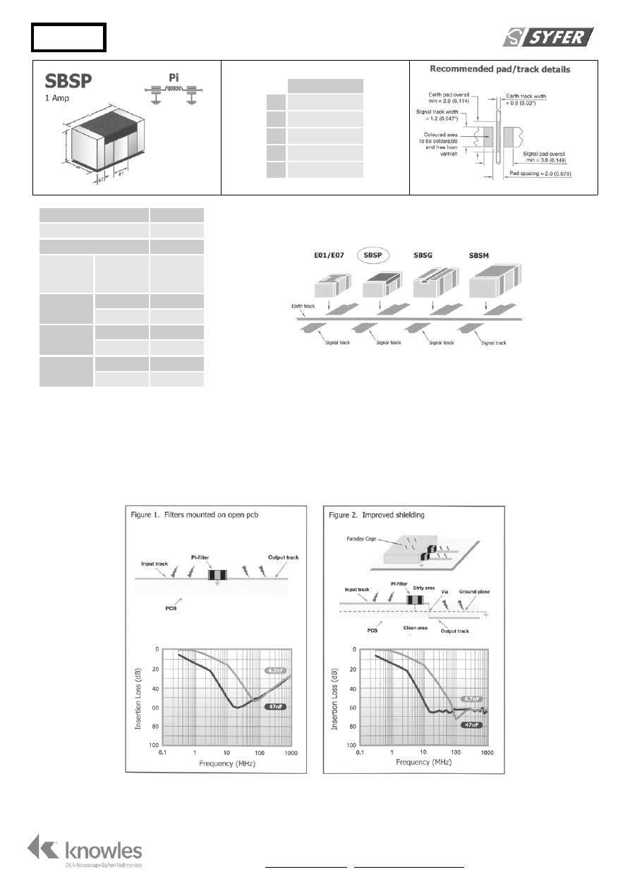
Effects of mounting method on insertion loss 

C and Pi filters are mounted to PCBs and soldered in identical manner to chip capacitors. Solder connections made to each end (signal lines) and 

each side band (earth track). 
Whilst SBSG, SBSM and SBSP filters can be mounted conventionally on PCBs, they are also suitable for mounting in a wall or partition on a board. 
This greatly improves the screening between filter input and output, thereby enhancing the high frequency response. 
The following insertion loss curves (for SBSP, SBSG, SBSM Pi filters), based on actual measurements, show the effect. It can be seen that the filters 
conventionally mounted (Fig. 1) exhibit a drop in attenuation at higher frequencies. Improved shielding methods (Fig. 2), maintain excellent 
suppression characteristics to 1GHz and above. See below for application example. 


Knowles-SBSPDatasheet-html.html
background image


© Knowles 2014 

SBSPDatasheet Issue 4 (P109792) Release Date 04/11/14  Page 2 of 3 


Tel: +44 1603 723300 | Email SyferSales@knowles.com | www.knowlescapacitors.com/syfer 

Insertion loss tables for surface mount EMI filters - Pi filter


Typical No-Load Insertion Loss (dB)* 

Product Code 

Packing 

Capacitance 

(±20%)


Dielectric 

Rated 

Voltage 

(dc) 

DWV 

(dc) 

Approximate 

Resonant 

Frequency 

(MHz) 

0.

1M

Hz 

1M

Hz 

10M

Hz 

100M

Hz 

1G

Hz 

SBSPP1000220MC


B = Bulk P

ack

ed


T = Tape-a

nd-Reel (178mm / 7” 

reels)


R = Tape-an

d

-Reel (330mm / 13” 

reels)


22pF 

C0G


100 

250 

1000 

22 

SBSPP1000470MC


47pF C0G


100 250 

620 

0  0  0  4 16 

SBSPP1000101MC


100pF 

C0G


100 

250 

400 

14 

SBSPP1000221MC


220pF C0G


100 250 

260 

0  0  1 14 12 

SBSPP1000471MC


470pF 

C0G 

100 

250 

180 

25 

16 

SBSPP1000102MX


1.0nF X7R


100 250 

120 

0  0  4 37 16 

SBSPP1000152MX


1.5nF 

X7R


100 

250 

90 

37 

16


SBSPP1000222MX


2.2nF X7R


100 250 

72 

0  0  9 37


16


SBSPP1000332MX


3.3nF 

X7R


100 

250 

59 

13 

37


16


SBSPP1000472MX


4.7nF X7R


100 250 

50 

0  2 14 37


16


SBSPP1000682MX


6.8nF 

X7R 

100 

250 

38 

24 

37


16


SBSPP1000103MX


10nF X7R


100 250 

33 

0  5 24 37


16


SBSPP1000153MX


15nF 

X7R


100 

250 

26 

32 

37


16


SBSPP0500223MX


22nF X7R


50


125


21 0 

10 

38 

37


16


SBSPP0500333MX


33nF 

X7R


50 

125


17 

13 

46 

37


16


SBSPP0500473MX


47nF X7R


50 125


13 2 

16 

50 

37


16


SBSPP0500683MX


68nF 

X7R


50 

125


10 

20 

54 

37


16


SBSPP0250104MX 100nF 

X7R

 25 

67.5 

8.5 6 

19 

52 

37


16


SBSPP0250154MX 

150nF 

X7R


25 

67.5 

24 

56


37


16


* - Insertion Loss performance quoted is measured on an open board mounted on a brass backplane in a 50

 system. Performance curves can be supplied on request. Performance in 

circuit is liable to be different and is affected by board material, track layout, grounding efficiency and circuit impedances.  Shielding can be used to improve high frequency 
performance. 


Ordering Information


SBS 

500 

0473 

Type 

Size 

Configuration 

Rated Voltage 

Capacitance in Pico farads (pF) 

Tolerance 

Dielectric 

Packaging 

Surface 

mount board 

filter


P = 1206


P

 = Pi Section


050 = 50Vdc 

100 = 100Vdc 
200 = 200Vdc 
500 = 500Vdc 

First digit is 0. 

Second and third digits are significant 

figures of capacitance code. The fourth 

digit is number of zeros following. 

Example: 

0473 

= 47nF 

M = ±20% 

X = X7R


T=178mm 

(7”) reel 

R=330mm 

(13”) reel 

B = Bulk


Reeled Quantities 

178mm (7”) reel 

1206 


330mm (13”) reel 

1206 

1500  

6000 


Knowles-SBSPDatasheet-html.html
background image


© Knowles 2014 

SBSPDatasheet Issue 4 (P109792) Release Date 04/11/14  Page 3 of 3 


Tel: +44 1603 723300 | Email SyferSales@knowles.com | www.knowlescapacitors.com/syfer 


Surface mount and panel mount solder-in filters 

Solder pad layouts are included with the detailed information 
for each part. 

Recommended soldering profile 


Soldering of filters 

The soldering process should be controlled such that the filter 
does not experience any thermal shocks which may induce 
thermal cracks in the ceramic dielectric. 
The pre-heat temperature rise of the filter should be kept to 
around 2°C per second. In practice successful temperature 
rises tend to be in the region of 1.5°C to 4°C per second 
dependent upon substrate and components. 
The introduction of a soak after pre-heat can be useful as it 
allows temperature uniformity to be established across the 
substrate thus preventing substrate warping. The magnitude 
or direction of any warping may change on cooling imposing 
damaging stresses upon the filter. 
E01, E03, E07 SBSP ranges are compatible with all standard 
solder types including lead-free, maximum temperature 

260°C. For SBSG, SBSM and SFSS ranges, solder time should 
be minimised, and the temperature controlled to a maximum 
of 220°C. For SFSR, SFST and SFSU ranges the maximum 
temperature is 250°C. 
Cooling to ambient temperature should be allowed to occur 
naturally. Natural cooling allows a gradual relaxation of 
thermal mismatch stresses in the solder joints. Draughts 
should be avoided. Forced air cooling can induce thermal 
breakage, and cleaning with cold fluids immediately after a 
soldering process may result in cracked filters. 
Note: The use of FlexiCap™ terminations is strongly 
recommended to reduce the risk of mechanical cracking. 

Soldering to axial wire leads 
Soldering temperature 

The tip temperature of the iron should not exceed 300°C. 

Dwell time 

Dwell time should be 3-5 seconds maximum to minimise the 
risk of cracking the capacitor due to thermal shock. 

Heat sink 

Where possible, a heat sink should be used between the solder 
joint and the body, especially if longer dwell times are 
required. 

Bending or cropping of wire leads 

Bending or cropping of the filter terminations should not be 
carried out within 4mm (0.157”) of the epoxy encapsulation, 
the wire should be supported when cropping. 

A more comprehensive application note covering 
installation of all Syfer products is available on the 
Syfer website.