
MADE IN USA
• Multi-function Timers
• Dedicated Timers
• Flashers
• Phase Control
• Current Sensors
• Voltage Monitors
• Solid-state Relays
• Alternating Relays
• Liquid Level Controls
• Sequencing Controls
• Obstruction Lighting Controls
Courtesy of Steven Engineering, Inc.-230 Ryan Way, South San Francisco, CA 94080-6370-Main Office: (650) 588-9200-Outside Local Area: (800) 258-9200-www.stevenengineering.com
Littelfuse-catalog-html.html

Accessories ............................... 149
AF .............................................. 107
ARP ........................................... 135
ASQU .......................................... 18
ASTU ........................................... 18
CT .............................................. 101
DCSA......................................... 126
DLMU .........................................111
DSQU .......................................... 19
DSTU ........................................... 19
ECS ........................................... 122
ECSW ........................................ 123
ERD3 ........................................... 82
ERDI ............................................ 58
ERDM .......................................... 25
ESD5 ........................................... 95
ESDR........................................... 86
FA155 ........................................ 137
FA165 ........................................ 137
FB120A, FB230A....................... 138
FB9L .......................................... 141
FS100 ........................................ 105
FS126 ........................................ 104
FS155 ........................................ 137
FS165 ........................................ 137
FS200 ........................................ 105
FS300 ........................................ 106
FS400 ........................................ 106
FS500 ........................................ 107
FSU ........................................... 104
HLMU ........................................ 112
HLV............................................ 119
HRD3 ........................................... 81
HRD9 ........................................... 67
HRDB .......................................... 44
HRDI ............................................ 70
HRDM .......................................... 24
HRDR .......................................... 80
HRDS .......................................... 57
HRID .............................................. 5
HRIS .............................................. 6
HRIU .............................................. 7
HRPD ............................................ 5
Series Index
HRPS............................................. 6
HRPU ............................................ 7
HSPZ ............................................. 8
HRV ........................................... 102
KRD3 ........................................... 84
KRD9 ........................................... 68
KRDB........................................... 46
KRDI ............................................ 71
KRDM .......................................... 27
KRDR .......................................... 83
KRDS........................................... 60
KRPD............................................. 3
KRPS ............................................. 4
KSD1 ........................................... 33
KSD2 ........................................... 76
KSD3 ........................................... 91
KSD4 ........................................... 39
KSDB ........................................... 50
KSDR........................................... 88
KSDS ........................................... 64
KSDU........................................... 28
KSPD ............................................. 9
KSPS ........................................... 10
KSPU ........................................... 11
KVM ........................................... 120
LCS............................................ 127
LLC1 .......................................... 129
LLC2 .......................................... 130
LLC4 .......................................... 131
LLC5 .......................................... 132
LLC6 .......................................... 133
LLC8 .......................................... 134
LPM ........................................... 127
MSM ............................................ 36
NHPD .......................................... 12
NHPS........................................... 13
NHPU .......................................... 14
NLF ............................................ 147
ORB ............................................. 45
ORM ............................................ 26
ORS ............................................. 59
PCR ........................................... 143
PHS ........................................... 148
PLM ........................................... 114
PLMU......................................... 113
PLR............................................ 117
PLS ............................................ 118
PRLB ........................................... 43
PRLM........................................... 23
PRLS ........................................... 56
PTHF ........................................... 92
RS................................................ 85
SC3/4......................................... 108
SCR430T ................................... 140
SCR490D .................................. 139
SCR630T ................................... 140
SCR9L ....................................... 142
SIR............................................. 145
SLR............................................ 146
SQ3/4 .......................................... 93
T2D .............................................. 97
TA .............................................. 99
TAC1 .......................................... 96
TAC4 ........................................... 98
TCS ........................................... 124
TCSA ......................................... 125
TDB ............................................. 41
TDBH ........................................... 41
TDBL ........................................... 41
TDI ............................................... 69
TDIH ............................................ 69
TDIL ............................................. 69
TDM ............................................. 21
TDMB .......................................... 94
TDMH .......................................... 21
TDML ........................................... 21
TDR ............................................. 79
TDS ............................................. 54
TDSH ........................................... 54
TDSL ........................................... 54
TDU ............................................. 28
TDUB ........................................... 47
TDUI ............................................ 72
TDUS ........................................... 61
TH1 .............................................. 35
TH2 .............................................. 78
THC ............................................. 66
THD1 ........................................... 32
THD2 ........................................... 74
THD3 ........................................... 89
THD4 ........................................... 38
THD7 ........................................... 52
THDB ........................................... 49
THDM .......................................... 31
THDS ........................................... 63
THS ............................................. 66
TL .............................................. 100
TMV8000 ..................................... 29
TRB ............................................. 42
TRDU ........................................... 16
TRM ............................................. 22
TRS ............................................. 55
TRU ............................................. 17
TS1 .............................................. 34
TS2 .............................................. 77
TS4 .............................................. 40
TS6 .............................................. 77
TSB.............................................. 53
TSD1 ........................................... 30
TSD2 ........................................... 73
TSD3 ........................................... 90
TSD4 ........................................... 37
TSD6 ........................................... 75
TSD7 ........................................... 51
TSDB ........................................... 48
TSDR ........................................... 87
TSDS ........................................... 62
TSS.............................................. 65
TSU2000 ..................................... 29
TVM ........................................... 116
TVW ........................................... 115
WVM .......................................... 110
Come visit our website at www.SSAC.com! It features our products and contains a special
section that explains which of our products are best suited for the different industries.
You can also download a complete copy of this catalog. This is our way of providing
you with the information you need 24 hours a day, 7 days a week.
Courtesy of Steven Engineering, Inc.-230 Ryan Way, South San Francisco, CA 94080-6370-Main Office: (650) 588-9200-Outside Local Area: (800) 258-9200-www.stevenengineering.com
Littelfuse-catalog-html.html

1
www.ssac.com • 800-843-8848 • fax: 605-348-5685
TABLE OF CONTENTS
Timers
. . . . . . . . . . . . . . . . . . . . . . . . . . . . . . . . . . . . . . . . . . . . . . . . . . 2
Flashers . . . . . . . . . . . . . . . . . . . . . . . . . . . . . . . . . . . . . . . . . . . . . . . . . 103
Voltage Monitors & Phase Monitors . . . . . . . . . . . . . . . . . . . . . . . . 109
Current Sensors & Monitors . . . . . . . . . . . . . . . . . . . . . . . . . . . . . . . 121
Appendix A -
Timer Functions & Descriptions
. . . . . . . . . . . . . . . . . 156
Appendix B -
Dimensional Drawings
. . . . . . . . . . . . . . . . . . . . . . . . . 165
Appendix C -
Connection Diagrams
. . . . . . . . . . . . . . . . . . . . . . . . . . 168
Tower & Obstruction Lighting Controls . . . . . . . . . . . . . . . . . . . . 136
Accessories . . . . . . . . . . . . . . . . . . . . . . . . . . . . . . . . . . . . . . . . . . . . . . 149
Liquid Level Controls & Alternating Relays . . . . . . . . . . . . . . . . . 128
Solid-State Relays . . . . . . . . . . . . . . . . . . . . . . . . . . . . . . . . . . . . . . . . 144
Multifunction. . . . . . . . . . . . . . . . . . . . . . . . . . . . . . . . . 15
Dedicated . . . . . . . . . . . . . . . . . . . . . . . . . . . . . . . . . . . . 20
ProgramaCube . . . . . . . . . . . . . . . . . . . . . . . . . . . . . . . . 2
Courtesy of Steven Engineering, Inc.-230 Ryan Way, South San Francisco, CA 94080-6370-Main Office: (650) 588-9200-Outside Local Area: (800) 258-9200-www.stevenengineering.com
Littelfuse-catalog-html.html

2
www.ssac.com • 800-843-8848 • fax: 605-348-5685
Timers (ProgramaCube)
Series Included
KRPD . . . . . . . . . . . . . . . . . . . . . . . . . . . . . . . . . . . . . . . . . . . .
3
KRPS . . . . . . . . . . . . . . . . . . . . . . . . . . . . . . . . . . . . . . . . . . . .
4
HRPD . . . . . . . . . . . . . . . . . . . . . . . . . . . . . . . . . . . . . . . . . . . .
5
HRID . . . . . . . . . . . . . . . . . . . . . . . . . . . . . . . . . . . . . . . . . . . .
5
HRPS . . . . . . . . . . . . . . . . . . . . . . . . . . . . . . . . . . . . . . . . . . . .
6
HRIS . . . . . . . . . . . . . . . . . . . . . . . . . . . . . . . . . . . . . . . . . . . . .
6
HRPU . . . . . . . . . . . . . . . . . . . . . . . . . . . . . . . . . . . . . . . . . . . .7
HRIU . . . . . . . . . . . . . . . . . . . . . . . . . . . . . . . . . . . . . . . . . . . .7
HSPZ . . . . . . . . . . . . . . . . . . . . . . . . . . . . . . . . . . . . . . . . . . . .
8
KSPD . . . . . . . . . . . . . . . . . . . . . . . . . . . . . . . . . . . . . . . . . . . .9
KSPS . . . . . . . . . . . . . . . . . . . . . . . . . . . . . . . . . . . . . . . . . . . . .
10
KSPU . . . . . . . . . . . . . . . . . . . . . . . . . . . . . . . . . . . . . . . . . . . .11
NHPD . . . . . . . . . . . . . . . . . . . . . . . . . . . . . . . . . . . . . . . . . . .12
NHPS . . . . . . . . . . . . . . . . . . . . . . . . . . . . . . . . . . . . . . . . . . . .
13
NHPU . . . . . . . . . . . . . . . . . . . . . . . . . . . . . . . . . . . . . . . . . . .
14
Relay Output - Single
Power Relay Output
Solid-State Output - Dual
Solid-State Output
Power Solid-State Output
Courtesy of Steven Engineering, Inc.-230 Ryan Way, South San Francisco, CA 94080-6370-Main Office: (650) 588-9200-Outside Local Area: (800) 258-9200-www.stevenengineering.com
Littelfuse-catalog-html.html
3
www.ssac.com • 800-843-8848 • fax: 605-348-5685
KRPD Series
Timer
Available Models:
Time Delay
Type . . . . . . . . . . . . . . . . . . . . . . . . . . . . . Microcontroller circuitry
Range . . . . . . . . . . . . . . . . . . . . . . . . . . . .
0.1s - 1000h in 9 adjustable ranges or fixed (to 999)
Repeat Accuracy . . . . . . . . . . . . . . . . . .
±0.5% or 20ms, whichever is greater
Tolerance (Factory Calibration) . . . . . .
≤ ±2%
Reset Time . . . . . . . . . . . . . . . . . . . . . . . .
≤ 150ms
Initiate Time . . . . . . . . . . . . . . . . . . . . . .
≤ 40ms; 750 operations per minute
Time Delay vs Temp. & Voltage
. . . . .
≤ ±2%
Input
Voltage
. . . . . . . . . . . . . . . . . . . . . . . . . . .
12 to 48VDC; 24 to 240VAC/DC
Tolerance 12 to 48VDC
. . . . . . . .
-15% - 20%
24 to 240VAC/DC
. . . . . . . .
-20% - 10%
AC Line Frequency / DC Ripple
. . . . .
50/60 Hz / ≤ 10%
Power Consumption . . . . . . . . . . . . . . .
AC ≤ 2VA; DC ≤ 2W
Output
Type . . . . . . . . . . . . . . . . . . . . . . . . . . . . . Isolated relay contacts
Form . . . . . . . . . . . . . . . . . . . . . . . . . . . . . SPDT
Rating (at 40°C)
. . . . . . . . . . . . . . . . . . .
10A resistive @ 125VAC
5A resistive @ 230VAC & 28VDC
1/4 hp @ 125VAC
Max. Switching Voltage
. . . . . . . . . . . .
250VAC
Life (Operations)
. . . . . . . . . . . . . . . . . .
Mechanical - 1 x 10
7
; Electrical - 1 x 10
5
Protection
Circuitry . . . . . . . . . . . . . . . . . . . . . . . . . Encapsulated
Isolation Voltage
. . . . . . . . . . . . . . . . . .
≥ 1500V RMS input to output
Insulation Resistance . . . . . . . . . . . . . . .
≥ 100 MΩ
Polarity . . . . . . . . . . . . . . . . . . . . . . . . . .
DC units are reverse polarity protected
Mechanical
Mounting . . . . . . . . . . . . . . . . . . . . . . . .
Surface mount with one #10 (M5 x 0.8) screw
Dimensions . . . . . . . . . . . . . . . . . . . . . . .
2 x 2 x 1.21 in. (50.8 x 50.8 x 30.7 mm)
Termination . . . . . . . . . . . . . . . . . . . . . .
0.25 in. (6.35 mm) male quick connects
Environmental
Operating / Storage Temperature
. . .
-40° to 60°C / -40° to 85°C
Humidity . . . . . . . . . . . . . . . . . . . . . . . . .
95% relative, non-condensing
Weight
. . . . . . . . . . . . . . . . . . . . . . . . . . .
≅
2.6 oz (74 g)
Features:
• Choose 1 of 12 standard dual functions
• Special time ranges & functions available
•
Factory programmed
• Microcontroller circuitry, ±0.5% repeat
accuracy
• Isolated, 10A, SPDT output contacts
• Input voltage from 12 to 240V in 2 ranges
• Delays from 100ms - 1000h in 9 ranges
Approvals:
Auxiliary Products:
•
External ad just potentiometer:
P/N: P1004-95
P/N: P1004-95-X
•
Versa-knob:
P/N: P0700-7
•
Female quick connect:
P/N: P1015-64 (AWG 14/16)
•
Quick connect to screw adaptor:
P/N: P1015-18
•
DIN rail:
P/N: C103PM
(Al)
•
DIN rail adaptor:
P/N: P1023-20
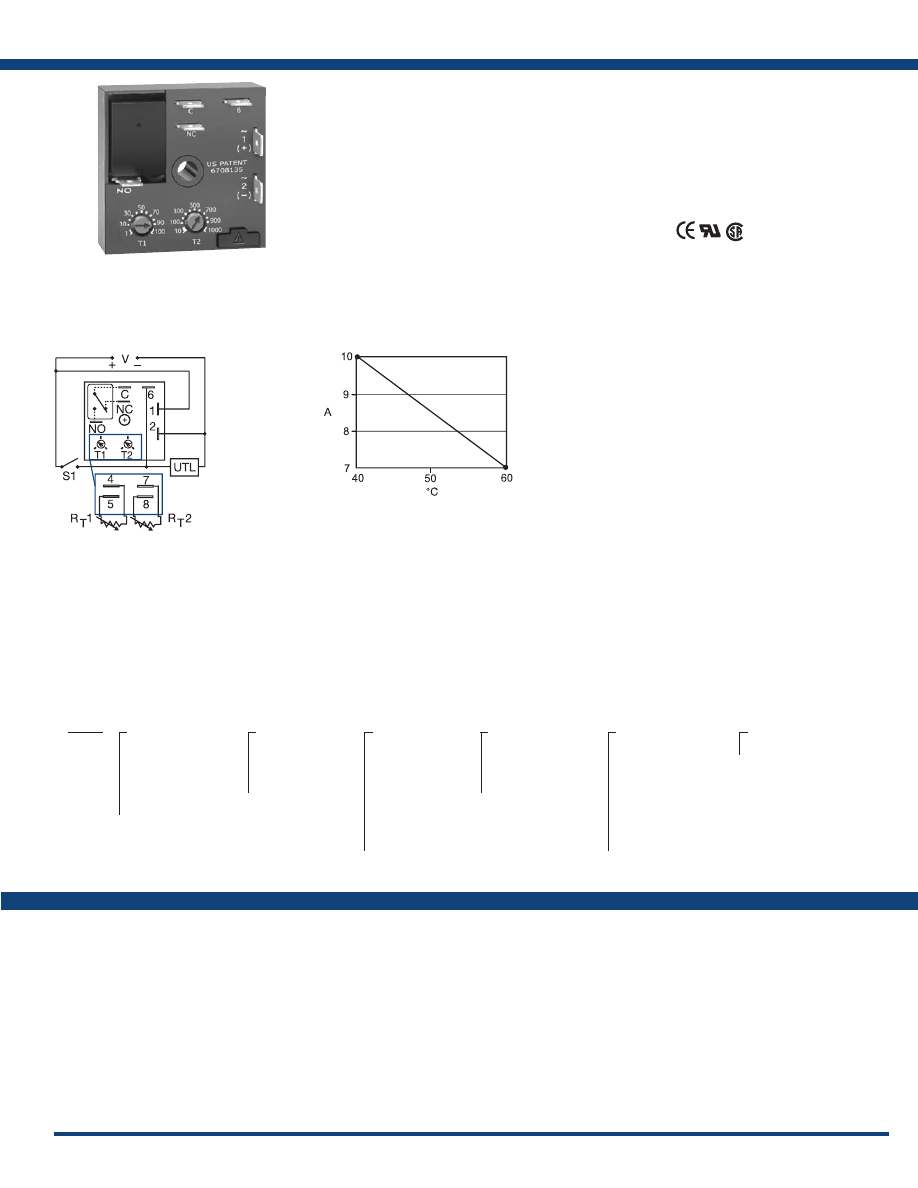
Specifications
Order Table:
KRPD12121MB
KRPD215S190SMB
KRPD417M113MRXD
KRPDA11M14MRXE
KRPDA175S130SMI
KRPDA2222RXE
KRPDA2825AMI
KRPDA3232MB
KRPDA3434MB
KRPDD2121MB
KRPDD3232RXE
L1
N/L2
Connection:
Output Current/Ambient Temperature:
The KRPD Series is a factory programmed time
delay relay available with 1 of 12 standard dual
functions. The time delays can be factory fixed,
onboard or externally adjustable or a combination
of fixed and adjustable. The SPDT output relay
contacts offer a full 10A rating with complete
isolation . Its microcontroller timing circuit
provides excellent repeat accuracy and stability.
Encapsulation protects against shock, vibration,
and humidity. The KRPD Series is a cost effective
approach for OEM applications that require small
size, isolation, accuracy and long life.
See Appendix B, page 165, Figure 1 for dimensional
drawing .
Functions:
MB, MRE, MI, MS,
IRE, BRE, SRE, RXE,
RXD, IM, AMI, SL
For a complete list of functions with descriptions and diagrams,
see Appendix A - Timer Functions, pages 156-164.
KRPD
X
Input
─
A
- 24 to 240VAC/DC
─
D
- 12 to 48VDC
─
1
- 12VDC
─
2
- 24VAC
─
4
- 120VAC
─
9
- 230VAC
X
First Adjustment
(T1 or R
T
1)
─
1
- Fixed
─
2
- Onboard adjust
─
3
- External adjust
X
First Time Delay*
─
1
- 0.1 - 10s
─
2
- 1 - 100s
─
3
- 10 - 1000s
─
4
- 0.1 - 10m
─
5
- 1 - 100m
─
6
- 10 - 1000m
─
7
- 0.1 - 10h
─
8
- 1 - 100h
─
9
- 10 - 1000h
X
Second Adjustment
(T2 or R
T
2)
─
1
- Fixed
─
2
- Onboard adjust
─
3
- External adjust
X
Second Time Delay*
─
1
- 0.1 - 10s
─
2
- 1 - 100s
─
3
- 10 - 1000s
─
4
- 0.1 - 10m
─
5
- 1 - 100m
─
6
- 10 - 1000m
─
7
- 0.1 - 10h
─
8
- 1 - 100h
─
9
- 10 - 1000h
X
Function
─Specify function
*If fixed delay is selected, insert delay (
0 .1-999
)
followed by (
S
) secs., or (
M
) mins., or (
H
) hrs.
V = Voltage
C = Common, Transfer Contact
NC = Normally Closed
NO = Normally Open
S1 = Initiate Switch
UTL = Untimed Load
If desired part number is not listed, please call us to
see if it is technically possible to build .
A knob is supplied for adjustable units
or R
T
terminals for external adjust. The
untimed load is optional . S1 is not used
for some functions.
Courtesy of Steven Engineering, Inc.-230 Ryan Way, South San Francisco, CA 94080-6370-Main Office: (650) 588-9200-Outside Local Area: (800) 258-9200-www.stevenengineering.com
Littelfuse-catalog-html.html
4
www.ssac.com • 800-843-8848 • fax: 605-348-5685
Features:
• Choose 1 of 15 standard functions
• Special time ranges & functions available
•
Factory programmed
• Microcontroller circuitry, ±0.5% repeat
accuracy
• Isolated, 10A, SPDT output contacts
• Input voltage from 12 to 240V in 2 ranges
• Delays from 0.1s - 1000h in 9 ranges
Approvals:
KRPS Series
Timer
Available Models:
Time Delay
Type . . . . . . . . . . . . . . . . . . . . . . . . . . . . . . . . . Microcontroller circuitry
Range . . . . . . . . . . . . . . . . . . . . . . . . . . . . . . . .
0.1s - 1000h in 9 adjustable ranges or fixed
Repeat Accuracy . . . . . . . . . . . . . . . . . . . . . .
±0.5% or 20ms, whichever is greater
Tolerance (Factory Calibration) . . . . . . . . . .
≤ ±2%
Reset Time . . . . . . . . . . . . . . . . . . . . . . . . . . . .
≤ 150ms
Initiate Time . . . . . . . . . . . . . . . . . . . . . . . . . .
≤ 40ms; ≤ 750 operations per minute
Time Delay vs Temp. & Voltage
. . . . . . . . .
≤ ±2%
Input
Voltage
. . . . . . . . . . . . . . . . . . . . . . . . . . . . . . .
12 to 48VDC; 24 to 240VAC/DC
Tolerance 12 to 48VDC
. . . . . . . . . . .
-15% - 20%
24 to 240VAC/DC
. . . . . . . . . .
-20% - 10%
AC Line Frequency / DC Ripple
. . . . . . . . .
50/60Hz / ≤ 10%
Power Consumption . . . . . . . . . . . . . . . . . . .
AC ≤ 2VA; DC ≤ 2W
Output
Type . . . . . . . . . . . . . . . . . . . . . . . . . . . . . . . . . Isolated relay contacts
Form . . . . . . . . . . . . . . . . . . . . . . . . . . . . . . . . . SPDT
Rating (at 40°C)
. . . . . . . . . . . . . . . . . . . . . . .
10A resistive @ 125VAC
5A resistive @ 230VAC & 28VDC
1/4 hp @ 125VAC
Max. Switching Voltage
. . . . . . . . . . . . . . . .
250VAC
Life (Operations)
. . . . . . . . . . . . . . . . . . . . . .
Mechanical - 1 x 10
7
; Electrical - 1 x 10
5
Protection
Circuitry . . . . . . . . . . . . . . . . . . . . . . . . . . . . . Encapsulated
Isolation Voltage
. . . . . . . . . . . . . . . . . . . . . .
≥ 1500V RMS input to output
Insulation Resistance . . . . . . . . . . . . . . . . . . .
≥ 100 MΩ
Polarity . . . . . . . . . . . . . . . . . . . . . . . . . . . . . .
DC units are reverse polarity protected
Mechanical
Mounting . . . . . . . . . . . . . . . . . . . . . . . . . . . . .
Surface mt. with one #10 (M5 x 0.8) screw
Dimensions . . . . . . . . . . . . . . . . . . . . . . . . . . .
2 x 2 x 1.21 in (50.8 x 50.8 x 30.7 mm)
Termination . . . . . . . . . . . . . . . . . . . . . . . . . .
0.25 in. (6.35 mm) male quick connects
Environmental
Operating / Storage Temperature.
. . . . . . .
-40° to 60°C / -40° to 85°C
Humidity . . . . . . . . . . . . . . . . . . . . . . . . . . . . .
95% relative, non-condensing
Weight
. . . . . . . . . . . . . . . . . . . . . . . . . . . . . . .
≅
2.6 oz (74 g)
Order Table:
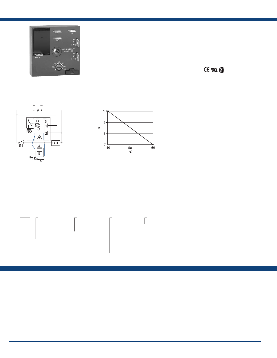
Specifications
The KRPS Series is a factory programmed time
delay relay available with 1 of 15 functions and
measures only 2 inches square. The KRPS offers
a wide range of fixed, onboard, or externally
adjustable time delays. The output relay contacts
offer a full 10A rating with complete isolation. Its
microcontroller timing circuit provides excellent
repeat accuracy and stability . Encapsulation
protects against shock, vibration, and humidity.
The KRPS Series is a cost effective approach for
OEM applications that require small size, isolation,
accuracy, and long life. Special time ranges and
functions are available.
See Appendix B, page 165, Figure 1 for dimensional
drawing .
Auxiliary Products:
•
External ad just potentiometer:
P/N: P1004-95
P/N: P1004-95-X
•
Versa-knob:
P/N: P0700-7
•
Female quick connect:
P/N: P1015-64 (AWG 14/16)
•
Quick connect to screw adaptor:
P/N: P1015-18
•
DIN rail:
P/N: C103PM
(Al)
•
DIN rail adaptor:
P/N: P1023-20
L1
N/L2
Connection:
Output Current/Ambient Temperature:
KRPS1110SM
KRPS4160MM
KRPS425M
KRPS913MB
KRPSA10.1SFT
KRPSA10.5SFT
KRPSA110SM
KRPSA12MM
KRPSA12SM
KRPSA15SM
KRPSA21RE
KRPSA22B
KRPSA22PSD
KRPSA24M
KRPSA28PSE
KRPSD10.1SF
KRPSD10.1SM
KRPSD10.5SS
KRPSD12STS
KRPSD13SB
KRPSD21B
KRPSD21M
KRPSD22M
KRPSD22PSD
KRPSD22S
KRPSD24B
KRPSD24M
KRPSD25B
KRPSD25S
For a complete list of functions with descriptions and diagrams,
see Appendix A - Timer Functions, pages 156-164.
KRPS
X
Input
─
A
- 24 to 240VAC/DC
─
D
- 12 to 48VDC
─
1
- 12VDC
─
4
- 120VAC
─
9
- 230VAC
X
Adjustment
─
1
- Fixed
─
2
- Onboard adjust
─
3
- External adjust
X
Delay*
─
1
- 0.1 - 10s
─
2
- 1 - 100s
─
3
- 10 - 1000s
─
4
- 0.1 - 10m
─
5
- 1 - 100m
─
6
- 10 - 1000m
─
7
- 0.1 - 10h
─
8
- 1 - 100h
─
9
- 10 - 1000h
X
Function
─Specify function
*If fixed delay is selected,
insert delay (
0 .1-1000
)
followed by (
S
) secs.,
(
M
) mins., or (
H
) hrs.
Functions:
M, B, RE, RD, S, SD, I,
TS, US, UB, AM, PSD,
FT, F, SF
If desired part number is not listed, please call us to
see if it is technically possible to build .
V = Voltage
C = Common, Transfer Contact
NC = Normally Closed
NO = Normally Open
S1 = Initiate Switch
UTL = Untimed Load
A knob is supplied for adjustable units, or
R
T
terminals 4 & 5 for external adjust. See
external adjustment vs. time delay chart. The
untimed load is optional. S1 is not used for
some functions.
Courtesy of Steven Engineering, Inc.-230 Ryan Way, South San Francisco, CA 94080-6370-Main Office: (650) 588-9200-Outside Local Area: (800) 258-9200-www.stevenengineering.com
Littelfuse-catalog-html.html
5
www.ssac.com • 800-843-8848 • fax: 605-348-5685
HRID / HRPD Series
Timer
Available Models:
Time Delay
Range . . . . . . . . . . . . . . . . . . . . . . . . . . . . . . .
0.1s - 1000h in 9 adjustable ranges or fixed
Repeat Accuracy . . . . . . . . . . . . . . . . . . . . .
±0.5% or 20ms, whichever is greater
Tolerance (Factory Calibration) . . . . . . . . .
±2%
Reset Time . . . . . . . . . . . . . . . . . . . . . . . . . . .
≤ 150ms
Initiate Time . . . . . . . . . . . . . . . . . . . . . . . . .
≤ 20ms; ≤ 1500 operations per minute
Time Delay vs. Temp. & Voltage
. . . . . . . .
≤ ±2%
Input
Voltage
. . . . . . . . . . . . . . . . . . . . . . . . . . . . . .
12 to 48VDC; 24 to 240VAC/24 to 110VDC
Tolerance 2 to 48VDC
. . . . . . . .
-15% - 20%
24 to 110VDC/24 to 240VAC
. . . . . . . .
-20% - 10%
AC Line Frequency . . . . . . . . . . . . . . . . . . .
50/60Hz
Power Consumption . . . . . . . . . . . . . . . . . .
AC ≤ 4VA; DC ≤ 2W
Output
Type . . . . . . . . . . . . . . . . . . . . . . . . . . . . . . . .
Electromechanical relay
Form . . . . . . . . . . . . . . . . . . . . . . . . . . . . . . . . SPDT
Ratings: SPDT-N.O SPDT-NC
General Purpose 125/240VAC 30A 15A
Resistive 125/240VAC 30A 15A
28VDC 20A 10A
Motor Load 125VAC 1 hp* 1/4 hp**
240VAC 2 hp** 1 hp**
Life (Operations)
. . . . . . . . . . . . . . . . . . . . .
Mechanical - 1 x 10
6
Electrical - 1 x 10
5
, *3 x10
4
, **6,000
Protection
Surge . . . . . . . . . . . . . . . . . . . . . . . . . . . . . . .
IEEE C62.41-1991 Level A
Circuitry . . . . . . . . . . . . . . . . . . . . . . . . . . . . Encapsulated
Isolation Voltage
. . . . . . . . . . . . . . . . . . . . .
≥1500V RMS input to output; isolated units
Insulation Resistance . . . . . . . . . . . . . . . . . .
≥100 MΩ
Polarity . . . . . . . . . . . . . . . . . . . . . . . . . . . . .
DC units are reverse polarity protected
Mechanical
Mounting . . . . . . . . . . . . . . . . . . . . . . . . . . .
Surface mt. with one #10 (M5 x 0.8) screw
Dimensions . . . . . . . . . . . . . . . . . . . . . . . . . .
3 x 2 x 1.5 in. (76.7 x 51.3 x 38.1 mm)
Termination . . . . . . . . . . . . . . . . . . . . . . . . .
0.25 in. (6.35 mm) male quick connects
Environmental
Operating / Storage Temperature.
. . . . . .
-40° to 60°C / -40° to 85°C
Humidity . . . . . . . . . . . . . . . . . . . . . . . . . . . .
95% relative, non-condensing
Weight
. . . . . . . . . . . . . . . . . . . . . . . . . . . . . .
≅
3.9 oz (111 g)
Features:
• Special time ranges & functions available
•
Factory programmed
• 30A, SPDT, NO output contacts
• 12 to 240V operation in 2 ranges
• Delays from 0.1s - 1000h in 9 ranges
• ±0.5% repeat accuracy
Approvals:
Auxiliary Products:
•
External ad just potentiometer:
P/N: P1004-95
P/N: P1004-95-X
•
Versa-knob:
P/N: P0700-7
•
Quick connect to screw adaptor:
P/N: P1015-18
•
Female quick connect:
P/N: P1015-13 (AWG 10/12)
P/N: P1015-64 (AWG 14/16)
•
Mounting bracket:
P/N: P1023-6
•
DIN rail:
P/N: C103PM
(Al)
•
DIN rail adaptor:
P/N: P1023-20
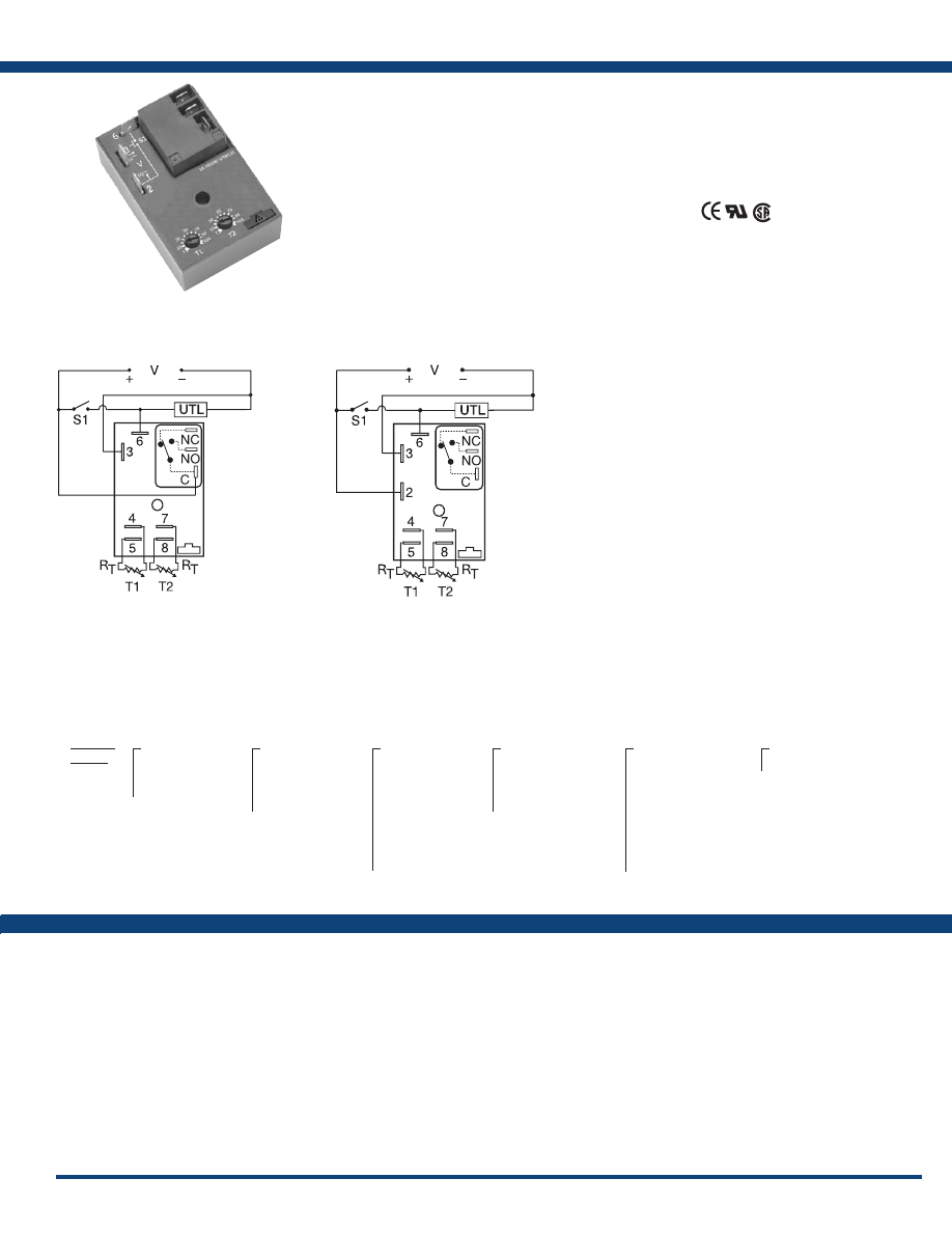
Specifications
Order Table:
Connection:
The HRID/HRPD Series combines an
electromechanical relay with microcontroller
timing circuitry. It is a factory programmed module
available in any 1 of 12 standard functions. It offers
12 to 240V operation in two universal ranges and
factory fixed, onboard or externally adjustable time
delays with a repeat accuracy of ±0.5%. The high
switching capacity of the output contacts allow
for direct control of heavy loads like compressors,
pumps, motors, heaters, and lighting. HRPD has
non-isolated SPDT relay contacts, and the HRID
has isolated SPDT relay contacts. An excellent
choice for OEM applications where cost is a
factor. Both offer dual functions in one convenient
package.
See Appendix B, page 165, Figure 2 for dimensional
drawing .
L1
N/L2
L1
N/L2
Relay contacts are
non-isolated.
HRPD
S1 = Initiate Switch
UTL = Optional Untimed Load
NO = Normally Open
NC = Normally Closed
C = Common
Relay contacts are
isolated .
HRID
HRID /
HRPD
X
Input
─
W
- 24 to 240VAC
24 to 110VDC
─
D
- 12 to 48VDC
X
First Adjustment
(T1 or R
T
1)
─
1
- Fixed
─
2
- Onboard adjust
─
3
- External adjust
X
First Time Delay*
─
1
- 0.1 - 10s
─
2
- 1 - 100s
─
3
- 10 - 1000s
─
4
- 0.1 - 10m
─
5
- 1 - 100m
─
6
- 10 - 1000m
─
7
- 0.1 - 10h
─
8
- 1 - 100h
─
9
- 10 - 1000h
X
Second Adjustment
(T2 or R
T
2)
─
1
- Fixed
─
2
- Onboard adjust
─
3
- External adjust
X
Second Time Delay*
─
1
- 0.1 - 10s
─
2
- 1 - 100s
─
3
- 10 - 1000s
─
4
- 0.1 - 10m
─
5
- 1 - 100m
─
6
- 10 - 1000m
─
7
- 0.1 - 10h
─
8
- 1 - 100h
─
9
- 10 - 1000h
X
Function
─Specify function
*If fixed delay is selected, insert delay (
0 .1-999
)
followed by (
S
) secs., or (
M
) mins., or (
H
) hrs.
Functions:
MB, MRE, MI, MS,
IRE, BRE, SRE, RXE,
RXD, IM, AMI, SL
HRPDD2225RXE
For a complete list of functions with descriptions and diagrams,
see Appendix A - Timer Functions, pages 156-164.
If desired part number is not listed, please call us to
see if it is technically possible to build .
R
T
is used when external
adjustment is ordered.
Courtesy of Steven Engineering, Inc.-230 Ryan Way, South San Francisco, CA 94080-6370-Main Office: (650) 588-9200-Outside Local Area: (800) 258-9200-www.stevenengineering.com
Littelfuse-catalog-html.html
6
www.ssac.com • 800-843-8848 • fax: 605-348-5685
HRPS / HRIS Series
Timer
Available Models:
Time Delay
Type . . . . . . . . . . . . . . . . . . . . . . . . . . . . . . . . Microcontroller circuitry
Range . . . . . . . . . . . . . . . . . . . . . . . . . . . . . . .
0.1s - 1000h in 9 adjustable ranges or fixed
Repeat Accuracy . . . . . . . . . . . . . . . . . . . . .
±0.5% or 20ms, whichever is greater
Tolerance (Factory Calibration) . . . . . . . . .
±2%
Reset Time . . . . . . . . . . . . . . . . . . . . . . . . . . .
≤ 150ms
Initiate Time . . . . . . . . . . . . . . . . . . . . . . . . .
≤ 20ms
Time Delay vs Temp. & Voltage
. . . . . . . .
±2%
Input
Voltage
. . . . . . . . . . . . . . . . . . . . . . . . . . . . . .
12 to 48VDC; 24 to 240VAC/24 to 110VDC
Tolerance 12 to 48VDC
. . . . . . .
-15% - 20%
24 to 110VDC/240VAC
. . . . . . .
-20% - 10%
AC Line Frequency . . . . . . . . . . . . . . . . . . .
50/60Hz
Power Consumption . . . . . . . . . . . . . . . . . .
AC ≤ 4VA; DC ≤ 2W
Output
Type . . . . . . . . . . . . . . . . . . . . . . . . . . . . . . . .
Electromechanical relay
Form . . . . . . . . . . . . . . . . . . . . . . . . . . . . . . . . SPDT
Ratings: SPDT-NO SPDT-NC
General Purpose 125/240VAC 30A 15A
Resistive 125/240VAC 30A 15A
28VDC 20A 10A
Motor Load 125VAC 1 hp* 1/4 hp**
240VAC 2 hp** 1 hp**
Life
. . . . . . . . . . . . . . . . . . . . . . . . . . . . . . . .
Mechanical - 1 x 10
6
Electrical - 1 x 10
5
, *3 x 10
4
, **6,000
Protection
Surge . . . . . . . . . . . . . . . . . . . . . . . . . . . . . . .
IEEE C62.41-1991 Level A
Circuitry . . . . . . . . . . . . . . . . . . . . . . . . . . . . Encapsulated
Isolation Voltage
. . . . . . . . . . . . . . . . . . . . .
≥ 1500V RMS input to output; isolated units
Insulation Resistance . . . . . . . . . . . . . . . . . .
≥ 100 MΩ
Polarity . . . . . . . . . . . . . . . . . . . . . . . . . . . . .
DC units are reverse polarity protected
Mechanical
Mounting . . . . . . . . . . . . . . . . . . . . . . . . . . .
Surface mt. with one #10 (M5 x 0.8) screw
Dimensions . . . . . . . . . . . . . . . . . . . . . . . . .
3 x 2 x 1.5 in (76.7 x 51.3 x 38.1 mm)
Termination . . . . . . . . . . . . . . . . . . . . . . . . .
0.25 in. (6.35 mm) male quick connects
Environmental
Operating / Storage Temperature.
. . . . . .
-40° to 60°C / -40° to 85°C
Humidity . . . . . . . . . . . . . . . . . . . . . . . . . . .
95% relative, non-condensing
Weight
. . . . . . . . . . . . . . . . . . . . . . . . . . . . . .
≅
3.9 oz (111 g)
Order Table:
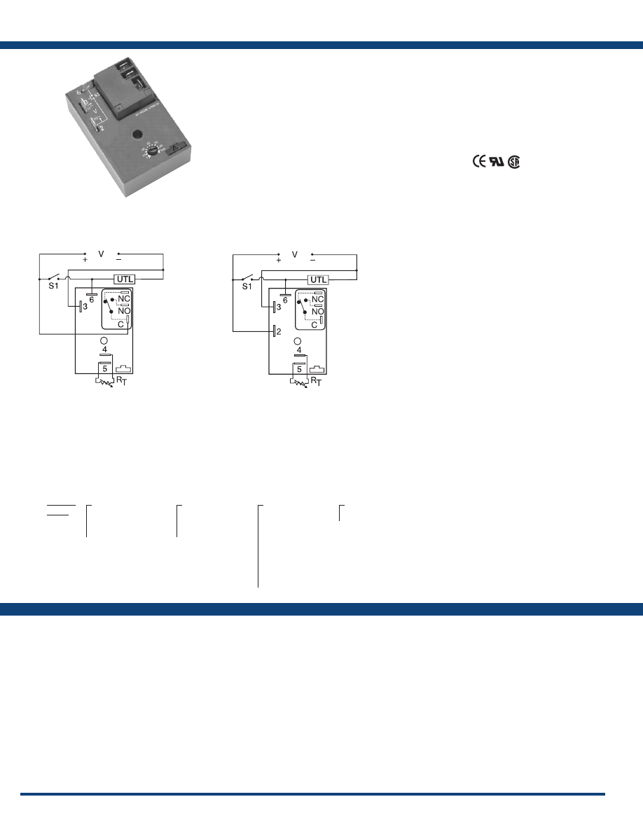
Specifications
T h e H R P S / H R I S S e r i e s c o m b i n e s a n
e l e c t r o m e c h a n i c a l r e l a y o u t p u t w i t h
microcontroller timing circuitry. It is a factory
programmed module available in any 1 of 13
standard functions. It offers 12 to 240V operation
in two universal ranges and factory fixed, onboard,
or external adjustable time delays with a repeat
accuracy of ±0.5%. The output contact rating
allows for direct operation of heavy loads, such as
compressors, pumps, blower motors, heaters, etc.
This series is ideal for OEM applications where
cost is a factor. The HRPS has non-isolated SPDT
relay contacts, and the HRIS has isolated SPDT
relay contacts. Both offer the most popular timer
functions in the industry.
See Appendix B, page 165, Figure 2 for dimensional
drawing .
Auxiliary Products:
•
External ad just potentiometer:
P/N: P1004-95
P/N: P1004-95-X
•
Mounting bracket:
P/N: P1023-6
•
Female quick connect:
P/N: P1015-13 (AWG 10/12)
P/N: P1015-64 (AWG 14/16)
•
Quick connect to screw adaptor:
P/N: P1015-18
•
Versa-knob:
P/N: P0700-7
•
DIN rail:
P/N: C103PM
(Al)
•
DIN rail adaptor:
P/N: P1023-20
Connection:
Features:
• 30A, SPDT, NO output contacts
•
Factory programmed
• 12 to 240V operation in 2 ranges
• Special time ranges & functions available
• Delays from 0.1s - 1000h in 9 ranges
• ±0.5% repeat accuracy
• ±2% factory calibration
• Fixed, external, or onboard adjustment
Approvals:
HRISW21FT
HRISW27I
HRPSD12HI
L1
N/L2
L1
N/L2
Relay contacts are
non-isolated.
HRPS
S1 = Initiate Switch
UTL = Untimed Load (optional)
NO = Normally Open
NC = Normally Closed
C = Common
Relay contacts are
isolated .
HRIS
HRPS /
HRIS
X
Input
─
W
- 24 to 240VAC
24 to 110VDC
─
D
- 12 to 48VDC
X
Adjustment
─
1
- Fixed
─
2
- Onboard adjust
─
3
- External adjust
X
Time Delay*
─
1
- 0.1 - 10s
─
2
- 1 - 100s
─
3
- 10 - 1000s
─
4
- 0.1 - 10m
─
5
- 1 - 100m
─
6
- 10 - 1000m
─
7
- 0.1 - 10h
─
8
- 1 - 100h
─
9
- 10 - 1000h
X
Function
─Specify function
*If fixed delay is selected,
insert delay (
0 .1-1000
)
followed by (
S
) secs.,
(
M
) mins., or (
H
) hrs.
Functions:
M, B, RE, RD, S, SD,
I, TS, US, UB, AM,
PSD, FT
For a complete list of functions with descriptions and diagrams,
see Appendix A - Timer Functions, pages 156-164.
A knob, or terminals 4 & 5 are only included
on adjustable units. R
T
is used when external
adjustment is ordered.
If desired part number is not listed, please call us to
see if it is technically possible to build .
Courtesy of Steven Engineering, Inc.-230 Ryan Way, South San Francisco, CA 94080-6370-Main Office: (650) 588-9200-Outside Local Area: (800) 258-9200-www.stevenengineering.com
Littelfuse-catalog-html.html
7
www.ssac.com • 800-843-8848 • fax: 605-348-5685
HRPU / HRIU Series
Timer
Available Models:
Count Functions/Switch Type
. . . . . . . . . .
Mechanical switch (counts on switch closure)
Count Range . . . . . . . . . . . . . . . . . . . . . . . . . .
1 - 1023 counts
Counter Output (Variable 7 & 8)
. . . . . . . . .
Pulse widths 300ms ±20%
Initiate Time . . . . . . . . . . . . . . . . . . . . . . . . . .
≤ 20ms, ≤ 1500 operations per minute
Time Delay/Range
*** . . . . . . . . . . . . . . . . .
Adjustable 0.1s - 1023h
Setting Accuracy . . . . . . . . . . . . . . . . . . . . . .
±1%, or 50ms, whichever is greater
Repeat Accuracy . . . . . . . . . . . . . . . . . . . . . .
0.1% or 20ms, whichever is greater
Reset Time . . . . . . . . . . . . . . . . . . . . . . . . . . . .
≤ 150ms
Time Delay vs Temp. & Voltage.
. . . . . . . . .
±2%
Input
Voltage
. . . . . . . . . . . . . . . . . . . . . . . . . . . . . . .
12 to 48VDC; 24 to 240VAC/24 to 110VDC
AC Line Frequency / DC Ripple
. . . . . . . . .
50/60Hz / ≤ 10%
Tolerance 12 to 48VDC
. . . . . .
-15% - 20%
24 to 240VAC/24 to 110VDC
. . . . . .
-20% - 10%
Power Consumption . . . . . . . . . . . . . . . . . . .
AC ≤ 4VA; DC ≤ 2W
Output
Type . . . . . . . . . . . . . . . . . . . . . . . . . . . . . . . . .
Electromechanical relay
Form . . . . . . . . . . . . . . . . . . . . . . . . . . . . . . . . . SPDT
Ratings: SPDT-NO SPDT-NC
General Purpose 125/240VAC 30A 15A
Resistive 125/240VAC 30A 15A
28VDC 20A 10A
Motor Load 125VAC 1 hp* 1/4 hp**
240VAC 2 hp** 1 hp**
Life
. . . . . . . . . . . . . . . . . . . . . . . . . . . . . . . . . .
Mechanical - 1 x 10
6
Electrical - 1 x 10
5
, *3 x 10
4
, ** 6,000
Protection
Surge . . . . . . . . . . . . . . . . . . . . . . . . . . . . . . . .
IEEE C62.41-1991 Level A
Circuitry . . . . . . . . . . . . . . . . . . . . . . . . . . . . . Encapsulated
Isolation Voltage
. . . . . . . . . . . . . . . . . . . . . .
≥ 1500V RMS input to output; isolated units
Insulation Resistance . . . . . . . . . . . . . . . . . . .
≥ 100 MΩ
Mechanical
Mounting . . . . . . . . . . . . . . . . . . . . . . . . . . . .
Surface mt. with one #10 (M5 x 0.8) screw
Dimensions . . . . . . . . . . . . . . . . . . . . . . . . . . .
3 x 2 x 1.5 in. (76.7 x 51.3 x 38.1 mm)
Termination . . . . . . . . . . . . . . . . . . . . . . . . . .
0.25 in. (6.35 mm) male quick connects
Environmental
Operating / Storage Temperature
. . . . . . .
-40° to 60°C / -40° to 85°C
Humidity . . . . . . . . . . . . . . . . . . . . . . . . . . . . .
95% relative, non-condensing
Weight
. . . . . . . . . . . . . . . . . . . . . . . . . . . . . . .
≅
3.9 oz (111 g)
***For CE approved applications, power must be removed from the unit when a switch
position is changed.
Auxiliary Products:
•
Female quick connect:
P/N: P1015-13 (AWG 10/12)
P/N: P1015-64 (AWG 14/16)
•
Mounting bracket:
P/N: P1023-6
•
Quick connect to screw adaptor:
P/N: P1015-18
•
DIN rail:
P/N: C103PM
(Al)
•
DIN rail adaptor:
P/N: P1023-20
Specifications
Order Table:
Connection:
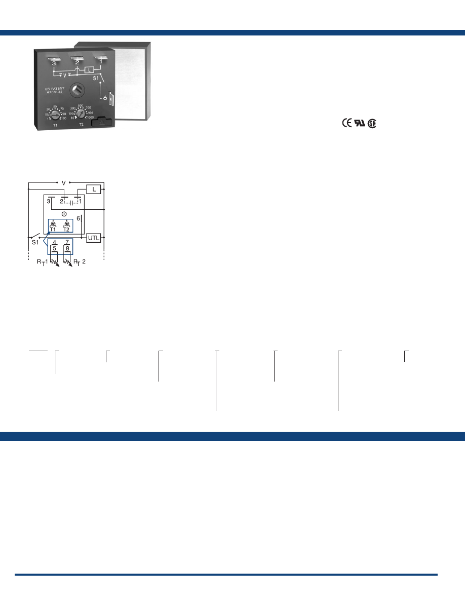
The HRPU/HRIU Series combines an
e l e c t r o m e c h a n i c a l r e l a y o u t p u t w i t h
microcontroller timing circuitry. Its switching
capacity allows direct control of loads like
compressors, pumps, motors, heaters, and
lighting. It is a factory programmed module
available in any 1 of 14 standard functions. The
HRPU/HRIU offers a single adjustable timer
or counter function. Switch adjustment allows
accurate selection of the time delay or number
of counts. The HRPU has non-isolated relay
contacts, the HRIU has isolated relay contacts.
Encapsulation protects against shock, vibration,
and humidity. The HRPU/HRIU Series is a cost
effective approach for OEM applications that
require small size, reliability and accurate switch
adjustment.
See Appendix B, page 165, Figure 2 for dimensional
drawing .
HRIUW2I
HRIUW2M
L1
N/L2
L1
N/L2
Isolated Output
HRIU
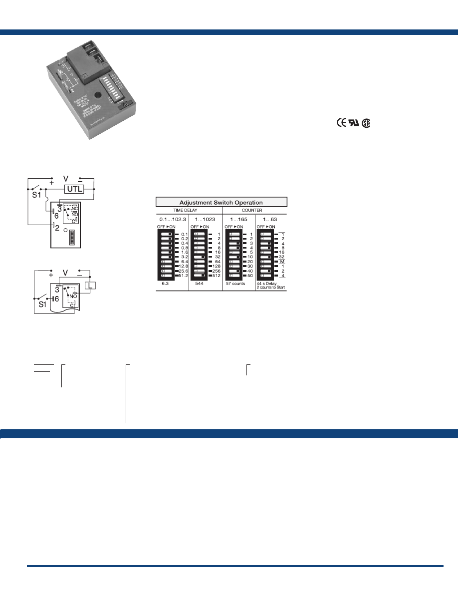
S1 = Initiate Switch
UTL = Optional Untimed Load
L = Load
V = Voltage
Non-isolated Output
HRPU
Features:
• Choose 1 of 14 standard functions
• Special time ranges & functions available
•
Factory programmed
• Microcontroller circuitry, ±0.1% repeat
accuracy
• 30A, SPDT, NO output contacts
• Accurate switch adjustment
• 12 to 240V operations in 2 ranges
• Delays from 0.1s - 1023h
Approvals:
Switch Adjustment:
Functions:
M, B, RE, RD, S, SD, I,
TS, PSD, US, AM, UB,
C, CI
HRPU/
HRIU
X
Input
─
W
- 24 to 240VAC
24 to 110VDC
─
D
- 12 to 48VDC
X
Time Delay/Counts
─
1
- 0.1 - 102.3s
─
2
- 1 - 1023s
─
3
- 0.1 - 102.3m
─
4
- 1 - 1023m
─
5
- 0.1 - 102.3h
─
6
- 1 - 1023h
─
7
- 1 - 165 counts (straight) w/ pulsed output
─
8
- 1 - 1023 counts (binary) w/ pulsed output
─
9
- 1 - 7 counts to start 1 - 63s or m interval time
X
Function
─Specify function
If desired part number is not listed, please call us to
see if it is technically possible to build .
For a complete list of functions with descriptions and diagrams,
see Appendix A - Timer Functions, pages 156-164.
Courtesy of Steven Engineering, Inc.-230 Ryan Way, South San Francisco, CA 94080-6370-Main Office: (650) 588-9200-Outside Local Area: (800) 258-9200-www.stevenengineering.com
Littelfuse-catalog-html.html
8
www.ssac.com • 800-843-8848 • fax: 605-348-5685
HSPZ Series
Timer
Available Models:
Time Delay
Type . . . . . . . . . . . . . . . . . . . . . . . . . . . . . . . . Microcontroller circuitry
Range . . . . . . . . . . . . . . . . . . . . . . . . . . . . . . .
0.1 - 102.3s, m or h in 0.1s, m or h increments
1 - 1023s, m or h in 1s, m or h increments
1 - 512s or m in 1s or m increments
Repeat Accuracy . . . . . . . . . . . . . . . . . . . . .
±0.1% or 20ms, whichever is greater
Setting Accuracy . . . . . . . . . . . . . . . . . . . . .
≤ ±1% or 20ms, whichever is greater
Reset Time . . . . . . . . . . . . . . . . . . . . . . . . . . .
≤ 150ms
Initiate Time . . . . . . . . . . . . . . . . . . . . . . . . .
≤ 20ms
Time Delay vs Temp. & Voltage
. . . . . . . .
≤ ±2%
Count Range . . . . . . . . . . . . . . . . . . . . . . . . .
1 - 1023 in 2 ranges
Count Rate . . . . . . . . . . . . . . . . . . . . . . . . . .
≤ 25 counts per second
Input
Voltage
. . . . . . . . . . . . . . . . . . . . . . . . . . . . . .
12 to 120VDC; 24 to 240VAC
Tolerance . . . . . . . . . . . . . . . . . . . . . . . . . . . .
≤ ±15%
AC Line Frequency / DC Ripple
. . . . . . . .
50/60Hz / ≤ 10%
Power Consumption . . . . . . . . . . . . . . . . .
AC ≤ 2VA; DC ≤ 1W
Output
Type . . . . . . . . . . . . . . . . . . . . . . . . . . . . . . . .
Solid-state output
Rating . . . . . . . . . . . . . . . . . . . . . . . . . . . . . .
1A steady, 10A inrush for 16ms
Voltage Drop
. . . . . . . . . . . . . . . . . . . . . . . . AC
≅
2.5V @ 1A; DC
≅
1V @ 1A
OFF State Leakage Current
. . . . . . . . . . . . AC
≅
5mA @ 240VAC; DC
≅
1mA
Counter Output . . . . . . . . . . . . . . . . . . . . . .
Output pulse width: 300ms ±20%
Protection
Circuitry . . . . . . . . . . . . . . . . . . . . . . . . . . . . Encapsulated
Dielectric Breakdown
. . . . . . . . . . . . . . . . .
≥ 2000V RMS terminals to mounting surface
Insulation Resistance . . . . . . . . . . . . . . . . . .
≥ 100 MΩ
Polarity . . . . . . . . . . . . . . . . . . . . . . . . . . . . .
DC units are reverse polarity protected
Mechanical
Mounting . . . . . . . . . . . . . . . . . . . . . . . . . . .
Surface mt. with one #10 (M5 x 0.8) screw
Dimensions . . . . . . . . . . . . . . . . . . . . . . . . . .
3 x 2 x 1.5 in. (76.7 x 51.3 x 38.1 mm)
Termination . . . . . . . . . . . . . . . . . . . . . . . . .
0.25 in. (6.35 mm) male quick connects
Environmental
Operating / Storage Temperature.
. . . . . .
-40° to 60°C / -40° to 85°C
Humidity . . . . . . . . . . . . . . . . . . . . . . . . . . . .
95% relative, non-condensing
Weight
. . . . . . . . . . . . . . . . . . . . . . . . . . . . . .
≅
3.9 oz (111 g)
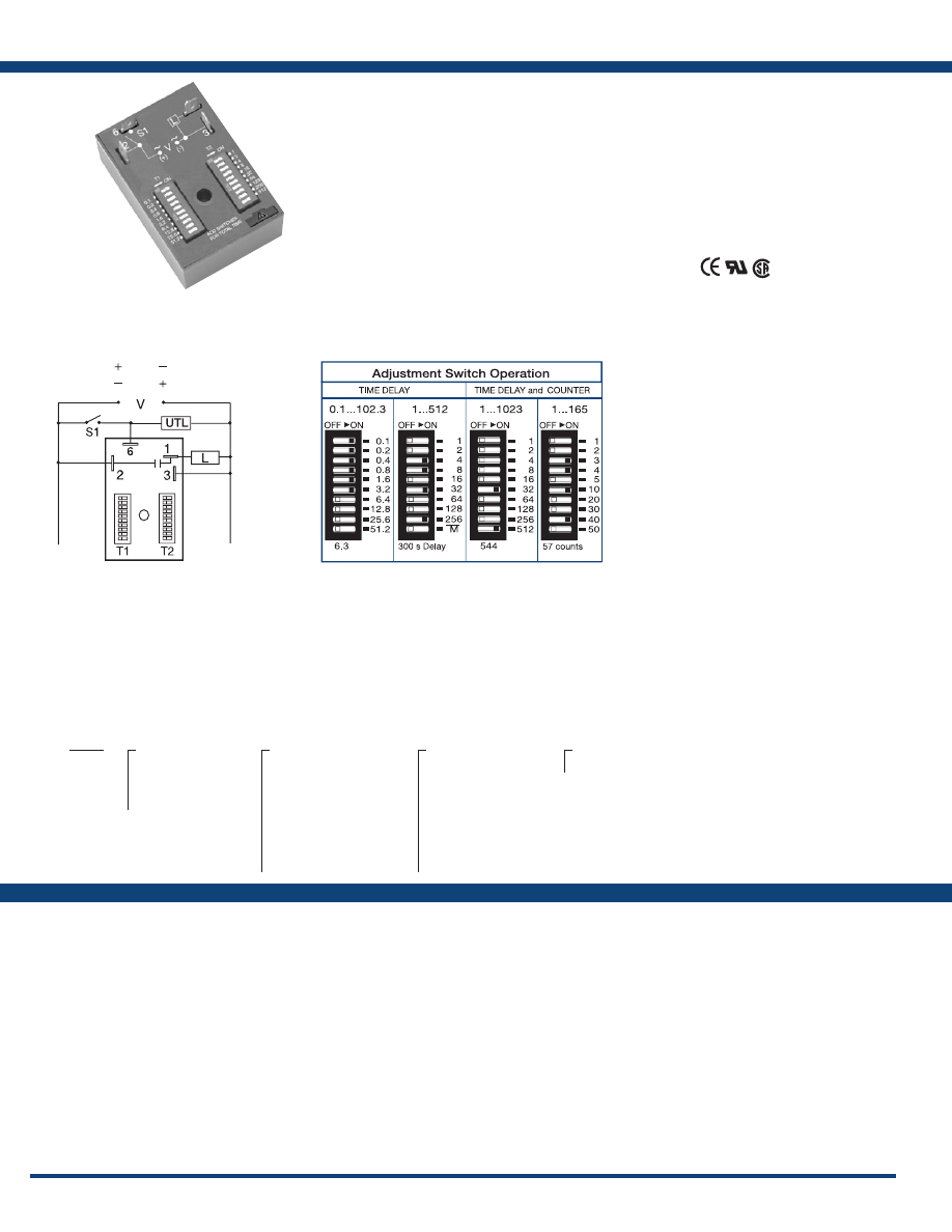
Order Table:
Specifications
The HSPZ Series is a factory programmed module
available in any 1 of 13 standard functions. The
HSPZ offers dual switch adjustable timer or
counter functions. Switch adjustment allows
accurate selection of the time delay or number
of counts the first time and every time. The
1A steady, 10A inrush rated solid-state output
provides 100 million operations, typical. Its
microcontroller timing circuit provides excellent
repeat accuracy and stability . Encapsulation
protects against shock, vibration, and humidity.
The HSPZ Series is a cost effective approach for
OEM applications that require small size, solid
state reliability, and accurate switch adjustment.
See Appendix B, page 165, Figure 3 for dimensional
drawing .
Auxiliary Products:
•
Female quick connect:
P/N: P1015-64 (AWG 14/16)
P/N: P1015-14 (AWG 18/22)
•
Quick connect to screw adaptor:
P/N: P1015-18
•
DIN rail:
P/N: C103PM
(Al)
•
DIN rail adaptor:
P/N: P1023-20
Connection:
Features:
• Choose 1 of 13 standard functions
• Special time ranges & functions available
•
Factory programmed
• Microcontroller circuitry, ±0.1% repeat
accuracy
• 1A, solid-state output
• Accurate switch adjustment
• 12 to 240V in 3 options
• Delays from 0.1s - 1023h
• Counts to 1023
Approvals:
HSPZA13MS
HSPZA22SL
(Positive Switching)
(Negative Switching)
L1
N/L2
S1 = Initiate Switch
UTL = Optional Untimed Load
L = Load
V = Voltage
Switch Adjustment:
HSPZ
X
Input
─
A
- 24 to 240VAC
─
P
- 12 to 120VDC
positive switching
─
N
- 12 to 120VDC
negative switching
X
T1 Time Delay/Counts
─
1
- 0.1 - 102.3s
─
2
- 1 - 1023s
─
3
- 0.1 - 102.3m
─
4
- 1 - 1023m
─
5
- 0.1 - 102.3h
─
6
- 1 - 1023h
─
7
- 1 - 165 counts (straight)
─
8
- 1 -1023 counts (binary)
─
9
- 1 - 512m or s
X
T2 Time Delay/Counts
─
1
- 0.1 - 102.3s
─
2
- 1 - 1023s
─
3
- 0.1 - 102.3m
─
4
- 1 - 1023m
─
5
- 0.1 - 102.3h
─
6
- 1 - 1023h
─
7
- for future expansion
─
8
- for future expansion
─
9
- 1 - 512m or s
X
Function
─Specify function
Functions:
MB, MRE, MI, MS,
IRE, BRE, SRE, RXE,
RXD, IM, AMI, SL, CI
If desired part number is not listed, please call us to
see if it is technically possible to build .
For a complete list of functions with descriptions and diagrams,
see Appendix A - Timer Functions, pages 156-164.
Courtesy of Steven Engineering, Inc.-230 Ryan Way, South San Francisco, CA 94080-6370-Main Office: (650) 588-9200-Outside Local Area: (800) 258-9200-www.stevenengineering.com
Littelfuse-catalog-html.html
9
www.ssac.com • 800-843-8848 • fax: 605-348-5685
KSPD Series
Timer
Available Models:
Time Delay
Type . . . . . . . . . . . . . . . . . . . . . . . . . . . . . . . Microcontroller circuitry
Range . . . . . . . . . . . . . . . . . . . . . . . . . . . . . .
0.1s - 1000h in 9 adjustable ranges or fixed (to 999)
Repeat Accuracy . . . . . . . . . . . . . . . . . . . .
±0.5% or 20ms, whichever is greater
Tolerance (Factory Calibration) . . . . . . . .
≤ ±2%
Reset Time . . . . . . . . . . . . . . . . . . . . . . . . . .
≤ 150ms
Initiate Time . . . . . . . . . . . . . . . . . . . . . . . .
≤ 20ms; ≤ 1500 operations per minute
Time Delay vs Temp. & Voltage
. . . . . . .
≤ ±2%
Input
Voltage
. . . . . . . . . . . . . . . . . . . . . . . . . . . . .
12 to 120VDC; 24 to 240VAC
Tolerance . . . . . . . . . . . . . . . . . . . . . . . . . . .
≤ ±15%
AC Line Frequency / DC Ripple
. . . . . . .
50/60Hz / ≤ 10%
Power Consumption . . . . . . . . . . . . . . . .
AC ≤ 2VA; DC ≤ 1W
Output
Type . . . . . . . . . . . . . . . . . . . . . . . . . . . . . . .
Solid-state output
Rating . . . . . . . . . . . . . . . . . . . . . . . . . . . . .
1A steady, 10A inrush for 16ms
Voltage Drop
. . . . . . . . . . . . . . . . . . . . . . . AC
≅
2.5V @ 1A; DC
≅
1V @ 1A
OFF State Leakage Current
. . . . . . . . . . . AC
≅
5mA @ 230VAC; DC
≅
1mA
Protection
Circuitry . . . . . . . . . . . . . . . . . . . . . . . . . . . Encapsulated
Dielectric Breakdown
. . . . . . . . . . . . . . . .
≥ 2000V RMS terminals to mounting surface
Insulation Resistance . . . . . . . . . . . . . . . . .
≥ 100 MΩ
Polarity . . . . . . . . . . . . . . . . . . . . . . . . . . . .
DC units are reverse polarity protected
Mechanical
Mounting . . . . . . . . . . . . . . . . . . . . . . . . . .
Surface mt. with one #10 (M5 x 0.8) screw
Dimensions . . . . . . . . . . . . . . . . . . . . . . . . .
2 x 2 x 1.21 in. (50.8 x 50.8 x 30.7 mm)
Termination . . . . . . . . . . . . . . . . . . . . . . . .
0.25 in. (6.35 mm) male quick connects
Environmental
Operating / Storage Temperature
. . . . .
-40° to 60°C / -40° to 85°C
Humidity . . . . . . . . . . . . . . . . . . . . . . . . . . .
95% relative, non-condensing
Weight
. . . . . . . . . . . . . . . . . . . . . . . . . . . . .
≅
2.4 oz (68 g)
Specifications
Order Table:
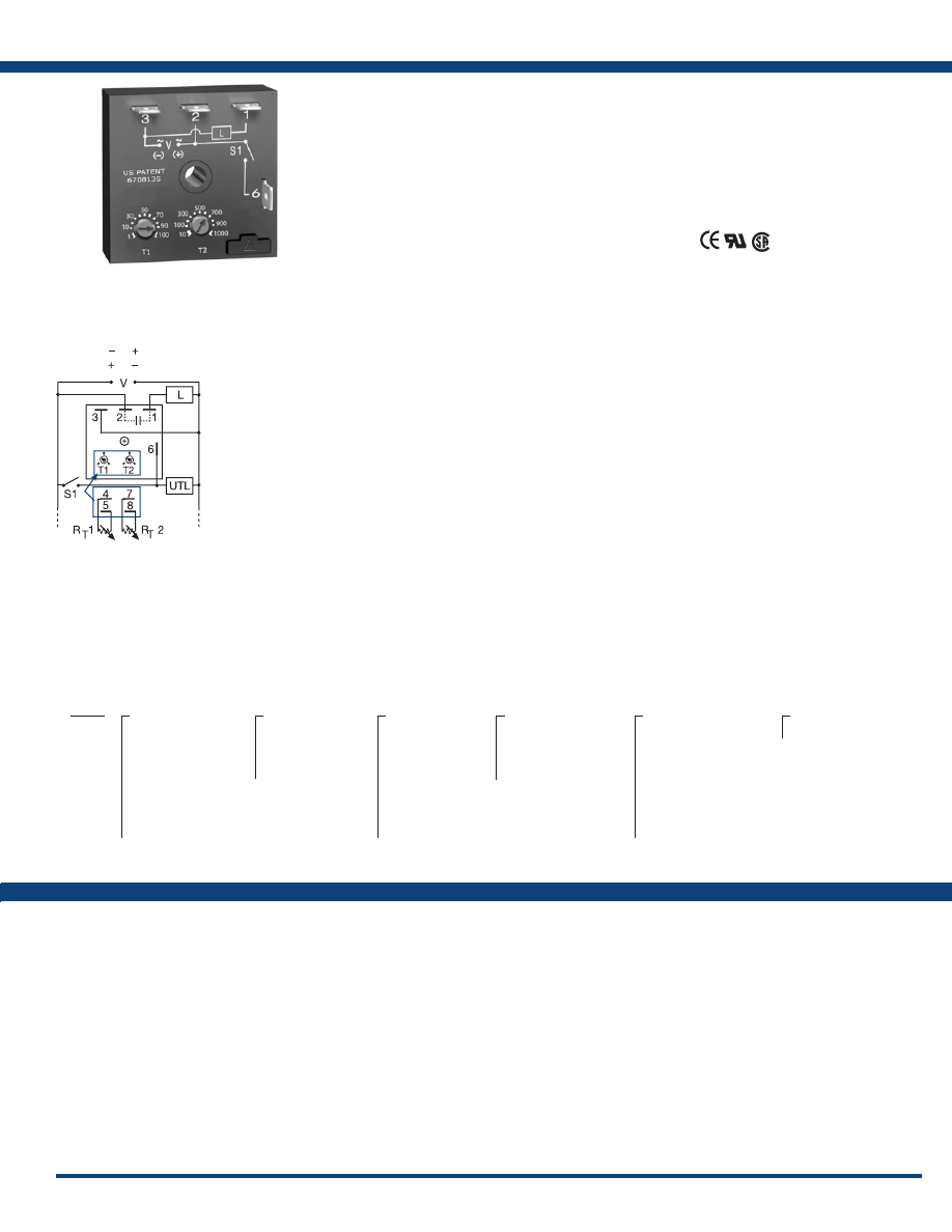
Connection:
The KSPD Series is a factory programmed module
available with 1 of 12 standard dual functions.
The time delays can be factory fixed, externally
or onboard adjustable, or a combination of
fixed and adjustable. The 1A steady, 10A inrush
rated solid-state output provides 100 million
operations, typical. Its microcontroller timing
circuit provides excellent repeat accuracy and
stability. Encapsulation protects against shock,
vibration, and humidity. The KSPD Series is a
cost effective approach for OEM applications that
require small size and long life.
See Appendix B, page 165, Figure 1 for dimensional
drawing .
Features:
• Choose 1 of 12 standard dual functions
• Special time ranges & functions available
•
Factory programmed
• Microcontroller circuitry, ±0.5% repeat
accuracy
• 1A steady, solid-state output , 10A inrush
• 12 to 240V in 3 options
• Delays from 0.1s - 1000h in 9 ranges
Approvals:
Auxiliary Products:
•
External ad just potentiometer:
P/N: P1004-95
P/N: P1004-95-X
•
Versa-knob:
P/N: P0700-7
•
Female quick connect:
P/N: P1015-64 (AWG 14/16)
•
Quick connect to screw adaptor:
P/N: P1015-18
•
DIN rail:
P/N: C103PM
(Al)
•
DIN rail adaptor:
P/N: P1023-20
L1
N/L2
(Positive Switching)
(Negative Switching)
V = Voltage
L = Load
S1 = Initiate Switch
UTL = Untimed Load
T1 & R
T
1 = First Adjustment
T2 & R
T
2 = Second Adjustment
Terminal Location for
External Adjustment.
KSPD32221RXD
KSPD4175S130SMS
KSPD42121MB
KSPDA110ST00127
KSPDA114ST00173
KSPDA2121RXE
KSPDA2222RXE
KSPDP10.1S31RXE
KSPDP110M18SRXD
KSPDP110M18SRXE
KSPDP3131MI
KSPD
X
Input
─
A
- 24 to 240VAC
─
P
- 12 to 120VDC
positive switching
─
N
- 12 to 120VDC
negative switching
─
1
- 120VDC
positive switching
─
3
- 24VDC
─
4
- 120VAC
X
First Adjustment
(T1 or R
T
1)
─
1
- Fixed
─
2
- Onboard adjust
─
3
- External adjust
X
First Time Delay*
─
1
- 0.1 - 10s
─
2
- 1 - 100s
─
3
- 10 - 1000s
─
4
- 0.1 - 10m
─
5
- 1 - 100m
─
6
- 10 - 1000m
─
7
- 0.1 - 10h
─
8
- 1 - 100h
─
9
- 10 - 1000h
X
Second Adjustment
(T2 or R
T
2)
─
1
- Fixed
─
2
- Onboard adjust
─
3
- External adjust
X
Second Time Delay*
─
1
- 0.1 - 10s
─
2
- 1 - 100s
─
3
- 10 - 1000s
─
4
- 0.1 - 10m
─
5
- 1 - 100m
─
6
- 10 - 1000m
─
7
- 0.1 - 10h
─
8
- 1 - 100h
─
9
- 10 - 1000h
X
Function
─Specify function
*If fixed delay is selected, insert delay (
0 .1-999
)
followed by (
S
) secs., or (
M
) mins., or (
H
) hrs.
Functions:
MB, MRE, MI, MS,
IRE, BRE, SRE, RXE,
RXD, IM, AMI, SL
If desired part number is not listed, please call us to
see if it is technically possible to build .
For a complete list of functions with descriptions and diagrams,
see Appendix A - Timer Functions, pages 156-164.
Courtesy of Steven Engineering, Inc.-230 Ryan Way, South San Francisco, CA 94080-6370-Main Office: (650) 588-9200-Outside Local Area: (800) 258-9200-www.stevenengineering.com
Littelfuse-catalog-html.html

10
www.ssac.com • 800-843-8848 • fax: 605-348-5685
KSPS Series
Timer
Available Models:
Time Delay
Type . . . . . . . . . . . . . . . . . . . . . . . . . . . . . . . . . . . . . Microcontroller circuitry
Range . . . . . . . . . . . . . . . . . . . . . . . . . . . . . . . . . . . .
0.1s - 1000h in 9 adjustable ranges or fixed
Repeat Accuracy . . . . . . . . . . . . . . . . . . . . . . . . . .
±0.5% or 20ms, whichever is greater
Tolerance (Factory Calibration) . . . . . . . . . . . . . .
≤ ±2%
Reset Time . . . . . . . . . . . . . . . . . . . . . . . . . . . . . . . .
≤ 150ms
Initiate Time . . . . . . . . . . . . . . . . . . . . . . . . . . . . . .
≤ 20ms; ≤ 1500 operations per minute
Time Delay vs Temp. & Voltage
. . . . . . . . . . . . .
≤ ±2%
Input
Voltage
. . . . . . . . . . . . . . . . . . . . . . . . . . . . . . . . . . .
12 to 120VDC; 24 to 240VAC
Tolerance . . . . . . . . . . . . . . . . . . . . . . . . . . . . . . . . .
≤ ±15%
AC Line Frequency / DC Ripple
. . . . . . . . . . . . .
50/60Hz / ≤ 10%
Power Consumption . . . . . . . . . . . . . . . . . . . . . . .
AC ≤ 2VA; DC ≤ 1W
Output
Type . . . . . . . . . . . . . . . . . . . . . . . . . . . . . . . . . . . . .
Solid-state output
Rating . . . . . . . . . . . . . . . . . . . . . . . . . . . . . . . . . . .
1A steady, 10A inrush for 16ms
Voltage Drop
. . . . . . . . . . . . . . . . . . . . . . . . . . . . . AC
≅
2.5V @ 1A; DC
≅
1V @ 1A
OFF State Leakage Current
. . . . . . . . . . . . . . . . . AC
≅
5mA @ 240VAC, DC
≅
1mA
Protection
Circuitry . . . . . . . . . . . . . . . . . . . . . . . . . . . . . . . . . Encapsulated
Dielectric Breakdown
. . . . . . . . . . . . . . . . . . . . . .
≥ 2000V RMS terminals to mounting surface
Insulation Resistance . . . . . . . . . . . . . . . . . . . . . . .
≥ 100 MΩ
Polarity . . . . . . . . . . . . . . . . . . . . . . . . . . . . . . . . . .
DC units are reverse polarity protected
Mechanical
Mounting . . . . . . . . . . . . . . . . . . . . . . . . . . . . . . . . . .
Surface mt. with one #10 (M5 x 0.8) screw
Dimensions . . . . . . . . . . . . . . . . . . . . . . . . . . . . . . .
2 x 2 x 1.21 in. (50.8 x 50.8 x 30.7 mm)
Termination . . . . . . . . . . . . . . . . . . . . . . . . . . . . . .
0.25 in. (6.35 mm) male quick connects
Environmental
Operating / Storage Temperature
. . . . . . . . . . .
-40° to 60°C / -40° to 85°C
Humidity . . . . . . . . . . . . . . . . . . . . . . . . . . . . . . . . .
95% relative, non-condensing
Weight
. . . . . . . . . . . . . . . . . . . . . . . . . . . . . . . . . . .
≅
2.4 oz (68 g)
Order Table:
Specifications
The KSPS Series is a factory programmed module
available in any 1 of 14 standard functions. The
KSPS offers a single, fixed, externally or onboard
adjustable time delay. The 1A steady, 10A inrush
rated solid-state output provides 100 million
operations typical . Its microcontroller timing
circuit provides excellent repeat accuracy and
stability. Encapsulation protects against shock,
vibration, and humidity. The KSPS Series is a
cost effective approach for OEM applications that
require small size and solid state reliability.
See Appendix B, page 165, Figure 1 for dimensional
drawing .
Auxiliary Products:
•
External ad just potentiometer:
P/N: P1004-95
P/N: P1004-95-X
•
Versa-knob:
P/N: P0700-7
•
Female quick connect:
P/N: P1015-64 (AWG 14/16)
•
Quick connect to screw adaptor:
P/N: P1015-18
•
DIN rail:
P/N: C103PM
(Al)
•
DIN rail adaptor:
P/N: P1023-20
Features:
• Choose 1 of 14 standard functions
• Special time ranges & functions available
•
Factory programmed
• Microcontroller circuitry, ±0.5% repeat
accuracy
• Solid-state output 1A steady, 10A inrush
• Fixed, external, or onboard adjustment
• 12 to 240V in 3 options
• Delays from 0.1s - 1000h in 9 ranges
Approvals:
KSPS121TS
KSPS124PS
KSPS2180SB
KSPS3115SRE
KSPSA21FT
KSPSA23SD
KSPSA24B
KSPSA24US
KSPSN110SI
KSPSN21B
KSPSP110SI
KSPSP145SM
KSPSP160MB
Connection:
L = Load
UTL = Untimed Load
V = Voltage
S1 = Initiate Switch
Functions:
M, B, RE, RD, S, SD,
FT I, TS, US, UB, AM,
PS, PSD
KSPS
X
Input
─
A
- 24 to 240VAC
─
P
- 12 to 120VDC
positive switching
─
N
- 12 to 120VDC
negative switching
─
1
- 12VDC
positive switching
─
2
- 24VAC
─
3
- 24VDC
positive switching
X
Adjustment
─
1
- Fixed
─
2
- Onboard adjust
─
3
- External adjust
X
Time Delay*
─
1
- 0.1 - 10s
─
2
- 1 - 100s
─
3
- 10 - 1000s
─
4
- 0.1 - 10m
─
5
- 1 - 100m
─
6
- 10 - 1000m
─
7
- 0.1 - 10h
─
8
- 1 - 100h
─
9
- 10 - 1000h
X
Function
─Specify function
*If fixed delay is selected, insert
delay (
0 .1-1000
) followed by (
S
)
secs., or (
M
) mins., or (
H
) hrs.
L1
N/L2
(Positive Switching)
(Negative Switching)
If desired part number is not listed, please call us to
see if it is technically possible to build .
For a complete list of functions with descriptions
and diagrams, see Appendix A - Timer Functions,
pages 156-164.
Courtesy of Steven Engineering, Inc.-230 Ryan Way, South San Francisco, CA 94080-6370-Main Office: (650) 588-9200-Outside Local Area: (800) 258-9200-www.stevenengineering.com
Littelfuse-catalog-html.html
11
www.ssac.com • 800-843-8848 • fax: 605-348-5685
KSPU Series
Timer
Available Models:
Time Delay
Type . . . . . . . . . . . . . . . . . . . . . . . . . . . . . . Microcontroller circuitry
Range . . . . . . . . . . . . . . . . . . . . . . . . . . . . . . . .
0.1 - 102.3s, m or h in 0.1s, m or h increments
1 - 1023s, m or h in 1s, m or h increments
1 - 63s or m in 1s or m increments
Repeat Accuracy . . . . . . . . . . . . . . . . . . .
±0.1% or 20ms, whichever is greater
Setting Accuracy . . . . . . . . . . . . . . . . . . .
≤ ±1% or 20ms, whichever is greater
Reset Time . . . . . . . . . . . . . . . . . . . . . . . . .
≤ 150ms
Initiate Time . . . . . . . . . . . . . . . . . . . . . . .
≤ 20ms
Time Delay vs Temp. & Voltage
. . . . . .
≤ ±2%
Count Range . . . . . . . . . . . . . . . . . . . . . . .
1 - 1023 in 3 ranges
Count Rate . . . . . . . . . . . . . . . . . . . . . . . .
≤ 25 counts per second
Input
Voltage
. . . . . . . . . . . . . . . . . . . . . . . . . . . .
12 to 120VDC; 24 to 240VAC
Tolerance . . . . . . . . . . . . . . . . . . . . . . . . . .
≤ ±15%
AC Line Frequency / DC Ripple
. . . . . .
50/60 Hz / ≤ 10%
Power Consumption . . . . . . . . . . . . . . . .
AC ≤ 2VA; DC ≤ 1W
Output
Type . . . . . . . . . . . . . . . . . . . . . . . . . . . . . .
Solid-state output
Rating . . . . . . . . . . . . . . . . . . . . . . . . . . . .
1A steady, 10A inrush for 16ms
Voltage Drop
. . . . . . . . . . . . . . . . . . . . . . AC
≅
2.5V @ 1A; DC
≅
1V @ 1A
OFF State Leakage Current
. . . . . . . . . . AC
≅
5mA @ 240VAC; DC
≅
1mA
Counter Output . . . . . . . . . . . . . . . . . . . .
Output pulse width: 300ms ±20%
Time Delay/Counts Variable 7 & 8
Protection
Circuitry . . . . . . . . . . . . . . . . . . . . . . . . . . Encapsulated
Dielectric Breakdown
. . . . . . . . . . . . . . . . . . .
≥ 2000V RMS terminals to mounting surface
Insulation Resistance . . . . . . . . . . . . . . . .
≥ 100 MΩ
Polarity . . . . . . . . . . . . . . . . . . . . . . . . . . .
DC units are reverse polarity protected
Mechanical
Mounting . . . . . . . . . . . . . . . . . . . . . . . . .
Surface mt. with one #10 (M5 x 0.8) screw
Dimensions . . . . . . . . . . . . . . . . . . . . . . . .
2 x 2 x 1.21 in. (50.8 x 50.8 x 30.7 mm)
Termination . . . . . . . . . . . . . . . . . . . . . . .
0.25 in. (6.35 mm) male quick connects
Environmental
Operating / Storage Temperature.
. . . .
-40° to 60°C / -40° to 85°C
Humidity . . . . . . . . . . . . . . . . . . . . . . . . . .
95% relative, non-condensing
Weight
. . . . . . . . . . . . . . . . . . . . . . . . . . . .
≅
2.4 oz (68 g)
Specifications
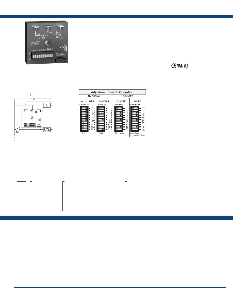
Order Table:
Connection:
The KSPU Series is a factory programmed module
available in any 1 of 14 standard functions. The
KSPU offers a single adjustable timer or counter
function. Switch adjustment allows accurate
selection of the time delay or number of counts
the first time and every time. The 1A steady,
10A inrush rated solid-state output provides 100
million operations, typical. Its microcontroller
timing circuit provides excellent repeat accuracy
and stability . Encapsulation protects against
shock, vibration, and humidity. The KSPU Series
is a cost effective approach for OEM applications
that require small size, solid state reliability, and
accurate switch adjustment.
See Appendix B, page 165, Figure 1 for dimensional
drawing .
Functions:
M, B, RE, RD, S, SD, I,
TS, US, UB, AM, PSD,
C, CI
Features:
• Choose 1 of 14 standard functions
• Special time ranges & functions available
•
Factory programmed
• Microcontroller circuitry, ±0.1% repeat
accuracy
• 1A steady, solid-state output, 10A inrush
• Accurate switch adjustment
• 12 to 240V in 3 options
• Delays from 0.1s - 1023h
• Counts 1 to 1023
Approvals:
Auxiliary Products:
•
Female quick connect:
P/N: P1015-64 (AWG 14/16)
P/N: P1015-14 (AWG 18/22)
•
Quick connect to screw adaptor:
P/N: P1015-18
•
DIN rail:
P/N: C103PM
(Al)
•
DIN rail adaptor:
P/N: P1023-20
KSPU11M
KSPUA2I
KSPUA8C
V = Voltage
S1 = Initiate Switch
L = Load
UTL = Untimed Load
Switch Adjustment:
KSPU
X
Input
─
A
- 24 to 240VAC
─
P
- 12 to 120VDC
positive switching
─
N
- 12 to 120VDC
negative switching
─
1
- 12VDC
positive switching
─
4
- 120VAC
─
9
- 120/240VAC
X
Time Delay/Counts
─
1
- 0.1 - 102.3s
─
2
- 1 - 1023s
─
3
- 0.1 - 102.3m
─
4
- 1 - 1023m
─
5
- 0.1 - 102.3h
─
6
- 1 - 1023h
─
7
- 1 - 165 counts (straight) w/ pulsed output
─
8
- 1 - 1023 counts (binary) w/ pulsed output
─
9
- 1 - 7 counts to start 1 - 63s or m interval time
X
Function
─Specify function
L1
N/L2
(Positive Switching)
(Negative Switching)
If desired part number is not listed, please call us to
see if it is technically possible to build .
For a complete list of functions with descriptions and diagrams,
see Appendix A - Timer Functions, pages 156-164.
Courtesy of Steven Engineering, Inc.-230 Ryan Way, South San Francisco, CA 94080-6370-Main Office: (650) 588-9200-Outside Local Area: (800) 258-9200-www.stevenengineering.com
Littelfuse-catalog-html.html
12
www.ssac.com • 800-843-8848 • fax: 605-348-5685
NHPD
X
Output Rating
─
A
- 6A
─
B
- 10A
─
C
- 20A
X
Input Voltage
─
A
- 24 to 240VAC
X
First Adjustment
(T1 or R
T
1)
─
1
- Fixed
─
2
- Onboard adjust
─
3
- External adjust
X
First Time Delay*
─
1
- 0.1 - 10s
─
2
- 1 - 100s
─
3
- 10 - 1000s
─
4
- 0.1 - 10m
─
5
- 1 - 100m
─
6
- 10 - 1000m
─
7
- 0.1 - 10h
─
8
- 1 - 100h
─
9
- 10 - 1000h
X
Second Adjustment
(T2 or R
T
2)
─
1
- Fixed
─
2
- Onboard adjust
─
3
- External adjust
X
Second Time Delay*
─
1
- 0.1 - 10s
─
2
- 1 - 100s
─
3
- 10 - 1000s
─
4
- 0.1 - 10m
─
5
- 1 - 100m
─
6
- 10 - 1000m
─
7
- 0.1 - 10h
─
8
- 1 - 100h
─
9
- 10 - 1000h
X
Function
─Specify function
NHPD Series
Timer
Available Models:
Time Delay
Type . . . . . . . . . . . . . . . . . . . . . . . . . . . . . . . . . . . . Microcontroller circuitry
Range . . . . . . . . . . . . . . . . . . . . . . . . . . . . . . . . . . .
0.1s - 1000h in 9 adjustable ranges or fixed (to 999)
Repeat Accuracy . . . . . . . . . . . . . . . . . . . . . . . . .
±0.5% or 20ms, whichever is greater
Tolerance (Factory Calibration) . . . . . . . . . . . . .
≤ ±2%
Reset Time . . . . . . . . . . . . . . . . . . . . . . . . . . . . . . .
≤ 150ms
Initiate Time . . . . . . . . . . . . . . . . . . . . . . . . . . . . .
≤ 20ms; ≤ 1500 operations per minute
Time Delay vs Temp. & Voltage
. . . . . . . . . . . .
≤ ±2%
Input
Voltage
. . . . . . . . . . . . . . . . . . . . . . . . . . . . . . . . . .
24 to 240VAC
Tolerance . . . . . . . . . . . . . . . . . . . . . . . . . . . . . . . .
≤ ±15%
AC Line Frequency . . . . . . . . . . . . . . . . . . . . . . .
50/60Hz
Output
Type . . . . . . . . . . . . . . . . . . . . . . . . . . . . . . . . . . . . Solid state
Rating Output Steady State Inrush**
A 6A 60A
B 10A 100A
C 20A 200A
Minimum Load Current . . . . . . . . . . . . . . . . . . .
100mA
Voltage Drop
. . . . . . . . . . . . . . . . . . . . . . . . . . . .
≅
2.5V @ rated current
OFF State Leakage Current
. . . . . . . . . . . . . . . .
≅
5mA @ 230VAC
Protection
Circuitry . . . . . . . . . . . . . . . . . . . . . . . . . . . . . . . . Encapsulated
Dielectric Breakdown
. . . . . . . . . . . . . . . . . . . . .
≥ 2000V RMS terminals to mounting surface
Insulation Resistance . . . . . . . . . . . . . . . . . . . . . .
≥ 100 MΩ
Mechanical
Mounting ** . . . . . . . . . . . . . . . . . . . . . . . . . . . . .
Surface mt with one #10 (M5 x 0.8) screw
Dimensions . . . . . . . . . . . . . . . . . . . . . . . . . . . . . .
2 x 2 x 1.51 in. (50.8 x 50.8 x 38.4 mm)
Termination . . . . . . . . . . . . . . . . . . . . . . . . . . . . .
0.25 in. (6.35 mm) male quick connects
Environmental
Operating / Storage Temperature
. . . . . . . . . .
-40° to 60°C / -40° to 85°C
Humidity . . . . . . . . . . . . . . . . . . . . . . . . . . . . . . . .
95% relative, non-condensing
Weight
. . . . . . . . . . . . . . . . . . . . . . . . . . . . . . . . . .
≅
3.9 oz (111 g)
**Must be bolted to a metal surface using the included heat sink compound. The maximum
mounting surface temperature is 90°C. Inrush: Non-repetitive for 16ms.
Order Table:
Specifications
The NHPD Series is a factory programmed module
available in any 1 of 12 standard dual functions.
The time delays can be factory fixed, externally or
onboard adjustable, or a combination of fixed and
adjustable. The NHPD includes a high current
solid-state output. It can switch motors, lamps
and heaters directly without the addition of a
contactor. It can switch up to 20A with up to 100
million operations typical . Its microcontroller
timing circuit provides excellent repeat accuracy
and stability . Encapsulation protects against
shock, vibration, and humidity. The NHPD Series
is a cost effective approach for OEM applications
that require small size and long life.
See Appendix B, page 165, Figure 4 for dimensional
drawing .
Auxiliary Products:
•
External ad just potentiometer:
P/N: P1004-95
P/N: P1004-95-X
•
Versa-knob:
P/N: P0700-7
•
Female quick connect:
P/N: P1015-13 (AWG 10/12)
P/N: P1015-64 (AWG 14/16)
•
Quick connect to screw adaptor:
P/N: P1015-18
Features:
• High load currents up to 20A, 200A inrush
•
Factory programmed
• Choose 1 of 12 standard dual functions
• Special time ranges & functions available
• Microcontroller circuitry, ±0.5% repeat
accuracy
• Fixed, external, or onboard adjustment
• 24 to 240VAC
• Delays from 0.1s - 1000h in 9 ranges
Approvals:
Connection:
L1 N/L2
Terminal Location for
External Adjustment
V = Voltage
L = Load
S1 = Initiate Switch
UTL = Untimed Load
T1 & R
T
1 = First Adjustment
T2 & R
T
2 = Second Adjustment
Functions:
MB, MRE, MI,
MS, IRE, BRE,
SRE, RXE, RXD,
IM, AMI, SL
*If fixed delay is selected, insert delay (
0 .1-999
)
followed by (
S
) secs., or (
M
) mins., or (
H
) hrs.
There are no part numbers currently active. Please call
Technical Support with your requirements.
For a complete list of functions with descriptions and diagrams,
see Appendix A - Timer Functions, pages 156-164.
Courtesy of Steven Engineering, Inc.-230 Ryan Way, South San Francisco, CA 94080-6370-Main Office: (650) 588-9200-Outside Local Area: (800) 258-9200-www.stevenengineering.com
Littelfuse-catalog-html.html
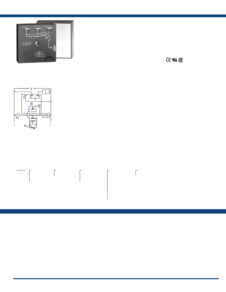
13
www.ssac.com • 800-843-8848 • fax: 605-348-5685
NHPD
X
Output Rating
─
A
- 6A
─
B
- 10A
─
C
- 20A
X
Input Voltage
─
A
- 24 to 240VAC
X
First Adjustment
(T1 or R
T
1)
─
1
- Fixed
─
2
- Onboard adjust
─
3
- External adjust
X
First Time Delay*
─
1
- 0.1 - 10s
─
2
- 1 - 100s
─
3
- 10 - 1000s
─
4
- 0.1 - 10m
─
5
- 1 - 100m
─
6
- 10 - 1000m
─
7
- 0.1 - 10h
─
8
- 1 - 100h
─
9
- 10 - 1000h
X
Second Adjustment
(T2 or R
T
2)
─
1
- Fixed
─
2
- Onboard adjust
─
3
- External adjust
X
Second Time Delay*
─
1
- 0.1 - 10s
─
2
- 1 - 100s
─
3
- 10 - 1000s
─
4
- 0.1 - 10m
─
5
- 1 - 100m
─
6
- 10 - 1000m
─
7
- 0.1 - 10h
─
8
- 1 - 100h
─
9
- 10 - 1000h
X
Function
─Specify function
NHPS Series
Timer
Available Models:
Time Delay
Type . . . . . . . . . . . . . . . . . . . . . . . . . . . . . . Microcontroller circuitry
Range . . . . . . . . . . . . . . . . . . . . . . . . . . . . . . .
0.1s - 1000h in 9 adjustable ranges or fixed
Repeat Accuracy . . . . . . . . . . . . . . . . . . .
±0.5% or 20ms, whichever is greater
Tolerance (Factory Calibration) . . . . . . .
≤ ±2%
Reset Time . . . . . . . . . . . . . . . . . . . . . . . . .
≤ 150ms
Initiate Time . . . . . . . . . . . . . . . . . . . . . . .
≤ 20ms; ≤ 1500 operations per minute
Time Delay vs Temp. & Voltage
. . . . . .
≤ ±2%
Input
Voltage
. . . . . . . . . . . . . . . . . . . . . . . . . . . .
24 to 240VAC
Tolerance . . . . . . . . . . . . . . . . . . . . . . . . . .
≤ ±15%
AC Line Frequency . . . . . . . . . . . . . . . . .
50/60Hz
Output
Type . . . . . . . . . . . . . . . . . . . . . . . . . . . . . . Solid state
Rating Output Steady State Inrush**
A 6A 60A
B 10A 100A
C 20A 200A
Minimum Load Current . . . . . . . . . . . . .
100mA
Voltage Drop
. . . . . . . . . . . . . . . . . . . . . .
≅
2.5V @ rated current
OFF State Leakage Current
. . . . . . . . . .
≅
5mA @ 230VAC
Protection
Circuitry . . . . . . . . . . . . . . . . . . . . . . . . . . Encapsulated
Dielectric Breakdown
. . . . . . . . . . . . . . . . . .
≥ 2000 V RMS terminals to mounting surface
Insulation Resistance . . . . . . . . . . . . . . . .
≥ 100 MΩ
Mechanical
Mounting ** . . . . . . . . . . . . . . . . . . . . . . .
Surface mt. with one #10 (M5 x 0.8) screw
Dimensions . . . . . . . . . . . . . . . . . . . . . . . .
2 x 2 x 1.51 in. (50.8 x 50.8 x 38.4 mm)
Termination . . . . . . . . . . . . . . . . . . . . . . .
0.25 in. (6.35 mm) male quick connects
Environmental
Operating / Storage Temperature
. . . .
-40° to 60°C / -40° to 85°C
Humidity . . . . . . . . . . . . . . . . . . . . . . . . . .
95% relative, non-condensing
Weight
. . . . . . . . . . . . . . . . . . . . . . . . . . . .
≅
3.9 oz (111 g)
**Must be bolted to a metal surface using the included heat sink compound. The maximum
mounting surface temperature is 90°C. Inrush: Non-repetitive for 16ms.
Specifications
Order Table:
The NHPS Series is a factory programmed module
available in any 1 of 13 standard functions. The
NHPS offers a single, fixed, onboard adjustment
or an externally adjustable time delay. The NHPS
includes a high current solid-state output. It can
switch motors, lamps and heaters directly without
the addition of a contactor. It can switch up to
20A with up to 100 million operations typical. Its
microcontroller timing circuit provides excellent
repeat accuracy and stability . Encapsulation
protects against shock, vibration, and humidity.
The NHPS Series is a cost effective approach for
OEM applications that require small size and solid
state reliability .
See Appendix B, page 165, Figure 4 for dimensional
drawing .
Features:
• High load currents up to 20A, 200A inrush
•
Factory programmed
• Choose 1 of 13 standard functions
• Special time ranges & functions available
• Microcontroller circuitry, ±0.5% repeat
accuracy
• Fixed, external, or onboard adjustment
• 24 to 240VAC
• Delays from 0.1s - 1000h in 9 ranges
Approvals:
Auxiliary Products:
•
External ad just potentiometer:
P/N: P1004-95
P/N: P1004-95-X
•
Versa-knob:
P/N: P0700-7
•
Female quick connect:
P/N: P1015-13 (AWG 10/12)
P/N: P1015-64 (AWG 14/16)
•
Quick connect to screw adaptor:
P/N: P1015-18
Functions:
M, B, RE, RD, S,
SD, I, TS, US, UB,
AM, FT, PSD
NHPS
X
Output Rating
─
A
- 6A
─
B
- 10A
─
C
- 20A
X
Input
─
A
- 24 to 240VAC
X
Adjustment
─
1
- Fixed
─
2
- Onboard adjust
─
3
- External adjust
X
Time Delay*
─
1
- 0.1 - 10s
─
2
- 1 - 100s
─
3
- 10 - 1000s
─
4
- 0.1 - 10m
─
5
- 1 - 100m
─
6
- 10 - 1000m
─
7
- 0.1 - 10h
─
8
- 1 - 100h
─
9
- 10 - 1000h
X
Function
─Specify function
*If fixed delay is selected, insert delay (
0 .1-1000
)
followed by (
S
) secs., or (
M
) mins., or (
H
) hrs.
Connection:
L1
N/L2
Terminal Location for
External Adjustment
V = Voltage
S1 = Initiate Switch
UTL = Untimed Load
L = Load
There are no part numbers currently active. Please call
Technical Support with your requirements.
For a complete list of functions with descriptions and diagrams,
see Appendix A - Timer Functions, pages 156-164.
Courtesy of Steven Engineering, Inc.-230 Ryan Way, South San Francisco, CA 94080-6370-Main Office: (650) 588-9200-Outside Local Area: (800) 258-9200-www.stevenengineering.com
Littelfuse-catalog-html.html
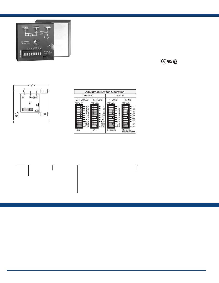
14
www.ssac.com • 800-843-8848 • fax: 605-348-5685
NHPU Series
Timer
Available Models:
Time Delay
Type . . . . . . . . . . . . . . . . . . . . . . . . . . . . . . . . . .Microcontroller circuitry
Range . . . . . . . . . . . . . . . . . . . . . . . . . . . . . . . . . . .
0.1 - 102.3s, m or h in 0.1s, m or h increments
1 - 1023s, m or h in 1s, m or h increments
1 - 63s or m in 1s or m increments
Repeat Accuracy . . . . . . . . . . . . . . . . . . . . . . .
±0.1% or 20ms, whichever is greater
Setting Accuracy . . . . . . . . . . . . . . . . . . . . . . .
≤ ±1% or 20ms, whichever is greater
Reset Time . . . . . . . . . . . . . . . . . . . . . . . . . . . .
≤ 150ms
Initiate Time . . . . . . . . . . . . . . . . . . . . . . . . . . .
≤ 20ms
Time Delay vs Temp. & Voltage
. . . . . . . . . .
≤ ±2%
Count Range . . . . . . . . . . . . . . . . . . . . . . . . . . .
1 - 1023 in 3 ranges
Count Rate . . . . . . . . . . . . . . . . . . . . . . . . . . . .
≤ 25 counts per second
Input
Voltage
. . . . . . . . . . . . . . . . . . . . . . . . . . . . . . . .
24 to 240VAC
Tolerance . . . . . . . . . . . . . . . . . . . . . . . . . . . . . .
≤ ±15%
AC Line Frequency . . . . . . . . . . . . . . . . . . . . .
50/60Hz
Output
Type . . . . . . . . . . . . . . . . . . . . . . . . . . . . . . . . . .Solid state
Rating Output Steady State Inrush**
A 6A 60A
B 10A 100A
C 20A 200A
Minimum Load Current . . . . . . . . . . . . . . . . .
100mA
Voltage Drop
. . . . . . . . . . . . . . . . . . . . . . . . . .
≅
2.5V @ 1A
OFF State Leakage Current
. . . . . . . . . . . . . .
≅
5mA @ 230VAC
Counter Output
Time Delay/CountsVariable 7 & 8)
. . . . .
Pulse width: 300ms ±20%
Protection
Circuitry . . . . . . . . . . . . . . . . . . . . . . . . . . . . . .Encapsulated
Dielectric Breakdown
. . . . . . . . . . . . . . . . . . . . .
≥ 2000V RMS terminals to mounting surface
Insulation Resistance . . . . . . . . . . . . . . . . . . . .
≥ 100 MΩ
Mechanical
Mounting ** . . . . . . . . . . . . . . . . . . . . . . . . . . . . . .
Surface mt. with one #10 (M5 x 0.8) screw
Dimensions . . . . . . . . . . . . . . . . . . . . . . . . . . . .
2 x 2 x 1.51 in. (50.8 x 50.8 x 38.4 mm)
Termination . . . . . . . . . . . . . . . . . . . . . . . . . . .
0.25 in. (6.35 mm) male quick connects
Environmental
Operating / Storage Temperature
. . . . . . . .
-40° to 60°C / -40° to 85°C
Humidity . . . . . . . . . . . . . . . . . . . . . . . . . . . . . .
95% relative, non-condensing
Weight
. . . . . . . . . . . . . . . . . . . . . . . . . . . . . . . .
≅
3.9 oz (111 g)
**Must be bolted to a metal surface using the included heat sink compound. The
maximum mounting surface temperature is 90°C. Inrush: Non-repetitive for 16ms.
Order Table:
Specifications
The NHPU Series is a factory programmed module
available in any 1 of 14 standard functions. The
NHPU offers a single adjustable timer or counter
function. Switch adjustment allows accurate
selection of the time delay or number of counts,
the first time and every time. The NHPU includes
a high current solid-state output. It can switch
motors, lamps and heaters directly without the
addition of a contactor. It can switch up to 20A
with up to 100 million operations, typical. Its
microcontroller timing circuit provides excellent
repeat accuracy and stability . Encapsulation
protects against shock, vibration, and humidity.
The NHPU Series is a cost effective approach for
OEM applications that require small size, solid
state reliability, and accurate switch adjustment.
See Appendix B, page 165, Figure 4 for dimensional
drawing .
Auxiliary Products:
•
Female quick connect:
P/N: P1015-13 (AWG 10/12)
P/N: P1015-64 (AWG 14/16)
P/N: P1015-14 (AWG 18/22)
•
Quick connect to screw adaptor:
P/N: P1015-18
Features:
• High load currents up to 20A, 200A inrush
•
Factory programmed
• Choose 1 of 14 standard functions
• Special time ranges & functions available
• Microcontroller circuitry, ±0.1% repeat
accuracy
• Accurate switch adjustment
• 24 to 240VAC
• Delays from 0.1s - 1023h
• Counts to 1023
Approvals:
Connection:
There are no part numbers currently active. Please call
Technical Support with your requirements.
L1
N/L2
V = Voltage
L = Load
UTL = Untimed Load
S1 = Initiate Switch
NHPU X
Output Rating
─
A
- 6A
─
B
- 10A
─
C
- 20A
X
Input Voltage
─
A
- 24 to 240VAC
X
Time Delay/Counts
─
1
- 0.1 - 102.3s
─
2
- 1 - 1023s
─
3
- 0.1 - 102.3m
─
4
- 1 - 1023m
─
5
- 0.1 - 102.3h
─
6
- 1 - 1023h
─
7
- 1 - 165 counts (straight) w/ pulsed output
─
8
- 1 - 1023 counts (binary) w/ pulsed output
─
9
- 1 - 7 counts to start 1 - 63s or m interval time
X
Function
─Specify function
Functions:
M, B, RE, RD, S, SD,
I, TS, US, UB, AM,
PSD, C, CI
Switch Adjustment:
For a complete list of functions with descriptions and diagrams,
see Appendix A - Timer Functions, pages 156-164.
Courtesy of Steven Engineering, Inc.-230 Ryan Way, South San Francisco, CA 94080-6370-Main Office: (650) 588-9200-Outside Local Area: (800) 258-9200-www.stevenengineering.com
Littelfuse-catalog-html.html

15
www.ssac.com • 800-843-8848 • fax: 605-348-5685
Timiers - Multifunction
Series Included
TRDU . . . . . . . . . . . . . . . . . . . . . . . . . . . . . . . . . . . . . . . . . . . .
16
TRU . . . . . . . . . . . . . . . . . . . . . . . . . . . . . . . . . . . . . . . . . . . . .17
ASQU . . . . . . . . . . . . . . . . . . . . . . . . . . . . . . . . . . . . . . . . . . . .
18
ASTU . . . . . . . . . . . . . . . . . . . . . . . . . . . . . . . . . . . . . . . . . . . .
18
DSQU . . . . . . . . . . . . . . . . . . . . . . . . . . . . . . . . . . . . . . . . . . . .19
DSTU . . . . . . . . . . . . . . . . . . . . . . . . . . . . . . . . . . . . . . . . . . . .19
Relay Output
Solid-State Output
Courtesy of Steven Engineering, Inc.-230 Ryan Way, South San Francisco, CA 94080-6370-Main Office: (650) 588-9200-Outside Local Area: (800) 258-9200-www.stevenengineering.com
Littelfuse-catalog-html.html
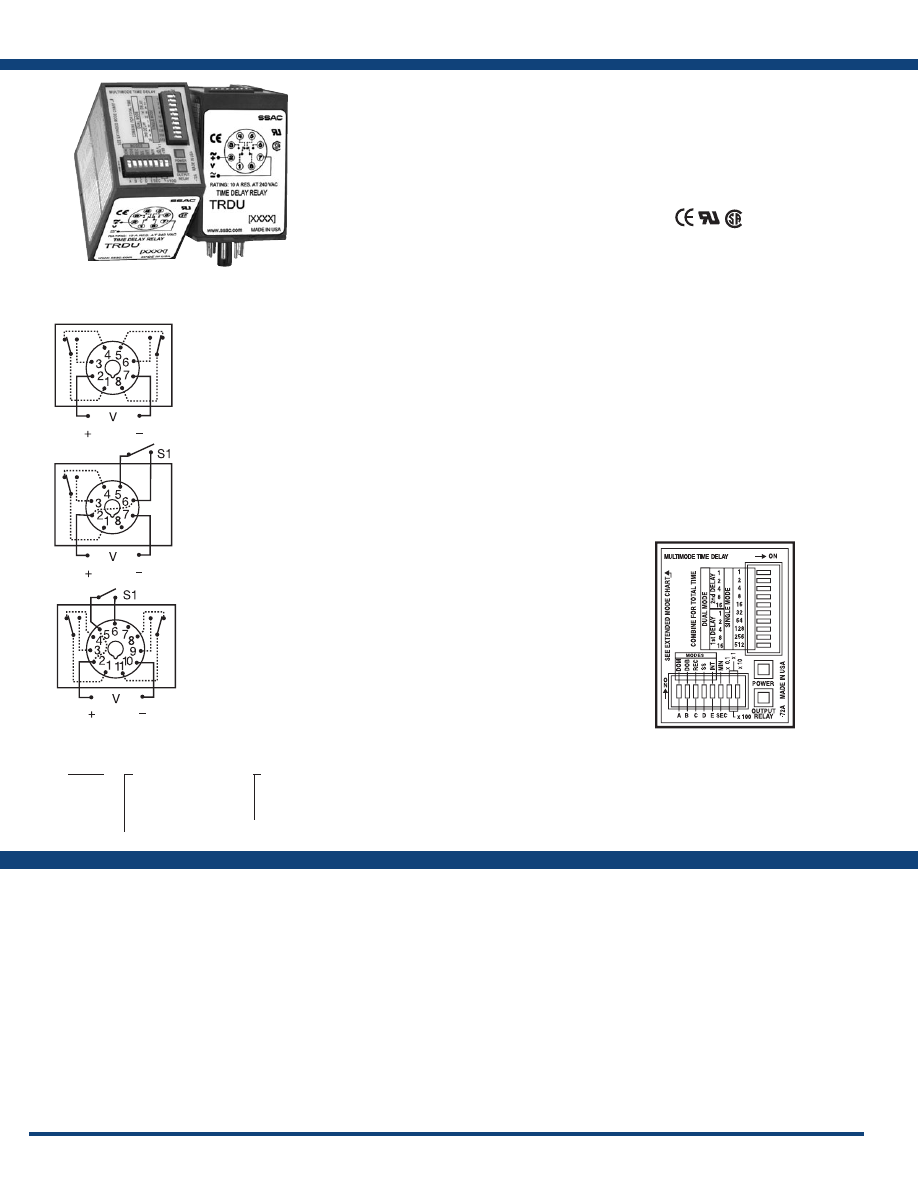
16
www.ssac.com • 800-843-8848 • fax: 605-348-5685
TRDU Series
Timer
Available Models:
Time Delay
Type . . . . . . . . . . . . . . . . . . . . . . . . . . . . . . . . . Microcontroller
Range: Switch Selectable**
. . . . . . . . . . . . .
Single Functions: 0.1s - 1,705h in 8 ranges
Dual Functions: 0.1s - 3,100m each in 8 ranges
Adjustments
. . . . . . . . . . . . . . . . . . . . . . . . . .
Multiplier: 3 position DIP switches select
0.1, 1, 10, or 100 in s or m
Setting Accuracy . . . . . . . . . . . . . . . . . . . . . .
±1% or 50ms, whichever is greater
Repeat Accuracy . . . . . . . . . . . . . . . . . . . . . .
±0.1% or 20ms, whichever is greater
Timing Functions . . . . . . . . . . . . . . . . . . . . . .
Five switches are provided to set one of
twenty-one single or dual functions
Reset Time . . . . . . . . . . . . . . . . . . . . . . . . . . . .
≤ 50ms
Initiate Time . . . . . . . . . . . . . . . . . . . . . . . . . .
120VAC: 75ms
Time Delay vs Temp. & Voltage
. . . . . . . . .
±1%
Indication
Two LEDs indicate . . . . . . . . . . . . . . . . . . . .
1) Input voltage applied 2) Output relay status
Input
Voltage
. . . . . . . . . . . . . . . . . . . . . . . . . . . . . . .
12VDC, 24VAC/DC, 120VAC, or 230VAC
Tolerance 12VDC & 24VAC/DC
. . . . . . . .
-15% - 20%
120 & 230VAC
. . . . . . .
-20% - 10%
AC Line Frequency . . . . . . . . . . . . . . . . . . . .
50/60Hz
Power Consumption . . . . . . . . . . . . . . . . . . .
24 to 230V ≤ 3W; 12VDC ≤ 2W
Output
Type . . . . . . . . . . . . . . . . . . . . . . . . . . . . . . . . .
Electromechanical relay
Form . . . . . . . . . . . . . . . . . . . . . . . . . . . . . . . . . SPDT or DPDT
Rating . . . . . . . . . . . . . . . . . . . . . . . . . . . . . . .
10A resistive @ 120/240VAC & 28 VDC;
1/3 hp @ 120/240VAC
Life
. . . . . . . . . . . . . . . . . . . . . . . . . . . . . . . . . .
Mechanical – 1 x 10
7
;
Electrical – 1 x 10
6
Protection
Isolation Voltage
. . . . . . . . . . . . . . . . . . . . . .
≥ 1500V RMS input to output
Insulation Resistance . . . . . . . . . . . . . . . . . . .
≥ 100 MΩ
Polarity . . . . . . . . . . . . . . . . . . . . . . . . . . . . . .
DC units are reverse polarity protected
Mechanical
Mounting . . . . . . . . . . . . . . . . . . . . . . . . . . . .
Plug-in socket
Dimensions . . . . . . . . . . . . . . . . . . . . . . . . . . .
3.1 x 2.39 x 1.78 in. (78.7 x 60.7 x 45.2 mm)
Termination . . . . . . . . . . . . . . . . . . . . . . . . . .
Octal 8-pin plug-in or magnal 11-pin plug-in
Environmental
Operating / Storage Temperature
. . . . . . .
-20° to 65°C / -40° to 85°C
Weight
. . . . . . . . . . . . . . . . . . . . . . . . . . . . . . .
≅
5.8 oz (164 g)
**For CE approved applications, power must be removed from the unit when a switch
position is changed.
Specifications
Order Table:
Connection:
The TRDU Series is a versatile universal time delay
relay with 21 selectable single and dual functions.
The dual functions replace up to three timers
required to accomplish the same function. Both
the function and the timing range are selectable
with switches located on the face of the unit. Two
LED’s indicate input voltage and output status.
This device offers full 10A isolated relay output
contacts in either SPDT or DPDT. The TRDU
replaces hundreds of part numbers, thereby,
reducing your stock inventory requirements.
Features:
• Microcontroller ±0.1% repeat accuracy
• Multifunction – 21 timing functions
• Multirange – 0.1s - 1,705h in 8 ranges
• Switch selectable modes, time delay, &
ranges
• AC & DC input voltages are available
• Isolated, 10A, SPDT or DPDToutput contacts
Approvals:
Auxiliary Products:
•
Panel mount kit:
P/N: BZ1
•
Hold-down c lips ( sold i n p airs):
P/N: PSC8 (NDS-8)
P/N: PSC11 (NDS-11)
•
11-pin socket:
P/N: NDS-11
•
Octal 8-pin socket:
P/N: NDS-8
•
DIN rail:
P/N: C103PM
(Al)
TRDU120A1
TRDU120A2
TRDU120A3
TRDU12D1
TRDU12D3
TRDU230A2
TRDU24A1
TRDU24A2
TRDU24A3
L1
N/L2
L1
N/L2
L1
N/L2
V = Voltage
S1 = Initiate Switch
*Limited to 9 operating functions in 8-pin DPDT units
Five switches are provided to set one of 10 single or
11 dual modes of operation.
Single Functions-
* Delay-on-Make
Delay-on-Break
* Recycle (ON time first, equal recycle delays)
Single Shot
* Interval
Trailing Edge Single Shot
Inverted Single Shot
Inverted Delay-on-Break
Accumulative Delay-on-Make
Retriggerable Single Shot (motion detector)
Dual Functions -
Delay-on-Make/Delay-on-Break
* Delay-on-Make/Recycle
(ON time first, equal recycle delays)
* Delay-on-Make/Interval
Delay-on-Make/Single Shot
* Interval/Recycle
(ON time first, equal recycle delays)
Delay-on-Break/Recycle
(ON time first, equal recycle delays)
Single Shot/Recycle
(ON time first, equal recycle delays)
* Recycle - both times adjust. (ON time first)
* Recycle - both times adjust. (OFF time first)
* Interval/Delay-on-Make
Accumulative Delay-on-Make/Interval
21 Functions:
8-pin DPDT
8-pin SPDT
11-pin DPDT
TRDU
X
Input Voltage
─
12D
- 12VDC
─
24A
- 24VAC/DC
─
120A
- 120VAC
─
230A
- 230VAC
X
Base Connection
─
1
- 8-pin DPDT*
─
2
- 8-pin SPDT
─
3
- 11-pin DPDT
For more information see:
Appendix A, page 163-164 for function diagrams.
Appendix B, page 165, Figure 5 for dimensional drawing.
If desired part number is not listed, please call us to
see if it is technically possible to build .
Courtesy of Steven Engineering, Inc.-230 Ryan Way, South San Francisco, CA 94080-6370-Main Office: (650) 588-9200-Outside Local Area: (800) 258-9200-www.stevenengineering.com
Littelfuse-catalog-html.html
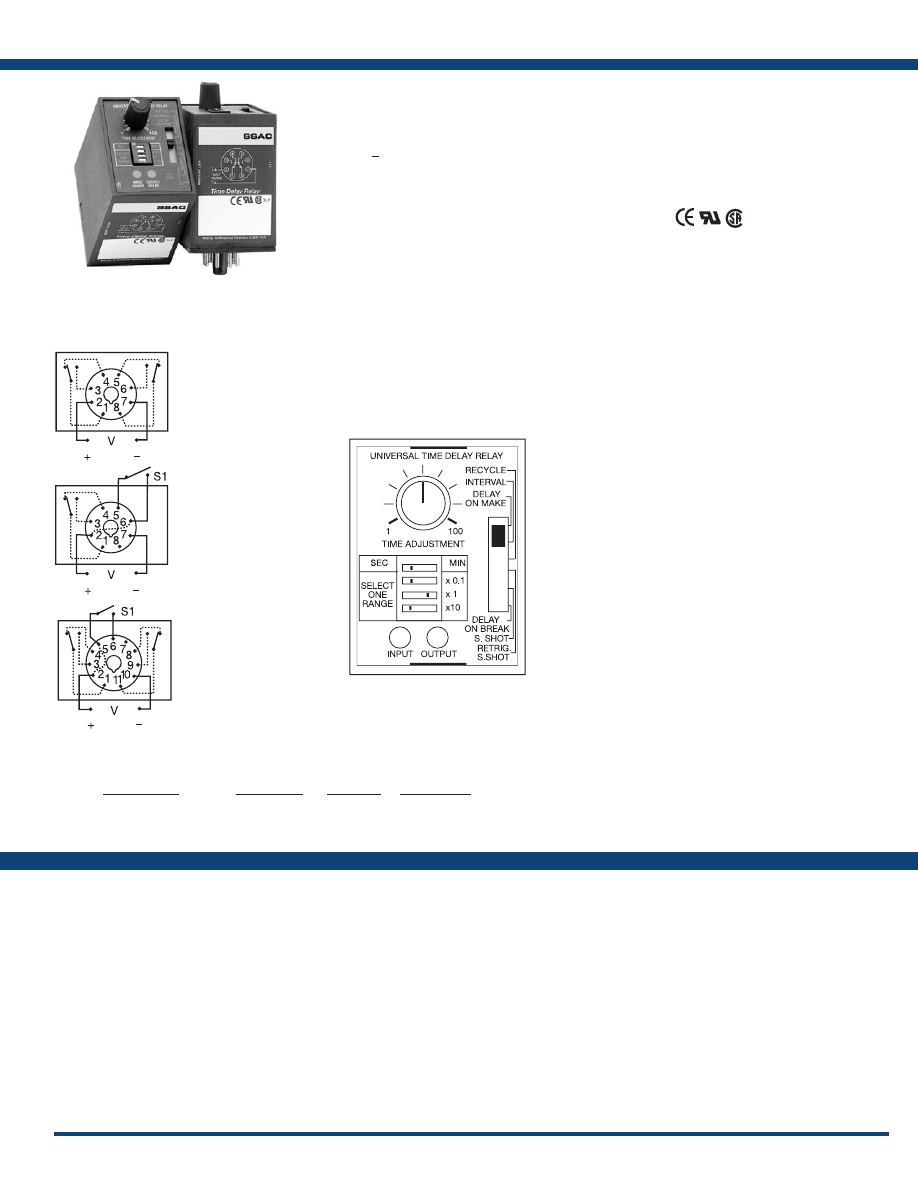
17
www.ssac.com • 800-843-8848 • fax: 605-348-5685
TRU Series
Timer
Available Models:
Time Delay
Type . . . . . . . . . . . . . . . . . . . . . . . . . . . . . . . . Digital integrated circuitry
Range: Switch Selectable*
. . . . . . . . . . . . . .
0.1s - 1000m in 6 ranges - 0.1 - 10, 1 - 100 or
10 - 1000s; 0.1 - 10, 1 - 100 or 10 - 1000m
Adjustments
. . . . . . . . . . . . . . . . . . . . . . . . .
Multiplier: 4 position DIP switch selects
x0.1, x1, x10, and s or m
Time Setting: Onboard knob adjustment with
1 - 100 reference dial
Two LEDs indicate . . . . . . . . . . . . . . . . . . .
1) Input voltage applied 2) Output relay status
Repeat Accuracy . . . . . . . . . . . . . . . . . . . . .
±0.1% or ±20ms, whichever is greater
Reset Time . . . . . . . . . . . . . . . . . . . . . . . . . . .
≤ 300ms
Time Delay vs Temp. & Voltage
. . . . . . . .
±2%
Input
Voltage - Universal Input Range
. . . . . . . .
19 to 264VAC and 19 to 30VDC
AC Line Frequency . . . . . . . . . . . . . . . . . . .
50/60Hz
Output
Type . . . . . . . . . . . . . . . . . . . . . . . . . . . . . . . .
Electromechanical relay
Form . . . . . . . . . . . . . . . . . . . . . . . . . . . . . . . .
SPDT & DPDT, isolated
Rating . . . . . . . . . . . . . . . . . . . . . . . . . . . . . .
10A resistive @ 120/240VAC & 28VDC;
1/3 hp @ 120/240VAC
Life
. . . . . . . . . . . . . . . . . . . . . . . . . . . . . . . . .
Mechanical - 1 x 10
7
; Electrical - 1 x 10
6
Protection
Transient . . . . . . . . . . . . . . . . . . . . . . . . . . . .
38 joules
Isolation Voltage
. . . . . . . . . . . . . . . . . . . . .
≥ 1500V RMS input to output
Polarity . . . . . . . . . . . . . . . . . . . . . . . . . . . . .
DC units are reversed polarity protected
Mechanical
Mounting . . . . . . . . . . . . . . . . . . . . . . . . . . .
Plug-in socket
Dimensions . . . . . . . . . . . . . . . . . . . . . . . . . .
3.44 x 2.39 x 1.78 in. (87.3 x 60.7 x 45.2 mm)
Termination . . . . . . . . . . . . . . . . . . . . . . . . .
Octal 8-pin plug-in or magnal 11-pin plug-in
Environmental
Operating / Storage Temperature
. . . . . .
-20° to 65°C / -30° to 85°C
Weight
. . . . . . . . . . . . . . . . . . . . . . . . . . . . . .
≅
6 oz (170 g)
* For CE approved applications, power must be removed when a switch position is changed.
Order Table:
Specifications
The TRU Series is a multifunction, knob adjustable,
Universal Time Delay Relay. It includes six of the
most popular timing functions selected by a slide
switch. The time delay is knob adjustable and the
time delay range is switch selectable. The repeat
accuracy is +
0.1%. Both function and time range
can be selected on the top face of the unit. In
addition to multifunctioning and multiple time
ranges, the TRU Series features universal input
voltage; 19 to 264VAC and 19 to 30VDC and full
10A output relay. The TRU Series can directly
replace up to 1000 competitive time delay relay
models .
Operation
A six position slide switch selects delay-on-make, interval,
single shot, recycling (ON time first, Equal Recycle
Delays), delay-on-break, and retriggerable single shot.
8-pin DPDT base wiring is limited to delay-on-make,
interval, and recycling functions. All six functions are
available in the 8-pin SPDT and 11-pin DPDT versions.
For more information see:
Appendix A, pages 156-164 for function descriptions
and diagrams .
Appendix B, page 165, Figure 6 for dimensional drawing.
Features:
• Microcontroller ±0.1% repeat accuracy
• Six timing functions are switch selectable
• 0.1s - 1000m in six ranges
• Knob adjustable time delay
• Universal input voltage 19 to 264VAC &
19 to 30VDC
• 10A, SPDT or DPDT output contacts
Approvals:
Connection:
Auxiliary Products:
•
Panel mount kit:
P/N: BZ1
•
Hold-down c lips ( sold i n p airs):
P/N: PSC8 (NDS-8)
P/N: PSC11 (NDS-11)
•
11-pin socket:
P/N: NDS-11
•
Octal 8-pin socket:
P/N: NDS-8
Input Voltage
19 to 264VAC; 19 to 30VDC
19 to 264VAC; 19 to 30VDC
19 to 264VAC; 19 to 30VDC
Base Wiring
8-pin DPDT
8-pin SPDT
11-pin DPDT
Functions
3
6
6
Part Number
TRU1
TRU2
TRU3
TRU1
TRU2
TRU3
L1
N/L2
L1
N/L2
L1
N/L2
Delay-on-Make
Interval
Recycling
Delay-on-Make
Interval
Single Shot
Recycling (ON Time First,
Equal Recycle Delays)
Delay-on-Break
Retriggerable Single Shot
11-pin DPDT
8-pin SPDT
8-pin DPDT
S1 = Initiate Switch
Courtesy of Steven Engineering, Inc.-230 Ryan Way, South San Francisco, CA 94080-6370-Main Office: (650) 588-9200-Outside Local Area: (800) 258-9200-www.stevenengineering.com
Littelfuse-catalog-html.html
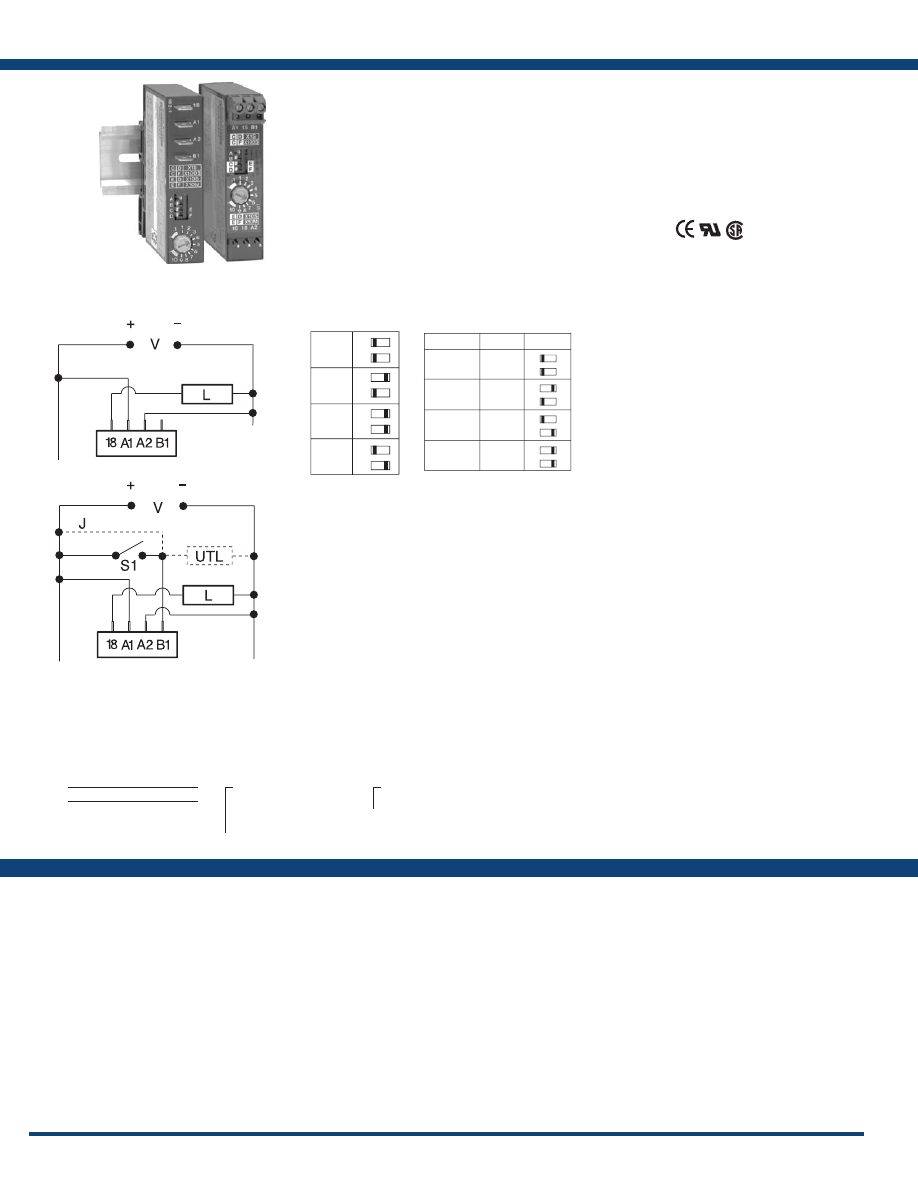
18
www.ssac.com • 800-843-8848 • fax: 605-348-5685
ASQU / ASTU Series
Timer
Available Models:
Time Delay
Type . . . . . . . . . . . . . . . . . . . . . . . . . . . . . . .
Microcontroller based with ceramic resonator
and watchdog circuitry
Adjustment
. . . . . . . . . . . . . . . . . . . . . . . . .
Knob with dial; 2 switches select 1 of 4 multipliers
Range* . . . . . . . . . . . . . . . . . . . . . . . . . . . . .
0.1 - 10s, 1 - 100s, 10 - 1000s, 1 - 100m
Repeat Accuracy . . . . . . . . . . . . . . . . . . . .
±1% or ±50ms, whichever is greater
Tolerance (Factory Calibration) . . . . . . . .
±2% or ±50ms, whichever is greater
Reset Time . . . . . . . . . . . . . . . . . . . . . . . . . .
≤ 300ms
Initiate Time . . . . . . . . . . . . . . . . . . . . . . . .
Single Shot & Delay-on-Break: ≤ 32ms
Time Delay vs Temp. & Voltage
. . . . . . .
±2%, or ±50ms, whichever is greater
Input
Voltage
. . . . . . . . . . . . . . . . . . . . . . . . . . . . .
AC: 24 to 240VAC; -20% - 10%
DC: 9 to 110VDC; -0% - 20% @ -25°C
9.4 to 110VDC; -0% - 20% @ -40°C
AC Line Frequency / DC Ripple
. . . . . . .
50/60Hz / ≤ 10%
Output
Type . . . . . . . . . . . . . . . . . . . . . . . . . . . . . . .Solid state
Form . . . . . . . . . . . . . . . . . . . . . . . . . . . . . . .NO
Rating . . . . . . . . . . . . . . . . . . . . . . . . . . . . .
0.7A steady state, 10A inrush
Voltage Drop
. . . . . . . . . . . . . . . . . . . . . . .AC
≅
2.5V @ 0.7A; DC
≅
1.5V @ 0.7A
Protection
Surge . . . . . . . . . . . . . . . . . . . . . . . . . . . . . .
IEEE C62.41-1991 Level A
Circuitry . . . . . . . . . . . . . . . . . . . . . . . . . . .Encapsulated
Dielectric Breakdown
. . . . . . . . . . . . . . . .
≥ 2000V RMS terminals to mounting surface
Polarity . . . . . . . . . . . . . . . . . . . . . . . . . . . .
DC units are reverse polarity protected
Mechanical
Mounting . . . . . . . . . . . . . . . . . . . . . . . . . .
Two base adaptors are available
DIN Rail . . . . . . . . . . . . . . . . . . . . . . .
Snap on to 32 mm DIN 1 & 35 mm DIN 3 rail
Surface
. . . . . . . . . . . . . . . . . . . . . . . .
Two #6 (M3.5 x 0.6) screws or quick mount fasteners
Termination
ASQU . . . . . . . . . . . . . . . . . . . . . . . . .
0.25 in. (6.35 mm) male quick connect terminals
ASTU . . . . . . . . . . . . . . . . . . . . . . . . .
0.197 in. (5 mm) push-on terminal blocks for up to
#14 AWG (2.5 mm
2
) wire
Environmental
Operating / Storage Temperature
. . . . .
-40° to 60°C / -40° to 85°C
Humidity . . . . . . . . . . . . . . . . . . . . . . . . . . .
95% relative, non-condensing
Weight
. . . . . . . . . . . . . . . . . . . . . . . . . . . . .
≅
4 oz (113 g)
*For CE approved applications, power must be removed from the unit when a switch position
is changed.
Specifications
Order Table:
Connection:
The ASQU/ASTU Series of 17.5 mm, knob
adjustable, universal solid-state timers offer
multiple functions, voltages, and time delay
ranges. Choose one of 5 functions and 4 time delay
ranges via 4 selection switches located on face of
the unit. Adjustment through the time range is
accomplished by an onboard knob.
For more information see:
Appendix A, pages 156-164 for function descriptions
and diagrams .
Appendix B, page 165, Figure 7 for dimensional drawing.
Features:
• 17.5 mm package for high rail density
• Microprocessor controlled with ±1% repeat
accuracy
• Multimode: 5 selectable functions
• Multirange: knob adjustable from 0.1s - 100m
• Multivoltage: 24 to 240VAC or 9 to 110VDC
• 0.7A steady, 10A inrush rated solid-state
output
Approvals:
Auxiliary Products:
•
Female quick connect:
P/N: P1015-13 (AWG 10/12)
P/N: P1015-64 (AWG 14/16)
P/N: P1015-14 (AWG 18/22)
ASQU
- Quick Connects
ASTU
- Terminal Blocks
X
Input Voltage
─
A
- Universal AC Voltage
(24 to 240VAC)
─
D
- Universal DC Voltage
(9 to 110VDC)
X
Base Adaptors
─
3
- Both - Surface & DIN rail adaptors with
quick mount fasteners
L1
N/L2
L1
N/L2
V = Voltage
L = Load
J= Wire Required for Interval Operation
S1= Initiate Switch
UTL = Optional Untimed Load
Delay-on-Make & Recycling
Single Shot, Interval & Delay-on-Break
DOM
SS
R
DOB
A
A
A
A
B
B
B
B
0.1-10s
1-100s
10-1000s
1-100m
X100s
X10s
X1s
X10m
R M S
D
C
D
C
D
C
D
C
F
E
F
E
F
E
F
E
Adjustment:
ASQUA3
ASQUD3
ASTUA3
ASTUD3
R = Range
M = Multiplier
S = Setting
DOM = Delay-on-Make
SS = Single Shot/Interval
R = Recycling
DOB = Delay-on-Break
Courtesy of Steven Engineering, Inc.-230 Ryan Way, South San Francisco, CA 94080-6370-Main Office: (650) 588-9200-Outside Local Area: (800) 258-9200-www.stevenengineering.com
Littelfuse-catalog-html.html
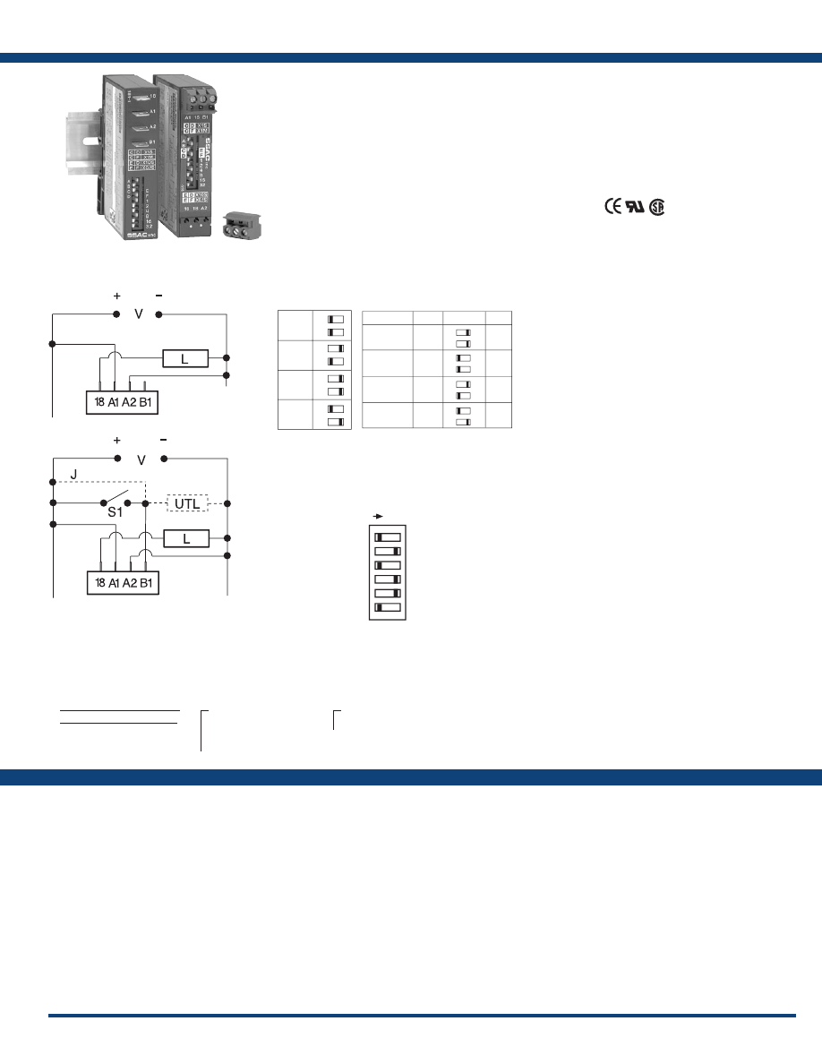
19
www.ssac.com • 800-843-8848 • fax: 605-348-5685
DSQU / DSTU Series
Timer
Available Models:
Time Delay
Type . . . . . . . . . . . . . . . . . . . . . . . . . . . . . . . .
Microcontroller based with ceramic resonator
and watchdog circuitry
Adjustment
. . . . . . . . . . . . . . . . . . . . . . . . . .
6 switches adjust the time delay;
2 switches select 1 of 4 multipliers
Range* . . . . . . . . . . . . . . . . . . . . . . . . . . . . . .
x0.1s = 0.1 - 6.3s in 0.1s increments
x1s = 1 - 63s in 1s increments
x10s = 10 - 630s in 10s increments
x1m = 1 - 63m in 1m increments
Repeat Accuracy . . . . . . . . . . . . . . . . . . . . .
±0.1% or ±20ms, whichever is greater
Setting Accuracy . . . . . . . . . . . . . . . . . . . . .
±2% or ±50ms, whichever is greater
Reset Time . . . . . . . . . . . . . . . . . . . . . . . . . . .
≤ 300ms
Initiate Time . . . . . . . . . . . . . . . . . . . . . . . . .
Single Shot & Delay-on-Break: ≤ 32ms
Time Delay vs Temp. & Voltage
. . . . . . . .
±2% or ±50ms, whichever is greater
Input
Voltage
. . . . . . . . . . . . . . . . . . . . . . . . . . . . . .
AC: 24 to 240VAC; -20% - 10%
DC: 9 to 110VDC; -0% - 20% @ -25°C
9.4 to 110VDC; -0% - 20% @ -40°C
AC Line Frequency / DC Ripple
. . . . . . . .
50/60Hz / ≤ 10%
Output
Type . . . . . . . . . . . . . . . . . . . . . . . . . . . . . . . .Solid state
Form . . . . . . . . . . . . . . . . . . . . . . . . . . . . . . . .NO
Rating . . . . . . . . . . . . . . . . . . . . . . . . . . . . . .
0.7A steady state, 10A inrush
Voltage Drop
. . . . . . . . . . . . . . . . . . . . . . . . AC
≅
2.5V @ 0.7A; DC
≅
1.5V @ 0.7A
Protection
Surge . . . . . . . . . . . . . . . . . . . . . . . . . . . . . . .
IEEE C62.41-1991 Level A
Circuitry . . . . . . . . . . . . . . . . . . . . . . . . . . . . Encapsulated
Dielectric Breakdown
. . . . . . . . . . . . . . . . .
≥ 2000V RMS terminals to mounting surface
Polarity . . . . . . . . . . . . . . . . . . . . . . . . . . . . .
DC units are reverse polarity protected
Mechanical
Mounting . . . . . . . . . . . . . . . . . . . . . . . . . . .
Two base adaptors are available
DIN Rail . . . . . . . . . . . . . . . . . . . . . .
Snap on to 32 mm DIN 1 & 35 mm DIN 3 rail
Surface
. . . . . . . . . . . . . . . . . . . . . . .
Two #6 (M3.5 x 0.6) screws or quick mount fasteners
Termination
DSQU . . . . . . . . . . . . . . . . . . . . . . . .
0.25 in. (6.35 mm) male quick connect terminals
DSTU . . . . . . . . . . . . . . . . . . . . . . . .
0.197 in. (5 mm) push-on terminal blocks for up to
#14 AWG (2.5 mm
2
) wire
Environmental
Operating / Storage Temperature
. . . . . .
-40° to 60°C / -40° to 85°C
Humidity . . . . . . . . . . . . . . . . . . . . . . . . . . . .
95% relative, non-condensing
Weight
. . . . . . . . . . . . . . . . . . . . . . . . . . . . . .
≅
4.2 oz (119 g)
*For CE approved applications, power must be removed from the unit when a switch position
is changed.
Order Table:
Specifications
The DSQU/DSTU Series of 17.5 mm, switch
adjustable, universal solid-state timers offer
multiple functions, voltages, and time delay
ranges. Choose one of 5 functions and 4 time delay
ranges via 4 selection switches located on face of
the unit. Six switches adjust the time delay through
the selected range.
For more information see:
Appendix A, pages 156-164 for function descriptions
and diagrams .
Appendix B, page 165, Figure 7 for dimensional drawing.
Features:
• 17.5 mm package for high rail density
• Microprocessor controlled with ±0.1%
timing accuracy
• Multimode: 5 selectable functions
• Multirange: switch adjust from 0.1s - 63m
• Multivoltage: 24 to 240VAC or 9 to 110VDC
• 0.7A steady, 10A inrush rated solid-state
output
Approvals:
Connection:
Auxiliary Products:
•
Female quick connect:
P/N: P1015-13 (AWG 10/12)
P/N: P1015-64 (AWG 14/16)
P/N: P1015-14 (AWG 18/22)
DSQU
- Quick Connects
DSTU
- Terminal Blocks
X
Input Voltage
─
A
- Universal AC Voltage
(24 to 240VAC)
─
D
- Universal DC Voltage
(9 to 110VDC)
X
Base Adaptors
─
3
- Both - Surface & DIN rail adaptors with
quick mount fasteners
DSQUA3
DSQUD3
DSTUA3
DSTUD3
L1
N/L2
L1
N/L2
Delay-on-Make & Recycling
DOM
SS
R
DOB
A
A
A
A
B
B
B
B
0.1s
1s
10s
1m
X10s
X1s
X0.1s
X1m
R M S I
D
C
D
C
D
C
D
C
F
E
F
E
F
E
F
E
0.1-6.3s
1-63s
10-630s
1-63m
Adjustment:
1
2
4
8
16
32
ON
Add switches
in ON position
TD = 2+8+16=26
DOM = Delay-on-Make
SS = Single Shot/Interval
R = Recycling
DOB = Delay-on-Break
R = Range
M = Multiplier
S = Setting
I = Increments of time
V = Voltage
L = Load
J= Wire Required for Interval Operation
S1= Initiate Switch (for Single Shot or
Delay-on-Break)
UTL = Optional Untimed Load
Single Shot, Interval & Delay-on-Break
Courtesy of Steven Engineering, Inc.-230 Ryan Way, South San Francisco, CA 94080-6370-Main Office: (650) 588-9200-Outside Local Area: (800) 258-9200-www.stevenengineering.com
Littelfuse-catalog-html.html

20
www.ssac.com • 800-843-8848 • fax: 605-348-5685
Timers - Dedicated
Series Included
SQ3 & SQ4
. . . . . . . . . . . . . . . . . . . . . . . . . . . . . . . . . . . . . . . .
93
Delay-on-Make/Delay-on-Break
. . . . . . . . . . . . . . . . . . . . .
94
Series: TDMB - Plug-In
Delay-on-Make/Interval
. . . . . . . . . . . . . . . . . . . . . . . . . . .
95
Series: ESD5
Single Function
Sequencer
Dual Function
HVAC Timers
Vending Timers
Solid-State Output
TAC1 - Anti Short Cycle, Random Start
. . . . . . . . . . . . . . .
96
T2D - Anti Short Cycle, Random Start
. . . . . . . . . . . . . . . .97
TAC4 - Bypass Timing
. . . . . . . . . . . . . . . . . . . . . . . . . . . . .
98
TA - Anti Short Cycle
. . . . . . . . . . . . . . . . . . . . . . . . . . . . . .99
TL - Anti Short Cycle
. . . . . . . . . . . . . . . . . . . . . . . . . . . . . . .
100
CT - Fan Delay
. . . . . . . . . . . . . . . . . . . . . . . . . . . . . . . . . . . .
101
HRV - Relay Output
. . . . . . . . . . . . . . . . . . . . . . . . . . . . . . .
102
Delay-on-Make (ON Delay)
. . . . . . . . . . . . . . . . . . . . . . . . .21
Series: TDM, TDMH, TDML, TRM, PRLM, HRDM,
ERDM, ORM, KRDM, KSDU, TDU, TMV8000, TSU2000,
TSD1, THDM, THD1, KSD1, TS1, TH1, MSM
Delay-on-Make, Normally Closed
. . . . . . . . . . . . . . . . . . .
37
Series: TSD4, THD4, KSD4, TS4
Delay-on-Break (OFF Delay)
. . . . . . . . . . . . . . . . . . . . . . . .
41
Series: TDB, TDBH, TDBL, TRB, PRLB, HRDB, ORB,
KRDB, TDUB, TSDB, THDB, KSDB, TSD7, THD7, TSB
Single Shot (Pulse Former)
. . . . . . . . . . . . . . . . . . . . . . . . . .
54
Series: TDS, TDSH, TDSL, TRS, PRLS, HRDS, ERDI,
ORS, KRDS, TDUS, TSDS, THDS, KSDS, TSS, THC,
THS
Single Shot, Retriggerable (Watchdog, Zero Speed)
. . . .
67
Series: HRD9, KRD9
Interval (Impulse ON)
. . . . . . . . . . . . . . . . . . . . . . . . . . . . . .
69
Series: TDI, TDIH, TDIL, HRDI, KRDI, TDUI, TSD2,
THD2, TSD6, KSD2, TS2, TS6, TH2
Recycling . . . . . . . . . . . . . . . . . . . . . . . . . . . . . . . . . . . . . . . . .79
Series: TDR, HRDR, HRD3, ERD3, KRDR, KRD3, RS,
ESDR, TSDR, KSDR, THD3, TSD3, KSD3
Percentage . . . . . . . . . . . . . . . . . . . . . . . . . . . . . . . . . . . . . . . .92
Series: PTHF
Courtesy of Steven Engineering, Inc.-230 Ryan Way, South San Francisco, CA 94080-6370-Main Office: (650) 588-9200-Outside Local Area: (800) 258-9200-www.stevenengineering.com
Littelfuse-catalog-html.html
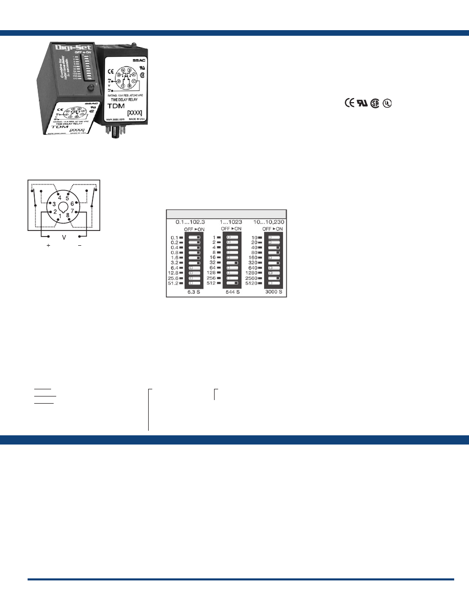
21
www.ssac.com • 800-843-8848 • fax: 605-348-5685
TDM / TDMH / TDML Series
Timer - Delay-on-Make
Available Models:
Time Delay
Type . . . . . . . . . . . . . . . . . . . . . . . . . . . . . . . . . . Digital integrated circuitry
Range* . . . . . . . . . . . . . . . . . . . . . . . . . . . . . . . .
0.1 - 102.3s in 0.1s increments
1 - 1023s in 1s increments
10 - 10,230s in 10s increments
Repeat Accuracy . . . . . . . . . . . . . . . . . . . . . . .
±0.1% or 20ms, whichever is greater
Setting Accuracy . . . . . . . . . . . . . . . . . . . . . . .
±2% or 50ms, whichever is greater
Reset Time . . . . . . . . . . . . . . . . . . . . . . . . . . . . .
≤ 50ms
Recycle Time . . . . . . . . . . . . . . . . . . . . . . . . . . .
During Timing - TDMH: ≤ 500ms
TDM, TDML: ≤ 300ms
Time Delay vs Temp. & Voltage
. . . . . . . . . .
±2%
Indicator . . . . . . . . . . . . . . . . . . . . . . . . . . . . . .
LED glows during timing; relay is
de-energized
Input
Voltage
. . . . . . . . . . . . . . . . . . . . . . . . . . . . . . . .
12, 24, or 110 VDC; 24, 120, or 230VAC
Tolerance 12VDC & 24VDC/AC
. . . . . .
-15% - 20%
110VAC/DC to 230VAC
. . . . . .
-20% - 10%
AC Line Frequency . . . . . . . . . . . . . . . . . . . . .
50/60 Hz
Power Consumption . . . . . . . . . . . . . . . . . . . .
≤ 2.25W
Output
Type . . . . . . . . . . . . . . . . . . . . . . . . . . . . . . . . . .
Electromechanical relay
Form . . . . . . . . . . . . . . . . . . . . . . . . . . . . . . . . . . DPDT
Rating . . . . . . . . . . . . . . . . . . . . . . . . . . . . . . . .
10A resistive @ 120/240VAC & 28VDC;
1/3 hp @ 120/240VAC
Life
. . . . . . . . . . . . . . . . . . . . . . . . . . . . . . . . . . .
Mechanical - 1 x10
7
; Electrical - 1 x 10
6
Protection
Polarity . . . . . . . . . . . . . . . . . . . . . . . . . . . . . . .
DC units are reverse polarity protected
Isolation Voltage
. . . . . . . . . . . . . . . . . . . . . . .
≥ 1500V RMS input to output
Mechanical
Mounting . . . . . . . . . . . . . . . . . . . . . . . . . . . . .
Plug-in socket
Dimensions . . . . . . . . . . . . . . . . . . . . . . . . . . . .
3.2 x 2.39 x 1.78 in. (81.3 x 60.7 x 45.2 mm)
Termination . . . . . . . . . . . . . . . . . . . . . . . . . . .
Octal 8-pin plug-in
Environmental
Operating / Storage Temperature
. . . . . . . .
-20° to 65°C / -30° to 85°C
Weight
. . . . . . . . . . . . . . . . . . . . . . . . . . . . . . . .
≅
6 oz (170 g)
*For CE approved applications, power must be removed from the unit when a switch position
is changed.
Order Table:
Specifications
The TDM Series is a delay-on-make timer that
combines accurate digital circuitry with isolated,
DPDT relay contacts in an industry standard
8-pin plug-in package. DIP switch adjustment
allows precise selection of the time delay over
the full time delay range. The TDM Series is the
product of choice for custom control panel and
OEM designers .
Operation (Delay-on-Make):
Upon application of input voltage, the time delay begins.
The output is de-energized before and during the time
delay. At the end of the time delay, the output relay
energizes and remains energized until input voltage is
removed.
Reset: Removing input voltage resets the time delay
and output .
For more information see:
Appendix A, pages 156-164 for function descriptions
and diagrams .
Appendix B, page 165, Figure 8 for dimensional drawing.
Features:
• Switch settable time delay
• Three time ranges from 0.1s - 10,230s
• ±0.1% repeat accuracy
• ±2% setting accuracy
• 10A, DPDT output contacts
•
LED indication
Approvals:
Connection:
Auxiliary Products:
•
Panel mount kit:
P/N: BZ1
•
8-pin socket:
P/N: NDS-8
•
Hold-down clips (sold in pairs):
P/N: PSC8 (NDS-8)
•
Octal socket for UL listing:
P/N: P1011-6
•
DIN rail:
P/N: C103PM
(Al)
TDM
- 1 - 1023s in 1s increments
TDMH
- 10 - 10,230s in 10s increments
TDML
- 0.1 - 102.3s in 0.1s increments
X
Input Voltage
─
12D
- 12VDC
─
24A
- 24VAC
─
24D
- 24VDC/28VDC
─
110D
- 110VDC
─
120A
- 120VAC
─
230A
- 230VAC
X
LED Indication
─
L
TDM120AL
TDM12DL
TDM230AL
TDM24AL
TDM24DL
TDMH120AL
TDMH24AL
TDMH24DL
TDML110DL
TDML120AL
TDML12DL
TDML230AL
TDML24DL
L1
N/L2
Digi-Set Binary Switch Operation:
8-pin models UL listed
when used in combination
with P1011-6 socket only.
If desired part number is not listed, please call us to
see if it is technically possible to build .
Relay contacts are isolated .
Courtesy of Steven Engineering, Inc.-230 Ryan Way, South San Francisco, CA 94080-6370-Main Office: (650) 588-9200-Outside Local Area: (800) 258-9200-www.stevenengineering.com
Littelfuse-catalog-html.html
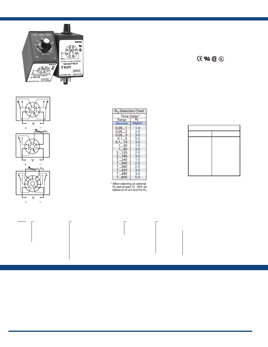
22
www.ssac.com • 800-843-8848 • fax: 605-348-5685
TRM Series
Timer - Delay-on-Make
Available Models:
Time Delay
Type . . . . . . . . . . . . . . . . . . . . . . . . . . . . . . . . . . . . . . . Analog circuitry
Range . . . . . . . . . . . . . . . . . . . . . . . . . . . . . . . . . . . . . .
50ms - 10m in 15 adjustable ranges
or fixed
Repeat Accuracy . . . . . . . . . . . . . . . . . . . . . . . . . . . .
±2% or 20 ms, whichever is greater
Fixed Time Tolerance & Setting Accuracy
. . . . . . .
±5, 10, or 20%
Reset Time . . . . . . . . . . . . . . . . . . . . . . . . . . . . . . . . . .
≤ 50ms
Recycle Time . . . . . . . . . . . . . . . . . . . . . . . . . . . . . . . .
After timing: ≤ 20ms
During timing: 0.1% of max. time delay
or 75ms, whichever is greater
Time Delay vs Temp. & Voltage
. . . . . . . . . . . . . . .
≤±10%
Input
Voltage
. . . . . . . . . . . . . . . . . . . . . . . . . . . . . . . . . . . . .
24 or 110VDC; 24, 120, or 230VAC
Tolerance 24VDC/AC
. . . . . . . . . .
-15% - 20%
110 to 230VAC/DC
. . . . . . . . . .
-20% - 10%
AC Line Frequency . . . . . . . . . . . . . . . . . . . . . . . . . .
50/60 Hz
Power Consumption . . . . . . . . . . . . . . . . . . . . . . . . .
≤ 2.25W
Output
Type . . . . . . . . . . . . . . . . . . . . . . . . . . . . . . . . . . . . . . .
Electromechanical relay
Form . . . . . . . . . . . . . . . . . . . . . . . . . . . . . . . . . . . . . . . Isolated DPDT or SPDT
Rating . . . . . . . . . . . . . . . . . . . . . . . . . . . . . . . . . . . . .
10A resistive @ 120/240VAC & 28VDC;
1/3 hp @ 120/240VAC
Life
. . . . . . . . . . . . . . . . . . . . . . . . . . . . . . . . . . . . . . . .
Mechanical - 1 x 10
7
; Electrical - 1 x 10
6
Protection
Isolation Voltage
. . . . . . . . . . . . . . . . . . . . . . . . . . . .
≥ 1500V RMS between input & output
terminals
Insulation Resistance . . . . . . . . . . . . . . . . . . . . . . . .
≥ 100 MΩ
Polarity . . . . . . . . . . . . . . . . . . . . . . . . . . . . . . . . . . . .
DC units are reverse polarity protected
Mechanical
Mounting . . . . . . . . . . . . . . . . . . . . . . . . . . . . . . . . . .
Plug-in socket
Dimensions . . . . . . . . . . . . . . . . . . . . . . . . . . . . . . . . .
3.62 x 2.39 x 1.78 in. (91.6 x 60.7 x 45.2 mm)
Termination . . . . . . . . . . . . . . . . . . . . . . . . . . . . . . . .
Octal 8-pin or 11-pin plug-In
Environmental
Operating / Storage Temperature
. . . . . . . . . . . . .
-20° to 65°C / -30° to 85°C
Weight
. . . . . . . . . . . . . . . . . . . . . . . . . . . . . . . . . . . . .
≅
6 oz (170 g)
Specifications
Order Table:
Connection:
The TRM Series is a combination of analog
electronic circuitry and electromechanical relay
output. It provides input to output isolation with
a wide variety of input voltages and time ranges.
Standard plug-in base wiring, fast reset, rugged
enclosure, and good repeat accuracy make the
TRM a select choice in any OEM application.
Operation (Delay-on-Make):
Upon application of input voltage, the time delay begins.
The output is de-energized before and during the time
delay. At the end of the time delay, the output relay
energizes and remains energized until input voltage is
removed.
Reset: Removing input voltage resets the time delay
and output .
For more information see:
Appendix A, pages 156-164 for function descriptions
and diagrams .
Appendix B, page 165, Figure 9 for dimensional drawing.
Features:
• 10A, DPDT or SPDT output contacts
• 24 to 230V operation in ranges
• 8-pin or 11-pin plug-in
• Fixed or adjustable delays from 0.05 - 600s
in multiple ranges
• ±2% repeat accuracy
Approvals:
Auxiliary Products:
•
Octal socket for UL listing:
P/N: P1011-6
•
Hold-down clips (sold in pairs):
P/N: PSC8 (NDS-8)
P/N: PSC11 (NDS-11)
•
8-pin socket:
P/N: NDS-8
•
11-pin socket:
P/N: NDS-11
•
Panel mount kit:
P/N: BZ1
•
Versa-knob:
P/N: P0700-7
•
External adjust potentiometer:
P/N: P1004-XX
P/N: P1004-XX-X
TRM110D1Z30
TRM120A2X1
TRM120A2X30
TRM120A2Y180
TRM120A2Y60
TRM120A2Y600
TRM24A8Y5
TRM24D1Y1
L1
N/L2
L1
N/L2
L1
N/L2
8-pin octal DPDT
8-pin octal SPDT
11-pin DPDT
TRM
X
Input Voltage
─
24A
- 24VAC
─
24D
- 24VDC/28VDC
─
110D
- 110VDC
─
120A
- 120VAC
─
230A
- 230VAC
X
Adjustment and Output Form
─
1
- Fixed, Octal, DPDT
─
2
- Knob Adjust, Octal, DPDT
─
3
- Lock Shaft Adjust, Octal, DPDT
─
5
- Ext. Adjust, 11-pin, DPDT
without potentiometer
─
6
- Ext. Adjust, 11-pin, DPDT
supplied with potentiometer
─
8
- Ext. Adjust, Octal, SPDT,
without potentiometer
─
9
- Ext. Adjust, Octal, SPDT,
with potentiometer
X
Time Tolerance
─
X
- ±20%
─
Y
- ±10%
─
Z
- ±5%
X
Time Delay*
(seconds)
─
1
- 0.05 - 1
─
2
- 0.05 - 2
─
3
- 0.05 - 3
─
5
- 0.1 - 5
─
10
- 0.1 - 10
─
30
- 1 - 30
─
60
- 1 - 60
─
120
- 2 - 120
─
180
- 2 - 180
─
240
- 7 - 240
─
300
- 7 - 300
─
360
- 7 - 360
─
420
- 7 - 420
─
480
- 7 - 480
─
600
- 7 - 600
*If fixed delay is selected, insert
delay (
0.05 - 600
) in seconds .
8-pin models UL listed
when used in combination
with P1011-6 socket only.
R
T
is used when external adjustment is ordered.
Relay contacts are isolated .
External R
T
P/N Selection Table
Value
Part Number
1M ohm
1.5M ohm
2M ohm
3M ohm
5M ohm
1M ohm
1.5M ohm
2M ohm
3M ohm
5M ohm
P1004-16
P1004-15
P1004-14
P1004-12
P1004-13
P1004-16-X
P1004-15-X
P1004-14-X
P1004-12-X
P1004-13-X
If desired part number is not listed, please call us to
see if it is technically possible to build .
Courtesy of Steven Engineering, Inc.-230 Ryan Way, South San Francisco, CA 94080-6370-Main Office: (650) 588-9200-Outside Local Area: (800) 258-9200-www.stevenengineering.com
Littelfuse-catalog-html.html
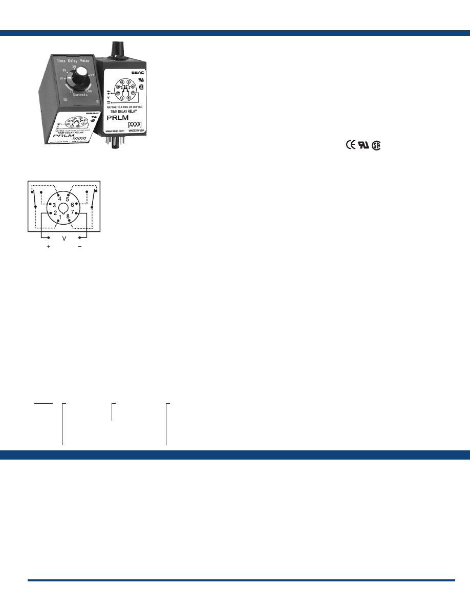
23
www.ssac.com • 800-843-8848 • fax: 605-348-5685
PRLM Series
Timer - Delay-on-Make
Available Models:
Time Delay
Type . . . . . . . . . . . . . . . . . . . . . . . . . . . . . . . . . . Analog circuitry
Range . . . . . . . . . . . . . . . . . . . . . . . . . . . . . . . . .
0.05 - 600s in 6 adjustable ranges or fixed
Repeat Accuracy . . . . . . . . . . . . . . . . . . . . . . .
±2% or 20ms, whichever is greater
Tolerance . . . . . . . . . . . . . . . . . . . . . . . . . . . . . .
Knob adjust: guaranteed range
Fixed: ±10%
Reset Time . . . . . . . . . . . . . . . . . . . . . . . . . . . . .
≤ 50ms
Recycle Time . . . . . . . . . . . . . . . . . . . . . . . . . . .
After timing: ≤ 20ms
During timing: 0.1% of max. time delay
or 75ms, whichever is greater
Time Delay vs Temp. & Voltage
. . . . . . . . . .
≤ ±10%
Input
Voltage
. . . . . . . . . . . . . . . . . . . . . . . . . . . . . . . .
12, 24, or 110VDC; 24, 120, or 230VAC
Tolerance 12VDC & 24VDC/AC
. . . . . . .
-15% - 20%
110 to 240VAC/DC
. . . . . . .
-20% - 10%
AC Line Frequency . . . . . . . . . . . . . . . . . . . . .
50/60 Hz
Power Consumption . . . . . . . . . . . . . . . . . . . .
≤ 2.25W
Output
Type . . . . . . . . . . . . . . . . . . . . . . . . . . . . . . . . . .
Electromechanical relay
Form . . . . . . . . . . . . . . . . . . . . . . . . . . . . . . . . . .
Isolated, DPDT
Rating . . . . . . . . . . . . . . . . . . . . . . . . . . . . . . . .
10A resistive @ 28VDC;
10A resistive @ 240VAC;
1/3 hp @ 120/240VAC
Life
. . . . . . . . . . . . . . . . . . . . . . . . . . . . . . . . . . .
Mechanical - 1x10
7
; Electrical - 1x10
6
Protection
Surge . . . . . . . . . . . . . . . . . . . . . . . . . . . . . . . . .
IEEE C62.41-1991 Level A
Isolation Voltage
. . . . . . . . . . . . . . . . . . . . . . .
≥ 1500V RMS input to output
Insulation Resistance . . . . . . . . . . . . . . . . . . . .
≥ 100 MΩ
Polarity . . . . . . . . . . . . . . . . . . . . . . . . . . . . . . .
DC units are reverse polarity protected
Indication
Type
. . . . . . . . . . . . . . . . . . . . . . . . . . . . . . . . . .
LED
Operation . . . . . . . . . . . . . . . . . . . . . . . . . . . . .
During timing - flashing
Output energized - on steady
Mechanical
Mounting . . . . . . . . . . . . . . . . . . . . . . . . . . . . .
Plug-in socket
Dimensions . . . . . . . . . . . . . . . . . . . . . . . . . . . .
3.62 x 2.39 x 1.78 in. (91.6 x 60.7 x 45.2 mm)
Termination . . . . . . . . . . . . . . . . . . . . . . . . . . .
Octal 8-pin plug-in
Environmental
Operating / Storage Temperature
. . . . . . . .
-20° to 65°C / -30° to 85°C
Weight
. . . . . . . . . . . . . . . . . . . . . . . . . . . . . . . .
≅
6 oz (170 g)
Order Table:
Specifications
The PRLM Series is designed for use in non-critical
timing applications. It offers low cost, knob
adjustable timing control, full 10A relay output,
and onboard LED indication. The knob adjustment
provides a guaranteed time range of up to 10
minutes in 6 ranges. The onboard LED indicates
whether or not the unit is timing (flashing LED)
as well as the status of the output.
Operation (Delay-on-Make):
The time delay is initiated when input voltage is applied.
LED flashes during timing. At the end of the delay period,
the output contacts energize. LED is on steady after the
unit times out .
Reset: Reset is accomplished by removal of input voltage.
There is no false output when reset during timing.
For more information see:
Appendix A, pages 156-164 for function descriptions
and diagrams .
Appendix B, page 165, Figure 9 for dimensional drawing.
Features:
• Knob adjustable time delay relay
• Electronic circuit with electromechanical
relay
• Popular AC & DC operating voltages
• Industry standard octal plug-in connection
• Fixed or adjustable delays from 0.05 - 600s
in multiple ranges
• ±2% repeat accuracy
• ±10% factory calibration
•
LED indication
• 10A, DPDT output contacts
•
Isolated relay contacts
Approvals:
Connection:
Auxiliary Products:
•
Panel mount kit:
P/N: BZ1
•
8-pin socket:
P/N: NDS-8
•
Hold-down clips (sold in pairs):
P/N: PSC8 (NDS-8)
•
DIN rail:
P/N: C103PM
(Al)
PRLM41180
PRLM423
L1
N/L2
8-pin octal
DPDT
PRLM
X
Input Voltage
─
1
- 12VDC
─
2
- 24VAC
─
3
- 24VDC
─
4
- 120VAC
─
5
- 110VDC
─
6
- 230VAC
X
Adjustment
─
1
- Factory Fixed
─
2
- Adjustable
X
Time Delay*
─
1
- 0.05 - 3s
─
2
- 0.1 - 10s
─
3
- 1 - 60s
─
4
- 2 - 180s
─
5
- 7 - 480s
─
6
- 7 - 600s
*If fixed delay is selected, insert
delay (
0.05 - 600
) in seconds .
If desired part number is not listed, please call us to
see if it is technically possible to build .
Courtesy of Steven Engineering, Inc.-230 Ryan Way, South San Francisco, CA 94080-6370-Main Office: (650) 588-9200-Outside Local Area: (800) 258-9200-www.stevenengineering.com
Littelfuse-catalog-html.html
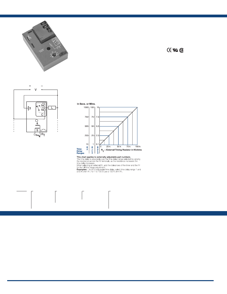
24
www.ssac.com • 800-843-8848 • fax: 605-348-5685
HRDM Series
Timer - Delay-on-Make
Available Models:
Time Delay
Type . . . . . . . . . . . . . . . . . . . . . . . . . . . . . . . . . . . Microcontroller circuitry
Range . . . . . . . . . . . . . . . . . . . . . . . . . . . . . . . . . .
0.1s - 100m in 5 adjustable ranges or fixed
Repeat Accuracy . . . . . . . . . . . . . . . . . . . . . . . .
±0.5% or 20 ms, whichever is greater
Tolerance (Factory Calibration) . . . . . . . . . . . .
±1%, ±5%
Reset Time . . . . . . . . . . . . . . . . . . . . . . . . . . . . . .
≤ 150ms
Time Delay vs Temp. & Voltage
. . . . . . . . . . .
±2%
Input
Voltage
. . . . . . . . . . . . . . . . . . . . . . . . . . . . . . . . .
12 or 24VDC; 24, 120, or 230VAC
Tolerance 12VDC & 24VDC
. . . . . . . .
-15% - 20%
24 to 230VAC
. . . . . . . .
-20% - 10%
AC Line Frequency . . . . . . . . . . . . . . . . . . . . . .
50/60 Hz
Power Consumption . . . . . . . . . . . . . . . . . . . . .
AC ≤ 4VA; DC ≤ 2W
Output
Type . . . . . . . . . . . . . . . . . . . . . . . . . . . . . . . . . . .
Electromechanical relay
Form . . . . . . . . . . . . . . . . . . . . . . . . . . . . . . . . . . .
Non-isolated, SPDT
Ratings: SPDT-NO SPDT-NC
General Purpose 125/240VAC 30A 15A
Resistive 125/240VAC 30A 15A
28VDC 20A 10A
Motor Load 125VAC 1 hp* 1/4 hp**
240VAC 2 hp** 1 hp**
Life
. . . . . . . . . . . . . . . . . . . . . . . . . . . . . . . . . . . .
Mechanical - 1 x 10
6
; Electrical - 1 x 10
5
,
*3 x 10
4
, **6,000
Protection
Surge . . . . . . . . . . . . . . . . . . . . . . . . . . . . . . . . . .
IEEE C62.41-1991 Level A
Circuitry . . . . . . . . . . . . . . . . . . . . . . . . . . . . . . . Encapsulated
Dielectric Breakdown
. . . . . . . . . . . . . . . . . . . .
≥ 2000V RMS terminals to mounting surface
Insulation Resistance . . . . . . . . . . . . . . . . . . . . .
≥ 100 MΩ
Polarity . . . . . . . . . . . . . . . . . . . . . . . . . . . . . . . .
DC units are reverse polarity protected
Mechanical
Mounting . . . . . . . . . . . . . . . . . . . . . . . . . . . . . .
Surface mount with one #10 (M5 x 0.8) screw
Dimensions . . . . . . . . . . . . . . . . . . . . . . . . . . . . .
3 x 2 x 1.5 in. (76.7 x 51.3 x 38.1mm)
Termination . . . . . . . . . . . . . . . . . . . . . . . . . . . .
0.25 in. (6.35 mm) male quick connect terminals
Environmental
Operating / Storage Temperature
. . . . . . . . .
-40° to 60°C / -40° to 85°C
Humidity . . . . . . . . . . . . . . . . . . . . . . . . . . . . . . .
95% relative, non-condensing
Weight
. . . . . . . . . . . . . . . . . . . . . . . . . . . . . . . . .
≅
3.9 oz (111 g)
Specifications
Order Table:
Connection:
The HRDM Series combines an electromechanical
relay output with microcontroller timing circuitry.
It offers 12 to 230V operation in five ranges and
factory fixed, onboard, or external adjustable
time delays with a repeat accuracy of ±0.5%. The
output contact rating allows for direct operation of
heavy loads, such as compressors, pumps, blower
motors, heaters, etc. This series is ideal for OEM
applications where cost is a factor.
Operation (Delay-on-Make):
Upon application of input voltage, the time delay begins.
The output is de-energized before and during the time
delay. At the end of the time delay, the output relay
energizes and remains energized until input voltage is
removed.
Reset: Removing input voltage resets the time delay
and output .
For more information see:
Appendix A, pages 156-164 for function descriptions
and diagrams .
Appendix B, page 165, Figure 2 for dimensional drawing.
Features:
• 30A, SPDT, NO output contact
• 12 to 230V operation in 5 ranges
•
Encapsulated circuitry
• Delays from 0.1s - 100m in 5 ranges
• ±0.5% repeat accuracy
• Factory fixed, onboard or external adjust
Approvals:
Auxiliary Products:
•
External ad just potentiometer:
P/N: P1004-95
P/N: P1004-95-X
•
Mounting bracket:
P/N: P1023-6
•
Female quick connect:
P/N: P1015-13 (AWG 10/12)
P/N: P1015-64 (AWG 14/16)
•
Quick connect t o s crew ad aptor:
P/N: P1015-18
•
Versa-knob:
P/N: P0700-7
•
DIN rail:
P/N: C103PM
(Al)
•
DIN rail adaptor:
P/N: P1023-20
HRDM
X
Input Voltage
─
1
- 12VDC
─
2
- 24VAC
─
3
- 24VDC
─
4
- 120VAC
─
6
- 230VAC
X
Adjustment
─
1
- Fixed
─
2
- Onboard knob
─
3
- External adjust
X
Time Tolerance
─
Blank
- ±5%
─
A
- ±1%
X
Time Delay*
─
0
- 0.1 - 10s
─
1
- 1 - 100s
─
2
- 10 - 1000s
─
3
- 0.1 - 10m
─
4
- 1 - 100m
*If fixed delay is selected, insert delay (
0 .1
- 1000
) followed by (
S
) sec, or (
0 .1 - 100
)
(
M
) min .
HRDM114S
HRDM120
HRDM220
HRDM221
HRDM222
HRDM223
HRDM224
HRDM3112S
HRDM320
HRDM321
HRDM322
HRDM323
HRDM324
HRDM4130S
HRDM413M
HRDM415M
HRDM420
HRDM421
HRDM422
HRDM423
L1
N/L2
External Resistance vs . Time Delay:
NO = Normally Open
L = Load
C = Common, Transfer Contact
If desired part number is not listed, please call us to
see if it is technically possible to build .
NOTE: A knob, or terminals 4 & 5
are only included on adjustable units.
R
T
is used when external adjustment
is ordered . Relay contacts are not
isolated .
Courtesy of Steven Engineering, Inc.-230 Ryan Way, South San Francisco, CA 94080-6370-Main Office: (650) 588-9200-Outside Local Area: (800) 258-9200-www.stevenengineering.com
Littelfuse-catalog-html.html
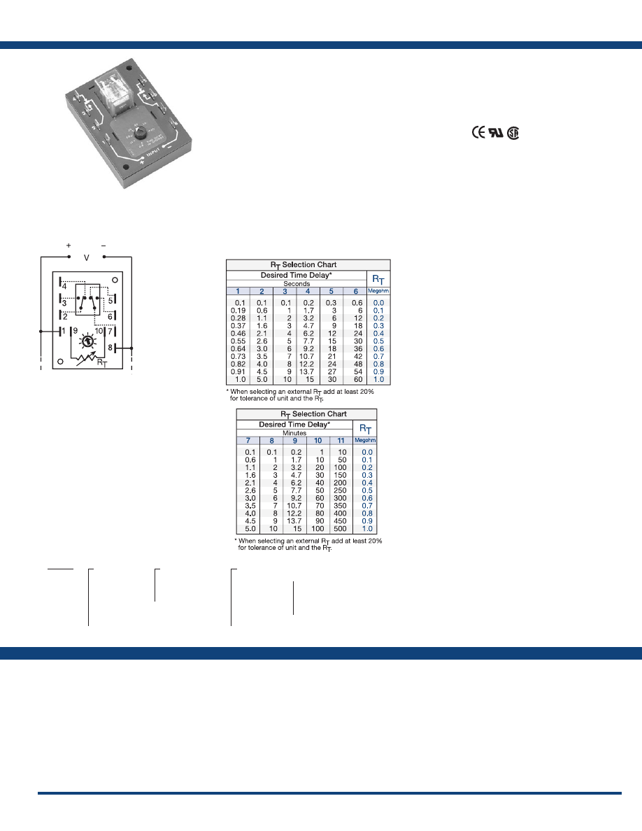
25
www.ssac.com • 800-843-8848 • fax: 605-348-5685
ERDM Series
Timer - Delay-on-Make
Available Models:
Time Delay
Type . . . . . . . . . . . . . . . . . . . . . . . . . . . . . . . . . . . . . Digital integrated circuitry
Range . . . . . . . . . . . . . . . . . . . . . . . . . . . . . . . . . . . .
0.1s - 500m in 11 adjustable ranges or
0.1s - 1000m fixed
Adjustment
. . . . . . . . . . . . . . . . . . . . . . . . . . . . . . .
Fixed, onboard or external adjust
Repeat Accuracy . . . . . . . . . . . . . . . . . . . . . . . . . .
±0.5%
Tolerance (Factory Calibration) . . . . . . . . . . . . . .
≤ ±10%
Recycle Time . . . . . . . . . . . . . . . . . . . . . . . . . . . . . .
≤ 150ms
Time Delay vs Temp. & Voltage
. . . . . . . . . . . . .
≤ ±2%
Input
Voltage
. . . . . . . . . . . . . . . . . . . . . . . . . . . . . . . . . . .
12, 24, or 120VDC; 24, 120, or 230VAC
Tolerance 12VDC & 24VDC/AC
. . . . . . .
-15% - 20%
120VAC/DC & 230VAC
. . . . . . .
-20% - 10%
AC Line Frequency . . . . . . . . . . . . . . . . . . . . . . . .
50/60 Hz
Output
Type . . . . . . . . . . . . . . . . . . . . . . . . . . . . . . . . . . . . . Isolated relay contacts
Form . . . . . . . . . . . . . . . . . . . . . . . . . . . . . . . . . . . . . DPDT
Rating . . . . . . . . . . . . . . . . . . . . . . . . . . . . . . . . . . .
10A resistive @ 120/240VAC & 28VDC;
1/3 hp @ 120/240VAC
Life
. . . . . . . . . . . . . . . . . . . . . . . . . . . . . . . . . . . . . .
Mechanical - 1 x 10
7
; Full Load - 1 x 10
6
Protection
Isolation Voltage
. . . . . . . . . . . . . . . . . . . . . . . . . .
≥1500V RMS input to output
Insulation Resistance . . . . . . . . . . . . . . . . . . . . . . .
≥100 MΩ
Polarity . . . . . . . . . . . . . . . . . . . . . . . . . . . . . . . . . .
DC units are reverse polarity protected
Mechanical
Mounting . . . . . . . . . . . . . . . . . . . . . . . . . . . . . . . .
Surface mount with two #6 (M3.5 x 0.6) screws
Dimensions . . . . . . . . . . . . . . . . . . . . . . . . . . . . . . .
3.5 x 2.5 x 1.7 in. (88.9 x 63.5 x 43.2 mm)
Termination . . . . . . . . . . . . . . . . . . . . . . . . . . . . . .
0.25 in. (6.35 mm) male quick connect terminals
Environmental
Operating / Storage Temperature
. . . . . . . . . . .
-40° to 65°C / -40° to 85°C
Weight
. . . . . . . . . . . . . . . . . . . . . . . . . . . . . . . . . . .
≅
5.7 oz (162 g)
Order Table:
Econo-Timers are a combination of digital
electronics and a reliable electromechanical relay.
These devices offer a DPDT relay output for relay
logic circuits, and isolation of input to output
voltages. Cost effective for OEM applications, such
as random starting, sequencing ON, switch de-
bouncing, anti-short cycling, and other common
delay-on-make applications.
Operation (Delay-on-Make):
Upon application of input voltage, the time delay begins.
The output is de-energized before and during the time
delay. At the end of the time delay, the output energizes
and remains energized until input voltage is removed.
Reset: Removing input voltage resets the time delay
and output .
For more information see:
Appendix A, pages 156-164 for function descriptions
and diagrams .
Appendix B, page 165, Figure 10 for dimensional drawing.
Features:
• Factory fixed, onboard or external adjust
• Delays from 0.1s - 1000m
• ±0.5% repeat accuracy
• Encapsulated, digital circuitry
• Isolated, 10A, DPDT output contacts
Approvals:
Connection:
ERDM1110S
ERDM123
ERDM126
ERDM128
ERDM222
ERDM310.5S
ERDM324
ERDM326
ERDM4110S
ERDM4130S
ERDM4210
ERDM422
ERDM423
ERDM425
ERDM427
ERDM429
ERDM6210
ERDM628
ERDM629
Auxiliary Products:
•
External ad just potentiometer:
P/N: P1004-16
P/N: P1004-16-X
•
Female quick connect:
P/N: P1015-64 (AWG 14/16)
•
Quick connect t o s crew ad aptor:
P/N: P1015-18
•
Versa-knob:
P/N: P0700-7
Specifications
ERDM
X
Input Voltage
─
1
- 12VDC
─
2
- 24VAC
─
3
- 24VDC
─
4
- 120VAC
─
5
- 120VDC
─
6
- 230VAC
X
Adjustment
─
1
- Fixed
─
2
- Onboard knob
─
3
- External adjust
X
Time Delay*
─
1
- 0.1 - 1s
─
2
- 0.1 - 5s
─
3
- 0.1 - 10s
─
4
- 0.2 - 15s
─
5
- 0.3 - 30s
─
6
- 0.6 - 60s
─
7
- 0.1 - 5m
─
8
- 0.1 - 10m
─
9
- 0.2 - 15m
─
10
- 1 - 100m
─
11
- 10 - 500m
*If fixed delay is selected, insert delay
(
0 .1 - 1000
) followed by (
S
) sec or (
M
) min .
L1
N/L2
A knob, or terminals 9 & 10 are only
included on adjustable units. Relay
contacts are isolated .
R
T
is used when external adjustment
is ordered .
If desired part number is not listed, please call us to
see if it is technically possible to build .
Courtesy of Steven Engineering, Inc.-230 Ryan Way, South San Francisco, CA 94080-6370-Main Office: (650) 588-9200-Outside Local Area: (800) 258-9200-www.stevenengineering.com
Littelfuse-catalog-html.html
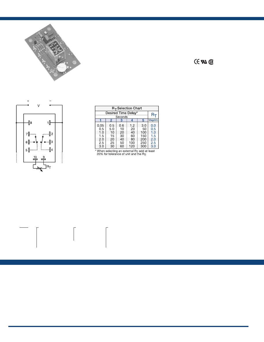
26
www.ssac.com • 800-843-8848 • fax: 605-348-5685
ORM Series
Timer - Delay-on-Make
Available Models:
Time Delay
Type . . . . . . . . . . . . . . . . . . . . . . . . . . . . . . . . . . . Analog circuitry
Range . . . . . . . . . . . . . . . . . . . . . . . . . . . . . . . . . .
0.05 - 300s in 5 adjustable ranges or fixed
Repeat Accuracy . . . . . . . . . . . . . . . . . . . . . . . .
±2% or 20ms, whichever is greater
Tolerance . . . . . . . . . . . . . . . . . . . . . . . . . . . . . . .
Adjustable: guaranteed range
Fixed: ±10%
Recycle Time . . . . . . . . . . . . . . . . . . . . . . . . . . . .
After timing - ≤ 16ms;
During timing - 0.1% of max. time delay
or 75ms, whichever is greater
Time Delay vs Temp. & Voltage
. . . . . . . . . . .
≤ ±10%
Input
Voltage
. . . . . . . . . . . . . . . . . . . . . . . . . . . . . . . . .
24 or 110VDC; 24, 120, or 230VAC
Tolerance 24VDC/AC
. . . . . .
-15% - 20%
110 to 230VAC/DC
. . . . . .
-20% - 10%
AC Line Frequency . . . . . . . . . . . . . . . . . . . . . .
50/60 Hz
Power Consumption . . . . . . . . . . . . . . . . . . . . .
2.25W
Output
Type . . . . . . . . . . . . . . . . . . . . . . . . . . . . . . . . . . .
Electromechanical relay
Form . . . . . . . . . . . . . . . . . . . . . . . . . . . . . . . . . . .
DPDT, Isolated
Rating . . . . . . . . . . . . . . . . . . . . . . . . . . . . . . . . .
10A resistive @ 120/240VAC & 28VDC;
1/3 hp @ 120/240VAC
Life
. . . . . . . . . . . . . . . . . . . . . . . . . . . . . . . . . . . .
Mechanical - 1x10
7
; Electrical - 1x10
6
Protection
Polarity . . . . . . . . . . . . . . . . . . . . . . . . . . . . . . . .
DC units are reverse polarity protected
Isolation Voltage
. . . . . . . . . . . . . . . . . . . . . . . .
≥1500V RMS input to output
Mechanical
Mounting . . . . . . . . . . . . . . . . . . . . . . . . . . . . . .
Surface mount with four #6 (M3.5 x 0.6) screws
Termination . . . . . . . . . . . . . . . . . . . . . . . . . . . .
0.25 in. (6.35 mm) male quick connect terminals
Environmental
Operating / Storage Temperature
. . . . . . . . .
-20° to 65°C / -30° to 85°C
Weight
. . . . . . . . . . . . . . . . . . . . . . . . . . . . . . . . .
≅
2.7 oz (77 g)
Specifications
Order Table:
Connection:
The ORM Series features open PC board
construction for reduced cost. It has isolated, 10A,
DPDT relay contacts and all connections are 0.25 in
(6.35 mm) male quick connect terminals. The time
delay may be ordered as factory fixed, onboard
knob, or external adjustment. Time delays from
0.05 - 300 seconds.
Operation (Delay-on-Make):
Upon application of input voltage, the time delay begins.
The output is de-energized before and during the time
delay. At the end of the time delay, the output energizes
and remains energized until voltage is removed.
Reset: Removing input voltage resets the time delay
and output .
For more information see:
Appendix A, pages 156-164 for function descriptions
and diagrams .
Appendix B, page 165, Figure 11 for dimensional drawing.
Features:
• Time delays from 0.05s - 300s in 5 ranges or
fixed
•
Low cost open PCB construction
• 10A, DPDT output contacts
• ±2% repeat accuracy
• ±10% factory calibration
• Factory fixed, onboard or external adjust
Approvals:
Auxiliary Products:
•
External ad just potentiometer:
P/N: P1004-12
P/N: P1004-12-X
•
Female quick connect:
P/N: P1015-64 (AWG 14/16)
•
Quick connect t o s crew ad aptor:
P/N: P1015-18
•
Versa-knob:
P/N: P0700-7
ORM120A110
ORM120A115
ORM120A145
ORM120A17
ORM120A25
ORM230A17
ORM24D13.5
ORM
X
Input Voltage
─
24A
- 24VAC
─
24D
- 24VAC/28VDC
─
110D
- 110VDC
─
120A
- 120VAC
─
230A
- 230VAC
X
Adjustment
─
1
- Fixed
─
2
- Onboard knob
─
3
- External adjust
X
Time Delay*
─
1
- 0.05 - 3s
─
2
- 0.5 - 30s
─
3
- 0.6 - 60s
─
4
- 1.2 - 120s
─
5
- 3 - 300s
*If fixed delay is selected, insert delay
(
0 .05 - 300
) in seconds .
L1
N/L2
R
T
is used when external adjustment
is ordered .
Relay contacts are isolated .
If desired part number is not listed, please call us to
see if it is technically possible to build .
Courtesy of Steven Engineering, Inc.-230 Ryan Way, South San Francisco, CA 94080-6370-Main Office: (650) 588-9200-Outside Local Area: (800) 258-9200-www.stevenengineering.com
Littelfuse-catalog-html.html
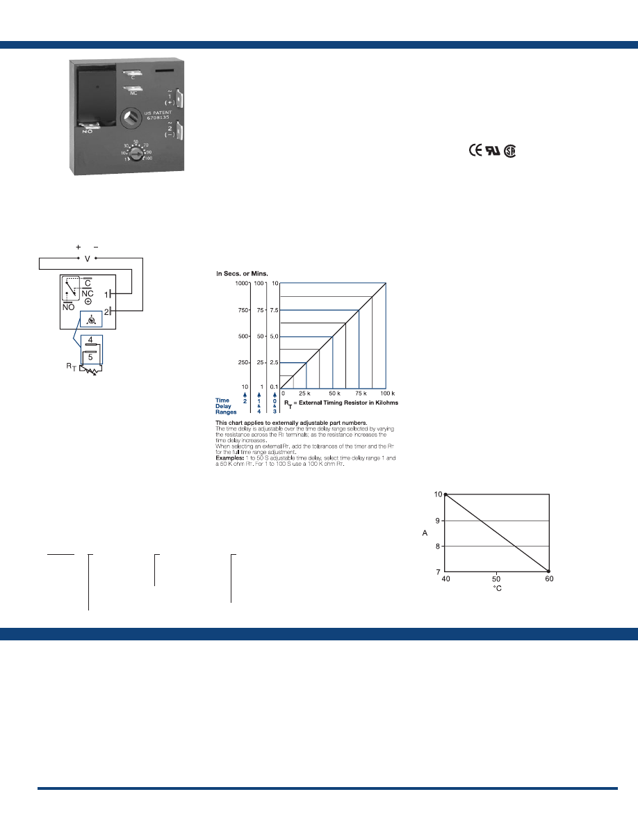
27
www.ssac.com • 800-843-8848 • fax: 605-348-5685
KRDM Series
Timer - Delay-on-Make
Available Models:
Time Delay
Range . . . . . . . . . . . . . . . . . . . . . . . . . . . . . . . . . . . . .
0.1s - 100m in 5 adjustable ranges or fixed
Repeat Accuracy . . . . . . . . . . . . . . . . . . . . . . . . . . .
±0.5% or 20ms, whichever is greater
Tolerance (Factory Calibration) . . . . . . . . . . . . . . .
≤ ±5%
Recycle Time . . . . . . . . . . . . . . . . . . . . . . . . . . . . . . .
≤ 150ms
Time Delay vs Temp. & Voltage
. . . . . . . . . . . . . .
≤ ±5%
Input
Voltage
. . . . . . . . . . . . . . . . . . . . . . . . . . . . . . . . . . . .
12, 24 or 110VDC; 24, 120 or 230VAC
Tolerance 12VDC & 24VAC/DC
. . . . . . . . .
-15% - 20%
110VDC 120 & 230VAC
. . . . . . . .
-20% - 10%
AC Line Frequency / DC Ripple
. . . . . . . . . . . . . .
50/60 Hz / ≤ 10%
Power Consumption . . . . . . . . . . . . . . . . . . . . . . . .
AC ≤ 2VA; DC ≤ 2W
Output
Type . . . . . . . . . . . . . . . . . . . . . . . . . . . . . . . . . . . . . .Isolated relay contacts
Form . . . . . . . . . . . . . . . . . . . . . . . . . . . . . . . . . . . . . .SPDT
Rating (at 40°C)
. . . . . . . . . . . . . . . . . . . . . . . . . . . .
10A resistive @ 125VAC;
5A resistive @ 230VAC & 28VDC;
1/4 hp @ 125VAC
Max. Switching Voltage
. . . . . . . . . . . . . . . . . . . . .
250VAC
Life (Operations)
. . . . . . . . . . . . . . . . . . . . . . . . . . .
Mechanical - 1 x 10
7
; Electrical - 1 x 10
5
Protection
Circuitry . . . . . . . . . . . . . . . . . . . . . . . . . . . . . . . . . .Encapsulated
Isolation Voltage
. . . . . . . . . . . . . . . . . . . . . . . . . . .
≥ 1500V RMS input to output
Insulation Resistance . . . . . . . . . . . . . . . . . . . . . . . .
≥ 100 MΩ
Polarity . . . . . . . . . . . . . . . . . . . . . . . . . . . . . . . . . . .
DC units are reverse polarity protected
Mechanical
Mounting . . . . . . . . . . . . . . . . . . . . . . . . . . . . . . . . .
Surface mount with one #10 (M5 x 0.8) screw
Dimensions . . . . . . . . . . . . . . . . . . . . . . . . . . . . . . . .
2 x 2 x 1.21 in (50.8 x 50.8 x 30.7 mm)
Termination . . . . . . . . . . . . . . . . . . . . . . . . . . . . . . .
0.25 in. (6.35 mm) male quick connect terminals
Environmental
Operating / Storage Temperature
. . . . . . . . . . . .
-20° to 60°C / -40° to 85°C
Humidity . . . . . . . . . . . . . . . . . . . . . . . . . . . . . . . . . .
95% relative, non-condensing
Weight
. . . . . . . . . . . . . . . . . . . . . . . . . . . . . . . . . . . .
≅
2.6 oz (74 g)
Order Table:
Specifications
The KRDM Series is a compact time delay relay
measuring only 2 in. (50.8 mm) square. Its solid-
state timing circuit provides excellent repeat
accuracy and stability . Encapsulation protects
against shock, vibration, and humidity. The
KRDM Series is a cost effective approach for OEM
applications that require small size, isolation,
reliability, and long life.
Operation (Delay-on-Make):
Upon application of input voltage, the time delay begins.
The output is de-energized before and during the time delay.
At the end of the time delay, the output relay energizes and
remains energized until input voltage is removed.
Reset: Removing input voltage resets the time delay and
output .
For more information see:
Appendix A, pages 156-164 for function descriptions
and diagrams .
Appendix B, page 165, Figure 1 for dimensional drawing.
Features:
•
Compact time delay relay
• 10A, SPDT output contacts
• Factory fixed, onboard or external adjust
• Delays from 0.1s - 100m in 5 ranges or fixed
• ±0.5% repeat accuracy
• ±5% factory calibration
• Input voltages from 12 to 230V in 6 ranges
Approvals:
Connection:
KRDM110.4S
KRDM110.5S
KRDM111.5S
KRDM1110S
KRDM111S
KRDM1130S
KRDM120
KRDM121
KRDM2110M
KRDM215M
KRDM220
KRDM221
KRDM222
KRDM223
KRDM224
KRDM234
KRDM310.2S
KRDM320
KRDM4110S
KRDM4145S
KRDM4160S
KRDM421
KRDM430
KRDM433
KRDM623
Auxiliary Products:
•
External ad just potentiometer:
P/N: P1004-95
P/N: P1004-95-X
•
Female quick connect:
P/N: P1015-13 (AWG 10/12)
P/N: P1015-64 (AWG 14/16)
•
Quick connect t o s crew ad aptor:
P/N: P1015-18
•
Versa-knob:
P/N: P0700-7
•
Mounting bracket:
P/N: P1023-6
•
DIN rail:
P/N: C103PM
(Al)
•
DIN rail adaptor:
P/N: P1023-20
•
KRDM
X
Input Voltage
─
1
- 12VDC
─
2
- 24VAC/DC
─
3
- 24VDC
─
4
- 120VAC
─
5
- 110VDC
─
6
- 230VAC
X
Adjustment
─
1
- Fixed
─
2
- Onboard knob
─
3
- External adjust
X
Time Delay*
─
0
- 0.1 - 10s
─
1
- 1 - 100s
─
2
- 10 - 1000s
─
3
- 0.1 - 10m
─
4
- 1 - 100m
*If fixed delay is selected, insert
delay (
0 .1 - 1000
) followed by (
S
)
sec . or (
0 .1 - 100
) (
M
) min .
L1
N/L2
External Resistance vs Time Delay:
V = Voltage
C = Common, Transfer Contact
NO = Normally Open
NC = Normally Closed
A knob is supplied for adjustable units, or
R
T
terminals 4 & 5 for external adjust. See
external adjustment vs time delay chart.
Relay contacts are isolated .
If desired part number is not listed, please call us to
see if it is technically possible to build .
Output Current/Ambient Temperature:
Courtesy of Steven Engineering, Inc.-230 Ryan Way, South San Francisco, CA 94080-6370-Main Office: (650) 588-9200-Outside Local Area: (800) 258-9200-www.stevenengineering.com
Littelfuse-catalog-html.html
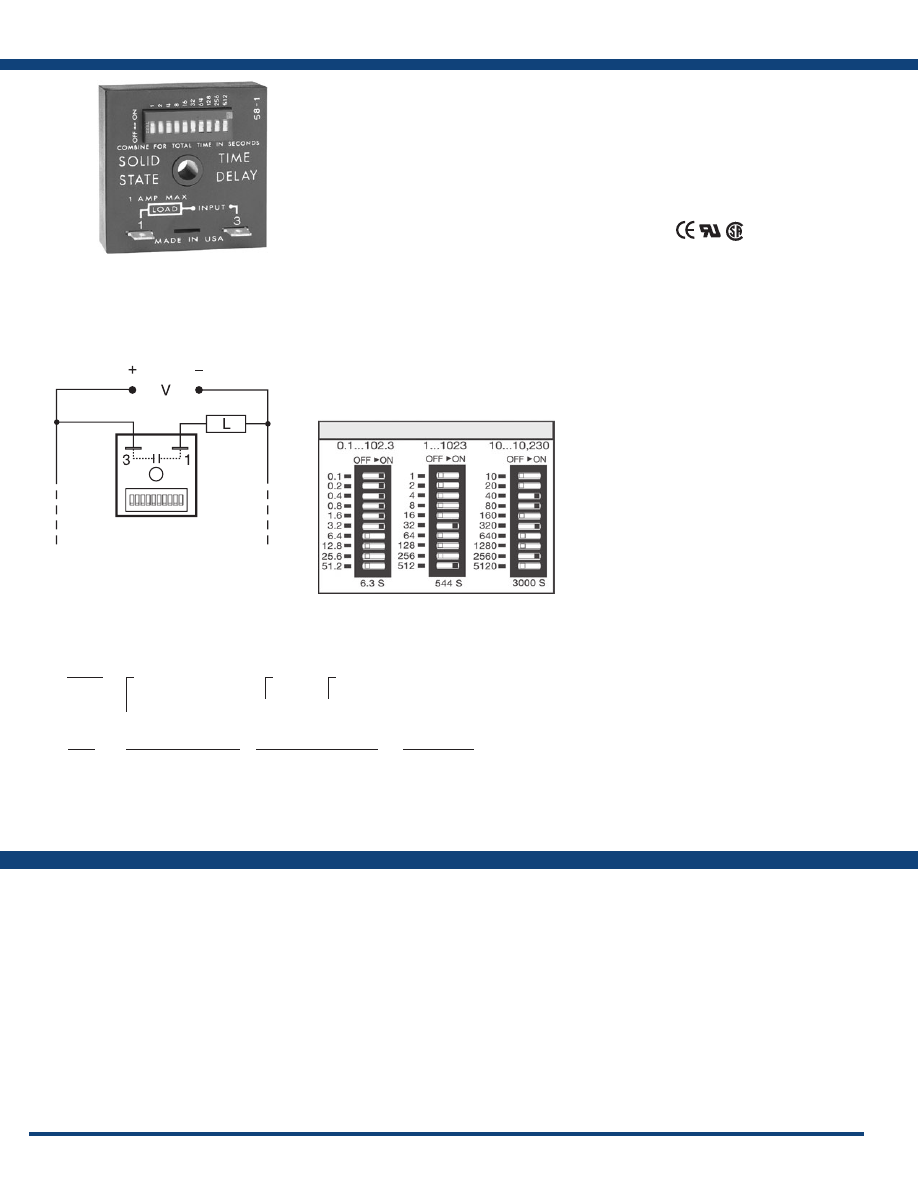
28
www.ssac.com • 800-843-8848 • fax: 605-348-5685
KSDU/ TDU Series
Timer - Delay-on-Make
Available Models:
Time Delay
Type . . . . . . . . . . . . . . . . . . . . . . . . . . . . . . . . . . . Digital integrated circuitry
Range* Adjustable (TDU)
. . . . .
0.1 - 102.3s in 0.1s increments
1 - 1023s in 1s increments
10 - 10230s in 10s increments
Fixed (KSDU)
. . . . .
Fixed from 0.1s - 10230s
Repeat Accuracy . . . . . . . . . . . . . . . . . . . . . . . . .
±0.5% or 20ms, whichever is greater
Tolerance (Factory Calibration) . . . . . . . . . . . .
±10%
Recycle Time . . . . . . . . . . . . . . . . . . . . . . . . . . . .
≤ 150ms
Time Delay vs Temp. & Voltage
. . . . . . . . . . .
±5%
Input
Voltage
. . . . . . . . . . . . . . . . . . . . . . . . . . . . . . . . .
24 to 120VAC/DC; 100 to 240VAC/DC
AC Line Frequency . . . . . . . . . . . . . . . . . . . . . .
50/60 Hz
Tolerance . . . . . . . . . . . . . . . . . . . . . . . . . . . . . . .
±20%
Output
Type . . . . . . . . . . . . . . . . . . . . . . . . . . . . . . . . . . . Solid state
Form . . . . . . . . . . . . . . . . . . . . . . . . . . . . . . . . . . .
NO, open during timing
Maximum Load Current
. . . . . . . . . . . . . . . . . .
1A steady state, 10A inrush at 60°C
Minimum Holding Current . . . . . . . . . . . . . . .
40mA
Voltage Drop
. . . . . . . . . . . . . . . . . . . . . . . . . . . .
≅
2.5V @ 1A
Protection
Circuitry . . . . . . . . . . . . . . . . . . . . . . . . . . . . . . . . Encapsulated
Dielectric Breakdown
. . . . . . . . . . . . . . . . . . . .
≥ 2000V RMS terminals to mounting surface
Insulation Resistance . . . . . . . . . . . . . . . . . . . . .
≥100 MΩ
Mechanical
Mounting . . . . . . . . . . . . . . . . . . . . . . . . . . . . . . .
Surface mount with one #10 (M5 x 0.8) screw
Dimensions . . . . . . . . . . . . . . . . . . . . . . . . . . . . .
2 x 2 x 1.21 in. (50.8 x 50.8 x 30.7 mm)
Termination . . . . . . . . . . . . . . . . . . . . . . . . . . . . .
0.25 in. (6.35 mm) male quick connect terminals
Environmental
Operating / Storage Temperature
. . . . . . . . . .
-40° to 60°C / -40° to 85°C
Humidity . . . . . . . . . . . . . . . . . . . . . . . . . . . . . . .
95% relative, non-condensing
Weight
. . . . . . . . . . . . . . . . . . . . . . . . . . . . . . . . .
≅
2.4 oz (68 g)
* For CE approved applications, power must be removed from the unit when a switch position
is changed.
Specifications
Order Tables:
Connection:
The TDU and KSDU Series are encapsulated solid-
state, delay-on-make timers that combine digital
timing circuitry with universal voltage operation.
The TDU offers DIP switch adjustment allowing
accurate selection of the time delay over the full
time delay range. The KSDU is factory fixed from
0.1s to 10,230s and does not include the DIP switch.
These series are excellent choices for process
control systems and OEM equipment .
Operation (Delay-on-Make):
Upon application of input voltage, the time delay begins.
The output is de-energized before and during the time
delay. At the end of the time delay, the output energizes
and remains energized until input voltage is removed.
Reset: Removing input voltage resets the time delay
and output .
For more information see:
Appendix A, pages 156-164 for function descriptions
and diagrams .
Appendix B, page 165, Figure 1 for dimensional drawing.
Features:
• 2 universal voltage ranges from
24 to 240VAC/DC
•
Digital integrated circuitry
• Switch selectable delays from 0.1s - 2.8h in 3
ranges or factory fixed
• ±0.5% repeat accuracy
• 1A steady, 10A inrush
• Totally solid state & encapsulated
Approvals:
Auxiliary Products:
•
Female quick connect:
P/N: P1015-64 (AWG 14/16)
•
Quick connect t o s crew ad aptor:
P/N: P1015-18
•
Mounting bracket:
P/N: P1023-6
•
DIN rail:
P/N: C103PM
(Al)
•
DIN rail adaptor:
P/N: P1023-20
KSDU8110
KSDU811200
TDU3000A
TDU3001A
TDU3003A
TDUH3000A
TDUH3001A
TDUL3000A
TDUL3001A
KSDU
X
Input Voltage Range
─
8
- 24 to 120VAC/DC
─
9
- 100 to 240VAC/DC
X
Type
─
1
- Fixed
X
Time Delay (Seconds)
─Specify fixed delay in
seconds
0 .1 - 10230
TDU
Input Voltage Range
24 to 120VAC/DC
100 to 240VAC/DC
24 to 120VAC/DC
100 to 240VAC/DC
120 to 277VAC
24 to 120VAC/DC
100 to 240VAC/DC
Time Range - Seconds
0.1 - 102.3
0.1 - 102.3
1 - 1023
1 - 1023
1 - 1023
10 - 10230
10 - 10230
Part Number
TDUL3000A
TDUL3001A
TDU3000A
TDU3001A
TDU3003A
TDUH3000A
TDUH3001A
L1
N/L2
Digi-Set Binary Switch Operation:
If desired part number is not listed, please call us to
see if it is technically possible to build .
Load may be connected to terminal 3 or 1.
TDU has DIP switch adjustment; KSDU is fixed.
Courtesy of Steven Engineering, Inc.-230 Ryan Way, South San Francisco, CA 94080-6370-Main Office: (650) 588-9200-Outside Local Area: (800) 258-9200-www.stevenengineering.com
Littelfuse-catalog-html.html
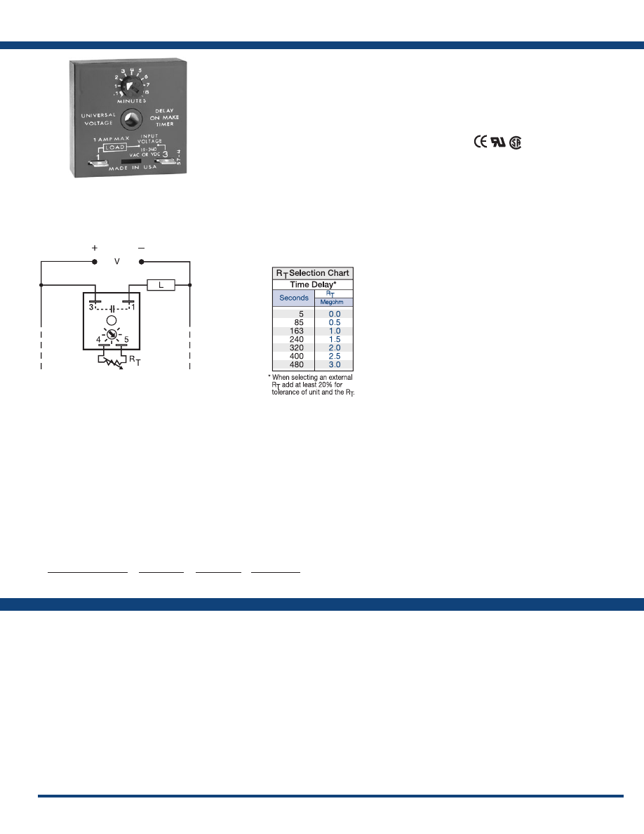
29
www.ssac.com • 800-843-8848 • fax: 605-348-5685
TMV8000 / TSU2000 Series
Timer - Delay-on-Make
Available Models:
Time Delay
Type . . . . . . . . . . . . . . . . . . . . . . . . . . . . . . . . . . . . . Analog circuitry
Range . . . . . . . . . . . . . . . . . . . . . . . . . . . . . . . . . . . .
5 - 480s (TSU2000)
0.1 - 8m (TMV8000)
Repeat Accuracy . . . . . . . . . . . . . . . . . . . . . . . . . .
±2%
Tolerance (Factory Calibration) . . . . . . . . . . . . . .
≤ ±10%
Reset Time . . . . . . . . . . . . . . . . . . . . . . . . . . . . . . . .
≤ 100ms
Input
Voltage
. . . . . . . . . . . . . . . . . . . . . . . . . . . . . . . . . . .
24 to 240VAC/DC ±20%
AC Line Frequency . . . . . . . . . . . . . . . . . . . . . . . .
50/60 Hz
Output
Type . . . . . . . . . . . . . . . . . . . . . . . . . . . . . . . . . . . . . Solid State
Form . . . . . . . . . . . . . . . . . . . . . . . . . . . . . . . . . . . . .
NO, open during timing
Maximum Load Current
. . . . . . . . . . . . . . . . . . . .
1A steady state, 10A inrush at 55°C
Minimum Holding Current . . . . . . . . . . . . . . . . .
≤ 40mA
Voltage Drop
. . . . . . . . . . . . . . . . . . . . . . . . . . . . .
≅
2.5V @ 1A
Protection
Circuitry . . . . . . . . . . . . . . . . . . . . . . . . . . . . . . . . . Encapsulated
Dielectric Breakdown
. . . . . . . . . . . . . . . . . . . . . .
≥ 2000V RMS terminals to mounting surface
Insulation Resistance . . . . . . . . . . . . . . . . . . . . . . .
≥ 100 MΩ
Mechanical
Mounting . . . . . . . . . . . . . . . . . . . . . . . . . . . . . . . .
Surface mount with one #10 (M5 x 0.8) screw
Dimensions . . . . . . . . . . . . . . . . . . . . . . . . . . . . . . .
2 x 2 x 1.21 in. (50.8 x 50.8 x 30.7 mm)
Termination . . . . . . . . . . . . . . . . . . . . . . . . . . . . . .
0.25 in. (6.35 mm) male quick connect terminals
Environmental
Operating / Storage Temperature
. . . . . . . . . . .
-20° to 70°C / -30° to 85°C
Humidity . . . . . . . . . . . . . . . . . . . . . . . . . . . . . . . . .
95% relative, non-condensing
Weight
. . . . . . . . . . . . . . . . . . . . . . . . . . . . . . . . . . .
≅
2.4 oz (68 g)
Order Table:
Specifications
The TMV and TSU Series are universal voltage
delay-on-make timers. Two models cover all the
popular voltages and time delays. Available with
knob or external adjust time delay. Its simple two
terminals can easily be connected in series with a
relay coil, contactor coil, solenoid, lamps, small
motor, etc., to delay their energization, prevent
short cycling or to sequence on various loads.
Operation (Delay-on-Make):
Upon application of input voltage, the time delay begins.
The output is de-energized before and during the time
delay. At the end of the time delay, the output energizes
and remains energized until input voltage is removed.
Reset: Removing input voltage resets the time delay
and output .
For more information see:
Appendix A, pages 156-164 for function descriptions
and diagrams .
Appendix B, page 165, Figure 1 for dimensional drawing.
Features:
• Operates from 24 to 240VAC/DC
• Onboard or external adjust time delays
• Delays from 5s - 8m
• Totally solid state & encapsulated
• 1A steady, 10A inrush
• Two terminal series connection with load
Approvals:
Connection:
TMV8000
TSU2000
Auxiliary Products:
•
External ad just potentiometer:
P/N: P1004-12
P/N: P1004-12-X
•
Female quick connect:
P/N: P1015-64 (AWG 14/16)
•
Quick connect t o s crew ad aptor:
P/N: P1015-18
•
Versa-knob:
P/N: P0700-7
•
Mounting bracket:
P/N: P1023-6
•
DIN rail:
P/N: C103PM
(Al)
•
DIN rail adaptor:
P/N: P1023-20
Input Voltage Range
24 to 240VAC/DC
24 to 240VAC/DC
Time Delay
5 - 480s
0.1 - 8m
Adjustment
External
Onboard
Part Number
TSU2000
TMV8000
L1
N/L2
Load may be connected to terminal 3 or 1.
TMV has knob adjustment.
TSU has external adjustment terminals 4 & 5.
Courtesy of Steven Engineering, Inc.-230 Ryan Way, South San Francisco, CA 94080-6370-Main Office: (650) 588-9200-Outside Local Area: (800) 258-9200-www.stevenengineering.com
Littelfuse-catalog-html.html
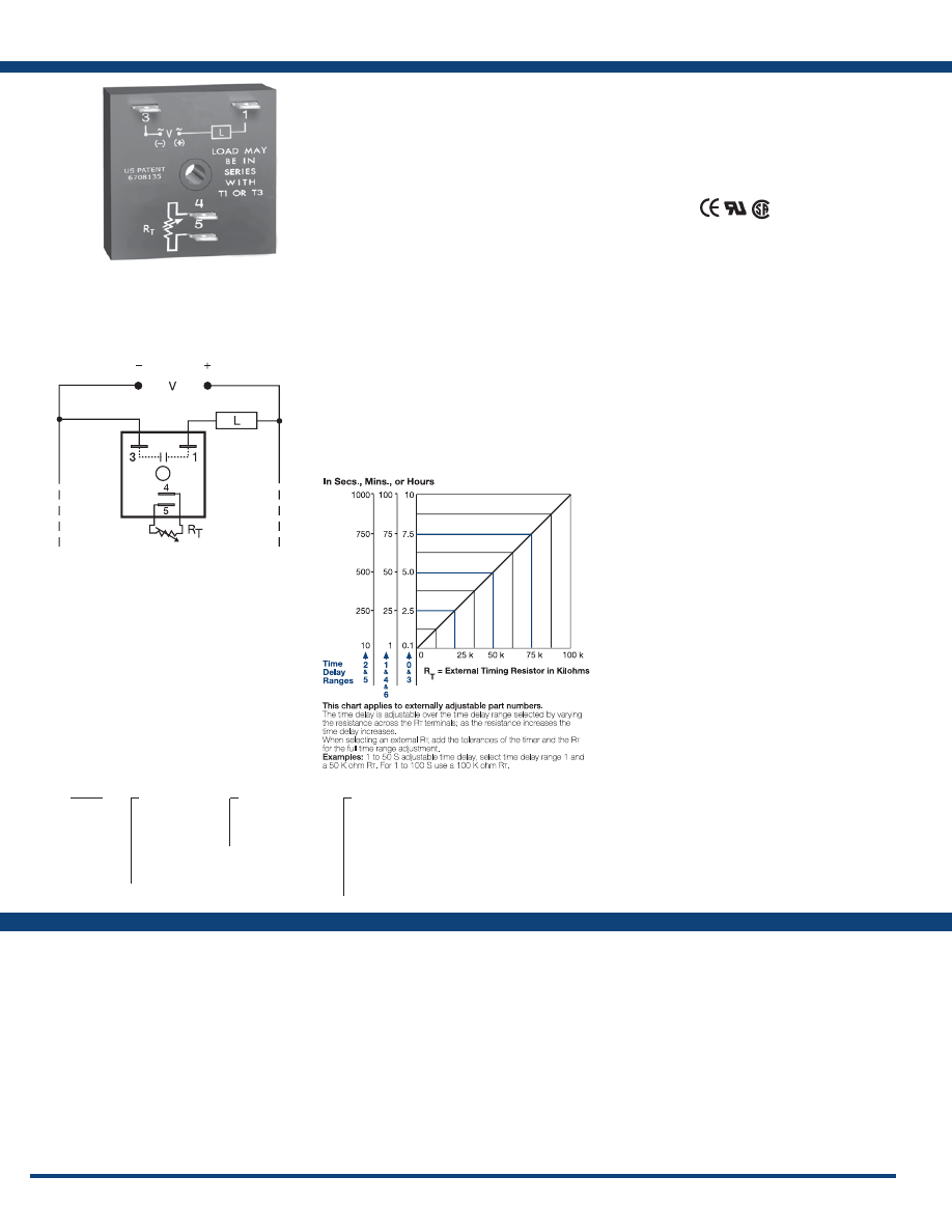
30
www.ssac.com • 800-843-8848 • fax: 605-348-5685
TSD1 Series
Timer - Delay-on-Make
Available Models:
Time Delay
Range . . . . . . . . . . . . . . . . . . . . . . . . . . . . . . . . . . . . .
0.1s - 100h in 7 adjustable ranges or fixed
Repeat Accuracy . . . . . . . . . . . . . . . . . . . . . . . . . . .
±0.1% or 20ms, whichever is greater
Tolerance (Factory Calibration) . . . . . . . . . . . . . . .
≤ ±1%
Recycle Time . . . . . . . . . . . . . . . . . . . . . . . . . . . . . . .
≤ 150ms
Time Delay vs Temp. & Voltage
. . . . . . . . . . . . . .
≤ ±1%
Input
Voltage
. . . . . . . . . . . . . . . . . . . . . . . . . . . . . . . . . . . .
12, 24, 120VDC; 24, 120, 230VAC
Tolerance . . . . . . . . . . . . . . . . . . . . . . . . . . . . . . . . . .
±20%
AC Line Frequency . . . . . . . . . . . . . . . . . . . . . . . . .
50/60 Hz
Output
Type . . . . . . . . . . . . . . . . . . . . . . . . . . . . . . . . . . . . . .Solid state
Form . . . . . . . . . . . . . . . . . . . . . . . . . . . . . . . . . . . . . .
NO, open during timing
Maximum Load Current
. . . . . . . . . . . . . . . . . . . . .
1A steady state, 10A inrush at 60°C
Minimum Holding Current . . . . . . . . . . . . . . . . . .
≤ 40mA
Off State Leakage Current
. . . . . . . . . . . . . . . . . . .
≅
7mA @ 230VAC
Voltage Drop
. . . . . . . . . . . . . . . . . . . . . . . . . . . . . .
≅
2.5V @ 1A
Protection
Circuitry . . . . . . . . . . . . . . . . . . . . . . . . . . . . . . . . . .Encapsulated
Dielectric Breakdown
. . . . . . . . . . . . . . . . . . . . . . .
≥ 2000V RMS terminals to mounting surface
Insulation Resistance . . . . . . . . . . . . . . . . . . . . . . . .
≥ 100 MΩ
Polarity . . . . . . . . . . . . . . . . . . . . . . . . . . . . . . . . . . .
DC units are reverse polarity protected
Mechanical
Mounting . . . . . . . . . . . . . . . . . . . . . . . . . . . . . . . . .
Surface mount with one #10 (M5 x 0.8) screw
Dimensions . . . . . . . . . . . . . . . . . . . . . . . . . . . . . . . .
2 x 2 x 1.21 in. (50.8 x 50.8 x 30.7 mm)
Termination . . . . . . . . . . . . . . . . . . . . . . . . . . . . . . .
0.25 in. (6.35 mm) male quick connect terminals
Environmental
Operating / Storage Temperature
. . . . . . . . . . . .
-40° to 75°C / -40° to 85°C
Humidity . . . . . . . . . . . . . . . . . . . . . . . . . . . . . . . . . .
95% relative, non-condensing
Weight
. . . . . . . . . . . . . . . . . . . . . . . . . . . . . . . . . . . .
≅
2.4 oz (68 g)
Specifications
Order Table:
Connection:
The TSD1 Series is designed for more demanding
commercial and industrial applications where small
size and accurate performance is required. The
factory calibration for fixed time delays is within
1% of the target time delay. The repeat accuracy,
under stable conditions, is 0.1% of the time delay.
The TSD1 Series is rated to operate over an extended
temperature range. Time delays of 0.1 seconds to 100
hours are available. The output is rated 1A steady
and 10A inrush. The modules are totally solid state
and encapsulated to protect the electronic circuitry.
Operation (Delay-on-Make):
Upon application of input voltage, the time delay begins.
The output is de-energized before and during the time
delay. At the end of the time delay, the output energizes
and remains energized until input voltage is removed.
Reset: Removing input voltage resets the time delay
and output .
For more information see:
Appendix A, pages 156-164 for function descriptions
and diagrams .
Appendix B, page 165, Figure 1 for dimensional drawing.
Features:
• Fixed or adjustable delays from 0.1s - 100h
• ±0.1% repeat accuracy
• ±1% factory calibration
• 12 to 230V in 6 ranges
• 1A, solid-state output
•
Encapsulated
Approvals:
Auxiliary Products:
•
External ad just potentiometer:
P/N: P1004-95
P/N: P1004-95-X
•
Female quick connect:
P/N: P1015-64 (AWG 14/16)
•
Quick connect t o s crew ad aptor:
P/N: P1015-18
•
Mounting bracket:
P/N: P1023-6
•
Versa-knob:
P/N: P0700-7
•
DIN rail:
P/N: C103PM
(Al)
•
DIN rail adaptor:
P/N: P1023-20
TSD11110S
TSD1311.2S
TSD1315S
TSD1320
TSD1321
TSD1424
TSD1
X
Input Voltage
─
1
- 12VDC
─
2
- 24VAC
─
3
- 24VDC
─
4
- 120VAC
─
5
- 120VDC
─
6
- 230VAC
X
Adjustment
─
1
- Fixed
─
2
- External adjust
─
3
- Onboard adjust
X
Time Delay*
─
0
- 0.1 - 10s
─
1
- 1 - 100s
─
2
- 10 - 1000s
─
3
- 0.1 - 10m
─
4
- 1 - 100m
─
5
- 10 - 1000m
─
6
- 1 - 100h
*If fixed delay is selected, insert
delay (
0 .1 - 1000
) followed by (
S
) sec .
(
M
) min . or (
1 - 100
) (
H
) hours.
L1
N/L2
External Resistance vs . Time Delay:
If desired part number is not listed, please call us to
see if it is technically possible to build .
Load may be connected to terminal 3 or 1.
R
T
is used when external adjustment is ordered.
Courtesy of Steven Engineering, Inc.-230 Ryan Way, South San Francisco, CA 94080-6370-Main Office: (650) 588-9200-Outside Local Area: (800) 258-9200-www.stevenengineering.com
Littelfuse-catalog-html.html
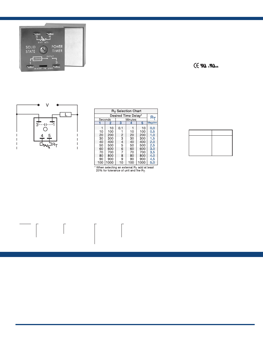
31
www.ssac.com • 800-843-8848 • fax: 605-348-5685
THDM Series
Timer - Delay-on-Make
Available Models:
Time Delay
Type . . . . . . . . . . . . . . . . . . . . . . . . . . . . . . . . . . . Digital intergrated circuitry
Range . . . . . . . . . . . . . . . . . . . . . . . . . . . . . . . . . .
1s - 1000m in 5 adjustable ranges or fixed
Repeat Accuracy . . . . . . . . . . . . . . . . . . . . . . . .
±0.5% or 20ms, whichever is greater
Tolerance (Factory Calibration) . . . . . . . . . . . .
≤ ± 10%
Recycle Time . . . . . . . . . . . . . . . . . . . . . . . . . . . .
After timing - ≤ 350ms;
During timing - ≤150ms
Time Delay vs Temp. & Voltage
. . . . . . . . . . .
≤ ±2%
Input
Voltage
. . . . . . . . . . . . . . . . . . . . . . . . . . . . . . . . .
24, 120, or 230VAC
Tolerance . . . . . . . . . . . . . . . . . . . . . . . . . . . . . . .
±20%
AC Line Frequency . . . . . . . . . . . . . . . . . . . . . .
50/60 Hz
Output
Type . . . . . . . . . . . . . . . . . . . . . . . . . . . . . . . . . . . Solid state
Form . . . . . . . . . . . . . . . . . . . . . . . . . . . . . . . . . . .
NO, open during timing
Maximum Load Currents Output Steady State Inrush**
A 6A 60A
B 10A 100A
C 20A 200A
Minimum Load Current . . . . . . . . . . . . . . . . . .
100mA
Effective Voltage Drop (V Line - V Load) Input Effective Drop
24VAC ≤ 3V
120VAC ≤ 3V
230VAC ≤ 5V
Protection
Circuitry . . . . . . . . . . . . . . . . . . . . . . . . . . . . . . . Encapsulated
Dielectric Breakdown
. . . . . . . . . . . . . . . . . . . .
≥ 2000V RMS terminals to mounting surface
Insulation Resistance . . . . . . . . . . . . . . . . . . . . .
≥ 100 MΩ
Mechanical
Mounting ** . . . . . . . . . . . . . . . . . . . . . . . . . . . .
Surface mount with one #10 (M5 x 0.8) screw
Dimensions . . . . . . . . . . . . . . . . . . . . . . . . . . . . .
2 x 2 x 1.51 in. (50.8 x 50.8 x 38.4 mm)
Termination . . . . . . . . . . . . . . . . . . . . . . . . . . . .
0.25 in. (6.35 mm) male quick connect terminals
Environmental
Operating / Storage Temperature
. . . . . . . . .
-40° to 60°C / -40° to 85°C
Humidity . . . . . . . . . . . . . . . . . . . . . . . . . . . . . . .
95% relative, non-condensing
Weight
. . . . . . . . . . . . . . . . . . . . . . . . . . . . . . . . .
≅
3.9 oz (111 g)
**Must be bolted to a metal surface using the included heat sink compound. The maximum
mounting surface temperature is 90°C. Inrush: Non-repetitive for 16ms.
Order Table:
Specifications
The THDM Series is a high power solid-state
delay-on-make timer that is connected in series
with the load. The THDM eliminates the need
for a timer and a separate solid-state relay. A cost
effective approach for controlling larger loads,
such as motors, electric heating elements, and
lamps. When mounted on a metal surface, it can
switch loads up to 20A steady, 200A inrush.
Operation (Delay-on-Make):
Upon application of input voltage, the time delay begins.
The output is de-energized before and during the time
delay. At the end of the time delay, the output is energized
and remains energized until input voltage is removed.
Reset: Removing input voltage resets the time delay
and output .
For more information see:
Appendix A, pages 156-164 for function descriptions
and diagrams .
Appendix B, page 165, Figure 4 for dimensional drawing.
Features:
• High load currents up to 20A, 200A inrush
• Simple-to-use two terminal series connection
• ± 0.5% repeat accuracy
• Fixed or adjustable delays from 1s - 1000m
• ± 10% factory calibration
• 24, 120, or 230VAC
• Metallized mounting surface for heat transfer
• Solid state & encapsulated
Approvals:
Connection:
Auxiliary Products:
•
External ad just potentiometer:
P/N: P1004-13
P/N: P1004-13-X
•
Female quick connect:
P/N: P1015-13 (AWG 10/12)
P/N: P1015-64 (AWG 14/16)
•
Quick connect t o s crew ad aptor:
P/N: P1015-18
•
Versa-knob:
P/N: P0700-7
•
Plug-on adjustment module:
P/N: VTP(X)(X)
There are no part numbers currently active. Please call
Technical Support with your requirements.
THDM
X
Input Voltage
─
2
- 24VAC
─
4
- 120VAC
─
6
- 230VAC
X
Adjustment
─
1
- Fixed
─
2
- External adjust
X
Time Delay*
─
1
- 1 - 100s
─
2
- 10 - 1000s
─
3
- 0.1 - 10m
─
4
- 1 - 100m
─
5
- 10 - 1000m
X
Output Rating
─
A
- 6A
─
B
- 10A
─
C
- 20A
*If fixed delay is selected, insert
delay (
0 .1 - 1000
) followed by (
S
) sec .
or (
1 - 100
) (
M
) min .
L1
N/L2
Selection Table for VTP Plug-on
Adjustment Accessory.
Time Delay
VTP P/N
1
- 1-100s
2
- 10-1000s
3
- 0.1-10m
4
- 1-100m
5
- 10-1000m
VTP5G
VTP5K
VTP5N
VTP5P
VTP5R
Load may be connected to terminal 3 or 1.
R
T
is used when external adjustment is ordered.
Courtesy of Steven Engineering, Inc.-230 Ryan Way, South San Francisco, CA 94080-6370-Main Office: (650) 588-9200-Outside Local Area: (800) 258-9200-www.stevenengineering.com
Littelfuse-catalog-html.html
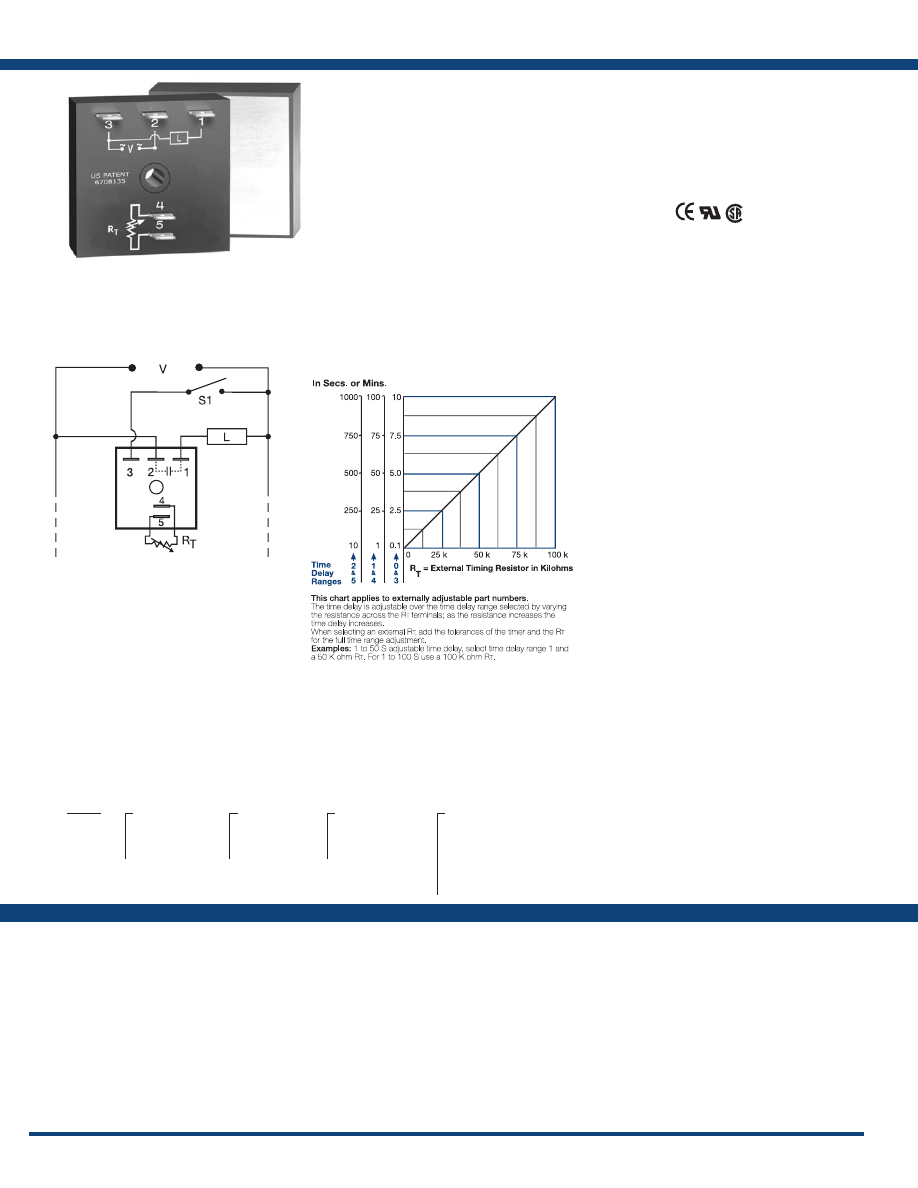
32
www.ssac.com • 800-843-8848 • fax: 605-348-5685
Features:
• High load currents up to 20A, 200A inrush
• Fixed or adjustable delays from 0.1s - 1000m
• ±0.5% repeat accuracy
• ±1% factory calibration
• 24, 120, or 230VAC
• Metallized mounting surface for heat transfer
• Totally solid state & encapsulated
Approvals:
THD1 Series
Timer - Delay-on-Make
Available Models:
Time Delay
Range . . . . . . . . . . . . . . . . . . . . . . . . . . . . . . . . . . .
0.1s - 1000m in 6 adjustable ranges or fixed
Repeat Accuracy . . . . . . . . . . . . . . . . . . . . . . . . .
±0.5% or 20ms, whichever is greater
Tolerance (Factory Calibration) . . . . . . . . . . . . .
≤ ±1%
Recycle Time . . . . . . . . . . . . . . . . . . . . . . . . . . . . .
≤ 150ms
Time Delay vs Temp. & Voltage
. . . . . . . . . . . .
≤ ±2%
Input
Voltage
. . . . . . . . . . . . . . . . . . . . . . . . . . . . . . . . . .
24, 120, or 230VAC
Tolerance . . . . . . . . . . . . . . . . . . . . . . . . . . . . . . . .
±20%
Line Frequency . . . . . . . . . . . . . . . . . . . . . . . . . . .
50/60 Hz
Power Consumption . . . . . . . . . . . . . . . . . . . . . .
≤ 2VA
Output
Type . . . . . . . . . . . . . . . . . . . . . . . . . . . . . . . . . . . . Solid state
Form . . . . . . . . . . . . . . . . . . . . . . . . . . . . . . . . . . . .
NO, open during timing
Maximum Load Current Output Steady State Inrush**
A 6A 60A
B 10A 100A
C 20A 200A
Minimum Load Current . . . . . . . . . . . . . . . . . . .
100mA
Voltage Drop
. . . . . . . . . . . . . . . . . . . . . . . . . . . .
≅
2.5V @ rated current
OFF State Leakage Current
. . . . . . . . . . . . . . . .
≅
5mA @ 230VAC
Protection
Circuitry . . . . . . . . . . . . . . . . . . . . . . . . . . . . . . . . Encapsulated
Dielectric Breakdown
. . . . . . . . . . . . . . . . . . . . .
≥ 2000V RMS terminals to mounting surface
Insulation Resistance . . . . . . . . . . . . . . . . . . . . . .
≥ 100 MΩ
Mechanical
Mounting ** . . . . . . . . . . . . . . . . . . . . . . . . . . . . .
Surface mount with one #10 (M5 x 0.8) screw
Dimensions . . . . . . . . . . . . . . . . . . . . . . . . . . . . . .
2 x 2 x 1.51 in. (50.8 x 50.8 x 38.4 mm)
Termination . . . . . . . . . . . . . . . . . . . . . . . . . . . . .
0.25 in. (6.35 mm) male quick connect terminals
Environmental
Operating / Storage Temperature
. . . . . . . . . .
-40° to 60°C / -40° to 85°C
Humidity . . . . . . . . . . . . . . . . . . . . . . . . . . . . . . . .
95% relative, non-condensing
Weight
. . . . . . . . . . . . . . . . . . . . . . . . . . . . . . . . . .
≅
3.9 oz (111 g)
**Must be bolted to a metal surface using the included heat sink compound. The maximum
mounting surface temperature is 90°C. Inrush: Non-repetitive for 16ms.
Specifications
Order Table:
Connection:
The THD1 Series combines accurate timing
circuitry with high power solid-state switching.
It can switch motors, lamps, and heaters directly
without a contactor. You can reduce labor,
component cost, and increase reliability with these
small, easy-to-use, Digi-Power timers.
Operation (Delay-on-Make):
Upon application of input voltage, the time delay begins.
The output is de-energized before and during the time
delay. At the end of the time delay, the output energizes
and remains energized until input voltage is removed.
Reset: Removing input voltage resets the time delay
and output .
For more information see:
Appendix A, pages 156-164 for function descriptions
and diagrams .
Appendix B, page 165, Figure 4 for dimensional drawing.
Auxiliary Products:
•
External ad just potentiometer:
P/N: P1004-95
P/N: P1004-95-X
•
Female quick connect:
P/N: P1015-13 (AWG 10/12)
P/N: P1015-64 (AWG 14/16)
•
Quick connect t o s crew ad aptor:
P/N: P1015-18
•
Versa-knob:
P/N: P0700-7
THD1B410.5S
THD1C231
THD1C232
THD1C233
THD1C234
THD1C235
THD1C415M
THD1C431
THD1C432
THD1C433
THD1C434
THD1C435
THD1C6110S
THD1
X
Output Rating
─
A
- 6A
─
B
- 10A
─
C
- 20A
X
Input Voltage
─
2
- 24VAC
─
4
- 120VAC
─
6
- 230VAC
X
Adjustment
─
1
- Fixed
─
2
- External adjust
─
3
- Onboard adjust
X
Time Delay*
─
0
- 0.1 - 10s
─
1
- 1 - 100s
─
2
- 10 - 1000s
─
3
- 0.1 - 10m
─
4
- 1 - 100m
─
5
- 10 - 1000m
*If fixed delay is selected, insert
delay (
0 .1 - 1000
) followed by (
S
) sec .
or (
M
) min .
L1
N/L2
External Resistance vs . Time Delay:
If desired part number is not listed, please call us to
see if it is technically possible to build .
S1 = Optional Low Current Initiate
Switch
R
T
is used when external adjustment
is ordered .
Courtesy of Steven Engineering, Inc.-230 Ryan Way, South San Francisco, CA 94080-6370-Main Office: (650) 588-9200-Outside Local Area: (800) 258-9200-www.stevenengineering.com
Littelfuse-catalog-html.html
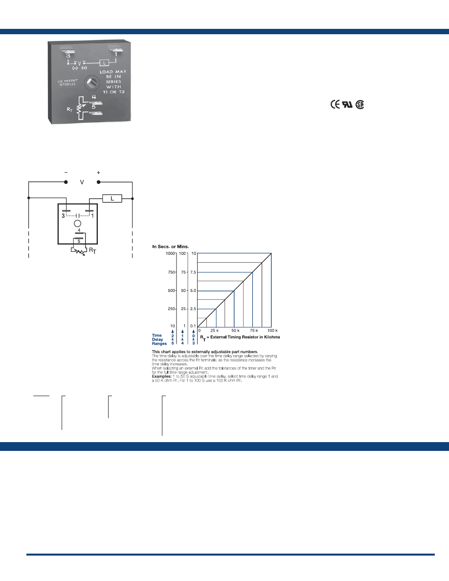
33
www.ssac.com • 800-843-8848 • fax: 605-348-5685
KSD1 Series
Timer - Delay-on-Make
Available Models:
Time Delay
Range . . . . . . . . . . . . . . . . . . . . . . . . . . . . . . . . . .
0.1s - 1000m in 6 adjustable ranges or fixed
Repeat Accuracy . . . . . . . . . . . . . . . . . . . . . . . .
±0.5% or 20ms, whichever is greater
Tolerance (Factory Calibration) . . . . . . . . . . . .
≤ ±5%
Recycle Time . . . . . . . . . . . . . . . . . . . . . . . . . . . .
≤ 150ms
Time Delay vs Temp. & Voltage
. . . . . . . . . . .
≤ ±10%
Input
Voltage
. . . . . . . . . . . . . . . . . . . . . . . . . . . . . . . . .
24, 120, or 230VAC; 12 or 24VDC
Tolerance . . . . . . . . . . . . . . . . . . . . . . . . . . . . . . .
±20%
AC Line Frequency . . . . . . . . . . . . . . . . . . . . . .
50/60 Hz
Output
Type . . . . . . . . . . . . . . . . . . . . . . . . . . . . . . . . . . . Solid state
Form . . . . . . . . . . . . . . . . . . . . . . . . . . . . . . . . . . .
NO, open during timing
Maximum Load Current
. . . . . . . . . . . . . . . . . .
1A steady state, 10A inrush at 60°C
Minimum Holding Current . . . . . . . . . . . . . . .
≤ 40mA
OFF State Leakage Current
. . . . . . . . . . . . . . .
≅
7mA @ 230VAC
Voltage Drop
. . . . . . . . . . . . . . . . . . . . . . . . . . .
≅
2.5V @ 1A
Protection
Circuitry . . . . . . . . . . . . . . . . . . . . . . . . . . . . . . . Encapsulated
Dielectric Breakdown
. . . . . . . . . . . . . . . . . . . .
≥ 2000V RMS terminals to mounting surface
Insulation Resistance . . . . . . . . . . . . . . . . . . . . .
≥ 100 MΩ
Polarity . . . . . . . . . . . . . . . . . . . . . . . . . . . . . . . .
DC units are reverse polarity protected
Mechanical
Mounting . . . . . . . . . . . . . . . . . . . . . . . . . . . . . .
Surface mount with one #10 (M5 x 0.8) screw
Dimensions . . . . . . . . . . . . . . . . . . . . . . . . . . . . .
2 x 2 x 1.21 in. (50.8 x 50.8 x 30.7 mm)
Termination . . . . . . . . . . . . . . . . . . . . . . . . . . . .
0.25 in. (6.35 mm) male quick connect terminals
Environmental
Operating / Storage Temperature
. . . . . . . . .
-40° to 60°C / -40° to 85°C
Humidity . . . . . . . . . . . . . . . . . . . . . . . . . . . . . . .
95% relative, non-condensing
Weight
. . . . . . . . . . . . . . . . . . . . . . . . . . . . . . . . .
≅
2.4 oz (68 g)
Order Table:
Specifications
The KSD1 Series features two-terminal, series-
connection with the load. The KSD1 Series
is an ideal choice for delay-on-make timing
applications. This series is designed for general
purpose commercial and industrial applications
where a small, cost effective, reliable solid-state
timer is required. The factory calibration for fixed
time delays is within 5% of the target time delay.
The repeat accuracy, under stable conditions,
is 0.5% of the selected time delay. This series is
designed for popular AC and DC voltages. Time
delays of 0.1 seconds to 1000 minutes are available
in 6 ranges. The output is rated 1A steady and 10A
inrush. The modules are totally solid state and
encapsulated to protect the electronic circuitry.
Operation (Delay-on-Make):
Upon application of input voltage, the time delay begins.
The output is de-energized before and during the time
delay. At the end of the time delay, the output energizes
and remains energized until input voltage is removed.
Reset: Removing input voltage resets the time delay
and output .
For more information see:
Appendix A, pages 156-164 for function descriptions
and diagrams .
Appendix B, page 165, Figure 1 for dimensional drawing.
Features:
• Fixed or adjustable delays from 0.1s - 1000m
in 6 ranges
• ±0.5% repeat accuracy
• ±5% factory calibration
• 12 to 230V in 5 options
• 1A, solid-state output
•
Encapsulated
Approvals:
Connection:
Auxiliary Products:
•
External ad just potentiometer:
P/N: P1004-95
P/N: P1004-95-X
•
Mounting bracket:
P/N: P1023-6
•
Female quick connect:
P/N: P1015-64 (AWG 14/16)
P/N: P1015-14 (AWG 18/22)
•
Quick connect t o s crew ad aptor:
P/N: P1015-18
•
Versa-knob:
P/N: P0700-7
•
DIN rail:
P/N: C103PM
(Al)
•
DIN rail adaptor:
P/N: P1023-20
KSD11120S
KSD1122
KSD1123
KSD1133
KSD1230
KSD13110M
KSD1320
KSD1412S
KSD14130S
KSD1420
KSD1431
KSD16130S
KSD1
X
Input Voltage
─
1
- 12VDC
─
2
- 24VAC
─
3
- 24VDC
─
4
- 120VAC
─
6
- 230VAC
X
Adjustment
─
1
- Fixed
─
2
- External adjust
─
3
- Onboard adjust
X
Time Delay*
─
0
- 0.1 - 10s
─
1
- 1 - 100s
─
2
- 10 - 1000s
─
3
- 0.1 - 10m
─
4
- 1 - 100m
─
5
- 10 - 1000m
*If fixed delay is selected, insert
delay (
0 .1 - 1000
) followed by (
S
) sec .
or (
M
) min .
L1
N/L2
External Resistance vs . Time Delay:
If desired part number is not listed, please call us to
see if it is technically possible to build .
Load may be connected to terminal 3 or 1.
R
T
is used when external adjustment is ordered.
Courtesy of Steven Engineering, Inc.-230 Ryan Way, South San Francisco, CA 94080-6370-Main Office: (650) 588-9200-Outside Local Area: (800) 258-9200-www.stevenengineering.com
Littelfuse-catalog-html.html
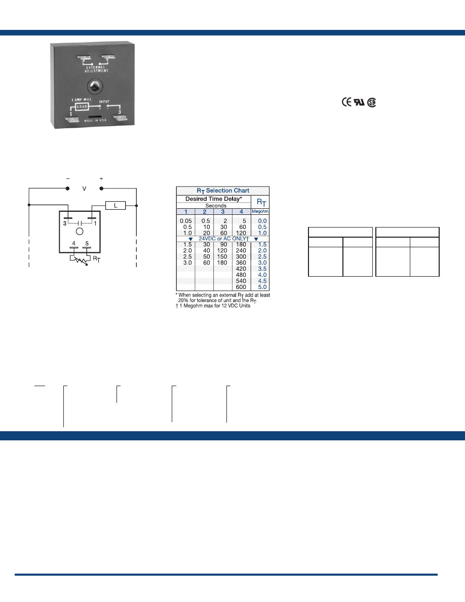
34
www.ssac.com • 800-843-8848 • fax: 605-348-5685
Features:
• Two terminal series connection with load
• 5mA - 1A load currents
• Totally solid state & encapsulated
• ±2% repeat accuracy
• Fixed or adjustable delays from 0.05s - 10m
in 8 ranges
Approvals:
TS1 Series
Timer - Delay-on-Make
Available Models:
Time Delay
Type . . . . . . . . . . . . . . . . . . . . . . . . . . . . . . . . . . Analog circuitry
Range 12VDC
. . . . . .
0.05 - 120s in 4 adjustable ranges or fixed
(1 MΩ max. R
T
)
Other Voltages
. . . . . . .
0.05 - 600s in 4 adjustable ranges or fixed
Repeat Accuracy . . . . . . . . . . . . . . . . . . . . . . .
±2% or 20ms, whichever is greater
Tolerance (Factory Calibration) . . . . . . . . . . .
≤ ±10%
Recycle Time . . . . . . . . . . . . . . . . . . . . . . . . . . .
After timing – ≤ 16ms
During timing – 0.1% of time delay or 75ms,
whichever is greater
Time Delay vs Temp. & Voltage
. . . . . . . . . .
≤ ±10%
Input
Voltage
. . . . . . . . . . . . . . . . . . . . . . . . . . . . . . . .
12, 24 or 120VDC; 24, 120, or 230VAC
Tolerance . . . . . . . . . . . . . . . . . . . . . . . . . . . . . .
±20%
AC Line Frequency . . . . . . . . . . . . . . . . . . . . .
50/60 Hz
Output
Type . . . . . . . . . . . . . . . . . . . . . . . . . . . . . . . . . . Solid state
Form . . . . . . . . . . . . . . . . . . . . . . . . . . . . . . . . . .
NO, open during timing
Maximum Load Current
. . . . . . . . . . . . . . . . .
1A steady state, 10A inrush at 60°C
Minimum Holding Current . . . . . . . . . . . . . .
5mA
Voltage Drop
. . . . . . . . . . . . . . . . . . . . . . . . . .
≅
2.5V @ 1A
Protection
Circuitry . . . . . . . . . . . . . . . . . . . . . . . . . . . . . . Encapsulated
Dielectric Breakdown
. . . . . . . . . . . . . . . . . . .
≥ 2000V RMS terminals to mounting surface
Insulation Resistance . . . . . . . . . . . . . . . . . . . .
≥ 100 MΩ
Polarity . . . . . . . . . . . . . . . . . . . . . . . . . . . . . . .
DC units are reverse polarity protected
Mechanical
Mounting . . . . . . . . . . . . . . . . . . . . . . . . . . . . .
Surface mount with one #10 (M5 x 0.8) screw
Dimensions . . . . . . . . . . . . . . . . . . . . . . . . . . . .
2 x 2 x 1.21 in. (50.8 x 50.8 x 30.7 mm)
Termination . . . . . . . . . . . . . . . . . . . . . . . . . . .
0.25 in. (6.35 mm) male quick connect terminals
Environmental
Operating / Storage Temperature
. . . . . . . .
-40° to 80°C / -40° to 85°C
Humidity . . . . . . . . . . . . . . . . . . . . . . . . . . . . . .
95% relative, non-condensing
Weight
. . . . . . . . . . . . . . . . . . . . . . . . . . . . . . . .
≅
2.4 oz (68 g)
Specifications
Order Table:
Connection:
Versa-Timer offers proven reliability and
performance with years of use in OEM equipment
and commercial applications. This encapsulated
general use timing module is capable of controlling
load currents ranging from 5mA to 1A. May be
connected in series with contactors, relays, valves,
solenoids, small motors, and lamps.
Operation (Delay-on-Make):
Upon application of input voltage, the time delay begins.
The output is de-energized before and during the time
delay. At the end of the time delay, the output energizes
and remains energized until input voltage is removed.
Reset: Removing input voltage resets the time delay
and output .
For more information see:
Appendix A, pages 156-164 for function descriptions
and diagrams .
Appendix B, page 165, Figure 1 for dimensional drawing.
Auxiliary Products:
•
External ad just potentiometer:
P/N: P1004-XX
P/N: P1004-XX-X
•
Female quick connect:
P/N: P1015-64 (AWG 14/16)
•
Quick connect t o s crew ad aptor:
P/N: P1015-18
•
Mounting bracket:
P/N: P1023-6
•
Versa-knob:
P/N: P0700-7
•
DIN rail:
P/N: C103PM
(Al)
•
DIN rail adaptor:
P/N: P1023-20
•
Plug-on adjustment module:
P/N: VTP(X)(X)
TS1111
TS12110
TS121150
TS12120
TS12130
TS121360
TS1214
TS121420
TS12160
TS12190
TS1221
TS1222
TS1224
TS13115
TS1321
TS1410.1
TS1410.25
TS1411
TS14110
TS141180
TS1412
TS14120
TS14130
TS1415
TS1416
TS1418
TS1421
TS1422
TS1423
TS1424
TS1612
TS1615
TS1621
TS1622
TS1
X
Input Voltage
─
1
- 12VDC
─
2
- 24VAC
─
3
- 24VDC
─
4
- 120VAC
─
5
- 120VDC
─
6
- 230VAC
X
Adjustment
─
1
- Fixed
─
2
- External adjust
X
Time Delay*
(12VDC)
─
1
- 0.05 - 1s
─
2
- 0.5 - 20s
─
3
- 2 - 60s
─
4
- 5 - 120s
X
Time Delay*
(ALL other voltages)
─
1
- 0.05 - 3s
─
2
- 0.5 - 60s
─
3
- 2 - 180s
─
4
- 5 - 600s
*If fixed delay is selected, insert delay
(
0 .05 - 120
) (12VDC) or (
0 .05 - 600
)
(other voltages) in secs.
L1
N/L2
Selection Table for VTP Plug-on Adjustment Accessory.
12VDC
Time Delay
VTP P/N
1
- 0.05-1s
2
- 0.5-20s
3
- 2-60s
4
- 5-120s
VTP2A
VTP2E
VTP2F
VTP2H
All Other Voltages
Time Delay
VTP P/N
1
- 0.05-3s
2
- 0.5-60s
3
- 2-180s
4
- 5-600s
VTP4B
VTP4F
VTP4J
VTP5N
Load may be connected to terminal 3 or 1.
R
T
is used when external adjustment is ordered.
Courtesy of Steven Engineering, Inc.-230 Ryan Way, South San Francisco, CA 94080-6370-Main Office: (650) 588-9200-Outside Local Area: (800) 258-9200-www.stevenengineering.com
Littelfuse-catalog-html.html
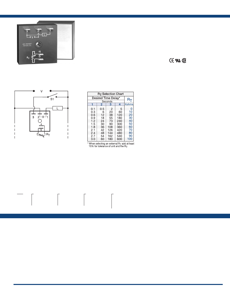
35
www.ssac.com • 800-843-8848 • fax: 605-348-5685
TH1 Series
Timer - Delay-on-Make
Available Models:
Time Delay
Range . . . . . . . . . . . . . . . . . . . . . . . . . . . . . . . . . .
0.1 - 600s in 4 adjustable ranges or fixed
Repeat Accuracy . . . . . . . . . . . . . . . . . . . . . . . .
±2% or 20ms, whichever is greater
Tolerance (Factory Calibration) . . . . . . . . . . . .
≤ ± 5%
Time Delay vs Temp. & Voltage
. . . . . . . . . . .
≤ ±10%
Recycle Time . . . . . . . . . . . . . . . . . . . . . . . . . . . .
≤ 150ms
Input
Voltage
. . . . . . . . . . . . . . . . . . . . . . . . . . . . . . . . .
24, 120, or 230VAC
Tolerance . . . . . . . . . . . . . . . . . . . . . . . . . . . . . . .
±15%
AC Line Frequency . . . . . . . . . . . . . . . . . . . . . .
50/60 Hz
Power Consumption . . . . . . . . . . . . . . . . . . . . .
≤ 2VA
Output
Type . . . . . . . . . . . . . . . . . . . . . . . . . . . . . . . . . . . Solid state
Form . . . . . . . . . . . . . . . . . . . . . . . . . . . . . . . . . . .
NO, open during timing
Maximum Load Currents Output Steady State Inrush**
A 6A 60A
B 10A 100A
C 20A 200A
Minimum Load Current . . . . . . . . . . . . . . . . . .
100mA
Voltage Drop
. . . . . . . . . . . . . . . . . . . . . . . . . . .
≅
2.5V at rated current
OFF State Leakage Current
. . . . . . . . . . . . . . .
≅
5mA @ 230VAC
Protection
Circuitry . . . . . . . . . . . . . . . . . . . . . . . . . . . . . . . Encapsulated
Dielectric Breakdown
. . . . . . . . . . . . . . . . . . . .
≥ 2000V RMS terminals to mounting surface
Insulation Resistance . . . . . . . . . . . . . . . . . . . . .
≥ 100 MΩ
Mechanical
Mounting ** . . . . . . . . . . . . . . . . . . . . . . . . . . . .
Surface mount with one #10 (M5 x 0.8) screw
Dimensions . . . . . . . . . . . . . . . . . . . . . . . . . . . . .
2 x 2 x 1.51 in. (50.8 x 50.8 x 38.4 mm)
Termination . . . . . . . . . . . . . . . . . . . . . . . . . . . .
0.25 in. (6.35 mm) male quick connect terminals
Environmental
Operating / Storage Temperature
. . . . . . . . .
-20° to 60°C / -40° to 85°C
Humidity . . . . . . . . . . . . . . . . . . . . . . . . . . . . . . .
95% relative, non-condensing
Weight
. . . . . . . . . . . . . . . . . . . . . . . . . . . . . . . . .
≅
3.9 oz (111 g)
**Must be bolted to a metal surface using the included heat sink compound. The maximum
mounting surface temperature is 90°C. Inrush: Non-repetitive for 16ms.
Order Table:
Specifications
The TH1 Series is a solid-state relay and timer
combined into one compact, easy-to-use control.
This highly reliable device eliminates the need
for a separate solid-state relay. When mounted to
a metal surface, it can switch load currents up to
20A steady state, and 200A inrush.
Operation (Delay-on-Make):
Upon application of input voltage, the time delay begins.
The output is de-energized before and during the time
delay. At the end of the time delay, the output energizes
and remains energized until input voltage is removed.
Reset: Removing input voltage resets the time delay
and output .
For more information see:
Appendix A, pages 156-164 for function descriptions
and diagrams .
Appendix B, page 165, Figure 4 for dimensional drawing.
Features:
• High current load capacity up to 20A with
200A inrush
• Solid-state switching - no contact wear or
arcing
•
Encapsulated
• Fixed or adjustable time delays from 0.1 - 600s
• ± 2% repeat accuracy
• ± 5% factory calibration
• Metallized mounting surface for heat transfer
Approvals:
Connection:
Auxiliary Products:
•
External ad just potentiometer:
P/N: P1004-95
P/N: P1004-95-X
•
Female quick connect:
P/N: P1015-13 (AWG 10/12)
P/N: P1015-64 (AWG 14/16)
•
Quick connect t o s crew ad aptor:
P/N: P1015-18
•
Versa-knob:
P/N: P0700-7
TH1A421
TH1B633
TH1C415
TH1C621
TH1
X
Output Rating
─
A
- 6A
─
B
- 10A
─
C
- 20A
X
Input Voltage
─
2
- 24VAC
─
4
- 120VAC
─
6
- 230VAC
X
Adjustment
─
1
- Fixed
─
2
- External adjust
─
3
- Onboard adjust
X
Time Delay*
─
1
- 0.1 - 3s
─
2
- 0.5 - 60s
─
3
- 2 - 180s
─
4
- 5 - 600s *If fixed delay is selected, insert
delay (
0 .1 - 600
) in secs .
L1
N/L2
If desired part number is not listed, please call us to
see if it is technically possible to build .
S1 = Optional Low Current Initiate Switch
R
T
is used when external adjustment is ordered.
Courtesy of Steven Engineering, Inc.-230 Ryan Way, South San Francisco, CA 94080-6370-Main Office: (650) 588-9200-Outside Local Area: (800) 258-9200-www.stevenengineering.com
Littelfuse-catalog-html.html
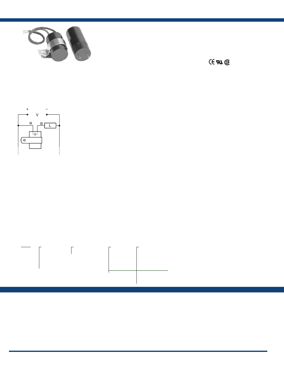
36
www.ssac.com • 800-843-8848 • fax: 605-348-5685
Features:
•
Printed circuit mount or wire leads
• Fixed delays from 0.05 - 180s
• ± 5% repeat accuracy
• ± 15% factory calibration
• Two-wire series connection with the load
•
Fast reset
Approvals:
MSM Series
Timer - Delay-on-Make
Available Models:
Time Delay
Type . . . . . . . . . . . . . . . . . . . . . . . . . . . . . . . . . . . Analog Circuitry
Range . . . . . . . . . . . . . . . . . . . . . . . . . . . . . . . . . .
0.05 - 180s fixed
Repeat Accuracy . . . . . . . . . . . . . . . . . . . . . . . .
±5%
Tolerance (Factory Calibration) . . . . . . . . . . . .
±15%
Recycle Time . . . . . . . . . . . . . . . . . . . . . . . . . . . .
≤ 75ms
Time Delay vs Temp. & Voltage
. . . . . . . . . . .
±15%
Input
Voltage
. . . . . . . . . . . . . . . . . . . . . . . . . . . . . . . . .
12 or 24VDC; 24, 120, or 230VAC
Tolerance . . . . . . . . . . . . . . . . . . . . . . . . . . . . . . .
±10%
AC Line Frequency . . . . . . . . . . . . . . . . . . . . . .
50/60 Hz
Output
Type . . . . . . . . . . . . . . . . . . . . . . . . . . . . . . . . . . . Solid State
Form . . . . . . . . . . . . . . . . . . . . . . . . . . . . . . . . . . .
NO, open during timing
Maximum Load Current
. . . . . . . . . . . . . . . . . .
0.5A steady state 25°C; 0.25A steady state 60°C
Minimum Holding Current . . . . . . . . . . . . . .
40mA
Voltage Drop
. . . . . . . . . . . . . . . . . . . . . . . . . . .
≅
2.5V @ 0.5A
Protection
Circuitry . . . . . . . . . . . . . . . . . . . . . . . . . . . . . . . Encapsulated
Dielectric Breakdown
. . . . . . . . . . . . . . . . . . . .
≥ 2000V RMS input to mounting surface
Insulation Resistance . . . . . . . . . . . . . . . . . . . . .
≥ 100 MΩ
Polarity . . . . . . . . . . . . . . . . . . . . . . . . . . . . . . . .
DC units are reverse polarity protected
Mechanical
Mounting . . . . . . . . . . . . . . . . . . . . . . . . . . . . . .
a. PC mount 14 AWG (2.087mm
2
) wires
(Can be inserted in AMP Miniature Spring
Socket #645980-1)
b. Stranded 18 AWG wire leads (0.933 mm
2
)
with mounting bracket
Environmental
Operation / Storage Temperature
. . . . . . . . .
-20° to 60°C / -30° to 85°C
Humidity . . . . . . . . . . . . . . . . . . . . . . . . . . . . . . .
95% relative, non-condensing
Weight
. . . . . . . . . . . . . . . . . . . . . . . . . . . . . . . . .
P:
≅
1.1 oz (31.2 g) W:
≅
1.2 oz (34 g)
Specifications
Order Table:
Connection:
The MSM replaces bi-metal type timing with
reliable solid-state circuitry. There are no moving
parts to arc or wear. It is a cost effective solution
for OEM designers. It is available for printed
circuit board mounting or surface mounting with a
removable bracket and wire leads. The MSM offers
immediate reset on removal of power.
Operation (Delay-on-Make):
The time delay begins upon application of input voltage.
The output is de-energized before and during the time
delay. At the end of the time delay, the output energizes
and remains energized until input voltage is removed.
Reset: Removing input voltage resets the time delay
and output .
For more information see:
Appendix A, pages 156-164 for function descriptions
and diagrams .
Appendix B, page 167, Figure 25 for dimensional drawing.
MSM10.2W7
MSM10.5W6
MSM10.7W6
MSM11W6
MSM110W6
MSM130W9
MSM16W9
MSM190W6
MSM20.15W9
MSM210P3
MSM21W9
MSM22W6
MSM25W9
MSM30.7W6
MSM33W9
MSM360P1
MSM40.2W6
MSM420W6
MSM42W6
MSM610W9
MSM
X
Input Voltage
─
1
- 12VDC
─
2
- 24VAC
─
3
- 24VDC
─
4
- 120VAC
─
6
- 230VAC
X
Fixed Time Delay
─
0 .05 - 180s
X
Wire Type
─
P
- PC Mount
─
W
- Stranded
Wire Leads
X
Wire Length Inches (mm)
─
1
- 0.250 (6.35)
─
2
- 0.375 (9.53)
─
3
- 0.5 (12.70)
─
4
- 0.625 (15.88)
─
5
- 0.75 (19.05)
─
6
- 6.0 (152.4)
─
7
- 7.0 (177.8)
─
8
- 8.0 (203.2)
─
9
- 9.0 (228.6)
Specify fixed time
in seconds .
L1
N/L2
V = Voltage
L = Load
R = Red Wire
B = Black Wire
If desired part number is not listed, please call us to
see if it is technically possible to build .
Courtesy of Steven Engineering, Inc.-230 Ryan Way, South San Francisco, CA 94080-6370-Main Office: (650) 588-9200-Outside Local Area: (800) 258-9200-www.stevenengineering.com
Littelfuse-catalog-html.html
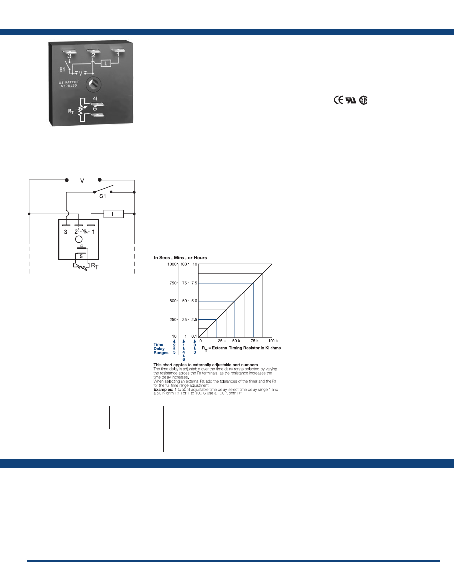
37
www.ssac.com • 800-843-8848 • fax: 605-348-5685
TSD4 Series
Timer - Delay-on-Make
Available Models:
Time Delay
Range . . . . . . . . . . . . . . . . . . . . . . . . . . . . . . . . . . . .
0.1s - 100h in 7 adjustable ranges or fixed
Repeat Accuracy . . . . . . . . . . . . . . . . . . . . . . . . . .
±0.1% or 20ms, whichever is greater
Tolerance (Factory Calibration) . . . . . . . . . . . . . .
≤ ±1%
Reset Time . . . . . . . . . . . . . . . . . . . . . . . . . . . . . . . .
≤ 150ms
Time Delay vs Temp. & Voltage
. . . . . . . . . . . . .
≤ ±1%
Input
Voltage
. . . . . . . . . . . . . . . . . . . . . . . . . . . . . . . . . . .
24, 120, or 230VAC
Tolerance . . . . . . . . . . . . . . . . . . . . . . . . . . . . . . . . .
±20%
AC Line Frequency . . . . . . . . . . . . . . . . . . . . . . . .
50/60 Hz
Power Consumption . . . . . . . . . . . . . . . . . . . . . . .
≤ 2VA
Output
Type . . . . . . . . . . . . . . . . . . . . . . . . . . . . . . . . . . . . . Solid state
Form . . . . . . . . . . . . . . . . . . . . . . . . . . . . . . . . . . . . .
NC, closed before & during timing
Maximum Load Current
. . . . . . . . . . . . . . . . . . . .
1A steady state, 10A inrush at 60°C
OFF State Leakage Current
. . . . . . . . . . . . . . . . .
≅
5mA @ 230VAC
Voltage Drop
. . . . . . . . . . . . . . . . . . . . . . . . . . . . .
≅
2.5V @ 1A
Protection
Circuitry . . . . . . . . . . . . . . . . . . . . . . . . . . . . . . . . . Encapsulated
Dielectric Breakdown
. . . . . . . . . . . . . . . . . . . . . .
≥ 2000V RMS terminals to mounting surface
Insulation Resistance . . . . . . . . . . . . . . . . . . . . . . .
≥ 100 MΩ
Mechanical
Mounting . . . . . . . . . . . . . . . . . . . . . . . . . . . . . . . .
Surface mount with one #10 (M5 x 0.8) screw
Dimensions . . . . . . . . . . . . . . . . . . . . . . . . . . . . . . .
2 x 2 x 1.21 in. (50.8 x 50.8 x 30.7 mm)
Termination . . . . . . . . . . . . . . . . . . . . . . . . . . . . . .
0.25 in. (6.35 mm) male quick connect terminals
Environmental
Operating / Storage Temperature
. . . . . . . . . . .
-40° to 75°C / -40° to 85°C
Humidity . . . . . . . . . . . . . . . . . . . . . . . . . . . . . . . . .
95% relative, non-condensing
Weight
. . . . . . . . . . . . . . . . . . . . . . . . . . . . . . . . . . .
≅
2.4 oz (68 g)
Order Table:
Specifications
The TSD4 Digi-Timer is a delay-on-make timer
with a normally closed solid-state output. The load
is energized prior to and during the delay period.
The TSD Series is designed for more demanding
commercial and industrial applications where
small size and accurate performance are required.
The factory calibration for fixed time delays is
within 1% of the target time delay. The repeat
accuracy, under stable conditions, is 0.1% of the
time delay. The TSD Series is rated to operate over
an extended temperature range. Time delays of 0.1
seconds to 100 hours are available. The output is
rated 1A steady and 10A inrush. The modules are
totally solid state and encapsulated to protect the
electronic circuitry .
Operation (Delay-on-Make NC):
Upon application of input voltage, the load energizes
immediately. When the initiate switch is closed, the
time delay begins. At the end of the time delay, the load
de-energizes.
Reset: When the initiate switch is reopened, the load
energizes again and the time delay is reset. Removing
input voltage resets the time delay.
For more information see:
Appendix A, pages 156-164 for function descriptions
and diagrams .
Appendix B, page 165, Figure 1 for dimensional drawing.
Features:
• Fixed or adjustable delays from 0.1s - 100h
• 24, 120, or 230VAC
• ±0.1% repeat accuracy
• ±1% factory calibration
• 1A, solid-state output
•
Encapsulated
Approvals:
Connection:
Auxiliary Products:
•
External ad just potentiometer:
P/N: P1004-95
P/N: P1004-95-X
•
Mounting bracket:
P/N: P1023-6
•
Female quick connect:
P/N: P1015-64 (AWG 14/16)
•
Quick connect t o s crew ad aptor:
P/N: P1015-18
•
Versa-knob:
P/N: P0700-7
•
DIN rail:
P/N: C103PM
(Al)
•
DIN rail adaptor:
P/N: P1023-20
TSD4
X
Input Voltage
─
2
- 24VAC
─
4
- 120VAC
─
6
- 230VAC
X
Adjustment
─
1
- Fixed
─
2
- External adjust
─
3
- Onboard adjust
X
Time Delay*
─
0
- 0.1 - 10s
─
1
- 1 - 100s
─
2
- 10 - 1000s
─
3
- 0.1 - 10m
─
4
- 1 - 100m
─
5
- 10 - 1000m
─
6
- 1 - 100h
*If fixed delay is selected, insert
delay (
0 .1 - 1000
) followed by (
S
) sec .
(
M
) min . or (
1 - 100
) (
H
) hours.
L1
N/L2
External Resistance vs . Time Delay:
TSD44115S
If desired part number is not listed, please call us to
see if it is technically possible to build .
S1 = Initiate Switch
R
T
is used when external adjustment is ordered.
Courtesy of Steven Engineering, Inc.-230 Ryan Way, South San Francisco, CA 94080-6370-Main Office: (650) 588-9200-Outside Local Area: (800) 258-9200-www.stevenengineering.com
Littelfuse-catalog-html.html
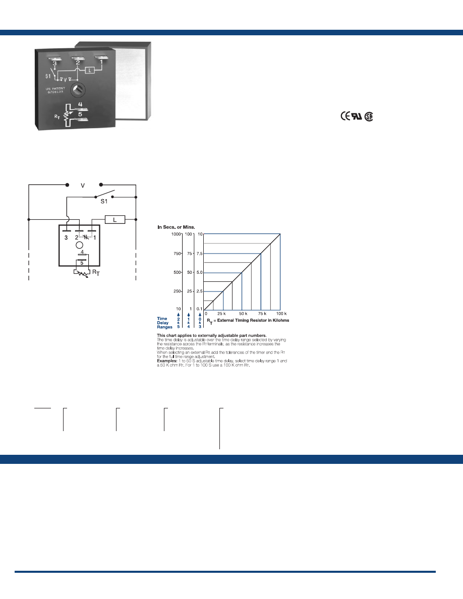
38
www.ssac.com • 800-843-8848 • fax: 605-348-5685
Features:
• High load current capacity up to 20A, 200A
inrush
• Load energized prior to & during timing
• ±0.5% repeat accuracy
• ±1% factory calibration
• Totally solid state & encapsulated
• Fixed or adjustable delays from 0.1s - 1000m
in 6 ranges
Approvals:
THD4 Series
Timer - Delay-on-Make
Available Models:
Time Delay
Range . . . . . . . . . . . . . . . . . . . . . . . . . . . . . . . .
0.1s - 1000m in 6 adjustable ranges or fixed
Repeat Accuracy . . . . . . . . . . . . . . . . . . . . . .
±0.5% or 20ms, whichever is greater
Tolerance (Factory Calibration) . . . . . . . . . .
≤ ±1%
Reset Time . . . . . . . . . . . . . . . . . . . . . . . . . . . .
≤ 150ms
Time Delay vs Temp. & Voltage
. . . . . . . . .
≤ ±2%
Input
Voltage
. . . . . . . . . . . . . . . . . . . . . . . . . . . . . . .
24, 120, or 230VAC
Tolerance . . . . . . . . . . . . . . . . . . . . . . . . . . . . .
±20%
AC Line Frequency . . . . . . . . . . . . . . . . . . . .
50/60 Hz
Power Consumption . . . . . . . . . . . . . . . . . . .
≤ 2VA
Output
Type . . . . . . . . . . . . . . . . . . . . . . . . . . . . . . . . . Solid state
Form . . . . . . . . . . . . . . . . . . . . . . . . . . . . . . . . . NC
Rating Output Steady State Inrush**
A 6A 60A
B 10A 100A
C 20A 200A
Minimum Load Current . . . . . . . . . . . . . . . .
100mA
Voltage Drop
. . . . . . . . . . . . . . . . . . . . . . . . .
≅
2.5V at rated current
OFF State Leakage Current
. . . . . . . . . . . . .
≅
5mA @ 230VAC
Protection
Circuitry . . . . . . . . . . . . . . . . . . . . . . . . . . . . . Encapsulated
Dielectric Breakdown
. . . . . . . . . . . . . . . . . .
≥ 2000V RMS terminals to mounting surface
Insulation Resistance . . . . . . . . . . . . . . . . . . .
≥ 100 MΩ
Mechanical
Mounting ** . . . . . . . . . . . . . . . . . . . . . . . . . .
Surface mount with one #10 (M5 x 0.8) screw
Dimensions . . . . . . . . . . . . . . . . . . . . . . . . . . .
2 x 2 x 1.51 in. (50.8 x 50.8 x 38.4 mm)
Termination . . . . . . . . . . . . . . . . . . . . . . . . . .
0.25 in. (6.35 mm) male quick connect terminals
Environmental
Operating / Storage Temperature
. . . . . . .
-40° to 60°C / -40° to 85°C
Humidity . . . . . . . . . . . . . . . . . . . . . . . . . . . . .
95% relative, non-condensing
Weight
. . . . . . . . . . . . . . . . . . . . . . . . . . . . . . .
≅
3.9 oz (111 g)
**Must be bolted to a metal surface using the included heat sink compound.
The maximum mounting surface temperature is 90°C. Inrush: Non-repetitive for 16ms.
Specifications
Order Table:
Connection:
The THD4 utilizes solid-state circuitry and a
solid-state relay in one easy to use control. The
metallized mounting surface allows a metal panel
to dissipate heat rather than adding an expensive
heat sink. The solid-state output is rated 6, 10, or 20
amps steady and up to 200 amps inrush. Motors,
heaters and valves can be switched directly,
eliminating the expense of a separate contactor.
The THD4 offers substantial performance,
reliability, and cost advantages for OEM designers.
Operation (Delay-on-Make NC):
Upon application of input voltage, the load is energized
immediately. When the initiate switch closes, the time
delay begins. At the end of the time delay, the load
de-energizes.
Reset: When the initiate switch is reopened, the load is
again energized and the time delay is reset. Removing
input voltage resets the time delay and the output.
For more information see:
Appendix A, pages 156-164 for function descriptions
and diagrams .
Appendix B, page 165, Figure 4 for dimensional drawing.
Auxiliary Products:
•
External ad just potentiometer:
P/N: P1004-95
P/N: P1004-95-X
•
Female quick connect:
P/N: P1015-13 (AWG 10/12)
P/N: P1015-64 (AWG 14/16)
•
Quick connect t o s crew ad aptor:
P/N: P1015-18
•
Versa-knob:
P/N: P0700-7
There are no part numbers currently active. Please call
Technical Support with your requirements.
THD4
X
Output Rating
─
A
- 6A
─
B
- 10A
─
C
- 20A
X
Input Voltage
─
2
- 24VAC
─
4
- 120VAC
─
6
- 230VAC
X
Adjustment
─
1
- Fixed
─
2
- External adjust
─
3
- Onboard adjust
X
Time Delay*
─
0
- 0.1 - 10s
─
1
- 1 - 100s
─
2
- 10 - 1000s
─
3
- 0.1 - 10m
─
4
- 1 - 100m
─
5
- 10 - 1000m
*If fixed delay is selected, insert
delay (
0 .1 - 1000
) followed by (
S
) sec .
or (
M
) min .
L1
N/L2
External Resistance vs . Time Delay:
S1 = Low Current Initiate Switch
R
T
is used when external adjustment is ordered.
Courtesy of Steven Engineering, Inc.-230 Ryan Way, South San Francisco, CA 94080-6370-Main Office: (650) 588-9200-Outside Local Area: (800) 258-9200-www.stevenengineering.com
Littelfuse-catalog-html.html
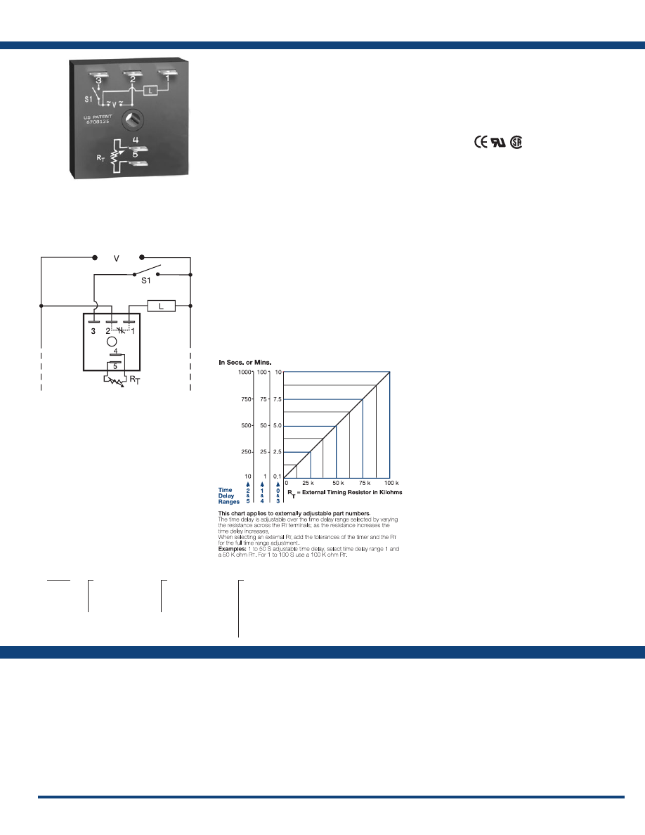
39
www.ssac.com • 800-843-8848 • fax: 605-348-5685
KSD4 Series
Timer - Delay-on-Make
Available Models:
Time Delay
Range . . . . . . . . . . . . . . . . . . . . . . . . . . . . . . . . . .
0.1s - 1000m in 6 adjustable ranges or fixed
Repeat Accuracy . . . . . . . . . . . . . . . . . . . . . . . .
±0.5% or 20ms, whichever is greater
Tolerance (Factory Calibration . . . . . . . . . . . .
≤ ± 5%
Reset Time . . . . . . . . . . . . . . . . . . . . . . . . . . . . . .
≤ 150ms
Time Delay vs Temp. & Voltage
. . . . . . . . . . .
≤ ±10%
Input
Voltage
. . . . . . . . . . . . . . . . . . . . . . . . . . . . . . . . .
24, 120, or 230VAC
Tolerance . . . . . . . . . . . . . . . . . . . . . . . . . . . . . . .
±20%
AC Line Frequency . . . . . . . . . . . . . . . . . . . . . .
50/60 Hz
Power Consumption . . . . . . . . . . . . . . . . . . . . .
≤ 2VA
Output
Type . . . . . . . . . . . . . . . . . . . . . . . . . . . . . . . . . . .Solid state
Form . . . . . . . . . . . . . . . . . . . . . . . . . . . . . . . . . . .
NC, closed before & during timing
Maximum Load Current
. . . . . . . . . . . . . . . . . .
1A steady state, 10A inrush at 60°C
OFF State Leakage Current
. . . . . . . . . . . . . . .
≅
5mA @ 230VAC
Voltage Drop
. . . . . . . . . . . . . . . . . . . . . . . . . . .
≅
2.5V @ 1A
Protection
Circuitry . . . . . . . . . . . . . . . . . . . . . . . . . . . . . . .Encapsulated
Dielectric Breakdown
. . . . . . . . . . . . . . . . . . . .
≥ 2000V RMS terminals to mounting surface
Insulation Resistance . . . . . . . . . . . . . . . . . . . . .
≥ 100 MΩ
Mechanical
Mounting . . . . . . . . . . . . . . . . . . . . . . . . . . . . . .
Surface mount with one #10 (M5 x 0.8) screw
Dimensions . . . . . . . . . . . . . . . . . . . . . . . . . . . . .
2 x 2 x 1.21 in. (50.8 x 50.8 x 30.7 mm)
Termination . . . . . . . . . . . . . . . . . . . . . . . . . . . .
0.25 in. (6.35 mm) male quick connect terminals
Environmental
Operating / Storage Temperature
. . . . . . . . .
-40° to 60°C / -40° to 85°C
Humidity . . . . . . . . . . . . . . . . . . . . . . . . . . . . . . .
95% relative, non-condensing
Weight
. . . . . . . . . . . . . . . . . . . . . . . . . . . . . . . . .
≅
2.4 oz (68 g)
Order Table:
Specifications
The KSD4 Digi-Timer offers a delay-on-make
function with normally closed solid-state output.
The load is energized prior to and during the time
delay. This series is designed for general purpose
commercial and industrial applications where a
small, cost effective, reliable solid-state timer is
required. The factory calibration for fixed time
delays is within 5% of the target time delay. The
repeat accuracy, under stable conditions, is 0.5% of
the selected time delay. This series is designed for
input voltages of 24, 120 or 230VAC. Time delays
of 0.1 seconds to 1000 minutes are available in 6
ranges. The output is rated 1A steady and 10A
inrush. The modules are totally solid state and
encapsulated to protect the electronic circuitry.
Operation (Delay-on-Make NC):
Upon application of input voltage, the load energizes
immediately. When the initiate switch is closed, the time
delay begins. At the end of the time delay, the load de-
energizes.
Reset: When the initiate switch is reopened, the load
energizes and the time delay is reset. Removing input
voltage resets the time delay.
For more information see:
Appendix A, pages 156-164 for function descriptions
and diagrams .
Appendix B, page 165, Figure 1 for dimensional drawing.
Features:
• Fixed or adjustable delays from 0.1s - 1000m
• ±0.5% repeat accuracy
• ±5% factory calibration
• 24, 120, or 230VAC
• 1A, solid-state output
•
Encapsulated
Approvals:
Connection:
Auxiliary Products:
•
External ad just potentiometer:
P/N: P1004-95
P/N: P1004-95-X
•
Mounting bracket:
P/N: P1023-6
•
Female quick connect:
P/N: P1015-64 (AWG 14/16)
•
Quick connect t o s crew ad aptor:
P/N: P1015-18
•
Versa-knob:
P/N: P0700-7
•
DIN rail:
P/N: C103PM
(Al)
•
DIN rail adaptor:
P/N: P1023-20
KSD4433
KSD4
X
Input Voltage
─
2
- 24VAC
─
4
- 120VAC
─
6
- 230VAC
X
Adjustment
─
1
- Fixed
─
2
- External adjust
─
3
- Onboard adjust
X
Time Delay*
─
0
- 0.1 - 10s
─
1
- 1 - 100s
─
2
- 10 - 1000s
─
3
- 0.1 - 10m
─
4
- 1 - 100m
─
5
- 10 - 1000m
*If fixed delay is selected, insert
delay (
0 .1 - 1000
) followed by (
S
) sec .
or (
M
) min .
L1
N/L2
External Resistance vs . Time Delay:
If desired part number is not listed, please call us to
see if it is technically possible to build .
S1 = Initiate Switch
R
T
is used when external adjustment is ordered.
Courtesy of Steven Engineering, Inc.-230 Ryan Way, South San Francisco, CA 94080-6370-Main Office: (650) 588-9200-Outside Local Area: (800) 258-9200-www.stevenengineering.com
Littelfuse-catalog-html.html
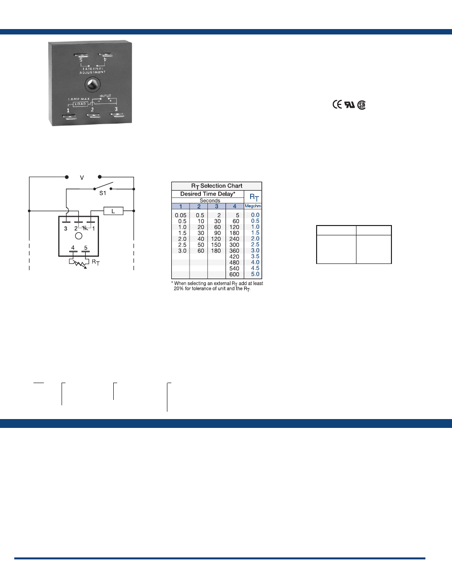
40
www.ssac.com • 800-843-8848 • fax: 605-348-5685
Features:
• Fixed or adjustable delay
• Load energized prior to & during time delay
• 0.05 - 600s in 4 ranges
• ±2% repeat accuracy
• 24, 120, or 230VAC
• 1A, solid-state output
•
Encapsulated
Approvals:
TS4 Series
Timer - Delay-on-Make
Available Models:
Time Delay
Type . . . . . . . . . . . . . . . . . . . . . . . . . . . . . . . . . . Analog circuitry
Range . . . . . . . . . . . . . . . . . . . . . . . . . . . . . . . . .
0.05 - 600s in 4 adjustable ranges or fixed
Repeat Accuracy . . . . . . . . . . . . . . . . . . . . . . .
±2% or 20ms, whichever is greater;
under fixed conditions
Tolerance (Factory Calibration) . . . . . . . . . . .
≤ ±10%
Time Delay vs Temp. & Voltage
. . . . . . . . . .
≤ ±10%
Recycle Time . . . . . . . . . . . . . . . . . . . . . . . . . . .
≤ 150ms
Input
Voltage
. . . . . . . . . . . . . . . . . . . . . . . . . . . . . . . .
24, 120, or 230VAC
Tolerance . . . . . . . . . . . . . . . . . . . . . . . . . . . . . .
±20%
AC Line Frequency . . . . . . . . . . . . . . . . . . . . .
50/60 Hz
Output
Type . . . . . . . . . . . . . . . . . . . . . . . . . . . . . . . . . . Solid state
Form . . . . . . . . . . . . . . . . . . . . . . . . . . . . . . . . . .
NC, closed during timing
Maximum Load Current
. . . . . . . . . . . . . . . . .
1A steady state, 10A inrush at 60°C
Voltage Drop
. . . . . . . . . . . . . . . . . . . . . . . . . .
≅
2.5V @ 1A
Protection
Circuitry . . . . . . . . . . . . . . . . . . . . . . . . . . . . . . Encapsulated
Dielectric Breakdown
. . . . . . . . . . . . . . . . . . .
≥ 2000V RMS terminals to mounting surface
Insulation Resistance . . . . . . . . . . . . . . . . . . . .
≥ 100 MΩ
Mechanical
Mounting . . . . . . . . . . . . . . . . . . . . . . . . . . . . .
Surface mount with one #10 (M5 x 0.8) screw
Dimensions . . . . . . . . . . . . . . . . . . . . . . . . . . . .
2 x 2 x 1.21 in. (50.8 x 50.8 x 30.7 mm)
Termination . . . . . . . . . . . . . . . . . . . . . . . . . . .
0.25 in. (6.35 mm) male quick connect terminals
Environmental
Operating / Storage Temperature
. . . . . . . .
-40° to 75°C / -40° to 85°C
Humidity . . . . . . . . . . . . . . . . . . . . . . . . . . . . . .
95% relative, non-condensing
Weight
. . . . . . . . . . . . . . . . . . . . . . . . . . . . . . . .
≅
2.4 oz (68 g)
Specifications
Order Table:
Connection:
The TS4 Versa-Timer is an analog delay-on-make
timer with a normally closed solid-state output.
Unlike an interval timer, the load is energized prior
to and during the time delay period. It can be used
as a faster starting interval time delay when S1 is
closed upon application of input voltage.
Operation (Delay-on-Make NC):
Upon application of input voltage, the load is energized
immediately. When the initiate switch is closed, the
time delay begins. At the end of the time delay, the load
de-energizes.
Reset: When the initiate switch is reopened, the load again
energizes and the time delay is reset. Removing input
voltage resets the time delay and output.
For more information see:
Appendix A, pages 156-164 for function descriptions
and diagrams .
Appendix B, page 165, Figure 1 for dimensional drawing.
Auxiliary Products:
•
External ad just potentiometer:
P/N: P1004-XX
P/N: P1004-XX-X
•
Mounting bracket:
P/N: P1023-6
•
Female quick connect:
P/N: P1015-64 (AWG 14/16)
•
Quick connect t o s crew ad aptor:
P/N: P1015-18
•
Versa-knob:
P/N: P0700-7
•
DIN rail:
P/N: C103PM
(Al)
•
DIN rail adaptor:
P/N: P1023-20
•
Plug-on adjustment module:
P/N: VTP(X)(X)
TS441180
TS4422
TS4611
TS4
X
Input Voltage
─
2
- 24VAC
─
4
- 120VAC
─
6
- 230VAC
X
Adjustment
─
1
- Fixed
─
2
- External adjust
X
Time Delay*
─
1
- 0.05 - 3s
─
2
- 0.5 - 60s
─
3
- 2 - 180s
─
4
- 5 - 600s
*If fixed delay is selected, insert
delay (
0 .05 - 600
) in secs .
L1
N/L2
Selection Table for VTP Plug-on
Adjustment Accessory.
Time Delay
VTP P/N
1
- 0.05-3s
2
- 0.5-60s
3
- 2-180s
4
- 5-600s
VTP4B
VTP4F
VTP4J
VTP5N
If desired part number is not listed, please call us to
see if it is technically possible to build .
S1 = Initiate Switch
R
T
is used when external adjustment is ordered.
Courtesy of Steven Engineering, Inc.-230 Ryan Way, South San Francisco, CA 94080-6370-Main Office: (650) 588-9200-Outside Local Area: (800) 258-9200-www.stevenengineering.com
Littelfuse-catalog-html.html
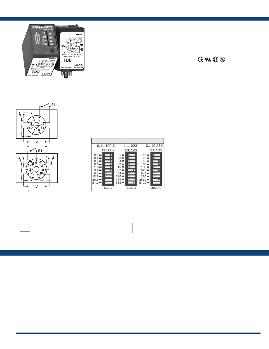
41
www.ssac.com • 800-843-8848 • fax: 605-348-5685
TDB / TDBH / TDBL Series
Timer - Delay-on-Break
Available Models:
Time Delay
Type . . . . . . . . . . . . . . . . . . . . . . . . . . . . . . . . .Digital integrated circuitry
Range** . . . . . . . . . . . . . . . . . . . . . . . . . . . . . .
0.1 - 102.3s in 0.1s increments
1 - 1023s in 1s increments
10 - 10,230s in 10s increments
Repeat Accuracy . . . . . . . . . . . . . . . . . . . . . .
±0.1% or 20ms, whichever is greater
Setting Accuracy . . . . . . . . . . . . . . . . . . . . . .
±2% or 50ms, whichever is greater
Reset Time . . . . . . . . . . . . . . . . . . . . . . . . . . . .
≤ 50ms
Recycle Time . . . . . . . . . . . . . . . . . . . . . . . . . .
≤ 150ms
Time Delay vs Temp. & Voltage
. . . . . . . . .
±5%
Indicator . . . . . . . . . . . . . . . . . . . . . . . . . . . . .
LED indicates relay is energized
Initiate Time . . . . . . . . . . . . . . . . . . . . . . . . . .
≤ 60ms
Input
Voltage
. . . . . . . . . . . . . . . . . . . . . . . . . . . . . . .
12, 24/28, or 110VDC; 24, 120, or 230VAC
Tolerance 12VDC & 24VDC/AC
. . . . . .
-15% - 20%
110 to 230VAC/DC
. . . . . .
-20% - 10%
AC Line Frequency . . . . . . . . . . . . . . . . . . . .
50/60 Hz
Power Consumption . . . . . . . . . . . . . . . . . . .
≤ 3.25W
Output
Type . . . . . . . . . . . . . . . . . . . . . . . . . . . . . . . . .
Electromechanical relay
Form . . . . . . . . . . . . . . . . . . . . . . . . . . . . . . . . .SPDT or DPDT
Rating . . . . . . . . . . . . . . . . . . . . . . . . . . . . . . .
10A resistive @ 120/240VAC & 28VDC;
1/3 hp @ 120/240VAC
Life
. . . . . . . . . . . . . . . . . . . . . . . . . . . . . . . . . .
Mechanical - 1 x 10
7
; Electrical - 1 x 10
6
Protection
Isolation Voltage
. . . . . . . . . . . . . . . . . . . . . .
≥ 1500V RMS input to output
Polarity . . . . . . . . . . . . . . . . . . . . . . . . . . . . . .
DC units reverse polarity protected
Mechanical
Mounting . . . . . . . . . . . . . . . . . . . . . . . . . . . .
Plug-in socket
Dimensions . . . . . . . . . . . . . . . . . . . . . . . . . . .
3.2 x 2.4 x 1.8 in. (81.3 x 60.7 x 45.2 mm)
Termination . . . . . . . . . . . . . . . . . . . . . . . . . .
Octal 8-pin plug-in or 11-pin plug-in
Environmental
Operating / Storage Temperature
. . . . . . .
-20° to 65°C / -30° to 85°C
Weight
. . . . . . . . . . . . . . . . . . . . . . . . . . . . . . .
≅
6 oz (170 g)
** For CE approved applications, power must be removed from the unit when a switch position
is changed.
Order Table:
Specifications
The TDB Series combines accurate digital circuitry
with isolated, 10A, DPDT or SPDT contacts in an 8
or 11-pin plug-in package. The TDB Series features
DIP switch selectable time delays ranging from
0.1-10,230 seconds in three ranges. The TDB Series
is the product of choice for custom control panel
and OEM designers .
Operation (Delay-on-Break):
Input voltage must be applied to the input before and
during timing. Upon closure of the initiate switch, the
output relay is energized. The time delay begins when
the initiate switch is opened (trailing edge triggered).
The output remains energized during timing. At the
end of the time delay, the output de-energizes. The
output will energize if the initiate switch is closed when
input voltage is applied.
Reset: Reclosing the initiate switch during timing resets
the time delay. Loss of input voltage resets the time delay
and output .
For more information see:
Appendix A, pages 156-164 for function descriptions
and diagrams .
Appendix B, page 165, Figure 8 for dimensional drawing.
Features:
• Switch settable time delay
• Three time ranges from 0.1s - 10,230s
• ±0.1% repeat accuracy
• ±2% setting accuracy
• 10A, SPDT or DPDT output contacts
•
LED indication
Approvals:
Connection:
Auxiliary Products:
•
Panel mount kit:
P/N: BZ1
•
Hold-down c lips (sold i n p airs):
P/N: PSC8 (NDS-8)
P/N: PSC11 (NDS-11)
•
11-pin socket:
P/N: NDS-11
•
Octal 8-pin socket:
P/N: NDS-8
•
Octal socket for UL listing:
P/N: P1011-6
TDB120AL
TDB120ALD
TDB12D
TDB230AL
TDB24AL
TDB24DL
TDBH120AL
TDBH120ALD
TDBH24AL
TDBL120AL
TDBL120ALD
TDBL24DL
8-pin models UL listed
when used in combination
with P1011-6 socket only.
TDB
- 1 - 1023s in 1s increments
TDBH
- 10 - 10,230s in 10s increments
TDBL
- 0.1 - 102.3s in 0.1s increments
X
Input Voltage
─
12D
- 12VDC
─
24A
- 24VAC
─
24D
- 24VDC/28VDC
─
110D
- 110VDC
─
120A
- 120VAC
─
230A
- 230VAC
X
LED*
─
L
X
Type Plug / Output Form
─
D
- 11-pin plug, DPDT
─
Blank
- Octal (8-pin)
plug, SPDT
*Note: LED not available
on 12VDC units.
L1
N/L2
L1
N/L2
8-pin octal
SPDT
11-pin
DPDT
S1 = Initiate Switch
Relay contacts are isolated .
Digi-Set Binary Switch Operation:
If desired part number is not listed, please call us to
see if it is technically possible to build .
Courtesy of Steven Engineering, Inc.-230 Ryan Way, South San Francisco, CA 94080-6370-Main Office: (650) 588-9200-Outside Local Area: (800) 258-9200-www.stevenengineering.com
Littelfuse-catalog-html.html
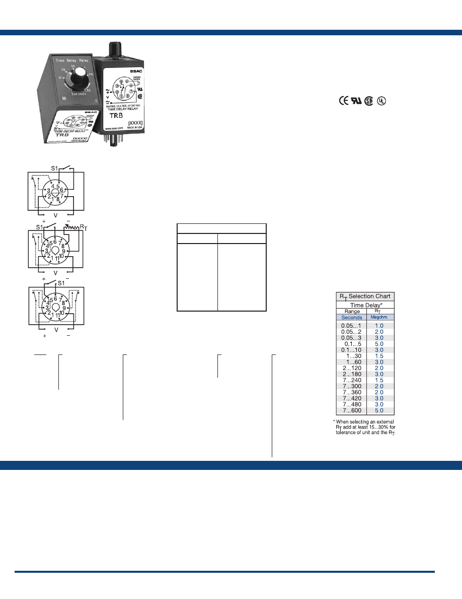
42
www.ssac.com • 800-843-8848 • fax: 605-348-5685
Features:
• Onboard adjustable time delays
• Fixed or adjustable delays from 0.05 - 600s in
multiple ranges
• ±2% repeat accuracy
• AC and DC operating voltages are available
• Isolated, 10A, SPDT or DPDT output contacts
Approvals:
TRB Series
Timer - Delay-on-Break
Available Models:
Time Delay
Type . . . . . . . . . . . . . . . . . . . . . . . . . . . . . . . . . . . .Analog circuitry
Range . . . . . . . . . . . . . . . . . . . . . . . . . . . . . . . . . . .
50ms - 10m in 15 adjustable ranges or fixed
Repeat Accuracy . . . . . . . . . . . . . . . . . . . . . . . . .
±2% or 20ms, whichever is greater
Fixed Time Tolerance & Setting Accuracy
. . . .
±5, 10, or 20%
Initiate Time . . . . . . . . . . . . . . . . . . . . . . . . . . . . .
≤ 70ms
Reset Time . . . . . . . . . . . . . . . . . . . . . . . . . . . . . . .
≤ 75ms
Recycle Time . . . . . . . . . . . . . . . . . . . . . . . . . . . . .
≤ 250ms
Time Delay vs Temp. & Voltage
. . . . . . . . . . . .
≤±10%
Input
Voltage
. . . . . . . . . . . . . . . . . . . . . . . . . . . . . . . . . .
24/28 or 110VDC; 24, 120, or 230VAC
(DC voltages on DPDT output models only)
Tolerance 24VDC/AC
. . . . . . . .
-15% - 20%
110 to 230VAC/DC
. . . . . . . .
-20% - 10%
AC Line Frequency . . . . . . . . . . . . . . . . . . . . . . .
50/60 Hz
Power Consumption . . . . . . . . . . . . . . . . . . . . . .
≤ 3.25W
Output
Type . . . . . . . . . . . . . . . . . . . . . . . . . . . . . . . . . . . .
Electromechanical relay
Form . . . . . . . . . . . . . . . . . . . . . . . . . . . . . . . . . . . .Isolated SPDT or DPDT
Rating . . . . . . . . . . . . . . . . . . . . . . . . . . . . . . . . . .
10A resistive @ 120/240VAC & 28VDC;
1/3 hp @ 120/240VAC
Life
. . . . . . . . . . . . . . . . . . . . . . . . . . . . . . . . . . . . .
Mechanical - 1 x 10
7
; Electrical - 1 x 10
6
Protection
Insulation Resistance . . . . . . . . . . . . . . . . . . . . . .
≥ 100 MΩ
Isolation Voltage
. . . . . . . . . . . . . . . . . . . . . . . . .
≥ 1500V RMS between input to output
Polarity . . . . . . . . . . . . . . . . . . . . . . . . . . . . . . . . .
DC units are reverse polarity protected
Mechanical
Mounting . . . . . . . . . . . . . . . . . . . . . . . . . . . . . . .
Plug-in socket
Dimensions . . . . . . . . . . . . . . . . . . . . . . . . . . . . . .
3.62 x 2.39 x 1.78 in (91.6 x 60.7 x 45.2 mm)
Termination . . . . . . . . . . . . . . . . . . . . . . . . . . . . .
Octal 8-pin plug-in or 11-pin plug-in
Environmental
Operating / Storage Temperature
. . . . . . . . . .
-20° to 65°C / -30° to 85°C
Weight
. . . . . . . . . . . . . . . . . . . . . . . . . . . . . . . . . .
≅
6 oz (170 g)
Specifications
Order Table:
Connection:
The TRB Series combines an isolated, 10A
electromechanical relay output with analog timing
circuitry. False trigger of the TRB by a transient is
unlikely because of the complete isolation of the
circuit from the line prior to initiation. The initiate
contact is common to one side of the line and may
be utilized to operate other loads. Installation is
easy due to the TRB’s industry standard 8 or 11-pin
plug-in base wiring.
Operation (Delay-on-Break):
Input voltage must be applied before and during timing.
Upon closure of the initiate switch, the output relay
energizes. The time delay begins when the initiate switch
is opened (trailing edge triggered). The output remains
energized during timing. At the end of the time delay,
the output de-energizes. The output will energize if the
initiate switch is closed when input voltage is applied.
Reset: Reclosing the initiate switch during timing resets
the time delay. Loss of input voltage resets the time delay
and output .
For more information see:
Appendix A, pages 156-164 for function descriptions
and diagrams .
Appendix B, page 165, Figure 9 for dimensional drawing.
TRB120A1Y240
TRB120A2Y1
TRB120A2Y3
TRB120A2Y30
TRB120A3X600
TRB24A1Y0.2
TRB24A4Y60
TRB24D10Y10
8-pin models UL listed
when used in combination
with P1011-6 socket only.
Auxiliary Products:
•
Panel mount kit:
P/N: BZ1
•
Hold-down c lips (sold i n p airs):
P/N: PSC8 (NDS-8)
P/N: PSC11 (NDS-11)
•
Octal 8-pin socket:
P/N: NDS-8
•
11-pin socket:
P/N: NDS-11
•
Octal socket for UL listing:
P/N: P1011-6
•
External ad just potentiometers:
P/N: P1004-XX
P/N: P1004-XX-X
•
Versa-knob:
P/N: P0700-7
TRB
X
Input Voltage
─
24A
- 24VAC
─
24D
- 24VDC/28VDC
─
110D
- 110VDC
─
120A
- 120VAC
─
230A
- 230VAC
X
Adjustment and Output Form
─
1
- Fixed, Octal, SPDT
(AC Volts only)
─
2
- Onboard Adjust, Octal, SPDT
(AC Volts only)
─
3
- Lock Shaft Adjust, Octal, SPDT
(AC Volts only)
─
4
- Onboard adjust, 11-pin, DPDT
─
7
- Ext. Adjust, 11-pin, SPDT
without potentiometer
─
10
- Fixed, 11-pin, DPDT
X
Time Tolerance
─
X
- ±20%
─
Y
- ±10%
─
Z
- ±5%
X
Time Delay*
(seconds)
─
1
- 0.05 - 1
─
2
- 0.05 - 2
─
3
- 0.05 - 3
─
5
- 0.1 - 5
─
10
- 0.1 - 10
─
30
- 1 - 30
─
60
- 1 - 60
─
120
- 2 - 120
─
180
- 2 - 180
─
240
- 7 - 240
─
300
- 7 - 300
─
360
- 7 - 360
─
420
- 7 - 420
─
480
- 7 - 480
─
600
- 7 - 600
*If fixed delay is selected, insert
delay (
0.05 - 600
) in seconds .
L1
N/L2
L1
N/L2
L1
N/L2
8-pin octal SPDT
11-pin SPDT
11-pin DPDT
External R
T
P/N Selection Table
Value
Part Number
1M ohm
1.5M ohm
2M ohm
3M ohm
5M ohm
1M ohm
1.5M ohm
2M ohm
3M ohm
5M ohm
P1004-16
P1004-15
P1004-14
P1004-12
P1004-13
P1004-16-X
P1004-15-X
P1004-14-X
P1004-12-X
P1004-13-X
If desired part number is not listed, please call us to
see if it is technically possible to build .
S1 = Initiate Switch
Relay contacts are isolated .
R
T
is used when external adjustment is ordered.
Courtesy of Steven Engineering, Inc.-230 Ryan Way, South San Francisco, CA 94080-6370-Main Office: (650) 588-9200-Outside Local Area: (800) 258-9200-www.stevenengineering.com
Littelfuse-catalog-html.html
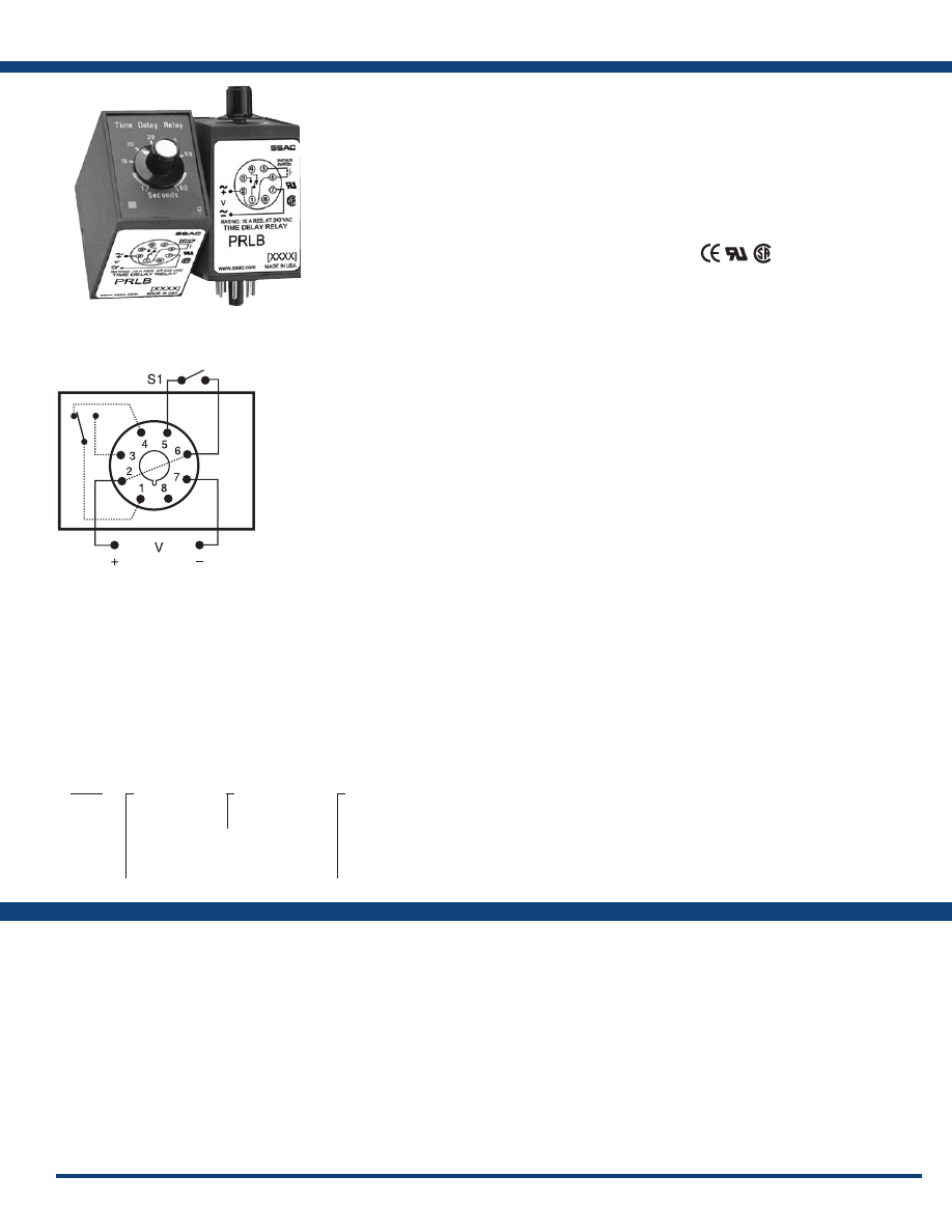
43
www.ssac.com • 800-843-8848 • fax: 605-348-5685
PRLB Series
Timer - Delay-on-Break
Available Models:
Time Delay
Type . . . . . . . . . . . . . . . . . . . . . . . . . . . . . . . . . . . Analog circuitry
Range . . . . . . . . . . . . . . . . . . . . . . . . . . . . . . . . . .
0.05 - 600s in 6 adjustable ranges or fixed
Repeat Accuracy . . . . . . . . . . . . . . . . . . . . . . . .
±2% or 20ms, whichever is greater
Tolerance . . . . . . . . . . . . . . . . . . . . . . . . . . . . . . .
Knob adjust: guaranteed range
Fixed: ±10%
Reset Time . . . . . . . . . . . . . . . . . . . . . . . . . . . . . .
≤ 75ms
Recycle Time . . . . . . . . . . . . . . . . . . . . . . . . . . . .
≤ 250ms
Time Delay vs Temp. & Voltage
. . . . . . . . . . .
≤ ±10%
Input
Voltage
. . . . . . . . . . . . . . . . . . . . . . . . . . . . . . . . .
12, 24, or 110VDC; 24, 120, or 230VAC
Tolerance 12VDC & 24VDC/AC
. . . . . .
-15% - 20%
110 to 230VAC/DC
. . . . . .
-20% - 10%
AC Line Frequency . . . . . . . . . . . . . . . . . . . . . .
50/60 Hz
Power Consumption . . . . . . . . . . . . . . . . . . . . .
≤ 2.25W
Output
Type . . . . . . . . . . . . . . . . . . . . . . . . . . . . . . . . . . .
Electromechanical relay
Form . . . . . . . . . . . . . . . . . . . . . . . . . . . . . . . . . . .
Isolated, SPDT
Rating . . . . . . . . . . . . . . . . . . . . . . . . . . . . . . . . .
10A resistive @ 28VDC; 10A resistive @ 240VAC;
1/3 hp @ 120 & 240VAC
Life
. . . . . . . . . . . . . . . . . . . . . . . . . . . . . . . . . . . .
Mechanical - 1x10
7
; Electrical - 1x10
6
Protection
Surge . . . . . . . . . . . . . . . . . . . . . . . . . . . . . . . . . .
IEEE C62.41-1991 Level A
Isolation Voltage
. . . . . . . . . . . . . . . . . . . . . . . .
≥ 1500V RMS input to output
Insulation Resistance . . . . . . . . . . . . . . . . . . . . .
≥ 100 MΩ
Polarity . . . . . . . . . . . . . . . . . . . . . . . . . . . . . . . .
DC units are reverse polarity protected
Indication
Type
. . . . . . . . . . . . . . . . . . . . . . . . . . . . . . . . . . .
LED
Operation . . . . . . . . . . . . . . . . . . . . . . . . . . . . . .
Output energized - on steady
Output energized & timing - flashing
Mechanical
Mounting . . . . . . . . . . . . . . . . . . . . . . . . . . . . . .
Plug-in socket
Dimensions . . . . . . . . . . . . . . . . . . . . . . . . . . . . .
3.62 x 2.39 x 1.78 in. (91.6 x 60.7 x 45.2 mm)
Termination . . . . . . . . . . . . . . . . . . . . . . . . . . . .
Octal 8-pin plug-in
Environmental
Operating / Storage Temperature
. . . . . . . . .
-20° to 65°C / -30° to 85°C
Weight
. . . . . . . . . . . . . . . . . . . . . . . . . . . . . . . . .
≅
6 oz (170 g)
Order Table:
Specifications
The PRLB Series is designed for use on non-critical
timing applications. It offers low cost, knob
adjustable timing control, full 10A relay output,
and onboard LED indication. The knob adjustment
provides a guaranteed time range of up to 10
minutes in 6 ranges. The onboard LED indicates
whether or not the unit is timing (flashing LED)
as well as the status of the output.
Operation (Delay-on-Break):
Input voltage must be applied at all times prior to and
during timing. Upon closure of the initiate switch, the
output contacts transfer and remain transferred if no
further action is taken. The LED is on steady. When the
initiate switch is opened, the time delay is started. The
LED flashes during timing. At the conclusion of the delay,
the output contacts revert to their original unenergized
position. Applying input voltage with the initiate switch
closed will energize the load.
Reset: Reclosing the initiate switch during timing resets
the time delay. Loss of input voltage resets the time delay
and output .
For more information see:
Appendix A, pages 156-164 for function descriptions
and diagrams .
Appendix B, page 165, Figure 9 for dimensional drawing.
Features:
• Onboard adjustable time delay relay
• Electronic circuit with electromechanical relay
• Popular AC & DC operating voltages
• Industry standard octal plug-in connection
• Time delays 0.05 - 600s in 6 ranges
• ±2% repeat accuracy
• ±10% factory calibration
•
LED indication
• 10A, SPDT output contacts
Approvals:
Connection:
Auxiliary Products:
•
Panel mount kit:
P/N: BZ1
•
Hold-down clips (sold in pairs):
P/N: PSC8 (NDS-8)
•
Octal 8-pin socket:
P/N: NDS-8
•
DIN rail:
P/N: C103PM
(Al)
PRLB422
PRLB425
PRLB
X
Input Voltage
─
1
- 12VDC
─
2
- 24VAC
─
3
- 24VDC
─
4
- 120VAC
─
5
- 110VDC
─
6
- 230VAC
X
Adjustment
─
1
- Factory Fixed
─
2
- Adjustable
X
Time Delay*
─
1
- 0.05 - 3s
─
2
- 0.1 - 10s
─
3
- 1 - 60s
─
4
- 2 - 180s
─
5
- 7 - 480s
─
6
- 7 - 600s
*If fixed delay is selected, insert
delay (
0.05 - 600
) in seconds .
L1
N/L2
If desired part number is not listed, please call us to
see if it is technically possible to build .
S1 = Initiate Switch
Relay contacts are isolated .
Courtesy of Steven Engineering, Inc.-230 Ryan Way, South San Francisco, CA 94080-6370-Main Office: (650) 588-9200-Outside Local Area: (800) 258-9200-www.stevenengineering.com
Littelfuse-catalog-html.html
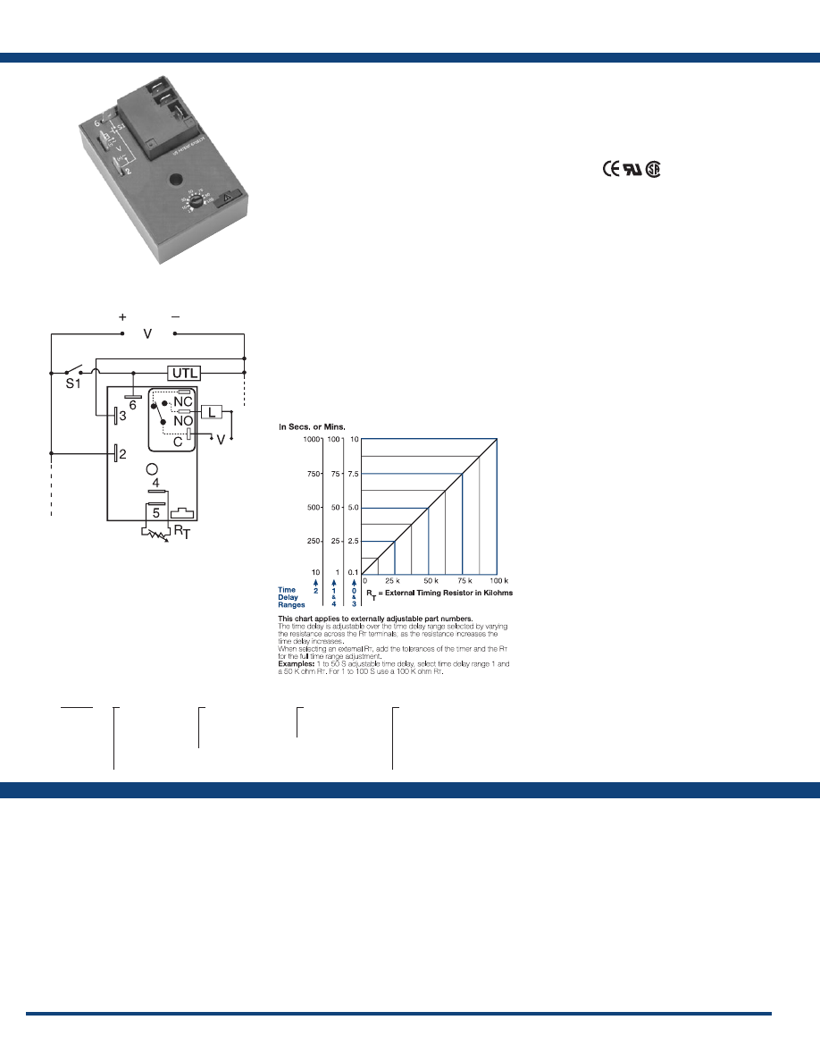
44
www.ssac.com • 800-843-8848 • fax: 605-348-5685
Features:
• Isolated, 30A, SPDT, NO output contacts
• 12 to 230V operation in 5 options
• Delays from 0.1s - 100m in 5 ranges
• ±0.5% repeat accuracy
• Factory fixed, onboard or external adjust
Approvals:
HRDB Series
Timer - Delay-on-Break
Available Models:
Time Delay
Type . . . . . . . . . . . . . . . . . . . . . . . . . . . . . . . . . . Microcontroller circuitry
Range . . . . . . . . . . . . . . . . . . . . . . . . . . . . . . . . .
0.1s - 100m in 5 adjustable ranges or fixed
Repeat Accuracy . . . . . . . . . . . . . . . . . . . . . . .
±0.5 % or 20ms, whichever is greater
Tolerance (Factory Calibration) . . . . . . . . . . .
±1%, ±5%
Reset Time . . . . . . . . . . . . . . . . . . . . . . . . . . . . .
≤ 150ms
Initiate Time . . . . . . . . . . . . . . . . . . . . . . . . . . .
≤ 20ms
Time Delay vs Temp. & Voltage
. . . . . . . . . .
±2%
Input
Voltage
. . . . . . . . . . . . . . . . . . . . . . . . . . . . . . . .
12 or 24VDC; 24, 120, or 230VAC
Tolerance 12VDC & 24VDC
. . . . . . .
-15% - 20%
24 to 230VAC
. . . . . . .
-20% - 10%
AC Line Frequency . . . . . . . . . . . . . . . . . . . . .
50/60 Hz
Power Consumption . . . . . . . . . . . . . . . . . . . .
AC ≤ 4VA; DC ≤ 2W
Output
Type . . . . . . . . . . . . . . . . . . . . . . . . . . . . . . . . . .
Electromechanical relay
Form . . . . . . . . . . . . . . . . . . . . . . . . . . . . . . . . . .
Isolated, SPDT
Ratings: SPDT-NO SPDT-NC
General Purpose 125/240VAC 30A 15A
Resistive 125/240VAC 30A 15A
28VDC 20A 10A
Motor Load 125VAC 1 hp* 1/4 hp**
240VAC 2 hp** 1 hp**
Life
. . . . . . . . . . . . . . . . . . . . . . . . . . . . . . . . . . .
Mechanical - 1 x 10
6
;
Electrical - 1 x 10
5
, *3 x 10
4
, **6,000
Protection
Surge . . . . . . . . . . . . . . . . . . . . . . . . . . . . . . . . .
IEEE C62.41-1991 Level A
Circuitry . . . . . . . . . . . . . . . . . . . . . . . . . . . . . . Encapsulated
Dielectric Breakdown
. . . . . . . . . . . . . . . . . . .
≥ 2000V RMS terminals to mounting surface
Insulation Resistance . . . . . . . . . . . . . . . . . . . .
≥ 100 MΩ
Polarity . . . . . . . . . . . . . . . . . . . . . . . . . . . . . . .
DC units are reverse polarity protected
Mechanical
Mounting . . . . . . . . . . . . . . . . . . . . . . . . . . . . .
Surface mount with one #10 (M5 x 0.8) screw
Dimensions . . . . . . . . . . . . . . . . . . . . . . . . . . . .
3 x 2 x 1.5 in. (76.7 x 51.3 x 38.1mm)
Termination . . . . . . . . . . . . . . . . . . . . . . . . . . .
0.25 in. (6.35 mm) male quick connect terminals
Environmental
Operating / Storage Temperature
. . . . . . . .
-40° to 60°C / -40° to 85°C
Humidity . . . . . . . . . . . . . . . . . . . . . . . . . . . . . .
95% relative, non-condensing
Weight
. . . . . . . . . . . . . . . . . . . . . . . . . . . . . . . .
≅
3.9 oz (111 g)
Specifications
Order Table:
Connection:
The HRDB Series combines an electromechanical,
relay output with microcontroller timing circuitry.
The HRDB offers 12 to 230V operation in five
options and factory fixed, external, or onboard
adjustable time delays with a repeat accuracy of
±0.5%. The isolated output contact rating allows
for direct operation of heavy loads, such as
compressors, pumps, blower motors, heaters, etc.
The HRDB is ideal for OEM applications where
cost is a factor.
Operation (Delay-on-Break):
Input voltage must be applied before and during timing.
Upon closure of the initiate switch, the output relay
energizes. The time delay begins when the initiate switch
is opened. The output remains energized during timing.
At the end of the time delay, the output de-energizes. The
output will energize if the initiate switch is closed when
input voltage is applied.
Reset: Reclosing the initiate switch during timing resets
the time delay. Loss of input voltage resets the time delay
and output .
For more information see:
Appendix A, pages 156-164 for function descriptions
and diagrams .
Appendix B, page 165, Figure 2 for dimensional drawing.
HRDB1110M
HRDB113S
HRDB117S
HRDB120
HRDB121
HRDB124
HRDB21A65M
HRDB220
HRDB221
HRDB222
HRDB223
HRDB224
HRDB315M
HRDB3160M
HRDB320
HRDB321
HRDB322
HRDB323
HRDB324
HRDB4130S
HRDB420
HRDB421
HRDB422
HRDB423
HRDB424
HRDB615M
HRDB621
HRDB623
Auxiliary Products:
•
External ad just potentiometer:
P/N: P1004-95
P/N: P1004-95-X
•
Mounting bracket:
P/N: P1023-6
•
Female quick connect:
P/N: P1015-13 (AWG 10/12)
P/N: P1015-64 (AWG 14/16)
•
Quick connect t o s crew ad aptor:
P/N: P1015-18
•
Versa-knob:
P/N: P0700-7
•
DIN rail:
P/N: C103PM
(Al)
•
DIN rail adaptor:
P/N: P1023-20
HRDB
X
Input Voltage
─
1
- 12VDC
─
2
- 24VAC
─
3
- 24VDC
─
4
- 120VAC
─
6
- 230VAC
X
Adjustment
─
1
- Fixed
─
2
- Onboard knob
─
3
- External adjust
X
Time Tolerance
─
Blank
- ±5%
─
A
- ±1%
X
Time Delay*
─
0
- 0.1 - 10s
─
1
- 1 - 100s
─
2
- 10 - 1000s
─
3
- 0.1 - 10m
─
4
- 1 - 100m
*If fixed delay is selected, insert delay (
0 .1
- 1000
) followed by (
S
) sec, or (
0 .1 - 100
)
(
M
) min .
L1
N/L2
External Resistance vs . Time Delay:
S1 = Initiate Switch
L = Timed Load
UTL = Untimed Load (optional)
NO = Normally Open
C = Common, Transfer Contact
NOTE: A knob, or terminals 4 & 5 are only
included on adjustable units. R
T
is used
when external adjustment is ordered. Relay
contacts are isolated. Dashed lines are
internal connections. The untimed load is
optional .
If desired part number is not listed, please call us to
see if it is technically possible to build .
Courtesy of Steven Engineering, Inc.-230 Ryan Way, South San Francisco, CA 94080-6370-Main Office: (650) 588-9200-Outside Local Area: (800) 258-9200-www.stevenengineering.com
Littelfuse-catalog-html.html
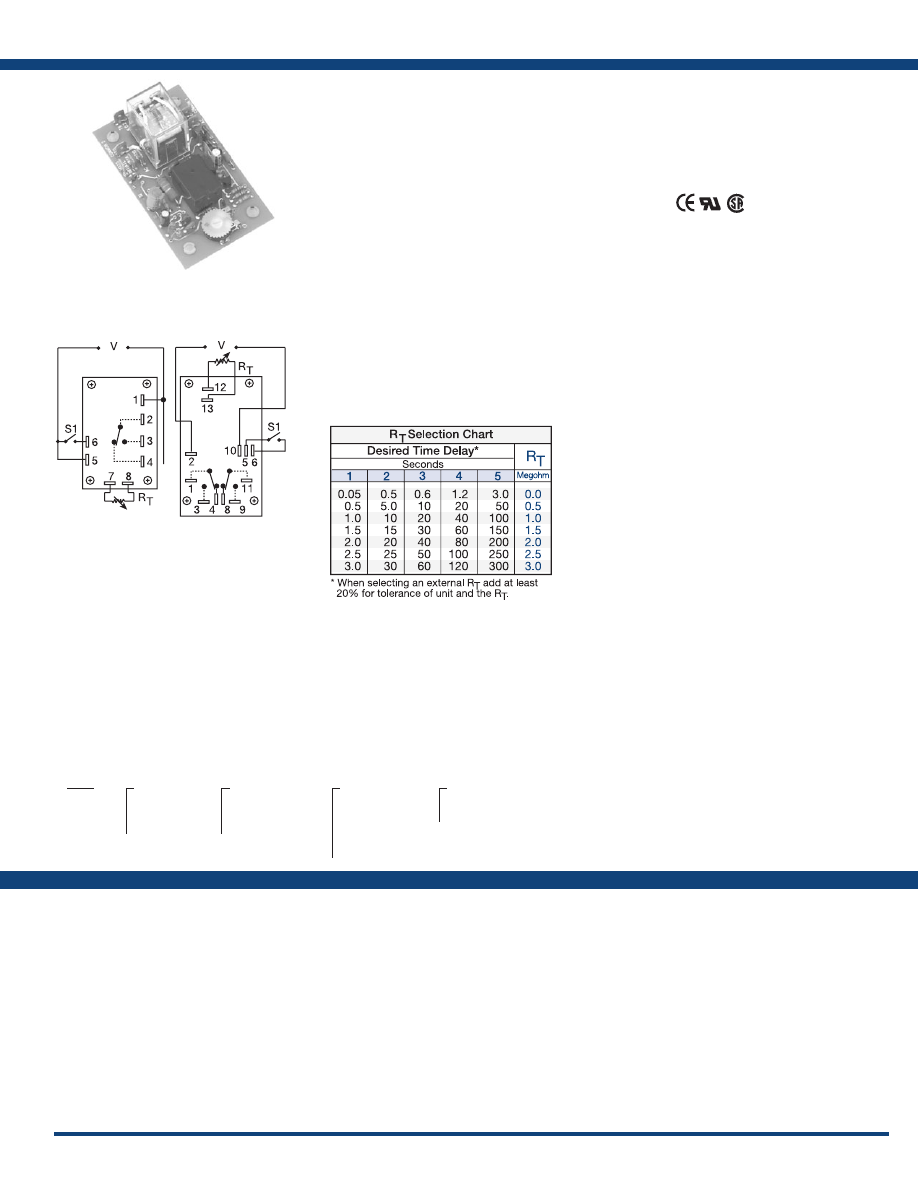
45
www.ssac.com • 800-843-8848 • fax: 605-348-5685
ORB Series
Timer - Delay-on-Break
Available Models:
Time Delay
Type . . . . . . . . . . . . . . . . . . . . . . . . . . . . . . . . . . . Analog circuitry
Range . . . . . . . . . . . . . . . . . . . . . . . . . . . . . . . . . .
0.05 - 300s in 5 adjustable ranges or fixed
Repeat Accuracy . . . . . . . . . . . . . . . . . . . . . . . .
±2% or 20ms, whichever is greater
Tolerance (Factory Calibration) . . . . . . . . . . . .
Adjustable: guaranteed range
Fixed: ±10%
Reset Time . . . . . . . . . . . . . . . . . . . . . . . . . . . . . .
≤ 50ms
Initiate Time . . . . . . . . . . . . . . . . . . . . . . . . . . . .
≤ 70ms
Time Delay vs Temp. & Voltage
. . . . . . . . . . .
≤ ±10%
Input
Voltage
. . . . . . . . . . . . . . . . . . . . . . . . . . . . . . . . .
24, 120, or 230VAC
Tolerance 24VAC
. . . . . .
-15% - 20%
120 & 230VAC
. . . . . .
-20% - 10%
AC Line Frequency . . . . . . . . . . . . . . . . . . . . . .
50/60 Hz
Power Consumption . . . . . . . . . . . . . . . . . . . . .
2.25W
Output
Type . . . . . . . . . . . . . . . . . . . . . . . . . . . . . . . . . . .
Electromechanical relay
Form . . . . . . . . . . . . . . . . . . . . . . . . . . . . . . . . . . .
Isolated, SPDT or DPDT
Rating . . . . . . . . . . . . . . . . . . . . . . . . . . . . . . . . .
10A resistive @ 120/240VAC & 28VDC;
1/3 hp @ 120/240VAC
Life
. . . . . . . . . . . . . . . . . . . . . . . . . . . . . . . . . . . .
Mechanical - 1x10
7
; Electrical - 1x10
6
Protection
Isolation Voltage
. . . . . . . . . . . . . . . . . . . . . . . .
≥1500V RMS input to output
Mechanical
Mounting . . . . . . . . . . . . . . . . . . . . . . . . . . . . . .
Surface mount with four #6 (M3.5 x 0.6) screws
Termination . . . . . . . . . . . . . . . . . . . . . . . . . . . .
0.25 in. (6.35 mm) male quick connect terminals
Environmental
Operating / Storage Temperature
. . . . . . . . .
-20° to 65°C / -30°to 85°C
Weight
. . . . . . . . . . . . . . . . . . . . . . . . . . . . . . . . .
≅
2.7 oz (77 g)
Order Table:
Specifications
The ORB Series’ open PCB construction offers
the user good economy without sacrificing
performance and reliability. The output relay
is available in isolated, 10A, DPDT or SPDT
forms. The time delay may be ordered as factory
fixed, onboard knob, or external adjustment. All
connections are 0.25 in. (6.35 mm) male quick
connect terminals .
Operation (Delay-on-Break):
Input voltage must be applied before and during timing.
Upon closure of the initiate switch, the output relay
energizes. The time delay begins when the initiate switch
is opened (trailing edge triggered). The output remains
energized during timing. At the end of the time delay,
the output de-energizes. The output will energize if the
initiate switch is closed when input voltage is applied.
Reset: Reclosing the initiate switch during timing resets
the time delay. Loss of input voltage resets the time delay
and output .
For more information see:
Appendix A, pages 156-164 for function descriptions
and diagrams .
Appendix B, page 165, Figure 11 for dimensional drawing.
Features:
•
Low cost open PCB construction
• 10A, DPDT or SPDT output contacts
• Line voltage initiation
• Delays from 0.05s - 300s in 5 ranges
• ±2% repeat accuracy
• ±10% factory calibration
Approvals:
Connection:
ORB120A160
ORB120A25
ORB24A15D
ORB24A21D
ORB24A25
Auxiliary Products:
•
External ad just potentiometer:
P/N: P1004-12
P/N: P1004-12-X
•
Female quick connect:
P/N: P1015-64 (AWG 14/16)
•
Quick connect t o s crew ad aptor:
P/N: P1015-18
•
Versa-knob:
P/N: P0700-7
ORB
X
Input Voltage
─
24A
- 24VAC
─
120A
- 120VAC
─
230A
- 230VAC
X
Adjustment
─
1
- Fixed
─
2
- Onboard knob
─
3
- External adjust
X
Time Delay*
─
1
- 0.05 - 3s
─
2
- 0.5 - 30s
─
3
- 0.6 - 60s
─
4
- 1.2 - 120s
─
5
- 3 - 300s
X
Output Form
─
Blank
- SPDT
─
D
- DPDT
*If fixed delay is selected, insert delay
(
0 .05 - 300
) in seconds .
L1
N/L2
L1
N/L2
SPDT
DPDT
If desired part number is not listed, please call us to
see if it is technically possible to build .
Relay contacts are isolated .
R
T
is used when external adjustment is ordered.
Courtesy of Steven Engineering, Inc.-230 Ryan Way, South San Francisco, CA 94080-6370-Main Office: (650) 588-9200-Outside Local Area: (800) 258-9200-www.stevenengineering.com
Littelfuse-catalog-html.html
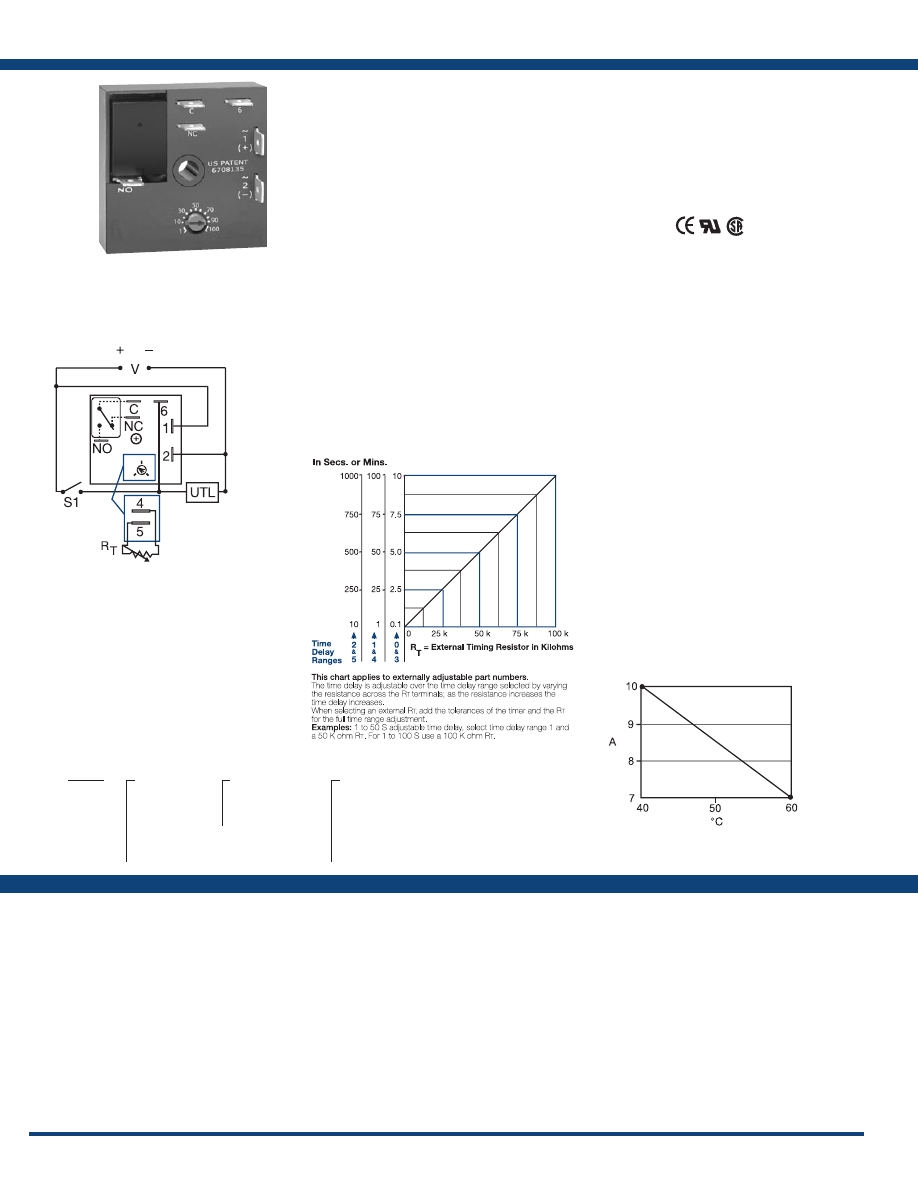
46
www.ssac.com • 800-843-8848 • fax: 605-348-5685
Features:
•
Compact time delay relay
•
Microcontroller circuitry
• ±0.5% repeat accuracy
• Isolated, 10A, SPDT output contacts
• Factory fixed, onboard or external adjust
• Delays from 0.1s - 1000m in 6 ranges
• Input voltages from 12 to 230V in 6 options
• ±5% factory calibration
Approvals:
KRDB Series
Timer - Delay-on-Break
Available Models:
Time Delay
Type . . . . . . . . . . . . . . . . . . . . . . . . . . . . . . . . . . . . . .
Microcontroller with watchdog circuitry
Range . . . . . . . . . . . . . . . . . . . . . . . . . . . . . . . . . . . . .
0.1s - 1000m in 6 adjustable ranges or fixed
Repeat Accuracy . . . . . . . . . . . . . . . . . . . . . . . . . . .
±0.5% or 20ms, whichever is greater
Tolerance (Factory Calibration) . . . . . . . . . . . . . . .
≤ ±5%
Recycle Time . . . . . . . . . . . . . . . . . . . . . . . . . . . . . . .
≤ 150ms
Initiate Time . . . . . . . . . . . . . . . . . . . . . . . . . . . . . . .
≤ 40ms
Time Delay vs Temp. & Voltage
. . . . . . . . . . . . . .
≤ ±5%
Input
Voltage
. . . . . . . . . . . . . . . . . . . . . . . . . . . . . . . . . . . .
12, 24, 110VDC; 24, 120 or 230VAC
Tolerance 12VDC & 24VDC/AC
. . . . . . . . . .
-15% - 20%
110VDC, 120 or 230VAC
. . . . . . . . . .
-20% - 10%
AC Line Frequency / DC Ripple
. . . . . . . . . . . . . .
50/60 Hz / ≤ 10%
Power Consumption . . . . . . . . . . . . . . . . . . . . . . . .
AC ≤ 2VA; DC ≤ 2W
Output
Type . . . . . . . . . . . . . . . . . . . . . . . . . . . . . . . . . . . . . . Isolated relay contacts
Form . . . . . . . . . . . . . . . . . . . . . . . . . . . . . . . . . . . . . . SPDT
Rating (at 40°C)
. . . . . . . . . . . . . . . . . . . . . . . . . . . .
10A resistive @ 125VAC;
5A resistive @ 230VAC & 28VDC;
1/4 hp @ 125VAC
Max. Switching Voltage
. . . . . . . . . . . . . . . . . . . . .
250VAC
Life (Operations)
. . . . . . . . . . . . . . . . . . . . . . . . . . .
Mechanical - 1 x 10
7
; Electrical - 1 x 10
5
Protection
Circuitry . . . . . . . . . . . . . . . . . . . . . . . . . . . . . . . . . . Encapsulated
Isolation Voltage
. . . . . . . . . . . . . . . . . . . . . . . . . . .
≥ 1500V RMS input to output
Insulation Resistance . . . . . . . . . . . . . . . . . . . . . . . .
≥ 100 MΩ
Polarity . . . . . . . . . . . . . . . . . . . . . . . . . . . . . . . . . . .
DC units are reverse polarity protected
Mechanical
Mounting . . . . . . . . . . . . . . . . . . . . . . . . . . . . . . . . .
Surface mount with one #10 (M5 x 0.8) screw
Dimensions . . . . . . . . . . . . . . . . . . . . . . . . . . . . . . . .
2 x 2 x 1.21 in. (50.8 x 50.8 x 30.7 mm)
Termination . . . . . . . . . . . . . . . . . . . . . . . . . . . . . . .
0.25 in. (6.35 mm) male quick connect
terminals
Environmental
Operating / Storage Temperature
. . . . . . . . . . . .
-40° to 60°C / -40° to 85°C
Humidity . . . . . . . . . . . . . . . . . . . . . . . . . . . . . . . . . .
95% relative, non-condensing
Weight
. . . . . . . . . . . . . . . . . . . . . . . . . . . . . . . . . . . .
≅
2.6 oz (74 g)
Specifications
Order Table:
Connection:
The KRDB Series is a compact time delay relay
measuring only 2 in. (50.8 mm) square. Its
microcontroller timing circuit provides excellent
repeat accuracy and stability . Encapsulation
protects against shock, vibration, and humidity.
The KRDB Series is a cost effective approach for
OEM applications that require small size, isolation,
reliability, and long life.
Operation (Delay-on-Break):
Input voltage must be applied before and during timing.
Upon closure of the initiate switch, the output relay
energizes. The time delay begins when the initiate switch
is opened. The output remains energized during timing.
At the end of the time delay, the output de-energizes. The
output will energize if the initiate switch is closed when
input voltage is applied.
Reset: Reclosing the initiate switch during timing resets
the time delay. Loss of input voltage resets the time delay
and output .
For more information see:
Appendix A, pages 156-164 for function descriptions
and diagrams .
Appendix B, page 165, Figure 1 for dimensional drawing.
KRDB1110S
KRDB112.5S
KRDB1120M
KRDB115M
KRDB1160M
KRDB120
KRDB121
KRDB124
KRDB125
KRDB217S
KRDB222
KRDB31120S
KRDB415S
KRDB420
KRDB421
KRDB422
KRDB424
KRDB425
Auxiliary Products:
•
External ad just potentiometer:
P/N: P1004-95
P/N: P1004-95-X
•
Mounting bracket:
P/N: P1023-6
•
Female quick connect:
P/N: P1015-13 (AWG 10/12)
P/N: P1015-64 (AWG 14/16)
•
Quick connect t o s crew ad aptor:
P/N: P1015-18
•
Versa-knob:
P/N: P0700-7
•
DIN rail:
P/N: C103PM
(Al)
•
DIN rail adaptor:
P/N: P1023-20
KRDB
X
Input Voltage
─
1
- 12VDC
─
2
- 24VAC/DC
─
3
- 24VDC
─
4
- 120VAC
─
5
- 110VDC
─
6
- 230VAC
X
Adjustment
─
1
- Fixed
─
2
- Onboard knob
─
3
- External adjust
X
Time Delay*
─
0
- 0.1 - 10s
─
1
- 1 - 100s
─
2
- 10 - 1000s
─
3
- 0.1 - 10m
─
4
- 1 - 100m
─
5
- 10 - 1000m
*If fixed delay is selected, insert delay (
0 .1
- 1000
) followed by (
S
) sec, or (
M
) min .
L1
N/L2
External Resistance vs . Time Delay:
V = Voltage
S1 = Initiate Switch
C = Common, Transfer Contact
NO = Normally Open
NC = Normally Closed
UTL = Untimed Load (optional)
If desired part number is not listed, please call us to
see if it is technically possible to build .
A knob is supplied for adjustable
units. The untimed load is optional.
Relay contacts are isolated .
Output Current/Ambient Temperature
Courtesy of Steven Engineering, Inc.-230 Ryan Way, South San Francisco, CA 94080-6370-Main Office: (650) 588-9200-Outside Local Area: (800) 258-9200-www.stevenengineering.com
Littelfuse-catalog-html.html
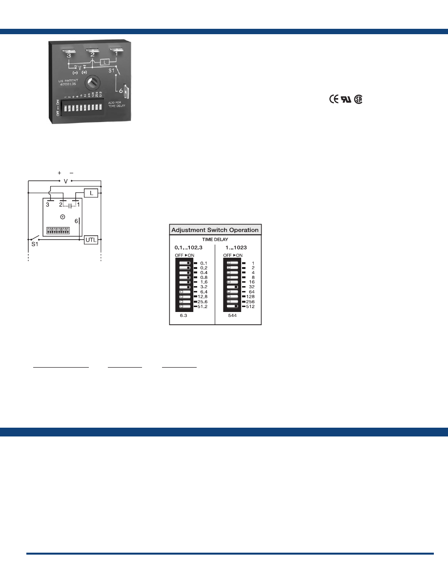
47
www.ssac.com • 800-843-8848 • fax: 605-348-5685
TDUB Series
Timer - Delay-on-Break
Available Models:
Time Delay
Range* . . . . . . . . . . . . . . . . . . . . . . . . . . . . . . .
0.1 - 102.3s in 0.1s increments
1 - 1023s in 1s increments
0.1 - 102.3m in 0.1m increments
Repeat Accuracy . . . . . . . . . . . . . . . . . . . . . . .
±0.5% or 20ms, whichever is greater
Setting Accuracy . . . . . . . . . . . . . . . . . . . . . . .
≤ ±2% or 20ms, whichever is greater
Reset Time . . . . . . . . . . . . . . . . . . . . . . . . . . . .
≤ 150ms
Initiate Time . . . . . . . . . . . . . . . . . . . . . . . . . .
≤ 20ms
Time Delay vs Temp. & Voltage
. . . . . . . . .
≤ ±5%
Input
Voltage / Tolerance
. . . . . . . . . . . . . . . . . . . .
24 to 240VAC, 12 to 24VDC /±20%
AC Line Frequency / DC Ripple
. . . . . . . . .
50/60 Hz / ≤ 10%
Power Consumption . . . . . . . . . . . . . . . . . . .
AC ≤ 2VA; DC ≤ 1W
Output
Type . . . . . . . . . . . . . . . . . . . . . . . . . . . . . . . . . Solid state
Form . . . . . . . . . . . . . . . . . . . . . . . . . . . . . . . . .
NO, closed before and during timing
Rating . . . . . . . . . . . . . . . . . . . . . . . . . . . . . . . .
1A steady state, 10A inrush at 60°C
Voltage Drop
. . . . . . . . . . . . . . . . . . . . . . . . . . AC
≅
2.5V @ 1A; DC
≅
1V @ 1A
Off State Leakage Current
. . . . . . . . . . . . . . AC
≅
5mA @ 230VAC; DC
≅
1mA
Protection
Circuitry . . . . . . . . . . . . . . . . . . . . . . . . . . . . . . Encapsulated
Dielectric Breakdown
. . . . . . . . . . . . . . . . . .
≥ 2000V RMS terminals to mounting surface
Insulation Resistance . . . . . . . . . . . . . . . . . . .
≥ 100 MΩ
Polarity . . . . . . . . . . . . . . . . . . . . . . . . . . . . . . .
DC units are reverse polarity protected
Mechanical
Mounting . . . . . . . . . . . . . . . . . . . . . . . . . . . . .
Surface mount with one #10 (M5 x 0.8) screw
Dimensions . . . . . . . . . . . . . . . . . . . . . . . . . . .
2 x 2 x 1.21 in (50.8 x 50.8 x 30.7 mm)
Termination . . . . . . . . . . . . . . . . . . . . . . . . . . .
0.25 in. (6.35 mm) male quick connect terminals
Environmental
Operating / Storage Temperature
. . . . . . .
-40° to 60°C / -40° to 85°C
Humidity . . . . . . . . . . . . . . . . . . . . . . . . . . . . .
95% relative, non-condensing
Weight
. . . . . . . . . . . . . . . . . . . . . . . . . . . . . . .
≅
2.4 oz (68 g)
*For CE approved applications, power must be removed from the unit when a switch
position is changed.
Order Table:
Specifications
The TDUB Series combines digital timing circuitry
with universal voltage operation. Voltages of
24 to 240VAC and 12 to 24VDC are available in
three ranges. The TDUB Series offers DIP switch
selectable time delays ranging from 0.1 seconds to
102.3 minutes in three ranges. Its 1A rated output,
ability to operate on multiple voltages, and wide
range of switch selectable time delays make the
TDUB Series an excellent choice for process control
systems and OEM equipment .
Operation (Delay-on-Break):
Input voltage must be applied before and during timing.
Upon closure of the initiate switch, the output energizes.
The time delay begins when the initiate switch is opened
(trailing edge triggered). The output remains energized
during timing. At the end of the time delay, the output
de-energizes. The output will energize if the initiate switch
is closed when input voltage is applied.
Reset: Reclosing the initiate switch during timing resets
the time delay. Loss of input voltage resets the time delay
and output .
For more information see:
Appendix A, pages 156-164 for function descriptions
and diagrams .
Appendix B, page 165, Figure 1 for dimensional drawing.
Features:
• Switch selectable time setting
• 0.1s - 102.3m in 3 ranges
• ± 0.5% repeat accuracy
• ± 2% setting accuracy
• 1A, solid-state output
• Wide voltage ranges
Approvals:
Connection:
TDUB3000A
TDUB3002A
TDUBH3002A
TDUBL3002A
Auxiliary Products:
•
Female quick connect:
P/N: P1015-13 (AWG 10/12)
P/N: P1015-64 (AWG 14/16)
P/N: P1015-14 (AWG 18/22)
•
Quick connect t o s crew ad aptor:
P/N: P1015-18
•
DIN rail:
P/N: C103PM
•
DIN rail adaptor:
P/N: 1023-20
Input Voltage Range
24 to 120VAC
100 to 240VAC
12 to 24VDC
24 to 120VAC
100 to 240VAC
12 to 24VDC
24 to 120VAC
100 to 240VAC
12 to 24VDC
Time Range
0.1 - 102.3s
0.1 - 102.3s
0.1 - 102.3s
1 - 1023s
1 - 1023s
1 - 1023s
0.1 - 102.3m
0.1 - 102.3m
0.1 - 102.3m
Part Number
TDUBL3000A
TDUBL3001A
TDUBL3002A
TDUB3000A
TDUB3001A
TDUB3002A
TDUBH3000A
TDUBH3001A
TDUBH3002A
L1
N/L2
Add the value of switches in the ON
position for the total time delay.
UTL = Optional Untimed Load
S1 = Initiate Switch
L = Timed Load
If desired part number is not listed, please call us to
see if it is technically possible to build .
Courtesy of Steven Engineering, Inc.-230 Ryan Way, South San Francisco, CA 94080-6370-Main Office: (650) 588-9200-Outside Local Area: (800) 258-9200-www.stevenengineering.com
Littelfuse-catalog-html.html
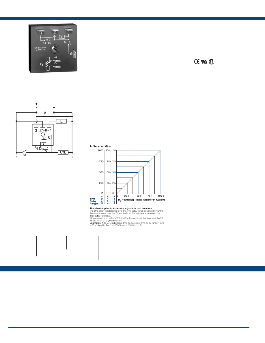
48
www.ssac.com • 800-843-8848 • fax: 605-348-5685
Features:
• Fixed or adjustable delays 0.1s - 1000m in
6 ranges
• ±0.5% repeat accuracy
• ± 1% factory calibration
• 12VDC to 230VAC in 5 options
• 1A, solid-state output
•
Encapsulated
Approvals:
TSDB Series
Timer - Delay-on-Break
Available Models:
Time Delay
Range . . . . . . . . . . . . . . . . . . . . . . . . . . . . . . . . . .
0.1s - 1000m in 6 adjustable ranges or fixed
Repeat Accuracy . . . . . . . . . . . . . . . . . . . . . . . .
±0.5 % or 20ms, whichever is greater
Tolerance (Factory Calibration) . . . . . . . . . . . .
≤ ±1%
Reset Time . . . . . . . . . . . . . . . . . . . . . . . . . . . . . .
≤ 150ms
Initiate Time . . . . . . . . . . . . . . . . . . . . . . . . . . . .
≤ 20ms
Time Delay vs Temp. & Voltage
. . . . . . . . . . .
≤ ±2%
Input
Voltage
. . . . . . . . . . . . . . . . . . . . . . . . . . . . . . . . .
12 or 24VDC; 24, 120, or 230VAC
Tolerance . . . . . . . . . . . . . . . . . . . . . . . . . . . . . . .
±15%
Power Consumption . . . . . . . . . . . . . . . . . . . . .
AC ≤ 2VA; DC ≤ 1W
AC Line Frequency / DC Ripple
. . . . . . . . . . .
50/60 Hz / ≤ 10 %
Output
Type . . . . . . . . . . . . . . . . . . . . . . . . . . . . . . . . . . .Solid state
Form . . . . . . . . . . . . . . . . . . . . . . . . . . . . . . . . . . .
NO, closed before & during timing
Maximum Load Current
. . . . . . . . . . . . . . . . . .
1A steady state, 10A inrush at 60°C
Off State Leakage Current
. . . . . . . . . . . . . . . .
≅
5mA @ 230VAC; DC
≅
1mA
Voltage Drop
. . . . . . . . . . . . . . . . . . . . . . . . . . .AC
≅
2.5V @ 1A; DC
≅
1V @ 1A
DC Operation . . . . . . . . . . . . . . . . . . . . . . . . . . .
Positive or negative switching
Protection
Circuitry . . . . . . . . . . . . . . . . . . . . . . . . . . . . . . .Encapsulated
Dielectric Breakdown
. . . . . . . . . . . . . . . . . . . .
≥ 2000V RMS terminals to mounting surface
Insulation Resistance . . . . . . . . . . . . . . . . . . . . .
≥ 100 MΩ
Polarity . . . . . . . . . . . . . . . . . . . . . . . . . . . . . . . .
DC units are reverse polarity protected
Mechanical
Mounting . . . . . . . . . . . . . . . . . . . . . . . . . . . . . .
Surface mount with one #10 (M5 x 0.8) screw
Dimensions . . . . . . . . . . . . . . . . . . . . . . . . . . . . .
2 x 2 x 1.21 in. (50.8 x 50.8 x 30.7mm)
Termination . . . . . . . . . . . . . . . . . . . . . . . . . . . .
0.25 in. (6.35 mm) male quick connect terminals
Environmental
Operating / Storage Temperature
. . . . . . . . .
-40° to 75°C / -40° to 85°C
Humidity . . . . . . . . . . . . . . . . . . . . . . . . . . . . . . .
95% relative, non-condensing
Weight
. . . . . . . . . . . . . . . . . . . . . . . . . . . . . . . . .
≅
2.4 oz (68 g)
Specifications
Order Table:
Connection:
The TSDB Series is designed for more demanding
commercial and industrial applications where
small size, and accurate performance are required.
The factory calibration for fixed time delays is
within 1% of the target time delay. The repeat
accuracy, under stable conditions, is 0.5% of the
time delay. The TSD Series is rated to operate over
an extended temperature range. Time delays of 0.1
seconds to 1000 minutes are available. The output
is rated 1A steady and 10A inrush. The modules
are totally solid state and encapsulated to protect
the electronic circuitry.
Operation (Delay-on-Break):
Input voltage must be applied before and during timing.
Upon closure of the initiate switch, the output energizes.
The time delay begins when the initiate switch is opened.
The output remains energized during timing. At the end
of the time delay, the output de-energizes. The output
will energize if the initiate switch is closed when input
voltage is applied.
Reset: Reclosing the initiate switch during timing resets
the time delay. Loss of input voltage resets the time
delay and output .
For more information see:
Appendix A, pages 156-164 for function descriptions
and diagrams .
Appendix B, page 165, Figure 1 for dimensional drawing.
TSDB120P
TSDB320P
TSDB420
TSDB431
TSDB434
Auxiliary Products:
•
External ad just potentiometer:
P/N: P1004-95
P/N: P1004-95-X
•
Mounting bracket:
P/N: P1023-6
•
Female quick connect:
P/N: P1015-64 (AWG 14/16)
•
Quick connect t o s crew ad aptor:
P/N: P1015-18
•
Versa-knob:
P/N: P0700-7
•
DIN rail:
P/N: C103PM
(Al)
•
DIN rail adaptor:
P/N: P1023-20
TSDB
X
Input Voltage
─
1
- 12VDC
─
2
- 24VAC
─
3
- 24VDC
─
4
- 120VAC
─
6
- 230VAC
X
Adjustment
─
1
- Fixed
─
2
- External adjust
─
3
- Onboard adjust
X
Time Delay*
─
0
- 0.1 - 10s
─
1
- 1 - 100s
─
2
- 10 - 1000s
─
3
- 0.1 - 10m
─
4
- 1 - 100m
─
5
- 10 - 1000m
X
Switching Mode
(VDC only)
─
P
- Positive
─
N
- Negative
*If fixed delay is selected, insert
delay (
0 .1 - 1000
) followed by (
S
) sec .
or (
M
) min .
UTL = Optional Untimed Load
L = Timed Load
S1 = Initiate Switch
External Resistance vs . Time Delay:
L1
N/L2
(Positive Switching)
(Negative Switching)
If desired part number is not listed, please call us to
see if it is technically possible to build .
R
T
is used when external adjustment is ordered.
Courtesy of Steven Engineering, Inc.-230 Ryan Way, South San Francisco, CA 94080-6370-Main Office: (650) 588-9200-Outside Local Area: (800) 258-9200-www.stevenengineering.com
Littelfuse-catalog-html.html
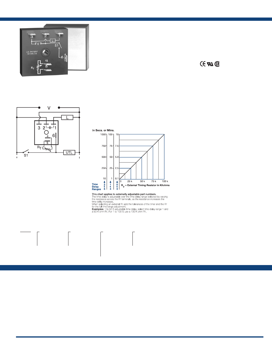
49
www.ssac.com • 800-843-8848 • fax: 605-348-5685
THDB Series
Timer - Delay-on-Break
Available Models:
Time Delay
Range . . . . . . . . . . . . . . . . . . . . . . . . . . . . . . . . .
0.1s - 1000m in 6 adjustable ranges or fixed
Repeat Accuracy . . . . . . . . . . . . . . . . . . . . . . .
±0.5% or 20ms, whichever is greater
Tolerance (Factory Calibration) . . . . . . . . . . .
≤ ±1%
Reset Time . . . . . . . . . . . . . . . . . . . . . . . . . . . . .
≤ 150ms
Initiate Time . . . . . . . . . . . . . . . . . . . . . . . . . . .
≤ 20ms
Time Delay vs Temp. & Voltage
. . . . . . . . . .
≤ ±2%
Input
Voltage
. . . . . . . . . . . . . . . . . . . . . . . . . . . . . . . .
24, 120, or 230VAC
Tolerance . . . . . . . . . . . . . . . . . . . . . . . . . . . . . .
±20%
AC Line Frequency . . . . . . . . . . . . . . . . . . . . .
50/60 Hz
Power Consumption . . . . . . . . . . . . . . . . . . . .
≤ 2VA
Output
Type . . . . . . . . . . . . . . . . . . . . . . . . . . . . . . . . . . Solid state
Form . . . . . . . . . . . . . . . . . . . . . . . . . . . . . . . . . .
NO, closed before & during timing
Maximum Load Current Output Steady State Inrush**
A 6A 60A
B 10A 100A
C 20A 200A
Voltage Drop
. . . . . . . . . . . . . . . . . . . . . . . . . .
≅
2.5V @ rated current
Off State Leakage Current
. . . . . . . . . . . . . . .
≅
5mA @t 230VAC
Minimum Load Current . . . . . . . . . . . . . . . . .
100mA
Protection
Circuitry . . . . . . . . . . . . . . . . . . . . . . . . . . . . . . Encapsulated
Dielectric Breakdown
. . . . . . . . . . . . . . . . . . .
≥ 2000V RMS terminals to mounting surface
Insulation Resistance . . . . . . . . . . . . . . . . . . . .
≥ 100 MΩ
Mechanical
Mounting ** . . . . . . . . . . . . . . . . . . . . . . . . . . .
Surface mount with one #10 (M5 x 0.8) screw
Dimensions . . . . . . . . . . . . . . . . . . . . . . . . . . . .
2 x 2 x 1.51 in. (50.8 x 50.8 x 38.4 mm)
Termination . . . . . . . . . . . . . . . . . . . . . . . . . . .
0.25 in. (6.35 mm) male quick connect terminals
Environmental
Operating / Storage Temperature
. . . . . . . .
-40° to 60°C / -40° to 85°C
Humidity . . . . . . . . . . . . . . . . . . . . . . . . . . . . . .
95% relative, non-condensing
Weight
. . . . . . . . . . . . . . . . . . . . . . . . . . . . . . . .
≅
3.9 oz (111 g)
**Must be bolted to a metal surface using the included heat sink compound. The maximum
surface temperature is 90°C. Inrush: Non-repetitive for 16ms.
Order Table:
Specifications
The THDB Series combines accurate timing
circuitry with high power, solid-state switching.
It can switch motors, lamps, and heaters directly
without a contactor. You can reduce labor,
component cost, and increase reliability with these
small, easy-to-use, Digi-Power timers.
Operation (Delay-on-Break):
Input voltage must be applied before and during timing.
Upon closure of the initiate switch, the output energizes.
The time delay begins when the initiate switch is opened.
The output remains energized during timing. At the end
of the time delay, the output de-energizes. The output
energizes if the initiate switch is closed when input
voltage is applied.
Reset: Reclosing the initiate switch during timing resets
the time delay. Loss of input voltage resets the time delay
and output .
For more information see:
Appendix A, pages 156-164 for function descriptions
and diagrams .
Appendix B, page 165, Figure 4 for dimensional drawing.
Features:
• High load currents up to 20A, 200A inrush
• Fixed or adjustable 0.1s - 1000m in 6 ranges
• ±0.5% repeat accuracy
• ±1% factory calibration
• 24, 120, or 230VAC
• Metallized mounting surface for heat transfer
• Totally solid-state & encapsulated
Approvals:
Connection:
THDB231C
THDB232C
THDB233C
THDB234C
THDB235C
THDB4110MC
THDB421A
THDB430C
THDB431C
THDB432C
THDB433C
THDB434C
THDB435C
Auxiliary Products:
•
External ad just potentiometer:
P/N: P1004-95
P/N: P1004-95-X
•
Female quick connect:
P/N: P1015-13 (AWG 10/12)
P/N: P1015-64 (AWG 14/16)
•
Quick connect t o s crew ad aptor:
P/N: P1015-18
•
Versa-knob:
P/N: P0700-7
THDB
X
Input Voltage
─
2
- 24VAC
─
4
- 120VAC
─
6
- 230VAC
X
Adjustment
─
1
- Fixed
─
2
- External adjust
─
3
- Onboard adjust
X
Time Delay*
─
0
- 0.1 - 10s
─
1
- 1 - 100s
─
2
- 10 - 1000s
─
3
- 0.1 - 10m
─
4
- 1 - 100m
─
5
- 10 - 1000m
X
Output Rating
─
A
- 6A
─
B
- 10A
─
C
- 20A
*If fixed delay is selected, insert
delay (
0 .1 - 1000
) followed by (
S
) sec .
or (
M
) min .
L1
N/L2
External Resistance vs . Time Delay:
UTL = Optional Untimed Load
L = Timed Load
S1 = Initiate Switch
If desired part number is not listed, please call us to
see if it is technically possible to build .
R
T
is used when external adjustment is ordered.
Courtesy of Steven Engineering, Inc.-230 Ryan Way, South San Francisco, CA 94080-6370-Main Office: (650) 588-9200-Outside Local Area: (800) 258-9200-www.stevenengineering.com
Littelfuse-catalog-html.html
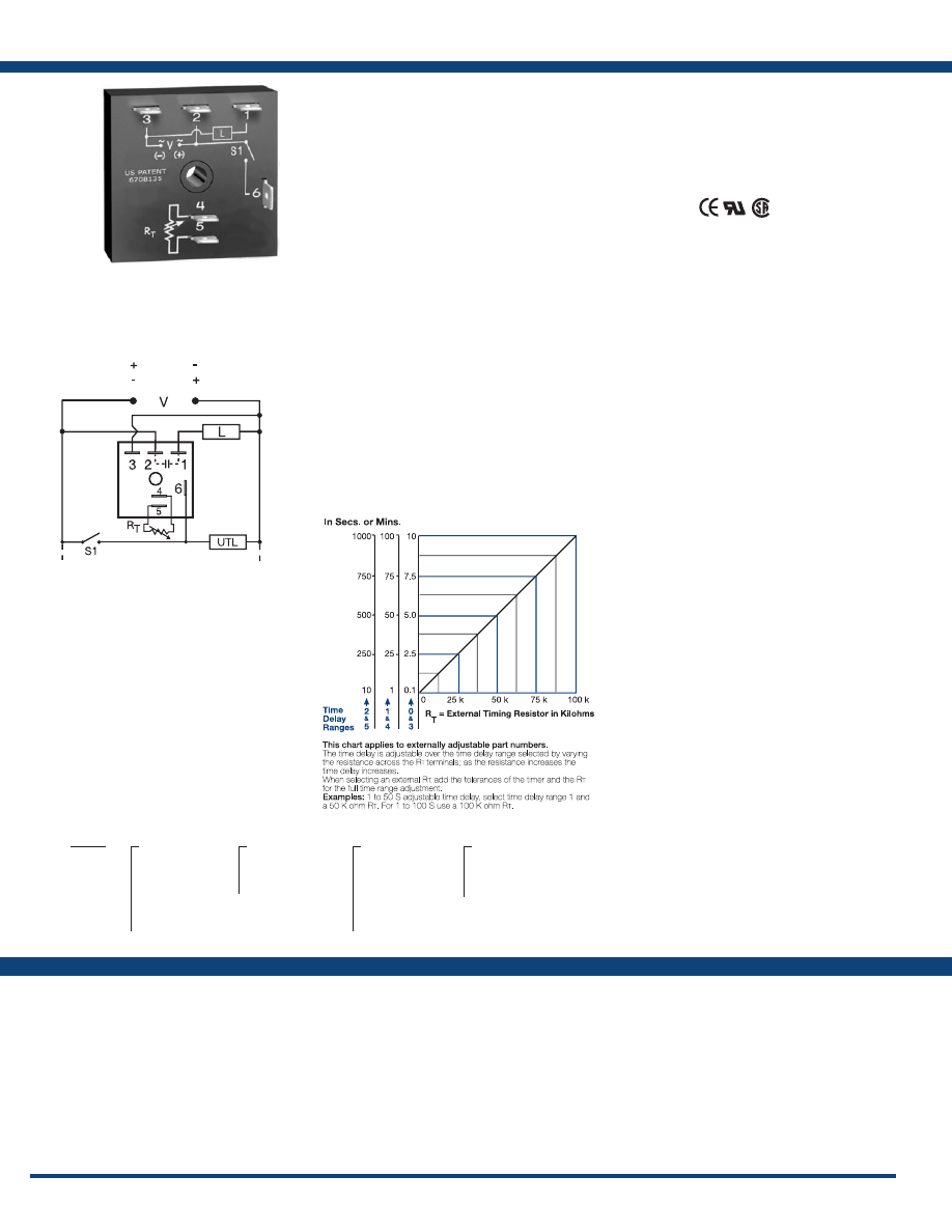
50
www.ssac.com • 800-843-8848 • fax: 605-348-5685
Features:
• Fixed or adjustable 0.1s - 1000m in 6 ranges
• ±0.5% repeat accuracy
• ± 5% factory calibration
• 12VDC to 230VAC in 6 ranges
• 1A, solid-state output
•
Encapsulated
Approvals:
KSDB Series
Timer - Delay-on-Break
Available Models:
Time Delay
Range . . . . . . . . . . . . . . . . . . . . . . . . . . . . . .
0.1s - 1000m in 6 adjustable ranges or fixed
Repeat Accuracy . . . . . . . . . . . . . . . . . . . .
±0.5 % or 20ms, whichever is greater
Tolerance (Factory Calibration) . . . . . . . .
≤ ±5%
Reset Time . . . . . . . . . . . . . . . . . . . . . . . . . .
≤ 150ms
Initiate Time . . . . . . . . . . . . . . . . . . . . . . . .
≤ 20ms
Time Delay vs Temp. & Voltage
. . . . . . .
≤ ±10%
Input
Voltage
. . . . . . . . . . . . . . . . . . . . . . . . . . . . .
12, 24, or 120VDC; 24, 120, or 230VAC
Tolerance . . . . . . . . . . . . . . . . . . . . . . . . . . .
±20%
Power Consumption . . . . . . . . . . . . . . . . .
AC ≤ 2VA; DC ≤ 2W
AC Line Frequency / DC Ripple
. . . . . . .
50/60 Hz / ≤ 10 %
Output
Type . . . . . . . . . . . . . . . . . . . . . . . . . . . . . . .Solid state
Form . . . . . . . . . . . . . . . . . . . . . . . . . . . . . . .
NO, closed before & during timing
Maximum Load Current
. . . . . . . . . . . . . .
1A steady state, 10A inrush at 60
oC
OFF State Leakage Current
. . . . . . . . . . .AC
≅
5mA @ 230VAC; DC
≅
1mA
Voltage Drop
. . . . . . . . . . . . . . . . . . . . . . .AC
≅
2.5V @ 1A; DC
≅
1V @ 1A
DC Operation . . . . . . . . . . . . . . . . . . . . . . .
Positive or negative switching
Protection
Circuitry . . . . . . . . . . . . . . . . . . . . . . . . . . .Encapsulated
Dielectric Breakdown
. . . . . . . . . . . . . . . .
≥ 2000V RMS terminals to mounting surface
Insulation Resistance . . . . . . . . . . . . . . . . .
≥ 100 MΩ
Polarity . . . . . . . . . . . . . . . . . . . . . . . . . . . .
DC units are reverse polarity protected
Mechanical
Mounting . . . . . . . . . . . . . . . . . . . . . . . . . .
Surface mount with one #10 (M5 x 0.8) screw
Dimensions . . . . . . . . . . . . . . . . . . . . . . . . .
2 x 2 x 1.21 in. (50.8 x 50.8 x 30.7mm)
Termination . . . . . . . . . . . . . . . . . . . . . . . .
0.25 in. (6.35 mm) male quick connect terminals
Environmental
Operating / Storage Temperature
. . . . .
-40° to 60°C / -40° to 80°C
Humidity . . . . . . . . . . . . . . . . . . . . . . . . . . .
95% relative, non-condensing
Weight
. . . . . . . . . . . . . . . . . . . . . . . . . . . . .
≅
2.4 oz (68 g)
Specifications
Order Table:
Connection:
The KSDB is designed for general purpose
commercial and industrial applications where a
small, cost effective, reliable solid-state timer is
required. The factory calibration for fixed time
delays is within 5% of the target time delay. The
repeat accuracy, under stable conditions, is 0.5% of
the selected time delay. This series is designed for
popular AC and DC voltages. Time delays of 0.1
seconds to 1000 minutes are available in 6 ranges.
The output is rated 1A steady and 10A inrush. The
modules are totally solid state and encapsulated
to protect the electronic circuitry.
Operation (Delay-on-Break):
Input voltage must be applied before and during timing.
Upon closure of the initiate switch, the output energizes.
The time delay begins when the initiate switch is opened.
The output remains energized during timing. At the end
of the time delay, the output de-energizes. The output
energizes if the initiate switch is closed when input
voltage is applied.
Reset: Reclosing the initiate switch during timing resets
the time delay. Loss of input voltage resets the time delay
and output .
For more information see:
Appendix A, pages 156-164 for function descriptions
and diagrams .
Appendix B, page 165, Figure 1 for dimensional drawing.
KSDB1110MP
KSDB1115SP
KSDB1120SP
KSDB113MP
KSDB113SP
KSDB1160SP
KSDB120P
KSDB134P
KSDB2115S
KSDB220
KSDB231
KSDB312SN
KSDB314SP
KSDB315SP
KSDB320P
KSDB324N
KSDB330N
KSDB330P
KSDB334P
KSDB4110S
KSDB41150S
KSDB4120M
KSDB4160S
KSDB4190M
KSDB431
KSDB61150S
KSDB631
Auxiliary Products:
•
External ad just potentiometer:
P/N: P1004-95
P/N: P1004-95-X
•
Mounting bracket:
P/N: P1023-6
•
Female quick connect:
P/N: P1015-64 (AWG 14/16)
P/N: P1015-14 (AWG 18/22)
•
Quick connect t o s crew ad aptor:
P/N: P1015-18
•
Versa-knob:
P/N: P0700-7
•
DIN rail:
P/N: C103PM
(Al)
•
DIN rail adaptor:
P/N: P1023-20
KSDB
X
Input Voltage
─
1
- 12VDC
─
2
- 24VAC
─
3
- 24VDC
─
4
- 120VAC
─
5
- 120VDC
─
6
- 230VAC
X
Adjustment
─
1
- Fixed
─
2
- External adjust
─
3
- Onboard adjust
X
Time Delay*
─
0
- 0.1 - 10s
─
1
- 1 - 100s
─
2
- 10 - 1000s
─
3
- 0.1 - 10m
─
4
- 1 - 100m
─
5
- 10 - 1000m
X
Switching Mode
(VDC only)
─
P
- Positive
─
N
- Negative
*If fixed delay is selected, insert
delay (
0 .1 - 1000
) followed by (
S
) sec .
or (
M
) min .
External Resistance vs . Time Delay:
UTL = Optional Untimed Load
L = Load
S1 = Initiate Switch
L1
N/L2
(Positive Switching)
(Negative Switching)
If desired part number is not listed, please call us to
see if it is technically possible to build .
R
T
is used when external adjustment is ordered.
Courtesy of Steven Engineering, Inc.-230 Ryan Way, South San Francisco, CA 94080-6370-Main Office: (650) 588-9200-Outside Local Area: (800) 258-9200-www.stevenengineering.com
Littelfuse-catalog-html.html
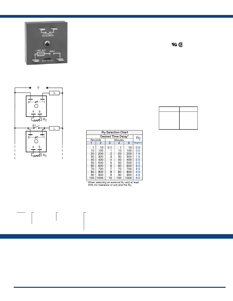
51
www.ssac.com • 800-843-8848 • fax: 605-348-5685
TSD7 Series
Timer - Interval/Delay-on-Break
Available Models:
Time Delay
Type . . . . . . . . . . . . . . . . . . . . . . . . . . . . . . . . . . Digital integrated circuitry
Range . . . . . . . . . . . . . . . . . . . . . . . . . . . . . . . . .
1s - 1000m in 5 adjustable ranges or fixed
Repeat Accuracy . . . . . . . . . . . . . . . . . . . . . . .
±0.5% or 20ms, whichever is greater
Tolerance (Factory Calibration) . . . . . . . . . . .
≤ ±10%
Recycle Time . . . . . . . . . . . . . . . . . . . . . . . . . . .
≤ 400ms
Time Delay vs Temp. & Voltage
. . . . . . . . . .
≤ ±2%
Input
Voltage
. . . . . . . . . . . . . . . . . . . . . . . . . . . . . . . .
24, 120, or 230VAC
Tolerance . . . . . . . . . . . . . . . . . . . . . . . . . . . . . .
±20%
AC Line Frequency . . . . . . . . . . . . . . . . . . . . .
50/60 Hz
Output
Type . . . . . . . . . . . . . . . . . . . . . . . . . . . . . . . . . . Solid state
Form . . . . . . . . . . . . . . . . . . . . . . . . . . . . . . . . . .
NO, closed during timing
Maximum Load Current
. . . . . . . . . . . . . . . . .
1A steady state, 10A inrush at 45°C
Minimum Load Current . . . . . . . . . . . . . . . . .
40mA
Effective Voltage Drop (VLine-VLoad) Input Effective Drop
24VAC 3V
120VAC 4V
230VAC 6V
Protection
Circuitry . . . . . . . . . . . . . . . . . . . . . . . . . . . . . . Encapsulated
Dielectric Breakdown
. . . . . . . . . . . . . . . . . . .
≥ 2000V RMS terminals to mounting surface
Insulation Resistance . . . . . . . . . . . . . . . . . . . .
≥ 100 MΩ
Mechanical
Mounting . . . . . . . . . . . . . . . . . . . . . . . . . . . . .
Surface mount with one #10 (M5 x 0.8) screw
Dimensions . . . . . . . . . . . . . . . . . . . . . . . . . . . .
2 x 2 x 1.21 in. (50.8 x 50.8 x 30.7 mm)
Termination . . . . . . . . . . . . . . . . . . . . . . . . . . .
0.25 in. (6.35 mm) male quick connect terminals
Environmental
Operating / Storage Temperature
. . . . . . . .
-40° to 75°C / -40° to 85°C
Humidity . . . . . . . . . . . . . . . . . . . . . . . . . . . . . .
95% relative, non-condensing
Weight
. . . . . . . . . . . . . . . . . . . . . . . . . . . . . . . .
≅
2.4 oz (68 g)
Order Table:
Specifications
The TSD7 utilizes only two terminals connected in
series with the load. Interval timing mode period
is achieved by using a small portion of the AC
sine wave allowing sufficient voltage for circuit
operation. It can be used as an interval timer to
control or pulse shape the operation of contactors,
solenoids, relays, and lamp loads. The TSD7 can be
wired to delay on the break of a switch for energy
saving fan delays.
Operation (Interval):
Upon application of input voltage, the output energizes
and the time delay begins. The output remains energized
throughout the time delay. At the end of the time delay,
the output de-energizes and remains de-energized until
power is removed.
Reset: Removing input voltage resets the time delay and
the output.
Operation (Delay-on-Break):
Upon closure of SW1, the load is energized and the timer is
reset (zero volts across its input terminals). Opening SW1
re-applies input voltage to the timer, the load remains
energized and the time delay begins. At the end of the
time delay, the output de-energizes. If SW1 is open when
power is applied, the load will energize for the time delay
then de-energize.
Reset: Reclosing SW1 resets the timer.
For more information see:
Appendix A, pages 156-164 for function descriptions
and diagrams .
Appendix B, page 165, Figure 1 for dimensional drawing.
Features:
•
Two terminal series connection to load
• Fixed or adjustable 1s - 1000m in 5 ranges
•
Digital integrated circuitry
• ±0.5% repeat accuracy
Approvals:
Connection:
TSD72130S
TSD7222
TSD74110M
TSD7412S
TSD7413S
TSD7414M
TSD7421
TSD7423
TSD7424
TSD761120S
TSD761180S
TSD7611S
TSD7621
Auxiliary Products:
•
External ad just potentiometer:
P/N: P1004-13
P/N: P1004-13-X
•
Female quick connect:
P/N: P1015-64 (AWG 14/16)
•
Quick connect t o s crew ad aptor:
P/N: P1015-18
•
Versa-knob:
P/N: P0700-7
•
DIN rail:
P/N: C103PM
(Al)
•
DIN rail adaptor:
P/N: P1023-20
•
Mounting bracket:
P/N: P1023-6
•
Plug-on adjustment module:
P/N: VTP(X)(X)
TSD7
X
Input Voltage
─
2
- 24VAC
─
4
- 120VAC
─
6
- 230VAC
X
Adjustment
─
1
- Fixed
─
2
- External adjust
X
Time Delay*
─
1
- 1 - 100s
─
2
- 10 - 1000s
─
3
- 0.1 - 10m
─
4
- 1 - 100m
─
5
- 10 - 1000m
*If fixed delay is selected, insert
delay (
0 .1 - 1000
) followed by (
S
) sec .
or (
1 - 1000
) (
M
) min .
L1
N/L2
V = Voltage
L = Load
S1 = Initiate Switch
Selection Table for VTP Plug-on
Adjustment Accessory.
Interval
Delay-on- Break
Time Delay
VTP P/N
1
- 1-100s
2
- 10-1000s
3
- 0.1-10m
4
- 1-100m
5
- 10-1000m
VTP5G
VTP5K
VTP5N
VTP5P
VTP5R
If desired part number is not listed, please call us to
see if it is technically possible to build .
R
T
is used when external adjustment is ordered.
Courtesy of Steven Engineering, Inc.-230 Ryan Way, South San Francisco, CA 94080-6370-Main Office: (650) 588-9200-Outside Local Area: (800) 258-9200-www.stevenengineering.com
Littelfuse-catalog-html.html
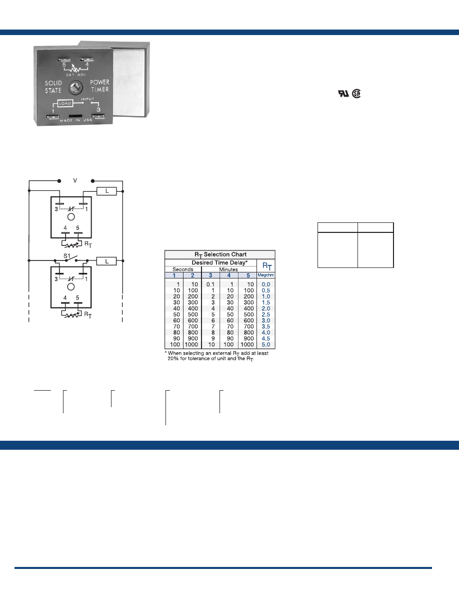
52
www.ssac.com • 800-843-8848 • fax: 605-348-5685
Features:
• Solid-state relay and timer combined
•
Two terminal series connection to load
• Up to 20A steady state, 200A inrush
• Fixed or adjustable delays from 1s - 1000m
• ±0.5% repeat accuracy
Approvals:
THD7 Series
Timer - Interval/Delay-on-Break
Available Models:
Time Delay
Type . . . . . . . . . . . . . . . . . . . . . . . . . . . . . . . . . .Digital integrated circuitry
Range . . . . . . . . . . . . . . . . . . . . . . . . . . . . . . . . .
1s - 1000m in 5 adjustable ranges or fixed
Repeat Accuracy . . . . . . . . . . . . . . . . . . . . . . .
±0.5% or 20ms, whichever is greater
Tolerance (Factory Calibration) . . . . . . . . . . .
≤ ±10%
Recycle Time . . . . . . . . . . . . . . . . . . . . . . . . . . .
After timing: ≤150ms; During timing: ≤ 350ms
Time Delay vs Temp. & Voltage
. . . . . . . . . .
≤ ±2%
Input
Voltage
. . . . . . . . . . . . . . . . . . . . . . . . . . . . . . . .
24, 120, or 230VAC
Tolerance . . . . . . . . . . . . . . . . . . . . . . . . . . . . . .
±20%
AC Line Frequency . . . . . . . . . . . . . . . . . . . . .
50/60 Hz
Output
Type . . . . . . . . . . . . . . . . . . . . . . . . . . . . . . . . . .Solid state
Form . . . . . . . . . . . . . . . . . . . . . . . . . . . . . . . . . .
NO, closed during timing
Rating Output Steady State Inrush**
A 6A 60A
B 10A 100A
C 20A 200A
Effective Voltage Drop (VLine-VLoad) Input Effective Drop
24VAC ≤ 3V
120VAC ≤ 3V
230VAC ≤ 5V
Minimum Load Current . . . . . . . . . . . . . . . . .
100mA
Protection
Circuitry . . . . . . . . . . . . . . . . . . . . . . . . . . . . . .Encapsulated
Dielectric Breakdown
. . . . . . . . . . . . . . . . . . .
≥ 2000V RMS terminals to mounting surface
Insulation Resistance . . . . . . . . . . . . . . . . . . . .
≥ 100 MΩ
Mechanical
Mounting ** . . . . . . . . . . . . . . . . . . . . . . . . . . .
Surface mount with one #10 (M5 x 0.8) screw
Dimensions . . . . . . . . . . . . . . . . . . . . . . . . . . . .
2 x 2 x 1.51 in. (50.8 x 50.8 x 38.4 mm)
Termination . . . . . . . . . . . . . . . . . . . . . . . . . . .
0.25 in. (6.35 mm) male quick connect terminals
Environmental
Operating / Storage Temperature
. . . . . . . .
-40° to 60°C / -40° to 85°C
Humidity . . . . . . . . . . . . . . . . . . . . . . . . . . . . . .
95% relative, non-condensing
Weight
. . . . . . . . . . . . . . . . . . . . . . . . . . . . . . . .
≅
3.9 oz (111 g)
**Must be bolted to a metal surface using the included heat sink compound. The maximum
mounting surface temperature is 90°C. Inrush: Non-repetitive for 16ms.
Specifications
Order Table:
Connection:
The THD7 utilizes only two terminals connected
in series with the load. Interval timing mode
is achieved by using a small portion of the AC
sine wave allowing sufficient voltage for circuit
operation. The THD7 can be used for interval or
delay-on-break timing. It is designed to operate
large loads directly, such as motors, heater
elements, and motor starters.
Operation (Interval):
Upon application of input voltage, the output energizes
and the time delay begins. The output remains energized
throughout the time delay. At the end of the time delay
the output de-energizes and remains de-energized until
power is removed.
Reset: Removing input voltage resets the time delay and
the output.
Operation (Delay-on-Break):
Upon closure of SW1, the load energizes and the timer is
reset (zero voltage across its input terminals). Opening
SW1 re-applies input voltage to the timer, the load
remains energized and the time delay begins. At the end
of the time delay the output de-energizes. If SW1 is open
when power is applied, the load will energize for the time
delay then de-energize.
Reset: Reclosing SW1 resets the timer.
For more information see:
Appendix A, pages 156-164 for function descriptions
and diagrams .
Appendix B, page 165, Figure 4 for dimensional drawing.
THD72110SA
THD7415SB
THD7421C
THD7612MA
THD7621C
Auxiliary Products:
•
External ad just potentiometer:
P/N: P1004-13
P/N: P1004-13-X
•
Mounting bracket:
P/N: P1023-6
•
Female quick connect:
P/N: P1015-13 (AWG 10/12)
P/N: P1015-64 (AWG 14/16)
•
Quick connect t o s crew ad aptor:
P/N: P1015-18
•
DIN rail:
P/N: C103PM
(Al)
•
DIN rail adaptor:
P/N: P1023-20
•
Versa-knob:
P/N: P0700-7
•
Plug-on adjustment module:
P/N: VTP(X)(X)
THD7
X
Input Voltage
─
2
- 24VAC
─
4
- 120VAC
─
6
- 230VAC
X
Adjustment
─
1
- Fixed
─
2
- External adjust
X
Time Delay*
─
1
- 1 - 100s
─
2
- 10 - 1000s
─
3
- 0.1 - 10m
─
4
- 1 - 100m
─
5
- 10 - 1000m
X
Output Rating
─
A
- 6A
─
B
- 10A
─
C
- 20A
*If fixed delay is selected, insert
delay (
1 - 1000
) followed by (
S
) sec .
or (
0 .1 - 1000
)(
M
) min .
L1
N/L2
V = Voltage
L = Load
S1 = Initiate Switch
Selection Table for VTP Plug-on
Adjustment Accessory.
Time Delay
VTP P/N
1
- 1-100s
2
- 10-1000s
3
- 0.1-10m
4
- 1-100m
5
- 10-1000m
VTP5G
VTP5K
VTP5N
VTP5P
VTP5R
Interval
Delay-on-
Break
If desired part number is not listed, please call us to
see if it is technically possible to build .
R
T
is used when external adjustment is ordered.
Courtesy of Steven Engineering, Inc.-230 Ryan Way, South San Francisco, CA 94080-6370-Main Office: (650) 588-9200-Outside Local Area: (800) 258-9200-www.stevenengineering.com
Littelfuse-catalog-html.html
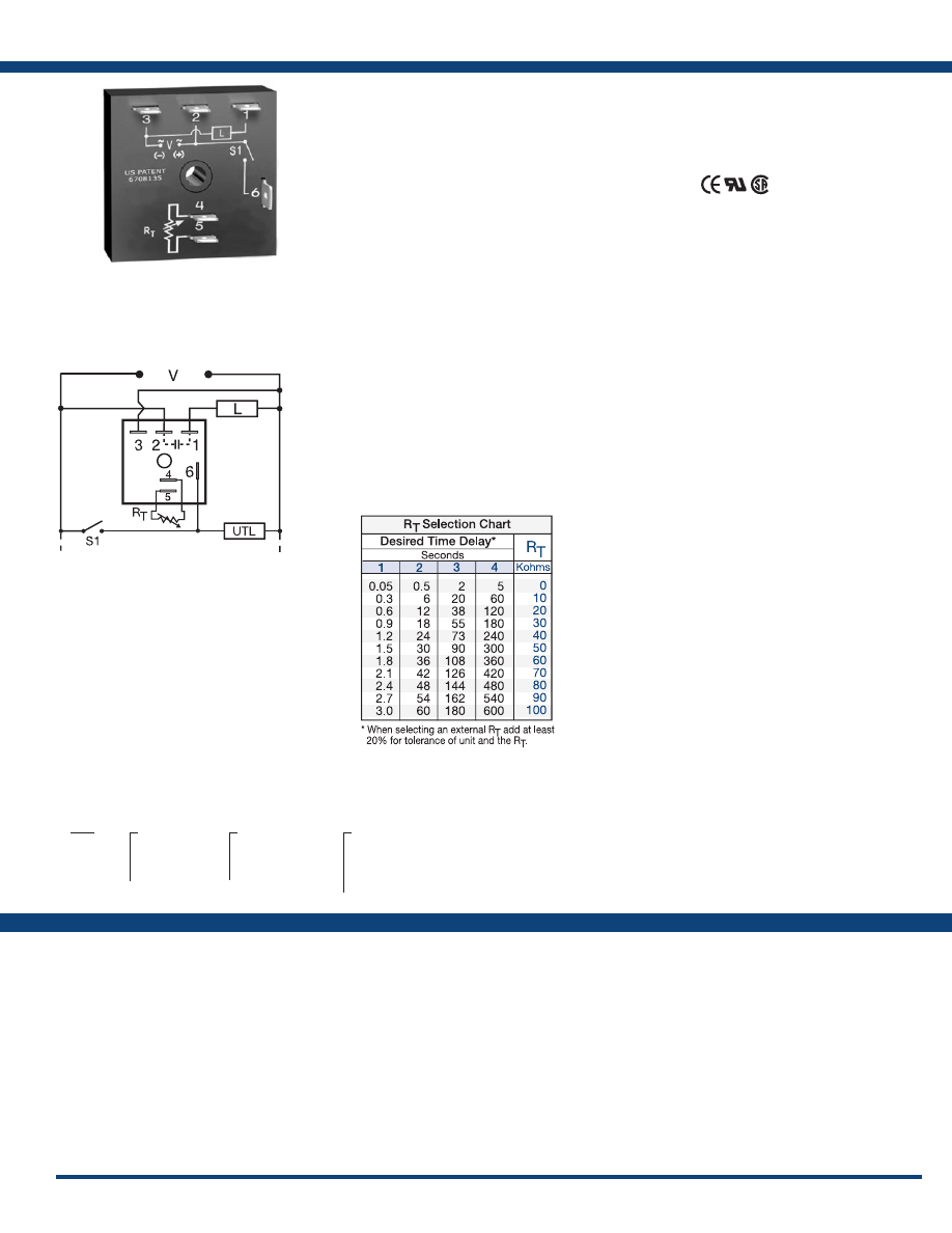
53
www.ssac.com • 800-843-8848 • fax: 605-348-5685
TSB Series
Timer - Delay-on-Break
Available Models:
Time Delay
Range . . . . . . . . . . . . . . . . . . . . . . . . . . . . . . . . .
0.05s - 600s in 4 adjustable ranges or fixed
Repeat Accuracy . . . . . . . . . . . . . . . . . . . . . . .
±2% or 20ms, whichever is greater
Tolerance (Factory Calibration) . . . . . . . . . . .
≤ ±5%
Time Delay vs Temp. & Voltage
. . . . . . . . . .
≤ ±10%
Reset Time . . . . . . . . . . . . . . . . . . . . . . . . . . . . .
≤
150ms
Input
Voltage
. . . . . . . . . . . . . . . . . . . . . . . . . . . . . . . .
24, 120, or 230VAC
Tolerance . . . . . . . . . . . . . . . . . . . . . . . . . . . . . .
±20%
AC Line Frequency . . . . . . . . . . . . . . . . . . . . .
50/60 Hz
Power Consumption . . . . . . . . . . . . . . . . . . . .
≤ 2VA
Output
Type . . . . . . . . . . . . . . . . . . . . . . . . . . . . . . . . . . Solid state
Form . . . . . . . . . . . . . . . . . . . . . . . . . . . . . . . . . .
NO, closed before & during timing
Maximum Load Current
. . . . . . . . . . . . . . . . .
1A steady state, 10A inrush at 60°C
Off State Leakage Current
. . . . . . . . . . . . . . .
≅
5mA @ 230VAC
Voltage Drop
. . . . . . . . . . . . . . . . . . . . . . . . . .
≅
2.5V @ 1A
Protection
Circuitry . . . . . . . . . . . . . . . . . . . . . . . . . . . . . . Encapsulated
Dielectric Breakdown
. . . . . . . . . . . . . . . . . . .
≥ 2000V RMS terminals to mounting surface
Insulation Resistance . . . . . . . . . . . . . . . . . . . .
≥ 100 MΩ
Mechanical
Mounting . . . . . . . . . . . . . . . . . . . . . . . . . . . . .
Surface mount with one #10 (M5 x 0.8) screw
Dimensions . . . . . . . . . . . . . . . . . . . . . . . . . . . .
2 x 2 x 1.21 in. (50.8 x 50.8 x 30.7 mm)
Termination . . . . . . . . . . . . . . . . . . . . . . . . . . .
0.25 in. (6.35 mm) male quick connect terminals
Environmental
Operating / Storage Temperature
. . . . . . . .
-40° to 75°C / -40° to 85°C
Humidity . . . . . . . . . . . . . . . . . . . . . . . . . . . . . .
95% relative, non-condensing
Weight
. . . . . . . . . . . . . . . . . . . . . . . . . . . . . . . .
≅
2.4 oz (68 g)
Order Table:
Specifications
The TSB Series is a totally solid-state, delay-on-
break timing module. The TSB is available with a
fixed, external, or onboard adjustable time delay.
Time Delays from 0.05 to 600 seconds, in 4 standard
ranges, cover over 90% of all OEM and commercial
appliance timing applications. The repeat accuracy
is ±2%. Operating voltages of 24, 120, or 230VAC
are available. The TSB’s 1A steady state, 10A rated,
solid-state output is perfect for direct control of
solenoids, contactors, relays, lamps, buzzers, and
small heaters. The TSB can be surface mounted
with a single screw, or snapped on a 35 mm DIN
rail using the P1023-20 adaptor.
Operation (Delay-on-Break):
Input voltage must be applied before and during timing.
Upon closure of the initiate switch, the output energizes.
The time delay begins when the initiate switch opens.
The output remains energized during timing. At the end
of the time delay, the output de-energizes. The output
will energize if the initiate switch is closed when input
voltage is applied.
Reset: Reclosing the initiate switch during timing resets
the time delay. Loss of input voltage resets the output
and the time delay.
For more information see:
Appendix A, pages 156-164 for function descriptions
and diagrams .
Appendix B, page 165, Figure 1 for dimensional drawing.
Features:
• Fixed or adjustable 0.05 - 600s in 4 ranges
• Totally solid state & encapsulated
• ± 2% repeat accuracy
• ±5% factory calibration
Approvals:
Connection:
TSB2130
TSB2190
TSB222
TSB232
TSB4110
TSB41300
TSB414
TSB4170
TSB418
TSB4190
TSB422
TSB423
TSB424
TSB432
TSB434
TSB632
TSB634
Auxiliary Products:
•
External ad just potentiometer:
P/N: P1004-95
P/N: P1004-95-X
•
Mounting bracket:
P/N: P1023-6
•
Female quick connect:
P/N: P1015-64 (AWG 14/16)
•
Quick connect t o s crew ad aptor:
P/N: P1015-18
•
Versa-knob:
P/N: P0700-7
•
DIN rail:
P/N: C103PM
(Al)
•
DIN rail adaptor:
P/N: P1023-20
TSB
X
Input Voltage
─
2
- 24VAC
─
4
- 120VAC
─
6
- 230VAC
X
Adjustment
─
1
- Fixed
─
2
- External adjust
─
3
- Onboard adjust
X
Time Delay*
─
1
- 0.05 - 3s
─
2
- 0.5 - 60s
─
3
- 2 - 180s
─
4
- 5 - 600s
*If fixed delay is selected, insert
delay (
0 .05 - 600
) in seconds .
S1 = Initiate Switch
UTL = Optional Untimed Load
L = Load
L1
N/L2
If desired part number is not listed, please call us to
see if it is technically possible to build .
R
T
is used when external adjustment is ordered.
Courtesy of Steven Engineering, Inc.-230 Ryan Way, South San Francisco, CA 94080-6370-Main Office: (650) 588-9200-Outside Local Area: (800) 258-9200-www.stevenengineering.com
Littelfuse-catalog-html.html
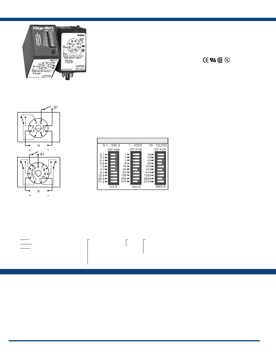
54
www.ssac.com • 800-843-8848 • fax: 605-348-5685
Features:
• Switch selectable time delay
• Three time ranges from 0.1s - 10,230s
• ±0.1% repeat accuracy
• ±2% setting accuracy
• 10A, SPDT or DPDT output contacts
•
LED indication
Approvals:
TDS / TDSH / TDSL Series
Timer - Single Shot
Available Models:
Time Delay
Type . . . . . . . . . . . . . . . . . . . . . . . . . . . . . . . . . .Digital integrated circuitry
Range** . . . . . . . . . . . . . . . . . . . . . . . . . . . . . . .
0.1 - 102.3s in 0.1s increments
1 - 1023s in 1s increments
10 - 10,230s in 10s increments
Repeat Accuracy . . . . . . . . . . . . . . . . . . . . . . .
±0.1% or 20ms, whichever is greater
Setting Accuracy . . . . . . . . . . . . . . . . . . . . . . .
±2% or 50ms, whichever is greater
Reset Time . . . . . . . . . . . . . . . . . . . . . . . . . . . . .
≤ 50ms
Recycle Time . . . . . . . . . . . . . . . . . . . . . . . . . . .
≤ 150ms
Time Delay vs Temp. & Voltage
. . . . . . . . . .
±5%
Indicator . . . . . . . . . . . . . . . . . . . . . . . . . . . . . .
LED glows during timing; relay is energized
Initiate Time . . . . . . . . . . . . . . . . . . . . . . . . . . .
≤ 60ms
Input
Voltage
. . . . . . . . . . . . . . . . . . . . . . . . . . . . . . . .
12, 24/28, or 110VDC; 24, 120, or 230VAC
Tolerance 12VDC & 24VDC/AC
. . . . . .
-15% - 20%
110 to 230VAC/DC
. . . . . .
-20% - 10%
AC Line Frequency . . . . . . . . . . . . . . . . . . . . .
50/60 Hz
Power Consumption . . . . . . . . . . . . . . . . . . . .
≤ 3.25W
Output
Type . . . . . . . . . . . . . . . . . . . . . . . . . . . . . . . . . .
Electromechanical relay
Form . . . . . . . . . . . . . . . . . . . . . . . . . . . . . . . . . .
SPDT & DPDT
Rating . . . . . . . . . . . . . . . . . . . . . . . . . . . . . . . .
10A resistive @ 120/240VAC & 28 VDC;
1/3 hp @ 120/240VAC
Life
. . . . . . . . . . . . . . . . . . . . . . . . . . . . . . . . . . .
Mechanical - 1 x 10
7
; Electrical - 1 x 10
6
Protection
Isolation Voltage
. . . . . . . . . . . . . . . . . . . . . . .
≥ 1500V RMS input to output
Polarity . . . . . . . . . . . . . . . . . . . . . . . . . . . . . . .
DC units are reverse polarity protected
Mechanical
Mounting . . . . . . . . . . . . . . . . . . . . . . . . . . . . .
Plug-in socket
Dimensions . . . . . . . . . . . . . . . . . . . . . . . . . . . .
3.2 x 2.4 x 1.8 in. (81.3 x 60.7 x 45.2 mm)
Termination . . . . . . . . . . . . . . . . . . . . . . . . . . .
Octal 8-pin plug-in or 11-pin plug-in
Environmental
Operating / Storage Temperature
. . . . . . . .
-20° to 65°C / -30° to 85°C
Weight
. . . . . . . . . . . . . . . . . . . . . . . . . . . . . . . .
≅
6 oz (170 g)
**For CE approved applications, power must be removed from the unit when a switch
position is changed.
Specifications
Order Table:
Connection:
The TDS Series combines accurate digital circuitry
with isolated, 10A rated, DPDT or SPDT relay
contacts in an 8 or 11-pin plug-in package. The
TDS Series features DIP switch selectable time
delays ranging from 0.1s to 10,230s in three ranges.
The TDS Series is the product of choice for custom
control panel and OEM designers .
Operation (Single Shot):
Input voltage must be applied to the input before and
during timing . Upon momentary or maintained closure
of the initiate switch (leading edge triggered), the output
relay energizes for a measured interval of time. At the
end of the delay, the output de-energizes. Opening or
reclosing the initiate switch during timing has no affect
on the time delay. The output will energize if the initiate
switch is closed when input voltage is applied.
Reset: Reset occurs when the time delay is complete and
the initiate switch is opened. Loss of input voltage resets
the time delay and output.
For more information see:
Appendix A, pages 156-164 for function descriptions
and diagrams .
Appendix B, page 165, Figure 8 for dimensional drawing.
TDS120AL
TDS120ALD
TDS12D
TDS230AL
TDS24AL
TDS24DL
TDSH120AL
TDSH120ALD
TDSH24ALD
TDSL120AL
TDSL12D
TDSL24D
Auxiliary Products:
•
Panel mount kit:
P/N: BZ1
•
Hold-down clips (sold in pairs):
P/N: PSC8 (NDS-8)
P/N: PSC11 (NDS-11)
•
11-pin socket:
P/N: NDS-11
•
Octal 8-pin socket:
P/N: NDS-8
•
Octal socket for UL listing:
P/N: P1011-6
8-pin models UL listed
when used in combination
with P1011-6 socket only.
TDS
- 1 - 1023s in 1s increments
TDSH
- 10 - 10,230s in 10s increments
TDSL
- 0.1 - 102.3s in 0.1s increments
X
Input Voltage
─
12D
- 12VDC
─
24A
- 24VAC
─
24D
- 24VDC/28VDC
─
110D
- 110VDC
─
120A
- 120VAC
─
230A
- 230VAC
X
LED*
─
L
X
Type of Plug /Output Form
─
Blank
- Octal (8-pin) plug,
SPDT
─
D
- 11-pin Plug, DPDT
* Note: LED not available in 12VDC
L1
N/L2
L1
N/L2
8-pin octal
SPDT
11-pin
DPDT
Digi-Set Binary Switch Operation:
If desired part number is not listed, please call us to
see if it is technically possible to build .
S1 = Initiate Switch
Relay contacts are isolated .
Courtesy of Steven Engineering, Inc.-230 Ryan Way, South San Francisco, CA 94080-6370-Main Office: (650) 588-9200-Outside Local Area: (800) 258-9200-www.stevenengineering.com
Littelfuse-catalog-html.html
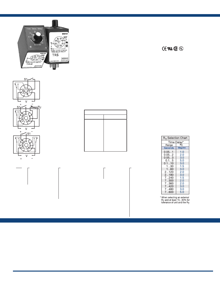
55
www.ssac.com • 800-843-8848 • fax: 605-348-5685
TRS Series
Timer - Single Shot
Available Models:
Time Delay
Type . . . . . . . . . . . . . . . . . . . . . . . . . . . . . . . . . . . Analog circuitry
Range . . . . . . . . . . . . . . . . . . . . . . . . . . . . . . . . . .
0.05s - 10m in 15 adjustable ranges or fixed
Repeat Accuracy . . . . . . . . . . . . . . . . . . . . . . . .
±2% or 20ms, whichever is greater
Fixed Time Tolerance & Setting Accuracy
. . .
±5, 10, or 20%
Initiate Time . . . . . . . . . . . . . . . . . . . . . . . . . . . .
≤ 70ms
Reset Time . . . . . . . . . . . . . . . . . . . . . . . . . . . . . .
≤ 75ms
Recycle Time . . . . . . . . . . . . . . . . . . . . . . . . . . . .
≤ 250ms
Time Delay vs Temp. & Voltage
. . . . . . . . . . .
≤±10%
Input
Voltage
. . . . . . . . . . . . . . . . . . . . . . . . . . . . . . . . .
24/28 or 110VDC; 24, 120, or 230VAC
(DC voltages on DPDT output models only)
Tolerance 24VDC/AC
. . . . . .
-15% - 20%
110 to 230VAC/DC
. . . . . .
-20% - 10%
AC Line Frequency . . . . . . . . . . . . . . . . . . . . . .
50/60 Hz
Power Consumption . . . . . . . . . . . . . . . . . . . . .
≤ 3.25W
Output
Type . . . . . . . . . . . . . . . . . . . . . . . . . . . . . . . . . . .
Electromechanical relay
Form . . . . . . . . . . . . . . . . . . . . . . . . . . . . . . . . . . . Isolated SPDT or DPDT
Rating . . . . . . . . . . . . . . . . . . . . . . . . . . . . . . . . .
10A resistive @ 120/240VAC & 28VDC;
1/3 hp @ 120/240VAC
Life
. . . . . . . . . . . . . . . . . . . . . . . . . . . . . . . . . . . .
Mechanical - 1 x 10
7
; Electrical - 1 x 10
6
Protection
Insulation Resistance . . . . . . . . . . . . . . . . . . . . .
≥ 100 MΩ
Isolation Voltage
. . . . . . . . . . . . . . . . . . . . . . . .
≥ 1500V RMS between input & output terminals
Polarity . . . . . . . . . . . . . . . . . . . . . . . . . . . . . . . .
DC units are reverse polarity protected
Mechanical
Mounting . . . . . . . . . . . . . . . . . . . . . . . . . . . . . .
Plug-in socket
Termination . . . . . . . . . . . . . . . . . . . . . . . . . . . .
Octal 8-pin plug-in or 11-pin plug-in
Dimensions . . . . . . . . . . . . . . . . . . . . . . . . . . . . .
3.62 x 2.39 x 1.78 in. (91.6 x 60.7 x 45.2 mm)
Environmental
Operating / Storage Temperature
. . . . . . . . .
-20° to 65°C / -30° to 85°C
Weight
. . . . . . . . . . . . . . . . . . . . . . . . . . . . . . . . .
≅
6 oz (170 g)
Order Table:
Specifications
The TRS Series combines an isolated, 10A
electromechanical, relay output with analog timing
circuitry. False trigger of the TRS by a transient is
unlikely because of the complete isolation of the
circuit from the line prior to initiation. The initiate
contact is common to one side of the line and may
be utilized to operate other loads. Installation is
easy due to the TRS’s industry standard 8 or 11-pin
plug-in base wiring.
Operation (Single Shot):
Input voltage must be applied to the input before and
during timing . Upon momentary or maintained closure
of the initiate switch (leading edge triggered), the output
energizes for a measured interval of time. At the end of
the delay, the output de-energizes. Opening or reclosing
the initiate switch during timing has no affect on the time
delay. Applying input voltage with the initiate switch
closed will energize the load and begin the time delay.
Reset: Reset occurs when the time delay is complete and
the initiate switch is opened. Loss of input voltage resets
the time delay and output.
For more information see:
Appendix A, pages 156-164 for function descriptions
and diagrams .
Appendix B, page 165, Figure 9 for dimensional drawing.
Features:
• Knob adjustable time delays
• Fixed or adjustable 0.05 - 600s in 15 ranges
•
Analog circuitry
• ±2% repeat accuracy
• AC & DC operating voltages are available
• Isolated, 10A, SPDT & DPDT output contacts
Approvals:
Connection:
TRS120A1X300
TRS120A2X300
TRS120A4Z3
TRS24D7Z10
TRS24D7Z3
Auxiliary Products:
•
External ad just potentiometer:
P/N: P1004-XX
P/N: P1004-XX-X
•
Octal socket for UL listing:
P/N: P1011-6
•
Hold-down clips (sold in pairs):
P/N: PSC8 (NDS-8)
P/N: PSC11 (NDS-11)
•
Octal 8-pin socket:
P/N: NDS-8
•
11-pin socket:
P/N: NDS-11
•
Panel mount kit:
P/N: BZ1
•
Versa-knob:
P/N: P0700-7
8-pin models UL listed
when used in combination
with P1011-6 socket only.
TRS
X
Input Voltage
─
24A
- 24VAC
─
24D
- 24VDC/28VDC
─
110D
- 110VDC
─
120A
- 120VAC
─
230A
- 230VAC
X
Adjustment and Output Form
─
1
- Fixed, Octal, SPDT
(AC Volts only)
─
2
- Knob Adjust, Octal, SPDT
(AC Volts only)
─
3
- Lock Shaft Adjust, Octal, SPDT
(AC Volts only)
─
4
- Knob adjust, 11-pin, DPDT
─
7
- Ext. Adjust, 11-pin, SPDT
without potentiometer
─
10
- Fixed, 11-pin, DPDT
X
Time Tolerance
─
X
- ±20%
─
Y
- ±10%
─
Z
- ±5%
X
Time Delay*
(seconds)
─
1
- 0.05 - 1
─
2
- 0.05 - 2
─
3
- 0.05 - 3
─
5
- 0.1 - 5
─
10
- 0.1 - 10
─
30
- 1 - 30
─
60
- 1 - 60
─
120
- 2 - 120
─
180
- 2 - 180
─
240
- 7 - 240
─
300
- 7 - 300
─
360
- 7 - 360
─
420
- 7 - 420
─
480
- 7 - 480
─
600
- 7 - 600
*If fixed delay is selected, insert
delay (
0.05 - 600
) in seconds .
L1
N/L2
L1
N/L2
L1
N/L2
8-pin octal SPDT
11-pin SPDT
11-pin DPDT
External R
T
P/N Selection Table
Value
Part Number
1M ohm
1.5M ohm
2M ohm
3M ohm
5M ohm
1M ohm
1.5M ohm
2M ohm
3M ohm
5M ohm
P1004-16
P1004-15
P1004-14
P1004-12
P1004-13
P1004-16-X
P1004-15-X
P1004-14-X
P1004-12-X
P1004-13-X
If desired part number is not listed, please call us to
see if it is technically possible to build .
S1 = Initiate Switch
Relay contacts are isolated .
R
T
is used when external
adjustment is ordered.
Courtesy of Steven Engineering, Inc.-230 Ryan Way, South San Francisco, CA 94080-6370-Main Office: (650) 588-9200-Outside Local Area: (800) 258-9200-www.stevenengineering.com
Littelfuse-catalog-html.html
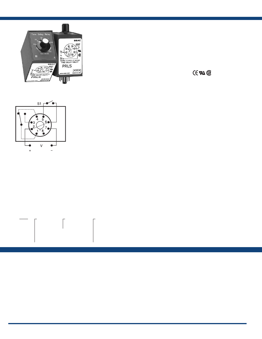
56
www.ssac.com • 800-843-8848 • fax: 605-348-5685
Features:
• Knob adjustable time delay relay
• Electronic circuit with electromechanical
relay
• AC & DC operating voltages
• Standard, octal plug-in connection
• Fixed or adjustable 0.05 - 600s in 6 ranges
• ±2% repeat accuracy
• ±10% factory calibration
•
LED indication
• 10A, SPDT output contacts
Approvals:
PRLS Series
Timer - Single Shot
Available Models:
Time Delay
Type . . . . . . . . . . . . . . . . . . . . . . . . . . . . . . . . . .Analog circuitry
Range . . . . . . . . . . . . . . . . . . . . . . . . . . . . . . . . .
0.05 - 600s in 6 adjustable ranges or fixed
Repeat Accuracy . . . . . . . . . . . . . . . . . . . . . . .
±2% or 20ms, whichever is greater
Tolerance . . . . . . . . . . . . . . . . . . . . . . . . . . . . . .
Knob adjust: guaranteed range
Fixed: ±10%
Reset Time . . . . . . . . . . . . . . . . . . . . . . . . . . . . .
≤ 75ms
Recycle Time . . . . . . . . . . . . . . . . . . . . . . . . . . .
≤ 250ms
Time Delay vs Temp. & Voltage
. . . . . . . . . .
≤ ±10%
Input
Voltage
. . . . . . . . . . . . . . . . . . . . . . . . . . . . . . . .
24, 120, or 230VAC; 12, 24, or 110VDC
Tolerance 12VDC & 24VDC/AC
. . . . . .
-15% - 20%
110 to 230VAC/DC
. . . . . .
-20% - 10%
AC Line Frequency . . . . . . . . . . . . . . . . . . . . .
50/60 Hz
Power Consumption . . . . . . . . . . . . . . . . . . . .
≤ 2.25W
Output
Type . . . . . . . . . . . . . . . . . . . . . . . . . . . . . . . . . .
Electromechanical relay
Form . . . . . . . . . . . . . . . . . . . . . . . . . . . . . . . . . .Isolated SPDT
Rating . . . . . . . . . . . . . . . . . . . . . . . . . . . . . . . .
10A resistive @ 28VDC;
10A resistive @ 240VAC;
1/3 hp @ 120 & 240VAC
Life
. . . . . . . . . . . . . . . . . . . . . . . . . . . . . . . . . . .
Mechanical - 1x10
7
; Electrical - 1x10
6
Protection
Surge . . . . . . . . . . . . . . . . . . . . . . . . . . . . . . . . .
IEEE C62.41-1991 Level A
Isolation Voltage
. . . . . . . . . . . . . . . . . . . . . . .
≥ 1500V RMS input to output
Insulation Resistance . . . . . . . . . . . . . . . . . . . .
≥ 100 MΩ
Polarity . . . . . . . . . . . . . . . . . . . . . . . . . . . . . . .
DC units are reverse polarity protected
Indication
Type
. . . . . . . . . . . . . . . . . . . . . . . . . . . . . . . . . .
LED
Operation . . . . . . . . . . . . . . . . . . . . . . . . . . . . .
Output energized & timing - flashing
Mechanical
Mounting . . . . . . . . . . . . . . . . . . . . . . . . . . . . .
Plug-in socket
Dimensions . . . . . . . . . . . . . . . . . . . . . . . . . . . .
3.62 x 2.39 x 1.78 in. (91.6 x 60.7 x 45.2 mm)
Termination . . . . . . . . . . . . . . . . . . . . . . . . . . .
Octal 8-pin, plug-in
Environmental
Operating / Storage Temperature
. . . . . . . .
-20° to 65°C / -30° to 85°C
Weight
. . . . . . . . . . . . . . . . . . . . . . . . . . . . . . . .
≅
6 oz (170 g)
Specifications
Order Table:
Connection:
The PRLS Series is designed for use on non-critical
timing applications. It offers low cost, knob
adjustable timing control; full 10A relay output;
and onboard LED indication. The knob adjustment
provides a guaranteed time range of up to 10
minutes in 6 ranges. The onboard LED indicates
whether or not the unit is timing (flashing LED)
as well as the status of the output.
Operation (Single Shot):
Input voltage must be applied to the input at all times
prior to and during timing. Upon closure of the initiate
switch (momentary or maintained) the output contacts
transfer and the time delay is initiated. The LED flashes
during timing. At the end of the delay, the output contacts
revert to their original position. If the initiate switch is
reclosed during timing, the time delay will not be affected.
Applying input voltage with the intiate switch closed will
energize the load and begin the time delay.
Reset: Reset occurs when the time delay is complete and
the initiate switch is opened. Loss of input voltage resets
the time delay and output.
For more information see:
Appendix A, pages 156-164 for function descriptions
and diagrams .
Appendix B, page 165, Figure 9 for dimensional drawing.
PRLS625
Auxiliary Products:
•
Panel mount kit:
P/N: BZ1
•
Hold-down clips (sold in pairs):
P/N: PSC8 (NDS-8)
•
Octal 8-pin socket:
P/N: NDS-8
•
DIN rail:
P/N: C103PM
(Al)
PRLS
X
Input Voltage
─
1
- 12VDC
─
2
- 24VAC
─
3
- 24VDC
─
4
- 120VAC
─
5
- 110VDC
─
6
- 230VAC
X
Adjustment
─
1
- Factory Fixed
─
2
- Adjustable
X
Time Delay*
─
1
- 0.05 - 3s
─
2
- 0.1 - 10s
─
3
- 1 - 60s
─
4
- 2 - 180s
─
5
- 7 - 480s
─
6
- 7 - 600s
*If fixed delay is selected, insert
delay (
0.05 - 600
) in seconds .
L1
N/L2
If desired part number is not listed, please call us to
see if it is technically possible to build .
S1 = Initiate Switch
V = Voltage
Relay contacts are isolated .
Courtesy of Steven Engineering, Inc.-230 Ryan Way, South San Francisco, CA 94080-6370-Main Office: (650) 588-9200-Outside Local Area: (800) 258-9200-www.stevenengineering.com
Littelfuse-catalog-html.html
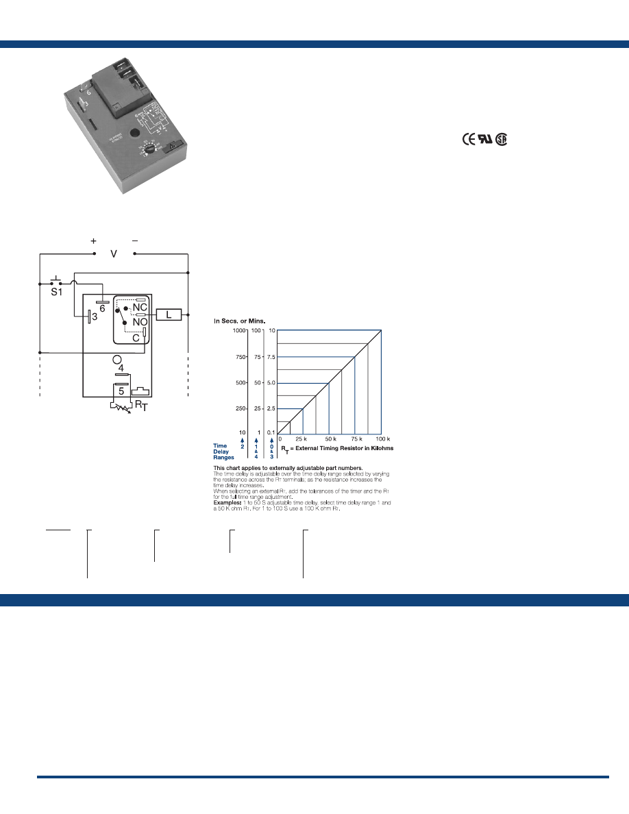
57
www.ssac.com • 800-843-8848 • fax: 605-348-5685
HRDS Series
Timer - Single Shot
Available Models:
Time Delay
Type . . . . . . . . . . . . . . . . . . . . . . . . . . . . . . . . . . . .Microcontroller circuitry
Range . . . . . . . . . . . . . . . . . . . . . . . . . . . . . . . . . . .
0.1s - 100m in 5 adjustable ranges or fixed
Repeat Accuracy . . . . . . . . . . . . . . . . . . . . . . . . .
±0.5% or 20 ms, whichever is greater
Tolerance (Factory Calibration) . . . . . . . . . . . . .
±1%, ±5%
Reset Time . . . . . . . . . . . . . . . . . . . . . . . . . . . . . . .
≤ 150ms
Initiate Time . . . . . . . . . . . . . . . . . . . . . . . . . . . . .
≤ 20ms
Time Delay vs Temp. & Voltage
. . . . . . . . . . . .
±2%
Input
Voltage
. . . . . . . . . . . . . . . . . . . . . . . . . . . . . . . . . .
12 or 24VDC; 24, 120, or 230VAC
Tolerance 12VDC & 24VDC
. . . . . . . .
-15% - 20%
24 to 230VAC
. . . . . . . .
-20% - 10%
AC Line Frequency . . . . . . . . . . . . . . . . . . . . . . .
50/60 Hz
Power Consumption . . . . . . . . . . . . . . . . . . . . . .
AC ≤ 4VA; DC ≤ 2W
Output
Type . . . . . . . . . . . . . . . . . . . . . . . . . . . . . . . . . . . .
Electromechanical relay
Form . . . . . . . . . . . . . . . . . . . . . . . . . . . . . . . . . . . .
Non-isolated, SPDT
Ratings: SPDT-NO SPDT-NC
General Purpose 125/240VAC 30A 15A
Resistive 125/240VAC 30A 15A
28VDC 20A 10A
Motor Load 125VAC 1 hp* 1/4 hp**
240VAC 2 hp** 1 hp**
Life
. . . . . . . . . . . . . . . . . . . . . . . . . . . . . . . . . . . . .
Mechanical - 1 x 10
6
;
Electrical - 1 x 10
5
, *3 x 10
4
,
**6,000
Protection
Surge . . . . . . . . . . . . . . . . . . . . . . . . . . . . . . . . . . .
IEEE C62.41-1991 Level A
Circuitry . . . . . . . . . . . . . . . . . . . . . . . . . . . . . . . . Encapsulated
Dielectric Breakdown
. . . . . . . . . . . . . . . . . . . . .
≥ 2000V RMS terminals to mounting surface
Insulation Resistance . . . . . . . . . . . . . . . . . . . . . .
≥ 100 MΩ
Polarity . . . . . . . . . . . . . . . . . . . . . . . . . . . . . . .
DC units are reverse polarity protected
Mechanical
Mounting . . . . . . . . . . . . . . . . . . . . . . . . . . . . . . .
Surface mount with one #10 (M5 x 0.8) screw
Dimensions . . . . . . . . . . . . . . . . . . . . . . . . . . . . . .
3 x 2 x 1.5 in (76.7 x 51.3 x 38.1mm)
Termination . . . . . . . . . . . . . . . . . . . . . . . . . . . . .
0.25 in. (6.35 mm) male quick connect terminals
Environmental
Operating / Storage Temperature
. . . . . . . . . .
-40° to 60°C/-40° to 85°C
Humidity . . . . . . . . . . . . . . . . . . . . . . . . . . . . . . . .
95% relative, non-condensing
Weight
. . . . . . . . . . . . . . . . . . . . . . . . . . . . . . . . . .
≅
3.9 oz (111 g)
Order Table:
Specifications
The HRDS Series combines an electromechanical
relay output with microcontroller timing circuitry.
It offers 12 to 230V operation in five options and
factory fixed, onboard or external adjustable
time delays with a repeat accuracy of ±0.5%. The
output contact rating allows for direct operation of
heavy loads, such as compressors, pumps, blower
motors, heaters, etc. This series is ideal for OEM
applications where cost is a factor.
Operation (Single Shot):
Input voltage must be applied before and during timing.
Upon momentary or maintained closure of the initiate
switch, the output relay energizes for a measured interval
of time. At the end of the delay, the output de-energizes.
Opening or reclosing the initiate switch during timing has
no affect on the time delay. The output will energize if the
initiate switch is closed when input voltage is applied.
Reset: Reset occurs when the time delay is complete and
the initiate switch is opened. Loss of input voltage resets
the time delay and output.
For more information see:
Appendix A, pages 156-164 for function descriptions
and diagrams .
Appendix B, page 165, Figure 2 for dimensional drawing.
Features:
• 30A, SPDT, NO output contacts
• 12 to 230V operation in 5 options
•
Encapsulated circuitry
• Delays from 0.1s - 100m in 5 ranges
• ±0.5% repeat accuracy
• Factory fixed, onboard or external adjust
Approvals:
Connection:
HRDS120
HRDS124
HRDS21120S
HRDS220
HRDS221
HRDS222
HRDS223
HRDS313M
HRDS320
HRDS321
HRDS322
HRDS323
HRDS324
HRDS420
HRDS421
HRDS422
HRDS423
HRDS424
HRDS430
Auxiliary Products:
•
External ad just potentiometer:
P/N: P1004-95
P/N: P1004-95-X
•
Mounting bracket:
P/N: P1023-6
•
Female quick connect:
P/N: P1015-13 (AWG 10/12)
P/N: P1015-64 (AWG 14/16)
•
Quick connect t o s crew ad aptor:
P/N: P1015-18
•
Versa-knob:
P/N: P0700-7
•
DIN rail:
P/N: C103PM
(Al)
•
DIN rail adaptor:
P/N: P1023-20
HRDS
X
Input Voltage
─
1
- 12VDC
─
2
- 24VAC
─
3
- 24VDC
─
4
- 120VAC
─
6
- 230VAC
X
Adjustment
─
1
- Fixed
─
2
- Onboard knob
─
3
- External adjust
X
Time Tolerance
─
Blank
- ±5%
─
A
- ±1%
X
Time Delay*
─
0
- 0.1 - 10s
─
1
- 1 - 100s
─
2
- 10 - 1000s
─
3
- 0.1 - 10m
─
4
- 1 - 100m
*If fixed delay is selected, insert delay (
0 .1
- 1000
) followed by (
S
) sec, or (
0 .1 - 100
)
(
M
) min .
L1
N/L2
NO = Normally Open
S1 = Initiate Switch
L = Load
C = Common, Transfer Contact
External Resistance vs . Time Delay:
If desired part number is not listed, please call us to
see if it is technically possible to build .
NOTE: A knob, or terminals 4 & 5 are only
included on adjustable units. R
T
is used
when external adjustment is ordered. Relay
contacts are not isolated .
Courtesy of Steven Engineering, Inc.-230 Ryan Way, South San Francisco, CA 94080-6370-Main Office: (650) 588-9200-Outside Local Area: (800) 258-9200-www.stevenengineering.com
Littelfuse-catalog-html.html
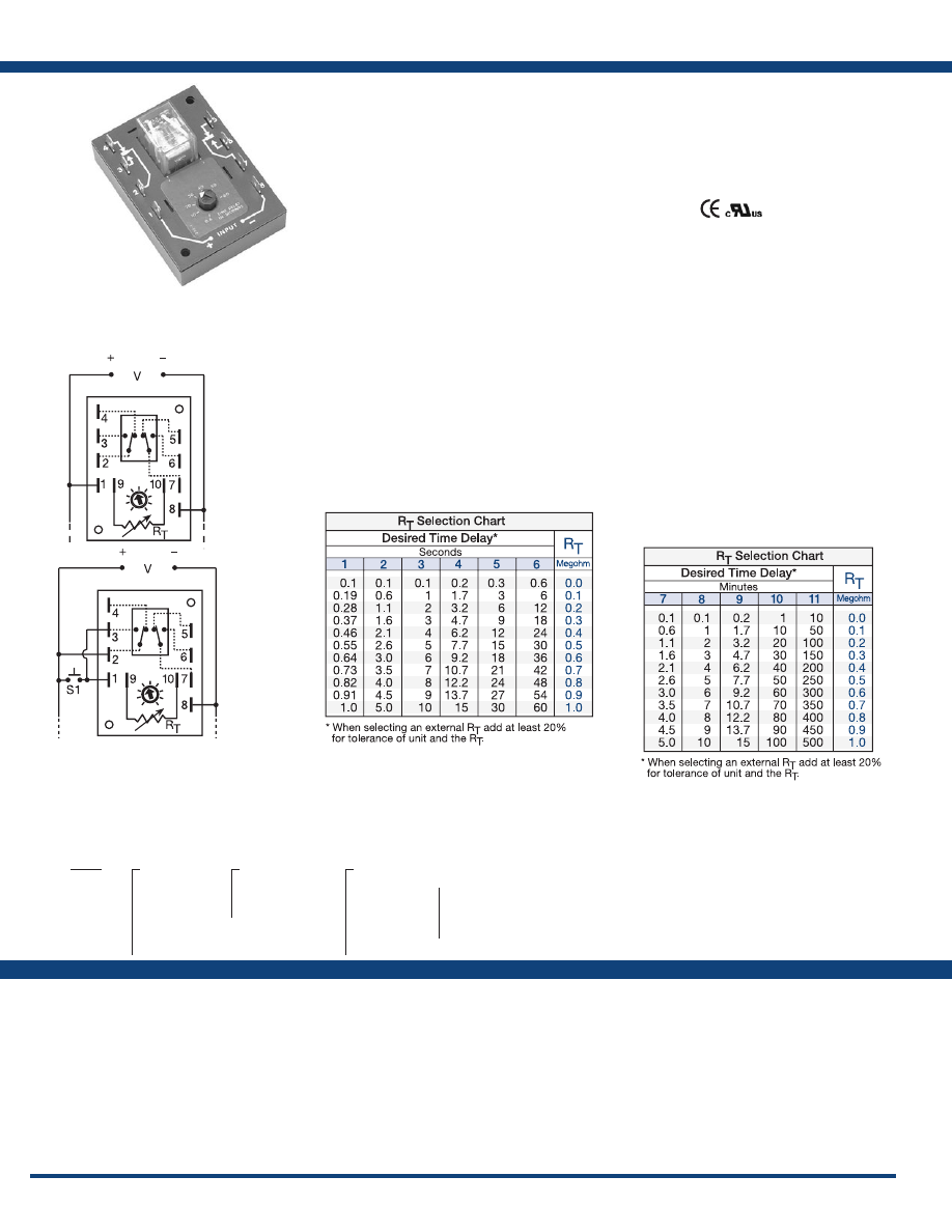
58
www.ssac.com • 800-843-8848 • fax: 605-348-5685
Features:
• Factory fixed, onboard or external adjust
• Delays from 0.1s - 1000m in 11 ranges
• ±0.5% repeat accuracy
• ± 10% factory calibration
•
Encapsulated digital circuitry
• Isolated 10A, DPDT output contacts
Approvals:
ERDI Series
Timer - Interval/Single Shot
Available Models:
Time Delay
Type . . . . . . . . . . . . . . . . . . . . . . . . . . . . . . . . . . . Digital integrated circuitry
Range . . . . . . . . . . . . . . . . . . . . . . . . . . . . . . . . . .
0.1s - 500m in 11 adjustable ranges,
0.1s - 1000m fixed
Adjustment
. . . . . . . . . . . . . . . . . . . . . . . . . . . . .
Knob, external adjust, or fixed
Repeat Accuracy . . . . . . . . . . . . . . . . . . . . . . . .
±0.5%
Tolerance (Factory Calibration) . . . . . . . . . . . .
≤ ±10%
Reset Time . . . . . . . . . . . . . . . . . . . . . . . . . . . . . .
≤ 150ms
Time Delay vs Temp. & Voltage
. . . . . . . . . . .
≤ ±2%
Input
Voltage
. . . . . . . . . . . . . . . . . . . . . . . . . . . . . . . . .
12, 24, or 120VDC; 24, 120, or 230VAC
Tolerance 12VDC & 24VDC/AC
. . . . . .
-15% - 20%
120VDC/AC & 230VAC
. . . . . .
-20% - 10%
AC Line Frequency . . . . . . . . . . . . . . . . . . . . . .
50/60 Hz
Output
Type . . . . . . . . . . . . . . . . . . . . . . . . . . . . . . . . . . . Isolated relay contacts
Form . . . . . . . . . . . . . . . . . . . . . . . . . . . . . . . . . . . DPDT
Rating . . . . . . . . . . . . . . . . . . . . . . . . . . . . . . . . .
10A resistive @ 120/240VAC & 28VDC;
1/3 hp @ 120/240VAC
Life
. . . . . . . . . . . . . . . . . . . . . . . . . . . . . . . . . . . .
Mechanical - 1 x 10
7
; Electrical - 1 x 10
6
Protection
Isolation Voltage
. . . . . . . . . . . . . . . . . . . . . . . .
≥ 1500V RMS input to output
Insulation Resistance . . . . . . . . . . . . . . . . . . . . .
≥ 100 MΩ
Polarity . . . . . . . . . . . . . . . . . . . . . . . . . . . . . . . .
DC units are reverse polarity protected
Mechanical
Mounting . . . . . . . . . . . . . . . . . . . . . . . . . . . . . .
Surface mount with two #6 (M3.5 x 0.6) screws
Dimensions . . . . . . . . . . . . . . . . . . . . . . . . . . . . .
3.5 x 2.5 x 1.7 in. (88.9 x 63.5 x 43.2 mm)
Termination . . . . . . . . . . . . . . . . . . . . . . . . . . . .
0.25 in. (6.35 mm) male quick connect terminals
Environmental
Operating / Storage Temperature
. . . . . . . . .
-40° to 65°C / -40° to 85°C
Weight
. . . . . . . . . . . . . . . . . . . . . . . . . . . . . . . . .
≅
5.7 oz (162 g)
Specifications
Order Table:
Connection:
Econo-Timers are a combination of digital
electronics and an electromechanical relay. DPDT
relay output for relay logic circuits, and isolation
of input to output voltages. For applications, such
as interval on, pulse shaping, minimum run time,
etc. The ERD Series is encapsulated to protect the
circuitry from shock, vibration and humidity.
Operation (Interval):
Upon application of input voltage, time delay begins, and
output relay energizes. At the end of time delay, output
de-energizes until input voltage is removed.
Reset: Removing input voltage resets the time delay and
the output.
Operation (Single Shot):
Input voltage must be applied before & during timing.
Upon momentary or maintained closure of initiate switch,
output relay energizes for time delay. At the end of the
delay, output de-energizes. Opening or reclosing initiate
switch during timing has no affect on time delay. Output
will energize if initiate switch is closed when input voltage
is applied .
Reset: Reset occurs when time delay is complete & initiate
switch is opened. Loss of input voltage resets time delay
& output.
For more information see:
Appendix A, pages 156-164 for function descriptions
and diagrams .
Appendix B, page 165, Figure 10 for dimensional drawing.
ERDI1210
ERDI123
ERDI323
ERDI326
ERDI4311
ERDI436
ERDI628
Auxiliary Products:
•
External ad just potentiometer:
P/N: P1004-16
P/N: P1004-16-X
•
Female quick connect:
P/N: P1015-64 (AWG 14/16)
•
Quick connect t o s crew ad aptor:
P/N: P1015-18
•
Versa-knob:
P/N: P0700-7
L1
N/L2
L1
N/L2
Interval
Single Shot
2-3 & 7-6 are Normally Open Contacts (NO)
2-4 & 7-5 are Normally Closed Contacts (NC)
ERDI
X
Input Voltage
─
1
- 12VDC
─
2
- 24VAC
─
3
- 24VDC
─
4
- 120VAC
─
5
- 120VDC
─
6
- 230VAC
X
Adjustment
─
1
- Fixed
─
2
- Onboard knob
─
3
- External adjust
X
Time Delay*
─
1
- 0.1 - 1s
─
2
- 0.1 - 5s
─
3
- 0.1 - 10s
─
4
- 0.2 - 15s
─
5
- 0.3 - 30s
─
6
- 0.6 - 60s
─
7
- 0.1 - 5m
─
8
- 0.1 - 10m
─
9
- 0.2 - 15m
─
10
- 1 - 100m
─
11
- 10 - 500m
*If fixed delay is selected, insert delay (
0 .1 - 1000
)
followed by (
S
) sec, or (
M
) min .
If desired part number is not listed, please call us to
see if it is technically possible to build .
A knob, or terminals 9 & 10 are included on
adjustable units. Relay contacts are isolated.
R
T
is used when external adjustment is
ordered .
Courtesy of Steven Engineering, Inc.-230 Ryan Way, South San Francisco, CA 94080-6370-Main Office: (650) 588-9200-Outside Local Area: (800) 258-9200-www.stevenengineering.com
Littelfuse-catalog-html.html
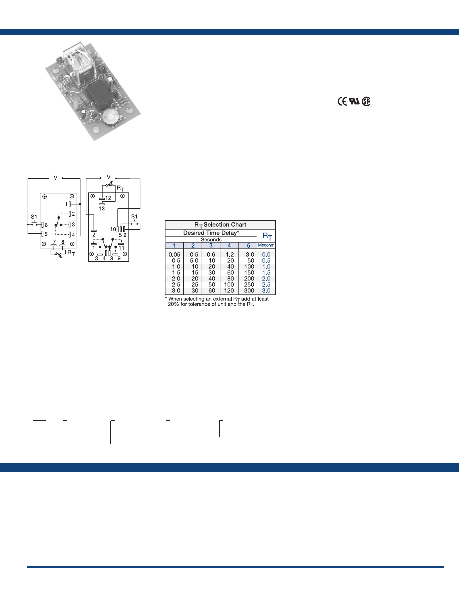
59
www.ssac.com • 800-843-8848 • fax: 605-348-5685
ORS Series
Timer - Single Shot
Available Models:
Time Delay
Type . . . . . . . . . . . . . . . . . . . . . . . . . . . . . . . . . . . Analog circuitry
Range . . . . . . . . . . . . . . . . . . . . . . . . . . . . . . . . . .
0.05 - 300s in 5 adjustable ranges or fixed
Repeat Accuracy . . . . . . . . . . . . . . . . . . . . . . . .
±2% or 20ms, whichever is greater
Tolerance (Factory Calibration) . . . . . . . . . . . .
Adjustable: guaranteed range
Fixed: ±10%
Reset Time . . . . . . . . . . . . . . . . . . . . . . . . . . . . . .
≤ 50ms
Initiate Time . . . . . . . . . . . . . . . . . . . . . . . . . . . .
≤ 70ms
Time Delay vs Temp. & Voltage
. . . . . . . . . . .
≤ ±10%
Input
Voltage
. . . . . . . . . . . . . . . . . . . . . . . . . . . . . . . . .
24, 120, or 230VAC
Tolerance 24VAC
. . . . . .
-15% - 20%
120 & 230VAC
. . . . . .
-20% - 10%
AC Line Frequency . . . . . . . . . . . . . . . . . . . . . .
50/60 Hz
Power Consumption . . . . . . . . . . . . . . . . . . . . .
2.25W
Output
Type . . . . . . . . . . . . . . . . . . . . . . . . . . . . . . . . . . .
Electromechanical relay
Form . . . . . . . . . . . . . . . . . . . . . . . . . . . . . . . . . . .
Isolated, SPDT or DPDT
Rating . . . . . . . . . . . . . . . . . . . . . . . . . . . . . . . . .
10A resistive @ 120/240VAC & 28VDC;
1/3 hp @ 120/240VAC
Life
. . . . . . . . . . . . . . . . . . . . . . . . . . . . . . . . . . . .
Mechanical - 1x10
7
; Electrical - 1x10
6
Protection
Isolation Voltage
. . . . . . . . . . . . . . . . . . . . . . . .
≥1500V RMS input to output
Mechanical
Mounting . . . . . . . . . . . . . . . . . . . . . . . . . . . . . .
Surface mount with four #6 (M3.5 x 0.6) screws
Termination . . . . . . . . . . . . . . . . . . . . . . . . . . . .
0.25 in. (6.35 mm) male quick connect terminals
Environmental
Operating / Storage Temperature
. . . . . . . . .
-20° to 65°C / -30° to 85°C
Weight
. . . . . . . . . . . . . . . . . . . . . . . . . . . . . . . . .
≅
2.7 oz (77 g)
Order Table:
Specifications
The ORS Series’ open PCB construction offers
the user good economy without sacrificing
performance and reliability. The output relay
is available in isolated, 10A, DPDT or SPDT
forms. The time delay may be ordered as factory
fixed, onboard knob, or external adjustment. All
connections are 0.25 in. (6.35 mm) male quick
connect terminals .
Operation (Single Shot):
Input voltage must be applied before and during
timing. Upon momentary or maintained closure of the
initiate switch (leading edge triggered), the output relay
energizes for a measured interval of time. At the end
of the time delay, the output de-energizes. Opening or
reclosing the initiate switch during timing has no affect
on the time delay. The output will energize if the initiate
switch is closed when input voltage is applied.
Reset: Reset occurs when the time delay is complete and
the initiate switch is opened. Loss of input voltage resets
the time delay and output.
For more information see:
Appendix A, pages 156-164 for function descriptions
and diagrams .
Appendix B, page 165, Figure 11 for dimensional drawing.
Features:
•
Low cost open PCB construction
•
Momentary or maintained initiation
• 10A, DPDT or SPDT output contacts
• Delays from 0.05s - 300s in 5 ranges
• ±2% repeat accuracy
• ±10% factory calibration
Approvals:
Connection:
ORS120A1180
ORS120A33
ORS230A150SD
Auxiliary Products:
•
External ad just potentiometer:
P/N: P1004-12
P/N: P1004-12-X
•
Female quick connect:
P/N: P1015-64 (AWG 14/16)
•
Quick connect t o s crew ad aptor:
P/N: P1015-18
•
Versa-knob:
P/N: P0700-7
L1
N/L2
L1
N/L2
SPDT
DPDT
ORS
X
Input Voltage
─
24A
- 24VAC
─
120A
- 120VAC
─
230A
- 230VAC
X
Adjustment
─
1
- Fixed
─
2
- Onboard knob
─
3
- External adjust
X
Time Delay*
─
1
- 0.05 - 3s
─
2
- 0.5 - 30s
─
3
- 0.6 - 60s
─
4
- 1.2 - 120s
─
5
- 3 - 300s
X
Output Form
─
Blank
- SPDT
─
D
- DPDT
*If fixed delay is selected, insert delay
(
0 .05 - 300
) in seconds .
If desired part number is not listed, please call us to
see if it is technically possible to build .
Relay contacts are isolated .
R
T
is used when external adjustment is ordered.
Courtesy of Steven Engineering, Inc.-230 Ryan Way, South San Francisco, CA 94080-6370-Main Office: (650) 588-9200-Outside Local Area: (800) 258-9200-www.stevenengineering.com
Littelfuse-catalog-html.html
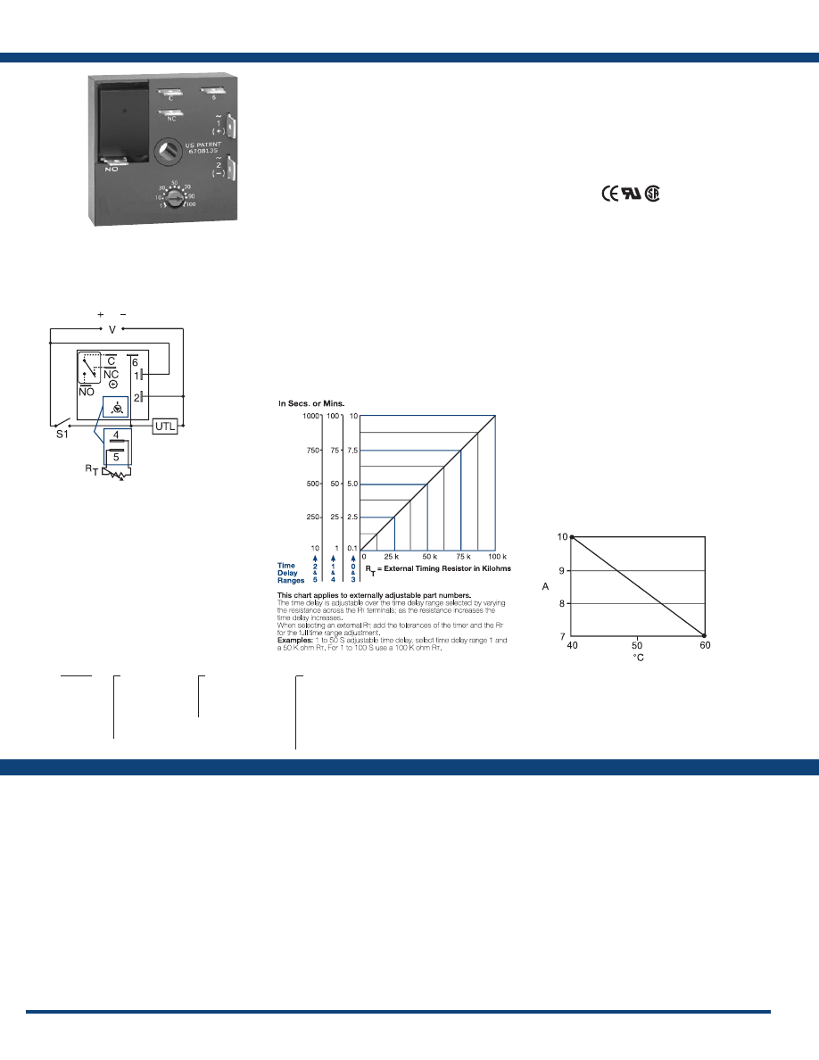
60
www.ssac.com • 800-843-8848 • fax: 605-348-5685
Features:
•
Compact time delay relay
• ±0.5% repeat accuracy
• Isolated, 10A, SPDT output contacts
• Factory fixed, onboard or external adjust
• Delays from 0.1s - 1000m in 6 ranges
• ±5% factory calibration
• Input voltages from 12 to 230V in 5 options
Approvals:
KRDS Series
Timer - Single Shot
Available Models:
Time Delay
Type . . . . . . . . . . . . . . . . . . . . . . . . . . . . . . . . . . .
Microcontroller with watchdog circuitry
Range . . . . . . . . . . . . . . . . . . . . . . . . . . . . . . . . . .
0.1s - 1000m in 6 adjustable ranges or fixed
Repeat Accuracy . . . . . . . . . . . . . . . . . . . . . . . .
±0.5% or 20ms, whichever is greater
Tolerance (Factory Calibration) . . . . . . . . . . . .
≤ ±5%
Reset Time . . . . . . . . . . . . . . . . . . . . . . . . . . . . . .
≤ 150ms
Initiate Time . . . . . . . . . . . . . . . . . . . . . . . . . . . .
≤ 40ms
Time Delay vs Temp. & Voltage
. . . . . . . . . . .
≤ ±5%
Input
Voltage
. . . . . . . . . . . . . . . . . . . . . . . . . . . . . . . . .
12, 24 or 110VDC; 24, 120 or 230VAC
Tolerance 12VDC & 24VDC/AC
. . . . . . .
-15% - 20%
110VDC, 120VAC or 230VAC
. . . . . . .
-20%- 10%
AC Line Frequency / DC Ripple
. . . . . . . . . . .
50/60 Hz / ≤ 10%
Power Consumption . . . . . . . . . . . . . . . . . . . . .
AC ≤ 2VA; DC ≤ 2W
Output
Type . . . . . . . . . . . . . . . . . . . . . . . . . . . . . . . . . . .Isolated relay contacts
Form . . . . . . . . . . . . . . . . . . . . . . . . . . . . . . . . . . .SPDT
Rating (at 40°C)
. . . . . . . . . . . . . . . . . . . . . . . . .
10A resistive @ 125VAC;
5A resistive @ 230VAC & 28VDC;
1/4 hp @ 125VAC
Life (Operations)
. . . . . . . . . . . . . . . . . . . . . . . .
Mechanical - 1 x 10
7
; Electrical - 1 x 10
5
Protection
Circuitry . . . . . . . . . . . . . . . . . . . . . . . . . . . . . . .Encapsulated
Isolation Voltage
. . . . . . . . . . . . . . . . . . . . . . . .
≥ 1500V RMS input to output
Insulation Resistance . . . . . . . . . . . . . . . . . . . . .
≥ 100 MΩ
Polarity . . . . . . . . . . . . . . . . . . . . . . . . . . . . . . . .
DC units are reverse polarity protected
Mechanical
Mounting . . . . . . . . . . . . . . . . . . . . . . . . . . . . . .
Surface mount with one #10 (M5 x 0.8) screw
Dimensions . . . . . . . . . . . . . . . . . . . . . . . . . . . . .
2 x 2 x 1.21 in. (50.8 x 50.8 x 30.7 mm)
Termination . . . . . . . . . . . . . . . . . . . . . . . . . . . .
0.25 in. (6.35 mm) male quick connect terminals
Environmental
. . . . . . . . . . . . . . . . . . . . . . . . . .
Operating / Storage Temperature
. . . . . . . . .
-40° to 60°C/-40° to 85°C
Humidity . . . . . . . . . . . . . . . . . . . . . . . . . . . . . . .
95% relative, non-condensing
Weight
. . . . . . . . . . . . . . . . . . . . . . . . . . . . . . . . .
≅
2.6 oz (74 g)
Specifications
Order Table:
Connection:
The KRDS Series is a compact time delay relay
measuring only 2 in. (50.8 mm) square. Its
microcontroller timing circuit provides excellent
repeat accuracy and stability . Encapsulation
protects against shock, vibration, and humidity.
The KRDS Series is a cost effective approach for
OEM applications that require small size, isolation,
reliability, and long life.
Operation (Single Shot):
Input voltage must be applied before and during timing.
Upon momentary or maintained closure of the initiate
switch, the output relay energizes for a measured interval
of time. At the end of the delay, the output de-energizes.
Opening or reclosing the initiate switch during timing has
no affect on the time delay. The output will energize if the
initiate switch is closed when input voltage is applied.
Reset: Reset occurs when the time delay is complete and
the initiate switch is opened. Loss of input voltage resets
the time delay and output.
For more information see:
Appendix A, pages 156-164 for function descriptions
and diagrams .
Appendix B, page 165, Figure 1 for dimensional drawing.
KRDS120
KRDS221
KRDS225
KRDS424
KRDS430
Auxiliary Products:
•
External ad just potentiometer:
P/N: P1004-95
P/N: P1004-95-X
•
Mounting bracket:
P/N: P1023-6
•
Female quick connect:
P/N: P1015-13 (AWG 10/12)
P/N: P1015-64 (AWG 14/16)
•
Quick connect t o s crew ad aptor:
P/N: P1015-18
•
Versa-knob:
P/N: P0700-7
•
DIN rail:
P/N: C103PM
(Al)
•
DIN rail adaptor:
P/N: P1023-20
KRDS
X
Input Voltage
─
1
- 12VDC
─
2
- 24VAC/DC
─
4
- 120VAC
─
5
- 110VDC
─
6
- 230VAC
X
Adjustment
─
1
- Fixed
─
2
- Onboard knob
─
3
- External adjust
X
Time Delay*
─
0
- 0.1 - 10s
─
1
- 1 - 100s
─
2
- 10 - 1000s
─
3
- 0.1 - 10m
─
4
- 1 - 100m
─
5
- 10 - 1000m
*If fixed delay is selected, insert delay (
0 .1
- 1000
) followed by (
S
) sec, or (
M
) min .
L1
N/L2
V = Voltage
S1 = Initiate Switch
C = Common, Transfer Contact
NO = Normally Open
NC = Normally Closed
UTL = Untimed Load
External Resistance vs . Time Delay:
If desired part number is not listed, please call us to
see if it is technically possible to build .
R
T
is used when external adjustment is ordered.
A knob is supplied for adjustable units. The
untimed load is optional . Relay contacts are
isolated .
Output Current/Ambient Temperature:
Courtesy of Steven Engineering, Inc.-230 Ryan Way, South San Francisco, CA 94080-6370-Main Office: (650) 588-9200-Outside Local Area: (800) 258-9200-www.stevenengineering.com
Littelfuse-catalog-html.html

61
www.ssac.com • 800-843-8848 • fax: 605-348-5685
TDUS Series
Timer - Single Shot
Available Models:
Time Delay
Range* . . . . . . . . . . . . . . . . . . . . . . . . . . . . . . . . .
0.1 - 102.3s in 0.1s increments
1 - 1023s in 1s increments
0.1 - 102.3m in 0.1m increments
Repeat Accuracy . . . . . . . . . . . . . . . . . . . . . . . .
±0.5% or 20 ms, whichever is greater
Setting Accuracy . . . . . . . . . . . . . . . . . . . . . . . .
≤ ±2% or 20 ms, whichever is greater
Reset Time . . . . . . . . . . . . . . . . . . . . . . . . . . . . . .
≤ 150ms
Initiate Time . . . . . . . . . . . . . . . . . . . . . . . . . . . .
≤ 20ms
Time Delay vs Temp. & Voltage
. . . . . . . . . . .
≤ ±5%
Input
Voltage/Tolerance
. . . . . . . . . . . . . . . . . . . . . . .
24 to 240VAC, 12 to 24VDC /±20%
AC Line Frequency / DC Ripple
. . . . . . . . . . .
50/60 Hz / ≤ 10%
Power Consumption . . . . . . . . . . . . . . . . . . . . .
AC ≤ 2VA; DC ≤ 1W
Output
Type . . . . . . . . . . . . . . . . . . . . . . . . . . . . . . . . . . .Solid state
Form . . . . . . . . . . . . . . . . . . . . . . . . . . . . . . . . . . .
NO, closed during timing
Rating . . . . . . . . . . . . . . . . . . . . . . . . . . . . . . . . .
1A steady state, 10A inrush at 60°C
Voltage Drop
. . . . . . . . . . . . . . . . . . . . . . . . . . .AC
≅
2.5V @ 1A; DC
≅
1V @ 1A
Off State Leakage Current
. . . . . . . . . . . . . . . .AC
≅
5mA @ 230VAC; DC
≅
1 mA
Protection
Circuitry . . . . . . . . . . . . . . . . . . . . . . . . . . . . . . .Encapsulated
Dielectric Breakdown
. . . . . . . . . . . . . . . . . . . .
≥ 2000V RMS terminals to mounting surface
Insulation Resistance . . . . . . . . . . . . . . . . . . . . .
≥ 100 MΩ
Polarity . . . . . . . . . . . . . . . . . . . . . . . . . . . . . . . .
DC units are reverse polarity protected
Mechanical
Mounting . . . . . . . . . . . . . . . . . . . . . . . . . . . . . .
Surface mount with one #10 (M5 x 0.8) screw
Dimensions . . . . . . . . . . . . . . . . . . . . . . . . . . . . .
2 x 2 x 1.21 in (50.8 x 50.8 x 30.7 mm)
Termination . . . . . . . . . . . . . . . . . . . . . . . . . . . .
0.25 in. (6.35 mm) male quick connect terminals
Environmental
Operating / Storage Temperature
. . . . . . . . .
-40° to 60°C / -40° to 85°C
Humidity . . . . . . . . . . . . . . . . . . . . . . . . . . . . . . .
95% relative, non-condensing
Weight
. . . . . . . . . . . . . . . . . . . . . . . . . . . . . . . . .
≅
2.4 oz (68 g)
*For CE approved applications, power must be removed from the unit when a switch position
is changed.
Order Table:
Specifications
The TDUS Series combines digital timing circuitry
with universal voltage operation. Voltages of
24 to 240VAC and 12 to 24VDC are available in
three ranges. The TDUS Series offers DIP switch
selectable time delays ranging from 0.1 seconds to
102.3 minutes in three ranges. Its 1A rated output,
ability to operate on multiple voltages, and wide
range of switch selectable time delays make the
TDUS Series an excellent choice for process control
systems and OEM equipment .
Operation (Single Shot):
Input voltage must be applied before and during timing.
Upon momentary or maintained closure of the initiate
switch (leading edge triggered), the output energizes for a
measured interval of time. At the end of the delay, the output
de-energizes. Opening or reclosing the initiate switch during
timing has no affect on the time delay. The output will energize
if the initiate switch is closed when input voltage is applied.
Reset: Reset occurs when the time delay is complete and the
initiate switch is opened. Loss of input voltage resets the time
delay and output .
For more information see:
Appendix A, pages 156-164 for function descriptions
and diagrams .
Appendix B, page 165, Figure 1 for dimensional drawing.
Features:
• Switch selectable time setting
• 0.1s - 102.3m in 3 ranges
• ± 0.5% repeat accuracy
• ± 2% setting accuracy
• 1A, solid-state output
•
Encapsulated
• Wide voltage ranges
Approvals:
Connection:
TDUS3000A
TDUS3002A
TDUSL3000A
Auxiliary Products:
•
Female quick connect:
P/N: P1015-13 (AWG 10/12)
P/N: P1015-64 (AWG 14/16)
P/N: P1015-14 (AWG 18/22)
•
Quick connect t o s crew ad aptor:
P/N: P1015-18
•
DIN rail:
P/N: C103PM
(Al)
•
DIN rail adaptor:
P/N: P1023-20
Input Voltage Range
24 to 120VAC
100 to 240VAC
12 to 24VDC
24 to 120VAC
100 to 240VAC
12 to 24VDC
24 to 120VAC
100 to 240VAC
12 to 24VDC
Time Range
0.1 - 102.3s
0.1 - 102.3s
0.1 - 102.3s
1 - 1023s
1 - 1023s
1 - 1023s
0.1 - 102.3m
0.1 - 102.3m
0.1 - 102.3m
Part Number
TDUSL3000A
TDUSL3001A
TDUSL3002A
TDUS3000A
TDUS3001A
TDUS3002A
TDUSH3000A
TDUSH3001A
TDUSH3002A
L1
N/L2
UTL = Optional Untimed Load
S1 = Initiate Switch
L = Timed Load
If desired part number is not listed, please call us to
see if it is technically possible to build .
Courtesy of Steven Engineering, Inc.-230 Ryan Way, South San Francisco, CA 94080-6370-Main Office: (650) 588-9200-Outside Local Area: (800) 258-9200-www.stevenengineering.com
Littelfuse-catalog-html.html
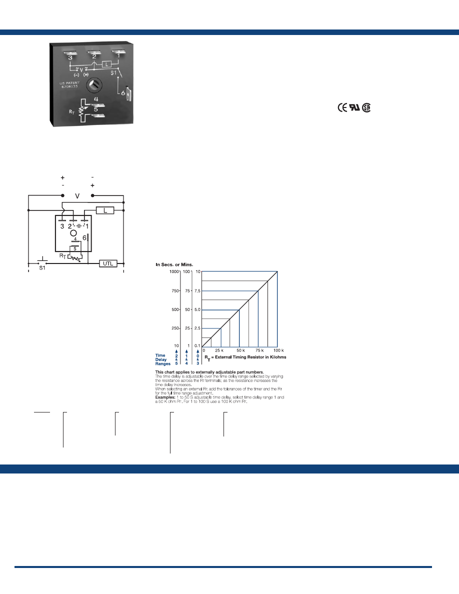
62
www.ssac.com • 800-843-8848 • fax: 605-348-5685
Features:
• Fixed or adjustable delays 0.1s - 1000m in
6 ranges
• ±0.5% repeat accuracy
• ±1% factory calibration
• 12VDC to 230VAC in 5 options
• 1A, solid-state output
•
Encapsulated
Approvals:
TSDS Series
Timer - Single Shot
Available Models:
Time Delay
Range . . . . . . . . . . . . . . . . . . . . . . . . . . . . . . . . . .
0.1s - 1000m in 6 adjustable ranges or fixed
Repeat Accuracy . . . . . . . . . . . . . . . . . . . . . . . .
±0.5% or 20ms, whichever is greater
Tolerance (Factory Calibration) . . . . . . . . . . . .
≤ ±1%
Reset Time . . . . . . . . . . . . . . . . . . . . . . . . . . . . . .
≤ 150ms
Initiate Time . . . . . . . . . . . . . . . . . . . . . . . . . . . .
≤ 20ms
Time Delay vs Temp. & Voltage
. . . . . . . . . . .
≤ ±2%
Input
Voltage
. . . . . . . . . . . . . . . . . . . . . . . . . . . . . . . . .
12 or 24VDC; 24, 120, or 230VAC
Tolerance . . . . . . . . . . . . . . . . . . . . . . . . . . . . . . .
±15%
Power Consumption . . . . . . . . . . . . . . . . . . . . .
AC ≤ 2VA; DC ≤ 1W
AC Line Frequency / DC Ripple
. . . . . . . . . . .
50/60 Hz / ≤ 10%
Output
Type . . . . . . . . . . . . . . . . . . . . . . . . . . . . . . . . . . .Solid state
Form . . . . . . . . . . . . . . . . . . . . . . . . . . . . . . . . . . .
NO, closed during timing
Maximum Load Current
. . . . . . . . . . . . . . . . . .
1A steady state, 10A inrush at 60°C
Voltage Drop
. . . . . . . . . . . . . . . . . . . . . . . . . . .AC
≅
2.5V @ 1A; DC
≅
1V @ 1A
Off State Leakage Current
. . . . . . . . . . . . . . . .AC
≅
5mA @ 230VAC; DC
≅
1mA
DC Operation . . . . . . . . . . . . . . . . . . . . . . . . . . .
Positive or negative switching
Protection
Circuitry . . . . . . . . . . . . . . . . . . . . . . . . . . . . . . .Encapsulated
Dielectric Breakdown
. . . . . . . . . . . . . . . . . . . .
≥ 2000V RMS terminals to mounting surface
Insulation Resistance . . . . . . . . . . . . . . . . . . . . .
≥ 100 MΩ
Polarity . . . . . . . . . . . . . . . . . . . . . . . . . . . . . . . .
DC units are reverse polarity protected
Mechanical
Mounting . . . . . . . . . . . . . . . . . . . . . . . . . . . . . .
Surface mount with one #10 (M5 x 0.8) screw
Dimensions . . . . . . . . . . . . . . . . . . . . . . . . . . . . .
2 x 2 x 1.21 in. (50.8 x 50.8 x 30.7 mm)
Termination . . . . . . . . . . . . . . . . . . . . . . . . . . . .
0.25 in. (6.35 mm) male quick connect terminals
Environmental
Operating / Storage Temperature
. . . . . . . . .
-40° to 75°C / -40° to 85°C
Humidity . . . . . . . . . . . . . . . . . . . . . . . . . . . . . . .
95% relative, non-condensing
Weight
. . . . . . . . . . . . . . . . . . . . . . . . . . . . . . . . .
≅
2.4 oz (68 g)
Specifications
Order Table:
Connection:
The TSD Series is designed for more demanding
commercial and industrial applications where
small size and accurate performance are required.
The factory calibration for fixed time delays is
within 1% of the target time delay. The repeat
accuracy, under stable conditions, is 0.5% of the
time delay. The TSD Series is rated to operate over
an extended temperature range. Time delays of 0.1
seconds to 1000 minutes are available. The output
is rated 1A steady and 10A inrush. The modules
are totally solid state and encapsulated to protect
the electronic circuitry. This product is suitable for
many applications, including dispensing, welding,
and exposure timing.
Operation (Single Shot):
Input voltage must be applied before and during timing.
Upon momentary or maintained closure of the initiate
switch, the output energizes for a measured interval of
time. At the end of the delay, the output de-energizes.
Opening or reclosing the initiate switch during timing has
no affect on the time delay. The output will not energize if
the initiate switch is closed when input voltage is applied.
Reset: Reset occurs when the time delay is complete and
the initiate switch is opened. Loss of input voltage resets
the time delay and output.
For more information see:
Appendix A, pages 156-164 for function descriptions
and diagrams .
Appendix B, page 165, Figure 1 for dimensional drawing.
TSDS11390SP
TSDS2110S
TSDS320N
TSDS321P
TSDS421
Auxiliary Products:
•
External ad just potentiometer:
P/N: P1004-95
P/N: P1004-95-X
•
Mounting bracket:
P/N: P1023-6
•
Female quick connect:
P/N: P1015-64 (AWG 14/16)
•
Quick connect t o s crew ad aptor:
P/N: P1015-18
•
Versa-knob:
P/N: P0700-7
•
DIN rail:
P/N: C103PM
(Al)
•
DIN rail adaptor:
P/N: P1023-20
TSDS
X
Input Voltage
─
1
- 12VDC
─
2
- 24VAC
─
3
- 24VDC
─
4
- 120VAC
─
6
- 230VAC
X
Adjustment
─
1
- Fixed
─
2
- External adjust
─
3
- Onboard adjust
X
Time Delay*
─
0
- 0.1 - 10s
─
1
- 1 - 100s
─
2
- 10 - 1000s
─
3
- 0.1 - 10m
─
4
- 1 - 100m
─
5
- 10 - 1000m
X
Switching Mode
(VDC only)
─
P
- Positive
─
N
- Negative
*If fixed delay is selected, insert
delay (
0 .1 - 1000
) followed by (
S
) sec .
or (
M
) min .
L = Timed Load
UTL = Optional Untimed Load
S1 = Initiate Switch
External Resistance vs . Time Delay:
L1
N/L2
(Positive Switching)
(Negative Switching)
If desired part number is not listed, please call us to
see if it is technically possible to build .
R
T
is used when external adjustment is ordered.
Courtesy of Steven Engineering, Inc.-230 Ryan Way, South San Francisco, CA 94080-6370-Main Office: (650) 588-9200-Outside Local Area: (800) 258-9200-www.stevenengineering.com
Littelfuse-catalog-html.html
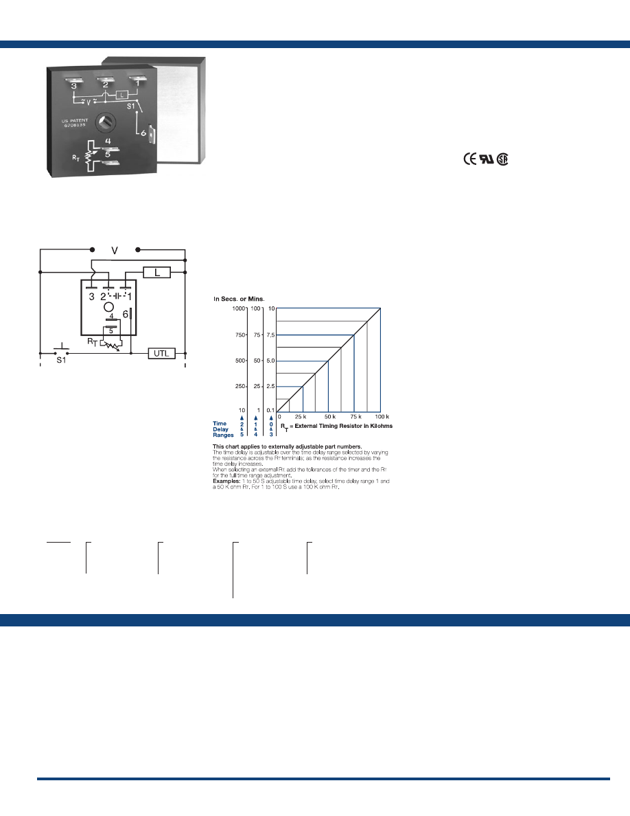
63
www.ssac.com • 800-843-8848 • fax: 605-348-5685
THDS Series
Timer - Single Shot
Available Models:
Time Delay
Range . . . . . . . . . . . . . . . . . . . . . . . . . . . . . . . . . .
0.1s - 1000m in 6 adjustable ranges or fixed
Repeat Accuracy . . . . . . . . . . . . . . . . . . . . . . . .
±0.5% or 20ms, whichever is greater
Tolerance (Factory Calibration) . . . . . . . . . . . .
≤ ±1%
Reset Time . . . . . . . . . . . . . . . . . . . . . . . . . . . . . .
≤150ms
Initiate Time . . . . . . . . . . . . . . . . . . . . . . . . . . . .
≤ 20ms
Time Delay vs Temp. & Voltage
. . . . . . . . . . .
≤ ±2%
Input
Voltage
. . . . . . . . . . . . . . . . . . . . . . . . . . . . . . . . .
24, 120, or 230VAC
Tolerance . . . . . . . . . . . . . . . . . . . . . . . . . . . . . . .
±20%
AC Line Frequency . . . . . . . . . . . . . . . . . . . . . .
50/60 Hz
Power Consumption . . . . . . . . . . . . . . . . . . . . .
≤ 2VA
Output
Type . . . . . . . . . . . . . . . . . . . . . . . . . . . . . . . . . . . Solid state
Form . . . . . . . . . . . . . . . . . . . . . . . . . . . . . . . . . . .
NO, closed during timing
Maximum Load Current Output Steady State Inrush**
A 6A 60A
B 10A 100A
C 20A 200A
Voltage Drop
. . . . . . . . . . . . . . . . . . . . . . . . . . .
≅
2.5V @ rated current
Off State Leakage Current
. . . . . . . . . . . . . . . .
≅
5mA @ 230VAC
Minimum Load Current . . . . . . . . . . . . . . . . . .
100mA
Protection
Circuitry . . . . . . . . . . . . . . . . . . . . . . . . . . . . . . . Encapsulated
Dielectric Breakdown
. . . . . . . . . . . . . . . . . . . .
≥ 2000V RMS terminals to mounting surface
Insulation Resistance . . . . . . . . . . . . . . . . . . . . .
≥ 100 MΩ
Mechanical
Mounting ** . . . . . . . . . . . . . . . . . . . . . . . . . . . .
Surface mount with one #10 (M5 x 0.8) screw
Dimensions . . . . . . . . . . . . . . . . . . . . . . . . . . . . .
2 x 2 x 1.51 in. (50.8 x 50.8 x 38.4 mm)
Termination . . . . . . . . . . . . . . . . . . . . . . . . . . . .
0.25 in. (6.35 mm) male quick connect terminals
Environmental
Operating / Storage Temperature
. . . . . . . . .
-40° to 60°C / -40° to 85°C
Humidity . . . . . . . . . . . . . . . . . . . . . . . . . . . . . . .
95% relative, non-condensing
Weight
. . . . . . . . . . . . . . . . . . . . . . . . . . . . . . . . .
≅
3.9 oz (111 g)
**Must be bolted to a metal surface using the included heat sink compound. The maximum
mounting surface temperature is 90°C. Inrush: Non-repetitive for 16ms.
Order Table:
Specifications
The THDS Series combines accurate timing
circuitry with high power solid-state switching.
It can switch motors, lamps, and heaters directly
without a contactor. You can reduce labor,
component cost, and increase reliability with these
small, easy-to-use, Digi-Power timers.
Operation (Single Shot):
Input voltage must be applied before and during timing.
Upon momentary or maintained closure of the initiate
switch, the output energizes for a measured interval of
time. At the end of the delay, the output de-energizes.
Opening or reclosing the initiate switch during timing
has no affect on the time delay. The output energizes if
the initiate switch is closed when input voltage is applied.
Reset: Reset occurs when the time delay is complete and
the initiate switch is opened. Loss of input voltage resets
the time delay and output.
For more information see:
Appendix A, pages 156-164 for function descriptions
and diagrams .
Appendix B, page 165, Figure 4 for dimensional drawing.
Features:
• High load currents up to 20A, 200A inrush
• Fixed or adjustable delays from 0.1s - 1000m
• ±0.5% repeat accuracy
• ±1% factory calibration
• 24, 120, or 230VAC
• Metallized mounting surface for heat
transfer
•
Totally solid state and encapsulated
Approvals:
Connection:
THDS230C
THDS231C
THDS232C
THDS233C
THDS234C
THDS235C
THDS410.25SA
THDS411.5SA
THDS414MC
THDS420B
THDS430C
THDS432C
THDS433C
THDS434C
THDS435C
THDS610.25SA
THDS611.5SA
Auxiliary Products:
•
External ad just potentiometer:
P/N: P1004-95
P/N: P1004-95-X
•
Female quick connect:
P/N: P1015-13 (AWG 10/12)
P/N: P1015-64 (AWG 14/16)
•
Quick connect t o s crew ad aptor:
P/N: P1015-18
•
Versa-knob:
P/N: P0700-7
THDS
X
Input Voltage
─
2
- 24VAC
─
4
- 120VAC
─
6
- 230VAC
X
Adjustment
─
1
- Fixed
─
2
- External adjust
─
3
- Onboard adjust
X
Time Delay*
─
0
- 0.1 - 10s
─
1
- 1 - 100s
─
2
- 10 - 1000s
─
3
- 0.1 - 10m
─
4
- 1 - 100m
─
5
- 10 - 1000m
X
Output Rating
─
A
- 6A
─
B
- 10A
─
C
- 20A
*If fixed delay is selected, insert
delay (
0 .1 - 1000
) followed by (
S
) sec .
or (
M
) min .
L1
N/L2
UTL = Optional Untimed Load
L = Timed Load
S1 = Initiate Switch
External Resistance vs . Time Delay:
If desired part number is not listed, please call us to
see if it is technically possible to build .
R
T
is used when external adjustment is ordered.
Courtesy of Steven Engineering, Inc.-230 Ryan Way, South San Francisco, CA 94080-6370-Main Office: (650) 588-9200-Outside Local Area: (800) 258-9200-www.stevenengineering.com
Littelfuse-catalog-html.html
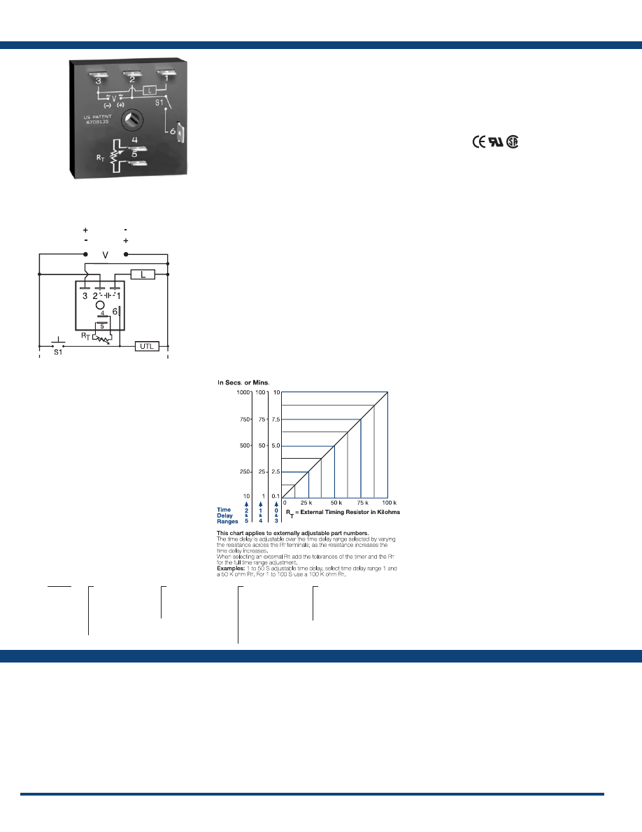
64
www.ssac.com • 800-843-8848 • fax: 605-348-5685
Features:
• Fixed or adjustable delays 0.1s - 1000m in
6 ranges
• ±0.5% repeat accuracy
• ± 5% factory calibration
• 12 to 230V in 5 ranges
• 1A, solid-state output
Approvals:
KSDS Series
Timer - Single Shot
Available Models:
Time Delay
Range . . . . . . . . . . . . . . . . . . . . . . . . . . . . . . . . . .
0.1s - 1000m in 6 adjustable ranges or fixed
Repeat Accuracy . . . . . . . . . . . . . . . . . . . . . . . .
±0.5 % or 20ms, whichever is greater
Tolerance (Factory Calibration) . . . . . . . . . . . .
≤ ±5%
Reset Time . . . . . . . . . . . . . . . . . . . . . . . . . . . . . .
≤ 150ms
Initiate Time . . . . . . . . . . . . . . . . . . . . . . . . . . . .
≤ 20ms
Time Delay vs Temp. & Voltage
. . . . . . . . . . .
≤ ±10%
Input
Voltage
. . . . . . . . . . . . . . . . . . . . . . . . . . . . . . . . .
12 or 24VDC; 24, 120, or 230VAC
Tolerance . . . . . . . . . . . . . . . . . . . . . . . . . . . . . . .
±20%
AC Line Frequency / DC Ripple
. . . . . . . . . . .
50/60 Hz / ≤ 10 %
Power Consumption . . . . . . . . . . . . . . . . . . . . .
AC ≤ 2VA; DC ≤ 1W
Output
Type . . . . . . . . . . . . . . . . . . . . . . . . . . . . . . . . . . .Solid state
Form . . . . . . . . . . . . . . . . . . . . . . . . . . . . . . . . . . .
NO, closed during timing
Maximum Load Current
. . . . . . . . . . . . . . . . . .
1A steady state, 10A inrush at 60°C
OFF State Leakage Current
. . . . . . . . . . . . . . .AC
≅
5mA @ 230VAC; DC
≅
1mA
Voltage Drop
. . . . . . . . . . . . . . . . . . . . . . . . . . .AC
≅
2.5V @ 1A; DC
≅
1V @ 1A
DC Operation . . . . . . . . . . . . . . . . . . . . . . . . . . .
Positive or negative switching
Protection
Circuitry . . . . . . . . . . . . . . . . . . . . . . . . . . . . . . .Encapsulated
Dielectric Breakdown
. . . . . . . . . . . . . . . . . . . .
≥ 2000V RMS terminals to mounting surface
Insulation Resistance . . . . . . . . . . . . . . . . . . . . .
≥ 100 MΩ
Polarity . . . . . . . . . . . . . . . . . . . . . . . . . . . . . . . .
DC units are reverse polarity protected
Mechanical
Mounting . . . . . . . . . . . . . . . . . . . . . . . . . . . . . .
Surface mount with one #10 (M5 x 0.8) screw
Dimensions . . . . . . . . . . . . . . . . . . . . . . . . . . . . .
2 x 2 x 1.21 in. (50.8 x 50.8 x 30.7 mm)
Termination . . . . . . . . . . . . . . . . . . . . . . . . . . . .
0.25 in. (6.35 mm) male quick connect terminals
Environmental
Operating / Storage Temperature
. . . . . . . . .
-40° to 60°C / -40° to 85°C
Humidity . . . . . . . . . . . . . . . . . . . . . . . . . . . . . . .
95% relative, non-condensing
Weight
. . . . . . . . . . . . . . . . . . . . . . . . . . . . . . . . .
≅
2.4 oz (68 g)
Specifications
Order Table:
Connection:
The KSDS Series is ideal for applications that
require momentary start interval timing including
dispensing, exposure timing, or pulse shaping.
This series is available for both AC and DC
voltages. This series is designed for general
purpose commercial and industrial applications
where a small, cost effective, reliable solid-state
timer is required. The factory calibration for fixed
time delays is within 5% of the target time delay.
The repeat accuracy, under stable conditions, is
0.5% of the selected time delay. Time delays of 0.1
seconds to 1000 minutes are available in 6 ranges.
The output is rated 1A steady and 10A inrush. The
modules are totally solid state and encapsulated
to protect the electronic circuitry.
Operation (Single Shot):
Input voltage must be applied before and during timing.
Upon momentary or maintained closure of the initiate
switch (leading edge triggered), the output energizes for
a measured interval of time. At the end of the delay, the
output de-energizes. Opening or reclosing the initiate
switch during timing has no affect on the time delay. The
output will not energize if the initiate switch is closed
when input voltage is applied.
Reset: Reset occurs when the time delay is complete and
the initiate switch is opened. Loss of input voltage resets
the time delay and output.
For more information see:
Appendix A, pages 156-164 for function descriptions
and diagrams .
Appendix B, page 165, Figure 1 for dimensional drawing.
KSDS1115SP
KSDS121P
KSDS130P
KSDS310.1SP
KSDS330P
KSDS415M
KSDS420
Auxiliary Products:
•
External ad just potentiometer:
P/N: P1004-95
P/N: P1004-95-X
•
Mounting bracket:
P/N: P1023-6
•
Female quick connect:
P/N: P1015-64 (AWG 14/16)
•
Quick connect t o s crew ad aptor:
P/N: P1015-18
•
Versa-knob:
P/N: P0700-7
•
DIN rail:
P/N: C103PM
(Al)
•
DIN rail adaptor:
P/N: P1023-20
KSDS
X
Input Voltage
─
1
- 12VDC
─
2
- 24VAC
─
3
- 24VDC
─
4
- 120VAC
─
6
- 230VAC
X
Adjustment
─
1
- Fixed
─
2
- External adjust
─
3
- Onboard adjust
X
Time Delay*
─
0
- 0.1 - 10s
─
1
- 1 - 100s
─
2
- 10 - 1000s
─
3
- 0.1 - 10m
─
4
- 1 - 100m
─
5
- 10 - 1000m
X
Switching Mode
(VDC only)
─
P
- Positive
─
N
- Negative
*If fixed delay is selected, insert
delay (
0 .1 - 1000
) followed by (
S
) sec .
or (
M
) min .
External Resistance vs . Time Delay:
UTL = Optional Untimed Load
L = Timed Load
S1 = Initiate Switch
L1
N/L2
(Positive Switching)
(Negative Switching)
If desired part number is not listed, please call us to
see if it is technically possible to build .
R
T
is used when external adjustment is ordered.
Courtesy of Steven Engineering, Inc.-230 Ryan Way, South San Francisco, CA 94080-6370-Main Office: (650) 588-9200-Outside Local Area: (800) 258-9200-www.stevenengineering.com
Littelfuse-catalog-html.html
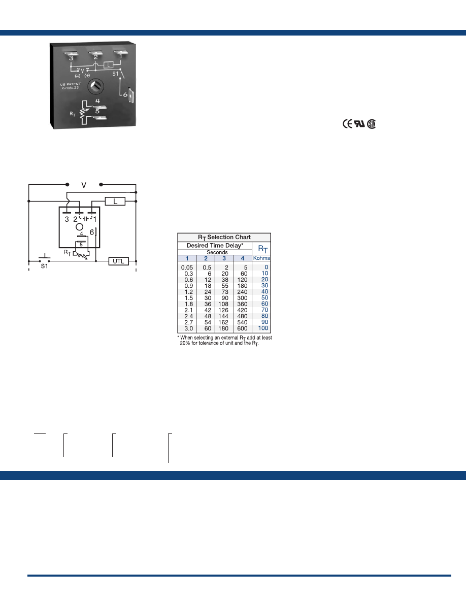
65
www.ssac.com • 800-843-8848 • fax: 605-348-5685
TSS Series
Timer - Single Shot
Available Models:
Time Delay
Range . . . . . . . . . . . . . . . . . . . . . . . . . . . . . . . . . .
0.05s - 600s in 4 adjustable ranges or fixed
Repeat Accuracy . . . . . . . . . . . . . . . . . . . . . . . .
±2% or 20ms, whichever is greater
Tolerance (Factory Calibration) . . . . . . . . . . . .
≤ ±5%
Reset Time . . . . . . . . . . . . . . . . . . . . . . . . . . . . . .
≤ 150ms
Initiate Time . . . . . . . . . . . . . . . . . . . . . . . . . . . .
≤ 20ms
Time Delay vs Temp. & Voltage
. . . . . . . . . . .
≤ ±10%
Input
Voltage
. . . . . . . . . . . . . . . . . . . . . . . . . . . . . . . . .
24, 120, or 230VAC
Tolerance . . . . . . . . . . . . . . . . . . . . . . . . . . . . . . .
±20%
AC Line Frequency . . . . . . . . . . . . . . . . . . . . . .
50/60 Hz
Power Consumption . . . . . . . . . . . . . . . . . . . . .
≤ 2VA
Output
Type . . . . . . . . . . . . . . . . . . . . . . . . . . . . . . . . . . .Solid state
Form . . . . . . . . . . . . . . . . . . . . . . . . . . . . . . . . . . .
NO, closed during timing
Maximum Load Current
. . . . . . . . . . . . . . . . . .
1A steady state, 10A inrush at 60°C
Off State Leakage Current
. . . . . . . . . . . . . . . .
≅
5mA @ 230VAC
Voltage Drop
. . . . . . . . . . . . . . . . . . . . . . . . . . .
≅
2.5V @ 1A
Protection
Circuitry . . . . . . . . . . . . . . . . . . . . . . . . . . . . . . .Encapsulated
Dielectric Breakdown
. . . . . . . . . . . . . . . . . . . .
≥ 2000V RMS terminals to mounting surface
Insulation Resistance . . . . . . . . . . . . . . . . . . . . .
≥ 100 MΩ
Mechanical
Mounting . . . . . . . . . . . . . . . . . . . . . . . . . . . . . .
Surface mount with one #10 (M5 x 0.8) screw
Dimensions . . . . . . . . . . . . . . . . . . . . . . . . . . . . .
2 x 2 x 1.21 in. (50.8 x 50.8 x 30.7 mm)
Termination . . . . . . . . . . . . . . . . . . . . . . . . . . . .
0.25 in. (6.35 mm) male quick connect terminals
Environmental
Operating / Storage Temperature
. . . . . . . . .
- 40° to 75°C / - 40° to 85°C
Humidity . . . . . . . . . . . . . . . . . . . . . . . . . . . . . . .
95% relative, non-condensing
Weight
. . . . . . . . . . . . . . . . . . . . . . . . . . . . . . . . .
≅
2.4 oz (68 g)
Order Table:
Specifications
The TSS is a totally solid-state timing module. Its
1A rated, solid-state output provides an excellent
method of time control for exposures, dispensing,
or for increasing or decreasing a switch closure.
Time delays from 0.05 to 600 seconds, in 4 ranges,
cover 90% of all OEM applications. Factory
calibration of fixed delays is ±5% and the repeat
accuracy is ±2%. The TSS can be surface mounted
with a single screw, or snapped on a 35mm DIN
rail using the P1023-20 accessory adaptor.
Operation (Single Shot):
Voltage must be applied before and during timing. Upon
momentary or maintained closure of the initiate switch,
the output energizes for a measured interval of time. At
the end of the delay, the output de-energizes. Opening or
reclosing the initiate switch during timing has no affect
on the time delay. The output will energize if the initiate
switch is closed when input voltage is applied.
Reset: Reset occurs when the time delay is complete and
the initiate switch opens. Loss of input voltage resets the
time delay and output .
For more information see:
Appendix A, pages 156-164 for function descriptions
and diagrams .
Appendix B, page 165, Figure 1 for dimensional drawing.
Features:
• Expands or decreases switch closures
• Momentary or maintained initiate switch
•
Totally solid state
• Encapsulated to protect against shock &
vibration
• Fixed or adjustable delays from 0.05 - 600s
in 4 ranges
• ±2% repeat accuracy
• ±5% factory calibration
Approvals:
Connection:
TSS223
TSS410.5
TSS421
TSS422
TSS424
TSS432
TSS622
TSS624
Auxiliary Products:
•
External ad just potentiometer:
P/N: P1004-95
P/N: P1004-95-X
•
Mounting bracket:
P/N: P1023-6
•
Female quick connect:
P/N: P1015-64 (AWG 14/16)
•
Quick connect t o s crew ad aptor:
P/N: P1015-18
•
Versa-knob:
P/N: P0700-7
•
DIN rail:
P/N: C103PM
(Al)
•
DIN rail adaptor:
P/N: P1023-20
TSS
X
Input Voltage
─
2
- 24VAC
─
4
- 120VAC
─
6
- 230VAC
X
Adjustment
─
1
- Fixed
─
2
- External adjust
─
3
- Onboard adjust
X
Time Delay*
─
1
- 0.05 - 3s
─
2
- 0.5 - 60s
─
3
- 2 - 180s
─
4
- 5 - 600s
*If fixed delay is selected, insert
delay (
0 .05 - 600
) in seconds .
L1
N/L2
S1 = Initiate Switch
L = Timed Load
UTL = Optional Untimed Load
If desired part number is not listed, please call us to
see if it is technically possible to build .
R
T
is used when external adjustment is ordered.
Courtesy of Steven Engineering, Inc.-230 Ryan Way, South San Francisco, CA 94080-6370-Main Office: (650) 588-9200-Outside Local Area: (800) 258-9200-www.stevenengineering.com
Littelfuse-catalog-html.html
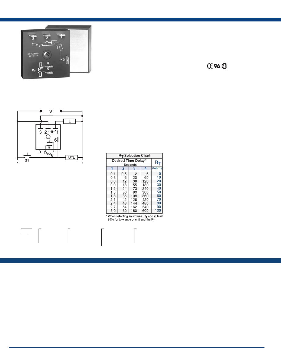
66
www.ssac.com • 800-843-8848 • fax: 605-348-5685
Features:
• High load current capacity, up to 20A, 200A
inrush
• Momentary or maintained initiate switch
• ±2% repeat accuracy
• ±5% factory calibration
• Fixed or adjustable 0.1 - 600s in 4 ranges
• Metallized mounting surface for heat transfer
Approvals:
THC / THS Series
Timer - Single Shot
Available Models:
Time Delay
Range . . . . . . . . . . . . . . . . . . . . . . . . . . . . . . . . . .
0.1 - 600s in 4 adjustable ranges or fixed
Repeat Accuracy . . . . . . . . . . . . . . . . . . . . . . . .
±2% or 20ms, whichever is greater
Tolerance (Factory Calibration) . . . . . . . . . . . .
≤ ± 5%
Reset Time . . . . . . . . . . . . . . . . . . . . . . . . . . . . . .
≤ 150ms
Initiate Time . . . . . . . . . . . . . . . . . . . . . . . . . . . .
≤ 20ms
Time Delay vs Temp. & Voltage
. . . . . . . . . . .
≤ ±10%
Input
Voltage
. . . . . . . . . . . . . . . . . . . . . . . . . . . . . . . . .
24, 120, or 230VAC
Tolerance . . . . . . . . . . . . . . . . . . . . . . . . . . . . . . .
±15%
AC Line Frequency . . . . . . . . . . . . . . . . . . . . . .
50/60 Hz
Power Consumption . . . . . . . . . . . . . . . . . . . . .
≤ 2VA
Output
Type . . . . . . . . . . . . . . . . . . . . . . . . . . . . . . . . . . .Solid state
Form . . . . . . . . . . . . . . . . . . . . . . . . . . . . . . . . . . .
NO, closed during timing
Maximum Load Currents Output Steady State Inrush**
A 6A 60A
B 10A 100A
C 20A 200A
Minimum Load Current . . . . . . . . . . . . . . . . . .
100mA
Voltage Drop
. . . . . . . . . . . . . . . . . . . . . . . . . . .
≅
2.5V at rated current
OFF State Leakage Current
. . . . . . . . . . . . . . .
≅
5mA @ 230VAC
Protection
Circuitry . . . . . . . . . . . . . . . . . . . . . . . . . . . . . . .Encapsulated
Dielectric Breakdown
. . . . . . . . . . . . . . . . . . . .
≥ 2000V RMS terminals to mounting surface
Insulation Resistance . . . . . . . . . . . . . . . . . . . . .
≥100 MΩ
Mechanical
Mounting ** . . . . . . . . . . . . . . . . . . . . . . . . . . . .
Surface mount with one #10 (M5 x 0.8) screw
Dimensions . . . . . . . . . . . . . . . . . . . . . . . . . . . . .
2 x 2 x 1.51 in. (50.8 x 50.8 x 38.4 mm)
Termination . . . . . . . . . . . . . . . . . . . . . . . . . . . .
0.25 in. (6.35 mm) male quick connect terminals
Environmental
Operating / Storage Temperature
. . . . . . . . .
-20° to 60°C / -40° to 85°C
Humidity . . . . . . . . . . . . . . . . . . . . . . . . . . . . . . .
95% relative, non-condensing
Weight
. . . . . . . . . . . . . . . . . . . . . . . . . . . . . . . . .
≅
3.9 oz (111 g)
**Must be bolted to a metal surface using the included heat sink compound. The maximum
mounting surface temperature is 90°C. Inrush: Non-repetitive for 16ms.
Specifications
Order Table:
Connection:
The TH series is a solid-state relay and timer
combined into one compact, easy-to-use control.
When mounted to a metal surface, the TH Series
may be used to directly control lamp or heater
loads of up to 20A steady, 200A inrush. Its single
shot function can perform dispensing and pulse
shaping operations. The initiate switch can be a
momentary or maintained type of switch. Time
delays can be selected from 0.1 - 600 seconds
in 4 ranges. The THC Series is used for coin
vending applications where fast initiate response
is required .
Operation (Single Shot):
Input voltage must be applied before and during timing.
Upon momentary or maintained closure of the initiate
switch (leading edge triggered), the output energizes for
a measured interval of time. At the end of the delay, the
output de-energizes. Opening or reclosing the initiate
switch during timing has no affect on the time delay. The
output will energize if the initiate switch is closed when
input voltage is applied.
Reset: Reset occurs when the time delay is complete and
the initiate switch opens. Loss of input voltage resets the
time delay and output .
For more information see:
Appendix A, pages 156-164 for function descriptions
and diagrams .
Appendix B, page 165, Figure 4 for dimensional drawing.
THC41180B
THC421C
THS422B
Auxiliary Products:
•
External ad just potentiometer:
P/N: P1004-95
P/N: P1004-95-X
•
Female quick connect:
P/N: P1015-13 (AWG 10/12)
P/N: P1015-64 (AWG 14/16)
•
Quick connect t o s crew ad aptor:
P/N: P1015-18
•
Versa-knob:
P/N: P0700-7
THC /
THS
X
Input Voltage
─
2
- 24VAC
─
4
- 120VAC
─
6
- 230VAC
X
Adjustment
─
1
- Fixed
─
2
- External adjust
─
3
- Onboard adjust
X
Time Delay*
─
1
- 0.1 - 3s
─
2
- 0.5 - 60s
─
3
- 2 - 180s
─
4
- 5 - 600s
X
Output Rating
─
A
- 6A
─
B
- 10A
─
C
- 20A
*If fixed delay is selected, insert
delay (
0 .1 - 600
) in seconds .
L1
N/L2
S1 = Initiate Switch
L = Timed Load
UTL = Optional Untimed Load
If desired part number is not listed, please call us to
see if it is technically possible to build .
R
T
is used when external adjustment is ordered.
Courtesy of Steven Engineering, Inc.-230 Ryan Way, South San Francisco, CA 94080-6370-Main Office: (650) 588-9200-Outside Local Area: (800) 258-9200-www.stevenengineering.com
Littelfuse-catalog-html.html
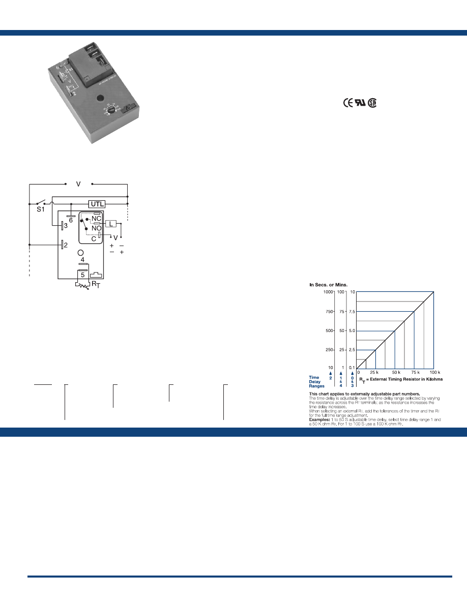
67
www.ssac.com • 800-843-8848 • fax: 605-348-5685
HRD9 Series
Timer - Retriggerable Single Shot
Available Models:
Time Delay
Type . . . . . . . . . . . . . . . . . . . . . . . . . . . . . . . . . . . Microcontroller circuitry
Range . . . . . . . . . . . . . . . . . . . . . . . . . . . . . . . . . .
0.1s - 100m in 5 adjustable ranges or fixed
Repeat Accuracy . . . . . . . . . . . . . . . . . . . . . . . .
±0.5 % or 20ms, whichever is greater
Tolerance (Factory Calibration) . . . . . . . . . . . .
±1%, ±5%
Reset Time . . . . . . . . . . . . . . . . . . . . . . . . . . . . . .
≤ 150ms
Time Delay vs Temp. & Voltage
. . . . . . . . . . .
±2%
Initiate Time . . . . . . . . . . . . . . . . . . . . . . . . . . . .
≤ 20ms (≤ 1500 operations per min.)
Input
Voltage
. . . . . . . . . . . . . . . . . . . . . . . . . . . . . . . . .
12 or 24VDC; 24, 120, or 230VAC
Tolerance 12VDC & 24VDC
. . . . . . . .
-15% - 20%
24 to 230VAC
. . . . . . . .
-20% - 10%
AC Line Frequency . . . . . . . . . . . . . . . . . . . . . .
50/60 Hz
Power Consumption . . . . . . . . . . . . . . . . . . . . .
AC ≤ 4VA; DC ≤ 2W
Output
Type . . . . . . . . . . . . . . . . . . . . . . . . . . . . . . . . . . .
Electromechanical relay
Form . . . . . . . . . . . . . . . . . . . . . . . . . . . . . . . . . . .
Isolated, SPDT
Ratings: SPDT-NO SPDT-NC
General Purpose 125/240VAC 30A 15A
Resistive 125/240VAC 30A 15A
28VDC 20A 10A
Motor Load 125VAC 1 hp* 1/4 hp**
240VAC 2 hp** 1 hp**
Life
. . . . . . . . . . . . . . . . . . . . . . . . . . . . . . . . . . . .
Mechanical - 1 x 10
6
;
Electrical - 1 x 10
5
, *3 x 10
4
, **6,000
Protection
Surge . . . . . . . . . . . . . . . . . . . . . . . . . . . . . . . . . .
IEEE C62.41-1991 Level A
Circuitry . . . . . . . . . . . . . . . . . . . . . . . . . . . . . . . Encapsulated
Dielectric Breakdown
. . . . . . . . . . . . . . . . . . . .
≥ 2000V RMS terminals to mounting surface
Insulation Resistance . . . . . . . . . . . . . . . . . . . . .
≥ 100 MΩ
Polarity . . . . . . . . . . . . . . . . . . . . . . . . . . . . . . . .
DC units are reverse polarity protected
Mechanical
Mounting . . . . . . . . . . . . . . . . . . . . . . . . . . . . . .
Surface mount with one #10 (M5 x 0.8) screw
Dimensions . . . . . . . . . . . . . . . . . . . . . . . . . . . . .
3 x 2 x 1.5 in. (76.7 x 51.3 x 38.1mm)
Termination . . . . . . . . . . . . . . . . . . . . . . . . . . . .
0.25 in. (6.35 mm) male quick connect terminals
Environmental
Operating / Storage Temperature
. . . . . . . . .
-40° to 60°C/-40° to 85°C
Humidity . . . . . . . . . . . . . . . . . . . . . . . . . . . . . . .
95% relative, non-condensing
Weight
. . . . . . . . . . . . . . . . . . . . . . . . . . . . . . . . .
≅
3.9 oz (111 g)
Order Table:
Specifications
The HRD9 Series combines an electromechanical
relay output with microcontroller timing circuitry.
It offers 12 to 230V operation in five ranges and
factory fixed, external, or onboard adjustable
time delays with a repeat accuracy of ±0.5%. The
isolated output contact rating allows for direct
operation of heavy loads, such as compressors,
pumps, blower motors, heaters, etc. The HRD9 is
ideal for OEM applications where cost is a factor.
Operation (Motion Detector/Retriggerable Single Shot):
Input voltage must be applied prior to and during timing.
The output is de-energized. Upon closure of the initiate
switch (momentary or maintained) the output energizes
and the time delay starts. On completion of the delay
period, the output de-energizes.
Reset: Reclosing the initiate switch during or after timing
will reset the time delay and restart timing. Reset is also
accomplished by removing and reapplying input voltage.
Note: Powering up the unit with the initiate switch closed
will not energize the output relay or start timing.
For more information see:
Appendix A, pages 156-164 for function descriptions
and diagrams .
Appendix B, page 165, Figure 2 for dimensional drawing.
Features:
• Isolated, 30A, SPDT, NO output contacts
• 12 to 230V operation in 5 options
• Delays from 0.1s - 100m in 5 ranges
• 0.5% repeat timing accuracy
• Factory fixed, onboard or external adjust
•
Encapsulated circuitry
Approvals:
Connection:
HRD93110S
HRD9320
Auxiliary Products:
•
External ad just potentiometer:
P/N: P1004-95
P/N: P1004-95-X
•
Mounting bracket:
P/N: P1023-6
•
Female quick connect:
P/N: P1015-13 (AWG 10/12)
P/N: P1015-64 (AWG 14/16)
•
Quick connect to screw adaptor:
P/N: P1015-18
•
Versa-knob:
P/N: P0700-7
•
DIN rail:
P/N: C103PM
(Al)
•
DIN rail adaptor:
P/N: P1023-20
HRD9
X
Input Voltage
─
1
- 12VDC
─
2
- 24VAC
─
3
- 24VDC
─
4
- 120VAC
─
6
- 230VAC
X
Adjustment
─
1
- Fixed
─
2
- Onboard knob
─
3
- External adjust
X
Time Tolerance
─
Blank
- ±5%
─
A
- ±1%
X
Time Delay*
─
0
- 0.1 - 10s
─
1
- 1 - 100s
─
2
- 10 - 1000s
─
3
- 0.1 - 10m
─
4
- 1 - 100m
*If fixed delay is selected, insert delay (
0 .1 - 1000
)
followed by (
S
) sec, or (
0 .1 - 100
) (
M
) min .
S1 = Initiate Switch
L = Timed Load
UTL = Untimed Load (optional)
NO = Normally Open
C = Common, Transfer Contact
External Resistance vs . Time Delay:
L1
N/L2
L1 N/L2
(Positive Switching)
(Negative Switching)
If desired part number is not listed, please call us to
see if it is technically possible to build .
NOTE: A knob, or terminals 4 & 5 are only
included on adjustable units. R
T
is used when
external adjustment is ordered. Relay contacts
are isolated. The untimed load is optional.
Courtesy of Steven Engineering, Inc.-230 Ryan Way, South San Francisco, CA 94080-6370-Main Office: (650) 588-9200-Outside Local Area: (800) 258-9200-www.stevenengineering.com
Littelfuse-catalog-html.html
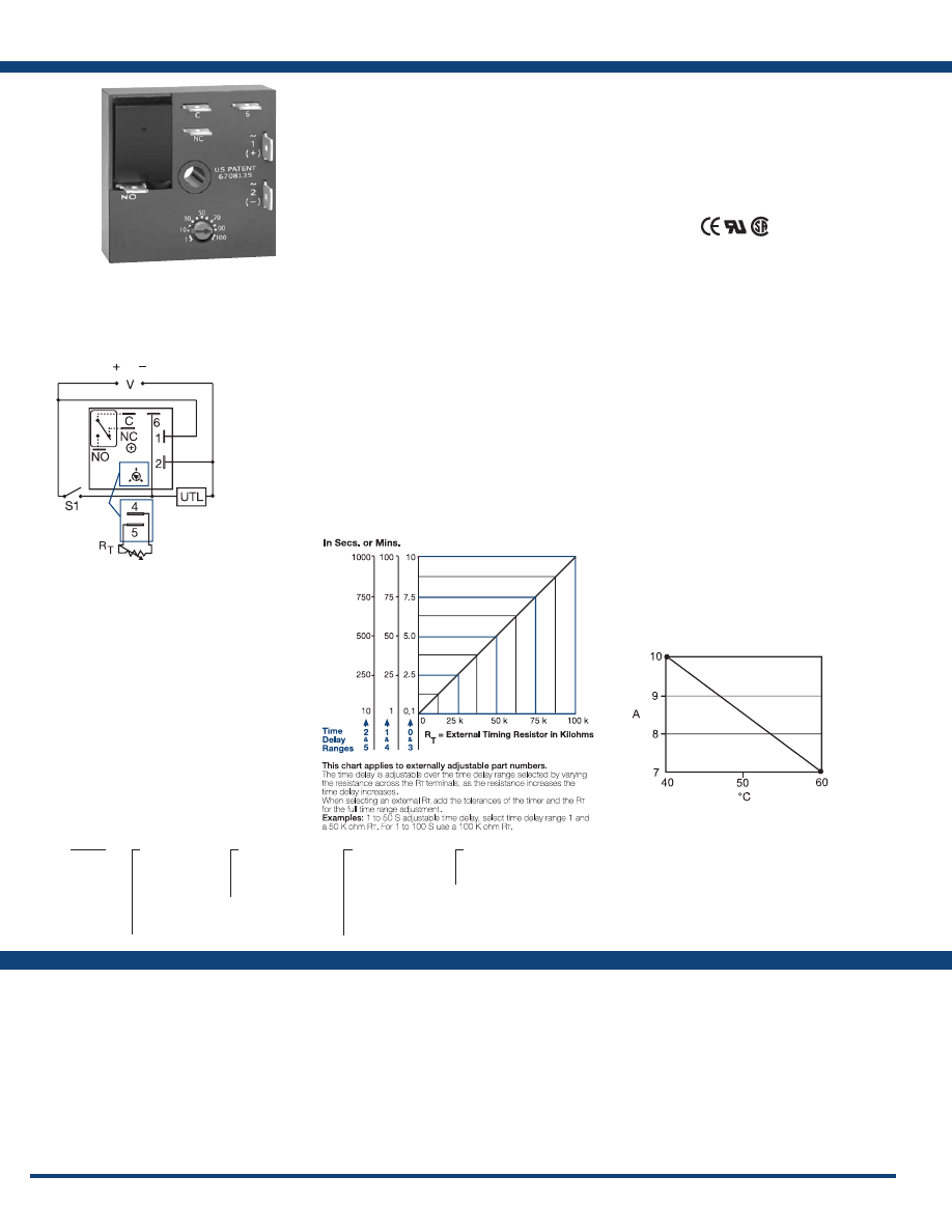
68
www.ssac.com • 800-843-8848 • fax: 605-348-5685
Features:
•
Compact time delay relay
•
Microcontroller circuitry
• ±0.5% repeat accuracy
• Isolated, 10A, SPDT output contacts
• Factory fixed, onboard or external adjust
• Delays from 0.1s - 1000m in 6 ranges
• Input voltages from 12 to 230V in 6 options
Approvals:
KRD9 Series
Timer - Retriggerable Single Shot
Available Models:
Time Delay
Type . . . . . . . . . . . . . . . . . . . . . . . . . . . . . . . . . . .
Microcontroller based with watchdog circuitry
Range . . . . . . . . . . . . . . . . . . . . . . . . . . . . . . . . . .
0.1s - 1000m in 6 adjustable ranges or fixed
Repeat Accuracy . . . . . . . . . . . . . . . . . . . . . . . .
±0.5% or 20ms, whichever is greater
Tolerance (Factory Calibration) . . . . . . . . . . . .
≤ ±5%
Reset Time . . . . . . . . . . . . . . . . . . . . . . . . . . . . . .
≤ 150ms
Initiate Time . . . . . . . . . . . . . . . . . . . . . . . . . . . .
≤ 40ms; ≤ 750 operations per minute
Time Delay vs Temp. & Voltage
. . . . . . . . . . .
≤ ±5%
Input
Voltage
. . . . . . . . . . . . . . . . . . . . . . . . . . . . . . . . .
12, 24 or 110VDC; 24, 120 or 230VAC
Tolerance 12VDC & 24VDC/AC
. . . . . .
-15% - 20%
110VDC, 120 or 230VAC
. . . . . .
-20% - 10%
AC Line Frequency / DC Ripple
. . . . . . . . . . .
50/60 Hz / ≤ 10%
Power Consumption . . . . . . . . . . . . . . . . . . . . .
AC ≤ 2VA; DC ≤ 2W
Output
Type . . . . . . . . . . . . . . . . . . . . . . . . . . . . . . . . . . . Isolated relay contacts
Form . . . . . . . . . . . . . . . . . . . . . . . . . . . . . . . . . . . SPDT
Rating (at 40°C)
. . . . . . . . . . . . . . . . . . . . . . . . .
10A resistive @ 125VAC; 5A resistive @ 230VAC
& 28VDC; 1/4 hp @ 125VAC
Max. Switching Voltage
. . . . . . . . . . . . . . . . . .
250VAC
Life (Operations)
. . . . . . . . . . . . . . . . . . . . . . . .
Mechanical - 1 x 10
7
; Electrical - 1 x 10
5
Protection
Circuitry . . . . . . . . . . . . . . . . . . . . . . . . . . . . . . . Encapsulated
Isolation Voltage
. . . . . . . . . . . . . . . . . . . . . . . .
≥ 1500V RMS input to output
Insulation Resistance . . . . . . . . . . . . . . . . . . . . .
≥ 100 MΩ
Polarity . . . . . . . . . . . . . . . . . . . . . . . . . . . . . . . .
DC units are reversed polarity protected
Mechanical
Mounting . . . . . . . . . . . . . . . . . . . . . . . . . . . . . .
Surface mount with one #10 (M5 x 0.8) screw
Dimensions . . . . . . . . . . . . . . . . . . . . . . . . . . . . .
2 x 2 x 1.21 in. (50.8 x 50.8 x 30.7 mm)
Termination . . . . . . . . . . . . . . . . . . . . . . . . . . . .
0.25 in. (6.35 mm) male quick connect terminals
Environmental
Operating / Storage Temperature
. . . . . . . . .
-40°to 60°C / -40° to 85°C
Humidity . . . . . . . . . . . . . . . . . . . . . . . . . . . . . . .
95% relative, non-condensing
Weight
. . . . . . . . . . . . . . . . . . . . . . . . . . . . . . . . .
≅
2.6 oz (74 g)
Specifications
Order Table:
Connection:
The KRD9 Series microcontroller timing circuit
provides excellent repeat accuracy and stability.
Cost effective approach for OEM applications
that require small size, isolation, reliability, and
long life.
Operation (Retriggerable Single Shot):
Function Type A (Output Initially De-energized): Input
voltage must be applied prior to and during timing. When
the initiate switch is closed, (momentary or maintained)
the output energizes and the time delay starts. On
completion of the delay, the output de-energizes. The unit
will time out if S1 remains in the open or closed position
for the full time delay. Reclosing the initiate switch resets
the time delay and restarts timing; the output remains
energized. The output will not energize if the initiate
switch is closed when input voltage is applied.
Function Type B (Output Initially Energized): Upon
application of input voltage, the output energizes and the
time delay starts. At the end of the time delay, the load
de-energizes. The unit will time out if S1 remains in the
open or closed position for the full time delay. Closing
(re-closing) the initiate switch resets the time delay and
restarts timing; the output remains energized.
Reset: The time delay and the output are reset when input
voltage is removed.
For more information see:
Appendix A, pages 156-164 for function descriptions
and diagrams .
Appendix B, page 165, Figure 1 for dimensional drawing.
KRD9120B
KRD92115MA
KRD92115MB
KRD9220B
KRD93115MA
KRD94115SB
KRD9423B
Auxiliary Products:
•
External ad just potentiometer:
P/N: P1004-95
P/N: P1004-95-X
•
Female quick connect:
P/N: P1015-13 (AWG 10/12)
P/N: P1015-64 (AWG 14/16)
•
Quick connect t o s crew ad aptor:
P/N: P1015-18
•
Versa-knob:
P/N: P0700-7
•
Mounting bracket:
P/N: P1023-6
•
DIN rail:
P/N: C103PM
(Al)
•
DIN rail adaptor:
P/N: P1023-20
KRD9
X
Input Voltage
─
1
- 12VDC
─
2
- 24VAC/DC
─
3
- 24VDC
─
4
- 120VAC
─
5
- 110VDC
─
6
- 230VAC
X
Adjustment
─
1
- Fixed
─
2
- Onboard knob
─
3
- External adjust
X
Time Delay*
─
0
- 0.1 - 10s
─
1
- 1 - 100s
─
2
- 10 - 1000s
─
3
- 0.1 - 10m
─
4
- 1 - 100m
─
5
- 10 - 1000m
X
Function Type
─
A
- De-energized
─
B
- Energized
*If fixed delay is selected, insert delay (
0 .1
- 1000
) followed by (
S
) sec, or (
M
) min .
L1
N/L2
C = Common, Transfer Contact
UTL = Untimed Load (optional)
External Resistance vs . Time Delay:
If desired part number is not listed, please call us to
see if it is technically possible to build .
A knob is supplied for adjustable units, or
R
T
terminals 4 & 5 for external adjust. See
external adjustment vs time delay chart. The
untimed load is optional . Relay contacts are
isolated .
Output Current / Ambient Temperature:
Courtesy of Steven Engineering, Inc.-230 Ryan Way, South San Francisco, CA 94080-6370-Main Office: (650) 588-9200-Outside Local Area: (800) 258-9200-www.stevenengineering.com
Littelfuse-catalog-html.html
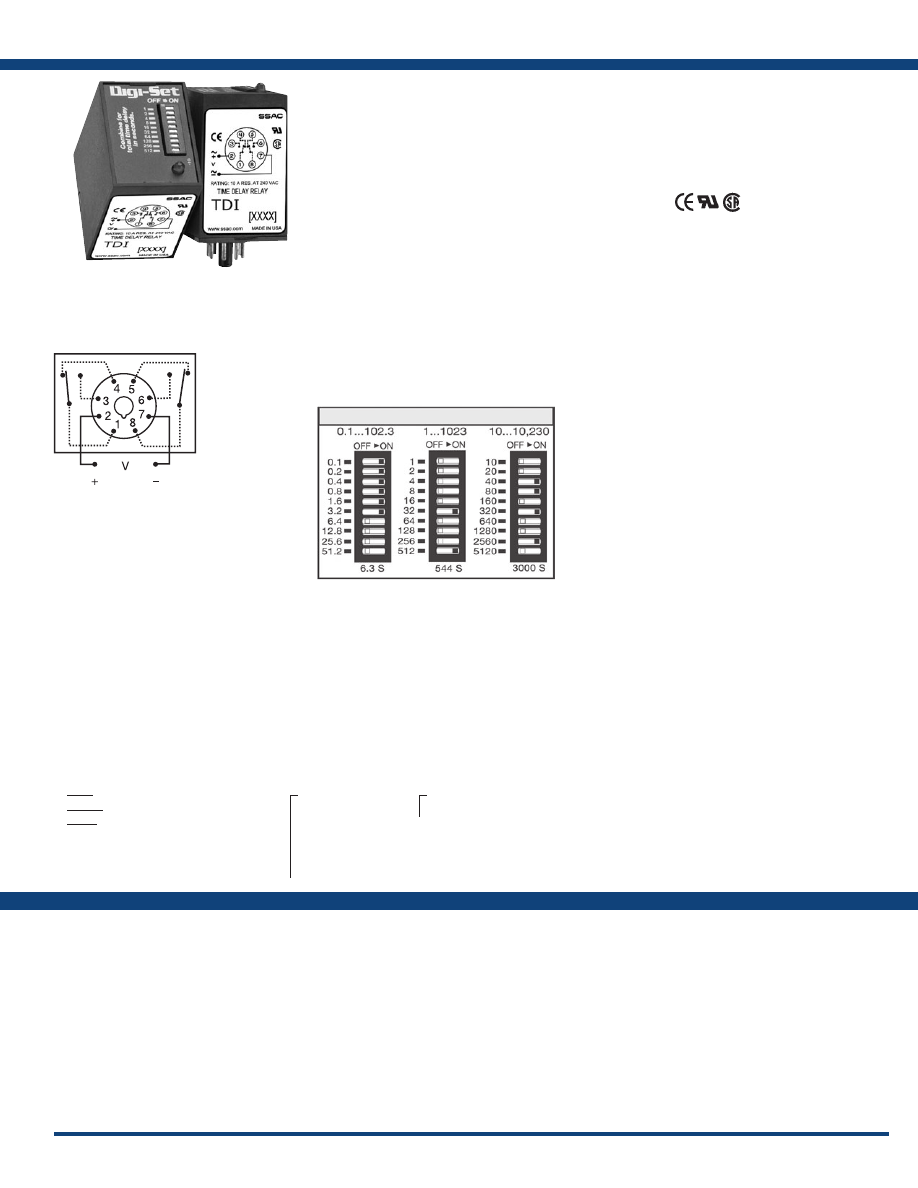
69
www.ssac.com • 800-843-8848 • fax: 605-348-5685
TDI / TDIH / TDIL Series
Timer - Interval
Available Models:
Time Delay
Type . . . . . . . . . . . . . . . . . . . . . . . . . . . . . . . . . . . Digital integrated circuitry
Range** . . . . . . . . . . . . . . . . . . . . . . . . . . . . . . . .
0.1 - 102.3s in 0.1s increments
1 - 1023s in 1s increments
10 - 10,230s in 10s increments
Repeat Accuracy . . . . . . . . . . . . . . . . . . . . . . . .
±0.1% or 20ms, whichever is greater
Setting Accuracy . . . . . . . . . . . . . . . . . . . . . . . .
±2% or 50ms, whichever is greater
Reset Time . . . . . . . . . . . . . . . . . . . . . . . . . . . . . .
≤ 50ms
Recycle Time . . . . . . . . . . . . . . . . . . . . . . . . . . . .
≤ 150ms
Time Delay vs Temp. & Voltage
. . . . . . . . . . .
±2%
Indicator . . . . . . . . . . . . . . . . . . . . . . . . . . . . . . .
LED glows during timing; relay is energized
Input
Voltage
. . . . . . . . . . . . . . . . . . . . . . . . . . . . . . . . .
12, 24, or 110VDC; 24, 120, or 230VAC
Tolerance 12VDC & 24VDC/AC
. . . . .
-15% - 20%
110 to 230VAC/DC
. . . . . .
-20% - 10%
AC Line Frequency . . . . . . . . . . . . . . . . . . . . . .
50/60 Hz
Power Consumption . . . . . . . . . . . . . . . . . . . . .
≤ 3.25W
Output
Type . . . . . . . . . . . . . . . . . . . . . . . . . . . . . . . . . . .
Electromechanical relay
Form . . . . . . . . . . . . . . . . . . . . . . . . . . . . . . . . . . . DPDT
Rating . . . . . . . . . . . . . . . . . . . . . . . . . . . . . . . . .
10A resistive @ 120/240VAC & 28VDC;
1/3 hp @ 120/240VAC
Life
. . . . . . . . . . . . . . . . . . . . . . . . . . . . . . . . . . . .
Mechanical - 1 x10
7
; Electrical - 1 x 10
6
Protection
Polarity . . . . . . . . . . . . . . . . . . . . . . . . . . . . . . . .
DC units are reverse polarity protected
Isolation Voltage
. . . . . . . . . . . . . . . . . . . . . . . .
≥ 1500V RMS input to output
Mechanical
Mounting . . . . . . . . . . . . . . . . . . . . . . . . . . . . . .
Plug-in socket
Dimensions . . . . . . . . . . . . . . . . . . . . . . . . . . . . .
3.2 x 2.4 x 1.8 in. (81.3 x 60.7 x 45.2 mm)
Termination . . . . . . . . . . . . . . . . . . . . . . . . . . . .
Octal 8-pin plug-in
Environmental
Operating / Storage Temperature
. . . . . . . . .
-20° to 65°C / -30° to 85°C
Weight
. . . . . . . . . . . . . . . . . . . . . . . . . . . . . . . . .
≅
6 oz (170 g)
** For CE approved applications, power must be removed from the unit when a switch
position is changed.
Order Table:
Specifications
The TDI Series is an interval timer that combines
accurate digital circuitry with isolated, 10A rated,
DPDT relay contacts in an 8-pin plug-in package.
The TDI Series features DIP switch selectable time
delays ranging from 0.1 to 10,230 seconds in three
ranges. The TDI Series is the product of choice for
custom control panel and OEM designers .
Operation (Interval):
Upon application of input voltage, the time delay begins.
The output relay is energized during the time delay. At
the end of the time delay, the output de-energizes and
remains de-energized until input voltage is removed.
Reset: Removing input voltage resets the time delay and
the output.
For more information see:
Appendix A, pages 156-164 for function descriptions
and diagrams .
Appendix B, page 165, Figure 8 for dimensional drawing.
Features:
• Switch settable time delay
• Three time ranges from 0.1s - 10,230s
• ±0.1% repeat accuracy
• ±2% setting accuracy
• 10A, DPDT output contacts
•
LED indication
Approvals:
Connection:
TDI120AL
TDI12D
TDI230AL
TDI24AL
TDI24DL
TDIH24AL
TDIL120AL
TDIL24DL
Auxiliary Products:
•
Panel mount kit:
P/N: BZ1
•
Octal 8-pin socket:
P/N: NDS-8
•
Hold-down clips (sold in pairs):
P/N: PSC8 (NDS-8)
•
DIN rail:
P/N: C103PM
(Al)
TDI
- 1 - 1023s in 1s increments
TDIH
- 10 - 10,230s in 10s increments
TDIL
- 0.1 - 102.3s in 0.1s increments
X
Input Voltage
─
12D
- 12VDC
─
24A
- 24VAC
─
24D
- 24VDC/28VDC
─
110D
- 110VDC
─
120A
- 120VAC
─
230A
- 230VAC
X
LED Indication*
─
L
* Note: LED not available in 12VDC
L1
N/L2
Digi-Set Binary Switch Operation:
If desired part number is not listed, please call us to
see if it is technically possible to build .
Relay contacts are isolated .
Courtesy of Steven Engineering, Inc.-230 Ryan Way, South San Francisco, CA 94080-6370-Main Office: (650) 588-9200-Outside Local Area: (800) 258-9200-www.stevenengineering.com
Littelfuse-catalog-html.html
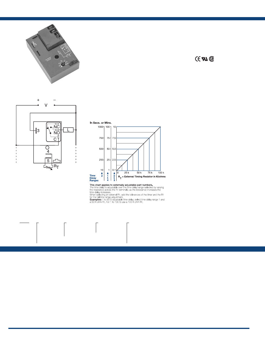
70
www.ssac.com • 800-843-8848 • fax: 605-348-5685
Features:
• 30A, SPDT, NO output contacts
• 12 to 230V operation in 5 options
•
Encapsulated circuitry
• Delays from 0.1s - 100m in 5 ranges
• ±0.5% repeat timing accuracy
• Factory fixed, onboard or external adjust
Approvals:
HRDI Series
Timer - Interval
Available Models:
Time Delay
Type . . . . . . . . . . . . . . . . . . . . . . . . . . . . . . . . . . .Microcontroller circuitry
Range . . . . . . . . . . . . . . . . . . . . . . . . . . . . . . . . . .
0.1s - 100m in 5 adjustable ranges or fixed
Repeat Accuracy . . . . . . . . . . . . . . . . . . . . . . . .
±0.5 % or 20ms, whichever is greater
Tolerance (Factory Calibration) . . . . . . . . . . . .
±1%, ±5%
Recycle Time . . . . . . . . . . . . . . . . . . . . . . . . . . . .
≤ 150ms
Time Delay vs Temp. & Voltage
. . . . . . . . . . .
±2%
Input
Voltage
. . . . . . . . . . . . . . . . . . . . . . . . . . . . . . . . .
12 or 24VDC; 24, 120, or 230VAC
Tolerance 12VDC & 24VDC
. . . . . . . . .
-15% - 20%
24 to 230VAC
. . . . . . . . .
-20% - 10%
AC Line Frequency . . . . . . . . . . . . . . . . . . . . . .
50/60 Hz
Power Consumption . . . . . . . . . . . . . . . . . . . . .
AC ≤ 4VA; DC ≤ 2W
Output
Type . . . . . . . . . . . . . . . . . . . . . . . . . . . . . . . . . . .
Electromechanical relay
Form . . . . . . . . . . . . . . . . . . . . . . . . . . . . . . . . . . .
SPDT, non-isolated
Ratings: SPDT-NO SPDT-NC
General Purpose 125/240VAC 30A 15A
Resistive 125/240VAC 30A 15A
28VDC 20A 10A
Motor Load 125VAC 1 hp* 1/4 hp**
240VAC 2 hp** 1 hp**
Life
. . . . . . . . . . . . . . . . . . . . . . . . . . . . . . . . . . . .
Mechanical - 1 x 10
6
;
Electrical - 1 x 10
5
, *3 x 10
4
, **6,000
Protection
Surge . . . . . . . . . . . . . . . . . . . . . . . . . . . . . . . . . .
IEEE C62.41-1991 Level A
Circuitry . . . . . . . . . . . . . . . . . . . . . . . . . . . . . . .Encapsulated
Dielectric Breakdown
. . . . . . . . . . . . . . . . . . . .
≥ 2000V RMS terminals to mounting surface
Insulation Resistance . . . . . . . . . . . . . . . . . . . . .
≥ 100 MΩ
Polarity . . . . . . . . . . . . . . . . . . . . . . . . . . . . . . . .
DC units are reverse polarity protected
Mechanical
Mounting . . . . . . . . . . . . . . . . . . . . . . . . . . . . . .
Surface mount with one #10 (M5 x 0.8) screw
Dimensions . . . . . . . . . . . . . . . . . . . . . . . . . . . . .
3 x 2 x 1.5 in. (76.7 x 51.3 x 38.1mm)
Termination . . . . . . . . . . . . . . . . . . . . . . . . . . . .
0.25 in. (6.35 mm) male quick connect terminals
Environmental
Operating / Storage Temperature
. . . . . . . . .
-40° to 60°C / -40° to 85°C
Humidity . . . . . . . . . . . . . . . . . . . . . . . . . . . . . . .
95% relative, non-condensing
Weight
. . . . . . . . . . . . . . . . . . . . . . . . . . . . . . . . .
≅
3.9 oz (111 g)
Specifications
Order Table:
Connection:
The HRDI Series combines an electromechanical
relay output with microcontroller timing circuitry.
It offers 12 to 230V operation in five ranges and
factory fixed, external, or onboard adjustable
time delays with a repeat accuracy of ±0.5%. The
output contact rating allows for direct operation of
heavy loads, such as compressors, pumps, blower
motors, heaters, etc. This series is ideal for OEM
applications where cost is a factor.
Operation (Interval):
Upon application of input voltage, the time delay begins.
The output relay is energized during the time delay. At
the end of the time delay, the output de-energizes and
remains de-energized until input voltage is removed.
Reset: Removing input voltage resets the time delay
and the output.
For more information see:
Appendix A, pages 156-164 for function descriptions
and diagrams .
Appendix B, page 165, Figure 2 for dimensional drawing.
HRDI117S
HRDI220
HRDI221
HRDI222
HRDI223
HRDI224
HRDI320
HRDI321
HRDI322
HRDI323
HRDI324
HRDI4130M
HRDI421
HRDI422
HRDI423
HRDI424
HRDI431
Auxiliary Products:
•
External ad just potentiometer:
P/N: P1004-95
P/N: P1004-95-X
•
Female quick connect:
P/N: P1015-13 (AWG 10/12)
P/N: P1015-64 (AWG 14/16)
•
Quick connect t o s crew ad aptor:
P/N: P1015-18
•
Versa-knob:
P/N: P0700-7
•
Mounting bracket:
P/N: P1023-6
•
DIN rail:
P/N: C103PM
(Al)
•
DIN rail adaptor:
P/N: P1023-20
HRDI
X
Input Voltage
─
1
- 12VDC
─
2
- 24VAC
─
3
- 24VDC
─
4
- 120VAC
─
6
- 230VAC
X
Adjustment
─
1
- Fixed
─
2
- Onboard knob
─
3
- External adjust
X
Time Tolerance
─
Blank
- ±5%
─
A
- ±1%
X
Time Delay*
─
0
- 0.1 - 10s
─
1
- 1 - 100s
─
2
- 10 - 1000s
─
3
- 0.1 - 10m
─
4
- 1 - 100m
*If fixed delay is selected, insert delay (
0 .1
- 1000
) followed by (
S
) sec, or (
0 .1 - 100
)
(
M
) min .
L1
N/L2
C = Common, Transfer Contact
NO = Normally Open
L = Load
External Resistance vs . Time Delay:
If desired part number is not listed, please call us to
see if it is technically possible to build .
NOTE: A knob, or terminals 4 & 5 are only
included on adjustable units. R
T
T
is used
when external adjustment is ordered. Relay
contacts are not isolated .
Courtesy of Steven Engineering, Inc.-230 Ryan Way, South San Francisco, CA 94080-6370-Main Office: (650) 588-9200-Outside Local Area: (800) 258-9200-www.stevenengineering.com
Littelfuse-catalog-html.html
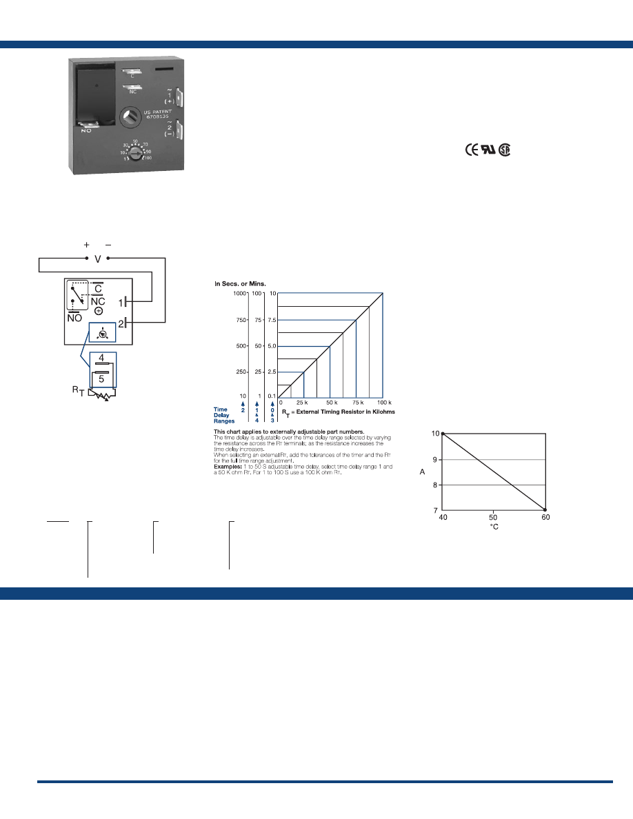
71
www.ssac.com • 800-843-8848 • fax: 605-348-5685
KRDI Series
Timer - Interval
Available Models:
Time Delay
Range . . . . . . . . . . . . . . . . . . . . . . . . . . . . . . . . . .
0.1s - 100m in 5 adjustable ranges or fixed
Repeat Accuracy . . . . . . . . . . . . . . . . . . . . . . . .
±0.5% or 20ms, whichever is greater
Tolerance (Factory Calibration) . . . . . . . . . . . .
≤ ± 5%
Reset Time . . . . . . . . . . . . . . . . . . . . . . . . . . . . . .
≤ 150ms
Time Delay vs Temp. & Voltage
. . . . . . . . . . .
≤ ±5%
Input
Voltage
. . . . . . . . . . . . . . . . . . . . . . . . . . . . . . . . .
12, 24 or 110VDC; 24, 120 or 230VAC
Tolerance 12VDC & 24VDC/AC
. . . . . . .
-15% - 20%
110VDC, 120VAC or 230VAC
. . . . . . .
-20% - 10%
AC Line Frequency / DC Ripple
. . . . . . . . . . .
50/60 Hz / ≤ 10%
Power Consumption . . . . . . . . . . . . . . . . . . . . .
AC ≤ 2VA; DC ≤ 2W
Output
Type . . . . . . . . . . . . . . . . . . . . . . . . . . . . . . . . . . .Isolated relay contacts
Form . . . . . . . . . . . . . . . . . . . . . . . . . . . . . . . . . . .SPDT
Rating (at 40°C)
. . . . . . . . . . . . . . . . . . . . . . . . .
10A resistive @ 125VAC;
5A resistive @ 230VAC & 28VDC;
1/4 hp @ 125VAC
Max. Switching Voltage
. . . . . . . . . . . . . . . . . .
250VAC
Life (Operations)
. . . . . . . . . . . . . . . . . . . . . . . .
Mechanical - 1 x 10
7
; Electrical - 1 x 10
5
Protection
Circuitry . . . . . . . . . . . . . . . . . . . . . . . . . . . . . . .Encapsulated
Isolation Voltage
. . . . . . . . . . . . . . . . . . . . . . . .
≥ 1500V RMS input to output
Insulation Resistance . . . . . . . . . . . . . . . . . . . . .
≥ 100 MΩ
Polarity . . . . . . . . . . . . . . . . . . . . . . . . . . . . . . . .
DC units are reverse polarity protected
Mechanical
Mounting . . . . . . . . . . . . . . . . . . . . . . . . . . . . . .
Surface mount with one #10 (M5 x 0.8) screw
Dimensions . . . . . . . . . . . . . . . . . . . . . . . . . . . . .
2 x 2 x 1.21 in. (50.8 x 50.8 x 30.7 mm)
Termination . . . . . . . . . . . . . . . . . . . . . . . . . . . .
0.25 in. (6.35 mm) male quick connect terminals
Environmental
Operating / Storage Temperature
. . . . . . . . .
-20° to 60°C / -40° to 85°C
Humidity . . . . . . . . . . . . . . . . . . . . . . . . . . . . . . .
95% relative, non-condensing
Weight
. . . . . . . . . . . . . . . . . . . . . . . . . . . . . . . . .
≅
2.6 oz (74 g)
Order Table:
Specifications
The KRDI Series is a compact time-delay relay
measuring only 2 in. (50.8 mm) square. Its solid-
state timing circuit provides excellent repeat
accuracy and stability . Encapsulation protects
against shock, vibration, and humidity. The
KRDI Series is a cost effective approach for OEM
applications that require small size, isolation,
reliability, and long life.
Operation (Interval):
Upon application of input voltage, the time delay begins.
The output relay energizes during the time delay. At
the end of the time delay, the output de-energizes and
remains de-energized until input voltage is removed.
Reset: Removing input voltage resets the time delay and
the output.
For more information see:
Appendix A, pages 156-164 for function descriptions
and diagrams .
Appendix B, page 165, Figure 1 for dimensional drawing.
Features:
•
Compact time delay relay
• 10A, SPDT output contacts
• Factory fixed, onboard or external adjust
• Delays from 0.1s - 100m in 5 ranges
• ±0.5% repeat accuracy
• ±5% factory calibration
• Input voltages from 12 to 230V in 6 options
Approvals:
Connection:
KRDI1132S
KRDI120
KRDI121
KRDI122
KRDI210.1S
KRDI2110S
KRDI21120S
KRDI320
KRDI420
KRDI423
Auxiliary Products:
•
External ad just potentiometer:
P/N: P1004-95
P/N: P1004-95-X
•
Female quick connect:
P/N: P1015-13 (AWG 10/12)
P/N: P1015-64 (AWG 14/16)
•
Quick connect t o s crew ad aptor:
P/N: P1015-18
•
Mounting bracket:
P/N: P1023-6
•
DIN rail:
P/N: C103PM
(Al)
•
DIN rail adaptor:
P/N: P1023-20
•
Versa-knob:
P/N: P0700-7
KRDI
X
Input Voltage
─
1
- 12VDC
─
2
- 24VAC
─
3
- 24VDC
─
4
- 120VAC
─
5
- 110VDC
─
6
- 230VAC
X
Adjustment
─
1
- Fixed
─
2
- Onboard knob
─
3
- External adjust
X
Time Delay*
─
0
- 0.1 - 10s
─
1
- 1 - 100s
─
2
- 10 - 1000s
─
3
- 0.1 - 10m
─
4
- 1 - 100m
*If fixed delay is selected, insert delay (
0 .1
- 1000
) followed by (
S
) sec, or (
0 .1 - 100
)
(
M
) min .
L1
N/L2
V = Voltage
C = Common, Transfer Contact
NO = Normally Open
NC = Normally Closed
External Resistance vs . Time Delay:
If desired part number is not listed, please call us to
see if it is technically possible to build .
A knob is supplied for adjustable units,
or R
T
terminals 4 & 5 for external adjust.
See external adjustment vs time delay
chart. Relay contacts are isolated.
Output Current/Ambient Temperature:
Courtesy of Steven Engineering, Inc.-230 Ryan Way, South San Francisco, CA 94080-6370-Main Office: (650) 588-9200-Outside Local Area: (800) 258-9200-www.stevenengineering.com
Littelfuse-catalog-html.html
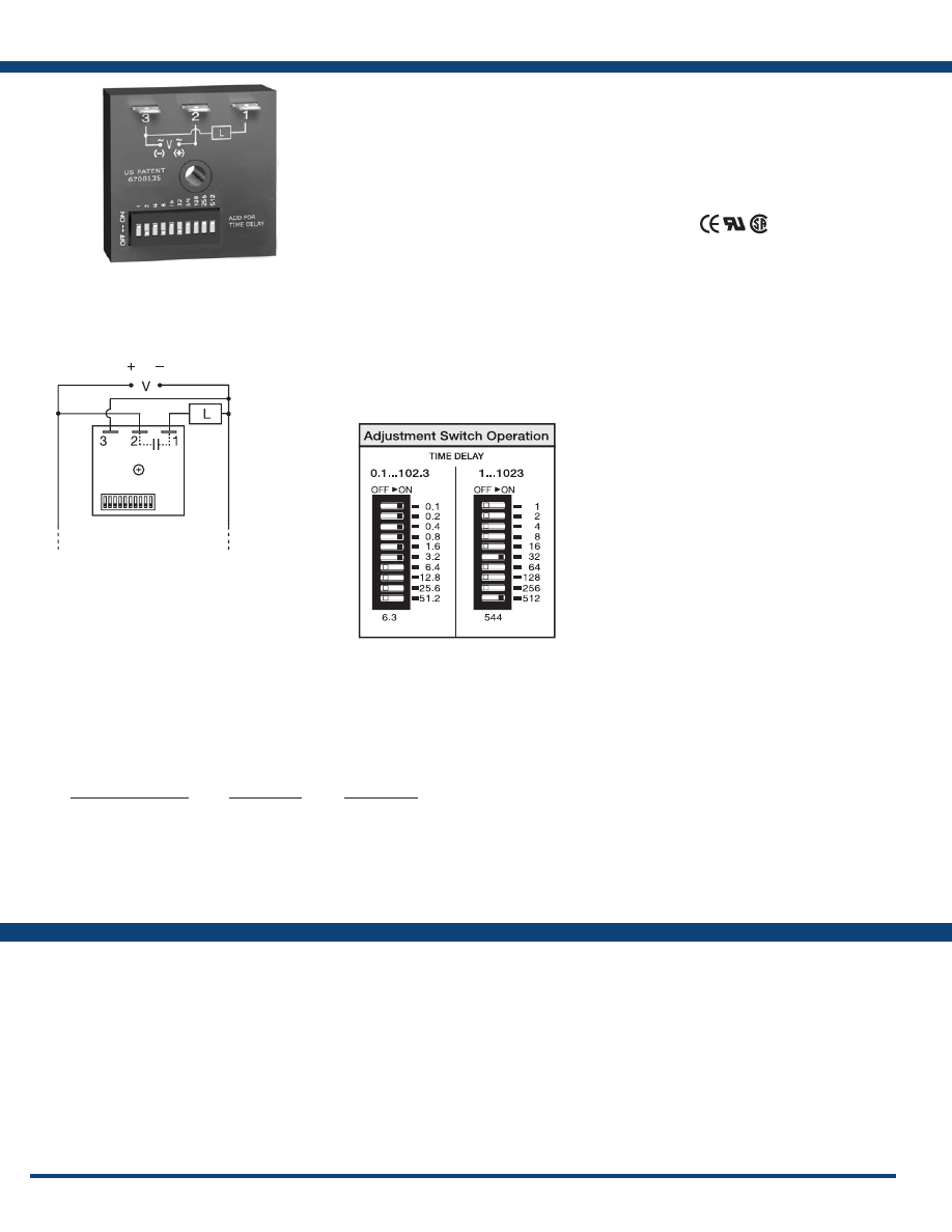
72
www.ssac.com • 800-843-8848 • fax: 605-348-5685
Features:
• Switch selectable time setting
• 0.1s - 102.3m in 3 ranges
• ±0.5% repeat accuracy
• ±2% setting accuracy
• 1A, solid-state output
•
Encapsulated
• Wide voltage ranges
Approvals:
TDUI Series
Timer - Interval
Available Models:
Time Delay
Range* . . . . . . . . . . . . . . . . . . . . . . . . . . . . . . . .
0.1 - 102.3s in 0.1s increments
1 - 1023s in 1s increments
0.1 - 102.3m in 0.1m increments
Repeat Accuracy . . . . . . . . . . . . . . . . . . . . . . . .
±0.5% or 20ms, whichever is greater
Setting Accuracy . . . . . . . . . . . . . . . . . . . . . . . .
≤ ±2% or 20ms, whichever is greater
Reset Time . . . . . . . . . . . . . . . . . . . . . . . . . . . . .
≤ 150ms
Time Delay vs Temp. & Voltage
. . . . . . . . . .
≤ ±5%
Input
Voltage
. . . . . . . . . . . . . . . . . . . . . . . . . . . . . . . .
24 to 240VAC, 12 to 24VDC ±20%
AC Line Frequency . . . . . . . . . . . . . . . . . . . . .
50/60 Hz
Power Consumption . . . . . . . . . . . . . . . . . . . .
AC ≤ 2VA; DC ≤ 1W
DC Ripple . . . . . . . . . . . . . . . . . . . . . . . . . . . . .
≤ 10%
Output
Type . . . . . . . . . . . . . . . . . . . . . . . . . . . . . . . . . . Solid state
Form . . . . . . . . . . . . . . . . . . . . . . . . . . . . . . . . . .
NO, closed during timing
Rating . . . . . . . . . . . . . . . . . . . . . . . . . . . . . . . . .
1A steady state, 10A inrush at 60°C
Voltage Drop
. . . . . . . . . . . . . . . . . . . . . . . . . . .
≅
2.5V @ 1A; DC
≅
1V @ 1A
OFF State Leakage Current
. . . . . . . . . . . . . . . AC
≅
5mA @ 230VAC; DC
≅
1mA
Protection
Circuitry . . . . . . . . . . . . . . . . . . . . . . . . . . . . . . . Encapsulated
Dielectric Breakdown
. . . . . . . . . . . . . . . . . . .
≥ 2000V RMS terminals to mounting surface
Insulation Resistance . . . . . . . . . . . . . . . . . . . .
≥ 100 MΩ
Polarity . . . . . . . . . . . . . . . . . . . . . . . . . . . . . . . .
DC units are reverse polarity protected
Mechanical
Mounting . . . . . . . . . . . . . . . . . . . . . . . . . . . . . .
Surface mount with one #10 (M5 x 0.8) screw
Dimensions . . . . . . . . . . . . . . . . . . . . . . . . . . . .
2 x 2 x 1.21 in (50.8 x 50.8 x 30.7 mm)
Termination . . . . . . . . . . . . . . . . . . . . . . . . . . . .
0.25 in. (6.35 mm) male quick connect terminals
Environmental
Operating / Storage Temperature
. . . . . . . . .
-40° to 60°C / -40° to 85°C
Humidity . . . . . . . . . . . . . . . . . . . . . . . . . . . . . .
95% relative, non-condensing
Weight
. . . . . . . . . . . . . . . . . . . . . . . . . . . . . . . .
≅
2.4 oz (68 g)
*For CE approved applications, power must be removed from the unit when a switch position
is changed.
Specifications
Order Table:
Connection:
The TDUI Series combines digital timing circuitry
with universal voltage operation. Voltages of
24 to 240VAC and 12 to 24VDC are available in
three ranges. The TDUI Series offers DIP switch
selectable time delays ranging from 0.1 seconds to
102.3 minutes in three ranges. Its 1A rated output,
ability to operate on multiple voltages, and wide
range of switch selectable time delays make the
TDUI Series an excellent choice for process control
systems and OEM equipment .
Operation (Interval):
Upon application of input voltage, the time delay begins.
The output energizes during the time delay. At the end
of the time delay, the output de-energizes and remains
de-energized until input voltage is removed.
Reset: Removing input voltage resets the time delay and
the output.
For more information see:
Appendix A, pages 156-164 for function descriptions
and diagrams .
Appendix B, page 165, Figure 1 for dimensional drawing.
TDUI3000A
TDUIH3001A
TDUIH3002A
TDUIL3002A
Auxiliary Products:
•
Female quick connect:
P/N: P1015-13 (AWG 10/12)
P/N: P1015-64 (AWG 14/16)
P/N: P1015-14 (AWG 18/22)
•
Quick connect t o s crew ad aptor:
P/N: P1015-18
•
DIN rail:
P/N: C103PM
(Al)
•
DIN rail adaptor:
P/N: P1023-20
Input Voltage Range
24 to 120VAC
100 to 240VAC
12 to 24VDC
24 to 120VAC
100 to 240VAC
12 to 24VDC
24 to 120VAC
100 to 240VAC
12 to 24VDC
Time Range
0.1 - 102.3s
0.1 - 102.3s
0.1 - 102.3s
1 - 1023s
1 - 1023s
1 - 1023s
0.1 - 102.3m
0.1 - 102.3m
0.1 - 102.3m
Part Number
TDUIL3000A
TDUIL3001A
TDUIL3002A
TDUI3000A
TDUI3001A
TDUI3002A
TDUIH3000A
TDUIH3001A
TDUIH3002A
L1
N/L2
Courtesy of Steven Engineering, Inc.-230 Ryan Way, South San Francisco, CA 94080-6370-Main Office: (650) 588-9200-Outside Local Area: (800) 258-9200-www.stevenengineering.com
Littelfuse-catalog-html.html
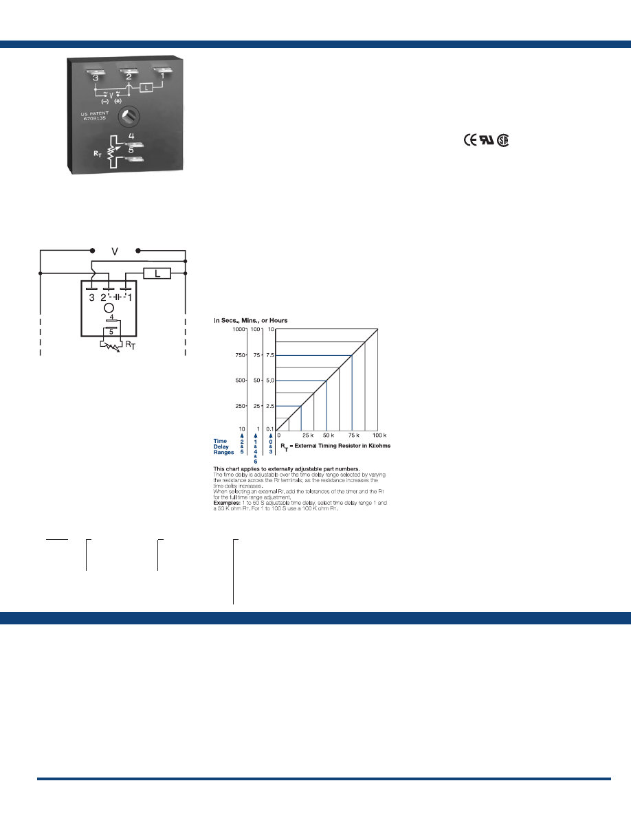
73
www.ssac.com • 800-843-8848 • fax: 605-348-5685
TSD2 Series
Timer - Interval
Available Models:
Time Delay
Range . . . . . . . . . . . . . . . . . . . . . . . . . . . . . . . . . .
0.1s - 100h in 7 adjustable ranges or fixed
Repeat Accuracy . . . . . . . . . . . . . . . . . . . . . . . .
±0.1% or 20ms, whichever is greater
Tolerance (Factory Calibration) . . . . . . . . . . . .
≤ ±1%
Reset Time . . . . . . . . . . . . . . . . . . . . . . . . . . . . . .
≤ 150ms
Time Delay vs Temp. & Voltage
. . . . . . . . . . .
≤ ±1%
Input
Voltage
. . . . . . . . . . . . . . . . . . . . . . . . . . . . . . . . .
24, 120, or 230VAC
Tolerance . . . . . . . . . . . . . . . . . . . . . . . . . . . . . . .
±20%
AC Line Frequency . . . . . . . . . . . . . . . . . . . . . .
50/60 Hz
Power Consumption . . . . . . . . . . . . . . . . . . . . .
≤ 2VA
Output
Type . . . . . . . . . . . . . . . . . . . . . . . . . . . . . . . . . . . Solid state
Form . . . . . . . . . . . . . . . . . . . . . . . . . . . . . . . . . . .
NO, closed during timing
Maximum Load Current
. . . . . . . . . . . . . . . . . .
1A steady state, 10A inrush at 60°C
Off State Leakage Current
. . . . . . . . . . . . . . . .
≅
5mA @ 230VAC
Voltage Drop
. . . . . . . . . . . . . . . . . . . . . . . . . . .
≅
2.5V @ 1A
Protection
Circuitry . . . . . . . . . . . . . . . . . . . . . . . . . . . . . . . Encapsulated
Dielectric Breakdown
. . . . . . . . . . . . . . . . . . . .
≥ 2000V RMS terminals to mounting surface
Insulation Resistance . . . . . . . . . . . . . . . . . . . . .
≥ 100 MΩ
Mechanical
Mounting . . . . . . . . . . . . . . . . . . . . . . . . . . . . . .
Surface mount with one #10 (M5 x 0.8) screw
Dimensions . . . . . . . . . . . . . . . . . . . . . . . . . . . . .
2 x 2 x 1.21 in. (50.8 x 50.8 x 30.7 mm)
Termination . . . . . . . . . . . . . . . . . . . . . . . . . . . .
0.25 in. (6.35 mm) male quick connect terminals
Environmental
Operating / Storage Temperature
. . . . . . . . .
-40° to 75°C / -40° to 85°C
Humidity . . . . . . . . . . . . . . . . . . . . . . . . . . . . . . .
95% relative, non-condensing
Weight
. . . . . . . . . . . . . . . . . . . . . . . . . . . . . . . . .
≅
2.4 oz (68 g)
Order Table:
Specifications
The TSD Series is designed for more demanding
commercial and industrial applications where
small size and accurate performance are required.
The factory calibration for fixed time delays is
within 1% of the target time delay. The repeat
accuracy, under stable conditions, is 0.1% of the
time delay. The TSD Series is rated to operate over
an extended temperature range. Time delays of 0.1
seconds to 100 hours are available. The output is
rated 1A steady and 10A inrush. The modules are
totally solid state and encapsulated to protect the
electronic circuitry .
Operation (Interval):
Upon application of input voltage, the time delay begins.
The output is energized during the time delay. At the end
of the time delay, the output de-energizes and remains
de-energized until input voltage is removed.
Reset: Removing input voltage resets the time delay and
the output.
For more information see:
Appendix A, pages 156-164 for function descriptions
and diagrams .
Appendix B, page 165, Figure 1 for dimensional drawing.
Features:
• Fixed or adjustable delays from 0.1s - 100h
• ±0.1% repeat accuracy
• ±1% factory calibration
• 24, 120, or 230VAC
• 1A, solid-state output
•
Encapsulated
Approvals:
Connection:
TSD2221
TSD2411S
TSD24145S
TSD241600S
TSD2434
Auxiliary Products:
•
External ad just potentiometer:
P/N: P1004-95
P/N: P1004-95-X
•
Female quick connect:
P/N: P1015-64 (AWG 14/16)
•
Quick connect t o s crew ad aptor:
P/N: P1015-18
•
Mounting bracket:
P/N: P1023-6
•
DIN rail:
P/N: C103PM
(Al)
•
DIN rail adaptor:
P/N: P1023-20
•
Versa-knob:
P/N: P0700-7
TSD2
X
Input Voltage
─
2
- 24VAC
─
4
- 120VAC
─
6
- 230VAC
X
Adjustment
─
1
- Fixed
─
2
- External adjust
─
3
- Onboard adjust
X
Time Delay*
─
0
- 0.1 - 10s
─
1
- 1 - 100s
─
2
- 10 - 1000s
─
3
- 0.1 - 10m
─
4
- 1 - 100m
─
5
- 10 - 1000m
─
6
- 1 - 100h
*If fixed delay is selected, insert
delay (
0 .1 - 1000
) followed by (
S
) sec .
or (
M
) min . or (
1 - 100
) (
H
) hours
L1
N/L2
External Resistance vs . Time Delay:
If desired part number is not listed, please call us to
see if it is technically possible to build .
R
T
is used when external adjustment is ordered.
Courtesy of Steven Engineering, Inc.-230 Ryan Way, South San Francisco, CA 94080-6370-Main Office: (650) 588-9200-Outside Local Area: (800) 258-9200-www.stevenengineering.com
Littelfuse-catalog-html.html
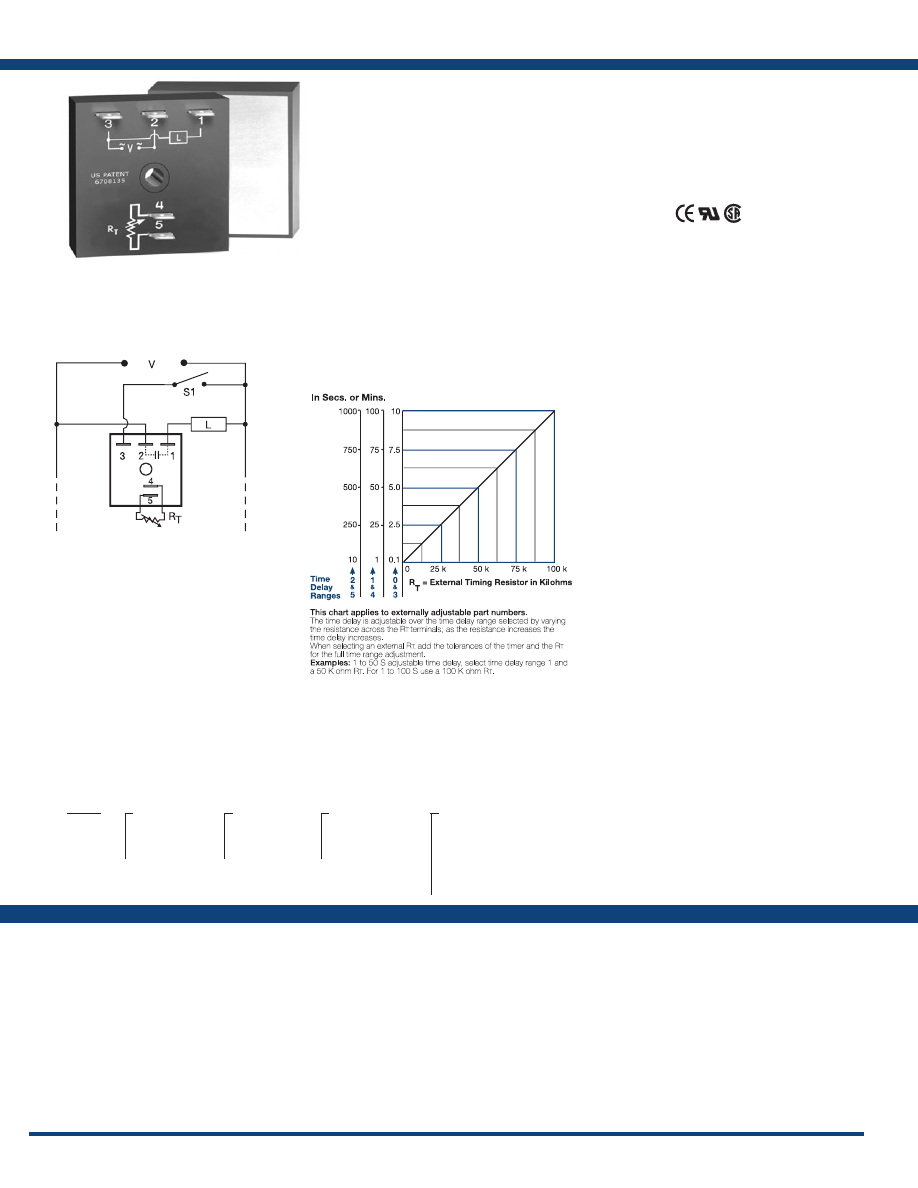
74
www.ssac.com • 800-843-8848 • fax: 605-348-5685
Features:
• High load currents up to 20A, 200A inrush
• Fixed or adjustable delays from 0.1s - 1000m
• ±0.5% repeat accuracy
• ±1% factory calibration
• 24, 120, or 230VAC
• Metallized mounting surface for heat transfer
•
Totally solid state and encapsulated
Approvals:
THD2 Series
Timer - Interval
Available Models:
Time Delay
Range . . . . . . . . . . . . . . . . . . . . . . . . . . . . . . . . . .
0.1s - 1000m in 6 adjustable ranges or fixed
Repeat Accuracy . . . . . . . . . . . . . . . . . . . . . . . .
±0.5% or 20ms, whichever is greater
Tolerance (Factory Calibration) . . . . . . . . . . . .
≤ ±1%
Reset Time . . . . . . . . . . . . . . . . . . . . . . . . . . . . . .
≤ 150ms
Time Delay vs Temp. & Voltage
. . . . . . . . . . .
≤ ±2%
Input
Voltage
. . . . . . . . . . . . . . . . . . . . . . . . . . . . . . . . .
24, 120, or 230VAC
Tolerance . . . . . . . . . . . . . . . . . . . . . . . . . . . . . . .
±20%
AC Line Frequency . . . . . . . . . . . . . . . . . . . . . .
50/60 Hz
Output
Type . . . . . . . . . . . . . . . . . . . . . . . . . . . . . . . . . . .Solid state
Form . . . . . . . . . . . . . . . . . . . . . . . . . . . . . . . . . . .
NO, closed during timing
Maximum Load Current Output Steady State Inrush**
A 6A 60A
B 10A 100A
C 20A 200A
Minimum Load Current . . . . . . . . . . . . . . . . . .
100mA
Voltage Drop
. . . . . . . . . . . . . . . . . . . . . . . . . . .
≅
2.5V at rated current
OFF State Leakage Current
. . . . . . . . . . . . . . .
≅
5mA @ 230VAC
Protection
Circuitry . . . . . . . . . . . . . . . . . . . . . . . . . . . . . . .Encapsulated
Dielectric Breakdown
. . . . . . . . . . . . . . . . . . . .
≥ 2000V RMS terminals to mounting surface
Insulation Resistance . . . . . . . . . . . . . . . . . . . . .
≥ 100 MΩ
Mechanical
Mounting ** . . . . . . . . . . . . . . . . . . . . . . . . . . . .
Surface mount with one #10 (M5 x 0.8) screw
Dimensions . . . . . . . . . . . . . . . . . . . . . . . . . . . . .
2 x 2 x 1.51 in. (50.8 x 50.8 x 38.4 mm)
Termination . . . . . . . . . . . . . . . . . . . . . . . . . . . .
0.25 in. (6.35 mm) male quick connect terminals
Environmental
Operating / Storage Temperature
. . . . . . . . .
-40° to 60°C / -40° to 85°C
Humidity . . . . . . . . . . . . . . . . . . . . . . . . . . . . . . .
95% relative, non-condensing
Weight
. . . . . . . . . . . . . . . . . . . . . . . . . . . . . . . . .
≅
3.9 oz (111 g)
**Must be bolted to a metal surface using the included heat sink compound. The maximum
mounting surface temperature is 90°C. Inrush: Non-repetitive for 16ms.
Specifications
Order Table:
Connection:
The THD2 Series combines accurate timing
circuitry with high power solid-state switching.
It can switch motors, lamps, and heaters directly
without a contactor. You can reduce labor,
component cost, and increase reliability with these
small, easy-to-use, Digi-Power timers.
Operation (Interval):
Upon application of input voltage, the time delay begins.
The output energizes during the time delay. At the end
of the time delay, the output de-energizes and remains
de-energized until input voltage is removed.
Reset: Removing input voltage resets the time delay and
the output.
For more information see:
Appendix A, pages 156-164 for function descriptions
and diagrams .
Appendix B, page 165, Figure 4 for dimensional drawing.
THD2B4110M
THD2B41600S
THD2B6110M
THD2C231
THD2C232
THD2C233
THD2C234
THD2C235
THD2C423
THD2C430
THD2C431
THD2C432
THD2C433
THD2C434
THD2C435
Auxiliary Products:
•
External ad just potentiometer:
P/N: P1004-95
P/N: P1004-95-X
•
Female quick connect:
P/N: P1015-13 (AWG 10/12)
P/N: P1015-64 (AWG 14/16)
•
Quick connect t o s crew ad aptor:
P/N: P1015-18
•
Versa-knob:
P/N: P0700-7
THD2
X
Output Rating
─
A
- 6A
─
B
- 10A
─
C
- 20A
X
Input Voltage
─
2
- 24VAC
─
4
- 120VAC
─
6
- 230VAC
X
Adjustment
─
1
- Fixed
─
2
- External adjust
─
3
- Onboard adjust
X
Time Delay*
─
0
- 0.1 - 10s
─
1
- 1 - 100s
─
2
- 10 - 1000s
─
3
- 0.1 - 10m
─
4
- 1 - 100m
─
5
- 10 - 1000m
*If fixed delay is selected, insert
delay (
1 - 1000
) followed by (
S
) secs .
or (
M
) mins .
L1
N/L2
S1 = Optional Low Current Initiate Switch
External Resistance vs . Time Delay:
If desired part number is not listed, please call us to
see if it is technically possible to build .
R
T
is used when external adjustment is ordered.
Courtesy of Steven Engineering, Inc.-230 Ryan Way, South San Francisco, CA 94080-6370-Main Office: (650) 588-9200-Outside Local Area: (800) 258-9200-www.stevenengineering.com
Littelfuse-catalog-html.html
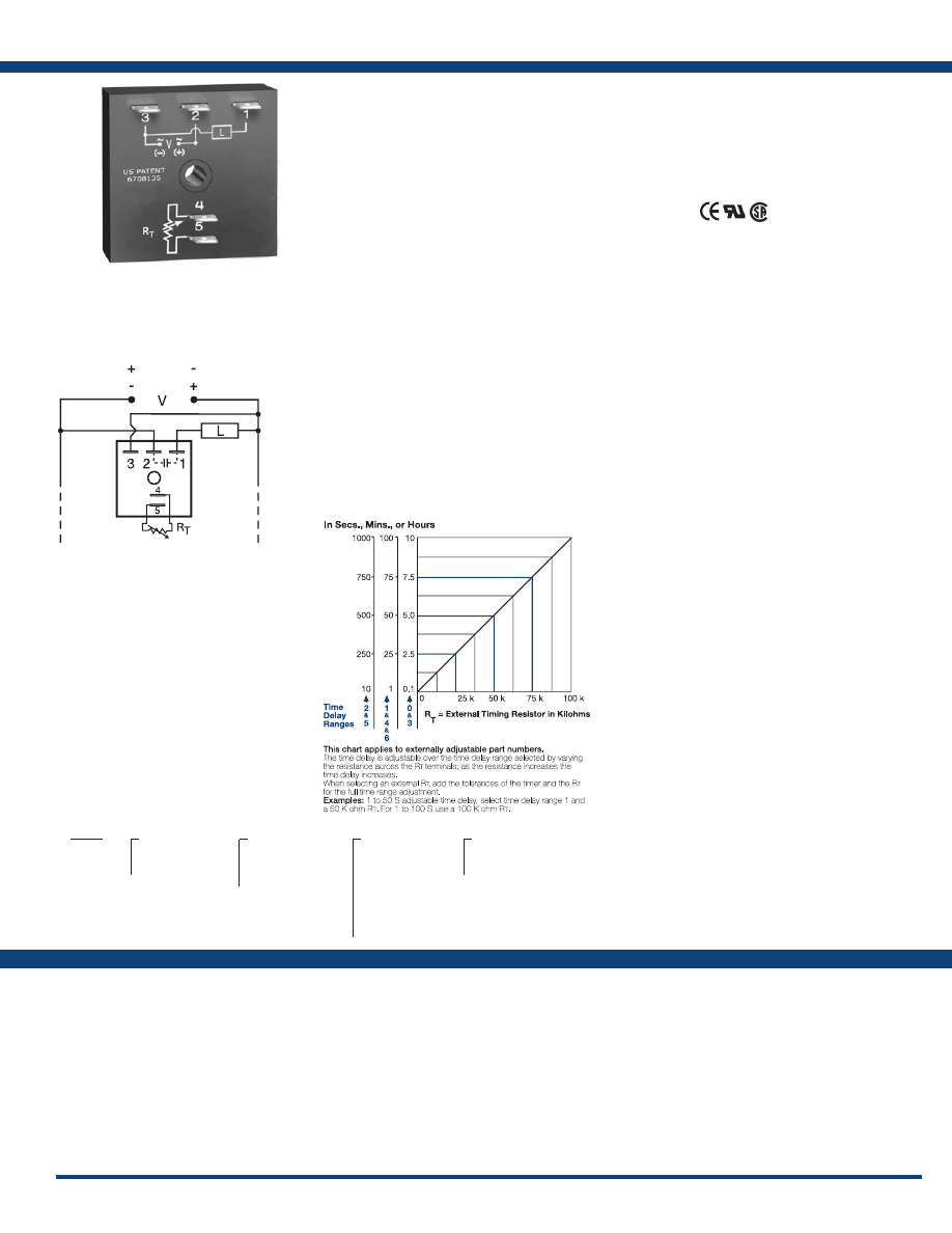
75
www.ssac.com • 800-843-8848 • fax: 605-348-5685
TSD6 Series
Timer - Interval
Available Models:
Time Delay
Range . . . . . . . . . . . . . . . . . . . . . . . . . . . . . . . . . .
0.1s - 100h 7 adjustable ranges or fixed
Repeat Accuracy . . . . . . . . . . . . . . . . . . . . . . . .
±0.1% or 20ms, whichever is greater
Tolerance (Factory Calibration) . . . . . . . . . . . .
≤ ±1%
Reset Time . . . . . . . . . . . . . . . . . . . . . . . . . . . . . .
≤ 150ms
Time Delay vs Temp. & Voltage
. . . . . . . . . . .
≤ ±1%
Input
Voltage
. . . . . . . . . . . . . . . . . . . . . . . . . . . . . . . . .
12 or 24VDC
Tolerance . . . . . . . . . . . . . . . . . . . . . . . . . . . . . . .
±15%
DC Ripple . . . . . . . . . . . . . . . . . . . . . . . . . . . . . .
±10%
Power Consumption . . . . . . . . . . . . . . . . . . . . .
≤ 1W
Output
Type . . . . . . . . . . . . . . . . . . . . . . . . . . . . . . . . . . .
Solid state, positive or negative switching
Form . . . . . . . . . . . . . . . . . . . . . . . . . . . . . . . . . . .
NO, closed during timing
Maximum Load Current
. . . . . . . . . . . . . . . . . .
1A steady state, 10A inrush at 60°C
Off State Leakage Current
. . . . . . . . . . . . . . . .
≅
1mA
Voltage Drop
. . . . . . . . . . . . . . . . . . . . . . . . . . .
≅
1.0V @ 1A
Protection
Circuitry . . . . . . . . . . . . . . . . . . . . . . . . . . . . . . . Encapsulated
Dielectric Breakdown
. . . . . . . . . . . . . . . . . . . .
≥ 2000V RMS terminals to mounting surface
Insulation Resistance . . . . . . . . . . . . . . . . . . . . .
≥ 100 MΩ
Polarity . . . . . . . . . . . . . . . . . . . . . . . . . . . . . . . .
Units are reverse polarity protected
Mechanical
Mounting . . . . . . . . . . . . . . . . . . . . . . . . . . . . . .
Surface mount with one #10 (M5 x 0.8) screw
Dimensions . . . . . . . . . . . . . . . . . . . . . . . . . . . . .
2 x 2 x 1.21 in. (50.8 x 50.8 x 30.7 mm)
Termination . . . . . . . . . . . . . . . . . . . . . . . . . . . .
0.25 in. (6.35 mm) male quick connect terminals
Environmental
Operating / Storage Temperature
. . . . . . . . .
-40° to 75°C / -40° to 85°C
Humidity . . . . . . . . . . . . . . . . . . . . . . . . . . . . . . .
95% relative, non-condensing
Weight
. . . . . . . . . . . . . . . . . . . . . . . . . . . . . . . . .
≅
2.4 oz (68 g)
Order Table:
Specifications
The TSD6 offers total solid-state, interval timing
for 12 or 24VDC applications. This series provides
either negative or positive switching. The TSD
Series is designed for more demanding commercial
and industrial applications where small size and
accurate performance is required. The factory
calibration for fixed time delays is within 1% of
the target time delay. The repeat accuracy, under
stable conditions, is 0.1% of the time delay. The
TSD Series is rated to operate over an extended
temperature range. Time delays of 0.1 seconds
to 100 hours are available. The output is rated
1A steady and 10A inrush. The modules are
totally solid state and encapsulated to protect the
electronic circuitry .
Operation (Interval):
Upon application of input voltage, the time delay begins.
The output energizes during the time delay. At the end
of the time delay, the output de-energizes and remains
de-energized until input voltage is removed.
Reset: Removing input voltage resets the time delay and
the output.
For more information see:
Appendix A, pages 156-164 for function descriptions
and diagrams .
Appendix B, page 165, Figure 1 for dimensional drawing.
Features:
• Fixed or adjustable delays from 0.1s - 100h
• ±0.1% repeat accuracy
• ±1% factory calibration
• 12 or 24VDC interval timing
• 1A, solid-state output
•
Encapsulated
Approvals:
Connection:
TSD6113SN
TSD6121N
TSD6121P
TSD6123N
TSD6124P
TSD6310.8SN
TSD631180SP
TSD631380SP
TSD6320P
TSD6334P
Auxiliary Products:
•
External ad just potentiometer:
P/N: P1004-95
P/N: P1004-95-X
•
Female quick connect:
P/N: P1015-64 (AWG 14/16)
•
Quick connect t o s crew ad aptor:
P/N: P1015-18
•
Mounting bracket:
P/N: P1023-6
•
DIN rail:
P/N: C103PM
(Al)
•
DIN rail adaptor:
P/N: P1023-20
•
Versa-knob:
P/N: P0700-7
TSD6
X
Input Voltage
─
1
- 12VDC
─
3
- 24VDC
X
Adjustment
─
1
- Fixed
─
2
- External adjust
─
3
- Onboard adjust
X
Time Delay*
─
0
- 0.1 - 10s
─
1
- 1 - 100s
─
2
- 10 - 1000s
─
3
- 0.1 - 10m
─
4
- 1 - 100m
─
5
- 10 - 1000m
─
6
- 1 - 100h
X
Switching Mode
─
P
- Positive
─
N
- Negative
*If fixed delay is selected, insert
delay (
0 .1 - 1000
) followed by (
S
) sec .
or (
M
) min . or (
1 - 100
) (
H
) hours
External Resistance vs . Time Delay:
(Positive Switching)
(Negative Switching)
If desired part number is not listed, please call us to
see if it is technically possible to build .
R
T
is used when external adjustment is ordered.
Courtesy of Steven Engineering, Inc.-230 Ryan Way, South San Francisco, CA 94080-6370-Main Office: (650) 588-9200-Outside Local Area: (800) 258-9200-www.stevenengineering.com
Littelfuse-catalog-html.html
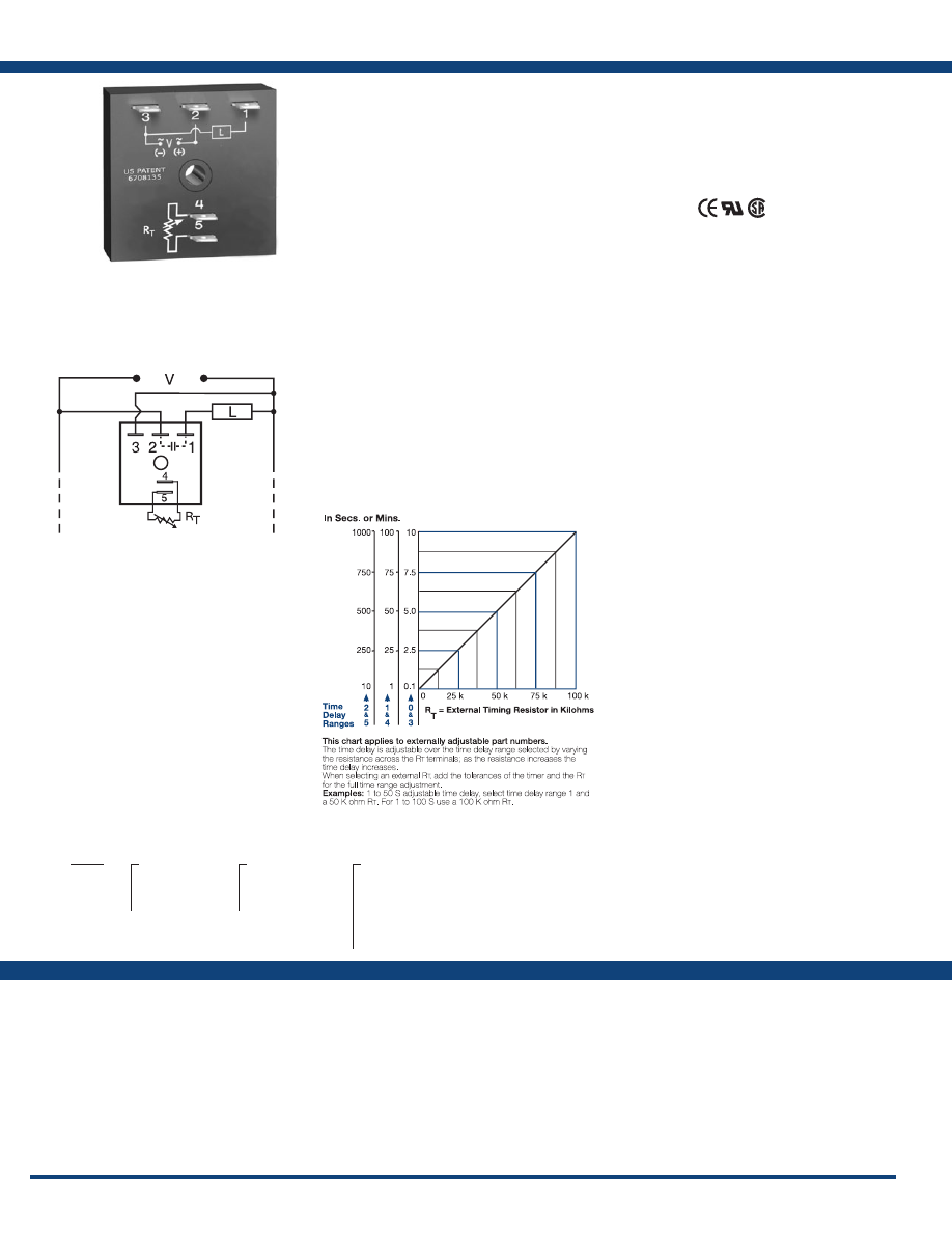
76
www.ssac.com • 800-843-8848 • fax: 605-348-5685
Features:
• Fixed or adjustable delays from 0.1s - 1000m
• ±0.5% repeat accuracy
• ± 5% factory calibration
• 24, 120, or 230VAC
• 1A, solid-state output
•
Encapsulated
Approvals:
KSD2 Series
Timer - Interval
Available Models:
Time Delay
Range . . . . . . . . . . . . . . . . . . . . . . . . . . . . . . . . . .
0.1s - 1000m in 6 adjustable ranges or fixed
Repeat Accuracy . . . . . . . . . . . . . . . . . . . . . . . .
±0.5% or 20ms, whichever is greater
Tolerance (Factory Calibration) . . . . . . . . . . . .
≤ ±5%
Reset Time . . . . . . . . . . . . . . . . . . . . . . . . . . . . . .
≤ 150ms
Time Delay vs Temp. & Voltage
. . . . . . . . . . .
≤ ±10%
Input
Voltage
. . . . . . . . . . . . . . . . . . . . . . . . . . . . . . . . .
24, 120, or 230VAC
Tolerance . . . . . . . . . . . . . . . . . . . . . . . . . . . . . . .
±20%
AC Line Frequency . . . . . . . . . . . . . . . . . . . . . .
50/60 Hz
Power Consumption . . . . . . . . . . . . . . . . . . . . .
≤ 2VA
Output
Type . . . . . . . . . . . . . . . . . . . . . . . . . . . . . . . . . . .Solid state
Form . . . . . . . . . . . . . . . . . . . . . . . . . . . . . . . . . . .
NO, closed during timing
Maximum Load Current
. . . . . . . . . . . . . . . . . .
1A steady state, 10A inrush at 60°C
OFF State Leakage Current
. . . . . . . . . . . . . . .
≅
5mA @ 230VAC
Voltage Drop
. . . . . . . . . . . . . . . . . . . . . . . . . . .
≅
2.5V @ 1A
Protection
Circuitry . . . . . . . . . . . . . . . . . . . . . . . . . . . . . . .Encapsulated
Dielectric Breakdown
. . . . . . . . . . . . . . . . . . . .
≥ 2000V RMS terminals to mounting surface
Insulation Resistance . . . . . . . . . . . . . . . . . . . . .
≥ 100 MΩ
Mechanical
Mounting . . . . . . . . . . . . . . . . . . . . . . . . . . . . . .
Surface mount with one #10 (M5 x 0.8) screw
Dimensions . . . . . . . . . . . . . . . . . . . . . . . . . . . . .
2 x 2 x 1.21 in. (50.8 x 50.8 x 30.7 mm)
Termination . . . . . . . . . . . . . . . . . . . . . . . . . . . .
0.25 in. (6.35 mm) male quick connect terminals
Environmental
Operating / Storage Temperature
. . . . . . . . .
-40° to 60°C / -40° to 85°C
Humidity . . . . . . . . . . . . . . . . . . . . . . . . . . . . . . .
95% relative, non-condensing
Weight
. . . . . . . . . . . . . . . . . . . . . . . . . . . . . . . . .
≅
2.4 oz (68 g)
Specifications
Order Table:
Connection:
The KSD2 Series is designed for general purpose
commercial and industrial applications where a
small, cost effective, reliable, solid-state timer is
required. The factory calibration for fixed time
delays is within 5% of the target time delay. The
repeat accuracy, under stable conditions, is 0.5% of
the selected time delay. This series is designed for
input voltages of 24, 120 or 230VAC. Time delays
of 0.1 seconds to 1000 minutes are available in 6
ranges. The output is rated 1A steady and 10A
inrush. The modules are totally solid state and
encapsulated to protect the electronic circuitry.
An excellent choice for most OEM pulse shaping,
maximum run time, and other process control
applications .
Operation (Interval):
Upon application of input voltage, the time delay begins.
The output energizes during the time delay. At the end
of the time delay, the output de-energizes and remains
de-energized until input voltage is removed.
Reset: Removing input voltage resets the time delay
and the output.
For more information see:
Appendix A, pages 156-164 for function descriptions
and diagrams .
Appendix B, page 165, Figure 1 for dimensional drawing.
KSD2211M
KSD2221
KSD2413M
KSD2420
Auxiliary Products:
•
External ad just potentiometer:
P/N: P1004-95
P/N: P1004-95-X
•
Mounting bracket:
P/N: P1023-6
•
Female quick connect:
P/N: P1015-64 (AWG 14/16)
•
Quick connect t o s crew ad aptor:
P/N: P1015-18
•
Versa-knob:
P/N: P0700-7
•
DIN rail:
P/N: C103PM
(Al)
•
DIN rail adaptor:
P/N: P1023-20
KSD2
X
Input Voltage
─
2
- 24VAC
─
4
- 120VAC
─
6
- 230VAC
X
Adjustment
─
1
- Fixed
─
2
- External adjust
─
3
- Onboard adjust
X
Time Delay*
─
0
- 0.1 - 10s
─
1
- 1 - 100s
─
2
- 10 - 1000s
─
3
- 0.1 - 10m
─
4
- 1 - 100m
─
5
- 10 - 1000m
*If fixed delay is selected, insert delay (
0 .1 - 1000
)
followed by (
S
) secs . or (
M
) mins .
L1
N/L2
External Resistance vs . Time Delay:
If desired part number is not listed, please call us to
see if it is technically possible to build .
R
T
is used when external adjustment is ordered.
Courtesy of Steven Engineering, Inc.-230 Ryan Way, South San Francisco, CA 94080-6370-Main Office: (650) 588-9200-Outside Local Area: (800) 258-9200-www.stevenengineering.com
Littelfuse-catalog-html.html
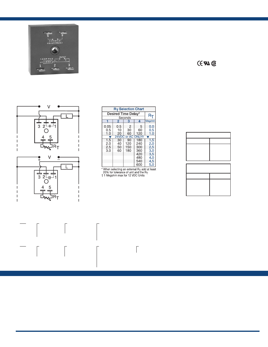
77
www.ssac.com • 800-843-8848 • fax: 605-348-5685
TS2 / TS6 Series
Timer - Interval
Available Models:
Time Delay
Type . . . . . . . . . . . . . . . . . . . . . . . . . . . . . . . . . . . Analog circuitry
Range 12VDC
. . . . .
0.05 - 120s in 4 adjustable ranges or fixed
(1 MΩ max. R
T
)
Other Voltages
. . . . .
0.05 - 600s in 4 adjustable ranges or fixed
Repeat Accuracy . . . . . . . . . . . . . . . . . . . . . . . .
±2% or 20ms, whichever is greater
Tolerance (Factory Calibration) . . . . . . . . . . . .
≤ ±10%
Time Delay vs Temp. & Voltage
. . . . . . . . . . .
≤ ±10%
Reset Time . . . . . . . . . . . . . . . . . . . . . . . . . . . . . .
≤ 150ms
Input
Voltage
. . . . . . . . . . . . . . . . . . . . . . . . . . . . . . . . .
12 or 24VDC; 24, 120, or 230VAC
Tolerance . . . . . . . . . . . . . . . . . . . . . . . . . . . . . . .
±15%
DC Ripple . . . . . . . . . . . . . . . . . . . . . . . . . . . . . .
10%
Power Consumption . . . . . . . . . . . . . . . . . . . . .
DC ≤ 1W; AC ≤ 2VA
Output
Type . . . . . . . . . . . . . . . . . . . . . . . . . . . . . . . . . . . Solid state
Form . . . . . . . . . . . . . . . . . . . . . . . . . . . . . . . . . . .
NO, closed during timing
Maximum Load Current
. . . . . . . . . . . . . . . . . .
1A steady state, 10A inrush at 60°C
Voltage Drop
. . . . . . . . . . . . . . . . . . . . . . . . . . . DC
≅
1.0V @ 1A; AC
≅
2.5V @ 1A
Protection
Circuitry . . . . . . . . . . . . . . . . . . . . . . . . . . . . . . . Encapsulated
Polarity . . . . . . . . . . . . . . . . . . . . . . . . . . . . . . . .
TS6 is not reverse polarity protected
Dielectric Breakdown
. . . . . . . . . . . . . . . . . . . .
≥ 2000V RMS terminals to mounting surface
Insulation Resistance . . . . . . . . . . . . . . . . . . . . .
≥ 100 MΩ
Mechanical
Mounting . . . . . . . . . . . . . . . . . . . . . . . . . . . . . .
Surface mount with one #10 (M5 x 0.8) screw
Dimensions . . . . . . . . . . . . . . . . . . . . . . . . . . . . .
2 x 2 x 1.21 in. (50.8 x 50.8 x 30.7 mm)
Termination . . . . . . . . . . . . . . . . . . . . . . . . . . . .
0.25 in. (6.35 mm) male quick connect terminals
Environmental
Operating / Storage Temperature
. . . . . . . . .
-40° to 75°C / -40° to 85°C
Humidity . . . . . . . . . . . . . . . . . . . . . . . . . . . . . . .
95% relative, non-condensing
Weight
. . . . . . . . . . . . . . . . . . . . . . . . . . . . . . . . .
≅
2.4 oz (68 g)
Order Tables:
Specifications
The TS2 Series is designed for 24, 120 or 230VAC
and the TS6 Series is designed for 12 or 24VDC.
These series are capable of controlling load
currents of up to 1A steady state, 10A inrush.
Encapsulated circuitry and the reliability of a ±2%
repeat accuracy make the TS2 and TS6 ideal for
cost sensitive applications.
Operation (Interval):
Upon application of input voltage, the time delay begins.
The output energizes during the time delay. At the end
of the time delay, the output de-energizes and remains
de-energized until input voltage is removed.
Reset: Removing input voltage resets the time delay and
the output.
For more information see:
Appendix A, pages 156-164 for function descriptions
and diagrams .
Appendix B, page 165, Figure 1 for dimensional drawing.
Features:
• 12 or 24VDC; 24,120, or 230VAC input
voltages
• Fixed or adjustable delays from 0.05s - 10m
in 8 ranges
• Repeat accuracy ±2%
• Load currents to 1A, 10A inrush
• Totally solid state & encapsulated
Approvals:
Connection:
TS22120
TS2213
TS2223
TS2411.5
TS24110
TS2412
TS2413
TS24130
TS2421
TS2422
TS2423
TS2424
TS2611.5
TS26130
TS26190
TS2621
TS6116P
TS6122P
TS6123P
TS6311P
TS63110P
TS6321P
Auxiliary Products:
•
External ad just potentiometer:
P/N: P1004-XX
P/N: P1004-XX-X
•
Female quick connect:
P/N: P1015-64 (AWG 14/16)
•
Quick connect t o s crew ad aptor:
P/N: P1015-18
•
Mounting bracket:
P/N: P1023-6
•
DIN rail:
P/N: C103PM
(Al)
•
DIN rail adaptor:
P/N: P1023-20
•
Versa-knob:
P/N: P0700-7
•
Plug-on adjustment module:
P/N: VTP(X)(X)
TS2
X
Input Voltage
─
2
- 24VAC
─
4
- 120VAC
─
6
- 230VAC
X
Adjustment
─
1
- Fixed
─
2
- External adjust
X
Time Delay*
─
1
- 0.05 - 3s
─
2
- 0.5 - 60s
─
3
- 2 - 180s
─
4
- 5 - 600s
*If fixed delay is selected, insert
delay (
0 .05 - 600
) in seconds .
TS6
X
Input Voltage
─
1
- 12VDC
─
3
- 24VDC
X
Adjustment
─
1
- Fixed
─
2
- External adjust
X
Time Delay*
12VDC 24VDC
─
1
- 0.05 - 1s 0.05 - 3s
─
2
- 0.5 - 20s 0.5 - 60s
─
3
- 2 - 60s 2 - 180s
─
4
- 5 - 120s 5 - 600s
X
Switching Mode
─
P
- Positive
*If fixed delay is selected, insert delay (
0 .05
- 120
12VDC
) or (
0 .05 - 600
24VDC
) in secs .
L1
N/L2
Selection Table for VTP Plug-on
Adjustment Accessory.
TS6 12VDC
Time Delay
VTP P/N
1
- 0.05-1s
2
- 0.5-20s
3
- 2-60s
4
- 5-120s
VTP2A
VTP2E
VTP2F
VTP2H
TS2 & TS6
All Other Voltages
Time Delay
VTP P/N
1
- 0.05-3s
2
- 0.5-60s
3
- 2-180s
4
- 5-600s
VTP4B
VTP4F
VTP4J
VTP5N
If desired part number is not listed, please call us to
see if it is technically possible to build .
R
T
is used when external adjustment is ordered.
Note: TS6 is not reverse polarity protected.
Courtesy of Steven Engineering, Inc.-230 Ryan Way, South San Francisco, CA 94080-6370-Main Office: (650) 588-9200-Outside Local Area: (800) 258-9200-www.stevenengineering.com
Littelfuse-catalog-html.html
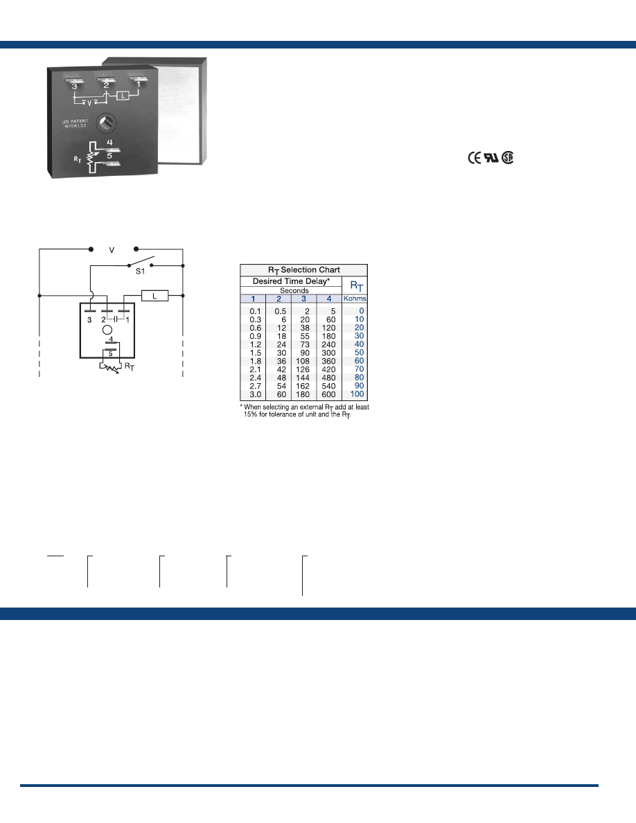
78
www.ssac.com • 800-843-8848 • fax: 605-348-5685
Features
• High load current capacity up to 20A, 200A
inrush
• Fixed or adjustable time delays from 0.1 -
600s in 4 ranges
• ±2% repeat accuracy
• ±5% factory calibration
• Metallized mounting surface for heat transfer
• Solid state & encapsulated
Approvals:
TH2 Series
Timer - Interval
Available Models:
Time Delay
Range . . . . . . . . . . . . . . . . . . . . . . . . . . . . . . . . . . . . .
0.1s - 600s in 4 adjustable ranges, or fixed
Repeat Accuracy . . . . . . . . . . . . . . . . . . . . . . . . . . .
±2% or 20ms, whichever is greater
Tolerance (Factory Calibration) . . . . . . . . . . . . . . .
≤ ±5%
Time Delay vs Temp. & Voltage
. . . . . . . . . . . . . .
≤ ±10%
Reset Time . . . . . . . . . . . . . . . . . . . . . . . . . . . . . . . . .
≤ 150ms
Input
Voltage
. . . . . . . . . . . . . . . . . . . . . . . . . . . . . . . . . . . .
24, 120, or 230VAC
Tolerance . . . . . . . . . . . . . . . . . . . . . . . . . . . . . . . . . .
±15%
AC Line Frequency . . . . . . . . . . . . . . . . . . . . . . . . .
50/60 Hz
Power Consumption . . . . . . . . . . . . . . . . . . . . . . . .
≤ 2VA
Output
Type . . . . . . . . . . . . . . . . . . . . . . . . . . . . . . . . . . . . . .Solid state
Form . . . . . . . . . . . . . . . . . . . . . . . . . . . . . . . . . . . . . .
NO, closed during timing
Maximum Load Currents Output Steady State Inrush**
A 6A 60A
B 10A 100A
C 20A 200A
Minimum Load Current . . . . . . . . . . . . . . . . . . . . .
100mA
Voltage Drop
. . . . . . . . . . . . . . . . . . . . . . . . . . . . . .
≅
2.5V at rated current
OFF State Leakage Current
. . . . . . . . . . . . . . . . . .
≅
5mA @ 230VAC
Protection
Circuitry . . . . . . . . . . . . . . . . . . . . . . . . . . . . . . . . . .Encapsulated
Dielectric Breakdown
. . . . . . . . . . . . . . . . . . . . . . .
≥ 2000V RMS terminals to mounting surface
Insulation Resistance . . . . . . . . . . . . . . . . . . . . . . . .
≥ 100 MΩ
Mechanical
Mounting ** . . . . . . . . . . . . . . . . . . . . . . . . . . . . . . .
Surface mount with one #10 (M5 x 0.8) screw
Dimensions . . . . . . . . . . . . . . . . . . . . . . . . . . . . . . . .
2 x 2 x 1.51 in. (50.8 x 50.8 x 38.4 mm)
Termination . . . . . . . . . . . . . . . . . . . . . . . . . . . . . . .
0.25 in. (6.35 mm) male quick connect terminals
Environmental
Operating / Storage Temperature
. . . . . . . . . . . .
-20° to 60°C / -40° to 85°C
Humidity . . . . . . . . . . . . . . . . . . . . . . . . . . . . . . . . . .
95% relative, non-condensing
Weight
. . . . . . . . . . . . . . . . . . . . . . . . . . . . . . . . . . . .
≅
3.9 oz (111 g)
**Must be bolted to a metal surface using the included heat sink compound. The maximum
mounting surface temperature is 90°C. Inrush: Non-repetitive for 16ms.
Specifications
Order Table:
Connection:
The TH2 is the combination of a timer and a solid-
state relay into one easy-to-use solid-state molded
module. When mounted to a metal surface, the
TH2 Series can switch load currents up to 20A
steady state with 200A inrush. The TH2 replaces
a timer and relay at a competitive price.
Operation (Interval):
Upon application of input voltage, the time delay begins.
The output energizes during the time delay. At the end
of the time delay, the output de-energizes and remains
de-energized until input voltage is removed.
Reset: Removing input voltage resets the time delay
and output .
For more information see:
Appendix A, pages 156-164 for function descriptions
and diagrams .
Appendix B, page 165, Figure 4 for dimensional drawing.
TH2A421
Auxiliary Products:
•
External ad just potentiometer:
P/N: P1004-95
P/N: P1004-95-X
•
Female quick connect:
P/N: P1015-13 (AWG 10/12)
P/N: P1015-64 (AWG 14/16)
•
Quick connect t o s crew ad aptor:
P/N: P1015-18
•
Versa-knob:
P/N: P0700-7
TH2
X
Output Rating
─
A
- 6A
─
B
- 10A
─
C
- 20A
X
Input Voltage
─
2
- 24VAC
─
4
- 120VAC
─
6
- 230VAC
X
Adjustment
─
1
- Fixed
─
2
- External adjust
─
3
- Onboard adjust
X
Time Delay*
─
1
- 0.1 - 3s
─
2
- 0.5 - 60s
─
3
- 2 - 180s
─
4
- 5 - 600s
*If fixed delay is selected, insert
delay (
0 .1 - 600
) in seconds .
L1
N/L2
If desired part number is not listed, please call us to
see if it is technically possible to build .
R
T
is used when external adjustment is ordered.
Courtesy of Steven Engineering, Inc.-230 Ryan Way, South San Francisco, CA 94080-6370-Main Office: (650) 588-9200-Outside Local Area: (800) 258-9200-www.stevenengineering.com
Littelfuse-catalog-html.html
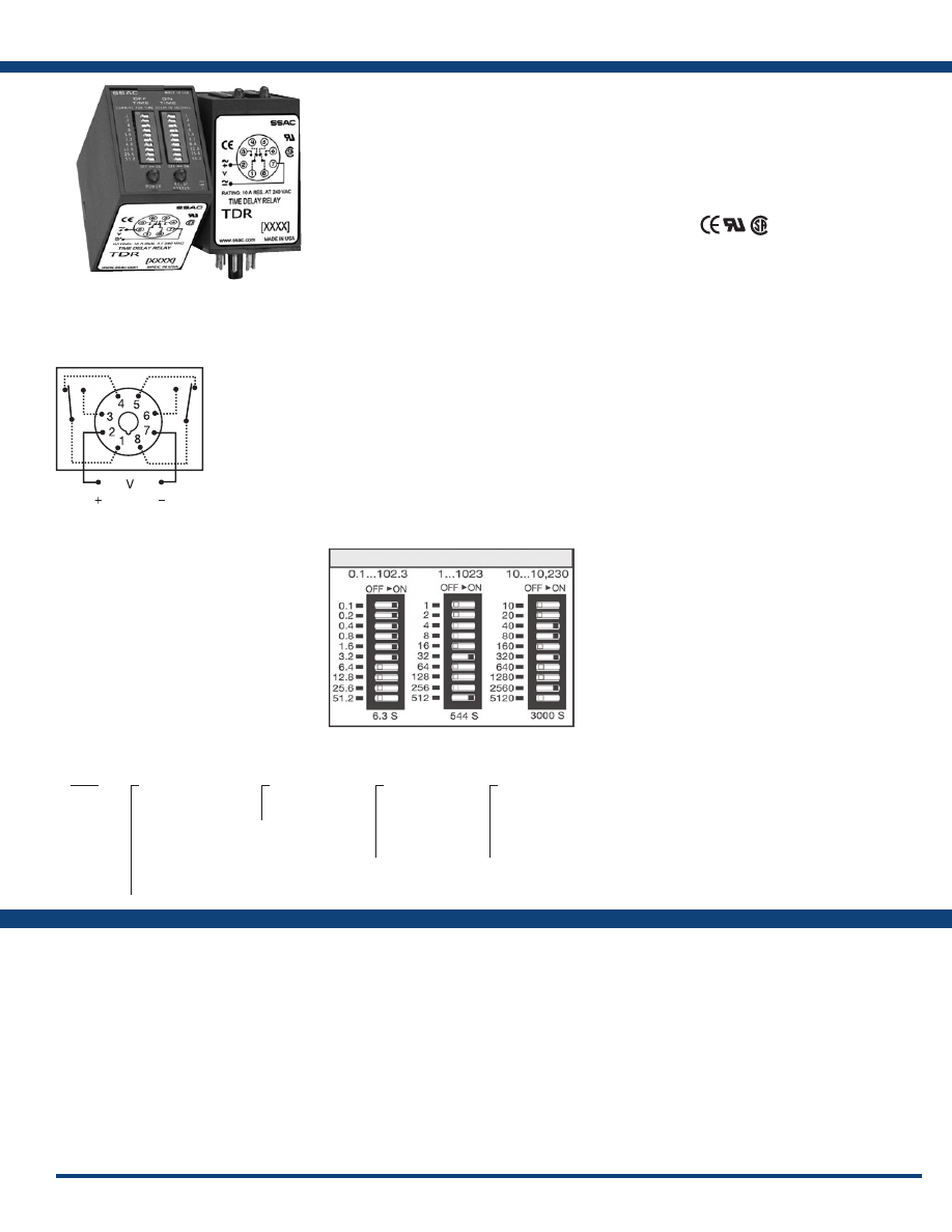
79
www.ssac.com • 800-843-8848 • fax: 605-348-5685
TDR Series
Timer - Recycling
Available Models:
Time Delay
Type . . . . . . . . . . . . . . . . . . . . . . . . . . . . . . . . . . . Microcontroller circuitry
Range** . . . . . . . . . . . . . . . . . . . . . . . . . . . . . . . .
0.1 - 102.3s in 0.1s increments
1 - 1023s in 1s increments
10 - 10,230s in 10s increments
Repeat Accuracy . . . . . . . . . . . . . . . . . . . . . . . .
±0.1% or 20ms, whichever is greater
Setting Accuracy . . . . . . . . . . . . . . . . . . . . . . . .
±2% or 50ms, whichever is greater
Reset Time . . . . . . . . . . . . . . . . . . . . . . . . . . . . . .
≤ 150ms
Recycle Time . . . . . . . . . . . . . . . . . . . . . . . . . . . .
≤ 500ms
Time Delay vs Temp. & Voltage
. . . . . . . . . . .
±2%
Input
Voltage
. . . . . . . . . . . . . . . . . . . . . . . . . . . . . . . . .
12 to 24VDC, 110VDC, 24, 120, or 230VAC;
24 to 240VAC/DC; 12 to 48VDC
Tolerance 12VDC & 24VDC/AC
. . . . . .
-15% - 20%
110 to 230VAC/DC
. . . . . .
-20% - 10%
AC Line Frequency / DC Ripple
. . . . . . . . . . .
50/60 Hz / ≤ 10%
Power Consumption . . . . . . . . . . . . . . . . . . . . .
AC ≤ 2VA; DC ≤ 2W
Input LED Indicator . . . . . . . . . . . . . . . . . . . . .
Green; On when input voltage is applied
Output
Type . . . . . . . . . . . . . . . . . . . . . . . . . . . . . . . . . . .
Electromechanical relay
Form . . . . . . . . . . . . . . . . . . . . . . . . . . . . . . . . . . . DPDT
Rating . . . . . . . . . . . . . . . . . . . . . . . . . . . . . . . . .
10A resistive @ 120/240VAC & 30VDC;
1/3 hp @ 230VAC
Life
. . . . . . . . . . . . . . . . . . . . . . . . . . . . . . . . . . . .
Mechanical - 1 x10
7
; Electrical - 1 x 10
5
Max. Switching Voltage
. . . . . . . . . . . . . . . . . .
250VAC
Relay LED Indicator . . . . . . . . . . . . . . . . . . . . .
Red; ON when output relay energizes
Protection
Isolation Voltage
. . . . . . . . . . . . . . . . . . . . . . . .
≥ 1500V RMS input to output
Insulation Resistance . . . . . . . . . . . . . . . . . . . . .
≥ 100 MΩ
Polarity . . . . . . . . . . . . . . . . . . . . . . . . . . . . . . . .
DC units are reverse polarity protected
Mechanical
Mounting . . . . . . . . . . . . . . . . . . . . . . . . . . . . . .
Plug-in socket
Dimensions . . . . . . . . . . . . . . . . . . . . . . . . . . . . .
3.2 x 2.39 x 1.78 in. (81.3 x 60.7 x 45.2 mm)
Termination . . . . . . . . . . . . . . . . . . . . . . . . . . . .
Octal 8-pin plug-in
Environmental
Operating / Storage Temperature
. . . . . . . . .
-20° to 60°C / -30° to 85°C
Weight
. . . . . . . . . . . . . . . . . . . . . . . . . . . . . . . . .
≅
6 oz (170 g)
**For CE approved applications, power must be removed from the unit when a switch
position is changed.
Order Table:
Specifications
The TDR Series of time-delay relays are comprised
of digital circuitry and an isolated, 10A relay
output. The on and off delays are selected by
means of two, ten position binary switches, which
allow the setting of the desired delay to be precise
every time.
Operation (Recycling - ON Time First):
Upon application of input voltage, the green LED glows,
the output relay is energized, the red LED glows, and
the T1 ON time begins. At the end of the ON time, the
output de-energizes, the red LED turns OFF and the T2,
OFF time begins. At the end of the OFF time, the output
relay energizes and the cycle repeats as long as input
voltage is applied.
Reset: Removing input voltage resets the output and
time delays, and returns the sequence to the first delay.
Operation (Recycling - OFF Time First):
Upon application of input voltage, the green LED glows,
the T1 OFF time begins, the load is OFF. At the end of
the OFF time, the T2 ON time begins, the load energizes,
and the red LED glows. At the end of the ON time the
load de-energizes and the red LED turns OFF. The cycle
repeats until input voltage is removed.
Reset: Removing input voltage resets the output and the
sequence to the OFF time.
For more information see:
Appendix A, pages 156-164 for function descriptions
and diagrams .
Appendix B, page 165, Figure 8 for dimensional drawing.
Features:
• Switch settable time delays - both times
adjustable
• 0.1s - 2.84h in 3 ranges
• ±0.1% repeat accuracy
• ±2% setting accuracy
• Isolated, 10A, DPDT output contacts
• Octal plug-in base connection
Approvals:
Connection:
TDR1A22
TDR2A22
TDR2A23
TDR4A11
TDR4A12
TDR4A13
TDR4A22
TDR4A23
TDR4A33
TDR4B22
TDR4B23
TDR6A22
Auxiliary Products:
•
Panel mount kit:
P/N: BZ1
•
Octal 8-pin socket:
P/N: NDS-8
•
Hold-down clips (sold in pairs):
P/N: PSC8 (NDS-8)
•
DIN rail:
P/N: C103PM
(Al)
TDR
X
Input Voltage
─
A
- 24 to 240VAC/DC
─
D
- 12* to 48VDC
─
1
- 12VDC*
─
2
- 24VAC
─
3
- 24VDC
─
4
- 120VAC
─
5
- 110VDC
─
6
- 230VAC
X
Sequence
─
A
- ON Time First
─
B
- OFF Time First
X
ON Time
─
1
- 0.1 - 102.3s in
0.1s increments
─
2
- 1 - 1023s in 1s
increments
─
3
- 10 - 10,230s in
10s increments
X
OFF Time
─
1
- 0.1 - 102.3s in
0.1s increments
─
2
- 1 - 1023s in 1s
increments
─
3
- 10 - 10,230s in
10s increments
L1
N/L2
Digi-Set Binary Switch Operation:
*Control status LED not available on 12VDC units.
If desired part number is not listed, please call us to
see if it is technically possible to build .
Relay contacts are isolated .
Courtesy of Steven Engineering, Inc.-230 Ryan Way, South San Francisco, CA 94080-6370-Main Office: (650) 588-9200-Outside Local Area: (800) 258-9200-www.stevenengineering.com
Littelfuse-catalog-html.html
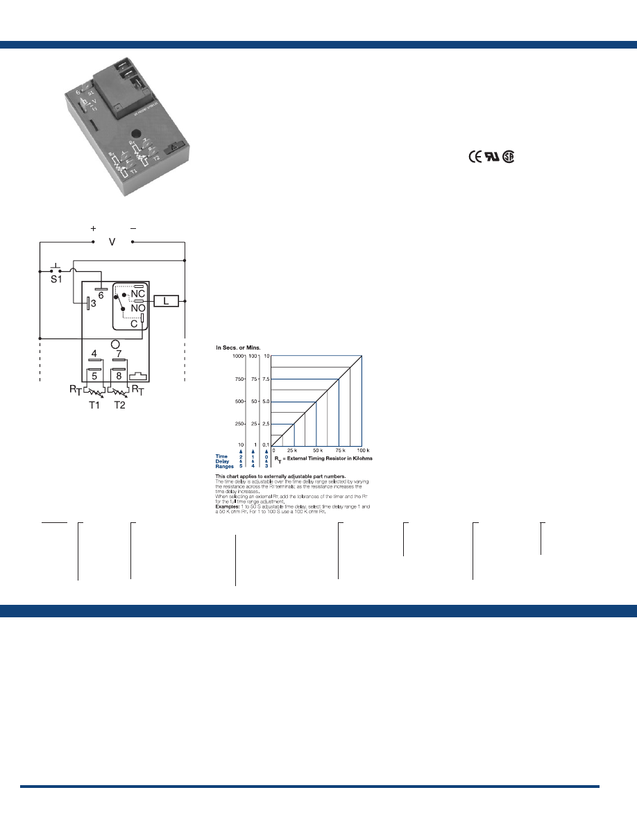
80
www.ssac.com • 800-843-8848 • fax: 605-348-5685
Features
• 30A, SPDT, NO output contacts
• 12 to 230V operation in 5 options
•
Encapsulated circuitry
• Delays from 0.1s - 1000m in 6 ranges
• Independent adjustment of on and off delays
• ±0.5% repeat accuracy
• ±5% factory calibration
• Factory fixed, onboard or external adjust
Approvals:
HRDR Series
Timer - Recycling
Available Models:
Time Delay
Range . . . . . . . . . . . . . . . . . . . . . . . . . . . . . . . . . .
100ms - 1000m in 6 adjustable ranges or fixed
Repeat Accuracy . . . . . . . . . . . . . . . . . . . . . . . .
±0.5% or 20ms, whichever is greater
Tolerance (Factory Calibration) . . . . . . . . . . . .
±5%
Reset Time . . . . . . . . . . . . . . . . . . . . . . . . . . . . . .
≤ 150ms
Time Delay vs Temp. & Voltage
. . . . . . . . . . .
≤ ±2%
Input
Voltage
. . . . . . . . . . . . . . . . . . . . . . . . . . . . . . . . .
12 or 24VDC; 24, 120, or 230VAC
Tolerance 12VDC & 24VDC
. . . . . . . .
-15% - 20%
24 to 230VAC
. . . . . . . .
-20% - 10%
AC Line Frequency . . . . . . . . . . . . . . . . . . . . . .
50/60 Hz
Power Consumption . . . . . . . . . . . . . . . . . . . . .
AC ≤ 4VA; DC ≤ 2W
Output
Type . . . . . . . . . . . . . . . . . . . . . . . . . . . . . . . . . . .
Electromechanical relay
Form . . . . . . . . . . . . . . . . . . . . . . . . . . . . . . . . . . .
SPDT, non-isolated
Ratings: SPDT- NO SPDT-NC
General Purpose 125/240VAC 30A 15A
Resistive
125/240VAC 30A 15A
28VDC 20A 10A
Motor Load
125VAC 1 hp* 1/4 hp**
240VAC 2 hp** 1 hp**
Life
. . . . . . . . . . . . . . . . . . . . . . . . . . . . . . . . . . . .
Mechanical - 1 x 10
6
;
Electrical - 1 x 10
5,
*3 x 10
4
, **6,000
Protection
Surge . . . . . . . . . . . . . . . . . . . . . . . . . . . . . . . . . .
IEEE C62.41-1991 Level A
Circuitry . . . . . . . . . . . . . . . . . . . . . . . . . . . . . . . Encapsulated
Dielectric Breakdown
. . . . . . . . . . . . . . . . . . . .
≥ 2000V RMS terminals to mounting surface
Insulation Resistance . . . . . . . . . . . . . . . . . . . . .
≥ 100 MΩ
Polarity . . . . . . . . . . . . . . . . . . . . . . . . . . . . . . . .
DC units are reverse polarity protected
Mechanical
Mounting . . . . . . . . . . . . . . . . . . . . . . . . . . . . . .
Surface mount with one #10 (M5 x 0.8) screw
Dimensions . . . . . . . . . . . . . . . . . . . . . . . . . . . . .
3 x 2 x 1.5 in. (76.7 x 51.3 x 38.1mm)
Termination . . . . . . . . . . . . . . . . . . . . . . . . . . . .
0.25 in. (6.35 mm) male quick connect terminals
Environmental
Operating / Storage Temperature
. . . . . . . . .
-40° to 60°C / -40° to 85°C
Humidity . . . . . . . . . . . . . . . . . . . . . . . . . . . . . . .
95% relative non-condensing
Weight
. . . . . . . . . . . . . . . . . . . . . . . . . . . . . . . . .
≅
3.9 oz (111 g)
Specifications
Order Table:
Connection:
The HRDR Series combines an electromechanical
relay and microcontroller timing circuitry. It offers
12 to 230V operation in five ranges and factory
fixed, onboard or externally adjustable time
delays with a repeat accuracy of ±0.5%. The high
switching capacity of the output contacts allow
for direct control of heavy loads like compressors,
pumps, motors, heaters and lighting. A bypass/
reset switch option allows operator to interrupt
normal recycling sequence and energize output
relay. An excellent choice for OEM applications.
Operation (Recycling with Reset Switch):
Upon application of input voltage, the ON time T1 begins
and output relay energizes. At the end of the ON time,
the output relay de-energizes and the OFF time T2 begins.
At the end of the OFF time, the output relay energizes
and the cycle repeats as long as input voltage is applied.
Some recycling timers have the OFF time as the first delay.
Reset: Removing input voltage resets output and time
delays, and returns sequence to the first delay.
Bypass/Reset Switch: Closing the normally open bypass/
reset switch energizes the output relay and resets the time
delays. Opening the switch restarts recycling operation
with the first delay.
For more information see:
Appendix A, pages 156-164 for function descriptions
and diagrams .
Appendix B, page 165, Figure 2 for dimensional drawing.
HRDR11720MB60S
HRDR120A1R
HRDR121A4R
HRDR130A0R
HRDR321A4R
HRDR322B2R
HRDR330A0R
HRDR331A1
HRDR4110MB20M
HRDR431A1R
Auxiliary Products:
•
External ad just potentiometer:
P/N: P1004-95
P/N: P1004-95-X
•
Female quick connect:
P/N: P1015-13 (AWG 10/12)
P/N: P1015-64 (AWG 14/16)
•
Quick connect t o s crew ad aptor:
P/N: P1015-18
•
Versa-knob:
P/N: P0700-7
•
Mounting bracket:
P/N: P1023-6
•
DIN rail:
P/N: C103PM
(Al)
•
DIN rail adaptor:
P/N: P1023-20
HRDR X
Input
Voltage
─
1
- 12VDC
─
2
- 24VAC
─
3
- 24VDC
─
4
- 120VAC
─
6
- 230VAC
X
External Adjust
─
1
- Both Times Fixed
─
2
- Both Times Onboard Adj.
─
3
- Both Times External Adj.
─
4
- ON Time External Adj.
OFF Time Fixed
─
5
- ON Time Fixed
OFF Time External Adj.
─
6
- ON Time Onboard Adj.
OFF Time Fixed
─
7
- ON Time Fixed
OFF Time Onboard Adj.
─
8
- ON Time Onboard Adj.
OFF Time External Adj.
─
9
- ON Time External Adj.
OFF Time Onboard Adj.
X
T1 ON Time*
─
0
- 0.1 - 10s
─
1
- 1 - 100s
─
2
- 10 - 1000s
─
3
- 0.1 - 10m
─
4
- 1 - 100m
─
5
- 10 - 1000m
X
Operating
Sequence
─
A
- ON time first
─
B
- OFF time first
X
T2 OFF Time*
─
0
- 0.1 - 10s
─
1
- 1 - 100s
─
2
- 10 - 1000s
─
3
- 0.1 - 10m
─
4
- 1 - 100m
─
5
- 10 - 1000m
X
Operation
─
Blank
- NoBypass/
Reset Option
─
R
- Bypass/Reset
Option
*If fixed delay is selected, insert delay (
0 .1 - 1000
)
followed by (
S
) sec . or (
0 .1 - 1000
) (
M
) min .
L1
N/L2
NO = Normally Open
S1 = Reset Switch
C = Common, Transfer Contact
L = Load
External Resistance vs . Time Delay:
Terminals 4 & 5 and/or 7 & 8 are only included
on externally adjustable units.
Relay contacts are non-isolated. R
T
is included
when external adjustment is ordered. Terminal 6 is
included when Bypass/Reset is selected.
If desired part number is not listed, please call us to
see if it is technically possible to build .
Courtesy of Steven Engineering, Inc.-230 Ryan Way, South San Francisco, CA 94080-6370-Main Office: (650) 588-9200-Outside Local Area: (800) 258-9200-www.stevenengineering.com
Littelfuse-catalog-html.html
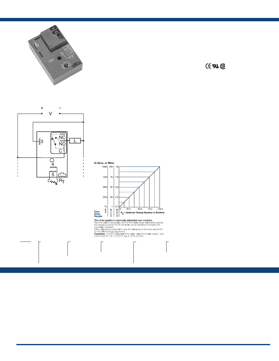
81
www.ssac.com • 800-843-8848 • fax: 605-348-5685
HRD3 Series
Timer - Recycling
Available Models:
Time Delay
Type . . . . . . . . . . . . . . . . . . . . . . . . . . . . . . . . . . . Microcontroller circuitry
Range . . . . . . . . . . . . . . . . . . . . . . . . . . . . . . . . . .
0.1s - 100m in 5 adjustable ranges or fixed
Repeat Accuracy . . . . . . . . . . . . . . . . . . . . . . . .
±0.5 % or 20ms, whichever is greater
Tolerance (Factory Calibration) . . . . . . . . . . . .
±1%, ±5%
Reset Time . . . . . . . . . . . . . . . . . . . . . . . . . . . . . .
≤ 150ms
Time Delay vs Temp. & Voltage
. . . . . . . . . . .
±2%
Input
Voltage
. . . . . . . . . . . . . . . . . . . . . . . . . . . . . . . . .
12 or 24VDC; 24, 120, or 230VAC
Tolerance 12VDC & 24VDC
. . . . . . .
-15% - 20%
24 to 230VAC
. . . . . . .
-20% - 10%
Line Frequency . . . . . . . . . . . . . . . . . . . . . . . . . .
50/60 Hz
Power Consumption . . . . . . . . . . . . . . . . . . . . .
AC ≤ 4VA; DC ≤ 2W
Output
Type . . . . . . . . . . . . . . . . . . . . . . . . . . . . . . . . . . .
Electromechanical relay
Form . . . . . . . . . . . . . . . . . . . . . . . . . . . . . . . . . . .
Non-isolated, SPDT
Ratings: SPDT-NO SPDT-NC
General Purpose 125/240VAC 30A 15A
Resistive 125/240VAC 30A 15A
28VDC 20A 10A
Motor Load 125VAC 1 hp* 1/4 hp**
240VAC 2 hp** 1 hp**
Life
. . . . . . . . . . . . . . . . . . . . . . . . . . . . . . . . . . . .
Mechanical - 1 x 10
6
;
Electrical - 1 x 10
5
, *3 x 10
4
, **6,000
Protection
Surge . . . . . . . . . . . . . . . . . . . . . . . . . . . . . . . . . .
IEEE C62.41-1991 Level A
Circuitry . . . . . . . . . . . . . . . . . . . . . . . . . . . . . . . Encapsulated
Dielectric Breakdown
. . . . . . . . . . . . . . . . . . . .
≥ 2000V RMS terminals to mounting surface
Insulation Resistance . . . . . . . . . . . . . . . . . . . . .
≥ 100 MΩ
Polarity . . . . . . . . . . . . . . . . . . . . . . . . . . . . . . . .
DC units are reverse polarity protected
Mechanical
Mounting . . . . . . . . . . . . . . . . . . . . . . . . . . . . . .
Surface mount with one #10 (M5 x 0.8) screw
Dimensions . . . . . . . . . . . . . . . . . . . . . . . . . . . . .
3 x 2 x 1.5 in. (76.7 x 51.3 x 38.1 mm)
Termination . . . . . . . . . . . . . . . . . . . . . . . . . . . .
0.25 in. (6.35 mm) male quick connect terminals
Environmental
Operating / Storage Temperature
. . . . . . . . .
-40° to 60°C / -40° to 85°C
Humidity . . . . . . . . . . . . . . . . . . . . . . . . . . . . . . .
95% relative, non-condensing
Weight
. . . . . . . . . . . . . . . . . . . . . . . . . . . . . . . . .
≅
3.9 oz (111 g)
Order Table:
Specifications
The HRD3 Series combines an electromechanical
relay output with microcontroller timing circuitry.
It offers 12 to 230V operation in five options and
factory fixed, external, or onboard adjustable
time delays with a repeat accuracy of ±0.5%. The
output contact rating allows for direct operation of
heavy loads, such as compressors, pumps, blower
motors, heaters, etc. This series is ideal for OEM
applications where cost is a factor.
Operation (Recycling - ON Time First):
Upon application of input voltage, the output relay
energizes and the T1 ON time begins. At the end of the ON
time, the output de-energizes and the T2 OFF time begins.
At the end of the OFF time, the output relay energizes
and the cycle repeats as long as input voltage is applied
Reset: Removing input voltage resets the output and time
delays, and returns the sequence to the first delay.
Operation (Recycling - OFF Time First):
Upon application of input voltage, the T2, OFF time
begins. At the end of the OFF time, the T1, ON time
begins and the load energizes. At the end of the ON time
the load de-energizes, and the cycle repeats until input
voltage is removed.
Reset: Removing input voltage resets the output and the
sequence to the OFF time.
For more information see:
Appendix A, pages 156-164 for function descriptions
and diagrams .
Appendix B, page 165, Figure 2 for dimensional drawing.
Features:
• Equal on and off delays
• 30A, SPDT, NO output contacts
• 12 to 230V operation in 5 options
•
Encapsulated
• Delays from 0.1s - 100m in 5 ranges
• ±0.5% repeat accuracy
• Factory fixed, onboard or external adjust
Approvals:
Connection:
HRD3220A
HRD3221A
HRD3222A
HRD3223A
HRD3224A
HRD3320A
HRD3321A
HRD3322A
HRD3323A
HRD3324A
HRD3420A
HRD3421A
HRD3422A
HRD3423A
HRD342A0A
Auxiliary Products:
•
External ad just potentiometer:
P/N: P1004-95
P/N: P1004-95-X
•
Female quick connect:
P/N: P1015-13 (AWG 10/12)
P/N: P1015-64 (AWG 14/16)
•
Quick connect t o s crew ad aptor:
P/N: P1015-18
•
Versa-knob:
P/N: P0700-7
•
Mounting bracket:
P/N: P1023-6
•
DIN rail:
P/N: C103PM
(Al)
•
DIN rail adaptor:
P/N: P1023-20
HRD3
X
Input Voltage
─
1
- 12VDC
─
2
- 24VAC
─
3
- 24VDC
─
4
- 120VAC
─
6
- 230VAC
X
Adjustment
─
1
- Fixed
─
2
- Onboard knob
─
3
- External adjust
X
Time Tolerance
─
Blank
- ±5%
─
A
- ±1%
X
Time Delay*
─
0
- 0.1 - 10s
─
1
- 1 - 100s
─
2
- 10 - 1000s
─
3
- 0.1 - 10m
─
4
- 1 - 100m
X
Operating Sequence
─
A
- ON Time First
─
B
- OFF Time First
*If fixed delay is selected, insert delay (
0 .1 - 1000
)
followed by (
S
) sec, or (
0 .1 - 100
) (
M
) min .
L1
N/L2
C = Common, Transfer Contact
NO = Normally Open
L = Load
External Resistance vs . Time Delay:
If desired part number is not listed, please call us to
see if it is technically possible to build .
NOTE: A knob, or terminals 4 & 5 are only
included on adjustable units. R
T
is used
when external adjustment is ordered. Relay
contacts are not isolated .
Courtesy of Steven Engineering, Inc.-230 Ryan Way, South San Francisco, CA 94080-6370-Main Office: (650) 588-9200-Outside Local Area: (800) 258-9200-www.stevenengineering.com
Littelfuse-catalog-html.html
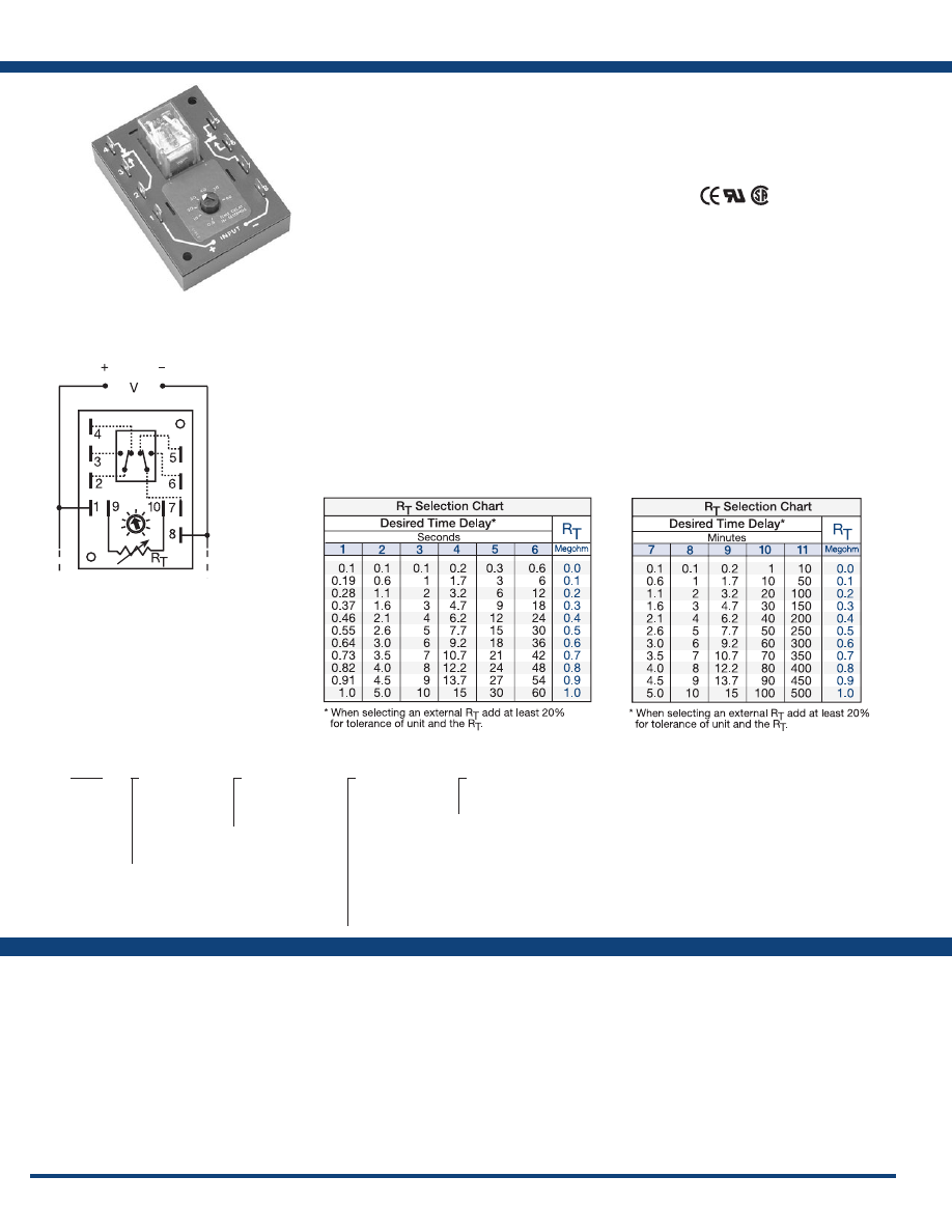
82
www.ssac.com • 800-843-8848 • fax: 605-348-5685
Features
• Factory fixed, onboard or external adjust
• Delays from 0.1s - 1000m
• ±0.5% repeat accuracy
•
Encapsulated digital circuitry
• Isolated, 10A, DPDT output contacts
Approvals:
ERD3 Series
Timer - Recycling
Available Models:
Time Delay
Type . . . . . . . . . . . . . . . . . . . . . . . . . . . . . . . . . . .Digital integrated circuitry
Range . . . . . . . . . . . . . . . . . . . . . . . . . . . . . . . . . .
0.1s - 500m in 11 adjustable ranges
0.1s - 1000m fixed
Adjustment
. . . . . . . . . . . . . . . . . . . . . . . . . . . . .
Knob, external adjust, or fixed
Repeat Accuracy . . . . . . . . . . . . . . . . . . . . . . . .
±0.5%
Tolerance (Factory Calibration) . . . . . . . . . . . .
≤ ±10%
Reset Time . . . . . . . . . . . . . . . . . . . . . . . . . . . . . .
≤ 150ms
Time Delay vs Temp. & Voltage
. . . . . . . . . . .
≤ ±2%
Input
Voltage
. . . . . . . . . . . . . . . . . . . . . . . . . . . . . . . . .
12, 24, or 120VDC; 24, 120, or 230VAC
Tolerance 12VDC & 24VDC/AC
. . . . . .
-15% - 20%
120VAC/DC & 230VAC
. . . . . .
-20% - 10%
AC Line Frequency . . . . . . . . . . . . . . . . . . . . . .
50/60 Hz
Output
Type . . . . . . . . . . . . . . . . . . . . . . . . . . . . . . . . . . .Isolated relay contacts
Form . . . . . . . . . . . . . . . . . . . . . . . . . . . . . . . . . . .DPDT
Rating . . . . . . . . . . . . . . . . . . . . . . . . . . . . . . . . .
10A resistive @ 120/240VAC & 28VDC;
1/3 hp @ 120/240VAC
Life
. . . . . . . . . . . . . . . . . . . . . . . . . . . . . . . . . . . .
Mechanical - 1 x 10
7
; Electrical - 1 x 10
6
Protection
Isolation Voltage
. . . . . . . . . . . . . . . . . . . . . . . .
≥ 1500V RMS input to output
Insulation Resistance . . . . . . . . . . . . . . . . . . . . .
≥ 100 MΩ
Polarity . . . . . . . . . . . . . . . . . . . . . . . . . . . . . . . .
DC units are reverse polarity protected
Mechanical
Mounting . . . . . . . . . . . . . . . . . . . . . . . . . . . . . .
Surface mount with two #6 (M3.5 x 0.6) screws
Dimensions . . . . . . . . . . . . . . . . . . . . . . . . . . . . .
3.5 x 2.5 x 1.7 in. (88.9 x 63.5 x 43.2 mm)
Termination . . . . . . . . . . . . . . . . . . . . . . . . . . . .
0.25 in. (6.35 mm) male quick connect terminals
Environmental
Operating / Storage Temperature
. . . . . . . . .
-40° to 65°C / -40° to 85°C
Weight
. . . . . . . . . . . . . . . . . . . . . . . . . . . . . . . . .
≅
5.7 oz (162 g)
Specifications
Order Table:
Connection:
Econo-Timers are a combination of digital
electronics and a reliable electromechanical relay.
DPDT relay output for relay logic circuits, and
isolation of input to output voltages. Cost effective
for OEM applications, such as duty cycling, drying,
washing, signaling, and flashing.
Operation (Recycling - ON Time First):
Upon application of input voltage, the output relay
energizes and the T1 ON time begins. At the end of the
ON time, the output de-energizes and the T2 OFF time
begins. At the end of the OFF time, the output relay
energizes and the cycle repeats as long as input voltage
is applied .
Reset: Removing input voltage resets the output and
time delays, and returns the sequence to the first delay.
Operation (Recycling - OFF Time First):
Upon application of input voltage, the T2 OFF time begins.
At the end of the OFF time, the T1 ON time begins and
the load energizes. At the end of the ON time the load
de-energizes, and the cycle repeats until input voltage
is removed.
Reset: Removing input voltage resets the output and the
sequence to the OFF time.
For more information see:
Appendix A, pages 156-164 for function descriptions
and diagrams .
Appendix B, page 165, Figure 10 for dimensional drawing.
Auxiliary Products:
•
External ad just potentiometer:
P/N: P1004-16
P/N: P1004-16-X
•
Female quick connect:
P/N: P1015-64 (AWG 14/16)
•
Quick connect t o s crew ad aptor:
P/N: P1015-18
•
Versa-knob:
P/N: P0700-7
ERD3425A
ERD3
X
Input Voltage
─
1
- 12VDC
─
2
- 24VAC
─
3
- 24VDC
─
4
- 120VAC
─
5
- 120VDC
─
6
- 230VAC
X
Adjustment
─
1
- Fixed
─
2
- Onboard knob
─
3
- External adjust
X
Time Delay*
─
1
- 0.1 - 1s
─
2
- 0.1 - 5s
─
3
- 0.1 - 10s
─
4
- 0.2 - 15s
─
5
- 0.3 - 30s
─
6
- 0.6 - 60s
─
7
- 0.1 - 5m
─
8
- 0.1 - 10m
─
9
- 0.2 - 15m
─
10
- 0.3 - 30s
─
11
- 10 - 500m
X
Operating Sequence
─
A
- ON Time First
─
B
- OFF Time First
*If fixed delay is selected, insert delay
(
0 .1 - 1000
) followed by (
S
) sec, or (
M
)
min .
L1
N/L2
If desired part number is not listed, please call us to
see if it is technically possible to build .
A knob, or terminals 9 & 10 are only
included on adjustable units. Relay contacts
are isolated. RT is used when external
adjustment is ordered.
Courtesy of Steven Engineering, Inc.-230 Ryan Way, South San Francisco, CA 94080-6370-Main Office: (650) 588-9200-Outside Local Area: (800) 258-9200-www.stevenengineering.com
Littelfuse-catalog-html.html
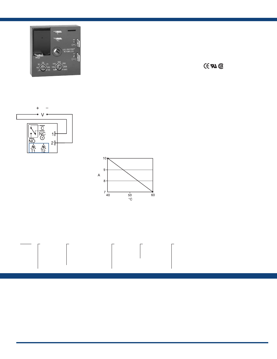
83
www.ssac.com • 800-843-8848 • fax: 605-348-5685
KRDR Series
Timer - Recycling
Available Models:
Time Delay
Range . . . . . . . . . . . . . . . . . . . . . . . . . . . . . . . . . .
0.1s - 1000m in 6 adjustable ranges or fixed
Repeat Accuracy . . . . . . . . . . . . . . . . . . . . . . . .
±0.5 % or 20ms, whichever is greater
Tolerance (Factory Calibration) . . . . . . . . . . . .
≤ ±5%
Reset Time . . . . . . . . . . . . . . . . . . . . . . . . . . . . . .
≤ 150ms
Time Delay vs Temp. & Voltage
. . . . . . . . . . .
≤ ±5%
Input
Voltage
. . . . . . . . . . . . . . . . . . . . . . . . . . . . . . . . .
12, 24 or 110VDC; 24, 120 or 230VAC
Tolerance 12VDC & 24VDC/AC
. . . . . .
-15% - 20%
110VDC & 120 or 230VAC
. . . . . .
-20% - 10%
AC Line Frequency / DC Ripple
. . . . . . . . . . .
50/60 Hz / ≤ 10%
Power Consumption . . . . . . . . . . . . . . . . . . . . .
AC ≤ 2VA; DC ≤ 2W
Output
Type . . . . . . . . . . . . . . . . . . . . . . . . . . . . . . . . . . . Isolated relay contacts
Form . . . . . . . . . . . . . . . . . . . . . . . . . . . . . . . . . . . SPDT
Rating (at 40°C)
. . . . . . . . . . . . . . . . . . . . . . . . .
10A resistive @ 125VAC;
5A resistive @ 230VAC & 28VDC;
1/4 hp @ 125VAC
Max. Switching Voltage
. . . . . . . . . . . . . . . . . .
250VAC
Life (Operations)
. . . . . . . . . . . . . . . . . . . . . . . .
Mechanical - 1 x 10
7
; Electrical - 1 x 10
5
Protection
Circuitry . . . . . . . . . . . . . . . . . . . . . . . . . . . . . . . Encapsulated
Isolation Voltage
. . . . . . . . . . . . . . . . . . . . . . . .
≥ 1500V RMS input to output
Insulation Resistance . . . . . . . . . . . . . . . . . . . . .
≥ 100 MΩ
Polarity . . . . . . . . . . . . . . . . . . . . . . . . . . . . . . . .
DC units are reverse polarity protected
Mechanical
Mounting . . . . . . . . . . . . . . . . . . . . . . . . . . . . . .
Surface mount with one #10 (M5 x 0.8) screw
Dimensions . . . . . . . . . . . . . . . . . . . . . . . . . . . . .
2 x 2 x 1.21 in. (50.8 x 50.8 x 30.7 mm)
Termination . . . . . . . . . . . . . . . . . . . . . . . . . . . .
0.25 in. (6.35 mm) male quick connect terminals
Environmental
Operating / Storage Temperature
. . . . . . . . .
-20° to 60°C / -40° to 85°C
Humidity . . . . . . . . . . . . . . . . . . . . . . . . . . . . . . .
95% relative, non-condensing
Weight
. . . . . . . . . . . . . . . . . . . . . . . . . . . . . . . . .
≅
2.6 oz (74 g)
Order Table:
Specifications
The KRDR Series is a compact time-delay relay
measuring only 2 in. (50.8 mm) square. Its solid-
state timing circuit provides excellent repeat
accuracy and stability . Encapsulation protects
against shock, vibration, and humidity. The KRDR
Series is a cost effective recycling timer for OEM
applications that require small size, isolation,
reliability, and long life.
Operation (Recycling - ON Time First):
Upon application of input voltage, the output relay
energizes and the T2 ON time begins. At the end of the ON
time, the output de-energizes and the T1 OFF time begins.
At the end of the OFF time, the output relay energizes
and the cycle repeats as long as input voltage is applied
Reset: Removing input voltage resets the output and the
time delays, and returns the sequence to the ON time.
Operation (Recycling - OFF Time First):
Upon application of input voltage, the T1 OFF time
begins. At the end of the OFF time, the T2 ON time
begins and the load energizes. At the end of the ON time
the load de-energizes, and the cycle repeats until input
voltage is removed.
Reset: Removing input voltage resets the output and the
sequence to the OFF time.
For more information see:
Appendix A, pages 156-164 for function descriptions
and diagrams .
Appendix B, page 165, Figure 1 for dimensional drawing.
Features:
•
Compact time delay relay
• 10A, SPDT output contacts
• Factory fixed or onboard adjust
• Delays from 0.1s - 1000m in 6 ranges
• Input voltages from 120 to 230V in 6 options
• ±0.5% repeat accuracy
• ±5% factory calibration
Approvals:
Connection:
KRDR115MB25M
KRDR120A0
KRDR123A4
KRDR124A4
KRDR320A1
KRDR320B0
KRDR321A4
KRDR321B4
KRDR421A4
KRDR424A0
KRDR440.5SA0
Auxiliary Products:
•
Female quick connect:
P/N: P1015-13 (AWG 10/12)
P/N: P1015-64 (AWG 14/16)
•
Quick connect t o s crew ad aptor:
P/N: P1015-18
•
Mounting bracket:
P/N: P1023-6
•
DIN rail:
P/N: C103PM
(Al)
•
DIN rail adaptor:
P/N: P1023-20
KRDR
X
Input Voltage
─
1
- 12VDC
─
2
- 24VAC
─
3
- 24VDC
─
4
- 120VAC
─
5
- 110VDC
─
6
- 230VAC
X
Adjustments
─
1
- Both Times Fixed
─
2
- Both Times Adj.
─
3
- ON Time Adj.
OFF Time Fixed
─
4
- ON Time Fixed
OFF Time Adj.
X
T2 ON Time*
─
0
- 0.1 - 10s
─
1
- 1 - 100s
─
2
- 10 - 1000s
─
3
- 0.1 - 10m
─
4
- 1 - 100m
─
5
- 10 - 1000m
X
Operating
Sequence
─
A
- ON time first
─
B
- OFF time first
X
T1 OFF Time*
─
0
- 0.1 - 10s
─
1
- 1 - 100s
─
2
- 10 - 1000s
─
3
- 0.1 - 10m
─
4
- 1 - 100m
─
5
- 10 - 1000m
*If fixed delay is selected, insert
delay (
0 .1 - 999
) followed by (
S
) sec .
or (
M
) min .
T1 = OFF Time
T2 = ON Time
NO = Normally Open
NC = Normally Closed
C = Common
A knob is supplied for adjustable units.
L1
N/L2
If desired part number is not listed, please call us to
see if it is technically possible to build .
Output Current/Ambient Temperature:
Courtesy of Steven Engineering, Inc.-230 Ryan Way, South San Francisco, CA 94080-6370-Main Office: (650) 588-9200-Outside Local Area: (800) 258-9200-www.stevenengineering.com
Littelfuse-catalog-html.html
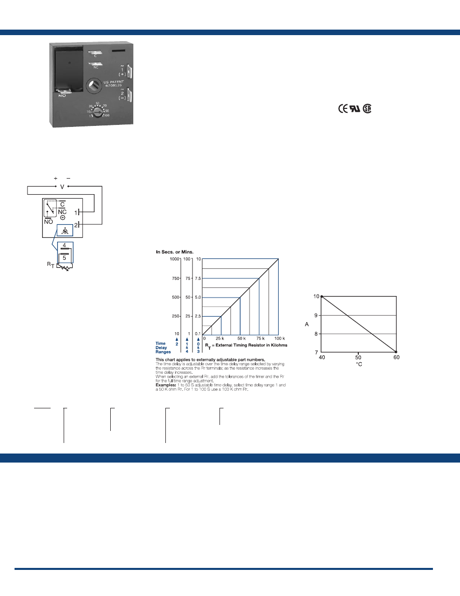
84
www.ssac.com • 800-843-8848 • fax: 605-348-5685
Features
• Compact time-delay relay
• 10A, SPDT output contacts
• Factory fixed, onboard or external adjust
• Delays from 0.1s - 100m in 5 ranges
• ±0.5% repeat accuracy
• ±5% factory calibration
• Input voltages from 12 to 230V in 5 options
Approvals:
KRD3 Series
Timer - Recycling
Available Models:
Time Delay
Range . . . . . . . . . . . . . . . . . . . . . . . . . . . . . . . . . .
0.1s - 100m in 5 adjustable ranges or fixed
Repeat Accuracy . . . . . . . . . . . . . . . . . . . . . . . .
±0.5% or 20ms, whichever is greater
Tolerance (Factory Calibration) . . . . . . . . . . . .
≤ ± 5%
Reset Time . . . . . . . . . . . . . . . . . . . . . . . . . . . . . .
≤ 150ms
Time Delay vs Temp. & Voltage
. . . . . . . . . . .
≤ ±5%
Input
Voltage
. . . . . . . . . . . . . . . . . . . . . . . . . . . . . . . . .
12, 24 or 110VDC; 24, 120, or 230VAC
Tolerance 12VDC & 24VDC/AC
. . . . .
-15% - 20%
110VDC, 120 or 230VAC
. . . . .
-20% - 10%
AC Line Frequency / DC Ripple
. . . . . . . . . . .
50/60 Hz / ≤ 10%
Power Consumption . . . . . . . . . . . . . . . . . . . . .
AC ≤ 2VA; DC ≤ 2W
Output
Type . . . . . . . . . . . . . . . . . . . . . . . . . . . . . . . . . . . Isolated relay contacts
Form . . . . . . . . . . . . . . . . . . . . . . . . . . . . . . . . . . . SPDT
Rating (at 40°C)
. . . . . . . . . . . . . . . . . . . . . . . . .
10A resistive @ 125VAC;
5A resistive @ 230VAC & 28VDC;
1/4 hp @ 125VAC
Max. Switching voltage
. . . . . . . . . . . . . . . . . . .
250VAC
Life (Operations)
. . . . . . . . . . . . . . . . . . . . . . . .
Mechanical - 1 x 10
7
; Electrical - 1 x 10
5
Protection
Circuitry . . . . . . . . . . . . . . . . . . . . . . . . . . . . . . . Encapsulated
Isolation Voltage
. . . . . . . . . . . . . . . . . . . . . . . .
≥ 1500V RMS input to output
Insulation Resistance . . . . . . . . . . . . . . . . . . . . .
≥ 100 MΩ
Polarity . . . . . . . . . . . . . . . . . . . . . . . . . . . . . . . .
DC units are reverse polarity protected
Mechanical
Mounting . . . . . . . . . . . . . . . . . . . . . . . . . . . . . .
Surface mount with one #10 (M5 x 0.8) screw
Dimensions . . . . . . . . . . . . . . . . . . . . . . . . . . . . .
2 x 2 x 1.21 in. (50.8 x 50.8 x 30.7 mm)
Termination . . . . . . . . . . . . . . . . . . . . . . . . . . . .
0.25 in. (6.35 mm) male quick connect terminals
Environmental
. . . . . . . . . . . . . . . . . . . . . . . . . .
Operating / Storage Temperature
. . . . . . . . .
-20° to 60°C / -40° to 85°C
Humidity . . . . . . . . . . . . . . . . . . . . . . . . . . . . . . .
95% relative, non-condensing
Weight
. . . . . . . . . . . . . . . . . . . . . . . . . . . . . . . . .
≅
2.6 oz (74 g)
Specifications
Order Table:
Connection:
The KRD3 Series measures only 2 in. (50.8
mm) square. Its solid-state timing circuit
provides excellent repeat accuracy and stability.
Encapsulation protects against shock, vibration,
and humidity. The KRD3 Series is a cost effective
approach for OEM applications that require small
size, isolation, reliability, and long life.
Operation (Recycling Flasher - ON Time First):
Upon application of input voltage, the output energizes
and the T1 ON time begins. At the end of the ON time,
the output de-energizes and the T2 OFF time begins. At
the end of the OFF time, the output energizes and the cycle
repeats as long as input voltage is applied.
Reset: Removing input voltage resets the output and time
delays, and returns the sequence to T1 ON time.
Operation (Recycling Flasher - OFF Time First):
Upon application of input voltage, the T2 OFF time begins.
At the end of the OFF time, the T1 ON time begins and
the load energizes. At the end of T1, T2 begins and the
load de-energizes. This cycle repeats until input voltage
is removed.
Reset: Removing input voltage resets the output and the
sequence to T2 OFF time .
For more information see:
Appendix A, pages 156-164 for function descriptions
and diagrams .
Appendix B, page 165, Figure 1 for dimensional drawing.
Auxiliary Products:
•
External ad just potentiometer:
P/N: P1004-95
P/N: P1004-95-X
•
Female quick connect:
P/N: P1015-13 (AWG 10/12)
P/N: P1015-64 (AWG 14/16)
•
Quick connect t o s crew ad aptor:
P/N: P1015-18
•
Versa-knob:
P/N: P0700-7
•
Mounting bracket:
P/N: P1023-6
•
DIN rail:
P/N: C103PM
(Al)
•
DIN rail adaptor:
P/N: P1023-20
KRD3
X
Input Voltage
─
1
- 12VDC
─
2
- 24VAC
─
4
- 120VAC
─
5
- 110VDC
─
6
- 230VAC
X
Adjustment
─
1
- Fixed
─
2
- Onboard knob
─
3
- External adjust
X
Time Delay*
─
0
- 0.1 - 10s
─
1
- 1 - 100s
─
2
- 10 - 1000s
─
3
- 0.1 - 10m
─
4
- 1 - 100m
X
Operating Sequence
─
A
- ON Time First
─
B
- OFF Time First
*If fixed delay is selected, insert delay (
0 .1
- 1000
) followed by (
S
) sec, or (
0 .1 - 100
)
(
M
) min .
KRD3110.4SA
KRD31160SA
KRD3420A
KRD3434A
L1
N/L2
V = Voltage
C = Common, Transfer Contact
NO = Normally Open
NC = Normally Closed
External Resistance vs . Time Delay:
If desired part number is not listed, please call us to
see if it is technically possible to build .
A knob is supplied for adjustable units, or
R
T
terminals 4 & 5 for external adjust. See
external adjustment vs time delay chart. Relay
contacts are isolated .
Output Current/Ambient Temperature:
Courtesy of Steven Engineering, Inc.-230 Ryan Way, South San Francisco, CA 94080-6370-Main Office: (650) 588-9200-Outside Local Area: (800) 258-9200-www.stevenengineering.com
Littelfuse-catalog-html.html
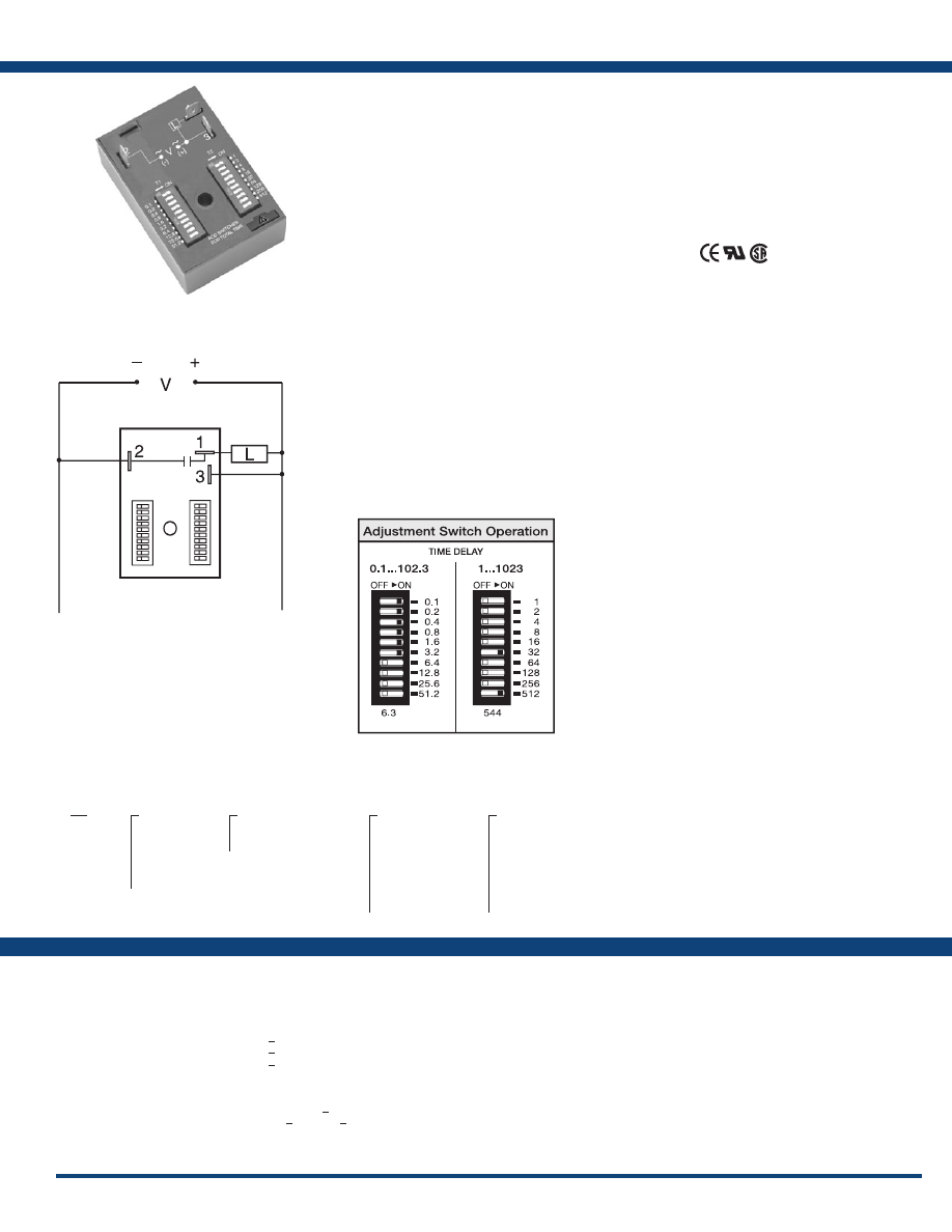
85
www.ssac.com • 800-843-8848 • fax: 605-348-5685
RS Series
Timer - Recycling
Available Models:
Time Delay
Range* . . . . . . . . . . . . . . . . . . . . . . . . . . . . . . . . .
0.1 - 102.3s in 0.1s increments
0.1 - 102.3m in 0.1m increments
1 - 1023m in 1m increments
1 - 1023h in 1h increments
Repeat Accuracy . . . . . . . . . . . . . . . . . . . . . . . .
±0.1% or 20ms, whichever is greater
Setting Accuracy . . . . . . . . . . . . . . . . . . . . . . . . <
±2% or 20ms, whichever is greater
Reset Time . . . . . . . . . . . . . . . . . . . . . . . . . . . . . . <
150ms
Time Delay vs Temp. & Voltage
. . . . . . . . . . . <
± 2%
Input
Voltage
. . . . . . . . . . . . . . . . . . . . . . . . . . . . . . . . .
12, or 24VDC; 24, 120, or 230VAC
Tolerance . . . . . . . . . . . . . . . . . . . . . . . . . . . . . . .
±20%
AC Line Frequency / DC Ripple
. . . . . . . . . . .
50/60 Hz /
<
±10%
Power Consumption . . . . . . . . . . . . . . . . . . . . . AC <
2VA; DC
<
1W
Output
Type . . . . . . . . . . . . . . . . . . . . . . . . . . . . . . . . . . . Solid state
Maximum Load Current
. . . . . . . . . . . . . . . . . .
1A steady state, 10A inrush at 60°C
OFF State Leakage Current
. . . . . . . . . . . . . . . AC
≅
5mA @ 230VAC; DC
≅
1mA
Voltage Drop
. . . . . . . . . . . . . . . . . . . . . . . . . . . AC
≅
2.5V @ 1A; DC
≅
1V @ 1A
Protection
Circuitry . . . . . . . . . . . . . . . . . . . . . . . . . . . . . . . Encapsulated
Dielectric Breakdown
. . . . . . . . . . . . . . . . . . . .
≥ 2000V RMS terminals to mounting surface
Insulation Resistance . . . . . . . . . . . . . . . . . . . . .
≥ 100 MΩ
Polarity . . . . . . . . . . . . . . . . . . . . . . . . . . . . . . . .
DC units are reverse polarity protected
Mechanical
Mounting . . . . . . . . . . . . . . . . . . . . . . . . . . . . . .
Surface mount with one #10 (M5 x 0.8) screw
Dimensions . . . . . . . . . . . . . . . . . . . . . . . . . . . . .
3 x 2 x 1.5 in (76.7 x 51.3 x 38.1 mm)
Termination . . . . . . . . . . . . . . . . . . . . . . . . . . . .
0.25 in. (6.35 mm) male quick connect terminals
Environmental
Operating / Storage Temperature
. . . . . . . . .
-40° to 75°C / -40° to 85°C
Humidity . . . . . . . . . . . . . . . . . . . . . . . . . . . . . . .
95% relative, non-condensing
Weight
. . . . . . . . . . . . . . . . . . . . . . . . . . . . . . . . .
≅
3.9 oz (111 g)
*For CE approved applications, power must be removed from the unit when a switch position
is changed.
Order Table:
Specifications
The RS Series is a solid-state, encapsulated,
recycling timer designed for tough industrial
environments. It is used by many testing labs as
a life cycle tester; by others as a cycle controller.
The RS Series has separate DIP switch adjustments
for the on delay and the off delay. These make
accurate adjustment possible the first time, every
time. Time delays of 0.1 seconds to 1023 hours are
available in 4 ranges.
Operation (Recycling - ON Time First)
Upon application of input voltage, the output energizes
and the T1 ON time begins. At the end of the ON time, the
output de-energizes and the T2 OFF time begins. At the
end of the OFF time, the output energizes and the cycle
repeats as long as input voltage is applied.
Reset: Removing input voltage resets the output and time
delays, and returns the sequence to the ON time.
Operation (Recycling - OFF Time First)
Upon application of input voltage, the T2 OFF time
begins. At the end of the OFF time, the output energizes
and the T1 ON time begins. At the end of the ON time,
the output de-energizes and the cycle repeats as long as
input voltage is applied.
Reset: Removing input voltage resets the output and time
delays, and returns the sequence to the OFF time.
For more information see:
Appendix A, pages 156-164 for function descriptions
and diagrams .
Appendix B, page 165, Figure 2 for dimensional drawing.
Features:
• Accurate, reliable, recycling timer
• Switch settable time delays - both times
adjustable
• ±0.1% repeat accuracy
• ±2% setting accuracy
• 0.1s - 1023h in 4 ranges
• 12 to 230V in 5 options
• 1A, solid-state output
•
Totally solid state and encapsulated
Approvals:
Connection:
RS1A11
RS1A12
RS1B12
RS2A12
RS2A24
RS2B44
RS4A11
RS4A12
RS4A13
RS4A22
RS4A24
RS4A31
RS4A33
RS4B23
RS6A13
RS6A24
Auxiliary Products:
•
Female quick connect:
P/N: P1015-64 (AWG 14/16)
•
Quick connect t o s crew ad aptor:
P/N: P1015-18
•
Mounting bracket:
P/N: P1023-6
•
DIN rail:
P/N: C103PM
(Al)
•
DIN rail adaptor:
P/N: P1023-20
RS
X
Input Voltage
─
1
- 12VDC
─
2
- 24VAC
─
3
- 24VDC
─
4
- 120VAC
─
6
- 230VAC
X
Operating Sequence
─
A
- ON time first
─
B
- OFF time first
X
T1 ON Time
─
1
- 0.1 - 102.3s in
0.1s increments
─
2
- 0.1 - 102.3m in
0.1m increments
─
3
- 1 - 1023m in
1m increments
─
4
- 1 - 1023h in
1h increments
X
T2 OFF Time
─
1
- 0.1 - 102.3s in
0.1s increments
─
2
- 0.1 - 102.3m in
0.1m increments
─
3
- 1 - 1023m in
1m increments
─
4
- 1 - 1023h in
1h increments
L1
N/L2
If desired part number is not listed, please call us to
see if it is technically possible to build .
L = Load
Courtesy of Steven Engineering, Inc.-230 Ryan Way, South San Francisco, CA 94080-6370-Main Office: (650) 588-9200-Outside Local Area: (800) 258-9200-www.stevenengineering.com
Littelfuse-catalog-html.html
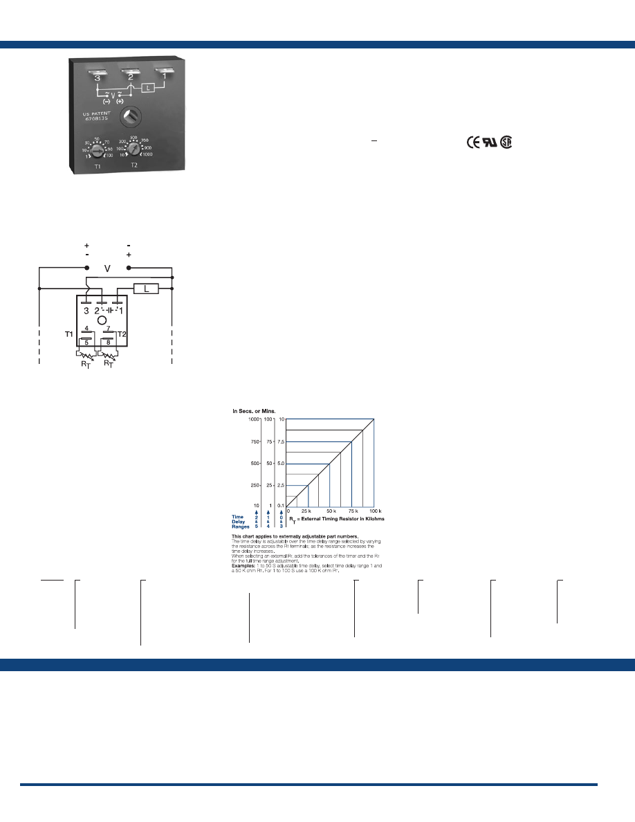
86
www.ssac.com • 800-843-8848 • fax: 605-348-5685
Features
• ON/OFF recycling with independent
adjustment of both the on and off periods
• Factory fixed, onboard or external adjust
• 0.1s to 1000m in 6 ranges
• ±0.1% repeat accuracy
• ± 5% factory calibration
• Available in AC or DC voltages
Approvals:
ESDR Series
Timer - Recycling
Available Models:
Time Delay
Range . . . . . . . . . . . . . . . . . . . . . . . . . . . . . . . . . .
0.1s - 1000m in 6 adjustable ranges or fixed
Repeat Accuracy . . . . . . . . . . . . . . . . . . . . . . . .
±0.1% or 20ms, whichever is greater
Tolerance (Factory Calibration) . . . . . . . . . . . .
≤ ± 5%
Time Delay vs Temp. & Voltage
. . . . . . . . . . .
≤ ±2%
Reset Time . . . . . . . . . . . . . . . . . . . . . . . . . . . . . .
≤ 150ms
Input
Voltage
. . . . . . . . . . . . . . . . . . . . . . . . . . . . . . . . .
12 or 24VDC; 24, 120, or 230VAC
Tolerance . . . . . . . . . . . . . . . . . . . . . . . . . . . . . . .
±20%
Power Consumption . . . . . . . . . . . . . . . . . . . . .
AC ≤ 2VA; DC ≤ 1W
AC Line Frequency / DC Ripple
. . . . . . . . . . .
50/60 Hz / ≤ 10%
Output
Type . . . . . . . . . . . . . . . . . . . . . . . . . . . . . . . . . . .Solid state
Maximum Load Current
. . . . . . . . . . . . . . . . . .
1A steady state , 10A inrush at 60°C
OFF State Leakage Current
. . . . . . . . . . . . . . .AC
≅
5mA @ 230VAC; DC
≅
1mA
Voltage Drop
. . . . . . . . . . . . . . . . . . . . . . . . . . .AC
≅
2.5V @ 1A; DC
≅
1V @ 1A
Protection
Circuitry . . . . . . . . . . . . . . . . . . . . . . . . . . . . . . .Encapsulated
Dielectric Breakdown
. . . . . . . . . . . . . . . . . . . .
≥ 2000V RMS terminals to mounting surface
Insulation Resistance . . . . . . . . . . . . . . . . . . . . .
≥ 100 MΩ
Polarity . . . . . . . . . . . . . . . . . . . . . . . . . . . . . . . .
DC units are reverse polarity protected
Mechanical
Mounting . . . . . . . . . . . . . . . . . . . . . . . . . . . . . .
Surface mount with one #10 (M5 x 0.8) screw
Dimensions . . . . . . . . . . . . . . . . . . . . . . . . . . . . .
2 x 2 x 1.21 in. (50.8 x 50.8 x 30.7 mm)
Termination . . . . . . . . . . . . . . . . . . . . . . . . . . . .
0.25 in. (6.35 mm) male quick connect terminals
Operating / Storage Temperature
. . . . . . . . .
-40° to 75°C / -40° to 85°C
Humidity . . . . . . . . . . . . . . . . . . . . . . . . . . . . . . .
95% relative, non-condensing
Weight
. . . . . . . . . . . . . . . . . . . . . . . . . . . . . . . . .
≅
2.4 oz (68 g)
Specifications
Order Table:
Connection:
The ESDR Series offers independent time
adjustment of both delay periods. Adjustment
options include fixed, onboard or external
adjust. The ESDR is recommended for air
drying, automatic oiling, life testing, chemical
metering and automatic duty cycling. This series
is designed for general purpose commercial
and industrial applications where a small, cost
effective, reliable, solid-state timer is required. The
factory calibration for fixed time delays is
<
±5%.
The repeat accuracy, under stable conditions,
is 0.1% of the selected time delay. This series is
designed for input voltages of 12VDC to 230VAC
in five ranges. Time delays of 0.1 seconds to 1000
minutes are available in six ranges. The output is
rated 1A steady and 10A inrush. The modules are
totally solid state and encapsulated to protect the
electronic circuitry .
Operation (Recycling - ON Time First):
Upon application of input voltage, the output energizes
and the T1, ON time begins. At the end of the ON time,
the output de-energizes and the T2, OFF time begins. At
the end of the OFF time, the output energizes and the cycle
repeats as long as input voltage is applied.
Reset: Removing input voltage resets the output and
time delays, and returns the sequence to the first delay.
Operation (Recycling - OFF Time First):
Upon application of input voltage, the T2 OFF time
begins. At the end of the OFF time, the output energizes
and the T1 ON time begins. At the end of the ON time,
the output de-energizes and the cycle repeats as long as
input voltage is applied.
Reset: Removing input voltage resets the output and
time delays, and returns the sequence to the first delay.
For more information see:
Appendix A, pages 156-164 for function descriptions
and diagrams .
Appendix B, page 165, Figure 1 for dimensional drawing.
Auxiliary Products:
•
External ad just potentiometer:
P/N: P1004-95
P/N: P1004-95-X
•
Female quick connect:
P/N: P1015-64 (AWG 14/16)
•
Quick connect t o s crew ad aptor:
P/N: P1015-18
•
Versa-knob:
P/N: P0700-7
•
Mounting bracket:
P/N: P1023-6
•
DIN rail:
P/N: C103PM
(Al)
•
DIN rail adaptor:
P/N: P1023-20
ESDR120A0P
ESDR120A1P
ESDR120A4P
ESDR120B3P
ESDR121A2P
ESDR121A3P
ESDR123A0P
ESDR123B4P
ESDR124A0P
ESDR125A5P
ESDR152B1P
ESDR221A2
ESDR221B5
ESDR224B4
ESDR310.7SA10SP
ESDR320A0P
ESDR320A3P
ESDR420A1
ESDR420A4
ESDR420B1
ESDR420B4
ESDR421A1
ESDR421A4
ESDR421B1
ESDR423A4
ESDR423B1
ESDR424A0
ESDR424A4
ESDR450A1
ESDR452B1
ESDR620B3
ESDR621A1
ESDR650A1
ESDR X
Input Voltage
─
1
- 12VDC
─
2
- 24VAC
─
3
- 24VDC
─
4
- 120VAC
─
6
- 230VAC
X
External Adjust
─
1
- Both Times Fixed
─
2
- Both Times Onboard Adj.
─
3
- ON Time Onboard Adj.
OFF Time Fixed
─
4
- ON Time Fixed
OFF Time Onboard Adj.
─
5
- Both Times External Adj.
─
6
- ON Time External Adj.
OFF Time Fixed
─
7
- ON Time Fixed
OFF Time External Adj.
─
8
- ON Time Onboard Adj.
OFF Time External Adj.
─
9
- ON Time External Adj.
OFF Time Onboard Adj.
X
T1 ON Time*
─
0
- 0.1 - 10s
─
1
- 1 - 100s
─
2
- 10 - 1000s
─
3
- 0.1 - 10m
─
4
- 1 - 100m
─
5
- 10 - 1000m
X
Operating
Sequence
─
A
- ON time first
─
B
- OFF time first
X
T2 OFF Time*
─
0
- 0.1 - 10s
─
1
- 1 - 100s
─
2
- 10 - 1000s
─
3
- 0.1 - 10m
─
4
- 1 - 100m
─
5
- 10 - 1000m
X
Switching
Mode
(VDC Only)
─
P
- Positive
─
N
- Negative
*If fixed delay is selected, insert delay (
0 .1 - 1000
)
followed by (
S
) sec . or (
M
) min .
V = Voltage
L = Load
T1 = ON Time
T2 = OFF Time
L1
N/L2
(Positive Switching)
(Negative Switching)
If desired part number is not listed, please call us to
see if it is technically possible to build .
R
T
is used when external adjustment is ordered.
A knob is supplied for adjustment on the unit;
terminals for external adjustment.
Courtesy of Steven Engineering, Inc.-230 Ryan Way, South San Francisco, CA 94080-6370-Main Office: (650) 588-9200-Outside Local Area: (800) 258-9200-www.stevenengineering.com
Littelfuse-catalog-html.html
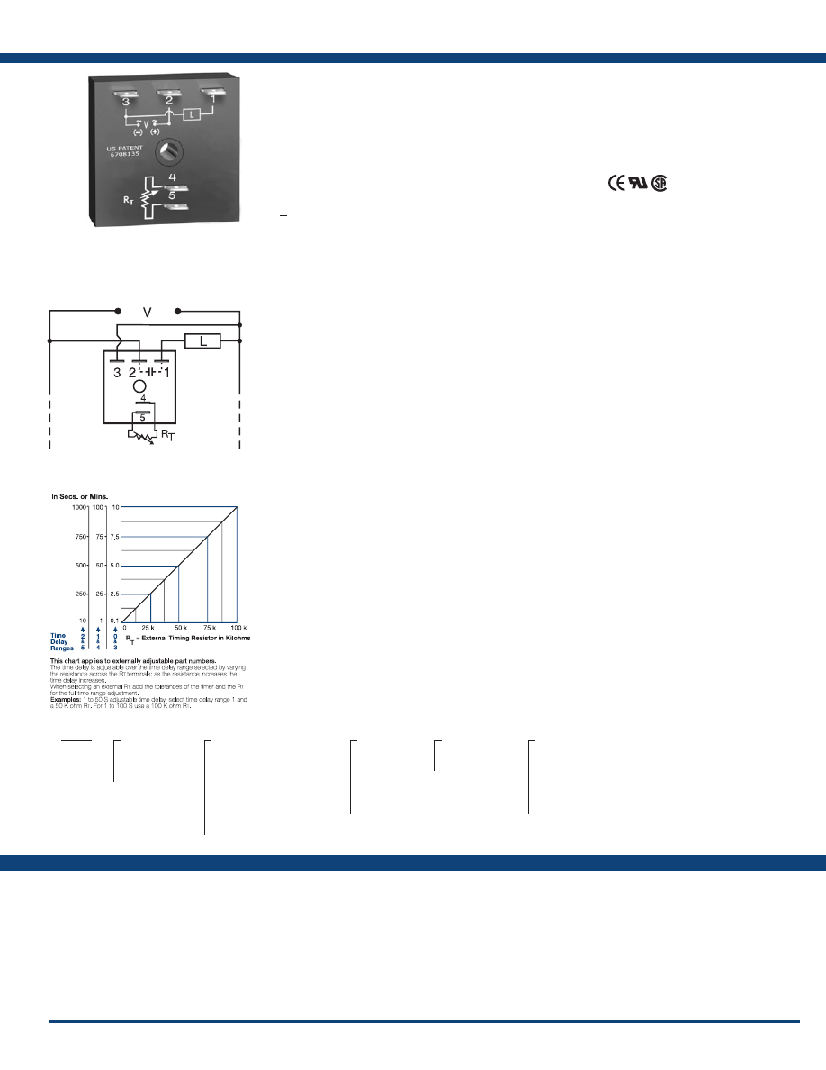
87
www.ssac.com • 800-843-8848 • fax: 605-348-5685
TSDR Series
Timer - Recycling
Available Models:
Time Delay
Range . . . . . . . . . . . . . . . . . . . . . . . . . . . . . . . . . .
0.1s - 1000m in 6 adjustable ranges or fixed
Repeat Accuracy . . . . . . . . . . . . . . . . . . . . . . . .
±0.5% or 20ms, whichever is greater
Tolerance (Factory Calibration) . . . . . . . . . . . .
≤ ±5%
Reset Time . . . . . . . . . . . . . . . . . . . . . . . . . . . . . .
≤ 150ms
Time Delay vs Temp. & Voltage
. . . . . . . . . . .
≤ ±5%
Input
Voltage
. . . . . . . . . . . . . . . . . . . . . . . . . . . . . . . . .
24, 120, or 230VAC
Tolerance . . . . . . . . . . . . . . . . . . . . . . . . . . . . . . .
±20%
AC Line Frequency . . . . . . . . . . . . . . . . . . . . . .
50/60 Hz
Power Consumption . . . . . . . . . . . . . . . . . . . . .
≤ 2VA
Output
Type . . . . . . . . . . . . . . . . . . . . . . . . . . . . . . . . . . . Solid state
Maximum Load Current
. . . . . . . . . . . . . . . . . .
1A steady state, 10A inrush at 60°C
Off State Leakage Current
. . . . . . . . . . . . . . . .
≅
5mA @ 230VAC
Voltage Drop
. . . . . . . . . . . . . . . . . . . . . . . . . . .
≅
2.5V @ 1A
Protection
Circuitry . . . . . . . . . . . . . . . . . . . . . . . . . . . . . . . Encapsulated
Dielectric Breakdown
. . . . . . . . . . . . . . . . . . . .
≥ 2000V RMS terminals to mounting surface
Insulation Resistance . . . . . . . . . . . . . . . . . . . . .
100 MΩ
Mechanical
Mounting . . . . . . . . . . . . . . . . . . . . . . . . . . . . . .
Surface mount with one #10 (M5 x 0.8) screw
Dimensions . . . . . . . . . . . . . . . . . . . . . . . . . . . . .
2 x 2 x 1.21 in. (50.8 x 50.8 x 30.7 mm)
Termination . . . . . . . . . . . . . . . . . . . . . . . . . . . .
0.25 in. (6.35 mm) male quick connect terminals
Environmental
Operating / Storage Temperature
. . . . . . . . .
-40° to 75°C / -40° to 85°C
Humidity . . . . . . . . . . . . . . . . . . . . . . . . . . . . . . .
95% relative, non-condensing
Weight
. . . . . . . . . . . . . . . . . . . . . . . . . . . . . . . . .
≅
2.4 oz (68 g)
Order Table:
Specifications
The TSDR Digi-Timer is an on/off or
off/on recycling timing module designed to
control metering pumps, chemical valves, flash
lamps, or use in energy saving or duty cycling
applications. It may be ordered with both time
delays factory fixed, or one delay fixed and the
other delay external or onboard adjustable. The
TSD Series is designed for more demanding
commercial and industrial applications where
small size and accurate performance are required.
The factory calibration for fixed time delays is
<
±5%. The repeat accuracy, under stable
conditions, is 0.5% of the time delay. The TSD
Series is rated to operate over an extended
temperature range. Time delays of 0.1 seconds to
1000 minutes are available. The output is rated
1A steady and 10A inrush. The modules are
totally solid state and encapsulated to protect the
electronic circuitry .
Operation (Recycling - ON Time First):
Upon application of input voltage, the output energizes
and the T1, ON time begins. At the end of the ON time,
the output de-energizes and the T2, OFF time begins. At
the end of the OFF time, the output energizes and the cycle
repeats as long as input voltage is applied.
Reset: Removing input voltage resets the output and
time delays, and returns the sequence to the T1 ON time.
Operation (Recycling - OFF Time First):
Upon application of input voltage, the T2 OFF time
begins. At the end of the OFF time, the T1 ON time begins
and the load energizes. At the end of the T1, T2 begins
and the load de-energizes. This cycle repeats until input
voltage is removed.
Reset: Removing input voltage resets the output and the
sequence to T2 OFF time .
For more information see:
Appendix A, pages 156-164 for function descriptions
and diagrams .
Appendix B, page 165, Figure 1 for dimensional drawing.
Features:
• Fixed or adjustable 0.1s - 1000m in 6 ranges
• ± 0.5% repeat accuracy
• ± 5% factory calibration
• 24, 120, or 230VAC
• 1A, solid-state output
•
Encapsulated
Approvals:
Connection:
TSDR2150MA5M
TSDR215SB18M
TSDR410.1SA0.3S
TSDR410.4SB4S
TSDR412.5SA0.5S
TSDR412.5SA4.5S
TSDR4140MA20M
TSDR415SB18M
TSDR440.25SA1
TSDR4412SA1
TSDR442MA2
TSDR4430SA2
TSDR450.3SA1
TSDR6110SA30S
TSDR612.5SA4.5S
TSDR615SB18M
Auxiliary Products:
•
External ad just potentiometer:
P/N: P1004-95
P/N: P1004-95-X
•
Female quick connect:
P/N: P1015-13 (AWG 10/12)
P/N: P1015-64 (AWG 14/16)
P/N: P1015-14 (AWG 18/22)
•
Quick connect t o s crew ad aptor:
P/N: P1015-18
•
Versa-knob:
P/N: P0700-7
•
Mounting bracket:
P/N: P1023-6
•
DIN rail:
P/N: C103PM
(Al)
•
DIN rail adaptor:
P/N: P1023-20
TSDR
X
Input Voltage
─
2
- 24VAC
─
4
- 120VAC
─
6
- 230VAC
X
Adjustment
─
1
- Both Times Fixed
─
2
- ON Time Onboard Adj.
OFF Time Fixed
─
3
- ON Time External Adj.
OFF Time Fixed
─
4
- ON Time Fixed
OFF Time External Adj.
─
5
- ON Time Fixed
OFF Time Onboard Adj.
X
T1 ON Time*
─
0
- 0.1 - 10s
─
1
- 1 - 100s
─
2
- 10 - 1000s
─
3
- 0.1 - 10m
─
4
- 1 - 100m
─
5
- 10 - 1000m
X
First Delay
─
A
- ON time
─
B
- OFF time
X
T2 OFF Time*
─
0
- 0.1 - 10s
─
1
- 1 - 100s
─
2
- 10 - 1000s
─
3
- 0.1 - 10m
─
4
- 1 - 100m
─
5
- 10 - 1000m
*If fixed delay is selected, insert delay (
0 .1 - 1000
)
followed by (
S
) sec . or (
M
) min .
L1
N/L2
If desired part number is not listed, please call us to
see if it is technically possible to build .
R
T
is used when external adjustment is ordered.
An onboard adjustment, or terminals 4 & 5 are
only included on adjustable units.
Courtesy of Steven Engineering, Inc.-230 Ryan Way, South San Francisco, CA 94080-6370-Main Office: (650) 588-9200-Outside Local Area: (800) 258-9200-www.stevenengineering.com
Littelfuse-catalog-html.html
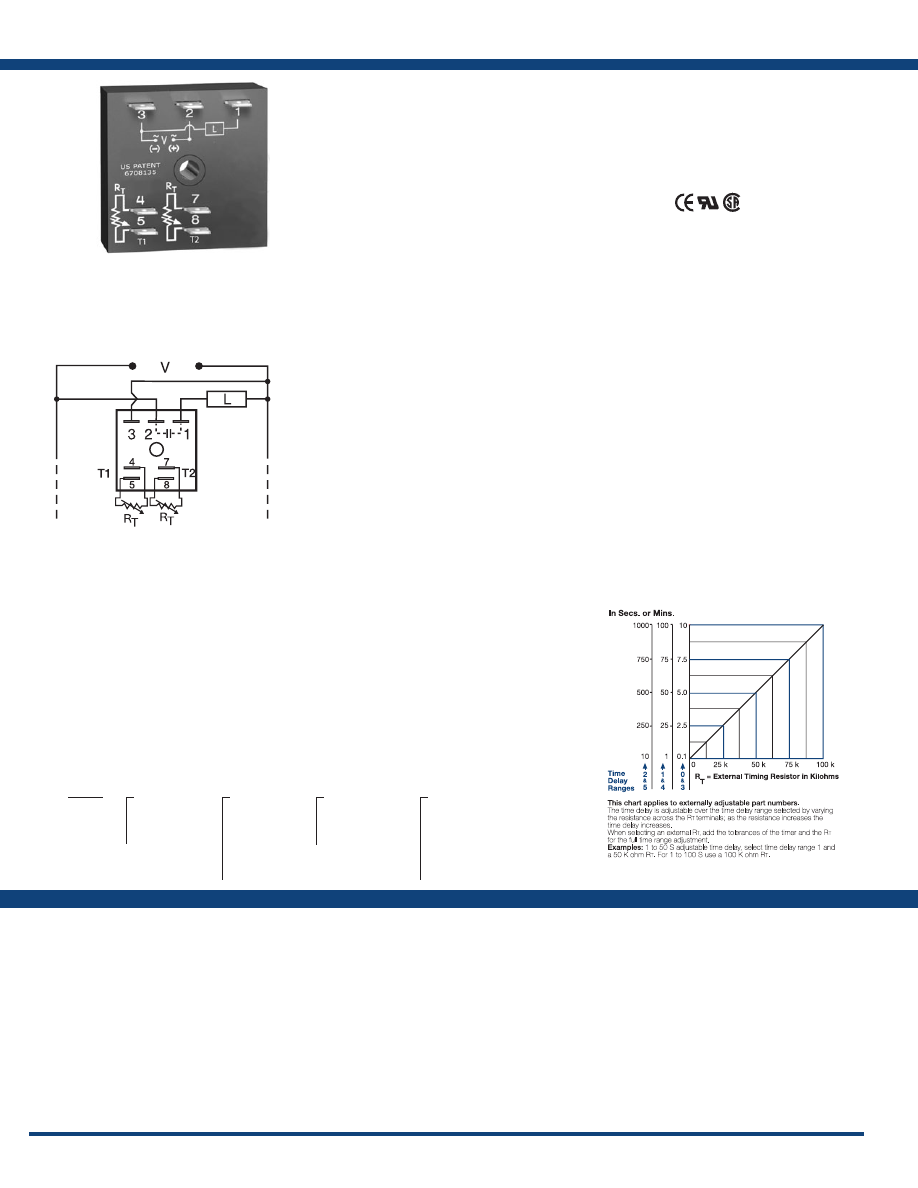
88
www.ssac.com • 800-843-8848 • fax: 605-348-5685
Features
• Adjustable 0.1s - 1000m in 6 ranges
• ±0.5% repeat accuracy
• ± 5% factory calibration
• 24, 120, or 230VAC
• 1A, solid-state output
•
Encapsulated
Approvals:
KSDR Series
Timer - Recycling
Available Models:
Time Delay
Range . . . . . . . . . . . . . . . . . . . . . . . . . . . . . . . . . .
0.1s - 1000m in 6 ranges
Repeat Accuracy . . . . . . . . . . . . . . . . . . . . . . . .
±0.5% or 20ms, whichever is greater
Tolerance (Factory Calibration) . . . . . . . . . . . .
≤ ±5%
Reset Time . . . . . . . . . . . . . . . . . . . . . . . . . . . . . .
≤ 150ms
Time Delay vs Temp. & Voltage
. . . . . . . . . . .
≤ ±10%
Input
Voltage
. . . . . . . . . . . . . . . . . . . . . . . . . . . . . . . . .
24, 120, or 230VAC
Tolerance . . . . . . . . . . . . . . . . . . . . . . . . . . . . . . .
±20%
AC Line Frequency . . . . . . . . . . . . . . . . . . . . . .
50/60 Hz
Power Consumption . . . . . . . . . . . . . . . . . . . . .
≤ 2VA
Output
Type . . . . . . . . . . . . . . . . . . . . . . . . . . . . . . . . . . .Solid state
Rating . . . . . . . . . . . . . . . . . . . . . . . . . . . . . . . . .
1A steady state, 10A inrush at 60°C
Voltage Drop
. . . . . . . . . . . . . . . . . . . . . . . . . . .
≅
2.5V @ 1A
OFF State Leakage Current
. . . . . . . . . . . . . . .
≅
5mA @ 230VAC
Protection
Circuitry . . . . . . . . . . . . . . . . . . . . . . . . . . . . . . .Encapsulated
Dielectric Breakdown
. . . . . . . . . . . . . . . . . . . .
≥ 2000V RMS terminals to mounting surface
Insulation Resistance . . . . . . . . . . . . . . . . . . . . .
≥ 100 MΩ
Mechanical
Mounting . . . . . . . . . . . . . . . . . . . . . . . . . . . . . .
Surface mount with one #10 (M5 x 0.8) screw
Dimensions . . . . . . . . . . . . . . . . . . . . . . . . . . . . .
2 x 2 x 1.21 in. (50.8 x 50.8 x 30.7 mm)
Termination . . . . . . . . . . . . . . . . . . . . . . . . . . . .
0.25 in. (6.35 mm) male quick connect terminals
Environmental
Operating / Storage Temperature
. . . . . . . . .
-40° to 75°C / -40° to 85°C
Humidity . . . . . . . . . . . . . . . . . . . . . . . . . . . . . . .
95% relative, non-condensing
Weight
. . . . . . . . . . . . . . . . . . . . . . . . . . . . . . . . .
≅
2.4 oz (68 g)
Specifications
Order Table:
Connection:
The KSDR Series offers independent time
adjustment of both delay periods. The KSDR is
recommended for air drying, automatic oiling,
life testing, chemical metering, and automatic
duty cycling. This series is designed for general
purpose commercial and industrial applications
where a small, cost effective, reliable, solid-state
timer is required. The factory calibration for fixed
time delays is within ± 5% of the target delay. The
repeat accuracy, under stable conditions, is 0.5% of
the selected time delay. This series is designed for
input voltages of 24, 120 or 230VAC. Time delays
of 0.1 seconds to 1000 minutes are available in 6
ranges. The output is rated 1A steady and 10A
inrush. The modules are totally solid state and
encapsulated to protect the electronic circuitry.
Operation (Recycling - ON Time First)
Upon application of input voltage, the output energizes
and the T1, ON time begins. At the end of the ON time,
the output de-energizes and the T2, OFF time begins. At
the end of the OFF time, the output energizes and the cycle
repeats as long as input voltage is applied.
Reset: Removing input voltage resets the output and time
delays, and returns the sequence to T1 ON time.
Operation (Recycling - OFF Time First)
Upon application of input voltage, the T2 OFF time begins.
At the end of the OFF time, the T1 ON time begins and
the load energizes. At the end of T1, T2 begins and the
load de-energizes. This cycle repeats until input voltage
is removed.
Reset: Removing input voltage resets the output and the
sequence to T2 OFF time .
For more information see:
Appendix A, pages 156-164 for function descriptions
and diagrams .
Appendix B, page 165, Figure 1 for dimensional drawing.
KSDR21A1
KSDR24A4
KSDR40A0
KSDR42A4
KSDR61A4
KSDR64A4
Auxiliary Products:
•
External ad just potentiometer:
P/N: P1004-95
P/N: P1004-95-X
•
Female quick connect:
P/N: P1015-13 (AWG 10/12)
P/N: P1015-64 (AWG 14/16)
P/N: P1015-14 (AWG 18/22)
•
Quick connect t o s crew ad aptor:
P/N: P1015-18
•
Versa-knob:
P/N: P0700-7
•
Mounting bracket:
P/N: P1023-6
•
DIN rail:
P/N: C103PM
(Al)
•
DIN rail adaptor:
P/N: P1023-20
KSDR
X
Input Voltage
─
2
- 24VAC
─
4
- 120VAC
─
6
- 230VAC
X
T1 ON Time
─
0
- 0.1 - 10s
─
1
- 1 - 100s
─
2
- 10 - 1000s
─
3
- 0.1 - 10m
─
4
- 1 - 100m
─
5
- 10 - 1000m
X
Operating
Sequence
─
A
- ON time first
─
B
- OFF time first
X
T2 OFF Time
─
0
- 0.1 - 10s
─
1
- 1 - 100s
─
2
- 10 - 1000s
─
3
- 0.1 - 10m
─
4
- 1 - 100m
─
5
- 10 - 1000m
L1
N/L2
External Resistance vs . Time Delay:
If desired part number is not listed, please call us to
see if it is technically possible to build .
R
T
is used when external adjustment is ordered.
Courtesy of Steven Engineering, Inc.-230 Ryan Way, South San Francisco, CA 94080-6370-Main Office: (650) 588-9200-Outside Local Area: (800) 258-9200-www.stevenengineering.com
Littelfuse-catalog-html.html
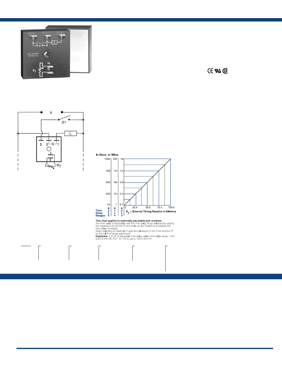
89
www.ssac.com • 800-843-8848 • fax: 605-348-5685
THD3 Series
Timer - Recycling Flasher
Available Models:
Time Delay
Range . . . . . . . . . . . . . . . . . . . . . . . . . . . . . . . . . .
0.1s - 1000m in 6 adjustable ranges or fixed
Adjustment
. . . . . . . . . . . . . . . . . . . . . . . . . . . . .
Single variable resistor changes both the
on & off times equally
Repeat Accuracy . . . . . . . . . . . . . . . . . . . . . . . .
±0.5% or 20ms, whichever is greater
Tolerance (Factory Calibration) . . . . . . . . . . . .
≤ ±1%
Reset Time . . . . . . . . . . . . . . . . . . . . . . . . . . . . . .
≤ 150ms
Time Delay vs Temp. & Voltage
. . . . . . . . . . .
≤ ±2%
Input
Voltage
. . . . . . . . . . . . . . . . . . . . . . . . . . . . . . . . .
24, 120, or 230VAC
Tolerance . . . . . . . . . . . . . . . . . . . . . . . . . . . . . . .
±20%
AC Line Frequency . . . . . . . . . . . . . . . . . . . . . .
50/60 Hz
Power Consumption . . . . . . . . . . . . . . . . . . . . .
≤ 2VA
Output
Type . . . . . . . . . . . . . . . . . . . . . . . . . . . . . . . . . . . Solid state
Maximum Load Current Output Steady State Inrush**
A 6A 60A
B 10A 100A
C 20A 200A
Minimum Load Current . . . . . . . . . . . . . . . . . .
100mA
Voltage Drop
. . . . . . . . . . . . . . . . . . . . . . . . . . .
≅
2.5V at rated current
OFF State Leakage Current
. . . . . . . . . . . . . . .
≅
5mA @ 230VAC
Protection
Circuitry . . . . . . . . . . . . . . . . . . . . . . . . . . . . . . . Encapsulated
Dielectric Breakdown
. . . . . . . . . . . . . . . . . . . .
≥ 2000V RMS terminals to mounting surface
Insulation Resistance . . . . . . . . . . . . . . . . . . . . .
≥ 100 MΩ
Mechanical
Mounting ** . . . . . . . . . . . . . . . . . . . . . . . . . . . .
Surface mount with one #10 (M5 x 0.8) screw
Dimensions . . . . . . . . . . . . . . . . . . . . . . . . . . . . .
2 x 2 x 1.51 in. (50.8 x 50.8 x 38.4 mm)
Termination . . . . . . . . . . . . . . . . . . . . . . . . . . . .
0.25 in. (6.35 mm) male quick connect terminals
Environmental
Operating / Storage Temperature
. . . . . . . . .
-40° to 60°C / -40° to 85°C
Humidity . . . . . . . . . . . . . . . . . . . . . . . . . . . . . . .
95% relative, non-condensing
Weight
. . . . . . . . . . . . . . . . . . . . . . . . . . . . . . . . .
≅
3.9 oz (111 g)
**Must be bolted to a metal surface using the included heat sink compound. The maximum
mounting surface temperature is 90°C. Inrush: Non-repetitive for 16ms.
Order Table:
Specifications
The THD Series combines accurate timing circuitry
with high power, solid-state switching. It can
switch motors, lamps, and heaters directly without
a contactor. The THD3 has equal on and off time
delays . A single R
T
sets both time delays. You
can reduce labor, component cost, and increase
reliability with these small, easy-to-use, Digi-
Power timers .
Operation (Recycling Flasher - ON Time First):
Upon application of input voltage, the output energizes
and the T1 ON time begins. At the end of the ON time, the
output de-energizes and the T2 OFF time begins. At the
end of the OFF time, the output energizes and the cycle
repeats as long as input voltage is applied.
Reset: Removing input voltage resets the output and time
delays, and returns the sequence to T1 ON time.
Operation (Recycling Flasher - OFF Time First):
Upon application of input voltage, the T2 OFF time begins.
At the end of the OFF time, the T1 ON time begins and
the load energizes. At the end of T1, T2 begins and the
load de-energizes. This cycle repeats until input voltage
is removed.
Reset: Removing input voltage resets the output and the
sequence to T2 OFF time .
For more information see:
Appendix A, pages 156-164 for function descriptions
and diagrams .
Appendix B, page 165, Figure 4 for dimensional drawing.
Features:
• High load currents up to 20A, 200A inrush
• Fixed or adjustable delays from 0.1s - 1000m
• ±0.5% repeat accuracy
• ±1% factory calibration
• 24, 120, or 230VAC
• Metallized mounting surface for heat
transfer
• Totally solid state & encapsulated
Approvals:
Connection:
THD3C23A0
THD3C23A1
THD3C23A2
THD3C23A3
THD3C23A4
THD3C23A5
THD3C42A0
THD3C43A1
THD3C43A2
THD3C43A3
THD3C43A4
THD3C43A5
Auxiliary Products:
•
External ad just potentiometer:
P/N: P1004-95
P/N: P1004-95-X
•
Female quick connect:
P/N: P1015-13 (AWG 10/12)
P/N: P1015-64 (AWG 14/16)
•
Quick connect t o s crew ad aptor:
P/N: P1015-18
•
Versa-knob:
P/N: P0700-7
THD3
X
Output Rating
─
A
- 6A
─
B
- 10A
─
C
- 20A
X
Input Voltage
─
2
- 24VAC
─
4
- 120VAC
─
6
- 230VAC
X
Adjustment
─
1
- Fixed
─
2
- External adjust
─
3
- Onboard adjust
X
Operating
Sequence
─
A
- ON time first
─
B
- OFF time first
X
Time Delay*
─
0
- 0.1 - 10s
─
1
- 1 - 100s
─
2
- 10 - 1000s
─
3
- 0.1 - 10m
─
4
- 1 - 100m
─
5
- 10 - 1000m
*If fixed delay is selected, insert delay (
0 .5 - 1000
)
followed by (
S
) secs . or (
M
) mins .
L1
N/L2
External Resistance vs . Time Delay:
If desired part number is not listed, please call us to
see if it is technically possible to build .
S1 = Optional Low Current Initiate Switch
R
T
is used when external adjustment is ordered.
Courtesy of Steven Engineering, Inc.-230 Ryan Way, South San Francisco, CA 94080-6370-Main Office: (650) 588-9200-Outside Local Area: (800) 258-9200-www.stevenengineering.com
Littelfuse-catalog-html.html
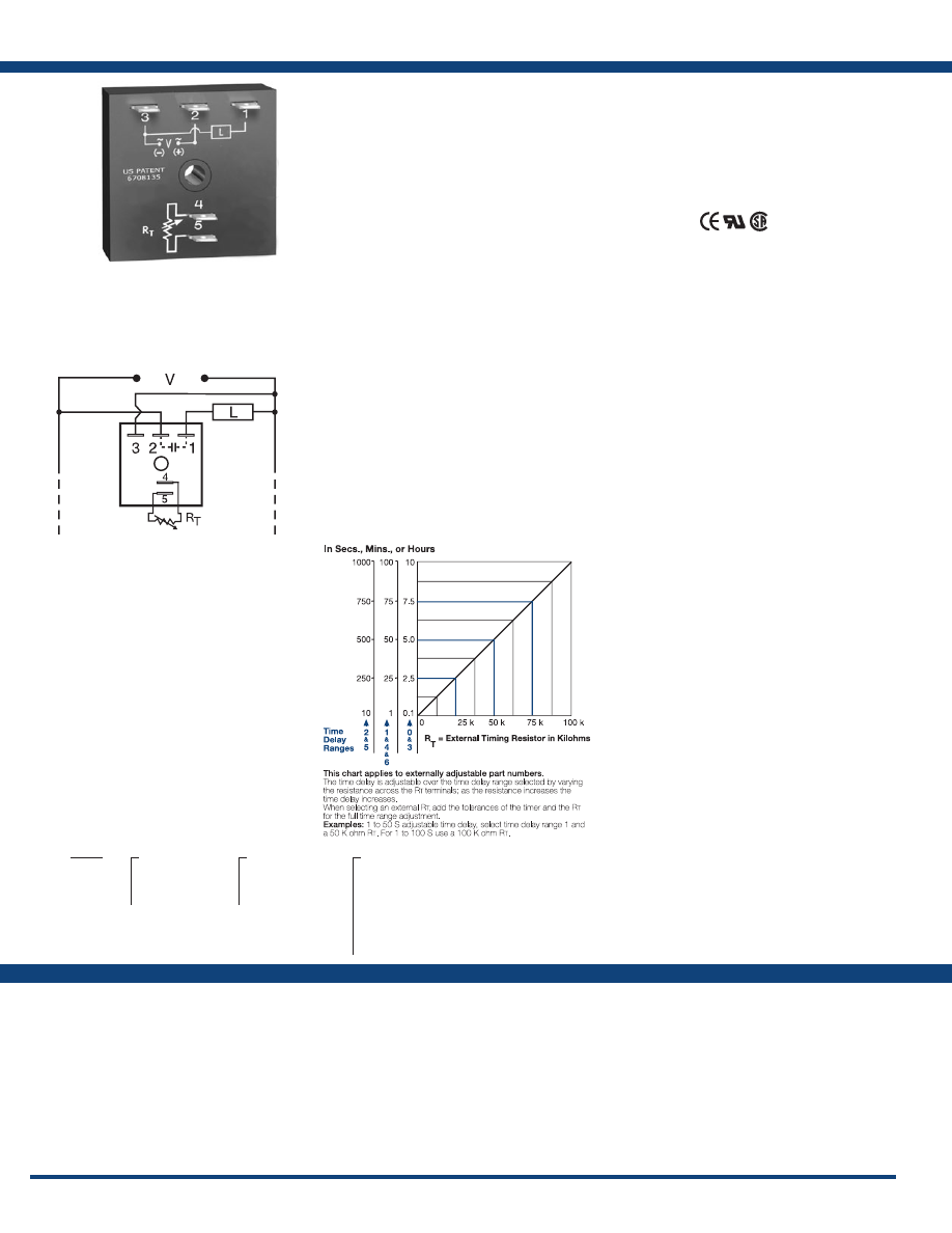
90
www.ssac.com • 800-843-8848 • fax: 605-348-5685
Features
• Equal on and off delays
• Fixed or adjustable delays from 0.1s - 100h
• ±0.1% repeat accuracy
• ±1% factory calibration
• 24, 120, or 230VAC
• 1A, solid-state output
•
Encapsulated
Approvals:
TSD3 Series
Timer - Recycling Flasher
Available Models:
Time Delay
Range . . . . . . . . . . . . . . . . . . . . . . . . . . . . . . . . . .
0.1s - 100h in 7 adjustable ranges or fixed
Repeat Accuracy . . . . . . . . . . . . . . . . . . . . . . . .
±0.1% or 20ms, whichever is greater
Tolerance (Factory Calibration) . . . . . . . . . . . .
≤ ±1%
Reset Time . . . . . . . . . . . . . . . . . . . . . . . . . . . . . .
≤ 150ms
Time Delay vs Temp. & Voltage
. . . . . . . . . . .
≤ ±1%
Input
Voltage
. . . . . . . . . . . . . . . . . . . . . . . . . . . . . . . . .
24, 120, or 230VAC
Tolerance . . . . . . . . . . . . . . . . . . . . . . . . . . . . . . .
±20%
AC Line Frequency . . . . . . . . . . . . . . . . . . . . . .
50/60 Hz
Power Consumption . . . . . . . . . . . . . . . . . . . . .
≤ 2VA
Output
Type . . . . . . . . . . . . . . . . . . . . . . . . . . . . . . . . . . .Solid state
Maximum Load Current
. . . . . . . . . . . . . . . . . .
1A steady state, 10A inrush at 60°C
Off State Leakage Current
. . . . . . . . . . . . . . . .
≅
5mA @ 230VAC
Voltage Drop
. . . . . . . . . . . . . . . . . . . . . . . . . . .
≅
2.5V @ 1A
Protection
Circuitry . . . . . . . . . . . . . . . . . . . . . . . . . . . . . . .Encapsulated
Dielectric Breakdown
. . . . . . . . . . . . . . . . . . . .
≥ 2000V RMS terminals to mounting surface
Insulation Resistance . . . . . . . . . . . . . . . . . . . . .
≥ 100 MΩ
Mechanical
Mounting . . . . . . . . . . . . . . . . . . . . . . . . . . . . . .
Surface mount with one #10 (M5 x 0.8) screw
Dimensions . . . . . . . . . . . . . . . . . . . . . . . . . . . . .
2 x 2 x 1.21 in. (50.8 x 50.8 x 30.7 mm)
Termination . . . . . . . . . . . . . . . . . . . . . . . . . . . .
0.25 in. (6.35 mm) male quick connect terminals
Environmental
Operating / Storage Temperature
. . . . . . . . .
-40° to 75°C / -40° to 85°C
Humidity . . . . . . . . . . . . . . . . . . . . . . . . . . . . . . .
95% relative, non-condensing
Weight
. . . . . . . . . . . . . . . . . . . . . . . . . . . . . . . . .
≅
2.4 oz (68 g)
Specifications
Order Table:
Connection:
The TSD3 is a solid-state ON/OFF recycling
timer with the on time always equal to the off
time. When time delay is changed by the RT,
both the ON and the OFF periods are changed.
The TSD Series is designed for more demanding
commercial and industrial applications where
small size, and accurate performance is required.
The factory calibration for fixed time delays is
within 1% of the target time delay. The repeat
accuracy, under stable conditions, is 0.1% of the
time delay. The TSD Series is rated to operate over
an extended temperature range. Time delays of 0.1
seconds to 100 hours are available. The output is
rated 1A steady and 10A inrush. The modules are
totally solid state and encapsulated to protect the
electronic circuitry .
Operation (Recycling Falsher - ON Time First):
Upon application of input voltage, the output energizes
and the T1, ON time begins. At the end of the ON time,
the output de-energizes and the T2 OFF time begins. At
the end of the OFF time, the output energizes and the cycle
repeats as long as input voltage is applied.
Reset: Removing input voltage resets the output and
time delays, and returns the sequence to the T1 ON time.
For more information see:
Appendix A, pages 156-164 for function descriptions
and diagrams .
Appendix B, page 165, Figure 1 for dimensional drawing.
TSD3411S
TSD34150S
TSD36130M
Auxiliary Products:
•
External ad just potentiometer:
P/N: P1004-95
P/N: P1004-95-X
•
Female quick connect:
P/N: P1015-64 (AWG 14/16)
•
Quick connect t o s crew ad aptor:
P/N: P1015-18
•
Versa-knob:
P/N: P0700-7
•
Mounting bracket:
P/N: P1023-6
•
DIN rail:
P/N: C103PM
(Al)
•
DIN rail adaptor:
P/N: P1023-20
TSD3
X
Input Voltage
─
2
- 24VAC
─
4
- 120VAC
─
6
- 230VAC
X
Adjustment
─
1
- Fixed
─
2
- External adjust
─
3
- Onboard adjust
X
Time Delay*
─
0
- 0.1 - 10s
─
1
- 1 - 100s
─
2
- 10 - 1000s
─
3
- 0.1 - 10m
─
4
- 1 - 100m
─
5
- 10 - 1000m
─
6
- 1 - 100h
*If fixed delay is selected, insert
delay (
0 .1 - 1000
) followed by (
S
) sec .
or (
M
) min . or (
1 - 100
) (
H
) hours
L1
N/L2
External Resistance vs . Time Delay:
If desired part number is not listed, please call us to
see if it is technically possible to build .
R
T
is used when external adjustment is ordered.
Courtesy of Steven Engineering, Inc.-230 Ryan Way, South San Francisco, CA 94080-6370-Main Office: (650) 588-9200-Outside Local Area: (800) 258-9200-www.stevenengineering.com
Littelfuse-catalog-html.html
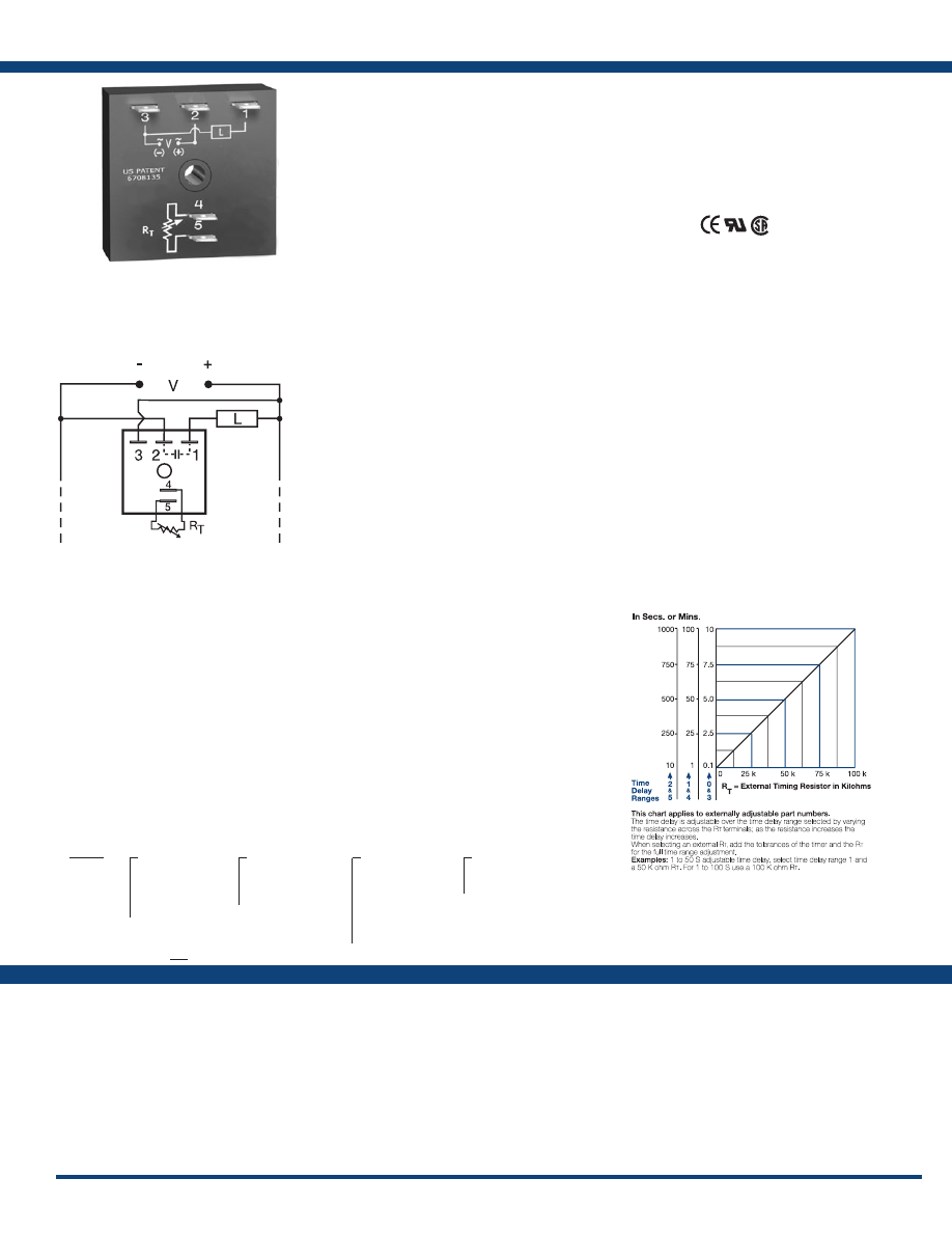
91
www.ssac.com • 800-843-8848 • fax: 605-348-5685
KSD3 Series
Timer - Recycling Flasher
Available Models:
Time Delay
Range . . . . . . . . . . . . . . . . . . . . . . . . . . . . . . . . . .
0.1s - 1000m in 6 adjustable ranges or fixed
Repeat Accuracy . . . . . . . . . . . . . . . . . . . . . . . .
±0.5% or 20ms, whichever is greater
Tolerance (Factory Calibration) . . . . . . . . . . . .
≤ ± 5%
Reset Time . . . . . . . . . . . . . . . . . . . . . . . . . . . . . .
≤ 150ms
Time Delay vs Temp. & Voltage
. . . . . . . . . . .
≤ ±10%
Input
Voltage
. . . . . . . . . . . . . . . . . . . . . . . . . . . . . . . . .
24 or 120VAC; 12 or 24VDC
Tolerance . . . . . . . . . . . . . . . . . . . . . . . . . . . . . . .
±20%
AC Line Frequency . . . . . . . . . . . . . . . . . . . . . .
50/60 Hz
Power Consumption . . . . . . . . . . . . . . . . . . . . .
AC ≤ 2VA; DC ≤ 1W
Output
Type . . . . . . . . . . . . . . . . . . . . . . . . . . . . . . . . . . .Solid state
Maximum Load Current
. . . . . . . . . . . . . . . . . .
1A steady state, 10A inrush at 60°C
OFF State Leakage Current
. . . . . . . . . . . . . . .AC
≅
5mA @ 230VAC; DC
≅
1mA
Voltage Drop
. . . . . . . . . . . . . . . . . . . . . . . . . . .AC
≅
2.5V @ 1A; DC
≅
1V @ 1A
DC Operation . . . . . . . . . . . . . . . . . . . . . . . . . . .
Negative switching only
Protection
Circuitry . . . . . . . . . . . . . . . . . . . . . . . . . . . . . . .Encapsulated
Dielectric Breakdown
. . . . . . . . . . . . . . . . . . . .
≥ 2000V RMS terminals to mounting surface
Insulation Resistance . . . . . . . . . . . . . . . . . . . . .
≥ 100 MΩ
Polarity . . . . . . . . . . . . . . . . . . . . . . . . . . . . . . . .
DC units are reverse polarity protected
Mechanical
Mounting . . . . . . . . . . . . . . . . . . . . . . . . . . . . . .
Surface mount with one #10 (M5 x 0.8) screw
Dimensions . . . . . . . . . . . . . . . . . . . . . . . . . . . . .
2 x 2 x 1.21 in. (50.8 x 50.8 x 30.7 mm)
Termination . . . . . . . . . . . . . . . . . . . . . . . . . . . .
0.25 in. (6.35 mm) male quick connect terminals
Environmental
Operating / Storage Temperature
. . . . . . . . .
-40° to 60°C / -40° to 85°C
Humidity . . . . . . . . . . . . . . . . . . . . . . . . . . . . . . .
95% relative, non-condensing
Weight
. . . . . . . . . . . . . . . . . . . . . . . . . . . . . . . . .
≅
2.4 oz (68 g)
Order Table:
Specifications
The KSD3 Digi-Timer is a cost effective approach
for ON/OFF recycling applications. The on time
is equal to the off time. An adjustment of the R
T
will change the time delays of both on and off
times. This series is designed for general purpose
commercial and industrial applications where a
small, cost effective, reliable, solid-state timer is
required. The factory calibration for fixed time
delays is within 5% of the target time delay. The
repeat accuracy, under stable conditions, is 0.5% of
the selected time delay. This series is designed for
popular AC and DC voltages. Time delays of 0.1
seconds to 1000 minutes are available in 6 ranges.
The output is rated 1A steady and 10A inrush. The
modules are totally solid state and encapsulated
to protect the electronic circuitry.
Operation (Recycling Flasher - ON Time First):
Upon application of input voltage, the output energizes
and the T1, ON time begins. At the end of the ON time,
the output de-energizes and the T2 OFF time begins. At
the end of the OFF time, the output energizes and the cycle
repeats as long as input voltage is applied.
Reset: Removing input voltage resets the output and time
delays, and returns the sequence to the ON time.
Operation (Recycling Flasher - OFF Time First):
Upon application of input voltage, the T2 OFF time
begins. At the end of the OFF time, the T1 ON time
begins and the load energizes. At the end of the ON time
the load de-energizes, and the cycle repeats until input
voltage is removed.
Reset: Removing input voltage resets the output and time
delays and the sequence to the OFF time.
For more information see:
Appendix A, pages 156-164 for function descriptions
and diagrams .
Appendix B, page 165, Figure 1 for dimensional drawing.
Features:
• Fixed or adjustable delays from 0.1s -1000m
• Equal on and off delays
• ±0.5% repeat accuracy
• ± 5% factory calibration
• 12 to 120V in 4 ranges
• 1A, solid-state output
•
Encapsulated
Approvals:
Connection:
KSD3120A
KSD3310.1SA
KSD3410.5SA
KSD3432A
Auxiliary Products:
•
External ad just potentiometer:
P/N: P1004-95
P/N: P1004-95-X
•
Female quick connect:
P/N: P1015-64 (AWG 14/16)
•
Quick connect t o s crew ad aptor:
P/N: P1015-18
•
Mounting bracket:
P/N: P1023-6
•
Versa-knob:
P/N: P0700-7
•
DIN rail:
P/N: C103PM
(Al)
•
DIN rail adaptor:
P/N: P1023-20
KSD3
X
Input Voltage
─
1
- 12VDC
─
2
- 24VAC
─
3
- 24VDC
─
4
- 120VAC
Note: DC voltages
available in negative
switching
only
X
Adjustment
─
1
- Fixed
─
2
- External adjust
─
3
- Onboard adjust
X
Time Delay*
─
0
- 0.1 - 10s
─
1
- 1 - 100s
─
2
- 10 - 1000s
─
3
- 0.1 - 10m
─
4
- 1 - 100m
─
5
- 10 - 1000m
X
Operating Sequence
─
A
- ON time first
─
B
- OFF time first
*If fixed delay is selected, insert
delay (
0 .1 - 1000
) followed by (
S
) sec .
or (
M
) min .
L1
N/L2
External Resistance vs . Time Delay:
If desired part number is not listed, please call us to
see if it is technically possible to build .
R
T
is used when external adjustment is ordered.
Courtesy of Steven Engineering, Inc.-230 Ryan Way, South San Francisco, CA 94080-6370-Main Office: (650) 588-9200-Outside Local Area: (800) 258-9200-www.stevenengineering.com
Littelfuse-catalog-html.html
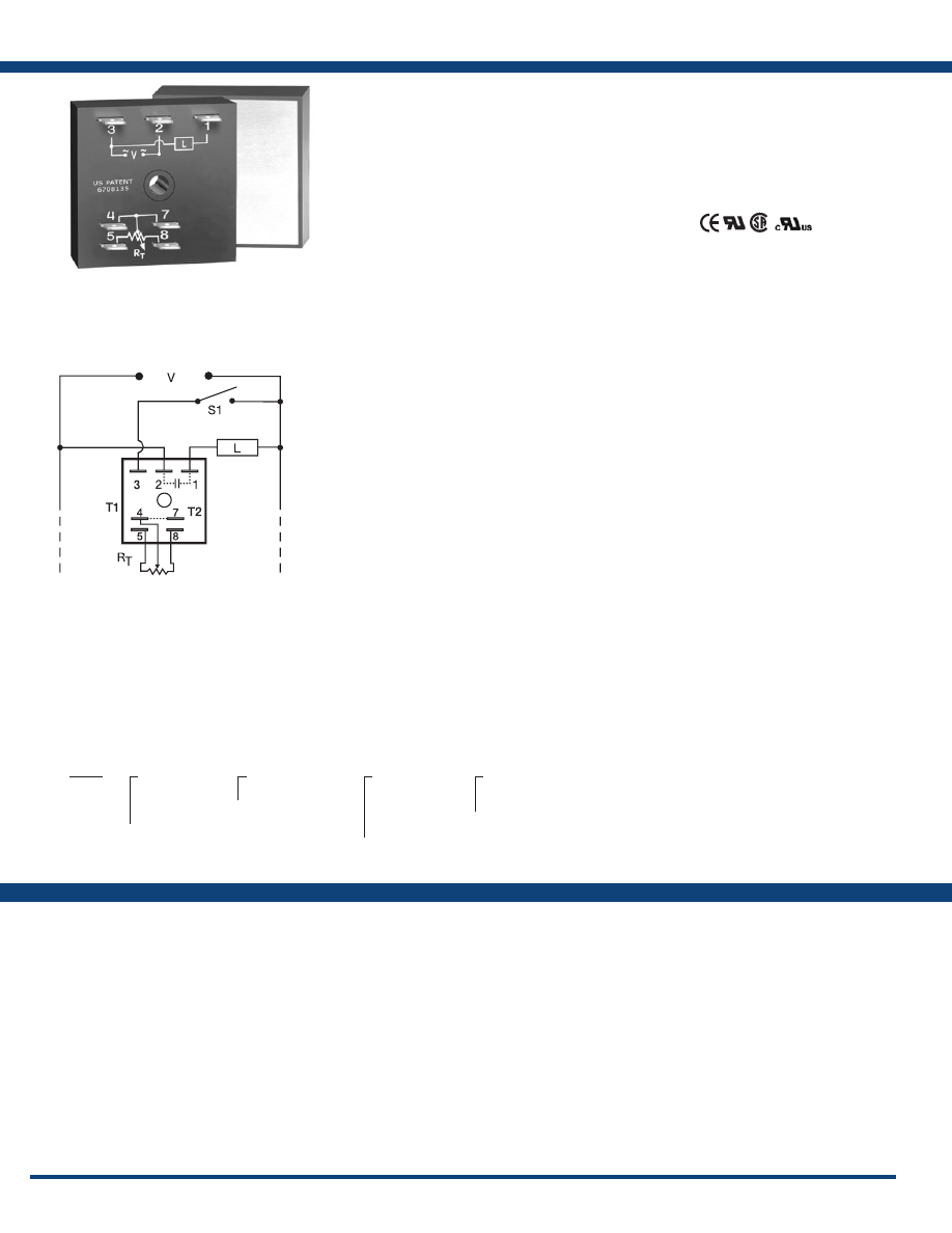
92
www.ssac.com • 800-843-8848 • fax: 605-348-5685
Features
• ON/OFF recycling percentage control
• Controls loads up to 20A, 200A inrush
• Fixed cycle period 10s - 1000m
• ±0.5% repeat accuracy
• ±5% factory calibration
• Totally solid state & encapsulated
• Onboard or external adjustment 1 - 99% ON
Approvals:
PTHF Series
Timer - Percentage
Available Models:
Time Delay
Type . . . . . . . . . . . . . . . . . . . . . . . . . . . . . . . . . . . . . .
External or onboard knob
Range / External Adjustment Resistance
. . . . . .
Adjustable from 1 - 99% / R
T
= 100 KΩ
Cycle Period . . . . . . . . . . . . . . . . . . . . . . . . . . . . . . .
Fixed from 10s - 1000m
Repeat Accuracy . . . . . . . . . . . . . . . . . . . . . . . . . . .
±0.5% or 20ms, whichever is greater
Cycle Period Tolerance (Factory Calibration) . . .
≤ ± 5%
Reset Time . . . . . . . . . . . . . . . . . . . . . . . . . . . . . . . . .
≤ 150ms
Time Delay vs Temp. & Voltage
. . . . . . . . . . . . . .
≤ ±10%
Input
Voltage
. . . . . . . . . . . . . . . . . . . . . . . . . . . . . . . . . . . .
24, 120, or 230VAC
Tolerance . . . . . . . . . . . . . . . . . . . . . . . . . . . . . . . . . .
±20%
AC Line Frequency . . . . . . . . . . . . . . . . . . . . . . . . .
50/60 Hz
Power Consumption . . . . . . . . . . . . . . . . . . . . . . . .
≤ 2VA
Output
Type . . . . . . . . . . . . . . . . . . . . . . . . . . . . . . . . . . . . . . . . Solid state
Maximum Load Currents Output Steady State Inrush* Minimum
A 6A 60A 100mA
B 10A 100A 100mA
C 20A 200A 100mA
D 1A 10A - -
Voltage Drop
. . . . . . . . . . . . . . . . . . . . . . . . . . . . . .
≅
2.5V at rated current
OFF State Leakage Current
. . . . . . . . . . . . . . . . . .
≅
5mA @ 230VAC
Protection
Circuitry . . . . . . . . . . . . . . . . . . . . . . . . . . . . . . . . . .Encapsulated
Dielectric Breakdown
. . . . . . . . . . . . . . . . . . . . . . .
≥ 2000V RMS terminals to mounting surface
Insulation Resistance . . . . . . . . . . . . . . . . . . . . . . . .
≥ 100 MΩ
Mechanical
Mounting * . . . . . . . . . . . . . . . . . . . . . . . . . . . . . . . .
Surface mount with one #10 (M5 x 0.8) screw
Dimensions . . . . . . . . . . . . . . . . . . . . . . . . . . . . . . . .
2 x 2 x 1.51 in. (50.8 x 50.8 x 38.4 mm)
Termination . . . . . . . . . . . . . . . . . . . . . . . . . . . . . . .
0.25 in. (6.35 mm) male quick connect terminals
Environmental
Operating / Storage Temperature
. . . . . . . . . . . .
-40° to 60°C / -40° to 85°C
Humidity . . . . . . . . . . . . . . . . . . . . . . . . . . . . . . . . . .
95% relative, non-condensing
Weight
. . . . . . . . . . . . . . . . . . . . . . . . . . . . . . . . . . . .
1A unit:
≅
2.4 oz (68 g);
6, 10, 20A units:
≅
3.9 oz (111 g)
*Units rated ≥ 6A must be bolted to a metal surface using the included heat sink compound.
The maximum mounting surface temperature is 90°C. Inrush: Non-repetitive for 16ms.
Specifications
Order Table:
Connection:
The PTHF Series can be used for a variety
of applications from chemical metering, to
temperature regulating, to energy management.
The infinite adjustability from 1 to 99% provides
accurate percentage on control over a wide
factory fixed cycle period. When mounted on a
metal surface, it can be used to drive solenoids,
contactors, relays, or lamps, up to 20A steady,
200A inrush. PTHF is the suggested replacement
for the PT Series.
Operation (Percentage):
Upon application of input voltage, the output energizes
and the T1 ON time begins. At the end of the ON time,
the output de-energizes and the T2 OFF time begins. At
the end of the OFF time, the output energizes and the cycle
repeats as long as input voltage is applied. Increasing the
ON time decreases the OFF time. The total cycle period is
equal to the ON time plus the OFF time. The total cycle
period is factory fixed. ON time range is 1 to 99 percent
of cycle period.
Reset: Removing input voltage resets the output and
time delays, and returns the sequence to the T1 ON time.
For more information see:
Appendix A, pages 156-164 for function descriptions
and diagrams .
Appendix B, page 165, Figure 4 for dimensional drawing.
PTHF410C
PTHF410CK
PTHF4120D
PTHF615A
Auxiliary Products:
•
External ad just potentiometer:
P/N: P1004-95
•
Female quick connect:
P/N: P1015-13 (AWG 10/12)
P/N: P1015-64 (AWG 14/16)
•
Quick connect t o s crew ad aptor:
P/N: P1015-18
•
Versa-knob:
P/N: P0700-7
PTHF
X
Input Voltage
─
2
- 24VAC
─
4
- 120VAC
─
6
- 230VAC
X
Fixed Cycle Period
─Specify
10 - 1000
as
the total fixed cycle
period in seconds .
If cycle period is in
minutes insert (M)
suffix.
X
Output Rating
─
A
- 6A
─
B
- 10A
─
C
- 20A
─
D
- 1A
X
Adjustment
─
Blank
- External adjust
─
K
- Onboard adjust
L1
N/L2
R
T
= 100 KΩ
S1 = Optional Low Current Initiate Switch
T1 = ON Time
T2 = OFF Time
R
T
is used when external adjustment is ordered.
If desired part number is not listed, please call us to
see if it is technically possible to build .
Courtesy of Steven Engineering, Inc.-230 Ryan Way, South San Francisco, CA 94080-6370-Main Office: (650) 588-9200-Outside Local Area: (800) 258-9200-www.stevenengineering.com
Littelfuse-catalog-html.html
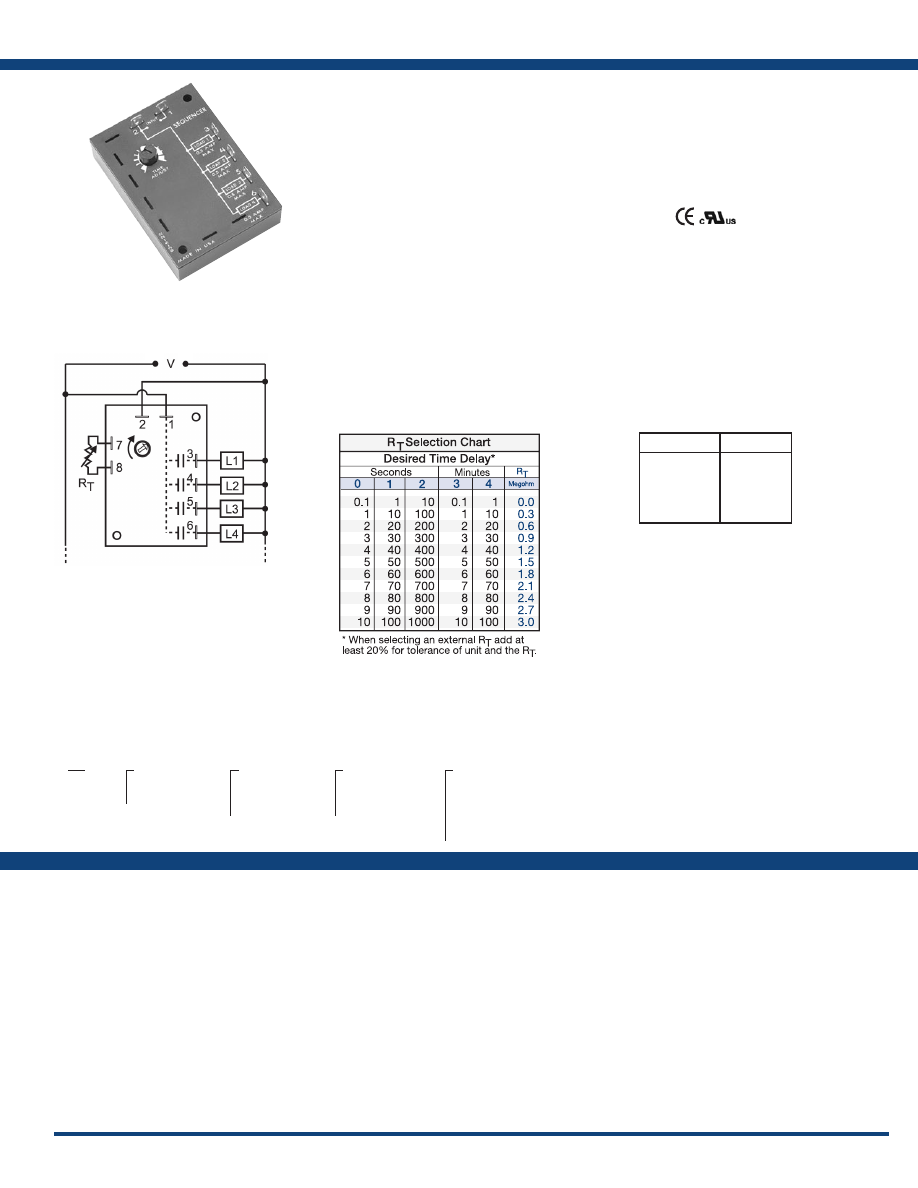
93
www.ssac.com • 800-843-8848 • fax: 605-348-5685
SQ Series
Timer - Sequencing
Available Models:
Time Delay
Type . . . . . . . . . . . . . . . . . . . . . . . . . . . . . . . . . . . Digital integrated circuitry
Range . . . . . . . . . . . . . . . . . . . . . . . . . . . . . . . . . .
0.1s - 100m in 5 adjustable ranges or fixed
Repeat Accuracy . . . . . . . . . . . . . . . . . . . . . . . .
±1% or 20ms, whichever is greater
Tolerance (Factory Calibration) . . . . . . . . . . . .
≤ ±10%
Time Delay vs Temp. & Voltage
. . . . . . . . . . .
≤ ±10%
Input
Voltage
. . . . . . . . . . . . . . . . . . . . . . . . . . . . . . . . .
24, 120, or 230VAC
Tolerance . . . . . . . . . . . . . . . . . . . . . . . . . . . . . . .
±20%
AC Line Frequency . . . . . . . . . . . . . . . . . . . . . .
50/60 Hz
Output
Type . . . . . . . . . . . . . . . . . . . . . . . . . . . . . . . . . . . Solid state
Form . . . . . . . . . . . . . . . . . . . . . . . . . . . . . . . . . . .
SPST NO (three or four)
Rating . . . . . . . . . . . . . . . . . . . . . . . . . . . . . . . . .
1A steady state, 10A inrush per output
Voltage Drop (Each Output)
. . . . . . . . . . . . . .
≅
1.5V @ 1A
Protection
Circuitry . . . . . . . . . . . . . . . . . . . . . . . . . . . . . . . Encapsulated
Dielectric Breakdown
. . . . . . . . . . . . . . . . . . . .
≥ 2000V RMS terminals to mounting surface
Insulation Resistance . . . . . . . . . . . . . . . . . . . . .
≥ 100 MΩ
Mechanical
Mounting . . . . . . . . . . . . . . . . . . . . . . . . . . . . . .
Surface mount with two #6 (M3.5 x 0.6) screws
Dimensions . . . . . . . . . . . . . . . . . . . . . . . . . . . . .
3.5 x 2.5 x 1.22 in. (88.9 x 63.5 x 31 mm)
Termination . . . . . . . . . . . . . . . . . . . . . . . . . . . .
0.25 in. (6.35 mm) male quick connect terminals
Environmental
Operating / Storage Temperature
. . . . . . . . .
-20° to 60°C / -40° to 85°C
Humidity . . . . . . . . . . . . . . . . . . . . . . . . . . . . . . .
95% relative, non-condensing
Weight
. . . . . . . . . . . . . . . . . . . . . . . . . . . . . . . . .
≅
5.4 oz (153 g)
Order Table:
Specifications
The SQ Series is available with either three (SQ3) or
four (SQ4) outputs and an adjustable or fixed time
delay. The time delay period is the same for each
output. This makes the SQ ideal for applications
like dust collection, automatic lubrication, air
drying, lighting displays, merchandising displays,
duty cycling, and energy management.
Operation (Sequencing):
Upon application of input voltage, Load 1 energizes for
the selected ON time delay. At the end of this ON time
delay, Load 1 de-energizes and Load 2 immediately
energizes starting another ON time delay. At the end
of this ON time delay, Load 2 de-energizes and Load 3
immediately energizes. At the end of the ON time delay
for Load 3 (Load 4 for 4 output devices), Load 1 re-
energizes and the cycle repeats. The sequential operation
continues as long as input voltage is applied.
Reset: Removing and re-applying input voltage resets the
sequence to the Load 1 ON time delay.
For more information see:
Appendix A, pages 156-164 for function descriptions
and diagrams .
Appendix B, page 166, Figure 14 for dimensional drawing.
Features:
• Three or four outputs
• Variable delays from 0.1s - 100m in 5 ranges
• Totally solid state for a long, reliable life
• Encapsulated to protect against the
environment
• Digital circuitry for accuracy and stability
• 1A, solid-state outputs
Approvals:
Connection:
SQ3221
SQ4424
SQ4434
Auxiliary Products:
•
External ad just potentiometer:
P/N: P1004-12
P/N: P1004-12-X
•
Female quick connect:
P/N: P1015-64 (AWG 14/16)
•
Quick connect t o s crew ad aptor:
P/N: P1015-18
•
Versa-knob:
P/N: P0700-7
•
Plug-on adjustment module:
P/N: VTP(X)(X)
L1
N/L2
Time Delay
VTP P/N
0
- 0.1-10s
1
- 1-100s
2
- 10-1000s
3
- 0.1-10m
4
- 1-100m
VTP4C
VTP4G
VTP4K
VTP45N
VTP4P
Selection Table for VTP Plug-on
Adjustment Accessory.
SQ
X
# of Outputs
─
3
- Three
─
4
- Four
X
Input Voltage
─
2
- 24VAC
─
4
- 120VAC
─
6
- 230VAC
X
Adjustment
─
1
- Fixed
─
2
- Onboard adjust
─
3
- External adjust
X
Time Delay*
─
0
- 0.1 - 10s
─
1
- 1 - 100s
─
2
- 10 - 1000s
─
3
- 0.1 - 10m
─
4
- 1 - 100m
*If fixed delay is selected, insert
delay (
0 .1 - 1000
) followed by (
S
) sec .
or (
1 - 100
) (
M
) min
If desired part number is not listed, please call us to
see if it is technically possible to build .
R
T
is 3 megohms, when external adjustment is
ordered. SQ4 shown; for SQ3, terminal 6 & load
L4 are eliminated.
Courtesy of Steven Engineering, Inc.-230 Ryan Way, South San Francisco, CA 94080-6370-Main Office: (650) 588-9200-Outside Local Area: (800) 258-9200-www.stevenengineering.com
Littelfuse-catalog-html.html
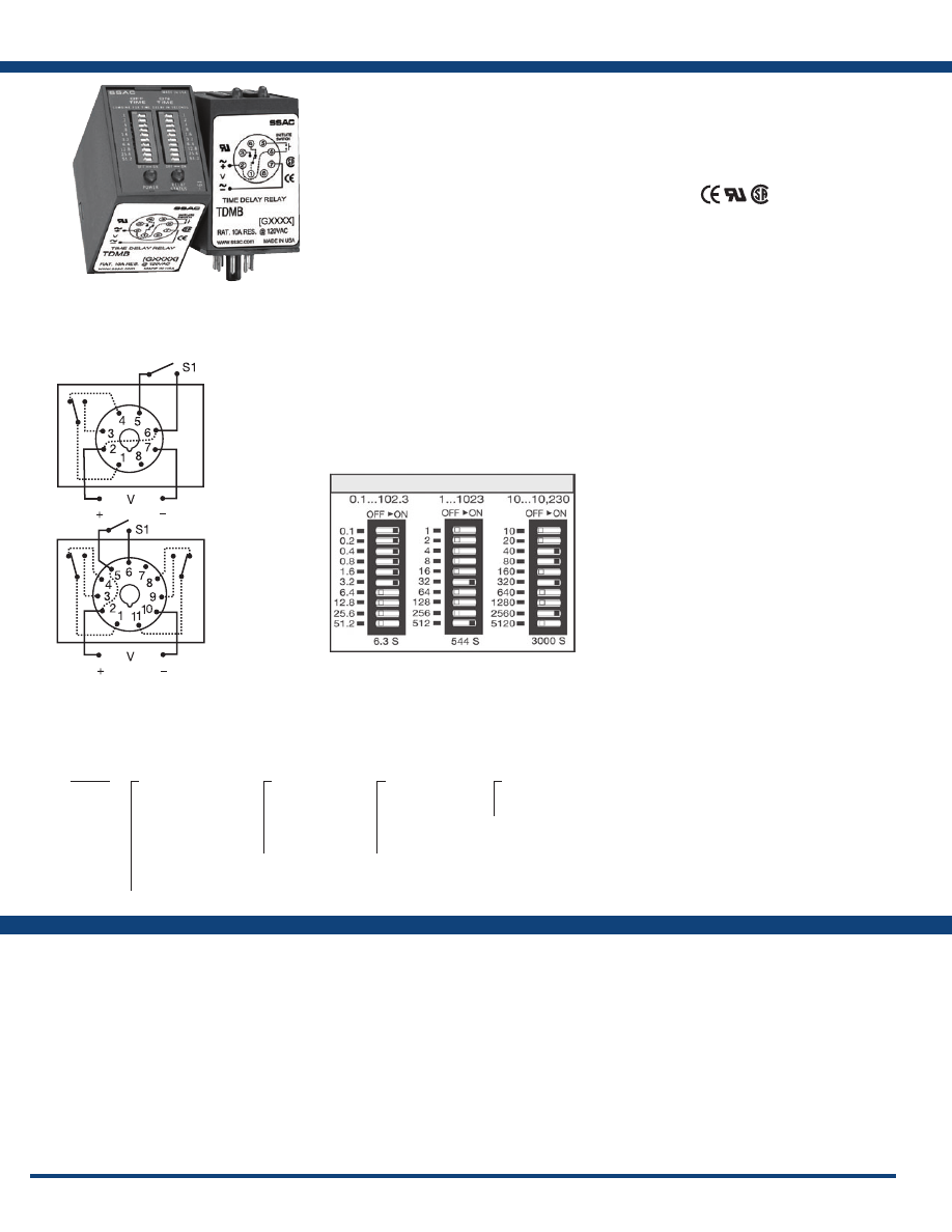
94
www.ssac.com • 800-843-8848 • fax: 605-348-5685
Features
• Switch settable time delays from
0.1s - 10,230s in 3 ranges
• ±2% setting accuracy
• ±0.1% repeat accuracy
• 10A, SPDT or DPDT output contacts
Approvals:
TDMB Series
Timer - Delay-on-Make/Delay-on-Break
Available Models:
Time Delay
Type . . . . . . . . . . . . . . . . . . . . . . . . . . . . . . . . . . . Microcontroller circuitry
Range** . . . . . . . . . . . . . . . . . . . . . . . . . . . . . . . .
0.1 - 102.3s in 0.1s increments
1 - 1023s in 1s increments
10 - 10,230s in 10s increments
Repeat Accuracy . . . . . . . . . . . . . . . . . . . . . . . .
±0.1% or 20ms, whichever is greater
Setting Accuracy . . . . . . . . . . . . . . . . . . . . . . . .
≤ ±2% or 50ms, whichever is greater
Reset Time . . . . . . . . . . . . . . . . . . . . . . . . . . . . . .
≤ 150ms
Time Delay vs Temp. & Voltage
. . . . . . . . . . .
≤ ±2%
Control LED Indicator . . . . . . . . . . . . . . . . . . . .
Green; on when the initiate switch is closed
Input
Voltage
. . . . . . . . . . . . . . . . . . . . . . . . . . . . . . . . .
12 or 24VDC; 24, 120, or 230VAC;
24 to 240VAC/DC; 12 to 48VDC
Tolerance 12VDC & 24VDC/AC
. . . . . . .
-15% - 20%
110 to 230VAC/DC
. . . . . . .
-20% - 10%
AC Line Frequency / DC Ripple
. . . . . . . . . . .
50/60 Hz / ≤ 10%
Power Consumption . . . . . . . . . . . . . . . . . . . . .
AC ≤ 2VA; DC ≤ 2W
Output
Type . . . . . . . . . . . . . . . . . . . . . . . . . . . . . . . . . . .
Electromechanical relay
Form . . . . . . . . . . . . . . . . . . . . . . . . . . . . . . . . . . . SPDT or DPDT
Rating . . . . . . . . . . . . . . . . . . . . . . . . . . . . . . . . .
10A resistive @ 120/240VAC & 28VDC;
1/3 hp @ 230VAC
Life
. . . . . . . . . . . . . . . . . . . . . . . . . . . . . . . . . . . .
Mechanical - 1 x10
7
; Electrical - 1 x 10
5
Max. Switching Voltage
. . . . . . . . . . . . . . . . . .
250VAC
Relay LED Indicator . . . . . . . . . . . . . . . . . . . . .
Red; on when output relay energizes
(not included on 12VDC units)
Protection
Insulation Resistance . . . . . . . . . . . . . . . . . . . . .
≥ 100M
Polarity . . . . . . . . . . . . . . . . . . . . . . . . . . . . . . . .
DC units are reverse polarity protected
Isolation Voltage
. . . . . . . . . . . . . . . . . . . . . . . .
≥ 1500V RMS input to output
Mechanical
Mounting . . . . . . . . . . . . . . . . . . . . . . . . . . . . . .
Plug-in socket
Dimensions . . . . . . . . . . . . . . . . . . . . . . . . . . . . .
3.2 x 2.4 x 1.8 in. (81.3 x 60.7 x 45.2 mm)
Termination . . . . . . . . . . . . . . . . . . . . . . . . . . . .
Octal 8-pin plug-in, magnal 11-pin plug-in
Environmental
Operating / Storage Temperature
. . . . . . . . .
-20° to 60°C / -30° to 85°C
Weight
. . . . . . . . . . . . . . . . . . . . . . . . . . . . . . . . .
≅
6 oz (170 g)
** For CE approved applications, power must be removed from the unit when a switch
position is changed.
Specifications
Order Table:
Connection:
The TDMB combines both delay-on-make and
delay-on-break functions into one plug-in package.
Selection of the time period is accomplished with
dual switches, one for the on delay and the other
for the off delay. SPDT or DPDT output options
provide isolated, 10A switching capability.
Operation (Delay-on-Make/Delay-on-Break):
Input voltage must be applied at all times. The output
relay is de-energized. Upon closure of the initiate switch,
the green LED glows and the delay-on-make time delay
(T1) begins. At the end of T1, the output relay energizes
and the red LED glows. When the initiate switch opens,
the green LED turns OFF and the delay-on-break time
delay (T2) begins. At the end of T2, the output relay de-
energizes and the red LED turns OFF.
Reset: Removing input voltage resets time delay and
output. Opening the initiate switch during the delay-on-
make delay, resets T1. Closing the initiate switch during
the delay-on-break delay, resets T2.
For more information see:
Appendix A, pages 156-164 for function descriptions
and diagrams .
Appendix B, page 165, Figure 8 for dimensional drawing.
TDMB411
TDMB411D
TDMB413D
TDMB422
TDMB422D
TDMB622
Auxiliary Products:
•
Panel mount kit:
P/N: BZ1
•
11-pin socket:
P/N: NDS-11
•
Octal 8-pin socket:
P/N: NDS-8
•
Hold-down c lips (sold i n p airs):
P/N: PSC8 (NDS-8)
P/N: PSC11 (NDS-11)
Digi-Set Binary Switch Operation:
L1
N/L2
L1
N/L2
8-pin octal SPDT
11-pin DPDT
(P/N ends with D)
TDMB
X
Input Voltage
─
A
- 24 to 240VAC/DC
─
D
- 12 to 48VDC
─
1
- 12VDC*
─
2
- 24VAC
─
3
- 24VDC
─
4
- 120VAC
─
5
- 110VDC
─
6
- 230VAC
X
Delay-on-Make
─
1
- 0.1 - 102.3s in
0.1s increments
─
2
- 1 - 1023s in 1s
increments
─
3
- 10 - 10230s in
10s increments
X
Delay-on-Break
─
1
- 0.1 - 102.3s in
0.1s increments
─
2
- 1 - 1023s in 1s
increments
─
3
- 10 - 10230s in
10s increments
X
Type Plug/Output Form
─
Blank
- Octal plug (8-pin) SPDT
─
D
- 11-pin plug DPDT
*No control status LED for 12VDC
If desired part number is not listed, please call us to
see if it is technically possible to build .
Relay contacts are isolated .
Courtesy of Steven Engineering, Inc.-230 Ryan Way, South San Francisco, CA 94080-6370-Main Office: (650) 588-9200-Outside Local Area: (800) 258-9200-www.stevenengineering.com
Littelfuse-catalog-html.html
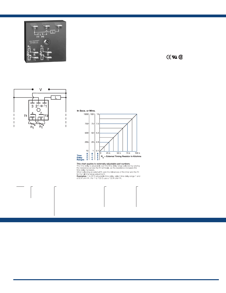
95
www.ssac.com • 800-843-8848 • fax: 605-348-5685
ESD5 Series
Timer - Delayed Interval
Available Models:
Time Delay
Range . . . . . . . . . . . . . . . . . . . . . . . . . . . . . . . . . .
0.1s - 1000m in 6 adjustable ranges or fixed
Repeat Accuracy . . . . . . . . . . . . . . . . . . . . . . . .
±0.1% or 20ms, whichever is greater
Tolerance (Factory Calibration) . . . . . . . . . . . .
≤ ±5%
Reset Time . . . . . . . . . . . . . . . . . . . . . . . . . . . . . .
≤ 150ms
Time Delay vs Temp. & Voltage
. . . . . . . . . . .
≤ ±2%
Input
Voltage
. . . . . . . . . . . . . . . . . . . . . . . . . . . . . . . . .
24, 120, or 230VAC
Tolerance . . . . . . . . . . . . . . . . . . . . . . . . . . . . . . .
±20%
AC Line Frequency . . . . . . . . . . . . . . . . . . . . . .
50/60 Hz
Power Consumption . . . . . . . . . . . . . . . . . . . . .
≤ 2VA
Output
Type . . . . . . . . . . . . . . . . . . . . . . . . . . . . . . . . . . . Solid state
Rating . . . . . . . . . . . . . . . . . . . . . . . . . . . . . . . . .
1A steady state, 10A inrush at 60°C
OFF State Leakage Current
. . . . . . . . . . . . . . .
≅
5mA @ 230VAC
Voltage Drop
. . . . . . . . . . . . . . . . . . . . . . . . . . .
≅
2.5V @ 1A
Protection
Circuitry . . . . . . . . . . . . . . . . . . . . . . . . . . . . . . . Encapsulated
Dielectric Breakdown
. . . . . . . . . . . . . . . . . . . .
≥ 2000V RMS terminals to mounting surface
Insulation Resistance . . . . . . . . . . . . . . . . . . . . .
≥ 100 MΩ
Mechanical
Mounting . . . . . . . . . . . . . . . . . . . . . . . . . . . . . .
Surface mount with one #10 (M5 x 0.8) screw
Dimensions . . . . . . . . . . . . . . . . . . . . . . . . . . . . .
2 x 2 x 1.21 in. (50.8 x 50.8 x 30.7 mm)
Termination . . . . . . . . . . . . . . . . . . . . . . . . . . . .
0.25 in. (6.35 mm) male quick connect terminals
Environmental
Operating / Storage Temperature
. . . . . . . . .
-40° to 75°C / -40° to 85°C
Humidity . . . . . . . . . . . . . . . . . . . . . . . . . . . . . . .
95% relative, non-condensing
Weight
. . . . . . . . . . . . . . . . . . . . . . . . . . . . . . . . .
≅
2.4 oz (68g)
Order Table:
Specifications
The ESD5 Series is an accurate, solid-state, delayed
interval timer. It offers a 1A steady, 10A inrush
output and is available with adjustable or fixed
time delays of 0.1 seconds to 1000 minutes in six
ranges. Input voltages of 24, 120, or 230VAC are
available. Encapsulation offers protection against
shock and vibration. Adjustment options are
factory fixed, onboard or externally adjustable. The
repeat accuracy, under stable conditions, is 0.1%.
The factory calibration of the time delay is ± 5%.
Operation (Delayed Interval):
Upon application of input voltage, the T1 delay-on-make
time delay begins and the output remains de-energized.
At the end of this delay, the output energizes and the T2
interval delay begins. At the end of the interval delay
period, the output de-energizes.
Reset: Removing input voltage resets the output and the
time delays, and returns the sequence to the first delay.
For more information see:
Appendix A, pages 156-164 for function descriptions
and diagrams .
Appendix B, page 165, Figure 1 for dimensional drawing.
Features:
• Delay-on-Make with interval output
• 0.1s - 1000m in 6 ranges
• ±0.1% repeat accuracy
• ±5% factory calibration
• Factory fixed, onboard or external adjust
• Totally solid state & encapsulated
• 24, 120 or 230VAC
• 1A, solid-state output
Approvals:
Connection:
ESD52233
ESD54160S2S
ESD54233
ESD54500
Auxiliary Products:
•
External ad just potentiometer:
P/N: P1004-95
P/N: P1004-95-X
•
Female quick connect:
P/N: P1015-64 (AWG 14/16)
•
Mounting bracket:
P/N: P1023-6
•
Quick connect t o s crew ad aptor:
P/N: P1015-18
•
Versa-knob:
P/N: P0700-7
•
DIN rail:
P/N: C103PM
(Al)
•
DIN rail adaptor:
P/N: P1023-20
ESD5
X
Input Voltage
─
2
- 24VAC
─
4
- 120VAC
─
6
- 230VAC
X
Adjustment
─
1
- Both Times Fixed
─
2
- Both Times External Adj.
─
3
- T1 Fixed, T2 External Adj.
─
4
- T1 External Adj., T2 Fixed
─
5
- Both Times Onboard Adj.
─
6
- T1 Fixed, T2 Onboard Adj.
─
7
- T1 External Adj., T2 Onboard Adj.
─
8
- T1 Onboard Adj., T2 Fixed
─
9
- T1 Onboard Adj., T2 External Adj.
X
T1 Delay-on-Make*
─
0
- 0.1 - 10s
─
1
- 1 - 100s
─
2
- 10 - 1000s
─
3
- 0.1 - 10m
─
4
- 1 - 100m
─
5
- 10 - 1000m
X
T2 Interval*
─
0
- 0.1 - 10s
─
1
- 1 - 100s
─
2
- 10 - 1000s
─
3
- 0.1 - 10m
─
4
- 1 - 100m
─
5
- 10 - 1000m
*If fixed delay is selected, insert delay (
0 .1 - 1000
)
followed by (
S
) sec . or (
M
) min .
External Resistance vs . Time Delay:
L1
N/L2
If desired part number is not listed, please call us to
see if it is technically possible to build .
R
T
is the external adjustment component.
Note: Terminals 4, 5 and/or 7, 8 are included
when external adjustment is ordered. A knob
is included when onboard adjust is ordered.
Courtesy of Steven Engineering, Inc.-230 Ryan Way, South San Francisco, CA 94080-6370-Main Office: (650) 588-9200-Outside Local Area: (800) 258-9200-www.stevenengineering.com
Littelfuse-catalog-html.html
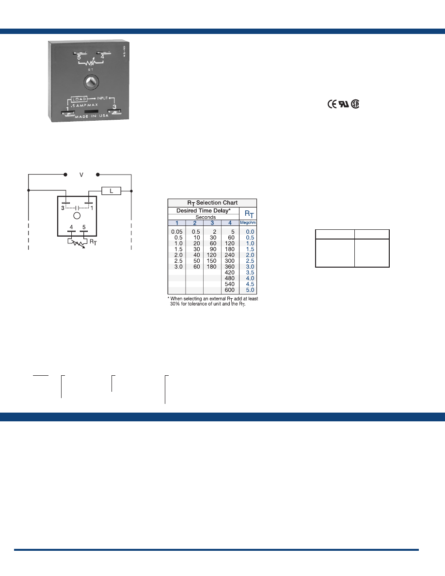
96
www.ssac.com • 800-843-8848 • fax: 605-348-5685
Features
• UL approved for air conditioning &
refrigeration equipment
• Fixed or adjustable delays from 0.05 - 600s
• 24 to 230VAC
• Fail-safe design eliminates contactor chatter
problems
• ±2% repeat accuracy
Approvals:
TAC1 Series
Timer - Delay-on-Make
Available Models:
Time Delay
Type . . . . . . . . . . . . . . . . . . . . . . . . . . . . . . . . . . . Analog circuitry
Range . . . . . . . . . . . . . . . . . . . . . . . . . . . . . . . . . .
0.05 - 600s in 4 adjustable ranges or fixed
Repeat Accuracy . . . . . . . . . . . . . . . . . . . . . . . .
±2%
Tolerance (Factory Calibration) . . . . . . . . . . . .
±20%
Recycle Time . . . . . . . . . . . . . . . . . . . . . . . . . . . .
≤ 20ms after timing, during timing - 0.1%
of time delay or 75ms, whichever is greater
Time Delay vs Temp. & Voltage
. . . . . . . . . . .
≤ ±10%
Input
Voltage
. . . . . . . . . . . . . . . . . . . . . . . . . . . . . . . . .
24, 120, or 230VAC
Tolerance . . . . . . . . . . . . . . . . . . . . . . . . . . . . . . .
±20%
AC Line Frequency . . . . . . . . . . . . . . . . . . . . . .
50/60 Hz
Output
Type . . . . . . . . . . . . . . . . . . . . . . . . . . . . . . . . . . . Solid state
Form . . . . . . . . . . . . . . . . . . . . . . . . . . . . . . . . . . .
NO, open during timing
Rating . . . . . . . . . . . . . . . . . . . . . . . . . . . . . . . . .
0.5A steady state, 10A inrush at 60°C
Voltage Drop
. . . . . . . . . . . . . . . . . . . . . . . . . . .
120 & 230VAC:
≅
4.2V @ 0.5A
24VAC:
≅
2.5V @ 0.5A
Protection
Circuitry . . . . . . . . . . . . . . . . . . . . . . . . . . . . . . . Encapsulated
Dielectric Breakdown
. . . . . . . . . . . . . . . . . . . .
≥ 2000V RMS terminals to mounting surface
Insulation Resistance . . . . . . . . . . . . . . . . . . . . .
≥ 100 MΩ
Mechanical
Mounting . . . . . . . . . . . . . . . . . . . . . . . . . . . . . .
Surface mount with one #10 (M5 x 0.8) screw
Dimensions . . . . . . . . . . . . . . . . . . . . . . . . . . . . .
2 x 2 x 1.21 in. (50.8 x 50.8 x 30.7 mm)
Termination . . . . . . . . . . . . . . . . . . . . . . . . . . . .
0.25 in. (6.35 mm) male quick connect terminals
Environmental
Operating / Storage Temperature
. . . . . . . . .
-40° to 80°C / -40° to 85°C
Humidity . . . . . . . . . . . . . . . . . . . . . . . . . . . . . . .
95% relative, non-condensing
Weight
. . . . . . . . . . . . . . . . . . . . . . . . . . . . . . . . .
≅
2.4 oz (68 g)
Specifications
Order Table:
Connection:
The TAC1 Series was designed to delay the
operation of a compressor relay. It eliminates the
possibility of relay chatter due to half-wave failure
of the output. It connects in series with the load
relay coil and provides a delay-on-make time delay
each time input voltage is applied. It can be used
for random start, anti-short cycling, sequencing,
and many other applications. It is an excellent
choice for all air conditioning and refrigeration
equipment .
Operation (Delay-on-Make):
Upon application of input voltage, the time delay begins.
The output is de-energized before and during the time
delay. At the end of the time delay, the output energizes
and remains energized until input voltage is removed.
Reset: Removing input voltage resets the time delay
and output .
For more information see:
Appendix A, pages 156-164 for function descriptions
and diagrams .
Appendix B, page 165, Figure 1 for dimensional drawing.
TAC1223
TAC1411
TAC141150
TAC1412
TAC1413
TAC14164
Auxiliary Products:
•
External ad just potentiometer:
P/N: P1004-XX
P/N: P1004-XX-X
•
Female quick connect:
P/N: P1015-64 (AWG 14/16)
•
Mounting bracket:
P/N: P1023-6
•
Quick connect t o s crew ad aptor:
P/N: P1015-18
•
Versa-knob:
P/N: P0700-7
•
DIN rail:
P/N: C103PM
(Al)
•
DIN rail adaptor:
P/N: P1023-20
•
Plug-on adjustment module:
P/N: VTP(X)(X)
TAC1
X
Input Voltage
─
2
- 24VAC
─
4
- 120VAC
─
6
- 230VAC
X
Adjustment
─
1
- Fixed
─
2
- External adjust
X
Time Delay*
─
1
- 0.05 - 3s
─
2
- 0.5 - 60s
─
3
- 2 - 180s
─
4
- 5 - 600s
*If fixed delay is selected, insert
delay (
0 .05 - 600
) in seconds .
L1
N/L2
Time Delay
VTP P/N
1
- 0.05-3s
2
- 0.5-60s
3
- 2-180s
4
- 5-600s
VTP4B
VTP4F
VTP4J
VTP5N
Selection Table for VTP Plug-on
Adjustment Accessory.
If desired part number is not listed, please call us to
see if it is technically possible to build .
Load may be connected to terminals 3 or 1.
R
T
is used when external adjustment is ordered.
Courtesy of Steven Engineering, Inc.-230 Ryan Way, South San Francisco, CA 94080-6370-Main Office: (650) 588-9200-Outside Local Area: (800) 258-9200-www.stevenengineering.com
Littelfuse-catalog-html.html
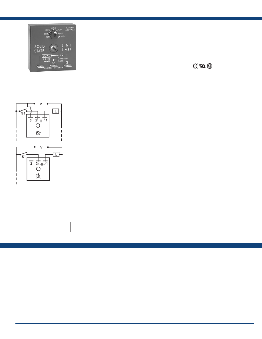
97
www.ssac.com • 800-843-8848 • fax: 605-348-5685
T2D Series
Timer - Lockout
Available Models:
Input
Voltage
. . . . . . . . . . . . . . . . . . . . . . . . . . . . . . . . .
24VAC, or 120/230VAC in 2 ranges
Tolerance . . . . . . . . . . . . . . . . . . . . . . . . . . . . . . .
±20%
AC Line Frequency . . . . . . . . . . . . . . . . . . . . . .
50/60 Hz
Output
Minimum Load Current . . . . . . . . . . . . . . . . . .
24VAC - 100mA; 120/230VAC - 40mA
Rating . . . . . . . . . . . . . . . . . . . . . . . . . . . . . . . . .
1A steady state, 10A inrush at 60°C
Voltage Drop
. . . . . . . . . . . . . . . . . . . . . . . . . . .
≅
2.5V @ 1A
Time Delay
Initiate Time . . . . . . . . . . . . . . . . . . . . . . . . . . . .
After timing - 16ms
Type . . . . . . . . . . . . . . . . . . . . . . . . . . . . . . . . . . .Analog circuitry
Lockout & Random Start Delays
. . . . . . . . . . .
1s - 100m in 4 adjustable ranges or fixed
Note: The lockout & random start delays
are the same length.
Tolerance . . . . . . . . . . . . . . . . . . . . . . . . . . . . . . .
Adjustable: ±30%; factory fixed: ±30%
Repeat Accuracy . . . . . . . . . . . . . . . . . . . . . . . .
±1% or 20ms, whichever is greater
Reset Time . . . . . . . . . . . . . . . . . . . . . . . . . . . . . .
After timing - ≤ 16ms;
During timing - ≤ 200ms
Protection
Dielectric Breakdown
. . . . . . . . . . . . . . . . . . . .
≥ 2000V RMS terminals to mounting surface
Insulation Resistance . . . . . . . . . . . . . . . . . . . . .
≥ 100 MΩ
Mechanical
Mounting . . . . . . . . . . . . . . . . . . . . . . . . . . . . . .
Surface mount with one #10 (M5 x 0.8) screw
Dimensions . . . . . . . . . . . . . . . . . . . . . . . . . . . . .
2 x 2 x 1.21 in. (50.8 x 50.8 x 30.7 mm)
Termination . . . . . . . . . . . . . . . . . . . . . . . . . . . .
0.25 in. (6.35 mm) male quick connect terminals
Environmental
Operating / Storage Temperature
. . . . . . . . .
-20° to 60°C / -40° to 85°C
Humidity . . . . . . . . . . . . . . . . . . . . . . . . . . . . . . .
95% relative, non-condensing
Weight
. . . . . . . . . . . . . . . . . . . . . . . . . . . . . . . . .
≅
2.4 oz (68 g)
Cooling Anticipator (24VAC Units Only)
Minimum Cooling Anticipator . . . . . . . . . . . .
≥ 3,000 Ω
Order Table:
Specifications
The T2D Series provides protection against short
cycling of compressors and other motors. At the
end of each operation, a lockout delay prevents
restarting the compressor or motor until the delay
is completed. 24VAC models can be used with
thermostats that include a cooling anticipator
resistor. It can be connected in series with the load
for delay-on-make operation.
Operation (Lockout with Random Start):
Connection #1: Upon application of input voltage, a
random start time delay begins. At the end of this time
delay, the output is energized. Lockout Delay: Input
voltage must be applied prior to and during timing.
When the thermostat or initiate switch opens, the output
de-energizes and the lockout time delay begins. At the
end of the lockout delay, the output is energized allowing
the load to immediately energize when the initiate switch
or thermostat closes.
Connection #2: Upon application of input voltage and
closure of initiate switch, the time delay begins. At the
end of the time delay, the output is energized and remains
energized until power is removed.
Reset: Removing power resets the output and the time
delay .
For more information see:
Appendix A, pages 156-164 for function descriptions
and diagrams .
Appendix B, page 165, Figure 1 for dimensional drawing.
Features:
• Lockout delay prevents rapid recycling of
compressor
• Random start delay helps prevent low
voltage starting
• Delay-on-make timer optional two terminal
series connection
• Totally solid-state 1A output
• 24VAC to 230VAC in 2 ranges
Approvals:
Connection:
T2D120A1150S
T2D120A15M
Auxiliary Products:
•
Female quick connect:
P/N: P1015-64 (AWG 14/16)
•
Mounting bracket:
P/N: P1023-6
•
Quick connect t o s crew ad aptor:
P/N: P1015-18
•
DIN rail:
P/N: C103PM
(Al)
•
DIN rail adaptor:
P/N: P1023-20
T2D
X
Input Voltage
─
24A
- 24VAC
─
120A
- 120/230VAC
X
Adjustment
─
1
- Fixed
─
2
- External adjust
X
Time Delay*
─
1
- 1 - 100s
─
2
- 10 - 1000s
─
3
- 0.1 - 10m
─
4
- 1 - 100m
*If fixed delay is selected, insert
delay (
1 - 1000
) followed by (
S
) sec .
or (
0 .1 - 100
) (
M
) min .
L1
N/L2
L1
N/L2
V = Voltage
L = Load
S1 = Initiate Switch or Thermostat
1
Random Start
Plus Lockout
2
Delay-on-Make
If desired part number is not listed, please call us to
see if it is technically possible to build .
Courtesy of Steven Engineering, Inc.-230 Ryan Way, South San Francisco, CA 94080-6370-Main Office: (650) 588-9200-Outside Local Area: (800) 258-9200-www.stevenengineering.com
Littelfuse-catalog-html.html
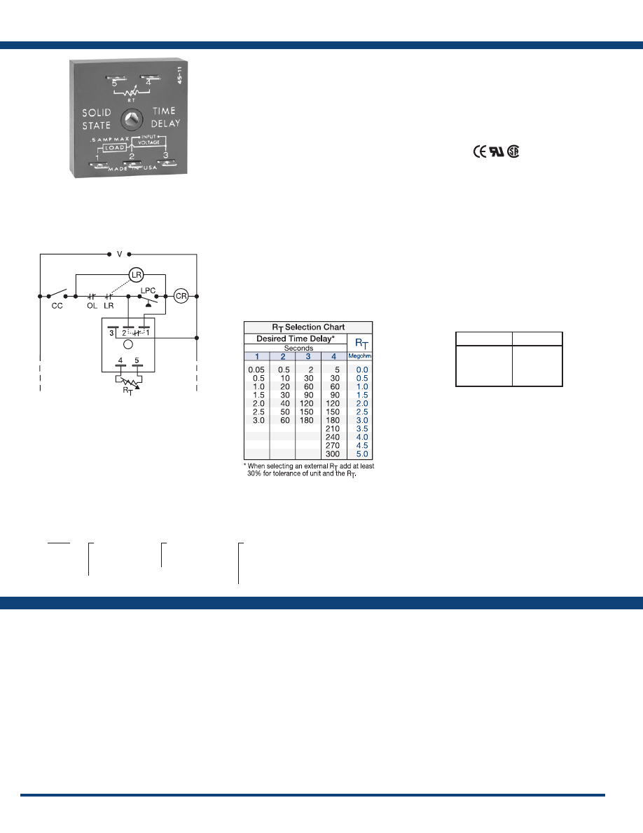
98
www.ssac.com • 800-843-8848 • fax: 605-348-5685
Features
• UL approved for air conditioning &
refrigeration equipment
• Fixed or adjustable delays from 0.05 - 600s
• 24, 120 or 230VAC
• Fail-safe design eliminates contactor chatter
problems
• ±2% repeat accuracy
Approvals:
TAC4 Series
Timer - Bypass
Available Models:
Time Delay
Type . . . . . . . . . . . . . . . . . . . . . . . . . . . . . . . . . . . Analog circuitry
Range . . . . . . . . . . . . . . . . . . . . . . . . . . . . . . . . . .
0.05 - 300s in 4 adjustable ranges or fixed
Repeat Accuracy . . . . . . . . . . . . . . . . . . . . . . . .
±2%
Tolerance (Factory Calibration) . . . . . . . . . . . .
±20%
Time Delay vs Temp. & Voltage
. . . . . . . . . . .
≤±10%
Reset Time . . . . . . . . . . . . . . . . . . . . . . . . . . . . . .
≤ 150ms
Input
Voltage
. . . . . . . . . . . . . . . . . . . . . . . . . . . . . . . . .
24, 120, or 230VAC
Tolerance . . . . . . . . . . . . . . . . . . . . . . . . . . . . . . .
±20%
AC Line Frequency . . . . . . . . . . . . . . . . . . . . . .
50/60 Hz
Output
Type . . . . . . . . . . . . . . . . . . . . . . . . . . . . . . . . . . . Solid state
Form . . . . . . . . . . . . . . . . . . . . . . . . . . . . . . . . . . .
NC, closed during timing
Rating . . . . . . . . . . . . . . . . . . . . . . . . . . . . . . . . .
0.5A steady state, 10A inrush at 60°C
Voltage Drop
. . . . . . . . . . . . . . . . . . . . . . . . . . .
120 & 230VAC
≅
4.2V @ 0.5A
24VAC
≅
2.5V @ 0.5A
Protection
Circuitry . . . . . . . . . . . . . . . . . . . . . . . . . . . . . . . Encapsulated
Dielectric Breakdown
. . . . . . . . . . . . . . . . . . . .
≥ 2000V RMS terminals to mounting surface
Insulation Resistance . . . . . . . . . . . . . . . . . . . . .
≥ 100 MΩ
Mechanical
Mounting . . . . . . . . . . . . . . . . . . . . . . . . . . . . . .
Surface mount with one #10 (M5 x 0.8) screw
Termination . . . . . . . . . . . . . . . . . . . . . . . . . . . .
0.25 in. (6.35 mm) male quick connect terminals
Dimensions . . . . . . . . . . . . . . . . . . . . . . . . . . . . .
2 x 2 x 1.21 in. (50.8 x 50.8 x 30.7 mm)
Environmental
Operating / Storage Temperature
. . . . . . . . .
-40° to 75°C / -40° to 85°C
Humidity . . . . . . . . . . . . . . . . . . . . . . . . . . . . . . .
95% relative, non-condensing
Weight
. . . . . . . . . . . . . . . . . . . . . . . . . . . . . . . . .
≅
2.4 oz (68 g)
Specifications
Order Table:
Connection:
The TAC4 is a bypass timer that provides a closure
across the low-pressure switch during compressor
startup. Its time-delay circuit is totally solid
state including the normally closed output. The
molded housing with encapsulation, the single
hole mounting, and 0.25 in. (6.35 mm) termination
makes the TAC4 easy to use, rugged, and reliable.
Operation (Bypass Timer):
(As shown in the connection & function diagrams) Upon
application of input voltage and closure of controller
contact, CC, the load, CR, energizes and the time delay
begins. During the time delay, the TAC4’s solid-state
output bypasses the LPC, low pressure cutout switch.
This allows the compressor controlled by CR to start and
establish acceptable pressure. At the end of the time delay,
TAC4’s output de-energizes and remains de-energized
until reset. The TAC4 may be used in other applications
where a controlling contact must be bypassed for a
specified period of time.
Reset: Removing input voltage or opening CC resets the
output and time delay .
For more information see:
Appendix A, pages 156-164 for function descriptions
and diagrams .
Appendix B, page 165, Figure 1 for dimensional drawing.
TAC42110
TAC441120
TAC4415
Auxiliary Products:
•
External ad just potentiometer:
P/N: P1004-12
P/N: P1004-12-X
•
Female quick connect:
P/N: P1015-64 (AWG 14/16)
•
Mounting bracket:
P/N: P1023-6
•
Quick connect t o s crew ad aptor:
P/N: P1015-18
•
Versa-knob:
P/N: P0700-7
•
DIN rail:
P/N: C103PM
(Al)
•
DIN rail adaptor:
P/N: P1023-20
•
Plug-on adjustment module:
P/N: VTP(X)(X)
TAC4
X
Input Voltage
─
2
- 24VAC
─
4
- 120VAC
─
6
- 230VAC
X
Adjustment
─
1
- Fixed
─
2
- External adjust
X
Time Delay*
─
1
- 0.05 - 3s
─
2
- 0.5 - 60s
─
3
- 2 - 180s
─
4
- 5 - 300s
*If fixed delay is selected, insert
delay (
0 .05 - 300
) in seconds .
L1
N/L2
V = Voltage
LR = Lockout Relay
OL = Overload or High Pressure Switch
LPC = Low Pressure Cutout
CR = Compressor Control Relay
CC = Controller Contact
Time Delay
VTP P/N
1
- 0.05-3s
2
- 0.5-60s
3
- 2-180s
4
- 5-300s
VTP4B
VTP4F
VTP4J
VTP5T
Selection Table for VTP Plug-on
Adjustment Accessory.
If desired part number is not listed, please call us to
see if it is technically possible to build .
R
T
is used when external adjustment is ordered.
Courtesy of Steven Engineering, Inc.-230 Ryan Way, South San Francisco, CA 94080-6370-Main Office: (650) 588-9200-Outside Local Area: (800) 258-9200-www.stevenengineering.com
Littelfuse-catalog-html.html
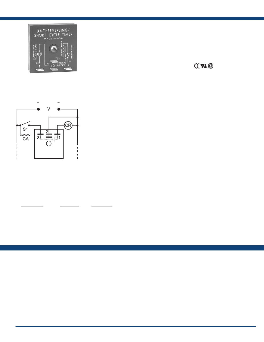
99
www.ssac.com • 800-843-8848 • fax: 605-348-5685
TA Series
Timer - Lockout
Available Models:
Input
Voltage
. . . . . . . . . . . . . . . . . . . . . . . . . . . . . .
12 or 24VDC; 24VAC
AC Line Frequency . . . . . . . . . . . . . . . . . . .
50/60 Hz
Impedance . . . . . . . . . . . . . . . . . . . . . . . . . . .
450 Ω (anticipator by-pass)
Output
Minimum Load Current . . . . . . . . . . . . . . .
75mA
Maximum Load Current
. . . . . . . . . . . . . . .
1A at 60°C
Voltage Drop
. . . . . . . . . . . . . . . . . . . . . . . .
≤ 1.25V
Time Delay
Initiate Time . . . . . . . . . . . . . . . . . . . . . . . . .
≅
16ms
Lockout Time
. . . . . . . . . . . . . . . . . . . . . . . .
Fixed 0.5, 1, 2, 3, or 5m
Tolerance . . . . . . . . . . . . . . . . . . . . . . . . . . . .
-15% - 35%
Protection
Circuitry . . . . . . . . . . . . . . . . . . . . . . . . . . . . Encapsulated
Low Voltage Protection
. . . . . . . . . . . . . . .
≅
20V: 24VAC/DC;
≅
9V: 12VDC
Dielectric Breakdown
. . . . . . . . . . . . . . . . .
≥ 2000V RMS terminals to mounting surface
Insulation Resistance . . . . . . . . . . . . . . . . . .
≥ 100 MΩ
Mechanical
Mounting . . . . . . . . . . . . . . . . . . . . . . . . . . .
Surface mount with one #10 (M5 x 0.8) screw
Dimensions . . . . . . . . . . . . . . . . . . . . . . . . . .
2 x 2 x 1.21 in. (50.8 x 50.8 x 30.7 mm)
Termination . . . . . . . . . . . . . . . . . . . . . . . . .
0.25 in. (6.35 mm) male quick connect terminals
Environmental
Operating / Storage Temperature
. . . . . .
-40° to 70°C / -40° to 85°C
Humidity . . . . . . . . . . . . . . . . . . . . . . . . . . . .
95% relative, non-condensing
Weight
. . . . . . . . . . . . . . . . . . . . . . . . . . . . . .
≅
2.4 oz (68 g)
Thermostat
Cooling Anticipator Resistor . . . . . . . . . . .
≥ 1800 Ω
Order Table:
Specifications
The TA Series prevents rapid recycling of a
compressor. A lockout delay is started when
the thermostat opens, or input voltage is lost.
Eliminates tripped circuit breakers or blown fuses
caused by a locked rotor during short cycling. The
TA will not allow the compressor to start when
the line voltage is low. Chatter of the compressor
relay is eliminated. Because of the fast initiate time,
bounce of the thermostat will not be transmitted
to the compressor relay coil. A 30 second delay
provides anti-reversing protection for scroll
compressors .
Operation (Lockout):
On initial closure of the S1, the compressor relay
energizes immediately. When S1 opens or input voltage
is interrupted, a lockout time delay is initiated. During
this lockout time delay, the compressor relay cannot
be energized. The low voltage (brownout) protection
prevents energization of the compressor when the line
voltage is low.
Reset:
The lockout time delay cannot be reset. After the
time delay is completed, the unit automatically resets.
For more information see:
Appendix A, pages 156-164 for function descriptions
and diagrams .
Appendix B, page 165, Figure 1 for dimensional drawing.
Features:
• Ideal for HVAC/R applications
• Lockout delay prevents rapid recycling of a
compressor
• Low voltage brownout protection
• Circuitry to activate the cooling anticipator
(24VAC models)
• Eliminates nuisance service calls due to
blown fuse or tripped breakers
Approvals:
Connection:
TA12D2
TA24A0.5
TA24A3
TA24A5
TA24D0.5
TA24D2
Auxiliary Products:
•
Female quick connect:
P/N: P1015-64 (AWG 14/16)
•
Mounting bracket:
P/N: P1023-6
•
Quick connect t o s crew ad aptor:
P/N: P1015-18
•
DIN rail:
P/N: C103PM
(Al)
•
DIN rail adaptor:
P/N: P1023-20
Input Voltage
24VAC
24VAC
24VAC
24VAC
12VDC
12VDC
24VDC
24VDC
24VDC
24VDC
Time Delay
30s
2m
3m
5m
1m
2m
30s
2m
3m
5m
Part Number
TA24A0.5
TA24A2
TA24A3
TA24A5
TA12D1
TA12D2
TA24D0.5
TA24D2
TA24D3
TA24D5
L1
N
S1 = Initiate Switch, Contact, or Thermostat
CR = Compressor Relay (Load)
CA = Optional Cooling Anticipator
V = Voltage
If desired part number is not listed, please call us to
see if it is technically possible to build .
Courtesy of Steven Engineering, Inc.-230 Ryan Way, South San Francisco, CA 94080-6370-Main Office: (650) 588-9200-Outside Local Area: (800) 258-9200-www.stevenengineering.com
Littelfuse-catalog-html.html
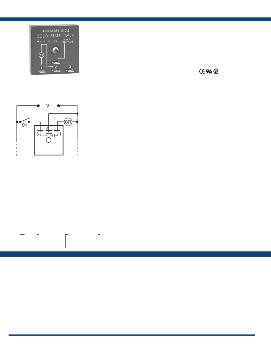
100
www.ssac.com • 800-843-8848 • fax: 605-348-5685
Features
• Ideal for HVAC/R applications
• Lockout delay prevents short cycling of a
compressor
• Optional 1s delay-on-make prevents
contactor chatter
•
Totally solid state and encapsulated
• 24VAC to 230VAC in 3 ranges
• Eliminates nuisance service calls due to
blown fuse or tripped breakers
Approvals:
TL Series
Timer - Lockout
Available Models:
Input
Voltage
. . . . . . . . . . . . . . . . . . . . . . . . . . .
24, 120, or 230VAC
AC Line Frequency . . . . . . . . . . . . . . . .
50/60 Hz
Tolerance . . . . . . . . . . . . . . . . . . . . . . . . .
±20%
Output
Minimum Load Current . . . . . . . . . . . .
≤ 40mA
Maximum Load Current
. . . . . . . . . . . .
1A @ 24VAC; 0.5A @ 120 & 230VAC at 60°C
Inrush Current
. . . . . . . . . . . . . . . . . . . .
10A at 60°C
Voltage Drop
. . . . . . . . . . . . . . . . . . . . .
24VAC - 2.5V @ 1A
120 & 230VAC - 4.2V @ 0.5A
Time Delay
Initiate Time . . . . . . . . . . . . . . . . . . . . . .
≅
8ms
Lockout Time*
. . . . . . . . . . . . . . . . . . . .
Fixed 2, 3, or 5m
Tolerance . . . . . . . . . . . . . . . . . . . . . . . . .
-15% - 35%
Option . . . . . . . . . . . . . . . . . . . . . . . . . . .
1s delay-on-make eliminates contactor chatter
due to thermostat bounce
Protection
Circuitry . . . . . . . . . . . . . . . . . . . . . . . . . Encapsulated
Dielectric Breakdown
. . . . . . . . . . . . . .
≥ 2000V RMS terminals to mounting surface
Insulation Resistance . . . . . . . . . . . . . . .
≥ 100 MΩ
Mechanical
Mounting . . . . . . . . . . . . . . . . . . . . . . . .
Surface mount with one #10 (M5 x 0.8) screw
Dimensions . . . . . . . . . . . . . . . . . . . . . . .
2 x 2 x 1.21 in. (50.8 x 50.8 x 30.7 mm)
Termination . . . . . . . . . . . . . . . . . . . . . .
0.25 in. (6.35 mm) male quick connect terminals
Environmental
Operating / Storage Temperature
. . .
-40° to 70°C / -40° to 85°C
Humidity . . . . . . . . . . . . . . . . . . . . . . . . .
95% relative, non-condensing
Weight
. . . . . . . . . . . . . . . . . . . . . . . . . . .
≅
2.4 oz (68 g)
*Power must be applied for at least 15 s to achieve a full lockout delay. Less than 15s will
result in proportionally shorter delay periods.
NOTE: Cooling anticipator resistor or leakage may cause erratic operation. See TA Series
for use with 24VAC systems that include anticipator resistors or use solid-state switches.
Specifications
Order Table:
Connection:
The TL Series provides protection against short
cycling of a compressor. At the end of each
operation, or whenever power is lost, a lockout
delay is initiated. This lockout delay prevents
restarting of the compressor until the head
pressure has equalized. Compressor relay chatter
due to thermostat bounce is eliminated by use
of optional one second delay-on-make. The TL
Series should not be used with cooling anticipator
resistors or solid-state switches. (See the TA
Series) .
Operation (Lockout):
Lockout: On initial closure of S1, the compressor relay
energizes immediately (or after an optional 1 s delay).
When the S1 opens or input voltage is interrupted, the
output opens and remains open for the lockout time delay.
During this lockout time delay period, the compressor
relay cannot be re-energized.
Reset: The lockout time delay cannot be reset. After the
time delay is completed, the unit automatically resets.
For more information see:
Appendix A, pages 156-164 for function descriptions
and diagrams .
Appendix B, page 165, Figure 1 for dimensional drawing.
TL120A5T
TL230A5
TL230A5T
TL24A5
Auxiliary Products:
•
Female quick connect:
P/N: P1015-64 (AWG 14/16)
•
Mounting bracket:
P/N: P1023-6
•
Quick connect t o s crew ad aptor:
P/N: P1015-18
•
DIN rail:
P/N: C103PM
(Al)
•
DIN rail adaptor:
P/N: P1023-20
TL
X
Input Voltage
─
24A
- 24VAC
─
120A
- 120VAC
─
230A
- 230VAC
X
Lockout Time
─
2
- 2m
─
3
- 3m
─
5
- 5m
X
Delay-on-Make
─
Blank
- No delay
─
T
- 1s
L1
N/L2
V = Voltage
S1 = Initiate Switch
CR = Compressor or Control Relay
If desired part number is not listed, please call us to
see if it is technically possible to build .
Courtesy of Steven Engineering, Inc.-230 Ryan Way, South San Francisco, CA 94080-6370-Main Office: (650) 588-9200-Outside Local Area: (800) 258-9200-www.stevenengineering.com
Littelfuse-catalog-html.html
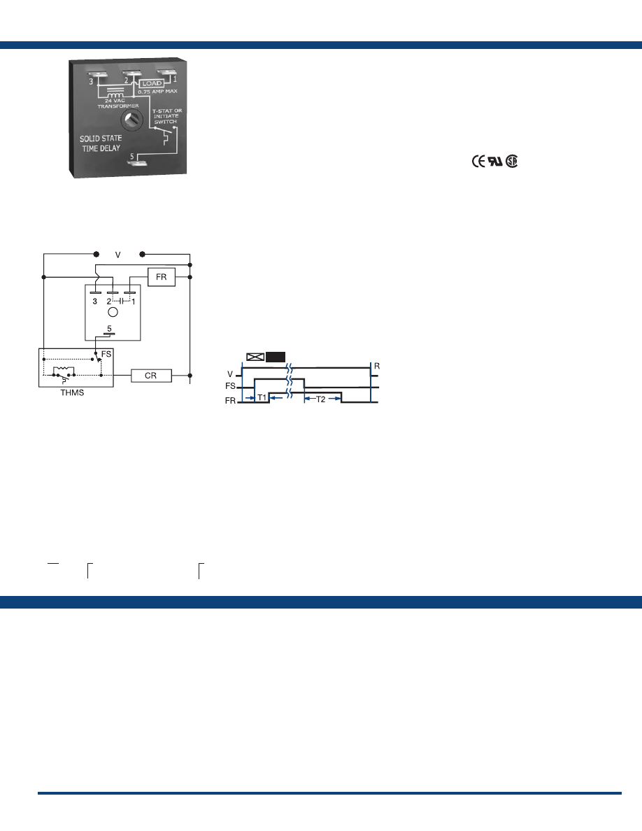
101
www.ssac.com • 800-843-8848 • fax: 605-348-5685
CT Series
Timer - Delay-on-Make/Delay-on-Break
Available Models:
Time Delay
Type . . . . . . . . . . . . . . . . . . . . . . . . . . . . . . . . . . .Microcontroller
Range . . . . . . . . . . . . . . . . . . . . . . . . . . . . . . . . . .
1 - 600s
Repeat Accuracy . . . . . . . . . . . . . . . . . . . . . . . .
±5%
Tolerance (Factory Calibration) . . . . . . . . . . . .
±20%
Recycle Time . . . . . . . . . . . . . . . . . . . . . . . . . . .
≤ 300ms
Input
Voltage
. . . . . . . . . . . . . . . . . . . . . . . . . . . . . . . . .
24VAC
Tolerance . . . . . . . . . . . . . . . . . . . . . . . . . . . . . . .
±15%
AC Line Frequency . . . . . . . . . . . . . . . . . . . . . .
50/60 Hz
Output
Type . . . . . . . . . . . . . . . . . . . . . . . . . . . . . . . . . . .Solid state
Form . . . . . . . . . . . . . . . . . . . . . . . . . . . . . . . . . . .NO
Rating . . . . . . . . . . . . . . . . . . . . . . . . . . . . . . . . .
0.75A steady state, 5A inrush at 55°C
Voltage Drop
. . . . . . . . . . . . . . . . . . . . . . . . . . .
≅
1.25V
Protection
Circuitry . . . . . . . . . . . . . . . . . . . . . . . . . . . . . . .Encapsulated
Dielectric Breakdown
. . . . . . . . . . . . . . . . . . . .
≥ 2000V RMS terminals to mounting surface
Insulation Resistance . . . . . . . . . . . . . . . . . . . . .
≥ 100 MΩ
Mechanical
Mounting . . . . . . . . . . . . . . . . . . . . . . . . . . . . . .
Surface mount with one #10 (M5 x 0.8) screw
Dimensions . . . . . . . . . . . . . . . . . . . . . . . . . . . . .
2 x 2 x 1.21 in. (50.8 x 50.8 x 30.7 mm)
Termination . . . . . . . . . . . . . . . . . . . . . . . . . . . .
0.25 in. (6.35 mm) male quick connect terminals
Environmental
Operating / Storage Temperature
. . . . . . . . .
-40° to 70°C / -40° to 85°C
Humidity . . . . . . . . . . . . . . . . . . . . . . . . . . . . . . .
95% relative, non-condensing
Weight
. . . . . . . . . . . . . . . . . . . . . . . . . . . . . . . . .
≅
2.4 oz (68 g)
Thermostat
. . . . . . . . . . . . . . . . . . . . . . . . . . . . .
Anticipator Resistor: ≥ 3000 Ω
Order Table:
Specifications
The CT Series combines a delay-on-make and
delay-on-break time delay into one unit and
may be used to control fan delays in heating
and/or cooling equipment. The CT includes
bypass circuitry to allow it to operate with cooling
anticipators ≥ 3000 ohms. It is designed to operate
in 24VAC control circuits. Several CT modules
may be combined to provide sequencing on of any
number of loads and sequencing off of the same
loads, such as electric heating elements.
Operation (Delay-on-Make/Delay-on-Break):
Forced Air Heating or Air Conditioning (as shown): When
the thermostat closes, the compressor relay is immediately
energized. At the end of a fixed delay-on-make delay (T1),
the fan relay is energized. When the thermostat opens,
the compressor relay is de-energized and the delay-
on-break delay is initiated. On completion of the fixed
delay-on- break delay (T2) the fan relay is de-energized.
If the thermostat is reclosed during the delay-on-break
delay, the delay-on-break delay is reset and the fan relay
remains energized. If the thermostat is closed when
input voltage is applied, the delay-on-make delay (T1)
begins as normal .
Reset: Removing input voltage resets the output and
time delays .
For more information see:
Appendix B, page 165, Figure 1 for dimensional drawing.
Features:
• Delay-on-make and delay-on-break in one
unit
• Use for fan delays in heating or cooling
equipment
• Use for multiple load sequencing
• 24VAC operation
• Factory fixed delays from 1 - 600s in 1s
increments
Approvals:
Connection:
CT1S12
CT1S30
CT1S300
CT1S45
CT1S8
CT1S90
CT30S1
CT45S45
CT5S300
Auxiliary Products:
•
Female quick connect:
P/N: P1015-64 (AWG 14/16)
•
Mounting bracket:
P/N: P1023-6
•
Quick connect t o s crew ad aptor:
P/N: P1015-18
•
DIN rail:
P/N: C103PM
(Al)
•
DIN rail adaptor:
P/N: P1023-20
CT
X
Delay-on-Make (fixed)
─Specify time in seconds
from
1 - 600
s followed by (S)
X
Delay-on-Break (fixed)
─Specify time in seconds
from
1 - 600
s
L1
N
CR = Compressor Relay
THMS = Wall Thermostat
Function:
If desired part number is not listed, please call us to
see if it is technically possible to build .
Delay-on-Make
Delay-on-Break
V = Voltage
R = Reset
FS = Fan Switch
FR = Fan Relay
T1 = Delay-on-Make
T2 = Delay-on-Break
Courtesy of Steven Engineering, Inc.-230 Ryan Way, South San Francisco, CA 94080-6370-Main Office: (650) 588-9200-Outside Local Area: (800) 258-9200-www.stevenengineering.com
Littelfuse-catalog-html.html
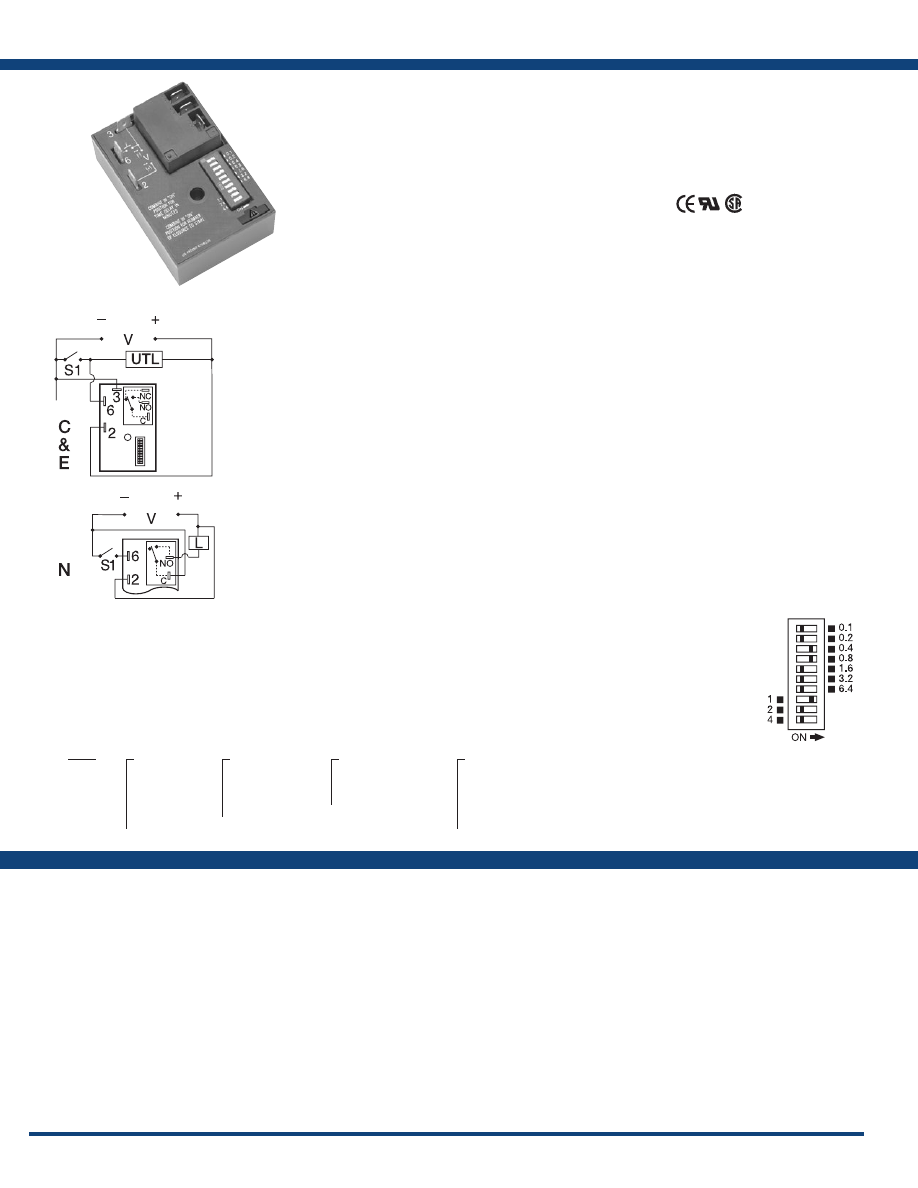
102
www.ssac.com • 800-843-8848 • fax: 605-348-5685
Features
• Accumulates 1 - 256 coins
• Switch selectable 1 - 7 coins to start
• Vend time from 1s - 31.75m
• Coin switch can be connected to a counter
• Up to 30A, 1 Hp at 125VAC, NO contacts
•
Encapsulated circuitry
Approvals:
HRV Series
Timer - Vending
Available Models:
Count Functions/Switch Type
. . . . . . . . . . . . . . .
Mechanical (counts on switch closure)
Minimum Switch Closure Time
. . . . . . . . . . . . . .
≥ 20ms
Min. Switch Open (between closures) Time
. . . .
≥ 20ms
Count Range to start . . . . . . . . . . . . . . . . . . . . . . . .
1 - 7 counts
Maximum Counts (“A” Version)
. . . . . . . . . . . . .
250
Time Delay/Range
*** . . . . . . . . . . . . . . . . . . . . . .
Adjustable 1s - 31.75m in 4 ranges
Adjustment
. . . . . . . . . . . . . . . . . . . . . . . . . . . . . . . .
7 of a 10 position DIP switch
Setting Accuracy . . . . . . . . . . . . . . . . . . . . . . . . . . .
0% to +2% or 50ms, whichever is greater
Repeat Accuracy . . . . . . . . . . . . . . . . . . . . . . . . . . .
±0.1% or 20ms, whichever is greater
Reset Time . . . . . . . . . . . . . . . . . . . . . . . . . . . . . . . . .
≤ 150ms
Time Delay vs Temp. & Voltage
. . . . . . . . . . . . . .
≤ ±2%
Input
Voltage
. . . . . . . . . . . . . . . . . . . . . . . . . . . . . . . . . . . .
12 or 24VDC; 24, 120, or 230VAC
Tolerance 12VDC & 24VDC/AC
. . . . .
-15% - 20%
120 & 230 VAC
. . . . .
-20% - 10%
AC Line Frequency / DC Ripple
. . . . . . . . . . . . . .
50/60 Hz / ≤ 10%
Power Consumption . . . . . . . . . . . . . . . . . . . . . . . .
AC ≤ 4VA; DC ≤ 2W
Output
Type . . . . . . . . . . . . . . . . . . . . . . . . . . . . . . . . . . . . . .
Electromechanical relay
Form . . . . . . . . . . . . . . . . . . . . . . . . . . . . . . . . . . . . . .I
solated, SPDT or non-isolated, SPDT
Ratings: SPDT-NO SPDT-NC
General Purpose 125/240VAC 30A 15A
Resistive 125/240VAC 30A 15A
28VDC 20A 10A
Motor Load 125VAC 1 hp* 1/4 hp**
240VAC 2 hp** 1 hp**
Life
. . . . . . . . . . . . . . . . . . . . . . . . . . . . . . . . . . . . . . .
Mechanical - 1 x 10
6;
Electrical - 1 x 10
5
, *3 x 10
4
, ** 6,000
Protection
Surge . . . . . . . . . . . . . . . . . . . . . . . . . . . . . . . . . . . . .
IEEE C62.41-1991 Level A
Circuitry . . . . . . . . . . . . . . . . . . . . . . . . . . . . . . . . . .Encapsulated
Dielectric Breakdown
. . . . . . . . . . . . . . . . . . . . . . .
≥ 1500V RMS input to output on isolated units
Insulation Resistance . . . . . . . . . . . . . . . . . . . . . . . .
≥ 100 MΩ
Mechanical
Mounting . . . . . . . . . . . . . . . . . . . . . . . . . . . . . . . . .
Surface mount with one #10 (M5 x 0.8) screw
Dimensions . . . . . . . . . . . . . . . . . . . . . . . . . . . . . . . .
3 x 2 x 1.5 in (76.7 x 51.3 x 38.1 mm)
Termination . . . . . . . . . . . . . . . . . . . . . . . . . . . . . . .
0.25 in. (6.35 mm) male quick connect terminals
Environmental
Operating / Storage Temperature
. . . . . . . . . . . .
-40° to 70°C / -40° to 85°C
Humidity . . . . . . . . . . . . . . . . . . . . . . . . . . . . . . . . . .
95% relative, non-condensing
Weight
. . . . . . . . . . . . . . . . . . . . . . . . . . . . . . . . . . . .
≅
3.9 oz (111 g)
***For CE approved applications, voltage must be removed when a switch position is changed.
Specifications
Order Table:
Connection:
The HRV combines the accuracy of microcontroller
based circuitry with an electromechanical relay
output. The HRV’s switching capacity allows
direct control of loads like compressors, pumps,
motors, heaters, and lighting. The HRV “S” version
provides a vend time after the selected number
of initiate switch closures to start is reached. The
HRV “A” version includes all of the “S” features
and allows the total vend time to be extended for
each additional initiate switch closure. The HRV is
ideal for cost sensitive single coin or token vending
machines. The electronic circuitry is encapsulated
to protect against humidity and vibration.
Operation
Coin Totalizer & Vending Timer (“S” Version):
Input voltage must be applied prior to & during operation.
When the total number of S1 initiate switch closures
equals the number to start set on the lower 3 DIP switches,
the load energizes and the vending time set on the upper
7 DIP switches begins. At the end of the vending time, the
load de-energizes and the vending time is reset. Closing
the initiate switch during vend timing will have no affect
on vend time delay.
Accumulating Vending Timer (“A” Version):
Input voltage must be applied prior to & during operation.
When the total number of S1 initiate switch closures
equals the number to start set on the lower 3 DIP switches,
the load energizes and the vending time starts. For every
initiate switch closure, the HRV unit adds one time per
coin period, as set on the upper 7 DIP switches, to the
total vending time.
Operation Note: If S1 is closed when input voltage is
applied, the output remains de-energized and the S1
counter remains at zero closures. At least one “vend
time” and one “closures to start” DIP switch must be in
the “ON” position for proper operation.
Reset: Removing input voltage resets the vend time delay,
the S1 closure counter, and de-energizes the output relay.
For more information see:
Appendix A, pages 156-164 for function descriptions
and diagrams .
Appendix B, page 165, Figure 2 for dimensional drawing.
HRV11SC
HRV24AC
HRV31AC
HRV31SC
HRV41AE
HRV41SC
HRV41SE
HRV42SE
HRV43AE
HRV43AN
Auxiliary Products:
•
Female quick connect:
P/N: P1015-13 (AWG 10/12)
P/N: P1015-64 (AWG 14/16)
•
Mounting bracket:
P/N: P1023-6
•
Quick connect t o s crew ad aptor:
P/N: P1015-18
•
DIN rail:
P/N: C103PM
(Al)
•
DIN rail adaptor:
P/N: P1023-20
HRV
X
Input Voltage
─
1
- 12VDC
─
2
- 24VAC
─
3
- 24VDC
─
4
- 120VAC
─
6
- 230VAC
X
Vend Time
─
1
- 1 - 127s
─
2
- 5 - 635s
─
3
- 0.1 - 12.7m
─
4
- 0.25 - 31.75m
X
Mode of Operation
─
S
- Coin totalizer
vending timer
─
A
- Accumulating
vending timer
X
Output Form & Rating
─
C
- 30A SPDT - NO
(Isolated)
─
E
- 30A SPDT - NO
(Isolated)
─
N
- 30A SPDT - NO
(Non-Isolated)
L1
N/L2
L1
N/L2
Combine upper seven switches
in “ON” position for vend time in
minutes .
Combine lower three switches
in “ON” position for number of
closures to start .
Switch Adjustment
V = Voltage
S1 = Initiate Switch
L = Load
UTL = Optional Untimed Load
Isolated
Output
Non-Isolated
Output
If desired part number is not listed, please call us to
see if it is technically possible to build .
Courtesy of Steven Engineering, Inc.-230 Ryan Way, South San Francisco, CA 94080-6370-Main Office: (650) 588-9200-Outside Local Area: (800) 258-9200-www.stevenengineering.com
Littelfuse-catalog-html.html

103
www.ssac.com • 800-843-8848 • fax: 605-348-5685
Flashers
Series Included
FSU1000
. . . . . . . . . . . . . . . . . . . . . . . . . . . . . . . . . . . . . . . . . .
104
FS126, FS127, FS146, FS147
. . . . . . . . . . . . . . . . . . . . . . . . . .
104
FS143, FS152, FS162
. . . . . . . . . . . . . . . . . . . . . . . . . . . . . . . .
105
FS200
. . . . . . . . . . . . . . . . . . . . . . . . . . . . . . . . . . . . . . . . . . . .
105
FS300
. . . . . . . . . . . . . . . . . . . . . . . . . . . . . . . . . . . . . . . . . . . .
106
FS400
. . . . . . . . . . . . . . . . . . . . . . . . . . . . . . . . . . . . . . . . . . . .
106
AF . . . . . . . . . . . . . . . . . . . . . . . . . . . . . . . . . . . . . . . . . . . . . . .
107
Solid State
Relay
Chasers
FS500
. . . . . . . . . . . . . . . . . . . . . . . . . . . . . . . . . . . . . . . . . . . .
107
SC3
. . . . . . . . . . . . . . . . . . . . . . . . . . . . . . . . . . . . . . . . . . . . . .
108
SC4
. . . . . . . . . . . . . . . . . . . . . . . . . . . . . . . . . . . . . . . . . . . . . .
108
Courtesy of Steven Engineering, Inc.-230 Ryan Way, South San Francisco, CA 94080-6370-Main Office: (650) 588-9200-Outside Local Area: (800) 258-9200-www.stevenengineering.com
Littelfuse-catalog-html.html
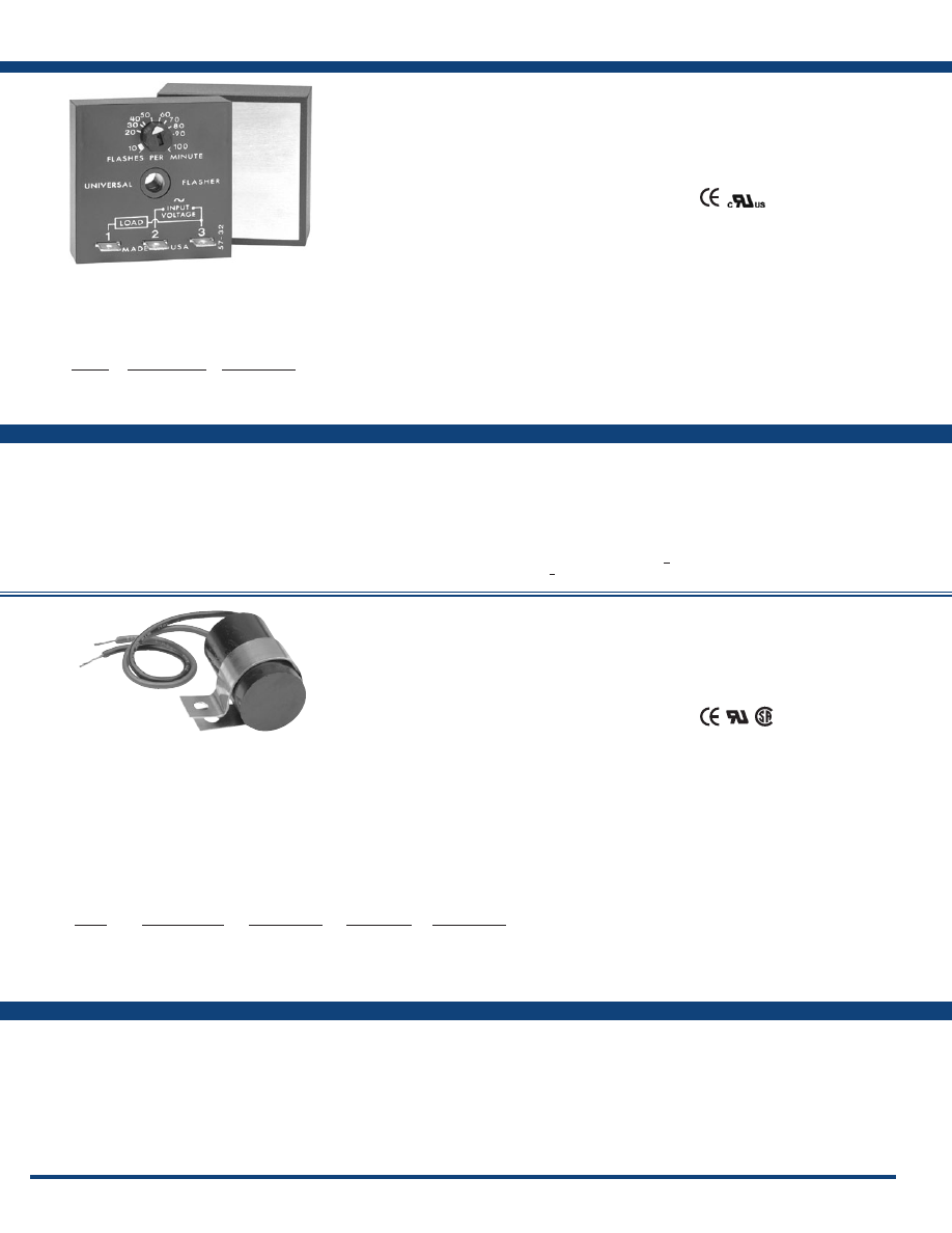
104
www.ssac.com • 800-843-8848 • fax: 605-348-5685
Features:
• All solid state – no moving parts or contacts
• Onboard adjustable flash rate
• Loads up to 20A
• High inrush up to 200A
• Universal voltage 24 to 240VAC
Approvals:
FSU1000 / FS100 Series
Flashers
Technical Data
Operation . . . . . . . . . . . . . . . . . . . . . . .
ON/OFF recycling solid-state flasher (continuous duty)
Flash Rate
. . . . . . . . . . . . . . . . . . . . . . .
Adjustable 10 - 100 FPM
ON/OFF Ratio
. . . . . . . . . . . . . . . . . . .
≅
50%
Input
Range/Frequency
. . . . . . . . . . . . . . . .
24 to 240VAC/50/60Hz
Output
Load Type . . . . . . . . . . . . . . . . . . . . . . .
Inductive, resistive, or incandescent
Maximum Load Rating
. . . . . . . . . . . .
1, 6, 10, or 20A steady state
Inrush
. . . . . . . . . . . . . . . . . . . . . . . . . . .
10 times steady state current
Mechanical
Mounting* . . . . . . . . . . . . . . . . . . . . . . .
Surface mount with one #10 (M5 x 0.8) screw
Dimensions . . . . . . . . . . . . . . . . . . . . . .
2 x 2 x 1.21 in. (50.8 x 50.8 x 30.7 mm)
Termination . . . . . . . . . . . . . . . . . . . . .
0.25 in. (6.35 mm) male quick connect terminals
Protection
Circuitry . . . . . . . . . . . . . . . . . . . . . . . . Encapsulated
Environmental
Operating / Storage Temperature
. .
-20° to 60°C (240VAC +50°C) / -40° to 85°C
Weight
. . . . . . . . . . . . . . . . . . . . . . . . . .
1A units:
≅
2.4 oz (68 g)
>
6A units:
≅
3.9 oz (111 g)
*Units rated >
6A must be bolted to a metal surface using the included heat sink compound.
The maximum mounting surface temperature is 90°C.
Available Models:
Specifications
FSU1000
FSU1003
FSU1004
Auxiliary Products:
•
Female quick connect:
P/N: P1015-13 (AWG 10/12)
P/N: P1015-64 (AWG 14/16)
P/N: P1015-14 (AWG 18/22)
•
Quick connect to screw adaptor:
P/N: P1015-18
Features:
• Fixed flash rate 75 FPM
• Custom flash rate 45 - 150 FPM
•
1 or 2A output
• 24 or 120VAC
• Small size: 1.5 x 0.94 in. (38 x 23.9 mm)
Approvals:
Technical Data
Operation . . . . . . . . . . . . . . . . . . . . . . .
OFF/ON solid-state flasher (continuous duty)
Flash Rate
. . . . . . . . . . . . . . . . . . . . . . .
Factory fixed at 75 FPM ±20%
Custom Flash Rates Available
. . . . . .
From 45 - 150 FPM ±20%
ON/OFF Ratio
. . . . . . . . . . . . . . . . . . .
≅
50%
Input
Voltage
. . . . . . . . . . . . . . . . . . . . . . . . . .
24, 120VAC, ±15%
AC Line Frequency . . . . . . . . . . . . . . .
50/60Hz
Output
Output . . . . . . . . . . . . . . . . . . . . . . . . . .
Fullwave AC or Halfwave rectified AC
Load Type . . . . . . . . . . . . . . . . . . . . . . .
Incandescent, resistive, or inductive
(Choose RC suffix for inductive loads)
Maximum Load Rating
. . . . . . . . . . . .
Fullwave: 1A steady state
Halfwave: 2A steady state
Inrush
. . . . . . . . . . . . . . . . . . . . . . . . . . .
10A
Mechanical
Mounting . . . . . . . . . . . . . . . . . . . . . . .
Removable mounting bracket, use one #8 (M4 x 0.7) screw
Connection/Wires
. . . . . . . . . . . . . . . .
18 AWG (0.82mm
2
) wires 6 in. (15.2cm)
Dimensions . . . . . . . . . . . . . . . . . . . . . .
1.5 x 0.94 in. (38.1 x 23.9 mm)
Protection
Circuitry . . . . . . . . . . . . . . . . . . . . . . . . Encapsulated
Environmental
Operating / Storage Temperature
. .
-20° to 60°C / -40° to 85°C
Humidity . . . . . . . . . . . . . . . . . . . . . . . .
95% relative, non-condensing
Weight
. . . . . . . . . . . . . . . . . . . . . . . . . .
≅
1.1 oz (31 g)
Available Models:
Specifications
FS126
FS126-45
FS126-60
FS126RC
FS126RC-90
FS127
FS146
FS146RC
The FSU1000 incorporates an onboard adjustable
flash rate of 10 to 100 FPM and a universal input
voltage in one device. Its circuitry is encapsulated
and is capable of controlling loads of up to 20A.
The versatility of the FSU1000 makes it ideal
for applications where various flash rates and
operating voltages are required.
Operation
When input voltage is applied to terminal 2 and the load
(lamp), the load energizes steadily. When input voltage
is applied to terminal 3, the output flashes.
Optional Low Current Switch (S1)
This low current switch could be a limit switch or contact.
While open, the operator sees the load (lamp) ON and
operating. When the limit switch closes, the load (lamp)
flashes to attract attention.
For more information see:
Appendix A, page 164 for Flasher (NC) function.
Appendix B, page 165, Figure 4 for dimensional drawing.
Appendix C, page 168, Figure 1 for connection diagram.
Rating
1A
6A
10A
20A
Inrush Rating
10A
60A
100A
200A
Part Number
FSU1000
FSU1003
FSU1004
FSU1005
Order Table:
Input
120VAC
120VAC
120VAC
24VAC
24VAC
24VAC
Output Rating
1A
1A
2A
1A
1A
2A
Output Type
AC, Fullwave
AC, Fullwave
AC, Halfwave
AC, Fullwave
AC, Fullwave
AC, Halfwave
Load Type*
A
B
A
A
B
A
Part Number
FS126
FS126RC
FS127
FS146
FS146RC
FS147
*Load Type:
A-Incandescent & Resistive
B-Incandescent, Resistive & Inductive
Order Table:
The FS100 Series (low amp) may be used to control
inductive, incandescent or resistive loads. This
series offers a 1A (fullwave) or a 2A (halfwave)
steady state, 10A inrush solid-state output and
may be ordered with an input voltage of 24 or
120VAC. The FS100 Series offers a factory fixed
flash rate of 75 FPM or may be ordered with a fixed,
custom flash rate ranging from 45 to 150 FPM.
Ideal for OEM applications where cost is a factor.
Operation
Upon application of input voltage, the T2 OFF time
begins. At the end of the OFF time, the T1 ON time begins
and the load energizes. At the end of T1, T2 begins and
the load de-energizes. This cycle repeats until input
voltage is removed.
Reset: Removing input voltage resets the output and the
sequence to T2 .
For more information see:
Appendix A, page 164 for Flasher (OFF First) function.
Appendix B, page 165, Figure 12 for dimensional drawing.
Appendix C, page 168, Figure 2 for connection diagram.
Add the suffix “-##” to any part number to
indicate the custom flash rate.
Courtesy of Steven Engineering, Inc.-230 Ryan Way, South San Francisco, CA 94080-6370-Main Office: (650) 588-9200-Outside Local Area: (800) 258-9200-www.stevenengineering.com
Littelfuse-catalog-html.html
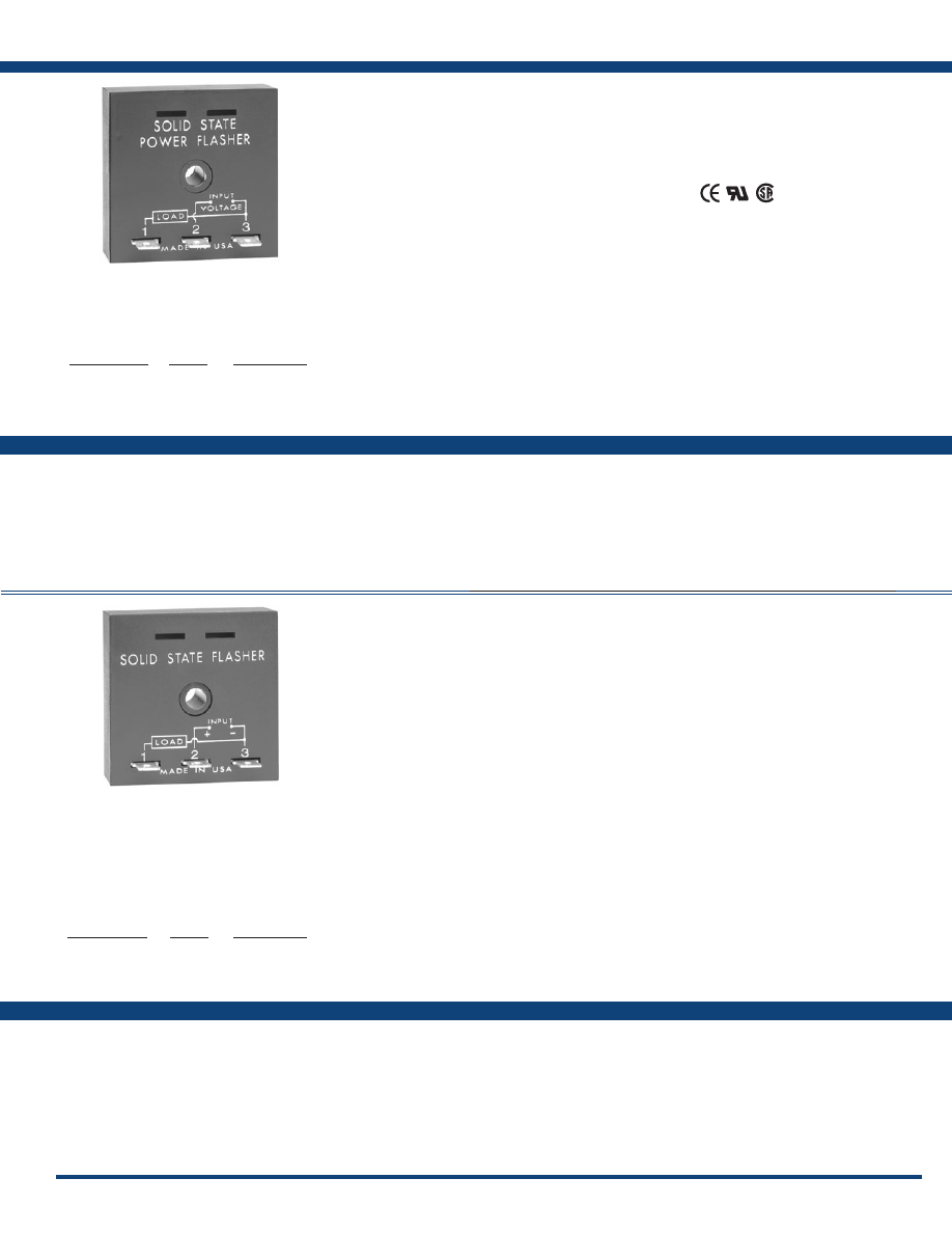
105
www.ssac.com • 800-843-8848 • fax: 605-348-5685
Features:
• Fixed at 90 FPM
• Custom flash rate 10 - 300 FPM
• Switches inrush currents up to 30A
• 24, 120, or 230VAC input voltages
• Totally solid state & encapsulated
Approvals:
FS100 / FS200 Series
Flashers
Specifications
FS143
FS152
FS152-30
FS152-50
FS152-60
FS162
FS162-30
Auxiliary Products:
•
Female quick connect:
P/N: P1015-64 (AWG 14/16)
•
Quick connect to screw adaptor:
P/N: P1015-18
•
Mounting bracket:
P/N: P1023-6
•
DIN rail:
P/N: C103PM
(Al)
•
DIN rail adaptor:
P/N: P1023-20
Features:
• Fixed at 90 FPM
• Custom flash rate 10 - 180 FPM
• 3A, SPST output contact
• 12 to 110VDC input voltages in 5 ranges
• Totally solid state & encapsulated
• 0.25 in. (6.35 mm) male quick connects
Technical Data
Operation . . . . . . . . . . . . . . . . . . . . . . . . . . . .
OFF/ON solid-state flasher (continuous duty)
Flash Rate
. . . . . . . . . . . . . . . . . . . . . . . . . . .
Fixed at 90 FPM ±10%
Custom Flash Rate
. . . . . . . . . . . . . . . . . . . .
10 - 180 FPM
ON/OFF Ratio
. . . . . . . . . . . . . . . . . . . . . . .
≅
50%
Input
Voltage
. . . . . . . . . . . . . . . . . . . . . . . . . . . . . .
12, 24, 36, 48, or 110VDC
Output
Load Type . . . . . . . . . . . . . . . . . . . . . . . . . . .
Inductive, resistive, or incandescent
Maximum Load Rating
. . . . . . . . . . . . . . . .
0.25 - 3A steady state
OFF State Leakage Current
12 & 24VDC
. . . . . . . . . .
≤ 250 µA
Inrush
. . . . . . . . . . . . . . . . . . . . . . . . . . . . . . .
10 times steady state current
Mechanical
Mounting . . . . . . . . . . . . . . . . . . . . . . . . . . . .
Surface mount with one #10 (M5 x 0.8) screw
Dimensions . . . . . . . . . . . . . . . . . . . . . . . . . .
2 x 2 x 1.21 in. (50.8 x 50.8 x 30.7 mm)
Termination . . . . . . . . . . . . . . . . . . . . . . . . . .
0.25 in. (6.35 mm) male quick connect terminals
Protection
Circuitry . . . . . . . . . . . . . . . . . . . . . . . . . . . . .Encapsulated
Environmental
Operating / Storage Temperature
. . . . . . .
-20° to 60°C / -40° to 85°C
Weight
. . . . . . . . . . . . . . . . . . . . . . . . . . . . . .
≅
2.2 oz (62 g)
Available Models:
Specifications
FS224
Technical Data
Operation . . . . . . . . . . . . . . . . . . . . . . . . . .
OFF/ON solid-state flasher (continuous duty)
Flash Rate
. . . . . . . . . . . . . . . . . . . . . . . . .
Fixed at 90 FPM ±10%
Custom Flash Rates
. . . . . . . . . . . . . . . . .
10 - 300 FPM ±10%
ON/OFF Ratio
. . . . . . . . . . . . . . . . . . . . .
≅
50%
Input
Voltage/Frequency
. . . . . . . . . . . . . . . . .
24, 120, or 230VAC ±15%/50/60 Hz
Output
Load Type . . . . . . . . . . . . . . . . . . . . . . . . .
Inductive, resistive, or incandescent
Output . . . . . . . . . . . . . . . . . . . . . . . . . . . .
Fullwave AC, solid state, SPST
Maximum Load Rating
. . . . . . . . . . . . . .
3A steady state
Inrush
. . . . . . . . . . . . . . . . . . . . . . . . . . . . .
10 times steady state current
Mechanical
Mounting . . . . . . . . . . . . . . . . . . . . . . . . . .
Surface mount with one #10 (M5 x 0.8) screw
Dimensions . . . . . . . . . . . . . . . . . . . . . . . .
2 x 2 x 1.21 in. (50.8 x 50.8 x 30.7 mm)
Termination . . . . . . . . . . . . . . . . . . . . . . . .
0.25 in. (6 .35 mm) male quick connect terminals
Protection
Circuitry . . . . . . . . . . . . . . . . . . . . . . . . . . . Encapsulated
Environmental
Operating / Storage Temperature
. . . . .
-20° to 60°C / -40° to 85°C
Weight
. . . . . . . . . . . . . . . . . . . . . . . . . . . .
≅
2.2 oz (62 g)
Auxiliary Products:
•
Female quick connect:
P/N: P1015-64 (AWG 14/16)
•
Quick connect to screw adaptor:
P/N: P1015-18
•
Mounting bracket:
P/N: P1023-6
•
DIN rail:
P/N: C103PM
(Al)
•
DIN rail adaptor:
P/N: P1023-20
Available Models:
The FS200 Series may be used to control inductive,
incandescent, or resistive loads. Input voltages of
12, 24, 36, 48, or 110VDC are available. Factory
fixed flash rate of 90 FPM or may be ordered with a
fixed custom flash rate ranging from 10 to 180 FPM.
Encapsulation provides protection against shock,
vibration, and humidity. Uniform performance,
high inrush current capability, and low RFI, make
this series ideal for general industrial applications.
Operation
Upon application of input voltage, the T2 OFF time begins.
At the end of the OFF time, the T1 ON time begins and
the load energizes. At the end of T1, T2 begins and the
load de-energizes. This cycle repeats until input voltage
is removed.
Reset: Removing input voltage resets the output and the
sequence to T2 .
For more information see:
Appendix A, page 164 for Flasher (OFF First) function.
Appendix B, page, 165, Figure 1 for dimensional drawing.
Appendix C, page 168, Figure 4 for connection diagram.
The FS100 Series (medium amp) may be used to
control inductive, incandescent, or resistive loads.
Input voltages of 24, 120, or 230VAC are available.
Factory fixed flash rate of 90 FPM or may be
ordered with a fixed, custom flash rate ranging
from 10 to 300 FPM. Encapsulation provides
protection against shock, vibration, and humidity.
This group of solid-state flashers has proven
reliability with years of use throughout the world.
Operation
Upon application of input voltage, the T2 OFF time
begins. At the end of the OFF time, the T1 ON time begins
and the load energizes. At the end of T1, T2 begins and
the load de-energizes. This cycle repeats until input
voltage is removed.
Reset: Removing input voltage resets the output and the
sequence to T2 .
For more information see:
Appendix A, page 164 for Flasher (OFF First) function.
Appendix B, page, 165, Figure 1 for dimensional drawing.
Appendix C, page168, Figure 3 for connection diagram.
Input Voltage
24VAC
120VAC
230VAC
Rating
3A
3A
3A
Part Number
FS143
FS152
FS162
Order Table:
Input Voltage
12VDC ±20%
24VDC ±20%
36VDC ±20%
48VDC ±15%
110VDC ±15%
Rating
3A
3A
1A
0.75A
0.25A
Part Number
FS219
FS224
FS236
FS248
FS290
Order Table:
If desired part number is not listed, please call us to
see if it is technically possible to build .
If desired part number is not listed, please call us to
see if it is technically possible to build .
Add the suffix “-##” to any part number to
indicate the custom flash rate.
Courtesy of Steven Engineering, Inc.-230 Ryan Way, South San Francisco, CA 94080-6370-Main Office: (650) 588-9200-Outside Local Area: (800) 258-9200-www.stevenengineering.com
Littelfuse-catalog-html.html
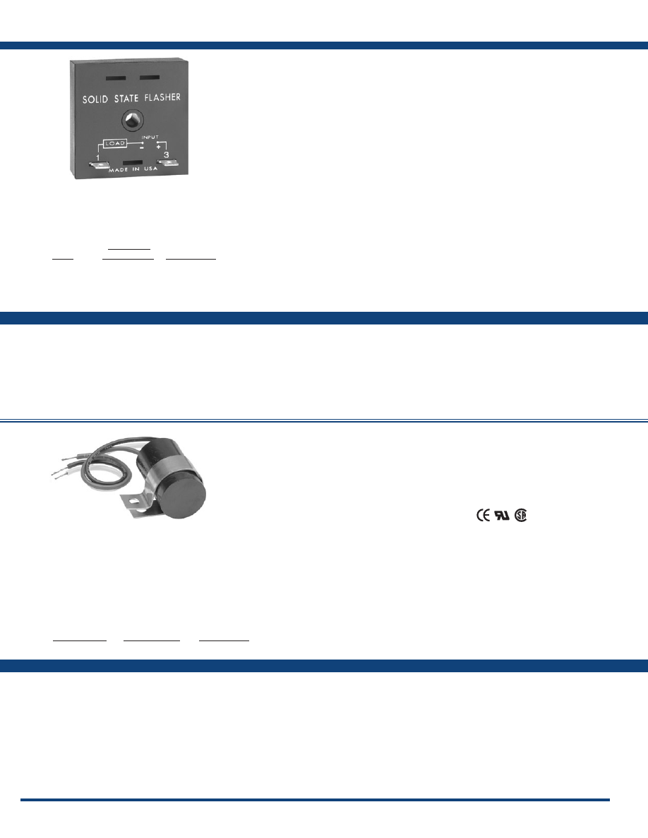
106
www.ssac.com • 800-843-8848 • fax: 605-348-5685
Features:
• All solid state – no moving parts or contacts
• High surge capability – designed to operate
incandescent lamp loads
• High noise & transient protection
• Two-terminal series connection
• Encapsulated – protects against shock,
vibration, & humidity
FS300 / FS400 Series
Flashers
Technical Data
Operation . . . . . . . . . . . . . . . . . . . . . . . . . . .
OFF/ON recycling solid-state flasher (continuous duty)
Flash Rate
. . . . . . . . . . . . . . . . . . . . . . . . . .
Fixed at 75 FPM ±10%
Custom Flash Rates
. . . . . . . . . . . . . . . . . .
60 - 150 FPM
ON/OFF Ratio
. . . . . . . . . . . . . . . . . . . . . .
≅
50%
Input
Voltage
. . . . . . . . . . . . . . . . . . . . . . . . . . . . .
12, 24, 36, 48, 72, & 110VDC
Output
Load Type . . . . . . . . . . . . . . . . . . . . . . . . . .
Incandescent or resistive
Maximum Load Rating
. . . . . . . . . . . . . . .
0.25 - 2.5A steady state
Inrush
. . . . . . . . . . . . . . . . . . . . . . . . . . . . . .
10 times steady state current
Mechanical
Mounting . . . . . . . . . . . . . . . . . . . . . . . . . . .
Surface mount with one #10 (M5 x 0.8) screw
Dimensions . . . . . . . . . . . . . . . . . . . . . . . . .
2 x 2 x 1.21 in. (50.8 x 50.8 x 30.7 mm)
Termination . . . . . . . . . . . . . . . . . . . . . . . . .
0.25 in. (6.35 mm) male quick connect terminals
Protection
Circuitry . . . . . . . . . . . . . . . . . . . . . . . . . . . .Encapsulated
Environmental
Operating / Storage Temperature
. . . . . .
-20° to 60°C / -40° to 85°C
Humidity . . . . . . . . . . . . . . . . . . . . . . . . . . .
95% relative, non-condensing
Weight
. . . . . . . . . . . . . . . . . . . . . . . . . . . . .
≅
2.2 oz (62 g)
Available Models:
Specifications
FS312
FS324
FS336
FS390
Features:
• Low leakage for LED lamps
• Fixed flash rate at 75 FPM
• Custom flash rate 45 - 150 FPM
• 0.5 or 1A, solid-state output
• 24V to 240VAC in 2 ranges
• Small size: 1.5 x 0.94 in. (38 x 23.9 mm)
Approvals:
Technical Data
Operation . . . . . . . . . . . . . . . . . . . . . . . . . . . . . . . .
ON/OFF solid-state flasher (continuous duty)
Flash Rate
. . . . . . . . . . . . . . . . . . . . . . . . . . . . . . .
Fixed at 75 FPM ±20%
Custom Flash Rates
. . . . . . . . . . . . . . . . . . . . . . .
45 - 150 FPM ±20%
ON/OFF Ratio
. . . . . . . . . . . . . . . . . . . . . . . . . . .
≅
50%
Input
Voltage
. . . . . . . . . . . . . . . . . . . . . . . . . . . . . . . . . .
24, or 120 - 240VAC
Tolerance . . . . . . . . . . . . . . . . . . . . . . . . . . . . . . . .
± 15%
AC Line Frequency . . . . . . . . . . . . . . . . . . . . . . .
50/60Hz
Output
Load Type . . . . . . . . . . . . . . . . . . . . . . . . . . . . . . .
LED or resistive
Output . . . . . . . . . . . . . . . . . . . . . . . . . . . . . . . . . .
Bridge Rectifier & FET
Maximum Load Rating
120VAC to 240VAC
. . . . . . . . . . .
0.5A steady state; 5A inrush
24VAC
. . . . . . . . . . . .
1A steady state; 10A inrush
Max. Load Leakage Current
. . . . . . . . . . . . . . . .
250µA
Voltage Drop
. . . . . . . . . . . . . . . . . . . . . . . . . . . . .
2V typical
Mechanical
Mounting . . . . . . . . . . . . . . . . . . . . . . . . . . . . . . . .
Surface mount with one #8 (M4 x 0.7) screw
Dimensions . . . . . . . . . . . . . . . . . . . . . . . . . . . . . .
1.5 x 0.94 in. (38.1 x 23.9 mm)
Protection
Surge . . . . . . . . . . . . . . . . . . . . . . . . . . . . . . . . . . .
IEEE C62.41 - 1991 Level A
Circuitry . . . . . . . . . . . . . . . . . . . . . . . . . . . . . . . . .Encapsulated
Environmental
Operating / Storage Temperature
. . . . . . . . . . .
-20° to 60°C / -40° to 85°C
Humidity . . . . . . . . . . . . . . . . . . . . . . . . . . . . . . . .
95% relative, non-condensing
Weight
. . . . . . . . . . . . . . . . . . . . . . . . . . . . . . . . . .
≅
1.1 oz (31 g)
Available Models:
Specifications
FS491
Auxiliary Products:
•
Female quick connect:
P/N: P1015-64 (AWG 14/16)
•
Quick connect to screw adaptor:
P/N: P1015-18
•
Mounting bracket:
P/N: P1023-6
•
DIN rail:
P/N: C103PM
(Al)
•
DIN rail adaptor:
P/N: P1023-20
The FS300 Series of solid-state flashers were
specifically designed to operate lamp loads. Their
two-terminal series connection feature makes
installation easy. The high immunity to line
noise and transients makes the FS300 Series ideal
for moving vehicle applications. All solid-state
construction means reliability and long life. The
FS300 Series offers a factory fixed flash rate of 75
FPM or may be ordered with a fixed, custom flash
rate ranging from 60 to 150 FPM.
Operation
Upon application of input voltage, the T2 OFF time
begins. At the end of the OFF time, the T1 ON time begins
and the load energizes. At the end of T1, T2 begins and
the load de-energizes. This cycle repeats until input
voltage is removed.
Reset: Removing input voltage resets the output and the
sequence to T2 .
For more information see:
Appendix A, page 164 for Flasher (OFF First) function.
Appendix B, page 165, Figure 1 for dimensional drawing.
Appendix C, page 168, Figure 5 for connection diagram.
The FS400 Series is a low leakage AC flasher
designed to control LED, or resistive loads. This
series offers a solid-state output and may be
ordered with an input voltage of 24V to 240VAC,
in two ranges. It offers a factory fixed flash rate of
75 FPM or may be ordered with a fixed, custom
flash rate ranging from 45 to 150 FPM. The FS400
is the perfect solution for LED lamp flashing.
Operation
Upon application of input voltage, the output energizes
and the ON time begins. At the end of the ON time, the
output de-energizes and the OFF time begins. At the end
of the OFF time, the output energizes and the cycle repeats
as long as input voltage is applied.
Reset: Removing input voltage resets the output and the
flash sequence.
For more information see:
Appendix A, page 164 for Flasher (ON First) function.
Appendix B, page 165, Figure 12 for dimensional drawing.
Appendix C, page 168, Figure 6 for connection diagram.
Input
12VDC ±20%
24VDC ±20%
36VDC ±20%
48VDC ±15%
72VDC ±15%
110VDC ±15%
Maximum
Current Load
2.5A
1.5A
1A
0.75A
0.5A
0.25A
Part Number
FS312
FS324
FS336
FS348
FS372
FS390
Input Voltage
120 to 240VAC
24VAC
Output Rating
0.5A
1A
Part Number
FS491
FS421
Order Table:
Order Table:
Courtesy of Steven Engineering, Inc.-230 Ryan Way, South San Francisco, CA 94080-6370-Main Office: (650) 588-9200-Outside Local Area: (800) 258-9200-www.stevenengineering.com
Littelfuse-catalog-html.html
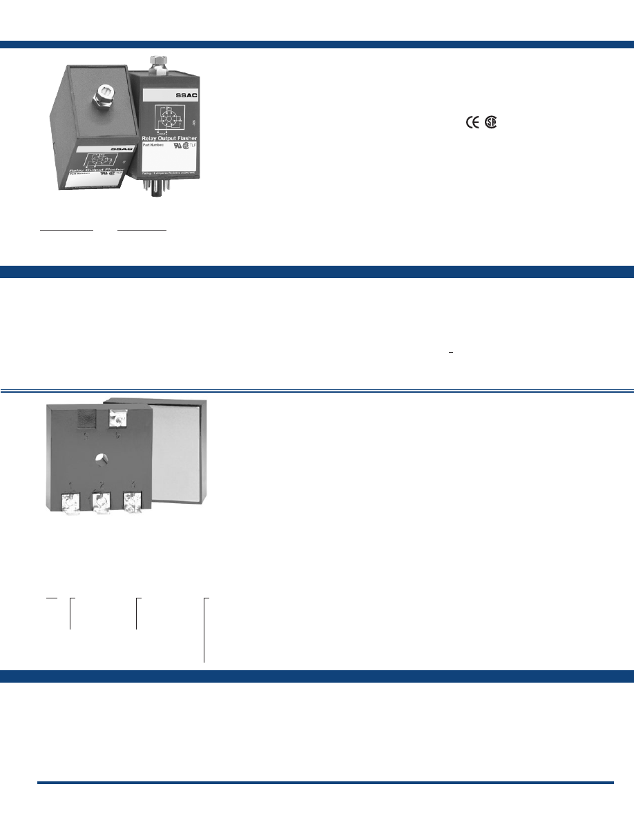
107
www.ssac.com • 800-843-8848 • fax: 605-348-5685
Features:
• Alternately flashes two high current loads
• High surge capacity - up to 200A
• Small size - 2 x 2 x 1.30 in.
(50.8 x 50.8 x 33 mm)
• Totally solid state & encapsulated
FS500 / AF Series
Flashers
Specifications
AF213
AF223
AF232
AF233
Auxiliary Products:
•
Female quick connect:
P/N: P1015-13 (AWG 10/12)
P/N: P1015-64 (AWG 14/16)
P/N: P1015-14 (AWG 18/22)
•
Quick connect to screw adaptor:
P/N: P1015-18
Features:
• Solid-state circuitry - relay output
• Industrial standard octal plug-in
• Adjustable flash rate 10 - 100 FPM
• 10A, DPDT output contacts
Approvals:
Technical Data
Operation . . . . . . . . . . . . . . . . . . . . . . . . . . .
ON/OFF recycling flasher with adjustable flash rate
Flash Rate
. . . . . . . . . . . . . . . . . . . . . . . . . . .
Adjustable from 10 - 100 operations per minute
(guaranteed range)
ON/OFF Ratio
. . . . . . . . . . . . . . . . . . . . . . .
≅
50%
Input
Input Voltage
. . . . . . . . . . . . . . . . . . . . . . . .
12VDC, 24VAC/DC, 120VAC/DC, 230VAC
Tolerance 12VDC & 24VDC/AC
. . . .
-15% - 20%
120 - 230VAC/DC
. . . .
-20% - 10%
AC Line Frequency . . . . . . . . . . . . . . . . . . .
50/60Hz
Output
Load Type . . . . . . . . . . . . . . . . . . . . . . . . . . .
Electromechanical relay
Form . . . . . . . . . . . . . . . . . . . . . . . . . . . . . . . .DPDT
Rating . . . . . . . . . . . . . . . . . . . . . . . . . . . . . . .
10A resistive @ 120/240VAC & 28VDC;
1/3 hp @ 120/ 240VAC
Mechanical
Mounting . . . . . . . . . . . . . . . . . . . . . . . . . . . .
Plug-in socket
Dimensions . . . . . . . . . . . . . . . . . . . . . . . . . .
3.62 x 2.39 x 1.78 in. (91.6 x 60.7 x 45.2 mm)
Termination . . . . . . . . . . . . . . . . . . . . . . . . . .
Octal 8-pin plug-in
Protection
Isolation Voltage
. . . . . . . . . . . . . . . . . . . . . .>
1500V RMS input to output
Polarity . . . . . . . . . . . . . . . . . . . . . . . . . . . . . .
DC units are reverse polarity protected
Environmental
Operating / Storage Temperature
. . . . . . .
-20° to 60°C / -30° to 85°C
Weight
. . . . . . . . . . . . . . . . . . . . . . . . . . . . . .
≅
5.8 oz (164 g)
Available Models:
Specifications
FS512
FS524
FS590
Technical Data
Operation . . . . . . . . . . . . . . . . . . . . . . . . . . . . .
Alternating solid-state flasher rated (continuous duty)
Flash Rate
. . . . . . . . . . . . . . . . . . . . . . . . . . . .
Factory fixed at 10, 30, 60, 90, 120, or 140 flashes
per min. ±10%.
Custom Flash Rate
. . . . . . . . . . . . . . . . . . . .
10 - 140 FPM
Ratio . . . . . . . . . . . . . . . . . . . . . . . . . . . . . . . .
≅
50%
Input
Input Voltage/Frequency
. . . . . . . . . . . . . .
24, 120, or 230VAC ±15% / 50/60Hz
Output
Load Type . . . . . . . . . . . . . . . . . . . . . . . . . . . .
Incandescent or resistive
Maximum Load Rating
. . . . . . . . . . . . . . . . .
6, 10, & 20A steady state
Inrush
. . . . . . . . . . . . . . . . . . . . . . . . . . . . . . . .
10 times steady state current
Mechanical
Mounting * . . . . . . . . . . . . . . . . . . . . . . . . . . .
Surface mount with one #10 (M5 x 0.8) screw
Dimensions . . . . . . . . . . . . . . . . . . . . . . . . . . .
2 x 2 x 1.30 in. (50.8 x 50.8 x 33 mm)
Protection
Circuitry . . . . . . . . . . . . . . . . . . . . . . . . . . . . . .Encapsulated
Environmental
Operating / Storage Temperature
. . . . . . . .
-20° to 60°C / -40° to 85°C
Humidity . . . . . . . . . . . . . . . . . . . . . . . . . . . . .
95% relative, non-condensing
Weight
. . . . . . . . . . . . . . . . . . . . . . . . . . . . . . .
≅
2.9 oz (82 g)
*Must be bolted to metal surface using the included heat sink compound. The maxim
mounting surface temperature is 90°C.
Auxiliary Products:
•
Panel mount kit:
P/N: BZ1
•
Octal 8-pin socket:
P/N: NDS-8
•
Hold-down clips (sold in pairs):
P/N: PSC8 (NDS-8)
•
DIN rail:
P/N: C103PM
(Al)
Available Models:
The FS500 Series flash rate is adjustable from 10 to
100 FPM. A locknut is provided to hold selected
flash rate. The long-life electronic circuit combined
with a quality electromechanical relay provides
flexibility and reliability in most applications.
Operation
Upon application of input voltage, the output relay is
energized and the ON time begins. At the end of the ON
time, the output relay de-energizes and the OFF time
begins. At the end of the OFF time, the output is energized
and the cycle repeats as long as input voltage is applied.
Reset: Removing input voltage resets the output and
the sequence.
For more information see:
Appendix A, page 164 for Flasher (ON First-DPDT)
function.
Appendix B, page 165, Figure 9 for dimensional drawing.
Appendix C, page 168, Figure 8 for connection diagram.
AF
X
Input Voltage
─
1
- 24VAC
─
2
- 120VAC
─
3
- 230VAC
X
Output Rating
─
1
- 6A
─
2
- 10A
─
3
- 20A
X
Flash Rate (flashes per min.)
─
1
- 10
─
2
- 30
─
3
- 60
─
4
- 90
─
5
- 120
─
6
- 140
─
Blank
- Custom Flash Rate
Input Voltage
12VDC
24VAC/DC
120VAC/DC
230VAC
Part Number
FS512
FS524
FS590
FS599
Order Table:
Order Table:
(some models)
The AF Series offers a high inrush capacity of up
to 200A. These devices exceed mechanical type
relays in both performance and lifespan. The AF
Series is constructed with no moving parts to arc,
wear, and eventually fail; 100 million operations
are typical. Circuitry is encapsulated to provide
protection against vibration and moisture, making
the AF Series ideal for outdoor applications.
Operation
Upon application of input voltage T1 begins, Load 1 is
ON and Load 2 is OFF. At the end of T1, T2 begins and
Load 2 is now ON and Load 1 is OFF. At the end of T2,
T1 repeats and this sequence continues until input voltage
is removed. The duration of T1 and T2 is approximately
equal .
Reset: Removing input voltage resets the flasher.
For more information see:
Appendix A, page 164 for Flasher (Alternating) function.
Appendix B, page 166, Figure 13 for dimensional drawing.
Appendix C, page 168, Figure 7 for connection diagram.
If desired part number is not listed, please call us to
see if it is technically possible to build .
If desired part number is not listed, please call us to
see if it is technically possible to build .
Courtesy of Steven Engineering, Inc.-230 Ryan Way, South San Francisco, CA 94080-6370-Main Office: (650) 588-9200-Outside Local Area: (800) 258-9200-www.stevenengineering.com
Littelfuse-catalog-html.html
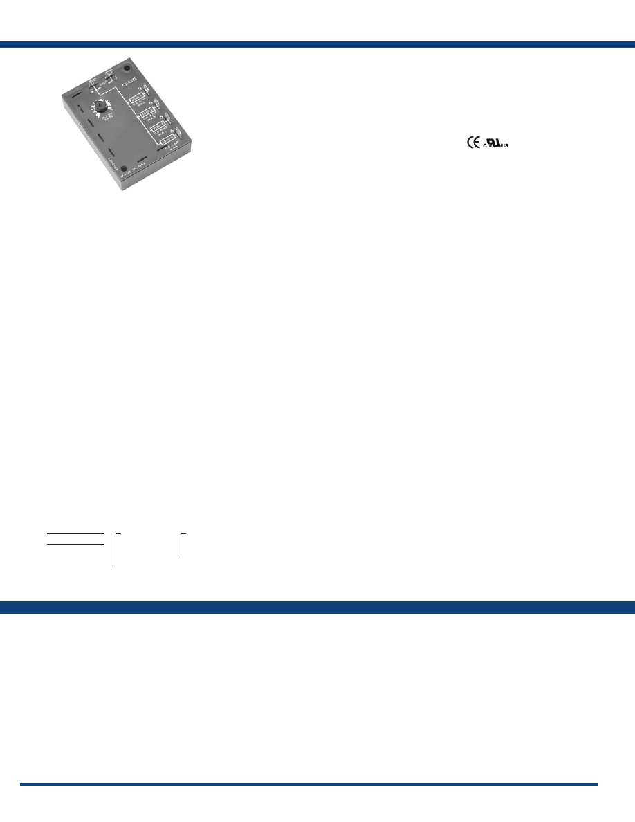
108
www.ssac.com • 800-843-8848 • fax: 605-348-5685
Features:
• Sequential 3 or 4 circuit flashing of
incandescent loads
• Fixed or adjustable at 30 - 300FPM
•
1A steady state output
• 24, 120, or 230VAC input voltage
• Totally solid state - encapsulated
Approvals:
SC3/SC4 Series
Flasher (Chaser)
Available Models:
Specifications
Order Table:
SC3120F30
Auxiliary Products:
•
Quick connect to screw adaptor:
P/N: P1015-18
•
Female quick connect:
P/N: P1015-13 (AWG 10/12)
P/N: P1015-64 (AWG 14/16)
P/N: P1015-14 (AWG 18/22)
The SC3/SC4 Series are solid-state 3 or 4 channel,
chasers designed for sequential three or four
circuit flashing of incandescent lamp loads. Unlike
electromechanical chasers, there are no contacts to
arc, wear, and eventually fail. Fixed or adjustable
rates of 30 to 300 operations per minute.
Operation
Sequential 3 or 4 circuit flashing of incandescent loads
with equal time delays for each load. Upon application
of input voltage, Load 1 is energized. At the end of the
time delay, Load 1 de-energizes and Load 2 energizes.
At the end of the time delay, Load 2 de-energizes and
Load 3 energizes. This cycle continues until input voltage
is removed.
Reset: Removing input voltage resets the unit and cycle.
For more information see:
Appendix A, page 164 for Flasher (Chasing) function.
Appendix B, page 166, Figure 14 for dimensional drawing.
Appendix C, page 168, Figure 9 for connection diagram.
SC3
(3 outputs)
SC4
(4 outputs)
X
Input Voltage
─
24
- 24VAC
─
120
- 120VAC
─
230
- 230VAC
X
Rate
─
A
- Adjustable (30 - 300)
─
F
- Fixed*
*If Fixed is selected, insert
(30 - 300) operations per
minute .
Technical Data
Operation . . . . . . . . . . . . . . . . . . . . . . . . . . . .
Sequential 3 or 4 circuit flashing of incandescent
lamp loads. Fixed or adjustable rates.
Rate . . . . . . . . . . . . . . . . . . . . . . . . . . . . . . . . .
Adjustable: 30 - 300 operations per minute
Fixed: 30 - 300 operations per minute (±10%)
Input
Voltage
. . . . . . . . . . . . . . . . . . . . . . . . . . . . . . .
24, 120, or 230VAC ±15%
AC Line Frequency . . . . . . . . . . . . . . . . . . . .
50/60 Hz
Output
Type . . . . . . . . . . . . . . . . . . . . . . . . . . . . . . . . . Solid state
Rating . . . . . . . . . . . . . . . . . . . . . . . . . . . . . . . 1A steady state per output
Mechanical
Mounting . . . . . . . . . . . . . . . . . . . . . . . . . . . .
Surface mount with two #6 (M3.5 x 0.6) screws
Termination . . . . . . . . . . . . . . . . . . . . . . . . . .
0.25 in. (6.35 mm) male quick connect terminals
Dimensions . . . . . . . . . . . . . . . . . . . . . . . . . . .
3.5 x 2.5 x 1.22 in. (88.9 x 63.5 x 31 mm)
Protection
Circuitry . . . . . . . . . . . . . . . . . . . . . . . . . . . . . Encapsulated
Dielectric Breakdown
. . . . . . . . . . . . . . . . . .
≥ 2000V RMS terminals to mounting surface
Insulation Resistance . . . . . . . . . . . . . . . . . . .
≥ 100 MΩ
Environmental
Operating / Storage Temperature
. . . . . . .
-20° to 60°C / -40° to 85°C
Humidity . . . . . . . . . . . . . . . . . . . . . . . . . . . . .
95% relative, non-condensing
Weight
. . . . . . . . . . . . . . . . . . . . . . . . . . . . . . .
≅
5.4 oz (153 g)
If desired part number is not listed, please call us to
see if it is technically possible to build .
Courtesy of Steven Engineering, Inc.-230 Ryan Way, South San Francisco, CA 94080-6370-Main Office: (650) 588-9200-Outside Local Area: (800) 258-9200-www.stevenengineering.com
Littelfuse-catalog-html.html

109
www.ssac.com • 800-843-8848 • fax: 605-348-5685
Voltage Monitors & Phase Monitors
Series Included
WVM
. . . . . . . . . . . . . . . . . . . . . . . . . . . . . . . . . . . . . . . . . . . .
110
DLMU . . . . . . . . . . . . . . . . . . . . . . . . . . . . . . . . . . . . . . . . . . .111
HLMU . . . . . . . . . . . . . . . . . . . . . . . . . . . . . . . . . . . . . . . . . . .112
PLMU . . . . . . . . . . . . . . . . . . . . . . . . . . . . . . . . . . . . . . . . . . .
113
PLM . . . . . . . . . . . . . . . . . . . . . . . . . . . . . . . . . . . . . . . . . . . . .
114
TVW
. . . . . . . . . . . . . . . . . . . . . . . . . . . . . . . . . . . . . . . . . . . . .
115
TVM
. . . . . . . . . . . . . . . . . . . . . . . . . . . . . . . . . . . . . . . . . . . . .
116
PLR . . . . . . . . . . . . . . . . . . . . . . . . . . . . . . . . . . . . . . . . . . . . . .117
PLS . . . . . . . . . . . . . . . . . . . . . . . . . . . . . . . . . . . . . . . . . . . . . .
118
HLV
. . . . . . . . . . . . . . . . . . . . . . . . . . . . . . . . . . . . . . . . . . . . .119
KVM
. . . . . . . . . . . . . . . . . . . . . . . . . . . . . . . . . . . . . . . . . . . . .
120
Phase Reversal
1-Phase Voltage Monitors
3-Phase Voltage Monitors
Low Volts, Phase Reversal
Courtesy of Steven Engineering, Inc.-230 Ryan Way, South San Francisco, CA 94080-6370-Main Office: (650) 588-9200-Outside Local Area: (800) 258-9200-www.stevenengineering.com
Littelfuse-catalog-html.html
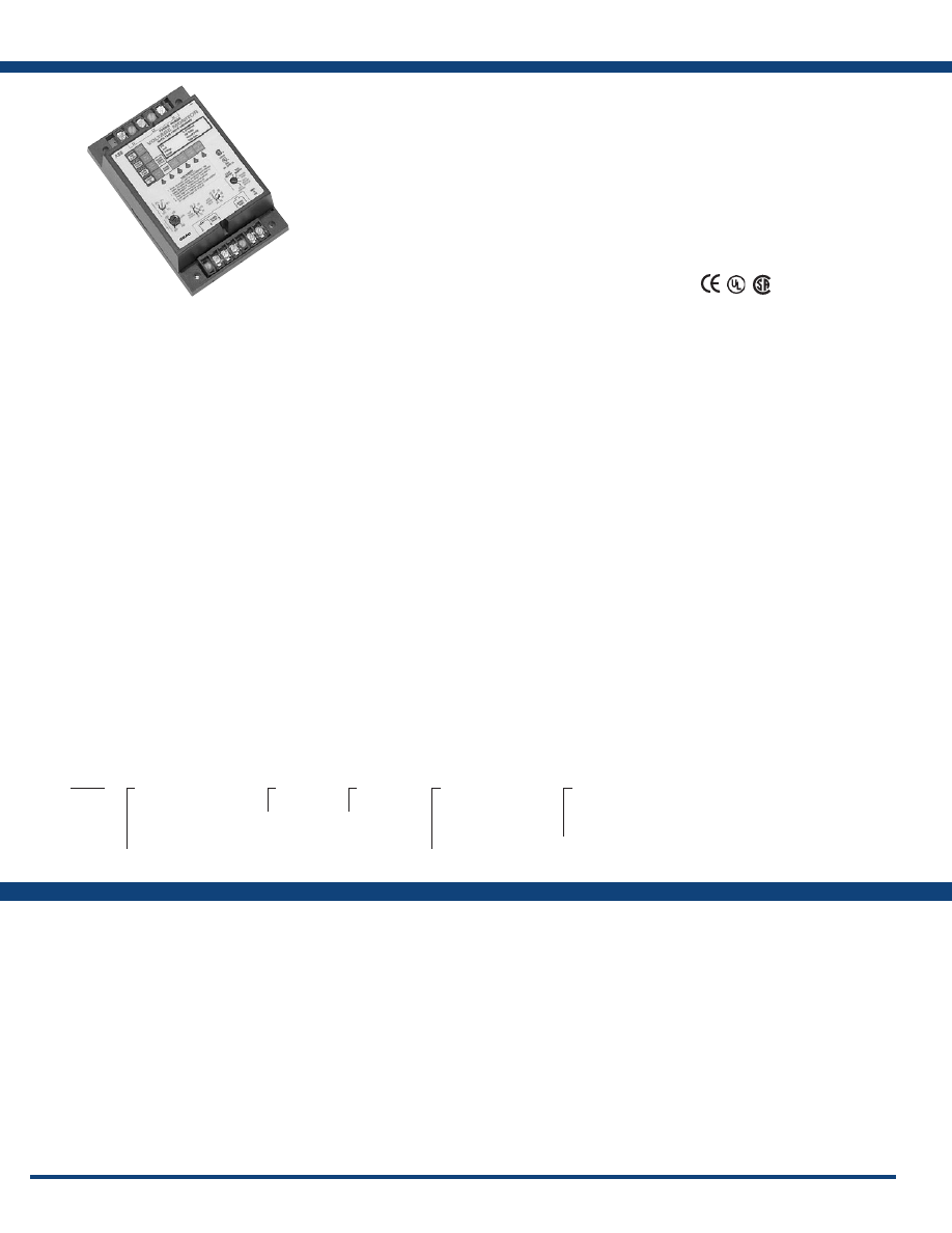
110
www.ssac.com • 800-843-8848 • fax: 605-348-5685
Features:
• Protects against phase loss & reversal; over,
under & unbalanced voltages; & short
cycling
• 10 fault memory & status displayed on 6
LED readout
• Switch selectable automatic restart, delayed
automatic restart, & manual reset
• Isolated, 10A, SPDT output contacts
• ASME A17.1 Rule 210.6
• NEMA MG1 14:30, 14:35
• IEEE C62.41-1991 Level B
Approvals:
Auxiliary Products:
•
3-phase fuse block/disconnect:
P/N: FH3P
•
2 Amp fuse:
P/N: P0600-11
•
DIN rail:
P/N: C103PM
(Al)
WVM Series
Voltage Monitors
Line Voltage
Type . . . . . . . . . . . . . . . . .
3-phase delta or wye with no connection to neutral
Operating Voltage Model Adj. Line Voltage Range
240 200-240VAC
380 355-425VAC
480 400-480VAC
600 500-600VAC
AC Line Frequency . . . . . . . . . . . . . . . . . . . . .
50/60 Hz
Overvoltage, Undervoltage, & Voltage Unbalance
Overvoltage Trip Point
. . . . . . . . . . . . . . . . . .
109-113% of adjusted voltage
Reset Voltage
. . . . . . . . . . . . . . . . . . . . . . . .
-2% of trip point
Undervoltage Trip Point
. . . . . . . . . . . . . . . . .
88-92% of adjusted voltage
Reset Voltage
. . . . . . . . . . . . . . . . . . . . . . . .
+2% of trip point
Voltage Unbalance
. . . . . . . . . . . . . . . . . . . . . .
Adjustable from 2-10%*
Trip Delay . . . . . . . . . . . . . . . . . . . . . . . . . . . . .
Adjustable from 0.25 - 30s ±15%
Phase Loss
. . . . . . . . . . . . . . . . . . . . . . . . . . . . .
≥ 15% unbalance
Response Time . . . . . . . . . . . . . . . . . . . . . . . .
≤ 200 ms
Random Start Delay Range
. . . . . . . . . . . . . .
3 - 15s
Reset (Restart) Delay
Low Range . . . . . . . . . . . . . . . . . . . . . . . . . . . .
0.25-64s ±15%
Normal Range . . . . . . . . . . . . . . . . . . . . . . . . .
6-300s ±15%
High Range
. . . . . . . . . . . . . . . . . . . . . . . . . . . .
0.25-64m ±15%
Fault Memory
Type . . . . . . . . . . . . . . . . . . . . . . . . . . . . . . . . . .
Nonvolatile RAM
Capacity . . . . . . . . . . . . . . . . . . . . . . . . . . . . . .
Stores last 10 faults
Status Indicators . . . . . . . . . . . . . . . . . . . . . . . .
6 LEDs provide existing status & memory readout
Note: 50% of operating line voltage must be applied to L1 & L2 for operation of status indicators
Output
Type . . . . . . . . . . . . . . . . . . . . . . . . . . . . . . . . . .
Electromechanical relay
Form . . . . . . . . . . . . . . . . . . . . . . . . . . . . . . . . . .
Isolated, SPDT
Rating . . . . . . . . . . . . . . . . . . . . . . . . . . . . . . . .
10A resistive @ 250VAC; 6A inductive (0.4 PF) @ 250VAC
Life
. . . . . . . . . . . . . . . . . . . . . . . . . . . . . . . . . . .
Mechanical - 1 x 10
7
Protection
Surge . . . . . . . . . . . . . . . . . . . . . . . . . . . . . . . . .
IEEE 62.41-1991 Level B
Isolation Voltage
. . . . . . . . . . . . . . . . . . . . . . .
≥ 2500V RMS input to output
Mechanical
Mounting . . . . . . . . . . . . . . . . . . . . . . . . . . . . .
Surface with 2 or 4 #8 (M4 x 0.7) screws
Dimensions . . . . . . . . . . . . . . . . . . . . . . . . . . . .
6.9 x 4.4 x 2.4 in. (175.3 x 111.8 x 61.0 mm)
Termination . . . . . . . . . . . . . . . . . . . . . . . . . . .
Screw terminals with captive wire clamps for up to
#12 AWG ( 3.2 mm
2
) wire
Environmental
Operating / Storage Temperature
. . . . . . . .
-40° to 65°C / -40° to 85°C
Weight
. . . . . . . . . . . . . . . . . . . . . . . . . . . . . . . .
≅
25 oz ( 709 g)
* Unbalance reset is 90% of the unbalance setting (i.e. VUB at 5% reset is 4.5%)
Available Models:
Specifications
Order Table:
WVM
X
3-Phase Line Voltage
─
6
- 200-240VAC
─
8
- 355-425VAC
─
9
- 400-480VAC
─
0
- 500-600VAC
X
Unbalance
─
1
- 2-10%
X
Trip Delay
─
1
- 0.25-30s
X
Reset Method
─
A
- Switch Selectable:
Automatic restart upon
fault trip
─
R
- Swith Selectable:
Automatic restart upon
fault correction
X
Restart Delay
─
L
- 0.25-64s
─
N
- 6-300s
─
H
- 0.25-64m
WVM011AL
WVM611AH
WVM611AL
WVM811AH
WVM911AH
WVM911AL
WVM911AL-60
WVM911RL
WVM911RN-60
The WVM Series provides protection against
premature equipment (motor) failure caused by
voltage faults on the 3-phase line. The WVM’s
microcontroller design provides reliable protection
even if regenerated voltages are present. It
combines dependable fault sensing with a 10
fault memory and a 6 LED status display. Part
instrument, part control, the WVM protects your
equipment when you’re not there and displays
what happened when you return. The WVM
is fully adjustable and includes time delays to
prevent nuisance tripping and improve system
operation. Time delays include a 0.25 to 30s
adjustable trip delay, an adjustable 0.25 to 64m
(in 3 ranges) restart delay, plus a unique 3 to 15s
true random start delay. The random start delay
prevents voltage sags caused by simultaneous
restarting of numerous motor loads after a power
outage .
For more information see:
Appendix B, page 166, Figure 15 for dimensional drawing.
Appendix C, page, 168, Figure 10 for connection diagram.
Operation
The output relay is energized when all conditions are acceptable and the WVM is reset. A restart and/or random start
delay may occur before the output relay is energized.
Field Adjustment: Select the line voltage listed on the motor’s name plate. This automatically sets the over and undervoltage
trip points. No further adjustment should be required to achieve maximum equipment protection.
Read Memory: Fault(s) stored in the memory are indicated when the yellow LED is flashing, up to 10 faults are noted.
Memory Reset: To clear the memory of all faults stored, rotate selector to Clear Memory for 5 seconds. The yellow
LED will turn off.
Memory Overload: Only the 10 most recent faults are retained.
Random Start Delay: A new 3 to 15s random start delay is selected by the microcontroller when a fault is corrected and when the operating voltage (L1, L2, L3) is applied to the WVM. A
random start delay does not occur when the reset is manual.
Automatic Restart: Upon fault correction, the output will re-energize after a random start delay.
Automatic Restart Upon Fault Trip: When a fault is sensed for the full trip delay, the output de- energizes and a restart delay is initiated. This delay locks out the output for the delay period.
Should the fault be corrected by the end of the restart delay, the output will re-energize after a random start delay. A restart delay will also occur when operating voltage (L1, L2, L3) is
applied to the WVM.
Manual Reset: After a fault condition is corrected, the WVM can be manually reset. There are two methods; a customer supplied remote switch, or the onboard selector switch.
Manual Reset (Onboard): Rotate selector switch from the Manual Reset position to Auto Restart w/ Delay then back again to Manual Reset within 3 seconds. The output will immediately
energize.
Remote Reset: Reset (Restart) is accomplished by a momentary contact closure across terminals 1 & 2. The output will immediately energize. Remote switch requirements are ≥10mA @ 20VDC
and the reset terminals are not isolated from line voltage. A resistance of ≤20KΩ across terminals 1 & 2 will cause immediate automatic restart.
Automatic Restart Upon Fault Correction: (P/N includes an R)
When a fault is sensed for the full trip delay, the output relay de-energizes. Upon correction of the fault, a restart delay begins. At the end of this delay, the output will re-energize after a
random start delay. If a fault occurs during restart timing, the restart time delay will be reset to zero, and the output will not energize until the restart delay is completed.
-60 Option:
Add the suffix -60 to any automatic
restart part number to remove the random start
delay feature.
If desired part number is not listed, please call us to
see if it is technically possible to build .
Courtesy of Steven Engineering, Inc.-230 Ryan Way, South San Francisco, CA 94080-6370-Main Office: (650) 588-9200-Outside Local Area: (800) 258-9200-www.stevenengineering.com
Littelfuse-catalog-html.html
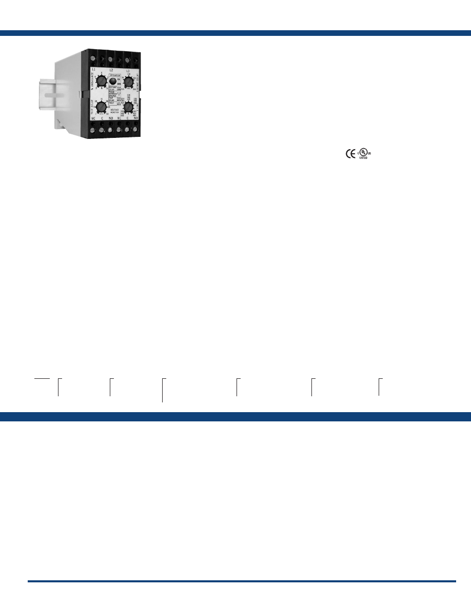
111
www.ssac.com • 800-843-8848 • fax: 605-348-5685
Features:
• Protects against phase & reversal; over,
under & unbalanced voltages; & over &
under frequency
• 35mm DIN rail or surface mounting
• Isolated, 10A, relay contacts
• Isolated, 2A, NO or NC, SPST relay contact
• LED indicates relay, faults, & time delays
• Universal line voltage 240 to 480VAC
• 600VAC version available
• 3-wire connection for delta or wye systems
• ASME A17.1 rule 210.6
• NEMA MG1 14:30, 14:35
• IEEE C62.41-1991 Level B
Approvals:
Auxiliary Products:
•
3-phase fuse block/disconnect:
P/N: FH3P
•
2 Amp fuse:
P/N: P0600-11
•
DIN rail:
P/N: C103PM
(Al)
DLMU Series
Voltage Monitors
Available Models:
Line Voltage
Type . . . . . . . . . . . . . . . . . . . . . . . .
3-phase delta or wye with no connection to neutral
Operating Voltage
200-480VAC Range Voltage Adj.Range Line Frequency Line Voltage Max.
240 200-240VAC 50/60Hz
380 340-420VAC 50Hz
480 400-480VAC 60Hz 550VAC
600VAC 600 500-600VAC 50/60Hz 600VAC
AC Line Frequency . . . . . . . . . . . .
50/60 Hz automatically detected
Phase Loss
. . . . . . . . . . . . . . . . . . . .
≥ 25% unbalance
Response Time . . . . . . . . . . . . . .
≤200ms
Undervoltage & Voltage Unbalance
Type . . . . . . . . . . . . . . . . . . . . . . .
Voltage detection with delayed trip & automatic reset
Overvoltage TripVoltage
. . . . . .
109 - 113% of the adjusted line voltage
Reset Voltage
. . . .
≅
-3% of the trip voltage
Undervoltage Trip Voltage
. . . . .
88 - 92% of the adjusted line voltage
Reset Voltage
. . . .
≅
+3% of the trip voltage
Voltage Unbalance
. . . . . . . . . . . .
Adjustable 2 - 10% or specify fixed unbalance of 2 - 10%
in 1% increments
Reset on balance . . .
≅
-0.7% unbalance
Trip Delay Active On
. . . . . . . . .
Over/undervoltage, voltage unbalance, over/under frequency
Range . . . . . . . . . . . . .
Adjustable from 1 - 30s or specify fixed delay 1 - 30s in 1s
increments
Tolerance . . . . . . . . . .
± 15%
Restart Delay Range . . . . . . . . . . . .
Adjustable from 0.6 - 300s; if no restart delay is
selected a 0.6s initialization delay applies
Tolerance . . . . . . . . .
± 15%
Over/Under Frequency
. . . . . . . . . .
±4%; Reset ±3%; 50/60 Hz
Phase Sequence
. . . . . . . . . . . . . . . . .
A, B, C, L1, L2, L3
Response Time
-Phase Reversal & Phase Loss . . . . ≤200 ms
Reset . . . . . . . . . . . . . . . . . . . . . . . . . . . Automatic
Output
Type . . . . . . . . . . . . . . . . . . . . . . . . . .
Isolated Electromechanical Relay
Rating . . . . . . . . . . . . . . . . . . . . . . . . .
10A resistive @ 240VAC; 8A resistive @ 277VAC;
NO-1/4 hp @ 120VAC; 1/3 hp @ 240VAC
Life
. . . . . . . . . . . . . . . . . . . . . . . . . . . .
Mechanical - 1 x 10
6
; Electrical - 1 x 30
3
Protection
Surge . . . . . . . . . . . . . . . . . . . . . . . . . .
IEEE C62.41-1991 Level B
Isolation Voltage
. . . . . . . . . . . . . . . .
≥ 2500V RMS input to output
Mechanical
Mounting . . . . . . . . . . . . . . . . . . . . . .
Surface mount with 2 #8 (M4 x 0.7) screw or snap on
35mm DIN Rail
Note: 0.25 in.(6.35 mm) spacing between units or other devices is required
Dimensions . . . . . . . . . . . . . . . . . . . . .
4.33 x 2.95 x 1.97 in. (110 x 75 x 50 mm)
Termination . . . . . . . . . . . . . . . . . . . .
Screw terminals with captive wire clamps for up to
#14 AWG (2.5 mm
2
) wire
Environmental
Operating / Storage Temperature
.
-40° to 60°C / -40° to 85°C
Humidity . . . . . . . . . . . . . . . . . . . . . . .
95% relative, non-condensing
Weight
. . . . . . . . . . . . . . . . . . . . . . . . .
≅
8.6 oz (244 g)
Specifications
Order Table:
DLM
X
Line Voltage
─
U
- 200-480VAC
─
H
- 500-600VAC
X
Output
─
B
- SPDT & NO
─
C
- SPDT & NC
X
Restart Function
─
L
- Lockout, min off time
─
R
- Staggered restarting
─
N
- No Restart Delay
X
Voltage Unbalance
─
A
- Adjustable 2-10%
─
Fixed
- Specify unbalance
2
-
10
% in 1% increments
using two digits
[04]
X
Trip Delay
─
A
- Adjustable 1-30s
─
Fixed
- Specify delay
1
-
30
s in 1s increments,
using two digits
[20]
X
Restart Delay
─
A*
- Adjustable 0.6-300s
─
N
- No Restart Delay
* Selection “A” is only available
for L or R Restart Functions
DLMHBRAAA
DLMUBNAAN
DLMUBRAAA
Operation
Upon application of line voltage, the output is de-energized and the restart delay begins. If all the 3-phase voltages are
within the acceptable range, the output energizes at the end of the restart delay. The microcontroller circuitry automatically
senses the voltage range, and selects the correct operating frequency (50 or 60Hz). The over and undervoltage trip points
are set automatically. When the measured value of any phase voltage exceeds the acceptable range limits (lower or upper)
the trip delay begins. At the end of the trip delay the output relay de-energizes. If the phase voltage returns to an acceptable
value before the trip delay expires, the trip delay is reset and the output remains energized. Under, over, and unbalanced
voltages plus over or under frequency must be sensed for the complete trip delay before the unit trips. The unit trips in
200ms when phase loss or reversal are sensed. The unit will not energize if a fault is sensed as the line voltage is applied.
Reset: Reset is automatic upon correction of the voltage or frequency fault or phase sequence.
Restart Delay Options:
L= Lockout or minimum OFF time. The restart delay begins when the output trips. The unit cannot be re-energized until the restart delay is complete. This provides a minimum off time or
lockout time to allow equipment sensitive to short cycling, time to reset. If the fault is corrected after the restart delay is complete the output energizes immediately. The restart delay also
occurs when line voltage is applied/reapplied.
R= Restart Delay on fault correction. The restart delay begins when line voltage is reapplied or when a voltage fault is corrected. This option is normally selected when staggered restarting
of multiple motors on a power system is required.
N= No Restart Delay. 0.6 second initialization delay on application of line voltage applies.
Restart Notes:
All restart options remain reset when the following conditions are detected:
1.) Phase loss (phase unbalance greater than 25%) 2.) Average line voltage less than 120VAC 3.) Phase reversal
The restart delay begins when the condition is corrected.
LED Operation
The LED flashes green during the restart delay, then glows green when the output energizes. It flashes red during the trip delay then glows red when the output de-energizes. It flashes red/
green if phase reversal is sensed If a fault is sensed during the restart delay, the LED will glow red during that portion or the full restart delay.
The DLMU Series is a universal voltage, 3-phase
voltage monitor. It continuously measures
the voltage of each of the three phases with
microcontroller accuracy and compares the value
to preset trip points. It separately senses phase
reversal and loss; over, under and unbalanced
voltages; and over or under frequency. Protection
is assured during periods of large average voltage
fluctuations or when regenerated voltages are
present. The unit trips within 200ms when phase
loss is detected. Adjustable time delays are
included to prevent nuisance tripping and short
cycling of sensitive equipment. The isolated,
10A, SPDT and 2A alarm output relay contacts
trip when a phase voltage exceeds the trip limits
for the trip delay. Nominal line voltage, voltage
unbalance, and time delays are knob adjustable.
The phase loss setpoint and the acceptable
frequency range are fixed. Both delta and wye
systems can be monitored; no connection to
neutral is required .
For more information see:
Appendix B, page 166, Figure 16 for dimensional drawing.
Appendix C, page 168, Figure 11 for connection diagram.
If desired part number is not listed, please call us to
see if it is technically possible to build .
Courtesy of Steven Engineering, Inc.-230 Ryan Way, South San Francisco, CA 94080-6370-Main Office: (650) 588-9200-Outside Local Area: (800) 258-9200-www.stevenengineering.com
Littelfuse-catalog-html.html

112
www.ssac.com • 800-843-8848 • fax: 605-348-5685
Features:
• Protects against phase loss & reversal; over,
under & unbalanced voltages; & over &
under frequency
•
Encapsulated circuitry
• Isolated, 10A, DPDT output contacts
• LED indicates relay status, faults, & time
delays
• Universal line voltage 200 to 480VAC in
one unit
•
Compact design
• Finger-safe terminal blocks, up to 12 AWG
• ASME A17.1 rule 210.6
• NEMA MG1 14:30, 14:35
• IEEE C62.41-1991 Level B
Approvals:
Auxiliary Products:
•
3-Phase fuse block/disconnect:
P/N: FH3P
•
2 Amp fuse:
P/N: P0600-11
•
DIN rail:
P/N: C103PM
(Al)
•
DIN rail adaptor:
P/N: P1023-20
HLMU Series
Voltage Monitors
Line Voltage
Type . . . . . . . . . . . . . . . . . . . . . . . . . . . . . . .
3-phase delta or wye with no connection to neutral
Operating Voltage 200 - 480VAC Range Voltage Adj. Range Frequency
240 200-240VAC 50 or 60Hz
380 340-420VAC 50Hz
480 400-480VAC 60Hz
Line Voltage Max.
. . . . . . . . . . . . . . . . . . .
550VAC
AC Line Frequency . . . . . . . . . . . . . . . . . .
50/60 Hz automatically detected
Phase Loss
. . . . . . . . . . . . . . . . . . . .
≥ 25% unbalance
Response Time . . . . . . . . . . . . . . . . . . . .
≤200ms
Undervoltage & Voltage Unbalance
Type . . . . . . . . . . . . . . . . . . . . . . . . . . . . . . .
Voltage detection with delayed trip &
automatic reset
Overvoltage Trip Voltage
. . . .
109 - 113% of the adjusted line voltage
Reset Voltage
. . .
≅
-3% of the trip voltage
Undervoltage Trip Voltage
. . . .
88 - 92% of the adjusted line voltage
Reset Voltage
. . .
≅
+3% of the trip voltage
Voltage Unbalance Trip Setpoint
. . . .
Adjustable 2 - 10% or specify fixed
unbalance of 2 - 10% in 1% increments
Reset on Balance
≅
-0.7% unbalance
Trip Delay Active On
. . . . . .
Over/undervoltage, voltage unbalance,
over/under frequency
Range . . . . . . . . . .
Adjustable from 1 - 30s or specify fixed
delay 1 - 30s in 1s increments
Tolerance . . . . . . .
± 15%
Restart Delay Range . . . . . . . . . .
Adjustable from 0.6 - 300s; if no restart
delay is selected a 0.6s initialization delay
applies
Tolerance . . . . . . .
± 15%
Over/Under Frequency
. . . . . . . . . . . . . . . . .
±4%; Reset ±3%; 50/60 Hz
Phase Sequence
. . . . . . . . . . . . . . . . . . . . . . .
A, B, C, L1, L2, L3
Response Time-Phase Reversal & Phase Loss. . . . . . ≤200 ms
Reset . . . . . . . . . . . . . . . . . . . . . . . . . . . . . . . . Automatic
Output
Type . . . . . . . . . . . . . . . . . . . . . . . . . . . . . . . . . .
Isolated Electromechanical Relay
Form . . . . . . . . . . . . . . . . . . . . . . . . . . . . . . . . . . DPDT
Rating . . . . . . . . . . . . . . . . . . . . . . . . . . . . . . . .
10A resistive @ 240VAC; 8A resistive @ 277VAC;
NO-1/4 hp @ 120VAC; 1/3 hp @ 240VAC
Life
. . . . . . . . . . . . . . . . . . . . . . . . . . . . . . . . . . .
Mechanical - 1 x 10
6
Electrical (at 10A) - DPDT - 1 x 30
3
Protection
Surge . . . . . . . . . . . . . . . . . . . . . . . . . . . . . . . . .
IEEE C62.41-1991 Level B
Isolation Voltage
. . . . . . . . . . . . . . . . . . . . . . .
≥ 2500V RMS input to output
Circuitry . . . . . . . . . . . . . . . . . . . . . . . . . . . . . . Encapsulated
Mechanical
Mounting . . . . . . . . . . . . . . . . . . . . . . . . . . . . .
Surface mount with one #10 (M5 x 0.7) screw
Note: 0.25 in.(6.35 mm) spacing between units or other devices is required
Dimensions . . . . . . . . . . . . . . . . . . . . . . . . . . . .
3 x 2 x 1.64 in. (76.7 x 51.3 x 41.7 mm)
Termination . . . . . . . . . . . . . . . . . . . . . . . . . . . Screw terminal connection up to
12 AWG (3.3 mm
2
) wire
Environmental
Operating / Storage Temperature
. . . . . . . .
-40° to 60°C / -40° to 85°C
Humidity . . . . . . . . . . . . . . . . . . . . . . . . . . . . . .
95% relative, non-condensing
Weight
. . . . . . . . . . . . . . . . . . . . . . . . . . . . . . . .
≅
3.9 oz (111 g)
Available Models:
Specifications
Order Table:
HLMUDLAAA
HLMUDN0405N
HLMUDNAAN
HLMUDRAAA
HLMUSR0604A
HLMU
X
Output
─
D
- DPDT
─
S
- SPDT
X
Restart Function
─
L
- Lockout, Min Off Time
─
R
- Staggered Restarting
─
N
- No Restart Delay
X
Voltage Unbalance
─
A
- Adjustable 2-10%
─
Fixed
- Specify Unbalance
2
-
10
% in 1% increments,
using two digits
[04]
X
Trip Delay
─
A
- Adjustable 1-30s
─
Fixed
- Specify delay
1
-
30
s in 1s increments,
using two digits
[05]
X
Restart Delay
─
A*
- Adjustable 0.6-300s
─
N
- No Restart Delay
*Selection “A” is only
available for Restart
Functions “L” and “R”
The HLMU Series is a universal voltage, encapsulated,
3-phase voltage monitor. It continuously measures
the voltage of each of the three phases with
microcontroller accuracy and compares the value to
preset trip points. It separately senses phase reversal
and loss; over, under and unbalanced voltages; and
over or under frequency. Protection is assured during
periods of large average voltage fluctuations, or when
regenerated voltages are present. The unit trips within
200ms when phase loss is detected. Adjustable time
delays are included to prevent nuisance tripping and
short cycling of sensitive equipment. The isolated,
10A, DPDT relay contacts trip when a phase voltage
exceeds the trip limits for the trip delay. Nominal line
voltage, voltage unbalance, and time delays are knob
adjustable. The phase loss setpoint and the acceptable
frequency range are fixed. Both delta and wye systems
can be monitored; no connection to neutral is required
.
For more information see:
Appendix B, page 166, Figure 17 for dimensional drawing.
Appendix C, page 168, Figure 12 for connection diagram.
Operation
Upon application of line voltage, the output is de-energized and the restart delay begins. If all the three-phase voltages
are within the acceptable range, the output energizes at the end of the restart delay. The microcontroller circuitry
automatically senses the voltage range, and selects the correct operating frequency (50 or 60Hz). The over and under
voltage trip points are set at ± 10% of the adjusted line voltage. When the measured value of any phase voltage exceeds the
acceptable range limits (lower or upper) the trip delay begins. At the end of the trip delay the output relay de-energizes.
If the phase voltage returns to an acceptable value before the trip delay expires, the trip delay is reset and the output
remains energized. Under, over, and unbalanced voltages plus over or under frequency must be sensed for the complete
trip delay before the unit trips. The unit trips in 200ms when phase loss or reversal are sensed. The unit will not energize
if a fault is sensed as the line voltage is applied.
Reset: Reset is automatic upon correction of the voltage or frequency fault or phase sequence.
Restart Delay Options:
L= Lockout or minimum OFF time. The restart delay begins when the output trips. The unit cannot be re-energized until the restart delay is complete. This provides a minimum off time
or lockout time to allow equipment sensitive to short cycling, time to reset. If the fault is corrected after the restart delay is complete, the output energizes immediately. The restart delay
also occurs when line voltage is applied/reapplied.
R= Restart Delay on fault correction. The restart delay begins when line voltage is reapplied or when a voltage fault is corrected. This option is normally selected when staggered restarting
of multiple motors on a power system is required.
N= No Restart Delay. 0.6 second initialization delay on application of line voltage applies.
Restart Notes:
All restart options remain reset when the following conditions are detected:
1.) Phase loss (phase unbalance greater than 25%) 2.) Average line voltage less than 120VAC 3.) Phase reversal
The restart delay begins when the condition is corrected.
LED Operation
The LED flashes green during the restart delay, then glows green when the output energizes. It flashes red during the trip delay then glows red when the output de-energizes. It flashes
red/green if phase reversal is sensed. If a fault is sensed during the restart delay, the LED will glow red during that portion or the full restart delay.
If desired part number is not listed, please call us to
see if it is technically possible to build .
Courtesy of Steven Engineering, Inc.-230 Ryan Way, South San Francisco, CA 94080-6370-Main Office: (650) 588-9200-Outside Local Area: (800) 258-9200-www.stevenengineering.com
Littelfuse-catalog-html.html
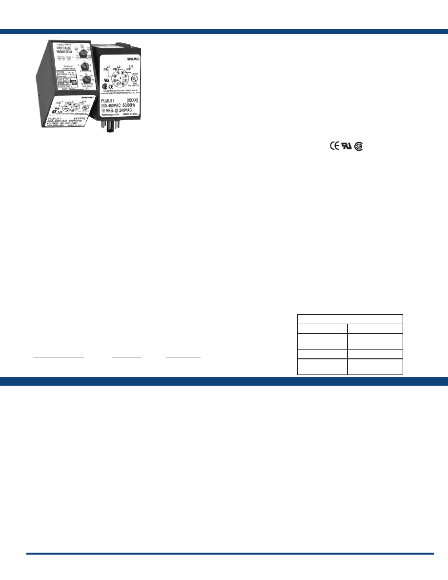
113
www.ssac.com • 800-843-8848 • fax: 605-348-5685
Features:
• Protects against phase & reversal; & over,
under & unbalanced voltages
• Octal plug-in
• Isolated, 10A,
SPDT output contacts
• Operates from 200 to 480VAC
• LED indicator glows green when voltages are
acceptable, red for faults
• Indicates reverse-phase wiring
• Simple 3-wire connection for delta or wye
systems
• ASME A17.1 Rule 210.6
• NEMA MG1 14:30, 14:35
• IEEE C62.41-1991 Level B
Approvals:
Auxilary Products:
•
Panel mount kit:
P/N: BZ1
•
8-pin octal socket
: P/N: OT08PC
•
3-phase fuse block/disconnect:
P/N: FH3P
•
2 Amp fuse:
P/N: P0600-11
•
DIN rail:
P/N: C103PM
(Al)
PLMU Series
Voltage Monitors
Available Models:
Line Voltage
Type . . . . . . . . . . . . . . . . . . . . . . . . . . . . . . . . . . .
3-phase delta or wye with no connection to
neutral
Line Voltage
. . . . . . . . . . . . . . . . . . . . . . . . . . . .
200 to 480VAC
±
15%, 50/60 Hz
±
2 Hz
Adjustable Voltage Ranges
(Automatic Range Selection) . . . . . . . . . . . .
200 to 240VAC, 50/60 Hz
340 to 420VAC, 50 Hz
400 to 480VAC, 60 Hz
Maximum Voltage
. . . . . . . . . . . . . . . . . . . . . .
552VAC
Phase Sequence
. . . . . . . . . . . . . . . . . . . . . . . . . ABC
Overvoltage, Undervoltage, & Voltage Unbalance
Type . . . . . . . . . . . . . . . . . . . . . . . . . . . . . . . . . . .
Voltage detection with delayed trip & automatic
reset
Overvoltage & Undervoltage
Undervoltage Trip Point
. . . . . . . . . . . . . . .
88 - 92% of adjusted line voltage
Reset Voltage
. . . . . . . . . . . . . . . . . . . . . . . . .
+2% of trip voltage
Overvoltage Trip Point
. . . . . . . . . . . . . . . .
109 - 113% of adjusted line voltage
Reset Voltage
. . . . . . . . . . . . . . . . . . . . . . . . .
-2% of trip voltage
Voltage Unbalance Trip Point
. . . . . . . . . . . . .
Adjustable from 2 - 10%
Factory fixed from 4 - 10% (a minimum order
quantity applies)
Reset on Balance (%):
Selected Unbalance 2 3 4 5 6 7 8 9 10
Reset 1.5 2.5 3.5 4.5 5.4 6.3 7.2 8.1 9
Trip Delay Range
. . . . . . . . . . . . . . . . . . . . . . . .
Adjustable from 0.25 - 30s
Factory fixed from 2 - 30s
±
15%
(a minimum order quantity applies)
Severe Unbalance - 2X Selected Unbalance
.
0.25 - 2s; disabled when the trip delay is less
than 2s
Random Start Delay . . . . . . . . . . . . . . . . . . . . .
≅
0.6s
Phase Reversal & Phase Loss Trip Time
. . . .
≤ 150ms
Phase Loss Setpoint
. . . . . . . . . . . . . . . . . . . . . .
≥ 15% unbalance
Reset Type . . . . . . . . . . . . . . . . . . . . . . . . . . . . . Automatic
Output Type
. . . . . . . . . . . . . . . . . . . . . . . . . . . .
Energized when voltages are acceptable
Rating . . . . . . . . . . . . . . . . . . . . . . . . . . . . . . . . .
10A resistive @ 240VAC; 1/4 hp @ 125VAC;
1/3 hp @ 250VAC; max. 277VAC
Life
. . . . . . . . . . . . . . . . . . . . . . . . . . . . . . . . . . . .
Mechanical - 1 x 10
6
; Electrical - 1 x 10
5
Protection
Surge . . . . . . . . . . . . . . . . . . . . . . . . . . . . . . . . . .
IEEE C62.41-1991 Level B
Isolation Voltage
. . . . . . . . . . . . . . . . . . . . . . . .
≥ 2500V RMS input to output
Mechanical
Mounting* . . . . . . . . . . . . . . . . . . . . . . . . . . . . . .
Plug-in socket rated 600VAC
Termination . . . . . . . . . . . . . . . . . . . . . . . . . . . .
Octal 8-pin plug-in
Dimensions . . . . . . . . . . . . . . . . . . . . . . . . . . . . .
3.03 x 2.39 x 1.78 in. (77.0 x 60.7 x 45.2 mm)
Environmental
Operating / Storage Temperature
. . . . . . . . .
-40° to 60°C / -40° to 85°C
Weight
. . . . . . . . . . . . . . . . . . . . . . . . . . . . . . . . .
≅
8.6 oz (244 g)
*CAUTION: Select an octal socket rated for 600VAC operation.
Specifications
Order Table:
Voltage Unbalance
Adjustable 2-10%
Trip Delay
Adjustable 0.25-30
s
Part Number
PLMU11
PLMU11
The PLMU Series continuously measures the
voltage of each of the three phases to provide
protection for 3-phase motors and sensitive loads.
Its microcontroller senses under and overvoltage,
voltage unbalance, phase loss, and phase reversal.
Protection is provided even when regenerated
voltages are present. Universal voltage operation
and standard base connection allows the PLMU
to replace hundreds of competitive part numbers.
For more information see:
Appendix B, page 166, Figure 18 for dimensional drawing.
Appendix C, page 168, Figure 13 for connection diagram.
Operation
Upon application of power, a 0.6s random start delay begins and the PLMU measures the voltage levels and line
frequency and selects the voltage range. The output relay is energized and the LED glows green when all voltages
are acceptable and the phase sequence is correct. LED flashes green during trip delay, glows red when output
de-energizes. Undervoltage, overvoltage, and voltage unbalance must be sensed for continuous trip delay before
the relay de-energizes. Re-energization is automatic upon fault correction. The output relay will not energize
if a fault condition is sensed as 3-phase input voltage is applied. The LED alternately flashes red/green when
phase reversal is sensed. Line voltage is selected with the knob, setting the over and under voltage trip points.
Voltage range is automatically selected by the microcontroller.
LED Indicator
Steady Green
Energized
Steady Red
De-engergized
(tripped on fault)
Flashing Green
Trip Delay
Alternate Flashing
Red/Green
Phase Reversal
Courtesy of Steven Engineering, Inc.-230 Ryan Way, South San Francisco, CA 94080-6370-Main Office: (650) 588-9200-Outside Local Area: (800) 258-9200-www.stevenengineering.com
Littelfuse-catalog-html.html
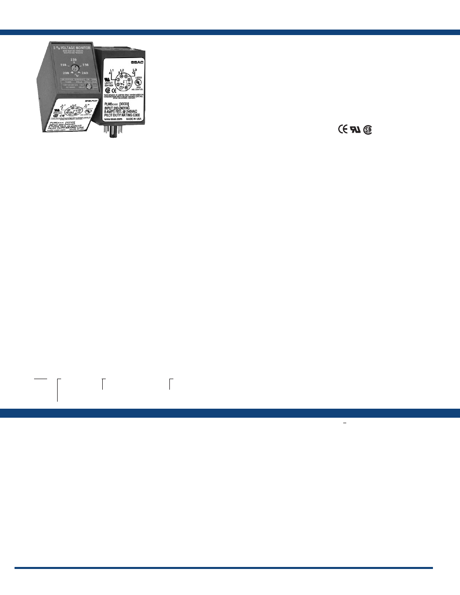
114
www.ssac.com • 800-843-8848 • fax: 605-348-5685
Features:
• Protects against phase loss & reversal; &
under & unbalanced voltages
• 8-pin plug-in base
• Adjustable low voltage trip point
• Factory fixed unbalance & trip delay
• Line voltages 200 to 480VAC in 3 ranges
• Isolated, 10A, SPDT output contacts
• ASME A17.1 rule 210.6
• NEMA MG1 14:30, 14:35
• IEEE C62.41-1991 Level B
Approvals:
Auxiliary Products:
•
Panel mount kit:
P/N: BZ1
•
Octal 8-pin socket:
P/N: OT08PC
•
3-phase fuse block/disconnect:
P/N: FH3P
•
2 Amp fuse:
P/N: P0600-11
•
DIN rail:
P/N: C103PM
(Al)
PLM Series
Voltage Monitors
Line Voltage
Type . . . . . . . . . . . . . . . . . . . . . . . . . . . . . . . . . . . . . . .
3-phase delta or wye with no connection to
neutral
Operating Voltage: Model Adj. Line Voltage Range Line Voltage Max.
240 200-240VAC 270VAC
380 360-430VAC 480VAC
480 400-480VAC 530VAC
AC Line Frequency . . . . . . . . . . . . . . . . . . . . . . . . . .
50/100 Hz
Phase Sequence
. . . . . . . . . . . . . . . . . . . . . . . . . . . . . ABC
Power Consumption . . . . . . . . . . . . . . . . . . . . . . . . .
≅
2W for 240V units
≅
3W for 380 - 480V units
Low Voltage & Voltage Unbalance
Type . . . . . . . . . . . . . . . . . . . . . . . . . . . . . . . . . . . . . . .
Voltage detection with delayed trip & automatic
reset
Low Voltage Trip Voltage
. . . . . .
88 - 92% of adjusted line voltage
Reset Voltage
. . . . .
Plus 3% of trip voltage
Voltage Unbalance Trip Unbalance
. . .
Factory fixed from 4 - 8%
Reset on Balance . .
-0.7% unbalance typical
Trip Delay Range . . . . . . . . . . .
Factory fixed from 2 - 20s
Tolerance . . . . . . . .
±15%
Phase Reversal & Phase Loss
Response Time: Phase Reversal
. . . . . .
≤ 200ms
Phase Loss
. . . . . . . . . .
≤ 200ms
Phase Loss
. . . . . . . . . . . . . . . . . . . . . . . . . . . . . >
35% unbalance
Reset . . . . . . . . . . . . . . . . . . . . . . . . . . . . . . . . . . Automatic
Output
Type . . . . . . . . . . . . . . . . . . . . . . . . . . . . . . . . . .
Electromechanical relay
Form . . . . . . . . . . . . . . . . . . . . . . . . . . . . . . . . . .
Isolated, SPDT
Rating . . . . . . . . . . . . . . . . . . . . . . . . . . . . . . . .
10A resistive @ 240VAC, 277VAC max;
1/2 Hp @ 240VAC; 1/4 Hp @ 120VAC
Life
. . . . . . . . . . . . . . . . . . . . . . . . . . . . . . . . . . .
Mechanical - 1 x 10
7
; Electrical - 1 x 10
5
Protection
Surge . . . . . . . . . . . . . . . . . . . . . . . . . . . . . . . . .
IEEE C62.41-1991 Level B
Isolation Voltage
. . . . . . . . . . . . . . . . . . . . . . .
≥ 2500V RMS input to output
Mechanical
Mounting* . . . . . . . . . . . . . . . . . . . . . . . . . . . . .
8-pin plug-in socket rated 600VAC
Dimensions . . . . . . . . . . . . . . . . . . . . . . . . . . . .
3.2 x 2.39 x 1.78 in. (81.3 x 60.7 x 45.2 mm)
Environmental
Operating / Storage Temperature
. . . . . . . .
-40° to 60°C / -40° to 85°C
Weight
. . . . . . . . . . . . . . . . . . . . . . . . . . . . . . . .
≅
4.4 oz (125 g)
*CAUTION: Select an octal socket rated for 600VAC operation.
Available Models:
Specifications
Order Table:
PLM
X
Line Voltage
─
6
- 240VAC
─
8
- 380VAC
─
9
- 480VAC
X
Voltage Unbalanced
─
Fixed
-
Specify -
4
-
8
%
in 1% increments
X
Trip Delay
─
Fixed
-
Specify from
2
-
20
s
in 1s increments using
two digits
PLM6405
PLM6502
PLM6805
PLM8405
PLM8805
PLM9405
PLM9502
PLM9805
PLM9820
The PLM Series continuously measures the voltage
of each of the three phases. The PLM Series
uses a microcontroller circuit design that senses
undervoltage, voltage unbalance, phase loss,
and phase reversal. Protection is assured when
regenerated voltages are present. Both delta and
wye systems can be monitored; no connection to
neutral is required .
For more information see:
Appendix B, page 165, Figure 8 for dimensional drawing.
Appendix C, page 168, Figure 13 for connection diagram.
Operation
The output relay is energized and the LED glows green when all voltages are acceptable and the phase sequence
is correct. Under and unbalanced voltages must be sensed for a continuous trip delay period before the relay
de-energizes. Reset is automatic upon correction of the fault condition. The output relay will not energize if a
fault condition is sensed as power is applied. The LED flashes red during the trip delay, then glows red when
the output de-energizes. The LED flashes green/red if phase reversal is sensed.
Field Adjustment:
Set voltage adjustment knob at the desired operating line voltage for the equipment. This adjustment automatically
sets the undervoltage trip point. Apply power. If the PLM fails to energize, (LED glows red) check wiring of
all 3 phases, voltage, and phase sequence. If phase sequence is incorrect, the LED flashes green/red. To correct
this, swap any two line voltage connections at the mounting socket. No further adjustment should be required.
If desired part number is not listed, please call us to
see if it is technically possible to build .
Courtesy of Steven Engineering, Inc.-230 Ryan Way, South San Francisco, CA 94080-6370-Main Office: (650) 588-9200-Outside Local Area: (800) 258-9200-www.stevenengineering.com
Littelfuse-catalog-html.html

115
www.ssac.com • 800-843-8848 • fax: 605-348-5685
Features:
• Protects against phase loss & reversal; over,
under & unbalanced voltages; short
cycling
• Fixed trip points & delays
• Adjustable voltages from 208 to 480VAC
in 4 ranges
• Monitor 600VAC lines by connecting VRM
accessory
• Isolated, 10A, SPDT output contacts
• Bi-color LED indicates: output status, faults,
time delays, phase reversal & setpoint
• ASME A17.1 rule 210.6
• NEMA MG1 14:30, 14:35
• IEEE C62.41-1991 Level B
Approvals:
Auxilary Products:
•
3-phase fuse block/disconnect:
P/N: FH3P
•
2 Amp fuse:
P/N: P0600-11
•
DIN rail:
P/N: C103PM
(Al)
•
Female quick connect:
P/N: P1015-13 (AWG 10/12)
P/N: P1015-64 (AWG 14/16)
P/N: P1015-14 (AWG 18/22)
•
Voltage reduction module:
P/N: VRM6048
TVW Series
Voltage Monitors
Available Models:
Line Voltage
Type . . . . . . . . . . . . . . . . . . . . . . . . . . . . . . . . . . . . .
3-phase delta or wye with no connection to neutral
Input Voltage/Tolerance
. . . . . . . . . . . . . . . . . . .
208 to 480VAC in 4 ranges/-30% - 20%
AC Line Frequency . . . . . . . . . . . . . . . . . . . . . . . .
50 - 100 Hz
Phase Sequence
. . . . . . . . . . . . . . . . . . . . . . . . . . . ABC
Power Consumption . . . . . . . . . . . . . . . . . . . . . . .
Approx. 2W for 240V units
Approx. 3W for 480V units
Overvoltage, Undervoltage, & Voltage Unbalance
Overvoltage & Undervoltage
. . . . . . . . . . . . . . . .
Voltage detection with delay trip & automatic
reset
Undervoltage Trip Point
. . . . . . . . . . . . . . . . . . . .
88 - 92% of the selected line voltage
Reset Voltage
. . . . . . . . . . . . . . . . . . . . . . . . . . . . .
≅
+3% of trip voltage
Overvoltage Trip Point
. . . . . . . . . . . . . . . . . . . . .
109 - 113% of the selected line voltage
Reset Voltage
. . . . . . . . . . . . . . . . . . . . . . . . . . . . .
≅
-3% of trip voltage
Trip Variation vs Temperature
. . . . . . . . . . . . . .
≤ ±2%
Voltage Unbalance
. . . . . . . . . . . . . . . . . . . . . . .
Factory fixed, from 4 - 10%
Reset On Balance . . . . . . . . . . . . . . . . . . . . . . . . . .
≅
-0.7% unbalance
Trip Delay Range . . . . . . . . . . . . . . . . . . . . . . . . . .
Fixed from 0.2 - 100s ±15% or ±0.1s,
whichever is greater
Restart Delay Range . . . . . . . . . . . . . . . . . . . . . . .
Fixed from 0.4s - 999m ±15% or ±0.2s,
whichever is greater
Phase Reversal & Phase Loss Response
. . . . . . .
≤ 200ms; automatic reset
Phase Loss
. . . . . . . . . . . . . . . . . . . . . . . . . . . . . . . .
≥ 25% unbalance
Output
Type . . . . . . . . . . . . . . . . . . . . . . . . . . . . . . . . . . . . .
Isolated, SPDT
Rating 208 to 240VAC (55°C)
. . . . . .
10A resistive @ 125VAC, 5A @ 250VAC,
1/4 hp @ 125VAC
380 to 480VAC
. . . . . . . . . . . .
10A resistive @ 240VAC, 1/4 hp @ 125VAC,
1/3 hp @ 250VAC, max. voltage 277VAC
Life
. . . . . . . . . . . . . . . . . . . . . . . . . . . . . . . . . . . . . .
Mechanical - 1 x 10
6
; Electrical - 1 x 10
5
Protection
Surge . . . . . . . . . . . . . . . . . . . . . . . . . . . . . . . . . . . .
IEEE C62.41-1991 Level B
Dielectric Breakdown 208 to 240VAC
. . . . . . .
≥ 1500V RMS input to output terminals
380 to 480VAC
. . . . . .
≥ 2500V RMS input to output terminals
Mechanical
Mounting . . . . . . . . . . . . . . . . . . . . . . . . . . . . . . . .
Surface mount with one #8 (M5 x 0.8) screw
Dimensions . . . . . . . . . . . . . . . . . . . . . . . . . . . . . . .
2 x 2 x 1.25 in. (50.8 x 50.8 x 31.8 mm)
Termination . . . . . . . . . . . . . . . . . . . . . . . . . . . . . .
0.25 in. (6.35 mm) male quick connect
terminals
Environmental
Operating / Storage Temperature
. . . . . . . . . . .
-40° to 55°C / -40° to 85°C
Humidity . . . . . . . . . . . . . . . . . . . . . . . . . . . . . . . . .
95% relative, non-condensing
Weight
. . . . . . . . . . . . . . . . . . . . . . . . . . . . . . . . . . .
≅
2.8 oz (79 g)
Specifications
TVW575S1M
TVW6510S0.4S
TVW9510S0.4S
Order Table:
TVW
X
Line Voltage
Wide Range
─
5
- 208-240VAC
Selectable
─
6
- 208, 220, 230 & 240VAC
─
8
- 380, 400 & 415VAC
─
9
- 430, 440, 460 & 480VAC
X
Voltage Unbalance
─
Fixed
-
Specify
4
-
10
%
in 1% increments
X
Trip Delay*
─
Fixed
- Specify from
0 .2
-
1
s
in 0.1s increments
─
Fixed
- Specify from
1
-
100
s in 1s increments
*Must indicate (S) for secs. or (M)
for mins.
X
Restart Delay*
─
Fixed
-
Specify from
0 .4
-
1
s
in 0.1s increments
─
Fixed
-
Specify from
1
-
100
s in 1s
increments
─
Fixed
-
Specify from
1
-
999
min in
1min increments
Provides protection for motors and other sensitive
loads. Continuously measures the voltage of
each of the three phases using a microcontroller
circuit design that senses under and overvoltage,
voltage unbalance, phase loss, and phase reversal.
Protection is provided even when regenerated
voltages are present. Includes a trip delay to
prevent nuisance tripping and a restart delay to
prevent short cycling after a momentary power
outage .
For more information see:
Appendix B, page 167, Figure 30 for dimensional drawing.
Appendix C, page 168, Figure 14 for connection diagram.
Operation
Upon application of line voltage, the restart delay begins. The output is de-energized during restart delay. Under
normal conditions, the output energizes after the restart delay. Undervoltage, overvoltage, and voltage unbalance
must be sensed for the complete trip delay period before the output de-energizes. The restart delay begins as
soon as the output de-energizes. If the restart delay is completed when a fault is corrected, the output energizes
immediately. The output will not energize if a fault is sensed as the input voltage is applied. If the voltage selector
is set between two voltage marks (i.e. between 220 and 230V), the LED will flash red rapidly. The TVW provides
fault protection at the lower of the two line voltages (i.e. 220V).
Reset: Reset is automatic upon correction of a fault.
LED Operation
The LED flashes green during the restart delay, then glows green when the output energizes. It flashes red during
the trip delay then glows red when the output de-energizes. It flashes red/green if phase reversal is sensed. If
the voltage selector knob is between settings, it rapidly flashes red.
If desired part number is not listed, please call us to
see if it is technically possible to build .
Courtesy of Steven Engineering, Inc.-230 Ryan Way, South San Francisco, CA 94080-6370-Main Office: (650) 588-9200-Outside Local Area: (800) 258-9200-www.stevenengineering.com
Littelfuse-catalog-html.html
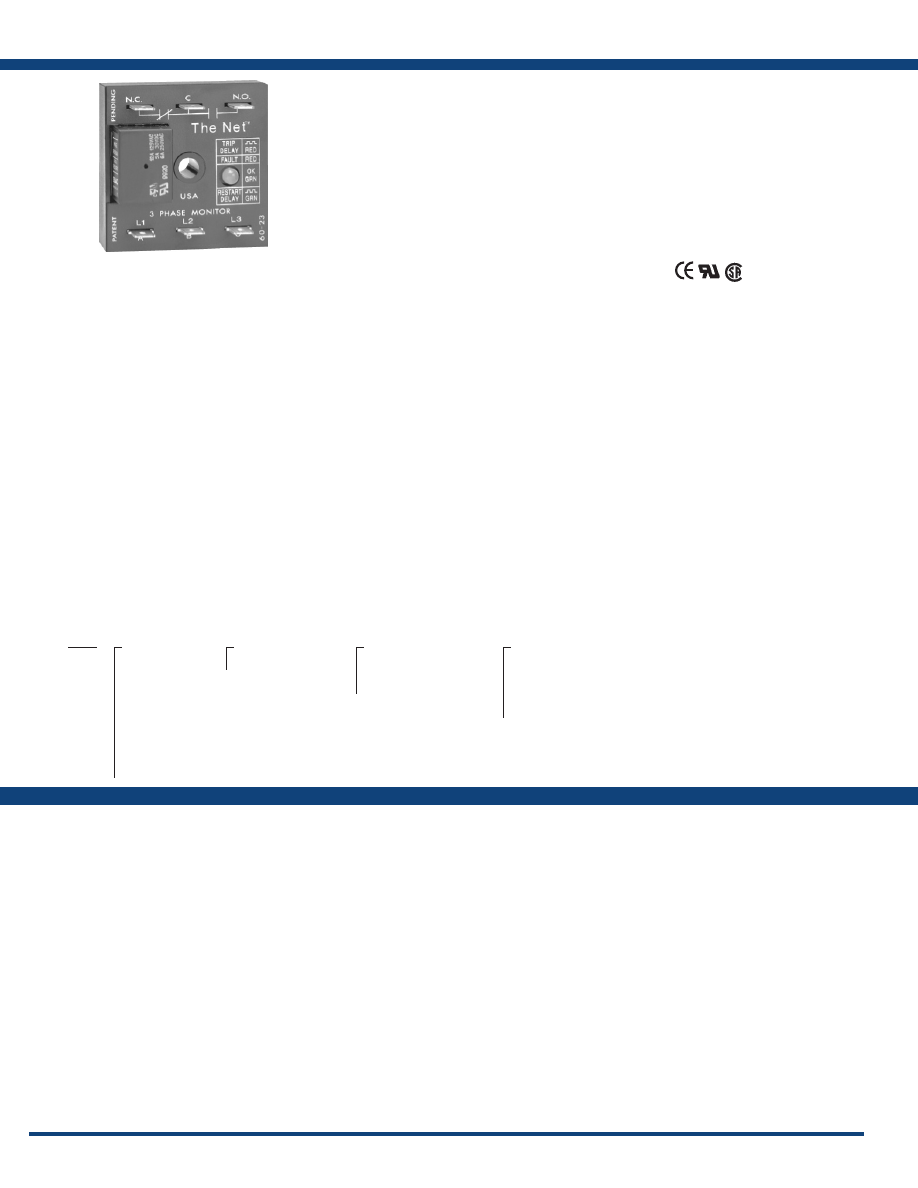
116
www.ssac.com • 800-843-8848 • fax: 605-348-5685
TVM Series
Voltage Monitors
Line Voltage
Type . . . . . . . . . . . . . . . . . . . . . . . . . . . . . . . . . . .
3-phase delta or wye with no connection to neutral
Input Voltage
. . . . . . . . . . . . . . . . . . . . . . . . . . . .
208 to 480VAC
AC Line Frequency . . . . . . . . . . . . . . . . . . . . . . .
50 - 100 Hz
Phase Sequence
. . . . . . . . . . . . . . . . . . . . . . . . . . ABC
Power Consumption . . . . . . . . . . . . . . . . . . . . .
Approx. 2W for 240V units
Approx. 3W for 480V units
Overvoltage, Undervoltage, & Voltage Unbalance
Overvoltage & Undervoltage
. . . . . . . . . . . . . .
Voltage detection with delay trip & automatic reset
Undervoltage Trip Point
. . . . . . . . . . . . . . . . .
88 - 92% of the selected line voltage
Reset Voltage
. . . . . . . . . . . . . . . . . . . . . . . . . .
≅
+3% of trip voltage
Overvoltage Trip Point
. . . . . . . . . . . . . . . . . .
109 - 113% of the selected line voltage
Reset Voltage
. . . . . . . . . . . . . . . . . . . . . . . . . .
≅
-3% of trip voltage
Trip Variation vs Temperature
. . . . . . . . . . .
≤ ±2%
Voltage Unbalance
. . . . . . . . . . . . . . . . . . . . . .
Factory fixed from 4 - 10%
Reset On Balance . . . . . . . . . . . . . . . . . . . . . . . . .
≅
-0.7% unbalance
Trip Delay Range . . . . . . . . . . . . . . . . . . . . . . . .
Fixed from 0.2 - 100s ±15% or ±0.1s,
whichever is greater
Restart Delay Range . . . . . . . . . . . . . . . . . . . . . .
Fixed from 0.5s - 999m ±15% or ±0.2s,
whichever is greater
Phase Reversal & Phase Loss Response
. . . . .
≤ 200ms; automatic reset
Phase Loss
. . . . . . . . . . . . . . . . . . . . . . . . . . . . . .
≥ 25% unbalance
Output
Type . . . . . . . . . . . . . . . . . . . . . . . . . . . . . . . . . . . Isolated SPDT relay contacts
Rating 208 to 240VAC (55°C)
. . . . .
10A resistive @ 125VAC, 5A @ 250VAC,
1/4 hp @ 125VAC
380 to 480VAC
. . . . . . . . . . .
10A resistive @ 240VAC, 1/4 hp @ 125VAC,
1/3 hp @ 250VAC, max. voltage 277VAC
Life
. . . . . . . . . . . . . . . . . . . . . . . . . . . . . . . . . . . .
Mechanical - 1 x 10
6
; Electrical - 1 x 10
5
Protection
Surge . . . . . . . . . . . . . . . . . . . . . . . . . . . . . . . . . . .
IEEE C62.41-1991 Level B
Dielectric Breakdown 208 to 240VAC
. . . . .
≥ 1500V RMS input to output terminals
380 to 480VAC
. . . . .
≥ 2500V RMS input to output terminals
Mechanical
Mounting . . . . . . . . . . . . . . . . . . . . . . . . . . . . . . .
Surface mount with one #8 (M5 x 0.8) screw
Dimensions . . . . . . . . . . . . . . . . . . . . . . . . . . . . .
2 x 2 x 1.25 in. (50.8 x 50.8 x 31.8 mm)
Termination . . . . . . . . . . . . . . . . . . . . . . . . . . . . .
0.25 in. (6.35 mm) male quick connect
terminals
Environmental
Operating / Storage Temperature
. . . . . . . . .
-40° to 55°C / -40° to 85°C
Humidity . . . . . . . . . . . . . . . . . . . . . . . . . . . . . . .
95% relative, non-condensing
Weight
. . . . . . . . . . . . . . . . . . . . . . . . . . . . . . . . .
≅
2.8 oz (79 g)
Available Models:
Features:
• Protects against phase loss & reversal; over,
under & unbalanced voltages; short
cycling
• Fixed trip points & delays
• Fixed voltages from 208 to 480VAC
• Isolated, 10A, SPDT ouput contacts
• Bi-color LED indicator shows: output status,
faults, time delays & phase reversal
• ASME A17.1 rule 210.6
• NEMA MG1 14:30, 14:35
• IEEE C62.41-1991 Level B
Approvals:
Auxiliary Products:
•
Female quick connect:
P/N: P1015-13 (AWG 10/12)
P/N: P1015-64 (AWG 14/16)
P/N: P1015-14 (AWG 18/22)
•
3-phase fuse block/disconnect:
P/N: FH3P
•
2 Amp fuse:
P/N: P0600-11
•
Voltage reduction module:
P/N: VRM6048
Specifications
Order Table:
TVM
X
Line Voltage
─
208A
- 208VAC
─
220A
- 220VAC
─
230A
- 230VAC
─
240A
- 240VAC
─
380A
- 380VAC
─
400A
- 400VAC
─
415A
- 415VAC
─
440A
- 440VAC
─
460A
- 460VAC
─
480A
- 480VAC
X
Voltage Unbalance
─
Fixed
-
Specify
4
-
10
%
in 1% increments
X
Trip Delay*
─
Fixed
- Specify from
0 .2
-
1
s
in 0.1s increments
─
Fixed
- Specify from
1
-
100
s in 1s increments
*Must indicate (S) for secs. or (M)
for mins.
X
Restart Delay*
─
Fixed
-
Specify from
0 .5
-
1
s
in 0.1s increments
─
Fixed
-
Specify from
1
-
100
s in 1s
increments
─
Fixed
-
Specify from
1
-
999
min in
1min increments
TVM208A100.5S3S
TVM230A101S1S
TVM400A101S1S
TVM460A101S1S
TVM460A41S5M
TVM460A510S5S
TVM460A75S2M
TVM480A100.5S3S
TVM480A50.5S2S
Provides protection for motors and other sensitive
loads. Continuously measures the voltage of
each of the three phases using a microcomputer
circuit design that senses under and overvoltage,
voltage unbalance, phase loss, and phase reversal.
Protection is provided even when regenerated
voltages are present. Includes a trip delay to
prevent nuisance tripping and a restart delay to
prevent short cycling after a momentary power
outage .
For more information see:
Appendix B, page 167, Figure 30 for dimensional drawing.
Appendix C, page 168, Figure 14 for connection diagram.
Operation
Upon application of line voltage, the restart delay begins. The output relay is de-energized during restart delay.
Under normal conditions, the output energizes after restart delay. Undervoltage, overvoltage, and voltage
unbalance must be sensed for continuous trip delay period before the output is de-energized. The output will not
de-energize if a fault is corrected during the trip delay. The restart delay begins as soon as the output relay de-
energizes. If the restart delay is completed when the fault is corrected, the output relay will energize immediately.
The output relay will not energize if a fault or phase reversal is sensed as 3-phase input voltage is applied.
Reset: Reset is automatic upon correction of a fault.
LED Operation
The LED flashes green during the restart delay, then glows green when the output energizes. It flashes red during
the trip delay then glows red when the output de-energizes. It flashes red/green if phase reversal is sensed.
If desired part number is not listed, please call us to
see if it is technically possible to build .
Courtesy of Steven Engineering, Inc.-230 Ryan Way, South San Francisco, CA 94080-6370-Main Office: (650) 588-9200-Outside Local Area: (800) 258-9200-www.stevenengineering.com
Littelfuse-catalog-html.html
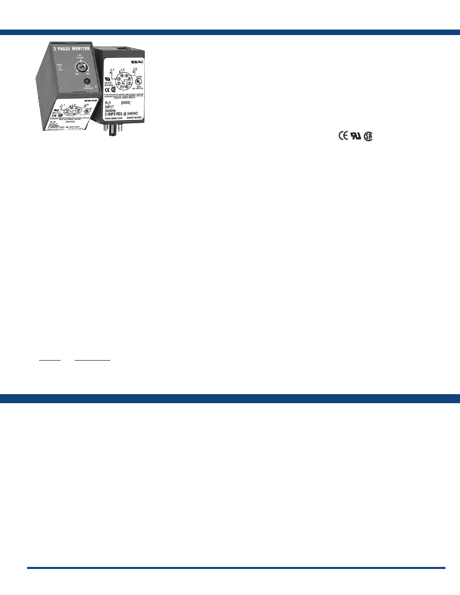
117
www.ssac.com • 800-843-8848 • fax: 605-348-5685
Features:
• Protects against phase loss (on startup),
phase reversal & undervoltage
• Used where moderate voltage unbalance
protection is not required
• Direct replacement for most popular
3-phase monitors
• 8-pin octal base connection
• Isolated, 5A, SPDT output contacts
• AMSE A17.1 rule 210.6
• NEMA MG1 14:30, 14:35
• IEEE C62.41-1991 Level B
Approvals:
Auxilary Products:
•
Panel mount kit:
P/N: BZ1
•
Octal 8-pin socket:
P/N: OT08PC
•
3-phase fuse block/disconnect:
P/N: FH3P
•
2 Amp fuse:
P/N: P0600-11
•
DIN rail:
P/N: C103PM
(Al)
PLR Series
Voltage Monitors
Line Voltage
Type . . . . . . . . . . . . . . . . . . . . . . . . . . . . .
3-phase delta or wye with no connection to neutral
Nominal Voltage Undervoltage Dropout Adj Range Line Voltage Max.
120VAC 85 to 130VAC 143VAC
240VAC 170 to 240VAC 270VAC
380VAC 310 to 410VAC 480VAC
480VAC 350 to 480VAC 530VAC
AC Line Frequency . . . . . . . . . . . . . . . .
50/60Hz
Phase Sequence
. . . . . . . . . . . . . . . . . . . ABC
Response Times
Pull-in
. . . . . . . . . . . . . . . . . . . . . . . . . . .
≤ 400ms
Drop-out
. . . . . . . . . . . . . . . . . . . . . . . . .
≤ 100ms
Hysterisis Pull-in/Drop-out
. . . .
≅
2%
Output
Type . . . . . . . . . . . . . . . . . . . . . . . . . . . . .
Electromechanical relay, energized when all
voltages are acceptable
Form . . . . . . . . . . . . . . . . . . . . . . . . . . . . . SPDT
Rating . . . . . . . . . . . . . . . . . . . . . . . . . . .
5A resistive @ 240VAC, 1/4 Hp @ 120VAC
Maximum Voltage
. . . . . . . . . . . . . . . . .
250VAC
Protection
Surge . . . . . . . . . . . . . . . . . . . . . . . . . . . .
IEEE C62.41-1991 Level B
Isolation Voltage 120 & 240VAC
. . . . . . . . . . . . .
≥ 1500V RMS input
to output
380 & 480VAC
. . . . . . . . . . . . .
≥ 2500V RMS input
to output
Mechanical
Dimensions . . . . . . . . . . . . . . . . . . . . . . .
3.2 x 2.39 x 1.78 in. (81.3 x 60.7 x 45.2 mm)
Mounting* . . . . . . . . . . . . . . . . . . . . . . . .
Plug-in socket
Termination . . . . . . . . . . . . . . . . . . . . . .
Octal 8-pin, plug-in
Environmental
Operating/ Storage Temperature
. . . .
0° to 55°C / -40° to 85°C
Weight
. . . . . . . . . . . . . . . . . . . . . . . . . . .
≅
6 oz (170 g)
*CAUTION: Select an octal socket rated for 600VAC operation.
Specifications
Available Models:
Order Table:
PLR120A
PLR240A
PLR380A
PLR480A
Voltage
95-140VAC
190-270VAC
340-450VAC
380-500VAC
Part Number
PLR120A
PLR240A
PLR380A
PLR480A
The PLR Series provides a cost effective means of
preventing 3-phase motor startup during adverse
voltage conditions. Proper A-B-C sequence must
occur in order for the PLR’s output contacts to
energize. In addition, the relay will not energize
when an undervoltage or phase loss condition
is present. The PLR protects a motor against
undervoltage operation. The adjustment knob sets
the undervoltage trip point.
For more information see:
Appendix B, page 165, Figure 8 for dimensional drawing.
Appendix C, page 168, Figure 13 for connection diagram.
Operation
The output relay is energized and the LED glows when all voltages are acceptable and the phase sequence is
correct. Undervoltage must be sensed for a continuous dropout delay period before the relay de-energizes.
Reset is automatic upon correction of the fault condition. The output relay will not energize if a fault condition
is sensed as power is applied .
Field Adjustment:
Turn the adjustment knob fully counterclockwise and apply three-phase power. The LED should
be ON. Increase adjustment until the LED goes OFF. Decrease adjustment until LED glows again. If nuisance
tripping occurs, decrease the adjustment slightly.
NOTE: When properly adjusted and operating in an average system, a voltage unbalance of 10% or more is
required for phase loss detection. When a phase is lost while the motor is running, a voltage will be induced
into the open phase nearly equal in magnitude to the normal phase-to-phase voltage. This condition is known
as regeneration. When regenerated voltages are present, the voltage unbalance during single phasing may not
exceed 10% for some motors. The PLR Series may not provide protection under this condition. For systems that
require superior phase loss protection, select the PLMU Series.
If desired part number is not listed, please call us to
see if it is technically possible to build .
Courtesy of Steven Engineering, Inc.-230 Ryan Way, South San Francisco, CA 94080-6370-Main Office: (650) 588-9200-Outside Local Area: (800) 258-9200-www.stevenengineering.com
Littelfuse-catalog-html.html

118
www.ssac.com • 800-843-8848 • fax: 605-348-5685
PLS Series
Voltage Monitors
Line Voltage
Type . . . . . . . . . . . . . . . . . . . . . . . . . . . . . . . . . . .
3-phase delta or wye with no connection to neutral
Nominal Voltage
Minimum Voltage Maximum Voltage
120VAC 95VAC 135VAC
208/240VAC 175VAC 255VAC
380/415VAC 310VAC 430VAC
440/480VAC 380VAC 500VAC
AC Line Frequency . . . . . . . . . . . . . . . . . . . . . .
50/60 Hz
Phase Sequence
. . . . . . . . . . . . . . . . . . . . . . . . . ABC
Response Times
Pull-in
. . . . . . . . . . . . . . . . . . . . . . . . . . . . . . . . .
≤ 300ms
Drop-out
. . . . . . . . . . . . . . . . . . . . . . . . . . . . . . .
≤ 50ms
Output
Type . . . . . . . . . . . . . . . . . . . . . . . . . . . . . . . . . . .
Electromechanical relay, energized when the
phase sequence is correct
Form . . . . . . . . . . . . . . . . . . . . . . . . . . . . . . . . . . . Isolated SPDT
Rating 120 & 240VAC
. . . . . .
10A resistive @ 240VAC
380 & 480VAC
. . . . .
8A resistive @ 240VAC
Maximum Voltage
. . . . . . . . . . . . . . . . . . . . . . .
250VAC
Protection
Isolation Voltage 120 & 240VAC
. . .
≥ 1500V RMS input to output
380 & 480VAC
. . .
≥ 2500V RMS input to output
Mechanical
Mounting* . . . . . . . . . . . . . . . . . . . . . . . . . . . . . .
Plug-in socket
Dimensions . . . . . . . . . . . . . . . . . . . . . . . . . . . . .
3.2 x 2.39 x 1.78 in. (81.3 x 60.7 x 45.2 mm)
Termination . . . . . . . . . . . . . . . . . . . . . . . . . . . .
Octal 8-pin plug-in
Environmental
Operating / Storage Temperature
. . . . . . . . .
-40°to 55°C / -40° to 85°C
Weight
. . . . . . . . . . . . . . . . . . . . . . . . . . . . . . . . .
≅
6 oz (170 g)
*CAUTION: Select an octal socket rated for 600VAC operation.
Available Models:
Specifications
Order Table:
PLS120A
PLS240A
PLS480A
Auxilary Products:
•
Panel mount kit:
P/N: BZ1
•
Octal 8-pin socket:
P/N: OT08PC
•
3-phase fuse block/disconnect:
P/N: FH3P
•
2 Amp fuse:
P/N: P0600-11
•
Din rail:
P/N: C103PM
(Al)
Voltage
120VAC
208/240VAC
380/415VAC
440/480VAC
Part Number
PLS120A
PLS240A
PLS380A
PLS480A
The PLS Series is a low cost phase sensitive control
that provides an isolated contact closure when the
proper A-B-C phase sequence is applied. Protects
sensitive 3-phase equipment and equipment
operators from reverse rotation. Designed to
be compatible with motor overloads or other
3-phase equipment protection devices. Protection
for equipment control centers where frequent
reconnection or electrical code makes reverse
rotation protection essential. Examples include:
mobile refrigerated containers, construction
equipment, hoists, pumps, conveyors, elevators
and escalators .
For more information see:
Appendix B, page 166, Figure 19 for dimensional drawing.
Appendix C, page 168, Figure 13 for connection diagram.
Operation
The internal relay and LED are energized when the phase sequence is correct. The output relay will not energize
if the phases are reversed. Reset is automatic upon correction of the fault.
Features:
• Protects against phase reversal
• Low cost protection, one unit for all sized
motors
• 3-wire connection for dela or wye systems
• Octal base connect - industry standard
wiring
• Isolated, SPDT output contacts
• Factory calibrated - no adjustments required
Approvals:
Courtesy of Steven Engineering, Inc.-230 Ryan Way, South San Francisco, CA 94080-6370-Main Office: (650) 588-9200-Outside Local Area: (800) 258-9200-www.stevenengineering.com
Littelfuse-catalog-html.html
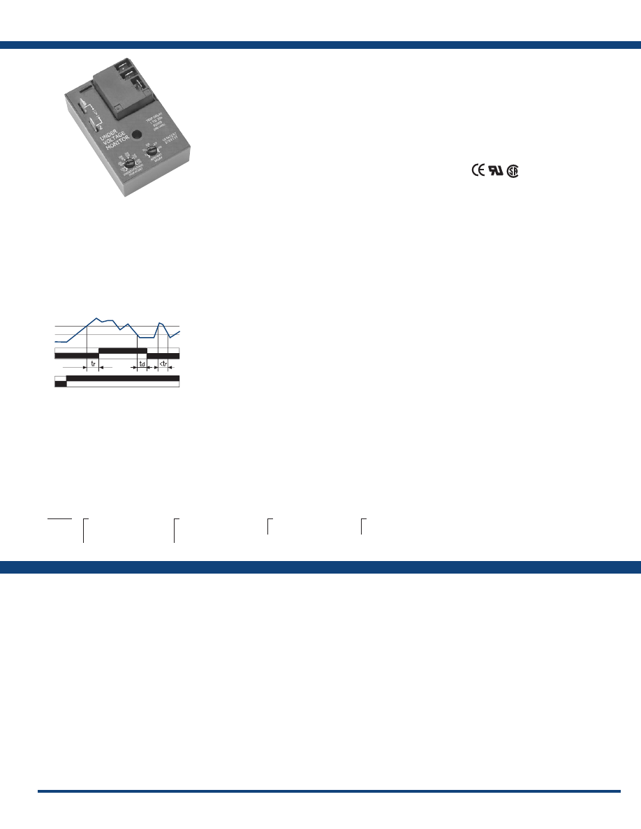
119
www.ssac.com • 800-843-8848 • fax: 605-348-5685
Features:
• Protects against undervoltage in single-
phase systems
• 30A, SPDT, NO output contacts
• 100 to 240VAC input voltage
• 70 to 220VAC adjustable undervoltage trip
point in 2 ranges
• Restart delays from 3 - 300s
• Trip delay 1 - 20s fixed
• Isolated or non-isolated relay contacts
Approvals:
Auxiliary Products:
•
Quick connect to screw adaptor:
P/N: P1015-18
•
Female quick connect:
P/N: P1015-13 (AWG 10/12)
P/N: P1015-64 (AWG 14/16)
•
Mounting bracket:
P/N: P1023-6
•
DIN rail:
P/N: C103PM
(Al)
•
DIN rail adaptor:
P/N: P1023-20
HLV Series
Voltage Monitors
Input
Min & Max RMS Voltage
. . . . . . . . . . . . . . . .
70 to 264VAC
AC Line Frequency . . . . . . . . . . . . . . . . . . . . .
50/60 Hz
Power Consumption . . . . . . . . . . . . . . . . . . . .
AC ≤ 4VA
Undervoltage Sensing
Type . . . . . . . . . . . . . . . . . . . . . . . . . . . . . . . . . .
Peak voltage sensing
Ranges (4)
. . . . . . . . . . . . . .
70 to 120VAC
(6)
. . . . . . . . . . . . . .
170 to 220VAC
Pull-In Voltage
. . . . . . . . . . . . . . . . . . . . . . . . .
105% or trip point voltage
Trip Point Accuracy . . . . . . . . . . . . . . . . . . . . .
± 3% of trip point
Time Delay
Restart Delays . . . . . . . . . . . . . . . . . . . . . . . . . .
3 - 300s adjustable
Trip Delay . . . . . . . . . . . . . . . . . . . . . . . . . . . . .
1 - 20s fixed in 1s increments
Repeat Accuracy . . . . . . . . . . . . . . . . . . . . . . .
±0.5% or 20ms, whichever is greater
Tolerance (Factory Calibration) . . . . . . . . . . .
±5%
Reset Time . . . . . . . . . . . . . . . . . . . . . . . . . . . .
≤ 150ms
Time Delay vs. Temp. & Voltage
. . . . . . . . . .
≤ ±10%
Output
Type . . . . . . . . . . . . . . . . . . . . . . . . . . . . . . . . . .
Electromechanical relay
Form . . . . . . . . . . . . . . . . . . . . . . . . . . . . . . . . . .SPDT
Ratings . . . . . . . . . . . . . . . . . . . . . . . . . . . . . . . .
SPDT-N.O SPDT-NC
General Purpose 125/240VAC 30A 15A
Resistive 125/240VAC 30A 15A
28VDC 20A 10A
Motor Load 125VAC 1 hp* 1/4 hp**
240VAC 2 hp** 1 hp**
Life
. . . . . . . . . . . . . . . . . . . . . . . . . . . . . . . . . . .
Mechanical - 1 x 10
6
Electrical - 1 x 10
5
, *3 x10
4
, **6,000
Protection
Surge . . . . . . . . . . . . . . . . . . . . . . . . . . . . . . . . .
IEEE C62.41-1991 Level A
Circuitry . . . . . . . . . . . . . . . . . . . . . . . . . . . . . .Encapsulated
Isolation Voltage
. . . . . . . . . . . . . . . . . . . . . . .
≥ 1500V RMS input to output; isolated units
Insulation Resistance . . . . . . . . . . . . . . . . . . . .
≥ 100 MΩ
Mechanical
Mounting . . . . . . . . . . . . . . . . . . . . . . . . . . . . .
Surface mount with one #10 (M5 x 0.8) screw
Dimensions . . . . . . . . . . . . . . . . . . . . . . . . . . . .
3 x 2 x 1.5 in. (76.7 x 51.3 x 38.1 mm)
Termination . . . . . . . . . . . . . . . . . . . . . . . . . . .
0.25 in. (6.35 mm) male quick connects
Environmental
Operating / Storage Temperature.
. . . . . . . .
-40° to 60°C / -40° to 85°C
Humidity . . . . . . . . . . . . . . . . . . . . . . . . . . . . . .
95% relative, non-condensing
Weight
. . . . . . . . . . . . . . . . . . . . . . . . . . . . . . . .
≅
3.9 oz (111 g)
Available Models:
Order Table:
HLVA
X
Undervoltage Range
─
4
- 70 to 120VAC
─
6
- 170 to 220VAC
X
Output Connection
─
I
- Isolated SPDT
─
N
- Non-Isolated SPDT
X
Restart Delay
─
2
- Onboard adjustment
3-300s
X
Trip Delay
─
Fixed
-
Specify from
1-20
s
in 1s increments
Specifications
The HLV Series is a single-phase undervoltage
monitor designed to protect sensitive equipment
from brownout or undervoltage conditions. Time
delays are included to prevent nuisance tripping
and short cycling. The 30A, 1hp rated, SPDT relay
contacts allow direct control of motors, solenoids
and valves. The output relay can be ordered with
isolated SPDT contact to allow monitoring of one
voltage and switching a separate voltage. Two
undervoltage trip point ranges allow monitoring
of 110 to 120VAC or 208 to 240VAC systems.
For more information see:
Appendix B, page 165, Figure 2 for dimensional drawing.
Appendix C, page 169, Figure 15 for connection diagram.
Operation
Upon application of input voltage the output relay remains de-energized. When the input voltage value is above
the pull-in voltage, the restart delay begins. At the end of the restart delay, the output relay energizes. When
the input voltage falls below the trip point, the trip delay begins. If the input voltage remains below the pull-in
voltage for the entire trip delay the relay de-energizes. If the input voltage returns to a value above the pull-in
voltage, during the trip delay, the trip delay is reset and the relay remains energized. If the input voltage falls
below the trip point voltage during the restart delay, the delay is reset and the relay remains de-energized. Reset
is automatic upon correction of an undervoltage fault.
Reset: Removing input voltage resets the output relay and the time delays.
HLVA6I23
If desired part number is not listed, please call us to
see if it is technically possible to build .
tr = Restart Delay
td = Trip Delay
PI = Pull-in 105% or trip point
TP = Trip Point
V = Monitored Voltage
IV = Input voltage
C-NO = Normally Open Contacts
C-NC = Normally Closed Contacts
PI
TP
V
C-NO
C-NC
IV
Courtesy of Steven Engineering, Inc.-230 Ryan Way, South San Francisco, CA 94080-6370-Main Office: (650) 588-9200-Outside Local Area: (800) 258-9200-www.stevenengineering.com
Littelfuse-catalog-html.html
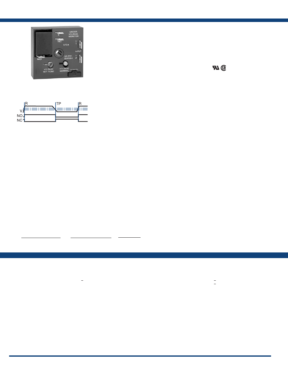
120
www.ssac.com • 800-843-8848 • fax: 605-348-5685
Features:
• Economical single-phase brownout/under-
voltage protection
• Isolated, 8A, SPDT output contacts
• Protects sensitive 110 to 120VAC or 220 to
240VAC loads
• Adjustable low voltage trip point
•
LED Indicator
Approvals:
Auxilary Products:
•
Quick connect to screw adaptor:
P/N: P1015-18
•
Female quick connect:
P/N: P1015-64 (AWG 14/16)
•
DIN rail:
P/N: C103PM
(Al)
•
DIN rail adaptor:
P/N: P1023-20
KVM Series
Voltage Monitors
Available Models:
Line Voltage
Type . . . . . . . . . . . . . . . . . . . . . . . . . . . . . . . . . . . . .
Single phase
Input Voltage
. . . . . . . . . . . . . . . . . . . . . . . . . . . . .
110 to 120VAC or 220 to 240VAC
AC Line Frequency . . . . . . . . . . . . . . . . . . . . . . . .
50/60 Hz
Power Consumption . . . . . . . . . . . . . . . . . . . . . . .
2.5W @ 132VAC; 4.5W @ 264VAC
Power Off Reset Time
. . . . . . . . . . . . . . . . . . . . . . <
150ms
Undervoltage Detection
Undervoltage Setpoint KVM4
. . . . . . . . .
78 to 99VAC
KVM6
. . . . . . . . .
156 to 199VAC
Undervoltage Reset Point KVM4
. . . . . . . . .
Fixed at 104VAC
KVM6
. . . . . . . . .
Fixed at 209VAC
Repeatability . . . . . . . . . . . . . . . . . . . . . . . . . . . . . .
± 0.5% under fixed conditions
±1% over temperature range
Voltage Sensing Accuracy
. . . . . . . . . . . . . . . . . .
±2% at 25°C
Output
Type . . . . . . . . . . . . . . . . . . . . . . . . . . . . . . . . . . . . .
Electromechanical relay
Form . . . . . . . . . . . . . . . . . . . . . . . . . . . . . . . . . . . . . SPDT
Rating . . . . . . . . . . . . . . . . . . . . . . . . . . . . . . . . . . . .
8A resistive @ 120VAC, 1/3 hp @ 120/240VAC
Life
. . . . . . . . . . . . . . . . . . . . . . . . . . . . . . . . . . . . . .
Mechanical - 1 x 10
6
; Electrical - 1x10
5
LED Indicator . . . . . . . . . . . . . . . . . . . . . . . . . . . . .
Glows green when output is energized
Protection
Surge . . . . . . . . . . . . . . . . . . . . . . . . . . . . . . . . . . . .
IEEE C62.41-1991 Level A
Circuitry . . . . . . . . . . . . . . . . . . . . . . . . . . . . . . . . . . Encapsulated
Isolation Voltage
. . . . . . . . . . . . . . . . . . . . . . . . . . . >
1500V RMS input to output
Insulation Resistance . . . . . . . . . . . . . . . . . . . . . . . >
100 MΩ minimum
Mechanical
Mounting . . . . . . . . . . . . . . . . . . . . . . . . . . . . . . . . .
Surface mount with one #10 (M5 x 0.8) screw
Dimensions . . . . . . . . . . . . . . . . . . . . . . . . . . . . . . .
2 x 2 x 1.21 in. (50.8 x 50.8 x 30.7 mm)
Termination . . . . . . . . . . . . . . . . . . . . . . . . . . . . . . .
0.25 in. (6.35 mm) male quick connect
terminals
Environmental
Operating / Storage Temperature
. . . . . . . . . . . .
-25 to 55°C / -40 to 85°C
Humidity . . . . . . . . . . . . . . . . . . . . . . . . . . . . . . . . .
95% relative, non-condensing
Weight
. . . . . . . . . . . . . . . . . . . . . . . . . . . . . . . . . . .
2.6 oz (74 g)
Specifications
Order Table:
Undervoltage Setpoint
78 to 99VAC
156 to 199VAC
Maximum Line Voltage
132VAC
264VAC
Part Number
KVM4
KVM6
KVM4
KVM6
The KVM Series is a single-phase undervoltage
monitor designed to protect sensitive equipment
against brownout undervoltage conditions. The
compact design and encapsulated construction
make the KVM an excellent choice for OEM
equipment .
For more information see:
Appendix B, page 165, Figure 1 for dimensional drawing.
Appendix C, page 169, Figure 16 for connection diagram.
Operation
The output relay is energized and the LED glows
green when the input voltage is above the reset
voltage threshold. If the input voltage drops below the
undervoltage setpoint, the output relay and LED will
de-energize. The output relay will remain de-energized
as long as the input voltage is below the reset voltage.
Reset is automatic when the input voltage returns to a
normal range .
TP = Undervoltage Setpoint
R = Reset Point
Courtesy of Steven Engineering, Inc.-230 Ryan Way, South San Francisco, CA 94080-6370-Main Office: (650) 588-9200-Outside Local Area: (800) 258-9200-www.stevenengineering.com
Littelfuse-catalog-html.html

121
www.ssac.com • 800-843-8848 • fax: 605-348-5685
Current Sensors & Monitors
Series Included
ECS . . . . . . . . . . . . . . . . . . . . . . . . . . . . . . . . . . . . . . . . . . . . . .122
TCS . . . . . . . . . . . . . . . . . . . . . . . . . . . . . . . . . . . . . . . . . . . . . .
124
ECSW
. . . . . . . . . . . . . . . . . . . . . . . . . . . . . . . . . . . . . . . . . . . .
123
TCSA . . . . . . . . . . . . . . . . . . . . . . . . . . . . . . . . . . . . . . . . . . . .
125
DCSA . . . . . . . . . . . . . . . . . . . . . . . . . . . . . . . . . . . . . . . . . . . .
126
LCS10T12
. . . . . . . . . . . . . . . . . . . . . . . . . . . . . . . . . . . . . . . . 127
LPM . . . . . . . . . . . . . . . . . . . . . . . . . . . . . . . . . . . . . . . . . . . . . 127
Over or Undercurrent
Over or Undercurrent Monitor
Current Transducer
Current Indicator
Courtesy of Steven Engineering, Inc.-230 Ryan Way, South San Francisco, CA 94080-6370-Main Office: (650) 588-9200-Outside Local Area: (800) 258-9200-www.stevenengineering.com
Littelfuse-catalog-html.html
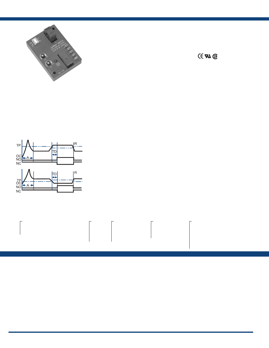
122
www.ssac.com • 800-843-8848 • fax: 605-348-5685
ECS Series
Current Sensor
Available Models:
Sensor
Type . . . . . . . . . . . . . . . . . . . . . . . . . . . . . . . . .
Toroidal through hole wiring
Mode . . . . . . . . . . . . . . . . . . . . . . . . . . . . . . . .
Over or undercurrent, switch selectable
on the unit or factory fixed
Trip Point Range . . . . . . . . . . . . . . . . . . . . . .
0.5 - 50A in 3 adjustable ranges or fixed
Tolerance Adjustable
. . . . . . .
Guaranteed range
Fixed
. . . . . . . . . . . .
0.5 - 25A: 0.5A or ±5% whichever is
less; 26 - 50A: ±2.5%
Maximum Allowable Current
. . . . . . . . . . .
Steady – 50A turns; Inrush – 300A turns for 10s
Trip Point Hysteresis . . . . . . . . . . . . . . . . . . .
≅
±5%
Trip Point vs. Temperature
. . . . . . . . . . . . .
±5%
Response Time . . . . . . . . . . . . . . . . . . . . . . . .
≤ 75ms
Frequency . . . . . . . . . . . . . . . . . . . . . . . . . . . .
45/500 Hz
Type of Detection
. . . . . . . . . . . . . . . . . . . . . .
Peak detection
Trip Delay
Type . . . . . . . . . . . . . . . . . . . . . . . . . . . . . . . . . Analog
Range Adjustable
. . . . . . . . . .
0.150 - 7s; 0.5 - 50s (guaran
teed ranges)
Factory Fixed
. . . . . . .
0.08 - 50s (±20ms, whichever is greater)
Delay vs. Temperature
. . . . . . . . . . . . . . . . .
±15%
Sensing Delay on Startup . . . . . . . . . . . . . . .
Factory fixed 0 - 6s: +40%, -0%
Input
Voltage
. . . . . . . . . . . . . . . . . . . . . . . . . . . . . . .
24 , 120, or 230VAC; 12 or 24VDC
Tolerance 12VDC & 24VDC/AC
. . . . . .
-15 - 20%
120 & 230VAC
. . . . . . . . . . . . .
-20 - 10%
AC Line Frequency . . . . . . . . . . . . . . . . . . . .
50/60 Hz
Output
Type . . . . . . . . . . . . . . . . . . . . . . . . . . . . . . . . .
Electromechanical relay
Form . . . . . . . . . . . . . . . . . . . . . . . . . . . . . . . . .
Isolated, SPDT
Rating . . . . . . . . . . . . . . . . . . . . . . . . . . . . . . .
10A resistive @ 240VAC; 1/4 hp @ 125VAC;
1/2 hp @ 250VAC
Life
. . . . . . . . . . . . . . . . . . . . . . . . . . . . . . . . . .
Mechanical – 1 x 10
6
; Electrical – 1 x 10
5
Protection
Circuitry . . . . . . . . . . . . . . . . . . . . . . . . . . . . . Encapsulated
Isolation Voltage
. . . . . . . . . . . . . . . . . . . . . .
≥ 2500V RMS input to output
Insulation Resistance . . . . . . . . . . . . . . . . . . .
≥ 100 MΩ
Mechanical
Mounting . . . . . . . . . . . . . . . . . . . . . . . . . . . .
Surface mount with two #6 (M3.5 x 0.6) screws
Dimensions . . . . . . . . . . . . . . . . . . . . . . . . . . .
3.5 x 2.5 x 1.75 in. (88.9 x 63.5 x 44.5 mm)
Termination . . . . . . . . . . . . . . . . . . . . . . . . . .
0.25 in. (6.35 mm) male quick connect terminals (5)
Environmental
Operating / Storage Temperature
. . . . . . .
-40° to 60°C / -40° to 85°C
Humidity
. . . . . . . . . . . . . . . . . . . . . . . . . . . . .
95% relative, non-condensing
Weight
. . . . . . . . . . . . . . . . . . . . . . . . . . . . . . .
≅
6.4 oz (181 g)
Features:
• Toroidal through hole wiring
• 0.5 - 50A trip points
• Adjustable or factory fixed trip delays
• Isolated, 10A, SPDT output contacts
• 5% trip point hysteresis (dead band)
Approvals:
Auxiliary Products:
•
Female q uick connect:
P/N: P1015-13 (AWG 10/12)
P/N: P1015-64 (AWG 14/16)
P/N: P1015-14 (AWG 18/22)
Specifications
Order Table:
X
Series
─
ECS
- Selectable over or undercurrent sensing
─
ECSH
- Overcurrent sensing
─
ECSL
- Undercurrent sensing
X
Input
─
1
- 12VDC
─
2
- 24VAC
─
3
- 24VDC
─
4
- 120VAC
─
6
- 230VAC
X
Trip Point
─
Fixed
- Specify
2-50
A i n
1A increments
─
0
- 0.5-5A adjustable
─
1
- 2-20A adjustable
─
H
- 5-50A adjustable
X
Trip Delay
─
F
- Specify: 0.08-50s
factory fixed
─
A
- 0.150-7s adjustable
─
B
- 0.5-50s adjustable
X
Sensing Delay on Start Up
─
Blank
- 0s
─
C
- 1s
─
D
- 2s
─
E
- 3s
─
F
- 4s
─
G
- 5s
─
H
- 6s
ECS20BC
ECS21BC
ECS21BH
ECS2HBC
ECS30AC
ECS40A
ECS40AC
ECS40BC
ECS40BD
ECS41A
ECS41AC
ECS41BC
ECS41BD
ECS41BH
ECS41F.08
ECS4HBC
ECS4HBH
ECS60AH
ECS60BC
ECS61BC
ECS6HAH
ECSH21F.08C
ECSH30AC
ECSH3HF0.08D
ECSH40AC
ECSH40AD
ECSH41AD
ECSH41BC
ECSH41F.08D
ECSH4HF.08D
ECSH61AD
ECSL31A
ECSL40AC
ECSL40B
ECSL40BH
ECSL41A
ECSL41AD
ECSL45F7
ECSL4HBH
ECSL61AH
ECSL6HAC
The ECS Series of single-phase AC current sensors
is a universal, overcurrent or undercurrent sensing
control. Its built-in toroidal sensor eliminates the
inconvenience of installing a stand-alone current
transformer. Includes onboard adjustments for
current sensing mode, trip point, and trip delay.
Detects over or undercurrent events like; locked
rotor, loss of load, an open heater or lamp load, or
proves an operation is taking place or has ended.
For more information see:
Appendix B, page 166, Figure 20 for dimensional drawing.
Appendix C, page 169, Figure 17 for connection diagram.
Operation
Input voltage must be supplied at all times for proper
operation. When a fault is sensed throughout the trip
delay, the output relay is energized. When the current
returns to the normal run condition or zero, the output and the delay are reset. If a fault is sensed and then
corrected before the trip delay is completed, the relay will not energize and the trip delay is reset to zero.
Adjustment
Select the desired function, over or under current sensing. Set the trip point and trip delay to approximate settings.
Apply power to the ECS and the monitored load. Turn adjustment and watch the LED. LED will light; turn slightly
in opposite direction until LED is off. Adjustment can be done while connected to the control circuitry if the trip
delay is set at maximum. To increase sensitivity, multiple turns may be made through the ECS’s toroidal sensor.
The trip point range is divided by the number of turns through the toroidal sensor to create a new range. When
using an external CT, select a 2VA, 0-5A output CT rated for the current to be monitored. Select ECS adjustment
range 0. Pass one secondary wire lead through the ECS toroid and connect the secondary leads together.
If desired part number is not listed, please call us to
see if it is technically possible to build .
NO = Normally Open Contact
NC = Normally Closed Contact
A = Sensing Delay On Start Up
TD = Trip Delay
TP = Trip Point
R = Reset
OC = Monitored Cur
rent
Courtesy of Steven Engineering, Inc.-230 Ryan Way, South San Francisco, CA 94080-6370-Main Office: (650) 588-9200-Outside Local Area: (800) 258-9200-www.stevenengineering.com
Littelfuse-catalog-html.html
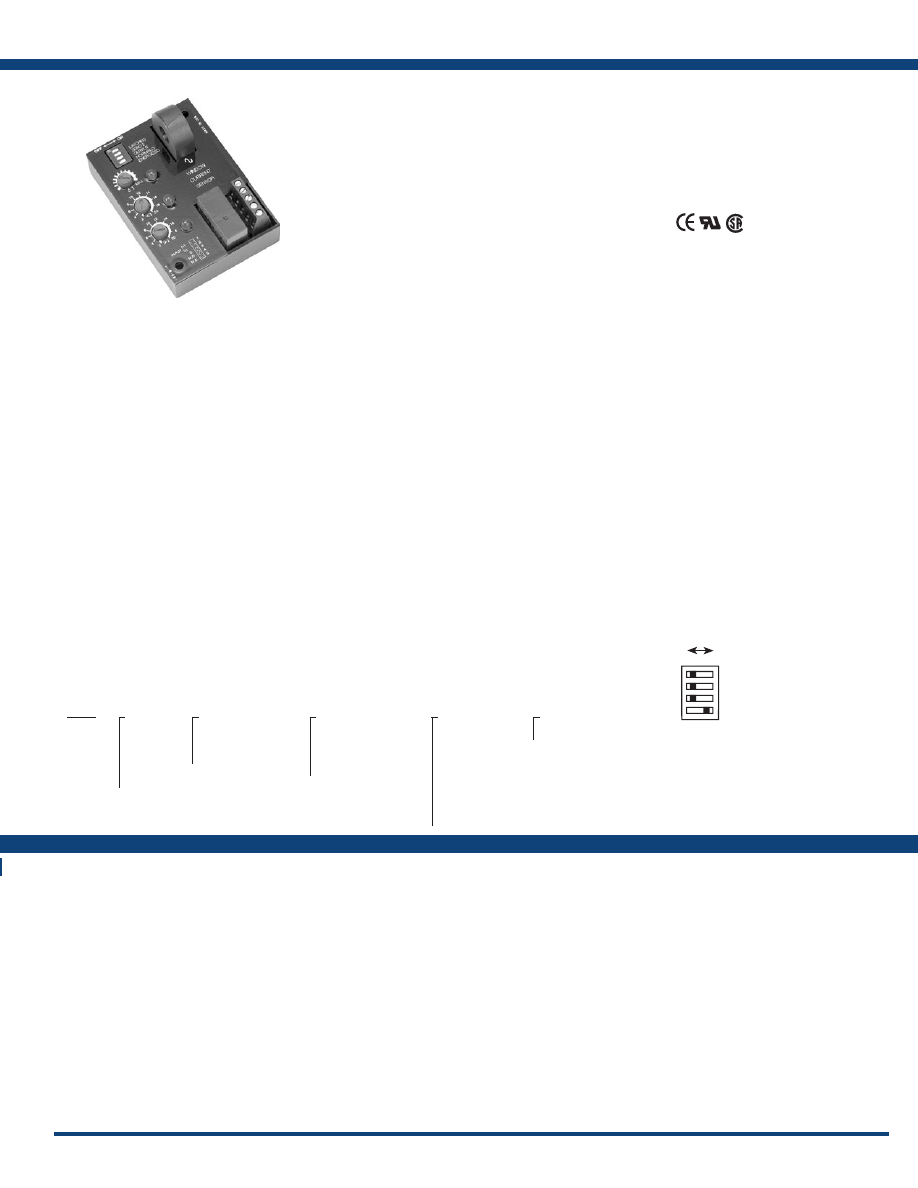
123
www.ssac.com • 800-843-8848 • fax: 605-348-5685
Features:
• Overcurrent & undercurrent (window
current) sensing
• Adjustable overcurrent & undercurrent trip
points
•
Current sensor is included
• Isolated, 10A, SPDT output contacts
•
LED indicators
Approvals:
ECSW Series
Current Sensors
Available Models:
Sensor
Type . . . . . . . . . . . . . . . . . . . . . . . . . . . . . .
Toroid, through hole wiring for up to #4 AWG (21.1 mm
2
)
THHN wire
Mode . . . . . . . . . . . . . . . . . . . . . . . . . . . . .
Over & undercurrent trip points (window current sensing)
Trip Point Range . . . . . . . . . . . . . . . . . . .
0.5 - 50A in 3 adjustable ranges
Tolerance . . . . . . . . . . . . . . . . . . . . . . . . . .
Guaranteed range
Maximum Allowable Current
. . . . . . . .
Steady - 50A turns; Inrush - 300A turns for 10s
Time Point vs Temp. & Voltage
. . . . . . .
±5%
Response Time . . . . . . . . . . . . . . . . . . . . .
≤ 75ms
Frequency . . . . . . . . . . . . . . . . . . . . . . . . .
45/500 Hz
Type of Detection
. . . . . . . . . . . . . . . . . . .
Peak detection
Zero Current Detection . . . . . . . . . . . . . .
< 250mA turns typical
Time Delay
Range . . . . . . . . . . . . . . . . . . . . . . . . . . . . .
0.15 - 50s in 2 adjustable ranges or 0.1 - 50s fixed
Tolerance . . . . . . . . . . . . . . . . . . . . . . . . . .
Adjustable: guaranteed range; Fixed: ±10%
Sensing Delay On Start Up . . . . . . . . . . .
Fixed ≅ 0.1 - 6s in 1s increments
Tolerance . . . . . . . . . . . . . . . . . . . . . . . . . .
+40% -0%
Delay vs. Temperature & Voltage
. . . . .
±15%
Input
Voltage
. . . . . . . . . . . . . . . . . . . . . . . . . . .
24, 120, or 230VAC; 12 or 24VDC
Tolerance 12VDC & 24VDC/AC
. . . .
-15% - 20%
120 & 230VAC
. . . . . . . . . .
-20% - 10%
AC Line Frequency . . . . . . . . . . . . . . . . .
50/60 Hz
Output
Type . . . . . . . . . . . . . . . . . . . . . . . . . . . . . .
Electromechanical relay
Mode: Switch selectable ON
. . . . . .
Energized during normal operation, de-energized
after a fault
OFF . . . . . .
De-energized during normal operation, energizes
during a fault
Form . . . . . . . . . . . . . . . . . . . . . . . . . . . . . .
Isolated, SPDT
Rating . . . . . . . . . . . . . . . . . . . . . . . . . . . .
10A resistive @ 240VAC; 1/4 hp @ 125VAC;
1/2 hp @ 250VAC
Life
. . . . . . . . . . . . . . . . . . . . . . . . . . . . . . .
Mechanical - 1 x 10
6
; Electrical - 1 x 10
5
Latch Type
. . . . . . . Electrical
Reset . . . . . . .
Remove input voltage
Function . . . .
Switch selectable latching function
Protection
Surge . . . . . . . . . . . . . . . . . . . . . . . . . . . . .
IEEE C62.41-1991 Level A
Circuitry . . . . . . . . . . . . . . . . . . . . . . . . . . Encapsulated
Isolation Voltage
. . . . . . . . . . . . . . . . . . .
≥ 2500V RMS input to output
Insulation Resistance . . . . . . . . . . . . . . . .
≥ 100 MΩ
Mechanical
Mounting . . . . . . . . . . . . . . . . . . . . . . . . .
Surface mount with two #6 (M3.5 x 0.6) screws
Dimensions . . . . . . . . . . . . . . . . . . . . . . . .
3.5 x 2.5 x 1.75 in. (88.9 x 63.5 x 44.5 mm)
Termination . . . . . . . . . . . . . . . . . . . . . . .
0.197 in. (5 mm) terminal blocks for up to #12
(3.2 mm
2
) AWG wire
Environmental
Operating / Storage Temperature
. . . .
-40° to 60° C/-40° to 85° C
Humidity . . . . . . . . . . . . . . . . . . . . . . . . .
95% relative, non-condensing
Weight
. . . . . . . . . . . . . . . . . . . . . . . . . . . .
≅
6.4 oz (181 g)
ECSW
X
Input
─
1
- 12VDC
─
2
- 24VAC
─
3
- 24VDC
─
4
- 120VAC
─
6
- 230VAC
X
Trip Point
─
L
- 0.5-5A adjustable
─
M
- 2-20A adjustable
─
H
- 5-50A adjustable
X
Trip Delay
─
F
- Specify:
0 .1
-
50
s
factory fixed*
─
A
- 0.150-7s adjustable
─
B
- 0.5-50s adjustable
X
Sensing Delay on
Start up
─
B
- 0.1s
─
C
- 1s
─
D
- 2s
─
E
- 3s
─
F
- 4s
─
G
- 5s
─
H
- 6s
X
Connection
─
T
- Terminal Blocks
*If fixed delay is selected, insert delay
(
0 .1
-
50
) in seconds. 0.1-1.9s in 0.1s
increments; 2-50s in 1s increments.
Order Table:
Specifications
Operation
When the input voltage is applied, sensing delay on startup begins and the output transfers (if normally energized is selected). Upon completion of the startup delay, sensing of the monitored
current begins. As long as current is above undercurrent trip point and below the overcurrent trip point (inside the window), the output relay remains in its normal operating condition and
both red LED’s are OFF. The green LED glows when the output is energized. If current varies outside the window, the associated red LED glows, and the trip delay begins. If the current
remains outside the window for the full trip delay, the relay transfers to fault condition state. If the current returns to normal levels (inside the window) during the trip delay, the red LED
goes OFF, the trip delay is reset, and the output remains in the normal condition.
Reset: Remove input voltage or open latch switch. If zero current detection is selected, the unit will reset as soon as zero current is detected.
Operation With Zero Current Detection Enabled: If the current decreases to zero within the trip delay period, then zero current is viewed as an acceptable current level. The unit’s output
remains in its normal operating state. This allows the monitored load to cycle ON and OFF without nuisance tripping the ECSW. Zero current is defined as current flow of less than 250
milliamp-turns. Note: When zero current detect is selected, the latching operation of switch SW2 is canceled; the output will not latch after a fault trip.
Notes on Operation:
1) There is no hysteresis on the trip points. The overcurrent and undercurrent trip points should be adjusted to provide adequate protection against short cycling.
2) If the upper setpoint is set below the lower setpoint, both red LED’s will glow indicating a setting error.
3) If zero current detection is selected (SW2 ON), and the system is wired to disconnect the monitored load, the system may short cycle. After the unit trips, the load de-energizes, and zero
current is detected. The ECSW resets, and the load energizes again immediately and may be short cycled.
4) The sensing delay on start up only occurs when input voltage is applied. When zero current detection is selected, the trip delay must be longer than the duration of the inrush current or
the unit will trip on the inrush current.
Typical Pump or Fan Protection Circuit Operation
Window Current Sensing: With the ECSW connected as shown in the diagram, a load may be monitored and controlled for over and undercurrent. The ECSW Series’ on board CT (CS) may
be placed on the line or load side of the contactor. The ECSW selection switches are set for zero current sensing (see Selector Switch SW2) and the output selection is normally de-energized
(see Selector Switch SW3). The input voltage (V) is applied to the ECSW continually. As the control switch (FSW) is closed, the input voltage (V) is applied to the motor contactor coil (MCC),
and the motor (M) energizes. As long as the current remains below the overcurrent and above the undercurrent trip points, the ECSW’s output contacts remain de-energized. If the load
current should rise above or fall below a trip point, for the full trip delay, the normally open (NO) contact will close, energizing the control relay (CR) coil. The CR normally closed contact
(CR1) opens and the MCC de-energizes and CR latches on through its normally open contacts (CR2). Reset is accomplished by momentarily opening the normally closed reset switch (RSW).
Note: If the current falls to zero within the trip delay, the ECSW remains de-energized. The sensing delay on startup occurs when input voltage is applied therefore trip delay must be longer
than the duration of the motor’s inrush current. The external latching relay CR2 is required in this system to prevent rapid cycling. A timer can be added to provide an automatic reset.
ECSW3LABT
ECSW4HBHT
ECSW4LABT
ECSW4LBHT
ECSW4MBHT
The ECSW Series of single-phase, AC window,
current sensors includes adjustable overcurrent
and undercurrent trip points. Detects locked rotor,
jam, loss of load, an open heater or lamp load, a
broken belt, or loss of suction. LED’s aid in trip
point adjustment and provide fault indication. The
built-in toroidal sensor eliminates the need for an
external current transformer. The output can be
electrically latched after a fault, or automatically
reset. Remote resetting of a latched output by
removing input voltage. The unit includes switch
selectable zero current detection and normally
de-energized or energized output operation. Time
delays are included to improve operation and
eliminate nuisance tripping .
For more information see:
Appendix B, page 166, Figure 20 for dimensional drawing.
Appendix C, page 169, Figure 18 for connection diagram.
If desired part number is not listed, please call us to
see if it is technically possible to build .
Not Used
Latched
Zero I
Output - Normally Energized
ON OFF
Selector Switch
SW1
SW2
SW3
Mode Selection Switches
SW1 = Latched or Auto reset selector
OFF - Automatic reset after a fault
ON - Output relay latches after a fault trips the unit
SW2 = Zero current detection (below 250 mA)
OFF- Zero current detection disabled
ON- Zero current detection enabled
SW3 = Output during normal operation
OFF- Output relay de-energized
ON - Output relay energized
Courtesy of Steven Engineering, Inc.-230 Ryan Way, South San Francisco, CA 94080-6370-Main Office: (650) 588-9200-Outside Local Area: (800) 258-9200-www.stevenengineering.com
Littelfuse-catalog-html.html
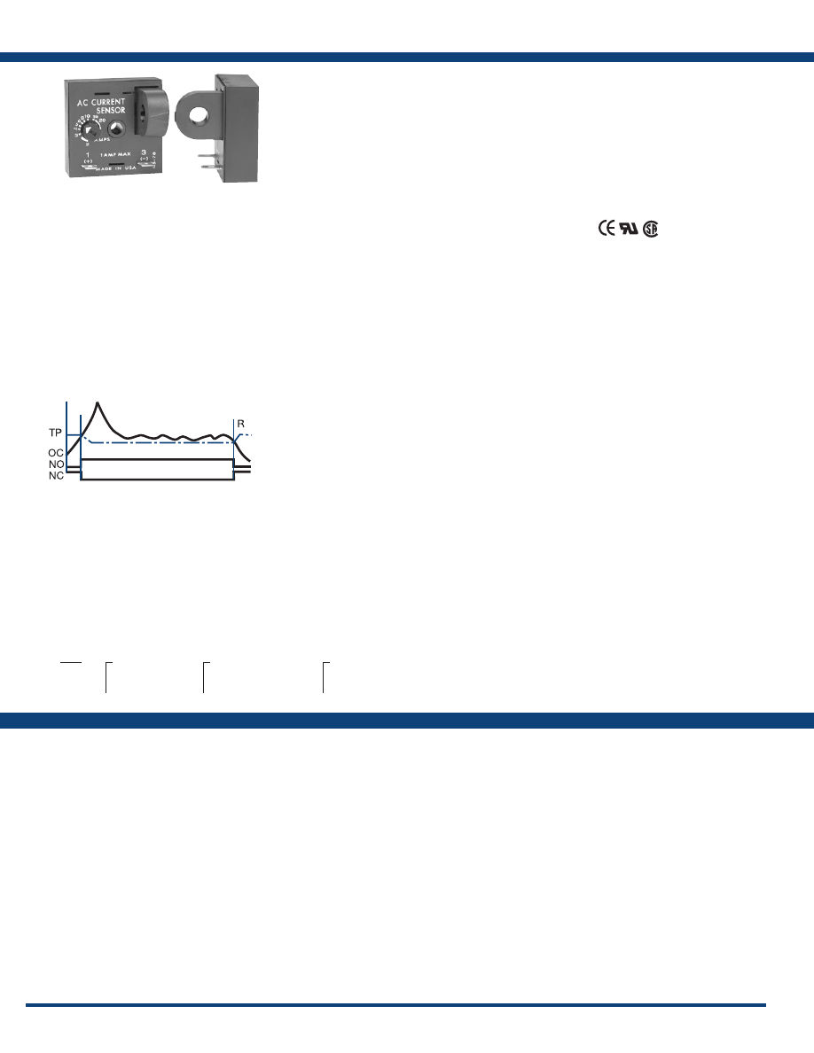
124
www.ssac.com • 800-843-8848 • fax: 605-348-5685
TCS Series
Current Sensor
Available Models:
Sensor
Type . . . . . . . . . . . . . . . . . . . . . . . . . . . . . . . . . . . . .
Toroid, through hole wiring, alternating current,
monitored wire must be properly insulated
Current to Actuate . . . . . . . . . . . . . . . . . . . . . . . . .
Adjustable: - 2 - 20A, guaranteed range
Fixed: - 2 - 45A, +0/-20%
Reset Current . . . . . . . . . . . . . . . . . . . . . . . . . . . . .
≅
95% of the actuate current
Maximum Allowable Current
. . . . . . . . . . . . . . .
Steady - 50A turns
Inrush - 300A turns for 10s
Actuate Current vs. Temp. & Voltage
. . . . . . . .
≤ ±5%
Response Times . . . . . . . . . . . . . . . . . . . . . . . . . . .
Overcurrent - ≤ 200ms
Undercurrent - ≤ 1s
Burden . . . . . . . . . . . . . . . . . . . . . . . . . . . . . . . . . . .
< 0.5VA
Output
Type . . . . . . . . . . . . . . . . . . . . . . . . . . . . . . . . . . . . . Solid state
Form . . . . . . . . . . . . . . . . . . . . . . . . . . . . . . . . . . . . . NO or NC
Rating . . . . . . . . . . . . . . . . . . . . . . . . . . . . . . . . . . .
1A steady, 10A inrush
Voltage
. . . . . . . . . . . . . . . . . . . . . . . . . . . . . . . . . . .
AC - 24 to 240VAC +10/-20%
DC - 3 to 50VDC
Voltage Drop
. . . . . . . . . . . . . . . . . . . . . . . . . . . . .
AC NO & NC -
≅
2.5V
DC NO & NC -
≅
1.2V
Protection
Circuitry . . . . . . . . . . . . . . . . . . . . . . . . . . . . . . . . . Encapsulated
Dielectric Breakdown
. . . . . . . . . . . . . . . . . . . . . .
≥ 2000V RMS terminals to mounting surface
Insulation Resistance . . . . . . . . . . . . . . . . . . . . . . .
≥ 100 MΩ
Mechanical
Mounting . . . . . . . . . . . . . . . . . . . . . . . . . . . . . . . .
Surface mount with one #10 (M5 x 0.8)
screw
Dimensions . . . . . . . . . . . . . . . . . . . . . . . . . . . . . . .
2 x 2 x 1.75 in. (50.8 x 50.8 x 44.5 mm)
Termination . . . . . . . . . . . . . . . . . . . . . . . . . . . . . .
0.25 in. (6.35 mm) male quick connect
terminals (2)
Sensor Hole . . . . . . . . . . . . . . . . . . . . . . . . . . . . . . .
0.36 in. (9.14 mm) for up to #4 AWG
(21 .1 mm
2
) THHN wire
Environmental
Operating / Storage Temperature
. . . . . . . . . . .
-20° to 60°C / -40° to 85°C
Humidity . . . . . . . . . . . . . . . . . . . . . . . . . . . . . . . . .
95% relative, non-condensing
Weight
. . . . . . . . . . . . . . . . . . . . . . . . . . . . . . . . . . .
≅
2.6 oz (74 g)
Features:
•
Direct connection to a PLC digital input
module
• 3 to 50VDC, 24 to 240VAC
• 1A steady - 10A inrush
• Actuation Points –
2 - 45A (fixed units)
2 - 20A (adjustable units)
• NO or NC solid-state output
•
Complete isolation between sensed current
& control circuit
Approvals:
Auxiliary Products:
•
Female q uick connect:
P/N: P1015-64 (AWG 14/16)
•
Quick connect to screw adaptor:
P/N: P1015-18
•
Mounting bracket:
P/N: P1023-6
•
DIN rail:
P/N: C103PM (A
l
)
•
DIN rail adaptor:
P/N: P1023-20
Specifications
Order Table:
TCSG2A
TCSGAA
TCSGAB
TCSH2A
TCSH2B
TCSH3A
TCSH4A
TCSHAA
TCSHAB
TCS
X
Output Voltage
─
G
- 3-50VDC
─
H
- 24-240VAC
X
Actuate Current
─
A
- 2-20A adjustable
─
Fixed
- Specify from
2
-
45
A in 1A increments
X
Output Form
─
A
- Normally Open
─
B
- Normally Closed
The TCS Series is a low cost method of go/no go
current detection. It includes a solid-state output to
sink or source current when connected directly to
a standard PLC digital input module . Its normally
open or normally closed output can also be used
to control relays, lamps, valves, and small heaters
rated up to 1A steady, 10A inrush. The TCS is self-
powered (no external power required to operate
the unit) and available with an adjustable actuation
range of 2 - 20A or factory fixed actuation points
from 2 - 45A.
For more information see:
Appendix B, page 166, Figure 21 for dimensional drawing.
Appendix C, page 169, Figure 19 for connection diagram.
Operation
Normally Open: When a current equal to or greater than the actuate current is passed through the toroidal
sensor, the output closes. When the current is reduced to 95% of the actuate current or less, the output opens.
Normally Closed: When the current through the toroid is equal to or greater than the actuate current, the output
opens. When the current is reduced below 95% of the actuate current, the output closes. To increase sensitivity,
multiple turns may be made through the TCS’s toroidal sensor. The trip point range is divided by the number of
turns through the toroidal sensor to create a new range. When using an external CT, select a 2VA, 0-20A output
CT rated for the current to be monitored. Select TCS adjustment range 0. Pass one secondary wire lead through
the TCS’ toroid and connect the secondary leads together.
If desired part number is not listed, please call us to
see if it is technically possible to build .
L = Load
V = Voltage
PS = Power Supply
PLC = PLC Digital Input Module
R = Reset
TP = Trip Point
OC = Monitored Current
NO = Normally Open Output
NC = Normally Closed Output
Courtesy of Steven Engineering, Inc.-230 Ryan Way, South San Francisco, CA 94080-6370-Main Office: (650) 588-9200-Outside Local Area: (800) 258-9200-www.stevenengineering.com
Littelfuse-catalog-html.html
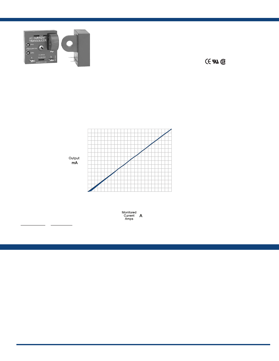
125
www.ssac.com • 800-843-8848 • fax: 605-348-5685
Features:
• Monitors 0 - 50A in 4 ranges
• Loop powered from 10 to 30VDC
• Linear output from 4 - 20mA
• Zero & span adjustments
•
Complete isolation between sensed current
& control circuit
Approvals:
Auxilary Products:
•
Female quick connect:
P/N: P1015-64 (AWG 14/16)
•
Quick connect to screw adaptor:
P/N: P1015-18
•
Mounting bracket:
P/N: P1023-6
•
DIN rail:
P/N: C103PM
•
DIN rail adaptor:
P/N: P1023-20
TCSA Series
Current Transducers
Available Models:
Sensor
Type . . . . . . . . . . . . . . . . . . . . . . . . . . . . . . . . . .
Toroid, through hole wiring, alternating current,
monitored conductor must be properly insulated
Monitored AC Current . . . . . . . . . . . . . . . . . .
0 - 50A
Ranges
4 factory calibrated ranges
. . . .
0 - 5A, 0 - 10A, 0 - 20A, or 0 - 50A
Factory calibration . . . . . . . . . . .
≤±2% of full scale
Maximum Allowable Current
. . . . . . . . . . . .
Steady – 50A turns; Inrush – 300A turns for 10s
Repeat Accuracy . . . . . . . . . . . . . . . . . . . . . . .
≤±0.25% of full scale under fixed conditions
Response Time . . . . . . . . . . . . . . . . . . . . . . . . .
≅
300ms
Burden . . . . . . . . . . . . . . . . . . . . . . . . . . . . . . . .
≤ 0.5VA
AC Line Frequency 0 - 20A / 21 - 50A
. . .
20 - 100Hz / 30 - 100Hz
Temperature Coefficient
. . . . . . . . . . . . . . . . .
±0.05%/°C
Output
Type: Series Connection
. . . . . . . . . . . . . . . . Current directly proportional to monitored current
Range . . . . . . . . . . . . . . . . . . . . . . . . . . . . . . . . .
4 - 20mA
Sensor Supply Voltage*
. . . . . . . . . . . . . . . . .
10 to 30VDC
Momentary Voltage
. . . . . . . . . . . . . . . . . . . . .
40VDC for 1m
Zero Adjust
. . . . . . . . . . . . . . . . . . . . . . . . . . . .
≅
3.75 - 4.25mA
Span Adjust
. . . . . . . . . . . . . . . . . . . . . . . . . . .
18mA - 22mA
Adjustment
. . . . . . . . . . . . . . . . . . . . . . . . . . . .
Mini-screw, 25-turn potentiometer
Protection
Dielectric Breakdown
. . . . . . . . . . . . . . . . . . .
≥ 2000V RMS terminals to mounting
surface
Insulation Resistance . . . . . . . . . . . . . . . . . . . .
≥ 100 MΩ
Polarity . . . . . . . . . . . . . . . . . . . . . . . . . . . . . . .
Units are reverse polarity protected
Mechanical
Mounting . . . . . . . . . . . . . . . . . . . . . . . . . . . . .
Surface mount with one #10 (M5 x 0.8)
screw
Dimensions . . . . . . . . . . . . . . . . . . . . . . . . . . . .
2 x 2 x 1.75 in. (50.8 x 50.8 x 44.5 mm)
Termination . . . . . . . . . . . . . . . . . . . . . . . . . . .
0.25 in. (6.35 mm) male quick connect
terminals
Sensor Hole . . . . . . . . . . . . . . . . . . . . . . . . . . . .
0.36 in. (9.14 mm) for up to
#4 AWG
(21 .1 mm
2
) THHN wire
Environmental
Operating / Storage Temperature
. . . . . . . .
-30° to 60°C/-40° to 85°C
Humidity . . . . . . . . . . . . . . . . . . . . . . . . . . . . . .
95% relative, non-condensing
Weight
. . . . . . . . . . . . . . . . . . . . . . . . . . . . . . . .
≅
2.4 oz (68 g)
*Minimum loop-power supply voltage equals the minimum sensor voltage 10VDC
plus the voltage drop developed across all the other loop devices at 20mA.
Specifications
Order Table:
Current Range
0-5A
0-10A
0-20A
0-50A
Part Number
TCSA5
TCSA10
TCSA20
TCSA50
TCSA5
TCSA10
TCSA20
TCSA50
1
2
4
10
20
18
16
14
12
10
8
6
4
2
4
8
20
3
6
12
30
4
8
16
40
5
10
20
50
0
The TCSA Series is a loop-powered, linear output
current transducer that provides an output that
is directly proportional to the RMS AC current
passing through the onboard toroid. The TCSA
provides a 4 - 20mA output over a power supply
range of 10 - 30VDC. Each unit is factory calibrated
for monitoring in one of four ranges; 0-5, 0-10,
0-20, or 0-50A. The 0 - 5A range allows the use
of external current transformers so loads up to
1200AC amps can be monitored.
For more information see:
Appendix B, page 166, Figure 21 for dimensional drawing.
Appendix C, page 169, Figure 20 for connection diagram.
Operation
The TCSA varies the effective resistance of its output in direct proportion to the current flowing in the monitored
conductor. The unit is factory calibrated so that 0 amps provides a 4mA output and full span provides a 20mA
output. Zero and span adjustments are provided for minor calibration adjustments in the field (if required).
Using an External Current Transformer (CT)
Select a 2VA, 0 to 5A output CT, rated for the current to be monitored. Select TCSA5. Pass one of the CT’s secondary
wire leads through the TCSA’s toroid. Connect the CT’s secondary leads together.
Courtesy of Steven Engineering, Inc.-230 Ryan Way, South San Francisco, CA 94080-6370-Main Office: (650) 588-9200-Outside Local Area: (800) 258-9200-www.stevenengineering.com
Littelfuse-catalog-html.html
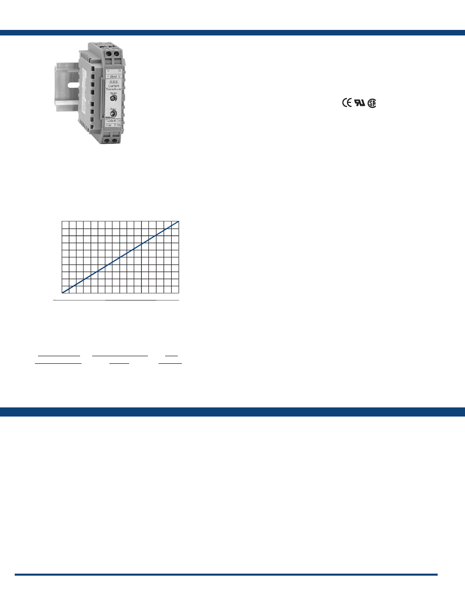
126
www.ssac.com • 800-843-8848 • fax: 605-348-5685
DCSA Series
Current Transducers
Available Models:
Input
Ranges (without LCSC10T12 connected)
4 factory calibrated ranges in mA AC
. . . . . . . . . .
0 - 5mA, 0 - 10mA, 0 - 20mA, or 0 - 50mA AC
Factory calibration . . . . . . . . . .
±0.5% of full scale
Repeat Accuracy . . . . . . . . . . . . . . . . . . . . . . . . . .
±0.25% of full scale under fixed conditions
Response Time . . . . . . . . . . . . . . . . . . . . . . . . . . . .
≅
300ms
Temperature Coefficient
. . . . . . . . . . . . . . . . . . . .
±0.05%/°C
Input To Output . . . . . . . . . . . . . . . . . . . . . . . . . . Not isolated
Output
Type Analog . . . . . . . . . . . . . . . . . . . . Current directly proportional to input current
Range . . . . . . . . . . . . . . . . . . . . . . . . . . . . . . . . . . . .
4 - 20mA, or 1 to 5VDC or 2 to 10VDC
Supply Voltage*
. . . . . . . . . . . . . . . . . . . . . . . . . . .
10 to 30VDC
Momentary Voltage
. . . . . . . . . . . . . . . . . . . . . . . .
40VDC for 1m
Zero Adjust
. . . . . . . . . . . . . . . . . . . . . . . . . . . . . . .
≅
3.75 - 4.25mA
Span Adjust
. . . . . . . . . . . . . . . . . . . . . . . . . . . . . .
18mA - 22mA
Adjustment
. . . . . . . . . . . . . . . . . . . . . . . . . . . . . . .
Mini-screw, multi-turn potentiometer
Protection
Dielectric Breakdown
. . . . . . . . . . . . . . . . . . . . . .
≥ 2500V RMS terminals to mounting surface
Insulation Resistance . . . . . . . . . . . . . . . . . . . . . . .
≥ 100 MΩ
Polarity . . . . . . . . . . . . . . . . . . . . . . . . . . . . . . . . . .
Units are reverse polarity protected
Mechanical
Mounting . . . . . . . . . . . . . . . . . . . . . . . . . . . . . . . .
DIN 1 & DIN 3 rail mounting
Termination Wire clamp
. . . . . . .
For 22 - 14AWG (.336 mm
2
... 2.5 mm
2
)
Environmental
Operating / Storage Temperature
. . . . . . . . . . .
-30° to 60°C / -40° to 85°C
Humidity . . . . . . . . . . . . . . . . . . . . . . . . . . . . . . . . .
95% relative, non-condensing
Weight
. . . . . . . . . . . . . . . . . . . . . . . . . . . . . . . . . . .
≅
1.6 oz (45.4 g)
Accessory - LCSC10T12 Toroidal Sensor
Number of Turns
. . . . . . . . . . . . . . . . . . . . . . . . . .
1000
Nominal Output Current Full Range . . . . . . . . .
0 - 50 mA
Maximum Allowable Current
. . . . . . . . . . . . . . .
Steady 50A turns
Inrush 300A turns for 10s
Burden . . . . . . . . . . . . . . . . . . . . . . . . . . . . . . . . . . .
≤ 0.5 VA
Frequency 0 - 20A / 21 - 50A
. . . . . . . . . .
20/100 Hz / 30/100 Hz
Sensor Hole . . . . . . . . . . . . . . . . . . . . . . . . . . . . . . .
0.36 in. (9.14 mm) for up to #4 AWG
(21 .1 mm
2
) THHN wire
Weight
. . . . . . . . . . . . . . . . . . . . . . . . . . . . . . . . . . .
≅
1 oz (28.3 g)
*Minimum loop-power supply voltage equals the minimum sensor voltage 10VDC plus
the voltage drop developed across all the other loop devices at 20mA.
Features:
• Mounts on DIN 1 or DIN 3 rail
• 0 - 50A in 4 ranges using LCSC10T12 sensor
• Loop powered from 10 to 30VDC
• Linear output from 4 - 20mA, 1 - 10VD
• Zero & span adjustments
• Separate sensor & control unit
Approvals:
Auxiliary Products:
•
Current sensor:
P/N: LCSC10T12
Current Range
with LCSC10T12
0-5A
0-10A
0-20A
0-50A
DCSA Input Range
(F to E)
0-5mA AC
0-10mA AC
0-20mA AC
0-50mA AC
Toroidal Current Sensor
Part
Number
DCSA5
DCSA10
DCSA20
DCSA50
LCSC10T12
Order Table:
Specifications
DCSA50
LCSC10T12
4
12
20
mA
A
50, 20, 10, 5
25, 10, 5, 2.5
0
Monitored
Current
Amps
2
1
6
3
10
5
VDC
Output
The DCSA Series is a loop-powered, linear output
current transducer that provides an output that
is directly proportional to the RMS AC current
passing through the LCSC10T12 sensor. The DCSA
provides either an analog current or voltage: 4 - 20
mA, 1 to 5VDC, or 2 to 10VDC. Each unit is factory
calibrated for monitoring (with the LCSC10T12
connected) in one of four ranges; 0 - 5, 0 - 10, 0 - 20,
or 0 - 50A. Zero and span adjustments allow field
calibration if needed. The DCSA mounts on both
DIN 1 and DIN 3 rails.
For more information see:
Appendix B, page 166, Figure 22 for dimensional drawing.
Appendix C, page 169, Figure 21 for connection diagram.
Operation
The DCSA varies the effective resistance of its output in direct proportion to the current flowing in the conductor
monitored by the LCSC10T12. Connecting the power supply to terminals C & D provides a 4 to 20mA DC current.
Connect the power supply to terminals C & A to get 1 to 5VDC at terminal D. Connect the power supply to
terminals C & B to get 2 to 10VDC at terminal D.
If desired part number is not listed, please call us to
see if it is technically possible to build .
Courtesy of Steven Engineering, Inc.-230 Ryan Way, South San Francisco, CA 94080-6370-Main Office: (650) 588-9200-Outside Local Area: (800) 258-9200-www.stevenengineering.com
Littelfuse-catalog-html.html

127
www.ssac.com • 800-843-8848 • fax: 605-348-5685
Features:
• Low cost go/no go indication
• May be connected to wires up to 500 feet
(152.4 m) long
• Remote monitoring of currents up to 50A
• Green or red LED indicator available
Approvals:
LCS10T12 / LPM
Current Indicators
Available Models:
Monitored Current
Current Range . . . . . . . . . . . . . . . . . . . . . . . . . . . .
2 - 50A AC
Wire Passes Min. Current Max Current Max. Inrush Max. Wire Dia.
1 5A 50A 120A 0.355 in. (9.0 mm)
2 2.5A 25A 60A 0.187 in. (4.7 mm)
3 1.7A 16.6A 40A 0.15 in. (3.8 mm)
4 1.3A 12.5A 30A 0.125 in. (3.2 mm)
5 5/X 50/X 120/X
Maximum Current
. . . . . . . . . . . . . . . . . . . . . . . . .
50A turns continuous
AC Line Frequency . . . . . . . . . . . . . . . . . . . . . . . .
50/60Hz
DC Resistance of Current Limiter
. . . . . . . . . . . .
65 Ω
Mechanical
Sensor Hole . . . . . . . . . . . . . . . . . . . . . . . . . . . . . . .
0.36 in. (9.14 mm) for up to #4 AWG
(21 .1 mm
2
) THHN wire
Termination . . . . . . . . . . . . . . . . . . . . . . . . . . . . . .
12 in. (30.4 cm) wire leads
Environmental
Operating / Storage Temperature
. . . . . . . . . . .
-40° to 60°C/-40° to 85°C
Weight
. . . . . . . . . . . . . . . . . . . . . . . . . . . . . . . . . . .
LCS:
≅
0.8 oz (23 g)
LPM:
≅
0.2 oz (6 g)
Description
AC Current Sensor
Red LED Indicator
Green LED Indicator
Part Number
LCS10T12
LPM12
LPMG12
Order Table:
Specifications
LCS10T12
LPM12
LPMG12
The LCS10T12 connected to the LPM12 or LPMG12
indicator is a low cost, easy to use, go/no-go
indication system for the remote monitoring of
current flow. The LCS10T12 is installed on an
adequately insulated wire of the monitored load.
Its 12in. (30.4cm) leads are connected to the LPM12
or LPMG12 panel mount indicator directly or via
customer supplied wires up to 500 feet (152.4m)
long .
For more information see:
Appendix B, pages 166 & 167, Figures 23 & 24 for
dimensional drawings .
Appendix C, page 170, Figure 22 for connection diagram.
Operation
When the monitored current is 5A turns, the panel mount LPM indicator will glow. The LCS10T12 is designed
to maximize the light output of the panel mount indicator. It can be used to monitor current flow of less than
5A by passing the monitored conductor 2 or more times through the sensor.
CAUTION: The LCS10T12 must be connected to the LPM12 or LPMG12 before current flows to prevent damage
or a shock hazard. Monitored wires must be properly insulated.
Panel mount indicator designed to match the output of the LCS10T12. The LPM12 and LPMG12 come with 12 in.
(30.4 cm) wires and a one piece mounting clip. Both devices install quickly in a 0.25 in. (6.35 mm) hole in panels
from 0.031 - 0.062 in. (0.79 - 1.6 mm) thick.
Courtesy of Steven Engineering, Inc.-230 Ryan Way, South San Francisco, CA 94080-6370-Main Office: (650) 588-9200-Outside Local Area: (800) 258-9200-www.stevenengineering.com
Littelfuse-catalog-html.html

128
www.ssac.com • 800-843-8848 • fax: 605-348-5685
Liquid Level Controls
& Alternating Relays
Series Included
LLC1 . . . . . . . . . . . . . . . . . . . . . . . . . . . . . . . . . . . . . . . . . . . .129
LLC2 . . . . . . . . . . . . . . . . . . . . . . . . . . . . . . . . . . . . . . . . . . . .
130
LLC4
. . . . . . . . . . . . . . . . . . . . . . . . . . . . . . . . . . . . . . . . . . . .
131
LLC5
. . . . . . . . . . . . . . . . . . . . . . . . . . . . . . . . . . . . . . . . . . . .
132
LLC6
. . . . . . . . . . . . . . . . . . . . . . . . . . . . . . . . . . . . . . . . . . . .
133
LLC8
. . . . . . . . . . . . . . . . . . . . . . . . . . . . . . . . . . . . . . . . . . . .
134
ARP . . . . . . . . . . . . . . . . . . . . . . . . . . . . . . . . . . . . . . . . . . . . .
135
Open Board
Alternating Relays
Octal Plug-in
Low Level Cut Off
Courtesy of Steven Engineering, Inc.-230 Ryan Way, South San Francisco, CA 94080-6370-Main Office: (650) 588-9200-Outside Local Area: (800) 258-9200-www.stevenengineering.com
Littelfuse-catalog-html.html
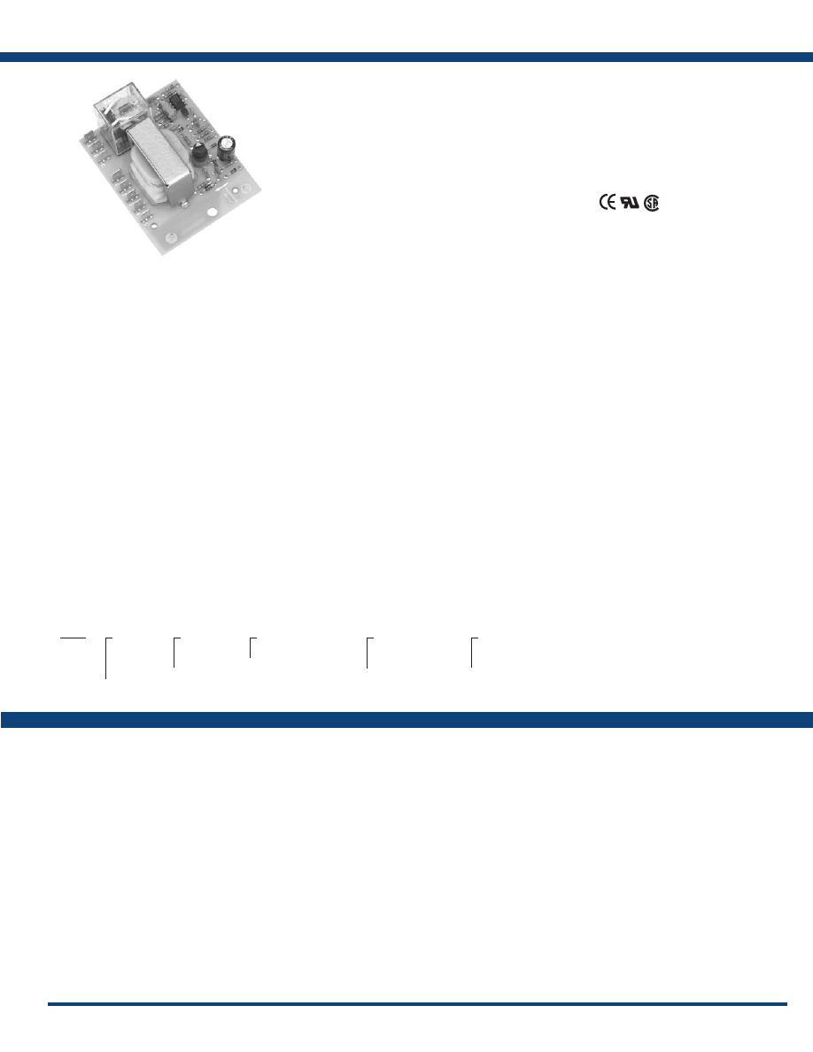
129
www.ssac.com • 800-843-8848 • fax: 605-348-5685
LLC1 Series
Liquid Level Controls
Available Models:
Control
Type . . . . . . . . . . . . . . . . . . . . . . . . . . . . . . . . .
ON/OFF (single level) resistance sensor with
built-in time delay to prevent rapid cycling
Sense Voltage
. . . . . . . . . . . . . . . . . . . . . . . . .
Low voltage AC between probe & common.
Isolated from input & output.
Sense Resistance . . . . . . . . . . . . . . . . . . . . . . .
Fixed or adjustable to 250KΩ
Sense Resistance Tolerance . . . . . . . . . . . . .
Adjustable - guaranteed range
Factory fixed ±10%
Time Delay
Range . . . . . . . . . . . . . . . . . . . . . . . . . . . . . . . .
Fixed 1 - 60s in 1s increments
Input
Voltage
. . . . . . . . . . . . . . . . . . . . . . . . . . . . . . .
24, 120, or 230VAC
Tolerance 24VAC
. . . . .
-15% - 20%
120 & 230VAC
. . . . .
-20% - 10%
AC Line Frequency . . . . . . . . . . . . . . . . . . . .
50/60 Hz
Output
Type . . . . . . . . . . . . . . . . . . . . . . . . . . . . . . . . .
Electromechanical relay
Form . . . . . . . . . . . . . . . . . . . . . . . . . . . . . . . . .
Non-isolated, SPST & Isolated, SPDT contacts
Rating . . . . . . . . . . . . . . . . . . . . . . . . . . . . . . .
10A resistive @ 120/240VAC & 28VDC;
1/3 hp @ 120/240VAC
Life
. . . . . . . . . . . . . . . . . . . . . . . . . . . . . . . . . .
Mechanical - 1 x 10
7
; Electrical - 1 x 10
5
Protection
Surge . . . . . . . . . . . . . . . . . . . . . . . . . . . . . . . .
IEEE C62.41-1991 Level A
Isolation Voltage
. . . . . . . . . . . . . . . . . . . . . .
≥ 1500V RMS between input, output & probe
Mechanical
Mounting . . . . . . . . . . . . . . . . . . . . . . . . . . . .
Surface mount to probe common with
two #6 (M3.5 x 0.6) screws or 0.50 in. (12.7 mm)
nylon standoffs with three #6 (M3.5 x 0.6) screws
(use Terminal 5 for probe common)
Termination . . . . . . . . . . . . . . . . . . . . . . . . . .
0.25 in. (6.35 mm) male quick connect terminals
Dimensions (Open Board) . . . . . . . . . . . . . .
3.5 x 2.75 x 2 in. (88.9 x 69.9 x 50.8 mm)
Environmental
Operating / Storage Temperature
. . . . . . .
-20° to 55°C/-40° to 80°C
Coating . . . . . . . . . . . . . . . . . . . . . . . . . . . . . .
Printed circuit board is conformal coated to
resist moisture and corrosion
Weight
. . . . . . . . . . . . . . . . . . . . . . . . . . . . . . .
≅
8.7 oz (247 g)
Features:
• Single probe level control for conductive
liquids
• Isolated AC voltage on the probes
• Adjustable or fixed sensing up to 250KΩ
• Fill or drain operation available
• 24, 120, or 230VAC models are available
• Isolated, 10A, SPDT & non-isolated, SPST
output contacts
Approvals:
Auxiliary Products:
•
Quick connect to screw adaptor:
P/N: P1015-18
•
Electrode:
P/N: PHST-38QTN
•
Threaded probe (24”):
P/N: LLP-24
•
Female quick connect:
P/N: P1015-13 (AWG 10/12)
P/N: P1015-64 (AWG 14/16)
P/N: P1015-14 (AWG 18/22)
LLC14A1AX
LLC14A5AX
LLC14A7AX
LLC14B15AX
LLC14B1AX
LLC14B60AX
LLC16A25AX
LLC16A3AX
LLC16B60A
Specifications
Order Table:
LLC1
X
Input
─
2
- 24VAC
─
4
- 120VAC
─
6
- 230VAC
X
Operation
─
A
- Drain
─
B
- Fill
X
Time Delay
─Fixed: Specify
1-60s
in
1s increments
X
Sense Resistance
─
A
- Adjustable
─
F
- Fixed (Specify
fixed resistance
(1-250) in 1K
Ω
increments .)
X
Mounting
─
Blank
- Surface mount
─
X
- 0.5 in. nylon
standoffs (three)
The LLC1 Series is a single probe conductive liquid
level control designed for OEM equipment and
commercial appliances. This unit may be ordered
with selectable or fixed fill or drain operation. A
time delay (1-60s) prevents rapid cycling of the
output relay. On adjustable units, the sensitivity
adjustment allows accurate level sensing while
ignoring foaming agents and floating debris.
Isolated AC voltage is provided at the probe to
prevent electrolysis. A trickle current of less than
1mA determines the presence or absence of liquid
between the probe and common. The LLC1 Series
printed circuit board is conformal coated to resist
moisture and corrosion .
For more information see:
Appendix B, page 167, Figure 26 for dimensional drawing.
Appendix C, page 170, Figure 23 for connection diagram.
Operation
Drain (Pump-Down Mode):
When the liquid level rises and touches the probe, a fixed time delay begins. This
time delay prevents rapid cycling of the output relay and its load. At the end of the time delay, the output relay
energizes and remains energized until the liquid level falls below the probe. The output relay then de-energizes
and remains de-energized until the liquid again touches the probe.
Fill (Pump-Up Mode):
When the liquid level falls below the probe, a fixed time delay begins. This time delay
prevents rapid cycling of the output relay and its load. At the end of the time delay, the output relay energizes
and remains energized until the liquid level rises and touches the probe. The output relay then de-energizes and
remains de-energized until the liquid level again falls below the probe.
If desired part number is not listed, please call us to
see if it is technically possible to build .
Courtesy of Steven Engineering, Inc.-230 Ryan Way, South San Francisco, CA 94080-6370-Main Office: (650) 588-9200-Outside Local Area: (800) 258-9200-www.stevenengineering.com
Littelfuse-catalog-html.html

130
www.ssac.com • 800-843-8848 • fax: 605-348-5685
LLC2 Series
Liquid Level Controls
Available Models:
Control
Type . . . . . . . . . . . . . . . . . . . . . . . . . . . . . . . . . . .
Resistance sensing for high & low level detection
of conductive liquids
Sense Voltage
. . . . . . . . . . . . . . . . . . . . . . . . . . .
12VAC at probe terminals
Sense Resistance . . . . . . . . . . . . . . . . . . . . . . . . .
Fixed or adjustable to 100KΩ
Sense Resistance Tolerance . . . . . . . . . . . . . . .
Adjustable: guaranteed range
Fixed: ±10%
Input
Voltage
. . . . . . . . . . . . . . . . . . . . . . . . . . . . . . . . .
24, 120, or 230VAC
Tolerance 24VAC
. . . . . . .
-15% - 20%
120 & 230VAC
. . . . . . .
-20% - 10%
AC Line Frequency . . . . . . . . . . . . . . . . . . . . . .
50/60 Hz
Output
Type . . . . . . . . . . . . . . . . . . . . . . . . . . . . . . . . . . .
Electromechanical relay
Form . . . . . . . . . . . . . . . . . . . . . . . . . . . . . . . . . . .
Isolated, SPDT
Rating . . . . . . . . . . . . . . . . . . . . . . . . . . . . . . . . .
10A resistive @ 120/240VAC & 28VDC;
1/3 hp @ 120/240VAC
Life
. . . . . . . . . . . . . . . . . . . . . . . . . . . . . . . . . . . .
Mechanical - 1 x 10
7
; Electrical - 1 x 10
5
Protection
Isolation Voltage
. . . . . . . . . . . . . . . . . . . . . . . .
≥ 1500V RMS between input, output, & probe
Mechanical
Mounting . . . . . . . . . . . . . . . . . . . . . . . . . . . . . .
Surface mount with two or four #6 (M3.5 x 0.6)
screws
Termination . . . . . . . . . . . . . . . . . . . . . . . . . . . .
0.25 in. (6.35 mm) duplex male quick
connect terminals
Terminal blocks for up to #14 AWG
(2.5 mm
2
) wire
Dimensions (Open Board) . . . . . . . . . . . . . . . .
4 x 3 x 2 in. (101.6 x 76.2 x 50.8 mm)
Environmental
Operating / Storage Temperature
. . . . . . . . .
-20° to 55°C / -40° to 80°C
Coating . . . . . . . . . . . . . . . . . . . . . . . . . . . . . . . .
Printed circuit board is conformal coated
to resist moisture and corrosion
Weight
. . . . . . . . . . . . . . . . . . . . . . . . . . . . . . . . .
≅
9 oz (255 g)
Features:
• Dual probe level control for conductive
liquids
• Isolated AC voltage on the probes
• Adjustable or fixed sensing up to 100KΩ
• Terminal block or quick connect terminals
• Fill or drain operation available
• 24, 120, or 230VAC models are available
• Isolated, 10A, SPDT output contacts
Approvals:
Auxiliary Products:
•
Quick connect to screw adaptor:
P/N: P1015-18
•
Electrode:
P/N: PHST-38QTN
•
Threaded probe (24”):
P/N: LLP-24
•
Female quick connect:
P/N: P1015-13 (AWG 10/12)
P/N: P1015-64 (AWG 14/16)
P/N: P1015-14 (AWG 18/22)
Specifications
Order Table:
LLC24A2AN
LLC24A2F50N
LLC24B2F50N
LLC26A1F25C
LLC2
X
Input
─
2
- 24VAC
─
4
- 120VAC
─
6
- 230VAC
X
Operation
─
A
- Drain
─
B
- Fill
X
Termination
─
1
- 0.25 Quick Connect
─
2
- Terminal Block
X
Sense Resistance
─
A
- Adjustable to 100k
Ω
─
F
- Fixed (Specify fixed
resistance
1-100
in 1K
Ω
increments .)
X
Mounting Dimension
─
N
─
C
N
C
W
0.44
(11.35)
0.25
(6.35)
X
3.62
(11.35)
3.5
(88.9)
Y
2 .12
(53.8)
2.5
(63.5)
Z
0.19
(4.83)
0.25
(6.35)
Mounting dimensions as indicated
in Appendix B, page 167.
The LLC2 Series is a dual-probe conductive liquid
level control designed for OEM equipment and
commercial appliance applications . Models are
available for fill or drain operation. Transformer
isolated 12VAC is provided at the probes to
prevent electrolysis. A trickle current of less than
1mA determines the presence or absence of liquid
between the probes and common. On adjustable
units, the sensitivity adjustment allows accurate
level sensing while ignoring foaming agents and
floating debris. The LLC2 Series printed circuit
board is conformal coated to resist moisture and
corrosion .
For more information see:
Appendix B, page 167, Figure 27 for dimensional drawing.
Appendix C, page 170, Figure 27 for connection diagram.
Operation
Drain (Pump-Down Mode):
When the liquid level rises and touches the high probe, the output relay energizes
and remains energized until the liquid level falls below the low probe. The output relay then de-energizes and
remains de-energized until the liquid again touches the high probe.
Fill (Pump-Up Mode):
When the liquid level falls below the low probe, the output relay energizes and remains
energized until the liquid level rises and touches the high probe. The output relay then de-energizes and remains
de-energized until the liquid level again falls below the low probe.
If desired part number is not listed, please call us to
see if it is technically possible to build .
Courtesy of Steven Engineering, Inc.-230 Ryan Way, South San Francisco, CA 94080-6370-Main Office: (650) 588-9200-Outside Local Area: (800) 258-9200-www.stevenengineering.com
Littelfuse-catalog-html.html
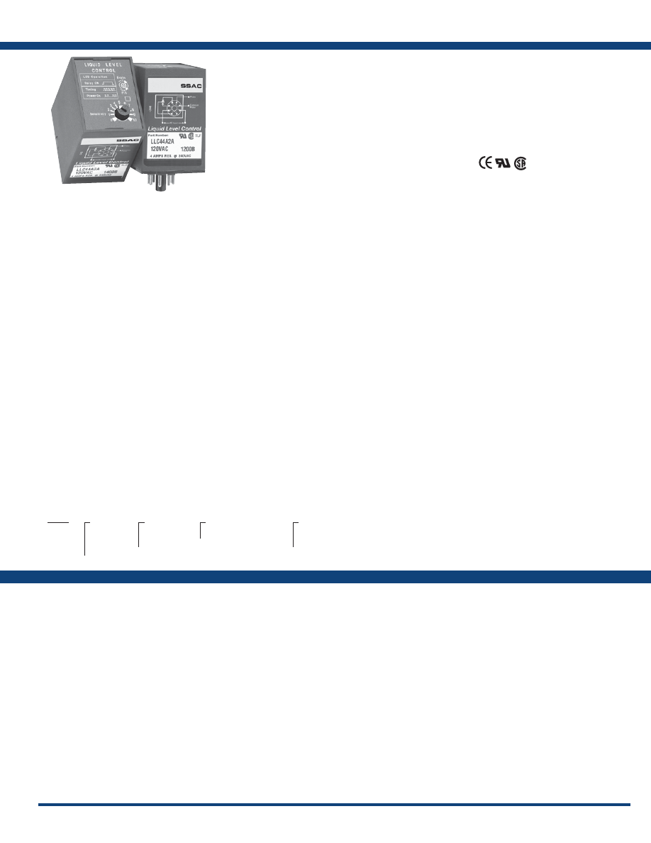
131
www.ssac.com • 800-843-8848 • fax: 605-348-5685
Features:
• Single probe level control for conductive
liquids
• Adjustable or fixed sensing up to 250 KΩ
• Selectable or fixed fill or drain operation
available
• 24, 120, or 230VAC models are available
• Isolated pulsed DC on the probes
• Isolated, 4A, SPDT output contacts
Approvals:
LLC4 Series
Liquid Level Controls
Available Models:
Control
Type . . . . . . . . . . . . . . . . . . . . . . . . . . . . . . . . .
ON/OFF (single level) resistance sensor with built-in
time delay to prevent rapid cycling
Sensing Voltage
. . . . . . . . . . . . . . . . . . . . . . .Pulsed DC at probe terminals
Sensing Resistance . . . . . . . . . . . . . . . . . . . . .
Fixed or adjustable to 250KΩ
Sensing Resistance Tolerance . . . . . . . . . . . .
Adjustable: 1K ±500Ω at low end;
250K ±25% at high end
Factory fixed: ±10% or 500Ω, whichever is greater
Input
Voltage
. . . . . . . . . . . . . . . . . . . . . . . . . . . . . . .
24, 120, or 230VAC
Tolerance 24VAC
. . . . . .
-15%, +20%
120 & 230VAC
. . . . . .
-20%, +10%
AC Line Frequency . . . . . . . . . . . . . . . . . . . .
50/60 Hz
Output
Type . . . . . . . . . . . . . . . . . . . . . . . . . . . . . . . . .
Electromechanical relay
Form . . . . . . . . . . . . . . . . . . . . . . . . . . . . . . . . .
Isolated, SPDT
Rating . . . . . . . . . . . . . . . . . . . . . . . . . . . . . . .
4A resistive @ 240VAC;
1/10 hp @ 240VAC
Protection
Surge . . . . . . . . . . . . . . . . . . . . . . . . . . . . . . . .
IEEE C62.41-1991 Level A
Isolation Voltage
. . . . . . . . . . . . . . . . . . . . . .
≥ 1500V RMS between input, output & probe
Mechanical
Mounting . . . . . . . . . . . . . . . . . . . . . . . . . . . .
Plug-in socket
Termination . . . . . . . . . . . . . . . . . . . . . . . . . . Octal
8-pin plug-in
Dimensions . . . . . . . . . . . . . . . . . . . . . . . . . .
2.91 x 2.39 x 1.78 in. (73.9 x 60.7 x 45.2 mm)
Environmental
Operating / Storage Temperature
. . . . . . .
-20° to 60°C/-40° to 80°C
Weight
. . . . . . . . . . . . . . . . . . . . . . . . . . . . . . .
≅
6 oz (170 g)
Specifications
LLC42A10A
LLC42A1A
LLC42B15A
LLC44A10A
LLC44A1A
LLC44A2A
LLC44A4A
LLC44A5A
LLC44A60A
LLC44B1F250
LLC44B20A
LLC44B2A
LLC44B30A
LLC44B4A
LLC44B5A
LLC44B5F100
Order Table:
Auxiliary Products:
•
Electrode:
P/N: PHST-38QTN
•
Threaded probe (24”):
P/N: LLP-24
•
Panel mount kit:
P/N: BZ1
•
8-pin socket:
P/N: NDS-8
•
Hold-down clips (sold in pairs):
P/N: PSC8 (NDS-8)
LLC4
X
Input
─
2
- 24VAC
─
4
- 120VAC
─
6
- 230VAC
X
Operation
─
A
- Drain
─
B
- Fill
X
Time Delay
─Specify fixed delay
1-60
s in 1s increments
X
Sense Resistance
─
A
- Adjustable (
1-250k
)
─
F
- Fixed (Specify
fixed resistance (
1-250
)
in 1K
Ω
increments .)
The LLC4 combines resistance sensing circuitry
with solid-state timing to provide single probe level
maintenance. On adjustable units, the sensitivity
adjustment allows accurate level sensing while
ignoring foaming agents and floating debris.
Isolated pulsed DC is provided at the probe to
prevent electrolysis. A trickle current of less
than 1mA determines the presence or absence of
conductive liquid between the probe and common.
The LLC4 Series can be used with many types of
low voltage (resistance changing) transducers to
perform other control functions like temperature
limit control, photo limit control, condensation
sensing, and ice sensing.
For more information see:
Appendix B, page 166, Figure 19 for dimensional drawing.
Appendix C, page 170, Figure 24 for connection diagram.
Operation
Drain (Pump-Down Mode):
When the liquid level rises and touches the probe, the time delay begins. This time
delay prevents rapid cycling of the output relay and its load. At the end of the time delay, the output relay and
LED energize and remain energized until the liquid level falls below the probe level. The output relay and LED
de-energize and remain de-energized until the liquid rises and touches the probe.
Fill (Pump-Up Mode):
When the liquid level falls below the probe, the time delay begins. This time delay prevents
rapid cycling of the output relay and its load. At the end of the time delay, the output relay and LED energize and
remain energized until the liquid level rises and touches the probe. The output relay and LED then de-energize
and remain de-energized until the liquid level again falls below the probe level.
If desired part number is not listed, please call us to
see if it is technically possible to build .
Courtesy of Steven Engineering, Inc.-230 Ryan Way, South San Francisco, CA 94080-6370-Main Office: (650) 588-9200-Outside Local Area: (800) 258-9200-www.stevenengineering.com
Littelfuse-catalog-html.html

132
www.ssac.com • 800-843-8848 • fax: 605-348-5685
Features:
• Dual probe level control for conductive
liquids
• Onboard knob or fixed sensing up to 100KΩ
• Fill or drain operation available
•
Select standard or diagnostic LED operation
• Diagnostic LED operation reduces adjustment
& troubleshooting time
• 24, 120, or 230VAC models are available
• Isolated, 5A, SPDT ouput contacts
Approvals:
LLC5 Series
Liquid Level Controls
Available Models:
Control
Type . . . . . . . . . . . . . . . . . . . . . . . . . . . . . . . . . .
Resistance sensing for high & low level detection
of conductive liquids
Sensing Voltage
. . . . . . . . . . . . . . . . . . . . . . . . Pulsed DC at probe terminals
Sensing Resistance . . . . . . . . . . . . . . . . . . . . . .
Factory fixed or adjustable to 100KΩ
Sensing Resistance Tolerance . . . . . . . . . . . . .
Adjustable: 1K ±500Ω at low end;
100KΩ ±25%, 0% at high end
Factory fixed: ±10% or 500Ω whichever is greater
Response Time . . . . . . . . . . . . . . . . . . . . . . . . . Debounce time delay <1s
Input
Voltage
. . . . . . . . . . . . . . . . . . . . . . . . . . . . . . . .
24, 120, or 230VAC
Tolerance 24VAC
. . . . . . .
-15%, +20%
120 & 230VAC
. . . . . . .
-20%, +10%
AC Line Frequency . . . . . . . . . . . . . . . . . . . . .
50/60 Hz
Output
Type . . . . . . . . . . . . . . . . . . . . . . . . . . . . . . . . . .
Electromechanical relay
Form . . . . . . . . . . . . . . . . . . . . . . . . . . . . . . . . . .
Isolated, SPDT
Rating . . . . . . . . . . . . . . . . . . . . . . . . . . . . . . . .
5A resistive @ 240VAC
1/10 hp @ 240VAC
Protection
Isolation Voltage
. . . . . . . . . . . . . . . . . . . . . . .
≥ 1500V RMS between input, output, & probe
Mechanical
Mounting . . . . . . . . . . . . . . . . . . . . . . . . . . . . .
Plug-in socket
Dimensions . . . . . . . . . . . . . . . . . . . . . . . . . . . .
3.01 x 2.39 x 1.78 in. (76.5 x 60.7 x 45.2 mm)
Termination . . . . . . . . . . . . . . . . . . . . . . . . . . . .Octal
8-pin plug-in
Environmental
Operating / Storage Temperature
. . . . . . . .
-20° to 60°C / -40° to 80°C
Weight
. . . . . . . . . . . . . . . . . . . . . . . . . . . . . . . .
≅
6 oz (170 g)
Specifications
Order Table:
Auxiliary Products:
•
Panel mount kit:
P/N: BZ1
•
Octal 8-pin socket:
P/N: NDS-8
•
Hold-down c lips (sold i n p airs):
P/N: PSC8 (NDS-8)
•
Electrode:
P/N: PHST-38QTN
•
Threaded probe (24”):
P/N: LLP-24
LLC52AA
LLC52BA
LLC54AA
LLC54AAS
LLC54AF10
LLC54BA
LLC54BAS
LLC56AA
LLC5
X
Input
─
2
- 24VAC
─
4
- 120VAC
─
6
- 230VAC
X
Operation
─
A
- Drain
─
B
- Fill
X
Sense Resistance
─
A
- Adjustable
─
F
- Fixed (Specify fixed
resistance
1-100
in 1K
Ω
increments .)
X
Connection
─
Blank
- Standard (#6
Low, #8 High)
─
S
- Reverse (#8 Low, #6
High)
X
LED Operation
─
Blank
- Standard LED
operation
─
D
- LED operation with
diagnostics
The LLC5 provides dual probe conductive liquid
level control in a convenient octal plug-in package.
Models are available for fixed fill or drain operation.
Isolated, pulsed DC voltage on the probes prevents
electrolytic plating. Less than 1 mA of current is used
to sense the presence of conductive liquid between
the probes and common. On adjustable units, the
sensitivity adjustment eliminates false tripping
caused by floating debris and foaming agents.
For more information see:
Appendix B, page 167, Figure 29 for dimensional drawing.
Appendix C, page 170, Figure 28 for connection diagram.
Operation
Drain (Pump-Down Mode):
When the liquid level rises and touches the high level probe, the output relay and
LED energize and remain energized until the liquid level falls below the low level probe. The output relay and
LED de-energize and remain de-energized until the liquid rises and touches the high level probe.
Fill (Pump-Up Mode):
When the liquid level falls below the low level probe, the output relay and LED energize
and remain energized until the liquid level rises and touches the high level probe. The output relay and LED de-
energize and remain de-energized until the liquid level again falls below the low level probe.
If desired part number is not listed, please call us to
see if it is technically possible to build .
Courtesy of Steven Engineering, Inc.-230 Ryan Way, South San Francisco, CA 94080-6370-Main Office: (650) 588-9200-Outside Local Area: (800) 258-9200-www.stevenengineering.com
Littelfuse-catalog-html.html
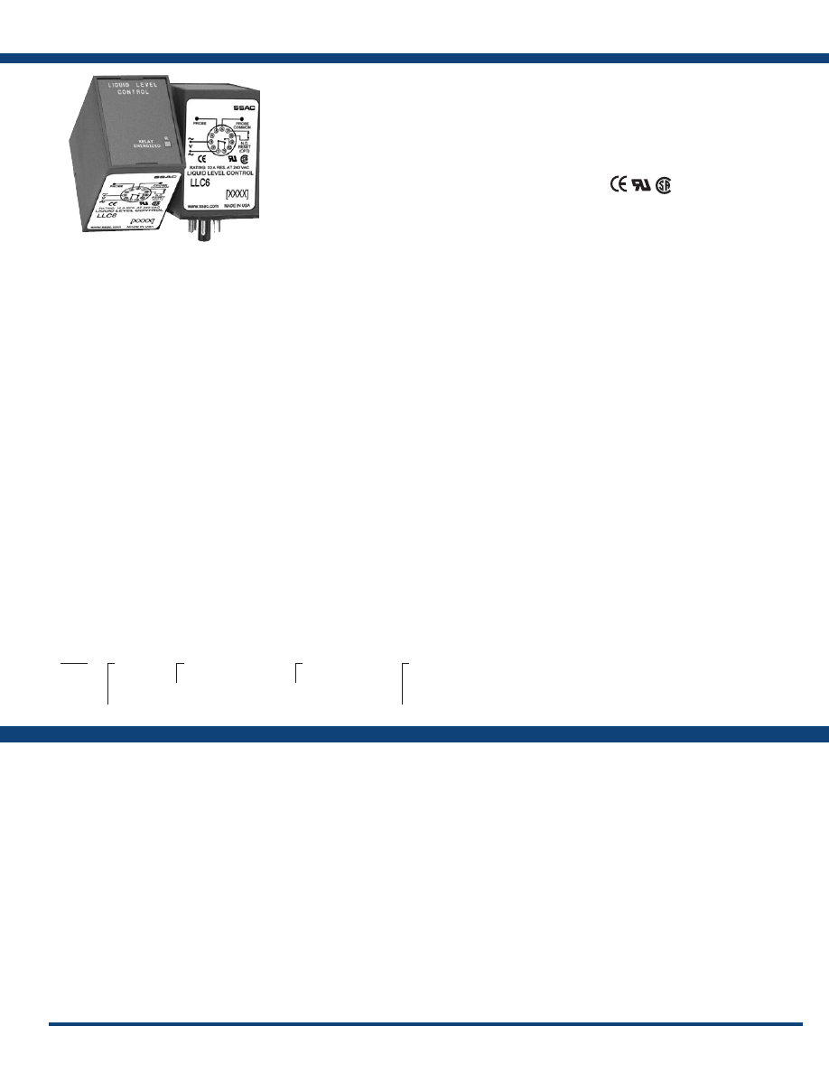
133
www.ssac.com • 800-843-8848 • fax: 605-348-5685
Features:
• Designed for low level cutoff protection
• Energized on wet probe
• Fixed time delay of 1 - 60s
• Fixed sense resistance of 5K - 250KΩ
• 24, 120, or 230VAC input voltage available
• Non-isolated, 10A, SPDT output contacts
Approvals:
LLC6 Series
Liquid Level Controls
Available Models:
Control
Type . . . . . . . . . . . . . . . . . . . . . . . . . . . . . . . . .
ON/OFF (single level) resistance sensor with built-in
time delay to prevent rapid cycling
Sense Voltage
. . . . . . . . . . . . . . . . . . . . . . . . .
12VAC nominal at probe terminals
Sense Resistance . . . . . . . . . . . . . . . . . . . . . . .
Fixed 5K - 250KΩ
Sense Resistance Tolerance . . . . . . . . . . . . .
Fixed ±10%
Time Delay
Range . . . . . . . . . . . . . . . . . . . . . . . . . . . . . . . .
1 - 60s in 1s increments
Tolerance . . . . . . . . . . . . . . . . . . . . . . . . . . . . .
±20%
Repeat Accuracy . . . . . . . . . . . . . . . . . . . . . .
±10%
Time Delay vs Temp. & Voltage
. . . . . . . . .
±10%
Power Outage Reset Delay . . . . . . . . . . . . . .
≤ 1s
Input
Voltage
. . . . . . . . . . . . . . . . . . . . . . . . . . . . . . .
24, 120, or 230VAC
Tolerance 24VAC
. . . . . .
+20% to -15%
120 or 230VAC
. . . . . .
+10% to -20%
AC Line Frequency . . . . . . . . . . . . . . . . . . . .
50/60 Hz
Output
Type . . . . . . . . . . . . . . . . . . . . . . . . . . . . . . . . .
Electromechanical relay
Form . . . . . . . . . . . . . . . . . . . . . . . . . . . . . . . . .
Non-isolated, SPDT
Rating . . . . . . . . . . . . . . . . . . . . . . . . . . . . . . .
10A resistive @ 240VAC; 1/4 hp @ 125VAC;
1/2 hp @ 250VAC
Protection
Surge . . . . . . . . . . . . . . . . . . . . . . . . . . . . . . . .
IEEE C62.41-1991 Level A
Isolation Voltage
. . . . . . . . . . . . . . . . . . . . . .
≥ 2500V RMS between input & output
terminals
Mechanical
Mounting . . . . . . . . . . . . . . . . . . . . . . . . . . . .
Plug-in socket
Termination . . . . . . . . . . . . . . . . . . . . . . . . . .
11-pin relay type
Dimensions . . . . . . . . . . . . . . . . . . . . . . . . . . .
2.91 x 2.39 x 1.78 in. (73.9 x 60.7 x 45.2 mm)
Environmental
Operating / Storage Temperature
. . . . . . .
-40° to 60°C / -40° to 80°C
Humidity . . . . . . . . . . . . . . . . . . . . . . . . . . . . .
95% relative, non-condensing
Weight
. . . . . . . . . . . . . . . . . . . . . . . . . . . . . . .
≅
7.3 oz (207 g)
Specifications
Order Table:
LLC6210F10M
LLC622F10P
LLC6410F10M
LLC642F10M
LLC643F250M
LLC645F250M
LLC6610F5P
Auxiliary Products:
•
Electrode:
P/N: PHST-38QTN
•
Threaded probe (24”):
P/N: LLP-24
•
Panel mount kit:
P/N: BZ1
•
11-pin socket:
P/N: NDS-11
•
Hold-down clips (sold in pairs):
P/N: PSC11 (NDS-11)
LLC6
X
Input
─
2
- 24VAC
─
4
- 120VAC
─
6
- 230VAC
X
Time Delay (fixed)
─Specify fixed delay
in seconds (
1-60
) in 1s
increments
X
Sense Resistance
─
F
- Fixed (Specify
fixed resistance in
kilohms (
5-250
)
in 1K increments .)
X
Reset
─
M
- Manual/Automatic
Reset
─
P
- Power outage
manual reset
The LLC6 Series is a plug-in, single-probe
conductive liquid level control designed for low
liquid level cutoff protection. It offers a factory
fixed time delay of 1 - 60s and is available in
input voltages of 24, 120, or 230VAC. LED
indicator illuminates whenever the LLC6’s 10A,
SPDT output relay is energized. Available with
automatic/manual reset or a special manual reset
with power outage feature, which auto resets
the unit when power is restored and the water
level is acceptable. 24VAC and 120VAC units
are recognized as limit switches under UL353
(230VAC units are UL508) and CSA certified under
Standard 14.
For more information see:
Appendix B, page 166, Figure 19 for dimensional drawing.
Appendix C, page 170, Figure 26 for connection diagram.
Operation
Automatic Reset (Reset terminals not connected):
When liquid rises to the low level cutoff probe, the output
relay and the LED indicator energize. When the liquid falls below low level cutoff probe, the output relay and
the LED indicator de-energize after a fixed time delay.
Manual Reset (Reset switch connected):
When the liquid level falls below the low level probe, the output relay
and LED de-energize after a fixed time delay. When the liquid level rises to the low level probe, the output relay
and LED indicator remain de-energized until the manual reset switch is opened; then they energize immediately.
Power Outage Manual Reset (Reset switch connected):
A power outage causes the output relay and LED
indicator to de-energize. Upon restoration of power, if the liquid level is above the low level probe, the output
relay and LED indicator will re-energize. If the liquid level is below the low level probe, the output relay and
LED indicator remain de-energized until the Normally Closed (NC) reset switch is opened.
If desired part number is not listed, please call us to
see if it is technically possible to build .
Courtesy of Steven Engineering, Inc.-230 Ryan Way, South San Francisco, CA 94080-6370-Main Office: (650) 588-9200-Outside Local Area: (800) 258-9200-www.stevenengineering.com
Littelfuse-catalog-html.html

134
www.ssac.com • 800-843-8848 • fax: 605-348-5685
LLC8 Series
Liquid Level Controls
Available Models:
Control
Type . . . . . . . . . . . . . . . . . . . . . . . . . . . . . . . . .
Resistance sensing for conductive liquids with time delay
Sense Voltage
. . . . . . . . . . . . . . . . . . . . . . . . .
12VAC nominal at probe terminals
Sense Resistance . . . . . . . . . . . . . . . . . . . . . . .
Fixed 5K - 250KΩ
Sense Resistance Tolerance . . . . . . . . . . . . .
±10%
Time Delay
Tolerance . . . . . . . . . . . . . . . . . . . . . . . . . . . . .
±20%
Repeat Accuracy . . . . . . . . . . . . . . . . . . . . . .
±10%
Time Delay vs Temp. & Voltage
. . . . . . . . .
±10%
Power Outage Reset Delay . . . . . . . . . . . . . .
≤1s
Input
Voltage
. . . . . . . . . . . . . . . . . . . . . . . . . . . . . . .
24, 120, or 230VAC
Tolerance 24VAC
. . . .
-15% - 20%
120 or 230VAC
. . . . .
-20% - 10%
AC Line Frequency . . . . . . . . . . . . . . . . . . . .
50/60 Hz
Output
Type . . . . . . . . . . . . . . . . . . . . . . . . . . . . . . . . .
Electromechanical relay
Form . . . . . . . . . . . . . . . . . . . . . . . . . . . . . . . . . Isolated SPDT
Rating . . . . . . . . . . . . . . . . . . . . . . . . . . . . . . .
10A resistive @ 120/240VAC; 1/4 hp @ 125VAC;
1/2 hp @ 250VAC
Protection
Surge . . . . . . . . . . . . . . . . . . . . . . . . . . . . . . . .
IEEE C62.41-1991 Level A
Isolation Voltage
. . . . . . . . . . . . . . . . . . . . . .
≥ 2500V RMS input to output terminals
Mechanical
Mounting . . . . . . . . . . . . . . . . . . . . . . . . . . . .
0.5 in. (12.7 mm) x .187 (4.76 mm) dia.
nylon standoffs (3)
Termination Electrical . . . . . .
0.25 in. (6.35 mm) male quick connect
terminals
Reset Switch & Probe(s)
. . . . . .
0.187 x 0.03 in. (4.75 x 0.76 mm) male quick
connect terminals
Environmental
Operating / Storage Temperature
. . . . . . .
-40° to 60°C / -40° to 80°C
Coating . . . . . . . . . . . . . . . . . . . . . . . . . . . . . .
Printed circuit board is conformal coated
to resist moisture & corrosion
Humidity . . . . . . . . . . . . . . . . . . . . . . . . . . . . .
95% relative, non-condensing
Weight
. . . . . . . . . . . . . . . . . . . . . . . . . . . . . . .
≅
5 oz (141.7 g)
Features:
• Designed for low level cutoff protection
• Energized on wet probe
• Fixed time delay 1 - 60s
• Fixed sense resistance of 5K - 250KΩ
• 24, 120, or 230VAC input voltages available
• Isolated, 10A, SPDT output contacts
Approvals:
Auxiliary Products:
•
Quick connect to screw adaptor:
P/N: P1015-18
•
Electrode:
P/N: PHST-38QTN
•
Threaded probe (24”):
P/N: LLP-24
•
Female quick connect:
P/N: P1015-13 (AWG 10/12)
P/N: P1015-64 (AWG 14/16)
P/N: P1015-14 (AWG 18/22)
Specifications
Order Table:
LLC825F5M
LLC843F10M
LLC843F10P
LLC843F26M
LLC843F26P
LLC845F25P
LLC8610F12M
LLC8
X
Input
─
2
- 24VAC
─
4
- 120VAC
─
6
- 230VAC
X
Time Delay (fixed)
─Specify fixed delay
in seconds (
1-60
) in 1s
increments
X
Sense Resistance
─
F
- Fixed (Specify
fixed resistance in
kilohms (
5-250
)
in 1K increments .)
X
Reset
─
M
- Manual/Automatic
Reset
─
P
- Power outage
manual reset
The LLC8 Series is a low cost, single-probe
conductive liquid level control designed for low
liquid level cutoff protection. It offers a factory
fixed time delay of 1 - 60s and is available for input
voltages of 24, 120, or 230VAC. LED indicator
illuminates whenever the LLC8’s isolated, 10A,
SPDT output relay is energized. Sense resistance
is fixed from 5K - 250KΩ. Available with manual/
automatic reset or a special manual reset with a
power outage feature that auto resets the unit when
power is restored and the water level is acceptable.
24 and 120VAC units are UL recognized as limit
switches under UL353 (230VAC units are UL 508)
and CSA certified under Standard 14.
For more information see:
Appendix B, page 167, Figure 28 for dimensional drawing.
Appendix C, page 170, Figure 25 for connection diagram.
Operation
Automatic Reset (Reset switch not connected):
When liquid rises to low level cutoff probe, output relay and
LED indicator energize. When liquid falls below the low level cutoff probe, the output relay and LED indicator
de-energize after a fixed time delay.
Manual Reset (Reset switch connected):
When the liquid level falls below low level probe, the output relay and
LED de-energize after a fixed time delay. When the liquid level rises to low level probe, the output relay and
LED indicator remain de-energized until the NC manual reset switch is opened; then they energize immediately.
Power Outage Manual Reset (Reset switch connected):
A power outage causes the output relay and LED
indicator to de-energize. Upon restoration of power, if the liquid is touching the low level probe, the output
relay and LED indicator will re-energize. If the liquid level is below the low level probe, the output relay and
LED indicator remain de-energized until the NC reset switch is opened.
If desired part number is not listed, please call us to
see if it is technically possible to build .
Courtesy of Steven Engineering, Inc.-230 Ryan Way, South San Francisco, CA 94080-6370-Main Office: (650) 588-9200-Outside Local Area: (800) 258-9200-www.stevenengineering.com
Littelfuse-catalog-html.html

135
www.ssac.com • 800-843-8848 • fax: 605-348-5685
ARP Series
Alternating Relay
Available Models:
Input
Voltage
. . . . . . . . . . . . . . . . . . . . . . . . . . . . . . . . . . . . . . .
24, 120, or 230VAC
Tolerance 24VAC
. . . . . . . . . . . .
-15% - 20%
120 & 230VAC
. . . . . . . . . . . .
-20% - 10%
AC Line Frequency . . . . . . . . . . . . . . . . . . . . . . . . . . . .
50/60Hz
Output
Type . . . . . . . . . . . . . . . . . . . . . . . . . . . . . . . . . . . . . . . . .
Electromechanical relay
Form . . . . . . . . . . . . . . . . . . . . . . . . . . . . . . . . . . . . . . . . .
SPDT, DPDT, or cross wired DPDT
Rating . . . . . . . . . . . . . . . . . . . . . . . . . . . . . . . . . . . . . . .
10A resistive @ 120/240VAC & 28 VDC;
1/3 hp @ 120/240VAC
Maximum Voltage
. . . . . . . . . . . . . . . . . . . . . . . . . . . . .
250VAC
Life
. . . . . . . . . . . . . . . . . . . . . . . . . . . . . . . . . . . . . . . . . .
Mechanical - 1 x 10
7
; Electrical - 1 x 10
6
Protection
Isolation Voltage
. . . . . . . . . . . . . . . . . . . . . . . . . . . . . .
≥ 1500V RMS input to output
Mechanical
Mounting . . . . . . . . . . . . . . . . . . . . . . . . . . . . . . . . . . . .
Plug-in socket
Dimensions . . . . . . . . . . . . . . . . . . . . . . . . . . . . . . . . . . .
3.2 x 2.39 x 1.78 in. (81.3 x 60.7 x 45.2 mm)
Termination . . . . . . . . . . . . . . . . . . . . . . . . . . . . . . . . . .
Octal 8-pin or magnal 11-pin
Environmental
Operating / Storage Temperature
. . . . . . . . . . . . . . .
-20° to 60°C / -30° to 85°C
Weight
. . . . . . . . . . . . . . . . . . . . . . . . . . . . . . . . . . . . . . .
≅
5.6 oz (159 g)
NOTE: Unit does not have debounce time delay.
Features:
• Provides equal run time for two motors
• Alternating or electrically locked operation
• Low profile selection switch
• 10A output contacts
•
LED status indication
•
Industry standard base connection
Approvals:
Auxiliary Products:
•
Hold-down c lips (sold i n p airs):
P/N: PSC8 (NDS-8)
P/N: PSC11 (NDS-11)
•
Panel mount kit:
P/N: BZ1
•
11-pin socket:
P/N: NDS-11
•
8-pin socket:
P/N: NDS-8
•
DIN rail:
P/N: C103PM
Specifications
Order Table:
ARP23S
ARP41
ARP41S
ARP42S
ARP43
ARP43S
ARP61S
ARP63
ARP63S
ARP
X
Input
─
2
- 24VAC
─
4
- 120VAC
─
6
- 230VAC
X
Output Form
─
1
- SPDT, 8-pin
─
2
- DPDT, 11-pin
─
3
- DPDT, 8-pin
cross wired
X
Switch Operation
─
Blank
- No Switch
─
S
- Rotary Switch
The ARP Series is used in systems where equal
run time for two motors is desirable. The selector
switch allows selection of alternation of either load
for continuous operation. LED’s indicate the status
of the output relay. This versatile series may be
front panel mounted (BZ1 accessory required) or
35 mm DIN rail mounted with an accessory socket.
For more information see:
Appendix B, page 167, Figure 31 for dimensional drawing.
Appendix C, 170, Figure 29 for connection diagram.
Operation
Alternating:
When the rotary switch is in the “alternate” position, alternating operation of Load A and Load B
occurs upon the opening of the control switch S1. To terminate alternating operation and cause only the selected
load to operate, rotate the switch to position “A” to lock Load A or position “B” to lock Load B. The LEDs indicate
the status of the internal relay and which load is selected to operate.
Note: Input voltage must be applied at all times for proper alternation. The use of a solid-state control switch
for S1 may not initiate alternation correctly. S1 voltage must be from the same supply as the unit’s input
voltage (see connection diagrams). Loss of input voltage resets the unit; Load A becomes the lead load for
the next operation.
Duplexing (Cross Wired):
Duplexing models operate the same as alternating relays and when both the Control
(S1) and Lag Load (S2) Switches are closed, Load A and Load B energize simultaneously.
The DPDT 8-pin, cross-wired option, allows extra system load capacity through simultaneous operation of both
motors when needed. Relay contacts are not isolated.
If desired part number is not listed, please call us to
see if it is technically possible to build .
Courtesy of Steven Engineering, Inc.-230 Ryan Way, South San Francisco, CA 94080-6370-Main Office: (650) 588-9200-Outside Local Area: (800) 258-9200-www.stevenengineering.com
Littelfuse-catalog-html.html

136
www.ssac.com • 800-843-8848 • fax: 605-348-5685
Tower & Obstruction Lighting Controls
Series Included
Beacon Flasher
Lamp Monitors
Photo Controls
FA . . . . . . . . . . . . . . . . . . . . . . . . . . . . . . . . . . . . . . . . . . . . . . .
137
FS155-
. . . . . . . . . . . . . . . . . . . . . . . . . . . . . . . . . . . . . . . . . . . .
137
FS165-
. . . . . . . . . . . . . . . . . . . . . . . . . . . . . . . . . . . . . . . . . . . .
137
Incandescent Lamps
FB . . . . . . . . . . . . . . . . . . . . . . . . . . . . . . . . . . . . . . . . . . . . . . .
138
SCR490D
. . . . . . . . . . . . . . . . . . . . . . . . . . . . . . . . . . . . . . . . .
139
SCR430T
. . . . . . . . . . . . . . . . . . . . . . . . . . . . . . . . . . . . . . . . .
140
SCR630T
. . . . . . . . . . . . . . . . . . . . . . . . . . . . . . . . . . . . . . . . .
140
LED Lamps
FB9L . . . . . . . . . . . . . . . . . . . . . . . . . . . . . . . . . . . . . . . . . . . . .
141
SCR9L . . . . . . . . . . . . . . . . . . . . . . . . . . . . . . . . . . . . . . . . . . .
142
PCR . . . . . . . . . . . . . . . . . . . . . . . . . . . . . . . . . . . . . . . . . . . . .
143
Courtesy of Steven Engineering, Inc.-230 Ryan Way, South San Francisco, CA 94080-6370-Main Office: (650) 588-9200-Outside Local Area: (800) 258-9200-www.stevenengineering.com
Littelfuse-catalog-html.html

137
www.ssac.com • 800-843-8848 • fax: 605-348-5685
Features:
• Zero voltage switching - up to 10 times
longer lamp life
•
No RFI caused by contacts closing
• High inrush capability - up to 200A
• RF model for AM hot towers & other high
RF installations
• Auxiliary units for synchronous flashing or
constant line loading
Approvals:
FS & FA Series
Beacon Tower Flasher
Available Models:
Operation . . . . . . . . . . . . . . . . . . . . . . . . . . . . . . . . . .
Single & multiple beacon flashing with
auxiliary modules
Flash Rate (FS Series Only)
. . . . . . . . . . . . . . . . . . .
30 ±10 FPM
ON/OFF Ratio (FS Series Only)
. . . . . . . . . . . . . . .
50 - 67% ON time; 33 - 50% OFF time
Voltage
. . . . . . . . . . . . . . . . . . . . . . . . . . . . . . . . . . . .
120 or 230VAC ±20%
AC Line Frequency . . . . . . . . . . . . . . . . . . . . . . . . .
50/60Hz
Output Rating (Zero Voltage Switching)
. . . . . . .
2500W @ 120VAC; 5000W @ 230VAC
Inrush Current
. . . . . . . . . . . . . . . . . . . . . . . . . . . . .
200A peak for 1 cycle of AC line
Mounting* . . . . . . . . . . . . . . . . . . . . . . . . . . . . . . . . .
Surface mount with one #10 (M5 x 0.8) screw
Dimensions . . . . . . . . . . . . . . . . . . . . . . . . . . . . . . . .
2 x 2 x 1.51 in. (50.8 x 50.8 x 38.4 mm)
Termination . . . . . . . . . . . . . . . . . . . . . . . . . . . . . . . .
0.25 in. (6.35 mm) male quick connect terminals
Circuitry . . . . . . . . . . . . . . . . . . . . . . . . . . . . . . . . . . . Encapsulated
Operating / Storage Temperature
. . . . . . . . . . . .
-40° to 65°C / -40° to 85°C
Humidity . . . . . . . . . . . . . . . . . . . . . . . . . . . . . . . . . .
95% relative, non-condensing
Weight
. . . . . . . . . . . . . . . . . . . . . . . . . . . . . . . . . . . .
≅
3.9 oz (111 g)
* Note: Must be mounted to metal surface using the included heat sink compound. The
maximum mounting surface temperature is 90°C.
Specifications
Order Table:
Auxiliary Products:
•
Quick connect to screw adaptor:
P/N: P1015-18
•
Female quick connect:
P/N: P1015-13 (AWG 10/12)
P/N: P1015-64 (AWG 14/16)
P/N: P1015-14 (AWG 18/22)
FA155
FA155-2
FA165
FA165-2
FS155-30RF
FS155-30T
FS165-30T
(FS155 & FA155 models only)
B-KON Flashers have proven their reliability
through years of use on communication towers,
smoke stacks, cooling towers, tall buildings,
bridges and utility towers. The highest quality
components are encapsulated in a rugged plastic
housing with a molded-in heat transfer plate. The
flash rate, ratio, and fail-safe design meet FAA
regulations. Zero voltage switching can increase
lamp life up to ten times. The FS155-30RF &
FS165-30RF include superior RF filtering circuitry
for use in high RF installations; including AM hot
towers .
For more information see:
Appendix B, page 165, Figure 4 for dimensional drawing.
Appendix C, page 171, Figure 30 for connection diagram.
Operation
FS Series - Flasher (OFF First)
FA Series - Flashers & Aux. Modules
Upon application of input voltage, the T2 OFF time begins.
At the end of the OFF time, the T1 ON time begins and the
load energizes. At the end of T1, T2 begins and the load
de-energizes. This cycle repeats until voltage is removed.
Reset: Removing input voltage resets the output and the
sequence to T2 .
Input
120VAC
120VAC
230VAC
230VAC
120VAC
120VAC
230VAC
120VAC
230VAC
Wattage
2500W
2500W
5000W
5000W
2500W
3000W
5000W
2500W
5000W
Inrush
200A
200A
200A
200A
200A
300A
200A
200A
200A
Description
For High RF Radiation locations including AM Hot Towers
Standard Flasher
For High RF Radiation locations including AM Hot Towers
Standard Flasher
Auxiliary unit for synchronous operating of additional beacons
Auxiliary unit with optical isolation between input and load contacts
Auxiliary unit for sychronous operating of additional beacons
Auxiliary unit to provide constant line loading
Auxiliary unit to provide constant line loading
Part Number
FS155-30RF
FS155-30T
FS165-30RF
FS165-30T
FA155-2
FA155-3
FA165-2
FA155
FA165
If desired part number is not listed, please call us to
see if it is technically possible to build .
Courtesy of Steven Engineering, Inc.-230 Ryan Way, South San Francisco, CA 94080-6370-Main Office: (650) 588-9200-Outside Local Area: (800) 258-9200-www.stevenengineering.com
Littelfuse-catalog-html.html
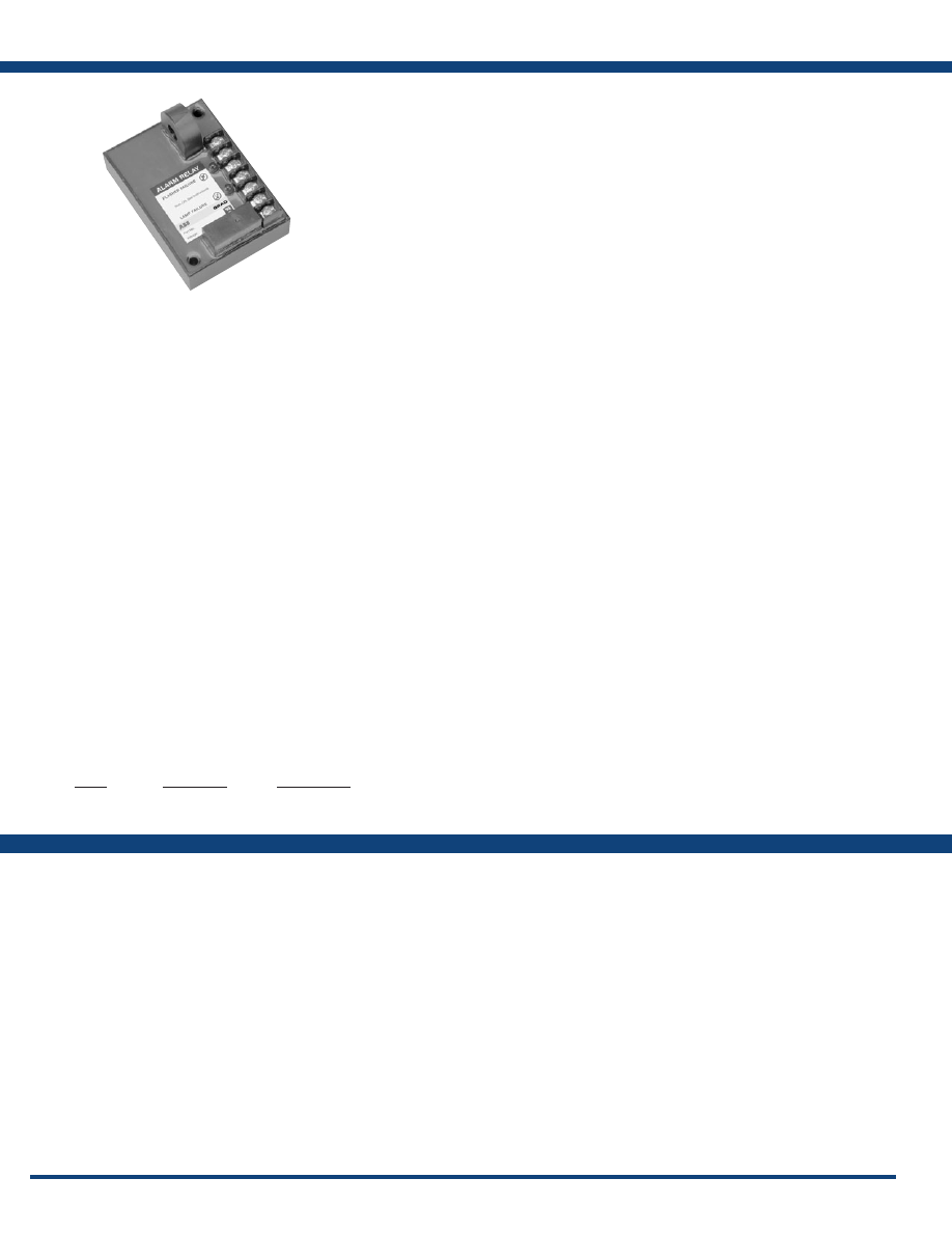
138
www.ssac.com • 800-843-8848 • fax: 605-348-5685
FB120A/FB230A
Flasher & Incandescent Beacon Alarm Relay
Available Models:
Input Voltage
FB120A
. . . . . . . . . . . . . . . . . . . . . . . . . . . .
120VAC ±15%
FB230A
. . . . . . . . . . . . . . . . . . . . . . . . . . . .
230VAC ±15%
AC Line Frequency . . . . . . . . . . . . . . . . . .
50/60Hz
Lamp Socket Voltage
. . . . . . . . . . . . . . . . .
±10%; 50/60Hz
Alarm Outputs
Type . . . . . . . . . . . . . . . . . . . . . . . . . . . . . . .
3 total - 1 relay, 2 solid state;
One isolated SPDT relay rated 5A resistive
Two solid-state line voltage outputs
rated 0.5A steady, 5A inrush
Lamp Failure Detection
FB120A
. . . . . . . . . . . . . . . . . . . . . . . . . . . .
For two 620W or 700W lamps
FB230A
. . . . . . . . . . . . . . . . . . . . . . . . . . . .
For two 500W or 700W lamps
Trip Delays
Flasher Failure
. . . . . . . . . . . . . . . . . . . . . .
Fixed at 6s; -0/+40%
Lamp Failure . . . . . . . . . . . . . . . . . . . . . . .
Fixed at 10s; -0/+40%
LEDs
Lamp Failure (Red) . . . . . . . . . . . . . . . . . .
Glows when one or both lamps fail
Flasher Failure (Red)
. . . . . . . . . . . . . . . . .
Glows when the flasher fails
Protection
Circuitry . . . . . . . . . . . . . . . . . . . . . . . . . . . Encapsulated
Mounting . . . . . . . . . . . . . . . . . . . . . . . . . .
Surface mount with two #6 (M3.5 x 0.6) screws
Dimensions . . . . . . . . . . . . . . . . . . . . . . . . .
3.5 x 2.5 x 1.75 in. (88.9 x 63.5 x 44.5 mm)
Termination . . . . . . . . . . . . . . . . . . . . . . . .
7 position barrier block for 20 AWG (0.5 mm
2
)
to 14 AWG (2.5 mm
2
) wire
Environmental
Operating / Storage Temperature
. . . . .
-40° to 60°C / -40° to 85°C
Weight
. . . . . . . . . . . . . . . . . . . . . . . . . . . . .
≅
7 oz (198 g)
Features:
• Senses failed flashing incandescent beacon
lamps & beacon flashers
•
Toroidal current sensing
• One isolated, 5A, SPDT alarm output
• Two 1A, solid-state line voltage alarm
outputs
• Trip delays prevent nuisance alarms
Specifications
Order Table:
FB120A
FB230A
Input
120VAC
230VAC
Lamp Type
Incandescent Beacon
Incandescent Beacon
Part Number
FB120A
FB230A
The FB120A and FB230A are used to monitor the
operation of one two-lamp incandescent beacon
and one beacon flasher (or auxiliary module).
The flasher and lamps are monitored by sensing
the flow of current in the circuit. If the lamp(s) or
the flasher fail to operate properly, a solid-state
output and an isolated SPDT relay energize. When
connected to a site monitoring system, this unit
provides the remote beacon monitoring protection
required by the FAA/FCC. On a multiple beacon
structure, one unit is required for each two-lamp
incandescent beacon (one unit per beacon for
LED beacons) .
For more information see:
Appendix B, page 167, Figure 32 for dimensional drawing.
Appendix C, page 171, Figure 31 for connection diagram.
Operation
If one lamp in an incandescent beacon fails, the relay
and solid-state lamp failure outputs energize after 10s.
If the flasher fails in the ON or OFF condition, the relay
and the solid-state flasher failure output energizes after
6s. If both failures occur, all three outputs energize after
their trip delays.
Note: If both incandescent lamps fail, all three outputs will
energize. The relay and solid-state flasher failure output
energizes after 6s, and the solid-state lamp failure output
energizes after 10s.
Courtesy of Steven Engineering, Inc.-230 Ryan Way, South San Francisco, CA 94080-6370-Main Office: (650) 588-9200-Outside Local Area: (800) 258-9200-www.stevenengineering.com
Littelfuse-catalog-html.html

139
www.ssac.com • 800-843-8848 • fax: 605-348-5685
Features:
• Senses failed obstruction lamps
• 2 - 9 steadily burning lamps can be
monitored
•
Toroidal current sensing
• Isolated, 10A, SPDT alarm output contacts
• 1A, solid-state line voltage alarm output
• 6 second trip delay prevents nuisance
alarms
Approvals:
SCR490D
Obstruction Lamp Alarm Relay
Available Models:
Operation
Number of Lamps
. . . . . . . . . . . . . . . . . . . . . . . . . . .
2 - 9 (selectable)
Lamp Wattage
. . . . . . . . . . . . . . . . . . . . . . . . . . . . . .
116W, incandescent lamps
Rated Lamp Voltage
. . . . . . . . . . . . . . . . . . . . . . . . .
120 or 130VAC (selectable)
Monitored Voltage
. . . . . . . . . . . . . . . . . . . . . . . . . . .
120VAC ±3%
Trip Delay . . . . . . . . . . . . . . . . . . . . . . . . . . . . . . . . . .
≅
6s fixed
Voltage
. . . . . . . . . . . . . . . . . . . . . . . . . . . . . . . . . . . . .
120VAC
AC Line Frequency
. . . . . . . . . . . . . . . . . . . . . . . . . .
50/60Hz
Tolerance 120VAC
. . . . . . . . . . . .
- 20% - 10%
Line Voltage Output (Solid State Rated)
. . . . . . . .
≤ 125W to operate a spare lamp or alarm
Isolated Alarm Output
. . . . . . . . . . . . . . . . . . . . . . .
10A @ 120VAC or 30VDC resistive;
1/4 hp @ 125VAC; 1/2 hp @ 250VAC
Mounting . . . . . . . . . . . . . . . . . . . . . . . . . . . . . . . . . .
Surface mount with two #6 (M3.5 x 0.6)
screws
Dimensions . . . . . . . . . . . . . . . . . . . . . . . . . . . . . . . . .
3.5 x 2.5 x 1.75 in. (88.9 x 63.5 x 44.5 mm)
Termination . . . . . . . . . . . . . . . . . . . . . . . . . . . . . . . .
Screws with captive clamps for up to
14 AWG (2.45 mm
2
) wire
Circuitry . . . . . . . . . . . . . . . . . . . . . . . . . . . . . . . . . . . Encapsulated
Operating / Storage Temperature
. . . . . . . . . . . . .
-40° to 65°C / -40° to 85°C
Humidity . . . . . . . . . . . . . . . . . . . . . . . . . . . . . . . . . . .
95% relative, non-condensing
Weight
. . . . . . . . . . . . . . . . . . . . . . . . . . . . . . . . . . . . .
≅
6.8 oz (193 g)
Specifications
Order Table:
SCR490D
Input
120VAC
Part Number
SCR490D
The SCR490D Series is used to provide remote
monitoring of steady burning incandescent marker
and obstruction lighting. Four onboard switches
allow operator programming for lighting systems
with two through nine lamps on a single AC
circuit. The SCR490D uses a toroidal sensor and
electronic circuitry to sense the failure of one or
more lamps .
For more information see:
Appendix B, page 167, Figure 32 for dimensional drawing.
Appendix C, page 171, Figure 32 for connection diagram.
Operation
When a lamp fails, the SCR490D senses a decrease in
current flow. Then, after a fixed time delay, it transfers
to its alarm mode. In alarm mode, the LED indicator, the
output relay (SPDT isolated contacts), and a non-isolated
solid-state output are energized. Replacement of the failed
lamps resets the alarm outputs and the LED indicator.
To prevent false alarm signals, power must be applied to
the SCR490D at the same time that lamps are energized.
Courtesy of Steven Engineering, Inc.-230 Ryan Way, South San Francisco, CA 94080-6370-Main Office: (650) 588-9200-Outside Local Area: (800) 258-9200-www.stevenengineering.com
Littelfuse-catalog-html.html
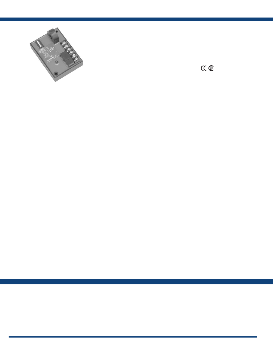
140
www.ssac.com • 800-843-8848 • fax: 605-348-5685
SCR Series
Universal Lamp Alarm Relay
Available Models:
Lamp Monitoring
Capacity (in lamps) . . . . . . . . . . . . . . . . . . . . . . . . .
100W 116W 620W 700W
SCR430T 120VAC Lamps
. . . . .
4
4 4 n/a
SCR630T 230VAC Lamps
. . . . . .
n/a
4 n/a 4
Time Delay
Trip Delay . . . . . . . . . . . . . . . . . . . . . . . . . . . . . . . . .
Factory fixed
≅
6s
Input
Input Voltage/Tolerance
. . . . . . . . . . . . . . . . . . . .
SCR430T - 120VAC ±10%
SCR630T - 230VAC ±10%
AC Line Frequency . . . . . . . . . . . . . . . . . . . . . . . . .
50/60Hz
Output
. . . . . . . . . . . . . . . . . . . . . . . . . . . . . . . . . . . .To operate a spare lamp or alarm
Line Voltage Output (Solid-state Rated)
. . . . . . .
≤ 125W @ 120VAC
≤ 250W @ 240VAC
Isolated Alarm Output (SPDT)
. . . . . . . . . . . . . . .
10A @ 240VAC or 30VDC resistive;
1/4 hp @ 125VAC; 1/2 hp @ 250VAC
Mechanical
Mounting . . . . . . . . . . . . . . . . . . . . . . . . . . . . . . . . .
Two #6 (M3.5 x 0.6) screws
Dimensions . . . . . . . . . . . . . . . . . . . . . . . . . . . . . . . .
3.5 x 2.5 x 1.75 in. (88.9 x 63.5 x 44.5 mm)
Termination . . . . . . . . . . . . . . . . . . . . . . . . . . . . . . .
Screws with captive clamps for up to
14 AWG (2.45 mm
2
) wire
Protection
Circuitry . . . . . . . . . . . . . . . . . . . . . . . . . . . . . . . . . .Encapsulated
Environmental
Operating Temperature
. . . . . . . . . . . . . . . . . . . . .
-40° to 65°C
Weight
. . . . . . . . . . . . . . . . . . . . . . . . . . . . . . . . . . . .
≅
6.8 oz (193 g)
Features:
• Monitors incandescent lamps for failure
• Senses failed flashing beacon or obstruction
lamps
• Switch selectable number, voltage, &
wattage of lamps
• Isolated, 10A, SPDT alarm output contacts
• 1A, solid-state line voltage alarm output
•
Toroidal current sensing
Approvals:
Specifications
Order Table:
SCR430T
SCR630T
(SCR430T only)
Input
120VAC
230VAC
Lamp Type
Incandescent
Incandescent
Part Number
SCR430T
SCR630T
The SCR series is a universal lamp alarm relay
designed to sense the failure of flashing or steady
incandescent beacon lamps or steady side lights.
The toroidal current sensor provides isolation and
allows monitoring of more than one line at a time.
The SCR Series energizes when one or more lamps
fail. It will monitor the operation of one to four
side lights and up to four beacon lamps.
For more information see:
Appendix B, page 167, Figure 32 for dimensional drawing.
Appendix C, page 171, Figure 33 for connection diagram.
Operation
When a lamp fails, the SCR Series senses a decrease in
current flow. After a fixed time delay, the LED glows
and the two alarm outputs energize. The outputs and the
LED are reset when the failed lamps are replaced and the
current returns to the nominal setting, or when the input
voltage is removed. The SCR will sense an open flasher,
it will not sense a continuously ON flasher (see FB Series).
Courtesy of Steven Engineering, Inc.-230 Ryan Way, South San Francisco, CA 94080-6370-Main Office: (650) 588-9200-Outside Local Area: (800) 258-9200-www.stevenengineering.com
Littelfuse-catalog-html.html
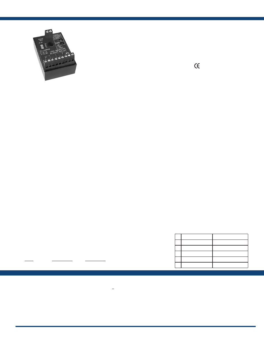
141
www.ssac.com • 800-843-8848 • fax: 605-348-5685
Features:
• Senses failed flashing beacon lamps
• Switch selectable number of beacons
• Senses flasher failure
• Isolated, 10A, SPDT alarm output contacts
• 10A, NO line voltage alarm output
• 0.5A, solid-state flasher failure output “F”
• Self calibrating; no fine adjustment required
• Meets FAA-AC No: 150/5345-43E
Approvals:
FB9L
Universal Lamp Alarm Relay
Available Models:
Sensors
Calibration Range (total all Lamps) . . . . . . . .
150mA - 8.0A
Absolute Max Current (total all Lamps)
. . . .
15A max. (may not calibrate above 8A)
Single Lamp Current . . . . . . . . . . . . . . . . . . . .
150mA - 8.0A (total all lamps
<
8.0A)
Trip Delay
Flasher Failure
. . . . . . . . . . . . . . . . . . . . . . . . . .
Fixed at 6s; -0/+40%
Lamp Failure . . . . . . . . . . . . . . . . . . . . . . . . . . .
Fixed at 10s; -0/+40%
Input
Input Voltage/Tolerance
. . . . . . . . . . . . . . . . .
120 to 230VAC / ±15%
AC Line Frequency
. . . . . . . . . . . . . . . . . . . . . .
50/60Hz
Output
. . . . . . . . . . . . . . . . . . . . . . . . . . . . . . . . . To operate a spare lamp or alarm
Line Voltage Output (SPNO)
. . . . . . . . . . . . . .
5A @ 240VAC or 30VDC resistive;
1/4 hp @ 125VAC; 1/2 hp @ 250VAC
Isolated Alarm Output (SPDT)
. . . . . . . . . . . .
10A @ 240VAC or 30VDC resistive;
1/4 hp @ 125VAC; 1/2 hp @ 250VAC
Solid-state Line Voltage Output (F)
. . . . . . . .
0.5A steady; 5A inrush
Mechanical
Mounting . . . . . . . . . . . . . . . . . . . . . . . . . . . . . .
One #10 (M5 x 0.8) screw
Dimensions . . . . . . . . . . . . . . . . . . . . . . . . . . . . .
3 x 2 x 1.64 in (76.7 x 51.3 x 41.7 mm)
Termination . . . . . . . . . . . . . . . . . . . . . . . . . . . .
IP20 screw terminals for up to 14 AWG
(2.45 mm
2
) wire or two 16 AWG
(1.3 mm
2
) w ires
LEDs
Power/Timing/Lamp Failure (Bi color)
. . . .
Glows red when one or more lamps fail
Flasher Failure (Red)
. . . . . . . . . . . . . . . . . . . . .
Glows red when the flasher fails
Protection
Circuitry . . . . . . . . . . . . . . . . . . . . . . . . . . . . . . . Encapsulated
Environmental
Operating / Storage Temperature
. . . . . . . . .
-40° to 60°C / -40° to 85°C
Weight
. . . . . . . . . . . . . . . . . . . . . . . . . . . . . . . . .
≅
3.9 oz (111 g)
Specifications
Order Table:
FB9L
Input
120 - 230VAC
Beacon Type
LED
Part Number
FB9L
Auxiliary Products:
•
DIN mount adaptor:
P/N: P1023-20
•
DIN rail:
P/N: C103PM
(Al)
The FB series is a universal lamp alarm relay
designed to sense the failure of flashing LED
beacon lamps. It will monitor the operation of
one to eight beacons connected to a single flasher
and/or auxiliary modules and the operation of
the flasher. The FB Series output relay energizes
when one or more lamps fail. All monitored lamps
must be the same wattage and voltage. The 0.5A
solid-state output energizes when a flasher failure
is sensed .
For more information see:
Appendix B, page 167, Figure 32 for dimensional drawing.
Appendix C, page 171, Figure 31 for connection diagram.
Operation
When a LED beacon lamp fails, the FB senses a decrease in current flow. After a 10s lamp failure trip delay, the
isolated SPDT (4-5-6) and non-isolated SPNO (3-1) relay contacts energize. These contacts are used to indicate a
beacon failure has occurred. The “L” onboard LED indicator flashes green during the trip delay and glows red
after the output relay energizes. Connected to a site monitoring system, it provides remote beacon monitoring
required by FAA-AC No: 150/5345-43E.
The FB also monitors the operation of the flasher. If the flasher remains in the ON or OFF condition for more than
6s the solid-state output energizes and the “F“ flasher failure, onboard LED glows red. This output is normally
used to energize an external flasher bypass relay. The contacts of the bypass relay are used to route voltage around
the failed flasher and to indicate an alarm condition.
Note: In a single flasher, single beacon system, if the beacon lamp fails, zero current flow is detected. This will
cause the flasher failure output to energize after 6s and then the beacon failure outputs after 10s. This is normal
operation and can be expected anytime zero current is flowing through the monitored conductor.
Calibration
The alarm relays must be calibrated after initial installation and each time the LED lamps are replaced. In order to calibrate or re-calibrate the alarm relay, the internal memory
must be cleared .
Clearing Memory:
Remove input voltage, transfer the calibration switch to the off position, re-apply input voltage. The LED will flash Red to indicate the memory is clear and the relay is ready
for calibration.
Calibration:
1) Perform visual inspection of the structure’s lighting to assure all lamps and flashers are operating properly.
2) Remove input voltage, and check to ensure the calibrate switch is in the OFF position. Adjust the lamp selector switches for the correct number of similar (see note a) lamps
to be monitored .
3) Reapply input voltage, the LED should flash Red. After confirming the LED is flashing Red and the lamp selector switches are properly adjusted, transfer the calibrate switch
from OFF to ON. The LED will alternately flash Red & Green. Within 30 seconds the LED will glow Green indicating input power is applied and the unit is calibrated. Leave the
calibrate switch in the ON position. Reapplying input voltage when this switch is in the ON position does not affect the calibration settings.
Calibration Failed:
4) If the relay is unable to establish trip points for the setup conditions within 60 seconds, the LED will double blink Red. Remove input voltage and repeat steps 2 and 3.
Notes:
a. Monitoring a mixture of LED beacons and LED obstruction lamps is not possible with the SCR9L.
b. This alarm relay is not designed to monitor incandescent lamps.
c. This alarm relay must be recalibrated each time an LED lamp is replaced.
d. Due to LED lamp aging, recalibration every 12 months is recommended.
e. Applying input voltage when the calibrate switch is in the OFF position, erases the previous calibration settings. The LED will flash Red. The output relays are OFF and the
unit will not sense lamp failures.
f. Only one (1) temperature compensated LED Beacon can be monitored with this product. A combination of temperature compensated and standard LED Beacons cannot be
monitored .
Indicator Table:
L
Green
Input ON & Calibrated
L
Green Flashing
Trip Delay
L
Red
Lamp Failure
L
Red/Green Flashing
Calibrating
L
Red Flashing
Not Calibrated
F
Red
Flasher Failure
Courtesy of Steven Engineering, Inc.-230 Ryan Way, South San Francisco, CA 94080-6370-Main Office: (650) 588-9200-Outside Local Area: (800) 258-9200-www.stevenengineering.com
Littelfuse-catalog-html.html
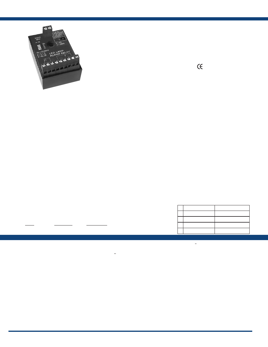
142
www.ssac.com • 800-843-8848 • fax: 605-348-5685
SCR9L
Universal Lamp Alarm Relay
Available Models:
Sensors
Calibration Range (total all Lamps) . . . . . . . . .
150mA - 8.0A
Absolute Max Current (total all Lamps)
. . . . .
15A max. (may not calibrate above 8A)
Single Lamp Current . . . . . . . . . . . . . . . . . . . . .
150mA - 8.0A (total all lamps
<
8.0A)
Time Delay
Trip Delay . . . . . . . . . . . . . . . . . . . . . . . . . . . . . . .
Factory fixed
≅
10s
Input
Input Voltage/Tolerance
. . . . . . . . . . . . . . . . . .
120 to 230VAC ±15%
AC Line Frequency . . . . . . . . . . . . . . . . . . . . . . .
50/60Hz
Output
. . . . . . . . . . . . . . . . . . . . . . . . . . . . . . . . . .To operate a spare lamp or alarm
Line Voltage Output (SPNO)
. . . . . . . . . . . . . .
5A @ 240VAC or 30VDC resistive;
1/4 hp @ 125VAC; 1/2 hp @ 250VAC
Isolated Alarm Output (SPDT)
. . . . . . . . . . . . .
10A @ 240VAC or 30VDC resistive;
1/4 hp @ 125VAC; 1/2 hp @ 250VAC
Auxilliary Input Voltage (H)
. . . . . . . . . . . . . . . <
2A @ 230VAC
Mechanical
Mounting . . . . . . . . . . . . . . . . . . . . . . . . . . . . . . .
One #10 (M5 x 0.8) screw
Dimensions . . . . . . . . . . . . . . . . . . . . . . . . . . . . . .
3 x 2 x 1.64 in (76.7 x 51.3 x 41.7 mm)
Termination . . . . . . . . . . . . . . . . . . . . . . . . . . . . .
IP20 screw terminals for up to 14 AWG
(2.45 mm
2
) wire or two 16 AWG (1.3 mm
2
) w ires
Protection
Circuitry . . . . . . . . . . . . . . . . . . . . . . . . . . . . . . . . Encapsulated
Environmental
Operating / Storage Temperature
. . . . . . . . . .
-40° to 60°C / - 40° to 85°C
Weight
. . . . . . . . . . . . . . . . . . . . . . . . . . . . . . . . . .
≅
3.9 oz (111 g
)
Features:
• Monitors LED lamps for failure
• Senses failed flashing or steady beacon or
obstruction lamps
• Switch selectable number of lamps
• Isolated, 10A, SPDT alarm output contacts
• 5A, NO line voltage alarm output
• Self calibrating; no fine adjustment required
• Meets FA-AC No: 150/5345-43E
Approvals:
Specifications
Order Table:
SCR9L
Input
120 - 230VAC
Lamp Type
LED
Part Number
SCR9L
The SCR series is a universal lamp alarm relay
designed to sense the failure of flashing or steady
LED beacon lamps or obstruction lamps. The SCR
Series energizes when one or more lamps fail. It
will monitor the operation of one to eight beacon
or obstruction lamps . All monitored lamps must
be the same wattage and voltage When connected
to a site monitoring system, it provides the remote
lamp monitoring protection required by the FAA-
AC No: 150/5345-43E.
For more information see:
Appendix B, page 167, Figure 32 for dimensional drawing.
Appendix C, page 172, Figure 35 for connection diagram.
Operation
When a lamp fails, the SCR Series senses a decrease in current flow. After a 10s trip delay, the onboard LED
glows and the two alarm outputs energize. The outputs and the LED are reset when the failed lamps are replaced
and the unit is recalibrated. The SCR will sense an open flasher, it will not sense a continuously ON flasher (see
FB Series). Removing input voltage de-energizes the output and the LED‘s. It does not change the calibration.
Calibration
The alarm relays must be calibrated after initial installation and each time the LED lamps are replaced. In order to calibrate or re-calibrate the alarm relay, the internal memory
must be cleared .
Clearing Memory:
Remove input voltage, transfer the calibration switch to the off position, re-apply input voltage. The LED will flash Red to indicate the memory is clear and the relay is ready
for calibration.
Calibration:
1) Perform visual inspection of the structure’s lighting to assure all lamps and flashers (if used) are operating properly.
2) Remove input voltage, and check to ensure the calibrate switch is in the OFF position. Adjust the lamp selector switches for the correct number of similar (see note a) lamps
to be monitored .
3) Reapply input voltage, the LED should flash Red. After confirming the LED is flashing Red and the lamp selector switches are properly adjusted, transfer the calibrate switch
from OFF to ON. The LED will alternately flash Red & Green. Within 30 seconds the LED will glow Green indicating input power is applied and the unit is calibrated. Leave the
calibrate switch in the ON position. Reapplying input voltage when this switch is in the ON position does not affect the calibration settings.
Calibration Failed:
4) If the relay is unable to establish trip points for the setup conditions within 60 seconds, the LED will double blink Red. Remove input voltage and repeat steps 2 and 3.
Notes:
a. Monitoring a mixture of LED beacons and LED obstruction lamps is not possible with the SCR9L.
b. This alarm relay is not designed to monitor incandescent lamps.
c. This alarm relay must be recalibrated each time an LED lamp is replaced.
d. Due to LED lamp aging, recalibration every 12 months is recommended.
e. Applying input voltage when the calibrate switch is in the OFF position, erases the previous calibration settings. The LED will flash Red. The output relays are OFF and the
unit will not sense lamp failures.
f. Only one temperature compensated LED Beacon can be monitored with this product. A combination of temperature compensated and standard LED Beacons cannot be
monitored .
Indicator Table:
L
Green
Input ON & Calibrated
L
Green Flashing
Trip Delay
L Red
Lamp Failure
L
Red/Green Flashing
Calibrating
L
Red Flashing
Not Calibrated
Courtesy of Steven Engineering, Inc.-230 Ryan Way, South San Francisco, CA 94080-6370-Main Office: (650) 588-9200-Outside Local Area: (800) 258-9200-www.stevenengineering.com
Littelfuse-catalog-html.html
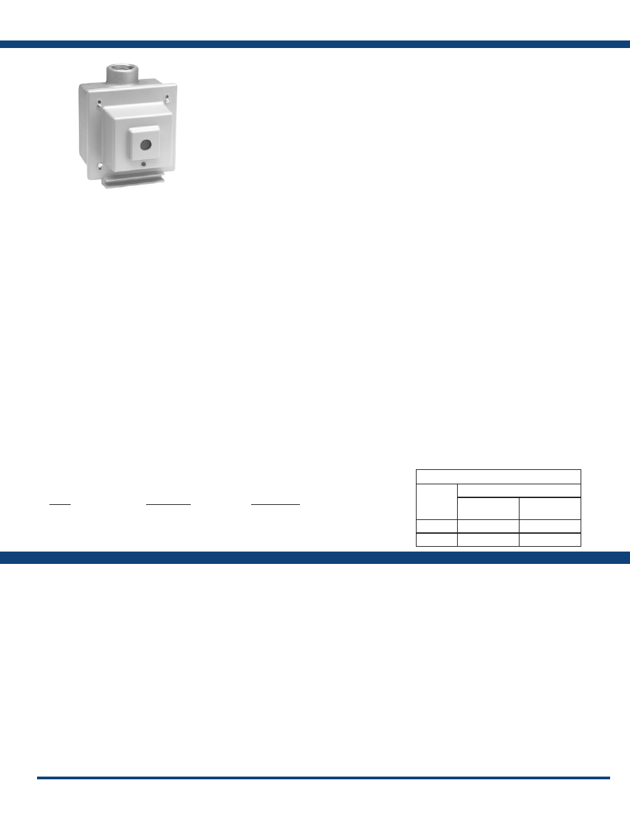
143
www.ssac.com • 800-843-8848 • fax: 605-348-5685
Features:
• Automatic lighting circuit operation: dusk
to dawn
• Meets FAA/FCC requirements for
obstruction lighting
• Two 20A load contacts
• Direct replacement of popular photo
controls
• Time delay eliminates contact chatter
PCR Series
Photo Control
Available Models:
Indication . . . . . . . . . . . . . . . . . . . . . . . . . . . . . . . . . . . LED indicates power is applied
Light Actuation Levels (Factory Calibrated)
. . . . .
Energized: ≤ 35 fc
De-energized: ≥ 60 fc
Voltage
. . . . . . . . . . . . . . . . . . . . . . . . . . . . . . . . . . . . .
120VAC or 230VAC
AC Line Frequency . . . . . . . . . . . . . . . . . . . . . . . . . .
50/60Hz
Tolerance 120 & 230VAC
. . . . . . .
-20% - 10%
Output Rating . . . . . . . . . . . . . . . . . . . . . . . . . . . . . . .
Two SPST NO 20A contacts
1 hp @ 120VAC
2.5 hp @ 240VAC
Termination . . . . . . . . . . . . . . . . . . . . . . . . . . . . . . . . .
Screw terminals for up to #8 (M4 x 0.7) AWG wire
Dimensions . . . . . . . . . . . . . . . . . . . . . . . . . . . . . . . . .
ABS plastic housing with gasket seal.
Multiple knockout holes for optional mounting
to Crouse Hinds or Hughey & Phillips cast
aluminum electrical boxes.
Specifications
Order Table:
PCR10
PCR11
PCR12
PCR13
Input
120VAC
230VAC
120VAC
230VAC
Description
Photo Control without aluminum box
Photo Control without aluminum box
Photo Control with aluminum box
Photo Control with aluminum box
Part Number
PCR10
PCR12
PCR11
PCR13
The PCR Series of photo control is a combination
of precision electronic circuitry, electromechanical
output, and unique molded plastic housing.
Designed and built to meet the demands of
the most rigorous requirement of tower and
obstruction lighting control, each unit is factory
calibrated to meet FAA and FCC specifications.
Electronic circuit, output contactor, and terminal
block are all contained within front plastic
housing. Edge support molded into the bottom
edge of housing allows easy wiring of new and
existing installations. Available with or without
cast aluminum junction box.
For more information see:
Appendix B, page 167, Figure 33 for dimensional drawing.
Appendix C, page 172, Figure 36 for connection diagram.
Operation
When the amount of light sensed falls below the actuation
level for energization, the output relay energizes.
Conversely, when the amount rises above the actuation
level for de-energization, the output relay de-energizes.
Conversion Chart
Part
Number
REPLACES
Hughey &
Phillips
Crouse Hinds
PCR11
PC800 120V
PEC52010
PCR13
PC800 240V
PEC52010-1
Courtesy of Steven Engineering, Inc.-230 Ryan Way, South San Francisco, CA 94080-6370-Main Office: (650) 588-9200-Outside Local Area: (800) 258-9200-www.stevenengineering.com
Littelfuse-catalog-html.html

144
www.ssac.com • 800-843-8848 • fax: 605-348-5685
Solid-State Relays
Series Included
SIR . . . . . . . . . . . . . . . . . . . . . . . . . . . . . . . . . . . . . . . . . . . . . .
145
SLR . . . . . . . . . . . . . . . . . . . . . . . . . . . . . . . . . . . . . . . . . . . . . .
146
NLF . . . . . . . . . . . . . . . . . . . . . . . . . . . . . . . . . . . . . . . . . . . . .
147
PHS . . . . . . . . . . . . . . . . . . . . . . . . . . . . . . . . . . . . . . . . . . . . .
148
Solid-State Relays
PHS Series
Courtesy of Steven Engineering, Inc.-230 Ryan Way, South San Francisco, CA 94080-6370-Main Office: (650) 588-9200-Outside Local Area: (800) 258-9200-www.stevenengineering.com
Littelfuse-catalog-html.html

145
www.ssac.com • 800-843-8848 • fax: 605-348-5685
SIR1 & SIR2 Series
Solid-State Relay - Isolated
Available Models:
Output
Type . . . . . . . . . . . . . . . . . . . . . . . . . . . . .
Optical isolation, totally solid state
Form . . . . . . . . . . . . . . . . . . . . . . . . . . . . .
SPST, NO or NC
Voltage
. . . . . . . . . . . . . . . . . . . . . . . . . . .
24, 120, or 230VAC
Tolerance . . . . . . . . . . . . . . . . . . . . . . . . .
±20%
Ratings . . . . . . . . . . . . . . . . . . . . . . . . . . .
Steady State Inrush* Output Device
3A 30A Triac
6A 60A Triac
10A 100A Triac
20A 200A Triac
Minimum Load Current . . . . . . . . . . . .
≅
50mA
Voltage Drop
. . . . . . . . . . . . . . . . . . . . .
≅
2.0V at rated current
Leakage Current (Open State)
. . . . . . .
≅
6mA
Input
Type . . . . . . . . . . . . . . . . . . . . . . . . . . . . .
Optical isolation LED/photo transistor
Control Voltage
. . . . . . . . . . . . . . . . . . .
9 to 290VAC/DC in 3 ranges
Power Consumption . . . . . . . . . . . . . . .
≤ 0.5W
Protection
Circuitry . . . . . . . . . . . . . . . . . . . . . . . . . Encapsulated
Dielectric Breakdown
. . . . . . . . . . . . . .
≥ 2000V RMS terminals to mounting surface
Insulation Resistance . . . . . . . . . . . . . . .
≥ 100 MΩ
Mechanical
Mounting* . . . . . . . . . . . . . . . . . . . . . . . .
Surface mount with one #10 (M5 x 0.8) screw
Dimensions . . . . . . . . . . . . . . . . . . . . . . .
2 x 2 x 1.51 in. (50.8 x 50.8 x 38.4 mm)
Termination . . . . . . . . . . . . . . . . . . . . . .
0.25 in. (6.35 mm) male quick connect terminals
Environmental
Operating / Storage Temperature
. . .
-20° to 60°C / -40° to 85°C
Humidity . . . . . . . . . . . . . . . . . . . . . . . . .
95% relative, non-condensing
Weight
. . . . . . . . . . . . . . . . . . . . . . . . . . .
≅
3.9 oz (111 g)
*Must be bolted to a metal surface using the included heat sink compound. The maximum
mounting surface temperature is 90°C. Inrush: Non-repetitive for 16ms.
Features:
• SIR1 - Random switching for inductive loads
• SIR2 - Zero voltage switching for resistive &
incandescent loads
•
Normally open or normally closed output
• 3 - 20A with up to 200A inrush
•
Encapsulated circuitry
•
Optically isolated output
• 0.25 in. (6.35 mm) terminals with single hole
mounting
Approvals:
Specifications
Order Table:
SIR1A10A6
SIR1A6A2
SIR1B10A4
SIR1B10B4
SIR1B20A4
SIR1B6B4
SIR1C20B6
SIR2A20A4
SIR2B20A4
SIR2B20B4
Auxiliary Products:
•
Quick connect to screw adaptor:
P/N: P1015-18
•
Female quick connect:
P/N: P1015-13 (AWG 10/12)
P/N: P1015-64 (AWG 14/16)
P/N: P1015-14 (AWG 18/22)
Designed for industrial applications requiring
rugged reliable operation. Provides an optically
isolated, high capacity, solid-state output, with
power switching capability up to 20A steady state,
200A inrush. Zero voltage switching SIR2 extends
the life of an incandescent lamp up to 10 times.
Random switching SIR1 is ideal for inductive
loads. When fully insulated female terminals are
used on the connection wires, the system meets the
requirements for touch-proof connections.
For more information see:
Appendix B, page 165, Figure 4 for dimensional drawing.
Appendix C, page 172, Figure 37 for connection diagram.
Operation
The solid-state output is located between terminals 1
and 3, and is normally open or normally closed without
control voltage applied to terminals 4 and 5. When control
voltage is applied to terminals 4 and 5, the solid-state
output opens or closes respectively.
Reset: Removing control voltage resets the output. The
unit is also reset if output voltage is removed.
X
Series
─
SIR1
- Random Switching
─
SIR2
- Zero Voltage Switching
X
Control Voltage
─
A
- 9 - 30VAC or DC
─
B
- 90 - 150VAC or DC
─
C
- 190 - 290VAC or DC
X
Rating
─
1
- 3A
─
6
- 6A
─
10
- 10A
─
20
- 20A
X
Form
─
A
- Normally Open
─
B
- Normally Closed
X
Voltage
─
2
- 24VAC
─
4
- 120VAC
─
6
- 230VAC
Solid-state Output Contact
If desired part number is not listed, please call us to
see if it is technically possible to build .
Function:
V = Voltage
CV = Control Voltage
R = Reset
NC = Normally Closed Output
NO = Normally Open Output
= Undefined time
Courtesy of Steven Engineering, Inc.-230 Ryan Way, South San Francisco, CA 94080-6370-Main Office: (650) 588-9200-Outside Local Area: (800) 258-9200-www.stevenengineering.com
Littelfuse-catalog-html.html
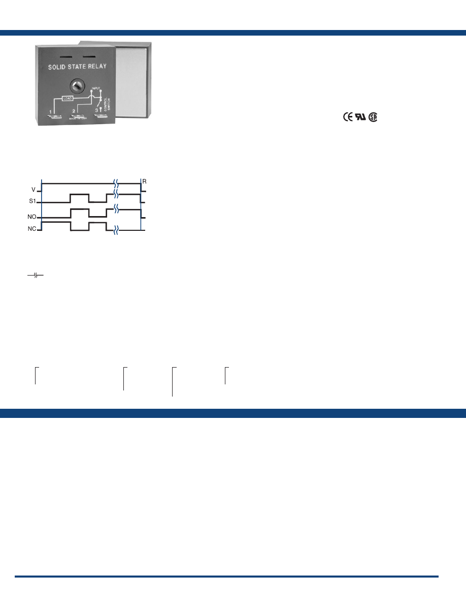
146
www.ssac.com • 800-843-8848 • fax: 605-348-5685
Features:
• SLR1 - Random switching for inductive loads
• SLR2 - Zero voltage switching for resistive &
incandescent loads
•
Normally open or normally closed output
• 1 - 20A with up to 200A inrush
• 0.25 in. (6.35 mm) termination with single
hole mounting
• Noiseless switching, reliability, and long life
Approvals:
SLR Series
Solid-State Relay - Non-Isolated
Available Models:
Output (Contact)
Type . . . . . . . . . . . . . . . . . . . . . . . . . . . . . . .
Non-isolated solid state
Form . . . . . . . . . . . . . . . . . . . . . . . . . . . . . . .
SPST, NO or NC
Voltage
. . . . . . . . . . . . . . . . . . . . . . . . . . . . .
24, 120, or 230VAC
Tolerance . . . . . . . . . . . . . . . . . . . . . . . . . . .
±20%
Ratings . . . . . . . . . . . . . . . . . . . . . . . . . . . . .
Steady State Inrush* Output Device
1A 10A SCR & Bridge Rectifier
6 A 60A Triac
10A 100A Triac
20A 200A Triac
Minimum Load Current . . . . . . . . . . . . . .
≅
50mA
Voltage Drop (at Rated Current)
. . . . . . .
≅
2.0V - 6, 10, & 20A units;
≅
2.5V - 1A units
Leakage Current (Open State)
. . . . . . . . .
≤ 5mA
Initiate Switch Voltage
. . . . . . . . . . . . . . .
Same as the output voltage
Power Consumption . . . . . . . . . . . . . . . . .
≤ 0.5W
Protection
Circuitry . . . . . . . . . . . . . . . . . . . . . . . . . . . Encapsulated
Dielectric Breakdown
. . . . . . . . . . . . . . . .
≥ 2000V RMS terminals to mounting surface
Insulation Resistance . . . . . . . . . . . . . . . . .
≥ 100MΩ
Mechanical
Mounting* . . . . . . . . . . . . . . . . . . . . . . . . . .
Surface mount with one #10 (M5 x 0.8) screw
Dimensions . . . . . . . . . . . . . . . . . . . . . . . . .
2 x 2 x 1.51 in. (50.8 x 50.8 x 38.4 mm)
Termination . . . . . . . . . . . . . . . . . . . . . . . .
0.25 in. (6.35 mm) male quick connect terminals
Environmental
Operating / Storage Temperature
. . . . .
-20° to 60°C / -40° to 85°C
Humidity . . . . . . . . . . . . . . . . . . . . . . . . . . .
95% relative, non-condensing
Weight
. . . . . . . . . . . . . . . . . . . . . . . . . . . . .
1A units:
≅
2.4 oz (68 g);
6, 10, 20A units:
≅
3.9 oz (111 g)
*Must be bolted to a metal surface using the included heat sink compound. The maxi-
mum mounting surface temperature is 90°C. Inrush: Non-repetitive for 16ms.
Specifications
Order Table:
SLR1410B
SLR1420A
SLR1610A
Auxiliary Products:
•
Quick connect to screw adaptor:
P/N: P1015-18
•
Female quick connect:
P/N: P1015-13 (AWG 10/12)
P/N: P1015-64 (AWG 14/16)
P/N: P1015-14 (AWG 18/22)
The SLR Series has no isolation between the control
switch input and the solid-state output. Select the
SLR for applications where the control switch is
the same voltage source as the load. Provides the
noiseless, reliability and long life of a solid-state
relay, without the cost of isolation circuitry. Zero
voltage switching SLR2 can extend the life of
an incandescent lamp up to 10 times its normal
life. Random switching SLR1 is normally used
for inductive loads. When fully insulated female
terminals are used on the connection wires, the
system meets the requirements for touch-proof
connections .
For more information see:
Appendix B, page 165, Figure 4 for dimensional drawing.
Appendix C, page 172, Figure 38 for connection diagram.
Operation
The solid-state output is located between terminals 1 and
2 and can be ordered as either normally open or normally
closed, when voltage is applied and S1 is open. When S1
is closed, the solid-state output between terminals 1 and
2 closes (or opens). If S1 is opened, the solid-state output
will open (or close) .
Reset: Opening S1 resets the output to its original state.
Reset is also accomplished by removing input voltage.
X
Series
─
SLR1
- Random Switching
─
SLR2
- Zero Voltage Switching
X
Voltage
─
2
- 24VAC
─
4
- 120VAC
─
6
- 230VAC
X
Output Rating
─
1
- 1A
─
6
- 6A
─
10
- 10A
─
20
- 20A
X
Output Form
─
A
- Normally Open
─
B
- Normally Closed
If desired part number is not listed, please call us to
see if it is technically possible to build .
Function:
V = Voltage
S1 = Initiate Switch
R = Reset
NO = Normally Open Output
NC = Normally Closed Output
= Undefined time
Courtesy of Steven Engineering, Inc.-230 Ryan Way, South San Francisco, CA 94080-6370-Main Office: (650) 588-9200-Outside Local Area: (800) 258-9200-www.stevenengineering.com
Littelfuse-catalog-html.html
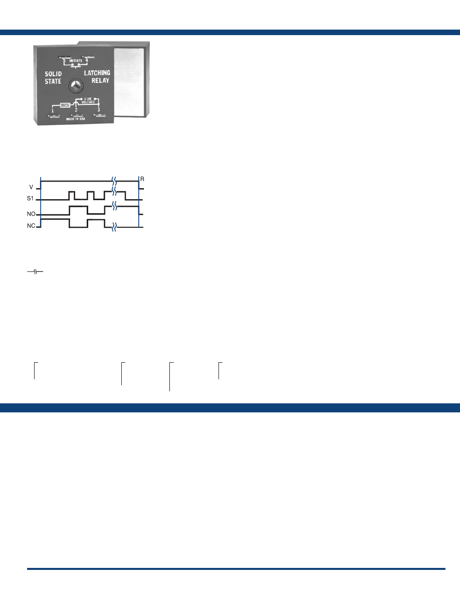
147
www.ssac.com • 800-843-8848 • fax: 605-348-5685
NLF1/NLF2 Series
Impulse Latching Relay
Available Models:
Output
Type . . . . . . . . . . . . . . . . . . . . . . . . . . . . . .
Non-isolated solid state
Form . . . . . . . . . . . . . . . . . . . . . . . . . . . . . .
SPST, NO or NC
Ratings . . . . . . . . . . . . . . . . . . . . . . . . . . . .
Steady State Inrush* Output Device
1A 10A SCR & Bridge Rectifier
6A 60A Triac
10A 100A Triac
20A 200A Triac
Minimum Load Current . . . . . . . . . . . . .
50mA
Voltage Drop (at Rated Current)
. . . . . .
≅
2.0V – 6, 10, & 20A units;
≅
2.5V – 1A units
Leakage Current (Open State)
. . . . . . . .
≤ 5mA
Input
Type . . . . . . . . . . . . . . . . . . . . . . . . . . . . . .
Non-isolated, switch contact (customer supplied)
Voltage
. . . . . . . . . . . . . . . . . . . . . . . . . . . .
24, 120, or 230VAC ±20%
Power Consumption . . . . . . . . . . . . . . . .
≤ 0.5W
Operations Per Second . . . . . . . . . . . . . .
≤ 5
Protection
Circuitry . . . . . . . . . . . . . . . . . . . . . . . . . . Encapsulated
Dielectric Breakdown
. . . . . . . . . . . . . . .
≥ 2000V RMS terminals to mounting surface
Insulation Resistance . . . . . . . . . . . . . . . .
≥ 100MΩ
Mechanical
Mounting * . . . . . . . . . . . . . . . . . . . . . . . .
Surface mount with one #10 (M5 x 0.8) screw
Dimensions 6, 10, 20A units
. . . . . . .
2 x 2 x 1.51 in. (50.8 x 50.8 x 38.4 mm)
1A units . . . . . . .
2 x 2 x 1.21 in. (50.8 x 50.8 x 30.7 mm)
Termination . . . . . . . . . . . . . . . . . . . . . . .
0.25 in. (6.35 mm) male quick connect terminals
Environmental
Operating / Storage Temperature
. . . .
-20° to 60°C / -40° to 85°C
Humidity . . . . . . . . . . . . . . . . . . . . . . . . . .
95% relative, non-condensing
Weight
. . . . . . . . . . . . . . . . . . . . . . . . . . . .
1A units:
≅
2.4 oz (68 g);
6, 10, 20A units:
≅
3.9 oz (111 g)
*Units rated ≥ 6A must be bolted to a metal surface using the included heat sink compound.
The maximum mounting surface temperature is 90°C. Inrush: Non-repetitive for 16ms.
Features:
• Totally solid-state latching relay -
encapsulated
• Non-isolated to reduce cost
• 1 - 20A with 200A inrush
• 24, 120, or 230VAC input voltages
• NLF1 - Random switching for inductive
loads
• NLF2 - Zero voltage switching for lamp &
resistive loads
Specifications
Order Table:
NLF126A
NLF141A
NLF1620A
Auxiliary Products:
•
Quick connect to screw adaptor:
P/N: P1015-18
•
Female quick connect:
P/N: P1015-13 (AWG 10/12)
P/N: P1015-64 (AWG 14/16)
P/N: P1015-14 (AWG 18/22)
X
Series
─
NLF1
- Random Switching
─
NLF2
- Zero Voltage Switching
X
Input
─
2
- 24VAC
─
4
- 120VAC
─
6
- 230VAC
X
Output Rating
─
1
- 1A
─
6
- 6A
─
10
- 10A
─
20
- 20A
X
Output Form
─
A
- Normally Open
─
B
- Normally Closed
The NLF1 and NLF2 Series provide a flip-flop
latching function. Each time the control switch
is closed, the solid-state output changes state and
latches. The NLF Series has no isolation between
the control switch and the solid-state output,
which lowers cost and reduces the number of
connections required. For use where the control
switch is the same voltage source as the load.
Zero voltage switching NLF2 extends the life of
an incandescent lamp by up to 10 times. Random
switching NLF1 is ideal for inductive loads. When
accessory fully insulated female terminals are used
on the connection wires, the system meets the
requirements for touch-proof connections.
For more information see:
Appendix B, page 165, Figure 4 for dimensional drawing.
Appendix C, page 172, Figure 39 for connection diagram.
Operation
The solid-state output is located between terminals 1 and
2, and can be ordered as either normally open or normally
closed, when voltage is applied. When S1 is closed, the
solid-state output between terminals 1 and 2 closes (or
opens). If S1 is opened and reclosed, the solid-state output
will open (or close) .
Reset: Open and reclose S1. Reset is also accomplished
by removing and reapplying input voltage.
If desired part number is not listed, please call us to
see if it is technically possible to build .
Function:
V = Voltage
S1 = Initiate Switch
R = Reset
NO = Normally Open Output
NC = Normally Closed Output
= Undefined time
Courtesy of Steven Engineering, Inc.-230 Ryan Way, South San Francisco, CA 94080-6370-Main Office: (650) 588-9200-Outside Local Area: (800) 258-9200-www.stevenengineering.com
Littelfuse-catalog-html.html
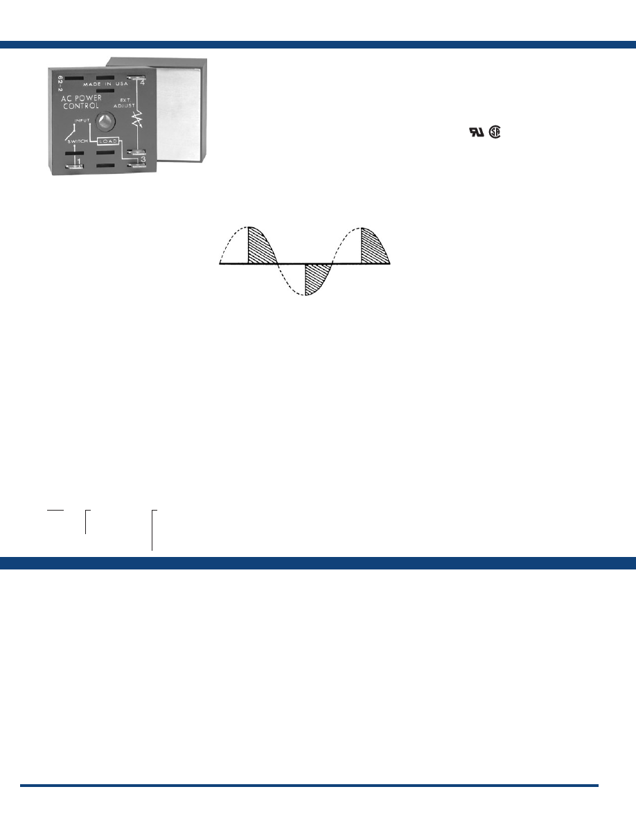
148
www.ssac.com • 800-843-8848 • fax: 605-348-5685
Features:
• External adjustment - 230VAC rated
potentiometer
• 120 or 230VAC input voltages available
• Up to 20A steady state - 200A inrush
• Single hole surface mounting
Approvals:
PHS Series
Phase Control
Available Models:
Output
Type . . . . . . . . . . . . . . . . . . . . . . . . . . . . . . . . . . . . .
Variable voltage phase angle control
Rating Steady State (at 100% On) Inrush*
1A 10A
6A 60A
10A 100A
20A 200A
Minimum Load Current . . . . . . . . . . . . . . . . . . . .
100mA
Voltage Drop
. . . . . . . . . . . . . . . . . . . . . . . . . . . . .
≅
2.0V at rated current
Input
Voltage
. . . . . . . . . . . . . . . . . . . . . . . . . . . . . . . . . . .
120 or 230VAC
Tolerance . . . . . . . . . . . . . . . . . . . . . . . . . . . . . . . . .
±20%
AC Line Frequency . . . . . . . . . . . . . . . . . . . . . . . .
50/60Hz
Protection
Dielectric Breakdown
. . . . . . . . . . . . . . . . . . . . . .
≥ 2000V RMS terminals to mounting surface
Insulation Resistance . . . . . . . . . . . . . . . . . . . . . . .
≥100MΩ
Mechanical
Mounting * . . . . . . . . . . . . . . . . . . . . . . . . . . . . . . .
Surface mount with one #10 (M5 x 0.8) screw
Dimensions . . . . . . . . . . . . . . . . . . . . . . . . . . . . . . .
2 x 2 x 1.51 in. (50.8 x 50.8 x 38.4 mm)
Termination . . . . . . . . . . . . . . . . . . . . . . . . . . . . . .
0.25 in. (6.35 mm) male quick connect
terminals
Environmental
Operating / Storage Temperature
. . . . . . . . . . .
-20° to 60°C / -40° to 85°C
Humidity . . . . . . . . . . . . . . . . . . . . . . . . . . . . . . . . .
95% relative, non-condensing
Weight
. . . . . . . . . . . . . . . . . . . . . . . . . . . . . . . . . . .
1A:
≅
2.4 oz (68 g)
6, 10, & 20A:
≅
3.9 oz (111 g)
External Adjustment Potentiometer
120VAC
. . . . . . . . . . . . . . . . . . . . . . . . . . . . . . . . .
100KΩ rated at 1W
230VAC
. . . . . . . . . . . . . . . . . . . . . . . . . . . . . . . . .
200KΩ rated at 2W
Must have insulation resistance suitable
for line voltage applications.
*Units rated ≥ 6A must be bolted to a metal surface using the included heat sink compound.
The maximum mounting surface temperature is 90°C. Inrush: Non-repetitive for 16ms.
Specifications
Order Table:
PHS120A10
PHS120A20
PHS120A6
PHS230A1
PHS230A10
PHS230A20
PHS230A6
Auxiliary Products:
•
Versa-knob:
P/N: P0700-7
•
Quick connect t o s crew ad aptor:
P/N: P1015-18
•
Female quick connect:
P/N: P1015-13 (AWG 10/12)
P/N: P1015-64 (AWG 14/16)
P/N: P1015-14 (AWG 18/22)
•
Potentiometers:
P/N: P1004-174 (100kΩ 1W)
P/N: P1004-175 (200kΩ 2W)
PHS
X
Input Voltage
─
120A
- 120VAC
─
230A
- 230VAC
X
Rating
─
1
- 1A
─
6
- 6A
─
10
- 10A
─
20
- 20A
The PHS Series is an ideal method of changing
lamp intensity, varying the speed of a fan/
motor, or controlling the temperature of a heater.
The effective output voltage is adjusted with an
accessory external potentiometer suitable for line
voltage applications.
For more information see:
Appendix B, page 165, Figure 4 for dimensional drawing.
Appendix C, page 172, Figure 40 for connection diagram.
Operation
Upon application of input voltage, effective output
voltage can be varied by changing the external resistance
value. As the external resistance increases, the effective
output voltage decreases. The inverse is also true.
If desired part number is not listed, please call us to
see if it is technically possible to build .
Typical Output Waveform
Courtesy of Steven Engineering, Inc.-230 Ryan Way, South San Francisco, CA 94080-6370-Main Office: (650) 588-9200-Outside Local Area: (800) 258-9200-www.stevenengineering.com
Littelfuse-catalog-html.html

149
www.ssac.com • 800-843-8848 • fax: 605-348-5685
Accessories
Series Included
DIN Rail/Surface Mount Sockets
Mounting Methods, Terminals, Varistors, Cover and Marker
Timer Adjustment Options & Dials
Motor Protectors
Liquid Level Probes & Probe Holders
Sockets
. . . . . . . . . . . . . . . . . . . . . . . . . . . . . . . . . . . . . . . . . . .
150
DIN Rail . . . . . . . . . . . . . . . . . . . . . . . . . . . . . . . . . . . . . . . . .
151
Hold-Down Clips
. . . . . . . . . . . . . . . . . . . . . . . . . . . . . . . . . .
150
Hold-Down Brackets
. . . . . . . . . . . . . . . . . . . . . . . . . . . . . . .
150
Mini Mount/Standard Bracket
. . . . . . . . . . . . . . . . . . . . . .
151
Front Panel Mount Kit . . . . . . . . . . . . . . . . . . . . . . . . . . . . .
150
DIN Rail Mount Adaptor . . . . . . . . . . . . . . . . . . . . . . . . . . .
151
Heat Sink Compound
. . . . . . . . . . . . . . . . . . . . . . . . . . . . . .
151
Quick Connect Screw Adaptor
. . . . . . . . . . . . . . . . . . . . . .
151
Female Quick Connect Terminals
. . . . . . . . . . . . . . . . . . . .
151
Metal Oxide Varistors
. . . . . . . . . . . . . . . . . . . . . . . . . . . . . .
151
Versa Pot
. . . . . . . . . . . . . . . . . . . . . . . . . . . . . . . . . . . . . . . . . .
152
Versa Knob
. . . . . . . . . . . . . . . . . . . . . . . . . . . . . . . . . . . . . . . .
152
Lock Shaft
. . . . . . . . . . . . . . . . . . . . . . . . . . . . . . . . . . . . . . . . .
152
Mini Pot . . . . . . . . . . . . . . . . . . . . . . . . . . . . . . . . . . . . . . . . . . .
152
Mini Knob . . . . . . . . . . . . . . . . . . . . . . . . . . . . . . . . . . . . . . . . .
152
Time Adjustment Dials
. . . . . . . . . . . . . . . . . . . . . . . . . . . . . .
153
VTP
. . . . . . . . . . . . . . . . . . . . . . . . . . . . . . . . . . . . . . . . . . . . . . .
153
Three-Phase Fuse Block/Disconnect
. . . . . . . . . . . . . . . . . . .
153
Voltage Reduction Module
. . . . . . . . . . . . . . . . . . . . . . . . . . .
154
Liquid Level Control Electrodes
. . . . . . . . . . . . . . . . . . . . . .
154
Liquid Level Probe
. . . . . . . . . . . . . . . . . . . . . . . . . . . . . . . . . .
154
Courtesy of Steven Engineering, Inc.-230 Ryan Way, South San Francisco, CA 94080-6370-Main Office: (650) 588-9200-Outside Local Area: (800) 258-9200-www.stevenengineering.com
Littelfuse-catalog-html.html
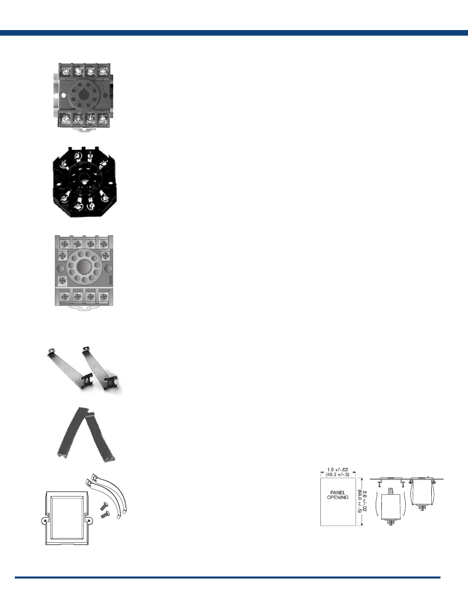
150
www.ssac.com • 800-843-8848 • fax: 605-348-5685
Octal Sockets:
8-pin
P/N: OT08PC
8-pin 35mm DIN rail or surface mount octal socket.
OT08PC is rated at 10A @ 600VAC and has pressure
clamp terminals. For use with AWG 12 to 22 (3.2 to 0.33
mm
2
) wire sizes.
P/N: NDS-8
8-pin 35mm DIN rail or surface mount octal socket.
NDS-8 is rated at 10A @ 300VAC. Surface mounted with
two #6 (M 3.5 x 0.6) screws or snaps onto a 35 mm DIN
rail. A spring mechanism allows easy removal. Screw
terminals with captive wire clamps accept up to two #14
AWG (2.45 mm
2
) wires. Uses PSC8 hold-down clips.
P/N: P1011-6
8-pin surface mount socket with binder head screw
terminals. Rated 10A @ 600VAC. When used with
TDM, TDB, TDS Series timers the combination is UL
Listed. Uses PSCRB8 hold-down brackets.
Magnal Sockets:
11-pin
P/N: OT11PC
11 pin 35 mm DIN rail or surface mount socket. OT11PC
is rated at 10A @ 300VAC and has pressure clamp
terminals. For use with AWG 12 to 22 (3.2 to 0.33 mm2)
wire sizes.
P/N: NDS-11
11 pin 35 mm DIN rail or surface mount socket. OT11PC
is rated at 10A @ 300VAC. Surface mounted with two
#6 (M 3.5 x 0.6) screws or snaps onto a 35 mm DIN
rail. A spring mechanism allows easy removal. Screw
terminals with captive wire clamps accept up to two #14
AWG (2.45 mm
2
) wires. Uses PSC11 hold-down clips.
Hold-down Clips:
P/N: PSC8 or PSC11
Securely mounts plug in controls in any position . Also
provides protection against vibration. Select the PSC8
for use with NDS-8, or the PSC11 for use with NDS-11
sockets. Comes in sets of two.
Hold-down Brackets:
P/N: PSCRB8
Designed for use with P1011-6 socket. Securely mounts
8-pin plug-in controls in any position, and provides
protection against vibration. Sold in pairs.
Front Panel Mount Kit:
P/N: BZ1
Provides an easy method of through-the-panel
mounting of 8 or 11-pin plug-in timers, flashers, and
other controls. May be mounted in panels up to 0.125
in. (3.2 mm) thick. Includes two clamps and two screws.
Accessories
Inches (Millimeters)
Illustrates panel opening
size required to mount BZ1.
Courtesy of Steven Engineering, Inc.-230 Ryan Way, South San Francisco, CA 94080-6370-Main Office: (650) 588-9200-Outside Local Area: (800) 258-9200-www.stevenengineering.com
Littelfuse-catalog-html.html
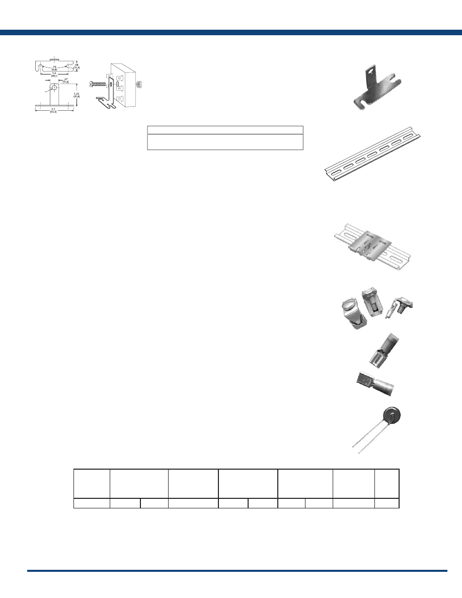
151
www.ssac.com • 800-843-8848 • fax: 605-348-5685
Mount Brackets:
P/N: P1023-6 / P1023-7
Provides a convenient method of mounting 2 x 2 x 1.21
in. (50.8 x 50.8 x 30.7 mm) or 2 x 3 x 1.5 in. (50.8 x 76.2
x 38.1 mm) modules. The 90° orientation of mounting
slots makes installation/removal of modules quick
and easy. The P1023-6 secures to module with a #8
(M4 x 0.7) screw. The P1023-7 secures to 2 x 2 x 1.21
in. (50.8 x 50.8 x 30.7 mm) module with Mini-Pot for
local adjustment. Made from steel with a cadmium
surface finish.
DIN Rail:
P/N: C103PM (
Al
)
Industry standard 35 mm aluminum or steel DIN rail.
C103PM aluminum rail is available in a 36 in. (91.4
cm) length.
DIN Rail Mount Adaptor:
P/N: P1023-20
Allows any 2 x 2 in. (50.8 x 50.8 mm) or 2 x 3 in. (50.8 x
76.2 mm) module to be mounted on a 35 mm DIN type
rail. Comes complete with mounting hardware for 0.75
in. (19 mm) and 1 in. (25.4 mm) thick modules.
Heat Sink Compound:
P/N: P0200-19
Single package of heat sink compound sufficient to
mount one high current, plated 2” x 2” (50.8 x 50.8
mm) timer or flasher. Contains approximately 2 grams.
Quick Connect Screw Adaptor:
P/N: P1015-18
Screw adaptor terminal designed for use with all
modules with 0.25 in. (6.35 mm) male quick connect
terminals . Screw terminal accepts ring or spade
terminals .
Female Quick Connect Terminals:
These 0.25 in. (6.35 mm) female terminals are constructed
with an insulator barrel to provide strain relief.
Metal Oxide Varistor:
Mounting Method Mounting Hole Size P/N
#8 (M4 x 0.7) screw 0.19 in. (4.8 mm) P1023-6
Mini-Pot 0.25 in (6.35 mm) P1023-7
Part Number Wire Size
P1015-13 AWG 10/12 (5.3/3.2 mm
2
)
P1015-64 AWG 14/16 (2.5/1.3 mm
2
)
P1015-14 AWG 18/22 (0.93/0.33 mm
2
)
Accessories
P/N
Max. Operating
Voltage
DC (V) AC (V)
Max Impulse
Current 80.20 us
current wave
(A)
Varistor Voltage at
1mA DC Test Current
Min. (V) Max. (V)
Peak Clamping
Voltage with 80 us
wave
Vc (V) 1p (A)
Capacitance
Size
(mm)
P1012-25
200
150
4500
212
268
395
50
800
14
a
Inches (Millimeters)
D = 0.25(6.35)
(P1023-7)
D = 0.19(4.8)
(P1023-6)
Courtesy of Steven Engineering, Inc.-230 Ryan Way, South San Francisco, CA 94080-6370-Main Office: (650) 588-9200-Outside Local Area: (800) 258-9200-www.stevenengineering.com
Littelfuse-catalog-html.html
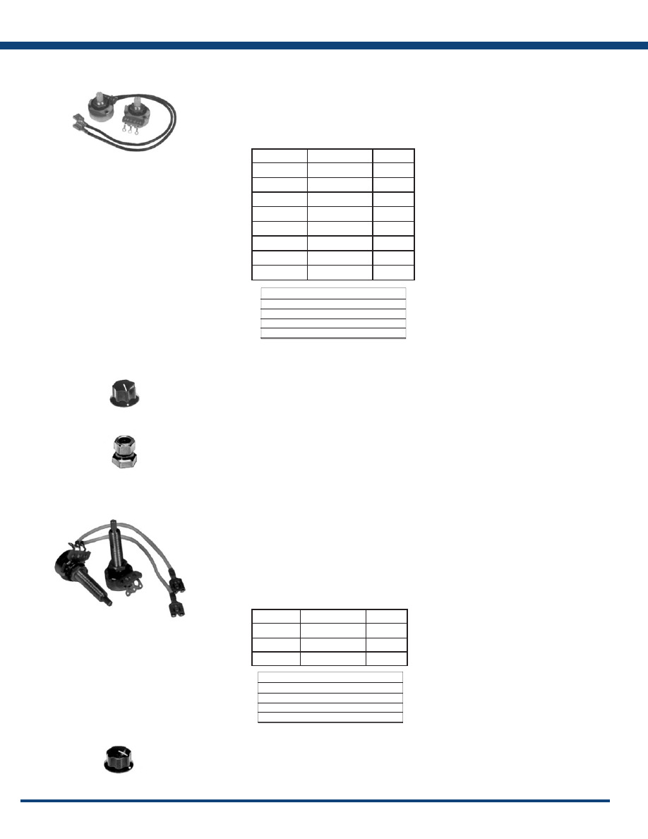
152
www.ssac.com • 800-843-8848 • fax: 605-348-5685
Versa-Pot:
Panel mountable, industrial potentiometer recommended
for remote time delay adjustment. The shaft is slotted for
screwdriver adjustment and serrated for slip-proof finger
adjustment. Accepts Versa-Knob or Lock Shaft. May be
ordered with two 8 in. (20.3 cm) wires soldered to pot
(clockwise increase) and female quick connect terminals
on other ends by adding suffix -X to end of part number.
Versa-Knob:
P/N: 0700-7
Versa-Knob is designed for 0.25 in (6.35 mm) shaft of
Versa-Pot. Semi-gloss industrial black finish.
Lock Shaft:
P/N: P0700-8
Fits 0.25 in. (6.35 mm) potentiometer shafts. Locks
by tightening nut onto four tapered/slotted fingers.
Pressure on the shaft locks control against mis-
adjustment. Nickel plated brass finish.
Mini-Pot:
P/N: P1004-10 & P1004-31
A high quality, industrial potentiometer for remote time
delay adjustment. The shaft extends through the timer’s
center hole for easy panel mounting. Use mini-mount
bracket for standup mounting of timer. Adjustment by
screwdriver or mini-knob. May be ordered with two 3
in. (7.6 cm) wires soldered to pot (clockwise increase)
and female quick connect terminals on other ends by
adding suffix -X to end of part number.
Mini-Knob:
P/N: 0700-21
Black plastic control knob with fluted body and white
index/dot for setting accuracy. Mounts on 0.125 in. (3.2
mm) shaft of Mini-Pot.
Specifications
Rating 0.25W at 55°C
Taper Linear
Shaft Rotation 300° ±5°
Tolerance ±10%
Accessories
Specifications
Rating 0.25W at 55°C
Taper Linear
Shaft Rotation 300° ±5°
Tolerance ±10%
P/N
With Wire Leads
Value
P1004-9
P1004-9-X
500k
Ω
P1004-10
P1004-10-X
1M
Ω
P1004-31
P1004-31-X
3MΩ
P/N
With Wire Leads
Value
P1004-198
25k
Ω
P1004-199
50k
Ω
P1004-95
P1004-95-X
100k
Ω
P1004-17
500k
Ω
P1004-16
P1004-16-X
1M
Ω
P1004-15
1.5M
Ω
P1004-12
P1004-12-X
3M
Ω
P1004-13
5M
Ω
Courtesy of Steven Engineering, Inc.-230 Ryan Way, South San Francisco, CA 94080-6370-Main Office: (650) 588-9200-Outside Local Area: (800) 258-9200-www.stevenengineering.com
Littelfuse-catalog-html.html
153
www.ssac.com • 800-843-8848 • fax: 605-348-5685
Time Adjustment Dials:
Dials for use with remote Versa-Pot and panel mounted
Mini-Pot. Reverse screen printed on clear plastic to avoid
damage to printed image .
VTP:
The VTP Series mounts on modules with in-line adjustment
terminals. Rated at 0.25W at 55°C. Available in resistance
values from 5K Ω to 5MΩ.
Three-Phase Fuse Block/Disconnect:
P/N: FH3P
3-phase fuse block disconnect designed for use with
HRC midget fuses [1.5 x .41 in. (38.1 x 10.4 mm)] rated
up to 30A @ 600VAC. DIN3 rail mounting. 3.9 x 2.09 x
2.2 in. (99 x 53.1 x 55.9 mm)
Replaced P/N: P0700-241
P/N: P0600-11 (Midget Fuse)
Fast acting fuse for use with voltage monitors. Rated
2A @ 500VAC. 1.5 x .41 in. (38.1 x 10.4 mm)
Ordering
Table
(select one from each column)
Series R
T
Value
Range
VTP
A
– 5KΩ
A
– 0.05 - 1s
B
– 10KΩ
B
– 0.05 - 3s
C
– 20KΩ
C
– 0.1 - 10s
D
– 50KΩ
D
– 0.5 - 10s
0
– 250KΩ
E
– 0.5 - 20s
1
– 0.5MΩ
F
– 0.5 - 60s
2
– 1MΩ
G
– 1 - 100s
3
– 2 MΩ
H
– 2 - 120s
4
– 3MΩ
J
– 2 - 180s
5
– 5 MΩ
K
– 10 - 1000s
L
– 0.1 - 4m
M
– 0.1 - 6m
N
– 0.1 - 10m
P
– 1 - 100m
R
– 0 - 10MRD*
S
– 0.1 - 8m
T
– 0.1 - 5m
X
– All time range labels
VTP1B
VTP1C
VTP1D
VTP2E
VTP2F
VTP2J
VTP2P
VTP3B
VTP3L
VTP4B
VTP4F
VTP4J
VTP4P
VTP5G
VTP5K
VTP5N
VTPDF
Available Models:
Approvals:
Accessories
*Multiplier Reference Dial
P/N
Range
Increments
P0400-82
P0400-17
P0400-83
P0400-27
0.1 - 10s
1 - 30s
1 - 60s
0 - 10
1s
5s
10s
MRD*
Courtesy of Steven Engineering, Inc.-230 Ryan Way, South San Francisco, CA 94080-6370-Main Office: (650) 588-9200-Outside Local Area: (800) 258-9200-www.stevenengineering.com
Littelfuse-catalog-html.html
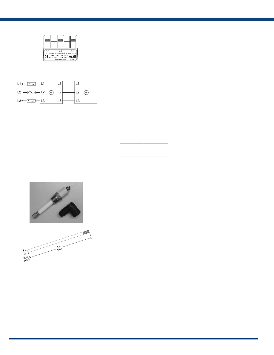
154
www.ssac.com • 800-843-8848 • fax: 605-348-5685
Voltage Monitor Accessory Module:
P/N: VRM6048
The VRM6048 accessory module allows the voltage
monitor to monitor a 3-phase 550 to 600VAC Line.
The VRM can be used with voltage monitor series:
TVM, TVW, PLM, PLR, and PLS manufactured after
December 2003.
*The VRM6048 must be connected as shown. If the
voltage monitor is disconnected, the VRM output
voltage equals the input voltage.
Adjustment: If the measured line voltage is 575VAC,
connect as shown and adjust/select the voltage monitor
for 460VAC operation.
Package: Molded housing with encapsulated
circuitry
Mounting: Surface mount with one #10 (M5 x 0.8)
plastic screw . May be DIN Rail
mounted using P1023-20 Adaptor.
Termination: Screw terminals with captive wire
clamps for up to No.12 AWG wire.
Operating: -40° to 70°C
Storage:
-40° to 85°C
Humidity: 95% relative, non-condensing
Liquid Level Control Electrodes:
P/N: PHST-38QTN (Probe Holder) & P0700-409
(Protective Boot)
Designed for use with all conductive liquid level
controls. Composed of insulators and metal parts made
of number 300 series stainless steel. These internally
conductive probe holders are designed for a maximum
steam pressure of 240 PSI; 400° F maximum. Maximum
voltage from electrode to ground. PHST-38QTN is
UL353 Recognized.
Liquid Level Probe:
P/N: LLP-24
Threaded stainless steel probe measuring 24 in. (61 cm)
long. Designed for use with PHST-38QTN liquid level
control electrodes .
Accessories
INPUT
*OUTPUT
600VAC
480VAC
575VAC
460VAC
550VAC
440VAC
Voltage:
VRM Module
Voltage Monitor
575VAC → 460VAC
Courtesy of Steven Engineering, Inc.-230 Ryan Way, South San Francisco, CA 94080-6370-Main Office: (650) 588-9200-Outside Local Area: (800) 258-9200-www.stevenengineering.com
Littelfuse-catalog-html.html

155
www.ssac.com • 800-843-8848 • fax: 605-348-5685
Appendix
Appendix A
Timer Functions . . . . . . . . . . . . . . . . . . . . . . . . . . . . . . . . . . .
156
TRDU Function Diagrams . . . . . . . . . . . . . . . . . . . . . . . . . .
163
Flasher Function Diagrams
. . . . . . . . . . . . . . . . . . . . . . . . .
164
Appendix B
Dimensional Drawings . . . . . . . . . . . . . . . . . . . . . . . . . . . . .
165
Appendix C
Connection Diagrams . . . . . . . . . . . . . . . . . . . . . . . . . . . . . .
168
Courtesy of Steven Engineering, Inc.-230 Ryan Way, South San Francisco, CA 94080-6370-Main Office: (650) 588-9200-Outside Local Area: (800) 258-9200-www.stevenengineering.com
Littelfuse-catalog-html.html
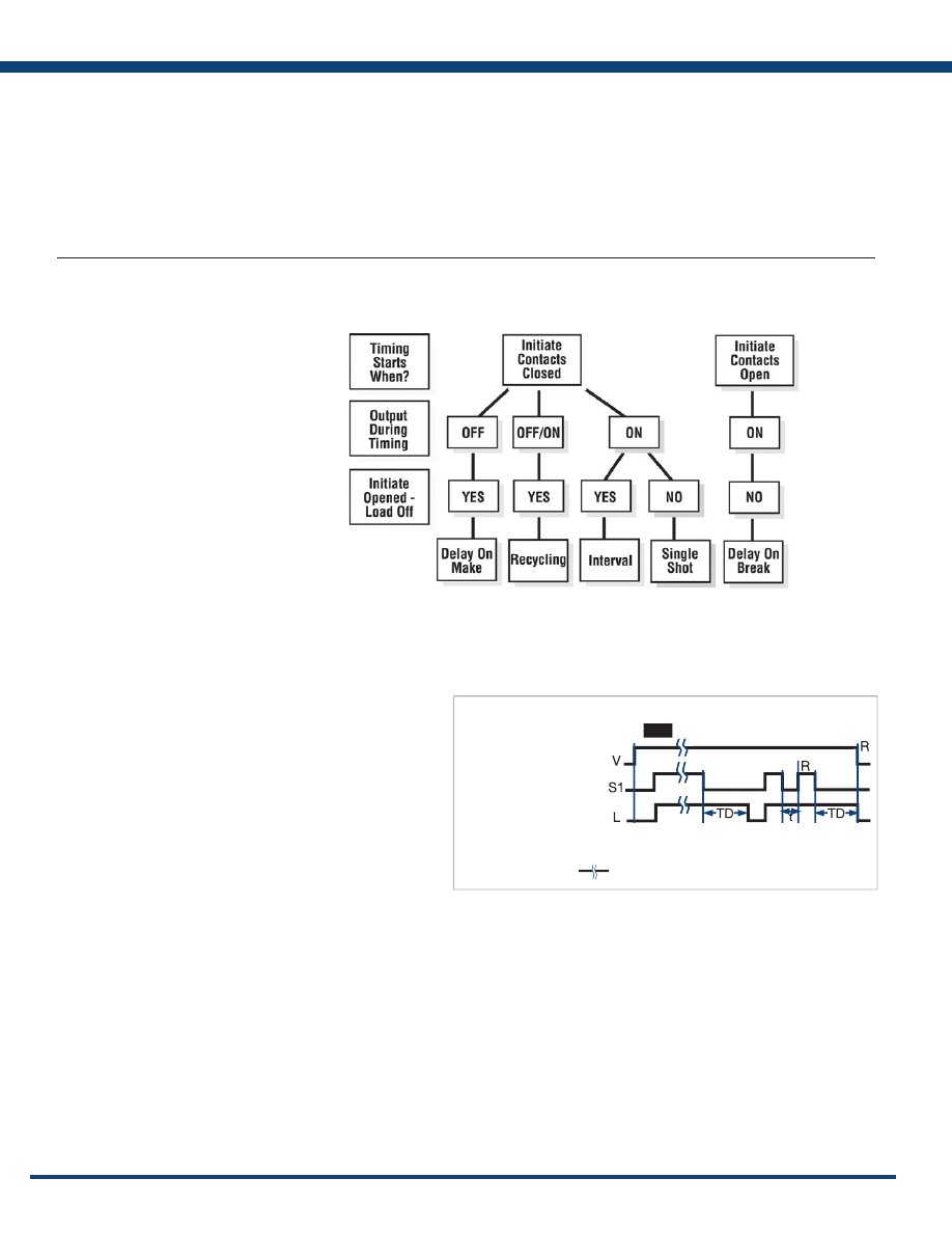
156
www.ssac.com • 800-843-8848 • fax: 605-348-5685
Selecting a Timer’s Function
Selecting one of the five most common timing functions can be as easy as answering three questions on the chart below. If you have trouble answering
these questions, try drawing a connection diagram that shows how the timer and load are connected. Time diagrams and written descriptions of the
five most popular functions, plus other common functions. Instantaneous contacts, accumulation, pause timing functions, and flashing LED’s are
included in some units to expand the versatility of the timer. These expanded operations are explained on the product’s catalog page. Time diagrams
are used on these pages along with text and international symbols for functions.
Function Selection Guide
Selection Questions
1) The timing starts when the
initiate (starting) contacts are:
A) Closed B) Opened
2) What is the status of the output
(or load) during timing:
A) On B) Off C) On/Off
3) Will the load de-energize
(or remain de-energized)
if the initiate (starting) contacts
are opened during timing:
A) Yes B) No
THE FIVE MOST USED FUNCTIONS
Understanding Time Diagrams
Time diagrams are used to show the relative operation of switches,
controls, and loads as time progresses. Time begins at the first vertical
boundary. There may be a line indicating the start of the operation or it
may just begin with the transition of the device that starts the operation.
Each row in the time diagram represents a separate component.
These rows will be labeled with the name of the device or its terminal
connection numbers. In a bistable or digital system, the switches,
controls, or loads can only be ON or OFF. The time lines are drawn
to represent these two possible conditions. Vertical lines are used to
define important starting or ending points in the operation.
The example to the right is the most common type of time diagram
in use in North America. It shows the energizing of loads, and the
closing of switches and contacts by an ascending vertical transition of
the time line. Opening switches or contacts or de-energizing loads are
represented by descending vertical transitions.
TIME DIAGRAM
Example:
Input Applied
Off
Output Energized
(Normally De-energized
Open)
Initiate Closed
Switch Open
R = Reset TD = Time Delay S1 = Initiate Switch
Delay-on-Break (Release)
Undefined time
t = Incomplete Time Delay
Appendix A - Timer Functions
Courtesy of Steven Engineering, Inc.-230 Ryan Way, South San Francisco, CA 94080-6370-Main Office: (650) 588-9200-Outside Local Area: (800) 258-9200-www.stevenengineering.com
Littelfuse-catalog-html.html
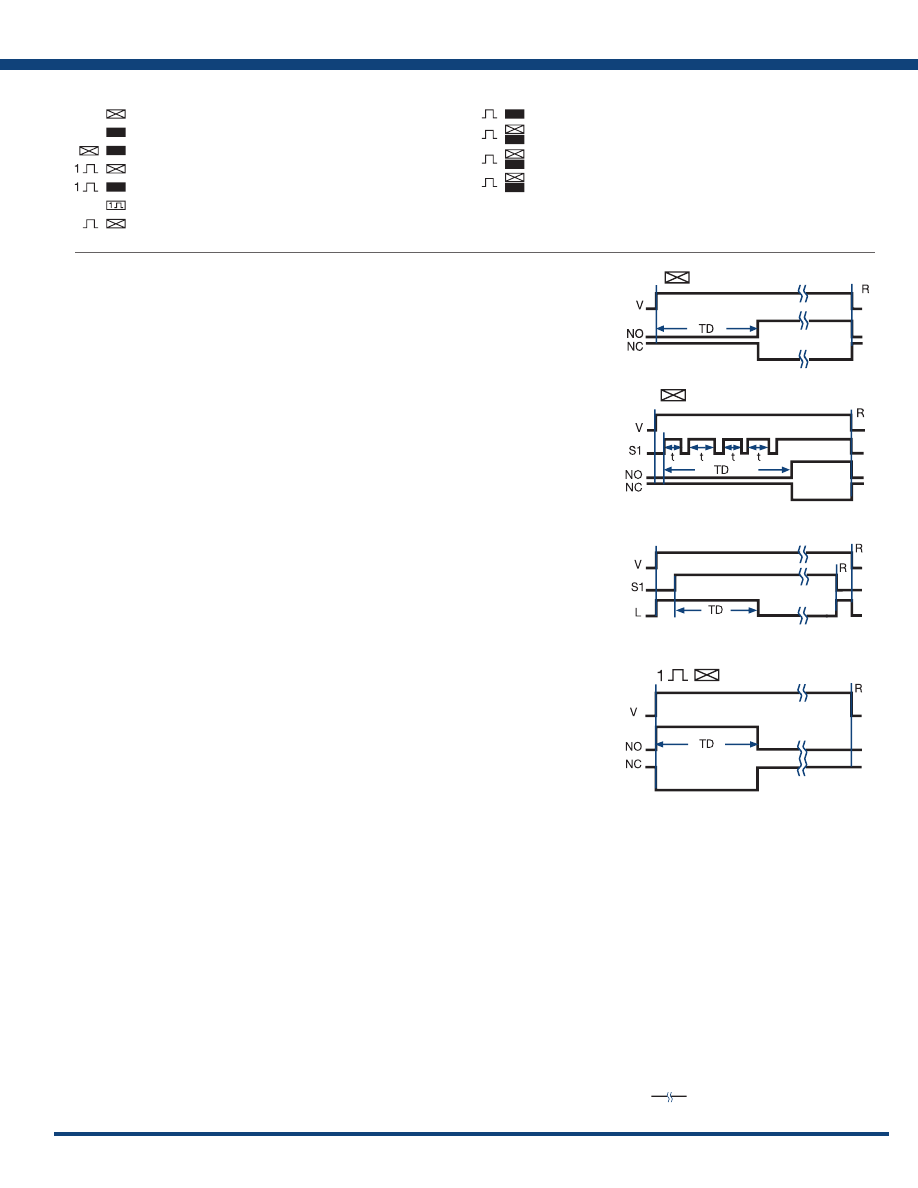
157
www.ssac.com • 800-843-8848 • fax: 605-348-5685
Delay-on-Make: (ProgramaCube
®
Function M)
(ON-delay, Delay on Operate, On Delay, Operate Delay, Delay On, Prepurge Delay)
OPERATION: Upon application of input voltage, the time delay begins. The output (relay or solid state)
is de-energized before and during the time delay. At the end of the time delay, the output energizes
and remains energized until input voltage is removed.
RESET: Removing input voltage resets the time delay and output.
See: HRPS, KRPS, KSPS, KSPU, NHPS, NHPU, TDM, TRDU
Extra Functions Included in Some Delay-on-Make (DOM) Timers:
Accumulating Time Delay Feature: (ProgramaCube
®
Function AM)
Some DOM timers allow the time delay to be stopped and held and then resumed by opening and closing
an external switch. The total time delay, TD is the sum of the accumulated partial time delays, “t”.
See: KRPD, KRPS, HRPS, NHPS, KSPD, KSPS, TRDU
Instantaneous Contacts:
Some DOM timers have a set of instantaneous contacts in addition to the delayed contacts. Instantaneous
contacts energize when input voltage is applied and remain until voltage is removed.
Delay-on-Make, Normally Closed Output:
All relay output delay-on-make timers with normally closed contacts include this function. (See Delay-
on-Make NC Contacts) This function is also available in solid-state output timers. The solid-state output
energizes when input voltage is applied. The time delay begins when an optional initiate switch S1 is closed
(timing starts when voltage is applied if S1 is not used). The output de-energizes at the end of the time delay.
R
eset: Opening S1 resets the time delay and the output immediately energizes (or remains energized).
Removing input voltage resets the time delay and de-energizes the output.
See:
KSD
4,
THD
4,
TS
4,
TSD
4
Accumulating
Delay-on-Make (Operate)
V = Voltage
NO = Normally Open Contact
R = Reset
NC = Normally Closed Contact
TD = Time Delay
t = Incomplete (Partial) Time Delay
S1 = Initiate Switch
L = Load
= Undefined time
(Impulse-ON, Single Pulse on Operate, On Interval, Interval On, Pulse Shaping, Bypass Timing)
OPERATION: Upon application of input voltage, the time delay begins. The output (relay or solid
state) energizes during the time delay. At the end of time delay the output de-energizes and remains
de-energized until input voltage is removed.
RESET: Removing input voltage resets the time delay and output.
See: HRPS, KRPS, KSPS, KSPU, NHPS, NHPU, TDI, TSD2
Extra Functions Included on Some Interval Timers:
Instantaneous Contacts:
Some Inter
val timers have a set of intantaneous contacts in addition to the delayed contacts.
Intantaneous contacts energize when input voltage is applied and remain until voltage is removed.
Interval: (ProgramaCube
®
Function I)
Interval (Impulse ON)
Delay-on-Make (ON-delay)
Legend
INTERNATIONAL TIMING FUNCTION SYMBOLS
= Delay-on-Make; ON-delay
= Delay-on-Break; OFF-delay
= Delay-on-Make & Break; ON and OFF-delay
= Interval; Impulse-ON
= Trailing Edge Interval; Impulse-OFF
= Single Shot; Pulse Former
= Flasher - ON Time First; Recycling Equal Times - ON First
= Flasher - OFF Time First; Recycling Equal Times - OFF First
= Recycling - Unequal Times; Pulse Generator
= Recycling - Unequal Times Starting with ON or OFF
= Delay-on-Make & Interval; Single Pulse Generator
Delay-on-Make (Normally Closed)
Appendix A - Timer Functions
Courtesy of Steven Engineering, Inc.-230 Ryan Way, South San Francisco, CA 94080-6370-Main Office: (650) 588-9200-Outside Local Area: (800) 258-9200-www.stevenengineering.com
Littelfuse-catalog-html.html
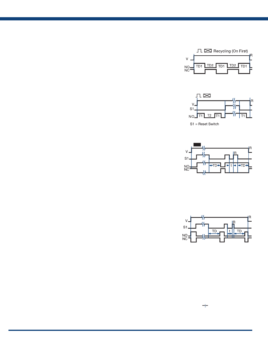
158
www.ssac.com • 800-843-8848 • fax: 605-348-5685
Timer Functions
Popular Functions
(Flasher, Pulse Generator, Recycle Timing, Repeat Cycle, Duty Cycling)
OPERATION: Upon application of input voltage, the output (relay or solid state) energizes
and the ON time begins. At the end of the ON time, the output de-energizes and the OFF
time begins. At the end of the OFF time, the output energizes and the cycle repeats as long
as input voltage is applied. The OFF time may be the first delay in some recycling timers.
RESET: Removing input voltage resets the output and time delays, and returns the
sequence to the first delay.
The time delays in some recycling timers are equal TD1=TD2. Flashers are an example of this type of
recycling timer. Others have separately selectable time delays.
See: HRPD, HRPS, KRPD, KRPS, KSPD, KSPS, KSPU, NHPD, NHPS, NHPU, TDR
Extra Functions Included in Some Recycling Timers:
Instantaneous Contacts:
Some Recycling timers have a set of instantaneous contacts in addition to the delayed contacts.
Instantaneous contacts energize when input voltage is applied and remain until voltage is removed.
RESET SWITCH: Closing an external switch transfers the output and resets the sequence to the first delay.
See: HRDR
Recycling: (ProgramaCube
®
Functions RE, RD, RXE, RXD)
Delay-on-Break: (ProgramaCube
®
Function B)
(Delay on Release, OFF-delay, Release Delay, Postpurge Delay)
OPERATION: Input voltage must be applied before and during timing. Upon closure of the initiate
switch, the output (relay or solid state) energizes. The time delay begins when the initiate switch is
opened. The output remains energized during timing. At the end of the time delay, the output de-
energizes. The output will energize if the initiate switch is closed when input voltage is applied.
RESET: Reclosing the initiate switch during timing resets the time delay. Removing input voltage resets
the time delay and output.
See: HRPS, HRPU, KRPS, KSPS, KSPU, NHPS, NHPU, TRDU, TDB
Extra Functions Included in Some Delay-on-Break (DOB) Timers:
Instantaneous Contacts:
Some DOB timers have a set of instantaneous contacts in addition to the delayed contacts. Instantaneous
contacts energize when input voltage is applied and remain until voltage is removed.
Related Functions:
Inverted Delay-on-Break: (ProgramaCube
®
Function UB)
OPERATION: Input voltage must be applied before and during timing. Upon closure of the initiate
switch S1, the output (relay or solid state) de-energizes. The time delay begins when S1 is opened. The
output remains de-energized during timing. At the end of the time delay, the output energizes. The
output remains de-energized if S1 is closed when input voltage is applied
RESET: Reclosing S1 during timing resets the time delay. Removing input voltage resets the time delay
and output .
See: HRPS, HRPU, KRPS, KSPS, KSPU, NHPS, NHPU, TRDU
Delay-on-Break (OFF-delay)
Recycling w/Reset Switch
Inverted Delay-on-Break
Legend
V = Voltage
R = Reset
T1 = ON Time
T2 = OFF Time
S1 =Initiate Switch
NO = Normally Open Contact
NC = Normally Closed Contact
t = Incomplete Time Delay
TD, TD1, TD2 = Time Delay
= Undefined Time
Appendix A - Timer Functions
Courtesy of Steven Engineering, Inc.-230 Ryan Way, South San Francisco, CA 94080-6370-Main Office: (650) 588-9200-Outside Local Area: (800) 258-9200-www.stevenengineering.com
Littelfuse-catalog-html.html
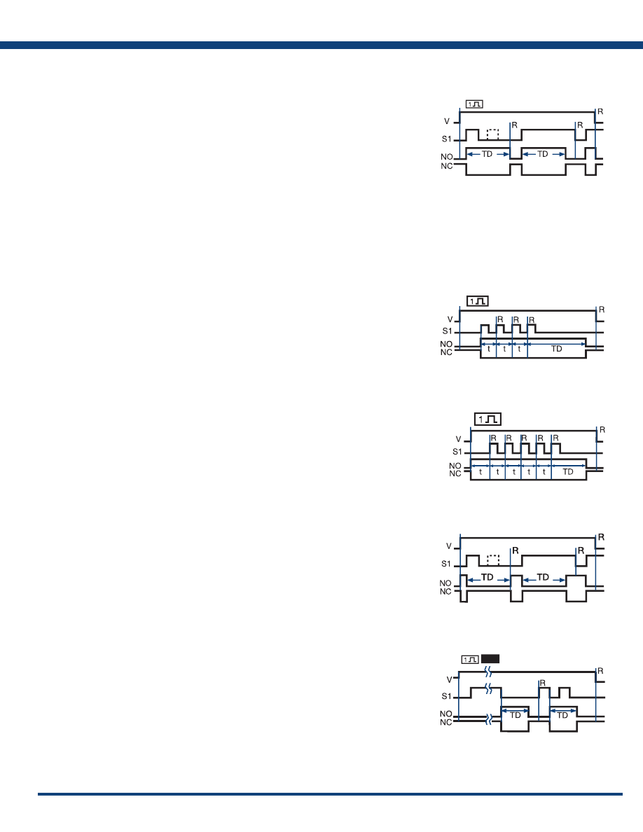
159
www.ssac.com • 800-843-8848 • fax: 605-348-5685
Inverted Delay-on-Break
(Pulse Former, One Shot Relay, Single Shot Interval, Pulse Shaping)
OPERATION: Input voltage must be applied before and during timing. Upon momentary or maintained
closure of the initiate switch, the output (relay or solid state) energizes and the time delay begins. At
the end of the delay, the output de-energizes. Opening or reclosing the initiate switch during timing
has no effect on the time delay. Note (for most single shot timers): If the initiate switch is closed when
input voltage is applied, the output energizes and the time delay begins.
RESET: Reset occurs when the time delay is complete and the initiate switch is opened. Removing input
voltage resets the time delay and output.
See: HRPS, HRPU, KRPS, KSPS, KSPU, NHPS, NHPU, TDS, TSDS, TRDU
Extra Functions Included in Some Single Shot Timers:
Instantaneous Contacts:
Some Single Shot timers have a set of instantaneous contacts in addition to the delayed contacts.
Instantaneous contacts energize when input voltage is applied and remain until voltage is removed.
Related Functions:
Retriggerable Single Shot (Motion Detector): (ProgramaCube
®
Function PSD)
(Motion Detector, Zero Speed Switch, Watchdog Timer, Missing Pulse Timer)
OPERATION: Input voltage must be applied prior to and during timing. The output (relay or solid state)
is de-energized. When the initiate switch S1 closes momentarily or maintained, the output energizes
and the time delay begins. Upon completion of the delay, the output de-energizes.
RESET: Reclosing S1 resets the time delay and restarts timing. Removing input voltage resets the time
delay and output .
See: HRD9, HRPS, HRPU, KRD9, KRPS, KSPS, KSPU, NHPS, NHPU, TRDU, TRU
Single S
hot:
(ProgramaCube
®
Functions S or SD)
Inverted Single Shot
Inverted Single Shot: (ProgramaCube
®
Function US)
OPERATION: Input voltage must be applied before and during timing. Upon momentary or
maintained closure of the initiate switch S1, the output (relay or solid state) de-energizes. At the
end of the time delay, the output energizes. Opening or reclosing S1 during timing has no affect on
the time delay. The output will remain de-energized if S1 is closed when input voltage is applied.
RESET: Reset occurs when the time delay is complete and S1 is open. Removing input voltage resets
the time delay and output.
See: HRPS, HRPU, KRPS, KSPS, KSPU, NHPS, NHPU, TRDU
Retriggerable Single Shot (Motion Detector): (ProgramaCube
®
Function PSE)
Trailing Edge Single Shot (Impulse-OFF): (ProgramaCube
®
Function TS)
OPERATION: Input voltage must be applied before and during timing. When the initiate switch
S1 opens, the output (relay or solid state) energizes. At the end of the time delay, the output
de-energizes. Reclosing and opening S1 during timing has no affect on the time delay. The output will
not energize if S1 is open when input voltage is applied.
RESET: Reset occurs when the time delay is complete and S1 is closed. Removing input voltage resets
the time delay and output.See: HRPS, KRPS, KSPS, KSPU, NHPU, TRDU
OPERATION: Similar to retriggerable single shot function PSD above except, when input voltage is applied,
the output (relay or solid state) immediately energizes and timing begins. At the end of the time delay, the
output de-energizes. The unit will timeout as long as S1 remains open or closed for a full time delay period.
RESET: During timing, reclosing S1 resets and restarts the time delay and the output remains energized.
After timeout, reclosing S1 starts a new operation. Removing input voltage resets the time delay and
the output.
See: KRD9
Motion Detector (PSD)
Retriggerable Single Shot
Single Shot (Pulse Former)
Motion Detector (PSE)
Retriggerable Single Shot
Trailing Edge Single Shot
Appendix A - Timer Functions
Courtesy of Steven Engineering, Inc.-230 Ryan Way, South San Francisco, CA 94080-6370-Main Office: (650) 588-9200-Outside Local Area: (800) 258-9200-www.stevenengineering.com
Littelfuse-catalog-html.html
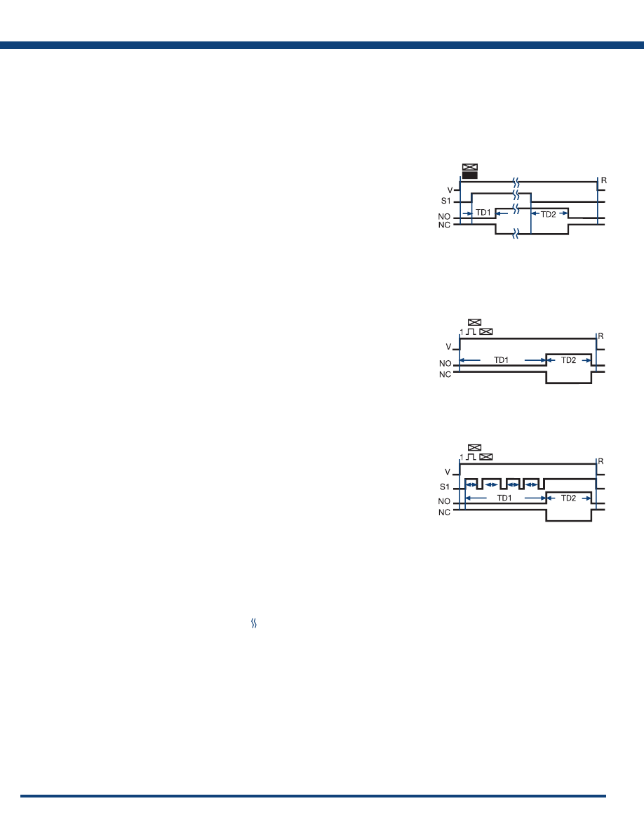
160
www.ssac.com • 800-843-8848 • fax: 605-348-5685
Delay-on-Make/Delay-on-Break: (ProgramaCube
®
Function MB)
(ON-delay/OFF-delay, Delay on Operate/Delay on Release, Sequencing ON & OFF, Fan Delay,
Prepurge & Postpurge)
OPERATION: Input voltage must be applied at all times. The output (relay or solid state) is de-
energized. Upon closure of the S1 initiate switch, the delay-on-make time delay (TD1) begins. At
the end of TD1, the output (relay or solid state) energizes. Opening S1 starts the delay-on-break time
delay (TD2). At the end of TD2, the output de-energizes.
RESET: Removing input voltage resets time delays and the output.If S1 is a) opened during TD1,
then TD1 is reset and the output remains de-energized. b) reclosed during TD2, then TD2 is reset
and the output remains energized.
See: HRPD, KRPD, KSPD, NHPD
Extra Functions Included in Some Delay-on-Make/Delay-on-Break Timers:
Instantaneous Contacts:
Some DOM/DOB timers have a set of instantaneous contacts in addition to the delayed contacts.
Instantaneous contacts energize when input voltage is applied and remain until voltage is removed.
Delay-on-Make/Interval: (ProgramaCube
®
Function MI)
(Single Pulse Generator, Delayed Interval, Delay on Operate/Single Pulse on Operate)
OPERATION: Upon application of input voltage, the delay-on-make time delay (TD1) begins, the
output remains de-energized. At the end of this delay, the output (relay or solid state) energizes
and the interval delay (TD2) begins. At the end of the interval delay (TD2), the output de-energizes.
RESET: Removing input voltage resets the output, the time delays and returns the sequence to the
first delay.
See: ESD5, HRPD, KRPD, KSPD, NHPD, TRDU
Delay-on-Make/
Delay-on-Break
Accumulative Delay-on-Make/Interval: (ProgramaCube
®
Function AMI)
Accumulative Delay-on-Make/
Interval
OPERATION: Input voltage must be applied before and during timing. The output is de-energized before
and during the TD1 time delay. Each time S1 closes, the time delay progresses; when it opens, timing stops.
When the amount of time S1 is closed equals the full TD1 delay, the output (relay or solid state) energizes
for TD2. Upon completion of TD2, the output relay de-energizes. Opening S1 during TD2 has no affect.
RESET: Removing input voltage resets the time delay, output relay, and the sequence to the first delay.
See: HRPD, KRPD, KSPD, NHPD
TD1, TD2 = Time Delay
NO = Normally Open
NC = Normally Closed
Delay-on-Make/
Interval
= Undefined Time
Legend
V = Voltage
S1 = Initiate Switch
R = Reset
Timer Functions
Two Functions in One Timer
Appendix A - Timer Functions
Courtesy of Steven Engineering, Inc.-230 Ryan Way, South San Francisco, CA 94080-6370-Main Office: (650) 588-9200-Outside Local Area: (800) 258-9200-www.stevenengineering.com
Littelfuse-catalog-html.html
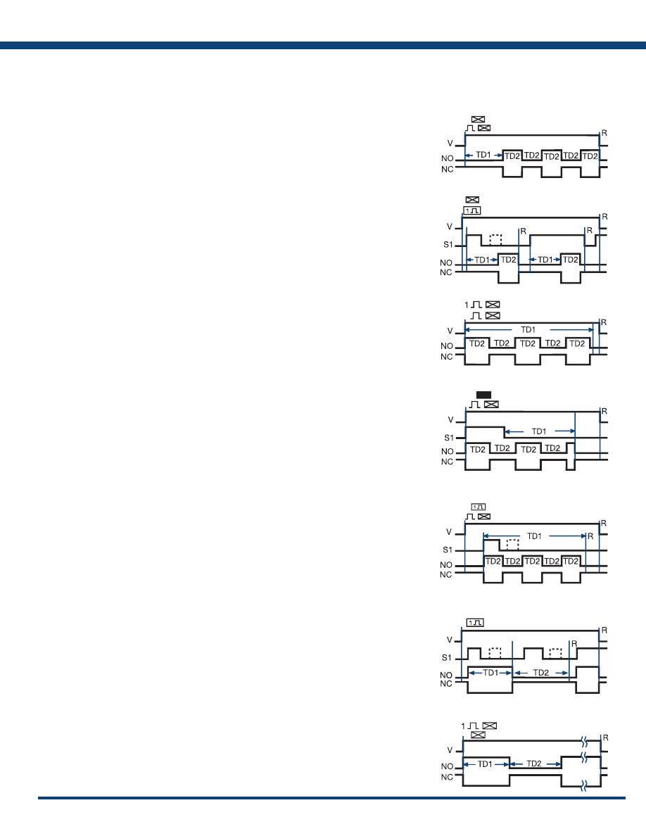
161
www.ssac.com • 800-843-8848 • fax: 605-348-5685
Delay-on-Make/Recycle: (ProgramaCube
®
Function MRE)
OPERATION: Upon application of input voltage, TD1 begins and the output (relay or solid state) remains
de-energized. At the end of TD1, the TD2 recycle function begins and the output (relay or solid state)
cycles ON and OFF for equal delays. This cycle continues until input voltage is removed.
RESET: Removing input voltage resets the output and time delays, and returns the sequence to the
first delay.
See: KSPD, KRPD, NHPD, HRPD, TRDU
Delay-on-Make/Single Shot: (ProgramaCube
®
Function MS)
OPERATION: Upon application of input voltage and the closure of S1, TD1 begins and the output (relay
or solid state) remains de-energized. The output (relay or solid state) energizes at the end of TD1, and
TD2 begins. At the end of TD2, the output (relay or solid state) de-energizes. Opening or reclosing S1
during timing has no affect on the time delays.
RESET: Reset occurs when the time delay is complete and S1 is open. Removing input voltage resets
the time delay, output, and the sequence to the first delay.
See: KSPD, KRPD, NHPD, HRPD, TRDU
Interval/Recycle: (ProgramaCube
®
Function IRE)
OPERATION: Upon application of input voltage TD1 begins. At the same time, the TD2 ON time begins
and the output (relay or solid state) energizes. At the end of the ON time, the TD2 OFF time begins and
the output de-energizes. The equal ON time OFF time cycle continues until TD1 is completed at which
time the output de-energizes.
RESET: Removing input voltage resets the time delays, output, and the sequence to the Interval function.
See: KSPD, KRPD, NHPD, HRPD, TRDU
Delay-on-Break/Recycle: (ProgramaCube
®
Function BRE)
OPERATION: Upon application of input voltage and the closure of S1, the TD2 ON time begins and
the output (relay or solid state) energizes. Upon completion of the ON time, the output de-energizes
for the TD2 OFF time. At the end of the OFF time, the equal ON/OFF cycle repeats. When S1 opens,
the TD1 delay begins. TD1 and TD2 run concurrently until the completion of TD1 at which time, the
TD2 ON/OFF cycle terminates and the output de-energizes. The output energizes if S1 is closed when
input voltage is applied.
RESET: Reclosing S1 during timing resets the TD1 time delay. Removing input voltage resets the time
delay, output, and the sequence to the Delay-on-Break function.
See: KSPD, KRPD, NHPD, HRPD, TRDU
Delay-on-Make
Recycle
Delay-on-Make
Single Shot
Interval
Recycle
Delay-on-Break
Recycle
Interval
Delay-on-Make
Interval/Delay-on-Make: (ProgramaCube
®
Function IM)
OPERATION: Upon application of input voltage, the output (relay or solid state) energizes and TD1
begins. At the end of TD1, the output de-energizes and TD2 begins. At the end of TD2, the output energizes.
RESET: Removing input voltage resets the time delays, output, and the sequence to the first delay.
See: HRPD, KRPD, KSPD, NHPD, TRDU
Single Shot/Recycle: (ProgramaCube
®
Function SRE)
OPERATION: Upon application of input voltage and the closure of S1, TD1 begins. At the same time,
the TD2 ON time begins and the output (relay or solid state) energizes. Upon completion of the ON
time, the output de-energizes for the TD2 OFF time. At the end of the OFF time, the equal ON/OFF
cycle repeats. TD1 and TD2 run concurrently until the completion of TD1 at which time, the TD2 ON/
OFF cycle terminates and the output de-energizes. Opening or reclosing S1 during timing has no affect
on the time delays. The output will energize if S1 is closed when input voltage is applied.
RESET: Removing input voltage resets the time delay, output, and the sequence to the first delay.
See: HRPD, KRPD, KSPD, NHPD, TRDU
Single Shot
Recycle
Single Shot/Lockout: (ProgramaCube
®
Function SL)
OPERATION: Upon application of input voltage and momentary or maintained closure of S1, the output
(relay or solid state) energizes and TD1 single shot time delay begins. The output relay de-energizes at
the end of TD1 and the TD2 lockout time delay begins. During TD2 (and TD1) closing switch S1 has no
effect on the operation. After TD2 is complete, closing S1 starts another operation. If S1 is closed when
input voltage is applied, the output energizes and the TD1 time delay begins.
RESET: Removing input voltage resets the time delays and the output and returns the cycle to the first
delay .
Single Shot
Lockout
Timer Functions
Two Functions in One Timer
Appendix A - Timer Functions
Courtesy of Steven Engineering, Inc.-230 Ryan Way, South San Francisco, CA 94080-6370-Main Office: (650) 588-9200-Outside Local Area: (800) 258-9200-www.stevenengineering.com
Littelfuse-catalog-html.html
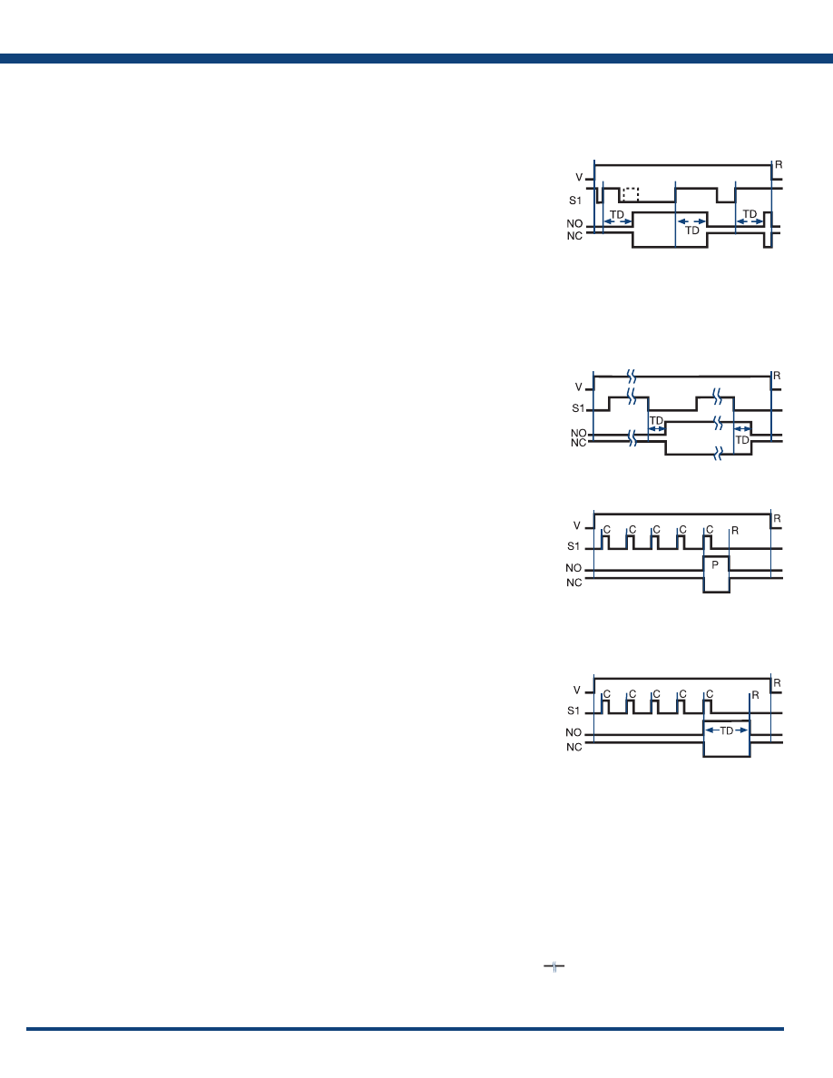
162
www.ssac.com • 800-843-8848 • fax: 605-348-5685
(Alternating Relay)
Timer Functions
Counting and Switching Functions
OPERATION: Input voltage must be applied before and during operation. The operation begins with
the output (relay or solid state) de-energized. Upon momentary or maintained closure (leading edge
triggered) of the initiate switch S1, the time delay begins. At the end of the time delay, the output
energizes and remains energized. Opening or re-closing S1 during timing has no affect. After the output
transfers, the next closure of S1 starts a new operation. Each time an S1 closure is recognized, the time
delay occurs and then the output transfers, ON to OFF, OFF to ON, ON to OFF. The first operation will
occur if S1 is closed when input voltage is applied.
RESET: Removing input voltage resets the time delay and the output to the de-energized state.
Function can be applied to ProgramaCube Series: HRPS, KRPS, KSPS
OPERATION: Input voltage must be applied at all times for proper operation. The operation begins
with the output (relay or solid state) de-energized. Closing S1 enables the next alternating operation.
When S1 opens (trailing edge triggered), the time delay begins. At the end of the time delay, the output
energizes and remains energized until S1 is (re-closed and) re-opened. Then the output relay de-energizes
and remains until S1 opens again. Each time S1 opens the time delay occurs and the output transfers.
RESET: Removing input voltage resets the output and the time delay.
See: ARP, HRPS, KRPS
Leading edge flip-flop: (ProgramaCube
®
Function F)
Counter with Pulsed Output: (ProgramaCube
®
Function C)
Counter with Interval Output: (ProgramaCube
®
Function CI)
Function Limited to Switch Adjustable ProgramaCubes
®
OPERATION: Input voltage must be applied before and during operation. Each time S1 is closed, a count
is added. When the total number of S1 closures equals the total count selected on the unit, the output
energizes. The output remains energized for the pulse duration specified for the product, and then de-
energizes. If S1 is closed while the output is energized, a count is not added. If S1 is closed when input
voltage is applied, a count is not added.
RESET: The unit automatically resets at the end of each operation. Removing input voltage resets the
output, counter, and pulse delay.
See: HRPU, KSPU, NHPU
Function Limited to Switch Adjustable ProgramaCubes
®
OPERATION:
Input voltage must be applied before and during operation. Each time S1 is closed, a count
is added. When the total number of S1 closures equals the total count selected on the unit, the output
energizes and the interval time delay begins. The output de-energizes at the end of the time delay. If
S1 is closed during the time delay, a count is not added. If S1 is closed when input voltage is applied,
a count is not added .
RESET: The counter is reset during the time delay, the unit automatically resets at the end of the interval
time delay. Removing input voltage resets the output, counter, and time delay.
See: HRPU, HRV, HSPZ, KSPU, NHPU
Trailing Edge Flip-Flop
Leading Edge Flip-Flop
Counter with Pulsed Output
Counter with Interval Output
Alternating Relay (Trailing edge flip-flop): (ProgramaCube
®
Function FT)
Legend
V = Voltage
R = Reset
S1 = Initiate Switch
Td, TD1, TD2 = Time Delay
NO = Normally Open Contact
NC = Normally Closed Contact
C = Count
P = Pulse Duration
= Undefined Time
Appendix A - Timer Functions
Courtesy of Steven Engineering, Inc.-230 Ryan Way, South San Francisco, CA 94080-6370-Main Office: (650) 588-9200-Outside Local Area: (800) 258-9200-www.stevenengineering.com
Littelfuse-catalog-html.html
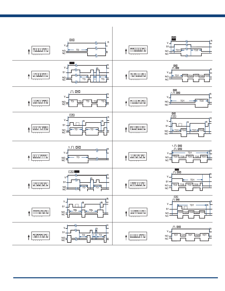
163
www.ssac.com • 800-843-8848 • fax: 605-348-5685
Appendix A - Timer Functions
Continued on next page...
TRDU Function Diagrams
ON
A B C D E
B
ON
A B C D
E
BRE
ON
A B C D E
RXE
ON
A B C D
E
I
ON
A B C D
E
IRE
ON
A B C D E
M
ON
A B C D E
MB
ON
A B C D
E
MI
ON
A B C D E
MRE
A B C D
E
ON
MS
ON
A B C D
E
RE
ON
A B C D E
SRE
ON
A B C D E
TS
ON
A B C D E
UB
ON
A B C D E
US
A B C D E
ON
S
Dual Functions
Single Functions
* Delay-on-Make
Delay-on-Break
* Recycle
(ON Time First, Equal Delays)
Single Shot
* Interval
Trailing Edge
Single Shot
Inverted
Single Shot
Inverted
Delay-on-Break
* Recycle
(ON Time First)
Both Times Adjustable
Single Shot
Recycle
(ON Time First)
Delay-on-Break
Recycle
(ON Time First)
Delay-on-Make
Delay-on-Break
* Delay-on-Make
Recycle (ON Time First)
* Delay-on-Make
Interval
Delay-on-Make
Single Shot
* Interval
Recycle
(ON Time First)
*
9 Functions included in the 8 pin DPDT models
Courtesy of Steven Engineering, Inc.-230 Ryan Way, South San Francisco, CA 94080-6370-Main Office: (650) 588-9200-Outside Local Area: (800) 258-9200-www.stevenengineering.com
Littelfuse-catalog-html.html
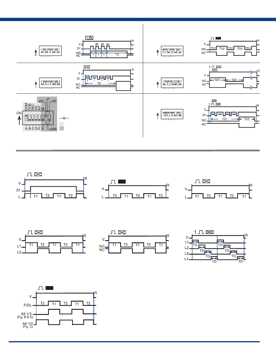
164
www.ssac.com • 800-843-8848 • fax: 605-348-5685
Appendix A - Timer/Flasher Functions
Flasher (NC)
V = Voltage S1 = Initiate Switch L = Load
R = Reset T1 = ON Time T2 = OFF Time
T1
≅
T2
Flasher (OFF First)
V = Voltage R = Reset L = Load
T1 = ON Time T2 = OFF Time
T1
≅
T2
Flasher (ON First)
V = Voltage R = Reset L = Load
T1 = ON Time T2 = OFF Time T1
≅
T2
ON time plus OFF time equals one complete flash.
Flasher (Alternating)
V = Voltage L1 = Load 1 L2 = Load 2
R = Reset T1 = ON Time T2 = OFF Time
T1
≅
T2
V = Voltage R = Reset
T1 = ON Time T2 = OFF Time
NO = Normally Open NC = Normally Closed
V = Voltage R = Reset L (1...4) = Lamps
TD = Time Delay (all are equal)
SC4 shown; SC3, L4 is eliminated
and L1 TD begins as soon as L3 TD is
completed .
Flasher (Chasing)
Flasher (ON First-DPDT)
Flashers & Aux. Modules
V = Voltage L = Load T1 = ON Time
T2 = OFF Time R = Reset
T1
≅
T2
Flasher Function Diagrams
ON
A B C D E
AM
ON
A B C D E
AMI
ON
A B C D E
RXD
ON
A B C D E
IM
A B C D E
ON
PS
Dual Functions
Single Functions
Retriggerable
Single Shot
Accumulative
Delay-on-Make
Accumulative Delay-on-Make
Interval
* Interval
Delay-on-Make
* Recycle
(OFF Time First)
Both Times Adjustable
*
9 Functions included in the 8 pin DPDT models
5 Switches for Function Selection
3 Switches for Time Delay Range
KEY
V=Voltage, R=Reset, S1=Initiate Switch,
NO=Normally Open Contact, NC=Normally Closed Contact,
TD,TD1,TD2=Complete Time Delay, t=Partial Time Delay,
DOM=Delay-on-Make, DOB=Delay-on-Break, REC=Recycle,
SS=Single Shot, INT=Interval, M=Minutes, S=Seconds,
= Undefined time
NOTE: The time delay range is the same for
both functions when dual functions are selected.
Courtesy of Steven Engineering, Inc.-230 Ryan Way, South San Francisco, CA 94080-6370-Main Office: (650) 588-9200-Outside Local Area: (800) 258-9200-www.stevenengineering.com
Littelfuse-catalog-html.html
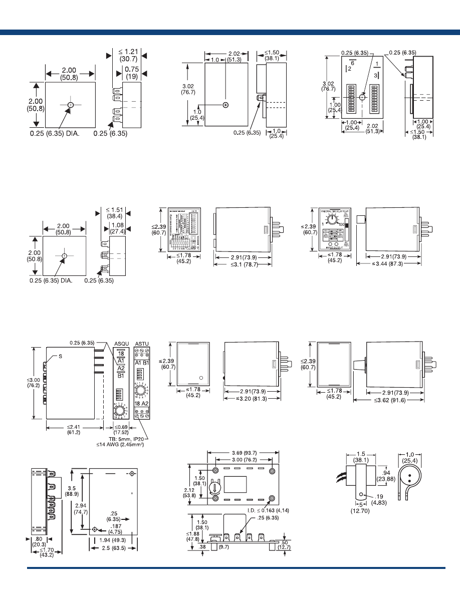
165
www.ssac.com • 800-843-8848 • fax: 605-348-5685
HSPZ
TRDU
TRU
ASQU; ASTU; DSQU; DSTU
(snap for
mounting
bases)
ERD3; ERDI; ERDM
ORB; ORM; ORS
CT; ESD5; ESDR; FS100; FS200; FS300; KRD3; KRD9;
KRDB; KRDI; KRDM; KRDR; KRDS; KRPD; KRPS;
KSD1; KSD2; KSD3; KSD4; KSDB; KSDR; KSDS;
KSDU; KSPD; KSPS; KSPU; KVM; T2D; TA; TAC1;
TAC4; TDU; TDUB; TDUI; TDUS; TL; TMV8000;
TS1; TS2; TS4; TS6; TSB; TSD1; TSD2; TSD3; TSD4;
TSD6; TSD7; TSDB; TSDR; TSDS; TSS; TSU2000
HLV; HRD3; HRD9; HRDB; HRDI;
HRDM; HRDR; HRDS; HRID; HRIS;
HRIU; HRPD; HRPS; HRPU; HRV; RS
FA; FS; FSU1000*; NHPD; NHPS; NHPU;
NLF1*; NLF2*; PHS*; PTHF*; SIR1; SIR2;
SLR1*; SLR2*; TH1; TH2; THC; THD1;
THD2; THD3; THD4; THD7; THDB; THDM;
THDS; THS
PLM; PLR; TDB; TDBH; TDBL; TDI; TDIH;
TDIL; TDM; TDMB; TDMH; TDML; TDR;
TDS; TDSH; TDSL
FS500; PRLB; PRLM; PRLS; TRB; TRM; TRS
Appendix B - Dimensional Drawings
FS100; FS400
FIGURE 1
FIGURE 2
FIGURE 3
FIGURE 4
FIGURE 5
FIGURE 6
FIGURE 7
FIGURE 10
FIGURE 8
FIGURE 9
FIGURE 11
FIGURE 12
inches (millimeters)
*If unit is rated @ 1A, see Figure 1
Courtesy of Steven Engineering, Inc.-230 Ryan Way, South San Francisco, CA 94080-6370-Main Office: (650) 588-9200-Outside Local Area: (800) 258-9200-www.stevenengineering.com
Littelfuse-catalog-html.html
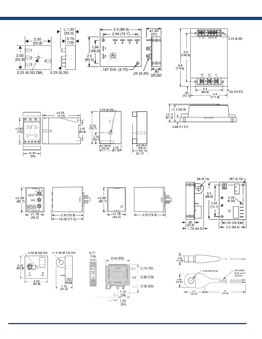
166
www.ssac.com • 800-843-8848 • fax: 605-348-5685
AF
SC3; SC4; SQ
WVM
DLMU
RC
RC
FB9L; HLMU; SCR9L
PLMU
LLC4; LLC6; PLS
ECS; ECSW
TCS; TCSA
Appendix B - Dimensional Drawings
FIGURE 13
FIGURE 14
FIGURE 15
FIGURE 16
FIGURE 17
FIGURE 18
FIGURE 19
FIGURE 20
FIGURE 21
DCSA
LCS
FIGURE 22
FIGURE 23
inches (millimeters)
(ECS has spade connectors and
ECSW has terminal board)
Courtesy of Steven Engineering, Inc.-230 Ryan Way, South San Francisco, CA 94080-6370-Main Office: (650) 588-9200-Outside Local Area: (800) 258-9200-www.stevenengineering.com
Littelfuse-catalog-html.html
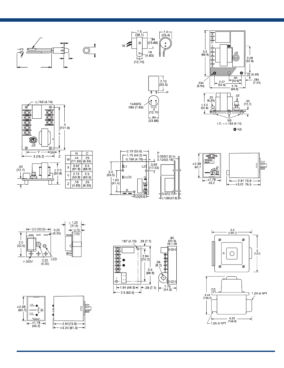
167
www.ssac.com • 800-843-8848 • fax: 605-348-5685
LPM
CURRENT LIMITING
RESISTOR
12 ± 1
(304.8 ± 25.4)
STRIPPED 0.25 (6.35)
0.53
(13.46)
0.28
(7.11)
0.22
(5.59)
UL1007
24 AWG (0.25 mm
2
)
<
_
LLC1
= Nylon Standoffs
LLC8
LLC2
LLC5
[
]
[
]
[
]
[
]
ARP
FB; SCR
PCR
FIGURE 24
FIGURE 25
FIGURE 26
FIGURE 27
FIGURE 28
FIGURE 29
FIGURE 30
FIGURE 31
MSM
TVM; TVW
FIGURE 32
FIGURE 33
Appendix B - Dimensional Drawings
inches (millimeters)
Courtesy of Steven Engineering, Inc.-230 Ryan Way, South San Francisco, CA 94080-6370-Main Office: (650) 588-9200-Outside Local Area: (800) 258-9200-www.stevenengineering.com
Littelfuse-catalog-html.html
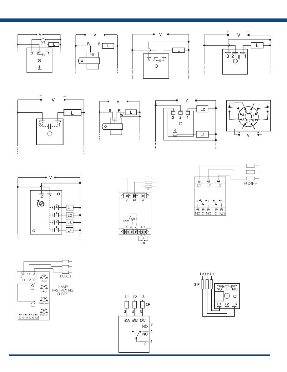
168
www.ssac.com • 800-843-8848 • fax: 605-348-5685
Appendix C - Connection Diagrams
L1
N/L2
FIGURE 1 - FSU1000 Series
L1
N
FIGURE 2 - FS100 Series
L1
N/L2
FIGURE 3 - FS100 Series
FIGURE 4 - FS200 Series
FIGURE 5 - FS300 Series
L1
N/L2
FIGURE 6 - FS400 Series
L1
N/L2
FIGURE 7 - AF Series
V = Voltage
L = Load
R = Red Wire
B = Black Wire
W= White Wire
L1
N/L2
FIGURE 8 - FS500 Series
L1
N/L2
FIGURE 9 - SC3/SC4 Series
SC4 shown;
for SC3, terminal 6 & load L4 are eliminated.
FIGURE 10 - WVM Series
F = Fuses
NO = Normally Open
NC = Normally Closed
RS = Optional Remote Reset Switch
Relay contacts are isolated .
CAUTION:
2 amp max fast acting fuses must
be installed externally in series
with each input. (3)
!
FIGURE 11 - DLMU Series
L1, L2, L3 = Line Voltage Input
NO = Normally Open Contact
NC = Normally Closed Contact
C = Common, Transfer Contact
CAUTION: 2 amp max. fast acting
fuses are recommended to protect
the equipment‘s wiring. They are not
required to protect the DLMU.
FIGURE 12 - HLMU Series
CAUTION: 2 amp max. fast acting fuses are
recommended to protect the equipment‘s
wiring. They are not required to protect the
HLMU .
L1, L2, L3 = Line Voltage Input
NO = Normally Open Contact
NC = Normally Closed Contact
C = Common, Transfer Contact
Note: Relay contacts are
isolated, 277VAC max.
FIGURE 13 -
PLMU/PLM/PLR/PLS Series
F = Fuses
ØA = Phase A = L1
ØB = Phase B = L2
ØC = Phase C = L3
NO = Normally Open
NC = Normally Closed
FIGURE 14 -
TVM/TVW Series
L1 = Phase A
L2 = Phase B
L3 = Phase C
NO = Normally Open
NC = Normally Closed
C = Common, Transfer Contact
Relay contacts are isolated .
F = 2A Fast acting fuses are recommended,
but not required
Note: Load may be in positive side.
2 A f a s t a c t i n g f u s e s
recommended for safety (not
required)
Relay contacts are isolated .
S1 = Optional low current switch
V = Voltage
L = Load
! = Select alarm contact connection as N.O. or
N.C. when ordering; N.O. Shown.
V = Voltage
L = Load
R = Red Wire
B = Black Wire
V = Voltage
L = Load
V = Voltage
L = Load
V = Voltage
L = Load
V = Voltage
L = Load
V = Voltage
Courtesy of Steven Engineering, Inc.-230 Ryan Way, South San Francisco, CA 94080-6370-Main Office: (650) 588-9200-Outside Local Area: (800) 258-9200-www.stevenengineering.com
Littelfuse-catalog-html.html
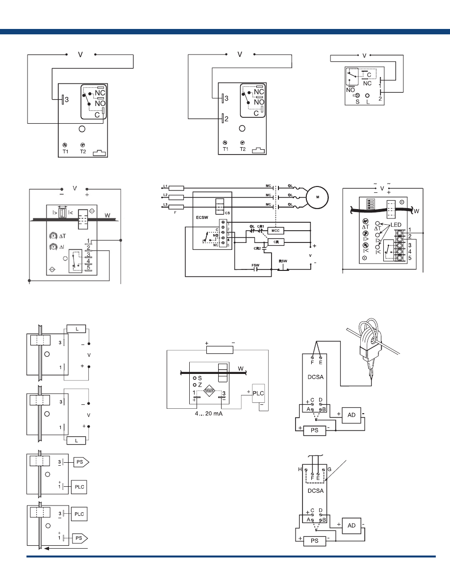
169
www.ssac.com • 800-843-8848 • fax: 605-348-5685
L1
N/L2
N = Relay contacts are non-isolated.
NO = Normally Open
NC = Normally Closed
C = Common
T1 = Undervoltage Trip Point
T2 = Restart Delay
I = Relay contacts
are isolated .
FIGURE 15 - HLV Series
L1
N/L2
FIGURE 16 - KVM Series
V = Voltage
L = LED
S = Undervoltage Setpoint
NO = Normally Open
NC = Normally Closed
C = Common, Transfer Contact
L1
N/L2
FIGURE 17 - ECS Series
V = Voltage
I> = Overcurrent
I< = Undercurrent
L1
N/L2
FIGURE 18 - ECSW Series
MC = Motor Contactor
M = Motor
F = Fuses
OL = Overload
RSW = Reset Switch
Positive
Switching
Negative
Switching
Sinking
Sourcing
Monitored AC conductor must
be insulated .
FIGURE 19 - TCS Series
PS
FIGURE 20 - TCSA Series
PS = Power Supply
Z = Zero Adjust
S = Span Adjust
W = Insulated Wire Carrying Monitored Current
PLC = PLC Analog Input or Meter Input
AD = Instrument, Meter, or PLC Input
PS = Power Supply
Connection for
4 - 20 mA Loop
LCSC10T12
Current Sensor
To LCSC10T12
Current Sensor
Connection for
Analog Voltage Output
Connect One:
A = 1 to 5VDC
B = 2 to 10VDC
Connect One:
A = 1 to 5VDC
B = 2 to 10VDC
Jumper used when
current source is not
LCSC10T12
FIGURE 21 - DCSA Series
Appendix C - Connection Diagrams
L1
N/L2
L1
N/L2
W = Insulated Wire
Carrying Monitored Current
Relay contacts are isolated .
FSW = Fan or Float Contacts
CR = Control Relay
CS = Current Sensor
MCC = Motor Contactor Coil
V = Voltage
I> = Adjustable Overcurrent
I< = Adjustable Undercurrent
W = Monitored Wire
∆
T - Adjustable Trip Delay
L = Load
V = Voltage
PS = Power Supply
PLC = PLC Digital Input Module
Courtesy of Steven Engineering, Inc.-230 Ryan Way, South San Francisco, CA 94080-6370-Main Office: (650) 588-9200-Outside Local Area: (800) 258-9200-www.stevenengineering.com
Littelfuse-catalog-html.html
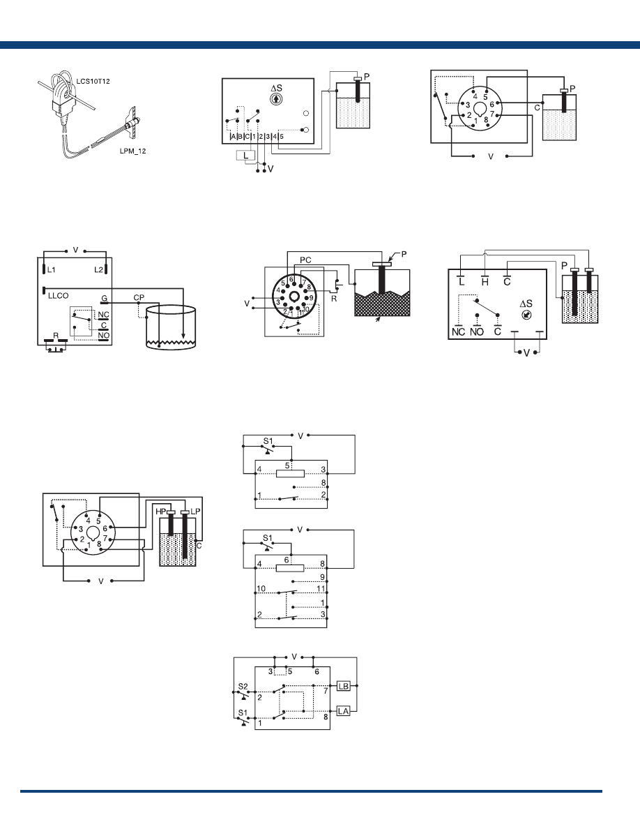
170
www.ssac.com • 800-843-8848 • fax: 605-348-5685
FIGURE 22 - LCS10T12
L1
N/L2
Metal Tank or use
additional Probe
FIGURE 24 - LLC4 Series
P = Probe
C = Probe Common
V = Voltage
Relay contacts are isolated .
Connect common to conductive tank. Additional probe
is necessary for non-conductive or insulated tanks.
Metal Tank or use
additional Probe
FIGURE 25 - LLC8 Series
V = Voltage
LLCO = Low Level Probe
G or CP = Ground or Common (Reference) Probe
R = Optional NC Reset Switch (not included)
NO = Normally Open
NC = Normally Closed
C = Common or Transfer Contact
Relay contacts are isolated .
Connect common to conductive tank. Additional
probe is necessary for non-conductive or insulated
tanks.
L1
N/L2
Metal Tank or use
additional Probe
FIGURE 26 - LLC6 Series
PC = Probe Common
P = Probe
V = Voltage
R = Optional NC Reset Switch
Connect common to conductive tank. Additional probe
is necessary for non-conductive or insulated tanks.
L1
N/L2
Metal Tank or use
additional Probe
FIGURE 27 - LLC2 Series
V = Voltage
L = Low Probe
H = High Probe
C = Probe Common
∆S = Sensitivity Adjustment
NC = Normally Closed
NO = Normally Open
Connect common to conductive tank.
Additional probe is necessary for non-
conductive or insulated tanks.
L1
N/L2
Metal Tank or use
additional Probe
HP = High Level Probe
LP = Low Level Probe
C = Probe Common
V = Voltage
Relay contacts are isolated .
Connect common to conductive tank. Additional probe
is necessary for non-conductive or insulated tanks.
FIGURE 28 - LLC5 Series
L1
N/L2
L1
N/L2
L1
N/L2
FIGURE 29 - ARP Series
SPDT 8-pin
DPDT 11-pin
DPDT 8-pin
cross wired
The DPDT 8-pin, cross wired option, allows extra system load
capacity through simultaneous operation of both motors when
needed . Relay contacts are not isolated .
Duplexing (Cross Wired): Duplexing models operate the same as
alternating relays and when both the Control (S1) and Lag Load (S2)
Switches are closed, Load A and Load B energize simultaneously.
V = Voltage
LA = Load A
LB = Load B
S1 = Primary Control Switch
S2 = Lag Load Switch
L1 N/L2
Metal Tank or use
additional Probe
C
FIGURE 23 - LLC1 Series
Appendix C - Connection Diagrams
Wire Length: 500 ft. (152.4m) max. (Customer
Supplied)
CAUTION: The LCS10T12 must be connected to
the LPM12 or LPMG12 before current flows to
prevent damage or shock hazard. Monitored wires
must be properly insulated .
P = Probe
L = Load
V = Voltage
∆
S = Sensitivity Adjustment
Connect common to conductive tank
or an additional probe as required .
Contacts A, B & C are isolated.
Relay contacts in above are isolated.
Courtesy of Steven Engineering, Inc.-230 Ryan Way, South San Francisco, CA 94080-6370-Main Office: (650) 588-9200-Outside Local Area: (800) 258-9200-www.stevenengineering.com
Littelfuse-catalog-html.html
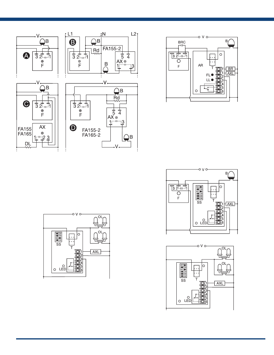
171
www.ssac.com • 800-843-8848 • fax: 605-348-5685
FIGURE 30 - FS155 & FS165 & FA
Series
F = Flasher (FS155-30T, FS155-30RF, FS165-30T, FS165-30RF)
AX = Auxiliary Unit
B = Beacon
DL = Dummy Load for Constant Line Loading
Rd = 3.3 KΩ @ 5W for 120VAC
8.5 KΩ @ 5W for 230VAC
L1
N/L2
FIGURE 31 - FB Series
V = Voltage
B = Beacon
F = Flasher
BRC = Flasher Bypass Relay Contacts
T = Toroid
AR = FB Alarm Relay
BR = Bypass Relay Coil
FL = Flasher Failure LED
LL = Lamp Failure LED
AXL = Lamp Alarm Relay Coil
NOTE: Flasher module may be located on either the
line or load side of the toroidal sensor.
L1
N/L2
FIGURE 32 - SCR490D
V = Voltage
OL = Obstruction Lamps
T = Toroid
SS = Selector Switch
AXL = Auxiliary Load/Alarm
Relay contacts are isolated .
L1 N/L2
L1
N/L2
Beacon Connection Diagram
Obstruction Lamp Connection Diagram
V = Voltage
B = Beacon Lamps
SS = Selector Switch
T = Toroid
F = Flasher
AXL = Auxiliary Load/Alarm
OL = Obstruction Lamps
Relay contacts are isolated .
FIGURE 33 - SCR Series
Appendix C - Connection Diagrams
Courtesy of Steven Engineering, Inc.-230 Ryan Way, South San Francisco, CA 94080-6370-Main Office: (650) 588-9200-Outside Local Area: (800) 258-9200-www.stevenengineering.com
Littelfuse-catalog-html.html
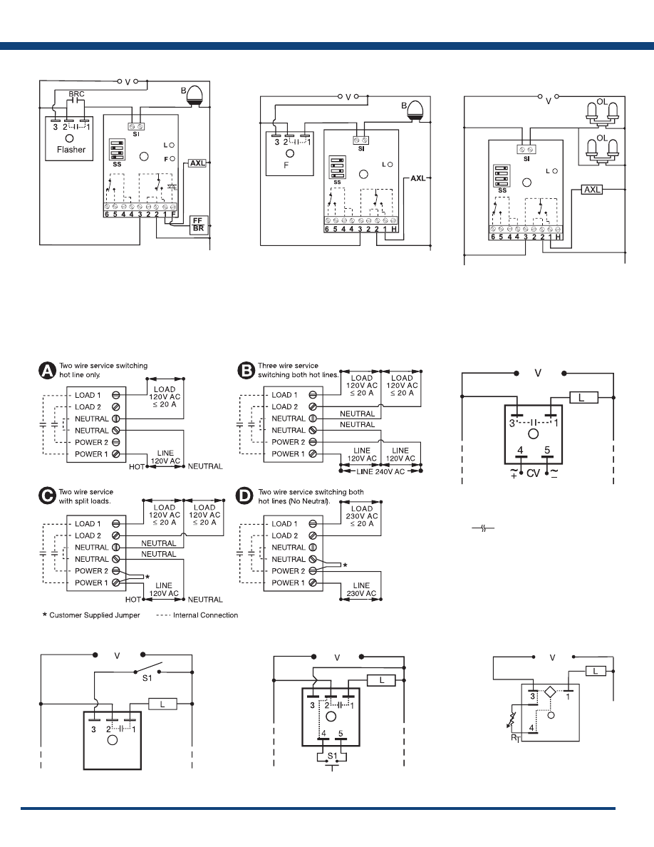
172
www.ssac.com • 800-843-8848 • fax: 605-348-5685
L1 N/L2
FIGURE 34 - FB9L
V = Voltage
B = LED Beacon
SS = Selector Switch
SI = Sensor Input
L = Indicator
F = Flasher Failure LED
AXL = Auxiliary Load/Alarm
FF = Flasher Failure/Bypass Relay
BRC = Bypass Relay Contacts
L1 N/L2
L1 N/L2
Beacon Connection Diagram
Obstruction Lamp Connection Diagram
FIGURE 35 - SCR9L
V = Voltage
B = Beacon Lamps
SS = Selector Switch
L = LED Indicator
F = Flasher
AXL = Auxiliary Load/Alarm
OL = Obstruction Lamps
SI = Sensor Input
H = “3“ Spare AC Hot Connection (2A max.)
FIGURE 36 - PCR Series
L1
N/L2
FIGURE 37 - SIR1/SIR2 Series
V = Voltage
CV = Control Voltage
R = Reset
NC = Normally Closed Output
NO = Normally Open Output
Load may be connected to terminal 3 or 1.
Note: Normally open output is shown. Nor-
mally closed output is also available.
= Undefined time
L1
N/L2
FIGURE 38- SLR Series
L = Load
S1 = Initiate Switch
L1
N/L2
L = Load
S1 = Control Switch
Internal connections between terminals
2 & 4.
FIGURE 39 - NLF1/NLF2 Series
L1
N/L2
Triac Output Device
V = Voltage
L = Load
R
T
= External Adjustment
FIGURE 40 - PHS Series
Appendix C - Connection Diagrams
Note: Normally open output is shown. Normally
closed output is also available.
Courtesy of Steven Engineering, Inc.-230 Ryan Way, South San Francisco, CA 94080-6370-Main Office: (650) 588-9200-Outside Local Area: (800) 258-9200-www.stevenengineering.com
Littelfuse-catalog-html.html

Terms and Conditions of Sale
Effective June 1, 2010
General Remarks: These Terms and Conditions of Sale apply to all sales and deliveries effected by SSAC. Any terms
or conditions on the part of the purchaser that are contrary to these shall not be binding on SSAC, even if they form the
basis of the order.
Prices: Subject to change without notice. Minimum order is one hundred-fifty dollars ($150.00), excluding shipping
charges.
Terms: Net 30 days from ship date with approved credit. New customers requesting trade credit must submit a credit
application prior, and receive approval prior to an order being placed in production.
Handling Fee: A $5.00 handling fee will be assessed on each order.
Delivery: Buyer’s delivery schedule will be met to the best of SSAC’s ability. SSAC reserves the right to make partial
shipments on any order. SSAC is not responsible for shipping errors on behalf of the carrier.
Freight: All sales are F.O.B., SSAC, Baldwinsville, NY. Shipments will be made by the transportation method selected
by the Buyer whenever practical.
Warranty: SSAC warrants its standard products against defects in material or workmanship for a period of ten (10)
years from the date of manufacture. All third-party products are warranted by their manufacturer and are handled as a
pass-through warranty by SSAC. All custom and private labeled products are warranted for eighteen (18) months unless
otherwise stated in writing. The liability of SSAC is limited, at its option, to replace, repair, or credit at the purchase price,
for any devices which are returned during the warranty period and which prove to be defective. This warranty constitutes
SSAC’s sole liability hereunder and is in lieu of any other warranty expressed, implied or statutory, written or oral,
including without limitation, any implied warranties of merchantability or fitness for a particular purpose and supersedes
any representations made by any person which are inconsistent with or expand the terms set forth in this document. No
person is authorized to modify this warranty in any way whatsoever.
Limits of Liability: IN NO EVENT, REGARDLESS OF CAUSE, SHALL SSAC BE LIABLE FOR (1) PENALTIES OR
PENALTY CAUSES OF ANY DESCRIPTION OR (2) FOR CERTIFICATION NOT OTHERWISE SPECIFICALLY
PROVIDED HEREIN AND/OR INDEMNIFICATION OF BUYER TO OTHERS FOR COSTS, DAMAGES OR EXPENSES,
EACH ARISING OUT OF OR RELATED TO THE PRODUCT OR SERVICES OF ANY ORDER OR (3) FOR ANY
DAMAGES, WHETHER GENERAL, SPECIAL, OR FOR NEGLIGENCE, AND EXPRESSLY EXCLUDES DAMAGES
RESULTING FROM LOSS OF PROFITS, USE OF PRODUCTS, ANY INCIDENTAL, OR INDIRECT CONSEQUENTIAL
DAMAGES EVEN IF ADVISED OF THE POSSIBILITY OF SUCH DAMAGES. SSAC’S OBLIGATION TO REPAIR,
REPLACE OR CREDIT THE PURCHASE PRICE SHALL BE THE LIMIT OF ITS LIABILITY UNDER THIS WARRANTY.
Returns: All returns must be authorized by SSAC and must have a Return Material Authorization (RMA) number. Issuance
of a RMA number does not acknowledge goods as defective or under warranty by the seller. Unauthorized returns will
be refused. Authorized returns must be shipped freight prepaid and are subject to inspection and/or testing prior to
disposition. Product built to Buyer’s specifications cannot be returned for credit or exchanged under any circumstances.
For SSAC’s complete RMA terms, please visit our website.
Cancellation of Custom or Non-Preferred Products: Buyer may cancel an order upon written notice to SSAC’s customer
service department and upon payment of cancellation charges, which shall include all costs, both direct and indirect,
incurred and/or committed. SSAC agrees to divert completed work and work in progress from a cancelled order to other
orders whenever possible.
Cancellation of Preferred Products: Full refund if returned within 30 days of purchase. Unit must be in original packaging
and in new condition. An RMA must be issued for any return.
Courtesy of Steven Engineering, Inc.-230 Ryan Way, South San Francisco, CA 94080-6370-Main Office: (650) 588-9200-Outside Local Area: (800) 258-9200-www.stevenengineering.com
Littelfuse-catalog-html.html

SymCom
222 Disk Drive
Rapid City, SD 57702
www.SymCom.com
SSAC
8242 Loop Rd
Baldwinsville, NY 13027
www.SSAC.com
CustomerService@SSAC.com
•
TechnicalSupport@SSAC.com
800.843.8848
•
605.348.5580
•
605.348.5685 fax
Courtesy of Steven Engineering, Inc.-230 Ryan Way, South San Francisco, CA 94080-6370-Main Office: (650) 588-9200-Outside Local Area: (800) 258-9200-www.stevenengineering.com