Selection Guide
Fuse Characteristics, Terms
and Consideration Factors
Selection Guide
Fuse Characteristics, Terms
and Consideration Factors

FUSEOLOGY
Selection Guide
Fuse Characteristics,
Terms and Consideration
Factors
Table of Contents
Page
Fuse Characteristics, Terms and Consideration Factors
2–4
Fuse Selection Checklist
5–7
PTC Characteristics and Terms
8–9
PTC Product Applications
10
Typical PTC Circuit Protection Designs
11
Standards
12–14
PTC Selection Worksheet
15
Fuse and PTC Products Selection Guide
16–18
Packaging and Part Numbering
19
Legal Disclaimers
20
About this guide
Fuses are current-sensitive devices that provide reliable protection for discrete components
or circuits by melting under current overload conditions. Choosing the right fuse for your
application can be an overwhelming, time-consuming process, even for a seasoned
electronics design engineer. This user-friendly Fuseology Selection Guide makes the fuse
selection process quick and easy-helping you optimize the reliability and performance of
the application.
Specifications descriptions and illustrative material in this literature are as accurate as known at the time of publication,
but are subject to changes without notice. Visit
littelfuse.com
for more information.
© 2014 Littelfuse, Inc.

Fuseology Selection Guide
©
2014 Littelfuse • Fuseology Selection Guide
www.littelfuse.com
The purpose of this introductory section is to promote
a better understanding of both fuses and common
application details within circuit design.
The fuses to be considered are current sensitive devices
designed to serve as the intentional weak link in the
electrical circuit. Their function is to provide protection of
discrete components, or of complete circuits, by reliably
melting under current overload conditions. This section
will cover some important facts about fuses, selection
considerations and standards.
The application guidelines and product data in this guide
are intended to provide technical information that will
help with application design.
The fuse parameters and
application concepts presented should be well understood
in order to properly select a fuse for a given application.
Since these are only a few of the contributing parameters,
application testing is strongly recommended and should be
used to verify performance in the circuit / application.
Littelfuse reserves the right to make changes in product
design, processes, manufacturing location and information
without notice. For current Littelfuse product infomation,
please visit our web site at
www.littelfuse.com
.
AMBIENT TEMPERATURE:
Refers to the temperature
of the air immediately surrounding the fuse and is not to
be confused with “room temperature.” The fuse ambient
temperature is appreciably higher in many cases, because
it is enclosed (as in a panel mount fuseholder) or mounted
near other heat producing components, such as resistors,
transformers, etc.
BREAKING CAPACITY:
Also known as interrupting rating
or short circuit rating, this is the maximum approved
current which the fuse can safely break at rated voltage.
Please refer to the INTERRUPTING RATING definition of
this section for additional information.
CURRENT RATING:
The nominal amperage value of the
fuse. It is established by the manufacturer as a value of
current which the fuse can carry, based on a controlled set
of test conditions (See RERATING section).
Catalog Fuse part numbers include series identification
and amperage ratings. Refer to the FUSE SELECTION
CHECKLIST section for guidance on making the proper
choice.
RERATING:
For 25ºC ambient temperatures, it is
recommended that fuses be operated at no more than
75% of the nominal current rating established using the
controlled test conditions. These test conditions are part of
UL/CSA/ANCE (Mexico) 248-14 “Fuses for Supplementary
Overcurrent Protection,” whose primary objective is
to specify common test standards necessary for the
continued control of manufactured items intended for
protection against fire, etc. Some common variations of
these standards include: fully enclosed fuseholders, high
contact resistances, air movement, transient spikes, and
changes in connecting cablesize (diameter and length).
Fuses are essentially temperature-sensitive devices. Even
small variations from the controlled test conditions can
greatly affect the predicted life of a fuse when it is loaded
to its nominal value, usually expressed as 100% of rating.
The circuit design engineer should clearly understand
that the purpose of these controlled test conditions is to
enable fuse manufacturers to maintain unified performance
standards for their products, and he must account for
the variable conditions of his application. To compensate
for these variables, the circuit design engineer who is
designing for trouble-free, long-life fuse protection in his
equipment generally loads his fuse not more than 75%
of the nominal rating listed by the manufacturer,keeping
in mind that overload and short circuit protection must be
adequately provided for.
The fuses under discussion are temperature-sensitive
devices whose ratings have been established in a 25ºC
ambient. The fuse temperature generated by the current
passing through the fuse increases or decreases with
ambient temperature change.
The ambient temperature chart in the FUSE SELECTION
CHECKLIST section illustrates the effect that ambient
temperature has on the nominal current rating of a fuse.
Most traditional Slo-Blo
®
Fuse designs use lower melting
temperature materials and are, therefore, more sensitive to
ambient temperature changes.
DIMENSIONS:
Unless otherwise specified, dimensions
are in inches.
The fuses in this catalog range in size from the approx.
0402 chip size (.041”L×.020”W×.012”H) up to the 5
AG, also commonly known as a”MIDGET” fuse (13/32”
Dia.×11/2” Length). As new products were developed
throughout the years, fuse sizes evolved to fill the various
electrical circuit protection needs.
The first fuses were simple, open-wire devices, followed
in the 1890’s by Edison’s enclosure of thin wire in a lamp
base to make the first plug fuse. By 1904, Underwriters
Laboratories had established size and rating specifications
to meet safety standards. The renewable type fuses and
automotive fuses appeared in 1914, and in 1927 Littelfuse
started making very low amperage fuses for the budding
electronics industry.
The fuse sizes in following chart began with the early
“Automobile Glass” fuses, thus the term “AG”. The
numbers were applied chronologically as different
manufacturers started making a new size: “3AG,” for
example, was the third size placed on the market. Other
non-glass fuse sizes and constructions were determined by
functional requirements, but they still retained the length
or diameter dimensions of the glass fuses. Their
Fuse Characteristics, terms and Consideration Factors
2

© 2014 Littelfuse • Fuseology Selection Guide
www.littelfuse.com
Fuseology Selection Guide
designation was modified to AB in place of AG, indicating
that the outer tube was constructed from Bakelite, fibre,
ceramic, or a similar material other than glass. The largest
size fuse shown in the chart is the 5AG, or “MIDGET,”
a name adopted from its use by the electrical industry
and the National Electrical Code range which normally
recognizes fuses of 9/16”× 2” as the smallest standard
fuse in use.
FUSE SIZES
SIZE
DIAMETER (Inches)
LENGTH (Inches)
1AG
1/4
.250
5/8
.625
2AG
–
.177
–
.588
3AG
1/4
.250
1¼
1.25
4AG
9/32
.281
1¼
1.25
5AG
13/32
.406
1½
1.50
7AG
1/4
.250
7⁄8
.875
8AG
1/4
.250
1
1
TOLERANCES:
The dimensions shown in this catalog
are nominal. Unless otherwise specified, tolerances are
applied as follows. Tolerances do not apply to lead lengths:
± .010” for dimensions to 2 decimal places.
± .005” for dimensions to 3 decimal places.
Contact Littelfuse should you have questions regarding
metric system and fractional tolerances.
FUSE CHARACTERISTICS:
This characteristic of a fuse
design refers to how rapidly it responds to various current
overloads. Fuse characteristics can be classified into three
general categories: very fast-acting, fast-acting, or Slo-Blo
®
Fuse. The distinguishing feature of Slo-Blo
®
fuses is that
these fuses have additional thermal inertia designed to
tolerate normal initial or start-up overload pulses.
FUSE CONSTRUCTION:
Internal construction may vary
depending on ampere rating. Fuse photos in this catalog
show typical construction of a particular ampere rating
within the fuse series.
FUSEHOLDERS:
In many applications, fuses are
installed in fuseholders. These fuses and their associated
fuseholders are not intended for operation as a “switch”
for turning power “on” and “off “.
INTERRUPTING RATING:
Also known as breaking
capacity or short circuit rating, the interrupting rating is
the maximum approved current which the fuse can safely
interrupt at rated voltage. During a fault or short circuit
condition, a fuse may receive an instantaneous overload
current many times greater than its normal operating
current. Safe operation requires that the fuse remain intact
(no explosion or body rupture) and clear the circuit.
Interrupting ratings may vary with fuse design and range
from 35 amperes for some 250VAC metric size (5×20mm)
fuses up to 200,000 amperes for the 600VAC KLK series.
Information on other fuse series can be obtained from the
Littelfuse.
Fuses listed in accordance with UL/CSA/ANCE 248 are
required to have an interrupting rating of 10,000 amperes
at 125V, with some exceptions (See STANDARDS section)
which, in many applications, provides a safety factor far in
excess of the short circuit currents available.
NUISANCE OPENING:
Nuisance opening is most often
caused by an incomplete analysis of the circuit under
consideration.
Of all the “Selection Factors” listed in the FUSE
SELECTION CHECKLIST, special attention must be given
to items 1, 3, and 6, namely, normal operating current,
ambient temperature, and pulses.
For example, one prevalent cause of nuisance opening in
conventional power supplies is the failure to adequately
consider the fuse’s nominal melting I
2
t rating. The fuse
cannot be selected solely on the basis of normal operating
current and ambient temperature. In this application, the
fuse’s nominal melting I
2
t rating must also meet the inrush
current requirements created by the input capacitor of the
power supply’s smoothing filter.
The procedure for converting various waveforms into
I
2
t circuit demand is given in the FUSE SELECTION
CHECKLIST. For trouble-free, long-life fuse protection, it is
good design practice to select a fuse such that the I
2
t of
the waveform is no more than 20% of the nominal melting
I
2
t rating of the fuse. Refer to the section on PULSES in the
FUSE SELECTION CHECKLIST.
RESISTANCE:
The resistance of a fuse is usually an
insignificant part of the total circuit resistance. Since the
resistance of fractional amperage fuses can be several
ohms, this fact should be considered when using them
in low-voltage circuits. Actual values can be obtained by
contacting Littelfuse.
Most fuses are manufactured from materials which have
positive temperature coefficients, and, therefore, it is
common to refer to cold resistance and hot resistance
(voltage drop at rated current), with actual operation being
somewhere in between.
Cold resistance is the resistance obtained using a
measuring current of no more than 10% of the fuse’s
nominal rated current. Values shown in this publication for
cold resistance are nominal and representative. The factory
should be consulted if this parameter is critical to the
design analysis.
Hot resistance is the resistance calculated from the
Fuse Characteristics, terms and Consideration Factors (continued)
3
Fuseology Selection Guide
©
2014 Littelfuse • Fuseology Selection Guide
www.littelfuse.com
stabilized voltage drop across the fuse, with current equal
to the nominal rated current flowing through it. Resistance
data on all Littelfuse products are available on request.
Fuses can be supplied to specified controlled resistance
tolerances at additional cost.
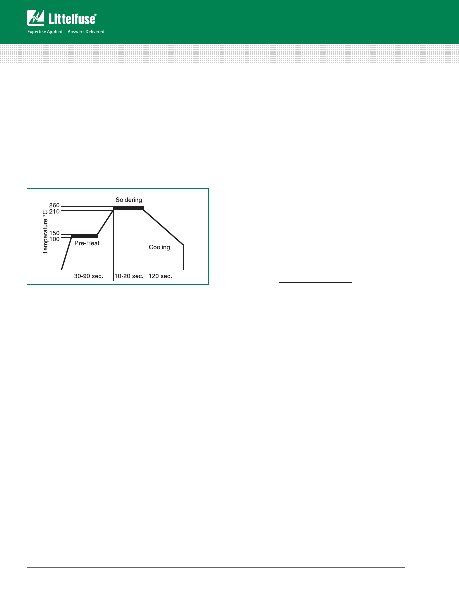
SOLDERING RECOMMENDATIONS:
Since most fuse
constructions incorporate soldered connections, caution
should be used when installing those fuses intended to
be soldered in place. The application of excessive heat can
reflow the solder within the fuse and change its rating.
Fuses are heat-sensitive components similar to semi-
conductors, and the use of heat sinks during soldering is
often recommended.
Lead-Free Soldering Parameters (most instances):
Wave Solder — 260ºC, 10 seconds max
Reflow Solder — 260ºC, 30 seconds max
TEST SAMPLING PLAN:
Because compliance with certain
specifications requires destructive testing, these tests are
selected on a statistical basis for each lot manufactured.
TIME-CURRENT CURVE:
The graphical presentation of
the fusing characteristic, time-current curves are generally
average curves which are presented as a design aid but
are not generally considered part of the fuse specification.
Time-current curves are extremely useful in defining
a fuse, since fuses with the same current rating can
be represented by considerably different time-current
curves. The fuse specification typically will include a life
requirement at 100% of rating and maximum opening
times at overload points (usually 135% and 200% of rating
depending on fuse standard characteristics). A time-current
curve represents average data for the design; how ever,
there may be some differences in the values for any one
given production lot. Samples should be tested to verify
performance, once the fuse has been selected.
UNDERWRITERS LABORATORIES:
Reference to “Listed
by Underwriters Laboratories” signifies that the fuses
meet the requirements of UL/CSA/ANCE 248-14 “Fuses
for Supplementary Overcurrent Protection”. Some 32
volt fuses (automotive) in this catalog are listed under
UL Standard 275. Reference to “Recognized under the
Component Program of Underwriters Laboratories”
signifies that the item is recognized under the component
program of Underwriters Laboratories and application
approval is required.
VOLTAGE RATING:
The voltage rating, as marked on a
fuse, indicates that the fuse can be relied upon to safely
interrupt its rated short circuit current in a circuit where the
voltage is equal to, or less than, its rated voltage.
This system of voltage rating is covered by N.E.C.
regulations and is a requirement of Underwriters
Laboratories as a protection against fire risk. The standard
voltage ratings used by fuse manufacturers for most small-
dimension and midget fuses are 32, 63, 125, 250 and 600.
In electronic equipment with relatively low output power
supplies, with circuit impedance limiting short circuit
currents to values of less than ten times the current rating
of the fuse, it is common practice to specify fuses with
125 or 250 volt ratings for secondary circuit protection of
500 volts or higher.
As mentioned previously (See RERATING section), fuses
are sensitive to changes in current, not voltage, maintaining
their “status quo” at any voltage up to the maximum rating
of the fuse. It is not until the fuse element melts and
arcing occurs that the circuit voltage and available power
become an issue. The safe interruption of the circuit, as it
relates to circuit voltage and available power, is discussed
in the section on INTERRUPTING RATING.
To summarize, a fuse may be used at any voltage that is
less than its voltage rating without detriment to its fusing
characteristics. Please contact the factory for applications
at voltages greater than the voltage rating.
DERIVATION OF NOMINAL MELTING I
2
t:
Laboratory
tests are conducted on each fuse design to determine the
amount of energy required to melt the fusing element. This
energy is described as nominal melting I
2
t and is expressed
as “Ampere Squared Seconds” (A
2
sec.).
A pulse of current is applied to the fuse, and a time
measurement is taken for melting to occur. If melting
does not occur within a short duration of about 8
milliseconds (0.008 seconds) or less, the level of pulse
current is increased. This test procedure is repeated until
melting of the fuse element is confined to within about 8
milliseconds.
The purpose of this procedure is to assure that the heat
created has insufficient time to thermally conduct away
from the fuse element. That is, all of the heat energy (I
2
t)
is used, to cause melting. Once the measurements of
current (I) and time (t) are determined, it is a simple matter
to calculate melting I
2
t. When the melting phase reaches
completion, an electrical arc occurs immediately prior to
the “opening” of the fuse element.
Clearing I
2
t = Melting I
2
t + arcing I
2
t
The nominal I
2
t values given in this publication pertain to
the melting phase portion of the “clearing” or “opening”.
Alternatively the time can be measured at 10 times of the
rated current and the I
2
t value is calculated like above.
Fuse Characteristics, terms and Consideration Factors (continued)
4
© 2014 Littelfuse • Fuseology Selection Guide
www.littelfuse.com
Fuseology Selection Guide
Fuse selection Checklist
The application guidelines and product data in this guide
are intended to provide technical information that will help
with application design. Since these are only a few of the
contributing parameters, application testing is strongly
recommended and should be used to verify performance in
the circuit/application.
Many of the factors involved with fuse selection are listed
below. For additional assistance with choosing fuses
appropriate to you requirements, contact your Littelfuse
products reprentative.
Selection Factors
1. Normal operating current
2. Application voltage (AC or DC)
3. Ambient temperature
4. Overload current and length of time in which the
fuse must open
5. Maximum available fault current
6. Pulses, Surge Currents, Inrush Currents, Start-up
Currents, and Circuit Transients
7. Physical size limitations, such as length, diameter,
or height
8. Agency Approvals required, such as UL, CSA, VDE,
METI, MITI or Military
9. Fuse features (mounting type/form factor, ease of
removal, axial leads, visual indication, etc.)
10. Fuseholder features, if applicable and associated
rerating (clips, mounting block, panel mount, PC
board mount, R.F.I. shielded, etc.)
11. Application testing and verification prior to
production
1. NORMAL OPERATING CURRENT:
The current rating
of a fuse is typically derated 25% for operation at 25ºC to
avoid nuisance blowing. For example, a fuse with a current
rating of 10A is not usually recommended for operation at
more than 7.5A in a 25ºC ambient. For additional details,
see RERATING in the previous section and AMBIENT
TEMPERATURE below.
2. APPLICATION VOLTAGE:
The voltage rating of the
fuse must be equal to, or greater than, the available circuit
voltage. For exceptions, see VOLTAGE RATING.
3. AMBIENT TEMPERATURE:
The current carrying
capacity tests of fuses are performed at 25ºC and will be
affected by changes in ambient temperature. The higher
the ambient temperature, the hotter the fuse will operate,
and the shorter its life. Conversely, operating at a lower
temperature will prolong fuse life. A fuse also runs hotter
as the normal operating current approaches or exceeds the
rating of the selected fuse. Practical experience indicates
fuses at
room temperature
should last indefinitely, if
operated at no more than 75% of catalog fuse rating.
Ambient temperature effects are in addition to the
normal re-rating, see example. Example: Given a normal
operating current of 1.5 amperes in an application using
a traditional Slo-Blo
®
fuse at room temperature, then:
Normal Operating Current
Catalog Fuse Rating = ——————————————————
0.75
- or -
1.5 Amperes
——————— = 2.0 Amp Fuse (at 25ºC)
0.75
Similarly, if that same fuse were operated at a very high
ambient temperature of 70°C, additional derating would
be necessary. Curve "A" (Traditional Slo-Blo
®
Fuse) of
that ambient temperature chart shows the maximum
operating "Percent of Rating" at 70°C to be 80%, in
which case;
Normal Operating Current
Catalog Fuse Rating = ——————————————————
0.75 x Percent of Rating
- or -
1.5 Amperes
——————— = 2.5 Amp Fuse (at 70ºC)
0.75 x 0.80
This charts shows typical ambient temperature effects on
current carrying capacity of Littelfuse products. For specific
re-rating information, please consult the product data sheet
at
www.littelfuse.com
or contact a Littelfuse representative.
Curve A: Thin-Film Fuses and 313 Series (.010 to .150A)
Curve B: FLAT-PAK
®
, TeleLink
®
, Nano
2®
, PICO
®
, Blade
Terminal and other leaded and catridge fuses
Curve C: Resettable PTC’s
5

Fuseology Selection Guide
©
2015 Littelfuse • Fuseology Selection Guide
www.littelfuse.com
4. OVERLOAD CURRENT CONDITION:
The current level
for which protection is required. Fault conditions may be
specified, either in terms of current or, in terms of both
current and maximum time the fault can be tolerated
before damage occurs. Time-current curves should be
consulted to try to match the fuse characteristic to the
circuit needs, while keeping in mind that the curves are
based on average data.
5. MAXIMUM FAULT CURRENT:
The Interrupting Rating
of a fuse must meet or exceed the Maximum Fault Current
of the circuit.
6. PULSES:
The general term “pulses” is used in this
context to describe the broad category of wave shapes
referred to as “surge currents”, “start-up currents”, “inrush
currents”, and “transients”. Electrical pulse conditions can
vary considerably from one application to another. Different
fuse constructions may not react the same to a given
pulse condition. Electrical pulses produce thermal cycling
and possible mechanical fatigue that could affect the life
of the fuse. Initial or start-up pulses are normal for some
applications and require the characteristic of a Slo-Blo
®
fuse. Slo-Blo
®
fuses incorporate a thermal delay design
to enable them to survive normal start-up pulses and still
provide protection against prolonged overloads. The start-
up pulse should be defined and then compared to the time-
current curve and I
2
t rating for the fuse. Application testing
is recommended to establish the ability of the fuse design
to withstand the pulse conditions.
Nominal melting I
2
t is a measure of the energy required
to melt the fusing element and is expressed as “Ampere
Squared Seconds” (A
2
Sec.). This nominal melting I
2
t,
and the energy it represents (within a time duration of
8 milliseconds [0.008 second] or less and 1 millisecond
[0.001 second]or less for thin film fuses), is a value that is
constant for each different fusing element. Because every
fuse type and rating, as well as its corresponding part
number, has a different fusing element, it is necessary to
determine the I
2
t for each. This I
2
t value is a parameter of
the fuse itself and is controlled by the element material
and the configuration of the fuse element. In addition
to selecting fuses on the basis of “Normal Operating
Currents”, “Rerating”, and “Ambient Temperature” as
discussed earlier, it is also necessary to apply the I
2
t
design approach. This nominal melting I
2
t is not only a
constant value for each fuse element design, but it is also
independent of temperature and voltage. Most often, the
nominal melting I
2
t method of fuse selection is applied to
those applications in which the fuse must sustain large
current pulses of a short duration. These high-energy
currents are common in many applications and are critical
to the design analysis.
The following example should assist in providing a better
understanding of the application of I
2
t.
EXAMPLE:
Select a 125V, very fast-acting PICO
®
II fuse that
is capable of withstanding 100,000 pulses of current (I) of
the pulse waveform shown in Figure 1.
The normal operating current is 0.75 ampere at an ambient
temperature of 25ºC.
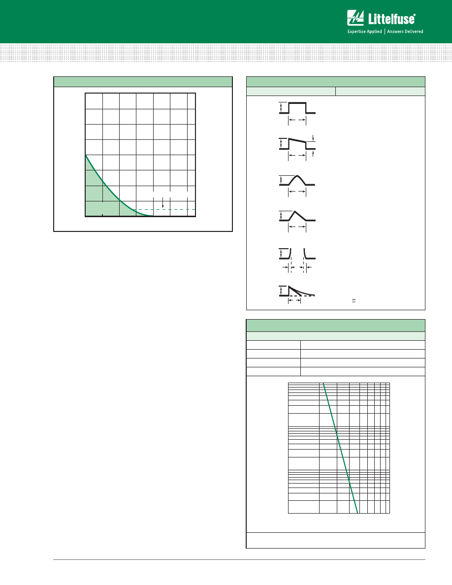
Step 1
— Refer to Chart 1 and select the appropriate
pulsewaveform, which is waveform (E) in this example.
Place the applicable value for peak pulse current (i
p
) and
time (t) into the corresponding formula for waveshape (E),
and calculate the result, as shown:
1
I
2
t = — (i
P
)
2
t
5
1
= —×8
2
×.004 = 0.0512 A
2
Sec.
5
This value is referred to as the “Pulse I
2
t”.
Step 2
— Determine the required value of Nominal Melting
I
2
t by referring to Chart 2. A figure of 22% is shown in
Chart II for 100,000 occurrences of the Pulse I
2
t calculated
in Step 1. This Pulse I
2
t is converted to its required value of
Nominal Melting I
2
t as follows:
Nom. Melt I
2
t = Pulse I
2
t/.22
0.0512/.22 = 0.2327 A
2
Sec.
Step 3
— Examine the I
2
t rating data for the PICO
®
II, 125V,
very fast-acting fuse. The part number 251001, 1 ampere
design is rated at 0.256 A
2
Sec., which is the minimum
fuse rating that will accommodate the 0.2327 A
2
Sec.
value calculated in Step 2. This 1 ampere fuse will also
accommodate the specified 0.75 ampere normal operating
current, when a 25% derating factor is applied to the 1
ampere rating, as previously described.
7. PHYSICAL SIZE LIMITATIONS:
Please refer to the
product dimensions presented in current Littelfuse product
data sheets for specific information.
8. AGENCY APPROVALS:
For background information
about common standards, please consult the STANDARDS
section of this guide or visit our Design Support web site
at
www.littelfuse.com/design-support.html
. For specific
agency approval information for each Littelfuse product,
please refer to the data sheets within this catalog and
information presented on
www.littelfuse.com
. As agency
approvals and standards may change, please rely on the
information presented on
www.littelfuse.com
as current
information.
9. FUSE FEATURES:
Please consult the specific product
features presented within this catalog and on our web
site at
www.littelfuse.com
. For additional information and
support contact your Littelfuse product representative.
Fuse Selection Checklist (continued)
6
© 2014 Littelfuse • Fuseology Selection Guide
www.littelfuse.com
Fuseology Selection Guide
.001
.002
.003
.004 .005
.006
Time (Seconds)
Cur
rent (Amperes)
Figure 1
2
4
6
8
10
Normal Operating Current
l t
Pulse
Energy
2
CHART 1
WAVESHAPES
FORMULAS
t
t
t
1
i
p
i
p
i
p
i
p
i
p
i
b
i
p
F
E
D
C
B
A
OR
t
t
t
t
i = k
I
2
t = i
p
2
t
i = i
p
-kt
I
2
t = (1/3)(i
p
2
+ i
p
i
b
+ i
b
2
) t
i = i
p
sin t
I
2
t = (1/2) i
p
2
t
I
2
t = (1/3) i
p
2
t
i = kt
2
OR i = i
p
(1-kt)
2
I
2
t = (1/5) i
p
2
t
i = i
p
e
–kt
)
I
2
t (1/2) i
p
2
t
1
CHART 2
PULSE CYCLE WITHSTAND CAPABILITY
100,000 Pulses
Pulse I
2
t = 22% of Nominal Melting I
2
t
10,000 Pulses
Pulse I
2
t = 29% of Nominal Melting I
2
t
1,000 Pulses
Pulse I
2
t = 38% of Nominal Melting I
2
t
100 Pulses
Pulse I
2
t = 48% of Nominal Melting I
2
t
100000
10000
1000
100
10%
100%
Number of P
ulses
Pulse I
2
t / Average Melting I
2
t
Note: Adequate time (10 seconds) must exist between pulse events
to allow heat from the previous event to dissipate.
10. FUSEHOLDER FEATURES AND RERATING:
For
information about the range of Littelfuse fuseholders and
specific features and characteristics, please consult with
a Littelfuse products representative or visit our web site
(
www.littelfuse.com
).
For 25ºC ambient temperatures, it is recommended that
fuseholders be operated at no more than 60% of the
nominal current rating established using the controlled test
conditions specified by Underwriters Laboratories. The
primary objective of these UL test conditions is to specify
common test standards necessary for the continued
control of manufactured items intended for protection
against fire, etc. A copper dummy fuse is inserted in
the fuseholder by Underwriters Laboratories, and then
the current is increased until a certain temperature rise
occurs. The majority of the heat is produced by the contact
resistance of the fuseholder clips. This value of current
is considered to be the rated current of the fuseholder,
expressed as 100% of rating. Some of the more common,
everyday applications may differ from these UL test
conditions as follows: fully enclosed fuseholders, high
contact resistance,air movement, transient spikes, and
changes in connecting cable size (diameter and length).
Even small variations from the controlled test conditions
can greatly affect the ratings of the fuse-holder. For
this reason, it is recommended that fuseholders be
derated by 40% (operated at no more than 60% of the
nominal current rating established using the Underwriter
Laboratories test conditions, as previously stated).
11. TESTING:
The factors presented here should be
considered in selecting a fuse for a given application. The
next step is to verify the selection by requesting samples
for testing in the actual circuit. Before evaluating the
samples, make sure the fuse is properly mounted with
good electrical connections, using adequately sized wires
or traces. The testing should include life tests under normal
conditions and overload tests Under fault conditions, to
ensure that the fuse will operate properly in the circuit.
FIGURE 1
Fuse selection Checklist (continued)
7
Fuseology Selection Guide
©
2014 Littelfuse • Fuseology Selection Guide
www.littelfuse.com
Overcurrent circuit protection can be accomplished
with the use of either a traditional fuse or PTC (positive
temperature coefficient) device.
PTCs are typically used in a wide variety of telecom,
computer, consumer electronics, battery and medical
electronics product applications where overcurrent events
are common and automatic resettability desired.
Littelfuse offers PTCs with the following general forms and
features, and come in a variety of sizes and capacities:
Surface Mount Devices:
• A full range of compact footprints
• Low hold current
• Very fast trip time
• Low resistance
Radial Leaded Series:
• Protection devices up to 600Vdc
• A very high hold current
• Low trip-to-hold current ratio
• Low resistance.
Battery Strap Devices:
• A narrow low profile design
• A weldable band Nickel terminal
• Low resistance–for extended battery run time
If your application requirements fall outside of our product
range, in certain instances we can offer customized
solutions. Please contact Littelfuse for more information.
Traditional Fuses Vs. PTCs
Fuses and PTCs are both overcurrent protection
devices, though each offer their own unique operating
characteristics and benefits. Understanding the differences
between the two technologies should make the choice in
selection easier, depending on the application.
The most obvious difference is that PTCs are automatically
resettable whereas traditional Fuses need to be replaced
after they they are tripped. Whereas a fuse will completely
stop the flow of current (which may be desired in critical
applications) after most similar overcurrent event, PTCs
continue to enable the equiment to function, except in
extreme cases.
Because they reset automatically, many circuit designers
choose PTCs in instances where overcurrent events are
expected to occur often, and where maintaining low
warranty and service costs, constant system uptime, and/
or user transparency are at a premium. They are also often
chosen in circuits that are difficult to access or in remote
locations, were fuse replacement would be difficult.
There are several other operating characteristics to be
considered that distinguish PTCs and fuses, and it is also
best to test and verify device performance before use
within the end application.
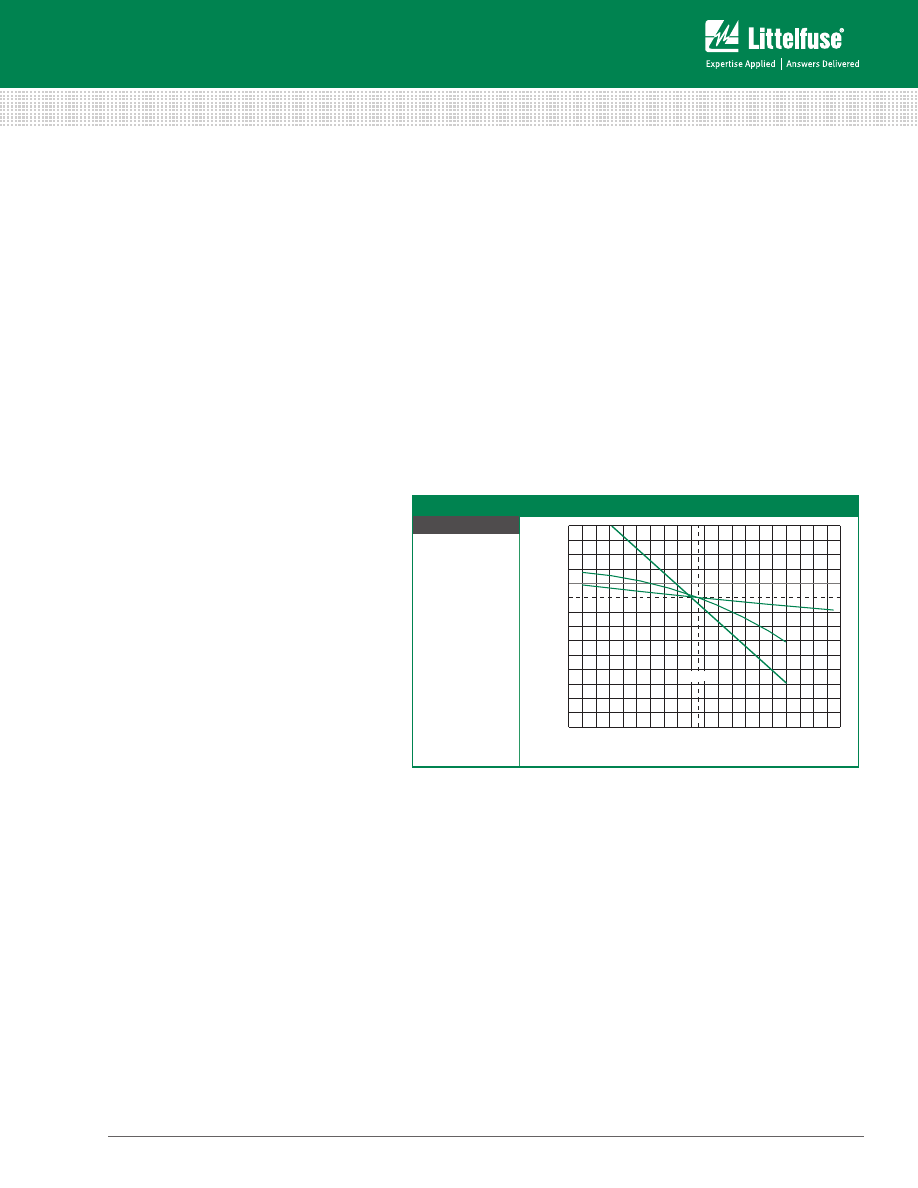
Littelfuse PTC Characteristics
Both Polymeric (Positive Temperature Coefficient) PTC
and traditional Fuse devices react to heat generated by
the excessive current flow in a circuit. A fuse melts open,
interrupting the current flow whereas a PTC limits current
flow as it rises in temperature, changing from low to high
resistance state. In both
cases this condition is
called "tripping." The
graph at right shows the
typical response of a
PTC to temperature.
Littelfuse Polymer PTCs
are made chiefly of high
density polyethylene
mixed with graphite.
During an overcurrent
event, a Polymer PTC
will heat and expand, which in turn causes the conducting
particles to break contact and stop the current.
The general procedure for resetting the device after an
overload has occurred is to remove power and allow the
device to cool down.
Log resistance (ohms)
Temperature (C)
Trip Point
PtC Characteristics and terms
To view a short online tutorial on using the Littelfuse
iDesign tool, visit: http://vimeo.com/90118164
Littelfuse iDesign
TM
Online Fuse Design
and Selection Tool
8
© 2014 Littelfuse • Fuseology Selection Guide
www.littelfuse.com
Fuseology Selection Guide
Leakage Current:
When a PTC is in a "tripped state" it
protects the circuitry by limiting the current flow to a low
leakage level. Leakage current can range from less than
a hundred milliamps (mA) at rated voltage up to a few
hundred milliamps (mA) at lower voltages. Fuses on the
other hand completely interrupt the current flow when
tripped, and this open circuit results in no leakage current
when subjected to an overload current.
Interrupting Rating:
PTCs are rated for a maximum
short circuit current at rated voltage also known as
"breaking capacity" or Imax. This fault current level is the
maximum current that the device can withstand safely,
keeping in mind that the PTC will not actually interrupt
the current flow (see Leakage Current above). A typical
Littelfuse PTC short circuit rating is 40A; or for the battery
strap PTCs, this value can reach 100A. Fuses do in fact
interrupt the current flow in response to the overload
and the range of interrupting ratings, vary from tens of
amperes (A) up to 10,000 (A) amperes at rated
voltage.
Operating Voltage Rating:
General use
Littelfuse PTCs are not rated above 60V while
fuses are rated up to 600V.
Hold Current Rating:
The hold (operating)
current rating for PTCs can be up to 14A, while
the maximum level for fuses can exceed 30A.
Resistance
:
Reviewing product
specifications indicates that similarly rated
PTCs have about twice (sometimes more) the
resistance of fuses.
Agency Approvals:
Littelfuse PTCs
are Recognized under the Component Program of
Underwriters Laboratories to UL Standard 1434 for
Thermistors. The devices have also been certified under
the CSA Component Acceptance Program.
Time-Current Characteristic
:
Comparing the time-
current curves of PTCs to time-current curves of fuses
show that the speed of response for a PTC is similar to the
time delay of a Littelfuse Slo-Blo® fuse.
Temperature Rerating:
The useful upper limit for a
PTC is generally 85ºC, while the maximum operating
temperature for fuses is 125ºC.
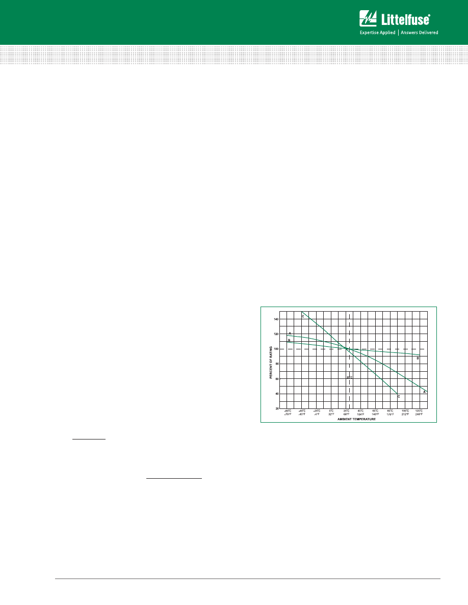
Ambient temperature effects are in addition to the normal
rerating. PTCs hold and trip rating must be rerated when
applied at conditions other than room ambient. For
example, any rise in ambient temperature will decrease the
hold current rating as well as the trip current. A reduction in
ambient temperature will increase the trip current as well
as the hold current.
The temperature rerating curves in the table below
compare PTCs to fuses and illustrate that more rerating is
required for a PTC at a given temperature.
Temperature Rerating Curves Comparing PTCs to Fuses
Chart Key
Curve A
Thin-Film Fuses and 313
Series (.010 to .150A)
Curve B
FLAT-PAK
®
, Nano
2®
,
PICO
®
, Blade Terminal,
Special Purpose and
other leaded and
cartridge fuses
(except 313.010 – .150A)
Curve C
Resettable PTCs
-60°C
-76°F
20
40
60
80
100
120
140
-40°C
-40°F
-20°C
-4°F
25°C
C
C
A
B
AMBIENT TEMPERATURE
PERCENT OF RA
TING
A
B
0°C
32°F
20°C
68°F
40°C
104°F
60°C
140°F
80°C
176°F
100°C
212°F
120°C
248°F
PtC Characteristics and terms (continued)
9

Fuseology Selection Guide
©
2014 Littelfuse • Fuseology Selection Guide
www.littelfuse.com
Surface Mount
raDIaL LeaDeD
Battery Strap
Series name
LoRho 0603L 0805L 1206L 1210L 1812L 2016L 2920L 250s usbR
16R
30R
60R
72R
250R 600R
LR
LR
Lt
st
VL
Vt
Telecom
application
ul60950 ,tiA-968-A, gR-1089 Req’s
X
X
X
itu-t Recoomendations
X
X
X
CPe (Customer Premises equipment)
X
X
X
Analog Line Card
X
X
X
t1/e1/J1 And hdsL
X
X
X
isdN
X
X
X
AdsL
X
X
X
Cable telephony
X
X
X
PbX/Kts And Key telephone system
X
X
X
Comput
er
CPu
X
X
X
usb
X
X
X
X
X
X
X
X
ieee1284 Parallel data bus
X
X
X
X
X
ieee 802.3
X
X
X
X
ieee 1394
X
X
X
i/o Ports
X
X
X
X
X
X
X
PC Card
X
X
X
X
X
X
X
X
X
sCsi
X
X
X
X
X
X
Video Port
X
X
X
X
X
X
LCd Monitor
X
X
X
X
X
X
X
X
Consumer
Electr
onics
set top box
X
X
X
X
Loudspeaker
X
smart Card Reader
X
Mobile Phone
X
X
X
X
X
Linear AC/dC Adapter
X
X
X
X
X
X
X
X
X
X
Portable electronic input Port
X
X
X
X
X
X
X
electromagnetic Loads, Motor
X
X
X
X
X
solenoid Protection
X
X
X
X
X
Bat
tery
Lithium Cell
X
X
X
X
X
X
battery Pack
X
X
X
X
X
X
Medical
electr
onic
Voltage / Current input terminal
X
X
Note: the application summary is for reference only. determination of suitability for a specific application is the responsibility of the customer.
PTCs are typically used as circuit protection in applications
where sensitive components are at constant risk of
damage from overcurrent conditions. The ability of PTCs to
reset themselves after exposure to a fault current makes
them ideal within circuits that are not easily accessible to a
user or technician or where constant uptime is required.
Typical applications include port protection on personal
computers (USB, Firewire, keyboard/mouse, and serial
ports), peripherals (hard drives, video cards, and hubs), cell
phone, battery packs, industrial controls, lighting ballast
and motor controls.
The chart below is meant as a quick guide in narrowing to
a Littelfuse PTC device that may be appropriate to certain
end applications.
For detailed application assistance please contact a
Littelfuse product specialist or visit our new reference
design center at
www.littelfuse.com/designcenter
.
For detailed product specifications, please consult the
Littelfuse PTC datasheets within this catalog or visit
www.littelfuse.com/PTCs.
PtC Product Applications
Littelfuse Electronics eCatalogs includes the latest standards, products, diagrams and videos in a new interactive
format. View the eBook on your mobile device, tablet or desktop for easy access to Littelfuse products, technologies
and technical resources. Quickly order free product samples, request more information and download datasheets all
within the new user-friendly design.
10
© 2014 Littelfuse • Fuseology Selection Guide
www.littelfuse.com
Fuseology Selection Guide
Outside
Wo
rl
d
D+
D -
VBU
Signal
Ground
Shield
Ground
(2) V0402MHS03
1206L150
USB Port
USB Controller
V5.5MLA0603
PTC
Cell Phone
Battery -
Control
Battery +
Signal
Ground
Shield
Ground
Battery Connector
Battery Controller IC
(3) V5.5MLA0402
(Multilayer
Varistor)
PTC
Outside
Wo
rl
d
D+
D -
VBUS
Signal
Ground
Shield
Ground
1206L150
USB Port
USB Controller
V5.5MLA063
(2) PGB1010603
(PulseGuard
®
ESD Suppressor)
PTC
Telco
Tip
Signal
Ground
RJ11 Connector
Tx/Rx Circuits
SMD/leaded
SIDACtor
®
Device
Ring
PTC
600R Series
250R Series
Outside W
orld
TPA+
TPA-
VBU
Signal
Ground
Shield
Ground
1812L110/33
1394 Port
1394 Controller
V33MLA1206
(4) PGB1010603
(PulseGuard
®
ESD Suppressor)
TPB+
TPB-
PTC
Data Pair
Data Pair
Data Pair
Data Pair
Power Source
Equipment
(PSE)
Powered
Device
(PD)
Switch/Hub
Powered End Station
PTC
POWER OVER ETHERNET
LI-ION BATTERY PACK
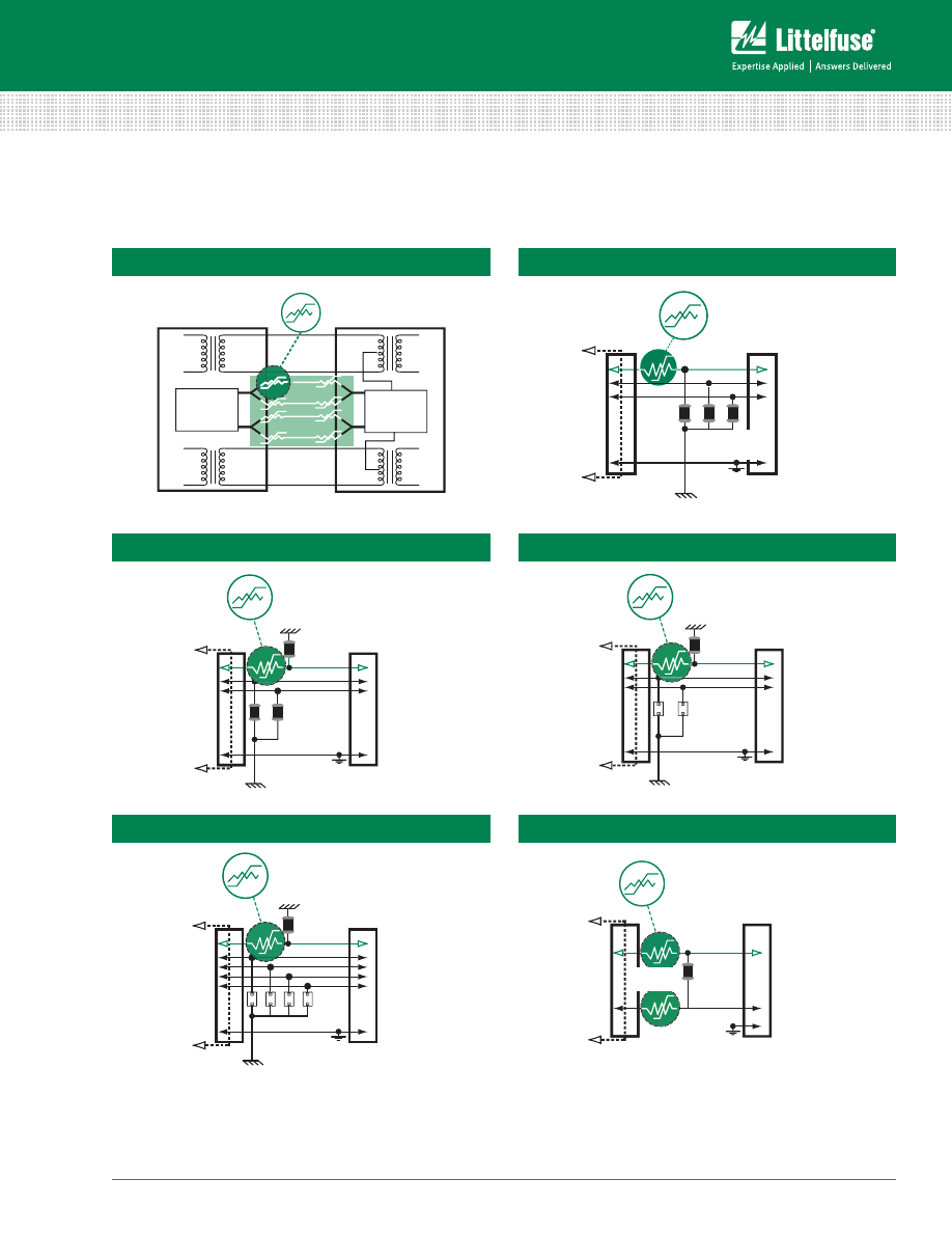
The following are examples of typical circuits using
Littelfuse PTCs in combination with other Littelfuse circuit
protection devices to provide a comprehensive protection
solution. Contact a Littelfuse application expert for design
assistance or visit
www.littelfuse.com/designcenter
or
www.littelfuse.com/PTCs
for additional information.
Be sure to to veryify specifications and test device
performance before use in the end application.
USB 1.1
USB 2.0
IEEE 1394 - FIREWIRE
TIP/RING CIRCUIT - METALLIC
typical PtC Circuit Protection designs
11
Fuseology Selection Guide
©
2014 Littelfuse • Fuseology Selection Guide
www.littelfuse.com
Littelfuse is at your service to help solve your electrical
protection problems. When contacting Littelfuse sales
engineers, please have all the requirements of your
applications available. Requests for quotes or assistance
in designing or selecting special types of circuit protection
components for your particular applications are also
welcome. In the absence of special requirements,
Littelfuse reserves the right to make appropriate changes
in design, process, and manufacturing location without
prior notice.
Fuse ratings and other performance criteria are evaluated
under laboratory conditions and accptance criteria, as
defined in one or more of the various fuse standards. It is
important to understand these standards so that the fuse
can be properly applied to circuit protection applications.
UL/CSA/ANCE (Mexico) 248-14 FUSES FOR
SUPPLEMENTARY OVERCURRENT PROTECTION (600 Volts,
Maximum) (Previously UL 198G and CSA C22.2, No. 59)
UL LISTED
A UL Listed fuse meets all the requirements of the UL/
CSA/ANCE 248-14 Standard. Following are some of the
requirements. UL ampere rating tests are conducted at
100%, 135%, and 200% of rated current. The fuse must
carry 100% of its ampere rating and must stabilize at a
temperature that does not exceed a 75ºC rise.
The fuse must open at 135% of rated current within one
hour. It also must open at 200% of rated current within 2
minutes for 0-30 ampere ratings and 4 minutes for 35-60
ampere ratings.
The interrupting rating of a UL Listed fuse is 10,000
amperes AC minimum at 125 volts. Fuses rated at 250
volts may be listed as interrupting 10,000 amperes at 125
volts and, at least, the minimum values shown below at
250 volts.
Ampere Rating of
Fuse
Interrupting Rating
In Amperes
Voltage Rating
0 to 1
35
250 VAC
1.1 to 3.5
100
250 VAC
3.6 to 10
200
250 VAC
0.1 to 15
750
250 VAC
15.1 to 30
1500
250 VAC
Recognized Under the Component Program of
Underwriters Laboratories
The Recognized Components Program of UL is different
from UL Listing. UL will test a fuse to a specification
requested by the manufacturer. The test points can be
different from the UL Listed requirements if the fuse
has been designed for a specific application. Application
approval is required by UL for fuses recognized under the
Component Program.
standards
UL 275 AUTOMOTIVE GLASS TUBE FUSES (32 Volts)
UL LISTED
UL ampere ratings tests are conducted at 110%, 135%,
and 200%. Interrupting rating tests are not required.
CSA Certification
CSA Certification in Canada is equivalent to UL Listing in
the United States.
The Component Acceptance Program of CSA is
equivalent to the Recognition Program at UL.
METI (Japan Ministry of Economy, Trade and Industry)
PS
E
METI APPROVAL
METI approval in Japan is similar to UL Recognition in the
United States.
METI
B
has its own design standard and characteristics.
INTERNATIONAL ELECTROTECHNICAL
COMMISSION (IEC)
Publication 60127, Parts 1, 2, 3, 4, 6
The IEC organization is different from UL and CSA, since
IEC only writes specifications and does not certify. UL
and CSA write the specifications, and are responsible for
testing and certification.
Certification to IEC specifications are given by such
organizations as SEMKO (Swedish Institute of Testing
and Approvals of Electrical Equipment) , BSI (British
Standards Institute) and VDE (German Standard Insitute)
E
D
V
, as well as UL and CSA.
IEC Publication 60127 defines three breaking capacity
levels (interrupting rating). Low breaking capacity fuses
must pass a test of 35 amperes or ten times rated current,
whichever is greater, while enhanced breaking capacity
fuses must pass a test of 150 amperes and high breaking
capacity fuses must pass a test of 1500 amperes.
60127 Part 2
Sheet 1
— Type F Quick Acting, High Breaking Capacity
Sheet 2
— Type F Quick Acting, Low Breaking Capacity
Sheet 3
— Type T Time Lag, Low Breaking Capacity
Sheet 4
— Style Fuses 1/4×1 1/4
Sheet 5
— Type T Time Lag, High Breaking Capacity
Sheet 6
— Type T Time Lag, Enhanced Breaking Capacity
The letters ‘F’ and ‘T’ represent the time-current
characteristic
of the fast-acting and time delay fuses. One
of these letters will be marked on the end cap of the fuse.
12
© 2014 Littelfuse • Fuseology Selection Guide
www.littelfuse.com
Fuseology Selection Guide
UL/CSA/ANCE (Mexico) 248-14 vs. IEC 60127 Part 2 FUSE
OPENING TIMES vs. METI/MITI
Percent of
Rating
uL & CsA
std 248-14
ieC tYPe F
sheet 1 (*)
ieC tYPe F
sheet 2 (*)
ieC tYPe t
sheet 3 (*)
ieC tYPe t
sheet 5 (*)
Meti/Miti
100
4Hr.Min.
—
—
—
—
130
—
—
—
—
—
1Hr.Min.
135
60 Minutes
Max.
—
—
—
—
150
—
60 Minutes
Min.
60 Minutes
Min.
60 Minutes
Min.
60 Minutes
Min.
160
—
—
—
—
—
1Hr.Max.
200
2 Minutes
Max.
—
—
—
—
2 Minutes
Max.
210
—
30 Minutes
Max.
30 Minutes
Max.
2 Minutes
Max.
30 Minutes
Max.
(*) Note: The IEC Specification is written up to
10.0A. Any components above these ratings are
not recognized by the IEC (although the fuses
may have similar opening characteristics).
IEC also has opening time requirements at 275%, 400%
and 1000%; however, the chart is used to show that
fuses with the same ampere rating made to different
specifications are not interchangeable. According to the
IEC 60127 Standard, a one ampere-rated fuse can be
operated at one ampere. A one ampere-rated fuse made to
UL/CSA/ANCE 248-14 should not be operated at more than
.75 ampere (25% derated — See RERATING section).
METI
B
does not differentiate between fast acting and time
delay characteristics.
Publication IEC 60127-4 (Universal Modular Fuse-Links
[UMF])
This part of IEC 60127-4 covers both PCB through-hole
and surface mount fuses. This standard covers fuses rated
32, 63, 125, and 250 volts. This standard will be accepted
by UL/CSA making it the first global fuse standard. This
specification uses different fusing gates than IEC 60127-2;
the gates used here are 125%, 200%, and 1000%.
The fuses must not open in less than one hour at 125%
of rated current and open within two minutes at 200% of
rated current. The 1000% overload is used to determine
the fuse characteristic. The opening time for each rating is
listed below.
Type FF : Less than 0.001 sec.
Type F : From 0.001 - 0.01 sec.
Type T : From 0.01 - 0.1 sec.
Type TT : From 0.1 - 1.00 sec.
These characteristics correlate to the terminology used in
IEC 60127-1.
Breaking capacity (interrupting rating) varies based on
voltage rating. Parts rated at 32 & 63 volts must pass a
test of 35 amperes or ten times rated current, whichever
is greater. Parts rated at 125 volts must pass a test of 50
amperes or ten times rated current, whichever is greater.
Parts rated at 250 volts are further defined as either low,
intermediate or high breaking. The low breaking capacity
fuses must pass a test of 100 amperes rated current, while
intermediate breaking capacity fuses must pass a test of
500 amperes and high breaking capacity fuses must pass a
test of 1500 amperes.
MILITARY/FEDERAL STANDARDS
MIL-PRF-15160 and MIL-PRF-23419
These specifications govern the construction and
performance of fuses suitable primarily for military
electronic applications.
MIL-PRF-19207
This specification governs the construction and
performance of fuseholders suitable for military
applications.
DSSC Drawing #87108
This drawing governs the construction and performance
of .177” × .570” (2AG size) cartridge fuses and axial lead
versions suitable for military applications. DSSC #87108
designation is included in the fuse end cap marking.
standards (continued)
A robust web-based tool to help circuit designers
identify the optimal electronic fuses for their products.
To use the Littelfuse iDesign tool, simply register to
create a free online account at the iDesign Login.
13

Fuseology Selection Guide
©
2014 Littelfuse • Fuseology Selection Guide
www.littelfuse.com
MILITARY/FEDERAL STANDARDS
FEDERAL SPECIFICATION W-F-1814
This specification governs the construction and
performance of fuses with high interrupting ratings that are
approved for federal applications. Fuses approved to these
specifications are on the Federal Qualified Products List.
Write to the following agencies for additional information
on standards, approvals, or copies of the specifications.
Underwriters Laboratories Inc. (UL)
333 Pfingsten Road
Northbrook, Illinois, USA 60062-2096
Canadian Standards Association (CSA)
5060 Spectrum Way, Suite 100
Mississauga, Ontario, Canada L4W 5N6
International Electrotechnical Commission (IEC)
3, Rue de Varembe
1211 Geneva 20, Switzerland
Naval Publications and Military StandardsForm
Center (for Military and Federal Standards)
5801 Tabor Avenue
Philadelphia, Pennsylvania, USA 19120
Defense Supply Center Columbus (DSCC)
3990 East Broad Street
Columbus, Ohio, USA 43218-3990
Ministry of Economy Trade and Industry (METI)
1-3-1 Kasumigaseki
Chiyouda-ku, Tokyo 100-8901, Japan
standards (continued)
14

© 2014 Littelfuse • Fuseology Selection Guide
www.littelfuse.com
Fuseology Selection Guide
1. Define the circuit operating parameters.
Normal operating current in amperes:
....................................................................................................
Normal operating voltage in volts:
....................................................................................................
Maximum interrupt current:
....................................................................................................
Ambient
temperature: ....................................................................................................
Typical overload current:
....................................................................................................
Required opening time at specified overload:
....................................................................................................
Transient pulses expected:
....................................................................................................
Agency
approvals:
....................................................................................................
Mounting type/form factor:
....................................................................................................
Typical resistance (in circuit):
....................................................................................................
2. Select the proper circuit protection component.
(
Refer to Table on Page 3 and specifications with Data Sheets
)
3. Determine the opening time at fault.
Consult the Time-Current (T-C) Curve of each PTC series to determine if the
selected part will operate within the constraints of your application.
If the device opens too soon, the application may experience nuisance
operation. If the device does not open soon enough, the overcurrent may
damage downstream components.
To determine the opening time for the chosen device, locate the overload
current on the X-axis of the appropriate T-C Curve and follow its line up to its
intersection with the curve. At this point read the time tested on the Y-axis.
This is the average opening time for that device.
If your overload current falls to the right of the curve the device will open.
If the overload current is to the left of the curve, the device will not operate.
4. Verify ambient operating parameters.
Ensure that the application voltage is less than or equal to the device’s rated
voltage and that the operating temperature limits are within those specified
by the device.
5. Verify the device’s dimensions.
Compare the maximum dimensions of the device to the space available in
the application. The dimension of each product is included within each data
sheets on the following pages.
6. Test the selected product in an actual application.
PtC selection Worksheet
A robust web-based tool to help circuit designers
identify the optimal electronic fuses for their products.
Littelfuse iDesign
TM
Online Fuse Design and Selection Tool
15
Fuseology Selection Guide
©
2014 Littelfuse • Fuseology Selection Guide
www.littelfuse.com
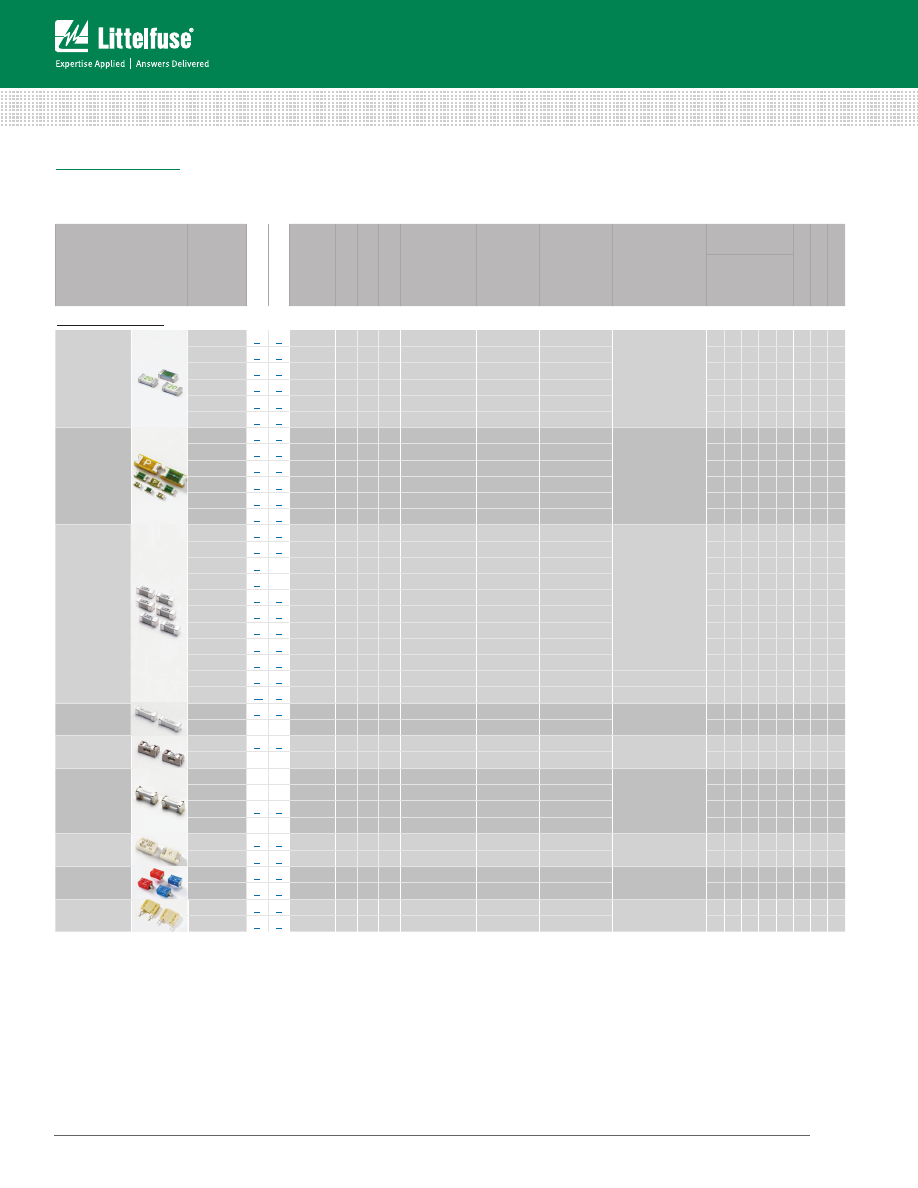
Fuse and PtC Products selection guide
Fuse PRoduCts
Fuses provide protection by completely stopping the flow of energy to sensitive circuits. If current exceeds the fuse’s operating range, the metal
wire or strip melts safely within an enclosure. Littelfuse offers the most extensive range of fuses available, and for easy replacement of cartridge
fuses Littelfuse offers a wide selection of fuseholders including panel mount, in-line, and surface and thru-hole circuit board mount devices.
Series
Name
1
Vie
w Dat
asheet
Order Samples
Size
2
Time Lag
Fast A
cting
Ver
y
Fast A
cting
Device Range
3
(Operating
Current Options
in Amps)
Max. Voltage
Rating
3
(Volts)
Interrupting
Rating at
Max. Voltage
Rating
3
(Amps)
Operating
Temperature
Range
Agency
Approvals
3
Halogen F
ree
R
oHS Compliant
Lead F
ree
UL
UR
C
SA
PSE
UMF
Surface Mount:
Ceramic Chip
437
•
•
1206
•
0.25 - 8
125 / 63 / 32
50
-55°C to +150°C
•
• • •
438
•
•
0603
•
0.25 - 6
32 / 24
50
•
• • •
440
•
•
1206
•
1.75 - 8
32
50
• •
• • •
441
•
•
0603
•
2 - 6
32
50
• •
• • •
469
•
•
1206
•
1 - 8
24 / 32
24 - 63
• •
• • •
501
•
•
1206
•
10, 12, 15, 20
32
150
•
• • •
Thin Film
466
•
•
1206
•
0.125 - 5
125 / 63 / 32
50
-55°C to +90°C
• •
• •
429
•
•
1206
•
7
24
35
• •
• •
468
•
•
1206
•
0.5 - 3
63 / 32
35 - 50
• •
• • •
467
•
•
0603
•
0.25 - 5
32
35 - 50
• •
• • •
494
•
•
0603
•
0.25 - 5
32
35 - 50
• •
• • •
435
•
•
0402
•
0.25 - 5
32
35
• •
• • •
Nano
2®
Fuse
448
•
•
2410
•
0.062 - 15
125 / 65
35 - 50
-55°C to +125°C
• • •
• •
449
•
•
2410
•
0.375 - 5
125
50
• • •
• •
451 / 453
•
2410
•
0.062 - 15
125 / 65
35 - 50
• • • •
• •
452 / 454
•
2410
•
0.375 - 12
125 / 72
50
• • •
• •
456
•
•
4012
•
20, 25, 30, 40
125
100
•
• •
458
•
•
1206
•
1.0 - 10
75 / 63
50
•
• •
443
•
•
4012
•
0.5 - 5
250
50
•
• •
464
•
•
4818
•
0.5 - 6.3
250
100
• • • •
465
•
•
4818
•
1 - 6.3
250
100
• • • •
462
•
•
4118
•
0.500 - 5
350
100
-40°C to +80°C
•
•
•
485
•
•
4818
•
0.500 - 3.15
600
100
-55°C to +125°C
•
• •
Telelink
®
Fuse
461
•
•
4012
0.5 - 2.0
600
60
-55°C to +125°C
• •
• •
461E
4012
1.25
600
60
•
• •
OMNI-BLOK
®
Fuseholder
154
•
•
*
•
0.062 - 10.0
125
35 - 50
-55°C to +125°C
•
• •
154T
*
•
0.375 - 5
125
50
•
• •
Fuse and Clip
Assemblies
157
*
•
0.062 - 10
125
35 - 50
-55°C to +125°C
•
• •
157T
*
•
0.375 - 5
125
50
•
• •
159
•
•
*
0.5 - 2
600
60
•
• •
160
*
•
0.5 - 5
250
50
•
• •
PICO
®
SMF
Fuse
459
•
•
*
•
0.062 - 5
125
50 - 300
-55°C to +125°C
• •
460
•
•
*
•
0.5 - 5
125
50
• •
Flat Pak
202
•
•
*
•
0.062 - 5
250
50
-55°C to +125°C
• •
203
•
•
*
•
0.25 - 5
250
50
• •
EBF
446
•
•
*
•
2.0 - 10.0
350
100
-40°C to +125°C
• •
447
•
•
*
•
2.0 - 10.0
350
100
• •
tAbLe CoNtiNues oN NeXt PAge
(1) Detailed information about most product series listed here can be found on our web site.
(2) Size for these surface mount items refers to common industry length and width dimensions of the device surface area. Example: 0402 = .04” x .02”
(3) In some cases for these categories the ratings, agency approvals and specifications vary by part number and are presented here as ranges representing the whole series.
Please refer to product data on www.littelfuse.com and in our data sheets for detailed information by part number.
* Please refer to data sheet for detailed specifications.
16
Series
Name
1
View Datasheet
Order Samples
Time Lag
Medium Acting
Fast Acting
Very Fast Acting
Device
Range
3
(Operating
Current
Options in
Amps)
Max. Voltage
Rating
3
(Volts)
Interrupting
Rating at
Max Voltage
Rating
3
(Amps)
Operating
Temperature
Range
Agency Approvals
3
RoHS Compliant
Lead Free
Americas
Europe
Asia
UL
UR
CSA
QPL
UMF
CE
VDE
TUV
BSI
Semko
PSE
K
CCC
CQC
Radial Leaded / Socket:
Micro
™
Fuse /
TR3 Fuse
262/268
• ••
•
0.002 - 5
125
10,000
-55°C to +125°C
• •
•
269
•
•
0.002 - 5
125
10,000
-55°C to +125°C
• • •
•
272/278
• ••
•
0.002 - 5
125
10,000
-55°C to +125°C
• •
•
273/279
• ••
•
0.002 - 5
125
10,000
-55°C to +85°C
• •
•
274
•
•
0.002 - 5
125
10,000
-55°C to +85°C
•
•
303
• •
•
0.5 - 5
125
50
-55°C to +70°C •
•
•
• •
TR5
®
Fuse
370
• •
•
0.4 - 6.3
250
35 - 50
-40°C to +85°C
•
• •
• •
•
• •
372
• •
•
0.4 - 6.3
250
35 - 50
•
• •
• • • • • • •
373
• •
•
0.5 - 10
250
50
•
•
•
• •
374
• •
•
0.5 - 10
250
50
•
•
•
• •
382
• •
•
1 - 10
250
100
•
• •
• • • • • • •
383
• •
•
1 - 10
300
50 - 100
•
• •
•
• •
TE5
369
• •
•
1 - 6.3
300
50
-40°C to +85°C
•
•
•
• •
385
• •
•
0.35 - 1.5
125
50
•
•
• •
391
• •
•
0.125 - 4
65
50
•
•
• •
392
• •
•
0.8 - 6.3
250
25 - 63
•
• •
• • •
• • •
395
• •
•
0.05 - 6.3
125
100
•
•
•
•
396
• •
•
0.05 - 6.3
125
100
•
•
•
• •
397
• •
•
0.35 - 1.5
125
50
•
•
• •
398
• •
•
0.125 - 4
65
50
•
•
• •
399
• •
•
0.125 - 4
65
50
•
•
• •
400
• •
•
0.5 - 6.3
250
130
•
• •
•
• •
804
• •
•
0.8 - 6.3
250
150
-40°C to +125°C
• • •
• •
• • •
808
• •
•
2 - 5
250
100
-40°C to +85°C
•
•
• •
TE7
807
• •
•
0.8 - 6.3
300
100
-40°C to +125°C • • •
•
• •
• •
Axial Leaded / Cartridge:
PICO
®
Fuse /
PICO
®
II
Fuse Axial
251
• •
•
0.062 - 15
125
300DC / 50AC
-55°C to +125°C
• •
•
•
•
•
253
• •
•
0.062 - 15
125
300DC / 50AC
•
•
•
•
•
275
• •
•
20 - 30
32
300DC / 50AC
• •
•
263
• •
•
0.062 - 5
250
50
• •
•
•
•
471
• •
•
0.5 - 5
125
50
• •
•
•
•
472
• •
•
0.5 - 5
125
50
•
•
•
473
• •
•
0.375 - 7
125
50
• •
•
•
•
265/266/267
• •••
•
0.062 - 15
125
300DC / 50AC
• • •
•
•
3.6x10 mm
874
• •
•
0.1 - 10
250
50
-55°C to +125°C
•
•
• •
875
• •
•
0.1 - 10
250
50
•
•
• •
876
• •
•
0.125 - 5
250
35 - 50
•
• •
• •
877
• •
•
2 - 6.3
250
35 - 63
•
• •
• •
4.5x14.5
mm
(2AG)
208
• •
•
0.125 - 10
350
100
-55°C to +125°C
•
•
•
•
• •
209
• •
•
0.25 - 7
350
100
•
•
•
•
• •
220
• •
Special Fuse
0.3 - 7
250 / 300 / 350
35 - 100
• • •
•
•
• •
2205
• •
•
0.25 - 2.5
250
35
• •
•
• •
224/225
• ••
•
0.375 - 10
250 / 125
35 - 500
• • •
•
•
• •
229/230
• ••
•
0.25 - 7
250 / 125
35 - 400
• • •
•
•
• •
5x20
mm
217
• •
•
0.032 - 15
250
35 - 150
-55°C to +125°C
• •
• •
• • • • •
• •
218
• •
•
0.032 - 16
250
35 - 100
• •
• •
• • • • •
• •
213
• •
•
0.2 - 6.3
250
35 - 63
• •
• •
• • •
•
• •
219XA
• •
•
0.04 - 6.3
250
150
• •
• •
• • •
•
• •
216
• •
•
0.05 - 16
250
750 - 1500
• •
• •
• • • • •
• •
215
• •
•
0.125 - 20
250
400 / 1500
• •
• •
• • • • •
• •
232
• •
•
1 - 10
250 / 125
300 / 10,000
•
• •
• •
235
• •
•
0.1 - 7
250 / 125
35 - 10,000
•
•
•
• •
• •
233
• •
•
1 - 10
125
10,000
•
•
•
• •
• •
234
• •
•
1 - 10
250
100 - 200
•
•
•
• •
• •
239
• •
•
0.08 - 7
250 / 125
35 - 10,000
•
•
•
• •
• •
285
• •
•
0.125 - 20
250
400 - 1500
•
•
• •
477
• •
•
0.5 - 16
400DC / 500AC
100 - 1500
• •
•
• •
• •
977
• •
•
0.5 - 16
450DC / 500AC
200 / 100
•
• •
• •
6.3x32 mm
(3AG/3AB)
312/318
• ••
•
0.062 - 35
250 / 32
35 - 300
-55°C to +125°C
• • •
•
• •
• •
313/315
• ••
•
0.01 - 30
250 / 125 / 32
35 - 300
• • •
•
• •
• •
314/324
• ••
•
0.375 - 40
250
35 - 1000
• • •
•
• •
• •
322
• •
•
12 - 30
65
200 - 1000
•
•
•
•
332
• •
•
1- 10
250
100 / 200
• •
•
•
• •
325/326
• ••
•
0.01 - 30
250
100 - 600
• • •
•
• •
• •
505
• •
•
10 - 30
450 / 500
20,000 - 50,000
• •
•
• •
506
• •
•
15 - 20
600DC
10,000
• •
•
• •
508
• •
1000VAC / DC
High Voltage
Fuse
0.315 - 1
1000
10,000
• •
•
• •
Fuseology Selection Guide
©
2014 Littelfuse • Fuseology Selection Guide
www.littelfuse.com
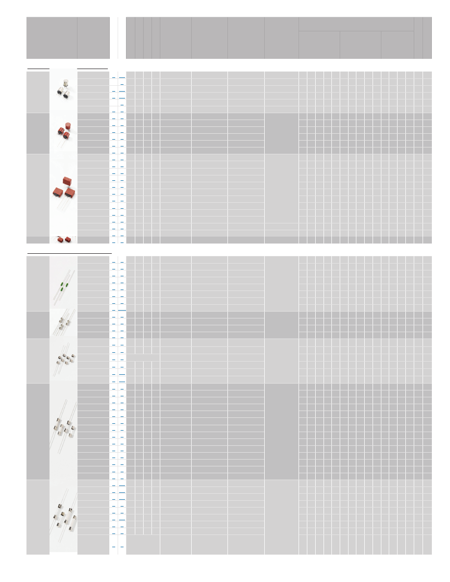
Fuse and PtC Products selection guide (continued)
PtC PRoduCts
PTCs (positive temperature coefficient) increase resistance as temperature increases. They are designed to prevent unsafe levels of current
while allowing constant safe current levels, and their resistance will “reset” automatically when the current and temperature returns to a
safe level. PTCs are typically used in applications where automatic reset is desired.
Series Name
1
Vie
w Dat
asheet
Order Samples
Size
2
Hold Current (I
HOLD
)
Max Voltage
(V
MAX
)
Max Fault
current (I
MAX
)
Operating
Temperature
Range
Agency Approvals
Halogen Free
RoHS
Lead Free
cUR
UR
TUV
Surface Mount:
LoRho PTC
(Low Resistance)
• •
0402
0.1 - 0.5A
6 / 12 V
50 A
•
•
•
•
•
•
0603
0.5 - 2.0A
0805
0.75 - 3.0A
-40°C to 85°C
1206
0.75 - 4.5A
1812
1.9 - 3.7A
2920
7.0A
0603L
• •
0603
(1608)
0.04 - 0.5A
6 - 15 V
40 A
•
•
•
•
•
•
0805L
• •
0805
(2012)
0.10 - 1.10 A
6 - 15 V
100 / 40 A
•
•
•
•
•
•
1206L
• •
1206
(3216)
0.10 - 2.0A
6 - 30 V
100 A
•
•
•
•
•
•
1210L
• •
1210
(3225)
0.05 - 2.0A
6 - 30 V
10 / 100 A
•
•
•
•
•
•
1812L
• •
1812
(4532)
0.1 - 3.0A
6 - 60 V
10 / 20 / 100 A
•
•
•
•
•
•
2016L
• •
2016
(5041)
0.30 - 2.00 A
6 - 60 V
20 / 40 A
•
•
•
•
•
•
2920L
• •
2920
(7351)
0.30 - 3.00 A
6 - 60 V
10 / 40 A
•
•
•
•
•
•
250S
• •
see data sheet
0.13 A
60 V
3 A
•
•
•
•
Radial Leaded:
USBR
• •
see data sheet
0.75 - 2.50 A
6 / 16 V
40 A
-40°C to 85°C
•
•
•
•
•
16R
• •
2.50 - 14.00 A
16 V
100 A
•
•
•
•
•
30R
• •
0.90 - 9.00 A
30 V
40 A
•
•
•
•
•
60R
• •
0.10 - 3.75 A
60 V
40 A
•
•
•
•
•
72R
• •
0.20 - 3.75 A
72 V
40 A
•
•
•
•
•
250R
• •
0.08 - 0.18 A
250 V
3 / 10 A
•
•
•
•
•
600R
• •
0.15 - 0.16 A
600 V
3 A
•
•
•
•
•
Battery Strap:
SL
(Low Resistance)
• •
see data sheet
1.9 - 3.7 A
6 V
50 A
-40°C to 85°C
•
•
•
•
•
•
(1) detailed information about most product series listed here can be found on our web site.
(2)
Size for these surface mount items refers to common industry length and width dimensions of the device surface area. Example: 0402 = .04” x .02”
18
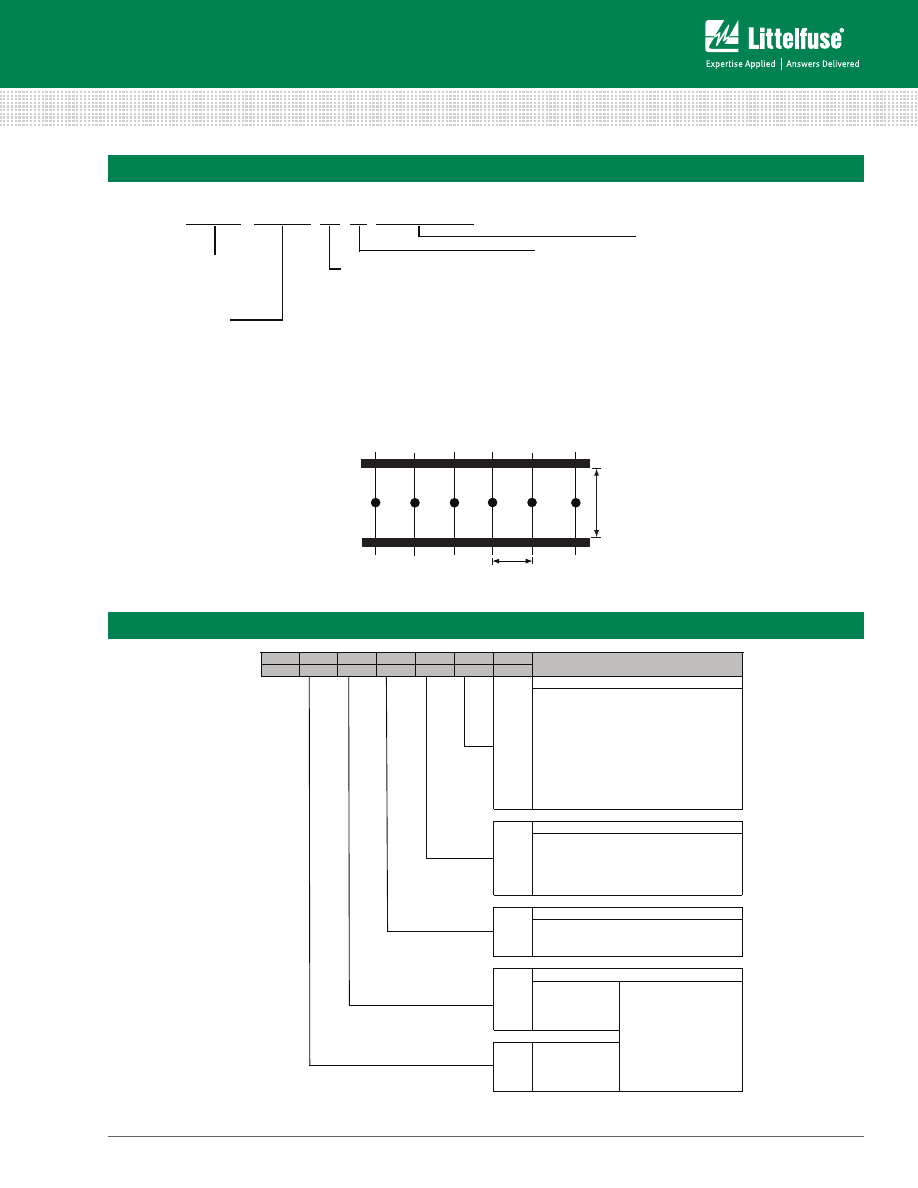
© 2014 Littelfuse • Fuseology Selection Guide
www.littelfuse.com
Fuseology Selection Guide
Packaging and Part Numbering
1.-3.
4.
5.-7.
8.
9.
10.
Stelle
3xx
X
XXX
X
X
X
digit
0
4
3
TR3
0
303
370
1
2
372
3
382
4
385
5
391
6
950
Y
373
374
Variant
0
Standard, long leads 18,8 mm
1
long leads 18,8 mm, TR3
392
2
395
4
short leads 4,3 mm
396
5
T²CP
Version
397
0
Standard
1
MP
S
PIP Surface Mount (TR5 blister tape 2x500 pcs.)
398
Rated Current Specification
IP
3-digit
399
062
= 62mA
example 4.-7. digit
100
= 100mA / 1A / 10A
Pico
125
= 125A
0062 = 62mA
275
0100 = 100mA
0
< 1A
1100 = 1A
1
≥ 1 - < 10A
2100 = 10A
2
≥ 10 - < 100A
3125 = 125A
3
≥ 100A
tape in bulk 100 pcs., only Picofuse 275
bulk 2.500 pcs., only Picofuse 275
Tape, Ammopack
Tape, Ammopack
Tap, Rolle/ Reel
varying production
customized
short leads 3,3 / 3,5 mm (special model)
bulk 1.400 pcs., only TE5
®
/ T²CP / MP / IP
bulk, 200 pcs., TR3 long leads / TR
®
Packaging
Tape, Ammopack 1.000 pcs. TR5
®
bulk, 1.000 pcs. TR5
®
bulk, 300 pcs., TR3 short leads
Explanation
TR5
®
TE5
®
Littelfuse Wickmann Products Part Numbering System
0 X X X X X X X X X X X X X X X
Packaging Type *
A
Ammo packed
B
Bubble packed
C
Chip packed
R
Reeled
X
Filler
A/X
1
V
5
T
10
S
20
L
50
H
100
F
200
G
250
U
500
M
1000
D
1500
P
2000
E
2500
W
3000
Y
4000
N
5000
K
10000
J
12000
Z
Misc.
Options Codes *
RT1
Reel and Tape, 2.062in (52.4mm) lead spacing
RT2
Reel and Tape, 2.50 in (63.5mm) lead spacing
RT3
Reel and Tape, 2.874 in (73mm) lead spacing
E
Pigtail lead type fuse
ID
Indicating fuse
L
RoHS compliant
P
Lead-free
Product Series Code
* Not all options and codes listed here are available for all products.
For information about the specific options available for any Littelfuse product,
please refer to the packaging details information within each product data sheet
or contact your Littelfuse products representative.
Ampere Rating Code
Decimal is to far right for whole number
amp ratings, to far left for ratings less than
one, and within center for fractional amp ratings.
Examples:
10A fuse is “010.”
1/4A or 0.25A fuse is “.250”
1 1/2A or 1.5A fuse is “01.5”
1 1/4A or 1.25A fuse is “1.25”
Refer to the Electrical Characteristics tables
presented in each product data sheet
for specific amp rating codes
Packaging Quantity Code *
y
x
Tape and Reel packaging per EIA-296:
Tape width is defined as the width of the tape and reeled fuse (x) as measured from inside tape to inside tape.
Pitch is defined as the space between two tape and reeled fuses (y) as measured from lead to lead.
Example:
437 series fuse is “0437”
Littelfuse Fuse Products Traditional Part Numbering System
19

Fuseology Selection Guide
©
2014 Littelfuse • Fuseology Selection Guide
www.littelfuse.com
Liability
Littelfuse, Inc. its affiliates, agents, and employees,
and all persons acting on its or their behalf (collectively,
“Littelfuse”), disclaim any and all liability for any errors,
inaccuracies or incompleteness contained here or in any
other disclosure relating to any product. Littelfuse disclaims
any and all liability arising out of the use or application
of any product described herein or of any information
provided herein to the maximum extent permitted by law.
The product specifications do not expand or otherwise
modify Littelfuse terms and conditions of purchase,
including but not limited to the warranty expressed therein,
which apply to these products.
Right to Make Changes
Littelfuse reserves the right to make any and all changes to
the products described herein without notice.
Not Intended for Use in Life Support or Life Saving
Applications
The products shown herein are not designed for use
in life sustaining or life saving applications unless
otherwise expressly indicated. Customers using or selling
Littelfuse products not expressly indicated for use in such
applications do so entirely at their own risk and agree
to fully indemnify Littelfuse for any damages arising or
resulting from such use or sale. Please contact authorized
Littelfuse personnel to obtain terms and conditions
regarding products designed for such applications.
Intellectual Property
No license, express or implied, by estoppel or otherwise,
to any intellectual property rights is granted by this
document or by any conduct of Littelfuse. Product
names and markings noted herein may be registered
trademarks of their respective owners. Littelfuse makes
no representations or warranties of non-infringement or
misappropriation of any third party intellectual property
rights unless specifically provided for herein.
Legal disclaimers
Disclaimer
Specifications, descriptions and data contained in this
document are believed to be accurate. However, users
should independently evaluate each product for the
particular application. Littelfuse reserves the right to
change any information contained herein without notice
and may, at its sole discretion, change the design,
manufacture or construction of any product. Visit
www.littelfuse.com
for the most up-to-date information.
Littelfuse’s only obligations for any of its products are
specified in its Standard Terms and Conditions and
Littelfuse shall not be liable for any indirect, consequential
or incidental damages from any sale or use of any of its
products.
20

littelfuse.com
circuitprotection@littelfuse.com
EC125Nv0
1
1
5