BE SURE POWER IS DISCONNECTED PRIOR TO INSTALLATION!
FOLLOW NATIONAL, STATE AND LOCAL CODES.
READ THESE INSTRUCTIONS ENTIRELY BEFORE INSTALLATION.
INTRODUCTION
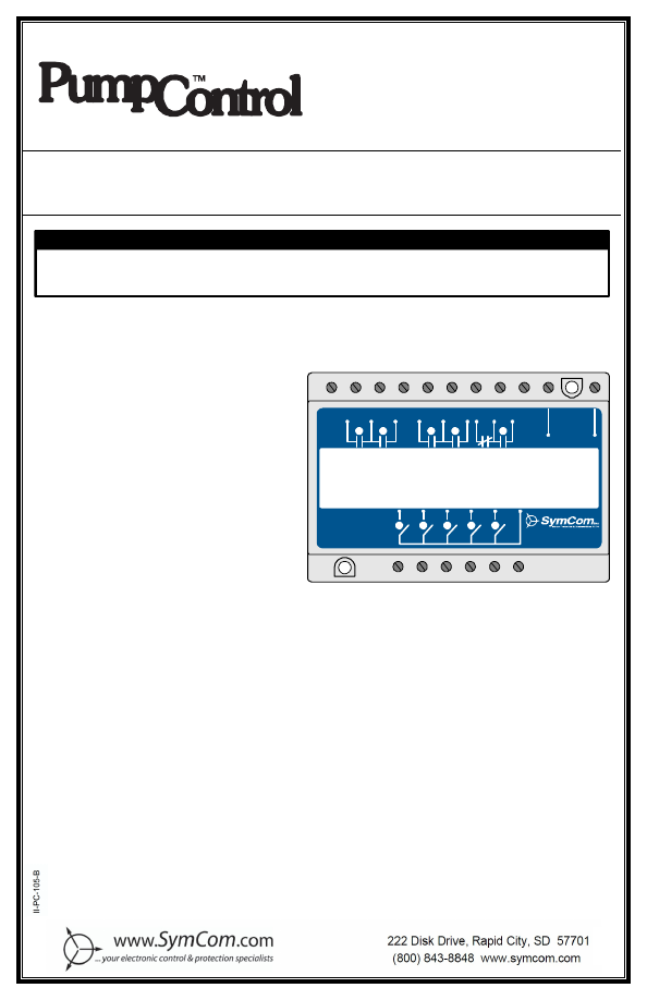
The PumpControl
™
Model PC-105 is a five-
channel pump controller that can handle
multiple pump applications or operate as a
5-channel switch. The PC-105 can indicate
low, high and out-of-sequence alarms and
use alternating pump control, non-
alternating pump control, or alternating
control with one non-alternating pump. The
non-alternating pump can be used as either
a jockey or emergency pump and can
optionally be cycled once every 50 cycles of
the lead pump to keep it working freely.
Using the built-in DIP switches, individual
pumps can be disabled when taken out of
service for repair or maintenance.
The PC-105 has the following features and capabilities:
4
High, low and out-of-sequence alarms
4
Variable time delay/lag pump delay
4
Separate pump stop
4
Pump alternation with or without a non-alternating pump
4
Jockey or emergency pump
4
Duplex, triplex or quadplex pump modes
4
Pump-up or pump-down functions
4
External silence, reset and alternation configuration
4
Five-channel relay
I
1
I
2
I
3
I
4
I
5
I
C
RELAY
#1
REL AY
#2
RELAY
#3
RELAY
#4
RELAY
#5
INPUT
PC-105
1-800-843-8848
www.pumpsaver.com
INSTALLATION INSTRUCTIONS
FOR SYMCOM’S
PUMPCONTROL
™
MODEL
PC-105
! WARNING !
UNEXPECTED OUTPUT ACTU ATION CAN OCCUR .
Use hard-wired safety interlocks where personnel and/or equipment hazards exist.
Failure to follow this instruction can result in death, injury or equipment damage.
2880 North Plaza Drive, Rapid City, South Dakota 57702
(800) 843-8848
·
(605) 348-5580
·
fax (605) 348-5685
www.symcom.com
Littelfuse_ProtectionRelays_001925__II_PC_105_B-html.html
2
10/06
QUICK START
The PC-105 can operate as a pump controller for eight different pumping configurations. Duplex,
triplex, quadplex and duplex SPS (separate pump stop) pumping modes are possible for either
pump-up or pump-down applications. Refer to page 18 for the full description of five-channel relay
operation.
Refer to
PUMPING MODES
(page 4) for details of PC-105 features and mode descriptions.
1. If you know the system’s pump configuration, follow Table 1 to the page showing the typical
wiring diagram and setup for each mode.
2. If further description is needed in choosing which mode to use, see Table 2 and Table 3 to view
the capabilities of each pumping mode and look at the typical wiring diagrams of the eight
different pumping modes starting on page 8.
3. Once the desired configuration is determined, punch out and slide the correct card into the slot
on the front of the PC-105 to display the input and output connections.
Mode Selector
Switch
Mode Description
Page
0
5-Channel Relay – Mode 0
19
1
Duplex Pump-Down – Mode 1
8
2
Triplex Pump-Down – Mode 2
9
3
Quadplex
Pump-Down
–
Mode
3
10
4
Duplex
SPS
Pump-Down
–
Mode
4
11
5
Duplex Pump-Up – Mode 5
12
6
Triplex Pump-Up – Mode 6
13
7
Quadplex Pump-Up – Mode 7
14
8
Duplex
SPS
Pump-Up
–
Mode
8
15
Table 1: Mode Selector Switch Details
Model Description
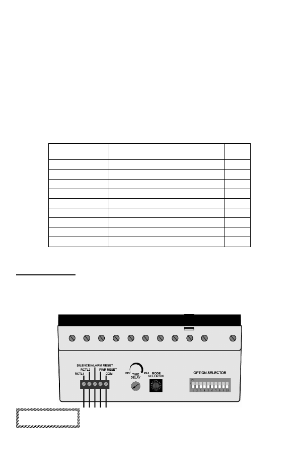
The PC-105 has three adjustable controls to set the mode of operation:
1.
Mode
Selector
2.
Option
Selector
3.
Time
Delay
WARNING!
To ensure proper initialization and operation, set the mode
and option selectors before applying power to the unit.
Littelfuse_ProtectionRelays_001925__II_PC_105_B-html.html
3
10/06
Time Delay
The time delay can be set from 2–255 seconds and is the delay before the lag pump will turn on in
each of the pumping modes. When the lead float closes (direct logic), the time delay starts and
when it expires, the lag pump is ready to turn on or will turn on if the lag input is closed (direct
logic). All subsequent pumps will turn on as called for after a two-second time delay each.
Mode Selector
The mode selector switch sets the operation mode. A description of each mode is shown in Table
1. The capabilities of each pumping mode and the non-alternating pump designations are shown in
Table 2 below.
Duplex
Triplex Quadplex Duplex
SPS
# Pumps
2
3
4
2
High alarm
Yes
*Yes
No
**Yes
Low alarm
Yes
*Yes
No
**Yes
Out-of-sequence alarm
Yes
Yes
Yes
Yes
# Stop floats
1
1
1
2
Pump direction
Up/Down Up/Down Up/Down Up/Down
Non-alternating start float
Lag
1
Lag
2
Lag
3
N/A
Non-alternation pump
Pump
2
Pump
3
Pump
4
N/A
Alternator
Yes
Yes
Yes
Yes
Table 2: Mode Capabilities
* On a Triplex system, either a High or Low Alarm is available—not both. See Triplex:
High/Low Alarm
(pg. 5) for
details.
** Duplex SPS applications typically use High Alarms on Pump-Down systems and Low Alarms on Pump-Up.
Option Selector
Table 2 describes the Option Selector for all pumping modes.
(A “
a
” Indicates the function is available for the pump mode)
Option
Selector
Switch
Function Description
Duplex Triplex Quadplex
Duplex SPS
(Separate
Pump Stop)
1
High alarm
a
*
a
a
2
Low alarm
a
*
a
a
3
Pump 1
a
a
a
a
4
Pump 2
a
a
a
a
5
Pump 3
a
a
6
Pump 4
a
7
Audible alarm relay logic
a
a
a
a
8
ALS-0 –
Alternator select 0 (see Table 4)
a
a
a
a
9
ALS-1 –
Alternator select 1 (see Table 4)
a
a
a
a
10
ALS-2 –
Alternator select 2 (see Table 4)
a
a
a
a
Table 3: Option Selector Switch Details
* On a Triplex system, either a high or low alarm can be utilized—not both. See
Triplex: High/Low Alarm
(page 4)
for details.
Littelfuse_ProtectionRelays_001925__II_PC_105_B-html.html

4
10/06
PUMPING MODES
Duplex
– two pumps with one stop float, a high alarm and a low alarm.
Triplex: High/Low Alarm
–
three pumps with one stop float and a high or low alarm.
Triplex Pump-Down
: a high alarm is typically used—Option Selector: 1=ON, 2=OFF.
If a low alarm is preferred, the alarm float must be moved to the location in the tank below the
Stop Float—Option Selector: 1=OFF and 2=ON.
Triplex Pump-Up
: a low alarm is typically used—Option Selector: 1=OFF, 2=ON.
If a high alarm is preferred, the alarm float must be moved to the location in the tank above the
Stop Float—Option Selector: 1=ON and 2=OFF.
Quadplex
– four pumps with one stop float and no alarms floats.
Separate Pump Stop (SPS)
– two pumps, two stop floats, and a high or low alarm.
In
Duplex SPS
mode, both the lead and lag pumps have their own stop floats.
Duplex SPS Pump-Down
: a high alarm is typically used—Option Selector: 1=ON, 2=OFF.
If a low alarm is preferred, the alarm float must be moved to the location in the tank below the
Lead Stop Float—Option Selector: 1=OFF, 2=ON.
Duplex SPS Pump-Up
: a low alarm is typically used—Option Selector: 1=OFF, 2=ON.
If a high alarm is preferred, the alarm float must be moved to the location in the tank above the
Lead Stop Float—Option Selector: 1=ON, 2=OFF.
PC-105 FUNCTIONS
High Alarm
The High Alarm relay is activated when the High Alarm Float closes, indicating the pumps are
unable to keep the water level down on a pump-down application. If the High Alarm Float closes at
any time, all pumps will turn on, bypassing the 10-second out-of-sequence trip delay, and the
adjustable Time Delay.
If a high alarm is used on a pump-up application, the alarm will be activated when the High Alarm
Float closes indicating the water level has been pumped too high, possibly due to a defective Stop
Float, and will turn off all pumps.
During a high or low alarm, the Alarm LED and Audible Alarm LED will be on. If the high or low
alarm condition ends, the Audible Alarm will turn off and the Alarm LED will flash indicating the
alarm had occurred, but is not present now. If the high or low alarm occurs again, the Audible
Alarm LED will turn on again, but the Alarm LED will remain flashing. The unit must be silenced or
reset to clear the flashing alarm LEDs.
Low Alarm
The Low Alarm relay is activated when the Low Alarm Float opens indicating the pumps are unable
to keep the water level up on a pump-up application. If the pump-up Low Alarm Float opens at any
time, except if a High Alarm is activated, all pumps will turn on.
If a low alarm is used on a pump-down application, the alarm will be activated when the Low Alarm
Float opens indicating the water level has been pumped too low. This may be a result of a defective
stop float. The low alarm will not turn off the pumps though, but will activate the low alarm relay—
another form of pump-dry protection such as the SymCom Model 777 may be necessary.
Littelfuse_ProtectionRelays_001925__II_PC_105_B-html.html

5
10/06
Out-of-Sequence Alarm
When a float in the series does not open or close in sequence, the Audible Alarm relay will be
activated and input LED(s) will flash until the unit is reset or power is cycled. An out-of-sequence
condition has to exist for 10 seconds before the PC-105 will alarm. When the stop float fails open in
pump-down mode or closed in pump-up mode, an out-of-sequence alarm will not occur and pumps
will not turn on with floats. In this case, all pumps will turn on when the High/Low Alarm input is
activated. Thus, in Quadplex mode, pumps will never turn on if the Stop Float malfunctions.
Audible Alarm
The Audible Alarm relay is activated when a high, low or out-of-sequence alarm occurs. The
Audible Alarm will turn off when there is no longer high or low alarms or if the unit is silenced.
Audible Alarm Logic / Fail-Safe
The Audible Alarm relay can be configured to operate in either fail-safe mode (switch 7=ON), or
non fail-safe mode (switch 7=OFF). In fail-safe mode, the N.C. (normally closed) contacts will be
open during normal operation and closed during an alarm. In non-fail-safe mode, the N.C. contacts
will be closed during normal operation and open during an alarm.
Clearing Alarms
The external Silence / Alarm Reset button will clear the Audible Alarm. The Reset button or cycling
power will clear out-of-sequence alarms.
Alternation
The PC-105 is equipped with a built-in alternator that determines which pump will start each
pumping cycle. This alternator is configured using switches ALS-0, ALS-1 and ALS-2 (switches 8, 9
and 10 of the Option Selector).
Function
ALS-0
(8)
ALS-1
(9) ALS-2
(10)
Alternation On
ON
ON
ON
Alternation On
OFF
ON
ON
Alternation
On,
Non-Alternating
Pump
Enabled
(1)
*ON
OFF
OFF
Alternation
On,
Non-Alternating
Pump
Enabled
(1)
**OFF
OFF
OFF
Alternation Off, Force Pump 1 as Lead
OFF
ON
OFF
Alternation Off, Force Pump 2 as Lead
OFF OFF
ON
Alternation Off, Force Pump 3 as Lead (2)
ON
ON
OFF
Alternation Off, Force Pump 4 as Lead (3)
ON
OFF
ON
Table 4: Alternator Options
Note (1) In Duplex Mode, this setting is the same as Alternation On.
Note (2) In Duplex Mode, Pump 1 is the Lead Pump and Pump 2 will be cycled every 50 cycles of the Lead.
Note (3) In Duplex Mode, Pump 2 is the Lead Pump and Pump 1 will be cycled every 50 cycles of the Lead.
* If ALS-0 is ON in this mode, the Non-Alternating Pump will cycle when the non-alternating float changes state,
or after 50 cycles of the Lead float.
** If ALS-0 is OFF the Non-Alternating Pump will cycle only when the non-alternating float changes state.
Littelfuse_ProtectionRelays_001925__II_PC_105_B-html.html

6
10/06
Alternation On
When the alternator is on, each pump will be alternated as the Lead Pump (see Table 5).
Cycle
1
Cycle
2
Cycle
3
Cycle
4
Cycle
5
Pump 1
Lead
Lag
3
Lag
2
Lag
1
Lead
Pump 2
Lag 1
Lead
Lag
3
Lag
2
Lag 1
Pump 3
Lag
2
Lag
1
Lead
Lag 3
Lag 2
Pump 4
Lag
3
Lag
2
Lag
1
Lead
Lag 3
Table 5. Pump Sequence
Alternation On, Non-Alternating Pump Enabled
The Triplex and Quadplex pump modes are equipped with an optional Non-Alternating Pump. This
pump will
not
be included in the normal pump alternation sequence when ALS-1 and ALS-2
(switches 9 and 10) are both OFF. If ALS-0 (switch 8) is ON, the non-alternating pump will cycle
when the Non-Alternating Float changes state or after every 50 cycles of the Lead Float. If ALS-0 is
OFF, the non-alternating pump will only cycle if the non-alternating float changes state.
The last pump in the float sequence (highest #) is the non-alternating pump and can be used as
either a jockey or emergency pump. (See Table 2, page 3 for non-alternating pump and float details
for each pumping mode.)
A
Jockey Pump
is typically a smaller pump that will always be used first in the pump sequence.
In order to implement a jockey pump, the non-alternating pump float must be moved in the tank
to just above the Stop Float on a pump-down system, and to just below the Stop Float on a
pump-up system. See
Figure 9 (page 16)—an example wiring diagram using a jockey pump in a duplex pump-down
system.
An
Emergency Pump
is usually a larger pump that is always used last. In order to implement an
emergency pump, the non-alternating pump is already the last pump in the sequence so there is
no need to move the float. See Figure 10 (page 17)—an example wiring diagram using an
emergency pump on a duplex pump-down system.
Alternation Off
When the alternator is off, a Lead Pump can be forced by setting ALS-0, ALS-1 and ALS- 2 (see
Table 4). The remaining pumps will start in a sequential order as each float opens/closes.
Disabling Pumps
Using the built-in DIP switches, individual pumps can be disabled, when taken out of service for
repair or maintenance.
Littelfuse_ProtectionRelays_001925__II_PC_105_B-html.html
7
10/06
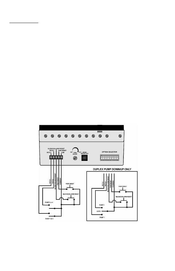
External Inputs
A five-pin connector is provided for optional external inputs.
· External Silence / Alarm Reset
This input allows for an external N.O. (normally open) pushbutton that will silence audible
alarms and clear flashing alarm lights.
· External Power Reset
This input allows for an external N.O. pushbutton to reset the PC-105, causing the same effect
as a power cycle.
· External Alternation Configuration
For duplex mode, a SPDT (single-pole, double-throw) switch can be connected to close RTCL1
or RTCL2 (remote controls) to force Pump 1 or 2 as the Lead Pump. Option Selector switches
8, 9 & 10 must be OFF. If the switch is in the middle position, pumps will be in alternation mode.
For triplex and quadplex modes, two SPST (single-pole, single-throw) switches can be
connected to force Pump 1, 2, 3 or 4 to be the Lead Pump. Option Selector switches 9 & 10
must be OFF.
To force Pump 1 or 2 as Lead, Option Selector switch 8 must be OFF.
To force Pump 3 or 4 as Lead, Option Selector switch 8 must be ON.
For alternation mode, close both RTCL1 and RTCL2.
Littelfuse_ProtectionRelays_001925__II_PC_105_B-html.html
8
10/06
WIRING DIAGRAMS
The following figures, 1-10, show typical wiring diagrams for all available PC-105 pumping modes .
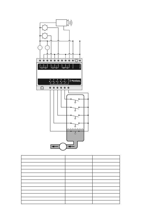
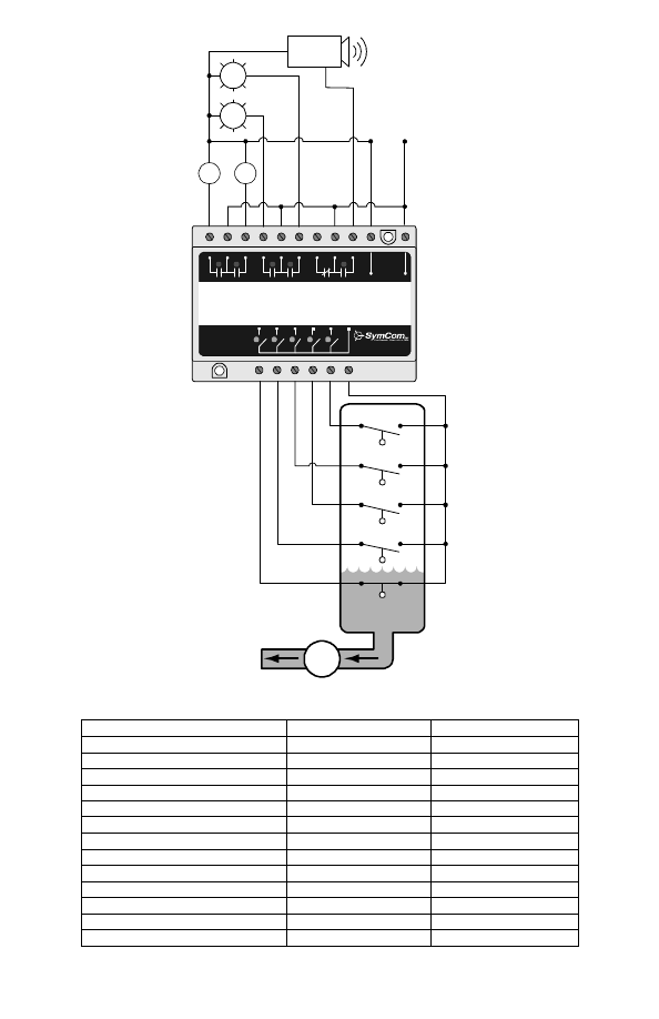
Figure 1: Typical Wiring for Duplex Pump-Down – Mode 1
Switch State
Mode Selector Switch
1
Time Delay Adjustment
MIN
Option Selector Switch
1
High Alarm
ON
2
Low Alarm
ON
3
Pump 1
ON
4
Pump 2
ON
5
Pump 3
NA
6
Pump 4
NA
7
Fail-Safe
OFF
8
ALS-0
ON
9
ALS-1
ON
10
ALS-2
ON
Table 6: Typical Duplex Pump-Down System
I
1
I
2
I
3
I
4
I
5
I
C
#1
PUMP
#1
PUMP
#2
LOW
ALARM
HIGH
ALARM
LOW
ALARM
HIGH
ALARM
STOP
LEAD
LAG1
COMMON
AUDIBLE
ALARM
1-800-843-8848
www. pumpsaver.com
#2
#3
#4
#5
INP UT
Low Alarm Float
Stop Float
Lead Float
Lag 1 Float
High Alarm Float
120 VAC
Pump
1
Pump
2
Audible Alarm
High
Ala rm
Low
Ala rm
PUMP
Littelfuse_ProtectionRelays_001925__II_PC_105_B-html.html
9
10/06
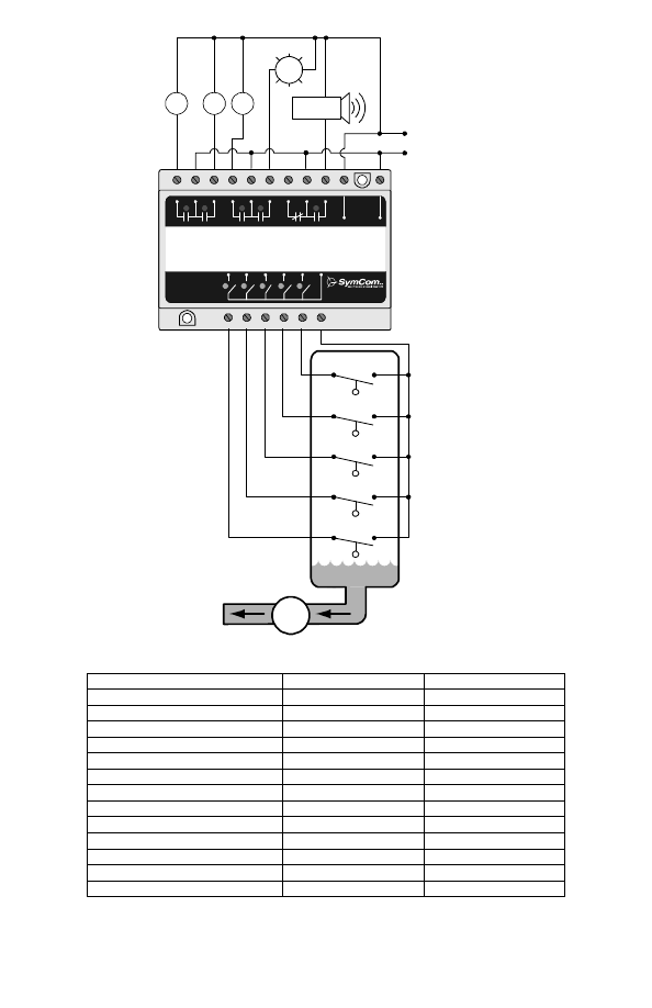
I
1
I
2
I
3
I
4
I
5
I
C
#1
PUMP
#1
PUMP
#2
PUMP
#3
HIGH/LOW
ALARM
HIGH/LOW
ALARM
LEAD
STOP
LAG1
LAG2
COMMON
AUDIBLE
ALARM
#2
#3
#4
#5
INPUT
Pump
1
Pump
2
Pump
3
Stop Float
Lead Float
Lag 1 Float
Lag 2 Float
High Alarm Float
120 VAC
Audible Alarm
Alarm
PUMP
1-800-843-8848
www.pumpsaver.com
Figure 2: Typical Wiring for Triplex Pump-Down – Mode 2
Switch State
Mode Selector Switch
2
Time Delay Adjustment
MIN
Option Selector Switch
1
High Alarm
ON
2
Low Alarm
OFF
3
Pump 1
ON
4
Pump 2
ON
5
Pump 3
ON
6
Pump 4
NA
7
Fail-Safe
OFF
8
ALS-0
ON
9
ALS-1
ON
10
ALS-2
ON
Table 7: Typical Triplex Pump-Down System
Littelfuse_ProtectionRelays_001925__II_PC_105_B-html.html
10
10/06
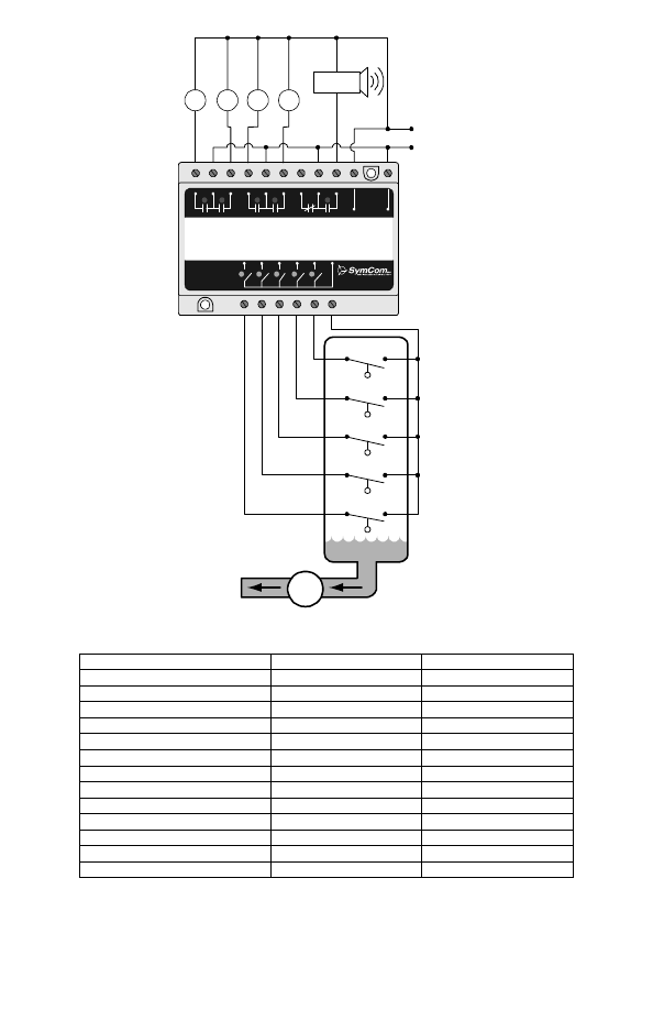
I
1
I
2
I
3
I
4
I
5
I
C
#1
PUMP
#1
PUMP
#2
PUMP
#3
PUMP
#4
LEAD
STOP
LAG1
LAG2
LAG3
COMMON
AUDIBLE
ALARM
#2
#3
#4
#5
INPUT
Pump
1
Pump
3
Stop Float
Lead Float
Lag 1 Float
Lag 2 Float
Lag 3 Float
120 VAC
Pump
2
Pump
4
Audible Alarm
PUMP
1-800-843-8848
www.pumpsaver.com
Figure 3: Typical Wiring for Quadplex Pump-Down – Mode 3
Switch State
Mode Selector Switch
3
Time Delay Adjustment
MIN
Option Selector Switch
1
High Alarm
NA
2
Low Alarm
NA
3
Pump 1
ON
4
Pump 2
ON
5
Pump 3
ON
6
Pump 4
ON
7
Fail-Safe
OFF
8
ALS-0
ON
9
ALS-1
ON
10
ALS-2
ON
Table 8: Typical Quadplex Pump-Down System
Littelfuse_ProtectionRelays_001925__II_PC_105_B-html.html
11
10/06
I
1
I
2
I
3
I
4
I
5
I
C
#1
PUMP
#1
PUMP
#2
HIGH
ALARM
LOW
ALARM
HIGH
ALARM
LOW
ALARM
STOP
LEAD
LAG1
COMMON
AUDIBLE
ALARM
#2
#3
#4
#5
INPUT
Low Alarm Float
Lag 1 Float
Lead Float
Stop Float
High Alarm Float
120 VAC
Pump
1
Pump
2
Audible Alarm
Low
Alarm
High
Alarm
PUMP
1-800-843-8848
www.pumpsaver.com
Figure 4: Typical Wiring for Duplex SPS Pump-Down – Mode 4
Switch State
Mode Selector Switch
4
Time Delay Adjustment
MIN
Option Selector Switch
1
High Alarm
ON
2
Low Alarm
OFF
3
Pump 1
ON
4
Pump 2
ON
5
Pump 3
NA
6
Pump 4
NA
7
Fail-Safe
OFF
8
ALS-0
ON
9
ALS-1
ON
10
ALS-2
ON
Table 9: Typical Duplex SPS Pump-Down System
Littelfuse_ProtectionRelays_001925__II_PC_105_B-html.html
12
10/06
I
1
I
2
I
3
I
4
I
5
I
C
#1
PUMP
#1
PUMP
#2
HIGH
ALARM
LOW
ALARM
HIGH
ALARM
LOW
ALARM
STOP
LEAD
LAG1
COMMON
AUDIBLE
ALARM
#2
#3
#4
#5
INPUT
Low Alarm Float
Lag 1 Float
Lead Float
Stop Float
High Alarm Float
120 VAC
Pump
1
Pump
2
Audible Alarm
Low
Alarm
High
Alarm
PUMP
1-800-843-8848
www.pumpsaver.com
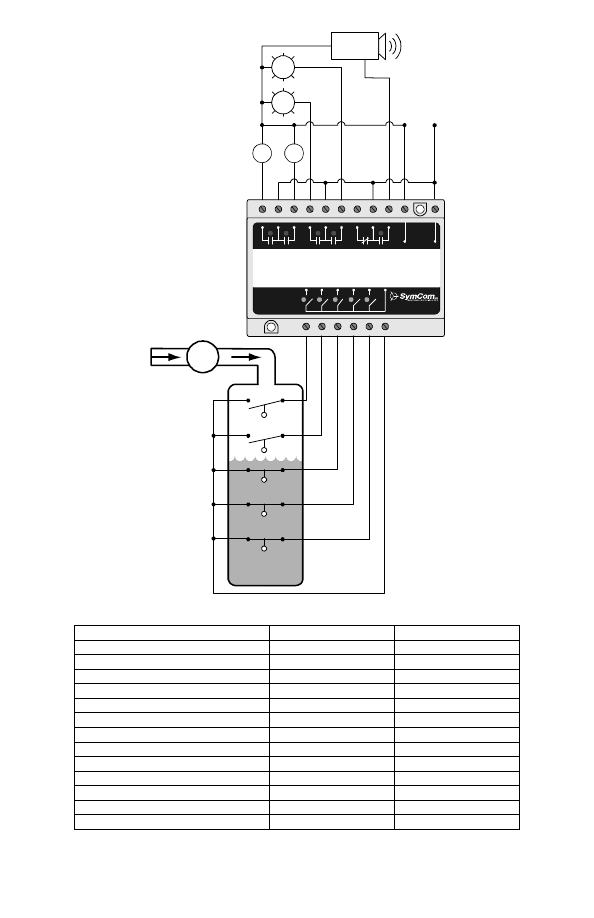
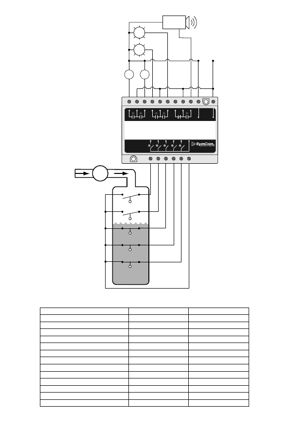
Figure 5: Typical Wiring for Duplex Pump-Up – Mode 5
Switch State
Mode Selector Switch
5
Time Delay Adjustment
MIN
Option Selector Switch
1
High Alarm
ON
2
Low Alarm
ON
3
Pump 1
ON
4
Pump 2
ON
5
Pump 3
NA
6
Pump 4
NA
7
Fail-Safe
OFF
8
ALS-0
ON
9
ALS-1
ON
10
ALS-2
ON
Table 10: Typical Duplex Pump-Up System
Littelfuse_ProtectionRelays_001925__II_PC_105_B-html.html
13
10/06
I
1
I
2
I
3
I
4
I
5
I
C
#1
PUMP
#1
PUMP
#2
PUMP
#3
HIGH/LOW
ALARM
HIGH/LOW
ALARM
LEAD
STOP
LAG1
LAG2
COMMON
AUDIBLE
ALARM
#2
#3
#4
#5
INPUT
Pump
1
Pump
2
Pump
3
Lag 2 Float
Lag 1 Float
Lead Float
Stop Float
Low Alarm Float
120 VAC
Audible Alarm
Alarm
PUMP
1-800-843-8848
www.pumpsaver.com
Figure 6: Typical Wiring for Triplex Pump-Up - Mode 6
Switch State
Mode Selector Switch
6
Time Delay Adjustment
MIN
Option Selector Switch
1
High Alarm
OFF
2
Low Alarm
ON
3
Pump 1
ON
4
Pump 2
ON
5
Pump 3
ON
6
Pump 4
NA
7
Fail-Safe
OFF
8
ALS-0
ON
9
ALS-1
ON
10
ALS-2
ON
Table 11: Typical Triplex Pump-Up System
Littelfuse_ProtectionRelays_001925__II_PC_105_B-html.html
14
10/06
I
1
I
2
I
3
I
4
I
5
I
C
#1
PUMP
#1
PUMP
#2
PUMP
#3
PUMP
#4
LEAD
STOP
LAG1
LAG2
LAG3
COMMON
AUDIBLE
ALARM
#2
#3
#4
#5
INPUT
Pump
1
Pump
3
Lag 3 Float
Lag 2 Float
Lag 1 Float
Lead Float
Stop Float
120 VAC
Pump
2
Pump
4
Audible Alarm
PUMP
1-800-843-8848
www.pumpsaver.com
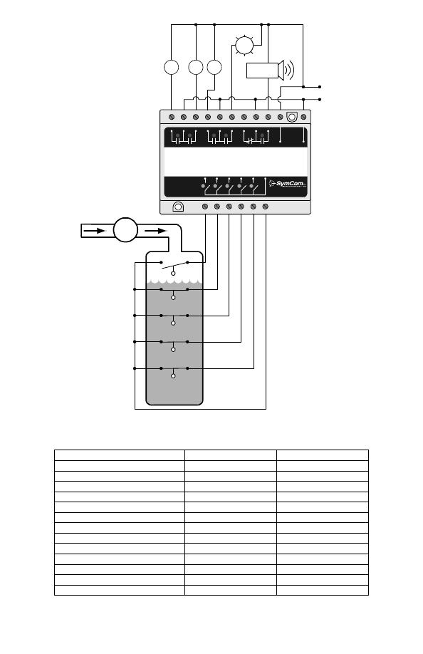
Figure 7: Typical Wiring for Quadplex Pump-Up – Mode 7
Mode Selector Switch
7
Time Delay Adjustment
MIN
Option Selector Switch
1
High Alarm
NA
2
Low Alarm
NA
3
Pump 1
ON
4
Pump 2
ON
5
Pump 3
ON
6
Pump 4
ON
7
Fail-Safe
OFF
8
ALS-0
ON
9
ALS-1
ON
10
ALS-2
ON
Table 12: Typical Quadplex Pump-Up System
Littelfuse_ProtectionRelays_001925__II_PC_105_B-html.html
15
10/06
I
1
I
2
I
3
I
4
I
5
I
C
#1
PUMP
#1
PUMP
#2
LOW
ALARM
HIGH/LOW
ALARM
LEAD
STOP
LAG
STOP
HIGH/LOW
ALARM
LEAD
LAG
COMMON
AUDI BLE
ALARM
#2
#3
#4
#5
INPUT
Low Alarm Float
Lag Float
Lag Stop Float
Lead Float
Lead Stop Float
120 VAC
Pump
2
Audible Alarm
Low
Alarm
Pump
1
PUMP
1-800-843-8848
www.pumpsaver.com
Figure 8: Typical Wiring for Duplex SPS Pump-Up – Mode 8
Switch State
Mode Selector Switch
8
Time Delay Adjustment
MIN
Option Selector Switch
1
High Alarm
OFF
2
Low Alarm
ON
3
Pump 1
ON
4
Pump 2
ON
5
Pump 3
NA
6
Pump 4
NA
7
Fail-Safe
OFF
8
ALS-0
ON
9
ALS-1
ON
10
ALS-2
ON
Table 13: Typical Duplex SPS Pump-Up System
Littelfuse_ProtectionRelays_001925__II_PC_105_B-html.html
16
10/06
I
1
I
2
I
3
I
4
I
5
I
C
#1
PUMP
#1
PUMP
#2
LOW
ALARM
HIGH
ALARM
LOW
ALARM
HIGH
ALARM
STOP
LEAD
LAG1
COMMON
AUDIBLE
ALARM
#2
#3
#4
#5
INPUT
Low Alarm Float
Stop Float
Jockey Float
Lead Float
High Alarm Float
120 VAC
Pump
1
Pump
2
Audible Alarm
High
Alarm
Low
Alarm
PUMP
1-800-843-8848
www.pumpsaver.com
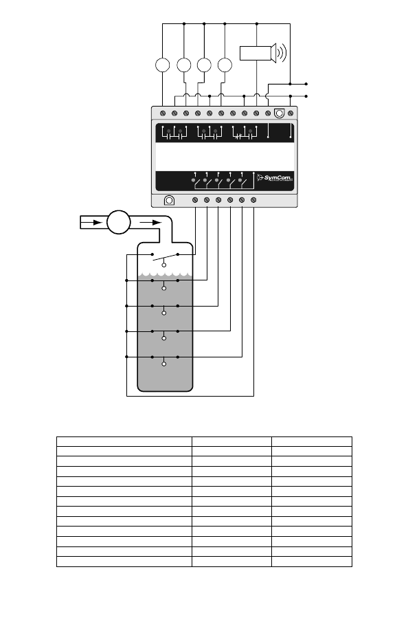
Figure 9: Typical Wiring for Duplex Pump-Down with Jockey Pump – Mode 1
Switch State
Mode Selector Switch
1
Time Delay Adjustment
MIN
Option Selector Switch
1
High Alarm
ON
2
Low Alarm
ON
3
Pump 1
ON
4
Pump 2
ON
5
Pump 3
NA
6
Pump 4
NA
7
Fail-Safe
OFF
8
ALS-0
OFF
9
ALS-1
ON
10
ALS-2
OFF
Table 14: Typical Duplex Pump-Down System with Jockey Pump
Littelfuse_ProtectionRelays_001925__II_PC_105_B-html.html
17
10/06
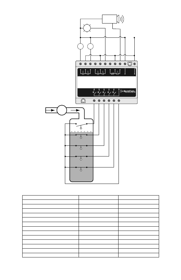
I
1
I
2
I
3
I
4
I
5
I
C
#1
PUMP
#1
PUMP
#2
LOW
ALARM
HIGH
ALARM
LOW
ALARM
HIGH
ALARM
STOP
LEAD
LAG1
COMMON
AUDIBLE
ALARM
#2
#3
#4
#5
INPUT
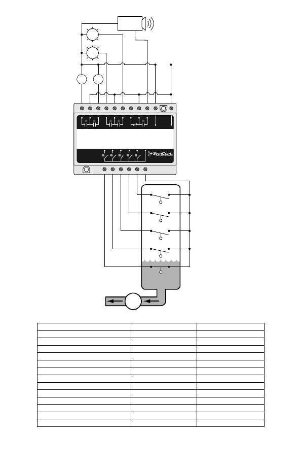
Low Alarm Float
Stop Float
Lead Float
Emergency Float
High Alarm Float
120 VAC
Pump
1
Pump
2
Audible Alarm
High
Alarm
Low
Alarm
PUMP
1-800-843-8848
www.pumpsaver.com
Figure 10: Typical Wiring for Duplex Pump-Down with Emergency Pump – Mode
1
Switch State
Mode Selector Switch
1
Time Delay Adjustment
MIN
Option Selector Switch
1
High Alarm
ON
2
Low Alarm
ON
3
Pump 1
ON
4
Pump 2
ON
5
Pump 3
NA
6
Pump 4
NA
7
Fail-Safe
OFF
8
ALS-0
OFF
9
ALS-1
OFF
10
ALS-2
ON
Table 15: Typical Duplex Pump-Down System with Jockey Pump
Littelfuse_ProtectionRelays_001925__II_PC_105_B-html.html

18
10/06
FIVE-CHANNEL RELAY MODE
Some unique features of the five-channel relay mode are described below.
To use the PC-105 in this mode, the Mode Selector dial must be set to 0.
Option
Selector
Switch
Function Description
ON Function
OFF Function
1
Enables
Channel
2
Latch
Channel 1 and 2 function
normally
Channel 1
Latches Channel 2
2
Enables
Channel
4
Latch
Channel 3 and 4 function
normally
Channel 3
Latches Channel 4
3
Relay 1 Logic
Positive
Negative
4
Relay 2 Logic
Positive
Negative
5
Relay 3 Logic
Positive
Negative
6
Relay 4 Logic
Positive
Negative
7
Relay 5 Logic
Positive
Negative
8
Selects Make/Break
Delay-On-Break
Delay-On-Make
9
Enables Delay-On-
Make/Break Timer
Make/Break Timer Disabled Make/Break Timer Enabled
10
Not Used
-----
-----
Table 16: Five-Channel Relay Options
Positive/Negative Logic
Using
positive logic
will give the same output as input—if the input is closed, the corresponding
output relay is closed.
If using
negative logic
, the output will be the opposite of the input—if the input is closed, the output
relay is open.
Latched Output
Relays 2 and 4 can be configured as latched relays. Input 2 will cause relay 2 to close, but this
relay will not open until input 1 opens. Relay 4 will close when input 4 closes, but will not open until
input 3 opens.
Time Delay Output
Relay 5 can be configured as a Delay-On-Make or a Delay-On-Break time delay output. All timing
starts when the input switch opens or closes. The time base for this output is adjustable using the
Time Delay knob and ranges from 2-255 seconds.
Delay-On-Make
If Input 5 closes, the Time Delay will start and LED 5 will flash. Once the time delay has
expired, output relay 5 will close and the LED will be on. If Input 5 opens at any point during the
timing cycle, the time delay stops and output relay 5 remains open.
Delay-On-Break
If input 5 opens, the time delay will start and LED 5 will flash. Once the time delay has expired,
output relay 5 will open and the LED will be off. If input 5 closes at any point during the timing
cycle, the time delay stops and output relay 5 remains closed.
Littelfuse_ProtectionRelays_001925__II_PC_105_B-html.html
19
10/06
I
1
I
2
I
3
I
4
I
5
I
C
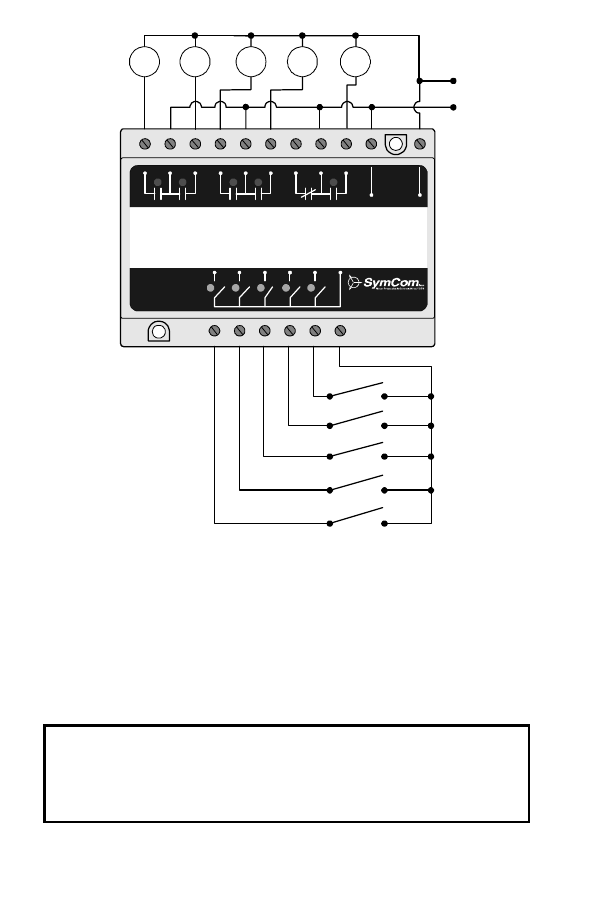
#1
OUTPUT OUTPUT
OUTPUT OUTPUT
INPUT
INPUT
INPUT
INPUT
INPUT
COMMON
TIME DELAY
OUTPUT
#2
#3
#4
#5
INPUT
Load
1
Load
3
120 VAC
Load
2
Load
4
Load
5
1-800-843-8848
www.pumpsaver.com
Figure 11: Typical Wiring for 5-channel Relay – Mode 0
SymCom warrants its microcontroller-based products against defects in material or
workmanship for a period of five (5) years from the date of manufacture. All other
products manufactured by SymCom shall be warranted against defects in material and
workmanship for a period of two (2) years from the date of manufacture. For complete
information on warranty, liability, terms, returns, and cancellations, please refer to the
SymCom Terms and Conditions of Sale document.
Littelfuse_ProtectionRelays_001925__II_PC_105_B-html.html
20
10/06
Model PC-105 Specifications
Control Voltage
108–132VAC
Frequency
50/60 Hz
Power
4 Watts (max.)
Adjustments
Time delay/lag pump delay
2–255 sec.
Mode Selector
0 – 8 (9–F: force mode 0)
Option Selector
1–10, ON/OFF
Silence button
dry input only
Reset button
dry input only
External
alternation
configuration
ALS-1
External
alternation
configuration
ALS-2
Pumping modes available
Duplex pump-down
2 pumps with high and low alarms
Triplex pump-down
3 pumps with high alarm (typical)
Quadplex pump-down
4 pumps
Duplex pump-down SPS
(separate pump stop)
2 pumps with high alarm (typical) 2 stop floats
Duplex pump-up
2 pumps with high and low alarms
Triplex pump-up
3 pumps with low alarm (typical)
Quadplex pump-up
4 pumps
Duplex pump-up SPS
(separate pump stop)
2 pumps with low alarm (typical) 2 stop floats
5-Channel relay mode
5-channel
1 relay latched / time delay output
Operating temperature
-20 to 55°C
Terminals
Wire AWG
12–20 AW G
Torque
6 in.-lbs.
Relay contacts
B 300 or 480VA @ 240VAC, Pilot Duty
240 VAC, 7A (max.), general purpose
Pump inrush delay
2 sec.
Standards passed
Electrostatic discharge (ESD)
IEC 61000-4-2, Level 3, 6 kv contact, 8 kv air
Radio frequency immunity (RFI)
IEC 61000-4-2, Level 3, 10V/m
Fast transients
IEC 61000-4-4, Level 3, 4 kv input power
2 kV inputs/outputs
2880 North Plaza Drive, Rapid City, South Dakota 57702
(800) 843-8848
·
(605) 348-5580
·
fax (605) 348-5685
www.symcom.com