background image

Product Line Catalogue

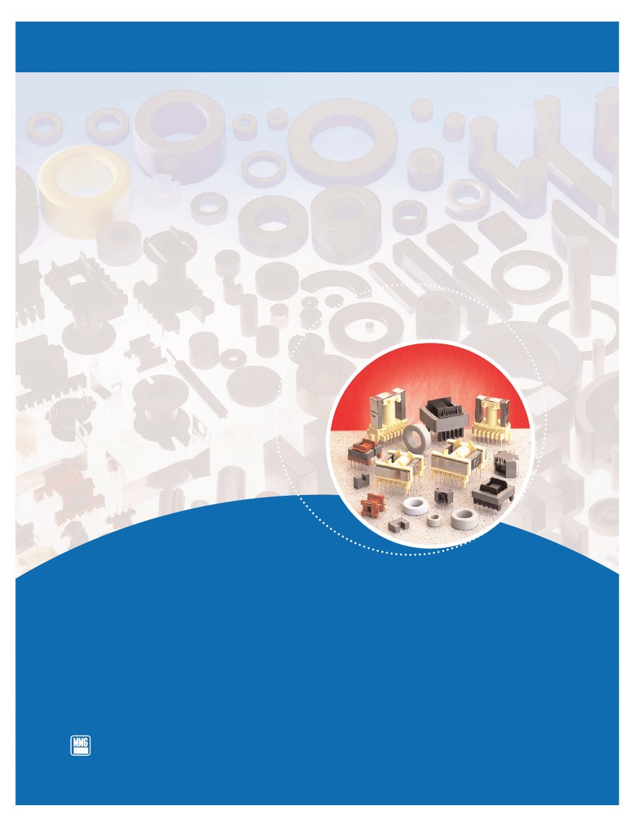
Soft Ferrite Materials & Components

for Power, Signal and EMC Applications

MMG Canada Limited

MMG-Neosid-Catalog-html.html
background image

MMG Companies: MMG-Neosid

Huntingdon Magnets

MMG-North America

MMG-Neosid has been manufacturing magnetic materials since its foundation in 1936
and now manufactures an extensive range of soft ferrite components and accessories.
These are used in the Industrial, Computer, Telecommunications and Automotive/
Aerospace industries and include both Mn-Zn and Ni-Zn ferrite components, thermo-
set/thermoplastic formers and bobbins, and clips.

We also offer a range of toroids and rods (leaded and un-leaded) in Iron and Nickel-
Iron Powders including Molypermalloy.

Isotropic hard ferrite magnets and resin bonded Neodymium-Iron-Boron magnets are
also available from Huntingdon Magnets - a division of MMG-Neosid, based in
Letchworth.

Always sensitive to market changes, MMG-Neosid is constantly developing new ferrite
materials and component geometries to meet changing customer requirements and it
is the experience gained from this that allows us to provide the very best of technical
support and assistance to our customers at all stages of their projects.

Our ISO 9002 accreditation forms the basis of our Quality Assurance Policy but we
would like to think we go beyond the scope of this and offer quality in every aspect of
the way we do business.

The Company’s policy is one of continuous
improvement and development and the right to
change materials, designs, dimensions and
descriptive matter, etc. at any time without notice is
reserved.
Specifications and information contained within this
brochure are intended for guidance only.

MMG-Neosid has exercised the utmost care and
attention in compiling the information contained in
this brochure and believes it to be accurate and
reliable.
 However, it is provided for illustrative purposes only
and MMG-Neosid gives no warranty and makes no
representation that  the theory or other information
contained in the brochure is suitable for any
particular purpose or application.
MMG-Neosid shall not be liable for any loss, direct
or consequential, which may result from the use of
such information.

MMG Canada Ltd

MMG-Neosid-Catalog-html.html
background image

 Materials and Applications

TABLE OF CONTENTS

Component Information

E Cores & Accessories

Planar E Cores

EFD Cores & Accessories

EP Cores & Accessories

ETD Cores & Accessories

2 Slot Pot Cores & Accessories

4 Slot Pot Cores & Accessories

RM Cores & Accessories

Low Profile RM Cores

U Cores & Accessories

Ring Cores

EMC/EMI Suppression & other ferrites

Plastic Products

Soft Ferrite Materials

Technical Information

Terms & Conditions of Sale

Terms & Conditions

Glossary of Terms

Index

Definitions & Properties of Soft Ferrites

Gapped Cores

Product Quality

MMG-Neosid-Catalog-html.html
background image

F47

F45

F44

F5A

F9

F9C

Soft Ferrite Materials

Specific Material Data

F10

F39

P11

P12

F58

F19

F25

F28

F29

F14

F16

MMG-Neosid-Catalog-html.html
background image

Material Characteristics

The following data tabulates the specified material
characteristics of MMG ferrites.
Supplementary graphs show typical performance.
These are given for guidance only.

Data is derived from measurements on toroidal
cores and the values obtained cannot be directly
transferred to products of another shape and size.

The Nickel-Zinc ferrites (mainly used in open-circuit
configurations) are described by Loss Factors
corresponding to the sum of the residual and eddy
current losses.
The grades of Manganese-Zinc ferrites mainly
developed for power applications are characterised
by the Power Loss Density under specified
conditions.
Other Manganese-Zinc ferrites, especially those
used in low frequency telecommunication

Information given for individual grades of ferrite
specify the typical or maximum Loss Factors  for a
range of frequencies where these losses remain
fairly low. Generally speaking, these loss factors
increase with frequency at a steady rate, slowly at
first and then rapidly increasing to overtake the
frequency rise. The point at which this accelerated
rate of increase of loss factors occurs depends upon
the composition and sintering conditions and may
vary between batches of cores.

At frequencies well outside their normal range of
application, all ferrites exhibit high loss
characteristics, and are extensively used for
suppression purposes.

Applications Guide

MMG ferrites are used in an extensive range of
products and applications. Electronics applications
are constantly developing. Listed below is an
applications guide outlining the most popular use of
MMG material grades. It is intended for guidance
only.

Pot cores/RM cores for inductors, transformers -
Grades:

 P11, P12, F58, F5A, F44, F45, F47, F9,

F9C, F10, F39

Low power and pulse transformer cores -
Grades:

F9, F9C, F10, F39, F14

Balun cores -
Grades:

P11, F9, F9C, F10, F19, F14

High power transformer core (E,U & Ring) -
Grades:

F5A, F44, F45, F47

Suppression cores -
Grades:

F9, F9C, F10, F39, F19, F14

Toroidal cores -
Grades:

All grades.

Aerial Rods and slabs -
Long and medium waves:
Grades:

F14

Short wave and VHF:
Grades:

F16, F25, F28, F29

Screw cores, rods, pins and tubes -
Grades:

F14, F25, F29

High frequency welding impeders -
Grades:

F14, F59

applications, are characterised by both the residual
and eddy current loss factor and the hysteresis loss
factors.

MMG-Neosid-Catalog-html.html
background image

Manganese-Zinc ferrites for Industrial and Professional Applications

Parameter

Symbol

Standard Conditions

Unit

F47

F45

F44

F5A

of test

Initial

B<0.1mT

Permeability

µ

i

-

1800

2000

1900

2500

(nominal)

10kHz

25°C

±20%

±20%

±20%

±20%

Saturation

H=796 A/m

Flux Density

B

sat

   =10 Oe

25°C

mT

470

500

500

470

   (typical)

Static

100°C

350

380

400

350

Remanent

H

0 (from near Saturation)

Flux Density

B

r

mT

130

165

270

150

   (typical)

10kHz

25°C

Coercivity

B

0 (from near Saturation)

(typical)

H

c

10kHz

25°C

A/m

24

15

27

15

Loss Factor

B<0.1mT

(maximum)

25°C

10kHz

-

-

-

-

tan 

δ


(r+e)

100kHz

10

-6

-

-

-

-

µ

i

200kHz

-

-

-

-

1MHz

-

-

-

-

Temperature

µ

B<0.1mT

10kHz

10

-6

/

Factor

µ

i

2

.

T

+25°C to +55°C

°C

-

-

-

-

Curie
Temperature

Θ

C

B<0.10mT

10kHz

°C

200

230

230

200

(minimum)

Disaccomodation

µ

B<0.25mT

10kHz

Factor (max)

µ

i

2

.log

10

(t

2

/t

1

)

50°C

10

-6

-

-

-

-

10 to 100 mins

Hysteresis

B from 1.5 to 3mT

10

-6

/

Material

η

Β

10kHz

25°C

mT

-

-

-

-

Constant(max)

Resistivity

1 V/cm

ohm-

(typical)

ρ

25°C

cm

100

100

100

100

 Amplitude

400mT

25°C

2000

2500

2500

2400

Permeability

µ

a

320mT

100°C

-

2500

-

-

1825

(minimum)

340mT

100°C

-

2000

1900

-

Total Power

200mT;   25kHz

25°C

120

-

200

-

Loss Density

200mT;   25kHz

60°C

-

-

-

190

(Maximum)

P

v

200mT;   25kHz

100°C

mW/

100

-

130

190

200mT;   25kHz

120°C

cm³

-

110

-

-

100mT;  100kHz

25°C

110

-

250

-

100mT;  100kHz

100°C

80

80

160

-

100mT;  100kHz

120°C

-

-

-

-

200mT;  100kHz

100°C

-

400

750

-

 50mT;   400kHz

25°C

150

-

-

-

 50mT;   400kHz

100°C

150

-

-

-

Typical Core Shapes:

ETD

E

E

E

EFD

ETD

ETD

ETD

Ring

EFD

EFD

Ring

Planar

Ring

Ring

RM

E

RM

RM & Pot

U

RM

U & I

EP

MMG-Neosid-Catalog-html.html
background image

Initial
Permeability
(Nominal)

Saturation
Flux Density
(Typical)

Remanent
Flux Density
(Typical)

Coercivity
(Typical)

Loss Factor
(Maximum)

Temperature
Factor

Curie
Temperature
(Minimum)

Disaccomodation
Factor (Max)

Hysteresis
Material
Constant (Max)

Resistivity
(Typical)

Data is derived from measurements on toroidal cores.

These values cannot be directly transferred to actual
products. The product related data can be taken only
from the relevant product specification.

Material Grade

Part No. suffix

F47

-47

F45

-45

F44

-44

F5A

-49

F9

-36

F9C

C36

F10

-37

F39

-39

P11

-41

P12

-42

F58

-58

When specifying
materials the
following
component Part
No. suffixes apply.

F9

F9C

F10

F39

P11

P12

F58

Parameter

4400

5000

6000

10 000

2250

2000

750

±20%

±20%

±20%

±20%

±20%

±20%

±20%

380

460

380

380

-

-

450

180

170

100

200

70

35

94

13

13

11

16

18

7

47

---

-

-

-

1.5

0.8

-

20

20

20

-

5

2.5

-

-

-

-

-

-

-

12

-

-

-

-

-

-

20

0 to

-1 to

-1 to

0.5 to

0.4 to

0.5 to

+2

+2

+2

-

1.5

1.0

2.3

130

160

130

125

150

150

200

-

-

-

-

4

3

12

-

-

-

-

0.8

0.45

1.8

50

50

50

100

100

100

100

Pot

Ring

Ring

Ring

RM

RM

RM

RM

E

RM

RM

Pot

Pot

Pot

E

RM

EP

EP

EP

Pot

Pot

Pot

U & I

MMG-Neosid-Catalog-html.html
background image

Nickel-Zinc ferrites for Industrial and Professional Applications

Parameter

Symbol

Standard Conditions

Unit

F19

 F14

F16

of test

Initial

B<0.1mT

Permeability

µ

i

-

1000

220

125

(nominal)

10kHz

25°C

±20%

±20%

±20%

Saturation

H=796 A/m

Flux Density

B

sat

   =10 Oe

25°C

mT

260

350

340

(typical)

Static

Remanent

H

0 (from near Saturation)

Flux Density

B

r

mT

130

270

165

(typical)

10kHz

25°C

Coercivity

B

0 (from near Saturation)

(typical)

H

c

10kHz

25°C

A/m

53

172

200

Loss Factor

B<0.1mT

(maximum)

25°C

250kHz

-

-

-

tan 

δ


(r+e)

500kHz

130

40

-

µ

i

1MHz

350

42

60

2MHz

-

50

-

3MHz

-

-

-

5MHz

10

-6

-

-

65

10MHz

-

-

100

15MHz

-

-

-

20MHz

-

-

-

40MHz

-

-

-

100MHz

-

-

-

200MHz

-

-

-

Temperature

µ

B<0.1mT

10kHz

10

-6

/

3 to

12 to

20 to

Factor

µ

i

2

.

T

+25°C to +55°C

°C

6.5

30

50

Curie
Temperature

Θ

Χ

B<0.10mT

10kHz

°C

120

270

270

(minimum)

Resistivity

1 V/cm

ohm-

(typical)

ρ

25°C

cm

10

5

10

5

10

5

Typical Core Shapes:

Ring

Rods

On

Beads

 Chokes

Request

Tubes

Flat Cable

Suppressor

MMG-Neosid-Catalog-html.html
background image

Initial
Permeability
(Nominal)

Saturation
Flux Density
(Typical)

Remanent
Flux Density
(Typical)

Coercivity
(Typical)

Loss Factor
(Maximum)

Temperature
Factor

Curie
Temperature
(Minimum)

Resistivity
(Typical)

Data is derived from measurements on toroidal cores.

These values cannot be directly transferred to actual
products. The product related data can be taken only
from the relevant product specification.

*

These are perminvar ferrites and undergo irreversible

changes of characteristics (permeability increases and
loss factors become much greater - especially at high
frequencies) if subjected to strong magnetic fields or
mechanical shock.

F25*

F28*

 F29*

50

30

12

±20%

±20%

±20%

-

-

-

-

-

-

-

-

-

-

-

-

-

-

-

50

-

-

50

-

-

55

-

-

65

-

-

75

80

100

100

-

-

125

-

-

300

-

-

-

250

200

-

-

1000

10 to

15

30

50

450

500

500

10

5

10

5

10

5

Rods

Rods

Rods

Slabs

Slabs

Slabs

Material Grade

Part No. suffix

F19

-38

F14

-31

F16

-32

F25

-34

F28

-46

F29

-35

When specifying
materials the
following
component Part
No. suffixes apply.

MMG-Neosid-Catalog-html.html
background image

Parameter

Symbol

Standard Conditions

Unit

F47

of test

Initial Permeability

B<0.1mT

-

1800

(nominal)

10kHz

25°C

±20%

Saturation Flux

H=796 A/m = 10 Oe

25°C

mT

470

Density 

(typical)

100°C

350

Remanent Flux

H

➞ 

(from near Saturation)

Density 

(typical)

10kHz

25°C

mT

130

Coercivity

B

➞ 

(from near Saturation)

(typical)

10kHz

25°C

A/m

24

Curie Temperature

(minimum)

B<0.10mT

10kHz

°C

200

Resistivity

1 V/cm

ohm-

(typical)

25°C

cm

100

Amplitude Permeability

400mT

25°C

-

2500

(minimum)

340mT

100°C

2000

Total Power
Loss Density

100mT; 100kHz

25°C (typ.)

mW/

110

100mT; 100kHz 100°C (max.)

cm³

80

1

50mT; 400kHz

25°C (typ.)

150

1

50mT; 400kHz 100°C (max.)

150

B

sat

B

r

-

H

c

Θ

c

ρ

µ

a

P

v

Material Specification

Relative Loss Factor vs. Frequency

Initial Permeability vs. Temperature

Complex Permeability vs. Frequency

Power Loss Density vs. Frequency

Power Loss Density vs. Temperature

Static Magnetisation: Permeability vs. B

Dynamic Magnetisation:  Typical B-H Loops

23°C

100°C

Data derived from measurements on a ring core of 30mm outside diameter.

F47

Material Type:

Manganese-Zinc Ferrite

Properties:

*Higher frequency power grade
*Low losses in recommended

frequency range

*High saturation
*Medium Permeability
*Losses minimised 60°C - 80°C

Frequency Range:

300kHz to 1MHz (depending
upon flux density)

Typical Applications:

SMPS.

Available core shapes:

E, ETD, EFD, RM, Ring Cores.

MMG-Neosid-Catalog-html.html
background image

Parameter

Symbol

Standard Conditions

Unit

F45

of test

Initial Permeability

B<0.1mT

-

2000

(nominal)

10kHz

25°C

±20%

Saturation Flux

H=796 A/m = 10 Oe

25°C

mT

500

Density 

(typical)

100°C

380

Remanent Flux

H

➞ 

(from near Saturation)

Density 

(typical)

10kHz

25°C

mT

165

Coercivity

B

➞ 

(from near Saturation)

(typical)

10kHz

25°C

A/m

15

Curie Temperature

(minimum)

B<0.10mT

10kHz

°C

230

Resistivity

1 V/cm

ohm-

(typical)

25°C

cm

100

Amplitude Permeability

400mT

25°C

-

2500

(minimum)

340mT

100°C

2000

Total Power

100mT;  100kHz

100°C

mW/

80

Loss Density

P

v

200mT;  100kHz

100°C

cm³

400

(maximum)

B

sat

B

r

-

H

c

Θ

c

ρ

µ

a

Material Specification

Relative Loss Factor vs. Frequency

Initial Permeability vs. Temperature

Complex Permeability vs. Frequency

Power Loss Density vs. Frequency

Power Loss Density vs. Temperature

Static Magnetisation: Permeability vs. B

Dynamic Magnetisation:  Typical B-H Loops

Data is derived from measurements on a ring core of 30mm outside diameter.

F45

Material Type:

Manganese-Zinc Ferrite

Properties:

*Low loss power grade.
*High saturation
*Losses minimised 80°C - 100°C
*Medium permeability

Frequency range:

Up to 500kHz (depending
upon flux density)

Typical Applications:

SMPS.

Available core shapes:

E, U, ETD, RM, Ring Cores.

MMG-Neosid-Catalog-html.html
background image

Parameter

Symbol

Standard Conditions

Unit

F44

of test

Initial Permeability

B<0.1mT

-

1900

(nominal)

10kHz

25°C

±20%

Saturation Flux

H=796 A/m = 10 Oe

25°C

mT

500

Density 

(typical)

100°C

400

Remanent Flux

H

➞ 

(from near Saturation)

Density 

(typical)

10kHz

25°C

mT

270

Coercivity

B

➞ 

(from near Saturation)

(typical)

10kHz

25°C

A/m

27

Curie Temperature

(minimum)

B<0.10mT

10kHz

°C

230

Resistivity

1 V/cm

ohm-

(typical)

25°C

cm

100

Amplitude Permeability

400mT

25°C

-

2500

(minimum)

340mT

100°C

1900

Total Power

200mT;   25kHz

25°C

200

Loss Density

200mT;   25kHz

100°C

mW/

130

(maximum)

100mT; 100kHz

25°C

cm³

250

100mT; 100kHz

100°C

160

200mT; 100kHz

100°C

750

B

sat

B

r

-

H

c

Θ

c

ρ

µ

a

P

v

Material Specification

Relative Loss Factor vs. Frequency

Initial Permeability vs. Temperature

Complex Permeability vs. Frequency

Power Loss Density vs. Frequency

Power Loss Density vs. Temperature

Static Magnetisation: Permeability vs. B

Dynamic Magnetisation:  Typical B-H Loops

Data is derived from measurements on a ring core of 30mm outside diameter.

Complex Permeability vs. Frequency

F44

Material Type:

Manganese-Zinc Ferrite

Properties:

*Higher saturation power grade
*Higher amplitude permeability
*Low power losses in
  recommended frequency range
*Losses minimised above 70°C
*Medium permeability

Frequency range:

Up to 300kHz 

(depending upon flux density)

Typical Applications:

SMPS, EHT Transformers,
converters.

Available core shapes:

E, U, ETD, EFD,EP,Pot,  RM,
Ring Cores.

MMG-Neosid-Catalog-html.html
background image

Parameter

Symbol

Standard Conditions

Unit

F5A

of test

Initial Permeability

B<0.1mT

-

2500

(nominal)

10kHz

25°C

±20%

Saturation Flux

H=796 A/m = 10 Oe

25°C

mT

470

Density 

(typical)

100°C

350

Remanent Flux

H

➞ 

(from near Saturation)

Density 

(typical)

10kHz

25°C

mT

150

Coercivity

B

➞ 

(from near Saturation)

(typical)

10kHz

25°C

A/m

15

Curie Temperature

(minimum)

B<0.10mT

10kHz

°C

200

Resistivity

1 V/cm

ohm-

(typical)

25°C

cm

100

Amplitude Permeability

400mT

25°C

-

2400

(minimum)

320mT

100°C

1825

Total Power

200mT; 25kHz

60°C

mW/

190

Loss Density

P

v

200mT;25kHz

100°C

cm³

190

(maximum)

B

sat

B

r

-

H

c

Θ

c

ρ

µ

a

Material Specification

Relative Loss Factor vs. Frequency

Initial Permeability vs. Temperature

Complex Permeability vs. Frequency

Power Loss Density vs. Frequency

Power Loss Density vs. Temperature

Static Magnetisation: Permeability vs. B

Dynamic Magnetisation:  Typical B-H Loops

Data is derived from measurements on a ring core of 30mm outside diameter.

25°C

100°C

F5A

Material Type:

Manganese-Zinc Ferrite

Properties:

*Higher permeability power
  grade
*High saturation
*Low loss
*Losses minimised 50°C - 80°C

Frequency range:

Up to 150/200kHz (depending

upon flux density)

Typical Applications:

Power Supplies, EHT
Transformers.

Available core shapes:

E, U, ETD, RM, Ring Cores.

60°C

MMG-Neosid-Catalog-html.html
background image

Relative Loss Factor vs. Frequency

Complex Permeability vs. Frequency

Dynamic Magnetisation:  Typical B-H Loops

Data is derived from measurements on a ring core of 30mm outside diameter.

Parameter

Symbol

Standard Conditions

Unit

F9

of test

Initial Permeability

B<0.1mT

-

4400

(nominal)

10kHz

25°C

±20%

Saturation Flux

H=796 A/m = 10 Oe

Density 

(typical)

25°C

mT

380

Remanent Flux

H

➞ 

(from near Saturation)

Density 

(typical)

10kHz

25°C

mT

180

Coercivity

B

➞ 

(from near Saturation)

(typical)

10kHz

25°C

A/m

13

Loss Factor

B<0.10mT

(maximum)

10kHz

25°C

10

-6

20

Curie Temperature

(minimum)

B<0.10mT

10kHz

°C

130

Temperature Factor

+25°C to +55°C

0 to

B<0.10mT

10kHz

°C

+2

Resistivity

1 V/cm

ohm-

(typical)

25°C

cm

50

B

sat

B

r

-

H

c

Θ

C

Material Specification

ρ

F9

Material Type:

Manganese-Zinc Ferrite

Properties:

High permeability.

Frequency range:

Depends on application

Typical Applications:

Wideband & Pulse
Transformers, Filter &
Interference

 Suppression

applications.

Available core shapes:

Ring, E, EP, U, RM & Pot Cores.

Initial Permeability vs. Temperature

∆µ

µ

i

2

.

T

tan

 δ

(r+e)

µ

i

MMG-Neosid-Catalog-html.html
background image

Relative Loss Factor vs. Frequency

Initial Permeability vs. Temperature

Complex Permeability vs. Frequency

Power Loss Density vs. Frequency

Power Loss Density vs. Temperature

Normalised Impedance vs. Frequency

Dynamic Magnetisation:  Typical B-H Loops

Data is derived from measurements on a ring core of 30mm outside diameter.

25°C

Parameter

Symbol

Standard Conditions

Unit

F9C

of test

Initial Permeability

B<0.1mT

-

5000

(nominal)

10kHz

25°C

±20%

Saturation Flux

H=796 A/m = 10 Oe

Density 

(typical)

25°C

mT

460

Remanent Flux

H

➞ 

(from near Saturation)

Density 

(typical)

10kHz

25°C

mT

170

Coercivity

B

➞ 

(from near Saturation)

(typical)

10kHz

25°C

A/m

13

Loss Factor

B<0.10mT

(maximum)

10kHz

25°C

10

-6

20

Curie Temperature

(minimum)

B<0.10mT

10kHz

°C

160

Temperature Factor

+25°C to +55°C

-1 to

B<0.10mT

10kHz

°C

+2

Resistivity

1 V/cm

ohm-

(typical)

25°C

cm

50

B

sat

B

r

-

H

c

Θ

C

Material Specification

ρ

Complex Permeability vs. Frequency

F9C

Material Type:

Manganese-Zinc Ferrite

Properties:

*High permeability
*High saturation
*Improved frequency response

(depending on application)

*High Curie temperature

Frequency range:

Depends on application

Typical Applications:

Specially developed for Mains
filtering, Wideband and Pulse
Transformers

Available core shapes:

Ring, E, RM & Pot Cores.

∆µ

µ

i

2

.

T

tan

 δ

(r+e)

µ

i

Z

act

=

Z

norm

C1

MMG-Neosid-Catalog-html.html
background image

Relative Loss Factor vs. Frequency

Initial Permeability vs. Temperature

Complex Permeability vs. Frequency

Dynamic Magnetisation:  Typical B-H Loops

Data is derived from measurements on a ring core of 30mm outside diameter.

Parameter

Symbol

Standard Conditions

Unit

F10

of test

Initial Permeability

B<0.1mT

-

6000

(nominal)

10kHz

25°C

±20%

Saturation Flux

H=796 A/m = 10 Oe

Density 

(typical)

25°C

mT

380

Remanent Flux

H

➞ 

(from near Saturation)

Density 

(typical)

10kHz

25°C

mT

200

Coercivity

B

➞ 

(from near Saturation)

(typical)

10kHz

25°C

A/m

16

Loss Factor

B<0.10mT

(maximum)

10kHz

25°C

10

-6

-

Curie Temperature

(minimum)

B<0.10mT

10kHz

°C

130

Temperature Factor

+25°C to +55°C

-1 to

B<0.10mT

10kHz

°C

+2

Resistivity

1 V/cm

ohm-

(typical)

25°C

cm

50

B

sat

B

r

-

H

c

Θ

C

Material Specification

ρ

Complex Permeability vs. Frequency

F10

Material Type:

Manganese-Zinc Ferrite

Properties:

High permeability.

Frequency range:

Depends on application

Typical Applications:

Wideband, Pulse
Transformers and Filter
applications.

Available core shapes:

Ring, E, EP, RM & Pot Cores.

∆µ

µ

i

2

.

T

tan

 δ

(r+e)

µ

i

MMG-Neosid-Catalog-html.html
background image

Initial Permeability vs. Temperature

Complex Permeability vs. Frequency

Dynamic Magnetisation:  Typical B-H Loops

Data is derived from measurements on a ring core of 30mm outside diameter.

Parameter

Symbol

Standard Conditions

Unit

F39

of test

Initial Permeability

B<0.1mT

-

10 000

(nominal)

10kHz

25°C

±30%

Saturation Flux

H=796 A/m = 10 Oe

Density 

(typical)

25°C

mT

380

Remanent Flux

H

➞ 

(from near Saturation)

Density 

(typical)

10kHz

25°C

mT

200

Coercivity

B

➞ 

(from near Saturation)

(typical)

10kHz

25°C

A/m

16

Loss Factor

B<0.10mT

(maximum)

10kHz

25°C

10

-6

-

Curie Temperature

(minimum)

B<0.10mT

10kHz

°C

125

Temperature Factor

+25°C to +55°C
B<0.10mT

10kHz

°C

-

Resistivity

1 V/cm

ohm-

(typical)

25°C

cm

100

B

sat

B

r

-

H

c

Θ

C

Material Specification

ρ

F39

Material Type:

Manganese-Zinc Ferrite

Properties:

Very high permeability

Frequency range:

Depends on application

Typical Applications:

Broadband and Pulse
Transformers, Balanced
(common-mode) chokes and

inductors for filters.

Available core shapes:

EP, Pot, RM, Ring Cores.

∆µ

µ

i

2

.

T

tan

 δ

(r+e)

µ

i

MMG-Neosid-Catalog-html.html
background image

Parameter

Symbol

Standard Conditions

Unit

P11

of test

Initial Permeability

B<0.1mT

-

2250

(nominal)

10kHz

25°C

±20%

Saturation Flux

H=796 A/m = 10 Oe

Density 

(typical)

25°C

mT

-

Remanent Flux

H

➞ 

(from near Saturation)

Density 

(typical)

10kHz

25°C

mT

70

Coercivity

B

➞ 

(from near Saturation)

(typical)

10kHz

25°C

A/m

18

Loss Factor

B<0.10mT

10kHz

1.5

(maximum)

25°C

100kHz

10

-6

5

Curie Temperature

(minimum)

B<0.10mT

10kHz

°C

150

Hysteresis Material

B from 1.5 to 3mT

10

-6

/

Constant

 (maximum)

10kHz

25°C

°C

0.8

Disaccommodation

10 to 100mins.

50°C

Factor  

(maximum)

B<0.25mT

10kHz

10

-6

4

Temperature Factor

+25°C to +55°C

0.5 to

B<0.10mT

10kHz

°C

1.5

Resistivity

1 V/cm

ohm-

(typical)

25°C

cm

100

Material Specification

Relative Loss Factor vs. Frequency

Initial Permeability vs. Temperature

Complex Permeability vs. Frequency

Dynamic Magnetisation:  Typical B-H Loops

Data is derived from measurements on a ring core of 30mm outside diameter.

B

sat

B

r

-

H

c

Θ

C

ρ

η

B

µ

i

2

.log

10

(t

2

/t

1

)

µ

P11

Material Type:

Manganese-Zinc Ferrite

Properties:

*High stability of inductance
*Low temperature coefficient
*Low loss factors
*Medium permeability

Frequency range:

Depends on application

Typical Applications:

Filter networks and proximity
detectors

Available core shapes:

RM and Pot Cores.

∆µ

µ

i

2

.

T

tan

 δ

(r+e)

µ

i

MMG-Neosid-Catalog-html.html
background image

Parameter

Symbol

Standard Conditions

Unit

P12

of test

Initial Permeability

B<0.1mT

-

2000

(nominal)

10kHz

25°C

±20%

Saturation Flux

H=796 A/m = 10 Oe

Density 

(typical)

25°C

mT

-

Remanent Flux

H

➞ 

(from near Saturation)

Density 

(typical)

10kHz

25°C

mT

35

Coercivity

B

➞ 

(from near Saturation)

(typical)

10kHz

25°C

A/m

7

Loss Factor

B<0.10mT

10kHz

0.8

(maximum)

25°C

100kHz

10

-6

2.5

Curie Temperature

(minimum)

B<0.10mT

10kHz

°C

150

Hysteresis Material

B from 1.5 to 3mT

10

-6

/

Constant

 (maximum)

10kHz

25°C

°C

0.45

Disaccommodation

10 to 100mins.

50°C

Factor  

(maximum)

B<0.25mT

10kHz

10

-6

3

Temperature Factor

+25°C to +55°C

0.4 to

B<0.10mT

10kHz

°C

1

Resistivity

1 V/cm

ohm-

(typical)

25°C

cm

100

Material Specification

Relative Loss Factor vs. Frequency

Initial Permeability vs. Temperature

Complex Permeability vs. Frequency

Dynamic Magnetisation:  Typical B-H Loops

Data is derived from measurements on a ring core of 30mm outside diameter.

B

sat

B

r

-

H

c

Θ

C

ρ

η

B

µ

i

2

.log

10

(t

2

/t

1

)

µ

P12

Material Type:

Manganese-Zinc Ferrite

Properties:

*High stability of inductance
*Low temperature coefficient
*Low loss factors
*Medium permeability

Frequency range:

Depends on application.

Typical Applications:

Filter networks.

Available core shapes:

RM and Pot cores.

∆µ

µ

i

2

.

T

tan

 δ

(r+e)

µ

i

MMG-Neosid-Catalog-html.html
background image

Parameter

Symbol

Standard Conditions

Unit

F58

of test

Initial Permeability

B<0.1mT

-

750

(nominal)

10kHz

25°C

±20%

Saturation Flux

H=796 A/m = 10 Oe

Density 

(typical)

25°C

mT

450

Remanent Flux

H

➞ 

(from near Saturation)

Density 

(typical)

10kHz

25°C

mT

94

Coercivity

B

➞ 

(from near Saturation)

(typical)

10kHz

25°C

A/m

47

Loss Factor

B<0.10mT

200kHz

12

(maximum)

25°C

1MHz

10

-6

20

Curie Temperature

(minimum)

B<0.10mT

10kHz

°C

200

Hysteresis Material

B from 1.5 to 3mT

10

-6

/

Constant

 (maximum)

10kHz

25°C

°C

1.8

Disaccommodation

10 to 100mins.

50°C

Factor  

(maximum)

B<0.25mT

10kHz

10

-6

12

Temperature Factor

+25°C to +55°C

0.5 to

B<0.10mT

10kHz

°C

2.3

Resistivity

1 V/cm

ohm-

(typical)

25°C

cm

100

Material Specification

Relative Loss Factor vs. Frequency

Initial Permeability vs. Temperature

Complex Permeability vs. Frequency

Dynamic Magnetisation:  Typical B-H Loops

Data is derived from measurements on a ring core of 30mm outside diameter.

B

sat

B

r

-

H

c

Θ

C

ρ

η

B

µ

i

2

.log

10

(t

2

/t

1

)

µ

F58

Material Type:

Manganese-Zinc Ferrite

Properties:

*High stability of inductance
*Low temperature coefficient
*Low loss factors at higher

frequencies in the
recommended range

Frequency range:

200kHz-1MHz 

(Subject to application)

Typical Applications:

Filter applications, proximity

switches and gate drive

transformers for SMPS.

Available core shapes:

RM and Pot Cores

∆µ

µ

i

2

.

T

tan

 δ

(r+e)

µ

i

MMG-Neosid-Catalog-html.html
background image

Relative Loss Factor vs. Frequency

Initial Permeability vs. Temperature

Complex Permeability vs. Frequency

Data is derived from measurements on a ring core of 30mm outside diameter.

Parameter

Symbol

Standard Conditions

Unit

F19

of test

Initial Permeability

B<0.1mT

-

1000

(nominal)

10kHz

25°C

±20%

Saturation Flux

H=796 A/m = 10 Oe

Density 

(typical)

25°C

mT

260

Remanent Flux

H

➞ 

(from near Saturation)

Density 

(typical)

10kHz

25°C

mT

165

Coercivity

B

➞ 

(from near Saturation)

(typical)

10kHz

25°C

A/m

53

Loss Factor

B<0.10mT

500kHz

130

(maximum)

25°C

1MHz

10

-6

350

Curie Temperature

(minimum)

B<0.10mT

10kHz

°C

120

Temperature Factor

+25°C to +55°C

3 to

B<0.10mT

10kHz

°C

6.5

Resistivity

1 V/cm

ohm-

(typical)

25°C

cm

10

4

B

sat

B

r

-

H

c

Θ

C

Material Specification

ρ

Dynamic Magnetisation:  Typical B-H Loops

Normalised Impedance vs. Frequency

F19

Material Type:

Nickel-Zinc Ferrite

Properties:

*Medium permeability
*Low loss factors at low

frequencies

*High impedance at

megahertz frequencies

Frequency range:

100kHz - 1MHz 

(Low losses)

25MHz - 100MHz 

(High impedance)

Typical Applications:

SMD suppression

Available core shapes:

Ring cores, beads, sleeves,
cable suppressors, SM beads.

Z

act

Z

norm

C1

∆µ

µ

i

2

.

T

tan

 δ

(r+e)

µ

i

MMG-Neosid-Catalog-html.html
background image

Relative Loss Factor vs. Frequency

Initial Permeability vs. Temperature

Complex Permeability vs. Frequency

Dynamic Magnetisation:  Typical B-H Loops

Data is derived from measurements on a ring core of 30mm outside diameter.

Parameter

Symbol

Standard Conditions

Unit

F14

of test

Initial Permeability

B<0.1mT

-

220

(nominal)

10kHz

25°C

±20%

Saturation Flux

H=796 A/m = 10 Oe

Density 

(typical)

25°C

mT

350

Remanent Flux

H

➞ 

(from near Saturation)

Density 

(typical)

10kHz

25°C

mT

217

Coercivity

B

➞ 

(from near Saturation)

(typical)

10kHz

25°C

A/m

172

Loss Factor

B<0.10mT

500kHz

40

(maximum)

1MHz

10

-6

42

25°c

2MHz

50

Curie Temperature

(minimum)

B<0.10mT

10kHz

°C

270

Temperature Factor

+25°C to +55°C

12 to

B<0.10mT

10kHz

°C

30

Resistivity

1 V/cm

ohm-

(typical)

25°C

cm

10

5

B

sat

B

r

-

H

c

Θ

C

Material Specification

ρ

F14

Material Type:

Nickel-Zinc Ferrite

Properties:

*Low loss factors at medium

frequencies

*High suppression impedance

at high frequencies

Frequency range:

Up to 3MHz 

(Low losses)

Over 100MHz 

(Suppression)

Typical Applications:

RF Suppression, balun
transformers, aerial rods,
medium frequency tuned circuits.

Available core shapes:

Rods, Chokes.

∆µ

µ

i

2

.

T

tan

 δ

(r+e)

µ

i

MMG-Neosid-Catalog-html.html
background image

Relative Loss Factor vs. Frequency

Initial Permeability vs. Temperature

Complex Permeability vs. Frequency

Dynamic Magnetisation:  Typical B-H Loops

Data is derived from measurements on a ring core of 145x3.8x12mm (ODxIDxHT)

Parameter

Symbol

Standard Conditions

Unit

F16

of test

Initial Permeability

B<0.1mT

-

125

(nominal)

10kHz

25°C

±20%

Saturation Flux

H=796 A/m = 10 Oe

Density 

(typical)

25°C

mT

340

Remanent Flux

H

➞ 

(from near Saturation)

Density 

(typical)

10kHz

25°C

mT

260

Coercivity

B

➞ 

(from near Saturation)

(typical)

10kHz

25°C

A/m

200

Loss Factor

B<0.10mT

1MHz

60

(maximum)

5MHz

10

-6

65

25°c

10MHz

100

Curie Temperature

(minimum)

B<0.10mT

10kHz

°C

270

Temperature Factor

+25°C to +55°C

20 to

B<0.10mT

10kHz

°C

50

Resistivity

1 V/cm

ohm-

(typical)

25°C

cm

10

5

B

sat

B

r

-

H

c

Θ

C

Material Specification

ρ

F16


Special Grade

Material Type:

Nickel-Zinc Ferrite

Properties:

Low loss factors at high
frequency

Frequency range:

500kHz-10MHz

(Subject  to application)

Typical Applications:

Aerial rods and tuned circuits.

Available core shapes:

On request.

∆µ

µ

i

2

.

T

tan

 δ

(r+e)

µ

i

MMG-Neosid-Catalog-html.html
background image

Data is derived from measurements on a ring core of 14.5x3.8x12mm (OD x ID x HT)

F25 F28 F29

Special Grades

Material Type:

Nickel-Zinc Ferrite

Properties:

*Perminvar
*Very high Q at high

frequency

Frequency range:

1MHz + depending on

material grade

Typical Applications:

Aerial rods and high
frequency tuned
circuits.

Available core shapes:

On request.

Material Specifications

Note

: Perminvar ferrites undergo irreversible

changes of characteristics if subject to strong
magnetic fields or mechanical shock.

Complex Permeability vs. Frequency

Relative Loss Factor vs. Frequency

Initial Permeability vs. Temperature

Complex Permeability vs. Frequency

Relative Loss Factor vs. Frequency

Initial Permeability vs. Temperature

Complex Permeability vs. Frequency

Relative Loss Factor vs. Frequency

Initial Permeability vs. Temperature

F25

F28

F29

Θ

C

ρ

Parameter

Symbol Standard Conditions

Unit

F25

F28

F29

of test

Initial Permeability

B<0.1mT

-

50

30

12

(nominal)

10kHz

25°C

±20%

±20

±20

Loss Factor

B<0.10mT

1MHz

50

-

-

(maximum)

2MHz

50

-

-

3MHz

55

-

-

5MHz

10

-6

65

-

-

10MHz

75

80

100

15MHz

100

-

-

20MHz

125

-

-

40MHz

300

-

-

100MHz

-

250

200

200MHz

-

-

1000

Curie Temperature

(minimum)

B<0.10mT

10kHz

°C

450

500

500

Temperature Factor

+25°C to +55°C

10 to

3050

B<0.10mT

10kHz

°C

15

Resistivity

1 V/cm

ohm-

(typical)

25°C

cm

10

5

10

5

10

5

∆µ

µ

i

2

.

T

tan

 δ

(r+e)

µ

i

MMG-Neosid-Catalog-html.html
background image

EF 25 

32-

190

-

E 25/9.5/6 

32-

030

-

E 30/30/7 

32-

130

-

EF 32 

32-

360

-

E 34/8 

32-

010

-

E 34/14 

32-

320

-

E 41/9 

32-

020

-

E Cores and Accessories

E 41/16/12 

32-

330

-

E 42/15


     32-

110 

-

E 42/20


  32-

120

-

E 55/21


32-

150

-

E 55/25


32-

170

-

E 65/27


32-

240

-

E 70/32 

32-

250

-

EF 12.6 

32-

200

-

EF 16 

32-

370

-

E 19/8/5 

32-

160

-

E 20/10/5 

32-

140

-

EF 20 

32-

180

-

MMG-Neosid-Catalog-html.html
background image

E Series

Components

E Series

Components

E Cores

E Cores were one of the first ferrite cores to be manufactured, being derived from their respective
iron lamination size. Having rectangular limbs they are relatively easy to manufacture and as such a
vast range exists in the marketplace. MMG-Neosid’s range reflects a selection of cores that have
become, over  many years, worldwide standards through continued use. E cores are particularly
suitable for power transformers and filters at low frequencies. They are not suitable in high frequency
applications as the rectangluar centre limb leads to higher leakage inductance and winding resistance.

E Core

Coilformer

E Core

MMG-Neosid-Catalog-html.html
background image

EF 12.6

32-200-

EF 12.6

32-200-

Parameter

Σ

/A

Effective Length

Effective Area

Minimum Area

Effective Volume

Symbol

C

1

l

e

A

e

A

min

V

e

Value

2.28mm

-1

29.60mm

13.00mm²

12.20mm²

384.00mm³


 Core Parameters

Material

A

L

 Value

Tolerance

Gap  Length

Eff. Permeability

Part Number

F9

 1000 +30/-20% - 1814 32-200-36

F44

 760 +30/-20% - 1380 32-200-44


 Electrical Specification

Part numbers refer to half cores. Other material grades and gap lengths may be available on request.

In accordance with IEC Document 60205.


 Bobbins/Coil Formers

Mounting

No. of Sections

Pins

Part Number

Horizontal

1

6

59-200-66

SMD

1

10

59-205-76


Core Dimensions (mm)

A

B

C

D

E

F

G

12.20 -
13.10

6.30 -
6.50

3.40 -
3.70

4.20 -
4.50

8.90 -
9.50

3.40 -
3.70

12.60 -
13.00

Part Number

76-075-95


 Clips

MMG-Neosid-Catalog-html.html
background image

EF 16

32-370-

EF 16

32-370-

Parameter

Σ

/A

Effective Length

Effective Area

Minimum Area

Effective Volume

Symbol

C

1

l

e

A

e

A

min

V

e

Value

1.87mm

-1

37.60mm

20.10mm²

19.40mm²

754.00mm³


 Core Parameters

Material

A

L

 Value

Tolerance

Gap  Length

Eff. Permeability

Part Number

F9

 1400 +30/-20% - 2083 32-370-36

F44

 960 +30/-20% - 1428 32-370-44


 Electrical Specification

Part numbers refer to half cores. Other material grades and gap lengths may be available on request.

In accordance with IEC Document 60205.


 Bobbins/Coil Formers

Mounting

No. of Sections

Pins

Part Number

Horizontal

1

6

59-370-66

Vertical

1

6

59-375-66


Core Dimensions (mm)

A

B

C

D

E

F

G

15.50 -
16.70

7.90 -
8.20

4.30 -
4.70

5.70 -
6.10

11.30 -
11.90

4.30 -
4.70

15.80 -
16.40

Part Number

76-076-95


 Clips

MMG-Neosid-Catalog-html.html
background image

E 19/8/5

32-160-

E 19/8/5

32-160-

Parameter

Σ

/A

Effective Length

Effective Area

Minimum Area

Effective Volume

Symbol

C

1

l

e

A

e

A

min

V

e

Value

1.78mm

-1

40.00mm

22.50mm²

-

900.00mm³


 Core Parameters

Material

A

L

 Value

Tolerance

Gap  Length

Eff. Permeability

Part Number

F44

 970 +30/-20% - 1375 32-160-44

F5A

 1190 +30/-20% - 1685 32-160-49

F9

 2160 +30/-20% - 3060 32-160-36

F9C

 2350 +30/-20% - 3330 32-160C36


 Electrical Specification


 Bobbins/Coil Formers

Mounting

No. of Sections

Pins

Part Number

Horizontal

1

8

59-160-76

Part numbers refer to half cores. Other material grades and gap lengths may be available on request.

In accordance with IEC Document 60205.


Core Dimensions (mm)

A

B

C

D

E

F

G

18.80 -
19.80

7.95 -
8.20

4.57 -
4.93

5.59 -
5.84

13.80 -
15.30

4.57 -
4.93

15.90 -
16.40

MMG-Neosid-Catalog-html.html
background image

E 20/10/5

32-140-

E 20/10/5

32-140-

Parameter

Σ

/A

Effective Length

Effective Area

Minimum Area

Effective Volume

Symbol

C

1

l

e

A

e

A

min

V

e

Value

1.37mm

-1

43.00mm

31.00mm²

25.50mm²

1330.00mm³


 Core Parameters

Material

A

L

 Value

Tolerance

Gap  Length

Eff. Permeability

Part Number

F44

 1390 +30/-20% - 1515 32-140-44

F9

 2500 +30/-20% - 2725 32-140-36


 Electrical Specification

Part numbers refer to half cores. Other material grades and gap lengths may be available on request.

In accordance with IEC Document 60205.


 Bobbins/Coil Formers

Mounting

No. of Sections

Pins

Part Number

Horizontal

1

8

59-140-64


Core Dimensions (mm)

A

B

C

D

E

F

G

19.60 -

20.70

9.80 -

10.20

4.90 -
5.30

6.30 -
6.70

12.80 -
13.40

4.80 -
5.20

19.60 -

20.40

Part Number

76-077-95


 Clips

MMG-Neosid-Catalog-html.html
background image

EF 20

32-180-

EF 20

32-180-

Parameter

Σ

/A

Effective Length

Effective Area

Minimum Area

Effective Volume

Symbol

C

1

l

e

A

e

A

min

V

e

Value

1.34mm

-1

44.90mm

33.50mm²

31.40mm²

1500.00mm³


 Core Parameters

Material

A

L

 Value

Tolerance

Gap  Length

Eff. Permeability

Part Number

F44

 1300 +30/-20% - 1385 32-180-44

F9

 2500 +30/-20% - 2585 32-180-36


 Electrical Specification


 Bobbins/Coil Formers

Mounting

No. of Sections

Pins

Part Number

Horizontal

1

8

59-180-66

Part numbers refer to half cores. Other material grades and gap lengths may be available on request.

In accordance with IEC Document 60205.

Part Number

76-077-95


 Clips


Core Dimensions (mm)

A

B

C

D

E

F

G

19.60 -

20.70

9.80 -

10.10

5.50 -
5.90

7.00 -
7.30

14.10 -
14.70

5.60 -
5.90

19.60 -

20.20

MMG-Neosid-Catalog-html.html
background image

EF 25

32-190-

EF 25

32-190-

Parameter

Σ

/A

Effective Length

Effective Area

Minimum Area

Effective Volume

Symbol

C

1

l

e

A

e

A

min

V

e

Value

1.09mm

-1

57.50mm

52.50mm²

51.50mm²

3020.00mm³


 Core Parameters


 Electrical Specification

Part numbers refer to half cores. Other material grades and gap lengths may be available on request.

In accordance with IEC Document 60205.


 Bobbins/Coil Formers

Mounting

No. of Sections

Pins

Part Number

Horizontal

1

10

59-190-66

Horizontal

2

10

59-191-66

Part Number

76-078-95


 Clips

Material

A

L

 Value

Tolerance

Gap  Length

Eff. Permeability

Part Number

F47

 1550 +30/-20% - 1345 32-190-47

F44

 1710 +30/-20% - 1485 32-190-44

F45

 1900 +30/-20% - 1650 32-190-45

F9

 3100 +30/-20% - 2690 32-190-36

F10

 4500 +30/-20% - 3900 32-190-37


Core Dimensions (mm)

A

B

C

D

E

F

G

24.30 -
25.40

12.30 -
12.80

6.90 -
7.50

8.70 -
9.20

17.50 -

18.30

7.00 -
7.50

24.60 -
25.60

MMG-Neosid-Catalog-html.html
background image

E 25/9.5/6

32-030-

E 25/9.5/6

32-030-

Parameter

Σ

/A

Effective Length

Effective Area

Minimum Area

Effective Volume

Symbol

C

1

l

e

A

e

A

min

V

e

Value

1.28mm

-1

48.70mm

38.10mm²

-

1860.00mm³


 Core Parameters


 Bobbins/Coil Formers

Mounting

No. of Sections

Pins

Part Number

Horizontal

1

0

59-030-66

Horizontal

1

10

59-031-66

In accordance with IEC Document 60205.

Material

A

L

 Value

Tolerance

Gap  Length

Eff. Permeability

Part Number

F44

 1480 +30/-20% - 1510 32-030-44

F5A

 1835 +30/-20% - 1870 32-030-49

F9

 2740 +30/-20% - 2790 32-030-36

F9C

 3280 +30/-20% - 3340 32-030C36

F10

 4000 +30/-20% - 4075 32-030-37

F39

 8570 +40/-30% - 8730 32-030-39


 Electrical Specification

Part numbers refer to half cores. Other material grades and gap lengths may be available on request.


Core Dimensions (mm)

A

B

C

D

E

F

G

24.77 -
26.03

9.40 -
9.65

6.07 -
6.47

6.30 -
6.68

19.05 -

20.07

6.07 -
6.47

18.80 -
19.30

MMG-Neosid-Catalog-html.html
background image

E 30/30/7

32-130-

E 30/30/7

32-130-


 Electrical Specification

Part numbers refer to half cores. Other material grades and gap lengths may be available on request.

In accordance with IEC Document 60205.


 Bobbins/Coil Formers

Mounting

No. of Sections

Pins

Part Number

Horizontal

1

10

59-130-64

Horizontal

1

12

59-130-66

Material

A

L

 Value

Tolerance

Gap  Length

Eff. Permeability

Part Number

F44

 1800 +30/-20% - 1605 32-130-44

F45

 1800 +30/-20% - 1605 32-130-45

F9

 3300 +30/-20% - 2940 32-130-36


 Core Parameters


Core Dimensions (mm)

A

B

C

D

E

F

G

29.40 -
30.80

14.80 -
15.20

6.80 -
7.30

9.20 -
9.70

19.50 -

20.30

6.80 -
7.20

29.60 -
30.40

Parameter

Σ

/A

Effective Length

Effective Area

Minimum Area

Effective Volume

Symbol

C

1

l

e

A

e

A

min

V

e

Value

1.12mm

-1

67.00mm

60.00mm²

-

4000.00mm³

MMG-Neosid-Catalog-html.html
background image

EF 32

32-360-

EF 32

32-360-

Parameter

Σ

/A

Effective Length

Effective Area

Minimum Area

Effective Volume

Symbol

C

1

l

e

A

e

A

min

V

e

Value

0.89mm

-1

74.31mm

83.16mm²

81.40mm²

6180.00mm³


 Core Parameters

Material

A

L

 Value

Tolerance

Gap  Length

Eff. Permeability

Part Number

F44

 2135 +30/-20% - 1510 32-360-44


 Electrical Specification


 Bobbins/Coil Formers

Mounting

No. of Sections

Pins

Part Number

Horizontal

1

12

59-360-66

Part numbers refer to half cores. Other material grades and gap lengths may be available on request.

In accordance with IEC Document 60205.

Part Number

76-079-95


 Clips


Core Dimensions (mm)

A

B

C

D

E

F

G

31.30 -
32.90

15.80 -
16.40

8.80 -
9.50

11.20 -
11.80

22.70 -
23.70

8.90 -
9.50

31.60 -
32.80

MMG-Neosid-Catalog-html.html
background image

E 34/8

32-010-

E 34/8

32-010-

Parameter

Σ

/A

Effective Length

Effective Area

Minimum Area

Effective Volume

Symbol

C

1

l

e

A

e

A

min

V

e

Value

0.808mm

-1

62.50mm

77.40mm²

-

4840.00mm³


 Core Parameters


 Electrical Specification

Part numbers refer to half cores. Other material grades and gap lengths may be available on request.

In accordance with IEC Document 60205.


 Bobbins/Coil Formers

Material

A

L

 Value

Tolerance

Gap  Length

Eff. Permeability

Part Number

F9

 4100 +30/-20% - 2640 32-010-36

F44

 2250 +30/-20% - 1450 32-010-44

Mounting

No. of Sections

Pins

Part Number

Horizontal

1

-

59-010-66


Core Dimensions (mm)

A

B

C

D

E

F

G

33.26 -
35.02

13.05 -
13.16

7.63 -
8.12

8.28 -
8.78

23.86 -
25.32

10.81 -

11.45

26.10 -
26.32

MMG-Neosid-Catalog-html.html
background image

E 34/14 

(US E375)

32-320-

E 34/14 

(US E375)

32-320-

Parameter

Σ

/A

Effective Length

Effective Area

Minimum Area

Effective Volume

Symbol

C

1

l

e

A

e

A

min

V

e

Value

0.79mm

-1

69.17mm

87.96mm²

-

6084.00mm³


 Core Parameters

Material

A

L

 Value

Tolerance

Gap  Length

Eff. Permeability

Part Number

F44

 2380 +30/-20% - 1490 32-320-44

F5A

 2890 +25/-25% - 1810 32-320-49

F9C

 4800 +30/-20% - 30200 32-320C36


 Electrical Specification

Part numbers refer to half cores. Other material grades and gap lengths may be available on request.

In accordance with IEC Document 60205.


Core Dimensions (mm)

A

B

C

D

E

F

G

34.16 -
35.20

14.27 -
14.53

9.02 -
9.52

9.53 -
9.77

25.02

    min.

9.27 -
9.53

18.54 -
19.06

MMG-Neosid-Catalog-html.html
background image

E 41/9

32-020-

E 41/9

32-020-

Parameter

Σ

/A

Effective Length

Effective Area

Minimum Area

Effective Volume

Symbol

C

1

l

e

A

e

A

min

V

e

Value

0.973mm

-1

102mm

105mm²

-

10,600mm³


 Core Parameters


 Electrical Specification

Part numbers refer to half cores. Other material grades and gap lengths may be available on request.

In accordance with IEC Document 60205.


 Bobbins/Coil Formers

Material

A

L

 Value

Tolerance

Gap  Length

Eff. Permeability

Part Number

F9

 3750 +30/-20% - 2900 32-020-36

F44

 1875 +30/-20% - 1450 32-020-44

Mounting

No. of Sections

Pins

Part Number

Horizontal

1

-

59-020-66

Two bobbins are required for each pair of E cores.


Core Dimensions (mm)

A

B

C

D

E

F

G

39.72 -
42.28

22.22 -
22.33

8.70 -
8.98

16.21 -
17.19

28.00 -
29.10

11.54 -
11.98

44.44 -
44.66

MMG-Neosid-Catalog-html.html
background image

E 41/16 

(US E21)

32-330-

E 41/16 

(US E21)

32-330-

Parameter

Σ

/A

Effective Length

Effective Area

Minimum Area

Effective Volume

Symbol

C

1

l

e

A

e

A

min

V

e

Value

0.50mm

-1

77.23mm

153.00mm²

-

11841.00mm³


 Core Parameters

Material

A

L

 Value

Tolerance

Gap  Length

Eff. Permeability

Part Number

F44

 3585 +30/-20% - 1425 32-330-44

F5A

 4375 +30/-20% - 1740 32-330-49


 Electrical Specification

Part numbers refer to half cores. Other material grades and gap lengths may be available on request.

In accordance with IEC Document 60205.


Core Dimensions (mm)

A

B

C

D

E

F

G

39.84 -
41.44

16.30 -
16.66

12.20 -
12.70

10.41 -
10.67

28.58

    min.

12.20 -
12.70

32.60 -
33.32


 Bobbins/Coil Formers

Mounting

No. of Sections

Pins

Part Number

Horizontal

1

12

59-330-66

Two bobbins are required for each pair of E cores.

MMG-Neosid-Catalog-html.html
background image

E 42/15

32-110-

E 42/15

32-110-

Parameter

Σ

/A

Effective Length

Effective Area

Minimum Area

Effective Volume

Symbol

C

1

l

e

A

e

A

min

V

e

Value

0.54mm

-1

97.00mm

181.00mm²

175.00mm²

17600.00mm³


 Core Parameters

Material

A

L

 Value

Tolerance

Gap  Length

Eff. Permeability

Part Number

F44

 3500 +30/-20% - 1490 32-110-44

F45

 3815 +30/-20% - 1625 32-110-45

F9C

 7700 +30/-20% - 3280 32-110C36


 Electrical Specification

Part numbers refer to half cores. Other material grades and gap lengths may be available on request.

In accordance with IEC Document 60205.


 Bobbins/Coil Formers

Mounting

No. of Sections

Pins

Part Number

Horizontal

1

10

59-110-66

Horizontal

1

12

59-113-66


Core Dimensions (mm)

A

B

C

D

E

F

G

41.30 -
43.00

20.80 -
21.20

14.70 -
15.20

14.80 -
15.40

29.50 -
30.70

11.70 -

12.20

41.60 -
42.40

MMG-Neosid-Catalog-html.html
background image

E 42/20

32-120-

E 42/20

32-120-

Parameter

Σ

/A

Effective Length

Effective Area

Minimum Area

Effective Volume

Symbol

C

1

l

e

A

e

A

min

V

e

Value

0.41mm

-1

97.00mm

240.00mm²

232.00mm²

23300.00mm³


 Core Parameters

Material

A

L

 Value

Tolerance

Gap  Length

Eff. Permeability

Part Number

F44

 4560 +30/-20% - 1470 32-120-44


 Electrical Specification


 Bobbins/Coil Formers

Mounting

No. of Sections

Pins

Part Number

Horizontal

1

12

59-120-66

Part numbers refer to half cores. Other material grades and gap lengths may be available on request.

In accordance with IEC Document 60205.


Core Dimensions (mm)

A

B

C

D

E

F

G

41.30 -
43.00

20.80 -
21.20

19.40 -

20.00

14.80 -
15.40

29.40 -
30.70

11.70 -

12.20

41.60 -
42.40

MMG-Neosid-Catalog-html.html
background image

E 55/21

32-150-

E 55/21

32-150-

Parameter

Σ

/A

Effective Length

Effective Area

Minimum Area

Effective Volume

Symbol

C

1

l

e

A

e

A

min

V

e

Value

0.35mm

-1

123.00mm

355.00mm²

350.00mm²

43700.00mm³


 Core Parameters

Material

A

L

 Value

Tolerance

Gap  Length

Eff. Permeability

Part Number

F44

 5570 +30/-20% - 1550 32-150-44

F5A

 6366 +30/-20% - 1775 32-150-49

F9

 11040 +30/-20% - 3075 32-150-36


 Electrical Specification

Part numbers refer to half cores. Other material grades and gap lengths may be available on request.

In accordance with IEC Document 60205.


 Bobbins/Coil Formers

Mounting

No. of Sections

Pins

Part Number

Horizontal

1

14

59-150-66


Core Dimensions (mm)

A

B

C

D

E

F

G

54.10 -
56.20

27.20 -
27.80

20.40 -
21.00

18.50 -
19.10

37.50 -

38.70

16.70 -
17.20

54.40 -
55.60

MMG-Neosid-Catalog-html.html
background image

E 55/25

32-170-

E 55/25

32-170-

Parameter

Σ

/A

Effective Length

Effective Area

Minimum Area

Effective Volume

Symbol

C

1

l

e

A

e

A

min

V

e

Value

0.29mm

-1

123.00mm

420.00mm²

420.00mm²

52000.00mm³


 Core Parameters

Material

A

L

 Value

Tolerance

Gap  Length

Eff. Permeability

Part Number

F44

 6875 +30/-20% - 1585 32-170-44

F5A

 7600 +30/-20% - 1755 32-170-49


 Electrical Specification


 Bobbins/Coil Formers

Mounting

No. of Sections

Pins

Part Number

Horizontal

1

14

59-170-66

Part numbers refer to half cores. Other material grades and gap lengths may be available on request.

In accordance with IEC Document 60205.


Core Dimensions (mm)

A

B

C

D

E

F

G

54.10 -
56.20

27.20 -
27.80

24.40 -
25.00

18.50 -
19.10

37.50 -
38.70

16.70 -
17.20

54.40 -
55.60

MMG-Neosid-Catalog-html.html
background image

E 65/27

32-240-

E 65/27

32-240-

Parameter

Σ

/A

Effective Length

Effective Area

Minimum Area

Effective Volume

Symbol

C

1

l

e

A

e

A

min

V

e

Value

0.28mm

-1

147.00mm

532.00mm²

532.00mm²

78200.00mm³


 Core Parameters

Material

A

L

 Value

Tolerance

Gap  Length

Eff. Permeability

Part Number

F44

 7430 +30/-20% - 1625 32-240-44

F5A

 10250 +30/-20% - 2240 32-240-49

F44

 470 

Approx. 

- 2.00 

±0.10 

mm 105 32-242-44


 Electrical Specification

Part numbers refer to half cores. Other material grades and gap lengths may be available on request.

In accordance with IEC Document 60205.


 Bobbins/Coil Formers

Mounting

No. of Sections

Pins

Part Number

Horizontal

1

16

59-240-66


Core Dimensions (mm)

A

B

C

D

E

F

G

63.80 -
66.50

32.20 -
32.80

26.80 -
27.40

22.20 -
22.90

44.20 -
45.70

19.30 -

20.00

64.40 -
65.60

MMG-Neosid-Catalog-html.html
background image

E 70/32

32-250-

E 70/32

32-250-

Parameter

Σ

/A

Effective Length

Effective Area

Minimum Area

Effective Volume

Symbol

C

1

l

e

A

e

A

min

V

e

Value

0.21mm

-1

146.00mm

697.00mm²

671.00mm²

101922.00mm³


 Core Parameters

Material

A

L

 Value

Tolerance

Gap  Length

Eff. Permeability

Part Number

F44

 9060 +30/-20% - 1514 32-250-44

F5A

 11125 +30/-20% - 1860 32-250-49


 Electrical Specification

Part numbers refer to half cores. Other material grades and gap lengths may be available on request.

In accordance with IEC Document 60205.


Core Dimensions (mm)

A

B

C

D

E

F

G

68.65 -
70.35

32.00 -
32.50

31.42 -
32.08

21.24 -
21.74

47.63 -
49.13

21.78 -
22.48

64.00 -
65.00

MMG-Neosid-Catalog-html.html
background image

EE 

Coilformers

59-XXX-

EE 

Coilformers

59-XXX-

No. of sections

Part No.

Type

Dimensions

‘X’

‘Y’

‘Z’

Winding Data

A

N  (mm²)

* Two coilformers required for a pair of E Cores. 32-020-XX

I

N  (mm)

Type H1

‘X’

‘Z’

‘Y’

‘P

L

‘P

O

‘X’

‘Z’

Type H3

59-140-64

H

1

17.50

17.50

11.80

25.0

30.0

Single

59-030-66

H

4

21.10

18.60

12.90

56.2

41.0

Single

59-031-66

H

1

24.00

18.90

19.90

52.3

41.8

Single

59-130-66

H

1

28.8

28.8

20.0

83.4

44.8

Single

59-010-66

H

4

23.60

20.30

16.20

73.4

55.3

Single

59-020-66*

H

4

27.70

24.90

16.0

97.3

61.2

Single

59-100-66

H

1

29.0

38.0

35.0

165.0

90.0

Single

59-113-66

H

3

29.0

39.7

38.6

180

88

Single

59-120-66

H

3

29.0

39.7

42.9

180

98

Single

59-150-66

H

3

37.0

44.7

47.4

280

110

Single

59-170-66

H

3

37.0

44.7

51.4

280

117

Single

59-240-66

H

3

40.0

52.6

55.9

414

134

Single

MMG-Neosid-Catalog-html.html
background image

Material

No. of

Clip Part Number

P

1

P

2

P

3

P

L

Pin Details

P

0

* Fitted with rectangular tag 0.95 x 1.1mm
** Fitted with rectangular tag 0.6 x 1.1mm

Type H3

‘Y’

‘P

O

‘P

L

‘Z’

‘X’

‘Y’

‘P

2

‘P

1

‘P

3

Type H4

8

0.85

5.0

20.0

15.0

3.50

Glass filled Phenolic

76-077-95

-

-

-

-

-

-

Glass filled Nylon 66

-

10

0.95*

5.08

20.32

15.24

5.0

G.F. Nylon 66 (VO)

-

12

0.95*

5.00

25.0

25.0

5.0

G.F. Nylon 66 (VO)

-

-

-

-

-

-

-

G.F. Nylon 66

-

-

-

-

-

-

-

G.F. Nylon 66

-

10

1.10**

5.00

20.0

35.0

10.5

G.F. Nylon 66

-

12

Sq.0.70

5.08

25.40

35.56

4.1

G.F. Nylon 66 (VO)

-

12

Sq.0.70

5.08

25.40

35.56

4.1

G.F. Nylon 66 (VO)

76-069-95

14

Sq.0.70

5.08

30.48

40.64

4.5

G.F. Nylon 66 (VO)

76-069-75

14

Sq.0.70

5.08

30.48

40.64

4.5

G.F. Nylon 66 (VO)

76-069-75

16

Sq.1.0

5.08

35.56

45.72

4.5

G.F. Nylon 66 (VO)

-

MMG-Neosid-Catalog-html.html
background image

EF 

Coilformers

59-XXX-

EF 

Coilformers

59-XXX-

No. of sections

Part No.

Type

Dimensions

‘X’

‘Y’

‘Z’

Winding Data

A

N  (mm²)

I

N  (mm)

59-200-66

H

1

12.70

12.70

9.60

11.6

24.0

Single

59-201-66

H

1

12.70

12.70

9.60

10.8

24.0

Double

59-205-76

SMD

13.00

18.00

8.90

12.0

30.6

Single

Type H

1

‘X’

‘Z’

‘Y’

‘P

L

‘P

O

‘X’

Type V

1

‘Z’

‘P

L

59-206-76

SMD

13.00

18.00

8.90

11.2

30.6

Double

59-370-66

H

1

13.10

16.00

11.10

21.6

33.0

Single

59-371-66

H

1

13.10

16.00

11.10

20.10

33.0

Double

59-375-66

V

1

11.10

11.10

16.00

21.6

33.0

Single

59-376-66

V

1

11.10

11.10

16.00

20.1

33.0

Double

59-180-66

H

1

20.00

20.00

15.50

34.8

39.0

Single

59-181-66

H

1

20.00

20.00

15.50

32.1

39.0

Double

59-185-66

V

1

13.90

13.90

16.80

34.8

39.0

Single

59-186-66

V

1

13.90

13.90

16.80

32.1

39.0

Double

59-190-66

H

1

27.00

24.10

19.10

56.4

48.0

Single

59-191-66

H

1

27.00

24.10

19.10

53.1

48.0

Double

59-196-64

V

1

17.20

17.20

20.80

56.4

52.0

Single

59-360-66

H

1

32.00

29.40

23.70

96.9

60.0

Single

59-361-66

H

1

32.00

29.40

23.70

92.4

60.0

Double

59-365-66

V

1

22.20

22.20

27.20

96.9

600

Double

MMG-Neosid-Catalog-html.html
background image

Material

No. of

Clip Part Number

P

1

P

2

P

3

P

L

Pin Details

P

0

* Rectangular wire 0.66 x 0.45mm
** Rectangular wire 0.88 x 0.60mm
† Tag 0.95 x 0.45mm

Type V

1

‘Z’

‘X’

‘Y’

‘P

2

‘P

1

‘P

3

‘P

0

Type SMD

‘Y’

‘P

O

6

0.66*

5.08

10.16

10.16

5.50

G.F. Nylon 66 (VO)

76-075-95

6

0.66*

5.08

10.16

10.16

5.50

G.F. Nylon 66 (VO)

76-075-95

10

0.45*

2.54

10.16

16.20

-

PPS (VO)

76-075-95

10

0.45*

2.54

10.16

16.20

-

PPS (VO)

76-075-95

6

0.66*

5.00

10.00

12.50

5.50

G.F. Nylon 66

76-076-95

6

0.66*

5.00

10.00

12.50

5.50

G.F. Nylon 66

76-076-95

6

0.66*

3.75

7.50

7.50

5.50

G.F. Nylon 66

76-076-95

6

0.66*

3.75

7.50

7.50

5.50

G.F. Nylon 66

76-076-95

8

0.66*

5.00

15.0

15.0

3.50

G.F. Nylon 66

76-077-95

8

0.66*

5.00

15.0

15.0

3.50

G.F. Nylon 66

76-077-95

6

0.66*

5.00

10.0

10.0

5.00

G.F. Nylon 66

76-077-95

6

0.66*

5.00

10.0

10.0

5.00

G.F. Nylon 66

76-077-95

10

0.95†

5.08

20.32

20.32

5.20

G.F. Nylon 66 (VO)

76-078-95

10

0.95†

5.08

20.32

20.32

5.20

G.F. Nylon 66 (VO)

76-078-95

6

0.85

5.08

10.16

12.70

9.00

G.F. Phenolic

76-078-95

12

0.88**

5.08

25.40

25.40

3.50

G.F. Nylon 66

76-079-95

12

0.88**

5.08

25.40

25.40

3.50

G.F. Nylon 66

76-079-95

6

0.88**

7.50

15.0

15.0

5.0

G.F. Nylon 66

76-079-95

MMG-Neosid-Catalog-html.html
background image

Planar E Cores

E 14/3.5/5 

32-

9140

-

E 18/4/10 

32-

9180

-

E 22/6/16 

32-

9210

-

E 32/6/20 

32-

9320

-

E 38/8/25 

32-

9380

-

E 64/10/50 

32-

9640

-

MMG-Neosid-Catalog-html.html
background image

Planar E Series

Components

Planar E Series

Components

Planar E Cores

Many next generation electronics equipment will use switched mode power supplies where the
voltage transformation unit is integrated on a circuit card. As cards may be racked with minimal
clearances, low profile components are necessary. Planar assemblies differ radically from
conventional transformers as wire windings are replaced by stacks of flat spiral laminations. In some
cases the winding can be replaced by printing circuit tracks, with the E core inserted through the
board. The planar E core’s low profile shape and ease of construction offers significant advantages
including: Fast error-free winding; excellent heat sinking properties and efficient repeatable
performance at low cost.

EE Pair

EI Pair

MMG-Neosid-Catalog-html.html
background image

Planar Magnetic Devices

Planar technology stems from the demand for
reduction in size, weight and profile of switching
power supplies. These can be achieved by
increasing the switching frequency of the device
allowing the reactive components - capacitors and
wound cores to be smaller. On the magnetic design
side, it also decreases the number of turns required
of the winding reducing copper loss and
magnetising current.
The design of the planar core range helps overcome
many of the problems associated with high
frequency transformers, including the hysteresis
and eddy current losses in the material, and the skin
effect and proximity losses of the winding. The main
losses have been reduced by the development of
high frequency power materials, F44 and F47 that
together cover the range 100kHz - 1MHz.
Planar magnetics do not rely on the traditional wire
wound bobbins but substitute the precision and
repeatability of printed circuit technology.

Planar Design

The utilisation of skin depth or current penetration in
the copper conductor at high frequencies is the key
to planar design.
The relationship between skin depth (penetration)
and frequency is:

where:

f = frequency (Hz)
k = thermal constant (72 at 70°C)

At 100kHz, D = 0.228mm which drops to 0.1mm at
500kHz.

Multi-layer PCB technology can closely control the
track width and height, helping to optimise this
relationship. For high current densities a number of
track layers can be assembled in parallel. Proximity
and eddy current losses are also reduced by utilising
the track thickness. Planar construction onto PCB’s
can be top mounting or through-board.

Key to Design Terminology

Thermal

Thermal resistance is defined as the

Resistance

temperature in degrees Celcius per
Watt of power dissipated in the
core. It can be used to determine
the approximate power loss in the
core for a given temperature rise ie.
for a given 

T and power loss

density, core volume required can
be calculated.

R

th

 = 23 x AP

-0.37

where AP = A

e

 x A

W

(see ‘Area Product’ below)

Flux Density

The current that passes through the
winding induces a magnetic field,
expressed in Tesla, within the core
material. The voltage across a
winding is related to the flux density
by:

where, N = No. of turns.

Power Loss

Sometimes abbreviated to PLD, this

Density

is the total material losses at a given
frequency and flux density divided
by the volume of ferrite.

PLD = Total loss/Effective Volume,V

e

also,

Total Power Loss(W) =

Temp. rise/Thermal Resistance

So for a given temperature in the
transformer, a core size can be
selected (assuming that losses are
split equally between the winding
and the core).
Power loss can be approximated for
a required frequency and flux
density by the Steinmetz equation:

PLD = k x f

1.62

 x B

2.3

where, k is derived from the power
loss data (206 x 10

-6

 for F44 at

100°C)
This is an emperical estimation and
cannot be claimed to hold over a
wide range of conditions and core
sizes.

B = 

2x

π

xNxA

e

xf

V

rms

D = 

f

k

MMG-Neosid-Catalog-html.html
background image

Area Product

This is the relationship between
winding area, A

W

 and core cross-

sectional area, A

e

.

AP = A

e

 x A

w

  (cm

4

)

This factor affects the current
density, J

p(max)

 in the primary

windings.

J

P(max)

 = 450 x AP

-0.125

(empirically derived)

By knowing the current density, the
required wire area can be found
using:

Axp = I

(max)

 / J

P(max)

   (m²)

But due to the skin effect at high
frequencies, as discussed earlier,
the cross-sectional area of the
copper strands can be reduced. In
conventional transformer design the
primary would be made up from
multi-strand wire. In planar design,
this would equate to multi-layer
boards with the reduced track
thickness. For high currents, boards
can be connected in parallel. The
secondary copper cross-section can
be calculated from the secondary
current.

  (Amps)

and the cross-section from:

A

XS

 = I

S

 / J

P(max)

The track size can then be calculated
as above.
Another empirically derived
relationship is that with frequency,
flux density and input power.

where:
k = circuit topology factor.

(0.141 for Half Bridge, 0.2 for flyback)

From this the power handling
capability for each core can be
found. However, as with
conventional transformers the
insulation between the windings and

associated creepage distance
reduces the winding area, AW,
which in turn reduces the core
power handling level.

Creepage

The distance between the outer and

Distance

inner most winding of the primary or
secondary and the corresponding
turns of the next set of windings
(typical values, 2 & 4mm).

Core

l

e

 =

Effective magnetic path length

Parameters

(mm).

A

e

 = Effective magnetic area (mm²).

V

e

 = Effective magnetic volume

(mm³).

C

1

 = Core constant 

Σ

/A (mm

-1

).

Inductance

Used to calculate the inductance for

Factor, A

L

a given number of turns (in nano-
Henrys).

Core Type

Thermal

Area

Power

Resistance

Product

Rating*

R

th

 (°C/W)

(cm

4

)

(W)

EE 14/3.5/5

92.6

0.02

20

EI 14/3.5/5

120.0

0.01

10

EE 18/4/10

58.8

0.08

40

EI 18/4/10

76.0

0.04

20

EE 22/6/16

32.6

0.30

120

EI 22/6/16

46.6

0.15

60

EE 32/6/20

25.4

0.77

280

EI 32/6/20

32.9

0.38

140

EE 38/8/25

17.3

1.93

640

EI 38/8/25

23.2

0.98

320

EE 64/10/50

9.4

11.30

2600

EI 64/10/50

12.1

5.66

1300

Typical Values for Planar E & I Cores

* Assuming power out is 90% of input power and fx

B = 20x10³

for a flyback circuit.

I

2

I

0(max)

AP =

[

kx

Bxf

]

1.143

11.1xP

in

MMG-Neosid-Catalog-html.html
background image

E 14/3.5/5

32-9140-

E 14/3.5/5

32-9140-


Core Dimensions (mm)

A

B

C

D

E

F

G

13.70 -
14.30

3.40 -
3.60

4.80-
5.10

10.75 -

11.25

2.75 -
3.05

1.90 -
2.20

1.45 -
1.55

Parameter

Σ

/A

Effective Length

Effective Area

Minimum Area

Effective Volume

Symbol

C

1

l

e

A

e

A

min

V

e

EE Pair

1.43mm

-1

20.70mm

14.50mm²

-

300.00mm³

EI Pair

1.16mm

-1

16.70mm

14.50mm²

-

240.00mm³


 Core Parameters

Material

A

L

 Value

Tolerance

Eff. Permeability

Part No. E Core

Part No. I Bar

E + E Pair

F47

 1100 +25/-25% 1250 32-9140-47 -

E + I Pair

F47

 1300 +25/-25% 1200 32-9140-47 33-9140-47


 Electrical Specification

Part numbers refer to half cores. Other material grades and gap lengths may be available on request.

In accordance with IEC Document 60205.

EE Pair

EI Pair

MMG-Neosid-Catalog-html.html
background image

E 18/4/10

32-9180-

E 18/4/10

32-9180-


Core Dimensions (mm)

A

B

C

D

E

F

G

17.65 -

18.35

3.90 -
4.10

9.80 -

10.20

13.70 -
14.30

3.80 -
4.10

1.90 -
2.20

1.90 -
2.10

EE Pair

EI Pair

Parameter

Σ

/A

Effective Length

Effective Area

Minimum Area

Effective Volume

Symbol

C

1

l

e

A

e

A

min

V

e

EE Pair

0.62mm

-1

24.30mm

39.50mm²

-

960.00mm³

EI Pair

0.51mm

-1

20.30mm

39.50mm²

-

800.00mm³


 Core Parameters

Material

A

L

 Value

Tolerance

Eff. Permeability

Part No. E Core

Part No. I Bar

E + E Pair

F47

 2700 +25/-25% 1330 32-9180-47 -

E + I Pair

F47

 3100 +25/-25% 1260 32-9180-47 33-9180-47


 Electrical Specification

Part numbers refer to half cores. Other material grades and gap lengths may be available on request.

In accordance with IEC Document 60205.

MMG-Neosid-Catalog-html.html
background image

E 22/6/16

32-9210-

E 22/6/16

32-9210-


Core Dimensions (mm)

A

B

C

D

E

F

G

21.40 -
22.20

5.60 -
5.80

15.50 -
16.10

16.40 -
17.20

4.70 -
5.10

3.10 -
3.40

2.45 -
2.55

Parameter

Σ

/A

Effective Length

Effective Area

Minimum Area

Effective Volume

Symbol

C

1

l

e

A

e

A

min

V

e

EE Pair

0.41mm

-1

32.50mm

78.50mm²

-

2550.00mm³

EI Pair

0.33mm

-1

26.10mm

78.50mm²

-

2040.00mm³


 Core Parameters

Material

A

L

 Value

Tolerance

Eff. Permeability

Part No. E Core

Part No. I Bar

E + E Pair

F47

 4300 +25/-25% 1405 32-9210-47 -

E + I Pair

F47

 5000 +25/-25% 1315 32-9210-47 33-9210-47


 Electrical Specification

Part numbers refer to half cores. Other material grades and gap lengths may be available on request.

In accordance with IEC Document 60205.

EE Pair

EI Pair

MMG-Neosid-Catalog-html.html
background image

E 32/6/20

32-9320-

E 32/6/20

32-9320-


Core Dimensions (mm)

A

B

C

D

E

F

G

31.11 -
32.39

6.22 -
6.48

19.91 -

20.73

24.90 -
25.90

6.12 -
6.48

3.08 -
3.38

3.05 -
3.31

Parameter

Σ

/A

Effective Length

Effective Area

Minimum Area

Effective Volume

Symbol

C

1

l

e

A

e

A

min

V

e

EE Pair

0.32mm

-1

41.70mm

129.00mm²

-

5380.00mm³

EI Pair

0.28mm

-1

35.90mm

129.00mm²

-

4560.00mm³


 Core Parameters

Material

A

L

 Value

Tolerance

Eff. Permeability

Part No. E Core

Part No. I Bar

E + E Pair

F47

 5900 +25/-25% 1500 32-9320-47 -

E + I Pair

F47

 6780 +25/-25% 1510 32-9320-47 33-9320-47

E + E Pair

F44

 6425 +25/-25% 1635 32-9320-44 -

E + I Pair

F44

 7350 +25/-25% 1635 32-9320-44 33-9320-44


 Electrical Specification

Part numbers refer to half cores. Other material grades and gap lengths may be available on request.

In accordance with IEC Document 60205.

EE Pair

EI Pair

MMG-Neosid-Catalog-html.html
background image

E 38/8/25

32-9380-

E 38/8/25

32-9380-


Core Dimensions (mm)

A

B

C

D

E

F

G

37.34 -
38.86

8.13 -
8.39

24.89 -
25.91

30.25 -
31.45

7.40 -
7.80

4.32 -
4.72

3.68 -
3.94

Parameter

Σ

/A

Effective Length

Effective Area

Minimum Area

Effective Volume

Symbol

C

1

l

e

A

e

A

min

V

e

EE Pair

0.27mm

-1

52.60mm

194.00mm²

-

10200.00mm³

EI Pair

0.23mm

-1

43.70mm

194.00mm²

-

8460.00mm³


 Core Parameters

In accordance with IEC Document 60205.

EE Pair

EI Pair

Material

A

L

 Value

Tolerance

Eff. Permeability

Part No. E Core

Part No. I Bar

E + E Pair

F47

 7250 +25/-25% 1550 32-9380-47 -

E + I Pair

F47

 8500 +25/-25% 1555 32-9380-47 33-9380-47

E + E Pair

F44

 7940 +25/-25% 1705 32-9380-44 -

E + I Pair

F44

 9290 +25/-25% 1700 32-9380-44 33-9380-44


 Electrical Specification

Part numbers refer to half cores. Other material grades and gap lengths may be available on request.

MMG-Neosid-Catalog-html.html
background image

E 64/10/50

32-9640-

E 64/10/50

32-9640-


Core Dimensions (mm)

A

B

C

D

E

F

G

62.50 -
65.10

10.07 -
10.33

49.30 -
51.30

52.50 -
54.70

10.00 -
10.40

4.97 -
5.23

4.95 -
5.21

Parameter

Σ

/A

Effective Length

Effective Area

Minimum Area

Effective Volume

Symbol

C

1

l

e

A

e

A

min

V

e

EE Pair

0.16mm

-1

79.70mm

511.00mm²

-

40700.00mm³

EI Pair

0.14mm

-1

69.60mm

511.00mm²

-

35500.00mm³


 Core Parameters

Material

A

L

 Value

Tolerance

Eff. Permeability

Part No. E Core

Part No. I Bar

E + E Pair

F47

 12720 +25/-25% 1620 32-9640-47 -

E + I Pair

F47

 14360 +25/-25% 1600 32-9640-47 33-9640-47

E + E Pair

F44

 13300 +25/-25% 1695 32-9640-44 -

E + I Pair

F44

 15050 +25/-25% 1675 32-9640-44 33-9640-44


 Electrical Specification

Part numbers refer to half cores. Other material grades and gap lengths may be available on request.

In accordance with IEC Document 60205.

EE Pair

EI Pair

MMG-Neosid-Catalog-html.html
background image

EFD Cores and Accessories

Low Profile Components

EFD 15 

32-

720

-

EFD 20 

32-

740

-

EFD 25 

32-

760

-

MMG-Neosid-Catalog-html.html
background image

EFD Series

Components

EFD Series

Components

EFD Cores

EFD (

E

conomical

 F

lat

 D

esign) cores have been developed in recent years to meet the increasing

demand for low profile components in power transformer design. A combination of very low height
and excellent throughput power, when compared to other cores of a similar height,  make these
cores ideal where space considerations are a priority.

EFD Cores are available in a range of sizes and materials together with their associated coilformers
and clips.

Clip

EFD Core

Coilformer

EFD Core

Clip

MMG-Neosid-Catalog-html.html
background image

EFD 15

32-720-

EFD 15

32-720-


Core Dimensions (mm)

A

B

C

D

E

F

G

H

14.60 -
15.40

7.35 -
7.65

4.50 -
4.80

10.65 -
11.35

5.25 -
5.75

2.30 -
2.50

5.15 -
5.45

0.20

     Ref

Parameter

Σ

/A

Effective Length

Effective Area

Minimum Area

Effective Volume

Symbol

C

1

l

e

A

e

A

min

V

e

Value

2.27mm

-1

34.00mm

15.00mm²

12.20mm²

510.00mm³


 Core Parameters


 Electrical Specification


 Bobbins/Coil Formers


 Clips

Part Number

76-070-95

Part numbers refer to half cores. Other material grades and gap lengths may be available on request.
*A

L

 Value shown is obtained when tested with an ungapped half core of the same grade.

In accordance with IEC Document 60205.

Material

A

L

 Value

Tolerance

Gap Length

Eff. Permeability

Part Number

F47

 650 +30/-20% - 1175 32-720-47

F44

 675 +30/-20% - 1220 32-720-44

F45

 780 +30/-20% - 1410 32-720-45

F44

 164 +15/-15% 0.10 

Approx. 

295 32-721-44

F47

 164 +15/-15% 0.10 

Approx. 

295 32-721-47

F44

 100 +10/-10% 0.17 

Approx. 

180 32-722-44

F47

 100 +10/-10% 0.17 

Approx. 

180 32-722-47

Mounting

No. of Sections

Pins

Part Number

Horizontal

1

8

59-720-76

MMG-Neosid-Catalog-html.html
background image

EFD 20

32-740-

EFD 20

32-740-


Core Dimensions (mm)

A

B

C

D

E

F

G

H

19.45 -

20.55

9.85 -

10.15

6.50 -
6.80

14.90 -
15.90

7.45 -
7.95

3.45 -
3.75

8.70 -
9.10

0.17

     Ref

Parameter

Σ

/A

Effective Length

Effective Area

Minimum Area

Effective Volume

Symbol

C

1

l

e

A

e

A

min

V

e

Value

1.52mm

-1

47.00mm

31.00mm²

29.00mm²

1460.00mm³


 Core Parameters


 Electrical Specification


 Bobbins/Coil Formers


 Clips

Part Number

76-071-95

Part numbers refer to half cores. Other material grades and gap lengths may be available on request.
*A

L

 Value shown is obtained when tested with an ungapped half core of the same grade.

In accordance with IEC Document 60205.

Material

A

L

 Value

Tolerance

Gap Length

Eff. Permeability

Part Number

F47

 1075 +30/-20% - 1300 32-740-47

F44

 1120 +30/-20% - 1355 32-740-44

F45

 1200 +30/-20% - 1450 32-740-45

F44

 160 +10/-10% 0.20 

Approx. 

195 32-741-44

F47

 160 +10/-10% 0.20 

Approx. 

195 32-741-47

F44

 100 +10/-10% 0.35 

Approx. 

120 32-742-44

F47

 100 +10/-10% 0.35 

Approx. 

120 32-742-47

Mounting

No. of Sections

Pins

Part Number

Horizontal

1

8

59-740-76

MMG-Neosid-Catalog-html.html
background image

EFD 25

32-760-

EFD 25

32-760-


Core Dimensions (mm)

A

B

C

D

E

F

G

H

24.45 -
25.65

12.35 -
12.65

8.90 -
9.30

18.10 -

19.30

9.05 -
9.55

8.90 -
9.30

11.20 -
11.60

0.60

     Ref

Parameter

Σ

/A

Effective Length

Effective Area

Minimum Area

Effective Volume

Symbol

C

1

l

e

A

e

A

min

V

e

Value

1.00mm

-1

57.00mm

58.00mm²

57.00mm²

3300.00mm³


 Core Parameters


 Electrical Specification


 Bobbins/Coil Formers


 Clips

Part Number

76-072-95

Part numbers refer to half cores. Other material grades and gap lengths may be available on request.
*A

L

 Value shown is obtained when tested with an ungapped half core of the same grade.

In accordance with IEC Document 60205.

Material

A

L

 Value

Tolerance

Gap Length

Eff. Permeability

Part Number

F47

 1720 +30/-20% - 1370 32-760-47

F44

 1790 +30/-20% - 1425 32-760-44

F45

 2000 +30/-20% - 1590 32-760-45

F44

 315 +10/-10% 0.20 

Approx. 

250 32-761-44

F47

 315 +10/-10% 0.20 

Approx. 

250 32-761-47

F44

 250 +10/-10% 0.30 

Approx. 

200 32-762-44

F47

 250 +10/-10% 0.30 

Approx. 

200 32-762-47

F44

 160 +10/-10% 0.60 

Approx. 

125 32-763-44

F47

 160 +10/-10% 0.60 

Approx. 

125 32-763-47

Mounting

No. of Sections

Pins

Part Number

Horizontal

1

10

59-760-76

MMG-Neosid-Catalog-html.html
background image

EFD 

Coilformers

59-720/740/760

EFD 

Coilformers

59-720/740/760

No. of sections

Part No.

Type

Dimensions

‘X’

‘Y’

‘Z’

Winding Data

A

N  (mm²)

I

N  (mm)

Material

No. of

Clip Part Number

P

1

P

2

P

3

P

L

Pin Details

P

0

TYPE H

3

Shown EFD 25

‘P

2

‘P

1

‘P

3

59-720-76

H

3

16.0

16.5

8.0

15.6

29.0

Single

59-740-76

H

3

21.0

20.0

10.0

27.9

40.0

Single

59-760-76

H

3

26.0

26.0

12.4

41.2

50.0

Single

8

0.7/0.5

3.75

11.25

13.75

3.5

Glass filled Nylon 66

76-070-95

8

0.7/0.5

5.00

15.00

17.50

3.5

Glass filled Nylon 66

76-071-95

10

0.7/0.5

5.00

20.00

22.50

3.5

Glass filled Nylon 66

76-072-95

MMG-Neosid-Catalog-html.html
background image

EP Cores and Accessories

EP 7 

32-

810

-

EP 10 

32-

820

-

EP 13 

32-

800

-

EP 17 

32-

830

-

EP 20 

32-

840

-

MMG-Neosid-Catalog-html.html
background image

EP Series

Components

EP Series

Components

EP Cores

EP Cores have a particularly compact, low profile shape and offer excellent shielding from adjacent
cores due to the winding being almost completely surrounded by the ferrite core. This allows for high
packing densities on printed circuit boards. Originally designed for broadband, small power
transformers and signal transmission applications, EP cores are well suited for the demanding
properties required from modern electronic components.

EP Cores are available in a range of sizes and materials together with their associated coilformers.

EP Core

EP Core

Coilformer

MMG-Neosid-Catalog-html.html
background image


Core Dimensions (mm)

A

B

C

D

E

F

G

9.00 -
9.40

1.60 -
1.80

6.20 -
6.50

5.00 -
5.40

7.20 -
7.60

3.20 -
3.40

7.30 -
7.50

Parameter

Σ

/A

Effective Length

Effective Area

Minimum Area

Effective Volume

Symbol

C

1

l

e

A

e

A

min

V

e

Value

1.52mm

-1

15.70mm

10.30mm²

8.50mm²

162.00mm³


 Core Parameters

Material

A

L

 Value

Tolerance

Gap  Length

Eff. Permeability

Part Number

F5A

 1200 +30/-20% - 1450 32-810-49

F9

 2000 +30/-20% - 2420 32-810-36

F10

 3400 +30/-20% - 4115 32-810-37

F39

 5200 +40/-30% - 6290 32-810-39


 Electrical Specification


 Bobbins/Coil Formers

Mounting

No. of Sections

Pins

Part Number

Horizontal

1

6

59-810-64

Horizontal

2

6

59-811-64

Part numbers refer to half cores. Other material grades and gap lengths may be available on request.

In accordance with IEC Document 60205.

EP 7

32-810-

EP 7

32-810-

MMG-Neosid-Catalog-html.html
background image

Parameter

Σ

/A

Effective Length

Effective Area

Minimum Area

Effective Volume

Symbol

C

1

l

e

A

e

A

min

V

e

Value

1.70mm

-1

19.20mm

11.30mm²

8.50mm²

217.00mm³


 Core Parameters

Material

A

L

 Value

Tolerance

Gap  Length

Eff. Permeability

Part Number

F5A

 1063 +30/-20% - 1435 32-820-49

F9

 2000 +30/-20% - 2700 32-820-36

F10

 3200 +30/-20% - 4330 32-820-37

F39

 4800 +40/-30% - 6495 32-820-39


 Electrical Specification

Part numbers refer to half cores. Other material grades and gap lengths may be available on request.

In accordance with IEC Document 60205.


 Bobbins/Coil Formers

Mounting

No. of Sections

Pins

Part Number

Horizontal

1

8

59-820-64

Horizontal

2

8

59-821-64


Core Dimensions (mm)

A

B

C

D

E

F

G

11.20 -
11.80

1.75 -
1.95

7.45 -
7.85

7.20 -
7.60

9.20 -
9.60

3.15 -
3.45

10.20 -
10.40

EP 10

32-820-

EP 10

32-820-

MMG-Neosid-Catalog-html.html
background image


Core Dimensions (mm)

A

B

C

D

E

F

G

12.20 -
12.80

2.30 -
2.50

8.60 -
9.00

9.00 -
9.40

9.70 -

10.30

4.20 -
4.50

12.70 -
13.00

Parameter

Σ

/A

Effective Length

Effective Area

Minimum Area

Effective Volume

Symbol

C

1

l

e

A

e

A

min

V

e

Value

1.24mm

-1

24.20mm

19.50mm²

14.90mm²

472.00mm³


 Core Parameters

Material

A

L

 Value

Tolerance

Gap  Length

Eff. Permeability

Part Number

F44

 1235 +30/-20% - 1220 32-800-44

F9

 2800 +30/-20% - 2760 32-800-36

F10

 4400 +30/-20% - 4340 32-800-37

F39

 7000 +40/-30% - 6905 32-800-39


 Electrical Specification


 Bobbins/Coil Formers

Mounting

No. of Sections

Pins

Part Number

Horizontal

1

10

59-805-64

Horizontal

2

10

59-806-64

Part numbers refer to half cores. Other material grades and gap lengths may be available on request.

In accordance with IEC Document 60205.

EP 13

32-800-

EP 13

32-800-

MMG-Neosid-Catalog-html.html
background image

Parameter

Σ

/A

Effective Length

Effective Area

Minimum Area

Effective Volume

Symbol

C

1

l

e

A

e

A

min

V

e

Value

0.84mm

-1

28.50mm

33.90mm²

25.50mm²

966.00mm³


 Core Parameters

Material

A

L

 Value

Tolerance

Gap  Length

Eff. Permeability

Part Number

F44

 2130 +30/-20% - 1425 32-830-44

F9

 4310 +30/-20% - 2880 32-830-36

F10

 6875 +30/-20% - 4595 32-830-37

F39

 11400 +40/-30% - 7620 32-830-39


 Electrical Specification

Part numbers refer to half cores. Other material grades and gap lengths may be available on request.

In accordance with IEC Document 60205.


 Bobbins/Coil Formers

Mounting

No. of Sections

Pins

Part Number

Horizontal

1

8

59-830-64

Horizontal

2

8

59-831-64


Core Dimensions (mm)

A

B

C

D

E

F

G

17.50 -

18.50

3.05 -
3.45

10.75 -

11.25

11.20 -
11.80

11.50 -

12.50

5.50 -
5.85

16.60 -
17.00

EP 17

32-830-

EP 17

32-830-

MMG-Neosid-Catalog-html.html
background image


Core Dimensions (mm)

A

B

C

D

E

F

G

23.50 -
24.50

4.30 -
4.70

14.60 -
15.30

14.00 -
14.60

16.10 -
16.90

8.50 -
9.00

21.20 -
21.60

Parameter

Σ

/A

Effective Length

Effective Area

Minimum Area

Effective Volume

Symbol

C

1

l

e

A

e

A

min

V

e

Value

0.51mm

-1

40.00mm

78.00mm²

60.00mm²

3120.00mm³


 Core Parameters

Material

A

L

 Value

Tolerance

Gap  Length

Eff. Permeability

Part Number

F9

 6700 +30/-20% - 2720 32-840-36

F10

 11200 +30/-20% - 4545 32-840-37

F39

 18700 +40/-30% - 7590 32-840-39


 Electrical Specification

Part numbers refer to half cores. Other material grades and gap lengths may be available on request.

In accordance with IEC Document 60205.


 Bobbins/Coil Formers

Mounting

No. of Sections

Pins

Part Number

Horizontal

1

10

59-840-64

Horizontal

2

10

59-841-64

EP 20

32-840-

EP 20

32-840-

MMG-Neosid-Catalog-html.html
background image

EP 

Coilformers

59-8XX-

EP 

Coilformers

59-8XX-

No. of sections

Part No.

Type

Dimensions

‘X’

‘Y’

‘Z’

Winding Data

A

N  (mm²)

I

N  (mm)

Type 1

Type 2

‘Y’

‘X’

‘P

L

‘X’

‘P

L

‘Y’

All formers are pinned using 0.46mm square wire plated to meet solderability to meet IEC 68-2-20B, Test T.
Maximum soldering temperature 400°C ,  2 seconds. Pin pull out 2.7N min.

59-810-64

1

9.10

7.85

7.30

3.7

17.9

1

59-811-64

1

9.10

7.85

7.30

1.6

17.9

2

59-820-64

3

10.90

10.30

10.90

11.4

21.5

1

59-821-64

3

10.90

10.30

10.90

5.0

21.5

2

59-801-64

1

12.50

10.80

13.40

13.8

23.8

1

59-803-64

1

12.50

10.80

13.40

7.5

23.8

2

59-805-64

2

12.50

10.80

13.40

13.8

23.8

1

59-806-64

2

12.50

10.80

13.40

7.5

23.8

2

59-830-64

3

18.85

14.0

18.85

18.8

28.8

1

59-831-64

3

18.85

14.0

18.85

8.9

28.8

2

59-840-64

3

24.55

17.90

21.35

33.8

38.9

1

59-841-64

3

24.55

17.90

21.35

15.9

38.9

2

MMG-Neosid-Catalog-html.html
background image

* Other pin configurations can be supplied on request.

‘P

2

‘P

1

‘P

3

Material

No. of pins*

P

1

P

2

P

3

P

L

Pin Dimensions

‘X’

‘Y’

‘Z’

Type 3

‘P

L

‘P

2

‘P

1

‘P

3

A

N

Double section shown

6

2.50

5.00

5.00

3.60

GRF Phenolic

6

2.50

5.00

5.00

3.60

GRF Phenolic

8

2.54

7.62

7.62

4.50

GRF Phenolic

8

2.54

7.62

7.62

4.50

GRF Phenolic

6

3.80

7.60

11.40

3.60

GRF Phenolic

6

3.80

7.60

11.40

3.60

GRF Phenolic

10

2.54

10.16

10.16

4.60

GRF Phenolic

10

2.54

10.16

10.16

4.60

GRF Phenolic

8

5.08

15.24

15.24

3.00

GRF Phenolic

8

5.08

15.24

15.24

3.00

GRF Phenolic

8

5.08

20.32

17.78

5.40

GRF Phenolic

8

5.08

20.32

17.78

5.40

GRF Phenolic

12345

12345

MMG-Neosid-Catalog-html.html
background image

ETD Cores and Accessories

(IEC Standard 1185)

ETD 29 

32-

580

-

ETD 34 

32-

500

-

ETD 39 

32-

520

-

ETD 44 

32-

540

-

ETD 49 

32-

560

-

MMG-Neosid-Catalog-html.html
background image

ETD Series

Components

ETD Series

Components

ETD Cores

ETD (

E

conomical

 T

ransformer 

D

esign) cores were developed specifically for Power Transformer cores

used in Switched Mode power supplies. The combined cross-sectional area of the two outer limbs
equals the cross-sectional area of the centre limb allowing an even flux distribution throughout the
core. This ensures the absence of localised ‘hot spots’ that can reduce performance at high
frequencies or high flux levels.  Their round centre limb provides for minimal winding resistance,
leakage inductance and copper eddy current losses.

ETD Cores are available in a range of sizes and materials together with their associated coilformers
(both Horizontal and Vertical mounting) and clips.

Clip

ETD Core

Coilformer

ETD Core

Clip

MMG-Neosid-Catalog-html.html
background image

ETD 29

32-580-

ETD 29

32-580-

Parameter

Σ

/A

Effective Length

Effective Area

Minimum Area

Effective Volume

Symbol

C

1

l

e

A

e

A

min

V

e

Value

0.93mm

-1

70.40mm

76.00mm²

70.00mm²

5376.00mm³


 Core Parameters

Material

A

L

 Value

Tolerance

Gap  Length

Eff. Permeability

Part Number

F47

 1800 +30/-20% - 1332 32-580-47

F44

 1950 +30/-20% - 1443 32-580-44

F45

 2000 +30/-20% - 1480 32-580-45

F5A

 2350 +30/-20% - 1739 32-580-49

F44

 800 

Approx. 

- 0.1 

± 0.03 

mm 590 32-586-44

F44

 460 

Approx. 

- 0.2 

± 0.03 

mm 340 32-587-44

F44

 220 

Approx. 

- 0.5 

± 0.03 

mm 160 32-588-44

F44

 125 

Approx. 

- 1.0 

± 0.05 

mm 92 32-589-44


 Electrical Specification


 Bobbins/Coil Formers

Mounting

No. of Sections

Pins

Part Number

Horizontal

1

14

59-580-76

Vertical

1

12

59-585-76


 Clips

Part Number

76-055-95

76-055-95

Part numbers refer to half cores. Other material grades and gap lengths may be available on request.

In accordance with IEC Standard 1185

In accordance with IEC Document 60205.


Core Dimensions (mm)

A

B

C

D

E

F

29.00 -
30.60

15.60 -
16.00

9.20 -
9.80

22.00 -
23.40

9.20 -
9.80

10.70 -

11.30

MMG-Neosid-Catalog-html.html
background image

ETD 34

32-500-

ETD 34

32-500-

Parameter

Σ

/A

Effective Length

Effective Area

Minimum Area

Effective Volume

Symbol

C

1

l

e

A

e

A

min

V

e

Value

0.81mm

-1

78.60mm

97.10mm²

91.60mm²

7640.00mm³


 Core Parameters

Material

A

L

 Value

Tolerance

Gap  Length

Eff. Permeability

Part Number

F44

 2250 +30/-20% - 1450 32-500-44

F45

 2400 +30/-20% - 1546 32-500-45

F5A

 2840 +30/-20% - 1830 32-500-49

F44

 1000 

Approx. 

- 0.1 

± 0.03 

mm 645 32-506-44

F44

 580 

Approx. 

- 0.2 

± 0.03 

mm 375 32-507-44

F44

 275 

Approx. 

- 0.5 

± 0.03 

mm 175 32-508-44

F44

 160 

Approx. 

- 1.0 

± 0.05 

mm 100 32-509-44


 Electrical Specification


 Bobbins/Coil Formers

Mounting

No. of Sections

Pins

Part Number

Horizontal

1

14

59-500-76

Vertical

1

14

59-505-76


 Clips

Part Number

76-050-95

76-050-95

Part numbers refer to half cores. Other material grades and gap lengths may be available on request.

In accordance with IEC Standard 1185

In accordance with IEC Document 60205.


Core Dimensions (mm)

A

B

C

D

E

F

33.40 -
35.00

17.10 -
17.50

10.50 -

11.10

25.60 -
27.00

10.50 -

11.10

11.80

     min

MMG-Neosid-Catalog-html.html
background image

ETD 39

32-520-

ETD 39

32-520-

Parameter

Σ

/A

Effective Length

Effective Area

Minimum Area

Effective Volume

Symbol

C

1

l

e

A

e

A

min

V

e

Value

0.74mm

-1

92.20mm

125.00mm²

123.00mm²

11500.00mm³


 Core Parameters

Material

A

L

 Value

Tolerance

Gap  Length

Eff. Permeability

Part Number

F44

 2470 +30/-20% - 1455 32-520-44

F5A

 3210 +30/-20% - 1890 32-520-49

F44

 1250 

Approx. 

- 0.1 

± 0.03 

mm 735 32-526-44

F44

 720 

Approx. 

- 0.2 

± 0.03 

mm 425 32-527-44

F44

 350 

Approx. 

- 0.5 

± 0.03 

mm 205 32-528-44

F44

 200 

Approx. 

- 1.0 

± 0.05 

mm 120 32-529-44


 Electrical Specification


 Bobbins/Coil Formers

Mounting

No. of Sections

Pins

Part Number

Horizontal

1

16

59-520-76

Vertical

1

16

59-525-76


 Clips

Part Number

76-051-95

76-051-95

Part numbers refer to half cores. Other material grades and gap lengths may be available on request.

In accordance with IEC Document 60205.

In accordance with IEC Standard 1185


Core Dimensions (mm)

A

B

C

D

E

F

38.20 -
40.00

19.60 -

20.00

12.20 -
12.80

29.30 -
30.90

12.20 -
12.80

14.20

     min

MMG-Neosid-Catalog-html.html
background image

ETD 44

32-540-

ETD 44

32-540-

In accordance with IEC Standard 1185

Parameter

Σ

/A

Effective Length

Effective Area

Minimum Area

Effective Volume

Symbol

C

1

l

e

A

e

A

min

V

e

Value

0.60mm

-1

103.00mm

173.00mm²

172.00mm²

17800.00mm³


 Core Parameters

Material

A

L

 Value

Tolerance

Gap  Length

Eff. Permeability

Part Number

F44

 3100 +30/-20% - 1480 32-540-44

F5A

 3920 +30/-20% - 1870 32-540-49

F44

 1670 

Approx. 

- 0.1 

± 0.03 

mm 800 32-546-44

F44

 970 

Approx. 

- 0.2 

± 0.03 

mm 460 32-547-44

F44

 470 

Approx. 

- 0.5 

± 0.03 

mm 225 32-548-44

F44

 270 

Approx. 

- 1.0 

± 0.05 

mm 130 32-549-44


 Electrical Specification


 Bobbins/Coil Formers

Mounting

No. of Sections

Pins

Part Number

Horizontal

1

18

59-540-76

Vertical

1

18

59-545-76


 Clips

Part Number

76-052-95

76-052-95

Part numbers refer to half cores. Other material grades and gap lengths may be available on request.

In accordance with IEC Document 60205.


Core Dimensions (mm)

A

B

C

D

E

F

43.00 -
45.00

22.10 -
22.50

14.40 -
15.20

32.50 -
34.10

14.40 -
15.20

16.10

     min

MMG-Neosid-Catalog-html.html
background image

ETD 49

32-560-

ETD 49

32-560-

Parameter

Σ

/A

Effective Length

Effective Area

Minimum Area

Effective Volume

Symbol

C

1

l

e

A

e

A

min

V

e

Value

0.54mm

-1

114.00mm

211.00mm²

209.00mm²

24000.00mm³


 Core Parameters

Material

A

L

 Value

Tolerance

Gap  Length

Eff. Permeability

Part Number

F44

 3525 +30/-20% - 1515 32-560-44

F5A

 4400 +30/-20% - 1890 32-560-49

F44

 2000 

Approx. 

- 0.1 

± 0.03 

mm 860 32-566-44

F44

 1165 

Approx. 

- 0.2 

± 0.03 

mm 500 32-567-44

F44

 570 

Approx. 

- 0.5 

± 0.03 

mm 245 32-568-44

F44

 335 

Approx. 

- 1.0 

± 0.05 

mm 145 32-569-44


 Electrical Specification


 Clips

Part numbers refer to half cores. Other material grades and gap lengths may be available on request.

In accordance with IEC Document 60205.

In accordance with IEC Standard 1185


 Bobbins/Coil Formers

Mounting

No. of Sections

Pins

Part Number

Horizontal

1

20

59-560-76

Vertical

1

20

59-565-76

Part Number

76-053-95

76-053-95


 Clips


Core Dimensions (mm)

A

B

C

D

E

F

47.60 -
49.80

24.50 -
24.90

15.90 -
16.70

36.10 -
37.90

15.90 -
16.70

17.70

     min

MMG-Neosid-Catalog-html.html
background image

ETD 

Coilformers

59-5XX-

ETD 

Coilformers

59-5XX-

No. of sections

Part No.

Type

Dimensions

‘X’

‘Y’

‘Z’

Winding Data

A

N  (mm²)

I

N  (mm)

Clip Part Number

Core size

‘A’

‘B’

‘C’

Dimensions

Type H

2

59-580-76

H

2

34.0

37.0

28.0

89.0

53.0

Single

59-585-76

V

2

34.6

24.0

40.9

89.0

53.0

Single

59-500-76

H

2

38.5

40.0

30.4

123.0

60.0

Single

59-505-76

V

2

38.8

26.4

43.2

123.0

60.0

Single

59-520-76

H

2

43.5

45.0

33.4

177.0

69.0

Single

59-525-76

V

2

43.5

29.0

47.9

177.0

69.0

Single

59-540-76

H

2

48.8

50.0

36.0

214.0

77.0

Single

59-545-76

V

2

48.8

31.5

51.8

214.0

77.0

Single

59-560-76

H

2

53.5

55.0

38.2

273.0

85.0

Single

59-565-76

V

2

53.5

34.0

56.0

273.0

85.0

Single

76-055-95

ETD 29

30.8

21.0

8.0

76-050-95

ETD 34

35.0

22.5

10.0

76-051-95

ETD 39

40.0

25.0

12.0

76-052-95

ETD 44

45.0

27.5

14.0

76-053-95

ETD 49

49.8

29.9

16.0

P

0

P

L

MMG-Neosid-Catalog-html.html
background image

Material

No. of

Clip Part Number

P

1

P

2

P

3

P

L

Pin Details

P

0

Type V

2

‘P

2

‘P

1

‘P

3

14

1.1/0.75

5.08

30.48

25.40

4.5

PETP

76-055-95

12

1.1/0.75

5.08

25.40

20.32

4.5

PETP

76-055-95

14

1.1/0.75

5.08

30.48

25.40

4.5

PETP

76-050-95

14

1.1/0.75

5.08

30.48

22.86

4.5

PETP

76-050-95

16

1.1/0.75

5.08

35.56

30.48

4.5

PETP

76-051-95

16

1.1/0.75

5.08

35.56

25.40

4.5

PETP

76-051-95

18

1.1/0.75

5.08

40.64

35.56

4.5

PETP

76-052-95

18

1.1/0.75

5.08

40.64

27.94

4.5

PETP

76-052-95

20

1.1/0.75

5.08

45.72

40.64

4.5

PETP

76-053-95

20

1.1/0.75

5.08

45.72

30.48

4.5

PETP

76-053-95

P

0

P

L

MMG-Neosid-Catalog-html.html
background image

2 Slot Pot Cores and Accessories

(IEC Standard 133)

22 x 13mm 

29-

550

-

26 x 16mm 

29-

600

-

30 x 19mm 

29-

620

-

36 x 22mm 

29-

6500

-

9 x 5mm 

29-

350

-

11 x 7mm 

29-

400

-

14 x 8mm 

29-

450

-

18 x 11mm 

29-

500

-

MMG-Neosid-Catalog-html.html
background image

2 Slot Pot Core

Components

2 Slot Pot Core

Components

2 Slot Pot Cores

As 2 slot pot cores are one of the oldest core designs, they are available in a wide range of
worldwide standardised sizes - according to IEC 133. Originally produced for filter inductors, pot
cores are becoming increasingly popular in power applications. With the introduction of new EMC
legislation, electromagnetic screening has become a prime concern in core selection. The pot core’s
shape almost completely encloses the windings and whilst this can be a hinderance for access
purposes, it provides excellent screening.

Pot Core

Coilformer

Pot Core

Adjuster

MMG-Neosid-Catalog-html.html
background image

9 x 5mm

29-350-

9 x 5mm

29-350-


Core Dimensions (mm)

A

B

C

D

E

F

G

H

9.00 -
9.30

5.20 -
5.40

7.51 -
7.75

3.70 -
3.90

1.80 -
2.20

3.58 -
3.90

5.50 -
5.80

2.10 -
2.30

Parameter

Σ

/A

Effective Length

Effective Area

Minimum Area

Effective Volume

Symbol

C

1

l

e

A

e

A

min

V

e

Value

1.25mm

-1

12.20mm

9.80mm²

8.00

120.00mm³


 Core Parameters


 Electrical Specification

Part numbers refer to half cores.

In accordance with IEC Document 60205.


 Bobbins/Coil Formers

Mounting

No. of Sections

Pins

Part Number

Horizontal

1

-

60-351-76

Material

A

L

 Value

Tolerance

Gap Length

Eff. Permeability

Part Number

F44

 1160 +30/-20% - 1450 29-350-44

MMG-Neosid-Catalog-html.html
background image

11 x 7mm

29-400-

11 x 7mm

29-400-

Parameter

Σ

/A

Effective Length

Effective Area

Minimum Area

Effective Volume

Symbol

C

1

l

e

A

e

A

min

V

e

Value

1.00mm

-1

15.90mm

15.90mm²

13.30

252.00mm³


 Core Parameters

Material

A

L

 Value

Tolerance

Gap Length

Eff. Permeability

Part Number

F47

 1455 +30/-20% - 1160 29-400-47

F44

 1580 +30/-20% - 1255 29-400-44

F5A

 1880 +30/-20% - 1495 29-400-49

P11

 1600 +30/-20% - 1275 29-400-41


 Electrical Specification

Part numbers refer to half cores.

In accordance with IEC Document 60205.


 Bobbins/Coil Formers


Core Dimensions (mm)

A

B

C

D

E

F

G

H

10.90 -

11.30

6.40 -
6.60

9.00 -
9.40

4.50 -
4.70

2.00 -
2.10

4.40 -
4.68

7.20 -
7.70

2.65 -
3.05

Mounting

No. of Sections

Pins

Part Number

Horizontal

1

-

60-400-76

Horizontal

2

-

60-401-76

MMG-Neosid-Catalog-html.html
background image

14 x 8mm

29-450-

14 x 8mm

29-450-


Core Dimensions (mm)

A

B

C

D

E

F

G

H

13.80 -
14.20

8.20 -
8.50

11.60 -

12.00

5.80 -
6.00

3.00 -
3.15

5.60 -
6.00

8.70 -

10.20

2.50 -
3.50

Parameter

Σ

/A

Effective Length

Effective Area

Minimum Area

Effective Volume

Symbol

C

1

l

e

A

e

A

min

V

e

Value

0.79mm

-1

20.00mm

25.00mm²

20.00

500.00mm³


 Core Parameters


 Bobbins/Coil Formers

Mounting

No. of Sections

Pins

Part Number

Horizontal

1

0

60-451-72

In accordance with IEC Document 60205.

Material

A

L

 Value

Tolerance

Gap Length

Eff. Permeability

Part Number

F47

 1875 +30/-20% - 1180 29-450-47

F44

 2090 +30/-20% - 1315 29-450-44

F9

 4600 +30/-20% - 2890 29-450-

36

P11

 2300 +30/-20% - 1445 29-450-41

P11

 100 +3/-3% 0.40 63 29-4504-41*

P11

 250 +5/-5% 0.10 155 29-4506-41*


 Electrical Specification

Part numbers refer to half cores unless otherwise indicated.

* Part number refers to a pair of cores fitted with a threaded
insert for adjustable inductance assemblies.

A

L

 Value

Part Number

100

64-4813-66

250

64-4814-66

  Adjusters

MMG-Neosid-Catalog-html.html
background image

18 x 11mm

29-500-

18 x 11mm

29-500-

Parameter

Σ

/A

Effective Length

Effective Area

Minimum Area

Effective Volume

Symbol

C

1

l

e

A

e

A

min

V

e

Value

0.60mm

-1

26.00mm

43.00mm²

36.10

1120.00mm³


 Core Parameters

Material

A

L

 Value

Tolerance

Gap Length

Eff. Permeability

Part Number

F47

 2500 +30/-20% - 1195 29-500-47

F44

 2600 +30/-20% - 1240 29-500-44

F9

 5600 +30/-20% - 2675 29-500-36

F10

 6450 +30/-20% - 3080 29-500-37

F39

 12600 +30/-20% - 6015 29-500-39

P11

 3100 +30/-20% - 1480 29-500-41

P11

 100 +3/-3% 0.68 48 29-5004-41*

P11

 250 +3/-3% 0.25 119 29-5006-41*


 Electrical Specification

Part numbers refer to half cores unless otherwise indicated.

In accordance with IEC Document 60205.


Core Dimensions (mm)

A

B

C

D

E

F

G

H

17.60 -

18.20

10.40 -
10.70

14.90 -
15.40

7.30 -
7.60

3.00 -
3.15

7.20 -
7.60

12.20 -
14.00

2.80 -
4.00

In accordance with IEC Standard 133


 Bobbins/Coil Formers

Mounting

No. of Sections

Pins

Part Number

Horizontal

1

0

60-501-72

A

L

 Value

Part Number

100

64-4824-66

250

64-4823-66

  Adjusters

* Part number refers to a pair of cores fitted with a
threaded insert for adjustable inductance assemblies.

MMG-Neosid-Catalog-html.html
background image

22 x 13mm

29-550-

22 x 13mm

29-550-


Core Dimensions (mm)

A

B

C

D

E

F

G

H

21.20 -
22.00

13.20 -
13.60

17.90 -

18.50

9.10 -
9.40

4.40 -
4.55

9.20 -
9.60

14.50 -
16.60

3.20 -
4.40

Parameter

Σ

/A

Effective Length

Effective Area

Minimum Area

Effective Volume

Symbol

C

1

l

e

A

e

A

min

V

e

Value

0.497mm

-1

31.50mm

63.40mm²

51.3mm²

2000.00mm³


 Core Parameters


 Bobbins/Coil Formers

Mounting

No. of Sections

Pins

Part Number

Horizontal

1

0

60-551-72

In accordance with IEC Document 60205.

In accordance with IEC Standard 133


 Electrical Specification

Part numbers refer to half cores unless otherwise indicated.

* Part number refers to a pair of cores fitted with a threaded
insert for adjustable inductance assemblies.
** Part number refers to a pair of cores.

A

L

 Value

Part Number

100

64-4834-66

250

64-4833-66

  Adjusters

Material

A

L

 Value

Tolerance

Gap Length

Eff. Permeability

Part Number

F44

 3500 +30/-20% - 1500 29-550-44

F5A

 4650 +30/-20% - 1840 29-550-49

F5A

 250 +30/-20% 0.25 99 29-556-49**

F9

 6860 +30/-20% - 2710 29-550-36

F10

 8600 +30/-20% - 3400 29-550-37

P11

 4650 +30/-20% - 1840 29-550-41

P11

 100 ±3% 1.10 40 29-5504-41*

P11

 250 ±3% 0.25 99 29-5506-41*

MMG-Neosid-Catalog-html.html
background image

26 x 16mm

29-600-

26 x 16mm

29-600-


 Core Parameters


 Electrical Specification

Part numbers refer to half cores unless otherwise indicated.

In accordance with IEC Document 60205.


Core Dimensions (mm)

A

B

C

D

E

F

G

H

25.00 -
26.00

15.90 -
16.30

21.20 -
22.00

11.10 -
11.40

5.40 -
5.60

11.00 -
11.40

17.50 -

20.00

3.20 -
4.40

In accordance with IEC Standard 133


 Bobbins/Coil Formers

Mounting

No. of Sections

Pins

Part Number

Horizontal

1

0

60-601-72

A

L

 Value

Part Number

100/250

64-4844-66

400

64-4843-66

  Adjusters

* Part number refers to a pair of cores fitted with a nut for
adjustable inductance assemblies.
** Part number denotes solid core.

Parameter

Σ

/A

Effective Length

Effective Area

Minimum Area

Effective Volume

Symbol

C

1

l

e

A

e

A

min

V

e

Value

0.40mm

-1

37.50mm

94.00mm²

76.50

3525.00mm³

Solid**

0.35mm

-1

39.50mm

112.00mm²

86.50

4410.00mm³

Material

A

L

 Value

Tolerance

Gap Length

Eff. Permeability

Part Number

F44

 4650 +30/-20% - 1480 29-600-44

F5A

 6000 +30/-20% - 1910 29-600-49

F9

 9000 +30/-20% - 2865 29-600-36

F10

 12000 +30/-20% - 3820 29-600-37

F9

 10000 ±3% - 2810 29-610-36**

F39

 25000 +40/-30% - 7020 29-610-39**

P11

 5200 +30/-20% - 1655 29-600-41

P11

 100 ±3% 1.60 32 29-6004-41*

P11

 250 ±3% 0.48 80 29-6006-41*

P11

 400 ±3% 0.25 127 29-6008-41*

MMG-Neosid-Catalog-html.html
background image

30 x 19mm

29-620-

30 x 19mm

29-620-


Core Dimensions (mm)

A

B

C

D

E

F

G

H

29.50 -
30.50

18.60 -
19.00

25.00 -
25.80

13.10 -
13.50

5.40 -
5.60

13.00 -
13.40

20.50 -
21.40

3.70 -
4.70

Parameter

Σ

/A

Effective Length

Effective Area

Minimum Area

Effective Volume

Symbol

C

1

l

e

A

e

A

min

V

e

Value

0.33mm

-1

45.00mm

136.00mm²

115

6120.00mm³


 Core Parameters


 Electrical Specification

Part numbers refer to half cores.

In accordance with IEC Document 60205.

In accordance with IEC Standard 133


 Bobbins/Coil Formers

Mounting

No. of Sections

Pins

Part Number

Horizontal

1

0

60-621-72

  Adjusters

* Part number refers to a pair of cores fitted with a threaded
insert for adjustable inductance assemblies.
** Part number refers to a pair of cores.

Material

A

L

 Value

Tolerance

Gap Length

Eff. Permeability

Part Number

F44

 6000 +30/-20% - 1575 29-620-44

F5A

 7500 +30/-20% - 1970 29-620-49

F5A

 250 +30/-20% 0.70 65 29-625-49**

F9

 10500 +30/-20% - 2760 29-620-36

F10

 14500 +30/-20% - 3810 29-620-37

P11

 6300 +30/-20% - 1654 29-620-41

P11

 400 ±3% 0.40 105 29-6208-41*

P11

 1000 ±3% 0.14 263 29-6210-41*

P11

 1600 ±5% 0.08 420 29-6211-41*

A

L

 Value

Part Number

400

64-4843-66

1000/1600

64-4845-66

MMG-Neosid-Catalog-html.html
background image

36 x 22mm

29-6500-

36 x 22mm

29-6500-

Parameter

Σ

/A

Effective Length

Effective Area

Minimum Area

Effective Volume

Symbol

C

1

l

e

A

e

A

min

V

e

Value

0.26mm

-1

53.0mm

202mm²

172

10700mm³


 Core Parameters


 Electrical Specification

Part numbers refer to half cores.

In accordance with IEC Document 60205.


 Bobbins/Coil Formers

Mounting

No. of Sections

Pins

Part Number

Horizontal

1

-

60-651-67


Core Dimensions (mm)

A

B

C

D

E

F

G

H

In accordance with IEC Standard 133

Material

A

L

 Value

Tolerance

Gap Length

Eff. Permeability

Part Number

F44

 7300 +30/-20% - 1570 29-6500-44

F9

 15200 +30/-20% - 3145 29-6500-36

P11

 8400 +30/-20% - 1740 29-6500-41

P11

 1000 ±3% 0.20 206 29-6510-41*

P11

 1600 ±3% 0.10 331 29-6511-41*

  Adjusters

A

L

 Value

Part Number

1000/1600

64-4845-66

35.00 -
36.20

21.40 -
22.00

29.90 -
30.90

15.60 -
16.20

5.20 -
5.60

14.60 -
15.00

24.25

    max

     4.50 -

5.00

* Part number refers to a pair of cores fitted with a nut for
adjustable inductance assemblies.

MMG-Neosid-Catalog-html.html
background image

Pot Core Bobbins
60-3/4/5/600-

Pot Core Bobbins
60-3/4/5/600-

1234567

1234567

1234567

1234567

No. of sections

Part No.

Core Type

Dimensions

‘A’

‘B’

‘C’

Winding Data

A

N  (mm²)

I

N  (mm)

The above components are manufactured in Polyacetal - colour white
Maximum working temperature 110°C
The exception to this is the P9/5 and P11/7 which are moulded in Polyethelyne Teraphalate.
Half height bobbins for proximity sensors are also available on request.

1234

1234

1234

1234

A

N

60-351-76

P9/5

7.40

4.00

3.50

3.60

19.20

Single

60-352-76

3.20

19.20

Double

60-401-76

P11/7

8.90

4.80

4.20

4.20

27.0

Single

60-402-76

3.80

22.00

Double

60-451-72

P14/9

11.50

6.10

5.40

8.60

28.00

Single

60-452-72

3.90

28.00

Double

60-501-72

P18/11

14.80

7.70

7.00

16.80

36.00

Single

60-502-72

7.80

36.00

Double

60-551-72

P22/13

17.80

9.60

9.00

25.00

44.00

Single

60-552-72

11.50

44.00

Double

60-601-72

P26/16

20.90

11.70

10.80

35.00

52.00

Single

60-602-72

16.00

52.00

Double

60-621-72

P30/19

24.70

13.70

12.80

51.00

60.00

Single

60-622-72

23.50

60.00

Double

60-651-72

P36/22

29.60

16.50

14.40

63.00

73.00

Single

MMG-Neosid-Catalog-html.html
background image

4 Slot Pot Cores and Accessories

25 x 16mm 

29-

1170

-

30 x 19mm 

29-

1200

-

35 x 23mm 

29-

1250

-

45 x 29mm 

29-

1280

-

10 x 7mm 

29-

1010

-

14 x 9mm 

29-

1050

-

18 x 11mm 

29-

1090

-

21 x 14mm 

29-

1130

-

MMG-Neosid-Catalog-html.html
background image

4 Slot Pot Core

Components

4 Slot Pot Core

Components

4 Slot Pot Cores

Pot Core

Adjuster

Ring

Clip

Base Plate

Pot Core

Coilformer

MMG offer a wide range of 4 Slot Pot cores based on the old ‘VINKOR’ series.
The cores are supplied gapped to an effective permeability range and are adjustable for tuned filters
up to 5MHz. The larger cross-sectional area offered by the 4 Slot range allows for a higher power
setting than the conventional 2 Slot version.
Also with the advantage of 2 more slots they can be used in applications where ½ and ¼ turns are
required.  A full range of bobbins and mounting assemblies are also available.

MMG-Neosid-Catalog-html.html
background image

10 x 7mm

29-1010

10 x 7mm

29-1010


Core Dimensions (mm)

A

B

C

D

E

F

G

H

9.78 -

10.22

6.70 -
6.90

8.14 -
8.54

4.14 -
4.38

2.00 -
2.10

4.20 -
4.60

6.54 -
6.86

-

Parameter

Σ

/A

Effective Length

Effective Area

Minimum Area

Effective Volume

Symbol

C

1

l

e

A

e

A

min

V

e

Value

1.02mm

-1

13.40mm

13.20mm²

-

177.00mm³


 Core Parameters


 Electrical Specification

Part numbers refer to half cores.
* Part number refers to a pair of cores fitted with a threaded insert for adjustable inductance assemblies.

In accordance with IEC Document 60205.

Material

A

L

 Value

Tolerance

Gap  Length

Eff. Permeability

Part Number

F9C

 3125 +30/-20% - 2540 29-1000C36

P11

 49 ±3% 0.23 40 29-1010-41*

P11

 78 ±3% 0.17 63 29-1011-41*

P11

 123 ±3% 0.10 100 29-1012-41*


 Bobbins/Coil Formers

Style

No. of Sections

Pins

Part Number

Vertical

1

-

60-1000-72

A

L

 Value

49/78/123

Adjusters

Part Number

64-7203-66

Mounting Assy

Clip (x4)

Ring

Base Plate

76-7701-95

76-7702-95

70-7703-90

MMG-Neosid-Catalog-html.html
background image

14 x 9mm

29-1050

14 x 9mm

29-1050

Parameter

Σ

/A

Effective Length

Effective Area

Minimum Area

Effective Volume

Symbol

C

1

l

e

A

e

A

min

V

e

Value

0.72mm

-1

18.70mm

25.90mm²

-

484.00mm³


 Core Parameters


 Electrical Specification

Part numbers refer to half cores.
Other material grades and gap lengths may be available on request.

In accordance with IEC Document 60205.


 Bobbins/Coil Formers

Mounting

No. of Sections

Pins

Part Number

Horizontal

1

-

60-1040-72


Core Dimensions (mm)

A

B

C

D

E

F

G

H

13.70 -
14.30

8.90 -
9.10

11.41 -
11.91

5.90 -
6.20

3.50 -
3.65

5.60 -
6.00

9.72 -

10.20

1.50 -
1.90

Material

A

L

 Value

Tolerance

Gap Length

Eff. Permeability

Part Number

P11

 2125 +30/-20% - 1220 29-1040-41

F58

 70 ±3% 0.48 40 29-1050-58*

P11

 110 ±3% 0.28 63 29-1051-41*

P11

 175 ±3% 0.17 100 29-1052-41*

P11

 279 ±3% 0.10 160 29-1053-41*

P11

 437 ±5% 0.04 250 29-1054-41*

A

L

 Value

110/70

175/279

437

Adjusters

Part Number

64-4824-66

64-4823-66

64-4825-66

Mounting Assy

Clip (x4)

Ring

Base Plate

76-7711-95

76-7712-95

70-7712-90

MMG-Neosid-Catalog-html.html
background image

18 x 11mm

29-1090

18 x 11mm

29-1090


Core Dimensions (mm)

A

B

C

D

E

F

G

H

17.62-

18.38

7.20-
7.60

12.37-
12.97

2.20-
2.80


 Core Parameters

In accordance with IEC Document 60205.


 Electrical Specification

Part numbers refer to half cores.

* Part number refers to a pair of cores supplied with nut for
adjustable inductance assemblies.

Material

A

L

 Value

Tolerance

Gap Length

Eff. Permeability

Part Number

P11

 3280 +30/-20% - 1460 29-1080-41

P11

 142 ±3% 0.40 63 29-1091-41*

F58

 142 ±3% 0.40 63 29-1091-58*

P11

 225 ±3% 0.25 100 29-1092-41*

P11

 360 ±3% 0.13 160 29-1093-41*

P11

 563 ±5% 0.06 250 29-1094-41*

Parameter

Σ

/A

Effective Length

Effective Area

Minimum Area

Effective Volume

Symbol

C

1

l

e

A

e

A

min

V

e

Value

0.55mm

-1

24.70mm

44.30mm²

-

1090.00mm³


 Bobbins/Coil Formers

Style

No. of Sections

Pins

Part Number

Horizontal

1

-

60-1080-72

A

L

 Value

142

225/360/563

Adjusters

Part Number

64-4834-66

64-4833-66

Mounting Assy

Clip (x4)

Ring

Base Plate

76-7721-95

76-7722-95

70-7722-90

11.10-
11.30

14.84-
15.50

7.74-
8.14

4.47-
4.65

MMG-Neosid-Catalog-html.html
background image

21 x 14mm

29-1130

21 x 14mm

29-1130

Parameter

Σ

/A

Effective Length

Effective Area

Minimum Area

Effective Volume

Symbol

C

1

l

e

A

e

A

min

V

e

Value

0.425mm

-1

30.70mm

73.20mm²

-

2220.00mm³


 Core Parameters


 Electrical Specification

Part numbers refer to half cores.

In accordance with IEC Document 60205.


Core Dimensions (mm)

A

B

C

D

E

F

G

H

21.05 -
21.95

13.50 -
13.70

17.69 -

18.47

9.41 -
9.87

4.47 -
4.65

8.60 -
9.00

15.00 -
15.75

2.40 -
3.00


 Bobbins/Coil Formers

Mounting

No. of Sections

Pins

Part Number

Horizontal

1

0

60-1120-76

A

L

 Value

Part Number

186

64-4834-66

296/473/739

64-4835-66

  Adjusters

Material

A

L

 Value

Tolerance

Gap Length

Eff. Permeability

Part Number

P11

 4290 +30/-20% - 1450 29-1120-41

P11

 186 ±3% 0.48 63 29-1131-41*

F58

 186 ±3% 0.48 63 29-1131-58*

P11

 296 ±3% 0.30 100 29-1132-41*

P11

 473 ±3% 0.15 160 29-1133-41*

P11

 739 ±3% 0.07 250 29-1134-41*

Mounting Assy

Clip (x4)

Ring

Base Plate

76-7731-95

76-7732-95

70-7732-90

MMG-Neosid-Catalog-html.html
background image

25 x 16mm

29-1170

25 x 16mm

29-1170


Core Dimensions (mm)

A

B

C

D

E

F

G

H

24.87 -
25.93

15.90 -
16.10

21.06 -
21.94

11.05 -
11.59

5.20 -
5.46

10.20 -
10.60

18.06 -
18.94

2.70 -
3.30

Parameter

Σ

/A

Effective Length

Effective Area

Minimum Area

Effective Volume

Symbol

C

1

l

e

A

e

A

min

V

e

Value

0.364mm

-1

36.40mm

99.90mm²

-

3630.00mm³


 Core Parameters


 Bobbins/Coil Formers

Mounting

No. of Sections

Pins

Part Number

Horizontal

1

0

60-1160-72

In accordance with IEC Document 60205.


 Electrical Specification

Part numbers refer to half cores unless otherwise indi-
cated.

* Part number refers to a pair of cores supplied with nut.

  Adjusters

Material

A

L

 Value

Tolerance

Gap Length

Eff. Permeability

Part Number

P11

 5210 +30/-20% - 1510 29-1160-41

F58

 138 ±3% 1.07 40 29-1170-58*

P11

 218 ±3% 0.58 63 29-1171-41*

F58

 218 ±3% 0.58 63 29-1171-58*

P11

 345 ±3% 0.37 100 29-1172-41*

P11

 552 ±3% 0.18 160 29-1173-41*

P11

 863 ±3% 0.09 250 29-1174-41*

P11

 1381 ±3% 0.05 400 29-1175-41*

Mounting Assy

Clip (x4)

Ring

Base Plate

76-7741-95

76-7742-95

70-7742-90

A

L

 Value

Part Number

138/218/345

64-4844-66

552

64-4843-66

863/1381

64-4845-66

MMG-Neosid-Catalog-html.html
background image

30 x 19mm

29-1200

30 x 19mm

29-1200

Parameter

Σ

/A

Effective Length

Effective Area

Minimum Area

Effective Volume

Symbol

C

1

l

e

A

e

A

min

V

e

Value

0.283mm

-1

43.20mm

153mm²

-

6590.00mm³


 Core Parameters


 Electrical Specification

Part numbers refer to half cores.

In accordance with IEC Document 60205.


Core Dimensions (mm)

A

B

C

D

E

F

G

H

28.88 -
30.10

18.70 -
18.90

23.88 -
24.92

13.39 -
14.05

5.20 -
5.46

12.00 -
12.40

20.75 -
21.01

3.10 -
3.91


 Bobbins/Coil Formers

Mounting

No. of Sections

Pins

Part Number

Horizontal

1

0

60-1200-72

  Adjusters

Material

A

L

 Value

Tolerance

Gap Length

Eff. Permeability

Part Number

P11

 7270 +30/-20% - 1640 29-1200-41

F9C

 14065 +30/-20% - 3170 29-1200C36

F58

 111 ±3% 1.44 25 29-1205-58*

P11

 280 ±3% 0.71 63 29-1211-41*

P11

 444 ±3% 0.46 100 29-1212-41*

P11

 711 ±3% 0.23 160 29-1213-41*

P11

 1176 ±3% 0.06 400 29-1215-41*

Mounting Assy

Clip (x4)

Ring

Base Plate

76-7751-95

76-7752-95

70-7752-90

A

L

 Value

Part Number

111

64-4844-66

280/444/711

64-4843-66

1176

64-4845-66

MMG-Neosid-Catalog-html.html
background image

35 x 23mm

29-125

35 x 23mm

29-1250


Core Dimensions (mm)

A

B

C

D

E

F

G

H

34.75 -
36.25

22.70 -
22.92

28.70 -
29.92

15.80 -
16.61

5.20 -
5.46

14.58 -
14.98

25.17 -
25.43

3.61 -
4.39

Parameter

Σ

/A

Effective Length

Effective Area

Minimum Area

Effective Volume

Symbol

C

1

l

e

A

e

A

min

V

e

Value

0.236mm

-1

52.50mm

223mm²

-

11,700mm³


 Core Parameters

In accordance with IEC Document 60205.


 Electrical Specification

Part numbers refer to half cores.

Material

A

L

 Value

Tolerance

Gap Length

Eff. Permeability

Part Number

F9C

 16690 +30/-20% - 3135 29-1240C36

P11

 8690 +30/-20% - 1632 29-1240-41

F58

 213 ±3% - 40 29-1250-58*

F58

 336 ±3% 0.86 63 29-1251-58*

P11

 336 ±3% 0.86 63 29-1251-41*

P11

 533 ±3% 0.55 100 29-1252-41*

P11

 852 ±3% 0.28 160 29-1253-41*

P11

 1331 ±-3% 0.14 250 29-1254-41*

P11

 2130 ±3% 0.08 400 29-1255-41*


 Bobbins/Coil Formers

Mounting

No. of Sections

Pins

Part Number

Horizontal

1

0

60-1240-72

  Adjusters

Mounting Assy

Clip (x4)

Ring

Base Plate

76-7761-95

76-7762-95

70-7762-90

A

L

 Value

Part Number

213

64-4844-66

336/533

64-4843-66

852/1331/2130

64-4863-66

MMG-Neosid-Catalog-html.html
background image

45 x 29mm

29-1280-

45 x 29mm

29-1280-

Parameter

Σ

/A

Effective Length

Effective Area

Minimum Area

Effective Volume

Symbol

C

1

l

e

A

e

A

min

V

e

Value

0.185mm

-1

67.00mm

362mm²

-

24,300mm³


 Core Parameters

Material

A

L

 Value

Tolerance

Gap Length

Eff. Permeability

Part Number

P11

 11040 +30/-20% - 1625 29-1280-41

F44

 10600 +30/-20% - 1560 29-1280-44

F9C

 18750 +30/-20% - 2760 29-1280C36


 Electrical Specification

Part numbers refer to half cores.

In accordance with IEC Document 60205.


 Bobbins/Coil Formers

Style

No. of Sections

Pins

Part Number

Vertical

1

-

60-1280-72


Core Dimensions (mm)

A

B

C

D

E

F

G

H

44.08 -
45.92

29.10 -
29.30

36.55 -
38.13

19.70 -

20.68

5.00 -
5.45

18.80 -
19.20

32.54 -
34.14

3.60 -
4.60

Mounting Assy

Clip (x4)

Ring

Base Plate

76-7771-95

76-7772-95

70-7772-90

MMG-Neosid-Catalog-html.html
background image

Pot Core Bobbins
60-1XXX-

Pot Core Bobbins
60-1XXX-

No. of sections

Part No.

Core Type

Dimensions

‘A’

‘B’

‘C’

Winding Data

A

N  (mm²)

I

N  (mm)

* Manufactured in Polyacetal - colour green

Flammability - UL-HB
Maximum working temperature 110°C

60-1000-72

10x7

8.13

4.39

4.20

5.6

20.5

Single

60-1040-72

14x9

11.40

6.20

5.60

10.2

28.8

Single

60-1080-72

18x11

14.83

8.15

7.20

17.4

37.4

Single

60-1081-72

18x11

14.83

8.15

7.20

6.7

17.4

Double

60-1120-72

21x14

17.68

9.88

8.60

24.7

44.7

Single

60-1160-72

25x16

21.05

11.60

10.20

35.7

26.6

Single

60-1200-72

30x19

23.86

14.06

12.00

43.5

61.5

Single

60-1201-72

30x19

23.86

14.06

12.00

15.7

61.5

Double

60-1240-72

35x23

28.68

16.62

14.58

65.9

73.4

Single

60-1280-72

45x29

36.54

20.69

18.80

114.0

92.8

Single

123456789

123456789

123456789

1234

1234

1234

1234

A

N

MMG-Neosid-Catalog-html.html
background image

Pot Core
Accessories

Pot Core
Accessories

Spring Clip

Part No.

Part Code

Ring

Part Number

A

B

C

P

L

Pin Details

*4 pin version.
Base plates are manufactured from SRBP with tinned brass pins.
Spring clips are made from spring steel and nickel flash dipped .
The securing rings are turned from zinc plated mild steel.
These may also be used with the 2 slot version and an alternative ring and clip may be quoted in some cases.

‘A’ max

‘B’ nom.

Tagboard (5 Pin)

‘C’ nom.

Ring

Spring Clip

P

L

70-7703-90*

13.34

10.16

10.16

9.65

76-7701-95

76-7702-95

70-7712-90

19.65

10.16

15.24

9.65

76-7711-95

76-7712-95

70-7722-90

22.15

12.7

17.78

9.65

76-7721-95

76-7722-95

70-7732-90

24.65

15.24

20.32

9.65

76-7731-95

76-7732-65

70-7742-90

30.15

25.24

25.40

9.65

76-7741-95

76-7742-95

70-7752-90

32.95

17.78

27.94

9.65

76-7751-95

76-7752-95

70-7762-90

40.15

22.86

33.02

9.65

76-7761-95

76-7762-95

70-7772-90

50.15

33.02

43.18

9.65

76-7771-95

76-7772-95

MMG-Neosid-Catalog-html.html
background image

RM  Cores and Accessories

(IEC Standard 431)

RM 6 

29-

730

-

RM 6 SOLID 

29-

750

-

RM 7 

29-

7600

-

RM 7 SOLID 

29-

7800

-

RM 4 

29-

900

-

RM 4 SOLID 

29-

920

-

RM 5 

29-

700

-

RM 5 SOLID 

29-

720

-

RM 8 

29-

790

-

RM 8 SOLID 

29-

810

-

RM 10 

29-

830

-

RM 10 SOLID 

29-

850

-

RM 12i SOLID 

29-

940

-

RM 14i SOLID 

29-

980

-

R 6

  29-

950

-

MMG-Neosid-Catalog-html.html
background image

RM Core

Components

RM Core

Components

RM Cores

RM (Rectangular modulus) cores arose due to the demand for coil formers with integrated pins that allow for
efficient winding and high PCB packing densities. Clamps engaging in recesses in the core base hold the cores in
place, meaning glue is not normally required in this process.
All the cores adhere to specifications laid down in IEC 431 and in DIN 41980. The coil formers adhere to DIN
41981.
RM cores are designed for two main applications:

-Highly stable, extremely low loss filter inductors and other resonance determining inductors (F58, P11).
-Low distortion broadband transmission at low signal modulation (F39, F10, F9).

RM cores can also be supplied without the centre hole. These have a higher A

L

 value and cross sectional area

and are used for power transformer applications (F47, F44, F45, F5A).

RM Core

Coilformer

RM Core

Clip

Clip

Adjuster

MMG-Neosid-Catalog-html.html
background image

RM 4

29-900-

RM 4

29-900-

Part Number

64-020-66

64-021-66

76-024-95

Parameter

Σ

/A

Effective Length

Effective Area

Minimum Area

Effective Volume

Symbol

C

1

l

e

A

e

A

min

V

e

Value

1.90mm

-1

21.0mm

11.0mm²

-

232.0mm³


 Core Parameters


 Electrical Specification

In accordance with IEC Document 60205.


 Bobbins/Coil Formers


 Adjusters

Material

A

L

 Value

Tolerance

Gap Length

Eff. Permeability

Part Number

F9

 1700 +30/-20% - 2570 29-900-36

F44

 800 +30/-20% - 1210 29-900-44

P11

 900 +30/-20% - 1360 29-900-41

P11

 63 ±3% 0.18 95 29-901-41*

P11

 100 ±3% 0.12 150 29-902-41*

P11

 160 ±3% 0.06 240 29-903-41*

P11

 250 ±3% 0.03 375 29-904-41*

P11

 100 ±3% 0.12 150 29-912-41**

P11

 160 ±3% 0.06 240 29-913-41**

P11

 250 ±3% 0.03 375 29-914-41**

Mounting

No. of Sections

Pins

Part Number

Vertical (AS)

1

4

60-901S64

Vertical (AS)

1

6

60-903S64

Other pin lengths or variation may be listed at the end of this section

A

L

 Value

63/100

160/250


 Clip

*Part number refers to a pair of cores fitted with a nut for adjust-
able inductance assemblies.

**Part number denotes a gapped pair without nut.
Other part numbers refer to half cores.


Core Dimensions (mm)

A

B

C

D

E

F

G

H

J

K

10.60 -
11.00

10.30 -
10.50

7.95 -
8.35

3.70 -
3.90

2.00 -
2.10

7.00 -
7.40

4.40 -
4.60

9.50 -
9.80

2.50 -
2.70

8.76 -
9.26

MMG-Neosid-Catalog-html.html
background image

RM 4 SOLID

29-920-

RM 4 SOLID

29-920-

76-024-95

Parameter

Σ

/A

Effective Length

Effective Area

Minimum Area

Effective Volume

Symbol

C

1

l

e

A

e

A

min

V

e

Value

1.70mm

-1

22.0mm

13.0mm²

11.3mm²

286.0mm³


 Core Parameters

In accordance with IEC Document 60205.

Part numbers refer to half cores.

*Part number refers to a pair of cores.

Other pin lengths and versions may be listed at the end of this section


 Electrical Specification

Material

A

L

 Value

Tolerance

Gap Length

Eff. Permeability

Part Number

F9

 1900 +30/-20% - 2570 29-920-36

F10

 2800 +30/-20% - 3790 29-920-37

F39

 3700 +40/-30% - 5000 29-920-39

F44

 860 +30/-20% - 1160 29-920-44

F44

 100 ±5% 0.35 75 29-921-44*

F44

 160 ±5% 0.20 120 29-922-44*

F44

 250 ±5% 0.10 188 29-923-44*


 Bobbins/Coil Formers

Mounting

No. of Sections

Pins

Part Number

Vertical (AS)

1

4

60-901S64

Vertical (AS)

1

6

60-902S64


 Clip

Part Number


Core Dimensions (mm)

A

B

C

D

E

F

G

H

J

K

10.60 -
11.00

10.30 -
10.50

7.95 -
8.35

3.70 -
3.90

7.00 -
7.40

4.40 -
4.60

9.50 -
9.80

2.50 -
2.70

8.76 -
9.26

MMG-Neosid-Catalog-html.html
background image

RM 5-

29-700-

RM 5-

29-700-

Parameter

Σ

/A

Effective Length

Effective Area

Minimum Area

Effective Volume

Symbol

C

1

l

e

A

e

A

min

V

e

Value

1.00mm

-1

20.80mm

20.80mm²

15.0mm²

430.0mm³


 Core Parameters


 Electrical Specification

In accordance with IEC Document 60205.


 Bobbins/Coil Formers


 Adjusters

Material

A

L

 Value

Tolerance

Gap Length

Eff. Permeability

Part Number

F10

 4800 +30/-20% - 3820 29-700-37

F39

 6000 +40/-30% - 4775 29-700-39

P11

 1840 +30/-20% - 1460 29-700-41

P11

 100 ±3% 0.18 80 29-701-41*

P11

 160 ±3% 0.12 128 29-702-41*

P11

 250 ±3% 0.06 200 29-703-41*

P11

 315 ±3% 0.03 250 29-704-41*

P11

 100 ±5% 0.18 80 29-711-41**

P11

 160 ±5% 0.12 128 29-712-41**

P11

 250 ±5% 0.06 200 29-713-41**

Other pin lengths or variation may be listed at the end of this section

A

L

 Value

100/160

250/315


 Clip

*Part number refers to a pair of cores fitted with a nut for adjust-
able inductance assemblies.

**Part number denotes a pair of cores without nut.
Other part numbers refer to half cores.

Part Number

64-020-66

64-021-66

76-024-95

Mounting

No. of Sections

Pins

Part Number

Vertical (AS)

1

4

60-701S64

Vertical (AS)

1

6

60-702S64


Core Dimensions (mm)

A

B

C

D

E

F

G

H

J

K

14.00 -
14.60

10.30 -
10.50

10.20 -
10.60

4.70 -
4.90

2.00 -
2.10

6.30 -
6.70

6.40 -
6.80

11.80 -
12.30

2.50 -
2.70

8.76 -
9.26

MMG-Neosid-Catalog-html.html
background image

RM 5 SOLID

29-720-

RM 5 SOLID

29-720-

76-024-95

Mounting

No. of Sections

Pins

Part Number

Vertical (AS)

1

4

60-701S64

Vertical (AS)

1

6

60-702S64

Parameter

Σ

/A

Effective Length

Effective Area

Minimum Area

Effective Volume

Symbol

C

1

l

e

A

e

A

min

V

e

Value

0.93mm

-1

22.10mm

23.80mm²

18.0mm²

526.0mm³


 Core Parameters

In accordance with IEC Document 60205.

Part numbers refer to half cores.

*Part number refers to a pair of cores.

Other pin lengths and versions may be listed at the end of this section


 Electrical Specification

Material

A

L

 Value

Tolerance

Gap Length

Eff. Permeability

Part Number

F9

 3840 +30/-20% - 2840 29-720-36

F10

 4815 +30/-20% - 3563 29-720-37

F39

 6700 +40/-30% - 4960 29-720-39

F47

 1520 +30/-20% - 1125 29-720-47

F44

 1570 +30/-20% - 1160 29-720-44

F44

 100 ±5% 0.35 74 29-721-44*

F44

 160 ±5% 0.20 118 29-722-44*

F44

 250 ±5% 0.12 185 29-723-44*


 Bobbins/Coil Formers


 Clip

Part Number


Core Dimensions (mm)

A

B

C

D

E

F

G

H

J

K

14.00 -
14.60

10.30 -
10.50

10.20 -
10.60

4.70 -
4.90

6.30 -
6.70

6.40 -
6.80

11.80 -
12.30

2.50 -
2.70

8.76 -
9.26

MMG-Neosid-Catalog-html.html
background image

RM 6

29-730-

RM 6

29-730-

*Part number refers to a pair of cores fitted with a nut for adjustable inductance assemblies.
Non adjustable cores may also be available on request. Part numbers refer to half cores.

Parameter

Σ

/A

Effective Length

Effective Area

Minimum Area

Effective Volume

Symbol

C

1

l

e

A

e

A

min

V

e

Value

0.87mm

-1

27.0mm

31.0mm²

-

840.0mm³


 Core Parameters


 Electrical Specification

In accordance with IEC Document 60205.


 Bobbins/Coil Formers


 Adjusters

Material

A

L

 Value

Tolerance

Gap Length

Eff. Permeability

Part Number

F58

 890 +30/-20% - 615 29-730-58

P11

 2000 +30/-20% - 1385 29-730-41

F58

 40 ±3% - 28 29-7302-58*

F58

 63 ±3% 0.60 44 29-7303-58*

F58

 100 ±3% 0.38 70 29-7304-58*

Other pin lengths or variation may be listed at the end of this section


 Clip

Mounting

No. of Sections

Pins

Part Number

Vertical (AS)

1

4

60-731-64

Vertical (AS)

1

6

60-7303-64

A

L

 Value

65/100/160

250

400/630

Part Number

64-025-66

64-026-66

64-027-66

76-020-95

P11

 100 ±3% 0.50 70 29-7304-41*

P11

 160 ±3% 0.20 110 29-7305-41*

P11

 250 ±3% 0.11 175 29-7306-41*

P11

 400 ±3% 0.05 275 29-7308-41*

P11

 630 ±10% 0.03 436 29-7309-41*


Core Dimensions (mm)

A

B

C

D

E

F

G

H

J

K

17.30 -
17.90

12.30 -
12.50

12.40 -
12.90

6.10 -
6.40

2.80 -
3.00

8.00 -
8.40

7.80 -
8.20

14.10 -
14.70

2.80 -
2.90

10.10 -
10.58

MMG-Neosid-Catalog-html.html
background image

RM 6 SOLID

29-750-

RM 6 SOLID

29-750-

76-020-95

Mounting

No. of Sections

Pins

Part Number

Vertical (AS)

1

4

60-731-64

Vertical (AS)

1

6

60-7303-64

Parameter

Σ

/A

Effective Length

Effective Area

Minimum Area

Effective Volume

Symbol

C

1

l

e

A

e

A

min

V

e

Value

0.78mm

-1

29.0mm

37.0mm²

31.0mm²

1090.0mm³


 Core Parameters

In accordance with IEC Document 60205.

Other pin lengths and versions may be listed at the end of this section


 Electrical Specification


 Bobbins/Coil Formers

F44

 2000 +30/-20% - 1370 29-750-44

F44

 100 ±5% 0.50 62 29-751-44*

F44

 160 ±5% 0.20 100 29-752-44*

F44

 250 ±5% 0.11 155 29-753-44*

F44

 400 ±5% 0.05 248 29-755-44*

Material

A

L

 Value

Tolerance

Gap Length

Eff. Permeability

Part Number

F9

 4300 +30/-20% - 2670 29-750-36

F10

 6200 +30/-20% - 3850 29-750-37

F39

 8600 +40/-30% - 5330 29-750-39

F47

 2050 +30/-20% - 1270 29-750-47

F45

 2400 +30/-20% - 1490 29-750-45

Part numbers refer to half cores.
*Part number refers to a pair of cores.


 Clip

Part Number


Core Dimensions (mm)

A

B

C

D

E

F

G

H

J

K

17.30 -
17.90

12.30 -
12.50

12.40 -
12.90

6.10 -
6.40

8.00 -
8.40

7.80 -
8.20

14.10 -
14.70

2.80 -
2.90

10.10 -
10.58

MMG-Neosid-Catalog-html.html
background image

RM 7

29-7600-

RM 7

29-7600-

Part numbers refer to half cores.
**Part number denotes solid core.

Parameter

Σ

/A

Effective Length

Effective Area

Minimum Area

Effective Volume

Symbol

C

1

l

e

A

e

A

min

V

e

Value

0.74mm

-1

29.80mm

40.00mm²

-

1200.00mm³


 Core Parameters


 Electrical Specification

In accordance with IEC Document 60205.


 Bobbins/Coil Formers


 Adjusters

Other pin lengths or variation may be listed at the end of this section


 Clip

Mounting

No. of Sections

Pins

Part Number

Vertical (AS)

1

4

60-7601-64

Vertical (AS)

1

6

60-7604-64

A

L

 Value

63/100/160

250

400/630

Part Number

64-025-66

64-026-66

64-027-66

76-021-95

Material

A

L

 Value

Tolerance

Gap Length

Eff. Permeability

Part Number

F9

 4690 +30/-20% - 29-7600-36

P11

 2860 +30/-20% - 29-7600-41

P11

 100 ±3% 0.76 29-7604-41*

P11

 160 ±3% 0.40 29-7605-41*

P11

 250 ±3% 0.25 29-7606-41*

P11

 400 ±3% 0.15 29-7608-41*

P11

 100 ±5% 0.70 29-7704-41**

P11

 160 ±5% 0.40 29-7705-41**

P11

 250 ±5% 0.25 29-7706-41**

P11

 400 ±5% 0.15 29-7708-41**

*Part number refers to a pair of cores fitted with a nut for adjust-
able inductance assemblies.


Core Dimensions (mm)

A

B

C

D

E

F

G

H

J

K

19.50 -
20.30

13.30 -
13.50

14.76 -
15.36

6.96 -
7.24

2.94 -
3.12

8.50 -
8.90

16.50 -
17.20

3.20 -
3.60

11.06 -
11.54

MMG-Neosid-Catalog-html.html
background image

RM 7 SOLID

29-7800-

RM 7 SOLID

29-7800-

Mounting

No. of Sections

Pins

Part Number

Vertical (AS)

1

4

60-7601-64

Vertical (AS)

1

8

60-7604-64

Parameter

Σ

/A

Effective Length

Effective Area

Minimum Area

Effective Volume

Symbol

C

1

l

e

A

e

A

min

V

e

Value

0.70mm

-1

30.40mm

43.0mm²

39.0mm²

1340.0mm³


 Core Parameters

In accordance with IEC Document 60205.

Other pin lengths and versions may be listed at the end of this section


 Electrical Specification


 Bobbins/Coil Formers

Part numbers refer to half cores.
*Part number refers to a pair of cores.

F44

 100 ±5% 0.70 55 29-7804-44*

F44

 160 ±5% 0.40 90 29-7805-44*

F44

 250 ±5% 0.25 140 29-7806-44*

F44

 400 ±5% 0.15 225 29-7808-44*

Material

A

L

 Value

Tolerance

Gap Length

Eff. Permeability

Part Number

F9

 5000 +30/-20% - 3150 29-7800-36

F10

 7000 +30/-20% - 3900 29-7800-37

F39

 10000 +40/-30% - 5700 29-7800-39

F44

 2370 +30/-20% - 1320 29-7800-44

F5A

 2850 +30/-20% - 1590 29-7800-49

76-021-95


 Clip

Part Number


Core Dimensions (mm)

A

B

C

D

E

F

G

H

J

K

19.50 -
20.30

13.30 -
13.50

14.76 -
15.36

6.96 -
7.24

8.50 -
8.90

16.50 -
17.20

3.20 -
3.60

11.06 -
11.54

MMG-Neosid-Catalog-html.html
background image

RM 8

29-790-

RM 8

29-790-

Part numbers refer to half cores.
Non adjustable type may be available on request.

Parameter

Σ

/A

Effective Length

Effective Area

Minimum Area

Effective Volume

Symbol

C

1

l

e

A

e

A

min

V

e

Value

0.68mm

-1

35.50mm

52.00mm²

-

1850.00mm³


 Core Parameters


 Electrical Specification

In accordance with IEC Document 60205.


 Bobbins/Coil Formers


 Adjusters

Other pin lengths or variation may be listed at the end of this section


 Clip

Mounting

No. of Sections

Pins

Part Number

Vertical (Z)

1

8

60-792-64

Vertical (AS)

1

12

60-793-64

A

L

 Value

63/100/160

250/400

630

Part Number

64-4834-66

64-4833-66

64-4835-66

76-022-95

Material

A

L

 Value

Tolerance

Gap Length

Eff. Permeability

Part Number

P11

 2500 +30/-20% - 1350 29-790-41

F58

 1170 +30/-20% - 630 29-790-58

F58

 63 ±3% 1.40 34 29-7903-58*

F58

 100 ±3% 0.80 54 29-7904-58*

P11

 100 ±3% 0.86 54 29-7904-41*

P11

 160 ±3% 0.40 86 29-7905-41*

P11

 250 ±3% 0.23 135 29-7906-41*

P11

 315 ±3% 0.18 170 29-7907-41*

P11

 400 ±3% 0.13 216 29-7908-41*

P11

 630 ±3% 0.08 341 29-7909-41*

*Part number refers to a pair of cores fitted with a nut for
adjustable inductance assemblies.


Core Dimensions (mm)

A

B

C

D

E

22.30 -
23.20

16.30 -
16.50

17.00 -
17.70

8.25 -
8.55

4.40 -
4.60

10.80 -
11.20

10.50 -
11.40

18.90 -
19.70

4.30 -
5.10

14.06 -
14.54

F

G

H

J

K

MMG-Neosid-Catalog-html.html
background image

RM 8 SOLID

29-810-

RM 8 SOLID

29-810-

Mounting

No. of Sections

Pins

Part Number

Vertical (Z)

1

8

60-792-64

Vertical (AS)

1

12

60-793-64

Parameter

Σ

/A

Effective Length

Effective Area

Minimum Area

Effective Volume

Symbol

C

1

l

e

A

e

A

min

V

e

Value

0.59mm

-1

38.0mm

64.0mm²

55.0mm²

2430.0mm³


 Core Parameters

In accordance with IEC Document 60205.

Other pin lengths and versions may be listed at the end of this section


 Electrical Specification


 Bobbins/Coil Formers

Part numbers refer to half cores.

F

5A

 4000 +30/-20% - 1880 29-810-49

F44

 100 ±5% 0.70 47 29-811-44*

F44

 160 ±5% 0.40 75 29-812-44*

F44

 250 ±5% 0.25 117 29-813-44*

F44

 315 ±5% 0.15 188 29-814-44*

Material

A

L

 Value

Tolerance

Gap Length

Eff. Permeability

Part Number

F9

 5700 +30/-20% - 2675 29-810-36

F10

 8375 +30/-20% - 3930 29-810-37

F39

 12500 +40/-30% - 5870 29-810-39

F44

 2905 +30/-20% - 1365 29-810-44

F45

 3300 +30/-20% - 1550 29-810-45

76-022-95


 Clip

Part Number


Core Dimensions (mm)

A

B

C

D

E

22.30 -
23.20

16.30 -
16.50

17.00 -
17.70

8.25 -
8.55

F

G

H

J

K

10.80 -
11.20

10.50 -
11.00

18.90 -
19.70

4.30 -
5.10

14.06 -
14.54

*Part number refers to a pair of cores.

MMG-Neosid-Catalog-html.html
background image

RM 10

29-830-

RM 10

29-830-

Part numbers refer to half cores.
Non adjustable type may be available on request.

Parameter

Σ

/A

Effective Length

Effective Area

Minimum Area

Effective Volume

Symbol

C

1

l

e

A

e

A

min

V

e

Value

0.50mm

-1

42.00mm

83.00mm²

-

3470.00mm³


 Core Parameters


 Electrical Specification

In accordance with IEC Document 60205.


 Bobbins/Coil Formers


 Adjusters

Other pin lengths or variation may be listed at the end of this section


 Clip

Style

No. of Sections

Pins

Part Number

Vertical (Z)

1

8

60-822-64

Vertical (AS)

1

12

60-823-64

A

L

 Value

63/100/160/250

400/630

1000

Part Number

64-8104-66

64-4843-66

64-4845-66

76-023-95

Material

A

L

 Value

Tolerance

Gap Length

Eff. Permeability

Part Number

P11

 3960 +30/-20% - 1575 29-830-41

F58

 1600 +30/-20% - 635 29-830-58

F58

 63 ±3% 2.60 25 29-8303-58*

F58

 100 ±3% 1.50 40 29-8304-58*

P11

 160 ±3% 0.90 64 29-8305-41*

P11

 250 ±3% 0.55 99 29-8306-41*

P11

 400 ±3% 0.21 159 29-8308-41*

P11

 630 ±3% 0.13 250 29-8309-41*

P11

 1000 ±3% 0.08 398 29-8310-41*

*Part number refers to a pair of cores fitted with a nut for adjust-
able inductance assemblies.


Core Dimensions (mm)

A

B

C

D

E

27.20 -
28.40

18.50 -
18.70

21.20 -
22.10

10.50 -
10.90

5.40 -
5.60

12.40 -
13.00

13.00 -
13.50

23.60 -
24.70

5.00 -
5.20

15.96 -
16.94

F

G

H

J

K

MMG-Neosid-Catalog-html.html
background image

RM 10 SOLID

29-850-

RM 10 SOLID

29-850-

Style

No. of Sections

Pins

Part Number

Vertical (Z)

1

8

60-822-64

Vertical (AS)

1

12

60-823-64

Parameter

Σ

/A

Effective Length

Effective Area

Minimum Area

Effective Volume

Symbol

C

1

l

e

A

e

A

min

V

e

Value

0.45mm

-1

44.0mm

98.0mm²

90.0mm²

4310.0mm³


 Core Parameters

In accordance with IEC Document 60205.

Other pin lengths and versions may be listed at the end of this section


 Electrical Specification


 Bobbins/Coil Formers

Part numbers refer to half cores.

F5A

 4490 +30/-20% - 1610 29-850-49

F44

 160 ±5% 0.90 57 29-862-44*

F44

 250 ±5% 0.55 89 29-863-44*

F44

 400 ±5% 0.21 143 29-865-44*

F44

 630 ±5% 0.13 225 29-866-44*

Material

A

L

 Value

Tolerance

Gap Length

Eff. Permeability

Part Number

F9

 7875 +30/-20% - 2820 29-850-36

F10

 11000 +30/-20% - 3940 29-850-37

F39

 16000 +40/-30% - 5730 29-850-39

F44

 3800 +30/-20% - 1360 29-850-44

F45

 4200 +30/-20% - 1505 29-850-45

76-023-95


 Clip

Part Number


Core Dimensions (mm)

A

B

C

D

E

27.20 -
28.40

18.50 -
18.70

21.20 -
22.10

10.50 -
10.90

12.40 -
13.00

13.00 -
13.50

23.60 -
24.70

5.00 -
5.20

15.96 -
16.44

F

G

H

J

K

*Part number refers to a pair of cores.

MMG-Neosid-Catalog-html.html
background image

RM 12i SOLID

29-940-

RM 12i SOLID

29-940-

76-085-95

Parameter

Σ

/A

Effective Length

Effective Area

Minimum Area

Effective Volume

Symbol

C

1

l

e

A

e

A

min

V

e

Value

0.388mm

-1

56.60mm

146.00mm²

125mm

2

8340.00mm³


 Core Parameters


 Electrical Specification

In accordance with IEC Document 60205.


 Bobbins/Coil Formers

Other pin lengths or variation may be listed at the end of this section

Style

No. of Sections

Pins

Part Number

Vertical (AS)

1

12

60-930-64

Vertical (DIL)

1

12

60-940-76

Material

A

L

 Value

Tolerance

Gap Length

Eff. Permeability

Part Number

F47

 4750 +30/-20% - 1465 29-940-47

F44

 5000 +30/-20% - 1545 29-940-44

F5A

 5800 +30/-20% - 1790 29-940-49

F5A

 160 ±5% 1.50 49 29-941-49*

F5A

 250 ±5% 0.90 77 29-942-49*

F5A

 400 ±5% 0.50 123 29-943-49*


Core Dimensions (mm)

A

B

C

D

E

36.10 -
37.40

24.30 -
24.60

25.00 -
26.00

12.40 -
12.80

16.80 -
17.70

15.60 -
16.10

27.70 -
28.80

4.90 -
5.10

21.40 -
21.98

Part numbers refer to half cores.

*Part number refers to a pair of cores.

NOTE:

  This core range now complies with the new industrial requirements for power

handling and should be ordered as replacements for previous RM12 cores supplied under
Part no’s. 29-930-xx to 29-939-xx.
The clips 76-030-95 are also 

not

 compatible with this new range.

Clip

Part Number

F

G

H

J

K

MMG-Neosid-Catalog-html.html
background image

RM 14i SOLID

29-980-

RM 14i SOLID

29-980-

Style

No. of Sections

Pins

Part Number

Vertical (AS)

1

12

60-882-64

Vertical (DIL)

1

12

60-990-76

Parameter

Σ

/A

Effective Length

Effective Area

Minimum Area

Effective Volume

Symbol

C

1

l

e

A

e

A

min

V

e

Value

0.353mm

-1

70.0mm

198.0mm²

168.0mm²

13,900.0mm³


 Core Parameters

In accordance with IEC Document 60205.

Other pin lengths and versions may be listed at the end of this section


 Electrical Specification


 Bobbins/Coil Formers

Part numbers refer to half cores.

F5A

 1000 ±5% 0.27 281 29-984-49*

Material

A

L

 Value

Tolerance

Gap Length

Eff. Permeability

Part Number

F47

 5400 +30/-20% - 1520 29-980-47

F5A

 6600 +30/-20% - 1855 29-980-49

F5A

 250 ±5% 1.40 70 29-981-49*

F5A

 400 ±5% 0.80 112 29-982-49*

F5A

 630 ±5% 0.47 177 29-983-49*

76-086-95


 Clip

Part Number

*Part number refers to a pair of cores.


Core Dimensions (mm)

A

B

C

D

E

40.80 -
42.40

30.00 -
30.20

29.00 -
30.20

14.50 -
15.00

20.80 -
21.40

18.40 -
19.00

33.50 -
34.70

5.60 -
5.80

26.80 -
27.28

NOTE:  

This core range now complies with the new industrial requirements for power

handling and should be ordered as replacements for previous RM14 cores supplied under
Part nos. 29-880-xx to 29-890-xx.
The clips 76-029-95 are also 

not 

compatible with this new range.

F

G

H

J

K

MMG-Neosid-Catalog-html.html
background image

RM Bobbins

RM Bobbins

No. of sections

Part No.

Type

Dimensions

‘X’

‘Y’

‘Z’

Winding Data

A

N  (mm²)

I

N  (mm)

4 Pins

6 Pins

60-901S64

RM4

9.7

9.4

7.55

7.7

20.0

1

60-904S64

RM4

9.7

9.4

7.55

3.65

20.0

2

60-903S64

RM4

9.7

12.8

7.55

7.7

20.0

1

60-906S64

RM4

9.7

12.8

7.55

3.65

20.0

2

60-701S64

RM5

12.5

12.9

6.90

9.50

25.0

1

60-703S64

RM5

12.5

12.9

6.90

4.35

25.0

2

60-702S64

RM5

12.5

16.2

6.90

9.50

25.0

1

60-704-64

RM5

12.5

16.2

6.90

4.35

25.0

2

60-731-64

RM6

15.0

16.6

8.50

15.0

30.0

1

60-734S64

RM6

15.0

16.6

8.50

7.0

30.0

2

60-7303-64

RM6

15.0

19.9

8.60

15.0

30.0

1

60-733-64

RM6

15.0

19.9

8.60

7.0

30.0

2

60-7313-64

RM6

15.0

19.9

8.60

15.0

30.0

2

60-736-64

RM6

15.0

19.9

8.60

7.0

30.0

2

60-951-64

R6

15.0

19.7

8.50

15.5

30.0

1

MMG-Neosid-Catalog-html.html
background image

Material

No. of

Clip Part Number

P

1

P

2

P

3

P

L

Pin Details

P

0

4

0.45

2.54

7.62

7.62

4.5

Glass filled Phenolic

76-024-95

4

0.45

2.54

7.62

7.62

4.5

Glass filled Phenolic

76-024-95

6

0.45

2.54

7.62

7.62

4.5

Glass filled Phenolic

76-024-95

6

0.45

2.54

7.62

7.62

4.5

Glass filled Phenolic

76-024-95

4

0.45

2.54

10.16

10.16

4.5

Glass filled Phenolic

76-024-95

4

0.45

2.54

10.16

10.16

4.5

Glass filled Phenolic

76-024-95

6

0.5

2.54

10.16

10.16

4.5

Glass filled Phenolic

76-024-95

6

0.5

2.54

10.16

10.16

4.5

Glass filled Phenolic

76-024-95

4

0.6

2.54

12.7

12.7

5.0

Glass Filled Phenolic

76-020-95

4

0.6

2.54

12.7

12.7

5.0

Glass Filled Phenolic

76-020-95

6

0.6

2.54

12.7

12.7

5.0

Glass Filled Phenolic

76-020-95

6

0.6

2.54

12.7

12.7

5.0

Glass Filled Phenolic

76-020-95

6

0.6

2.54

12.7

12.7

5.0

Glass Filled Phenolic

76-020-95

6

0.6

2.54

12.7

12.7

5.0

Glass Filled Phenolic

76-020-95

6

0.6

2.54

12.7

12.7

6.50

Glass Filled Phenolic

76-020-95

MMG-Neosid-Catalog-html.html
background image

No. of sections

Part No.

Type

Dimensions

‘X’

‘Y’

‘Z’

Winding Data

A

N  (mm²)

I

N  (mm)

RM Bobbins

RM Bobbins

60-7601-64

RM7

17.2

16.2

9.2

21.4

35.6

1

60-7604-64

RM7

17.2

23.3

9.2

21.4

35.6

1

60-760-64

RM7

17.1

23.4

9.2

21.4

35.6

1

60-7902-64

RM8

20.0

24.6

12.0

30.0

42.0

1

60-790-64

RM8

20.0

24.6

12.0

30.0

42.0

1

60-792-64

RM8

20.0

24.6

12.0

30.0

42.0

1

60-792A64

RM8

20.0

24.6

12.0

30.0

42.0

1

60-795-64

RM8

20.0

24.6

12.0

14.2

42.0

2

60-793-64

RM8

20.0

24.6

12.0

30.0

42.0

1

60-796-64

RM8

20.0

24.6

12.0

14.2

42.0

2

60-822-64

RM10

25.5

26.8

13.3

41.5

52

1

60-825-64

RM10

25.5

26.8

13.3

19.5

52

2

60-823-64

RM10

25.5

26.8

13.3

41.5

52

1

60-826-64

RM10

25.5

26.8

13.3

19.5

52

2

60-930-64

RM12i

30.0

38.2

18.0

73

61.0

1

60-881-64

RM14i

35.5

41.9

21.5

107

71.0

1

60-882-64

RM14i

35.5

41.9

21.5

107

71.0

1

RM7

RM8,10,12,14

All bobbins are manufactured in Glass reinforced flame resistant Phenolic (See Plastics section for material specifications).
Pin solderability to I.E.C 68-2-20B Test T.

MMG-Neosid-Catalog-html.html
background image

Pin Configuration

No. of

Clip Part Number

P

1

P

2

P

3

P

L

Pin Details

P

0

RM8,10

RM12,14

RM7

4

0.60

2.54

15.24

15.24

6.0

3,4,7,8

76-021-95

8

0.60

2.54

15.24

15.24

6.0

1,2,3,4,5,6,7,8

76-021-95

5

0.60

2.54

15.24

15.24

6.3

3,4,5,7,9

76-021-95

5

0.60

2.54

17.78

17.78

5.5

1,2,5,8,11

76-022-95

8

0.60

2.54

17.78

17.78

5.5

1,2,5,6,7,8,11,12

76-022-95

8

0.60

2.54

17.78

17.78

5.0

1,3,4,6,7,9,10,12

76-022-95

8

0.60

2.54

17.78

17.78

7.2

1,3,4,6,7,9,10,12

76-022-95

8

0.60

2.54

17.78

17.78

5.0

1,3,4,6,7,9,10,12

76-022-95

12

0.60

2.54

17.78

17.78

5.0

All

76-022-95

12

0.60

2.54

17.78

17.78

5.5

All

76-022-95

8

0.70

2.54

20.32

20.32

5.5

1,3,4,6,7,9,10,12

76-023-95

8

0.70

2.54

20.32

20.32

5.5

1,3,4,6,7,9,10,12

76-023-95

12

0.70

2.54

20.32

20.32

5.5

All

76-023-95

12

0.70

2.54

20.32

20.32

5.5

All

76-023-95

12

0.83

2.54

27.94

27.94

6.3

All

76-085-95

10

0.85

2.54

33.02

33.02

6.3

1,2,3,4,6,7,9,10,11,12

76-086-95

12

0.85

2.54

33.02

33.02

6.3

All

76-086-95

MMG-Neosid-Catalog-html.html
background image

RM Power
Bobbins

RM Power
Bobbins

No. of sections

Part No.

Type

Dimensions

‘X’

‘Y’

‘Z’

Winding Data

A

N  (mm²)

I

N  (mm)

Part No.

P

1

P

L

P

X

Pin Details

P

0

No. of

Clip Part Number

60-750-76

RM6

15.6

18.3

13.0

15

30

1

60-810-76

RM8

23.3

23.3

16.6

30

42

1

60-850-76

RM10

23.2

31.0

19.3

42

52

1

60-940-76

RM12i

28.4

36.1

23.5

72

61

1

60-980-76

RM14i

31.6

38.7

28.5

106

72

1

Material:

Glass fibre re-inforced PETP

Flammability:

Meets UL94V-O

Temp. class:

H,180°C

Pin material:

Tinned bronze

Max. soldering temp:

350°C, 2 secs.

RM6

RM10

RM8

RM12

RM14

60-750-76

8

0.8

0.3

4.0

2.5

76-020-95

60-810-76

12

0.8

0.3

3.8

2.0

76-022-95

60-850-76

12

0.8

0.3

3.3

2.8

76-023-95

60-940-76

12

0.8

0.3

3.5

2.5

76-085-95

60-980-76

12

0.8

0.3

3.2

2.5

76-086-95

MMG-Neosid-Catalog-html.html
background image

Low Profile RM Cores

RM 6 

29-

220

-

RM 8 

29-

240

-

RM 10 

29-

250

-

RM 12 

29-

260

-

RM 14 

29-

270

-

MMG-Neosid-Catalog-html.html
background image

RM Core

 (Low Profile)

Components

RM Core


(Low Profile)

Components

Low Profile RM Cores

With the increasing miniaturisation of electronic circuits and Switched Mode power supplies being integrated into
PCB philosophy, low profile components are necessary to overcome height restrictions. In some cases the
conventional Windings can be replaced by printed circuit tracks directly onto the PCB.
The RM core’s low profile shape and ease of construction give significant advantages including, fast error free
winding and efficient repeatable performance.

Core

MMG-Neosid-Catalog-html.html
background image

RM 6 

LOW PROFILE

29-220-

RM 6 

LOW PROFILE

29-220-

Part numbers refers to half cores
Gapped core pairs may be available on request.

Parameter

Σ

/A

Effective Length

Effective Area

Minimum Area

Effective Volume

Symbol

C

1

l

e

A

e

A

min

V

e

Value

0.58mm

-1

21.8mm

37.5mm²

31.2mm

3

820.0mm³


 Core Parameters


 Electrical Specification

In accordance with IEC Document 60205.


Core Dimensions (mm)

A

B

C

D

E

F

G

H

J

K

17.30 -
17.90

8.80 -
9.00

12.40 -
12.90

6.10 -
6.40

2.80 -
3.00

4.50 -
4.90

7.80 -
8.20

14.10 -
14.70

2.80 -
2.90

6.60 -
7.08

Material

A

L

 Value

Tolerance

Gap Length

Eff. Permeability

Part Number

F47

 2400 +30/-20% - 1110 29-220-47

F44

 2500 +30/-20% - 1155 29-220-44

F45

 2600 +30/-20% - 1200 29-220-45

F10

 6600 +30/-20% - 3050 29-220-37

F39

 10500 +40/-30% - 4850 29-220-39

F9C

 5500 +30/-20% - 2540 29-220C36

MMG-Neosid-Catalog-html.html
background image

RM 8 

LOW PROFILE

29-240-

RM 8 

LOW PROFILE

29-240-

Parameter

Σ

/A

Effective Length

Effective Area

Minimum Area

Effective Volume

Symbol

C

1

l

e

A

e

A

min

V

e

Value

0.44mm

-1

28.7mm

64.9mm²

55.4mm²

1860.0mm³


 Core Parameters

In accordance with IEC Document 60205.


 Electrical Specification


Core Dimensions (mm)

A

B

C

D

E

F

G

H

J

K

22.30 -
23.20

11.40 -
11.60

17.00 -
17.70

8.25 -
8.55

5.90 -
6.30

10.50 -
11.00

18.90 -

19.70

4.30 -
5.10

9.16 -
9.64

Part numbers refers to half cores
Gapped core pairs may be available on request.

Material

A

L

 Value

Tolerance

Gap Length

Eff. Permeability

Part Number

F44

 3600 +30/-20% - 1260 29-240-44

F45

 3750 +30/-20% - 1310 29-240-45

F39

 15000 +40/-30% - 5250 29-240-39

F9C

 7050 +30/-20% - 2470 29-240C36

MMG-Neosid-Catalog-html.html
background image

RM 10 

LOW PROFILE

29-250-

RM 10 

LOW PROFILE

29-250-

Part numbers refers to half cores.
Gapped cores may be available on request.

Parameter

Σ

/A

Effective Length

Effective Area

Minimum Area

Effective Volume

Symbol

C

1

l

e

A

e

A

min

V

e

Value

0.34mm

-1

33.9mm

99.1mm²

93.3mm

3

3360.0mm³


 Core Parameters


 Electrical Specification

In accordance with IEC Document 60205.


Core Dimensions (mm)

A

B

C

D

E

F

G

H

J

K

27.20 -
28.40

12.80 -
13.00

21.20 -
22.10

10.50 -
10.90

6.70 -
7.10

13.00 -
13.50

23.60 -
24.70

5.00 -
5.20

10.26 -
10.74

Material

A

L

 Value

Tolerance

Gap Length

Eff. Permeability

Part Number

F44

 4700 +30/-20% - 1270 29-250-44

F45

 4900 +30/-20% - 1325 29-250-45

F39

 19500 +40/-30% - 5275 29-250-39

F9C

 10500 +30/-20% - 2840 29-250C36

MMG-Neosid-Catalog-html.html
background image

RM 12 

LOW PROFILE

29-260-

RM 12 

LOW PROFILE

29-260-

Parameter

Σ

/A

Effective Length

Effective Area

Minimum Area

Effective Volume

Symbol

C

1

l

e

A

e

A

min

V

e

Value

0.28mm

-1

42.0mm

147.5mm²

124.7mm²

6195.0mm³


 Core Parameters

In accordance with IEC Document 60205.


 Electrical Specification


Core Dimensions (mm)

A

B

C

D

E

F

G

H

J

K

36.10 -
37.40

16.60 -
16.80

25.00 -
26.00

12.40 -
12.80

9.00 -
9.50

15.60 -
16.10

27.70 -
28.80

4.90 -
5.10

13.56 -
14.04

Part numbers refers to half cores
Gapped cores may be available on request.

Material

A

L

 Value

Tolerance

Gap Length

Eff. Permeability

Part Number

F47

 5600 +30/-20% - 1250 29-260-47

F44

 6000 +30/-20% - 1335 29-260-44

F45

 6300 +30/-20% - 1400 29-260-45

F39

 23800 +40/-30% - 5305 29-260-39

F9C

 12750 +30/-20% - 2840 29-260C36

MMG-Neosid-Catalog-html.html
background image

RM 14 

LOW PROFILE

29-270-

RM 14 

LOW PROFILE

29-270-

Part numbers refers to half cores.
Gapped cores may be available on request.

Parameter

Σ

/A

Effective Length

Effective Area

Minimum Area

Effective Volume

Symbol

C

1

l

e

A

e

A

min

V

e

Value

0.25mm

-1

50.9mm

201.0mm²

170.0mm

3

10230.0mm³


 Core Parameters


 Electrical Specification

In accordance with IEC Document 60205.


Core Dimensions (mm)

A

B

C

D

E

F

G

H

J

K

40.00 -
42.40

20.30 -
20.50

29.00 -
30.20

14.50 -
15.00

11.10 -
11.70

18.40 -

19.00

33.50 -
34.70

5.60 -
5.80

17.06 -
17.54

Material

A

L

 Value

Tolerance

Gap Length

Eff. Permeability

Part Number

F47

 6280 +30/-20% - 1250 29-270-47

F44

 6710 +30/-20% - 1335 29-270-44

F45

 7040 +30/-20% - 1400 29-270-45

F39

 26640 +40/-30% - 5300 29-270-39

F9C

 14275 +30/-20% - 2840 29-270C36

MMG-Neosid-Catalog-html.html
background image

U Cores and Accessories

U12.7 

34-

491

U+I 12.7 

33/34-

490

U13.5 

34-

031

U15 

34-

010

U20 

34-

012

U25 

34-

015/016/018

U31 

34-

025

U59 

34-

044

U101/25.4 

34-

029

U101/12.7 

34-

030

UR29/18 

34-

543

UR37/25 

34-

521

UR42/32 

34-

536

U26.5 

34-

540

U41 

34-

548/539

U47 

34-

533

U53 

34-

513/514

U58 

34-

525

U59 

34-

517

U70 

34-

515

U81 

34-

537

U30/7.5 

34-

546

U42/10.5 

34-

531

U60 

34-

520

MMG-Neosid-Catalog-html.html
background image

U Series

Components

U Series

Components

U & I Cores

U Core

Coilformer

U Core

These cores are used for the construction of transformers in the frequency range from 10 to 500kHz.
The transferable outputs will be determined by core geometry, and the upper frequency limits by the
material selected.
Other applications are in line transformers producing an electron deflection beam for CRT’s, and new
areas of design are emerging in the automotive industry.
Materials used for these applications are characterised by high flux density, low specific power losses
and the decline of losses dependant on temperature in the range from 20ºC to 100ºC.

MMG-Neosid-Catalog-html.html
background image

34-491-36

F9

34-491-49

F5A

Part No.

Material

Dimensions

Tolerance

C

1

lllll

e

A

e

V

e

A

B

C

D

E

F

G

U12.7

34-010-39

F39

U13.5

U15

U+I 12.7

Core Parameters

Square

Square

A

L

 Value

33/34-490-36

F9 F44

34-031-36

F9

34-010-36

F9

34-010-44

12.70

12.70

12.70

13.50

15.20

15.20

15.20

6.35

6.35

6.35

9.7

11.20

11.20

11.20

4.95

4.95

4.95

4.80

6.45

6.45

6.45

3.81

3.81

3.81

6.25

6.00

6.00

6.00

2.54

2.54

2.54

3.34

5.00

5.00

5.00

7.30min

7.30min

7.30min

6.50min

5.00min

5.00min

5.00min

-

-

8.90

-

-

-

-

860

500

1000

1060

2625

5000

1120

+30/-20%

+30/-20%

+30/-20%

±25%

+30/-20%

+40/-30%

+30/-20%

3.05mm

3.05mm

2.62mm

3.01mm

1.50mm

1.50mm

1.50mm

38.45

38.45

33.00

49.20

48.00

48.00

48.00

12.60mm²

12.60mm²

12.60mm²

16.31mm²

32.00mm²

32.00mm²

32.00mm²

484.0mm³

484.0mm³

416.0mm³

803.0mm³

1540.0mm³

1540.0mm³

1540.0mm³

Description

In accordance with IEC Document 60205.

MMG-Neosid-Catalog-html.html
background image

Part No.

Material

Dimensions

A

L

 Value

Tolerance

C

1

lllll

e

A

e

V

e

A

B

C

D

E

F

G

Core Parameters

34-015-49

F5A

U20

34-018-36

F9

34-025-36

F9

34-032S49

F5C

U59

U25

U31

34-012-44

F44

34-015-44

F44

34-016-44

F44

21.00

24.75

24.75

24.75

24.65

31.00

59.00

15.38

19.43

19.43

19.43

17.20

15.50

55.00

7.50

12.70

12.70

7.0

7.30

16.00

15.27

8.24

11.33

11.33

11.33

11.10

8.70

40.00

7.40

8.30

8.30

8.30

7.23

7.00

15.00

6.0min

8.0min

8.0min

8.0min

9.90min

16.0min

28.5min

-

-

-

-

-

-

-

1560

2480

2900

1240

2475

4500

2530

+30/-20%

+30/-20%

+30/-20%

+30/-20%

+30/-20%

+30/-20%

±30%

1.24mm

3.05mm

2.62mm

3.01mm

1.50mm

1.50mm

1.50mm

68.0

86.0

86.0

86.0

87.0

90.0

187.0

54.9mm²

105.0mm²

105.0mm²

52.5mm²

54.0mm²

112.0mm²

225.0mm²

3730mm³

9030mm³

9030mm³

4515mm³

4700mm³

10079mm³

42100mm³

Description

Square

Square

MMG-Neosid-Catalog-html.html
background image

Square

Square

Part No.

Material

Dimensions

A

L

 Value

Tolerance

C

1

lllll

e

A

e

V

e

A

B

C

D

E

F

G

U101/25.4

U101/12.7

I101/25.4

Core Parameters

34-029-44

F44

34-029-49

F5A

33-029-44

F44

33-029-49

F5A

0.478

0.478

0.380

0.380

0.956

308.40

308.40

245.00

245.00

308.40

645.20

645.20

645.00

645.20

322.60

198980.00

198980.00

158000.00

158000.00

99482.00

101.6

101.6

101.6

101.6

101.6

57.15

57.15

25.4

25.4

57.15

25.40

25.40

25.40

25.40

12.70

31.75

31.75

0.45

0.45

31.75

25.40

25.40

25.40

25.40

25.40

49.78

49.78

49.78

49.78

49.78

25.40

25.40

25.40

25.40

25.4

4500

5400

5625

6750

2060

+30/-20%

+30/-20%

+30/-20%

+30/-20%

+30/-20%

34-030-49

F5A

Description

In accordance with IEC Document 60205.

MMG-Neosid-Catalog-html.html
background image

I

I

II

UR29/18

UR37/25

UR42/32

I

Square/Round

Square/Round

Part No.

Material

Dimensions

A

L

 Value

Tolerance

C

1

lllll

e

A

e

V

e

A

B

C

D

E

F

G

Core Parameters

Style

34-521-44

F44

34-521-49

F5A

34-536-44

F44

29.0

36.9

36.9

42.5

17.8

28.2

28.2

31.65

16.0

18.0

18.0

18.0

11.7

16.5

16.5

20.9

11.0

14.7

14.7

15.85

11.0 

MIN

13.9

 MIN

13.9 

MIN

16.58 

MIN

5.8

7.3

7.3

9.85

2000

2200

3000

2425

+30/-20%

+30/-20%

+30/-20%

+30/-20%

0.945

0.833

0.833

0.862

90.9

125.0

125.0

160.3

96.2

150.0

150.0

186.0

8744

18750

18750

29820

34-543-44

F44

Description

Style I

Style II

In accordance with IEC Document 60205.

MMG-Neosid-Catalog-html.html
background image

Round

Round

Part No.

Material

Dimensions

A

L

 Value

Tolerance

C

1

lllll

e

A

e

V

e

A

B

C

D

E

F

G

34-540-49

F5A

34-548-49

F5A

34-539-49

F5A

34-533-49

F5A

34-513-49

F5A

34-514-49

F5A

34-525-44

F44

Core Parameters

U26.5

U41

U47

U53

U58

I

I

I

III

I

I

III

Style

26.54

41.15

41.15

47.3

52.8

52.8

58.8

20.07

17.45

20.62

39.00

23.70

27.50

30.10

9.40

11.70

11.70

15.25

11.30

11.30

16.50

14.60

7.94

11.10

27.00

14.20

17.50

19.00

20.18 

MIN

34.70 

MIN

34.70 

MIN

15.00

46.00

46.00

15.85

7.87

18.70 

MIN

18.70 

MIN

16.75 

MIN

29.50 

MIN

29.50 

MIN

26.9 

MIN

1.14

3.18

3.18

15.00

3.40

3.40

15.85

1790

2550

2375

2600

1500

1300

2250

+30/-20%

+30/-20%

+30/-20%

+30/-20%

+30/-20%

+30/-20%

+30/-20%

1.59

1.05

1.18

1.03

1.58

1.74

0.918

95.40

103.00

116.00

184.00

146.00

162.00

174.00

60.00

98.00

98.10

177.70

93.00

93.00

189.60

5724.00

10094.00

11300.00

32700.00

13650.00

15100.00

32990.00

All dimensions are nominal unless stated.

Description

A

B

C

D

E

Style I

Style II

In accordance with IEC Document 60205.

F

MMG-Neosid-Catalog-html.html
background image

C

1

lllll

e

A

e

V

e

A

L

 Value

Tolerance

Part No.

Material

Dimensions

A

B

C

D

E

F

G

Core Parameters

59.20

59.20

69.80

80.80

30.00

42.00

60.50

34.46

34.46

29.70

44.53

7.60

10.50

35.80

16.30

16.30

16.00

15.00

20.00

28.00

23.00

27.05

27.05

15.90

30.55

5.0

7.0

26.50

15.50

15.50

59.20 MIN

77.00

8.00

11.00

43.75

26.90 MIN

26.90 MIN

37.2 MIN

50.8 MIN

13.70 MIN

19.70 MIN

26.75

15.90

15.90

4.80

3.56

-

-

17.0

2240

2690

2220

1810

1000

1850

1730

III

III

I

I

II

II

IV

U59

U70

U81

U30/7.5

U42/10.5

U60

Style

+30/-20%

+30/-20%

+30/-20%

+30/-20%

+30/-20%

+30/-20%

+30/-20%

0.935

0.935

1.02

1.52

1.28

0.845

0.90

164.0

164.0

184.0

268.5

64.49

89.2

189.0

179.0

179.0

181.0

177.2

50.11

105.6

210.0

33650.00

33650.00

33300.00

47600.00

3230.00

9420.00

39700.00

34-546-44

F44

34-515-44

F44

34-517-49

F5A

34-551-44

F44

34-520-49

F5A

34-517-44

F44

34-537-49

F5A

Round

Round

Description

A

B

C

D

E

Style III

F

E

Style IV

MMG-Neosid-Catalog-html.html
background image

U,U+I 

Coilformers

U,U+I 

Coilformers

No. of sections

Part No.

Type

Dimensions

‘X’

‘Y’

‘Z’

Winding Data

A

N  (mm²)

I

N  (mm)

59-490-66

H

5

12.70

12.70

10.50

19.4

25.3

Single

59-112-66

H

6

16.20

18.10

17.2

45.0

38.6

Single

59-100-66

H

6

18.50

24.50

22.0

72.5

41.5

Single

59-115-66

H

7

32.80

34.50

26.9

133.0

61.0

Single

‘Z’

‘X’

‘Y’

‘P

L

‘P

0

‘Z’

‘X’

‘P

L

Type H5

Type H6

MMG-Neosid-Catalog-html.html
background image

Material

No. of

Used with Part

Number

P

1

P

2

P

3

P

L

Pin Details

P

0

6

0.71

5.08

10.16

10.16

6.0

   Glass filled Nylon 66 (VO)

33/34-490-00

4

0.91

12.7

12.7

15.24

4.0

   Glass filled Nylon 66 (VO)

34-010-00

4

1.00

15.24

15.24

20.32

4.0

 Glass filled Nylon 66

34-012-00

12

0.95*

5.00

25.0

27.5

5.0

   Glass filled Nylon 66 (VO)

34-015-00

‘Z’

‘X’

‘Y’

‘P

0

‘P

L

‘P

0

‘P

1

‘P

2

‘P

3

Type H6

Type H7

‘Y’

MMG-Neosid-Catalog-html.html
background image

Ring Cores

Ferrite 

28-

700

-

Ferrite 

28-

3200

-

MPP 

18-

0703

-

Iron Powder 

17-

1204

-

MMG-Neosid-Catalog-html.html
background image

Ring Cores

28-XXXX-

Ring Cores

28-XXXX-

Part No.

Dimensions

‘A’

‘B’

‘C’

Core Constants

L

e

 mm

A

e

mm

2

V

e

mm

3

C

1

mm

-1

28-3200-

2.03

1.27

1.00

5.00

0.37

1.86

13.40

28-3250-

2.54

1.27

1.27

5.53

0.77

4.29

7.14

28-3251-

2.54

1.78

1.27

6.64

0.48

3.17

13.91

28-3351-

3.51

1.78

1.27

7.70

1.06

8.15

7.29

28-3391-

3.94

1.78

1.27

8.10

1.30

10.55

6.23

28-3482-

4.83

2.29

2.3

10.21

2.78

28.35

3.68

28-3581-

5.84

3.05

1.52

13.03

2.05

26.67

6.38

28-3583-

5.84

3.05

3.05

13.03

4.11

53.52

3.17

28-704-

6.35

3.18

3.00

13.84

4.57

63.25

3.03

28-3763-

7.62

3.18

3.18

14.98

6.63

99.29

2.26

28-3764-

7.62

3.18

4.78

14.98

9.90

148.32

1.51

28-770-

9.52

4.75

3.18

20.71

7.29

150.87

2.84

28-7107-

10.00

6.00

4.00

24.07

7.83

188.44

3.08

28-712-

12.70

6.35

6.35

27.66

19.37

535.77

1.43

28-719-

12.70

7.92

6.35

31.22

14.90

465.05

2.10

28-717-

12.85

7.35

5.00

30.14

13.40

403.78

2.25

28-718-

12.85

7.35

6.35

30.14

17.02

572.81

1.77

28-794-

13.90

7.50

7.00

31.57

21.70

685.23

1.45

28-785-

14.00

9.00

5.00

34.98

12.30

430.19

2.84

28-784-

14.00

9.00

9.00

34.98

22.14

774.35

1.58

Ordering information:


Suffix the material code at the end of the part no.

i.e. A core 12.7 x 7.75 x 6.3 / F9C Epoxy coated is 28-718C36

Ring Core - Ferrite

Ring cores manufactured from
ferrite offer an efficient shape for
a variety of wide band, pulse,
power transformers and
inductors.
The part No’s below are for
parylene or epoxy coated cores.
Alternative coatings or un-
coated cores and other sizes
may be available on request.

MMG-Neosid-Catalog-html.html
background image

Power

High Permeability

Suppression

F47 F44 F5A F9 F10 F39 F9C

555

925

465

1055

1760

880

540

900

450

1035

1725

860

1210

2015

1005

2050

3415

1705

1185

1975

985

2375

3960

1980

750

790

1040

2490

4160

2075

3335

5555

2775

4980

8300

4150

800

840

1150

1945

2653

4425

2210

740

-

1000

-

2455

4050

2000

-

1670

-

3710

5430

8830

4320

1080

1140

-

-

3600

6000

2965

1000

1060

-

2340

3245

5600

2800

1320

1755

7100

8640

4530

795

840

2540

4420

2160

1950

4800

8000

3900

Coated Ring Cores:

A

L

 Tolerance

Material

Order Code

A

L

 +30/-25%

F47

-47

A

L

 +30/-25%

F44

-44

A

L

 +30/-25%

F5A

-49

A

L

 +30/-25%

F9

-36

A

 ±30%

F10

-37

A

L

 ±40%

F39

-39

A

L

 +30/-25%

F9C

C36

Dimensions shown are nominal for uncoated cores (mm).

Coating Characteristics

Dielectric breakdown strength and approximate thickness
per surface for coated cores is as follows:
Epoxy;         1000V dc for cores up to 10mm outside

         diameter

1500V dc for cores >10mm and </=20mm
outside diameter
2000V dc for cores >20mm outside diameter
Coating thickness is 0.25mm approx. per
surface.

Parylene;

500V  ac (single layer); >0.013mm approx. per
surface
1000V ac (double layer); >0.026mm approx.
per surface

Note:

 With some grades of ferrite the A

L

 value may be up to 20%

lower when coated.

The A

values listed below carry the corresponding tolerances

for material grade and ordering code.

MMG-Neosid-Catalog-html.html
background image

Ring Cores

28-XXXX-

Ring Cores

28-XXXX-

Part No.

Dimensions

‘A’

‘B’

‘C’

28-759-

16.70

9.60

5.0

39.45

17.33

683

2.28

28-763-

16.70

9.60

6.35

39.45

21.84

861

1.81

28-723-

19.05

12.70

9.52

48.50

29.88

1449

1.62

28-7116-

20.0

10.0

6.80

43.60

33.10

1443

1.32

28-757-

20.0

10.0

10.0

43.60

48.92

2135

0.90

28-782-

22.1

13.7

6.35

54.19

26.10

1414

2.07

28-795-

22.1

13.7

12.7

54.19

51.6

2791

1.05

28-755-

24.0

12.0

12.0

52.0

69.2

3598

0.76

28-780-

25.0

15.0

10.0

60.2

49.0

2950

1.23

28-736-

25.0

15.0

16.0

60.2

78.3

4711

0.77

28-760-

31.5

19.6

7.0

77.3

40.88

3160

1.78

28-756-

31.5

19.6

12.5

77.3

73.0

5645

1.06

28-7140-

36.0

23.0

16.0

89.65

95.89

8596

0.93

28-744-

38.1

25.4

15.90

97.10

99.4

9650

0.97

28-743-

38.1

25.4

19.05

97.10

119.4

11580

0.81

28-796-

38.1

19.6

12.70

84.21

113.24

9545

0.74

28-797-

38.1

19.6

25.40

84.29

226.49

19090

0.37

28-7132-

49.0

31.8

19.0

123.05

160.88

19796

0.76

28-761-

63.0

38.0

25.0

152.0

305.0

46530

0.50

28-7797-

78.0

45.0

14.0

183.8

225.26

41403

0.82

Core Constants

L

e

 mm

A

e

mm

2

V

e

mm

3

C

1

mm

-1

Ordering information:


Suffix the material code at the end of the part no.

i.e. A core 12.7 x 7.75 x 6.3 / F9C Epoxy coated is 28-718C36

Ring Core - Ferrite

Ring cores manufactured from
ferrite offer an efficient shape for
a variety of wide band, pulse,
power transformers and
inductors.
The part No’s below are for
parylene or epoxy coated cores.
Alternative coatings or un-
coated cores and other sizes
may be available on request.

MMG-Neosid-Catalog-html.html
background image

Power

High Permeability

Suppression

F47

F44

F5A

F9

F10

F39

F9C

1050

2330

3320

4855

2710

1325

2995

4190

6980

3470

1470

3400

4650

7720

3880

4760

2635

1170

2675

3645

6020

3040

2310

2940

7285

12030

6110

3160

4200

10000

16640

8400

1940

6130

10220

5110

7200

9650

8175

2925

3260

2255

2655

5220

7120

11860

6000

2555

8060

13440

6720

2450

7770

6450

2935

6800

15500

7725

4220

10130

8490

20260

16880

3120

4110

7230

9860

8215

11120

15170

12640

3830

7650

Dimensions shown are nominal for uncoated cores (mm).

Coated Ring Cores:

A

L

 Tolerance

Material

Order Code

A

L

 +30/-25%

F47

-47

A

L

 +30/-25%

F44

-44

A

L

 +30/-25%

F5A

-49

A

L

 +30/-25%

F9

-36

A

 ±30%

F10

-37

A

L

 ±40%

F39

-39

A

L

 +30/-25%

F9C

C36

Coating Characteristics

Dielectric breakdown strength and approximate thickness
per surface for coated cores is as follows:
Epoxy;         1000V dc for cores up to 10mm outside

         diameter

1500V dc for cores >10mm and </=20mm
outside diameter
2000V dc for cores >20mm outside diameter
Coating thickness is 0.25mm approx. per
surface.

Parylene;

500V  ac (single layer); >0.013mm approx. per
surface
1000V ac (double layer); >0.026mm approx.
per surface

Note:

 With some grades of ferrite the A

L

 value may be up to 20%

lower when coated.

The A

values listed below carry the corresponding tolerances

for material grade and ordering code.

MMG-Neosid-Catalog-html.html
background image

EMC/

EMI Suppression and

other ferrites

Beads
Sleeves
Rings
Surface Mount Beads
Balun & Multi-Aperture Cores

Ribbon Cable Suppressors

Small Rods

Antenna Rods

Axial leaded Choke Cores

MMG-Neosid-Catalog-html.html
background image

Electromagnetic Compatibility

Electromagnetic compatibility (interference
suppression) aims at maintaining an environment in
which electrical and electronic apparatus can operate
without being unduly affected by spurious signals. It
covers two fields:

1. The prevention of excessive polluting signals

being sent out from electrical appliances, industrial
equipment and electronic devices.

2. The protection of sensitive devices by making

them immune to spurious signals not regarded as
excessive by national and international regulations,
and controlling the emission of interference.

There are two ways in which spurious signals can
propagate from their sources to the endangered
devices:

1. By conductance - mains pollution, earth

coupling, common current or voltage tracks.

2. By radiation - disturbance sources include

elements capable of acting as transmitters.

Ferrite components are efficient and cost effective for
the prevention of - and protection against - spurious
signals transmitted by conductance and radiation.

Suppression components are offered in a number of
ferrite materials, optimising impedance over a wide
range of frequencies. The most popular materials are
described below.

F9C

 - A high permeability Manganese-Zinc ferrite

with peak suppression performance up to 10MHz.

F19

 - A high permeability Nickel-Zinc ferrite offering

peak performance over a wide range from 20MHz
to 200MHz.

F14

 - Lower permeability Nickel-Zinc ferrites

offering peak performance at high frequencies
>200MHz.

Normalised Impedance vs. Frequency

A graphical representation of material performance is
shown below.

MMG-Neosid-Catalog-html.html
background image

F

Flat Ribbon Cable Suppressors

A simple method of suppression of RFI in ribbon
cables is offered by MMG - Flat ribbon cable
suppressors in F19 material.
These components are available in two types: the
solid single piece version through which the cable is
threaded, and the split version which may be
conveniently fitted to existing equipment assemblies
using clips.

Beads and tubes

Cylindrical beads are among the simplest
components for suppression use and are threaded
over conductors, as the impedance is, in general,
directly proportional to the length of the bead. It
should be noted that at frequencies above each
material’s optimum range, it is advisable to use a
number of shorter beads in preference to a single
long bead.

Two terminal (leaded) chokes

In their simplest form, chokes are ferrite rods with a
single winding, preferably close to the rod because
distant turns hardly couple to the rod and contribute
very little to the inductance of a choke. Such chokes
may be used as LC filter components or inserted in
the lines to and from devices producing
(asymmetrical) interference. At low frequencies, the
reactance is low and does not affect the flow of
desired currents, but at higher frequencies the
reactance is high enough to attenuate the
interference, generating in or endangering the
protected device.
Ferrite ring, pot, RM and other closed cores can
provide much higher inductance values required for
suppression at lower frequencies, but they are more
prone to saturation when high operational currents
have to be handled. In some conditions, iron powder
toroids, having much higher saturation induction
than any other ferrite grade, may be useful.

Toroidal cores

Toroidal cores are widely used as designed filters
and chokes in electronic circuits, for example, Mains
filters, common and differential mode chokes. They
have the advantage of being large enough to allow
for multiple turns of wire.

Surface mount beads

The MMG surface mount bead inductors in grade F19
give excellent suppression of RFI in the range 10-
300MHz. Two sizes are available and are supplied
on reels for automatic insertion.

Multi-Aperture cores

Multi-Aperture cores are designed as suppression
components which are compact in size and provide
high resistive impedence over a wide frequency
band. These cores avoid the self resonance effects
experienced with single aperture cores wound with
multiple turns.

Transformer (Balun) cores

Originally designed for balun transformers, matching
balanced to unbalanced circuits in the television
frequency spectrum, these cores can also be used
for wideband and pulse transformers and interfer-
ence suppression.

Surface mount four-way bead

A multi-hole bead for printed circuit boards offers
excellent attenuation at frequencies from 25-
100MHz. Good isolation between each single turn
winding means the bead can be used on up to four
lines simultaneously or with two, three or four turns
on a single line.

Rods and Slabs

Small rods are generally used to increase the
inductance of a coil. The magnetic current is consid-
ered to be very open and therefore the mechanical
dimensions of the rod or slab have more influence
on the inductance than the ferrite material’s perme-
ability.
With the magnetic circuit being open, rods can be
used at higher current levels than other ferrite
components and some typical applications are in-
line chokes, ignition coils, loud speaker crossovers.
The high surface resistivity of Ni-Zn material lends
itself to being directly wound.
Long rods can be used for receiving antenna and
MMG recommend:-
F6

LW up to 500kHz

F14 MW/SW up to 2MHz
F16 MW/SW up to 10MHz.
Fluted rods in F6 are designed to stop dimensional
resonance at the lower kHz frequency range.

MMG-Neosid-Catalog-html.html
background image

Beads and
Sleeves

Beads and
Sleeves

Part No.

Dimensions

‘A’

‘B’min

‘C’

Beads

Electrical Data

35-002-31 3.50 1.20 3.0 2.115 28 37 

F14

35-002-38 3.50 1.20 3.0 2.115 25 34 

F19

35-010-38 4.00 1.50 4.0 1.714 30 42 

F19

35-011-31 4.00 1.50 5.0 1.371 43 58 

F14

35-011-38 4.00 1.50 5.0 1.371 38 53 

F19

35-013-38 4.00 1.50 6.3 1.088 48 67 

F19

35-018-31 4.00 1.50 9.5 0.722 82 110 

F14

35-018-38 4.00 1.50 9.5 0.722 72 101 

F19

35-031-31 4.00 2.00 4.0 2.438 15 20 

F14

35-031-38 4.00 2.00 4.0 2.438 13 19 

F19

35-032-38 4.00 2.00 5.0 1.95 27 37 

F19

28-133-38 9.52 4.50 9.75 0.927 26 40 

F19

28-106-38 10.00 5.90 7.6 1.62 27 40 

F19

28-123-38 12.30 4.74 12.0 0.556 85 140 

F19

28-010-38 12.30 4.74 25.4 0.267 157 243 

F19

28-074-38 14.30 7.00 28.6 0.326 150 220 

F19

28-108-38 17.50 9.30 12.7 0.824 55 88 

F19

28-129-38 17.50 9.30 14.0 0.747 64 96 

F19

28-076-38 17.50 9.30 28.5 0.367 136 218 

F19

28-112-38 28.60 13.50 23.6 0.303 145 250 

F19

C

1

Z

(TYP)
25MHz

Z

(TYP)
100MHz

Material

Beads and Sleeves

Beads and Sleeves

Small beads can be used to remove
the parasitic interference on PCB by
slipping over the legs of transistors
and the pins on connectors.
The large MMG range of sleeves are
designed to slip over 4,7,9 and
13mm co-axial cable used for data
transfer  between computers and
hardware.

Sleeves

MMG-Neosid-Catalog-html.html
background image

Rings

Rings

Rings

Part No.

Dimensions

‘A’

‘B’min

‘C’

Electrical Data

C

1

Z

(TYP)
10MHz

Z

(TYP)
25MHz

Z

(TYP)
100MHz

28-002-38

6.35

3.00

3.96

2.29

13

21

31

28-070-38

9.52

4.50

3.18

2.84

11

17

25

28-012-38

12.70

6.10

6.35

1.43

21

34

50

28-094-38

14.0

7.32

7.0

1.48

20

32

49

28-085-38

14.0

8.60

5.0

2.84

11

17

25

28-072-38

17.2

9.70

5.1

2.27

13

21

32

28-0629-38

19.1

6.18

8.9

0.64

47

75

113

28-071-38

21.0

12.40

6.35

1.97

15

24

37

28-095-38

22.1

13.47

12.70

1.05

29

46

69

28-109-38

25.4

12.40

6.35

1.42

21

34

51

28-090-38

25.4

12.40

12.70

0.71

42

68

101

28-068-38

28.0

17.6

7.5

1.90

16

25

38

28-077-38

31.5

19.0

9.0

1.38

21

34

50

28-087-38

31.5

19.0

15.9

0.83

36

58

87

28-096-38

38.1

19.1

12.7

0.74

41

65

97

28-0645-38

63.0

37.1

12.7

0.98

31

49

73

Rings

Ring Cores in F19 are advantageous
in that multiple turns are possible in
situations where a single turn does
not provide the desired level of
attenuation. Listed below are the
typical impedance details for
material  grade F19.

These Ring Core sizes may be available in other grades of Ferrite powder other than F19. - See Ring Core section.
 These core sizes may also be pressed in taller or shorter versions to increase or reduce the typical inductance.

MMG-Neosid-Catalog-html.html
background image

Surface Mount
4-Way Bead

Surface Mount
4-Way Bead

48-057-38

10.86

10.86

6.35

2.54

1.0

7.62

160

190

Surface Mount 4-Way
Beads

Good isolation between each
single turning means that the 4
way bead can be used on up to
four lines simultaneously or with
two, three or four turns on a
single line.
Beads are supplied loose packed.
Tape and reel specifications for
automatic insertion equipment
can be discussed.

Impedence

Typical Impedence vs. Frequency

4 x 1 Turn

2 x 2 Turns

4  Turns

3 Turns

Winding Arrangements

Dimensions

‘A’

‘B’

‘C’

‘D’

‘E’

‘F’

Electrical Data

Part No.

Z

(TYP)
25MHz

Z

(TYP)
100MHz

MMG-Neosid-Catalog-html.html
background image

Balun & Multi-
Aperture Cores

Balun & Multi-
Aperture Cores

Mat

er

ial

Dimensions

Style

Part No.

42-033*

42-034*

42-035*

42-002

42-001

42-003

35-001

3.51

6.98

6.98

13.35

13.35

10.80

6.0

2.06

3.94

3.94

7.37

7.37

5.40

-

2.54

3.18

7.62

6.60

13.46

10.90

10.0

0.79

1.85

1.85

3.81

3.81

2.00

0.90

1.82

1.82

0.76

0.99

0.49

0.34

-

85

90

220

320

645

800

600

650

1560

2500

15620

3530*

3825*

9180*

7055*

7655*

18360*

A

B

C

D

Σ

l

/

A

F16

F14

F19

F9

F9C

F39

I

I

I

I

I

II

III

Style I

Style III

Style II

* These cores can be supplied parylene coated to give a 500V dielectric breakdown.
Other coatings may be available on request. i.e. Enamel and Epoxy.
To order a parylene coated core replace the ‘0’ in the Part No. with a ‘3’. i.e. An F16 Balun core 6.98 x 3.94 x 3.18  will be
order code 42-034-32. But a parylene coated version will be 42-334-32.

Part No. suffix

The Part No. material ordering suffix
codes are as follows:-

Grade

Suffix

F16

-32

F14

-31

F19

-38

F9

-36

F9C

C36

F39

-39

MMG-Neosid-Catalog-html.html
background image

Ribbon Cable
Suppressors

Ribbon Cable
Suppressors

Part Number

Type

Size

A

B

C

D

E

25MHz 


100MHz

48-042-38

Solid

16 Way

28.0

±0.6

23.0

±0.5

7.7

±0.25

7.0

±0.25

1.5

±0.25

39           122

48-043-38

Solid

34Way

60.0

±1.3

48.3

±1.0

12.0

±0.25

12.7

±0.25

1.9

±0.25

50           130

48-044-38

Split

34Way

60.0

±1.3

48.3

±1.0

12.7

±0.5

12.7

±0.4

1.7

±0.5

50           130

48-045-38

Split

50Way

76.2

±1.5

65.3

±1.0

12.7

±0.5

28.6

±0.6

1.66

±0.4

90           250

Typical impedance 

Z(

)

Cable

Dimensions

Clamps:

 48-044-38 and 48-045-38 may be clamped together using clips (Part No. 76-061-95).

Typical Impedance vs. Frequency

Typical Impedance vs. Frequency

MMG-Neosid-Catalog-html.html
background image

Small Rods

36-XXX-

Small Rods

36-XXX-


 Plain

O.D.

Length

F6 Part Number

F14 Part Number

1.6 ±0.08

28.0 ±0.80

-

36-106-31

2.0 ±0.30

25.4 ±0.80

-

36-151-31

3.2 ±0.15

25.4 ±0.76

-

36-253-31

4.0 ±0.17

20.0 ±0.40

36-309-26

36-306-31

5.0 ±0.15

20.0 ±0.60

-

36-960-31

5.0 ±0.15

30.0 ±0.60

-

36-381-31

6.35 ±0.25

19.0 ±0.50

36-452-26

36-452-31

6.35 ±0.25

25.4 ±0.80

36-453-26

36-453-31

6.35 ±0.25

35.0 ±1.0

-

36-462-31

6.35 ±0.25

38.0 ±1.20

36-456-26

36-456-31

8.0 +0/-0.4

27.0 ±1.00

-

36-552-31

9.50 ±0.29

25.4 ±0.76

36-601-26

36-601-31

9.50 ±0.29

50.8 ±1.50

36-606-26

36-606-31

10.0 +0/-0.5

30.0 ±1.00

-

36-652-31

10.0 +0/-0.5

45.0 ±0.35

36-667-26

-

12.7 +0.15/-0.38

25.4 ±0.76

36-701-26

-

12.7 ±0.30

50.8 ±1.50

36-702-26

-

15.9 ±0.30

50.8 ±0.60

36-755-26

-

19.05 ±0.57

38.1 ±1.14

36-803-26

-

Small Rods

These can be used to increase
the inductance of a coil.
F14 can be used for in-line chokes
and suppressors as well as small
antennae up to 1MHz.
F6 can be used for motor
suppression and in-line chokes as
well as loud speaker crossover
network energy storage
inductors.

MMG-Neosid-Catalog-html.html
background image

Antenna Rods

37-XXX-

Antenna Rods

37-XXX-


 Plain


 Slab


 Fluted

O.D.

Length

Depth

F6 Part Number

F14 Part Number

7.92 ±0.24

203.2 ±6.10

-

-

37-155-31

8.0 +0/-0.4

200 ±4.0

-

37-206-26

-

8.0 ±0.24

150 ±3.0

-

37-207-26

-

8.0 ±0.24

160 ±3.2

-

37-208-26

37-208-31

9.5 ±0.28

203.2 ±4.0

-

-

37-256-31

10.0 +0/-0.5

160 ±3.2

-

37-305-26

37-305-31

10.0 +0/-0.5

200 ±4.0

-

37-307-26

37-307-31

12.7 ±0.38

200 ±4.0

-

37-359-26

-

18.0 +0/-0.7

3.5 +0/-0.4

100 ±2.0

-

39-052-31

18.25 ±0.55

3.78 ±0.12

80 ±1.6

-

39-043-31

6 ±0.3

100 ±2.0

4

38-003-26

-

6 ±0.3

200 ±4.0

4

38-004-26

-

8 ±0.3

150 ±3.0

5

38-005-26

-

8 ±0.3

200 ±4.0

5

38-007-26

-

10 ±0.3

150 ±3.0

6

38-012-26

-

10 ±0.3

200 ±4.0

6

38-014-26

-

Plain

Slab

Fluted

Width

Height

Length

F6 Part Number

F14 Part Number

O.D.

Length

No. of Flutes

F6 Part Number

F14 Part Number

MMG-Neosid-Catalog-html.html
background image

Plastic Products

MMG-Neosid-Catalog-html.html
background image

Plastics

Plastic is used extensively in the manufacture of
coil formers and bobbins because its ease and
speed of moulding allows the creation of a wide
range of shapes.
Many different plastic materials are now available
which are ideally suited for such use depending
upon the requirements of the application. For
many applications 

thermoplastics such as Nylon

and Polymide can be used in the manufacturing
process. The material is inexpensive and parts
can be produced very quickly, resulting in a low
cost product. However, they can be
dimensionally unstable and might soften during
soldering or when being operated in a
component under load.
Advanced thermoplastic materials are now
available but when a rigid and stable component
that can operate in high ambient temperatures is
required then 

thermoset plastic should be

seriously considered.
Where 

thermoplastic products such as Glass

Fibre Reinforced Nylon 66 may withstand Class
B temperatures (130

o

C) , 

thermoset plastic will

remain rigid up to 185 

o

C and survive soldering

temperatures of 400

o

C. The penalty is in their

cost where the more expensive material and
longer cycle times increase the final component
cost.
The stability of both types of material can be
improved by filling the plastic with Glass Fibre
and plastics such as Nylon 66 are also available
with a halogen free additive which gives them
flame retardant properties to meet UL94VO.

MMG-Neosid manufacture both 

thermoset and

thermoplastic components which may be
roughly divided into two groups: self supporting
coil formers and core bobbins.

The Table below compares the the specifications for two types of material:

Glass

Glass

Reinforced

Reinforced

Flame resistant

Flame resistant

NYLON 66

PHENOLIC

Relative density

1380 Kg/m

3

1640 Kg/m

3

Cold Water Absorbtion

0.75%

0.1%

Melting Point

260

o

C

N/A

Maximum Service Temp

(20,000hrs)

120

0

C

150

o

C

Heat Deflection under load

250

o

C

190

o

C

(at 1.8 MPa)

Co-ef of Linear Expansion

30x10

6

/

o

C

18-28 x10

6

/

o

C

Flammability

UL94VO

UL94VO

Tensile Breaking Strength

150/110 MPa

70/90 MPa

Volume Resistivity

10

12

-10

14 

Ohms/cm

10

11

-10

12


Ohms/cm

Dielectric Strength

25KV/mm

30KV/mm

Tracking Resistance

350V

125V

MMG-Neosid-Catalog-html.html
background image

Bobbins:

Data on the common bobbins is given in the main ferrite component sections of this catalogue.
The following tables summarise the range of bobbins available from MMG- Neosid.

Bobbins for E U I cores:

Part Number

Type

Vert/Horiz

Sections  Pins

Material

59-490-66

U+I 12.7

H

1

4

Glass filled Nylon 66

59-112-66

U15 x6.5

H

1

4

Glass filled Nylon 66

59-100-66

U21 x 7.5

H

1

4

Glass filled Nylon 66

59-115-66

U25/20

H

1

12

Glass filled Nylon 66

59-140-64

E20x10x5

H

1

8

Glass filled Phenolic

59-030-66

E25x19x6

-

1

0

Glass filled Nylon 66

59-031-66

E25x19x6

H

1

10

Glass filled Nylon 66

59-130-66

E30x30x7

H

1

12

Glass filled Nylon 66 (VO)

59-010-66

E34x26x8

-

1

0

Glass filled Nylon 66

59-020-66

E41x44x9

-

1

0

Glass filled Nylon 66

59-110-66

E42/15

H

1

10

Glass filled Nylon 66 (VO)

59-113-66

E42/15

H

1

12

Glass filled Nylon 66 (VO)

59-120-66

E42/20

H

1

12

Glass filled Nylon 66 (VO)

59-150-66

E55/21

H

1

14

Glass filled Nylon 66 (VO)

59-170-66

E55/25

H

1

14

Glass filled Nylon 66 (VO)

59-240-66

E65/27

H

1

16

Glass filled Nylon 66 (VO)

59-205-76

EF12.6

SMD

1

8

Glass Polyethelene Sulphide

59-206-76

EF12.6

SMD

2

8

Glass Polyethelene Sulphide

59-200-66

EF12.6

H

1

6

Glass filled Nylon 66

59-201-66

EF12.6

H

2

6

Glass filled Nylon 66

59-375-66

EF16

V

1

6

Glass filled Nylon 66

59-376-66

EF16

V

2

6

Glass filled Nylon 66

59-370-66

EF16

H

1

6

Glass filled Nylon 66

59-371-66

EF16

H

2

6

Glass filled Nylon 66

59-180-66

EF20

H

1

8

Glass filled Nylon 66

59-181-66

EF20

H

2

8

Glass filled Nylon 66

59-185-66

EF20

V

1

6

Glass filled Nylon 66

59-186-66

EF20

V

2

6

Glass filled Nylon 66

59-196-66

EF25

V

1

6

Glass filled Nylon 66 (VO)

59-190-66

EF25

H

1

10

Glass filled Nylon 66 (VO)

59-191-66

EF25

H

2

10

Glass filled Nylon 66 (VO)

MMG-Neosid-Catalog-html.html
background image

Part Number

Type

Vert/Horiz

Sections  Pins

Material

59-365-66

EF32

V

1

6

Glass filled Nylon 66

59-361-66

EF32

H

2

12

Glass filled Nylon 66

59-360-66

EF32

H

1

12

Glass filled Nylon 66

59-720-76

EFD15

H

1

8

Glass filled Nylon 66

59-740-76

EFD20

H

1

8

Glass filled Nylon 66

59-760-76

EFD25

H

1

10

Glass filled Nylon 66

59-810-64

EP7

H

1

6

Glass filled Phenolic

59-811-64

EP7

H

2

6

Glass filled Phenolic

59-820-64

EP10

H

1

8

Glass filled Phenolic

59-821-64

EP10

H

2

8

Glass filled Phenolic

59-803-64

EP13

H

2

6

Glass filled Phenolic

59-800-64

EP13

H

1

5

Glass filled Phenolic

59-802-64

EP13

H

2

5

Glass filled Phenolic

59-801-64

EP13

H

1

6

Glass filled Phenolic

59-805-64

EP13

H

1

10

Glass filled Phenolic

59-806-64

EP13

H

2

10

Glass filled Phenolic

59-830-64

EP17

H

1

8

Glass filled Phenolic

59-831-64

EP17

H

2

8

Glass filled Phenolic

59-840-64

EP20

H

1

10

Glass filled Phenolic

59-841-64

EP20

H

2

10

Glass filled Phenolic

59-585-76

ETD29

V

1

12

PETP

59-580-76

ETD29

H

1

14

PETP

59-500-76

ETD34

H

1

14

PETP

59-505-76

ETD34

V

1

14

PETP

59-525-76

ETD39

V

1

16

PETP

59-520-76

ETD39

H

1

16

PETP

59-540-76

ETD44

H

1

18

PETP

59-545-76

ETD44

V

1

18

PETP

59-560-76

ETD49

H

1

20

PETP

59-565-76

ETD49

V

1

20

PETP

MMG-Neosid-Catalog-html.html
background image

Bobbins for Pot Cores:

Bobbins for RM cores:

Part Number

Type

Style

Sections

Pins Pin length

Material

Part Number             Type

Sections

Pins

Material

60-351-76

P/ CORE 9X5

  1

-

PETP

60-352-76

P/ CORE 9X5

  2

-

PETP

60-1000-72

P/CORE 10x7 (4 Slot)

  1

-

Polyacetal

60-401-76

P/CORE 11X7

  2

-

PETP

60-400-76

P/CORE 11X7

  1

-

PETP

60-452-72

P/CORE 14X8

  2

-

Polyacetal

60-451-72

P/CORE 14X8

  1

-

Polyacetal

60-1040-72

P/CORE 14x9 (4 Slot)

  1

   Polyacetal

60-501-72

P/CORE 18X11

  1

-

Polyacetal

60-502-72

P/CORE 18X11

  2

-

Polyacetal

60-1080-72

P/CORE 18x11 (4 Slot)

  1

Polyacetal

60-1120-72

P/CORE 21x14 (4 Slot)

  1

Polyacetal

60-551-72

P/CORE 22x13

  1

-

Polyacetal

60-552-72

P/CORE 22x13

  2

-

Polyacetal

60-632-66

P/CORE 23/15x11

(Wide slot)

  1

10

G/F Nylon 66

60-635-66

P/CORE 23/15x18 

(Wide slot)


 1

10

 G/F Nylon 66

60-1160-72

P/CORE 25x16 (4 Slot)

  1

Polyacetal

60-601-72

P/CORE 26x16

  1

-

Polyacetal

60-602-72

P/CORE 26x16

  2

-

Polyacetal

60-621-72

P/CORE 30x19

  1

-

Polyacetal

60-622-72

P/CORE 30x19

  2

-

Polyacetal

60-637-66

P/CORE 30/20x19

 (Wide slot)

  1

10

G/F Nylon 66

60-1200-72

P/CORE 30x19 (4 Slot)

  1

Polypropylene

60-1240-72

P/CORE 35x23 (4 Slot)

  1

Polyacetal

60-651-76

P/CORE 36x22

  1

PETP

60-1280-72

P/CORE 45x29 (4 Slot)

  1

Polyacetal

60-904S64

RM4

AS

2

  4

  4.5

Glass Filled Phenolic

60-906S64

RM4

AS

2

  6

  4.5

Glass Filled Phenolic

60-901S64

RM4

AS

1

  4

  4.5

Glass Filled Phenolic

60-903S64

RM4

AS

1

  6

  4.5

Glass Filled Phenolic

60-701S64

RM5

AS

1

  4

  4.5

Glass Filled Phenolic

60-702S64

RM5

AS

1

  6

  4.5

Glass Filled Phenolic

60-703-64

RM5

AS

2

  4

  4.5

Glass Filled Phenolic

MMG-Neosid-Catalog-html.html
background image

Bobbins for RM cores:

Part Number

Type

Style

Sections

Pins Pin length

Material

KEY:-

Style Pins Fitted

AS

All

DIL

All

Z

 1,3,4,,6,7,9,10,12

Euro  1,2,5,6,7,8,11,12

AP

1,2,5,8,11

AX

1,2,3,4,6,7,9,10,11,12

AM

3,4,7,8

AG

3,4,5,7,9

60-704-64

RM5

AS

2

  6

  4.5

Glass Filled Phenolic

60-951-66

R6

AS

1

  6

  6.5

Glass Filled Phenolic

60-7303-64

RM6

AS

1

  6

  5.0

Glass Filled Phenolic

60-7313-64

RM6

AS

2

  6

  5.0

Glass Filled Phenolic

60-733-64

RM6

AS

1

  6

  5.0

Glass Filled Phenolic

60-731-64

RM6

AS

1

  4

  5.0

Glass Filled Phenolic

60-736-64

RM6

AS

2

  6

  5.0

Glass Filled Phenolic

60-734S64

RM6

AS

2

  4

  5.0

Glass Filled Phenolic

60-750-76

RM6i

D.I.L.

1

  8

  4.3

PETP

60-7601-64

RM7

AM

1

  4

  6.0

Glass Filled Phenolic

60-7604-64

RM7

AS

1

  8

  6.0

Glass Filled Phenolic

60-760-64

RM7

AG

1

  5

  6.3

Glass Filled Phenolic

60-7902-64

RM8

AP

1

  5

  5.5

Glass Filled Phenolic

60-796-64

RM8

AS

2

  12

  5.5

Glass Filled Phenolic

60-793-64

RM8

AS

1

  12

  5.5

Glass Filled Phenolic

60-792-64

RM8

Z

1

  8

  5.5

Glass Filled Phenolic

60-790-64

RM8

Euro

1

  8

  5.0

Glass Filled Phenolic

60-792A64

RM8

Z

1

  8

  7.2

Glass Filled Phenolic

60-795-64

RM8

Z

2

  8

  5.5

Glass Filled Phenolic

60-810-76

RM8

D.I.L.

1

  12

  4.3

PETP

60-8207-64

RM10

AS

1

  12

  5.5

Glass Filled Phenolic

60-8208-64

RM10

Z

1

  8

  5.5

Glass Filled Phenolic

60-826-64

RM10

AS

2

  12

  5.5

Glass Filled Phenolic

60-823-64

RM10

AS

1

  12

  5.5

Glass Filled Phenolic

60-822-64

RM10

Z

1

  8

  5.5

Glass Filled Phenolic

60-825-64

RM10

Z

2

  8

  5.5

Glass Filled Phenolic

60-850-76

RM10

D.I.L.

1

  12

  4.8

PETP

60-930-64

RM12

AS

1

  12

  6.3

Glass Filled Phenolic

60-940-76

RM12

D.I.L.

1

  12

  4.8

PETP

60-882-64

RM14

AS

1

  12

  6.3

Glass Filled Phenolic

60-881-64

RM14

AX

1

  10

  6.3

Glass Filled Phenolic

60-980-76

RM14

D.I.L.

1

  12

  4.8

PETP

MMG-Neosid-Catalog-html.html
background image

Definitions and Properties of
Soft Ferrites

Definitions of Component Parameters

Manufacturing Considerations

MMG-Neosid-Catalog-html.html
background image

2.1 Intrinsic Permeability

Intrinsic permeability is the ratio between flux density

B in a closed ring core, and the applied field strength

H at very low a.c. fields.

where µ

o

 is the magnetic field constant:

Measurements are genarally made at a flux density
<0.1mT for ring cores and <1mT for components
with a sheared flux path.
Intrinsic permeability is calculated from:

The intrinsic permeability is also known as the initial
permeability (reference to its position on the B vs. H
curve), and as the 'toroidal' permeability (reference to
its measurement on ring cores).

2.2 Geometric core constants

For a thin walled toroid, a uniform and magnetic flux
density may be assumed. For thick toroids and other
components, where the cross-sectional area varies
along the flux path, it is necessary to calculate
'effective' magnetic dimensions.

Geometric core constants are calculated from
component dimensions according to the IEC
document 60205, giving constants:

Geometric Core Constant:

(mm)

Definitions  of Component Parameters
1. Ferrites

Ferrites are crystalline oxides manufactured by
ceramic technology. They belong to a class of
materials which exhibit the technically useful property
of ferromagnetism.

In metals, ferromagnetism is due to the atomic forces
aligning adjacent electron 'spins' in parallel, creating
very strong magnetic fields within a body.

Ferrites differ from metals in that they are oxides with
a 'spinel' crystalline structure. This contains two
magnetically opposing layers and can be represented
as successive planes of metallic ions separated by
oxygen ions. Interactions between metal and oxygen
result in a reduction of electron conductivity
compared to a metallic material, giving ferrites their
high resistivity and low losses at high frequencies.
The opposing spins also result in a lower polarisation
than for metals and correspondingly lower saturation
flux densities.

2. Permeability

The principal properties of ferrites which determine
their technical performance are permeability and its
variation in response to external field, to frequency
and to temperature.

Permeability is defined as the ratio between the
magnetic flux density induced in the material and the
magnetic force which causes it.
A schematic view of this relationship is shown below
and has led to several concepts of permeability.

µ

i

 =

1

µ

o

B

H

(Lim.

H


0)

.

µ

o

 = 4

π

 x 10

-7

H

m

or

T

(A/m)

µ

i

 =

10

-6

µ

o

. L

n

2

.

l

A

Σ

l

A

Σ

= Geometric core constant, C

(mm

-1

)

n = Number of  Turns
L = Inductance (nH)

. L

n

2

.

l

A

Σ

0.4

π

1

=

l

Σ

l

A

2

Σ

C

1

and

 C

2

(

)

(

)

l

A

Σ

= C

1

(mm

-1

)

C

1

2

C

2

L

e

  =

=

A

l

Σ

(

)

A

2

Effective Length

l

Σ

A

2

MMG-Neosid-Catalog-html.html
background image

2.3 Effective Permeability (µ

e

)

In most cases ferrite cores contain an air gap, either
purposely introduced for a specific magnetic
performance or caused by grinding the mating faces.

This results in the permeability of the core being
lower than the intrinsic permeability of the material.
This reduced permeability is calculated from the
inductance of a winding on the core and is the
effective permeability, µ

e

.

(See section 

‘Gapped Cores’

)

The effective permeability is used in the calculation
of losses, temperature coefficient and
disaccommodation.

2.4 Inductance Factor (A

L

)

It is usual to provide information on the expected
inductance when winding a specific core. This
information is given by the A

L

, inductance factor.

As inductance of a coil is proportional to the square of
the number of turns , A

L

 is the inductance per turn

squared.

A

L

 values are generally measured using fully wound

coil formers.
The number of turns required to produce a specific
inductance is:

2.5 Rod Permeability (µ

rod

 )

Many ferrite cores, of which aerial rods and screw
cores are typical examples, are used in such a manner
that the ferrite material only occupies part of the path
of the magnetic lines generated by the current
flowing in the winding. The magnetic circuit is then
virtually open and very strong demagnetising fields
appear at the end faces of the core. Depending on
the length-to-diameter ratio for cylindrical cores, the
permeability (rod permeability) can be calculated from
the intrinsic permeability of the material.

Because of the nature of the magnetic circuit, rod
permeability is always much lower than the intrinsic
permeability of the material, and the difference
between these permeabilities increases as the
length-to-diameter ration decreases.

For guidance a graph of µ

rod

 vs. length-to-diameter

ratio is given in the component pages for rods.

2.6 Amplitude Permeability (µ

a

)

When a high alternating magnetic field is applied, as
in power transformers, the curve of the B vs. H path
causes the permeability to change during the cycle.

The definition of permeability which is of greater use
to the designer is the amplitude permeability, µa,
generally at specific flux densities and temperatures.

where B is the peak flux density in Tesla (sinusoidal
induction) and H is the peak field strength in A/m.

In the case of measurements carried out on the
winding of a gapped core the result is an 'effective'
amplitude permeability in which the amplitude
permeability of an equivalent toroid is reduced by the
reluctance of the air gap.

In the material data pages amplitude permeabilities
are indicated for toroidal cores. In the component
specifications the effective amplitude permeabilities
are given.

For components where the cross sectional area of
the flux path varies, µ

a

 is measured setting the peak

flux density in the minimum cross section (i.e. the
voltage calculation uses A

min

 in place of A

e

).

For ferrites used in power applications, information
generally includes the bottom limit of the amplitude
permeability, at 25°C and 100°C

C

1

3

C

2

2

V

e

  =

=

l

Σ

A

l

Σ

A

2

Effective Area

Effective Volume

(mm

2

)

(mm

3

)

l

e

.A

e

C

1

C

2

A

e

  =

=

µ

e

 =

1

µ

o

. L

n

2

.

l

A

Σ

l

A

Σ

µ

o

=

A

L

µ

e

=

.

L (nH)

n

2

n  =

L

A

L

µ

a

 =

1

µ

o

B

H

.


MMG-Neosid-Catalog-html.html
background image

2.7 Incremental Permeability (µ

D

)

Where a d.c current is applied to a winding, producing
a biasing field (H

B

), the operating point of a small a.c.

excitation is moved to a higher point on the B-H curve.

The amplitude permeability of the a.c. excursion is
termed the incremental permeability.

For further discussion refer to section 

'Gapped Cores

D.C. Loading'.

2.8 Saturation Induction (B

Sat

)

Saturation flux density (B

S

) as that value obtained for a

field strength of 800A/m (10 Oersted).

where J

S

 is the saturation polarisation of the material.

The saturation induction is an important parameter in
the design of power transformers. Although it is an
intrinsic property, saturation induction is normally
indirectly specified in component data pages for
transformer cores as a minimum value of amplitude
permeability.

3.0 Losses (general)

Losses associated with a coil wound on a ferrite core
can be represented by the resistive component of its
impedance at any frequency and any field strength.

R

wind

is the winding resistance loss

R

h

is the hysteresis loss of the core

R

r

is the residual loss of the core

R

e

is the eddy current loss of the core

jwL

is the inductive reactance of the core

3.1 Impedance (Z)

The ratio of r.m.s. voltage over r.m.s. current in a
circuit with sinusoidal excitation is defined as the
impedance and is expressed in Ohms.

Φ

 is the angle by which voltage leads the current.

Hence,

Resistance, R = ZCos 

Φ

   (ohms)

and

Reactance, X = ZSin  

Φ

   (ohms)

This can be represented in the impedance triangle,

For suppression applications it is advantageous to
maximise the resistive component at the interfering
frequency.
In the material data pages for F9C and F19
impedance is shown as the modulus value  Z  only.
In some component pages and in the EMC section
impedance may be expressed in ohms as;
R + jX, or Z  

Φ

 , or as the modulus value.

3.2 Complex Permeability (µ)

The complex permeability (µ) expands the permeabil-
ity concept using complex notation to include both an
inductive component (real, inductive permeability, µ')
and the loss component (imaginary, resistive perme-
ability, µ").

The impedance (Z) of a loss-free winding would be
expressed as:

where L

0

 is the inductance of a winding on a core

with unit permeability.

For a wound ferrite component the impedance can be
represented by an inductive reactance in combination
with a loss resistance.
For series representation:

Hence:

µ

 =

1

µ

o

B

H

H

B

(Lim.

H


0)

]

[

B

S

 =  H  +  4

π

J

S

Z  =  R

wind

 + R

h

 + R

r

 + R

e

 + j

ω

L

µ =  µ

 - jµ

Z =  j

ω

µL

0

=  Z  =  R

s

  +  j

ω

L

s

V

I

=  j

ω

µL

0

  =  j

ω

L

0

  (µ

 - jµ

s

)

R

s

  =  

ω

L

0

 µ

s

ω

L

s

  =  

ω

L

0

 µ

s

MMG-Neosid-Catalog-html.html
background image

The inclusion of the resistive loss results in a reduction
of the phase angle between voltage and current from
90° by an angle 

δ

, the loss angle.

Q is the magnification factor (see section 3.3)
Curves of real and imaginary components of complex
permeability (series representation) as a function of
frequency are given in the material data pages. As
measurements are made at low field strength
(<0.1mT) the real component corresponds to the
intrinsic initial permeability of the material.

For parallel representation:

giving:

The conversion between series and parallel mode
measurement is:

and

It is common practice to give curves of complex
permeability in the series form. However, it should be
noted that the series change in real permeability can
be misleading, with graphs showing permeability
falling off rapidly at high frequencies; this is only a
mathematical representation and at this point parallel
permeability should be used.

Although series representation befits suppression and
wide band applications, it is physically more correct to
consider the parallel form and conversion to this is
preferable in transformer applications where a more
useful expression of in-phase and out-of-phase
current can be gained.

3.3  Q (Magnification Factor)

The quality of an inductor in a resonant circuit is
commonly described by the Q factor, the ratio of
reactance and resistance at a given frequency,

As the Q of capacitors is high, the Q of a resonant
circuit, which is the ratio between the centre
frequency and the spacing between ±3dB points on
the resonance curve, is determined by the Q of the
inductor.

In open-circuit cores, the true Q value is dependant
on the properties of the ferrite material and shape and
size of the core. It can only be found by measuring
the Q value of the winding, both with and without the
core and calculating the a.c. resistance of the
winding. Therefore,

where L is the inductance of the coil with the core.

Vector Diagram

Vector Diagram

1

z

=

1

R

p

+

1

j

ω

L

p

=

1

j

ω

L

o

(

)

1

-

µ

p

1

p

R

p

  =  

ω

L

o

µ

,

ω

L

p

  =  

ω

L

o

µ

p

R

s

 = R

/ (1 = Q

2

) = R

p

 / (1+1/tan

2

δ

)

L

s

 = L

/ (1+1/Q

2

) = L

p

 / (1+ tan

2

δ

)

µ

p

 = µ

s

(1+tan

2

δ

)

µ

p

 = µ

s

(1+1/tan

2

δ

)

ω

L

R

=

Q

1

=

Q

tan 

δ

=

1

µ

. Loss Factor

ω

L

Q

total

=

R

total

 =  R

ferrite

 +  R

wind

MMG-Neosid-Catalog-html.html
background image

as the inductance of the winding without the core is
reduced by a factor of µ

coil

  (the ratio of inductance of

coil with core to inductance of coil without core).

The direct comparison of the values of Q is only
possible when all conditions of measurement are held
constant.

3.4 Losses at low magnetising field
strengths

For individual grades of ferrite information on losses
at low field strengths is given by the loss factors
normalised to unit intrinsic permeability. It is
understood that the loss coefficients are always
proportional to the effective permeability of such
cores.

3.4.1 Loss Factor
(residual and eddy current)

Residual and eddy current losses are measured
together at a flux density of <0.1mT for ring cores,
and <1mT for components with a sheared flux path.

For a gapped core with an effective permeability µ

e

, the

residual & eddy current loss coefficient is:

i.e. it is reduced by a factor of µ

e

i

Similarly the Q

(r+e)

 is increased by a factor of µ

i

e

3.4.2 Hysteresis Loss
(Low magnetising field strengths)

Hysteresis loss must be normalised not only with
respect to unit intrinsic permeability, but also with
respect to unit flux density.

Hysteresis material constant (

η

B

)(IEC

Publication 125, 128).

where tan 

δ

h

 = R

h

/

ω

L and B is the peak flux density.

This definition is quoted in the material data

pages

where measurement of R

s

 and L

s

 are made on an

impedance analyser at two peak fluxdensities of 1.5
and 3.0mT.

Where a sheared or gapped core is involved, the
hysteresis loss is reduced by a factor µ

e

/µ, and

tan 

δ

h

 = 

η

B

e

.B.

3.5 Losses at high magnetising field
strengths.
Power Loss Density (P

V

)

The previous hysteresis loss factors can only be
applied when the flux density in the core is relatively
low  (up to say, 20mT).
When the flux density is high, as in power
applications, the losses are specified as the power
loss density (P

V

) (i.e. total power losses per unit

volume of the core) at a given frequency and flux
density.
The power loss density may be empirically expressed
as a function of frequency and flux density by the
relation:

where

constant 'a' has values between 1.3 & 1.6.
constant 'b' has values between 2.2 & 2.6.
'k' is a constant dependant upon
temperature.

Power losses are expressed in the material data for
power ferrites in mW/cm

3

. In component data it is

more commonly expressed in total power loss
(Watts) at specific flux densities, frequencies and
temperatures, assuming sinusoidal induction.

3.6  Frequency Range

The range of frequencies in which a grade of ferrite
material may be used depends upon the conditions of
the application and on the configuration of the core.

The upper limit of the range is based on the rapid rise
of loss factor at and above a certain frequency.
This point is easily measured for any given core.
If the core is to be used in a transformer, the
circumstances are different. It is not only the loss in
the core and winding that is significant but the
relationship between the shunt reactance of the
transformer winding and the impedance of the source
or load circuit is also of fundamental importance.

η

B

 =                   (mT x 10¯

6

)

tan 

δ

h

µ

i . B

^

ω

L

µ

coil

 . Q

wind

R

wind 

 =

L.F.  =

R

(r+e)

ω

L

.

1

µ

i

1

µ

i

 . Q

(r+e)

=

tan


δ

(r+e)

µ

i

=

P

v

 = k.f

a

.B

b


mW/cm

3

MMG-Neosid-Catalog-html.html
background image

Leakage inductance also determines the losses in the
transformer at the high-frequency end of its working
range.

It must be clearly stated that manufacturers test their
products at frequencies specified in their tabulated
publications and the behaviour of ferrite material
outside these frequencies cannot be guaranteed.

4.  Stability
4.1  Temperature Factor and Temperature
Coefficient

Temperature coefficient is the proportional
inductance rise per °C.

Where 

T is the temperature rise (°C) causing the

change 

L in inductance (or 

µ permeability).

Temperature Factor is normalised to the unit
permeability and is expressed in ppm/°C and given for
a specified temperature range (25°C to 55°C).

When a core has a closed magnetic path with a gap
the µ

e

 is used.

Temperature Coefficient = T.F. x µ

e

i.e. T.C. reduced by µ

e

i

.

In open-circuit core configurations the temperature
coefficient can only be ascertained by direct
measurement in each specific case.

4.2  Curie Temperature, (

θ

C

)

The 

Curie temperature

 is the temperature above

which the disruption of magnetic ordering by
increasing thermal motion causes the material to lose
its ferromagnetic character, and the permeability falls
to near unity. This is a reversible effect and lowering
the temperature below the Curie Point restores the
permeability.

The 

Curie temperature

 of each material is defined in

the data pages at the temperature where the intrinsic

permeability has fallen to 10% of its room temperature
value.

4.3  Disaccommodation Factor

After a ferrite core has been subjected to a shock
(thermal, mechanical or magnetic) its permeability
abruptly increases and immediately begins drifting
downwards. This continues for a very long period.
The decrease in permeability is linear when plotted on
a logarithmic scale,

This form of instability is termed 

disaccommodation

.

where µ

1

 is the permeability at the time t

1

, and µ

2

 is

the permeability at the time t

2

. The relative inductance

drop in the period 1 to 10 hours after the shock is the
same as the in the period 1 to 10 years, so that the
long-term instability of the inductance can be
predicted.

In the case of a core with a closed magnetic path, but
containing a gap the µ

e

 is used.

i.e. Disaccommodation  =  D.F. x  µ

e

i.e. the coefficient is reduced by a factor µ

e

i

The relationship in the case of open circuit cores is
not so simple and it is generally not possible to
predict the actual value of their disaccommodation
coefficients.

Specified disaccommodation measurements in the
data pages are carried out at 50°C.

5.0  Resistivity

Ferrites are semi-conducting materials and their
resistivity varies with the grade of ferrite.

For nickel-zinc ferrites, the resistivity is of the order of
10

5

 to 10

7

 ohm-cm. For manganese-zinc ferrites, it is

appreciably lower, say 10

1

 to 10

3

 ohm-cm, but

remaining very much higher than the resistivity of
metals and metallic alloys.

6.0  Dielectric Constant

Manganese-zinc ferrites have high values of dielectric
constant which in some cases may approach 10

6

 at a

frequency of 1kHz. The value of the dielectric
constant drops with the frequency, not very rapidly at
first but then more and more steeply until at very high
frequencies it approaches a value of 10.

T.C.  =

L

L

T

=

µ

µ

T

T.F.   =

µ

µ

i

T

i

µ

µ

i

2

.

T

=

DF  =

µ

-


µ

1

µ

1

.log

10

 t

2

/t

1

MMG-Neosid-Catalog-html.html
background image

binding material is added. After drying, the powder is
ready to be pressed, extruded or injection

moulded into the required component shape.
The “green” components thus formed are sintered at
between 1200oC and 13500C
where they densify and shrink to formed a fully
formed cubic crystalline material with
its cells arranged in a spinel lattice.

9.3  Physical Shrinkage

The exact amount by which a ferrite component
shrinks during manufacture will
depend on the material and the process itself, but is
typically about 11%- 18%.

Controlling the final size of a component is difficult
since the shrinkage can vary both within a batch and
between batches. As a result, the specified toler-
ances on the dimensions of such components is
usually wide and if closer dimensions are required,
the component must be ground or lapped. This adds
cost to a component so it is often desirable to make
allowances in the design to accommodate the wider
tolerances.

The following information on general dimensional
tolerances is given as guidance to those specifying
new components:

(a) Pressed Parts:

Between pressed faces:
The greater of ± 2% or ± 0.25mm (Mn-Zn)
The greater of ± 3% or ± 0.30mm (Ni-Zn)

Between pressed-ground faces ± 0.2mm
Between ground-ground faces ± 0.05mm

(b)  Extruded Parts:

As detailed in the data sheets for rods and

tubes

(c) Injection Moulded Parts:

The greater of ± 3% or ± 0.30mm

An MMG Sales department should be contacted in
the early stages of design if closer tolerances than
those shown above are required.

Because of the high dielectric constant of some cores (
particularly when they are made from Manganese
Zinc) it is important to insulate the winding from the
core with a layer of tape. In this way, losses due to
increased self capacitance will be reduced.

7.0  Physical Parameters

Exact values of the physical parameters of ferrite
components cannot be given as those obtained will
depend both upon the type of material used and the
conditions under which it is manufactured. How-
ever, the table below indicates the order of magni-
tude of these values:

Tensile Strength: 20 N/mm

2

Compressive Strength: 100 N/mm

2

Hardness: 10000 N/mm

2

 (Vickers HV

15

)

Linear Expansion

Coefficient: 10 x10

-6 

/°C (Room

Temperature)

Youngs Modulus: 1.5 x 10

N/mm

2

Thermal Conductivity: 4 x 10

-3

 J/mm sec °C

Density: 4 to 5 g/cm

3

8.0  Perminvar Ferrites

Magnetically Permivar ferrites are those which have
undergone further heat treatment after sintering to
increase the alignment of their magnetic domains.
Such materials are characterised by their high values
of Q and low losses at high frequencies and are
ideal for tuned applications. It should be noted that
permivar ferrites may be irreversibly degraded if
subjected to a strong magnetic field, excessive heat
or mechanical shock.

9. Manufacturing Considerations
9.1  General Manufacturing Process

Commercially available ferrite materials fall into two
main classes - Manganese Zinc ferrite and Nickel
Zinc ferrite. Both are manufactured in the same way
but display different electrical characteristics and
this allows their use in a wide variety of applica-
tions.

Ferrite is a ceramic material made from three
principle metal oxides -Iron, Manganese (or Nickel)
and Zinc. These are intimately mixed in exact propor-
tions, granulated and pre-fired ( a process known as
“calcining”) at a temperature of 1000°C to partially
form the final material.  The pre-fired granules are
then ground into a fine powder in a ball mill and a

MMG-Neosid-Catalog-html.html
background image

10.0  Effects of Mechanical Stressing

When a ferrite component is physically stressed it
undergoes changes in its electrical characteristics.
Compression beyond an ill defined limit causes a
decrease in effective permeability at low flux
densities and an increase in the losses - an effect
which is also seen in metal alloy cores if there are
stamped or spirally wound.

Unfortunately, ferrite components can be stressed by
three commonly used practices:

1. During the grinding of their surfaces

2. Whilst they are being clamped together as a

complete core

3. When they are being encapsulated in a

synthetic resin as an insulating coating

During the 

grinding 

of polycrystalline ferrites,

stresses are applied to the surface and underlying
layers which lead to the permanent deformation of
the structure.
However, it is possible to grind until a perfect, stress-
free finish is obtained but economical factors
generally prohibit this in all but the manufacture of
specialist, high permeability components.

Clamping

 a pair of cores is another process which

can induce enough stress to impair the performance
of the core assembly. If the clamping is relatively
light and the applied force is directed along the axis
of the mating cores, the effect can be beneficial with
the permeability increased and the losses reduced.
However, if the clamping force is great, subjecting
the mating surfaces to high stress levels, the
electromagnetic characteristics will be degraded and
structural damage ( cracking ) may occur in the
polycrystalline structure of the ferrite .

The third and most common cause of stress in
finished ferrite components ( particularly toroids) is
when they are 

encapsulated 

in either an epoxy or

nylon coating. The ferrite is heated, either when the
coating is applied or afterwards and when both cool,
the difference in the thermal coefficients of expansion
of the ferrite and the coating, produces stresses in
the ferrite which may reduce its permeability by as
much as 20%.
This effect is reduced if components are coated in
wet epoxy or enclosed in plastic caps but these
processes are expensive and are generally reserved
for higher permeability toroids.

Alternatively, the shrinkage of compounds used for
potting may be reduced by adding an inorganic
material such as silica or glass fibre to the coating
material.

The shape of the hysteresis loop is changed by any
compression to the core; if the magnetostriction ( a
small change in the dimension parallel to the
direction of the applied field) is negative, as with Ni-
Zn ferrites, the loop becomes more square. If the
magnetostriction is positive, the loop becomes less
square.

Finally, if a core is gapped, all effects of stressing
are greatly diminished ( unless the stress effects
the actual length of the gap itself! )

MMG-Neosid-Catalog-html.html
background image

Gapped Cores

MMG-Neosid-Catalog-html.html
background image

A

L

 =             or  

µ

e

 =

0.4

π.µ

e

 A

L

A

Σ 

l

0.4

π

Effect of an air gap

A method is described below for the approximate
evaluation of the effective permeability, µ

e

 of gapped

E and U cores, at low flux densities. The A

L

 values

which are of greater direct interest to the user, are
related to µ

e

 by the formula:


     ...(1)

where A

L

 (the inductance of one turn) is in nH.

        (given in the component pages for specific
cores) is in mm

-1

.

The demagnetising effect of magnetic poles on both
sides of an air gap makes the effective permeability of
a gapped core lower than the intrinsic permeability of
the core material. The extent of this reduction in value
depends on the magnetic reluctance of the flux path
in the core and on the reluctance of the air gap. It can
be written:


...(2)

where R

m

 is the reluctance of the flux path in the core

and R

gap

 is the reluctance of the air gap.

The value of R

m

 can be calculated from the published

geometric parameters of the core and the value of
the intrinsic permeability of the core material.


...(3)

where

 l

e

 is the effective length and A

e

 is the effective

cross-sectional area of magnetic path.

To take the published 

l

e

 value for the above expres-

sion is not strictly correct; the length of the gap
should be subtracted from 

l

which is always given for

an ungapped core, however the error is generally
small.
 The value of R

gap

 is:


...(4)

While the total length of the air gap,

 l

gap

, presents no

problems, the cross-sectional area of the gap, is more
difficult to ascertain. The magnetic flux between pole
faces on both sides of the gap is not strictly contained
within the area of the poles. The magnetic lines barrel

A

Σ 

l

A

Σ 

l

µ

e

 =                   .

µ

i

R

m

R

m

 + R

gap

R

m

 =      .

l

e

A

e

1

µ

i

R

gap 

=            (

µ

 of air is 1)

l

gap

A

gap

A

gap

 = k.A

pole

R

gap

 =

l

gap

k.A

e

µ

e

 =

l

e

 . 

µ

i

l

e

 +           .

µ

i

l

gap

k

out and, therefore, the cross-sectional area of the gap
reaches its maximum halfway between the poles.

The effect can be taken into account by introducing a
correction factor, K (greater than 1):


...(5)

where A

pole

 is the area of this part of the core where

the gap is situated.

In the design of U and E cores, the general tendency
is to maintain the same cross-sectional area in all core
parts, so that the same flux density is maintained and
the losses are not increased in the narrower parts
(losses increase with flux density raised to the power
of 2.2 to 2.6). Nevertheless, A

pole

 is not necessarily

identical with A

e

. However to simplify the calculations,

it can be approximated that A

pole

 = A

e

.

For an E42 core (32-110-25), A

e

 = 181mm

2

.

A

pole

 = 178.7mm

2

For E56 x 37 x 19 (32-620-25), A

e

 =211mm

2

,

A

pole

 = 201mm

2

.

For U 65 x 37 x 19 (34-510-25), A

e

 =241mm

2

,

A

pole

 = 248mm

2

.

Formula (4) can now be written as follows:


...(6)

Introducing expressions (3) and (6) into (2):


...(7)

The value of k can be determined only experimentally
( and not very accurately). In approximate calculation,
the following values may be taken:

Gap length mm

0.1

0.2

0.5

1.0

2.0

3.0

4.0

k

-

1.1

1.2

1.3

1.4

1.5

1.65

1.8

l

gap

mm

0.09

0.17

0.38

0.71

1.33

1.82

2.22

k

If the total gap consists of two gaps, located in
different parts of the magnetic circuit, a value of k
should be taken which corresponds to the half length
of the total gap.

Formula (7) can be rearranged to show directly the
value of

l

gap

/k as a function of µ

e

 and µ

:

MMG-Neosid-Catalog-html.html
background image

DC Loading

An approximate method is described below for
finding the length of the gap required to ensure that
the inductance remains constant when a DC current
flows through the winding on a given core.
Conversely the method can be used to determine the
DC loading, compatible with constant inductance,
when the length of the gap in a core is known.

For a given type of core, both the total DC loading
(ampere turns) and the number of turns required for a
given inductance vary with the length of the gap.

With a current, I, flowing through n turns of the
winding, the total magnetomotive force applied to the
magnetic circuit (I.n. ampere turns) generates a
magnetic flux which flows through the core and
through the gap. This causes the magnetisation of the
core to be moved to a point on its B-H curve where
the slope of the minor loops (dB/dH, corresponding to
the small AC current used for inductance
measurements) ceases to be identical with the
effective permeability (measured with no DC loading).
The point on the B-H curve at which the change in the
slope of the minor loop begins, marks the limit of the
permissible DC loading.

The flux produced by DC current in a gapped
magnetic circuit is:


                      ...(1)

or:


...(2)

In other words, the total magnetomotive force can be
divided into two parts: (I.n.)

core

, required to overcome

the reluctance of the core path and the other (I.n.)

gap

,

required to overcome the reluctance of the air gap.

The reluctance of any path is proportional to its length
and inversely proportional to its cross-sectional area
and permeability. This provides the means to
separate the above two parts of the magnetomotive
force:


...(3)

or in terms of A

L

:

Since the value of k depends on 

l

gap

, some trial

calculations may be needed before the physical
length of the air gap can be calculated for a required
value of A

L

; the third row of figures in the table

relating 

l

gap

 and k, will help these calculations.

When the magnetic circuit of an E or U core has no
intentional air gaps, the roughness of the mating
surfaces produces an effect equivalent to the
existence of a very small gap. The length of this gap
is of the order of 0.01mm for U cores and 0.015mm
for E cores. For this length of the gap, k is obviously
1.

Since the initial permeabilities of the ferrite grades
used for U and E cores are in the order of 1500-3000,
even very small gaps seriously reduce the effective
permeability, as the following example will show:

assume 

l

gap

 = 0.015mm,    µ

i

 = 2000,    

l

e

 = 50mm

Obviously the larger the core is (and its 

l

e

), the higher

the µ

e

.

The above method for evaluating the effect of the air
gap is only approximate and can be used only for the
preliminary calculation, but not as a source of exact
design data. This can only be obtained experimentally
from careful measurement of the gapped cores.

This method can also be used for preliminary
evaluation of the amplitude permeability at high flux
densities, although the errors will be greater because
the determination of reluctance under the conditions
of large cyclic variations of the magnetising field
strength is more difficult than when the flux density is
very low.

l

gap

k

l

e


(    -   )

1

µ

e

1

µ

i

l

gap

k = 

l

e


(

         -   

)

0.4

π

1

µ

i

A

L

.

Σ

l

A

µ

e

 =                                     = 1250

50

50 + 0.015 x 2000

magnetomotive force

reluctance of the core + reluctance of the air gap

Φ

  =

R

core

+R

gap

= const.

I

.n

(

I

.n)

total 

= const.

 (R

core

+ R

gap

) . 

Φ

(

I

.n.)

core 

= (

I

.n.)

total

  .

R

core

+ R

gap

R

core

MMG-Neosid-Catalog-html.html
background image


...(7)

The magnetic field strength in the gap, H, is:

where, 

l

gap

 is in mm. When equation (7) is combined

with the above,


...(8)

The above equation states the relationship between
the DC loading current, the type of core (V

e

 and 

l

e

),

the required inductance and the length of the air gap.

The survey of various available data for the
permissible DC loading shows that for typical ferrite
grades with an intrinsic permeability of about 2000
and saturation induction of 400mT or higher, the
inductance hardly varies until the DC current brings
the core material to a flux density of about one half of
the saturation induction, i.e. to 200mT. The flux
density in the gap is somewhat lower than in the
core, because of the barrelling effect.

A more conservative value would therefore assume
that the flux density in the air gap must not exceed
170mT (1700 Gauss) and the maximum permitted
field strength in the air gap is 1700 Gauss or 1350A/
m.

Putting this value into (8), taking µi = 2000 and
transforming the equation so as to show the
maximum permitted DC current, we obtain:


...(9)

To facilitate the calculations, the number of turns,
required for L mH, can be obtained from equation (6),

...(4)

Assuming that the cross-sectional areas of the core
and of the gap are the same, the separation of the
magnetomotive force would be related to the
respective lengths and to the ferrite permeability.
However, the cross-sectional areas cannot be
regarded as identical because of the barrelling effect
in the air gap. This effectively increases the cross-
sectional area of the gap compared with the surface
area of the core faces. The core faces bordering on
the gap may be approximated to A

because the error

is small and the method itself is an approximation.

The barrelling effect (i.e. the increase in the cross-
sectional area of the gap) is expressed by a factor, k
(see section U,E and I cores - Effect of an air gap).
whose value increases with the length of the gap.
The reluctance of the air gap therefore decreases by
the same factor.
The magnetomotive force for the air gap can now be
written:


...(5)

where µ

is the intrinsic permeability of the core

material.
An inductance of L requires n=1000, 

L/A

L

 turns,

where L is in mH and A

L

 in nH.

where 

l

e

 is in mm and A

e

 in mm

2

 as given in the

product data section and µ

e

 is the effective

permeability:

so that

...(6)

Using the above formula for the calculation of the
number of turns (n) required for an inductance of L
mH, equation (5) for the (I.n.)

gap

 becomes, after some

rearrangements and substituting 0.892 for the square
root of 1/(0.4

π

) and V

e

 for A

l

e

:-

the value of A

L

(

I

.n.)

gap 

= (

I

.n.)

total

  .

R

core

+ R

gap

R

gap

(

I

.n.)

gap 

= (

I

.n.)

total

  .

l

e

/A

e

i + 

l

gap

/k.A

e

l

gap

/k.A

e


= (

I

.n.)

total

  .

l

e

/

µ

i + 

l

gap

/k

l

gap

/k

0.4

π

e

Σ

l

/A


=

0.4

π

e

l

e

/A

e


=

(nH)

l

e

 + µ

.


l

gap

/k

l

e

 . µ

i

 µ

e  

=

0.4

π


A

=

l

e

/A

e

.

l

e

 + µ

i

.


l

gap

/k

l

e

 . µ

i

=

l

e

 /µ

i

+


l

gap

/k

0.4

π

.

A

e

(

I

.n)

gap 

= 1000.

I

.                    .                  .

l

e

i + 

l

gap

/k

l

gap

/k

0.4

π

.A

e

L

(

l

e

i + 

l

gap

/k)

k

l

gap

= 892.

I

.

V

e

L

1 + µ

.

l

e

.k

l

gap

µ

i

.

H

gap 

 =

l

gap

l

gap

(

I

.n.)

gap

=

10.(

I

.n.)

gap

A

cm

)

(

k

l

gap

H

gap 

 = 8920.

I

.

V

e

L

1 + µ

.

l

e

.k

l

gap

µ

i

.

I

max 

 = 0.00338k

V

e

L

1 + 2000


.

l

e

.k

l

gap

)

(

MMG-Neosid-Catalog-html.html
background image


...(10)

Equation (9) gives only a very approximate value for
the maximum DC loading permitted for constant
inductance, and equation (10) gives a smaller number
of turns for a given L than the number which would
be derived, taking into account the bottom limit of
intrinsic permeability.
Using equations (9) and (10), I

max

 and n have been

calculated for a range of air gaps found in common

core types that may be used with a DC load. The
results are shown in the table below based on L =
1mH. For E cores which have, nearly always, only one
gap in the centre leg, factor k has been taken from
data shown on page 13.

NOTE that, if the considered value of inductance is L
mH and not 1 mH, the value of I shown in the table
must be divided by 

L while the number of turns, n,

must be multiplied by 

L. The product (I.n.) (=

magnetomotive force) remains constant, since it is a
function of the effective magnetic path length of the
core, 

l

e

, of the length of the air gap and of the intrinsic

permeability of the core material.

Permissible DC Current (A) and number of turns required for 1 mH

Assumptions:

1. Intrinsic Permeability = 2000.
2. Area of core faces bordering the air gap = A

e

.

3. Maximum permitted field strength in the air gap = 135000A/m.
4. Effective magnetic path length of cores not changed by the introduction of the air gap.
5. Numerical values of the factor k expressing the barrelling effect of flux lines in the gap.

Gap

E 42/15

E42/20

E55/21

E55/25

E65/27

(mm)

I

n

I

n

I

n

I

n

I

n

0.05

0.68

21

0.78

18

1.02

16

1.08

14

1.27

13

0.10

0.87

25

1.00

21

1.27

19

1.33

17

1.55

16

0.15

1.01

28

1.16

24

1.46

21

1.57

19

1.81

17

0.20

1.13

31

1.30

27

1.63

23

1.78

21

2.05

19

0.25

1.25

34

1.44

29

1.79

25

1.95

22

2.24

20

0.30

1.35

36

1.56

31

1.94

27

2.12

24

2.42

22

0.40

1.56

40

1.79

35

2.22

29

2.42

27

2.76

24

0.50

1.74

44

2.00

38

2.47

32

2.70

29

3.07

26

0.60

1.91

47

2.19

41

2.70

34

2.95

31

3.34

28

0.70

2.06

50

2.37

44

2.92

36

3.18

33

3.61

30

0.80

2.21

53

2.54

46

3.12

38

3.41

35

3.86

31

0.90

2.35

56

2.71

49

3.32

40

3.62

37

4.10

33

1.00

2.49

58

2.86

51

3.51

42

3.83

38

4.33

34

1.10

2.62

60

3.02

53

3.70

44

4.02

40

4.54

36

1.20

2.75

63

3.17

54

3.88

45

4.20

41

4.74

37

1.30

2.87

65

3.30

56

4.04

47

4.38

43

4.94

38

1.40

2.98

67

3.43

58

4.20

48

4.55

44

5.13

40

1.50

3.09

69

3.56

60

4.36

50

4.72

45

5.32

41

1.60

3.20

71

3.68

62

4.51

51

4.88

47

5.50

42

1.80

3.42

74

3.94

64

4.82

53

5.20

49

5.86

44

2.00

3.62

77

4.17

67

5.10

56

5.51

51

6.20

46

n = 1000.

1

 µ

i

+

l

e

.k

l

gap

(

)

.

l

e

L

 0.4

π

.V

e

.

l

e

1 + 2000


.

l

e

.k

l

gap

)

= 19.95 

l

e

V

e

L

(

MMG-Neosid-Catalog-html.html
background image

Product Quality

MMG-Neosid-Catalog-html.html
background image

Committed to Quality

MMG-Neosid is committed to quality and recog-
nizes the need to manufacture products to meet the
highest quality standards of the marketplace,
together with first class customer service in all its
aspects. Our quality assurance team constantly
monitor performance of product and service to
maintain the high standards and to promote contin-
ued improvement.
The quality system operated complies with the
standard BS EN ISO 9000.

Product Quality

A comprehensive analysis of the manufacturing
process, giving full traceability of materials and test
data is an ongoing operation. Strategically placed
checks where materials and products are subject to
approval testing, monitors the complex process. A
flow chart overleaf shows these QA control meas-
ures.

Final Inspection

At the end of the manufacturing process each batch
of components is subjected to final inspection. A
sampling system in accordance with BS6001
(identical to ISO 2859-1) is used to select samples
for test. Acceptable quality levels (AQL’s) are set for
different classes of defects. Emphasis is placed on
continuous process monitoring and improvement,
to build in quality.

Fitness for Use and Reliability

Once assembled into finished tested product, it is
particularly rare for ferrite components to fail during
normal use. In general, soft ferrite cores form a
single component in a wound product. Many
sources of failure for the product may not be the
fault of the ferrite core. MMG-Neosid considers
customer feedback an integral part of the QA
process, ensuring possible future problems are
averted at an early stage.

Classification of Defects

Every manufactured component has a mechanical
and electrical specification developed not just
through standard performance data but also
through many years of manufacturing experience
and a broad knowledge base of the applications for
which they are intended. If a component does not
comply with these specifications it is considered
defective. Defects are classified into two distinct
categories; major and minor.

Major defects are those affecting the fit of the
components into their respective accessories
(mechanical) or the ability of the finished assembled
product to function (electrical). Minor defects are
those that do not affect the performance of the
finished product.

MMG-Neosid-Catalog-html.html
background image

Sequence of Quality Assurance in Manufacturing

Manufacturing Process

Quality Control

Quality Control Gate

Quality Control Gate

Incoming Goods

Raw Materials

Weighing

Mixing

Po

wd

er

 M

an

ufa

ct

ur

in

g

Co

mp

on

en

t M

anu

fa

ct

ur

in

g

Pre-firing (Calcining)

Milling

Drying

Extrude

Press

Sintering (Firing)

Surface Finishing

Packing

Despatch

Final Inspection.

Finished Components

In Process component testing

In Process component testing

Process monitoring.

Component testing

Component testing.

Random sampling

Quality Control Gate

Quality Control Gate

Quality Control Gate

Quality Control Gate

Batch Testing

Random Inspection

C

ont

in

uo

us

 m

on

ito

ring

of

 P

roce

ss

 an

d P

ow

d

er

s

MMG-Neosid-Catalog-html.html
background image

Classification

Major Defect

Minor Defect

d

2

 min.

d

2

 max.

d

3

 max.

d

3

 min.

h

2

 min.

h

2

 max.

h

3

a

d

4

c

b

h

1

Classification

Major Defect

Minor Defect

d

1

 max.

d

1

 min.

d

2

 min.

d

2

 max.

d

3

 max.

d

3

 min.

h

min.

h

2

 max.

d

4

b max.

b min.

a

h

1

Classification

Major Defect

Minor Defect

A max.

A min.

B

C max.

C min.

D min.

D max.

E max.

E min.

H min.

H max.

G

Classification

Major Defect

Minor Defect

A

B

C

Classification

Major Defect

Minor Defect

A max.

A min.

C max.

C min.

D min.

D max.

E max.

E min.

H min.

H max.

B

RM Cor

es

P

ot Cor

es

E/ETD Cor

es

I Cor

es

U Cor

es

Classification of Mechanical Defects

MMG-Neosid-Catalog-html.html
background image

Classification

Major Defect

Minor Defect

A max.

A min.

B

C

D min.

D max.

E max.

E min.

F max.

F min.

H min.

H max.

Classification

Major Defect

Minor Defect

h max.

h min.

D max.

D min.

d min.

d max.

Classification

Major Defect

Minor Defect

b

d

1

 min.

d

1

 max.

d

2

 max.

d

2

 min.

d

3

 max.

d

3

 min.

l

Solderability

Terminal Pitch

Classification

Major Defect

Minor Defect

D max.

D min.

d min.

d max.

L

H

EP Cor

es

To

roidal Cor

es

Coilf

o

rmers

Rods/ Beads/ Multi-Aper

tu

re

 Cor

es

Classification of Mechanical Defects

MMG-Neosid-Catalog-html.html
background image

Neosid Ltd.

Terms and Conditions of Sale

Terms and Conditions of Sale

1.               INTERPRETATION

In these terms and conditions “the Company” means Neosid Limited “the Buyer” means
the party with whom the Company is contracting and “goods”

, where the context so

permits and requires, means the goods and/or services which the Company contracts to
supply and/or to provide and “Conditions” means the following terms and conditions of
sale.

2.

THESE CONDITIONS APPLY

2.1

Unless the Company shall otherwise expressly agree in writing every offer,

tender, quotation, acceptance and contract for the sale or supply of goods, including
services ancillary thereto, by the Company is made subject to these conditions and all
other terms and conditions proposed by the Buyer are expressly excluded.  No modifica-
tion of these terms and conditions shall be effective unless reduced to writing and signed
by a person duly authorised by the Company.  No binding contract shall be created by the
acceptance of a quotation or offer made by the Company until notice of  acceptance of
the order in writing signed by a person duly authorised shall have been given to the
Company by the Buyer.
2.2

In the absence of any agreement in writing expressly excluding or varying the

Conditions the Conditions apply to contracts for the sale of goods arising on acceptance
by the Company, by whatever means, of any order received via the interchange of data by
teletransmission (Electronic Data Exchange).

3.

BUYER’S CREDIT STATUS

Unless and until the credit status of the Buyer has been approved by the Company the
acceptance by the Company of any order is conditional on its approval of such credit
status.

4.               PRICES

4.1

All tender prices are based on costs payable by the Company ruling on the

date of tender.  Such costs may increase between tender and delivery date.  The Com-
pany shall have the right, by giving notice to the Buyer at any time before delivery, to
increase the price of any goods to reflect any increase in cost to the Company.  Exercise
by the Company of this right shall not entitle the Buyer to cancel the contract.
4.2

Where any additional or changed information is submitted to the Company by

the Buyer after the date of the Contract the Company reserves the right to increase
prices to cover any additional costs (including additional overheads) incurred by the Com-
pany as a result of such alteration and/or to extend the delivery period.
4.3

All prices are ex works unless otherwise stated.  Carriage by whatever method

may, at the Company’s option,  be charged to the Buyer in addition.
4.4

The Company shall be entitled to charge at such rate as shall be fair and rea-

sonable for all preliminary or development work which the Company carries out at the
request of the Buyer.
4.5

Unless previously withdrawn a quotation is available for the period stated

therein or, if no period is stated, for thirty days from its date, and lapses if not previously
accepted, at the end of that time.
4.6

The Company shall be entitled to make a surcharge for fulfilling any order with

a value less than such minimum as the Company shall from time to time fix as its current
minimum order price.
4.7

Where the Buyer requests items to be supplied with release certificates the

Company reserves the right to make an extra and reasonable charge for providing such
certificates.

5.

QUANTITY

The price quoted is for the stated quantities only and not for materially lesser or greater
quantities.

6.               SCHEDULE ORDERS

6.1

A Schedule Order, when accepted by the Company, shall constitute authority

for the manufacture of all goods in the Schedule Order.  The Buyer shall be obliged to take
delivery of and pay for all goods in the Schedule Order.
6.2

The Buyer shall take delivery of goods in a Schedule Order within twelve months

from the date of acceptance of the Schedule Order by the Company.
6.3

The Buyer shall be entitled by notice in writing to bring forward or to postpone

the date of delivery of goods in a Schedule Order but, unless the Company expressly
otherwise agrees in writing, not in the case of custom goods by less than eight weeks’
notice and in any other case by less than four weeks’ notice.
6.4

The Buyer shall at all times be liable to pay to the Company all costs and losses

incurred by the Company in respect of goods in a Schedule Order including (but without
limitation) those in respect of finished goods, work in progress, materials acquired by the
Company for the purpose of fulfilling the Schedule Order and manufacturing tools.

7.

INVOICING AND  PAYMENT

7.1

The Company will be entitled to invoice the Buyer on the date on which the

goods are despatched.  If the Company agrees at the request of the Buyer to defer deliv-
ery of any goods or suspends delivery of any goods in accordance with condition 7.8 or
extends the delivery in accordance with condition 4.2 or 8.2, the Company will be enti-
tled to invoice the Buyer for such goods on the date on which they would otherwise have
been due for despatch.
7.2

In the case of contracts for the supply by the Company of custom goods,

charges for design artwork and tooling charges may be invoiced by the Company at the
time of shipment of the first prototype.  Minor component or layout changes not affect-
ing costs may at the Company’s discretion be accepted without extra charge, provided
notification is received in writing before design starts or within three working days of
receipt by the Company of the Buyer’s order, whichever is the earlier.  The Company
reserves the right to invoice at the time of shipment of the first prototype any additional
design tooling or prototype manufacturing charges arising from changes requested by
the Buyer after the contract has been entered into.
7.3

Unless the Company notifies the Buyer otherwise, payment is due, whether

or not title to the goods has passed to the Buyer, by the end of the month following the
month of invoice.
7.4

Unless otherwise expressly agreed in writing by the Company, payment in full

without discount shall be made in Pounds Sterling and the Buyer shall not be entitled for
any reason to withhold payment of the amount shown on the invoice as due.
7.5

Payment is made and received only at the time when cash is handed to a duly

authorised representative of the Company who issues an official written receipt therefor
or when any cheque or draft sent or delivered to the Company is cleared and/or the
Company’s bank account credited with the relevant amount, and not at any earlier time.
7.6

If goods are for delivery outside the United Kingdom, the Company, unless

otherwise agreed with the Buyer, shall be entitled to payment by irrevocable letter of
credit confirmed by a bank approved in writing by the Company against the usual docu-
ments.  The Buyer shall reimburse to the Company any costs and expenses which are
incurred by the Company in receiving payment by irrevocable letter of credit.
7.7

The Company reserves the right to charge interest at the rate of three per cent

per annum above Midland Bank plc base rate for the time being on all overdue accounts
from the due date until the date of actual payment.
7.8

Failure to make payment on due date shall constitute a breach of contract and

without prejudice to any other rights which it may have against the Buyer the Company

may suspend all further deliveries of goods under all contracts then in existence be-
tween the Company and the Buyer until payment of all sums payable by the Buyer under
that contract and of all other sums then due and payable to the Company by the Buyer
has been made in full and/or may terminate the contract.
7.9

If the Company exercises its right to suspend delivery of goods in accordance

with Condition 7.8 the dates for delivery of all goods under all contracts in existence at
the time when the Company exercises such right of suspension shall, unless the Com-
pany otherwise decides, be postponed by a period equal in length to that of the delay in
payment by the Buyer entitling the Company to suspend deliveries (or, if the suspension
shall be in respect of payments due on more than one date, for the period during which
the earliest such payment shall be delayed).
7.10            Time for payment is of the essence.

8.

MANUFACTURING SPECIFICATIONS

8.1

The Company reserves the right to supply, without additional cost to the Buyer,

goods with a technical specification higher than that of the goods which it has contracted
to supply.
8.2

Where any specification is to be supplied by the Buyer it must be supplied

within fourteen days of the contract being entered into.  Delay in the supply of such
specification will entitle the Company to defer delivery of the goods by a period equiva-
lent to the delay.
8.3

Where goods have been supplied to the Buyer’s specification, the Company

accepts no liability for any defect in goods which meet that specification and the Buyer
shall indemnify the Company against all actions, claims, costs and proceedings, in re-
spect of such goods including claims that the specification or goods infringe(s) any pat-
ent,  registered design, copyright or other industrial or intellectual property right of any
third party.  The Company gives no warranty as to the fitness for any particular purpose of
goods so supplied to the Buyer’s own specification and accepts no liability for clerical or
stenographical errors on any drawings or specification provided by the Buyer.

9.

DELIVERY

9.1

Although the Company will make every effort to deliver on the agreed date,

time for delivery is not of the essence of the contract.  Any quoted delivery date or period
is a business estimate only and is conditional on the Buyer, at the time of placing the
order, providing the Company with such information concerning the Buyer’s requirements
as enables the Company to fulfil the order.  The Company shall be not liable for any loss or
damage whatsoever caused by delayed delivery of goods.  Delay in delivery will not
entitle the Buyer to rescind the contract.
9.2

Goods will be deemed to be delivered within five days after the date of in-

voice, unless prior to the expiry of such five days, the Buyer notifies the Company and
any carrier in writing of non-delivery.
9.3

The Buyer must notify the Company by telephone of any non delivery or short

delivery or loss of or damage to goods in transit immediately upon delivery of the goods
or of the invoice therefor (whichever is the earlier) and must confirm the same in writing
within seventy two hours thereafter;  the Buyer shall at the same time notify any carrier in
writing of any such loss or damage and, if relevant, shall enter a note of the same on the
carrier’s receipt.  If the Buyer fails to give notice as provided above and the Company is
precluded from making recovery whether from any insurer or any other third party in
respect of the loss or damage complained of, then the Buyer shall be liable to pay for the
goods as though no such loss or damage had occurred.
9.4

If any carrier of any consignment of goods receives an unqualified receipt

therefor by or on behalf of the Buyer, the Company shall have no liability to the Buyer for
loss of or damage in transit to such goods or for misdelivery or non delivery thereof.
9.5

The Company may at its discretion deliver the goods by instalments in any

sequence.
9.6

If the goods are delivered by instalments each instalment shall be deemed to

be the subject of a separate contract and no default or failure by the Company in respect
of any one or more instalments shall avoid the contract in respect  of goods previously
delivered or undelivered  goods.
9.7

If the goods are to be delivered to the Buyer at any location other than premises

of the Company, delivery shall be deemed to take place on arrival of the vehicle transport-
ing the goods at that location and the Buyer shall be responsible for unloading the goods.
Personnel of the Company involved in such unloading shall be deemed to be under the
control and direction of the Buyer.  The Company shall have no liability for any act or
omission of any such personnel done or failed to be done in the course of such unload-
ing.

10.

FAILURE TO TAKE  DELIVERY

10.1

If goods are ready for delivery and the Buyer fails to take delivery at the time

required by the contract the Company shall be entitled:-
10.1.1        to invoice such goods forthwith; and
10.1.2

to charge at rates giving an economic return for the handling and storage of

such goods, and for their insurance, from the date of invoice to the date when the Buyer
takes delivery or the Company disposes of the same.
10.2

If the Buyer fails to take delivery within thirty days of date of invoice it shall be

deemed to have repudiated the contract and without prejudice to any other right which it
may have against the Buyer, the Company shall be entitled to resell the goods.

11.

WARRANTY AGAINST DEFECTS

11.1

The Company warrants that at the time when they leave the premises of the

Company all goods correspond with their specification and are free from defect in mate-
rial and workmanship provided that the Company’s liability under this warranty shall be
limited to either, at the Company’s discretion, replacement or repair of goods free of cost
to the Buyer or payment by the Company to the Buyer of an amount not exceeding the
original purchase price of the goods in respect of which notice of the defect is given to
the Company within twelve months of the date of invoice and which are returned to the
Company carriage paid within seven days of the Buyer first becoming aware of the de-
fect.
11.2

The warranty contained in condition 11.1 above is given in lieu of and shall be

deemed to exclude all other warranties and conditions whether express or implied and
whether arising by common law statute or otherwise other than relating to title to the
goods.
11.3

The warranty contained in condition 11.1 above does not apply to and the Com-

pany accepts no responsibility for defects in goods which have been tested in accord-
ance with the Buyer’s express contractual requirements and have satisfied such tests.
11.4

Unless otherwise expressly agreed by the Company the warranty contained

in condition 11.1 does not apply to and the Company accepts no responsibility for:-
11.4.1        damage occurring in transit
11.4.2

goods which have suffered or been subject to use otherwise than in accord-

ance with the instructions or advice of the Company or undue wear and tear, accident,
mis-use, improper application, neglect or overloading;
11.4.3

goods which have not been operated and maintained in accordance with writ-

ten operation and maintenance instructions supplied by the Company; or
11.4.4       consumable items.
11.5

The Buyer shall not rely upon any representation concerning any goods sup-

plied unless the same shall have been made by a person authorised by the Company  in
writing.

MMG-Neosid-Catalog-html.html
background image

12.             TESTS

If the Buyer requires special tests, witness tests or site tests the Company shall be enti-
tled to make a reasonable charge for conducting them, unless the Company shall other-
wise have agreed in writing.

13.

RETENTION OF TITLE

13.1

The legal and equitable title to the goods supplied under the contract (in this

condition referred to as “the contract goods” which expression includes any of them)
will not pass to the Buyer until the price for the contract goods has been paid in full and
until such payment the Buyer will hold them in a fiduciary capacity as bailee for the Com-
pany.
13.2

Notwithstanding the provisions of condition 13.1 above, the Buyer shall be

entitled to dispose of the goods for the account of the Company (but so that any warran-
ties, conditions or representations given or made by the Buyer to his customer shall not
bind the Company which shall be indemnified by the Buyer in respect thereof) and to
pass good title to the goods to any customer which is a bona fide purchaser for value
without notice of the Company’s rights.
13.3

Where the contract goods are resold by the Buyer and at the time of such

resale the property in such goods has not passed to the Buyer then the proceeds of such
resale will be held by the Buyer in a fiduciary capacity on trust for the Company and the
Buyer will account to the Company for the same to the extent necessary to pay the price
for the contract goods and the Company shall have the additional right to recover in the
name of the Buyer (for which purpose the Company is hereby appointed the Buyer’s
attorney) any price payable to the Buyer by his customer but if it shall exercise such right
the Company shall account to the Buyer for the balance of the amounts recovered after
recouping all debts due to the Company from the Buyer and the costs of such recovery.
13.4

The Buyer shall so long as the Company is entitled to the property in the con-

tract goods store the contract goods so that they are identifiable as the property of the
Company.
13.5

Without prejudice to any of the Company’s other rights (whether to damages

or under contract or otherwise howsoever) the Company may at any time after the price
for the contract goods has become due and remains unpaid rescind the contract and/or
recover any contract goods which are still the property of the Company.  By entering into
this contract the Buyer hereby authorises the Company’s servants and agents to enter
into any premises of the Buyer for that purpose.

14

.

RISK

14.1          Risk in the goods shall pass to the Buyer on delivery thereof.
14.2

The Buyer shall keep the goods fully insured against all risks normally insured

against throughout the period between the risk therein passing to the Buyer and the
property therein ceasing to remain with the Company.
14.3

All items and materials which are the property of the Buyer or which are sup-

plied by the Buyer to the Company shall while in the possession of the Company or in
transit to or from the Buyer be at the Buyer’s risk, unless otherwise expressly agreed in
writing by the Company.

15

.

COMPANY’S REMEDIES

15.1

If the Buyer shall make default in any material respect in its obligations to the

Company, or if any distress or execution shall be levied upon the Buyer’s property or
assets, or if the Buyer shall make or offer any arrangement or composition with its credi-
tors or if there shall be any other grounds upon which the Buyer shall become insolvent
for the purposes of the Insolvency Act 1986 or any resolution or petition to wind up the
Buyer or for the appointment of an administrator of the Buyer shall be passed or pre-
sented the Company (without prejudice to any other right to which it may be entitled):-
15.1.1

may suspend or terminate the contract or any unfulfilled part thereof without

prejudice to its existing rights thereunder;
15.1.2        may stop any goods in transit;
15.1.3

may recover from the Buyer’s premises any goods which are the property of

the Company; and
15.1.4

shall be entitled to claim against the Buyer for any loss or damage sustained

as a result of such suspension or termination.
15.2

If items or materials supplied by the Buyer for working by the Company are

defective the Buyer shall be liable to the Company for the cost of all work performed by
the Company thereon including work to remedy such defects.

16

.

LIMITATION OF LIABILITY

16.1

Except as otherwise expressly provided in these conditions, or in respect of

personal injury or death caused by the negligence of the Company, the Company shall be
under no liability in respect of the quality, condition or description of the goods or for loss
or damage including consequential loss or damage howsoever caused to the Buyer or to
any other person, and whether for breach of any express or implied provision of the
contract or for negligence, breach of statutory or other duty on the part of the Company
or otherwise arising out of or in connection with the performance or non-performance or
purported performance of the contract.
16.2

If items or materials are supplied by the Buyer to the Customer for work to be

performed on them or for incorporating with goods to be supplied by the Company to the
Buyer the liability of the Company for defective work shall be limited to rectifying the
work or satisfactorily repairing the work or to carrying out like work on replacement items
or materials supplied by the Buyer free of charge and in no event shall any such liability of
the Company continue after the items concerned have been inspected or delivered or
left the United Kingdom whichever shall be the earliest.

17.

INDEMNITY BY BUYER

The Buyer shall indemnify the Company against all liabilities costs and expenses which
the Company may incur by reason of any claim by any subsequent purchaser or user of
the goods or of any product incorporating the goods or manufactured by using the goods
or by reason of any claim by any relative or dependant of such purchaser or user arising
from any defect or alleged defect in the goods or in such product except and to the extent
that such liabilities, costs and expenses arise from a breach by the Company of its obliga-
tions under these conditions.

18.

RETURNED GOODS

18.1

No contract for goods ordered may be cancelled by the Buyer and save as

otherwise provided in these conditions no goods may be returned without the prior writ-
ten consent of the Company.
18.2

If the Company agrees to accept return of any goods the Buyer shall be obliged

to effect the return of such goods in good condition and at its own risk and cost.
18.3

Notwithstanding any agreement to accept return of goods the Company will

not be obliged to accept delivery of any returned goods unless they are returned in car-
tons which are undamaged and which have not been opened since their despatch by the
Company.

19.

HEALTH AND  SAFETY

19.1

The Company has available up-to-date information and/or product literature

concerning the conditions necessary to ensure that the goods supplied  will be safe and
without risk to health when properly used.  This information is and will remain available
from the Company.
19.2

The Buyer shall be solely responsible for and shall keep the  Company indem-

nified against any loss, liability or expenses arising directly or  indirectly from use of the
goods other than in accordance with their specification or    the Company’s operating
instructions or the information and product literature referred to in condition 19.1 or (where
no such specifications or instructions exist) in a manner which could not reasonably be
considered to be safe and without risk.
19.3

If the Company has an obligation under the contract to carry out installation

works the Buyer is responsible for ensuring that any site at which installation is to be
carried out the condition of the site and activities of the Buyer and of third parties at the
site comply with statutory requirements relating to conditions of work performance of
such activities and otherwise and that the servants agents sub-contractors and officers
of the Company are not exposed to risks to their health and safety during or as a result of
working at the site.

20.

INSTALLATION

Where the obligations of the Company include installation, the Buyer will provide suit-
able access to the installation site and conditions for safe and unobstructed installation
and all lighting heating and power supplies and facilities (including without limitation
lifting tackle cranes and scaffolding) which the Company requires for or in connection
with the installation.  If at the time when delivery of the goods is effected installation
cannot be undertaken by reason of any failure by the Buyer to comply with its obligations
under the foregoing provisions of this paragraph, all expenses and extra costs incurred by
the Company as a result of or in connection with the inability to undertake installation
and/or any resulting delay in installation, including a reasonable charge for the time of
employees, will be charged by the Company to the Buyer.

21.             EXPORT ONLY

21.1

If the Company concludes the contract of carriage and/or arranges for the in-

surance of the goods for transit the Company shall be deemed to be acting solely as the
Buyer’s agent and sub-sections (2) and (3) of Section 32 of the Sale of Goods Act 1979
shall not be applicable.
21.2

In the case of any goods to be exported from the United Kingdom,  the Buyer

is responsible for obtaining import authorisations, and the Company shall have no obliga-
tion to despatch the goods unless and until the Buyer has provided all documentation
and information necessary for export and import of the goods to be effected.

22.

SPECIFICATIONS ETC

Except as otherwise expressly agreed in writing, all specifications, patterns, drawings,
unregistered designs, dies, moulds, tools and the like produced by the Company shall
remain the property of the Company.  The Buyer may not utilise, reproduce or communi-
cate knowledge of such items and the Buyer shall return the same to the Company at the
Company’s request.

23.              CUSTOMER RETURNABLE PACKAGES

If the contract is for the supply of goods to be delivered in the United Kingdom and the
Customer and the Buyer have not otherwise agreed, customer returnable packages used
for delivery of the goods shall remain the property of the Company and must be returned
by the Buyer to the Company within one month of such delivery in the same condition as
received by the Buyer.  Customer returnable packages not so returned will be charged at
replacement cost and the Buyer shall be liable to the Company accordingly.

24.             TECHNICAL DATA

Whilst every effort has been made to ensure the accuracy of any technical data provided
to the Buyer, the Company accepts no liability arising from errors or omissions therein.
Illustrations, photographs, weights, dimensions and descriptions are illustrative and for
general guidance and do not form the basis of any sale by description.  Performance
figures quoted by the Company for its products are similarly illustrative and for general
guidance, are based upon experience and are not warranted.

25

.

PRINCIPALS

The contract is between the Company and the Buyer and shall not be assignable without
the express written consent of the Company.  The Company reserves the right to sub-
contract the fulfilment of any order or contract or any part thereof.

26.

FORCE MAJEURE

The Company shall not be liable for failure to comply with any of its obligations under the
contract in the event that compliance is delayed or prevented by any cause whatsoever
beyond its reasonable control, including, but not limited to, war, riot. strike, lock-out, act
of God, storm, fire, earthquake, explosion, flood, confiscation, action of any government
or government agency or shortage.

27.

RIGHTS OF COMPANY

No forbearance or indulgence by the Company shown or granted to the Buyer in respect
of the terms and conditions of sale of the goods shall affect or prejudice the rights of the
Company against the Buyer.

28.

SET OFF

The Buyer shall not be entitled to the benefit of any set-off to which the Buyer  might be
otherwise entitled in law or in equity.  All sums payable under the contract will be payable
without any deduction and the Company shall be entitled in the event of non-payment to
obtain and enforce judgement thereon without any stay of execution pending the deter-
mination of any cross or counter claim by the Buyer.

29.

CONFIDENTIAL

The existence of the contract its content and subject matter are confidential and shall not
be disclosed by the Buyer without the prior written consent of the Company.

30.

EFFECT OF INVALID PROVISIONS

If any provision of the contract is held to be invalid, illegal or unenforceable in any way,
the validity, legality and enforceability of the remaining provisions shall not be affected or
impaired in any way.

31.              NOTICE

Any notice under the contract shall be in writing sent by first class pre-paid letter post or
facsimile transmission confirmed by first class pre-paid letter post.  Any notice to the
Company shall be addressed to the Company at its registered office and to the Buyer at
the address notified by the Buyer to the Company for that purpose or if none is so noti-
fied to the address of the Buyer last known to the Company.  A notice given as aforesaid
by post shall be deemed served forty eight hours after posting and by facsimile at the
time of transmission thereof.

32.

HEADINGS

Headings are inserted for convenience only and shall not affect the meaning or construc-
tion of these conditions.

33.             PROPER LAW

These conditions and the contract shall be subject to and construed in accordance with
English Law and the parties hereby agree to accept the exclusive jurisdiction of the Eng-
lish Courts in all matters connected therewith or relating thereto.

December 1997
Issue 1

Neosid Ltd.

Terms and Conditions of Sale

MMG-Neosid-Catalog-html.html
background image

Glossary of Terms

Symbol

Unit

Definition

A

L

Henrys

Inductance Factor

 is the

inductance per turn squared

in nH (L/n

²

)

A

e

mm²

Effective cross sectional area

of core

A

min

mm²

Minimum cross sectional

 area

of core

l

e

mm

Effective magnetic path

length

V

e

mm³

Effective volume of core

C

1

mm¯¹

Geometric Core constant

(

Σ

l

/A)

µ

i

-

Initial (or intrinsic)

permeability

 is the ratio

between flux density 

B in a

closed ring core, and the applied

field strength 

H at very low

a.c. fields (

H>0)

B

sat

mT

Saturation Flux Density

 is the

maximum flux density achieved

with a field of 796A/m

(or 10 Oersteds) applied.

B

rem

mT

Remanent Flux Density

 is the

flux  density remaining in the

core (following magnetisation to

saturation) in the absence of an

applied field.

H

c

A/m

Coersive Force

 is the applied

field strength required to

reduce the remanent flux

density to zero.

η

B

10¯

6

Hysteresis Material Constant

is the hysteresis loss normalised

to unit intrinsic permeability

 and flux density.

µ

e

-

Effective permeability

 for cores

with air gaps.

Symbol

Unit

Definition

Θ

c

°C

Curie Temperature

 is that

temperature above which ferrite

materials lose their ferromagnetic

 properties and permeability

drops to 1. This phenomenon

is completely reversible and

ferromagnetic properties return

when the temperature is reduced

below 

Θ

c

.


ρ

-cm

Electrical 

Resistivity

 of

ferrite material

µ

a

-

Amplitude Permeability

 is the

core permeability at relatively

high applied field strengths.

µ

a

 is usually specified at given

flux densities and temperatures.

P

v

mW/cm³

Power Loss Density

(sometimes referred to as PLD)

 is the power loss in the core per

unit volume at specified flux

densities and temperatures.

tan 

δ

(r+e)

10¯

6

Relative Loss Factor

 is the loss

coefficient normalised to

intrinsic permeability, associated

with low field strength conditions.

∆µ

10¯

6

/°C

Temperature Factor

 is the

proportional rise in inductance per

degree Celsius normalised per

unit intrinsic permeability.

∆µ

-

The 

Disaccommodation Factor

 is

the proportional decrease of

permeability after magnetic

conditioning over a given time

interval relative to the initial

permeability prior to magnetic

disturbance.

A

N

mm²

Winding Area

 is the area available

on the bobbin for winding.

I

N

mm

Winding Length

 is the average

length of a single turn.

A

R

-

Resistance Factor

 is the

approximate resistance of the

winding per turn squared.

µ

i

µ

i

².

T

µ

i

²log

10

(t

2

/t

1

)

MMG-Neosid-Catalog-html.html
background image

A subsidiary of TT electronics plc 

MMG Canada Limited

MMG Canada Limited

10 Vansco Road  
Toronto, Ontario M8Z 5J4, Canada

Telephone: +1 (416) 251 2831
Facsimile:

+1 (416) 251 6790

Email:

sales@mmgca.com

Website:

www.mmgca.com

Authorized Distributor / Sales Representative