Sales and Corporate Office
1717 Chicago Avenue
Riverside, California 92507-2364
Phone: (951) 788-1700
Fax: (951) 369-1151
Applications Engineering
17271 North Umpqua Hwy.
Roseburg, Oregon 97470-9422
Phone: (541) 496-0700
Fax: (541) 496-0408
e-mail: caddock@caddock.com • web: www.caddock.com
For Caddock Distributors listed by country see caddock.com/contact/dist.html
© 2004 Caddock Electronics, Inc.
CAD
K
DOC
0.410
±
0.010
(10.41
±
0.26)
0.150
±
0.030
(3.81
±
0.76)
0.500
±
0.050
(12.70
±
1.27)
0.035
±
0.007
(0.89
±
0.18)
0.175
±
0.010
(4.45
±
0.26)
0.105
±
0.010
(2.67
±
0.26)
0.100
±
0.020
(2.54
±
0.51)
0.050
±
0.007
(1.27
±
0.18)
0.200
±
0.010
(5.08
±
0.26)
0.640
±
0.010
(16.26
±
0.26)
MP2060
50.0
1%
MP2060 - 0.050 - 1%
Model Number:
Resistor Value:
Tolerance
0.015
Ω
Current
Limited
0.005
Ω
MP2060
Model
Thermal Resistance
R
θ
JC
Film (
J
) to Case (
C
)
Resistance
Max.
Voltage
0.020
Ω
to 1.00K
Package
TO-220
Style
Current
Limited
250 V
rms
6.94
°
C/Watt
2.31
°
C/Watt
2.08
°
C/Watt
60 A
rms
Max. Current
Rating (Amps)
60 A
rms
Power
Rating
18 Watts
*
60 Watts
*
I = P/R
Current
Limited
0.010
Ω
3.47
°
C/Watt
60 A
rms
36 Watts
*
54 Watts
*
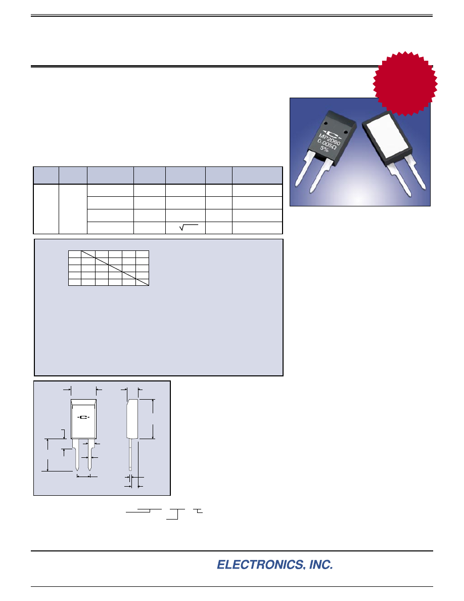
MP2060 Kool-Pak
®
Clip Mount
Power Film Resistor
25
100
150
CASE TEMPERATURE,
°
C
0
20
40
100
80
60
RA
TED POWER
%
All power and associated overload ratings are
derated based upon case temperature using the
derating curve. The case temperature is mea-
sured at the center of the ceramic mounting sur-
face, with the part properly mounted and under
electrical load. Without a heat sink, when in free
air at +25°C, the MP2060 is rated for 2.5 watts.
The thermal design should satisfy the following equation:
Case Temperature (Tc) + [Thermal Resistance (R
θ
JC
) x power applied (Watts)] ≤ 150°C, considering the full
operating temperature range of the application.
Mounting Note:
Mount on a smooth, clean and flat heat sink surface with a thermal interface material, such as
thermal grease. The entire exposed ceramic portion must be in contact with the heat sink. When using a
spring clip, it is recommended that a mounting force of 8 to 30 pounds (35 to 130 N) be applied to the center of
the package. The clip should be round or smooth in the contact area to avoid concentrating the load on a small
point of the plastic body of the package. Another mounting option is to use a pressure bar method which can
achieve a greater mounting force with a greater contact area.
For additional applications information regarding mounting and pulse handling see the Caddock Ap-
plications Notes at caddock.com or contact Applications Engineering.
*
Derating Using Case Temperature (TC):
Derating Curve
0.005
Ω
5%
0.010
Ω
2%
0.015
Ω
2%
0.020
Ω
0.025
Ω
0.030
Ω
0.033
Ω
0.040
Ω
0.050
Ω
0.075
Ω
0.10
Ω
0.15
Ω
0.20
Ω
0.25
Ω
0.30
Ω
0.33
Ω
0.40
Ω
0.50
Ω
0.75
Ω
1.00
Ω
1.50
Ω
2.00
Ω
2.50
Ω
3.00
Ω
3.30
Ω
4.00
Ω
5.00
Ω
7.50
Ω
8.00
Ω
10.0
Ω
12.0
Ω
15.0
Ω
20.0
Ω
25.0
Ω
27.0
Ω
30.0
Ω
33.0
Ω
40.0
Ω
47.0
Ω
50.0
Ω
56.0
Ω
75.0
Ω
100
Ω
120
Ω
150
Ω
200
Ω
250
Ω
300
Ω
330
Ω
400
Ω
470
Ω
500
Ω
560
Ω
750
Ω
1.00 K
Standard Resistance Values:
Tolerance: 1% Standard (except as noted)
For custom values and tolerances contact
Applications Engineering
Ordering Information:
DIMENSIONS IN INCHES AND (MILLIMETERS)
Specifications:
Temperature Coefficient:
TC referenced to +25°C,
Δ
R taken at +150°C
0.50 ohm and above, -20 to +80 ppm/°C
0.050 ohm to 0.49 ohm, 0 to +100 ppm/°C
0.015 ohm to 0.049 ohm, 0 to +200 ppm/°C
0.005 ohm to 0.014 ohm, 0 to +300 ppm/°C
Operating Temperature:
-55°C to +150°C
Inductance:
10 nH typical in series when
measured at the shoulder of the lead.
Capacitance:
<1 pf typical without heat sink.
DWV:
1500 V
rms
AC isolation to the mounting
surface or a clip in contact with the top surface.
Insulation Resistance:
10,000 Megohms, min.
The resistor element is electrically isolated from the
mounting surface.
Momentary Overload:
1.5 times rated power for
5 seconds,
Δ
R ±(0.5 percent + 0.0005 ohm) max.
Load Stability:
2000 hours at rated power
Δ
R less than ±(1 percent +0.0005 ohm).
Moisture Resistance:
Mil-Std-202, Method 106,
Δ
R ±(0.5 percent + 0.0005 ohm) max.
Thermal Shock:
Mil-Std-202, Method 107,
Cond. F,
Δ
R ±(0.5 percent + 0.0005 ohm) max.
Shock:
100G, Mil-Std-202, Method 213,
Cond. I,
Δ
R ±(0.4 percent + 0.0005 ohm) max.
Vibration, High Frequency:
Mil-Std 202,
Method 204, Condition D,
Δ
R ±(0.4 percent
+ 0.0005 ohm) max.
Terminal Strength:
Mil-Std-202, Method 211,
Cond. A (Pull Test) 5 lbs.,
Δ
R ±(0.2 percent
+ 0.0005 ohm) max.
Terminal Material:
Solderable
Measurement Note:
Resistance measurements
shall be made at 0.2 inch (5.08 mm) from the
resistor body.
These products are covered by one or more
patents, also patents pending.
• Up to 60 Watts continuous power at +25°C case temperature, 0.020
Ω
and above.
• Up to 60 Amps continuous current at +25°C case temperature, 0.015
Ω
and below.
• TO-220 Style package utilizes proven power semiconductor thermal solutions.
• Equivalent to UL94 V-0 flammability rating.
• Excellent pulse/surge performance.
• Non-inductive design for high speed switching, snubbers and rf applications.
• Operation up to +150°C case temperature.
• Electrically isolated case.
TO-220 Style Power Resistor Designed for Clip Mounting -
Non-Inductive
Packaging Information:
MP2060 resistors are packaged in plastic shipping tubes, 50 pieces
per tube. These resistors are available in a 50 piece minimum quantity and in full tube
quantity increments (i.e. 50, 100, 150, etc.).
New
Clip M
ount
Values to
0.005
Ω
28_IL128.1004