Sales and Corporate Office
1717 Chicago Avenue
Riverside, California 92507-2364
Phone: (951) 788-1700
Fax: (951) 369-1151
Applications Engineering
17271 North Umpqua Hwy.
Roseburg, Oregon 97470-9422
Phone: (541) 496-0700
Fax: (541) 496-0408
e-mail: caddock@caddock.com • web: www.caddock.com
For Caddock Distributors listed by country see caddock.com/contact/dist.html
© 2004 Caddock Electronics, Inc.
CAD
K
DOC
Certain products shown in this catalog are covered by
one or more patents, there are also patents pending.
25 Watts
1.00K
0.020
Ω
Model No.
Power
Rating
Resistance
Min.
Max.
Dielect. Strength
V
RMS
AC
MP725
*
Max.
Voltage
Terminal
Solderable
200
1,500
Specifications:
Resistance Tolerance:
±1% for 0.050
Ω
up to
1.00K
Ω
, ±5% for 0.020
Ω
up to 0.049
Ω
(5% and
20% are available for most resistance values).
Temperature Coefficient:
TC referenced to +25°C,
Δ
R taken at +150°C
0.50 ohm and above, -20 to +80 ppm/°C
0.050 ohm to 0.49 ohm, 0 to +200 ppm/°C
0.020 ohm to 0.049 ohm, 0 to +300 ppm/°C
Thermal Shock:
Mil-Std-202, Method 107,
Cond. F,
Δ
R ±(0.5 percent + 0.0005 ohm) max.
Momentary Overload:
1.5 times rated power
with applied voltage not to exceed 1.5 times
maximum continuous operating voltage for 5
seconds,
Δ
R ±(0.5 percent + 0.0005 ohm) max.
Load Life:
2,000 hours at rated power,
Δ
R ±(1.0
percent + 0.0005 ohm). Power rating dependent
upon case temperature. See derating curve.
Moisture Resistance:
Mil-Std-202, Method 106,
Δ
R ±(0.5 percent + 0.0005 ohm) max.
Shock:
100G, Mil-Std-202, Method 213,
Cond. I,
Δ
R ±(0.4 percent + 0.0005 ohm) max.
Vibration, High Frequency:
Mil-Std-202,
Method 204, Cond. D,
Δ
R ±(0.4 percent
+ 0.0005 ohm) max.
Terminal Strength:
Mil-Std-202, Method 211,
Cond. A (Pull Test) 5 lbs.,
Δ
R ±(0.2 percent
+ 0.0005 ohm) max
.
Insulation Resistance:
10,000 Megohms min.
The resistor is electrically isolated from the metal
tab.
DWV:
The dielectric strength rating of
1500 V
rms
AC is based upon connections made
between terminals shorted and either the metal
surface the part is mounted to or a metal clip in
contact with the top surface of the part.
Packaging Note:
Quantities of 250 pieces or greater will be
supplied in tape and reel packaging. The full reel
quantity is 1250 pieces.
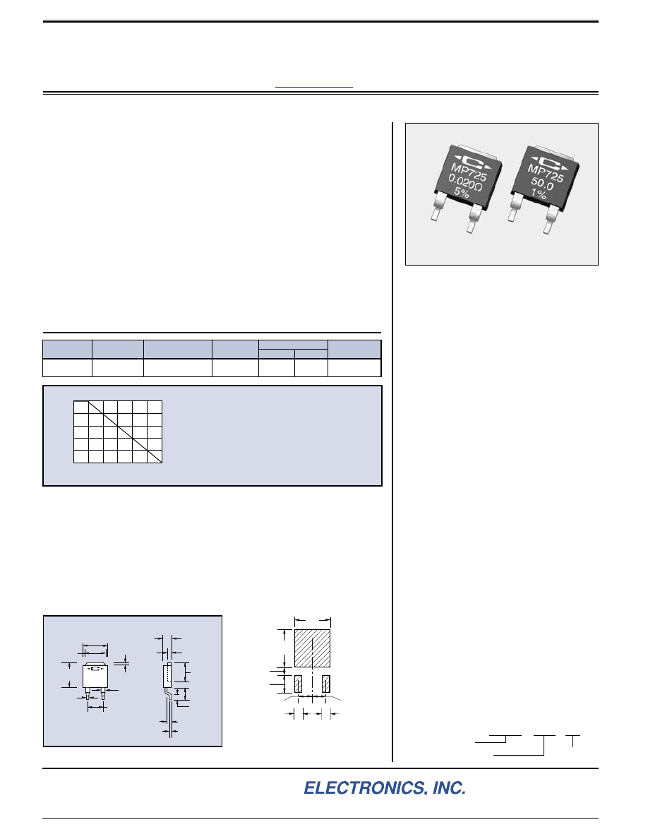
MP725 Surface Mount Power Film Resistors
D-Pak Style Surface Mount Power Package including Metal Tab - 0.020 ohm to 1.00 Kohm
Ordering Information:
Use your thermal design experience with power semiconductors in
D-Pak style power packages. This experience will help you get the most out
of this unique family of surface mount power resistors. The thermal design
issues are the same where power handling capability is based on the case
temperature which is maintained in your design.
MP725 Surface Mount Power Film Resistors introduce our proven
Micronox
®
resistance film system in the widely accepted D-Pak style surface
mount power package. The non-inductive design makes this resistor ideal in
high frequency communications, power switching circuits, and snubbers.
The special performance features of our patented MP725 Surface Mount
Power Film Resistors include:
•
D-Pak style power package for surface mount applications.
•
Metal tab assists in post surface mount soldering inspection.
•
Resistance values to 0.020 ohm for current sense applications.
•
Non-Inductive Design.
•
Up to 25 Watt power rating at +25°C case temperature.
•
Resistor element is electrically isolated from the metal heat sink tab.
DERATING CURVE
The case temperature is to be used for purposes of
establishing the maximum applied power. See Derating
Curve.
The case temperature measurement is made on the
metal mounting tab against the molded body.
Derate
appropriately for the ambient temperature range, the thermal
resistance of the mounting surface, and the temperature
limitations of the adjacent materials (such as glass epoxy).
Derating ( thermal resistance ) is 0.200 W/°C ( 5.0°C/W ).
*
Standard Resistance Values:
0.020
Ω
0.025
Ω
0.030
Ω
0.033
Ω
0.040
Ω
0.050
Ω
0.075
Ω
0.10
Ω
0.15
Ω
0.20
Ω
0.25
Ω
0.30
Ω
0.33
Ω
0.40
Ω
0.50
Ω
0.75
Ω
1.00
Ω
1.50
Ω
2.00
Ω
2.50
Ω
3.00
Ω
3.30
Ω
4.00
Ω
5.00
Ω
7.50
Ω
8.00
Ω
10.0
Ω
12.0
Ω
15.0
Ω
20.0
Ω
25.0
Ω
27.0
Ω
30.0
Ω
33.0
Ω
40.0
Ω
47.0
Ω
50.0
Ω
56.0
Ω
75.0
Ω
100
Ω
120
Ω
150
Ω
200
Ω
250
Ω
300
Ω
330
Ω
400
Ω
470
Ω
500
Ω
560
Ω
750
Ω
1.00 K
25
100
150
CASE TEMPERATURE,
°
C
0
20
40
100
RA
TED LOAD,
%
80
60
Power dissipation is 2.5 watts, at an ambient temperature of
25°C, when mounted on a double sided copper board (2 ounce,
G-10 or FR-4) 1 inch x 1 inch x .063 inch (thick).
MP 725
10.0
1%
.040
±
.018
(1.02
±
.46)
.320
±
.010
(8.13
±
.26)
.200
±
.010
(5.08
±
.26)
.053
±
.007
(1.35
±
.18)
.030
±
.004
(.76
±
.10)
.325
±
.020
(8.26
±
.51)
.250
(6.35)
.110
±
.010
(2.79
±
.26)
.032
±
.003
(.81
±
.08)
.058
±
.007
(1.47
±
.18)
.025
±
.004
(.64
±
.10)
.070
±
.010
(1.78
±
.26)
.160
±
.010
(4.06
±
.26)
.275
(6.99)
Heat sink
height
Scale:
1.5X
Dimensions in inches and (millimeters)
Soldering Note:
During surface mount
soldering the soldering temperature profile
must not cause the metal tab of this
device to exceed 220°C.
PACKAGE DIMENSIONS
.310
(7.87)
.335
(8.51)
.070
(1.78)
.150
(3.81)
.100
(2.54)
.100
(2.54)
.065
(1.65)
.065
(1.65)
FOOTPRINT FOR
SOLDERABLE CONTACT AREA
MP725 - 10.0 - 1%
Resistor Value:
Tolerance
Model Number:
Custom resistance values can be
manufactured for high quantity
applications. Please contact Caddock
Applications Engineering.
Measurement Note:
For the specifications, resistance
measurement shall be made at the
foot of surface mount formed terminal.
28_IL101.1004
www.caddock.com