3111 N. Deer Run Road, Suite 4
Carson City, NV USA 89701
800-808-2434 / 775-884-2434
Fax 775-884-0670 / www.ametherm.com
Circuit Protection Thermistors
Ametherm’s MegaSurge™ Inrush Current Limiter is an economical and space saving way to limit
high inrush current. MegaSurge’s rugged high temperature construction allows safe operation at
high continuous currents. It is specially designed to withstand up to 50 amperes of continuous
current and 900 joules of input energy.
The MegaSurge Inrush Current Limiter is useful in:
➤
AC Motors
➤
Power Supplies
➤
Motor Drives
➤
Audio Amplifiers
➤
Battery Chargers
The MegaSurge Inrush Current Limiter absorbs high amounts of inrush current when electrical
equipment is turned on by offering a high resistance to current and quickly decreasing in
resistance once steady state current begins to flow through the thermistor. In a switching power
supply, the instantaneous surge energy is caused by the large input filter capacitors and
AC input voltage.
During the absorption of energy, the initial high resistance of the thermistor drops within
milliseconds to a negligible resistance in preparation of allowing high levels of steady state
current to flow with a minimal loss of power through the circuit. The MegaSurge Inrush Current
Limiter will absorb up to 900 joules of input energy and carry 50 amperes of steady state current.
➤
Use the maximum allowable inrush
current and Ohm’s Law to determine
the least allowable resistance at
turn on for your application.
➤
Using the formula J=
1
/
2
CV
2
,
determine how much input energy
the thermistor will absorb when the
device is turned on.
➤
Determine the maximum steady state
current that will flow through
the Inrush Current Limiter.
➤
Select the Ametherm Inrush
Current Limiter that will work for
your application.
How does the
MegaSurge
Inrush Current
Limiter work?
Specify the right
MegaSurge
Inrush Current Limiter
for your application.
Ametherm’s new Inrush Current Limiter
provides big protection.
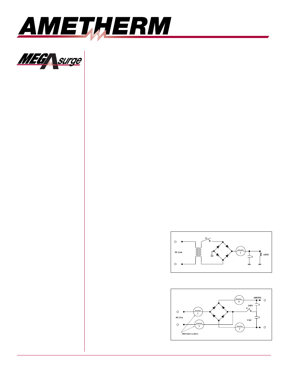
One example of a typical circuit for limiting
inrush current.
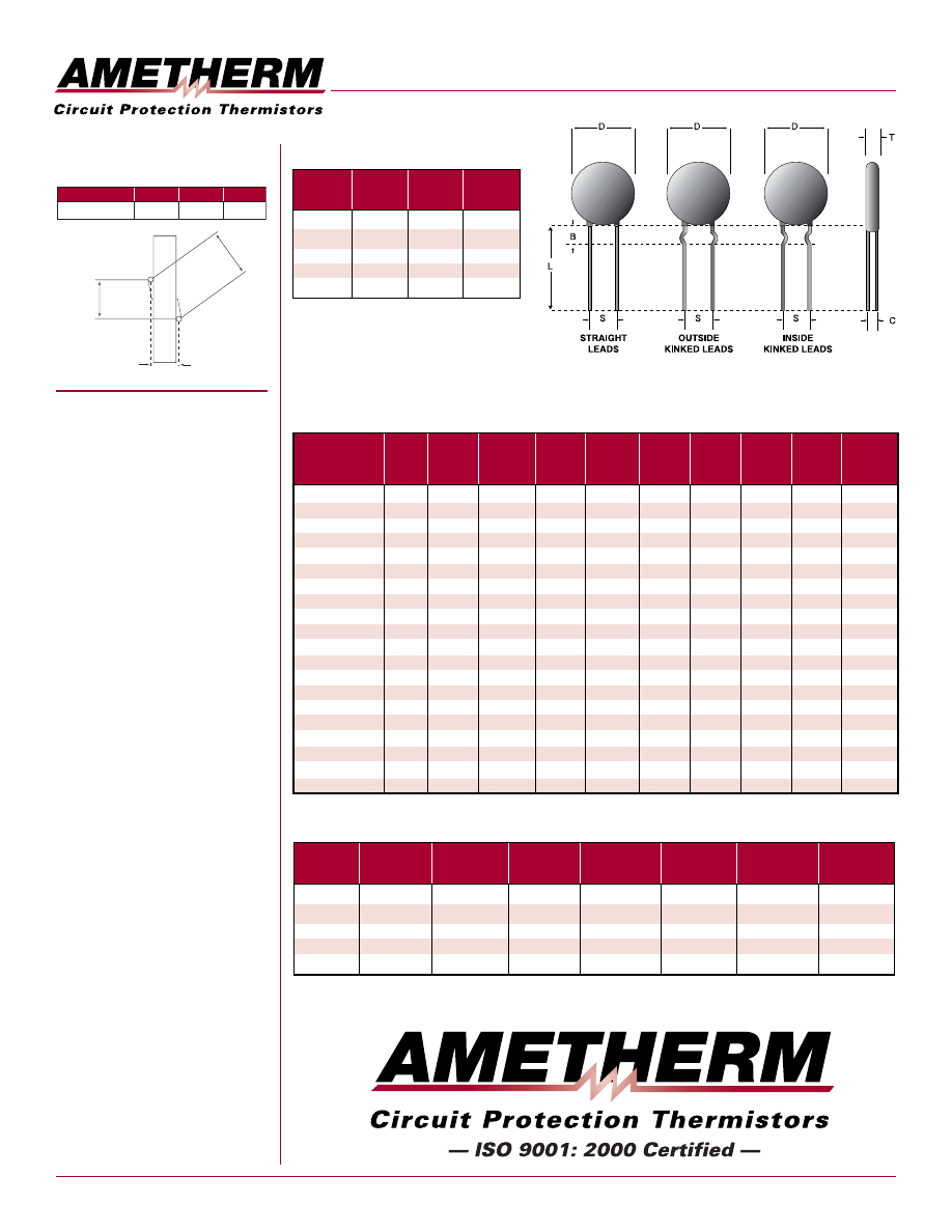
Another example of a typical circuit for limiting
inrush current.
➤
Frequency Generators
➤
Plasma Cutting Tools
➤
MRI Machines
➤
Toroidal Transformers up to 4.0KVA
➤
Other equipment that can be improved with
inrush current protection
Copyright ® Ametherm 2003. All rights reserved.
Made in the U.S.A.
www.ametherm.com
Ametherm – USA
Corporate Headquarters
3111 N. Deer Run Rd., Suite 4
Carson City, NV 89701
U.S.A.
800-808-2434
Tel: 775-884-2434
Fax: 775-884-0670
Ametherm – Europe
Thomatronik
Brückenstrasse 1
D83022 Rosenheim
GERMANY
Tel: +49 8031-2175-10
Fax: +49 8031-2175-30
Ametherm – Europe
Sequoia Technology Ltd.
Basingstoke Road
Spencers Wood, Reading
Berks
ENGLAND RG71PW
Tel: +44 1883-7228-22
Fax: +44 1189-7690-20
Ametherm – Asia
Cost Effective Solutions
Ltd.
Rm. 1034,10/F Nan Fung Centre
264-298 Castle Peak Road
Tsuen Wan, New Territories
HONG KONG
Tel: +852 241-11998
Fax: +852 241-10278
Ametherm –
Middle East
RAPAC Electronics Ltd.
60 Amal Street, PO Box 4127
Kiryat Arie, Petach Tikva
ISRAEL 49130
Tel: +972 3-9203-456
Fax: +972 3-9203-443
MegaSurge Inrush Current Limiter Specifications
Mechanical Specifications
Part
Series
D
(mm)
S
(mm)
L
(mm)
B
(mm)
C
(mm)
T
(mm)
Lead Dia
(mm)
MS12
12.0 Nom
9.0 Nom
1.3 Nom
7.80 Nom
38.0 Nom
6.35 Nom
6.70 Nom
MS15
15.0 Nom
9.0 Nom
1.3 Nom
7.80 Nom
38.0 Nom
6.30 Nom
6.70 Nom
MS22
22.0 Nom
9.0 Nom
1.3 Nom
7.80 Nom
38.0 Nom
7.60 Nom
6.70 Nom
MS32
32.0 Nom
9.0 Nom
1.3 Nom
7.80 Nom
38.0 Nom
7.60 Nom
6.70 Nom
MS35
35.0 Nom
9.0 Nom
2.5 Nom
19.0 Nom
39.0 Nom
9.80 Nom
7.50 Nom
Part
Series
Straight
Inside
Kink
Outside
Kink
MS12
✔
✔
✔
MS15
✔
✔
✔
MS22
✔
✔
✔
MS32
✔
✔
MS35
✔
Available Lead Configurations
MegaSurge Footprint
Specifications
C
A
B
Component shown
without coating
Tolerance: +/- .5mm
Part Number
A
B
C
MS32 10015
7.8mm
9.6mm
5.6mm
Part
Number
Material
Type
R @
25
°
C
(
Ω
)
Max
SSI
(Amp)
Max
Voltage
(Volts)
Max Cap
@ Max
Voltage
(
µ
F)
Max
Energy
(Joules)
Rhot @
100%
SSI
Rhot @
75%
SSI
Rhot @
50%
SSI
Rhot @
25%
SSI
MS32 1R036-L
1
36
300
440
1500
0.012
0.015
0.030
0.070
B
MS32 2R025
2
25
350
440
1500
0.020
0.032
0.060
0.160
C
MS32 5R020
5
20
325
440
1250
0.035
0.060
0.100
0.300
G
MS32 10015
10
15
250
440
1250
0.060
0.100
0.190
0.500
H
MS32 20008
20
8
220
440
1250
0.200
0.330
0.570
1.360
I
MS22 20005
20
5
150
440
1000
0.320
0.500
0.720
2.000
H
MS15 40004
40
4
135
440
700
0.400
0.623
0.960
2.500
I
MS22 50004
50
4
240
440
1200
0.400
0.625
1.100
3.150
I
MS15 66003
66
3.5
125
440
600
0.400
0.824
1.730
2.950
H
MS22 75004
75
4
240
440
1200
0.500
0.770
1.350
3.540
M
MS22 12103
120
3
220
440
1100
0.950
1.400
2.500
6.400
M
MS12 15102
150
2
110
440
560
1.050
1.900
2.710
3.840
I
MS22 22103
220
3
100
440
775
1.000
1.670
3.000
8.000
L
MS35 0R550
0.5
50
900
680
2000
0.008
0.013
0.020
0.050
B
MS35 1R040
1
40
800
680
1700
0.012
0.020
0.030
0.080
B
MS35 2R035
2
35
750
680
1600
0.020
0.027
0.040
0.102
C
MS35 3R030
3
30
750
680
1250
0.030
0.052
0.080
0.200
G
MS35 5R025
5
25
600
680
1000
0.050
0.100
0.150
0.400
H
MS35 10018
10
18
500
680
1000
0.100
0.320
0.480
1.250
I
MS35 20010
20
10
500
680
1600
0.030
0.040
0.065
0.155
I