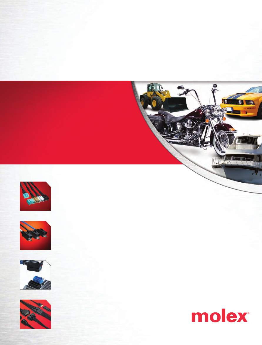
Transportation Products Catalog
Explore our range of Industry and
Board-Level Products that can
take your design to the next level.
Transportation Products Catalog
Explore our range of Industry and
Board-Level Products that can
take your design to the next level.