Capability Brochure, power film resistor-20120101
Power Film Resistors
NIKKOHM
NIKKOHM Co., Ltd.
Office: 3rd fl., K&Y Bldg., 2-24-4 Nihonbashi Ningyo Cho Chuo Ku, Tokyo 103-0013 Japan
Phone: +81-03-3664-1391, Fax: +81-3-3664-5770, kishino-k@nikkohm.co.jp
Factory: 3-31-2640 Minami Cho Misawa Shi, Aomori 033-0036 Japan
Phone: +81-176-53-2105, Fax: +81-176-53-2106, kishino-k@nikkohm.co.jp
January 2012
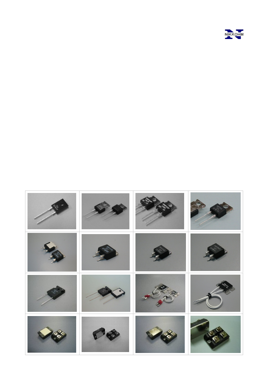
RNP-10S, 20W
RNP-10, 20W
RNP-20S, 35W
RNP-50U, 50W
RNP-50F, 50W
RNP-20D, 35W
RNP-20E, 35W
RPM200, 200W
RPL310, 300W
RPL300, 300W
RNP-100S, 140W
RNP-50S, 100W
RPK900, 600W
RPM600, 600W
RPM300, 300W
RNP-20F, 35W